solar combisystems promotion and standardisation · 6 main recommendations for an efficient solar...
TRANSCRIPT
The sole responsibility for the content of this publication lies with the authors. It does not necessarily reflect the
opinion of the European Union. Neither the EACI nor the European Commission are responsible for any use that may
be made of the information contained therein.
Solar Combisystems Promotion and Standardisation
Final report
Created by:
Philippe Papillon
Staff member of CEA-INES
Contributions from
Jan Erik Nielsen (PlanEnergi), Xavier Cholin, Thomas Letz (INES Education),
Alexander Thür, Gabrielle Kuhness (AEE INTEC) Chris Bales (SERC)
Philippe Papillon, Mickael Albaric (CEA-INES) Barbara Mette, Jens Ullmann, Harald Drueck (ITW)
(2010)
Date 12/20/2010 Version Final Revision 2
CombiSol :Solar Combisystems Promotion and Standardisation page 2
CONTENTS
Symbol list ............................................................................................................................... 5
Table list .................................................................................................................................. 6
Figure list ................................................................................................................................. 6
Introduction ............................................................................................................................. 9
1 Potential of solar combisystems ....................................................................................... 10
2 Typical solar combisystem................................................................................................ 14
2.1 Different hydraulic schemes...................................................................................................14 2.1.1 Domestic Hot Water Preparation............................................................................................................15 2.1.2 Auxiliary energy and its integration in a solar combisystems .................................................................17 2.1.3 Typical solar loops ...................................................................................................................................18
2.2 Products and tendencies........................................................................................................20 2.2.1 Prefabricated component groups ...........................................................................................................20 2.2.2 Compact prefabricated systems..............................................................................................................21
3 Qualitative inspection ...................................................................................................... 23
3.1 Procedure..............................................................................................................................23
3.2 Main results ..........................................................................................................................25 3.2.1 Overall System.........................................................................................................................................25 3.2.2 Solar Loop................................................................................................................................................26 3.2.3 Heat Storage............................................................................................................................................31 3.2.4 Space Heating..........................................................................................................................................34 3.2.5 Domestic Hot Water................................................................................................................................36 3.2.6 Auxiliary Heater.......................................................................................................................................37
3.3 Conclusion.............................................................................................................................38
4 In-Situ Monitoring of solar combisystems ......................................................................... 40
4.1 Procedure..............................................................................................................................40
4.2 Monitoring equipment ..........................................................................................................42
4.3 Presentation of monitored systems........................................................................................42
4.4 Main results ..........................................................................................................................45 4.4.1 Results sorted by country........................................................................................................................46 4.4.2 Results sorted by manufacturer ..............................................................................................................46 4.4.3 Results sorted by system type.................................................................................................................47 4.4.4 Analysis of thermal losses and solar gains ..............................................................................................47 4.4.5 Analysis of parasitic electricity ................................................................................................................48 4.4.6 Comparison between compact systems and systems assembled on site...............................................48
4.5 Comparison between laboratory tests and on site monitoring ................................................49
4.6 Outcomes..............................................................................................................................51
5 Test methods ................................................................................................................... 52
5.1 CTSS method .........................................................................................................................52
5.2 SCSPT method .......................................................................................................................53
CombiSol :Solar Combisystems Promotion and Standardisation page 3
5.3 Comparison of test methods ..................................................................................................53 5.3.1 System design of the solar combisystems investigated ..........................................................................54 5.3.2 Quantities characterizing the thermal performance of a thermal solar system .....................................55 5.3.3 Test results of the CTSS method and SCSPT method ..............................................................................56 5.3.4 Adaption of the CTSS method to the boundary condition of the SCSPT method ...................................57
5.4 Performance prediction for different boundary conditions .....................................................59
5.5 Summary and conclusion .......................................................................................................60
6 Main recommendations for an efficient solar combi-systems............................................ 63
6.1 Overall System Concept .........................................................................................................63
6.2 Single or Multi Store Concepts ...............................................................................................64
6.3 Heat Storage .........................................................................................................................65 6.3.1 System with two heat storages: ..............................................................................................................66 6.3.2 Connection of space heating return pipe:...............................................................................................67
6.4 Auxiliary Heater.....................................................................................................................67 6.4.1 Problem of over-dimensioned auxiliary heater:......................................................................................67 6.4.2 Typical specific problems in auxiliary type 1 systems “auxiliary boiler as return flow increase”: ..........67 6.4.3 Typical problem of auxiliary volume as hydraulic switch: .......................................................................68 6.4.4 Auxiliary heater flow rate setting or control: ..........................................................................................69 6.4.5 How to control the space heating auxiliary volume:...............................................................................69 6.4.6 Potentials for keeping heat storage small and avoid multi store systems:.............................................70
6.5 Space Heating........................................................................................................................71 6.5.1 High temperature space heating systems ...............................................................................................72 6.5.2 Medium temperature space heating systems.........................................................................................72 6.5.3 Low temperature space heating systems................................................................................................73 6.5.4 How to achieve low return temperatures in practice: ............................................................................73 6.5.5 Advanced ideas/concepts to increase the system performance: ...........................................................73
6.6 Solar Collector Circuit ............................................................................................................74 6.6.1 Quality of external piping:.......................................................................................................................75 6.6.2 Dimensioning of Solar Heat Exchanger: ..................................................................................................75 6.6.3 How to install stagnation proof solar collector circuit: ...........................................................................75
6.7 General Aspects.....................................................................................................................79 6.7.1 Important thoughts before starting the installation: ..............................................................................79 6.7.2 Heat loss never is useful:.........................................................................................................................80 6.7.3 Documentation of the solar combisystem: .............................................................................................80
7 Tools................................................................................................................................ 82
8 Training ........................................................................................................................... 84
8.1 Suggested Contents for courses on SCS ..................................................................................84 8.1.1 Essential contents of courses ..................................................................................................................84 8.1.2 Possible Extra Contents for Longer Courses............................................................................................85
8.2 Training Materials for Installers Courses.................................................................................86
8.3 Comparison of tools for calculating the size of the expansion vessel .......................................87
9 Recommendations for subsidies scheme........................................................................... 89
9.1 Carrots: incentive schemes ....................................................................................................90
9.2 Sticks: Regulatory schemes ....................................................................................................90
9.3 Guidance: education-based schemes......................................................................................90

CombiSol :Solar Combisystems Promotion and Standardisation page 4
9.4 Recommendations.................................................................................................................91
Conclusion.............................................................................................................................. 92
Bibliography .......................................................................................................................... 93
CombiSol :Solar Combisystems Promotion and Standardisation page 5
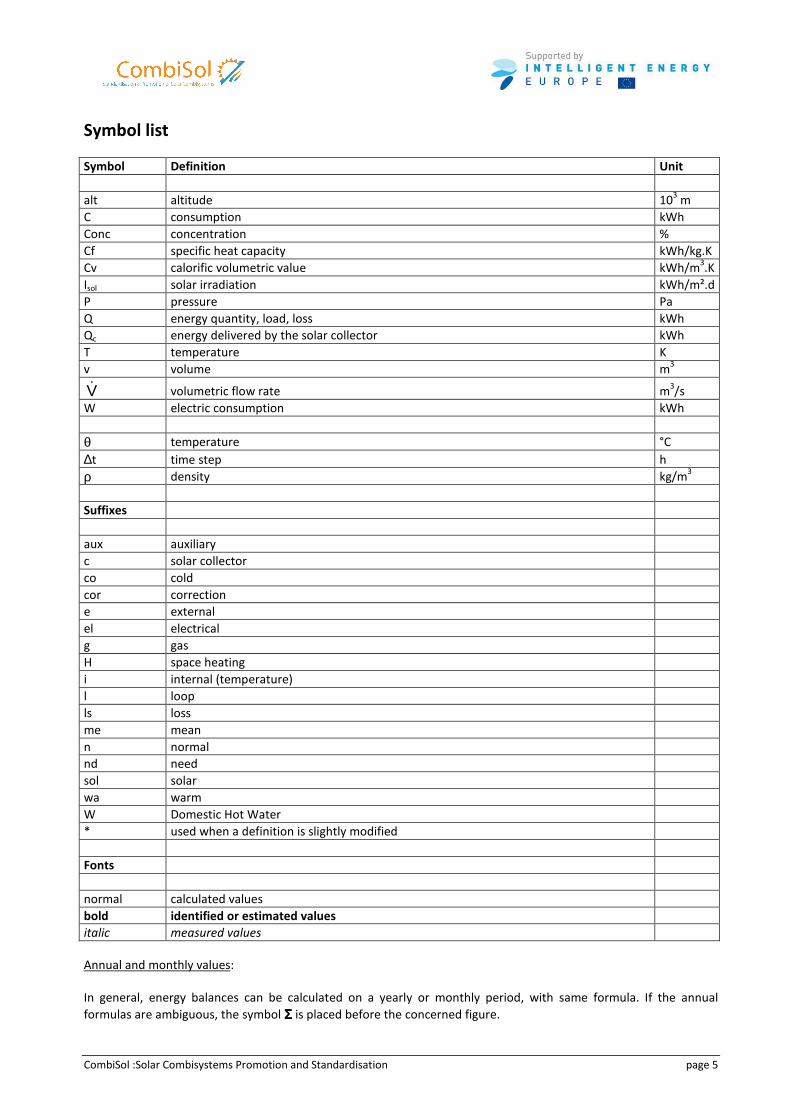
Symbol list
Symbol Definition Unit
alt altitude 103 m
C consumption kWh
Conc concentration %
Cf specific heat capacity kWh/kg.K
Cv calorific volumetric value kWh/m3.K
Isol solar irradiation kWh/m².d
P pressure Pa
Q energy quantity, load, loss kWh
Qc energy delivered by the solar collector kWh
T temperature K
v volume m3
V& volumetric flow rate m3/s
W electric consumption kWh
θ temperature °C
∆t time step h
ρ density kg/m3
Suffixes
aux auxiliary
c solar collector
co cold
cor correction
e external
el electrical
g gas
H space heating
i internal (temperature)
l loop
ls loss
me mean
n normal
nd need
sol solar
wa warm
W Domestic Hot Water
* used when a definition is slightly modified
Fonts
normal calculated values
bold identified or estimated values
italic measured values
Annual and monthly values:
In general, energy balances can be calculated on a yearly or monthly period, with same formula. If the annual
formulas are ambiguous, the symbol ΣΣΣΣ is placed before the concerned figure.
CombiSol :Solar Combisystems Promotion and Standardisation page 6
Table list Table 1: Summary of advantages and disadvantages of different DHW preparation typologies ....................................................... 16 Table 2: Summary of advantages and disadvantages of different auxiliary integration typologies................................................... 17 Table 3: Characteristics of monitored systems ................................................................................................................................... 44 Table 4: Comparison between indicators coming from laboratory tests and from on site monitoring............................................... 50 Table 5: Boundary conditions for laboratory testing according to the SCSPT method....................................................................... 53 Table 6: Heat demand of the SCSPT and CTSS methods...................................................................................................................... 56 Table 7: Annual energy demand and gain on the different circuits determined by the annual simulation of the SimCTSS test method
and the extrapolated results of the SCSPT method.................................................................................................................... 58
Figure list Figure 1: Solar thermal potential in EU 27 based on the three scenarios; Source: [17] ...................................................................... 10 Figure 2: Overall solar thermal potential and potential for SCS in Austria: once the BAU-scenario (left), once the RDP-scenario
(right) ......................................................................................................................................................................................... 11 Figure 3: Overall solar thermal potential and potential for SCS in Denmark: once the BAU-scenario (left), once the RDP-scenario
(right) ......................................................................................................................................................................................... 12 Figure 4: Overall solar thermal potential and potential for SCS in Germany: once the BAU-scenario (left), once the RDP-scenario
(right) ......................................................................................................................................................................................... 12 Figure 5: Overall solar thermal potential and potential for SCS in France: once the BAU-scenario (left), once the RDP-scenario (right)
................................................................................................................................................................................................... 13 Figure 6: Overall solar thermal potential and potential for SCS in Sweden: once the BAU-scenario (left), once the RDP-scenario
(right) ......................................................................................................................................................................................... 13 Figure 7: Hydraulic scheme of a tank-in-tank system – auxiliary boiler is integrated as return flow increase (left) or is charging the
heat storage tank (right)............................................................................................................................................................ 14 Figure 8: Hydraulic scheme of a heat storage system with an immersed heat exchanger – auxiliary boiler is integrated as return
flow increase (left) or is charging the heat storage tank (right) ................................................................................................ 15 Figure 9: Solar heating plant with a fresh water unit – auxiliary boiler is integrated as return flow increase (left) or is charging the
heat storage tank (right)............................................................................................................................................................ 15 Figure 10: Immersed/internal heat exchanger at one level ................................................................................................................ 18 Figure 11: Examples of immersed heat exchanger at two levels; left: one or BOTH heat exchanger are used; right: one OR the other
heat exchanger is used............................................................................................................................................................... 18 Figure 12: External heat exchanger with: left: two pipe connections at two different level (external stratification via switching
valve); right: internal stratification device ................................................................................................................................. 19 Figure 13: Solar Charging Unit (Viessmann, SOLution, Tisun, Sonnenkraft, Bosch-Junkers) ............................................................... 20 Figure 14: External DHW unit (SOLution, Sonnenkraft) ...................................................................................................................... 20 Figure 15: Space Heating Units (Sonnenkraft, Vaillant)...................................................................................................................... 20 Figure 16: Compact combisystems including condensing gas boilers (Solvis, DeDietrich, Bösch, Clipsol)........................................... 21 Figure 17: Compact combisystems including condensing gas boilers (Rotex, Capito, Sonnenkraft) ................................................... 21 Figure 18: Compact combisystems including gas or oil burner (Olymp) ............................................................................................. 22 Figure 19: Compact combisystems including heat pump (Sonnenkraft) ............................................................................................. 22 Figure 20: Compact combisystems including pellet boilers (Solarfocus, Okofen) ............................................................................... 22 Figure 21: Partition of the Evaluation Points ...................................................................................................................................... 23 Figure 22: Space heating Area and Collector Area of the evaluated houses....................................................................................... 23 Figure 23: Standard Procedure for Evaluation available as D5.1a and D5.1b. ................................................................................... 24 Figure 24: Example of 2 Page-Documentation available as D5.2 for each of the 70 plants................................................................ 24 Figure 25: Type of systems evaluated within CombiSol ...................................................................................................................... 25 Figure 26: Available documents on site .............................................................................................................................................. 26 Figure 27: Example of documentation of controller settings and hydraulic scheme on site ............................................................... 26 Figure 28: Type of collector mounting ................................................................................................................................................ 27 Figure 29: Examples of collector mounting (Source: Ines Education / France) ................................................................................... 27 Figure 30: Examples of collector mounting (Source: SERC / Sweden) ................................................................................................. 27 Figure 31: Examples of collector mounting (Source: AEE INTEC / Austria).......................................................................................... 28 Figure 32: Examples of collector mounting (Source: ITW / Germany) ................................................................................................ 28 Figure 33: External pipe insulation ..................................................................................................................................................... 28 Figure 34: External pipe insulation (Source: Ines Education / France): left side good quality of insulation and protection; right side
well insulated but no protection. ............................................................................................................................................... 29 Figure 35: External pipe insulation (Source: AEE INTEC / Austria): good quality of insulation and protection ................................... 29 Figure 36: External pipe insulation (Source: AEE INTEC / Austria): left side: partly no insulation and no protection; right side:
absolutely no insulation, therefore nothing which could be protected �.................................................................................. 29
CombiSol :Solar Combisystems Promotion and Standardisation page 7
Figure 37: Stagnation characteristics ................................................................................................................................................. 30 Figure 38: Solar expansion vessel connection correct ......................................................................................................................... 30 Figure 39: Solar expansion vessel connected via stagnation cooler (left) or “preposition vessel” (right) ........................................... 31 Figure 40: Specific storage volume versus collector area – fuel separated......................................................................................... 32 Figure 41: Number of heat storage tanks ........................................................................................................................................... 32 Figure 42: Unused pipe connections insulated (left), Thermosiphon heat traps installed (right)........................................................ 33 Figure 43: Multistore system in Sweden (left), bad top insulation of a tank in tank system in Austria (right).................................... 33 Figure 44: Not insulated and upwards connected pipes at the top of a tank in France (left), not insulated pipe connections and cold
bridges due to temperature sensors at a tank in Germany (right)............................................................................................. 33 Figure 45: Perfect insulated thermosiphon heat trap (left), good closed top tank insulation and insulated pipe connection (middle),
pipe connection downwards and insulated temperature sensor immersion sleeve and insulated unused pipe connections
(right). (Source: INES Education and AEE INTEC)........................................................................................................................ 34 Figure 46: Heat storage with thermosiphon heat traps at all pipe connections and all pipes insulated (left), prefabricated insulation
elements for unused pipe connections (middle), pipes connected at the tank are good insulated completely to the tank (right).
(Source: INES Education, SERC and AEE INTEC).......................................................................................................................... 34 Figure 47: Type of space heating ........................................................................................................................................................ 35 Figure 48: Examples of space heating pump groups, left: non insulated pipes but nice insulated pumps; right: good insulation of
heat storage and all pipes and pumps as a basis of a good performing solar combisystem. .................................................... 35 Figure 49: Type of domestic hot water preparation ........................................................................................................................... 36 Figure 50: Heat storage insulation quality of tank in tank systems: pipe connections at top and bad (left) and good insulation
(middle) or well insulated pipe connections at the side of the tank (right) which could be improved with pipes leading
downwards immediately (thermosiphon heat trap). (Source: INES Education and AEE INTEC)................................................. 36 Figure 51: External Heat exchanger modules direct mounted at the tank (left and middle) or extra mounted at the wall (right).
(Source: ITW and AEE INTEC) ..................................................................................................................................................... 37 Figure 52: Type of auxiliary heater ..................................................................................................................................................... 38 Figure 53: Nominal auxiliary power versus space heating area.......................................................................................................... 38 Figure 54: Monitoring diagram for systems without (left) and with (right) storage........................................................................... 41 Figure 55: Fsav vs FSC diagram with the range of properly working systems, ..................................................................................... 41 Figure 56: Location of sensors and meters ......................................................................................................................................... 42 Figure 57: Location of monitored systems in Austria, France, Germany and Sweden ........................................................................ 43 Figure 58: Typology of monitored systems ......................................................................................................................................... 43 Figure 59: Characteristics of monitored systems ................................................................................................................................ 45 Figure 60: Results sorted by country................................................................................................................................................... 46 Figure 61: Results sorted by manufacturer ......................................................................................................................................... 46 Figure 62: Results sorted by system type ............................................................................................................................................ 47 Figure 63: System heat losses and solar gains .................................................................................................................................... 47 Figure 64: Parasitic electricity consumed............................................................................................................................................ 48 Figure 65: Global results of the Combisol project (savings evaluated at the auxiliary heater outlet)................................................. 49 Figure 66: Global results of the Combisol project (savings evaluated at the auxiliary heater inlet) ................................................... 49 Figure 67: Comparison between laboratory and on site monitoring results....................................................................................... 50 Figure 68: Principal structure of the CTSS-method ............................................................................................................................. 52 Figure 69: System design of the solar combisystem 1......................................................................................................................... 54 Figure 70: System design of the solar combisystem 2......................................................................................................................... 54 Figure 71: Method for the comparison of the test results of the CTSS method and the SCSP test method......................................... 58 Figure 72: Fractional energy savings of the solar combisystem 1 for different climates (Stockholm, Wurzburg) and daily hot water
loads (110 l/d, 200 l/d) determined according to the CTSS method (blue bars) and extrapolated from the test results of the
SCSPT test method using the COMBI-EN tool (red bars). ........................................................................................................... 60 Figure 73: Fractional energy savings of the solar combisystem 2 for different climates (Stockholm, Wurzburg) and daily hot water
loads (110 l/d, 200 l/d) determined according to the CTSS method (blue bars) and extrapolated from the test results of the
SCSPT test method using the COMBI-EN tool (red bars). ........................................................................................................... 60 Figure 74: Examples of tank designs with pipe connection at tank side in medium/low temperature zones with internal pipes to the
top; Source: Pink (left) Bösch (middle); example of well insulated piping and thermosiphon heat traps at all pipe connections
at the heat storage (right; Source: Tisun) .................................................................................................................................. 65 Figure 75: Examples of good insulated top of heat storages and best case (right) of a totally closed top insulation of a heat storage.
(Source : AEE INTEC)................................................................................................................................................................... 66 Figure 76: Example of good/acceptable installation details: insulated thermosiphon heat trap (left, Source: INES Education); basic
insulation of temperature sensor and unused pipe connections (middle, Source: INES Education); temperature sensor well
fixed and pipe for immersion sleeve insulated (right, Source : AEE INTEC) ................................................................................ 66 Figure 77: Good examples of prefabricated insulation elements for unused pipe connections (Source: Sonnenkraft (left) Bösch
(right))........................................................................................................................................................................................ 66 Figure 78: Dependency of the fractional energy savings on tilt angle and azimuth of the collector (climate: central Europe, 100% =
39% of extended fractional energy savings), source: Weiss 2003 [7]. ....................................................................................... 75 Figure 79: External pipe insulation (Source: AEE INTEC / Austria): good quality of insulation and protection ................................... 75

CombiSol :Solar Combisystems Promotion and Standardisation page 8
Figure 80: Right and false way for connecting an expansion vessel in a solar thermal system (left).................................................. 76 Figure 81: Stagnation cooler, performed as a baseboard heating fitting (left) and mounted (middle) or “preposition vessel” (right)
................................................................................................................................................................................................... 77 Figure 82: Correct position of the non-return valve in relation to the expansion vessel (left) and correct position of a stagnation
cooler keeping the steam above temperature critical components (right) (Source: AEE INTEC)................................................ 77 Figure 83: Collectors with bad emptying behaviour............................................................................................................................ 78 Figure 84: Collectors with good emptying behaviour ......................................................................................................................... 78 Figure 85: Drain pipe at outlet of pressure relief valve made of copper (left) and collection tank which is closed and made of metal
(right) ......................................................................................................................................................................................... 79 Figure 86: COMBI-EN result sheet - example ...................................................................................................................................... 83 Figure 87: example OH slides from one of the training presentations................................................................................................ 86 Figure 88: comparison of the suggested size of expansion vessel as calculated by six different tools [8]. ......................................... 88 Figure 89: Technology development, industrial development and market deployment are linked to produce a market with critical
mass that becomes self-sustaining [16] ..................................................................................................................................... 89 Figure 90: Policy instruments categories for renewable heating and cooling with examples [16] ..................................................... 90
CombiSol :Solar Combisystems Promotion and Standardisation page 9
Introduction
Solar combisystems (SCS) are solar heating installations providing both space heating and domestic hot water in
buildings. The main objective of Combisol project was to encourage an accelerated market deployment of SCS –
hence a higher share of heat produced by solar energy - and to promote an improved quality of the systems
installed.
In particular, Combisol project wants to:
• promote best practices for solar combisystems in new and existing buildings,
• promote standardised systems and cost-effective solutions,
• propose recommendations to manufacturers with regard to combisystems design,
• train installers,
• develop specific dimensioning tools in order to facilitate the recommendation for solar combisystems based
on the EPBD methodology,
• increase consumers confidence, providing information on energy efficiency of solar combisystems, based on
in-situ monitoring and test labs.
In this report, lessons learned and results of the project are presented.
After evaluating the potential of solar combisystems in terms of market and energy savings, a review presents the
different technologies available on the market and trends.
Then the results of a qualitative assessment carried out in Germany, Austria, France and Sweden on 70 systems are
reported. Thanks to a detailed questionnaire and inspection on site, key points for progress, but also good examples
are presented, and some conclusion provided to improve the quality.
Out of the 70 systems qualitatively evaluated, 45 were selected in-situ monitoring based on the same methodology
in the 4 participating countries. The results after several months of measurement are presented with valuable
lessons about optimizing performance.
Measuring the thermal performance thanks to in-situ monitoring is the best option to evaluate both design of the
system and installation of the system. But this option is expensive and the end-user is only informed about the
thermal performance of the system only after buying and measuring it. To provide end-user with valuable
information on the thermal performance before purchasing such systems, lab test methods are required. Two test
methods will be presented based on a component approach and on a system approach. Inter-comparisons of system
performance in labs have been done with promising results but further development is still required. More, a relative
good correlation between in-situ monitoring and lab tests has been checked.
Based mainly on the qualitative and quantitative evaluation, main recommendations for efficient solar combi-
systems have been elaborated. These recommendations addressed to manufacturers, installers and planners are the
results of intensive work, and should be taken into account in the future for quality improvement of solar
combisystems.
Finally, quality of systems relies also on efficient tools for dimensioning, and qualifications of installers. The last
sections of this report will present tools that have been developed within this project as well as training materials
focusing on the main lessons learned in this project.
Once quality of systems is achieved, the last section provides recommendations related for the promotion of solar
combi-systems in the form of “carrots” (incentives), “sticks” (regulation) and “guidance” (education) policies.
CombiSol :Solar Combisystems Promotion and Standardisation page 10
1 Potential of solar combisystems Main authors : Alexander Thür and Gabriele Kuhness
According to the goals of the energy policy in Europe to reduce CO2 emissions it is necessary to find and to use all
possible sources for renewable energy in a proper way. Thermal heat is a main part of energy consumption in Europe
and again space heating and domestic hot water for residential buildings is a significant part of low temperature heat
consumption in Europe.
In order to estimate possible contribution of overall solar thermal energy for all types of demand in Europe the study
“POTENTIAL OF SOLARTHERMAL IN EUROPE” was prepared for the European Solar Thermal Industry Federation
(ESTIF) within the 6th framework program by the Vienna University of Technology – Energy Economics Group (EEG),
Peter Biermayr, and the AEE – Institute for Sustainable Technologies (AEE INTEC), Werner Weiss [17].
Within the CombiSol project based on this study and also based on the actual statistic data from IEA-SHC report
“Solar Heat Worldwide 2008” 1 the possible contribution of solar combisystems for space heating and domestic hot
water preparation mainly in single family houses was derived based on estimations from national experts of the
participating institutions. Therefore, these numbers specifically related to solar combisystems shall be interpreted as
a good guess but not as the result of detailed statistical calculations.
The determination of the potential of solar thermal in the European Union (EU 27) in this report is based on detailed
country studies done within the ESTIF study concerning the solar thermal potential in the five reference countries
Austria, Denmark, Germany, Poland and Spain representing a good mix of all climate zones in Europe, varied subsidy
models and different solar thermal market developments.
The potential study is based on a model, which accounts for many factors like e.g. share of new buildings, energy
index of buildings, the quality of retrofits, economic state, subsidy structure and also limited factors like availability
of space for solar collectors. The model delivers the potential of the solar thermal market for 2020, 2030 and 2050.
This potential results in three differently ambitious scenarios - „BAU-“ (Business As Usual), „AMD-” (Advanced
Market Deployment) and „RDP-scenario” (Full Research Development and Policy). First it was detailed evaluated for
the five countries Austria, Germany, Denmark, Poland and Spain and based on that derived for the EU 27.
Because of missing results within this study for France and Sweden, the potential for these countries were derived
from other countries with similar structures. The French potential is based on Spain, the Swedish potential is based
on Denmark. The result of the potential study for solar thermal in general and for solar combisystems especially can
be summarized for EU 27 and the CombiSol partner countries as following.
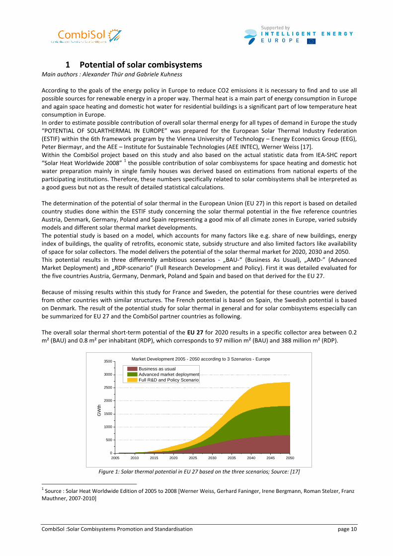
The overall solar thermal short-term potential of the EU 27 for 2020 results in a specific collector area between 0.2
m² (BAU) and 0.8 m² per inhabitant (RDP), which corresponds to 97 million m² (BAU) and 388 million m² (RDP).
2005 2010 2015 2020 2025 2030 2035 2040 2045 20500
500
1000
1500
2000
2500
3000
3500 Market Development 2005 - 2050 according to 3 Szenarios - Europe
GW
th
Business as usual Advanced market deployment Full R&D and Policy Scenario
Figure 1: Solar thermal potential in EU 27 based on the three scenarios; Source: [17]
1 Source : Solar Heat Worldwide Edition of 2005 to 2008 [Werner Weiss, Gerhard Faninger, Irene Bergmann, Roman Stelzer, Franz
Mauthner, 2007-2010]
CombiSol :Solar Combisystems Promotion and Standardisation page 11
The overall solar thermal medium-term potential of the EU 27 for 2030 results in a specific collector area between 1
m² (BAU) and 3 m² per inhabitant (RDP), which corresponds to 485 million m² (BAU) and 1,455 million m² (RDP).
The overall solar thermal long-term potential of the EU 27 for 2050 results in a specific collector area between 2 m²
(BAU) and 8 m² per inhabitant (RDP), which corresponds to 970 million m² (BAU) and 3,880 million m² (RDP). This
collector area corresponds to an energy saving of 1,552 TWh and would reduce the CO2 emission to 687 million tons
per year.
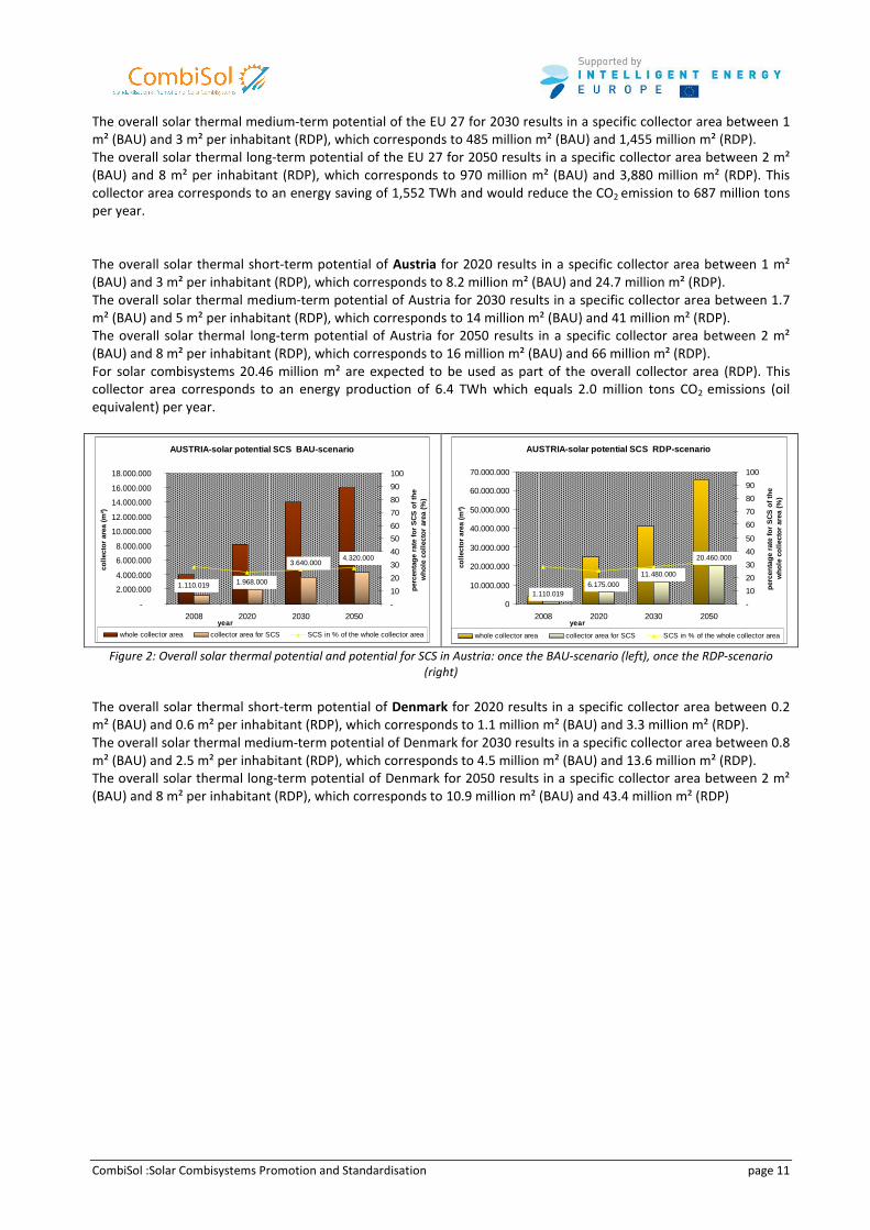
The overall solar thermal short-term potential of Austria for 2020 results in a specific collector area between 1 m²
(BAU) and 3 m² per inhabitant (RDP), which corresponds to 8.2 million m² (BAU) and 24.7 million m² (RDP).
The overall solar thermal medium-term potential of Austria for 2030 results in a specific collector area between 1.7
m² (BAU) and 5 m² per inhabitant (RDP), which corresponds to 14 million m² (BAU) and 41 million m² (RDP).
The overall solar thermal long-term potential of Austria for 2050 results in a specific collector area between 2 m²
(BAU) and 8 m² per inhabitant (RDP), which corresponds to 16 million m² (BAU) and 66 million m² (RDP).
For solar combisystems 20.46 million m² are expected to be used as part of the overall collector area (RDP). This
collector area corresponds to an energy production of 6.4 TWh which equals 2.0 million tons CO2 emissions (oil
equivalent) per year.
AUSTRIA-solar potential SCS BAU-scenario
1.968.000 1.110.019
3.640.000 4.320.000
-
2.000.000
4.000.000
6.000.000
8.000.000
10.000.000
12.000.000
14.000.000
16.000.000
18.000.000
2008 2020 2030 2050year
colle
ctor
are
a (m
²)
-
10
20
30
40
50
60
70
80
90
100
perc
enta
ge r
ate
for
SC
S o
f the
w
hole
col
lect
or a
rea
(%)
whole collector area collector area for SCS SCS in % of the whole collector area
AUSTRIA-solar potential SCS RDP-scenario
1.110.019 6.175.000
11.480.000
20.460.000
0
10.000.000
20.000.000
30.000.000
40.000.000
50.000.000
60.000.000
70.000.000
2008 2020 2030 2050year
colle
ctor
are
a (m
²)
-
10
20
30
40
50
60
70
80
90
100
perc
enta
ge r
ate
for
SC
S o
f the
w
hole
col
lect
or a
rea
(%)
whole collector area collector area for SCS SCS in % of the whole collector area
Figure 2: Overall solar thermal potential and potential for SCS in Austria: once the BAU-scenario (left), once the RDP-scenario
(right)
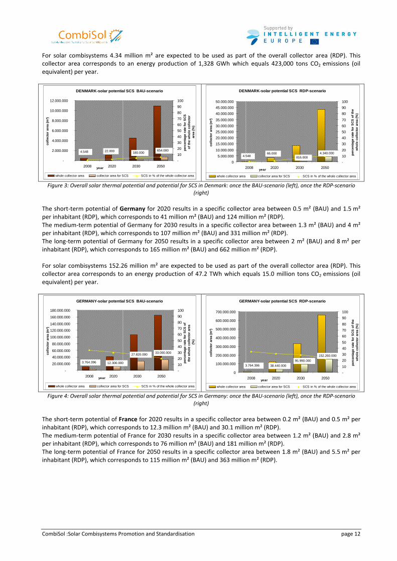
The overall solar thermal short-term potential of Denmark for 2020 results in a specific collector area between 0.2
m² (BAU) and 0.6 m² per inhabitant (RDP), which corresponds to 1.1 million m² (BAU) and 3.3 million m² (RDP).
The overall solar thermal medium-term potential of Denmark for 2030 results in a specific collector area between 0.8
m² (BAU) and 2.5 m² per inhabitant (RDP), which corresponds to 4.5 million m² (BAU) and 13.6 million m² (RDP).
The overall solar thermal long-term potential of Denmark for 2050 results in a specific collector area between 2 m²
(BAU) and 8 m² per inhabitant (RDP), which corresponds to 10.9 million m² (BAU) and 43.4 million m² (RDP)
CombiSol :Solar Combisystems Promotion and Standardisation page 12
For solar combisystems 4.34 million m² are expected to be used as part of the overall collector area (RDP). This
collector area corresponds to an energy production of 1,328 GWh which equals 423,000 tons CO2 emissions (oil
equivalent) per year.
DENMARK-solar potential SCS BAU-scenario
22.000 654.000 180.000 4.548
-
2.000.000
4.000.000
6.000.000
8.000.000
10.000.000
12.000.000
2008 2020 2030 2050year
colle
ctor
are
a (m
²)
-
10
20
30
40
50
60
70
80
90
100
perc
enta
ge r
ate
for
SC
S
of th
e w
hole
col
lect
or
area
(%
)
whole collector area collector area for SCS SCS in % of the whole collector area
DENMARK-solar potential SCS RDP-scenario
816.000 4.340.000 66.000
4.548
0
5.000.000
10.000.000
15.000.000
20.000.000
25.000.000
30.000.000
35.000.000
40.000.000
45.000.000
50.000.000
2008 2020 2030 2050year
colle
ctor
are
a (m
²)
-
10
20
30
40
50
60
70
80
90
100
perc
enta
ge r
ate
for
SC
S o
f the
w
hole
col
lect
or a
rea
(%)
whole collector area collector area for SCS SCS in % of the whole collector area
Figure 3: Overall solar thermal potential and potential for SCS in Denmark: once the BAU-scenario (left), once the RDP-scenario
(right)
The short-term potential of Germany for 2020 results in a specific collector area between 0.5 m² (BAU) and 1.5 m²
per inhabitant (RDP), which corresponds to 41 million m² (BAU) and 124 million m² (RDP).
The medium-term potential of Germany for 2030 results in a specific collector area between 1.3 m² (BAU) and 4 m²
per inhabitant (RDP), which corresponds to 107 million m² (BAU) and 331 million m² (RDP).
The long-term potential of Germany for 2050 results in a specific collector area between 2 m² (BAU) and 8 m² per
inhabitant (RDP), which corresponds to 165 million m² (BAU) and 662 million m² (RDP).
For solar combisystems 152.26 million m² are expected to be used as part of the overall collector area (RDP). This
collector area corresponds to an energy production of 47.2 TWh which equals 15.0 million tons CO2 emissions (oil
equivalent) per year.
GERMANY-solar potential SCS BAU-scenario
12.300.000 3.764.396
27.820.000 33.000.000
-
20.000.000
40.000.000
60.000.000
80.000.000
100.000.000
120.000.000
140.000.000
160.000.000
180.000.000
2008 2020 2030 2050year
colle
ctor
are
a (m
²)
-
10
20
30
40
50
60
70
80
90
100
perc
enta
ge r
ate
for
SC
S o
f th
e w
hole
col
lect
or a
rea
(%)
whole collector area collector area for SCS SCS in % of the whole collector area
GERMANY-solar potential SCS RDP-scenario
38.440.000
95.990.000
152.260.000
3.764.396
0
100.000.000
200.000.000
300.000.000
400.000.000
500.000.000
600.000.000
700.000.000
2008 2020 2030 2050year
colle
ctor
are
a (m
²)
-
10
20
30
40
50
60
70
80
90
100
perc
enta
ge r
ate
for
SC
S o
f the
w
hole
col
lect
or a
rea
(%)
whole collector area collector area for SCS SCS in % of the whole collector area
Figure 4: Overall solar thermal potential and potential for SCS in Germany: once the BAU-scenario (left), once the RDP-scenario
(right)
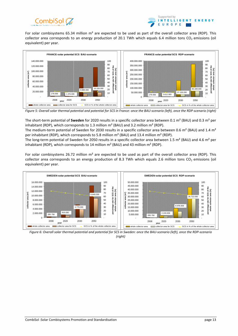
The short-term potential of France for 2020 results in a specific collector area between 0.2 m² (BAU) and 0.5 m² per
inhabitant (RDP), which corresponds to 12.3 million m² (BAU) and 30.1 million m² (RDP).
The medium-term potential of France for 2030 results in a specific collector area between 1.2 m² (BAU) and 2.8 m²
per inhabitant (RDP), which corresponds to 76 million m² (BAU) and 181 million m² (RDP).
The long-term potential of France for 2050 results in a specific collector area between 1.8 m² (BAU) and 5.5 m² per
inhabitant (RDP), which corresponds to 115 million m² (BAU) and 363 million m² (RDP).
CombiSol :Solar Combisystems Promotion and Standardisation page 13
For solar combisystems 65.34 million m² are expected to be used as part of the overall collector area (RDP). This
collector area corresponds to an energy production of 20.1 TWh which equals 6.4 million tons CO2 emissions (oil
equivalent) per year.
FRANCE-solar potential SCS BAU-scenario
1.476.000
16.100.000 9.880.000
279.936
-
20.000.000
40.000.000
60.000.000
80.000.000
100.000.000
120.000.000
140.000.000
2008 2020 2030 2050year
colle
ctor
are
a (m
²)
-
10
20
30
40
50
60
70
80
90
100
perc
enta
ge r
ate
for
SC
S o
f the
w
hole
col
lect
or a
rea
(%)
whole collector area collector area for SCS SCS in % of the whole collector area
FRANCE-solar potential SCS RDP-scenario
279.936 3.612.000 27.150.000
65.340.000
0
50.000.000
100.000.000
150.000.000
200.000.000
250.000.000
300.000.000
350.000.000
400.000.000
2008 2020 2030 2050year
colle
ctor
are
a (m
²)
-
10
20
30
40
50
60
70
80
90
100
perc
enta
ge r
ate
for
SC
S o
f the
w
hole
col
lect
or a
rea
(%)
whole collector area collector area for SCS SCS in % of the whole collector area
Figure 5: Overall solar thermal potential and potential for SCS in France: once the BAU-scenario (left), once the RDP-scenario (right)
The short-term potential of Sweden for 2020 results in a specific collector area between 0.1 m² (BAU) and 0.3 m² per
inhabitant (RDP), which corresponds to 1.3 million m² (BAU) and 3.2 million m² (RDP).
The medium-term potential of Sweden for 2030 results in a specific collector area between 0.6 m² (BAU) and 1.4 m²
per inhabitant (RDP), which corresponds to 5.8 million m² (BAU) and 13.4 million m² (RDP).
The long-term potential of Sweden for 2050 results in a specific collector area between 1.5 m² (BAU) and 4.6 m² per
inhabitant (RDP), which corresponds to 14 million m² (BAU) and 43 million m² (RDP).
For solar combisystems 26.72 million m² are expected to be used as part of the overall collector area (RDP). This
collector area corresponds to an energy production of 8.3 TWh which equals 2.6 million tons CO2 emissions (oil
equivalent) per year.
SWEDEN-solar potential SCS BAU-scenario
910.000 285.750
3.770.000
8.640.000
0
2.000.000
4.000.000
6.000.000
8.000.000
10.000.000
12.000.000
14.000.000
16.000.000
2008 2020 2030 2050year
colle
ctor
are
a (m
²)
-
10
20
30
40
50
60
70
80
90
100
perc
enta
ge r
ate
for
SC
S o
f the
w
hole
col
lect
or a
rea
(%)
whole collector area collector area for SCS SCS in % of the whole collector area
SWEDEN-solar potential SCS RDP-scenario
26.722.000
285.750 2.240.000
8.978.000
-
5.000.000
10.000.000
15.000.000
20.000.000
25.000.000
30.000.000
35.000.000
40.000.000
45.000.000
50.000.000
2008 2020 2030 2050year
colle
ctor
are
a (m
²)
-
10
20
30
40
50
60
70
80
90
100
perc
enta
ge r
ate
for
SC
S o
f the
w
hole
col
lect
or a
rea
(%)
whole collector area collector area for SCS SCS in % of the whole collector area
Figure 6: Overall solar thermal potential and potential for SCS in Sweden: once the BAU-scenario (left), once the RDP-scenario
(right)
CombiSol :Solar Combisystems Promotion and Standardisation page 14
2 Typical solar combisystem
Main Authors : Alexander Thür, Philippe Papillon
Within CombiSol project, a survey has been done regarding typical solar combisystems available on the market. The
main results of this survey are:
A standardization of hydraulic schemes has been observed since the end of the 90’s, leading to 6 main categories,
More and more complete packages are available on the market, leading to more prefabricated systems that offer the
potential to increase the compactness, the level of quality and to reduce the man-power required for installation on
site, and thus reducing the risks of misfunctionning.
The following section will address first the main layouts of typical solar combisystems, and then present some
products available on the market as well as tendencies for the future.
2.1 Different hydraulic schemes
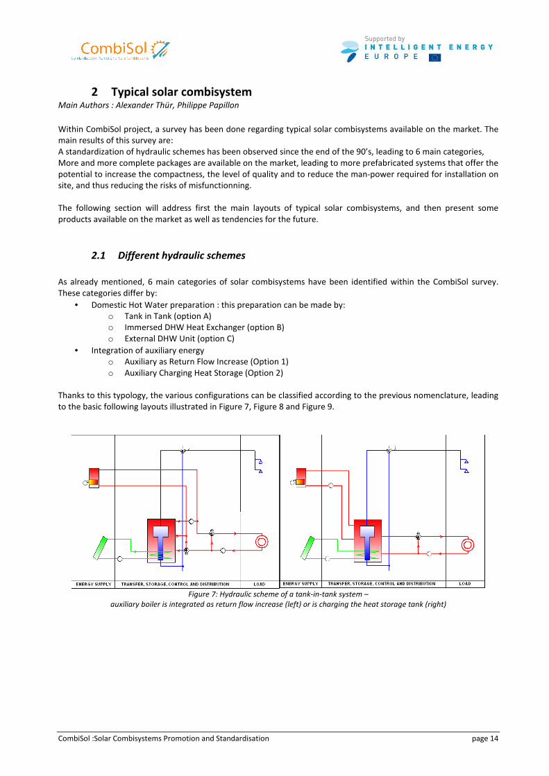
As already mentioned, 6 main categories of solar combisystems have been identified within the CombiSol survey.
These categories differ by:
• Domestic Hot Water preparation : this preparation can be made by:
o Tank in Tank (option A)
o Immersed DHW Heat Exchanger (option B)
o External DHW Unit (option C)
• Integration of auxiliary energy
o Auxiliary as Return Flow Increase (Option 1)
o Auxiliary Charging Heat Storage (Option 2)
Thanks to this typology, the various configurations can be classified according to the previous nomenclature, leading
to the basic following layouts illustrated in Figure 7, Figure 8 and Figure 9.
Figure 7: Hydraulic scheme of a tank-in-tank system –
auxiliary boiler is integrated as return flow increase (left) or is charging the heat storage tank (right)
CombiSol :Solar Combisystems Promotion and Standardisation page 15
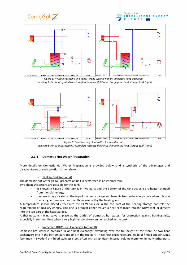
Figure 8: Hydraulic scheme of a heat storage system with an immersed heat exchanger –
auxiliary boiler is integrated as return flow increase (left) or is charging the heat storage tank (right)
Figure 9: Solar heating plant with a fresh water unit –
auxiliary boiler is integrated as return flow increase (left) or is charging the heat storage tank (right)
2.1.1 Domestic Hot Water Preparation
More details on Domestic Hot Water Preparation is provided below, and a synthesis of the advantages and
disadvantages of each solution is then shown.
o Tank in Tank (option A)
The domestic hot water (DHW) preparation unit is performed in an internal tank.
Two shapes/locations are possible for this tank:
- as shown in Figure 7, the tank is in two parts and the bottom of the tank act as a pre-heater charged
from the solar energy
- the tank is only located at the top of the heat storage and benefits from solar energy only when this one
is at a higher temperature than those needed by the heating loop.
A temperature sensor placed either into the DHW tank or in the top part of the heating storage controls the
requirement of auxiliary energy. This one is brought either trough a heat exchanger into the DHW tank or directly
into the top part of the heat storage.
A thermostatic mixing valve is place at the outlet of domestic hot water, for protection against burning risks,
especially in summer time when a very high temperature can be reached in the tank.
o Immersed DHW Heat Exchanger (option B)
Domestic hot water is prepared in one heat exchanger extending over the full height of the store, or two heat
exchangers one in the bottom part and one in the top part. These heat exchangers are made of finned copper tubes
(common in Sweden) or ribbed stainless steel, often with a significant internal volume (common in many other parts
CombiSol :Solar Combisystems Promotion and Standardisation page 16
of Europe). The top part of the tank has to be kept above the minimum temperature required to prepare the desired
DHW temperature. The greater the flow the higher is the required temperature in the top part of the store. Hot
water is then mixed with cold water to the desired temperature before reaching the user.
o External DHW Unit (option C)
The domestic hot water (DHW) preparation unit is performed as an external flat plate heat exchanger unit. This
DHW-unit is heating up hot water exactly at the same time when hot water tapping takes place. Based on a signal
from a sensor that realizes some hot water tapping the pump in the primary loop is started and the pre-defined DHW
temperature is controlled automatically depending on the actual hot water power demand. For this DHW
temperature control in principle two different power control strategies are offered on the market: a) mass flow
control or b) temperature control on the primary side of the flat plate heat exchanger.
a) Mass flow control is realized either with a speed controlled pump in combination with a DHW temperature
sensor and a PI(D) controller, or:
with a full speed running pump in combination with a flow control valve which is mechanically controlled by
a temperature sensor mounted directly at the hot outlet of the DHW heat exchanger and/or a flow sensor
measuring the tap water flow rate.
Additionally a mixing valve might be used on the primary side which limits the inlet temperature at the heat
exchanger (typically 55 to 60 degree) resulting in more stable DHW tap temperature and to avoid lime
deposit on the secondary side of the DHW heat exchanger.
b) Temperature at the primary inlet side of the DHW heat exchanger can be controlled by a mixing valve which
is mechanically controlled by a temperature sensor mounted directly at the hot outlet of the DHW heat
exchanger; the pump in this case is running full speed.
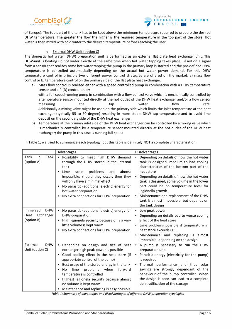
In Table 1, we tried to summarize each typology, but this table is definitely NOT a complete characterisation:
Advantages Disadvantages
Tank in Tank
(option A)
• Possibility to meat high DHW demand
through the DHW stored in the internal
tank
• Lime scale problems are almost
impossible; should they occur, then they
will only have a minimal effect.
• No parasitic (additional electric) energy for
hot water preparation
• No extra connections for DHW preparation
• Depending on details of how the hot water
tank is designed, medium to bad cooling
characteristics of the bottom part of the
heat store
• Depending on details of how the hot water
tank is designed, some volume in the lower
part could be on temperature level for
legionella growth
• Maintenance and replacement of the DHW
tank is almost impossible, but depends on
the tank design
Immersed DHW
Heat Exchanger
(option B)
• No parasitic (additional electric) energy for
DHW-preparation
• High legionela security because only a very
little volume is kept warm
• No extra connections for DHW preparation
• Low peak power
• Depending on details bad to worse cooling
effect of the heat store
• Lime problems possible if temperature in
heat store exceeds 60°C
• Maintenance and replacing is almost
impossible, depending on the design
External DHW
Unit (option C)
• Depending on design and size of heat
exchanger high peak power is possible
• Good cooling effect in the heat store (if
appropriate control of the pump)
• Best usage of the stored energy in the tank
• No lime problems when forward
temperature is controlled
• Highest legionela security because almost
no volume is kept warm
• Maintenance and replacing is easy possible
• A pump is necessary to run the DHW
preparation unit
• Parasitic energy (electricity for the pump)
is required
• Thermal performance and thus solar
savings are strongly dependant of the
behaviour of the pump controller. When
the design is poor can lead to a complete
de-stratification of the storage
Table 1: Summary of advantages and disadvantages of different DHW preparation typologies
CombiSol :Solar Combisystems Promotion and Standardisation page 17
2.1.2 Auxiliary energy and its integration in a solar combisystems
Several types of auxiliary heater are available to be used in solar combisystems and they might have quite different
operating conditions. For example a condensing natural gas boiler needs very low return temperatures (<<57°C) to
be able to use the condensation effect, whereas a wood log or pellet boiler on the other hand needs a minimum
return temperature (>55°C) in order to avoid corrosion and deposit problems due to condensation of the flue gas.
Also different boilers have different characteristics how they can be controlled. A natural gas boiler can change the
power by modulating quite fast and easy; other boiler types just can change power by the stop or go principle.
Since the boundary conditions of each house, each country, each system concept, availability of different fuel types,
etc. are different, it can not be stated the one or the other auxiliary heater is the best. Therefore just some main
characteristics important for integration in a solar combisystem are mentioned:
o Auxiliary as Return Flow Increase (Option 1)
Depending on SH return temperature and heat storage temperature the heat storage is bypassed or SH flow is
preheated by solar heated water in the heat storage and finally heated to the set temperature by the auxiliary
heater. Therefore the auxiliary heater is operating within the full range of power: between almost zero and
maximum power.
The DHW-tank is heated up by the auxiliary volume in the buffer tank up to a set temperature. The set temperature
is typically controlled with a temperature sensor immersed inside the DHW-tank, sensor locations at the buffer tank
are also possible but less precise. The auxiliary heating stops when set temperature is reached.
This configuration is well adapted to auxiliary boiler with a wide range of power modulation and able to provide the
required flow temperature to the SH loop according to the ambient temperature like gas boilers.
o Auxiliary Charging Heat Storage (Option 2)
The auxiliary heater has to keep the middle part of the heat storage at a sufficient high temperature if the input of
solar energy is not sufficient. Due to the inertia effect of the water in the tank, the auxiliary heater is operating
mostly at its maximum power during time periods long enough to minimize harmful exhaust gas emission of the
burner.
This configuration is well adapted to auxiliary boilers with a low range of power modulation, which require long
running cycles like wood boilers.
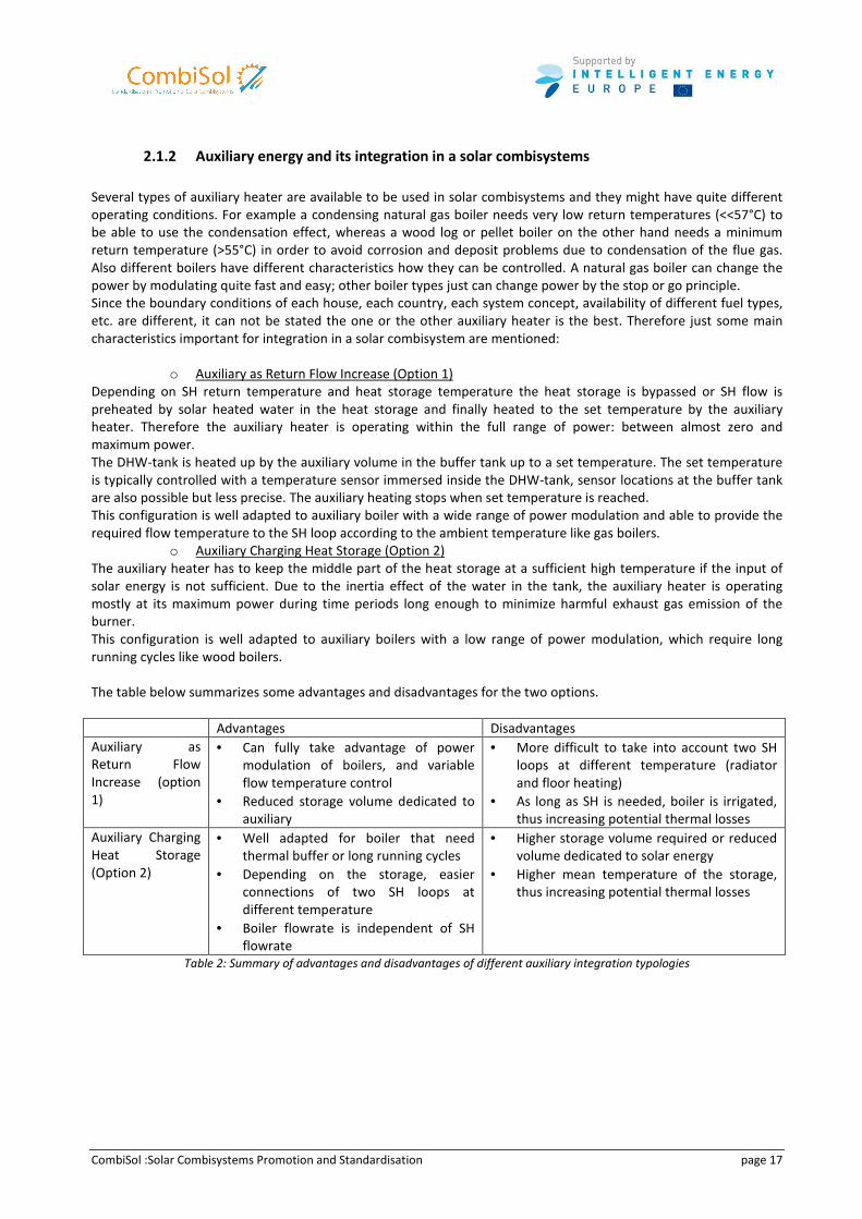
The table below summarizes some advantages and disadvantages for the two options.
Advantages Disadvantages
Auxiliary as
Return Flow
Increase (option
1)
• Can fully take advantage of power
modulation of boilers, and variable
flow temperature control
• Reduced storage volume dedicated to
auxiliary
• More difficult to take into account two SH
loops at different temperature (radiator
and floor heating)
• As long as SH is needed, boiler is irrigated,
thus increasing potential thermal losses
Auxiliary Charging
Heat Storage
(Option 2)
• Well adapted for boiler that need
thermal buffer or long running cycles
• Depending on the storage, easier
connections of two SH loops at
different temperature
• Boiler flowrate is independent of SH
flowrate
• Higher storage volume required or reduced
volume dedicated to solar energy
• Higher mean temperature of the storage,
thus increasing potential thermal losses
Table 2: Summary of advantages and disadvantages of different auxiliary integration typologies
CombiSol :Solar Combisystems Promotion and Standardisation page 18
2.1.3 Typical solar loops
For solar combisystems flat plate or vacuum tube collectors can be used. Typically vacuum tube collectors have
better properties in the transition- and winter periods, but the investment costs are higher than for flat plate
collectors as well.
The heat transfer from the collector loop to the heat store can happen in two ways. The first option is that a heat
store with an immersed heat exchanger is used. In this case the collector fluid is pumped through one or more
immersed heat exchanger. This system needs only one pump for the solar heating system and is mostly installed in
small plants like up to 20 m². The second option is an external heat exchanger. In this case the collector loop is
shared in two parts: primary collector loop and secondary collector loop. This system is used in solar combisystems
with collector area of about 15 m² and upwards.
o Stratification Strategies
In order to optimise the process of charging solar energy into the solar heat storage it is possible to use different
kinds of stratification strategies. This means that depending on the collector flow line temperature the solar energy is
charged into the heat storage at the height where the temperature is more or less equal.
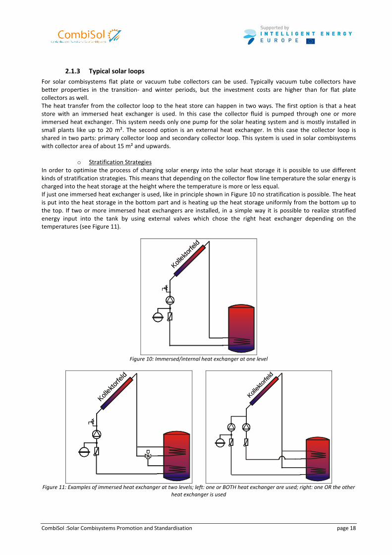
If just one immersed heat exchanger is used, like in principle shown in Figure 10 no stratification is possible. The heat
is put into the heat storage in the bottom part and is heating up the heat storage uniformly from the bottom up to
the top. If two or more immersed heat exchangers are installed, in a simple way it is possible to realize stratified
energy input into the tank by using external valves which chose the right heat exchanger depending on the
temperatures (see Figure 11).
Kollek
torfe
ld
Kollek
torfe
ld
Figure 10: Immersed/internal heat exchanger at one level
Kollek
torfe
ld
Kollek
torfe
ld
Kollek
torfe
ld
Kollek
torfe
ld
Figure 11: Examples of immersed heat exchanger at two levels; left: one or BOTH heat exchanger are used; right: one OR the other
heat exchanger is used
CombiSol :Solar Combisystems Promotion and Standardisation page 19
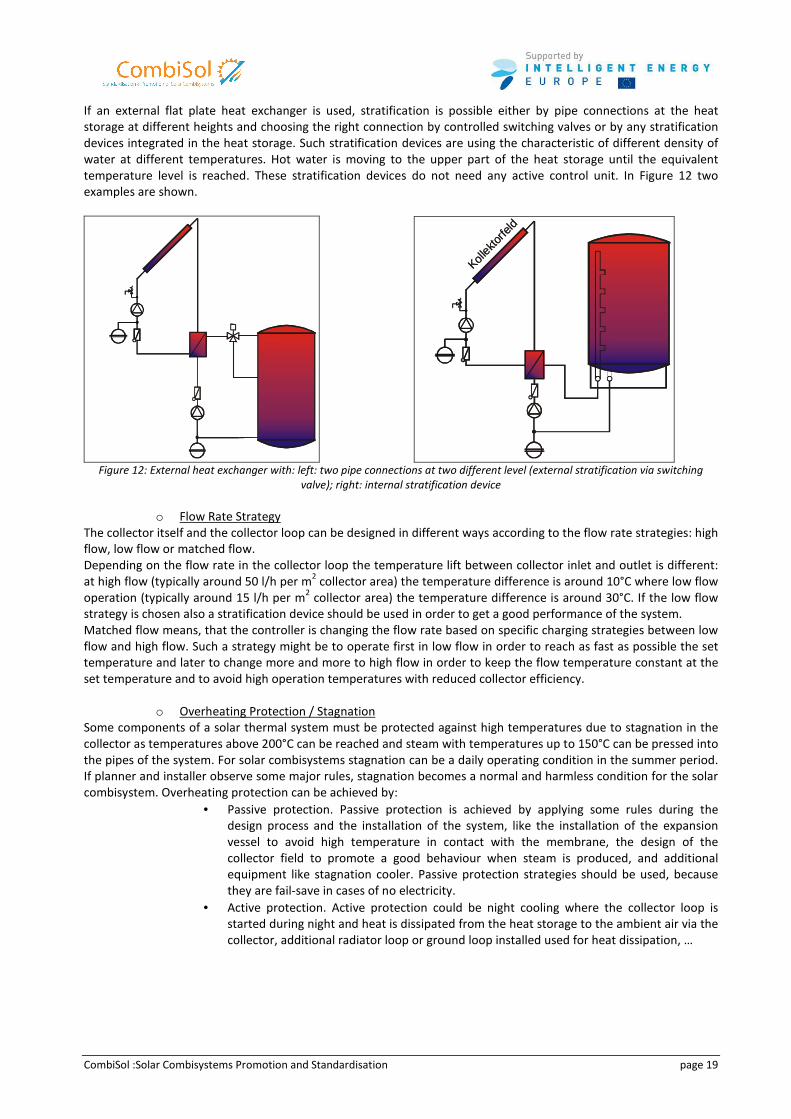
If an external flat plate heat exchanger is used, stratification is possible either by pipe connections at the heat
storage at different heights and choosing the right connection by controlled switching valves or by any stratification
devices integrated in the heat storage. Such stratification devices are using the characteristic of different density of
water at different temperatures. Hot water is moving to the upper part of the heat storage until the equivalent
temperature level is reached. These stratification devices do not need any active control unit. In Figure 12 two
examples are shown.
Kollekto
rfeld
T2
T3Kol
lektorfe
ld
T2
T3
Figure 12: External heat exchanger with: left: two pipe connections at two different level (external stratification via switching
valve); right: internal stratification device
o Flow Rate Strategy
The collector itself and the collector loop can be designed in different ways according to the flow rate strategies: high
flow, low flow or matched flow.
Depending on the flow rate in the collector loop the temperature lift between collector inlet and outlet is different:
at high flow (typically around 50 l/h per m2 collector area) the temperature difference is around 10°C where low flow
operation (typically around 15 l/h per m2 collector area) the temperature difference is around 30°C. If the low flow
strategy is chosen also a stratification device should be used in order to get a good performance of the system.
Matched flow means, that the controller is changing the flow rate based on specific charging strategies between low
flow and high flow. Such a strategy might be to operate first in low flow in order to reach as fast as possible the set
temperature and later to change more and more to high flow in order to keep the flow temperature constant at the
set temperature and to avoid high operation temperatures with reduced collector efficiency.
o Overheating Protection / Stagnation
Some components of a solar thermal system must be protected against high temperatures due to stagnation in the
collector as temperatures above 200°C can be reached and steam with temperatures up to 150°C can be pressed into
the pipes of the system. For solar combisystems stagnation can be a daily operating condition in the summer period.
If planner and installer observe some major rules, stagnation becomes a normal and harmless condition for the solar
combisystem. Overheating protection can be achieved by:
• Passive protection. Passive protection is achieved by applying some rules during the
design process and the installation of the system, like the installation of the expansion
vessel to avoid high temperature in contact with the membrane, the design of the
collector field to promote a good behaviour when steam is produced, and additional
equipment like stagnation cooler. Passive protection strategies should be used, because
they are fail-save in cases of no electricity.
• Active protection. Active protection could be night cooling where the collector loop is
started during night and heat is dissipated from the heat storage to the ambient air via the
collector, additional radiator loop or ground loop installed used for heat dissipation, …

CombiSol :Solar Combisystems Promotion and Standardisation page 20
2.2 Products and tendencies
During the last decade, a significant change in solar combi-systems was observed with the market introduction of
prefabricated component groups, and compact prefabricated systems.
2.2.1 Prefabricated component groups
Some manufacturers provide a wide variety of prefabricated component groups that could be used for a solar
combisystems:
• Solar charging unit which combines pump, non return valves, thermometer, safety valves and in most cases
the controller of the solar loop.
• External DHW unit which includes DHW heat exchanger, pump, thermostatic valves, …
• Space heating unit with various hydraulic layouts depending on the heating loop designed. These units
includes pumps, 3 way-valve, …
Figure 13: Solar Charging Unit (Viessmann, SOLution, Tisun, Sonnenkraft, Bosch-Junkers)
Figure 14: External DHW unit (SOLution, Sonnenkraft)
Figure 15: Space Heating Units (Sonnenkraft, Vaillant)
CombiSol :Solar Combisystems Promotion and Standardisation page 21
In some cases, the prefabricated component groups can be directly fixed to the water storage and plugged to the
various connections of the storage thanks to flexible stainless steel hoses. This design reduced the time spent by the
installer and also the risks of wrong connections, but insulation of the storage as well as the flexible pipes and pre-
fabricated component groups has to be well realised to limit the heat losses.
2.2.2 Compact prefabricated systems.
The first step was to produce some prefabricated component groups to reduce man-power on site and to limit the
risks of wrong connections or bad dimensioning components. The second step that more and more manufacturers
are crossing is to produce complete, compact prefabricated systems.
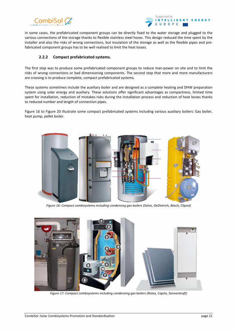
These systems sometimes include the auxiliary boiler and are designed as a complete heating and DHW preparation
system using solar energy and auxiliary. These solutions offer significant advantages as compactness, limited time
spent for installation, reduction of mistakes risks during the installation process and reduction of heat losses thanks
to reduced number and length of connection pipes.
Figure 16 to Figure 20 illustrate some compact prefabricated systems including various auxiliary boilers: Gas boiler,
heat pump, pellet boiler.
Figure 16: Compact combisystems including condensing gas boilers (Solvis, DeDietrich, Bösch, Clipsol)
Figure 17: Compact combisystems including condensing gas boilers (Rotex, Capito, Sonnenkraft)
CombiSol :Solar Combisystems Promotion and Standardisation page 22
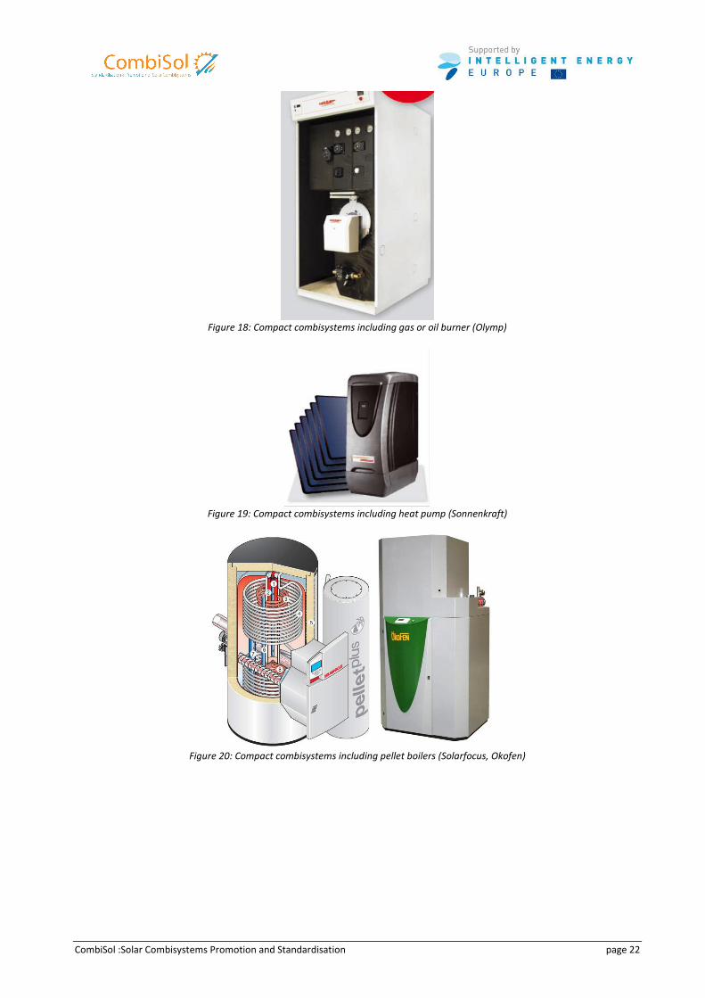
Figure 18: Compact combisystems including gas or oil burner (Olymp)
Figure 19: Compact combisystems including heat pump (Sonnenkraft)
Figure 20: Compact combisystems including pellet boilers (Solarfocus, Okofen)
CombiSol :Solar Combisystems Promotion and Standardisation page 23
3 Qualitative inspection
Main Author : Alexander Thür
Within the CombiSol project 70 recently built solar combisystems in Austria (20), Germany (6), France (24), and
Sweden (20), were qualitatively analyzed by experts from the respective countries using an evaluation tool specially
developed within the CombiSol project. On the project webpage available as download is the evaluation tool itself
(D5.1a) and a guideline how to use it (D5.1b), a two-page documentation of all 70 evaluated solar combisystems
(D5.2), and a summary report on the result of all qualitative evaluations (D5.4).
3.1 Procedure
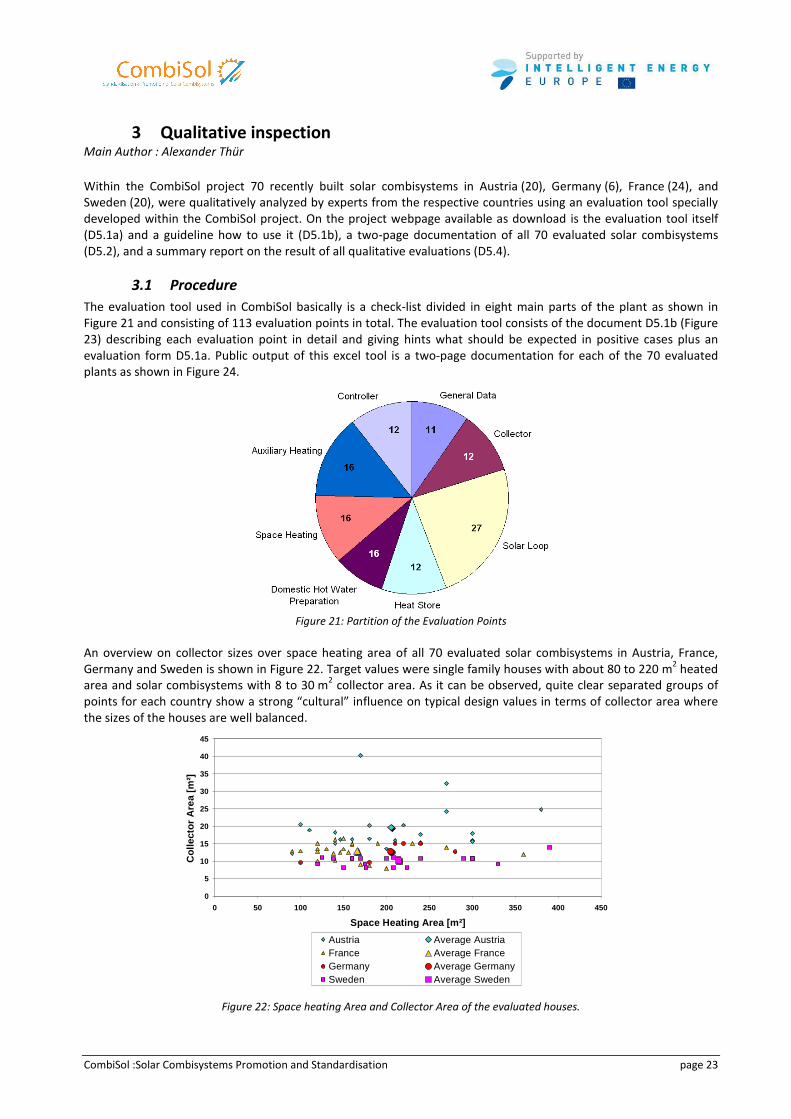
The evaluation tool used in CombiSol basically is a check-list divided in eight main parts of the plant as shown in
Figure 21 and consisting of 113 evaluation points in total. The evaluation tool consists of the document D5.1b (Figure
23) describing each evaluation point in detail and giving hints what should be expected in positive cases plus an
evaluation form D5.1a. Public output of this excel tool is a two-page documentation for each of the 70 evaluated
plants as shown in Figure 24.
Figure 21: Partition of the Evaluation Points
An overview on collector sizes over space heating area of all 70 evaluated solar combisystems in Austria, France,
Germany and Sweden is shown in Figure 22. Target values were single family houses with about 80 to 220 m2 heated
area and solar combisystems with 8 to 30 m2 collector area. As it can be observed, quite clear separated groups of
points for each country show a strong “cultural” influence on typical design values in terms of collector area where
the sizes of the houses are well balanced.
0
5
10
15
20
25
30
35
40
45
0 50 100 150 200 250 300 350 400 450
Space Heating Area [m²]
Col
lect
or A
rea
[m²]
Austria Average AustriaFrance Average FranceGermany Average GermanySweden Average Sweden
Figure 22: Space heating Area and Collector Area of the evaluated houses.
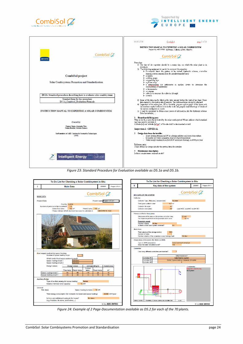
CombiSol :Solar Combisystems Promotion and Standardisation page 24
Figure 23: Standard Procedure for Evaluation available as D5.1a and D5.1b.
Figure 24: Example of 2 Page-Documentation available as D5.2 for each of the 70 plants.
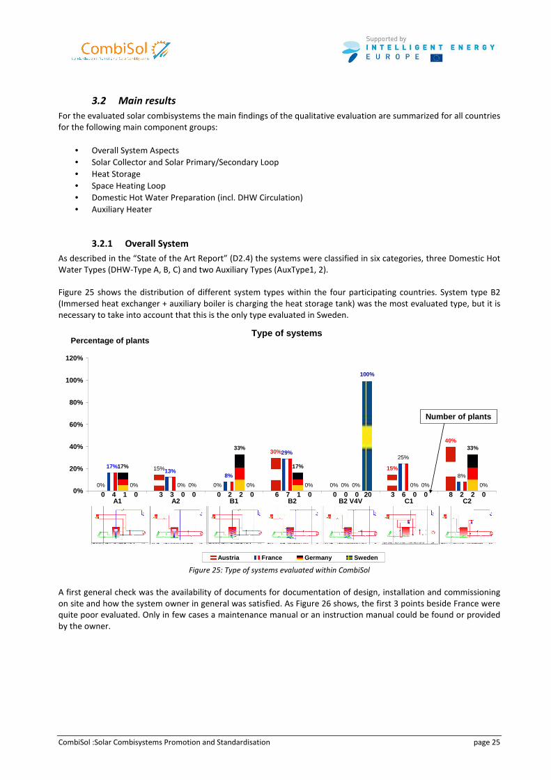
CombiSol :Solar Combisystems Promotion and Standardisation page 25
3.2 Main results
For the evaluated solar combisystems the main findings of the qualitative evaluation are summarized for all countries
for the following main component groups:
• Overall System Aspects
• Solar Collector and Solar Primary/Secondary Loop
• Heat Storage
• Space Heating Loop
• Domestic Hot Water Preparation (incl. DHW Circulation)
• Auxiliary Heater
3.2.1 Overall System
As described in the “State of the Art Report” (D2.4) the systems were classified in six categories, three Domestic Hot
Water Types (DHW-Type A, B, C) and two Auxiliary Types (AuxType1, 2).
Figure 25 shows the distribution of different system types within the four participating countries. System type B2
(Immersed heat exchanger + auxiliary boiler is charging the heat storage tank) was the most evaluated type, but it is
necessary to take into account that this is the only type evaluated in Sweden.
Type of systems
30%
17%
8%
29%
17% 17%
0%
15%
0% 0%
15%
40%
13%
0%
25%
8%
0%
33%
0% 0%
33%
0% 0% 0% 0%
100%
0% 0%0%
20%
40%
60%
80%
100%
120%
A1 A2 B1 B2 B2 V4V C1 C2
Percentage of plants
Austria France Germany Sweden
0 0 6 0 3 84 3 2 7 0 6 21 2 1 0 0 20 0 20 0 03 00 0
Number of plants
Figure 25: Type of systems evaluated within CombiSol
A first general check was the availability of documents for documentation of design, installation and commissioning
on site and how the system owner in general was satisfied. As Figure 26 shows, the first 3 points beside France were
quite poor evaluated. Only in few cases a maintenance manual or an instruction manual could be found or provided
by the owner.
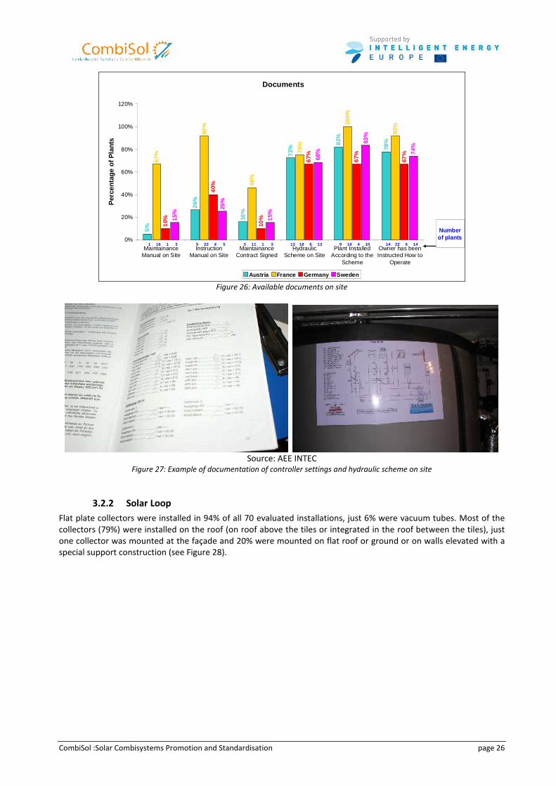
CombiSol :Solar Combisystems Promotion and Standardisation page 26
Documents
5%
26%
16%
72%
82%
78%
67%
92%
46%
75%
100%
92%
10%
40%
10%
67%
67%
67%
15%
25%
15%
68%
83%
74%
0%
20%
40%
60%
80%
100%
120%
MaintainanceManual on Site
InstructionManual on Site
MaintainanceContract Signed
HydraulicScheme on Site
Plant InstalledAccording to the
Scheme
Owner has beenInstructed How to
Operate
Per
cent
age
of P
lant
s
Austria France Germany Sweden
1 5 3 13 9 1416 22 11 18 18 221 4 1 6 4 63 5 3 13 10 14
Number of plants
Figure 26: Available documents on site
Source: AEE INTEC
Figure 27: Example of documentation of controller settings and hydraulic scheme on site
3.2.2 Solar Loop
Flat plate collectors were installed in 94% of all 70 evaluated installations, just 6% were vacuum tubes. Most of the
collectors (79%) were installed on the roof (on roof above the tiles or integrated in the roof between the tiles), just
one collector was mounted at the façade and 20% were mounted on flat roof or ground or on walls elevated with a
special support construction (see Figure 28).
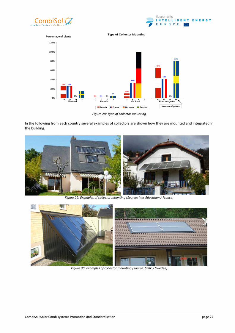
CombiSol :Solar Combisystems Promotion and Standardisation page 27
Type of Collector Mounting
25%
0%
10%
25%
33%
42%
0% 0%
65%
0% 0%
80%
5%
0%
20%
40%
60%
80%
100%
120%
Elevated Facade On Roof Roof Integrated
Percentage of plants
Austria France Germany Sweden
5 0 2 136 0 8 100 0 6 03 1 0 16
Number of plants
Figure 28: Type of collector mounting
In the following from each country several examples of collectors are shown how they are mounted and integrated in
the building.
Figure 29: Examples of collector mounting (Source: Ines Education / France)
Figure 30: Examples of collector mounting (Source: SERC / Sweden)
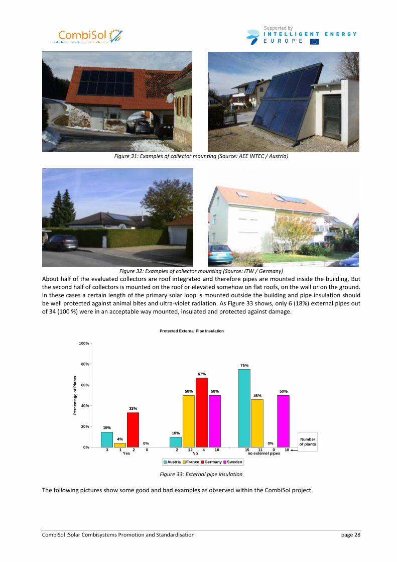
CombiSol :Solar Combisystems Promotion and Standardisation page 28
Figure 31: Examples of collector mounting (Source: AEE INTEC / Austria)
Figure 32: Examples of collector mounting (Source: ITW / Germany)
About half of the evaluated collectors are roof integrated and therefore pipes are mounted inside the building. But
the second half of collectors is mounted on the roof or elevated somehow on flat roofs, on the wall or on the ground.
In these cases a certain length of the primary solar loop is mounted outside the building and pipe insulation should
be well protected against animal bites and ultra-violet radiation. As Figure 33 shows, only 6 (18%) external pipes out
of 34 (100 %) were in an acceptable way mounted, insulated and protected against damage.
Protected External Pipe Insulation
10%
75%
50%46%
33%
67%
0%0%
50% 50%
15%
4%
0%
20%
40%
60%
80%
100%
Yes No no externel pipes
Per
cent
age
of P
lant
s
Austria France Germany Sweden
2 1512 112 4 00 10 103 1
Number of plants
Figure 33: External pipe insulation
The following pictures show some good and bad examples as observed within the CombiSol project.
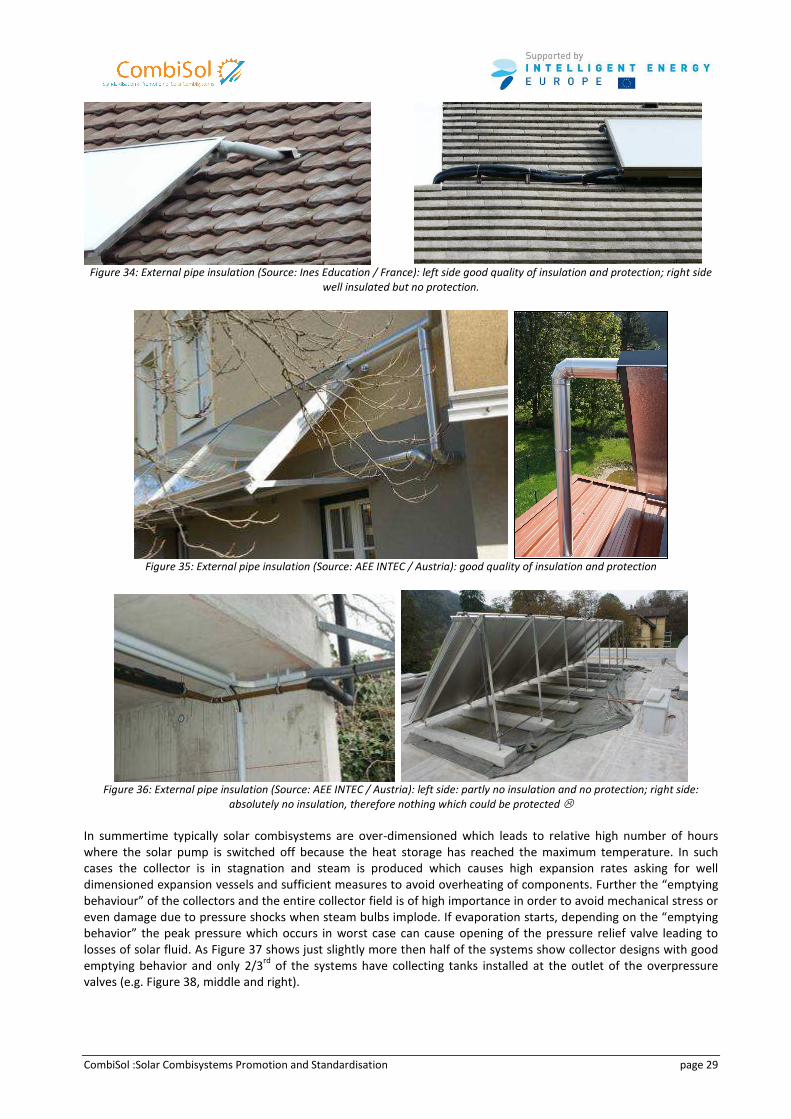
CombiSol :Solar Combisystems Promotion and Standardisation page 29
Figure 34: External pipe insulation (Source: Ines Education / France): left side good quality of insulation and protection; right side
well insulated but no protection.
Figure 35: External pipe insulation (Source: AEE INTEC / Austria): good quality of insulation and protection
Figure 36: External pipe insulation (Source: AEE INTEC / Austria): left side: partly no insulation and no protection; right side:
absolutely no insulation, therefore nothing which could be protected �
In summertime typically solar combisystems are over-dimensioned which leads to relative high number of hours
where the solar pump is switched off because the heat storage has reached the maximum temperature. In such
cases the collector is in stagnation and steam is produced which causes high expansion rates asking for well
dimensioned expansion vessels and sufficient measures to avoid overheating of components. Further the “emptying
behaviour” of the collectors and the entire collector field is of high importance in order to avoid mechanical stress or
even damage due to pressure shocks when steam bulbs implode. If evaporation starts, depending on the “emptying
behavior” the peak pressure which occurs in worst case can cause opening of the pressure relief valve leading to
losses of solar fluid. As Figure 37 shows just slightly more then half of the systems show collector designs with good
emptying behavior and only 2/3rd
of the systems have collecting tanks installed at the outlet of the overpressure
valves (e.g. Figure 38, middle and right).
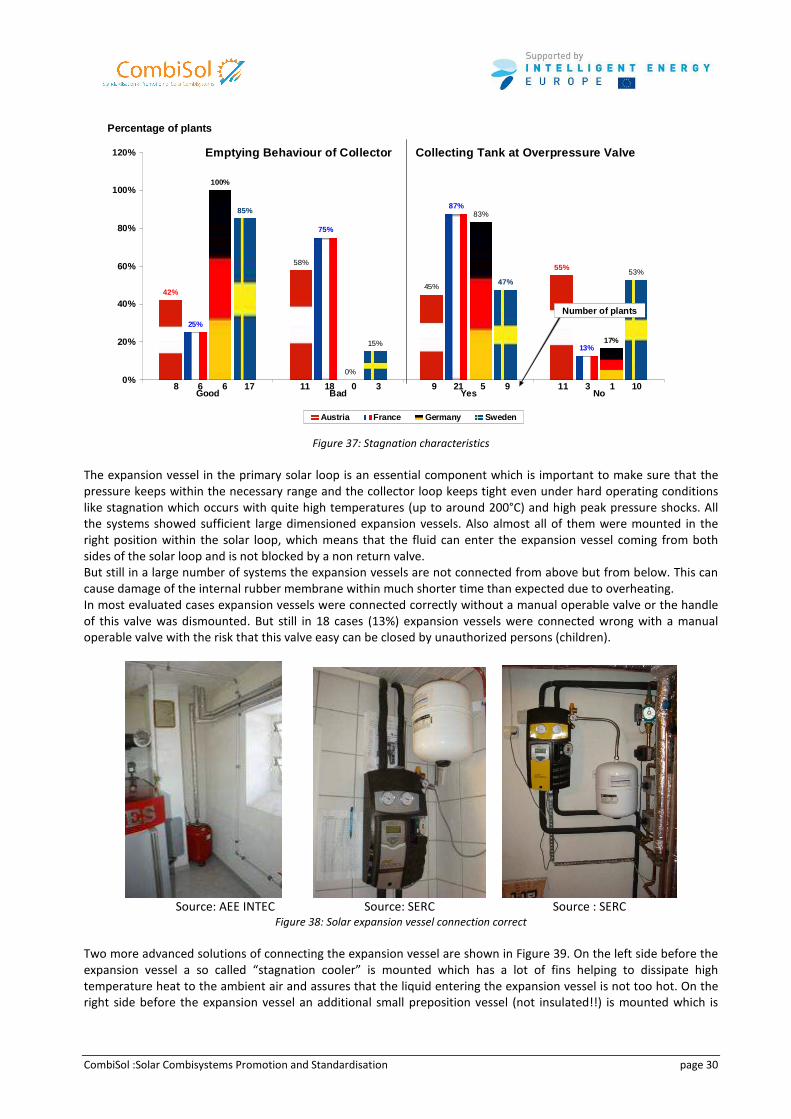
CombiSol :Solar Combisystems Promotion and Standardisation page 30
Emptying Behaviour of Collector Collecting Ta nk at Overpressure Valve
42%
55%
25%
87%
13%
100%
17%
45%
58%
75%
83%
0%
15%
47%53%
85%
0%
20%
40%
60%
80%
100%
120%
Good Bad Yes No
Percentage of plants
Austria France Germany Sweden
8 11 9 116 18 21 36 0 5 117 3 9 10
Number of plants
Figure 37: Stagnation characteristics
The expansion vessel in the primary solar loop is an essential component which is important to make sure that the
pressure keeps within the necessary range and the collector loop keeps tight even under hard operating conditions
like stagnation which occurs with quite high temperatures (up to around 200°C) and high peak pressure shocks. All
the systems showed sufficient large dimensioned expansion vessels. Also almost all of them were mounted in the
right position within the solar loop, which means that the fluid can enter the expansion vessel coming from both
sides of the solar loop and is not blocked by a non return valve.
But still in a large number of systems the expansion vessels are not connected from above but from below. This can
cause damage of the internal rubber membrane within much shorter time than expected due to overheating.
In most evaluated cases expansion vessels were connected correctly without a manual operable valve or the handle
of this valve was dismounted. But still in 18 cases (13%) expansion vessels were connected wrong with a manual
operable valve with the risk that this valve easy can be closed by unauthorized persons (children).
Source: AEE INTEC Source: SERC Source : SERC
Figure 38: Solar expansion vessel connection correct
Two more advanced solutions of connecting the expansion vessel are shown in Figure 39. On the left side before the
expansion vessel a so called “stagnation cooler” is mounted which has a lot of fins helping to dissipate high
temperature heat to the ambient air and assures that the liquid entering the expansion vessel is not too hot. On the
right side before the expansion vessel an additional small preposition vessel (not insulated!!) is mounted which is
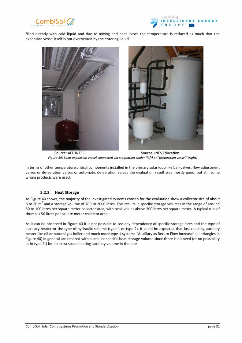
CombiSol :Solar Combisystems Promotion and Standardisation page 31
filled already with cold liquid and due to mixing and heat losses the temperature is reduced as much that the
expansion vessel itself is not overheated by the entering liquid.
Source: AEE INTEC Source: INES Education
Figure 39: Solar expansion vessel connected via stagnation cooler (left) or “preposition vessel” (right)
In terms of other temperature critical components installed in the primary solar loop like ball-valves, flow adjustment
valves or de-aeration valves or automatic de-aeration valves the evaluation result was mostly good, but still some
wrong products were used.
3.2.3 Heat Storage
As Figure 40 shows, the majority of the investigated systems chosen for the evaluation show a collector size of about
8 to 20 m2 and a storage volume of 700 to 2000 litres. This results in specific storage volumes in the range of around
50 to 100 litres per square meter collector area, with peak values above 200 litres per square meter. A typical rule of
thumb is 50 litres per square meter collector area.
As it can be observed in Figure 40 it is not possible to see any dependency of specific storage sizes and the type of
auxiliary heater or the type of hydraulic scheme (type 1 or type 2). It could be expected that fast reacting auxiliary
heater like oil or natural gas boiler and much more type 1 systems “Auxiliary as Return Flow Increase” (all triangles in
Figure 40) in general are realized with a smaller specific heat storage volume since there is no need (or no possibility
as in type 2!) for an extra space heating auxiliary volume in the tank.
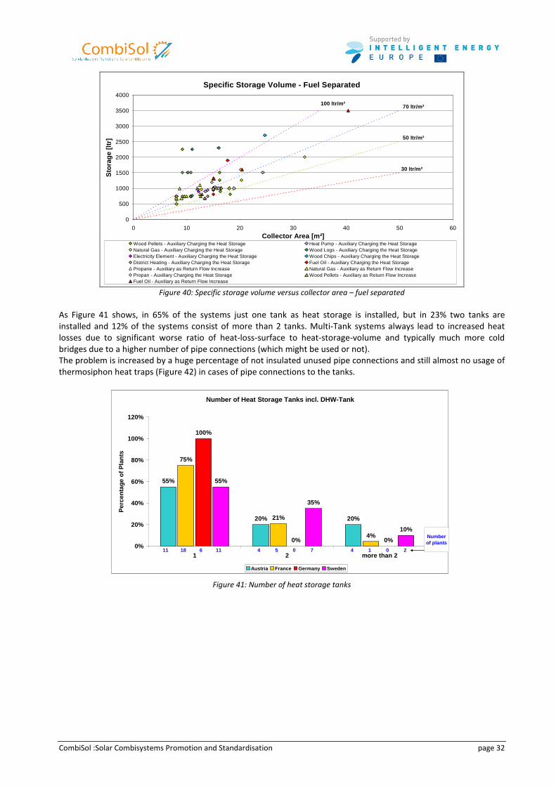
CombiSol :Solar Combisystems Promotion and Standardisation page 32
Specific Storage Volume - Fuel Separated
0
500
1000
1500
2000
2500
3000
3500
4000
0 10 20 30 40 50 60
Collector Area [m²]
Sto
rage
[ltr
]
Wood Pellets - Auxiliary Charging the Heat Storage Heat Pump - Auxiliary Charging the Heat StorageNatural Gas - Auxiliary Charging the Heat Storage Wood Logs - Auxiliary Charging the Heat StorageElectricity Element - Auxiliary Charging the Heat Storage Wood Chips - Auxiliary Charging the Heat StorageDistrict Heating - Auxiliary Charging the Heat Storage Fuel Oil - Auxiliary Charging the Heat StoragePropane - Auxiliary as Return Flow Increase Natural Gas - Auxiliary as Return Flow IncreasePropan - Auxiliary Charging the Heat Storage Wood Pellets - Auxiliary as Return Flow IncreaseFuel Oil - Auxiliary as Return Flow Increase
50 ltr/m²
70 ltr/m²
30 ltr/m²
100 ltr/m²
Figure 40: Specific storage volume versus collector area – fuel separated
As Figure 41 shows, in 65% of the systems just one tank as heat storage is installed, but in 23% two tanks are
installed and 12% of the systems consist of more than 2 tanks. Multi-Tank systems always lead to increased heat
losses due to significant worse ratio of heat-loss-surface to heat-storage-volume and typically much more cold
bridges due to a higher number of pipe connections (which might be used or not).
The problem is increased by a huge percentage of not insulated unused pipe connections and still almost no usage of
thermosiphon heat traps (Figure 42) in cases of pipe connections to the tanks.
Number of Heat Storage Tanks incl. DHW-Tank
55%
20% 20%
75%
21%
4%
100%
0% 0%
55%
35%
10%
0%
20%
40%
60%
80%
100%
120%
1 2 more than 2
Per
cent
age
of P
lant
s
Austria France Germany Sweden
11 4 418 5 16 0 011 7 2
Number of plants
Figure 41: Number of heat storage tanks
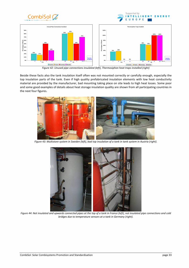
CombiSol :Solar Combisystems Promotion and Standardisation page 33
Unused Pipe Connections Insulated
20%
80%
17%
83%
50% 50%
30%
70%
0%
10%
20%
30%
40%
50%
60%
70%
80%
90%
Yes No
Per
cent
age
of P
lan
ts
Austria France Germany Sweden
4 164 203 36 14
Number of plants
Thermosiphon Traps Installed
35%
65%
38%
63%
0%
100%
0%
100%
0%
20%
40%
60%
80%
100%
120%
Yes No
Per
cent
age
of P
lant
s
Austria France Germany Sweden
7 139 150 60 20
Number of plants
Figure 42: Unused pipe connections insulated (left), Thermosiphon heat traps installed (right)
Beside these facts also the tank insulation itself often was not mounted correctly or carefully enough, especially the
top insulation parts of the tank. Even if high quality prefabricated insulation elements with low heat conductivity
material are provided by the manufacturer, bad mounting taking place on site leads to high heat losses. Some poor
and some good examples of details about heat storage insulation quality are shown from all participating countries in
the next four figures.
Figure 43: Multistore system in Sweden (left), bad top insulation of a tank in tank system in Austria (right).
Figure 44: Not insulated and upwards connected pipes at the top of a tank in France (left), not insulated pipe connections and cold
bridges due to temperature sensors at a tank in Germany (right).
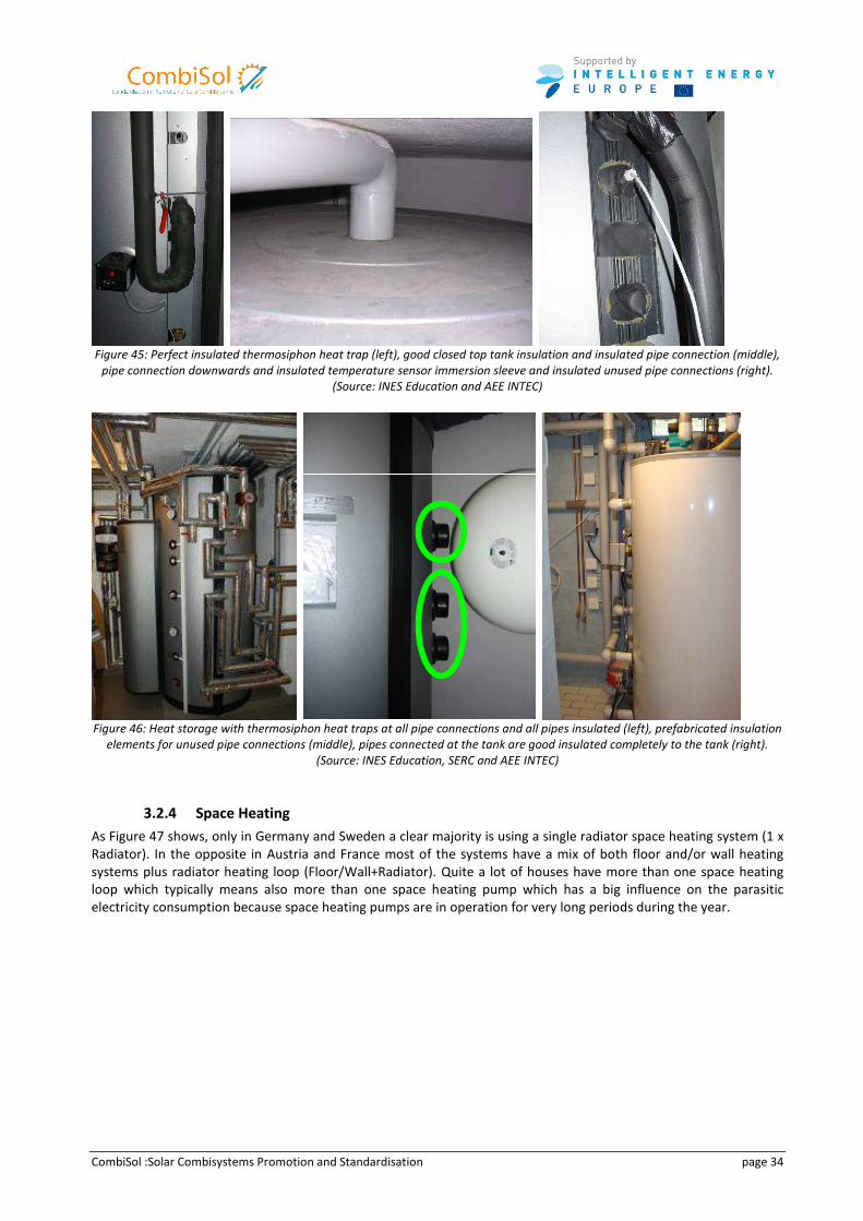
CombiSol :Solar Combisystems Promotion and Standardisation page 34
Figure 45: Perfect insulated thermosiphon heat trap (left), good closed top tank insulation and insulated pipe connection (middle),
pipe connection downwards and insulated temperature sensor immersion sleeve and insulated unused pipe connections (right).
(Source: INES Education and AEE INTEC)
Figure 46: Heat storage with thermosiphon heat traps at all pipe connections and all pipes insulated (left), prefabricated insulation
elements for unused pipe connections (middle), pipes connected at the tank are good insulated completely to the tank (right).
(Source: INES Education, SERC and AEE INTEC)
3.2.4 Space Heating
As Figure 47 shows, only in Germany and Sweden a clear majority is using a single radiator space heating system (1 x
Radiator). In the opposite in Austria and France most of the systems have a mix of both floor and/or wall heating
systems plus radiator heating loop (Floor/Wall+Radiator). Quite a lot of houses have more than one space heating
loop which typically means also more than one space heating pump which has a big influence on the parasitic
electricity consumption because space heating pumps are in operation for very long periods during the year.
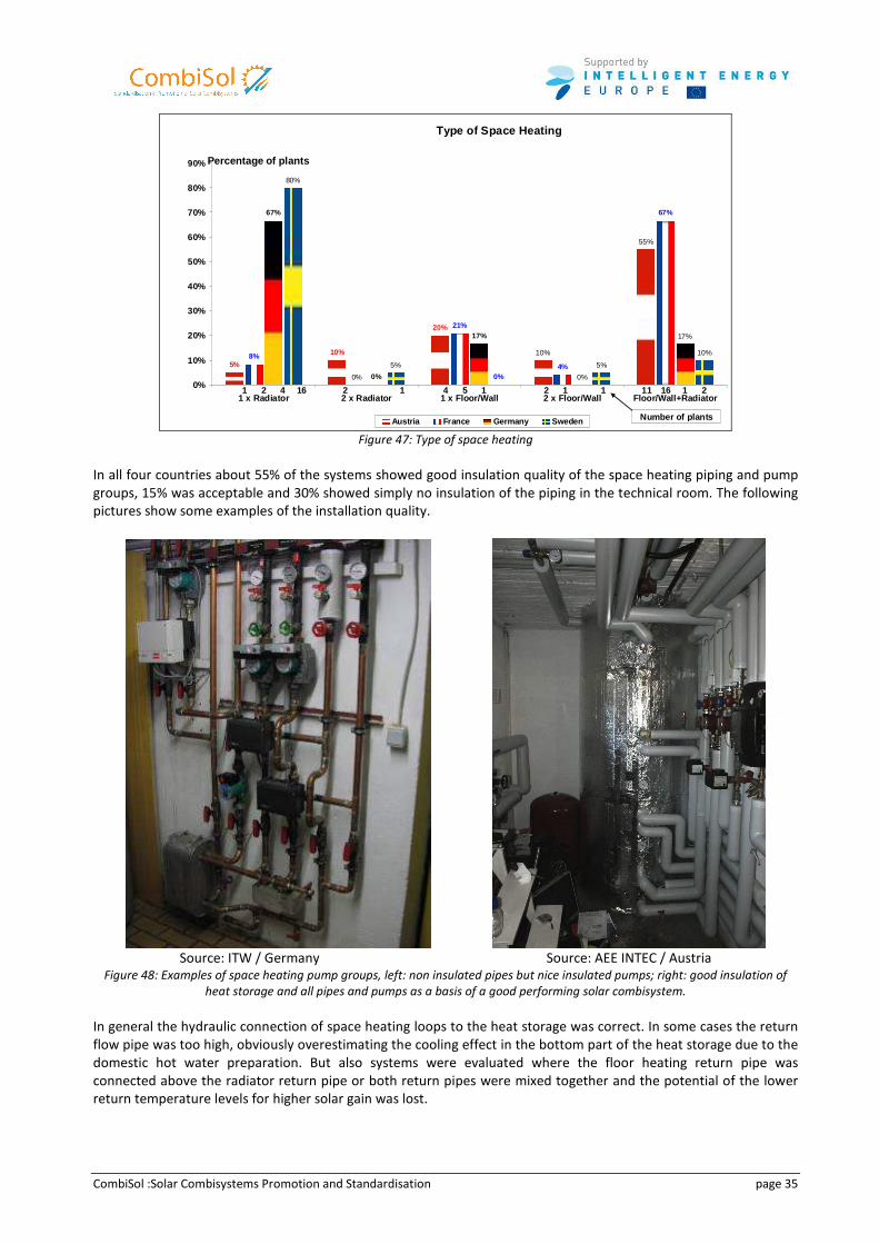
CombiSol :Solar Combisystems Promotion and Standardisation page 35
Type of Space Heating
5%
10%
20%
8%
21%
4%
67%67%
0%
10%
55%
0% 0%
17%17%
80%
10%
5%
0%
5%
0%
10%
20%
30%
40%
50%
60%
70%
80%
90%
1 x Radiator 2 x Radiator 1 x Floor/Wall 2 x Floor/Wal l Floor/Wall+Radiator
Percentage of plants
Austria France Germany Sweden
1 2 4 2 112 5 1 164 1 116 1 1 2
Number of plants
Figure 47: Type of space heating
In all four countries about 55% of the systems showed good insulation quality of the space heating piping and pump
groups, 15% was acceptable and 30% showed simply no insulation of the piping in the technical room. The following
pictures show some examples of the installation quality.
Source: ITW / Germany Source: AEE INTEC / Austria
Figure 48: Examples of space heating pump groups, left: non insulated pipes but nice insulated pumps; right: good insulation of
heat storage and all pipes and pumps as a basis of a good performing solar combisystem.
In general the hydraulic connection of space heating loops to the heat storage was correct. In some cases the return
flow pipe was too high, obviously overestimating the cooling effect in the bottom part of the heat storage due to the
domestic hot water preparation. But also systems were evaluated where the floor heating return pipe was
connected above the radiator return pipe or both return pipes were mixed together and the potential of the lower
return temperature levels for higher solar gain was lost.
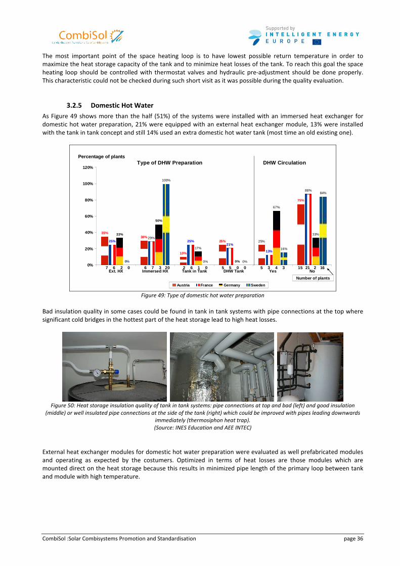
CombiSol :Solar Combisystems Promotion and Standardisation page 36
The most important point of the space heating loop is to have lowest possible return temperature in order to
maximize the heat storage capacity of the tank and to minimize heat losses of the tank. To reach this goal the space
heating loop should be controlled with thermostat valves and hydraulic pre-adjustment should be done properly.
This characteristic could not be checked during such short visit as it was possible during the quality evaluation.
3.2.5 Domestic Hot Water
As Figure 49 shows more than the half (51%) of the systems were installed with an immersed heat exchanger for
domestic hot water preparation, 21% were equipped with an external heat exchanger module, 13% were installed
with the tank in tank concept and still 14% used an extra domestic hot water tank (most time an old existing one).
Type of DHW Preparation DHW Circulation
35%30%
10%
25%25% 25%21%
13%
33%
50%
0%0%
25%
75%
29%
88%
17%
67%
33%
100%
0% 0%
16%
84%
0%
20%
40%
60%
80%
100%
120%
Ext. HX Immersed HX Tank in Tank DHW Tank Yes No
Percentage of plants
Austria France Germany Sweden
7 6 2 5 5 156 7 6 5 3 212 3 1 0 4 20 20 0 0 3 16
Number of plants
Figure 49: Type of domestic hot water preparation
Bad insulation quality in some cases could be found in tank in tank systems with pipe connections at the top where
significant cold bridges in the hottest part of the heat storage lead to high heat losses.
Figure 50: Heat storage insulation quality of tank in tank systems: pipe connections at top and bad (left) and good insulation
(middle) or well insulated pipe connections at the side of the tank (right) which could be improved with pipes leading downwards
immediately (thermosiphon heat trap).
(Source: INES Education and AEE INTEC)
External heat exchanger modules for domestic hot water preparation were evaluated as well prefabricated modules
and operating as expected by the costumers. Optimized in terms of heat losses are those modules which are
mounted direct on the heat storage because this results in minimized pipe length of the primary loop between tank
and module with high temperature.
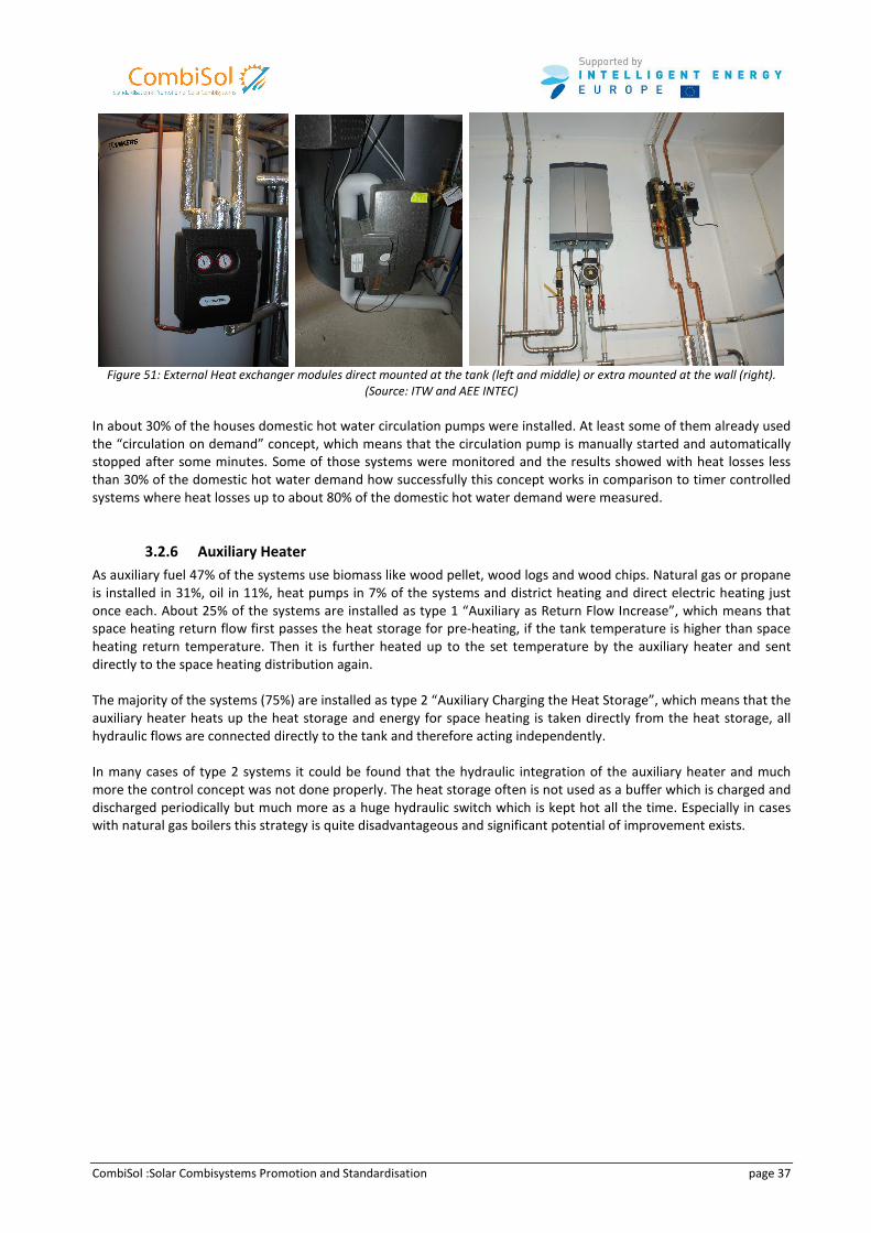
CombiSol :Solar Combisystems Promotion and Standardisation page 37
Figure 51: External Heat exchanger modules direct mounted at the tank (left and middle) or extra mounted at the wall (right).
(Source: ITW and AEE INTEC)
In about 30% of the houses domestic hot water circulation pumps were installed. At least some of them already used
the “circulation on demand” concept, which means that the circulation pump is manually started and automatically
stopped after some minutes. Some of those systems were monitored and the results showed with heat losses less
than 30% of the domestic hot water demand how successfully this concept works in comparison to timer controlled
systems where heat losses up to about 80% of the domestic hot water demand were measured.
3.2.6 Auxiliary Heater
As auxiliary fuel 47% of the systems use biomass like wood pellet, wood logs and wood chips. Natural gas or propane
is installed in 31%, oil in 11%, heat pumps in 7% of the systems and district heating and direct electric heating just
once each. About 25% of the systems are installed as type 1 “Auxiliary as Return Flow Increase”, which means that
space heating return flow first passes the heat storage for pre-heating, if the tank temperature is higher than space
heating return temperature. Then it is further heated up to the set temperature by the auxiliary heater and sent
directly to the space heating distribution again.
The majority of the systems (75%) are installed as type 2 “Auxiliary Charging the Heat Storage”, which means that the
auxiliary heater heats up the heat storage and energy for space heating is taken directly from the heat storage, all
hydraulic flows are connected directly to the tank and therefore acting independently.
In many cases of type 2 systems it could be found that the hydraulic integration of the auxiliary heater and much
more the control concept was not done properly. The heat storage often is not used as a buffer which is charged and
discharged periodically but much more as a huge hydraulic switch which is kept hot all the time. Especially in cases
with natural gas boilers this strategy is quite disadvantageous and significant potential of improvement exists.
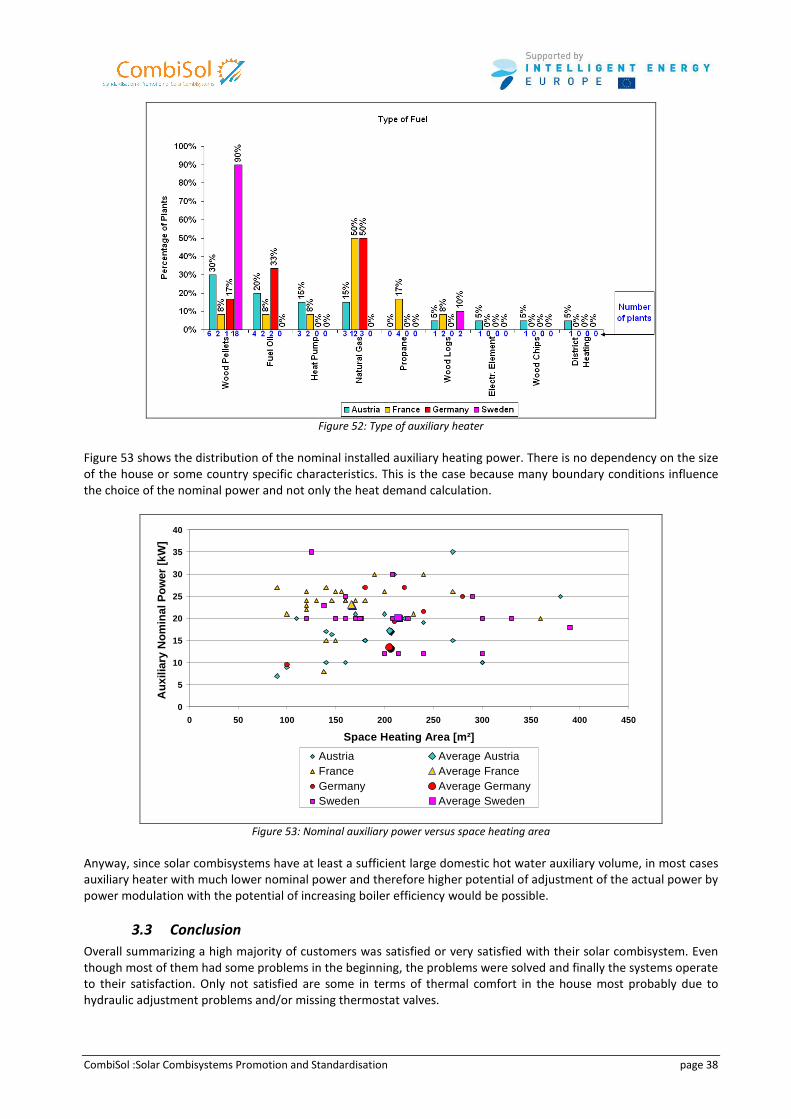
CombiSol :Solar Combisystems Promotion and Standardisation page 38
Figure 52: Type of auxiliary heater
Figure 53 shows the distribution of the nominal installed auxiliary heating power. There is no dependency on the size
of the house or some country specific characteristics. This is the case because many boundary conditions influence
the choice of the nominal power and not only the heat demand calculation.
0
5
10
15
20
25
30
35
40
0 50 100 150 200 250 300 350 400 450
Space Heating Area [m²]
Aux
iliar
y N
omin
al P
ower
[kW
]
Austria Average AustriaFrance Average FranceGermany Average GermanySweden Average Sweden
Figure 53: Nominal auxiliary power versus space heating area
Anyway, since solar combisystems have at least a sufficient large domestic hot water auxiliary volume, in most cases
auxiliary heater with much lower nominal power and therefore higher potential of adjustment of the actual power by
power modulation with the potential of increasing boiler efficiency would be possible.
3.3 Conclusion
Overall summarizing a high majority of customers was satisfied or very satisfied with their solar combisystem. Even
though most of them had some problems in the beginning, the problems were solved and finally the systems operate
to their satisfaction. Only not satisfied are some in terms of thermal comfort in the house most probably due to
hydraulic adjustment problems and/or missing thermostat valves.
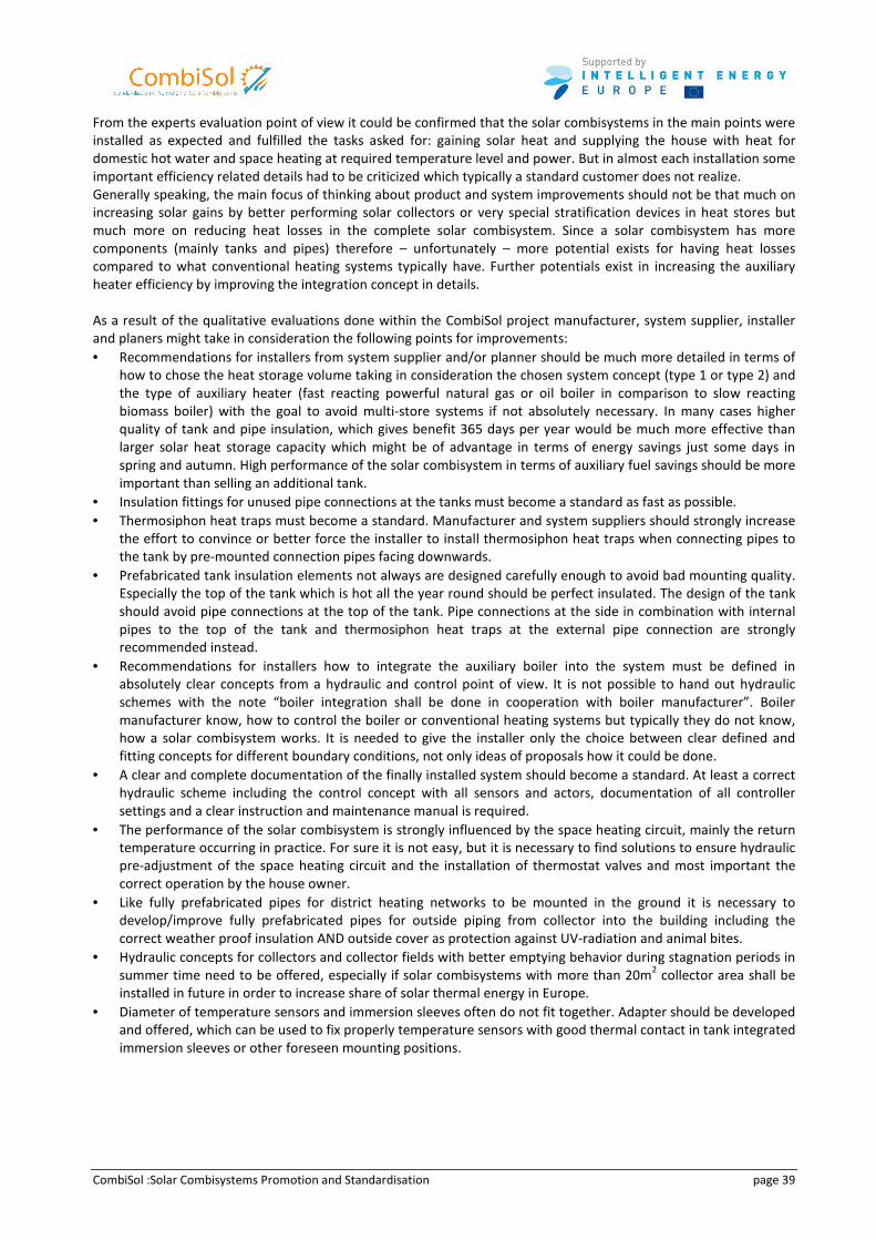
CombiSol :Solar Combisystems Promotion and Standardisation page 39
From the experts evaluation point of view it could be confirmed that the solar combisystems in the main points were
installed as expected and fulfilled the tasks asked for: gaining solar heat and supplying the house with heat for
domestic hot water and space heating at required temperature level and power. But in almost each installation some
important efficiency related details had to be criticized which typically a standard customer does not realize.
Generally speaking, the main focus of thinking about product and system improvements should not be that much on
increasing solar gains by better performing solar collectors or very special stratification devices in heat stores but
much more on reducing heat losses in the complete solar combisystem. Since a solar combisystem has more
components (mainly tanks and pipes) therefore – unfortunately – more potential exists for having heat losses
compared to what conventional heating systems typically have. Further potentials exist in increasing the auxiliary
heater efficiency by improving the integration concept in details.
As a result of the qualitative evaluations done within the CombiSol project manufacturer, system supplier, installer
and planers might take in consideration the following points for improvements:
• Recommendations for installers from system supplier and/or planner should be much more detailed in terms of
how to chose the heat storage volume taking in consideration the chosen system concept (type 1 or type 2) and
the type of auxiliary heater (fast reacting powerful natural gas or oil boiler in comparison to slow reacting
biomass boiler) with the goal to avoid multi-store systems if not absolutely necessary. In many cases higher
quality of tank and pipe insulation, which gives benefit 365 days per year would be much more effective than
larger solar heat storage capacity which might be of advantage in terms of energy savings just some days in
spring and autumn. High performance of the solar combisystem in terms of auxiliary fuel savings should be more
important than selling an additional tank.
• Insulation fittings for unused pipe connections at the tanks must become a standard as fast as possible.
• Thermosiphon heat traps must become a standard. Manufacturer and system suppliers should strongly increase
the effort to convince or better force the installer to install thermosiphon heat traps when connecting pipes to
the tank by pre-mounted connection pipes facing downwards.
• Prefabricated tank insulation elements not always are designed carefully enough to avoid bad mounting quality.
Especially the top of the tank which is hot all the year round should be perfect insulated. The design of the tank
should avoid pipe connections at the top of the tank. Pipe connections at the side in combination with internal
pipes to the top of the tank and thermosiphon heat traps at the external pipe connection are strongly
recommended instead.
• Recommendations for installers how to integrate the auxiliary boiler into the system must be defined in
absolutely clear concepts from a hydraulic and control point of view. It is not possible to hand out hydraulic
schemes with the note “boiler integration shall be done in cooperation with boiler manufacturer”. Boiler
manufacturer know, how to control the boiler or conventional heating systems but typically they do not know,
how a solar combisystem works. It is needed to give the installer only the choice between clear defined and
fitting concepts for different boundary conditions, not only ideas of proposals how it could be done.
• A clear and complete documentation of the finally installed system should become a standard. At least a correct
hydraulic scheme including the control concept with all sensors and actors, documentation of all controller
settings and a clear instruction and maintenance manual is required.
• The performance of the solar combisystem is strongly influenced by the space heating circuit, mainly the return
temperature occurring in practice. For sure it is not easy, but it is necessary to find solutions to ensure hydraulic
pre-adjustment of the space heating circuit and the installation of thermostat valves and most important the
correct operation by the house owner.
• Like fully prefabricated pipes for district heating networks to be mounted in the ground it is necessary to
develop/improve fully prefabricated pipes for outside piping from collector into the building including the
correct weather proof insulation AND outside cover as protection against UV-radiation and animal bites.
• Hydraulic concepts for collectors and collector fields with better emptying behavior during stagnation periods in
summer time need to be offered, especially if solar combisystems with more than 20m2 collector area shall be
installed in future in order to increase share of solar thermal energy in Europe.
• Diameter of temperature sensors and immersion sleeves often do not fit together. Adapter should be developed
and offered, which can be used to fix properly temperature sensors with good thermal contact in tank integrated
immersion sleeves or other foreseen mounting positions.
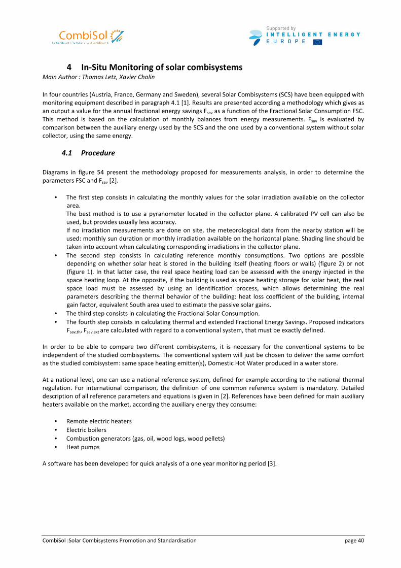
CombiSol :Solar Combisystems Promotion and Standardisation page 40
4 In-Situ Monitoring of solar combisystems
Main Author : Thomas Letz, Xavier Cholin
In four countries (Austria, France, Germany and Sweden), several Solar Combisystems (SCS) have been equipped with
monitoring equipment described in paragraph 4.1 [1]. Results are presented according a methodology which gives as
an output a value for the annual fractional energy savings Fsav as a function of the Fractional Solar Consumption FSC.
This method is based on the calculation of monthly balances from energy measurements. Fsav is evaluated by
comparison between the auxiliary energy used by the SCS and the one used by a conventional system without solar
collector, using the same energy.
4.1 Procedure
Diagrams in figure 54 present the methodology proposed for measurements analysis, in order to determine the
parameters FSC and Fsav [2].
• The first step consists in calculating the monthly values for the solar irradiation available on the collector
area.
The best method is to use a pyranometer located in the collector plane. A calibrated PV cell can also be
used, but provides usually less accuracy.
If no irradiation measurements are done on site, the meteorological data from the nearby station will be
used: monthly sun duration or monthly irradiation available on the horizontal plane. Shading line should be
taken into account when calculating corresponding irradiations in the collector plane.
• The second step consists in calculating reference monthly consumptions. Two options are possible
depending on whether solar heat is stored in the building itself (heating floors or walls) (figure 2) or not
(figure 1). In that latter case, the real space heating load can be assessed with the energy injected in the
space heating loop. At the opposite, if the building is used as space heating storage for solar heat, the real
space load must be assessed by using an identification process, which allows determining the real
parameters describing the thermal behavior of the building: heat loss coefficient of the building, internal
gain factor, equivalent South area used to estimate the passive solar gains.
• The third step consists in calculating the Fractional Solar Consumption.
• The fourth step consists in calculating thermal and extended Fractional Energy Savings. Proposed indicators
Fsav,th, Fsav,ext are calculated with regard to a conventional system, that must be exactly defined.
In order to be able to compare two different combisystems, it is necessary for the conventional systems to be
independent of the studied combisystems. The conventional system will just be chosen to deliver the same comfort
as the studied combisystem: same space heating emitter(s), Domestic Hot Water produced in a water store.
At a national level, one can use a national reference system, defined for example according to the national thermal
regulation. For international comparison, the definition of one common reference system is mandatory. Detailed
description of all reference parameters and equations is given in [2]. References have been defined for main auxiliary
heaters available on the market, according the auxiliary energy they consume:
• Remote electric heaters
• Electric boilers
• Combustion generators (gas, oil, wood logs, wood pellets)
• Heat pumps
A software has been developed for quick analysis of a one year monitoring period [3].
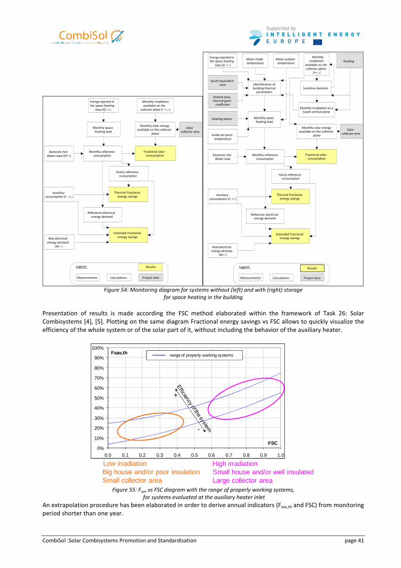
CombiSol :Solar Combisystems Promotion and Standardisation page 41
Figure 54: Monitoring diagram for systems without (left) and with (right) storage
for space heating in the building
Presentation of results is made according the FSC method elaborated within the framework of Task 26: Solar
Combisystems [4], [5]. Plotting on the same diagram Fractional energy savings vs FSC allows to quickly visualize the
efficiency of the whole system or of the solar part of it, without including the behavior of the auxiliary heater.
0%
10%
20%
30%
40%
50%
60%
70%
80%
90%
100%
0.0 0.1 0.2 0.3 0.4 0.5 0.6 0.7 0.8 0.9 1.0
FSC
Fsav,th Range of good running systems
Small house and/or well insulatedLarge collector area
High irradiationLow irradiationBig house and/or poor insulationSmall collector area
+
-
range of properly working systems
Figure 55: Fsav vs FSC diagram with the range of properly working systems,
for systems evaluated at the auxiliary heater inlet
An extrapolation procedure has been elaborated in order to derive annual indicators (Fsav,th and FSC) from monitoring
period shorter than one year.
Energy injected in
the space heating
loop (Q h,inj )
Monthly space heating load
Monthly reference consumption
Domestic Hot Water load (Q* w )
Fractional solar consumption
Monthly irradiation available on the
collector plane (I sol , c )
Solar collector area
Monthly solar energy available on the collector
plane
Measurements Calculations Project data
Legend :
Yearly reference consumption
Auxiliary consumption (C aux )
Thermal Fractional energy savings
Real electrical energy demand
(W sol )
Reference electrical energy demand
Extended Fractional energy savings
Results
South equivalent area Identification of
building thermal parameters
Energy injected in
the space heating
loop (Q h,inj )
Monthly space heating load
Inside set point
temperature
Mean inside
temperature Mean outdoor
temperature
Monthly reference consumption
Domestic Hot
Water load
Fractional solar consumption
Heated area, internal gains
coefficient
Heating season
Monthly
irradiation
available on the
collector plane
(I sol , c )
Shading
Sunshine duration
Solar collector area
Monthly irradiation on a South vertical plane
Monthly solar energy available on the collector
plane
Measurements Calculations Project data
Legend :
Yearly reference consumption
Auxiliary
consumption (C aux )Thermal Fractional
energy savings
Real electrical
energy demand
(Wsol )
Reference electrical energy demand
Extended Fractional energy savings
Results
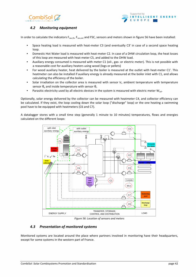
CombiSol :Solar Combisystems Promotion and Standardisation page 42
4.2 Monitoring equipment
In order to calculate the indicators Fsav,th, Fsav,ext and FSC, sensors and meters shown in figure 56 have been installed:
• Space heating load is measured with heat-meter C3 (and eventually C3' in case of a second space heating
loop.
• Domestic Hot Water load is measured with heat-meter C2. In case of a DHW circulation loop, the heat losses
of this loop are measured with heat-meter C5, and added to the DHW load.
• Auxiliary energy consumed is measured with meter C1 (oil-, gas- or electric meter). This is not possible with
a reasonable cost for auxiliary heaters using wood (logs or pellets)
• For wood auxiliary heater, heat delivered by the boiler is measured at the outlet with heat-meter C1'. This
heatmeter can also be installed if auxiliary energy is already measured at the boiler inlet with C1, and allows
calculating the efficiency of the boiler.
• Solar irradiation on the collector area is measured with sensor Ic, ambient temperature with temperature
sensor θe and inside temperature with sensor θi.
• Parasitic electricity used by all electric devices in the system is measured with electric meter Wsol.
Optionally, solar energy delivered by the collector can be measured with heatmeter C4, and collector efficiency can
be calculated. If they exist, the loop cooling down the solar loop ("discharge" loop) or the one heating a swimming
pool have to be equipped with heatmeters (C6 and C7).
A datalogger stores with a small time step (generally 1 minute to 10 minutes) temperatures, flows and energies
calculated on the different loops:
Solar collector
C1
TRANSFER, STORAGE, CONTROL AND DISTRIBUTION LOAD
C2
ENERGY SUPPLY
C5
C3
C3'
C4
C1'
Wsol
Controller
Discharge loop
Swimming pool
Domestic Hot Water
Space heating loops
Auxiliary boiler
θe
θi
Ic
C7
C6
Boiler losses
Tank and
pipes losses
with outlet auxiliary energy
with inlet auxiliary energy
Figure 56: Location of sensors and meters
4.3 Presentation of monitored systems
Monitored systems are located around the place where partners involved in monitoring have their headquarters,
except for some systems in the western part of France.
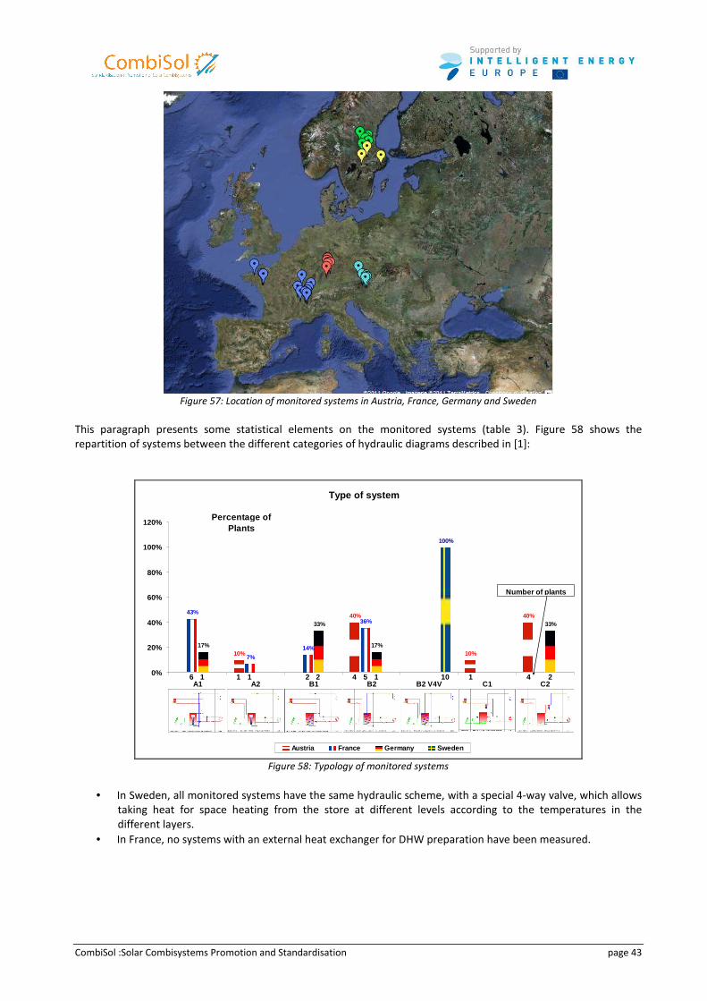
CombiSol :Solar Combisystems Promotion and Standardisation page 43
Figure 57: Location of monitored systems in Austria, France, Germany and Sweden
This paragraph presents some statistical elements on the monitored systems (table 3). Figure 58 shows the
repartition of systems between the different categories of hydraulic diagrams described in [1]:
Type of system
40%43%
14%
36%
17% 17%10% 10%
40%
7%
33% 33%
100%
0%
20%
40%
60%
80%
100%
120%
A1 A2 B1 B2 B2 V4V C1 C2
Percentage of Plants
Austria France Germany Sweden
4 1 46 1 2 51 2 1 2101
Number of plants
Figure 58: Typology of monitored systems
• In Sweden, all monitored systems have the same hydraulic scheme, with a special 4-way valve, which allows
taking heat for space heating from the store at different levels according to the temperatures in the
different layers.
• In France, no systems with an external heat exchanger for DHW preparation have been measured.
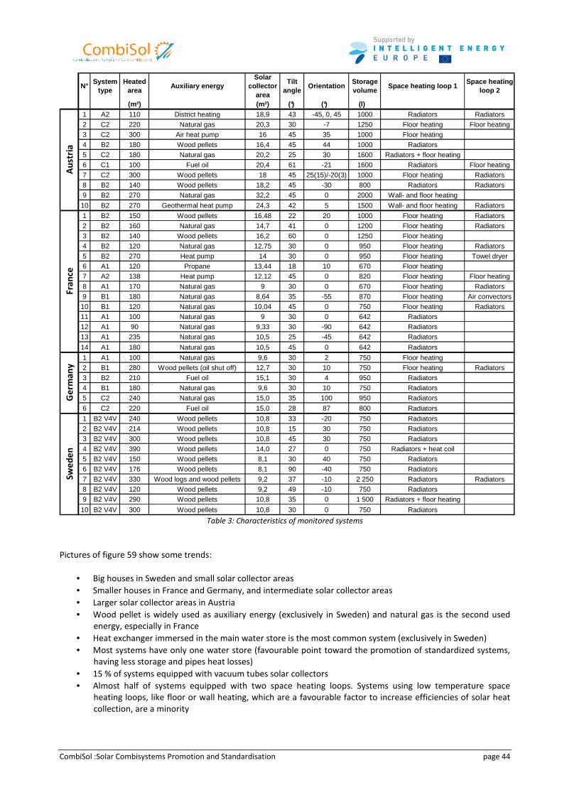
CombiSol :Solar Combisystems Promotion and Standardisation page 44
N°System
typeHeated
areaAuxiliary energy
Solar collector
area
Tilt angle
OrientationStorage volume
Space heating loop 1Space heating
loop 2
(m²) (m²) (°) (°) (l)
1 A2 110 District heating 18,9 43 -45, 0, 45 1000 Radiators Radiators
2 C2 220 Natural gas 20,3 30 -7 1250 Floor heating Floor heating
3 C2 300 Air heat pump 16 45 35 1000 Floor heating
4 B2 180 Wood pellets 16,4 45 44 1000 Radiators
5 C2 180 Natural gas 20,2 25 30 1600 Radiators + floor heating
6 C1 100 Fuel oil 20,4 61 -21 1600 Radiators Floor heating
7 C2 300 Wood pellets 18 45 25(15)/-20(3) 1000 Floor heating Radiators
8 B2 140 Wood pellets 18,2 45 -30 800 Radiators Radiators
9 B2 270 Natural gas 32,2 45 0 2000 Wall- and floor heating
10 B2 270 Geothermal heat pump 24,3 42 5 1500 Wall- and floor heating Radiators
1 B2 150 Wood pellets 16,48 22 20 1000 Floor heating Radiators
2 B2 160 Natural gas 14,7 41 0 1200 Floor heating Radiators
3 B2 140 Wood pellets 16,2 60 0 1250 Floor heating
4 B2 120 Natural gas 12,75 30 0 950 Floor heating Radiators
5 B2 270 Heat pump 14 30 0 950 Floor heating Towel dryer
6 A1 120 Propane 13,44 18 10 670 Floor heating
7 A2 138 Heat pump 12,12 45 0 820 Floor heating Floor heating
8 A1 170 Natural gas 9 30 0 670 Floor heating Radiators
9 B1 180 Natural gas 8,64 35 -55 870 Floor heating Air convectors
10 B1 120 Natural gas 10,04 45 0 750 Floor heating Radiators
11 A1 100 Natural gas 9 30 0 642 Radiators
12 A1 90 Natural gas 9,33 30 -90 642 Radiators
13 A1 235 Natural gas 10,5 25 -45 642 Radiators
14 A1 180 Natural gas 10,5 45 0 642 Radiators
1 A1 100 Natural gas 9,6 30 2 750 Floor heating
2 B1 280 Wood pellets (oil shut off) 12,7 30 10 750 Floor heating Radiators
3 B2 210 Fuel oil 15,1 30 4 950 Radiators
4 B1 180 Natural gas 9,6 30 10 750 Radiators
5 C2 240 Natural gas 15,0 35 100 950 Radiators
6 C2 220 Fuel oil 15,0 28 87 800 Radiators
1 B2 V4V 240 Wood pellets 10,8 33 -20 750 Radiators
2 B2 V4V 214 Wood pellets 10,8 15 30 750 Radiators
3 B2 V4V 300 Wood pellets 10,8 45 30 750 Radiators
4 B2 V4V 390 Wood pellets 14,0 27 0 750 Radiators + heat coil
5 B2 V4V 150 Wood pellets 8,1 30 40 750 Radiators
6 B2 V4V 176 Wood pellets 8,1 90 -40 750 Radiators
7 B2 V4V 330 Wood logs and wood pellets 9,2 37 -10 2 250 Radiators Radiators
8 B2 V4V 120 Wood pellets 9,2 49 -10 750 Radiators
9 B2 V4V 290 Wood pellets 10,8 35 0 1 500 Radiators + floor heating
10 B2 V4V 300 Wood pellets 10,8 30 0 750 Radiators
Au
stri
aFr
an
ceG
erm
any
Swe
de
n
Table 3: Characteristics of monitored systems
Pictures of figure 59 show some trends:
• Big houses in Sweden and small solar collector areas
• Smaller houses in France and Germany, and intermediate solar collector areas
• Larger solar collector areas in Austria
• Wood pellet is widely used as auxiliary energy (exclusively in Sweden) and natural gas is the second used
energy, especially in France
• Heat exchanger immersed in the main water store is the most common system (exclusively in Sweden)
• Most systems have only one water store (favourable point toward the promotion of standardized systems,
having less storage and pipes heat losses)
• 15 % of systems equipped with vacuum tubes solar collectors
• Almost half of systems equipped with two space heating loops. Systems using low temperature space
heating loops, like floor or wall heating, which are a favourable factor to increase efficiencies of solar heat
collection, are a minority
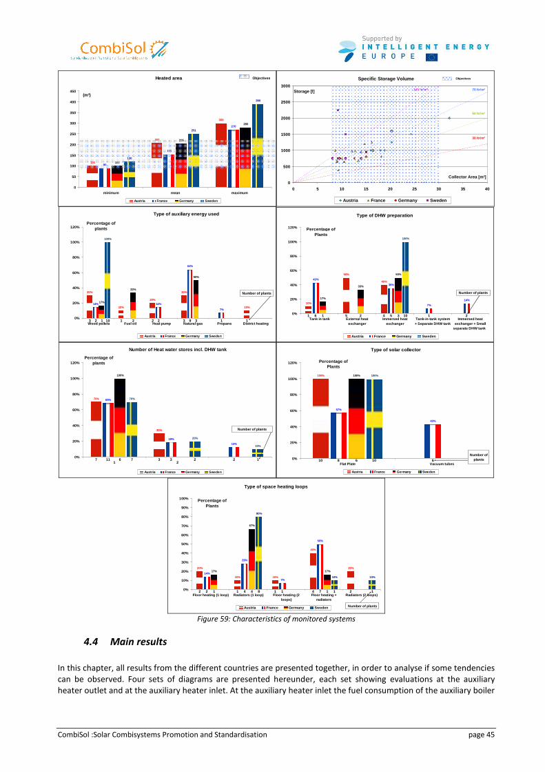
CombiSol :Solar Combisystems Promotion and Standardisation page 45
Heated area
100
207
300
90
155
270
100
205
280
120
251
390
0
50
100
150
200
250
300
350
400
450
minimum mean maximum
(m²)
Austria France Germany Sweden
Objectives Specific Storage Volume
0
500
1000
1500
2000
2500
3000
0 5 10 15 20 25 30 35 40
Collector Area [m²]
Storage [l]
Austria France Germany Sweden
50 ltr/m²
70 ltr/m²
30 ltr/m²
100 ltr/m²
Objectives
Type of auxiliary energy used
30%
10%
20%
30%
14% 14%
64%
7%
17%
33%
50%
100%
10%
0%
20%
40%
60%
80%
100%
120%
Wood pellets Fuel oil Heat pump Natural gas Propane Dist rict heating
Percentage of plants
Austria France Germany Sweden
3 1 2 3 12 2 9 11 2 310
Number of plants
Type of DHW preparation
10%
50%
40%43%
36%
7%
14%17%
33%
50%
100%
0%
20%
40%
60%
80%
100%
120%
Tank in tank External heatexchanger
Immersed heatexchanger
Tank-in-tank system+ Separate DHW tank
Immersed heatexchanger + Small
separate DHW tank
Percentage of Plants
Austria France Germany Sweden
1 5 46 5 1 21 2 3 10
Number of plants
Number of Heat water stores incl. DHW tank
70%
30%
69%
13%
100%
19%
70%
20%
10%
0%
20%
40%
60%
80%
100%
120%
1 2
Percentage of plants
Austria France Germany Sweden
7 311 3 26 7 2 1
Number of plants
Type of solar collector
100%
57%
100%
43%
100%
0%
20%
40%
60%
80%
100%
120%
Flat Plate Vacuum tubes
Percentage of Plants
Austria France Germany Sweden
10 8 66 10
Number of plants
Type of space heating loops
20%
10% 10%
40%
14%
7%
50%
17%
67%
17%20%
29%
10%10%
80%
0%
10%
20%
30%
40%
50%
60%
70%
80%
90%
100%
Floor heating (1 loop) Radiators (1 loop) Floor heati ng (2loops)
Floor heating +radiators
Radiators (2 loops)
Percentage of Plants
Austria France Germany Sweden
2 1 1 4 22 4 1 71 4 1 1 18
Number of plants
Figure 59: Characteristics of monitored systems
4.4 Main results
In this chapter, all results from the different countries are presented together, in order to analyse if some tendencies
can be observed. Four sets of diagrams are presented hereunder, each set showing evaluations at the auxiliary
heater outlet and at the auxiliary heater inlet. At the auxiliary heater inlet the fuel consumption of the auxiliary boiler
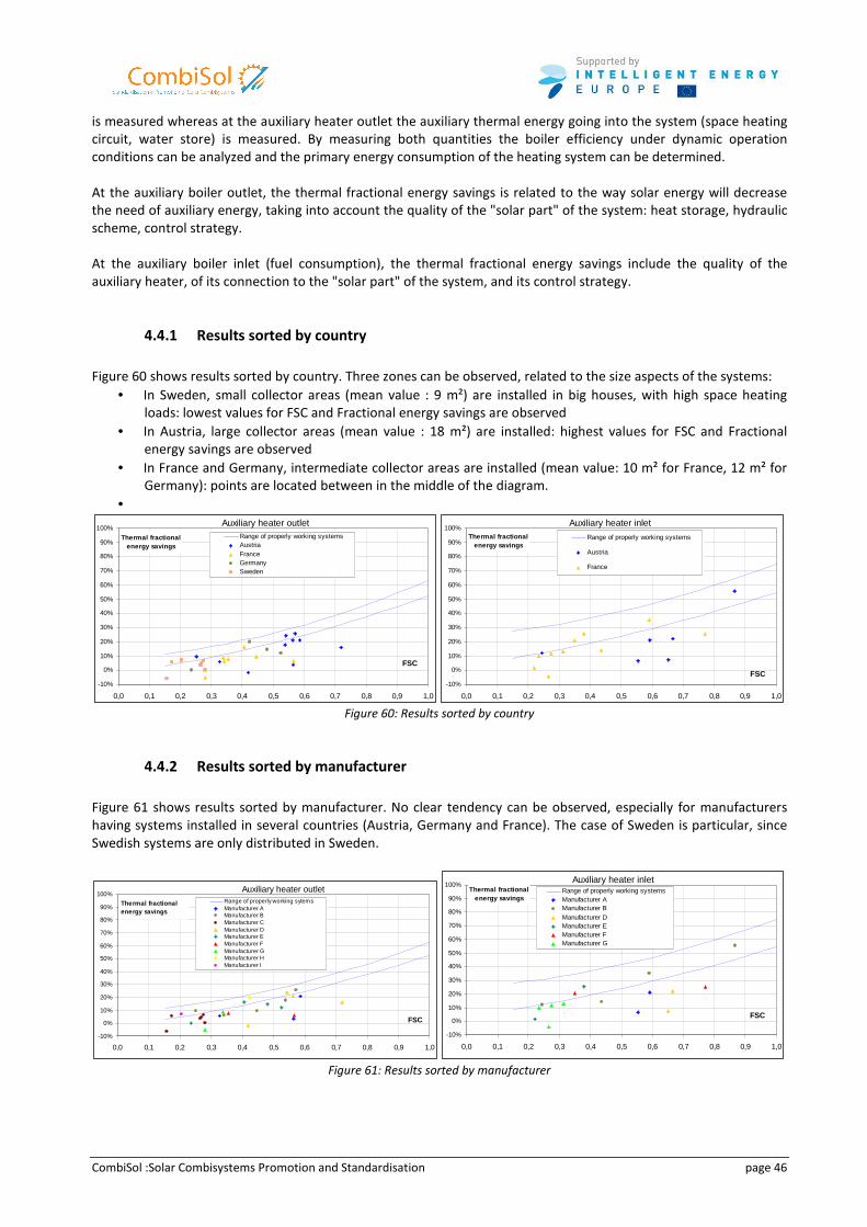
CombiSol :Solar Combisystems Promotion and Standardisation page 46
is measured whereas at the auxiliary heater outlet the auxiliary thermal energy going into the system (space heating
circuit, water store) is measured. By measuring both quantities the boiler efficiency under dynamic operation
conditions can be analyzed and the primary energy consumption of the heating system can be determined.
At the auxiliary boiler outlet, the thermal fractional energy savings is related to the way solar energy will decrease
the need of auxiliary energy, taking into account the quality of the "solar part" of the system: heat storage, hydraulic
scheme, control strategy.
At the auxiliary boiler inlet (fuel consumption), the thermal fractional energy savings include the quality of the
auxiliary heater, of its connection to the "solar part" of the system, and its control strategy.
4.4.1 Results sorted by country
Figure 60 shows results sorted by country. Three zones can be observed, related to the size aspects of the systems:
• In Sweden, small collector areas (mean value : 9 m²) are installed in big houses, with high space heating
loads: lowest values for FSC and Fractional energy savings are observed
• In Austria, large collector areas (mean value : 18 m²) are installed: highest values for FSC and Fractional
energy savings are observed
• In France and Germany, intermediate collector areas are installed (mean value: 10 m² for France, 12 m² for
Germany): points are located between in the middle of the diagram.
•
Auxiliary heater outlet
-10%
0%
10%
20%
30%
40%
50%
60%
70%
80%
90%
100%
0,0 0,1 0,2 0,3 0,4 0,5 0,6 0,7 0,8 0,9 1,0
FSC
Thermal fractional energy savings
Range of properly working systemsAustriaFranceGermanySweden
Auxiliary heater inlet
-10%
0%
10%
20%
30%
40%
50%
60%
70%
80%
90%
100%
0,0 0,1 0,2 0,3 0,4 0,5 0,6 0,7 0,8 0,9 1,0
FSC
Thermal fractional energy savings
Range of properly working systems
Austria
France
Figure 60: Results sorted by country
4.4.2 Results sorted by manufacturer
Figure 61 shows results sorted by manufacturer. No clear tendency can be observed, especially for manufacturers
having systems installed in several countries (Austria, Germany and France). The case of Sweden is particular, since
Swedish systems are only distributed in Sweden.
Auxiliary heater outlet
-10%
0%
10%
20%
30%
40%
50%
60%
70%
80%
90%
100%
0,0 0,1 0,2 0,3 0,4 0,5 0,6 0,7 0,8 0,9 1,0
FSC
Range of properly working sytemsManufacturer AManufacturer BManufacturer CManufacturer DManufacturer EManufacturer FManufacturer GManufacturer HManufacturer I
Thermal fractional energy savings
Auxiliary heater inlet
-10%
0%
10%
20%
30%
40%
50%
60%
70%
80%
90%
100%
0,0 0,1 0,2 0,3 0,4 0,5 0,6 0,7 0,8 0,9 1,0
FSC
Thermal fractional energy savings
Range of properly working systemsManufacturer AManufacturer BManufacturer DManufacturer EManufacturer FManufacturer G
Figure 61: Results sorted by manufacturer
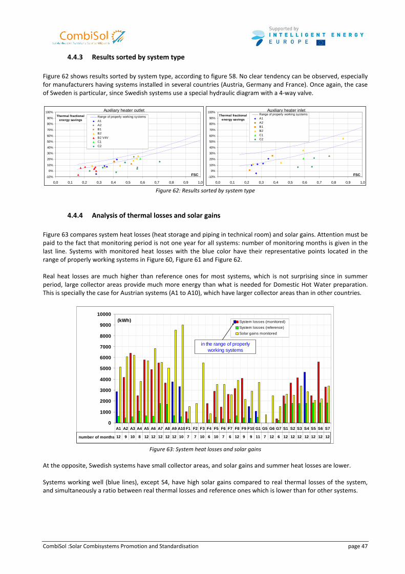
CombiSol :Solar Combisystems Promotion and Standardisation page 47
4.4.3 Results sorted by system type
Figure 62 shows results sorted by system type, according to figure 58. No clear tendency can be observed, especially
for manufacturers having systems installed in several countries (Austria, Germany and France). Once again, the case
of Sweden is particular, since Swedish systems use a special hydraulic diagram with a 4-way valve.
Auxiliary heater outlet
-10%
0%
10%
20%
30%
40%
50%
60%
70%
80%
90%
100%
0,0 0,1 0,2 0,3 0,4 0,5 0,6 0,7 0,8 0,9 1,0
FSC
Thermal fractional energy savings
Range of properly working systemsA1A2B1B2B2 V4VC1C2
Auxiliary heater inlet
-10%
0%
10%
20%
30%
40%
50%
60%
70%
80%
90%
100%
0,0 0,1 0,2 0,3 0,4 0,5 0,6 0,7 0,8 0,9 1,0
FSC
Thermal fractional energy savings
Range of properly working systemsA1A2B1B2C1C2
Figure 62: Results sorted by system type
4.4.4 Analysis of thermal losses and solar gains
Figure 63 compares system heat losses (heat storage and piping in technical room) and solar gains. Attention must be
paid to the fact that monitoring period is not one year for all systems: number of monitoring months is given in the
last line. Systems with monitored heat losses with the blue color have their representative points located in the
range of properly working systems in Figure 60, Figure 61 and Figure 62.
Real heat losses are much higher than reference ones for most systems, which is not surprising since in summer
period, large collector areas provide much more energy than what is needed for Domestic Hot Water preparation.
This is specially the case for Austrian systems (A1 to A10), which have larger collector areas than in other countries.
0
1000
2000
3000
4000
5000
6000
7000
8000
9000
10000
A1 A2 A3 A4 A5 A6 A7 A8 A9 A10 F1 F2 F3 F4 F5 F6 F7 F8 F9 F10 G1 G5 G6 G7 S 1 S2 S3 S4 S5 S6 S7
12 9 10 8 12 12 12 12 12 10 7 7 10 6 10 7 6 12 9 9 11 7 12 6 12 12 12 12 12 12 12
System losses (monitored)
System losses (reference)
Solar gains monitored
(kWh)
in the range of properly working systems
number of months
Figure 63: System heat losses and solar gains
At the opposite, Swedish systems have small collector areas, and solar gains and summer heat losses are lower.
Systems working well (blue lines), except S4, have high solar gains compared to real thermal losses of the system,
and simultaneously a ratio between real thermal losses and reference ones which is lower than for other systems.
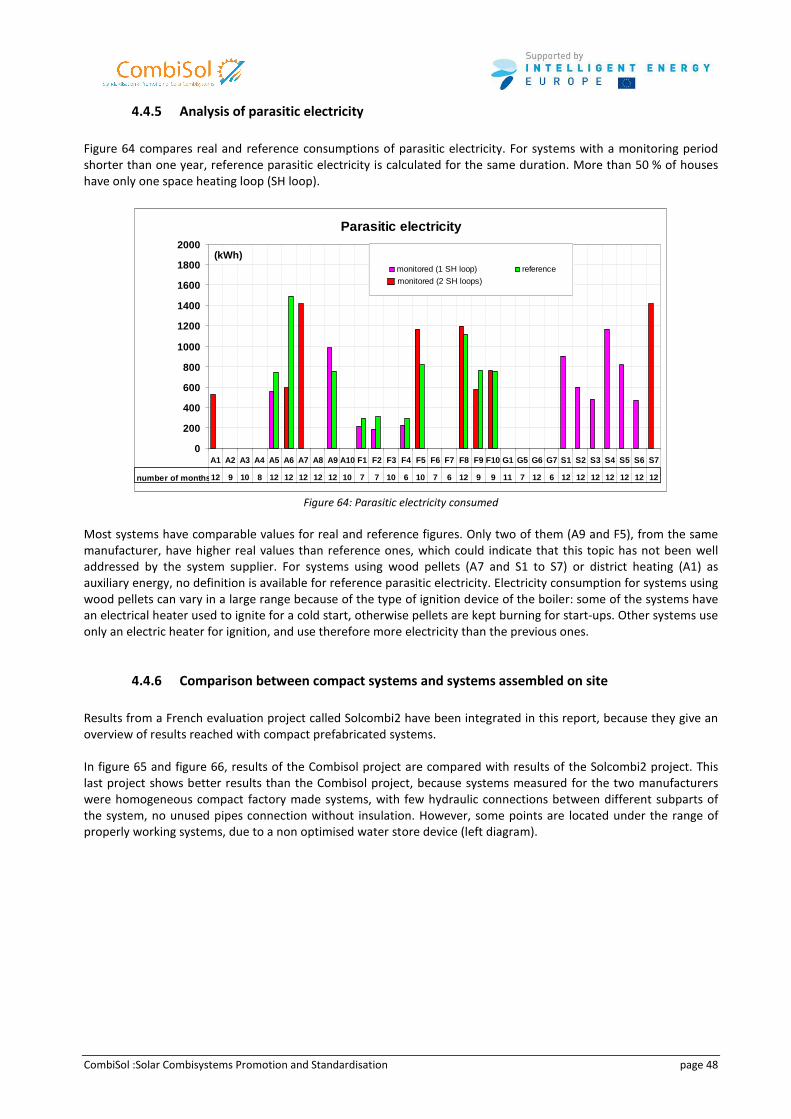
CombiSol :Solar Combisystems Promotion and Standardisation page 48
4.4.5 Analysis of parasitic electricity
Figure 64 compares real and reference consumptions of parasitic electricity. For systems with a monitoring period
shorter than one year, reference parasitic electricity is calculated for the same duration. More than 50 % of houses
have only one space heating loop (SH loop).
Parasitic electricity
0
200
400
600
800
1000
1200
1400
1600
1800
2000
A1 A2 A3 A4 A5 A6 A7 A8 A9 A10 F1 F2 F3 F4 F5 F6 F7 F8 F9 F10 G1 G5 G6 G7 S 1 S2 S3 S4 S5 S6 S7
12 9 10 8 12 12 12 12 12 10 7 7 10 6 10 7 6 12 9 9 11 7 12 6 12 12 12 12 12 12 12
monitored (1 SH loop) reference
(kWh)
number of months
monitored (2 SH loops)
Figure 64: Parasitic electricity consumed
Most systems have comparable values for real and reference figures. Only two of them (A9 and F5), from the same
manufacturer, have higher real values than reference ones, which could indicate that this topic has not been well
addressed by the system supplier. For systems using wood pellets (A7 and S1 to S7) or district heating (A1) as
auxiliary energy, no definition is available for reference parasitic electricity. Electricity consumption for systems using
wood pellets can vary in a large range because of the type of ignition device of the boiler: some of the systems have
an electrical heater used to ignite for a cold start, otherwise pellets are kept burning for start-ups. Other systems use
only an electric heater for ignition, and use therefore more electricity than the previous ones.
4.4.6 Comparison between compact systems and systems assembled on site
Results from a French evaluation project called Solcombi2 have been integrated in this report, because they give an
overview of results reached with compact prefabricated systems.
In figure 65 and figure 66, results of the Combisol project are compared with results of the Solcombi2 project. This
last project shows better results than the Combisol project, because systems measured for the two manufacturers
were homogeneous compact factory made systems, with few hydraulic connections between different subparts of
the system, no unused pipes connection without insulation. However, some points are located under the range of
properly working systems, due to a non optimised water store device (left diagram).
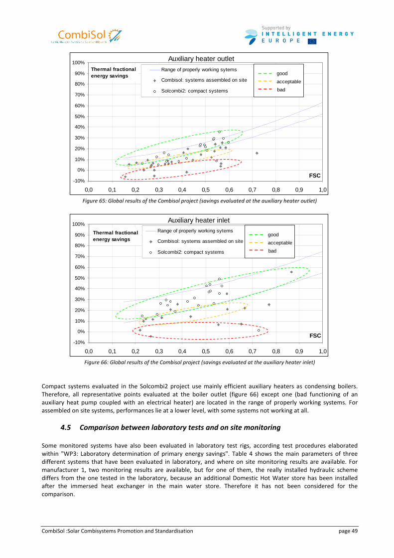
CombiSol :Solar Combisystems Promotion and Standardisation page 49
Auxiliary heater outlet
-10%
0%
10%
20%
30%
40%
50%
60%
70%
80%
90%
100%
0,0 0,1 0,2 0,3 0,4 0,5 0,6 0,7 0,8 0,9 1,0
FSC
Range of properly working sytems
Combisol: systems assembled on site
Solcombi2: compact systems
Thermal fractional energy savings good
acceptable
bad
Figure 65: Global results of the Combisol project (savings evaluated at the auxiliary heater outlet)
Auxiliary heater inlet
-10%
0%
10%
20%
30%
40%
50%
60%
70%
80%
90%
100%
0,0 0,1 0,2 0,3 0,4 0,5 0,6 0,7 0,8 0,9 1,0
FSC
Range of properly working sytems
Combisol: systems assembled on site
Solcombi2: compact systems
Thermal fractional energy savings
good
acceptable
bad
Figure 66: Global results of the Combisol project (savings evaluated at the auxiliary heater inlet)
Compact systems evaluated in the Solcombi2 project use mainly efficient auxiliary heaters as condensing boilers.
Therefore, all representative points evaluated at the boiler outlet (figure 66) except one (bad functioning of an
auxiliary heat pump coupled with an electrical heater) are located in the range of properly working systems. For
assembled on site systems, performances lie at a lower level, with some systems not working at all.
4.5 Comparison between laboratory tests and on site monitoring
Some monitored systems have also been evaluated in laboratory test rigs, according test procedures elaborated
within "WP3: Laboratory determination of primary energy savings". Table 4 shows the main parameters of three
different systems that have been evaluated in laboratory, and where on site monitoring results are available. For
manufacturer 1, two monitoring results are available, but for one of them, the really installed hydraulic scheme
differs from the one tested in the laboratory, because an additional Domestic Hot Water store has been installed
after the immersed heat exchanger in the main water store. Therefore it has not been considered for the
comparison.
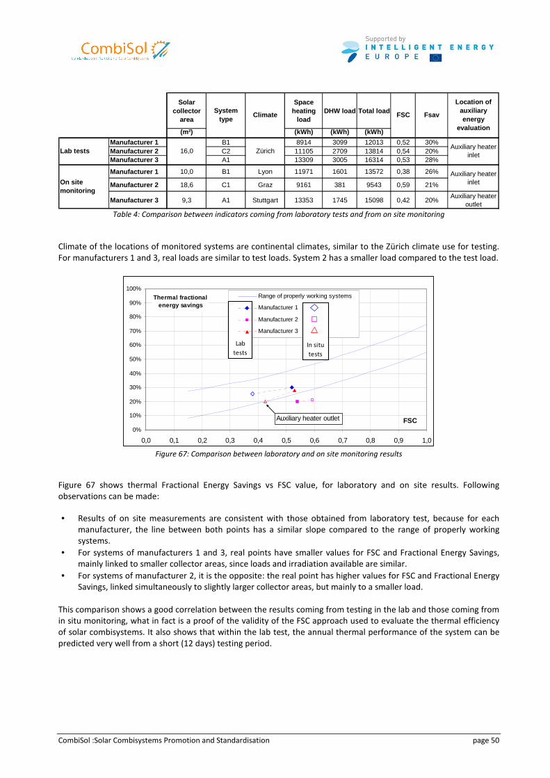
CombiSol :Solar Combisystems Promotion and Standardisation page 50
Solar collector
area
Space heating
loadDHW load Total load
(m²) (kWh) (kWh) (kWh)
Manufacturer 1 B1 8914 3099 12013 0,52 30%Manufacturer 2 C2 11105 2709 13814 0,54 20%Manufacturer 3 A1 13309 3005 16314 0,53 28%
Manufacturer 1 10,0 B1 Lyon 11971 1601 13572 0,38 26%
Manufacturer 2 18,6 C1 Graz 9161 381 9543 0,59 21%
Manufacturer 3 9,3 A1 Stuttgart 13353 1745 15098 0,42 20%Auxiliary heater
outlet
Location of auxiliary energy
evaluation
System type
Climate FSC Fsav
Auxiliary heater inlet
Auxiliary heater inletOn site
monitoring
Lab tests 16,0 Zürich
Table 4: Comparison between indicators coming from laboratory tests and from on site monitoring
Climate of the locations of monitored systems are continental climates, similar to the Zürich climate use for testing.
For manufacturers 1 and 3, real loads are similar to test loads. System 2 has a smaller load compared to the test load.
0%
10%
20%
30%
40%
50%
60%
70%
80%
90%
100%
0,0 0,1 0,2 0,3 0,4 0,5 0,6 0,7 0,8 0,9 1,0
FSC
Thermal fractional energy savings
Range of properly working systems
Manufacturer 1
Manufacturer 2
Manufacturer 3
Auxiliary heater outlet
Lab
testsIn situ
tests
Figure 67: Comparison between laboratory and on site monitoring results
Figure 67 shows thermal Fractional Energy Savings vs FSC value, for laboratory and on site results. Following
observations can be made:
• Results of on site measurements are consistent with those obtained from laboratory test, because for each
manufacturer, the line between both points has a similar slope compared to the range of properly working
systems.
• For systems of manufacturers 1 and 3, real points have smaller values for FSC and Fractional Energy Savings,
mainly linked to smaller collector areas, since loads and irradiation available are similar.
• For systems of manufacturer 2, it is the opposite: the real point has higher values for FSC and Fractional Energy
Savings, linked simultaneously to slightly larger collector areas, but mainly to a smaller load.
This comparison shows a good correlation between the results coming from testing in the lab and those coming from
in situ monitoring, what in fact is a proof of the validity of the FSC approach used to evaluate the thermal efficiency
of solar combisystems. It also shows that within the lab test, the annual thermal performance of the system can be
predicted very well from a short (12 days) testing period.
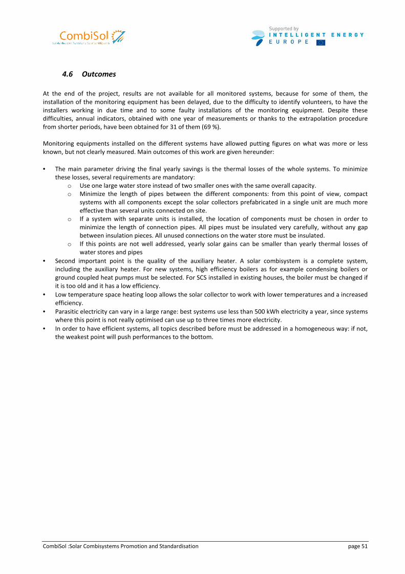
CombiSol :Solar Combisystems Promotion and Standardisation page 51
4.6 Outcomes
At the end of the project, results are not available for all monitored systems, because for some of them, the
installation of the monitoring equipment has been delayed, due to the difficulty to identify volunteers, to have the
installers working in due time and to some faulty installations of the monitoring equipment. Despite these
difficulties, annual indicators, obtained with one year of measurements or thanks to the extrapolation procedure
from shorter periods, have been obtained for 31 of them (69 %).
Monitoring equipments installed on the different systems have allowed putting figures on what was more or less
known, but not clearly measured. Main outcomes of this work are given hereunder:
• The main parameter driving the final yearly savings is the thermal losses of the whole systems. To minimize
these losses, several requirements are mandatory:
o Use one large water store instead of two smaller ones with the same overall capacity.
o Minimize the length of pipes between the different components: from this point of view, compact
systems with all components except the solar collectors prefabricated in a single unit are much more
effective than several units connected on site.
o If a system with separate units is installed, the location of components must be chosen in order to
minimize the length of connection pipes. All pipes must be insulated very carefully, without any gap
between insulation pieces. All unused connections on the water store must be insulated.
o If this points are not well addressed, yearly solar gains can be smaller than yearly thermal losses of
water stores and pipes
• Second important point is the quality of the auxiliary heater. A solar combisystem is a complete system,
including the auxiliary heater. For new systems, high efficiency boilers as for example condensing boilers or
ground coupled heat pumps must be selected. For SCS installed in existing houses, the boiler must be changed if
it is too old and it has a low efficiency.
• Low temperature space heating loop allows the solar collector to work with lower temperatures and a increased
efficiency.
• Parasitic electricity can vary in a large range: best systems use less than 500 kWh electricity a year, since systems
where this point is not really optimised can use up to three times more electricity.
• In order to have efficient systems, all topics described before must be addressed in a homogeneous way: if not,
the weakest point will push performances to the bottom.
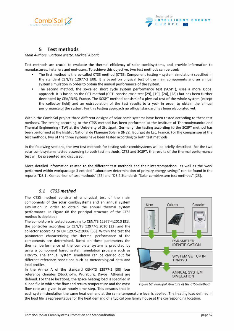
CombiSol :Solar Combisystems Promotion and Standardisation page 52
5 Test methods
Main Authors : Barbara Mette, Mickael Albaric
Test methods are crucial to evaluate the thermal efficiency of solar combisystems, and provide information to
manufactures, installers and end-users. To achieve this objective, two test methods can be used:
• The first method is the so-called CTSS method (CTSS: Component testing – system simulation) specified in
the standard CEN/TS 12977-2 [30]. It is based on physical test of the main components and an annual
system simulation in order to obtain the annual performance of the system.
• The second method, the so-called short cycle system performance test (SCSPT), uses a more global
approach. It is based on the CCT method (CCT: concise cycle test [29], [19], [24], [28]) but has been further
developed by CEA/INES, France. The SCSPT method consists of a physical test of the whole system (except
the collector field) and an extrapolation of the test results to a year in order to obtain the annual
performance of the system. For this testing approach no official standard has been elaborated yet.
Within the CombiSol project three different designs of solar combisystems have been tested according to these test
methods. The testing according to the CTSS method has been performed at the Institute of Thermodynamics and
Thermal Engineering (ITW) at the University of Stuttgart, Germany, the testing according to the SCSPT method has
been performed at the Institut National de l’Energie Solaire (INES), Bourget du Lac, France. For the comparison of the
test methods, two of the three systems have been tested according to both test methods.
In the following sections, the two test methods for testing solar combisystems will be briefly described. For the two
solar combisystems tested according to both test methods, CTSS and SCSPT, the results of the thermal performance
test will be presented and discussed.
More detailed information related to the different test methods and their intercomparison as well as the work
performed within workpackage 3 entitled “Laboratory determination of primary energy savings” can be found in the
reports “D3.1 : Comparison of test methods” [22] and “D3.2 Standards “Solar combisystem test methods” [23].
5.1 CTSS method
The CTSS method consists of a physical test of the main
components of the solar combisystems and an annual system
simulation in order to obtain the annual thermal system
performance. In Figure 68 the principal structure of the CTSS
method is depicted:
The combistore is tested according to CEN/TS 12977-4:2010 [31],
the controller according to CEN/TS 12977-5:2010 [32] and the
collector according to EN 12975-2:2006 [33]. Within the test the
parameters characterizing the thermal performance of the
components are determined. Based on these parameters the
thermal performance of the complete system is predicted by
using a component based system simulation program such as
TRNSYS. The annual system simulation can be carried out for
different reference conditions such as meteorological data and
load profiles.
In the Annex A of the standard CEN/TS 12977-2 [30] four
reference climates (Stockholm, Wurzburg, Davos, Athens) are
defined. For these locations, the space heating load is specified in
a load file in which the flow and return temperature and the mass
flow rate are given in an hourly time step. This ensures that in
each system simulation the same heat demand at the same temperature level is applied. The heating load defined in
the load file is representative for the heat demand of a typical one family house at the corresponding location.
Figure 68: Principal structure of the CTSS-method
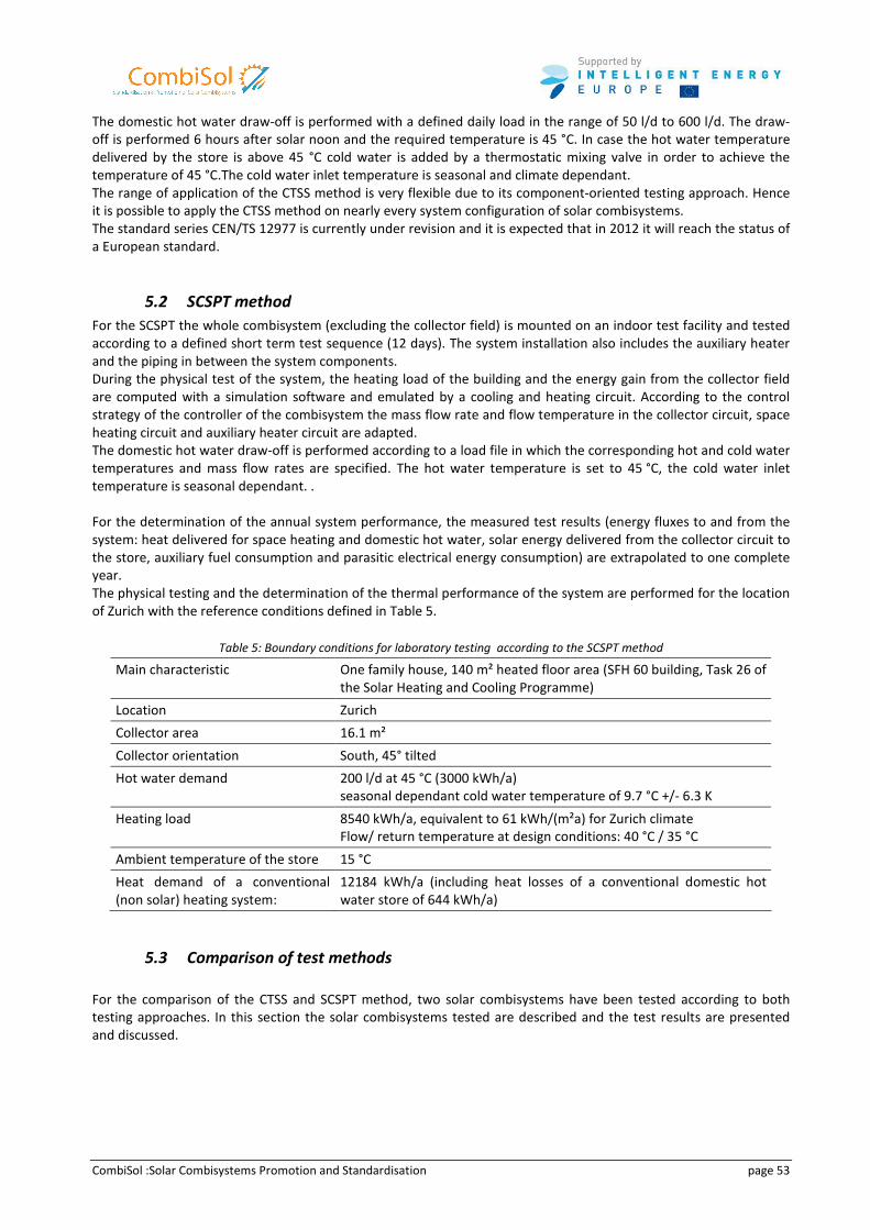
CombiSol :Solar Combisystems Promotion and Standardisation page 53
The domestic hot water draw-off is performed with a defined daily load in the range of 50 l/d to 600 l/d. The draw-
off is performed 6 hours after solar noon and the required temperature is 45 °C. In case the hot water temperature
delivered by the store is above 45 °C cold water is added by a thermostatic mixing valve in order to achieve the
temperature of 45 °C.The cold water inlet temperature is seasonal and climate dependant.
The range of application of the CTSS method is very flexible due to its component-oriented testing approach. Hence
it is possible to apply the CTSS method on nearly every system configuration of solar combisystems.
The standard series CEN/TS 12977 is currently under revision and it is expected that in 2012 it will reach the status of
a European standard.
5.2 SCSPT method
For the SCSPT the whole combisystem (excluding the collector field) is mounted on an indoor test facility and tested
according to a defined short term test sequence (12 days). The system installation also includes the auxiliary heater
and the piping in between the system components.
During the physical test of the system, the heating load of the building and the energy gain from the collector field
are computed with a simulation software and emulated by a cooling and heating circuit. According to the control
strategy of the controller of the combisystem the mass flow rate and flow temperature in the collector circuit, space
heating circuit and auxiliary heater circuit are adapted.
The domestic hot water draw-off is performed according to a load file in which the corresponding hot and cold water
temperatures and mass flow rates are specified. The hot water temperature is set to 45 °C, the cold water inlet
temperature is seasonal dependant. .
For the determination of the annual system performance, the measured test results (energy fluxes to and from the
system: heat delivered for space heating and domestic hot water, solar energy delivered from the collector circuit to
the store, auxiliary fuel consumption and parasitic electrical energy consumption) are extrapolated to one complete
year.
The physical testing and the determination of the thermal performance of the system are performed for the location
of Zurich with the reference conditions defined in Table 5.
Table 5: Boundary conditions for laboratory testing according to the SCSPT method
Main characteristic One family house, 140 m² heated floor area (SFH 60 building, Task 26 of
the Solar Heating and Cooling Programme)
Location Zurich
Collector area 16.1 m²
Collector orientation South, 45° tilted
Hot water demand
200 l/d at 45 °C (3000 kWh/a)
seasonal dependant cold water temperature of 9.7 °C +/- 6.3 K
Heating load 8540 kWh/a, equivalent to 61 kWh/(m²a) for Zurich climate
Flow/ return temperature at design conditions: 40 °C / 35 °C
Ambient temperature of the store 15 °C
Heat demand of a conventional
(non solar) heating system:
12184 kWh/a (including heat losses of a conventional domestic hot
water store of 644 kWh/a)
5.3 Comparison of test methods
For the comparison of the CTSS and SCSPT method, two solar combisystems have been tested according to both
testing approaches. In this section the solar combisystems tested are described and the test results are presented
and discussed.
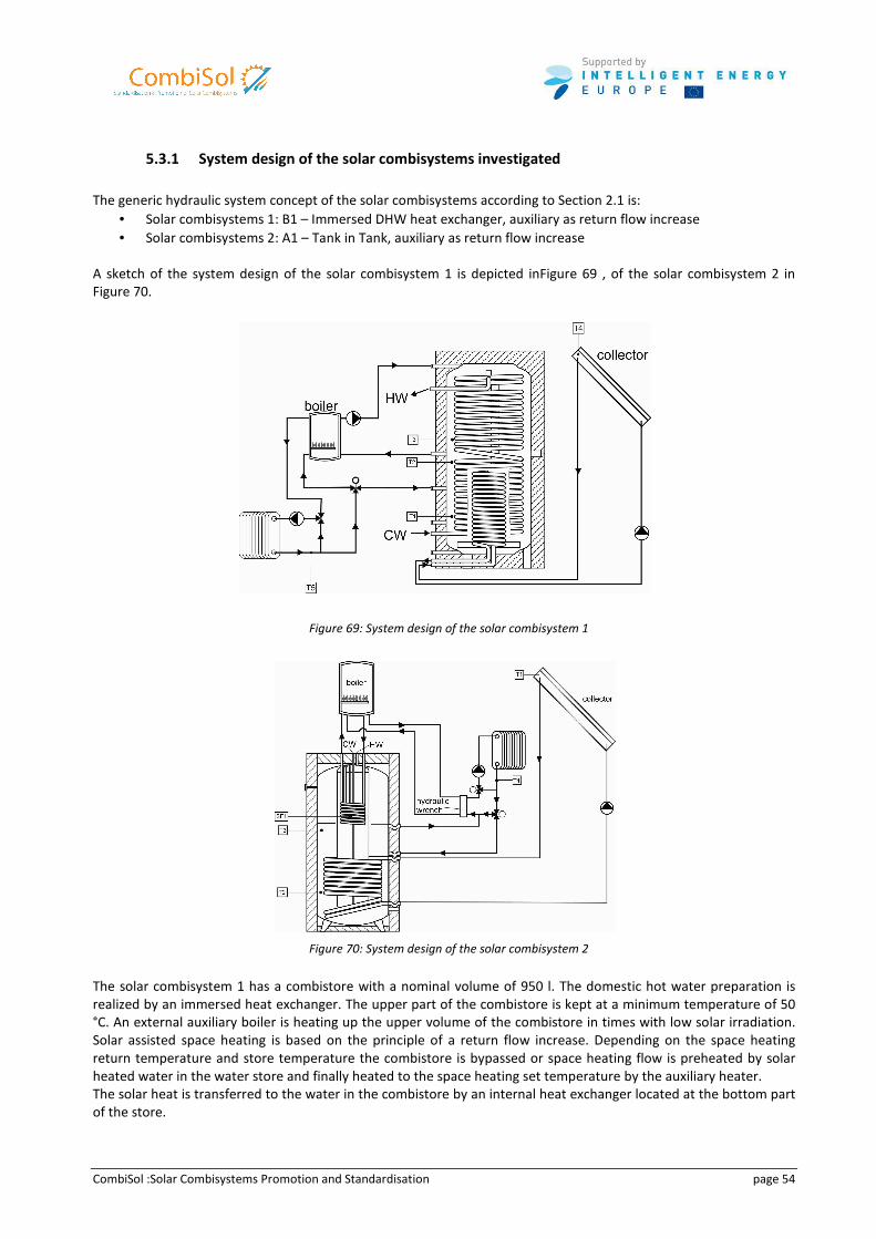
CombiSol :Solar Combisystems Promotion and Standardisation page 54
5.3.1 System design of the solar combisystems investigated
The generic hydraulic system concept of the solar combisystems according to Section 2.1 is:
• Solar combisystems 1: B1 – Immersed DHW heat exchanger, auxiliary as return flow increase
• Solar combisystems 2: A1 – Tank in Tank, auxiliary as return flow increase
A sketch of the system design of the solar combisystem 1 is depicted inFigure 69 , of the solar combisystem 2 in
Figure 70.
Figure 69: System design of the solar combisystem 1
Figure 70: System design of the solar combisystem 2
The solar combisystem 1 has a combistore with a nominal volume of 950 l. The domestic hot water preparation is
realized by an immersed heat exchanger. The upper part of the combistore is kept at a minimum temperature of 50
°C. An external auxiliary boiler is heating up the upper volume of the combistore in times with low solar irradiation.
Solar assisted space heating is based on the principle of a return flow increase. Depending on the space heating
return temperature and store temperature the combistore is bypassed or space heating flow is preheated by solar
heated water in the water store and finally heated to the space heating set temperature by the auxiliary heater.
The solar heat is transferred to the water in the combistore by an internal heat exchanger located at the bottom part
of the store.
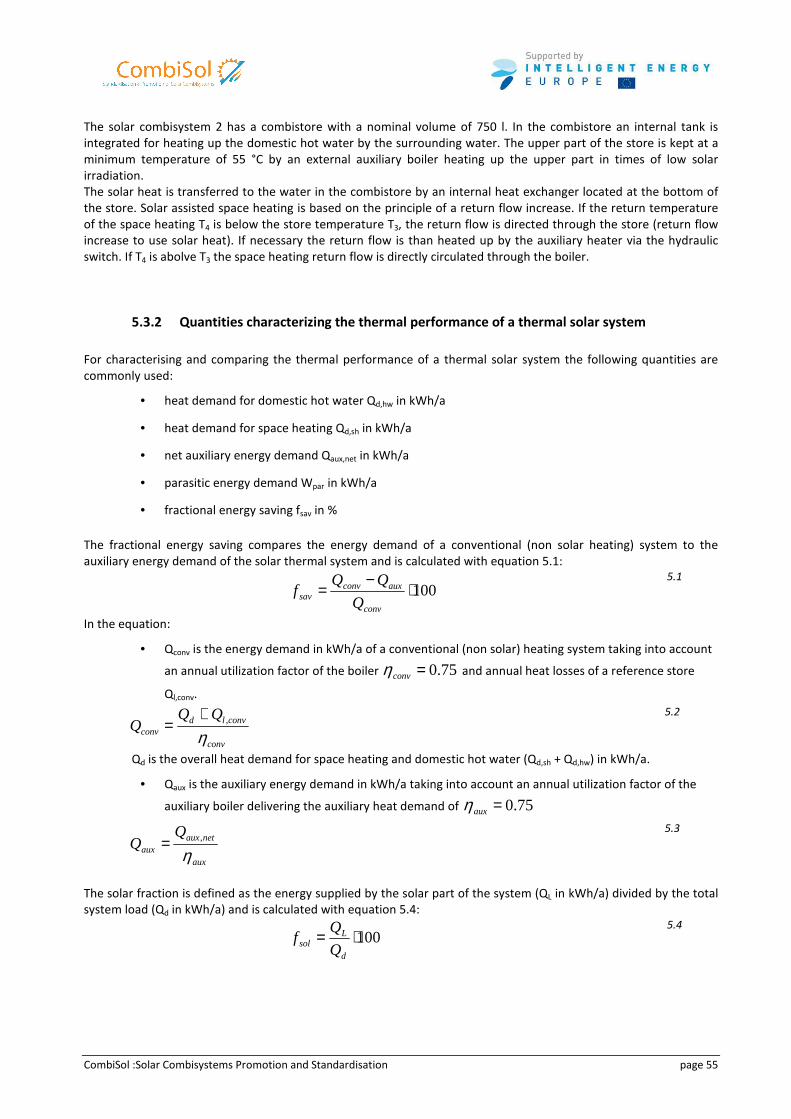
CombiSol :Solar Combisystems Promotion and Standardisation page 55
The solar combisystem 2 has a combistore with a nominal volume of 750 l. In the combistore an internal tank is
integrated for heating up the domestic hot water by the surrounding water. The upper part of the store is kept at a
minimum temperature of 55 °C by an external auxiliary boiler heating up the upper part in times of low solar
irradiation.
The solar heat is transferred to the water in the combistore by an internal heat exchanger located at the bottom of
the store. Solar assisted space heating is based on the principle of a return flow increase. If the return temperature
of the space heating T4 is below the store temperature T3, the return flow is directed through the store (return flow
increase to use solar heat). If necessary the return flow is than heated up by the auxiliary heater via the hydraulic
switch. If T4 is abolve T3 the space heating return flow is directly circulated through the boiler.
5.3.2 Quantities characterizing the thermal performance of a thermal solar system
For characterising and comparing the thermal performance of a thermal solar system the following quantities are
commonly used:
• heat demand for domestic hot water Qd,hw in kWh/a
• heat demand for space heating Qd,sh in kWh/a
• net auxiliary energy demand Qaux,net in kWh/a
• parasitic energy demand Wpar in kWh/a
• fractional energy saving fsav in %
The fractional energy saving compares the energy demand of a conventional (non solar heating) system to the
auxiliary energy demand of the solar thermal system and is calculated with equation 5.1:
100⋅
−=
conv
auxconvsav Q
QQf
5.1
In the equation:
• Qconv is the energy demand in kWh/a of a conventional (non solar) heating system taking into account
an annual utilization factor of the boiler 75.0=convη and annual heat losses of a reference store
Ql,conv.
conv
convldconv
QQQ
η,+
=
5.2
Qd is the overall heat demand for space heating and domestic hot water (Qd,sh + Qd,hw) in kWh/a.
• Qaux is the auxiliary energy demand in kWh/a taking into account an annual utilization factor of the
auxiliary boiler delivering the auxiliary heat demand of 75.0=auxη
aux
netauxaux
η,=
5.3
The solar fraction is defined as the energy supplied by the solar part of the system (QL in kWh/a) divided by the total
system load (Qd in kWh/a) and is calculated with equation 5.4:
100⋅=
d
Lsol Q
Qf
5.4
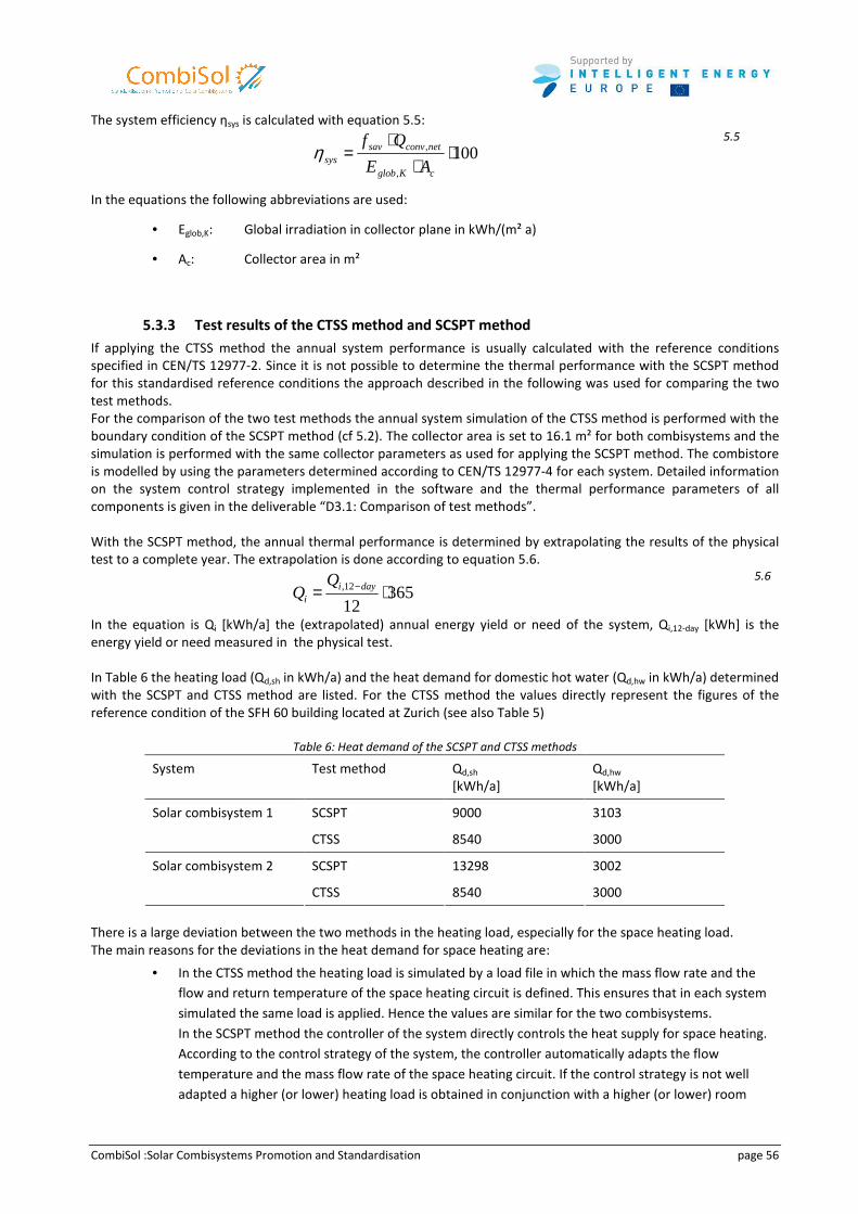
CombiSol :Solar Combisystems Promotion and Standardisation page 56
The system efficiency ηsys is calculated with equation 5.5:
100,
, ⋅⋅
⋅=
cKglob
netconvsavsys AE
Qfη
5.5
In the equations the following abbreviations are used:
• Eglob,K: Global irradiation in collector plane in kWh/(m² a)
• Ac: Collector area in m²
5.3.3 Test results of the CTSS method and SCSPT method
If applying the CTSS method the annual system performance is usually calculated with the reference conditions
specified in CEN/TS 12977-2. Since it is not possible to determine the thermal performance with the SCSPT method
for this standardised reference conditions the approach described in the following was used for comparing the two
test methods.
For the comparison of the two test methods the annual system simulation of the CTSS method is performed with the
boundary condition of the SCSPT method (cf 5.2). The collector area is set to 16.1 m² for both combisystems and the
simulation is performed with the same collector parameters as used for applying the SCSPT method. The combistore
is modelled by using the parameters determined according to CEN/TS 12977-4 for each system. Detailed information
on the system control strategy implemented in the software and the thermal performance parameters of all
components is given in the deliverable “D3.1: Comparison of test methods”.
With the SCSPT method, the annual thermal performance is determined by extrapolating the results of the physical
test to a complete year. The extrapolation is done according to equation 5.6.
3651212, ⋅= −dayi
i
5.6
In the equation is Qi [kWh/a] the (extrapolated) annual energy yield or need of the system, Qi,12-day [kWh] is the
energy yield or need measured in the physical test.
In Table 6 the heating load (Qd,sh in kWh/a) and the heat demand for domestic hot water (Qd,hw in kWh/a) determined
with the SCSPT and CTSS method are listed. For the CTSS method the values directly represent the figures of the
reference condition of the SFH 60 building located at Zurich (see also Table 5)
Table 6: Heat demand of the SCSPT and CTSS methods
System Test method Qd,sh
[kWh/a]
Qd,hw
[kWh/a]
SCSPT 9000 3103 Solar combisystem 1
CTSS 8540 3000
SCSPT 13298 3002 Solar combisystem 2
CTSS 8540 3000
There is a large deviation between the two methods in the heating load, especially for the space heating load.
The main reasons for the deviations in the heat demand for space heating are:
• In the CTSS method the heating load is simulated by a load file in which the mass flow rate and the
flow and return temperature of the space heating circuit is defined. This ensures that in each system
simulated the same load is applied. Hence the values are similar for the two combisystems. In the SCSPT method the controller of the system directly controls the heat supply for space heating.
According to the control strategy of the system, the controller automatically adapts the flow
temperature and the mass flow rate of the space heating circuit. If the control strategy is not well
adapted a higher (or lower) heating load is obtained in conjunction with a higher (or lower) room
CombiSol :Solar Combisystems Promotion and Standardisation page 57
temperature in the building simulation.
In the solar combisystem 2 the control strategy implemented was solely ambient temperature
dependant. Hence, no feedback from the actual room temperature is given to the controller. This
explains the much higher heating load than the one required. The mean temperature in the building
was 21.8 °C instead of 20.0 °C.
• In the CTSS method no heat losses of pipes and components (valves, pumps) from the store to the
space heating or domestic hot water circuit or the auxiliary heater circuit are included. Only heat
losses of pipes in the collector circuit are considered.
In the SCSPT method the complete system is setup on the test facility and heat losses of pipes
between the different components and of the components themselves are taken into account. The
heat losses in the heating circuit have to be compensated. This results in a higher energy demand in
the space heating circuit.
The deviation in the heat demand for domestic hot water in the CTSS method and the SCSPT can be explained by:
• Differences in the hot water and cold water temperature during a draw-off.
In the simulation of the CTSS method the draw-off temperature and cold water temperature are
exactly specified (draw-off temperature: 45 °C, cold water temperature: seasonal dependant)
In the SCSPT method the same set temperatures as in the CTSS method are implemented in the
testing software. However, the measurements performed during the SCSP test show that the draw-off
temperature varies between 44 °C and 52 °C with a mean temperature of 48 °C. Reason for this is that
the thermostatic mixing valve used for in the system test set up does not provide the right draw-off
temperature. Furthermore, due to cold water stagnation between two draw-offs, the cold water
temperature is higher than the specified temperature, especially for low flow rates (lower than 100
kg/h). As the draw-off is time-controlled a defined hot water volume is drawn and not a defined
energy quantity.
5.3.4 Adaption of the CTSS method to the boundary condition of the SCSPT method
For the comparison of the two test methods, the boundary conditions in the annual system simulation of the CTSS
method are further adapted to the laboratory test of the SCSPT method. For the determination of the heating load a
building model (TYPE 56) of the SFH60 building is implemented in the simulation software. The corresponding flow
temperature and flow rate to cover the load are adjusted directly by the controller of the solar combisystem.
In addition, in the simulation software, the piping between the components have been adapted to the real system
set up during the SCSPT by means of piping length, piping insulation and heat loss coefficients of the piping
insulation. In this case the control strategy is adapted according to the control strategy described in the Combisol
deliverable D3.1.
In the flow chart in Figure 71 the methodology for the comparison is shown. The nomenclature “SimCTSS” is
introduced to differ from the CTSS method where the annual system simulation is performed with the reference
boundary condition according to EN 12977-2, Annex A.
The comparison of the test methods was performed in two stages:
1. Comparing the results of the 12 day test
2. Comparing the annual results
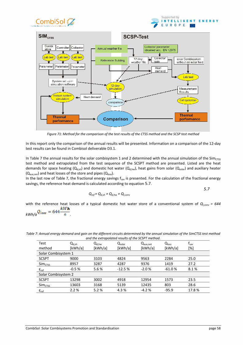
CombiSol :Solar Combisystems Promotion and Standardisation page 58
Figure 71: Method for the comparison of the test results of the CTSS method and the SCSP test method
In this report only the comparison of the annual results will be presented. Information on a comparison of the 12-day
test results can be found in Combisol deliverable D3.1.
In Table 7 the annual results for the solar combisystem 1 and 2 determined with the annual simulation of the SimCTSS
test method and extrapolated from the test sequence of the SCSPT method are presented. Listed are the heat
demands for space heating (Qd,sh) and domestic hot water (Qd,hw), heat gains from solar (Qsolar) and auxiliary heater
(Qaux,net) and heat losses of the store and pipes (Qloss).
In the last row of Table 7, the fractional energy savings fsav is presented. For the calculation of the fractional energy
savings, the reference heat demand is calculated according to equation 5.7.
Qref = Qd,sh + Qd,hw + Ql,conv
5.7
with the reference heat losses of a typical domestic hot water store of a conventional system of Ql,conv = 644
kWh/a .
Table 7: Annual energy demand and gain on the different circuits determined by the annual simulation of the SimCTSS test method
and the extrapolated results of the SCSPT method. Test
method
Qd,sh
[kWh/a]
Qd,hw
[kWh/a]
Qsolar
[kWh/a]
Qaux,net
[kWh/a]
Qloss
[kWh/a]
fsav
[%]
Solar Combisystem 1
SCSPT 9000 3103 4824 9563 2284 25.0
SimCTSS 8957 3287 4287 9376 1419 27.2
εref -0.5 % 5.6 % -12.5 % -2.0 % -61.0 % 8.1 %
Solar Combisystem 2
SCSPT 13298 3002 4918 12954 1573 23.5
SimCTSS 13603 3168 5139 12435 803 28.6
εref 2.2 % 5.2 % 4.3 % -4.2 % -95.9 17.8 %
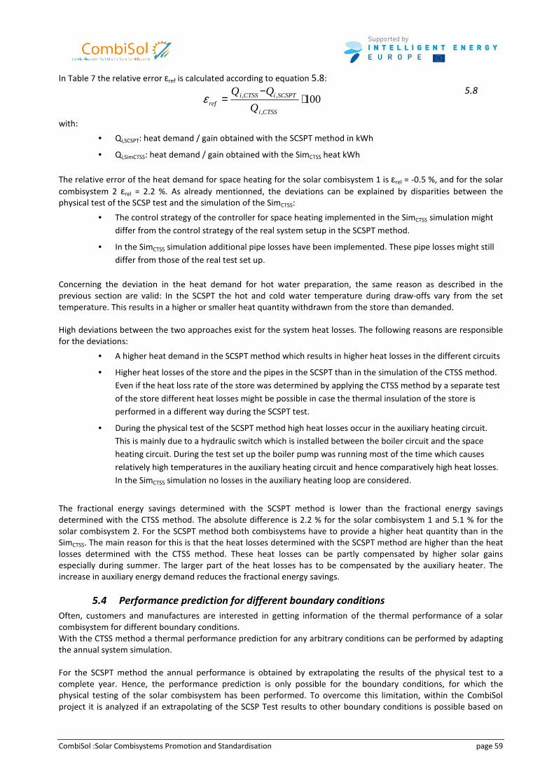
CombiSol :Solar Combisystems Promotion and Standardisation page 59
In Table 7 the relative error εref is calculated according to equation 5.8:
100
,
,, ⋅−
=CTSSi
SCSPTiCTSSiref Q
QQε
5.8
with:
• Qi,SCSPT: heat demand / gain obtained with the SCSPT method in kWh
• Qi,SimCTSS: heat demand / gain obtained with the SimCTSS heat kWh
The relative error of the heat demand for space heating for the solar combisystem 1 is εrel = -0.5 %, and for the solar
combisystem 2 εrel = 2.2 %. As already mentionned, the deviations can be explained by disparities between the
physical test of the SCSP test and the simulation of the SimCTSS:
• The control strategy of the controller for space heating implemented in the SimCTSS simulation might
differ from the control strategy of the real system setup in the SCSPT method.
• In the SimCTSS simulation additional pipe losses have been implemented. These pipe losses might still
differ from those of the real test set up.
Concerning the deviation in the heat demand for hot water preparation, the same reason as described in the
previous section are valid: In the SCSPT the hot and cold water temperature during draw-offs vary from the set
temperature. This results in a higher or smaller heat quantity withdrawn from the store than demanded.
High deviations between the two approaches exist for the system heat losses. The following reasons are responsible
for the deviations:
• A higher heat demand in the SCSPT method which results in higher heat losses in the different circuits
• Higher heat losses of the store and the pipes in the SCSPT than in the simulation of the CTSS method.
Even if the heat loss rate of the store was determined by applying the CTSS method by a separate test
of the store different heat losses might be possible in case the thermal insulation of the store is
performed in a different way during the SCSPT test.
• During the physical test of the SCSPT method high heat losses occur in the auxiliary heating circuit.
This is mainly due to a hydraulic switch which is installed between the boiler circuit and the space
heating circuit. During the test set up the boiler pump was running most of the time which causes
relatively high temperatures in the auxiliary heating circuit and hence comparatively high heat losses.
In the SimCTSS simulation no losses in the auxiliary heating loop are considered.
The fractional energy savings determined with the SCSPT method is lower than the fractional energy savings
determined with the CTSS method. The absolute difference is 2.2 % for the solar combisystem 1 and 5.1 % for the
solar combisystem 2. For the SCSPT method both combisystems have to provide a higher heat quantity than in the
SimCTSS. The main reason for this is that the heat losses determined with the SCSPT method are higher than the heat
losses determined with the CTSS method. These heat losses can be partly compensated by higher solar gains
especially during summer. The larger part of the heat losses has to be compensated by the auxiliary heater. The
increase in auxiliary energy demand reduces the fractional energy savings.
5.4 Performance prediction for different boundary conditions
Often, customers and manufactures are interested in getting information of the thermal performance of a solar
combisystem for different boundary conditions.
With the CTSS method a thermal performance prediction for any arbitrary conditions can be performed by adapting
the annual system simulation.
For the SCSPT method the annual performance is obtained by extrapolating the results of the physical test to a
complete year. Hence, the performance prediction is only possible for the boundary conditions, for which the
physical testing of the solar combisystem has been performed. To overcome this limitation, within the CombiSol
project it is analyzed if an extrapolating of the SCSP Test results to other boundary conditions is possible based on
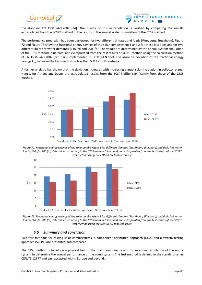
CombiSol :Solar Combisystems Promotion and Standardisation page 60
the standard EN 15316-4-3:2007 [34]. The quality of this extrapolation is verified by comparing the results
extrapolated from the SCSPT method to the results of the annual system simulation of the CTSS method.
The performance prediction has been performed for two different climates and loads (Wurzburg, Stockholm). Figure
72 and Figure 73 show the fractional energy savings of the solar combisystem 1 and 2 for these locations and for two
different daily hot water demands (110 l/d and 200 l/d). The values are determined by the annual system simulation
of the CTSS method (blue bars) and extrapolated from the test results of SCSPT method using the calculation method
of EN 15316-4-3:2007 (red bars) implemented in COMBI-EN tool. The absolute deviation of the fractional energy
savings fsav between the two methods is less than 5 % for both systems.
A further analysis has shown that the deviation increases with increasing annual solar irradiation in collector plane.
Hence, for Athens and Davos the extrapolated results from the SCSPT differ significantly from those of the CTSS
method.
Figure 72: Fractional energy savings of the solar combisystem 1 for different climates (Stockholm, Wurzburg) and daily hot water
loads (110 l/d, 200 l/d) determined according to the CTSS method (blue bars) and extrapolated from the test results of the SCSPT
test method using the COMBI-EN tool (red bars).
Figure 73: Fractional energy savings of the solar combisystem 2 for different climates (Stockholm, Wurzburg) and daily hot water
loads (110 l/d, 200 l/d) determined according to the CTSS method (blue bars) and extrapolated from the test results of the SCSPT
test method using the COMBI-EN tool (red bars).
5.5 Summary and conclusion
Two test methods for testing solar combisystems, a component orientated approach (CTSS) and a system testing
approach (SCSPT) are presented and compared.
The CTSS method is based on a physical test of the main components and on an annual simulation of the entire
system to determine the annual performance of the combisystem. The test method is defined in the standard series
CEN/TS 12977 and well accepted within Europe and beyond.
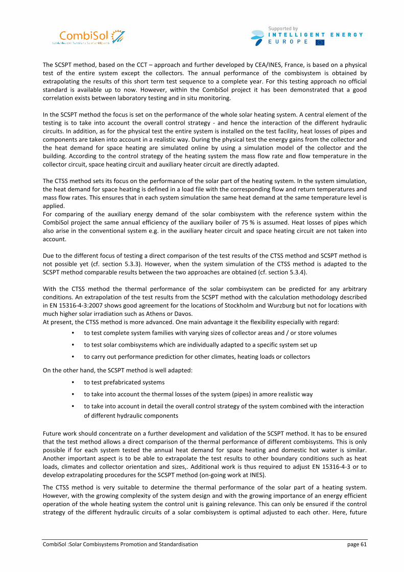
CombiSol :Solar Combisystems Promotion and Standardisation page 61
The SCSPT method, based on the CCT – approach and further developed by CEA/INES, France, is based on a physical
test of the entire system except the collectors. The annual performance of the combisystem is obtained by
extrapolating the results of this short term test sequence to a complete year. For this testing approach no official
standard is available up to now. However, within the CombiSol project it has been demonstrated that a good
correlation exists between laboratory testing and in situ monitoring.
In the SCSPT method the focus is set on the performance of the whole solar heating system. A central element of the
testing is to take into account the overall control strategy - and hence the interaction of the different hydraulic
circuits. In addition, as for the physical test the entire system is installed on the test facility, heat losses of pipes and
components are taken into account in a realistic way. During the physical test the energy gains from the collector and
the heat demand for space heating are simulated online by using a simulation model of the collector and the
building. According to the control strategy of the heating system the mass flow rate and flow temperature in the
collector circuit, space heating circuit and auxiliary heater circuit are directly adapted.
The CTSS method sets its focus on the performance of the solar part of the heating system. In the system simulation,
the heat demand for space heating is defined in a load file with the corresponding flow and return temperatures and
mass flow rates. This ensures that in each system simulation the same heat demand at the same temperature level is
applied.
For comparing of the auxiliary energy demand of the solar combisystem with the reference system within the
CombiSol project the same annual efficiency of the auxiliary boiler of 75 % is assumed. Heat losses of pipes which
also arise in the conventional system e.g. in the auxiliary heater circuit and space heating circuit are not taken into
account.
Due to the different focus of testing a direct comparison of the test results of the CTSS method and SCSPT method is
not possible yet (cf. section 5.3.3). However, when the system simulation of the CTSS method is adapted to the
SCSPT method comparable results between the two approaches are obtained (cf. section 5.3.4).
With the CTSS method the thermal performance of the solar combisystem can be predicted for any arbitrary
conditions. An extrapolation of the test results from the SCSPT method with the calculation methodology described
in EN 15316-4-3:2007 shows good agreement for the locations of Stockholm and Wurzburg but not for locations with
much higher solar irradiation such as Athens or Davos.
At present, the CTSS method is more advanced. One main advantage it the flexibility especially with regard:
• to test complete system families with varying sizes of collector areas and / or store volumes
• to test solar combisystems which are individually adapted to a specific system set up
• to carry out performance prediction for other climates, heating loads or collectors
On the other hand, the SCSPT method is well adapted:
• to test prefabricated systems
• to take into account the thermal losses of the system (pipes) in amore realistic way
• to take into account in detail the overall control strategy of the system combined with the interaction
of different hydraulic components
Future work should concentrate on a further development and validation of the SCSPT method. It has to be ensured
that the test method allows a direct comparison of the thermal performance of different combisystems. This is only
possible if for each system tested the annual heat demand for space heating and domestic hot water is similar.
Another important aspect is to be able to extrapolate the test results to other boundary conditions such as heat
loads, climates and collector orientation and sizes,. Additional work is thus required to adjust EN 15316-4-3 or to
develop extrapolating procedures for the SCSPT method (on-going work at INES).
The CTSS method is very suitable to determine the thermal performance of the solar part of a heating system.
However, with the growing complexity of the system design and with the growing importance of an energy efficient
operation of the whole heating system the control unit is gaining relevance. This can only be ensured if the control
strategy of the different hydraulic circuits of a solar combisystem is optimal adjusted to each other. Here, future

CombiSol :Solar Combisystems Promotion and Standardisation page 62
work should concentrate on the development of more advanced controller testing procedures or even the
integration of the real control unit into the dynamic comupter simulaton of the entire solar heating system. A first
step towords this direction are the test procedures for multi-function controllers already specified in the new
standard CEN/TS 12977-5:2010 [32] [26].
Concerning the testing of solar combisystems two parallel existing performance test methods might in general be an
option for the future. The same situation already exists for solar domestic hot water systems with regard to the CTSS
method and the DST (cf. ISO 9459-5, [21]) or CSTG (cf. ISO 9459-2, [20]) method respectively. The main advantage of
two test methods for the same product category is the option to apply for a specific test the most appropriate and
cost effective method. However, in order to implement the SCSPT method as a standardised performance test
method it has to be further developed with regard to the aspects mentioned above and applied and validated for a
broad spectrum of different system concepts.
In the future, with the energy-labelling of products, the two test methods will have to converge to provide
comparable results, and thus inform the end-user about the real thermal performance of solar combisystems.
CombiSol :Solar Combisystems Promotion and Standardisation page 63
6 Main recommendations for an efficient solar combi-systems
Main Author: Alexander Thür
Generally speaking, based on experiences within CombiSol project, the main focus of thinking about product and
system improvements should not be on increasing solar gains but much more on reducing heat losses within a solar
combisystem, which has more components causing heat losses (mainly tanks and pipes) and therefore –
unfortunately – more potential of overall heat losses than conventional heating systems typically have. Further a
solar combisystem consist of two main parts: the solar thermal and the auxiliary heating system. The integration of
both in terms of hydraulic AND control integration is a complex problem and needs to be handled with sufficient
design and planning effort in order to achieve high performance of all subparts during heat generation (solar thermal
and auxiliary) but also during heat storage and heat distribution.
6.1 Overall System Concept
As stated in section 2.1, modern solar combisystems nowadays can be classified in six categories, three domestic hot
water types (DHW-Type A, B, C) and two auxiliary types (AuxType 1, 2):
• DHW type A: Tank in tank system (DHW tank inside the space heating tank)
• DHW type B: Immersed heat exchanger (DHW heat exchanger inside the space heating tank)
• DHW type C: Fresh water unit (DHW flat plate heat exchanger outside the space heating the tank)
• Auxiliary type 1: Tank in tank system + auxiliary boiler is involved as return flow increase
• Auxiliary type 2: Tank in tank system + auxiliary boiler is charging the heat storage tank
Of course different sub-types are possible, for example:
• DHW-type C*: Instead of external DHW heat exchanger an external DHW tank with immersed heat exchanger;
this is occasionally used when a solar combisystem is added to an existing heating system.
• Auxiliary type 2*: Auxiliary boiler is charging the heat storage tank and a 4-way valve is used to discharge the
space heating tank from two different temperature levels.
Auxiliary type 1 systems are typically used for:
• Auxiliary heater which can modulate the power in a wide range and still operate with high efficiency and their
own heat losses are very low when they are heated passive by the solar tank; such auxiliary heater are mainly
natural gas boiler or small oil boiler or district/community heating or top heat pumps with speed controlled
compressor (or direct electric heater).
• Solar combisystems with small solar fraction (e.g. <20%), because then it happens relative few hours that space
heating is on and the burner is off because sufficient heat is available from the solar heat storage which would
result in increased heat losses by the boiler.
Auxiliary type 2 systems are typically used for:
• Auxiliary heater which need long running periods for high efficiency: standard heat pumps or pellet boilers or
large dimensioned oil boilers.
• Solar combisystems with medium to large solar fraction (>20 to 50% or up to 100%) where significant long
periods with space heating demand occur which can be covered by solar energy directly. During these periods
the auxiliary boiler in a auxiliary type 1 system would act as a significant heat loss element within the space
heating loop.
Auxiliary type 2 systems are mandatory for:
• Auxiliary heater which can not be switched off easily when started until the fuel is out: wood log boiler
• Auxiliary heater which need to run a minimum time period to be acceptable efficient, like wood chip boiler or
large dimensioned pellet boiler.
In principle all DHW types can be combined with all types of auxiliary heater. In general it should be kept in mind that
a large domestic hot water volume which is kept at set temperature of course guarantees domestic hot water
comfort all time, but also is one of the main reasons for heat losses. Since it is not possible to have pipe connections
CombiSol :Solar Combisystems Promotion and Standardisation page 64
at the tank flexible in terms of height, it should at least be possible with flexible height positions of temperature
sensors at the tank to optimize (=minimize) the domestic hot water auxiliary volume according to the specific need of
the residents of the house.
DHW type A and B fit best to biomass boiler which have minimum flow temperatures of typically 60 to 65°C which
always is sufficient for domestic hot water preparation. Further biomass boiler typically need auxiliary type 2 systems
and therefore the DHW auxiliary volume automatically is kept hot during space heating operation.
DHW type C with special advantage can be used in combination with modulating, fast reacting and sufficient
powerful auxiliary heater like natural gas boiler, oil boiler or district/community heating. In this combination it is
possible to keep the DHW auxiliary volume very little because even a small remaining volume of hot water in the top
of the heat storage allows preparing domestic hot water at set temperature. Using this characteristic in a optimised
way, most of the heat storage capacity can be kept free for the solar heating system or is kept cold leading to
minimized heat losses. This leads to the possibility to choose relative small (cheaper) heat storage without
disadvantage in solar fraction.
Further important influencing boundary characteristics for choosing the best system concept will be discussed in the
case of auxiliary heater in chapter 6.4, for heat storage in chapter 6.2 and chapter 6.3 and for the space heating
circuit in chapter 6.5.
6.2 Single or Multi Store Concepts
A very rough and well known rule of thumb for the ratio heat storage volume to collector area is about 50 Liter/m2.
According to the qualitative evaluation of 70 solar combisystems done within the CombiSol project, the majority of
the systems have a specific heat storage volume between 50 and 100 Liter/m2, about 1/3
rd of the systems have
installed more than one tank.
Multi store systems have serious disadvantages in terms of heat losses due to several effects:
• The ratio of heat loss surface to volume of two tanks in comparison to one tank with the same total volume is
1/3rd
higher, consequently leading to significant higher heat losses.
• Two tanks need to be connected to each other resulting in additional cold bridges for each tank due to the pipe
connections AND additional piping within the system both further increasing the heat losses.
• If not smart and clever designed, two tanks connected in parallel typically lead to almost double high
temperature auxiliary volume since pipe connections and/or temperature sensor positions are not adapted at
standard tanks depending if the tank is used in a single or a double tank concept.
It is strongly recommended to proof very carefully, if it is really necessary to install a multi store system and if the
advantage of larger heat storage capacity is high enough in comparison to increased heat losses and double cost for
heat storage. The specific storage volume of 50 liter/m2 is not a general rule which fits in all cases and which is a
must. In combination with fast and sufficient powerful auxiliary heater, smart hydraulic and control concept and high
insulation quality a specific heat storage volume of 25 liter/m2 might be reasonable and resulting in a very well and
maybe better performing solar combisystem as well, provided that a smart control strategy is implemented and a
minimum total volume higher than 400 liter is used.
Unfortunately prepared standard configurations in standard simulation programs for solar combisystems typically do
not give the possibility to calculate such details in an easy way, in most cases some tricks and reasonable
assumptions are necessary to do such comparison calculations and getting reliable results. Alternatively it is
recommended to use simulation programs which give sufficient freedom in creating the system concept as it should
look like, the effort for modelling the system of course is somewhat higher and more complex.
Further important influencing boundary characteristics for choosing the right heat storage volume and number of
tanks will be discussed in the case of auxiliary heater in chapter 6.4 and for the space heating circuit in chapter 6.5.
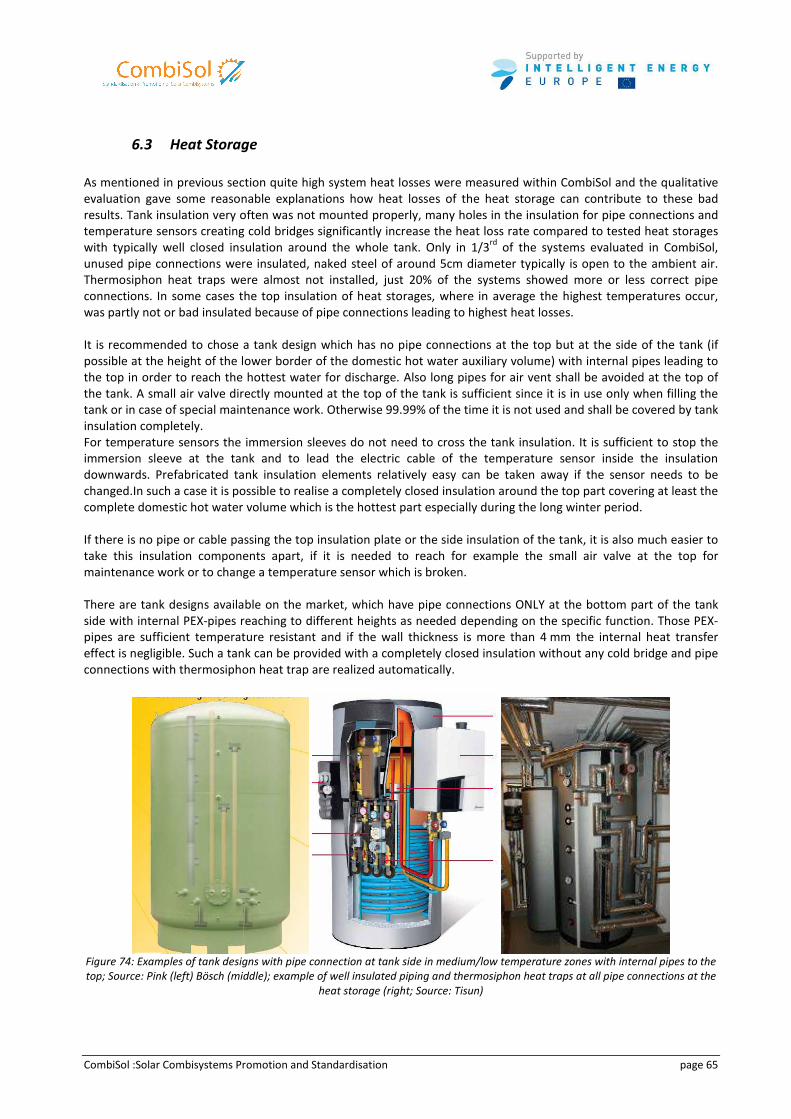
CombiSol :Solar Combisystems Promotion and Standardisation page 65
6.3 Heat Storage
As mentioned in previous section quite high system heat losses were measured within CombiSol and the qualitative
evaluation gave some reasonable explanations how heat losses of the heat storage can contribute to these bad
results. Tank insulation very often was not mounted properly, many holes in the insulation for pipe connections and
temperature sensors creating cold bridges significantly increase the heat loss rate compared to tested heat storages
with typically well closed insulation around the whole tank. Only in 1/3rd
of the systems evaluated in CombiSol,
unused pipe connections were insulated, naked steel of around 5cm diameter typically is open to the ambient air.
Thermosiphon heat traps were almost not installed, just 20% of the systems showed more or less correct pipe
connections. In some cases the top insulation of heat storages, where in average the highest temperatures occur,
was partly not or bad insulated because of pipe connections leading to highest heat losses.
It is recommended to chose a tank design which has no pipe connections at the top but at the side of the tank (if
possible at the height of the lower border of the domestic hot water auxiliary volume) with internal pipes leading to
the top in order to reach the hottest water for discharge. Also long pipes for air vent shall be avoided at the top of
the tank. A small air valve directly mounted at the top of the tank is sufficient since it is in use only when filling the
tank or in case of special maintenance work. Otherwise 99.99% of the time it is not used and shall be covered by tank
insulation completely.
For temperature sensors the immersion sleeves do not need to cross the tank insulation. It is sufficient to stop the
immersion sleeve at the tank and to lead the electric cable of the temperature sensor inside the insulation
downwards. Prefabricated tank insulation elements relatively easy can be taken away if the sensor needs to be
changed.In such a case it is possible to realise a completely closed insulation around the top part covering at least the
complete domestic hot water volume which is the hottest part especially during the long winter period.
If there is no pipe or cable passing the top insulation plate or the side insulation of the tank, it is also much easier to
take this insulation components apart, if it is needed to reach for example the small air valve at the top for
maintenance work or to change a temperature sensor which is broken.
There are tank designs available on the market, which have pipe connections ONLY at the bottom part of the tank
side with internal PEX-pipes reaching to different heights as needed depending on the specific function. Those PEX-
pipes are sufficient temperature resistant and if the wall thickness is more than 4 mm the internal heat transfer
effect is negligible. Such a tank can be provided with a completely closed insulation without any cold bridge and pipe
connections with thermosiphon heat trap are realized automatically.
Figure 74: Examples of tank designs with pipe connection at tank side in medium/low temperature zones with internal pipes to the
top; Source: Pink (left) Bösch (middle); example of well insulated piping and thermosiphon heat traps at all pipe connections at the
heat storage (right; Source: Tisun)
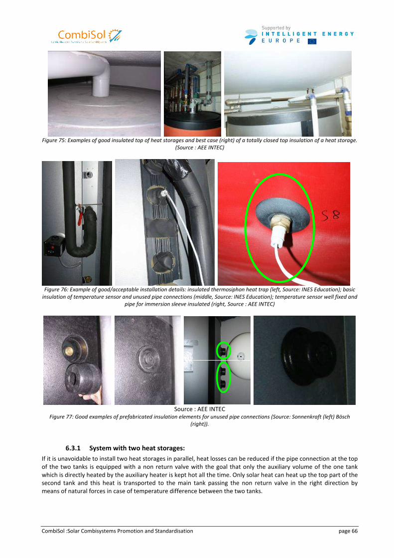
CombiSol :Solar Combisystems Promotion and Standardisation page 66
Figure 75: Examples of good insulated top of heat storages and best case (right) of a totally closed top insulation of a heat storage.
(Source : AEE INTEC)
Figure 76: Example of good/acceptable installation details: insulated thermosiphon heat trap (left, Source: INES Education); basic
insulation of temperature sensor and unused pipe connections (middle, Source: INES Education); temperature sensor well fixed and
pipe for immersion sleeve insulated (right, Source : AEE INTEC)
Source : AEE INTEC
Figure 77: Good examples of prefabricated insulation elements for unused pipe connections (Source: Sonnenkraft (left) Bösch
(right)).
6.3.1 System with two heat storages:
If it is unavoidable to install two heat storages in parallel, heat losses can be reduced if the pipe connection at the top
of the two tanks is equipped with a non return valve with the goal that only the auxiliary volume of the one tank
which is directly heated by the auxiliary heater is kept hot all the time. Only solar heat can heat up the top part of the
second tank and this heat is transported to the main tank passing the non return valve in the right direction by
means of natural forces in case of temperature difference between the two tanks.
CombiSol :Solar Combisystems Promotion and Standardisation page 67
6.3.2 Connection of space heating return pipe:
Often discussed point is where to connect the space heating return pipe at the heat storage. In the case of floor
and/or wall heating systems it is simple, return pipe should be connected at the bottom of the tank. The volume
exchanged in the tank due to space heating is much higher than due to domestic hot water preparation and due to
internal heat conductivity inside the tank the some degree lower temperature in the bottom part of the tank due to
domestic hot water preparation is heated up in very short time.
In the case of radiators in the space heating circuit, the situation is slightly different. If the space heating circuit is
adjusted and controlled correct with thermostat valves and the radiators are large enough designed as low
temperature radiators (or maybe oversized after thermal renovation of the house), the return temperature always
should be lowest possible and the return pipe can be connected at the bottom of the heat storage. If high return
temperature has to be expected during high space heating load periods or the house residents keep windows open
without closing thermostat valves it might be of advantage to use a 3-way valve in order to decide in combination
with a temperature sensor if the return flow shall enter the tank in the bottom or at the height where the auxiliary
heater return pipe is connected.
6.4 Auxiliary Heater
Several types of auxiliary heater are available to be used in solar combisystems and they might have quite different
operating conditions. For example a condensing natural gas boiler needs very low return temperatures (<<57°C) to
be able to use the condensation effect, whereas a wood log or pellet boiler on the other hand needs a minimum
return temperature (>55°C) in order to avoid corrosion and deposit problems due to condensation of the flue gas.
Also different boilers have different characteristics how they can be controlled. A natural gas boiler can change the
power by modulating quite fast and easy; other boiler types just can change power by start and stop of the burner.
Since the boundary conditions of each house, each country, each system concept, availability of different fuel types,
etc. are different, it can not be stated the one or the other auxiliary heater is the best.
The integration of the auxiliary heater turned out to be a critical point in many installations evaluated within the
CombiSol project, especially if the solar combisystem is not delivered as a complete package from ONE system
supplier. The main problem is in many cases, that the auxiliary volume of the heat storage in fact is not used as a
buffer but much more as a huge hydraulic switch which is kept hot all the time with high potential of excessive heat
losses. Especially in cases with condensing natural gas boilers this strategy is quite disadvantageous and significant
potential of improvement of boiler and system efficiency exists.
6.4.1 Problem of over-dimensioned auxiliary heater:
Since a solar combisystem has a relative large domestic hot water auxiliary volume there is no need to design the
boiler according to domestic hot water peak load. The average power for domestic hot water preparation over
24 hours in a one family house is about 0.5 kW (200 litre per day with 10/60C°) or less. The boiler should have a
nominal power not higher than the design space heating load.
This point of keeping the nominal boiler power as small as possible is true for all boiler types, but the efficiency effect
is most likely less critical with light and small boilers like natural gas boiler or oil boiler than for pellet boiler or wood
chip boiler with big internal heat capacity and big heat loss surface. Therefore later in this chapter in contradiction to
this paragraph a concept is discussed which uses high power condensing natural gas boiler but reducing dramatically
heat storage volume (maybe number of tanks) and therefore heat losses and investment cost as well.
6.4.2 Typical specific problems in auxiliary type 1 systems “auxiliary boiler as return flow increase”:
In auxiliary type 1 systems the auxiliary boiler during space heating operation is operating as in any conventional
heating system without any possibility to buffer heat in the heat storage. Therefore it is important to choose a boiler
type which has highest possible part load efficiency because this is the huge part of operation during the year.
CombiSol :Solar Combisystems Promotion and Standardisation page 68
Therefore also the nominal power of the boiler MUST NOT be over-dimensioned. Very often the minimum power of
the boiler is in the range of the maximum space heating load of the house, therefore the boiler never is operating in
a constant and efficient mode but in a less efficient start/stop mode all the time.
Further it was observed that the temperature sensor controlling the domestic hot water volume is placed too close
to the space heating auxiliary volume leading to the effect that this sensor is strongly influenced by the space heating
flow rate and therefore the boiler most of the time is operating in high temperature domestic hot water mode which
leads to much worse or no condensation effect and therefore much worse boiler efficiency. In fact this system than
partly is somehow operated as auxiliary type 2 system, because due to heating the domestic hot water volume in the
top heat also is transferred downwards into the solar volume due to several heat transport effects and then used for
space heating.
The temperature sensor should be placed at least 20 maybe better 30 cm above the boiler inlet pipe to avoid such
effects. Since the domestic hot water auxiliary volume typically is in the range of 200 to 300 litres, it might be useful
to set time periods in the boiler controller when he is allowed to operate in domestic hot water mode, e.g. 1 hour in
the morning and 1 hour in late afternoon, depending on the need of the residents. Conventional heating systems in
one family houses often have domestic hot water tanks with about 150 litres and a time controller is used in a similar
way to allow hot water preparation only during specified periods.
6.4.3 Typical problem of auxiliary volume as hydraulic switch:
In auxiliary type 2 systems “auxiliary boiler charging the heat storage” in combination with condensing natural gas
boiler it happens that the boiler pump is in operation all time with constant speed and just the burner is controlling
the flow temperature by modulation or start/stop mode. The result is that the auxiliary volume of the heat storage in
fact is used as a hydraulic switch and kept all the time at the high set temperature as controlled by the natural gas
boiler.
Second, a follow up effect is that therefore the boiler return temperature is more or less equal to the flow
temperature depending on the ratio of boiler flow rate and space heating flow rate. In combination with floor/wall
heating systems the problem is less critical than in combination with radiator systems because those typically change
the flow rate much more when (hopefully) controlled by thermostat valves. In combination with radiators the risk is
very high that the temperature level of both flow and return flow is getting that high that no or only very little
condensation occurs which decreases the boiler efficiency dramatically.
Third, if the solar collector heats up the heat storage the boiler loop including the boiler itself is heated up and
generating absolutely avoidable heat losses if the boiler pump would be switched off.
Further number four, also in auxiliary type 2 systems it was observed that the temperature sensor controlling the
domestic hot water volume is placed too close to the space heating auxiliary volume leading to the effect that this
sensor is strongly influenced by the space heating flow rate and therefore the boiler most of the time is operating in
high temperature domestic hot water mode which leads to much worse or no condensation effect and therefore
much worse boiler efficiency.
The temperature sensor should be placed at least 20 maybe better 30 cm above the boiler inlet pipe to avoid such
effects. Since the domestic hot water auxiliary volume typically is in the range of 200 to 300 litres, it might be useful
to set time periods in the boiler controller when he is allowed to operate in domestic hot water mode, e.g. 1 hour in
the morning and 1 hour in late afternoon, depending on the need of the residents.
In auxiliary type 2 systems in combination with condensing natural gas boilers and especially with DHW type A or B it
might be a good solution just to heat the domestic hot water auxiliary volume with constant 50°C (maximum 55°C)
independent of the ambient temperature. In this case the domestic hot water volume is kept hot all the time and
due to the flow around the inner tank or the immersed domestic hot water heat exchanger (if the boiler is in
operation) the heat transfer rate for domestic hot water preparation is increased that much that typically also peak
domestic hot water load can be covered without problems.
The advantage of this strategy is that the condensing natural gas boiler is not switching all the time between
domestic hot water mode and space heating mode but operating constant in one standard operation mode with a
constant flow temperature which is low enough (in combination with the lower return temperature) to have good
condensation effect and high enough to allow a sufficient high domestic hot water temperature. Further it is possible
to adjust the boiler flow rate according to the maximum space heating power which forces the condensing natural
gas boiler at least to modulate to this power rate. In case of a peak domestic hot water demand the boiler return
CombiSol :Solar Combisystems Promotion and Standardisation page 69
temperature will decrease and automatically the natural gas boiler increases the power because the set flow
temperature must be reached.
Since a solar combisystem anyway needs a mixing valve to control the space heating flow temperature it is not
needed that the boiler is doing this task as in conventional heating systems.
In combination with DHW type C systems due to the domestic hot water preparation with an external flat plate heat
exchanger it might be a problem to keep the boiler flow temperature below 55°C, if for the domestic hot water
temperature more than 48°C at full load is required.
In order to reduce start/stop frequency, someone should also consider that auxiliary volume for space heating can be
discharged completely before heated up again. If space heating power is reduced for 10 to 15 minutes because the
flow temperature is not reached exactly according to the control settings, this does not result in freezing in the
house. Thanks to the huge heat storage effect of the house itself nobody will notice reduction of a room
temperature. In fact this is the same situation as when the boiler is switched to domestic hot water preparation for
typically around 15 minutes. This way the auxiliary volume is used really as a buffer than a hydraulic switch and due
to in average lower temperatures in the tank the heat losses will decrease as well.
6.4.4 Auxiliary heater flow rate setting or control:
In many cases in auxiliary type 2 systems it was observed that the boiler flow rate was at the maximum all time, just
as a result of pressure drop and flow capacity of the pump at highest power set point. Based on the fact that
maximum boiler heating power typically is much too high (see before the discussion of over-dimensioning) this leads
to very short operating periods with high heating power.
If the flow rate of the boiler loop is adjusted based on nominal space heating power and typical temperature
difference (depending on boiler type and controller settings) it can be achieved that the boiler is operating under
longer constant part load conditions than in very short intervals with maximum power at least at the beginning. Of
course it must be avoided that the boiler is forced to operate with less power than possible due to power
modulation. If done correctly, this should result in higher average boiler efficiency.
A further improvement could be reached if the boiler loop pump is speed controlled within a reasonable range with
the effect that the boiler is forced to modulate the heating power according to the load. But this typically is not
possible with standard options in existing controllers, it would be necessary to develop a special control algorithm in
each case. However, if an external boiler pump is used, a reasonable control strategy in combination with an
additional small controller beside the boiler controller could be to control the pump speed (with a minimum
limitation) on a first level in order to keep the temperature difference of boiler return and flow temperature constant
at a relative high level (depending on the demand temperature difference conditions: mainly if floor/wall heating
and/or radiator heating). As second – overruling – level the space heating forward temperature must be controlled: if
the forward temperature does not reach the set or minimum temperature anymore, the boiler pump speed needs to
be increased. This will be the case in situations when the actual demand power is higher than minimum boiler power.
Consequently this effort of speed controlling the boiler pump only makes sense, if the boiler is able to modulate to
significantly less power than the maximum space heating power of the house and the part load efficiency of the
boiler is reasonable high enough.
Free programmable controllers are on the market which are able to manage such tasks and which can be used by
system supplier and installers to realize such a concept if the integrated controller of the boiler is not able to manage
this task.
6.4.5 How to control the space heating auxiliary volume:
In principle two different boiler types exist for this problem: those which are able to control the boiler temperature
in the same range as the demand temperature occurs (natural gas boiler, oil boiler, district/community heating, heat
pumps, electric heater) and biomass boiler (pellet-, wood chip- and wood log boiler) which typically have a minimum
supply temperature higher than the demand temperature of space heating and/or domestic hot water.
CombiSol :Solar Combisystems Promotion and Standardisation page 70
Many boilers have integrated in their own controller only the possibility to use just one temperature sensor which is
typically mounted in the tank at the lower border of the auxiliary volume. If set temperature is reached the boiler is
switched off and if set temperature minus hysteresis is reached the boiler starts again. Typically to be sure and to
have no problems with the customer the set temperature of the auxiliary volume is set clear higher then the set
demand temperature because also set temperature minus hysteresis must be above set demand temperature.
This is forcing the temperatures in the system to be higher and higher and heat losses are increased and heat
capacity of the tank for solar energy is reduced because almost the complete tank is hot anyway due to heat
conductivity which also heats the lower parts of the tank.
Second problem: if only one temperature sensor is used and hysteresis is little practically only a very little volume
around the temperature sensor is really used as buffer. It does not help if pipe connections give the possibility to use
a larger auxiliary volume.
Improvement step 1 could be reached if the temperature sensor is placed at the top of the auxiliary volume and the
set temperature to stop the boiler is slightly above the set flow temperature of the boiler. Only if the complete
auxiliary volume is heated up and the boiler return temperature starts increasing that much that the boiler is not
able to reduce the power to keep the set flow temperature the flow temperature increases as well and the set
temperature for switching off will be reached. Problem is the risk that first the internal controller stops the boiler
due to overheating. So it is necessary to find all the right settings with all different controllers active in the complete
procedure. This or other similar tricky solutions might be possible if one supplier is offering the complete system with
matched controller settings. For the installer on site most likely it is not an easy task to find the right settings.
In the case of biomass boiler where the hysteresis of the internal controller typically is relatively high (about 10°C or
more) it is easier to find the right settings with the sensor placed at the top of the auxiliary volume. If boiler flow set
temperature is 70°C, set temperature for switching off is 75°C and hysteresis for switching on is 40°C (switching on
temperature is 35°C in case of floor heating) quite a long running period for the boiler can be expected. The question
is, if the boiler controller allows such a wide range of settings, what is not always the case.
Improvement step 2 is to use 2 temperature sensors, one at the top and one at the bottom of the defined auxiliary
volume; this also can be different places than flow and return pipes are connected. In this case the set flow
temperature of the boiler can be equal to the set demand temperature, the set temperature for switching on the
boiler (= top sensor) can be set even lower than the demand temperature (in order to cool down completely the
auxiliary volume, see before) and the set temperature for switching off the boiler (=bottom sensor) can be set just a
little higher than space heating return temperature in order to guarantee that return temperature to the boiler is low
until stop of the boiler in order to have good condensation until the end of operation (or the sensor is placed clear
above return pipe connection).
Alternatively it is also possible to chose a switch off set temperature relatively high in order to get long running time
and to charge the auxiliary volume as much as possible (most probably in case of non condensing boilers).
6.4.6 Potentials for keeping heat storage small and avoid multi store systems:
In principle the tank volume is split into 3 parts: DHW-auxiliary volume, SH-auxiliary volume and solar volume, mainly
depending on the auxiliary type both auxiliary volumes can be minimized in order to increase the available solar
volume. As discussed in chapter 6.2 the well known rule of thumb is to install 50 litre/m2 collector area. But the main
question is which volume is really needed for the auxiliary heater how much volume is available for being charged
with solar energy. There is a huge difference if the auxiliary heater is a wood log boiler, a pellet boiler or a
condensing natural gas boiler.
Auxiliary type 1 system “auxiliary boiler as return flow increase”:
The auxiliary type 1 system per definition has no space heating auxiliary volume. Therefore in such a system the solar
volume typically is at least 100 to 200 liters larger than in auxiliary type 2 systems.
A very special case is the condensing natural gas boiler in terms of system optimization. Such natural gas boiler can
be activated very fast, if domestic hot water mode is activated typically within 20 to 30 seconds the boiler is in
operation with full power. For a natural gas boiler with sufficient peak power for direct domestic hot water
preparation in combination with DHW type C system (external flat plate heat exchanger) and auxiliary type 1 systems
CombiSol :Solar Combisystems Promotion and Standardisation page 71
there is a quite big potential to have almost no auxiliary volume and to have almost the complete tank as a solar
tank. It might be worth to try the following strategy since the only risk is to replace a temperature sensor to another
place:
If the pipe connection of the boiler flow pipe and the domestic hot water discharge pipe both are in the very top of
the heat storage it is sufficient to have the temperature sensor for the domestic hot water not in the tank but
directly at the outlet of the discharge pipe of the domestic hot water preparation loop. If DHW set temperature for
taping is 45°C and the outlet temperature decreases below 55°C the natural gas boiler shall start with set flow
temperature of 60°C. Within the delay period of about 30 seconds the DHW outlet temperature might further
decrease from 55 to 53°C but still enough for hot water preparation. After these 30 seconds the very small volume in
the very top of the tank is heated up by the boiler again until the temperature sensor at the DHW outlet pipe reaches
boiler set temperature of 60°C plus hysteresis, the boiler is switched off again or switching back to space heating
operation. Important installation point is that the natural gas boiler is placed very close to the heat storage to avoid
extended delay time due to long pipes.
In fact this is nothing different than a conventional heating installation with a domestic hot water tank controlled by
a temperature sensor in this tank. The advantage of the space heating heat storage is that there is no low power
immersed heat exchanger between natural gas boiler and space heating water like in a conventional domestic hot
water tank which is the real bottle neck for fast heating up the water in the tank.
If this concept does not work with sufficient comfort, it is just necessary to replace the temperature sensor from the
outlet pipe position to a place lower in the tank in order to get a larger DHW auxiliary volume.
But if this is realized that way, about 90 to 95% of the heat storage is free to be charged by solar energy and even a
25 to 30 m2 collector field can be realized in combination with ONE heat storage of 800 or 1000 liter volume with
high overall performance thanks to minimized heat losses. Instead of a second tank effort and money should be
invested in perfect insulation of the tank and thermosiphon heat traps as pipe connections at the tank.
Auxiliary type 2 system “Auxiliary boiler charging the heat storage”:
In auxiliary type 2 systems in combination with very small dimensioned and modulating boilers like condensing
natural gas boiler, oil boiler or even pellet boiler it is also possible to keep the space heating auxiliary volume in
practice small and cold (as also already described before):
If an external boiler pump is used, a reasonable control strategy in combination with an additional small controller
beside the boiler controller could be to control the pump speed (with a minimum limitation) on a first level in order
to keep the temperature difference of boiler return and flow temperature constant at a relative high level
(depending on the demand temperature difference conditions: mainly if floor/wall heating and/or radiator heating).
As second – overruling – level the space heating forward temperature must be controlled: if the forward
temperature does not reach the set or minimum temperature anymore, the boiler pump speed needs to be
increased. This will be the case in situations when the actual demand power is higher than minimum boiler power.
Consequently this effort of speed controlling the boiler pump only makes sense, if the boiler is able to modulate to
significantly less power than the maximum space heating power of the house and the part load efficiency of the
boiler is reasonable high enough.
Free programmable controllers are on the market which are able to manage such tasks and which can be used by
system supplier and installers to realize such a concept if the integrated controller of the boiler is not able to manage
this task.
6.5 Space Heating
For a solar combisystem the space heating distribution is in most cases (except extreme low energy houses) far the
most important influencing heat demand circuit since still 70 to 90% of the overall heat demand is caused by space
heating and just 10 to 30% is caused by domestic hot water consumption. Also the space heating demand mainly
takes place in the winter period with bad operating conditions for the solar collector like reduced solar radiation and
low ambient temperatures. Therefore the space heating system has a large influence on the system behavior:
• As lower the forward temperature as more heat can be used from the heat storage because the auxiliary can
start heat up again later at lower tank temperatures. Additionally for condensing boiler low forward
temperature is essential to achieve high condensation rate and following up high efficiency.
CombiSol :Solar Combisystems Promotion and Standardisation page 72
• As lower the forward temperature as lower can be kept the heat storage temperature by the auxiliary heater
and following the heat losses are reduced.
• As lower the forward temperature as more heat capacity has the heat storage because the temperature
difference useful forward temperature to the maximum possible temperature is maximized.
• As lower the return temperature as more heat capacity has the heat storage because the potential of useful
temperature difference is maximized.
• As lower the return temperature as lower the average temperature in the heat storage as lower the heat losses.
• As lower the space heating return temperature as lower the solar collector return temperature which increases
the collector efficiency and reduces the needed solar radiation to start gaining solar energy.
Temperatures are depending on different boundary conditions like:
• Return and forward temperature is depending on the used components like old, small designed high
temperature radiators or new, large designed low temperature radiators, wall/floor heating systems or often in
Passivhouses used air distributing space heating system.
• Return temperature is strongly depending on the operating conditions, for example if the hydraulic loop is
adjusted or not. Also the control strategies like ambient temperature controlled or controlled by thermostatic
valves, etc. have a high influence on the return temperature of the space heating loop.
Several simulation studies done within the IEA SHC Task26 program showed that in general most influencing factor is
the space heating return temperature and less strong influencing is the forward temperature. Therefore the most
important focus should be on achieving lowest possible return temperatures from the space heating distribution
system.
For example if the auxiliary set temperature is 60°C and space heating return temperature is 40 or 30°C, this leads to
useful temperature difference of 20°C (60-40) or 30°C (60-30) which is equal to a difference of heat storage capacity
for the same volume of additional 50% in the case of 30°C space heating return temperature. In principle the
following space heating systems can be classified based on the temperature level:
6.5.1 High temperature space heating systems
Old radiator systems with design temperatures like 90/70 (very old systems) or 70/50°C (forward/return
temperature, for design outdoor temperature) are typically installed in old houses.
• Advantage: No advantage but easy decision: Do not install a solar combisystem if the heat load of the building is
still high. It is possible to invest money more efficient in reducing the energy consumption for the house.
• Disadvantage: Very high return temperature to the heat store leads to high heat storage heat losses and bad
operating conditions for the collector.
After thermal insulation of the building the radiators might change to a medium temperature heating system since
then the radiators are oversized. Then maybe such a heating system is usable for solar combisystems with low solar
fraction and good hydraulic adjustment of the space heating system.
Such systems are also often installed in old houses, which even in summertime often have little space heating
demand; in such cases, a solar combisystem can be a good opportunity.
6.5.2 Medium temperature space heating systems
In new buildings, radiator systems are typically designed for medium or low temperature operation, like 60/40 or
very advanced: 50/30°C (flow/return temperature, for design outdoor temperature). Also water/air heat exchanger
in modern Passivhouses might operate in this category.
• Advantages:
o Cheap space heating system
o Very low return temperatures are possible, especially in spring and autumn; but only if the radiators are
correctly designed AND hydraulically adjusted AND controlled by thermostatic valves (especially 50/30-
systems) AND thermostatic valves are operated correct by the residents.
o Because of large temperature differences (flow/return) very little mass flow occurs which causes little
turbulences in the heat store.
• Disadvantage:
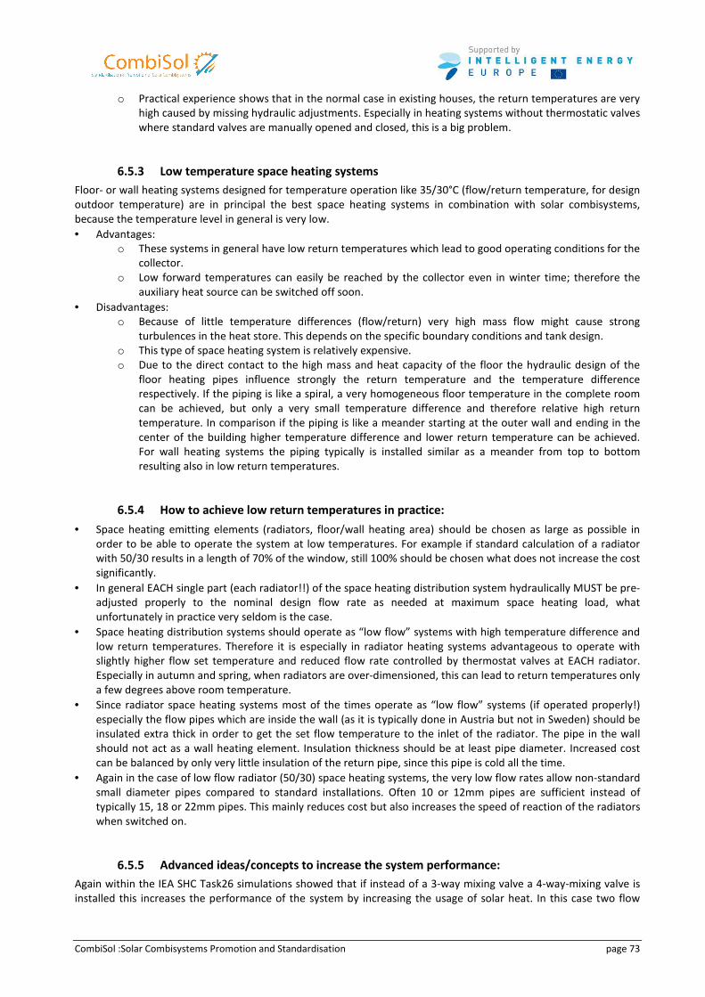
CombiSol :Solar Combisystems Promotion and Standardisation page 73
o Practical experience shows that in the normal case in existing houses, the return temperatures are very
high caused by missing hydraulic adjustments. Especially in heating systems without thermostatic valves
where standard valves are manually opened and closed, this is a big problem.
6.5.3 Low temperature space heating systems
Floor- or wall heating systems designed for temperature operation like 35/30°C (flow/return temperature, for design
outdoor temperature) are in principal the best space heating systems in combination with solar combisystems,
because the temperature level in general is very low.
• Advantages:
o These systems in general have low return temperatures which lead to good operating conditions for the
collector.
o Low forward temperatures can easily be reached by the collector even in winter time; therefore the
auxiliary heat source can be switched off soon.
• Disadvantages:
o Because of little temperature differences (flow/return) very high mass flow might cause strong
turbulences in the heat store. This depends on the specific boundary conditions and tank design.
o This type of space heating system is relatively expensive.
o Due to the direct contact to the high mass and heat capacity of the floor the hydraulic design of the
floor heating pipes influence strongly the return temperature and the temperature difference
respectively. If the piping is like a spiral, a very homogeneous floor temperature in the complete room
can be achieved, but only a very small temperature difference and therefore relative high return
temperature. In comparison if the piping is like a meander starting at the outer wall and ending in the
center of the building higher temperature difference and lower return temperature can be achieved.
For wall heating systems the piping typically is installed similar as a meander from top to bottom
resulting also in low return temperatures.
6.5.4 How to achieve low return temperatures in practice:
• Space heating emitting elements (radiators, floor/wall heating area) should be chosen as large as possible in
order to be able to operate the system at low temperatures. For example if standard calculation of a radiator
with 50/30 results in a length of 70% of the window, still 100% should be chosen what does not increase the cost
significantly.
• In general EACH single part (each radiator!!) of the space heating distribution system hydraulically MUST be pre-
adjusted properly to the nominal design flow rate as needed at maximum space heating load, what
unfortunately in practice very seldom is the case.
• Space heating distribution systems should operate as “low flow” systems with high temperature difference and
low return temperatures. Therefore it is especially in radiator heating systems advantageous to operate with
slightly higher flow set temperature and reduced flow rate controlled by thermostat valves at EACH radiator.
Especially in autumn and spring, when radiators are over-dimensioned, this can lead to return temperatures only
a few degrees above room temperature.
• Since radiator space heating systems most of the times operate as “low flow” systems (if operated properly!)
especially the flow pipes which are inside the wall (as it is typically done in Austria but not in Sweden) should be
insulated extra thick in order to get the set flow temperature to the inlet of the radiator. The pipe in the wall
should not act as a wall heating element. Insulation thickness should be at least pipe diameter. Increased cost
can be balanced by only very little insulation of the return pipe, since this pipe is cold all the time.
• Again in the case of low flow radiator (50/30) space heating systems, the very low flow rates allow non-standard
small diameter pipes compared to standard installations. Often 10 or 12mm pipes are sufficient instead of
typically 15, 18 or 22mm pipes. This mainly reduces cost but also increases the speed of reaction of the radiators
when switched on.
6.5.5 Advanced ideas/concepts to increase the system performance:
Again within the IEA SHC Task26 simulations showed that if instead of a 3-way mixing valve a 4-way-mixing valve is
installed this increases the performance of the system by increasing the usage of solar heat. In this case two flow
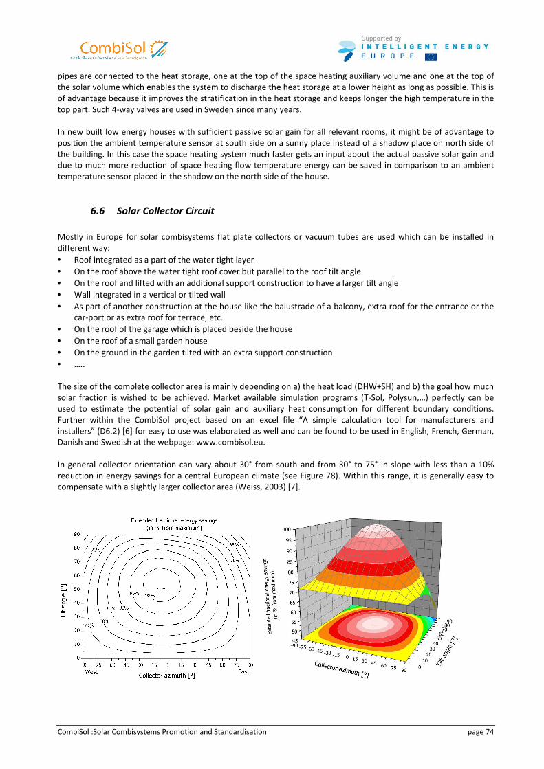
CombiSol :Solar Combisystems Promotion and Standardisation page 74
pipes are connected to the heat storage, one at the top of the space heating auxiliary volume and one at the top of
the solar volume which enables the system to discharge the heat storage at a lower height as long as possible. This is
of advantage because it improves the stratification in the heat storage and keeps longer the high temperature in the
top part. Such 4-way valves are used in Sweden since many years.
In new built low energy houses with sufficient passive solar gain for all relevant rooms, it might be of advantage to
position the ambient temperature sensor at south side on a sunny place instead of a shadow place on north side of
the building. In this case the space heating system much faster gets an input about the actual passive solar gain and
due to much more reduction of space heating flow temperature energy can be saved in comparison to an ambient
temperature sensor placed in the shadow on the north side of the house.
6.6 Solar Collector Circuit
Mostly in Europe for solar combisystems flat plate collectors or vacuum tubes are used which can be installed in
different way:
• Roof integrated as a part of the water tight layer
• On the roof above the water tight roof cover but parallel to the roof tilt angle
• On the roof and lifted with an additional support construction to have a larger tilt angle
• Wall integrated in a vertical or tilted wall
• As part of another construction at the house like the balustrade of a balcony, extra roof for the entrance or the
car-port or as extra roof for terrace, etc.
• On the roof of the garage which is placed beside the house
• On the roof of a small garden house
• On the ground in the garden tilted with an extra support construction
• …..
The size of the complete collector area is mainly depending on a) the heat load (DHW+SH) and b) the goal how much
solar fraction is wished to be achieved. Market available simulation programs (T-Sol, Polysun,…) perfectly can be
used to estimate the potential of solar gain and auxiliary heat consumption for different boundary conditions.
Further within the CombiSol project based on an excel file “A simple calculation tool for manufacturers and
installers” (D6.2) [6] for easy to use was elaborated as well and can be found to be used in English, French, German,
Danish and Swedish at the webpage: www.combisol.eu.
In general collector orientation can vary about 30° from south and from 30° to 75° in slope with less than a 10%
reduction in energy savings for a central European climate (see Figure 78). Within this range, it is generally easy to
compensate with a slightly larger collector area (Weiss, 2003) [7].
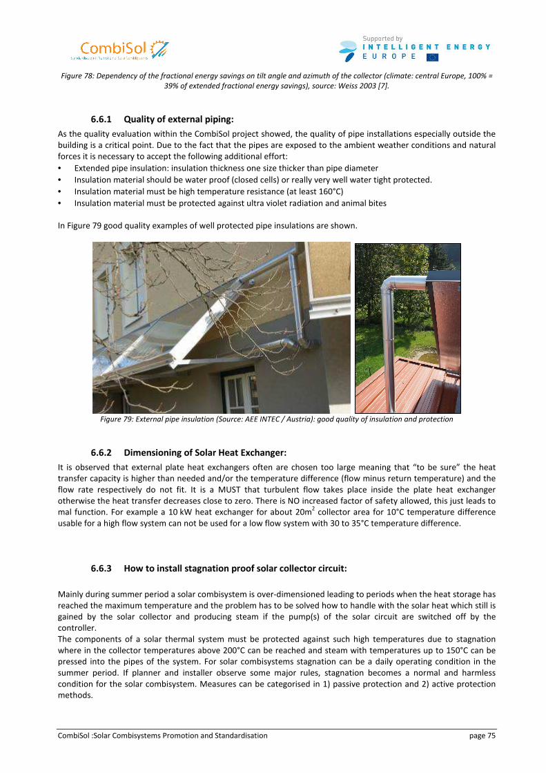
CombiSol :Solar Combisystems Promotion and Standardisation page 75
Figure 78: Dependency of the fractional energy savings on tilt angle and azimuth of the collector (climate: central Europe, 100% =
39% of extended fractional energy savings), source: Weiss 2003 [7].
6.6.1 Quality of external piping:
As the quality evaluation within the CombiSol project showed, the quality of pipe installations especially outside the
building is a critical point. Due to the fact that the pipes are exposed to the ambient weather conditions and natural
forces it is necessary to accept the following additional effort:
• Extended pipe insulation: insulation thickness one size thicker than pipe diameter
• Insulation material should be water proof (closed cells) or really very well water tight protected.
• Insulation material must be high temperature resistance (at least 160°C)
• Insulation material must be protected against ultra violet radiation and animal bites
In Figure 79 good quality examples of well protected pipe insulations are shown.
Figure 79: External pipe insulation (Source: AEE INTEC / Austria): good quality of insulation and protection
6.6.2 Dimensioning of Solar Heat Exchanger:
It is observed that external plate heat exchangers often are chosen too large meaning that “to be sure” the heat
transfer capacity is higher than needed and/or the temperature difference (flow minus return temperature) and the
flow rate respectively do not fit. It is a MUST that turbulent flow takes place inside the plate heat exchanger
otherwise the heat transfer decreases close to zero. There is NO increased factor of safety allowed, this just leads to
mal function. For example a 10 kW heat exchanger for about 20m2 collector area for 10°C temperature difference
usable for a high flow system can not be used for a low flow system with 30 to 35°C temperature difference.
6.6.3 How to install stagnation proof solar collector circuit:
Mainly during summer period a solar combisystem is over-dimensioned leading to periods when the heat storage has
reached the maximum temperature and the problem has to be solved how to handle with the solar heat which still is
gained by the solar collector and producing steam if the pump(s) of the solar circuit are switched off by the
controller.
The components of a solar thermal system must be protected against such high temperatures due to stagnation
where in the collector temperatures above 200°C can be reached and steam with temperatures up to 150°C can be
pressed into the pipes of the system. For solar combisystems stagnation can be a daily operating condition in the
summer period. If planner and installer observe some major rules, stagnation becomes a normal and harmless
condition for the solar combisystem. Measures can be categorised in 1) passive protection and 2) active protection
methods.
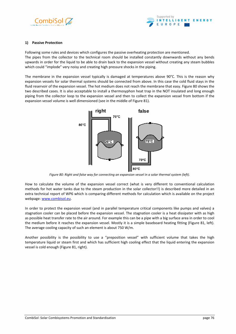
CombiSol :Solar Combisystems Promotion and Standardisation page 76
1) Passive Protection
Following some rules and devices which configures the passive overheating protection are mentioned.
The pipes from the collector to the technical room should be installed constantly downwards without any bends
upwards in order for the liquid to be able to drain back to the expansion vessel without creating any steam bubbles
which could “implode” very noisy and creating high pressure shocks in the piping.
The membrane in the expansion vessel typically is damaged at temperatures above 90°C. This is the reason why
expansion vessels for solar thermal systems should be connected from above. In this case the cold fluid stays in the
fluid reservoir of the expansion vessel. The hot medium does not reach the membrane that easy. Figure 80 shows the
two described cases. It is also acceptable to install a thermosyphon heat trap in the NOT insulated and long enough
piping from the collector loop to the expansion vessel and then to collect the expansion vessel from bottom if the
expansion vessel volume is well dimensioned (see in the middle of Figure 81).
right false
Figure 80: Right and false way for connecting an expansion vessel in a solar thermal system (left).
How to calculate the volume of the expansion vessel correct (what is very different to conventional calculation
methods for hot water tanks due to the steam production in the solar collector!!) is described more detailed in an
extra technical report of WP6 which is comparing different methods for calculation which is available on the project
webpage: www.combisol.eu.
In order to protect the expansion vessel (and in parallel temperature critical components like pumps and valves) a
stagnation cooler can be placed before the expansion vessel. The stagnation cooler is a heat dissipater with as high
as possible heat transfer rate to the air around. For example this can be a pipe with a big surface area in order to cool
the medium before it reaches the expansion vessel. Mostly it is a simple baseboard heating fitting (Figure 81, left).
The average cooling capacity of such an element is about 750 W/m.
Another possibility is the possibility to use a “preposition vessel” with sufficient volume that takes the high
temperature liquid or steam first and which has sufficient high cooling effect that the liquid entering the expansion
vessel is cold enough (Figure 81, right).
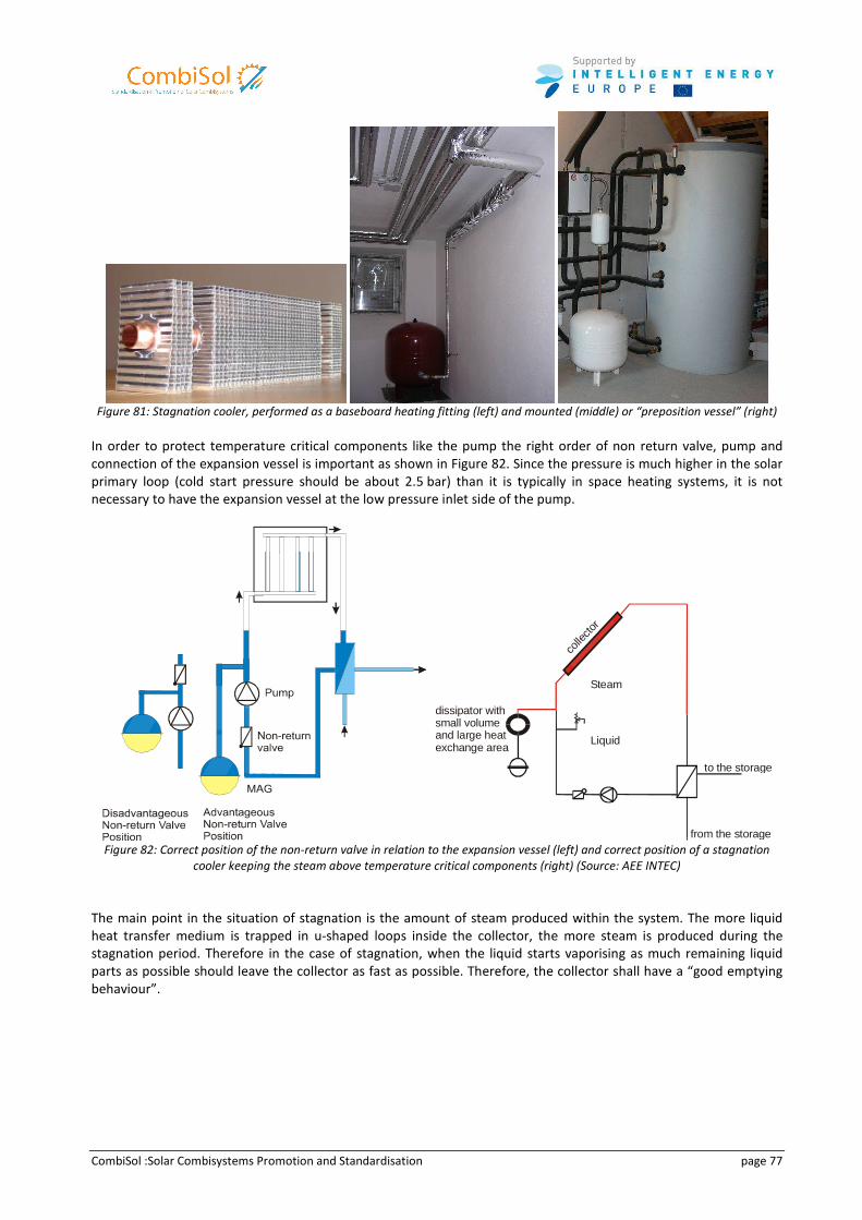
CombiSol :Solar Combisystems Promotion and Standardisation page 77
Figure 81: Stagnation cooler, performed as a baseboard heating fitting (left) and mounted (middle) or “preposition vessel” (right)
In order to protect temperature critical components like the pump the right order of non return valve, pump and
connection of the expansion vessel is important as shown in Figure 82. Since the pressure is much higher in the solar
primary loop (cold start pressure should be about 2.5 bar) than it is typically in space heating systems, it is not
necessary to have the expansion vessel at the low pressure inlet side of the pump.
to the storage
from the storage
colle
ctor
dissipator with small volumeand large heatexchange area
Steam
Liquid
Figure 82: Correct position of the non-return valve in relation to the expansion vessel (left) and correct position of a stagnation
cooler keeping the steam above temperature critical components (right) (Source: AEE INTEC)
The main point in the situation of stagnation is the amount of steam produced within the system. The more liquid
heat transfer medium is trapped in u-shaped loops inside the collector, the more steam is produced during the
stagnation period. Therefore in the case of stagnation, when the liquid starts vaporising as much remaining liquid
parts as possible should leave the collector as fast as possible. Therefore, the collector shall have a “good emptying
behaviour”.
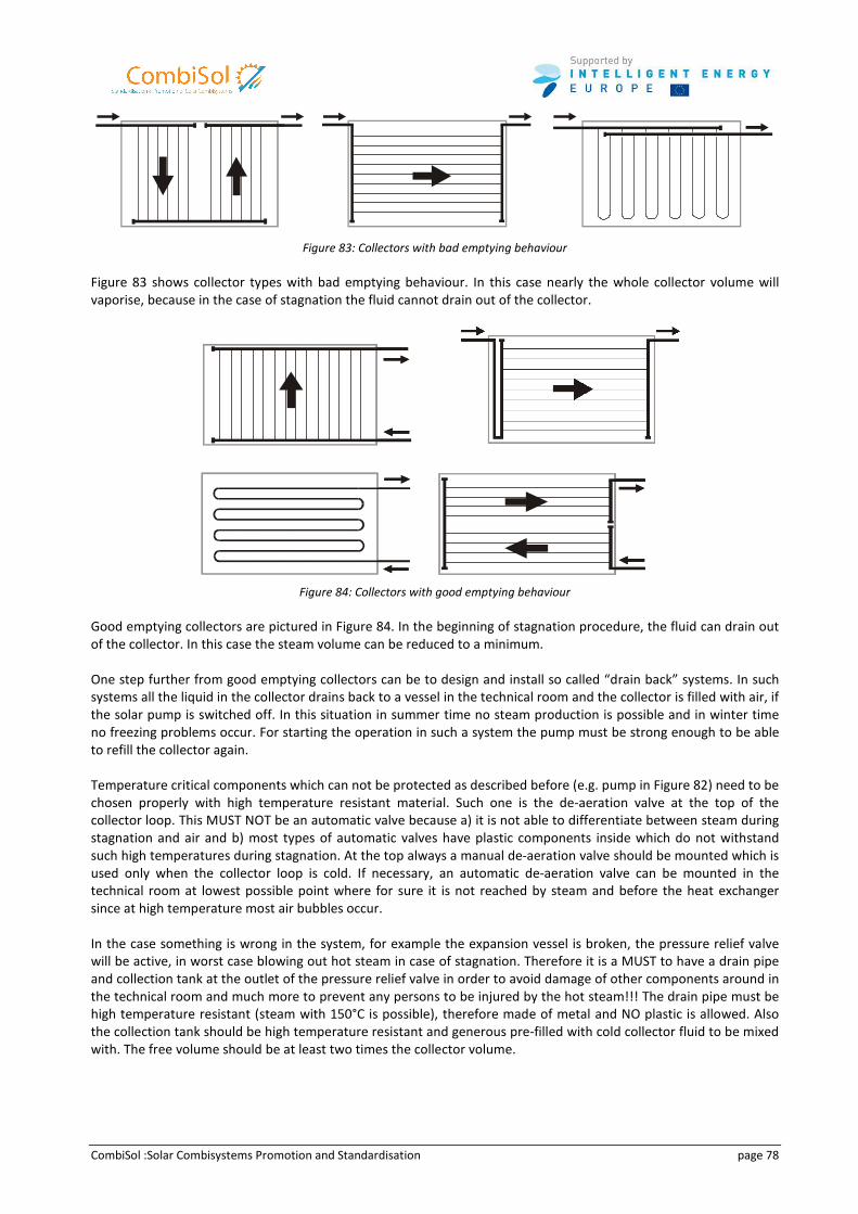
CombiSol :Solar Combisystems Promotion and Standardisation page 78
Figure 83: Collectors with bad emptying behaviour
Figure 83 shows collector types with bad emptying behaviour. In this case nearly the whole collector volume will
vaporise, because in the case of stagnation the fluid cannot drain out of the collector.
Figure 84: Collectors with good emptying behaviour
Good emptying collectors are pictured in Figure 84. In the beginning of stagnation procedure, the fluid can drain out
of the collector. In this case the steam volume can be reduced to a minimum.
One step further from good emptying collectors can be to design and install so called “drain back” systems. In such
systems all the liquid in the collector drains back to a vessel in the technical room and the collector is filled with air, if
the solar pump is switched off. In this situation in summer time no steam production is possible and in winter time
no freezing problems occur. For starting the operation in such a system the pump must be strong enough to be able
to refill the collector again.
Temperature critical components which can not be protected as described before (e.g. pump in Figure 82) need to be
chosen properly with high temperature resistant material. Such one is the de-aeration valve at the top of the
collector loop. This MUST NOT be an automatic valve because a) it is not able to differentiate between steam during
stagnation and air and b) most types of automatic valves have plastic components inside which do not withstand
such high temperatures during stagnation. At the top always a manual de-aeration valve should be mounted which is
used only when the collector loop is cold. If necessary, an automatic de-aeration valve can be mounted in the
technical room at lowest possible point where for sure it is not reached by steam and before the heat exchanger
since at high temperature most air bubbles occur.
In the case something is wrong in the system, for example the expansion vessel is broken, the pressure relief valve
will be active, in worst case blowing out hot steam in case of stagnation. Therefore it is a MUST to have a drain pipe
and collection tank at the outlet of the pressure relief valve in order to avoid damage of other components around in
the technical room and much more to prevent any persons to be injured by the hot steam!!! The drain pipe must be
high temperature resistant (steam with 150°C is possible), therefore made of metal and NO plastic is allowed. Also
the collection tank should be high temperature resistant and generous pre-filled with cold collector fluid to be mixed
with. The free volume should be at least two times the collector volume.
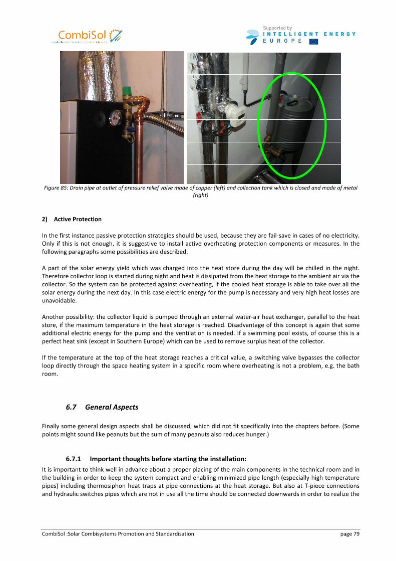
CombiSol :Solar Combisystems Promotion and Standardisation page 79
Figure 85: Drain pipe at outlet of pressure relief valve made of copper (left) and collection tank which is closed and made of metal
(right)
2) Active Protection
In the first instance passive protection strategies should be used, because they are fail-save in cases of no electricity.
Only if this is not enough, it is suggestive to install active overheating protection components or measures. In the
following paragraphs some possibilities are described.
A part of the solar energy yield which was charged into the heat store during the day will be chilled in the night.
Therefore collector loop is started during night and heat is dissipated from the heat storage to the ambient air via the
collector. So the system can be protected against overheating, if the cooled heat storage is able to take over all the
solar energy during the next day. In this case electric energy for the pump is necessary and very high heat losses are
unavoidable.
Another possibility: the collector liquid is pumped through an external water-air heat exchanger, parallel to the heat
store, if the maximum temperature in the heat storage is reached. Disadvantage of this concept is again that some
additional electric energy for the pump and the ventilation is needed. If a swimming pool exists, of course this is a
perfect heat sink (except in Southern Europe) which can be used to remove surplus heat of the collector.
If the temperature at the top of the heat storage reaches a critical value, a switching valve bypasses the collector
loop directly through the space heating system in a specific room where overheating is not a problem, e.g. the bath
room.
6.7 General Aspects
Finally some general design aspects shall be discussed, which did not fit specifically into the chapters before. (Some
points might sound like peanuts but the sum of many peanuts also reduces hunger.)
6.7.1 Important thoughts before starting the installation:
It is important to think well in advance about a proper placing of the main components in the technical room and in
the building in order to keep the system compact and enabling minimized pipe length (especially high temperature
pipes) including thermosiphon heat traps at pipe connections at the heat storage. But also at T-piece connections
and hydraulic switches pipes which are not in use all the time should be connected downwards in order to realize the
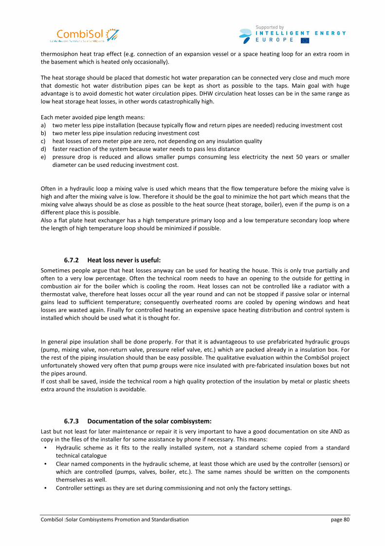
CombiSol :Solar Combisystems Promotion and Standardisation page 80
thermosiphon heat trap effect (e.g. connection of an expansion vessel or a space heating loop for an extra room in
the basement which is heated only occasionally).
The heat storage should be placed that domestic hot water preparation can be connected very close and much more
that domestic hot water distribution pipes can be kept as short as possible to the taps. Main goal with huge
advantage is to avoid domestic hot water circulation pipes. DHW circulation heat losses can be in the same range as
low heat storage heat losses, in other words catastrophically high.
Each meter avoided pipe length means:
a) two meter less pipe installation (because typically flow and return pipes are needed) reducing investment cost
b) two meter less pipe insulation reducing investment cost
c) heat losses of zero meter pipe are zero, not depending on any insulation quality
d) faster reaction of the system because water needs to pass less distance
e) pressure drop is reduced and allows smaller pumps consuming less electricity the next 50 years or smaller
diameter can be used reducing investment cost.
Often in a hydraulic loop a mixing valve is used which means that the flow temperature before the mixing valve is
high and after the mixing valve is low. Therefore it should be the goal to minimize the hot part which means that the
mixing valve always should be as close as possible to the heat source (heat storage, boiler), even if the pump is on a
different place this is possible.
Also a flat plate heat exchanger has a high temperature primary loop and a low temperature secondary loop where
the length of high temperature loop should be minimized if possible.
6.7.2 Heat loss never is useful:
Sometimes people argue that heat losses anyway can be used for heating the house. This is only true partially and
often to a very low percentage. Often the technical room needs to have an opening to the outside for getting in
combustion air for the boiler which is cooling the room. Heat losses can not be controlled like a radiator with a
thermostat valve, therefore heat losses occur all the year round and can not be stopped if passive solar or internal
gains lead to sufficient temperature; consequently overheated rooms are cooled by opening windows and heat
losses are wasted again. Finally for controlled heating an expensive space heating distribution and control system is
installed which should be used what it is thought for.
In general pipe insulation shall be done properly. For that it is advantageous to use prefabricated hydraulic groups
(pump, mixing valve, non-return valve, pressure relief valve, etc.) which are packed already in a insulation box. For
the rest of the piping insulation should than be easy possible. The qualitative evaluation within the CombiSol project
unfortunately showed very often that pump groups were nice insulated with pre-fabricated insulation boxes but not
the pipes around.
If cost shall be saved, inside the technical room a high quality protection of the insulation by metal or plastic sheets
extra around the insulation is avoidable.
6.7.3 Documentation of the solar combisystem:
Last but not least for later maintenance or repair it is very important to have a good documentation on site AND as
copy in the files of the installer for some assistance by phone if necessary. This means:
• Hydraulic scheme as it fits to the really installed system, not a standard scheme copied from a standard
technical catalogue
• Clear named components in the hydraulic scheme, at least those which are used by the controller (sensors) or
which are controlled (pumps, valves, boiler, etc.). The same names should be written on the components
themselves as well.
• Controller settings as they are set during commissioning and not only the factory settings.

CombiSol :Solar Combisystems Promotion and Standardisation page 81
• Instruction manual what can/shall be changed by the resident to adapt the system to the own needs; this is
mainly the domestic hot water tap temperature, room set temperature, heating curve depending on ambient
temperature, time schedules for space heating, heating of the domestic hot water auxiliary volume and
domestic hot water circulation pump
• Maintenance manual explaining what shall be done by the resident himself in which time interval and what the
resident shall as an installer to do within specific time intervals.

CombiSol :Solar Combisystems Promotion and Standardisation page 82
7 Tools
Main Author : Jan-Erik Nielsen
A simple tool “COMBI-EN” for calculating the savings of a solar combisystems has been developed. The advantages of
the tool are:
• Easy to use: Spread sheet type; input in one sheet; output in another. Can be used by manufacturers,
planners/architects, installers and users.
• Simple: Calculations are based on simple explicit equations (monthly basis) → instant results.
• Compatible with European Standards: Calculations of the solar output are done according to the EN 15316-
4-3 specifying how to calculate output and savings from a solar heating system in a building. The En15316
series is used in more and more countries for calculating the “energy performance of buildings” as specified
in the DIRECTIVE 2010/31/EU on the energy performance of buildings. Uses standard collector test results
as input (such test results are easily available for 90 % of the collectors on the EU market from
www.solarkeymar.org.
• Availability: The tool is available for free in 5 languages from CombiSol web www.combisol.eu.
As input the “COMBI-EN” needs:
• System type
• Location
• Load
• Collector data from Keymark data sheet
• Tank size and a few other specifications
• Back-up system information
Results are:
• Solar output
• Annual savings (energy. kWh)
• Annual savings (fuel: m3 gas / litres oil / kWh electricity / kg biomass)
• Annual savings (tones of CO2)
• Annual savings (€)
The result sheet is shown in Figure 86.
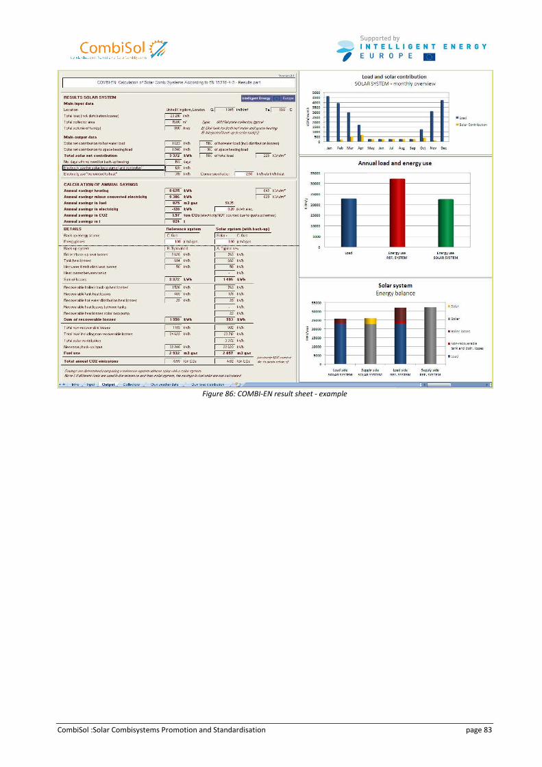
CombiSol :Solar Combisystems Promotion and Standardisation page 83
Figure 86: COMBI-EN result sheet - example
CombiSol :Solar Combisystems Promotion and Standardisation page 84
8 Training
Main Author : Chris Bales
A survey on available training material has been done: A huge amount of materials is already available in the
different countries.
Instead of producing a new standard set of training material it was decided to prepare the following:
• A list of topics that should be addressed in a training session dealing with SCS
• Additional training materials based on experience gained during the project
In addition a “database” (excel work book) with information on literature concerning SCS was created by updating
and revising a more general database created in a previous EU project, the NEGST Project, in the mid 2000’s. This is
available on the project website and thus available to the general public. For each book/document there is
information about the contents, target groups and whether it has information about 16 different categories such as
materials, storage etc.
8.1 Suggested Contents for courses on SCS
A document summarizing the suggested contents for teaching about SCS in training courses has been compiled
within Combisol [8]. This is split into two categories: basic information that should be taught in all courses; extra
contents that could be included in a longer and more in-depth course. Information on possible sources of
information on the topics is given in the report. The report is available on the project website and thus available to
the general public. It is summarized here.
The contents assume that the students already have a basic understanding of solar hot water systems as well as
general HVAC knowledge.
8.1.1 Essential contents of courses
Characteristics of loads (DHW and space heating)
Differences in heating rates, temperatures and flows as well as typical profiles
Differences between solar DHW and combisystems
Differences in loads, types of circuits required, heat exchangers
Types of DHW preparation
Tank in tank, immersed heat exchangers and external flat plate heat exchangers and their advantages and
disadvantages.
Difference between buffer and DHW stores
Requirements for DHW store materials (fresh water), relative costs
Different thermal zones in a solar combistore
At what heights should you connect different heat sources and sinks.
Connection and types of auxiliary heaters
Auxiliary heater heating the store or being preheated by the store.
Common system designs
The six different characteristic designs of Combisol. Examples of compact systems.
CombiSol :Solar Combisystems Promotion and Standardisation page 85
Stagnation protection
Degradation of glycol at high temperatures, the basic concept of the boil-back approach (emptying the collector by
boiling), stages in stagnation, how to calculate the correct system pressure, prepressure in the expansion vessel and
the size of the expansion vessel as well the need for cooling.
Control, including items important in stagnation control
Starting and stopping the collector in normal operation. Protecting from overheating by night cooling of the store via
collector, hindering restart of the collector with high temperatures in the collector. Charging of the store from
auxiliary: two sensor and one sensor control.
Sizing of solar combisystems (collector, store, piping)
Variation of savings with collector area and store size, two store and one store systems, size of pipes, rules of thumb
for store size dependent on collector size.
Dependence of savings on temperature and size of auxiliary heated volume in store
Energy saving are less for higher set temperatures for the auxiliary heated volume in the store as well as with an
increase of this volume. The available DHW capacity increases as savings decrease.
Heat losses from stores and pipes and how to prevent them
Reduction of heat losses from the stores and pipes are critical to achieving a good performance in practice with solar
combisystems. Thermosiphon breaks, non-return valves and good store insulation without thermal bridges are
required.
Legionella and national regulations for its avoidance
Legionella growth and destruction. Methods for prevention and national regulations.
8.1.2 Possible Extra Contents for Longer Courses
This section deals with topics that are not essential for a shorter course but which can be taken up in longer courses.
Which of the topics are taken into a course depends on the target group for the course. Much of the material can be
found in the handbooks from IEA-SHC Tasks 26 [7] and 32 [10] as well as Combisol reports. The Viessman technical
guide [11] also covers several of the topics as does the VDI guide for solar DHW systems [13]. The Combisol report
D2.3 on guidelines for solar combisystems covers a lot of the material as well [12].
• Solar radiation and its variation in time and place.
• Stratification in tanks and how it is achieved.
o Internal heat exchangers.
o Direct connections.
o Stratifying units.
• Comparison of low and high flow systems.
• Different types of system design.
• Integration of collectors into roof and façade.
• Collector field design and calculations.
• Test methods for solar combisystems.
• Solar combisystems for multi-family houses.
• System simulation with design tools (T-sol, Polysun etc).
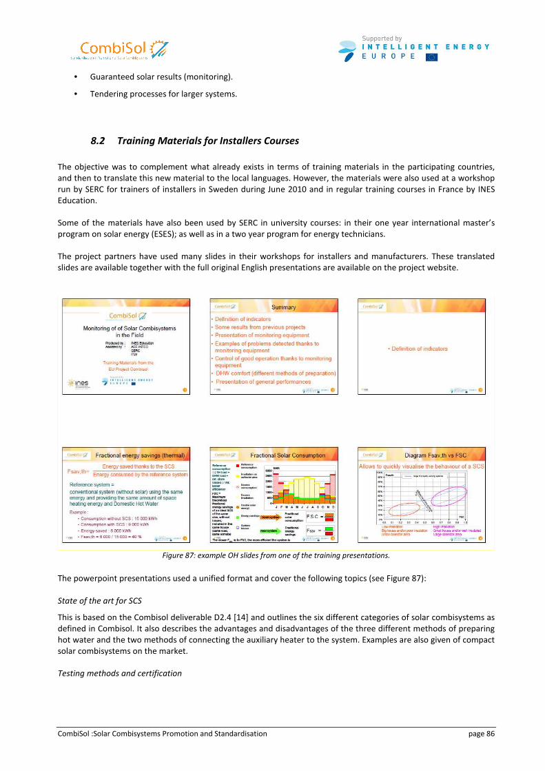
CombiSol :Solar Combisystems Promotion and Standardisation page 86
• Guaranteed solar results (monitoring).
• Tendering processes for larger systems.
8.2 Training Materials for Installers Courses
The objective was to complement what already exists in terms of training materials in the participating countries,
and then to translate this new material to the local languages. However, the materials were also used at a workshop
run by SERC for trainers of installers in Sweden during June 2010 and in regular training courses in France by INES
Education.
Some of the materials have also been used by SERC in university courses: in their one year international master’s
program on solar energy (ESES); as well as in a two year program for energy technicians.
The project partners have used many slides in their workshops for installers and manufacturers. These translated
slides are available together with the full original English presentations are available on the project website.
Figure 87: example OH slides from one of the training presentations.
The powerpoint presentations used a unified format and cover the following topics (see Figure 87):
State of the art for SCS
This is based on the Combisol deliverable D2.4 [14] and outlines the six different categories of solar combisystems as
defined in Combisol. It also describes the advantages and disadvantages of the three different methods of preparing
hot water and the two methods of connecting the auxiliary heater to the system. Examples are also given of compact
solar combisystems on the market.
Testing methods and certification
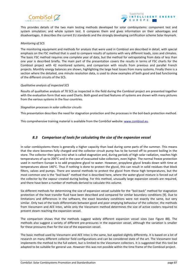
CombiSol :Solar Combisystems Promotion and Standardisation page 87
This provides details of the two main testing methods developed for solar combisystems: component test and
system simulation; and whole system test. It compares them and gives information on their advantages and
disadvantages. It describes the current EU standards and the strongly developing certification scheme Solar Keymark.
Monitoring of SCS
The monitoring equipment and methods for analysis that were used in Combisol are described in detail, with special
emphasis on the FSC method that is used to compare results of systems with very different loads, sizes and climates.
The basic FSC method requires one complete year of data, but the method for extrapolating from data of less than
one year is described briefly. The main part of the presentation covers the results in terms of FSC charts for the
Combisol project with 42 monitored systems, and comparison with results from previous and parallel French
projects. Monthly energy balances are shown, highlighting the large heat losses from many systems. Finally there is a
section where the detailed, one minute resolution data, is used to show examples of both good and bad functioning
of the different circuits of the SCS.
Qualitative analysis of inspected SCS
Results of qualitative analysis of 70 SCS as inspected in the field during the Combisol project are presented together
with the evaluation form that was used Charts. Both good and bad features of systems are shown with many pictures
from the various systems in the four countries.
Stagnation processes in solar collector circuits
This presentation describes the need for stagnation protection and the processes in the boil-back protection method.
This comprehensive training material is available from the CombiSol website: www.combisol.eu.
8.3 Comparison of tools for calculating the size of the expansion vessel
In solar combisystems there is generally a higher capacity than load during some parts of the summer. This means
that the store becomes fully charged and the collector circuit pump has to be turned off to prevent boiling in the
store. The collector then goes into what is called stagnation and, during periods of high solar radiation, reaches high
temperatures of up to 200°C and in the case of evacuated tube collectors, even higher. The normal freeze protection
used in northern Europe is to add propylene glycol to water. However, propylene glycol breaks down with time at
temperatures above 140°C. Thus if nothing is done to protect the glycol, this can result in solid residues that block
filters, valves and pumps. There are several methods to protect the glycol from these high temperatures, but the
most common one is the “boil-back” method that is described here, where the water-glycol mixture is forced out of
the collector by the vapour created during boiling. For this method, unusually large expansion vessels are required,
and there have been a number of methods derived to calculate this volume.
Six different methods for determining the size of expansion vessel suitable for the “boil-back” method for stagnation
protection of the heat transfer fluid have been described and compared for similar boundary conditions [9]. Due to
limitations and differences in the software, the exact boundary conditions were not exactly the same, but very
similar. Only two of the tools differentiate between good and poor emptying behaviour of the collector, the methods
from Viessmann and AEE Intec, while only the Viessmann method determines the size of active coolers required to
prevent steam reaching the expansion vessel.
The comparison shows that the methods suggest widely different expansion vessel sizes (see Figure 88). The
methods also suggest a variety of different pre-pressures in the expansion vessel, although the variation is smaller
for these pressures than for the size of the expansion vessel.
The basic method used by Viessmann and AEE Intec is the same, but applied slightly differently. It is based on a lot of
research on many different collector field configurations and can be considered state of the art. The Viessmann tool
implements the method to the full extent, but is limited to the Viessmann collectors. It is suggested that this tool be
adapted to be suitable for general use. However this was not possible within the time frame of the Combisol project.
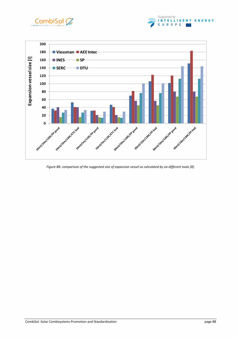
CombiSol :Solar Combisystems Promotion and Standardisation page 88
0
20
40
60
80
100
120
140
160
180
200
Viessman AEE Intec
INES SP
SERC DTU
Exp
ansi
on
ve
sse
l siz
e[l
]
Figure 88: comparison of the suggested size of expansion vessel as calculated by six different tools [8].
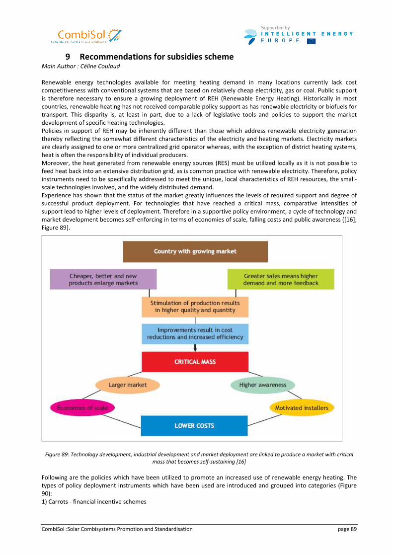
CombiSol :Solar Combisystems Promotion and Standardisation page 89
9 Recommendations for subsidies scheme Main Author : Céline Coulaud
Renewable energy technologies available for meeting heating demand in many locations currently lack cost
competitiveness with conventional systems that are based on relatively cheap electricity, gas or coal. Public support
is therefore necessary to ensure a growing deployment of REH (Renewable Energy Heating). Historically in most
countries, renewable heating has not received comparable policy support as has renewable electricity or biofuels for
transport. This disparity is, at least in part, due to a lack of legislative tools and policies to support the market
development of specific heating technologies.
Policies in support of REH may be inherently different than those which address renewable electricity generation
thereby reflecting the somewhat different characteristics of the electricity and heating markets. Electricity markets
are clearly assigned to one or more centralized grid operator whereas, with the exception of district heating systems,
heat is often the responsibility of individual producers.
Moreover, the heat generated from renewable energy sources (RES) must be utilized locally as it is not possible to
feed heat back into an extensive distribution grid, as is common practice with renewable electricity. Therefore, policy
instruments need to be specifically addressed to meet the unique, local characteristics of REH resources, the small-
scale technologies involved, and the widely distributed demand.
Experience has shown that the status of the market greatly influences the levels of required support and degree of
successful product deployment. For technologies that have reached a critical mass, comparative intensities of
support lead to higher levels of deployment. Therefore in a supportive policy environment, a cycle of technology and
market development becomes self-enforcing in terms of economies of scale, falling costs and public awareness ([16];
Figure 89).
Figure 89: Technology development, industrial development and market deployment are linked to produce a market with critical
mass that becomes self-sustaining [16]
Following are the policies which have been utilized to promote an increased use of renewable energy heating. The
types of policy deployment instruments which have been used are introduced and grouped into categories (Figure
90):
1) Carrots - financial incentive schemes
CombiSol :Solar Combisystems Promotion and Standardisation page 90
2) Sticks - regulatory schemes, and
3) Guidance, or educationally based schemes.
Figure 90: Policy instruments categories for renewable heating and cooling with examples [16]
9.1 Carrots: incentive schemes
Typically carrots act to entice a customer into utilizing RES to meet local heating needs and aims to address the cost
gap between RETs and conventional technologies used for either direct or indirect heating. Such incentives schemes
may be further categorized into:
63
1) financial incentives – based on direct financial support such as capital grants used to reduce the capital cost of
deploying renewable energy technologies, or investment risk reduction using soft loans (IEA, 2004), and
2) fiscal incentives such as tax benefits.
Generally these types of incentive are funded out of government budgets. In order to be effective the design of these
incentive schemes needs to allocate sufficient levels of funding to bridge the gap between the market price of heat
energy and the costs for RETs. The incentives should be predictable and consistent over the life of the policy to
provide investment confidence.
9.2 Sticks: Regulatory schemes
Generally implemented by means of regulation, governments can intervene in the market by placing requirements
on specified sectors. This type of instrument forces REH deployment by directly requiring the development of
specified technologies. The legal and administrative costs of political incentives are often kept to a minimum for
governments, although monitoring and enforcement may be required at the local or regional level.
67
9.3 Guidance: education-based schemes
Education to promote REH aims to enhance the awareness of the public by information campaigns and providing
training to increase installer knowledge. This type of support may take the form of technical assistance, financial
advice, labelling of appliances, or information distribution. Information on resource availability, the benefits and
potential of renewable energy, plant type, capacity and heat production statistics, and available government
incentives, may be distributed in a variety of forms.
In addition, training programmes may be established in schools, universities, or amongst key professional groups so
they consist of well-informed, skilled individuals and networks. Professionals within the supply chain for heat and
cold include equipment installers, heating engineers, and architects who should be encouraged to incorporate REH
systems into their designs. Information provision and knowledge-based promotion needs to work in conjunction with
other political tools. A lack of information regarding renewable energy resource availability, technology
development, and product availability may inhibit investment in REHC applications simply due to a lack of awareness.
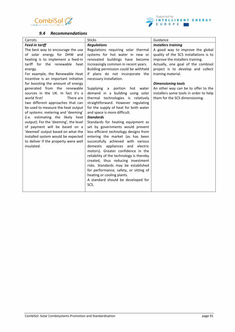
CombiSol :Solar Combisystems Promotion and Standardisation page 91
9.4 Recommendations
Carrots Sticks Guidance
Feed-in tariff
The best way to encourage the use
of solar energy for DHW and
heating is to implement a feed-in
tariff for the renewable heat
energy.
For example, the Renewable Heat
Incentive is an important initiative
for boosting the amount of energy
generated from the renewable
sources in the UK. In fact it's a
world first! There are
two different approaches that can
be used to measure the heat output
of systems: metering and 'deeming'
(i.e. estimating the likely heat
output). For the ‘deeming’, the level
of payment will be based on a
'deemed' output based on what the
installed system would be expected
to deliver if the property were well
insulated.
Regulations
Regulations requiring solar thermal
systems for hot water in new or
renovated buildings have become
increasingly common in recent years.
Building permission could be withheld
if plans do not incorporate the
necessary installation.
Supplying a portion hot water
demand in a building using solar
thermal technologies is relatively
straightforward. However regulating
for the supply of heat for both water
and space is more difficult.
Standards
Standards for heating equipment as
set by governments would prevent
less efficient technology designs from
entering the market (as has been
successfully achieved with various
domestic appliances and electric
motors). Greater confidence in the
reliability of the technology is thereby
created, thus reducing investment
risks. Standards may be established
for performance, safety, or sitting of
heating or cooling plants.
A standard should be developed for
SCS.
Installers training
A good way to improve the global
quality of the SCS installations is to
improve the installers training.
Actually, one goal of the combisol
project is to develop and collect
training material.
Dimensioning tools
An other way can be to offer to the
installers some tools in order to help
them for the SCS dimensioning.
CombiSol :Solar Combisystems Promotion and Standardisation page 92
Conclusion
The main objective of Combisol project was to encourage an accelerated market deployment of SCS – hence a higher
share of heat produced by solar energy - and to promote an improved quality of the systems installed.
Thanks to an intensive work on qualitative and quantitative evaluations of existing combi-systems, CombiSol project
has partially achieved this main objective since the main results of these qualitative and quantitative evaluations are
not up to what was expected.
Nevertheless major results were achieved that allow to be optimistic about the future of SSC provided the industrial
sector and installers react quickly to provide consumers with high quality systems that achieve expected energy
savings.
Through in-situ monitoring and laboratory tests, CombiSol also proved it was possible to achieve significant energy
savings, provided the system is well designed and its installation is done carefully.
Finally, based on the learning and in order to encourage an accelerated market deployment of SCS and to promote
an improved quality of the systems installed, CombiSol provides clear guidelines related to:
• System design dedicated to manufacturers,
• System installation for installers,
• Performance assessment of systems in labs to increase consumers’ confidence,
• Training and tools to promote installers’ skill,
• Recommandations for subsidies.
All the materials delivered within this project should significantly contribute to increase the share of heat produced
by solar energy in the future, and thus helping to achieve the main goal of reducing our carbon footprint.
CombiSol :Solar Combisystems Promotion and Standardisation page 93
Bibliography
[1] : LETZ T., 2001, Combisystems characterisation, IEA SHC – TASK 26, 6th
Experts Meeting, Delft, Finland, April 2 - 4,
2001
[2] : SUTER J.-M., LETZ T., WEISS W., INÄBNIT J., 2000, SOLAR COMBISYSTEMS in Austria, Denmark, Finland, France,
Germany, Sweden, Switzerland, the Netherlands and the USA; overview 2000 ; IEA SHC – TASK 26, Bern, 42 p.
[3] : LETZ T., 2003, Altener program: SOLAR COMBISYSTEMS, WORKPACKAGE 6 : MONITORING PROCEDURE, 18 p
[4] : IEA SHC – TASK 26, 2001 : SOLAR COMBISYSTEMS ; subtask C milestone report C 0.2 ; Reference conditions ;
October, 2001. Rapperswil, Switzerland, October 7 - 10, 2001
[5] : M. CONDE Engineering, 2002 ; Thermophysical properties of brines, 11 p.
[6] : European Standard 2006 : EN 12975 : Thermal solar systems and components - Solar collectors – Part 2: Test
methods ; Annex I : Properties of water (DIN V 4757-4:1995-11)
[7]: Weiss, W. (ed.): Solar heating systems for houses, a design handbook for solar combisystems, James & James
(Science Publishers) Ltd, London, 2003.
[8] : Bales et al., 2010 : Suggested Contents for Training on Solar Combisystems for Installers. Report from EU project
Combisol. Högskolan Dalarna, SERC. www.combisol.eu.
[9] : Bales et al., 2010 : Comparison of Expansion Vessel Calculation Tools for « Boil-Back » Stagnation Protection.
Report from EU project Combisol. Högskolan Dalarna, SERC. www.combisol.eu.
[10] : Hadorn, J-C., ed. : Thermal energy storage for solar and low energy buildings - State of the art, 2005, University
of Lleida: Lleida, Spain. ISBN: 84-8409-877-X
[11] : Viessman Verk : Technical Guide Solar Thermal Systems, Viessman GmbH & Co KG, Allendorf, Germany. 2009
[12] : Thur, A. et al. : EU project Combisol public deliverable: D2.3: Guidelines for design and dimensioning of solar
combisystems, AEE Intec, Gleisdorf, Austria. www.combisol.eu. 2010
[13] : VDI, VDI 6002 Blatt 1: 2004-9 : Solar heating for domestic water – General principles, system technology and
use in residential buildings. VDI, Dusseldorf, Germany. 2004.
[14] : Thur, A. et al. : EU project Combisol public deliverable: D2.4: Updated State of the Art Report of Solar
Combisystems Analysed within CombiSol, AEE Intec, Gleisdorf, Austria. www.combisol.eu. 2010
[15] : Thur, A. et al. : EU project Combisol public deliverable: D2.3: Guidelines for Design and Dimensioning, AEE
Intec, Gleisdorf, Austria. www.combisol.eu. 2010
[16] : International Energy Agency : Renewables for Heating and Cooling : Untapped Potential. Paris, France, July
2007
[17] : Werner Weiss, Peter Biermayr : “POTENTIAL OF SOLARTHERMAL IN EUROPE”, European Solar Thermal
Industry Federation (ESTIF), AEE – Institute for Sustainable Technologies (AEE INTEC) and Vienna University of
Technology – Energy Economics Group (EEG).
[18] : IEA SHC: Solar Heat Worldwide, Edition 2008, Werner Weiss, et.al., 2010
CombiSol :Solar Combisystems Promotion and Standardisation page 94
[19]: HALLER, M., Heimrath, R. (2007) “The reference heating system, the template solar system”, Technical
report, IEA Solar Heating & Cooling programme Task 32, http://www.iea-shc.org/task32
[20]: ISO 9459-2 (1995): “Solar heating - Domestic water heating systems. Part 2: Outdoor test methods for
system performance characterization and yearly performance prediction of solar-only systems”
[21]: ISO 9459-5 (2007): “Solar heating - Domestic water heating systems. Part 5: System performance
characterization by means of whole-system tests and computer simulation”
[22]: METTE, B. et al (2011): “D3.1: Comparison of test methods”, Technical report, Intelligent Energy Europe,
http://www.combisol.eu
[23]: METTE, B. et al (2011): “D3.2: Standards “Solar combisystem test methods”, Technical report, Intelligent
Energy Europe, http://www.combisol.eu
[24]: NARON, D. J., Visser H. (2002) “Direct Characterisation Test Procedure for Solar Combisystems”, Technical
report, IEA Solar Heating & Cooling programme Task 26, http://www.iea-shc.org/task26
[25]: NIELSEN, J.E. (2010): COMBI-EN - version 1.8. PlanEnergi DZ, Hvalsö, Denmark, download of the tool:
http://www.combisol.eu
(26]: PETER, M., Drück, H (2008): Testing of controllers for thermal solar systems, Solar Energy 82 (2008), pp.
676-685 Sience Direct: Reference: SE2069, Journal title: Solar Energy
[27]: THÜR, A., Breidler, J. (2009) “D2.4: Updated State of the Art Report Of Solar Combisystems Analysed within
CombiSol” , Technical report, Intelligent Energy Europe, http://www.combisol.eu
[28]: VOGELSANGER, P. (2002) “The Concise Cycle Test – An Indoor Test Method using a 12-day test Cycle”,
Technical report, IEA Solar Heating & Cooling programme Task 26, http://www.ieashc.org/task26
[29]: BALES, C. (2002) “Combitest _ Initial Development of the AC/DC Test Method”, Technical report, IEA Solar
Heating & Cooling programme Task 26, http://www.iea-shc.org/task26
[30]: CEN/TS 12977-2, (2010): “Thermal solar systems and components. Custom built systems. Part 2: Test
methods for solar water heaters and combisystems”
[31]: CEN/TS 12977-4, (2010): „Thermal solar systems and components. Custom built systems. Part 4:
Performance test methods for solar combistores”
[32]: CEN/TS 12977-5, (2010): “Thermal solar systems and components. Custom built systems. Part 5:
Performance test methods for control equipment”
[33]: EN 12975-2, (2006): Thermal solar systems and components. Solar collectors. Part 2: Test methods
[34]: EN 15316-4-3, (2007): “Heating systems in buildings. Method for calculation of system energy requirements
and system efficiencies - Part 4-3: Heat generation systems, thermal solar systems”