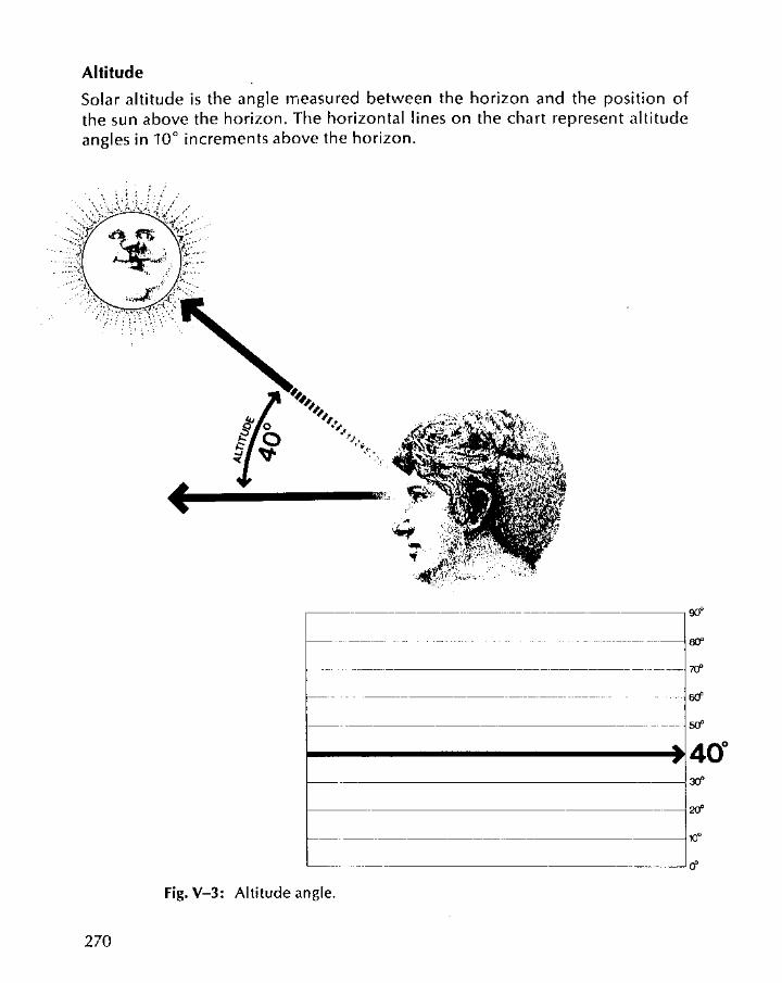
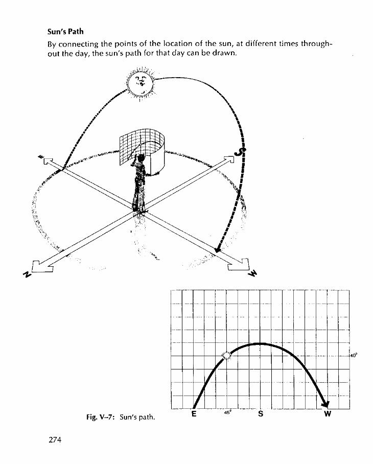
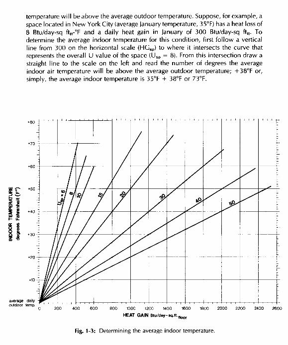
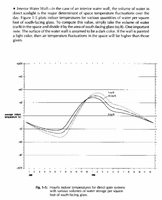
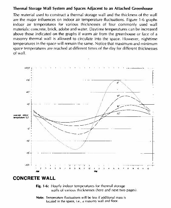
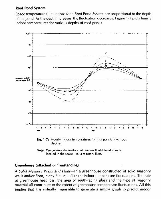
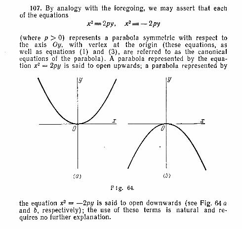
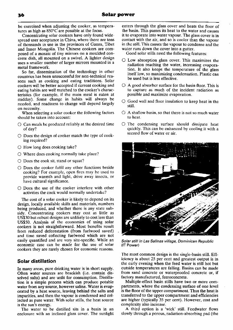
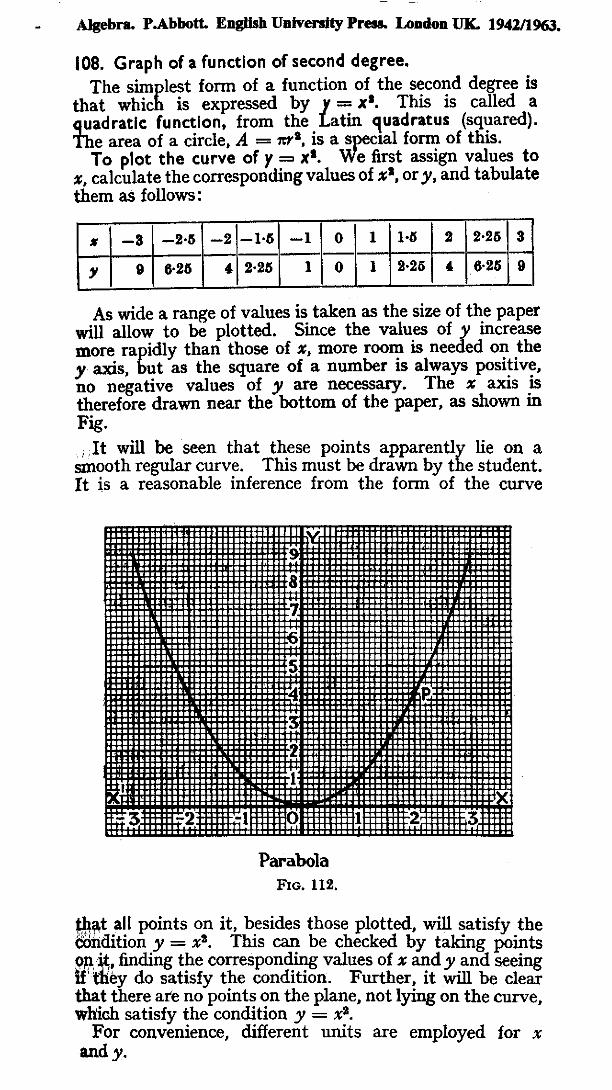
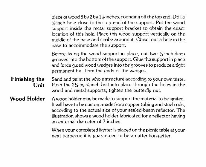
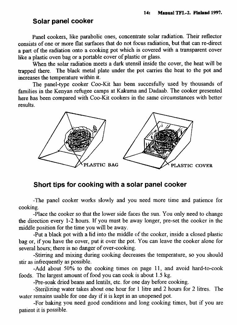
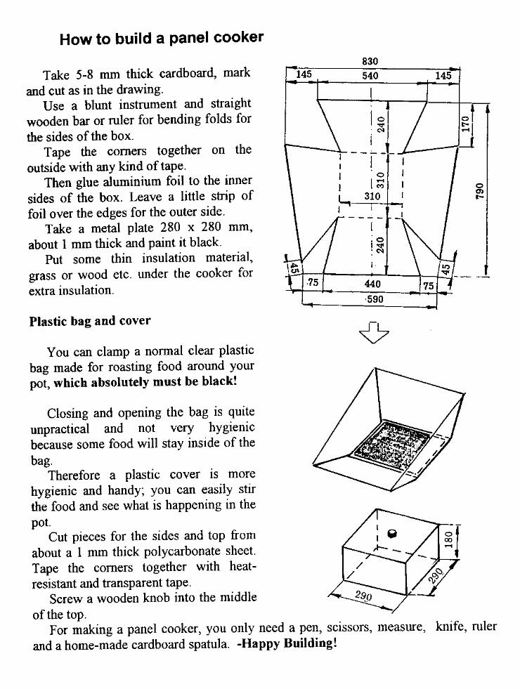
solar cookers and food dryers
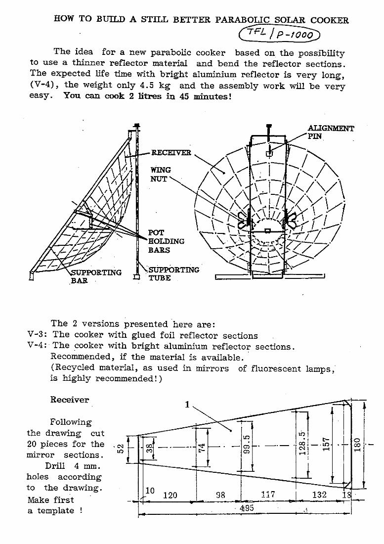
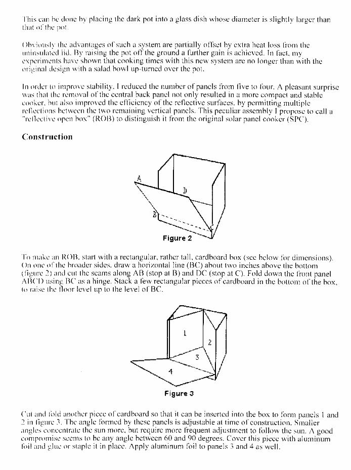
DESCRIPTION
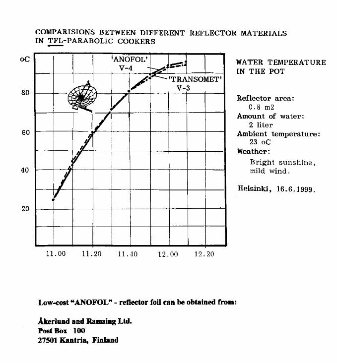
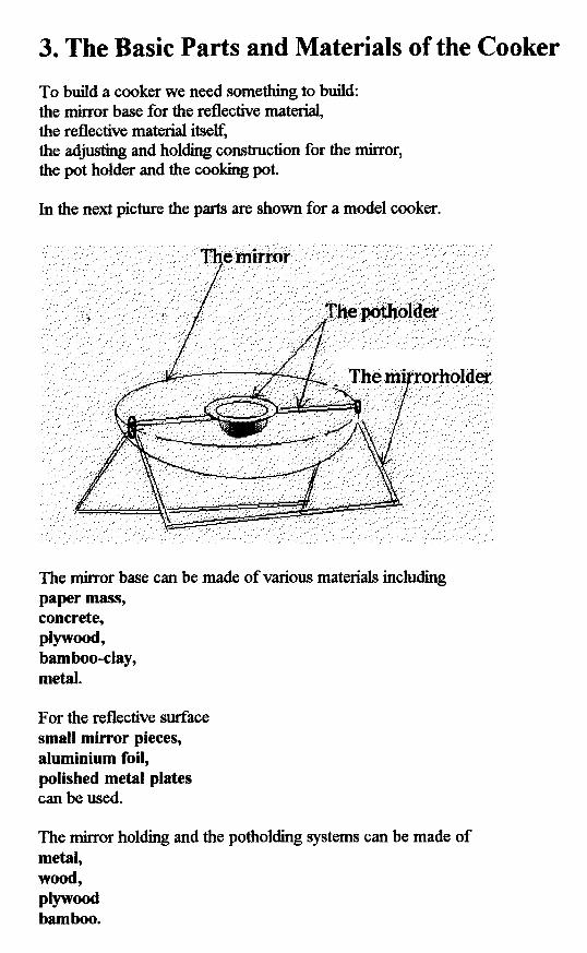
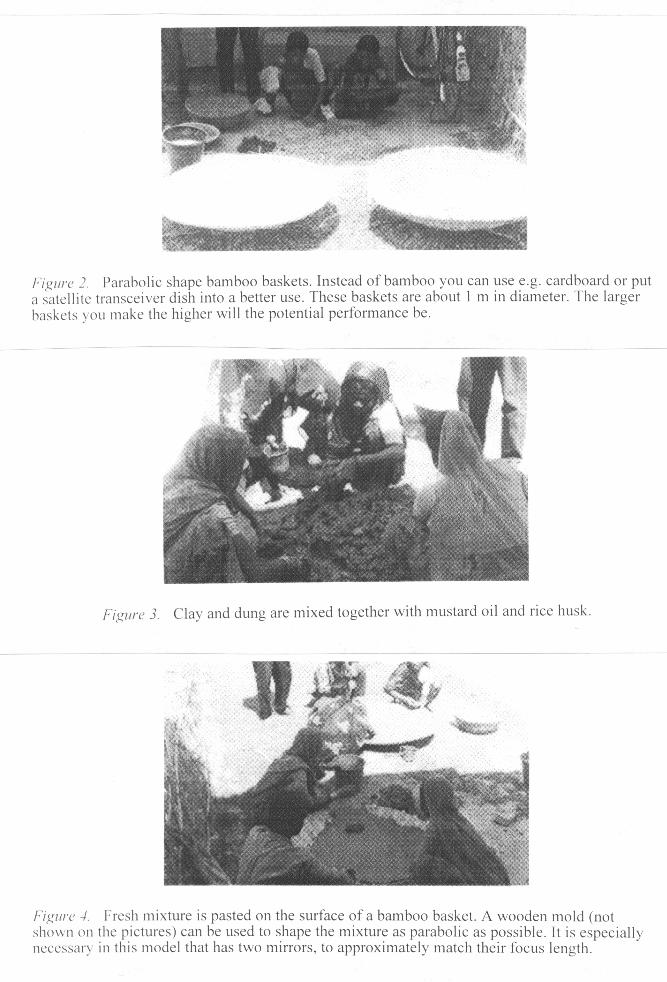
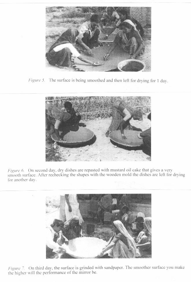
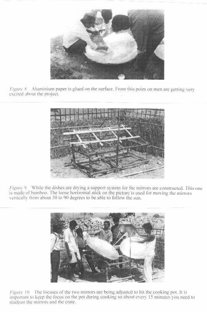
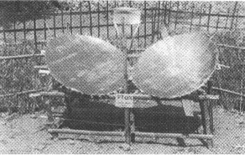
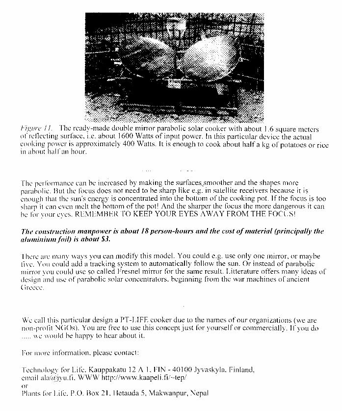
Solar Cookers and Food Dryers, schematics and diagramsTRANSCRIPT
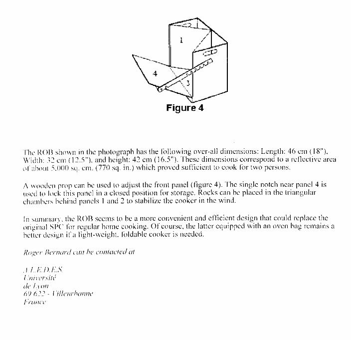
Compendium In Solar-Cookers & Food-Dryers
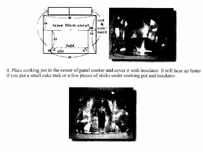
2nd. Revised Edition
Selected & Edited by John Furze 1996/98/2002 2nd. Completely Revised Edition 1999. Holme Bygade 12, 8400 Ebeltoft Denmark Tel/Fax/Voice: + 45 86 10 07 86 E-mail: <[email protected]> Aarhus University, Faculty of Political Science, Law & Economics
CONTENTS. 10: The Power Guide. Hulsher, Fraenkel. UK/Netherlands 1994 1-85339-192-1. 15: The Sunshine Revolution. Røstvig. Norway/USA 1992 82-91052-01[3]-8[4]. 16: Manual TFL-2. Technology for Life. Finland 1997 951-96884-0-4. 18: Peoples Workbook. EDA. South Africa 1981 0-620-05355-0. 19: Energy Primer. Portola Institute. California USA 1974 0-914774-00-X. Parabolic Solar Cookers. 21: Manual TFL-2. Finland 1997. 38: Download from Internet. Infoseek => Solar Cookers. 40: Bogen om Alt. Energikild. E-Lura. Politikens Forlag. DK 1997 87-567-2741-0. 41: Algebra. P.Abbott. English University Press. London UK 1942/1963. 42: Teaching about Energy. C.Eastland. Southgate/CAT. UK 1999 1-85741-088-2. 43: Cookers. H.Virtanen. TFL. Finland. 59: Cookers. A.Lampinen. TFL. Finland. 66: Direct Use of the Sun’s Energy. Daniels. USA 1964 Lib. Of Congress 64-20913. 70: App. Technology Sourcebook. Darrow, Pam. VITA. USA 1976 0-917704-00-2. Einfälle statt Abfälle. Verlag – Ch. Kuhtz. Kiel Germany 1985 3-924038-11-2. 71: Handbook of Homemade Power. Shuttleworth. Mother Earth News. USA 1974. 78: Cooking with the Sun. B. & D. Halacy. Morning Sun Press. USA 1978/92 0-9629069-2-1. 106: Byg en Solovn. Nissen. Systime Forlag. Denmark 1998 87-616-0042-3. 135: Soft Technology Magazine # 15. ATA - 247 Flinders Lane Melbourne Australia. 137: Solar Fun Book. Barling. USA 1979 0-9311790-04-2. 159: Home Power Magazine # 43. Ashland Or. USA 1994. 166: Cardboard Solar Cookers &b Food Dryers. Gujarat Energy Development Agency Sayajigunj, Vadodara 390 005, Gujarat India. Solar Panel Cookers. 170: Manual TFL-2. Finland 1997. 172: Different designs downloaded from Internet. – Alta Vista => Solar Cookers. Solar Box Cookers. 195: Eco-Tech. Robert s. de Ropp. Dell Publishers. New York USA 1975.
197: Catalogue # March 1995. Real Goods. Ukiah California USA 1995. 200: Solar Cooking Manual. Brace Research Institute. Quebec Canada 1982/1997.180: 214: Home Power Magazine # 31. www.homepower.com USA 1992. 221: Home Power Magazine # 37. USA 1993. 228: Handbook of Homemade Power. USA 1974. 235: Cooking with the Sun. Halacy. USA 1978/1992. 263: Solar Fun Book. USA 1979. 269: Heaven’s Flame. J.Radabaugh. Home Power Pub. USA 1998 0-9629588-2-4. 304: Soft Technology Magazine # 15. ATA - 247 Flinders Lane Melbourne Australia. 307: ULOG. Morgartenring 18, CH-4054 Basel Switzerland. 337: Solar Cooking. H.Kofalk. Book Pub. Company. USA 1995 1-57067-007-2. 343: Manual TFL-2. Finland 1997. 362: Different designs downloaded from Internet. – Alta Vista => Solar Cookers. 381: Cardboard Solar Cookers & Food Dryers. Gujarat India. Plate Cookers. 389: Solar Cooking Manual. Canada 1982/1997. 390: Sunshine Revolution. Norway/USA 1992. 391: Appropriate Technology Sourcebook. USA 1976. 392: Solar Cooking Manual. Canada 1982/1997. 397: Hot-air Cooker. H.Virtanen. TFL. Finland. Solar Food Dryers. 398: Ferment & Human Nutrition. B.Mollison. NSW. Australia 1993 0-908228-06-6. 401: Living on the Earth. Alicia Bay Laurel. Random House Pub. USA 1970 0-394-71056-8 402: Cloudburst 1. V. Marks [ed.]. Cloudburst Press Brackendale BC. Canada 1973. 404: Cardboard Solar Cookers & Food Dryers. Gujarat India. 406: Solar Fun Book. USA 1979. 411: Peoples Workbook. South Africa 1981. 412: ULOG. Switzerland. 428: Download from Internet. – Alta Vista=> Solar Cookers.
429: Home Power Magazine # 29. USA 1992. 434: Home Power Magazine # 69. USA 1999. 445: Cloudburst 2. V. Marks [ed.]. Cloudburst Press Mayne Island BC. Canada 1976 449: Home Power Magazine # 63. USA 1998. Cardboard and Paper Technology. 457: Appropriate Paper-based Technology – APT. Packer. Zimbabwe/UK 1989/95. Cooking. 471: Haybox Cooking. CAT. Machynlleth Powys Wales UK 1977. 473: Solar Cooking & recipes from many different sources. Cooling, Water Heating, Greenhouses and Water Distillation. 497: Sunshine Revolution. Røstvig. Norway/USA 1992. 498: Build a Village. S.A. Sibtain. Australian Council of Churches. Aus. 1982. 0-85821-030-4. 499: Home Power Magazine # 41. USA 1994. 504: Thermische Solarenergie. Müller. Franzis-Verlag. Germany 1997. 3-7723-4622-7. 508: Solar Airconditioning & Refrigeration. Adelson. Isotech Res.Labs. Michigan USA 1975. 512: Solar Living Sourcebook. Real Goods. USA 1994 0-930031-68-7. 513: Fishing Technology. National Acad. Press. Washington DC. USA 1988 0-309-03788-3. 515: Home Power Magazine # 53. USA 1996. 519: Søby Sunice Pump. Århus Denmark. 521: Soft Tech. Baldwin, Brand [eds]. Co-Evolution/Point-Penguin. USA 1978 0-14-00-48065. 522: Handbook of Homemade Power. USA 1974. 528: Solar Water Heating for the Handyman. Paige. Edmund Scientific Co. USA 1974. 529: Home Power Magazine # 24. USA 1991. 531: Home Power Magazine # 25. USA 1991. 535: Home Power Magazine # 63. USA 1998. 542: Home Power Magazine # 76. USA 2000. 544: Solar Fun Book. USA 1979. 599: Instituto Technológico y de Energias Renovables – Teneriffe.
602: Solar Fun Book. USA 1979. 607: Download from Internet. – Alta Vista=> Solar Cookers. 612: Home Power Magazine # 10. USA 1989. 614: Home Power Magazine # 36. USA 1993. 619: Solar Distillation Pump. H.Virtanen. TFL. Finland. 620: Solar Disinfection of Drinking Water. Acra, Raffoul, Karahagopian. Dept of Environmental health. American Univ. of Beirut. Lebanon/UNICEF. 623: Water Pasteurization Techniques. Andreatta USA 1994. Site Analysis. 631: Passive Solar Water Heaters. Reif. Brick House Publishing. USA. 1983 0-931790-42-5. 647: Home Power Magazine # 28. USA 1992. 650: Other Homes & Garbage. Leckie et al. Sierra Club. SF-CA. USA 1975. 651: Passive Solar Energy Book. Mazria. Rodale Press Em-Pa. USA 1979 0-87156-141-7. 728: Solar Home Book. Anderson, Riordan. Cheshire Books. USA 1976 0-917352-01-7. 732: RAPS. University of Cape Town. South Africa 1992 0-7992-1435-3. 741: Owner-built Home/Owner-built Homestead. Kern. Schribner Press NY USA 1972/75/77 0-684-14223-6/ 0-684-14926-5. 745: Conversions, Tables etc. More information and assistance can be downloaded from the Internet. Try search engines: - Alta Vista – Infoseek or www.accessone.com or www.crest.org - search words – “ Solar Cookers” – etc.
B: ENERGY. #Solar:A: Solenergi. / Sunshine Revolution [book, - video also available]. - Harald N. Røstvik, Stavanger, Norway/USA 1991 82-91052-01-8 / 82-91052-03-04 / Video - 82-91052-02-6B: Pratical Photovoltaics. R.J. Komp, Aatec Pub. Ann Arbor Mich. USA 1981/82 0-937948-02-0C: Strom aus der Sonne. Bernhard Krieg, Elektor Verlag Aachen Germany 1992 3-928051-05-9D: Sol.tech.3-7723-7792-0/Sol.anlag.3-7723-4452-6/Sol.energ.3-7723-7932-X B.Hanus, De. 96/97E: Thermische Solarnergie. Müller, Germany [ De.] 1997 3-7723-4622-7F: Compendium in Solar-cookers & Food-dryers. J. Furze 1996 1: SolEnergiCenter Denmark Tel: +45 43 50 43 50 E-mail - www.solenergi.dk2: EDRC-Univ. of Cape Town S. Africa E-mails - [email protected] [email protected]
Wind:A: Forsøgsmøllen Rapport 1-4. Poul La Cour, Denmark 1900/1903B: Wind Power for Home & Business. Paul Gipe, USA 1993 0-930031-64-4 C: Wind Power Plants. Hau, Germany 1997/98 3-540-57064-0D: Windgeneratoren Technik. Hanus, Germany 1997 3-7723-4712-6 E: Wind-turbine Blade Design and Praxis. J. Furze, 1993/94F: Compendium in Low-cost Wind-mills. J. Furze, 1993/95
Bio-Mass Energy and Fiber Technology:1: a: Danish Energy Agency. b: Prof. H. Carlsen Danish Technical University. c: S. Houmøller E-mail - [email protected] d: Bio-Raf, Bornholm Denmark. 2: Prof. H. Stassen, BTG University of Twente Netherlands.3: Huub J. Gijzen, IHE Delft University Netherlands. [University Cali Columbia]4: Prof. T. Reed, Bio-Mass Energy Foundation Golden Co. USA. E-m. [email protected]: Prof. J.R. Moreira, NEGAWATT São Paulo Brazil.6: Dr. A. Borroto, CEMA University of Cienfuegos Cuba. 7: Dr. P.R. Rogue, CETA University Santa Clara Cuba. E-mail - [email protected]: Prof. R.H. Williams, Center for Energy & Environmental Studies, Princeton University USA.A: Biological Paths to Self-Reliance. R. E. Anderson, Sweden/USA 1979 0-442-20329-2B: Energie aus Bio-Mass. Flaig, Mohr. Germany 1994 3-540-57227-9C: Bioenergy for Development. Woods, Hall. FAO-Rome 1994 92-5-103449-4
Bio-Gas Energy. - [ Digesters ]:For Large Systems: - Danish Energy Agency. Copenhagen DK Fax: + 45 3311 4743For Medium-size Systems: - "Danish Bio-Energi" Issue nr. 28/1996 p.10. - nr. 30/96 p.12. & nr. 32/97 p.10. E-mail - [email protected] - Prof. H. Stassen, BTG University of Twente Netherlands. For Small Low-cost Units: - Prof. Zhong, Guangzhou Inst. of Geography China.[Plastic-bag digesters, - University of Agriculture & Forestry, Thu Duc HCM City Viet Nam,& Integrated Farming]. <http//ourworld.compuserve.com/homepages/utaf> <[email protected]> - Dr. Bo Göhl FSP: E-mail - [email protected] - Dr. E. Murgueitio: E-mail - [email protected] - Prof. Preston: E-mail - thomas.preston%sarec%[email protected] - F. Dolberg: E-mail - [email protected] - Prof. G. Chan: E-mail - [email protected] Wave Power:1: Power from the Waves. D. Ross Oxford University Press UK 19972: Erik Skaarup, Wave Plane Int. Cph. Denmark Tel: + 45 3917 9833 / Univ.of Cork Ireland. See: "Energi & Planlægning" June 1997 page 10. E-mail - [email protected]
Water-treatment Water-pumping - etc.:1: Prof. Thomas L. Crisman, University of Florida Gainesville Florida USA 2: Prof. P. D. Jenssen, Agricultural University of Norway E-mail - [email protected]: Beth Josephson, Center for Rest. of Waters Falmouth Ma. USA E-mail - [email protected]: Angus Marland, Watershed Systems Ltd. Edinburgh Scotland Fax: +44 [0]31 662 46 785: Alexander Gudimov, Murmansk Marine Biological Inst. Russia E-mail - [email protected]: François Gigon, NATURA Les Reussilles Switzerland Fax: +41 [0]32 97 42 257: Carl Etnier, Stensund Ecological Center Trosa Sweden Fax: +46 15 65 32 228: Prof. Ülo Mander, Institute of Geography Univ. of Tartu Estonia E-mail - [email protected]: Field Engineering. F. Longland - [P. Stern, ed.], UK 1936//93 0-903031-68-XB: Mini HydroPower, T. Jiandong et al. UNESCO/John Wiley & Sons UK 1996 0-471-96264-3 C: Compendium in Hydraulic Ram-pumps. J. Furze, 1995
# NB: It should be noted that a comprehensive multimedia6 program on renewable energy on 3 CD's, is issued by the Danish Technological Institute. E-mail - [email protected] - The Danish branch organization for heat and ventilation: CD - "Multi-Sol", showing mounting/assembly work processes for solar-collectors. http://www.vvsu.dk - During 1998, a CD on access to wind-energy info. - should be issued under a common EU project, with as the coordinating Danish partner; - Handelshøjskole in Århus DK. - A CD with a database on Renewable Energy is available from UNESCO-Publishing Paris. - An energy/development CD-library is available from Belgium. E-mail - [email protected] http://www.oneworld.org/globalprojects/humcdrom Plus: - Rainbow Power Company Catalogue, Ninbin NSW 2480 Australia. Fax: + 61 66 89 11 09. - Catalogue from Real Goods Co. Ukiah CA 95482-3471 USA. Fax: + 1 707 468 94 86 E-mail - [email protected] - Home Power Journal, Post-box 520 Ashland OR 97520 USA. Fax: + 1 916 475 3179.
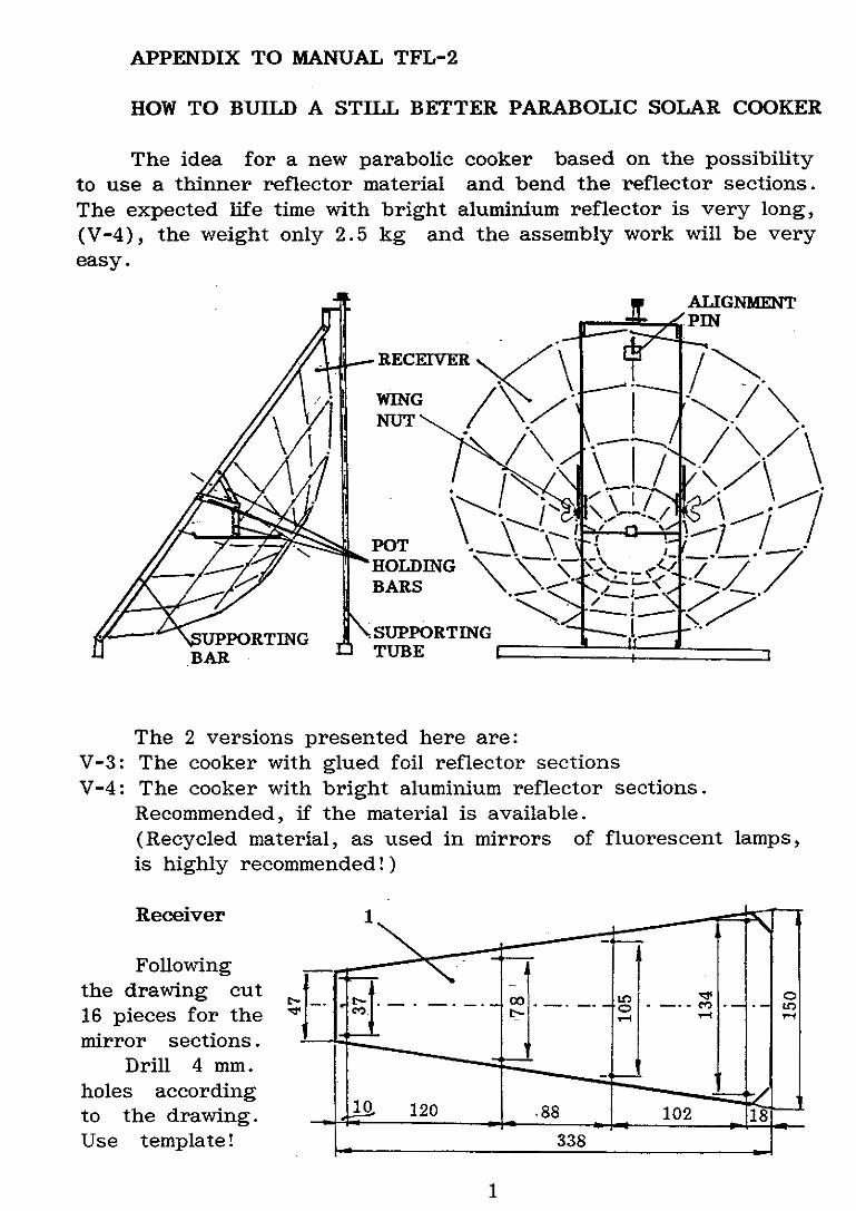
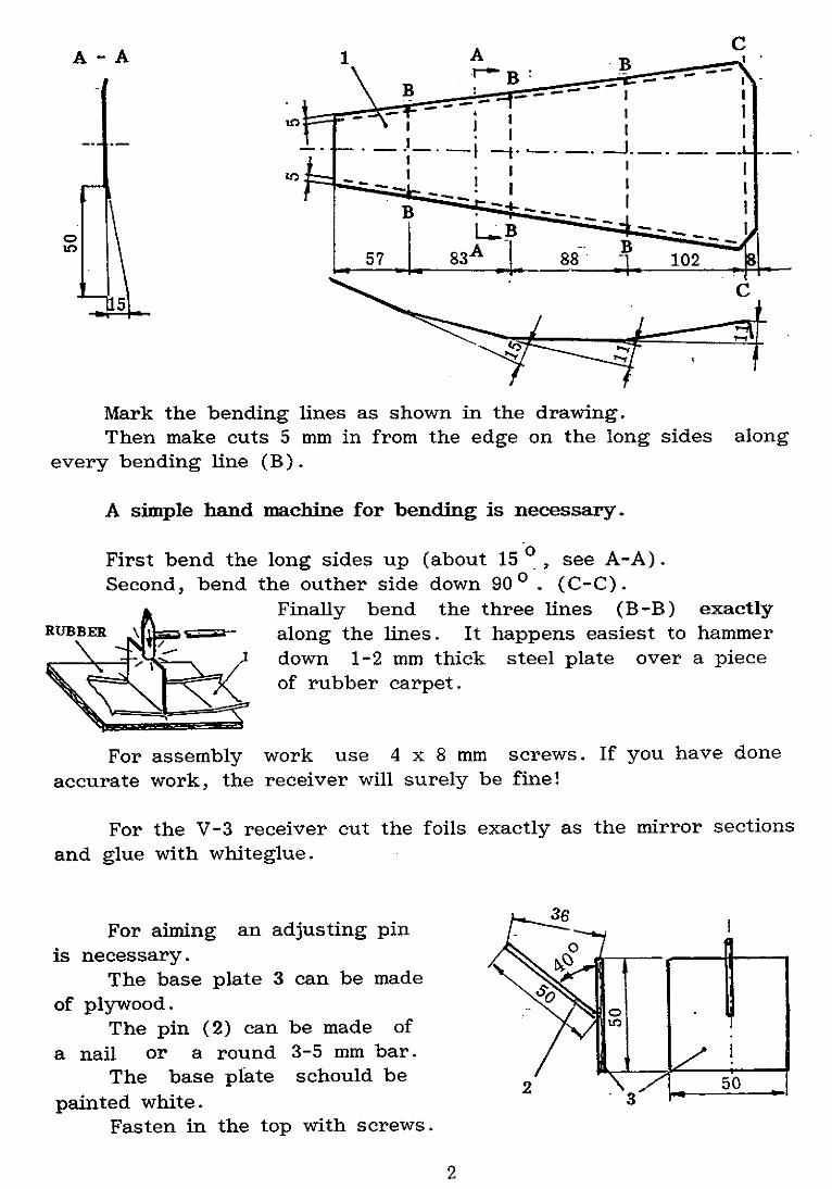
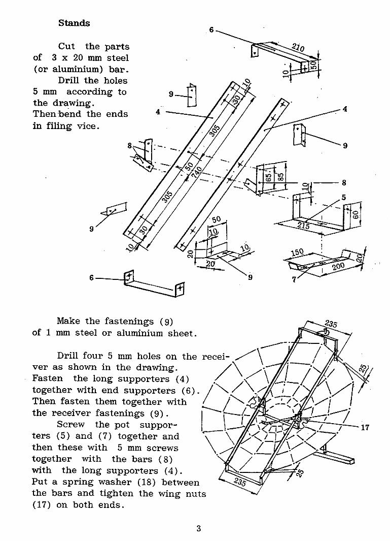
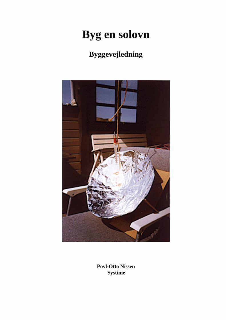
Byg en solovn
Byggevejledning
Povl-Otto NissenSystime
EUROPEANEDUCATIONALPUBLISHERSGROUP
Byg en solovn
© 1998 by Povl-Otto Nissen og Forlaget Systime A/S
Oprindelig sat med Times New Roman 11/13 hos tekst & data, Aabenraa
ISBN 87 616 0042 31. udgave (identisk med cd-rom-udgaven fra 1995)
Systimes CD-ROM-temaserie til fysikundervisningen omfatter desuden følgende titler:
Jens Ingwersen:Termoelementer - undervisningsmateriale til længerevarende eksperimentelt forløb med undervisningsdifferentiering
Aage Rasmussen:Energi og menneske- om fysikken i menneskekroppen
Torben Rosenquist:Renlighed er en god ting- om fysikken i badeværelset
Torben Svendsen:Måling og styring
Forlaget Systime A/SSkt. Pauls Gade 258000 ÅrhusTlf: 86 18 14 00Fax: 86 18 14 05Web: http://www.systime.dke-mail: [email protected]
Medlem af:
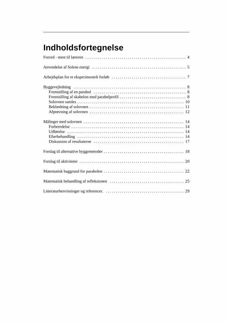
IndholdsfortegnelseForord - mest til læreren . . . . . . . . . . . . . . . . . . . . . . . . . . . . . . . . . . . . . . . . . . . . . . . . .. 4
Anvendelse af Solens energi . . . . . . . . . . . . . . . . . . . . . . . . . . . . . . . . . . . . . . . . . . . . . .. 5
Arbejdsplan for et eksperimentelt forløb . . . . . . . . . . . . . . . . . . . . . . . . . . . . . . . . . . . .. 7
Byggevejledning . . . . . . . . . . . . . . . . . . . . . . . . . . . . . . . . . . . . . . . . . . . . . . . . . . . . . . .. 8Fremstilling af en parabol . . . . . . . . . . . . . . . . . . . . . . . . . . . . . . . . . . . . . . . . . . . . .. 8Fremstilling af skabelon med parabelprofil . . . . . . . . . . . . . . . . . . . . . . . . . . . . . . . .. 8Solovnen samles . . . . . . . . . . . . . . . . . . . . . . . . . . . . . . . . . . . . . . . . . . . . . . . . . . . .. 10Beklædning af solovnen . . . . . . . . . . . . . . . . . . . . . . . . . . . . . . . . . . . . . . . . . . . . . .. 11Afprøvning af solovnen . . . . . . . . . . . . . . . . . . . . . . . . . . . . . . . . . . . . . . . . . . . . . .. 12
Målinger med solovnen . . . . . . . . . . . . . . . . . . . . . . . . . . . . . . . . . . . . . . . . . . . . . . . . .. 14Forberedelse . . . . . . . . . . . . . . . . . . . . . . . . . . . . . . . . . . . . . . . . . . . . . . . . . . . . . . .. 14Udførelse . . . . . . . . . . . . . . . . . . . . . . . . . . . . . . . . . . . . . . . . . . . . . . . . . . . . . . . . .. 14Efterbehandling . . . . . . . . . . . . . . . . . . . . . . . . . . . . . . . . . . . . . . . . . . . . . . . . . . . .. 14Diskussion af resultaterne . . . . . . . . . . . . . . . . . . . . . . . . . . . . . . . . . . . . . . . . . . . .. 17
Forslag til alternative byggemetoder . . . . . . . . . . . . . . . . . . . . . . . . . . . . . . . . . . . . . . .. 18
Forslag til aktiviteter . . . . . . . . . . . . . . . . . . . . . . . . . . . . . . . . . . . . . . . . . . . . . . . . . . .. 20
Matematisk baggrund for parabolen . . . . . . . . . . . . . . . . . . . . . . . . . . . . . . . . . . . . . . .. 22
Matematisk behandling af refleksionen . . . . . . . . . . . . . . . . . . . . . . . . . . . . . . . . . . . .. 25
Litteraturhenvisninger og referencer. . . . . . . . . . . . . . . . . . . . . . . . . . . . . . . . . . . . . . .. 29
Forord - mest til lærerenInspirationen til dette temahefte om solovnen er kommet mange steder fra, og det er blevetudviklet over en årrække. Gennembruddet kom, da jeg fandt et legetøjseksperimentsætover emnet med en indholdsrig og god manual (se litt.henv.). Selve sættet var imidlertidnoget småt og uholdbart i længden til undervisningsformål.
Den første solovn i stor størrelse, godt en meter i diameter, blev lavet af et HF-hold ien emneuge i 1984. Den var lavet af spånpladeprofiler, masonit, pålimede spejlstumper ogvar ret tung. Den har siden været på Miljø-89 udstilling og på FDF-lejr.
Nærværende letvægtsmodel af genbrugspap og alufolie blev udviklet gennem en som-merferies hyggeeksperimenter. Papmodellen kan laves på ca. 3 timer - andre modeller ta-ger længere tid.
Aktiviteten og de håndskrevne noter har så siden været brugt flere gange på seminari-ets natur/teknik kurser og som eksperimentelt forløb på HF.
Måske vil en aktivitet som denne også lige være sagen i det nye teknikfag. Aktivitetenfremtræder som en passende blanding af manuelt arbejde, elementær måleteknik og teori.Afhængigt af skoleform, klassetrin og ambitioner (pensumkrav) kan de nævnte aspektergives forskellig vægt.
Man kan vælge at vægte det manuelle og det kvantitative og nøjes med at varme tingop.
Man kan bruge den som udgangspunkt for optikken.Man kan vægte det energimæssige, kalorimetriske målinger og efterbehandlingen.Desuden er parablen/parabolen jo matematisk set et ganske interessant fænomen. Der
er tale om et godt emne til den analytiske geometri, der åbner mulighed for samarbejdemellem fysik og matematik.
Ved anvendelse i læreruddannelsen vil det være naturligt at knytte didaktiske og meto-diske overvejelser på, f.eks. hvad angår betydningen af koblingen mellem det manuelle ogdet teoretiske.
Solovnens plads i emner omkring energiforsyningen og parabolens i emner omkringkommunikationsteknologi har også samfundsfaglige aspekter.
Det må være op til den enkelte lærer at strukturere aktiviteten og lægge vægten efterformålet.
Den langt overvejende del af forløbet foregår i laboratoriet. Målingerne foregår dogudendørs. For overskuelighedens skyld er afsnit, der beskriver egentlige fysiske eksperi-menter, markeret med en lysegrå streg på venstre side.
Hermed overlades ideen til alle, som har lyst til at eksperimentere og afprøve nye mu-ligheder.
Povl-Otto NissenRibe Statsseminarium og HF.

Povl-Otto Nissen Byg en solovn Side 5
1. Én type er den flade solfanger, som efterhånden ses på mange hustage. Den består iprincippet af en sortmalet metalplade i tæt forbindelse med et rørsystem med væske,f.eks. vand. Vandet bliver varmet op, mens det antager samme temperatur som pladen.Det kan så enten tappes direkte som varmt brugsvand eller lagres til husopvarmning.Varmen flytter rundt med vandet, når det strømmer.
Et anlæg kan være indrettet, så vandet er selvcirkulerende, men ofte er detcirkuleret med en pumpe.
Princippet er baseret på det naturfænomen, at der opstår varme der, hvor lysetstoppes. Det hvide lys ændrer bølgelængden, så strålingen bliver til mørk (infrarød)varmestråling. Varmemængden svarer præcis til lysets energiindhold, hvis refleksio-nen kan forhindres.
Anvendelse af Solens energiDer er mange gode grunde til at forske i udnyttelse af Solens energi. For det første er So-len den primære kilde for tilførslen af den energi, som vedligeholder de naturlige fysiske,kemiske og biologiske processer på Jorden. Der er naturligvis mange betingelser, som skalvære opfyldt. For eksempel skal der være grundstoffer og mineraler tilstede i passendemængde samt et passende balanceret temperaturniveau. Man kan vel sige, at solenergiener “vedligeholder” af livsprocesserne, hvordan de så end er startet.
At forske i den proces - fusionen -, som i Solen frigør energien i form af stråling, er enkæmpeopgave i sig selv. Den vil vi lade ligge i denne omgang. I stedet vil vi koncentrereos om solenergiens virkning og anvendelsesmuligheder, når den med en fart af300.000 km/s ankommer til Jorden, ca. 150 mill. km fra oprindelsesstedet.
På jordoverfladen har naturen sin egen teknik. Dels sætter solstrålingen gang i de kli-matiske processer, og dels fremmer solstrålingen plantevæksten.
Man kan godt opfatte planternes blade som små solfangere, hvor grønkornene - kloro-fylet - er katalysatorer for en proces, hvor vand (H O) og kuldioxid (CO ) ved hjælp af2 2
solenergien bliver til kulhydrat og den for os så nødvendige ilt (oxygen O ).2
6 CO + 6 H 0 + lysenergi C H O + 6 O2 2 6 12 6 26
Visse planters evne til yderligere at binde kvælstof (nitrogen N ) giver i det videre forløb2
proteiner, som også er nødvendige for dyrelivets processer. Disse processer kan menne-sket ikke efterligne i større stil. Det er heller ikke nødvendigt. Vi kan imidlertid godt un-derstøtte naturens egen villighed med kunstgødning og kunstvanding. Men vi skal i lige såhøj grad passe på, at vi ikke kommer til at ødelægge de naturlige betingelser eller forrykkebalancen med vore aktiviteter.
Menneskets energihunger i forbindelse med den “teknologiske udvikling” mod “højerelevestandard” har medført afbrænding af en lang række fossile brændstoffer, som kul ogolie. Det ville måske ikke engang være så alvorligt, hvis ikke der i forbindelse med denindustrielle produktion udledtes en hel del miljøgifte, som hæmmer den naturlige væksteller ophobes i fødekæden.
I dette hæfte vil vi se på nogle miljøvenlige måder at udnytte Solens energi på. Der erstort set tre typer af solenergiomsættere.
Povl-Otto Nissen Byg en solovn Side 6
2. En anden type er solovnen, som fra et større areal koncentrerer sollyset i et centraltpunkt, kaldet brændpunktet. I dette punkt anbringes så den genstand eller den væske,der skal opvarmes. I brændpunktet er princippet det samme som ovenfor. Det gælderom, at lyset stoppes og omdannes til varme.
Men forinden skal lyset reflekteres så godt som muligt i solovnens flade uden atblive omdannet til varme. Ovnen skal have form som en parabol. Det er der en hel delmatematik i, som vi vil vende tilbage til.
Det drejer sig faktisk om en gammelkendt teknologi. Allerede Newton brugteparabolen i sin opfindelse af spejlteleskopet, og rundt omkring på mange huse siddernu parabolantenner, der ikke er beregnet til at koncentrere lys, men elektromagnetiskefelter. Parabolen anvendes jo også i billygter. Blot går lyset i det tilfælde den modsattevej, så der sker en spredning ud på vejen fra den elektriske lampe, som er anbragtomtrent i parabolens brændpunkt. Matematikken og refleksionen er i alle tre tilfældeden samme.
3. En tredie type er solceller. Udviklingen af halvleder-elektronikken (transistorer,integrerede kredse o. lign.) har også gjort det muligt at fremstille solceller, der er istand til at omsætte sollyset direkte til elektricitet. Der skal mange celler til, før manhar en energimængde svarende til, hvad der er til rådighed i stikkontakten.
Men fremstillingsteknologien har udviklet sig, således at solceller absolut erkonkurrencedygtige som mobile anlæg eller hvor afstandene gør det for dyrt at trækkeledninger.
Disse tre typer af solenergi-omsættere kan hver for sig eller i forening gøres til genstandfor eksperimenteren og bearbejdning i skolen, f.eks. i længere eksperimentelle forløb igymnasiet, på HF eller på seminarierne.
I det følgende findes et forslag til eksperimenter med en primitiv solovn, altså type 2.Man bygger den selv af billige materialer.
Selve den manuelle fremstilling og en del af målingerne vil også kunne udføres af ele-ver i folkeskolen, mens den teoretiske bearbejdning kræver noget mere.
Ved at gennemføre målinger af energiomsætningen i solovnen kan man beregne nytte-virkningen ved at sammenligne den modtagne/omsatte effekt baseret på grafisk fremstil-ling af målingerne med den indstrålede effekt. I sammenhæng med dette lærer man nogetom varme, varmekapacitet og kalorimetri. Til måling af den indstrålede effekt anvendes ensolcelle.
Som særlig udfordring er der endvidere et afsnit om matematikken bag parabolens an-vendelighed til koncentration af lyset i et punkt. Parablen, som er et plant snit på langsgennem top/bundpunktet og brændpunktet af parabolen, kan beskrives ved hjælp af enandengradsligning. Parablen kan også beskrives som “det geometriske sted” for de punk-ter, der ligger lige langt fra en ret linie og et fast punkt uden for linien. Vi kigger påsammenhængen mellem de to beskrivelser. Dette afsnit er ikke en forudsætning for at kun-ne gøre alt det andet.
Nu til arbejdet! Man kan for eksempel lægge arbejdet til rette på følgende måde:
Povl-Otto Nissen Byg en solovn Side 7
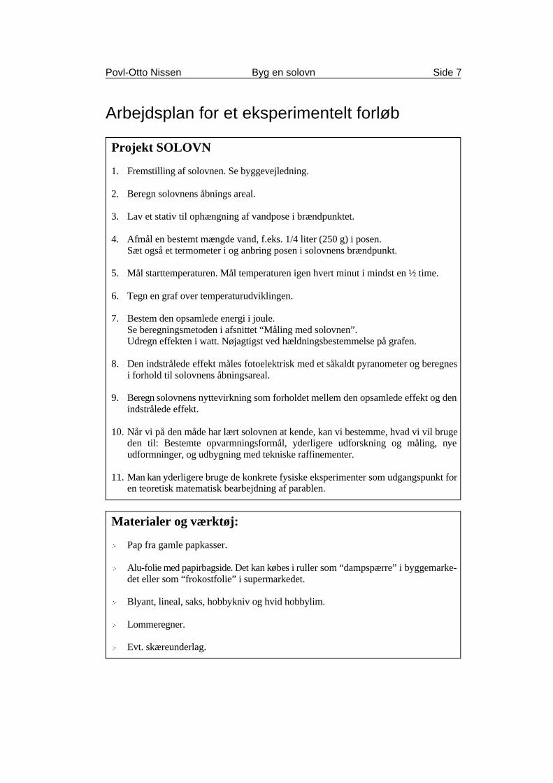
Projekt SOLOVN
1. Fremstilling af solovnen. Se byggevejledning.
2. Beregn solovnens åbnings areal.
3. Lav et stativ til ophængning af vandpose i brændpunktet.
4. Afmål en bestemt mængde vand, f.eks. 1/4 liter (250 g) i posen.Sæt også et termometer i og anbring posen i solovnens brændpunkt.
5. Mål starttemperaturen. Mål temperaturen igen hvert minut i mindst en ½ time.
6. Tegn en graf over temperaturudviklingen.
7. Bestem den opsamlede energi i joule. Se beregningsmetoden i afsnittet “Måling med solovnen”.Udregn effekten i watt. Nøjagtigst ved hældningsbestemmelse på grafen.
8. Den indstrålede effekt måles fotoelektrisk med et såkaldt pyranometer og beregnesi forhold til solovnens åbningsareal.
9. Beregn solovnens nyttevirkning som forholdet mellem den opsamlede effekt og denindstrålede effekt.
10. Når vi på den måde har lært solovnen at kende, kan vi bestemme, hvad vi vil brugeden til: Bestemte opvarmningsformål, yderligere udforskning og måling, nyeudformninger, og udbygning med tekniske raffinementer.
11. Man kan yderligere bruge de konkrete fysiske eksperimenter som udgangspunkt foren teoretisk matematisk bearbejdning af parablen.
Materialer og værktøj:
Í Pap fra gamle papkasser.
Í Alu-folie med papirbagside. Det kan købes i ruller som “dampspærre” i byggemarke-det eller som “frokostfolie” i supermarkedet.
Í Blyant, lineal, saks, hobbykniv og hvid hobbylim.
Í Lommeregner.
Í Evt. skæreunderlag.
Arbejdsplan for et eksperimentelt forløb
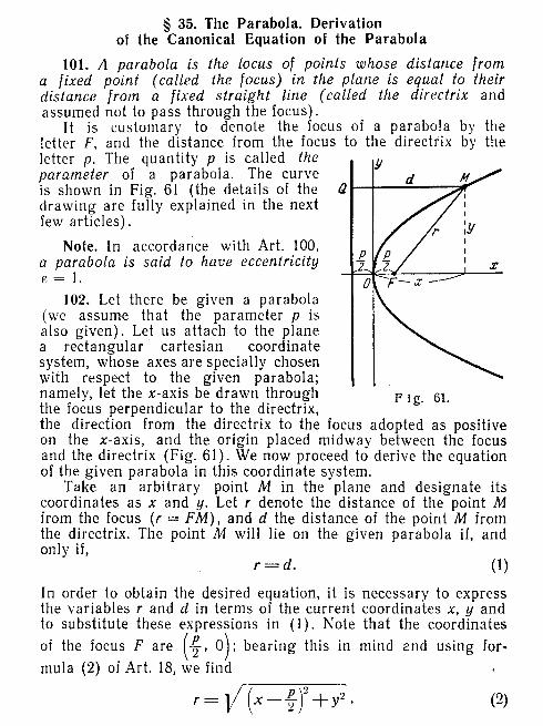
y a x y a x2 4 4= ⋅ ⋅ = ± ⋅ ⋅ eller
y x y x x= ± ⋅ ⋅ = ± = ± ⋅4 9 36 6, dvs.
Povl-Otto Nissen Byg en solovn Side 8
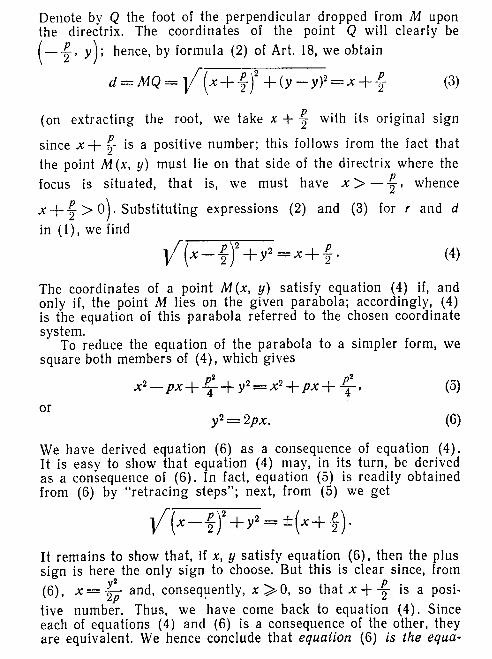
Byggevejledning
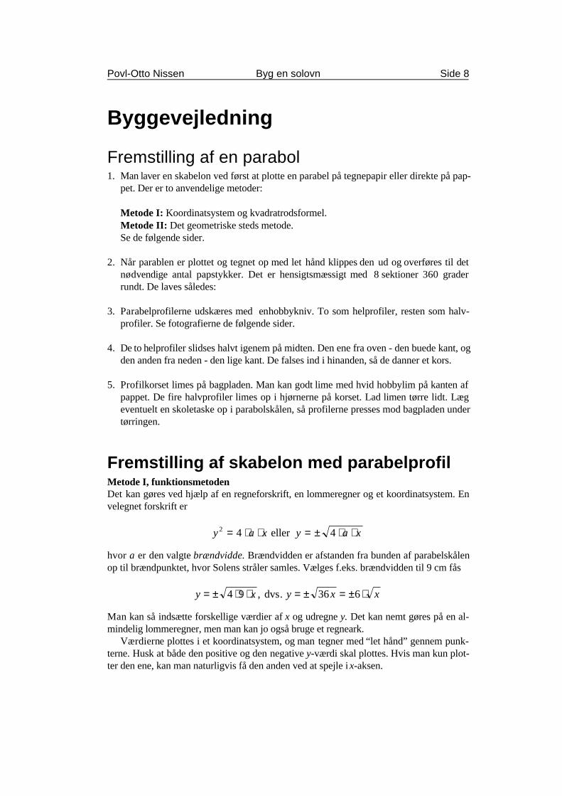
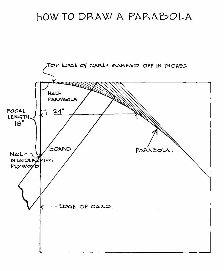
Fremstilling af en parabol1. Man laver en skabelon ved først at plotte en parabel på tegnepapir eller direkte på pap-
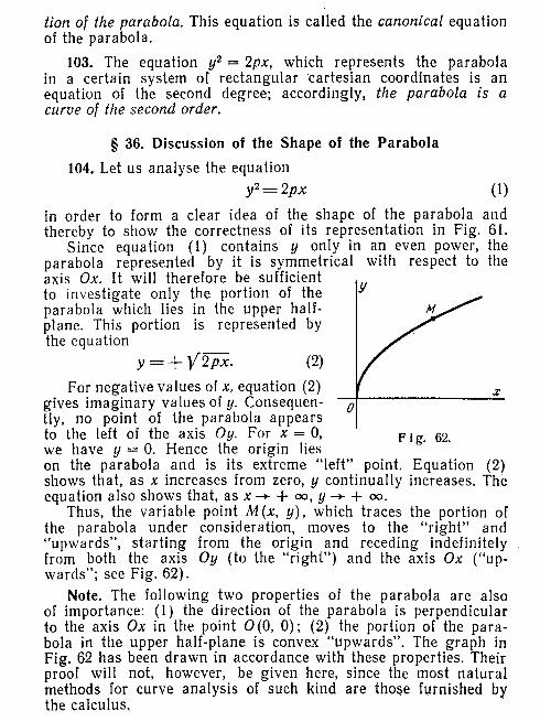
pet. Der er to anvendelige metoder:
Metode I: Koordinatsystem og kvadratrodsformel.Metode II: Det geometriske steds metode.Se de følgende sider.
2. Når parablen er plottet og tegnet op med let hånd klippes den ud og overføres til detnødvendige antal papstykker. Det er hensigtsmæssigt med 8 sektioner 360 graderrundt. De laves således:
3. Parabelprofilerne udskæres med en hobbykniv. To som helprofiler, resten som halv-profiler. Se fotografierne de følgende sider.
4. De to helprofiler slidses halvt igenem på midten. Den ene fra oven - den buede kant, ogden anden fra neden - den lige kant. De falses ind i hinanden, så de danner et kors.
5. Profilkorset limes på bagpladen. Man kan godt lime med hvid hobbylim på kanten afpappet. De fire halvprofiler limes op i hjørnerne på korset. Lad limen tørre lidt. Lægeventuelt en skoletaske op i parabolskålen, så profilerne presses mod bagpladen undertørringen.
Fremstilling af skabelon med parabelprofilMetode I, funktionsmetodenDet kan gøres ved hjælp af en regneforskrift, en lommeregner og et koordinatsystem. Envelegnet forskrift er
hvor a er den valgte brændvidde. Brændvidden er afstanden fra bunden af parabelskålenop til brændpunktet, hvor Solens stråler samles. Vælges f.eks. brændvidden til 9 cm fås
Man kan så indsætte forskellige værdier af x og udregne y. Det kan nemt gøres på en al-mindelig lommeregner, men man kan jo også bruge et regneark.
Værdierne plottes i et koordinatsystem, og man tegner med “let hånd” gennem punk-terne. Husk at både den positive og den negative y-værdi skal plottes. Hvis man kun plot-ter den ene, kan man naturligvis få den anden ved at spejle i x-aksen.
Povl-Otto Nissen Byg en solovn Side 9
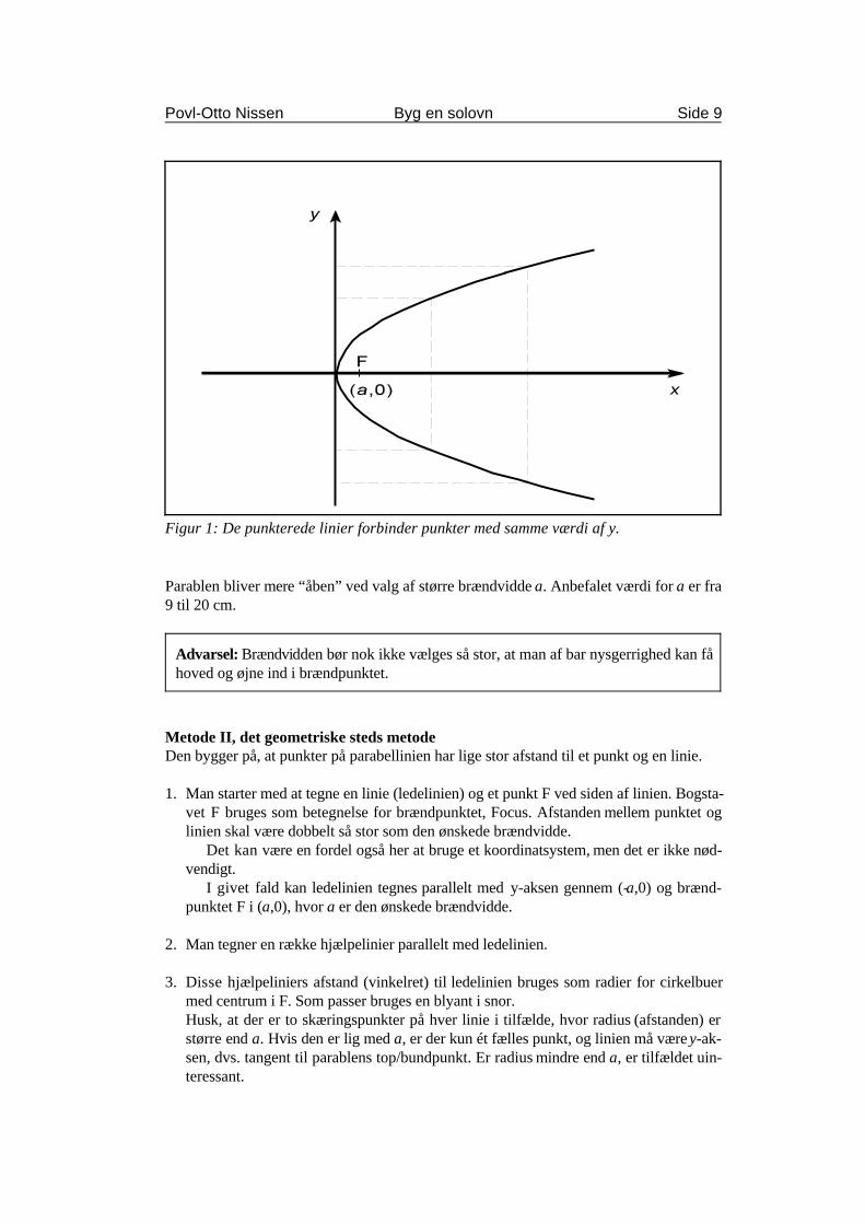
Figur 1: De punkterede linier forbinder punkter med samme værdi af y.
Advarsel: Brændvidden bør nok ikke vælges så stor, at man af bar nysgerrighed kan fåhoved og øjne ind i brændpunktet.
Parablen bliver mere “åben” ved valg af større brændvidde a. Anbefalet værdi for a er fra9 til 20 cm.
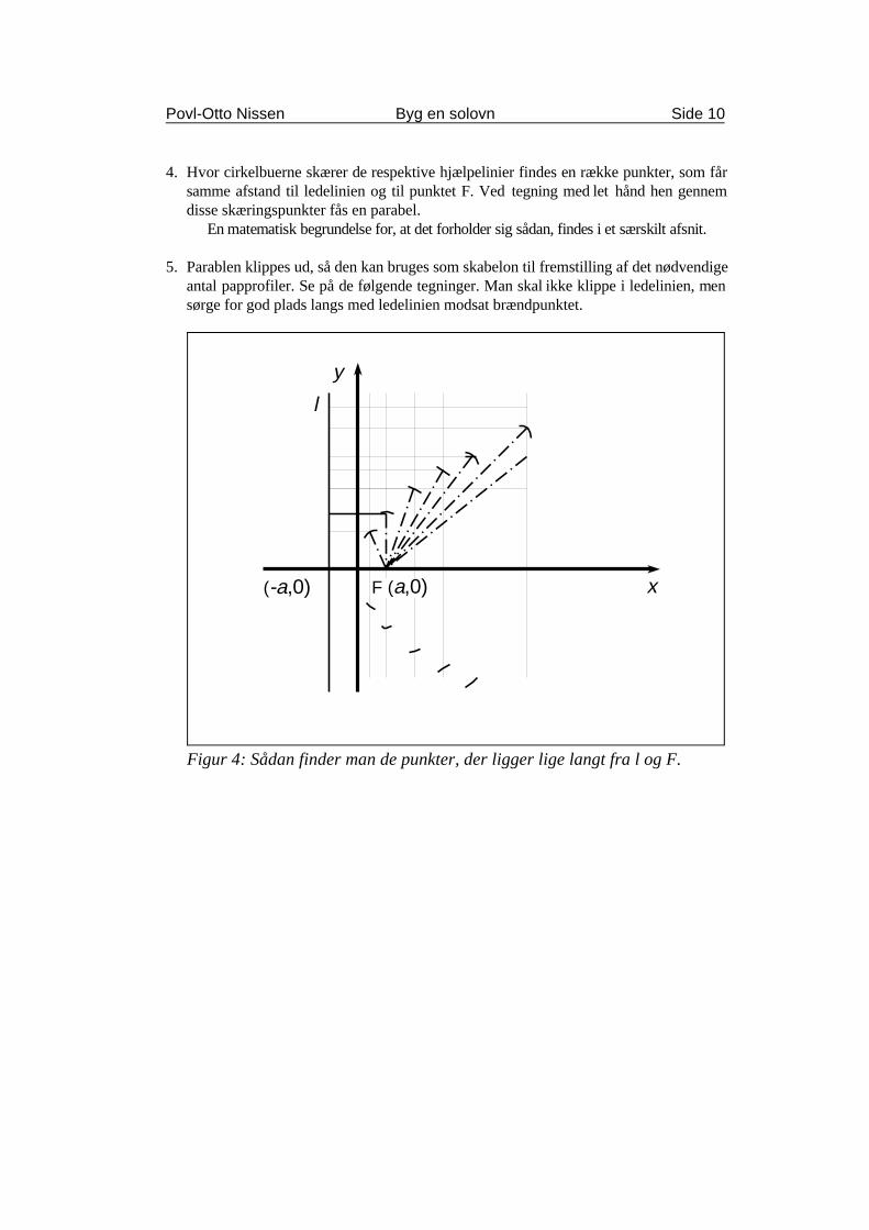
Metode II, det geometriske steds metodeDen bygger på, at punkter på parabellinien har lige stor afstand til et punkt og en linie.
1. Man starter med at tegne en linie (ledelinien) og et punkt F ved siden af linien. Bogsta-vet F bruges som betegnelse for brændpunktet, Focus. Afstanden mellem punktet oglinien skal være dobbelt så stor som den ønskede brændvidde.
Det kan være en fordel også her at bruge et koordinatsystem, men det er ikke nød-vendigt.
I givet fald kan ledelinien tegnes parallelt med y-aksen gennem (-a,0) og brænd-punktet F i (a,0), hvor a er den ønskede brændvidde.
2. Man tegner en række hjælpelinier parallelt med ledelinien.
3. Disse hjælpeliniers afstand (vinkelret) til ledelinien bruges som radier for cirkelbuermed centrum i F. Som passer bruges en blyant i snor.Husk, at der er to skæringspunkter på hver linie i tilfælde, hvor radius (afstanden) erstørre end a. Hvis den er lig med a, er der kun ét fælles punkt, og linien må være y-ak-sen, dvs. tangent til parablens top/bundpunkt. Er radius mindre end a, er tilfældet uin-teressant.
(-a,0) F (a,0)
l
y
x
Povl-Otto Nissen Byg en solovn Side 10
Figur 4: Sådan finder man de punkter, der ligger lige langt fra l og F.
4. Hvor cirkelbuerne skærer de respektive hjælpelinier findes en række punkter, som fårsamme afstand til ledelinien og til punktet F. Ved tegning med let hånd hen gennemdisse skæringspunkter fås en parabel.
En matematisk begrundelse for, at det forholder sig sådan, findes i et særskilt afsnit.
5. Parablen klippes ud, så den kan bruges som skabelon til fremstilling af det nødvendigeantal papprofiler. Se på de følgende tegninger. Man skal ikke klippe i ledelinien, mensørge for god plads langs med ledelinien modsat brændpunktet.
Povl-Otto Nissen Byg en solovn Side 11
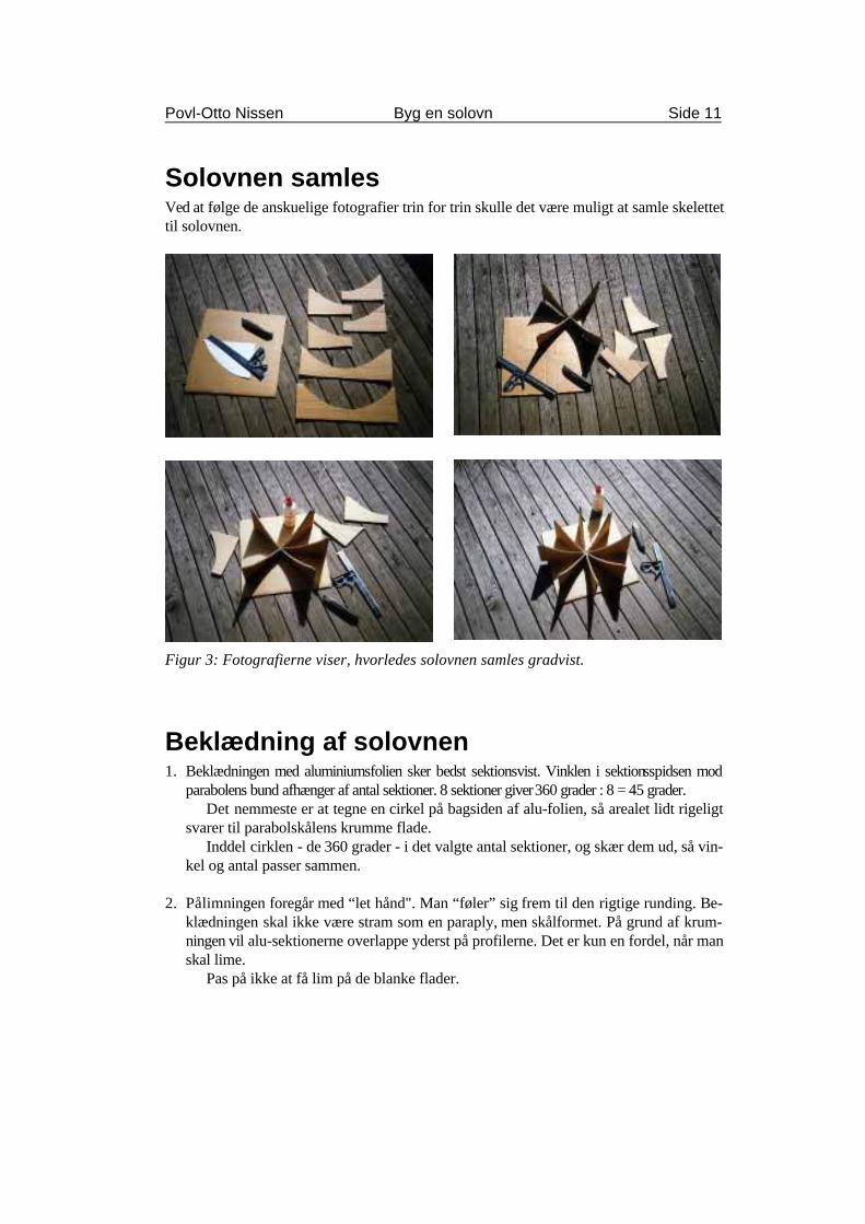
Solovnen samlesVed at følge de anskuelige fotografier trin for trin skulle det være muligt at samle skelettettil solovnen.
Figur 3: Fotografierne viser, hvorledes solovnen samles gradvist.
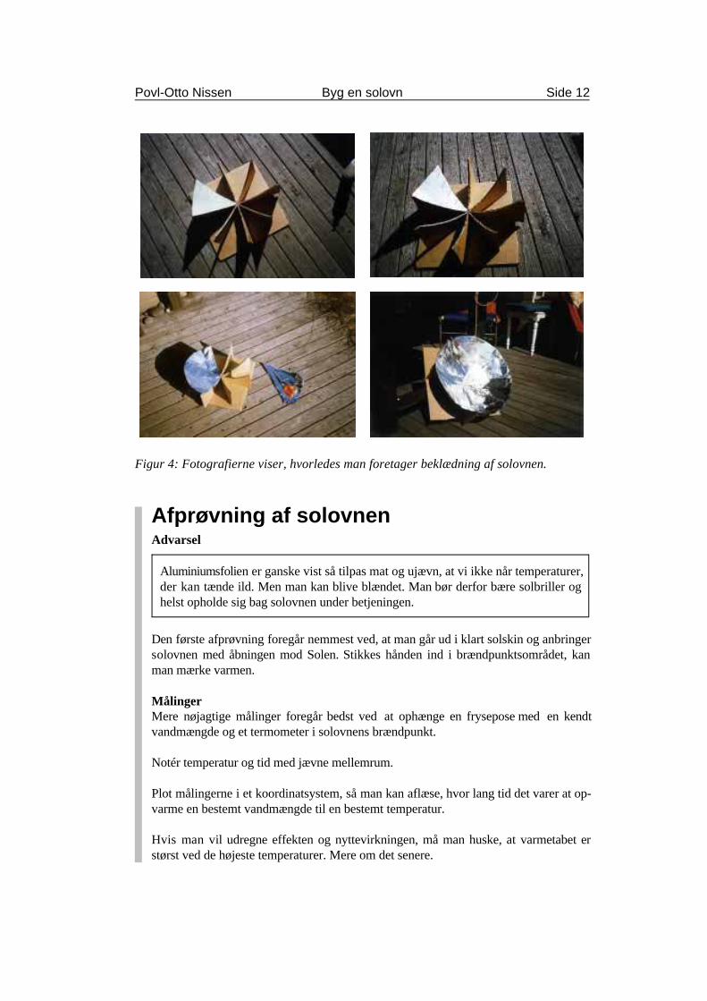
Beklædning af solovnen1. Beklædningen med aluminiumsfolien sker bedst sektionsvist. Vinklen i sektionsspidsen mod
parabolens bund afhænger af antal sektioner. 8 sektioner giver 360 grader : 8 = 45 grader.Det nemmeste er at tegne en cirkel på bagsiden af alu-folien, så arealet lidt rigeligt
svarer til parabolskålens krumme flade.Inddel cirklen - de 360 grader - i det valgte antal sektioner, og skær dem ud, så vin-
kel og antal passer sammen.
2. Pålimningen foregår med “let hånd". Man “føler” sig frem til den rigtige runding. Be-klædningen skal ikke være stram som en paraply, men skålformet. På grund af krum-ningen vil alu-sektionerne overlappe yderst på profilerne. Det er kun en fordel, når manskal lime.
Pas på ikke at få lim på de blanke flader.
Povl-Otto Nissen Byg en solovn Side 12
Aluminiumsfolien er ganske vist så tilpas mat og ujævn, at vi ikke når temperaturer,der kan tænde ild. Men man kan blive blændet. Man bør derfor bære solbriller oghelst opholde sig bag solovnen under betjeningen.
Figur 4: Fotografierne viser, hvorledes man foretager beklædning af solovnen.
Afprøvning af solovnenAdvarsel
Den første afprøvning foregår nemmest ved, at man går ud i klart solskin og anbringersolovnen med åbningen mod Solen. Stikkes hånden ind i brændpunktsområdet, kanman mærke varmen.
MålingerMere nøjagtige målinger foregår bedst ved at ophænge en frysepose med en kendtvandmængde og et termometer i solovnens brændpunkt.
Notér temperatur og tid med jævne mellemrum.
Plot målingerne i et koordinatsystem, så man kan aflæse, hvor lang tid det varer at op-varme en bestemt vandmængde til en bestemt temperatur.
Hvis man vil udregne effekten og nyttevirkningen, må man huske, at varmetabet erstørst ved de højeste temperaturer. Mere om det senere.
Kan vippes
Fastholdesaf klemme
Hængsel af tape
Tape
Sol
Hængsel af bredt, kraftigt klæbebånd
Povl-Otto Nissen Byg en solovn Side 13
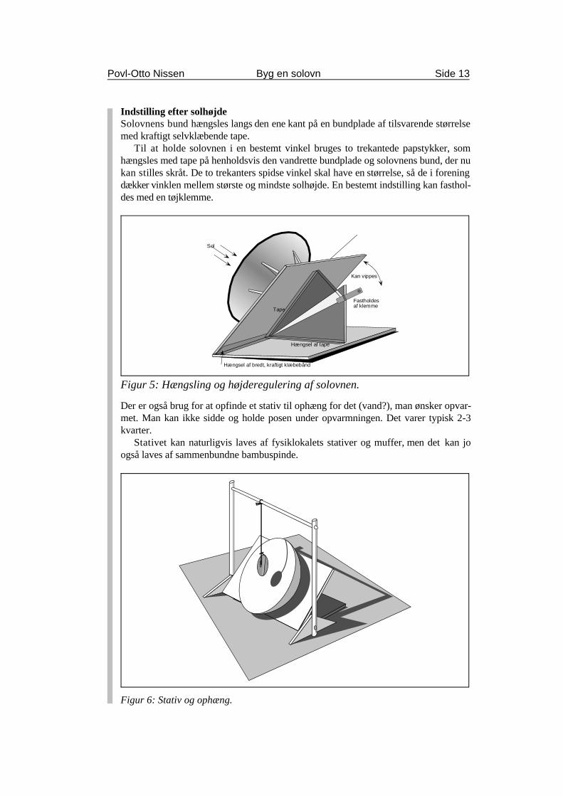
Figur 5: Hængsling og højderegulering af solovnen.
Indstilling efter solhøjdeSolovnens bund hængsles langs den ene kant på en bundplade af tilsvarende størrelsemed kraftigt selvklæbende tape.
Til at holde solovnen i en bestemt vinkel bruges to trekantede papstykker, somhængsles med tape på henholdsvis den vandrette bundplade og solovnens bund, der nukan stilles skråt. De to trekanters spidse vinkel skal have en størrelse, så de i foreningdækker vinklen mellem største og mindste solhøjde. En bestemt indstilling kan fasthol-des med en tøjklemme.
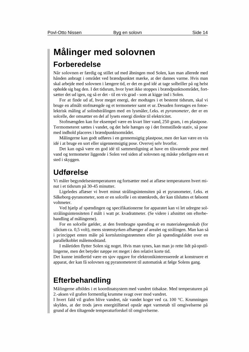
Der er også brug for at opfinde et stativ til ophæng for det (vand?), man ønsker opvar-met. Man kan ikke sidde og holde posen under opvarmningen. Det varer typisk 2-3kvarter.
Stativet kan naturligvis laves af fysiklokalets stativer og muffer, men det kan joogså laves af sammenbundne bambuspinde.
Figur 6: Stativ og ophæng.
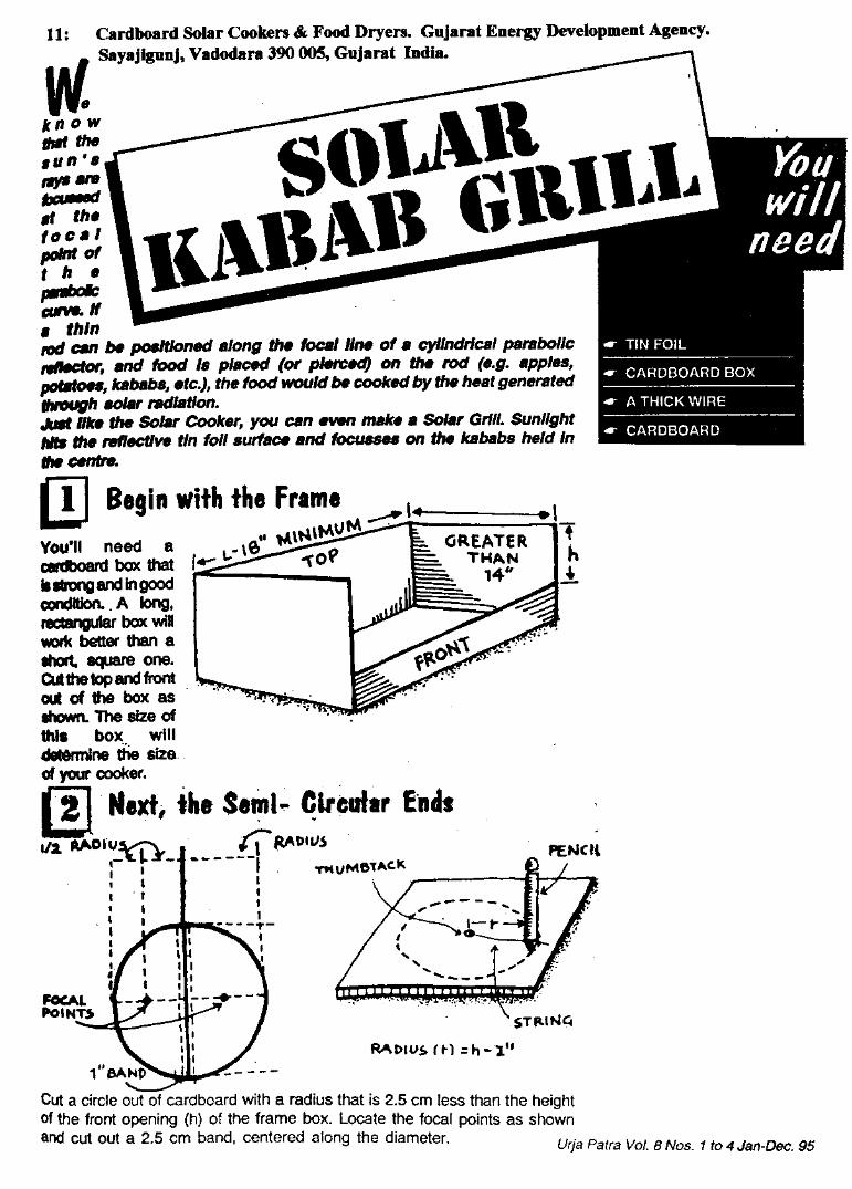
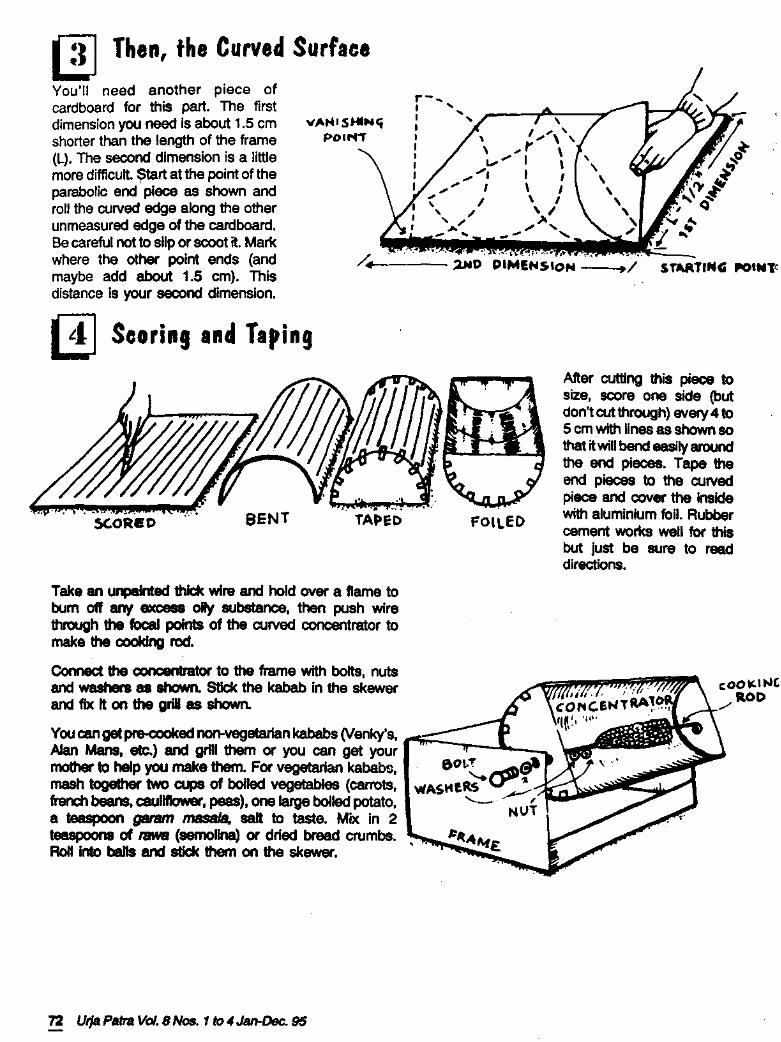
Povl-Otto Nissen Byg en solovn Side 14
Målinger med solovnenForberedelseNår solovnen er færdig og stillet ud med åbningen mod Solen, kan man allerede medhånden anbragt i området ved brændpunktet mærke, at der dannes varme. Hvis manskal arbejde med solovnen i længere tid, er det en god idé at tage solbriller på og helstopholde sig bag den. I det tidsrum, hvor lyset ikke stoppes i brændpunktsområdet, fort-sætter det ud igen, og så er det - til en vis grad - som at kigge ind i Solen.
For at finde ud af, hvor meget energi, der modtages i et bestemt tidsrum, skal vibruge en afmålt stofmængde og et termometer samt et ur. Desuden foretages en fotoe-lektrisk måling af solindstrålingen med en lysmåler, f.eks. et pyranometer, der er ensolcelle, der omsætter en del af lysets energi direkte til elektricitet.
Stofmængden kan for eksempel være en kvart liter vand, 250 gram, i en plastpose.Termometeret sættes i vandet, og det hele hænges op i det fremstillede stativ, så posemed indhold placeres i brændpunktsområdet.
Målingerne kan godt udføres i en gennemsigtig plastpose, men der kan være en visidé i at bruge en sort eller uigennemsigtig pose. Overvej selv hvorfor.
Det kan også være en god idé til sammenligning at have en tilsvarende pose medvand og termometer liggende i Solen ved siden af solovnen og måske yderligere een etsted i skyggen.
UdførelseVi måler begyndelsestemperaturen og fortsætter med at aflæse temperaturen hvert mi-nut i et tidsrum på 30-45 minutter.
Ligeledes aflæser vi hvert minut strålingsintensiten på et pyranometer, f.eks. etSilkeborg-pyranometer, som er en solcelle i en strømkreds, der kan tilsluttes et følsomtvoltmeter.
Ved hjælp af spændingen og specifikationerne for apparatet kan vi let udregne sol-strålingsintensiteten I målt i watt pr. kvadratmeter. (Se videre i afsnittet om efterbe-handling af målingerne).
For en solcelle gælder, at den frembragte spænding er en materialeegenskab (forsilicium ca. 0,5 volt), mens strømstyrken afhænger af arealet og strålingen. Man kan såi princippet enten måle på kortslutningstrømmen eller på spændingsfaldet over enparallelkoblet målemodstand.
I måletiden flytter Solen sig noget. Hvis man synes, kan man jo rette lidt på opstil-lingerne, men det betyder næppe ret meget i den relativt korte tid.Det kunne imidlertid være en sjov opgave for elektronikinteresserede at konstruere etapparat, der kan få solovnen og pyranometeret til automatisk at følge Solens gang.
EfterbehandlingMålingerne afbildes i et koordinatsystem med vandret tidsakse. Med temperaturen på2.-aksen vil grafen formentlig krumme svagt over mod vandret. I hvert fald vil grafen blive vandret, når vandet koger ved ca. 100 °C. Krumningenskyldes, at der trods jævn energitilførsel opstår øget varmetab til omgivelserne pågrund af den tiltagende temperaturforskel til omgivelserne.
20
30
40
50
60
70
80
90
T
temp i °C
tid i mint
Povl-Otto Nissen Byg en solovn Side 15
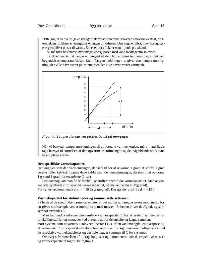
Figur 7: Temperaturkurven plottes bedst på mm-papir.
Dette gør, at vi må bruge et særligt trick for at bestemme solovnens maximale effekt, brut-toeffekten. Effekten er energiomsætningen pr. tidsrum. Den angiver altså, hvor hurtigt lys-energien bliver omsat til varme. Enheden for effekt er watt = joule pr. sekund.
Vi må først bestemme, hvor meget energi posen med vand modtager fra solovnen.Trick´et består i at lægge en tangent til den lidt krumme temperatur-graf tæt ved
begyndelsestemperatur/tidspunktet. Tangenthældningen angiver den temperaturstig-ning, der ville have været pr. minut, hvis der ikke havde været varmetab.
Når vi benytter temperaturstigningen til at beregne varmeenergien, må vi naturligvistage hensyn til størrelsen af den opvarmede stofmængde og det pågældende stofs evnetil at optage varme.
Den specifikke varmekapacitet.Den angives som den varmemængde, der skal til for at opvarme 1 gram af stoffet 1 gradcelsius (eller kelvin). I gamle dage kaldte man den energimængde, der skal til at opvarme1 g vand 1 grad, for en kalorie (1 cal).
I en databog kan man finde forskellige stoffers specifikke varmekapacitet. Man anven-der ofte symbolet c for specifik varmekapacitet, og måleenheden er J/(g·grad).For vands vedkommende er c = 4,19 J/(gram·grad). Der gælder altså 1 cal = 4,19 J.
Varmekapacitet for stofmængder og sammensatte systemer.På basis af de specifikke varmekapaciteter er det muligt at beregne varmekapaciteten foren given stofmængde ved at multiplicere med massen. Enheden bliver da J/grad, og somsymbol anvendes C.
Man kan endda udregne den samlede varmekapacitet C for et system sammensat afforskellige stoffer og mængder ved at regne ud for de enkelte og lægge sammen.Vort system, som opvarmes i solovnen, består f.eks. af en vandmængde, en plastpose oget termometer. I princippet skulle disse ting vejes hver for sig, masserne multipliceres medde respektive varmekapaciteter og det hele lægges sammen til C for systemet.
Overvej selv størrelsen af bidrag fra posen og temometeret, når de respektive masserog varmekapaciteter tages i betragtning.
∆ ∆
∆
E m T
T T T
= ⋅⋅
⋅
= −
4,19 J
g grad
hvor slut begynd
,
PE
tt t t= = −∆
∆∆, hvor slut begynd
I ind 2 2
W
m
W
m= ⋅ =1000
108
137788 3,
P A I r Iind = ⋅ = ⋅ ⋅π 2
η = P
Pmålt
ind
∆ t
Povl-Otto Nissen Byg en solovn Side 16
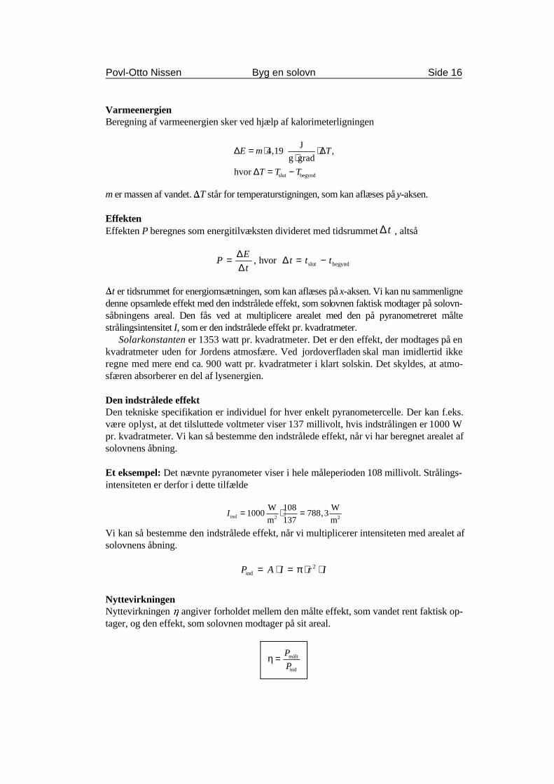
VarmeenergienBeregning af varmeenergien sker ved hjælp af kalorimeterligningen
m er massen af vandet. )T står for temperaturstigningen, som kan aflæses på y-aksen.
EffektenEffekten P beregnes som energitilvæksten divideret med tidsrummet , altså
)t er tidsrummet for energiomsætningen, som kan aflæses på x-aksen. Vi kan nu sammenlignedenne opsamlede effekt med den indstrålede effekt, som solovnen faktisk modtager på solovn-såbningens areal. Den fås ved at multiplicere arealet med den på pyranometreret måltestrålingsintensitet I, som er den indstrålede effekt pr. kvadratmeter.
Solarkonstanten er 1353 watt pr. kvadratmeter. Det er den effekt, der modtages på enkvadratmeter uden for Jordens atmosfære. Ved jordoverfladen skal man imidlertid ikkeregne med mere end ca. 900 watt pr. kvadratmeter i klart solskin. Det skyldes, at atmo-sfæren absorberer en del af lysenergien.
Den indstrålede effektDen tekniske specifikation er individuel for hver enkelt pyranometercelle. Der kan f.eks.være oplyst, at det tilsluttede voltmeter viser 137 millivolt, hvis indstrålingen er 1000 Wpr. kvadratmeter. Vi kan så bestemme den indstrålede effekt, når vi har beregnet arealet afsolovnens åbning.
Et eksempel: Det nævnte pyranometer viser i hele måleperioden 108 millivolt. Strålings-intensiteten er derfor i dette tilfælde
Vi kan så bestemme den indstrålede effekt, når vi multiplicerer intensiteten med arealet afsolovnens åbning.
NyttevirkningenNyttevirkningen 0 angiver forholdet mellem den målte effekt, som vandet rent faktisk op-tager, og den effekt, som solovnen modtager på sit areal.
I iW
m2 I iW
m2
Povl-Otto Nissen Byg en solovn Side 17
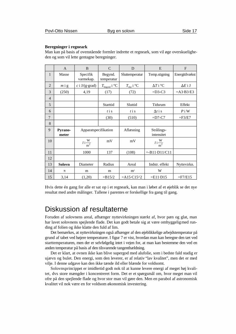
Beregninger i regnearkMan kan på basis af ovenstående formler indrette et regneark, som vil øge overskuelighe-den og som vil lette gentagne beregninger.
A B C D E F
1 Masse Specifik Begynd. Sluttemperatur Temp.stigning Energitilvækstvarmekap. temperatur
2 m i g c i J/(g·grad) T i °C T i °C )T i °C )E i Jbegynd slut
3 (250) 4,19 (17) (72) =D3-C3 =A3·B3·E3
4
5 Starttid Sluttid Tidsrum Effekt
6 t i s t i s )t i s P i W
7 (30) (510) =D7-C7 =F3/E7
8
9 Apparatspecifikation Aflæsning Strålings-Pyrano-meter intensitet
10 mV mV
11 1000 137 (108) =-B11·D11/C11
12
13 Diameter Radius Areal Indstr. effekt Nyttevirkn.Solovn
14 B m m m W2
15 3,14 (1,20) =B15/2 =A15·C15^2 =E11·D15 =F7/E15
Hvis dette én gang for alle er sat op i et regneark, kan man i løbet af et øjeblik se det nyeresultat med andre målinger. Tallene i parentes er forskellige fra gang til gang.
Diskussion af resultaterneForuden af solovnens areal, afhænger nyttevirkningen stærkt af, hvor pæn og glat, manhar lavet solovnens spejlende flade. Det kan godt betale sig at være omhyggelig med run-ding af folien og ikke klatte den fuld af lim.
Det bemærkes, at nyttevirkningen også afhænger af den øjeblikkelige arbejdstemperatur pågrund af tabet ved højere temperaturer. I figur 7 er vist, hvordan man kan beregne den tæt vedstarttemperaturen, men der er selvfølgelig intet i vejen for, at man kan bestemme den ved enanden temperatur på basis af den tilsvarende tangenthældning.
Det er klart, at ovnen ikke kan blive supergod med alufolie, som i bedste fald stadig erujævn og bulet. Den energi, som den leverer, er af relativ “lav kvalitet”, men det er medvilje. I denne udgave kan den ikke tænde ild eller blænde for voldsomt.
Solovnsprincippet er imidlertid godt nok til at kunne levere energi af meget høj kvali-tet, dvs store mængder i koncentreret form. Det er et spørgsmål om, hvor meget man vilofre på den spejlende flade og hvor stor man vil gøre den. Men en parabol af astronomiskkvalitet vil nok være en for voldsom økonomisk investering.
Parabelprofil
Povl-Otto Nissen Byg en solovn Side 18
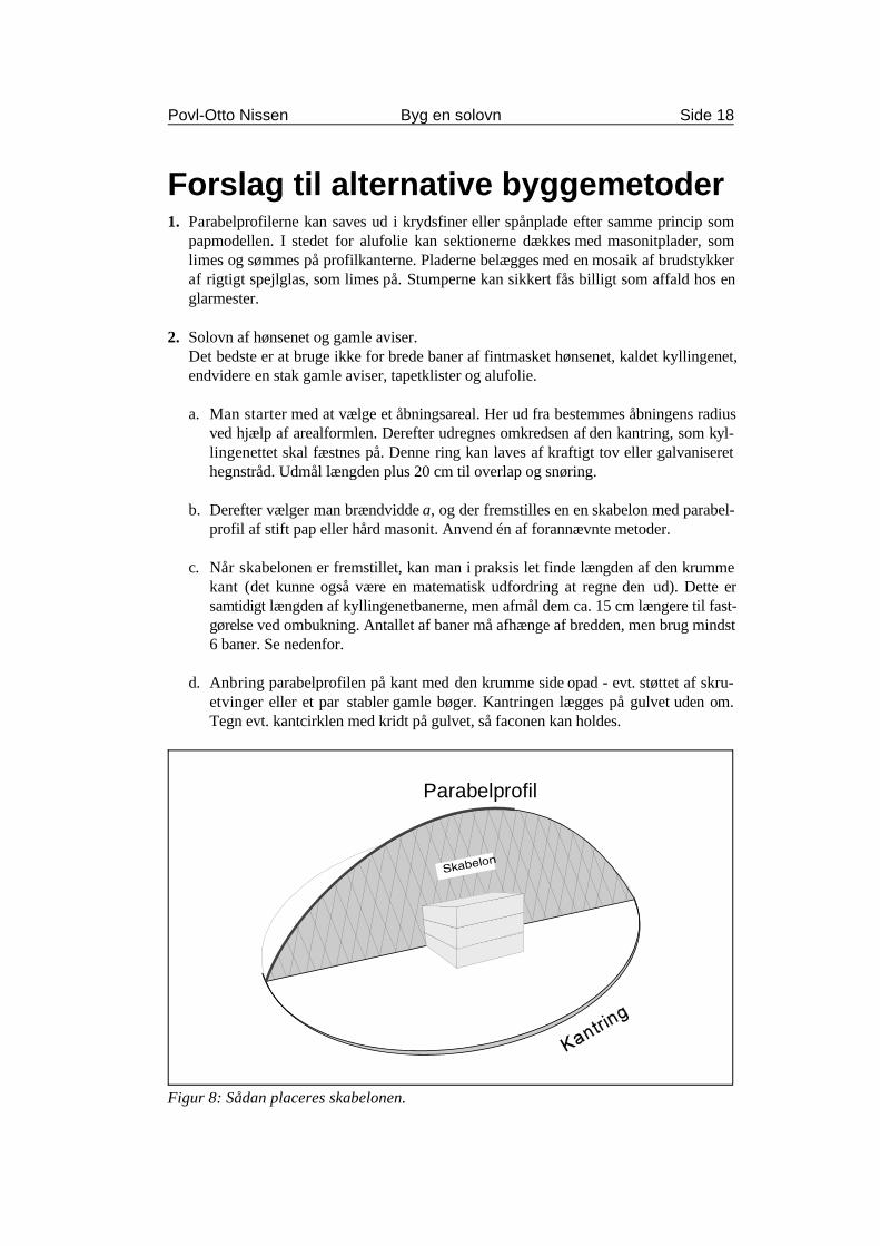
Figur 8: Sådan placeres skabelonen.
Forslag til alternative byggemetoder1. Parabelprofilerne kan saves ud i krydsfiner eller spånplade efter samme princip som
papmodellen. I stedet for alufolie kan sektionerne dækkes med masonitplader, somlimes og sømmes på profilkanterne. Pladerne belægges med en mosaik af brudstykkeraf rigtigt spejlglas, som limes på. Stumperne kan sikkert fås billigt som affald hos englarmester.
2. Solovn af hønsenet og gamle aviser.Det bedste er at bruge ikke for brede baner af fintmasket hønsenet, kaldet kyllingenet,endvidere en stak gamle aviser, tapetklister og alufolie.
a. Man starter med at vælge et åbningsareal. Her ud fra bestemmes åbningens radiusved hjælp af arealformlen. Derefter udregnes omkredsen af den kantring, som kyl-lingenettet skal fæstnes på. Denne ring kan laves af kraftigt tov eller galvaniserethegnstråd. Udmål længden plus 20 cm til overlap og snøring.
b. Derefter vælger man brændvidde a, og der fremstilles en en skabelon med parabel-profil af stift pap eller hård masonit. Anvend én af forannævnte metoder.
c. Når skabelonen er fremstillet, kan man i praksis let finde længden af den krummekant (det kunne også være en matematisk udfordring at regne den ud). Dette ersamtidigt længden af kyllingenetbanerne, men afmål dem ca. 15 cm længere til fast-gørelse ved ombukning. Antallet af baner må afhænge af bredden, men brug mindst6 baner. Se nedenfor.
d. Anbring parabelprofilen på kant med den krumme side opad - evt. støttet af skru-etvinger eller et par stabler gamle bøger. Kantringen lægges på gulvet uden om.Tegn evt. kantcirklen med kridt på gulvet, så faconen kan holdes.
Povl-Otto Nissen Byg en solovn Side 19
e. Første kyllingenetbane lægges over parabelprofilen, føres under kantringen i ender-ne og bukkes om. Vær omhyggelig med at forme netenderne, så kantringens cirkel-form holdes. Kyllingenetbanernes langsgående kanter forkortes ved at man “krøl-ler” dem, og man kan derved tilnærme en parabelform “på tværs”.
f. Parabelprofilen vendes nu på tværs af første bane, og bane nr. 2 lægges på, fæstnesog formes. Yderligere to baner lægges over “på kryds”. Det er vigtigt, at man om-hyggeligt former netbanerne ved hjælp af bidetang og ombukning, så vi ender meden parabolsk form i en cirkelring. Afhængigt af banebredden lægges om nødvendigtflere baner på. Det er vigtigt at parabolnettet har en vis stivhed før belægningen.
g. Belægningen foregår som ved tapetsering - blot med aviser. Ugeavis-formatet ervelegnet, og ugeaviser har ofte den umiddelbare fordel ikke at være heftede. Limensmøres på med en bred pensel. Eventuelt kan avisarket limes dobbelt før det limespå parabolnettet. Der er erfaring for, at det kan være en fordel først at tapetsere denkonvekse bagside først og lade det tørre. Det øger stivheden før belægningen af deninteressante inderside af parabolen.
Det er vigtigt omhyggeligt at sørge for en glat overflade og undgå folder. Derkan ske ved, at man under pålimningen river folderne op, så krumningen skabes vedat papiret kommer til at overlappe sig selv i passende grad.
h. Det yderste lag indvendigt skal naturligvis være så glat og blankt som muligt.Ujævnheder må eventuelt fyldes ud med papirmasse eller slibes af før belægningenmed alufolie. Derefter er man klar til afprøvningen.
3. Som en mulig belægningsform kan vælges glasfiber i stedet for gamle aviser. Det ernoget dyrere, men kyllingenettet kan også i dette tilfælde bruges som skelet - eller avis-modellen kan måske ligefrem bruges som støbeform. Pålægningen af glasfiber skalforegå efter de forskrifter, som gælder for den slags med god ventilation, handsker ogåndedrætsværn.
Pudse- og polerearbejde er i dette tilfælde mere omfattende, men også her er alufo-lien nok den billigste som spejlende flade.
4. Der findes solovne af “tagrendemodellen”, altså parabelbøjede plader, hvorfra stråler-ne focuseres i en “brændlinie”. Her kan man så anbringe et rør med vand, og ved ind-pasning i et system med en svag hældning på røret vil vandet ved opvarmning kunnegøres selvcirkulerende. Se også nedenfor.
Povl-Otto Nissen Byg en solovn Side 20
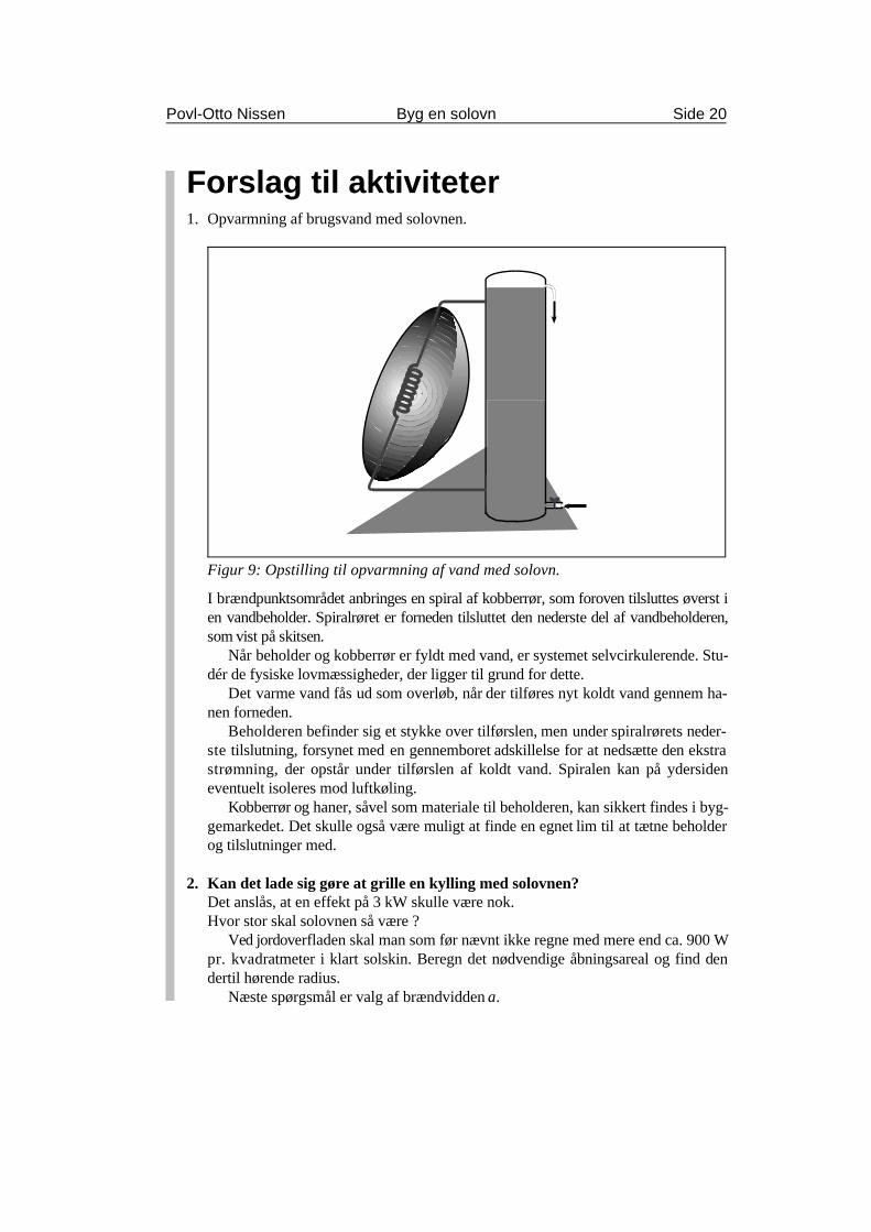
Figur 9: Opstilling til opvarmning af vand med solovn.
Forslag til aktiviteter1. Opvarmning af brugsvand med solovnen.
I brændpunktsområdet anbringes en spiral af kobberrør, som foroven tilsluttes øverst ien vandbeholder. Spiralrøret er forneden tilsluttet den nederste del af vandbeholderen,som vist på skitsen.
Når beholder og kobberrør er fyldt med vand, er systemet selvcirkulerende. Stu-dér de fysiske lovmæssigheder, der ligger til grund for dette.
Det varme vand fås ud som overløb, når der tilføres nyt koldt vand gennem ha-nen forneden.
Beholderen befinder sig et stykke over tilførslen, men under spiralrørets neder-ste tilslutning, forsynet med en gennemboret adskillelse for at nedsætte den ekstrastrømning, der opstår under tilførslen af koldt vand. Spiralen kan på ydersideneventuelt isoleres mod luftkøling.
Kobberrør og haner, såvel som materiale til beholderen, kan sikkert findes i byg-gemarkedet. Det skulle også være muligt at finde en egnet lim til at tætne beholderog tilslutninger med.
2. Kan det lade sig gøre at grille en kylling med solovnen?Det anslås, at en effekt på 3 kW skulle være nok.Hvor stor skal solovnen så være ?
Ved jordoverfladen skal man som før nævnt ikke regne med mere end ca. 900 Wpr. kvadratmeter i klart solskin. Beregn det nødvendige åbningsareal og find dendertil hørende radius.
Næste spørgsmål er valg af brændvidden a.
Povl-Otto Nissen Byg en solovn Side 21
Advarsel. Her må igen advares mod, at man laver brændvidden så stor, at nogenuforvarende kan få hoved og øjne ind i brændpunktsområdet. Etabler eventuelt ensikkerhedsafstand og bær solbriller.
Et andet spørgsmål er naturligvis den spejlende flades effektivitet og evne til at fo-kusere, dvs. om den er blank nok og uden ujævne buler.
Her ved vi fra målinger af nyttevirkningen, at alufolien har sine begrænsninger,men det skulle være muligt at kompensere for dette ved at øge arealet. Det er her-med overladt til læseren at finde en eksperimentel løsning.
3. Bestemmelse af smeltepunktet for f.eks. stearin.Det skulle også - i princippet - være muligt at bestemme smeltevarmen, hvis manholder øje med, hvor lang tid det tager at smelte en bestemt masse stearin og iøvrigtved hvor stor effekten er den dag.
4. Automatisk drejning af solovnen.Det kunne være en sjov opgave at få solovnen til at følge med Solen mens tiden går.Det kan måske løses ved hjælp af et vækkeur af ældre dato. Søg på loppemarkedet.
Det kunne sikkert også løses med tandhjul, lodder og et pendul.En elektronisk løsningsmulighed ved hjælp af fotosensorer og Wheatstones bro
er foreslået i “Bogen om Solenergi”, side 52, (Clausen Bøger 1978).
y a x y a x a x2 4 4= ⋅ ⋅ = ± ⋅ ⋅ eller , > 0 og > 0
Povl-Otto Nissen Byg en solovn Side 22
Matematisk baggrund for parabolenVi vil i dette afsnit se på den matematiske baggrund for parabolens egnethed til at reflek-tere lyset, så den kan bruges som solovn. Skabelonerne til solovnens parabelprofiler kanudskæres efter at være plottede på én ud af to forskellige måder.
Først et lille detaljeret resumé af de to fremstillingsmetoder:
Metode IDen ene er, at man i et koordinatsystem plotter en graf med ligningen
simpelthen ved først at vælge en række x-værdier og udregne de tilsvarende y-værdier.Det er en parabel, der “ligger ned” med åbningen i x-aksens retning og top/bundpunkt i
(0,0). Man skal plotte både den positive og negative y-værdi for forskellige x-værdier.Parabolen fremkommer ideelt set, når parablen roteres 180 grader med x-aksen som
omdrejningsakse. I vort tilfælde har vi bygget den op af 8 sektioner.Værdien a vælges konstant for den enkelte parabel, og dens størrelse bestemmer faktisk
brændvidden, som er afstanden fra parabolskålens bund op til det punkt F, hvor stråler paral-lelle med x-aksen samles. Det kaldes brændpunktet og har således koordinaten (a,0). Man kannetop ved fastsættelse af denne værdi bestemme dimensionerne på sin solovn.
Metode IIDen anden metode er kaldt “det geometriske steds metode”. Den bygger på, at parablen eren punktmængde, hvor punkterne opfylder den betingelse at ligge lige langt fra en ret linieog fra et fast punkt uden for linien.
Når man skal tegne den, er det nemmest først at tegne et koordinatsystem. Man vælger så enbrændvidde a og afsætter et fast punkt F på x-aksen med koordinaten (a,0). Parallel med y-ak-sen tegnes nu en ret linie l gennem (-a,0). Den kaldes ledelinien.
Parallelt med ledelinien (og y-aksen) tegnes i vilkårlige afstande for positive værdier af xnogle hjælpelinier. En given hjælpelinies afstand til ledelinien tages som radius i en passer elleren blyant i snor. Husk at afstanden skal måles vinkelret på linierne
Med denne radius og med F som centrum tegnes nu en cirkelbue. Hvor denne cirkelbueskærer den valgte hjælpelinie, findes punkter, der tilhører parablens punktmængde. Huskat der er to på hver linie, hvis det ikke ligefrem er y-aksen. Den ligger jo i forvejen midtmellem ledelinien og F.
Ved på denne måde et antal gange at finde skæringspunkter, vil man hurtigt få nok tilmed fri hånd at kunne tegne parabelprofilen.
BevisførelseVi vil nu bevise, 1. At punkter med lige stor afstand til en linie og et fast punkt udgør en parabel. 2. At punkter på en parabel ligger lige langt fra et fast punkt og en linie.
y
Ps (x,y)
R(a,0)
F
0(-a,0) x
FR RP FP2 2 2+ =
( ) ( )x a y x a
x a x a y x a x a
y a x
− + = +
− ⋅ ⋅ + + = + ⋅ ⋅ +
= ⋅ ⋅
2 2 2
2 2 2 2 2
2
2 2
4
Povl-Otto Nissen Byg en solovn Side 23
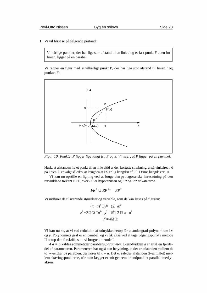
Vilkårlige punkter, der har lige stor afstand til en linie l og et fast punkt F uden forlinien, ligger på en parabel.
Figur 10: Punktet P ligger lige langt fra F og S. Vi viser, at P ligger på en parabel.
1. Vi vil først se på følgende påstand:
Vi tegner en figur med et vilkårligt punkt P, der har lige stor afstand til linien l ogpunktet F:
Husk, at afstanden fra et punkt til en linie altid er den korteste strækning, altså vinkelret indpå linien. P er valgt således, at længden af PS er lig længden af PF. Denne længde er x+a.
Vi kan nu opstille en ligning ved at bruge den pythagoræiske læresætning på denretvinklede trekant PRF, hvor PF er hypotenusen og FR og RP er kateterne.
Vi indfører de tilsvarende størrelser og variable, som de kan læses på figuren:
Vi kan nu se, at vi ved reduktion af udtrykket netop får et andengradspolynomium i xog y. Polynomiets graf er en parabel, og vi fik altså ved at tage udgangspunkt i metodeII netop den forskrift, som vi brugte i metode I.
4·a = p kaldes sommetider parablens parameter. Brændvidden a er altså en fjerde-del af parameteren. Parameteren har også den betydning, at det er afstanden mellem deto y-værdier på parablen, der hører til x = a. Det er således afstanden (tværmålet) mel-lem skæringspunkterne, når man lægger et snit gennem brændpunktet parallelt med y-aksen.
y
QS
R
(a,0)
F
0
(-a,y1)
x(-a,0)
(x1,y1)
(x1,0)
QF y x a= + −12
12( )
y a x1 14= ± ⋅ ⋅
QF a x x a
QF a x x a x a x a x a
QF x a x a
= ± ⋅ ⋅ + −
= ⋅ ⋅ + − ⋅ ⋅ + = + ⋅ ⋅ +
= + = +
( ) ( )
( )
4
4 2 2
12
12
1 12
12
12
12
12
1
Povl-Otto Nissen Byg en solovn Side 24
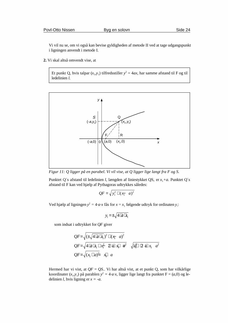
Et punkt Q, hvis talpar (x ,y ) tilfredsstiller y = 4ax, har samme afstand til F og til1 12
ledelinien l.
Figur 11: Q ligger på en parabel. Vi vil vise, at Q ligger lige langt fra F og S.
Vi vil nu se, om vi også kan bevise gyldigheden af metode II ved at tage udgangspunkti ligningen anvendt i metode I.
2. Vi skal altså omvendt vise, at
Punktet Q´s afstand til ledelinien l, længden af liniestykket QS, er x +a. Punktet Q´s1
afstand til F kan ved hjælp af Pythagoras udtrykkes således:
Ved hjælp af ligningen y = 4·a·x fås for x = x følgende udtryk for ordinaten y :21 1
som indsat i udtrykket for QF giver
Hermed har vi vist, at QF = QS.. Vi har altså vist, at et punkt Q, som har vilkårligekoordinater (x ,y ) på parablen y = 4·a·x, ligger lige langt fra punktet F = (a,0) og le-1 1
2
delinien l, hvis ligning er x = -a.
∠ = ∠u i
Indfaldslod
Lysstråle
ggu
Spejlende flade
90° - gu 90° - gi
ggi
90 90°−∠ = °−∠u i
Povl-Otto Nissen Byg en solovn Side 25
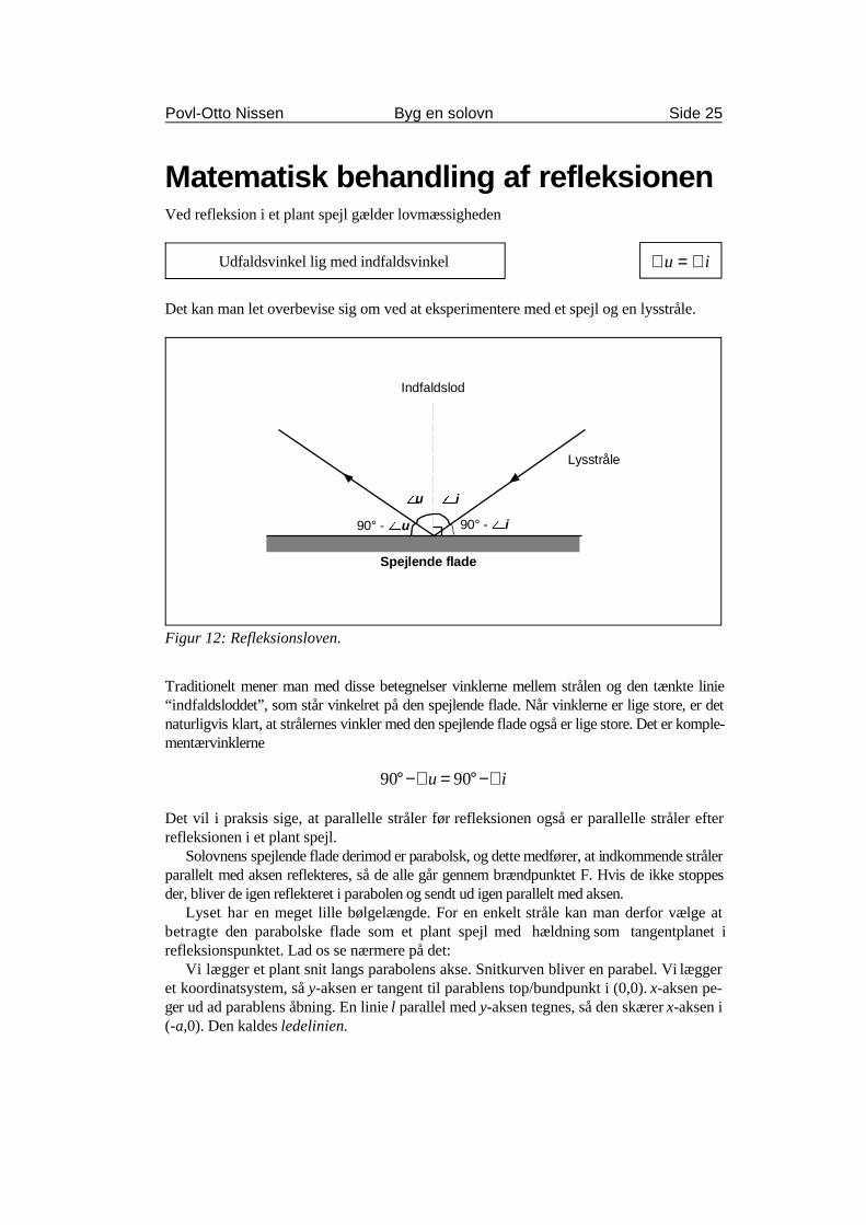
Udfaldsvinkel lig med indfaldsvinkel
Figur 12: Refleksionsloven.
Matematisk behandling af refleksionenVed refleksion i et plant spejl gælder lovmæssigheden
Det kan man let overbevise sig om ved at eksperimentere med et spejl og en lysstråle.
Traditionelt mener man med disse betegnelser vinklerne mellem strålen og den tænkte linie“indfaldsloddet”, som står vinkelret på den spejlende flade. Når vinklerne er lige store, er detnaturligvis klart, at strålernes vinkler med den spejlende flade også er lige store. Det er komple-mentærvinklerne
Det vil i praksis sige, at parallelle stråler før refleksionen også er parallelle stråler efterrefleksionen i et plant spejl.
Solovnens spejlende flade derimod er parabolsk, og dette medfører, at indkommende strålerparallelt med aksen reflekteres, så de alle går gennem brændpunktet F. Hvis de ikke stoppesder, bliver de igen reflekteret i parabolen og sendt ud igen parallelt med aksen.
Lyset har en meget lille bølgelængde. For en enkelt stråle kan man derfor vælge atbetragte den parabolske flade som et plant spejl med hældning som tangentplanet irefleksionspunktet. Lad os se nærmere på det:
Vi lægger et plant snit langs parabolens akse. Snitkurven bliver en parabel. Vi læggeret koordinatsystem, så y-aksen er tangent til parablens top/bundpunkt i (0,0). x-aksen pe-ger ud ad parablens åbning. En linie l parallel med y-aksen tegnes, så den skærer x-aksen i(-a,0). Den kaldes ledelinien.
∠ = ∠i u
Povl-Otto Nissen Byg en solovn Side 26
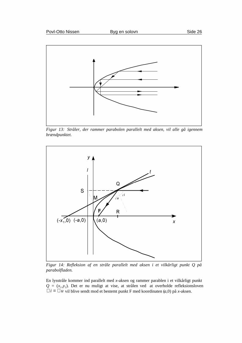
Figur 13: Stråler, der rammer parabolen parallelt med aksen, vil alle gå igennembrændpunktet.
Figur 14: Refleksion af en stråle parallelt med aksen i et vilkårligt punkt Q påparabolfladen.
En lysstråle kommer ind parallelt med x-aksen og rammer parablen i et vilkårligt punktQ = (x ,y ). Det er nu muligt at vise, at strålen ved at overholde refleksionsloven1 1
vil blive sendt mod et bestemt punkt F med koordinaten (a,0) på x-aksen.
∠ = ∠FQM SQM
yx
x
y= +2 21
1 ,
x yy
yx
x
xy x
= ⇔ =
= ⇔ = + =
02
0 02 2
1
1
11 1
og
idet ,
xx
x x= − ⋅ ⋅ = −11 12
2
(0,y1
2)
f(x) ' xy ' 4@a@x
y ' x
(0,y1
2)
y ' x
Povl-Otto Nissen Byg en solovn Side 27
Vi tegner tangenten t til parablen i Q = (x ,y). Tangenten skærer y-aksen i M og x-aksen i T.1 1
Det hele står og falder med, om vi kan vise, at gFQM = gSQM, idet gSQM er top-vinkel sammen med strålens vinkel med tangenten, altså 90° - gi.. gFQM er jo, som detses af figuren, lig med 90° - gu.
Dette er tilfældet, såfremt tangenten i skæringspunktet M med y-aksen står vinkelret
på midten af FS, og at dette punkt har koordinatsættet .
I samme tilfælde er tangentens skæringspunkt med x-aksen T = (-x ,0). I så fald er tan-1
genten højde i den ligebenede trekant SQF med SQ = QF og der gælder, at
For at være sikker på dette er vi nødt til at finde tangentens ligning og bestemme densskæringspunkter med akserne. Der gør vi med lidt differentialregning. Udledningen kanses i et efterfølgende afsnit.
Vi vælger at se på funktionen , hvilket svarer til, at vi i vor anvendte lig-ning for nemheds skyld har valgt a = 0,25. Ved hjælp af differentiation fin-der vi tangentligningen
hvor (x ,y ) er koordinaten til tangentens røringspunkt.Skæringspunkterne med akserne1 1
findes. Det ses netop at
Heraf fås
Vi har hermed fundet, at tangenten til parabelgrenen skærer x-aksen i punktet
med koordinatsættet (-x ,0) og y-aksen i punktet med koordinatsættet , når (x ,y )1 1 1
er tangentens røringspunkt.Dette var netop forudsætningen for, at en indfaldende stråle parallelt med x-aksen re-
flekteres gennem et punkt F = (a,0).
Et taleksempel:
Vi vælger at lade tangenten røre i (x ,y ) = (9,3), som tilfredsstiller . Talparret1 1
indsættes i tangentligningen
yx
x
y
yx
y x
= +
= + ⇔ = +
2 2
2 9
3
2
1
6
3
2
1
1
y x x= ⇔ = − ⇔ = −01
6
3
29
′ =−−
f xf x f x
x x( )
( ) ( )1
1
1
y f x x x f x= ′ − +( )( ) ( )1 1 1
yx
x x x
yx
x
x
xx
yx
x
xx
yx
x
x
= − +
= − +
= − +
= +
1
2
2 2
2 2
2 2
1
1 1
1
1
11
1
11
1
1
( )
yx
xy= +1
2 21
1
f(x) ' x
′ =f xx
( )11
1
2
x1 ' y1
y ' x
(0,y1
2)
Povl-Otto Nissen Byg en solovn Side 28
Heraf ses umiddelbart, at skæringen med y-aksen sker i y = 3/2. Skæringen med x-aksen bestemmes
Det ses hermed, at tangenten i (9,3), skærer x-aksen i (- 9,0) og y-aksen i (0, 3/2)
Udledning af tangentligningenVi kigger på den differentiable funktion , hvis graf er parabelgren i 1.kvadrant.Tangenthældningen for x=x kan udtrykkes1
Vi sætter f(x) = y. Tangentens ligning kan herefter udtrykkes
Idet , fås
Da , får vi
Dette er ligningen for en tangent til parabelgrenen med ligningen , hvor (x ,y ) er1 1
koordinatsættet for tangentens røringspunkt.Som man kan se, skærer tangenten y-aksen i . Som vi har påvist foran, skærer
den x-aksen i (-x ,0).1
Povl-Otto Nissen Byg en solovn Side 29
Litteraturhenvisninger og referencerDer findes umådelig meget litteratur om solenergi. I forbindelse med udarbejdelsen af det-te temahefte er især anvendt
1. “Sonnenenergie”, Avi Sochaczevsky, Tree of Knowledge, Yasur, Israel. (Manual til legetøjseksperimentsæt).
2. “Bogen om Solenergi”, Esbensen og Lawaetz, Clausen Bøger 1978.
3. “Vedvarende energi”, masser af artikler, Organisationen for Vedvarende Energi.
Afsnittet om den matematiske baggrund for parabolen har hentet inspiration fra
4. “Matematik til anvendelse i Fysik og Teknik”, Poul Thomsen, Gyldendal 1967.
5. “Differentialregning, Teori og redskab”, S.Jensen og K.Sørensen, Chr. Ejler 1982.
Til beregninger og basis for parabelgrafer er anvendt
6. EDB-programmet “GrafMat”, Jens Ole Bach, Matematiklærerforeningen.
Som måleudstyr er - udover termometer, ur og universalinstrument - anvendt
7. “Pyranometer” fra “Soldata”, F.Bason, Linåbakken 13, 8600 Silkeborg.
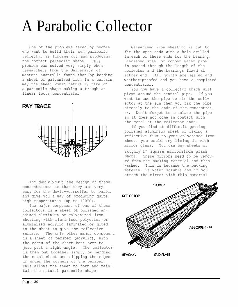
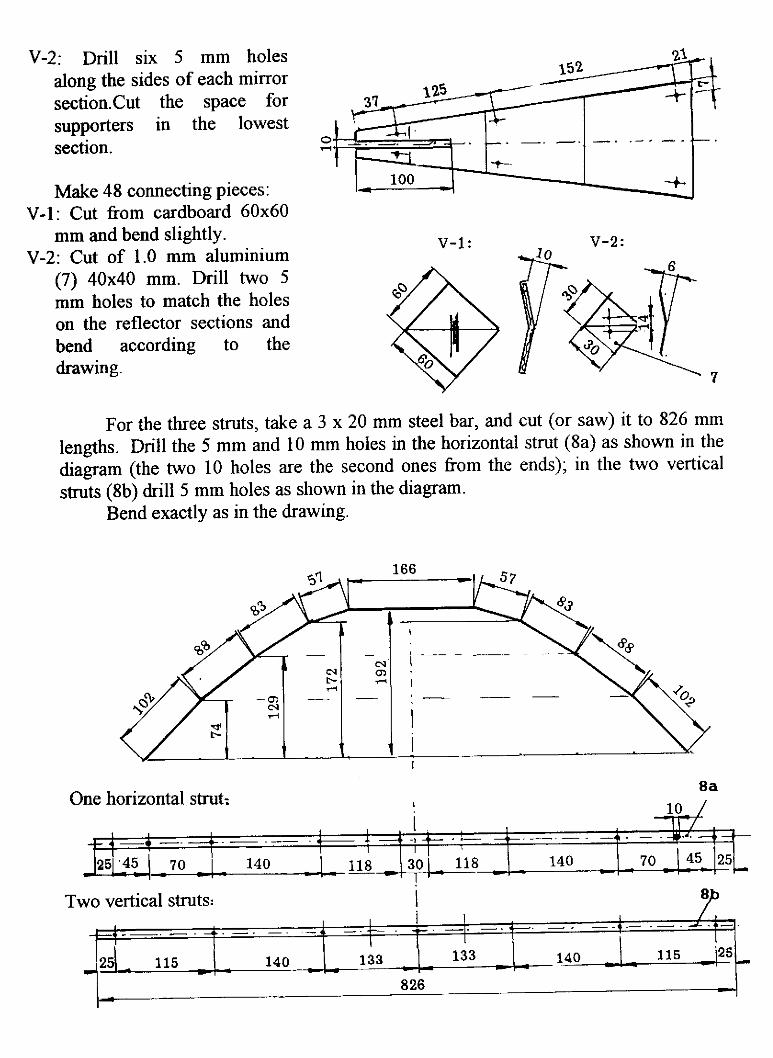
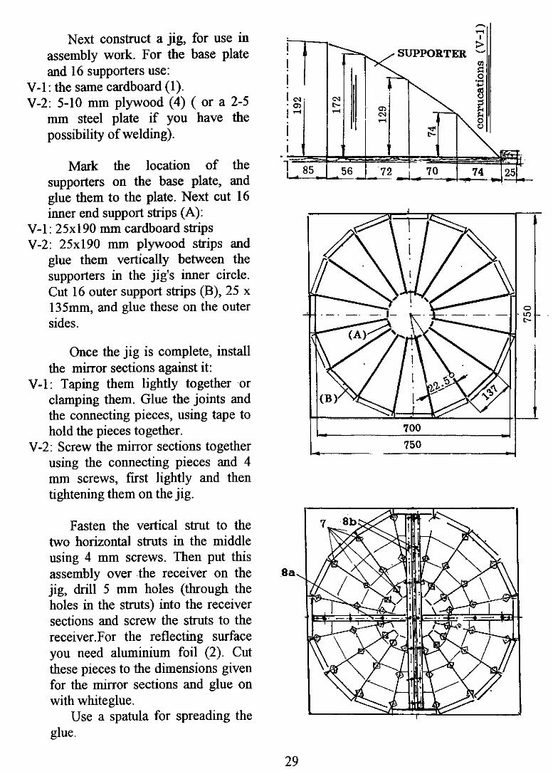
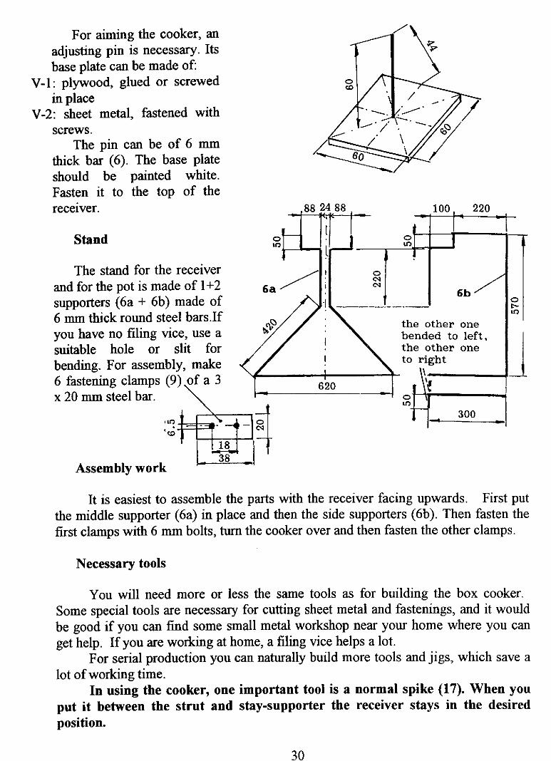
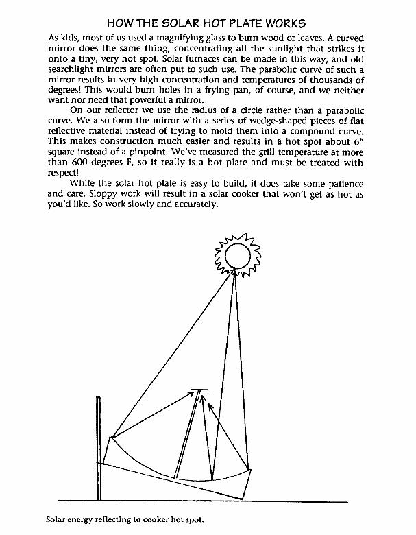
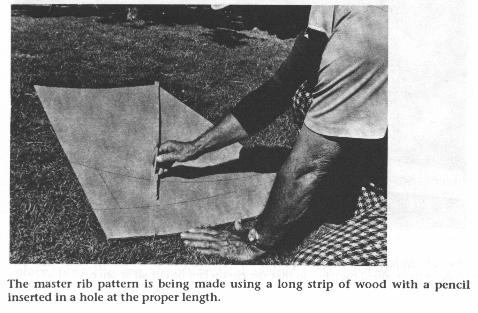
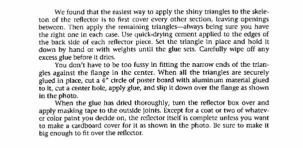
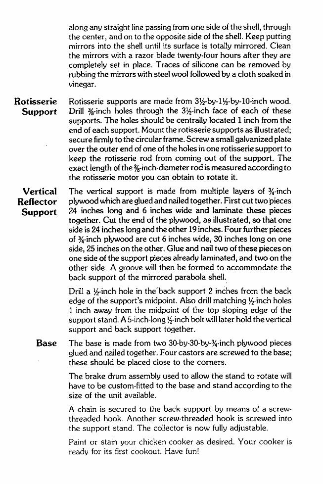
A Parabolic CollectorOne of the problems faced by people
who want to build their own parabolicreflector is finding out and producingthe correct parabolic shape. Thisproblem was solved very simply whenresearchers from the University ofWestern Australia found that by bendinga sheet of galvanised iron in a certainway the sheet would naturally take ona parabolic shape making a troughlinear focus concentrator,
RAY TRACE
The thing a b o u t the design of theseconcentrators is that they are veryeasy for the do-it-yourselfer to build,and give you a way of producing quitehigh temperatures (up to 100°C).
or
The major component of one of thesecollectors is a sheet of polished an-odised aluminium or galvanized ironsheeting with aluminised polyester oraluminised acrylic laminated or gluedto the sheet to give the reflectivesurface. The only other major componentis a sheet of perspex (acrylic), withthe edges of the sheet bent over tojust past a right angle. The collector
Galvanised iron sheeting is cut tofit the open ends with a hole drilledin each of these ends for the bearing.Blackened steel or copper water pipeis passed through the length of thecollector and the bearings fixed ateither end. All joints are sealed andweather-proofed and you have a completedconcentrator.
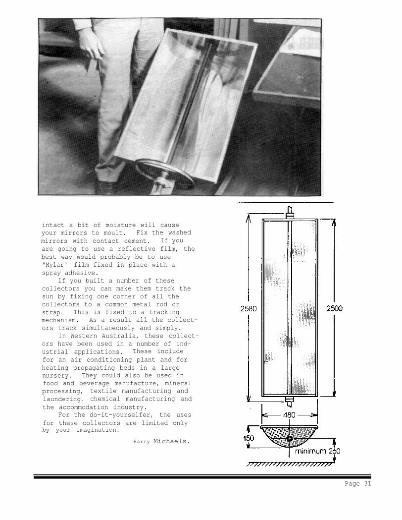
You now have a collector which willpivot around the central pipe. If youwant to use the pipe to aim the coll-ector at the sun then you fix the pipedirectly to the ends of the concentrat-or. Don't forget to insulate the pipeso it does not come in contact withthe metal at the collector ends.
If you find it difficult gettingpolished aluminium sheet or fixing areflective film to your galvanised ironsheet, you could try lining it withmirror glass. You can buy sheets of
roughly 1" square mirrorsfrom glassshops. These mirrors need to be remov-ed from the backing material and thenwashed. This is because the backingmaterial is water soluble and if youattach the mirror with this material
is then put together simply by bendingthe metal sheet and clipping the edgesin under the corners of the perspex.This allows the sheet to form and main-tain the natural parabolic shape.
Page 30
intact a bit of moisture will causeyour mirrors to moult. Fix the washedmirrors with contact cement. If youare going to use a reflective film, thebest way would probably be to use"Mylar" film fixed in place with aspray adhesive.
If you built a number of thesecollectors you can make them track thesun by fixing one corner of all thecollectors to a common metal rod orstrap. This is fixed to a trackingmechanism. As a result all the collect-ors track simultaneously and simply.
In Western Australia, these collect-ors have been used in a number of ind-ustrial applications. These includefor an air conditioning plant and forheating propagating beds in a largenursery. They could also be used infood and beverage manufacture, mineralprocessing, textile manufacturing andlaundering, chemical manufacturing andthe accommodation industry.
For the do-it-yourselfer, the usesfor these collectors are limited onlyby your imagination.
Harry Michaels.
Page 31
38 Home Power #31 • October / November 1992
he sun shines on therich and poor, hungryand well-fed alike. In the
United States, a growingnumber use the sun’s energyto cook food, with solarcookers built from scrap andlow cost materials, such ascardboard, foil, and glass.What are some low cost or scrapmaterials in other countries that could beused to make solar cookers? In HomePower issue #28, we asked readers todesign and build a solar cooker usingmaterials readily available in adeveloping country of their choice.
T
IndigenousMaterialsSolar CookerContestKathleen Jarschke-Schultze
and Therese Peffer
We received numerous phone calls; eight entries madetheir way to HP Central. Alan Nichols sent his design for atracking solar cooker. Another reader sent a sample offiber cement that could be formed into walls for a cooker.Philip Hodes’ simple waterproof cooker required a plasticmilk crate, plastic mirrors for reflectors, and foil-backedfoam for insulation.
We chose four cooker designs to build for the cookoffSaturday at the Solar Energy Expo and Rally 1992 inWillits, California. The four finalists were chosen based ontheir use of simple, “low tech” materials and included abamboo-type box cooker, a hole-in-the-ground model, aparabolic design, and a foldable cooker.
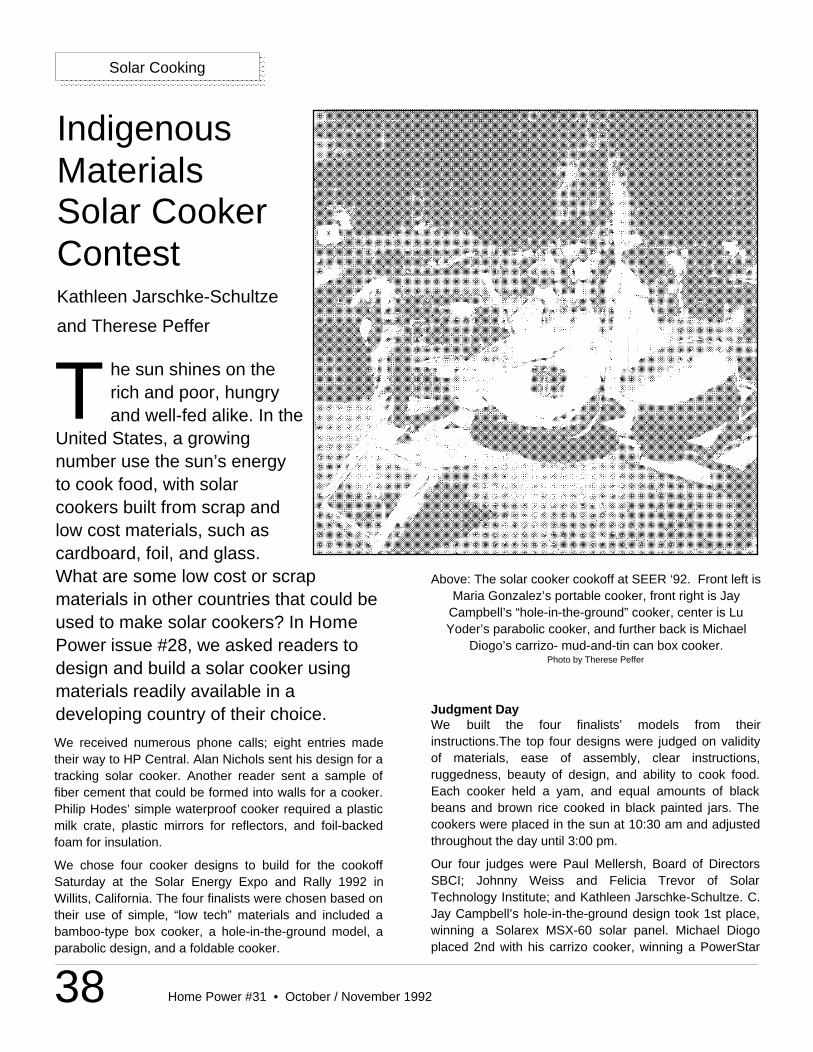
Above: The solar cooker cookoff at SEER ‘92. Front left isMaria Gonzalez’s portable cooker, front right is Jay
Campbell’s “hole-in-the-ground” cooker, center is LuYoder’s parabolic cooker, and further back is Michael
Diogo’s carrizo- mud-and-tin can box cooker.Photo by Therese Peffer
Solar Cooking
Judgment DayWe built the four finalists’ models from theirinstructions.The top four designs were judged on validityof materials, ease of assembly, clear instructions,ruggedness, beauty of design, and ability to cook food.Each cooker held a yam, and equal amounts of blackbeans and brown rice cooked in black painted jars. Thecookers were placed in the sun at 10:30 am and adjustedthroughout the day until 3:00 pm.
Our four judges were Paul Mellersh, Board of DirectorsSBCI; Johnny Weiss and Felicia Trevor of SolarTechnology Institute; and Kathleen Jarschke-Schultze. C.Jay Campbell’s hole-in-the-ground design took 1st place,winning a Solarex MSX-60 solar panel. Michael Diogoplaced 2nd with his carrizo cooker, winning a PowerStar
39Home Power #31 • October / November 1992
Solar Cooking
200 inverter. Maria Gonzalez’sfoldable design won 3rd place, andLu Yoder’s frustum-based modelplaced 4th; they chose either anOsram compact fluorescent light ora Kyocera Jetski PV module astheir prize.
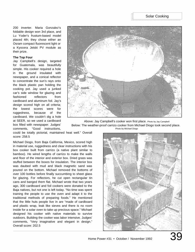
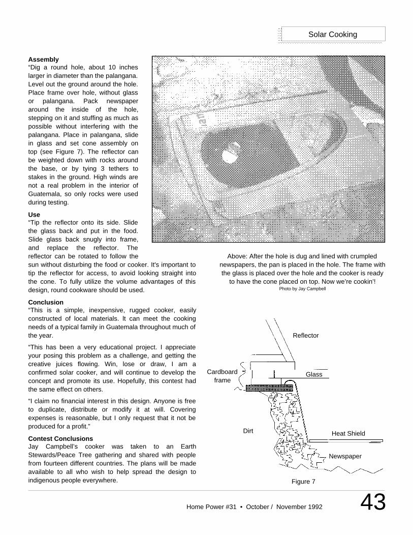
The Top FourJay Campbell’s design, targetedfor Guatemala, was beautifullysimple. His cooker required a holein the ground insulated withnewspaper, and a conical reflectorto concentrate the sun’s rays ontothe black plastic pan holding thecooking pot. Jay used a junkedcar’s side window for glazing andfashioned reflectors fromcardboard and aluminum foil. Jay’sdesign scored high on all criteria;the lowest scores were forruggedness, because of thecardboard. We couldn’t dig a holeat SEER, so we used a cardboardbox filled with newspaper. Judges’comments, “Good instructions,could be totally pictorial, maintained heat well.” Overallscore: 258.5
Michael Diogo, from Baja California, Mexico, scored highin material use, ruggedness and clear instructions with hisbox cooker built from carrizo (a native plant similar tobamboo). He wired lengths of carrizo to make the wallsand floor of the interior and exterior box. Dried grass wasstuffed between the boxes for insulation. The interior boxwas daubed with mud and black magnetic sand waspoured on the bottom. Michael removed the bottoms ofover 100 bottles before finally succumbing to sheet glassfor glazing. For reflectors, he cut open rectangular tincans and banged them flat. Michael wrote that two yearsago, 300 cardboard and foil cookers were donated to theBaja natives, but not one is left today. “No time was spenttraining the people to use the oven and adapt it to thetraditional methods of preparing foods.” He mentionedthat the little huts people live in are “made of cardboardand plastic wrap, leak like sieves and there is no roominside for a solar oven to take up precious space.” Michaeldesigned his cooker with native materials to surviveoutdoors. Building the cooker was labor intensive. Judges’comments, “Very imaginative and elegant in design.”Overall score: 202.5
Above: Jay Campbell’s cooker won first place. Photo by Jay Campbell
Below: The weather-proof carrizo cooker from Michael Diogo took second place. Photo by Michael Diogo
40 Home Power #31 • October / November 1992
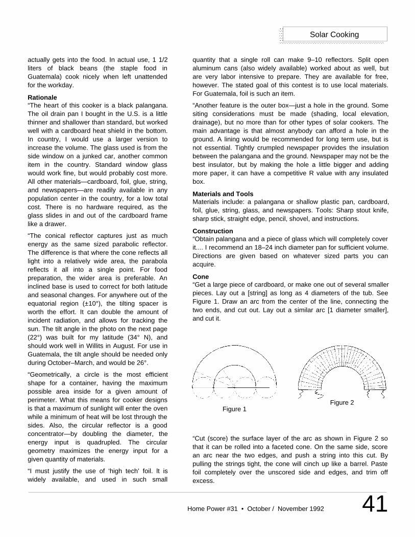
Below: Lu Yoder’s parabolic cooker came in fourth place.Photo by Lu Yoder
Solar Cooking
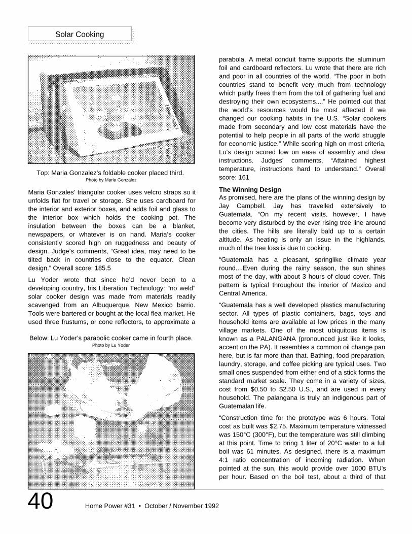
Maria Gonzales’ triangular cooker uses velcro straps so itunfolds flat for travel or storage. She uses cardboard forthe interior and exterior boxes, and adds foil and glass tothe interior box which holds the cooking pot. Theinsulation between the boxes can be a blanket,newspapers, or whatever is on hand. Maria’s cookerconsistently scored high on ruggedness and beauty ofdesign. Judge’s comments, “Great idea, may need to betilted back in countries close to the equator. Cleandesign.” Overall score: 185.5
Lu Yoder wrote that since he’d never been to adeveloping country, his Liberation Technology: “no weld”solar cooker design was made from materials readilyscavenged from an Albuquerque, New Mexico barrio.Tools were bartered or bought at the local flea market. Heused three frustums, or cone reflectors, to approximate a
parabola. A metal conduit frame supports the aluminumfoil and cardboard reflectors. Lu wrote that there are richand poor in all countries of the world. “The poor in bothcountries stand to benefit very much from technologywhich partly frees them from the toil of gathering fuel anddestroying their own ecosystems....” He pointed out thatthe world’s resources would be most affected if wechanged our cooking habits in the U.S. “Solar cookersmade from secondary and low cost materials have thepotential to help people in all parts of the world strugglefor economic justice.” While scoring high on most criteria,Lu’s design scored low on ease of assembly and clearinstructions. Judges’ comments, “Attained highesttemperature, instructions hard to understand.” Overallscore: 161
The Winning DesignAs promised, here are the plans of the winning design byJay Campbell. Jay has travelled extensively toGuatemala. “On my recent visits, however, I havebecome very disturbed by the ever rising tree line aroundthe cities. The hills are literally bald up to a certainaltitude. As heating is only an issue in the highlands,much of the tree loss is due to cooking.
“Guatemala has a pleasant, springlike climate yearround....Even during the rainy season, the sun shinesmost of the day, with about 3 hours of cloud cover. Thispattern is typical throughout the interior of Mexico andCentral America.
“Guatemala has a well developed plastics manufacturingsector. All types of plastic containers, bags, toys andhousehold items are available at low prices in the manyvillage markets. One of the most ubiquitous items isknown as a PALANGANA (pronounced just like it looks,accent on the PA). It resembles a common oil change panhere, but is far more than that. Bathing, food preparation,laundry, storage, and coffee picking are typical uses. Twosmall ones suspended from either end of a stick forms thestandard market scale. They come in a variety of sizes,cost from $0.50 to $2.50 U.S., and are used in everyhousehold. The palangana is truly an indigenous part ofGuatemalan life.
“Construction time for the prototype was 6 hours. Totalcost as built was $2.75. Maximum temperature witnessedwas 150°C (300°F), but the temperature was still climbingat this point. Time to bring 1 liter of 20°C water to a fullboil was 61 minutes. As designed, there is a maximum4:1 ratio concentration of incoming radiation. Whenpointed at the sun, this would provide over 1000 BTU'sper hour. Based on the boil test, about a third of that
Top: Maria Gonzalez’s foldable cooker placed third. Photo by Maria Gonzalez
41Home Power #31 • October / November 1992
Solar Cooking
actually gets into the food. In actual use, 1 1/2liters of black beans (the staple food inGuatemala) cook nicely when left unattendedfor the workday.
Rationale“The heart of this cooker is a black palangana.The oil drain pan I bought in the U.S. is a littlethinner and shallower than standard, but workedwell with a cardboard heat shield in the bottom.In country, I would use a larger version toincrease the volume. The glass used is from theside window on a junked car, another commonitem in the country. Standard window glasswould work fine, but would probably cost more.All other materials—cardboard, foil, glue, string,and newspapers—are readily available in anypopulation center in the country, for a low totalcost. There is no hardware required, as theglass slides in and out of the cardboard framelike a drawer.
“The conical reflector captures just as muchenergy as the same sized parabolic reflector.The difference is that where the cone reflects alllight into a relatively wide area, the parabolareflects it all into a single point. For foodpreparation, the wider area is preferable. Aninclined base is used to correct for both latitudeand seasonal changes. For anywhere out of theequatorial region (±10°), the tilting spacer isworth the effort. It can double the amount ofincident radiation, and allows for tracking thesun. The tilt angle in the photo on the next page(22°) was built for my latitude (34° N), andshould work well in Willits in August. For use inGuatemala, the tilt angle should be needed onlyduring October–March, and would be 26°.
“Geometrically, a circle is the most efficientshape for a container, having the maximumpossible area inside for a given amount ofperimeter. What this means for cooker designsis that a maximum of sunlight will enter the ovenwhile a minimum of heat will be lost through thesides. Also, the circular reflector is a goodconcentrator—by doubling the diameter, theenergy input is quadrupled. The circulargeometry maximizes the energy input for agiven quantity of materials.
“I must justify the use of ‘high tech’ foil. lt iswidely available, and used in such small
quantity that a single roll can make 9–10 reflectors. Split openaluminum cans (also widely available) worked about as well, butare very labor intensive to prepare. They are available for free,however. The stated goal of this contest is to use local materials.For Guatemala, foil is such an item.
“Another feature is the outer box—just a hole in the ground. Somesiting considerations must be made (shading, local elevation,drainage), but no more than for other types of solar cookers. Themain advantage is that almost anybody can afford a hole in theground. A lining would be recommended for long term use, but isnot essential. Tightly crumpled newspaper provides the insulationbetween the palangana and the ground. Newspaper may not be thebest insulator, but by making the hole a little bigger and addingmore paper, it can have a competitive R value with any insulatedbox.
Materials and ToolsMaterials include: a palangana or shallow plastic pan, cardboard,foil, glue, string, glass, and newspapers. Tools: Sharp stout knife,sharp stick, straight edge, pencil, shovel, and instructions.
Construction“Obtain palangana and a piece of glass which will completely coverit.... I recommend an 18–24 inch diameter pan for sufficient volume.Directions are given based on whatever sized parts you canacquire.
Cone“Get a large piece of cardboard, or make one out of several smallerpieces. Lay out a [string] as long as 4 diameters of the tub. SeeFigure 1. Draw an arc from the center of the line, connecting thetwo ends, and cut out. Lay out a similar arc [1 diameter smaller],and cut it.
Figure 1Figure 2
“Cut (score) the surface layer of the arc as shown in Figure 2 sothat it can be rolled into a faceted cone. On the same side, scorean arc near the two edges, and push a string into this cut. Bypulling the strings tight, the cone will cinch up like a barrel. Pastefoil completely over the unscored side and edges, and trim offexcess.
42 Home Power #31 • October / November 1992
Figure 6
Glass
Palangana
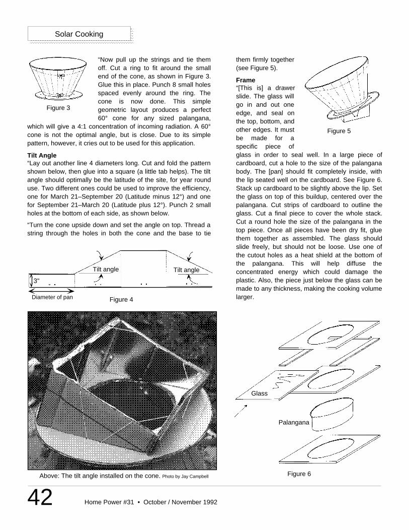
“Now pull up the strings and tie themoff. Cut a ring to fit around the smallend of the cone, as shown in Figure 3.Glue this in place. Punch 8 small holesspaced evenly around the ring. Thecone is now done. This simplegeometric layout produces a perfect60° cone for any sized palangana,
which will give a 4:1 concentration of incoming radiation. A 60°cone is not the optimal angle, but is close. Due to its simplepattern, however, it cries out to be used for this application.
Tilt Angle “Lay out another line 4 diameters long. Cut and fold the patternshown below, then glue into a square (a little tab helps). The tiltangle should optimally be the latitude of the site, for year rounduse. Two different ones could be used to improve the efficiency,one for March 21–September 20 (Latitude minus 12°) and onefor September 21–March 20 (Latitude plus 12°). Punch 2 smallholes at the bottom of each side, as shown below.
“Turn the cone upside down and set the angle on top. Thread astring through the holes in both the cone and the base to tie
Solar Cooking
them firmly together(see Figure 5).
Frame“[This is] a drawerslide. The glass willgo in and out oneedge, and seal onthe top, bottom, andother edges. It mustbe made for aspecific piece ofglass in order to seal well. In a large piece ofcardboard, cut a hole to the size of the palanganabody. The [pan] should fit completely inside, withthe lip seated well on the cardboard. See Figure 6.Stack up cardboard to be slightly above the lip. Setthe glass on top of this buildup, centered over thepalangana. Cut strips of cardboard to outline theglass. Cut a final piece to cover the whole stack.Cut a round hole the size of the palangana in thetop piece. Once all pieces have been dry fit, gluethem together as assembled. The glass shouldslide freely, but should not be loose. Use one ofthe cutout holes as a heat shield at the bottom ofthe palangana. This will help diffuse theconcentrated energy which could damage theplastic. Also, the piece just below the glass can bemade to any thickness, making the cooking volumelarger.
Tilt angle Tilt angle
Figure 4
3"
Diameter of pan
Figure 3
Above: The tilt angle installed on the cone. Photo by Jay Campbell
Figure 5
43Home Power #31 • October / November 1992
Assembly“Dig a round hole, about 10 incheslarger in diameter than the palangana.Level out the ground around the hole.Place frame over hole, without glassor palangana. Pack newspaperaround the inside of the hole,stepping on it and stuffing as much aspossible without interfering with thepalangana. Place in palangana, slidein glass and set cone assembly ontop (see Figure 7). The reflector canbe weighted down with rocks aroundthe base, or by tying 3 tethers tostakes in the ground. High winds arenot a real problem in the interior ofGuatemala, so only rocks were usedduring testing.
Use“Tip the reflector onto its side. Slidethe glass back and put in the food.Slide glass back snugly into frame,and replace the reflector. Thereflector can be rotated to follow thesun without disturbing the food or cooker. It's important totip the reflector for access, to avoid looking straight intothe cone. To fully utilize the volume advantages of thisdesign, round cookware should be used.
Conclusion“This is a simple, inexpensive, rugged cooker, easilyconstructed of local materials. lt can meet the cookingneeds of a typical family in Guatemala throughout much ofthe year.
“This has been a very educational project. I appreciateyour posing this problem as a challenge, and getting thecreative juices flowing. Win, lose or draw, I am aconfirmed solar cooker, and will continue to develop theconcept and promote its use. Hopefully, this contest hadthe same effect on others.
“I claim no financial interest in this design. Anyone is freeto duplicate, distribute or modify it at will. Coveringexpenses is reasonable, but I only request that it not beproduced for a profit.”
Contest ConclusionsJay Campbell’s cooker was taken to an EarthStewards/Peace Tree gathering and shared with peoplefrom fourteen different countries. The plans will be madeavailable to all who wish to help spread the design toindigenous people everywhere.
Reflector
GlassCardboardframe
Dirt Heat Shield
Newspaper
Figure 7
Above: After the hole is dug and lined with crumplednewspapers, the pan is placed in the hole. The frame withthe glass is placed over the hole and the cooker is ready
to have the cone placed on top. Now we’re cookin’!Photo by Jay Campbell
Solar Cooking
44 Home Power #31 • October / November 1992
Michael Diogo, c/o Bill Keys, 8111 Stanford, #159,Garden Grove, CA 92641
Maria C. Gonzales, 48 Sycamore #3, San Francisco, CA94110
Lu Yoder, 315 Harvard Dr. SE, Albuquerque, NM 87106 •505-265-3730
Milk crate oven: H. Philip Hodes, 3137 Capri Rd., PalmBeach Garden, FL 33410
Tracking solar oven (plans available for $2): Alan Nichols,4220 N. Bear Canyon Rd., Tucson, AZ 85749
Congratulations to all of our entrants for your time andcreativity! For you readers who had an idea for a solarcooker, but did not think you had enough time to developone, there is always next year’s competition. Look for thedetails in the next issue of Home Power. Go for it.
AccessAuthors: Kathleen Jarschke-Schultze and Therese Peffer,c/o Home Power, POB 520, Ashland, OR 97520 •916-475-3179
C. Jay Campbell, Applied Engineering, 218 DartmouthSE, Albuquerque, NM 87106-2220 • 505-848-7674 •505-256-1261
Solar Cooking
GIVE YOUR GENERATOR
some MANNERSThe Sun Selector® GenMate™ generatorcontroller can make your generatorsomething you'll love.
Using the latest microcomputertechnology, GenMate teaches your oldgenerator new tricks.
GenMate works with nearly any electricstart generator.
If your generator doesn't start itself whenbatteries are low, stop itself when batteriesare full, and interface with the rest of yoursolar, wind, or hydro system automatically,you need GenMate.
Ask your Sun Selector dealer for
information today.
Bobier Electronics, Inc.304-485-7150
ARRAY TECH(WATTSUN)
camera-ready
SKYLINE ENGINEERINGcamera-ready
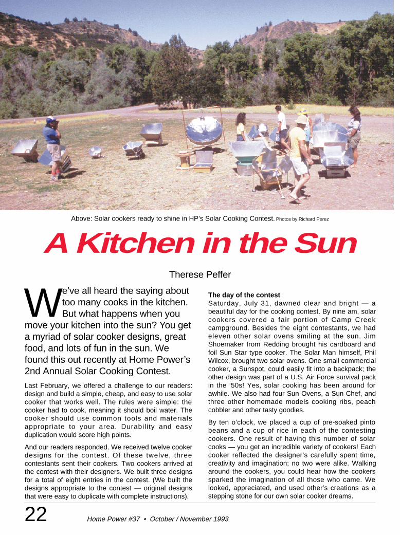
22 Home Power #37 • October / November 1993
We’ve all heard the saying abouttoo many cooks in the kitchen.But what happens when you
move your kitchen into the sun? You geta myriad of solar cooker designs, greatfood, and lots of fun in the sun. Wefound this out recently at Home Power’s2nd Annual Solar Cooking Contest.Last February, we offered a challenge to our readers:design and build a simple, cheap, and easy to use solarcooker that works well. The rules were simple: thecooker had to cook, meaning it should boil water. Thecooker should use common tools and materialsappropriate to your area. Durability and easyduplication would score high points.
And our readers responded. We received twelve cookerdesigns for the contest. Of these twelve, threecontestants sent their cookers. Two cookers arrived atthe contest with their designers. We built three designsfor a total of eight entries in the contest. (We built thedesigns appropriate to the contest — original designsthat were easy to duplicate with complete instructions).
The day of the contestSaturday, July 31, dawned clear and bright — abeautiful day for the cooking contest. By nine am, solarcookers covered a fair portion of Camp Creekcampground. Besides the eight contestants, we hadeleven other solar ovens smiling at the sun. JimShoemaker from Redding brought his cardboard andfoil Sun Star type cooker. The Solar Man himself, PhilWilcox, brought two solar ovens. One small commercialcooker, a Sunspot, could easily fit into a backpack; theother design was part of a U.S. Air Force survival packin the ‘50s! Yes, solar cooking has been around forawhile. We also had four Sun Ovens, a Sun Chef, andthree other homemade models cooking ribs, peachcobbler and other tasty goodies.
By ten o’clock, we placed a cup of pre-soaked pintobeans and a cup of rice in each of the contestingcookers. One result of having this number of solarcooks — you get an incredible variety of cookers! Eachcooker reflected the designer’s carefully spent time,creativity and imagination; no two were alike. Walkingaround the cookers, you could hear how the cookerssparked the imagination of all those who came. Welooked, appreciated, and used other’s creations as astepping stone for our own solar cooker dreams.
A Kitchen in the SunTherese Peffer
Above: Solar cookers ready to shine in HP’s Solar Cooking Contest. Photos by Richard Perez
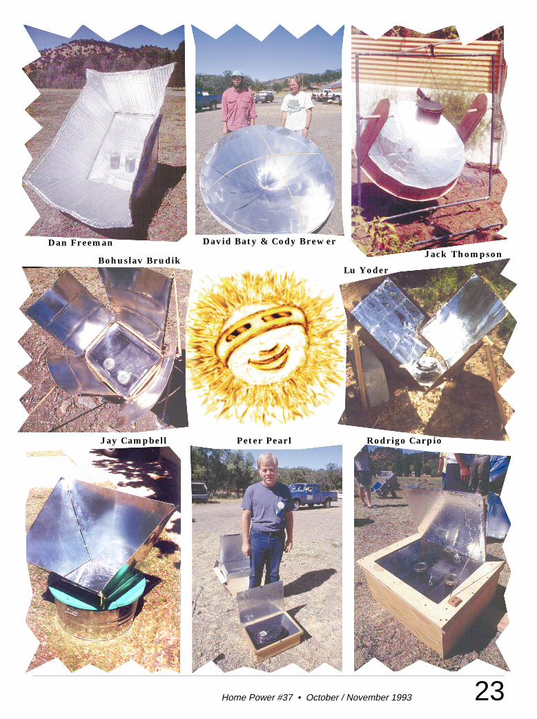
23Home Power #37 • October / November 1993
Dan Freeman
Bohuslav Brudik
Jay Campbell Peter Pearl Rodrigo Carpio
Jack ThompsonDavid Baty & Cody Brewer
Lu Yoder
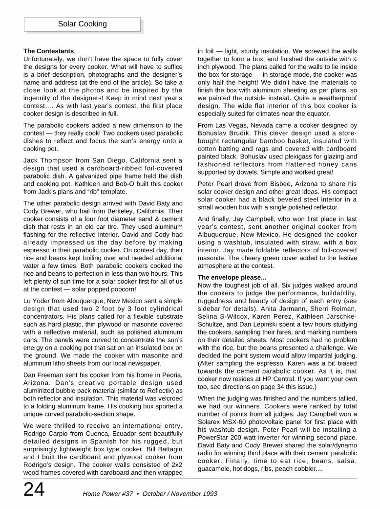
24 Home Power #37 • October / November 1993
Solar Cooking
The ContestantsUnfortunately, we don’t have the space to fully coverthe designs for every cooker. What will have to sufficeis a brief description, photographs and the designer’sname and address (at the end of the article). So take aclose look at the photos and be inspired by theingenuity of the designers! Keep in mind next year’scontest…. As with last year’s contest, the first placecooker design is described in full.
The parabolic cookers added a new dimension to thecontest — they really cook! Two cookers used parabolicdishes to reflect and focus the sun’s energy onto acooking pot.
Jack Thompson from San Diego, California sent adesign that used a cardboard-ribbed foil-coveredparabolic dish. A galvanized pipe frame held the dishand cooking pot. Kathleen and Bob-O built this cookerfrom Jack’s plans and “rib” template.
The other parabolic design arrived with David Baty andCody Brewer, who hail from Berkeley, California. Theircooker consists of a four foot diameter sand & cementdish that rests in an old car tire. They used aluminumflashing for the reflective interior. David and Cody hadalready impressed us the day before by makingespresso in their parabolic cooker. On contest day, theirrice and beans kept boiling over and needed additionalwater a few times. Both parabolic cookers cooked therice and beans to perfection in less than two hours. Thisleft plenty of sun time for a solar cooker first for all of usat the contest — solar popped popcorn!
Lu Yoder from Albuquerque, New Mexico sent a simpledesign that used two 2 foot by 3 foot cylindricalconcentrators. His plans called for a flexible substratesuch as hard plastic, thin plywood or masonite coveredwith a reflective material, such as polished aluminumcans. The panels were curved to concentrate the sun’senergy on a cooking pot that sat on an insulated box onthe ground. We made the cooker with masonite andaluminum litho sheets from our local newspaper.
Dan Freeman sent his cooker from his home in Peoria,Arizona. Dan’s creative portable design usedaluminized bubble pack material (similar to Reflectix) asboth reflector and insulation. This material was velcroedto a folding aluminum frame. His cooking box sported aunique curved parabolic-section shape.
We were thrilled to receive an international entry.Rodrigo Carpio from Cuenca, Ecuador sent beautifullydetailed designs in Spanish for his rugged, butsurprisingly lightweight box type cooker. Bill Battaginand I built the cardboard and plywood cooker fromRodrigo’s design. The cooker walls consisted of 2x2wood frames covered with cardboard and then wrapped
in foil — light, sturdy insulation. We screwed the wallstogether to form a box, and finished the outside with 1⁄4inch plywood. The plans called for the walls to lie insidethe box for storage — in storage mode, the cooker wasonly half the height! We didn't have the materials tofinish the box with aluminum sheeting as per plans, sowe painted the outside instead. Quite a weatherproofdesign. The wide flat interior of this box cooker isespecially suited for climates near the equator.
From Las Vegas, Nevada came a cooker designed byBohuslav Brudik. This clever design used a store-bought rectangular bamboo basket, insulated withcotton batting and rags and covered with cardboardpainted black. Bohuslav used plexigass for glazing andfashioned reflectors from flattened honey canssupported by dowels. Simple and worked great!
Peter Pearl drove from Bisbee, Arizona to share hissolar cooker design and other great ideas. His compactsolar cooker had a black beveled steel interior in asmall wooden box with a single polished reflector.
And finally, Jay Campbell, who won first place in lastyear’s contest, sent another original cooker fromAlbuquerque, New Mexico. He designed the cookerusing a washtub, insulated with straw, with a boxinterior. Jay made foldable reflectors of foil-coveredmasonite. The cheery green cover added to the festiveatmosphere at the contest.
The envelope please...Now the toughest job of all. Six judges walked aroundthe cookers to judge the performance, buildability,ruggedness and beauty of design of each entry (seesidebar for details). Anita Jarmann, Sherri Reiman,Selina S-Wilcox, Karen Perez, Kathleen Jarschke-Schultze, and Dan Lepinski spent a few hours studyingthe cookers, sampling their fares, and marking numberson their detailed sheets. Most cookers had no problemwith the rice, but the beans presented a challenge. Wedecided the point system would allow impartial judging.(After sampling the espresso, Karen was a bit biasedtowards the cement parabolic cooker. As it is, thatcooker now resides at HP Central. If you want your owntoo, see directions on page 34 this issue.)
When the judging was finished and the numbers tallied,we had our winners. Cookers were ranked by totalnumber of points from all judges. Jay Campbell won aSolarex MSX-60 photovoltaic panel for first place withhis washtub design. Peter Pearl will be installing aPowerStar 200 watt inverter for winning second place.David Baty and Cody Brewer shared the solar/dynamoradio for winning third place with their cement paraboliccooker. Finally, t ime to eat rice, beans, salsa,guacamole, hot dogs, ribs, peach cobbler....
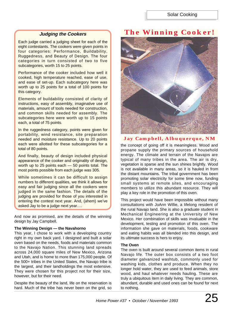
Judging the Cookers
Each judge carried a judging sheet for each of theeight contestants. The cookers were given points infour categories: Performance, Buildabil ity,Ruggedness, and Beauty of Design. The fourcategories in turn consisted of two to fivesubcategories, worth 15 to 25 points.
Performance of the cooker included how well itcooked, high temperature reached, ease of use,and ease of set-up. Each subcategory here wasworth up to 25 points for a total of 100 points forthis category.
Elements of buildability consisted of clarity ofinstructions, easy of assembly, imaginative use ofmaterials, amount of tools needed for construction,and common skills needed for assembly. Thesubcategories here were worth up to 15 pointseach, a total of 75 points.
In the ruggedness category, points were given forportability, wind resistance, site preparationneeded and moisture resistance. Up to 20 pointseach were allotted for these subcategories for atotal of 80 points.
And finally, beauty of design included physicalappearance of the cooker and originality of design,worth up to 25 points each — 50 points total. Themost points possible from each judge was 305.
While sometimes it can be difficult to assignnumbers to different qualities, we think it allows foreasy and fair judging since all the cookers werejudged in the same fashion. The details of thejudging are provided for those of you interested inentering the contest next year. And, (ahem) we’veasked Jay to be a judge next year….
25Home Power #37 • October / November 1993
Solar Cooking
And now as promised, are the details of the winningdesign by Jay Campbell.
The Winning Design — the NavahornoThis year, I chose to work with a developing countryright in my own back yard. I designed and built a solaroven based on the needs, foods and materials commonto the Navajo Nation. This stunning land spreadsacross 24,000 square miles of New Mexico, Arizonaand Utah, and is home to more than 175,000 people. Ofthe 500+ tribes in the United States, the Navajo tribe isthe largest, and their landholdings the most extensive.They were chosen for this project not for their size,however, but for their need.
Despite the beauty of the land, life on the reservation ishard. Much of the tribe has never been on the grid, so
The Winning Cooker!
Jay Campbell, Albuquerque, NMthe concept of going off it is meaningless. Wood andpropane supply the primary sources of householdenergy. The climate and terrain of the Navajos aretypical of many tribes in the area. The air is dry,vegetation is sparse and the sun shines brightly. Woodis not available in many areas, so it is hauled in fromthe distant mountains. The tribal government has beenpromoting solar electricity for some time now, fundingsmall systems at remote sites, and encouragingmembers to utilize this abundant resource. They willplay a key role in the promotion of this oven.
This project would have been impossible without manyconsultations with JoAnn Willie, a lifelong resident ofthe rural Navajo land. She is also a graduate student inMechanical Engineering at the University of NewMexico. Her combination of skills was invaluable in thedevelopment, testing and promotion of this oven. Theinformation she gave on materials, foods, cookwareand eating habits was all blended into this design, andits ultimate success is hers to enjoy.
The OvenThe oven is built around several common items in ruralNavajo life. The outer box consists of a two footdiameter galvanized washtub, commonly used forwashing kids, clothes and produce. When they nolonger hold water, they are used to feed animals, storewood, and haul whatever needs hauling. These aretruly a ubiquitous item in daily living. They are common,abundant, durable and used ones can be found for nextto nothing.
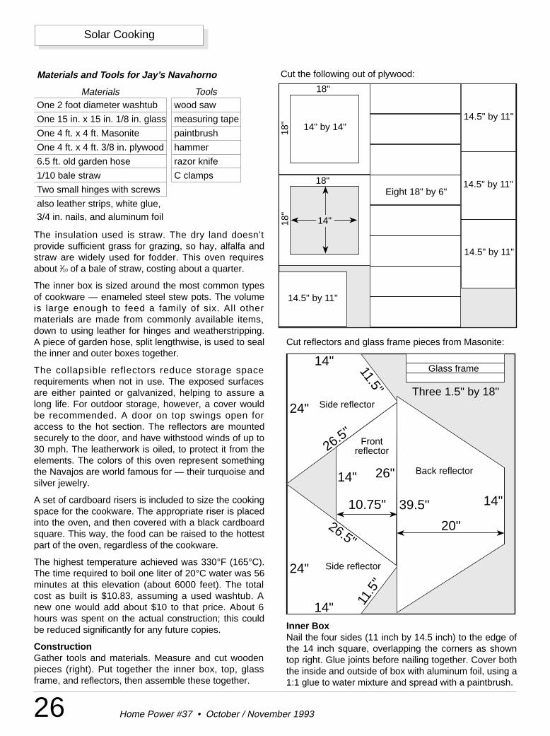
Cut the following out of plywood:
Cut reflectors and glass frame pieces from Masonite:
26 Home Power #37 • October / November 1993
Solar Cooking
The insulation used is straw. The dry land doesn’tprovide sufficient grass for grazing, so hay, alfalfa andstraw are widely used for fodder. This oven requiresabout 1⁄10 of a bale of straw, costing about a quarter.
The inner box is sized around the most common typesof cookware — enameled steel stew pots. The volumeis large enough to feed a family of six. All othermaterials are made from commonly available items,down to using leather for hinges and weatherstripping.A piece of garden hose, split lengthwise, is used to sealthe inner and outer boxes together.
The collapsible reflectors reduce storage spacerequirements when not in use. The exposed surfacesare either painted or galvanized, helping to assure along life. For outdoor storage, however, a cover wouldbe recommended. A door on top swings open foraccess to the hot section. The reflectors are mountedsecurely to the door, and have withstood winds of up to30 mph. The leatherwork is oiled, to protect it from theelements. The colors of this oven represent somethingthe Navajos are world famous for — their turquoise andsilver jewelry.
A set of cardboard risers is included to size the cookingspace for the cookware. The appropriate riser is placedinto the oven, and then covered with a black cardboardsquare. This way, the food can be raised to the hottestpart of the oven, regardless of the cookware.
The highest temperature achieved was 330°F (165°C).The time required to boil one liter of 20°C water was 56minutes at this elevation (about 6000 feet). The totalcost as built is $10.83, assuming a used washtub. Anew one would add about $10 to that price. About 6hours was spent on the actual construction; this couldbe reduced significantly for any future copies.
ConstructionGather tools and materials. Measure and cut woodenpieces (right). Put together the inner box, top, glassframe, and reflectors, then assemble these together.
Materials and Tools for Jay’s Navahorno
Materials ToolsOne 2 foot diameter washtub wood saw
One 15 in. x 15 in. 1/8 in. glass measuring tape
One 4 ft. x 4 ft. Masonite paintbrush
One 4 ft. x 4 ft. 3/8 in. plywood hammer
6.5 ft. old garden hose razor knife
1/10 bale straw C clamps
Two small hinges with screws
also leather strips, white glue, 3/4 in. nails, and aluminum foil
Inner BoxNail the four sides (11 inch by 14.5 inch) to the edge ofthe 14 inch square, overlapping the corners as showntop right. Glue joints before nailing together. Cover boththe inside and outside of box with aluminum foil, using a1:1 glue to water mixture and spread with a paintbrush.
14"
14"
14"
14"
24"
24"
26.5"
26.5"
10.75" 39.5"
20"
11.5
"
11.5"
26"
Three 1.5" by 18"
Back reflector
Side reflector
Front reflector
Side reflector
Glass frame
18"
18"
18"
18"
14" by 14"
14.5" by 11"
14.5" by 11"
14.5" by 11"
14.5" by 11"
Eight 18" by 6"
14"
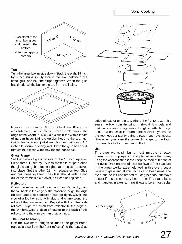
27Home Power #37 • October / November 1993
Solar Cooking
TopTurn the inner box upside down. Stack the eight 18 inchby 6 inch strips snugly around the box (below). Oncefitted, glue and nail the strips together. When the gluehas dried, nail the box to the top from the inside.
Now set the inner box/top upside down. Place thewashtub over it, and center it. Draw a circle around theedge of the washtub. Next, cut a slit in the whole lengthof garden hose. Nail the garden hose to the top, justinside the circle you just drew. Use one nail every 4–5inches to assure a strong joint. Once the glue has dried,trim off the excess wood beyond the hose/seal.
Glass FrameSet the piece of glass on one of the 18 inch squares.Place three 1 inch by 15 inch masonite strips aroundthe glass, snug, but not so tight that the glass is lockedinto place. Set the other 18 inch square on top. Glueand nail these together. The glass should slide in andout of the frame like a drawer, so it can be replaced.
ReflectorsCover the reflectors with aluminum foil. Once dry, trimthe foil back to the edge of the masonite. Align the largereflector and a side reflector (see top right). Cover oneside of a leather strip with glue and clamp along theedge of the two reflectors. Repeat with the other sidereflector. Align the small front reflector to the edge ofthe window. Glue a piece of leather to the back of thisreflector and the window frame, as a hinge.
The Final AssemblyUse the two metal hinges to attach the glass frame(opposite side from the front reflector) to the top. Glue
strips of leather on the top, where the frame rests. Thisseals the box from the wind. It should fit snugly andmake a continuous ring around the glass. Attach an eyehook to a corner of the frame and another eyehook tothe top. Hook a sturdy string through both eye hooks.Now when you open the cooker lid to get to the food,the string holds the frame and reflector.
UseThis oven works similar to most multiple reflectorovens. Food is prepared and placed into the oven,using the appropriate riser to keep the food at the top ofthe oven. Dark enameled steel cookware (the standardin the area) works extremely well in this oven, but avariety of glass and aluminum has also been used. Theoven can be left unattended for long periods, but stayshottest if it is turned every hour or so. The round baseand handles makes turning it easy. Like most solar
14" by 14"
14" by 11" 14" by 11"
Two sides of theinner box gluedand nailed to the
bottom.Note overlapping
corners.
leather hinge
metal hinge
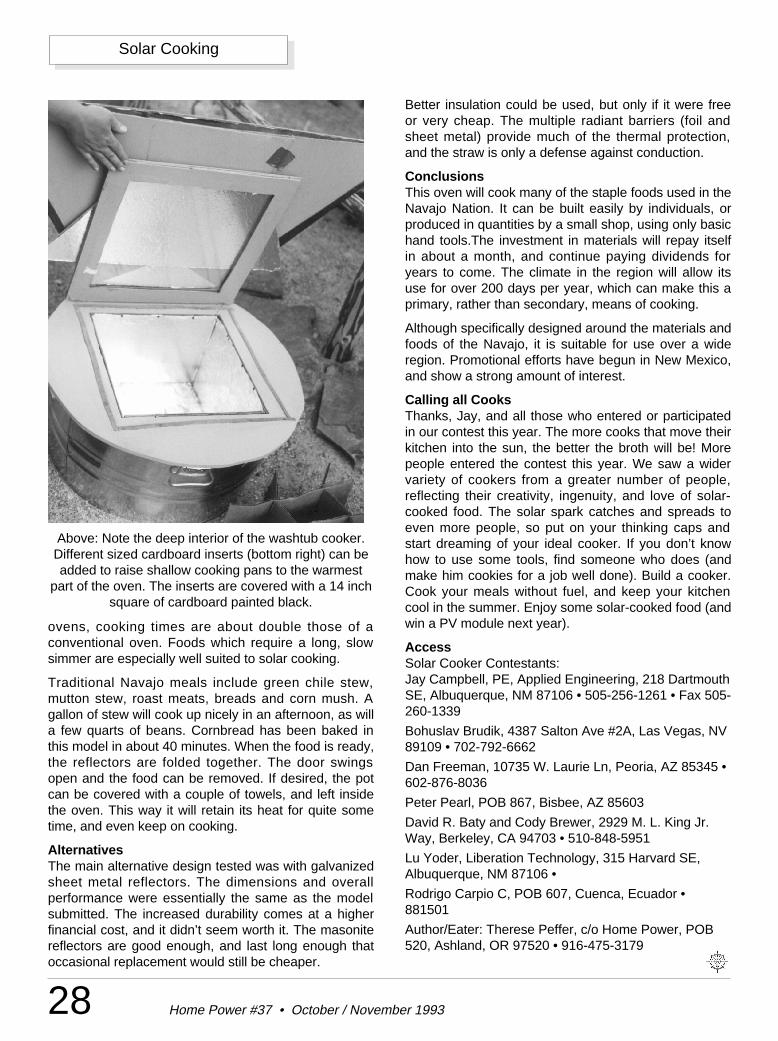
ovens, cooking times are about double those of aconventional oven. Foods which require a long, slowsimmer are especially well suited to solar cooking.
Traditional Navajo meals include green chile stew,mutton stew, roast meats, breads and corn mush. Agallon of stew will cook up nicely in an afternoon, as willa few quarts of beans. Cornbread has been baked inthis model in about 40 minutes. When the food is ready,the reflectors are folded together. The door swingsopen and the food can be removed. If desired, the potcan be covered with a couple of towels, and left insidethe oven. This way it will retain its heat for quite sometime, and even keep on cooking.
AlternativesThe main alternative design tested was with galvanizedsheet metal reflectors. The dimensions and overallperformance were essentially the same as the modelsubmitted. The increased durability comes at a higherfinancial cost, and it didn’t seem worth it. The masonitereflectors are good enough, and last long enough thatoccasional replacement would still be cheaper.
Better insulation could be used, but only if it were freeor very cheap. The multiple radiant barriers (foil andsheet metal) provide much of the thermal protection,and the straw is only a defense against conduction.
ConclusionsThis oven will cook many of the staple foods used in theNavajo Nation. It can be built easily by individuals, orproduced in quantities by a small shop, using only basichand tools.The investment in materials will repay itselfin about a month, and continue paying dividends foryears to come. The climate in the region will allow itsuse for over 200 days per year, which can make this aprimary, rather than secondary, means of cooking.
Although specifically designed around the materials andfoods of the Navajo, it is suitable for use over a wideregion. Promotional efforts have begun in New Mexico,and show a strong amount of interest.
Calling all CooksThanks, Jay, and all those who entered or participatedin our contest this year. The more cooks that move theirkitchen into the sun, the better the broth will be! Morepeople entered the contest this year. We saw a widervariety of cookers from a greater number of people,reflecting their creativity, ingenuity, and love of solar-cooked food. The solar spark catches and spreads toeven more people, so put on your thinking caps andstart dreaming of your ideal cooker. If you don’t knowhow to use some tools, find someone who does (andmake him cookies for a job well done). Build a cooker.Cook your meals without fuel, and keep your kitchencool in the summer. Enjoy some solar-cooked food (andwin a PV module next year).
AccessSolar Cooker Contestants:Jay Campbell, PE, Applied Engineering, 218 DartmouthSE, Albuquerque, NM 87106 • 505-256-1261 • Fax 505-260-1339
Bohuslav Brudik, 4387 Salton Ave #2A, Las Vegas, NV89109 • 702-792-6662
Dan Freeman, 10735 W. Laurie Ln, Peoria, AZ 85345 •602-876-8036
Peter Pearl, POB 867, Bisbee, AZ 85603
David R. Baty and Cody Brewer, 2929 M. L. King Jr.Way, Berkeley, CA 94703 • 510-848-5951
Lu Yoder, Liberation Technology, 315 Harvard SE,Albuquerque, NM 87106 •
Rodrigo Carpio C, POB 607, Cuenca, Ecuador •881501
Author/Eater: Therese Peffer, c/o Home Power, POB520, Ashland, OR 97520 • 916-475-3179
28 Home Power #37 • October / November 1993
Solar Cooking
Above: Note the deep interior of the washtub cooker.Different sized cardboard inserts (bottom right) can beadded to raise shallow cooking pans to the warmest
part of the oven. The inserts are covered with a 14 inchsquare of cardboard painted black.
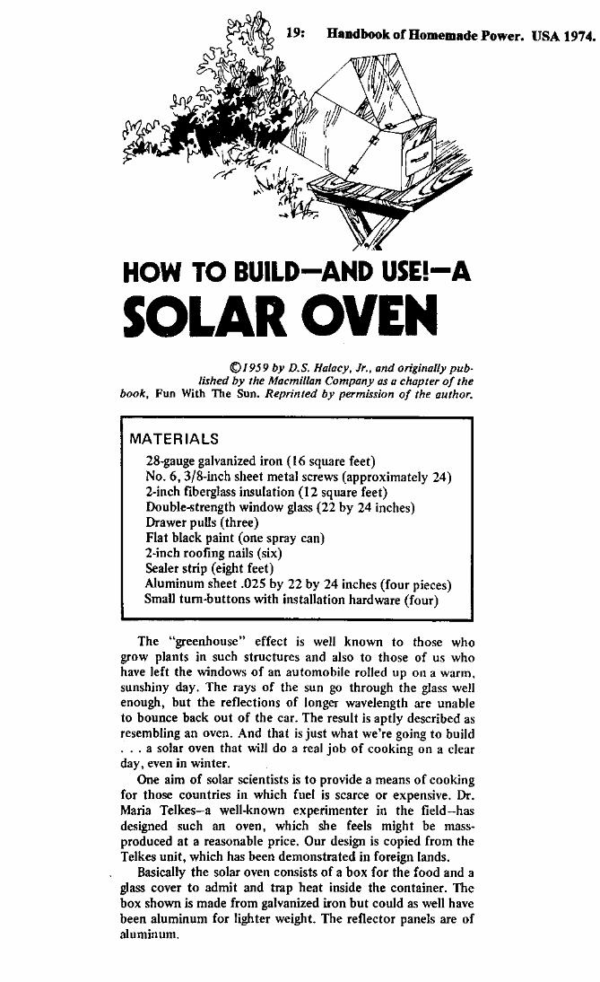
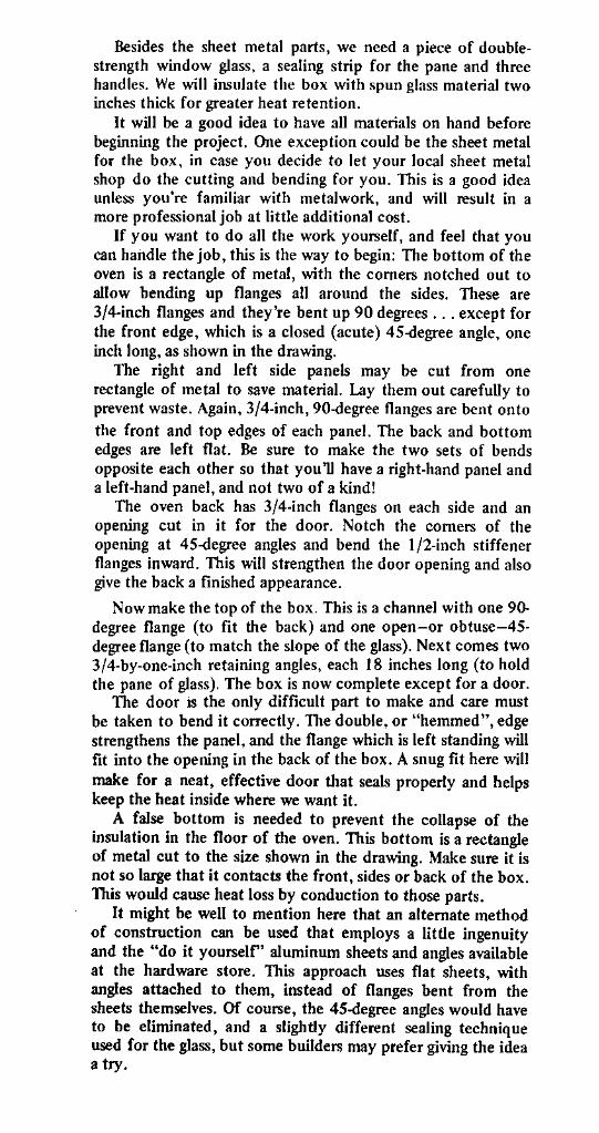
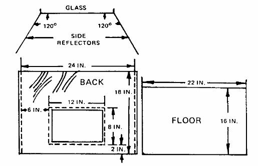
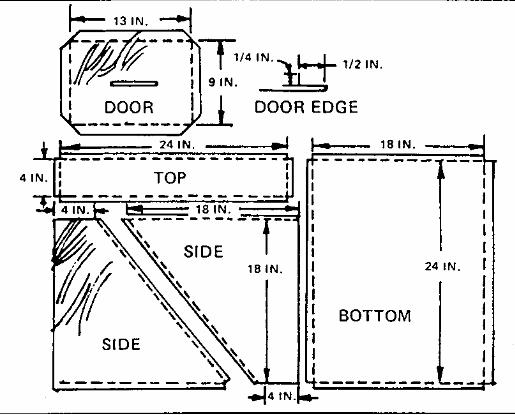
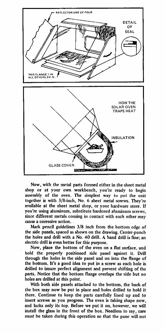
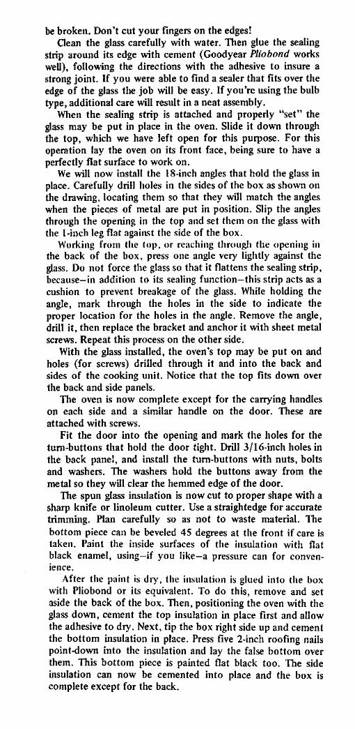
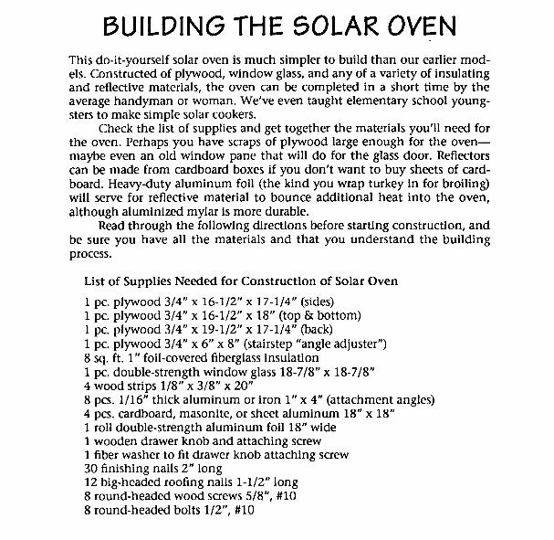
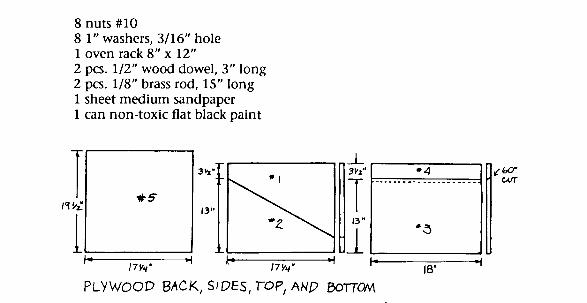
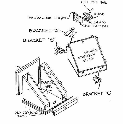
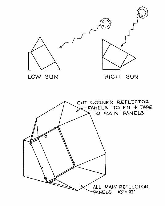
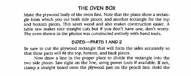
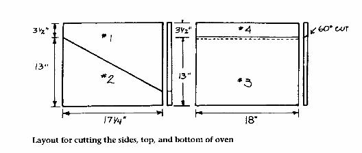
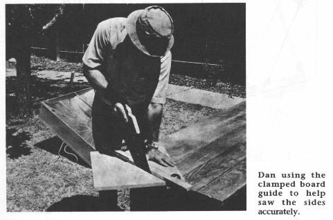
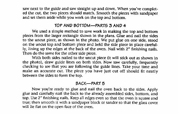
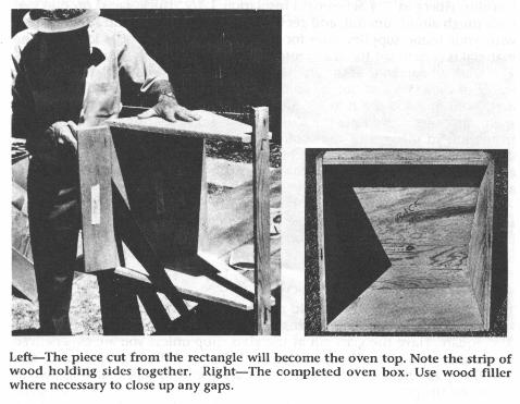
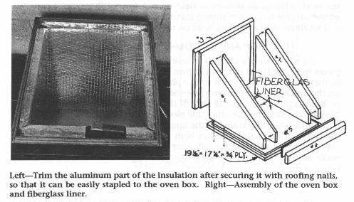
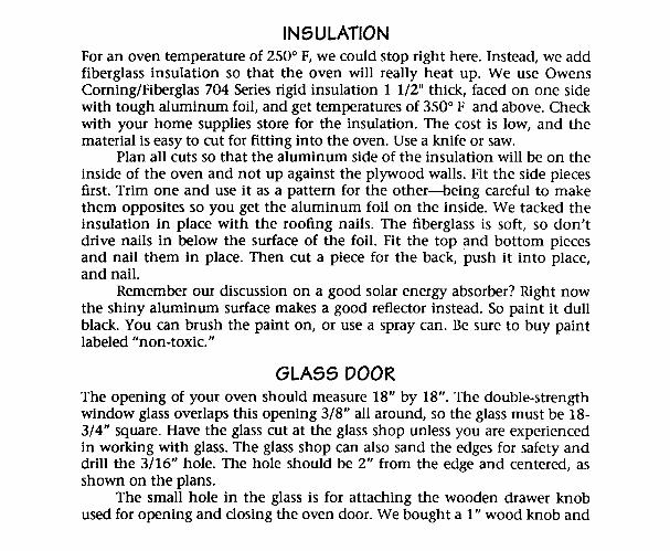
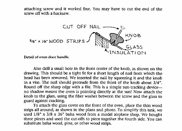
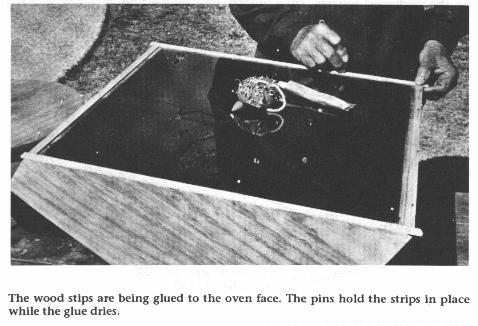
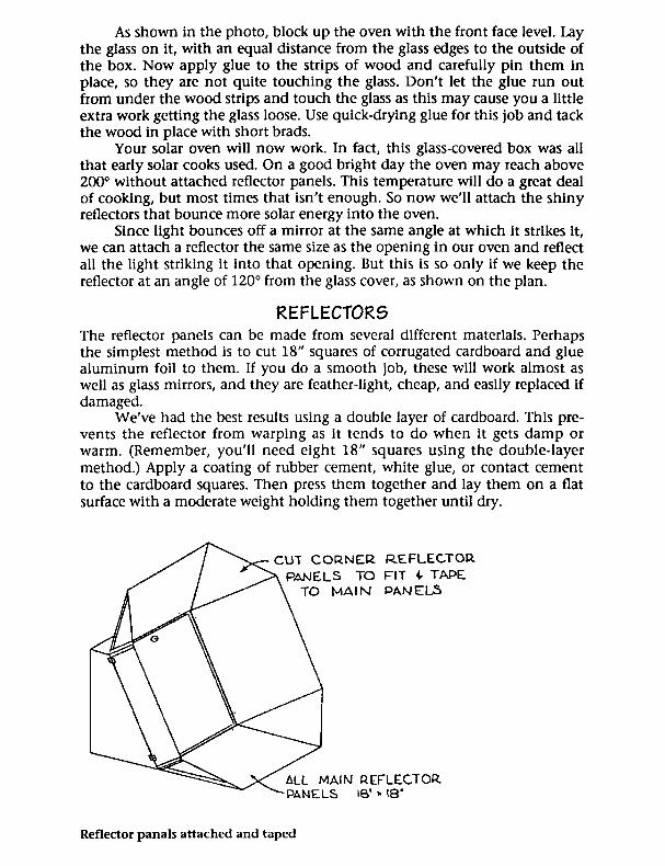
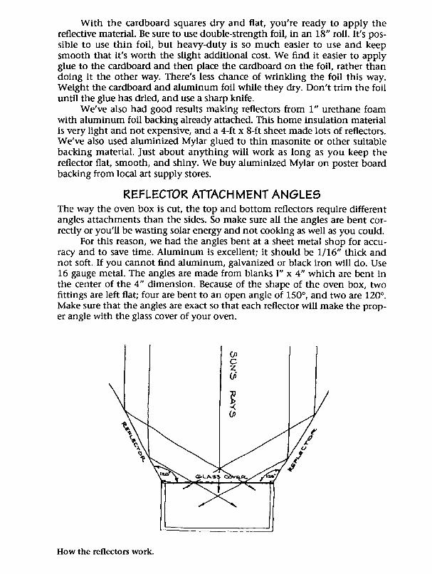
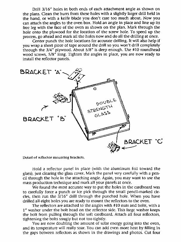

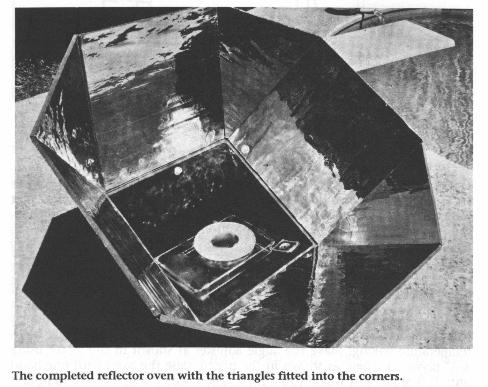

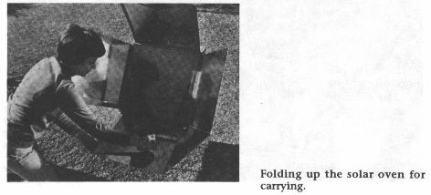
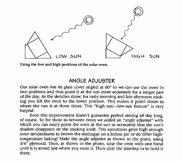
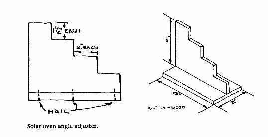
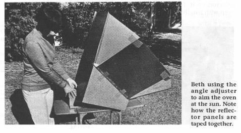
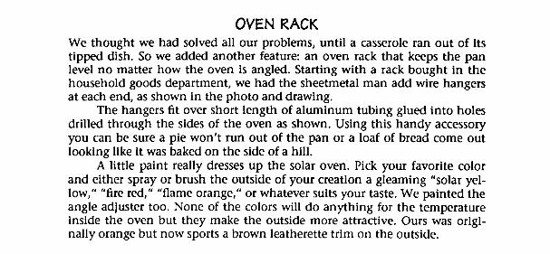
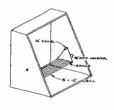
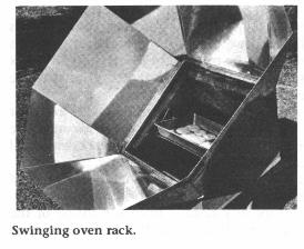
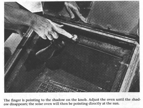
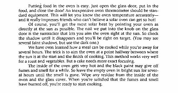
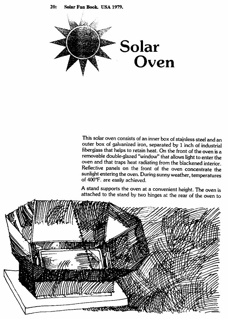
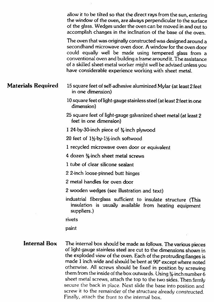
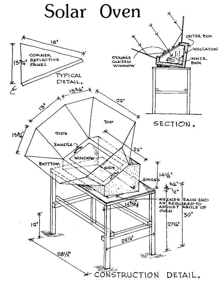
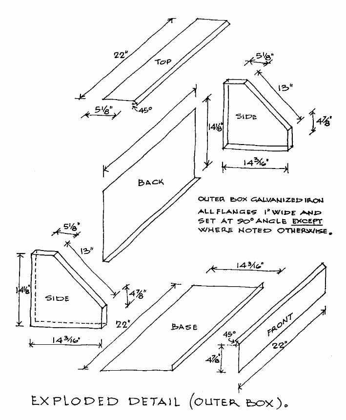
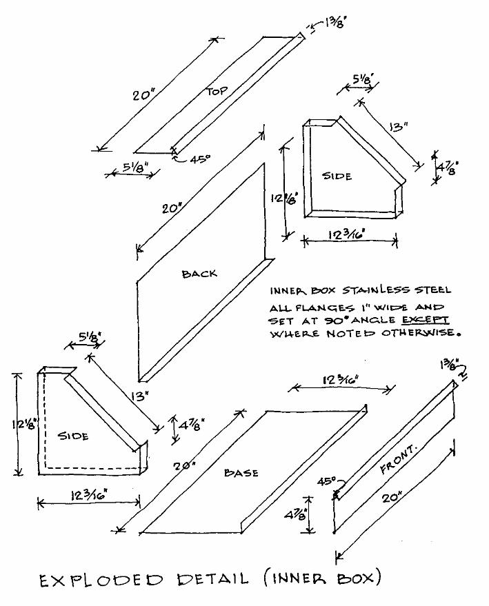
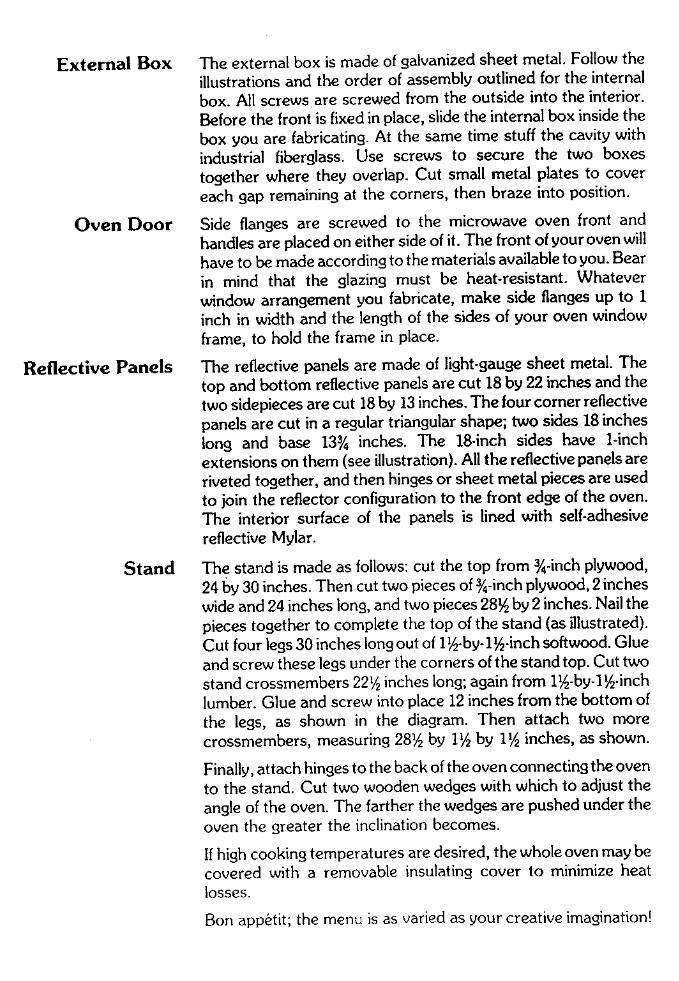
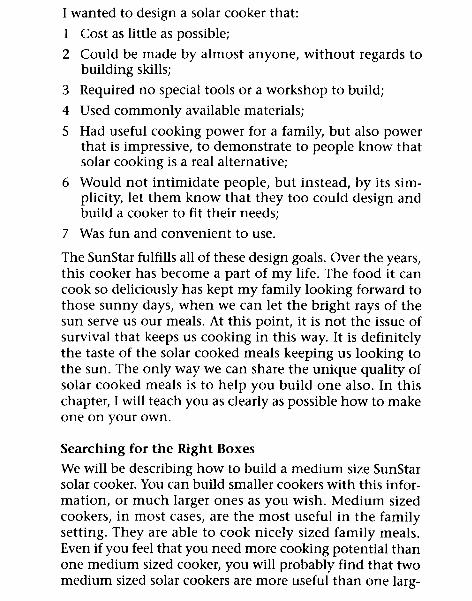
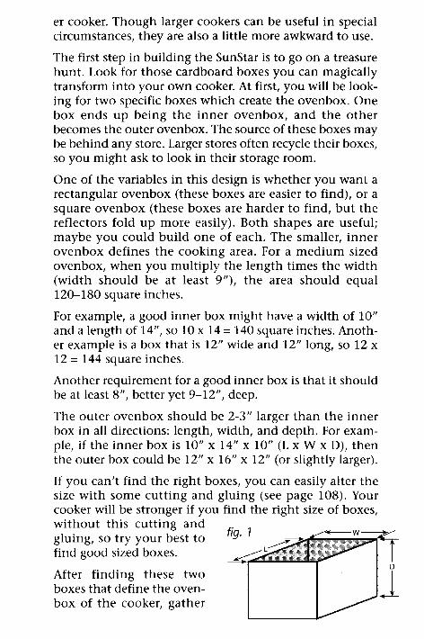
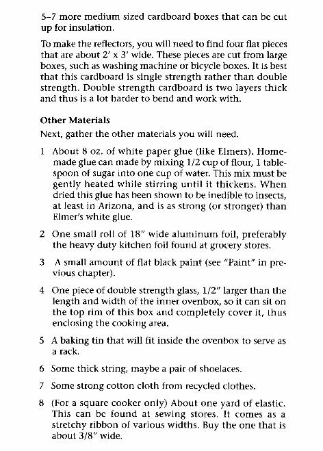
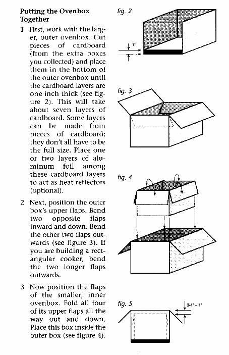
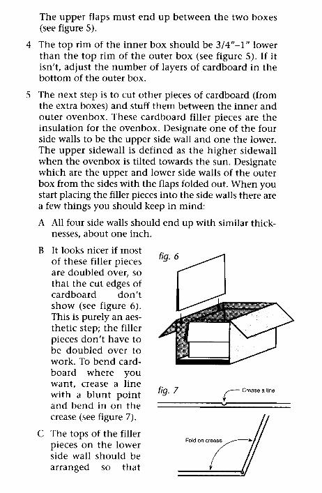
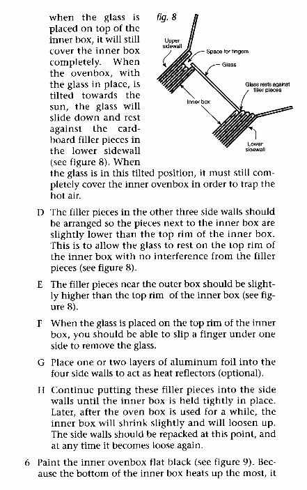
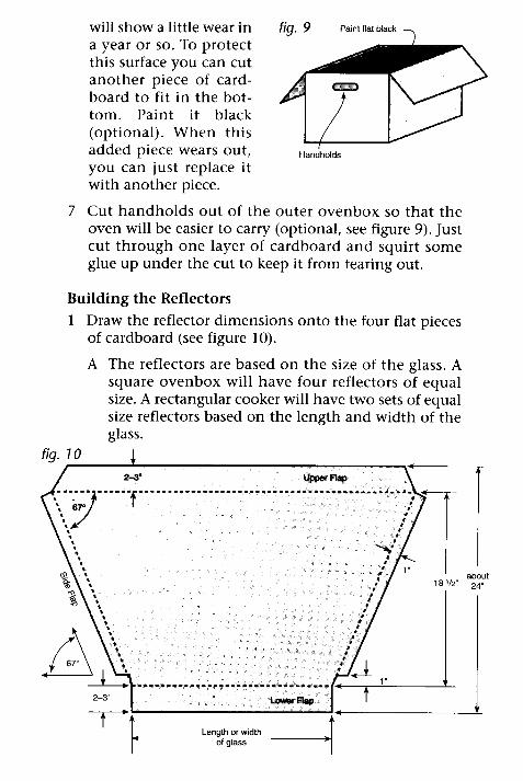
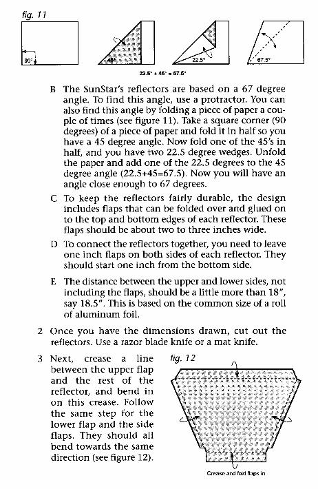
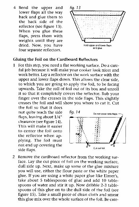
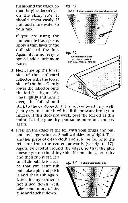
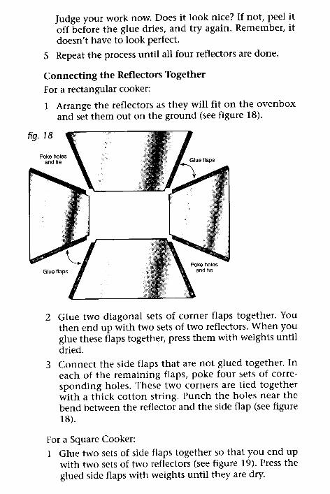
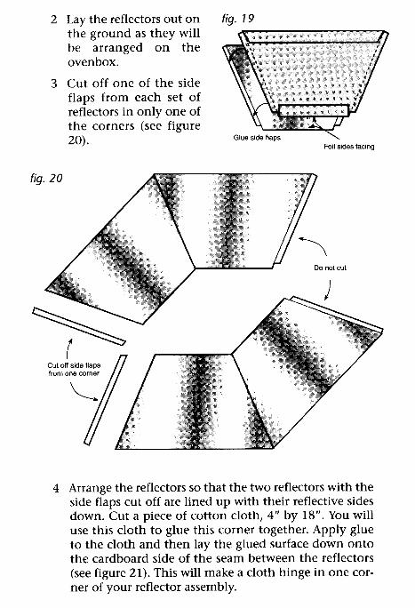
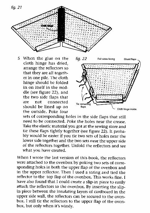
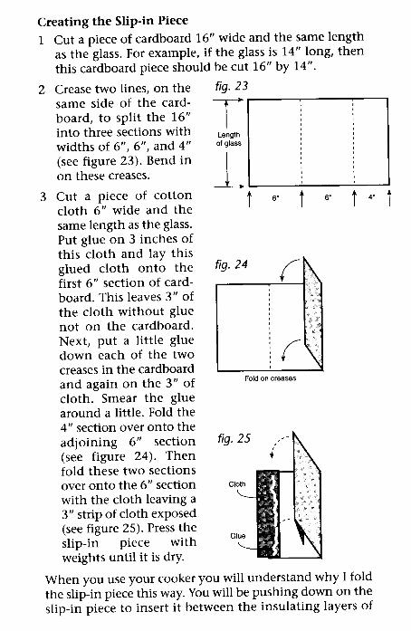
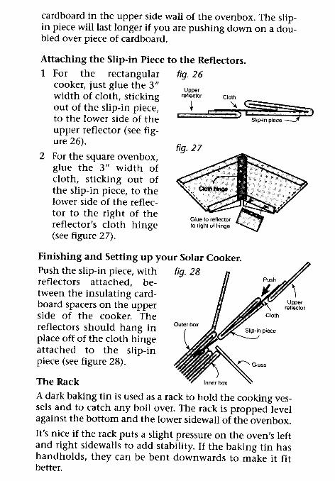
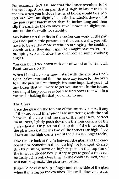
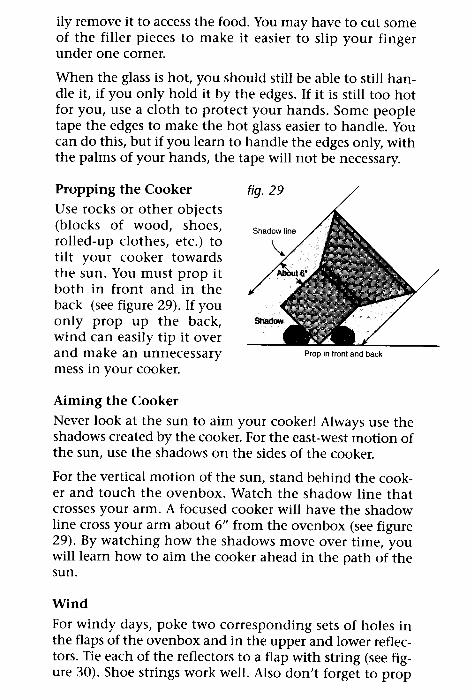

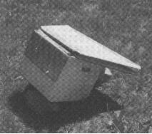
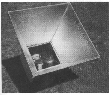
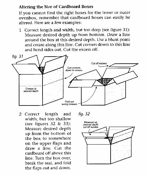
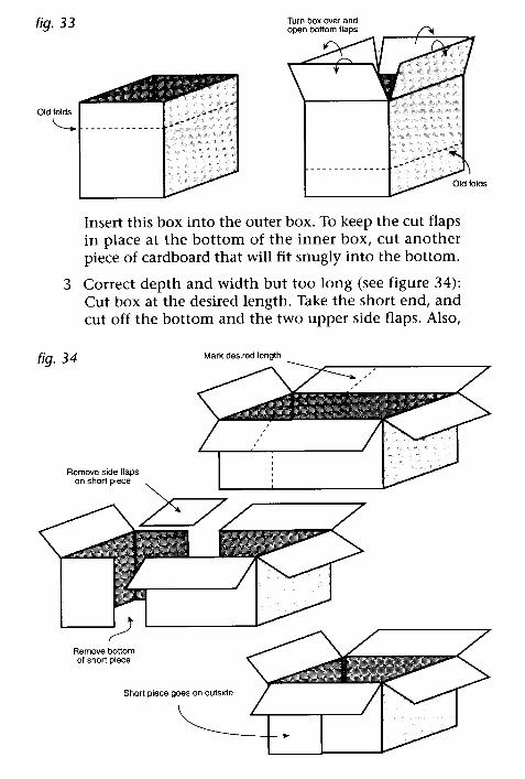
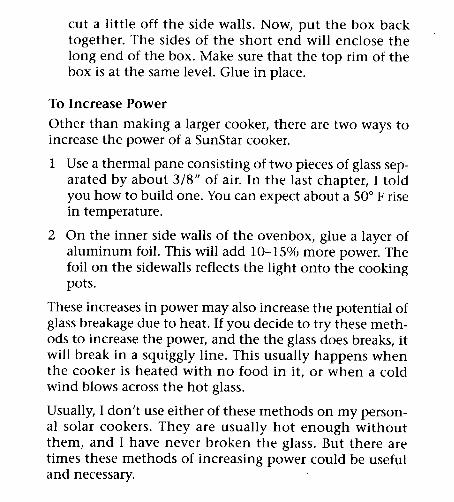
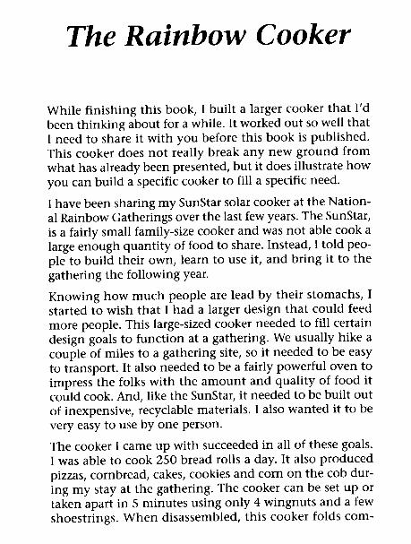
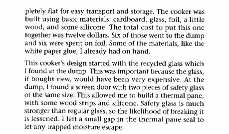
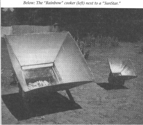

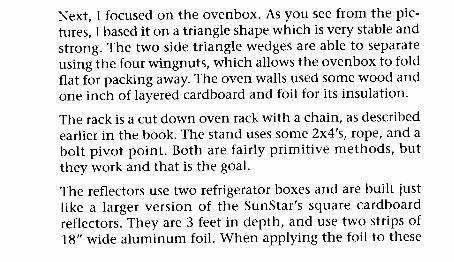
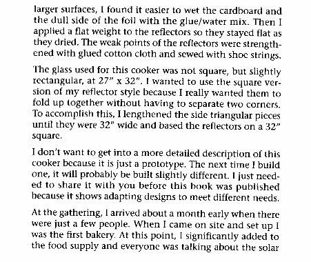
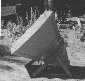
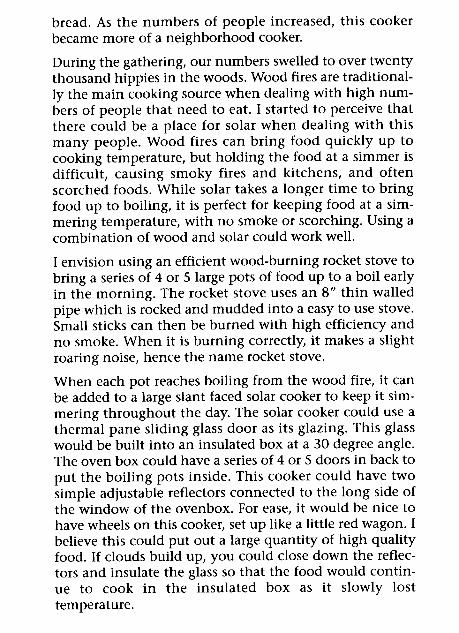
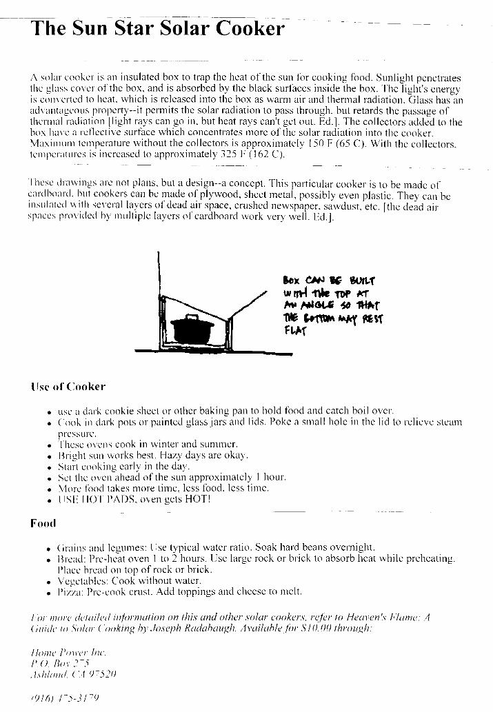
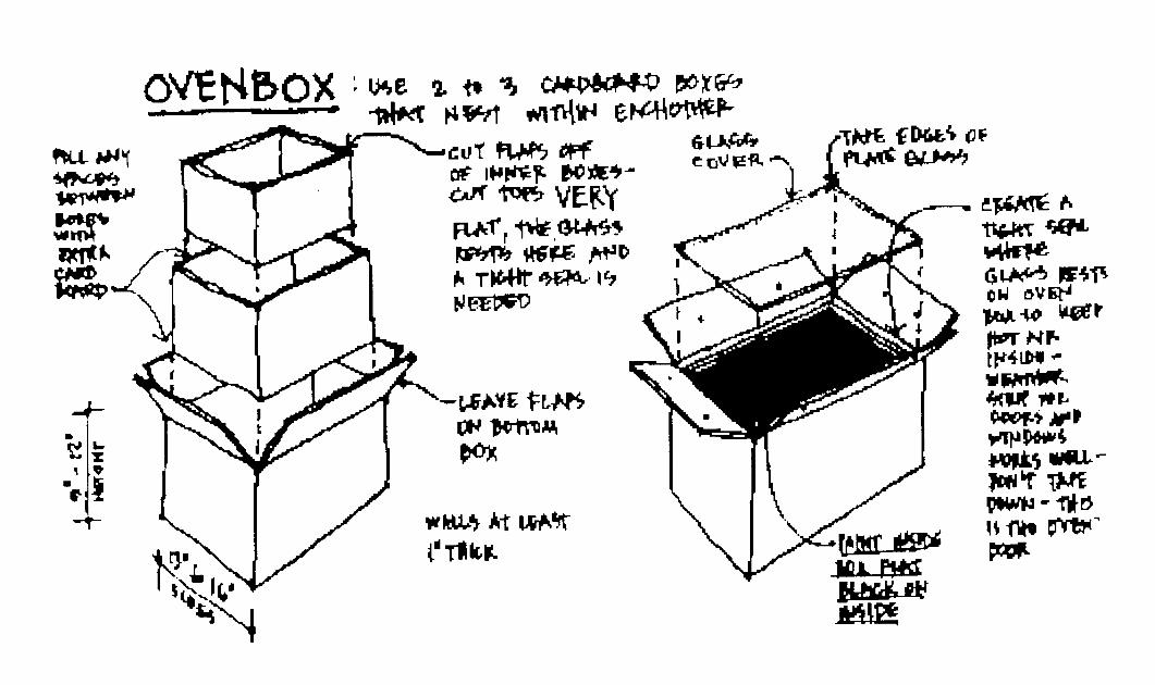
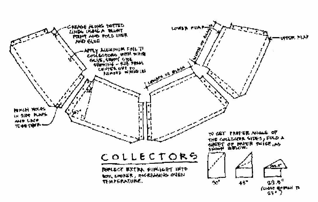
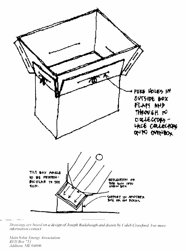
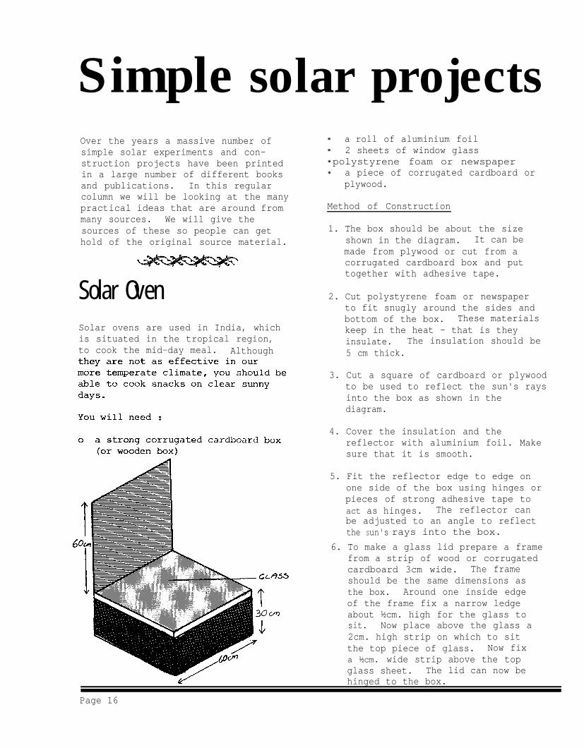
Simple solar projectsOver the years a massive number ofsimple solar experiments and con-struction projects have been printedin a large number of different booksand publications. In this regularcolumn we will be looking at the manypractical ideas that are around frommany sources. We will give thesources of these so people can gethold of the original source material.
Solar OvenSolar ovens are used in India, whichis situated in the tropical region,to cook the mid-day meal. Although
* a roll of aluminium foil* 2 sheets of window glass* polystyrene foam or newspaper* a piece of corrugated cardboard or
plywood.
Method of Construction
1. The box should be about the sizeshown in the diagram. It can bemade from plywood or cut from acorrugated cardboard box and puttogether with adhesive tape.
2. Cut polystyrene foam or newspaperto fit snugly around the sides andbottom of the box. These materialskeep in the heat - that is theyinsulate. The insulation should be5 cm thick.
3. Cut a square of cardboard or plywoodto be used to reflect the sun's raysinto the box as shown in thediagram.
4. Cover the insulation and thereflector with aluminium foil. Makesure that it is smooth.
5. Fit the reflector edge to edge onone side of the box using hinges orpieces of strong adhesive tape toact as hinges. The reflector canbe adjusted to an angle to reflectthe Sun's rays into the box.
6. To make a glass lid prepare a framefrom a strip of wood or corrugatedcardboard 3cm wide. The frameshould be the same dimensions asthe box. Around one inside edgeof the frame fix a narrow ledgeabout ½cm. high for the glass tosit. Now place above the glass a2cm. high strip on which to sitthe top piece of glass. Now fixa ½cm. wide strip above the topglass sheet. The lid can now behinged to the box.
Page 16
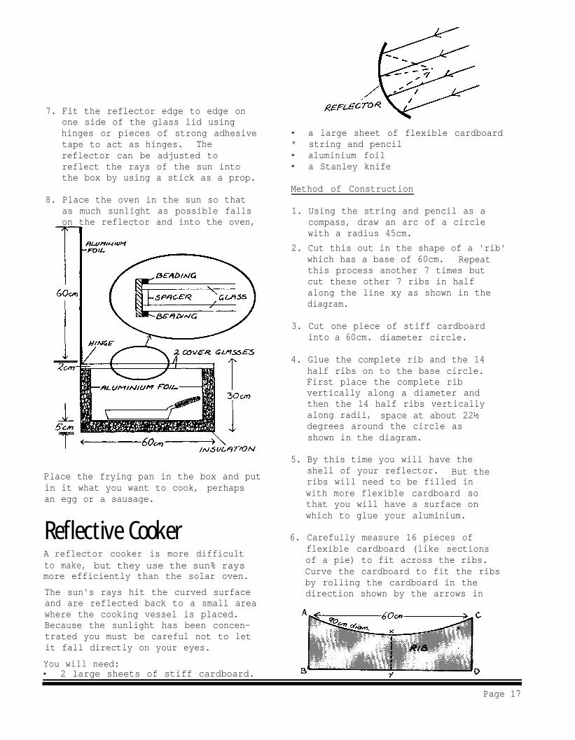
7. Fit the reflector edge to edge onone side of the glass lid usinghinges or pieces of strong adhesivetape to act as hinges. Thereflector can be adjusted toreflect the rays of the sun intothe box by using a stick as a prop.
8. Place the oven in the sun so thatas much sunlight as possible fallson the reflector and into the oven,
Place the frying pan in the box and putin it what you want to cook, perhapsan egg or a sausage.
Reflective CookerA reflector cooker is more difficultto make, but they use the sun% raysmore efficiently than the solar oven.
The sun's rays hit the curved surfaceand are reflected back to a small areawhere the cooking vessel is placed.Because the sunlight has been concen-trated you must be careful not to letit fall directly on your eyes.
You will need:* 2 large sheets of stiff cardboard.
* a large sheet of flexible cardboard* string and pencil* aluminium foil* a Stanley knife
Method of Construction
1. Using the string and pencil as acompass, draw an arc of a circlewith a radius 45cm.
2. Cut this out in the shape of a 'rib'which has a base of 60cm. Repeatthis process another 7 times butcut these other 7 ribs in halfalong the line xy as shown in thediagram.
3. Cut one piece of stiff cardboardinto a 60cm. diameter circle.
4. Glue the complete rib and the 14half ribs on to the base circle.First place the complete ribvertically along a diameter andthen the 14 half ribs verticallyalong radii, space at about 22½degrees around the circle asshown in the diagram.
5. By this time you will have theshell of your reflector. But theribs will need to be filled inwith more flexible cardboard sothat you will have a surface onwhich to glue your aluminium.
6. Carefully measure 16 pieces offlexible cardboard (like sectionsof a pie) to fit across the ribs.Curve the cardboard to fit the ribsby rolling the cardboard in thedirection shown by the arrows in
Page 17
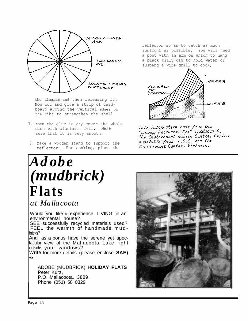
the diagram and then releasing it.Now cut and give a strip of card-board around the vertical edges ofthe ribs to strengthen the shell.
7. When the glue is dry cover the wholedish with aluminium foil. Makesure that it is very smooth.
8. Make a wooden stand to support thereflector. For cooking, place the
reflector so as to catch as muchsunlight as possible. You will needa post with an arm on which to hanga black billy-can to hold water orsuspend a wire grill to cook,
Adobe(mudbrick)Flatsat MallacootaWould you like to experience LIVING in anenvironmental house?SEE successfully recycled materials used?FEEL the warmth of handmade m u d -
bricks?AndtacularoutsideWriteto
as a bonus have the serene yet spec- view of the Mallacoota Lake right your windows? for more details (please enclose SAE)
ADOBE (MUDBRICK) HOLIDAY FLATSPeter Kurz,P.O. Mallacoota, 3889.Phone (051) 58 0329
Page 18
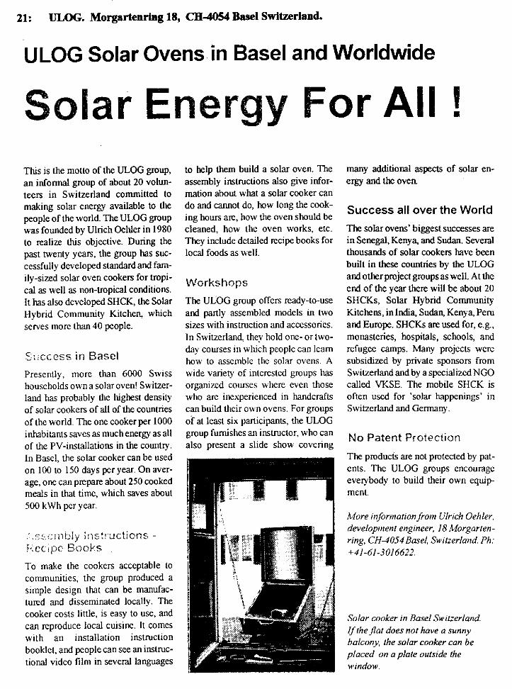
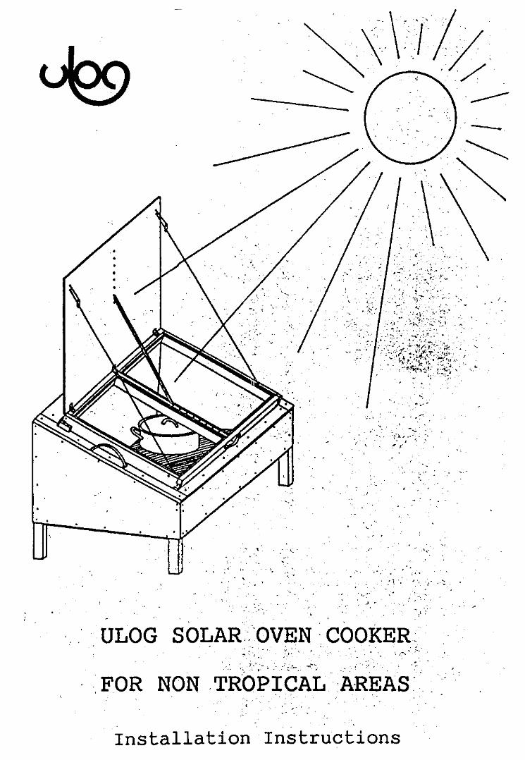
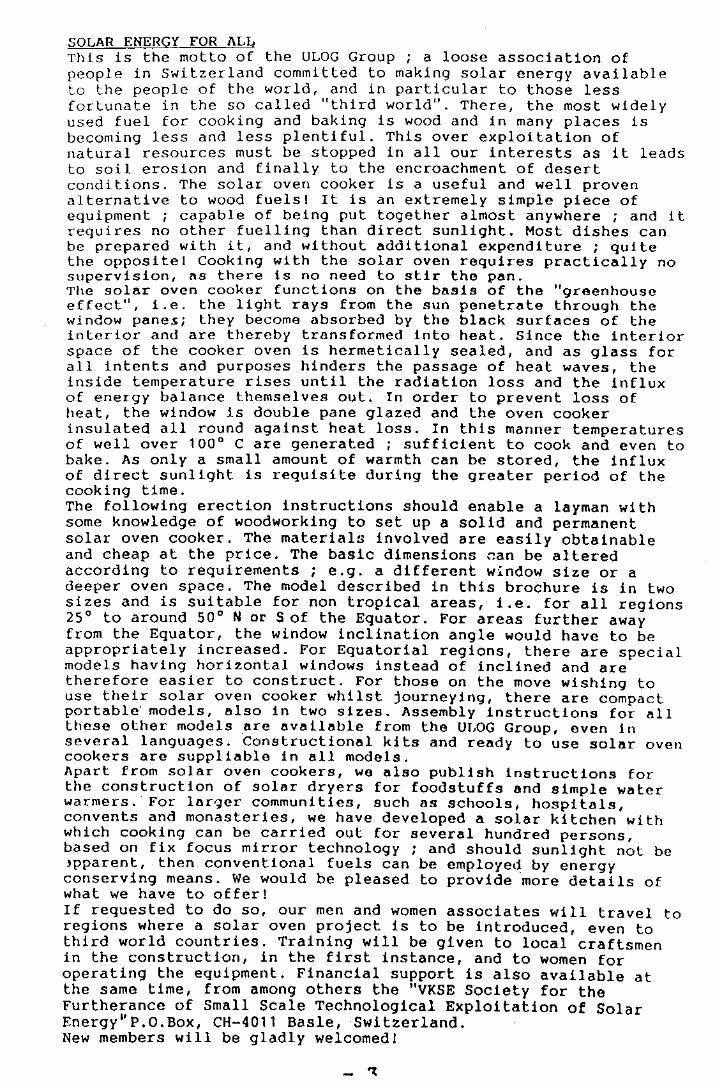
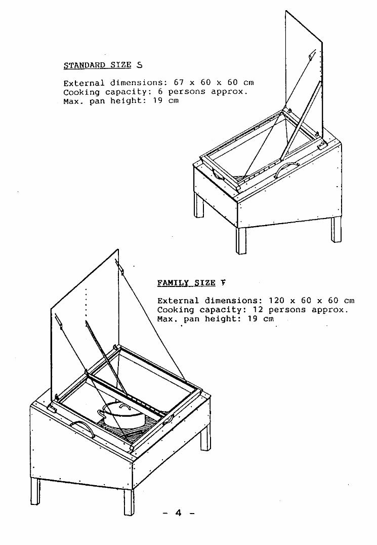
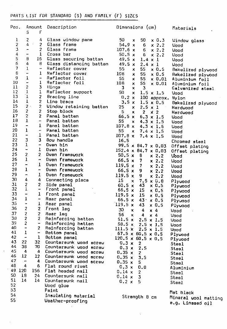
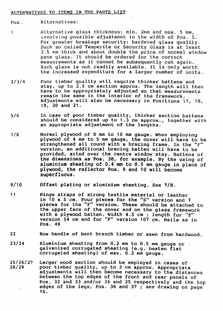
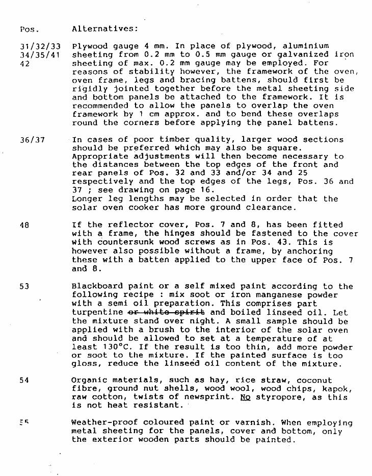
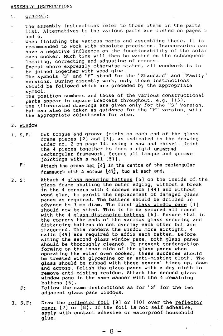
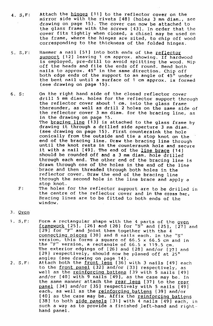
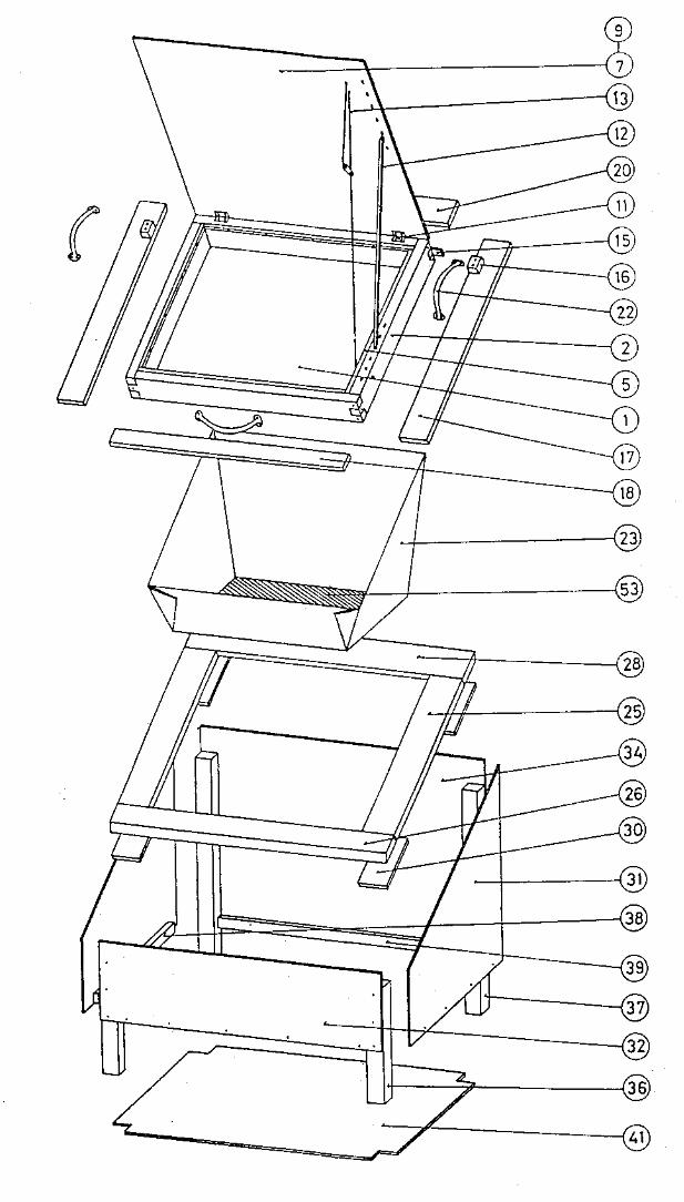
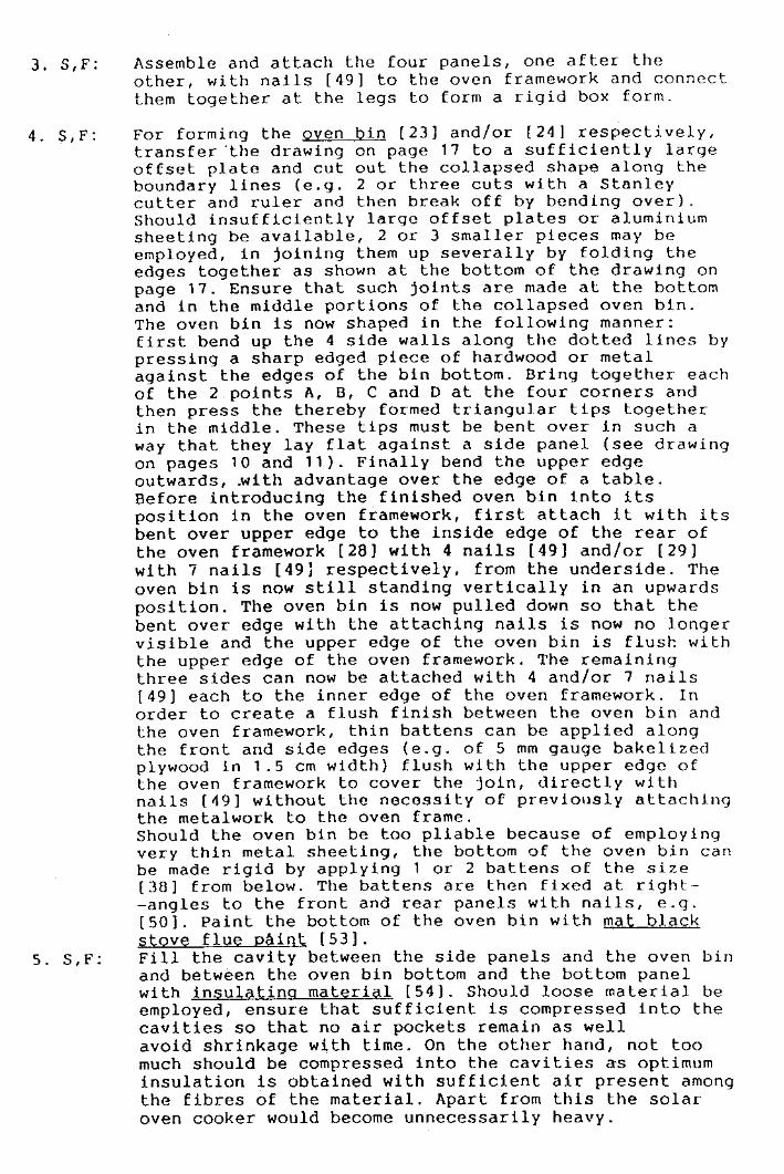
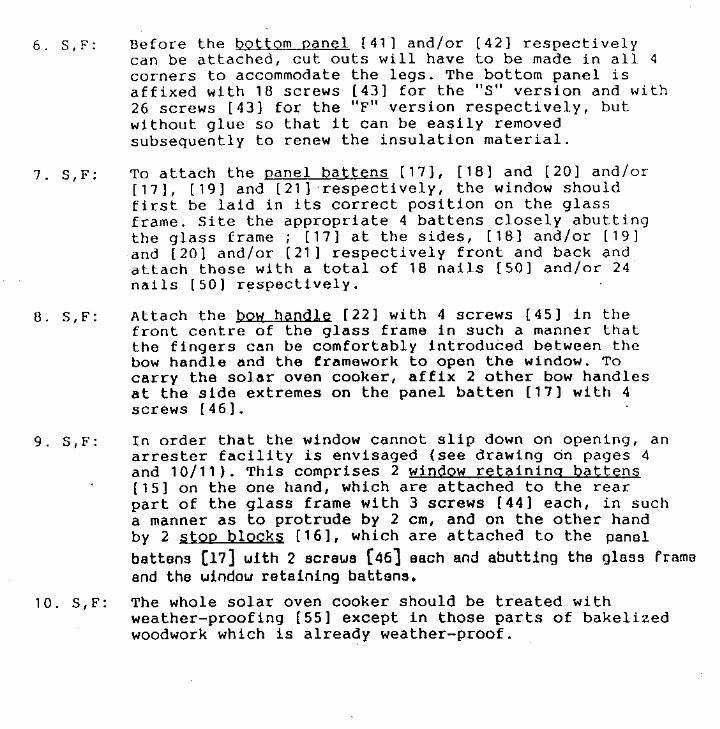
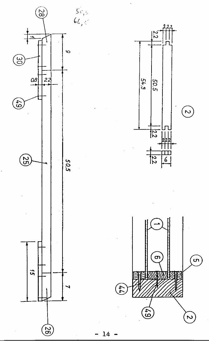
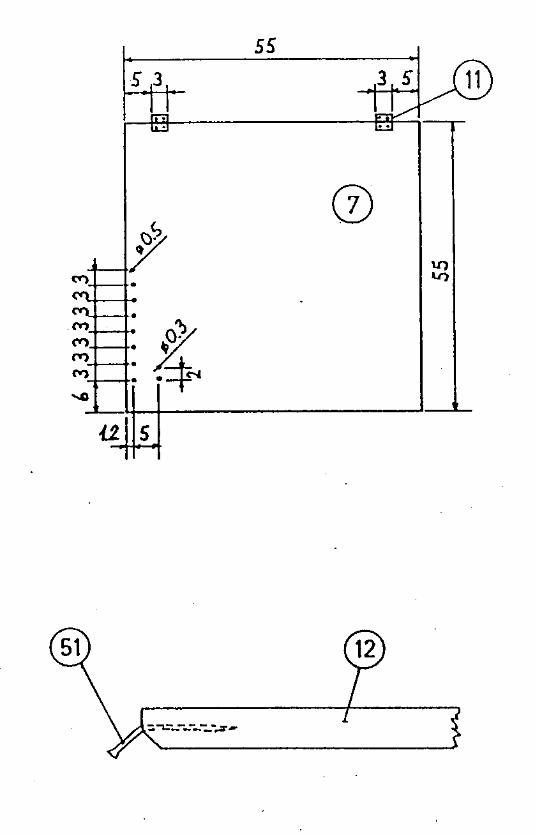
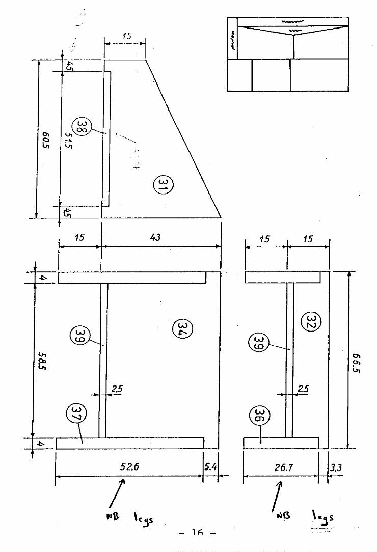
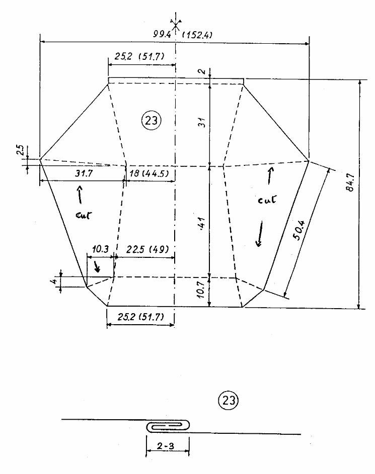
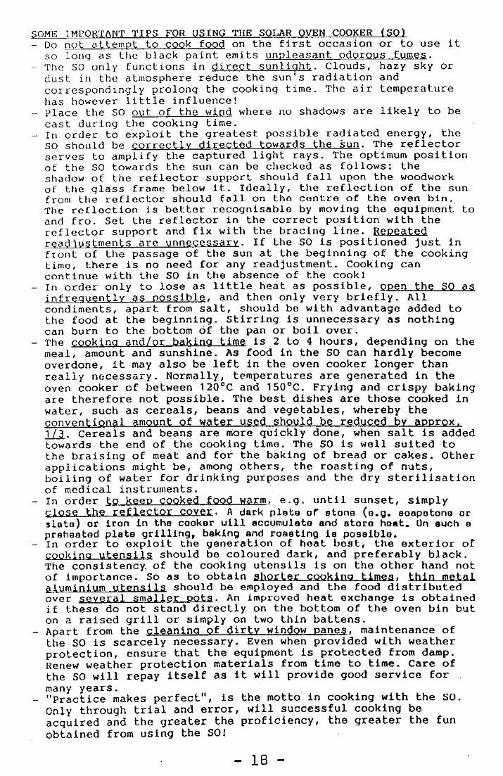
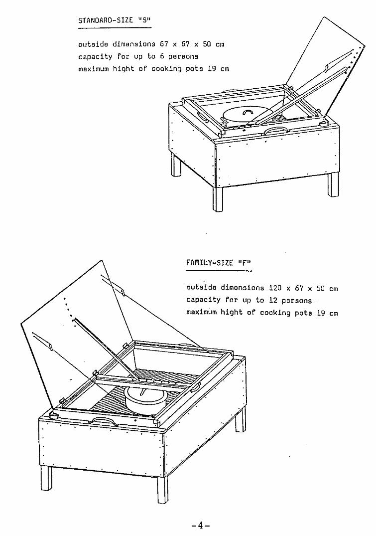
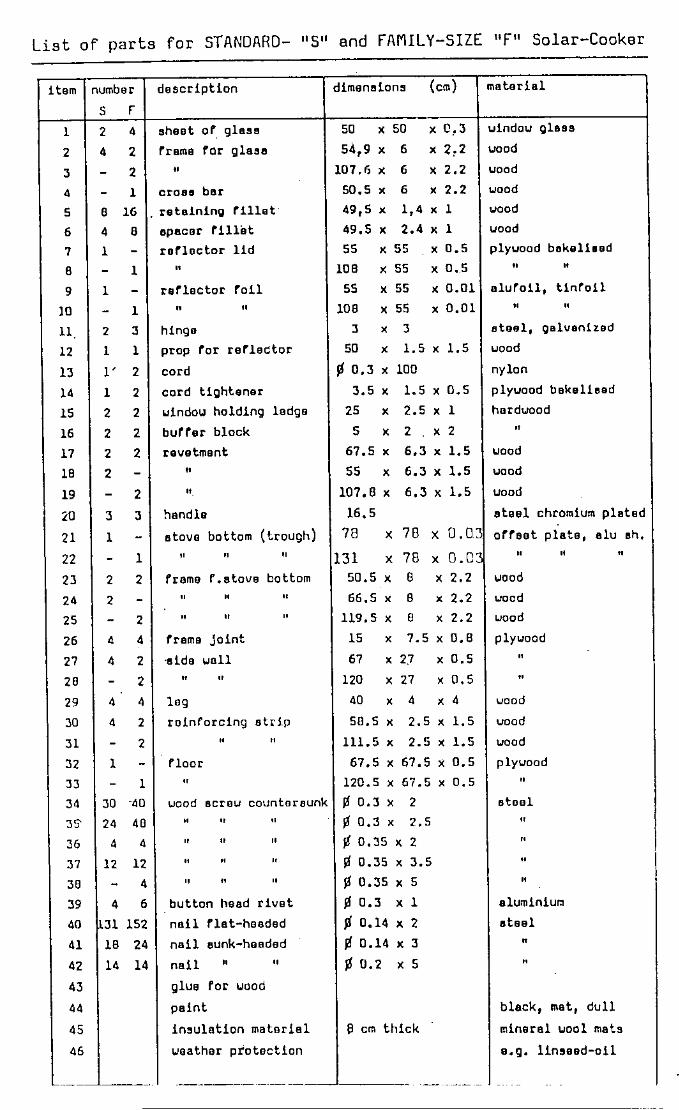
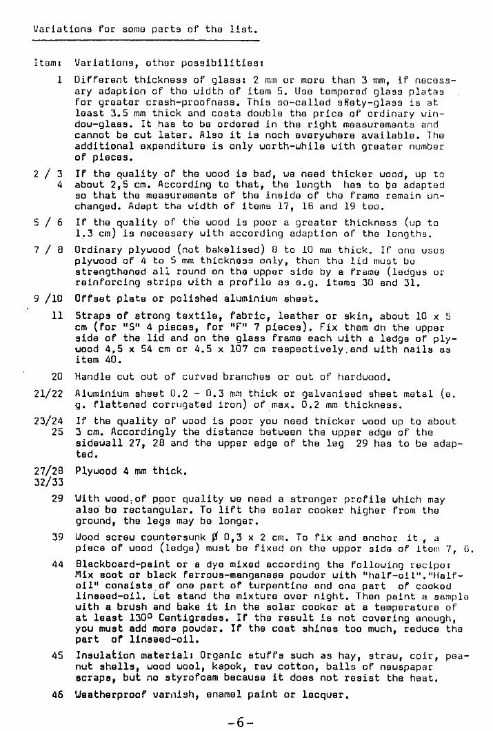
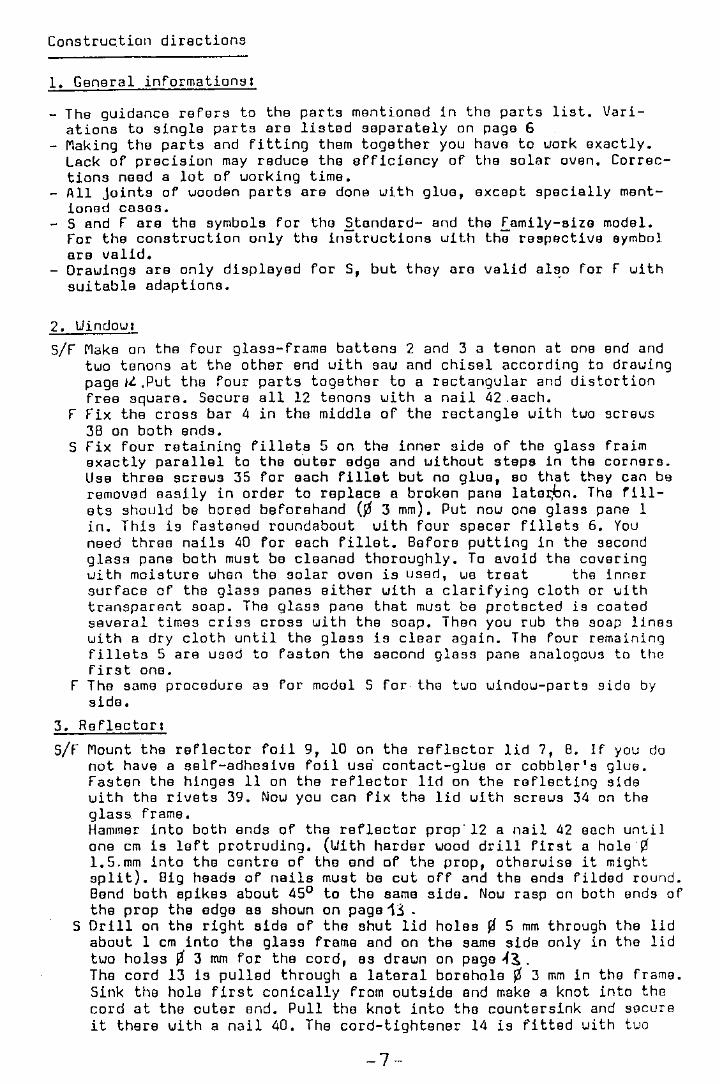
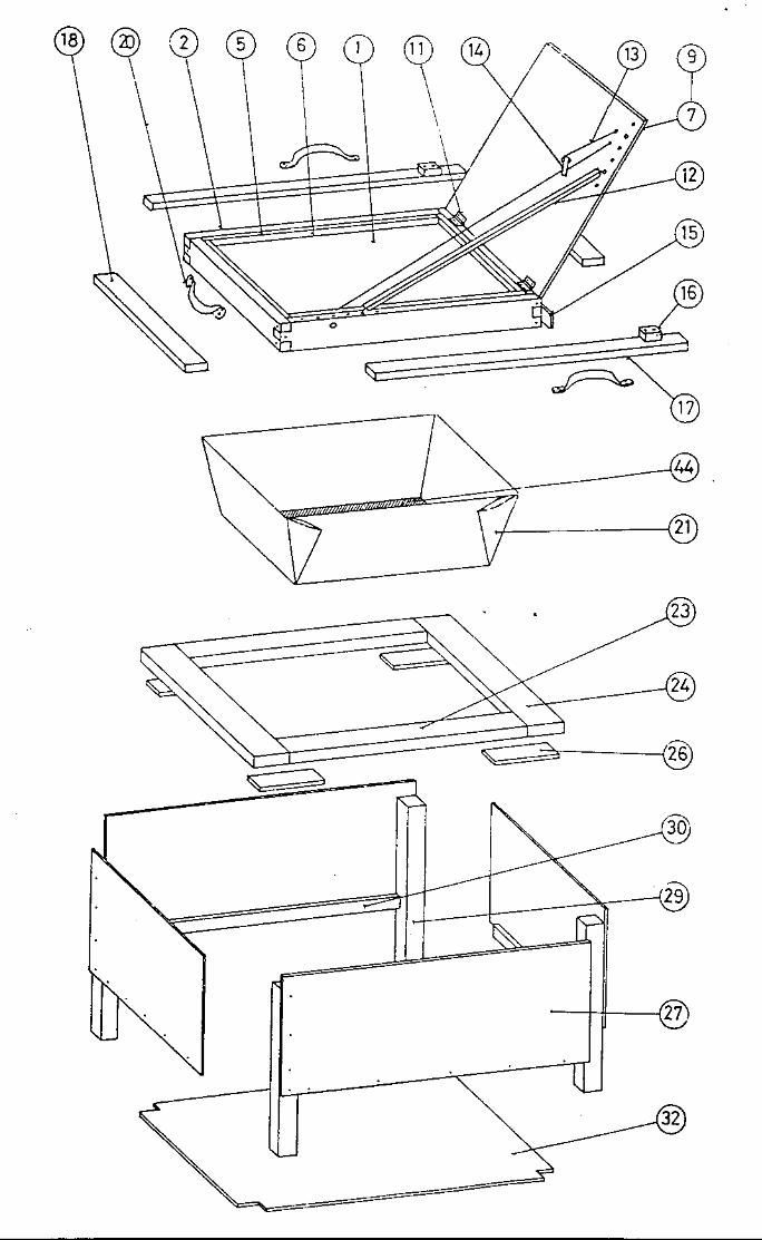
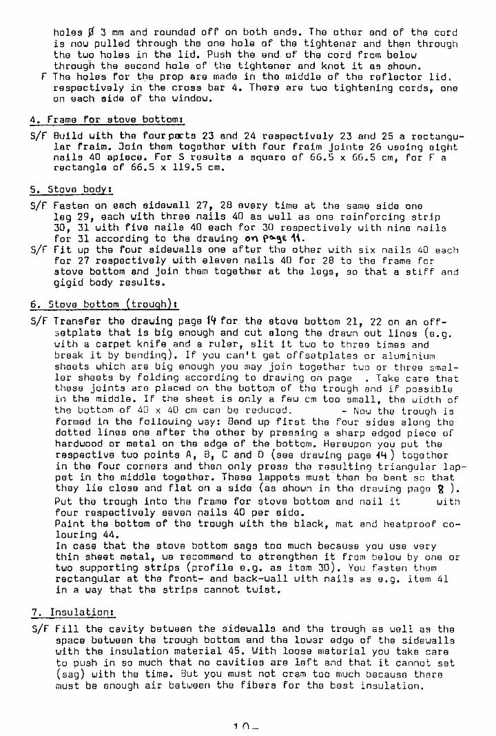
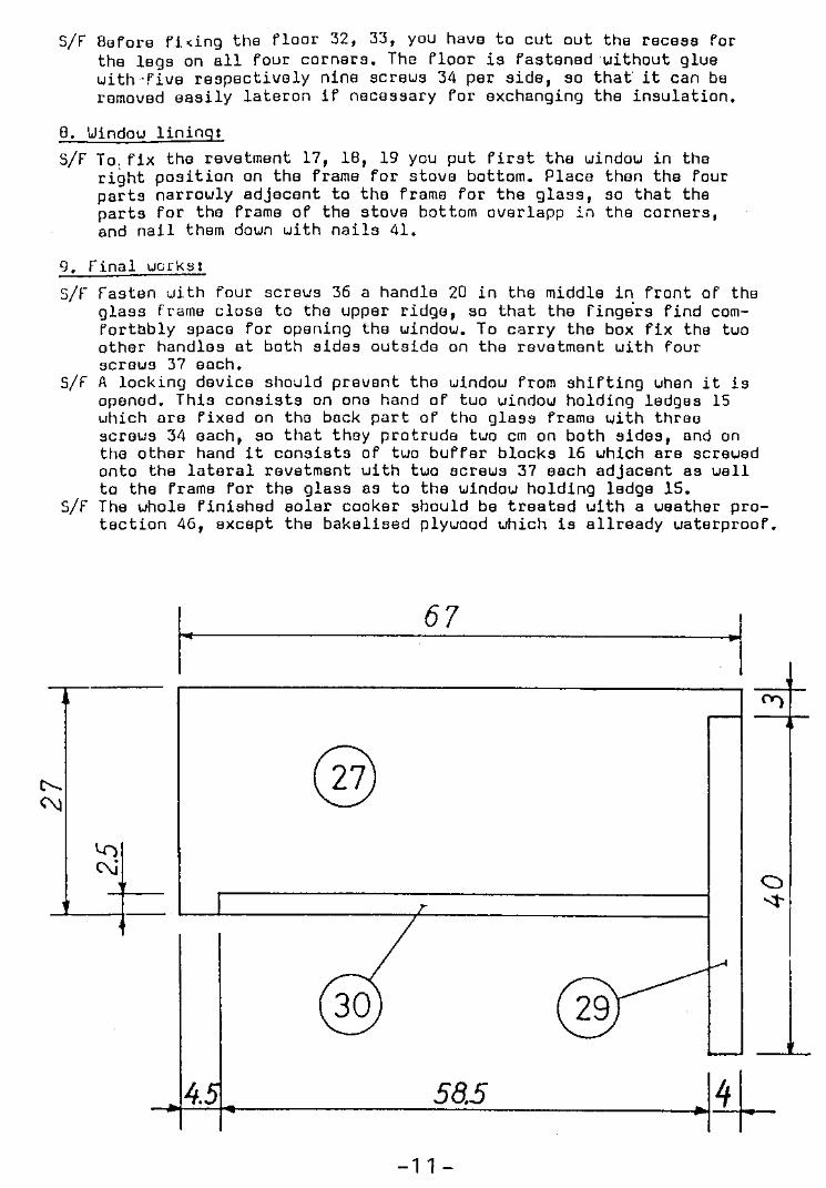
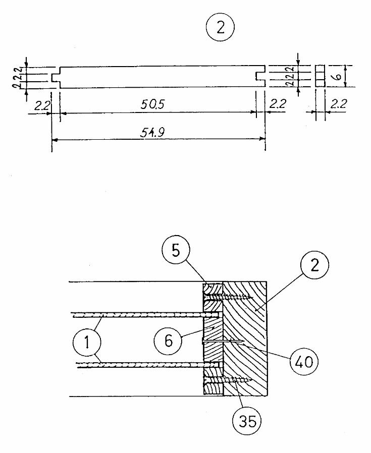
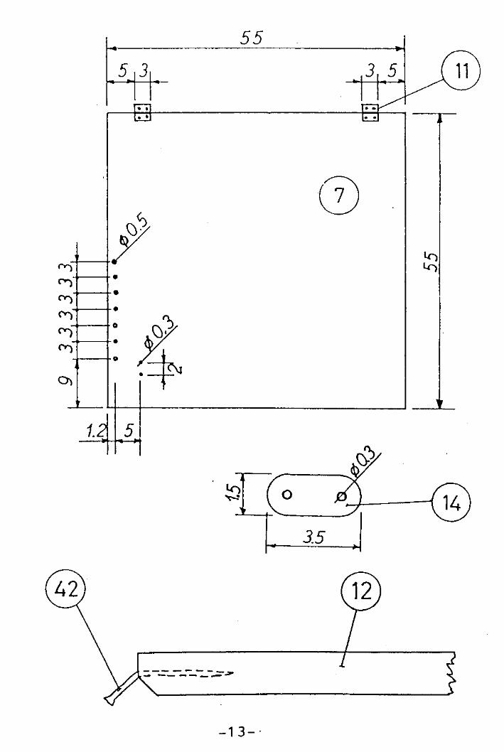
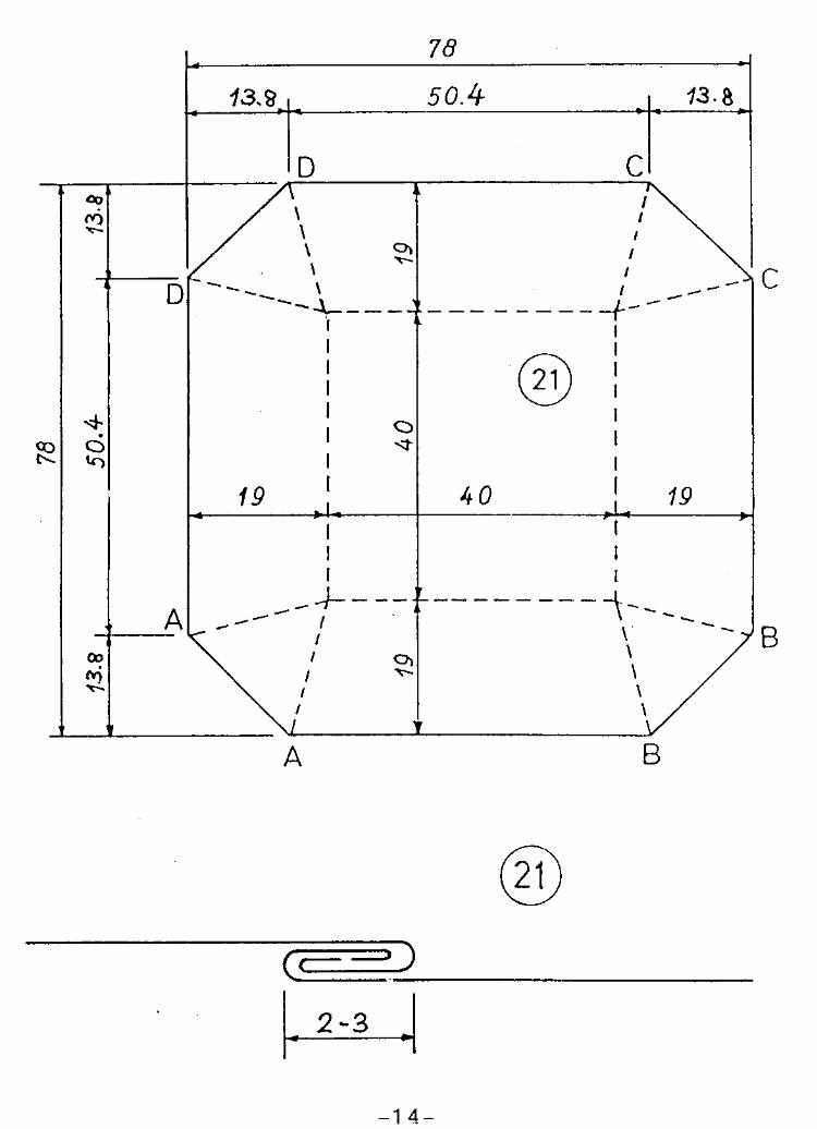
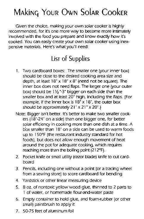
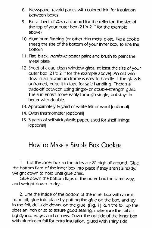
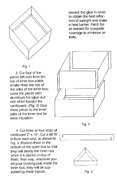
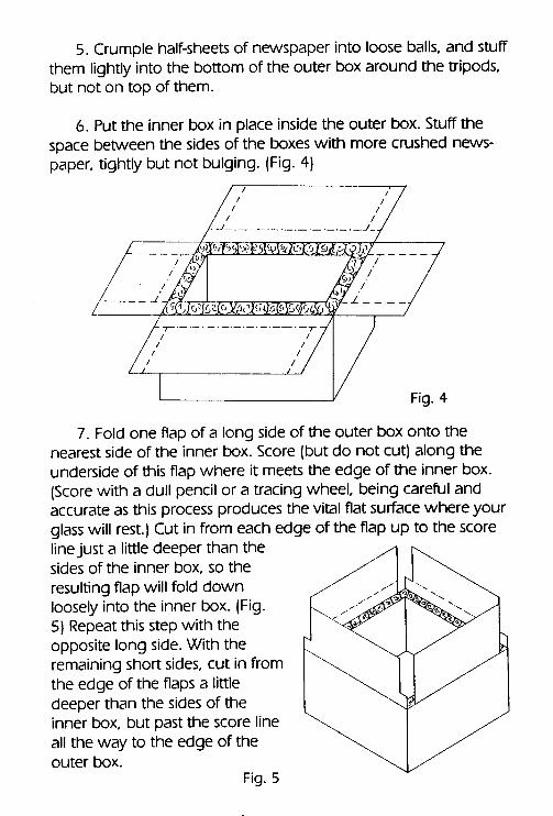
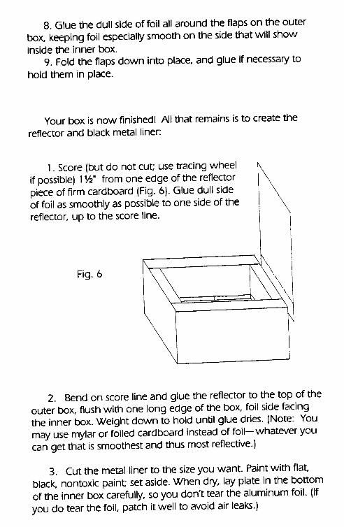
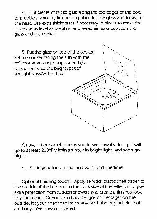
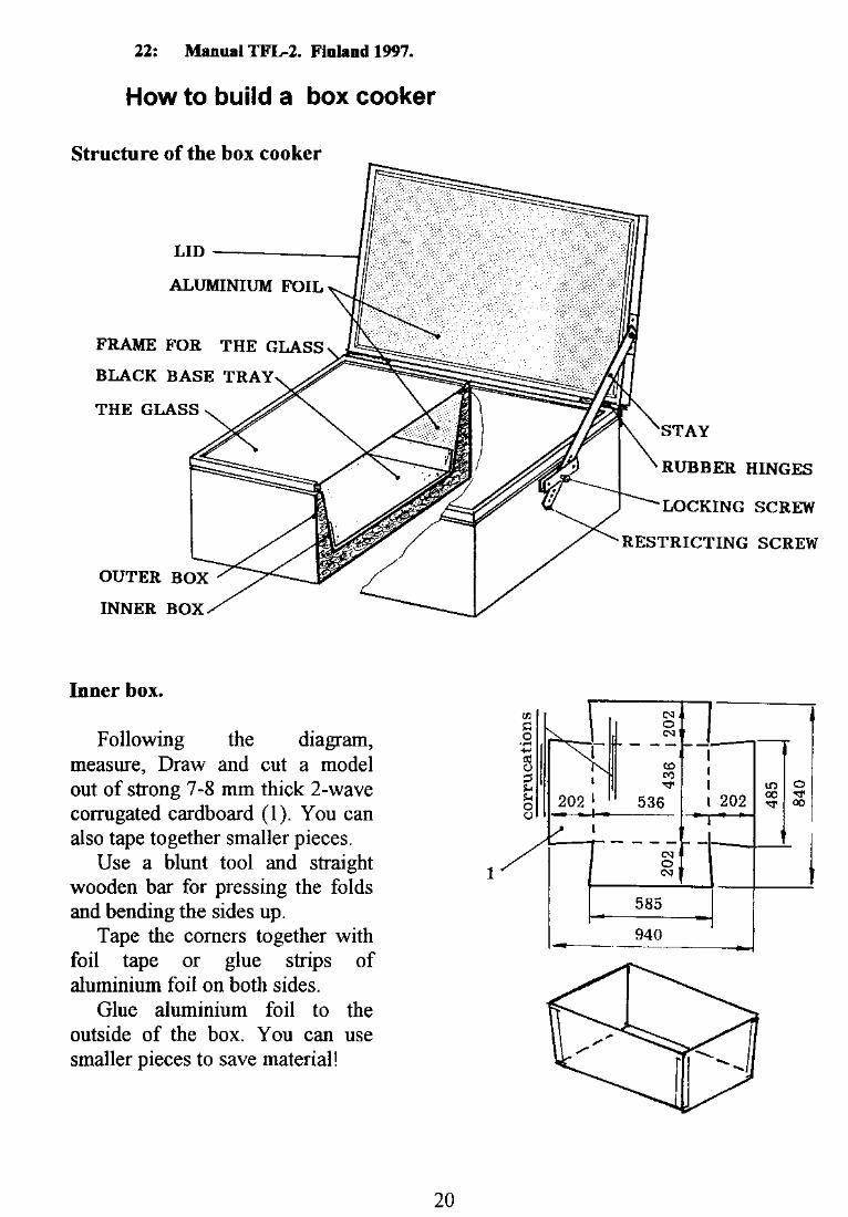
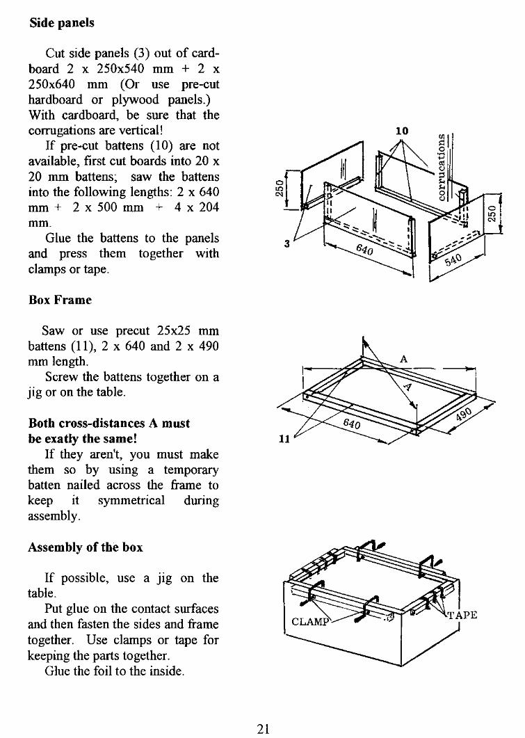
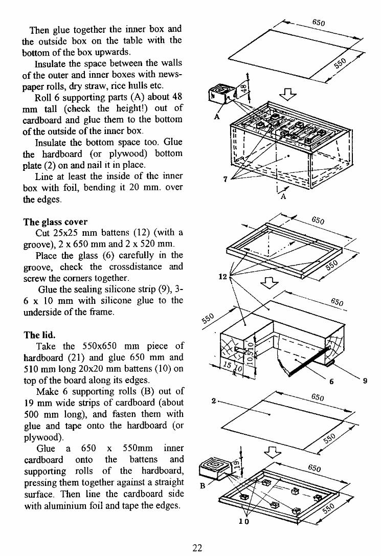
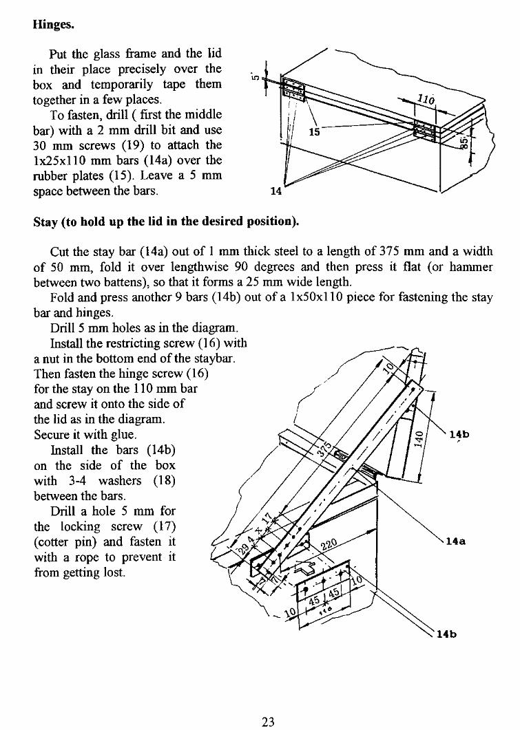
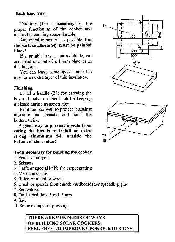
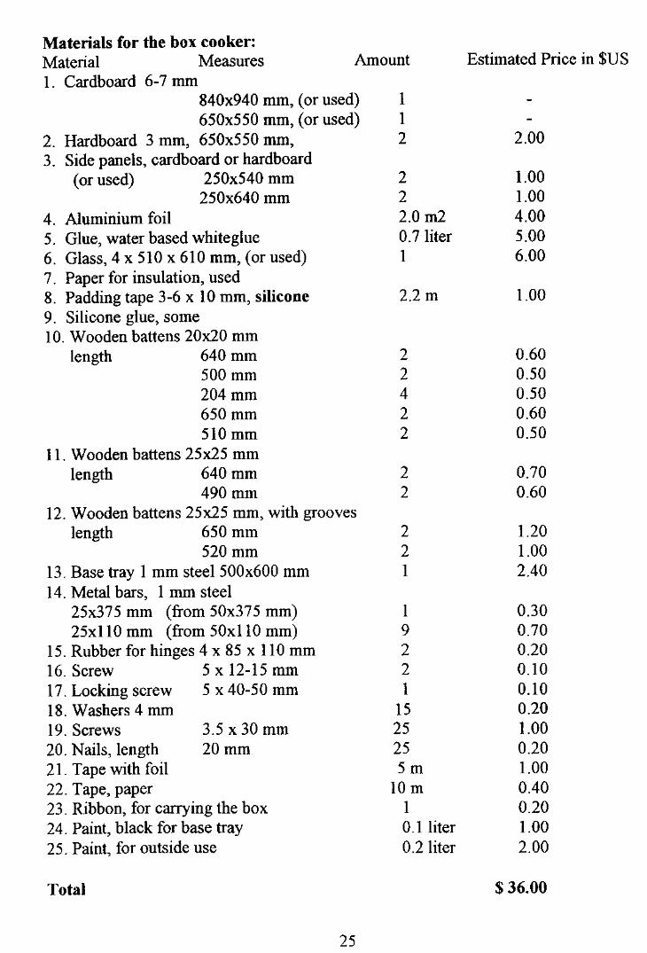
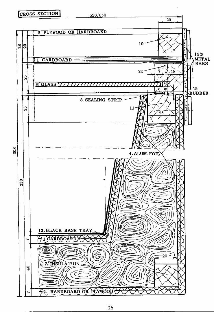
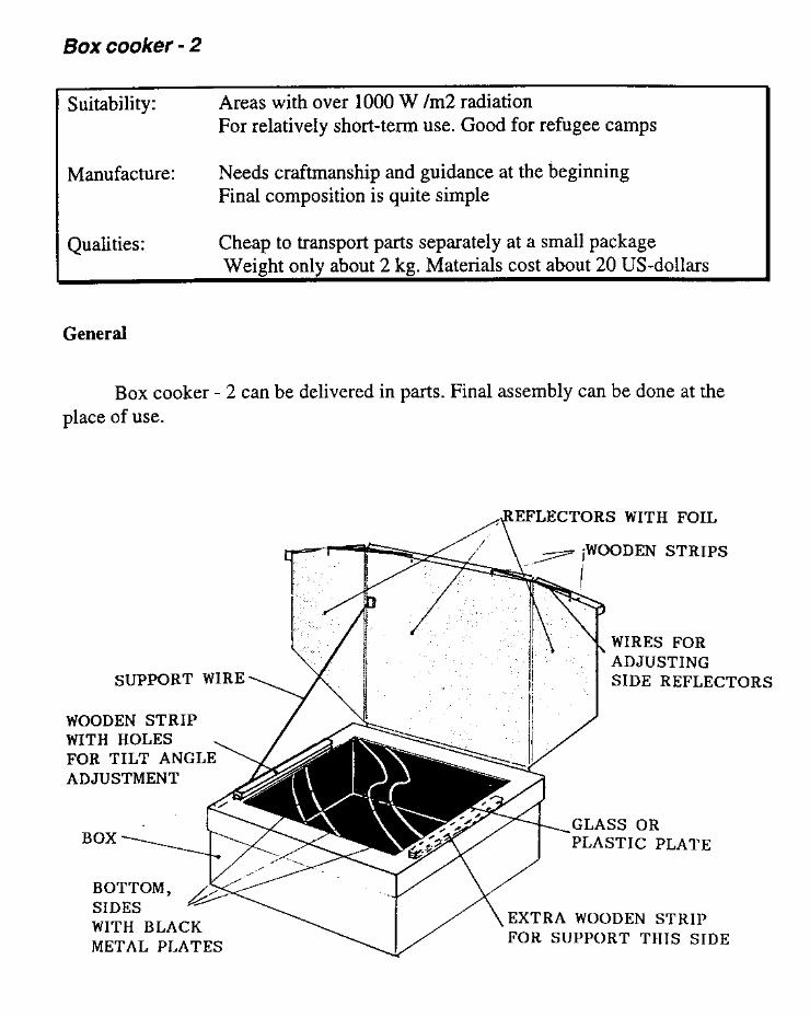
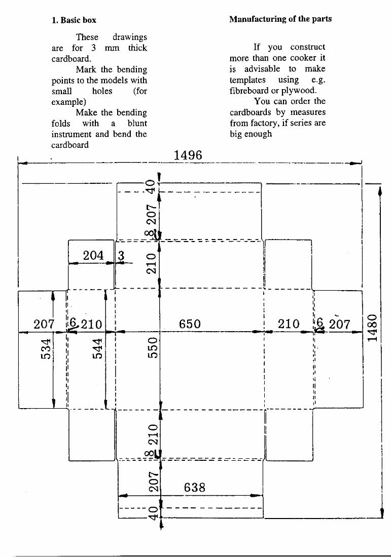
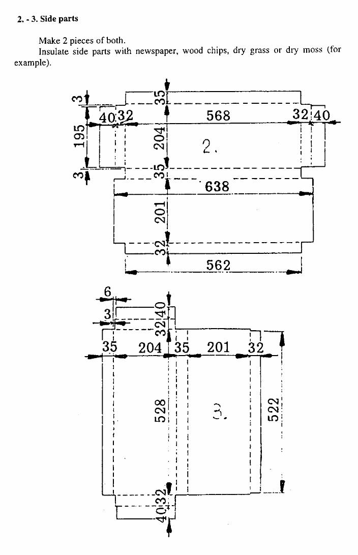
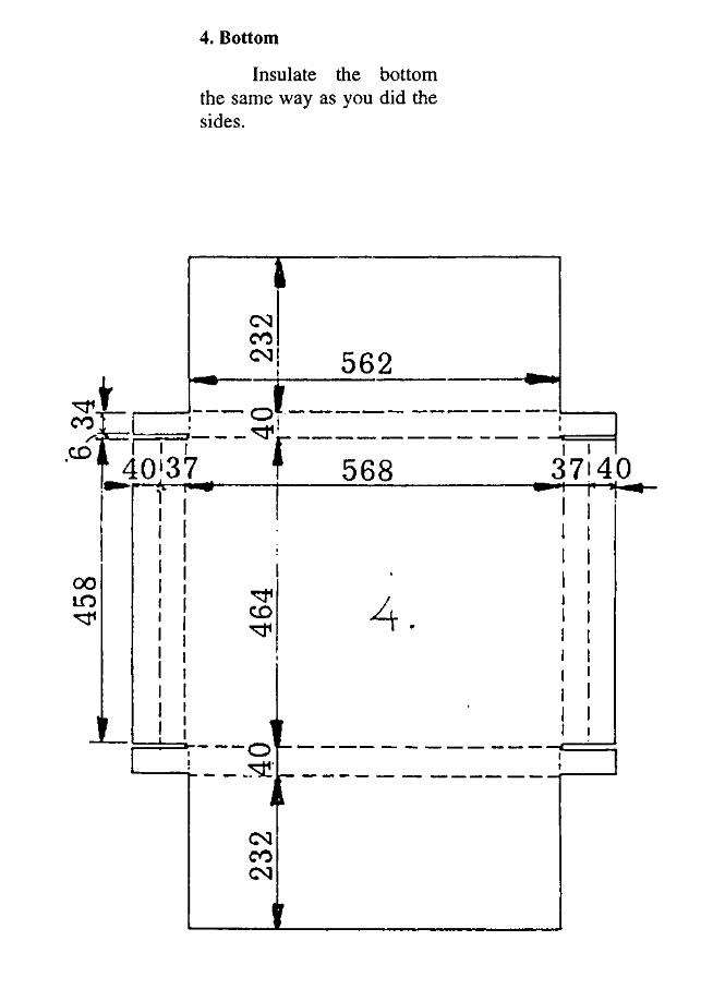
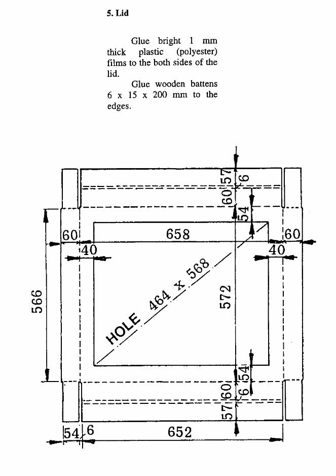
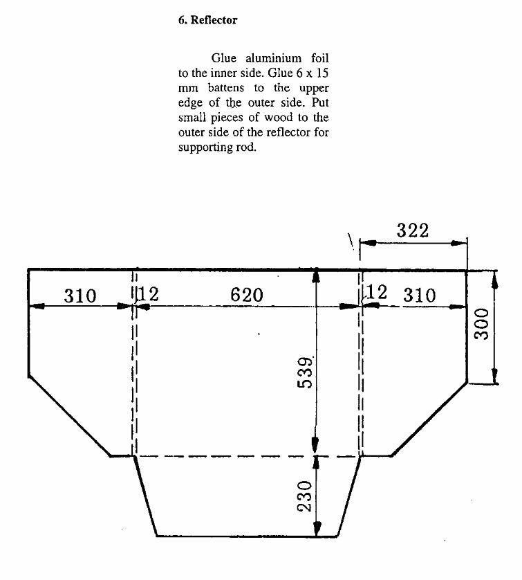
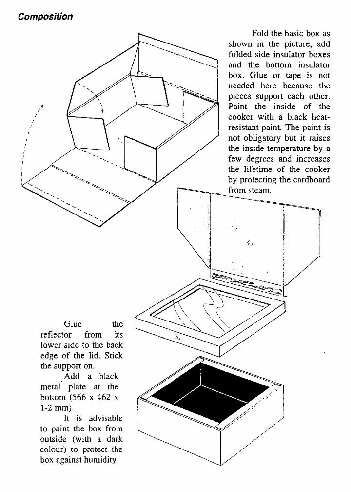
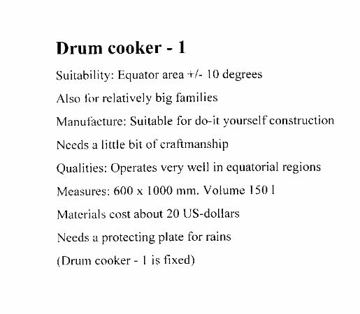
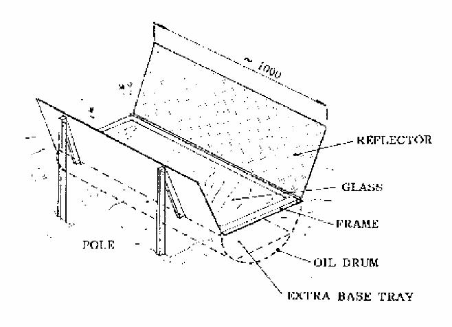
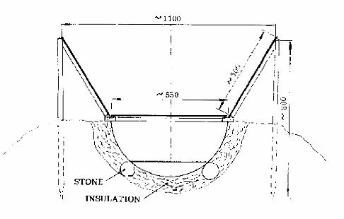
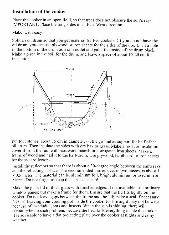
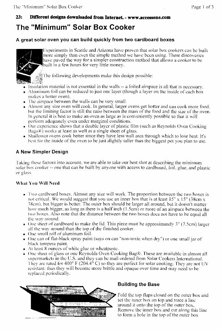
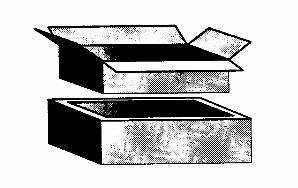
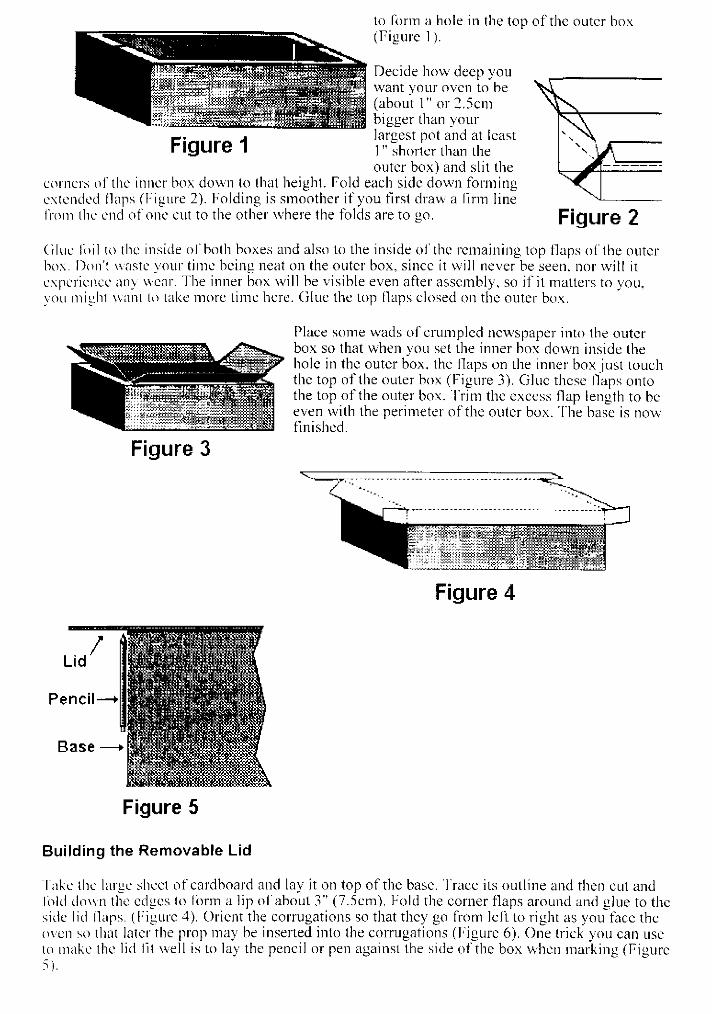
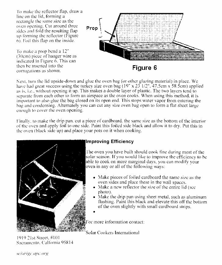
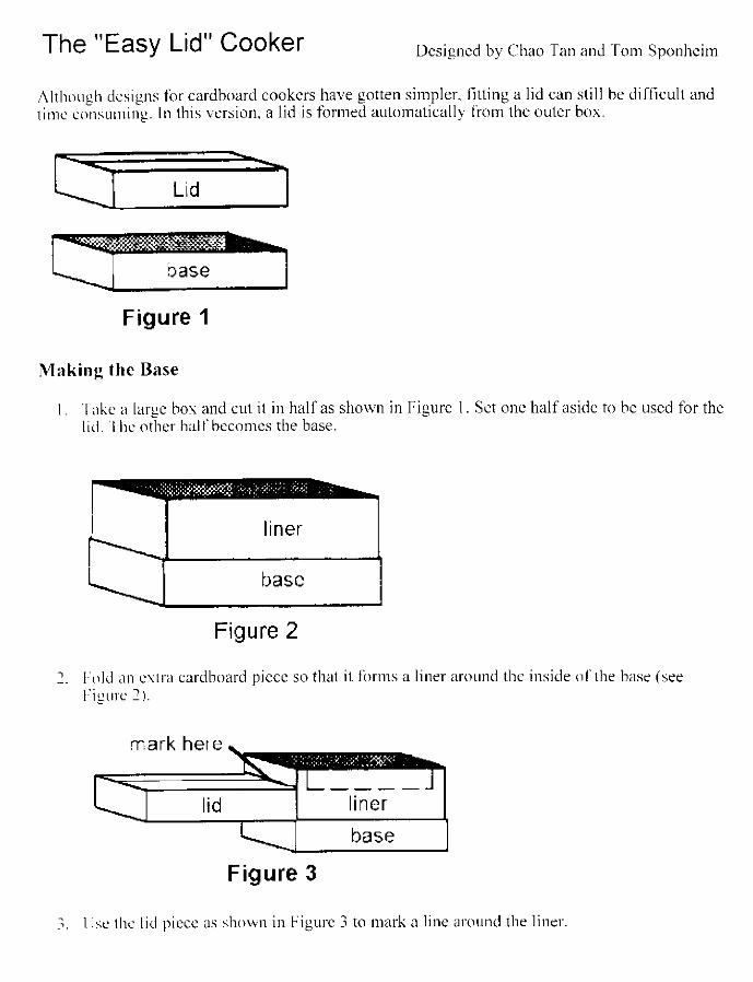
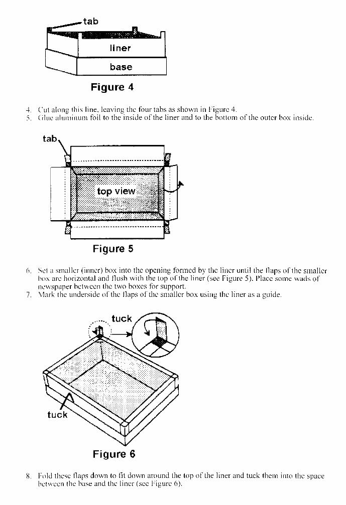
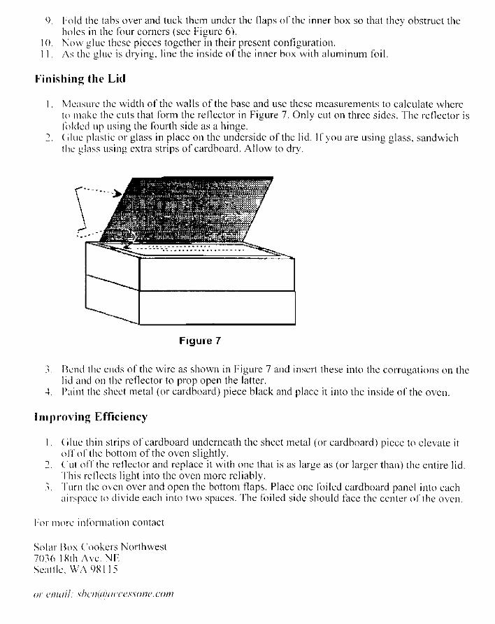
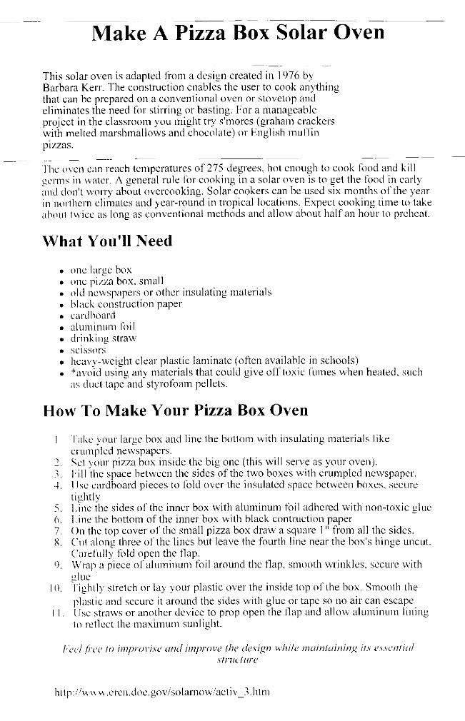
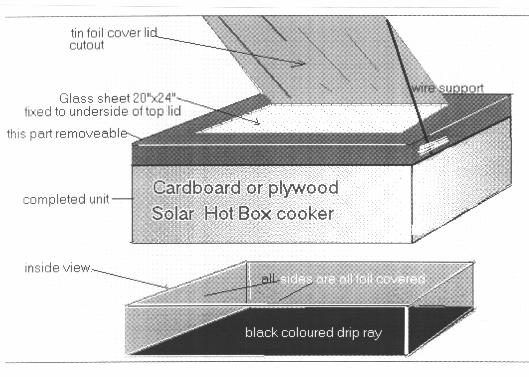

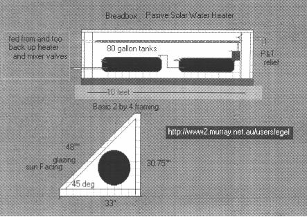
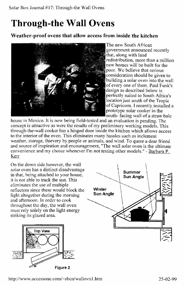
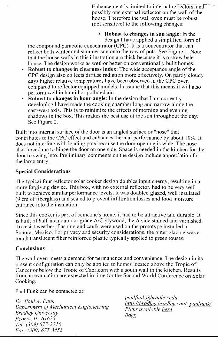
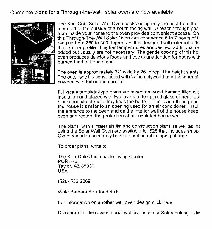
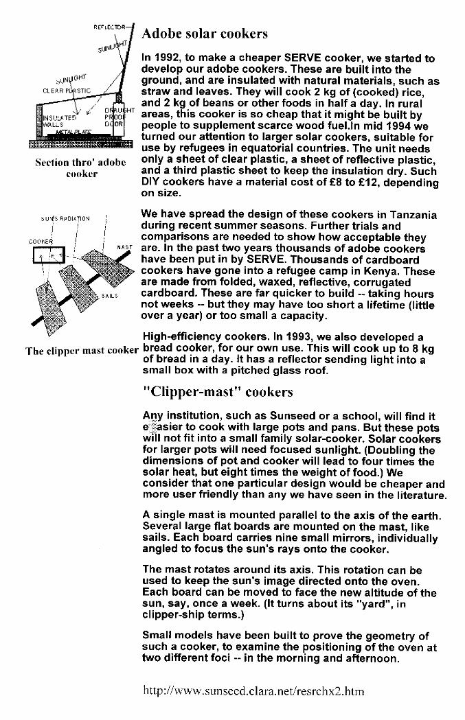
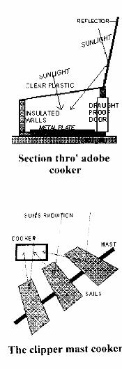
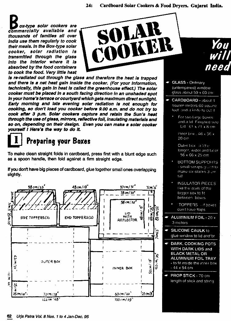
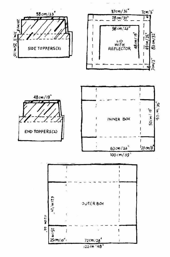
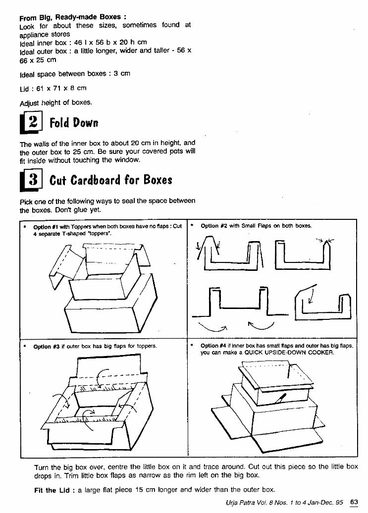
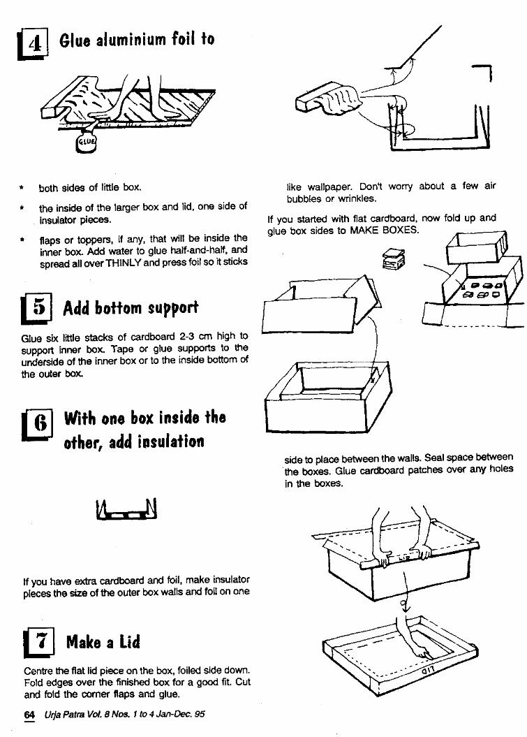
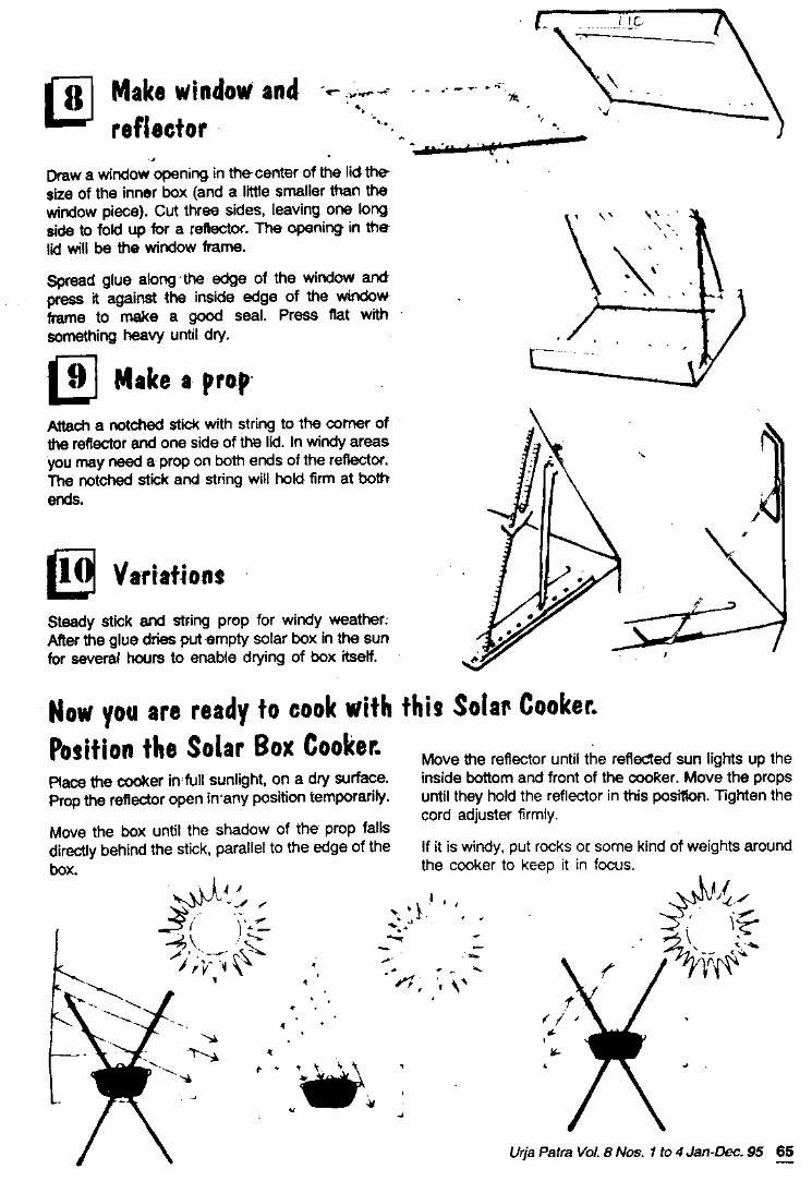
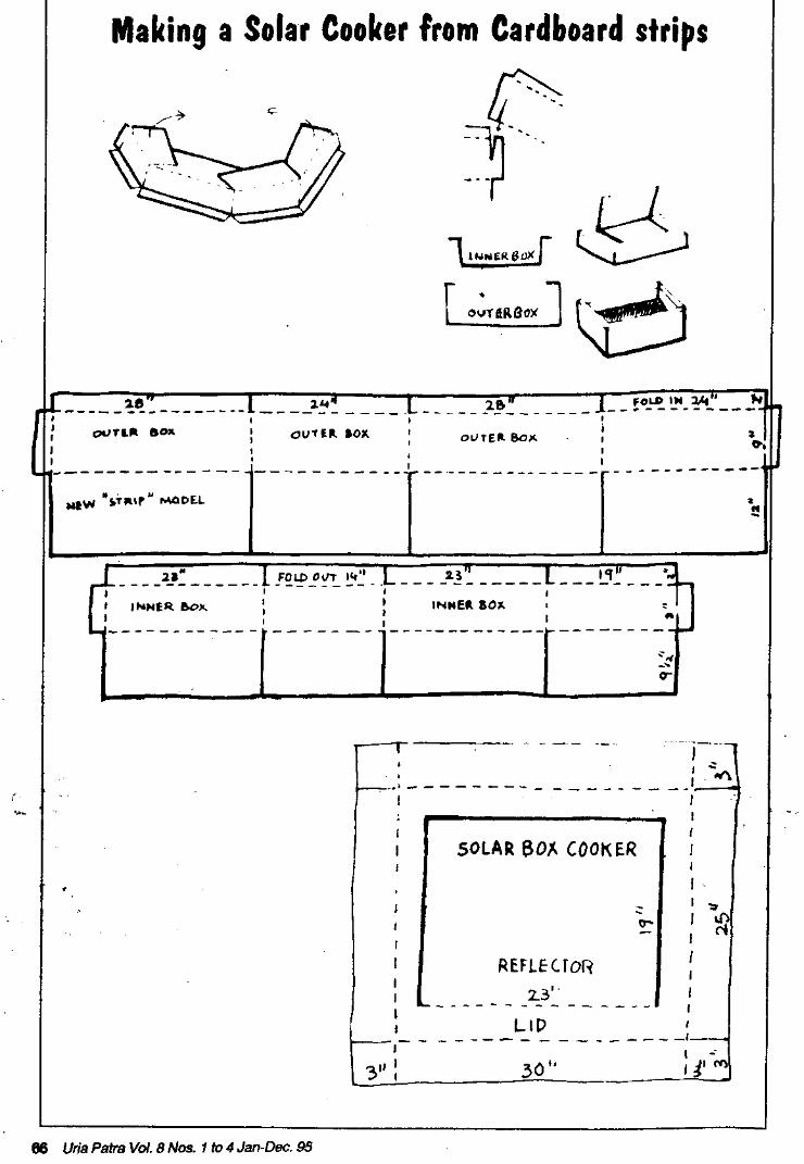
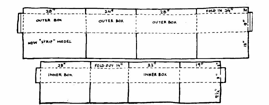
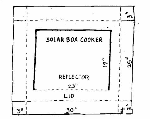
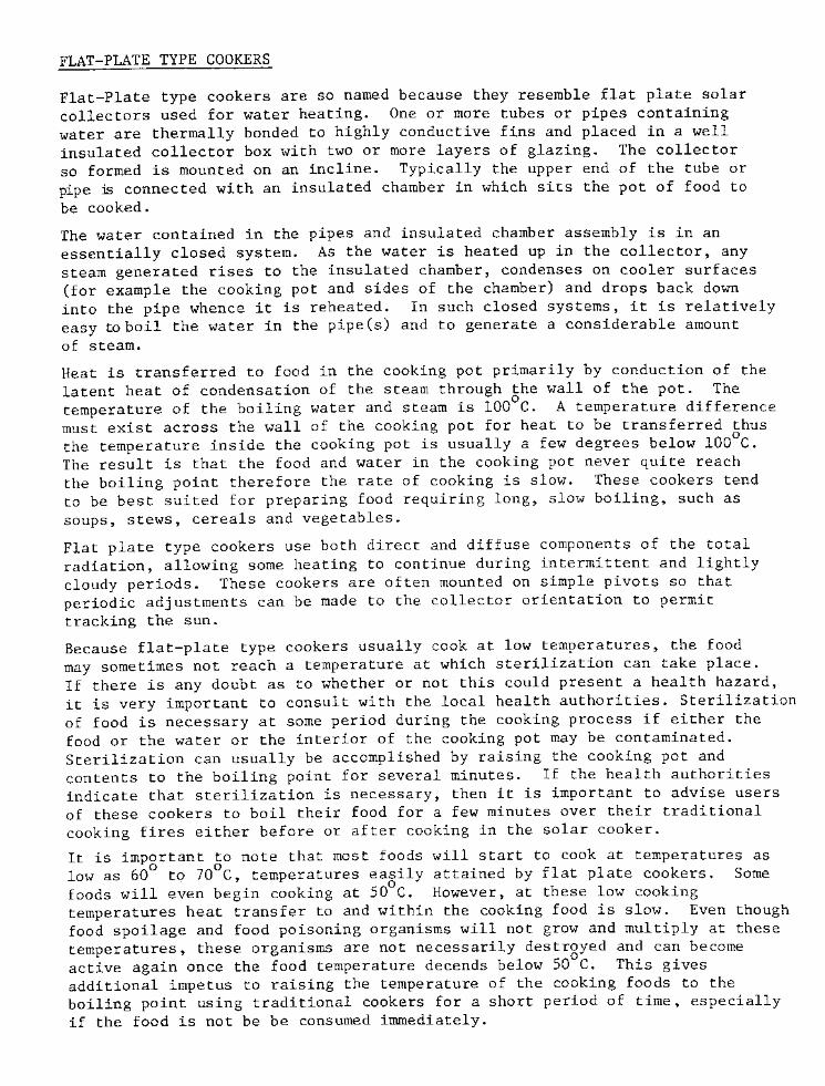
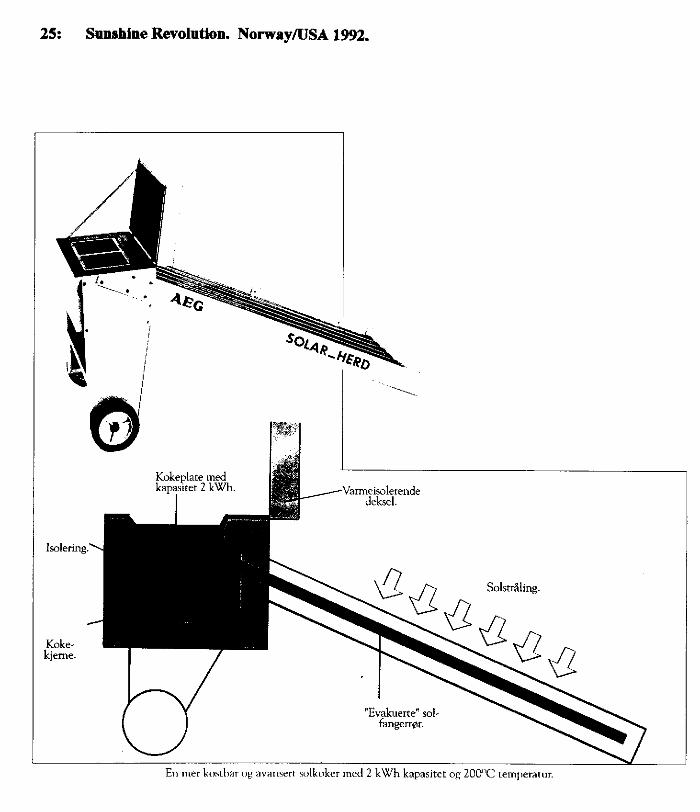
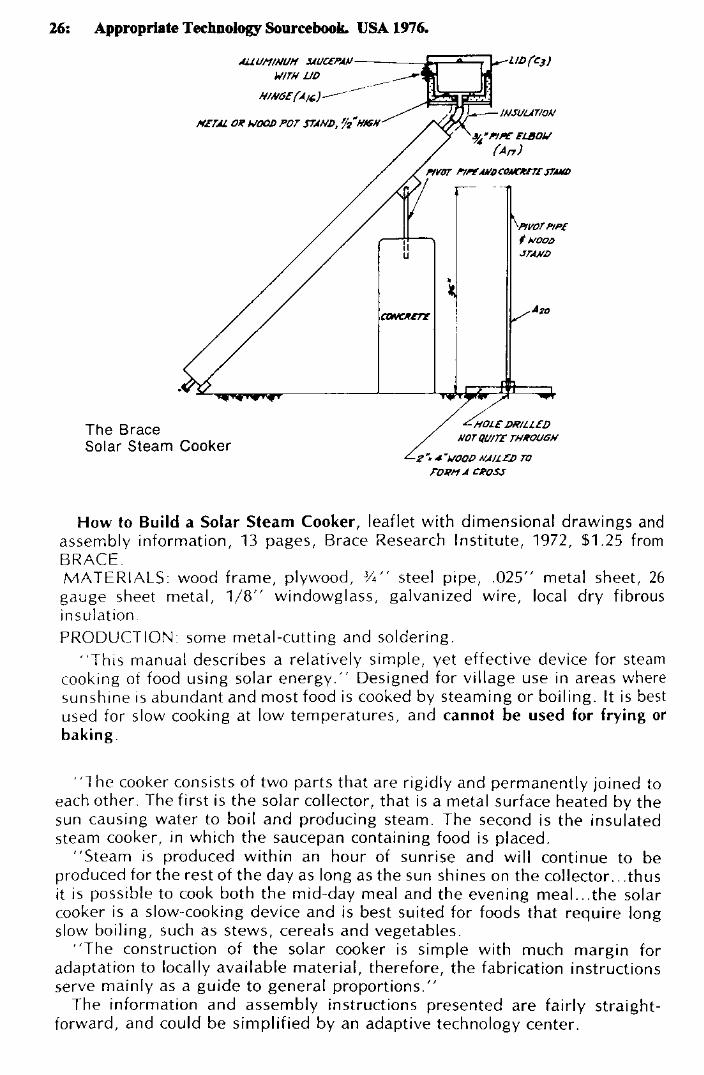
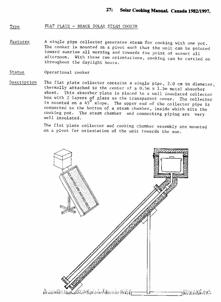
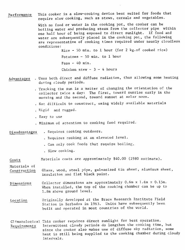
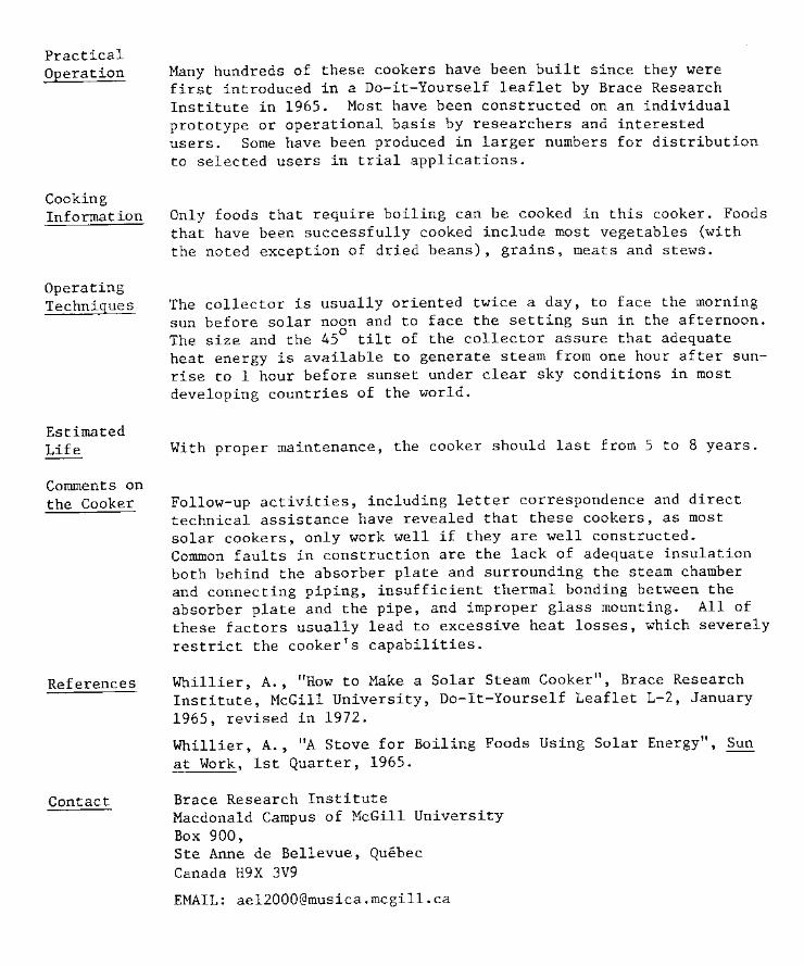
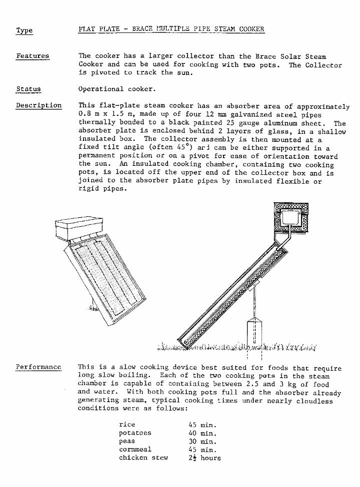
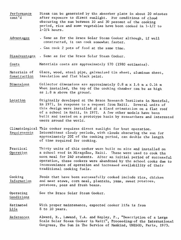
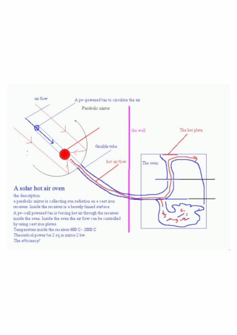
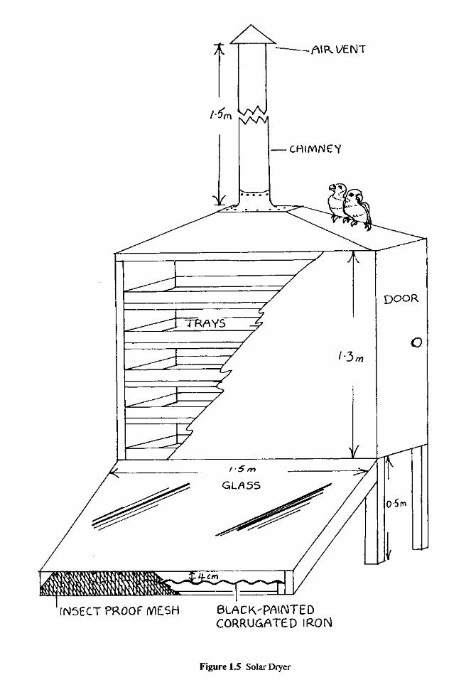
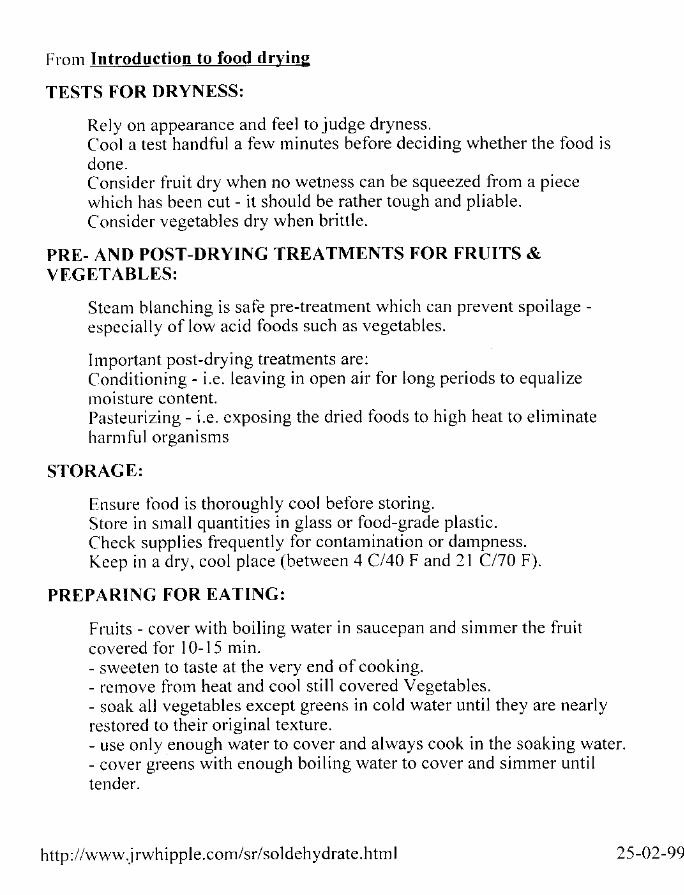
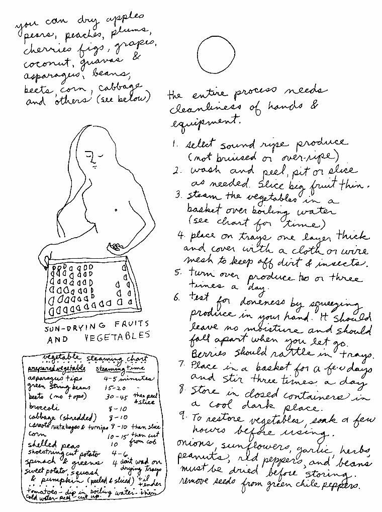
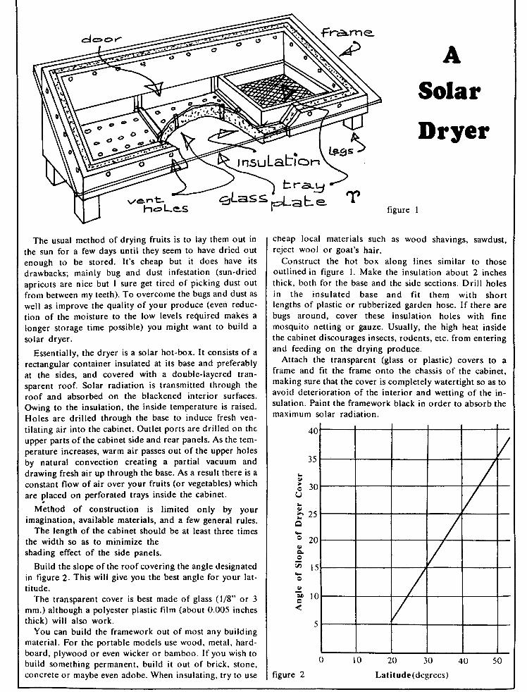
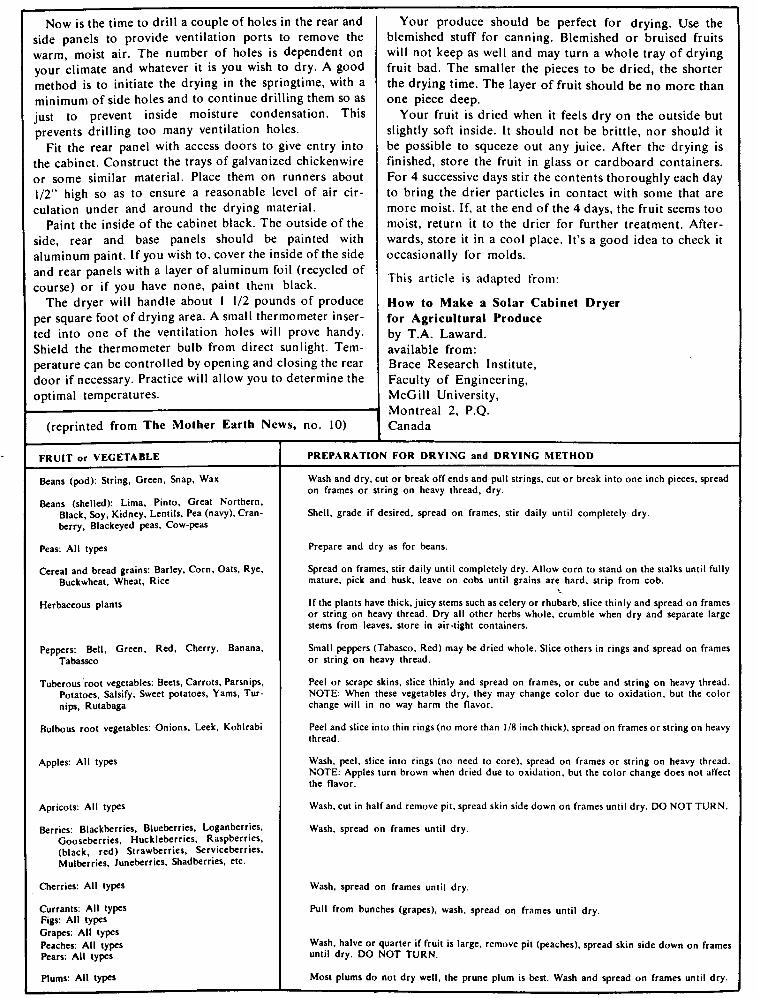
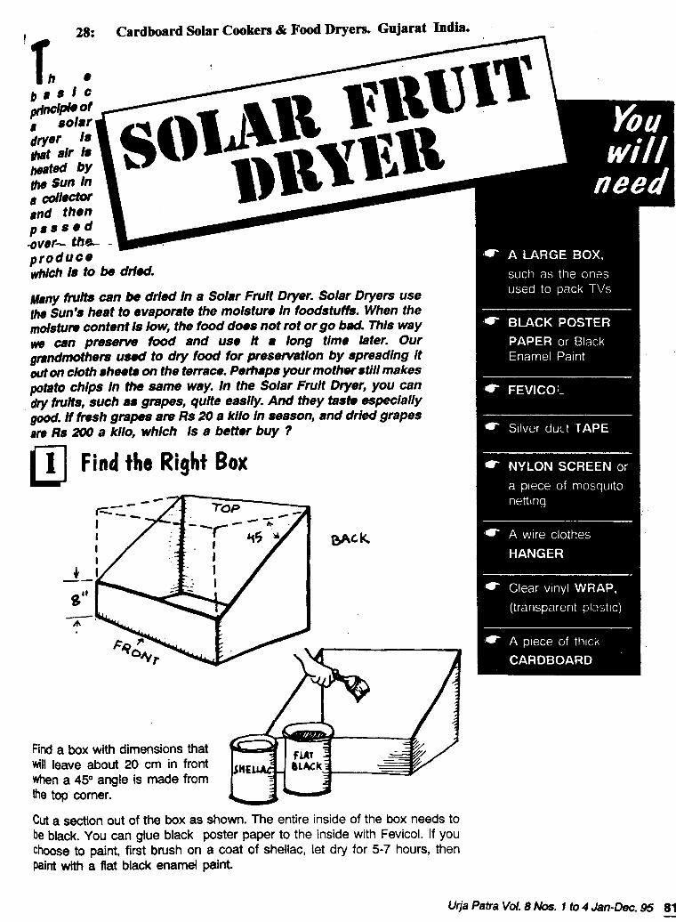
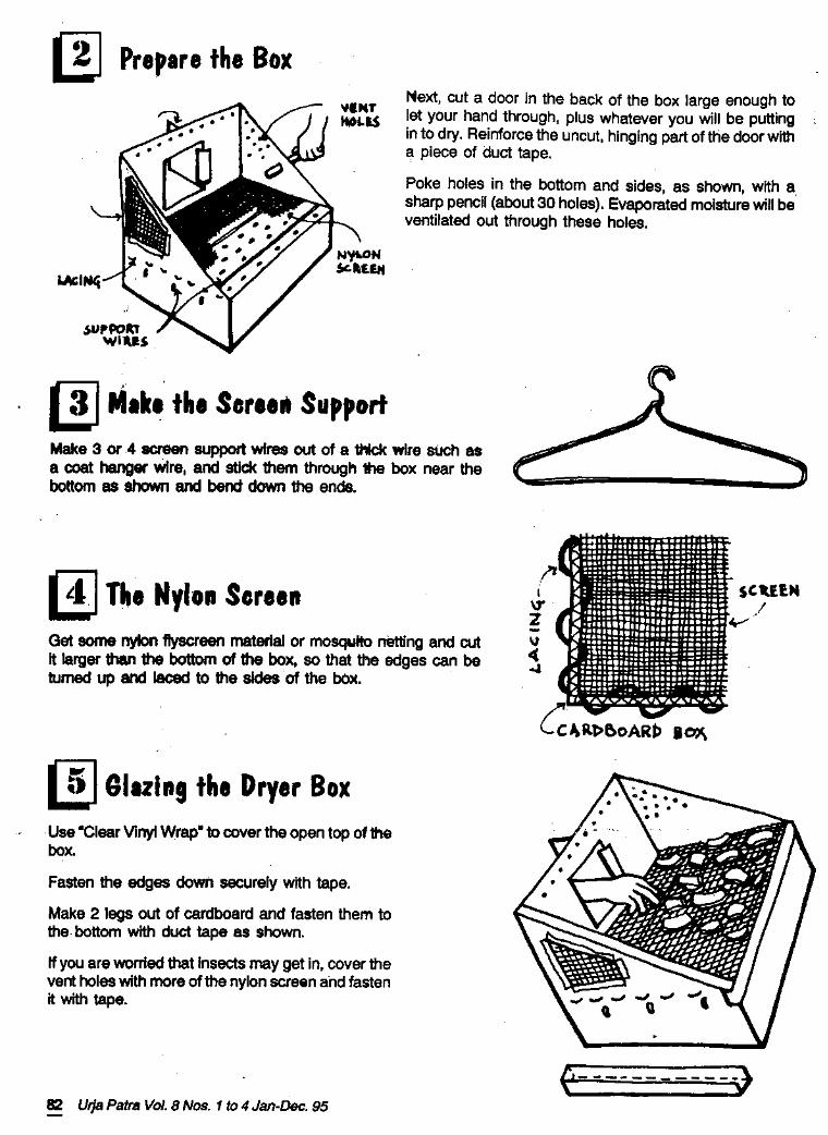
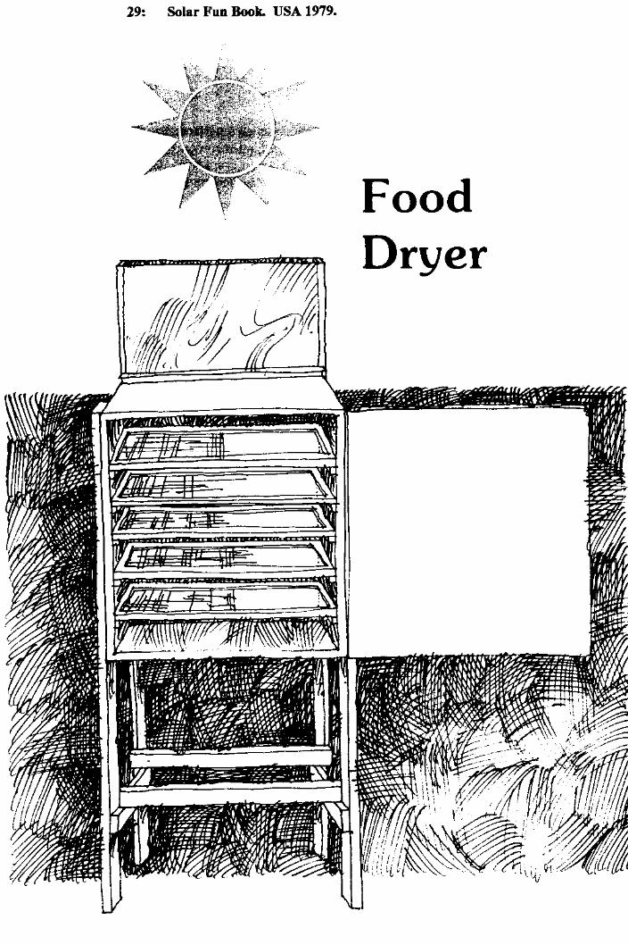
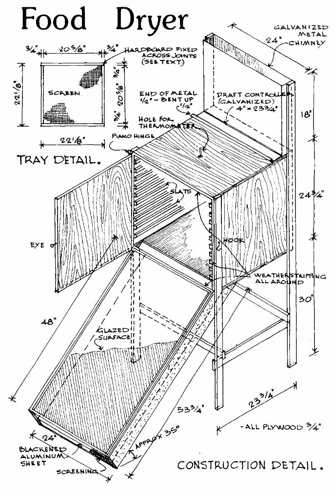
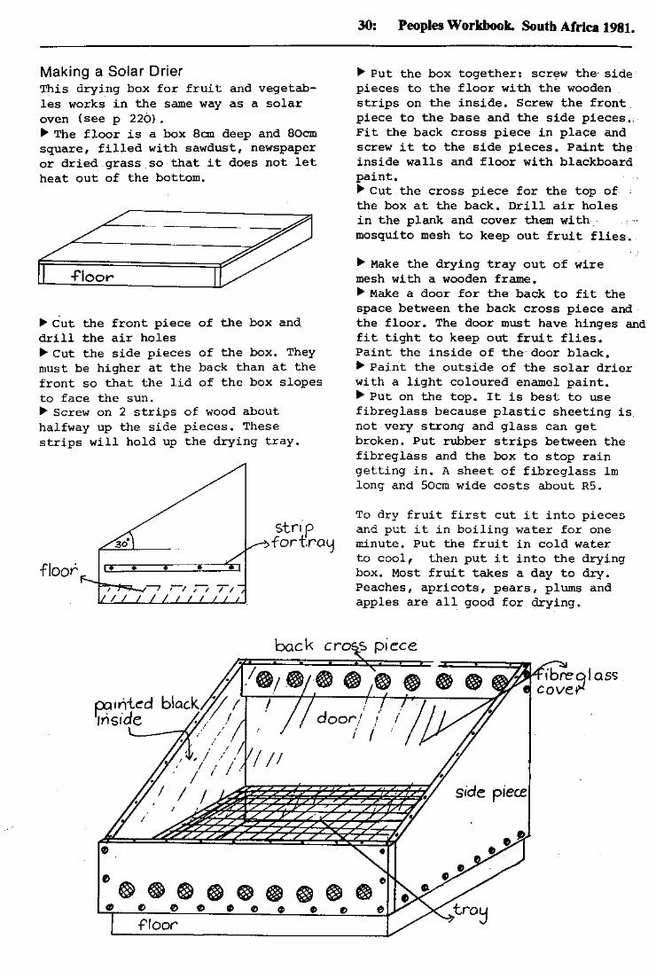
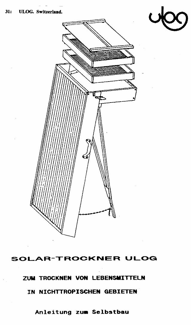
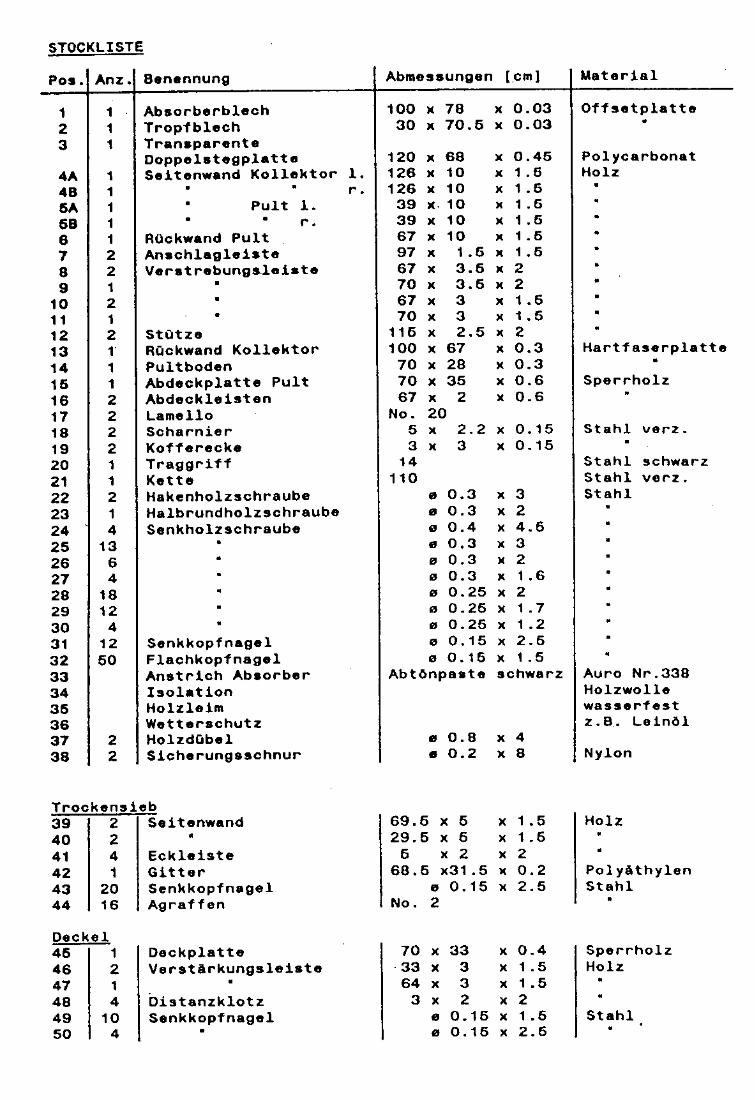
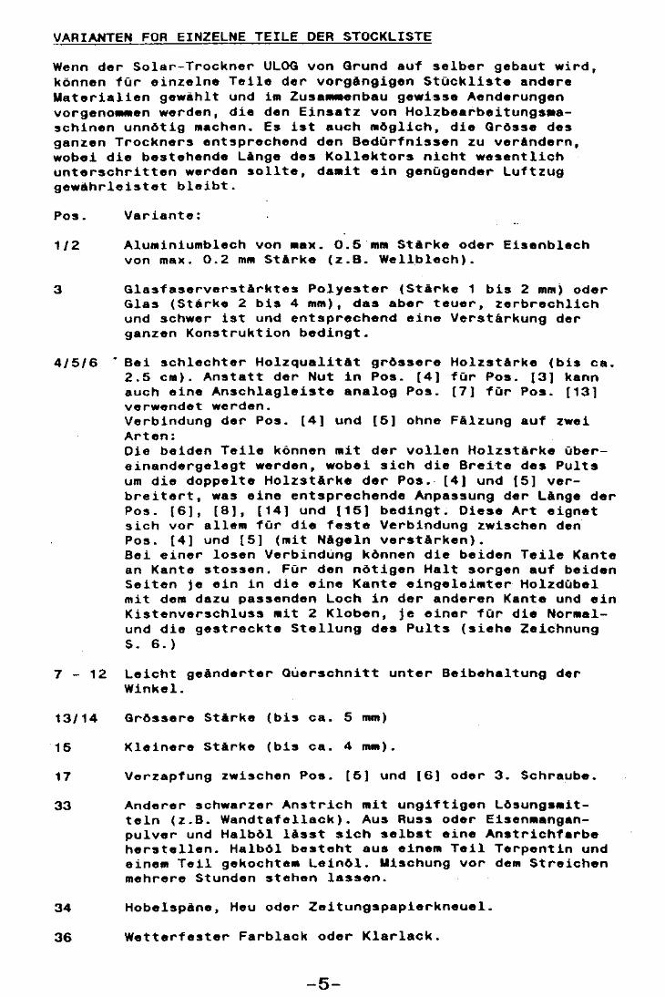
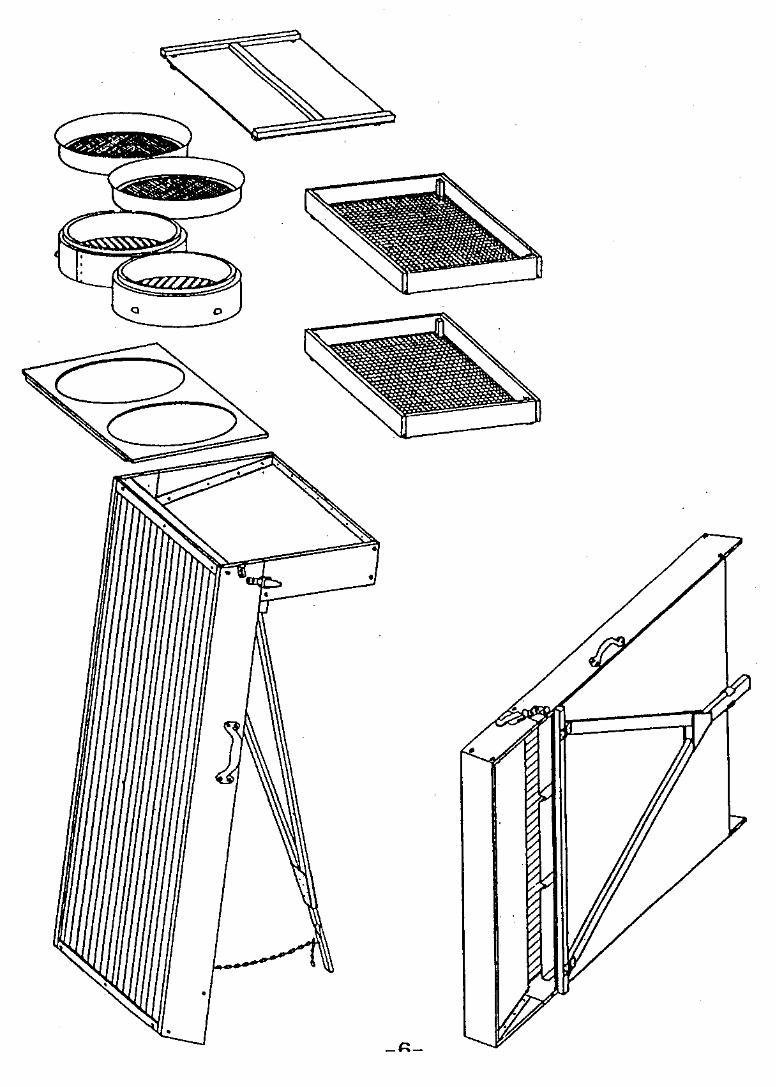
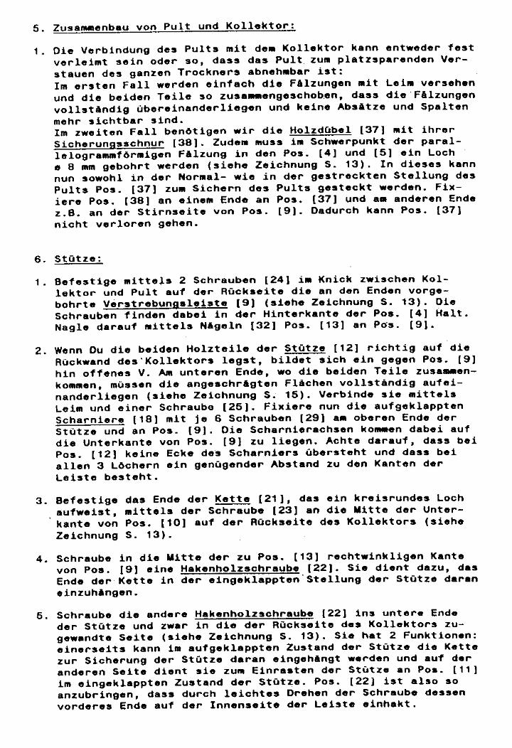
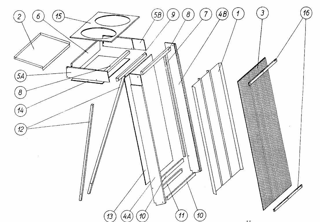
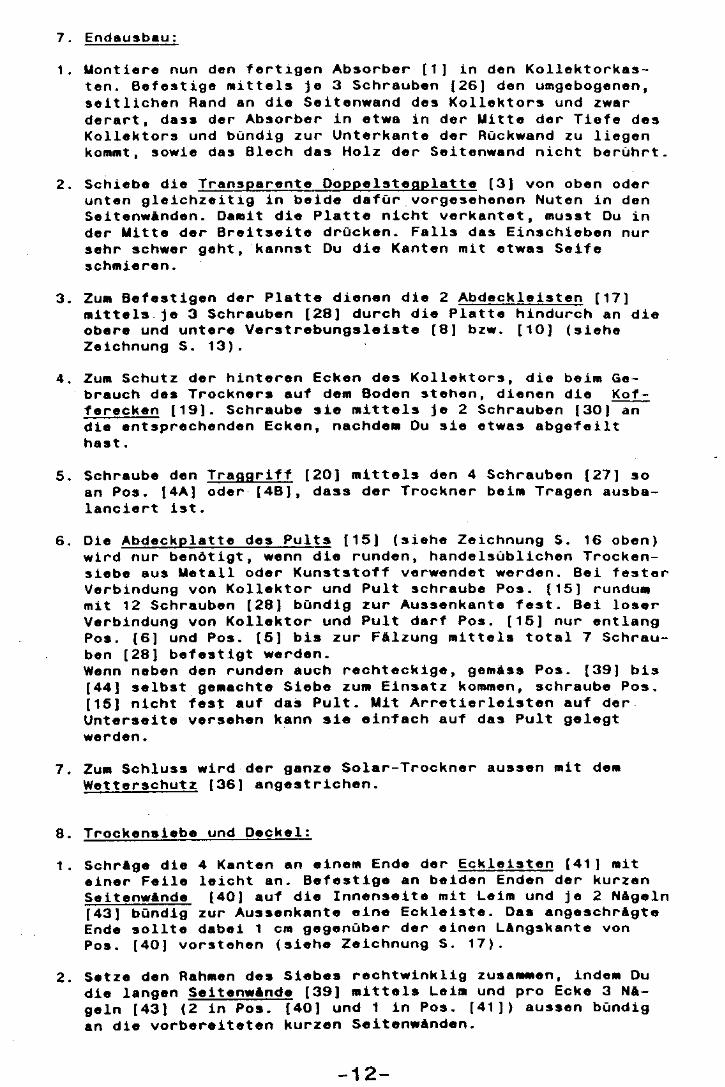
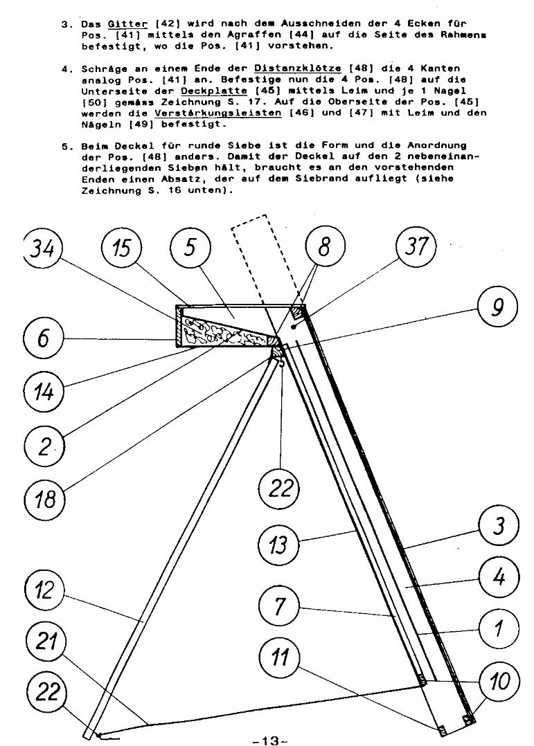
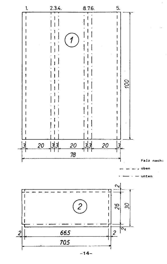
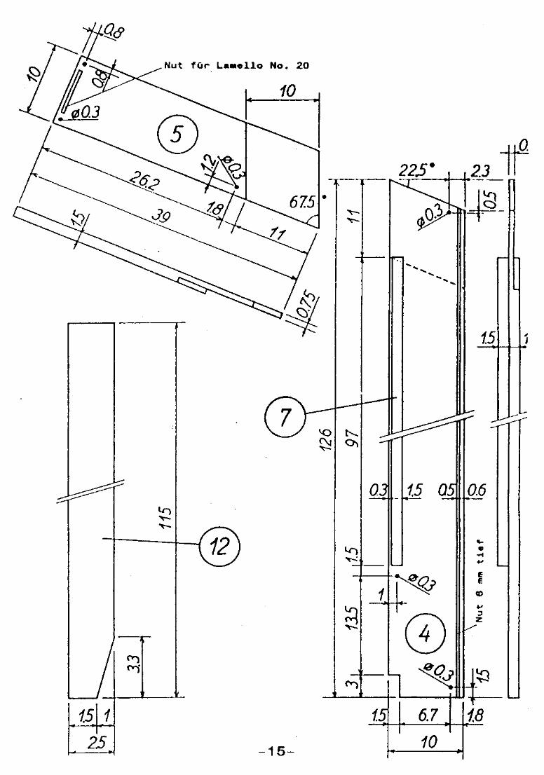
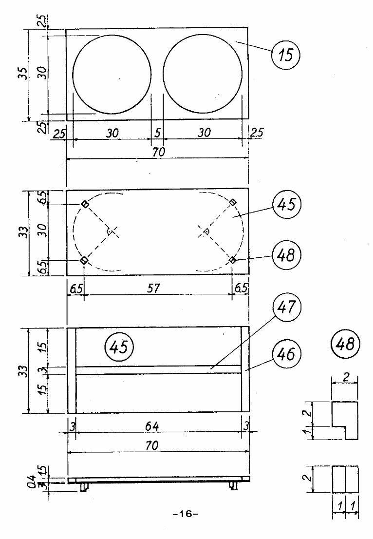
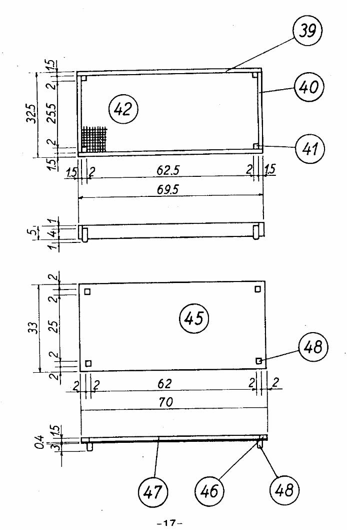
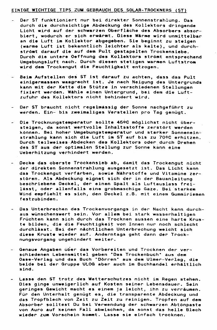
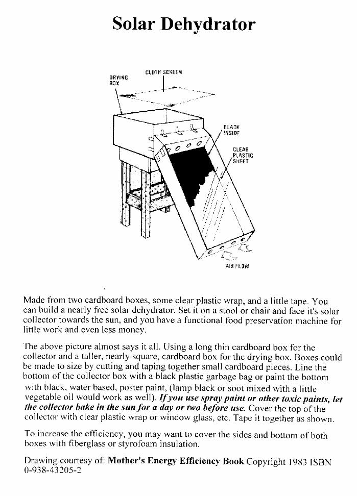
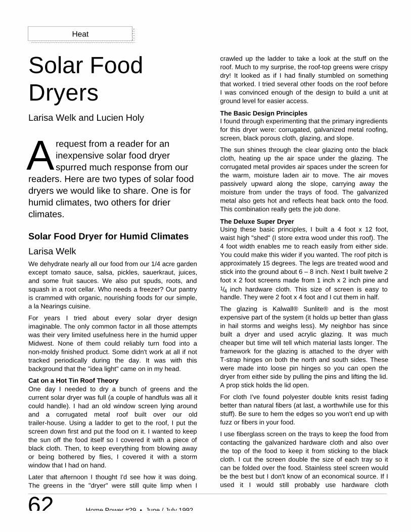
62 Home Power #29 • June / July 1992
Heat
request from a reader for aninexpensive solar food dryerspurred much response from our
readers. Here are two types of solar fooddryers we would like to share. One is forhumid climates, two others for drierclimates.
A
Solar FoodDryersLarisa Welk and Lucien Holy
Solar Food Dryer for Humid Climates
Larisa WelkWe dehydrate nearly all our food from our 1/4 acre gardenexcept tomato sauce, salsa, pickles, sauerkraut, juices,and some fruit sauces. We also put spuds, roots, andsquash in a root cellar. Who needs a freezer? Our pantryis crammed with organic, nourishing foods for our simple,a la Nearings cuisine.
For years I tried about every solar dryer designimaginable. The only common factor in all those attemptswas their very limited usefulness here in the humid upperMidwest. None of them could reliably turn food into anon-moldy finished product. Some didn't work at all if nottracked periodically during the day. It was with thisbackground that the "idea light" came on in my head.
Cat on a Hot Tin Roof TheoryOne day I needed to dry a bunch of greens and thecurrent solar dryer was full (a couple of handfuls was all itcould handle). I had an old window screen lying aroundand a corrugated metal roof built over our oldtrailer-house. Using a ladder to get to the roof, I put thescreen down first and put the food on it. I wanted to keepthe sun off the food itself so I covered it with a piece ofblack cloth. Then, to keep everything from blowing awayor being bothered by flies, I covered it with a stormwindow that I had on hand.
Later that afternoon I thought I'd see how it was doing.The greens in the "dryer" were still quite limp when I
crawled up the ladder to take a look at the stuff on theroof. Much to my surprise, the roof-top greens were crispydry! It looked as if I had finally stumbled on somethingthat worked. I tried several other foods on the roof beforeI was convinced enough of the design to build a unit atground level for easier access.
The Basic Design PrinciplesI found through experimenting that the primary ingredientsfor this dryer were: corrugated, galvanized metal roofing,screen, black porous cloth, glazing, and slope.
The sun shines through the clear glazing onto the blackcloth, heating up the air space under the glazing. Thecorrugated metal provides air spaces under the screen forthe warm, moisture laden air to move. The air movespassively upward along the slope, carrying away themoisture from under the trays of food. The galvanizedmetal also gets hot and reflects heat back onto the food.This combination really gets the job done.
The Deluxe Super DryerUsing these basic principles, I built a 4 foot x 12 foot,waist high "shed" (I store extra wood under this roof). The4 foot width enables me to reach easily from either side.You could make this wider if you wanted. The roof pitch isapproximately 15 degrees. The legs are treated wood andstick into the ground about 6 – 8 inch. Next I built twelve 2foot x 2 foot screens made from 1 inch x 2 inch pine and1/4 inch hardware cloth. This size of screen is easy tohandle. They were 2 foot x 4 foot and I cut them in half.
The glazing is Kalwall® Sunlite® and is the mostexpensive part of the system (it holds up better than glassin hail storms and weighs less). My neighbor has sincebuilt a dryer and used acrylic glazing. It was muchcheaper but time will tell which material lasts longer. Theframework for the glazing is attached to the dryer withT-strap hinges on both the north and south sides. Thesewere made into loose pin hinges so you can open thedryer from either side by pulling the pins and lifting the lid.A prop stick holds the lid open.
For cloth I've found polyester double knits resist fadingbetter than natural fibers (at last, a worthwhile use for thisstuff). Be sure to hem the edges so you won't end up withfuzz or fibers in your food.
I use fiberglass screen on the trays to keep the food fromcontacting the galvanized hardware cloth and also overthe top of the food to keep it from sticking to the blackcloth. I cut the screen double the size of each tray so itcan be folded over the food. Stainless steel screen wouldbe the best but I don't know of an economical source. If Iused it I would still probably use hardware cloth
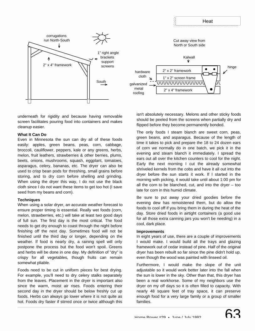
63Home Power #29 • June / July 1992
Heat
underneath for rigidity and because having removablescreen facilitates pouring food into containers and makescleanup easier.
What It Can DoEven in Minnesota the sun can dry all of these foodseasily: apples, green beans, peas, corn, cabbage,broccoli, cauliflower, peppers, kale or any greens, herbs,melon, fruit leathers, strawberries & other berries, plums,beets, onions, mushrooms, squash, eggplant, tomatoes,asparagus, celery, bananas, etc. The dryer can also beused to crisp bean pods for threshing, small grains beforestoring, and to dry corn before shelling and grinding.When using the dryer this way, I do not use the blackcloth since I do not want these items to get too hot (I saveseed from my beans and corn).
TechniquesWhen using a solar dryer, an accurate weather forecast toensure proper timing is essential. Really wet foods (corn,melon, strawberries, etc.) will take at least two good daysof full sun. The first day is the most critical. The foodneeds to get dry enough to coast through the night beforefinishing off the next day. Sometimes food will not befinished until the third day or longer, depending on theweather. If food is nearly dry, a raining spell will onlypostpone the process but the food won't spoil. Greensand herbs will be done in one day. My definition of "dry" iscrispy for all vegetables, though fruits can remainsomewhat pliable.
Foods need to be cut in uniform pieces for best drying.For example, you'll need to dry celery stalks separatelyfrom the leaves. Placement in the dryer is important alsosince the warm, moist air rises. Foods entering theirsecond day in the dryer should be below freshly cut upfoods. Herbs can always go lower where it is not quite ashot. Foods dry faster if stirred once or twice although this
isn't absolutely necessary. Melons and other sticky foodsshould be peeled from the screens when partially dry andflipped before they become permanently bonded.
The only foods I steam blanch are sweet corn, peas,green beans, and asparagus. Because of the length oftime it takes to pick and prepare the 18 to 24 dozen earsof corn we normally do in one batch, we pick it in theevening and steam blanch it immediately. I spread theears out all over the kitchen counters to cool for the night.Early the next morning I cut the already somewhatshriveled kernels from the cobs and have it all out into thedryer before the sun starts it work. If I started in themorning with picking, it would take until about 1:00 pm forall the corn to be blanched, cut, and into the dryer – toolate for corn in this humid climate.
Be sure to put away your dried goodies before theevening dew has remoistened them, but do allow thefoods to cool off if you bring them in during the heat of theday. Store dried foods in airtight containers (a good usefor all those extra canning jars you won't be needing) in acool, dark place.
ImprovementsIn eight years of use, there are a couple of improvementsI would make. I would build all the trays and glazingframework out of cedar instead of pine. Half of the originaldryer has been rebuilt so far since the pine didn't hold up,even though the wood was painted with linseed oil.
Furthermore, I would make the slope of the unitadjustable so it would work better later into the fall whenthe sun is lower in the sky. Other than that, this dryer hasbeen a real workhorse. Some of my neighbors use thedryer on my off days so it is often filled to capacity. Withnearly 48 square feet of tray space, it can preserveenough food for a very large family or a group of smallerfamilies.
2" x 4" framework2" x 4" framework
2" x 4" framework
corrugationsrun North-South
South
1" right angle brackets support screens
Cut away view from North or South side
2" x 2" framework
1" x 2" screen frame
hardware cloth
galvanized metal roofing
Kalwall
hinge
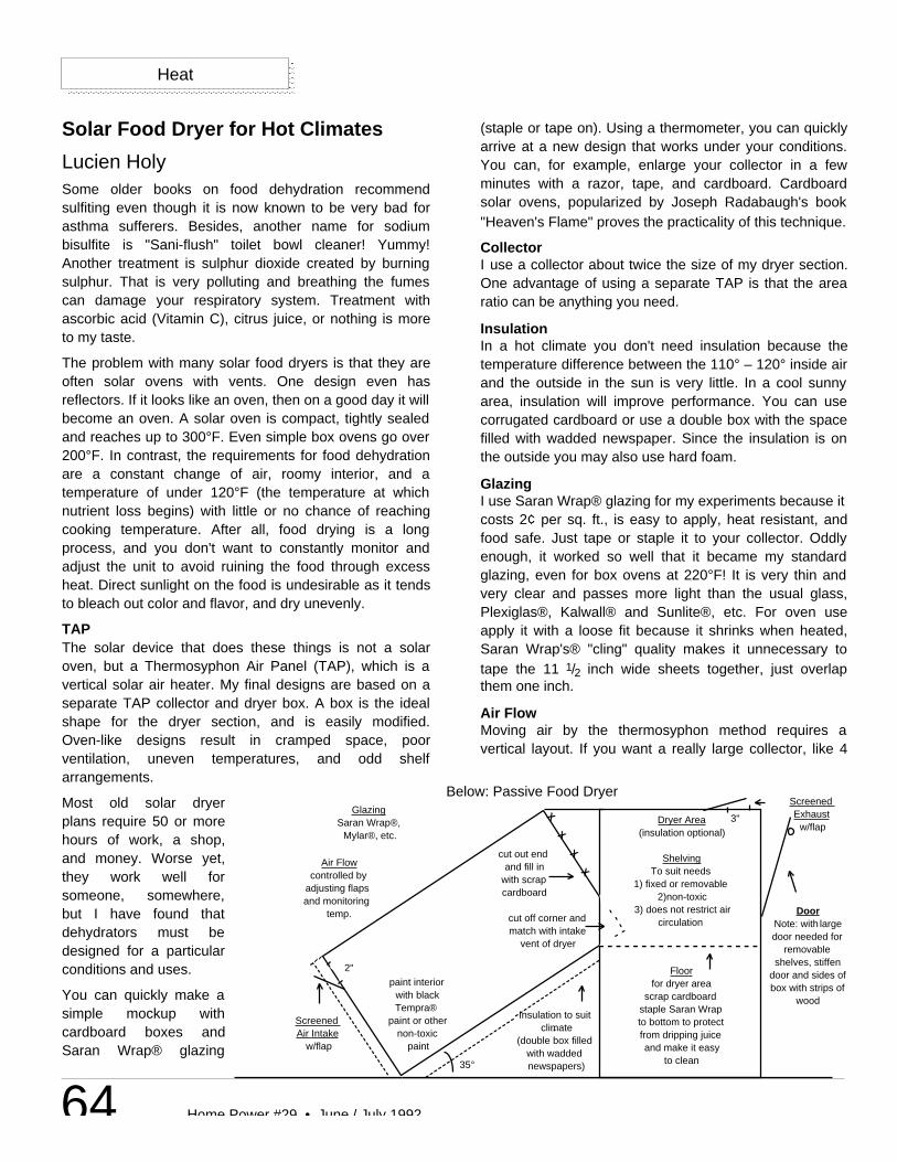
64 Home Power #29 • June / July 1992
Heat
(staple or tape on). Using a thermometer, you can quicklyarrive at a new design that works under your conditions.You can, for example, enlarge your collector in a fewminutes with a razor, tape, and cardboard. Cardboardsolar ovens, popularized by Joseph Radabaugh's book"Heaven's Flame" proves the practicality of this technique.
CollectorI use a collector about twice the size of my dryer section.One advantage of using a separate TAP is that the arearatio can be anything you need.
InsulationIn a hot climate you don't need insulation because thetemperature difference between the 110° – 120° inside airand the outside in the sun is very little. In a cool sunnyarea, insulation will improve performance. You can usecorrugated cardboard or use a double box with the spacefilled with wadded newspaper. Since the insulation is onthe outside you may also use hard foam.
GlazingI use Saran Wrap® glazing for my experiments because itcosts 2¢ per sq. ft., is easy to apply, heat resistant, andfood safe. Just tape or staple it to your collector. Oddlyenough, it worked so well that it became my standardglazing, even for box ovens at 220°F! It is very thin andvery clear and passes more light than the usual glass,Plexiglas®, Kalwall® and Sunlite®, etc. For oven useapply it with a loose fit because it shrinks when heated,Saran Wrap's® "cling" quality makes it unnecessary totape the 11 1/2 inch wide sheets together, just overlapthem one inch.
Air FlowMoving air by the thermosyphon method requires avertical layout. If you want a really large collector, like 4
DoorNote: with large door needed for
removable shelves, stiffen
door and sides of box with strips of
wood
Dryer Area(insulation optional)
ShelvingTo suit needs
1) fixed or removable2)non-toxic
3) does not restrict aircirculation
Floorfor dryer area
scrap cardboardstaple Saran Wrapto bottom to protectfrom dripping juiceand make it easy
to clean
cut out end and fill in
with scrap cardboard
cut off corner and match with intake
vent of dryer
Insulation to suit climate
(double box filled with wadded newspapers)35°
paint interior with black Tempra®
paint or other non-toxic
paint
Screened Air Intake
w/flap
GlazingSaran Wrap®,
Mylar®, etc.
Air Flowcontrolled by
adjusting flaps and monitoring
temp.
2"
3"
Screened Exhaust
w/flapX
X
X
X
Solar Food Dryer for Hot Climates
Lucien HolySome older books on food dehydration recommendsulfiting even though it is now known to be very bad forasthma sufferers. Besides, another name for sodiumbisulfite is "Sani-flush" toilet bowl cleaner! Yummy!Another treatment is sulphur dioxide created by burningsulphur. That is very polluting and breathing the fumescan damage your respiratory system. Treatment withascorbic acid (Vitamin C), citrus juice, or nothing is moreto my taste.
The problem with many solar food dryers is that they areoften solar ovens with vents. One design even hasreflectors. If it looks like an oven, then on a good day it willbecome an oven. A solar oven is compact, tightly sealedand reaches up to 300°F. Even simple box ovens go over200°F. In contrast, the requirements for food dehydrationare a constant change of air, roomy interior, and atemperature of under 120°F (the temperature at whichnutrient loss begins) with little or no chance of reachingcooking temperature. After all, food drying is a longprocess, and you don't want to constantly monitor andadjust the unit to avoid ruining the food through excessheat. Direct sunlight on the food is undesirable as it tendsto bleach out color and flavor, and dry unevenly.
TAPThe solar device that does these things is not a solaroven, but a Thermosyphon Air Panel (TAP), which is avertical solar air heater. My final designs are based on aseparate TAP collector and dryer box. A box is the idealshape for the dryer section, and is easily modified.Oven-like designs result in cramped space, poorventilation, uneven temperatures, and odd shelfarrangements.
Most old solar dryerplans require 50 or morehours of work, a shop,and money. Worse yet,they work well forsomeone, somewhere,but I have found thatdehydrators must bedesigned for a particularconditions and uses.
You can quickly make asimple mockup withcardboard boxes andSaran Wrap® glazing
Below: Passive Food Dryer
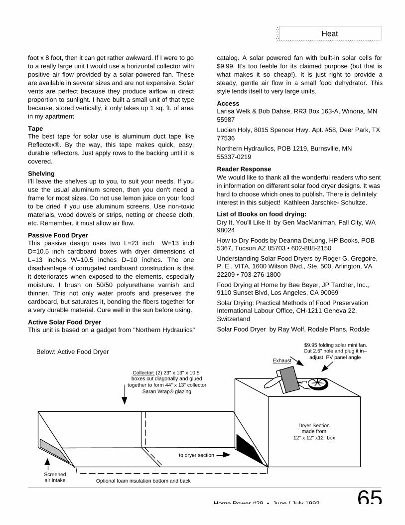
65Home Power #29 • June / July 1992
Heat
foot x 8 foot, then it can get rather awkward. If I were to goto a really large unit I would use a horizontal collector withpositive air flow provided by a solar-powered fan. Theseare available in several sizes and are not expensive. Solarvents are perfect because they produce airflow in directproportion to sunlight. I have built a small unit of that typebecause, stored vertically, it only takes up 1 sq. ft. of areain my apartment
TapeThe best tape for solar use is aluminum duct tape likeReflectex®. By the way, this tape makes quick, easy,durable reflectors. Just apply rows to the backing until it iscovered.
ShelvingI'll leave the shelves up to you, to suit your needs. If youuse the usual aluminum screen, then you don't need aframe for most sizes. Do not use lemon juice on your foodto be dried if you use aluminum screens. Use non-toxicmaterials, wood dowels or strips, netting or cheese cloth,etc. Remember, it must allow air flow.
Passive Food DryerThis passive design uses two L=23 inch W=13 inchD=10.5 inch cardboard boxes with dryer dimensions ofL=13 inches W=10.5 inches D=10 inches. The onedisadvantage of corrugated cardboard construction is thatit deteriorates when exposed to the elements, especiallymoisture. I brush on 50/50 polyurethane varnish andthinner. This not only water proofs and preserves thecardboard, but saturates it, bonding the fibers together fora very durable material. Cure well in the sun before using.
Active Solar Food DryerThis unit is based on a gadget from "Northern Hydraulics"
catalog. A solar powered fan with built-in solar cells for$9.99. It's too feeble for its claimed purpose (but that iswhat makes it so cheap!). It is just right to provide asteady, gentle air flow in a small food dehydrator. Thisstyle lends itself to very large units.
AccessLarisa Welk & Bob Dahse, RR3 Box 163-A, Winona, MN55987
Lucien Holy, 8015 Spencer Hwy. Apt. #58, Deer Park, TX77536
Northern Hydraulics, POB 1219, Burnsville, MN55337-0219
Reader ResponseWe would like to thank all the wonderful readers who sentin information on different solar food dryer designs. It washard to choose which ones to publish. There is definitelyinterest in this subject! Kathleen Jarschke- Schultze.
List of Books on food drying:Dry It, You'll Like It by Gen MacManiman, Fall City, WA98024
How to Dry Foods by Deanna DeLong, HP Books, POB5367, Tucson AZ 85703 • 602-888-2150
Understanding Solar Food Dryers by Roger G. Gregoire,P. E., VITA, 1600 Wilson Blvd., Ste. 500, Arlington, VA22209 • 703-276-1800
Food Drying at Home by Bee Beyer, JP Tarcher, Inc.,9110 Sunset Blvd, Los Angeles, CA 90069
Solar Drying: Practical Methods of Food PreservationInternational Labour Office, CH-1211 Geneva 22,Switzerland
Solar Food Dryer by Ray Wolf, Rodale Plans, Rodale
Screenedair intake
Collector: (2) 23" x 13" x 10.5"boxes cut diagonally and glued
together to form 44" x 13" collectorSaran Wrap® glazing
Optional foam insulation bottom and back
to dryer section
Dryer Sectionmade from
12" x 12" x12" box
Exhaust
$9.95 folding solar mini fan.Cut 2.5" hole and plug it in–
adjust PV panel angleBelow: Active Food Dryer

66 Home Power #29 • June / July 1992
Press, 33 East Minor St., Emmaus, PA 18049
A Handbook for Solar Food Drying State Energy Office; 335Merchant St., Ste 110. Honolulu, HI 96813 • 808-548-4080
Heat
Abraham Solarcamera-ready
12 Volt Productscamera-readyleave border in layout
Healthy EnvironmentsCamera-ready
SANDERSON'S REBUILT VACUUMSSpecializing in 3 & 4 AMP Kirbys
Lower amperage Kirby's are the ultimate in chore relief -
kind to your batteries and back alike.
3 AMP - $175 4 AMP - $150For More Information Call (408) 628-3362
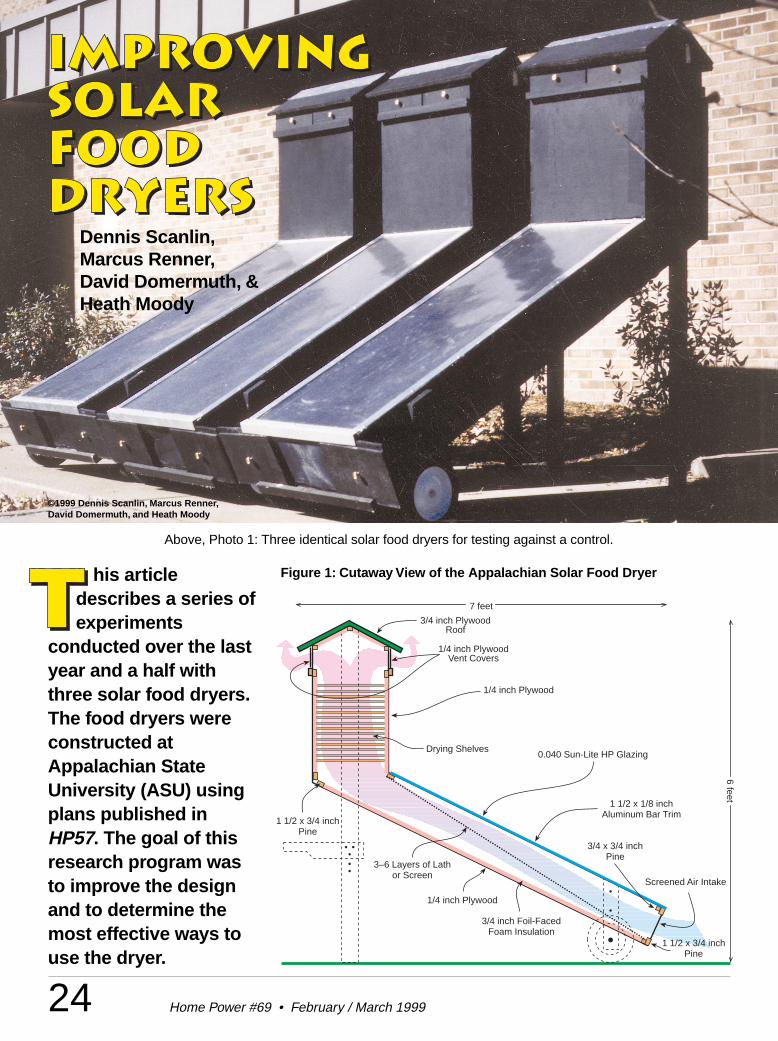
24 Home Power #69 • February / March 1999
his articledescribes a series ofexperiments
conducted over the lastyear and a half withthree solar food dryers.The food dryers wereconstructed atAppalachian StateUniversity (ASU) usingplans published inHP57. The goal of thisresearch program wasto improve the designand to determine themost effective ways touse the dryer.
Dennis Scanlin,Marcus Renner,David Domermuth, &Heath Moody
Above, Photo 1: Three identical solar food dryers for testing against a control.
1 1/2 x 3/4 inchPine
1/4 inch PlywoodVent Covers
0.040 Sun-Lite HP Glazing
Screened Air Intake
3/4 inch Foil-FacedFoam Insulation
Drying Shelves
1/4 inch Plywood
1 1/2 x 3/4 inchPine
3/4 x 3/4 inchPine
1/4 inch Plywood
1 1/2 x 1/8 inchAluminum Bar Trim
3/4 inch PlywoodRoof
3–6 Layers of Lathor Screen
7 feet
6 feet
Figure 1: Cutaway View of the Appalachian Solar Food Dryer
©1999 Dennis Scanlin, Marcus Renner,David Domermuth, and Heath Moody
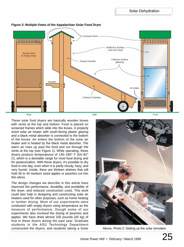
25Home Power #69 • February / March 1999
Solar Dehydration
These solar food dryers are basically wooden boxeswith vents at the top and bottom. Food is placed onscreened frames which slide into the boxes. A properlysized solar air heater with south-facing plastic glazingand a black metal absorber is connected to the bottomof the boxes. Air enters the bottom of the solar airheater and is heated by the black metal absorber. Thewarm air rises up past the food and out through thevents at the top (see Figure 1). While operating, thesedryers produce temperatures of 130–180° F (54–82°C), which is a desirable range for most food drying andfor pasteurization. With these dryers, it’s possible to dryfood in one day, even when it is partly cloudy, hazy, andvery humid. Inside, there are thirteen shelves that willhold 35 to 40 medium sized apples or peaches cut intothin slices.
The design changes we describe in this article haveimproved the performance, durability, and portability ofthe dryer, and reduced construction costs. This workcould also help in designing and constructing solar airheaters used for other purposes, such as home heatingor lumber drying. Most of our experiments wereconducted with empty dryers using temperature as themeasure of performance, though some of ourexperiments also involved the drying of peaches andapples. We have dried almost 100 pounds (45 kg) offruit in these dryers during the past year. Graduatestudents in the ASU Technology Departmentconstructed the dryers, and students taking a Solar
Access Doorto Drying Trays
Handles
Exhaust Vents
Collector Surface(glazing)
Air Intake
Reflective Surface(one test case)
Rear Side Front
Collector Chamber
Drying Chamber
Figure 2: Multiple Views of the Appalachian Solar Food Dryer
Above, Photo 2: Setting up the solar simulator.
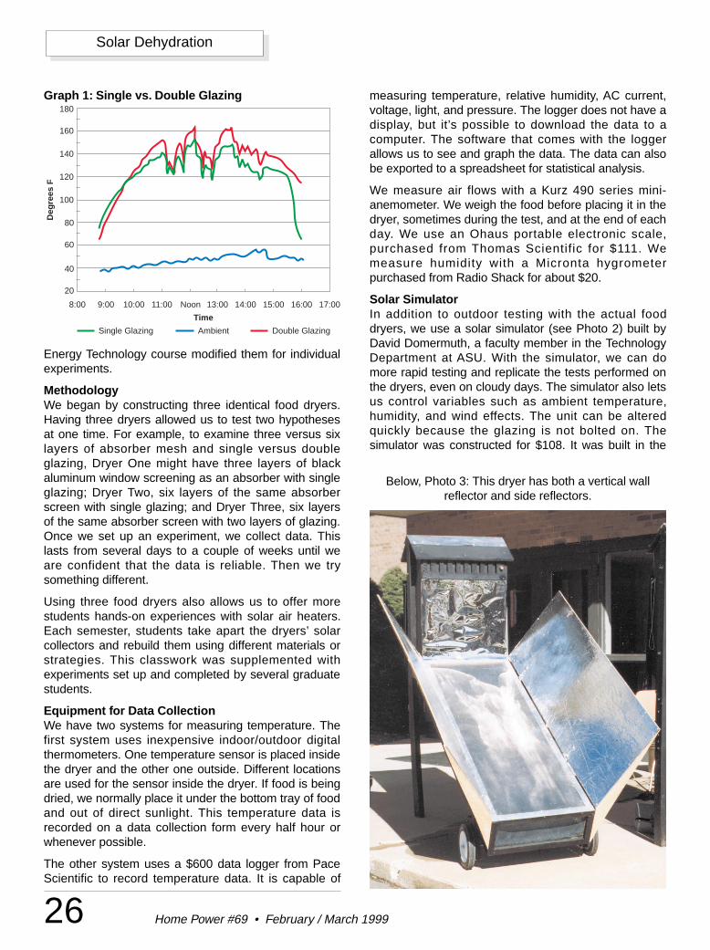
26 Home Power #69 • February / March 1999
Solar Dehydration
Energy Technology course modified them for individualexperiments.
MethodologyWe began by constructing three identical food dryers.Having three dryers allowed us to test two hypothesesat one time. For example, to examine three versus sixlayers of absorber mesh and single versus doubleglazing, Dryer One might have three layers of blackaluminum window screening as an absorber with singleglazing; Dryer Two, six layers of the same absorberscreen with single glazing; and Dryer Three, six layersof the same absorber screen with two layers of glazing.Once we set up an experiment, we collect data. Thislasts from several days to a couple of weeks until weare confident that the data is reliable. Then we trysomething different.
Using three food dryers also allows us to offer morestudents hands-on experiences with solar air heaters.Each semester, students take apart the dryers’ solarcollectors and rebuild them using different materials orstrategies. This classwork was supplemented withexperiments set up and completed by several graduatestudents.
Equipment for Data CollectionWe have two systems for measuring temperature. Thefirst system uses inexpensive indoor/outdoor digitalthermometers. One temperature sensor is placed insidethe dryer and the other one outside. Different locationsare used for the sensor inside the dryer. If food is beingdried, we normally place it under the bottom tray of foodand out of direct sunlight. This temperature data isrecorded on a data collection form every half hour orwhenever possible.
The other system uses a $600 data logger from PaceScientific to record temperature data. It is capable of
measuring temperature, relative humidity, AC current,voltage, light, and pressure. The logger does not have adisplay, but it’s possible to download the data to acomputer. The software that comes with the loggerallows us to see and graph the data. The data can alsobe exported to a spreadsheet for statistical analysis.
We measure air flows with a Kurz 490 series mini-anemometer. We weigh the food before placing it in thedryer, sometimes during the test, and at the end of eachday. We use an Ohaus portable electronic scale,purchased from Thomas Scientific for $111. Wemeasure humidity with a Micronta hygrometerpurchased from Radio Shack for about $20.
Solar SimulatorIn addition to outdoor testing with the actual fooddryers, we use a solar simulator (see Photo 2) built byDavid Domermuth, a faculty member in the TechnologyDepartment at ASU. With the simulator, we can domore rapid testing and replicate the tests performed onthe dryers, even on cloudy days. The simulator also letsus control variables such as ambient temperature,humidity, and wind effects. The unit can be alteredquickly because the glazing is not bolted on. Thesimulator was constructed for $108. It was built in the
Time
Single Glazing Ambient Double Glazing
Deg
rees
F
20
40
60
80
100
120
140
160
180
8:00 9:00 10:00 11:00 Noon 13:00 14:00 15:00 16:00 17:00
Graph 1: Single vs. Double Glazing
Below, Photo 3: This dryer has both a vertical wallreflector and side reflectors.
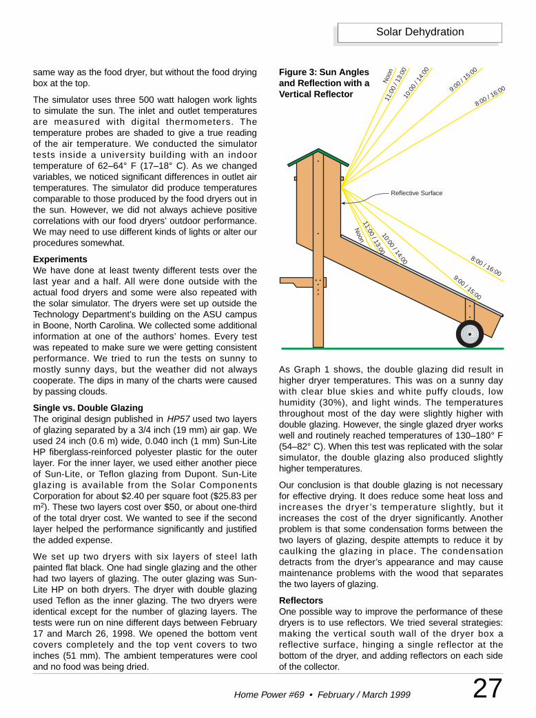
27Home Power #69 • February / March 1999
Solar Dehydration
same way as the food dryer, but without the food dryingbox at the top.
The simulator uses three 500 watt halogen work lightsto simulate the sun. The inlet and outlet temperaturesare measured with digital thermometers. Thetemperature probes are shaded to give a true readingof the air temperature. We conducted the simulatortests inside a university building with an indoortemperature of 62–64° F (17–18° C). As we changedvariables, we noticed significant differences in outlet airtemperatures. The simulator did produce temperaturescomparable to those produced by the food dryers out inthe sun. However, we did not always achieve positivecorrelations with our food dryers’ outdoor performance.We may need to use different kinds of lights or alter ourprocedures somewhat.
ExperimentsWe have done at least twenty different tests over thelast year and a half. All were done outside with theactual food dryers and some were also repeated withthe solar simulator. The dryers were set up outside theTechnology Department’s building on the ASU campusin Boone, North Carolina. We collected some additionalinformation at one of the authors’ homes. Every testwas repeated to make sure we were getting consistentperformance. We tried to run the tests on sunny tomostly sunny days, but the weather did not alwayscooperate. The dips in many of the charts were causedby passing clouds.
Single vs. Double GlazingThe original design published in HP57 used two layersof glazing separated by a 3/4 inch (19 mm) air gap. Weused 24 inch (0.6 m) wide, 0.040 inch (1 mm) Sun-LiteHP fiberglass-reinforced polyester plastic for the outerlayer. For the inner layer, we used either another pieceof Sun-Lite, or Teflon glazing from Dupont. Sun-Liteglazing is available from the Solar ComponentsCorporation for about $2.40 per square foot ($25.83 perm2). These two layers cost over $50, or about one-thirdof the total dryer cost. We wanted to see if the secondlayer helped the performance significantly and justifiedthe added expense.
We set up two dryers with six layers of steel lathpainted flat black. One had single glazing and the otherhad two layers of glazing. The outer glazing was Sun-Lite HP on both dryers. The dryer with double glazingused Teflon as the inner glazing. The two dryers wereidentical except for the number of glazing layers. Thetests were run on nine different days between February17 and March 26, 1998. We opened the bottom ventcovers completely and the top vent covers to twoinches (51 mm). The ambient temperatures were cooland no food was being dried.
As Graph 1 shows, the double glazing did result inhigher dryer temperatures. This was on a sunny daywith clear blue skies and white puffy clouds, lowhumidity (30%), and light winds. The temperaturesthroughout most of the day were slightly higher withdouble glazing. However, the single glazed dryer workswell and routinely reached temperatures of 130–180° F(54–82° C). When this test was replicated with the solarsimulator, the double glazing also produced slightlyhigher temperatures.
Our conclusion is that double glazing is not necessaryfor effective drying. It does reduce some heat loss andincreases the dryer ’s temperature slightly, but itincreases the cost of the dryer significantly. Anotherproblem is that some condensation forms between thetwo layers of glazing, despite attempts to reduce it bycaulking the glazing in place. The condensationdetracts from the dryer’s appearance and may causemaintenance problems with the wood that separatesthe two layers of glazing.
ReflectorsOne possible way to improve the performance of thesedryers is to use reflectors. We tried several strategies:making the vertical south wall of the dryer box areflective surface, hinging a single reflector at thebottom of the dryer, and adding reflectors on each sideof the collector.
8:00 / 16:00
Noo
n
8:00 / 16:00
11:00 / 13:00
9:00 / 15:00
9:00 / 15:00
10:0
0 / 1
4:00
10:00 / 14:00
11:0
0 / 1
3:00
Noon
Reflective Surface
Figure 3: Sun Anglesand Reflection with aVertical Reflector
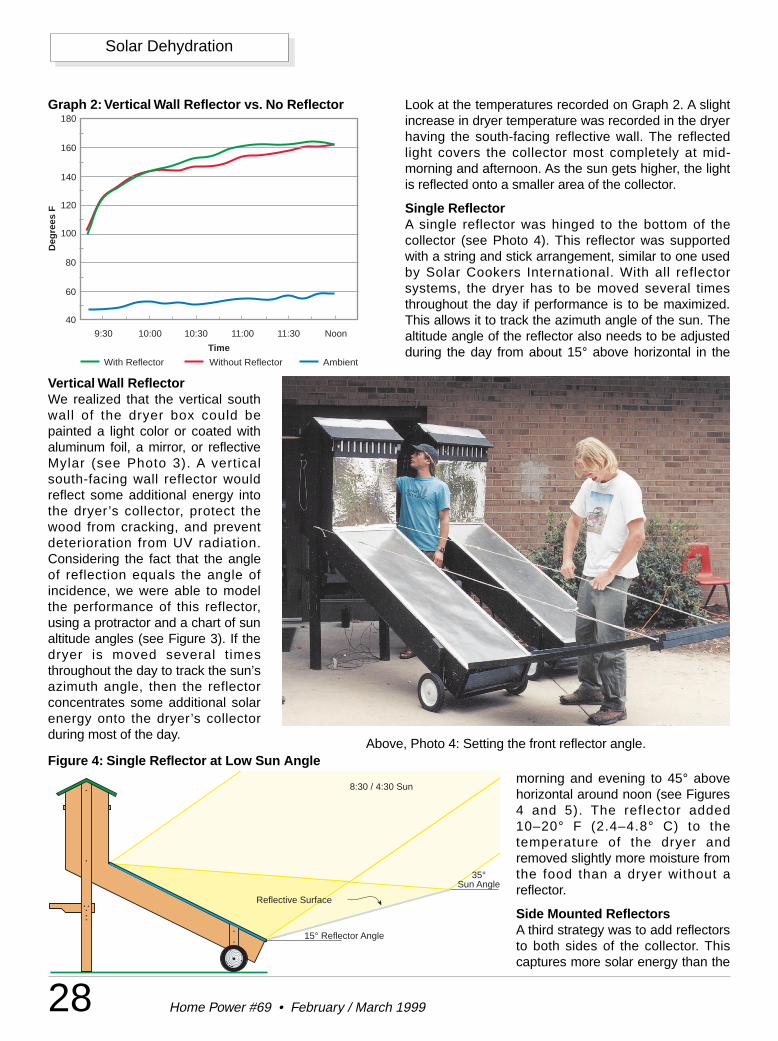
28 Home Power #69 • February / March 1999
Solar Dehydration
Vertical Wall ReflectorWe realized that the vertical southwall of the dryer box could bepainted a light color or coated withaluminum foil, a mirror, or reflectiveMylar (see Photo 3). A verticalsouth-facing wall reflector wouldreflect some additional energy intothe dryer’s collector, protect thewood from cracking, and preventdeterioration from UV radiation.Considering the fact that the angleof reflection equals the angle ofincidence, we were able to modelthe performance of this reflector,using a protractor and a chart of sunaltitude angles (see Figure 3). If thedryer is moved several timesthroughout the day to track the sun’sazimuth angle, then the reflectorconcentrates some additional solarenergy onto the dryer’s collectorduring most of the day.
Look at the temperatures recorded on Graph 2. A slightincrease in dryer temperature was recorded in the dryerhaving the south-facing reflective wall. The reflectedlight covers the collector most completely at mid-morning and afternoon. As the sun gets higher, the lightis reflected onto a smaller area of the collector.
Single ReflectorA single reflector was hinged to the bottom of thecollector (see Photo 4). This reflector was supportedwith a string and stick arrangement, similar to one usedby Solar Cookers International. With all reflectorsystems, the dryer has to be moved several timesthroughout the day if performance is to be maximized.This allows it to track the azimuth angle of the sun. Thealtitude angle of the reflector also needs to be adjustedduring the day from about 15° above horizontal in the
Reflective Surface
15° Reflector Angle
35°Sun Angle
8:30 / 4:30 Sun
Figure 4: Single Reflector at Low Sun Angle
40
60
80
100
120
140
160
180
9:30 10:00 10:30 11:00 11:30 Noon
Time
Deg
rees
F
With Reflector Without Reflector Ambient
Graph 2: Vertical Wall Reflector vs. No Reflector
Above, Photo 4: Setting the front reflector angle.
morning and evening to 45° abovehorizontal around noon (see Figures4 and 5). The reflector added10–20° F (2.4–4.8° C) to thetemperature of the dryer andremoved slightly more moisture fromthe food than a dryer without areflector.
Side Mounted ReflectorsA third strategy was to add reflectorsto both sides of the collector. Thiscaptures more solar energy than the
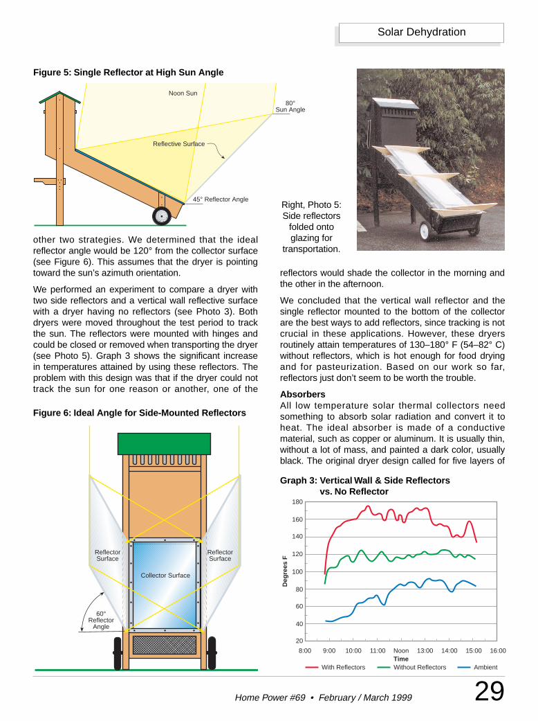
29Home Power #69 • February / March 1999
Solar Dehydration
reflectors would shade the collector in the morning andthe other in the afternoon.
We concluded that the vertical wall reflector and thesingle reflector mounted to the bottom of the collectorare the best ways to add reflectors, since tracking is notcrucial in these applications. However, these dryersroutinely attain temperatures of 130–180° F (54–82° C)without reflectors, which is hot enough for food dryingand for pasteurization. Based on our work so far,reflectors just don’t seem to be worth the trouble.
AbsorbersAll low temperature solar thermal collectors needsomething to absorb solar radiation and convert it toheat. The ideal absorber is made of a conductivematerial, such as copper or aluminum. It is usually thin,without a lot of mass, and painted a dark color, usuallyblack. The original dryer design called for five layers of
Reflective Surface
45° Reflector Angle
80°Sun Angle
Noon Sun
Figure 5: Single Reflector at High Sun Angle
60°Reflector
Angle
Collector Surface
ReflectorSurface
ReflectorSurface
Figure 6: Ideal Angle for Side-Mounted Reflectors
20
40
60
80
100
120
140
160
180
8:00 9:00 10:00 11:00 Noon 13:00 14:00 15:00 16:00Time
With Reflectors Without Reflectors Ambient
Deg
rees
F
Graph 3: Vertical Wall & Side Reflectors vs. No Reflector
Right, Photo 5:Side reflectors
folded ontoglazing for
transportation.other two strategies. We determined that the idealreflector angle would be 120° from the collector surface(see Figure 6). This assumes that the dryer is pointingtoward the sun’s azimuth orientation.
We performed an experiment to compare a dryer withtwo side reflectors and a vertical wall reflective surfacewith a dryer having no reflectors (see Photo 3). Bothdryers were moved throughout the test period to trackthe sun. The reflectors were mounted with hinges andcould be closed or removed when transporting the dryer(see Photo 5). Graph 3 shows the significant increasein temperatures attained by using these reflectors. Theproblem with this design was that if the dryer could nottrack the sun for one reason or another, one of the
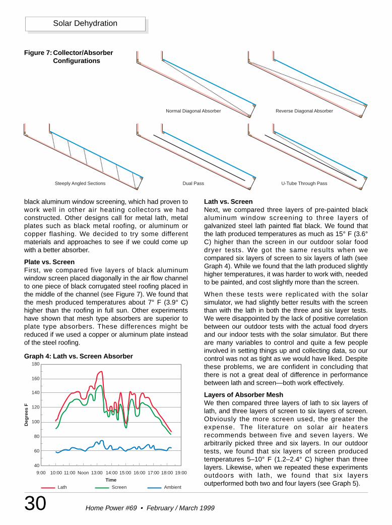
30 Home Power #69 • February / March 1999
Solar Dehydration
black aluminum window screening, which had proven towork well in other air heating collectors we hadconstructed. Other designs call for metal lath, metalplates such as black metal roofing, or aluminum orcopper flashing. We decided to try some differentmaterials and approaches to see if we could come upwith a better absorber.
Plate vs. ScreenFirst, we compared five layers of black aluminumwindow screen placed diagonally in the air flow channelto one piece of black corrugated steel roofing placed inthe middle of the channel (see Figure 7). We found thatthe mesh produced temperatures about 7° F (3.9° C)higher than the roofing in full sun. Other experimentshave shown that mesh type absorbers are superior toplate type absorbers. These differences might bereduced if we used a copper or aluminum plate insteadof the steel roofing.
Lath vs. ScreenNext, we compared three layers of pre-painted blackaluminum window screening to three layers ofgalvanized steel lath painted flat black. We found thatthe lath produced temperatures as much as 15° F (3.6°C) higher than the screen in our outdoor solar fooddryer tests. We got the same results when wecompared six layers of screen to six layers of lath (seeGraph 4). While we found that the lath produced slightlyhigher temperatures, it was harder to work with, neededto be painted, and cost slightly more than the screen.
When these tests were replicated with the solarsimulator, we had slightly better results with the screenthan with the lath in both the three and six layer tests.We were disappointed by the lack of positive correlationbetween our outdoor tests with the actual food dryersand our indoor tests with the solar simulator. But thereare many variables to control and quite a few peopleinvolved in setting things up and collecting data, so ourcontrol was not as tight as we would have liked. Despitethese problems, we are confident in concluding thatthere is not a great deal of difference in performancebetween lath and screen—both work effectively.
Layers of Absorber MeshWe then compared three layers of lath to six layers oflath, and three layers of screen to six layers of screen.Obviously the more screen used, the greater theexpense. The literature on solar air heatersrecommends between five and seven layers. Wearbitrarily picked three and six layers. In our outdoortests, we found that six layers of screen producedtemperatures 5–10° F (1.2–2.4° C) higher than threelayers. Likewise, when we repeated these experimentsoutdoors with lath, we found that six layersoutperformed both two and four layers (see Graph 5).
Steeply Angled Sections U-Tube Through Pass
Reverse Diagonal AbsorberNormal Diagonal Absorber
Dual Pass
Figure 7: Collector/AbsorberConfigurations
40
60
80
100
120
140
160
180
9:00 10:00 11:00 Noon 13:00 14:00 15:00 16:00 17:00 18:00 19:00
Time
Lath Screen Ambient
Deg
rees
F
Graph 4: Lath vs. Screen Absorber
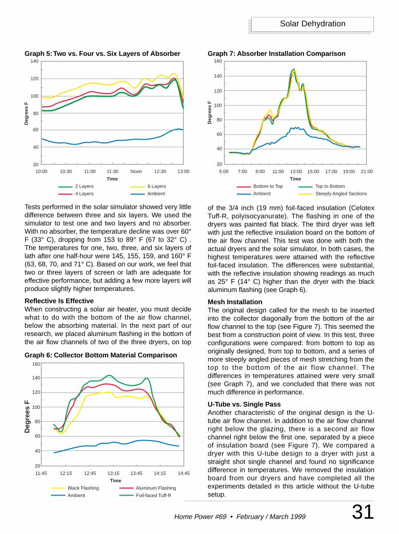
31Home Power #69 • February / March 1999
Solar Dehydration
Tests performed in the solar simulator showed very littledifference between three and six layers. We used thesimulator to test one and two layers and no absorber.With no absorber, the temperature decline was over 60°F (33° C), dropping from 153 to 89° F (67 to 32° C) .The temperatures for one, two, three, and six layers oflath after one half-hour were 145, 155, 159, and 160° F(63, 68, 70, and 71° C). Based on our work, we feel thattwo or three layers of screen or lath are adequate foreffective performance, but adding a few more layers willproduce slightly higher temperatures.
Reflective Is EffectiveWhen constructing a solar air heater, you must decidewhat to do with the bottom of the air flow channel,below the absorbing material. In the next part of ourresearch, we placed aluminum flashing in the bottom ofthe air flow channels of two of the three dryers, on top
of the 3/4 inch (19 mm) foil-faced insulation (CelotexTuff-R, polyisocyanurate). The flashing in one of thedryers was painted flat black. The third dryer was leftwith just the reflective insulation board on the bottom ofthe air flow channel. This test was done with both theactual dryers and the solar simulator. In both cases, thehighest temperatures were attained with the reflectivefoil-faced insulation. The differences were substantial,with the reflective insulation showing readings as muchas 25° F (14° C) higher than the dryer with the blackaluminum flashing (see Graph 6).
Mesh InstallationThe original design called for the mesh to be insertedinto the collector diagonally from the bottom of the airflow channel to the top (see Figure 7). This seemed thebest from a construction point of view. In this test, threeconfigurations were compared: from bottom to top asoriginally designed, from top to bottom, and a series ofmore steeply angled pieces of mesh stretching from thetop to the bottom of the air f low channel. Thedifferences in temperatures attained were very small(see Graph 7), and we concluded that there was notmuch difference in performance.
U-Tube vs. Single PassAnother characteristic of the original design is the U-tube air flow channel. In addition to the air flow channelright below the glazing, there is a second air flowchannel right below the first one, separated by a pieceof insulation board (see Figure 7). We compared adryer with this U-tube design to a dryer with just astraight shot single channel and found no significancedifference in temperatures. We removed the insulationboard from our dryers and have completed all theexperiments detailed in this article without the U-tubesetup.
20
40
60
80
100
120
140
10:00 11:00 Noon 12:30 13:00
Time
2 Layers
4 Layers
6 Layers
Ambient
Deg
rees
F
11:3010:30
Graph 5:Two vs. Four vs. Six Layers of Absorber
20
40
60
80
100
120
140
160
5:00 7:00 9:00 11:00 13:00 15:00 17:00 19:00 21:00
Time
Bottom to Top Top to Bottom
Ambient Steeply Angled Sections
Deg
rees
F
Graph 7: Absorber Installation Comparison
Black Flashing Aluminum Flashing
Ambient Foil-faced Tuff-R
Deg
rees
F
20
40
60
80
100
120
140
160
11:45 12:15 12:45 13:15 13:45 14:15 14:45
Time
Graph 6: Collector Bottom Material Comparison
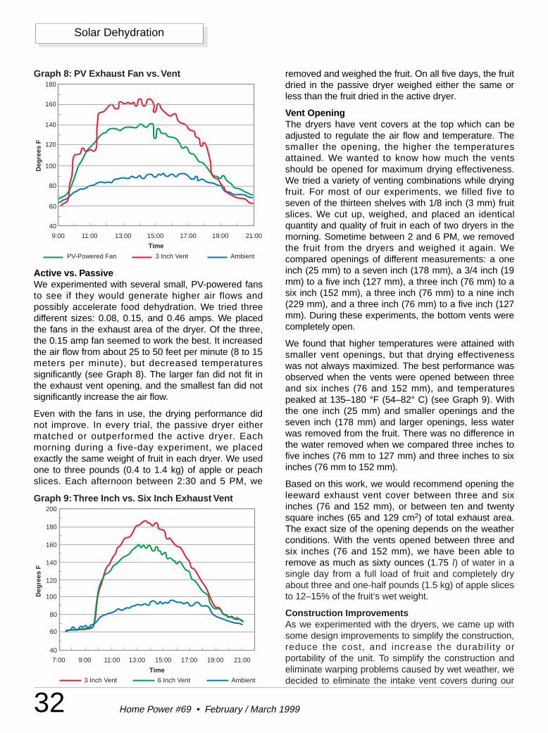
32 Home Power #69 • February / March 1999
Solar Dehydration
Active vs. PassiveWe experimented with several small, PV-powered fansto see if they would generate higher air flows andpossibly accelerate food dehydration. We tried threedifferent sizes: 0.08, 0.15, and 0.46 amps. We placedthe fans in the exhaust area of the dryer. Of the three,the 0.15 amp fan seemed to work the best. It increasedthe air flow from about 25 to 50 feet per minute (8 to 15meters per minute), but decreased temperaturessignificantly (see Graph 8). The larger fan did not fit inthe exhaust vent opening, and the smallest fan did notsignificantly increase the air flow.
Even with the fans in use, the drying performance didnot improve. In every trial, the passive dryer eithermatched or outperformed the active dryer. Eachmorning during a five-day experiment, we placedexactly the same weight of fruit in each dryer. We usedone to three pounds (0.4 to 1.4 kg) of apple or peachslices. Each afternoon between 2:30 and 5 PM, we
removed and weighed the fruit. On all five days, the fruitdried in the passive dryer weighed either the same orless than the fruit dried in the active dryer.
Vent OpeningThe dryers have vent covers at the top which can beadjusted to regulate the air flow and temperature. Thesmaller the opening, the higher the temperaturesattained. We wanted to know how much the ventsshould be opened for maximum drying effectiveness.We tried a variety of venting combinations while dryingfruit. For most of our experiments, we filled five toseven of the thirteen shelves with 1/8 inch (3 mm) fruitslices. We cut up, weighed, and placed an identicalquantity and quality of fruit in each of two dryers in themorning. Sometime between 2 and 6 PM, we removedthe fruit from the dryers and weighed it again. Wecompared openings of different measurements: a oneinch (25 mm) to a seven inch (178 mm), a 3/4 inch (19mm) to a five inch (127 mm), a three inch (76 mm) to asix inch (152 mm), a three inch (76 mm) to a nine inch(229 mm), and a three inch (76 mm) to a five inch (127mm). During these experiments, the bottom vents werecompletely open.
We found that higher temperatures were attained withsmaller vent openings, but that drying effectivenesswas not always maximized. The best performance wasobserved when the vents were opened between threeand six inches (76 and 152 mm), and temperaturespeaked at 135–180 °F (54–82° C) (see Graph 9). Withthe one inch (25 mm) and smaller openings and theseven inch (178 mm) and larger openings, less waterwas removed from the fruit. There was no difference inthe water removed when we compared three inches tofive inches (76 mm to 127 mm) and three inches to sixinches (76 mm to 152 mm).
Based on this work, we would recommend opening theleeward exhaust vent cover between three and sixinches (76 and 152 mm), or between ten and twentysquare inches (65 and 129 cm2) of total exhaust area.The exact size of the opening depends on the weatherconditions. With the vents opened between three andsix inches (76 and 152 mm), we have been able toremove as much as sixty ounces (1.75 l) of water in asingle day from a full load of fruit and completely dryabout three and one-half pounds (1.5 kg) of apple slicesto 12–15% of the fruit’s wet weight.
Construction ImprovementsAs we experimented with the dryers, we came up withsome design improvements to simplify the construction,reduce the cost, and increase the durabil ity orportability of the unit. To simplify the construction andeliminate warping problems caused by wet weather, wedecided to eliminate the intake vent covers during our
40
60
80
100
120
140
160
180
9:00 11:00 13:00 15:00 17:00 19:00 21:00
Time
PV-Powered Fan 3 Inch Vent Ambient
Deg
rees
F
Graph 8: PV Exhaust Fan vs. Vent
40
60
80
100
120
140
160
180
200
7:00 9:00 11:00 13:00 15:00 17:00 19:00 21:00
Time
Deg
rees
F
3 Inch Vent 6 Inch Vent Ambient
Graph 9:Three Inch vs. Six Inch Exhaust Vent
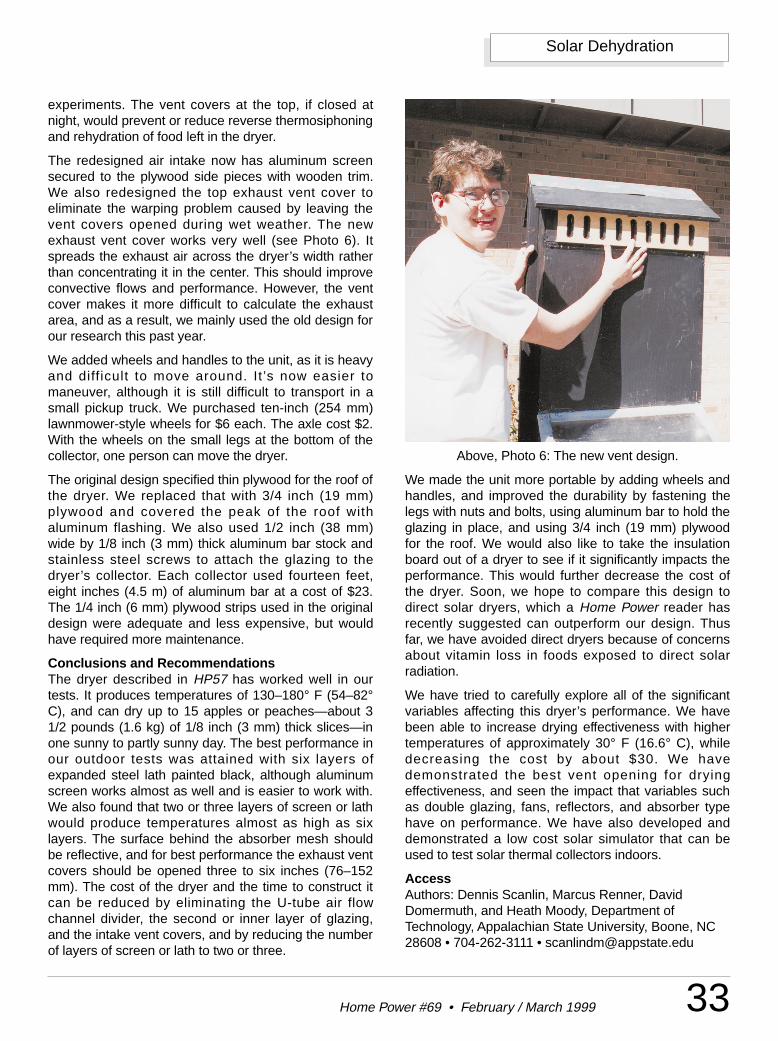
33Home Power #69 • February / March 1999
Solar Dehydration
experiments. The vent covers at the top, if closed atnight, would prevent or reduce reverse thermosiphoningand rehydration of food left in the dryer.
The redesigned air intake now has aluminum screensecured to the plywood side pieces with wooden trim.We also redesigned the top exhaust vent cover toeliminate the warping problem caused by leaving thevent covers opened during wet weather. The newexhaust vent cover works very well (see Photo 6). Itspreads the exhaust air across the dryer’s width ratherthan concentrating it in the center. This should improveconvective flows and performance. However, the ventcover makes it more difficult to calculate the exhaustarea, and as a result, we mainly used the old design forour research this past year.
We added wheels and handles to the unit, as it is heavyand diff icult to move around. It ’s now easier tomaneuver, although it is still difficult to transport in asmall pickup truck. We purchased ten-inch (254 mm)lawnmower-style wheels for $6 each. The axle cost $2.With the wheels on the small legs at the bottom of thecollector, one person can move the dryer.
The original design specified thin plywood for the roof ofthe dryer. We replaced that with 3/4 inch (19 mm)plywood and covered the peak of the roof withaluminum flashing. We also used 1/2 inch (38 mm)wide by 1/8 inch (3 mm) thick aluminum bar stock andstainless steel screws to attach the glazing to thedryer’s collector. Each collector used fourteen feet,eight inches (4.5 m) of aluminum bar at a cost of $23.The 1/4 inch (6 mm) plywood strips used in the originaldesign were adequate and less expensive, but wouldhave required more maintenance.
Conclusions and RecommendationsThe dryer described in HP57 has worked well in ourtests. It produces temperatures of 130–180° F (54–82°C), and can dry up to 15 apples or peaches—about 31/2 pounds (1.6 kg) of 1/8 inch (3 mm) thick slices—inone sunny to partly sunny day. The best performance inour outdoor tests was attained with six layers ofexpanded steel lath painted black, although aluminumscreen works almost as well and is easier to work with.We also found that two or three layers of screen or lathwould produce temperatures almost as high as sixlayers. The surface behind the absorber mesh shouldbe reflective, and for best performance the exhaust ventcovers should be opened three to six inches (76–152mm). The cost of the dryer and the time to construct itcan be reduced by eliminating the U-tube air flowchannel divider, the second or inner layer of glazing,and the intake vent covers, and by reducing the numberof layers of screen or lath to two or three.
We made the unit more portable by adding wheels andhandles, and improved the durability by fastening thelegs with nuts and bolts, using aluminum bar to hold theglazing in place, and using 3/4 inch (19 mm) plywoodfor the roof. We would also like to take the insulationboard out of a dryer to see if it significantly impacts theperformance. This would further decrease the cost ofthe dryer. Soon, we hope to compare this design todirect solar dryers, which a Home Power reader hasrecently suggested can outperform our design. Thusfar, we have avoided direct dryers because of concernsabout vitamin loss in foods exposed to direct solarradiation.
We have tried to carefully explore all of the significantvariables affecting this dryer’s performance. We havebeen able to increase drying effectiveness with highertemperatures of approximately 30° F (16.6° C), whiledecreasing the cost by about $30. We havedemonstrated the best vent opening for dryingeffectiveness, and seen the impact that variables suchas double glazing, fans, reflectors, and absorber typehave on performance. We have also developed anddemonstrated a low cost solar simulator that can beused to test solar thermal collectors indoors.
AccessAuthors: Dennis Scanlin, Marcus Renner, DavidDomermuth, and Heath Moody, Department ofTechnology, Appalachian State University, Boone, NC28608 • 704-262-3111 • [email protected]
Above, Photo 6: The new vent design.
34 Home Power #69 • February / March 1999
Solar Dehydration
Solar Cookers International (SCI), 1919 21st Street,Sacramento, CA 95814 • 916-455-4499Fax: 916-455-4498 • [email protected]
Sun-Lite HP glazing was purchased from SolarComponents Corporation, 121 Valley Street,Manchester, NH 03103-6211 • 603-668-8186Fax: 603-668-1783 • [email protected]
Scales, anemometers, and other data collectionequipment were purchased from Thomas Scientific,PO Box 99, Swedesboro, NJ 08085 • 800-345-2100609-467-2000 • Fax: [email protected] • www.thomassci.com
Data logger was purchased from Pace Scientific, Inc.,6407 Idlewild Rd., Suite 2.214, Charlotte, NC 28212704-568-3691 • Fax: [email protected] • www.pace-sci.com
Creating Peaceof Mind!
Peace of mind has become a premium in today’s society. The Y2Kproblem has created unrest, fear andeven panic in the minds of millions ofAmericans. The global economy isgoing berserk. But while the future isdefinitely uncertain, one thing you cancount on is the fact that no matterwhat happens, you will need food andwater! Emergency food storage is awise safeguard against all emergen-cies from floods, earthquakes and hurricanes to unemployment or illness.
Millennium III Foods offers nutritionallybalanced food plans for individuals, families or communities at competitiveprices.
At Millennium III Foods, we don’t justsell storage food… WE CREATE PEACE OF MIND.
• TWO WEEK SHIPPING• “One Year Supplies” are nutri-
tionally balanced to deliver over1,900 calories per day
• Real food that’s easy to use!• Awarded #1 Best Tasting• A La Carte ordering or purchase One
Year Units for one, two or four per-sons. Great value, simple planning!
Call for prices and informationSALES 888•883•1603
FAX 406•388•2603
P.O. Box 10010Bozeman, Montana 59719WWW.M3MFOODS.COM
Fight Global Warming
P.O. Box 1101, Arcata, CA 95518-1101Phone: 707-822-9095 • Fax: 707-822-6213 • www.sunfrost.com
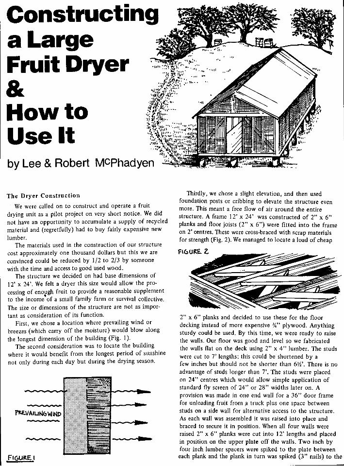
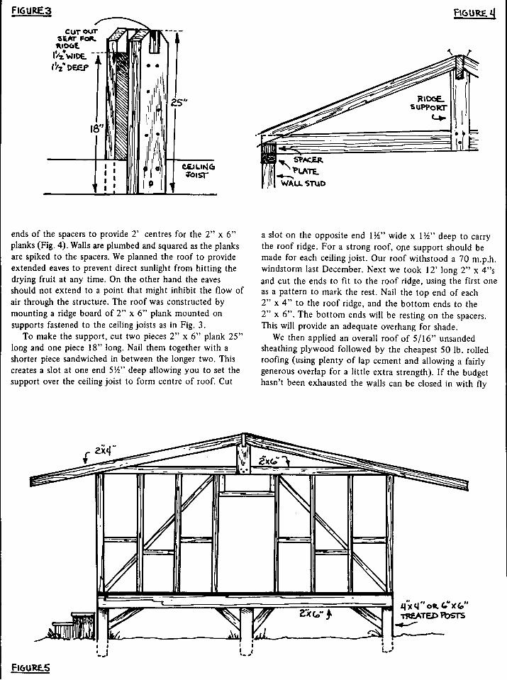
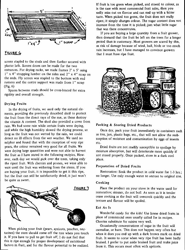
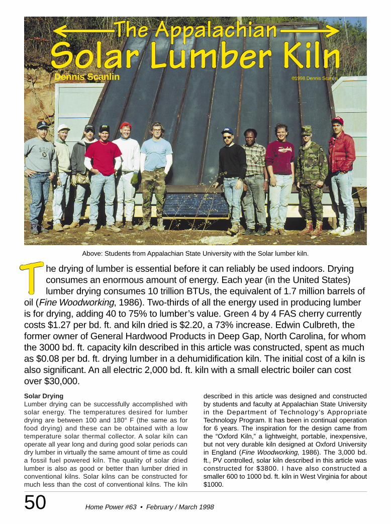
50 Home Power #63 • February / March 1998
he drying of lumber is essential before it can reliably be used indoors. Dryingconsumes an enormous amount of energy. Each year (in the United States)lumber drying consumes 10 trillion BTUs, the equivalent of 1.7 million barrels of
oil (Fine Woodworking, 1986). Two-thirds of all the energy used in producing lumberis for drying, adding 40 to 75% to lumber’s value. Green 4 by 4 FAS cherry currentlycosts $1.27 per bd. ft. and kiln dried is $2.20, a 73% increase. Edwin Culbreth, theformer owner of General Hardwood Products in Deep Gap, North Carolina, for whomthe 3000 bd. ft. capacity kiln described in this article was constructed, spent as muchas $0.08 per bd. ft. drying lumber in a dehumidification kiln. The initial cost of a kiln isalso significant. An all electric 2,000 bd. ft. kiln with a small electric boiler can costover $30,000.
Solar DryingLumber drying can be successfully accomplished withsolar energy. The temperatures desired for lumberdrying are between 100 and 180° F (the same as forfood drying) and these can be obtained with a lowtemperature solar thermal collector. A solar kiln canoperate all year long and during good solar periods candry lumber in virtually the same amount of time as coulda fossil fuel powered kiln. The quality of solar driedlumber is also as good or better than lumber dried inconventional kilns. Solar kilns can be constructed formuch less than the cost of conventional kilns. The kiln
Dennis Scanlin ©1998 Dennis Scanlin
described in this article was designed and constructedby students and faculty at Appalachian State Universityin the Department of Technology’s AppropriateTechnology Program. It has been in continual operationfor 6 years. The inspiration for the design came fromthe “Oxford Kiln,” a lightweight, portable, inexpensive,but not very durable kiln designed at Oxford Universityin England (Fine Woodworking, 1986). The 3,000 bd.ft., PV controlled, solar kiln described in this article wasconstructed for $3800. I have also constructed asmaller 600 to 1000 bd. ft. kiln in West Virginia for about$1000.
Above: Students from Appalachian State University with the Solar lumber kiln.
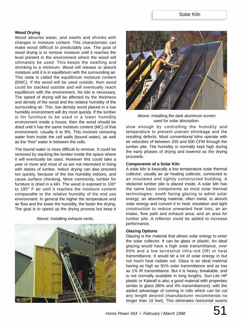
51Home Power #63 • February / March 1998
Solar Kiln
Wood DryingWood absorbs water, and swells and shrinks withchanges in moisture content. This characteristic canmake wood difficult to predictably use. The goal ofwood drying is to remove moisture until it reaches thelevel present in the environment where the wood willultimately be used. This keeps the swelling andshrinking to a minimum. Wood will release or absorbmoisture until it is in equilibrium with the surrounding air.This state is called the equilibrium moisture content(EMC). If the wood will be used outside, then woodcould be stacked outside and will eventually reachequilibrium with the environment. No kiln is necessary.The speed of drying will be affected by the thicknessand density of the wood and the relative humidity of thesurrounding air. Thin, low density wood placed in a lowhumidity environment will dry most quickly. If the lumberis for furniture to be used in a lower humidityenvironment inside a house, then the wood should bedried until it has the same moisture content (MC) of thatenvironment. Usually 6 to 8%. This involves removingwater from inside the cell walls (bound water), as wellas the “free” water in between the cells.
The bound water is more difficult to remove. It could beremoved by stacking the lumber inside the space whereit will eventually be used. However this could take ayear or more and most of us are not interested in livingwith stacks of lumber. Indoor drying can also proceedtoo quickly, because of the low humidity indoors, andcause surface checking. More commonly, lumber forfurniture is dried in a kiln. The wood is exposed to 100°to 180° F air until it reaches the moisture contentcomparable to the relative humidity of the end useenvironment. In general the higher the temperature andair flow and the lower the humidity, the faster the drying.The goal is to speed up the drying process but keep it
slow enough by controll ing the humidity andtemperature to prevent uneven shrinkage and theresulting defects. Most conventional kilns operate withair velocities of between 200 and 500 CFM through thelumber pile. The humidity is normally kept high duringthe early phases of drying and lowered as the dryingproceeds.
Components of a Solar KilnA solar kiln is basically a low temperature solar thermalcollector, usually an air heating collector, connected toan insulated and tightly constructed building. Astickered lumber pile is placed inside. A solar kiln hasthe same basic components as most solar thermaltechnologies: south facing glazing to admit solarenergy; an absorbing material, often metal, to absorbsolar energy and convert it to heat; insulation and tightconstruction to reduce unwanted heat loss; an airintake, flow path and exhaust area; and an area forlumber pile. A reflector could be added to increaseperformance.
Glazing OptionsGlazing is the material that allows solar energy to enterthe solar collector. It can be glass or plastic. An idealglazing would have a high solar transmittance, over90% and a low terrestrial infra-red (IR) or heattransmittance. It would let a lot of solar energy in butnot much heat radiate out. Glass is an ideal materialhaving as high as 91% solar transmittance and as lowas 1% IR transmittance. But it is heavy, breakable, andis not normally available in long lengths. Sun-Lite HPplastic or Kalwall is also a good material with propertiessimilar to glass (86% and 4% transmittances), with theadded advantage of coming in rolls which can be cutany length desired (manufacturer recommends nolonger than 16 feet). This eliminates horizontal seams
Above: Installing the dark aluminum screen used for solar absorption.
Above: Installing exhaust vents.
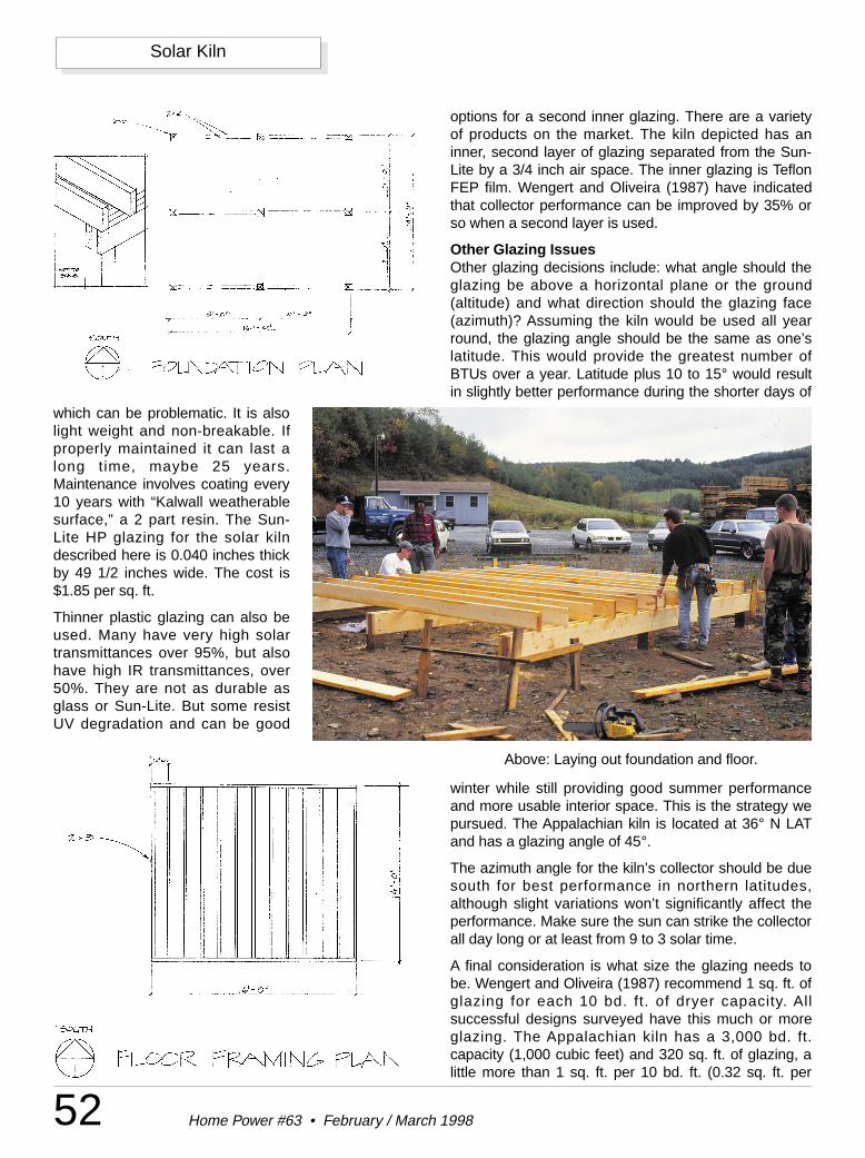
52 Home Power #63 • February / March 1998
Solar Kiln
which can be problematic. It is alsolight weight and non-breakable. Ifproperly maintained it can last along time, maybe 25 years.Maintenance involves coating every10 years with “Kalwall weatherablesurface,” a 2 part resin. The Sun-Lite HP glazing for the solar kilndescribed here is 0.040 inches thickby 49 1/2 inches wide. The cost is$1.85 per sq. ft.
Thinner plastic glazing can also beused. Many have very high solartransmittances over 95%, but alsohave high IR transmittances, over50%. They are not as durable asglass or Sun-Lite. But some resistUV degradation and can be good
options for a second inner glazing. There are a varietyof products on the market. The kiln depicted has aninner, second layer of glazing separated from the Sun-Lite by a 3/4 inch air space. The inner glazing is TeflonFEP film. Wengert and Oliveira (1987) have indicatedthat collector performance can be improved by 35% orso when a second layer is used.
Other Glazing IssuesOther glazing decisions include: what angle should theglazing be above a horizontal plane or the ground(altitude) and what direction should the glazing face(azimuth)? Assuming the kiln would be used all yearround, the glazing angle should be the same as one’slatitude. This would provide the greatest number ofBTUs over a year. Latitude plus 10 to 15° would resultin slightly better performance during the shorter days of
winter while still providing good summer performanceand more usable interior space. This is the strategy wepursued. The Appalachian kiln is located at 36° N LATand has a glazing angle of 45°.
The azimuth angle for the kiln’s collector should be duesouth for best performance in northern latitudes,although slight variations won’t significantly affect theperformance. Make sure the sun can strike the collectorall day long or at least from 9 to 3 solar time.
A final consideration is what size the glazing needs tobe. Wengert and Oliveira (1987) recommend 1 sq. ft. ofglazing for each 10 bd. ft. of dryer capacity. Allsuccessful designs surveyed have this much or moreglazing. The Appalachian kiln has a 3,000 bd. ft.capacity (1,000 cubic feet) and 320 sq. ft. of glazing, alittle more than 1 sq. ft. per 10 bd. ft. (0.32 sq. ft. per
Above: Laying out foundation and floor.
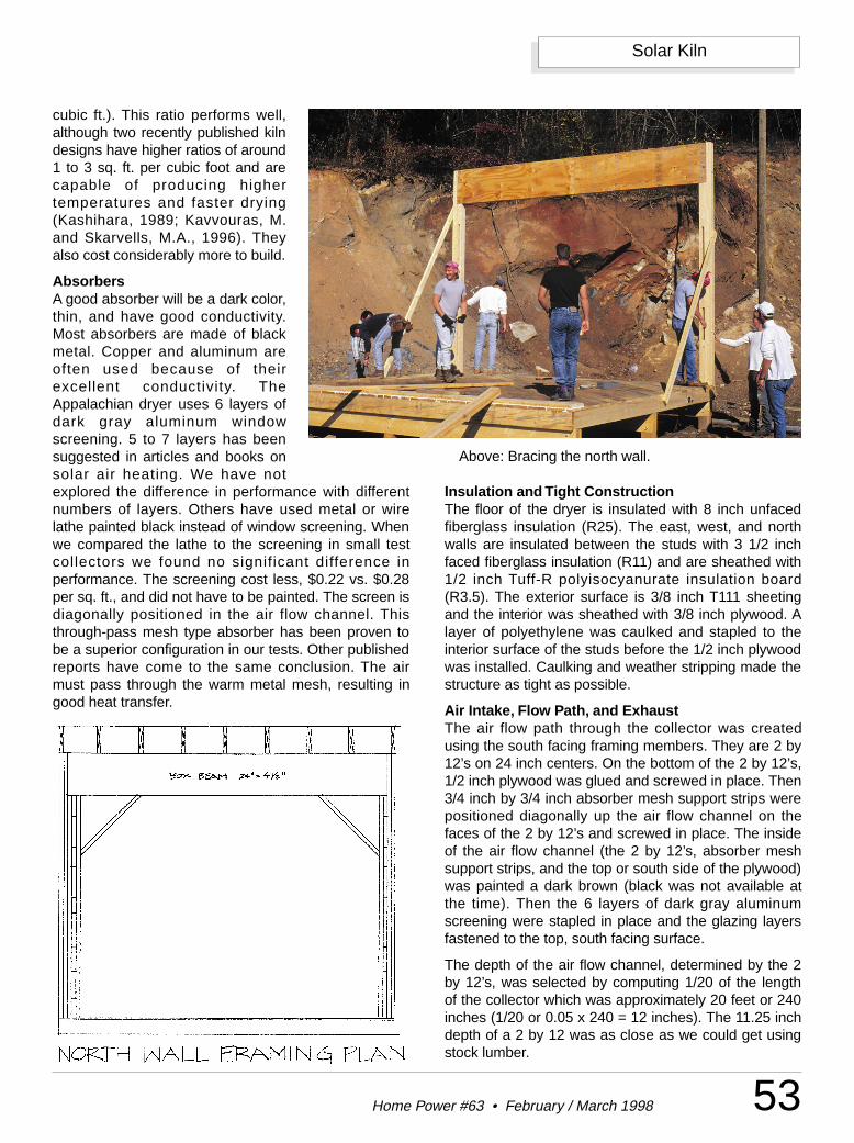
53Home Power #63 • February / March 1998
Solar Kiln
cubic ft.). This ratio performs well,although two recently published kilndesigns have higher ratios of around1 to 3 sq. ft. per cubic foot and arecapable of producing highertemperatures and faster drying(Kashihara, 1989; Kavvouras, M.and Skarvells, M.A., 1996). Theyalso cost considerably more to build.
AbsorbersA good absorber will be a dark color,thin, and have good conductivity.Most absorbers are made of blackmetal. Copper and aluminum areoften used because of theirexcellent conductivity. TheAppalachian dryer uses 6 layers ofdark gray aluminum windowscreening. 5 to 7 layers has beensuggested in articles and books onsolar air heating. We have notexplored the difference in performance with differentnumbers of layers. Others have used metal or wirelathe painted black instead of window screening. Whenwe compared the lathe to the screening in small testcollectors we found no significant difference inperformance. The screening cost less, $0.22 vs. $0.28per sq. ft., and did not have to be painted. The screen isdiagonally positioned in the air flow channel. Thisthrough-pass mesh type absorber has been proven tobe a superior configuration in our tests. Other publishedreports have come to the same conclusion. The airmust pass through the warm metal mesh, resulting ingood heat transfer.
Insulation and Tight ConstructionThe floor of the dryer is insulated with 8 inch unfacedfiberglass insulation (R25). The east, west, and northwalls are insulated between the studs with 3 1/2 inchfaced fiberglass insulation (R11) and are sheathed with1/2 inch Tuff-R polyisocyanurate insulation board(R3.5). The exterior surface is 3/8 inch T111 sheetingand the interior was sheathed with 3/8 inch plywood. Alayer of polyethylene was caulked and stapled to theinterior surface of the studs before the 1/2 inch plywoodwas installed. Caulking and weather stripping made thestructure as tight as possible.
Air Intake, Flow Path, and ExhaustThe air flow path through the collector was createdusing the south facing framing members. They are 2 by12’s on 24 inch centers. On the bottom of the 2 by 12’s,1/2 inch plywood was glued and screwed in place. Then3/4 inch by 3/4 inch absorber mesh support strips werepositioned diagonally up the air flow channel on thefaces of the 2 by 12’s and screwed in place. The insideof the air flow channel (the 2 by 12’s, absorber meshsupport strips, and the top or south side of the plywood)was painted a dark brown (black was not available atthe time). Then the 6 layers of dark gray aluminumscreening were stapled in place and the glazing layersfastened to the top, south facing surface.
The depth of the air flow channel, determined by the 2by 12’s, was selected by computing 1/20 of the lengthof the collector which was approximately 20 feet or 240inches (1/20 or 0.05 x 240 = 12 inches). The 11.25 inchdepth of a 2 by 12 was as close as we could get usingstock lumber.
Above: Bracing the north wall.
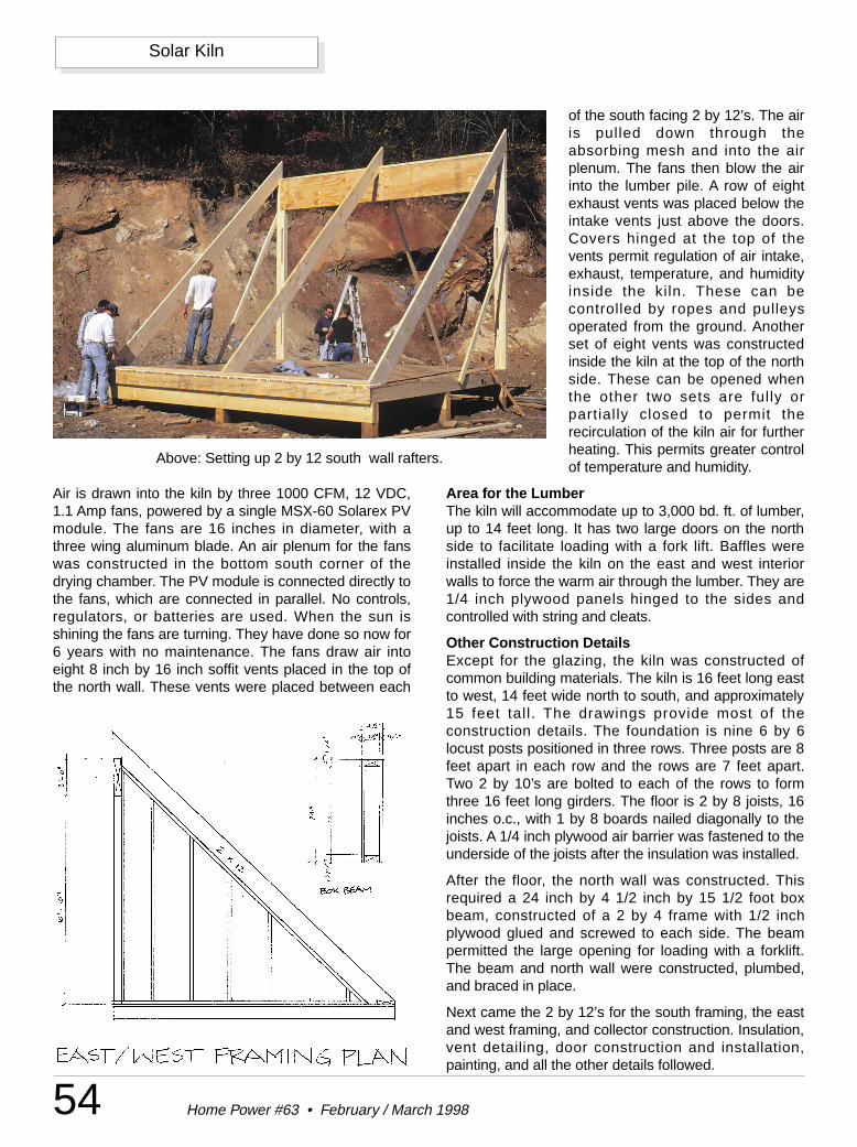
54 Home Power #63 • February / March 1998
Solar Kiln
Air is drawn into the kiln by three 1000 CFM, 12 VDC,1.1 Amp fans, powered by a single MSX-60 Solarex PVmodule. The fans are 16 inches in diameter, with athree wing aluminum blade. An air plenum for the fanswas constructed in the bottom south corner of thedrying chamber. The PV module is connected directly tothe fans, which are connected in parallel. No controls,regulators, or batteries are used. When the sun isshining the fans are turning. They have done so now for6 years with no maintenance. The fans draw air intoeight 8 inch by 16 inch soffit vents placed in the top ofthe north wall. These vents were placed between each
of the south facing 2 by 12’s. The airis pulled down through theabsorbing mesh and into the airplenum. The fans then blow the airinto the lumber pile. A row of eightexhaust vents was placed below theintake vents just above the doors.Covers hinged at the top of thevents permit regulation of air intake,exhaust, temperature, and humidityinside the kiln. These can becontrolled by ropes and pulleysoperated from the ground. Anotherset of eight vents was constructedinside the kiln at the top of the northside. These can be opened whenthe other two sets are fully orpartially closed to permit therecirculation of the kiln air for furtherheating. This permits greater controlof temperature and humidity.
Area for the LumberThe kiln will accommodate up to 3,000 bd. ft. of lumber,up to 14 feet long. It has two large doors on the northside to facilitate loading with a fork lift. Baffles wereinstalled inside the kiln on the east and west interiorwalls to force the warm air through the lumber. They are1/4 inch plywood panels hinged to the sides andcontrolled with string and cleats.
Other Construction DetailsExcept for the glazing, the kiln was constructed ofcommon building materials. The kiln is 16 feet long eastto west, 14 feet wide north to south, and approximately15 feet tall. The drawings provide most of theconstruction details. The foundation is nine 6 by 6locust posts positioned in three rows. Three posts are 8feet apart in each row and the rows are 7 feet apart.Two 2 by 10’s are bolted to each of the rows to formthree 16 feet long girders. The floor is 2 by 8 joists, 16inches o.c., with 1 by 8 boards nailed diagonally to thejoists. A 1/4 inch plywood air barrier was fastened to theunderside of the joists after the insulation was installed.
After the floor, the north wall was constructed. Thisrequired a 24 inch by 4 1/2 inch by 15 1/2 foot boxbeam, constructed of a 2 by 4 frame with 1/2 inchplywood glued and screwed to each side. The beampermitted the large opening for loading with a forklift.The beam and north wall were constructed, plumbed,and braced in place.
Next came the 2 by 12’s for the south framing, the eastand west framing, and collector construction. Insulation,vent detailing, door construction and installation,painting, and all the other details followed.
Above: Setting up 2 by 12 south wall rafters.
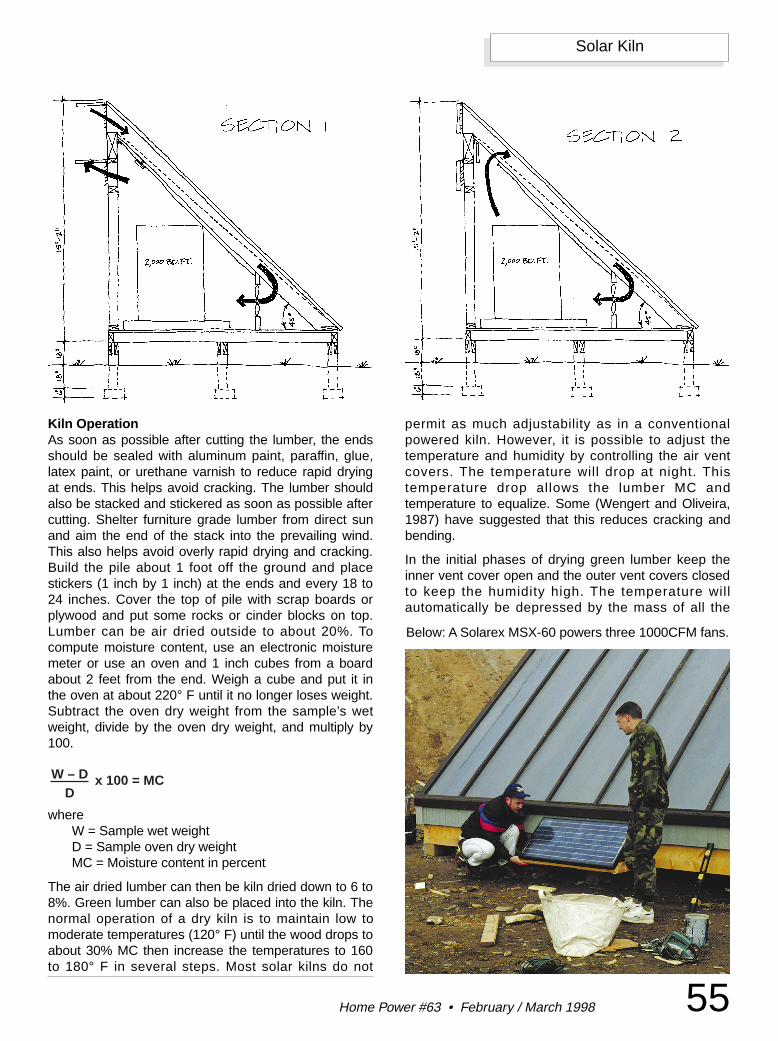
55Home Power #63 • February / March 1998
Solar Kiln
Kiln OperationAs soon as possible after cutting the lumber, the endsshould be sealed with aluminum paint, paraffin, glue,latex paint, or urethane varnish to reduce rapid dryingat ends. This helps avoid cracking. The lumber shouldalso be stacked and stickered as soon as possible aftercutting. Shelter furniture grade lumber from direct sunand aim the end of the stack into the prevailing wind.This also helps avoid overly rapid drying and cracking.Build the pile about 1 foot off the ground and placestickers (1 inch by 1 inch) at the ends and every 18 to24 inches. Cover the top of pile with scrap boards orplywood and put some rocks or cinder blocks on top.Lumber can be air dried outside to about 20%. Tocompute moisture content, use an electronic moisturemeter or use an oven and 1 inch cubes from a boardabout 2 feet from the end. Weigh a cube and put it inthe oven at about 220° F until it no longer loses weight.Subtract the oven dry weight from the sample’s wetweight, divide by the oven dry weight, and multiply by100.
whereW = Sample wet weightD = Sample oven dry weightMC = Moisture content in percent
The air dried lumber can then be kiln dried down to 6 to8%. Green lumber can also be placed into the kiln. Thenormal operation of a dry kiln is to maintain low tomoderate temperatures (120° F) until the wood drops toabout 30% MC then increase the temperatures to 160to 180° F in several steps. Most solar kilns do not
permit as much adjustability as in a conventionalpowered kiln. However, it is possible to adjust thetemperature and humidity by controlling the air ventcovers. The temperature will drop at night. Thistemperature drop allows the lumber MC andtemperature to equalize. Some (Wengert and Oliveira,1987) have suggested that this reduces cracking andbending.
In the initial phases of drying green lumber keep theinner vent cover open and the outer vent covers closedto keep the humidity high. The temperature willautomatically be depressed by the mass of all the
Below: A Solarex MSX-60 powers three 1000CFM fans.
W – DD
x 100 = MC
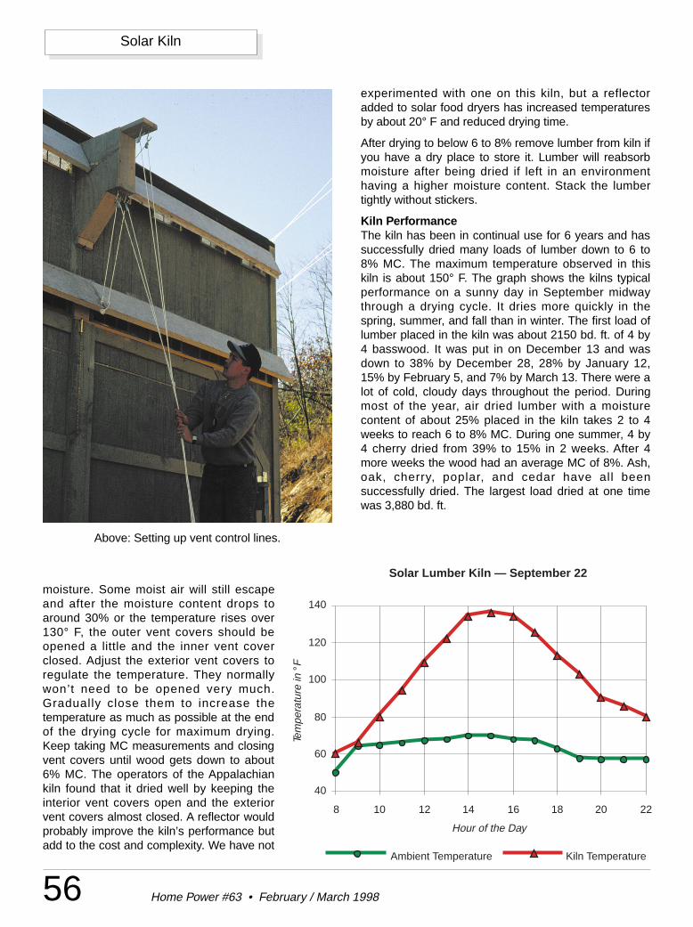
56 Home Power #63 • February / March 1998
Solar Kiln
moisture. Some moist air will still escapeand after the moisture content drops toaround 30% or the temperature rises over130° F, the outer vent covers should beopened a little and the inner vent coverclosed. Adjust the exterior vent covers toregulate the temperature. They normallywon’t need to be opened very much.Gradually close them to increase thetemperature as much as possible at the endof the drying cycle for maximum drying.Keep taking MC measurements and closingvent covers until wood gets down to about6% MC. The operators of the Appalachiankiln found that it dried well by keeping theinterior vent covers open and the exteriorvent covers almost closed. A reflector wouldprobably improve the kiln’s performance butadd to the cost and complexity. We have not
experimented with one on this kiln, but a reflectoradded to solar food dryers has increased temperaturesby about 20° F and reduced drying time.
After drying to below 6 to 8% remove lumber from kiln ifyou have a dry place to store it. Lumber will reabsorbmoisture after being dried if left in an environmenthaving a higher moisture content. Stack the lumbertightly without stickers.
Kiln PerformanceThe kiln has been in continual use for 6 years and hassuccessfully dried many loads of lumber down to 6 to8% MC. The maximum temperature observed in thiskiln is about 150° F. The graph shows the kilns typicalperformance on a sunny day in September midwaythrough a drying cycle. It dries more quickly in thespring, summer, and fall than in winter. The first load oflumber placed in the kiln was about 2150 bd. ft. of 4 by4 basswood. It was put in on December 13 and wasdown to 38% by December 28, 28% by January 12,15% by February 5, and 7% by March 13. There were alot of cold, cloudy days throughout the period. Duringmost of the year, air dried lumber with a moisturecontent of about 25% placed in the kiln takes 2 to 4weeks to reach 6 to 8% MC. During one summer, 4 by4 cherry dried from 39% to 15% in 2 weeks. After 4more weeks the wood had an average MC of 8%. Ash,oak, cherry, poplar, and cedar have all beensuccessfully dried. The largest load dried at one timewas 3,880 bd. ft.
Solar Lumber Kiln — September 22
Hour of the Day
Tem
pera
ture
in °
F
40
60
80
100
120
140
8 10 12 14 16 18 20 22
Ambient Temperature Kiln Temperature
Above: Setting up vent control lines.
57Home Power #63 • February / March 1998
Solar Kiln
AccessAuthor: Dennis Scanlin, Appalachian State University,Department of Technology, Boone, NC 28608704-297-5084 • E-Mail: [email protected]
Fans and module: Alternative Energy Engineering, POBox 339, Redway, CA 95560800-707-6609.
Sun-Lite HP: Solar Components Corporation, 121Valley Street, Manchester, NH 03103 • 603-668-8186.
Teflon FEP film: DuPont Company, ElectronicsDepartment, High Performance Films Division,Wilmington DE 19898 • 800-441-9494.
ReferencesBertorelli, P. (Ed) (1986). Fine Woodworking, on “Woodand How to Dry it.” Connecticut: The Tauton Press
Kashihara, S. (1989). Lumber drying in a solar lumberkiln. Business Japan. Sept. 01 (34) #9. page 68.
Kavvouras, P. K. and Skarvells, M. A. (1996).Performance of a solar-heated, forced-air, fullyautomatic lumber dryer. Holz als Roh- und Werkstoff.Jan 01, 1996. (54) #1.
Rasmussen, E. F. (1961). Dry kiln: Operator’s manual.Agriculture Handbook # 188. Madison, Wisconsin:Forest Products Laboratory, Forest Department, U.S.Department of Agriculture.
Wengert, E. M. and Oliveira, L. C. (1987). Solar heatedlumber dry kiln designs: A discussion and compilationof existing solar heated lumber dry kiln designs.Blacksburg, VA: Department of Forest Products,Virginia Polytechnic Institute and State University
Solar Kiln Costs
Basic framing, sheathing and foundation $1,800Insulation $279Absorber mesh $480Glazing (FRP) $635Air distribution system (PV module, 3 fans) $665
Total $3,859
MAPLE STATE BATTERYLowest Prices — Delivered Anywhere
Panels • Controllers • InvertersServel & Sun Frost Refrigeration
Jesus said, “I am the way, the truthand the life…” John 14:6
(802) 467-3662Sutton, Vermont 05867
Q. Whydid thesolarnerdcrossthe road
A.Tocheckhismailinglabel.
Don’t miss an issue: The number ofthe last issue of your currentsubscription is clearly printed onyour mailing label.
Q. Whydid thesolarnerdcrossthe road
A.Tocheckhismailinglabel.
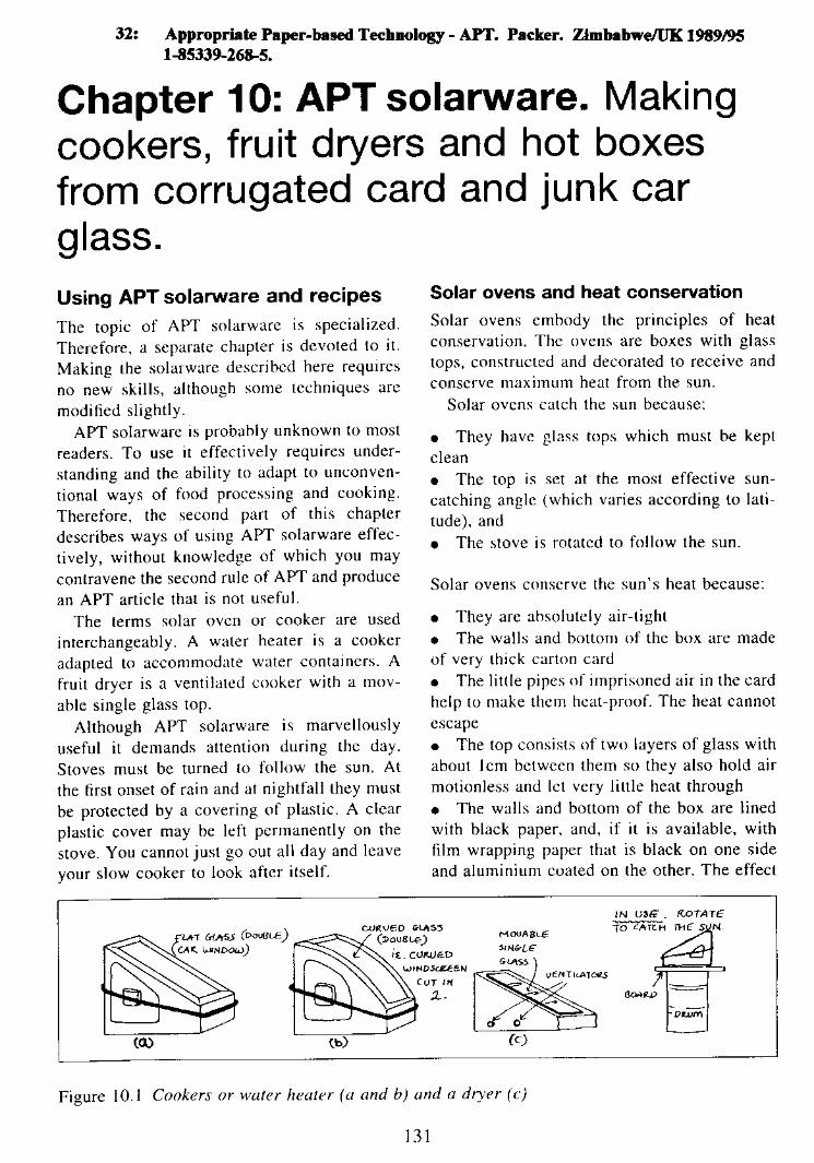
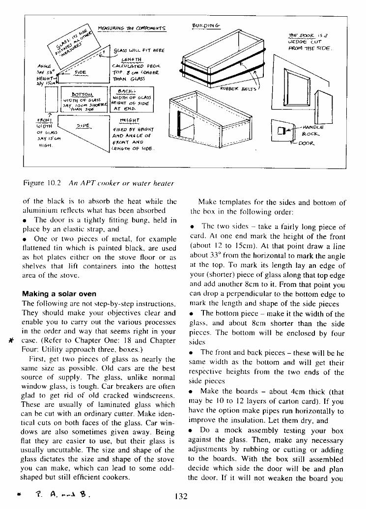
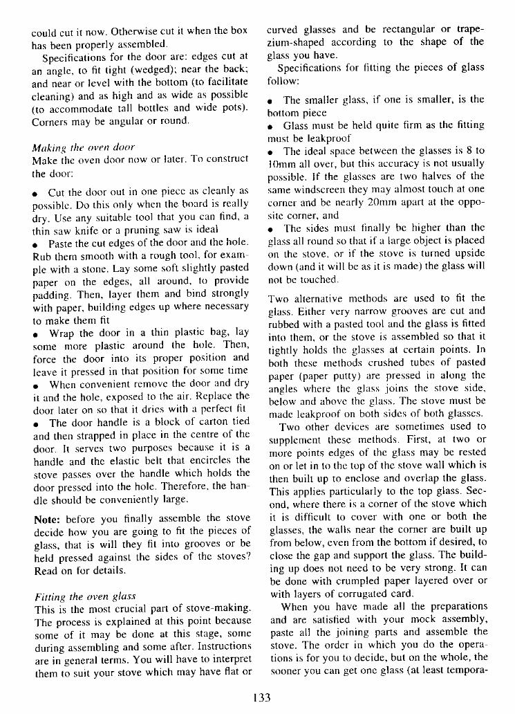
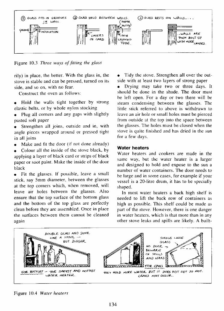
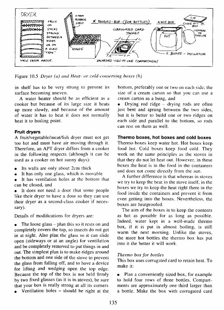
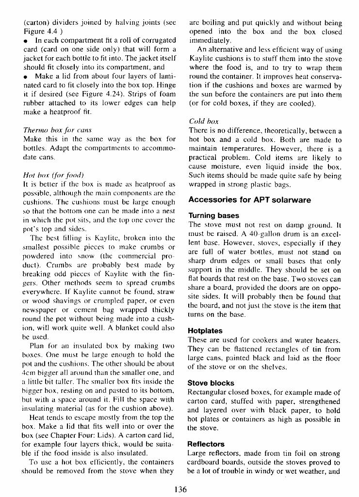
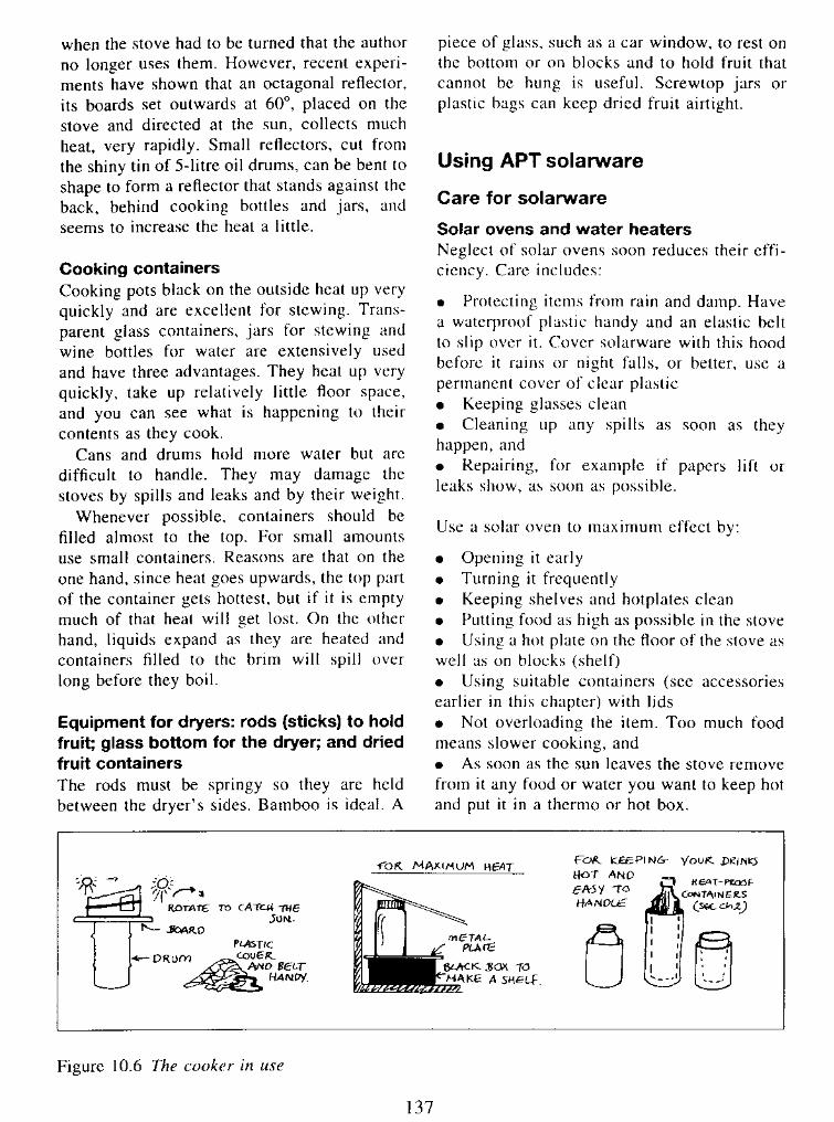
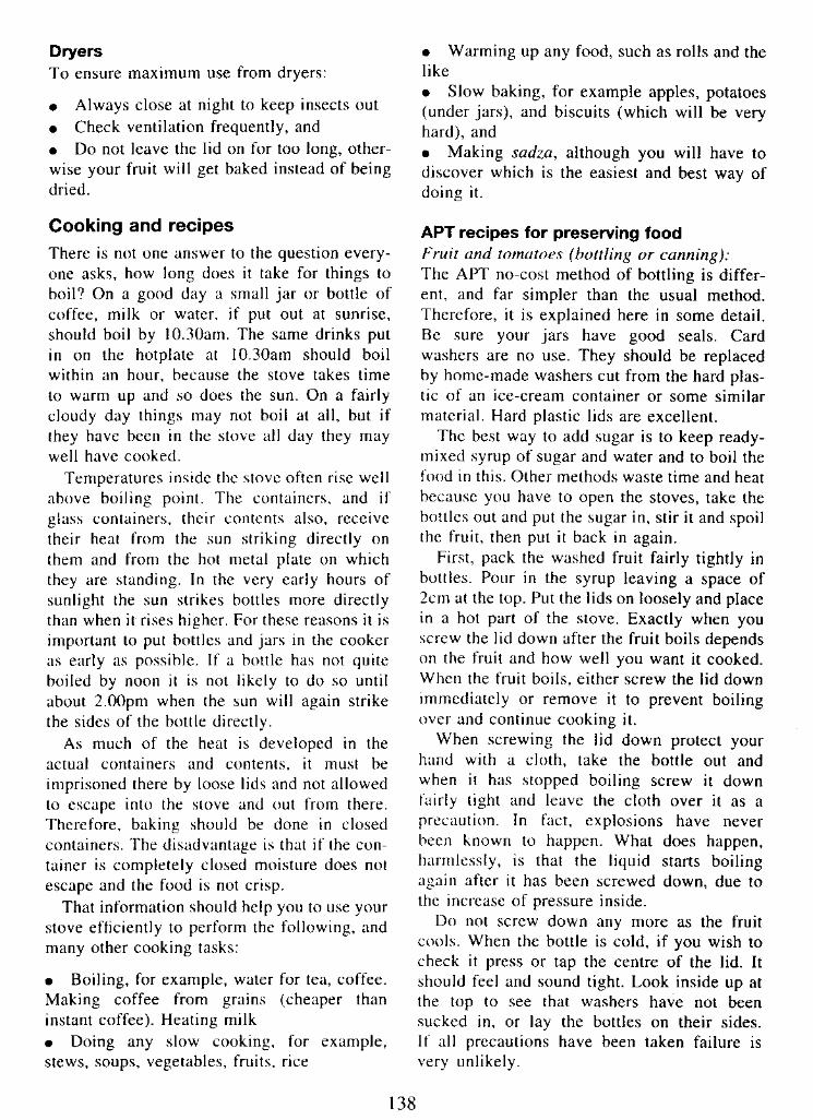
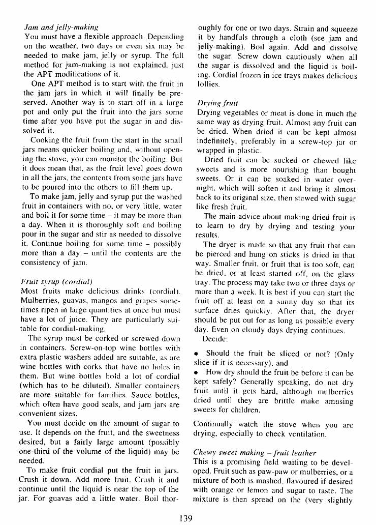
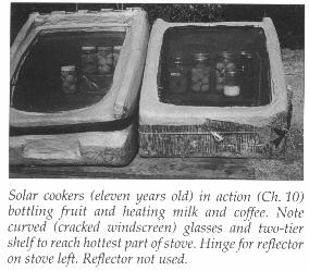
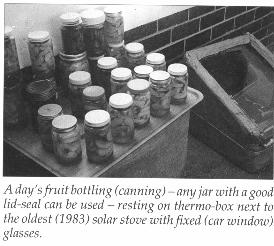
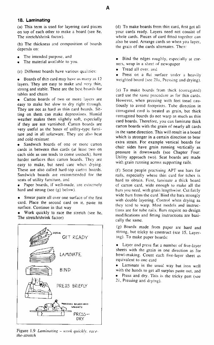
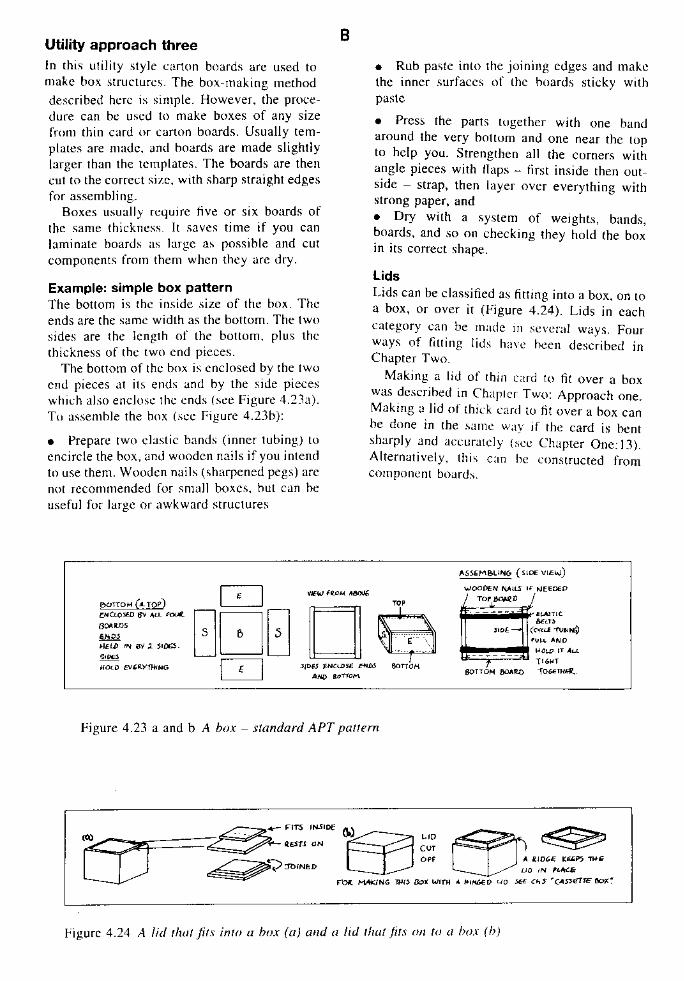
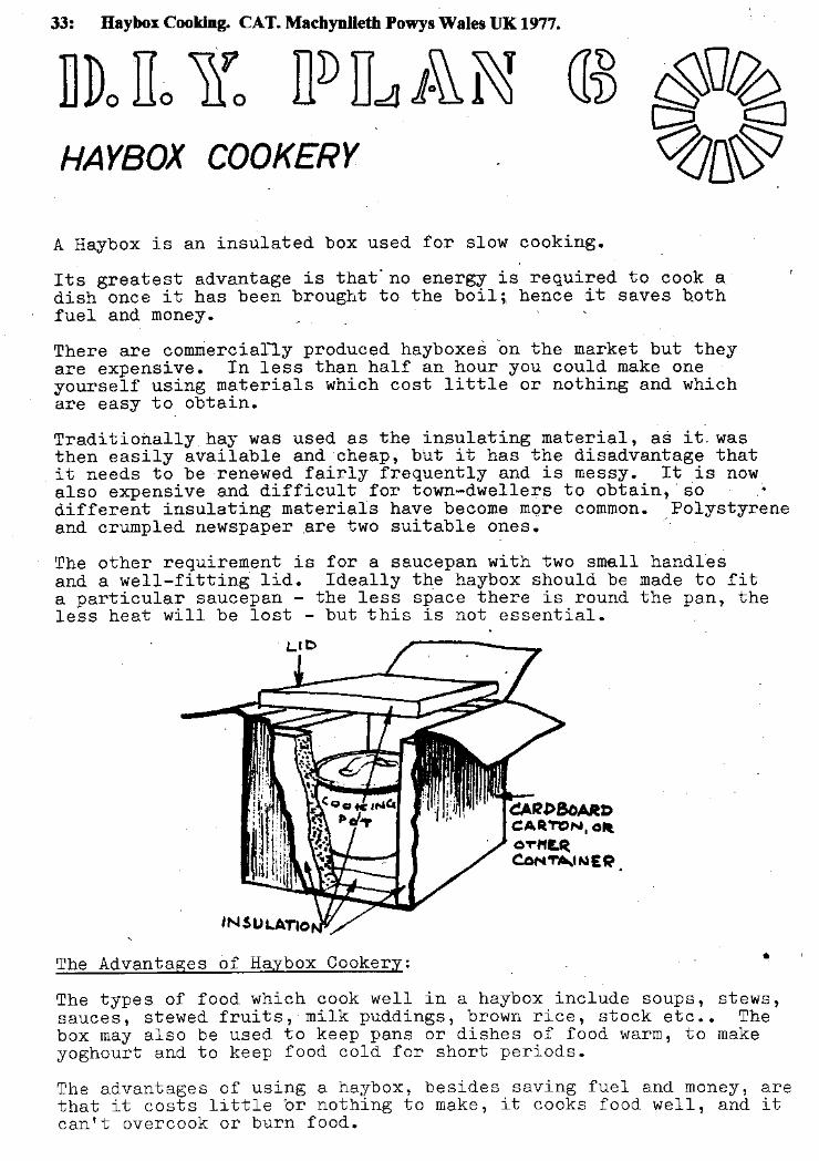
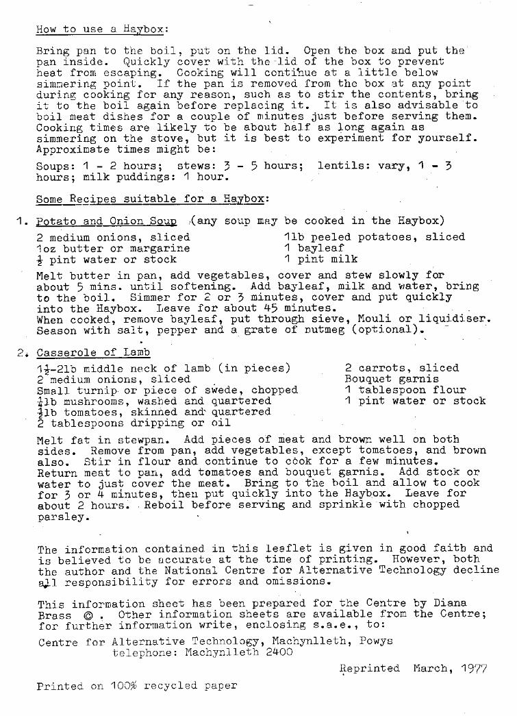
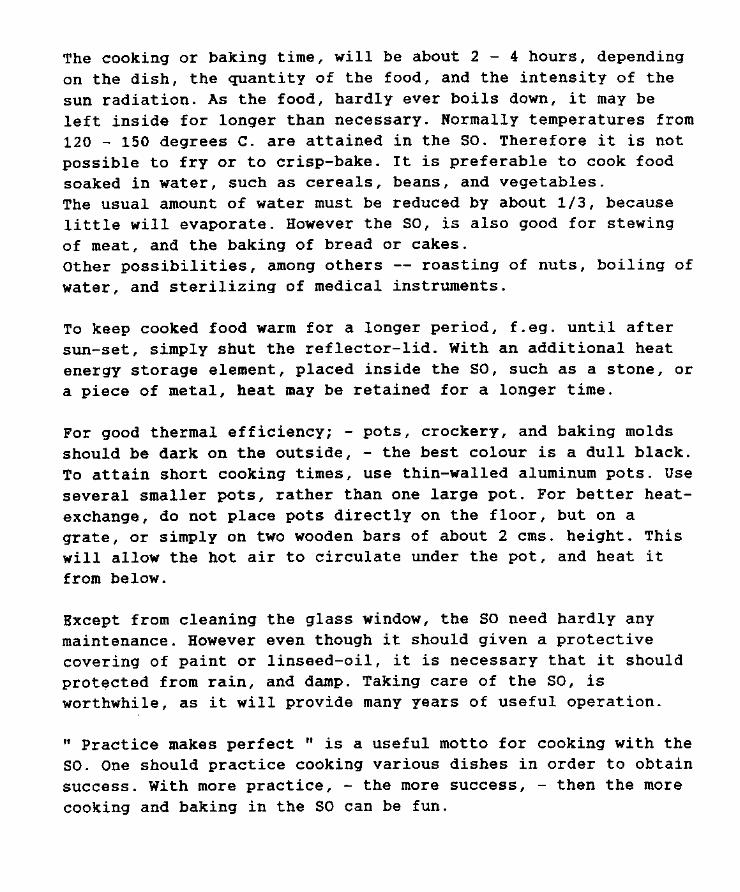
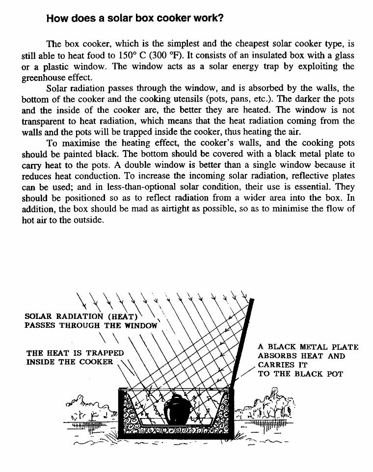
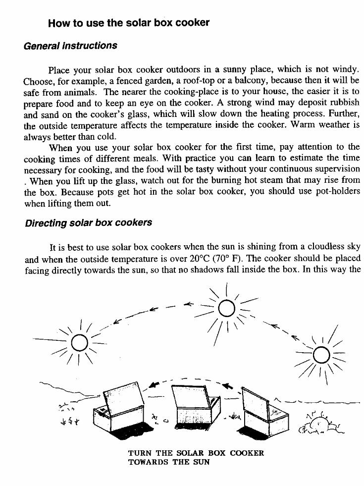
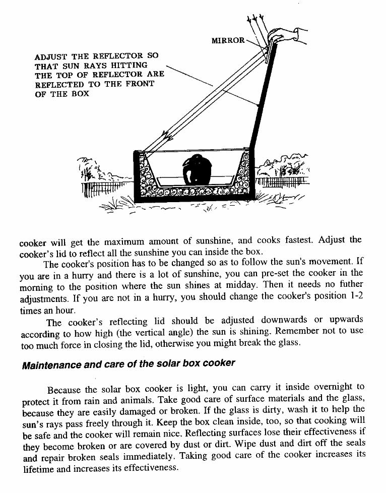
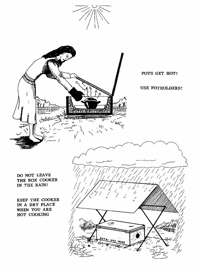
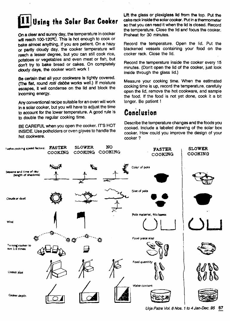
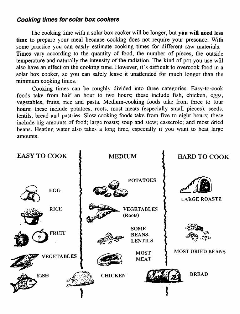
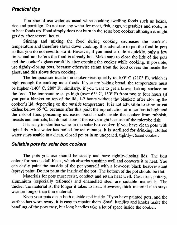
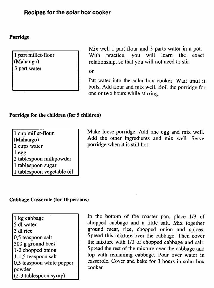
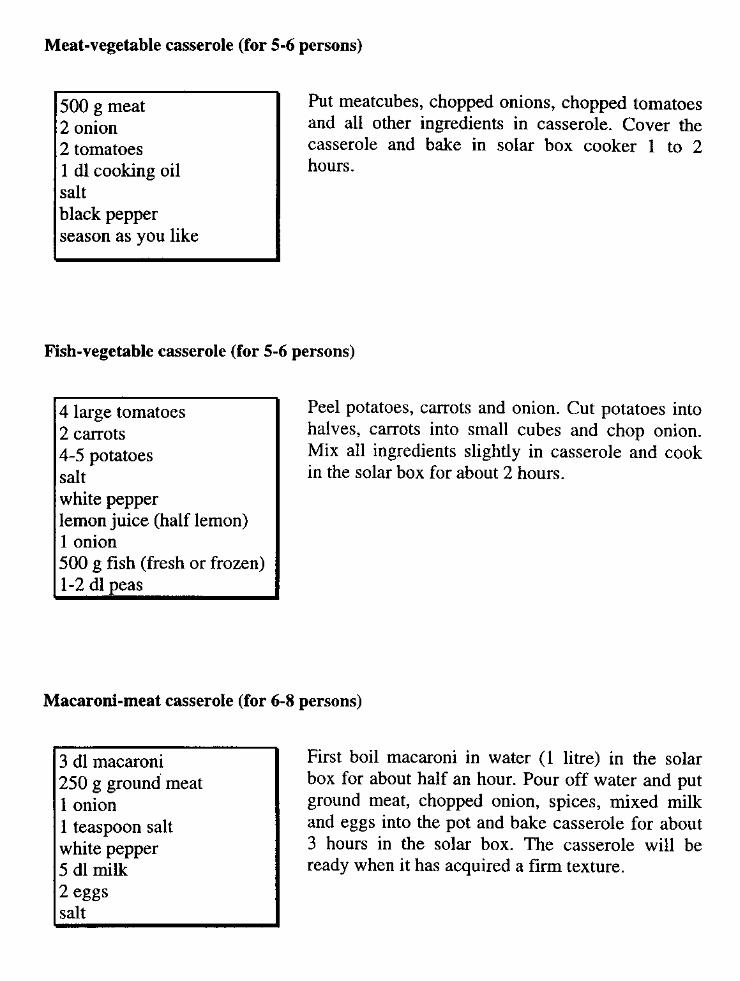
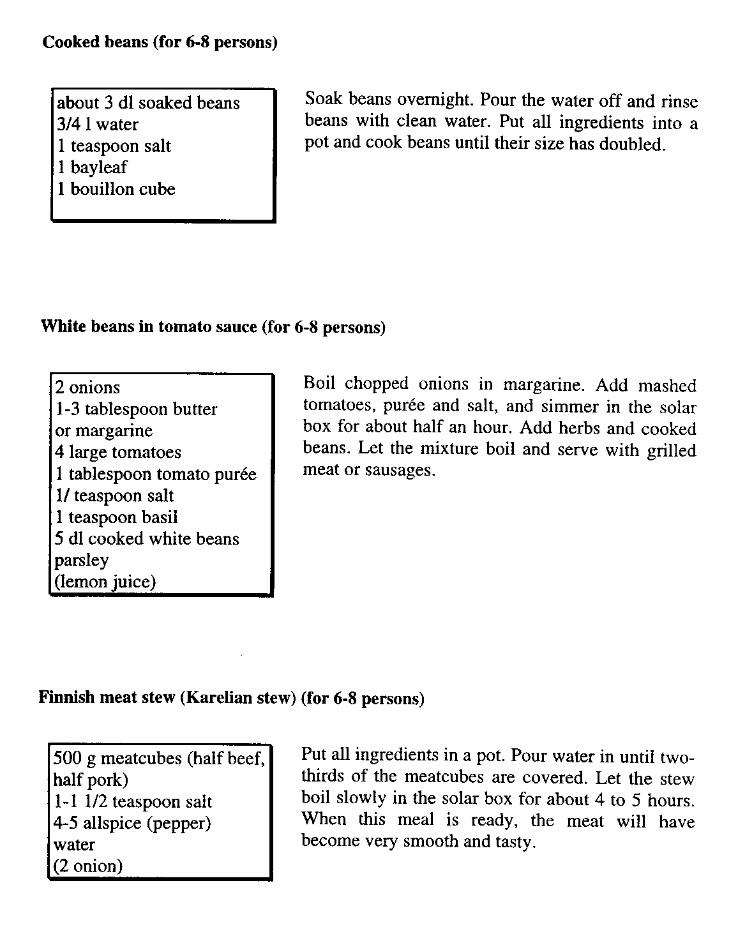
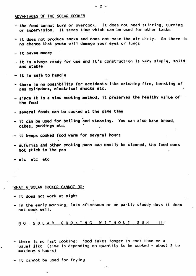
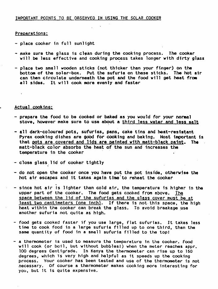
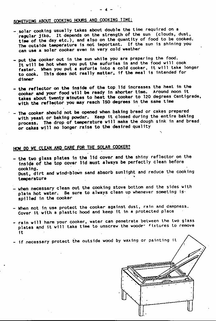
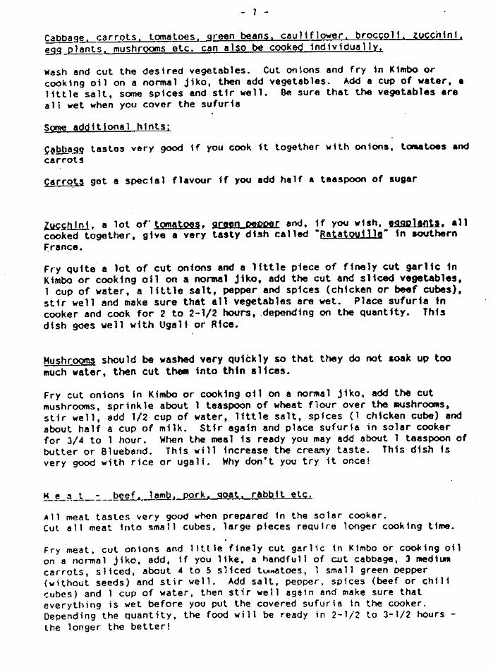
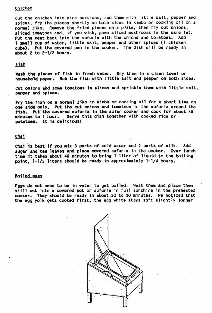
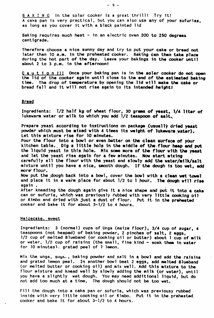
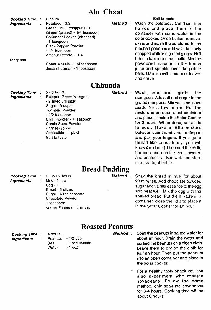
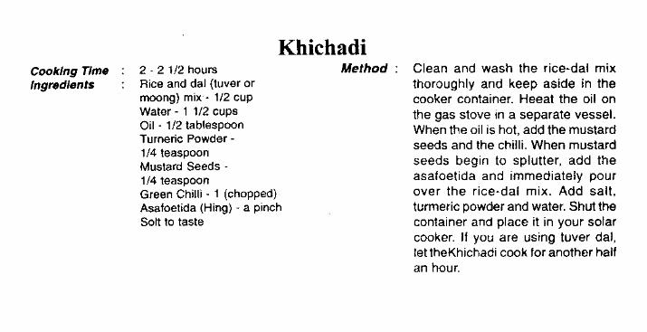
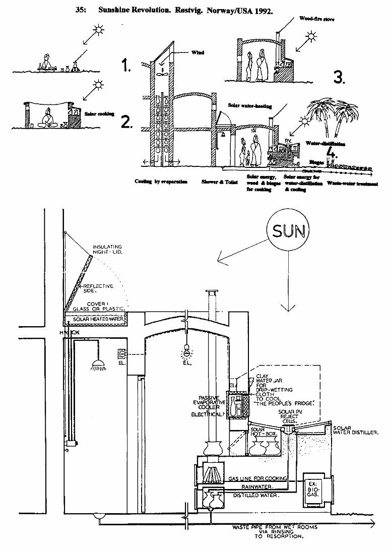
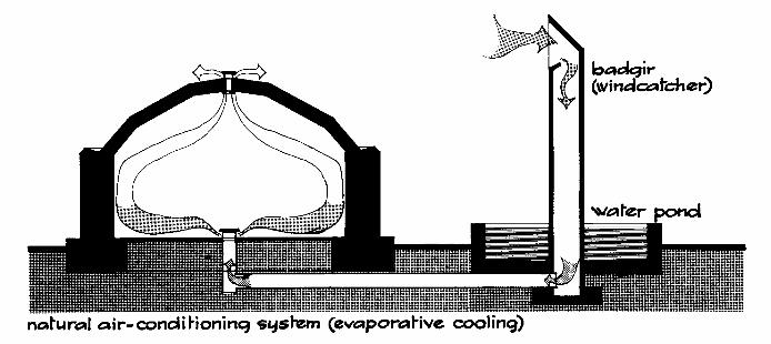
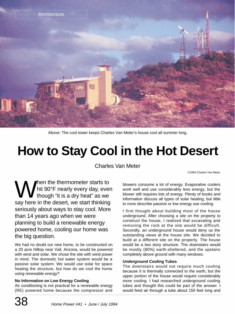
38 Home Power #41 • June / July 1994
Architecture
When the thermometer starts tohit 90°F nearly every day, eventhough “it is a dry heat” as we
say here in the desert, we start thinkingseriously about ways to stay cool. Morethan 14 years ago when we wereplanning to build a renewable energypowered home, cooling our home wasthe big question.We had no doubt our new home, to be constructed ona 20 acre hilltop near Vail, Arizona, would be poweredwith wind and solar. We chose the site with wind powerin mind. The domestic hot water system would be apassive solar system. We would use solar for spaceheating the structure, but how do we cool the homeusing renewable energy?
No Information on Low Energy CoolingAir conditioning is not practical for a renewable energy(RE) powered home because the compressor and
blowers consume a lot of energy. Evaporative coolerswork well and use considerably less energy, but theblower still requires lots of energy. Plenty of books andinformation discuss all types of solar heating, but littleto none describe passive or low energy use cooling.
I first thought about building most of the houseunderground. After choosing a site on the property toconstruct the house, I realized that excavating andremoving the rock at the site would be difficult.Secondly, an underground house would deny us theoutstanding views at the house site. We decided tobuild at a different site on the property. The housewould be a two story structure. The downstairs wouldbe mostly (80%) earth-sheltered, and the upstairscompletely above ground with many windows.
Underground Cooling TubesThe downstairs would not require much coolingbecause it is thermally connected to the earth, but theupper portion of the house would require considerablymore cooling. I had researched underground coolingtubes and thought this could be part of the answer. Iwould feed air through a tube about 150 feet long and
How to Stay Cool in the Hot DesertCharles Van Meter
©1994 Charles Van Meter
Above: The cool tower keeps Charles Van Meter’s house cool all summer long.
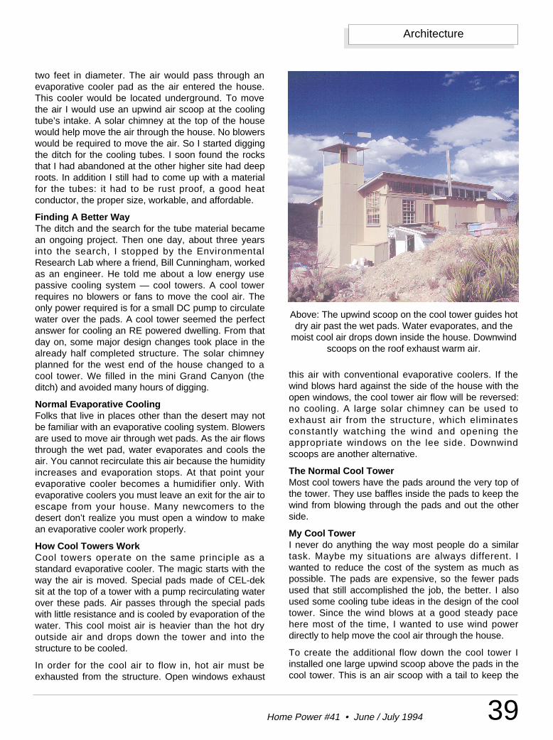
39Home Power #41 • June / July 1994
Architecture
two feet in diameter. The air would pass through anevaporative cooler pad as the air entered the house.This cooler would be located underground. To movethe air I would use an upwind air scoop at the coolingtube’s intake. A solar chimney at the top of the housewould help move the air through the house. No blowerswould be required to move the air. So I started diggingthe ditch for the cooling tubes. I soon found the rocksthat I had abandoned at the other higher site had deeproots. In addition I still had to come up with a materialfor the tubes: it had to be rust proof, a good heatconductor, the proper size, workable, and affordable.
Finding A Better WayThe ditch and the search for the tube material becamean ongoing project. Then one day, about three yearsinto the search, I stopped by the EnvironmentalResearch Lab where a friend, Bill Cunningham, workedas an engineer. He told me about a low energy usepassive cooling system — cool towers. A cool towerrequires no blowers or fans to move the cool air. Theonly power required is for a small DC pump to circulatewater over the pads. A cool tower seemed the perfectanswer for cooling an RE powered dwelling. From thatday on, some major design changes took place in thealready half completed structure. The solar chimneyplanned for the west end of the house changed to acool tower. We filled in the mini Grand Canyon (theditch) and avoided many hours of digging.
Normal Evaporative CoolingFolks that live in places other than the desert may notbe familiar with an evaporative cooling system. Blowersare used to move air through wet pads. As the air flowsthrough the wet pad, water evaporates and cools theair. You cannot recirculate this air because the humidityincreases and evaporation stops. At that point yourevaporative cooler becomes a humidifier only. Withevaporative coolers you must leave an exit for the air toescape from your house. Many newcomers to thedesert don’t realize you must open a window to makean evaporative cooler work properly.
How Cool Towers WorkCool towers operate on the same principle as astandard evaporative cooler. The magic starts with theway the air is moved. Special pads made of CEL-deksit at the top of a tower with a pump recirculating waterover these pads. Air passes through the special padswith little resistance and is cooled by evaporation of thewater. This cool moist air is heavier than the hot dryoutside air and drops down the tower and into thestructure to be cooled.
In order for the cool air to flow in, hot air must beexhausted from the structure. Open windows exhaust
this air with conventional evaporative coolers. If thewind blows hard against the side of the house with theopen windows, the cool tower air flow will be reversed:no cooling. A large solar chimney can be used toexhaust air from the structure, which eliminatesconstantly watching the wind and opening theappropriate windows on the lee side. Downwindscoops are another alternative.
The Normal Cool TowerMost cool towers have the pads around the very top ofthe tower. They use baffles inside the pads to keep thewind from blowing through the pads and out the otherside.
My Cool TowerI never do anything the way most people do a similartask. Maybe my situations are always different. Iwanted to reduce the cost of the system as much aspossible. The pads are expensive, so the fewer padsused that still accomplished the job, the better. I alsoused some cooling tube ideas in the design of the cooltower. Since the wind blows at a good steady pacehere most of the time, I wanted to use wind powerdirectly to help move the cool air through the house.
To create the additional flow down the cool tower Iinstalled one large upwind scoop above the pads in thecool tower. This is an air scoop with a tail to keep the
Above: The upwind scoop on the cool tower guides hotdry air past the wet pads. Water evaporates, and the
moist cool air drops down inside the house. Downwindscoops on the roof exhaust warm air.
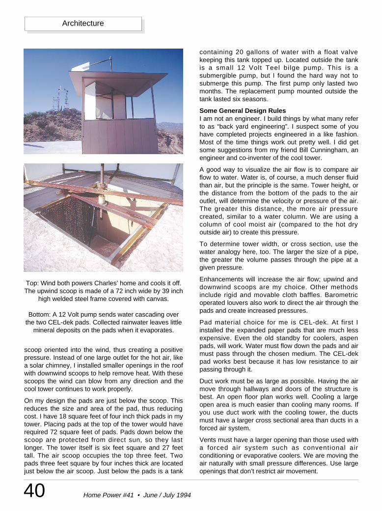
40 Home Power #41 • June / July 1994
Architecture
scoop oriented into the wind, thus creating a positivepressure. Instead of one large outlet for the hot air, likea solar chimney, I installed smaller openings in the roofwith downwind scoops to help remove heat. With thesescoops the wind can blow from any direction and thecool tower continues to work properly.
On my design the pads are just below the scoop. Thisreduces the size and area of the pad, thus reducingcost. I have 18 square feet of four inch thick pads in mytower. Placing pads at the top of the tower would haverequired 72 square feet of pads. Pads down below thescoop are protected from direct sun, so they lastlonger. The tower itself is six feet square and 27 feettall. The air scoop occupies the top three feet. Twopads three feet square by four inches thick are locatedjust below the air scoop. Just below the pads is a tank
containing 20 gallons of water with a float valvekeeping this tank topped up. Located outside the tankis a small 12 Volt Teel bilge pump. This is asubmergible pump, but I found the hard way not tosubmerge this pump. The first pump only lasted twomonths. The replacement pump mounted outside thetank lasted six seasons.
Some General Design RulesI am not an engineer. I build things by what many referto as “back yard engineering”. I suspect some of youhave completed projects engineered in a like fashion.Most of the time things work out pretty well. I did getsome suggestions from my friend Bill Cunningham, anengineer and co-inventer of the cool tower.
A good way to visualize the air flow is to compare airflow to water. Water is, of course, a much denser fluidthan air, but the principle is the same. Tower height, orthe distance from the bottom of the pads to the airoutlet, will determine the velocity or pressure of the air.The greater this distance, the more air pressurecreated, similar to a water column. We are using acolumn of cool moist air (compared to the hot dryoutside air) to create this pressure.
To determine tower width, or cross section, use thewater analogy here, too. The larger the size of a pipe,the greater the volume passes through the pipe at agiven pressure.
Enhancements will increase the air flow; upwind anddownwind scoops are my choice. Other methodsinclude rigid and movable cloth baffles. Barometricoperated louvers also work to direct the air through thepads and create increased pressures.
Pad material choice for me is CEL-dek. At first Iinstalled the expanded paper pads that are much lessexpensive. Even the old standby for coolers, aspenpads, will work. Water must flow down the pads and airmust pass through the chosen medium. The CEL-dekpad works best because it has low resistance to airpassing through it.
Duct work must be as large as possible. Having the airmove through hallways and doors of the structure isbest. An open floor plan works well. Cooling a largeopen area is much easier than cooling many rooms. Ifyou use duct work with the cooling tower, the ductsmust have a larger cross sectional area than ducts in aforced air system.
Vents must have a larger opening than those used witha forced air system such as conventional airconditioning or evaporative coolers. We are moving theair naturally with small pressure differences. Use largeopenings that don’t restrict air movement.
Top: Wind both powers Charles’ home and cools it off.The upwind scoop is made of a 72 inch wide by 39 inch
high welded steel frame covered with canvas.
Bottom: A 12 Volt pump sends water cascading overthe two CEL-dek pads. Collected rainwater leaves little
mineral deposits on the pads when it evaporates.
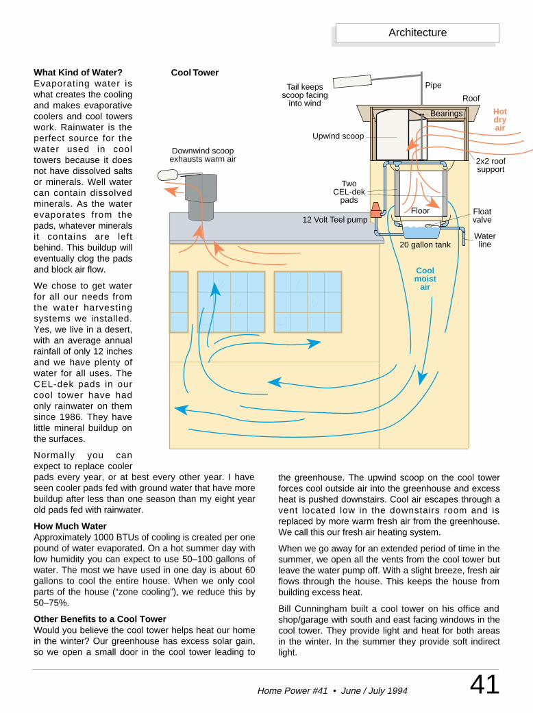
41Home Power #41 • June / July 1994
Architecture
What Kind of Water?Evaporating water iswhat creates the coolingand makes evaporativecoolers and cool towerswork. Rainwater is theperfect source for thewater used in cooltowers because it doesnot have dissolved saltsor minerals. Well watercan contain dissolvedminerals. As the waterevaporates from thepads, whatever mineralsit contains are leftbehind. This buildup willeventually clog the padsand block air flow.
We chose to get waterfor all our needs fromthe water harvestingsystems we installed.Yes, we live in a desert,with an average annualrainfall of only 12 inchesand we have plenty ofwater for all uses. TheCEL-dek pads in ourcool tower have hadonly rainwater on themsince 1986. They havelittle mineral buildup onthe surfaces.
Normally you canexpect to replace coolerpads every year, or at best every other year. I haveseen cooler pads fed with ground water that have morebuildup after less than one season than my eight yearold pads fed with rainwater.
How Much WaterApproximately 1000 BTUs of cooling is created per onepound of water evaporated. On a hot summer day withlow humidity you can expect to use 50–100 gallons ofwater. The most we have used in one day is about 60gallons to cool the entire house. When we only coolparts of the house (“zone cooling”), we reduce this by50–75%.
Other Benefits to a Cool TowerWould you believe the cool tower helps heat our homein the winter? Our greenhouse has excess solar gain,so we open a small door in the cool tower leading to
the greenhouse. The upwind scoop on the cool towerforces cool outside air into the greenhouse and excessheat is pushed downstairs. Cool air escapes through avent located low in the downstairs room and isreplaced by more warm fresh air from the greenhouse.We call this our fresh air heating system.
When we go away for an extended period of time in thesummer, we open all the vents from the cool tower butleave the water pump off. With a slight breeze, fresh airflows through the house. This keeps the house frombuilding excess heat.
Bill Cunningham built a cool tower on his office andshop/garage with south and east facing windows in thecool tower. They provide light and heat for both areasin the winter. In the summer they provide soft indirectlight.
Upwind scoop
Hot dry air
Cool moist
air
Two CEL-dek
pads
12 Volt Teel pump
Tail keeps scoop facing
into wind
2x2 roof support
Roof
Pipe
Bearings
Floor
20 gallon tank
Float valve
Water line
Downwind scoop exhausts warm air
Cool Tower
42 Home Power #41 • June / July 1994
Architecture
ConclusionWe started construction on the cooltower in the spring of 1985 andused it that summer. The systemhas undergone several changes.The first upwind scoop was metal,and not a good choice unless youuse aluminum. Our scoop now hasa framework of steel covered withheavy canvas. The cool tower hasbeen in operation nine years. On ahot dry day (100°F with 10%humidity) the air coming from thetower is 65–70°F. We are verypleased with the performance. I amsaving the finishing touches for a110°F day — that’s when workinginside the cool tower is quiteenjoyable!
AccessAuthor: Charles Van Meter,Alternative Research Center Inc.,PO Box 383, Vail, AZ 85641-0383 •602-647-7220
Custom Cool Tower & Solar Design,Bill Cunningham, 5085 SMelpomene Way, Tucson, AZ85747 • 602-885-7925
Suppliers of CEL-dek: MuntersCorporation, Mrs. Pat Thomas, Box6428, Fort Myers, FL 33911 • 1-800-446-6868
12 Volt Teel bilge pump: Stock #1P811, W.W. Grainger Inc., localphone book
GYRO-KITE
™
“The Little Wind-powered Gyroplane You Can Fly Like A Kite”Gyro-Kite™ is a revolutionary new concept in kites. “The little wind-powered gyroplane you can fly like a kite”. Takes off and landsvertically, hovers and flies sideways and backwards. No batteries,motor, rubberbands, or springs. Inexpensive, replaceable wood rotorblades. Rotor dia. 19 3/4”. Nylon Body, Steel Landing Gear, OiliteBearing. One String control.
Only $ 24.95Allow four weeks delivery • Dealer inquiry invited
1-800-99-ROTORGyro-Kite™ International4606 Milton St. Box HP, Shoreview, MN 55126
Pat. Pending © 1993 ALL RIGHTS RESERVED
IT’S HERE...
* APT Power Centers
Visa & MCAccepted
ALTERNATIVE SOLAR PRODUCTS(800) 229-7652 • FAX (909) 308-2388
27420 Jefferson, Suite 104B, Temecula, CA 92590Visit our Solar and Wind Power Showroom in Southern California
Ourprices aredown and
dirty. I can bea real “electric
hog” withthese newproducts!
* Solarex VLX-53Value Line Modules
* Trace 4000 WattSinewave Inverter
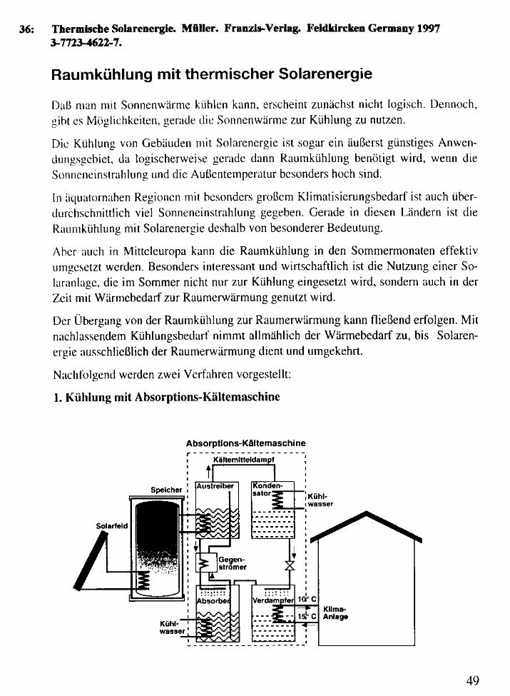
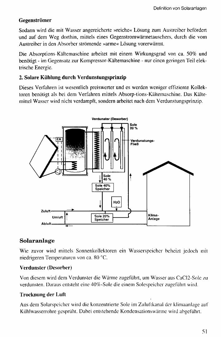
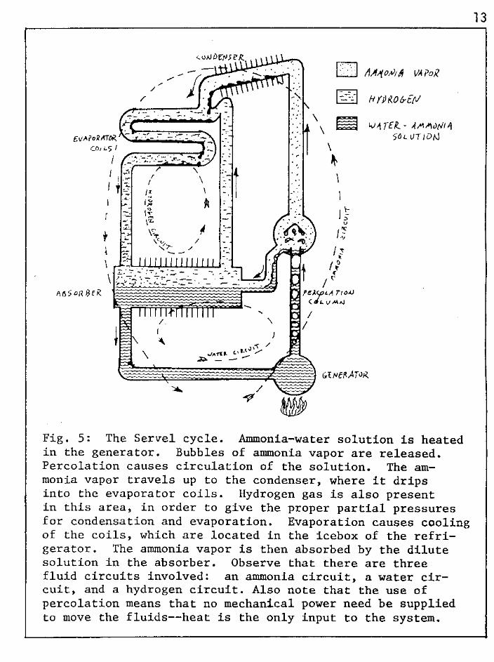
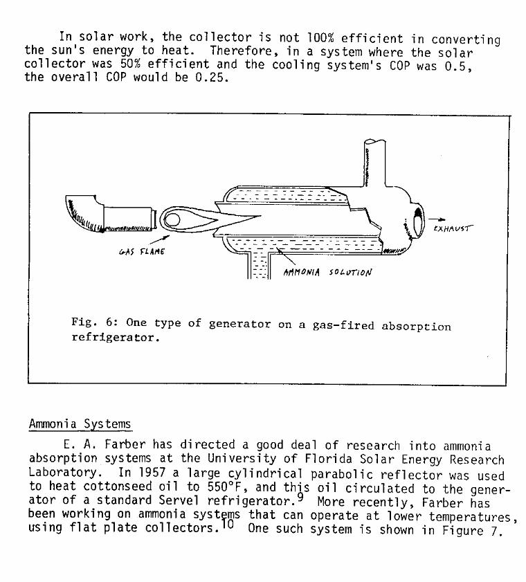
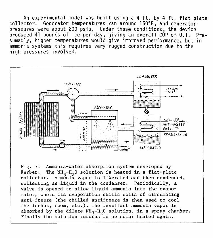
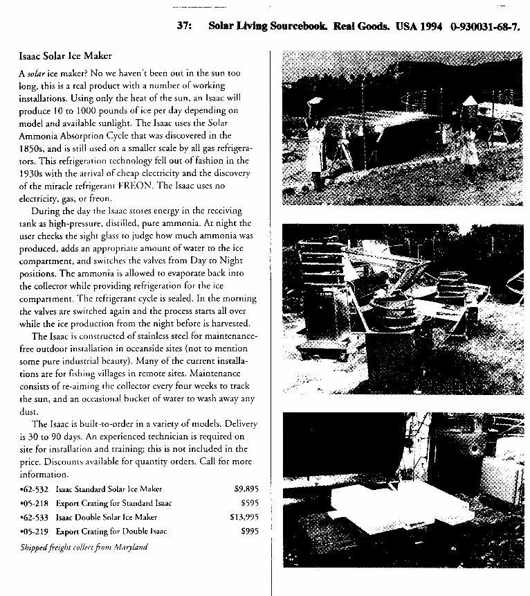
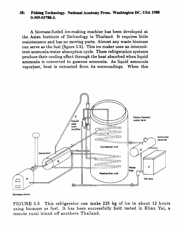
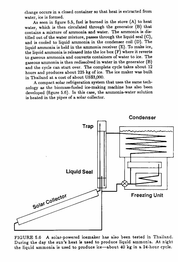
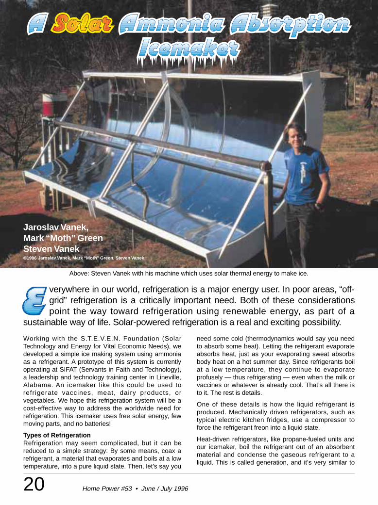
E verywhere in our world, refrigeration is a major energy user. In poor areas, “off-grid” refrigeration is a critically important need. Both of these considerationspoint the way toward refrigeration using renewable energy, as part of a
sustainable way of life. Solar-powered refrigeration is a real and exciting possibility.
20 Home Power #53 • June / July 1996
Working with the S.T.E.V.E.N. Foundation (SolarTechnology and Energy for Vital Economic Needs), wedeveloped a simple ice making system using ammoniaas a refrigerant. A prototype of this system is currentlyoperating at SIFAT (Servants in Faith and Technology),a leadership and technology training center in Lineville,Alabama. An icemaker like this could be used torefrigerate vaccines, meat, dairy products, orvegetables. We hope this refrigeration system will be acost-effective way to address the worldwide need forrefrigeration. This icemaker uses free solar energy, fewmoving parts, and no batteries!
Types of RefrigerationRefrigeration may seem complicated, but it can bereduced to a simple strategy: By some means, coax arefrigerant, a material that evaporates and boils at a lowtemperature, into a pure liquid state. Then, let’s say you
need some cold (thermodynamics would say you needto absorb some heat). Letting the refrigerant evaporateabsorbs heat, just as your evaporating sweat absorbsbody heat on a hot summer day. Since refrigerants boilat a low temperature, they continue to evaporateprofusely — thus refrigerating — even when the milk orvaccines or whatever is already cool. That’s all there isto it. The rest is details.
One of these details is how the liquid refrigerant isproduced. Mechanically driven refrigerators, such astypical electric kitchen fridges, use a compressor toforce the refrigerant freon into a liquid state.
Heat-driven refrigerators, like propane-fueled units andour icemaker, boil the refrigerant out of an absorbentmaterial and condense the gaseous refrigerant to aliquid. This is called generation, and it’s very similar to
Above: Steven Vanek with his machine which uses solar thermal energy to make ice.
Jaroslav Vanek,Mark “Moth” GreenSteven Vanek©1996 Jaroslav Vanek, Mark “Moth” Green, Steven Vanek

21Home Power #53 • June / July 1996
Refrigeration
the way grain alcohol is purified through distillation.After the generation process, the liquefied refrigerantevaporates as it is re-absorbed by an absorbentmaterial. Absorbent materials are materials which havea strong chemical attraction for the refrigerant.
This process can be clarified using an analogy: it is likesqueezing out a sponge (the absorbent material)soaked with the refrigerant. Instead of actuallysqueezing the sponge, heat is used. Then, when thesponge cools and becomes “thirsty” again, it reabsorbsthe refrigerant in gas form. As it is absorbed, therefrigerant evaporates and absorbsheat: refrigeration!
In an ammonia absorptionrefrigerator, ammonia is therefrigerant. Continuously cyclingammonia refrigerators, such ascommercial propane-fueledsystems, generally use water as theabsorbent, and provide continuouscooling action.
The S.T.E.V.E.N. Solar IcemakerWe call our current design anicemaker. It’s not a true refrigeratorbecause the refrigeration happensin intermittent cycles, which fit thecycle of available solar energy fromday to night. Intermittent absorptionsystems can use a salt instead ofwater as the absorbent material.This has distinct advantages in thatthe salt doesn’t evaporate with thewater during heating, a problemencountered with water as theabsorber.
Our intermittent absorption solar icemaker uses calciumchloride salt as the absorber and pure ammonia as therefrigerant. These materials are comparatively easy toobtain. Ammonia is available on order from gassuppliers and calcium chloride can be bought in thewinter as an ice melter.
The plumbing of the icemaker can be divided into threeparts: a generator for heating the salt-ammonia mixture,a condenser coil, and an evaporator, where distilledammonia collects during generation. Ammonia flowsback and forth between the generator and evaporator.
Parabolic Trough Collectors:7 X 20 feet total collecting area
West – East
Generator Pipe:filled with calcium-chloride-ammonia mixture
Condenser Coil:in water bath
Evaporator / Collecting Tank:in insulated ice-making Box
Condenser Coil: 1/4" pipeshaped by wrapping around form
Valves: stainless steel1/4" or 1/8" pipe thread
3" Black Iron Cap1/4" nipple & coupling
tapped & welded in
Collector Suspended by U-boltinto 1-1/2" angle iron bracket
Condenser Tank:half of a 55 gallon drum
Icemaker Box:scrap chest freezeror wood/metal box
Storage Tank:welded from 1/4" steel plate
& 3" pipe
Union: 1/4" stainless steel or black iron(optional union at base of condenser coil)
Plumbing Detail All plumbing is ungalvanized steel (black iron) unless indicated
Layout of the Solar Thermal Icemaker
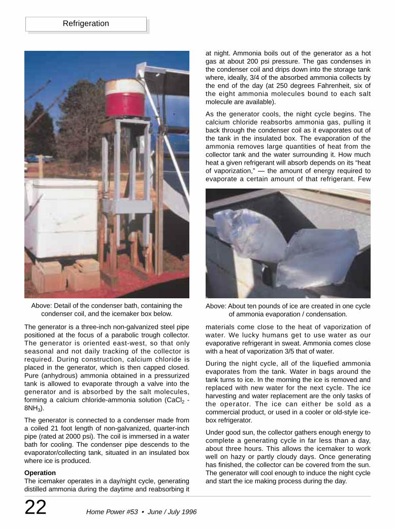
22 Home Power #53 • June / July 1996
Refrigeration
The generator is a three-inch non-galvanized steel pipepositioned at the focus of a parabolic trough collector.The generator is oriented east-west, so that onlyseasonal and not daily tracking of the collector isrequired. During construction, calcium chloride isplaced in the generator, which is then capped closed.Pure (anhydrous) ammonia obtained in a pressurizedtank is allowed to evaporate through a valve into thegenerator and is absorbed by the salt molecules,forming a calcium chloride-ammonia solution (CaCl2 -8NH3).
The generator is connected to a condenser made froma coiled 21 foot length of non-galvanized, quarter-inchpipe (rated at 2000 psi). The coil is immersed in a waterbath for cooling. The condenser pipe descends to theevaporator/collecting tank, situated in an insulated boxwhere ice is produced.
OperationThe icemaker operates in a day/night cycle, generatingdistilled ammonia during the daytime and reabsorbing it
at night. Ammonia boils out of the generator as a hotgas at about 200 psi pressure. The gas condenses inthe condenser coil and drips down into the storage tankwhere, ideally, 3/4 of the absorbed ammonia collects bythe end of the day (at 250 degrees Fahrenheit, six ofthe eight ammonia molecules bound to each saltmolecule are available).
As the generator cools, the night cycle begins. Thecalcium chloride reabsorbs ammonia gas, pulling itback through the condenser coil as it evaporates out ofthe tank in the insulated box. The evaporation of theammonia removes large quantities of heat from thecollector tank and the water surrounding it. How muchheat a given refrigerant will absorb depends on its “heatof vaporization,” — the amount of energy required toevaporate a certain amount of that refrigerant. Few
Above: Detail of the condenser bath, containing thecondenser coil, and the icemaker box below.
Above: About ten pounds of ice are created in one cycleof ammonia evaporation / condensation.
materials come close to the heat of vaporization ofwater. We lucky humans get to use water as ourevaporative refrigerant in sweat. Ammonia comes closewith a heat of vaporization 3/5 that of water.
During the night cycle, all of the liquefied ammoniaevaporates from the tank. Water in bags around thetank turns to ice. In the morning the ice is removed andreplaced with new water for the next cycle. The iceharvesting and water replacement are the only tasks ofthe operator. The ice can either be sold as acommercial product, or used in a cooler or old-style ice-box refrigerator.
Under good sun, the collector gathers enough energy tocomplete a generating cycle in far less than a day,about three hours. This allows the icemaker to workwell on hazy or partly cloudy days. Once generatinghas finished, the collector can be covered from the sun.The generator will cool enough to induce the night cycleand start the ice making process during the day.
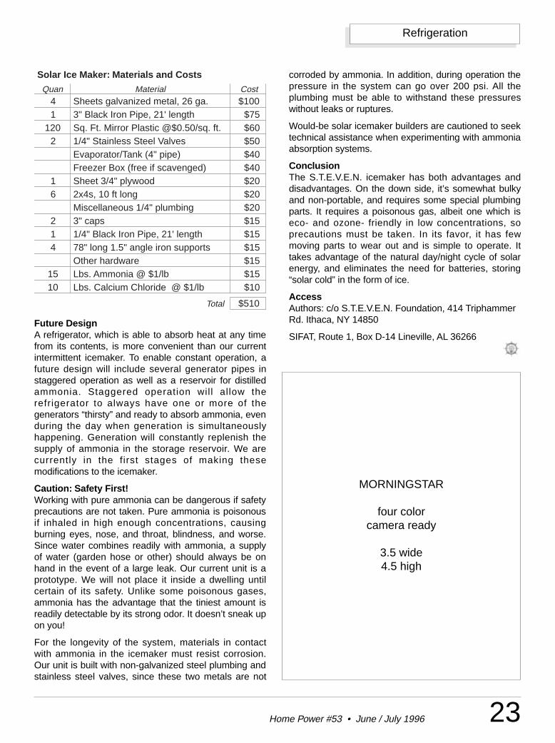
23Home Power #53 • June / July 1996
Refrigeration
Future DesignA refrigerator, which is able to absorb heat at any timefrom its contents, is more convenient than our currentintermittent icemaker. To enable constant operation, afuture design will include several generator pipes instaggered operation as well as a reservoir for distilledammonia. Staggered operation will allow therefrigerator to always have one or more of thegenerators “thirsty” and ready to absorb ammonia, evenduring the day when generation is simultaneouslyhappening. Generation will constantly replenish thesupply of ammonia in the storage reservoir. We arecurrently in the first stages of making thesemodifications to the icemaker.
Caution: Safety First!Working with pure ammonia can be dangerous if safetyprecautions are not taken. Pure ammonia is poisonousif inhaled in high enough concentrations, causingburning eyes, nose, and throat, blindness, and worse.Since water combines readily with ammonia, a supplyof water (garden hose or other) should always be onhand in the event of a large leak. Our current unit is aprototype. We will not place it inside a dwelling untilcertain of its safety. Unlike some poisonous gases,ammonia has the advantage that the tiniest amount isreadily detectable by its strong odor. It doesn’t sneak upon you!
For the longevity of the system, materials in contactwith ammonia in the icemaker must resist corrosion.Our unit is built with non-galvanized steel plumbing andstainless steel valves, since these two metals are not
corroded by ammonia. In addition, during operation thepressure in the system can go over 200 psi. All theplumbing must be able to withstand these pressureswithout leaks or ruptures.
Would-be solar icemaker builders are cautioned to seektechnical assistance when experimenting with ammoniaabsorption systems.
ConclusionThe S.T.E.V.E.N. icemaker has both advantages anddisadvantages. On the down side, it’s somewhat bulkyand non-portable, and requires some special plumbingparts. It requires a poisonous gas, albeit one which iseco- and ozone- friendly in low concentrations, soprecautions must be taken. In its favor, it has fewmoving parts to wear out and is simple to operate. Ittakes advantage of the natural day/night cycle of solarenergy, and eliminates the need for batteries, storing“solar cold” in the form of ice.
AccessAuthors: c/o S.T.E.V.E.N. Foundation, 414 TriphammerRd. Ithaca, NY 14850
SIFAT, Route 1, Box D-14 Lineville, AL 36266
Solar Ice Maker: Materials and Costs
Quan Material Cost4 Sheets galvanized metal, 26 ga. $1001 3" Black Iron Pipe, 21' length $75
120 Sq. Ft. Mirror Plastic @$0.50/sq. ft. $602 1/4" Stainless Steel Valves $50
Evaporator/Tank (4" pipe) $40Freezer Box (free if scavenged) $40
1 Sheet 3/4" plywood $206 2x4s, 10 ft long $20
Miscellaneous 1/4" plumbing $202 3" caps $151 1/4" Black Iron Pipe, 21' length $154 78" long 1.5" angle iron supports $15
Other hardware $1515 Lbs. Ammonia @ $1/lb $1510 Lbs. Calcium Chloride @ $1/lb $10
Total $510
MORNINGSTAR
four colorcamera ready
3.5 wide4.5 high
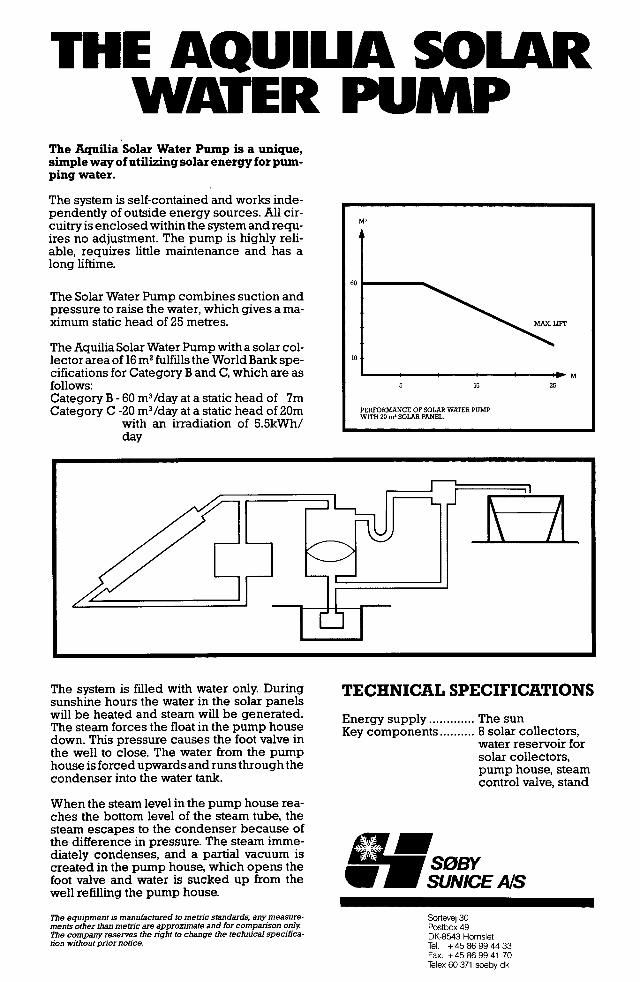
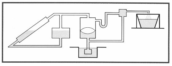
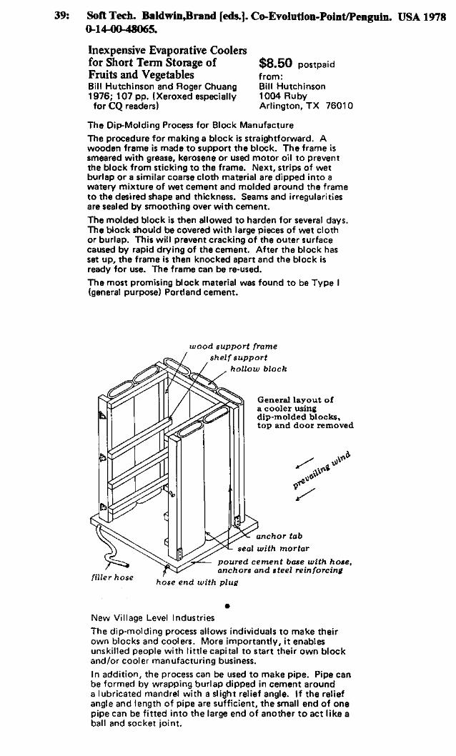
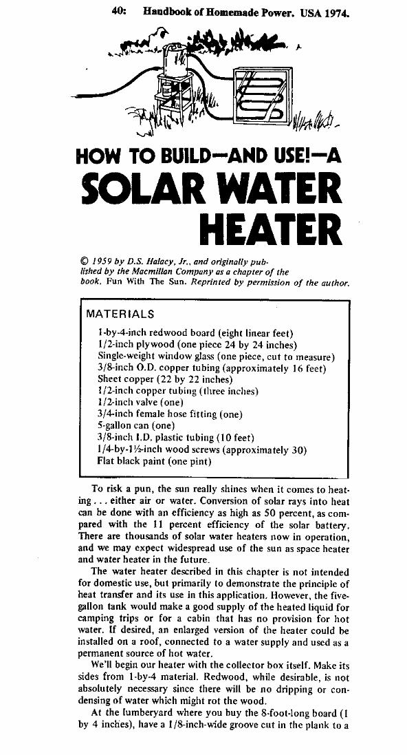
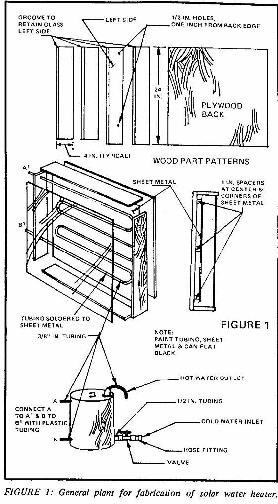
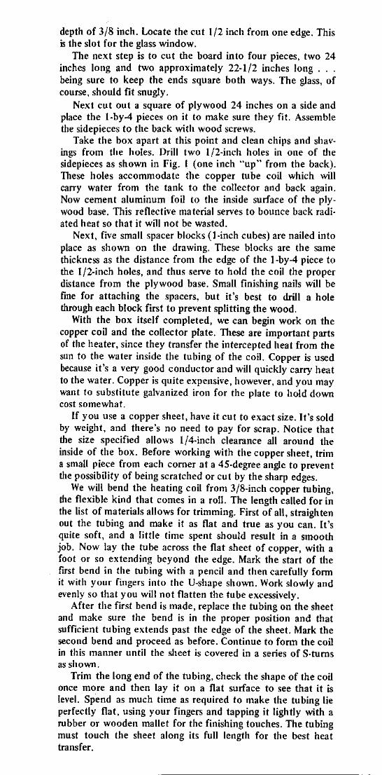
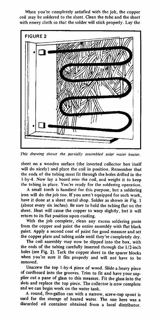

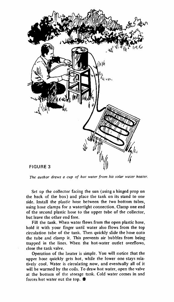
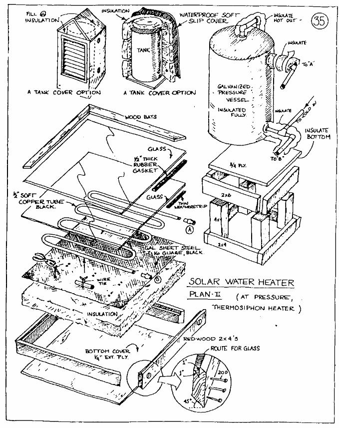
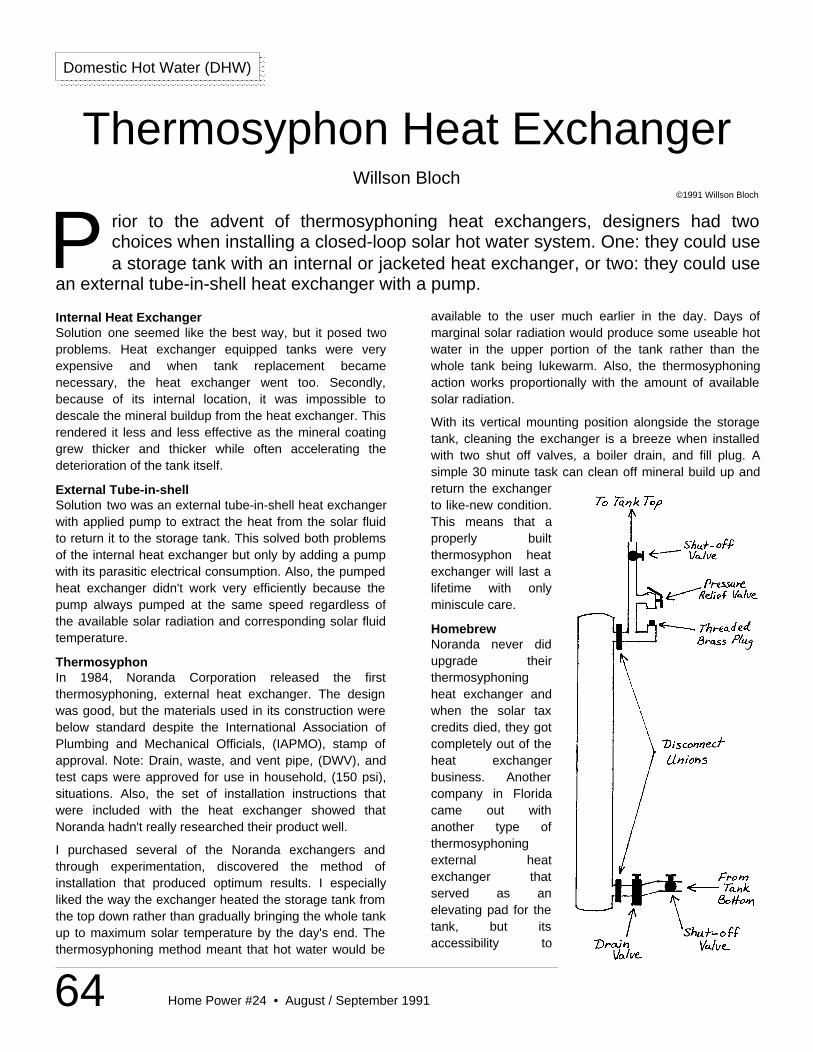
64 Home Power #24 • August / September 1991
available to the user much earlier in the day. Days ofmarginal solar radiation would produce some useable hotwater in the upper portion of the tank rather than thewhole tank being lukewarm. Also, the thermosyphoningaction works proportionally with the amount of availablesolar radiation.
With its vertical mounting position alongside the storagetank, cleaning the exchanger is a breeze when installedwith two shut off valves, a boiler drain, and fill plug. Asimple 30 minute task can clean off mineral build up andreturn the exchangerto like-new condition.This means that aproperly builtthermosyphon heatexchanger will last alifetime with onlyminiscule care.
HomebrewNoranda never didupgrade theirthermosyphoningheat exchanger andwhen the solar taxcredits died, they gotcompletely out of theheat exchangerbusiness. Anothercompany in Floridacame out withanother type ofthermosyphoningexternal heatexchanger thatserved as anelevating pad for thetank, but itsaccessibility to
Domestic Hot Water (DHW)
rior to the advent of thermosyphoning heat exchangers, designers had twochoices when installing a closed-loop solar hot water system. One: they could usea storage tank with an internal or jacketed heat exchanger, or two: they could use
an external tube-in-shell heat exchanger with a pump.P
Thermosyphon Heat ExchangerWillson Bloch
©1991 Willson Bloch
Internal Heat ExchangerSolution one seemed like the best way, but it posed twoproblems. Heat exchanger equipped tanks were veryexpensive and when tank replacement becamenecessary, the heat exchanger went too. Secondly,because of its internal location, it was impossible todescale the mineral buildup from the heat exchanger. Thisrendered it less and less effective as the mineral coatinggrew thicker and thicker while often accelerating thedeterioration of the tank itself.
External Tube-in-shellSolution two was an external tube-in-shell heat exchangerwith applied pump to extract the heat from the solar fluidto return it to the storage tank. This solved both problemsof the internal heat exchanger but only by adding a pumpwith its parasitic electrical consumption. Also, the pumpedheat exchanger didn't work very efficiently because thepump always pumped at the same speed regardless ofthe available solar radiation and corresponding solar fluidtemperature.
ThermosyphonIn 1984, Noranda Corporation released the firstthermosyphoning, external heat exchanger. The designwas good, but the materials used in its construction werebelow standard despite the International Association ofPlumbing and Mechanical Officials, (IAPMO), stamp ofapproval. Note: Drain, waste, and vent pipe, (DWV), andtest caps were approved for use in household, (150 psi),situations. Also, the set of installation instructions thatwere included with the heat exchanger showed thatNoranda hadn't really researched their product well.
I purchased several of the Noranda exchangers andthrough experimentation, discovered the method ofinstallation that produced optimum results. I especiallyliked the way the exchanger heated the storage tank fromthe top down rather than gradually bringing the whole tankup to maximum solar temperature by the day's end. Thethermosyphoning method meant that hot water would be
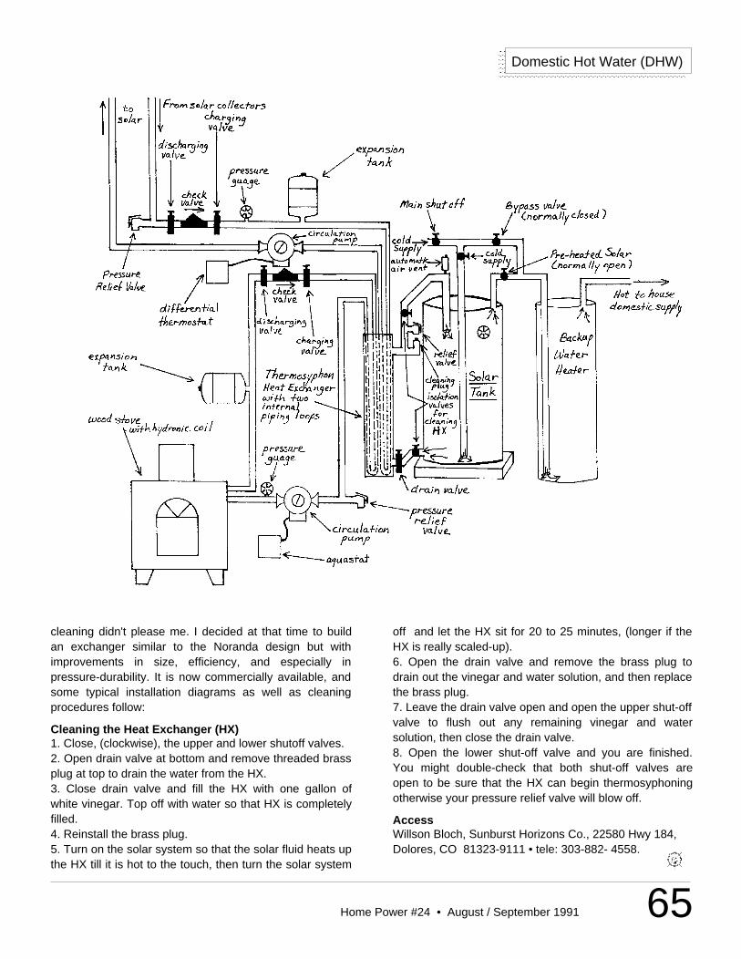
65Home Power #24 • August / September 1991
Domestic Hot Water (DHW)
cleaning didn't please me. I decided at that time to buildan exchanger similar to the Noranda design but withimprovements in size, efficiency, and especially inpressure-durability. It is now commercially available, andsome typical installation diagrams as well as cleaningprocedures follow:
Cleaning the Heat Exchanger (HX)1. Close, (clockwise), the upper and lower shutoff valves.2. Open drain valve at bottom and remove threaded brassplug at top to drain the water from the HX.3. Close drain valve and fill the HX with one gallon ofwhite vinegar. Top off with water so that HX is completelyfilled.4. Reinstall the brass plug.5. Turn on the solar system so that the solar fluid heats upthe HX till it is hot to the touch, then turn the solar system
off and let the HX sit for 20 to 25 minutes, (longer if theHX is really scaled-up).6. Open the drain valve and remove the brass plug todrain out the vinegar and water solution, and then replacethe brass plug.7. Leave the drain valve open and open the upper shut-offvalve to flush out any remaining vinegar and watersolution, then close the drain valve.8. Open the lower shut-off valve and you are finished.You might double-check that both shut-off valves areopen to be sure that the HX can begin thermosyphoningotherwise your pressure relief valve will blow off.
AccessWillson Bloch, Sunburst Horizons Co., 22580 Hwy 184,Dolores, CO 81323-9111 • tele: 303-882- 4558.
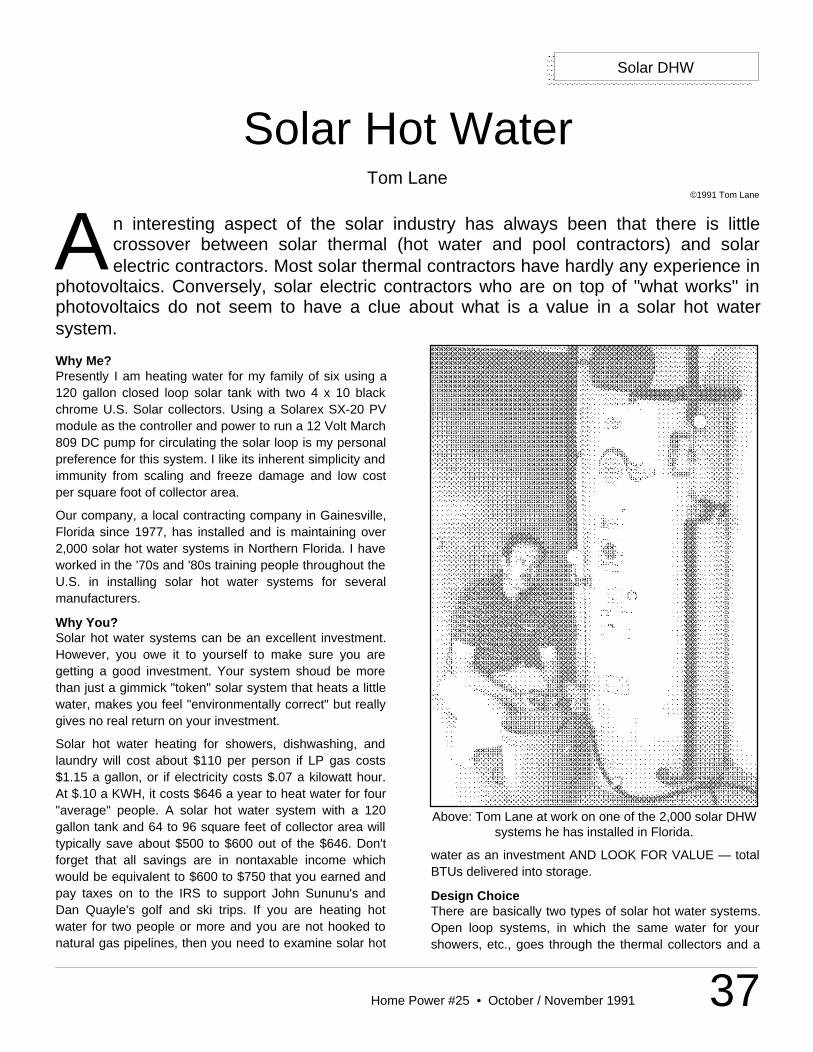
37Home Power #25 • October / November 1991
n interesting aspect of the solar industry has always been that there is littlecrossover between solar thermal (hot water and pool contractors) and solarelectric contractors. Most solar thermal contractors have hardly any experience in
photovoltaics. Conversely, solar electric contractors who are on top of "what works" inphotovoltaics do not seem to have a clue about what is a value in a solar hot watersystem.
A
Solar Hot WaterTom Lane
©1991 Tom Lane
Why Me?Presently I am heating water for my family of six using a120 gallon closed loop solar tank with two 4 x 10 blackchrome U.S. Solar collectors. Using a Solarex SX-20 PVmodule as the controller and power to run a 12 Volt March809 DC pump for circulating the solar loop is my personalpreference for this system. I like its inherent simplicity andimmunity from scaling and freeze damage and low costper square foot of collector area.
Our company, a local contracting company in Gainesville,Florida since 1977, has installed and is maintaining over2,000 solar hot water systems in Northern Florida. I haveworked in the '70s and '80s training people throughout theU.S. in installing solar hot water systems for severalmanufacturers.
Why You?Solar hot water systems can be an excellent investment.However, you owe it to yourself to make sure you aregetting a good investment. Your system shoud be morethan just a gimmick "token" solar system that heats a littlewater, makes you feel "environmentally correct" but reallygives no real return on your investment.
Solar hot water heating for showers, dishwashing, andlaundry will cost about $110 per person if LP gas costs$1.15 a gallon, or if electricity costs $.07 a kilowatt hour.At $.10 a KWH, it costs $646 a year to heat water for four"average" people. A solar hot water system with a 120gallon tank and 64 to 96 square feet of collector area willtypically save about $500 to $600 out of the $646. Don'tforget that all savings are in nontaxable income whichwould be equivalent to $600 to $750 that you earned andpay taxes on to the IRS to support John Sununu's andDan Quayle's golf and ski trips. If you are heating hotwater for two people or more and you are not hooked tonatural gas pipelines, then you need to examine solar hot
Solar DHW
Above: Tom Lane at work on one of the 2,000 solar DHWsystems he has installed in Florida.
water as an investment AND LOOK FOR VALUE — totalBTUs delivered into storage.
Design ChoiceThere are basically two types of solar hot water systems.Open loop systems, in which the same water for yourshowers, etc., goes through the thermal collectors and a
38 Home Power #25 • October / November 1991
Solar DHW
closed loop system. These typically uses a glycolantifreeze or a drain back reservoir and an external heatexchanger or a heat exchanger built into the tank. Themain criterion for these systems is how hard the freezingweather is where you live.
Open loop systems should be used where you get nofreezes. If your local area can grow mangoes, avocados,or citrus groves without danger of being damaged by amild freeze, then you are in an area that can directlycirculate water through the collectors. If not, use a closedloop system or one day you will have a visit from Mr.Murphy. Since 95% of the U.S.'s population, includingCentral Florida and most of Southern California andArizona are in areas where freezing conditions occur, I willdiscuss my experience with closed loop systems andsolar hot water as an investment.
System SizingThe home owner must make sure he is getting enoughstorage (gallons) in tank size and enough collector area togive him a real return on his investment. Plan on at least20 gallons per person for the first four people and 15gallons for each additional person per day. Solar hotwater tanks typically come in 80, 100, and 120 gallonsizes. The 120 gallon size tank typically costs only $150to $200 more than an 80 gallon tank and the money iswell spent considering you are adding 50% more storagecapacity for a small increase in dollars. Experience inphotovoltaics has obviously taught solar electricalcontractors the value of amp hour capacity in batterystorage whose counter is gallons in storage.
You should have at least 40 square feet of collector areafor the first two family members, then add 12 square feetof collector area for each additional family member, if youlive in the sunbelt. In northern climates, add 14 squarefeet of collector area for each additional family member.Never add more than 64 square feet to an 80 gallon tankor 96 square feet to a 120 gallon tank. Keeping tank sizeat a ratio of 1.25 gallons or more to a 1 square foot ofcollector area will keep the solar system from grosslyoverheating in times of little demand. This assures thatthe collector to storage ratio is efficiently matched.Overheating a hot water tank dramatically decreases itslife span. In Arizona and Southern Florida keep the ratioat least 1.5 gallons to 1 square foot of collector area.
CollectorsThe typical sizes available for flat plate collectors are 4' by8' (32 sq. ft.) and 4' by 10' (40 sq. ft.). The minimumcollector area size worth investing in is one 4' by 10' in aclosed loop system. I strongly suggest two 4' by 8's with at
least an 80 gallon tank for more than three people. Usetwo 4' by 8's, two 4' by 10's, or three 4' by 8's with a 120gallon tank for larger families. Always use thermalcollectors that have ALL copper tubes AND absorberplates for collecting the solar energy, that has a temperedglass cover in front of the absorber plate. NEVER useplastics or fiberglass covers instead of tempered glass orany other material than all copper collector plates forabsorbing the heat. Avoid using evacuated tube collectorsfor heating hot water. It is like hunting rabbits with ahowitzer and can grossly overheat your tank. A 120 gallontank with two 4' by 8' or 4' by 10' collectors is the bestinvestment in dollar per BTU delivered into storage. Avoidsolar systems with less than 40 square feet of collection.They are simply not worth the investment. All solar hotwater heaters capture sunlight to heat water. No matterhow exotic the bottom end of a solar water heater mightbe it cannot create more solar energy than falls on thecollector area. Less than 40 square feet just is not enoughsquare footage in an active open or closed loop system.
ThermosyphonsAvoid external heat exchangers that rely onthermosyphoning of heat. Thermosyphon heatexchangers that work off natural convection will typicallyonly heat the top half of the tank NO MATTER HOW YOUPLUMB THE TANK. External heat exchangers only workwell if you double pump in counter flow, also pumping thewater side of the heat exchanger through the tank andback through the heat exchanger. Another seriousproblem for external heat exchangers is scaling due tohard water. If you have hard water, especially calciumand magnesium, DO NOT use an external heatexchanger unless you have a water conditioner oranti-scale equipment.
Closed LoopFortunately the two largest manufacturers of hot watertanks in the country, Rheem/Rudd, and State Industries,manufacture 82, 100 and 120 gallon solar tanks. Thesehave closed loop heat exchangers that are bonded to thelower half of the solar tank's wall. This enables you to usea closed loop system that avoids the two biggestproblems for solar hot water systems: 1) freezing and 2)scaling due to hard water. It also keeps the systemincredibly simple since you need only one pump to pumpthe heat exchanger side of the system. The Rheem orRudd tanks use copper tubing bonded to the exterior wallof the tank. This enables you to use Prestone II carantifreeze in a 2 gallons of antifreeze to 3 gallons distilledwater mix to run through the heat exchanger. If yourcoldest freeze on record is above 0° F use 1 gallon of
39Home Power #25 • October / November 1991
Solar DHW
antifreeze to 2 gallons distilled water. State Industriesuses an integral single wall heat exchanger that is bondedto the lower half of the outer tank wall. The State heatexchange tank works extremely well, however, you cannotuse ethylene glycol (Prestone II) but must use its cousin,propylene glycol, a non-toxic antifreeze used in all softdrinks and many other foods. The mixture ratio is thesame and the excellent heat transfer properties areidentical for ethylene and propylene glycol. Never usehydrocarbon oils, silicone oil or alcohol as heat transferfluid because they have low specific heat characteristicsand are poor choices for heat transfer fluids. One of yourlocal plumbing distributors can order you a State, Rheem,or Rudd closed loop solar tank. The cost is about $480 foran 80 gallon tank, and $580 for a 120 gallon tank.
Caution on MaterialsThe entire collector loop, all fittings and pipe, must becopper or red brass. All copper couplings must besoldered with 95/5 tin/alimony, or brazed. Never use50/50 lead solder. The antifreeze/distilled water solutionwill not need to be changed for over ten years if you donot mix metals in the collector loop. NEVER usegalvanized pipe, yellow brass, or any plastic pipe or parts.
Pumps & PanelsThe most efficient trouble-free control and pumpingsystem is to use the 12 Volt DC March 809 pump. Thenconnect it to a small solar electric module rated, at aminimum of 1.2 Amps to a maximum of 2 Amps under fullsun conditions (typically a 14 to 20 Watt PV module). Thesolar electric module pop-riveted to the side of the framewall of the solar thermal collector will slowly start pumpingat the correct solar intensity at a variable speed.
Solar thermal and solar electric energies are completelydifferent forms of energy from the sun. However, they arealways in the same proportion based on the intensity ofthe sunlight. The choice of a solar electric or PV modulerated 1.2 to 2 Amps matched to the March 809 12 Volt DCpump enables it to provide power to run the pump. It alsoacts as a variable speed controller to start and stop thepump and vary the speed at the correct solar intensity. Asmaller PV module (less than 1.2 Amps) will start too lateand a module bigger than 2 Amps would start too earlyand run too long. Use only a single crystal orpolycrystalline PV module - do NOT use an amorphousPV module. Just connect the positive and negative leadson the March 12 Volt 809 pump with 18 or 16 gaugestranded PVC jacketed wire. This means no sensors tofail, no differential thermostats, (which means it cannotmalfunction and run at the wrong time), no AC power
outages from the utilities. After the hurricane that hitTallahassee, Florida, in 1985, the city lost utility power forseveral days. The solar systems with solar electric pumpswere still providing hot water to their homeowners. Do notlet anyone try to sell you on the obsolete differentialcontrols with sensors and an AC pump. Tell them to sendtheir dinosaurs back to the city dump.
PipeAll lines in the solar loop from the tank to the collectorsand back should be in type L soft and/or hard 3/4" copperpipe. Use hard type L copper around the tank andcollectors and use soft type L coils on the long attic piperuns. Insulate the lines with 3/4" thick elastomericinsulation (trade name Rubatex or Armaflex) available atair conditioning and heating distributors. Do NOT usepolyethylene rigid pipe insulation! All exterior insulationexposed to sunlight must be protected from UV light. Oneway to do this is by encasing the insulation in PVC orABS plastic pipe, or you can spray it with auto motiveundercoating spray and touch up as needed in the future.
Safe SixBesides the pump, there are only six simple parts in thesystem. 1) A pressure gauge (0-60 PSI) will let you knowyour system has not lost its charge of antifreeze andwater. 2) A solar expansion tank (about the size of abasketball) that allows the solar solution to expand into itas a fluid heats up. 3) A check valve above the pump toprevent reverse flow thermosyphoning at night. 4) Apressure relief valve rated at 75 PSI to 125 PSI (not apressure & temperature relief valve). 5) One boiler drain(hose bib) valve at the lowest point in the system for fillingand draining. 6) A two way ball valve, to create a bypassaround the check valve. This last item, #6, enables you tofill and drain from a single drain hose bib. If you go onvacation you can let the system dump all the heat back tothe roof each night by reverse thermosyphoning if the ballvalve bypass is open. If you vacation for a week or moreand do not have a means to keep your tank fromoverheating , you will definitely shorten the tank's life.
ChargingOnce the system is completely installed it will be time forcharging. All you will need for system charging is twowashing machine hoses, a drill pump for the end of a 3/8"power drill, and a bucket.
Simply add your antifreeze/distilled water mixture, to thebucket as your drill pumps the water into the washingmachine hose connected to the lower boiler drain. If thecollectors are extremely high, cover the collectors,remove the air vent, and slowly fill from the top with a
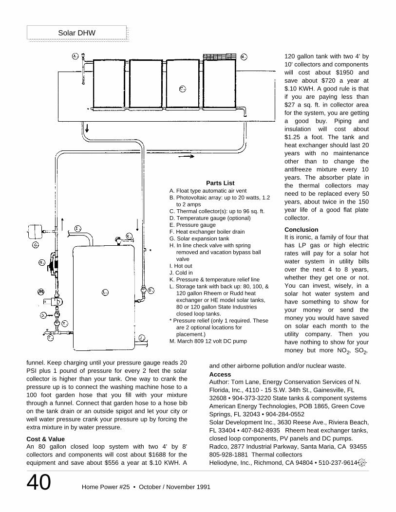
40 Home Power #25 • October / November 1991
and other airborne pollution and/or nuclear waste.AccessAuthor: Tom Lane, Energy Conservation Services of N.Florida, Inc., 4110 - 15 S.W. 34th St., Gainesville, FL32608 • 904-373-3220 State tanks & component systemsAmerican Energy Technologies, POB 1865, Green CoveSprings, FL 32043 • 904-284-0552Solar Development Inc., 3630 Reese Ave., Riviera Beach,FL 33404 • 407-842-8935 Rheem heat exchanger tanks,closed loop components, PV panels and DC pumps.Radco, 2877 Industrial Parkway, Santa Maria, CA 93455805-928-1881 Thermal collectorsHeliodyne, Inc., Richmond, CA 94804 • 510-237-9614
Solar DHW
Parts ListA. Float type automatic air ventB. Photovoltaic array: up to 20 watts, 1.2
to 2 ampsC. Thermal collector(s): up to 96 sq. ft.D. Temperature gauge (optional)E. Pressure gaugeF. Heat exchanger boiler drainG. Solar expansion tankH. In line check valve with spring
removed and vacation bypass ballvalve
I. Hot outJ. Cold inK. Pressure & temperature relief lineL. Storage tank with back up: 80, 100, &
120 gallon Rheem or Rudd heatexchanger or HE model solar tanks,80 or 120 gallon State Industriesclosed loop tanks.
* Pressure relief (only 1 required. Theseare 2 optional locations forplacement.)
M. March 809 12 volt DC pump
120 gallon tank with two 4' by10' collectors and componentswill cost about $1950 andsave about $720 a year at$.10 KWH. A good rule is thatif you are paying less than$27 a sq. ft. in collector areafor the system, you are gettinga good buy. Piping andinsulation will cost about$1.25 a foot. The tank andheat exchanger should last 20years with no maintenanceother than to change theantifreeze mixture every 10years. The absorber plate inthe thermal collectors mayneed to be replaced every 50years, about twice in the 150year life of a good flat platecollector.
ConclusionIt is ironic, a family of four thathas LP gas or high electricrates will pay for a solar hotwater system in utility billsover the next 4 to 8 years,whether they get one or not.You can invest, wisely, in asolar hot water system andhave something to show foryour money or send themoney you would have savedon solar each month to theutility company. Then youhave nothing to show for yourmoney but more NO2, SO2,
funnel. Keep charging until your pressure gauge reads 20PSI plus 1 pound of pressure for every 2 feet the solarcollector is higher than your tank. One way to crank thepressure up is to connect the washing machine hose to a100 foot garden hose that you fill with your mixturethrough a funnel. Connect that garden hose to a hose bibon the tank drain or an outside spigot and let your city orwell water pressure crank your pressure up by forcing theextra mixture in by water pressure.
Cost & ValueAn 80 gallon closed loop system with two 4' by 8'collectors and components will cost about $1688 for theequipment and save about $556 a year at $.10 KWH. A
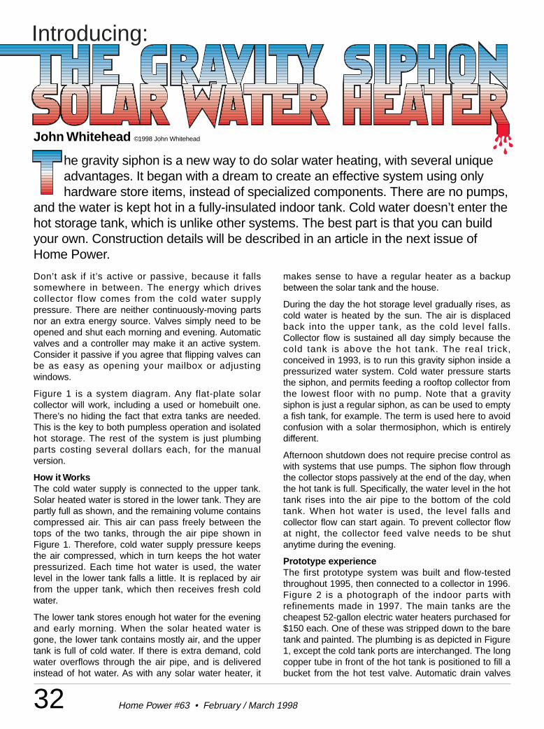
Introducing:
32 Home Power #63 • February / March 1998
Don’t ask if it’s active or passive, because it fallssomewhere in between. The energy which drivescollector flow comes from the cold water supplypressure. There are neither continuously-moving partsnor an extra energy source. Valves simply need to beopened and shut each morning and evening. Automaticvalves and a controller may make it an active system.Consider it passive if you agree that flipping valves canbe as easy as opening your mailbox or adjustingwindows.
Figure 1 is a system diagram. Any flat-plate solarcollector will work, including a used or homebuilt one.There’s no hiding the fact that extra tanks are needed.This is the key to both pumpless operation and isolatedhot storage. The rest of the system is just plumbingparts costing several dollars each, for the manualversion.
How it WorksThe cold water supply is connected to the upper tank.Solar heated water is stored in the lower tank. They arepartly full as shown, and the remaining volume containscompressed air. This air can pass freely between thetops of the two tanks, through the air pipe shown inFigure 1. Therefore, cold water supply pressure keepsthe air compressed, which in turn keeps the hot waterpressurized. Each time hot water is used, the waterlevel in the lower tank falls a little. It is replaced by airfrom the upper tank, which then receives fresh coldwater.
The lower tank stores enough hot water for the eveningand early morning. When the solar heated water isgone, the lower tank contains mostly air, and the uppertank is full of cold water. If there is extra demand, coldwater overflows through the air pipe, and is deliveredinstead of hot water. As with any solar water heater, it
makes sense to have a regular heater as a backupbetween the solar tank and the house.
During the day the hot storage level gradually rises, ascold water is heated by the sun. The air is displacedback into the upper tank, as the cold level falls.Collector flow is sustained all day simply because thecold tank is above the hot tank. The real trick,conceived in 1993, is to run this gravity siphon inside apressurized water system. Cold water pressure startsthe siphon, and permits feeding a rooftop collector fromthe lowest floor with no pump. Note that a gravitysiphon is just a regular siphon, as can be used to emptya fish tank, for example. The term is used here to avoidconfusion with a solar thermosiphon, which is entirelydifferent.
Afternoon shutdown does not require precise control aswith systems that use pumps. The siphon flow throughthe collector stops passively at the end of the day, whenthe hot tank is full. Specifically, the water level in the hottank rises into the air pipe to the bottom of the coldtank. When hot water is used, the level falls andcollector flow can start again. To prevent collector flowat night, the collector feed valve needs to be shutanytime during the evening.
Prototype experienceThe first prototype system was built and flow-testedthroughout 1995, then connected to a collector in 1996.Figure 2 is a photograph of the indoor parts withrefinements made in 1997. The main tanks are thecheapest 52-gallon electric water heaters purchased for$150 each. One of these was stripped down to the baretank and painted. The plumbing is as depicted in Figure1, except the cold tank ports are interchanged. The longcopper tube in front of the hot tank is positioned to fill abucket from the hot test valve. Automatic drain valves
he gravity siphon is a new way to do solar water heating, with several uniqueadvantages. It began with a dream to create an effective system using onlyhardware store items, instead of specialized components. There are no pumps,
and the water is kept hot in a fully-insulated indoor tank. Cold water doesn’t enter thehot storage tank, which is unlike other systems. The best part is that you can buildyour own. Construction details will be described in an article in the next issue ofHome Power.
John Whitehead ©1998 John Whitehead
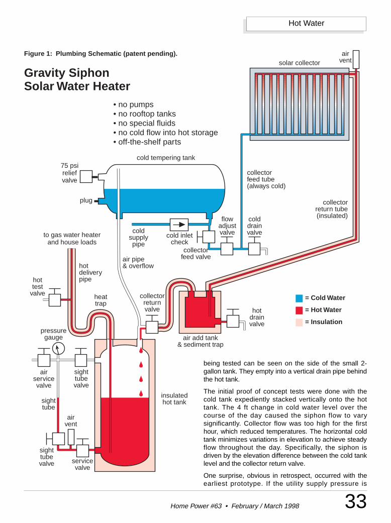
cold inletcheck
hotdeliverypipe
coldsupplypipe
air pipe& overflow
solar collectorair
vent
collectorreturn tube(insulated)
collectorfeed tube(always cold)
cold tempering tank
insulatedhot tanksight
tube
airvent
Gravity SiphonSolar Water Heater
air add tank& sediment trap
hottest
valve
• no pumps• no rooftop tanks• no special fluids• no cold flow into hot storage• off-the-shelf parts
75 psireliefvalve
collectorfeed valve
flowadjustvalve
sighttubevalve service
valve
collectorreturnvalve
plug
heattrap
sighttubevalve
pressuregauge
airservicevalve
hotdrainvalve
colddrainvalveto gas water heater
and house loads
Figure 1: Plumbing Schematic (patent pending).
= Cold Water
= Hot Water
= Insulation
33Home Power #63 • February / March 1998
Hot Water
being tested can be seen on the side of the small 2-gallon tank. They empty into a vertical drain pipe behindthe hot tank.
The initial proof of concept tests were done with thecold tank expediently stacked vertically onto the hottank. The 4 ft change in cold water level over thecourse of the day caused the siphon flow to varysignificantly. Collector flow was too high for the firsthour, which reduced temperatures. The horizontal coldtank minimizes variations in elevation to achieve steadyflow throughout the day. Specifically, the siphon isdriven by the elevation difference between the cold tanklevel and the collector return valve.
One surprise, obvious in retrospect, occurred with theearliest prototype. If the utility supply pressure is
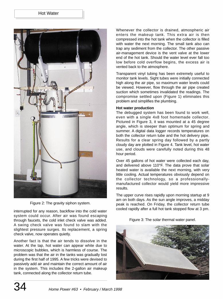
34 Home Power #63 • February / March 1998
Hot Water
interrupted for any reason, backflow into the cold watersystem could occur. After air was found escapingthrough faucets, the cold inlet check valve was added.A swing check valve was found to slam with theslightest pressure surges. Its replacement, a springcheck valve, now operates quietly.
Another fact is that the air tends to dissolve in thewater. At the tap, hot water can appear white due tomicroscopic bubbles, which is harmless of course. Theproblem was that the air in the tanks was gradually lostduring the first half of 1995. A few tricks were devised topassively add air and maintain the correct amount of airin the system. This includes the 2-gallon air makeuptank, connected along the collector return tube.
Whenever the collector is drained, atmospheric airenters the makeup tank. This extra air is thencompressed into the hot tank when the collector is filledwith water the next morning. The small tank also cantrap any sediment from the collector. The other passiveair-management device is the vent valve at the lowerend of the hot tank. Should the water level ever fall toolow before cold overflow begins, the excess air isvented back to the atmosphere.
Transparent vinyl tubing has been extremely useful tomonitor tank levels. Sight tubes were initially connectedhigh along the air pipe, so maximum water levels couldbe viewed. However, flow through the air pipe createdsuction which sometimes invalidated the readings. Thecompromise settled upon (Figure 1) eliminates thisproblem and simplifies the plumbing.
Hot water productionThe debugged system has been found to work well,even with a single 4x8 foot homemade collector.Pictured in Figure 3, it was mounted at a 45 degreeangle, which is steeper than optimum for spring andsummer. A digital data logger records temperatures onboth the collector return tube and the hot delivery pipe.Results for a clear spring day followed by a partlycloudy day are plotted in Figure 4. Tank level, hot wateruse, and clouds were carefully noted during this 48hour period.
Over 45 gallons of hot water were collected each day,and delivered above 110°F. The data prove that solarheated water is available the next morning, with verylittle cooling. Actual temperatures obviously depend onthe collector technology, so a professionally-manufactured collector would yield more impressiveresults.
The upper curve rises rapidly upon morning startup at 9am on both days. As the sun angle improves, a middaypeak is reached. On Friday, the collector return tubecooled rapidly after a full hot tank stopped flow at 3 pm.
Figure 2: The gravity siphon system.
Figure 3: The solar thermal water panel.
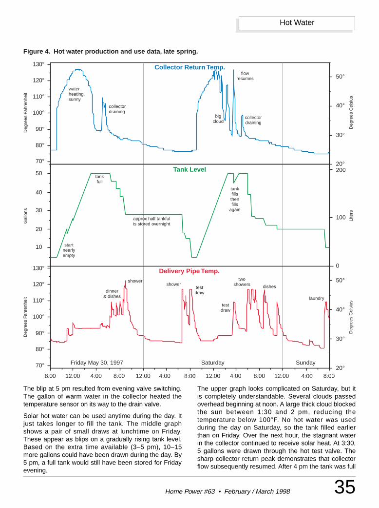
35Home Power #63 • February / March 1998
Hot Water
The blip at 5 pm resulted from evening valve switching.The gallon of warm water in the collector heated thetemperature sensor on its way to the drain valve.
Solar hot water can be used anytime during the day. Itjust takes longer to fill the tank. The middle graphshows a pair of small draws at lunchtime on Friday.These appear as blips on a gradually rising tank level.Based on the extra time available (3–5 pm), 10–15more gallons could have been drawn during the day. By5 pm, a full tank would still have been stored for Fridayevening.
The upper graph looks complicated on Saturday, but itis completely understandable. Several clouds passedoverhead beginning at noon. A large thick cloud blockedthe sun between 1:30 and 2 pm, reducing thetemperature below 100°F. No hot water was usedduring the day on Saturday, so the tank filled earlierthan on Friday. Over the next hour, the stagnant waterin the collector continued to receive solar heat. At 3:30,5 gallons were drawn through the hot test valve. Thesharp collector return peak demonstrates that collectorflow subsequently resumed. After 4 pm the tank was full
20°
30°
40°
50°
70°
80°
90°
110°
120°
100°
130°
70°
80°
90°
110°
120°
100°
130°
20°
30°
40°
50°
10
20
30
40
50
Deg
rees
Cel
sius
8:00 12:00 4:00 8:00 12:00 4:00 8:00 12:00 4:00 8:00 12:00 4:00 8:00
100 Lite
rs
200
0
shower
dinner& dishes
showertestdraw
testdraw
laundry
twoshowers dishes
collectordraining
collectordraining
waterheating,sunny
bigcloud
flowresumes
tankfull
tankfillsthenfills
again
approx half tankfulis stored overnight
startnearlyempty
Figure 4. Hot water production and use data, late spring.
Friday May 30, 1997 Saturday Sunday
Deg
rees
Fah
renh
eit
Deg
rees
Cel
sius
Deg
rees
Fah
renh
eit
Gal
lons
Collector Return Temp.
Tank Level
Delivery Pipe Temp.
36 Home Power #63 • February / March 1998
Hot Water
again. The cloud-cooled collector draining blip appearson schedule at 5 o’clock.
The delivery temperature graph is tricky to interpret,since it is visually tempting to assign meaning to thearea under the curve. Instead, the middle graph shouldbe used to interpret volume information. Hot water useactually occurs over very short periods, after which ittakes almost an hour for the pipe to cool down. Iffaucets are turned on briefly, the pipe sensor may notreach the actual water temperature. This explainsnumerous low temperature peaks on Friday.
Showers and washing machine operation havesufficient duration to show the actual water temperatureon the lower graph. Starting late on Friday, the peaksindicate deliveries consistently above 115°F. Saturdaymorning deliveries were not affected by heat losses tocold water as occurs in conventional solar tanks. Theclouds which rolled through Saturday afternoonreduced the Sunday morning delivery to just below110°F.
Solar hot water was delivered all summer, but it was feltthat a better test would come later in the season. Figure5 shows similar data for two sunny days in October.
Collector flow gradually increases the tank level duringthe day, with temperatures exceeding 125°F in theupper graph. The return tube rapidly cools when thetank becomes full and stops collector flow. Thesubsequent spike each day results from stagnant waterflowing past the sensor on its way to the drain valve.
The tank level falls in steps which correspond to actualhot water use. Each step lines up with its deliverytemperature peak in the lower graph. For example,showers used approximately 10 gallons. On Sundaymorning, the dishwasher used about 5 gallons to wash,then 4 gallons to rinse almost an hour later.
Early on Saturday morning, the tank was nearly full.The hot test valve was used to demonstrate that lots ofsolar heated water can indeed be delivered afterovernight storage. This left the tank ready to receivefreshly heated water. Saturday’s production was over45 gallons, including 5 gallons used for laundry duringthe day.
A greater total volume would have been heated if thetank had started completely empty. This wasdeliberately avoided because a tree shadow reachedthe collector just after 2 pm at this particular time ofyear. No hot water was used during the day on Sunday,so the tank filled a half hour earlier. Flow stopped whilethe collector was fully illuminated, which explains theprecipitous drop in Sunday’s collector returntemperature.
Performance is good considering the time of year,although it should be noted that the 45 degree collectorangle is nearly perfect for this date and latitude.Delivery temperatures were consistently above 115°F,and as high as 125°F on Saturday evening. Veryefficient overnight storage was demonstrated on allthree mornings in Figure 5. Outdoor ambienttemperatures varied from the sixties to the seventiesduring the day. Cold water remained at 70°F duringOctober.
The test data represent actual hot water use by twopeople. The temperatures shown represent deliveries toa backup gas heater. Additional heating was notspecifically recorded, but the main burner was rarelyheard. Summer gas bills and extra meter readingsindicated that the vast majority of additional heat camefrom the pilot light alone.
PerspectiveThe gravity siphon is a “once through” or “single pass”system, because heated water never returns to thecollector. As another example, some heaters indeveloping nations have a vented hot storage tank onthe roof. During the day, cold water is simply fedthrough a solar collector and into the unpressurizedtank. In the engineering literature, these systems havebeen documented to be very effective. They are notwell known in the United States, since high deliverypressure is considered essential here. The ideas in thisarticle are offered as one solution. The gravity siphonsystem even provides a little pressurized water duringsupply outages.
Single pass heaters don’t need insulation on thecollector feed tube. The tube may even be routedthrough a hot attic for low temperature preheating. Anair-to-water heat exchanger would maximize the effect.Similarly, a low cost solar collector can in turn feed asmaller high temperature collector. The latter wouldfinally maximize the water ’s temperature after itreceives most of its energy in the low tech unit. Thesecost-effective schemes don’t work with repeatedcirculation, because hot water would lose heat in theattic or in the low-cost collector.
Flow rate in pumped circulating systems has been asubject of debate and detailed study. The olderstandard of rapid circulation increases collectorefficiency early in the day, by evenly adding heat to theentire tank at low temperatures. Temperatures can bemaximized because all the water receives a final passthrough the collector in the afternoon. Unfortunately,this mixes the tank and destroys thermal stratification.Water used before noon is lukewarm. Draws during theafternoon introduce fresh cold water, which is thenmixed in.
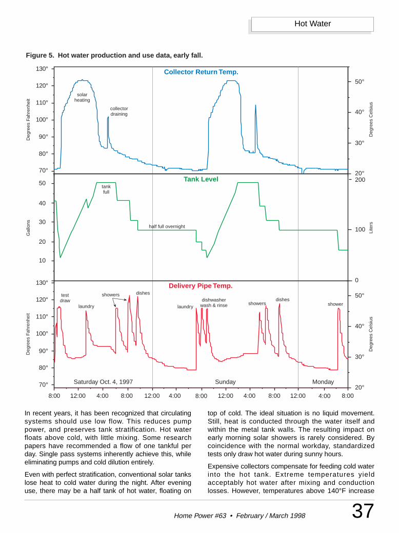
37Home Power #63 • February / March 1998
Hot Water
In recent years, it has been recognized that circulatingsystems should use low flow. This reduces pumppower, and preserves tank stratification. Hot waterfloats above cold, with little mixing. Some researchpapers have recommended a flow of one tankful perday. Single pass systems inherently achieve this, whileeliminating pumps and cold dilution entirely.
Even with perfect stratification, conventional solar tankslose heat to cold water during the night. After eveninguse, there may be a half tank of hot water, floating on
top of cold. The ideal situation is no liquid movement.Still, heat is conducted through the water itself andwithin the metal tank walls. The resulting impact onearly morning solar showers is rarely considered. Bycoincidence with the normal workday, standardizedtests only draw hot water during sunny hours.
Expensive collectors compensate for feeding cold waterinto the hot tank. Extreme temperatures yieldacceptably hot water after mixing and conductionlosses. However, temperatures above 140°F increase
20°
30°
40°
50°
70°
80°
90°
110°
120°
100°
130°
70°
80°
90°
110°
120°
100°
130°
20°
30°
40°
50°
10
20
30
40
50
Deg
rees
Cel
sius
8:00 12:00 4:00 8:00 12:00 4:00 8:00 12:00 4:00 8:00 12:00 4:00 8:00
100 Lite
rs
200
0
laundry
dishesshowerstestdraw
showershowersdishes
collectordraining
solarheating
tankfull
half full overnight
Figure 5. Hot water production and use data, early fall.
Saturday Oct. 4, 1997 Sunday Monday
Deg
rees
Fah
renh
eit
Deg
rees
Cel
sius
Deg
rees
Fah
renh
eit
Gal
lons
Collector Return Temp.
Tank Level
Delivery Pipe Temp.
laundrydishwasher
wash & rinse
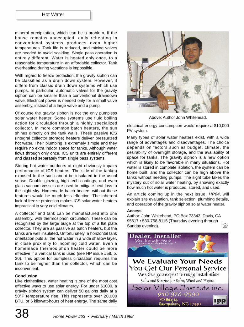
38 Home Power #63 • February / March 1998
Hot Water
mineral precipitation, which can be a problem. If thehouse remains unoccupied, daily reheating inconventional systems produces even highertemperatures. Tank life is reduced, and mixing valvesare needed to avoid scalding. Single pass operation isentirely different. Water is heated only once, to areasonable temperature in an affordable collector. Tankoverheating during vacations is impossible.
With regard to freeze protection, the gravity siphon canbe classified as a drain down system. However, itdiffers from classic drain down systems which usepumps. In particular, automatic valves for the gravitysiphon can be smaller than a conventional draindownvalve. Electrical power is needed only for a small valveassembly, instead of a large valve and a pump.
Of course the gravity siphon is not the only pumplesssolar water heater. Some systems use fluid boilingaction for circulation through a highly specializedcollector. In more common batch heaters, the sunshines directly on the tank walls. These passive ICS(integral collector storage) heaters deliver pressurizedhot water. Their plumbing is extremely simple and theyrequire no extra indoor space for tanks. Although waterflows through only once, ICS units are entirely differentand classed separately from single pass systems.
Storing hot water outdoors at night obviously impairsperformance of ICS heaters. The side of the tank(s)exposed to the sun cannot be insulated in the usualsense. Double glazing, high tech coatings, and evenglass vacuum vessels are used to mitigate heat loss tothe night sky. Homemade batch heaters without thesefeatures would be much less effective. The inherentlack of freeze protection makes ICS solar water heatersimpractical in very cold climates.
A collector and tank can be manufactured into oneassembly, with thermosiphon circulation. These can berecognized by the large bulge at the top of a flat platecollector. They are as passive as batch heaters, but thetanks are well insulated. Unfortunately, a horizontal tankorientation puts all the hot water in a wide shallow layer,in close proximity to incoming cold water. Even ahomemade thermosiphon heater could be moreeffective if a vertical tank is used (see HP issue #58, p.30). This option for pumpless circulation requires thetank to be higher than the collector, which can beinconvenient.
ConclusionLike clotheslines, water heating is one of the most costeffective ways to use solar energy. For under $1000, agravity siphon system can deliver 50 gallons daily at a50°F temperature rise. This represents over 20,000BTU, or 6 kilowatt-hours of heat energy. The same daily
electrical energy consumption would require a $10,000PV system.
Many types of solar water heaters exist, with a widerange of advantages and disadvantages. The choicedepends on factors such as budget, climate, thedesirability of overnight storage, and the availability ofspace for tanks. The gravity siphon is a new optionwhich is likely to be favorable in many situations. Hotwater is stored in complete isolation, the system can behome built, and the collector can be high above thetanks without needing pumps. The sight tube takes themystery out of solar water heating, by showing exactlyhow much hot water is produced, stored, and used.
An article coming up in the next issue, HP64, willexplain site evaluation, tank selection, plumbing details,and operation of the gravity siphon solar water heater.
AccessAuthor: John Whitehead, PO Box 73343, Davis, CA95617 • 530-758-8115 (Thursday evening throughSunday evening).
Above: Author John Whitehead.
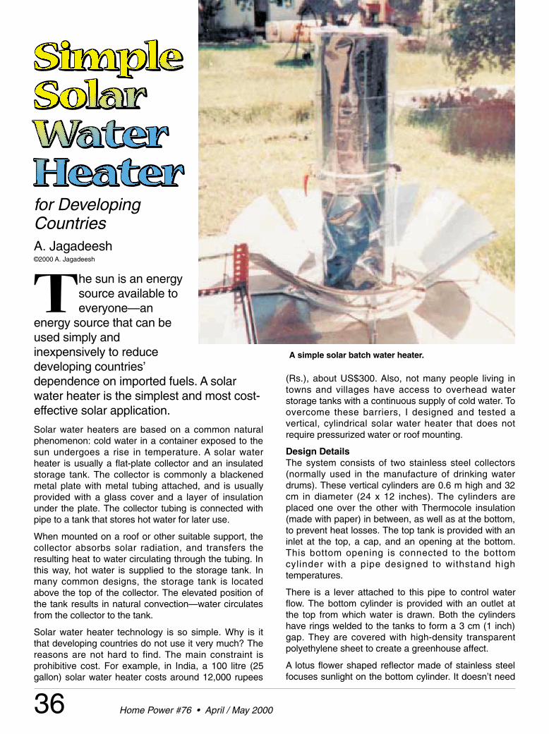
36 Home Power #76 • April / May 2000
for DevelopingCountriesA. Jagadeesh©2000 A. Jagadeesh
The sun is an energysource available toeveryone—an
energy source that can beused simply andinexpensively to reducedeveloping countries’dependence on imported fuels. A solarwater heater is the simplest and most cost-effective solar application.
Solar water heaters are based on a common naturalphenomenon: cold water in a container exposed to thesun undergoes a rise in temperature. A solar waterheater is usually a flat-plate collector and an insulatedstorage tank. The collector is commonly a blackenedmetal plate with metal tubing attached, and is usuallyprovided with a glass cover and a layer of insulationunder the plate. The collector tubing is connected withpipe to a tank that stores hot water for later use.
When mounted on a roof or other suitable support, thecollector absorbs solar radiation, and transfers theresulting heat to water circulating through the tubing. Inthis way, hot water is supplied to the storage tank. Inmany common designs, the storage tank is locatedabove the top of the collector. The elevated position ofthe tank results in natural convection—water circulatesfrom the collector to the tank.
Solar water heater technology is so simple. Why is itthat developing countries do not use it very much? Thereasons are not hard to find. The main constraint isprohibitive cost. For example, in India, a 100 litre (25gallon) solar water heater costs around 12,000 rupees
(Rs.), about US$300. Also, not many people living intowns and villages have access to overhead waterstorage tanks with a continuous supply of cold water. Toovercome these barriers, I designed and tested avertical, cylindrical solar water heater that does notrequire pressurized water or roof mounting.
Design DetailsThe system consists of two stainless steel collectors(normally used in the manufacture of drinking waterdrums). These vertical cylinders are 0.6 m high and 32cm in diameter (24 x 12 inches). The cylinders areplaced one over the other with Thermocole insulation(made with paper) in between, as well as at the bottom,to prevent heat losses. The top tank is provided with aninlet at the top, a cap, and an opening at the bottom.This bottom opening is connected to the bottomcylinder with a pipe designed to withstand hightemperatures.
There is a lever attached to this pipe to control waterflow. The bottom cylinder is provided with an outlet atthe top from which water is drawn. Both the cylindershave rings welded to the tanks to form a 3 cm (1 inch)gap. They are covered with high-density transparentpolyethylene sheet to create a greenhouse affect.
A lotus flower shaped reflector made of stainless steelfocuses sunlight on the bottom cylinder. It doesn’t need
A simple solar batch water heater.
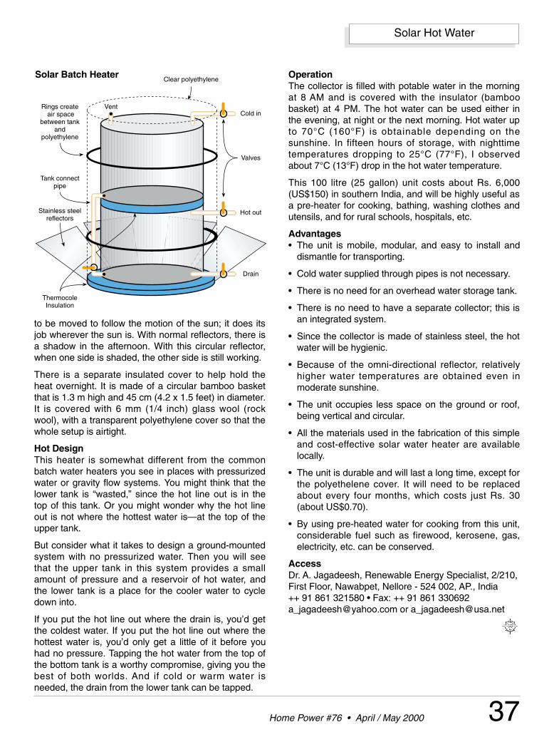
Cold in
Hot out
Drain
Tank connectpipe
Rings create air space
between tankand
polyethylene
Clear polyethylene
ThermocoleInsulation
Vent
Stainless steelreflectors
Valves
37Home Power #76 • April / May 2000
Solar Hot Water
to be moved to follow the motion of the sun; it does itsjob wherever the sun is. With normal reflectors, there isa shadow in the afternoon. With this circular reflector,when one side is shaded, the other side is still working.
There is a separate insulated cover to help hold theheat overnight. It is made of a circular bamboo basketthat is 1.3 m high and 45 cm (4.2 x 1.5 feet) in diameter.It is covered with 6 mm (1/4 inch) glass wool (rockwool), with a transparent polyethylene cover so that thewhole setup is airtight.
Hot DesignThis heater is somewhat different from the commonbatch water heaters you see in places with pressurizedwater or gravity flow systems. You might think that thelower tank is “wasted,” since the hot line out is in thetop of this tank. Or you might wonder why the hot lineout is not where the hottest water is—at the top of theupper tank.
But consider what it takes to design a ground-mountedsystem with no pressurized water. Then you will seethat the upper tank in this system provides a smallamount of pressure and a reservoir of hot water, andthe lower tank is a place for the cooler water to cycledown into.
If you put the hot line out where the drain is, you’d getthe coldest water. If you put the hot line out where thehottest water is, you’d only get a little of it before youhad no pressure. Tapping the hot water from the top ofthe bottom tank is a worthy compromise, giving you thebest of both worlds. And if cold or warm water isneeded, the drain from the lower tank can be tapped.
OperationThe collector is filled with potable water in the morningat 8 AM and is covered with the insulator (bamboobasket) at 4 PM. The hot water can be used either inthe evening, at night or the next morning. Hot water upto 70°C (160°F) is obtainable depending on thesunshine. In fifteen hours of storage, with nighttimetemperatures dropping to 25°C (77°F), I observedabout 7°C (13°F) drop in the hot water temperature.
This 100 litre (25 gallon) unit costs about Rs. 6,000(US$150) in southern India, and will be highly useful asa pre-heater for cooking, bathing, washing clothes andutensils, and for rural schools, hospitals, etc.
Advantages• The unit is mobile, modular, and easy to install and
dismantle for transporting.
• Cold water supplied through pipes is not necessary.
• There is no need for an overhead water storage tank.
• There is no need to have a separate collector; this isan integrated system.
• Since the collector is made of stainless steel, the hotwater will be hygienic.
• Because of the omni-directional reflector, relativelyhigher water temperatures are obtained even inmoderate sunshine.
• The unit occupies less space on the ground or roof,being vertical and circular.
• All the materials used in the fabrication of this simpleand cost-effective solar water heater are availablelocally.
• The unit is durable and will last a long time, except forthe polyethelene cover. It will need to be replacedabout every four months, which costs just Rs. 30(about US$0.70).
• By using pre-heated water for cooking from this unit,considerable fuel such as firewood, kerosene, gas,electricity, etc. can be conserved.
AccessDr. A. Jagadeesh, Renewable Energy Specialist, 2/210,First Floor, Nawabpet, Nellore - 524 002, AP., India ++ 91 861 321580 • Fax: ++ 91 861 [email protected] or [email protected]
Solar Batch Heater
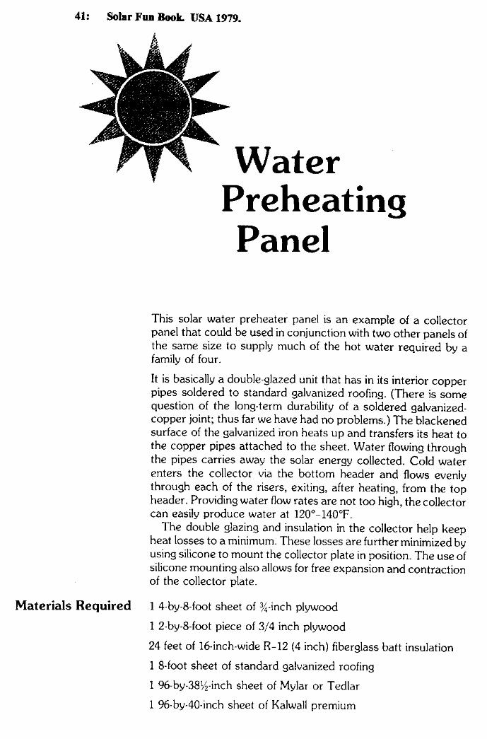
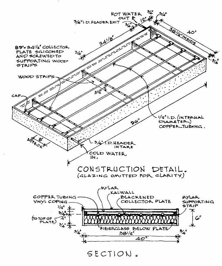
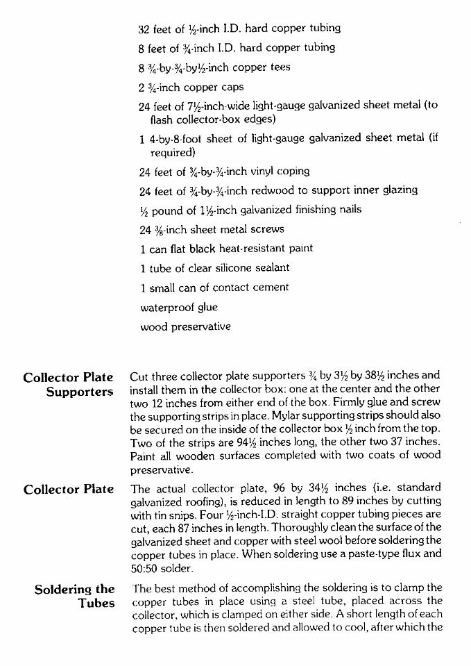
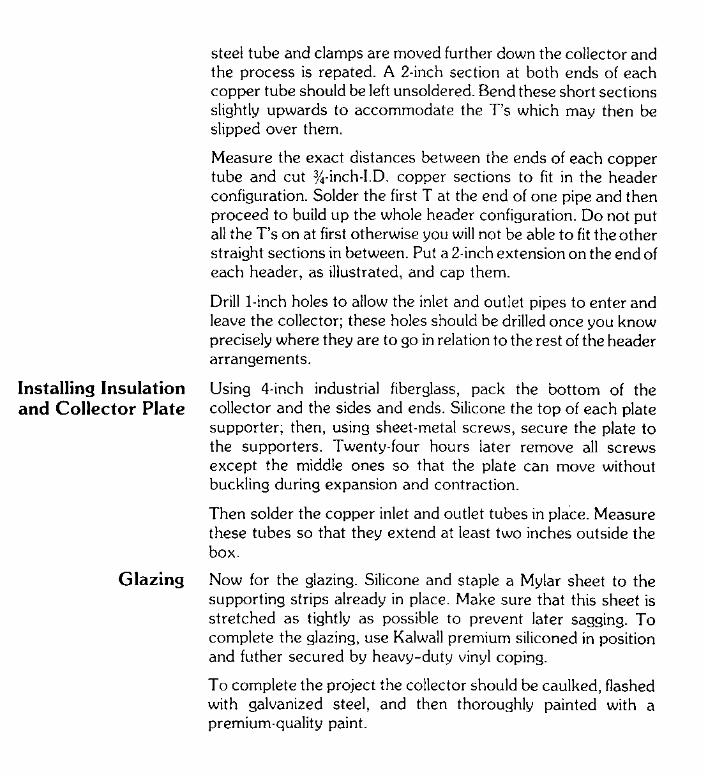
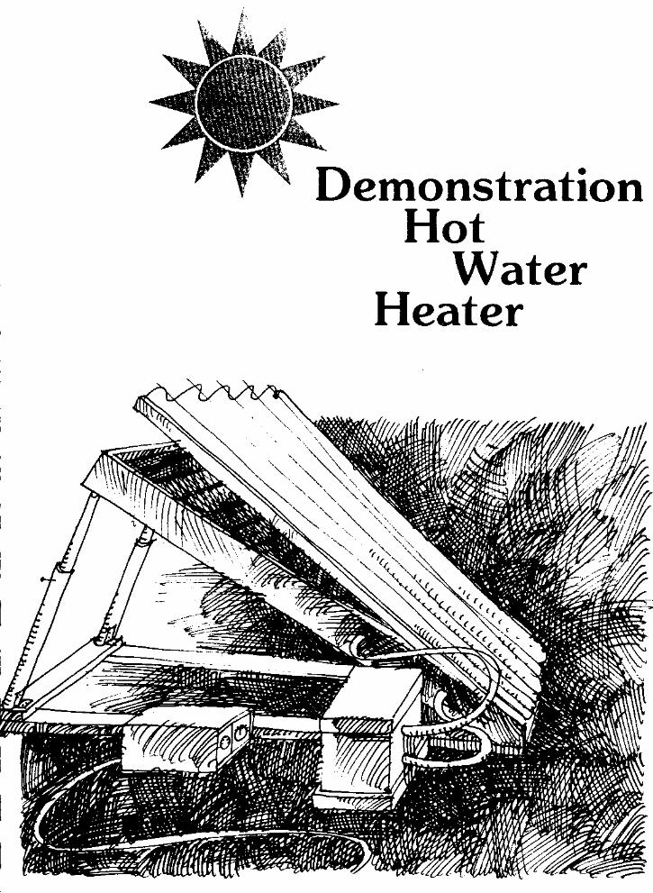
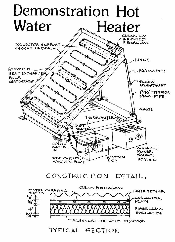
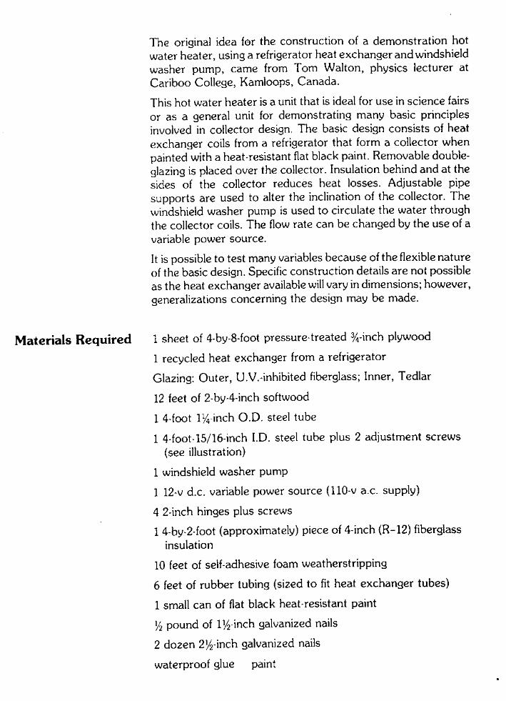
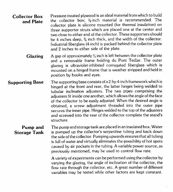
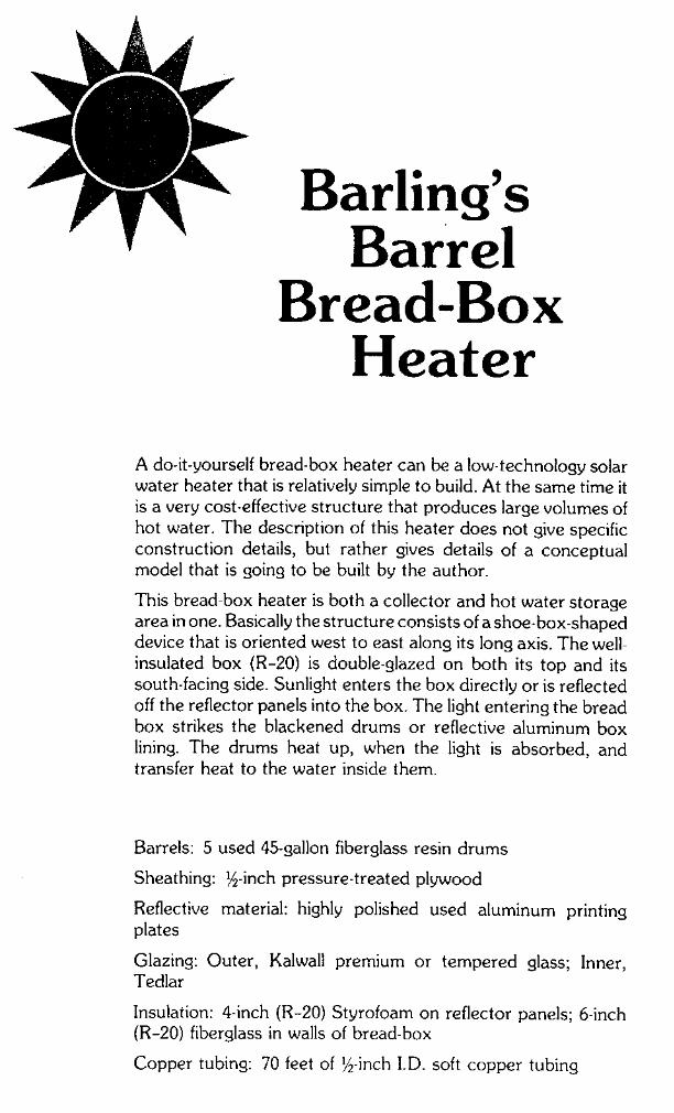
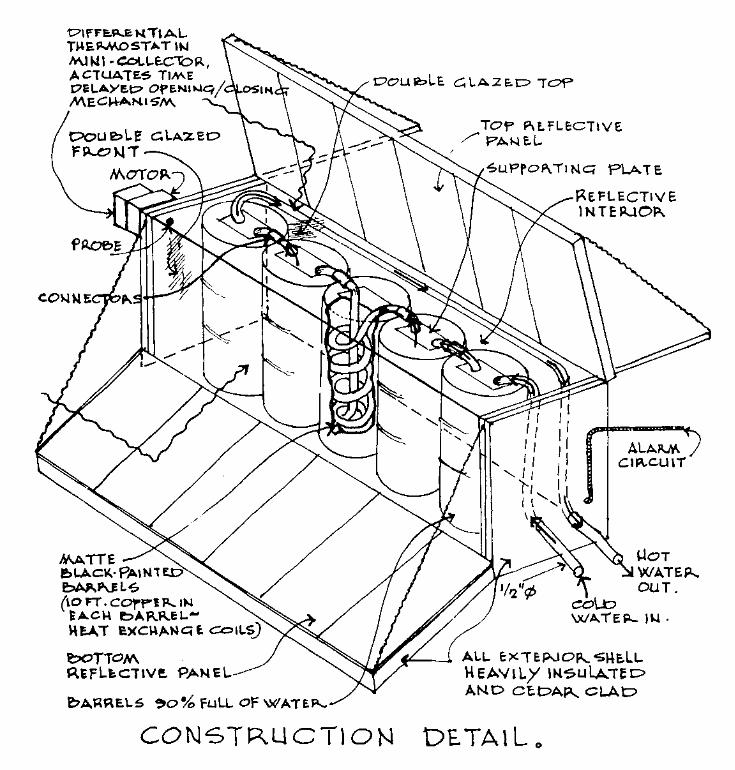
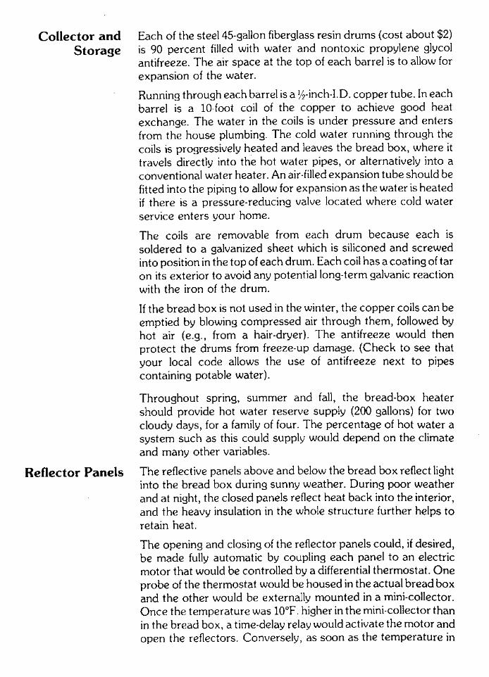
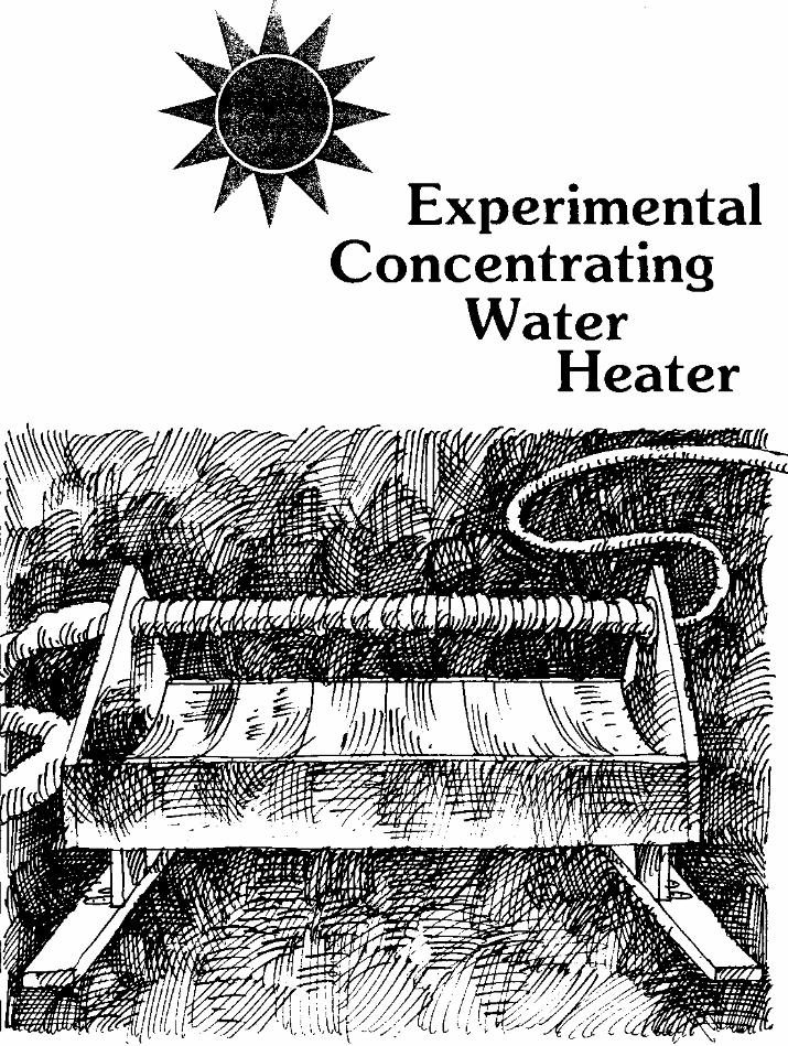
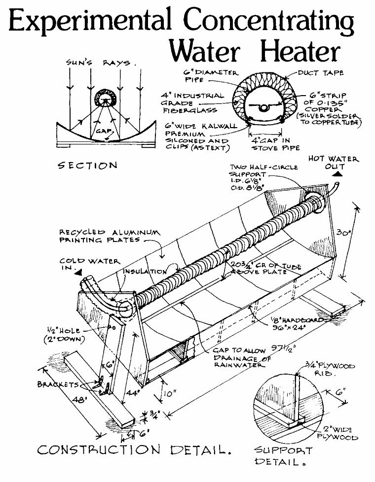
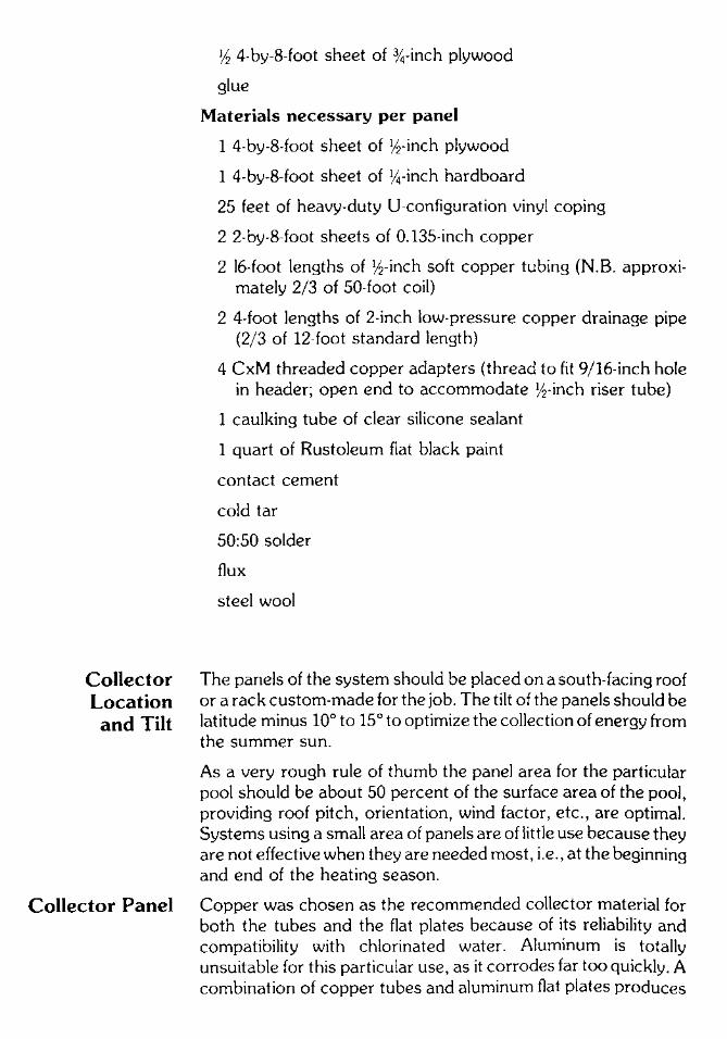
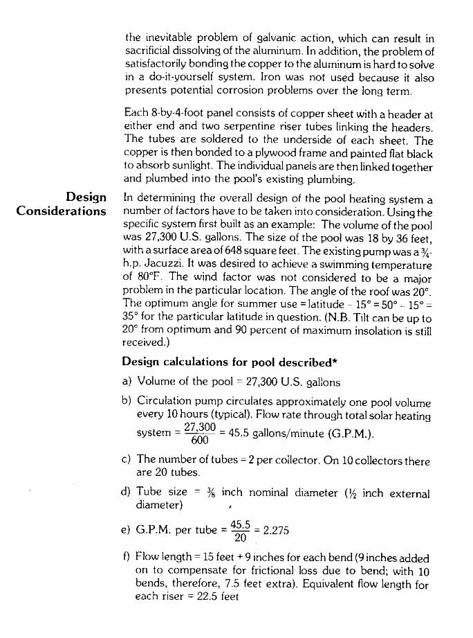
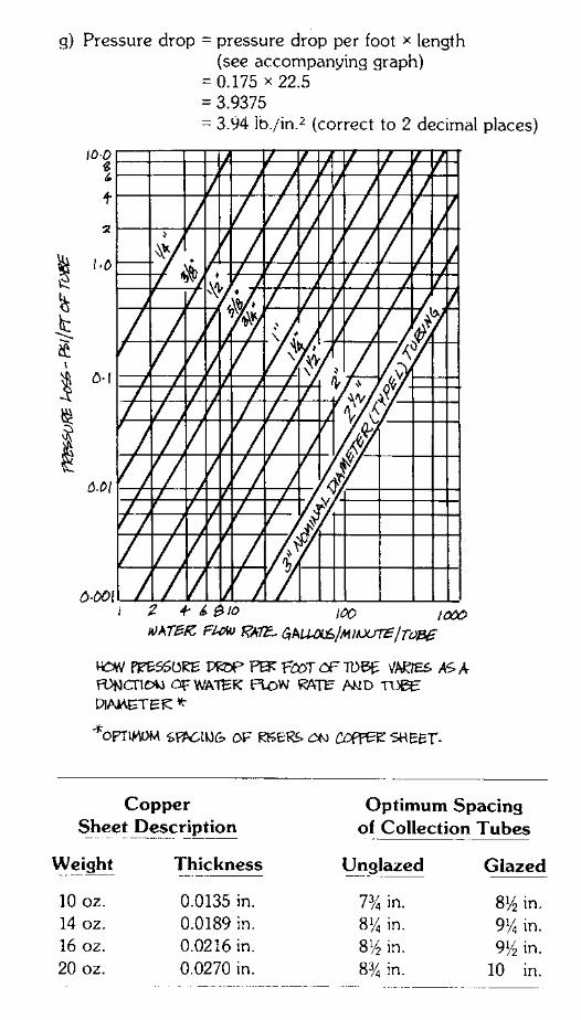
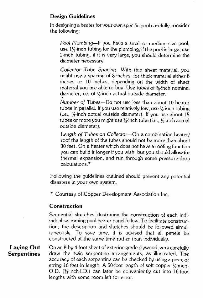
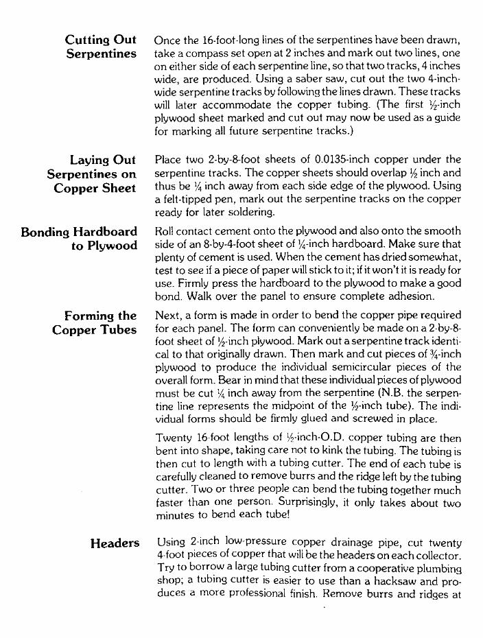
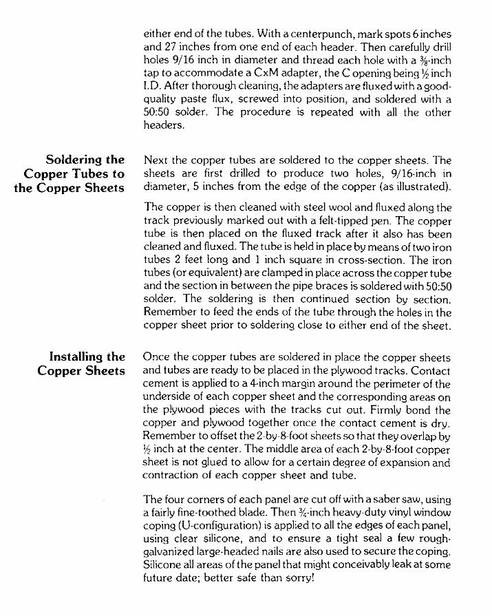
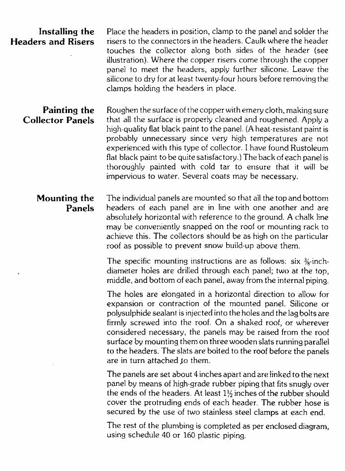
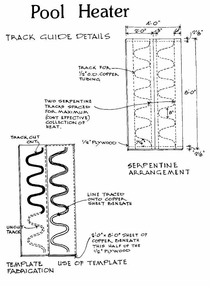
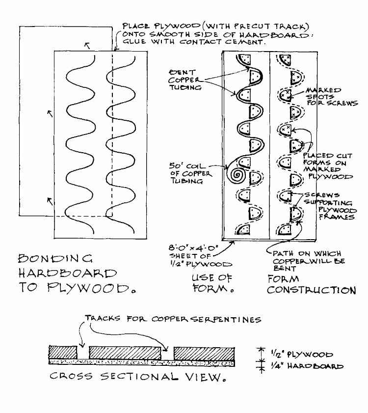
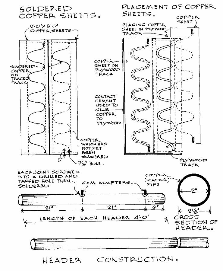
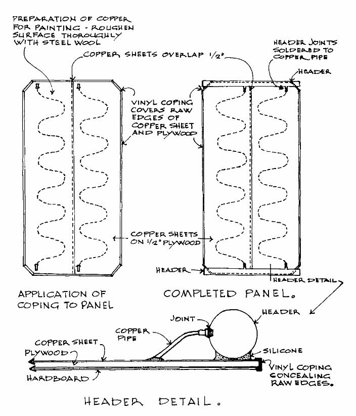
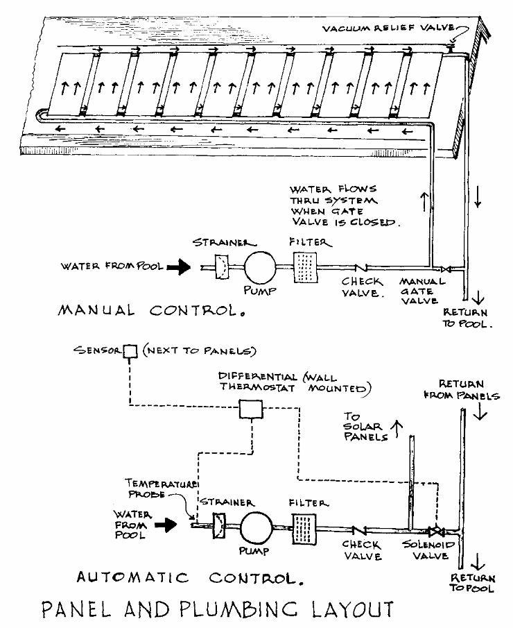
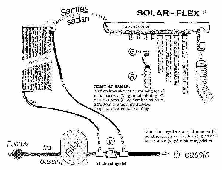
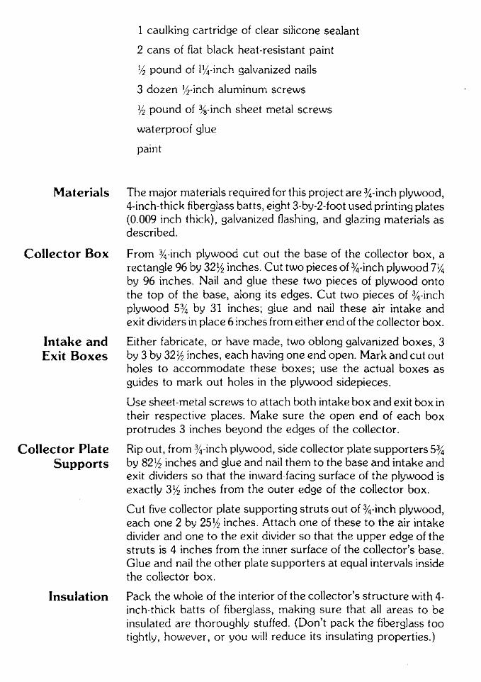
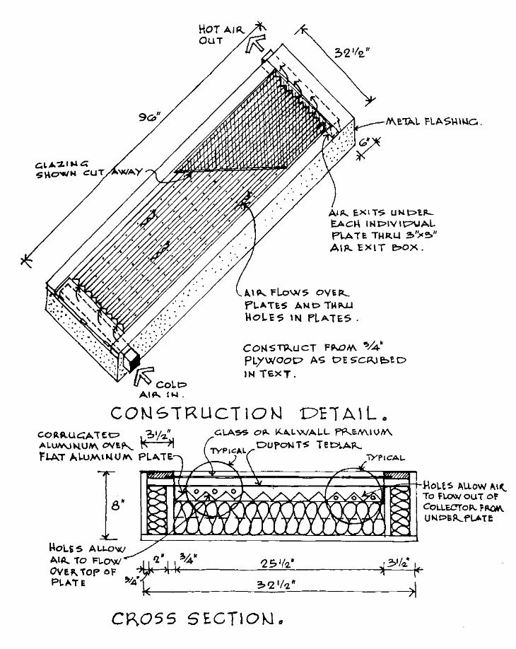

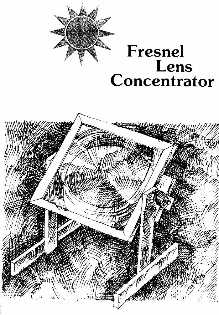
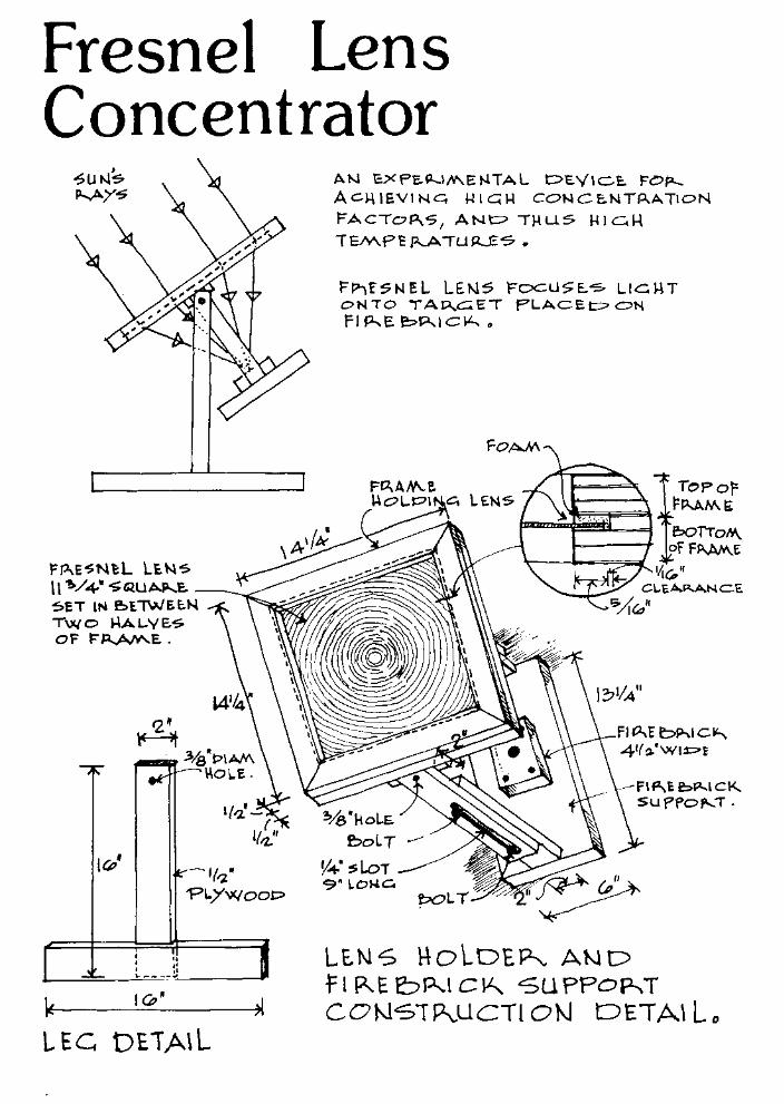
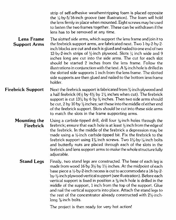
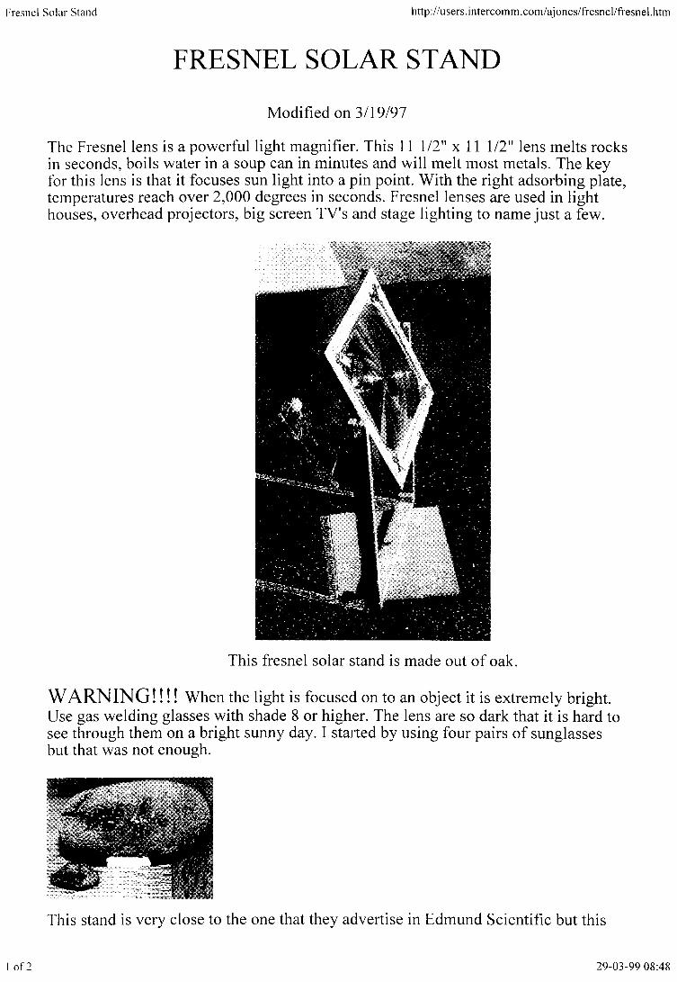
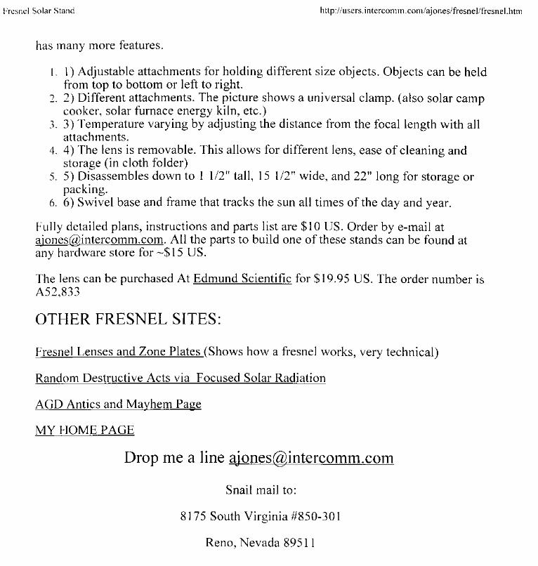
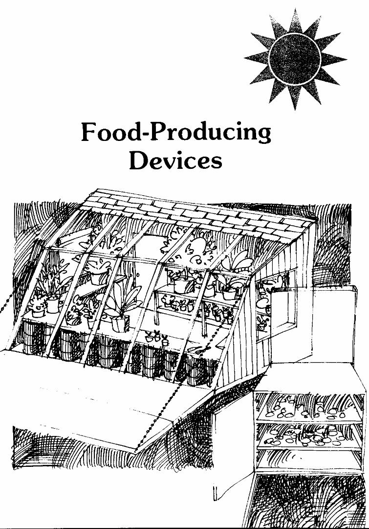
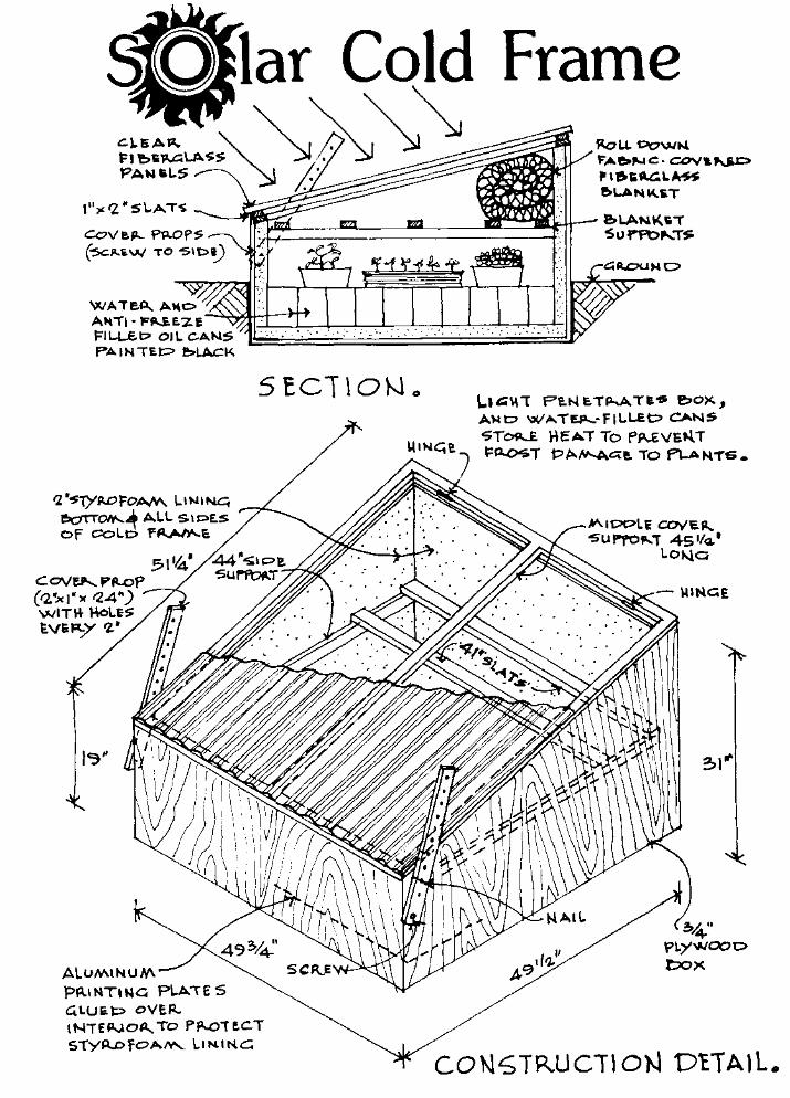
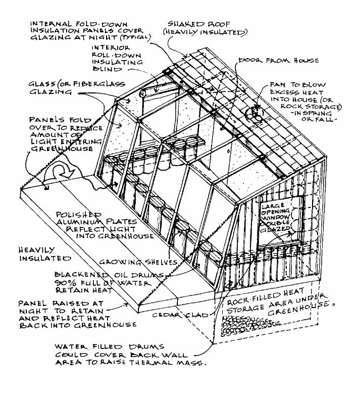
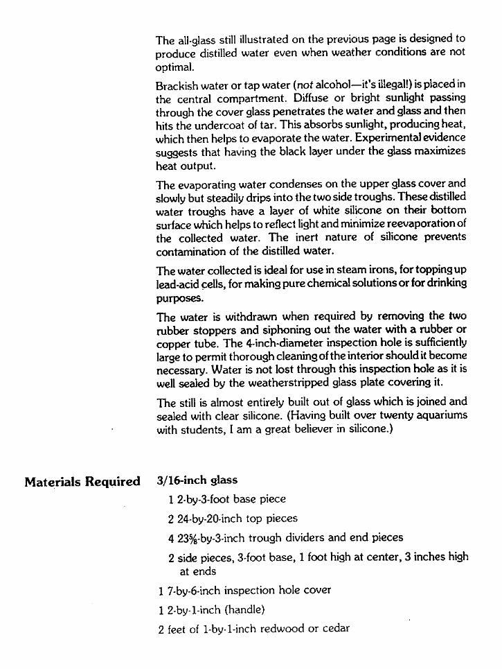

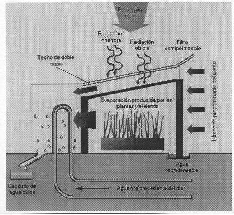
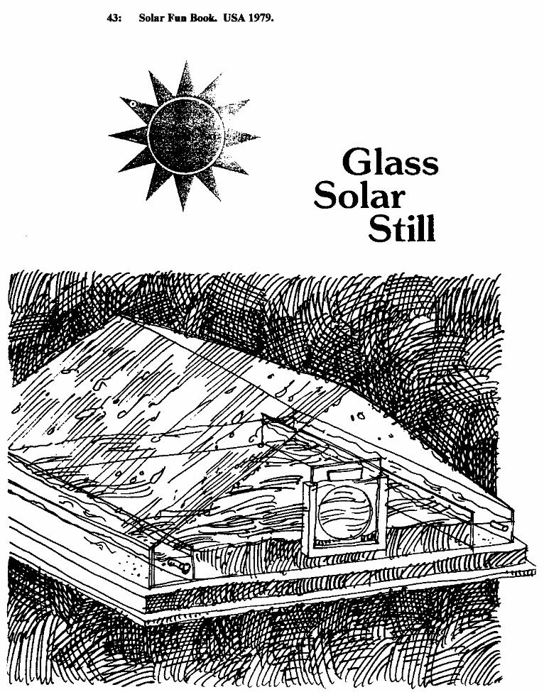
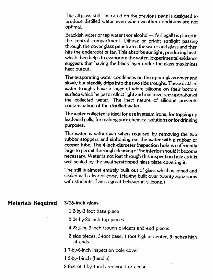
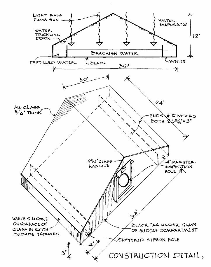
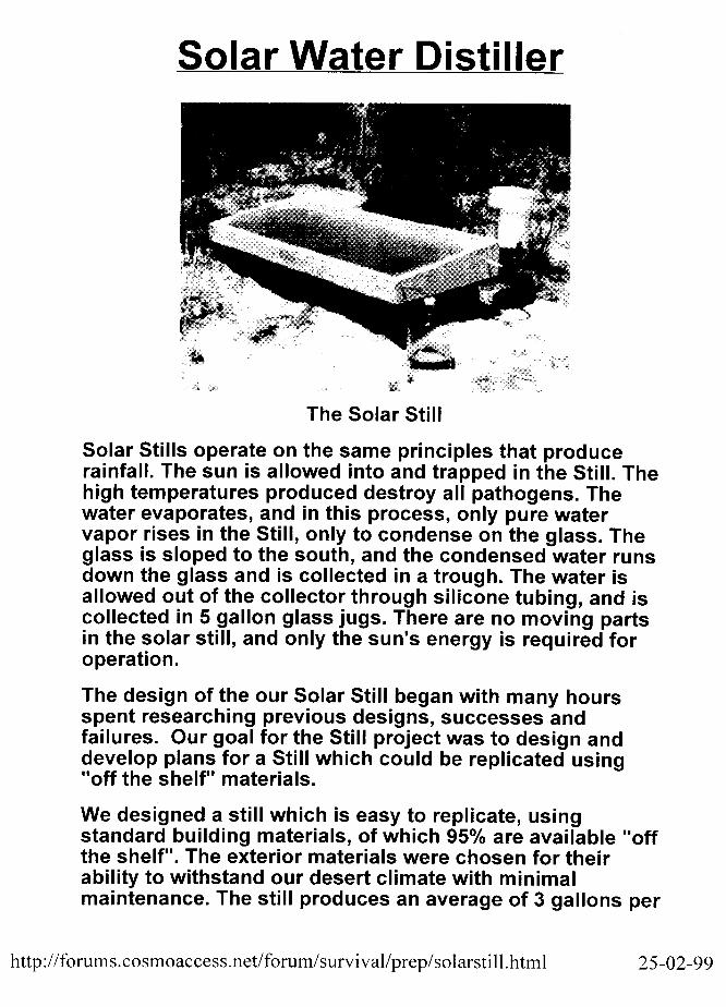
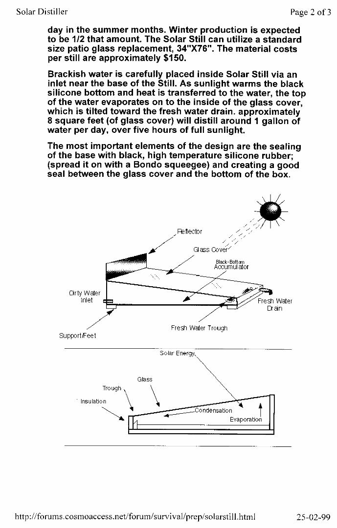
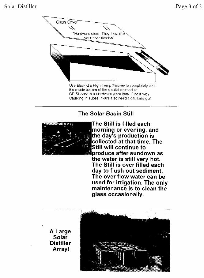
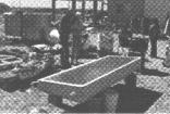
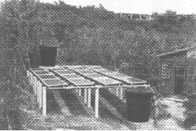
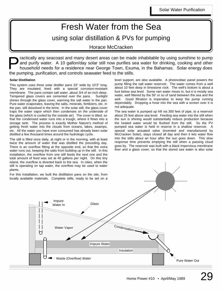
Home Power #10 • April/May 1989 29
Impure Water
Water Vapor Condensation
Impure Water In
Waste (Overflow) WaterPure Water Out
Glass
Insulation
Solar Water Purification
ractically any seacoast and many desert areas can be made inhabitable by using sunshine to pumpand purify water. A 10 gallon/day solar still now purifies sea water for drinking, cooking and otherhousehold needs for a residence near George Town, Exuma, in the Bahamas. Solar energy does
the pumping, purification, and controls seawater feed to the stills.P
Fresh Water from the Seausing solar distillation & PVs for pumping
Horace McCracken
Solar Distillation
This system uses three solar distiller pans 33" wide by 10'3" long.They are insulated, lined with a special corrosion-resistantmembrane. The pans contain salt water, about 3/4 of an inch deep.Tempered glass covers are cemented over the pans. Sunlightshines through the glass cover, warming the salt water in the pan.Pure water evaporates, leaving the salts, minerals, fertilizers, etc. inthe pan, still dissolved in the brine. In the solar still, the glass covertraps the water vapor which then condenses on the underside ofthe glass (which is cooled by the outside air). The cover is tilted, sothat the condensed water runs into a trough, where it flows into astorage tank. The process is exactly Mother Nature's method ofgetting fresh water into the clouds from oceans, lakes, swamps,etc. All the water you have ever consumed has already been solardistilled a few thousand times around the hydrologic cycle.
The still is filled once daily, at night or in the morning, with at leasttwice the amount of water that was distilled the preceding day.There is an overflow fitting at the opposite end, so that the extrawater runs out, keeping the salts from building up in the still. In thisinstallation, the overflow from one still feeds the next one and thetotal amount of feed was set at 40 gallons per night. On this tinyisland, the overflow is diverted back to the sea. In cities, when thestill is operating on tap water, the overflow may be used to waterplants.For this installation, we built the distillation pans on the site, fromlocally available materials. Complete stills, ready to be set on a
level support, are also available. A photovoltaic panel powers thepump filling the salt water reservoir. The water comes from a wellabout 10 feet deep in limestone rock. The well's bottom is about afoot below sea level. Some rain water mixes in, but it is mostly seawater, well filtered by the 50' or so of sand between the sea and thewell. Good filtration is imperative to keep the pump runningdependably. Dropping a hose into the sea with a screen over it isnot adequate.The sea water is pumped up hill via 300 feet of pipe, to a reservoirabout 25 feet above sea level. Feeding sea water into the still whenthe sun is shining would substantially reduce production becausethe heated water would be flushed from the still, So the PVpumped sea water is held in reserve in a shallow reservoir. Aspecial solar actuated valve (invented and manufactured byMcCracken Solar), stays closed all day and then it lets water flowinto the stills about an hour after the sun goes down. This slowresponse time prevents emptying the still when a passing cloudgoes by. The reservoir was built with a black impervious membraneliner and a glass cover, so that the stored sea water is also solar
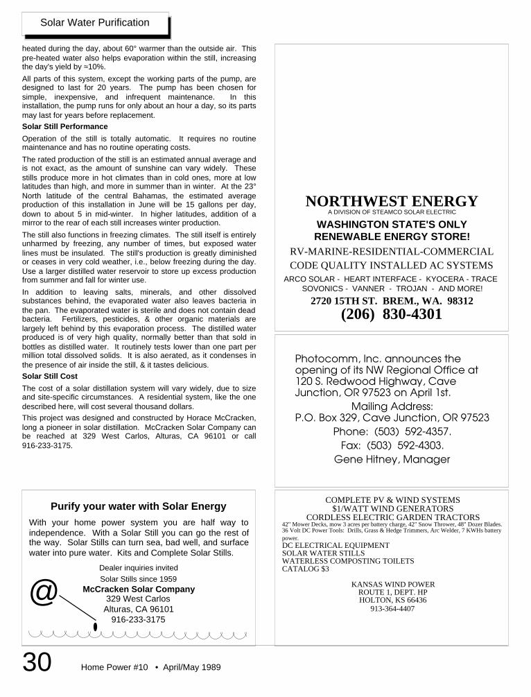
Home Power #10 • April/May 198930
Solar Water Purification
heated during the day, about 60° warmer than the outside air. Thispre-heated water also helps evaporation within the still, increasingthe day's yield by ≈10%.
All parts of this system, except the working parts of the pump, aredesigned to last for 20 years. The pump has been chosen forsimple, inexpensive, and infrequent maintenance. In thisinstallation, the pump runs for only about an hour a day, so its partsmay last for years before replacement.Solar Still Performance
Operation of the still is totally automatic. It requires no routinemaintenance and has no routine operating costs.
The rated production of the still is an estimated annual average andis not exact, as the amount of sunshine can vary widely. Thesestills produce more in hot climates than in cold ones, more at lowlatitudes than high, and more in summer than in winter. At the 23°North latitude of the central Bahamas, the estimated averageproduction of this installation in June will be 15 gallons per day,down to about 5 in mid-winter. In higher latitudes, addition of amirror to the rear of each still increases winter production.
The still also functions in freezing climates. The still itself is entirelyunharmed by freezing, any number of times, but exposed waterlines must be insulated. The still's production is greatly diminishedor ceases in very cold weather, i.e., below freezing during the day.Use a larger distilled water reservoir to store up excess productionfrom summer and fall for winter use.
In addition to leaving salts, minerals, and other dissolvedsubstances behind, the evaporated water also leaves bacteria inthe pan. The evaporated water is sterile and does not contain deadbacteria. Fertilizers, pesticides, & other organic materials arelargely left behind by this evaporation process. The distilled waterproduced is of very high quality, normally better than that sold inbottles as distilled water. It routinely tests lower than one part permillion total dissolved solids. It is also aerated, as it condenses inthe presence of air inside the still, & it tastes delicious.Solar Still Cost
The cost of a solar distillation system will vary widely, due to sizeand site-specific circumstances. A residential system, like the onedescribed here, will cost several thousand dollars.This project was designed and constructed by Horace McCracken,long a pioneer in solar distillation. McCracken Solar Company canbe reached at 329 West Carlos, Alturas, CA 96101 or call916-233-3175.
Purify your water with Solar Energy
With your home power system you are half way toindependence. With a Solar Still you can go the rest ofthe way. Solar Stills can turn sea, bad well, and surfacewater into pure water. Kits and Complete Solar Stills.
Dealer inquiries invitedSolar Stills since 1959
McCracken Solar Company329 West Carlos
Alturas, CA 96101916-233-3175
@
A DIVISION OF STEAMCO SOLAR ELECTRIC
WASHINGTON STATE'S ONLYRENEWABLE ENERGY STORE!
RV-MARINE-RESIDENTIAL-COMMERCIALCODE QUALITY INSTALLED AC SYSTEMS
ARCO SOLAR - HEART INTERFACE - KYOCERA - TRACE SOVONICS - VANNER - TROJAN - AND MORE!
2720 15TH ST. BREM., WA. 98312(206) 830-4301
NORTHWEST ENERGY
Photocomm, Inc. announces theopening of its NW Regional Office at120 S. Redwood Highway, CaveJunction, OR 97523 on April 1st.
Mailing Address:P.O. Box 329, Cave Junction, OR 97523
Phone: (503) 592-4357.Fax: (503) 592-4303.
Gene Hitney, Manager
COMPLETE PV & WIND SYSTEMS$1/WATT WIND GENERATORS
CORDLESS ELECTRIC GARDEN TRACTORS42" Mower Decks, mow 3 acres per battery charge, 42" Snow Thrower, 48" Dozer Blades.36 Volt DC Power Tools: Drills, Grass & Hedge Trimmers, Arc Welder, 7 KWHs batterypower.DC ELECTRICAL EQUIPMENTSOLAR WATER STILLSWATERLESS COMPOSTING TOILETSCATALOG $3
KANSAS WIND POWERROUTE 1, DEPT. HPHOLTON, KS 66436
913-364-4407
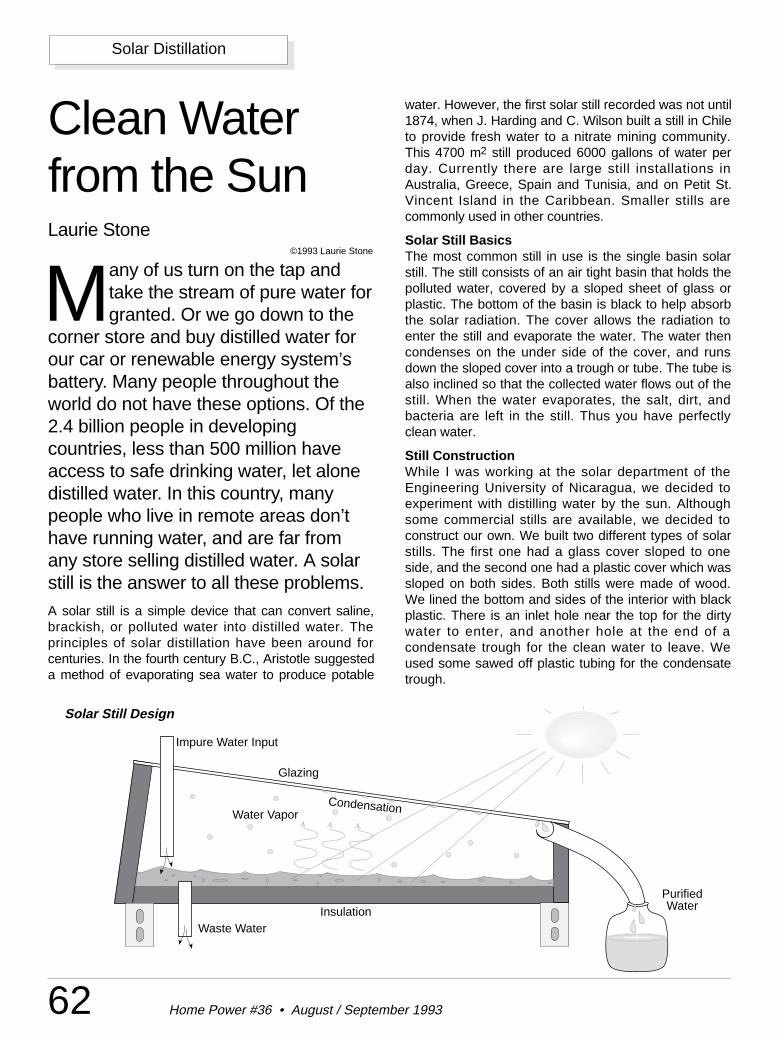
62 Home Power #36 • August / September 1993
Solar Distillation
Clean Waterfrom the SunLaurie Stone
©1993 Laurie Stone
Many of us turn on the tap andtake the stream of pure water forgranted. Or we go down to the
corner store and buy distilled water forour car or renewable energy system’sbattery. Many people throughout theworld do not have these options. Of the2.4 billion people in developingcountries, less than 500 million haveaccess to safe drinking water, let alonedistilled water. In this country, manypeople who live in remote areas don’thave running water, and are far fromany store selling distilled water. A solarstill is the answer to all these problems.A solar still is a simple device that can convert saline,brackish, or polluted water into distilled water. Theprinciples of solar distillation have been around forcenturies. In the fourth century B.C., Aristotle suggesteda method of evaporating sea water to produce potable
water. However, the first solar still recorded was not until1874, when J. Harding and C. Wilson built a still in Chileto provide fresh water to a nitrate mining community.This 4700 m2 still produced 6000 gallons of water perday. Currently there are large still installations inAustralia, Greece, Spain and Tunisia, and on Petit St.Vincent Island in the Caribbean. Smaller stills arecommonly used in other countries.
Solar Still BasicsThe most common still in use is the single basin solarstill. The still consists of an air tight basin that holds thepolluted water, covered by a sloped sheet of glass orplastic. The bottom of the basin is black to help absorbthe solar radiation. The cover allows the radiation toenter the still and evaporate the water. The water thencondenses on the under side of the cover, and runsdown the sloped cover into a trough or tube. The tube isalso inclined so that the collected water flows out of thestill. When the water evaporates, the salt, dirt, andbacteria are left in the still. Thus you have perfectlyclean water.
Still ConstructionWhile I was working at the solar department of theEngineering University of Nicaragua, we decided toexperiment with distilling water by the sun. Althoughsome commercial stills are available, we decided toconstruct our own. We built two different types of solarstills. The first one had a glass cover sloped to oneside, and the second one had a plastic cover which wassloped on both sides. Both stills were made of wood.We lined the bottom and sides of the interior with blackplastic. There is an inlet hole near the top for the dirtywater to enter, and another hole at the end of acondensate trough for the clean water to leave. Weused some sawed off plastic tubing for the condensatetrough.
Solar Still Design
Purified Water
Glazing
Impure Water Input
InsulationWaste Water
Water VaporCondensation
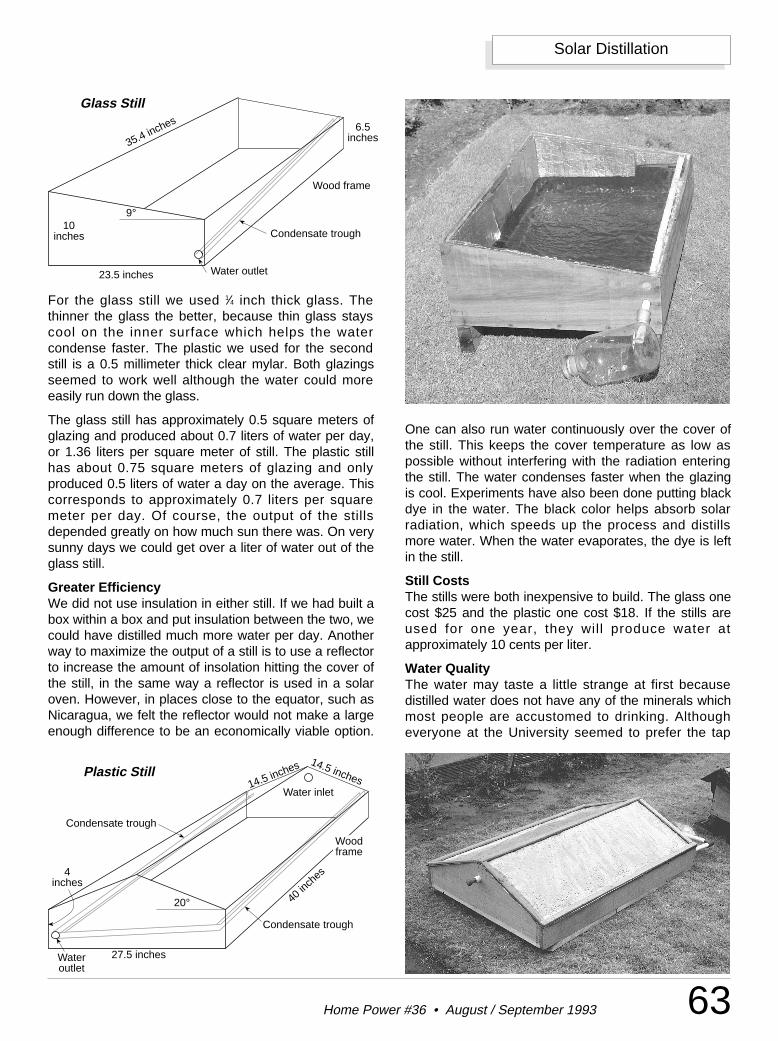
63Home Power #36 • August / September 1993
Solar Distillation
For the glass still we used 1⁄4 inch thick glass. Thethinner the glass the better, because thin glass stayscool on the inner surface which helps the watercondense faster. The plastic we used for the secondstill is a 0.5 millimeter thick clear mylar. Both glazingsseemed to work well although the water could moreeasily run down the glass.
The glass still has approximately 0.5 square meters ofglazing and produced about 0.7 liters of water per day,or 1.36 liters per square meter of still. The plastic stillhas about 0.75 square meters of glazing and onlyproduced 0.5 liters of water a day on the average. Thiscorresponds to approximately 0.7 liters per squaremeter per day. Of course, the output of the stillsdepended greatly on how much sun there was. On verysunny days we could get over a liter of water out of theglass still.
Greater EfficiencyWe did not use insulation in either still. If we had built abox within a box and put insulation between the two, wecould have distilled much more water per day. Anotherway to maximize the output of a still is to use a reflectorto increase the amount of insolation hitting the cover ofthe still, in the same way a reflector is used in a solaroven. However, in places close to the equator, such asNicaragua, we felt the reflector would not make a largeenough difference to be an economically viable option.
One can also run water continuously over the cover ofthe still. This keeps the cover temperature as low aspossible without interfering with the radiation enteringthe still. The water condenses faster when the glazingis cool. Experiments have also been done putting blackdye in the water. The black color helps absorb solarradiation, which speeds up the process and distillsmore water. When the water evaporates, the dye is leftin the still.
Still CostsThe stills were both inexpensive to build. The glass onecost $25 and the plastic one cost $18. If the stills areused for one year, they will produce water atapproximately 10 cents per liter.
Water QualityThe water may taste a little strange at first becausedistilled water does not have any of the minerals whichmost people are accustomed to drinking. Althougheveryone at the University seemed to prefer the tap
35.4 inches
10 inches
23.5 inches
6.5 inches
9°
Condensate trough
Wood frame
Glass Still
Water outlet
14.5 inches
27.5 inches
40 in
ches
14.5 inches
4 inches
20°
Condensate trough
Wood frame
Water outlet
Water inlet
Plastic Still
Condensate trough
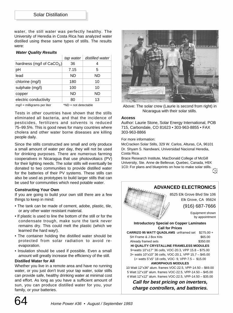
ADVANCED ELECTRONICS8525 Elk Grove Blvd Ste 106
Elk Grove, CA 95624
(916) 687-7666Equipment shown
by appointment
Introductory Special on Copper LaminatesCall for Prices
CARRIZO 95 WATT QUADLAMS unframed set $275.00 +SH Frame & J Box Kits $65.00Already framed sets $350.00HI QUALITY CRYSTALLINE FRAMELESS MODULES9+watts 10"x17" 36 cells, VOC-20.3, VPP 15.8 – $75.003+ watts 10”x10” 36 cells, VOC-20.1, VPP 15.7 – $45.00
1+ watts 5”x5” 18 cells, VOC- 9, VPP-7.5 – $15.00AMORPHOUS MODULES
10 Watt 12"x36" alum. frames VOC-22.5, VPP-14.50 – $69.005 Watt 12"x18" alum. frames VOC-22.5, VPP-14.50 – $45.004 Watt 12"x12" alum. frames VOC-22.5, VPP-14.50 – $35.00
Call for best pricing on inverters,charge controllers, and batteries.
64 Home Power #36 • August / September 1993
Solar Distillation
water, the still water was perfectly healthy. TheUniversity of Heredia in Costa Rica has analyzed waterdistilled using these same types of stills. The resultswere:
Tests in other countries have shown that the stillseliminated all bacteria, and that the incidence ofpesticides, ferti l izers and solvents is reduced75–99.5%. This is good news for many countries wherecholera and other water borne diseases are killingpeople daily.
Since the stills constructed are small and only producea small amount of water per day, they will not be usedfor drinking purposes. There are numerous farmingcooperatives in Nicaragua that use photovoltaics (PV)for their lighting needs. The solar stills will eventually bedonated to two communities to provide distilled waterfor the batteries of their PV systems. These stills canalso be used as prototypes to build larger stills that canbe used for communities which need potable water.
Constructing Your OwnIf you are going to build your own still there are a fewthings to keep in mind:
• The tank can be made of cement, adobe, plastic, tile,or any other water resistant material.
• If plastic is used to line the bottom of the still or for thecondensate trough, make sure the tank neverremains dry. This could melt the plastic (which welearned the hard way!).
• The container holding the distilled water should beprotected from solar radiation to avoid re-evaporation.
• Insulation should be used if possible. Even a smallamount will greatly increase the efficiency of the still.
Distilled Water for AllWhether you live in a remote area and have no runningwater, or you just don’t trust your tap water, solar stillscan provide safe, healthy drinking water at minimal costand effort. As long as you have a sufficient amount ofsun, you can produce distilled water for you, yourfamily, or your batteries.
Above: The solar crew (Laurie is second from right) inNicaragua with their solar stills.
Water Quality Resultstap water distilled water
hardness (mg/l of CaCO3) 36 4
pH 7.15 5
lead ND ND
chlorine (mg/l) 180 10
sulphate (mg/l) 100 10
copper ND ND
electric conductivity 80 13mg/l = milligrams per liter *ND = not detectable
3
AccessAuthor: Laurie Stone, Solar Energy International, POB715, Carbondale, CO 81623 • 303-963-8855 • FAX303-963-8866
For more information:McCracken Solar Stills, 329 W. Carlos, Alturas, CA, 96101Dr. Shyam S. Nandwani, Universidad Nacional Heredia,Costa Rica.Brace Research Institute, MacDonald College of McGillUniversity, Ste. Anne de Bellevue, Quebec, Canada, H9X1C0: For plans and blueprints on how to make solar stills.
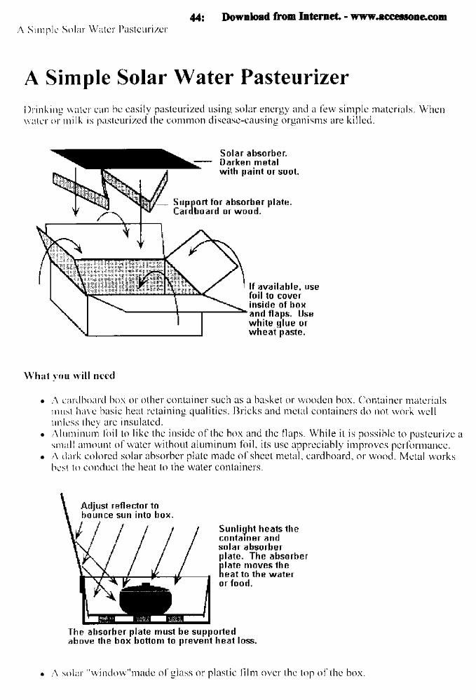
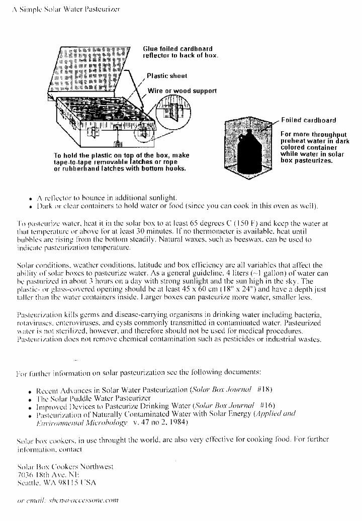
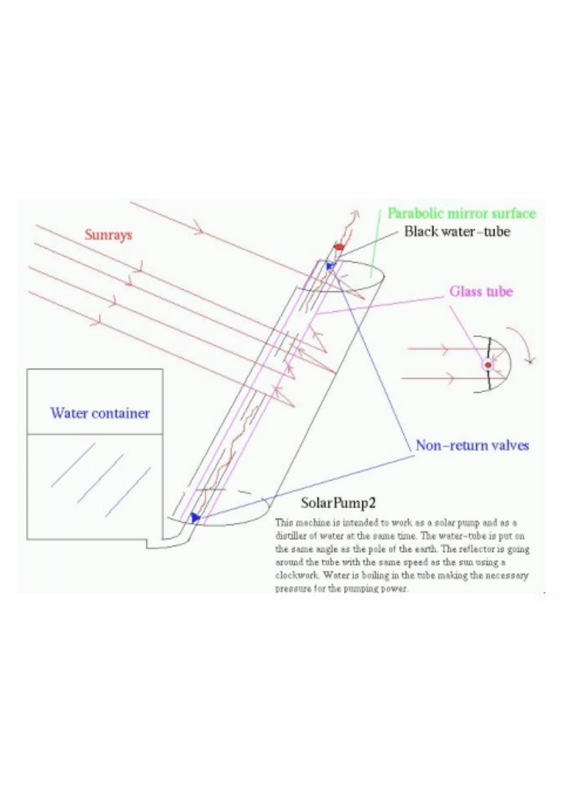
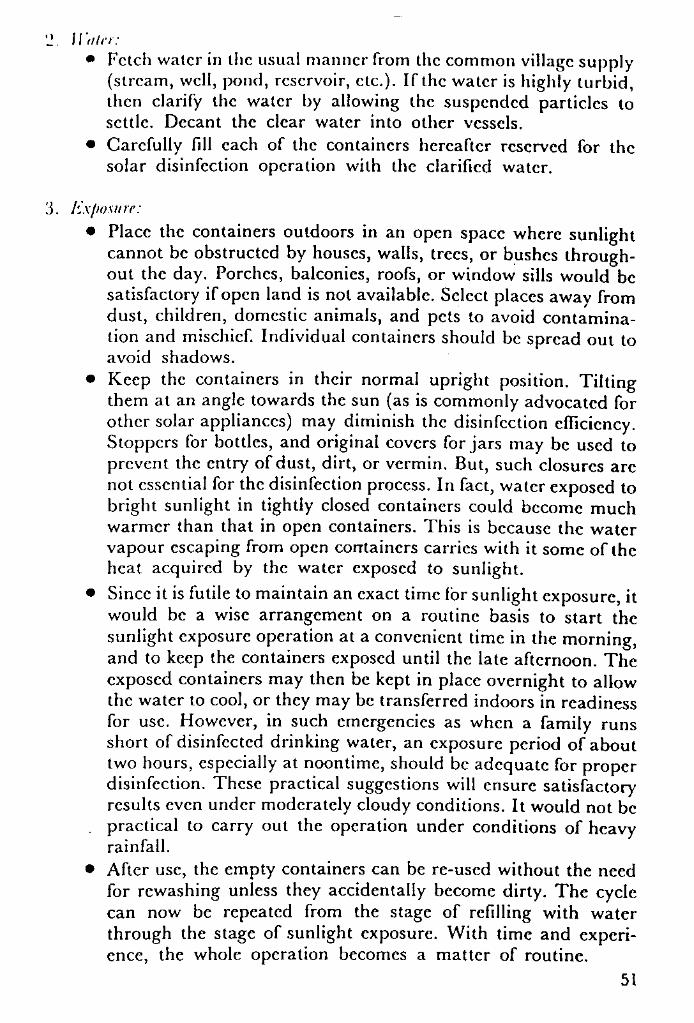
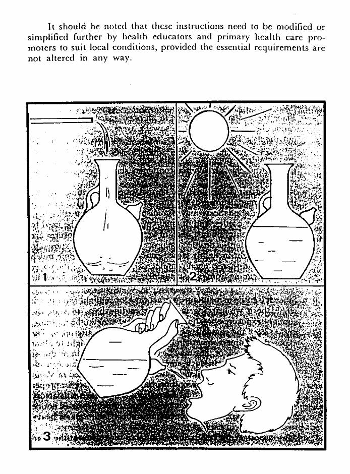
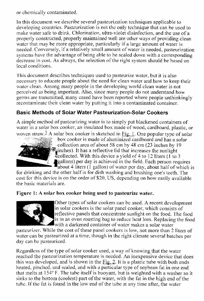
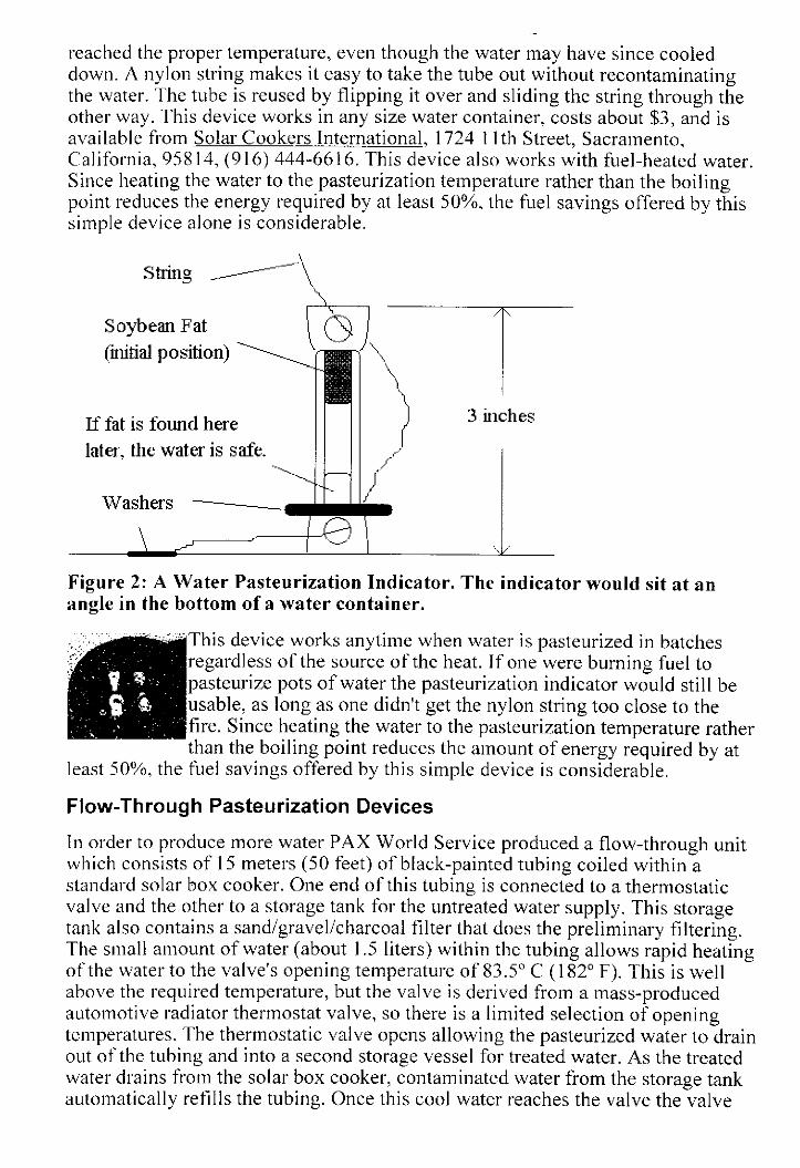
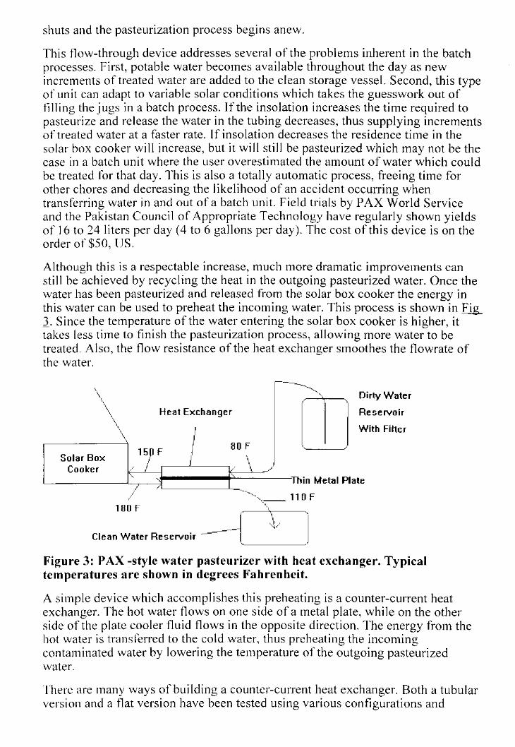
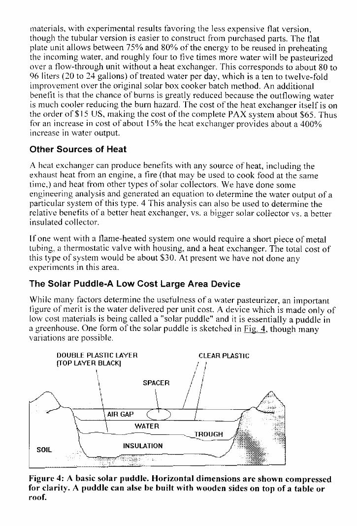

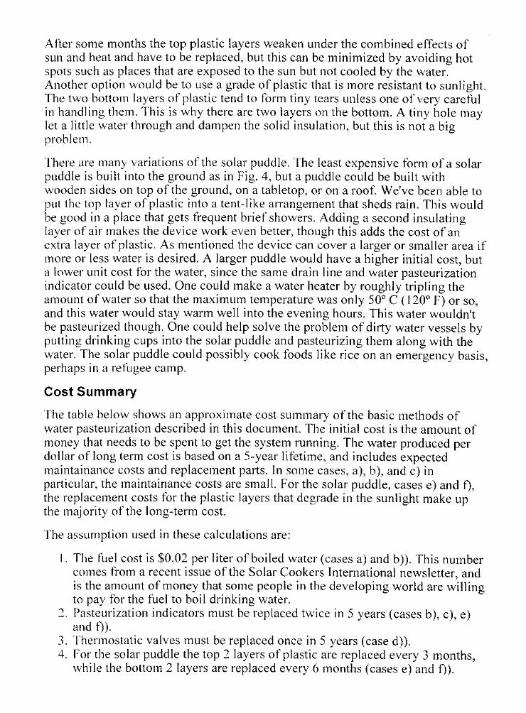
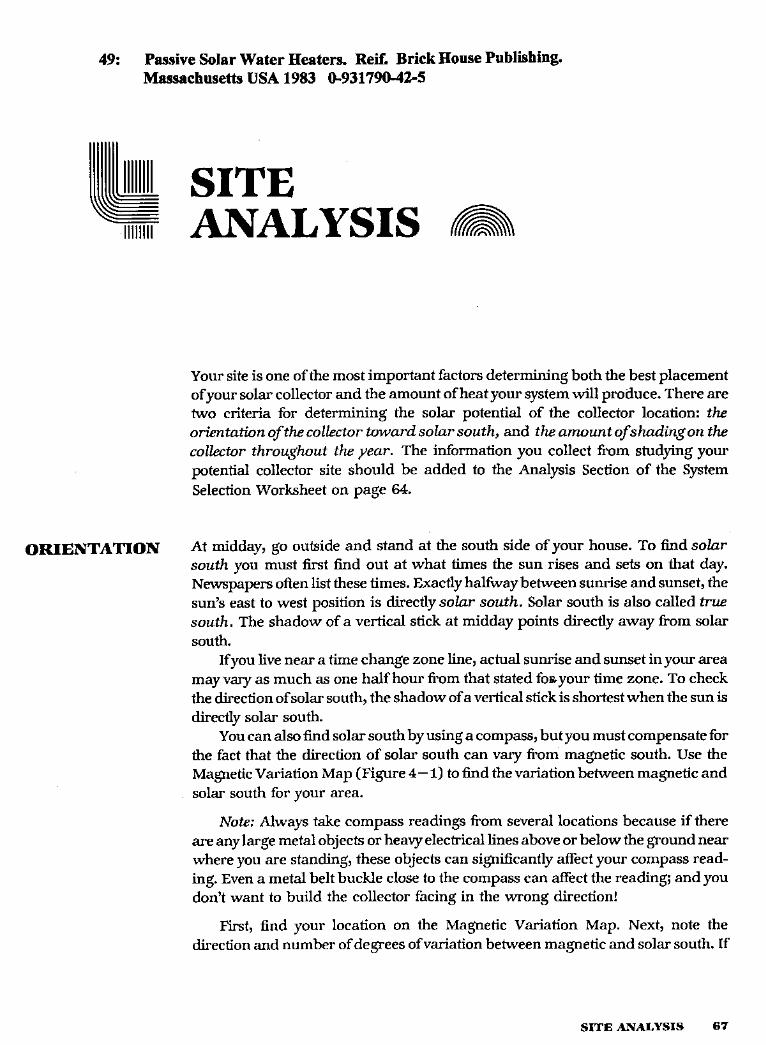
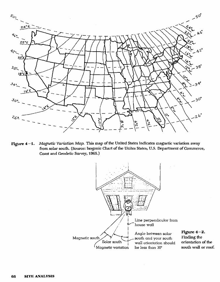
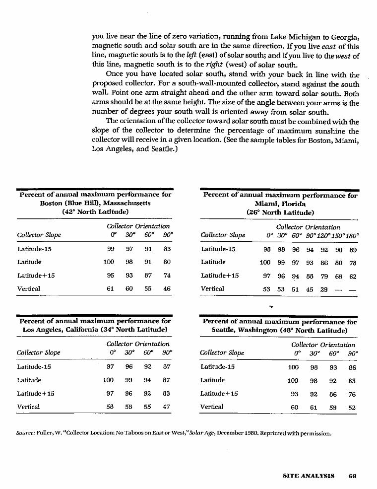
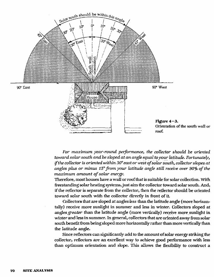
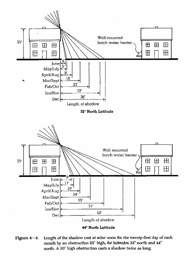
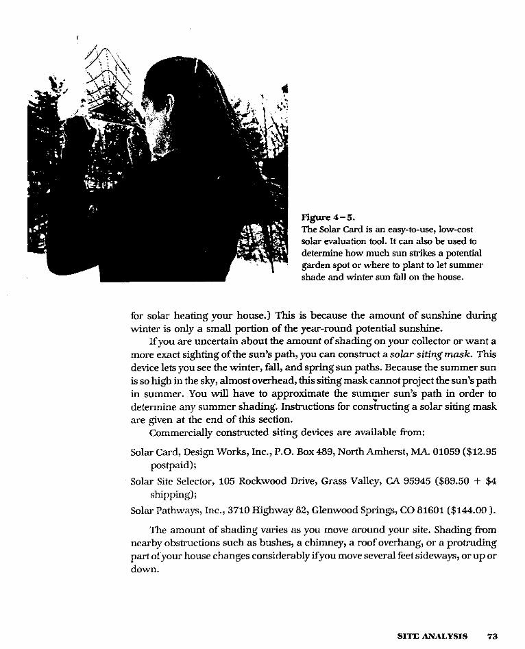
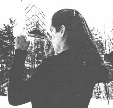
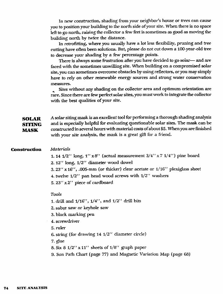
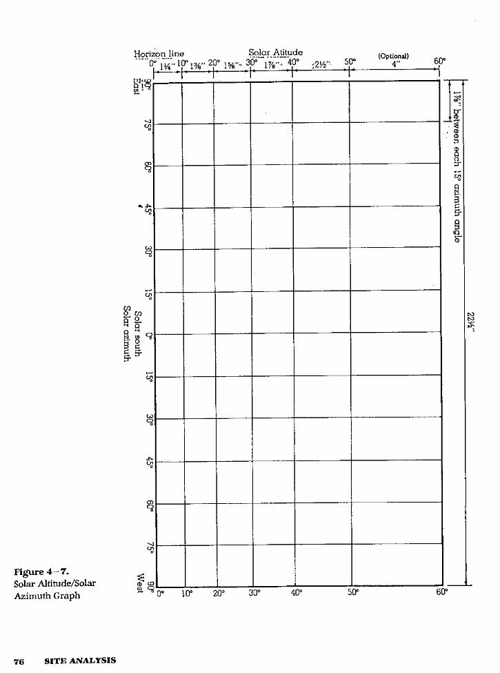
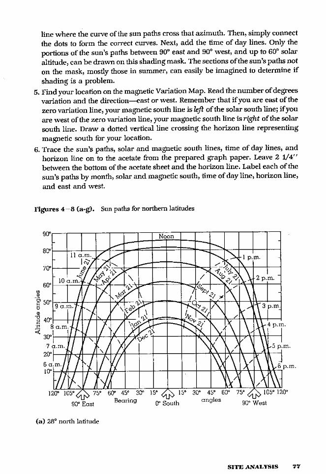
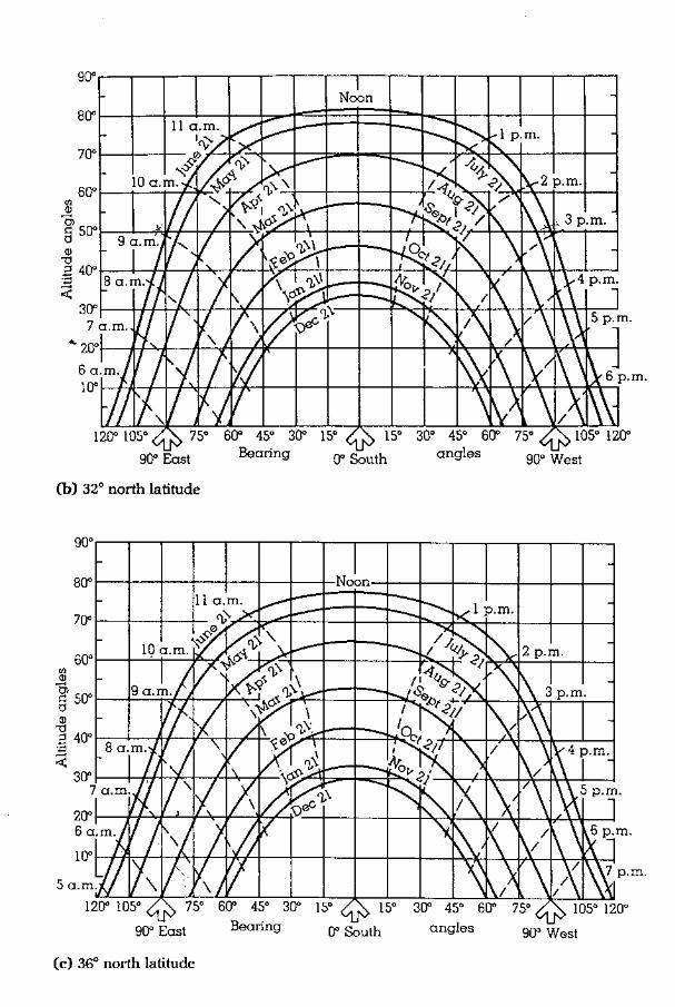
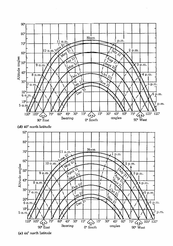
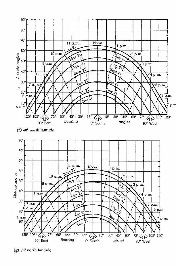
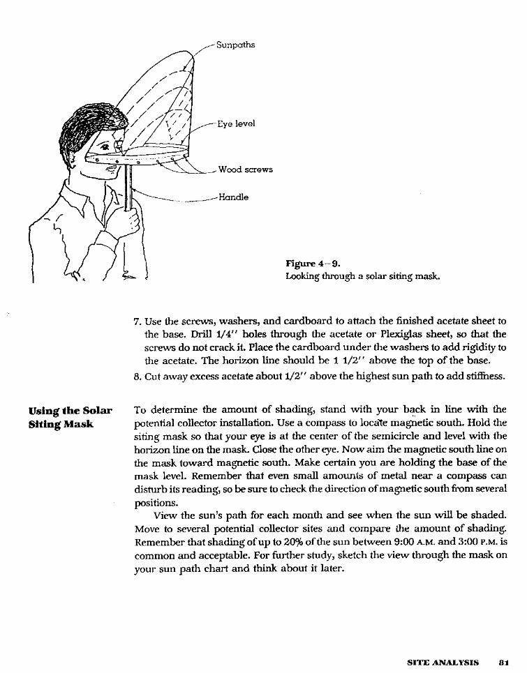
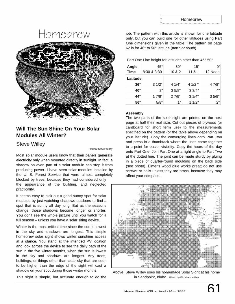
61Home Power #28 • April / May 1992
Will The Sun Shine On Your SolarModules All Winter?
Steve Willey©1992 Steve Willey
Most solar module users know that their panels generateelectricity only when mounted directly in sunlight. In fact, ashadow on even part of a solar module can stop it fromproducing power. I have seen solar modules installed bythe U. S. Forest Service that were almost completelyblocked by trees, because they had considered onlythe appearance of the building, and neglectedpracticality.
It seems easy to pick out a good sunny spot for solarmodules by just watching shadows outdoors to find aspot that is sunny all day long. But as the seasonschange, those shadows become longer or shorter.You don't see the whole picture until you watch for afull season – unless you have a solar siting device.
Winter is the most critical time since the sun is lowestin the sky and shadows are longest. This simplehomebrew solar sight shows winter sunshine accessat a glance. You stand at the intended PV locationand look across the device to see the daily path of thesun in the five winter months, when the sun is lowestin the sky and shadows are longest. Any trees,buildings, or things other than clear sky that are seento be higher than the edge of the sight will cast ashadow on your spot during those winter months.
This sight is simple, but accurate enough to do the
Part One Line height for latitudes other than 46°-50°
Angle 45° 30° 15° 0°Time 8:30 & 3:30 10 & 2 11 & 1 12 Noon
Latitude
36° 3 1/2" 4 1/4" 4 1/2 " 4 7/8"
40° 2" 3 5/8" 3 3/4" 4"
44° 1 7/8" 2 7/8" 3 1/4" 3 5/8"
56° 5/8" 1" 1 1/2" 2"
Homebrew
Homebrew job. The pattern with this article is shown for one latitudeonly, but you can build one for other latitudes using PartOne dimensions given in the table. The pattern on page62 is for 46° to 50° latitude (north or south).
AssemblyThe two parts of the solar sight are printed on the nextpage at half their real size. Cut out pieces of plywood (orcardboard for short term use) to the measurementsspecified on the pattern (or the table above depending onyour latitude). Copy the converging lines onto Part Twoand press in a thumbtack where the lines come togetherto a point for easier visibility. Copy the hours of the dayonto Part One. Join Part One at a right angle to Part Twoat the dotted line. The joint can be made sturdy by gluingin a piece of quarter-round moulding on the back side(see photo). Elmer's wood glue works great; do not usescrews or nails unless they are brass, because they mayaffect your compass.
Above: Steve Willey uses his homemade Solar Sight at his homein Sandpoint, Idaho. Photo by Elizabeth Willey
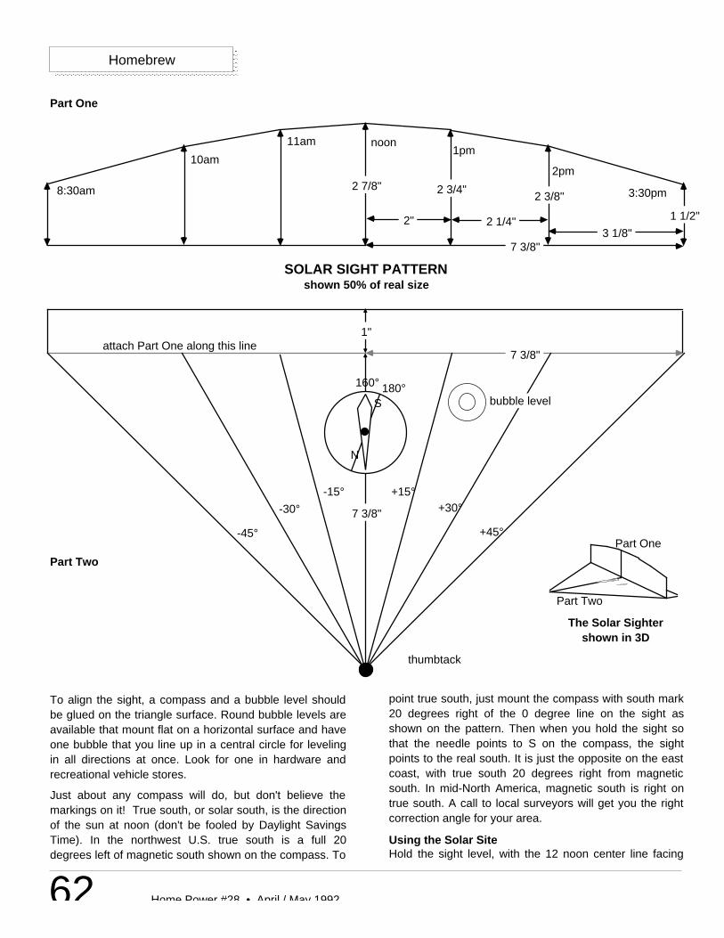
62 Home Power #28 • April / May 1992
Homebrew
2 7/8" 2 3/4"
1 1/2"
7 3/8"
2"
2 3/8"
3 1/8" 2 1/4"
8:30am
10am
11am noon1pm
2pm
3:30pm
7 3/8"
7 3/8"
+15°+30°
+45°
-15°
-30°
-45°
1" attach Part One along this line
bubble levelS
N
160° 180°
thumbtack
Part One
Part Two
The Solar Sightershown in 3D
Part One
Part Two
SOLAR SIGHT PATTERNshown 50% of real size
To align the sight, a compass and a bubble level shouldbe glued on the triangle surface. Round bubble levels areavailable that mount flat on a horizontal surface and haveone bubble that you line up in a central circle for levelingin all directions at once. Look for one in hardware andrecreational vehicle stores.
Just about any compass will do, but don't believe themarkings on it! True south, or solar south, is the directionof the sun at noon (don't be fooled by Daylight SavingsTime). In the northwest U.S. true south is a full 20degrees left of magnetic south shown on the compass. To
point true south, just mount the compass with south mark20 degrees right of the 0 degree line on the sight asshown on the pattern. Then when you hold the sight sothat the needle points to S on the compass, the sightpoints to the real south. It is just the opposite on the eastcoast, with true south 20 degrees right from magneticsouth. In mid-North America, magnetic south is right ontrue south. A call to local surveyors will get you the rightcorrection angle for your area.
Using the Solar SiteHold the sight level, with the 12 noon center line facing
63Home Power #28 • April / May 1992
true solar south. Put the head of the thumb tack infront of your eye and gaze up across the top edgeof the site. Be sure you are looking right along astraight line starting at the thumb tack and rising tothe upper edge of the sight, where the time of dayis marked, your eye always level with the thumbtack. What you see just over the edgeapproximately represents the sun's path inNovember, December and January, at the time ofday shown. Mentally add 1-1/4 inch to the heightof the sight to see the sun's path in October andFebruary. Any trees or mountains or buildings thatyou can see above the curved sight edge will casta shadow on you in those months. Ideally, youwant to see only sky.
AccessAuthor: Steve Willey, Backwoods Solar ElectricSystems, 8530 Rapid Lightning Creek Road,Sandpoint, ID 83864 • 208-263-4290.
Homebrew
Solar Electric Inccamera-ready
Active Techcamera-ready
Energy Systems & Design Camera-ready
Independent Energy Systems
For a real quantum leap in Photon Capture Economics
PLUG INTO
1 Dozen Solarex MSX60's $50281 Dozen Siemens M55's $516620% off Wattsun 12 Panel Tracker $1265
Prices incl. Delivery to Lower 48. WA residents add 8.2% tax
Look Windward West of the Mississippiand you'll see
Independent Energy Systems
Bergey & Jacobs Turbines 1.5kW to 20kW
( all new machines, no bootleg or remanufactured parts)
New JACOBS 20kW on 100 ft. tower $30,000 INSTALLED!!!Let's get Them Flying!!!
• Windturbines 300W to 300kW• Wind, hydro & solar electric designs• Contractor with 15 years of remote power experience• Send $10 for equipment catalog & design manual
MICHAEL F. KITCHEN • 14306 BATTEN ROAD NE •DUVALL WA 98019 • (206) 839-9361 • (206) 788-4569
Tradewind's OdometerWhisper 1000 Turbine
New Whisper 3000 watt Turbine
$110$1235$2650