solarpower europe o&m best practices guidelines · the o&m business across europe is also...
TRANSCRIPT

1 / SolarPower Europe / O&M Best Practices Guidelines
SolarPower Europe O&M Best Practices Guidelines Version 1.0, June 2016
Supported by:

2 / SolarPower Europe / O&M Best Practices Guidelines

SolarPower Europe / O&M Best Practices Guidelines / 3
Foreword
All the evidence points towards the fact that Operations and Maintenance (O&M) are being recognized
for their critical role in optimizing photovoltaic solar power assets. O&M has long evolved from the
days of being an add-on to Engineering, Procurement and Construction (EPC) contracts and has
charted its own course to become a standalone industry that is seen as a critical component in the
solar energy value chain.
This, of course, has led to consolidation within the industry and a clear distinction between the
competencies of service providers. In fact, as O&M industry leaders professionalize and establish
new benchmarks, asset owners have seen the inevitable gap in knowledge and skills between
services providers with varying capabilities.
This led to the recognition by the industry, represented by the members of Solar Power Europe, that
a joint effort was required to collate, filter, and then communicate what should ideally be the
universally accepted standard for professional O&M services. Thus, the Task Force on O&M Best
Practices and Guidelines, led by First Solar and coordinated by SolarPower Europe, was born.
The collaboration of almost 3 dozen solar energy professionals has been outstanding and we are
expecting, that this document will be enhanced and improved over time. We trust, that the
experience of all participating professionals, allies as well as competitors, representing O&M Service
Providers, Asset Owners, Asset Managers, Technical Advisors and manufacturers provides a very
good overview of what the reader shall expect when considering O&M for utility-scale PV power
plants.
The market for services around solar PV assets is changing and becoming increasingly mature. This
leads to the observation, that O&M is becoming a business and is separating from EPC, which it was
attached to in the early years of the industry. The O&M business across Europe is also consolidating
and specialised companies are offering their services. In these guidelines O&M focuses on the
technical operations and maintenance services for utility-scale PV power plants. Asset management,
which is also a very important piece of PV plant ownership, is seen to cover all the commercial and
administrative activities of importance during the lifetime of the plant. Since the responsibilities of
O&M and asset management cannot be separated along a clearly defined line of tasks or items,
SolarPower Europe welcome feedback on this document, which aims to capture the experience now.
As our industry evolves there will always be room for improvement, also in the content of this
document, please do take the time to let us know of your experience and the value of these
guidelines.
Enjoy this report! Your feedback is more than welcome on any aspect, in order to improve the next version and make it more impactful for our industry. Stefan Degener James Watson
Senior Director O&M Chief Executive Officer First Solar Energy Services O&M Task Force Leader

4
Task Force Coordinator
Ioannis Thomas Theologitis, SolarPower Europe
Contributions and co-authors
SolarPower Europe O&M Task Force members (see the full list in the next page)
Acknowledgements
SolarPower Europe would like to extend special thanks to all the Task Force Members that contributed
with their knowledge and experience to this report. This work would never have been realized without
their continuous support.
Project Information
The SolarPower Europe O&M Task Force officially started its work in April 2015 and continues with
frequent exchanges and meetings. The first version of the Best Practices Guidelines is a product of
one year and reflects the views of a considerable share of the O&M industry in the EU today. There
has been no external funding or sponsoring for this project.
Supported
By Intersolar Europe
Disclaimer
Adherence to the “O&M Best Practices Guidelines” version 1.0 report and its by-products is voluntary.
SolarPower Europe and the Task Force members hold no responsibility for misinterpretations or
misuse of the content and will provide no indemnities. Any stakeholders that adhere to this version
are responsible for self-certifying that they have fulfilled the guide requirements.
Please note that version 1.0 is subject to further changes, updates and improvements.

SolarPower Europe / O&M Best Practices Guidelines / 5
Task Force Members
Stefan Degener, First Solar
Achim Woyte, 3E
Stefan Jensen, 3E
Heinz Hackmann, Adler Solar
Patrick Wurster, tco-solar
Wolfgang Rosenberg, tco-solar
Vassilis Papaeconomou, Alectris
Richard Jackson, Lark Energy
Paolo Chiantore, Kenergia Sviluppo
Paolo Di Ciaccio, Kenergia Sviluppo
Bengt Jaeckel, UL
Iain Davidson, Solarcentury
Jose Guinea, Martifer Solar
Vasco Vieira, Martifer Solar
Angus Campbell, British Solar Renewables
Lucie Garreau Iles, DuPont Photovoltaic Solutions
Anna Vidlund, Fortum
Ignasi Sospedra, Trinal Solar
Martin Nuemeyr, Meteocontrol
Tobias Knoblauch, Meteocontrol
Paolo Seripa, Enel Green Power
Angelo Guardo, Enel Green Power
Kenneth Heidecke, Conergy Services
Bjarn Roese, Conergy Services
Nicola Waters, Primrose Solar Management
Oliver Laufmann, Schneider-Electric
Adrian Timbus, ABB
Juan Carlos Gonzalez, Jinko Solar
John Messaritis, Messaritis
Martyn Berry, Enphase Energy
Etienne Lecompte, Powerhub
Aristotelis Biliouris, Iris Hellas
6
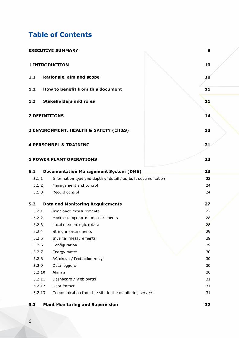
Table of Contents
EXECUTIVE SUMMARY 9
1 INTRODUCTION 10
1.1 Rationale, aim and scope 10
1.2 How to benefit from this document 11
1.3 Stakeholders and roles 11
2 DEFINITIONS 14
3 ENVIRONMENT, HEALTH & SAFETY (EH&S) 18
4 PERSONNEL & TRAINING 21
5 POWER PLANT OPERATIONS 23
5.1 Documentation Management System (DMS) 23
5.1.1 Information type and depth of detail / as-built documentation 23
5.1.2 Management and control 24
5.1.3 Record control 24
5.2 Data and Monitoring Requirements 27
5.2.1 Irradiance measurements 27
5.2.2 Module temperature measurements 28
5.2.3 Local meteorological data 28
5.2.4 String measurements 29
5.2.5 Inverter measurements 29
5.2.6 Configuration 29
5.2.7 Energy meter 30
5.2.8 AC circuit / Protection relay 30
5.2.9 Data loggers 30
5.2.10 Alarms 30
5.2.11 Dashboard / Web portal 31
5.2.12 Data format 31
5.2.13 Communication from the site to the monitoring servers 31
5.3 Plant Monitoring and Supervision 32

SolarPower Europe / O&M Best Practices Guidelines / 7
5.4 Performance Analysis & Improvement 32
5.5 Predictive Maintenance 32
5.6 Plant Controls 34
5.7 Power Generation Forecasting 34
5.8 Reporting 35
5.9 Regulatory compliance 36
5.9.1 Grid code compliance requirements 36
5.10 Management of change 37
5.11 Warranty management 37
5.11.1 Warranty of good execution of works and equipment warranties 38
5.11.2 Performance Warranty 39
5.12 Insurance claims 39
6 SPARE PARTS MANAGEMENT 40
7 POWER PLANT MAINTENANCE 43
7.1 Preventative Maintenance 43
7.2 Corrective Maintenance 43
7.3 Extraordinary Maintenance 44
7.4 Additional Services 45
8 SOLAR PV PLANT SECURITY 46
9 CONTRACT MANAGEMENT 47
10 KEY PERFORMANCE INDICATORS (KPIS) 48
10.1 PV plant KPIs 48
10.1.1 Availability 48
10.1.2 Energy-based availability 50
10.1.3 Performance Ratio 51
10.1.4 Energy Performance Index 52
10.2 O&M Contractor KPIs 52

8
10.2.1 Reaction Time 52
10.2.2 Reporting 53
10.2.3 O&M Contractor experience 53
10.2.4 Maintenance Effectiveness & Maintenance Support Efficiency 53
11 CONTRACTUAL COMMITMENTS 54
11.1 O&M Contractors Qualification 54
11.2 Responsibility and Accountability 54
11.3 Bonus Schemes and Liquidated Damages 55
REFERENCES 56

SolarPower Europe / O&M Best Practices Guidelines / 9
EXECUTIVE SUMMARY
The provision of Operation and Maintenance (O&M) services has been emerging as an important field
for the photovoltaic (PV) sector. Over the last couple of years there have been major developments in
this part of the value chain and there is no doubt that demand for O&M services worldwide will only
increase. The universal recognition of the positive factual impact that professional O&M has on the
technical and economic lifetime performance of solar PV system, especially in a period with many
changes in the regulatory and support scheme environment, supports that forecast.
On the brink of the “post 100 GW solar PV” era, Europe has the potential to be positioned at the
forefront of O&M provision within the solar sector, create value and be the beacon for other regions
and markets. The boom and bust market development in many EU countries over the last years has
left an aging fleet that requires proper “health care” for the rest of its “life” in order to meet its
performance expectations and consequently strengthen the reliability of the PV system facilitating
solar’s evolution into mainstream electricity supply.
Acknowledging the above, SolarPower Europe initiated a dedicated Task Force (TF) where leading
stakeholders have come together to share knowledge and years of experience, with a sole objective
to identify and develop industry-led Best Practices Guidelines on how to provide professional O&M
services. Our motivation to set up this Task Force came from the following factors: The lack of
standardisation in O&M service provision, the shortcomings and bad practices found in the field, the
lack of awareness and negligence towards incorporating proper O&M services, the untapped
opportunity to optimise assets and the impact on investment returns.
The companies involved come from across the supply chain – O&M contractors, asset managers,
developers, manufacturers, monitoring solutions providers, consultants and utilities – covering the
largest share of EU capacity which is under O&M provision and bringing valuable international
experience.
The current version of the report (version 1.0) is a product of one year’s work and covers all the
main responsibilities of the O&M contractor, classifying them when possible into minimum
requirements and best practices. This distinction was deemed necessary in order to cover first the
important tasks below which the O&M provision is considered as poor or insufficient and then suggest,
when available, best practices which can add to the quality of the service. Minimum requirements
form a quality benchmark for a professional and bankable service provider and of course a high level
asset performance.
The scope of this version is ground mounted systems of 1MW and above (utility scale) which cover
nowadays more than one third of the installed capacity in Europe. The report starts with clarifying
the roles of the main stakeholders involved, building an understanding of the respective
responsibilities and then dives into the main aspects of O&M and the tasks of the O&M contractor,
covering both technical but mainly non-technical tasks. The Task Force has also identified
shortcomings in the Operations field where standardization is less present and therefore, this report
tries to list in a concise and simple way important steps that should be taken (e.g. how to do
predictive, preventative and corrective maintenance, contract management, reporting, what are the
monitoring requirements etc.).
Attached to this report, a suggested Maintenance Plan has been created (excel sheet) which covers
all periodic actions to prevent failures and ensure optimal operating conditions of equipment and of
the entire PV plant (Preventative Maintenance).
This report has been drafted to be primarily used by O&M contractors, asset managers and owners,
investors, and developers, but it can be a valuable tool for all relevant stakeholders with interests
both in the primary and secondary market.
In the future, the Task Force will extend the report, improve it with additional inputs, include national
consideration and effectively promote it in- and outside of Europe, aiming at increasing the
consensus.

10
1 Introduction
1.1 Rationale, aim and scope
A professional O&M service package ensures that the photovoltaic system will maintain high levels
of technical and consequently economic performance over its lifetime. Nowadays, it is well
acknowledged by all stakeholders that high quality of O&M services mitigates the potential risks,
improves the levelised cost of electricity (LCOE) and Power Purchase Agreement (PPA) prices and
positively impacts the return on investment (ROI). This can be highlighted if one considers the
lifecycle of a PV project which can be broken down into the 4 phases below. The O&M phase is by far
the longest phase.
Development (typically 1-3 years)
Construction (some months)
Operation & Maintenance (typically 20-35 years)
Dismantling or repowering (some months)
Therefore, the benefits for increasing the quality and in contrast the risks for neglecting O&M are
high. The PV industry – a “young” industry that evolves also in the services part – offers a wide range
of practices and approaches. Although this is partly logical, reflecting the specificities of each system,
topologies, installation sites and country requirements, there is a confusion or lack of clarity and
knowledge by many asset owners and the funding authorities (investors or/and banks) of what the
minimum requirements should be. In cases, especially in the past where feed-in tariffs were very
high and favourable, there was a clear lack of risk perception in combination with an underestimated
performance metrics definition which hindered the proof of value of a professional and high quality
service provision.
Existing standardisation still does not fill in the gaps, or clarify the requirements and their
implementation. Although in the Maintenance part, there are a number of technical international
standards that can be followed, in the Operations field where more planning, scheduling and
administrative related tasks are also covered the shortcomings are many. Therefore, it is crucial to
develop best practices in order to optimise the Operations, meaning the energy production, the power
plant management, and resulting benefits. This will set the quality bar high and enhance the
understanding and confidence of the investors.
SolarPower Europe and its respective Task Force aims at contributing with the present “O&M Best
Practices Guidelines” to reach this objective and improve the communication among the different
stakeholders. The value proposition of this report is that it is industry-led, containing the knowledge
and the experience of well-established and leading companies in the field of service provision, project
development and construction (EPC), asset management, utilities, manufacturers and monitoring
tool providers.
The scope of the current work includes the utility scale segment and more specifically, systems above
1MW. The geographical focus is Europe. The “O&M Best Practices Guidelines” version 1.0 provides
the high level requirements that can be applied in all countries around Europe (and beyond). Specific
national considerations are not included and should enhance this version if this is to be used in
specific countries. Adoption is considered effortless.

SolarPower Europe / O&M Best Practices Guidelines / 11
The content covers technical and non-technical requirements, classifying them when possible into
minimum requirements and best practices. This distinction was deemed necessary in order to cover
first the important tasks below which the O&M provision is considered as poor or insufficient and
then suggest, when available, best practices which can add to the quality of the service. Minimum
requirements (whatever is not referred as best practice in the text) form a quality benchmark for a
professional and bankable service provider and of course a high level asset performance.
1.2 How to benefit from this document
This report includes the main and important considerations for a successful and professional O&M
provision. Although it has not been tailored for each stakeholder, the use is similar for all; understand
the mandatory requirements and necessity of a professional O&M and incorporate accordingly those
guidelines into the service package. Any of the directly relevant stakeholders (see chapter 1.3 below)
can benefit from this work, tailor it to their needs without lowering the bar and know what to ask for,
offer or expect.
Although the focus is European, most of the content can be used in other regions around the world,
especially in those with similar conditions and moderate climate. Additional requirements or
modifications can easily take place for other regions with unique characteristics.
1.3 Stakeholders and roles
Usually multiple stakeholders interact in the O&M phase and therefore it is important to clarify as much as possible the different roles and responsibilities. These can be abstracted to the following basic roles:
Asset Owner
The stakeholder who contributes to financing of construction and operation of the PV power plant is normally the investor (or a group of investors), who can be classified as private individuals, financing investors or investment funds and Independent Power Producers (IPPs) or Utilities. Assets are
generally owned by “Special Purpose Vehicles” (SPV), i.e. limited liability companies, specifically
incorporated for building, owning and operating one or more PV plants.
Lender
Lender or debt provider (financing bank) is not considered as an “asset owner” even if the loans are backed up by securities (collateral). In principal, the interests and performance expectations are different between the investor (equity provider) and the lender who normally measures the risk based on the debt service coverage ratio (DSCR). The role of the lender is becoming more and more
“smart” and less passive, with enhanced considerations and involvement regarding the requirements for the debt provision.
Asset Manager
Asset management aims at ensuring optimal profitability of the PV power plant (or a portfolio of plants) by supervising energy sales, energy production, and O&M activities. It also ensures the fulfilment of all the administrative, fiscal, insurance and financial obligations of the SPVs. Therefore,
this role has a financial as well as a technical aspect. Asset Managers report to Asset Owners. In
some cases, in particular where SPVs belong to large Asset owners such as utilities or large IPPs, the Asset management activity is done in-house.
O&M Contractor
The entity that is in charge of O&M activities as defined in the O&M contract. In some cases, this role
can be subdivided into:
12
Operations service provider (team) who is in charge of monitoring, supervision and
control of the PV power plant, management of maintenance activities, and reporting to Asset
manager.
Maintenance service provider (team) who carries out maintenance activities.
A comprehensive set of O&M activities (technical and non-technical) is presented in this report.
However, the two activities are often provided by a single entity through a full service O&M contract.
Technical Advisors / Engineers
These are individuals or teams of experts that provide specialized services (e.g. detailed information, advice, technical consulting etc.). Their role is rather important since they ensure that procedures and practices are robust and of high quality – according to standards and best practices – to maintain high performance levels of the PV plant. Technical advisors can represent different stakeholders (e.g. investors, lenders)
Specialised suppliers
Such suppliers could be of specialised services (e.g., technical consulting) or hardware (e.g., electricity generating components, security system).
Authorities
These can be local (e.g., the mayor), regional (e.g., the provincial or regional authorities supervising environmental constraints), national (e.g., the national grid operator), or international (e.g., the
authors of a European grid code).
Off-taker
The entity who pays for the produced electricity. This role is still evolving and is often subdivided according to national renewable power support resp. purchase schemes:
The state or national grid operator / electricity seller(s), or specific authorities for renewable
(such as GSE in Italy) in a feed-in tariff (FIT) scheme.
Energy traders or direct sellers in a direct marketing scheme.
End customers in schemes that underline autonomy in energy supply.
The aforementioned basic abstract stakeholders and roles should support the provision of the necessary services and transfer the guidelines of this report to real life situations, where in cases either one stakeholder/party may take over several roles and responsibilities or one role might be represented by several parties. For example:
Investor may take asset management responsibilities
Asset manager may take over a more active role and intervene in operations
Asset manager may even take over full O&M
O&M contractor role may be subdivided as already mentioned but may also include some
asset management activities (e.g. electricity sale, insurance, fiscal registrations, etc.)
End customer (or electricity buyer) may be at the same time asset owner, asset manager,
and O&M contractor (e.g. PV power plant on an industrial site to cover own energy needs)
In Figure 1 below there is an attempt to classify and distribute in a clear way the responsibilities
among the different stakeholders and in particular among the Asset Manager (Asset management),
the O&M Contractor (Operations Management & Maintenance) and the EPC (Engineering,
Procurement, Construction). This was presented in a past study from GTM Research1 and is a simple
and well-accepted allocation of tasks.
1 The figure is redesigned and based on a figure from GTM Research report: “Megawatt-Scale PV Plant Operations and Maintenance: Services, Markets and Competitors, 2013-2017”, 2013

SolarPower Europe / O&M Best Practices Guidelines / 13
It is shown that the supervision of the O&M activities is under the “technical asset management”
(when externalised2) and in most cases the O&M Contractor will have a more technical role (energy
output optimization) and the asset manager will undertake more commercial responsibilities
(financial optimization).
Figure 1: Roles and responsibilities by different stakeholders in the field of O&M
However, experience shows that in cases, and due to the current developments of the O&M market
in the PV sector, the role of the Asset manager as described above can overlap with the role of the
O&M Contractor as this is described in current contracts. The O&M Contractor then, and when
requested and if qualified, can be assigned to manage more commercial tasks or represent the Asset
manager (even the Asset Owner) in front of third parties. In fact, today, most of the O&M Contractors
are equipped to offer asset management services, having in-house financial/commercial skills.
This grey zone of responsibilities makes it difficult to standardize properly the responsibilities of each
stakeholder. In this perspective it is important that contracts define as precisely as possible scope,
rights and obligations of each party and the general work order management.
However, all stakeholders should have a good understanding of both technical and financial aspects in order to ensure a successful and impactful implementation of services. That will require for Asset Managers to have technical skills in-house for a meaningful supervision and proper assessment of
the technical solutions, and O&M Contractors to have the ability to cost-assess and prioritize their operational decisions and maintenance services.
2 It is acknowledged that nowadays there are entities which provide both asset managements and O&M services. However, in this report, it is assumed to be kept separately and provided by separate entities.

14
2 Definitions
This section introduces a basic set of definitions of important terms that are widely used in the O&M
field (contracts) and is necessary for all different stakeholders to have a common understanding. In
general, there are standards in place that explain some of these terms, however, it is still difficult in
practice to agree on the boundaries of those terms and what exactly is expected under these terms
or services (e.g. the different types of maintenances or operational tasks).
Indeed, it is more challenging for terms in the Operational field since those are less technical and
not standardized as in the case for Maintenance. The chapter provides a short list (alphabetically
ordered) below which is not exhaustive, but reflects the different sections of this document. For the
definitions of the Maintenance the EN 13306 was used as a base.
1. Additional Services Actions and/or works performed, managed or
overseen by the O&M Contractor, which are not
(but can be if agreed) part of the regular
services and normally charged “as-you-go”,
e.g. ground maintenance, module cleaning,
security services etc. Some of the Additional
Services can be found as a part of the
Preventive Maintenance, depending on the
contractual agreement.
2. Contract management Activities related to the proper fulfilment of
O&M contract obligations such as reporting,
billing, contract amendments, regulator
interaction, etc.
3. Contractual Commitments An agreement with specific terms between the
asset owner and the O&M Contractor. This
agreement defines in details the O&M services,
both remote operations services and local
maintenance activities, the management and
interfaces of those services, as well as the
responsibilities of each party. Liquidated
damages and bonus schemes are also part of
the contractual commitments.
4. Control Room Services/ Operations Centre Services
Comprehensive actions like PV plant
monitoring, supervision, remote controls,
management of maintenance activities,
interaction with grid operators, regulators,
Asset Managers and Asset Owner, as well as
the preparation and provision of regular
reporting performed by experienced and

SolarPower Europe / O&M Best Practices Guidelines / 15
qualified staff in a control Room during
operational hours for 365days/year.
5. Corrective maintenance Actions and/or techniques (immediate or
deferred) taken to correct failures,
breakdowns, malfunctions, anomalies or
damages detected during inspections, or
through monitoring, alarming, or reporting or
any other source. The actions are desired to
restore the PV system back into regular and
required operation mode.
6. Data and monitoring requirements Hardware and software, technical and
functional specifications to collect, transmit and
store production, performance and
environmental data for plant management.
7. Documentation management system A management system that records, manages
and stores documents required for O&M, such
as technical plant and equipment
documentation and drawings, maintenance
manuals, photos and reports, including the
various versions that are being created by
different users, reviews and approvals.
Documentation management system also
defines a proper format and use (information
exchange).
8. Environment Health & Safety (EH&S) Environment, Health and Safety indicates the
activities performed to ensure environmental
protection, occupational health and safety at
work and on site applicable to staff and visitors
according to the national applicable laws and
regulations.
9. Extraordinary maintenance Actions and/or works performed in case of
major unpredictable faults, such as serial
defects, force majeure events etc., that are
generally considered outside of the ordinary
course of business.
10. Grid code compliance requirements Equipment, procedures, actions and activities
required by the respective grid operator(s) in
order to comply to grid safety, power quality
and operating specifications.
11. Insurance claims Customer’s activities required to claim a
reimbursement based on specific insurance
policy terms.
12. Key Performance Indicator (KPI) A technical parameter that helps the
stakeholders to evaluate the successful
operation of a PV plant and/or the success of
the O&M Contractor’s activities.
13. Management of change Management of change defines the way to
handle necessary adjustments of design of a PV
power plant after the Commercial Operation

16
Date. Changes require a close cooperation
between the plant owner and the O&M
Contractor.
14. Performance Analysis & Improvement Measurements, calculations, trending,
comparisons, inspections, etc. performed in
order to evaluate PV plant, segments and/or
single component performance, site conditions,
equipment behaviour, etc., and to provide
reports and assessment studies to whom it may
concern (customer, public authority, etc.).
15. Personnel & Training Operators, technicians, engineers and
managers employed for the execution of the
O&M activities and training plans/programmes
to train them on relevant PV plant related
aspects and to keep them continuously updated
on their respective roles.
16. Plant Control Actions required by the grid operator, for
controlling active and/or reactive power being
fed into the grid, other power quality factors
that are subject to adjustments and/or
(emergency) shut down (if applicable).
17. Plant Monitoring Overall monitoring of the functioning, energy
generation and reference data of the PV plant
and its components, which is performed
through real-time (web based) monitoring
software. The monitoring operates 24h/365d
and is fed by in-plant data-logging systems that
collects data from different plants as well as by
irradiation and temperature measurements
from particular sensors and other sources such
as meteorological information (data acquisition
24h/365d).
18. Plant Supervision The activity to supervise and analyse data
provided by the monitoring system which is
performed by experienced human resources
during daylight hours and managed by one or
more control rooms (365 days/year). The
reception and qualification of the alarms from
the monitoring tool is also considered to be part
of the supervision.
19. Predictive maintenance Actions and/or techniques that are performed
to help assess the condition of a PV system and
its components, predict/forecast and
recommend when maintenance actions should
be performed. The prediction is derived from
the analysis and evaluation of significant
parameters of the component (e.g. parameters
related to degradation). Monitoring systems
and respective expert knowledge base is used
to identify the appropriate actions based on a
cost benefit analysis.

SolarPower Europe / O&M Best Practices Guidelines / 17
20. Preventative maintenance Actions and/or testing and/or measurements to
ensure optimal operating conditions of
equipment and of the entire PV plant and to
prevent defects and failures. Those take place
periodically and according to a specific
maintenance-plan and maintenance schedules.
21. Power Generation Forecasting Adoption of forecasting tools calculating
expected power production for a certain
timeframe from weather forecasts in order to
supply the expected power production to
owner, grid operator, energy traders or others.
This is normally country and plant dependent.
22. Regulatory compliance Compliance to any law, statute, directive,
bylaw, regulation, rule, order, delegated
legislation or subordinate legislation directly
applicable in the country where the service is
provided, as well as to any mandatory
guidelines and measures issued by a utility and
any other competent public authority.
23. Reporting and other deliverables Deliverables produced periodically, according
to requirements detailed in the O&M agreement
or following best market practices, including PV
plant performance, Key Performance
Indicators, maintenance activities and work
orders performed, alarm handling, equipment
status, warranty handling activities and spare
parts tracking and any other Analysis
performed in compliance with the O&M contract
requirements.
24. Security Actions, procedures, equipment and/or
techniques that are adopted on site and
remotely in order to protect the plant from
theft, vandalism, fire, etc.
25. Spare parts management Activities that ensure availability of the right
amount and type of components, equipment,
parts, etc. either on site or in warehouses or in
manufacturers’ consignment stocks, for prompt
replacement in case of failure and/or to meet
guarantees under O&M contracts.
26. Warranty management Warranty management usually aggregates
activities of diverse nature which are linked to
areas such as supply of equipment and
services, and project construction. All these
responsibilities (warranties) are usually
materialized with the issue of the Provisional
Acceptance Certificate (PAC) by the EPC.
Warranty Management is the activity that
manages these warranties with the objective of
reducing the costs and response times after
warranty claims for repair or replacement of
certain PV system components (under the
warranty of the EPC and/or the components
manufacturer).

18
3 Environment, Health & Safety (EH&S)
The Asset Owner has the ultimate legal and moral responsibility to ensure the health and safety of
people in and around the solar plant and for the protection of the environment around it. The practical
implementation is normally subcontracted to the O&M Contractor.
Environment Renewable energies are popular because of their low environmental impact and it is important that
solar plants are operated and maintained to minimise any adverse effects. Environmental problems
are normally avoidable through proper plant design and maintenance – for example, bunds and
regular inspection of HV transformers will reduce the chances of significant oil leaks – but where
issues do occur the O&M Contractor must detect them and respond promptly. As well as the
environmental damage there may be financial or legal penalties for the owner of the plant.
Other aspects that need to be taken into account are recycling of broken panels and electric waste
so that glass, aluminium and semiconductor materials can be recovered and reused. In areas with
water scarcity, water use for module cleaning should be minimized.
In many situations, solar plants offer an opportunity, where managed sympathetically, to provide a
valuable natural habitat for plants and animals alongside the primary purpose of generation of
electricity. A well thought out environmental management plan can help promote the development
of natural habitat, as well as reduce the overall maintenance costs of managing the grounds of the
plant. It can also ensure the satisfaction of any legal requirements to protect or maintain the habitat
of the plant.
Health and Safety The risk to the health and safety of people from the solar plant is a primary concern of the O&M
Contractor. Solar plants are electricity generating power stations and have significant hazards
present which can result in permanent injury or death. Through proper hazard identification, careful
planning of works, briefing out of procedures to be followed, documented and regular inspection and
maintenance, risks are reduced (see also Solar PV Plant Security chapter 8).
The dangers of electricity are well known and can be effectively managed through properly controlled
access and supervision by the O&M Contractor. Any person coming on to a solar farm should expect
some form of induction to ensure they are briefed on any hazards and risks. Staff actually working
on electrical equipment must be appropriately trained, experienced and supervised, but it is also key
that others working around the equipment - for example panel cleaners - are equally aware of the
potential risks and have safe methods of working around HV and LV electricity.
Hazardous areas and equipment should carry appropriate marking to warn personnel of possible
hazards and wiring sequence. Such marking should be clear and evident to all personnel and third
parties (and intruders) entering the plant premises.
As well as the inherent dangers of a typical solar plant, every site will have its own set of individual
hazards which must be considered as a whole when working on the plant. An up to date plan of

SolarPower Europe / O&M Best Practices Guidelines / 19
hazards is important for the O&M Contractor to use to plan and manage his own staff and to provide
third party contractors with adequate information. It is usually the case that the O&M Contractor
holds the authority and responsibility to review and, where necessary, reject works taking place on
the plant. Failure to carry this out properly has important consequences to general safety.
Besides workers on the solar plant, it is not unusual for other parties to require access to it. This
may be the Asset Owner, or their representative, the landlord of the land, or in some situations
members of the public. It is important that the plant access control and security system keeps
people away from areas of danger and that they are appropriately supervised and inducted as
necessary.
The Asset Owner is ultimately the responsible for the compliance of H&S regulations within the
site/plant. He will make sure at all times that the installation and all equipment meets all the relevant
legislations of the country and also, that all contractors, workers and visitors respect the H&S
Legislation by strictly following all the established procedures, including the use of established
personal protective equipment (PPE).
At the same time, the O&M Contractor shall prepare and operate its own safety management systems
to be agreed with the Asset Owner taking into account site rules and the Works in relation to health
and safety and perceived hazards. The O&M Contractor shall ensure that it complies, and that all of
its subcontractors comply, at all times with the H&S Legislation.
The Asset Owner will have to require from the O&M Contractor to represent, warrant and undertake
to the Owner that it has the competence and that it will allocate adequate resources to perform the
duties of the principal contractor pursuant to specific national regulations for health and safety.
Before starting any activity on site the Asset Owner will deliver a risk assessment and method
statements to the O&M Contractor who will provide a complete list of personnel Training Certifications
and appoint a H&S coordinator. During the whole duration of the contract the O&M Contractor will
keep updated the H&S file of each site.
The O&M Contractor must have his personnel trained in full accordance with respective national legal
and professional requirements, that generally result in specific certification to be obtained, for
example in order to be allowed to work in MV and/or HV electrical plants. Within Europe, referral to
European Standards is not sufficient (examples of standards used today are ISO 14001, OHSAS
18001 etc.).
However, there are some basic cross cutting considerations that apply to each country and will ensure
proper compliance with basic requirements around H&S matters. Those can be found in Table 1
below:
Table 1: Examples for typical/minimum requirements for H&S
H&S – Examples for Minimum requirements3
Qualifications
Minimum level of entry and demonstration that the O&M Contractor and
respective personnel have served an apprenticeship. Provision of relevant documentation (proof) is required.
A certification scheme that covers technical and safety requirements for PV when available in the respective country. It is important for the solar industry to work towards that direction in Europe, in order to raise the bar and ensure high quality of trained and professional people. The skills’ matrix in chapter 4 could be a starting
point to filter the requirements needed.
Personal Protective Equipment
Minimum requirements for PPE are listed below (not exhaustive). The list
includes mandatory items and bespoke items based on risk assessment:
3 It should be noted that the content of this table is only indicative and based on typical but important requirements that are found in all national regulations. However, this list is not exhaustive and therefore the reader should not treat it is as such and always refer to the relevant national standards related to H&S. The authors and contributors of this report will hold no responsibility if the reader acts otherwise.

20
Safety shoes
High visibility (Hi-Vis) clothing
Helmet
Gloves (and/or insulated gloves for live work)
Flash masks and glasses (depending on the site)
Fire retardant and/or arc flash rated PPE where necessary
Equipment Only certificated and calibrated equipment that has full documentation should be used

SolarPower Europe / O&M Best Practices Guidelines / 21
4 Personnel & Training
It is of critical importance that both Operations and Maintenance Personnel have the relevant
qualifications to perform the works in a safe, responsible and accountable manner. It is difficult to
define exactly and in general not advisable to be rigid with the profile of the employees suitable to
carry out the work and meet the necessary requirements. Indeed, the necessary knowledge and
experience can be gained through different career developments and by different engagements.
The O&M teams benefit from a range of skills and experience. Team members with a range of
electrical, mechanical, financial, business and communications skills are required to handle different
tasks and all of them strengthen the positive impact of the service provision. Obviously, there are
some cross cutting requirements such as everyone needs to be suitably educated and experienced
to understand the range of hazards on a park with the works he is carrying out, it also needs to meet
the local regulations, to strive for personal development and to stay updated (shared responsibility
with the employer). Awareness of the necessary health and safety regulations is a must.
In an attempt to identify the requirements for the core group of specialists and technical personnel:
Operations (Centre) specialists working remotely should have an electromechanical or
similar education with proven analytical skills; supervisors for Operations and senior
personnel are recommended to be electrical or electromechanical engineers (Educational
level ≥ Level 4) with certain practical working experience in the field or in control centres.
Experience with DC electrical equipment is critical to allow operations staff to draw the right
conclusions from their data evaluation and analysis and provide the correct
recommendations to maintenance personnel on site. Experience with grid codes and
standards is required for operators actively managing PV plants locally or remotely.
Availability and continuous update of local / regional Electrical Operators licenses and
permits is required in legislations where authorities ask for compliance. Ability for data-
driven financial and business decisions are also required, especially for senior personnel.
Plant Operators and Maintenance Personnel shall also have the appropriate technical
knowledge, usually of an electrical or electromechanical nature (Educational level ≥ Level
3). Working experience with electrical circuits and systems is necessary and ability to read
the respective drawings. As for the Operations personnel, knowledge and experience with
DC power and the specifics of PV plants will facilitate the service provision and right
decisions. Troubleshooting is a needed skill for the maintenance personnel.
Regular training schemes should be designed and available to the personnel for maintaining the high
quality of staff and service provision. Proper documentation of training procedures is also expected
and shall be made available to interested parties.
In order to ensure compliance of competence the principal of a skills’ matrix is proposed below in
Table 2. The matrix goes beyond any educational background and focuses on the skills
required by the O&M company in a specific country. Therefore, many of the
skills/requirements are adjustable due to different practices and regulations across
Europe.
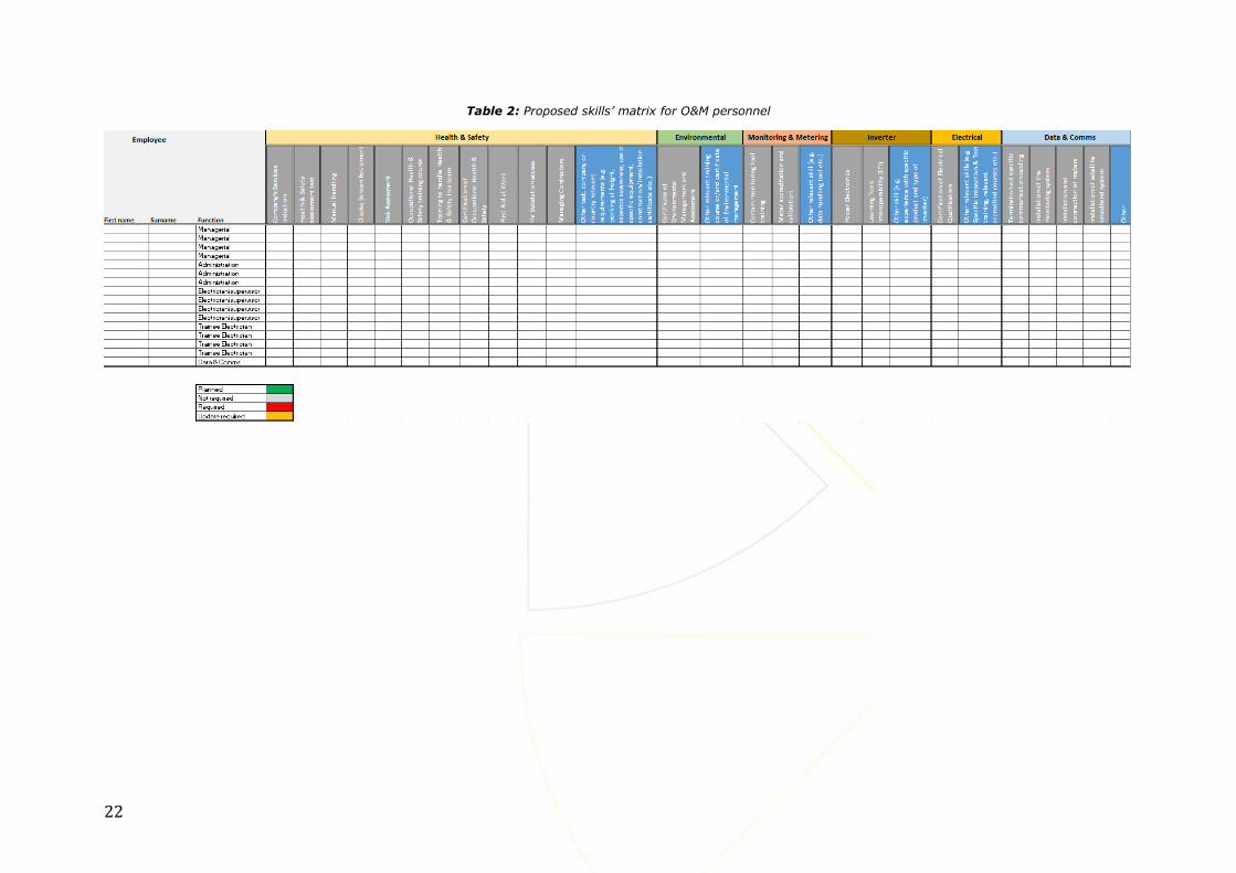
22
Table 2: Proposed skills’ matrix for O&M personnel

SolarPower Europe / O&M Best Practices Guidelines / 23
5 Power Plant Operations
5.1 Documentation Management System (DMS)
Solar PV plant documentation is crucial for an in-depth understanding of the design, configuration
and technical details thereof. It is the Asset Owner’s responsibility to provide those documents and
if not available, they should be recreated at his/her cost.
Before assuming any maintenance and/or operational activities, it is important to understand in-
depth the technical characteristics of the asset. There are two important aspects related to the
management of this information:
Information type and depth of detail / as-built documentation
Management and control
Moreover, for quality / risk management and effective operations management a good and clear
documentation of contract information, plant information, maintenance activities and asset
management is needed over the lifetime of the plant. This is what is called here:
Record control (or records management)
Nowadays, there are different DMSs available and described by a series of standards (ISO) that can
be implemented. This is an important requirement that would allow any relevant party to trace any
changes during the lifetime of the plant’s operation and follow up accordingly (e.g. when the O&M
Contractor changes, or the teams change, or the plant is sold etc.)
5.1.1 Information type and depth of detail / as-built documentation
The documentation set accompanying the solar PV plant should contain the documents described in
the Annex. The IEC 62446 standard can also be considered to cover the minimum requirements for
as built documentation.
In general, for optimum service provision, the O&M Contractor should have access to all possible
documents (from the EPC phase). The Site Operating Plan is the comprehensive document prepared
and provided by the plant EPC, which lays out a complete overview of the plant location, layout,
electrical diagrams, components in use and reference to their operating manuals, EH&S rules for the
site and certain further topics. All detailed drawings from the EPC need to be handed over to the
O&M Contractor and being stored safely for immediate access in case of PV plant issues or questions
and clarifications with regards to permits and regulation.

24
5.1.2 Management and control
As regards the document control, the following guidelines should be followed:
Documents should be stored either electronically or physically (depending on
permits/regulations) in a location with controlled access. An electronic copy of all
documents should be available for all documents.
Only authorized people should be able to view or modify the documentation. A logbook of all
the modifications should be kept. Such a logbook should contain minimally the following
information:
o Name of person, who modified the document
o Date of modification
o Reason of modification and further information, e.g. link to the work orders and
service activities
Versioning control should be implemented. Involved people should be able to review past
versions and be able to follow through the whole history of the document
5.1.3 Record control
A key point is that necessary data and documentation are available for all parties in a shared
environment and that alarms and maintenance can be documented in a seamless way. Critical to the
Operations team is that the maintenance tasks are documented back to and linked with the alarms
which might have triggered the respective maintenance activity (work order management system
log). Photographs from on-site should complement the documentation (when applicable) – photo
documentation. Tickets (ticket interventions) should be stored electronically and made available to
all partners. The Asset Owner should also maintain ownership of those records for future references.
To learn from the past and ongoing operations and maintenance and to then be able to improve
performance via for example predictive maintenance in the following years, it is crucial that all data
is stored and that all workflows and alarms are stored to create automatic logbooks of operations
and maintenance and alarms. Such data collection together with those acquired by the monitoring
tool can be used for further analysis and future recommendations to the client. Such analysis and
the respective outcomes should also be recorded.
Last but not least, there should be a proper documentation for the curtailment periods as well as the
repairing periods when the plant is fully or partly unavailable. This will all be recorded by the
monitoring system in order to be able to measure lost energy during maintenance activities. For this,
having the correct reference values at hand is crucial. Table 3 below summarizes important examples
of input records that should be included in the record control.
As in the case of the as built documentation, all records, data and configuration of the
monitoring tool and any sort of documentation and log that might be useful for a proper
service provision must be backed up and available when required. This is also important when
the O&M Contractor changes.

SolarPower Europe / O&M Best Practices Guidelines / 25
Table 3: Important examples of input records included in the record control
Record control
No. Activity Type Information
Type
Input Record References/Comments
1 Alarms / Operation Incidents
Alarms description Date and Time, Affected Power, Equipment Code / Name, Error messages / Codes, Severity Classification, Curtailment Period, External Visits/Inspections from third parties
2 Contract Management
Contract general description
Project Name / Code, Client Name, Peak Power (kWp)
3 Contract Management
Asset description Structure Type, Installation Type
4 Contract Management
Contract period Contract Start and End Date
5 Contract Management
Contractual clauses Contract Value, Availability (%), PR (%), Materials / Spare parts, Corrective Work Labour
6 Corrective Maintenance
Activity description Detailed Failure Typification, Failure, Fault Status, Problem Resolution Description, Problem Cause
EN 13306 - Maintenance. Maintenance terminology
7 Corrective Maintenance
Corrective maintenance event
Associated Alarms (with date), Event Status EN 13306 - Maintenance. Maintenance terminology
8 Corrective
Maintenance
Corrective
maintenance event log
Date and Time of Corrective Maintenance Creation (or Work Order), Date and Time status change (pending, open, recovered,
close), End date and time of the intervention, Start date and time of the intervention, Technicians and Responsible Names and
Function
EN 13306 - Maintenance.
Maintenance terminology
9 Corrective
Maintenance
Intervention equipment/Element name
Affected Power and Affected Production, Equipment Code / Name
10 Inventory Management
Warehouse management
Inventory Stock Count and Movement, Equipment Code / Name
11 Monitoring & Supervision
Equipment status Date, Status log (protection devices, inverters, monitoring systems, surveillance systems)
12 Monitoring &
Supervision Meteo data
Irradiation, Module temperature, Other meteo variables (ambient
temperature, air humidity, wind velocity and direction, …)
IEC 61724 - Photovoltaic system
performance monitoring -
Guidelines for measurement, data exchange and analysis
13 Monitoring & Supervision
Production / consumption data
AC active and reactive power at PV Plant Injection Point and other subsystems or equipment, Consumption from auxiliary systems,
IEC 61724 - Photovoltaic system performance monitoring -
26
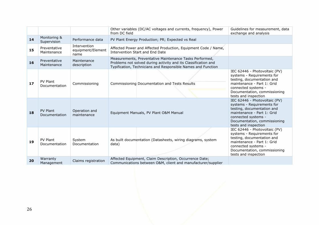
Other variables (DC/AC voltages and currents, frequency), Power from DC field
Guidelines for measurement, data exchange and analysis
14 Monitoring & Supervision
Performance data PV Plant Energy Production; PR; Expected vs Real
15 Preventative Maintenance
Intervention equipment/Element name
Affected Power and Affected Production, Equipment Code / Name, Intervention Start and End Date
16 Preventative Maintenance
Maintenance description
Measurements, Preventative Maintenance Tasks Performed, Problems not solved during activity and its Classification and Typification, Technicians and Responsible Names and Function
17 PV Plant Documentation
Commissioning Commissioning Documentation and Tests Results
IEC 62446 - Photovoltaic (PV)
systems - Requirements for testing, documentation and maintenance - Part 1: Grid connected systems - Documentation, commissioning
tests and inspection
18 PV Plant Documentation
Operation and maintenance
Equipment Manuals, PV Plant O&M Manual
IEC 62446 - Photovoltaic (PV) systems - Requirements for testing, documentation and maintenance - Part 1: Grid
connected systems - Documentation, commissioning
tests and inspection
19 PV Plant Documentation
System Documentation
As built documentation (Datasheets, wiring diagrams, system data)
IEC 62446 - Photovoltaic (PV) systems - Requirements for testing, documentation and
maintenance - Part 1: Grid connected systems - Documentation, commissioning tests and inspection
20 Warranty
Management Claims registration
Affected Equipment, Claim Description, Occurrence Date;
Communications between O&M, client and manufacturer/supplier

SolarPower Europe / O&M Best Practices Guidelines / 27
5.2 Data and Monitoring Requirements
The Asset Owner (or SPV) owns the data from the monitoring system and data loggers, separate to
the O&M Contractor.
In general, the monitoring system should allow follow up on the energy flow in a photovoltaic system.
In principle it reports the parameters that determine the energy conversion chain. These parameters
along with the most important energy measures in terms of yields and losses are illustrated in Figure
2. These yields and losses are always normalized to installed PV power at standard test conditions in
kilowatt-peak.
Figure 2: Energy flow in a grid-connected photovoltaic system with parameters, yields and losses4
5.2.1 Irradiance measurements Irradiance Sensors Solar irradiance in the plane of the PV array (POA) is measured on site by means of at least one
irradiance measurement device according to Secondary Standard or First Class quality classification
and IS0 9060:1990 (ISO 9060 1990). The higher the quality of the pyranometer, the lower the
uncertainty will be. Best practice is to apply at least two pyranometers in the plane of the PV
array. In case of different array orientations within the plant, at least one pyranometer is required
for each orientation. Ensure that the pyranometers are properly assigned to the different arrays for
the calculation of the Performance Ratio (PR) and expected yield.
Pyranometers are preferred over silicon reference cells because they allow a direct comparison of
the measured performance of the PV plant with the performance figures estimated in the energy
4 The figure is redesigned and based on a figure produced by 3E and published at (Woyte et al. 2014)

28
yield assessment. For plants in Central and Western Europe, measuring irradiance with silicon cells
yields approximately 2 to 4% higher long-term PR than with a thermopile pyranometer (N. Reich et
al. 2012).
Irradiance sensors must be placed at the least shaded location. They must be mounted and wired in
accordance with manufacturers’ guidelines. Preventative maintenance and calibration of the sensors
must follow the manufacturers’ guidelines.
The irradiance is recorded with averages over 15 minutes (minimum requirement) or down to 1
minute or less (best practice).
Satellite-based Irradiance Measurements
In addition to the irradiance sensors, to record irradiance data from a high-quality satellite-based
data service as a complement to data from ground-based sensors can be considered as best practice.
For daily irradiation values, the error of satellite-based irradiation data is relatively high with root-
mean-square error (RMSE) values of 8 to 14% in Western Europe. For monthly and annual values it
is largely below 5 and 3%, respectively, which is not worse than an on-site sensor (Richter et al.
2015). Moreover, satellite-based data services are often more reliable and less subject to systematic
errors than on-site sensors.
Satellite-based irradiance data should at least (minimum requirement) have hourly granularity with
a trend towards 15 minutes. The data must be retrieved once per day at least.
5.2.2 Module temperature measurements
The direct measurement of the module temperature is required. The temperature sensor should be
stuck with appropriate and stable thermally conductive glue to the middle of the backside of the
module in the middle of the array table, positioned in the centre of a cell, away from the junction
box of the module (Woyte et al. 2013). The installation should be in accordance with manufacturer
guidelines (e.g. respecting cabling instructions towards the datalogger). The accuracy of the
temperature sensor, including signal conditioning, should be < ±1 °C.
Very large plants should have measurement of module temperature at different places across the PV
array. For large arrays, the module temperature should be measured at different representative
positions, e.g., for a module in the centre of the array and for modules at edge locations where
temperature variation is expected.
5.2.3 Local meteorological data
It is best practice to measure ambient temperature and wind speed with the installation of a local
meteorological station in accordance with the manufacturers’ guidelines. Ambient temperature is
measured with a shielded thermometer, e.g., of the PT100 type. The shield protects the sensor from
radiative heat transfer. Wind speed is measured with an anemometer, at 10 m height above ground
level.
Wind and ambient temperature data are not required for calculating PR unless this is a contractual
requirement/agreement (e.g. according to specific recommendations such as from NREL). However,
they are required when the PV plant is to be modelled in operation or in retrospect.
For plants >10 MWp, automated data collection of independent hourly meteo data should be present
(ambient temperature, wind speed, snow coverage) from an independent meteo source. The reason
for this is that on-site meteorological stations are subject to local phenomena and installation-specific
results. Data from an independent meteo-station is less subject to this while being also more stable
and robust with respect to long-term drift.
Therefore, for both performance assessment and detailed analysis purposes, it is recommended to
enable automated data collection from a nearby independent meteo reference.
SolarPower Europe / O&M Best Practices Guidelines / 29
However, for performance assessment the most important measurement remains the in-plane
irradiation (see also chapter 10).
5.2.4 String measurements
PV arrays that are not subject to DC input current monitoring at inverter level, should have current
monitoring at string level. Depending on module technology used in the plant, strings are combined
(harnesses) which can help reducing operation costs.
As best practice, it is recommended to increase up-time for timely detection of faults. Measurement
requirements using 1 second sampling and 1-minute averaging at data logger are being used more
and more, with a maximum two strings current measurement in parallel.
5.2.5 Inverter measurements
At AC level, energy and power data should be collected. The energy data to be measured and sent
to the monitoring system should be cumulative values over the lifetime of the inverter. This allows
to follow the overall electricity generation of each inverter over time, even during outages of the
monitoring system.
It is very important to collect all inverter alarms. Inverter alarms are a valuable source of information
for fault detection, organisation of the maintenance and even setting up preventive maintenance
actions.
Monitor all control settings of the plant at inverter level and grid injection level if available. Many
plants apply control settings for local grid regulation (injection management) or optimisation of the
market value of the PV generation portfolio (remote control). These settings need to be monitored
for reasons of contractual reporting or performance assessment.
Measurement of the input DC voltage and current to the inverter based on a <1s sampling and <1min
averaging. For ad-hoc performance analysis purposes e.g. to allow the analysis of PV array
performance, root cause analysis or possible MPP-tracking problems, the input DC voltage and
current need to be measured and stored separately.
In general, and as best practice, any parameter from an inverter that can be measured should be
logged by the data loggers, since there are a lot of additional important parameters such as internal
temperature, isolation level etc. that could be useful for O&M services.
Inverters should detect inverter overheating. Therefore, it is advisable to record the temperature as
provided by the inverter or measure it using a suitable thermocouple so that the requirement for
additional ventilation can be assessed.
5.2.6 Configuration
The configuration of the monitoring systems and data loggers needs to be checked in order to avoid
mistakes. This is normally done at commissioning phase or at plant take over by a new O&M
Contractor (recommissioning of the monitoring system).
As best practice auto-configuration is recommended if technically possible. The monitoring solution
captures automatically the device configuration information (plug-and-play). This also allows for
inverter replacement detection. An example could be that all inverter labels such as serial number,
inverter ID and inverter input are collected. Furthermore, as best practice the ID of all sensors should
be collected. Back up of this configuration data should be in place.

30
5.2.7 Energy meter
Automated collection of meter data with at least daily frequency and 15 min granularity should be
included in the monitoring system. Energy meter data are required for invoicing purposes but also
serve as an independent reference versus the inverter yield for benchmarking, analysis purposes and
loss detection. A high accuracy energy meter for the total output of the plant with an uncertainty of
± 0.5% is required for plants > 100 kWp and highly recommended for all plants – also below 100
kWp (best practice).
As a best practice recommendation for plants > 1 MWp, the meter should have two communication
bus channels to allow data collection via digital meter communication (bus) or via Automatic Meter
Reading (AMR) service and it is advisable that the meter sends total cumulative values.
5.2.8 AC circuit / Protection relay
As a best practice, the AC switch positions as for (sub) plants should be monitored and also it should
be possible to read the alarms from the protection relay via the communication bus.
5.2.9 Data loggers
As minimum requirement, data loggers should have sufficient memory to store at least one month
of data. Historical data should be backed up. After a communication failure, the data logger should
automatically resend all pending information.
As best practice, the data logger should store a minimum of six months of data and a full data backup
in the cloud. Moreover, the operation of the data logger itself should be monitored. Such monitoring
should be done out of an independent server from remote and ideally should deliver information for
the status of operation of the data loggers on Operating System (OS) and hardware level and also
provide alerts to the Operations room in case of failures and communication loss.
As best practice the system should use an open protocol, in order to enable easy transition between
monitoring platforms.
In cases and depending on the data logger, it should be rebooted by itself (firmware solution, soft
reset) once a day during night time in order to increase its reliability. Alternatively, dataloggers and
routers could be monitored (response to ping pos./neg.) by appropriate hardware on site. In case
of no response to the control unit, the power supply has to be interrupted (by the control unit) as a
hard reset.
The entire monitoring installation should be protected by an uninterruptable power supply (UPS).
This includes measurement devices, data loggers and signal converters.
5.2.10 Alarms
As a minimum requirement, the monitoring system will have the following alarms sent by email:
Loss of communication
Plant stop
Inverter stop
Plant with Low Performance
Inverter with Low Performance (e.g. due to overheating):
As best practice, the following alarms will also be sent by the monitoring system:
String without current
Plant under UPS operation
Intrusion detection

SolarPower Europe / O&M Best Practices Guidelines / 31
Fire alarm detection
Discretion Alarm (or Alarm Aggregation)
The above lists are not exhaustive.
5.2.11 Dashboard / Web portal
As minimum requirement, the monitoring system will have the following features:
Web portal accessible 24 hours 365 days
Graphs of irradiation, energy production, performance and yield
Downloadable tables with all the registered figures
Alarms register
As best practice, the following features will also be included in the monitoring system:
User configurable dashboard
User configurable alarms
User configurable reports
Ticket management
The above lists are not exhaustive.
5.2.12 Data format
The data format of the recorded data files must respect standards such as IEC 61724 and has to be
clearly documented. Data loggers should collect all inverter alarms in accordance with original
manufacturers format so that all available information is obtained.
5.2.13 Communication from the site to the monitoring servers
The Asset Owner should make sure to provide the best possible network connectivity to the O&M
Contractor with sufficient bandwidth according to the installed monitoring system.
Whenever a DSL connection is available within the PV-site area, this should be the preferred way to
connect to the internet; industrial routers can be seen as standard. In case a DSL connection isn’t
available, satellite communication is preferred. An additional GPRS-connection as a back-up system
can be seen as best practice. Any subscriptions should allow for the data quantity required and should
foresee the amount of data (e.g. Closed-Circuit Television (CCTV) or not) and the granularity of data.
For sites > 1MW it is advised to have a LAN connection and as an alternative an industrial router that
allows for GPRS or satellite communication back-up in case the LAN connection fails. A router with
an auto-reset capability in case of loss of internet connection is recommended.
A direct connection to a monitoring server with a service-level agreement (SLA) guarantees
continuous data access. If data passes via alternative monitoring servers without SLA, (e.g.
monitoring portal of the inverter manufacturer), this SLA can no longer be guaranteed. The automatic
firmware updates of the data logger should be disabled. Firmware updates are subject to acceptance
procedure with the monitoring service.
Data security is very important and is becoming increasingly a concern, especially for bigger clients. Therefore, respective considerations and measures should be taken to assure data security.
As minimum requirements loggers should not be accessible directly from the internet or at least be protected via a firewall. Secure and restrictive connection to the data server is also important.

32
All communication cables must be shielded. Physical distance between (DC or AC) power cables and
communication cables should be ensured, as well as that communication cables are protected from
direct sunlight.
Furthermore, cables with different polarities must be clearly distinguishable (label or colour) for
avoiding polarity connection errors.
5.3 Plant Monitoring and Supervision
The Operations team of the O&M Contractor is responsible for continuous monitoring and supervision
of the PV power plant conditions and its performance. This service is done remotely through the use
of monitoring software system and/or plant operations centres. The O&M Contractor should have full
access to all data collected from the site in order to perform data analysis and provide direction to
the Maintenance service provider/team.
Besides the data from the site, if a CCTV system is available on site, he/she should be able to access
it for visual supervision and also have access to local weather information.
The O&M Contractor is responsible for being the main interface between the plant owner, the grid
operator and the regulator (if applicable) over the lifetime of the O&M contract regarding production
data. The Operations team should be staffed to provide services during daytime, when the system is
expected to generate electricity and is responsible to coordinate accordingly with the Maintenance
service provider/team.
5.4 Performance Analysis & Improvement
In general, the data should be analysed down to the following levels:
1. Portfolio level (group of plants)
2. Plant level
3. Inverter level
4. String level
The analysis should furthermore show the required data on the specific levels listed above and for
different time aggregation periods from the actual recording interval up to monthly and quarterly
levels.
The analysis should also include the option for having custom alarms based on client specific
thresholds such as for example business plan data or real time deviations between inverters on site.
In particular, the agreed KPIs should be computed and reported (see Chapter 10 for main KPIs).
Special attention should be paid to the fact that such KPI calculations should take into consideration
the contractual parameters between O&M Contractor and Asset Owner, in order to provide an
accurate and useful calculation for evaluation and eventually liquidated damages or bonuses.
5.5 Predictive Maintenance
Predictive maintenance is a special service provided by O&M Contractors who follow best practices
principles.
The Operations team of the O&M Contractor is doing thorough monitoring, supervision, forecast and
performance data analysis (e.g. historical performance and anomalies) of the PV plant in order to

SolarPower Europe / O&M Best Practices Guidelines / 33
identify subtle trends that indicate upcoming component and system failures (e.g. module, inverter,
combiner boxes etc.). Following such analysis, the Operations team alerts the Maintenance team
who should decide which predictive maintenance activities to perform to prevent any possible failures
which can cause energy generation loss.
The Asset Owner or interested party that wants to apply predictive maintenance should have a
monitoring software system in place which should be able to provide basic trending and comparison
(timewise or between components) functionality (minimum requirement).
Before deciding which predictive maintenance actions to do, the Operations team should implement
and develop procedures to effectively analyse historical data and faster identify behaviour changes
that might jeopardize systems performance. These changes of behaviour are usually related to the
pre-determined or unpredicted equipment degradation process. For this reason, it´s important to
define and to monitor all significant parameters of wear status.
To carry out an efficient conduct of this type of maintenance, it is required that a certain level of
maturity and experience which is at best a combination of systems’ performance knowledge,
equipment operation behaviour and of course relevant accumulated experience and track record from
the service provider. Normally it is a process that starts after the implementation of an appropriate
monitoring system and recreation of a base line that represents the entire PV system operation and
also how equipment interact with each other and how this system reacts to “environmental” changes.
Predictive maintenance is condition-based and has several advantages, including:
Anticipate maintenance services;
Eliminate some maintenance activities;
Increase availability;
Reduce emergency and non-planned work;
The analysis of the “DC health” of the system (at the DC array, transformer, inverter, combiner box
or/and string level) on a regular basis in order to detect underperformance conditions that would
otherwise go unnoticed until the next circuit testing or thermal imaging (several months later) is
important. For the Asset Owner this normally translates into lower capital equipment replacement
costs and higher energy production levels.
The following two specific examples show how predictive maintenance might be implemented.
Example 1 – An O&M Contractor signs a new contract for a PV plant equipped with central inverters.
Analysing its back-log of maintenance, the O&M Contractor knows that these inverters showed
several times in the past signs of power loss due to overheating. This might be related to problems
in the air flow, filter obstructions, fans or environmental changes (high temperature during summer).
It was decided to monitor the temperature of IGBT5s. Before any emergency action might be needed,
in case these components have some variations in their behaviour, an “air flow inspection” is
performed to detect if this change is related to the air flow.
This type of activity, “air flow inspection”, is a condition based inspection, performed after the
detection of a change in a significant parameter. It is also considered as a type of predictive
maintenance.
The final purpose is to identify if, for example, the ventilation systems will need some upgrade,
replacement or if there´s any type of air flow obstruction or even if it is required to anticipate the
filters’ substitution or cleaning.
Example 2 – The Operations team detects a possible underperformance of one of the sections inside
the PV plant.
This could be the power transformer, the inverter or some particular PV generator area that presents
a lower performance when compared with others in the same conditions (or past behaviours evidence
5 IGBT = Insulated-Gate Bipolar Transistor

34
of loss of production). After the anomaly detection or recognition, an incident is created and
instantaneously sent to the Maintenance team.
Before anything happens that might jeopardize contractual issues and might need urgent
interventions, the O&M Contractor decides to do a “General Infrared Inspection” in the PV field taking
RPAS6 general pictures.
This inspection has as main purpose to identify possible problems related to PV modules that might
justify the loss of performance. This is considered as a type of predictive maintenance.
5.6 Plant Controls
If applicable, the Operations team is the responsible contact for the grid operator for plant controls.
The Operations will control the plant remotely (if applicable) or instruct the qualified maintenance
personnel to operate breakers/controls on site. The O&M Contractor is responsible for the remote
plant controls or emergency shut-down of the plant, if applicable and in accordance with the
respective grid operator requirements and regulations (see also 5.9.1 for grid code compliance). The
plant control function varies from country to country and in some case from region to region. The
respective document refers to details in PV plant controls regulation which are issued by the
respective grid operator and (energy market) regulator.
5.7 Power Generation Forecasting
If required by regulation or the Asset Owner, the O&M Contractor shall be responsible to supply
Power Generation Forecasts (at the moment normally for large scale plants). Forecasting services
for PV power generation are generally offered by operators of PV monitoring services. The O&M
Contractor should always insist on a service level agreement with the forecast provider. For the state
of the art of PV power forecasting, the paper of (Pelland et al. 2013) can be used as reference.
The requirements for such forecasts may differ from country to country. They are characterized by
the forecast horizon, the time resolution, and the update frequency, all depending on the purpose.
For power system or power market related purposes, forecast horizons are typically below 48 hours
and the time resolution is 15 minutes to one hour, in line with the programme time unit of the power
system or the market. Common products are day-ahead forecasts, intra-day forecasts and combined
forecasts. Day-ahead forecasts are typically delivered in the morning for the next day from 0 to 24
and updated once or twice. Intraday forecasts are delivered and updated several times per day for
the rest of the day.
For long-term planning of unit commitment and maintenance decisions, forecasts with longer time
horizons are used, typically one week or more.
PV power generation forecasts rely on numerical weather predictions, satellite data and/or statistical
forecasting and filtering methods. Most products combine several of these techniques. Good practice
requires numerical weather predictions for day-ahead forecasting and a combination with satellite
data for intra-day forecasts. In all cases good practice requires statistical filtering which in turn
requires a near-real-time data feed from the monitoring system to the forecast provider. For best
practice, the forecast provider should also be informed about scheduled outages and the expected
duration of forced outages.
The most common KPIs for forecast quality are the root mean square error (RMSE) and the mean
absolute error (MAE). They are normalized to peak power and not to energy yield.
6 RPAS = Remotely Piloted Aircraft Systems
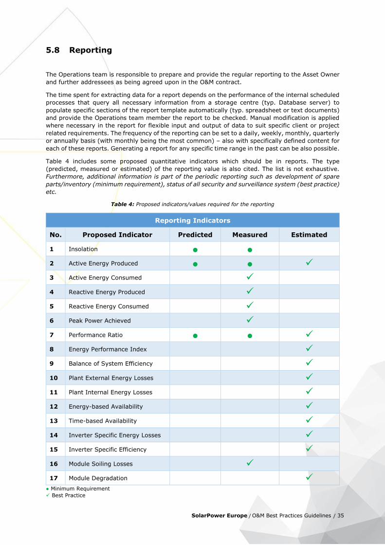
SolarPower Europe / O&M Best Practices Guidelines / 35
5.8 Reporting
The Operations team is responsible to prepare and provide the regular reporting to the Asset Owner
and further addressees as being agreed upon in the O&M contract.
The time spent for extracting data for a report depends on the performance of the internal scheduled
processes that query all necessary information from a storage centre (typ. Database server) to
populate specific sections of the report template automatically (typ. spreadsheet or text documents)
and provide the Operations team member the report to be checked. Manual modification is applied
where necessary in the report for flexible input and output of data to suit specific client or project
related requirements. The frequency of the reporting can be set to a daily, weekly, monthly, quarterly
or annually basis (with monthly being the most common) – also with specifically defined content for
each of these reports. Generating a report for any specific time range in the past can be also possible.
Table 4 includes some proposed quantitative indicators which should be in reports. The type
(predicted, measured or estimated) of the reporting value is also cited. The list is not exhaustive.
Furthermore, additional information is part of the periodic reporting such as development of spare
parts/inventory (minimum requirement), status of all security and surveillance system (best practice)
etc.
Table 4: Proposed indicators/values required for the reporting
Reporting Indicators
No. Proposed Indicator Predicted Measured Estimated
1 Insolation ● ●
2 Active Energy Produced ● ●
3 Active Energy Consumed
4 Reactive Energy Produced
5 Reactive Energy Consumed
6 Peak Power Achieved
7 Performance Ratio ● ●
8 Energy Performance Index
9 Balance of System Efficiency
10 Plant External Energy Losses
11 Plant Internal Energy Losses
12 Energy-based Availability
13 Time-based Availability
14 Inverter Specific Energy Losses
15 Inverter Specific Efficiency
16 Module Soiling Losses
17 Module Degradation
● Minimum Requirement
Best Practice
36
5.9 Regulatory compliance
The O&M Contractor is responsible to ensure the operation of the PV plant in compliance with the
regulations. Several levels of regulation have to be considered besides the grid code (see chapter
5.9.1).
Furthermore, many countries have a governing law for the operation of energy generating assets or
renewables/PV in particular.
Power Purchase Agreements (PPA) and Interconnection Agreements also form a part of the
regulation, which needs to be known and respected by the O&M team.
Particularly, power generation license agreements need to be made available by the Asset Owner to
the O&M Contractor in order to allow him to act in compliance with the regulations of these licenses.
Building permits, environmental permits and regulations form the specific regulation for the site and
can contain certain requirements and the need to cooperate with the local administration. Examples
can be: restrictions to the vegetation management and the disposal of green waste which are being
ruled by the environmental administration body. Or the building permit may contain stipulations to
restrict working time on site, storage of utilities etc.
The minimum requirement should be, that the O&M contract lists all the relevant permits and
regulations and that the asset owner makes the relevant documents available to the O&M Contractor.
The management of all regulations, permits and stipulations within the electronic document
management system is expected to be best practice. This allows the O&M party to track reporting
and maintenance requirements automatically and report back to the asset owner or administration
bodies.
5.9.1 Grid code compliance requirements The O&M Contractor and in particular the Operations team is responsible to operate the PV plant in
accordance with the respective national grid code. The operator of the grid, to which the PV plant is
connected (either low voltage grid or medium voltage grid or high voltage grid) provides the
requirements for power quality, voltage regulation and management of active and reactive power.
In some countries (and/or regions) specific grid codes for renewable energy generators and
consequently solar PV plants have been issued.
Depending on the voltage level of the grid the plant is connected to, the specificities and quality
requirements for the PV plant change. A higher level of the grid usually has more specific and higher
quality requirements.
Most of the utility scale PV plants in Europe connected to a grid are required to be controllable to
meet the grid operator requirements. Such plant controls allow the grid operator to adjust the power
output from the PV plant according to the grid capacity and power frequency requirements.
It is expected, that the O&M Contractor is familiar with all the details of the grid code and grid
operator requirements. Depending on the regulations, either the grid operator himself is steering the
PV plant controller (with remote signals) or the Operations team is managing the plant controller per
direction of the grid operator.

SolarPower Europe / O&M Best Practices Guidelines / 37
5.10 Management of change
In the event, that the design of a PV power plant needs to be adjusted after the Commercial Operation
Date, the O&M Contractor needs to be involved by the Asset Owner and the EPC and should be a
main contributor if not the leader of this change process. Reasons for such changes can be motivated
by non-compliance or a shortfall of the PV power plant with predicted capacity by the EPC, by
regulation (introduction of new PV power plant controls regulations) or by the unavailability of spare
parts or components. These events would cause some new design works for the PV power plant,
procurement and installation of equipment and will lead to adjustment of operation and maintenance
procedures and/or documentation. It may also impact certain performance commitments or
warranties provided by the O&M Contractor, which need to be adjusted.
In any such case, the O&M Contractor needs to be involved in such changes to the PV power plant
right from the beginning. Concepts, design works and execution need to be coordinated with ongoing
O&M activities. Implementation to the plant SCADA and monitoring system is required. Adjustments
to the Site Operating Plan, the Annual Maintenance Plan and the Annual Maintenance Schedule need
to be applied and the O&M Contractor needs to familiarize his staff with the operating manuals of the
new equipment. Such change will have a definite impact on the spare parts management and
inventory (replacement). Depending on the significance of such changes, the O&M annual fee might
need to be adjusted.
It is advisable that the O&M Contractor takes the lead in the process of such change. The O&M
Contractor is the trusted partner of the Asset Owner and should advise the owner in the decision
making of such change processes. In the case of major changes the owner should also consider to
inform lenders in the decision process and provide concepts, proposals and calculations.
The fixed O&M fee does not usually cover such services. The Asset Owner and the O&M Contractor
should manage changes in a rather formalistic way. This procedure might include the following steps:
description of proposed change (including time plan, costs, consequences, and alternatives),
authorization of the change by the Asset Owner, realization of the change, documentation by the
O&M Contractor and acceptance.
5.11 Warranty management
The Operations team from the O&M Contractor shall act as the Asset Owner’s representative for any
warranty claims vis-à-vis the OEM manufacturers of such components. The O&M Agreement is
expected to rule the level of responsibility for warranty management between the Asset Owner and
the Operations team and certain thresholds under which the Operations service provider is
empowered to act directly or seek the owner’s consent. The Operations team will direct the
Maintenance team to perform warranty related works on site. Usually the warranty management
scope is limited by Endemic Failures (see 5.11.1). Execution of warranty is often separately billable.
For any warranty claims the formal procedure provided by the warranty provider should be followed.
All communications and reports should be archived (see Record control) for compliance and
traceability reasons.
Objectives of Warranty Management:
Improve the efficiency in complaining processes
Help to reduce the warranty period costs
Receive and collect all the warranty complaints
Support the complaint process
Negotiate with manufacturers more efficient complaint procedures
38
Study the behaviour of the installed equipment
Analyse the costs incurred during the warranty period
Types of warranties on a PV Plant:
Warranty of Good Execution of Works
Warranty of Equipment
Performance Warranty
5.11.1 Warranty of good execution of works and equipment warranties
During the warranty period, anomalies can occur in the facility, which the EPC provider is liable for.
The anomalies must be resolved according to their nature and classification, in accordance to what
is described in the following chapters.
The anomalies or malfunctions that might occur within the facility warranty period might be classified
the following way:
Pending Works, in accordance to the List of Pending Works agreed with the client;
Insufficiencies, these being understood as any pathology in the facility resulting from
supplies or construction, that although done according to the project execution approved by
the client, has proven to be inadequate, unsatisfactory or insufficient;
Defects, these being understood as any pathology resulting from supplies or construction
executed in a different way from the one foreseen and specified in the project execution
approved by the client;
Failure or malfunction of equipment, being understood as any malfunction or pathology
found in the equipment of the photovoltaic facility – Modules, Inverters, Power transformers
or other equipment;
Anomalies Handling During the Warranty Period, all the Anomaly processing should be centralized by the O&M Contractor,
who is responsible for the first acknowledgment of the problem and its framework according to its
type, having in this manner, the role of a pivot and linking element between the internal
organizational structure and the client in accordance to the criteria defined below:
Pending Works, Insufficiencies and Defects In the case of anomalies of the type “Pending Works”, “Insufficiencies” or “Defects”, the O&M
Contractor must communicate the occurrence to the EPC provider, who shall be responsible to assess
the framework of the complaint in the scope of the EPC contract, validating its grant and determine
the action to be taken.
Resolution of failures in the case of anomalies of the type “Failures” The O&M Contractor shall present the claim to the equipment supplier and follow the claiming
process.
Endemic Failures
Means product failures at or above the expected failure rates resulting from defects in material,
workmanship, manufacturing process and/or design deficiencies attributable to the manufacturer.
Endemic failure is limited to product failures attributable to the same root cause.

SolarPower Europe / O&M Best Practices Guidelines / 39
5.11.2 Performance Warranty
During the Warranty Period, it is the responsibility of the Operations team to monitor, calculate,
report and follow-up the values of Performance Ratio and other guaranteed KPIs.
Within this scope, it is the responsibility of the O&M Contractor to:
Manage the interventions done within the scope of the warranty in order to safeguard the
performance commitments undertaken under the contract;
Periodically inform the owner about the condition of the contracted performance indicators;
Immediately alert the owner whenever the levels of the indicators present values or
tendencies that could indicate a risk of failure.
5.12 Insurance claims
The Operations team can act as the Asset Owner’s representative for any insurance claims vis-à-vis
the insurance provider. In some cases, this task is being awarded to the asset management company
rather than the O&M Contractor.
The O&M Agreement is expected to rule the level of responsibility for insurance management between
the Asset Owner and the Operations team. The Operations will at least be responsible for the
coordination of site visits by an insurance provider’s representative or technical/financial advisors in
connection with the information collection and damage qualification, as well as for the drafting of
technical notes to support the reimbursement procedure.
For any insurance claims the formal procedure provided by the insurance provider should be followed.
All communications and reports should be archived (see Records control) for compliance and
traceability reasons.

40
6 Spare Parts Management
Spare Parts Management is an inherent and substantial part of O&M. It should ensure that spare
parts are available in a timely manner for corrective maintenance in order to minimize the downtime
of (a part of) a solar PV plant. As regards to spare part management, the following considerations
have to be made:
Ownership and responsibility of insurance
Stocking level
Location of storage
o Proximity to the plant
o Security
o Environmental conditions
Depending on the agreement between the Asset Owner and the O&M Contractor, spare parts
management may be a responsibility of one of the two. Ownership of spares is with the Asset Owner
while normally the storage (and hence insurance) responsibility is on the shoulders of the O&M
Contractor. Besides ownership matters, it is above all important to make sure (upon mutual
agreement) that one of the parties undertakes the responsibility of insuring the spares.
The O&M Contractor shall act as the main interface for the spare parts management. Access to the
spare parts inventory books should be ensured and responsibility to order spare parts and goods for
the replenishment of the spare parts inventory should be assumed.
For a new PV plant, the initial spare parts are procured by the EPC. However, it is best practice, if
the EPC and O&M Contractor have agreed upon the list. The O&M Contractor is free to add additional
spares that he deems necessary to meet the contractual obligations (e.g. reaction time, availability
guarantees etc.).
Regarding the stocking level, due to the very different configurations and sizes of solar PV plants, it
is very difficult to define a hard number for stocking specific spare parts. Furthermore, the regional
portfolio of the O&M Contractor might also influence this and as it was mentioned above, the
determination of spare items and quantity is also driven by the O&M Contractor’s contractual
commitments7 on reaction time and/or plant availability and related Liquidated Damages (LDs).
It is important at this point to differentiate between Consumables and Spare Parts. Consumables are
low cost and frequently used spare parts, like for example fuses, that the O&M Contractor should
have always on stock and maintenance crews should carry with them, together with the relevant
tools, during every site visit.
7 If the O&M contract does not include any of such obligations also the leverage of the asset owner to hold
the O&M Contractor accountable may be weak.
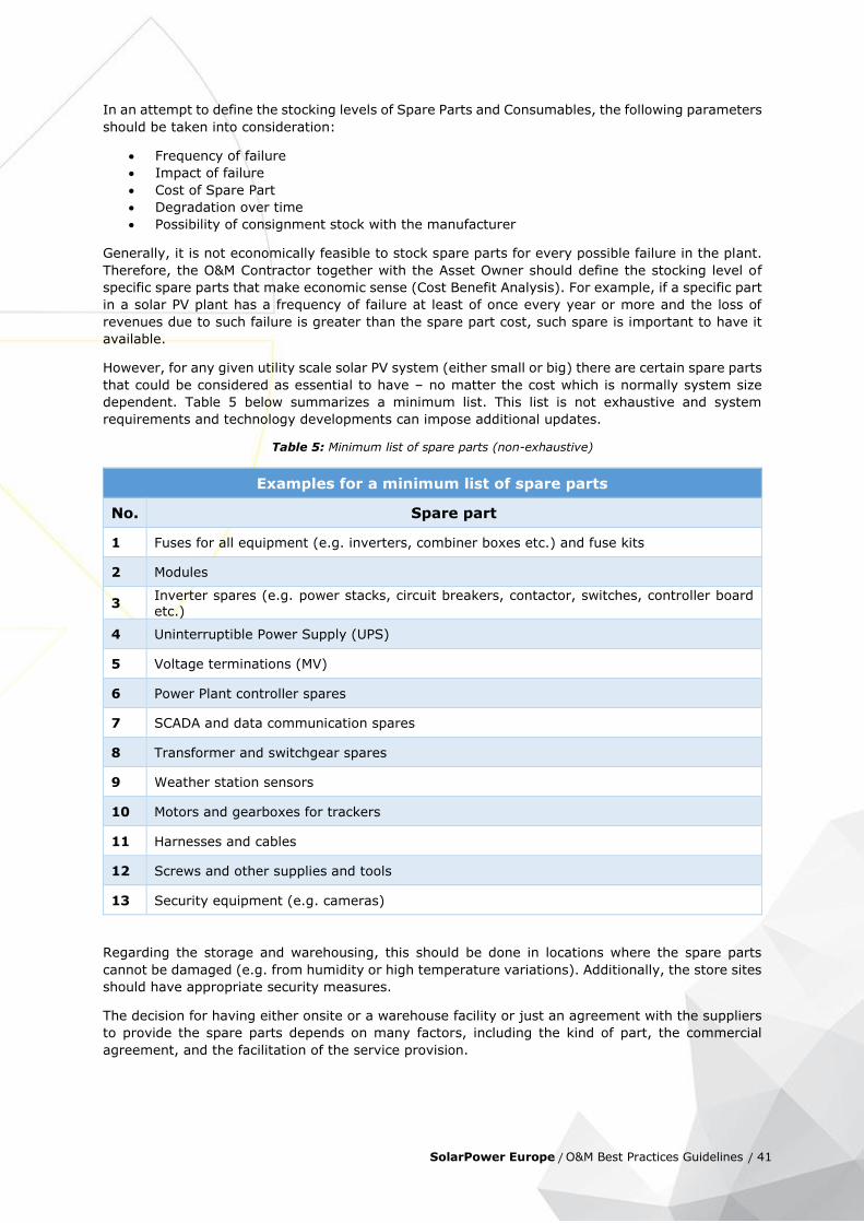
SolarPower Europe / O&M Best Practices Guidelines / 41
In an attempt to define the stocking levels of Spare Parts and Consumables, the following parameters
should be taken into consideration:
Frequency of failure
Impact of failure
Cost of Spare Part
Degradation over time
Possibility of consignment stock with the manufacturer
Generally, it is not economically feasible to stock spare parts for every possible failure in the plant.
Therefore, the O&M Contractor together with the Asset Owner should define the stocking level of
specific spare parts that make economic sense (Cost Benefit Analysis). For example, if a specific part
in a solar PV plant has a frequency of failure at least of once every year or more and the loss of
revenues due to such failure is greater than the spare part cost, such spare is important to have it
available.
However, for any given utility scale solar PV system (either small or big) there are certain spare parts
that could be considered as essential to have – no matter the cost which is normally system size
dependent. Table 5 below summarizes a minimum list. This list is not exhaustive and system
requirements and technology developments can impose additional updates.
Table 5: Minimum list of spare parts (non-exhaustive)
Examples for a minimum list of spare parts
No. Spare part
1 Fuses for all equipment (e.g. inverters, combiner boxes etc.) and fuse kits
2 Modules
3 Inverter spares (e.g. power stacks, circuit breakers, contactor, switches, controller board etc.)
4 Uninterruptible Power Supply (UPS)
5 Voltage terminations (MV)
6 Power Plant controller spares
7 SCADA and data communication spares
8 Transformer and switchgear spares
9 Weather station sensors
10 Motors and gearboxes for trackers
11 Harnesses and cables
12 Screws and other supplies and tools
13 Security equipment (e.g. cameras)
Regarding the storage and warehousing, this should be done in locations where the spare parts
cannot be damaged (e.g. from humidity or high temperature variations). Additionally, the store sites
should have appropriate security measures.
The decision for having either onsite or a warehouse facility or just an agreement with the suppliers
to provide the spare parts depends on many factors, including the kind of part, the commercial
agreement, and the facilitation of the service provision.
42
While proximity to the plant is a parameter that needs to be evaluated on a per case basis, Security
and Environmental conditions are very important as they could lead to a loss of property either
through thefts or damage.

SolarPower Europe / O&M Best Practices Guidelines / 43
7 Power Plant Maintenance
7.1 Preventative Maintenance
Preventative Maintenance activities are the core element of the maintenance services to a PV plant.
It comprises regular visual and physical inspections, as well as verification activities with a specific
task periodicity of all key components which are necessary to comply with the operating manuals
and recommendations issued by the Original Equipment Manufacturers (OEMs). It must also maintain
the equipment and component warranties in place and reduce the probability of failure or
degradation. The activities should also comply with respective legal issues e.g. national standards
for periodic inspection of certain electrical components. Technical experience and relevant track
records will optimise the activities further. The O&M contract should include this scope of services
and each task periodicity.
This maintenance is carried out at predetermined intervals or according to prescribed OEM manuals.
These are included in a detailed Annual Maintenance Plan which provides an established time
schedule with a specific number of iterations for carrying out the maintenance.
It is under the responsibility of the O&M Contractor to prepare the task plan until the end of the
contract, following the periodicities contracted. These activities should be reported to the Client
(Asset Owner or Asset Manager). The reporting of this activity is important to follow up the plan.
The “Annual Maintenance Plan” developed as an attachment of this report includes a list of regular
inspections per equipment (e.g. module, inverter etc.) and per unit of equipment (e.g. sensors, fuses
etc.).
Examples of preventative maintenance can also be irregular replacement of parts of inverters or
sensors (Predictive Maintenance). In general, outside of the equipment warranty terms or after its
expiration it is important to follow detailed preventative maintenance procedures, which are agreed
upon in the Annual Maintenance Plan.
In cases, where downtime is necessary to perform preventative maintenance, the execution of
preventative maintenance activities during the night would be considered best practice as the overall
power generation would not be affected.
7.2 Corrective Maintenance
Corrective Maintenance (CM) covers the activities performed by the Maintenance team in order to
restore a PV plant system, equipment or component to a status where it can perform the required
function. The CM takes place after a failure detection either by remote monitoring and supervision

44
or during regular inspections and specific measurement activities (see also the “Annual Maintenance
Plan” attachment).
The CM includes three maintenance activities: Fault Diagnosis also called troubleshooting to identify
fault cause and localization, Repair and Temporary Repairs. The last two actions are physical
actions taken to restore the required function of a faulty item. After Temporary Repairs the items
are able to perform the required function for a limited interval and until a Repair is carried out.
The scope of CM activities and its “border” with preventative maintenance requires specific attention
and it should be properly defined in the Maintenance contract. For an easier comprehension, an
example is presented below:
a cable tightening activity using a cable for the correct fixation should be under the
preventive maintenance scope of works, but depending on the quantity and/or frequency, it
could be considered in the scope of Corrective Activity;
Usually the corrective maintenance is contractually obliged to comply with certain response times
and / or minimum repair times (refer to section 10.2.1).
Interventions for reconditioning, renewal and technological updating, save for the cases where those
actions are directly included in the scope of the contract, should be excluded from CM and included
in the Extraordinary Maintenance (7.3).
Contractual agreements can foresee, that the corrective maintenance will tend to be capped on a per
year basis. This provides a risk for the Asset Owner when the CM works are very extensive.
Depending on the type of the Asset Owner being a pure financial investor or an energy producer
(utility, IPP) the requirements for coverage under the corrective maintenance will vary.
Best Practices of O&M agreements in regard to CM activities refer to a table in which specific detection
and repair times are agreed (see example Table 6 in 10.2.1 chapter). A failure of the O&M Contractor
to meet such agreed repair times will lead to Liquidated Damages, described in chapter 11. In cases,
where the PV plant or segments need to be taken offline, the execution of scheduled corrective
maintenance during night or low irradiation hours would be considered best practice as the overall
power generation would not be affected.
7.3 Extraordinary Maintenance
Extraordinary Maintenance actions are necessary when major unpredictable events take place in the
plant site, that require substantial activities and works to restore the previous plant conditions.
Generally, these activities are being billed separately in the O&M contract and are managed under a
separate order. It is advisable that the O&M contract includes the rules agreed among the parties
to prepare the quotation and to execute the works. Both a “lump sum turn-key” or a “cost-plus”
method can be used for such purpose.
Extraordinary maintenance interventions are required for:
damages that are a consequence of a Force Majeure event;
damages as a consequence of a theft or a fire;
serial defects on equipment, occurring suddenly and after months or years from plant start-
up;
modifications required by regulatory changes;
In case the O&M Contractor was not the EPC of the plant, it is to be considered that also the following
occurrence is an extraordinary maintenance:
major issues of which O&M Contractor becomes aware during its ordinary activity i.e. defects
or other problems that are not a consequence of equipment wear or deterioration and that

SolarPower Europe / O&M Best Practices Guidelines / 45
are not of the O&M Contractor’s responsibility because are reasonably caused by design
mistakes (e.g. “hidden” defects that require re-engineering).
Although not necessarily maintenance interventions, also the following can be included in the
extraordinary maintenance list, or at least managed with same rules:
improvement, revamping (restoring and optimization) activities, etc.
After the approval by the Asset Owner of the O&M Contractor’s proposal, activities may commence,
subject to availability of the required equipment and special machinery (if required).
The potential loss of energy between the event occurrence and full repair generally cannot be
considered in the SPV financial model, but it has to be considered that many of the above events are
reimbursed to the Asset Owner by the insurance company according to an “All Risk Insurance”
coverage that is in place.
Best Practices of O&M agreements in regard to extraordinary maintenance activities include:
general rules to quantify price and schedule to perform repair activities, and the right of the
Asset Owner to ask for third parties quotations to compare the one of the O&M Contractor;
in this case a “right-to-match” option should be granted to the O&M Contractor
the obligation for the Asset Owner to have in place a consistent “All Risk Property” Insurance
including loss of profit
7.4 Additional Services
The O&M agreement can foresee additional services to be performed by the O&M Contractor upon
the Asset Owners or Asset Manager’s request. These services are being requested on demand and
can either be priced per service action or based on hourly rates applicable to the level of qualification
of staff required to perform the works. These hourly rates usually escalate at the same rate as the
O&M Service fee. The following non-exhaustive list provides an overview of additional services:
Module Cleaning
Vegetation Management
Road Maintenance
Snow Removal
Pest Control
Waste Disposal
Maintenance of buildings
Perimeter fencing and repairs
Maintenance of Security Equipment
String Measurements – to the extent exceeding the agreed level of preventative maintenance
Thermal Inspections – to the extent exceeding the agreed level of preventative maintenance
Meter weekly/monthly readings and data entry on fiscal registers or in authority web portals
for FIT tariff assessment (where applicable)
It should be noted that some of these items are to be found as a part of the preventive maintenance.
This depends on the agreement between the Asset Owner and the O&M Contractor.

46
8 Solar PV Plant Security
It is important that the solar PV plant, or key areas of it, are protected from unauthorised
access. This serves the dual purpose of protecting the equipment of the plant and also keeping
members of the public safe. Unauthorised access may be accidental, people wandering into the plant
without realising the dangers, or it may be deliberate for the purposes of theft or vandalism.
A security system may be formed of simple fencing or barriers but may also include alarm detection
and alerting systems and remote closed-circuit television (CCTV) video monitoring. An access
protocol would be required if solar plants have CCTV when reactive and planned works are carried
out. This will ensure that authorised access is always maintained. This can be done by way of phone
with passwords or security pad codes, both of which should be changed periodically.
For additional security and in high risk areas it is advised that there is a backup communication line
installed (the first thing that gets damaged in case of vandalism is the communication with the
surveillance station) as well as an infrastructure for monitoring connectivity and communication with
the security system. As well as any remote monitoring, it is likely that provision for onsite attendance
is required when significant events occur. Processes for liaison with local emergency services, e.g.
Police, should be considered.
Within the solar plant, there may also be additional areas with restricted access, for example locations
containing High Voltage equipment. When authorising access to the parks it is important that all
workers or visitors are appropriately informed of the specific access and security arrangements and
where they should or should not be. Warning signs and notices can form an important part of this
and may be mandated depending on local regulations.
As well as the general security of the site over the lifetime of the park, particular attention should be
made to periods of construction or maintenance when usual access arrangements may be
different. It is important that security is maintained at all times particularly when there are activities
that may be of more interest to members of the public, children or thieves.
The Asset Owner will likely have insurance policies in place directly or indirectly and these will be
dependent on certain levels of security and response being maintained. Failure to meet these may
have important consequences in the case of an accident or crime.
Together with the O&M Contractor and the surveillance provider, the Asset Owner will put in place a
Security Protocol in case an intrusion is detected.
O&M Contractors will be responsible for the correct functioning of all the security equipment including
intrusion and surveillance systems. He will be also responsible for any site patrolling or other relevant
services. These normally considered as part of the additional services described in 7.4.
Surveillance providers will be responsible for processing the alarms arriving from the security system
by following the Security Protocol and the use of the surveillance systems installed on site.

SolarPower Europe / O&M Best Practices Guidelines / 47
9 Contract Management
Regardless of breadth of scope, the solar O&M Contractor (be it as a full Operations and Maintenance
vendor or only as a partial subcontractor) is almost always tasked with some form of contract
management responsibilities. This oversight of the contractual parameters, responsibilities, and
obligations, varies widely depending on geographic location, project size, construction, off-taker
arrangements, etc. of the project.
As a minimum requirement the initial step in this process is a comprehensive analysis of the contract
followed by a well-defined Division of Responsibility (“DOR”) matrix that clearly delineates which
entity is responsible for commercial, operational, and maintenance actions both short and long term.
Upon mutual agreement between the parties, the DOR can serve as the driving and tracking tool for
term of life contractual oversight.
Although highly dependent on the extent and complexity of the agreement in question, the O&M
Contractor is often tasked with a wide range of activities including operations, maintenance, data
analysis, communication with the off-taker, invoicing, regulatory compliance, etc. Frequent (if not
daily) correspondence with the owner on many of these topics is implicit in the contractual terms.
Further responsibilities – often treated as non-fixed fee items – can also be included (such as weed
management, spare parts inventory oversight and replacement, and soiling mitigation).
As a form of best practice, the Contract Manager’s responsibilities often also extend to functioning
as the initial, and triaging, portal for all external questions. This allows for optimal access by the
owner to all areas of the service provider’s organization, and ensures that adherence to the
contractual responsibilities occurs. Also the Contract Management group assumes responsibility for
invoicing of the O&M fees to the Asset Owner.
For reasons of quality, the O&M Contractor should also bear the responsibility to track own
compliance with the content of the contract and report back to the client in full transparency.
Upon agreement O&M Contractor could also handle the contract management of contracts between
the Owner/Asset Manager and component suppliers. This however is considered as an additional
service and can be assumed best practice.

48
10 Key Performance Indicators (KPIs)
This section deals with Key Performance Indicators (KPIs), which provide the Asset Owner with a
quick reference on the performance of his asset(s). The KPIs are distinguished between the PV plant
KPIs which directly reflect the performance of the plant and are under the duties of the O&M
Contractor and the O&M Contractor KPIs which reflect the performance of the service.
While the Plant Performance KPIs are quantitative and measure the plant performance ratio, the
plant availability, uptime and the energy output, the O&M Contractor KPIs are both quantitative and
qualitative.
10.1 PV plant KPIs
10.1.1 Availability
Availability is the parameter that represents the time in which the plant is operating over the total
possible time it is able to operate, taking into account the number of hours the plant is not operating
for reasons contractually not attributable to the O&M Contractor (listed below in the same section).
The total possible time is considered the time when the plant is exposed to irradiation levels above
the generator’s Minimum Irradiance Threshold (MIT).
Availability is then defined and calculated as:
𝐴 [%] =∑ 𝑇𝑢𝑠𝑒𝑓𝑢𝑙 − ∑ 𝑇𝑑𝑜𝑤𝑛 + ∑ 𝑇𝑒𝑥𝑐𝑙𝑢𝑑𝑒𝑑
∑ 𝑇𝑢𝑠𝑒𝑓𝑢𝑙 × 100
where:
Tuseful [h] = period of time with irradiation above MIT
Tdown [h] = period of Tuseful when the system is down (no energy production)
Texcluded [h] = part of Tdown to be excluded because of presence of an exclusion factor
(see below)
The figure below illustrates the various periods in time mentioned above.
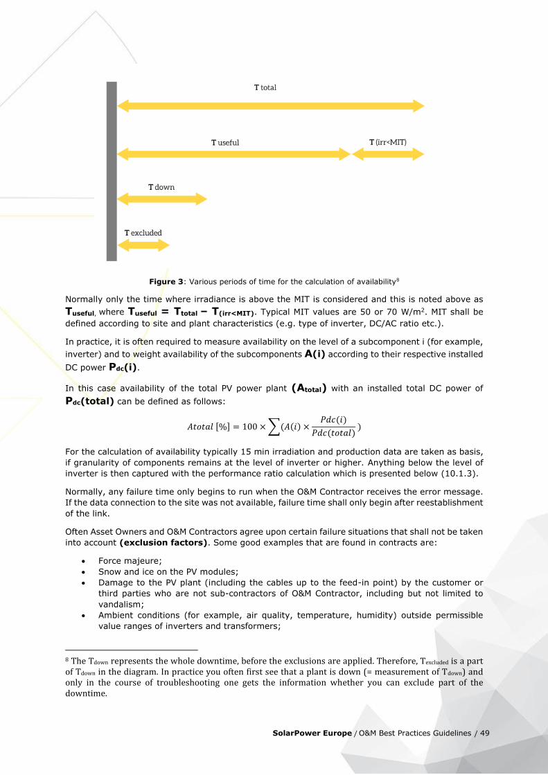
SolarPower Europe / O&M Best Practices Guidelines / 49
Figure 3: Various periods of time for the calculation of availability8
Normally only the time where irradiance is above the MIT is considered and this is noted above as
Tuseful, where Tuseful = Ttotal – T(irr<MIT). Typical MIT values are 50 or 70 W/m2. MIT shall be
defined according to site and plant characteristics (e.g. type of inverter, DC/AC ratio etc.).
In practice, it is often required to measure availability on the level of a subcomponent i (for example,
inverter) and to weight availability of the subcomponents A(i) according to their respective installed
DC power Pdc(i).
In this case availability of the total PV power plant (Atotal) with an installed total DC power of
Pdc(total) can be defined as follows:
𝐴𝑡𝑜𝑡𝑎𝑙 [%] = 100 × ∑(𝐴(𝑖) ×𝑃𝑑𝑐(𝑖)
𝑃𝑑𝑐(𝑡𝑜𝑡𝑎𝑙) )
For the calculation of availability typically 15 min irradiation and production data are taken as basis,
if granularity of components remains at the level of inverter or higher. Anything below the level of
inverter is then captured with the performance ratio calculation which is presented below (10.1.3).
Normally, any failure time only begins to run when the O&M Contractor receives the error message.
If the data connection to the site was not available, failure time shall only begin after reestablishment
of the link.
Often Asset Owners and O&M Contractors agree upon certain failure situations that shall not be taken
into account (exclusion factors). Some good examples that are found in contracts are:
Force majeure;
Snow and ice on the PV modules;
Damage to the PV plant (including the cables up to the feed-in point) by the customer or
third parties who are not sub-contractors of O&M Contractor, including but not limited to
vandalism;
Ambient conditions (for example, air quality, temperature, humidity) outside permissible
value ranges of inverters and transformers;
8 The Tdown represents the whole downtime, before the exclusions are applied. Therefore, Texcluded is a part of Tdown in the diagram. In practice you often first see that a plant is down (= measurement of Tdown) and only in the course of troubleshooting one gets the information whether you can exclude part of the downtime.

50
Disconnection or reduction of energy generation by the customer or as a result of an order
issued to the customer by a court or public authority;
Operational disruption by grid disconnections or disruptions in the grid of the grid operator;
Disconnections or power regulation by the grid operator or his control devices;
Downtimes resulting from failures of the inverter or MV voltage components (for example,
transformer, switchgear), if this requires
o Technical support of the manufacturer and/or
o Logistical support (for example supply of spare parts) by the manufacturer;
Downtimes due to scheduled maintenance measured per year and component.
Outages of the communication system.
Delays of approval by the customer to conduct necessary works;
Downtimes for implementation of measures to improve the PV plant, if this is agreed between
the parties;
Downtimes caused by the fact that the customer has commissioned third parties with the
implementation of technical work on the PV plant.
Note that variants of the above-defined availability are:
Uptime (availability without correction for exclusion factors)
Energy-based availability which is presented below in 10.1.2
10.1.2 Energy-based availability
Energy-based availability takes into consideration that an hour in a period with high irradiance is
more valuable than in a period with low irradiance. Therefore, it uses as base for calculation not time but energy (and lost energy):
𝐸𝐴 [%] = (1 −∑ 𝐸𝑙𝑜𝑠𝑠
(𝑖)𝑖
𝐸𝑡𝑜𝑡𝑎𝑙 + ∑ 𝐸𝑙𝑜𝑠𝑠(𝑖)
𝑖
) × 100
where:
Eloss(i) [kWh] = calculated lost yield per event (i)
Etotal [kWh] = absolute yield in the period under review according to feed-in meters
The challenge of this method is to accurately determine the lost yield. The following cases can be
distinguished:
Failure of the whole system, where lost yield can be calculated via performance ratio (PR –
see 10.1.3) and irradiation according to the formula below:
𝐸 [𝑘𝑊ℎ] = 𝑃𝑅 × 𝐻 × 𝑃
where:
PR = performance ratio. The PR is determined from the average PR over the last ten days during
which the PV system fed into the grid without faults.
H [kWh/m²] = irradiation measured in module plane
P [kWp] = the nominal power of the system.
Failure of an inverter or module string, where the expected yield of the failed inverter/module
string for the period of the failure is ascertained by comparing the specific yields in kWh/kWp
of the other inverters or module strings with the same alignment/inclination/configuration.
The periods for which the Contractor cannot accept any responsibility and that are not included in
the calculation of technical system availability are listed in section 10.1.1.

SolarPower Europe / O&M Best Practices Guidelines / 51
10.1.3 Performance Ratio
The Performance Ratio (PR) is a quality indicator of the PV plant. It is reported as a percentage and
indicates the overall effect of losses of the PV generator by normalizing produced AC energy with
respect to installed PV peak power and irradiance. The higher the PR is, the more energy efficient
the plant is. In reality the PR cannot be 100% due to losses (e.g. thermal losses, conversion losses,
wiring etc.)9.
Performance Ratio is defined as:
𝑷𝑹 [%] =𝐹𝑖𝑛𝑎𝑙 𝑌𝑖𝑒𝑙𝑑 𝑖𝑛 ℎ 𝑝𝑒𝑟 𝑦𝑒𝑎𝑟 (𝒀𝒇)
𝑅𝑒𝑓𝑒𝑟𝑒𝑛𝑐𝑒 𝑦𝑖𝑒𝑙𝑑 𝑖𝑛 ℎ 𝑝𝑒𝑟 𝑦𝑒𝑎𝑟 (𝒀𝑟)× 100
The final system yield that can be read from the grid export meter is defined as:
𝒀𝒇 =𝑇ℎ𝑒 𝑒𝑛𝑒𝑟𝑔𝑦 𝑡𝑜 𝑡ℎ𝑒 𝑢𝑡𝑖𝑙𝑖𝑡𝑦 𝑔𝑟𝑖𝑑 𝑖𝑛 𝑘𝑊ℎ 𝑝𝑒𝑟 𝑦𝑒𝑎𝑟 (𝑬𝑨𝑪)
𝑇ℎ𝑒 𝑖𝑛𝑠𝑡𝑎𝑙𝑙𝑒𝑑 𝑃𝑉 𝑝𝑒𝑎𝑘 𝑝𝑜𝑤𝑒𝑟 (𝑷𝒐)
The installed capacity (DC power) is eventually corrected by module degradation.
The reference yield (nominal plant output) is defined as:
𝒀𝒓 =𝑇ℎ𝑒 𝑝𝑙𝑎𝑛𝑒 𝑜𝑓 𝑎𝑟𝑟𝑎𝑦 𝑖𝑟𝑟𝑎𝑑𝑖𝑎𝑡𝑖𝑜𝑛 (𝐇𝐏𝐎𝐀)
𝑇ℎ𝑒 𝑟𝑒𝑓𝑒𝑟𝑒𝑛𝑐𝑒 𝑖𝑟𝑟𝑎𝑑𝑖𝑎𝑛𝑐𝑒 𝑎𝑡 𝑠𝑡𝑎𝑛𝑑𝑎𝑟𝑑 𝑡𝑒𝑠𝑡 𝑐𝑜𝑛𝑑𝑖𝑡𝑖𝑜𝑛𝑠 (𝐆𝐒𝐓𝐂10)
These definitions are based on (Woyte et al. 2014) in line with the IEC 61724 (ed1.0 1998) and are
common practice.
Notably, the above definitions are purely technical. However, as for KPI used for the verification of
contractual terms, the PR definition excludes periods during which the PV plant experienced external
disturbances. Therefore, the computation of final yield and reference yield for PR should exclude
periods during which the power generation of the plant was reduced due to force majeure, grid
disconnection or activities ordered by the client (non-available). Detailed provisions for contractual
PR differ from contract to contract.
It should be noted that PR is considered a KPI of the PV plant and not purely of the O&M Contractor,
due to the fact that certain parameters for its calculation have to do for instance with design aspects.
Therefore, PR underlines the significance of having a close communication link established between
the EPC/installer and the service provider during the design phase.
However, PR is used as a primary KPI in contracts with penalties and incentives when PR thresholds
are exceeded and therefore the O&M Contractor is responsible to measure this as one of his/her key
operational duties. For this reason, the quality of the underlying data needs to be warranted by both
contractual parties jointly.
The O&M Contractor may provide guarantees on PR (with bonuses and liabilities) under certain
conditions and specifically:
based on design/PAC11/FAC12 data if the O&M Contractor has been the same entity as the
EPC
based on a specific procedure, preliminary to guarantee commencement, designed to
objectively assess PR of the plant at take over
with a formula that clarifies exceptions to the calculation (same exceptions as with
availability)
9 In theory PR can be higher than 100%. Panel nominal power is measured at STC, so under more favorable conditions (higher irradiation, lower temperature than STC) the PR can be higher than 100%. Such values have been measured for short periods of time. 10 STC = 1000 W/m2 11 Provisional Acceptance Certificate 12 Final Acceptance Certificate

52
by defining whether periods of low irradiation or non-availability have to be taken into
consideration (not recommended), and which kind of measurement device is used for
irradiance measurement
with a procedure that describes how to consider module degradation
Note that if it is decided to introduce a correction factor for non-availability (in order to exclude
periods of non-availability for PR calculation), energy-based availability (see below) should be used.
Based on PR, the O&M Contractor provides recommendations to the plant owners on eventual
investment or interventions.
10.1.4 Energy Performance Index
The Energy Performance Index (EPI) is defined as the ratio between the final system yield Yf and the
expected yield Yexp as determined by a PV model, using the actual weather data as input to the model
over the assessment period (typically day/month/year). The concept was proposed, e.g., in (Honda
et al. 2012).
𝐸𝑃𝐼 [%] =𝑇ℎ𝑒 𝐹𝑖𝑛𝑎𝑙 𝑦𝑖𝑒𝑙𝑑 𝑖𝑛 ℎ (𝒀𝒇)
𝑇ℎ𝑒 𝐸𝑥𝑝𝑒𝑐𝑡𝑒𝑑 𝑦𝑖𝑒𝑙𝑑 𝑏𝑦 𝑃𝑉 𝑚𝑜𝑑𝑒𝑙 (𝒀𝐞𝐱𝐩 )
The advantage of using the EPI is that its expected value is 100% at project start-up and is
independent of climate or weather. This indicator relies on the accuracy of the expected model.
Unfortunately, there are more than one established models for the expected yield of PV systems in
operation and not all of them are transparent. Therefore, the use of EPIs is recommended mainly for
identification of performance flaws and comparison of plants to each other.
10.2 O&M Contractor KPIs
10.2.1 Reaction Time The O&M Contractor is committed to react on alarms received from the plant through the monitoring
and supervision system within a certain period of time. The duration of required reaction time is
usually tied to the (potential) loss of energy generation capacity and can be classified according to
this requirement (see examples in Table 6 below). Definitions:
Acknowledgement Time is the period of detecting the problem (receipt of the alarm) but also the
period of assessing the failure (remotely or on-site) in order to organise the proper response.
Response Time means that the O&M Contractor shall have the necessary employees addressing the
failure and in the performance of corrective maintenance.
Normally acknowledgement and response times are guaranteed. It is difficult to guarantee resolution
time, because resolution often does not depend totally on the O&M Contractor.
Table 6: High level classification of failures and the respective Acknowledgement and Response Time (average examples)
Failure Class
Definition Acknowledgement Time Response Time
1
Any event that causes a plant-wide
outage during expected production
periods, or the loss of
communications resulting in an
[2 hours] [12 hours]

SolarPower Europe / O&M Best Practices Guidelines / 53
inability to monitor or control the
Plant.
2
Any event that causes a Power
Conversion Station (PCS) outage during expected production periods, or the loss of communications with a Plant component resulting in an inability to monitor or control the Plant.
[4 hours] [24 hours]
3
Any event that causes the outage of one or more inverters during expected production periods at the plant.
[6 hours] [36 hours]
The above times will vary greatly depending on the location of the plant and the contract.
10.2.2 Reporting
It is very important for the O&M Contractor to comply with reporting requirements and reporting timelines. Content of the reporting should be expected to be consistent and any change in content or format needs to be explained by the O&M Contractor (see also 5.8 chapter). Delivery of reports per the agreed upon timeline is an important indicator for reliability and process adherence within the O&M Contractors organization.
10.2.3 O&M Contractor experience Experience of the O&M Contractor with PV power plants in the particular country, region, grid environment and/or with PV power plants equipped with certain technology or size can play an important role. This is quite relevant for the selection of the O&M Contractor and can be tracked by
the owner over time (track record).
10.2.4 Maintenance Effectiveness & Maintenance Support Efficiency To evaluate preventative maintenance there are two main indicators that may be considered
according to the best practices (see chapter 7.1):
Maintenance Effectiveness: Is the ratio between the maintenance performance target and
actual result.
Maintenance Support Efficiency: Is the ratio between the planned or expected resources and
those that are actually used.
54
11 Contractual Commitments
11.1 O&M Contractors Qualification
The Asset Owner follows the interest, that he is contracting with an O&M Contractor, who is
professional in his job and has the capabilities to operate and maintain the plant in accordance with
the contractual obligations. Experience and availability of a professional organization, skilled teams
and access to spare parts are criteria for the selection of the O&M Contractor. As O&M services are
a combination of remote operations services and local maintenance activities, the Asset Owner should
make sure, that both components are well managed and interfaces between operations services and
maintenance services are well defined, especially when the O&M works are not contracted with one
single entity and each entity is responsible and can be held accountable for the overall O&M
performance.
11.2 Responsibility and Accountability
The responsibility of the O&M Contractor is usually defined in the Scope of Works, which forms a part
of the O&M contract. A detailed description of the O&M scope items ensure clarity of what the O&M
Contractor will do during the term of the contract. In addition to the scope of works, the Annual
Maintenance Plan (AMP) and Annual Maintenance Schedule (AMS) (please refer to attachment
“Annual Maintenance Plan”) outline the granularity and frequency of (predominantly) preventive
maintenance works. The execution of the activities is being reported to the Asset Owner through the
regular reporting – this forms the minimum guidelines. Best practices can be seen if the regular
reporting compares the executed activities with the AMP and AMS, and outlines deviations and
reasoning.
Corrective maintenance activities, which will be performed in case of any component failure or energy
generation shortfall are controlled by performance commitments signed by the O&M Contractor.
Based on the KPIs explained in chapter 10, the Asset Owner and the O&M Contractor can define the
level of accountability of the O&M Contractor.
The minimum level is to agree on certain reaction times. These reaction times can be used to measure
the time of the detection of any failure, the reporting time between the Operations team and the
Maintenance team, the time, until the Maintenance provider is on site and the time to fix a certain
component failure and/or restore the plant back into proper function (see 10.2.1).
A more comprehensive measure for accountability is the plant availability. Besides the possibility to
agree on minimum reaction times, the O&M Contractor’s performance can be measured through a
commitment to certain plant availability ratio. Based on the definition of plant availability, usually
measured on an annual basis, the O&M Contractor will be held accountable against a to be agreed
plant availability threshold. The level of such threshold is negotiable and determined by the Asset

SolarPower Europe / O&M Best Practices Guidelines / 55
Owner’s expectation of minimum energy production and the O&M Contractor’s willingness to agree.
A higher level of plant availability commitment is expected to have an effect on the pricing of the
O&M contract, since the O&M Contractor will calculate for a risk premium.
11.3 Bonus Schemes and Liquidated Damages
The accountability of the O&M Contractor will finally be translated into Bonus Schemes and Liquidated
Damages. These ensure, that the Asset Owner will be compensated for shortfalls under the reaction
time or availability commitments.
Since the O&M Contractor’s responsibility is focused on the operations and maintenance works for
the PV asset, other influencing factors like force majeure events, grid operator activities to reduce
the plant output, grid instability or offline periods or any weather related power generation shortfall
shall be exempted from the O&M Contractor’s responsibility and therefore from any Liquidated
Damages.
Liquidated Damages shall usually be tied to a reduction of the O&M Annual Fee and are limited by
the Liquidated Damages Cap. This can for example be 100% of an annual fee per year or a multiple
of an annual fixed fee in aggregate. If the Liquidated Damages Cap is reached, this usually translates
into termination rights for the asset owner and O&M Contractor.
If the O&M Contractor is overachieving the reaction time or availability threshold levels, his
compensation can be improved according to agreed Bonus Schemes. Especially in cases, where the
O&M Contractor commits to a certain plant availability, his motivation to provide best-in-class
services and performance will be triggered by a Bonus, which can be agreed as a certain increase of
his annual fixed fee. Higher plant availability usually leads to higher power generation and an increase
of revenues for the benefit of the plant owner. Hence the Bonus Scheme agreements lead to a win-
win situation for both parties and ensures that the O&M Contractor is highly motivated.
Example for Availability Commitment related Bonus Schemes and Liquidated Damages can be found
in Table 7 below:
Table 7: Examples for Availability Commitment related Bonus Schemes and Liquidated Damages
Plant Availability
Availability Commitment
Bonus
(as percentage of O&M
Service Fees
for applicable Reporting
Period)
Availability Commitment
Liquidated Damages
(as percentage of O&M
Service Fees
for applicable Reporting Period
(1Y))
99.00% < x < 100.0% +15% -
98.00% < x < 99.00% +10% -
97.1% < x < 98.00% +5% -
97.00% < x 0% 0%
96.00% < x < 97.00% - -10.00%
95.00% < x < 96.00% - -20.00%
94.00% < x < 95.00% - -30.00%
93.00% < x < 94.00% - -40.00%

56
References
IEC 61724 ed1.0. 1998. Photovoltaic System Performance Monitoring-Guidelines for Measurement,
Data Exchange and Analysis. International Electrical Commission. ISO 9060. 1990. “Solar Energy -- Specification and Classification of Instruments for Measuring
Hemispherical Solar and Direct Solar Radiation.” http://www.iso.org/iso/home/store/catalogue_tc/catalogue_detail.htm?csnumber=16629.
N. Reich, B. Mueller, A. Armbruster, W. G. J. H. M. van Sark, K. Kiefer, and C. Reise. 2012. “Performance Ratio Revisited: Is PR > 90% Realistic?” Progress in Photovoltaics: Research
and Applications 20 (6): 717–26. doi:10.1002/pip.1219. Pelland, Sophie, Jan Remund, Jan Kleissl, Takashi Oozeki, and Karel De Brabandere. 2013.
“Photovoltaic and Solar Forecasting - State of the Art.” Report IEA PVPS T14-01:2013. International Energy Agency Photovoltaic Power Systems Programme.
Richter, Mauricio, Karel De Brabandere, John Kalisch, Thomas Schmidt, and Elke Lorenz. 2015. “Best Practice Guide on Uncertainty in PV Modelling.” Public report Performance Plus WP2 Deliverable D2.4.
http://www.perfplus.eu/frontend/files/userfiles/files/308991_PerfPlus_Deliverable_D2_4_2
0150205.pdf. Shelton Honda, Alex Lechner, Sharath Raju, and Ivica Tolich. 2012. “Solar PV System Performance
Assessment Guideline for SolarTech.” San Jose, California: San Jose State University. Woyte, Achim, Mauricio Richter, David Moser, Stefan Mau, Nils H. Reich, and Ulrike Jahn. 2013.
“Monitoring of Photovoltaic Systems: Good Practices and Systematic Analysis.” In 28th EU PVSEC, 3686–94. Paris, France.
Woyte, Achim, Mauricio Richter, David Moser, Nils Reich, Mike Green, Stefan Mau, and Hans Georg Beyer. 2014. “Analytical Monitoring of Grid-Connected Photovoltaic Systems - Good Practice for Monitoring and Performance Analysis.” Report IEA-PVPS T13-03: 2014. IEA PVPS.

SolarPower Europe / O&M Best Practices Guidelines / 57
Annex – Documentation control Information type and depth of detail / as-built documents
No. Minimum Requirements Description Comments
1 Site Information Location / Map / GPS Coordinates
Plant Access / Keys Access Roads O&M Building Spare Parts Storage / Warehouse Site Security Information Stakeholder list and contact information (for example, owner of the
site, administration contacts, firefighters, subcontractors / service
providers, ...)
2 Project Drawings Plant Layout and General Arrangement Cable routing drawings Cable list Cable schedule/ cable interconnection document
Single Line Diagram Configuration of strings (string numbers, in order to identify where
the strings are in relation to each connection box and inverter) Earthing/Grounding System layout drawing Lightning Protection System layout drawing Lighting System layout drawing (optional)
Topographic drawing
“Lightning Protection System layout drawing” can be considered as optional
3 Project studies Shading study/simulation Energy yield study/simulation Inverter sizing study
4 Studies according to national
regulation requirements
Voltage drop calculations
Protection coordination study Short circuit study Grounding study Cable sizing calculations Lightning protection study
5 PV Modules Datasheets
Flash list with PV modules positioning on the field (reference to
string numbers and positioning in the string) Warranties & Certificates
6 Inverters O&M Manual Commissioning Report
Warranties & Certificates

58
Factory Acceptance Test Inverter settings Dimensional drawings
7 Medium Voltage/Inverter Cabin Medium Voltage/Inverter Cabin layout and general arrangement drawing
Medium Voltage/Inverter Cabin foundation drawing Erection procedure Internal Normal/Emergency Lighting Layout Drawing Fire Detection and Fire Fighting System Layout Drawing (if
required) HVAC system Layout Drawing
HVAC system Installation & O&M Manual
HVAC Study (according to national regulations) Earthing system layout drawing Cable list
8 MV/LV Transformer O&M Manual Commissioning Report Factory Acceptance Test Report
Type Test Reports Routine Test Reports Warranties & Certificates Dimensional drawing with parts list
9 Cables Datasheets
Type & Routine test reports
10 LV & MV Switchgear Single Line Diagram Switchgear wiring diagrams Equipment datasheets and manuals Factory Acceptance Test report Type Test Reports
Routine Test Reports Dimensional drawings Warranties & Certificates Protection relays settings Switching procedure (according to national regulations)
“Protection relays settings” and “Switching procedure” are considerations for the MV Switchgear
11 HV Switchgear Single Line Diagram Steel structures assembly drawings
HV Switchyard general arrangement drawing HV Equipment Datasheets and Manuals (CTs, VTs, Circuit Breakers,
Disconnectors, Surge Arresters, Post Insulators) Protection & Metering Single Line Diagram HV Equipment Type & Routine Test Reports

SolarPower Europe / O&M Best Practices Guidelines / 59
Interlock study Switching procedure (according to national regulations) Warranties & Certificates
12 UPS & Batteries Installation & O&M Manual Commissioning report
Warranties & Certificates Datasheets Dimensional Drawings
13 Mounting Structure Mechanical Assembly Drawings Warranties & Certificates
14 Trackers Mechanical Assembly Drawings
Electrical Schematic Diagrams Block diagram Equipment Certificates, Manuals and Datasheets (Motors,
Encoders) PLC list of inputs and outputs (I/O) by type (Digital, Analog or Bus) Commissioning reports
Warranties & Certificates
15 Security, Anti-intrusion and Alarm System
Security system layout/general arrangement drawing Security system block diagram Alarm system schematic diagram Equipment manuals and datasheets
Access to security credentials (e.g. passwords, instructions, keys
etc.) Warranties & Certificates
16 Monitoring/SCADA system Installation & O&M manual List of inputs by type (Digital, Analog or Bus) Electrical Schematic diagram
Block diagram (including network addresses) Equipment datasheets
I/O list includes e.g. sensor readings that are collected by data loggers.
17 Plant Controls Power Plant Control System description Control Room (if applicable) Plant Controls instructions
Breaker Control functionality (remote / on-site) and instructions List of inputs and outputs
18 Communication system Installation and O&M manual
System internal communication External Communication to monitoring system or Operations
Centre
IP network plan Bus network plans

60