solas 2018 consolidated edition - samgöngustofa · engaged on international voyages. any such ship...
TRANSCRIPT

1
SOLAS 2018
Consolidated Edition
CHAPTER I
GENERAL PROVISIONS
PART A-APPLICATION, DEFINITIONS, ETC.
Regulation 1
Application*
* Refer to MSC-MEPC.5/Circ.8 on Unified interpretation of the application of regulations governed
by the building contract date, the keel laying date and the delivery date for the requirements of the
SOLAS and MARPOL Conventions.
(a) Unless expressly provided otherwise, the present Regulations apply only to ships engaged on
international voyages.
(b) The classes of ships to which each Chapter applies are more precisely defined, and the extent of
the application is shown, in each Chapter.
Regulation 2
Definitions
For the purpose of the present regulations, unless expressly provided otherwise:
(a) Regulations means the regulations contained in the annex to the present Convention.
(b) Administration means the Government of the State whose flag the ship is entitled to fly.
(c) Approved means approved by the Administration.
(d) International voyage means a voyage from a country to which the present Convention applies to a
port outside such country, or conversely.
(e) A passenger is every person other than:

2
(i) the master and the members of the crew or other persons employed or engaged in any capacity
on board a ship on the business of that ship and
(ii) a child under one year of age.
(f) A passenger ship is a ship which carries more than twelve passengers.
(g) A cargo ship is any ship which is not a passenger ship.
(h) A tanker is a cargo ship constructed or adapted for the carriage in bulk of liquid cargoes of an
inflammable* nature.
* "Inflammable" has the same meaning as "flammable"
(i) A fishing vessel is a vessel used for catching fish, whales, seals, walrus or other living resources of
the sea.
(j) A nuclear ship is a ship provided with a nuclear power plant.
(k) New ship means a ship the keel of which is laid or which is at a similar stage of construction on or
after 25 May 1980.
(l) Existing ship means a ship which is not a new ship.
(m) A mile is 1,852 metres or 6,080 feet.
(n) Anniversary date means the day and the month of each year which will correspond to the date of
expiry of the relevant certificate.
Regulation 3
Exceptions
(a) The present Regulations, unless expressly provided otherwise, do not apply to:
(i) Ships of war and troopships.
(ii) Cargo ships of less than 500 tons gross tonnage.
(iii) Ships not propelled by mechanical means.
(iv) Wooden ships of primitive build.
(v) Pleasure yachts not engaged in trade.

3
(vi) Fishing vessels.
(b) Except as expressly provided in Chapter V, nothing herein shall apply to ships solely navigating the
Great Lakes of North America and the River St. Lawrence as far east as a straight line drawn from Cap
des Rosiers to West Point, Anticosti Island and, on the north side of Anticosti Island, the 63rd
Meridian.
Regulation 4
Exemptions*
* Refer to Issue of exemption certificates under the 1974 SOLAS Convention and amendments
thereto, as amended (SLS.14/Circ.115) and Port State concurrence with SOLAS exemptions
(MSC/Circ.606).
(a) A ship which is not normally engaged on international voyages but which, in exceptional
circumstances, is required to undertake a single international voyage may be exempted by the
Administration from any of the requirements of the present Regulations provided that it complies with
safety requirements which are adequate in the opinion of the Administration for the voyage which is
to be undertaken by the ship.
(b) The Administration may exempt any ship which embodies features of a novel kind from any of the
provisions of Chapters II-1, II-2, III and IV of these Regulations the application of which might
seriously impede research into the development of such features and their incorporation in ships
engaged on international voyages. Any such ship shall, however, comply with safety requirements
which, in the opinion of that Administration, are adequate for the service for which it is intended and
are such as to ensure the overall safety of the ship and which are acceptable to the Governments of
the States to be visited by the ship. The Administration which allows any such exemption shall
communicate to the Organization particulars of same and the reasons therefor which the
Organization shall circulate to the Contracting Governments for their information.
Regulation 5
Equivalents
(a) Where the present Regulations require that a particular fitting, material, appliance or apparatus, or
type thereof, shall be fitted or carried in a ship, or that any particular provision shall be made, the
Administration may allow any other fitting, material, appliance or apparatus, or type thereof, to be
fitted or carried, or any other provision to be made in that ship, if it is satisfied by trial thereof or
otherwise that such fitting, material, appliance or apparatus, or type thereof, or provision, is at least
as effective as that required by the present Regulations.
(b) Any Administration which so allows, in substitution, a fitting, material, appliance or apparatus, or
type thereof, or provision, shall communicate to the Organization particulars thereof together with a

4
report on any trials made and the Organization shall circulate such particulars to other Contracting
Governments for the information of their officers.
Regulation 6
Inspection and Survey
(a) The inspection and survey of ships, so far as regards the enforcement of the provisions of the
present regulations and the granting of exemptions therefrom, shall be carried out by officers of the
Administration. The Administration may, however, entrust the inspections and surveys either to
surveyors nominated for the purpose or to organizations recognized by it.
(b) An Administration nominating surveyors or recognizing organizations to conduct inspections and
surveys as set forth in paragraph (a) shall as a minimum empower any nominated surveyor or
recognized organization to:
(i) require repairs to a ship;
(ii) carry out inspections and surveys if requested by the appropriate authorities of a port state.
The Administration shall notify the Organization of the specific responsibilities and conditions of the
authority delegated to nominated surveyors or recognized organizations.*
* Refer to MSC/Circ.1010 - MEPC/Circ.382 on Communication of information on the authorization
of recognized organizations (ROs), and the information collected via the Global Integrated Shipping
Information System (GISIS).
(c) When a nominated surveyor or recognized organization determines that the condition of the ship
or its equipment does not correspond substantially with the particulars of the certificate or is such that
the ship is not fit to proceed to sea without danger to the ship, or persons on board, such surveyor or
organization shall immediately ensure that corrective action is taken and shall in due course notify the
Administration. If such corrective action is not taken the relevant certificate should be withdrawn and
the Administration shall be notified immediately;and, if the ship is in the port of another party, the
appropriate authorities of the port state shall also be notified immediately. When an officer of the
Administration, a nominated surveyor or recognized organization has notified the appropriate
authorities of the port state, the Government of the port state concerned shall give such officer,
surveyor or organization any necessary assistance to carry out their obligations under this regulation.
When applicable, the Government of the port state concerned shall ensure that the ship shall not sail
until it can proceed to sea, or leave port for the purpose of proceeding to the appropriate repair yard,
without danger to the ship or persons on board.

5
(d) In every case, the Administration shall fully guarantee the completeness and efficiency of the
inspection and survey, and shall undertake to ensure the necessary arrangements to satisfy this
obligation.
Regulation 7
Surveys of passenger ships*
* Refer to Surveys and inspections of ro-ro passenger ships (resolution A.794(19), Guidelines for
unscheduled inspections of ro-ro passenger ships by flag States (MSC/Circ.956) and Guidelines for
the assessment of technical provisions for the performance of an in-water survey in lieu of bottom
inspection in dry-dock to permit one dry-dock examination in any five-year period for passenger
ships other than ro-ro passenger ships (MSC.1/Circ.1348).
(a) A passenger ship shall be subjected to the surveys specified below:
(i) an initial survey before the ship is put in service;
(ii) a renewal survey once every 12 months, except where regulation 14 (b), (e), (f) and (g) is
applicable;
(iii) additional surveys, as occasion arises.
(b) The surveys referred to above shall be carried out as follows:
(i) the initial survey shall include a complete inspection of the ship's structure, machinery and
equipment, including the outside of the ship's bottom and the inside and outside of the boilers.
This survey shall be such as to ensure that the arrangements, materials and scantlings of the
structure, boilers and other pressure vessels and their appurtenances, main and auxiliary
machinery, electrical installation, radio installations including those used in life-saving appliances,
fire protection, fire safety systems and appliances, life-saving appliances and arrangements,
shipborne navigational equipment, nautical publications, means of embarkation for pilots and
other equipment fully comply with the requirements of he present regulations, and of the laws,
decrees, orders and regulations promulgated as a result thereof by the Administration for ships of
the service for which it is intended. The survey shall also be such as to ensure that the workmanship
of all parts of the ship and its equipment is in all respects satisfactory, and that the ship is provided
with the lights, shapes, means of making sound signals and distress signals as required by the
provisions of the present regulations and the International Regulations for Preventing Collisions at
Sea in force;
(ii) the renewal survey shall include an inspection of the structure, boilers and other pressure
vessels, machinery and equipment, including the outside of the ship's bottom. The survey shall be

6
such as to ensure that the ship, as regards the structure, boilers and other pressure vessels and
their appurtenances, main and auxiliary machinery, electrical installation, radio installations
including those used in life-saving appliances, fire protection, fire safety systems and appliances,
life-saving appliances and arrangements, shipborne navigational equipment, nautical publications,
means of embarkation for pilots and other equipment is in satisfactory condition and is fit for the
service for which it is intended, and that it complies with the requirements of the present
regulations and of the laws, decrees, orders and regulations promulgated as a result thereof by the
Administration. The lights, shapes, means of making sound signals and distress signals carried by
the ship shall also be subject to the abovementioned survey for the purpose of ensuring that they
comply with the requirements of the present regulations and of the International Regulation for
Preventing Collisions at Sea in force;
(iii) an additional survey either general or partial, according to the circumstances, shall be made
after a repair resulting from investigations prescribed in regulation 11, or whenever any important
repairs or renewals are made. The survey shall be such as to ensure that the necessary repairs or
renewals have been effectively made, that the material and workmanship of such repairs or
renewals are in all respects satisfactory, and that the ship complies in all respects with the
provisions of the present regulation and of the International Regulations for Preventing Collisions
at Sea in force, and of the laws, decrees, orders and regulations promulgated as a result thereof by
Administration;
(c)
(i) the laws, decrees, orders and regulations referred to in paragraph (b) of this regulation shall be
in all respects such as to ensure that, from the point of view of safety of life, the ship is fit for the
service for which it is intended;
(ii) they shall among other things prescribe the requirements to be observed as to the initial and
subsequent hydraulic or other acceptable alternative tests to which the main and auxiliary boilers,
connections, steam pipes, high pressure receivers and fuel tanks for internal combustion engines are
to be submitted including the test procedures to be followed and the intervals between two
consecutive tests.
Regulation 8
Surveys of life-saving appliances and other equipment of cargo ships
(a) The life-saving appliances and other equipment of cargo ships of 500 tons gross tonnage and
upwards as referred to in paragraph (b) (i) shall be subject to the surveys specified below:
(i) an initial survey before the ship is put in service;

7
(ii) a renewal survey at intervals specified by the Administration but not exceeding 5 years, except
where regulation 14 (b), (e), (f) and (g) is applicable;
(iii) a periodical survey within three months before or after the second anniversary date or within
three months before or after the third anniversary date of the Cargo Ship Safety Equipment
Certificate which shall take the place of one of the annual surveys specified in paragraph (a) (iv);
(iv) an annual survey within 3 months before or after each anniversary date of the Cargo Ship Safety
Equipment Certificate;
(v) an additional survey as prescribed for passenger ships in regulation 7 (b) (iii).
(b) The surveys referred to in paragraph (a) shall be carried out as follows;
(i) the initial survey shall include a complete inspection of the fire safety systems and appliances,
life-saving appliances and arrangements except radio installations, the shipborne navigational
equipment, means of embarkation for pilots and other equipment to which chapters II-1, II-2, III
and V apply to ensure that they comply with the requirements of the present regulations, are in
satisfactory condition and are fit for the service for which the ship is intended. The fire control
plans, nautical publications, lights, shapes, means of making sound signals and distress signals shall
also be subject to the above-mentioned survey for the purpose of ensuring that they comply with
the requirements of the present regulations and, where applicable, the International Regulations
for Preventing Collisions at Sea in force*;
* Refer to the Record of approved cargo ship safety equipment(SLS.14/Circ.1)
(ii) the renewal and periodical surveys shall include an inspection of the equipment referred to in
paragraph (b) (i) to ensure that it complies with the relevant requirements of the present
regulations and the International Regulations for Preventing Collisions at Sea in force, is in
satisfactory condition and is fit for the service for which the ship is intended;
(iii) the annual survey shall include a general inspection of the equipment referred to in paragraph
(b) (i) to ensure that it has been maintained in accordance with regulation 11 (a) and that it remains
satisfactory for the service for which the ship is intended.
(c) the periodical and annual surveys referred to in paragraphs (a) (iii) and (a) (iv) shall be endorsed
on the Cargo Ship Safety Equipment Certificate.
Regulation 9
Surveys of radio installations of cargo ships

8
(a) The radio installations, including those used in life-saving appliances, of cargo ships to which
chapters III and IV apply shall be subject to the surveys specified below:
(i) an initial survey before the ship is put in service;
(ii) a renewal survey at intervals specified by the Administration but not exceeding five years, except
where regulation 14(b), (e), (f) and (g) is applicable;
(iii) a periodical survey within three months before or after each anniversary date of the Cargo Ship
Safety Radio Certificate;
(iv) an additional survey as prescribed for passenger ships in regulation 7 (b) (iii).
(b) The surveys referred to in paragraph (a) shall be carried out as follows:
(i) the initial survey shall include a complete inspection of the radio installations of cargo ships,
including those used in life-saving appliances, to ensure that they comply with the requirements of
the present regulations;
(ii) the renewal and periodical surveys shall include an inspection of the radio installations of cargo
ships, including those used in life-saving appliances, to ensure that they comply with the
requirements of the present regulations.
(c) The periodical surveys referred to in paragraph (a) (iii) shall be endorsed on the Cargo Ship Safety
Radio Certificate.
Regulation 10
Surveys of structure, machinery and equipment of cargo ships*
* Refer to Guidelines for bulk carrier hatch cover surveys and owner's inspections and maintenance
(MSC/Circ.1071)
(a) The structure, machinery and equipment (other than items in respect of which a Cargo Ship
Safety Equipment Certificate and a Cargo Ship Safety Radio Certificate are issued) of a cargo ship as
referred to in paragraph (b) (i) shall be subject to the surveys and inspections specified below :
(i) an initial survey including an inspection of the outside of the ship's bottom before the ship is put
in service*;
* Refer to the circular concerning inspection of the outside of the ship's bottom (PSLS.2/Circ.5).

9
(ii) a renewal survey at intervals specified by the Administration but not exceeding 5 years, except
where regulation 14 (b), (e), (f) and (g) is applicable;
(iii) an intermediate survey within three months before or after the second anniversary date or
within three months before or after the third anniversary date of the Cargo Ship Safety
Construction Certificate, which shall take the place of one of the annual surveys specified in
paragraph (a) (iv);
(iv) an annual survey within 3 months before or after each anniversary date of the Cargo Ship Safety
Construction Certificate;
(v) a minimum of two inspections of the outside of the ship's bottom during any five year period,
except where regulation 14 (e) or (f) is applicable. Where regulation 14 (e) or (f) is applicable, this
five year period may be extended to coincide with the extended period of validity of the certificate.
In all cases the interval between any two such inspections shall not exceed 36 months;
(v)* a minimum of two inspections of the outside of the ship’s bottom during the five-year period of
validity of the Cargo Ship Safety Construction Certificate or the Cargo Ship Safety Certificate, except
where regulation 14(e) or 14(f) is applicable. Where regulation 14(e) or 14(f) is applicable, this five-
year period may be extended to coincide with the extended period of validity of the certificate. In
all cases the interval between any two such inspections shall not exceed 36 months; ( Adopted by
Res.MSC.204(81))
* Adopted by Res.MSC.204(81) and to be entered into force six months after the date on which
is deemed to have been accepted by two thirds of the Parties to the Protocol.
(vi) an additional survey as prescribed for passenger ships in regulation 7 (b) (iii).
(b) The surveys and inspections referred to in paragraph (a) shall be carried out as follows;
(i) the initial survey shall include a complete inspection of the structure, machinery and equipment.
This survey shall be such as to ensure that the arrangements, materials, scantlings and
workmanship of the structure, boilers and other pressure vessels, their appurtenances, main and
auxiliary machinery including steering gear and associated control systems, electrical installation
and other equipment comply with the requirements of the present regulations, are in satisfactory
condition and are fit for the service for which the ship is intended and that the required stability
information is provided. In the case of tankers such a survey shall also include an inspection of the
pump-rooms, cargo, bunker and ventilation piping systems and associated safety devices;
(ii) the renewal survey shall include an inspection of the structure, machinery and equipment as
referred to in paragraph (b) (i) to ensure that they comply with the requirements of the present
regulations, are in satisfactory condition and are fit for the service for which the ship is intended;

10
(iii) the intermediate survey shall include an inspection of the structure, boilers and other pressure
vessels, machinery and equipment, the steering gear and the associated control systems and
electrical installations to ensure that they remain satisfactory for the service for which the ship is
intended. In the case of tankers, the survey shall also include an inspection of the pump-rooms,
cargo, bunker and ventilation piping systems and associated safety devices and the testing of
insulation resistance of electrical installations in dangerous zones;
(iv) the annual survey shall include a general inspection of the structure, machinery and equipment
referred to in paragraph (b) (i), to ensure that they have been maintained in accordance with
regulation 11 (a) and that they remain satisfactory for the service for which the ship is intended;
(v) the inspection of the outside of the ship's bottom and the survey of related items inspected at
the same time shall be such as to ensure that they remain satisfactory for the service for which the
ship is intended.
(c) The intermediate and annual surveys and the inspections of the outside of the ship's bottom
referred to in paragraphs (a) (iii), (a) (iv) and (a) (v) shall be endorsed on the Cargo Ship Safety
Construction Certificate.
Regulation 11
Maintenance of conditions after survey*
* Refer to Ship design, construction, repair and maintenance (MSC/Circ.1070) and Shipboard
technical operating and maintenance manuals (MSC.1/Circ.1253).
(a) The condition of the ship and its equipment shall be maintained to conform with the provisions of
the present regulations to ensure that the ship in all respects will remain fit to proceed to sea without
danger to the ship or persons on board.
(b) After any survey of the ship under regulation 7, 8, 9 or 10 has been completed, no change shall be
made in the structural arrangements, machinery, equipment and other items covered by the survey,
without the sanction of the Administration.
(c) Whenever an accident occurs to a ship or a defect is discovered, either of which affects the safety
of the ship or the efficiency or completeness of its life-saving appliances or other equipment, the
master or owner of the ship shall report at the earliest opportunity to the Administration, the
nominated surveyor or recognized organization responsible for issuing the relevant certificate, who
shall cause investigations to be initiated to determine whether a survey, as required by regulations 7,
8, 9 or 10, is necessary. If the ship is in a port of another Contracting Government, the master or
owner shall also report immediately to the appropriate authorities of the port state and the
nominated surveyor or recognized organization shall ascertain that such a report has been made.
Regulation 12

11
Issue or endorsement of certificates*
* Refer to resolution A.1073(28) on recommendation on the use of national tonnage in applying
international conventions.
(a)
(i) a certificate called a Passenger Ship Safety Certificate shall be issued after an initial or renewal
survey to a passenger ship which complies with the relevant requirements of chapters II-1, II-2, III,
IV and V and any other relevant requirements of the present regulations;
(ii) a certificate called a Cargo Ship Safety Construction Certificate** shall be issued after an initial
or renewal survey to a cargo ship which complies with the relevant requirements of chapters II-1
and II-2 (other than those relating to fire safety systems and appliances and fire control plans) and
any other relevant requirements of the present regulations;
** Refer to the circular concerning issue of supplements and attachments (PSLS.2/Circ.1).
(iii) a certificate called a Cargo Ship Safety Equipment Certificate shall be issued after an initial or
renewal survey to a cargo ship which complies with the relevant requirements of chapters II-1, II-
2, III and V and any other relevant requirements of the present regulations;
(iv) a certificate called a Cargo Ship Safety Radio Certificate shall be issued after an initial or renewal
survey to a cargo ship which complies with the relevant requirements of chapter IV and any other
relevant requirements of the present regulations;
(v)
(1) a certificate called a Cargo Ship Safety Certificate may be issued after an initial or renewal
survey to a cargo ship which complies with the relevant requirements of chapters II-1, II-2, III,
IV and V and any other relevant requirements of the present regulations, as an alternative to
the certificates referred to in paragraph (a) (ii), (a) (iii) and (a) (iv);
(2) whenever in this chapter reference is made to a Cargo Ship Safety Construction Certificate,
Cargo Ship Safety Equipment Certificate or Cargo Ship Safety Radio Certificate, it shall apply to
a Cargo Ship Safety Certificate, if it is used as an alternative to these certificates.
(vi) the Passenger Ship Safety Certificate, the Cargo Ship Safety Equipment Certificate, the Cargo
Ship Safety Radio Certificate and the Cargo Ship Safety Certificate, referred to in subparagraphs (i),
(iii), (iv) and (v), shall be supplemented by a Record of Equipment;

12
(vii) when an exemption is granted to a ship under and in accordance with the provisions of the
present regulations, a certificate called an Exemption Certificate shall be issued in addition to the
certificates prescribed in this paragraph;
(viii) the certificates referred to in this regulation shall be issued or endorsed either by the
Administration or by any person or organization authorized by it, In every case, that Administration
assumes full responsibility for the certificates.
(b) A Contracting Government shall not issue certificates under, and in accordance with, the
provisions of the International Convention for the Safety of Life at Sea, 1960, 1948 or 1929 after the
date on which acceptance of the present Convention by the Government takes effect.
Regulation 13
Issue or endorsement of certificates by another Government
A Contracting Government may, at the request of the Administration, cause a ship to be surveyed
and, if satisfied that the requirements of the present regulations are complied with, shall issue or
authorize the issue of certificates to the ship and, where appropriate, endorse or authorize the
endorsement of certificates on the ship in accordance with the present regulations. Any certificate so
issued shall contain a statement to the effect that it has been issued at the request of the
Government of the State the flag of which the ship is entitled to fly, and it shall have the same force
and receive the same recognitions as a certificate issued under regulation 12.
Regulation 14
Duration and validity of certificates*
* Refer to MSC-MEPC.5/Circ.1 on Recommended conditions for extending the period of validity of
a certificate and to MSC-MEPC.5/Circ.3 on Unified interpretation of the date of completion of the
survey and verification on which the certificates are based.
(a) A Passenger Ship Safety Certificate shall be issued for a period not exceeding 12 months. A Cargo
Ship Safety Construction Certificate, Cargo Ship Safety Equipment Certificate and Cargo Ship Safety
Radio Certificate shall be issued for a period specified by the Administration which shall not exceed
five years. An Exemption Certificate shall not be valid for longer than the period of the certificate to
which it refers.
(b)
(i) notwithstanding the requirements of paragraph (a), when the renewal survey is completed
within three months before the expiry date of the existing certificate, the new certificate shall be
valid from the date of completion of the renewal survey to:

13
(1) for a passenger ship, a date not exceeding 12 months from the date of expiry of the existing
certificate;
(2) for a cargo ship, a date not exceeding five years from the date of expiry of the existing
certificate;
(ii) when the renewal survey is completed after the expiry date of the existing certificate, the new
certificate shall be valid from the date of completion of the renewal survey to :
(1) for a passenger ship, a date not exceeding 12 months from the date of expiry of the existing
certificate;
(2) for a cargo ship, a date not exceeding five years from the date of expiry of the existing
certificate;
(iii) when the renewal survey is completed more than three months before the expiry date of the
existing certificate, the new certificate shall be valid from the date of completion of the renewal
survey to:
(1) for a passenger ship, a date not exceeding 12 months from the date of completion of the
renewal survey;
(2) for a cargo ship, a date not exceeding five years from the date of completion of the renewal
survey.
(c) If a certificate other than a Passenger Ship Safety Certificate is issued for a period of less than five
years, the Administration may extend the validity of the certificate beyond the expiry date to the
maximum period specified in paragraph (a), provided that the surveys referred to in regulations 8, 9
and 10 applicable when a certificate is issued for a period of 5 years are carried out as appropriate.
(d) If a renewal survey has been completed and a new certificate cannot be issued or placed on board
the ship before the expiry date of the existing certificate, the person or organization authorized by the
Administration may endorse the existing certificate and such a certificate shall be accepted as valid for
a further period which shall not exceed 5 months from the expiry date.
(e) If a ship at the time when a certificate expires is not in a port in which it is to be surveyed, the
Administration may extend the period of validity of the certificate but this extension shall be granted
only for the purpose of allowing the ship to complete its voyage to the port in which it is to be surveyed,
and then only in cases where it appears proper and reasonable to do so. No certificate shall be
extended for a period longer than three months, and a ship to which an extension is granted shall not,
on its arrival in the port in which it is to be surveyed, be entitled by virtue of such extension to leave
that port without having a new certificate. When the renewal survey is completed, the new certificate
shall be valid to:

14
(i) for a passenger ship, a date not exceeding 12 months from the date of expiry of the existing
certificate before the extension was granted;
(ii) for a cargo ship, a date not exceeding 5 years from the date of expiry of the existing certificate
before the extension was granted.
(f) A certificate issued to a ship engaged on short voyages which has not been extended under the
foregoing provisions of this regulation may be extended by the Administration for a period of grace of
up to one month from the date of expiry stated on it. When the renewal survey is completed, the new
certificate shall be valid to:
(i) for a passenger ship, a date not exceeding 12 months from the date of expiry of the existing
certificate before the extension was granted;
(ii) for a cargo ship, a date not exceeding 5 years from the date of expiry of the existing certificate
before the extension was granted.
(g) In special circumstances, as determined by the Administration, a new certificate need not be dated
from the date of expiry of the existing certificate as required by paragraphs (b) (ii), (e) or (f) In these
special circumstances, the new certificate shall be valid to:
(i) for a passenger ship, a date not exceeding 12 months from the date of completion of the renewal
survey;
(ii) for a cargo ship, a date not exceeding five years from the date of completion of the renewal
survey.
(h) If an annual, intermediate or periodical survey is completed before the period specified in the
relevant regulations then:
(i) the anniversary date shown on the relevant certificate shall be amended by endorsement to a
date which shall not be more than three months later than the date on which the survey was
completed;
(ii) the subsequent annual, intermediate or periodical survey required by the relevant regulations
shall be completed at the intervals prescribed by these regulations using the new anniversary date;
(iii) the expiry date may remain unchanged provided one or more annual, intermediate or
periodical surveys, as appropriate, are carried out so that the maximum intervals between the
surveys prescribed by the relevant regulations are not exceeded.
(i) A certificate issued under regulation 12 or 13 shall cease to be valid in any of the following case:

15
(i) if the relevant surveys and inspections are not completed within the periods specified under
regulations 7 (a), 8 (a), 9 (a) and 10 (a);
(ii) if the certificate is not endorsed in accordance with the present regulations;
(iii) upon transfer of the ship to the flag of another State. A new certificate shall only be issued when
the Government issuing the new certificate is fully satisfied that the ship is in compliance with the
requirements of regulation 11 (a) and (b). In the case of a transfer between Contracting
Governments, if requested within three months after the transfer has taken place, the Government
of the State whose flag the ship was formerly entitled to fly shall, as soon as possible, transmit to the
Administration copies of the certificates carried by the ship before the transfer and, if available,
copies of the relevant survey reports.
Regulation 15
Forms of certificates and records of equipment*
* Refer to Guidance on the timing of replacement of existing certificates by the certificates issued
after the entry into force of amendments to certificates in IMO instruments (MSC-MEPC.5/Circ.6)
The certificates and records of equipment shall be drawn up in the form corresponding to the models
given in the appendix to the Annex to the present Convention. If the language used is neither English
nor French, the text shall include a translation into one of these languages.*
* Refer to resolution A.561(14) on translation of the text of certificates.
Regulation 16
Availability of certificates*
* Refer to Retention of original records/documents on board ships (MSC-MEPC.4/Circ.1) and
Guidance on the timing of replacement of existing certificates by the certificates issued after the
entry into force of amendments to certificates in IMO instruments (MSC-MEPC.5/Circ.6).
The certificates issued under regulation 12 and 13 shall be readily available on board for examination
at all times.
Regulation 17
Acceptance of Certificates
Certificates issued under the authority of a Contracting Government shall be accepted by the other
Contracting Governments for all purposes covered by the present Convention. They shall be
regarded by the other Contracting Governments as having the same force as certificates issued by
them.

16
Regulation 18
Qualification of Certificates
(a) If in the course of a particular voyage a ship has on board a number of persons less than the total
number stated in the Passenger Ship Safety Certificate and is in consequence, in accordance with the
provisions of the present Regulations, free to carry a smaller number of lifeboats and other life-saving
appliances than that stated in the Certificate, an annex may be issued by the Government, person or
organization referred to in Regulation 12 or 13 of this Chapter.
(b) This annex shall state that in the circumstances there is no infringement of the provisions of the
present Regulations. It shall be annexed to the Certificate and shall be substituted for it in so far as
the life-saving appliances are concerned. It shall be valid only for the particular voyage for which it is
issued.
Regulation 19
Control*
* Refer to the Procedures for Port State Control adopted by the Organization by resolution
A.1052(27) and Code of good practice for port State control officers (MSC-MEPC.4/Circ.2).
(a) Every ship when in a port of another Contracting Government is subject to control by officers duly
authorized by such Government in so far as this control is directed towards verifying that the
certificates issued under regulation 12 or regulation 13 are valid.
(b) Such certificates, if valid, shall be accepted unless there are clear grounds for believing that the
condition of the ship or of its equipment does not correspond substantially with the particulars of any
of the certificates or that the ship and its equipment are not in compliance with the provisions of
regulation 11(a) and (b).
(c) In the circumstances given in paragraph (b) or where a certificate has expired or ceased to be valid,
the officer carrying out the control shall take steps to ensure that the ship shall not sail until it can
proceed to sea or leave the port for the purpose of proceeding to the appropriate repair yard without
danger to the ship or persons on board.
(d) In the event of this control giving rise to an intervention of any kind, the officer carrying out the
control shall forthwith inform, in writing, the Consul or, in his absence, the nearest diplomatic
representative of the State whose flag the ship is entitled to fly* of all the circumstances in which
intervention was deemed necessary. In addition, nominated surveyors or recognized organizations
responsible for the issue of the certificates shall also be notified. The facts concerning the intervention
shall be reported to the Organization.

17
* Refer to MSC/Circ.1011 - MEPC/Circ.383 on Measures to improve port State control procedure
and to MSC-MEPC.6 circular series and to the information collected via the Global Integrated
Shipping Information System (GISIS).
(e) The port state authority concerned shall notify all relevant information about the ship to the
authorities of the next port of call, in addition to parties mentioned in paragraph (d), if it is unable to
take action as specified in paragraphs (c) and (d) or if the ship has been allowed to proceed to the next
port of call.
(f) When exercising control under this regulation all possible efforts shall be made to avoid a ship
being unduly detained or delayed. If a ship is thereby unduly detained or delayed it shall be entitled
to compensation for any loss or damage suffered.
Regulation 20
Privileges
The privileges of the present Convention may not be claimed in favour of any ship unless it holds
appropriate valid certificates.
PART C-CASUALTIES
Regulation 21
Casualties*
* See additional requirements for the investigation of marine casualties and incidents in regulation
XI-1/6
(a) Each Administration undertakes to conduct an investigation of any casualty occurring to any of its
ships subject to the provisions of the present Convention when it judges that such an investigation
may assist in determining what changes in the present Regulations might be desirable.*
(b) Each Contracting Government undertakes to supply the Organization with pertinent information
concerning the findings of such investigations. No reports or recommendations of the Organization
based upon such information shall disclose the identity or nationality of the ships concerned or in
any manner fix or imply responsibility upon any ship or person.
18
CHAPTER II-1
CONSTRUCTION - STRUCTURE, SUBDIVISION AND STABILITY, MACHINERY AND ELECTRICAL
INSTALLATIONS
PART A
GENERAL
Regulation 1
Application*
* Refer to Unified interpretation of the application of regulations governed by the building contract
date, the keel laying date and the delivery date for the requirements of the SOLAS and MARPOL
Conventions (MSC-MEPC.5/Circ.8)
1.1 Unless expressly provided otherwise, this chapter shall apply to ships the keels of which are laid or
which are at a similar stage of construction on or after 1 January 2009.
1.1.1 Unless expressly provided otherwise, parts B, B-1, B-2 and B-4 of this chapter shall only apply
to ships:( Inserted by Res.MSC.436(99))
.1 for which the building contract is placed on or after 1 January 2020; or
.2 in the absence of a building contract, the keel of which is laid or which are at a similar stage
of construction on or after 1 July 2020; or
.3 the delivery of which is on or after 1 January 2024.
1.1.2 Unless expressly provided otherwise, for ships not subject to the provisions of sub-paragraph
1.1.1 but constructed on or after 1 January 2009, the Administration shall:
.1 ensure that the requirements for parts B, B-1, B-2 and B-4 which are applicable under chapter
II-1 of the International Convention for the Safety of Life at Sea, 1974, as amended by
resolutions MSC.216(82), MSC.269(85) and MSC.325(90) are complied with; and
.2 ensure that the requirements of regulations 8-1.3 and 19-1 are complied with.
1.2 For the purpose of this chapter, the term a similar stage of construction means the stage at which:
.1 construction identifiable with a specific ship begins; and

19
.2 assembly of that ship has commenced comprising at least 50 tonnes or one per cent of the
estimated mass of all structural material, whichever is less.
1.3 For the purpose of this chapter:
.1 the expression ships constructed means ships the keels of which are laid or which are at a similar
stage of construction;
.2 the expression all ships means ships constructed before, on or after 1 January 2009;
.3 a cargo ship, whenever built, which is converted to a passenger ship shall be treated as a
passenger ship constructed on the date on which such a conversion commences with.
.4 the expression alterations and modifications of a major character means, in the context of cargo
ship subdivision and stability, any modification to the construction which affects the level of
subdivision of that ship. Where a cargo ship is subject to such modification, it shall be demonstrated
that the A/R ratio calculated for the ship after such modifications is not less than the A/R ratio
calculated for the ship before the modification. However, in those cases where the ship’s A/R ratio
before modification is equal to or greater than unity, it is only necessary that the ship after
modification has an A value which is not less than R, calculated for the modified ship.(
Deleted by Res.MSC.436(99))
2 Unless expressly provided otherwise, for ships constructed before 1 January 2009, the Administration
shall:( Replaced by Res.MSC.436(99))
.1 ensure that the requirements which are applicable under chapter II-1 of the International
Convention for the Safety of Life at Sea, 1974, as amended by resolutions MSC.1(XLV), MSC.6(48),
MSC.11(55), MSC.12(56), MSC.13(57), MSC.19(58), MSC.26(60), MSC.27(61), Resolution 1 of the
1995 SOLAS Conference, MSC.47(66), MSC.57(67), MSC.65(68), MSC.69(69), MSC.99(73),
MSC.134(76), MSC.151(78) and MSC.170(79) are complied with; and
.2 ensure that the requirements of regulations 8-1.3 and 19-1 are complied with.
3 All ships which undergo repairs, alterations, modifications and outfitting related thereto shall
continue to comply with at least the requirements previously applicable to these ships. Such ships, if
constructed before the date on which any relevant amendments enter into force, shall, as a rule,
comply with the requirements for ships constructed on or after that date to at least the same extent
as they did before undergoing such repairs, alterations, modifications or outfitting. Repairs, alterations
and modifications of a major character and outfitting related thereto shall meet the requirements for
ships constructed on or after the date on which any relevant amendments enter into force, in so far as
the Administration deems reasonable and practicable.

20
Refer to IACS UI SC226 IACS Unified Interpretations (UI) for the application of SOLAS regulations
to conversions of Single Hull Tanker to Double Hull Tanker or Bulk Carrier/Ore Carrier
Refer to MSC.1/Circ.1284, UNIFIED INTERPRETATIONS OF SOLAS REGULATIONS II-1/1.3 AND II-
1/3-6
4 The Administration of a State may, if it considers that the sheltered nature and conditions of the
voyage are such as to render the application of any specific requirements of this chapter unreasonable
or unnecessary, exempt from those requirements individual ships or classes of ships entitled to fly the
flag of that State which, in the course of their voyage, do not proceed more than 20 miles from the
nearest land.
5 In the case of passenger ships which are employed in special trades for the carriage of large numbers
of special trade passengers, such as the pilgrim trade, the Administration of the State whose flag such
ships are entitled to fly, if satisfied that it is impracticable to enforce compliance with the requirements
of this chapter, may exempt such ships from those requirements, provided that they comply fully with
the provisions of:
.1 the rules annexed to the Special Trade Passenger Ships Agreement, 1971; and
.2 the rules annexed to the Protocol on Space Requirements for Special Trade Passenger Ships, 1973.
CHAPTER II-1
CONSTRUCTION - STRUCTURE, SUBDIVISION AND STABILITY, MACHINERY AND ELECTRICAL
INSTALLATIONS
PART A
GENERAL
Regulation 1
Application*
* Refer to Unified interpretation of the application of regulations governed by the building contract
date, the keel laying date and the delivery date for the requirements of the SOLAS and MARPOL
Conventions (MSC-MEPC.5/Circ.8)
1.1 Unless expressly provided otherwise, this chapter shall apply to ships the keels of which are laid or
which are at a similar stage of construction on or after 1 January 2009.

21
1.1.1 Unless expressly provided otherwise, parts B, B-1, B-2 and B-4 of this chapter shall only apply
to ships:( Inserted by Res.MSC.421(98))
.1 for which the building contract is placed on or after 1 January 2020; or
.2 in the absence of a building contract, the keel of which is laid or which are at a similar stage
of construction on or after 1 July 2020; or
.3 the delivery of which is on or after 1 January 2024.
1.1.2 Unless expressly provided otherwise, for ships not subject to the provisions of subparagraph
1.1.1 but constructed on or after 1 January 2009, the Administration shall:
.1 ensure that the requirements in parts B, B-1, B-2 and B-4 which are applicable under chapter
II-1 of the International Convention for the Safety of Life at Sea, 1974, as amended by
resolutions MSC.216(82), MSC.269(85) and MSC.325(90) are complied with; and
.2 ensure that the requirements of regulation 19-1 are complied with.
1.2 For the purpose of this chapter, the term a similar stage of construction means the stage at which:
.1 construction identifiable with a specific ship begins; and
.2 assembly of that ship has commenced comprising at least 50 tonnes or one per cent of the
estimated mass of all structural material, whichever is less.
1.3 For the purpose of this chapter:
.1 the expression ships constructed means ships the keels of which are laid or which are at a similar
stage of construction;
.2 the expression all ships means ships constructed before, on or after 1 January 2009;
.3 a cargo ship, whenever built, which is converted to a passenger ship shall be treated as a
passenger ship constructed on the date on which such a conversion commences with.
.4 the expression alterations and modifications of a major character means, in the context of cargo
ship subdivision and stability, any modification to the construction which affects the level of
subdivision of that ship. Where a cargo ship is subject to such modification, it shall be demonstrated
that the A/R ratio calculated for the ship after such modifications is not less than the A/R ratio
calculated for the ship before the modification. However, in those cases where the ship’s A/R ratio
before modification is equal to or greater than unity, it is only necessary that the ship after
modification has an A value which is not less than R, calculated for the modified ship.(
Deleted by Res.MSC.421(98))

22
2 Unless expressly provided otherwise, for ships constructed before 1 January 2009, the Administration
shall:( Replaced by Res.MSC.421(98))
.1 ensure that the requirements which are applicable under chapter II-1 of the International
Convention for the Safety of Life at Sea, 1974, as amended by resolutions MSC.1(XLV), MSC.6(48),
MSC.11(55), MSC.12(56), MSC.13(57), MSC.19(58), MSC.26(60), MSC.27(61), Resolution 1 of the
1995 SOLAS Conference, MSC.47(66), MSC.57(67), MSC.65(68), MSC.69(69), MSC.99(73),
MSC.134(76), MSC.151(78) and MSC.170(79) are complied with; and
.2 ensure that the requirements of regulation 19-1 are complied with
3 All ships which undergo repairs, alterations, modifications and outfitting related thereto shall
continue to comply with at least the requirements previously applicable to these ships. Such ships, if
constructed before the date on which any relevant amendments enter into force, shall, as a rule,
comply with the requirements for ships constructed on or after that date to at least the same extent
as they did before undergoing such repairs, alterations, modifications or outfitting. Repairs, alterations
and modifications of a major character and outfitting related thereto shall meet the requirements for
ships constructed on or after the date on which any relevant amendments enter into force, in so far as
the Administration deems reasonable and practicable.
Refer to IACS UI SC226 IACS Unified Interpretations (UI) for the application of SOLAS regulations
to conversions of Single Hull Tanker to Double Hull Tanker or Bulk Carrier/Ore Carrier
Refer to MSC.1/Circ.1284, UNIFIED INTERPRETATIONS OF SOLAS REGULATIONS II-1/1.3 AND II-
1/3-6
4 The Administration of a State may, if it considers that the sheltered nature and conditions of the
voyage are such as to render the application of any specific requirements of this chapter unreasonable
or unnecessary, exempt from those requirements individual ships or classes of ships entitled to fly the
flag of that State which, in the course of their voyage, do not proceed more than 20 miles from the
nearest land.
5 In the case of passenger ships which are employed in special trades for the carriage of large numbers
of special trade passengers, such as the pilgrim trade, the Administration of the State whose flag such
ships are entitled to fly, if satisfied that it is impracticable to enforce compliance with the requirements
of this chapter, may exempt such ships from those requirements, provided that they comply fully with
the provisions of:
.1 the rules annexed to the Special Trade Passenger Ships Agreement, 1971; and
.2 the rules annexed to the Protocol on Space Requirements for Special Trade Passenger Ships, 1973.

23
Regulation 2
Definitions
For the purpose of this chapter, unless expressly provided otherwise:
1 Subdivision length (Ls) of the ship is the greatest projected moulded length of that part of the ship
at or below deck or decks limiting the vertical extent of flooding with the ship at the deepest
subdivision draught.
2 Amidships is at the middle of the length (L).( Replaced by Res.MSC.421(98))
3 Aft terminal is the aft limit of the subdivision length.
4 Forward terminal is the forward limit of the subdivision length.
5 Length (L) is the length as defined in the International Convention on Load Lines in force.
6 Freeboard deck is the deck as defined in the International Convention on Load Lines in force.
7 Forward perpendicular is the forward perpendicular as defined in the International Convention
on Load Lines in force.
8 Breadth (B) is the greatest moulded breadth of the ship at or below the deepest subdivision
draught.
9 Draught (d) is the vertical distance from the keel line at:( Replaced by Res.MSC.421(98))
.1 amidships, for ships subject to the provisions of regulation II-1/1.1.1.1; and
.2 the mid-point of the subdivision length (Ls), for ships not subject to the provisions of
regulation II-1/1.1.1.1 but constructed on or after 1 January 2009;
to the waterline in question.
10 Deepest subdivision draught (ds) is the summer load line draught of the ship
11 Light service draught (dl) is the service draught corresponding to the lightest anticipated loading
and associated tankage, including, however, such ballast as may be necessary for stability and/or
immersion. Passenger ships should include the full complement of passengers and crew on board.
12 Partial subdivision draught (dp) is the light service draught plus 60% of the difference between
the light service draught and the deepest subdivision draught.

24
13 Trim is the difference between the draught forward and the draught aft, where the draughts are
measured at the forward and aft:( Replaced by Res.MSC.421(98))
.1 perpendiculars respectively, as defined in the International Convention on Load Lines in force,
for ships subject to the provisions of regulation II-1/1.1.1.1; and
.2 terminals respectively, for ships not subject to the provisions of regulation II-1/1.1.1.1 but
constructed on or after 1 January 2009;
disregarding any rake of keel.
14 Permeability (μ) of a space is the proportion of the immersed volume of that space which can
be occupied by water.
Refer to the IACS UI SC225 The occupied volume by flooded water of a flooded space in the
SOLAS Chapter II-1 (Regulation 2(14))
Refer to the MSC.1/Circ.1362 UNIFIED INTERPRETATION OF SOLAS CHAPTER II-1
15 Machinery spaces are spaces between the watertight boundaries of a space containing the main
and auxiliary propulsion machinery, including boilers, generators and electric motors primarily
intended for propulsion. In the case of unusual arrangements, the Administration may define the
limits of the machinery spaces.
16 Weathertight means that in any sea conditions water will not penetrate into the ship.
17 Watertight means having scantlings and arrangements capable of preventing the passage of
water in any direction under the head of water likely to occur in intact and damaged conditions. In
the damaged condition, the head of water is to be considered in the worst situation at equilibrium,
including intermediate stages of flooding.
18 Design pressure means the hydrostatic pressure for which each structure or appliance assumed
watertight in the intact and damage stability calculations is designed to withstand.
19 Bulkhead deck in a passenger ship means the uppermost deck:( Replaced by
Res.MSC.421(98))
.1 to which the main bulkheads and the ship's shell are carried watertight, for ships subject to
the provisions of regulation II-1/1.1.1.1; and
.2 at any point in the subdivision length (Ls) to which the main bulkheads and the ship's shell
are carried watertight and the lowermost deck from which passenger and crew evacuation will
not be impeded by water in any stage of flooding for damage cases defined in regulation 8 and

25
in part B-2 of this chapter, for ships not subject to the provisions of regulation II-1/1.1.1.1 but
constructed on or after 1 January 2009.
The bulkhead deck may be a stepped deck. In a cargo ship not subject to the provisions of
regulation II-1/1.1.1.1 but constructed on or after 1 January 2009, the freeboard deck may be
taken as the bulkhead deck.
20 Deadweight is the difference in tonnes between the displacement of a ship in water of a specific
gravity of 1.025 at the draught corresponding to the assigned summer freeboard and the
lightweight of the ship.
21 Lightweight is the displacement of a ship in tonnes without cargo, fuel, lubricating oil, ballast
water, fresh water and feedwater in tanks, consumable stores, and passengers and crew and their
effects.
Refer to the UI(MSC.1/Circ.1539)
22 Oil tanker is the oil tanker defined in regulation 1 of Annex I of the Protocol of 1978 relating to
the International Convention for the Prevention of Pollution from Ships, 1973.
23 Ro-ro passenger ship means a passenger ship with ro-ro spaces or special category spaces as
defined in regulation II-2/3.
24 Bulk carrier means a bulk carrier as defined in regulation XII/1.1.
25 Keel line is a line parallel to the slope of the keel passing amidships through:
.1 the top of the keel at centreline or line of intersection of the inside of shell plating with the
keel if a bar keel extends below that line, on a ship with a metal shell; or
.2 in wood and composite ships, the distance is measured from the lower edge of the keel
rabbet. When the form at the lower part of the midship section is of a hollow character, or
where thick garboards are fitted, the distance is measured from the point where the line of the
flat of the bottom continued inward intersects the centreline amidships.
26 Amidship is at the middle of the length (L).( Deleted by Res.MSC.421(98))
26 2008 IS Code means the International Code on Intact Stability, 2008, consisting of an
introduction, part A (the provisions of which shall be treated as mandatory) and part B (the
provisions of which shall be treated as recommendatory), as adopted by resolution MSC.267(85),
provided that:
26
.1 amendments to the introduction and part A of the Code are adopted, brought into force and
take effect in accordance with the provisions of article VIII of the present Convention concerning
the amendment procedures applicable to the Annex other than chapter I thereof; and
.2 amendments to part B of the Code are adopted by the Maritime Safety Committee in
accordance with its Rules of Procedure.
27 Goal-based Ship Construction Standards for Bulk Carriers and Oil Tankers means the
International Goal-Based Ship Construction Standards for Bulk Carriers and Oil Tankers, adopted by
the Maritime Safety Committee by resolution MSC.287(87), as may be amended by the
Organization, provided that such amendments are adopted, brought into force and take effect in
accordance with the provisions of article VIII of the present Convention concerning the amendment
procedures applicable to the annex other than chapter I thereof.
28 IGF Code means the International Code of safety for ships using gases or other low-flashpoint
fuels as adopted by the Maritime Safety Committee of the Organization by resolution MSC.391(95),
as may be amended by the Organization, provided that such amendments are adopted, brought
into force and take effect in accordance with the provisions of article VIII of the present Convention
concerning the amendment procedures applicable to the annex other than chapter I.
29 Low-flashpoint fuel means gaseous or liquid fuel having a flashpoint lower than otherwise
permitted under regulation II-2/4.2.1.1.
Regulation 3
Definitions relating to parts C, D and E
For the purpose of parts C, D and E, unless expressly provided otherwise:
1 Steering gear control system is the equipment by which orders are transmitted from the
navigating bridge to the steering gear power units. Steering gear control systems comprise
transmitters, receivers, hydraulic control pumps and their associated motors, motor controllers,
piping and cables.
2 Main steering gear is the machinery, rudder actuators, steering gear, power units, if any, and
ancillary equipment and the means of applying torque to the rudder stock (e.g. tiller or quadrant)
necessary for effecting movement of the rudder for the purpose of steering the ship under normal
service conditions.
3 Steering gear power unit is:
.1 in the case of electric steering gear, an electric motor and its associated electrical equipment;

27
.2 in the case of electrohydraulic steering gear, an electric motor and its associated electrical
equipment and connected pump; or
.3 in the case of other hydraulic steering gear, a driving engine and connected pump.
4 Auxiliary steering gear is the equipment other than any part of the main steering gear necessary
to steer the ship in the event of failure of the main steering gear but not including the tiller,
quadrant or components serving the same purpose.
5 Normal operational and habitable condition is a condition under which the ship as a whole, the
machinery, services, means and aids ensuring propulsion, ability to steer, safe navigation, fire and
flooding safety, internal and external communications and signals, means of escape, and
emergency boat winches, as well as the designed comfortable conditions of habitability are in
working order and functioning normally.
6 Emergency condition is a condition under which any services needed for normal operational and
habitable conditions are not in working order due to failure of the main source of electrical power.
7 Main source of electrical power is a source intended to supply electrical power to the main
switchboard for distribution to all services necessary for maintaining the ship in normal operational
and habitable conditions.
8 Dead ship condition is the condition under which the main propulsion plant, boilers and auxiliaries
are not in operation due to the absence of power.
9 Main generating station is the space in which the main source of electrical power is situated.
10 Main switchboard is a switchboard which is directly supplied by the main source of electrical
power and is intended to distribute electrical energy to the ship’s services.
11 Emergency switchboard is a switchboard which in the event of failure of the main electrical
power supply system is directly supplied by the emergency source of electrical power or the
transitional source of emergency power and is intended to distribute electrical energy to the
emergency services.
12 Emergency source of electrical power is a source of electrical power, intended to supply the
emergency switchboard in the event of a failure of the supply from the main source of electrical
power.
13 Power actuating system is the hydraulic equipment provided for supplying power to turn the
rudder stock, comprising a steering gear power unit or units, together with the associated pipes
and fittings, and a rudder actuator. The power actuating systems may share common mechanical
components (i.e. tiller, quadrant and rudder stock) or components serving the same purpose.

28
14 Maximum ahead service speed is the greatest speed which the ship is designed to maintain in
service at sea at the deepest sea-going draught.
15 Maximum astern speed is the speed which it is estimated the ship can attain at the designed
maximum astern power at the deepest sea-going draught.
16 Machinery spaces are all machinery spaces of category A and all other spaces containing
propelling machinery, boilers, oil fuel units, steam and internal combustion engines, generators
and major electrical machinery, oil filling stations, refrigerating, stabilizing, ventilation and air
conditioning machinery, and similar spaces, and trunks to such spaces.
17 Machinery spaces of category A are those spaces and trunks to such spaces which contain:
.1 internal combustion machinery used for main propulsion;
.2 internal combustion machinery used for purposes other than main propulsion where such
machinery has in the aggregate a total power output of not less than 375 kW; or
.3 any oil-fired boiler or oil fuel unit.
18 Control stations are those spaces in which the ship's radio or main navigating equipment or the
emergency source of power is located or where the fire recording or fire control equipment is
centralized.
19 Chemical tanker is a cargo ship constructed or adapted and used for the carriage in bulk of any
liquid product listed in either:
.1 chapter 17 of the International Code for the Construction and Equipment of Ships Carrying
Dangerous Chemicals in Bulk adopted by the Maritime Safety Committee by resolution
MSC.4(48), hereinafter referred to as “the International Bulk Chemical Code”, as may be
amended by the Organization; or
.2 chapter VI of the Code for the Construction and Equipment of Ships Carrying Dangerous
Chemicals in Bulk adopted by the Assembly of the Organization by resolution A.212(VII),
hereinafter referred to as “the Bulk Chemical Code”, as has been or may be amended by the
Organization,
whichever is applicable.
20 Gas carrier is a cargo ship constructed or adapted and used for the carriage in bulk of any
liquefied gas or other products listed in either:

29
.1 chapter 19 of the International Code for the Construction and Equipment of Ships Carrying
Liquefied Gases in Bulk adopted by the Maritime Safety Committee by resolution MSC.5(48),
hereinafter referred to as “the International Gas Carrier Code”, as may be amended by the
Organization; or
.2 chapter XIX of the Code for the Construction and Equipment of Ships Carrying Liquefied Gases
in Bulk adopted by the Organization by resolution A.328(IX), hereinafter referred to as “the Gas
Carrier Code”, as has been or may be amended by the Organization,
whichever is applicable.
PART A-1
STRUCTURE OF SHIPS
Regulation 3-1
Structural, mechanical and electrical requirements for ships
In addition to the requirements contained elsewhere in the present regulations, ships shall be
designed, constructed and maintained in compliance with the structural, mechanical and electrical
requirements of a classification society which is recognized by the Administration in accordance with
the provisions of regulation XI-1/1, or with applicable national standards of the Administration which
provide an equivalent level of safety.
( This regulation was adopted by Res.MSC.194(80))
Regulation 3-2
Protective coatings of dedicated seawater ballast tanks in all types of ships and double-side skin
spaces of bulk carriers
Refer to the IACS UI SC227 The dedicated seawater ballast tanks in SOLAS Chapter II-1
(Regulation 3-2)
Refer to the IACS UI SC226 IACS Unified Interpretations (UI) for the application of SOLAS
regulations to conversions of Single Hull Tanker to Double Hull Tanker or Bulk Carrier/Ore Carrier
Refer to the IACS UI SC223 For Application of SOLAS Regulation II-1/3-2 Performance Standard
for Protective Coatings (PSPC) for Dedicated Seawater Ballast Tanks in All Types of Ships and
Double-side Skin Spaces of Bulk Carriers, adopted by Resolution MSC.215(82)

30
Refer to the IACS UI SC122 Corrosion Prevention in Seawater Ballast Tanks
Refer to the UI(MSC.1/Circ.1539)
1 Paragraphs 2 and 4 of this regulation shall apply to ships of not less than 500 gross tonnage:
.1 for which the building contract is placed on or after 1 July 2008; or
.2 in the absence of a building contract, the keels of which are laid or which are at a similar stage
of construction on or after 1 January 2009; or
.3 the delivery of which is on or after 1 July 2012.*
* Refer to Unified interpretation of "unforeseen delay in delivery of ships" (MSC.1/Circ.1247)
2 All dedicated seawater ballast tanks arranged in ships and double-side skin spaces arranged in bulk
carriers of 150 m in length and upwards shall be coated during construction in accordance with the
Performance standard for protective coatings for dedicated seawater ballast tanks in all types of
ships and double-side skin spaces of bulk carriers, adopted by the Maritime Safety Committee by
resolution MSC.215(82), as may be amended by the Organization, provided that such amendments
are adopted, brought into force and take effect in accordance with the provisions of article VIII of the
present Convention concerning the amendment procedures applicable to the Annex other than
chapter I.
3 All dedicated seawater ballast tanks arranged in oil tankers and bulk carriers constructed on or after
1 July 1998, for which paragraph 2 is not applicable, shall comply with the requirements of regulation
II-1/3-2 adopted by resolution MSC.47(66).
4 Maintenance of the protective coating system shall be included in the overall ship’s maintenance
scheme. The effectiveness of the protective coating system shall be verified during the life of a ship
by the Administration or an organization recognized by the Administration, based on the guidelines
developed by the Organization.*
* Refer to the guidelines for maintenance and repair of protective coatings (MSC.1/Circ.1330)
( This regulation was replaced by Res.MSC.216(82) and will enter into force on 1 July 2008).
31
Regulation 3-3
Safe access to tanker bows
1 For the purpose of this regulation and regulation 3-4, tankers include oil tankers as defined in
regulation 2, chemical tankers as defined in regulation VII/8.2 and gas carriers as defined in
regulation VII/11.2.
2 Every tanker shall be provided with the means to enable the crew to gain safe access to the bow
even in severe weather conditions. Such means of access shall be approved by the Administration
based on the guidelines developed by the Organization.*
* Refer to the Guidelines for safe access to tanker bows, adopted by the Maritime Safety
Committee by resolution MSC.62(67) .
( This regulation was adopted by Res.MSC.194(80) )
Regulation 3-4
Emergency towing arrangements and procedures
1 Emergency towing arrangements on tankers
1.1 Emergency towing arrangements shall be fitted at both ends on board every tanker of not
less than 20,000 tonnes deadweight.
1.2 For tankers constructed on or after 1 July 2002:
.1 the arrangements shall, at all times, be capable of rapid deployment in the absence of
main power on the ship to be towed and easy connection to the towing ship. At least one of
the emergency towing arrangements shall be pre-rigged ready for rapid deployment; and
.2 emergency towing arrangements at both ends shall be of adequate strength taking into
account the size and deadweight of the ship, and the expected forces during bad weather
conditions. The design and construction and prototype testing of emergency towing
arrangements shall be approved by the Administration, based on the Guidelines developed
by the Organization*.
1.3 For tankers constructed before 1 July 2002, the design and construction of emergency
towing arrangements shall be approved by the Administration, based on the Guidelines
developed by the Organization*.

32
* Refer to the Guidelines on emergency towing arrangements for tankers, adopted by the Maritime
Safety Committee by resolution MSC.35(63), as amended.
( The above paragraphs were replaced by Res.MSC.256(84) )
2 Emergency towing procedures on ships
2.1 This paragraph applies to:
.1 all passenger ships, not later than 1 January 2010;
.2 cargo ships constructed on or after 1 January 2010; and
.3 cargo ships constructed before 1 January 2010, not later than 1 January 2012.
2.2 Ships shall be provided with a ship-specific emergency towing procedure. Such a procedure
shall be carried aboard the ship for use in emergency situations and shall be based on existing
arrangements and equipment available on board the ship.
2.3 The procedure** shall include:
** Refer to the Guidelines for owners/operators on preparing emergency towing procedures
(MSC.1/Circ.1255).
.1 drawings of fore and aft deck showing possible emergency towing arrangements;
.2 inventory of equipment on board that can be used for emergency towing;
.3 means and methods of communication; and
.4 sample procedures to facilitate the preparation for and conducting of emergency towing
operations.
( This regulation was newly added by Res.MSC.256(84) )
Regulation 3-5
New installation of materials containing asbestos*
* Refer to Information on prohibiting the use of asbestos on board ships (MSC.1/Circ.1374)
Refer to MSC.1/Circ.1426 UNIFIED INTERPRETATION OF SOLAS REGULATION II-1/3-5

33
1 This regulation shall apply to materials used for the structure, machinery, electrical installations
and equipment covered by the present Convention.
2 From 1 January 2011, for all ships, new installation of materials which contain asbestos shall be
prohibited. ( Replaced by Res.MSC.282(86))
Refer to IACS UI SC249 Implementation of SOLAS II-1, Regulation 3-5 and MSC.1/Circ.1379
Regulation 3-6
Access to and within spaces in, and forward of, the cargo area of oil tankers and bulk carriers
Refer to MSC.1/Circ.1464/Rev.1 UNIFIED INTERPRETATIONS OF SOLAS CHAPTERS II-1 AND
XII, OF THE TECHNICAL PROVISIONS FOR MEANS OF ACCESS FOR INSPECTIONS(RESOLUTION
MSC.158(78)) AND OF THE PERFORMANCE STANDARDS FOR WATER LEVEL DETECTORS ON BULK
CARRIERS AND SINGLE HOLD CARGO SHIPS OTHER THAN BULK CARRIERS(RESOLUTION
MSC.188(79))
Refer to IACS UI SC226 IACS Unified Interpretations (UI) for the application of SOLAS regulations
to conversions of Single Hull Tanker to Double Hull Tanker or Bulk Carrier/Ore Carrier
Refer to IACS UI SC191 the application of amended SOLAS regulation II-1/3-6 (resolution
MSC.151(78)) and revised Technical provisions for means of access for inspections (resolution
MSC.158(78))
Refer to IACS UI SC190 Application of SOLAS Regulation II-1/3-6 (Res MSC.134(76)) and Technical
Provisions on Permanent Means of Access (Res MSC.133(76))
Refer to MSC.1/Circ.1284, UNIFIED INTERPRETATIONS OF SOLAS REGULATIONS II-1/1.3 AND II-
1/3-6
1 Application
1.1 Except as provided for in paragraph 1.2, this regulation applies to oil tankers of 500 gross
tonnage and over and bulk carriers, as defined in regulation IX/1, of 20,000 gross tonnage and over,
constructed on or after 1 January 2006.
1.2 Oil tankers of 500 gross tonnage and over constructed on or after 1 October 1994 but before 1
January 2005 shall comply with the provisions of regulation II-1/12-2 adopted by resolution
MSC.27(61).
2 Means of access to cargo and other spaces

34
2.1 Each space shall be provided with means of access to enable, throughout the life of a ship,
overall and close-up inspections and thickness measurements of the ship's structures to be carried
out by the Administration, the company, as defined in regulation IX/1, and the ship's personnel and
others as necessary. Such means of access shall comply with the requirements of paragraph 5 and
with the Technical provisions for means of access for inspections, adopted by the Maritime Safety
Committee by resolution MSC.133(76) , as may be amended by the Organization, provided that
such amendments are adopted, brought into force and take effect in accordance with the
provisions of article VIII of the present Convention concerning the amendment procedures
applicable to the Annex other than chapter I.
2.2 Where a permanent means of access may be susceptible to damage during normal cargo
loading and unloading operations or where it is impracticable to fit permanent means of access,
the Administration may allow, in lieu thereof, the provision of movable or portable means of access,
as specified in the Technical provisions, provided that the means of attaching, rigging, suspending
or supporting the portable means of access forms a permanent part of the ship's structure. All
portable equipment shall be capable of being readily erected or deployed by ship's personnel.
2.3 The construction and materials of all means of access and their attachment to the ship's
structure shall be to the satisfaction of the Administration. The means of access shall be subject to
survey prior to, or in conjunction with, its use in carrying out surveys in accordance with regulation
I/10.
3 Safe access to cargo holds, cargo tanks, ballast tanks and other spaces
3.1 Safe access* to cargo holds, cofferdams, ballast tanks, cargo tanks and other spaces in the cargo
area shall be direct from the open deck and such as to ensure their complete inspection. Safe access
to double bottom spaces or to forward ballast tanks may be from a pump-room, deep cofferdam,
pipe tunnel, cargo hold, double hull space or similar compartment not intended for the carriage of
oil or hazardous cargoes.
* Refer to the Recommendations for entering enclosed spaces aboard ships, adopted by the
Organization by resolution A.1050(27).
3.2 Tanks, and subdivisions of tanks, having a length of 35 m or more, shall be fitted with at least
two access hatchways and ladders, as far apart as practicable. Tanks less than 35 m in length shall
be served by at least one access hatchway and ladder. When a tank is subdivided by one or more
swash bulkheads or similar obstructions which do not allow ready means of access to the other
parts of the tank, at least two hatchways and ladders shall be fitted.
3.3 Each cargo hold shall be provided with at least two means of access as far apart as practicable.
In general, these accesses should be arranged diagonally, for example one access near the forward
bulkhead on the port side, the other one near the aft bulkhead on the starboard side.

35
4 Ship structure access manual
4.1 A ship's means of access to carry out overall and close-up inspections and thickness
measurements shall be described in a Ship structure access manual approved by the
Administration, an updated copy of which shall be kept on board. The Ship structure access manual
shall include the following for each space:
.1 plans showing the means of access to the space, with appropriate technical specifications and
dimensions;
.2 plans showing the means of access within each space to enable an overall inspection to be
carried out, with appropriate technical specifications and dimensions. The plans shall indicate
from where each area in the space can be inspected;
.3 plans showing the means of access within the space to enable close-up inspections to be
carried out, with appropriate technical specifications and dimensions. The plans shall indicate
the positions of critical structural areas, whether the means of access is permanent or portable
and from where each area can be inspected;
.4 instructions for inspecting and maintaining the structural strength of all means of access and
means of attachment, taking into account any corrosive atmosphere that may be within the
space;
.5 instructions for safety guidance when rafting is used for close-up inspections and thickness
measurements;
.6 instructions for the rigging and use of any portable means of access in a safe manner;
.7 an inventory of all portable means of access; and
.8 records of periodical inspections and maintenance of the ship's means of access.
4.2 For the purpose of this regulation "critical structural areas" are locations which have been
identified from calculations to require monitoring or from the service history of similar or sister
ships to be sensitive to cracking, buckling, deformation or corrosion which would impair the
structural integrity of the ship.
5 General technical specifications
5.1 For access through horizontal openings, hatches or manholes, the dimensions shall be sufficient
to allow a person wearing a self-contained air-breathing apparatus and protective equipment to
ascend or descend any ladder without obstruction and also provide a clear opening to facilitate the
hoisting of an injured person from the bottom of the space. The minimum clear opening shall not

36
be less than 600 mm x 600 mm. When access to a cargo hold is arranged through the cargo hatch,
the top of the ladder shall be placed as close as possible to the hatch coaming. Access hatch
coamings having a height greater than 900 mm shall also have steps on the outside in conjunction
with the ladder.
5.2 For access through vertical openings, or manholes, in swash bulkheads, floors, girders and web
frames providing passage through the length and breadth of the space, the minimum opening shall
be not less than 600 mm x 800 mm at a height of not more than 600 mm from the bottom shell
plating unless gratings or other foot holds are provided.
5.3 For oil tankers of less than 5,000 tonnes deadweight, the Administration may approve, in special
circumstances, smaller dimensions for the openings referred to in paragraphs 5.1 and 5.2, if the
ability to traverse such openings or to remove an injured person can be proved to the satisfaction
of the Administration.
( This regulation was adopted by Res.MSC.194(80) )
Regulation 3-7
Construction drawings maintained on board and ashore
1 A set of as-built construction drawings* and other plans showing any subsequent structural
alterations shall be kept on board a ship constructed on or after 1 January 2007.
* Refer to MSC/Circ.1135 on As-built construction drawings to be maintained on board the ship
and ashore.
2 An additional set of such drawings shall be kept ashore by the Company, as defined in regulation
IX/1.2.
( This regulation was adopted by Res.MSC.194(80) )
Regulation 3-8
Towing and mooring equipment
Refer to IACS UI SC226 IACS Unified Interpretations (UI) for the application of SOLAS regulations
to conversions of Single Hull Tanker to Double Hull Tanker or Bulk Carrier/Ore Carrier
Refer to IACS UI SC212 Shipboard fittings and supporting hull structures associated with towing
and mooring on conventional vessels

37
1 This regulation applies to ships constructed on or after 1 January 2007, but does not apply to
emergency towing arrangements provided in accordance with regulation 3-4.
2 Ships shall be provided with arrangements, equipment and fittings of sufficient safe working load
to enable the safe conduct of all towing and mooring operations associated with the normal
operation of the ship.
3 Arrangements, equipment and fittings provided in accordance with paragraph 2 shall meet the
appropriate requirements of the Administration or an organization recognized by the Administration
under regulation I/6.*
* Refer to MSC/Circ.1175 on Guidance on shipboard towing and mooring equipment.
4 Each fitting or item of equipment provided under this regulation shall be clearly marked with any
restrictions associated with its safe operation, taking into account the strength of its attachment to
the ship's structure.
( This regulation was adopted by Res.MSC.194(80) )
Regulation 3-9
Means of embarkation on and disembarkation from ships
1 Ships constructed on or after 1 January 2010 shall be provided with means of embarkation on
and disembarkation from ships for use in port and in port related operations, such as gangways and
accommodation ladders, in accordance with paragraph 2, unless the Administration deems that
compliance with a particular provision is unreasonable or impractical*.
* Circumstances where compliance may be deemed unreasonable or impractical may include
where the ship:
.1 has small freeboards and is provided with boarding ramps; or
.2 is engaged in voyages between designated ports where appropriate shore
accommodation/embarkation ladders (platforms) are provided.
2 The means of embarkation and disembarkation required in paragraph 1 shall be constructed and
installed based on the guidelines developed by the Organization**.
3 For all ships the means of embarkation and disembarkation shall be inspected and maintained**
in suitable condition for their intended purpose, taking into account any restrictions related to safe
loading. All wires used to support the means of embarkation and disembarkation shall be
maintained as specified in regulation III/20.4.

38
** Refer to the Guidelines for construction, installation, maintenance and inspection/survey of
means of embarkation and disembarkation. (MSC.1/Circ.1331)
( This regulation was newly added by Res.MSC.256(84) )
Regulation 3-10 ( Added by Res.MSC.290(87))
Goal-based ship construction standards for bulk carriers and oil tankers
1 This regulation shall apply to oil tankers of 150 m in length and above and to bulk carriers of 150 m
in length and above, constructed with single deck, top-side tanks and hopper side tanks in cargo
spaces, excluding ore carriers and combination carriers:
.1 for which the building contract is placed on or after 1 July 2016;
.2 in the absence of a building contract, the keels of which are laid or which are at a similar stage
of construction on or after 1 July 2017; or
.3 the delivery of which is on or after 1 July 2020.
2 Ships shall be designed and constructed for a specified design life to be safe and environmentally
friendly, when properly operated and maintained under the specified operating and environmental
conditions, in intact and specified damage conditions, throughout their life.
2.1 Safe and environmentally friendly means the ship shall have adequate strength, integrity and
stability to minimize the risk of loss of the ship or pollution to the marine environment due to
structural failure, including collapse, resulting in flooding or loss of watertight integrity.
2.2 Environmentally friendly also includes the ship being constructed of materials for
environmentally acceptable recycling.
2.3 Safety also includes the ship's structure, fittings and arrangements providing for safe access,
escape, inspection and proper maintenance and facilitating safe operation.
2.4 Specified operating and environmental conditions are defined by the intended operating area
for the ship throughout its life and cover the conditions, including intermediate conditions, arising
from cargo and ballast operations in port, waterways and at sea.
2.5 Specified design life is the nominal period that the ship is assumed to be exposed to operating
and/or environmental conditions and/or the corrosive environment and is used for selecting
appropriate ship design parameters. However, the ship's actual service life may be longer or shorter
depending on the actual operating conditions and maintenance of the ship throughout its life cycle.

39
3 The requirements of paragraphs 2 to 2.5 shall be achieved through satisfying applicable structural
requirements of an organization which is recognized by the Administration in accordance with the
provisions of regulation XI-1/1, or national standards of the Administration, conforming to the
functional requirements of the Goal-based Ship Construction Standards for Bulk Carriers and Oil
Tankers.
4 A Ship Construction File with specific information on how the functional requirements of the Goal-
based Ship Construction Standards for Bulk Carriers and Oil Tankers have been applied in the ship
design and construction shall be provided upon delivery of a new ship, and kept on board the ship
and/or ashore* and updated as appropriate throughout the ship's service. The contents of the Ship
Construction File shall, at least, conform to the guidelines developed by the Organization.*
* Refer to the Guidelines for the information to be included in a Ship Construction File
(MSC.1/Circ.1343).
Regulation 3-11 ( Added by Res.MSC.291(87))
Corrosion protection of cargo oil tanks of crude oil tankers
1 Paragraph 3 shall apply to crude oil tankers*, as defined in regulation 1 of Annex I to the
International Convention for the Prevention of Pollution from Ships, 1973, as modified by the
Protocol of 1978 relating thereto, of 5,000 tonnes deadweight and above:
* Refer to items 1.11.1 or 1.11.4 of the Supplement to the International Oil Pollution Prevention
Certificate (Form B).
.1 for which the building contract is placed on or after 1 January 2013; or
.2 in the absence of a building contract, the keels of which are laid or which are at a similar stage
of construction on or after 1 July 2013; or
.3 the delivery of which is on or after 1 January 2016.
2 Paragraph 3 shall not apply to combination carriers or chemical tankers as defined in regulations
1 of Annexes I and II, respectively, to the International Convention for the Prevention of Pollution
from Ships, 1973, as modified by the Protocol of 1978 relating thereto. For the purpose of this
regulation, chemical tankers also include chemical tankers certified to carry oil.
3 All cargo oil tanks of crude oil tankers shall be:
.1 coated during the construction of the ship in accordance with the Performance standard for
protective coatings for cargo oil tanks of crude oil tankers, adopted by the Maritime Safety

40
Committee by resolution MSC.288(87), as may be amended by the Organization, provided that
such amendments are adopted, brought into force and take effect in accordance with the
provisions of article VIII of the present Convention concerning the amendment procedures
applicable to the Annex other than chapter I; or
.2 protected by alternative means of corrosion protection or utilization of corrosion resistance
material to maintain required structural integrity for 25 years in accordance with the
Performance standard for alternative means of corrosion protection for cargo oil tanks of crude
oil tankers, adopted by the Maritime Safety Committee by resolution MSC.289(87), as may be
amended by the Organization, provided that such amendments are adopted, brought into force
and take effect in accordance with the provisions of article VIII of the present Convention
concerning the amendment procedures applicable to the Annex other than chapter I.
4 The Administration may exempt a crude oil tanker from the requirements of paragraph 3 to allow
the use of novel prototype alternatives to the coating system specified in paragraph 3.1, for testing,
provided they are subject to suitable controls, regular assessment and acknowledgement of the
need for immediate remedial action if the system fails or is shown to be failing. Such exemption
shall be recorded on an exemption certificate.
5 The Administration may exempt a crude oil tanker from the requirements of paragraph 3 if the
ship is built to be engaged solely in the carriage of cargoes and cargo handling operations not
causing corrosion**. Such exemption and conditions for which it is granted shall be recorded on an
exemption certificate.
** Refer to the guidelines to be developed by the Organization.
Refer to MSC.1/Circ.1421 GUIDELINES ON EXEMPTIONS FOR CRUDE OIL TANKERS SOLDELY
ENGAGED IN THE CARRIAGE OF CARGOES AND CARGO HANDLING OPERATIONS NOT CAUSING
CORROSION
Refer to IACS UI SC259 For Application of SOLAS Regulation II-1/3-11 Performance Standard
for Protective Coatings for Cargo Oil Tanks of Crude Oil Tankers (PSPC-COT)
Regulation 3-12
Protection against noise
1 This regulation shall apply to ships of 1,600 gross tonnage and above:
.1 for which the building contract is placed on or after 1 July 2014; or
.2 in the absence of a building contract, the keels of which are laid or which are at a similar stage
of construction on or after 1 January 2015; or

41
.3 the delivery of which is on or after 1 July 2018,
unless the Administration deems that compliance with a particular provision is unreasonable or
impractical.
2 On ships delivered before 1 July 2018 and:
.1 contracted for construction before 1 July 2014 and the keels of which are laid or which are at
a similar stage of construction on or after 1 January 2009; or( Amended by
Res.MSC.409(97))
.2 in the absence of a building contract, the keels of which are laid or which are at a similar stage
of construction on or after 1 January 2009 but before 1 January 2015,
measures* shall be taken to reduce machinery noise in machinery spaces to acceptable levels as
determined by the Administration. If this noise cannot be sufficiently reduced the source of
excessive noise shall be suitably insulated or isolated or a refuge from noise shall be provided if the
space is required to be manned. Ear protectors shall be provided for personnel required to enter
such spaces, if necessary.
* Refer to the Code on Noise levels on board ships, adopted by the Organization by resolution
A.468(XII).
3 Ships shall be constructed to reduce onboard noise and to protect personnel from the noise in
accordance with the Code on noise levels on board ships, adopted by the Maritime Safety
Committee by resolution MSC.337(91), as may be amended by the Organization, provided that such
amendments are adopted, brought into force and take effect in accordance with the provisions of
Article VIII of the present Convention concerning the amendment procedures applicable to the
annex other than chapter I. For the purpose of this regulation, although the Code on noise levels
on board ships is treated as a mandatory instrument, recommendatory parts as specified in chapter
I of the Code shall be treated as non-mandatory, provided that amendments to such
recommendatory parts are adopted by the Maritime Safety Committee in accordance with its Rules
of Procedure.
4 Notwithstanding the requirements of paragraph 1, this regulation does not apply to types of ships
listed in paragraph 1.3.4 of the Code on noise levels on board ships.
PART B
SUBDIVISION AND STABILITY
Refer to IACS UI SC226 IACS Unified Interpretations (UI) for the application of SOLAS regulations
to conversions of Single Hull Tanker to Double Hull Tanker or Bulk Carrier/Ore Carrier

42
Regulation 4
General
1 Unless expressly provided otherwise, the requirements in parts B-1 to B-4 shall apply to passenger
ships.( Replaced by Res.MSC.421(98))
2 For cargo ships, the requirements in parts B-1 to B-4 shall apply as follows:
2.1 In part B-1:
.1 Unless expressly provided otherwise, regulation 5 shall apply to cargo ships and regulation 5-
1 shall apply to cargo ships other than tankers, as defined in regulation I/2(h);
.2 Regulation 6 to regulation 7-3 shall apply to cargo ships having a length (L) of 80 m and
upwards, but may exclude those ships subject to the following instruments and shown to
comply with the subdivision and damage stability requirements of that instrument:
.1 Annex I to MARPOL, except that combination carriers (as defined in SOLAS regulation II-
2/3.14) with type B freeboards shall be in compliance with regulation 6 to regulation 7-3*;
or
.2 the International Code for the Construction and Equipment of Ships Carrying Dangerous
Chemicals in Bulk (IBC Code)*; or
.3 the International Code for the Construction and Equipment of Ships Carrying Liquefied
Gases in Bulk (IGC Code)*; or
* Refer to Guidelines for verification of damage stability requirements for tankers
(MSC.1/Circ.1461).
.4 the damage stability requirements of regulation 27 of the 1966 Load Lines Convention as
applied in compliance with resolutions A.320(IX)andA.514(13), provided that in the case of
cargo ships to which regulation 27(9) applies, main transverse watertight bulkheads, to be
considered effective, are spaced according to paragraph (12)(f) of resolution A.320(IX),
except that ships intended for the carriage of deck cargo shall be in compliance with
regulation 6 to regulation 7-3; or
.5 the damage stability requirements of regulation 27 of the 1988 Load Lines Protocol, except
that ships intended for the carriage of deck cargo shall be in compliance with regulation 6 to
regulation 7-3; or

43
.6 the subdivision and damage stability standards in other instruments** developed by the
Organization.
** .1 For offshore supply vessels of not more than 100 m in length (L), the Guidelines for the design
and construction of offshore supply vessels, 2006 (resolution MSC.235(82), as amended by
resolution MSC.335(90)); or
.2 For special purpose ships, the Code of safety for special purpose ships, 2008 (resolution
MSC.266(84), as amended)."
2.2 Unless expressly provided otherwise, the requirements in parts B-2 and B-4 shall apply to cargo
ships.
Refer to IACS UI LL65 SHIPS WITH ASSIGNED OR REASSIGNED REDUCED FREEBOARDS AND
INTENDED TO CARRY DECK CARGO
3 The Administration may, for a particular ship or group of ships, accept alternative methodologies if
it is satisfied that at least the same degree of safety as represented by these regulations is achieved.
Any Administration which allows such alternative methodologies shall communicate to the
Organization particulars thereof.
4 Ships shall be as efficiently subdivided as is possible having regard to the nature of the service for
which they are intended. The degree of subdivision shall vary with the subdivision length (Ls) of the
ship and with the service, in such manner that the highest degree of subdivision corresponds with the
ships of greatest subdivision length (Ls), primarily engaged in the carriage of passengers.
5 Where it is proposed to fit decks, inner skins or longitudinal bulkheads of sufficient tightness to
seriously restrict the flow of water, the Administration shall be satisfied that proper consideration is
given to beneficial or adverse effects of such structures in the calculations.
PART B-1
STABILITY
Regulation 5
Intact stability*
* Refer to the Code on Intact Stability for All Types of Ships covered by IMO Instruments, adopted
by the Organization by resolution A.749(18), as amended. From 1 July 2010, the International Code
on Intact Stability, 2008, adopted by resolution MSC.267(85), is expected to enter into force.
1 Every passenger ship, regardless of size, and every cargo ship having a length (L) of 24 m and upwards,
shall be inclined upon its completion. The lightship displacement and the longitudinal, transverse and
vertical position of its centre of gravity shall be determined. In addition to any other applicable

44
requirements of the present regulations, ships having a length of 24 m and upwards shall as a minimum
comply with the requirements of part A of the 2008 IS Code.( Replaced by Res.MSC.421(98))
2 The Administration may allow the inclining test of an individual cargo ship to be dispensed with
provided basic stability data are available from the inclining test of a sister ship and it is shown to the
satisfaction of the Administration that reliable stability information for the exempted ship can be
obtained from such basic data, as required by regulation 5-1. A lightweight survey shall be carried out
upon completion and the ship shall be inclined whenever in comparison with the data derived from
the sister ship, a deviation from the lightship displacement exceeding 1% for ships of 160 m or more
in length and 2% for ships of 50 m or less in length and as determined by linear interpolation for
intermediate lengths or a deviation from the lightship longitudinal centre of gravity exceeding 0.5% of
L is found.
3 The Administration may also allow the inclining test of an individual ship or class of ships especially
designed for the carriage of liquids or ore in bulk to be dispensed with when reference to existing data
for similar ships clearly indicates that due to the ship’s proportions and arrangements more than
sufficient metacentric height will be available in all probable loading conditions.
4 Where any alterations are made to a ship so as to materially affect the stability information supplied
to the master, amended stability information shall be provided. If necessary the ship shall be re-
inclined. The ship shall be re-inclined if anticipated deviations exceed one of the values specified in
paragraph 5.
5 At periodical intervals not exceeding five years, a lightweight survey shall be carried out on all
passenger ships to verify any changes in lightship displacement and longitudinal centre of gravity.
The ship shall be re-inclined whenever, in comparison with the approved stability information, a
deviation from the lightship displacement exceeding 2% or a deviation of the longitudinal centre of
gravity exceeding 1% of L is found or anticipated.( Replaced by Res.MSC.421(98))
6 Every ship shall have scales of draughts marked clearly at the bow and stern. In the case where the
draught marks are not located where they are easily readable, or operational constraints for a
particular trade make it difficult to read the draught marks, then the ship shall also be fitted with a
reliable draught indicating system by which the bow and stern draughts can be determined.
Regulation 5-1
Stability information to be supplied to the master*
* Refer also to the Guidelines for the preparation of intact stability information (MSC/Circ.456) and
the Revised guidance to the master for avoiding dangerous situations in adverse weather and sea
conditions (MSC.1/Circ.1228).( Replaced by Res.MSC.421(98))
1 The master shall be supplied with such information to the satisfaction of the Administration as is
necessary to enable him by rapid and simple processes to obtain accurate guidance as to the stability

45
of the ship under varying conditions of service. A copy of the stability information shall be furnished to
the Administration.( Replaced by Res.MSC.421(98))
2 The information should include:
.1 curves or tables of minimum operational metacentric height (GM) and maximum permissible
trim versus draught which assures compliance with the intact and damage stability requirements
where applicable, alternatively corresponding curves or tables of the maximum allowable vertical
centre of gravity (KG) and maximum permissible trim versus draught, or with the equivalents of
either of these curves or tables;( Replaced by Res.MSC.421(98))
.2 instructions concerning the operation of cross-flooding arrangements; and
.3 all other data and aids which might be necessary to maintain the required intact stability and
stability after damage.
3 The intact and damage stability information required by regulation 5-1.2 shall be presented as
consolidated data and encompass the full operating range of draught and trim. Applied trim values
shall coincide in all stability information intended for use on board. Information not required for
determination of stability and trim limits should be excluded from this information.
4 If the damage stability is calculated in accordance with regulation 6 to regulation 7-3 and, if
applicable, with regulations 8 and 9.8, a stability limit curve is to be determined using linear
interpolation between the minimum required GM assumed for each of the three draughts ds, dp and
dl. When additional subdivision indices are calculated for different trims, a single envelope curve based
on the minimum values from these calculations shall be presented. When it is intended to develop
curves of maximum permissible KG it shall be ensured that the resulting maximum KG curves
correspond with a linear variation of GM.
5 As an alternative to a single envelope curve, the calculations for additional trims may be carried out
with one common GM for all of the trims assumed at each subdivision draught. The lowest values of
each partial index As, Ap and Al across these trims shall then be used in the summation of the attained
subdivision index A according to regulation 7.1. This will result in one GM limit curve based on the GM
used at each draught. A trim limit diagram showing the assumed trim range shall be developed.
6 When curves or tables of minimum operational metacentric height (GM) or maximum allowable KG
versus draught are not provided, the master shall ensure that the operating condition does not
deviate from approved loading conditions, or verify by calculation that the stability requirements are
satisfied for this loading condition.
Regulation 6
Required subdivision index R*

46
* The Maritime Safety Committee, in adopting the regulations contained in parts B to B-4, invited
Administrations to note that the regulations should be applied in conjunction with the explanatory
notes developed by the Organization in order to ensure their uniform application.
1 The subdivision of a ship is considered sufficient if the attained subdivision index A, determined in
accordance with regulation 7, is not less than the required subdivision index R calculated in accordance
with this regulation and if, in addition, the partial indices As, Ap and Al are not less than 0.9R for
passenger ships and 0.5R for cargo ships.
2 For ships to which the damage stability requirements of this part apply, the degree of subdivision to
be provided shall be determined by the required subdivision index R, as follows:( Replaced by
Res.MSC.421(98))
.1 In the case of cargo ships greater than 100 m in length (Ls):
.2 In the case of cargo ships not less than 80 m in length (L) and not greater than 100 m in length
(Ls):"
where Ro is the value R as calculated in accordance with the formula in subparagraph .1.
.3 In the case of passenger ships:( Replaced by Res.MSC.421(98))
Persons on board R
N < 400 R = 0.722
400 ≤ N ≤ 1,350 R = N / 7,580 + 0.66923
1,350 < N ≤ 6,000 R = 0.0369 × Ln (N + 89.048) + 0.579
N > 6,000 R = 1 - (852.5 + 0.03875 × N) / (N + 5,000)
Regulation 7
Attained subdivision index A
1 An attained subdivision index A is obtained by the summation of the partial indices As, Ap and Al,
weighted as shown and calculated for the draughts ds, dp and dl defined in regulation 2 in accordance
with the following formula:( Replaced by Res.MSC.421(98))
A = 0.4 As + 0.4 Ap + 0.2 Al

47
Each partial index is a summation of contributions from all damage cases taken in consideration,
using the following formula:
A = ∑pi si
where:
i represents each compartment or group of compartments under consideration,
pi accounts for the probability that only the compartment or group of compartments under
consideration may be flooded, disregarding any horizontal subdivision, as defined in regulation 7-
1,
si accounts for the probability of survival after flooding the compartment or group of compartments
under consideration, and includes the effect of any horizontal subdivision, as defined in regulation
7-2.
2 As a minimum, the calculation of A shall be carried out at the level trim for the deepest subdivision
draught ds and the partial subdivision draught dp. The estimated service trim may be used for the
light service draught dl. If, in any anticipated service condition within the draught range from ds to dl,
the trim variation in comparison with the calculated trims is greater than 0.5% of L, one or more
additional calculations of A are to be performed for the same draughts but including sufficient trims
to ensure that, for all intended service conditions, the difference in trim in comparison with the
reference trim used for one calculation will be not more than 0.5% of L. Each additional calculation of
A shall comply with regulation 6.1.( Replaced by Res.MSC.421(98))
3 When determining the positive righting lever (GZ) of the residual stability curve in the intermediate
and final equilibrium stages of flooding, the displacement used should be that of the intact loading
condition. All calculations should be done with the ship freely trimming.
4 The summation indicated by the above formula shall be taken over the ship’s subdivision length
(Ls) for all cases of flooding in which a single compartment or two or more adjacent compartments
are involved. In the case of unsymmetrical arrangements, the calculated A value should be the mean
value obtained from calculations involving both sides. Alternatively, it should be taken as that
corresponding to the side which evidently gives the least favourable result.
5 Wherever wing compartments are fitted, contribution to the summation indicated by the formula
shall be taken for all cases of flooding in which wing compartments are involved. Additionally, cases
of simultaneous flooding of a wing compartment or group of compartments and the adjacent
inboard compartment or group of compartments, but excluding damage of transverse extent greater
than one half of the ship breadth B, may be added. For the purpose of this regulation, transverse
extent is measured inboard from ship’s side, at right angle to the centreline at the level of the
deepest subdivision draught.

48
6 In the flooding calculations carried out according to the regulations, only one breach of the hull and
only one free surface need to be assumed. The assumed vertical extent of damage is to extend from
the baseline upwards to any watertight horizontal subdivision above the waterline or higher.
However, if a lesser extent of damage will give a more severe result, such extent is to be assumed.
7 If pipes, ducts or tunnels are situated within the assumed extent of damage, arrangements are to
be made to ensure that progressive flooding cannot thereby extend to compartments other than
those assumed flooded. However, the Administration may permit minor progressive flooding if it is
demonstrated that its effects can be easily controlled and the safety of the ship is not impaired.
Regulation 7-1
Calculation of the factor pi
1 The factor pi for a compartment or group of compartments shall be calculated in accordance with
paragraphs 1.1 and 1.2 using the following notations:
j = the aftmost damage zone number involved in the damage starting with No.1 at the stern;
n = the number of adjacent damage zones involved in the damage;
k = is the number of a particular longitudinal bulkhead as barrier for transverse penetration in
a damage zone counted from shell towards the centre line. The shell has k = 0;
x1 = the distance from the aft terminal of Ls to the aft end of the zone in question;
x2 = the distance from the aft terminal of Ls to the forward end of the zone in question;
b = the mean transverse distance in metres measured at right angles to the centreline at the
deepest subdivision draught between the shell and an assumed vertical plane extended
between the longitudinal limits used in calculating the factor pi and which is a tangent to, or
common with, all or part of the outermost portion of the longitudinal bulkhead under
consideration. This vertical plane shall be so orientated that the mean transverse distance to
the shell is a maximum, but not more than twice the least distance between the plane and the
shell. If the upper part of a longitudinal bulkhead is below the deepest subdivision draught the
vertical plane used for determination of b is assumed to extend upwards to the deepest
subdivision waterline. In any case, b is not to be taken greater than B/2.( Replaced by
Res.MSC.421(98))
If the damage involves a single zone only:
pi = p(x1j, x2j) · [r(x1j, x2j, bk) - r(x1j, x2j, b k-1)]
If the damage involves two adjacent zones:

49
pi = p(x1j, x2j+1) · [r(x1j, x2j+1, bk) - r(x1j, x2j+1, bk-1)]
- p(x1, x2j) · [r(x1jx2j, bk) - r(x1j, x2j, bk-1)]
- p(x1j+1, x2j+1)·[r(x1j+1, x2j+1, bk) - r(x1j+1, x2j+1, bk-1)]
If the damage involves three or more adjacent zones:
pi= p(x1j, x2j+n-1)·[r(x1j, x2j+n-1, bk) - r(x1j, x2j+n-1, bk-1)]
- p(x1jx2j+n-2)·[r(x1j, x2j+n-2, bk) - r(x1j, x2j+n-2, bk-1)]
- p(x1 j+1, x2j+n-1)·[r(x1 j+1, x2j+n-1, bk) - r(x1 j+1, x2j+n-1, b k-1)]
+ p(xj+1, x2j+n-2)·[r(x1j+1, x2j+n-2, bk) - r(x1 j+1, x2 j+n-2, bk-1)]
and where r(x1, x2, b0) = 0
1.1 The factor p(x1, x2) is to be calculated according to the following formulae:
Overall normalized max damage length: J max = 10/33
Knuckle point in the distribution: Jkn = 5/33
Cumulative probability at Jkn : pk = 11/12
Maximum absolute damage length: l max = 60 m
Length where normalized distribution ends: L* = 260 m
Probability density at J = 0:
When Ls ≤ L*:
When Ls > L*:

50
The non-dimensional damage length:
The normalized length of a compartment or group of compartments:
Jn is to be taken as the lesser of J and Jm
1.1.1 Where neither limits of the compartment or group of compartments under consideration
coincides with the aft or forward terminals:

51
1.1.2 Where the aft limit of the compartment or group of compartments under consideration
coincides with the aft terminal or the forward limit of the compartment or group of compartments
under consideration coincides with the forward terminal:
1.1.3 Where the compartment or groups of compartments considered extends over the entire
subdivision length (Ls):
p(x1, x2) = 1
1.2 The factor r(x1, x2, b) shall be determined by the following formulae:
where:
1.2.1 Where the compartment or groups of compartments considered extends over the entire
subdivision length (Ls):
1.2.2 Where neither limits of the compartment or group of compartments under consideration
coincides with the aft or forward terminals:
1.2.3 Where the aft limit of the compartment or group of compartments under consideration
coincides with the aft terminal or the forward limit of the compartment or group of compartments
under consideration coincides with the forward terminal:
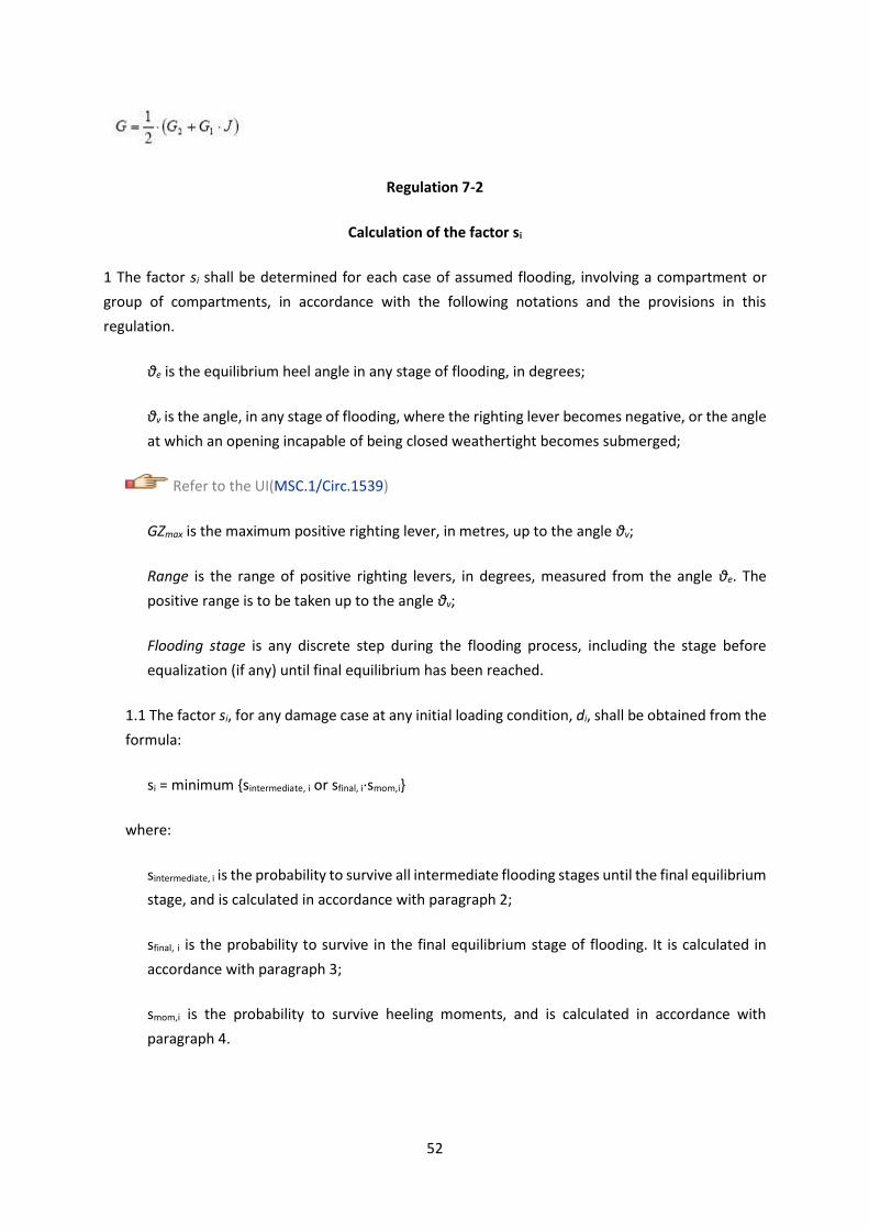
52
Regulation 7-2
Calculation of the factor si
1 The factor si shall be determined for each case of assumed flooding, involving a compartment or
group of compartments, in accordance with the following notations and the provisions in this
regulation.
θe is the equilibrium heel angle in any stage of flooding, in degrees;
θv is the angle, in any stage of flooding, where the righting lever becomes negative, or the angle
at which an opening incapable of being closed weathertight becomes submerged;
Refer to the UI(MSC.1/Circ.1539)
GZmax is the maximum positive righting lever, in metres, up to the angle θv;
Range is the range of positive righting levers, in degrees, measured from the angle θe. The
positive range is to be taken up to the angle θv;
Flooding stage is any discrete step during the flooding process, including the stage before
equalization (if any) until final equilibrium has been reached.
1.1 The factor si, for any damage case at any initial loading condition, di, shall be obtained from the
formula:
si = minimum {sintermediate, i or sfinal, i·smom,i}
where:
sintermediate, i is the probability to survive all intermediate flooding stages until the final equilibrium
stage, and is calculated in accordance with paragraph 2;
sfinal, i is the probability to survive in the final equilibrium stage of flooding. It is calculated in
accordance with paragraph 3;
smom,i is the probability to survive heeling moments, and is calculated in accordance with
paragraph 4.

53
2 For passenger ships, and cargo ships fitted with cross-flooding devices, the factor sintermediate,iis taken
as the least of the s-factors obtained from all flooding stages including the stage before equalization,
if any, and is to be calculated as follows:( Replaced by Res.MSC.421(98))
where GZmax is not to be taken as more than 0.05 m and Range as not more than 7°. sintermediate,i = 0,
if the intermediate heel angle exceeds 15º for passenger ships and 30° for cargo ships.
For cargo ships not fitted with cross-flooding devices the factor sintermediate,i is taken as unity, except
if the Administration considers that the stability in intermediate stages of flooding may be
insufficient, it should require further investigation thereof.
For passenger and cargo ships, where cross-flooding devices are fitted, the time for equalization
shall not exceed 10 min.
3 The factor sfinal,ishall be obtained from the formula:
where:
GZmax is not to be taken as more than TGZmax;
Range is not to be taken as more than TRange;
TGZmax = 0.20 m, for ro-ro passenger ships each damage case that involves a ro-ro space,
TGZmax = 0.12 m, otherwise;
TRange = 20º, for ro-ro passenger ships each damage case that involves a ro-ro space,
TRange = 16º, otherwise;

54
otherwise,
where:
is 7° for passenger ships and 25° for cargo ships; and
is 15° for passenger ships and 30° for cargo ships.
4 The factor smom,i is applicable only to passenger ships (for cargo ships smom,i shall be taken as unity)
and shall be calculated at the final equilibrium from the formula:
Displacement is the intact displacement at the respective draught (ds, dp or dl).
Mheel is the maximum assumed heeling moment as calculated in accordance with subparagraph 4.1;
and
smom,i ≤ 1
4.1 The heeling moment Mheel is to be calculated as follows:
Mheel = maximum (Mpassenger or Mwind or Msurvivalcraft)
4.1.1 Mpassenger is the maximum assumed heeling moment resulting from movement of passengers, and
is to be obtained as follows:
Mpassenger = (0.075 × Np) × (0.45 × B) (tm)
where:
Np is the maximum number of passengers permitted to be on board in the service condition
corresponding to the deepest subdivision draught under consideration; and
B is the breadth of the ship as defined in regulation 2.8.
Alternatively, the heeling moment may be calculated assuming the passengers are distributed with
4 persons per square metre on available deck areas towards one side of the ship on the decks where
55
muster stations are located and in such a way that they produce the most adverse heeling moment.
In doing so, a weight of 75 kg per passenger is to be assumed.
4.1.2 Mwind is the maximum assumed wind moment acting in a damage situation:
Mwind = (P × A × Z) / 9,806 (tm)
where:
P = 120 N/m2 ;
A = projected lateral area above waterline;
Z = distance from centre of lateral projected area above waterline to T/2; and
T = respective draught (ds, dp or dl)."
5 Unsymmetrical flooding is to be kept to a minimum consistent with the efficient arrangements.
Where it is necessary to correct large angles of heel, the means adopted shall, where practicable, be
self-acting, but in any case where controls to equalization devices are provided they shall be operable
from above the bulkhead deck of passenger ships and the freeboard deck of cargo ships. These fittings
together with their controls shall be acceptable to the Administration*. Suitable information
concerning the use of equalization devices shall be supplied to the master of the ship.
* Reference is made to theRevised recommendation on a standard method for evaluating cross-
flooding arrangements,adopted by the Organization by resolution MSC.362(92), as may be
amended.
5.1 Tanks and compartments taking part in such equalization shall be fitted with air pipes or
equivalent means of sufficient cross-section to ensure that the flow of water into the equalization
compartments is not delayed.
5.2 The factor si is to be taken as zero in those cases where the final waterline, taking into account
sinkage, heel and trim, immerses:
.1 the lower edge of openings through which progressive flooding may take place and such
flooding is not accounted for in the calculation of factor si. Such openings shall include air-pipes,
ventilators and openings which are closed by means of weathertight doors or hatch covers; and
.2 any part of the bulkhead deck in passenger ships considered a horizontal evacuation route
for compliance with chapter II-2.
56
5.3 The factor si is to be taken as zero if, taking into account sinkage, heel and trim, any of the
following occur in any intermediate stage or in the final stage of flooding:
.1 immersion of any vertical escape hatch in the bulkhead deck of passenger ships and the
freeboard deck of cargo ships intended for compliance with chapter II-2;
.2 any controls intended for the operation of watertight doors, equalization devices, valves on
piping or on ventilation ducts intended to maintain the integrity of watertight bulkheads from
above the bulkhead deck of passenger ships and the freeboard deck of cargo ships become
inaccessible or inoperable; and
.3 immersion of any part of piping or ventilation ducts located within the assumed extent of
damage and carried through a watertight boundary if this can lead to the progressive flooding
of compartments not assumed as flooded.
5.4 However, where compartments assumed flooded due to progressive flooding are taken into
account in the damage stability calculations multiple values of sintermediate, i may be calculated
assuming equalization in additional flooding phases.
5.5 Except as provided in paragraph 5.3.1, openings closed by means of watertight manhole covers
and flush scuttles, remotely operated sliding watertight doors, sidescuttles of the non-opening type
as well as watertight access doors and watertight hatch covers required to be kept closed at sea
need not be considered.
6 Where horizontal watertight boundaries are fitted above the waterline under consideration the s-
value calculated for the lower compartment or group of compartments shall be obtained by
multiplying the value as determined in paragraph 1.1 by the reduction factor vmaccording to paragraph
6.1, which represents the probability that the spaces above the horizontal subdivision will not be
flooded.
6.1 The factor vm shall be obtained from the formula:
vm = v(Hj, n, m, d) - v(Hj, n, m-1, d)
where:
Hj, n, m is the least height above the baseline, in metres, within the longitudinal range
of x1(j)...x2(j+n-1) of the mth horizontal boundary which is assumed to limit the vertical extent of
flooding for the damaged compartments under consideration;
Hj, n, m-1 is the least height above the baseline, in metres, within the longitudinal range
of x1(j)...x2(j+n-1) of the (m-1)th horizontal boundary which is assumed to limit the vertical extent of
flooding for the damaged compartments under consideration;

57
j signifies the aft terminal of the damaged compartments under consideration;
m represents each horizontal boundary counted upwards from the waterline under
consideration;
d is the draught in question as defined in regulation 2;
x1and x2represent the terminals of the compartment or group of compartments considered in
regulation 7-1.
6.1.1 The factors v(Hj, n, m, d) and v(Hj, n, m-1, d) shall be obtained from the formulae:
where:
v(Hj, n, m, d) is to be taken as 1, if Hm coincides with the uppermost watertight boundary of the
ship within the range x1(j)...x2(j+n-1), and
v(Hj, n, 0, d) is to be taken as 0.
In no case is vm to be taken as less than zero or more than 1.
6.2 In general, each contribution dA to the index A in the case of horizontal subdivisions is obtained
from the formula:
dA = pi · [v1 · smin1 + (v2 - v1) · smin2 + ··· + (1-vm-1) · sminm]
where:
vm = the v-value calculated in accordance with paragraph 6.1;
smin = the least s-factor for all combinations of damages obtained when the assumed damage extends
from the assumed damage height Hm downwards.
Regulation 7-3
Permeability

58
1 For the purpose of the subdivision and damage stability calculations of the regulations, the
permeability of each general compartment or part of a compartment shall be as follows:
Spaces Permeability
Appropriated to stores
Occupied by accommodation
Occupied by machinery
Void spaces
Intended for liquids
0.60
0.95
0.85
0.95
0 or 0.95*
* Whichever results in the more severe requirement.
2 For the purpose of the subdivision and damage stability calculations of the regulations, the
permeability of each cargo compartment or part of a compartment shall be as follows:
Spaces Permeability at draught ds Permeability
at draught dp
Permeability
at draught dl
Dry cargo spaces
Container spaces
Ro-ro spaces
Cargo liquids
0.70
0.70
0.90
0.70
0.80
0.80
0.90
0.80
0.95
0.95
0.95
0.95
3 Other figures for permeability may be used if substantiated by calculations.
Regulation 8
Special requirements concerning passenger ship stability
1 A passenger ship intended to carry 400 or more persons shall have watertight subdivision abaft the
collision bulkhead so that si= 1 for a damage involving all the compartments within 0.08L measured
from the forward perpendicular for the three loading conditions used to calculate the attained
subdivision index A. If the attained subdivision index A is calculated for different trims, this
requirement shall also be satisfied for those loading conditions.( Replaced by Res.MSC.421(98))
2 A passenger ship intended to carry 36 or more persons is to be capable of withstanding damage along
the side shell to an extent specified in paragraph 3. Compliance with this regulation is to be achieved
by demonstrating that si, as defined in regulation 7-2, is not less than 0.9 for the three loading
conditions used to calculate the attained subdivision index A. If the attained subdivision index A is
calculated for different trims, this requirement shall also be satisfied for those loading conditions.
3 The damage extent to be assumed when demonstrating compliance with paragraph 2, is to be
dependent on the total number of persons carried, and L, such that:

59
.1 the vertical extent of damage is to extend from the ship’s moulded baseline to a position up to
12.5 m above the position of the deepest subdivision draught as defined in regulation 2, unless a
lesser vertical extent of damage were to give a lower value of si, in which case this reduced extent
is to be used;
.2 where 400 or more persons are to be carried, a damage length of 0.03L, but not less than 3 m is
to be assumed at any position along the side shell, in conjunction with a penetration inboard of
0.1B but not less than 0.75 m measured inboard from the ship side, at right angles to the centreline
at the level of the deepest subdivision draught;
.3 where less than 400 persons are carried, damage length is to be assumed at any position along
the shell side between transverse watertight bulkheads provided that the distance between two
adjacent transverse watertight bulkheads is not less than the assumed damage length. If the
distance between adjacent transverse watertight bulkheads is less than the assumed damage
length, only one of these bulkheads shall be considered effective for the purpose of demonstrating
compliance with paragraph 2;
.4 where 36 persons are carried, a damage length of 0.015L but not less than 3 m is to be assumed,
in conjunction with a penetration inboard of 0.05B but not less than 0.75 m; and
.5 where more than 36, but fewer than 400 persons are carried the values of damage length and
penetration inboard, used in the determination of the assumed extent of damage, are to be obtained
by linear interpolation between the values of damage length and penetration which apply for ships
carrying 36 persons and 400 persons as specified in subparagraphs .4 and .2.
Regulation 8-1
System capabilities and operational information after a flooding casualty on passenger ships
1 Application
Passenger ships having length, as defined in regulation II-1/2.5, of 120 m or more or having three
or more main vertical zones shall comply with the provisions of this regulation.
2 Availability of essential systems in case of flooding damage*
* Refer to the Interim Explanatory Notes for the assessment of passenger ship systems' capabilities
after a fire or flooding casualty (MSC.1/Circ.1369) and Unified Interpretations of SOLAS regulation
II-2/21.4 (MSC.1/Circ.1437).
A passenger ship shall be designed so that the systems specified in regulation II-2/21.4 remain
operational when the ship is subject to flooding of any single watertight compartment.:(
Replaced by Res.MSC.421(98))

60
3 For the purpose of providing operational information to the Master for safe return to port after a
flooding casualty, passenger ships shall have.
For the purpose of providing operational information to the Master for safe return to port after a
flooding casualty, passenger ships constructed on or after 1 January 2014 shall have:
.1 onboard stability computer; or
.2 shore-based support,
based on guidelines developed by the Organization**.
** Refer to the Guidelines on operational information for masters of passenger ships for safe return
to port by own power or under tow (MSC.1/Circ.1400) and the Revised guidelines on operational
information for masters of passenger ships for safe return to port (MSC.1/Circ.1532).
Regulation 8-1
System capabilities and operational information after a flooding casualty on passenger ships
1 Application( Amended by Res.MSC.436(99))
Passenger ships having length, as defined in regulation II-1/2.5, of 120 m or more or having three or
more main vertical zones shall comply with the provisions of this regulation.
2 Availability of essential systems in case of flooding damage*
* Refer to the Interim Explanatory Notes for the assessment of passenger ship systems' capabilities
after a fire or flooding casualty (MSC.1/Circ.1369).
A passenger ship shall be designed so that the systems specified in regulation II-2/21.4 remain
operational when the ship is subject to flooding of any single watertight compartment.
3 Operational information after a flooding casualty
3.1 For the purpose of providing operational information to the master for safe return to port after a
flooding casualty, passenger ships, as specified in paragraph 1, shall have:
.1 an onboard stability computer; or
.2 shore-based support,

61
based on the guidelines developed by the Organization.**
** Refer to the Guidelines on operational information for Masters of passenger ships for safe return
to port by own power or under tow (MSC.1/Circ.1400) for ships constructed on or after 1 January
2014 but before 13 May 2016, or the Revised Guidelines on operational information for masters of
passenger ships for safe return to port (MSC.1/Circ.1532/Rev.1) for ships constructed on or after
13 May 2016, or the Guidelines on operational information for masters in case of flooding for
passenger ships constructed before 1 January 2014 (MSC.1/Circ.1589).
3.2 Passenger ships constructed before 1 January 2014 shall comply with the provisions in paragraph
3.1 not later than the first renewal survey after 1 January 2025.
PART B-2
SUBDIVISION, WATERTIGHT AND WEATHERTIGHT INTEGRITY
Regulation 9
Double bottoms in passenger ships and cargo ships other than tankers
1 A double bottom shall be fitted extending from the collision bulkhead to the afterpeak bulkhead, as
far as this is practicable and compatible with the design and proper working of the ship.
2 Where a double bottom is required to be fitted the inner bottom shall be continued out to the ship's
sides in such a manner as to protect the bottom to the turn of the bilge. Such protection will be deemed
satisfactory if the inner bottom is not lower at any part than a plane parallel with the keel line and
which is located not less than a vertical distance h measured from the keel line, as calculated by the
formula:
h = B/20
However, in no case is the value of h to be less than 760 mm, and need not be taken as more than
2,000 mm.
3.1 Small wells constructed in the double bottom in connection with drainage arrangements shall not
extend downward more than necessary. The vertical distance from the bottom of such a well to a plane
coinciding with the keel line shall not be less thanh/2or 500 mm, whichever is greater, or compliance
with paragraph 8 of this regulation shall be shown for that part of the ship.( Replaced by
Res.MSC.421(98))

62
3.2 Other wells (e.g. for lubricating oil under main engines) may be permitted by the Administration if
satisfied that the arrangements give protection equivalent to that afforded by a double bottom
complying with this regulation.
3.2.1 For a cargo ship of 80 m in length and upwards or for a passenger ship, proof of equivalent
protection is to be shown by demonstrating that the ship is capable of withstanding bottom
damages as specified in paragraph 8. Alternatively, wells for lubricating oil below main engines may
protrude into the double bottom below the boundary line defined by the distance h provided that
the vertical distance between the well bottom and a plane coinciding with the keel line is not less
thanh/2or 500 mm, whichever is greater.
3.2.2 For cargo ships of less than 80 m in length the arrangements shall provide a level of safety to
the satisfaction of the Administration.
4 A double bottom need not be fitted in way of watertight tanks, including dry tanks of moderate size,
provided the safety of the ship is not impaired in the event of bottom or side damage.
5 In the case of passenger ships to which the provisions of regulation 1.5 apply and which are engaged
on regular service within the limits of a short international voyage as defined in regulation III/3.22, the
Administration may permit a double bottom to be dispensed with if satisfied that the fitting of a double
bottom in that part would not be compatible with the design and proper working of the ship.
6 Any part of a cargo ship of 80 m in length and upwards or of a passenger ship that is not fitted with
a double bottom in accordance with paragraphs 1, 4 or 5, as specified in paragraph 2, shall be capable
of withstanding bottom damages, as specified in paragraph 8, in that part of the ship. For cargo ships
of less than 80 m in length the alternative arrangements shall provide a level of safety to the
satisfaction of the Administration.
7 In the case of unusual bottom arrangements in a cargo ship of 80 m in length and upwards or a
passenger ship, it shall be demonstrated that the ship is capable of withstanding bottom damages as
specified in paragraph 8. For cargo ships of less than 80 m in length the alternative arrangements shall
provide a level of safety to the satisfaction of the Administration.
8 Compliance with paragraphs 3.1, 3.2.1, 6 or 7 is to be achieved by demonstrating that si, when
calculated in accordance with regulation 7-2, is not less than 1 for all service conditions when subject
to bottom damage with an extent specified in subparagraph .2 below for any position in the affected
part of the ship:
.1 Flooding of such spaces shall not render emergency power and lighting, internal communication,
signals or other emergency devices inoperable in other parts of the ship.
.2 Assumed extent of damage shall be as follows:

63
For 0.3 L from the forward Any other part of the ship
perpendicular of the ship
Longitudinal 1/3 L2/3 or 14.5 m, whichever 1/3 L2/3 or 14.5 m, whichever
extent is less is less
Transverse B/6 or 10 m, whichever is less B/6 or 5 m, whichever is less
extent
Vertical extent, B/20, to be taken not less B/20, to be taken not less
measured from than 0.76 m and not more than 0.76 m and not more
the keel line than 2 m than 2 m
.3 If any damage of a lesser extent than the maximum damage specified in .2 would result in a more
severe condition, such damage should be considered.
9 In case of large lower holds in passenger ships, the Administration may require an increased double
bottom height of not more than B/10 or 3 m, whichever is less, measured from the keel line.
Alternatively, bottom damages may be calculated for these areas, in accordance with paragraph 8,
but assuming an increased vertical extent.
Regulation 10
Construction of watertight bulkheads
1 Each watertight subdivision bulkhead, whether transverse or longitudinal, shall be constructed
having scantlings as specified in regulation 2.17. In all cases, watertight subdivision bulkheads shall be
capable of supporting at least the pressure due to a head of water up to the bulkhead deck of
passenger ships and the freeboard deck of cargo ships.( Replaced by Res.MSC.421(98))
2 Steps and recesses in watertight bulkheads shall be as strong as the bulkhead at the place where
each occurs.
Regulation 11
Initial testing of watertight bulkheads, etc.
1 Testing watertight spaces not intended to hold liquids and cargo holds intended to hold ballast by
filling them with water is not compulsory. When testing by filling with water is not carried out, a hose
test shall be carried out where practicable. This test shall be carried out in the most advanced stage of
the fitting out of the ship. Where a hose test is not practicable because of possible damage to
machinery, electrical equipment insulation or outfitting items, it may be replaced by a careful visual
examination of welded connections, supported where deemed necessary by means such as a dye
penetrant test or an ultrasonic leak test or an equivalent test. In any case a thorough inspection of the
watertight bulkheads shall be carried out.

64
2 The forepeak, double bottom (including duct keels) and inner skins shall be tested with water to a
head corresponding to the requirements of regulation 10.1.
3 Tanks which are intended to hold liquids, and which form part of the watertight subdivision of the
ship, shall be tested for tightness and structural strength with water to a head corresponding to its
design pressure. The water head is in no case to be less than the top of the air pipes or to a level of 2.4
m above the top of the tank, whichever is the greater.
4 The tests referred to in paragraphs 2 and 3 are for the purpose of ensuring that the subdivision
structural arrangements are watertight and are not to be regarded as a test of the fitness of any
compartment for the storage of oil fuel or for other special purposes for which a test of a superior
character may be required depending on the height to which the liquid has access in the tank or its
connections.
Regulation 12
Peak and machinery space bulkheads, shaft tunnels, etc.
1 A collision bulkhead shall be fitted which shall be watertight up to the bulkhead deck of passenger
ships and the freeboard deck of cargo ships. This bulkhead shall be located at a distance from the
forward perpendicular of not less than 0.05L or 10 m, whichever is the less, and, except as may be
permitted by the Administration, not more than 0.08L or 0.05L + 3 m, whichever is the greater.(
Replaced by Res.MSC.421(98))
2 The ship shall be so designed that si calculated in accordance with regulation 7-2 will not be less than
1 at the deepest subdivision draught loading condition, level trim or any forward trim loading
conditions, if any part of the ship forward of the collision bulkhead is flooded without vertical limits:
.1 at the mid-length of such extension;
.2 at a distance 0.015L forward of the forward perpendicular; or
.3 at a distance 3 m forward of the forward perpendicular,
whichever gives the smallest measurement.
3 Where any part of the ship below the waterline extends forward of the forward perpendicular, e.g.
a bulbous bow, the distances stipulated in paragraph 1 shall be measured from a point either:
.1 at the mid-length of such extension;
.2 at a distance 0.015L forward of the forward perpendicular; or

65
.3 at a distance 3 m forward of the forward perpendicular,
whichever gives the smallest measurement.
4 The bulkhead may have steps or recesses provided they are within the limits prescribed in paragraph
1 or 3.
5 No doors, manholes, access openings, ventilation ducts or any other openings shall be fitted in the
collision bulkhead below the bulkhead deck of passenger ships and the freeboard deck of cargo ships.
6.1 Except as provided in paragraph 6.2, the collision bulkhead may be pierced below the bulkhead
deck of passenger ships and the freeboard deck of cargo ships by not more than one pipe for dealing
with fluid in the forepeak tank, provided that the pipe is fitted with a screw-down valve capable of
being operated from above the bulkhead deck of passenger ships and the freeboard deck of cargo
ships, the valve being located inside the forepeak at the collision bulkhead. The Administration may,
however, authorize the fitting of this valve on the after side of the collision bulkhead provided that the
valve is readily accessible under all service conditions and the space in which it is located is not a cargo
space. Alternatively, for cargo ships, the pipe may be fitted with a butterfly valve suitably supported
by a seat or flanges and capable of being operated from above the freeboard deck. All valves shall be
of steel, bronze or other approved ductile material. Valves of ordinary cast iron or similar material are
not acceptable.
6.2 If the forepeak is divided to hold two different kinds of liquids the Administration may allow the
collision bulkhead to be pierced below the bulkhead deck of passenger ships and the freeboard deck
of cargo ships by two pipes, each of which is fitted as required by paragraph 6.1, provided the
Administration is satisfied that there is no practical alternative to the fitting of such a second pipe and
that, having regard to the additional subdivision provided in the forepeak, the safety of the ship is
maintained.
7 Where a long forward superstructure is fitted, the collision bulkhead shall be extended weathertight
to the deck next above the bulkhead deck of passenger ships and the freeboard deck of cargo ships.
The extension need not be fitted directly above the bulkhead below provided that all parts of the
extension, including any part of the ramp attached to it are located within the limits prescribed in
paragraph 1 or 3, with the exception permitted by paragraph 8 and that the part of the deck which
forms the step is made effectively weathertight. The extension shall be so arranged as to preclude the
possibility of the bow door or ramp, where fitted, causing damage to it in the case of damage to, or
detachment of, a bow door or any part of the ramp.
8 Where bow doors are fitted and a sloping loading ramp forms part of the extension of the collision
bulkhead above the bulkhead deck of passenger ships and the freeboard deck of cargo ships the ramp
shall be weathertight over its complete length. In cargo ships the part of the ramp which is more than

66
2.3 m above the freeboard deck may extend forward of the limit specified in paragraph 1 or 3. Ramps
not meeting the above requirements shall be disregarded as an extension of the collision bulkhead.
9 The number of openings in the extension of the collision bulkhead above the freeboard deck shall be
restricted to the minimum compatible with the design and normal operation of the ship. All such
openings shall be capable of being closed weathertight.
10 Bulkheads shall be fitted separating the machinery space from cargo and accommodation spaces
forward and aft and made watertight up to the bulkhead deck of passenger ships and the freeboard
deck of cargo ships. An afterpeak bulkhead shall also be fitted and made watertight up to the bulkhead
deck or the freeboard deck. The afterpeak bulkhead may, however, be stepped below the bulkhead
deck or the freeboard deck, provided the degree of safety of the ship as regards subdivision is not
thereby diminished.
11 In all cases stern tubes shall be enclosed in watertight spaces of moderate volume. In passenger
ships the stern gland shall be situated in a watertight shaft tunnel or other watertight space separate
from the stern tube compartment and of such volume that, if flooded by leakage through the stern
gland, the bulkhead deck will not be immersed. In cargo ships other measures to minimize the danger
of water penetrating into the ship in case of damage to stern tube arrangements may be taken at the
discretion of the Administration."
Refer to IACS UI SC93 Enclosure of stern tubes on cargo ships
Regulation 13
Openings in watertight bulkheads below the bulkhead deck in passenger ships
1 The number of openings in watertight bulkheads shall be reduced to the minimum compatible with
the design and proper working of the ship, satisfactory means shall be provided for closing these
openings.
2.1 Where pipes, scuppers, electric cables, etc., are carried through watertight bulkheads,
arrangements shall be made to ensure the watertight integrity of the bulkheads.
2.2 Valves not forming part of a piping system shall not be permitted in watertight bulkheads.
2.3 Lead or other heat sensitive materials shall not be used in systems which penetrate watertight
bulkheads, where deterioration of such systems in the event of fire would impair the watertight
integrity of the bulkheads.
3 No doors, manholes, or access openings are permitted in watertight transverse bulkheads dividing a
cargo space from an adjoining cargo space, except as provided in paragraph 9.1 and in regulation 14.

67
4 Subject to paragraph 10, not more than one door, apart from the doors to shaft tunnels, may be
fitted in each watertight bulkhead within spaces containing the main and auxiliary propulsion
machinery including boilers serving the needs of propulsion. Where two or more shafts are fitted, the
tunnels shall be connected by an intercommunicating passage. There shall be only one door between
the machinery space and the tunnel spaces where two shafts are fitted and only two doors where
there are more than two shafts. All these doors shall be of the sliding type and shall be so located as
to have their sills as high as practicable. The hand gear for operating these doors from above the
bulkhead deck shall be situated outside the spaces containing the machinery.
5.1 Watertight doors, except as provided in paragraph 9.1 or regulation 14, shall be power-operated
sliding doors complying with the requirements of paragraph 7 capable of being closed simultaneously
from the central operating console at the navigation bridge in not more than 60 s with the ship in the
upright position.
5.2 The means of operation whether by power or by hand of any power-operated sliding watertight
door shall be capable of closing the door with the ship listed to 15o either way. Consideration shall also
be given to the forces which may act on either side of the door as may be experienced when water is
flowing through the opening applying a static head equivalent to a water height of at least 1 m above
the sill on the centreline of the door.
5.3 Watertight door controls, including hydraulic piping and electric cables, shall be kept as close as
practicable to the bulkhead in which the doors are fitted, in order to minimize the likelihood of them
being involved in any damage which the ship may sustain. The positioning of watertight doors and their
controls shall be such that if the ship sustains damage within one fifth of the breadth of the ship, as
defined in regulation 2, such distance being measured at right angles to the centreline at the level of
the deepest subdivision draught, the operation of the watertight doors clear of the damaged portion
of the ship is not impaired.
6 All power-operated sliding watertight doors shall be provided with means of indication which will
show at all remote operating positions whether the doors are open or closed. Remote operating
positions shall only be at the navigation bridge as required by paragraph 7.1.5 and at the location
where hand operation above the bulkhead deck is required by paragraph 7.1.4.
7.1 Each power-operated sliding watertight door:
.1 shall have a vertical or horizontal motion;
.2 shall, subject to paragraph 10, be normally limited to a maximum clear opening width of 1.2 m.
The Administration may permit larger doors only to the extent considered necessary for the
effective operation of the ship provided that other safety measures, including the following, are
taken into consideration:
68
.1 special consideration shall be given to the strength of the door and its closing appliances in
order to prevent leakages; and
.2 the door shall be located inboard the damage zone B/5;
.3 shall be fitted with the necessary equipment to open and close the door using electric power,
hydraulic power, or any other form of power that is acceptable to the Administration;
.4 shall be provided with an individual hand-operated mechanism. It shall be possible to open and
close the door by hand at the door itself from either side, and in addition, close the door from an
accessible position above the bulkhead deck with an all round crank motion or some other
movement providing the same degree of safety acceptable to the Administration. Direction of
rotation or other movement is to be clearly indicated at all operating positions. The time necessary
for the complete closure of the door, when operating by hand gear, shall not exceed 90 s with the
ship in the upright position;
.5 shall be provided with controls for opening and closing the door by power from both sides of the
door and also for closing the door by power from the central operating console at the navigation
bridge;
.6 shall be provided with an audible alarm, distinct from any other alarm in the area, which will
sound whenever the door is closed remotely by power and which shall sound for at least 5 s but no
more than 10 s before the door begins to move and shall continue sounding until the door is
completely closed. In the case of remote hand operation it is sufficient for the audible alarm to
sound only when the door is moving. Additionally, in passenger areas and areas of high ambient
noise the Administration may require the audible alarm to be supplemented by an intermittent
visual signal at the door; and
.7 shall have an approximately uniform rate of closure under power. The closure time, from the
time the door begins to move to the time it reaches the completely closed position shall in no case
be less than 20 s or more than 40 s with the ship in the upright position.
7.2 The electrical power required for power-operated sliding watertight doors shall be supplied from
the emergency switchboard either directly or by a dedicated distribution board situated above the
bulkhead deck. The associated control, indication and alarm circuits shall be supplied from the
emergency switchboard either directly or by a dedicated distribution board situated above the
bulkhead deck and be capable of being automatically supplied by the transitional source of emergency
electrical power required by regulation 42.3.1.3 in the event of failure of either the main or emergency
source of electrical power.
7.3 Power-operated sliding watertight doors shall have either:

69
.1 a centralized hydraulic system with two independent power sources each consisting of a motor
and pump capable of simultaneously closing all doors. In addition, there shall be for the whole
installation hydraulic accumulators of sufficient capacity to operate all the doors at least three
times, i.e. closed-open-closed, against an adverse list of 15º. This operating cycle shall be capable
of being carried out when the accumulator is at the pump cut-in pressure. The fluid used shall be
chosen considering the temperatures liable to be encountered by the installation during its service.
The power operating system shall be designed to minimize the possibility of having a single failure
in the hydraulic piping adversely affect the operation of more than one door. The hydraulic system
shall be provided with a low-level alarm for hydraulic fluid reservoirs serving the power-operated
system and a low gas pressure alarm or other effective means of monitoring loss of stored energy
in hydraulic accumulators. These alarms are to be audible and visual and shall be situated on the
central operating console at the navigation bridge; or
.2 an independent hydraulic system for each door with each power source consisting of a motor
and pump capable of opening and closing the door. In addition, there shall be a hydraulic
accumulator of sufficient capacity to operate the door at least three times, i.e. closed-open-closed,
against an adverse list of 15o. This operating cycle shall be capable of being carried out when the
accumulator is at the pump cut-in pressure. The fluid used shall be chosen considering the
temperatures liable to be encountered by the installation during its service. A low gas pressure
group alarm or other effective means of monitoring loss of stored energy in hydraulic accumulators
shall be provided at the central operating console on the navigation bridge. Loss of stored energy
indication at each local operating position shall also be provided; or
.3 an independent electrical system and motor for each door with each power source consisting of
a motor capable of opening and closing the door. The power source shall be capable of being
automatically supplied by the transitional source of emergency electrical power as required by
regulation 42.4.2 - in the event of failure of either the main or emergency source of electrical power
and with sufficient capacity to operate the door at least three times, i.e. closed-open-closed,
against an adverse list of 15o.
For the systems specified in paragraphs 7.3.1, 7.3.2 and 7.3.3, provision should be made as follows:
Power systems for power-operated watertight sliding doors shall be separate from any other power
system. A single failure in the electric or hydraulic power-operated systems excluding the hydraulic
actuator shall not prevent the hand operation of any door.
7.4 Control handles shall be provided at each side of the bulkhead at a minimum height of 1.6 m above
the floor and shall be so arranged as to enable persons passing through the doorway to hold both
handles in the open position without being able to set the power closing mechanism in operation
accidentally. The direction of movement of the handles in opening and closing the door shall be in the
direction of door movement and shall be clearly indicated.

70
7.5 As far as practicable, electrical equipment and components for watertight doors shall be situated
above the bulkhead deck and outside hazardous areas and spaces.
7.6 The enclosures of electrical components necessarily situated below the bulkhead deck shall provide
suitable protection against the ingress of water.*
* Refer to the following publication IEC 60529:2003:
.1 electrical motors, associated circuits and control components; protected to IPX 7 standard;
.2 door position indicators and associated circuit components; protected to IPX 8 standard; and
.3 door movement warning signals; protected to IPX 6 standard.
Other arrangements for the enclosures of electrical components may be fitted provided the
Administration is satisfied that an equivalent protection is achieved. The water pressure IPX 8 shall
be based on the pressure that may occur at the location of the component during flooding for a
period of 36 h.
7.7 Electric power, control, indication and alarm circuits shall be protected against fault in such a way
that a failure in one door circuit will not cause a failure in any other door circuit. Short circuits or other
faults in the alarm or indicator circuits of a door shall not result in a loss of power operation of that
door. Arrangements shall be such that leakage of water into the electrical equipment located below
the bulkhead deck will not cause the door to open.
7.8 A single electrical failure in the power operating or control system of a power-operated sliding
watertight door shall not result in a closed door opening. Availability of the power supply should be
continuously monitored at a point in the electrical circuit as near as practicable to each of the motors
required by paragraph 7.3. Loss of any such power supply should activate an audible and visual alarm
at the central operating console at the navigation bridge.
8.1 The central operating console at the navigation bridge shall have a “master mode” switch with two
modes of control: a “local control” mode which shall allow any door to be locally opened and locally
closed after use without automatic closure, and a “doors closed” mode which shall automatically close
any door that is open. The “doors closed” mode shall automatically close any door that is open. The
“doors closed” mode shall permit doors to be opened locally and shall automatically re-close the doors
upon release of the local control mechanism. The “master mode” switch shall normally be in the “local
control” mode. The “doors closed” mode shall only be used in an emergency or for testing purposes.
Special consideration shall be given to the reliability of the “master mode” switch.
8.2 The central operating console at the navigation bridge shall be provided with a diagram showing
the location of each door, with visual indicators to show whether each door is open or closed. A red
light shall indicate a door is fully open and a green light shall indicate a door is fully closed. When the

71
door is closed remotely the red light shall indicate the intermediate position by flashing. The indicating
circuit shall be independent of the control circuit for each door.
8.3 It shall not be possible to remotely open any door from the central operating console.
9.1 If the Administration is satisfied that such doors are essential, watertight doors of satisfactory
construction may be fitted in watertight bulkheads dividing cargo between deck spaces. Such doors
may be hinged, rolling or sliding doors but shall not be remotely controlled. They shall be fitted at the
highest level and as far from the shell plating as practicable, but in no case shall the outboard vertical
edges be situated at a distance from the shell plating which is less than one fifth of the breadth of the
ship, as defined in regulation 2, such distance being measured at right angles to the centreline at the
level of the deepest subdivision draught.
9.2 Should any such doors be accessible during the voyage, they shall be fitted with a device which
prevents unauthorized opening. When it is proposed to fit such doors, the number and arrangements
shall receive the special consideration of the Administration.
10 Portable plates on bulkheads shall not be permitted except in machinery spaces. The Administration
may permit not more than one power-operated sliding watertight door in each watertight bulkhead
larger than those specified in paragraph 7.1.2 to be substituted for these portable plates, provided
these doors are intended to remain closed during navigation except in case of urgent necessity at the
discretion of the master. These doors need not meet the requirements of paragraph 7.1.4 regarding
complete closure by hand-operated gear in 90 s.
11.1 Where trunkways or tunnels for access from crew accommodation to the machinery spaces, for
piping, or for any other purpose are carried through watertight bulkheads, they shall be watertight and
in accordance with the requirements of regulation 16-1. The access to at least one end of each such
tunnel or trunkway, if used as a passage at sea, shall be through a trunk extending watertight to a
height sufficient to permit access above the bulkhead deck. The access to the other end of the
trunkway or tunnel may be through a watertight door of the type required by its location in the ship.
Such trunkways or tunnels shall not extend through the first subdivision bulkhead abaft the collision
bulkhead.( Replaced by Res.MSC.421(98))
11.2 Where it is proposed to fit tunnels piercing watertight bulkheads, these shall receive the special
consideration of the Administration.
11.3 Where trunkways in connection with refrigerated cargo and ventilation or forced draught trunks
are carried through more than one watertight bulkhead, the means of closure at such openings shall
be operated by power and be capable of being closed from a central position situated above the
bulkhead deck.
Regulation 13-1

72
Openings in watertight bulkheads and internal decks in cargo ships
1 The number of openings in watertight subdivisions is to be kept to a minimum compatible with the
design and proper working of the ship. Where penetrations of watertight bulkheads and internal decks
are necessary for access, piping, ventilation, electrical cables, etc., arrangements are to be made to
maintain the watertight integrity. The Administration may permit relaxation in the watertightness of
openings above the freeboard deck, provided that it is demonstrated that any progressive flooding can
be easily controlled and that the safety of the ship is not impaired.
2 Doors provided to ensure the watertight integrity of internal openings which are used while at sea
are to be sliding watertight doors capable of being remotely closed from the bridge and are also to be
operable locally from each side of the bulkhead. Indicators are to be provided at the control position
showing whether the doors are open or closed, and an audible alarm is to be provided at the door
closure. The power, control and indicators are to be operable in the event of main power failure.
Particular attention is to be paid to minimizing the effect of control system failure. Each power-
operated sliding watertight door shall be provided with an individual hand-operated mechanism. It
shall be possible to open and close the door by hand at the door itself from both sides.
3 Access doors and access hatch covers normally closed at sea, intended to ensure the watertight
integrity of internal openings, shall be provided with means of indication locally and on the bridge
showing whether these doors or hatch covers are open or closed. A notice is to be affixed to each such
door or hatch cover to the effect that it is not to be left open.
4 Watertight doors or ramps of satisfactory construction may be fitted to internally subdivide large
cargo spaces, provided that the Administration is satisfied that such doors or ramps are essential.
These doors or ramps may be hinged, rolling or sliding doors or ramps, but shall not be remotely
controlled. Should any of the doors or ramps be accessible during the voyage, they shall be fitted with
a device which prevents unauthorized opening.
5 Other closing appliances which are kept permanently closed at sea to ensure the watertight
integrity of internal openings shall be provided with a notice which is to be affixed to each such
closing appliance to the effect that it is to be kept closed. Manholes fitted with closely bolted covers
need not be so marked.
Regulation 14
Passenger ships carrying goods vehicles and accompanying personnel
1 This regulation applies to passenger ships designed or adapted for the carriage of goods vehicles and
accompanying personnel.
2 If in such a ship the total number of passengers which include personnel accompanying vehicles does
not exceed 12 + Ad/25, where Ad = total deck area (square metres) of spaces available for the stowage
of goods vehicles and where the clear height at the stowage position and at the entrance to such

73
spaces is not less than 4 m, the provisions of regulations 13.9.1 and 13.9.2 in respect of watertight
doors apply except that the doors may be fitted at any level in watertight bulkheads dividing cargo
spaces. Additionally, indicators are required on the navigation bridge to show automatically when each
door is closed and all door fastenings are secured.
3 The ship may not be certified for a higher number of passengers than assumed in paragraph 2, if a
watertight door has been fitted in accordance with this regulation.
Regulation 15
Openings in the shell plating below the bulkhead deck of passenger ships and the freeboard deck
of cargo ships
1 The number of openings in the shell plating shall be reduced to the minimum compatible with the
design and proper working of the ship.
2 The arrangement and efficiency of the means for closing any opening in the shell plating shall be
consistent with its intended purpose and the position in which it is fitted and generally to the
satisfaction of the Administration.
3.1 Subject to the requirements of the International Convention on Load Lines in force, no sidescuttle
shall be fitted in such a position that its sill is below a line drawn parallel to the bulkhead deck at side
and having its lowest point 2.5% of the breadth of the ship above the deepest subdivision draught, or
500 mm, whichever is the greater.
3.2 All sidescuttles the sills of which are below the bulkhead deck of passenger ships and the freeboard
deck of cargo ships, as permitted by paragraph 3.1, shall be of such construction as will effectively
prevent any person opening them without the consent of the master of the ship.
4 Efficient hinged inside deadlights so arranged that they can be easily and effectively closed and
secured watertight, shall be fitted to all sidescuttles except that abaft one eighth of the ship's length
from the forward perpendicular and above a line drawn parallel to the bulkhead deck at side and
having its lowest point at a height of 3.7 m plus 2.5% of the breadth of the ship above the deepest
subdivision draught, the deadlights may be portable in passenger accommodation, unless the
deadlights are required by the International Convention on Load Lines in force to be permanently
attached in their proper positions. Such portable deadlights shall be stowed adjacent to the
sidescuttles they serve.( Replaced by Res.MSC.421(98))
5.1 No sidescuttles shall be fitted in any spaces which are appropriated exclusively to the carriage of
cargo.

74
5.2 Sidescuttles may, however, be fitted in spaces appropriated alternatively to the carriage of cargo
or passengers, but they shall be of such construction as will effectively prevent any person opening
them or their deadlights without the consent of the master.
6 Automatic ventilating sidescuttles shall not be fitted in the shell plating below the bulkhead deck of
passenger ships and the freeboard deck of cargo ships without the special sanction of the
Administration.
7 The number of scuppers, sanitary discharges and other similar openings in the shell plating shall be
reduced to the minimum either by making each discharge serve for as many as possible of the sanitary
and other pipes, or in any other satisfactory manner.
8.1 All inlets and discharges in the shell plating shall be fitted with efficient and accessible
arrangements for preventing the accidental admission of water into the ship.
8.2.1 Subject to the requirements of the International Convention on Load Lines in force, and except
as provided in paragraph 8.3, each separate discharge led through the shell plating from spaces below
the bulkhead deck of passenger ships and the freeboard deck of cargo ships shall be provided with
either one automatic non-return valve fitted with a positive means of closing it from above the
bulkhead deck of passenger ships and the freeboard deck of cargo ships or with two automatic non-
return valves without positive means of closing, provided that the inboard valve is situated above the
deepest subdivision draught and is always accessible for examination under service conditions. Where
a valve with positive means of closing is fitted, the operating position above the bulkhead deck of
passenger ships and the freeboard deck of cargo ships shall always be readily accessible and means
shall be provided for indicating whether the valve is open or closed.
8.2.2 The requirements of the International Convention on Load Lines in force shall apply to discharges
led through the shell plating from spaces above the bulkhead deck of passenger ships and the
freeboard deck of cargo ships.
8.3 Machinery space, main and auxiliary sea inlets and discharges in connection with the operation of
machinery shall be fitted with readily accessible valves between the pipes and the shell plating or
between the pipes and fabricated boxes attached to the shell plating. In manned machinery spaces the
valves may be controlled locally and shall be provided with indicators showing whether they are open
or closed.
8.4 Moving parts penetrating the shell plating below the deepest subdivision draught shall be fitted
with a watertight sealing arrangement acceptable to the Administration. The inboard gland shall be
located within a watertight space of such volume that, if flooded, the bulkhead deck of passenger ships
and the freeboard deck of cargo ships will not be submerged. The Administration may require that if
such compartment is flooded, essential or emergency power and lighting, internal communication,
signals or other emergency devices must remain available in other parts of the ship.

75
8.5 All shell fittings and valves required by this regulation shall be of steel, bronze or other approved
ductile material. Valves of ordinary cast iron or similar material are not acceptable. All pipes to which
this regulation refers shall be of steel or other equivalent material to the satisfaction of the
Administration.
9 Gangway, cargo and fuelling ports fitted below the bulkhead deck of passenger ships and the
freeboard deck of cargo ships shall be watertight and in no case be so fitted as to have their lowest
point below the deepest subdivision draught.
10.1 The inboard opening of each ash-chute, rubbish-chute, etc., shall be fitted with an efficient cover.
10.2 If the inboard opening is situated below the bulkhead deck of passenger ships and the freeboard
deck of cargo ships, the cover shall be watertight and, in addition, an automatic non-return valve
shall be fitted in the chute in an easily accessible position above the deepest subdivision draught.
Regulation 15-1
External openings in cargo ships
1 All external openings leading to compartments assumed intact in the damage analysis, which are
below the final damage waterline, are required to be watertight.
2 External openings required to be watertight in accordance with paragraph 1 shall, except for cargo
hatch covers, be fitted with indicators on the bridge.
3 Openings in the shell plating below the deck limiting the vertical extent of damage shall be fitted
with a device that prevents unauthorized opening if they are accessible during the voyage.
4 Other closing appliances which are kept permanently closed at sea to ensure the watertight
integrity of external openings shall be provided with a notice affixed to each appliance to the effect
that it is to be kept closed. Manholes fitted with closely bolted covers need not be so marked.
Regulation 16
Construction and initial tests of watertight closures( Replaced by Res.MSC.421(98))
1 In all ships:
1.1 The design, materials and construction of all watertight closures such as doors, hatches,
sidescuttles, gangway and cargo ports, valves, pipes, ash-chutes and rubbish-chutes referred to in
these regulations shall be to the satisfaction of the Administration.
1.2 Such valves, doors, hatches and mechanisms shall be suitably marked to ensure that they may
be properly used to provide maximum safety.

76
1.3 The frames of vertical watertight doors shall have no groove at the bottom in which dirt might
lodge and prevent the door closing properly.
2 Watertight doors and hatches shall be tested by water pressure to the maximum head of water
they might sustain in a final or intermediate stage of flooding. For cargo ships not covered by damage
stability requirements, watertight doors and hatches shall be tested by water pressure to a head of
water measured from the lower edge of the opening to one metre above the freeboard deck. Where
testing of individual doors and hatches is not carried out because of possible damage to insulation or
outfitting items, testing of individual doors and hatches may be replaced by a prototype pressure test
of each type and size of door or hatch with a test pressure corresponding at least to the head
required for the individual location. The prototype test shall be carried out before the door or hatch
is fitted. The installation method and procedure for fitting the door or hatch on board shall
correspond to that of the prototype test. When fitted on board, each door or hatch shall be checked
for proper seating between the bulkhead, the frame and the door or between deck, the coaming and
the hatch.( Replaced by Res.MSC.421(98))
Regulation 16-1
Construction and initial tests of watertight decks, trunks, etc.
1 Watertight decks, trunks, tunnels, duct keels and ventilators shall be of the same strength as
watertight bulkheads at corresponding levels. The means used for making them watertight, and the
arrangements adopted for closing openings in them, shall be to the satisfaction of the Administration.
Watertight ventilators and trunks shall be carried at least up to the bulkhead deck in passenger ships
and up to the freeboard deck in cargo ships.
2 In passenger ships, where a ventilation trunk passing through a structure penetrates a watertight
area of the bulkhead deck, the trunk shall be capable of withstanding the water pressure that may be
present within the trunk, after having taken into account the maximum heel angle during flooding, in
accordance with regulation 7-2.( Replaced by Res.MSC.421(98))
3 In ro-ro passenger ships, where all or part of the penetration of the bulkhead deck is on the main ro-
ro deck, the trunk shall be capable of withstanding impact pressure due to internal water motions
(sloshing) of water trapped on the ro-ro deck.
4 After completion, a hose or flooding test shall be applied to watertight decks and a hose test to
watertight trunks, tunnels and ventilators.
Regulation 17
Internal watertight integrity of passenger ships above the bulkhead deck
1 The Administration may require that all reasonable and practicable measures shall be taken to limit
the entry and spread of water above the bulkhead deck. Such measures may include partial bulkheads
or webs. When partial watertight bulkheads and webs are fitted on the bulkhead deck, above or in the
immediate vicinity of watertight bulkheads, they shall have watertight shell and bulkhead deck

77
connections so as to restrict the flow of water along the deck when the ship is in a heeled damaged
condition. Where the partial watertight bulkhead does not line up with the bulkhead below, the
bulkhead deck between shall be made effectively watertight. Where openings, pipes, scuppers, electric
cables etc. are carried through the partial watertight bulkheads or decks within the immersed part of
the bulkhead deck, arrangements shall be made to ensure the watertight integrity of the structure
above the bulkhead deck.*
* Refer to the Guidance notes on the integrity of flooding boundaries above the bulkhead deck of
passenger ships for proper application of regulations II-1/8 and 20, paragraph 1, of SOLAS 1974, as
amended (MSC/Circ.541, as may be amended).
2 All openings in the exposed weather deck shall have coamings of ample height and strength and shall
be provided with efficient means for expeditiously closing them weathertight. Freeing ports, open rails
and scuppers shall be fitted as necessary for rapidly clearing the weather deck of water under all
weather conditions.
3 Air pipes terminating within a superstructure which are not fitted with watertight means of closure
shall be considered as unprotected openings when applying regulation 7-2.6.1.1( Replaced by
Res.MSC.421(98))
4 Sidescuttles, gangway, cargo and fuelling ports and other means for closing openings in the shell
plating above the bulkhead deck shall be of efficient design and construction and of sufficient strength
having regard to the spaces in which they are fitted and their positions relative to the deepest
subdivision draught.**
** Refer to the Recommendation on strength and security and locking arrangements of shell doors
on ro-ro passenger ships, adopted by the Organization by resolution A.793(19).
5 Efficient inside deadlights, so arranged that they can be easily and effectively closed and secured
watertight, shall be provided for all sidescuttles to spaces below the first deck above the bulkhead
deck.
Regulation 17-1
Integrity of the hull and superstructure, damage prevention and control on ro-ro passenger ships
Refer to the IACS UI SC220 Special requirements for vehicle ferries, ro-ro ships and other ships
of similar type
1.1 Subject to the provisions of paragraphs 1.2 and 1.3, all accesses that lead to spaces below the
bulkhead deck shall have a lowest point which is not less than 2.5 m above the bulkhead deck.

78
1.2 Where vehicle ramps are installed to give access to spaces below the bulkhead deck, their openings
shall be able to be closed weathertight to prevent ingress of water below, alarmed and indicated to
the navigation bridge.
1.3 The Administration may permit the fitting of particular accesses to spaces below the bulkhead deck
provided they are necessary for the essential working of the ship, e.g. the movement of machinery and
stores, subject to such accesses being made watertight, alarmed and indicated on the navigation
bridge.
2 Indicators shall be provided on the navigation bridge for all shell doors, loading doors and other
closing appliances which, if left open or not properly secured, could, in the opinion of the
Administration, lead to flooding of a special category space or ro-ro space. The indicator system shall
be designed on the fail-safe principle and shall show by visual alarms if the door is not fully closed or
if any of the securing arrangements are not in place and fully locked and by audible alarms if such door
or closing appliances become open or the securing arrangements become unsecured. The indicator
panel on the navigation bridge shall be equipped with a mode selection function “harbour/sea voyage”
so arranged that an audible alarm is given on the navigation bridge if the ship leaves harbour with the
bow doors, inner doors, stern ramp or any other side shell doors not closed or any closing device not
in the correct position. The power supply for the indicator system shall be independent of the power
supply for operating and securing the doors.
3 Television surveillance and a water leakage detection system shall be arranged to provide an
indication to the navigation bridge and to the engine control station of any leakage through inner
and outer bow doors, stern doors or any other shell doors which could lead to flooding of special
category spaces or ro-ro spaces.
PART B-3
SUBDIVISION LOAD LINE ASSIGNMENT FOR PASSENGER SHIPS
Regulation 18
Assigning, marking and recording of subdivision load lines for passenger ships
1 In order that the required degree of subdivision shall be maintained, a load line corresponding to the
approved subdivision draught shall be assigned and marked on the ship's sides. A ship intended for
alternating modes of operation may, if the owners desire, have one or more additional load lines
assigned and marked to correspond with the subdivision draughts which the Administration may
approve for the alternative service configurations. Each service configuration so approved shall comply
with part B-1 of this chapter independently of the results obtained for other modes of operation.
2 The subdivision load lines assigned and marked shall be recorded in the Passenger Ship Safety
Certificate, and shall be distinguished by the notation P1 for the principal passenger service
configuration, and P2, P3, etc., for the alternative configurations. The principal passenger configuration
79
shall be taken as the mode of operation in which the required subdivision index R will have the highest
value.
3 The freeboard corresponding to each of these load lines shall be measured at the same position and
from the same deck line as the freeboards determined in accordance with the International
Convention on Load Lines in force.
4 The freeboard corresponding to each approved subdivision load line and the service configuration,
for which it is approved, shall be clearly indicated on the Passenger Ship Safety Certificate.
5 In no case shall any subdivision load line mark be placed above the deepest load line in salt water as
determined by the strength of the ship or the International Convention on Load Lines in force.
6 Whatever may be the position of the subdivision load line marks, a ship shall in no case be loaded so
as to submerge the load line mark appropriate to the season and locality as determined in accordance
with the International Convention on Load Lines in force.
7 A ship shall in no case be so loaded that when it is in salt water the subdivision load line mark
appropriate to the particular voyage and service configuration is submerged.
PART B-4
STABILITY MANAGEMENT
Regulation 19
Damage control information*
* Refer to the Guidelines for damage control plans and information to the master (MSC/Circ.1245).
1 There shall be permanently exhibited, or readily available on the navigation bridge, for the guidance
of the officer in charge of the ship, plans showing clearly for each deck and hold the boundaries of the
watertight compartments, the openings therein with the means of closure and position of any controls
thereof, and the arrangements for the correction of any list due to flooding. In addition, booklets
containing the aforementioned information shall be made available to the officers of the ship.
2 Watertight doors in passenger ships permitted to remain open during navigation shall be clearly
indicated in the ship's stability information.( Replaced by Res.MSC.421(98))
2 General precautions to be included shall consist of a listing of equipment, conditions, and operational
procedures, considered by the Administration to be necessary to maintain watertight integrity under
normal ship operations.
80
3 Specific precautions to be included shall consist of a listing of elements (i.e. closures, security of
cargo, sounding of alarms, etc.) considered by the Administration to be vital to the survival of the ship,
passengers and crew.
4 In case of ships to which damage stability requirements of part B-1 apply, damage stability
information shall provide the master a simple and easily understandable way of assessing the ship’s
survivability in all damage cases involving a compartment or group of compartments.
Regulation 19-1( Replaced by Res.MSC.421(98))
Damage control drills for passenger ships
1 This regulation applies to passenger ships constructed before, on or after 1 January 2020.
2 A damage control drill shall take place at least every three months. The entire crew need not
participate in every drill, but only those crew members with damage control responsibilities.
3 The damage control drill scenarios shall vary each drill so that emergency conditions are simulated
for different damage conditions and shall, as far as practicable, be conducted as if there were an actual
emergency.
4 Each damage control drill shall include:
.1 for crew members with damage control responsibilities, reporting to stations and preparing for
the duties described in the muster list required by regulation III/8;
.2 use of the damage control information and the on board damage stability computer, if fitted, to
conduct stability assessments for the simulated damage conditions;
.3 establishment of the communications link between the ship and shore-based support, if
provided;
.4 operation of watertight doors and other watertight closures;
.5 demonstrating proficiency in the use of the flooding detection system, if fitted, in accordance
with muster list duties;
.6 demonstrating proficiency in the use of cross-flooding and equalization systems, if fitted, in
accordance with muster list duties;
.7 operation of bilge pumps and checking of bilge alarms and automatic bilge pump starting
systems; and
.8 instruction in damage survey and use of the ship's damage control systems.

81
5 At least one damage control drill each year shall include activation of the shore-based support, if
provided in compliance with regulation II-1/8-1.3, to conduct stability assessments for the simulated
damage conditions.
6 Every crew member with assigned damage control responsibilities shall be familiarized with their
duties and about the damage control information before the voyage begins.
7 A record of each damage control drill shall be maintained in the same manner as prescribed for the
other drills in regulation III/19.5.
Regulation 20
Loading of passenger ships
1 On completion of loading of the ship and prior to its departure, the master shall determine the ship's
trim and stability and also ascertain and record that the ship is upright and in compliance with stability
criteria in relevant regulations. The determination of the ship's stability shall always be made by
calculation or by ensuring that the ship is loaded according to one of the precalculated loading
conditions within the approved stability information. The Administration may accept the use of an
electronic loading and stability computer or equivalent means for this purpose.( Replaced by
Res.MSC.421(98))
2 Water ballast should not in general be carried in tanks intended for oil fuel. In ships in which it is not
practicable to avoid putting water in oil fuel tanks, oily-water separating equipment to the satisfaction
of the Administration shall be fitted, or other alternative means, such as discharge to shore facilities,
acceptable to the Administration shall be provided for disposing of the oily-water ballast.
3 The provisions of this regulation are without prejudice to the provisions of the International
Convention for the Prevention of Pollution from Ships in force.
Regulation 21
Periodical operation and inspection of watertight doors, etc., in passenger ships
Refer to the MSC.1/Circ.1369 INTERIM EXPLANATORY NOTES FOR THE ASSESSMENT OF
PASSENGER SHIP SYSTEMS' CAPABILITIES AFTER A FIRE OR FLOODING CASUALTY
1 Operational tests of watertight doors, sidescuttles, valves and closing mechanisms of scuppers, ash-
chutes and rubbish-chutes shall take place weekly. In ships in which the voyage exceeds one week in
duration a complete set of operational tests shall be held before the voyage commences, and others
thereafter at least once a week during the voyage.( Replaced by Res.MSC.421(98))
2 All watertight doors, both hinged and power operated, in watertight bulkheads, in use at sea, shall
be operated daily.

82
3 The watertight doors and all mechanisms and indicators connected therewith, all valves, the closing
of which is necessary to make a compartment watertight, and all valves the operation of which is
necessary for damage control cross connections shall be periodically inspected at sea at least once a
week.
4 A record of all operational tests and inspections required by this regulation shall be recorded in the
logbook with an explicit record of any defects which may be disclosed.
Regulation 22
Prevention and control of water ingress, etc.
Refer to the MSC.1/Circ.1369 INTERIM EXPLANATORY NOTES FOR THE ASSESSMENT OF
PASSENGER SHIP SYSTEMS' CAPABILITIES AFTER A FIRE OR FLOODING CASUALTY
Refer to the MSC.1/Circ.1380 GUIDANCE FOR WATERTIGHT DOORS ON PASSENGER SHIPS
WHICH MAY BE OPENED DURING NAVIGATION
1 All watertight doors shall be kept closed during navigation except that they may be opened during
navigation as specified in paragraphs 3 and 4. Watertight doors of a width of more than 1.2 m in
machinery spaces as permitted by regulation 13.10 may only be opened in the circumstances detailed
in that regulation. Any door which is opened in accordance with this paragraph shall be ready to be
immediately closed.
2 Watertight doors located below the bulkhead deck of passenger ships and the freeboard deck of
cargo ships having a maximum clear opening width of more than 1.2 m shall be kept closed during
navigation, except for limited periods when absolutely necessary as determined by the
Administration.( Replaced by Res.MSC.421(98))
3 A watertight door may be opened during navigation to permit the passage of passengers or crew, or
when work in the immediate vicinity of the door necessitates it being opened. The door must be
immediately closed when transit through the door is complete or when the task which necessitated it
being open is finished. The Administration shall authorize that such a watertight door may be opened
during navigation only after careful consideration of the impact on ship operations and survivability
taking into account guidance issued by the Organization*. A watertight door permitted to be opened
during navigation shall be clearly indicated in the ship's stability information and shall always be ready
to be immediately closed.
* Refer to the Revised guidance for watertight doors on passenger ships which may be opened
during navigation (MSC.1/Circ.1564).
4 Portable plates on bulkheads shall always be in place before the voyage commences, and shall not
be removed during navigation except in case of urgent necessity at the discretion of the master. The

83
necessary precautions shall be taken in replacing them to ensure that the joints are watertight. Power-
operated sliding watertight doors permitted in machinery spaces in accordance with regulation 13.10
shall be closed before the voyage commences and shall remain closed during navigation except in case
of urgent necessity at the discretion of the master.
5 Watertight doors fitted in watertight bulkheads dividing cargo between deck spaces in accordance
with regulation 13.9.1 shall be closed before the voyage commences and shall be kept closed during
navigation. The time at which such doors are opened or closed shall be recorded in such log-book as
may be prescribed by the Administration.
6 Gangway, cargo and fuelling ports fitted below the bulkhead deck of passenger ships and the
freeboard deck of cargo ships shall be effectively closed and secured watertight before voyage
commences, and shall be kept closed during navigation.
7 The following doors, located above the bulkhead deck of passenger ships and the freeboard deck of
cargo ships, shall be closed and locked before the voyage commences and shall remain closed and
locked until the ship is at its next berth:
.1 cargo loading doors in the shell or the boundaries of enclosed superstructures;
.2 bow visors fitted in positions as indicated in paragraph 7.1;
.3 cargo loading doors in the collision bulkhead; and
.4 ramps forming an alternative closure to those defined in paragraphs 7.1 to 7.3 inclusive
8 Provided that where a door cannot be opened or closed while the ship is at the berth such a door
may be opened or left open while the ship approaches or draws away from the berth, but only so far
as may be necessary to enable the door to be immediately operated. In any case, the inner bow door
must be kept closed.
9 Notwithstanding the requirements of paragraphs 7.1 and 7.4, the Administration may authorize that
particular doors can be opened at the discretion of the master, if necessary for the operation of the
ship or the embarking and disembarking of passengers when the ship is at safe anchorage and provided
that the safety of the ship is not impaired.
10 The master shall ensure that an effective system of supervision and reporting of the closing and
opening of the doors referred to in paragraph 7 is implemented.
11 The master shall ensure, before any voyage commences, that an entry in such log-book as may be
prescribed by the Administration is made of the time the doors specified in paragraph 12 are closed
and the time at which particular doors are opened in accordance with paragraph 13.

84
12 Hinged doors, portable plates, sidescuttles, gangway, cargo and bunkering ports and other
openings, which are required by these regulations to be kept closed during navigation, shall be closed
before the voyage commences. The time at which such doors are opened and closed (if permissible
under these regulations) shall be recorded in such log-book as may be prescribed by the
Administration.
13 Where in a between-deck, the sills of any of the sidescuttles referred to in regulation 15.3.2 are
below a line drawn parallel to the bulkhead deck at side of passenger ships and the freeboard deck at
side of cargo ships, and having its lowest point 1.4 m plus 2.5% of the breadth of the ship above the
water when the voyage commences, all the sidescuttles in that between-deck shall be closed
watertight and locked before the voyage commences, and they shall not be opened before the ship
arrives at the next port. In the application of this paragraph the appropriate allowance for fresh water
may be made when applicable.
.1 The time at which such sidescuttles are opened in port and closed and locked before the voyage
commences shall be recorded in such log-book as may be prescribed by the Administration.
.2 For any ship that has one or more sidescuttles so placed that the requirements of paragraph 13
would apply when it was floating at its deepest subdivision draught, the Administration may
indicate the limiting mean draught at which these sidescuttles will have their sills above the line
drawn parallel to the bulkhead deck at side of passenger ships and the freeboard deck at side of
cargo ships, and having its lowest point 1.4 m plus 2.5% of the breadth of the ship above the
waterline corresponding to the limiting mean draught, and at which it will therefore be permissible
for the voyage to commence without them being closed and locked and to be opened during
navigation on the responsibility of the master during navigation. In tropical zones as defined in the
International Convention on Load Lines in force, this limiting draught may be increased by 0.3 m.
14 Sidescuttles and their deadlights which will not be accessible during navigation shall be closed and
secured before the voyage commences.
15 If cargo is carried in spaces referred to in regulation 15.5.2, the sidescuttles and their deadlights
shall be closed watertight and locked before the cargo is shipped and the time at which such scuttles
and deadlights are closed and locked shall be recorded in such log-book as may be prescribed by the
Administration.
16 When a rubbish-chute, etc., is not in use, both the cover and the valve required by regulation
15.10.2 shall be kept closed and secured.
Regulation 22-1
Flooding detection systems for passenger ships carrying 36 or more persons constructed on or after
1 July 2010.( Deleted by Res.MSC.421(98))

85
A flooding detection system for watertight spaces below the bulkhead deck shall be provided based
on the guidelines developed by the Organization.*
* Refer to the guidelines for flooding detection systems on passenger ships (MSC.1/Circ.1291)
Regulation 23
Special requirements for ro-ro passenger ships
1 Special category spaces and ro-ro spaces shall be continuously patrolled or monitored by effective
means, such as television surveillance, so that any movement of vehicles in adverse weather conditions
and unauthorized access by passengers thereto can be detected during navigation.( Replaced by
Res.MSC.421(98))
2 Documented operating procedures for closing and securing all shell doors, loading doors and other
closing appliances which, if left open or not properly secured, could, in the opinion of the
Administration, lead to flooding of a special category space or ro-ro space, shall be kept on board and
posted at an appropriate place.
3 All accesses from the ro-ro deck and vehicle ramps that lead to spaces below the bulkhead deck shall
be closed before the voyage commences and shall remain closed until the ship is at its next berth.
4 The master shall ensure that an effective system of supervision and reporting of the closing and
opening of such accesses referred to in paragraph 3 is implemented.
5 The master shall ensure, before the voyage commences, that an entry in the log-book, as required
by regulation 22.12, is made of the time of the last closing of the accesses referred to in paragraph 3.
6 Notwithstanding the requirements of paragraph 3, the Administration may permit some accesses to
be opened during the voyage, but only for a period sufficient to permit through passage and, if
required, for the essential working of the ship.
7 All transverse or longitudinal bulkheads which are taken into account as effective to confine the
seawater accumulated on the ro-ro deck shall be in place and secured before the voyage commences
and remain in place and secured until the ship is at its next berth.
8 Notwithstanding the requirements of paragraph 7, the Administration may permit some accesses
within such bulkheads to be opened during the voyage but only for sufficient time to permit through
passage and, if required, for the essential working of the ship.
9 In all ro-ro passenger ships, the master or the designated officer shall ensure that, without the
expressed consent of the master or the designated officer, no passengers are allowed access to an
enclosed ro-ro deck during navigation.
Regulation 24

86
Additional requirements for prevention and control of water ingress, etc. in cargo ships(
Replaced by Res.MSC.421(98))
1 Openings in the shell plating below the deck limiting the vertical extent of damage shall be kept
permanently closed during navigation.
2 Notwithstanding the requirements of paragraph 3, the Administration may authorize that particular
doors may be opened at the discretion of the master, if necessary for the operation of the ship and
provided that the safety of the ship is not impaired.
3 Watertight doors or ramps fitted to internally subdivide large cargo spaces shall be closed before the
voyage commences and shall be kept closed during navigation. The time at which such doors are
opened or closed shall be recorded in such log-book as may be prescribed by the Administration.
4 The use of access doors and hatch covers intended to ensure the watertight integrity of internal
openings shall be authorized by the officer of the watch.
Regulation 25
Water level detectors on single hold cargo ships other than bulk carriers
1 Single hold cargo ships other than bulk carriers constructed before 1 January 2007 shall comply with
the requirements of this regulation not later than 31 December 2009.
2 Ships having a length (L) of less than 80 m, or 100 m if constructed before 1 July 1998, and a single
cargo hold below the freeboard deck or cargo holds below the freeboard deck which are not separated
by at least one bulkhead made watertight up to that deck, shall be fitted in such space or spaces with
water level detectors*.
* Refer to the Performance standards for water level detectors on bulk carriers and single hold
cargo ships other than bulk carriers, adopted by the Maritime Safety Committee by resolution
MSC.188(79).
3 The water level detectors required by paragraph 2 shall:
.1 give an audible and visual alarm at the navigation bridge when the water level above the inner
bottom in the cargo hold reaches a height of not less than 0.3 m, and another when such level
reaches not more than 15% of the mean depth of the cargo hold; and
.2 be fitted at the aft end of the hold, or above its lowest part where the inner bottom is not parallel
to the designed waterline. Where webs or partial watertight bulkheads are fitted above the inner
bottom, Administrations may require the fitting of additional detectors.

87
4 The water level detectors required by paragraph 2 need not be fitted in ships complying with
regulation XII/12, or in ships having watertight side compartments each side of the cargo hold length
extending vertically at least from inner bottom to freeboard deck.”
Part C - MACHINERY INSTALLATIONS
(Except where expressly provided otherwise part C applies to passenger ships and cargo ships)
Regulation 26
General
1 The machinery, boilers and other pressure vessels, associated piping systems and fittings shall be of
a design and construction adequate for the service for which they are intended and shall be so
installed and protected as to reduce to a minimum any danger to persons on board, due regard being
paid to moving parts, hot surfaces and other hazards. The design shall have regard to materials used
in construction, the purpose for which the equipment is intended, the working conditions to which it
will be subjected and the environmental conditions on board.*
* Refer to MSC/Circ. 834, Guidelines for engine-room lay-out, design and arrangement.
2 The Administration shall give special consideration to the reliability of single essential propulsion
components and may require a separate source of propulsion power sufficient to give the ship a
navigable speed, especially in the case of unconventional arrangements.
3 Means shall be provided whereby normal operation of propulsion machinery can be sustained or
restored even though one of the essential auxiliaries becomes inoperative. Special consideration
shall be given to the malfunctioning of :
.1 a generating set which serves as a main source of electrical power ;
.2 the sources of steam supply ;
.3 the boiler feedwater systems ;
.4 the fuel oil supply systems for boilers or engines ;**
** Refer to MSC/Circ. 647, Guidelines to minimize leakage from flammable liquid Systems, as
supplemented by MSC/Circ.851, Guidelines on engine-room oil fuel systems.
Refer to MSC.1/Circ.1467 UNIFIED INTERPRETATION OF SOLAS REGULATION II-1/26.3
IACS UI SC255
.5 the sources of lubricating oil pressure ;

88
.6 the sources of water pressure ;
.7 a condensate pump and the arrangements to maintain vacuum in condensers ;
.8 the mechanical air supply for boilers ;
.9 an air compressor and receiver for starting or control purposes ;
.10 the hydraulic, pneumatic or electrical means for control in main propulsion machinery including
controllable pitch propellers.
However, the Administration, having regard to overall safety considerations, may accept a partial
reduction in propulsion capability from normal operation.
4 Means shall be provided to ensure that the machinery can be brought into operation from the
dead ship condition without external aid.
IACS UI SC184, SOLAS Reg.II-1/42.3.4(for Passenger ships constructed on or after 1 July
1998), SOLAS Reg.II-1/43.3.4( for Cargo Ships constructed on or after 1 July 1998)
Refer to MSC.1/Circ.1464/Rev.1 UNIFIED INTERPRETATIONS OF SOLAS CHAPTERS II-1 AND
XII, OF THE TECHNICAL PROVISIONS FOR MEANS OF ACCESS FOR INSPECTIONS (Res.MSC.158(78))
AND OF THE PERFORMANCE STANDARDS FOR WATER LEVEL DETECTORS ON BULK CARRIERS AND
SINGLE HOLD CARGO SHIPS OTHER THAN BULK CARRIERS (Res.MSC.188(79))
5 All boilers, all parts of machinery, all steam, hydraulic, pneumatic and other systems and their
associated fittings which are under internal pressure shall be subjected to appropriate tests including
a pressure test before being put into service for the first time.
6 Main propulsion machinery and all auxiliary machinery essential to the propulsion and the safety of
the ship shall, as fitted in the ship, be designed to operate when the ship is upright and when inclined
at any angle of list up to and including 15 ˚either way under static conditions and 22.5 ˚under
dynamic conditions(rolling) either way and simultaneously inclined dynamically(pitching) 7.5 ˚by bow
or stern. The Administration may permit deviation from these angles, taking into consideration the
type, size and service conditions of the ship.
7 Provision shall be made to facilitate cleaning, inspection and maintenance of main propulsion and
auxiliary machinery including boilers and pressure vessels.
8 Special consideration shall be given to the design, construction and installation of propulsion
machinery systems so that any mode of their vibrations shall not cause undue stresses in this
machinery in the normal operating ranges.

89
9 Non-metallic expansion joints in piping systems, if located in a system which penetrates the ship's
side and both the penetration and the non-metallic expansion joint are located below the deepest
load waterline, shall be inspected as part of the surveys prescribed in regulation I/10(a) and replaced
as necessary, or at an interval recommended by the manufacturer.
10 Operating and maintenance instructions and engineering drawings for ship machinery and
equipment essential to the safe operation of the ship shall be written in a language understandable
by those officers and crew members who are required to understand such information in the
performance of their duties.
11 Location and arrangement of vent pipes for fuel oil service, settling and lubrication oil tanks shall
be such that in the event of a broken vent pipe this shall not directly lead to the risk of ingress of
seawater splashes or rainwater. Two fuel oil service tanks for each type of fuel used on board
necessary for propulsion and vital systems or equivalent arrangements shall be provided on each
new ship, with a capacity of at least 8 h at maximum continuous rating of the propulsion plant and
normal operating load at sea of the generator plant.* This paragraph applies only to ships
constructed on or after 1 July 1998.
* Refer to regulation II-2/4.2 "Arrangements for oil fuel, lubricating oil and other flammable oils."
IACS UI SC123
Refer to MSC.1/Circ.1464/Rev.1 UNIFIED INTERPRETATIONS OF SOLAS CHAPTERS II-1 AND XII,
OF THE TECHNICAL PROVISIONS FOR MEANS OF ACCESS FOR INSPECTIONS (Res.MSC.158(78)) AND
OF THE PERFORMANCE STANDARDS FOR WATER LEVEL DETECTORS ON BULK CARRIERS AND SINGLE
HOLD CARGO SHIPS OTHER THAN BULK CARRIERS (Res.MSC.188(79))
Regulation 27
Machinery
1 Where risk from overspeeding of machinery exists, means shall be provided to ensure that the safe
speed is not exceeded.
2 Where main or auxiliary machinery including pressure vessels or any parts of such machinery are
subject to internal pressure and may be subject to dangerous over pressure, means shall be provided
where practicable to protect against such excessive pressure.
3 All gearing and every shaft and coupling used for transmission of power to machinery essential for
the propulsion and safety of the ship or for the safety of persons on board shall be so designed and
constructed that they will withstand the maximum working stresses to which they may be subjected
in all service conditions, and due consideration shall be given to the type of engines by which they
are driven or of which they form part.

90
4 Internal combustion engines of a cylinder diameter of 200mm or a crankcase volume of 0.6 m³ and
above shall be provided with crankcase explosion relief valves of a suitable type with sufficient relief
area. The relief valves shall be arranged or provided with means to ensure that discharge from them
is so directed as to minimize the possibility of injury to personnel.
5 Main turbine propulsion machinery and, where applicable, main internal combustion propulsion
machinery and auxiliary machinery shall be provided with automatic shut-off arrangements in the
case of failures such as lubricating oil supply failure which could lead rapidly to complete breakdown,
serious damage or explosion. The Administration may permit provisions for overriding automatic
shutoff devices.
Refer to MSC.1/Circ.1345 UNIFIED INTERPRETATION OF SOLAS REGULATION II-1/27.5
Refer to IACS UI SC228 Machinery shutoff arrangements - Oil mist detector arrangements
Regulation 28
Means of going astern*
* Refer to the Recommendation on the provision and the display of manoeuvring information on
board ships (resolution A.601(15)), the Standards for ship manoeuvrability (resolution
MSC.137(76)), and the Explanatory notes to the standards for ship manoeuvrability
(MSC/Circ.1053).
Refer to MSC.1/Circ.1416 UNIFIED INTERPRETATION OF SOLAS REGULATION II-1/28 AND II-1/29
Refer to IACS UI SC 242 Arrangements for steering capability and function on ships fitted with
propulsion and steering systems other than traditional arrangements for a ship’s directional control
1 Sufficient power for going astern shall be provided to secure proper control of the ship in all normal
circumstances.
2 The ability of the machinery to reverse the direction of thrust of the propeller in sufficient time,
and so to bring the ship to rest within a reasonable distance from maximum ahead service speed,
shall be demonstrated and recorded.
3 The stopping times, ship headings and distances recorded on trials, together with the results of
trials to determine the ability of ships having multiple propellers to navigate and manoeuvre with
one or more propellers inoperative, shall be available on board for the use of the master or
designated personnel.
4 Where the ship is provided with supplementary means for manoeuvring or stopping, the
effectiveness of such means shall be demonstrated and recorded as referred to in paragraphs 2 and
3.

91
Regulation 29
Steering gear*
* Refer to resolution A.415(XI) on improved steering gear standards for passenger and cargo ships
and resolution A.416(XI) on examination of steering gears on existing tankers.
Refer to MSC.1/Circ.1398 UNIFIED INTERPRETATION OF SOLAS REGULATION II-1/29
Refer to MSC.1/Circ.1416 UNIFIED INTERPRETATION OF SOLAS REGULATION II-1/28 AND II-1/29
Refer to IACS US SC94 Mechanical, hydraulic and electrical independency and failure detection
and response of steering control systems
Refer to IACS UI SC 242 Arrangements for steering capability and function on ships fitted with
propulsion and steering systems other than traditional arrangements for a ship’s directional control
1 Unless expressly provided otherwise, every ship shall be provided with a main steering gear and an
auxiliary steering gear to the satisfaction of the Administration. The main steering gear and the
auxiliary steering gear shall be so arranged that the failure of one of them will not render the other
one inoperative.
2.1 All the steering gear components and the rudder stock shall be of sound and reliable construction
to the satisfaction of the Administration. Special consideration shall be given to the suitability of any
essential component which is not duplicated. Any such essential component shall, where
appropriate, utilize anti-friction bearings such as ball bearings, roller bearings or sleeve bearings
which shall be permanently lubricated or provided with lubrication fittings.
2.2 The design pressure for calculations to determine the scantlings of piping and other steering gear
components subjected to internal hydraulic pressure shall be at least 1.25 times the maximum
working pressure to be expected under the operational conditions specified in paragraph 3.2, taking
into account any pressure which may exist in the low pressure side of the system. At the discretion of
the Administration, fatigue criteria shall be applied for the design of piping and components, taking
into account pulsating pressures due to dynamic loads.
2.3 Relief valves shall be fitted to any part of the hydraulic system which can be isolated and in which
pressure can be generated from the power source or from external forces. The setting of the relief
valves shall not exceed the design pressure. The valves shall be of adequate size and so arranged as
to avoid an undue rise in pressure above the design pressure.
3 The main steering gear and rudder stock shall be:
Refer to IACS UI SC246 Steering gear test with the vessel not at the deepest seagoing draught

92
Refer to MSC.1/Circ.1425 UNIFIED INTERPRETATION OF SOLAS REGULATIONS II-1/29.3 AND 29.4
.1 of adequate strength and capable of steering the ship at maximum ahead service speed which
shall be demonstrated;
.2 capable of putting the rudder over from 35° on one side to 35° on the other side with the ship at
its deepest seagoing draught and running ahead at maximum ahead service speed and, under the
same conditions, from 35° on either side to 30° on the other side in not more than 28 seconds;
where it is impractical to demonstrate compliance with this requirement during sea trials with the
ship at its deepest seagoing draught and running ahead at the speed corresponding to the number
of maximum continuous revolutions of the main engine and maximum design pitch, ships
regardless of date of construction may demonstrate compliance with this requirement by one of
the following methods: ( Added by Res.MSC.365(93))
.1 during sea trials the ship is at even keel and the rudder fully submerged whilst running ahead
at the speed corresponding to the number of maximum continuous revolutions of the main
engine and maximum design pitch; or
.2 where full rudder immersion during sea trials cannot be achieved, an appropriate ahead
speed shall be calculated using the submerged rudder blade area in the proposed sea trial
loading condition. The calculated ahead speed shall result in a force and torque applied to the
main steering gear which is at least as great as if it was being tested with the ship at its deepest
seagoing draught and running ahead at the speed corresponding to the number of maximum
continuous revolutions of the main engine and maximum design pitch; or
.3 the rudder force and torque at the sea trial loading condition have been reliably predicted
and extrapolated to the full load condition. The speed of the ship shall correspond to the
number of maximum continuous revolutions of the main engine and maximum design pitch of
the propeller;
.3 operated by power where necessary to meet the requirements of paragraph 3.2 and in any case
when the Administration requires a rudder stock of over 120 mm diameter in way of the tiller,
excluding strengthening for navigation in ice; and
Refer to IACS UI SC 153 Rudder Stock Diameter
.4 so designed that they will not be damaged at maximum astern speed; however, this design
requirement need not be proved by trials at maximum astern speed and maximum rudder angle.
4 The auxiliary steering gear shall be:
Refer to IACS UI SC246 Steering gear test with the vessel not at the deepest seagoing draught

93
Refer to MSC.1/Circ.1425 UNIFIED INTERPRETATION OF SOLAS REGULATIONS II-1/29.3 AND 29.4
.1 of adequate strength and capable of steering the ship at navigable speed and of being brought
speedily into action in an emergency;
.2 capable of putting the rudder over from 15° on one side to 15° on the other side in not more
than 60 seconds with the ship at its deepest seagoing draught and running ahead at one half of the
maximum ahead service speed or 7 knots, whichever is the greater;
where it is impractical to demonstrate compliance with this requirement during sea trials with the
ship at its deepest seagoing draught and running ahead at one half of the speed corresponding to
the number of maximum continuous revolutions of the main engine and maximum design pitch or
7 knots, whichever is greater, ships regardless of date of construction, including those constructed
before 1 January 2009, may demonstrate compliance with this requirement by one of the following
methods: ( Added by Res.MSC.365(93))
.1 during sea trials the ship is at even keel and the rudder fully submerged whilst running ahead
at one half of the speed corresponding to the number of maximum continuous revolutions of
the main engine and maximum design pitch or 7 knots, whichever is greater; or
.2 where full rudder immersion during sea trials cannot be achieved, an appropriate ahead
speed shall be calculated using the submerged rudder blade area in the proposed sea trial
loading condition. The calculated ahead speed shall result in a force and torque applied to the
auxiliary steering gear which is at least as great as if it was being tested with the ship at its
deepest seagoing draught and running ahead at one half of the speed corresponding to the
number of maximum continuous revolutions of the main engine and maximum design pitch or
7 knots, whichever is greater; or
.3 the rudder force and torque at the sea trial loading condition have been reliably predicted
and extrapolated to the full load condition; and
.3 operated by power where necessary to meet the requirements of paragraph 4.2 and in any case
when the Administration requires a rudder stock of over 230 mm diameter in way of the tiller,
excluding strengthening for navigation in ice.
Refer to IACS UI SC 153 Rudder Stock Diameter
5 Main and auxiliary steering gear power units shall be:
.1 arranged to restart automatically when power is restored after a power failure; and

94
.2 capable of being brought into operation from a position on the navigating bridge. In the event of
a power failure to any one of the steering gear power units, an audible and visual alarm shall be
given on the navigating bridge.
6.1 Where the main steering gear comprises two or more identical power units, an auxiliary steering
gear need not be fitted, provided that:
.1 in a passenger ship, the main steering gear is capable of operating the rudder as required by
paragraph 3.2 while any one of the power units is out of operation;
.2 in a cargo ship, the main steering gear is capable of operating the rudder as required by
paragraph 3.2 while operating with all power units;
.3 the main steering gear is so arranged that after a single failure in its piping system or in one of
the power units the defect can be isolated so that steering capability can be maintained or speedily
regained.
6.2 The Administration may, until 1 September 1986, accept the fitting of a steering gear which has a
proven record of reliability but does not comply with the requirements of paragraph 6.1.3 for a
hydraulic system.
6.3 Steering gears, other than of the hydraulic type, shall achieve standards equivalent to the
requirements of this paragraph to the satisfaction of the Administration.
7 Steering gear control shall be provided:
.1 for the main steering gear, both on the navigating bridge and in the steering gear compartment;
.2 where the main steering gear is arranged in accordance with paragraph 6, by two independent
control systems, both operable from the navigating bridge. This does not require duplication of the
steering wheel or steering lever. Where the control system consists of an hydraulic telemotor, a
second independent system need not be fitted, except in a tanker, chemical tanker or gas carrier
of 10,000 tons gross tonnage and upwards;
.3 for the auxiliary steering gear, in the steering gear compartment and, if power operated, it shall
also be operable from the navigating bridge and shall be independent of the control system for the
main steering gear.
8 Any main and auxiliary steering gear control system operable from the navigating bridge shall
comply with the following:
.1 if electric, it shall be served by its own separate circuit supplied from a steering gear power circuit
from a point within the steering gear compartment, or directly from switchboard busbars supplying

95
that steering gear power circuit at a point on the switchboard adjacent to the supply to the steering
gear power circuit;
.2 means shall be provided in the steering gear compartment for disconnecting any control system
operable from the navigating bridge from the steering gear it serves;
.3 the system shall be capable of being brought into operation from a position on the navigating
bridge;
.4 in the event of a failure of electrical power supply to the control system, an audible and visual
alarm shall be given on the navigating bridge; and
.5 short circuit protection only shall be provided for steering gear control supply circuits.
9 The electric power circuits and the steering gear control systems with their associated components,
cables and pipes required by this Regulation and by Regulation 30 shall be separated as far as is
practicable throughout their length.
10 A means of communication shall be provided between the navigating bridge and the steering gear
compartment.
11 The angular position of the rudder shall:
.1 if the main steering gear is power operated, be indicated on the navigating bridge. The rudder
angle indication shall be independent of the steering gear control system;
.2 be recognizable in the steering gear compartment.
12 Hydraulic power-operated steering gear shall be provided with the following:
.1 arrangements to maintain the cleanliness of the hydraulic fluid taking into consideration the type
and design of the hydraulic system;
.2 a low level alarm for each hydraulic fluid reservoir to give the earliest practicable indication of
hydraulic fluid leakage. Audible and visual alarms shall be given on the navigating bridge and in the
machinery space where they can be readily observed; and
.3 a fixed storage tank having sufficient capacity to recharge at least one power actuating system
including the reservoir, where the main steering gear is required to be power operated. The storage
tank shall be permanently connected by piping in such a manner that the hydraulic systems can be
readily recharged from a position within the steering gear compartment and shall be provided with
a contents gauge.
13 The steering gear compartment shall be:

96
.1 readily accessible and, as far as practicable, separated from machinery spaces; and
.2 provided with suitable arrangements to ensure working access to steering gear machinery and
controls. These arrangements shall include handrails and gratings or other non-slip surfaces to
ensure suitable working conditions in the event of hydraulic fluid leakage.
14 Where the rudder stock is required to be over 230 mm diameter in way of the tiller, excluding
strengthening for navigation in ice, an alternative power supply, sufficient at least to supply the
steering gear power unit which complies with the requirements of paragraph 4.2 and also its
associated control system and the rudder angle indicator, shall be provided automatically, within 45
seconds, either from the emergency source of electrical power or from an independent source of
power located in the steering gear compartment. This independent source of power shall be used
only for this purpose. In every ship of 10,000 tons gross tonnage and upwards, the alternative power
supply shall have a capacity for at least 30 minutes of continuous operation and in any other ship for
at least 10 minutes.
Refer to SC 153 Rudder Stock Diameter
15 In every tanker, chemical tanker or gas carrier of 10,000 tons gross tonnage and upwards and in
every other ship of 70,000 tons gross tonnage and upwards, the main steering gear shall comprise
two or more identical power units complying with the provisions of paragraph 6.
16 Every tanker, chemical tanker or gas carrier of 10,000 tons gross tonnage and upwards shall,
subject to paragraph 17, comply with the following:
.1 the main steering gear shall be so arranged that in the event of loss of steering capability due to
a single failure in any part of one of the power actuating systems of the main steering gear,
excluding the tiller, quadrant or components serving the same purpose, or seizure of the rudder
actuators, steering capability shall be regained in not more than 45 seconds after the loss of one
power actuating system;
.2 the main steering gear shall comprise either:
.2.1 two independent and separate power actuating systems, each capable of meeting the
requirements of paragraph 3.2; or
.2.2 at least two identical power actuating systems which, acting simultaneously in normal
operation, shall be capable of meeting the requirements of paragraph 3.2. Where necessary to
comply with this requirement, inter-connexion of hydraulic power actuating systems shall be
provided. Loss of hydraulic fluid from one system shall be capable of being detected and the
defective system automatically isolated so that the other actuating system or systems shall
remain fully operational;
97
.3 steering gears other than of the hydraulic type shall achieve equivalent standards.
17 For tankers, chemical tankers or gas carriers of 10,000 tons gross tonnage and upwards, but of
less than 100,000 tonnes deadweight, solutions other than those set out in paragraph 16, which
need not apply the single failure criterion to the rudder actuator or actuators, may be permitted
provided that an equivalent safety standard is achieved and that:
.1 following loss of steering capability due to a single failure of any part of the piping system or in
one of the power units, steering capability shall be regained within 45 seconds; and
.2 where the steering gear includes only a single rudder actuator, special consideration is given to
stress analysis for the design including fatigue analysis and fracture mechanics analysis, as
appropriate, to the material used, to the installation of sealing arrangements and to testing and
inspection and to the provision of effective maintenance. In consideration of the foregoing, the
Administration shall adopt regulations which include the provisions of the Guidelines for
Acceptance of Non-Duplicated Rudder Actuators for Tankers, Chemical Tankers and Gas Carriers of
10,000 Tons Gross Tonnage and Above but Less than 100,000 Tonnes Deadweight, adopted by the
Organization*
* adopted by the Organization by resolution A.467(XII).
18 For a tanker, chemical tanker or gas carrier of 10,000 tons gross tonnage and upwards, but less
than 70,000 tonnes deadweight, the Administration may, until 1 September 1986, accept a steering
gear system with a proven record of reliability which does not comply with the single failure criterion
required for a hydraulic system in paragraph 16.
19 Every tanker, chemical tanker or gas carrier of 10,000 tons gross tonnage and upwards,
constructed before 1 September 1984, shall comply, not later than 1 September 1986, with the
following:
.1 the requirements of paragraphs 7.1, 8.2, 8.4, 10, 11, 12.2,12.3 and 13.2;
.2 two independent steering gear control systems shall be provided each of which can be operated
from the navigating bridge. This does not require duplication of the steering wheel or steering lever;
.3 if the steering gear control system in operation fails, the second system shall be capable of being
brought into immediate operation from the navigating bridge; and
.4 each steering gear control system, if electric, shall be served by its own separate circuit supplied
from the steering gear power circuit or directly from switchboard busbars supplying that steering
gear power circuit at a point on the switchboard adjacent to the supply to the steering gear power
circuit.

98
20 In addition to the requirements of paragraph 19, in every tanker, chemical tanker or gas carrier of
40,000 tons gross tonnage and upwards, constructed before 1 September 1984, the steering gear
shall, not later than 1 September 1988, be so arranged that, in the event of a single failure of the
piping or of one of the power units, steering capability can be maintained or the rudder movement
can be limited so that steering capability can be speedily regained. This shall be achieved by:
.1 an independent means of restraining the rudder; or
.2 fast acting valves which may be manually operated to isolate the actuator or actuators from the
external hydraulic piping together with a means of directly refilling the actuators by a fixed
independent power-operated pump and piping system, or
.3 an arrangement such that, where hydraulic power systems are interconnected, loss of hydraulic
fluid from one system shall be detected and the defective system isolated either automatically or
from the navigating bridge so that the other system remains fully operational.
Regulation 30
Additional requirements for electric and electrohydraulic steering gear
1 Means for indicating that the motors of electric and electrohydraulic steering gear are running shall
be installed on the navigating bridge and at a suitable main machinery control position.
2 Each electric or electrohydraulic steering gear comprising one or more power units shall be served
by at least two exclusive circuits fed directly from the main switchboard; however, one of the circuits
may be supplied through the emergency switchboard. An auxiliary electric or electrohydraulic
steering gear associated with a main electric or electrohydraulic steering gear may be connected to
one of the circuits supplying this main steering gear. The circuits supplying an electric or
electrohydraulic steering gear shall have adequate rating for supplying all motors which can be
simultaneously connected to them and may be required to operate simultaneously.
3 Short circuit protection and an overload alarm shall be provided for such circuits and motors.
Protection against excess current, including starting current, if provided, shall be for not less than
twice the full load current of the motor or circuit so protected, and shall be arranged to permit the
passage of the appropriate starting currents. Where a three-phase supply is used an alarm shall be
provided that will indicate failure of any one of the supply phases. The alarms required in this
paragraph shall be both audible and visual and shall be situated in a conspicuous position in the main
machinery space or control room from which the main machinery is normally controlled and as may
be required by Regulation 51. IACS UI SC 187
4 When in a ship of less than 1,600 tons gross tonnage an auxiliary steering gear which is required by
Regulation 29.4.3 to be operated by power is not electrically powered or is powered by an electric
motor primarily intended for other services, the main steering gear may be fed by one circuit from
the main switchboard. Where such an electric motor primarily intended for other services is arranged

99
to power such an auxiliary steering gear, the requirement of paragraph 3 may be waived by the
Administration if satisfied with the protection arrangement together with the requirements of
Regulation 29.5.1 and .2 and 29.7.3 applicable to auxiliary steering gear.
Regulation 31
Machinery controls
1 Main and auxiliary machinery essential for the propulsion and safety of the ship shall be provided
with effective means for its operation and control.
2 Where remote control of propulsion machinery from the navigating bridge is provided and the
machinery spaces are intended to be manned, the following shall apply:
.1 the speed, direction of thrust and, if applicable, the pitch of the propeller shall be fully
controllable from the navigating bridge under all sailing conditions, including manoeuvring;
.2 the remote control shall be performed, for each independent propeller, by a control device so
designed and constructed that its operation does not require particular attention to the operational
details of the machinery. Where multiple propellers are designed to operate simultaneously, they
may be controlled by one control device;
.3 the main propulsion machinery shall be provided with an emergency stopping device on the
navigating bridge which shall be independent of the navigating bridge control system;
.4 propulsion machinery orders from the navigating bridge shall be indicated in the main machinery
control room or at the manoeuvring platform as appropriate;
.5 remote control of the propulsion machinery shall be possible only from one location at a time;
at such locations interconnected control positions are permitted. At each location there shall be an
indicator showing which location is in control of the propulsion machinery. The transfer of control
between the navigating bridge and machinery spaces shall be possible only in the main machinery
space or the main machinery control room. This system shall include means to prevent the
propelling thrust from altering significantly when transferring control from one location to another;
.6 it shall be possible to control the propulsion machinery locally, even in the case of failure in any
part of the remote control system;
.7 the design of the remote control system shall be such that in case of its failure an alarm will be
given. Unless the Administration considers it impracticable the preset speed and direction of thrust
of the propellers shall be maintained until local control is in operation;
.8 indicators shall be fitted on the navigating bridge for:
100
.8.1 propeller speed and direction of rotation in the case of fixed pitch propellers;
.8.2 propeller speed and pitch position in the case of controllable pitch propellers;
.9 an alarm shall be provided on the navigating bridge and in the machinery space to indicate low
starting air pressure which shall be set at a level to permit further main engine starting operations.
If the remote control system of the propulsion machinery is designed for automatic starting, the
number of automatic consecutive attempts which fail to produce a start shall be limited in order to
safeguard sufficient starting air pressure for starting locally.
.10 deleted ( by Res.MSC.194(80))
3 Where the main propulsion and associated machinery, including sources of main electrical supply,
are provided with various degrees of automatic or remote control and are under continuous manual
supervision from a control room the arrangements and controls shall be so designed, equipped and
installed that the machinery operation will be as safe and effective as if it were under direct
supervision; for this purpose regulations 46 to 50 shall apply as appropriate. Particular consideration
shall be given to protect such spaces against fire and flooding.
4 In general, automatic starting, operational and control systems shall include provisions for
manually overriding the automatic controls. Failure of any part of such systems shall not prevent the
use of the manual override.
5 Notwithstanding the requirements of paragraph 1 to 4, ships constructed on or after 1 July 1998
shall comply with the following requirements:
.1 Main and auxiliary machinery essential for the propulsion, control and safety of the ship shall be
provided with effective means for its operation and control. All control systems essential for the
propulsion, control and safety of the ship shall be independent or designed such that failure of one
system does not degrade the performance of another system.";
.2 Where remote control of propulsion machinery from the navigating bridge is provided, the
following shall apply:
.2.1 the speed, direction of thrust and, if applicable, the pitch of the propeller shall be fully
controllable from the navigating bridge under all sailing conditions, including manoeuvring;
.2.2 the control shall be performed by a single control device for each independent propeller,
with automatic performance of all associated services, including, where necessary, means of
preventing overload of the propulsion machinery;
.2.3 the main propulsion machinery shall be provided with an emergency stopping device on
the navigating bridge which shall be independent of the navigating bridge control system;

101
.2.4 propulsion machinery orders from the navigation bridge shall be indicated in the main
machinery control room and at the manoeuvring platform;
.2.5 remote control of the propulsion machinery shall be possible only from one location at a
time; at such locations interconnected control positions are permitted. At each location there
shall be an indicator showing which locations is in control of the propulsion machinery. The
transfer of control between the navigating bridge and machinery spaces shall be possible only
in the main machinery space or the main machinery control room. This system shall include
means to prevent the propelling thrust from altering significantly when transferring control
from one location to another;
.2.6 it shall be possible to control the propulsion machinery locally, even in the case of failure in
any part of the remote control system. It shall also be possible to control the auxiliary
machinery, essential for the propulsion and safety of the ship, at or near the machinery
concerned;
.2.7 the design of the remote control system shall be such that in case of its failure an alarm will
be given. Unless the Administration considers it impracticable the preset speed and direction of
thrust of the propellers shall be maintained until local control is in operation;
.2.8 indicators shall be fitted on the navigation bridge, the main machinery control room and at
the manoeuvring platform, for:
.2.8.1 propeller speed and direction of rotation in the case of fixed pitch propellers; and
.2.8.2 propeller speed and pitch position in the case of controllable pitch propellers;
.2.9 an alarm shall be provided on the navigating bridge and in the machinery space to indicate
low starting air pressure which shall be set at a level to permit further main engine starting
operations. If the remote control system of the propulsion machinery is designed for automatic
starting, the number of automatic consecutive attempts which fail to produce a start shall be
limited in order to safeguard sufficient starting air pressure for starting locally.
.3 Where the main propulsion and associated machinery, including sources of main electrical
supply, are provided with various degrees of automatic or remote control and are under continuous
manual supervision from a control room, the arrangements and controls shall be so designed,
equipped and installed that the machinery operation will be as safe and effective as if it were under
direct supervision; for this purpose regulations 46 to 50 shall apply as appropriate. Particular
consideration shall be given to protect such spaces against fire and flooding.
.4 In general, automatic starting, operational and control systems shall include provisions for
manually overriding the automatic controls. Failure of any part of such systems shall not prevent
the use of the manual override.

102
6 Ships constructed on or after 1 July 2004 shall comply with the requirements of paragraphs 1 to 5,
as amended, as follows:
.1 a new subparagraph .10 is added to paragraph 2 to read as follows:
".10 automation systems shall be designed in a manner which ensures that threshold warning of
impending or imminent slowdown or shutdown of the propulsion system is given to the officer in
charge of the navigational watch in time to assess navigational circumstances in an emergency. In
particular, the systems shall control, monitor, report, alert and take safety action to slow down or
stop propulsion while providing the officer in charge of the navigational watch an opportunity to
manually intervene, except for those cases where manual intervention will result in total failure of
the engine and/or propulsion equipment within a short time, for example in the case of
overspeed." ( Adopted by Res.MSC.194(80))
Regulation 32
Steam boilers and boiler feed systems
1 Every steam boiler and every unfired steam generator shall be provided with not less than two
safety valves of adequate capacity. However, having regard to the output or any other features of
any boiler or unfired steam generator, the Administration may permit only one safety valve to be
fitted if it is satisfied that adequate protection against overpressure is thereby provided.
Refer to MSC.1/Circ.1286, UNIFIED INTERPRETATION OF SOLAS REGULATION II-1/32.1
2 Each oil-fired boiler which is intended to operate without manual supervision shall have safety
arrangements which shut off the fuel supply and give an alarm in the case of low water level, air
supply failure or flame failure.
3 Water tube boilers serving turbine propulsion machinery shall be fitted with a high-water-level
alarm.
4 Every steam generating system which provides services essential for the safety of the ship, or which
could be rendered dangerous by the failure of its feed water supply, shall be provided with not less
than two separate feed water systems from and including the feed pumps, noting that a single
penetration of the steam drum is acceptable. Unless overpressure is prevented by the pump
characteristics means shall be provided which will prevent overpressure in any part of the systems.
Refer to IACS UI SC232 Steam Boilers and Boiler Feed Systems
5 Boilers shall be provided with means to supervise and control the quality of the feed water.
Suitable arrangements shall be provided to preclude, as far as practicable, the entry of oil or other
contaminants which may adversely affect the boiler.

103
6 Every boiler essential for the safety of the ship and designed to contain water at a specified level
shall be provided with at least two means for indicating its water level, at least one of which shall be
a direct reading gauge glass.
Regulation 33
Steam pipe systems
1 Every steam pipe and every fitting connected thereto through which steam may pass shall be so
designed, constructed and installed as to withstand the maximum working stresses to which it may be
subjected.
2 Means shall be provided for draining every steam pipe in which dangerous water hammer action
might otherwise occur.
3 If a steam pipe or fitting may receive steam from any source at a higher pressure than that for
which it is designed a suitable reducing valve, relief valve and pressure gauge shall be fitted.
Regulation 34
Air pressure systems
1 In every ship means shall be provided to prevent overpressure in any part of compressed air systems
and wherever water jackets or casings of air compressors and coolers might be subjected to dangerous
overpressure due to leakage into them from air pressure parts. Suitable pressure relief arrangements
shall be provided for all systems.
2 The main starting air arrangements for main propulsion internal combustion engines shall be
adequately protected against the effects of backfiring and internal explosion in the starting air pipes.
3 All discharge pipes from starting air compressors shall lead directly to the starting air receivers, and
all starting pipes from the air receivers to main or auxiliary engines shall be entirely separate from the
compressor discharge pipe system.
4 Provision shall be made to reduce to a minimum the entry of oil into the air pressure systems and
to drain these systems.
Regulation 35
Ventilation systems in machinery spaces
Machinery spaces of category A shall be adequately ventilated so as to ensure that when machinery
or boilers therein are operating at full power in all weather conditions including heavy weather, an
adequate supply of air is maintained to the spaces for the safety and comfort of personnel and the
operation of the machinery. Any other machinery space shall be adequately ventilated appropriate
for the purpose of that machinery space.

104
Regulation 35-1
Bilge pumping arrangements
1 This regulation applies to ships constructed on or after 1 January 2009.
2 Passenger ships and cargo ships
2.1 An efficient bilge pumping system shall be provided, capable of pumping from and draining any
watertight compartment other than a space permanently appropriated for the carriage of fresh
water, water ballast, oil fuel or liquid cargo and for which other efficient means of pumping are
provided, under all practical conditions. Efficient means shall be provided for draining water from
insulated holds.
2.2 Sanitary, ballast and general service pumps may be accepted as independent power bilge
pumps if fitted with the necessary connections to the bilge pumping system.
2.3 All bilge pipes used in or under coal bunkers or fuel storage tanks or in boiler or machinery
spaces, including spaces in which oil-settling tanks or oil fuel pumping units are situated, shall be
of steel or other suitable material.
2.4 The arrangement of the bilge and ballast pumping system shall be such as to prevent the
possibility of water passing from the sea and from water ballast spaces into the cargo and
machinery spaces, or from one compartment to another. Provision shall be made to prevent any
deep tank having bilge and ballast connections being inadvertently flooded from the sea when
containing cargo, or being discharged through a bilge pump when containing water ballast.
2.5 All distribution boxes and manually operated valves in connection with the bilge pumping
arrangements shall be in positions which are accessible under ordinary circumstances.
2.6 Provision shall be made for the drainage of enclosed cargo spaces situated on the bulkhead
deck of a passenger ship and on the freeboard deck of a cargo ship, provided that the
Administration may permit the means of drainage to be dispensed with in any particular
compartment of any ship or class of ship if it is satisfied that by reason of size or internal subdivision
of those spaces the safety of the ship is not thereby impaired. For ships subject to the provisions of
regulation II-1/1.1.1.1, for the special hazards associated with loss of stability when fitted with fixed
pressure water-spraying fire-extinguishing systems refer to regulation II-2/20.6.1.4( Added
by Res.MSC.421(98))
2.6.1 Where the freeboard to the bulkhead deck or the freeboard deck, respectively, is such
that the deck edge is immersed when the ship heels more than 5°, the drainage shall be by
means of a sufficient number of scuppers of suitable size discharging directly overboard, fitted
in accordance with the requirements of regulation 15 in the case of a passenger ship and the

105
requirements for scuppers, inlets and discharges of the International Convention on Load Lines
in force in the case of a cargo ship.
Refer to IACS UI SC81 Drainage of enclosed spaces situated on the bulkhead deck
2.6.2 Where the freeboard is such that the edge of the bulkhead deck or the edge of the
freeboard deck, respectively, is immersed when the ship heels 5° or less, the drainage of the
enclosed cargo spaces on the bulkhead deck or on the freeboard deck, respectively, shall be led
to a suitable space, or spaces, of adequate capacity, having a high water level alarm and
provided with suitable arrangements for discharge overboard. In addition it shall be ensured
that:
.1 the number, size and disposition of the scuppers are such as to prevent unreasonable
accumulation of free water;
.2 the pumping arrangements required by this regulation for passenger ships or cargo ships,
as applicable, take account of the requirements for any fixed pressure water-spraying fire
extinguishing system;
.3 water contaminated with petrol or other dangerous substances is not drained to
machinery spaces or other spaces where sources of ignition may be present; and
.4 where the enclosed cargo space is protected by a carbon dioxide fire extinguishing system
the deck scuppers are fitted with means to prevent the escape of the smothering gas.
2.6.3 Provisions for the drainage of closed vehicle and ro-ro spaces and special category spaces
shall also comply with regulations II-2/20.6.1.4 and II-2/20.6.1.5.
3 Passenger ships
3.1 The bilge pumping system required by paragraph 2.1 shall be capable of operation under all
practicable conditions after a casualty whether the ship is upright or listed. For this purpose wing
suctions shall generally be fitted except in narrow compartments at the end of the ship where one
suction may be sufficient. In compartments of unusual form, additional suctions may be required.
Arrangements shall be made whereby water in the compartment may find its way to the suction
pipes. Where, for particular compartments, the Administration is satisfied that the provision of
drainage may be undesirable, it may allow such provision to be dispensed with if calculations made
in accordance with the conditions laid down in regulations 7 and 8 show that the survival capability
of the ship will not be impaired.
3.2 At least three power pumps shall be fitted connected to the bilge main, one of which may be
driven by the propulsion machinery. Where the bilge pump numeral is 30 or more, one additional
independent power pump shall be provided.

106
The bilge pump numeral shall be calculated as follows:
when P1 is greater than P: bilge pump numeral =
in other cases: bilge pump numeral =
where:
L = the length of the ship (metres), as defined in regulation 2;
M = the volume of the machinery space (cubic metres), as defined in regulation 2, that is below
the bulkhead deck; with the addition thereto of the volume of any permanent oil fuel bunkers
which may be situated above the inner bottom and forward of, or abaft, the machinery space;
P = the whole volume of the passenger and crew spaces below the bulkhead deck (cubic
metres), which are provided for the accommodation and use of passengers and crew, excluding
baggage, store and provision rooms;
V = the whole volume of the ship below the bulkhead deck (cubic metres);
P1 = KN,
where:
N = the number of passengers for which the ship is to be certified; and
K = 0.056L
However, where the value of KN is greater than the sum of P and the whole volume of the
actual passenger spaces above the bulkhead deck, the figure to be taken as P1 is that sum
or two-thirds KN, whichever is the greater.
3.3 Where practicable, the power bilge pumps shall be placed in separate watertight compartments
and so arranged or situated that these compartments will not be flooded by the same damage. If
the main propulsion machinery, auxiliary machinery and boilers are in two or more watertight
compartments, the pumps available for bilge service shall be distributed as far as is possible
throughout these compartments.
3.4 On a ship of 91.5 m in length L and upwards or having a bilge pump numeral, calculated in
accordance with paragraph 3.2, of 30 or more, the arrangements shall be such that at least one
power bilge pump shall be available for use in all flooding conditions which the ship is required to
107
withstand, and, for ships subject to the provisions of regulation II-1/1.1.1.1, in all flooding
conditions derived from consideration of minor damages as specified in regulation 8 as follows:(
Replaced by Res.MSC.421(98))
.1 one of the required bilge pumps shall be an emergency pump of a reliable submersible type
having a source of power situated above the bulkhead deck; or
.2 the bilge pumps and their sources of power shall be so distributed throughout the length of
the ship that at least one pump in an undamaged compartment will be available.
3.5 With the exception of additional pumps which may be provided for peak compartments only,
each required bilge pump shall be so arranged as to draw water from any space required to be
drained by paragraph 2.1.
3.6 Each power bilge pump shall be capable of pumping water through the required main bilge pipe
at a speed of not less than 2 m/s. Independent power bilge pumps situated in machinery spaces
shall have direct suctions from these spaces, except that not more than two such suctions shall be
required in any one space. Where two or more such suctions are provided, there shall be at least
one on each side of the ship. The Administration may require independent power bilge pumps
situated in other spaces to have separate direct suctions. Direct suctions shall be suitably arranged
and those in a machinery space shall be of a diameter not less than that required for the bilge main.
3.7.1 In addition to the direct bilge suction or suctions required by paragraph 3.6, a direct suction
from the main circulating pump leading to the drainage level of the machinery space and fitted with
a non-return valve shall be provided in the machinery space. The diameter of this direct suction
pipe shall be at least two thirds of the diameter of the pump inlet in the case of steamships, and of
the same diameter as the pump inlet in the case of motorships.
3.7.2 Where in the opinion of the Administration the main circulating pump is not suitable for this
purpose, a direct emergency bilge suction shall be led from the largest available independent power
driven pump to the drainage level of the machinery space; the suction shall be of the same diameter
as the main inlet of the pump used. The capacity of the pump so connected shall exceed that of a
required bilge pump by an amount deemed satisfactory by the Administration.
3.7.3 The spindles of the sea inlet and direct suction valves shall extend well above the engine-
room platform.
3.8 All bilge suction piping up to the connection to the pumps shall be independent of other piping.
3.9 The diameter d of the bilge main shall be calculated according to the following formula.
However, the actual internal diameter of the bilge main may be rounded off to the nearest standard
size acceptable to the Administration:
108
where:
d is the internal diameter of the bilge main (millimetres);
L and B are the length and the breadth of the ship (metres) as defined in regulation 2; and
D is the moulded depth of the ship to the bulkhead deck (metres) provided that, in a ship having
an enclosed cargo space on the bulkhead deck which is internally drained in accordance with
the requirements of paragraph 2.6.2 and which extends for the full length of the ship, D shall be
measured to the next deck above the bulkhead deck. Where the enclosed cargo spaces cover a
lesser length, D shall be taken as the moulded depth to the bulkhead deck plus lh/L where l and
h are the aggregate length and height respectively of the enclosed cargo spaces (metres). The
diameter of the bilge branch pipes shall meet the requirements of the Administration.
3.10 Provision shall be made to prevent the compartment served by any bilge suction pipe being
flooded in the event of the pipe being severed or otherwise damaged by collision or grounding in
any other compartment. For this purpose, where the pipe is at any part situated nearer the side of
the ship than one fifth of the breadth of the ship (as defined in regulation 2 and measured at right
angles to the centreline at the level of the deepest subdivision load line), or is in a duct keel, a non-
return valve shall be fitted to the pipe in the compartment containing the open end. For ships
subject to the provisions of regulation II-1/1.1.1.1, the deepest subdivision load line shall be taken
as the deepest subdivision draught( Added by Res.MSC.421(98))
3.11 Distribution boxes, cocks and valves in connection with the bilge pumping system shall be so
arranged that, in the event of flooding, one of the bilge pumps may be operative on any
compartment; in addition, damage to a pump or its pipe connecting to the bilge main outboard of
a line drawn at one fifth of the breadth of the ship shall not put the bilge system out of action. If
there is only one system of pipes common to all the pumps, the necessary valves for controlling the
bilge suctions must be capable of being operated from above the bulkhead deck. Where in addition
to the main bilge pumping system an emergency bilge pumping system is provided, it shall be
independent of the main system and so arranged that a pump is capable of operating on any
compartment under flooding condition as specified in paragraph 3.1; in that case only the valves
necessary for the operation of the emergency system need be capable of being operated from
above the bulkhead deck.
3.12 All cocks and valves referred to in paragraph 3.11 which can be operated from above the
bulkhead deck shall have their controls at their place of operation clearly marked and shall be
provided with means to indicate whether they are open or closed.
4 Cargo ships

109
At least two power pumps connected to the main bilge system shall be provided, one of which may
be driven by the propulsion machinery. If the Administration is satisfied that the safety of the ship is
not impaired, bilge pumping arrangements may be dispensed with in particular compartments.
Regulation 36 ( Deleted by Res.MSC.338(91))
Protection against noise*
* Reference is made to the Code on Noise Levels on Board Ships, adopted by the Organization by
resolution A.468(XII)
IACS UI SC 82
Measures shall be taken to reduce machinery noise in machinery spaces to acceptable levels as
determined by the Administration. If this noise cannot be sufficiently reduced the source of excessive
noise shall be suitably insulated or isolated or a refuge from noise shall be provided if the space is
required to be manned. Ear protectors shall be provided for personnel required to enter such spaces,
if necessary.
Regulation 37
Communication between navigation bridge and machinery space
IACS UI SC 95
1 At least two independent means shall be provided for communicating orders from the navigating
bridge to the position in the machinery space or in the control room from which the engines are
normally controlled: one of these shall be an engine room telegraph which provides visual indication
of the orders and responses both in the machinery space and on the navigating bridge. Appropriate
means of communication shall be provided to any other positions from which the engines may be
controlled.
2 For ships constructed on or after 1 October 1994 the following requirements apply in lieu of the
provisions of paragraph 1:
At least two independent means shall be provided for communicating orders from the navigating
bridge to the position in the machinery space or in the control room from which the speed and
direction of thrust of the propellers are normally controlled: one of these shall be an engine-room
telegraph which provides visual indication of the orders and responses both in the machinery spaces
and on the navigating bridge. Appropriate means of communication shall be provided from the
navigating bridge and the engine-room to any other position from which the speed or direction of
thrust of the propellers may be controlled.
Regulation 38
Engineer's alarm
110
An engineer's alarm shall be provided to be operated from the engine control room or at the
manoeuvring platform as appropriate, and shall be clearly audible in the engineers' accommodation.
Regulation 39
Location of emergency installations in passenger ships
Emergency sources of electrical power, fire pumps, bilge pumps except those specifically serving the
spaces forward of the collision bulkhead, any fixed fire-extinguishing system required by Chapter II-2,
and other emergency installations which are essential for the safety of the ship, except anchor
windlasses, shall not be installed forward of the collision bulkhead.
PART D - ELECTRICAL INSTALLATIONS
(Except where expressly provided otherwise part D applies to passenger ships and cargo ships)
Regulation 40
General
Refer to MSC.1/Circ.1464/Rev.1 UNIFIED INTERPRETATIONS OF SOLAS CHAPTERS II-1 AND
XII, OF THE TECHNICAL PROVISIONS FOR MEANS OF ACCESS FOR INSPECTIONS (Res.MSC.158(78))
AND OF THE PERFORMANCE STANDARDS FOR WATER LEVEL DETECTORS ON BULK CARRIERS AND
SINGLE HOLD CARGO SHIPS OTHER THAN BULK CARRIERS (Res.MSC.188(79))
IACS UI SC 134
1 Electrical installations shall be such that:
.1 all electrical auxiliary services necessary for maintaining the ship in normal operational and
habitable conditions will be ensured without recourse to the emergency source of electrical power;
.2 electrical services essential for safety will be ensured under various emergency conditions; and
.3 the safety of passengers, crew and ship from electrical hazards will be ensured.
2 The Administration shall take appropriate steps to ensure uniformity in the implementation and
application of the provisions of this Part in respect of electrical installations*.
* Reference is made to the Recommendations published by the International Electrotechnical
Commission and, in particular, Publication IEC 60092 - Electrical Installations in Ships.
Regulation 41

111
Main source of electrical power and lighting systems
Refer to MSC.1/Circ.1464/Rev.1 UNIFIED INTERPRETATIONS OF SOLAS CHAPTERS II-1 AND
XII, OF THE TECHNICAL PROVISIONS FOR MEANS OF ACCESS FOR INSPECTIONS (Res.MSC.158(78))
AND OF THE PERFORMANCE STANDARDS FOR WATER LEVEL DETECTORS ON BULK CARRIERS AND
SINGLE HOLD CARGO SHIPS OTHER THAN BULK CARRIERS (Res.MSC.188(79))
IACS UI SC 134 Essential Services and Arrangements of Sources of Power, Supply, Control and
Monitoring to the different Catergories of Essential Services (SOLAS Regulations ll-1/40 & 41)
1.1 A main source of electrical power of sufficient capacity to supply all those services mentioned in
regulation 40.1.1 shall be provided. This main source of electrical power shall consist of at least two
generating sets.
1.2 The capacity of these generating sets shall be such that in the event of any one generating set
being stopped it will still be possible to supply those services necessary to provide normal
operational conditions of propulsion and safety. Minimum comfortable conditions of habitability
shall also be ensured which include at least adequate services for cooking, heating, domestic
refrigeration, mechanical ventilation, sanitary and fresh water.
1.3 The arrangements of the ship's main source of electrical power shall be such that the services
referred to in regulation 40.1.1 can be maintained regardless of the speed and direction of rotation
of the propulsion machinery or shafting.
Refer to the IACS UI SC1 Main source of electrical power
1.4 In addition, the generating sets shall be such as to ensure that with any one generator or its
primary source of power out of operation, the remaining generating sets shall be capable of
providing the electrical services necessary to start the main propulsion plant from a dead ship
condition. The emergency source of electrical power may be used for the purpose of starting from a
dead ship condition if its capability either alone or combined with that of any other source of
electrical power is sufficient to provide at the same time those services required to be supplied by
regulations 42.2.1 to 42.2.3, or 43.2.1 to 43.2.4.
1.5 Where transformers constitute an essential part of the electrical supply system required by this
paragraph, the system shall be so arranged as to ensure the same continuity of the supply as is
stated in this paragraph.
Refer to the IACS UI SC 83 Continuity of the Supply when Transformers Constitutes an Essential
Part of the Electrical Supply System
112
2.1 A main electric lighting system which shall provide illumination throughout those parts of the
ship normally accessible to and used by passengers or crew shall be supplied from the main source of
electrical power.
2.2 The arrangement of the main electric lighting system shall be such that a fire or other casualty in
spaces containing the main source of electrical power, associated transforming equipment, if any,
the main switchboard and the main lighting switchboard, will not render the emergency electric
lighting system required by regulations 42.2.1 and 42.2.2 or 43.2.1, 43.2.2 and 43.2.3 inoperative.
2.3 The arrangement of the emergency electric lighting system shall be such that a fire or other
casualty in spaces containing the emergency source of electrical power, associated transforming
equipment, if any, the emergency switchboard and the emergency lighting switchboard will not
render the main electric lighting system required by this regulation inoperative.
3 The main switchboard shall be so placed relative to one main generating station that, as far as is
practicable, the integrity of the normal electrical supply may be affected only by a fire or other
casualty in one space. An environmental enclosure for the main switchboard, such as may be
provided by a machinery control room situated within the main boundaries of the space, is not to be
considered as separating the switchboards from the generators.
Refer to the IACS UI SC 151 Location of the main generating station with respect to the main
switchboard and associated section boards
4 Where the total installed electrical power of the main generating sets is in excess of 3 MW, the
main busbars shall be subdivided into at least two parts which shall normally be connected by
removable links or other approved means; so far as is practicable, the connection of generating sets
and any other duplicated equipment shall be equally divided between the parts. Equivalent
arrangements may be permitted to the satisfaction of the Administration.
5 Ships constructed on or after 1 July 1998 :
Refer to the IACS UI SC 157 Main Source of Electrical Power
.1 in addition to paragraphs 1 to 3, shall comply with the following :
.1.1 where the main source of electrical power is necessary for propulsion and steering of the
ship, the system shall be so arranged that the electrical supply to equipment necessary for
propulsion and steering and to ensure safety of the ship will be maintained or immediately
restored in the case of loss of any one of the generators in service ;
.1.2 load shedding or other equivalent arrangements shall be provided to protect the generators
required by this regulation against sustained overload ;

113
.1.3 where the main source of electrical power is necessary for propulsion of the ship, the main
busbar shall be subdivided into at least two parts which shall normally be connected by circuit
breakers or other approved means; so far as is practicable, the connection of generating sets
and other duplicated equipment shall be equally divided between the parts ;and
Refer to the IACS UI SC 136 Connecting means by which the main bus bars of the main source of
electrical power are normally connected
.2 need not comply with paragraph 4.
6 In passenger ships constructed on or after 1 July 2010, ( Inserted by Res.MSC.308(88))
supplementary lighting shall be provided in all cabins to clearly indicate the exit so that occupants
will be able to find their way to the door. Such lighting, which may be connected to an emergency
source of power or have a self-contained source of electrical power in each cabin, shall automatically
illuminate when power to the normal cabin lighting is lost and remain on for a minimum of 30 min.
Refer to the MSC.1/Circ.1372 GUIDANCE FOR APPLICATION OF SOLAS REGULATION II-1/41.6
Regulation 42
Emergency source of electrical power in passenger ships
Refer to MSC.1/Circ.1464/Rev.1 UNIFIED INTERPRETATIONS OF SOLAS CHAPTERS II-1 AND
XII, OF THE TECHNICAL PROVISIONS FOR MEANS OF ACCESS FOR INSPECTIONS (Res.MSC.158(78))
AND OF THE PERFORMANCE STANDARDS FOR WATER LEVEL DETECTORS ON BULK CARRIERS AND
SINGLE HOLD CARGO SHIPS OTHER THAN BULK CARRIERS (Res.MSC.188(79))
(Paragraphs 2.6.1 and 4.2 of this regulation apply to ships constructed on or after 1 February 1992)
1.1 A self-contained emergency source of electrical power shall be provided.
1.2 The emergency source of electrical power, associated transforming equipment, if any,
transitional source of emergency power, emergency switchboard and emergency lighting
switchboard shall be located above the uppermost continuous deck and shall be readily accessible
from the open deck. They shall not be located forward of the collision bulkhead.
1.3 The location of the emergency source of electrical power and associated transforming
equipment, if any, the transitional source of emergency power, the emergency switchboard and the
emergency electric lighting switchboards in relation to the main source of electrical power,
associated transforming equipment, if any, and the main switchboard shall be such as to ensure to
the satisfaction of the Administration that a fire or other casualty in spaces containing the main
source of electrical power, associated transforming equipment, if any, and the main switchboard or
114
in any machinery space of category A will not interfere with the supply, control and distribution of
emergency electrical power. As far as practicable, the space containing the emergency source of
electrical power, associated transforming equipment, if any, the transitional source of emergency
electrical power and the emergency switchboard shall not be contiguous to the boundaries of
machinery spaces of category A or those spaces containing the main source of electrical power,
associated transforming equipment, if any, or the main switchboard.
1.4 Provided that suitable measures are taken for safeguarding independent emergency operation
under all circumstances, the emergency generator may be used exceptionally, and for short periods,
to supply non-emergency circuits.
Refer to IACS UI SC3 Emergency source of electrical power
Refer to IACS UI SC152 Use of emergency generator in port
2 The electrical power available shall be sufficient to supply all those services that are essential for
safety in an emergency, due regard being paid to such services as may have to be operated
simultaneously. The emergency source of electrical power shall be capable, having regard to starting
currents and the transitory nature of certain loads, of supplying simultaneously at least the following
services for the periods specified hereinafter, if they depend upon an electrical source for their
operation :
2.1 For a period of 36 h, emergency lighting :
.1 at every muster and embarkation station and over the sides as required by regulations III/11.4
and III/16.7 ;
.2 in alleyways, stairways and exits giving access to the muster and embarkation stations, as
required by regulation III/11.5 ;
.3 in all service and accommodation alleyways, stairways and exits, personnel lift cars ;
.4 in the machinery spaces and main generating stations including their control positions ;
.5 in all control stations, machinery control rooms, and at each main and emergency
switchboard ;
.6 at all stowage positions for firemen's outfits ;
.7 at the steering gear ;and
.8 at the fire pump, the sprinkler pump and the emergency bilge pump referred to in paragraph
2.4 and at the starting position of their motors.
115
2.2 For a period of 36 h :
.1 the navigation lights and other lights required by the International Regulations for Preventing
Collisions at Sea in force ;and
.2 on ships constructed on or after 1 February 1995, the VHF radio installation required by
regulation IV/7.1.1 and IV/7.1.2 ;and, if applicable :
.2.1 the MF radio installation required by regulations IV/9.1.1,IV/9.1.2,IV/10.1.2 and
IV/10.1.3 ;
.2.2 the ship earth station required by regulation IV/10.1.1 ;and
.2.3 the MF/HF radio installation required by regulations IV/10.2.1,IV/10.2.2 and IV/11.1.
2.3 For a period of 36 h :
.1 all internal communication equipment required in an emergency ;
Refer to IACS UI SC4 Emergency source of electrical power
Refer to IACS UI SC5 Emergency source of electrical power in passenger ships
.2 the shipborne navigational equipment as required by regulation V/12 *;where such provision
is unreasonable or impracticable the Administration may waive this requirement for ships of
less than 5,000 tons gross tonnage ;
* This relates to the chapter V in force before 1 July 2002. The equivalents in the amended chapter
V is regulation 19.
.3 the fire detection and fire alarm system, and the fire door holding and release system; and
.4 for intermittent operation of the daylight signalling lamp, the ship's whistle, the manually
operated call points, and all internal signals that are required in an emergency ;
Unless such services have an independent supply for the period of 36 h from an accumulator
battery suitably located for use in an emergency.
2.4 For a period of 36 h :
.1 one of the fire pumps required by regulation II-2/4.3.1 and 4.3.3 **;
** These relate to the chapter II-2 in force before 1 July 2002. The equivalents in the amended
chapter II-2 are 10.2.2.2 and 10.2.2.3.

116
.2 the automatic sprinkler pump, if any; and
.3 the emergency bilge pump and all the equipment essential for the operation of electrically
powered remote controlled bilge valves.
2.5 For the period of time required by regulation 29.14 the steering gear if required to be so
supplied by that regulation.
2.6 For a period of half an hour :
.1 any watertight doors required by regulation 13* to be power-operated together with their
indicators and warning signal( Corrected by MSC 82/24/Add.1/Corr.7)
* Prior to 1 January 2009, regulation 13 was regulation 15
.2 the emergency arrangements to bring the lift cars to deck level for the escape of persons. The
passenger lift cars may be brought to deck level sequentially in an emergency.
2.7 In a ship engaged regularly on voyages of short duration, the Administration if satisfied that an
adequate standard of safety would be attained may accept a lesser period than the 36 h period
specified in paragraphs 2.1 to 2.5 but not less than 12 h.
Refer to IACS UI SC72 In a ship engaged regularly in voyages of short duration
3 The emergency source of electrical power may be either a generator or an accumulator battery,
which shall comply with the following :
3.1 Where the emergency source of electrical power is a generator, it shall be :
.1 driven by a suitable prime mover with an independent supply of fuel having a flashpoint
(closed cup test) of not less than 43 °C;
.2 started automatically upon failure of the electrical supply from the main source of electrical
power and shall be automatically connected to the emergency switchboard; those services
referred to in paragraph 4 shall then be transferred automatically to the emergency generating
set. The automatic starting system and the characteristic of the prime mover shall be such as to
permit the emergency generator to carry its full rated load as quickly as is safe and practicable,
subject to a maximum of 45 s ;unless a second independent means of starting the emergency
generating set is provided, the single source of stored energy shall be protected to preclude its
complete depletion by the automatic starting system ;and
.3 provided with a transitional source of emergency electrical power according to paragraph 4.

117
3.2 Where the emergency source of electrical power is an accumulator battery, it shall be capable
of :
.1 carrying the emergency electrical load without recharging while maintaining the voltage of
the battery throughout the discharge period within 12% above or below its nominal voltage ;
Refer to IACS UI SC186 Acceptable voltage variations in voltage when the emergency loads are
supplied from a battery via an electronic converter/inverter
.2 automatically connecting to the emergency switchboard in the event of failure of the main
source of electrical power ;and
.3 immediately supplying at least those services specified in paragraph 4.
3.3 The following provision in paragraph 3.1.2 shall not apply to ships constructed on or after 1
October 1994 :
Unless a second independent means of starting the emergency generating set is provided, the
single source of stored energy shall be protected to preclude its complete depletion by the
automatic starting system.
3.4 For ships constructed on or after 1 July 1998, where electrical power is necessary to restore
propulsion, the capacity shall be sufficient to restore propulsion to the ship in conjunction with
other machinery, as appropriate, from a dead ship condition within 30 min after blackout.
Refer to IACS UI SC124 Emergency Source of Power in Passenger and Cargo Ships
4 The transitional source of emergency electrical power required by paragraph 3.1.3 shall consist of
an accumulator battery suitably located for use in an emergency which shall operate without
recharging while maintaining the voltage of the battery throughout the discharge period within 12%
above or below its nominal voltage and be of sufficient capacity and so arranged as to supply
automatically in the event of failure of either the main or emergency source of electrical power at
least the following services, if they depend upon an electrical source for their operation :
Refer to IACS UI SC186 Acceptable voltage variations in voltage when the emergency loads are
supplied from a battery via an electronic converter/inverter
4.1 For half an hour :
.1 the lighting required by paragraphs 2.1 and 2.2 ;

118
.2 all services required by paragraphs 2.3.1, 2.3.3 and 2.3.4 unless such services have an
independent supply for the period specified from an accumulator battery suitably located for
use in an emergency.
4.2 Power to operate the watertight doors, as required by regulation 13.7.3.3*, but not necessarily
all of them simultaneously, unless an independent temporary source of stored energy is provided.
Power to the control, indication and alarm circuits as required by regulation 13.7.2** for half an
hour.( Corrected by MSC 82/24/Add.1/Corr.7)
* Prior to 1 January 2009, regulation 13.7.3.3 was regulation 15.7.3.3
** Prior to 1 January 2009, regulation 13.7.2 was regulation 15.7.2
5.1 The emergency switchboard shall be installed as near as is practicable to the emergency source of
electrical power.
5.2 Where the emergency source of electrical power is a generator, the emergency switchboard shall
be located in the same space unless the operation of the emergency switchboard would thereby be
impaired.
5.3 No accumulator battery fitted in accordance with this regulation shall be installed in the same
space as the emergency switchboard. An indicator shall be mounted in a suitable place on the main
switchboard or in the machinery control room to indicate when the batteries constituting either the
emergency source of electrical power or the transitional source of emergency electrical power
referred to in paragraph 3.2 or 4 are being discharged.
5.4 The emergency switchboard shall be supplied during normal operation from the main
switchboard by an interconnector feeder which is to be adequately protected at the main
switchboard against overload and short circuit and which is to be disconnected automatically at the
emergency switchboard upon failure of the main source of electrical power. Where the system is
arranged for feedback operation, the interconnector feeder is also to be protected at the emergency
switchboard at least against short circuit.
5.5 In order to ensure ready availability of the emergency source of electrical power, arrangements
shall be made where necessary to disconnect automatically non-emergency circuits from the
emergency switchboard to ensure that power shall be available to the emergency circuits.
6 The emergency generator and its prime mover and any emergency accumulator battery shall be so
designed and arranged as to ensure that they will function at full rated power when the ship is
upright and when inclined at any angle of list up to 22.5 ˚or when inclined up to 10 ˚either in the fore
or aft direction, or is in any combination of angles within those limits.

119
7 Provision shall be made for the periodic testing of the complete emergency system and shall
include the testing of automatic starting arrangements.
Regulation 42
Emergency source of electrical power in passenger ships
1.1 A self-contained emergency source of electrical power shall be provided.
1.2 The emergency source of electrical power, associated transforming equipment, if any, transitional
source of emergency power, emergency switchboard and emergency lighting switchboard shall be
located above the uppermost continuous deck and shall be readily accessible from the open deck. They
shall not be located forward of the collision bulkhead.
1.3 The location of the emergency source of electrical power and associated transforming equipment,
if any, the transitional source of emergency power, the emergency switchboard and the emergency
electric lighting switchboards in relation to the main source of electrical power, associated
transforming equipment, if any, and the main switchboard shall be such as to ensure to the satisfaction
of the Administration that a fire or other casualty in spaces containing the main source of electrical
power, associated transforming equipment, if any, and the main switchboard or in any machinery
space of category A will not interfere with the supply, control and distribution of emergency electrical
power, associated transforming equipment, if any, the transitional source of emergency electrical
power and the emergency switchboard shall not be contiguous to the boundaries of machinery spaces
of category A or those spaces containing the main source of electrical power, associated transforming
equipment, if any, or the main switchboard.
1.4 Provided that suitable measures are taken for safeguarding independent emergency operation
under all circumstances the emergency generator may be used exceptionally, and for short periods, to
supply non-emergency circuits.
2 The electrical power available shall be sufficient to supply all those services that are essential for
safety in an emergency, due regard being paid to such services as may have to be operated
simultaneously. The emergency source of electrical power shall be capable, having regard to starting
currents and the transitory nature of certain loads, of supplying simultaneously at least the following
services for the periods specified hereinafter, if they depend upon an electrical source for their
operation:
2.1 For a period of 36 hours, emergency lighting:
.1 at every muster and embarkation station and over the sides as required by regulations III/11.4
and III/15.7;

120
.2 in alleyways, stairways and exits giving access to the muster and embarkation stations, as
required by regulation III/11.5;
.3 in all service and accommodation alleyways, stairways, and exits, personnel lift cars;
.4 in the machinery spaces and main generating stations including their control positions;
.5 in all control stations, machinery control rooms, and at each main and emergency
switchboard;
.6 at all stowage positions for firemen's outfits;
.7 at the steering gear; and .8 at the fire pump, the sprinkler pump and the emergency bilge
pump referred to in paragraph 2.4 and at the starting position of their motors.
2.2 For a period of 36 hours:
.1 the navigation lights and other lights required by the International Regulations for Preventing
Collisions at Sea in force; and
.2 on ships constructed on or after 1 February 1995, the VHF radio installation required by
regulation IV/7.1.1 and IV/7.1.2; and, if applicable:
.2.1 the MF radio installation required by regulations IV/9.1.1, IV/9.1.2, IV/10.1.2 and IV/10.1.3;
.2.2 the ship earth station required by regulation IV/10.1.1; and
.2.3 the MS/HF radio installation required by regulations IV/10.2.1, IV/10.2.2 and IV/11.1
2.3 For a period of 36 hours:
.1 all internal communication equipment required in an emergency;
.2 the shipborne navigational equipment as required by Reg. V/12; where such provision is
unreasonable or impracticable the Administration may waive this requirement for ships of less
than 5,000 tons gross tonnage;
.3 the fire detection and fire alarm system, and the fire door holding and release system; and
.4 for intermittent operation of the daylight signalling lamp, the ship's whistle, the manually
operated call points and all internal signals that are required in an emergency; unless such
services have an independent supply for the period of 36hours from an accumulator battery
suitably located for use in an emergency.

121
2.4 For a period of 36 hours:
.1 one of the fire pumps required by Reg. II-2/4.3.1 and 4.3.3;
.2 the automatic sprinkler pump, if any; and
.3 the emergency bilge pump and all the equipment essential for the operation of electrically
powered remote controlled bilge valves.
2.5 For the period of time required by Reg. 29.14 the steering gear if required to be so supplied by
that Regulation.
2.6 For a period of half an hour:
.1 any watertight doors required by Reg. 15 to be power operated together with their indicators
and warning signals.
.2 the emergency arrangements to bring the lift cars to deck level for the escape of persons. The
passenger lift cars may be brought to deck level sequentially in an emergency.
2.7 In a ship engaged regularly on voyages of short duration, the Administration if satisfied that an
adequate standard of safety would be attained may accept a lesser period than the 36 hour period
specified in paragraphs 2.1 to 2.5 but not less than 12 hours.
3 The emergency source of electrical power may be either a generator or an accumulator battery,
which shall comply with the following:
3.1 Where the emergency source of electrical power is a generator, it shall be:
.1 driven by a suitable prime-mover with an independent supply of fuel having a flashpoint
(closed cup test) of not less than 43°C;
.2 started automatically upon failure of the electrical supply from the main source of electrical
power and shall be automatically connected to the emergency switchboard; those services
referred to in paragraph 4 shall then be transferred automatically to the emergency generating
set. The automatic starting system and the characteristic of the prime-mover shall be such as to
permit the emergency generator to carry its full rated load as quickly as is safe and practicable,
subject to a maximum of 45 s; unless a second independent means of starting the emergency
generating set is provided, the single source of stored energy shall be protected to preclude its
complete depletion by the automatic starting system; and
.3 provided with a transitional source of emergency electrical power according to paragraph 4.

122
3.2 Where the emergency source of electrical power is an accumulator battery, it shall be capable
of:
.1 carrying the emergency electrical load without recharging while maintaining the voltage of
the battery throughout the discharge period within 12% above or below its nominal voltage;
.2 automatically connecting to the emergency switchboard in the event of failure of the main
source of electrical power; and
.3 immediately supplying at least those services specified in paragraph 4.
4 The transitional source of emergency electrical power required by paragraph 3.1.3 shall consist of an
accumulator battery suitably located for use in an emergency which shall operate without recharging
while maintaining the voltage of the battery throughout the discharge period within 12% above or
below its nominal voltage and be of sufficient capacity and so arranged as to supply automatically in
the event of failure of either the main or emergency source of electrical power at least the following
services, if they depend upon an electrical source for their operation:
4.1 For half an hour:
.1 the lighting required by paragraphs 2.1 and 2.2.1;
.2 all services required by paragraphs 2.3.1, 2.3.3 and 2.3.4 unless such services have an
independent supply for the period specified from an accumulator battery suitably located for
use in an emergency.
4.2 Power to operate the watertight doors, as required by regulation 15.7.3.3, but not necessarily
all of them simultaneously, unless an independent temporary source of stored energy is provided.
Power to the control, indication and alarm circuits as required by regulation 15.7.2 for half an hour
5.1 The emergency switchboard shall be installed as near as is practicable to the emergency source of
electrical power.
5.2 Where the emergency source of electrical power is a generator, the emergency switchboard shall
be located in the same space unless the operation of the emergency switchboard would thereby be
impaired.
5.3 No accumulator battery fitted in accordance with this Regulation shall be installed in the same
space as the emergency switchboard. An indicator shall be mounted in a suitable place on the main
switchboard or in the machinery control room to indicate when the batteries constituting either the
emergency source of electrical power or the transitional source of emergency electrical power referred
to in paragraph 3.1.3 or 4 are being discharged.

123
5.4 The emergency switchboard shall be supplied during normal operation from the main switchboard
by an interconnector feeder which is to be adequately protected at the main switchboard against
overload and short circuit and which is to be disconnected automatically at the emergency
switchboard upon failure of the main source of electrical power. Where the system is arranged for
feedback operation, the interconnector feeder is also to be protected at the emergency switchboard
at least against short circuit.
5.5 In order to ensure ready availability of the emergency source of electrical power, arrangements
shall be made where necessary to disconnect automatically non-emergency circuits from the
emergency switchboard to ensure that power shall be available to the emergency circuits.
6 The emergency generator and its prime-mover and any emergency accumulator battery shall be so
designed and arranged as to ensure that they will function at full rated power when the ship is upright
and when inclined at any angle of list up to 22.5°or when inclined up to 10°either in the fore or aft
direction, or is in any combination of angles within those limits.
7 Provision shall be made for the periodic testing of the complete emergency system and shall
include the testing of automatic starting arrangements.
Regulation 42-1
Supplementary emergency lighting for ro-ro passenger ships
(This regulation applies to all passenger ships with ro-ro cargo spaces or special category spaces as
defined in regulation II-2/3, except that for ships constructed before 22 October 1989, this regulation
shall apply not later than 22 October 1990)
In addition to the emergency lighting required by regulation 42.2, on every passenger ship with ro-ro
cargo spaces or special category spaces as defined in regulation II-2/3:
.1 all passenger public spaces and alleyways shall be provided with supplementary electric lighting
that can operate for at least three hours when all other sources of electric power have failed and
under any condition of heel. The illumination provided shall be such that the approach to the means
of escape can be readily seen. The source of power for the supplementary lighting shall consist of
accumulator batteries located within the lighting units that are continuously charged, where
practicable, from the emergency switchboard. Alternatively, any other means of lighting which is
at least as effective may be accepted by the Administration. The supplementary lighting shall be
such that any failure of the lamp will be immediately apparent. Any accumulator battery provided
shall be replaced at intervals having regard to the specified service life in the ambient conditions
that they are subject to in service; and

124
.2 a portable rechargeable battery operated lamp shall be provided in every crew space alleyway,
recreational space and every working space which is normally occupied unless supplementary
emergency lighting, as required by subparagraph .1, is provided.
Regulation 43
Emergency source of electrical power in cargo ships
Refer to MSC.1/Circ.1464/Rev.1 UNIFIED INTERPRETATIONS OF SOLAS CHAPTERS II-1 AND
XII, OF THE TECHNICAL PROVISIONS FOR MEANS OF ACCESS FOR INSPECTIONS (Res.MSC.158(78))
AND OF THE PERFORMANCE STANDARDS FOR WATER LEVEL DETECTORS ON BULK CARRIERS AND
SINGLE HOLD CARGO SHIPS OTHER THAN BULK CARRIERS (Res.MSC.188(79))
1.1 A self-contained emergency source of electrical power shall be provided.
1.2 The emergency source of electrical power, associated transforming equipment, if any,
transitional source of emergency power, emergency switchboard and emergency lighting
switchboard shall be located above the uppermost continuous deck and shall be readily accessible
from the open deck. They shall not be located forward of the collision bulkhead, except where
permitted by the Administration in exceptional circumstances.
1.3 The location of the emergency source of electrical power, associated transforming equipment, if
any, the transitional source of emergency power, the emergency switchboard and the emergency
lighting switchboard in relation to the main source of electrical power, associated transforming
equipment, if any, and the main switchboard shall be such as to ensure to the satisfaction of the
Administration that a fire or other casualty in the space containing the main source of electrical
power, associated transforming equipment, if any, and the main switchboard, or in any machinery
space of category A will not interfere with the supply, control and distribution of emergency
electrical power. As far as practicable the space containing the emergency source of electrical power,
associated transforming equipment, if any, the transitional source of emergency electrical power and
the emergency switchboard shall not be contiguous to the boundaries of machinery spaces of
category A or those spaces containing the main source of electrical power, associated transforming
equipment, if any, and the main switchboard.
1.4 Provided that suitable measures are taken for safeguarding independent emergency operation
under all circumstances, the emergency generator may be used, exceptionally, and for short periods,
to supply non-emergency circuits.
Refer to IACS UI SC3 Emergency source of electrical power
Refer to IACS UI SC 152 Use of emergency generator in port

125
2 The electrical power available shall be sufficient to supply all those services that are essential for
safety in an emergency, due regard being paid to such services as may have to be operated
simultaneously. The emergency source of electrical power shall be capable, having regard to starting
currents and the transitory nature of certain loads, of supplying simultaneously at least the following
services for the periods specified hereinafter, if they depend upon an electrical source for their
operation :
2.1 For a period of 3 h, emergency lighting at every muster and embarkation station and over the
sides as required by regulations III/11.4 and III/16.7.
2.2 For a period of 18 h, emergency lighting :
.1 in all service and accommodation alleyways, stairways and exits, personnel lift cars and
personnel lift trunks ;
.2 in the machinery spaces and main generating stations including their control positions ;
.3 in all control stations, machinery control rooms, and at each main and emergency
switchboard ;
.4 at all stowage positions for firemen's outfits ;
.5 at the steering gear ;
.6 at the fire pump referred to in paragraph 2.5, at the sprinkler pump, if any, and at the
emergency bilge pump, if any, and at the starting positions of their motors ; and
.7 in all cargo pump-rooms of tankers constructed on or after 1 July 2002.
2.3 For a period of 18 h :
.1 the navigation lights and other lights required by the International Regulations for Preventing
Collisions at Sea in force ;
.2 on ships constructed on or after 1 February 1995 the VHF radio installation required by
regulation IV/7.1.1 and IV/7.1.2 ;and if applicable :
.2.1 the MF radio installation required by regulations IV/9.1.1,IV/9.1.2,IV/10.1.2
and,IV/10.1.3 ;
.2.2 the ship earth station required by regulation IV/10.1.1 ;and
.2.3 the MF/HF radio installation required by regulations IV/10.2.1,IV/10.2.2 and IV/11.1.

126
2.4 For a period of 18 h :
.1 all internal communication equipment as required in an emergency ;
Refer to IACS UI SC 4 Emergency source of electrical power
.2 the shipborne navigational equipment as required by regulation V/12* ;where such provision
is unreasonable or impracticable the Administration may waive this requirement for ships of
less than 5,000 tons gross tonnage ;
* This relates to the chapter V in force before 1 July 2002. The equivalent in the amended chapter
V is regulation 19.
.3 the fire detection and fire alarm system ;and
.4 intermittent operation of the daylight signalling lamp, the ship's whistle, the manually
operated call points and all internal signals that are required in an emergency ;
unless such services have an independent supply for the period of 18 h from an accumulator battery
suitably located for use in an emergency.
2.5 For a period of 18 h one of the fire pumps required by regulation II-2/4.3.1 and 4.3.3** if
dependent upon the emergency generator for its source of power.
** These relate to the chapter II-2 in force before 1 July 2002. The equivalents in the amended
chapter II-2 are 10.2.2.2 and 10.2.2.3.
2.6.1 For the period of time required by regulation 29.14 the steering gear where it is required to
be so supplied by that regulation.
2.6.2 In a ship engaged regularly in voyages of short duration, the Administration if satisfied that
an adequate standard of safety would be attained may accept a lesser period than the 18 h period
specified in paragraphs 2.2 to 2.5 but not less than 12 h.
Refer to IACS UI SC 72 In a ship engaged regularly in voyages of short duration
3 The emergency source of electrical power may be either a generator or an accumulator battery,
which shall comply with the following :
3.1 Where the emergency source of electrical power is a generator, is shall be :
.1 driven by a suitable prime mover with an independent supply of fuel, having a flashpoint
(closed cup test) of not less than 43 °C;

127
.2 started automatically upon failure of the main source of electrical power supply unless a
transitional source of emergency electrical power in accordance with paragraph 3.1.3 is
provided; where the emergency generator is automatically started, it shall be automatically
connected to the emergency switchboard; those services referred to in paragraph 4 shall then
be connected automatically to the emergency generator; and unless a second independent
means of starting the emergency generator is provided the single source of stored energy shall
be protected to preclude its complete depletion by the automatic starting system ; and
.3 provided with a transitional source of emergency electrical power as specified in paragraph
4 unless an emergency generator is provided capable both of supplying the services mentioned
in that paragraph and of being automatically started and supplying the required load as quickly
as is safe and practicable subject to a maximum of 45 s.
3.2 Where the emergency source of electrical power is an accumulator battery it shall be capable
of :
.1 carrying the emergency electrical load without recharging while maintaining the voltage of
the battery throughout the discharge period within 12% above or below its nominal voltage ;
Refer to IACS UI SC 186 Acceptable voltage variations in voltage when the emergency loads are
supplied from a battery via an electronic converter/inverter
.2 automatically connecting to the emergency switchboard in the event of failure of the main
source of electrical power ;and
.3 immediately supplying at least those services specified in paragraph 4.
3.3 The following provision in paragraph 3.1.2 shall not apply to ships constructed on or after 1
October 1994 :
Unless a second independent means of starting the emergency generating set is provided, the
single source of stored energy shall be protected to preclude its complete depletion by the
automatic starting system.
3.4 For ships constructed on or after 1 July 1998, where electrical power is necessary to restore
propulsion, the capacity shall be sufficient to restore propulsion to the ship in conjunction with
other machinery, as appropriate, from a dead ship condition within 30 min after blackout.
Refer to IACS UI SC 124 Emergency Source of Power in Passenger and Cargo Ships
4 The transitional source of emergency electrical power where required by paragraph 3.1.3 shall
consist of an accumulator battery suitable located for use in an emergency which shall operate
without recharging while maintaining the voltage of the battery throughout the discharge period

128
within 12% above or below its nominal voltage and be of sufficient capacity and shall be so arranged
as to supply automatically in the event of failure of either the main or the emergency source of
electrical power for half an hour at least the following services if they depend upon an electrical
source for their operation:
Refer to IACS UI SC 186 Acceptable voltage variations in voltage when the emergency loads are
supplied from a battery via an electronic converter/inverter
.1 the lighting required by paragraphs 2.1, 2.2 and 2.3.1. For this transitional phase, the required
emergency electric lighting, in respect of the machinery space and accommodation and service
spaces may be provided by permanently fixed, individual, automatically charged, relay operated
accumulator lamps ;and
.2 all services required by paragraphs 2.4.1, 2.4.3 and 2.4.4 unless such services have an
independent supply for the period specified from an accumulator battery suitably located for use
in an emergency.
5.1 The emergency switchboard shall be installed as near as is practicable to the emergency source of
electrical power.
5.2 Where the emergency source of electrical power is a generator, the emergency switchboard shall
be located in the same space unless the operation of the emergency switchboard would thereby be
impaired.
5.3 No accumulator battery fitted in accordance with this regulation shall be installed in the same
space as the emergency switchboard. An indicator shall be mounted in a suitable place on the main
switchboard or in the machinery control room to indicate when the batteries constituting either the
emergency source of electrical power or the transitional source of electrical power referred to in
paragraph 3.2 or 4 are being discharged.
5.4 The emergency switchboard shall be supplied during normal operation from the main
switchboard by an interconnector feeder which is to be adequately protected at the main
switchboard against overload and short circuit and which is to be disconnected automatically at the
emergency switchboard upon failure of the main source of electrical power. Where the system is
arranged for feedback operation, the interconnector feeder is also to be protected at the emergency
switchboard at least against short circuit.
5.5 In order to ensure ready availability of the emergency source of electrical power, arrangements
shall be made where necessary to disconnect automatically non-emergency circuits from the
emergency switchboard to ensure that electrical power shall be available automatically to the
emergency circuits.

129
6 The emergency generator and its prime mover and any emergency accumulator battery shall be so
designed and arranged as to ensure that they will function at full rated power when the ship is
upright and when inclined at any angle of list up to 22.5 ˚or when inclined up to 10 ˚either in the fore
or aft direction, or is in any combination of angles within those limits.
Refer to IACS UI SC 6 Emergency source of electrical power in cargo ships
7 Provision shall be made for the periodic testing of the complete emergency system and shall
include the testing of automatic starting arrangements.
Regulation 44
Starting arrangements for emergency generating sets
Refer to MSC.1/Circ.1464/Rev.1 UNIFIED INTERPRETATIONS OF SOLAS CHAPTERS II-1 AND
XII, OF THE TECHNICAL PROVISIONS FOR MEANS OF ACCESS FOR INSPECTIONS (Res.MSC.158(78))
AND OF THE PERFORMANCE STANDARDS FOR WATER LEVEL DETECTORS ON BULK CARRIERS AND
SINGLE HOLD CARGO SHIPS OTHER THAN BULK CARRIERS (Res.MSC.188(79))
1 Emergency generating sets shall be capable of being readily started in their cold condition at a
temperature of 0°C. If this is impracticable, or if lower temperatures are likely to be encountered,
provision acceptable to the Administration shall be made for the maintenance of heating
arrangements, to ensure ready starting of the generating sets.
IACS UI SC 185
2 Each emergency generating set arranged to be automatically started shall be equipped with
starting devices approved by the Administration with a stored energy capability of at least three
consecutive starts. A second source energy shall be provided for an additional three starts within 30
min unless manual starting can be demonstrated to be affective.
IACS UI SC 185
2.1 Ships constructed on or after 1 October 1994, in lieu of the provision of the second sentence of
paragraph 2, shall comply with the following requirements:
The source of stored energy shall be protected to preclude critical depletion by the automatic
starting system, unless a second independent means of starting is provided. In addition, a second
source of energy shall be provided for an additional three starts within 30 minutes unless manual
starting can be demonstrated to be effective.
3 The stored energy shall be maintained at all times, as follows:
.1 electrical and hydraulic starting systems shall be maintained from the emergency switchboard;

130
.2 compressed air starting systems may be maintained by the main or auxiliary compressed air
receivers through a suitable non-return valve or by an emergency air compressor which, if
electrically driven, is supplied from the emergency switchboard;
.3 all of these starting, charging and energy storing devices shall be located in the emergency
generator space; these devices are not to be used for any purpose other than the operation of the
emergency generating set. This does not preclude the supply to the air receiver of the emergency
generating set from the main or auxiliary compressed air system through the non-return valve
fitted in the emergency generator space.
4.1 Where automatic starting is not required, manual starting is permissible, such as manual
cranking, inertia starters, manually charged hydraulic accumulators, or powder charge cartridges,
where they can be demonstrated as being effective.
4.2 When manual starting is not practicable, the requirements of paragraphs 2 and 3 shall be
complied with except that starting may be manually initiated.
Regulation 45
Precautions against shock, fire and other hazards of electrical origin
(Paragraphs 10 and 11 of this regulation apply to ships constructed on or after 1 January 2007)
1.1 Exposed metal parts of electrical machines or equipment which are not intended to be live but
which are liable under fault conditions to become live shall be earthed unless the machines or
equipments are:
.1 supplied at a voltage not exceeding 50V direct current or 50V, root mean square between
conductors ; autotransformers shall not be used for the purpose of achieving this voltage;or
.2 supplied at a voltage not exceeding 250V by safety isolating transformers supplying only one
consuming device;or
.3 constructed in accordance with the principle of double insulation.
1.2 The Administration may require additional precautions for portable electrical equipment for use
in confined or exceptionally damp spaces where particular risks due to conductivity may exist.
1.3 All electrical apparatus shall be so constructed and so installed as not to cause injury when
handled or touched in the normal manner.
2 Main and emergency switchboards shall be so arranged as to give easy access as may be needed to
apparatus and equipment, without danger to personnel. The sides and the rear and, where
necessary, the front of switchboards shall be suitably guarded. Exposed live parts having voltages to

131
earth exceeding a voltage to be specified by the Administration shall not be installed on the front of
such switchboards. Where necessary, nonconducting mats or gratings shall be provided at the front
and rear of the switchboard. IACS UI SC 7
3.1 The hull return system of distribution shall not be used for any purpose in a tanker, or for power,
heating, or lighting in any other ship of 1,600 tons gross tonnage and upwards.
3.2 The requirement of paragraph 3.1 does not preclude under conditions approved by the
Administration the use of:
.1 impressed current cathodic protective systems;
.2 limited and locally earthed systems;or
.3 insulation level monitoring devices provided the circulation current does not exceed 30 mA under
the most unfavourable conditions.
3.2-1 For ships constructed on or after 1 October 1994, the requirement of paragraph 3.1 does not
preclude the use of limited and locally earthed systems, provided that any possible resulting current
does not flow directly through any dangerous spaces.
3.3 Where the hull return system is used, all final subcircuits, i.e. all circuits fitted after the last
protective device, shall be two-wire and special precautions shall be taken to the satisfaction of the
Administration. IACS UI SC 8
4.1 Earthed distribution systems shall not be used in a tanker. The Administration may exceptionally
permit in a tanker the earthing of the neutral for alternating current power networks of 3,000V (line
to line) and over, provided that any possible resulting current does not flow directly through any of
the dangerous spaces.
4.2 When a distribution system, whether primary or secondary, for power, heating or lighting, with
no connection to earth is used, a device capable of continuously monitoring the insulation level to
earth and of giving an audible or visual indication of abnormally low insulation values shall be
provided. IACS UI SC 9
4.3 Ships constructed on or after 1 October 1994, in lieu of the provisions of paragraph 4.1, shall
comply with the following requirements:
.1 Except as permitted by 4.3.2 earthed distribution systems shall not be used in a tanker.
.2 The requirement of paragraph 4.3.1 does not preclude the use of earthed intrinsically safe
circuits and in addition, under conditions approved by the Administration, the use of the following
earthed systems:

132
.2.1 power supplied, control circuits and instrumentation circuits where technical or safety
reasons preclude the use of a system with no connection to earth, provided the current in the
hull is limited to not more than 5 amps in both normal and fault conditions;or
.2.2 limited and locally earthed systems, provided that any possible resulting current does not
flow directly through any of the dangerous spaces;or
.2.3 alternating current power networks of 1,000V root mean square (line to line) and over,
provided that any possible resulting current does not flow directly through any of the dangerous
spaces.
5.1 Except as permitted by the Administration in exceptional circumstances, all metal sheaths and
armour of cables shall be electrically continuous and shall be earthed.
5.2 All electric cables and wiring external to equipment shall be at least of a flame-retardant type and
shall be so installed as not to impair their original flame-retarding properties. Where necessary for
particular applications the Administration may permit the use of special types of cables such as radio
frequency cables, which do not comply with the foregoing. IACS UI SC 10
5.3 Cables and wiring serving essential or emergency power, lighting, internal communications or
signals shall so far as practicable be routed clear of galleys, laundries, machinery spaces of category A
and their casings and other high fire risk areas. In ro-ro passenger ship, cabling for emergency alarms
and public address systems installed on or after 1 July 1998 shall be approved by the Administration
having regard to the recommendations developed by the Organization.* Cables connecting fire
pumps to the emergency switchboard shall be of a fire-resistant type where they pass through high
fire risk areas. Where practicable all such cables should be run in such a manner as to preclude their
being rendered unserviceable by heating of the bulkheads that may be caused by a fire in an adjacent
space. IACS UI SC 11
* Refer to MSC/Circ.808, Recommendation on performance standards for public address systems
on passenger ships, including cabling.
5.4 Where cables which are installed in hazardous areas introduce the risk of fire or explosion in the
event of an electrical fault in such areas, special precautions against such risks shall be taken to the
satisfaction of the Administration. IACS UI SC 12
5.5 Cables and wiring shall be installed and supported in such a manner as to avoid chafing or other
damage.
5.6 Terminations and joints in all conductors shall be so made as to retain the original electrical,
mechanical, flame-retarding and, where necessary, fire-resisting properties of the cable.

133
6.1 Each separate circuit shall be protected against short circuit and against overload, except as
permitted in regulations 29 and 30 or where the Administration may exceptionally otherwise permit.
IACS UI SC 13
6.2 The rating or appropriate setting of the overload protective device for each circuit shall be
permanently indicated at the location of the protective device.
7 Lighting fittings shall be so arranged as to prevent temperature rises which could damage the
cables and wiring, and to prevent surrounding material from becoming excessively hot.
8 All lighting and power circuits terminating in a bunker or cargo space shall be provided with a
multiple-pole switch outside the space for disconnecting such circuits.
9.1 Accumulator batteries shall be suitably housed, and compartments used primarily for their
accommodation shall be properly constructed and efficiently ventilated.
9.2 Electrical or other equipment which may constitute a source of ignition of flammable vapours
shall not be permitted in these compartments except as permitted in paragraph 10.
9.3 Accumulator batteries shall not be located in sleeping quarters except where hermetically sealed
to the satisfaction of the Administration.
10 No electrical equipment shall be installed in any space where flammable mixtures are liable to
collect, e.g. in compartments assigned principally to accumulator batteries, in paint lockers,
acetylene stores or similar spaces, unless the Administration is satisfied that such equipment is: (
Replaced by Res.MSC.170(79))
.1 essential for operational purposes;
.2 of a type which will not ignite the mixture concerned;
.3 appropriate to the space concerned; and
.4 appropriately certified for safe usage in the dusts, vapours or gases likely to be encountered.
11 In tankers, electrical equipment, cables and wiring shall not be installed in hazardous locations
unless it conforms with standards not inferior to those acceptable to the Organization.* However, for
locations not covered by such standards, electrical equipment, cables and wiring which do not
conform to the standards may be installed in hazardous locations based on a risk assessment to the
satisfaction of the Administration, to ensure that an equivalent level of safety is assured. ( Adopted
by Res.MSC.170(79))

134
* Refer to the standards published by the International Electrotechnical Commission, IEC 60092-
502:1999 'Electrical installations in ships - Tankers'.
12 In a passenger ship, distribution systems shall be so arranged that fire in any main vertical zone as
is defined in regulation II-2/3.32 will not interfere with services essential for safety in any other such
zone. This requirement will be met if main and emergency feeders passing through any such zone are
separated both vertically and horizontally as widely as is practicable.
PART E - ADDITIONAL REQUIREMENTS FOR PERIODICALLY
UNATTENDED MACHINERY SPACES
(Part E applies to cargo ships except that Regulation 54 refers to passenger ships)
Regulation 46
General
1 The arrangements provided shall be such as to ensure that the safety of the ship in all sailing
conditions, including manoeuvring, is equivalent to that of a ship having the machinery spaces
manned.
2 Measures shall be taken to the satisfaction of the Administration to ensure that the equipment is
functioning in a reliable manner and that satisfactory arrangements are made for regular inspections
and routine tests to ensure continuous reliable operation.
3 Every ship shall be provided with documentary evidence, to the satisfaction of the Administration,
of its fitness to operate with periodically unattended machinery spaces.
Regulation 47
Fire precautions
1 Means shall be provided to detect and give alarms at an early stage in case of fires:
.1 in boiler air supply casings and exhausts (uptakes); and
.2 in scavenging air belts of propulsion machinery,
unless the Administration considers this to be unnecessary in a particular case.
2 Internal combustion engines of 2250 kW and above or having cylinders of more than 300mmbore
shall be provided with crankcase oil mist detectors or engine bearing temperature monitors or
equivalent devices. IACS UI SC 76 , SC 133

135
Regulation 48
Protection against flooding
1 Bilge wells in periodically unattended machinery spaces shall be located and monitored in such a way
that the accumulation of liquids is detected at normal angles of trim and heel, and shall be large enough
to accommodate easily the normal drainage during the unattended period.
2 Where the bilge pumps are capable of being started automatically, means shall be provided to
indicate when the influx of liquid is greater than the pump capacity or when the pump is operating
more frequently than would normally be expected. In these cases, smaller bilge wells to cover a
reasonable period of time maybe permitted. Where automatically controlled bilge pumps are
provided, special attention shall be given to oil pollution prevention requirements.
3 The location of the controls of any valve serving a sea inlet, a discharge below the water-line or a
bilge injection system shall be so sited as to allow adequate time for operation in case of influx of water
to the space, having regard to the time likely to be required in order to reach and operate such controls.
If the level to which the space could become flooded with the ship in the fully loaded condition so
requires, arrangements shall be made to operate the controls from a position above such level.
Refer to IACS UI SC251 Controls of emergency bilge suction valve in periodically unattended
machinery spaces
Refer to MSC.1/Circ.1424 UNIFIED INTERPRETATION OF SOLAS REGULATION II-1/48.3
Regulation 49
Control of propulsion machinery from the navigating bridge
1 Under all sailing conditions, including manoeuvring, the speed, direction of thrust and, if applicable
the pitch of the propeller shall be fully controllable from the navigating bridge.
1.1 Such remote control shall be performed by a single control device for each independent
propeller, with automatic performance of all associated services, including where necessary, means
of preventing overload of the propulsion machinery.
1.2 The main propulsion machinery shall be provided with an emergency stopping device on the
navigating bridge which shall be independent of the navigating bridge control system.
2 Propulsion machinery orders from the navigating bridge shall be indicated in the main machinery
control room or at the propulsion machinery control position as appropriate.

136
3 Remote control of the propulsion machinery shall be possible only from one location at a time; at
such locations interconnected control positions are permitted. At each location there shall be an
indicator showing which location is in control of the propulsion machinery. The transfer of control
between the navigating bridge and machinery space shall be possible only in the main machinery space
or in the main machinery control room. The system shall include means to prevent the propelling thrust
from altering significantly when transferring control from one location to another.
4 It shall be possible for all machinery essential for the safe operation of the ship to be controlled from
a local position, even in the case of failure in any part of the automatic or remote control systems.
5 The design of the remote automatic control system shall be such that in case of its failure an alarm
will be given. Unless the Administration considers it impracticable, the present speed and direction of
thrust of the propeller shall be maintained until local control is in operation.
6 Indicators shall be fitted on the navigating bridge for:
.1 propeller speed and direction of rotation in the case of fixed pitch propellers; or
.2 propeller speed and pitch position in the case of controllable pitch propellers
7 The number of consecutive automatic attempts which fail to produce a start shall be limited to
safeguard sufficient starting air pressure. An alarm shall be provided to indicate low starting air
pressure set at a level which still permits starting operations of the propulsion machinery.
Regulation 50
Communication
A reliable means of vocal communication shall be provided between the main machinery control
room or the propulsion machinery control position as appropriate, the navigating bridge and the
engineer officers' accommodation.
Regulation 51
Alarm system
1 An alarm system shall be provided indicating any fault requiring attention and shall:
.1 be capable of sounding an audible alarm in the main machinery control room or at the propulsion
machinery control position, and indicate visually each separate alarm function at a suitable
position;
.2 have a connexion to the engineers' public rooms and to each of the engineers' cabins through a
selector switch, to ensure connexion to at least one of those cabins. Administrations may permit
equivalent arrangements;

137
.3 activate an audible and visual alarm on the navigating bridge for any situation which requires
action by or attention of the officer on watch;
.4 as far as is practicable be designed on the fail-to-safety principle; and
.5 activate the engineers' alarm required by Regulation 38 if an alarm function has not received
attention locally within a limited time.
2.1 The alarm system shall be continuously powered and shall have an automatic change-over to a
stand-by power supply in case of loss of normal power supply.
2.2 Failure of the normal power supply of the alarm system shall be indicated by an alarm.
3.1 The alarm system shall be able to indicate at the same time more than one fault and the acceptance
of any alarm shall not inhibit another alarm.
3.2 Acceptance at the position referred to in paragraph 1 of any alarm condition shall be indicated at
the positions where it was shown. Alarms shall be maintained until they are accepted and the visual
indications of individual alarms shall remain until the fault has been corrected, when the alarm
system shall automatically reset to the normal operating condition.
Regulation 52
Safety systems
A safety system shall be provided to ensure that serious malfunction in machinery or boiler
operations, which present an immediate danger, shall initiate the automatic shut-down of that part
of the plant and that an alarm shall be given. Shut-down of the propulsion system shall not be
automatically activated except in cases which could lead to serious damage, complete breakdown, or
explosion. Where arrangements for overriding the shut-down of the main propelling machinery are
fitted, these shall be such as to preclude inadvertent operation. Visual means shall be provided to
indicate when the override has been activated.
Regulation 53
Special requirements for machinery, boiler and electrical installations
1 The special requirements for the machinery, boiler and electrical installations shall be to the
satisfaction of the Administration and shall include at least the requirements of this Regulation.
2 The main source of electrical power shall comply with the following:
2.1 Where the electrical power can normally be supplied by one generator, suitable load shedding
arrangements shall be provided to ensure the integrity of supplies to services required for
propulsion and steering as well as the safety of the ship. In the case of loss of the generator in
operation, adequate provisions shall be made for automatic starting and connecting to the main

138
switchboard of a stand-by generator of sufficient capacity to permit propulsion and steering and to
ensure the safety of the ship with automatic re-starting of the essential auxiliaries including, where
necessary, sequential operations. The Administration may dispense with this requirement for a ship
of less than 1,600 tons gross tonnage, if it is considered impracticable.
2.2 If the electrical power is normally supplied by more than one generator simultaneously in
parallel operation, provision shall be made, for instance by load shedding, to ensure that, in case
of loss of one of these generating sets, the remaining ones are kept in operation without overload
to permit propulsion and steering, and to ensure the safety of the ship.
3 Where stand-by machines are required for other auxiliary machinery essential to propulsion,
automatic change-over devices shall be provided. IACS UI SC 14
4 Automatic control and alarm system
4.1 The control system shall be such that the service needed for the operation of the main
propulsion machinery and its auxiliaries are ensured through the necessary automatic
arrangements.
4.2 An alarm shall be given on the automatic change-over.
4.3 An alarm system complying with Regulation 51 shall be provided for all important pressures,
temperatures and fluid levels and other essential parameters.
4.4 A centralized control position, shall be arranged with the necessary alarm panels and
instrumentation indicating any alarm.
5 Means shall be provided to keep the starting air pressure at the required level where internal
combustion engines are used for main propulsion.
Regulation 54
Special consideration in respect of passenger ships
Passenger ships shall be specially considered by the Administration as to whether or not their
machinery spaces may be periodically unattended and if so whether additional requirements to those
stipulated in these Regulations are necessary to achieve equivalent safety to that of normally attended
machinery spaces.
PART F
ALTERNATIVE DESIGN AND ARRANGEMENTS
139
Regulation 55
Alternative design and arrangements
1 Purpose ( Replaced by Res.MSC.392(95))
The purpose of this regulation is to provide a methodology for alternative design and arrangements
for machinery, electrical installations and low-flashpoint fuel storage and distribution systems.
2 General
2.1 Machinery, electrical installation and low-flashpoint fuel storage and distribution systems
design and arrangements may deviate from the requirements set out in parts C, D, E or G, provided
that the alternative design and arrangements meet the intent of the requirements concerned and
provide an equivalent level of safety to this chapter.
2.2 When alternative design or arrangements deviate from the prescriptive requirements of parts
C, D, E or G, an engineering analysis, evaluation and approval of the design and arrangements shall
be carried out in accordance with this regulation.
3 Engineering analysis
The engineering analysis shall be prepared and submitted to the Administration, based on the
guidelines developed by the Organization* and shall include, as a minimum, the following
elements:
* Refer to the Guidelines on alternative design and arrangements for SOLAS chapters II-1 and III
(MSC.1/Circ.1212) and the Guidelines for the approval of alternatives and equivalents as provided
for in various IMO instruments (MSC.1/Circ.1455).
.1 determination of the ship type, machinery, electrical installations, low-flashpoint fuel storage
and distribution systems and space(s) concerned;
.2 identification of the prescriptive requirement(s) with which the machinery, electrical
installations and low-flashpoint fuel storage and distribution systems will not comply;
.3 identification of the reason the proposed design will not meet the prescriptive requirements
supported by compliance with other recognized engineering or industry standards;
.4 determination of the performance criteria for the ship, machinery, electrical installation, low-
flashpoint fuel storage and distribution system or the space(s) concerned addressed by the
relevant prescriptive requirement(s):

140
.1 performance criteria shall provide a level of safety not inferior to the relevant prescriptive
requirements contained in parts C, D, E or G; and
.2 performance criteria shall be quantifiable and measurable;
.5 detailed description of the alternative design and arrangements, including a list of the
assumptions used in the design and any proposed operational restrictions or conditions;
.6 technical justification demonstrating that the alternative design and arrangements meet the
safety performance criteria; and
.7 risk assessment based on identification of the potential faults and hazards associated with
the proposal.
4 Evaluation of the alternative design and arrangements
4.1 The engineering analysis required in paragraph 3 shall be evaluated and approved by the
Administration, taking into account the guidelines developed by the Organization.*
* Refer to the Guidelines on alternative design and arrangements for SOLAS chapters II-1 and III
(MSC.1/Circ.1212).
4.2 A copy of the documentation, as approved by the Administration, indicating that the alternative
design and arrangements comply with this regulation, shall be carried on board the ship.
5 Exchange of information
The Administration shall communicate to the Organization pertinent information concerning
alternative design and arrangements approved by them for circulation to all Contracting
Governments.
6 Re-evaluation due to change of conditions
If the assumptions and operational restrictions that were stipulated in the alternative design and
arrangements are changed, the engineering analysis shall be carried out under the changed condition
and shall be approved by the Administration.”
Part G ( Added by Res.MSC.392(95))
Ships using low-flashpoint fuels
Regulation 56

141
Application
1 Except as provided for in paragraphs 4 and 5, this part shall apply to ships using low-flashpoint fuels:
.1 for which the building contract is placed on or after 1 January 2017;
.2 in the absence of a building contract, the keels of which are laid or which are at a similar stage
of construction on or after 1 July 2017; or
.3 the delivery of which is on or after 1 January 2021.
Such ships using low-flashpoint fuels shall comply with the requirements of this part in addition to any
other applicable requirements of the present regulations.
2 Except as provided for in paragraphs 4 and 5, a ship, irrespective of the date of construction, including
one constructed before 1 January 2009, which converts to using low-flashpoint fuels on or after 1
January 2017 shall be treated as a ship using low-flashpoint fuels on the date on which such conversion
commenced.
3 Except as provided for in paragraphs 4 and 5, a ship using low-flashpoint fuels, irrespective of the
date of construction, including one constructed before 1 January 2009, which, on or after 1 January
2017, undertakes to use low-flashpoint fuels different from those which it was originally approved to
use before 1 January 2017 shall be treated as a ship using low-flashpoint fuels on the date on which
such undertaking commenced.
4 This part shall not apply to gas carriers, as defined in regulation VII/11.2:
.1 using their cargoes as fuel and complying with the requirements of the IGC Code, as defined in
regulation VII/11.1; or
.2 using other low-flashpoint gaseous fuels provided that the fuel storage and distribution systems
design and arrangements for such gaseous fuels comply with the requirements of the IGC Code for
gas as a cargo.
5 This part shall not apply to ships owned or operated by a Contracting Government and used, for the
time being, only in Government non-commercial service. However, ships owned or operated by a
Contracting Government and used, for the time being, only in Government non-commercial service
are encouraged to act in a manner consistent, so far as reasonable and practicable, with this part.
Regulation 57 ( Added by Res.MSC.392(95))
Requirements for ships using low-flashpoint fuels

142
Except as provided in regulations 56.4 and 56.5, ships using low-flashpoint fuels shall comply with the
requirements of the IGF Code.
CHAPTER II-2
CONSTRUCTION - FIRE PROTECTION, FIRE DETECTION AND FIRE EXTINCTION
PART A - GENERAL
Regulation 1*
Application
* The application date of 1 July 2012 was introduced by Res.MSC.308(88). However, this resolution
amended, under chapter II-2, regulations II-2/3.23 (definition of "Fire Test Procedures Code") and
II-2/7.4.1(new subparagraph .3) only, and all other regulations with the original application date of
1 July 2002 were not amended ( Added by Res.MSC.338(91)).
1 Application
2 Applicable requirements to existing ships
2.1 Unless expressly provided otherwise, for ships constructed before 1 July 2012, the
Administration shall ensure that the requirements which are applicable under chapter II-2 of the
International Convention for the Safety of Life at Sea, 1974, as amended by
resolutions MSC.1(45), MSC.6(48), MSC.13(57), MSC.22(59), MSC.24(60), MSC.27(61), MSC.31(63)
, MSC.57(67), MSC.99(73), MSC.134(76), MSC.194(80), MSC.201(81), MSC.216(82), MSC.256(84),
MSC.269(85) and MSC.291(87) are complied with.
2.2. Ships constructed before 1 July 2002 shall also comply with:
.1 paragraphs 3, 6.5 and 6.7, as appropriate;
.2 regulations 13.3.4.2 to 13.3.4.5, 13.4.3 and Part E, except regulations 16.3.2.2 and 16.3.2.3
thereof, as appropriate, not later than the date of the first survey* after 1 July 2002;
*Refer to MSC.1/Circ.1290 on the Unified interpretation of the term "first survey" referred to in
SOLAS regulations.
IACS UI SC 171, MSC/Circ.1141
.3 regulations 10.4.1.3 and 10.6.4 for new installations only;

143
.4 regulation 10.5.6 not later than 1 October 2005 for passenger ships of 2,000 gross tonnage
and above;
.5 regulations 5.3.1.3.2 and 5.3.4 to passenger ships not later than the date of the first survey
after 1 July 2008. and
.6 regulation 4.5.7.1.
2.3 Ships constructed on or after 1 July 2002 and before 1 July 2010 shall comply with paragraphs
7.1.1, 7.4.4.2, 7.4.4.3 and 7.5.2.1.2 of regulation 9, as adopted by resolution MSC.99(73)
2.4 The following ships, with cargo spaces intended for the carriage of packaged dangerous goods,
shall comply with regulation 19.3, except when carrying dangerous goods specified as classes 6.2
and 7 and dangerous goods in limited quantities* and excepted quantities** in accordance with
tables 19.1 and 19.3, not later than the date of the first renewal survey on or after the 1 January
2011:
* Refer to chapter 3.4 of the IMDG Code.
** Refer to chapter 3.5 of the IMDG Code.
.1 cargo ships of 500 gross tonnage and upwards and passenger ships constructed on or after 1
September 1984 but before 1 January 2011; and
.2 cargo ships of less than 500 gross tonnage constructed on or after 1 February 1992 but before
1 January 2011,
and notwithstanding these provisions:
.3 cargo ships of 500 gross tonnage and upwards and passenger ships constructed on or after 1
September 1984 but before 1 July 1986 need not comply with regulation 19.3.3 provided that
they comply with regulation 54.2.3 as adopted by resolution MSC.1(45);
.4 cargo ships of 500 gross tonnage and upwards and passenger ships constructed on or after 1
July 1986 but before 1 February 1992 need not comply with regulation 19.3.3 provided that they
comply with regulation 54.2.3 as adopted by resolution MSC.6(48);
.5 cargo ships of 500 gross tonnage and upwards and passenger ships constructed on or after 1
September 1984 but before 1 July 1998 need not comply with regulations 19.3.10.1 and
19.3.10.2; and
.6 cargo ships of less than 500 gross tonnage constructed on or after 1 February 1992 but before
1 July 1998 need not comply with regulations 19.3.10.1 and 19.3.10.2.
144
.7 cargo ships of 500 gross tonnage and upwards and passenger ships constructed on or after 1
February 1992 but before 1 July 2002 need not comply with regulation 19.3.3 provided that they
comply with regulation 54.2.3 as adopted by resolution MSC.13(57); and
.8 cargo ships of 500 gross tonnage and upwards and passenger ships constructed on or after 1
September 1984 but before 1 July 2002 need not comply with regulations 19.3.1, 19.3.5, 19.3.6,
19.3.9, provided that they comply with regulations 54.2.1, 54.2.5, 54.2.6, 54.2.9 as adopted by
resolution MSC.1(45);
2.5 Ships constructed before 1 July 2012 shall also comply with regulation 10.10.1.2, as adopted by
resolution MSC.338(91).
2.6 Vehicle carriers constructed before 1 January 2016, including those constructed before 1 July
2012, shall comply with paragraph 2.2 of regulation 20-1, as adopted by resolution MSC.365(93).
2.7 Tankers constructed before 1 January 2016, including those constructed before 1 July 2012,
shall comply with regulation 16.3.3 except 16.3.3.3.
2.8 Regulations 4.5.5.1.1 and 4.5.5.1.3 apply to ships constructed on or after 1 July 2002 but before
1 January 2016, and regulation 4.5.5.2.1 applies to all ships constructed before 1 January 2016.
2.9 Regulation 10.5.1.2.2, as amended by resolution MSC.409(97), applies to ships constructed
before 1 January 2020, including those constructed before 1 July 2012.( Added by
Res.MSC.409(97))
1.1 Unless expressly provided otherwise, this chapter shall apply to ships constructed on or after
1 July 2012 ( Replaced by Res.MSC.308(88)).
1.2 For the purpose of this chapter:
.1 the expression ships constructed means ships the keels of which are laid or which are at a
similar stage of construction;
.2 the expression all ships means ships, irrespective of type, constructed before, on or after
1 July 2012 ( Replaced by Res.MSC.308(88)); and
.3 a cargo ship, whenever built, which is converted to a passenger ship shall be treated as a
passenger ship constructed on the date on which such a conversion commences.
1.3 For the purpose of this chapter, the expression a similar stage of construction means the stage
at which:
.1 construction identifiable with a specific ship begins; and

145
.2 assembly of that ship has commenced comprising at least 50 tonnes or one per cent of the estimated
mass of all structural material, whichever is less.
3 Repairs, alterations, modifications and outfitting
Refer to IACS UI SC226 IACS Unified Interpretations (UI) for the application of SOLAS regulations
to conversions of Single Hull Tanker to Double Hull Tanker or Bulk Carrier/Ore Carrier
3.1 All ships which undergo repairs, alterations, modifications and outfitting related thereto shall
continue to comply with at least the requirements previously applicable to these ships. Such ships,
if constructed before 1 July 2012 ( Replaced by Res.MSC.308(88)), shall, as a rule, comply with
the requirements for ships constructed on or after that date to at least the same extent as they did
before undergoing such repairs, alterations, modifications or outfitting.
3.2 Repairs, alterations and modifications which substantially alter the dimensions of a ship or the
passenger accommodation spaces, or substantially increase a ship's service life and outfitting related
thereto shall meet the requirements for ships constructed on or after 1 July 2012 ( Replaced by
Res.MSC.308(88)) in so far as the Administration deems reasonable and practicable.
4 Exemptions
4.1 The Administration may, if it considers that the sheltered nature and conditions of the voyage
are such as to render the application of any specific requirements of this chapter unreasonable or
unnecessary, exempt* from those requirements individual ships or classes of ships entitled to fly
the flag of its State, provided that such ships, which, in the course of their voyage, do not sail at
distances of more than 20 miles from the nearest land.
* Refer to Port State concurrence with SOLAS exemptions (MSC/Circ.606).
4.2 In the case of passenger ships which are employed in special trades for the carriage of large
numbers of special trade passengers, such as the pilgrim trade, the Administration, if satisfied that
it is impracticable to enforce compliance with the requirements of this chapter, may exempt such
ships from those requirements, provided that they comply fully with the provisions of:
.1 the rules annexed to the Special Trade Passenger Ships Agreement, 1971; and
.2 the rules annexed to the Protocol on Space Requirements for Special Trade Passenger Ships, 1973.
5 Applicable requirements depending on ship type
Unless expressly provided otherwise:
.1 requirements not referring to a specific ship type shall apply to ships of all types; and

146
.2 requirements referring to "tankers" shall apply to tankers subject to the requirements specified in
paragraph 6 below.
6 Application of requirements for tankers
6.1 Requirements for tankers in this chapter shall apply to tankers carrying crude oil or petroleum
products having a flashpoint not exceeding 60°C (closed cup test), as determined by an approved
flashpoint apparatus, and a Reid vapour pressure which is below the atmospheric pressure or other
liquid products having a similar fire hazard.
6.2 Where liquid cargoes other than those referred to in paragraph 6.1 or liquefied gases which
introduce additional fire hazards are intended to be carried, additional safety measures shall be
required, having due regard to the provisions of the International Bulk Chemical Code, as defined
in regulation VII/8.1, the Bulk Chemical Code, the International Gas Carrier Code, as defined in
regulation VII/11.1, and the Gas Carrier Code, as appropriate. ( Refer to IACS UI SC 131)
6.2.1 A liquid cargo with a flashpoint of less than 60 degrees C for which a regular foam fire-
fighting system complying with the Fire Safety Systems Code is not effective, is considered to
be a cargo introducing additional fire hazards in this context. The following additional measures
are required:
.1 the foam shall be of alcohol resistant type;
.2 the type of foam concentrates for use in chemical tankers shall be to the satisfaction of
the Administration taking into account the guidelines developed by the Organization;* and
* Refer to the Revised Guidelines for performance and testing criteria and surveys of foam
concentrates for fixed fire-extinguishing systems (MSC.1/Circ.1312 and Corr.1).
.3 the capacity and application rates of the foam extinguishing system shall comply with
chapter 11 of the International Bulk Chemical Code, except that lower application rates may
be accepted based on performance tests. For tankers fitted with inert gas systems, a quantity
of foam concentrate sufficient for 20 min of foam generation may be accepted;*
* Refer to the Information on flashpoint and recommended fire-fighting media for chemicals to
which neither the IBC nor BCH Codes apply (MSC/Circ.553).
6.2.2 For the purpose of this regulation, a liquid cargo with a vapour pressure greater than 1.013 bar
absolute at 37.8 degrees C is considered to be a cargo introducing additional fire hazards. Ships carrying
such substances shall comply with paragraph 15.14 of the IBC Code. When ships operate in restricted
areas and at restricted times, the Administration concerned may agree to waive the requirements for
refrigeration systems in accordance with paragraph 15.14.3 of the International Bulk Chemical Code.
6.3 Liquid cargoes with a flashpoint exceeding 60 degrees C other than oil products or liquid cargoes
subject to the requirements of the International Bulk Chemical Code are considered to constitute a
low fire risk, not requiring the protection of a fixed foam extinguishing system.

147
6.4 Tankers carrying petroleum products with a flashpoint exceeding 60 degrees C (closed cup test), as
determined by an approved flashpoint apparatus, shall comply with the requirements provided in
regulations 10.2.1.4.4. and 10.10.2.3 and the requirements for cargo ships other than tankers, except
that, in lieu of the fixed fire extinguishing system required in regulation 10.7, they shall be fitted with
a fixed deck foam system which shall comply with the provisions of the Fire Safety Systems Code.
IACS UI SC48
6.5 Combination carriers constructed before, on or after 1 July 2002 shall not carry cargoes other than
oil unless all cargo spaces are empty of oil and gas-freed or unless the arrangements provided in each
case have been be approved by the Administration taking into account the guidelines developed by
the Organization.*
* Refer to the Revised Guidelines for inert gas systems (MSC/Circ.353), as amended by MSC/Circ.387.
6.6 Chemical tankers and gas carriers shall comply with the requirements for tankers, except where
alternative and supplementary arrangements are provided to the satisfaction of the Administration,
having due regard to the provisions of the International Bulk Chemical Code and the International Gas
Carrier Code, as appropriate.
Regulation 2
Fire safety objectives and functional requirements
1 Fire safety objectives
1.1 The fire safety objectives of this chapter are to:
.1 prevent the occurrence of fire and explosion;
.2 reduce the risk to life caused by fire;
.3 reduce the risk of damage caused by fire to the ship, its cargo and the environment;
.4 contain, control and suppress fire and explosion in the compartment of origin; and
.5 provide adequate and readily accessible means of escape for passengers and crew.
2 Functional requirements
2.1 In order to achieve the fire safety objectives set out in paragraph 1 above, the following
functional requirements are embodied in the regulations of this chapter as appropriate:
.1 division of the ship into main vertical and horizontal zones by thermal and structural
boundaries;

148
.2 separation of accommodation spaces from the remainder of the ship by thermal and
structural boundaries;
.3 restricted use of combustible materials;
.4 detection of any fire in the zone of origin;
.5 containment and extinction of any fire in the space of origin;
.6 protection of means of escape and access for fire-fighting;
.7 ready availability of fire-extinguishing appliances; and
.8 minimization of possibility of ignition of flammable cargo vapour.
3 Achievement of the fire safety objectives
The fire safety objectives set out in paragraph 1 above shall be achieved by ensuring compliance with
the prescriptive requirements specified in Parts B, C, D, E or G, or by alternative design and
arrangements which comply with Part F. A ship shall be considered to meet the functional
requirements set out in paragraph 2 and to achieve the fire safety objectives set out in paragraph 1
when either:
.1 the ship's designs and arrangements, as a whole, complies with the relevant prescriptive
requirements in Parts B, C, D, E or G;
.2 the ship's designs and arrangements, as a whole, have been reviewed and approved in
accordance with Part F; or
.3 part(s) of the ship's designs and arrangements have been reviewed and approved in accordance
with Part F and the remaining parts of the ship comply with the relevant prescriptive requirements in
Parts B, C, D, E or G.
Regulation 3
Definitions
For the purpose of this chapter, unless expressly provided otherwise, the following definitions shall
apply:
1 Accommodation spaces are those spaces used for public spaces, corridors, lavatories, cabins,
offices, hospitals, cinemas, game and hobby rooms, barber shops, pantries containing no cooking
appliances and similar spaces;

149
2 "A" class divisions are those divisions formed by bulkheads and decks which comply with the
following criteria:
.1 they are constructed of steel or other equivalent material;
.2 they are suitably stiffened;
.3 they are insulated with approved non-combustible materials such that the average temperature
of the unexposed side will not rise more than 140 degrees C above the original temperature, nor
will the temperature, at any one point, including any joint, rise more than 180 degrees C above the
original temperature, within the time listed below:
class "A-60" 60 min
class "A-30" 30 min
class "A-15" 15 min
class "A-0" 0 min
Refer to IACS UI SC 239 Insulation with approved non-combustible materials (Reg. II-2/3.2.3)
Refer to MSC.1/Circ.1434 "UNIFIED INTERPRETATIONS OF SOLAS CHAPTER II-2"
.4 they are constructed as to be capable of preventing the passage of smoke and flame to the end
of the one-hour standard fire test; and
.5 the Administration has required a test of a prototype bulkhead or deck in accordance with the
Fire Test Procedures Code to ensure that it meets the above requirements for integrity and
temperature rise.
3 Atriums are public spaces within a single main vertical zone spanning three or more open decks.
4 "B" class divisions are those divisions formed by bulkheads, decks, ceilings or linings which comply
with the following criteria:
.1 they are constructed of approved non-combustible materials and all materials used in the
construction and erection of "B" class divisions are non-combustible, with the exception that
combustible veneers may be permitted provided they meet other appropriate requirements of this
chapter;
.2 they have an insulation value such that the average temperature of the unexposed side will not
rise more than 140 degrees C above the original temperature, nor will the temperature at any one

150
point, including any joint, rise more than 225 degrees C above the original temperature, within the
time listed below:
class "B-15" 15 min
class "B-0" 0 min
.3 they are constructed as to be capable of preventing the passage of flame to the end of the first
half hour of the standard fire test; and
.4 the Administration has required a test of a prototype division in accordance with the Fire Test
Procedures Code to ensure that it meets the above requirements for integrity and temperature
rise.
5 Bulkhead deck is the uppermost deck up to which the transverse watertight bulkheads are carried.
6 Cargo area is that part of the ship that contains cargo holds, cargo tanks, slop tanks and cargo
pump-rooms including pump-rooms, cofferdams, ballast and void spaces adjacent to cargo tanks and
also deck areas throughout the entire length and breadth of the part of the ship over the above-
mentioned spaces.
Refer to IACS UI SC211 Protection of fuel oil
7 Cargo ship is a ship as defined in regulation I/2 (g).
8 Cargo spaces are spaces used for cargo, cargo oil tanks, tanks for other liquid cargo and trunks to
such spaces.
9 Central control station is a control station in which the following control and indicator functions are
centralized:
.1 fixed fire detection and fire alarm systems;
.2 automatic sprinkler, fire detection and fire alarm systems;
.3 fire door indicator panels;
.4 fire door closure;
.5 watertight door indicator panels;
.6 watertight door closures;
.7 ventilation fans;

151
.8 general/fire alarms;
.9 communication systems including telephones; and
.10 microphones to public address systems.
10 "C" class divisions are divisions constructed of approved non-combustible materials. They need
meet neither requirements relative to the passage of smoke and flame nor limitations relative to the
temperature rise. Combustible veneers are permitted provided they meet the requirements of this
chapter.
11 Chemical tanker is a cargo ship constructed or adapted and used for the carriage in bulk of any
liquid product of a flammable nature listed in chapter 17 of the International Bulk Chemical Code, as
defined in regulation VII/8.1.
12 Closed ro-ro spaces are ro-ro spaces which are neither open ro-ro spaces nor weather decks.
13 Closed vehicle spaces are vehicle spaces which are neither open vehicle spaces nor weather decks.
14 Combination carrier is a cargo ship designed to carry both oil and solid cargoes in bulk.
15 Combustible material is any material other than a non-combustible material.
16 Continuous "B" class ceilings or linings are those "B" class ceilings or linings which terminate at an
"A" or "B" class division.
17 Continuously manned central control station is a central control station which is continuously
manned by a responsible member of the crew.
18 Control stations are those spaces in which the ship's radio or main navigating equipment or the
emergency source of power is located or where the fire recording or fire control equipment is
centralized. Spaces where the fire recording or fire control equipment is centralized are also
considered to be a fire control station.
Refer to IACS UI SC17
Refer to IACS UI SC 260 Sample Extraction Smoke Detection System
19 Crude oil is any oil occurring naturally in the earth whether or not treated to render it suitable for
transportation and includes crude oil where certain distillate fractions may have been removed from
or added to.
20 Dangerous goods are those goods referred to in the IMDG Code, as defined in regulation VII/1.1.

152
21 Deadweight is the difference in tonnes between the displacement of a ship in water of a specific
gravity of 1.025 at the load waterline corresponding to the assigned summer freeboard and the
lightweight of the ship.
22 Fire Safety Systems Code means the International Code for Fire Safety Systems as adopted by the
Maritime Safety Committee of the Organization by resolution MSC.98(73), as may be amended by
the Organization, provided that such amendments are adopted, brought into force and take effect in
accordance with the provisions of article VIII of the present Convention concerning the amendment
procedures applicable to the annex other than chapter I thereof.
23 Fire Test Procedures Code means the International Code for Application of Fire Test Procedures,
2010 (2010 FTP Code) as adopted by the Maritime Safety Committee of the Organization by
resolution MSC.307(88), as may be amended by the Organization, provided that such amendments
are adopted, brought into force and take effect in accordance with the provisions of article VIII of the
present Convention concerning the amendment procedures applicable to the Annex other than
chapter I.
24 Flashpoint is the temperature in degrees Celsius (closed cup test) at which a product will give off
enough flammable vapour to be ignited, as determined by an approved flashpoint apparatus.
25 Gas carrier is a cargo ship constructed or adapted and used for the carriage in bulk of any
liquefied gas or other products of a flammable nature listed in chapter 19 of the International Gas
Carrier Code, as defined in regulation VII/11.1.
26 Helideck is a purpose-built helicopter landing area located on a ship including all structure, fire-
fighting appliances and other equipment necessary for the safe operation of helicopters.
27 Helicopter facility is a helideck including any refuelling and hangar facilities.
28 Lightweight is the displacement of a ship in tonnes without cargo, fuel, lubricating oil, ballast
water, fresh water and feedwater in tanks, consumable stores, and passengers and crew and their
effects.
29 Low flame spread means that the surface thus described will adequately restrict the spread of
flame, this being determined in accordance with the Fire Test Procedures Code.
30 Machinery spaces are machinery spaces of category A and other spaces containing propulsion
machinery, boilers, oil fuel units, steam and internal combustion engines, generators and major
electrical machinery, oil filling stations, refrigerating, stabilizing, ventilation and air conditioning
machinery, and similar spaces, and trunks to such spaces.
31 Machinery spaces of category A are those spaces and trunks to such spaces which contain either:

153
.1 internal combustion machinery used for main propulsion;
.2 internal combustion machinery used for purposes other than main propulsion where such
machinery has in the aggregate a total power output of not less than 375 kW; or
.3 any oil-fired boiler or oil fuel unit, or any oil-fired equipment other than boilers, such as inert gas
generators, incinerators, etc.
32 Main vertical zones are those sections into which the hull, superstructure and deckhouses are
divided by "A" class divisions, the mean length and width of which on any deck does not in general
exceed 40 m.
33 Non-combustible material is a material which neither burns nor gives off flammable vapours in
sufficient quantity for self-ignition when heated to approximately 750° C, this being determined in
accordance with the Fire Test Procedures Code.
34 Oil fuel unit is the equipment used for the preparation of oil fuel for delivery to an oil-fired boiler,
or equipment used for the preparation for delivery of heated oil to an internal combustion engine,
and includes any oil pressure pumps, filters and heaters dealing with oil at a pressure of more than
0.18 N/mm².
Refer to IACS UI SC16
35 Open ro-ro spaces are those ro-ro spaces that are either open at both ends or have an opening at
one end, and are provided with adequate natural ventilation effective over their entire length
through permanent openings distributed in the side plating or deckhead or from above, having a
total area of at least 10% of the total area of the space sides.
36 Open vehicle spaces are those vehicle spaces either open at both ends, or have an opening at one
end and are provided with adequate natural ventilation effective over their entire length through
permanent openings distributed in the side plating or deckhead or from above, having a total area of
at least 10% of the total area of the space sides.
37 Passenger ship is a ship as defined in regulation I/2(f).
38 Prescriptive requirements means the construction characteristics, limiting dimensions, or fire
safety systems specified in Parts B, C, D, E or G.
39 Public spaces are those portions of the accommodation which are used for halls, dining rooms,
lounges and similar permanently enclosed spaces.

154
40 Rooms containing furniture and furnishings of restricted fire risk, for the purpose of regulation 9,
are those rooms containing furniture and furnishings of restricted fire risk (whether cabins, public
spaces, offices or other types of accommodation) in which:
.1 case furniture such as desks, wardrobes, dressing tables, bureaux, dressers, are constructed
entirely of approved non-combustible materials, except that a combustible veneer not exceeding
2 mm may be used on the working surface of such articles;
.2 free-standing furniture such as chairs, sofas, tables, are constructed with frames of non-
combustible materials;
.3 draperies, curtains and other suspended textile materials have qualities of resistance to the
propagation of flame not inferior to those of wool having a mass of mass 0.8 kg/m² , this being
determined in accordance with the Fire Test Procedures Code;
.4 floor coverings have low flame spread characteristics;
.5 exposed surfaces of bulkheads, linings and ceilings have low flame-spread characteristics;
.6 upholstered furniture has qualities of resistance to the ignition and propagation of flame, this
being determined in accordance with the Fire Test Procedures Code; and
.7 bedding components have qualities of resistance to the ignition and propagation of flame, this
being determined in accordance with the Fire Test Procedures Code.
41 Ro-ro spaces are spaces not normally subdivided in any way and normally extending to either a
substantial length or the entire length of the ship in which motor vehicles with fuel in their tanks for
their own propulsion and/or goods (packaged or in bulk, in or on rail or road cars, vehicles (including
road or rail tankers), trailers, containers, pallets, demountable tanks or in or on similar stowage units
or other receptacles) can be loaded and unloaded normally in a horizontal direction.
42 Ro-ro passenger ship means a passenger ship with ro-ro spaces or special category spaces.
43 Steel or other equivalent material means any non-combustible material which, by itself or due to
insulation provided, has structural and integrity properties equivalent to steel at the end of the
applicable exposure to the standard fire test (e.g. aluminium alloy with appropriate insulation).
44 Sauna is a hot room with temperatures normally varying between 80 degrees - 120 degrees C
where the heat is provided by a hot surface (e.g. by an electrically-heated oven). The hot room may
also include the space where the oven is located and adjacent bathrooms.

155
45 Service spaces are those spaces used for galleys, pantries containing cooking appliances, lockers,
mail and specie rooms, storerooms, workshops other than those forming part of the machinery
spaces, and similar spaces and trunks to such spaces.
46 Special category spaces are those enclosed vehicle spaces above and below the bulkhead deck,
into and from which vehicles can be driven and to which passengers have access. Special category
spaces may be accommodated on more than one deck provided that the total overall clear height for
vehicles does not exceed 10m.
47 A standard fire test is a test in which specimens of the relevant bulkheads or decks are exposed in
a test furnace to temperatures corresponding approximately to the standard time-temperature curve
in accordance with the test method specified in the Fire Test Procedures Code.
48 Tanker is a ship as defined in regulation I/2(h).
49 Vehicle spaces are cargo spaces intended for carriage of motor vehicles with fuel in their tanks for
their own propulsion.
50 Weather deck is a deck which is completely exposed to the weather from above and from at least
two sides.
51 Safe area in the context of a casualty is, from the perspective of habitability, any area(s) which is
not flooded or which is outside the main vertical zone(s) in which a fire has occurred such that it can
safely accommodate all persons onboard to protect them from hazards to life or health and provide
them with basic services.
52 Safety centre is a control station dedicated to the management of emergency situations. Safety
systems’ operation, control and/or monitoring are an integral part of the safety centre.
53 Cabin balcony is an open deck space which is provided for the exclusive use of the occupants of a
single cabin and has direct access from such a cabin.
Refer to MSC.1/Circ.1282, for application of paragraph 51, 52 and 53
54 Fire damper is, for the purpose of implementing regulation 9.7 adopted by resolution MSC.365(93),
as may be amended, a device installed in a ventilation duct, which under normal conditions remains
open allowing flow in the duct, and is closed during a fire, preventing the flow in the duct to restrict
the passage of fire. In using the above definition the following terms may be associated:
.1 automatic fire damper is a fire damper that closes independently in response to exposure to fire
products;

156
.2 manual fire damper is a fire damper that is intended to be opened or closed by the crew by hand
at the damper itself; and
.3 remotely operated fire damper is a fire damper that is closed by the crew through a control
located at a distance away from the controlled damper.
55 Smoke damper is, for the purpose of implementing regulation 9.7 adopted by resolution
MSC.365(93), as may be amended, a device installed in a ventilation duct, which under normal
conditions remains open allowing flow in the duct, and is closed during a fire, preventing the flow in
the duct to restrict the passage of smoke and hot gases. A smoke damper is not expected to contribute
to the integrity of a fire rated division penetrated by a ventilation duct. In using the above definition
the following terms may be associated:
.1 automatic smoke damper is a smoke damper that closes independently in response to exposure
to smoke or hot gases;
.2 manual smoke damper is a smoke damper intended to be opened or closed by the crew by hand
at the damper itself; and
.3 remotely operated smoke damper is a smoke damper that is closed by the crew through a control
located at a distance away from the controlled damper.
56 Vehicle carrier means a cargo ship with multi deck ro-ro spaces designed for the carriage of empty
cars and trucks as cargo.
57 Helicopter landing area is an area on a ship designated for occasional or emergency landing of
helicopters but not designed for routine helicopter operations.( Added by Res.MSC.404(96))
58 Winching area is a pick-up area provided for the transfer by helicopter of personnel or stores to or
from the ship, while the helicopter hovers above the deck.
Regulation 3
Definitions
For the purpose of this chapter, unless expressly provided otherwise, the following definitions shall
apply:
1 Accommodation spaces are those spaces used for public spaces, corridors, lavatories, cabins,
offices, hospitals, cinemas, game and hobby rooms, barber shops, pantries containing no cooking
appliances and similar spaces;
157
2 "A" class divisions are those divisions formed by bulkheads and decks which comply with the
following criteria:
.1 they are constructed of steel or other equivalent material;
.2 they are suitably stiffened;
.3 they are insulated with approved non-combustible materials such that the average temperature
of the unexposed side will not rise more than 140 degrees C above the original temperature, nor
will the temperature, at any one point, including any joint, rise more than 180 degrees C above the
original temperature, within the time listed below:
class "A-60" 60 min
class "A-30" 30 min
class "A-15" 15 min
class "A-0" 0 min
Refer to IACS UI SC 239 Insulation with approved non-combustible materials (Reg. II-2/3.2.3)
Refer to MSC.1/Circ.1434 "UNIFIED INTERPRETATIONS OF SOLAS CHAPTER II-2"
.4 they are constructed as to be capable of preventing the passage of smoke and flame to the end
of the one-hour standard fire test; and
.5 the Administration has required a test of a prototype bulkhead or deck in accordance with the
Fire Test Procedures Code to ensure that it meets the above requirements for integrity and
temperature rise.
3 Atriums are public spaces within a single main vertical zone spanning three or more open decks.
4 "B" class divisions are those divisions formed by bulkheads, decks, ceilings or linings which comply
with the following criteria:
.1 they are constructed of approved non-combustible materials and all materials used in the
construction and erection of "B" class divisions are non-combustible, with the exception that
combustible veneers may be permitted provided they meet other appropriate requirements of this
chapter;
.2 they have an insulation value such that the average temperature of the unexposed side will not
rise more than 140 degrees C above the original temperature, nor will the temperature at any one

158
point, including any joint, rise more than 225 degrees C above the original temperature, within the
time listed below:
class "B-15" 15 min
class "B-0" 0 min
.3 they are constructed as to be capable of preventing the passage of flame to the end of the first
half hour of the standard fire test; and
.4 the Administration has required a test of a prototype division in accordance with the Fire Test
Procedures Code to ensure that it meets the above requirements for integrity and temperature
rise.
5 Bulkhead deck is the uppermost deck up to which the transverse watertight bulkheads are carried.
6 Cargo area is that part of the ship that contains cargo holds, cargo tanks, slop tanks and cargo
pump-rooms including pump-rooms, cofferdams, ballast and void spaces adjacent to cargo tanks and
also deck areas throughout the entire length and breadth of the part of the ship over the above-
mentioned spaces.
Refer to IACS UI SC211 Protection of fuel oil
7 Cargo ship is a ship as defined in regulation I/2 (g).
8 Cargo spaces are spaces used for cargo, cargo oil tanks, tanks for other liquid cargo and trunks to
such spaces.
9 Central control station is a control station in which the following control and indicator functions are
centralized:
.1 fixed fire detection and fire alarm systems;
.2 automatic sprinkler, fire detection and fire alarm systems;
.3 fire door indicator panels;
.4 fire door closure;
.5 watertight door indicator panels;
.6 watertight door closures;
.7 ventilation fans;

159
.8 general/fire alarms;
.9 communication systems including telephones; and
.10 microphones to public address systems.
10 "C" class divisions are divisions constructed of approved non-combustible materials. They need
meet neither requirements relative to the passage of smoke and flame nor limitations relative to the
temperature rise. Combustible veneers are permitted provided they meet the requirements of this
chapter.
11 Chemical tanker is a cargo ship constructed or adapted and used for the carriage in bulk of any
liquid product of a flammable nature listed in chapter 17 of the International Bulk Chemical Code, as
defined in regulation VII/8.1.
12 Closed ro-ro spaces are ro-ro spaces which are neither open ro-ro spaces nor weather decks.
13 Closed vehicle spaces are vehicle spaces which are neither open vehicle spaces nor weather decks.
14 Combination carrier is a cargo ship designed to carry both oil and solid cargoes in bulk.
15 Combustible material is any material other than a non-combustible material.
16 Continuous "B" class ceilings or linings are those "B" class ceilings or linings which terminate at an
"A" or "B" class division.
17 Continuously manned central control station is a central control station which is continuously
manned by a responsible member of the crew.
18 Control stations are those spaces in which the ship's radio or main navigating equipment or the
emergency source of power is located or where the fire recording or fire control equipment is
centralized. Spaces where the fire recording or fire control equipment is centralized are also
considered to be a fire control station.
Refer to IACS UI SC17
Refer to IACS UI SC 260 Sample Extraction Smoke Detection System
19 Crude oil is any oil occurring naturally in the earth whether or not treated to render it suitable for
transportation and includes crude oil where certain distillate fractions may have been removed from
or added to.
20 Dangerous goods are those goods referred to in the IMDG Code, as defined in regulation VII/1.1.

160
21 Deadweight is the difference in tonnes between the displacement of a ship in water of a specific
gravity of 1.025 at the load waterline corresponding to the assigned summer freeboard and the
lightweight of the ship.
22 Fire Safety Systems Code means the International Code for Fire Safety Systems as adopted by the
Maritime Safety Committee of the Organization by resolution MSC.98(73), as may be amended by
the Organization, provided that such amendments are adopted, brought into force and take effect in
accordance with the provisions of article VIII of the present Convention concerning the amendment
procedures applicable to the annex other than chapter I thereof.
23 Fire Test Procedures Code means the International Code for Application of Fire Test Procedures,
2010 (2010 FTP Code) as adopted by the Maritime Safety Committee of the Organization by
resolution MSC.307(88), as may be amended by the Organization, provided that such amendments
are adopted, brought into force and take effect in accordance with the provisions of article VIII of the
present Convention concerning the amendment procedures applicable to the Annex other than
chapter I.
24 Flashpoint is the temperature in degrees Celsius (closed cup test) at which a product will give off
enough flammable vapour to be ignited, as determined by an approved flashpoint apparatus.
25 Gas carrier is a cargo ship constructed or adapted and used for the carriage in bulk of any
liquefied gas or other products of a flammable nature listed in chapter 19 of the International Gas
Carrier Code, as defined in regulation VII/11.1.
26 Helideck is a purpose-built helicopter landing area located on a ship including all structure, fire-
fighting appliances and other equipment necessary for the safe operation of helicopters.
27 Helicopter facility is a helideck including any refuelling and hangar facilities.
28 Lightweight is the displacement of a ship in tonnes without cargo, fuel, lubricating oil, ballast
water, fresh water and feedwater in tanks, consumable stores, and passengers and crew and their
effects.
29 Low flame spread means that the surface thus described will adequately restrict the spread of
flame, this being determined in accordance with the Fire Test Procedures Code.
30 Machinery spaces are machinery spaces of category A and other spaces containing propulsion
machinery, boilers, oil fuel units, steam and internal combustion engines, generators and major
electrical machinery, oil filling stations, refrigerating, stabilizing, ventilation and air conditioning
machinery, and similar spaces, and trunks to such spaces.
31 Machinery spaces of category A are those spaces and trunks to such spaces which contain either:

161
.1 internal combustion machinery used for main propulsion;
.2 internal combustion machinery used for purposes other than main propulsion where such
machinery has in the aggregate a total power output of not less than 375 kW; or
.3 any oil-fired boiler or oil fuel unit, or any oil-fired equipment other than boilers, such as inert gas
generators, incinerators, etc.
32 Main vertical zones are those sections into which the hull, superstructure and deckhouses are
divided by "A" class divisions, the mean length and width of which on any deck does not in general
exceed 40 m.
33 Non-combustible material is a material which neither burns nor gives off flammable vapours in
sufficient quantity for self-ignition when heated to approximately 750° C, this being determined in
accordance with the Fire Test Procedures Code.
34 Oil fuel unit is the equipment used for the preparation of oil fuel for delivery to an oil-fired boiler,
or equipment used for the preparation for delivery of heated oil to an internal combustion engine,
and includes any oil pressure pumps, filters and heaters dealing with oil at a pressure of more than
0.18 N/mm².
Refer to IACS UI SC16
35 Open ro-ro spaces are those ro-ro spaces that are either open at both ends or have an opening at
one end, and are provided with adequate natural ventilation effective over their entire length
through permanent openings distributed in the side plating or deckhead or from above, having a
total area of at least 10% of the total area of the space sides.
36 Open vehicle spaces are those vehicle spaces either open at both ends, or have an opening at one
end and are provided with adequate natural ventilation effective over their entire length through
permanent openings distributed in the side plating or deckhead or from above, having a total area of
at least 10% of the total area of the space sides.
37 Passenger ship is a ship as defined in regulation I/2(f).
38 Prescriptive requirements means the construction characteristics, limiting dimensions, or fire
safety systems specified in Parts B, C, D, E or G.
39 Public spaces are those portions of the accommodation which are used for halls, dining rooms,
lounges and similar permanently enclosed spaces.

162
40 Rooms containing furniture and furnishings of restricted fire risk, for the purpose of regulation 9,
are those rooms containing furniture and furnishings of restricted fire risk (whether cabins, public
spaces, offices or other types of accommodation) in which:
.1 case furniture such as desks, wardrobes, dressing tables, bureaux, dressers, are constructed
entirely of approved non-combustible materials, except that a combustible veneer not exceeding
2 mm may be used on the working surface of such articles;
.2 free-standing furniture such as chairs, sofas, tables, are constructed with frames of non-
combustible materials;
.3 draperies, curtains and other suspended textile materials have qualities of resistance to the
propagation of flame not inferior to those of wool having a mass of mass 0.8 kg/m² , this being
determined in accordance with the Fire Test Procedures Code;
.4 floor coverings have low flame spread characteristics;
.5 exposed surfaces of bulkheads, linings and ceilings have low flame-spread characteristics;
.6 upholstered furniture has qualities of resistance to the ignition and propagation of flame, this
being determined in accordance with the Fire Test Procedures Code; and
.7 bedding components have qualities of resistance to the ignition and propagation of flame, this
being determined in accordance with the Fire Test Procedures Code.
41 Ro-ro spaces are spaces not normally subdivided in any way and normally extending to either a
substantial length or the entire length of the ship in which motor vehicles with fuel in their tanks for
their own propulsion and/or goods (packaged or in bulk, in or on rail or road cars, vehicles (including
road or rail tankers), trailers, containers, pallets, demountable tanks or in or on similar stowage units
or other receptacles) can be loaded and unloaded normally in a horizontal direction.
42 Ro-ro passenger ship means a passenger ship with ro-ro spaces or special category spaces.
43 Steel or other equivalent material means any non-combustible material which, by itself or due to
insulation provided, has structural and integrity properties equivalent to steel at the end of the
applicable exposure to the standard fire test (e.g. aluminium alloy with appropriate insulation).
44 Sauna is a hot room with temperatures normally varying between 80 degrees - 120 degrees C
where the heat is provided by a hot surface (e.g. by an electrically-heated oven). The hot room may
also include the space where the oven is located and adjacent bathrooms.

163
45 Service spaces are those spaces used for galleys, pantries containing cooking appliances, lockers,
mail and specie rooms, storerooms, workshops other than those forming part of the machinery
spaces, and similar spaces and trunks to such spaces.
46 Special category spaces are those enclosed vehicle spaces above and below the bulkhead deck,
into and from which vehicles can be driven and to which passengers have access. Special category
spaces may be accommodated on more than one deck provided that the total overall clear height for
vehicles does not exceed 10m.
47 A standard fire test is a test in which specimens of the relevant bulkheads or decks are exposed in
a test furnace to temperatures corresponding approximately to the standard time-temperature curve
in accordance with the test method specified in the Fire Test Procedures Code.
48 Tanker is a ship as defined in regulation I/2(h).
49 Vehicle spaces are cargo spaces intended for carriage of motor vehicles with fuel in their tanks for
their own propulsion.
50 Weather deck is a deck which is completely exposed to the weather from above and from at least
two sides.
51 Safe area in the context of a casualty is, from the perspective of habitability, any area(s) which is
not flooded or which is outside the main vertical zone(s) in which a fire has occurred such that it can
safely accommodate all persons onboard to protect them from hazards to life or health and provide
them with basic services.
52 Safety centre is a control station dedicated to the management of emergency situations. Safety
systems’ operation, control and/or monitoring are an integral part of the safety centre.
53 Cabin balcony is an open deck space which is provided for the exclusive use of the occupants of a
single cabin and has direct access from such a cabin.
Refer to MSC.1/Circ.1282, for application of paragraph 51, 52 and 53
54 Fire damper is, for the purpose of implementing regulation 9.7 adopted by resolution MSC.365(93),
as may be amended, a device installed in a ventilation duct, which under normal conditions remains
open allowing flow in the duct, and is closed during a fire, preventing the flow in the duct to restrict
the passage of fire. In using the above definition the following terms may be associated:
.1 automatic fire damper is a fire damper that closes independently in response to exposure to fire
products;

164
.2 manual fire damper is a fire damper that is intended to be opened or closed by the crew by hand
at the damper itself; and
.3 remotely operated fire damper is a fire damper that is closed by the crew through a control
located at a distance away from the controlled damper.
55 Smoke damper is, for the purpose of implementing regulation 9.7 adopted by resolution
MSC.365(93), as may be amended, a device installed in a ventilation duct, which under normal
conditions remains open allowing flow in the duct, and is closed during a fire, preventing the flow in
the duct to restrict the passage of smoke and hot gases. A smoke damper is not expected to contribute
to the integrity of a fire rated division penetrated by a ventilation duct. In using the above definition
the following terms may be associated:
.1 automatic smoke damper is a smoke damper that closes independently in response to exposure
to smoke or hot gases;
.2 manual smoke damper is a smoke damper intended to be opened or closed by the crew by hand
at the damper itself; and
.3 remotely operated smoke damper is a smoke damper that is closed by the crew through a control
located at a distance away from the controlled damper.
56 Vehicle carrier means a cargo ship which only carries cargo in ro-ro spaces or vehicle spaces, and
which is designed for the carriage of unoccupied motor vehicles without cargo, as cargo.(
Replaced by Res.MSC.421(98))
57 Helicopter landing area is an area on a ship designated for occasional or emergency landing of
helicopters but not designed for routine helicopter operations.
58 Winching area is a pick-up area provided for the transfer by helicopter of personnel or stores to or
from the ship, while the helicopter hovers above the deck.
PART B - PREVENTION OF FIRE AND EXPLOSION*
*Refer to Guidelines for measures to prevent fires in engine-rooms and cargo pump-
rooms(MSC.1/Circ.1321)
Regulation 4
Probability of ignition
1 Purpose

165
The purpose of this regulation is to prevent the ignition of combustible materials or flammable
liquids. For this purpose, the following functional requirements shall be met:
.1 means shall be provided to control leaks of flammable liquids;
.2 means shall be provided to limit the accumulation of flammable vapours;
.3 the ignitability of combustible materials shall be restricted;
.4 ignition sources shall be restricted;
.5 ignition sources shall be separated from combustible materials and flammable liquids; and
.6 the atmosphere in cargo tanks shall be maintained out of the explosive range.
2 Arrangements for oil fuel, lubrication oil and other flammable oils
2.1 Limitations in the use of oils as fuel
The following limitations shall apply to the use of oil as fuel:
.1 Except as otherwise permitted by this paragraph, no oil fuel with a flashpoint of less than 60
degrees C shall be used;*
* Refer to the Recommended procedures to prevent the illegal or accidental use of low flashpoint
cargo oil as fuel adopted by the Organization by resolution A.565(14).
.2 In emergency generators oil fuel with a flashpoint of not less than 43 degrees C may be used;
.3 The use of oil fuel having a flashpoint of less than 60 degrees C but not less than 43 degrees
C may be permitted (e.g., for feeding the emergency fire pump's engines and the auxiliary
machines which are not located in the machinery spaces of category A) subject to the following:
.3.1 fuel oil tanks except those arranged in double bottom compartments shall be located
outside of machinery spaces of category A;
.3.2 provisions for the measurement of oil temperature are provided on the suction pipe of
the oil fuel pump;
.3.3 stop valves and/or cocks are provided on the inlet side and outlet side of the oil fuel
strainers; and
.3.4 pipe joints of welded construction or of circular cone type or spherical type union joint
are applied as much as possible;
166
.4 in cargo ships, to which part G of chapter II-1 is not applicable, the use of oil fuel having a
lower flashpoint than otherwise specified in paragraph 2.1.1, for example crude oil, may be
permitted provided that such fuel is not stored in any machinery space and subject to the
approval by the Administration of the complete installation; and
.5 in ships, to which part G of chapter II-1 is applicable, the use of oil fuel having a lower
flashpoint than otherwise specified in paragraph 2.1.1 is permitted.( Replaced by
Res.MSC.392(95))
2.2 Arrangements for oil fuel
In a ship in which oil fuel is used, the arrangements for the storage, distribution and utilization
of the oil fuel shall be such as to ensure the safety of the ship and persons on board and shall at
least comply with the following provisions.
2.2.1 Location of oil fuel systems
As far as practicable, parts of the oil fuel system containing heated oil under pressure
exceeding 0.18 N/mm² shall not be placed in a concealed position such that defects and
leakage cannot readily be observed. The machinery spaces in way of such parts of the oil fuel
system shall be adequately illuminated.
2.2.2 Ventilation of machinery spaces
The ventilation of machinery spaces shall be sufficient under normal conditions to prevent
accumulation of oil vapour.
2.2.3 Oil fuel tanks
2.2.3.1 Fuel oil, lubrication oil and other flammable oils shall not be carried in forepeak tanks.
2.2.3.2 As far as practicable, oil fuel tanks shall be part of the ships structure and shall be
located outside machinery spaces of category A. Where oil fuel tanks, other than double
bottom tanks, are necessarily located adjacent to or within machinery spaces of category A,
at least one of their vertical sides shall be contiguous to the machinery space boundaries,
and shall preferably have a common boundary with the double bottom tanks, and the area
of the tank boundary common with the machinery spaces shall be kept to a minimum.*
Where such tanks are situated within the boundaries of machinery spaces of category A they
shall not contain oil fuel having a flashpoint of less than 60 degrees C . In general, the use of
free-standing oil fuel tanks shall be avoided. When such tanks are employed their use shall
be prohibited in category A machinery spaces on passenger ships. Where permitted, they
shall be placed in an oil-tight spill tray of ample size having a suitable drain pipe leading to a
suitably sized spill oil tank.

167
* Refer to Unified interpretations of SOLAS chapter II-2 (MSC.1/Circ.1322)
2.2.3.3 No oil fuel tank shall be situated where spillage or leakage therefrom can constitute
a fire or explosion hazard by falling on heated surfaces.
2.2.3.4 Oil fuel pipes, which, if damaged, would allow oil to escape from a storage, settling
or daily service tank having a capacity of 500 l and above situated above the double bottom,
shall be fitted with a cock or valve directly on the tank capable of being closed from a safe
position outside the space concerned in the event of a fire occurring in the space in which
such tanks are situated. In the special case of deep tanks situated in any shaft or pipe tunnel
or similar space, valves on the tank shall be fitted, but control in the event of fire may be
effected by means of an additional valve on the pipe or pipes outside the tunnel or similar
space. If such an additional valve is fitted in the machinery space it shall be operated from a
position outside this space. The controls for remote operation of the valve for the emergency
generator fuel tank shall be in a separate location from the controls for remote operation of
other valves for tanks located in machinery spaces.
2.2.3.5 Safe and efficient means of ascertaining the amount of oil fuel contained in any oil
fuel tank shall be provided.
2.2.3.5.1 Where sounding pipes are used, they shall not terminate in any space where
the risk of ignition of spillage from the sounding pipe might arise. In particular, they shall
not terminate in passenger or crew spaces. As a general rule, they shall not terminate in
machinery spaces. However, where the Administration considers that these latter
requirements are impracticable, it may permit termination of sounding pipes in
machinery spaces on condition that all of the following requirements are met:
.1 an oil-level gauge is provided meeting the requirements of paragraph 2.2.3.5.2;
.2 the sounding pipes terminate in locations remote from ignition hazards unless
precautions are taken, such as the fitting of effective screens, to prevent the oil fuel
in the case of spillage through the terminations of the sounding pipes from coming
into contact with a source of ignition; and
.3 the termination of sounding pipes are fitted with self-closing blanking devices and
with a small-diameter self-closing control cock located below the blanking device for
the purpose of ascertaining before the blanking device is opened that oil fuel is not
present. Provisions shall be made so as to ensure that any spillage of oil fuel through
the control cock involves no ignition hazard.
2.2.3.5.2 Other oil-level gauges may be used in place of sounding pipes subject to the
following conditions:

168
.1 in passenger ships, such gauges shall not require penetration below the top of the
tank and their failure or overfilling of the tanks shall not permit release of fuel; and
.2 in cargo ships, the failure of such gauges or overfilling of the tank shall not permit
release of fuel into the space. The use of cylindrical gauge glasses is prohibited. The
Administration may permit the use of oil-level gauges with flat glasses and self-closing
valves between the gauges and fuel tanks.
2.2.3.5.3 The means prescribed in paragraph 2.2.3.5.2 which are acceptable to the
Administration shall be maintained in the proper condition to ensure their continued
accurate functioning in service.
2.2.4 Prevention of overpressure Provisions shall be made to prevent overpressure in any oil
tank or in any part of the oil fuel system, including the filling pipes served by pumps on board.
Air and overflow pipes and relief valves shall discharge to a position where there is no risk of
fire or explosion from the emergence of oils and vapour and shall not lead into crew spaces,
passenger spaces nor into special category spaces, closed ro-ro cargo spaces, machinery spaces
or similar spaces.
2.2.5 Oil fuel piping
2.2.5.1 Oil fuel pipes and their valves and fittings shall be of steel or other approved material,
except that restricted use of flexible pipes shall be permissible in positions where the
Administration is satisfied that they are necessary.* Such flexible pipes and end attachments
shall be of approved fire-resisting materials of adequate strength and shall be constructed
to the satisfaction of the Administration. For valves, fitted to oil fuel tanks and which are
under static pressure, steel or spheroidal-graphite cast iron may be accepted. However,
ordinary cast iron valves may be used in piping systems where the design pressure is lower
than 7 bar and the design temperature is below 60 degrees C .
* Refer to recommendations published by the International Organization for Standardization, in
particular, Publications ISO 15540:1999 on Test methods for fire resistance of hose assemblies and
ISO 15541:1999 on Requirements for the test bench of fire resistance of hose assemblies.
2.2.5.2 External high-pressure fuel delivery lines between the high-pressure fuel pumps and
fuel injectors shall be protected with a jacketed piping system capable of containing fuel
from a high-pressure line failure. A jacketed pipe incorporates an outer pipe into which the
high-pressure fuel pipe is placed, forming a permanent assembly. The jacketed piping system
shall include a means for collection of leakages and arrangements and shall be provided with
an alarm in case of a fuel line failure.
2.2.5.3 Oil fuel lines shall not be located immediately above or near units of high
temperature including boilers, steam pipelines, exhaust manifolds, silencers or other

169
equipment required to be insulated by paragraph 2.2.6. As far as practicable, oil fuel lines
shall be arranged far apart from hot surfaces, electrical installations or other sources of
ignition and shall be screened or otherwise suitably protected to avoid oil spray or oil leakage
onto the sources of ignition. The number of joints in such piping systems shall be kept to a
minimum.
2.2.5.4 Components of a diesel engine fuel system shall be designed considering the
maximum peak pressure which will be experienced in service, including any high pressure
pulses which are generated and transmitted back into the fuel supply and spill lines by the
action of fuel injection pumps. Connections within the fuel supply and spill lines shall be
constructed having regard to their ability to prevent pressurized oil fuel leaks while in service
and after maintenance.
2.2.5.5 In multi-engine installations which are supplied from the same fuel source, means of
isolating the fuel supply and spill piping to individual engines, shall be provided. The means
of isolation shall not affect the operation of the other engines and shall be operable from a
position not rendered inaccessible by a fire on any of the engines.
2.2.5.6 Where the Administration may permit the conveying of oil and combustible liquids
through accommodation and service spaces, the pipes conveying oil or combustible liquids
shall be of a material approved by the Administration having regard to the fire risk.
2.2.6 Protection of high temperature surfaces
2.2.6.1 Surfaces with temperatures above 220 degrees C which may be impinged as a result
of a fuel system failure shall be properly insulated.
2.2.6.2 Precautions shall be taken to prevent any oil that may escape under pressure from
any pump, filter or heater from coming into contact with heated surfaces.
2.3 Arrangements for lubricating oil
2.3.1 The arrangements for the storage, distribution and utilization of oil used in pressure
lubrication systems shall be such as to ensure the safety of the ship and persons on board. The
arrangements made in machinery spaces of category A, and whenever practicable in other
machinery spaces, shall at least comply with the provisions of paragraphs 2.2.1, 2.2.3.3, 2.2.3.4,
2.2.3.5, 2.2.4, 2.2.5.1, 2.2.5.3, and 2.2.6 except that: IACS UI SC 38
.1 this does not preclude the use of sight-flow glasses in lubricating systems provided that
they are shown by testing to have a suitable degree of fire resistance; and

170
.2 sounding pipes may be authorized in machinery spaces; however, the requirements of
paragraphs 2.2.3.5.1.1 and 2.2.3.5.1.3 need not be applied on condition that the sounding
pipes are fitted with appropriate means of closure;
2.3.2 The provisions of paragraph 2.2.3.4 shall also apply to lubricating oil tanks except those
having a capacity less than 500 l, storage tanks on which valves are closed during the normal
operation mode of the ship, or where it is determined that an unintended operation of a quick
closing valve on the oil lubricating tank would endanger the safe operation of the main
propulsion and essential auxiliary machinery.
2.4 Arrangements for other flammable oils
The arrangements for the storage, distribution and utilization of other flammable oils employed
under pressure in power transmission systems, control and activating systems and heating
systems shall be such as to ensure the safety of the ship and persons on board. Suitable oil
collecting arrangements for leaks shall be fitted below hydraulic valves and cylinders. In
locations where means of ignition are present, such arrangements shall at least comply with the
provisions of paragraphs 2.2.3.3, 2.2.3.5, 2.2.5.3 and 2.2.6 and with the provisions of paragraphs
2.2.4 and 2.2.5.1 in respect of strength and construction.
2.5 Arrangements for oil fuel in periodically unattended machinery spaces
In addition to the requirements of paragraphs 2.1 to 2.4, the oil fuel and lubricating oil systems
in a periodically unattended machinery space shall comply with the following:
.1 where daily service oil fuel tanks are filled automatically, or by remote control, means shall
be provided to prevent overflow spillages. Other equipment which treats flammable liquids
automatically (e.g. oil fuel purifiers) which, whenever practicable, shall be installed in a special
space reserved for purifiers and their heaters, shall have arrangements to prevent overflow
spillages; and
.2 where daily service oil fuel tanks or settling tanks are fitted with heating arrangements, a high
temperature alarm shall be provided if the flashpoint of the oil fuel can be exceeded.
3 Arrangements for gaseous fuel for domestic purpose
Gaseous fuel systems used for domestic purposes shall be approved by the Administration. Storage
of gas bottles shall be located on the open deck or in a well ventilated space which opens only to
the open deck.
Refer to the IACS UI SC214 Portions of open decks utilized for the storage of gas bottles
4 Miscellaneous items of ignition sources and ignitability

171
4.1 Electric radiators
Electric radiators, if used, shall be fixed in position and so constructed as to reduce fire risks to
a minimum. No such radiators shall be fitted with an element so exposed that clothing, curtains,
or other similar materials can be scorched or set on fire by heat from the element.
4.2 Waste receptacles IACS UI SC 166
Waste receptacles shall be constructed of non-combustible materials with no openings in the
sides or bottom.
4.3 Insulation surfaces protected against oil penetration
In spaces where penetration of oil products is possible, the surface of insulation shall be
impervious to oil or oil vapours.
4.4 Primary deck coverings
Primary deck coverings, if applied within accommodation and service spaces and control stations or if
applied on cabin balconies of passenger ships constructed on or after 1 July 2008, shall be of
approved material which will not readily ignite, this being determined in accordance with the Fire
Test Procedures Code. ( Added by Res.MSC.216(82))
5 Cargo areas of tankers
5.1 Separation of cargo oil tanks
Refer to the IACS UI SC54 Location and separation of spaces
5.1.1 Cargo pump-rooms, cargo tanks, slop tanks and cofferdams shall be positioned forward of
machinery spaces. However, oil fuel bunker tanks need not be forward of machinery spaces.
Cargo tanks and slop tanks shall be isolated from machinery spaces by cofferdams, cargo pump-
rooms, oil bunker tanks or ballast tanks. Pump-rooms containing pumps and their accessories
for ballasting those spaces situated adjacent to cargo tanks and slop tanks and pumps for oil
fuel transfer, shall be considered as equivalent to a cargo pump-room within the context of this
regulation provided that such pump-rooms have the same safety standard as that required for
cargo pump-rooms. Pump-rooms intended solely for ballast or oil fuel transfer, however, need
not comply with the requirements of regulation 10.9. The lower portion of the pump-room may
be recessed into machinery spaces of category A to accommodate pumps, provided that the
deck head of the recess is in general not more than one third of the moulded depth above the
keel, except that in the case of ships of not more than 25,000 tonnes deadweight, where it can
be demonstrated that for reasons of access and satisfactory piping arrangements this is
impracticable, the Administration may permit a recess in excess of such height, but not
exceeding one half of the moulded depth above the keel.

172
Refer to the IACS UI SC188 Segregation of Cargo Oil Tanks (Reg.II-2/4.5.1.1)
Refer to the IACS UI SC211 Protection of fuel oil
5.1.2 Main cargo control stations, control stations, accommodation and service spaces
(excluding isolated cargo handling gear lockers) shall be positioned aft of cargo tanks, slop tanks,
and spaces which isolate cargo or slop tanks from machinery spaces, but not necessarily aft of
the oil fuel bunker tanks and ballast tanks, and shall be arranged in such a way that a single
failure of a deck or bulkhead shall not permit the entry of gas or fumes from the cargo tanks
into an accommodation space, main cargo control stations, control station, or service spaces. A
recess provided in accordance with paragraph 5.1.1 need not be taken into account when the
position of these spaces is being determined.
Refer to the IACS UI SC201 Location of paint lockers within cargo block
5.1.3 However, where deemed necessary, the Administration may permit main cargo control
stations, control stations, accommodation and service spaces forward of the cargo tanks, slop
tanks and spaces which isolate cargo and slop tanks from machinery spaces, but not necessarily
forward of oil fuel bunker tanks or ballast tanks. Machinery spaces, other than those of category
A, may be permitted forward of the cargo tanks and slop tanks provided they are isolated from
the cargo tanks and slop tanks by cofferdams, cargo pump-rooms, oil fuel bunker tanks or ballast
tanks, and have at least one portable fire extinguisher. In cases where they contain internal
combustion machinery, one approved foam-type extinguisher of at least 45 l capacity or
equivalent shall be arranged in addition to portable fire extinguishers. If operation of a semi-
portable fire extinguisher is impracticable, this fire extinguisher may be replaced by two
additional portable fire extinguishers. Accommodation spaces, main cargo control spaces,
control stations and service spaces shall be arranged in such a way that a single failure of a deck
or bulkhead shall not permit the entry of gas or fumes from the cargo tanks into such spaces. In
addition, where deemed necessary for the safety or navigation of the ship, the Administration
may permit machinery spaces containing internal combustion machinery not being main
propulsion machinery having an output greater than 375 kW to be located forward of the cargo
area provided the arrangements are in accordance with the provisions of this paragraph.
Refer to the IACS UI SC201 Location of paint lockers within cargo block
5.1.4 In combination carriers only:
.1 The slop tanks shall be surrounded by cofferdams except where the boundaries of the slop
tanks, where slop may be carried on dry cargo voyages, are part of the hull, main cargo deck,
cargo pump-room bulkhead or oil fuel bunker tank. These cofferdams shall not be open to a
double bottom, pipe tunnel, pump-room or other enclosed space, nor shall they be used for
cargo or ballast and shall not be connected to piping systems serving oil cargo or ballast.
173
Means shall be provided for filling the cofferdams with water and for draining them. Where
the boundary of a slop tank is part of the cargo pump-room bulkhead, the pump-room shall
not be open to the double bottom, pipe tunnel or other enclosed space; however, openings
provided with gastight bolted covers may be permitted;
.2 Means shall be provided for isolating the piping connecting the pump-room with the slop
tanks referred to in paragraph 5.1.4.1. The means of isolation shall consist of a valve followed
by a spectacle flange or a spool piece with appropriate blank flanges. This arrangement shall
be located adjacent to the slop tanks, but where this is unreasonable or impracticable, it
may be located within the pump-room directly after the piping penetrates the bulkhead. A
separate permanently installed pumping and piping arrangement incorporating a manifold,
provided with a shut-off valve and a blank flange, shall be provided for discharging the
contents of the slop tanks directly to the open deck for disposal to shore reception facilities
when the ship is in the dry cargo mode. When the transfer system is used for slop transfer
in the dry cargo mode, it shall have no connection to other systems. Separation from other
systems by means of removal of spool pieces may be accepted;
.3 Hatches and tank cleaning openings to slop tanks shall only be permitted on the open deck
and shall be fitted with closing arrangements. Except where they consist of bolted plates
with bolts at watertight spacing, these closing arrangements shall be provided with locking
arrangements under the control of the responsible ship's officer; and
.4 Where cargo wing tanks are provided, cargo oil lines below deck shall be installed inside
these tanks. However, the Administration may permit cargo oil lines to be placed in special
ducts provided there are capable of being adequately cleaned and ventilated to the
satisfaction of the Administration. Where cargo wing tanks are not provided, cargo oil lines
below deck shall be placed in special ducts.
5.1.5 Where the fitting of a navigation position above the cargo area is shown to be necessary,
it shall be for navigation purposes only and it shall be separated from the cargo tank deck by
means of an open space with a height of at least 2 m. The fire protection requirements for such
a navigation position shall be that required for control stations, as specified in regulation 9.2.4.2
and other provisions for tankers, as applicable.
5.1.6 Means shall be provided to keep deck spills away from the accommodation and service areas.
This may be accomplished by provision of a permanent continuous coaming of a height of at least
300 mm, extending from side to side. Special consideration shall be given to the arrangements
associated with stern loading.
5.2 Restriction on boundary openings
5.2.1 Except as permitted in paragraph 5.2.2, access doors, air inlets and openings to
accommodation spaces, service spaces, control stations and machinery spaces shall not face the

174
cargo area. They shall be located on the transverse bulkhead not facing the cargo area or on the
outboard side of the superstructure or deckhouse at a distance of at least 4% of the length of
the ship but not less than 3 m from the end of the superstructure or deckhouse facing the cargo
area. This distance need not exceed 5 m. ( Refer to IACS UI SC120)
5.2.2 The Administration may permit access doors in boundary bulkheads facing the cargo area
or within the 5 m limits specified in paragraph 5.2.1, to main cargo control stations and to such
service spaces used as provision rooms, store-rooms and lockers, provided they do not give
access directly or indirectly to any other space containing or providing for accommodation,
control stations or service spaces such as galleys, pantries or workshops, or similar spaces
containing sources of vapour ignition. The boundary of such a space shall be insulated to "A-60"
class standard, with the exception of the boundary facing the cargo area. Bolted plates for the
removal of machinery may be fitted within the limits specified in paragraph 5.2.1. Wheelhouse
doors and windows may be located within the limits specified in paragraph 5.2.1 so long as they
are designed to ensure that the wheelhouse can be made rapidly and efficiently gas and vapour
tight. ( Refer to IACS UI SC120)
5.2.3 Windows and sidescuttles facing the cargo area and on the sides of the superstructures
and deckhouses within the limits specified in paragraph 5.2.1 shall be of the fixed (non-opening)
type. Such windows and sidescuttles, except wheelhouse windows, shall be constructed to "A-
60" class standard except that “A-0” class standard is acceptable for windows and sidescuttles
outside the limit specified in regulation 9.2.4.2.5. ( Added by Res.MSC.216(82))
5.2.4 Where there is permanent access from a pipe tunnel to the main pump-room, a watertight
door shall be fitted complying with the requirements of regulation II-1/13-1.2 and, in addition,
with the following: ( Amended by Res.MSC.194(80))
.1 in addition to the bridge operation, the watertight door shall be capable of being manually
closed from outside the main pump-room entrance; and
.2 the watertight door shall be kept closed during normal operations of the ship except when
access to the pipe tunnel is required.
5.2.5 Permanent approved gastight lighting enclosures for illuminating cargo pump-rooms may
be permitted in bulkheads and decks separating cargo pump-rooms and other spaces provided
they are of adequate strength and the integrity and gastightness of the bulkhead or deck is
maintained.
5.2.6 The arrangement of ventilation inlets and outlets and other deckhouse and superstructure
boundary space openings shall be such as to complement the provisions of paragraph 5.3 and
regulation 11.6. Such vents, especially for machinery spaces, shall be situated as far aft as
practicable. Due consideration in this regard shall be given when the ship is equipped to load or

175
discharge at the stern. Sources of ignition such as electrical equipment shall be so arranged as to
avoid an explosion hazard.
5.3 Cargo tank venting
5.3.1 General requirements
The venting systems of cargo tanks are to be entirely distinct from the air pipes of the other
compartments of the ship. The arrangements and position of openings in the cargo tank deck
from which emission of flammable vapours can occur shall be such as to minimize the
possibility of flammable vapours being admitted to enclosed spaces containing a source of
ignition, or collecting in the vicinity of deck machinery and equipment which may constitute
an ignition hazard. In accordance with this general principle, the criteria in paragraphs 5.3.2
to 5.3.5 and regulation 11.6 will apply.
5.3.2 Venting arrangements
5.3.2.1 The venting arrangements in each cargo tank may be independent or combined with
other cargo tanks and may be incorporated into the inert gas piping.
5.3.2.2 Where the arrangements are combined with other cargo tanks, either stop valves or
other acceptable means shall be provided to isolate each cargo tank. Where stop valves are
fitted, they shall be provided with locking arrangements which shall be under the control of
the responsible ship's officer. There shall be a clear visual indication of the operational status
of the valves or other acceptable means. Where tanks have been isolated, it shall be ensured
that relevant isolating valves are opened before cargo loading or ballasting or discharging of
those tanks is commenced. For tankers constructed on or after 1 January 2017, any isolation
shall also continue to permit the passage of large volumes of vapour, air or inert gas mixtures
during cargo loading and ballasting, or during discharging in accordance with regulation
11.6.1.2( Added by Res.MSC.392(95))
IACS UI SC 140
Any isolation must continue to permit the flow caused by thermal variations in a cargo tank
in accordance with regulation 11.6.1.1.
5.3.2.3 If cargo loading and ballasting or discharging of a cargo tank or cargo tank group is
intended, which is isolated from a common venting system, that cargo tank or cargo tank
group shall be fitted with a means for over-pressure or under-pressure protection as
required in regulation 11.6.3.2.
5.3.2.4 The venting arrangements shall be connected to the top of each cargo tank and shall
be self-draining to the cargo tanks under all normal conditions of trim and list of the ship.

176
Where it may not be possible to provide self-draining lines, permanent arrangements shall
be provided to drain the vent lines to a cargo tank.
5.3.3 Safety devices in venting systems IACS UI SC 173
The venting system shall be provided with devices to prevent the passage of flame into the
cargo tanks. The design, testing and locating of these devices shall comply with the
requirements established by the Administration based on the guidelines developed by the
Organization.* Ullage openings shall not be used for pressure equalization. They shall be
provided with self-closing and tightly sealing covers. Flame arresters and screens are not
permitted in these openings.
* Refer to the Revised standards for the design, testing and locating of devices to prevent the
passage of flame into cargo tanks in tankers(MSC/Circ.677), as amended by MSC/Circ.1009), and to
the Revised factors to be taken into consideration when designing cargo tank venting and gas-
freeing arrangements (MSC/Circ.731).
Refer to MSC/Circ.450 - Revised factors to be taken into consideration when designing cargo
tank venting and gas-freeing arrangements
5.3.4 Vent outlets for cargo handling and ballasting
5.3.4.1 Vent outlets for cargo loading, discharging and ballasting required by regulation
11.6.1.2 shall:
.1.1 permit the free flow of vapour mixtures; or
.1.2 permit the throttling of the discharge of the vapour mixtures to achieve a velocity of
not less than 30 m/s;
.2 be so arranged that the vapour mixture is discharged vertically upwards;
.3 where the method is by free flow of vapour mixtures, be such that the outlet shall be
not less than 6 m above the cargo tank deck or fore and aft gangway if situated within 4
m of the gangway and located not less than 10 m measured horizontally from the nearest
air intakes and openings to enclosed spaces containing a source of ignition and from deck
machinery, which may include anchor windlass and chain locker openings, and
equipment which may constitute an ignition hazard; and IACS UI SC 57
.4 where the method is by high-velocity discharge, be located at a height not less than 2
m above the cargo tank deck and not less than 10 m measured horizontally from the
nearest air intakes and openings to enclosed spaces containing a source of ignition and
from deck machinery, which may include anchor windlass and chain locker openings, and

177
equipment which may constitute an ignition hazard. These outlets shall be provided with
high velocity devices of an approved type. IACS UI SC 57
5.3.4.2 The arrangements for the venting of vapours displaced from the cargo tanks during
loading and ballasting shall comply with paragraph 5.3 and regulation 11.6 and shall consist
of either one or more mast risers, or a number of high-velocity vents. The inert gas supply
main may be used for such venting.
5.3.5 Isolation of slop tanks in combination carriers
In combination carriers, the arrangements for isolating slop tanks containing oil or oil residues from
other cargo tanks shall consist of blank flanges which will remain in position at all times when
cargoes other than liquid cargoes referred to in regulation 1.6.1 are carried.
5.4 Ventilation
5.4.1 Ventilation systems in cargo pump rooms
Cargo pump-rooms shall be mechanically ventilated and discharges from the exhaust fans
shall be led to a safe place on the open deck. The ventilation of these rooms shall have
sufficient capacity to minimize the possibility of accumulation of flammable vapours. The
number of air changes shall be at least 20 per hour, based upon the gross volume of the
space. The air ducts shall be arranged so that all of the space is effectively ventilated. The
ventilation shall be of the suction type using fans of the non-sparking type.
5.4.2 Ventilation systems in combination carriers
In combination carriers, cargo spaces and any enclosed spaces adjacent to cargo spaces shall be
capable of being mechanically ventilated. The mechanical ventilation may be provided by portable
fans. An approved fixed gas warning system capable of monitoring flammable vapours shall be
provided in cargo pump-rooms, pipe ducts and cofferdams, as referred to in paragraph 5.1.4,
adjacent to slop tanks. Suitable arrangements shall be made to facilitate measurement of flammable
vapours in all other spaces within the cargo area. Such measurements shall be made possible from
the open deck or easily accessible positions.
5.5 Inert gas systems ( Replaced by Res.MSC.365(93))
5.5.1 Application
5.5.1.1 For tankers of 20,000 tonnes deadweight and upwards constructed on or after 1 July
2002 but before 1 January 2016, the protection of the cargo tanks shall be achieved by a
fixed inert gas system in accordance with the requirements of the Fire Safety Systems Code,
as adopted by resolution MSC.98(73), except that the Administration may accept other
equivalent systems or arrangements, as described in paragraph 5.5.4.

178
5.5.1.2 For tankers of 8,000 tonnes deadweight and upwards constructed on or after 1
January 2016 when carrying cargoes described in regulation 1.6.1 or 1.6.2, the protection of
the cargo tanks shall be achieved by a fixed inert gas system in accordance with the
requirements of the Fire Safety Systems Code, except that the Administration may accept
other equivalent systems or arrangements, as described in paragraph 5.5.4.
5.5.1.3 Tankers operating with a cargo tank cleaning procedure using crude oil washing shall
be fitted with an inert gas system complying with the Fire Safety Systems Code and with
fixed tank washing machines. However, inert gas systems fitted on tankers constructed on
or after 1 July 2002 but before 1 January 2016 shall comply with the Fire Safety Systems
Code, as adopted by resolution MSC.98(73).
5.5.1.4 Tankers required to be fitted with inert gas systems shall comply with the following
provisions:
.1 double-hull spaces shall be fitted with suitable connections for the supply of inert gas;
.2 where hull spaces are connected to a permanently fitted inert gas distribution system,
means shall be provided to prevent hydrocarbon gases from the cargo tanks entering the
double hull spaces through the system; and
.3 where such spaces are not permanently connected to an inert gas distribution system, appropriate
means shall be provided to allow connection to the inert gas main.
5.5.2 Inert gas systems of chemical tankers and gas carriers ( Replaced by
Res.MSC.365(93))
5.5.2.1 The requirements for inert gas systems contained in the Fire Safety Systems Code
need not be applied to chemical tankers constructed before 1 January 2016, including those
constructed before 1 July 2012, and all gas carriers:
.1 when carrying cargoes described in regulation 1.6.1, provided that they comply with
the requirements for inert gas systems on chemical tankers established by the
Administration, based on the guidelines developed by the Organization*; or
* Refer to the Regulation for inert gas systems on chemical tankers, adopted by the Organization
by resolution A.567(14), and Corr.1.
.2 when carrying flammable cargoes other than crude oil or petroleum products such as cargoes
listed in chapters 17 and 18 of the International Bulk Chemical Code, provided that the capacity of
tanks used for their carriage does not exceed 3,000 m3 and the individual nozzle capacities of tank
washing machines do not exceed 17.5 m3/h and the total combined throughput from the number of
machines in use in a cargo tank at any one time does not exceed 110 m3/h.
5.5.3 General requirements for inert gas systems ( Replaced by Res.MSC.365(93))

179
5.5.3.1 The inert gas system shall be capable of inerting, purging and gas-freeing empty tanks
and maintaining the atmosphere in cargo tanks with the required oxygen content.
5.5.3.2 Tankers fitted with a fixed inert gas system shall be provided with a closed ullage system.
5.5.4 Requirements for equivalent systems ( Replaced by Res.MSC.365(93))
5.5.4.1 The Administration may, after having given consideration to the ship's arrangement
and equipment, accept other fixed installations, in accordance with regulation I/5 and
paragraph 5.5.4.3.
5.5.4.2 For tankers of 8,000 tonnes deadweight and upwards but less than 20,000 tonnes
deadweight constructed on or after 1 January 2016, in lieu of fixed installations as required
by paragraph 5.5.4.1, the Administration may accept other equivalent arrangements or
means of protection in accordance with regulation I/5 and paragraph 5.5.4.3.
5.5.4.3 Equivalent systems or arrangements shall:
.1 be capable of preventing dangerous accumulations of explosive mixtures in intact
cargo tanks during normal service throughout the ballast voyage and necessary in-tank
operations; and
.2 be so designed as to minimize the risk of ignition from the generation of static electricity by the
system itself.
5.6 Inerting, purging and gas freeing
5.6.1 Arrangements for purging and/or gas freeing shall be such as to minimize the hazards due
to dispersal of flammable vapours in the atmosphere and to flammable mixtures in a cargo tank.
5.6.2 The procedure for cargo tank purging and/or gas freeing shall be carried out in accordance
with regulation 16.3.2.
5.6.3 The arrangements for inerting, purging or gas-freeing of empty tanks as required in
paragraph 5.5.3.1 shall be to the satisfaction of the Administration and shall be such that the
accumulation of hydrocarbon vapours in pockets formed by the internal structural members in
a tank is minimized and that: IACS UI SC 58
.1 on individual cargo tanks, the gas outlet pipe, if fitted, shall be positioned as far as
practicable from the inert gas/air inlet and in accordance with paragraph 5.3 and regulation
11.6. The inlet of such outlet pipes may be located either at deck level or at not more than
1 m above the bottom of the tank;

180
.2 the cross-sectional area of such gas outlet pipe referred to in paragraph 5.6.3.1 shall be
such that an exit velocity of at least 20 m/s can be maintained when any three tanks are
being simultaneously supplied with inert gas. Their outlets shall extend not less than 2 m
above deck level; and
.3 each gas outlet referred to in paragraph 5.6.3.2 shall be fitted with suitable blanking
arrangements.
5.7 Gas measurement and detection ( Added by Res.MSC.291(87))
5.7.1 Portable instrument
Tankers shall be equipped with at least one portable instrument for measuring oxygen and
one for measuring flammable vapour concentrations, together with a sufficient set of spares.
Suitable means shall be provided for the calibration of such instruments.
Refer to MSC.1/Circ.1456 Unified Interpretations of SOLAS Chapter II-2 and the FSS and FTP
Codes
5.7.2 Arrangements for gas measurement in double-hull spaces and double-bottom spaces
5.7.2.1 Suitable portable instruments for measuring oxygen and flammable vapour
concentrations in double-hull spaces and double-bottom spaces shall be provided. In
selecting these instruments, due attention shall be given to their use in combination with
the fixed gas sampling line systems referred to in paragraph 5.7.2.2.
5.7.2.2 Where the atmosphere in double-hull spaces cannot be reliably measured using
flexible gas sampling hoses, such spaces shall be fitted with permanent gas sampling lines.
The configuration of gas sampling lines shall be adapted to the design of such spaces.
5.7.2.3 The materials of construction and dimensions of gas sampling lines shall be such as
to prevent restriction. Where plastic materials are used, they shall be electrically conductive.
5.7.3 Arrangements for fixed hydrocarbon gas detection systems in double-hull and double-
bottom spaces of oil tankers
5.7.3.1 In addition to the requirements in paragraphs 5.7.1 and 5.7.2, oil tankers of 20,000
tonnes deadweight and above, constructed on or after 1 January 2012, shall be provided
with a fixed hydrocarbon gas detection system complying with the Fire Safety Systems Code
for measuring hydrocarbon gas concentrations in all ballast tanks and void spaces of double-
hull and double-bottom spaces adjacent to the cargo tanks, including the forepeak tank and
any other tanks and spaces under the bulkhead deck adjacent to cargo tanks.

181
5.7.3.2 Oil tankers provided with constant operative inerting systems for such spaces need
not be equipped with fixed hydrocarbon gas detection equipment.
5.7.3.3 Notwithstanding the above, cargo pump-rooms subject to the provisions of
paragraph 5.10 need not comply with the requirements of this paragraph.
Refer to the MSC.1/Circ.1370 GUIDELINES FOR THE DESIGN, CONSTRUCTION AND TESTING OF
FIXED HYDROCARBON GAS DETECTION SYSTEMS
5.8 Air supply to double hull and double bottom spaces
Double hull and double bottom spaces shall be fitted with suitable connections for the supply of air.
5.9 Protection of cargo area
Drip pans for collecting cargo residues in cargo lines and hoses shall be provided in the area of pipe
and hose connections under the manifold area. Cargo hoses and tank washing hoses shall have
electrical continuity over their entire lengths including couplings and flanges (except shore
connections) and should be earthed for removal of electrostatic charges.
5.10 Protection of cargo pump-rooms
5.10.1 In tankers:
.1 cargo pumps, ballast pumps and stripping pumps, installed in cargo pump-rooms and
driven by shafts passing through pump-room bulkheads shall be fitted with temperature
sensing devices for bulkhead shaft glands, bearings and pump casings. A continuous audible
and visual alarm signal shall be automatically effected in the cargo control room or the pump
control station;
.2 lighting in cargo pump-rooms, except emergency lighting, shall be interlocked with
ventilation such that the ventilation shall be in operation when switching on the lighting.
Failure of the ventilation system shall not cause the lighting to go out;
.3 a system for continuous monitoring of the concentration of hydrocarbon gases shall be
fitted. Sampling points or detector heads shall be located in suitable positions in order that
potentially dangerous leakages are readily detected. When the hydrocarbon gas
concentration reaches a pre-set level which shall not be higher than 10% of the lower
flammable limit, a continuous audible and visual alarm signal shall be automatically effected
in the pump-room, engine control room, cargo control room and navigation bridge to alert
personnel to the potential hazard; and IACS UI SC 172
.4 all pump-rooms shall be provided with bilge level monitoring devices together with appropriately
located alarms.
Regulation 5
182
Fire growth potential
1 Purpose
The purpose of this regulation is to limit the fire growth potential in every space of the ship. For
this purpose, the following functional requirements shall be met:
.1 means of control for the air supply to the space shall be provided;
.2 means of control for flammable liquids in the space shall be provided; and
.3 the use of combustible materials shall be restricted.
2 Control of air supply and flammable liquid to the space
2.1 Closing appliances and stopping devices of ventilation
2.1.1 The main inlets and outlets of all ventilation systems shall be capable of being closed from
outside the spaces being ventilated. The means of closing shall be easily accessible as well as
prominently and permanently marked and shall indicate whether the shutoff is open or closed.
Refer to IACS UI SC240 Closing device for ventilation of battery rooms (SOLAS II-2/5.2.1.1)
Refer to MSC.1/Circ.1434 "UNIFIED INTERPRETATIONS OF SOLAS CHAPTER II-2"
Refer to IACS UI SC100
2.1.2 Power ventilation of accommodation spaces, service spaces, cargo spaces, control stations and
machinery spaces shall be capable of being stopped from an easily accessible position outside the
space being served. This position shall not be readily cut off in the event of a fire in the spaces
served.
2.1.3 In passenger ships carrying more than 36 passengers, power ventilation, except machinery space
and cargo space ventilation and any alternative system which may be required under regulation 8.2,
shall be fitted with controls so grouped that all fans may be stopped from either of two separate
positions which shall be situated as far apart as practicable. Fans serving power ventilation systems to
cargo spaces shall be capable of being stopped from a safe position outside such spaces.
IACS UI SC 148
2.2 Means of control in machinery spaces
2.2.1 Means of control shall be provided for opening and closure of skylights, closure of openings in
funnels which normally allow exhaust ventilation and closure of ventilator dampers.
2.2.2 Means of control shall be provided for stopping ventilating fans. Controls provided for the
power ventilation serving machinery spaces shall be grouped so as to be operable from two
positions, one of which shall be outside such spaces. The means provided for stopping the power

183
ventilation of the machinery spaces shall be entirely separate from the means provided for stopping
ventilation of other spaces.
2.2.3 Means of control shall be provided for stopping forced and induced draught fans, oil fuel
transfer pumps, oil fuel unit pumps, lubricating oil service pumps, thermal oil circulating pumps and
oil separators (purifiers). However, paragraphs 2.2.4 and 2.2.5 need not apply to oily water
separators.
2.2.4 The controls required in paragraphs 2.2.1 to 2.2.3 and in regulation 4.2.2.3.4 shall be located
outside the space concerned so they will not be cut off in the event of fire in the space they serve.
2.2.5 In passenger ships, the controls required in paragraphs 2.2.1 to 2.2.4 and in regulations 8.3.3
and 9.5.2.3 and the controls for any required fire-extinguishing system shall be situated at one
control position or grouped in as few positions as possible to the satisfaction of the Administration.
Such positions shall have a safe access from the open deck.
2.3 Additional requirements for means of control in periodically unattended machinery spaces.
2.3.1 For periodically unattended machinery spaces, the Administration shall give special consideration
to maintaining the fire integrity of the machinery spaces, the location and centralization of the fire-
extinguishing system controls, the required shutdown arrangements (e.g. ventilation, fuel pumps, etc.)
and that additional fire-extinguishing appliances and other fire-fighting equipment and breathing
apparatus may be required.
2.3.2 In passenger ships, these requirements shall be at least equivalent to those of machinery
spaces normally attended.
3 Fire protection materials IACS UI SC 126
3.1 Use of non-combustible materials
3.1.1 Insulating materials
Insulating materials shall be non-combustible, except in cargo spaces, mail rooms, baggage rooms
and refrigerated compartments of service spaces. Vapour barriers and adhesives used in conjunction
with insulation, as well as the insulation of pipe fittings for cold service systems, need not be of non-
combustible materials, but they shall be kept to the minimum quantity practicable and their exposed
surfaces shall have low flame spread characteristics IACS UI SC 102
3.1.2 Ceilings and linings
3.1.2.1 In passenger ships, except in cargo spaces, all linings, grounds, draught stops and ceilings shall
be of non-combustible material except in mail rooms, baggage rooms, saunas or refrigerated
compartments of service spaces. ( The last sentence, "Partial bulkheads or decks used to
subdivide a space for utility or artistic treatment shall also be of non-combustible materials.", was
deleted by Res.MSC.216(82))
3.1.2.2 In cargo ships, all linings, ceilings, draught stops and their associated grounds shall
be of non-combustible materials in the following spaces:

184
.1 in accommodation and service spaces and control stations for ships where Method IC
is specified as referred to in regulation 9.2.3.1; and
.2 in corridors and stairway enclosures serving accommodation and service spaces and control
stations for ships where Method IIC and IIIC are specified as referred to in regulation 9.2.3.1.
3.1.3 Partial bulkheads and decks on passenger ships
3.1.3.1 Partial bulkheads or decks used to subdivide a space for utility or artistic treatment
shall be of non-combustible materials.
( This paragraph is added by Res.MSC.216(82).)
3.1.3.2 Linings, ceilings and partial bulkheads or decks used to screen or to separate
adjacent cabin balconies shall be of non-combustible materials. Cabin balconies on
passenger ships constructed before 1 July 2008 shall comply with the requirements of this
paragraph by the first survey after 1 July 2008.
( This paragraph is added by Res.MSC.216(82).)
3.2 Use of combustible materials
3.2.1 General
3.2.1.1 In passenger ships, "A", "B" or "C" class divisions in accommodation and services
spaces and cabin balconies which are faced with combustible materials, facings, mouldings,
decorations and veneers shall comply with the provisions of paragraphs 3.2.2 to 3.2.4 and
regulation 6. However, traditional wooden benches and wooden linings on bulkheads and
ceilings are permitted in saunas and such materials need not be subject to the calculations
prescribed in paragraphs 3.2.2 and 3.2.3. However, the provisions of paragraph 3.2.3 need
not be applied to cabin balconies. ( Added by Res.MSC.216(82))
3.2.1.2 In cargo ships, non-combustible bulkheads, ceilings and linings fitted in
accommodation and service spaces may be faced with combustible materials, facings,
mouldings, decorations and veneers provided such spaces are bounded by non-combustible
bulkheads, ceilings and linings in accordance with the provisions of paragraphs 3.2.2 to 3.2.4
and regulation 6.
3.2.2 Maximum calorific value of combustible materials
Combustible materials used on the surfaces and linings specified in paragraph 3.2.1 shall
have a calorific value * not exceeding 45 MJ/m² of the area for the thickness used. The
requirements of this paragraph are not applicable to the surfaces of furniture fixed to linings
or bulkheads.
185
* Refer to the recommendations published by the International Organization for Standardization,
in particular,Publication ISO 1716, Reaction to fire tests for building and transport productions -
Determination of the heat combustion.
3.2.3 Total volume of combustible materials
Where combustible materials are used in accordance with paragraph 3.2.1, they shall comply
with the following requirements:
.1 The total volume of combustible facings, mouldings, decorations and veneers in
accommodation and service spaces shall not exceed a volume equivalent to 2.5 mm veneer
on the combined area of the walls and ceiling linings. Furniture fixed to linings, bulkheads or
decks need not be included in the calculation of the total volume of combustible materials;
and
.2 In the case of ships fitted with an automatic sprinkler system complying with the
provisions of the Fire Safety Systems Code, the above volume may include some combustible
material used for erection of "C" class divisions.
3.2.4 Low flame-spread characteristics of exposed surfaces
The following surfaces shall have low flame-spread characteristics in accordance with the
Fire Test Procedures Code:
3.2.4.1 In passenger ships:
.1 exposed surfaces in corridors and stairway enclosures and of bulkhead and ceiling
linings in accommodation and service spaces (except saunas) and control stations; and
.2 surfaces and grounds in concealed or inaccessible spaces in accommodation and
service spaces and control stations.
.3 exposed surfaces of cabin balconies, except for natural hard wood decking systems. (
Added by Res.MSC.216(82))
3.2.4.2 In cargo ships:
.1 exposed surfaces in corridors and stairway enclosures and of ceilings in
accommodation and service spaces (except saunas) and control stations; and
.2 surfaces and grounds in concealed or inaccessible spaces in accommodation and service spaces
and control stations.
3.3 Furniture in stairway enclosures of passenger ships

186
Furniture in stairway enclosures shall be limited to seating. It shall be fixed, limited to six seats on
each deck in each stairway enclosure, be of restricted fire risk determined in accordance with the
Fire Test Procedure Code, and shall not restrict the passenger escape route. The Administration may
permit additional seating in the main reception area within a stairway enclosure if it is fixed, non-
combustible and does not restrict the passenger escape route. Furniture shall not be permitted in
passenger and crew corridors forming escape routes in cabin areas. In addition to the above, lockers
of non-combustible material, providing storage for non-hazardous safety equipment required by
these regulations, may be permitted. Drinking water dispensers and ice cube machines may be
permitted in corridors provided they are fixed and do not restrict the width of the escape routes. This
applies as well to decorative flower or plant arrangements, statues or other objects of art such as
paintings and tapestries in corridors and stairways.
3.4 Furniture and furnishings on cabin balconies of passenger ships
On passenger ships, furniture and furnishings on cabin balconies shall comply with regulations
3.40.1, 3.40.2, 3.40.3, 3.40.6 and 3.40.7 unless such balconies are protected by a fixed pressure
water-spraying and fixed fire detection and fire alarm systems complying with regulations
7.10 and 10.6.1.3. Passenger ships constructed before 1 July 2008 shall comply with the
requirements of this paragraph by the first survey after 1 July 2008.
( This paragraph is added by Res.MSC.216(82))
Regulation 6
Smoke generation potential and toxicity
1 Purpose
The purpose of this regulation is to reduce the hazard to life from smoke and toxic products
generated during a fire in spaces where persons normally work or live. For this purpose, the
quantity of smoke and toxic products released from combustible materials, including surface
finishes, during fire shall be limited.
2.1 Paints, varnishes and other finishes IACS UI SC 126, UI SC 127
Paints, varnishes and other finishes used on exposed interior surfaces shall not be capable of
producing excessive quantities of smoke and toxic products, this being determined in accordance
with the Fire Test Procedures Code.
2.2 On passenger ships constructed on or after 1 July 2008, paints, varnishes and other finishes
used on exposed surfaces of cabin balconies, excluding natural hard wood decking systems, shall
not be capable of producing excessive quantities of smoke and toxic products, this being
determined in accordance with the Fire Test Procedures Code. ( Added by Res.MSC.216(82))

187
3.1 Primary deck coverings
Primary deck coverings, if applied within accommodation and service spaces and control stations,
shall be of approved material which will not give rise to smoke or toxic or explosive hazards at
elevated temperatures, this being determined in accordance with the Fire Test Procedures Code.
3.2 On passenger ships constructed on or after 1 July 2008, primary deck coverings on cabin
balconies shall not give rise to smoke, toxic or explosive hazards at elevated temperatures, this
being determined in accordance with the Fire Test Procedures Code. ( Added by
Res.MSC.216(82))
PART C - SUPPRESSION OF FIRE
Regulation 7
Detection and alarm
1 Purpose
The purpose of this regulation is to detect a fire in the space of origin and to provide alarm for safe
escape and fire-fighting activity. For this purpose, the following functional requirements shall be
met:
.1 fixed fire detection and fire alarm system installations shall be suitable for the nature of the
space, fire growth potential and potential generation of smoke and gases;
.2 manually operated call points shall be placed effectively to ensure a readily accessible means of
notification; and
.3 fire patrols shall provide an effective means of detecting and locating fires and alerting the
navigation bridge and fire teams.
2 General requirements
2.1 A fixed fire detection and fire alarm system shall be provided in accordance with the provisions
of this regulation.
2.2 A fixed fire detection and fire alarm system and a sample extraction smoke detection system
required in this regulation and other regulations in this part shall be of an approved type and
comply with the Fire Safety Systems Code.
2.3 Where a fixed fire detection and fire alarm system is required for the protection of spaces other
than those specified in paragraph 5.1, at least one detector complying with the Fire Safety Systems
Code shall be installed in each such space.
188
2.4 A fixed fire detection and fire alarm system for passenger ships shall be capable of remotely
and individually identifying each detector and manually operated call point. ( Added by
Res.MSC.216(82))
3 Initial and periodical tests
3.1 The function of fixed fire detection and fire alarm systems required by the relevant regulations
of this chapter shall be tested under varying conditions of ventilation after installation.
3.2 The function of fixed fire detection and fire alarm systems shall be periodically tested to the
satisfaction of the Administration by means of equipment producing hot air at the appropriate
temperature, or smoke or aerosol particles having the appropriate range of density or particle size,
or other phenomena associated with incipient fires to which the detector is designed to respond.
4 Protection of machinery spaces IACS UI SC 129
4.1 Installation
A fixed fire detection and fire alarm system shall be installed in:
.1 periodically unattended machinery spaces; and ( Deleted by Res.MSC.308(88))
.2 machinery spaces where:
.2.1 the installation of automatic and remote control systems and equipment has been
approved in lieu of continuous manning of the space; and
.2.2 the main propulsion and associated machinery including sources of main source of
electrical power are provided with various degrees of automatic or remote control and are
under continuous manned supervision from a control room ; and ( Replaced by
Res.MSC.308(88))
.3 enclosed spaces containing incinerators ( Added by Res.MSC.308(88))
4.2 Design
The fixed fire detection and fire alarm system required in paragraph 4.1.1 shall be so designed and
the detectors so positioned as to detect rapidly the onset of fire in any part of those spaces and
under any normal conditions of operation of the machinery and variations of ventilation as required
by the possible range of ambient temperatures. Except in spaces of restricted height and where their
use is specially appropriate, detection systems using only thermal detectors shall not be permitted.
The detection system shall initiate audible and visual alarms distinct in both respects from the alarms
of any other system not indicating fire, in sufficient places to ensure that the alarms are heard and
observed on the navigating bridge and by a responsible engineer officer. When the navigating bridge
is unmanned the alarm shall sound in a place where a responsible member of the crew is on duty.

189
5 Protection of accommodation and service spaces and control stations
5.1 Smoke detectors in accommodation spaces
Smoke detectors shall be installed in all stairways, corridors and escape routes within
accommodation spaces as provided in paragraphs 5.2, 5.3 and 5.4. Consideration shall be given to
the installation of special purpose smoke detectors within ventilation ducting.
5.2 Requirements for passenger ships carrying more than 36 passengers
A fixed fire detection and fire alarm system shall be installed and arranged as to provide smoke
detection in service spaces, control stations and accommodation spaces, including corridors,
stairways and escape routes within accommodation spaces. Smoke detectors need not be fitted in
private bathrooms and galleys. Spaces having little or no fire risk such as voids, public toilets, carbon
dioxide rooms and similar spaces need not be fitted with a fixed fire detection and alarm system.
Detectors fitted in cabins, when activated, shall also be capable of emitting, or cause to be emitted,
an audible alarm within the space where they are located. ( Added by Res.MSC.216(82))
5.3 Requirements for passenger ships carrying not more than 36 passengers
There shall be installed throughout each separate zone, whether vertical or horizontal, in all
accommodation and service spaces and, where it is considered necessary by the Administration,
in control stations, except spaces which afford no substantial fire risk such as void spaces,
sanitary spaces, etc., either:
.1 a fixed fire detection and fire alarm system so installed and arranged as to detect the presence
of fire in such spaces and providing smoke detection in corridors, stairways and escape routes
within accommodation spaces. Detectors fitted in cabins, when activated, shall also be
capable of emitting, or cause to be emitted, an audible alarm within the space where they are
located. ( Added by Res.MSC.216(82)); or
.2 an automatic sprinkler, fire detection and fire alarm system of an approved type complying
with the relevant requirements of the Fire Safety Systems Code and so installed and arranged
as to protect such spaces and, in addition, a fixed fire detection and fire alarm system and so
installed and arranged as to provide smoke detection in corridors, stairways and escape routes
within accommodation spaces.
Refer to Res.A.800(19) REVISED GUIDELINES FOR APPROVAL OF SPRINKLER SYSTEMS EQUIVALENT
TO THAT REFERRED TO IN SOLAS REGULATION II-2/12
5.4 Protection of atriums in passenger ships
The entire main vertical zone containing the atrium shall be protected throughout with a smoke
detection system.
5.5 Cargo ships

190
Refer to MSC.1/Circ.1456 Unified Interpretations of SOLAS Chapter II-2 and the FSS and FTP
Codes
Accommodation and service spaces and control stations of cargo ships shall be protected by a
fixed fire detection and fire alarm system and/or an automatic sprinkler, fire detection and fire
alarm system as follows depending on a protection method adopted in accordance with
regulation 9.2.3.1.
5.5.1 Method IC
A fixed fire detection and fire alarm system shall be so installed and arranged as to provide
smoke detection in all corridors, stairways and escape routes within accommodation spaces.
5.5.2 Method IIC
An automatic sprinkler, fire detection and fire alarm system of an approved type complying
with the relevant requirements of the Fire Safety Systems Code shall be so installed and
arranged as to protect accommodation spaces, galleys and other service spaces, except
spaces which afford no substantial fire risk such as void spaces, sanitary spaces, etc. In
addition, a fixed fire detection and fire alarm system shall be so installed and arranged as to
provide smoke detection in all corridors, stairways and escape routes within accommodation
spaces.
5.5.3 Method IIIC IACS UI SC 160
A fixed fire detection and fire alarm system shall be so installed and arranged as to detect the
presence of fire in all accommodation spaces and service spaces providing smoke detection in
corridors, stairways and escape routes within accommodation spaces, except spaces which afford no
substantial fire risk such as void spaces, sanitary spaces, etc. In addition, a fixed fire detection and
fire alarm system shall be so installed and arranged as to provide smoke detection in all corridors,
stairways and escape routes within accommodation spaces.
6 Protection of cargo spaces in passenger ships
A fixed fire detection and fire alarm system or a sample extraction smoke detection system shall be
provided in any cargo space which, in the opinion of the Administration, is not accessible, except
where it is shown to the satisfaction of the Administration that the ship is engaged on voyages of
such short duration that it would be unreasonable to apply this requirement.
Refer to IACS UI SC 241 Manually operated call points (SOLAS II-2/7.7)
7 Manually operated call points
Manually operated call points complying with the Fire Safety Systems Code shall be installed
throughout the accommodation spaces, service spaces and control stations. One manually operated

191
call point shall be located at each exit. Manually operated call points shall be readily accessible in the
corridors of each
8 Fire patrols in passenger ships
8.1 Fire patrols
For ships carrying more than 36 passengers an efficient patrol system shall be maintained so
that an outbreak of fire may be promptly detected. Each member of the fire patrol shall be
trained to be familiar with the arrangements of the ship as well as the location and operation
of any equipment he may be called upon to use.
8.2 Inspection hatches
The construction of ceiling and bulkheads shall be such that it will be possible, without impairing
the efficiency of the fire protection, for the fire patrols to detect any smoke originating in
concealed and inaccessible places, except where in the opinion of the Administration there is
no risk of fire originating in such places.
8.3 Two-way portable radiotelephone apparatus
Each member of the fire patrol shall be provided with a two-way portable radiotelephone apparatus.
9 Fire alarm signalling systems in passenger ships *
* Refer to the Code on Alerts and Indicators as adopted by the Organization by resolution
A.1021(26), as may be amended.
9.1 Passenger ships shall at all times when at sea, or in port (except when out of service), be so
manned or equipped as to ensure that any initial fire alarm is immediately received by a responsible
member of the crew.
9.2 The control panel of fixed fire detection and fire alarm systems shall be designed on the fail-
safe principle (e.g. an open detector circuit shall cause an alarm condition).
9.3 Passenger ships carrying more than 36 passengers shall have the fire detection alarms for the
systems required by paragraph 5.2 centralized in a continuously manned central control station. In
addition, controls for remote closing of the fire doors and shutting down the ventilation fans shall
be centralized in the same location. The ventilation fans shall be capable of reactivation by the crew
at the continuously manned control station. The control panels in the central control station shall
be capable of indicating open or closed positions of fire doors and closed or off status of the
detectors, alarms and fans. The control panel shall be continuously powered and shall have an
automatic change-over to standby power supply in case of loss of normal power supply. The control
panel shall be powered from the main source of electrical power and the emergency source of

192
electrical power defined by regulation II-1/42 unless other arrangements are permitted by the
regulations, as applicable. IACS UI SC 148
9.4 A special alarm, operated from the navigation bridge or fire control station, shall be fitted to
summon the crew. This alarm may be part of the ship's general alarm system and shall be capable of
being sounded independently of the alarm to the passenger spaces.
10 Protection of cabin balconies on passenger ships
A fixed fire detection and fire alarm system complying with the provisions of the Fire Safety Systems
Code shall be installed on cabin balconies of ships to which regulation 5.3.4 applies, when furniture
and furnishings on such balconies are not as defined in regulations 3.40.1, 3.40.2, 3.40.3, 3.40.6 and
3.40.7. ( Added by Res.MSC.216(82))
1 Purpose
The purpose of this regulation is to control the spread of smoke in order to minimize the hazards
from smoke. For this purpose, means for controlling smoke in atriums, control stations, machinery
spaces and concealed spaces shall be provided.
2 Protection of control stations outside machinery spaces IACS UI SC 39
Practicable measures shall be taken for control stations outside machinery spaces in order to
ensure that ventilation, visibility and freedom from smoke are maintained so that, in the event of
fire, the machinery and equipment contained therein may be supervised and continue to function
effectively. Alternative and separate means of air supply shall be provided and air inlets of the two
sources of supply shall be so disposed that the risk of both inlets drawing in smoke simultaneously
is minimized. At the discretion of the Administration, such requirements need not apply to control
stations situated on, and opening on to, an open deck or where local closing arrangements would
be equally effective.
The ventilation system serving safety centres may be derived from the ventilation system serving the
navigation bridge, unless located in an adjacent main vertical zone.( Added by Res.MSC.216(82))
3 Release of smoke from machinery spaces
3.1 The provisions of this paragraph shall apply to machinery spaces of category A and, where the
Administration considers desirable, to other machinery spaces.
3.2 Suitable arrangements shall be made to permit the release of smoke, in the event of fire, from
the space to be protected, subject to the provisions of regulation 9.5.2.1 The normal ventilation
systems may be acceptable for this purpose.
3.3 Means of control shall be provided for permitting the release of smoke and such controls shall be
located outside the space concerned so that, in the event of fire, they will not be cut off from the
space they serve.

193
3.4 In passenger ships, the controls required by paragraph 3.3 shall be situated at one control
position or grouped in as few positions as possible to the satisfaction of the Administration. Such
positions shall have a safe access from the open deck.
4 Draft stops
Air spaces enclosed behind ceilings, panelling or linings shall be divided by close-fitting draught stops
spaced not more than 14 m apart. In the vertical direction, such enclosed air spaces, including those
behind linings of stairways, trunks, etc., shall be closed at each deck.
5 Smoke extraction systems in atriums of passenger ships
Atriums shall be equipped with a smoke extraction system. The smoke extraction system shall be
activated by the required smoke detection system and be capable of manual control. The fans shall
be sized such that the entire volume within space can be exhausted in 10 min or less.
Regulation 9
Containment of fire
1 Purpose
The purpose of this regulation is to contain a fire in the space of origin. For this purpose, the
following functional requirements shall be met:
.1 the ship shall be subdivided by thermal and structural boundaries;
.2 thermal insulation of boundaries shall have due regard to the fire risk of the space and adjacent
spaces; and
.3 the fire integrity of the divisions shall be maintained at openings and penetrations.
2 Thermal and structural boundaries
2.1 Thermal and structural subdivision
Ships of all types shall be subdivided into spaces by thermal and structural divisions having regard to
the fire risks of the space.
2.2 Passenger ships
2.2.1 Main vertical zones and horizontal zones
Refer to the IACS UI SC 101 Main vertical zones
2.2.1.1

194
2.2.1.1.1 In ships carrying more than 36 passengers, the hull, superstructure and
deckhouses shall be subdivided into main vertical zones by "A-60" class divisions. Steps
and recesses shall be kept to a minimum, but where they are necessary they shall also be
"A-60" class divisions. Where a category (5), (9) or (10) space defined in paragraph
2.2.3.2.2 is on one side or where fuel oil tanks are on both sides of the division the
standard may be reduced to "A-0".
2.2.1.1.2 In ships carrying not more than 36 passengers, the hull, superstructure and
deckhouses in way of accommodation and service spaces shall be subdivided into main
vertical zones by "A" class divisions. These divisions shall have insulation values in
accordance with tables in paragraph 2.2.4.
2.2.1.2 As far as practicable, the bulkheads forming the boundaries of the main vertical zones
above the bulkhead deck shall be in line with watertight subdivision bulkheads situated
immediately below the bulkhead deck. The length and width of main vertical zones may be
extended to a maximum of 48 m in order to bring the ends of main vertical zones to coincide
with watertight subdivision bulkheads or in order to accommodate a large public space
extending for the whole length of the main vertical zone provided that the total area of the
main vertical zone is not greater than 1,600 m² on any deck. The length or width of a main
vertical zone is the maximum distance between the furthermost points of the bulkheads
bounding it.
2.2.1.3 Such bulkheads shall extend from deck to deck and to the shell or other boundaries.
2.2.1.4 Where a main vertical zone is subdivided by horizontal "A" class divisions into
horizontal zones for the purpose of providing an appropriate barrier between a zone with
sprinklers and a zone without sprinklers, the divisions shall extend between adjacent main
vertical zone bulkheads and to the shell or exterior boundaries of the ship and shall be
insulated in accordance with the fire insulation and integrity values given in table 9.4.
2.2.1.5
2.2.1.5.1 On ships designed for special purposes, such as automobile or railroad car
ferries, where the provision of main vertical zone bulkheads would defeat the purpose
for which the ship is intended, equivalent means for controlling and limiting a fire shall
be substituted and specifically approved by the Administration. Service spaces and ship
stores shall not be located on ro-ro decks unless protected in accordance with the
applicable regulations.
2.2.1.5.2 However, in a ship with special category spaces, such spaces shall comply with the
applicable provisions of regulation 20 and where such compliance would be inconsistent with other
requirements for passenger ships specified in this chapter, the requirements of regulation 20 shall
prevail.
195
2.2.2 Bulkheads within a main vertical zone
2.2.2.1 For ships carrying more than 36 passengers, bulkheads which are not required to be
"A" class divisions shall be at least "B" class or "C" class divisions as prescribed in the tables
in paragraph 2.2.3.
2.2.2.2 For ships carrying not more than 36 passengers, bulkheads within accommodation
and service spaces which are not required to be "A" class divisions shall be at least "B" class
or "C" class divisions as prescribed in the tables in paragraph 2.2.4. In addition, corridor
bulkheads, where not required to be "A" class, shall be "B" class divisions which shall extend
from deck to deck except:
.1 when continuous "B" class ceilings or linings are fitted on both sides of the bulkhead,
the portion of the bulkhead behind the continuous ceiling or lining shall be of material
which, in thickness and composition, is acceptable in the construction of "B" class
divisions, but which shall be required to meet "B" class integrity standards only in so far
as is reasonable and practicable in the opinion of the Administration; and
.2 in the case of a ship protected by an automatic sprinkler system complying with the
provisions of the Fire Safety Systems Code, the corridor bulkheads may terminate at a
ceiling in the corridor provided such bulkheads and ceilings are of "B" class standard in
compliance with paragraph 2.2.4. All doors and frames in such bulkheads shall be of non-
combustible materials and shall have the same fire integrity as the bulkhead in which
they are fitted.
2.2.2.3 Bulkheads required to be "B" class divisions, except corridor bulkheads as prescribed
in paragraph 2.2.2.2, shall extend from deck to deck and to the shell or other boundaries.
However, where a continuous "B" class ceiling or lining is fitted on both sides of a bulkhead
which is at least of the same fire resistance as the adjoining bulkhead, the bulkhead may
terminate at the continuous ceiling or lining.
Refer to the IACS UI SC 107 Continuous ceiling
2.2.3 Fire integrity of bulkheads and decks in ships carrying more than 36 passengers
2.2.3.1 In addition to complying with the specific provisions for fire integrity of bulkheads
and decks of passenger ships, the minimum fire integrity of all bulkheads and decks shall be
as prescribed in tables 9.1 and 9.2. Where, due to any particular structural arrangements in
the ship, difficulty is experienced in determining from the tables the minimum fire integrity
value of any divisions, such values shall be determined to the satisfaction of the
Administration.
2.2.3.2 The following requirements shall govern application of the tables:

196
.1 Table 9.1 shall apply to bulkheads not bounding either main vertical zones or horizontal
zones. Table 9.2 shall apply to decks not forming steps in main vertical zones nor
bounding horizontal zones.
.2 For determining the appropriate fire integrity standards to be applied to boundaries
between adjacent spaces, such spaces are classified according to their fire risk as shown
in categories (1) to (14) below. Where the contents and use of a space are such that there
is a doubt as to its classification for the purpose of this regulation, or where it is possible
to assign two or more classifications to a space, it shall be treated as a space within the
relevant category having the most stringent boundary requirements. Smaller, enclosed
rooms within a space that have less than 30 % communicating openings to that space are
considered separate spaces. The fire integrity of the boundary bulkheads and decks of
such smaller rooms shall be as prescribed in tables 9.1 and 9.2. The title of each category
is intended to be typical rather than restrictive. The number in parentheses preceding
each category refers to the applicable column or row in the tables.
(1) Control stations
Spaces containing emergency sources of power and lighting.
Wheelhouse and chartroom.
Spaces containing the ship's radio equipment.
Fire control stations
Control room for propulsion machinery when located outside the propulsion
machinery space.
Spaces containing centralized fire alarm equipment.
Spaces containing centralized emergency public address system stations and
equipment.
(2) Stairways
Interior stairways, lifts, totally enclosed emergency escape trunks , and escalators
(other than those wholly contained within the machinery spaces) for passengers and
crew and enclosures thereto.
In this connection a stairway which is enclosed at only one level shall be regarded as
part of the space from which it is not separated by a fire door.

197
(3) Corridors
Passenger and crew corridors and lobbies.
(4) Evacuation stations and external escape routes
Survival craft stowage area.
Open deck spaces and enclosed promenades forming lifeboat and liferaft
embarkation and lowering stations.
Assembly stations, internal and external.
External stairs and open decks used for escape routes.
The ship's side to the waterline in the lightest seagoing condition, superstructure and
deckhouse sides situated below and adjacent to the liferaft and evacuation slide
embarkation areas.
(5) Open deck spaces
Open deck spaces and enclosed promenades clear of lifeboat and liferaft embarkation
and lowering stations. To be considered in this category, enclosed promenades shall
have no significant fire risk, meaning that furnishings shall be restricted to deck
furniture. In addition, such spaces shall be naturally ventilated by permanent
openings. Air spaces (the space outside superstructures and deckhouses).
(6) Accommodation spaces of minor fire risk
Cabins containing furniture and furnishings of restricted fire risk.
Offices and dispensaries containing furniture and furnishings of restricted fire risk.
Public spaces containing furniture and furnishings of restricted fire risk and having a
deck area of less than 50 m² .
(7) Accommodation spaces of moderate fire risk
Spaces as in category (6) above but containing furniture and furnishings of other than
restricted fire risk.
Public spaces containing furniture and furnishings of restricted fire risk and having a
deck area of 50 m² or more.
198
Isolated lockers and small store-rooms in accommodation spaces having areas less
than 4 m² (in which flammable liquids are not stowed).
Sale shops. ( deleted by Res.MSC.216(82)) Motion picture projection and film
stowage rooms. Diet kitchens (containing no open flame).
Cleaning gear lockers (in which flammable liquids are not stowed).
Laboratories (in which flammable liquids are not stowed).
Pharmacies.
Small drying rooms (having a deck area of 4 m² or less).
Specie rooms.
Operating rooms.
(8) Accommodation spaces of greater fire risk
Public spaces containing furniture and furnishings of other than restricted fire risk and
having a deck area of 50 m² or more.
Barber shops and beauty parlours. Saunas
Sale shops ( Added by Res.MSC.216(82))
(9) Sanitary and similar spaces
Communal sanitary facilities, showers, baths, water closets, etc.
Small laundry rooms.
Indoor swimming pool area.
Isolated pantries containing no cooking appliances in accommodation spaces.
Private sanitary facilities shall be considered a portion of the space in which they are
located.
(10) Tanks, voids and auxiliary machinery spaces having little or no fire risk
Water tanks forming part of the ship's structure.
Voids and cofferdams.

199
Auxiliary machinery spaces which do not contain machinery having a pressure
lubrication system and where storage of combustibles is prohibited, such as:
ventilation and air-conditioning rooms;
windlass room; steering gear room;
stabilizer equipment room;
electrical propulsion motor room;
rooms containing section switchboards and purely electrical equipment other
than oil-filled electrical transformers (above 10 kVA);
shaft alleys and pipe tunnels;
spaces for pumps and refrigeration machinery (not handling or using flammable
liquids).
Closed trunks serving the spaces listed above.
Other closed trunks such as pipe and cable trunks.
(11) Auxiliary machinery spaces, cargo spaces, cargo and other oil tanks and other similar
spaces of moderate fire risk
Cargo oil tanks.
Cargo holds, trunkways and hatchways.
Refrigerated chambers.
Oil fuel tanks (where installed in a separate space with no machinery).
Shaft alleys and pipe tunnels allowing storage of combustibles.
Auxiliary machinery spaces as in category (10) which contain machinery having a
pressure lubrication system or where storage of combustibles is permitted.
Oil fuel filling stations.
Spaces containing oil-filled electrical transformers (above 10 kVA).

200
Spaces containing turbine and reciprocating steam engine driven auxiliary generators
and small internal combustion engines of power output up to 110 kW driving
generators, sprinkler, drencher or fire pumps, bilge pumps, etc.
Closed trunks serving the spaces listed above.
(12) Machinery spaces and main galleys
Main propulsion machinery rooms (other than electric propulsion motor rooms) and
boiler rooms.
Auxiliary machinery spaces other than those in categories (10) and (11) which contain
internal combustion machinery or other oil-burning, heating or pumping units.
Main galleys and annexes.
Trunks and casings to the spaces listed above.
(13) Store-rooms, workshops, pantries, etc.
Main pantries not annexed to galleys.
Main laundry.
Large drying rooms (having a deck area of more than 4 m² )
Miscellaneous stores.
Mail and baggage rooms.
Garbage rooms.
Workshops (not part of machinery spaces, galleys, etc.).
Lockers and store-rooms having areas greater than 4 m² , other than those spaces
that have provisions for the storage of flammable liquids.
(14) Other spaces in which flammable liquids are stowed
Paint lockers.
Store-rooms containing flammable liquids (including dyes, medicines, etc.).
Laboratories (in which flammable liquids are stowed)

201
.3 Where a single value is shown for the fire integrity of a boundary between two spaces,
that value shall apply in all cases;
.4 Notwithstanding the provisions of paragraph 2.2.2 there are no special requirements
for material or integrity of boundaries where only a dash appears in the tables; and
.5 The Administration shall determine in respect of category (5) spaces whether the
insulation values in table 9.1 shall apply to ends of deckhouses and superstructures, and
whether the insulation values in table 9.2 shall apply to weather decks. In no case shall
the requirements of category (5) of tables 9.1 or 9.2 necessitate enclosure of spaces
which in the opinion of the Administration need not be enclosed.
Table 9.1 Bulkheads not bounding either main vertical zones or horizontal zones
Spaces (1
)
(2
)
(3
)
(4
)
(5
) (6) (7) (8)
(9
)
(10
)
(11
)
(12
)
(13
)
(14
)
Control
stations (1)
B-
0a A-0 A-0 A-0 A-0
A-
60
A-
60
A-
60 A-0 A-0 A-60 A-60 A-60 A-60
Stairways (2) A-
0a A-0 A-0 A-0
A-
0
A-
15
A-
15
A-
0c A-0 A-15 A-30 A-15 A-30
Corridors (3) B-
15
A-
60 A-0
B-
15
B-
15
B-
15
B-
15 A-0 A-15 A-30 A-0 A-30
Evacuation
stations
and
external
escape
routes
(4) A-0
A-
60b
,d
A-
60b
,d
A-
60b
,d
A-
0d A-0
A-
60b
A-
60b
A-
60b
A-
60b
Open deck
spaces (5)
A-
0
A-
0
A-
0 A-0 A-0 A-0 A-0 A-0 A-0
Accommod
ation
spaces of
minor
firerisk
(6) B-0 B-0 B-0 C A-0 A-0 A-30 A-0 A-30

202
Accommod
ation
spaces of
moderate
fire risk
(7) B-0 B-0 C A-0 A-15 A-60 A-15 A-60
Accommod
ation
spaces of
greater fire
risk
(8) B-0 C A-0 A-30 A-60 A-15 A-60
Sanitary
and similar
spaces
(9) C A-0 A-0 A-0 A-0 A-0
Tanks, voids
and
auxiliary
machinery
spaces
having little
or no fire
risk
(1
0) A-0a A-0 A-0 A-0 A-0
Auxiliary
machinery
spaces,
cargo
spaces, carg
o
and other
oil tanks
and other
similar
spaces of
moderate
fire risk
(1
1) A-0a A-0 A-0 A-15

203
Machinery
spaces and
main
galleys
(1
2) A-0a A-0 A-60
Store-
rooms,
workshops,
pantries,
etc.
(1
3) A-0a A-0
Other
spaces in
which
flammable
liquids are
stowed
(1
4) A-30
See notes following table 9.2
Table 9.2 - Decks not forming steps in main vertical zones nor bounding horizontal zones
Space
below↓
Space
above
→
(1
)
(2
)
(3
)
(4
)
(5
)
(6
)
(7
)
(8
)
(9
)
(1
0)
(1
1)
(1
2)
(1
3)
(1
4)
Control
stations (1)
A-
30
A-
30
A-
15 A-0 A-0 A-0
A-
15
A-
30 A-0 A-0 A-0
A-
60 A-0
A-
60
Stairways (2) A-0 A-0 A-0 A-0 A-0 A-0 A-0 A-0 A-0 A-0 A-0 A-
30 A-0
A-
30
Corridors (3) A-
15 A-0
A-
0a
A-
60 A-0 A-0
A-
15
A-
15 A-0 A-0 A-0
A-
30 A-0
A-
30
Evacuation
stations
and
external
escape
routes
(4) A-0 A-0 A-0 A-0 - A-0 A-0 A-0 A-0 A-0 A-0 A-0 A-0 A-0

204
Open deck
spaces (5) A-0 A-0 A-0 A-0 - A-0 A-0 A-0 A-0 A-0 A-0 A-0 A-0 A-0
Accommod
ation
spaces of
minor
firerisk
(6) A-
60
A-
15 A-0
A-
60 A-0 A-0 A-0 A-0 A-0 A-0 A-0 A-0 A-0 A-0
Accommod
ation
spaces of
moderate
fire risk
(7) A-
60
A-
15
A-
15
A-
60 A-0 A-0
A-
15
A-
15 A-0 A-0 A-0 A-0 A-0 A-0
Accommod
ation
spaces of
greater fire
risk
(8) A-
60
A-
15
A-
15
A-
60 A-0
A-
15
A-
15
A-
30 A-0 A-0 A-0 A-0 A-0 A-0
Sanitary
and similar
spaces
(9) A-0 A-0 A-0 A-0 A-0 A-0 A-0 A-0 A-0 A-0 A-0 A-0 A-0 A-0
Tanks,
voids and
auxiliary
machinery
spaces
having little
or no fire
risk
(10) A-0 A-0 A-0 A-0 A-0 A-0 A-0 A-0 A-0 A-0a A-0 A-0 A-0 A-0
Auxiliary
machinery
spaces,
cargo
spaces,
cargo and
other oil
(11) A-
60
A-
60
A-
60
A-
60 A-0 A-0
A-
15
A-
30 A-0 A-0 A-0a A-0 A-0
A-
30

205
tanks and
other
similar
spaces of
moderate
fire risk
Machinery
spaces and
main
galleys
(12) A-
60
A-
60
A-
60
A-
60 A-0
A-
60
A-
60
A-
60 A-0 A-0
A-
30
A-
30a A-0
A-
60
Store-
rooms,
workshops,
pantries,
etc.
(13) A-
60
A-
30
A-
15
A-
60 A-0
A-
15
A-
30
A-
30 A-0 A-0 A-0 A-0 A-0 A-0
Other
spaces in
which
flammable
liquids are
stowed
(14) A-
60
A-
60
A-
60
A-
60 A-0
A-
30
A-
60
A-
60 A-0 A-0 A-0 A-0 A-0 A-0
Note: To be applied to tables 9.1 and 9.2.
a Where adjacent spaces are in the same numerical category and superscript "a" appears, a
bulkhead or deck between such spaces need not be fitted if deemed unnecessary by the
Administration. For example, in category (12) a bulkhead need not be required between a galley
and its annexed pantries provided the pantry bulkhead and decks maintain the integrity of the
galley boundaries. A bulkhead is, however, required between a galley and machinery space even
though both spaces are in category (12).
b The ship's side, to the waterline in the lightest seagoing condition, superstructure and deckhouse
sides situated below and adjacent to liferafts and evacuation slides may be reduced to "A-30".
c Where public toilets are installed completely within the stairway enclosure, the public toilet
bulkhead within the stairway enclosure can be of "B" class integrity.
d Where spaces of categories (6), (7), (8) and (9) are located completely within the outer perimeter
of the assembly station, the bulkheads of these spaces are allowed to be of "B-0" class integrity.

206
Control positions for audio, video and light installations may be considered as part of the assembly
station.
2.2.3.3 Continuous "B" class ceilings or linings, in association with the relevant decks or
bulkheads, may be accepted as contributing wholly or in part, to the required insulation and
integrity of a division.
2.2.3.4 Construction and arrangement of saunas
2.2.3.4.1 The perimeter of the sauna shall be of "A" class boundaries and may include
changing rooms, showers and toilets. The sauna shall be insulated to A-60 standard
against other spaces except those inside of the perimeter and spaces of categories (5),
(9) and (10).
2.2.3.4.2 Bathrooms with direct access to saunas may be considered as part of them. In
such cases, the door between sauna and the bathroom need not comply with fire safety
requirements.
2.2.3.4.3 The traditional wooden lining on the bulkheads and ceiling are permitted in the
sauna. The ceiling above the oven shall be lined with a non-combustible plate with an air
gap of at least 30 mm. The distance from the hot surfaces to combustible materials shall
be at least 500 mm or the combustible materials shall be protected (e.g. non-combustible
plate with an air gap of at least 30 mm).
2.2.3.4.4 The traditional wooden benches are permitted to be used in the sauna.
2.2.3.4.5 The sauna door shall open outwards by pushing.
2.2.3.4.6 Electrically heated ovens shall be provided with a timer.
2.2.4 Fire integrity of bulkheads and decks in ships carrying not more than 36 passengers
2.2.4.1 In addition to complying with the specific provisions for fire integrity of bulkheads
and decks of passenger ships, the minimum fire integrity of bulkheads and decks shall be as
prescribed in tables 9.3 and 9.4.
2.2.4.2 The following requirements govern application of the tables:
.1 Tables 9.3 and 9.4 shall apply respectively to the bulkheads and decks separating
adjacent spaces.
.2 For determining the appropriate fire integrity standards to be applied to divisions
between adjacent spaces, such spaces are classified according to their fire risk as shown
207
in categories (1) to (11) below. Where the contents and use of a space are such that there
is a doubt as to its classification for the purpose of this regulation, or where it is possible
to assign two or more classifications to a space, it shall be treated as a space within the
relevant category having the most stringent boundary requirements. Smaller, enclosed
rooms within a space that have less than 30 % communicating openings to that space are
considered separate spaces. The fire integrity of the boundary bulkheads and decks of
such smaller rooms shall be as prescribed in tables 9.3 and 9.4. The title of each category
is intended to be typical rather than restrictive. The number in parentheses preceding
each category refers to the applicable column or row in the tables.
(1) Control stations
Spaces containing emergency sources of power and lighting.
Wheelhouse and chartroom.
Spaces containing the ship's radio equipment.
Fire control stations.
Control room for propulsion machinery when located outside the machinery space.
Spaces containing centralized fire alarm equipment.
(2) Corridors
Passenger and crew corridors and lobbies.
(3) Accommodation spaces
Spaces as defined in regulation 3.1 excluding corridors.
(4) Stairways
Interior stairways, lifts, totally enclosed emergency escape trunks , and escalators
(other than those wholly contained within the machinery spaces) and enclosures
thereto.
In this connection, a stairway which is enclosed only at one level shall be regarded as
part of the space from which it is not separated by a fire door.
(5) Service spaces (low risk)
Refer to the IACS UI SC 167 Electrical distribution boards

208
Lockers and store-rooms not having provisions for the storage of flammable liquids
and having areas less than 4 m² and drying rooms and laundries.
(6) Machinery spaces of category A
Spaces as defined in regulation 3.31.
(7) Other machinery spaces
Electrical equipment rooms (auto-telephone exchange, air-conditioning duct spaces).
Spaces as defined in regulation 3.30 excluding machinery spaces of category A.
(8) Cargo spaces
All spaces used for cargo (including cargo oil tanks) and trunkways and hatchways to
such spaces, other than special category spaces.
(9) Service spaces (high risk)
Galleys, pantries containing cooking appliances, paint and lamp rooms, lockers and
store-rooms having areas of 4 m² or more, spaces for the storage of flammable liquids,
saunas and workshops other than those forming part of the machinery spaces.
(10) Open decks
Open deck spaces and enclosed promenades having little or no fire risk. Enclosed
promenades should have no significant fire risk, meaning that furnishing should be
restricted to deck furniture. In addition, such spaces should be naturally ventilated by
permanent openings. Air spaces (the space outside superstructures and deckhouses).
(11) Special category spaces and ro-ro space
Spaces as defined in regulations 3.41 and 3.46.
.3 In determining the applicable fire integrity standard of a boundary between two spaces
within a main vertical zone or horizontal zone which is not protected by an automatic
sprinkler system complying with the provisions of the Fire Safety Systems Code or
between such zones neither of which is so protected, the higher of the two values given
in the tables shall apply;
.4 In determining the applicable fire integrity standard of a boundary between two spaces
within a main vertical zone or horizontal zone which is protected by an automatic
sprinkler system complying with the provisions of the Fire Safety Systems Code or

209
between such zones both of which are so protected, the lesser of the two values given in
the tables shall apply. Where a zone with sprinklers and a zone without sprinklers meet
within accommodation and service spaces, the higher of the two values given in the
tables shall apply to the division between the zones;
2.2.4.3 Continuous "B" class ceilings or linings, in association with the relevant decks or
bulkheads, may be accepted as contributing, wholly or in part, to the required insulation and
integrity of a division.
2.2.4.4 External boundaries which are required in regulation 11.2 to be of steel or other
equivalent material may be pierced for the fitting of windows and sidescuttles provided that
there is no requirement for such boundaries of passenger ships to have "A" class integrity.
Similarly, in such boundaries which are not required to have "A" class integrity, doors may
be constructed of materials which are to the satisfaction of the Administration.
2.2.4.5 Saunas shall comply with paragraph 2.2.3.4.
Table 9.3 - Fire integrity of bulkheads separating adjacent spaces ( Amended by
Res.MSC.338(91))
Spaces (1) (2) (3) (4) (5) (6) (7) (8) (9) (10) (11)
Control stations (1) A-
0c A-0
A-
60 A-0
A-
15
A-
60
A-
15
A-
60 A-60 * A-60
Corridors (2) Ce B-
0e
A-0a
B-0e
B-
0e
A-
60 A-0 A-0
A-15
A-0d * A-30g
Accommodation spaces (3) Ce A-0a
B-0e
B-
0e
A-
60 A-0 A-0
A-15
A-0d *
A-30
A-0d
Stairways (4) A-0a
B-0e
A-
0a
B-
0e
A-
60 A-0 A-0
A-15
A-0d
*
* A-30g
Service spaces (low risk) (5) Ce A-
60 A-0 A-0 A-0 * A-0
Machinery spaces of
category A (6) * A-0 A-0 A-60 * A-60

210
Other machinery spaces (7) A-
0b A-0 A-0 * A-0
Cargo spaces (8) * A-0 * A-0
Service spaces (high risks) (9) A-0b * A-30
Open decks (10) * A-0
Special category spaces and
ro-ro spaces (11) A-30g
Table 9.4 - Fire integrity of decks separating adjacent spaces ( Amended by Res.MSC.338(91))
Space below↓ Space
above→ (1) (2) (3) (4) (5) (6) (7) (8) (9) (10) (11)
Control stations (1) A-0 A-0 A-0 A-0 A-0 A-
60 A-0 A-0
A-
0 *
A-
60g
Corridors (2) A-0 * * A-0 * A-
60 A-0 A-0
A-
0 *
A-
30g
Accommodation
spaces (3) A-60 A-0 * A-0 *
A-
60 A-0 A-0
A-
0 *
A-
30
A-
0d
Stairways (4) A-0 A-0 A-0 * A-0 A-
60 A-0 A-0
A-
0
*
*
A-
30g
Service spaces
(low risk) (5) A-15 A-0 A-0 A-0 *
A-
60 A-0 A-0
A-
0 * A-0
Machinery spaces
of category A (6) A-60
A-
60 A-60
A-
60 A-60 * A-60f A-30
A-
60 *
A-
60
Other machinery
spaces (7) A-15 A-0 A-0 A-0 A-0 A-0 * A-0
A-
0 * A-0
Cargo spaces (8) A-60 A-0 A-0 A-0 A-0 A-0 A-0 * A-
0 * A-0
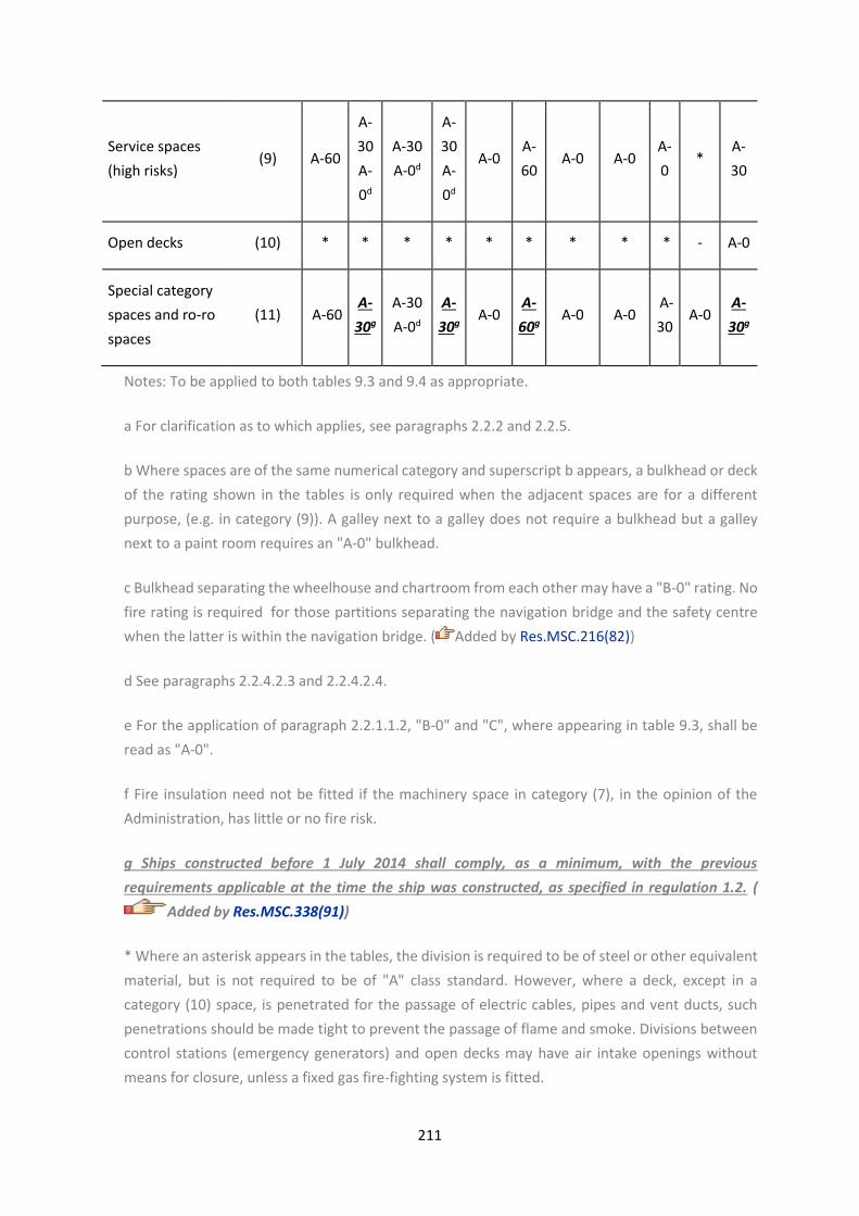
211
Service spaces
(high risks) (9) A-60
A-
30
A-
0d
A-30
A-0d
A-
30
A-
0d
A-0 A-
60 A-0 A-0
A-
0 *
A-
30
Open decks (10) * * * * * * * * * - A-0
Special category
spaces and ro-ro
spaces
(11) A-60 A-
30g
A-30
A-0d
A-
30g A-0
A-
60g A-0 A-0
A-
30 A-0
A-
30g
Notes: To be applied to both tables 9.3 and 9.4 as appropriate.
a For clarification as to which applies, see paragraphs 2.2.2 and 2.2.5.
b Where spaces are of the same numerical category and superscript b appears, a bulkhead or deck
of the rating shown in the tables is only required when the adjacent spaces are for a different
purpose, (e.g. in category (9)). A galley next to a galley does not require a bulkhead but a galley
next to a paint room requires an "A-0" bulkhead.
c Bulkhead separating the wheelhouse and chartroom from each other may have a "B-0" rating. No
fire rating is required for those partitions separating the navigation bridge and the safety centre
when the latter is within the navigation bridge. ( Added by Res.MSC.216(82))
d See paragraphs 2.2.4.2.3 and 2.2.4.2.4.
e For the application of paragraph 2.2.1.1.2, "B-0" and "C", where appearing in table 9.3, shall be
read as "A-0".
f Fire insulation need not be fitted if the machinery space in category (7), in the opinion of the
Administration, has little or no fire risk.
g Ships constructed before 1 July 2014 shall comply, as a minimum, with the previous
requirements applicable at the time the ship was constructed, as specified in regulation 1.2. (
Added by Res.MSC.338(91))
* Where an asterisk appears in the tables, the division is required to be of steel or other equivalent
material, but is not required to be of "A" class standard. However, where a deck, except in a
category (10) space, is penetrated for the passage of electric cables, pipes and vent ducts, such
penetrations should be made tight to prevent the passage of flame and smoke. Divisions between
control stations (emergency generators) and open decks may have air intake openings without
means for closure, unless a fixed gas fire-fighting system is fitted.

212
For the application of paragraph 2.2.1.1.2, an asterisk, where appearing in table 9.4, except for
categories (8) and (10), shall be read as “A-0".
2.2.5 Protection of stairways and lifts in accommodation area
2.2.5.1 Stairways shall be within enclosures formed of "A" class divisions, with positive
means of closure at all openings, except that:
.1 a stairway connecting only two decks need not be enclosed, provided the integrity of
the deck is maintained by proper bulkheads or self-closing doors in one 'tween-deck
space. When a stairway is closed in one 'tween-deck space, the stairway enclosure shall
be protected in accordance with the tables for decks in paragraphs 2.2.3 or 2.2.4; and
.2 stairways may be fitted in the open in a public space, provided they lie wholly within
the public space.
2.2.5.2 Lift trunks shall be so fitted as to prevent the passage of smoke and flame from one 'tween-
deck to another and shall be provided with means of closing so as to permit the control of draught
and smoke. Machinery for lifts located within stairway enclosures shall be arranged in a separate
room, surrounded by steel boundaries, except that small passages for lift cables are permitted. Lifts
which open into spaces other than corridors, public spaces, special category spaces, stairways and
external areas shall not open into stairways included in the means of escape.
2.2.6 Arrangement of cabin balconies
On passenger ships constructed on or after 1 July 2008, non-load bearing partial bulkheads which
separate adjacent cabin balconies shall be capable of being opened by the crew from each side for
the purpose of fighting fires. ( Added by Res.MSC.216(82))
2.2.7 Protection of atriums
2.2.7.1 Atriums shall be within enclosures formed of “A” class divisions having a fire rating
determined in accordance with tables 9.2 and 9.4, as applicable.
2.2.7.2 Decks separating spaces within atriums shall have a fire rating determined in accordance with
tables 9.2 and 9.4, as applicable.( Added by Res.MSC.216(82))
2.3 Cargo Ships except tankers
2.3.1 Methods of protection in accommodation area
2.3.1.1 One of the following methods of protection shall be adopted in accommodation and
service spaces and control stations:
.1 Method IC - The construction of internal divisional bulkheads of non-combustible "B"
or "C" class divisions generally without the installation of an automatic sprinkler, fire

213
detection and fire alarm system in the accommodation and service spaces, except as
required by regulation 7.5.5.1; or
.2 Method IIC - The fitting of an automatic sprinkler, fire detection and fire alarm system
as required by regulation 7.5.5.2 for the detection and extinction of fire in all spaces in
which fire might be expected to originate, generally with no restriction on the type of
internal divisional bulkheads; or
.3 Method IIIC - The fitting of a fixed fire detection and fire alarm system as required by
regulation 7.5.5.3, in spaces in which a fire might be expected to originate, generally with
no restriction on the type of internal divisional bulkheads, except that in no case must
the area of any accommodation space or spaces bounded by an "A" or "B" class division
exceed 50 m² . Consideration may be given by the Administration to increasing this area
for public spaces.
2.3.1.2 The requirements for the use of non-combustible materials in the construction and
insulation of boundary bulkheads of machinery spaces, control stations, service spaces, etc.,
and the protection of the above stairway enclosures and corridors will be common to all
three methods outlined in paragraph 2.3.1.1.
2.3.2 Bulkheads within accommodation area
2.3.2.1 Bulkheads required to be "B" class divisions shall extend from deck to deck and to
the shell or other boundaries. However, where a continuous "B" class ceiling or lining is fitted
on both sides of the bulkhead, the bulkhead may terminate at the continuous ceiling or
lining.
2.3.2.2 Method IC - Bulkheads not required by this or other regulations for cargo ships to be
"A" or "B" class divisions, shall be of at least "C" class construction.
2.3.2.3 Method IIC - There shall be no restriction on the construction of bulkheads not
required by this or other regulations for cargo ships to be "A" or "B" class divisions except in
individual cases where "C" class bulkheads are required in accordance with table 9.5.
2.3.2.4 Method IIIC - There shall be no restriction on the construction of bulkheads not
required for cargo ships to be "A" or "B" class divisions except that the area of any
accommodation space or spaces bounded by a continuous "A" or "B" class division must in
no case exceed 50 m² , except in individual cases where "C" class bulkheads are required in
accordance with table 9.5. Consideration may be given by the Administration to increasing
this area for public spaces.
2.3.3 Fire integrity of bulkheads and decks

214
Refer to the IACS UI SC 45 Fire integrity of bulkheads and decks
2.3.3.1 In addition to complying with the specific provisions for fire integrity of bulkheads
and decks of cargo ships, the minimum fire integrity of bulkheads and decks shall be as
prescribed in tables 9.5 and 9.6.
2.3.3.2 The following requirements shall govern application of the tables:
.1 Tables 9.5 and 9.6 shall apply respectively to the bulkheads and decks separating
adjacent spaces.
.2 For determining the appropriate fire integrity standards to be applied to divisions
between adjacent spaces, such spaces are classified according to their fire risk as shown
in categories (1) to (11) below. Where the contents and use of a space are such that there
is a doubt as to its classification for the purpose of this regulation, or where it is possible
to assign two or more classifications to a space, it shall be treated as a space within the
relevant category having the most stringent boundary requirements. Smaller, enclosed
rooms within a space that have less than 30 % communicating openings to that space are
considered separate spaces. The fire integrity of the boundary bulkheads and decks of
such smaller rooms shall be as prescribed in tables 9.5 and 9.6. The title of each category
is intended to be typical rather than restrictive. The number in parentheses preceding
each category refers to the applicable column or row in the tables;
(1) Control stations
Spaces containing emergency sources of power and lighting.
Wheelhouse and chartroom.
Spaces containing the ship's radio equipment.
Fire control stations.
Control room for propulsion machinery when located outside the machinery space.
Spaces containing centralized fire alarm equipment.
(2) Corridors
corridors and lobbies.
(3) Accommodation spaces
Spaces as defined in regulation 3.1, excluding corridors.

215
(4) Stairways
Interior stairway, lifts, totally enclosed emergency escape trunks, and escalators
(other than those wholly contained within the machinery spaces) and enclosures
thereto.
In this connection, a stairway which is enclosed only at one level shall be regarded as
part of the space from which it is not separated by a fire door.
(5) Service spaces (low risk)
Refer to the IACS UI SC 167 Electrical distribution boards
Lockers and store-rooms not having provisions for the storage of flammable liquids
and having areas less than 4 m² and drying rooms and laundries.
(6) Machinery spaces of category A
Spaces as defined in regulation 3.31.
(7) Other machinery spaces
Electrical equipment rooms (auto-telephone exchange, air-conditioning duct spaces).
Spaces as defined in regulation 3.30 excluding machinery spaces of category A.
(8) Cargo spaces
All spaces used for cargo (including cargo oil tanks) and trunkways and hatchways to
such spaces.
(9) Service spaces (high risk)
Galleys, pantries containing cooking appliances, saunas, paint lockers and store-
rooms having areas of 4 m² or more, spaces for the storage of flammable liquids, and
workshops other than those forming part of the machinery spaces.
(10) Open decks
Open deck spaces and enclosed promenades having little or no fire risk. To be
considered in this category, enclosed promenades shall have no significant fire risk,
meaning that furnishings shall be restricted to deck furniture. In addition, such spaces
shall be naturally ventilated by permanent openings.

216
Air spaces (the space outside superstructures and deckhouses).
(11) Ro-ro and vehicle spaces
Ro-ro spaces as defined in regulation 3.41.
Vehicle spaces as defined in regulation 3.49.
Table 9.5 - Fire integrity of bulkheads separating adjacent spaces ( Amended by
Res.MSC.338(91))
Refer to MSC.1/Circ.1511 UNIFIED INTERPRETATIONS OF SOLAS REGULATIONS II-2/9 AND II-
2/13
Spaces (1)
(2)
(3)
(4)
(5)
(6)
(7)
(8)
(9)
(10)
(11)
Control
stations (1) A-0e A-0 A-60 A-0 A-15 A-60 A-15 A-60 A-60 * A-60
Corridors (2) C B-0 B-0
A-0c B-0 A-60 A-0 A-0 A-0 * A-30
Accommodatio
n spaces (3) Ca,b
B-0
A-0c B-0 A-60 A-0 A-0 A-0 * A-30
Stairways (4) B-0
A-0c
B-0
A-0c A-60 A-0 A-0 A-0
*
* A-30
Service spaces
(low risk) (5) C A-60 A-0 A-0 A-0 * A-0
Machinery
spaces of
category A
(6) * A-0 A-0g A-60 * A-60f
Other
machinery
spaces
(7) A-0d A-0 A-0 * A-0
Cargo spaces (8) * A-0 * A-0

217
Service spaces
(high risks) (9)
A-
0d * A-30
Open decks (10
) - A-0
Ro-ro and
vehicle spaces
(11
) A-30j
Table 9.6 - Fire integrity of decks separating adjacent space ( Amended by
Res.MSC.338(91))
Refer to MSC.1/Circ.1511 UNIFIED INTERPRETATIONS OF SOLAS REGULATIONS II-2/9 AND II-
2/13
Space below↓
Space
above
→
(1)
(2)
(3)
(4)
(5)
(6)
(7)
(8)
(9)
(10)
(11)
Control
stations (1) A-0 A-0 A-0 A-0 A-0 A-60 A-0 A-0 A-0 * A-60
Corridors (2) A-0 * * A-0 * A-60 A-0 A-0 A-0 * A-30
Accommodati
on spaces (3) A-60 A-0 * A-0 * A-60 A-0 A-0 A-0 * A-30
Stairways (4) A-0 A-0 A-0 * A-0 A-60 A-0 A-0 A-0 * A-30
Service spaces
(low risk) (5) A-15 A-0 A-0 A-0 * A-60 A-0 A-0 A-0 * A-0
Machinery
spaces of
category A
(6) A-60 A-60 A-60 A-60 A-60 * A-
60i A-30 A-60 * A-60
Other
machinery
spaces
(7) A-15 A-0 A-0 A-0 A-0 A-0 * A-0 A-0 * A-0

218
Cargo spaces (8) A-60 A-0 A-0 A-0 A-0 A-0 A-0 * A-0 * A-0
Service spaces
(high risks) (9) A-60 A-0 A-0 A-0 A-0 A-60 A-0 A-0 A-0d * A-30
Open decks (10) * * * * * * * * * - A-0j
Ro-ro and
vehicle spaces (11) A-60 A-30 A-30 A-30 A-0 A-60 A-0 A-0 A-30 A-0j A-30j
Note: To be applied to tables 9.5 and 9.6 as appropriate.
a No special requirements are imposed upon bulkheads in methods IIC and IIIC fire protection.
b In case of method IIIC "B" class bulkheads of "B-0" rating shall be provided between spaces or
groups of spaces of 50 m2 and over in area.
c For clarification as to which applies, see paragraphs 2.3.2 and 2.3.4.
d Where spaces are of the same numerical category and superscript d appear, a bulkhead or deck
of the rating shown in the tables is only required when the adjacent spaces are for a different
purpose (e.g. in category (9)). A galley next to a galley does not require a bulkhead but a galley next
to a paint room requires an "A-0" bulkhead.
e Bulkheads separating the wheelhouse, chartroom and radio room from each other may have a
"B-0" rating.
f An "A-0" rating may be used if no dangerous goods are intended to be carried or if such goods are
stowed not less than 3 m horizontally from such a bulkhead.
g For cargo spaces in which dangerous goods are intended to be carried, regulation 19.3.8 applies.
h Bulkheads and decks separating ro-ro spaces shall be capable of being closed reasonably gastight
and such divisions shall have "A" class integrity in so far as reasonable and practicable, if in the
opinion of the Administration it has little or no fire risk. ( deleted by Res.MSC.338(91))
i Fire insulation need not be fitted if the machinery in category (7) if, in the opinion of the
Administration, it has little or no fire risk.

219
j Ships constructed before 1 July 2014 shall comply, as a minimum, with the previous requirements
applicable at the time the ship was constructed, as specified in regulation 1.2. ( Added by
Res.MSC.338(91))
* Where an asterisk appears in the tables, the division is required to be of steel or other equivalent
material but is not required to be of "A" class standard. However, where a deck, except an open
deck, is penetrated for the passage of electric cables, pipes and vent ducts, such penetrations
should be made tight to prevent the passage of flame and smoke. Divisions between control
stations (emergency generators) and open decks may have air intake openings without means for
closure, unless a fixed gas fire-fighting system is fitted.
2.3.3.3 Continuous "B" class ceilings or linings, in association with the relevant decks or
bulkheads, may be accepted as contributing, wholly or in part, to the required insulation and
integrity of a division.
2.3.3.4 External boundaries which are required in regulation 11.2 to be of steel or other
equivalent material may be pierced for the fitting of windows and sidescuttles provided that
there is no requirement for such boundaries of cargo ships to have "A" class integrity.
Similarly, in such boundaries which are not required to have "A" class integrity, doors may
be constructed of materials which are to the satisfaction of the Administration.
2.3.3.5 Saunas shall comply with paragraph 2.2.3.4.
2.3.4 Protection of stairways and lift trunks in accommodation spaces, service spaces and control
stations
2.3.4.1 Stairways which penetrate only a single deck shall be protected, at a minimum, at
one level by at least "B-0" class divisions and self-closing doors. Lifts which penetrate only a
single deck shall be surrounded by "A-0" class divisions with steel doors at both levels.
Stairways and lift trunks which penetrate more than a single deck shall be surrounded by at
least "A-0" class divisions and be protected by self-closing doors at all levels.
Refer to the IACS UI SC 46 Protection of stairways and lift trunks in accommodation spaces,
service spaces and control stations
2.3.4.2 On ships having accommodation for 12 persons or less, where stairways penetrate more than
a single deck and where there are at least two escape routes direct to the open deck at every
accommodation level, the "A-0" requirements of paragraph 2.3.4.1 may be reduced to "B-0".
2.4 Tankers
2.4.1 Application
For tankers, only method IC as defined in paragraph 2.3.1.1 shall be used.

220
2.4.2 Fire integrity of bulkheads and decks
Refer to the IACS UI SC45 Fire integrity of bulkheads and decks
2.4.2.1 In lieu of paragraph 2.3 and in addition to complying with the specific provisions for
fire integrity of bulkheads and decks of tankers, the minimum fire integrity of bulkheads and
decks shall be as prescribed in tables 9.7 and 9.8.
2.4.2.2 The following requirements shall govern application of the tables:
.1 Tables 9.7 and 9.8 shall apply respectively to the bulkhead and decks separating
adjacent spaces;
.2 For determining the appropriate fire integrity standards to be applied to divisions
between adjacent spaces, such spaces are classified according to their fire risk as shown
in categories (1) to (10) below. Where the contents and use of a space are such that there
is a doubt as to its classification for the purpose of this regulation, or where it is possible
to assign two or more classifications to a space, it shall be treated as a space within the
relevant category having the most stringent boundary requirements. Smaller, enclosed
areas within a space that have less than 30 % communicating openings to that space are
considered separate areas. The fire integrity of the boundary bulkheads and decks of
such smaller spaces shall be as prescribed in tables 9.7 and 9.8. The title of each category
is intended to be typical rather than restrictive. The number in parentheses preceding
each category refers to the applicable column or row in the tables;
(1) Control stations
Spaces containing emergency sources of power and lighting.
Wheelhouse and chartroom.
Spaces containing the ship's radio equipment.
Fire control stations.
Control room for propulsion machinery when located outside the machinery space.
Spaces containing centralized fire alarm equipment.
(2) Corridors
Corridors and lobbies.
(3) Accommodation spaces
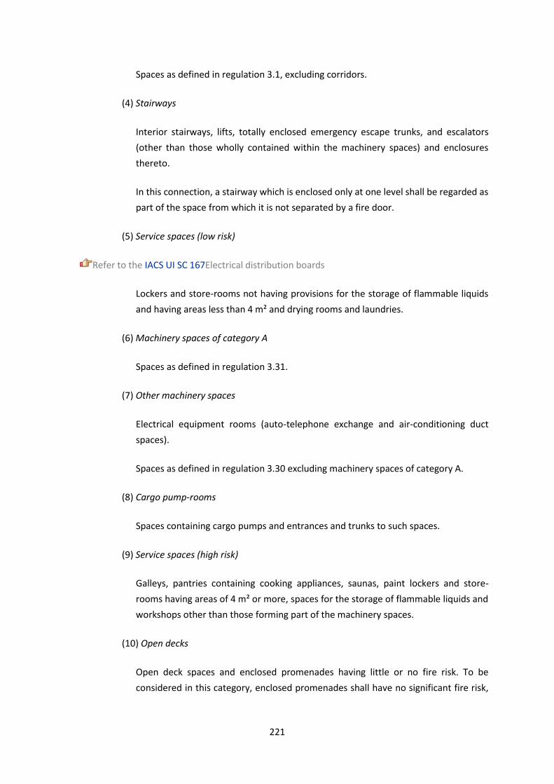
221
Spaces as defined in regulation 3.1, excluding corridors.
(4) Stairways
Interior stairways, lifts, totally enclosed emergency escape trunks, and escalators
(other than those wholly contained within the machinery spaces) and enclosures
thereto.
In this connection, a stairway which is enclosed only at one level shall be regarded as
part of the space from which it is not separated by a fire door.
(5) Service spaces (low risk)
Refer to the IACS UI SC 167Electrical distribution boards
Lockers and store-rooms not having provisions for the storage of flammable liquids
and having areas less than 4 m² and drying rooms and laundries.
(6) Machinery spaces of category A
Spaces as defined in regulation 3.31.
(7) Other machinery spaces
Electrical equipment rooms (auto-telephone exchange and air-conditioning duct
spaces).
Spaces as defined in regulation 3.30 excluding machinery spaces of category A.
(8) Cargo pump-rooms
Spaces containing cargo pumps and entrances and trunks to such spaces.
(9) Service spaces (high risk)
Galleys, pantries containing cooking appliances, saunas, paint lockers and store-
rooms having areas of 4 m² or more, spaces for the storage of flammable liquids and
workshops other than those forming part of the machinery spaces.
(10) Open decks
Open deck spaces and enclosed promenades having little or no fire risk. To be
considered in this category, enclosed promenades shall have no significant fire risk,

222
meaning that furnishings shall be restricted to deck furniture. In addition, such spaces
shall be naturally ventilated by permanent openings.
Air spaces (the space outside superstructures and deckhouses).
2.4.2.3 Continuous "B" class ceilings or linings, in association with the relevant decks or
bulkheads, may be accepted as contributing, wholly or in part, to the required insulation and
integrity of a division.
2.4.2.4 External boundaries which are required in regulation 11.2 to be of steel or other
equivalent material may be pierced for the fitting of windows and sidescuttles provided that
there is no requirement for such boundaries of tankers to have "A" class integrity. Similarly,
in such boundaries which are not required to have "A" class integrity, doors may be
constructed of materials which are to the satisfaction of the Administration.
2.4.2.5 Exterior boundaries of superstructures and deckhouses enclosing accommodation
and including any overhanging decks which support such accommodation, shall be
constructed of steel and insulated to "A-60" standard for the whole of the portions which
face the cargo area and on the outward sides for a distance of 3 m from the end boundary
facing the cargo area. The distance of 3 m shall be measured horizontally and parallel to the
middle line of the ship from the boundary which faces the cargo area at each deck level. In
the case of the sides of those superstructures and deckhouses, such insulation shall be
carried up to the underside of the deck of the navigation bridge.
Refer to the IACS UI SC 174 A 60 Front Insulation of Tankers
2.4.2.6 Skylights to cargo pump-rooms shall be of steel, shall not contain any glass and shall
be capable of being closed from outside the pump-room.
2.4.2.7 Construction and arrangement of saunas shall comply with paragraph 2.2.3.4.
Table 9.7 - Fire integrity of bulkheads separating adjacent spaces
Spaces (1) (2) (3) (4) (5) (6) (7) (8) (9) (10)
Control stations (1) A-0c A-0 A-60 A-0 A-15 A-60 A-15 A-60 A-60 *
Corridors (2) C B-0 B-0
A-0a B-0 A-60 A-0 A-60 A-0 *
Accommodation spaces (3) C B-0
A-0a B-0 A-60 A-0 A-60 A-0 *
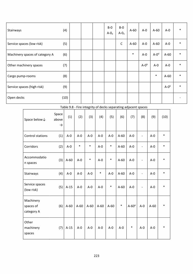
223
Stairways (4) B-0
A-0a
B-0
A-0a A-60 A-0 A-60 A-0 *
Service spaces (low risk) (5) C A-60 A-0 A-60 A-0 *
Machinery spaces of category A (6) * A-0 A-0d A-60 *
Other machinery spaces (7) A-0b A-0 A-0 *
Cargo pump-rooms (8) * A-60 *
Service spaces (high risk) (9) A-0b *
Open decks (10) -
Table 9.8 - Fire integrity of decks separating adjacent spaces
Space below↓
Space
above
→
(1)
(2)
(3)
(4)
(5)
(6)
(7)
(8)
(9)
(10)
Control stations (1) A-0 A-0 A-0 A-0 A-0 A-60 A-0 - A-0 *
Corridors (2) A-0 * * A-0 * A-60 A-0 - A-0 *
Accommodatio
n spaces (3) A-60 A-0 * A-0 * A-60 A-0 - A-0 *
Stairways (4) A-0 A-0 A-0 * A-0 A-60 A-0 - A-0 *
Service spaces
(low risk) (5) A-15 A-0 A-0 A-0 * A-60 A-0 - A-0 *
Machinery
spaces of
category A
(6) A-60 A-60 A-60 A-60 A-60 * A-60e A-0 A-60 *
Other
machinery
spaces
(7) A-15 A-0 A-0 A-0 A-0 A-0 * A-0 A-0 *

224
Cargo pump-
rooms (8) - - - - - A-0d A-0 * - *
Service spaces
(high risk) (9) A-60 A-0 A-0 A-0 A-0 A-60 A-0 - A-0b *
Open decks (10) * * * * * * * * * -
Notes: To be applied to tables 9.7 and 9.8 as appropriate.
a For clarification as to which applies, see paragraphs 2.3.2 and 2.3.4.
b Where spaces are of the same numerical category and superscript b appears, a bulkhead or deck
of the rating shown in the tables is only required when the adjacent spaces are for a different
purpose (e.g. in category (9)). A galley next to a galley does not require a bulkhead but a galley next
to a paint room requires an "A-0" bulkhead.
c Bulkheads separating the wheelhouse, chartroom and radio room from each other may have a
"B-0" rating.
d Bulkheads and decks between cargo pump-rooms and machinery spaces of category A may be
penetrated by cargo pump shaft glands and similar gland penetrations, provided that gas tight seals
with efficient lubrication or other means of ensuring the permanence of the gas seal are fitted in
way of the bulkheads or deck.
e Fire insulation need not be fitted if the machinery space in category (7) if, in the opinion of the
Administration, it has little or no fire risk.
* Where an asterisk appears in the table, the division is required to be of steel or other equivalent
material, but is not required to be of "A" class standard. However, where a deck, except an open
deck, is penetrated for the passage of electric cables, pipes and vent ducts, such penetrations should
be made tight to prevent the passage of flame and smoke. Divisions between control stations
(emergency generators) and open decks may have air intake openings without means for closure,
unless a fixed gas fire-fighting system is fitted.
3 Penetration in fire -resisting divisions and prevention of heat transmission
3.1 Where "A" class divisions are penetrated, such penetrations shall be tested in accordance with
the Fire Test Procedures Code, subject to the provisions of paragraph 4.1.1.6 ( Amended by MSC
85/26/Add.1/Corr.1). In the case of ventilation ducts, paragraphs 7.1.2 and 7.3.1 apply. However,
where a pipe penetration is made of steel or equivalent material having a thickness of 3mm or
greater and a length of not less than 900 mm (preferably 450 mm on each side of the division), and
no openings, testing is not required. Such penetrations shall be suitably insulated by extension of
the insulation at the same level of the division.

225
3.2 Where "B" class divisions are penetrated for the passage of electric cables, pipes, trunks, ducts,
etc., or for the fitting of ventilation terminals, lighting fixtures and similar devices, arrangements
shall be made to ensure that the fire resistance is not impaired, subject to the provisions of
paragraph 7.3.2. Pipes other than steel or copper that penetrate "B" class divisions shall be
protected by either:
.1 a fire tested penetration device, suitable for the fire resistance of the division pierced and the
type of pipe used; or
.2 a steel sleeve, having a thickness of not less than 1.8 mm and a length of not less than 900
mm for pipe diameters of 150 mm or more and not less than 600 mm for pipe diameters of less
than 150 mm (preferably equally divided to each side of the division). The pipe shall be
connected to the ends of the sleeve by flanges or couplings; or the clearance between the sleeve
and the pipe shall not exceed 2.5 mm; or any clearance between pipe and sleeve shall be made
tight by means of non-combustible or other suitable material.
3.3 Uninsulated metallic pipes penetrating "A" or "B" class divisions shall be of materials having a
melting temperature which exceeds 950 degrees C for "A-0" and 850 degrees C for "B-0" class
divisions.
3.4 In approving structural fire protection details, the Administration shall have regard to the risk of
heat transmission at intersections and terminal points of required thermal barriers. The insulation of
a deck or bulkhead shall be carried past the penetration, intersection or terminal point for a distance
of at least 450 mm in the case of steel and aluminium structures. If a space is divided with a deck or a
bulkhead of "A" class standard having insulation of different values, the insulation with the higher
value shall continue on the deck or bulkhead with the insulation of the lesser value for a distance of
at least 450 mm.
4 Protection of openings in fire resisting divisions
4.1 Openings in bulkheads and decks in passenger ships
4.1.1 Openings in "A" class divisions
4.1.1.1 Except for hatches between cargo, special category, store, and baggage spaces, and
between such spaces and the weather decks, openings shall be provided with permanently
attached means of closing which shall be at least as effective for resisting fires as the
divisions in which they are fitted.
4.1.1.2 The construction of doors and door frames in "A" class divisions, with the means of
securing them when closed, shall provide resistance to fire as well as to the passage of smoke
and flame equivalent to that of the bulkheads in which the doors are situated, this being
determined in accordance with the Fire Test Procedures Code. Such doors and door frames
shall be constructed of steel or other equivalent material. Doors approved without the sill

226
being part of the frame, which are installed on or after 1 July 2010, shall be installed such
that the gap under the door does not exceed 12 mm. A non-combustible sill shall be installed
under the door such that floor coverings do not extend beneath the closed door.
4.1.1.3 Watertight doors need not be insulated.
4.1.1.4 It shall be possible for each door to be opened and closed from each side of the
bulkhead by one person only.
4.1.1.5 Fire doors in main vertical zone bulkheads, galley boundaries and stairway enclosures
other than power-operated watertight doors and those which are normally locked, shall
satisfy the following requirements:
.1 the doors shall be self-closing and be capable of closing with an angle of inclination of
up to 3.5° opposing closure;
.2 the approximate time of closure for hinged fire doors shall be no more than 40s and
no less than 10s from the beginning of their movement with the ship in upright position.
The approximate uniform rate of closure for sliding doors shall be of no more than 0.2
m/s and no less than 0.1 m/s with the ship in upright position;
.3 the doors, except those for emergency escape trunks, shall be capable of remote
release from the continuously manned central control station, either simultaneously or
in groups and shall be capable of release also individually from a position at both sides of
the door. Release switches shall have an on-off function to prevent automatic resetting
of the system;
.4 hold-back hooks not subject to central control station release are prohibited;
.5 a door closed remotely from the central control station shall be capable of being re-
opened from both sides of the door by local control. After such local opening, the door
shall automatically close again;
.6 indication must be provided at the fire door indicator panel in the continuously
manned central control station whether each door is closed;
.7 the release mechanism shall be so designed that the door will automatically close in
the event of disruption of the control system or central power supply;
.8 local power accumulators for power-operated doors shall be provided in the
immediate vicinity of the doors to enable the doors to be operated after disruption of
the control system or central power supply at least ten times (fully opened and closed)
using the local controls;
227
.9 disruption of the control system or central power supply at one door shall not impair
the safe functioning of the other doors;
.10 remote-released sliding or power-operated doors shall be equipped with an alarm
that sounds at least 5 s but no more than 10 s after the door being released from the
central control station and before the door begins to move and continues sounding until
the door is completely closed;
.11 a door designed to re-open upon contacting an object in its path shall re-open not
more than 1 m from the point of contact;
.12 double-leaf doors equipped with a latch necessary for their fire integrity shall have a
latch that is automatically activated by the operation of the doors when released by the
system;
.13 doors giving direct access to special category spaces which are power-operated and
automatically closed need not be equipped with the alarms and remote-release
mechanisms required in paragraphs 4.1.1.5.3 and 4.1.1.5.10;
.14 the components of the local control system shall be accessible for maintenance and
adjusting;
.15 power-operated doors shall be provided with a control system of an approved type
which shall be able to operate in case of fire and be in accordance with the Fire Test
Procedures Code. This system shall satisfy the following requirements:
.15.1 the control system shall be able to operate the door at the temperature of at least
200 degrees C for at least 60 min, served by the power supply;
.15.2 the power supply for all other doors not subject to fire shall not be impaired; and
.15.3 at temperatures exceeding 200 degrees C the control system shall be automatically
isolated from the power supply and shall be capable of keeping the door closed up to at
least 945 degrees C .
4.1.1.6 In ships carrying not more than 36 passengers, where a space is protected by an
automatic sprinkler fire detection and alarm system complying with the provisions the Fire
Safety Systems Code or fitted with a continuous "B" class ceiling, openings in decks not
forming steps in main vertical zones nor bounding horizontal zones shall be closed
reasonably tight and such decks shall meet the "A" class integrity requirements in so far as
is reasonable and practicable in the opinion of the Administration.

228
4.1.1.7 The requirements for "A" class integrity of the outer boundaries of a ship shall not
apply to glass partitions, windows and sidescuttles, provided that there is no requirement
for such boundaries to have "A" class integrity in paragraph 4.1.3.3. The requirements for
"A" class integrity of the outer boundaries of the ship shall not apply to exterior doors, except
for those in superstructures and deckhouses facing lifesaving appliances, embarkation and
external assembly station areas, external stairs and open decks used for escape routes.
Stairway enclosure doors need not meet this requirement.
4.1.1.8 Except for watertight doors, weathertight doors (semi-watertight doors), doors
leading to the open deck and doors which need to be reasonably gastight, all "A" class doors
located in stairways, public spaces and main vertical zone bulkheads in escape routes shall
be equipped with a self-closing hose port of material, construction and fire resistance which
is equivalent to the door into which it is fitted, and shall be a 150 mm square clear opening
with the door closed and shall be inset into the lower edge of the door, opposite the door
hinges or, in the case of sliding doors, nearest the opening.
4.1.1.9 Where it is necessary that a ventilation duct passes through a main vertical zone
division, a fail-safe automatic closing fire damper shall be fitted adjacent to the division. The
damper shall also be capable of being manually closed from each side of the division. The
operating position shall be readily accessible and be marked in red light-reflecting colour.
The duct between the division and the damper shall be of steel or other equivalent material
and, if necessary, insulated to comply with the requirements of paragraph 3.1. The damper
shall be fitted on at least one side of the division with a visible indicator showing whether
the damper is in the open position.
4.1.2 Openings in "B" class divisions
Refer to the IACS UI SC 119 Balancing ducts
4.1.2.1 Doors and door frames in "B" class divisions and means of securing them shall provide
a method of closure which shall have resistance to fire equivalent to that of the divisions,
this being determined in accordance with the Fire Test Procedure Code except that
ventilation openings may be permitted in the lower portion of such doors. Where such
opening is in or under a door the total net area of any such opening or openings shall not
exceed 0.05 m². Alternatively, a non-combustible air balance duct routed between the cabin
and the corridor, and located below the sanitary unit is permitted where the cross-sectional
area of the duct does not exceed 0.05 m². All ventilation openings shall be fitted with a grill
made of non-combustible material. Doors shall be non-combustible. Doors approved
without the sill being part of the frame, which are installed on or after 1 July 2010, shall be
installed such that the gap under the door does not exceed 25 mm.

229
4.1.2.2 Cabin doors in "B" class divisions shall be of a self-closing type. Hold-back hooks are
not permitted.
4.1.2.3 The requirements for "B" class integrity of the outer boundaries of a ship shall not
apply to glass partitions, windows and sidescuttles. Similarly, the requirements for "B" class
integrity shall not apply to exterior doors in superstructures and deckhouses. For ships
carrying not more than36 passengers, the Administration may permit the use of combustible
materials in doors separating cabins from the individual interior sanitary spaces such as
showers.
4.1.2.4 In ships carrying not more than 36 passengers, where an automatic sprinkler system
complying with the provisions of the Fire Safety Systems Code is fitted:
.1 openings in decks not forming steps in main vertical zones nor bounding horizontal
zones shall be closed reasonably tight and such decks shall meet the "B" class integrity
requirements in so far as is reasonable and practicable in the opinion of the
Administration; and
.2 openings in corridor bulkheads of "B" class materials shall be protected in accordance
with the provisions of paragraph 2.2.2.
4.1.3 Windows and sidescuttles
4.1.3.1 Windows and sidescuttles in bulkheads within accommodation and service spaces
and control stations other than those to which the provisions of paragraph 4.1.1.6 and of
paragraph 4.1.2.3 apply, shall be so constructed as to preserve the integrity requirements of
the type of bulkheads in which they are fitted, this being determined in accordance with the
FTP Code.
4.1.3.2 Notwithstanding the requirements of tables 9.1 to 9.4, windows and sidescuttles in
bulkheads separating accommodation and service spaces and control stations from weather
shall be constructed with frames of steel or other suitable material. The glass shall be
retained by a metal glazing bead or angle.
4.1.3.3 Windows facing life-saving appliances, embarkation and assembly stations, external
stairs and open decks used for escape routes, and windows situated below liferaft and
escape slide embarkation areas shall have fire integrity as required in table 9.1. Where
automatic dedicated sprinkler heads are provided for windows, "A-0" windows may be
accepted as equivalent. To be considered under this paragraph, the sprinkler heads must
either be:
.1 dedicated heads located above the windows, and installed in addition to the
conventional ceiling sprinklers; or

230
.2 conventional ceiling sprinkler heads arranged such that the window is protected by an
average application rate of at least 5 litres/min/m² and the additional window area is
included in the calculation of the area of coverage; or
.3 water-mist nozzles that have been tested and approved in accordance with the
guidelines approved by the Organization*.
* Refer to the Revised Guidelines for approval of sprinkler systems equivalent to that referred to in
SOLAS regulation II-2/12 (resolution A.800(19), as amended).
Windows located in the ship's side below the lifeboat embarkation area shall have fire
integrity at least equal to "A-0" class.
4.1.3.4 Notwithstanding the requirement in paragraph 4.1.3.3, the requirements in
paragraphs 4.1.3.5 and 4.1.3.6 shall apply to ships constructed on or after 1 January 2020.(
Added by Res.MSC.421(98))
4.1.3.5 For ships carrying more than 36 passengers, windows facing survival craft,
embarkation and assembly stations, external stairs and open decks used for escape routes,
and windows situated below liferaft and escape slide embarkation areas shall have fire
integrity as required in table 9.1. Where automatic dedicated sprinkler heads are provided
for windows, "A-0" windows may be accepted as equivalent. To be considered under this
paragraph, the sprinkler heads must either be:
.1 dedicated heads located above the windows, and installed in addition to the
conventional ceiling sprinklers; or
.2 conventional ceiling sprinkler heads arranged such that the window is protected by an
average application rate of at least 5 l/min per square metre and the additional window
area is included in the calculation of the area of coverage; or
.3 water-mist nozzles that have been tested and approved in accordance with the
Guidelines approved by the Organization*; and
Windows located in the ship's side below the lifeboat embarkation area shall have fire
integrity at least equal to "A-0" class.
* Refer to theRevised guidelines for approval of sprinkler systems equivalent to that referred to in
SOLAS regulation II-2/12(resolution A.800(19), as amended)."
4.1.3.6 For ships carrying not more than 36 passengers, windows facing survival craft and escape
slide, embarkation areas and windows situated below such areas shall have fire integrity at least
equal to "A-0" class.

231
4 Protection of openings in fire resisting divisions
4.1 Openings in bulkheads and decks in passenger ships
4.1.1 Openings in "A" class divisions
4.1.1.1 Except for hatches between cargo, special category, store, and baggage spaces, and
between such spaces and the weather decks, openings shall be provided with permanently
attached means of closing which shall be at least as effective for resisting fires as the
divisions in which they are fitted.
4.1.1.2 The construction of doors and door frames in "A" class divisions, with the means of
securing them when closed, shall provide resistance to fire as well as to the passage of smoke
and flame equivalent to that of the bulkheads in which the doors are situated, this being
determined in accordance with the Fire Test Procedures Code. Such doors and door frames
shall be constructed of steel or other equivalent material. Watertight doors need not be
insulated.
4.1.1.3 It shall be possible for each door to be opened and closed from each side of the
bulkhead by one person only.
4.1.1.4 Fire doors in main vertical zone bulkheads, galley boundaries and stairway enclosures
other than power-operated watertight doors and those which are normally locked, shall
satisfy the following requirements:
.1 the doors shall be self-closing and be capable of closing with an angle of inclination of
up to 3.5° opposing closure;
.2 the approximate time of closure for hinged fire doors shall be no more than 40s and
no less than 10s from the beginning of their movement with the ship in upright position.
The approximate uniform rate of closure for sliding doors shall be of no more than 0.2
m/s and no less than 0.1 m/s with the ship in upright position;
.3 the doors, except those for emergency escape trunks, shall be capable of remote
release from the continuously manned central control station, either simultaneously or
in groups and shall be capable of release also individually from a position at both sides of
the door. Release switches shall have an on-off function to prevent automatic resetting
of the system;
.4 hold-back hooks not subject to central control station release are prohibited;

232
.5 a door closed remotely from the central control station shall be capable of being re-
opened from both sides of the door by local control. After such local opening, the door
shall automatically close again;
.6 indication must be provided at the fire door indicator panel in the continuously
manned central control station whether each door is closed;
.7 the release mechanism shall be so designed that the door will automatically close in
the event of disruption of the control system or central power supply;
.8 local power accumulators for power-operated doors shall be provided in the
immediate vicinity of the doors to enable the doors to be operated after disruption of
the control system or central power supply at least ten times (fully opened and closed)
using the local controls;
.9 disruption of the control system or central power supply at one door shall not impair
the safe functioning of the other doors;
.10 remote-released sliding or power-operated doors shall be equipped with an alarm
that sounds at least 5 s but no more than 10 s after the door being released from the
central control station and before the door begins to move and continues sounding until
the door is completely closed;
.11 a door designed to re-open upon contacting an object in its path shall re-open not
more than 1 m from the point of contact;
.12 double-leaf doors equipped with a latch necessary for their fire integrity shall have a
latch that is automatically activated by the operation of the doors when released by the
system;
.13 doors giving direct access to special category spaces which are power-operated and
automatically closed need not be equipped with the alarms and remote-release
mechanisms required in paragraphs 4.1.1.4.3 and 4.1.1.4.10;
.14 the components of the local control system shall be accessible for maintenance and
adjusting;
.15 power-operated doors shall be provided with a control system of an approved type
which shall be able to operate in case of fire and be in accordance with the Fire Test
Procedures Code. This system shall satisfy the following requirements:
.15.1 the control system shall be able to operate the door at the temperature of at least
200 degrees C for at least 60 min, served by the power supply;

233
.15.2 the power supply for all other doors not subject to fire shall not be impaired; and
.15.3 at temperatures exceeding 200 degrees C the control system shall be automatically
isolated from the power supply and shall be capable of keeping the door closed up to at
least 945 degrees C .
4.1.1.5 In ships carrying not more than 36 passengers, where a space is protected by an
automatic sprinkler fire detection and alarm system complying with the provisions the Fire
Safety Systems Code or fitted with a continuous "B" class ceiling, openings in decks not
forming steps in main vertical zones nor bounding horizontal zones shall be closed
reasonably tight and such decks shall meet the "A" class integrity requirements in so far as
is reasonable and practicable in the opinion of the Administration.
4.1.1.6 The requirements for "A" class integrity of the outer boundaries of a ship shall not
apply to glass partitions, windows and sidescuttles, provided that there is no requirement
for such boundaries to have "A" class integrity in paragraph 4.1.3.3. The requirements for
"A" class integrity of the outer boundaries of the ship shall not apply to exterior doors, except
for those in superstructures and deckhouses facing lifesaving appliances, embarkation and
external assembly station areas, external stairs and open decks used for escape routes.
Stairway enclosure doors need not meet this requirement.
4.1.1.7 Except for watertight doors, weathertight doors (semi-watertight doors), doors
leading to the open deck and doors which need to be reasonably gastight, all "A" class doors
located in stairways, public spaces and main vertical zone bulkheads in escape routes shall
be equipped with a self-closing hose port of material, construction and fire resistance which
is equivalent to the door into which it is fitted, and shall be a 150 mm square clear opening
with the door closed and shall be inset into the lower edge of the door, opposite the door
hinges or, in the case of sliding doors, nearest the opening.
4.1.1.8 Where it is necessary that a ventilation duct passes through a main vertical zone
division, a fail-safe automatic closing fire damper shall be fitted adjacent to the division. The
damper shall also be capable of being manually closed from each side of the division. The
operating position shall be readily accessible and be marked in red light-reflecting colour.
The duct between the division and the damper shall be of steel or other equivalent material
and, if necessary, insulated to comply with the requirements of paragraph 3.1. The damper
shall be fitted on at least one side of the division with a visible indicator showing whether
the damper is in the open position.
4.1.2 Openings in "B" class divisions IACS UI SC 119
4.1.2.1 Doors and door frames in "B" class divisions and means of securing them shall provide
a method of closure which shall have resistance to fire equivalent to that of the divisions,
234
this being determined in accordance with the Fire Test Procedure Code except that
ventilation openings may be permitted in the lower portion of such doors. Where such
opening is in or under a door the total net area of any such opening or openings shall not
exceed 0.05 m². Alternatively, a non-combustible air balance duct routed between the cabin
and the corridor, and located below the sanitary unit is permitted where the cross-sectional
area of the duct does not exceed 0.05 m². All ventilation openings shall be fitted with a grill
made of non-combustible material. Doors shall be non-combustible.
4.1.2.2 Cabin doors in "B" class divisions shall be of a self-closing type. Hold-back hooks are
not permitted.
4.1.2.3 The requirements for "B" class integrity of the outer boundaries of a ship shall not
apply to glass partitions, windows and sidescuttles. Similarly, the requirements for "B" class
integrity shall not apply to exterior doors in superstructures and deckhouses. For ships
carrying not more than36 passengers, the Administration may permit the use of combustible
materials in doors separating cabins from the individual interior sanitary spaces such as
showers.
4.1.2.4 In ships carrying not more than 36 passengers, where an automatic sprinkler system
complying with the provisions of the Fire Safety Systems Code is fitted:
.1 openings in decks not forming steps in main vertical zones nor bounding horizontal
zones shall be closed reasonably tight and such decks shall meet the "B" class integrity
requirements in so far as is reasonable and practicable in the opinion of the
Administration; and
.2 openings in corridor bulkheads of "B" class materials shall be protected in accordance
with the provisions of paragraph 2.2.2.
4.1.3 Windows and sidescuttles
4.1.3.1 Windows and sidescuttles in bulkheads within accommodation and service spaces
and control stations other than those to which the provisions of paragraph 4.1.1.6 and of
paragraph 4.1.2.3 apply, shall be so constructed as to preserve the integrity requirements of
the type of bulkheads in which they are fitted, this being determined in accordance with the
FTP Code.
4.1.3.2 Notwithstanding the requirements of tables 9.1 to 9.4, windows and sidescuttles in
bulkheads separating accommodation and service spaces and control stations from weather
shall be constructed with frames of steel or other suitable material. The glass shall be
retained by a metal glazing bead or angle.

235
4.1.3.3 Windows facing life-saving appliances, embarkation and assembly stations, external
stairs and open decks used for escape routes, and windows situated below liferaft and
escape slide embarkation areas shall have fire integrity as required in table 9.1. Where
automatic dedicated sprinkler heads are provided for windows, "A-0" windows may be
accepted as equivalent. To be considered under this paragraph, the sprinkler heads must
either be:
.1 dedicated heads located above the windows, and installed in addition to the
conventional ceiling sprinklers; or
.2 conventional ceiling sprinkler heads arranged such that the window is protected by an
average application rate of at least 5 litres/min/m² and the additional window area is
included in the calculation of the area of coverage; or
.3 water-mist nozzles that have been tested and approved in accordance with the
guidelines approved by the Organization*. (Added by Res.MSC.201(81))
* Refer to the Revised Guidelines for approval of sprinkler systems equivalent to that referred to in
SOLAS regulation II-2/12 (resolution A.800(19)).
Windows located in the ship's side below the lifeboat embarkation area shall have fire integrity at
least equal to "A-0" class.
4.2 Doors in fire-resisting divisions in cargo ships
Refer to the IACS UI SC 119 Balancing ducts
4.2.1 The fire resistance of doors shall be equivalent to that of the division in which they are
fitted, this being determined in accordance with the Fire Test Procedures Code. Doors approved
as "A" class without the sill being part of the frame, which are installed on or after 1 July 2010,
shall be installed such that the gap under the door does not exceed 12 mm and a non-
combustible sill shall be installed under the door such that floor coverings do not extend
beneath the closed door. Doors approved as "B" class without the sill being part of the frame,
which are installed on or after 1 July 2010, shall be installed such that the gap under the door
does not exceed 25 mm.Doors and door frames in "A" class divisions shall be constructed of
steel. Doors in "B" class divisions shall be non-combustible. Doors fitted in boundary bulkheads
of machinery spaces of category A shall be reasonably gastight and self-closing. In ships
constructed according to method IC, the Administration may permit the use of combustible
materials in doors separating cabins from individual interior sanitary accommodation such as
showers. ( Added by Res.MSC.269(85))
4.2.2 Doors required to be self-closing shall not be fitted with hold-back hooks. However, hold-
back arrangements fitted with remote release devices of the fail-safe type may be utilized.
236
4.2.3 In corridor bulkheads ventilation openings may be permitted in and under the doors of
cabins and public spaces. Ventilation openings are also permitted in "B" class doors leading to
lavatories, offices, pantries, lockers and store rooms. Except as permitted below, the openings
shall be provided only in the lower half of a door. Where such an opening is in or under a door
the total net area of any such opening or openings shall not exceed 0.05m². Alternatively, a non-
combustible air balance duct routed between the cabin and the corridor, and located below the
sanitary unit is permitted where the cross-sectional area of the duct does not exceed 0.05m².
Ventilation openings, except those under the door, shall be fitted with a grille made of non-
combustible material.
4.2.4 Watertight doors need not be insulated.
5 Protection of openings in machinery spaces boundaries
5.1 Application
5.1.1 The provision of this paragraph shall apply to machinery spaces of category A and, where the
Administration considers it desirable, to other machinery spaces.
5.2 Protection of openings in machinery space boundaries
5.2.1 The number of skylights, doors, ventilators, openings in funnels to permit exhaust ventilation
and other openings to machinery spaces shall be reduced to a minimum consistent with the needs of
ventilation and the proper and safe working of the ship.
5.2.2 Skylights shall be of steel and shall not contain glass panels.
5.2.3 Means of control shall be provided for closing power-operated doors or actuating release
mechanisms on doors other than power-operated watertight doors. The control shall be located
outside the space concerned, where they will not be cut off in the event of fire in the space it serves.
5.2.4 In passenger ships, the means of control required in paragraph 5.2.3 shall be situated at one
control position or grouped in as few positions as possible to the satisfaction of the Administration.
Such positions shall have safe access from the open deck.
5.2.5 In passenger ships, doors, other than power-operated watertight doors shall be so arranged
that positive closure is assured in case of fire in the space by power-operated closing arrangements
or by the provision of self-closing doors capable of closing against an inclination of 3.5° opposing
closure, and having a fail-safe hold-back arrangement, provided with a remotely operated release
device. Doors for emergency escape trunks need not be fitted with a fail-safe hold-back facility and a
remotely operated release device.
5.2.6 Windows shall not be fitted in machinery space boundaries. However, this does not preclude
the use of glass in control rooms within the machinery spaces.
6 Protection of cargo space boundaries
6.1 In passenger ships carrying more than 36 passengers, the boundary bulkheads and decks of
special category and ro-ro spaces shall be insulated to "A-60" class standard. However, where a
category (5), (9) and (10) space, as defined in paragraph 2.2.3, is on one side of the division the
237
standard may be reduced to "A-0". Where fuel oil tanks are below a special category space, the
integrity of the deck between such spaces may be reduced to "A-0" standard.
6.2 In passenger ships, indicators shall be provided on the navigating bridge which shall indicate
when any fire door leading to or from the special category spaces is closed. ( Renumbered by
Res.MSC.338(91))
6.3 In tankers, for the protection of cargo tanks carrying crude oil and petroleum products having a
flashpoint not exceeding 60 degrees C, materials readily rendered ineffective by heat shall not be
used for valves, fittings, tank opening covers, cargo vent piping, and cargo piping so as to prevent the
spread of fire to the cargo. ( Renumbered by Res.MSC.338(91))
7 Ventilation systems ( Replaced by Res.MSC.365(93))
(This paragraph applies to ships constructed on or after 1 January 2016)
7.1 General
7.1.1 Ventilation ducts, including single and double wall ducts, shall be of steel or equivalent
material except flexible bellows of short length not exceeding 600 mm used for connecting fans
to the ducting in air-conditioning rooms. Unless expressly provided otherwise in paragraph
7.1.6, any other material used in the construction of ducts, including insulation, shall also be
non-combustible. However, short ducts, not generally exceeding 2 m in length and with a free
cross-sectional area* not exceeding 0.02 m2, need not be of steel or equivalent material, subject
to the following conditions:
* The term free cross-sectional area means, even in the case of a pre-insulated duct, the area
calculated on the basis of the inner dimensions of the duct itself and not the insulation.
Refer to MSC.1/Circ.1480 Unified Interpretation of SOLAS Regulation II-2/9.7.1.1
.1 the ducts shall be made of non-combustible material, which may be faced internally and
externally with membranes having low flame-spread characteristics and, in each case, a
calorific value** not exceeding 45 MJ/m2 of their surface area for the thickness used;
** Refer to the recommendations published by the International Organization for Standardization,
in particular publication ISO 1716:2002, Reaction to the fire tests for building products –
Determination of the heat of combustion.
.2 the ducts are only used at the end of the ventilation device; and
.3 the ducts are not situated less than 600 mm, measured along the duct, from an opening
in an "A" or "B" class division, including continuous "B" class ceiling.

238
7.1.2 The following arrangements shall be tested in accordance with the Fire Test Procedures
Code:
.1 fire dampers, including their relevant means of operation, however, the testing is not
required for dampers located at the lower end of the duct in exhaust ducts for galley ranges,
which must be of steel and capable of stopping the draught in the duct; and
.2 duct penetrations through "A" class divisions. However, the test is not required where
steel sleeves are directly joined to ventilation ducts by means of riveted or screwed
connections or by welding.
7.1.3 Fire dampers shall be easily accessible. Where they are placed behind ceilings or linings,
these ceilings or linings shall be provided with an inspection hatch on which the identification
number of the fire damper is marked. The fire damper identification number shall also be
marked on any remote controls provided.
7.1.4 Ventilation ducts shall be provided with hatches for inspection and cleaning. The hatches
shall be located near the fire dampers.
7.1.5 The main inlets and outlets of ventilation systems shall be capable of being closed from
outside the spaces being ventilated. The means of closing shall be easily accessible as well as
prominently and permanently marked and shall indicate the operating position of the closing
device.
7.1.6 Combustible gaskets in flanged ventilation duct connections are not permitted within 600
mm of openings in "A" or "B" class divisions and in ducts required to be of "A" class construction.
7.1.7 Ventilation openings or air balance ducts between two enclosed spaces shall not be provided
except as permitted by paragraphs 4.1.2.1 and 4.2.3.
7.2 Arrangement of ducts ( Replaced by Res.MSC.365(93))
7.2.1 The ventilation systems for machinery spaces of category A, vehicle spaces, ro-ro spaces,
galleys, special category spaces and cargo spaces shall, in general, be separated from each other
and from the ventilation systems serving other spaces. However, the galley ventilation systems
on cargo ships of less than 4,000 gross tonnage and in passenger ships carrying not more than
36 passengers need not be completely separated from other ventilation systems, but may be
served by separate ducts from a ventilation unit serving other spaces. In such a case, an
automatic fire damper shall be fitted in the galley ventilation duct near the ventilation unit.
7.2.2 Ducts provided for the ventilation of machinery spaces of category A, galleys, vehicle
spaces, ro-ro spaces or special category spaces shall not pass through accommodation spaces,
service spaces, or control stations unless they comply with paragraph 7.2.4.
239
7.2.3 Ducts provided for the ventilation of accommodation spaces, service spaces or control
stations shall not pass through machinery spaces of category A, galleys, vehicle spaces, ro-ro
spaces or special category spaces unless they comply with paragraph 7.2.4.
7.2.4 As permitted by paragraphs 7.2.2 and 7.2.3 ducts shall be either:
.1.1 constructed of steel having a thickness of at least 3 mm for ducts with a free cross-
sectional area of less than 0.075 m2, at least 4 mm for ducts with a free cross-sectional area
of between 0.075 m2 and 0.45 m2, and at least 5 mm for ducts with a free cross-sectional
area of over 0.45 m2;
.1.2 suitably supported and stiffened;
.1.3 fitted with automatic fire dampers close to the boundaries penetrated; and
.1.4 insulated to "A-60" class standard from the boundaries of the spaces they serve to a
point at least 5 m beyond each fire damper;
or
.2.1 constructed of steel in accordance with paragraphs 7.2.4.1.1 and 7.2.4.1.2; and
.2.2 insulated to "A-60" class standard throughout the spaces they pass through, except for
ducts that pass through spaces of category (9) or (10) as defined in paragraph 2.2.3.2.2.
7.2.5 For the purposes of paragraphs 7.2.4.1.4 and 7.2.4.2.2, ducts shall be insulated over their
entire cross-sectional external surface. Ducts that are outside but adjacent to the specified
space, and share one or more surfaces with it, shall be considered to pass through the specified
space, and shall be insulated over the surface they share with the space for a distance of 450
mm past the duct*.
* Sketches of such arrangements are contained in the Unified Interpretations of SOLAS chapter II-
2 (MSC.1/Circ.1276).
7.2.6 Where it is necessary that a ventilation duct passes through a main vertical zone division, an
automatic fire damper shall be fitted adjacent to the division. The damper shall also be capable of
being manually closed from each side of the division. The control location shall be readily accessible
and be clearly and prominently marked. The duct between the division and the damper shall be
constructed of steel in accordance with paragraphs 7.2.4.1.1 and 7.2.4.1.2 and insulated to at least
the same fire integrity as the division penetrated. The damper shall be fitted on at least one side of
the division with a visible indicator showing the operating position of the damper.
7.3 Details of fire dampers and duct penetrations ( Replaced by Res.MSC.365(93))
7.3.1 Ducts passing through "A" class divisions shall meet the following requirements:

240
.1 where a thin plated duct with a free cross sectional area equal to, or less than, 0.02㎡
passes through "A" class divisions, the opening shall be fitted with a steel sheet sleeve having
a thickness of at least 3 mm and a length of at least 200 mm, divided preferably into 100 mm
on each side of a bulkhead or, in the case of a deck, wholly laid on the lower side of the decks
penetrated;
.2 where ventilation ducts with a free cross-sectional area exceeding 0.02㎡, but not more
than 0.075㎡, pass through "A" class divisions, the openings shall be lined with steel sheet
sleeves. The ducts and sleeves shall have a thickness of at least 3 mm and a length of at least
900 mm. When passing through bulkheads, this length shall be divided preferably into 450
mm on each side of the bulkhead. These ducts, or sleeves lining such ducts, shall be provided
with fire insulation. The insulation shall have at least the same fire integrity as the division
through which the duct passes; and
.3 automatic fire dampers shall be fitted in all ducts with a free cross-sectional area
exceeding 0.075㎡ that pass through "A" class divisions. Each damper shall be fitted close to
the division penetrated and the duct between the damper and the division penetrated shall
be constructed of steel in accordance with paragraphs 7.2.4.2.1 and 7.2.4.2.2. The fire
damper shall operate automatically, but shall also be capable of being closed manually from
both sides of the division. The damper shall be fitted with a visible indicator which shows the
operating position of the damper. Fire dampers are not required, however, where ducts pass
through spaces surrounded by "A" class divisions, without serving those spaces, provided
those ducts have the same fire integrity as the divisions which they penetrate. A duct of
cross-sectional area exceeding 0.075㎡ shall not be divided into smaller ducts at the
penetration of an "A" class division and then recombined into the original duct once through
the division to avoid installing the damper required by this provision.
7.3.2 Ventilation ducts with a free cross-sectional area exceeding 0.02㎡ passing through "B"
class bulkheads df shall be lined with steel sheet sleeves of 900 mm in length, divided preferably
into 450 mm on each side of the bulkheads unless the duct is of steel for this length.
7.3.3 All fire dampers shall be capable of manual operation. The dampers shall have a direct
mechanical means of release or, alternatively, be closed by electrical, hydraulic, or pneumatic
operation. All dampers shall be manually operable from both sides of the division. Automatic fire
dampers, including those capable of remote operation, shall have a failsafe mechanism that will close
the damper in a fire even upon loss of electrical power or hydraulic or pneumatic pressure loss.
Remotely operated fire dampers shall be capable of being reopened manually at the damper.
7.4 Ventilation systems for passenger ships carrying more than 36 passengers ( Replaced by
Res.MSC.365(93))
7.4.1 In addition to the requirements in sections 7.1, 7.2 and 7.3, the ventilation system of a
passenger ship carrying more than 36 passengers shall also meet the following requirements.

241
7.4.2 In general, the ventilation fans shall be so arranged that the ducts reaching the various
spaces remain within a main vertical zone.
7.4.3 Stairway enclosures shall be served by an independent ventilation fan and duct system
(exhaust and supply) which shall not serve any other spaces in the ventilation systems.
7.4.4 A duct, irrespective of its cross-section, serving more than one 'tween-deck
accommodation space, service space or control station, shall be fitted, near the penetration of
each deck of such spaces, with an automatic smoke damper that shall also be capable of being
closed manually from the protected deck above the damper. Where a fan serves more than one
'tween-deck space through separate ducts within a main vertical zone, each dedicated to a
single 'tween-deck space, each duct shall be provided with a manually operated smoke damper
fitted close to the fan.
7.4.5 Vertical ducts shall, if necessary, be insulated as required by tables 9.1 and 9.2. Ducts shall be
insulated as required for decks between the space they serve and the space being considered, as
applicable.
7.5 Exhaust ducts from galley ranges ( Replaced by Res.MSC.365(93))
7.5.1 Requirements for passenger ships carrying more than 36 passengers
7.5.1.1 In addition to the requirements in sections 7.1, 7.2 and 7.3, exhaust ducts from galley
ranges shall be constructed in accordance with paragraphs 7.2.4.2.1 and 7.2.4.2.2 and
insulated to "A-60" class standard throughout accommodation spaces, service spaces, or
control stations they pass through. They shall also be fitted with:
.1 a grease trap readily removable for cleaning unless an alternative approved grease
removal system is fitted;
.2 a fire damper located in the lower end of the duct at the junction between the duct
and the galley range hood which is automatically and remotely operated and, in addition,
a remotely operated fire damper located in the upper end of the duct close to the outlet
of the duct;
.3 a fixed means for extinguishing a fire within the duct*;
* Refer to the recommendations published by the International Organization for Standardization,
in particular publication ISO 15371:2009, Ships and marine technology – Fire-extinguishing systems
for protection of galley cooking equipment.
.4 remote-control arrangements for shutting off the exhaust fans and supply fans, for
operating the fire dampers mentioned in paragraph 7.5.1.1.2 and for operating the fire-
extinguishing system, which shall be placed in a position outside the galley close to the

242
entrance to the galley. Where a multi-branch system is installed, a remote means located
with the above controls shall be provided to close all branches exhausting through the
same main duct before an extinguishing medium is released into the system; and
.5 suitably located hatches for inspection and cleaning, including one provided close to
the exhaust fan and one fitted in the lower end where grease accumulates.
7.5.1.2 Exhaust ducts from ranges for cooking equipment installed on open decks shall conform to
paragraph 7.5.1.1, as applicable, when passing through accommodation spaces or spaces containing
combustible materials.
7.5.2 Requirements for cargo ships and passenger ships carrying not more than 36 passengers (
Replaced by Res.MSC.365(93))
When passing through accommodation spaces or spaces containing combustible materials, the
exhaust ducts from galley ranges shall be constructed in accordance with paragraphs 7.2.4.1.1
and 7.2.4.1.2. Each exhaust duct shall be fitted with:
.1 a grease trap readily removable for cleaning;
.2 an automatically and remotely operated fire damper located in the lower end of the duct
at the junction between the duct and the galley range hood and, in addition, a remotely
operated fire damper in the upper end of the duct close to the outlet of the duct;
.3 arrangements, operable from within the galley, for shutting off the exhaust and supply
fans; and
.4 fixed means for extinguishing a fire within the duct.*
* Refer to the recommendations published by the International Organization for Standardization, in
particular publication ISO 15371:2009, Ships and marine technology – Fire-extinguishing systems for
protection of galley cooking equipment.
7.6 Ventilation rooms serving machinery spaces of category A containing internal combustion
machinery ( Replaced by Res.MSC.365(93))
7.6.1 Where a ventilation room serves only such an adjacent machinery space and there is no
fire division between the ventilation room and the machinery space, the means for closing the
ventilation duct or ducts serving the machinery space shall be located outside of the ventilation
room and machinery space.
7.6.2 Where a ventilation room serves such a machinery space as well as other spaces and is
separated from the machinery space by a "A-0" class division, including penetrations, the means for
closing the ventilation duct or ducts for the machinery space can be located in the ventilation room.

243
7.7 Ventilation systems for laundries in passenger ships carrying more than 36 passengers (
Replaced by Res.MSC.365(93))
Exhaust ducts from laundries and drying rooms of category (13) spaces as defined in paragraph
2.2.3.2.2 shall be fitted with:
.1 filters readily removable for cleaning purposes;
.2 a fire damper located in the lower end of the duct which is automatically and remotely
operated;
.3 remote-control arrangements for shutting off the exhaust fans and supply fans from within
the space and for operating the fire damper mentioned in paragraph 7.7.2; and
.4 suitably located hatches for inspection and cleaning
1 Purpose ( Replaced by Res.MSC.365(93))
1.1 The purpose of this regulation is to suppress and swiftly extinguish a fire in the space of origin,
except for paragraph 1.2. For this purpose, the following functional requirements shall be met:
.1 fixed fire-extinguishing systems shall be installed having due regard to the fire growth
potential of the protected spaces; and
.2 fire-extinguishing appliances shall be readily available.
1.2 For open-top container holds* and on deck container stowage areas on ships designed to carry
containers on or above the weather deck, constructed on or after 1 January 2016, fire protection
arrangements shall be provided for the purpose of containing a fire in the space or area of origin
and cooling adjacent areas to prevent fire spread and structural damage.
* For a definition of this term, refer to the Interim guidelines for open-top containerships
(MSC/Circ.608/Rev.1).
2 Water supply systems
Ships shall be provided with fire pumps, fire mains, hydrants and hoses complying with the
applicable requirements of this regulation.
2.1 Fire mains and hydrants
2.1.1 General
Materials readily rendered ineffective by heat shall not be used for fire mains and hydrants unless
adequately protected. The pipes and hydrants shall be so placed that the fire hoses may be easily
244
coupled to them. The arrangement of pipes and hydrants shall be such as to avoid the possibility of
freezing. Suitable drainage provisions shall be provided for fire main piping. Isolation valves shall be
installed for all open deck fire main branches used for purposes other than fire fighting. In ships
where deck cargo may be carried, the positions of the hydrants shall be such that they are always
readily accessible and the pipes shall be arranged as far as practicable to avoid risk of damage by
such cargo.
2.1.2 Ready availability of water supply
The arrangements for the ready availability of water supply shall be:
.1 in passenger ships:
.1.1 of 1,000 gross tonnage and upwards such that at least one effective jet of water is
immediately available from any hydrant in an interior location and so as to ensure the
continuation of the output of water by the automatic starting of one required fire pump;
IACS UI SC 23
.1.2 of less than 1,000 gross tonnage by automatic start of at least one fire pump or by
remote starting from the navigation bridge of at least one fire pump. If the pump starts
automatically or if the bottom valve cannot be opened from where the pump is remotely
started, the bottom valve shall always be kept open; and
.1.3 if fitted with periodically unattended machinery spaces in accordance with
regulation II-1/54, the Administration shall determine provisions for fixed water fire-
extinguishing arrangement for such spaces equivalent to those required for normally
attended machinery spaces;
.2 in cargo ships:
.2.1 to the satisfaction of the Administration; and
.2.2 with a periodically unattended machinery space or when only one person is required on watch,
there shall be immediate water delivery from the fire main system at a suitable pressure, either by
remote starting of one of the main fire pumps with remote starting from the navigating bridge and
fire control station, if any, or permanent pressurization of the fire main system by one of the main
fire pumps, except that the Administration may waive this requirement for cargo ships of less than
1,600 gross tonnage if the fire pump starting arrangement in the machinery space is in an easily
accessible position.
2.1.3 Diameter of fire mains
The diameter of the fire main and water service pipes shall be sufficient for the effective distribution
of the maximum required discharge from two fire pumps operating simultaneously, except that in
the case of cargo ships, other than those included in paragraph 7.3.2, the diameter need only be
sufficient for the discharge of 140 m3 /h. ( Added by Res.MSC.365(93))

245
2.1.4 Isolating valves and relief valves
2.1.4.1 Isolating valves to separate the section of the fire main within the machinery space
containing the main fire pump or pumps from the rest of the fire main shall be fitted in an
easily accessible and tenable position outside the machinery spaces. The fire main shall be
so arranged that when the isolating valves are shut all the hydrants on the ship, except those
in the machinery space referred to above, can be supplied with water by another fire pump
or an emergency fire pump. The emergency fire pump, its seawater inlet, and suction and
delivery pipes and isolating valves shall be located outside the machinery space. If this
arrangement cannot be made, the sea-chest may be fitted in the machinery space if the
valve is remotely controlled from a position in the same compartment as the emergency
pump and the suction pipe is as short as practicable. Short lengths of suction or discharge
piping may penetrate the machinery space, provided they are enclosed in a substantial steel
casing, or are insulated to A-60 class standards. The pipes shall have substantial wall
thickness, but in no case less than 11 mm, and shall be welded except for the flanged
connection to the sea inlet valve.
Refer to the IACS UI SC121 Fire Pump Isolation Requirements (Reg.II-2/10.2.1.4.1)
Refer to the IACS UI SC245 Suction piping of emergency fire pumps, which are run through the
machinery space (SOLAS II-2/10.2.1.4.1)
Refer to MSC.1/Circ.1456 Unified Interpretations of SOLAS Chapter II-2 and the FSS and FTP
Codes
2.1.4.2 A valve shall be fitted to serve each fire hydrant so that any fire hose may be removed while
the fire pumps are in operation.
2.1.4.3 Relief valves shall be provided in conjunction with fire pumps if the pumps are capable of
developing a pressure exceeding the design pressure of the water service pipes, hydrants and hoses.
These valves shall be so placed and adjusted as to prevent excessive pressure in any part of the fire
main system.
2.1.4.4 In tankers, isolation valves shall be fitted in the fire main at poop front in a protected
position and on the tank deck at intervals of not more than 40 m to preserve the integrity of
the fire main system in case of fire or explosion.
Refer to MSC.1/Circ.1456 Unified Interpretations of SOLAS Chapter II-2 and the FSS and FTP
Codes
2.1.5 Number and position of hydrants
2.1.5.1 The number and position of hydrants shall be such that at least two jets of water not
emanating from the same hydrant, one of which shall be from a single length of hose, may reach any
part of the ship normally accessible to the passengers or crew while the ship is being navigated and
any part of any cargo space when empty, any ro-ro space or any vehicle space in which latter case

246
the two jets shall reach any part of the space, each from a single length of hose. Furthermore, such
hydrants shall be positioned near the accesses to the protected spaces.
2.1.5.2 In addition to the requirements in the paragraph 2.1.5.1, passenger ships shall
comply with the following:
.1 in the accommodation, service and machinery spaces the number and position of
hydrants shall be such that the requirements of paragraph 2.1.5.1 may be complied with
when all watertight doors and all doors in main vertical zone bulkheads are closed; and
.2 where access is provided to a machinery space of category A at a low level from an adjacent shaft
tunnel, two hydrants shall be provided external to, but near the entrance to that machinery space.
Where such access is provided from other spaces, in one of those spaces two hydrants shall be
provided near the entrance to the machinery space of category A. Such provision need not be made
where the tunnel or adjacent spaces are not part of the escape route.
2.1.6 Pressure at hydrants
With the two pumps simultaneously delivering water through the nozzles specified in
paragraph 2.3.3, with the quantity of water as specified in paragraph 2.1.3, through any
adjacent hydrants, the following minimum pressures shall be maintained at all hydrants:
.1 for passenger ships:
4,000 gross tonnage and upwards 0.40 N/mm²
less than 4000 gross tonnage 0.30 N/mm² ;
.2 for cargo ships,
6,000 gross tonnage and upwards 0.27 N/mm²
less than 6,000 gross tonnage; 0.25 N/mm² and
.3 the maximum pressure at any hydrant shall not exceed that at which the effective control of a fire
hose can be demonstrated.
2.1.7 International shore connection
2.1.7.1 Ships of 500 gross tonnage and upwards shall be provided with at least one
international shore connection complying with the Fire Safety Systems Code.
2.1.7.2 Facilities shall be available enabling such a connection to be used on either side of the ship.
2.2 Fire pumps
2.2.1 Pumps accepted as fire pumps

247
Sanitary, ballast, bilge or general service pumps may be accepted as fire pumps, provided that they
are not normally used for pumping oil and that if they are subject to occasional duty for the transfer
or pumping of oil fuel, suitable change-over arrangements are fitted.
2.2.2 Number of fire pumps
Ships shall be provided with independently driven fire pumps as follows:
.1 in passenger ships of:
4,000 gross tonnage and upwards at least three
less than 4,000 gross tonnage at least two
.2 in cargo ships of:
1,000 gross tonnage and upwards at least two
less than 1,000 gross tonnage at least two power driven pumps, one of which shall be independently
driven.
2.2.3 Arrangement of fire pumps and fire mains
2.2.3.1 Fire pumps
The arrangement of sea connections, fire pumps and their sources of power shall be as
to ensure that:
.1 in passenger ships of 1,000 gross tonnage and upwards, in the event of a fire in any
one compartment all the fire pumps will not be put out of action; and
.2 in passenger ships of less than 1,000 gross tonnage and in cargo ships, if a fire in any
one compartment could put all the pumps out of action, there shall be an alternative
means consisting of an emergency fire pump complying with the provisions of the Fire
Safety Systems Code with its source of power and sea connection located outside the
space where the main fire pumps or their sources of power are located.
Refer to IACS UI SC165, SC162
2.2.3.2 Requirements for the space containing the emergency fire pump
2.2.3.2.1 Location of the space
The space containing the fire pump shall not be contiguous to the boundaries of
machinery spaces of category A or those spaces containing main fire pumps. Where this
is not practicable, the common bulkhead between the two spaces shall be insulated to a

248
standard of structural fire protection equivalent to that required for a control station in
regulation 9.2.3.3. IACS UI SC 114
2.2.3.2.2 Access to the emergency fire pump
No direct access shall be permitted between the machinery space and the space
containing the emergency fire pump and its source of power. When this is impracticable,
the Administration may accept an arrangement where the access is by means of an
airlock with the door of the machinery space being of A-60 class standard, and the other
door being at least steel, both reasonably gastight, self-closing and without any hold back
arrangements. Alternatively, the access may be through a watertight door capable of
being operated from a space remote from the machinery space and the space containing
the emergency fire pump and unlikely to be cut off in the event of fire in those spaces. In
such cases, a second means of access to the space containing the emergency fire pump
and its source of power shall be provided.
2.2.3.2.3 Ventilation of the emergency fire pump space
Ventilation arrangements to the space containing the independent source of power for the
emergency fire pump shall be such as to preclude, as far as practicable, the possibility of
smoke from a machinery space fire entering or being drawn into that space. 2.2.3.3
Additional pumps for cargo ships IACS UI SC 97
In addition, in cargo ships where other pumps, such as general service, bilge and ballast, etc., are
fitted in a machinery space, arrangements shall be made to ensure that at least one of these pumps,
having the capacity and pressure required by paragraphs 2.1.6.2 and 2.2.4.2, is capable of providing
water to the fire main.
2.2.4 Capacity of fire pumps
Refer to MSC.1/Circ.1314 Application of SOLAS regulation II-2/10 and chapter 12 of the FSS Code
related to Emergency fire pump capacity
2.2.4.1 Total capacity of required fire pumps
The required fire pumps shall be capable of delivering for fire-fighting purposes a
quantity of water, at the pressure specified in paragraph 2.1.6, as follows:
.1 pumps in passenger ships, the quantity of water is not less than two thirds of the
quantity required to be dealt with by the bilge pumps when employed for bilge pumping;
and
.2 pumps in cargo ships, other than any emergency pump, the quantity of water is not
less than four thirds of the quantity required under regulation II-1/35-1 to be dealt with

249
by each of the independent bilge pumps in a passenger ship of the same dimension when
employed in bilge pumping, provided that in no cargo ship, other than those included in
paragraph 7.3.2, need the total required capacity of the fire pumps exceed 180 m3/h. (
Added by Res.MSC.365(93))
2.2.4.2 Capacity of each fire pump
Each of the required fire pumps (other than any emergency pump required in paragraph 2.2.3.1.2 for
cargo ships) shall have a capacity not less than 80% of the total required capacity divided by the
minimum number of required fire pumps but in any case not less than 25 m3/h and each such pump
shall in any event be capable of delivering at least the two required jets of water. These fire pumps
shall be capable of supplying the fire main system under the required conditions. Where more
pumps than the minimum of required pumps are installed such additional pumps shall have a
capacity of at least 25 m3/h and shall be capable of delivering at least the two jets of water required
in paragraph 2.1.5.1.
2.3 Fire hoses and nozzles IACS UI SC 146
2.3.1 General specifications
2.3.1.1 Fire hoses shall be of non-perishable material approved by the Administration and
shall be sufficient in length to project a jet of water to any of the spaces in which they may
be required to be used. Each hose shall be provided with a nozzle and the necessary
couplings. Hoses specified in this chapter as "fire hoses" shall, together with any necessary
fittings and tools, be kept ready for use in conspicuous positions near the water service
hydrants or connections. Additionally, in interior locations in passenger ships carrying more
than 36 passengers fire hoses shall be connected to the hydrants at all times. Fire hoses shall
have a length of at least 10 m, but not more than:
.1 15 m in machinery spaces;
.2 20 m in other spaces and open decks; and
.3 25 m for open decks on ships with a maximum breadth in excess of 30 m.
2.3.1.2 Unless one hose and nozzle is provided for each hydrant in the ship, there shall be complete
interchangeability of hose couplings and nozzles.
2.3.2 Number and diameter of fire hoses
2.3.2.1 Ships shall be provided with fire hoses the number and diameter of which shall be to the
satisfaction of the Administration.
2.3.2.2 In passenger ships, there shall be at least one fire hose for each of the hydrants required by
paragraph 2.1.5 and these hoses shall be used only for the purposes of extinguishing fires or testing
the fire-extinguishing apparatus at fire drills and surveys.

250
2.3.2.3 In cargo ships:
.1 of 1,000 gross tonnage and upwards, the number of fire hoses to be provided shall be
one for each 30 m length of the ship and one spare but in no case less than five in all. This
number does not include any hoses required in any engine or boiler room. The
Administration may increase the number of hoses required so as to ensure that hoses in
sufficient number are available and accessible at all times, having regard to the type of
ship and the nature of trade in which the ship is employed. Ships carrying dangerous
goods in accordance with regulation 19 shall be provided with 3 hoses and nozzles, in
addition to those required above; and
.2 of less than 1,000 gross tonnage, the number of fire hoses to be provided shall be calculated in
accordance with the provisions of paragraph 2.3.2.3.1. However, the number of hoses shall in no
case be less than three.
2.3.3 Size and types of nozzles IACS UI SC 98
2.3.3.1 For the purposes of this chapter, standard nozzle sizes shall be 12 mm, 16 mm and
19 mm or as near thereto as possible. Larger diameter nozzles may be permitted at the
discretion of the Administration.
2.3.3.2 For accommodation and service spaces, a nozzle size greater than 12 mm need not
be used.
2.3.3.3 For machinery spaces and exterior locations, the nozzle size shall be such as to obtain
the maximum discharge possible from two jets at the pressure mentioned in paragraph 2.1.6
from the smallest pump, provided that a nozzle size greater than 19 mm need not be used.
2.3.3.4 Nozzles shall be of an approved dual-purpose type (i.e., spray/jet type) incorporating a
shutoff.
3 Portable fire extinguishers *
Refer to MSC.1/Circ.1275 UNIFIED INTERPRETATION OF SOLAS CHAPTER II-2 ON THE NUMBER
AND ARRANGEMENT OF PORTABLE FIRE EXTINGUISHERS ON BOARD SHIPS
* Refer to the Improved Guidelines for Marine Portable Fire Extinguishers adopted by the
Organization by resolution A.951(23) and Unified interpretation of SOLAS chapter II-2 on the
number and arrangement of portable fire extinguishers on board ships (MSC.1/Circ.1275).
3.1 Type and design
Portable fire extinguishers shall comply with the requirements of the Fire Safety Systems Code.

251
3.2 Arrangement of fire extinguishers
3.2.1 Accommodation spaces, service spaces and control stations shall be provided with
portable fire extinguishers of appropriate types and in sufficient number to the satisfaction of
the Administration. Ships of 1,000 gross tonnage and upwards shall carry at least five portable
fire extinguishers.
3.2.2 One of the portable fire extinguishers intended for use in any space shall be stowed near
the entrance to that space.
3.2.3 Carbon dioxide fire extinguishers shall not be placed in accommodation spaces. In control
stations and other spaces containing electrical or electronic equipment or appliances necessary
for the safety of the ship, fire extinguishers should be provided whose extinguishing media are
neither electrically conductive nor harmful to the equipment and appliances.
3.2.4 Fire extinguishers shall be situated ready for use at easily visible places, which can be
reached quickly and easily at any time in the event of a fire, and in such a way that their
serviceability is not impaired by the weather, vibration or other external factors. Portable fire
extinguishers shall be provided with devices which indicate whether they have been used.
3.3 Spare charges
3.3.1 Spare charges shall be provided for 100% of the first 10 extinguishers and 50% of the
remaining fire extinguishers capable of being recharged on board. Not more than 60 total spare
charges are required. Instructions for recharging shall be carried on board.
3.3.2 For fire extinguishers which cannot be recharged onboard, additional portable fire
extinguishers of the same quantity, type, capacity and number as determined in paragraph 3.3.1
above shall be provided in lieu of spare charges.
4 Fixed fire-extinguishing systems
4.1 Types of fixed fire extinguishing systems
4.1.1 A fixed fire extinguishing system required by paragraph 5 below may be any of the
following systems:
.1 a fixed gas fire-extinguishing system complying with the provisions of the Fire Safety
Systems Code;
.2 a fixed high-expansion foam fire-extinguishing system complying with the provisions of
the Fire Safety Systems Code; and

252
.3 a fixed pressure water-spraying fire-extinguishing system complying with the provisions of the Fire
Safety Systems Code.
4.1.2 Where a fixed fire-extinguishing system not required by this chapter is installed, it shall meet
the requirements of the relevant regulations of this chapter and the Fire Safety Systems Code.
4.1.3 Fire-extinguishing systems using Halon 1211, 1301, and 2402 and perfluorocarbons shall be
prohibited. (Link : MSC/Circ.668)
4.1.4 In general, the Administration shall not permit the use of steam as a fire-extinguishing medium
in fixed fire-extinguishing systems. Where the use of steam is permitted by the Administration, it
shall be used only in restricted areas as an addition to the required fire-extinguishing system and
shall comply with the requirements of the Fire Safety System Code.
4.1.5 By the first scheduled dry-docking after 1 January 2010, fixed carbon dioxide fire-extinguishing
systems for the protection of machinery spaces and cargo pump-rooms on ships constructed before
1 July 2002 shall comply with the provisions of paragraph 2.2.2 of chapter 5 of the Fire Safety
Systems Code. ( Added by Res.MSC.256(84))
4.2 Closing appliances for fixed gas fire-extinguishing systems
Where a fixed gas fire-extinguishing system is used, openings which may admit air to, or allow gas to
escape from, a protected space shall be capable of being closed from outside the protected space.
4.3 Storage rooms of fire extinguishing medium
When the fire extinguishing medium is stored outside a protected space, it shall be stored in a
room which is located behind the forward collision bulkhead, and is used for no other purposes.
Any entrance to such a storage room shall preferably be from the open deck and shall be
independent of the protected space. If the storage space is located below deck, it shall be
located no more than one deck below the open deck and shall be directly accessible by a
stairway or ladder from the open deck. Spaces which are located below deck or spaces where
access from the open deck is not provided, shall be fitted with a mechanical ventilation system
designed to take exhaust air from the bottom of the space and shall be sized to provide at least
6 air changes per hour. Access doors shall open outwards, and bulkheads and decks including
doors and other means of closing any opening therein, which form the boundaries between
such rooms and adjacent enclosed spaces shall be gastight. For the purpose of the application
of tables 9.1 to 9.8, such storage rooms shall be treated as fire control stations.
Refer to the IACS UI SC204 Storage of fire-extinguishing media forward the cargo holds
Refer to IACS UI SC 260 Sample Extraction Smoke Detection System
4.4 Water pumps for other fire-extinguishing systems
Pumps, other than those serving the fire main, required for the provision of water for fire-
extinguishing systems required by this chapter, their sources of power and their controls shall be
installed outside the space or spaces protected by such systems and shall be so arranged that a fire in
the space or spaces protected will not put any such system out of action.
253
5 Fire extinguishing arrangements in machinery spaces
5.1 Machinery spaces containing oil-fired boilers or oil fuel units ( Refer to IACS UI SC30)
5.1.1 Fixed fire-extinguishing systems
Machinery spaces of category A containing oil-fired boilers or oil fuel units shall be provided
with any one of the fixed fire-extinguishing systems in paragraph 4.1. In each case, if the
engine and boiler rooms are not entirely separate, or if fuel oil can drain from the boiler
room into the engine-room, the combined engine and boiler rooms shall be considered as
one compartment.
5.1.2 Additional fire-extinguishing arrangements *
*Refer to MSC.1/Circ.1275 UNIFIED INTERPRETATION OF SOLAS CHAPTER II-2 ON THE NUMBER
AND ARRANGEMENT OF PORTABLE FIRE EXTINGUISHERS ON BOARD SHIPS
5.1.2.1 There shall be in each boiler room or at an entrance outside of the boiler room at
least one portable foam applicator unit complying with the provisions of the Fire Safety
Systems Code.
5.1.2.2 There shall be at least two portable foam extinguishers or equivalent in each firing
space in each boiler room and in each space in which a part of the oil fuel installation is
situated. There shall be not less than one approved foam-type extinguisher of at least 135 l
capacity or equivalent in each boiler room. These extinguishers shall be provided with hoses
on reels suitable for reaching any part of the boiler room. In the case of domestic boilers of
less than 175 kW, or boilers protected by fixed water-based local application fire-
extinguishing systems as required by paragraph 5.6, an approved foam-type extinguisher of
at least 135 l capacity is not required.( Replaced by Res.MSC.409(97))
5.1.2.3 In each firing space there shall be a receptacle containing at least 0.1 m³ sand, sawdust
impregnated with soda, or other approved dry material, along with a suitable shovel for spreading
the material. An approved portable extinguisher may be substituted as an alternative.
5.2 Machinery spaces of category A containing internal combustion machinery ( Replaced by
Res.MSC.380(94))
( Refer to IACS UI SC30)
5.2.1 Fixed fire-extinguishing systems
Machinery spaces of category A containing internal combustion machinery shall be provided
with one of the fixed fire-extinguishing systems in paragraph 4.1.

254
5.2.2 Additional fire-extinguishing arrangements*
* Refer to Unified interpretation of SOLAS chapter II-2 on the number and arrangement of portable
fire extinguishers on board ships (MSC.1/Circ.1275).
5.2.2.1 There shall be at least one portable foam applicator unit complying with the
provisions of the Fire Safety Systems Code.
5.2.2.2 There shall be in each such space approved foam-type fire extinguishers, each of at least 45 l
capacity or equivalent, sufficient in number to enable foam or its equivalent to be directed on to any
part of the fuel and lubricating oil pressure systems, gearing and other fire hazards. In addition, there
shall be provided a sufficient number of portable foam extinguishers or equivalent which shall be so
located that no point in the space is more than 10 m walking distance from an extinguisher and that
there are at least two such extinguishers in each such space. For smaller spaces of cargo ships the
Administration may consider relaxing this requirement.
5.3 Machinery spaces containing steam turbines or enclosed steam engines
5.3.1 Fixed fire-extinguishing systems
In spaces containing steam turbines or enclosed steam engines used for main propulsion or
other purposes having in the aggregate a total output of not less than 375 kW, one of the
fire-extinguishing systems specified in paragraph 4.1 shall be provided if such spaces are
periodically unattended.
5.3.2 Additional fire-extinguishing arrangements
5.3.2.1 There shall be approved foam fire extinguishers each of at least 45 l capacity or
equivalent sufficient in number to enable foam or its equivalent to be directed on to any
part of the pressure lubrication system, on to any part of the casings enclosing pressure
lubricated parts of the turbines, engines or associated gearing, and any other fire hazards.
However, such extinguishers shall not be required if protection, at least equivalent to that
required by this subparagraph, is provided in such spaces by a fixed fire-extinguishing system
fitted in compliance with paragraph 4.1.
5.3.2.2 There shall be a sufficient number of portable foam extinguishers* or equivalent
which shall be so located that no point in the space is more than 10 m walking distance from
an extinguisher and that there are at least two such extinguishers in each such space, except
that such extinguishers shall not be required in addition to any provided in compliance with
paragraph 5.1.2.2.
* Refer to Unified interpretation of SOLAS chapter II-2 on the number and arrangement of portable
fire extinguishers on board ships (MSC.1/Circ.1275).
5.4 Other machinery spaces

255
Refer to MSC.1/Circ.1275 UNIFIED INTERPRETATION OF SOLAS CHAPTER II-2 ON THE NUMBER
AND ARRANGEMENT OF PORTABLE FIRE EXTINGUISHERS ON BOARD SHIPS
Where, in the opinion of the Administration, a fire hazard exists in any machinery space for which no
specific provisions for fire-extinguishing appliances are prescribed in paragraphs 5.1, 5.2 and 5.3,
there shall be provided in, or adjacent to, that space such a number of approved portable fire
extinguishers or other means of fire extinction as the Administration may deem sufficient.
5.5 Additional requirements for passenger ships
In passenger ships carrying more than 36 passengers, each machinery space of category A shall
be provided with at least two suitable water fog applicators * .
* A water fog applicator might consist of a metal L-shaped pipe, the long limb being about 2 m in
length capable of being fitted to a fire hose and the short limb being about 250 mm in length fitted
with a fixed water fog nozzle or capable of being fitted with a water spray nozzle.
5.6 Fixed local application fire-fighting systems IACS UI SC 176
5.6.1 Paragraph 5.6 shall apply to passenger ships of 500 gross tonnage and above and cargo
ships of 2000 gross tonnage and above.
5.6.2 Machinery spaces of category A above 500 m³ in volume shall, in addition to the fixed fire-
extinguishing system required in paragraph 5.1.1, be protected by an approved type of fixed
water-based or equivalent local application fire-fighting system, based on the guidelines
developed by the Organization*. In the case of periodically unattended machinery spaces, the
fire fighting system shall have both automatic and manual release capabilities. In the case of
continuously manned machinery spaces, the fire-fighting system is only required to have a
manual release capability.
* Refer to the Revised Guidelines for the approval of fixed water-based local application fire-
fighting systems for use in category A machinery spaces (MSC/Circ.1387), Unified interpretations
of the Guidelines for the approval of fixed water-based local application fire-fighting systems
(MSC/Circ.1387) (MSC/Circ.1082) and Unified interpretations of SOLAS chapter II-2
(MSC.1/Circ.1276).
5.6.3 Fixed local application fire-fighting systems are to protect areas such as the following
without the necessity of engine shutdown, personnel evacuation, or sealing of the spaces:
Refer to the IACS UI SC 198 Sections in local application fire extinguishing systems
.1 the fire hazard portions of internal combustion machinery or, for ships constructed before
1 July 2014, the fire hazard portions of internal combustion machinery used for the ship's
main propulsion and power generation; ( Replaced by Res.MSC.338(91))

256
.2 boiler fronts;
.3 the fire hazard portions of incinerators; and
.4 purifiers for heated fuel oil.
5.6.4 Activation of any local application system shall give a visual and distinct audible alarm in the
protected space and at continuously manned stations. The alarm shall indicate the specific system
activated. The system alarm requirements described within this paragraph are in addition to, and not
a substitute for, the detection and fire alarm system required elsewhere in this chapter.
6 Fire -extinguishing arrangements in control stations, accommodation and service spaces
6.1 Sprinkler and water spray systems in passenger ships ( Replaced by Res.MSC.216(82))
6.1.1 Passenger ships carrying more than 36 passengers shall be equipped with an automatic
sprinkler, fire detection and fire alarm system of an approved type complying with the requirements
of the Fire Safety Systems Code in all control stations, accommodation and service spaces, including
corridors and stairways. Alternatively, control stations, where water may cause damage to essential
equipment, may be fitted with an approved fixed fire-extinguishing system of another type. Spaces
having little or no fire risk such as voids, public toilets, carbon dioxide rooms and similar spaces need
not be fitted with an automatic sprinkler system. IACS UI SC 130
6.1.2 In passenger ships carrying not more than 36 passengers, when a fixed smoke detection and
fire alarm system complying with the provisions of the Fire Safety Systems Code is provided only in
corridors, stairways and escape routes within accommodation spaces, an automatic sprinkler system
shall be installed in accordance with regulation 7.5.3.2.
6.1.3 A fixed pressure water-spraying fire-extinguishing system complying with the provisions of the
Fire Safety Systems Code shall be installed on cabin balconies of ships to which regulation 5.3.4
applies, where furniture and furnishings on such balconies are not as defined in regulations 3.40.1,
3.40.2, 3.40.3, 3.40.6 and 3.40.7. ( Added by Res.MSC.216(82))
6.2 Sprinkler systems for cargo ships
In cargo ships in which method IIC specified in regulation 9.2.3.1.1.2 is adopted, an automatic
sprinkler, fire detection and fire alarm system shall be fitted in accordance with the requirements in
regulation 7.5.5.2.
6.3 Spaces containing flammable liquid
6.3.1 Paint lockers shall be protected by:
.1 a carbon dioxide system, designed to give a minimum volume of free gas equal to 40% of
the gross volume of the protected space;
.2 a dry powder system, designed for at least 0.5 kg powder/m³ ;

257
.3 a water spraying or sprinkler system, designed for 5 litres/m² min. Water spraying systems
may be connected to the fire main of the ship; or
.4 a system providing equivalent protection, as determined by the Administration.
In any case, the system shall be operable from outside the protected space.
6.3.2 Flammable liquid lockers shall be protected by an appropriate fire-extinguishing
arrangement approved by the Administration.
Refer to the IACS UI SC 199 Fire fighting systems in cargo sampling lockers
6.3.3 For lockers of a deck area of less than 4 m² , which do not give access to accommodation
spaces, a carbon dioxide portable fire extinguisher sized to provide a minimum volume of free gas
equal to 40% of the gross volume of the space may be accepted in lieu of a fixed system. A discharge
port shall be arranged in the locker to allow the discharge of the extinguisher without having to enter
into the protected space. The required portable fire extinguisher shall be stowed adjacent to the
port. Alternatively, a port or hose connection may be provided to facilitate the use of fire main
water.
6.4 Deep-fat cooking equipment
Deep-fat cooking equipment installed in enclosed spaces or on open decks shall be fitted with
the following: ( Added by Res.MSC.216(82))
.1 an automatic or manual extinguishing system tested to an international standard
acceptable to the Organization;*
* Refer to the recommendations by the International Organization for Standardization, in
particular, Publication ISO15371:2009, Ships and marine technology - Fire-extinguishing systems
for protection of galley cooking equipment.
* Refer to MSC.1/Circ.1433 "UNIFIED INTERPRETATIONS OF SOLAS REGULATION II-2/10.6.4 AND
CHAPTER 9 OF THE FSS CODE"
.2 a primary and backup thermostat with an alarm to alert the operator in the event of failure
of either thermostat;
.3 arrangements for automatically shutting off the electrical power upon activation of the
extinguishing system;
.4 an alarm for indicating operation of the extinguishing system in the galley where the
equipment is installed; and

258
.5 controls for manual operation of the extinguishing system which are clearly labelled for ready use
by the crew.
7 Fire -extinguishing arrangements in cargo spaces
7.1 Fixed gas fire-extinguishing systems for general cargo
7.1.1 Except as provided for in paragraph 7.2, the cargo spaces of passenger ships of 1,000 gross
tonnage and upwards shall be protected by a fixed carbon dioxide or inert gas fire-extinguishing
system complying with the provisions of the Fire Safety Systems Code or by a fixed high expansion
foam fire-extinguishing system which gives equivalent protection.
7.1.2 Where it is shown to the satisfaction of the Administration that a passenger ship is engaged on
voyages of such short duration that it would be unreasonable to apply the requirements of
paragraph 7.1.1 and also in ships of less than 1,000 gross tonnage, the arrangements in cargo spaces
shall be to the satisfaction of the Administration, provided that the ship is fitted with steel hatch
covers and effective means of closing all ventilators and other openings leading to the cargo spaces.
7.1.3 Except for ro-ro and vehicle spaces, cargo spaces on cargo ships of 2,000 gross tonnage and
upwards shall be protected by a fixed carbon dioxide or inert gas fire-extinguishing system complying
with the provisions of the Fire Safety Systems Code, or by a fire-extinguishing system which gives
equivalent protection. IACS UI SC48
Refer to MSC.1/Circ.1456 Unified Interpretations of SOLAS Chapter II-2 and the FSS and FTP
Codes
7.1.4 The Administration may exempt from the requirements of paragraphs 7.1.3 and 7.2, cargo spaces
of any cargo ship if constructed, and solely intended for, the carriage of ore, coal, grain, unseasoned
timber, non-combustible cargoes or cargoes which, in the opinion of the Administration, constitute a
low fire risk* . Such exemptions may be granted only if the ship is fitted with steel hatch covers and
effective means of closing ventilators and other openings leading to the cargo spaces. When such
exemptions are granted, the Administration shall issue an Exemption Certificate, irrespective of the
date of construction of the ship concerned, in accordance with regulation I/12(a)(vii), and shall ensure
that the list of cargoes the ship is permitted to carry is attached to the Exemption Certificate.
* Refer to the International Maritime Solid Bulk Cargoes (IMSBC) Code, adopted by the Organization
by resolution MSC.268(85), as amended, appendix 1, entry for coal, and to the Lists of solid bulk
cargoes for which a fixed gas fire-extinguishing system may be exempted of for which a fixed gas
fire-extinguishing system is ineffective (MSC.1/Circ.1395/Rev.1)
Refer to the IACS UI SC 197 Non-combustible cargoes (Reg.II-2/10.7.1.4)
7.2 Fixed gas fire-extinguishing systems for dangerous goods IACS UI SC49, SC159
A ship engaged in the carriage of dangerous goods in any cargo spaces shall be provided with a
fixed carbon dioxide or inert gas fire-extinguishing system complying with the provisions of the
259
Fire Safety Systems Code or with a fire-extinguishing system which, in the opinion of the
Administration, gives equivalent protection for the cargoes carried.
Refer to MSC.1/Circ.1456 Unified Interpretations of SOLAS Chapter II-2 and the FSS and FTP
Codes
7.3 Firefighting for ships constructed on or after 1 January 2016 designed to carry containers on or
above the weather deck ( Added by Res.MSC.365(93))
7.3.1 Ships shall carry, in addition to the equipment and arrangements required by paragraphs
1 and 2, at least one water mist lance.
7.3.1.1 The water mist lance shall consist of a tube with a piercing nozzle which is capable of
penetrating a container wall and producing water mist inside a confined space (container,
etc.) when connected to the fire main.
7.3.2 Ships designed to carry five or more tiers of containers on or above the weather deck shall
carry, in addition to the requirements of paragraph 7.3.1, mobile water monitors* as follows:
* Refer to the Guidelines for the design, performance, testing and approval of mobile water
monitors used for the protection of on-deck cargo areas of ships designed and constructed to carry
five or more tiers of containers on or above the weather deck (MSC.1/Circ.1472).
.1 ships with breadth less than 30 m: at least two mobile water monitors; or
.2 ships with breadth of 30 m or more: at least four mobile water monitors.
7.3.2.1 The mobile water monitors, all necessary hoses, fittings and required fixing hardware
shall be kept ready for use in a location outside the cargo space area not likely to be cut-off
in the event of a fire in the cargo spaces.
7.3.2.2 A sufficient number of fire hydrants shall be provided such that:
.1 all provided mobile water monitors can be operated simultaneously for creating
effective water barriers forward and aft of each container bay;
.2 the two jets of water required by paragraph 2.1.5.1 can be supplied at the pressure
required by paragraph 2.1.6; and
.3 each of the required mobile water monitors can be supplied by separate hydrants at
the pressure necessary to reach the top tier of containers on deck.
7.3.2.3 The mobile water monitors may be supplied by the fire main, provided the capacity
of fire pumps and fire main diameter are adequate to simultaneously operate the mobile

260
water monitors and two jets of water from fire hoses at the required pressure values. If
carrying dangerous goods, the capacity of fire pumps and fire main diameter shall also
comply with regulation 19.3.1.5, as far as applicable to on-deck cargo areas.
7.3.2.4 The operational performance of each mobile water monitor shall be tested during
initial survey on board the ship to the satisfaction of the Administration. The test shall verify
that:
.1 the mobile water monitor can be securely fixed to the ship structure ensuring safe and
effective operation; and
.2 the mobile water monitor jet reaches the top tier of containers with all required monitors and
water jets from fire hoses operated simultaneously.
8 Cargo tank protection IACS UI SC 169
8.1 Fixed deck foam systems
8.1.1 For tankers of 20,000 tonnes deadweight and upwards, a fixed deck foam system shall be
provided in accordance with the requirements of the Fire Safety Systems Code, except that, in
lieu of the above, the Administration, after having given consideration to the ship's arrangement
and equipment, may accept other fixed installations if they afford protection equivalent to the
above, in accordance with regulation I/5. The requirements for alternative fixed installations
shall comply with the requirements in paragraph 8.1.2.
8.1.2 In accordance with paragraph 8.1.1, where the Administration accepts an equivalent fixed
installation in lieu of the fixed deck foam system, the installation shall:
.1 be capable of extinguishing spill fires and also preclude ignition of spilled oil not yet
ignited; and
.2 be capable of combating fires in ruptured tanks.
8.1.3 Tankers of less than 20,000 tonnes deadweight shall be provided with a deck foam system
complying with the requirements of the Fire Safety Systems Code.
9 Protection of cargo pump rooms
9.1 Fixed fire-extinguishing systems
Each cargo pump-room shall be provided with one of the following fixed fire-extinguishing
systems operated from a readily accessible position outside the pump-room. Cargo pump-
rooms shall be provided with a system suitable for machinery spaces of category A.

261
9.1.1 A carbon dioxide system complying with the provisions the Fire Safety Systems Code and
with the following:
.1 the alarms giving audible warning of the release of fire-extinguishing medium shall be safe
for use in a flammable cargo vapour/air mixture; and
.2 a notice shall be exhibited at the controls stating that due to the electrostatic ignition
hazard, the system is to be used only for fire extinguishing and not for inerting purposes.
9.1.2 A high-expansion foam system complying with the provisions of the Fire Safety Systems
Code, provided that the foam concentrate supply is suitable for extinguishing fires involving the
cargoes carried.
9.1.3 A fixed pressure water-spraying system complying with the provisions of the Fire Safety
Systems Code.
9.2 Quantity of fire-extinguishing medium
Where the extinguishing medium used in the cargo pump-room system is also used in systems
serving other spaces, the quantity of medium provided or its delivery rate need not be more than the
maximum required for the largest compartment.
10 Fire-fighter's outfits
10.1 Types of fire-fighter's outfits ( Replaced by Res.MSC.338(91))
.1 Fire-fighter's outfits shall comply with the Fire Safety Systems Code; and
.2 Self-contained compressed air breathing apparatus of fire-fighter's outfits shall comply with
paragraph 2.1.2.2 of chapter 3 of the Fire Safety Systems Code by 1 July 2019.
10.2 Number of fire-fighter's outfits
10.2.1 Ships shall carry at least two fire-fighter's outfits.
10.2.2 In addition, in passenger ships there shall be provided:
.1 for every 80 m, or part thereof, of the aggregate of the lengths of all passenger spaces and
service spaces on the deck which carries such spaces or, if there is more than one such deck,
on the deck which has the largest aggregate of such lengths, two fire-fighter's outfits and, in
addition, two sets of personal equipment, each set comprising the items stipulated in the
Fire Safety Systems Code. In passenger ships carrying more than 36 passengers, two
additional fire-fighter's outfits shall be provided for each main vertical zone. However, for
stairway enclosures which constitute individual main vertical zones and for the main vertical

262
zones in the fore or aft end of a ship which do not contain spaces of categories (6), (7), (8)
or (12) defined in regulation 9.2.2.3, no additional fire-fighter's outfits are required; and
.2 ships carrying more than 36 passengers, for each pair of breathing apparatus there shall be provided
one water fog applicator which shall be stored adjacent to such apparatus.
10.2.3 In addition, in tankers, two fire-fighter's outfits shall be provided.
10.2.4 The Administration may require additional sets of personal equipment and breathing apparatus,
having due regard to the size and type of the ship.
10.2.5 Two spare charges shall be provided for each required breathing apparatus. Passenger ships
carrying not more than 36 passengers and cargo ships that are equipped with suitably located means
for fully recharging the air cylinders free from contamination, need carry only one spare charge for
each required apparatus. In passenger ships carrying more than 36 passengers, at least two spare
charges for each breathing apparatus shall be provided.
10.2.6 Passenger ships carrying more than 36 passengers constructed on or after 1 July 2010
shall be fitted with a suitably located means for fully recharging breathing air cylinders, free
from contamination. The means for recharging shall be either:
.1 breathing air compressors supplied from the main and emergency switchboard, or
independently driven, with a minimum capacity of 60 l/min per required breathing
apparatus, not to exceed 420 l/min; or
.2 self-contained high-pressure storage systems of suitable pressure to recharge the breathing
apparatus used on board, with a capacity of at least 1,200 l per required breathing apparatus, not to
exceed 50,000 l of free air. ( Newly added by Res.MSC.269(85) )
10.3 Storage of fire-fighter's outfits
10.3.1 The fire-fighter's outfits or sets of personal equipment shall be kept ready for use in an easily
accessible location that is permanently and clearly marked and, where more than one fire-fighter's
outfit or more than one set of personal equipment is carried, they shall be stored in widely separated
positions.
10.3.2 In passenger ships, at least two fire-fighter's outfits and, in addition, one set of personal
equipment shall be available at any one position. At least two fire-fighter's outfits shall be stored in
each main vertical zone.
10.4 Fire-fighter's communication ( Added by Res.MSC.338(91))
For ships constructed on or after 1 July 2014, a minimum of two two-way portable radiotelephone
apparatus for each fire party for fire-fighter's communication shall be carried on board. Those two-
way portable radiotelephone apparatus shall be of an explosion-proof type or intrinsically safe. Ships
constructed before 1 July 2014 shall comply with the requirements of this paragraph not later than the
first survey after 1 July 2018.
Regulation 11

263
Structural Integrity
1 Purpose
The purpose of this regulation is to maintain structural integrity of the ship preventing partial or whole
collapse of the ship structures due to strength deterioration by heat. For this purpose, materials used
in the ships structure shall ensure that the structural integrity is not degraded due to fire.
2 Material of hull, superstructures, structural bulkheads, decks and deckhouses
The hull, superstructures, structural bulkheads, decks and deckhouses shall be constructed of steel or
other equivalent material. For the purpose of applying the definition of steel or other equivalent
material as given in regulation 3.43 the "applicable fire exposure" shall be according to the integrity
and insulation standards given in tables 9.1 to 9.4. For example, where divisions such as decks or sides
and ends of deckhouses are permitted to have "B-0" fire integrity, the "applicable fire exposure shall
be half an hour.
3 Structure of aluminium alloy
Unless otherwise specified in paragraph 2, in cases where any part of the structure is of aluminium
alloy, the following shall apply:
.1 the insulation of aluminium alloy components of "A" or "B" class divisions, except structure
which, in the opinion of the Administration, is non-load-bearing, shall be such that the temperature
of the structural core does not rise more than 200 degrees C above the ambient temperature at
any time during the applicable fire exposure to the standard fire test; and
.2 special attention shall be given to the insulation of aluminium alloy components of columns,
stanchions and other structural members required to support lifeboat and liferaft stowage,
launching and embarkation areas, and "A" and "B" class divisions to ensure:
.2.1 that for such members supporting lifeboat and liferaft areas and "A" class divisions, the
temperature rise limitation specified in paragraph 3.1 shall apply at the end of one hour; and
.2.2 that for such members required to support "B" class divisions, the temperature rise limitation
specified in paragraph 3.1 shall apply at the end of half an hour.
4 Machinery spaces of category A
4.1 Crowns and casings
Crowns and casings of machinery spaces of category A shall be of steel construction and shall
be insulated as required by tables 9.5 and 9.7, as appropriate.
4.2 Floor plating

264
The floor plating of normal passageways in machinery spaces of category A shall be made of steel.
5 Materials of overboard fittings
Materials readily rendered ineffective by heat shall not be used for overboard scuppers, sanitary
discharges, and other outlets which are close to the waterline and where the failure of the material in
the event of fire would give rise to danger of flooding.
6 Protection of cargo tank structure against pressure or vacuum in tankers
6.1 General
The venting arrangements shall be so designed and operated as to ensure that neither pressure
nor vacuum in cargo tanks shall exceed design parameters and be such as to provide for:
.1 the flow of the small volumes of vapour, air or inert gas mixtures caused by thermal variations
in a cargo tank in all cases through pressure/vacuum valves; and
.2 the passage of large volumes of vapour, air or inert gas mixtures during cargo loading and
ballasting, or during discharging.
6.2 Openings for small flow by thermal variations
Openings for pressure release required by paragraph 6.1.1 shall:
.1 have as great a height as is practicable above the cargo tank deck to obtain maximum
dispersal of flammable vapours, but in no case less than 2 m above the cargo tank deck; and
.2 be arranged at the furthest distance practicable but not less than 5 m from the nearest air
intakes and openings to enclosed spaces containing a source of ignition and from deck
machinery and equipment which may constitute an ignition hazard. Anchor windlass and chain
locker openings constitute an ignition hazard. IACS UI SC 70
For tankers constructed on or after 1 January 2017, the openings shall be arranged in
accordance with regulation 4.5.3.4.1( Added by Res.MSC.392(95))
6.3 Safety measures in cargo tanks
6.3.1 Preventive measures against liquid rising in the venting system IACS UI SC 71
Provisions shall be made to guard against liquid rising in the venting system to a height which
would exceed the design head of cargo tanks. This shall be accomplished by high-level alarms
or overflow control systems or other equivalent means, together with independent gauging
devices and cargo tank filling procedures. For the purposes of this regulation, spill valves are
not considered equivalent to an overflow system.

265
6.3.2 Secondary means for pressure/vacuum relief IACS UI SC 140
A secondary means of allowing full flow relief of vapour, air or inert gas mixtures to prevent
over-pressure or under-pressure in the event of failure of the arrangements in paragraph
6.1.2. In addition, for tankers constructed on or after 1 January 2017, the secondary means
shall be capable of preventing over-pressure or under-pressure in the event of damage to,
or inadvertent closing of, the means of isolation required in regulation 4.5.3.2.2.
Alternatively, pressure sensors may be fitted in each tank protected by the arrangement
required in paragraph 6.1.2, with a monitoring system in the ship's cargo control room or
the position from which cargo operations are normally carried out. Such monitoring
equipment shall also provide an alarm facility which is activated by detection of over-
pressure or under-pressure conditions within a tank. ( Added by Res.MSC.392(95))
6.3.3 Bypasses in vent mains
Pressure/vacuum valves required by paragraph 6.1.1 may be provided with a bypass
arrangement when they are located in a vent main or masthead riser. Where such an
arrangement is provided there shall be suitable indicators to show whether the bypass is
open or closed.
6.3.4 Pressure/vacuum-breaking devices
One or more pressure/vacuum-breaking devices shall be provided to prevent the cargo tanks
from being subject to:
.1 a positive pressure, in excess of the test pressure of the cargo tank, if the cargo were to
be loaded at the maximum rated capacity and all other outlets are left shut; and
.2 a negative pressure in excess of 700 mm water gauge if cargo were to be discharged at
the maximum rated capacity of the cargo pumps and the inert gas blowers were to fail.
Such devices shall be installed on the inert gas main unless they are installed in the venting
system required by regulation 4.5.3.1 or on individual cargo tanks. The location and design
of the devices shall be in accordance with regulation 4.5.3 and paragraph 6.
6.4 Size of vent outlets
Vent outlets for cargo loading, discharging and ballasting required by paragraph 6.1.2 shall be designed
on the basis of the maximum designed loading rate multiplied by a factor of at least 1.25 to take
account of gas evolution, in order to prevent the pressure in any cargo tank from exceeding the design
pressure. The master shall be provided with information regarding the maximum permissible loading
rate for each cargo tank and in the case of combined venting systems, for each group of cargo tanks.
PART D - ESCAPE
266
Regulation 12
Notification of crew and passengers
1 Purpose
The purpose of this regulation is to notify crew and passengers of a fire for safe evacuation. For this
purpose, a general emergency alarm system and a public address system shall be provided.
2 General emergency alarm system
A general emergency alarm system required by regulation III/6.4.2 shall be used for notifying crew and
passengers of a fire.
3 Public address systems in passenger ships
A public address system or other effective means of communication complying with the requirements
of regulation III/6.5 shall be available throughout the accommodation and service spaces and control
stations and open decks.
Regulation 13
Means of escape
1 Purpose
The purpose of this regulation is to provide means of escape so that persons onboard can safely
and swiftly escape to the lifeboat and liferaft embarkation deck. For this purpose, the following
functional requirements shall be met:
.1 safe escape routes shall be provided;
.2 escape routes shall be maintained in a safe condition, clear of obstacles; and
.3 additional aids for escape shall be provided as necessary to ensure accessibility, clear marking,
and adequate design for emergency situations.
Refer to IACS UI SC247 Emergency exit hatches to open deck (SOLAS Reg. II-2/13.1)
Refer to the Unified Interpretation of SOLAS Chapter II-2, FSS and FTP Code(MSC.1/Circ.1456)
2 General requirements
2.1 Unless expressly provided otherwise in this regulation, at least two widely separated and ready
means of escape shall be provided from all spaces or group of spaces.
2.2 Lifts shall not be considered as forming one of the means of escape as required by this regulation.

267
3 Means of escape from control stations, accommodation and service spaces
3.1 General requirements
3.1.1 Stairways and ladders shall be so arranged as to provide ready means of escape to the
lifeboat and liferaft embarkation deck from passenger and crew accommodation spaces and
from spaces in which the crew is normally employed, other than machinery spaces.
3.1.2 Unless expressly provided otherwise in this regulation, a corridor, lobby, or part of a
corridor from which there is only one route of escape shall be prohibited. Dead-end corridors
used in service areas which are necessary for the practical utility of the ship, such as fuel oil
stations and athwartship supply corridors, shall be permitted, provided such dead-end corridors
are separated from crew accommodation areas and are inaccessible from passenger
accommodation areas. Also, a part of a corridor that has a depth not exceeding its width is
considered a recess or local extension and is permitted.
3.1.3 All stairways in accommodation and service spaces and control stations shall be of steel
frame construction except where the Administration sanctions the use of other equivalent
material.
3.1.4 If a radiotelegraph station has no direct access to the open deck, two means of escape
from or access to, the station shall be provided, one of which may be a porthole or window of
sufficient size or other means to the satisfaction of the Administration.
3.1.5 Doors in escape routes shall, in general, open in way of the direction of escape, except
that:
.1 individual cabin doors may open into the cabins in order to avoid injury to persons inthe
corridor when the door is opened; and
.2 doors in vertical emergency escape trunks may open out of the trunk in order to permit the trunk to
be used both for escape and for access.
3.2 Means of escape in passenger ships *
* Refer to the Interim Guidelines for evacuation analysis for new and existing passenger ships
(MSC/Circ. 1238) ( Deleted by Res.MSC.404(96))
3.2.1 Escape from spaces below the bulkhead deck
3.2.1.1 Below the bulkhead deck two means of escape, at least one of which shall be
independent of watertight doors, shall be provided from each watertight compartment or
similarly restricted space or group of spaces. Exceptionally, the Administration may dispense

268
with one of the means of escape for crew spaces that are entered only occasionally, if the
required escape route is independent of watertight doors.
3.2.1.2 Where the Administration has granted dispensation under the provisions of
paragraph 3.2.1.1, this sole means of escape shall provide safe escape. However, stairways
shall not be less than 800 mm in clear width with handrails on both sides.
3.2.2 Escape from spaces above the bulkhead deck
Above the bulkhead deck there shall be at least two means of escape from each main vertical
zone or similarly restricted space or group of spaces at least one of which shall give access
to a stairway forming a vertical escape.
3.2.3 Direct access to stairway enclosures
Stairway enclosures in accommodation and service spaces shall have direct access from the
corridors and be of a sufficient area to prevent congestion, having in view the number of
persons likely to use them in an emergency. Within the perimeter of such stairway
enclosures, only public toilets, lockers of non-combustible material providing storage for
non-hazardous safety equipment and open information counters are permitted. Only
corridors, lifts, public toilets, special category spaces and open ro-ro spaces to which any
passengers carried can have access, other escape stairways required by paragraph 3.2.4.1
and external areas are permitted to have direct access to these stairway enclosures. Public
spaces may also have direct access to stairway enclosures except for the backstage of a
theatre. Small corridors or "lobbies" used to separate an enclosed stairway from galleys or
main laundries may have direct access to the stairway provided they have a minimum deck
area of 4.5 m² , a width of no less than 900 mm and contain a fire hose station.
3.2.4 Details of means of escape
3.2.4.1 At least one of the means of escape required by paragraphs 3.2.1.1 and 3.2.2 shall
consist of a readily accessible enclosed stairway, which shall provide continuous fire shelter
from the level of its origin to the appropriate lifeboat and liferaft embarkation decks, or to
the uppermost weather deck if the embarkation deck does not extend to the main vertical
zone being considered. In the latter case, direct access to the embarkation deck by way of
external open stairways and passageways shall be provided and shall have emergency
lighting in accordance with regulation III/11.5 and slip-free surfaces underfoot. Boundaries
facing external open stairways and passageways forming part of an escape route and
boundaries in such a position that their failure during a fire would impede escape to the
embarkation deck shall have fire integrity, including insulation values, in accordance with
tables 9.1 to 9.4, as appropriate.

269
3.2.4.2 Protection of access from the stairway enclosures to the lifeboat and liferaft
embarkation areas shall be provided either directly or through protected internal routes
which have fire integrity and insulation values for stairway enclosures as determined by
tables 9.1 to 9.4, as appropriate.
3.2.4.3 Stairways serving only a space and a balcony in that space shall not be considered as
forming one of the required means of escape.
3.2.4.4 Each level within an atrium shall have two means of escape, one of which shall give
direct access to an enclosed vertical means of escape meeting the requirements of
paragraph 3.2.4.1.
3.2.4.5 The widths, number and continuity of escapes shall be in accordance with the
requirements in the Fire Safety Systems Code.
3.2.5 Marking of escape routes
3.2.5.1 In addition to the emergency lighting required by regulations II-1/42 and III/11.5, the
means of escape, including stairways and exits, shall be marked by lighting or
photoluminescent strip indicators placed not more than 300 mm above the deck at all points
of the escape route including angles and intersections. The marking must enable passengers
to identify the routes of escape and readily identify the escape exits. If electric illumination
is used, it shall be supplied by the emergency source of power and it shall be so arranged
that the failure of any single light or cut in a lighting strip will not result in the marking being
ineffective. Additionally, escape route signs and fire equipment location markings shall be of
photoluminescent material or marked by lighting. The Administration shall ensure that such
lighting or photoluminescent equipment has been evaluated, tested and applied in
accordance with the Fire Safety Systems Code.
3.2.5.2 In passenger ships carrying more than 36 passengers, the requirements of the
paragraph 3.2.5.1 shall also apply to the crew accommodation areas.
3.2.5.3 In lieu of the escape route lighting system required by paragraph 3.2.5.1, alternative
evacuation guidance systems may be accepted if approved by the Administration based on
the guidelines developed by the Organization*.
* Refer to the Functional requirements and performance standards for the assessment of
evacuation guidance systems (MSC/Circ.1167) and the Interim guidelines for the testing, approval
and maintenance of evacuation guidance systems used as an alternative to low-location lighting
systems (MSC/Circ.1168).
3.2.6 Normally locked doors that form part of an escape route

270
3.2.6.1 Cabin and stateroom doors shall not require keys to unlock them from inside the
room. Neither shall there be any doors along any designated escape route which require
keys to unlock them when moving in the direction of escape.
3.2.6.2 Escape doors from public spaces that are normally latched shall be fitted with a
means of quick release. Such means shall consist of a door-latching mechanism incorporating
a device that releases the latch upon the application of a force in the direction of escape
flow. Quick release mechanisms shall be designed and installed to the satisfaction of the
Administration and, in particular:
.1 consist of bars or panels, the actuating portion of which extends across at least one
half of the width of the door leaf, at least 760 mm and not more than 1120 mm above
the deck;
.2 cause the latch to release when a force not exceeding 67 N is applied; and
.3 not be equipped with any locking device, set screw or other arrangement that prevents
the release of the latch when pressure is applied to the releasing device.
3.2.7 Evacuation analysis for passenger ships* ( Added by Res.MSC.404(96))
* Refer to the Revised Guidelines on evacuation analyses for new and existing passenger ships
(MSC.1/Circ.1533), as may be amended.
3.2.7.1 Escape routes shall be evaluated by an evacuation analysis early in the design
process. This analysis shall apply to:
.1 ro-ro passenger ships constructed on or after 1 July 1999; and
.2 other passenger ships constructed on or after 1 January 2020 carrying more than 36
passengers.
3.2.7.2 The analysis shall be used to identify and eliminate, as far as practicable, congestion which may
develop during an abandonment, due to normal movement of passengers and crew along escape
routes, including the possibility that crew may need to move along these routes in a direction opposite
to the movement of passengers. In addition, the analysis shall be used to demonstrate that escape
arrangements are sufficiently flexible to provide for the possibility that certain escape routes, assembly
stations, embarkation stations or survival craft may not be available as a result of a casualty.
3.3 Means of escape in cargo ships
3.3.1 General
At all levels of accommodation there shall be provided at least two widely separated means
of escape from each restricted space or group of spaces.

271
3.3.2 Escape from spaces below the lowest open deck
Below the lowest open deck the main means of escape shall be a stairway and the second
escape may be a trunk or a stairway.
Refer to MSC.1/Circ.1511 UNIFIED INTERPRETATIONS OF SOLAS REGULATIONS II-2/9 AND II-
2/13
3.3.3 Escape from spaces above the lowest open deck
Above the lowest open deck the means of escape shall be stairways or doors to an open
deck or a combination thereof.
Refer to MSC.1/Circ.1511 UNIFIED INTERPRETATIONS OF SOLAS REGULATIONS II-2/9 AND II-
2/13
3.3.4 Dead-end corridors
No dead-end corridors having a length of more than 7 m shall be accepted.
3.3.5 Width and continuity of escape routes
The width, number and continuity of escape routes shall be in accordance with the
requirements in the Fire Safety Systems Code.
3.3.6 Dispensation from two means of escape
Exceptionally the Administration may dispense with one of the means of escape, for crew spaces that
are entered only occasionally, if the required escape route is independent of watertight doors.
3.4 Emergency escape breathing devices *
* Refer to the Guidelines for the performance, location, use and care of emergency escape
breathing devices (MSC/Circ.849).
3.4.1 Emergency escape breathing devices shall comply with the Fire Safety Systems Code. Spare
emergency escape breathing devices shall be kept onboard.
3.4.2 All ships shall carry at least two emergency escape breathing devices within accommodation
spaces.
3.4.3 In passenger ships, at least two emergency escape breathing devices shall be carried in each main
vertical zone.
3.4.4 In passenger ships carrying more than 36 passengers, two emergency escape breathing devices,
in addition to those required in paragraph 3.4.3 above, shall be carried in each main vertical zone.

272
3.4.4 In passenger ships carrying more than 36 passengers, two emergency escape breathing devices,
in addition to those required in paragraph 3.4.3 above, shall be carried in each main vertical zone.
3.4.5 However, paragraphs 3.4.3 and 3.4.4 do not apply to stairway enclosures which constitute
individual main vertical zones and for the main vertical zones in the fore or aft end of a ship which do
not contain spaces of categories (6), (7), (8) or (12) defined in regulation 9.2.2.3.
4 Means of escape from machinery spaces
4.1 Means of escape on passenger ships
Means of escape from each machinery space in passenger ships shall comply with the following
provisions.
4.1.1 Escape from spaces below the bulkhead deck
Where the space is below the bulkhead deck the two means of escape shall consist of either:
.1 two sets of steel ladders as widely separated as possible, leading to doors in the upper
part of the space similarly separated and from which access is provided to the appropriate
lifeboat and liferaft embarkation decks. One of these ladders shall be located within a
protected enclosure that satisfies regulation 9.2.2.3, category (2), or regulation 9.2.2.4,
category (4), as appropriate, from the lower part of the space it serves to a safe position
outside the space. Self-closing fire doors of the same fire integrity standards shall be fitted
in the enclosure. The ladder shall be fixed in such a way that heat is not transferred into the
enclosure through non-insulated fixing points. The protected enclosure shall have minimum
internal dimensions of at least 800 mm x 800 mm, and shall have emergency lighting
provisions; or
.2 one steel ladder leading to a door in the upper part of the space from which access is
provided to the embarkation deck and additionally, in the lower part of the space and in a
position well separated from the ladder referred to, a steel door capable of being operated
from each side and which provides access to a safe escape route from the lower part of the
space to the embarkation deck.
4.1.2 Escape from spaces above the bulkhead deck
Where the space is above the bulkhead deck, the two means of escape shall be as widely
separated as possible and the doors leading from such means of escape shall be in a position
from which access is provided to the appropriate lifeboat and liferaft embarkation decks.
Where such means of escape require the use of ladders, these shall be of steel.
4.1.3 Dispensation from two means of escape
273
In a ship of less than 1,000 gross tonnage, the Administration may dispense with one of the
means of escape, due regard being paid to the width and disposition of the upper part of the
space. In a ship of 1,000 gross tonnage and above, the Administration may dispense with
one means of escape from any such space, including a normally unattended auxiliary
machinery space, so long as either a door or a steel ladder provides a safe escape route to
the embarkation deck, due regard being paid to the nature and location of the space and
whether persons are normally employed in that space. In the steering gear space, a second
means of escape shall be provided when the emergency steering position is located in that
space unless there is direct access to the open deck.
Refer to the IACS UI SC41 Means of Escape
4.1.4 Escape from machinery control rooms
Two means of escape shall be provided from a machinery control room located within a
machinery space, at least one of which will provide continuous fire shelter to a safe position
outside the machinery space.
Refer to MSC.1/Circ.1511 UNIFIED INTERPRETATIONS OF SOLAS REGULATIONS II-2/9 AND II-
2/13
4.1.5 Inclined ladders and stairways ( Added by Res.MSC.365(93))
For ships constructed on or after 1 January 2016, all inclined ladders/stairways fitted to
comply with paragraph 4.1.1 with open treads in machinery spaces being part of or providing
access to escape routes but not located within a protected enclosure shall be made of steel.
Such ladders/stairways shall be fitted with steel shields attached to their undersides, such
as to provide escaping personnel protection against heat and flame from beneath.
4.1.6 Escape from main workshops within machinery spaces ( Added by
Res.MSC.365(93))
For ships constructed on or after 1 January 2016, two means of escape shall be provided
from the main workshop within a machinery space. At least one of these escape routes shall
provide a continuous fire shelter to a safe position outside the machinery space.
Refer to MSC.1/Circ.1511 UNIFIED INTERPRETATIONS OF SOLAS REGULATIONS II-2/9 AND II-2/13
4.2 Means of escape of cargo ships
Means of escape from each machinery space in cargo ships shall comply with the following
provisions.
4.2.1 Escape from machinery spaces of category A
274
Except as provided in paragraph 4.2.2, two means of escape shall be provided from each
machinery space of category A. In particular, one of the following provisions shall be
complied with:
.1 two sets of steel ladders as widely separated as possible leading to doors in the upper part
of the space similarly separated and from which access is provided to the open deck. One of
these ladders shall be located within a protected enclosure that satisfies regulation 9.2.3.3,
category (4), from the lower part of the space it serves to a safe position outside the space.
Self-closing fire doors of the same fire integrity standards shall be fitted in the enclosure.
The ladder shall be fixed in such a way that heat is not transferred into the enclosure through
non-insulated fixing points. The enclosure shall have minimum internal dimensions of at
least 800 mm x 800 mm, and shall have emergency lighting provisions; or
.2 one steel ladder leading to a door in the upper part of the space from which access is
provided to the open deck and, additionally, in the lower part of the space and in a position
well separated from the ladder referred to, a steel door capable of being operated from each
side and which provides access to a safe escape route from the lower part of the space to
the open deck.
4.2.2 Dispensation from two means of escape
In a ship of less than 1,000 gross tonnage, the Administration may dispense with one of the
means of escape required under paragraph 4.2.1, due regard being paid to the dimension
and disposition of the upper part of the space. In addition, the means of escape from
machinery spaces of category A need not comply with the requirement for an enclosed fire
shelter listed in paragraph 4.2.1.1. In the steering gear space, a second means of escape shall
be provided when the emergency steering position is located in that space unless there is
direct access to the open deck.
4.2.3 Escape from machinery spaces other than those of category A
From machinery spaces other than those of category A, two escape routes shall be provided
except that a single escape route may be accepted for spaces that are entered only
occasionally, and for spaces where the maximum travel distance to the door is 5 m or less.
4.2.4 Inclined ladders and stairways ( Added by Res.MSC.365(93))
For ships constructed on or after 1 January 2016, all inclined ladders/stairways fitted to
comply with paragraph 4.2.1 with open treads in machinery spaces being part of or providing
access to escape routes but not located within a protected enclosure shall be made of steel.
Such ladders/stairways shall be fitted with steel shields attached to their undersides, such
as to provide escaping personnel protection against heat and flame from beneath.

275
4.2.5 Escape from machinery control rooms in machinery spaces of category "A" ( Added
by Res.MSC.365(93))
For ships constructed on or after 1 January 2016, two means of escape shall be provided
from the machinery control room located within a machinery space. At least one of these
escape routes shall provide a continuous fire shelter to a safe position outside the machinery
space.
Refer to MSC.1/Circ.1511 UNIFIED INTERPRETATIONS OF SOLAS REGULATIONS II-2/9 AND II-
2/13
4.2.6 Escape from main workshops in machinery spaces of category "A" ( Added by
Res.MSC.365(93))
For ships constructed on or after 1 January 2016, two means of escape shall be provided
from the main workshop within a machinery space. At least one of these escape routes shall
provide a continuous fire shelter to a safe position outside the machinery space.
Refer to MSC.1/Circ.1511 UNIFIED INTERPRETATIONS OF SOLAS REGULATIONS II-2/9 AND II-2/13
4.3 Emergency escape breathing devices
4.3.1 On all ships, within the machinery spaces, emergency escape breathing devices shall be
situated ready for use at easily visible places, which can be reached quickly and easily at any
time in the event of fire. The location of emergency escape breathing devices shall take into
account the layout of the machinery space and the number of persons normally working in the
spaces.*
* Refer to the Guidelines for the performance, location, use and care of emergency escape
breathing devices (MSC/Circ.849).
4.3.2 The number and location of these devices shall be indicated in the fire control plan
required in regulation 15.2.4.
4.3.3 Emergency escape breathing devices shall comply with the Fire Safety Systems Code.
5 Means of escape on passenger ships from special category and open ro-ro spaces to which any
passengers carried can have access
5.1 In special category and open ro-ro spaces to which any passengers carried can have access, the
number and locations of the means of escape both below and above the bulkhead deck shall be to
the satisfaction of the Administration and, in general, the safety of access to the embarkation deck
shall be at least equivalent to that provided for under paragraphs 3.2.1.1, 3.2.2, 3.2.4.1 and 3.2.4.2.
Such spaces shall be provided with designated walkways to the means of escape with a breadth of

276
at least 600 mm. The parking arrangements for the vehicles shall maintain the walkways clear at all
times.
5.2 One of the escape routes from the machinery spaces where the crew is normally employed shall
avoid direct access to any special category space.
6 Means of escape from ro-ro spaces
At least two means of escape shall be provided in ro-ro spaces where the crew are normally
employed. The escape routes shall provide a safe escape to the lifeboat and liferaft embarkation
decks and shall be located at the fore and aft ends of the space.
Refer to MSC.1/Circ.1505 UNIFIED INTERPRETATION OF SOLAS REGULATION II-2/13.6
PART E - OPERATIONAL REQUIREMENTS
Regulation 14
Operational readiness and maintenance
1 Purpose
The purpose of this regulation is to maintain and monitor the effectiveness of the fire safety
measures the ship is provided with. For this purpose, the following functional requirements shall
be met:
.1 fire protection systems and fire-fighting systems and appliances shall be maintained ready for
use; and
.2 fire protection systems and fire-fighting systems and appliances shall be properly tested and
inspected.
2 General requirements
At all times while the ship is in service, the requirements of paragraph 1.1 shall be complied with.
A ship is not in service when:
.1 it is in for repairs or lay-up (either at anchor or in port) or in dry-dock;
.2 it is declared not in service by the owner or the owner's representative; and
.3 in the case of passenger ships, there are no passengers on board.
2.1 Operational readiness

277
2.1.1 The following fire protection systems shall be kept in good order so as to ensure their
required performance if a fire occurs:
.1 structural fire protection including fire resisting divisions, and protection of openings and
penetrations in these divisions;
.2 fire detection and fire alarm systems; and
.3 means of escape systems and appliances.
2.1.2 Fire-fighting systems and appliances shall be kept in good working order and readily
available for immediate use. Portable extinguishers which have been discharged shall be
immediately recharged or replaced with an equivalent unit.
2.2 Maintenance, testing and inspections
2.2.1 Maintenance, testing and inspections shall be carried out based on the guidelines
developed by the Organization* and in a manner having due regard to ensuring the reliability
of fire-fighting systems and appliances.
* Refer to the Revised Guidelines for the maintenance and inspection of fire protection systems
and appliances (MSC/Circ.1432).
2.2.2 The maintenance plan shall be kept on board the ship and shall be available for inspection
whenever required by the Administration.
2.2.3 The maintenance plan shall include at least the following fire protection systems and fire-
fighting systems and appliances, where installed:
.1 fire mains, fire pumps and hydrants including hoses, nozzles and international shore
connections;
.2 fixed fire detection and fire alarm systems;
.3 fixed fire-extinguishing systems and other fire extinguishing appliances;
.4 automatic sprinkler, fire detection and fire alarm systems;
.5 ventilation systems including fire and smoke dampers, fans and their controls;
.6 emergency shut down of fuel supply;
.7 fire doors including their controls;

278
.8 general emergency alarm systems;
.9 emergency escape breathing devices;
.10 portable fire extinguishers including spare charges; and
.11 fire-fighter's outfits.
2.2.4 The maintenance programme may be computer-based.
3 Additional requirements for passenger ships
In addition to the fire protection systems and appliances listed in paragraph 2.2.3, ships carrying more
than 36 passengers shall develop a maintenance plan for low-location lighting and public address
systems.
4 Additional requirements for tankers
In addition to the fire protection systems and appliances listed in paragraph 2.2.3, tankers shall
develop a maintenance plan for:
.1 inert gas systems;
.2 deck foam systems;
.3 fire safety arrangements in cargo pump rooms; and
.4 flammable gas detectors.
Regulation 15
Instructions, onboard training and drills
1 Purpose
The purpose of this regulation is to mitigate the consequences of fire by means of proper instructions
for training and drills of persons onboard in correct procedures under emergency conditions. For this
purpose, the crew shall have the necessary knowledge and skills to handle fire emergency cases,
including passenger care. 2 General requirements
2.1 Instructions, duties and organization
2.1.1 Crew members shall receive instruction on fire safety onboard the ship.
2.1.2 Crew members shall receive instructions on their assigned duties.

279
2.1.3 Parties responsible for fire-extinguishing shall be organized. These parties shall have the
capability to complete their duties at all times while the ship is in service.
2.2 Onboard training and drills
2.2.1 Crew members shall be trained to be familiar with the arrangements of the ship as well as
the location and operation of any fire-fighting systems and appliances that they may be called
upon to use.
2.2.2 Training in the use of the emergency escape breathing devices shall be considered as part
of on board training.
2.2.3 Performance of crew members assigned fire-fighting duties shall be periodically evaluated
by conducting onboard training and drills to identify areas in need of improvement, to ensure
competency in fire-fighting skills is maintained, and to ensure the operational readiness of the
fire-fighting organization.
2.2.4 Onboard training in the use of the ship's fire-extinguishing systems and appliances shall
be planned and conducted in accordance with provisions of regulation III/19.4.1.
2.2.5 Fire drills shall be conducted and recorded in accordance with the provisions of regulations
III/19.3 and III/19.5.
2.2.6 An onboard means of recharging breathing apparatus cylinders used during drills shall be
provided or a suitable number of spare cylinders shall be carried onboard to replace those
used. ( Added by Res.MSC.338(91))
2.3 Training manuals
2.3.1 A training manual shall be provided in each crew mess room and recreation room or in
each crew cabin.
2.3.2 The training manual shall be written in the working language of the ship.
2.3.3 The training manual, which may comprise several volumes, shall contain the instructions
and information required in paragraph 2.3.4 in easily understood terms and illustrated
wherever possible. Any part of such information may be provided in the form of audio-visual
aides in lieu of the manual.
2.3.4 The training manual shall explain the following in detail:
.1 general fire safety practice and precautions related to the dangers of smoking, electrical
hazards, flammable liquids and similar common shipboard hazards;

280
.2 general instructions on fire-fighting activities and fire-fighting procedures including
procedures for notification of a fire and use of manually operated call points;
.3 meanings of the ship's alarms;
.4 operation and use of fire-fighting systems and appliances;
.5 operation and use of fire doors;
.6 operation and use of fire and smoke dampers; and
.7 escape systems and appliances.
2.4 Fire control plans *
* Refer to the Graphical symbols for fire control plans as adopted by the Organization by resolution
A.952(23) .
2.4.1 General arrangement plans shall be permanently exhibited for the guidance of the ship's
officers, showing clearly for each deck the control stations, the various fire sections enclosed by
"A" class divisions, the sections enclosed by "B" class divisions together with particulars of the
fire detection and fire alarm systems, the sprinkler installation, the fire-extinguishing
appliances, means of access to different compartments, decks, etc., and the ventilating system
including particulars of the fan control positions, the position of dampers and identification
numbers of the ventilating fans serving each section. Alternatively, at the discretion of the
Administration, the aforementioned details may be set out in a booklet, a copy of which shall
be supplied to each officer, and one copy shall at all times be available on board in an accessible
position. Plans and booklets shall be kept up to date; any alterations thereto shall be recorded
as soon as practicable. Description in such plans and booklets shall be in the language or
languages required by the Administration. If the language is neither English nor French, a
translation into one of those languages shall be included.
2.4.2 A duplicate set of fire control plans or a booklet containing such plans shall be permanently
stored in a prominently marked weathertight enclosure outside the deckhouse for the
assistance of shore-side fire-fighting personnel.**
** Refer to the Guidance concerning the location of fire control plans for assistance of shoreside fire-
fighting personnel (MSC/Circ.451).
3 Additional requirements for passenger ships
3.1 Fire drills
281
In addition to the requirement of paragraph 2.2.3, fire drills shall be conducted in accordance with the
provisions of regulation III/30 having due regard to notification of passengers and movement of
passengers to assembly stations and embarkation decks.
3.2 Fire control plans
In ships carrying more than 36 passengers, plans and booklets required by this regulation shall
provide information regarding fire protection, fire detection and fire extinction based on the
guidelines issued by the Organization. *
* Refer to the Guidelines on the information to be provided with fire control plans and booklets
required by SOLAS regulations II-2/20 and 41-2 adopted by the Organization by resolution A.756(18).
Regulation 16
Operations
1 Purpose
The purpose of this regulation is to provide information and instructions for proper ship and cargo
handling operations in relation to fire safety. For this purpose, the following functional
requirements shall be met:
.1 fire safety operational booklets shall be provided on board; and
.2 flammable vapour releases from cargo tank venting shall be controlled.
2 Fire Safety operational booklets
2.1 The required fire safety operational booklet shall contain the necessary information and
instructions for the safe operation of the ship and cargo handling operations in relation to fire
safety. The booklet shall include information concerning the crew's responsibilities for the general
fire safety of the ship while loading and discharging cargo and while underway. Necessary fire safety
precautions for handling general cargoes shall be explained. For ships carrying dangerous goods
and flammable bulk cargoes, the fire safety operational booklet shall also provide reference to the
pertinent fire-fighting and emergency cargo handling instructions contained in the International
Maritime Solid Bulk Cargoes(IMSBC) Code, the International Bulk Chemical Code, the International
Gas Carrier Code and the International Maritime Dangerous Goods Code, as appropriate. (
Amended by Res.MSC.269(85))
2.2 The fire safety operational booklet shall be provided in each crew mess room and recreation
room or in each crew cabin.
2.3 The fire safety operational booklet shall be written in the working language of the ship.

282
2.4 The fire safety operational booklet may be combined with the training manuals required in
regulation 15.2.3.
3 Additional requirements for tankers
3.1 General
The fire safety operational booklet referred to in paragraph 2 shall include provisions for preventing
fire spread to the cargo area due to ignition of flammable vapours and include procedures of cargo
tank gas-purging and/or gas-freeing taking into account the provisions in paragraph 3.2.
3.2 Procedures for cargo tank purging and/or gas-freeing (Link: MSC/Circ.731)
3.2.1 When the ship is provided with an inert gas system, the cargo tanks shall first be purged in
accordance with the provisions of regulation 4.5.6 until the concentration of hydrocarbon vapours in
the cargo tanks has been reduced to less than 2% by volume. Thereafter, gas-freeing may take place
at the cargo tank deck level.
3.2.2 When the ship is not provided with an inert gas system, the operation shall be such that
the flammable vapour is discharged initially through:
.1 the vent outlets as specified in regulation 4.5.3.4;
.2 outlets at least 2 m above the cargo tank deck level with a vertical efflux velocity of at
least 30 m/s maintained during the gas-freeing operation; or
.3 outlets at least 2 m above the cargo tank deck level with a vertical efflux velocity of at least 20 m/s
and which are protected by suitable devices to prevent the passage of flame.
3.2.3 The above outlets shall be located not less than 10 m measured horizontally from the nearest air
intakes and openings to enclosed spaces containing a source of ignition and from deck machinery,
which may include anchor windlass and chain locker openings, and equipment which may constitute
an ignition hazard.
3.2.4 When the flammable vapour concentration at the outlet has been reduced to 30% of the lower
flammable limit, gas-freeing may be continued at cargo tank deck level.
3.3 Operation of inert gas system ( Added by Res.MSC.365(93))
3.3.1 The inert gas system for tankers required in accordance with regulation 4.5.5.1 shall be so
operated as to render and maintain the atmosphere of the cargo tanks non-flammable, except
when such tanks are required to be gas-free.
3.3.2 Notwithstanding the above, for chemical tankers, the application of inert gas, may take
place after the cargo tank has been loaded, but before commencement of unloading and shall
continue to be applied until that cargo tank has been purged of all flammable vapours before
gas-freeing. Only nitrogen is acceptable as inert gas under this provision.

283
3.3.3 Notwithstanding regulation 1.2.2.2, the provisions of this paragraph shall only apply to
tankers constructed on or after 1 January 2016. If the oxygen content of the inert gas exceeds
5% by volume, immediate action shall be taken to improve the gas quality. Unless the quality of
the gas improves, all operations in those cargo tanks to which inert gas is being supplied shall
be suspended so as to avoid air being drawn into the cargo tanks, the gas regulating valve, if
fitted, shall be closed and the off-specification gas shall be vented to atmosphere.
3.3.4 In the event that the inert gas system is unable to meet the requirement in paragraph
16.3.3.1 and it has been assessed that it is impractical to effect a repair, then cargo discharge
and cleaning of those cargo tanks requiring inerting shall only be resumed when suitable
emergency procedures have been followed, taking into account guidelines developed by the
Organization*.
* Refer to the Clarification of inert gas system requirements under the Convention (MSC/Circ.485)
and to the Revised Guidelines for inert gas systems (MSC/Circ.353), as amended by MSC/Circ.387.
Refer to MSC.1/Circ.1501 UNIFIED INTERPRETATION OF SOLAS REGULATION II-2/16.3.3 FOR
PRODUCTS REQUIRING OXYGEN-DEPENDENT INHIBITORS
PART F - ALTERNATIVE DESIGN AND ARRANGEMENTS
Regulation 17
Alternative design and arrangements
1. Purpose
The purpose of this regulation is to provide a methodology for alternative design and arrangements
for fire safety.
2 General
2.1 Fire safety design and arrangements may deviate from the prescriptive requirements set out in
Parts B, C, D, E or G, provided that the design and arrangements meet the fire safety objectives and
the functional requirements.
2.2 When fire safety design or arrangements deviate from the prescriptive requirements of this
chapter, engineering analysis, evaluation and approval of the alternative design and arrangements
shall be carried out in accordance with this regulation.
3 Engineering analysis
The engineering analysis shall be prepared and submitted to the Administration, based on the
guidelines developed by the Organization* and shall include, as a minimum, the following elements:

284
* Refer to the Guidelines on alternative design and arrangements for fire safety (MSC/Circ.1002).
.1 determination of the ship type and space(s) concerned;
.2 identification of prescriptive requirement(s) with which the ship or the space(s) will not comply;
.3 identification of the fire and explosion hazards of the ship or the space(s) concerned;
.3.1 identification of the possible ignition sources;
.3.2 identification of the fire growth potential of each space concerned;
.3.3 identification of the smoke and toxic effluent generation potential for each space
concerned;
.3.4 identification of the potential for the spread of fire, smoke or of toxic effluents from the
space(s) concerned to other spaces;
.4 determination of the required fire safety performance criteria for the ships or the space(s)
concerned addressed by the prescriptive requirement(s);
.4.1 performance criteria shall be based on the fire safety objectives and on the functional
requirements of this chapter;
.4.2 performance criteria shall provide a degree of safety not less than that achieved by using
the prescriptive requirements; and
.4.3 performance criteria shall be quantifiable and measurable;
.5 detailed description of the alternative design and arrangements, including a list of the
assumptions used in the design and any proposed operational restrictions or conditions; and
.6 technical justification demonstrating that the alternative design and arrangements meet the
required fire safety performance criteria.
4 Evaluation of the alternative design and arrangements
4.1 The engineering analysis required in paragraph 3 shall be evaluated and approved by the
Administration taking into account the guidelines developed by the Organization.*
* Refer to the Guidelines on alternative design and arrangements for fire safety (MSC/Circ.1002).
4.2 A copy of the documentation, as approved by the Administration, indicating that the alternative
design and arrangements comply with this regulation shall be carried onboard the ship.

285
5 Exchange of information
The Administration shall communicate to the Organization pertinent information concerning
alternative design and arrangements approved by them for circulation to all contracting governments.
6 Re-evaluation due to change of conditions
If the assumptions, and operational restrictions that were stipulated in the alternative design and
arrangements are changed, the engineering analysis shall be carried out under the changed condition
and shall be approved by the Administration.
PART G - SPECIAL REQUIREMENTS
Regulation 18
Helicopter facilities
1 Purpose
The purpose of this regulation is to provide additional measures in order to address the fire safety
objectives of this chapter for ships fitted with special facilities for helicopters. For this purpose, the
following functional requirements shall be met:
.1 helideck structure must be adequate to protect the ship from the fire hazards associated with
helicopter operations;
.2 fire fighting appliances shall be provided to adequately protect the ship from the fire hazards
associated with helicopter operations;
.3 refuelling and hangar facilities and operations shall provide the necessary measures to protect
the ship from the fire hazards associated with helicopter operations; and
.4 operation manuals and training shall be provided.
2 Application
2.1 In addition to complying with the requirements of regulations in Part B, C, D and E as
appropriate, ships equipped with helidecks shall comply with the requirements of this regulation.
2.2 Where helicopters land or conduct winching operations on an occasional or emergency basis
on ships without helidecks, fire-fighting equipment fitted in accordance with the requirements in
Part C may be used. This equipment shall be made readily available in close proximity to the landing
or winching areas during helicopter operations.
286
2.3 Notwithstanding the requirements of paragraph 2.2 above, ships constructed on or after 1
January 2020, having a helicopter landing area, shall be provided with foam firefighting appliances
which comply with the relevant provisions of chapter 17 of the Fire Safety Systems Code.(
Added by Res.MSC.404(96))
2.4 Notwithstanding the requirements of paragraph 2.2 or 2.3 above, ro-ro passenger ships without
helidecks shall comply with regulation III/28.
3 Structure
3.1 Construction of steel or other equivalent material
In general, the construction of the helidecks shall be of steel or other equivalent materials. If
the helideck forms the deckhead of a deckhouse or superstructure, it shall be insulated to "A-
60" class standard.
3.2 Construction of aluminium or other low melting point metals
If the Administration permits aluminium or other low melting point metal construction that is
not made equivalent to steel, the following provisions shall be satisfied:
.1 if the platform is cantilevered over the side of the ship, after each fire on the ship or on the
platform, the platform shall undergo a structural analysis to determine its suitability for further
use; and
.2 if the platform is located above the ship's deckhouse or similar structure, the following
conditions shall be satisfied:
.2.1 the deckhouse top and bulkheads under the platform shall have no openings;
.2.2 windows under the platform shall be provided with steel shutters; and
.2.3 after each fire on the platform or in close proximity, the platform shall undergo a
structural analysis to determine its suitability for further use.
4 Means of escape
A helideck shall be provided with both a main and an emergency means of escape and access for
fire fighting and rescue personnel. These shall be located as far apart from each other as is
practicable and preferably on opposite sides of the helideck.
5 Fire -fighting appliances

287
5.1 In close proximity to the helideck, the following fire-fighting appliances shall be provided and
stored near the means of access to that helideck:
.1 at least two dry powder extinguishers having a total capacity of not less than 45 kg;*
.2 carbon dioxide extinguishers of a total capacity of not less than 18 kg or equivalent;*
* Refer to Unified Interpretation of SOLAS chapter II-2 on the number and arrangement of portable
fire extinguishers on board ships (MSC.1/Circ.1275)
.3 a suitable foam application system consisting of monitors or foam making branch pipes
capable of delivering foam to all parts of the helideck in all weather conditions in which
helicopters can operate. The system shall be capable of delivering a discharge rate as required
in table 18.1 for at least five minutes;
Table 18.1 - Foam discharge rates
Category Helicopter overall length
Discharge rate
foam solution
(l/min)
H1 up to but not including 15m 250
H2 from 15m up to but not including 24m 500
H3 from 24m up to but not including 35m 800
.4 the principal agent shall be suitable for use with salt water and conform to performance
standards not inferior to those acceptable to the Organization;*
* Refer to the International Civil Aviation Organization Airport Services Manual, part 1 - Rescue and
Fire fighting, Chapter 8 - Extinguishing Agent Characteristics, Paragraph 8.1.5 - Foam Specifications
Table 8-1, Level 'B'.
.5 at least two nozzles of an approved dual-purpose type (jet/spray) and hoses sufficient to
reach any part of the helideck;
.6 in lieu of the requirements of paragraphs 5.1.3 through 5.1.5, on ships constructed on or after
1 January 2020 having a helideck, foam firefighting appliances which comply with the provisions
of the Fire Safety Systems Code.( Added by Res.MSC.404(96))
.7 in addition to the requirements of regulation 10.10, two sets of fire-fighter's outfits; and
.8 at least the following equipment shall be stored in a manner that provides for immediate use
and protection from the elements:

288
.1 adjustable wrench;
.2 blanket, fire-resistant;
.3 cutters, bolt, 60 cm;
.4 hook, grab or salving;
.5 hacksaw, heavy duty complete with 6 spare blades;
.6 ladder;
.7 lift line 5 mm diameter and 15 m in length;
.8 pliers, side-cutting;
.9 set of assorted screwdrivers; and
.10 harness knife complete with sheath.
6 Drainage facilities
Drainage facilities in way of helidecks shall be constructed of steel and shall lead directly overboard
independent of any other system and shall be designed so that drainage does not fall onto any part
of the ship.
7 Helicopter refueling and hanger facilities
Where the ship has helicopter refuelling and hangar facilities, the following requirements shall be
complied with:
.1 a designated area shall be provided for the storage of fuel tanks which shall be:
.1.1 as remote as is practicable from accommodation spaces, escape routes and embarkation
stations; and
.1.2 isolated from areas containing a source of vapour ignition;
.2 the fuel storage area shall be provided with arrangements whereby fuel spillage may be collected
and drained to a safe location;
.3 tanks and associated equipment shall be protected against physical damage and from a fire in an
adjacent space or area;

289
.4 where portable fuel storage tanks are used, special attention shall be given to:
.4.1 design of the tank for its intended purpose;
.4.2 mounting and securing arrangements;
.4.3 electric bonding; and
.4.4 inspection procedures;
.5 storage tank fuel pumps shall be provided with means which permit shutdown from a safe
remote location in the event of a fire. Where a gravity fuelling system is installed, equivalent closing
arrangements shall be provided to isolate the fuel source;
.6 the fuel pumping unit shall be connected to one tank at a time. The piping between the tank and
the pumping unit shall be of steel or equivalent material, as short as possible, and protected against
damage;
.7 electrical fuel pumping units and associated control equipment shall be of a type suitable for the
location and potential hazards;
.8 fuel pumping units shall incorporate a device which will prevent over-pressurization of the
delivery or filling hose;
.9 equipment used in refuelling operations shall be electrically bonded;
.10 "NO SMOKING" signs shall be displayed at appropriate locations;
.11 hanger, refuelling and maintenance facilities shall be treated as category 'A' machinery spaces
with regard to structural fire protection, fixed fire-extinguishing and detection system
requirements;
.12 enclosed hanger facilities or enclosed spaces containing refuelling installations shall be provided
with mechanical ventilation, as required by regulation 20.3 for closed ro-ro spaces of cargo ships.
Ventilation fans shall be of non-sparking type; and
.13 electric equipment and wiring in enclosed hanger or enclosed spaces containing refuelling
installations shall comply with regulations 20.3.2, 20.3.3 and 20.3. 4.
8 Operations manual and fire -fighting service
8.1 Each helicopter facility shall have an operations manual, including a description and a checklist
of safety precautions, procedures and equipment requirements. This manual may be part of the
ship's emergency response procedures.

290
8.2 The procedures and precautions to be followed during refuelling operations shall be in
accordance with recognized safe practices and contained in the operations manual.
8.3 Fire-fighting personnel consisting of at least two persons trained for rescue and fire-fighting
duties and fire-fighting equipment shall be immediately available at all times when helicopter
operations are expected.
8.4 Fire-fighting personnel shall be present during refuelling operations. However, the fire-fighting
personnel shall not be involved with refuelling activities.
8.5 On-board refresher training shall be carried out and additional supplies of fire-fighting media shall
be provided for training and testing of the equipment.
Regulation 19
Carriage of dangerous goods *
* Refer to the Interim guidelines for open-top containerships MSC/Circ.608/Rev.1
1 Purpose
The purpose of this regulation is to provide additional safety measures in order to address the fire
safety objectives of this chapter for ships carrying dangerous goods. For this purpose, the following
functional requirements shall be met:
.1 fire protection systems shall be provided to protect the ship from the added fire hazards
associated with carriage of dangerous goods;
.2 dangerous goods shall be adequately separated from ignition sources; and
.3 appropriate personnel protective equipment shall be provided for the hazards associated with
the carriage of dangerous goods.
2 General requirements
2.1 In addition to complying with the requirements of regulations in Parts B, C, D and E and
regulations 18 and 20* as appropriate, ship types and cargo spaces, referred to in paragraph 2.2,
intended for the carriage of dangerous goods shall comply with the requirements of this regulation,
as appropriate, except when carrying dangerous goods in limited quantities** and excepted
quantities*** unless such requirements have already been met by compliance with the
requirements elsewhere in this chapter. The types of ships and modes of carriage of dangerous
goods are referred to in paragraph 2.2 and in table 19.1. Cargo ships of less than 500 gross tonnage
shall comply with this regulation, but Administrations may reduce the requirements and such

291
reduced requirements shall be recorded in the document of compliance referred to in paragraph
4.( Added by Annex 2 of Res.MSC.269(85))
* Refer to part 7 of the General Introduction to the International Maritime Dangerous Goods Code.
** Refer to chapter 3.4 of the General Introduction to the International Maritime Dangerous Goods
Code.
*** Refer to chapter 3.5 of the IMDG Code. ( Added by Annex 2 of Res.MSC.269(85))
2.2 The following ship types and cargo spaces shall govern the application of tables 19.1 and 19.2:
.1 ships and cargo spaces not specifically designed for the carriage of freight containers, but
intended for the carriage of dangerous goods in packaged form including goods in freight
containers and portable tanks;
.2 purpose-built container ships and cargo spaces intended for the carriage of dangerous goods
in freight containers and portable tanks;
Refer to the IACS UI SC 84 Purpose Built Container Space
.3 ro-ro ships and ro-ro spaces intended for the carriage of dangerous goods;
Refer to the IACS UI SC 85 Ro-Ro Space
.4 ships and cargo spaces intended for the carriage of solid dangerous goods in bulk; and
.5 ships and cargo spaces intended for carriage of dangerous goods other than liquids and gases
in bulk in shipborne barges.
3 Special requirements
Refer to the IACS UI SC 87 Certification of Carriage of Solid Dangerous Bulk Cargoes
Unless otherwise specified, the following requirements shall govern the application of tables 19.1, 19.2
and 19.3 to both "on-deck" and "under-deck" stowage of dangerous goods where the numbers of the
following paragraphs are indicated in the first column of the tables.
3.1 Water supplies
Refer to the IACS UI SC 109 Open Top Container Holds - Water Supplies

292
3.1.1 Arrangements shall be made to ensure immediate availability of a supply of water from
the fire main at the required pressure either by permanent pressurization or by suitably placed
remote arrangements for the fire pumps.
3.1.2 The quantity of water delivered shall be capable of supplying four nozzles of a size and at
pressures as specified in regulation 10.2, capable of being trained on any part of the cargo space
when empty. This amount of water may be applied by equivalent means to the satisfaction of
the Administration.
Refer to the IACS UI SC 168 Hydrants for dangerous goods
3.1.3 Means shall be provided for effectively cooling the designated underdeck cargo space by
at least 5 litres/min per square metre of the horizontal area of cargo spaces, either by a fixed
arrangement of spraying nozzles or flooding the cargo space with water. Hoses may be used for
this purpose in small cargo spaces and in small areas of larger cargo spaces at the discretion of
the Administration. However, the drainage and pumping arrangements shall be such as to
prevent the build-up of free surfaces. The drainage system shall be sized to remove no less than
125% of the combined capacity of both the water spraying system pumps and the required
number of fire hose nozzles. The drainage system valves shall be operable from outside the
protected space at a position in the vicinity of the extinguishing system controls. Bilge wells shall
be of sufficient holding capacity and shall be arranged at the side shell of the ship at a distance
from each other of not more than 40 m in each watertight compartment. If this is not possible,
the adverse effect upon stability of the added weight and free surface of water shall be taken
into account to the extent deemed necessary by the Administration in its approval of the
stability information.*
* Refer to the Recommendation on fixed fire-extinguishing systems for special cargo spaces as
adopted by the Organization by resolution A.123(V).
3.1.4 Provision to flood a designated under-deck cargo space with suitable specified media may
be substituted for the requirements in paragraph 3.1.3.
Refer to IACS UI SC51
3.1.5 The total required capacity of the water supply shall satisfy paragraphs 3.1.2 and 3.1.3, if
applicable, simultaneously calculated for the largest designated cargo space. The capacity
requirements of paragraph 3.1.2 shall be met by the total capacity of the main fire pump(s) not
including the capacity of the emergency fire pump, if fitted. If a drencher system is used to
satisfy paragraph 3.1.3, the drencher pump shall also be taken into account in this total capacity
calculation.
3.2 Sources of ignition

293
Refer to the IACS UI SC79 Certified Safe Type Electrical Equipment for Ships Carrying Dangerous
Goods
Electrical equipment and wiring shall not be fitted in enclosed cargo spaces or vehicle spaces unless
it is essential for operational purposes in the opinion of the Administration. However, if electrical
equipment is fitted in such spaces, it shall be of a certified safe type* for use in the dangerous
environments to which it may be exposed unless it is possible to completely isolate the electrical
system (e.g. by removal of links in the system, other than fuses). Cable penetrations of the decks
and bulkheads shall be sealed against the passage of gas or vapour. Through runs of cables and
cables within the cargo spaces shall be protected against damage from impact. Any other
equipment which may constitute a source of ignition of flammable vapour shall not be permitted.
* Refer to the recommendations of the International Electrotechnical Commission, in particular,
publication IEC 60092 on Electrical installations in ships.
3.3 Detection system
Ro-ro spaces shall be fitted with a fixed fire detection and fire alarm system complying with the
requirements of the Fire Safety Systems Code. All other types of cargo spaces shall be fitted with
either a fixed fire detection and fire alarm system or a sample extraction smoke detection system
complying with the requirements of the Fire Safety Systems Code. If a sample extraction smoke
detection system is fitted, particular attention shall be made to paragraph 2.1.3 in chapter 10 of
the Fire Safety Systems Code in order to prevent the leakage of toxic fumes into occupied areas.
3.4 Ventilation arrangement ( Replaced by Annex 2 of Res.MSC.269(85))
Refer to the IACS UI SC 89 Ventilation of Cargo Spaces
Refer to the IACS UI SC 110 Open Top Container Holds - Ventilation
Refer to MSC.1/Circ.1434 "UNIFIED INTERPRETATIONS OF SOLAS CHAPTER II-2"
3.4.1 Adequate power ventilation shall be provided in enclosed cargo spaces. The arrangement
shall be such as to provide for at least six air changes per hour in the cargo space based on an
empty cargo space and for removal of vapours from the upper or lower parts of the cargo space,
as appropriate.
3.4.2 The fans shall be such as to avoid the possibility of ignition of flammable gas air mixtures.
Suitable wire mesh guards shall be fitted over inlet and outlet ventilation openings.
Refer to the IACS UI SC 52 Special requirements for ships carrying dangerous goods

294
3.4.3 Natural ventilation shall be provided in enclosed cargo spaces intended for the carriage of
solid dangerous goods in bulk, where there is no provision for mechanical ventilation.
3.5 Bilge pumping
Refer to the IACS UI SC 90 Bilge Drainage
Refer to the IACS UI SC111 Open Top Container Holds - Bilge Pumping
3.5.1 Where it is intended to carry flammable or toxic liquids in enclosed cargo spaces, the bilge
pumping system shall be designed to protect against inadvertent pumping of such liquids
through machinery space piping or pumps. Where large quantities of such liquids are carried,
consideration shall be given to the provision of additional means of draining those cargo spaces.
3.5.2 If the bilge drainage system is additional to the system served by pumps in the machinery
space, the capacity of the system shall be not less than 10 m³ /h per cargo space served. If the
additional system is common, the capacity need not exceed 25 m³ /h. The additional bilge
system need not be arranged with redundancy.
3.5.3 Whenever flammable or toxic liquids are carried, the bilge line into the machinery space
shall be isolated either by fitting a blank flange or by a closed lockable valve.
3.5.4 Enclosed spaces outside machinery spaces containing bilge pumps serving cargo spaces
intended for carriage of flammable or toxic liquids should be fitted with separate mechanical
ventilation giving at least 6 air changes per hour. If the space has access from another enclosed
space, the door shall be self-closing.
3.5.5 If bilge drainage of cargo spaces is arranged by gravity drainage, the drainage shall be
either led directly overboard or to a closed drain tank located outside the machinery spaces.
The tank shall be provided with a vent pipe to a safe location on the open deck. Drainage from
a cargo space into bilge wells in a lower space is only permitted if that space satisfies the same
requirements as the cargo space above.
3.6 Personnel protection
3.6.1 Four sets of full protective clothing resistant to chemical attack shall be provided in
addition to the fire-fighter's outfits required by regulation 10.10 and shall be selected taking
into account the hazards associated with the chemicals being transported and the standards
developed by the Organization according to the class and physical state*. The protective
clothing shall cover all skin, so that no part of the body is unprotected. ( Added by Annex
2 of Res.MSC.269(85))

295
* For solid bulk cargoes, the protective clothing should satisfy the equipment provisions specified
in the respective schedules of the IMSBC Code for the individual substances. For packaged goods,
the protective clothing should satisfy the equipment provisions specified in emergency procedures
(EmS) of the Supplement to the IMDG Code for the individual substances.
Refer to the IACS UI SC 91 Personal Protection - Protective Clothing
3.6.2 At least two self-contained breathing apparatuses additional to those required by
regulation 10 shall be provided. Two spare charges suitable for use with the breathing apparatus
shall be provided for each required apparatus. Passenger ships carrying not more than 36
passengers and cargo ships that are equipped with suitably located means for fully recharging
the air cylinders free from contamination, need carry only one spare charge for each required
apparatus.
Refer to the IACS UI SC92 Personal Protection - Self-Contained Breathing Apparatus
3.7 Portable fire extinguishers*
* Refer to Unified interpretation of SOLAS chapter II-2 on the number and arrangement of portable
fire extinguishers on board ships (MSC.1/Circ.1275).
Portable fire extinguishers with a total capacity of at least 12 kg of dry powder or equivalent shall
be provided for the cargo spaces. These extinguishers shall be in addition to any portable fire
extinguishers required elsewhere in this chapter.
3.8 Insulation of machinery space boundaries
Refer to the IACS UI SC 103 Insulation of machinery space boundaries
Bulkheads forming boundaries between cargo spaces and machinery spaces of category A shall be
insulated to "A-60" class standard, unless the dangerous goods are stowed at least 3 m horizontally
away from such bulkheads. Other boundaries between such spaces shall be insulated to "A-60"
class standard.
3.9 Water spray system
Each open ro-ro space having a deck above it and each space deemed to be a closed ro-ro space
not capable of being sealed, shall be fitted with an approved fixed pressure water-spraying system
for manual operation which shall protect all parts of any deck and vehicle platform in the space,
except that the Administration may permit the use of any other fixed fire-extinguishing system that
has been shown by full-scale test to be no less effective. However, the drainage and pumping
arrangements shall be such as to prevent the build-up of free surfaces. The drainage system shall
be sized to remove no less than 125% of the combined capacity of both the water spraying system

296
pumps and the required number of fire hose nozzles. The drainage system valves shall be operable
from outside the protected space at a position in the vicinity of the extinguishing system controls.
Bilge wells shall be of sufficient holding capacity and shall be arranged at the side shell of the ship
at a distance from each other of not more than 40 m in each watertight compartment. If this is not
possible the adverse effect upon stability of the added weight and free surface of water shall be
taken into account to the extent deemed necessary by the Administration in its approval of the
stability information.*
* Refer to the Recommendation on fixed fire-extinguishing systems for special cargo spaces as
adopted by the Organization by resolution A.123(V)
3.10 Separation of ro-ro spaces
3.10.1 In ships having ro-ro spaces, a separation shall be provided between a closed ro-ro space
and an adjacent open ro-ro space. The separation shall be such as to minimize the passage of
dangerous vapours and liquids between such spaces. Alternatively, such separation need not
be provided if the ro-ro space is considered to be a closed cargo space over its entire length and
shall fully comply with the relevant special requirements of this regulation.
3.10.2 In ships having ro-ro spaces, a separation shall be provided between a closed ro-ro space
and the adjacent weather deck. The separation shall be such as to minimize the passage of
dangerous vapours and liquids between such spaces. Alternatively, a separation need not be
provided if the arrangements of the closed ro-ro spaces are in accordance with those required
for the dangerous goods carried on adjacent weather deck.
4 Document of compliance*
* Refer to Document of compliance with the special requirements for ships carrying dangerous
goods under the provisions of regulation 19, as amended, and paragraph 7.17 of the 2000 HSC
Code, as amended (MSC.1/Circ.1266)
Refer to the IACS UI SC 87 Certification of Carriage of Solid Dangerous Bulk Cargoes
Refer to the IACS UI SC 196 Document of compliance for the carriage of dangerous goods (DoC)
(Reg.II-2/19.4)
The Administration shall provide the ship with an appropriate document as evidence of compliance
of construction and equipment with the requirements of this regulation. Certification for dangerous
goods, except solid dangerous goods in bulk, is not required for those cargoes specified as class 6.2

297
and 7 and dangerous goods in limited quantities and excepted quantities. ( Added by Annex
2 of Res.MSC.269(85))
Table 19.1 - Application of the requirements to different modes of carriage of dangerous goods in ships
and cargo spaces
Refer to the IACS UI SC 86 Weather Decks
Where X appears in table 19.1 it means this requirement is applicable to all classes of dangerous goods
as given in the appropriate line of table 19.3, except as indicated by the notes.
Regulation
19.2.2 Weather
decks
.1 to .5
inclusive
.1 Not
specifically
designed
.2
Container
cargo
spaces
.3
.4 Solid
dangerous
goods in bulk
.5
Shipborne
barges
Regulation
19
Closed
ro-ro
cargo
spaces5
Open
ro-ro
cargo
spaces
3.1.1 x x x x x
For application
of requirements
of
Regulation 19 to
different classes
of dangerous
goods - see
Table 19.2
x
3.1.2 x x x x x -
3.1.3 - x x x x x
3.1.4 - x x x x x
3.2 - x x x x x4
3.3 - x x x - x4
3.4.1 - x x1 x - x4
3.4.2 - x x1 x - x4
3.5 - x x x - -
3.6.1 x x x x x -
3.6.2 x x x x x -

298
3.7 x x - - x -
3.8 x x x2 x x -
3.9 - - - x3 x -
3.10.1 - - - x - -
3.10.2 - - - x - -
-Notes
1 For classes 4 and 5.1 solids not applicable to closed freight containers. For classes 2, 3, 6.1 and 8
when carried in closed freight containers, the ventilation rate may be reduced to not less than two
air changes per hour. For classes 4 and 5.1 liquids when carried in closed freight containers, the
ventilation rate may be reduced to not less than two air changes per hour. For the purpose of this
requirement, a portable tank is a closed freight container. ( Replaced by Annex 2
of Res.MSC.269(85))
2 Applicable to decks only.
3 Applies only to closed ro-ro spaces, not capable of being sealed.
4 In the special case where the barges are capable of containing flammable vapours or alternatively
if they are capable of discharging flammable vapours to a safe space outside the barge carrier
compartment by means of ventilation ducts connected to the barges, these requirements may be
reduced or waived to the satisfaction of the Administration.
5 Special category spaces shall be treated as closed ro-ro spaces when dangerous goods are carried.
Table 19.2 - Application of the requirements to different classes of dangerous goods for ships and cargo
spaces carrying solid dangerous goods in bulk
Class 4.1 4.2 4.36 5.1 6.1 8 9
Regulation 19
3.1.1 x x - x - - x
3.1.2 x x - x - - x
3.2 x x7 x x8 - - x8

299
3.4.1 - x7 x - - - -
3.4.2 x9 x7 x x7,9 - - x7,9
3.4.3 x x x x x x x
3.6 x x x x x x x
3.8 x x x x7 - - x10
Notes:
6 The hazards of substances in this class which may be carried in bulk are such that special
consideration must be given by the Administration to the construction and equipment of the ship
involved in addition to meeting the requirements enumerated in this table.
7 Only applicable to Seedcake containing solvent extractions, to Ammonium nitrate and to
Ammonium nitrate fertilizers.
8 Only applicable to Ammonium nitrate and to Ammonium nitrate fertilizers. However, a degree of
protection in accordance with standards contained in the International Electrotechnical
Commission publication 60079, Electrical Apparatus for Explosive Gas Atmospheres, is sufficient.
9 Only suitable wire mesh guards are required.
10 The requirements of the International Maritime Solid Bulk Cargoes (IMSBC) Code, as amended,
are sufficient. ( Replaced by Annex 2 of Res.MSC.269(85))
Table 19.3 - Application of the requirements to different classes of dangerous goods except solid
dangerous goods in bulk ( Replaced by Annex 2 of Res.MSC.269(85))
Class 1
.
1
t
o
1
.
6
1
.4
S
2
.
1
2
.
2
2.3
fla
m
m-
abl
e20
2.3
no
n-
fla
m
m-
abl
e
3
F
P1
5
<
2
3°
C
3
F
P1
5
≥
2
3°
C
to
≤
6
4
.
1
4
.
2
4.
3
li
q
u-
id
s2
1
4.
3
so
li
d
5
.
1
5.
21
6
6.1
liq
uid
s
FP15
< 2
3°
C
6.1
liq
uid
s
FP15
≥
23
°C
to
≤
6.
1
li
q
u-
id
s
6.
1
so
lid
s
8
liq
uid
s
FP15
< 2
3°
C
8
liq
uid
s
FP15
≥
23
°C
to
≤
8
li
q
u-
id
s
8
so
lid
s
9
Regu
latio
n 19

300
0°
C
60
°C
60
°C
3.1.1 x x x x x x x x x x x x x x x x x x x x x x x
3.1.2 x x x x x x x x x x x x x x x x x x x x x x -
3.1.3 x - - - - - - - - - - - - - - - - - - - - - -
3.1.4 x - - - - - - - - - - - - - - - - - - - - - -
3.2 x - x - x - x - - - x1
8 - - - x - - - x - - -
x1
7
3.3 x x x x - x x x x x x x x - x x x x x x x x -
3.4.1 - - x - - x x - x11
x11
x x x11
- x x - x11 x x - - x1
1
3.4.2 - - x - - - x - - - - - - - x - - - x - - - x1
7
3.5 - - - - - - x - - - - - - - x x x - x x19 x1
9 - -
3.6 - - x x x x x x x x x x x x x x x x x x x x x1
4
3.7 - - - - - - x x x x x x x - x x - - x x - - -
3.8
x1
2
- x x x x x x x x x x x13
x x x - - x x - - -
3.9 x x x x x x x x x x x x x x x x x x x x x x x
3.10.
1 x x x x x x x x x x x x x x x x x x x x x x x
3.10.
2 x x x x x x x x x x x x x x x x x x x x x x x

301
Notes
11 When "mechanically-ventilated spaces" are required by the IMDG Code.
12 Stow 3 m horizontally away from the machinery space boundaries in all cases.
13 Refer to the IMDG Code.
14 As appropriate for the goods to be carried.
15 FP means flashpoint.
16 Under the provisions of the IMDG Code, stowage of class 5.2 dangerous goods under deck or in
enclosed ro-ro spaces is prohibited.
17 Only applicable to dangerous goods evolving flammable vapour listed in the IMDG Code.
18 Only applicable to dangerous goods having a flashpoint less than 23ºC listed in the IMDG Code.
19 Only applicable to dangerous goods having a subsidiary risk class 6.1.
20 Under the provisions of the IMDG Code, stowage of class 2.3 having subsidiary risk class 2.1
under deck or in enclosed ro-ro spaces is prohibited.
21 Under the provisions of the IMDG Code, stowage of class 4.3 liquids having a flashpoint less than
23ºC under deck or in enclosed ro-ro spaces is prohibited.
Regulation 20
Protection of vehicle, special category and ro-ro spaces
1 Purpose
The purpose of this regulation is to provide additional safety measures in order to address the fire
safety objectives of this chapter for ships fitted with vehicle, special category and ro-ro spaces. For
this purpose, the following functional requirements shall be met:
.1 fire protection systems shall be provided to adequately protect the ship from the fire hazards
associated with vehicle, special category and ro-ro spaces;
.2 ignition sources shall be separated from vehicle, special category and ro-ro spaces; and
.3 vehicle, special category and ro-ro spaces shall be adequately ventilated.
2 General requirements

302
2.1.1 Application
In addition to complying with the requirements of regulations in Parts B, C, D and E, as
appropriate, vehicle, special category and ro-ro spaces shall comply with the requirements
of this regulation.
2.1.2 On all ships, vehicles with fuel in their tanks for their own propulsion may be carried in
cargo spaces other than vehicle, special category or ro-ro spaces, provided that all the following
conditions are met:( Added by Res.MSC.421(98))
.1 the vehicles do not use their own propulsion within the cargo spaces;
.2 the cargo spaces are in compliance with the appropriate requirements of regulation 19;
and
.3 the vehicles are carried in accordance with the IMDG Code, as defined in regulation
VII/1.1."
2.2 Basic principles for passenger ships
2.2.1 The basic principle underlying the provisions of this regulation is that the main vertical
zoning required by regulation 9.2 may not be practicable in vehicle spaces of passenger ships
and, therefore, equivalent protection must be obtained in such spaces on the basis of a
horizontal zone concept and by the provision of an efficient fixed fire-extinguishing system.
Based on this concept, a horizontal zone for the purpose of this regulation may include special
category spaces on more than one deck provided that the total overall clear height for vehicles
does not exceed 10 m. IACS UI SC 158
2.2.2 The basic principle underlying the provisions of paragraph 2.2.1 are also applicable to ro-
ro spaces.
2.2.3 The requirements of ventilation systems, openings in "A" class divisions and penetrations in "A"
class divisions for maintaining the integrity of vertical zones in this chapter shall be applied equally to
decks and bulkheads forming the boundaries separating horizontal zones from each other and from
the remainder of the ship.
3 Precaution against ignition of flammable vapours in closed vehicle spaces, closed ro-ro spaces and
special category spaces
3.1 Ventilation systems *
* Refer to the Design Guidelines and operational recommendations for ventilation systems in ro-ro
cargo spaces (MSC/Circ. 729)

303
3.1.1 Capacity of ventilation systems
There shall be provided an effective power ventilation system sufficient to give at least the
following air changes:
.1 Passenger ships
Special category spaces 10 air changes per hour
Closed ro-ro and vehicle spaces other than
special category spaces for ships carrying
more than 36 passengers
10 air changes per hour
Closed ro-ro and vehicle spaces other than
special category spaces for ships carrying
not more than 36 passengers
6 air changes per hour
.2 Cargo ships 6 air changes per hour
The Administration may require an increased number of air changes when vehicles are being loaded
and unloaded.
3.1.2 Performance of ventilation systems ( Replaced by Res.MSC.392(95))
3.1.2.1 In passenger ships, the power ventilation system shall be separate from other ventilation
systems. The power ventilation system shall be operated to give at least the number of air changes
required in paragraph 3.1.1 at all times when vehicles are in such spaces, except where an air quality
control system in accordance with paragraph 3.1.2.4 is provided. Ventilation ducts serving such cargo
spaces capable of being effectively sealed shall be separated for each such space. The system shall be
capable of being controlled from a position outside such spaces.
3.1.2.2 In cargo ships, the ventilation fans shall normally be run continuously and give at least the
number of air changes required in paragraph 3.1.1 whenever vehicles are on board, except where an
air quality control system in accordance with paragraph 3.1.2.4 is provided. Where this is
impracticable, they shall be operated for a limited period daily as weather permits and in any case for
a reasonable period prior to discharge, after which period the ro-ro or vehicle space shall be proved
gas-free. One or more portable combustible gas detecting instruments shall be carried for this purpose.
The system shall be entirely separate from other ventilation systems. Ventilation ducts serving ro-ro
or vehicle spaces shall be capable of being effectively sealed for each cargo space. The system shall be
capable of being controlled from a position outside such spaces.( Replaced by Res.MSC.392(95))
3.1.2.3 The ventilation system shall be such as to prevent air stratification and the formation of air
pockets.( Replaced by Res.MSC.392(95))
3.1.2.4 For all ships, where an air quality control system is provided based on the guidelines
developed by the Organization,* the ventilation system may be operated at a decreased

304
number of air changes and/or a decreased amount of ventilation. This relaxation does not
apply to spaces to which at least ten air changes per hour is required by paragraph 3.2.2 of
this regulation and spaces subject to regulations 19.3.4.1 and 20-1.( Replaced
by Res.MSC.392(95))
* Refer to the Revised design guidelines and operational recommendations for ventilation systems in
ro-ro cargo spaces (MSC.1/Circ.1515)
3.1.3 Indication of ventilation systems IACS UI SC 75
Means shall be provided on the navigation bridge to indicate any loss of the required ventilating
capacity.
3.1.4 Closing appliances and ducts
3.1.4.1 Arrangements shall be provided to permit a rapid shutdown and effective closure of
the ventilation system from outside of the space in case of fire, taking into account the
weather and sea conditions.
Refer to the IACS UI SC243 Access to controls for closing of ventilation of vehicle, special
category and ro-ro spaces
Refer to MSC.1/Circ.1434 "UNIFIED INTERPRETATIONS OF SOLAS CHAPTER II-2"
3.1.4.2 Ventilation ducts, including dampers, within a common horizontal zone shall be made of steel.
In passenger ships, ventilation ducts that pass through other horizontal zones or machinery spaces
shall be "A-60" class steel ducts constructed in accordance with regulations 9.7.2.4.1.1 and
9.7.2.4.1.2. ( Replaced by Res.MSC.365(93))
3.1.5 Permanent openings
Permanent openings in the side plating, the ends or deckhead of the space shall be so situated that a
fire in the cargo space does not endanger stowage areas and embarkation stations for survival craft
and accommodation spaces, service spaces and control stations in superstructures and deckhouses
above the cargo spaces.
3.2 Electrical equipment and wiring
3.2.1 Except as provided in paragraph 3.2.2, electrical equipment and wiring shall be of a type
suitable for use in an explosive petrol and air mixture*. IACS UI SC 43
* Refer to the recommendations of the International Electrotechnical Commission, in particular,
publication 60079, Electrical apparatus for explosive gas atmospheres.
3.2.2 In case of other than special category spaces below the bulkhead deck, notwithstanding the
provisions in paragraph 3.2.1, above a height of 450 mm from the deck and from each platform for
vehicles, if fitted, except platforms with openings of sufficient size permitting penetration of petrol

305
gases downwards, electrical equipment of a type so enclosed and protected as to prevent the escape
of sparks shall be permitted as an alternative on condition that the ventilation system is so designed
and operated as to provide continuous ventilation of the cargo spaces at the rate of at least ten air
changes per hour whenever vehicles are on board. IACS UI SC 42
3.3 Electrical equipment and wiring in exhaust ventilation ducts
Electrical equipment and wiring, if installed in an exhaust ventilation duct, shall be of a type approved
for use in explosive petrol and air mixtures and the outlet from any exhaust duct shall be sited in a safe
position, having regard to other possible sources of ignition. IACS UI SC 43, SC 74
3.4 Other ignition sources
Other equipment which may constitute a source of ignition of flammable vapours shall not be
permitted.
3.5 Scuppers and discharges
Scuppers shall not be led to machinery or other spaces where sources of ignition may be present.
4 Detection and alarm IACS UI SC 73
4.1 Fixed fire detection and fire alarm systems
Except as provided in paragraph 4.3.1, there shall be provided a fixed fire detection and fire
alarm system complying with the requirements of the Fire Safety Systems Code. The fixed fire
detection system shall be capable of rapidly detecting the onset of fire. The type of detectors
and their spacing and location shall be to the satisfaction of the Administration taking into
account the effects of ventilation and other relevant factors. After being installed the system
shall be tested under normal ventilation conditions and shall give an overall response time to
the satisfaction of the Administration.
4.2 Sample extraction smoke detection systems
Except open ro-ro spaces, open vehicle spaces and special category spaces, a sample extraction
smoke detection system complying with the requirements of the Fire Safety Systems Code may
be used as an alternative of the fixed fire detection and fire alarm system required in paragraph
4.1.
4.3 Special category spaces
4.3.1 An efficient fire patrol system shall be maintained in special category spaces. However, if
an efficient fire patrol system is maintained by a continuous fire watch at all times during the
voyage, a fixed fire detection and fire alarm systems is not required.
4.3.2 Manually operated call points shall be spaced so that no part of the space is more than 20 m from
a manually operated call point, and one shall be placed close to each exit from such spaces.
306
5 Structural protection
Notwithstanding the provisions of regulation 9.2.2, in passenger ships carrying more than 36
passengers, the boundary bulkheads and decks of special category spaces and ro-ro spaces shall be
insulated to "A-60" class standard. However, where a category (5), (9) and (10) space, as defined in
regulation 9.2.2.3, is on one side of the division the standard may be reduced to "A-0". Where fuel oil
tanks are below a special category space or a ro-ro space, the integrity of the deck between such
spaces, may be reduced to "A-0" standard.
6 Fire -extinction
6.1 Fixed fire-extinguishing systems*
* Refer to the Guidelines for the approval of fixed water-based fire-fighting systems for ro-ro spaces
and special category spaces equivalent to that referred to in resolution A.123(V) (MSC.1/Circ.1430).
(The requirements of paragraphs 6.1.1 and 6.1.2 shall apply to ships constructed on or after 1 July
2014. Ships constructed before 1 July 2014 shall comply with the previously applicable
requirements of paragraphs 6.1.1 and 6.1.2.) ( Added by Res.MSC.338(91))
6.1.1 Vehicle spaces and ro-ro spaces, which are not special category spaces and are capable of
being sealed from a location outside of the cargo spaces, shall be fitted with one of the following
fixed fire-extinguishing systems: ( Replaced by Res.MSC.338(91))
.1 a fixed gas fire-extinguishing system complying with the provisions of the Fire Safety
Systems Code;
.2 a fixed high-expansion foam fire-extinguishing system complying with the provisions of
the Fire Safety Systems Code; or
.3 a fixed water-based fire fighting system for ro-ro spaces and special category spaces complying with
the provisions of the Fire Safety Systems Code and paragraphs 6.1.2.1 to 6.1.2.4.
6.1.2 Vehicle spaces and ro-ro spaces not capable of being sealed and special category spaces
shall be fitted with a fixed water-based fire-fighting system for ro-ro spaces and special category
spaces complying with the provisions of the Fire Safety Systems Code which shall protect all
parts of any deck and vehicle platform in such spaces. Such a water-based fire-fighting system
shall have: ( Replaced by Res.MSC.338(91))
.1 a pressure gauge on the valve manifold;
.2 clear marking on each manifold valve indicating the spaces served;
.3 instructions for maintenance and operation located in the valve room; and
.4 a sufficient number of drainage valves to ensure complete drainage of the system.

307
6.1.3 The Administration may permit the use of any other fixed fire-extinguishing system* that
has been shown that it is not less effective by a full-scale test in conditions simulating a flowing
petrol fire in a vehicle space or a ro-ro space in controlling fires likely to occur in such a space.
* Refer to Guidelines for the approval of fixed water-based fire-fighting systems for ro-ro spaces and
special category spaces equivalent to that referred to in resolution A.123(V) (MSC.1/Circ.1272) and
Revised Guidelines for the design and approval of fixed water-based fire-fighting systems for ro-ro
spaces and special category spaces
6.1.4 The requirement of this paragraph shall apply to ships constructed on or after 1 January
2010. Ships constructed on or after 1 July 2002 and before 1 January 2010 shall comply with the
previously applicable requirements of paragraph 6.1.4, as amended by resolution MSC.99(73).
When fixed pressure waterspraying systems are fitted, in view of the serious loss of stability
which could arise due to large quantities of water accumulating on the deck or decks during the
operation of the fixed pressure water-spraying system, the following arrangements shall be
provided: ( Replaced by Res.MSC.256(84))
.1 in passenger ships:
.1.1 in the spaces above the bulkhead deck, scuppers shall be fitted so as to ensure that
such water is rapidly discharged directly overboard, taking into account the guidelines
developed by the Organization*;
* Refer to Drainage of fire-fighting water from enclosed vehicle and ro-ro spaces and special
category spaces for passenger and cargo ships (MSC.1/Circ.1234)
.1.2.1 in ro-ro passenger ships, discharge valves for scuppers, fitted with positive
means of closing operable from a position above the bulkhead deck in accordance
with the requirements of the International Convention on Load Lines in force, shall be
kept open while the ships are at sea;
.1.2.2 any operation of valves referred to in paragraph 6.1.4.1.2.1 shall be recorded
in the log-book;
.1.3 in the spaces below the bulkhead deck, the Administration may require pumping and
drainage facilities to be provided additional to the requirements of regulation II-1/35-1.
In such case, the drainage system shall be sized to remove no less than 125% of the
combined capacity of both the water-spraying system pumps and the required number
of fire hose nozzles, taking into account the guidelines developed by the Organization*.
The drainage system valves shall be operable from outside the protected space at a
position in the vicinity of the extinguishing system controls. Bilge wells shall be of
sufficient holding capacity and shall be arranged at the side shell of the ship at a distance
from each other of not more than 40 m in each watertight compartment;

308
.2 in cargo ships, the drainage and pumping arrangements shall be such as to prevent the
build-up of free surfaces. In such case, the drainage system shall be sized to remove no less
than 125% of the combined capacity of both the water-spraying system pumps and the
required number of fire hose nozzles, taking into account the guidelines developed by the
Organization*. The drainage system valves shall be operable from outside the protected
space at a position in the vicinity of the extinguishing system controls. Bilge wells shall be of
sufficient holding capacity and shall be arranged at the side shell of the ship at a distance
from each other of not more than 40 m in each watertight compartment. If this is not
possible, the adverse effect upon stability of the added weight and free surface of water
shall be taken into account to the extent deemed necessary by the Administration in its
approval of the stability information**. Such information shall be included in the stability
information supplied to the master as required by regulation II-1/5-1.
* Refer to Drainage of fire-fighting water from enclosed vehicle and ro-ro spaces and special
category spaces for passenger and cargo ships (MSC.1/Circ.1234)
** Refer to the Recommendation on fixed fire-extinguishing systems for special category spaces,
adopted by the Organization by resolution A.123(V).
6.1.5 On all ships, for closed vehicles and ro-ro spaces and special category spaces, where fixed
pressure water-spraying systems are fitted, means shall be provided to prevent the blockage of
drainage arrangements, taking into account the guidelines developed by the Organization*.
Ships constructed before 1 January 2010 shall comply with the requirements of this paragraph
by the first survey after 1 January 2010.( Added by Res.MSC.256(84))
* Refer to Drainage of fire-fighting water from enclosed vehicle and ro-ro spaces and special category
spaces for passenger and cargo ships (MSC.1/Circ.1234)
6.2 Portable fire extinguishers
6.2.1 Portable extinguishers shall be provided at each deck level in each hold or compartment
where vehicles are carried, spaced not more than 20 m apart on both sides of the space. At least
one portable fire-extinguisher shall be located at each access to such a cargo space. *
* Refer to Unified interpretation of SOLAS chapter II-2 on the number and arrangement of portable
fire extinguishers on board ships (MSC.1/Circ.1275).
6.2.2 In addition to the provision of paragraph 6.2.1, the following fire extinguishing appliances
shall be provided in vehicle, ro-ro and special category spaces intended for the carriage of motor
vehicles with fuel in their tanks for their own propulsion:
.1 at least three water-fog applicators; and

309
.2 one portable foam applicator unit complying with the provisions of the Fire Safety Systems
Code, provided that at least two such units are available in the ship for use in such ro-ro
spaces.
Refer to the IACS UI SC205 Portable fire-fighting appliances in cargo holds loaded with vehicles with
fuel in their tanks (Regulation II-2/20.6.2)
Regulation 20-1 ( Added by Res.MSC.365(93))
Requirements for vehicle carriers carrying motor vehicles with compressed hydrogen or natural gas
in their tanks for their own propulsion as cargo
1 Purpose
The purpose of this regulation is to provide additional safety measures in order to address the fire
safety objectives of this chapter for vehicle carriers with vehicle and ro-ro spaces intended for carriage
of motor vehicles with compressed hydrogen or compressed natural gas in their tanks for their own
propulsion as cargo.
2 Application
2.1 In addition to complying with the requirements of regulation 20, as appropriate, vehicle carriers
constructed on or after 1 January 2016 intended for the carriage of motor vehicles with compressed
hydrogen or compressed natural gas in their tanks for their own propulsion as cargo shall comply
with the requirements in paragraphs 3 to 5 of this regulation.( Replaced by Res.MSC.421(98))
2.2 In addition to complying with the requirements of regulation 20, as appropriate, vehicle carriers
constructed before 1 January 2016, including those constructed before 1 July 2012*, shall comply
with the requirements in paragraph 5 of this regulation.
* Refer to the Recommendation on safety measures for existing vehicle carriers carrying motor vehicles
with compressed hydrogen or natural gas in their tanks for their own propulsion as cargo
(MSC.1/Circ.1471).
3 Requirements for spaces intended for carriage of motor vehicles with compressed natural gas in their
tanks for their own propulsion as cargo ( Added by Res.MSC.365(93))
3.1 Electrical equipment and wiring
All electrical equipment and wiring shall be of a certified safe type for use in an explosive
methane and air mixture*.
* Refer to the recommendations of the International Electrotechnical Commission, in particular,
publication IEC 60079.
3.2 Ventilation arrangement ( Added by Res.MSC.365(93))

310
3.2.1 Electrical equipment and wiring, if installed in any ventilation duct, shall be of a certified
safe type for use in explosive methane and air mixtures.
3.2.2 The fans shall be such as to avoid the possibility of ignition of methane and air mixtures. Suitable
wire mesh guards shall be fitted over inlet and outlet ventilation openings.
3.3 Other ignition sources ( Added by Res.MSC.365(93))
Other equipment which may constitute a source of ignition of methane and air mixtures shall not be
permitted.
4 Requirements for spaces intended for carriage of motor vehicles with compressed hydrogen in their
tanks for their own propulsion as cargo ( Added by Res.MSC.365(93))
4.1 Electrical equipment and wiring
All electrical equipment and wiring shall be of a certified safe type for use in an explosive
hydrogen and air mixture*.
* Refer to the recommendations of the International Electrotechnical Commission, in particular,
publication IEC 60079.
4.2 Ventilation arrangement ( Added by Res.MSC.365(93))
4.2.1 Electrical equipment and wiring, if installed in any ventilation duct, shall be of a certified
safe type for use in explosive hydrogen and air mixtures and the outlet from any exhaust duct
shall be sited in a safe position, having regard to other possible sources of ignition.
4.2.2 The fans shall be designed such as to avoid the possibility of ignition of hydrogen and air mixtures.
Suitable wire mesh guards shall be fitted over inlet and outlet ventilation openings.
4.3 Other ignition sources ( Added by Res.MSC.365(93))
Other equipment which may constitute a source of ignition of hydrogen and air mixtures shall not be
permitted.
5 Detection ( Added by Res.MSC.365(93))
When a vehicle carrier carries as cargo one or more motor vehicles with either compressed hydrogen
or compressed natural gas in their tanks for their own propulsion, at least two portable gas detectors
shall be provided. Such detectors shall be suitable for the detection of the gas fuel and be of a certified
safe type for use in the explosive gas and air mixture.

311
Regulation 21 ( Added by Res.MSC.216(82))
Casualty threshold, safe return to port and safe areas
1 Application
Passenger ships constructed on or after 1 July 2010 having length, as defined in regulation II-1/2.5,
of 120 m or more or having three or more main vertical zones shall comply with the provisions of
this regulation.
2 Purpose
The purpose of this regulation is to establish design criteria for a ship’s safe return to port under its
own propulsion after a casualty that does not exceed the casualty threshold stipulated in paragraph
3 and also provides functional requirements and performance standards for safe areas.
3 Casualty threshold
The casualty threshold, in the context of a fire, includes:
.1 loss of space of origin up to the nearest “A” class boundaries, which may be a part of the
space of origin, if the space of origin is protected by a fixed fire extinguishing system; or
.2 loss of the space of origin and adjacent spaces up to the nearest “A” class boundaries, which
are not part of the space of origin.
4 Safe return to port*
* Refer to the INTERIM EXPLANATORY NOTES FOR THE ASSESSMENT OF PASSENGER SHIP SYSTEMS'
CAPABILITIES AFTER A FIRE OR FLOODING CASUALTY (MSC.1/Circ.1369)
Refer to MSC.1/Circ.1437 UNIFIED INTERPRETATIONS OF SOLAS REGULATION II-2/21.4
When fire damage does not exceed the casualty threshold indicated in paragraph 3, the ship shall
be capable of returning to port while providing a safe area as defined in regulation 3. To be deemed
capable of returning to port, the following systems shall remain operational in the remaining part
of the ship not affected by fire:
.1 propulsion;
.2 steering systems and steering-control systems;
.3 navigational systems;

312
.4 systems for fill, transfer and service of fuel oil;
.5 internal communication between the bridge, engineering spaces, safety centre, fire-fighting
and damage control teams, and as required for passenger and crew notification and mustering;
.6 external communication;
.7 fire main system;
.8 fixed fire-extinguishing systems;
.9 fire and smoke detection system;
.10 bilge and ballast system;
.11 power-operated watertight and semi-watertight doors;
.12 systems intended to support “safe areas” as indicated in paragraph 5.1.2;
.13 flooding detection systems; and
.14 other systems determined by the Administration to be vital to damage control efforts.
5 Safe area(s)
5.1 Functional requirements:
.1 the safe area(s) shall generally be internal space(s); however, the use of an external space as
a safe area may be allowed by the Administration taking into account any restriction due to the
area of operation and relevant expected environmental conditions;
.2 the safe area(s) shall provide all occupants with the following basic services* to ensure that
the health of passengers and crew is maintained:
* Refer to the INTERIM EXPLANATORY NOTES FOR THE ASSESSMENT OF PASSENGER SHIP SYSTEMS'
CAPABILITIES AFTER A FIRE OR FLOODING CASUALTY (MSC.1/Circ.1369)
.1 sanitation;
.2 water;
.3 food;
.4 alternate space for medical care;

313
.5 shelter from the weather;
.6 means of preventing heat stress and hypothermia;
.7 light; and
.8 ventilation;
.3 ventilation design shall reduce the risk that smoke and hot gases could affect the use of the
safe area(s); and
.4 means of access to life-saving appliances shall be provided from each area identified or used
as a safe area, taking into account that a main vertical zone may not be available for internal
transit.
5.2 Alternate space for medical care
Alternate space for medical care shall conform to a standard acceptable to the
Administration.**
** Refer to the Guidance on the establishment of medical and sanitation related programmes for
passenger ships (MSC/Circ.1129).
Regulation 22 ( Added by Res.MSC.216(82))
Design criteria for systems to remain operational after a fire casualty
1 Application
Passenger ships constructed on or after 1 July 2010 having length, as defined in regulation II-1/2.5
of 120 m or more or having three or more main vertical zones shall comply with the provisions of
this regulation.
2 Purpose
The purpose of this regulation is to provide design criteria for systems required to remain
operational for supporting the orderly evacuation and abandonment of a ship, if the casualty
threshold, as defined in regulation 21.3, is exceeded.
3 Systems*
* Refer to the INTERIM EXPLANATORY NOTES FOR THE ASSESSMENT OF PASSENGER SHIP SYSTEMS'
CAPABILITIES AFTER A FIRE OR FLOODING CASUALTY (MSC.1/Circ.1369/Add.1)
314
3.1 In case any one main vertical zone is unserviceable due to fire, the following systems shall be
so arranged and segregated as to remain operational:
.1 fire main;
.2 internal communications (in support of fire-fighting as required for passenger and crew
notification and evacuation);
.3 means of external communications;
.4 bilge systems for removal of fire-fighting water;
.5 lighting along escape routes, at assembly stations and at embarkation stations of life-saving
appliances; and
.6 guidance systems for evacuation shall be available.
3.2 The above systems shall be capable of operation for at least 3 h based on the assumption of no
damage outside the unserviceable main vertical zone. These systems are not required to remain
operational within the unserviceable main vertical zones.
3.3 Cabling and piping within a trunk constructed to an “A-60” standard shall be deemed to remain
intact and serviceable while passing through the unserviceable main vertical zone for the purposes of
paragraph 3.1. An equivalent degree of protection for cabling and piping may be approved by the
Administration.
Regulation 23 ( Added by Res.MSC.216(82))
Safety centre on passenger ships
Refer to the MSC.1/Circ.1368 INTERIM CLARIFICATIONS OF SOLAS CHAPTER II-2 REQUIREMENTS
REGARDING INTERRELATION BETWEEN THE CENTRAL CONTROL STATION, NAVIGATION BRIDGE
AND SAFETY CENTRE
1 Application
Passenger ships constructed on or after 1 July 2010 shall have on board a safety centre complying
with the requirements of this regulation.
2 Purpose
The purpose of this regulation is to provide a space to assist with the management of emergency
situations.

315
3 Location and arrangement
The safety centre shall either be a part of the navigation bridge or be located in a separate space
adjacent to and having direct access to the navigation bridge, so that the management of
emergencies can be performed without distracting watch officers from their navigational duties.
4 Layout and ergonomic design
The layout and ergonomic design of the safety centre shall take into account the guidelines
developed by the Organization*, as appropriate.
* Refer to guidelines to be developed by the Organization.
5 Communications
Means of communication between the safety centre, the central control station, the navigation
bridge, the engine control room, the storage room(s) for fire extinguishing system(s) and fire
equipment lockers shall be provided.
6 Control and monitoring of safety systems
Notwithstanding the requirements set out elsewhere in the Convention, the full functionality
(operation, control, monitoring or any combination thereof, as required) of the safety systems
listed below shall be available from the safety centre:
.1 all powered ventilation systems;
.2 fire doors;
.3 general emergency alarm system;
.4 public address system;
.5 electrically powered evacuation guidance systems;
.6 watertight and semi-watertight doors;
.7 indicators for shell doors, loading doors and other closing appliances;
.8 water leakage of inner/outer bow doors, stern doors and any other shell door;
.9 television surveillance system;
.10 fire detection and alarm system;

316
.11 fixed fire-fighting local application system(s);
.12 sprinkler and equivalent systems;
.13 water-based systems for machinery spaces;
.14 alarm to summon the crew;
.15 atrium smoke extraction system;
.16 flooding detection systems; and
.17 fire pumps and emergency fire pumps.
CHAPTER III
Life-saving appliances and arrangements
PART A-GENERAL
Regulation 1
Application
1 Unless expressly provided otherwise, this chapter shall apply to ships the keels of which are laid or
which are at a similar stage of construction on or after 1 July 1998.
2 For the purpose of this chapter the term a similar stage of construction means the stage at which:
.1 construction identifiable with a specific ship begins;and
.2 assembly of that ship has commenced comprising at least 50 tonnes or 1% of the estimated mass
of all structural material, whichever is less.
3 For the purpose of this chapter:
.1 the expression ships constructed means ships the keels of which are laid or which are at a similar
stage of construction ;
.2 the expression all ships means ships constructed before, on or after 1 July 1998; the expressions
all passenger ships and all cargo ships shall be construed accordingly;
.3 a cargo ship, whenever built, which is converted to a passenger ship shall be treated as a
passenger ship constructed on the date on which such a conversion commences.

317
4 For ships constructed before 1 July 1998, the Administration shall:( Replaced by
Res.MSC.421(98))
.1 ensure that, subject to the provisions of paragraph 4.2, the requirements which are applicable
under chapter III of the International Convention for the Safety of Life at Sea, 1974, in force prior
to 1 July 1998 to new or existing ships as prescribed by that chapter are complied with;
.2 ensure that when life-saving appliances or arrangements on such ships are replaced or such ships
undergo repairs, alterations or modifications of a major character which involve replacement of, or
any addition to, their existing life-saving appliances or arrangements, such life-saving appliances or
arrangements, in so far as is reasonable and practicable, comply with the requirements of this
chapter. However, if a survival craft other than an inflatable liferaft is replaced without replacing
its launching appliance, or vice versa, the survival craft or launching appliance may be of the same
type as that replaced; and
.3 ensure that the requirements of regulations 30.3 and 37.3.9 are complied with.
Refer to IACS UI SC226 IACS Unified Interpretations (UI) for the application of SOLAS regulations
to conversions of Single Hull Tanker to Double Hull Tanker or Bulk Carrier/Ore Carrier
5 Notwithstanding paragraph 4.2, for all ships, not later than the first scheduled dry-docking after 1
July 2014, but not later than 1 July 2019, lifeboat on-load release mechanisms not complying with
paragraphs 4.4.7.6.4 to 4.4.7.6.6 of the Code shall be replaced with equipment that complies with the
Code.*
* Refer to the Guidelines for evaluation and replacement of lifeboat release and retrieval systems
(MSC.1/Circ.1392).
Refer to MSC.1/Circ.1445 CLARIFICATION OF THE TERM "FIRST SCHEDULED DRY-DOCKING" AS
CONTAINED IN SOLAS REGULATION III/1.5, AS AMENDED BY RESOLUTION MSC.317(89)
( added by Res.MSC.317(89))
Regulation 2
Exemptions
1 The Administration may, if it considers that the sheltered nature and conditions of the voyage are
such as to render the application of any specific requirements of this chapter unreasonable or
unnecessary, exempt from those requirements individual ships or classes of ships which, in the course
of their voyage, do not proceed more than 20 miles from the nearest land.
2 In the case of passenger ships which are employed in special trades for the carriage of large numbers
of special trade passengers, such as the pilgrim trade, the Administration, if satisfied that it is

318
impracticable to enforce compliance with the requirements of this chapter, may exempt such ships
from those requirements, provided that such ships comply fully with the provisions of :
.1 the rules annexed to the Special Trade Passenger Ships Agreement, 1971;and
.2 the rules annexed to the Protocol on Space Requirements for Special Trade Passenger Ships, 1973.
Regulation 3
Definitions
For the purpose of this chapter, unless expressly provided otherwise:
1 "Anti-exposure suit" is a protective suit designed for use by rescue boat crews and marine evacuation
system parties.
2 "Certificated person" is a person who holds a certificate of proficiency in survival craft issued under
the authority of, or recognized as valid by, the Administration in accordance with the requirements of
the International Convention on Standards of Training, Certification and Watchkeeping for Seafarers,
in Force;or a person who holds a certificate issued or recognized by the Administration of a State not
a Party to that Convention for the same purpose as the convention certificate.
3 "Detection" is the determination of the location of survivors or survival craft.
4 "Embarkation ladder" is the ladder provided at survival craft embarkation stations to permit safe
access to survival craft after launching.
5 "Float-free launching" is that method of launching a survival craft whereby the craft is automatically
released from a sinking ship and is ready for use.
6 "Free-fall launching" is that method of launching a survival craft whereby the craft with its
complement of persons and equipment on board is released and allowed to fall into the sea without
any restraining apparatus.
7 "Immersion suit" is a protective suit which reduces the body heatless of a person wearing it in cold
water.
8 "Inflatable appliance" is an appliance which depends upon non-rigid, gas-filled chambers for
buoyancy and which is normally kept uninflated until ready for use.
9 "Inflated appliance" is an appliance which depends upon non-rigid, gas-filled chambers for buoyancy
and which is kept inflated and ready for use at all times.

319
10 "International Life-Saving Appliance(LSA) Code"(referred to as "the Code" in this chapter) means
the International Life-Saving Appliance(LSA) Code adopted by the Maritime Safety Committee of the
Organization by resolution MSC.48(66), as it may be amended by the Organization, provided that such
amendments are adopted, brought into force and take effect in accordance with the provisions of
article VIII of the present Convention concerning the amendment procedures applicable to the Annex
other than chapter I.
11 "Launching appliance or arrangement" is a means of transferring a survival craft or rescue boat from
its stowed position safely to the water.
12 "Length" is 96% of the total length on a waterline at 85% of the least moulded depth measured
from the top of the keel, or the length from the fore-side of the stem to the axis of the rudder stock
on that waterline, if that be greater. In ships designed with a rake of keel the waterline on which this
is measured shall be parallel to the designed waterline.
13 "Lightest sea-going condition" is the loading condition with the ship on even keel, without cargo,
with 10% stores and fuel remaining and in the case of a passenger ship with the full number of
passengers and crew and their luggage.
Refer to MSC.1/Circ.1468 Unified Interpretation of Paragraph 1.1.4 of the LSA Code
Refer to IACS UI SC248 Greatest Launching Height for a Free-Fall Lifeboat (LSA Code 1.1.4)
14 "Marine evacuation system" is an appliance for the rapid transfer of persons from the embarkation
deck of a ship to a floating survival craft.
15 "Moulded depth"
.1 The moulded depth is the vertical distance measured from the top of the keel to the top of the
freeboard deck beam a side. In wood and composite ships the distance is measured from the lower
edge of the keel rabbet. Where the form at the lower part of the midship section is of a hollow
character, or where thick garboards are fitted, the distance is measured from the point where the
line of the flat of the bottom continued inwards cuts the side of the keel.
.2 In ships having rounded gunwales, the moulded depth shall be measured to the point of
intersection of the moulded lines of the deck and side shell plating, the lines extending as though
the gunwale were of angular design.
.3 Where the freeboard deck is stepped and the raised part of the deck extends over the point at
which the moulded depth is to be determined, the moulded depth shall be measured to a line of
reference extending from the lower part of the deck along a line parallel with the raised part.

320
16 "Novel life-saving appliance or arrangement" is a life-saving appliance or arrangement which
embodies new features not fully covered by the provisions of this chapter or the Code but which
provides an equal or higher standard of safety.
17 "Positive stability" is the ability of a craft to return to its original position after the removal of a
heeling moment.
18 "Recovery time" for a rescue boat is the time required to raise the boat to a position where persons
on board can disembark to the deck of the ship. Recovery time includes the time required to make
preparations for recovery on board the rescue boat such as passing and securing a painter, connecting
the rescue boat to the launching appliance, and the time to raise the rescue boat. Recovery time does
not include the time needed to lower the launching appliance into position to recover the rescue boat.
19 "Rescue boat" is a boat designed to rescue persons in distress and to marshal survival craft.
20 "Retrieval" is the safe recovery of survivors.
21 "Ro-ro passenger ship" means a passenger ship with ro-ro cargo spaces or special category spaces
as defined in regulation II-2/3.
22 "Short international voyage" is an international voyage in the course of which a ship is not more
than 200 miles from a port or place in which the passengers and crew could be placed in safety. Neither
the distance between the last port of call in the country in which the voyage begins and the final port
of destination nor the return voyage shall exceed 600 miles. The final port of destination is the last
port of call in the scheduled voyage at which the ship commences its return voyage to the country in
which the voyage began.
23 "Survival craft" is a craft capable of sustaining the lives of persons in distress from the time of
abandoning the ship.
24 "Thermal protective aid" is a bag or suit made of waterproof material with low thermal
conductances.
25 Requirements for maintenance, thorough examination, operational testing, overhaul and repair
means the Requirements for maintenance, thorough examination, operational testing, overhaul and
repair of lifeboats and rescue boats, launching appliances and release gear, adopted by the Maritime
Safety Committee of the Organization by resolution MSC.402(96), as may be amended by the
Organization, provided that such amendments are adopted, brought into force and take effect in
accordance with the provisions of article VIII of the present Convention concerning the amendment
procedures applicable to the annex other than chapter I.( Added by Res.MSC.404(96))
Regulation 4
Evaluation, testing and approval of life-saving appliances and arrangements

321
1 Except as provided in paragraphs 5 and 6, life-saving appliances and arrangements required by this
chapter shall be approved by the Administration.
2 Before giving approval to life-saving appliances and arrangements, the Administration shall ensure
that such life-saving appliances and arrangements:
.1 are tested, to confirm that they comply with the requirements of this chapter and the Code, in
accordance with the recommendations of the Organization*;or
* Refer to the Recommendation on Testing of Life-Saving Appliances adopted by the Organization
by resolution A.689(17). For life-saving appliances installed on board on or after 1 July 1999, refer
to the Revised Recommendations on testing of life-saving appliances adopted by the Maritime
Safety Committee of the Organization by resolution MSC.81(70)
.2 have successfully undergone, to the satisfaction of the Administration, tests which are
substantially equivalent to those specified in those recommendations.
3 Before giving approval to novel life-saving appliances or arrangements, the Administration shall
ensure that such:
.1 appliances provide safety standards at least equivalent to the requirements of this chapter and
the Code and have been evaluated and tested based on the guidelines developed by the
Organization*; or
* Refer to the Code of Practice for the Evaluation, Testing and Acceptance of Prototype Novel Life-
Saving Appliances and Arrangements adopted by the Organization by resolution A.520(13).
.2 arrangements have successfully undergone, to the satisfaction of the Administration, evaluation
and tests which are substantially equivalent to those recommendations.
( Replaced by Res.MSC.216(82) )
4 Procedures adopted by the Administration for approval shall also include the conditions whereby
approval would continue or would be withdrawn.
5 Before accepting life-saving appliances and arrangements that have not been previously approved
by the Administration, the Administration shall be satisfied that life-saving appliances and
arrangements comply with the requirements of this chapter and the Code.
6 Life-saving appliances required by this chapter for which detailed specifications are not included in
the Code shall be to the satisfaction of the Administration.
322
Regulation 5
Production tests
The Administration shall require life-saving appliances to be subjected to such production tests as are
necessary to ensure that the life-saving appliances are manufactured to the same standard as the
approved prototype.
PART B-REQUIREMENTS FOR SHIPS AND
LIFE-SAVING APPLIANCES
SECTION I-PASSENGER SHIPS AND CARGO SHIPS
Regulation 6
Communications
1 Paragraph 2 applies to all passenger ships and to all cargo ships of 300 gross tonnage and upwards.
2 Radio life-saving appliances
2.1 Two-way VHF radiotelephone apparatus
2.1.1 At least three two-way VHF radiotelephone apparatus shall be provided on every
passenger ship and on every cargo ship of 500 gross tonnage and upwards. At least two two-
way VHF radiotelephone apparatus shall be provided on every cargo ship of 300 gross tonnage
and upwards but less than 500 gross tonnage. Such apparatus shall conform to performance
standards not inferior to those adopted by the Organization.* If a fixed twoway VHF
radiotelephone apparatus is fitted in a survival craft it shall conform to performance standards
not inferior to those adopted by Organization.*
* Refer to the Performance Standards for Survival Craft Two-Way VHF Radiotelephone Apparatus,
adopted by the Organization by resolution A.809(19), as it may be amended, annex 1 or annex 2 as
applicable, and resolution MSC.149(77).
2.1.2 Two-way VHF radiotelephone apparatus provided on board ships prior to 1 February 1992 and
not complying fully with the performance standards adopted by the Organization may be accepted
by the Administration until 1 February 1999 provided the Administration is satisfied that are
compatible with approved two-way VHF radiotelephone apparatus.
2.2 Search and rescue locating devices
At least one search and rescue locating device shall be carried on each side of every passenger ship
and of every cargo ship of 500 gross tonnage and upwards. At least one search and rescue locating

323
device shall be carried on every cargo ship of 300 gross tonnage and upwards but less than 500
gross tonnage. Such search and rescue locating devices shall conform to the applicable
performance standards not inferior to those adopted by the Organization*. The search and rescue
locating devices** shall be stowed in such location that they can be rapidly placed in any survival
craft other than the liferaft or liferafts required by regulation 31.1.4. Alternatively one search and
rescue locating device shall be stowed in each survival craft other than those required by regulation
31.1.4. On ships carrying at least two search and rescue locating devices and equipped with free-
fall lifeboats one of the search and rescue locating devices shall be stowed in a free-fall lifeboat and
the other located in the immediate vicinity of the navigation bridge so that it can be utilized on
board and ready for transfer to any of the other survival craft.
* Refer to the Recommendation on performance standards for survival craft radar transponders
for use in search and rescue operations, adopted by the Organization by resolution MSC.247(83)
(A.802(19)), as amended) and the Recommendation on performance standards for survival craft
AIS Search and Rescue transmitter (AIS SART), adopted by the Organization by resolution
MSC.246(83).
** One of these search and rescue locating devices may be the search and rescue locating device
required by regulation IV/7.1.3.
( Replaced by Res.MSC.256(84) )
3 Distress flares
Not less than 12 rocket parachute flares, complying with the requirements of section 3.1 of the Code,
shall be carried and be stowed on or near the navigation bridge.
4 On-board communications and alarm systems
4.1 An emergency means comprised of either fixed or portable equipment or both shall be provided
for two-way communications between emergency control stations, muster and embarkation
stations and strategic positions on board.
4.2 A general emergency alarm system complying with the requirements of paragraph 7.2.1 of the
Code shall be provided and shall be used for summoning passengers and crew to muster stations
and to initiate the actions included in the muster list. The system shall be supplemented by either
a public address system complying with the requirements of paragraph 7.2.2 of the Code or other
suitable means of communication. Entertainment sound systems shall automatically be turned off
when the general emergency alarm system is activated.
Refer to MSC.1/Circ.1418 GUIDELINES FOR THE DESIGN AND INSTALLATION OF A VISIBLE
ELEMENT TO THE GENERAL EMERGENCY ALARM ON PASSENGER SHIPS

324
4.3 The general emergency alarm system shall be audible throughout all the accommodation and
normal crew working spaces. On passenger ships, the system shall also be audible on all open
decks. ( Replaced by Res.MSC.216(82))
4.4 On ships fitted with a marine evacuation system communication between the embarkation
station and the platform or the survival craft shall be ensured.
5 Public address systems on passenger ships
5.1 In addition to the requirements of regulation II-2/40.5 or regulation II-2/ 41-2*, as appropriate,
and of paragraph 6.4.2, all passenger ships shall be fitted with a public address system. With respect
to passenger ships constructed before 1 July 1997 the requirements of paragraphs 5.2 and 5.4,
subject to the provisions of paragraph 5.5, shall apply not later than the date of the first periodical
survey after 1 July 1997.
* These relate to the chapter II-2 in force before 1 July 2002. The equivalent for each in the
amended chapter II-2 is 12.3.
5.2 The public address system shall be clearly audible above the ambient noise in all spaces,
prescribed by paragraph 7.2.2.1 of the Code, and shall be provided with an override function
controlled from one location on the navigation bridge and such other places on board as the
Administration deems necessary, so that all emergency messages will be broadcast if any
loudspeaker in the spaces concerned has been switched off, its volume has been turned down or
the public address system is used for other purposes.
5.3 On passenger ships constructed on or after 1 July 1997:
.1 the public address system shall have at least two loops which shall be sufficiently separated
throughout their length and have two separate and independent amplifier s;and
.2 the public address system and its performance standards shall be approved by the
Administration having regard to the recommendations adopted by the Organization.**
** Refer to MSC/Circ. 808, Recommendation on performance standards for public address systems
on passenger ships, including cabling.
5.4 The public address system shall be connected to the emergency source of electrical power
required by regulation II-1/42.2.2.
5.5 Ships constructed before 1 July 1997 which are already fitted with the public address system
approved by the Administration which complies substantially with those required by paragraphs 5.2
and 5.4 and paragraph 7.2.2.1 of the Code are not required to change their system.
Regulation 7

325
Personal life-saving appliances
1 Lifebuoys
1.1 Lifebuoys complying with the requirements of paragraph 2.1.1 of the Code shall be:
.1 so distributed as to be readily available on both sides of the ship and as far as practicable on
all open decks extending to the ship's side;at least one shall be placed in the vicinity of the
stern;and
.2 so stowed as to be capable of being rapidly cast loose, and not permanently secured in any
way.
1.2 At least one lifebuoy on each side of the ship shall be fitted with a buoyant lifeline complying
with the requirements of paragraph 2.1.4 of the Code equal in length to not less than twice the
height at which it is stowed above the waterline in the lightest seagoing condition, or 30 m,
whichever is the greater.
1.3 Not less than one half of the total number of lifebuoys shall be provided with lifebuoy self-
igniting lights complying with the requirements of paragraph 2.1.2 of the Code, not less than two
of these shall also be provided with lifebuoy self-activating smoke signals complying with the
requirements of paragraph 2.1.3 of the Code and be capable of quick release from the navigation
bridge;lifebuoys with lights and those with lights and smoke signals shall be equally distributed on
both sides of the ship and shall not be the lifebuoys provided with lifelines in compliance with the
requirements of paragraph 1.2.
1.4 Each lifebuoy shall be marked in block capitals of the Roman alphabet with the name and port
of registry of the ship on which it is carried.
2 Lifejackets
2.1 A lifejacket complying with the requirements of paragraph 2.2.1 or 2.2.2 of the Code shall be
provided for every person on board the ship and, in addition:
.1 for passenger ships on voyages less than 24 h, a number of infant lifejackets equal to at least
2.5% of the number of passengers on board shall be provided; ( Added by Res.MSC.201(81))
.2 for passenger ships on voyages 24 h or greater, infant lifejackets shall be provided for each
infant on board; ( Added by Res.MSC.201(81))
.3 a number of lifejackets suitable for children equal to at least 10% of the number of
passengers on board shall be provided or such greater number as may be required to provide a
lifejacket for each child;

326
.4 a sufficient number of lifejackets shall be carried for persons on watch and for use at
remotely located survival craft stations. The lifejackets carried for persons on watch should be
stowed on the bridge, in the engine control room and at any other manned watch station; and
Refer to the IACS UI SC213 Arrangements for remotely located survival craft
.5 if the adult lifejackets provided are not designed to fit persons weighing up to 140 kg and with
a chest girth of up to 1,750 mm, a sufficient number of suitable accessories shall be available on
board to allow them to be secured to such persons. ( Added by Res.MSC.201(81))
2.2 Lifejackets shall be so placed as to be readily accessible and their position shall be plainly
indicated. Where, due to the particular arrangements of the ship, the lifejackets provided in
compliance with the requirements of paragraph 2.1 may become inaccessible, alternative
provisions shall be made to the satisfaction of the Administration which may include an increase in
the number of Lifejackets to be carried.
2.3 The lifejackets used in totally enclosed lifeboats, except free-fall lifeboats, shall not impede
entry into the lifeboat or seating, including operation of the seat belts in the lifeboat.
2.4 Lifejackets selected for free-fall lifeboats, and the manner in which they are carried or worn,
shall not interfere with entry into the lifeboat, occupant safety or operation of the lifeboat.
3 Immersion suits and anti-exposure suits
An immersion suit, complying with the requirements of section 2.3 of the Code or an anti-exposure
suit complying with section 2.4 of the Code, of an appropriate size, shall be provided for every
person assigned to crew the rescue boat or assigned to the marine evacuation system party. If the
ship is constantly engaged in warm climates* where, in the opinion of the Administration thermal
protection is unnecessary, this protective clothing need not be carried.
* Refer to MSC/Circ.1046, Guidelines for the assessment of thermal protection.
Regulation 8
Muster list and emergency instructions
1 This regulation applies to all ships.
2 Clear instructions to be followed in the event of an emergency shall be provided for every person on
board. In the case of passenger ships these instructions shall be drawn up in the language or languages
required by the ship's flag State and in the English language.

327
3 Muster lists and emergency instructions complying with the requirements of regulation 37 shall be
exhibited in conspicuous places throughout the ship including the navigation bridge, engine-room and
crew accommodation spaces.
4 Illustrations and instructions in appropriate languages shall be posted in passenger cabins and be
conspicuously displayed at muster stations and other passenger spaces to inform passengers of:
.1 their muster station;
.2 the essential actions they must take in an emergency;and
.3 the method of donning lifejackets.
Regulation 9
Operating instructions
1 This regulation applies to all ships.
2 Posters or signs shall be provided on or in the vicinity of survival craft and their launching controls
and shall:
.1 illustrate the purpose of controls and the procedures for operating the appliance and give
relevant instructions or warnings;
.2 be easily seen under emergency lighting conditions;and
.3 use symbols in accordance with the recommendations of the Organization.*
* Refer to the Symbols Related to Life-Saving Appliances and Arrangements adopted by the
Organization by resolution A.760(18) , as amended by resolution MSC.82(70) (MSC/Circ.1046).
Regulation 10
Manning of survival craft and supervision
1 This regulation applies to all ships.
2 There shall be a sufficient number of trained persons on board for mustering and assisting untrained
persons.
3 There shall be a sufficient number of crew members, who may be deck officers or certificated
persons, on board for operating the survival craft and launching arrangements required for
abandonment by the total number of persons on board.

328
4 A deck officer or certificated person shall be placed in charge of each survival craft to be used.
However, the Administration, having due regard to the nature of the voyage, the number of persons
on board and the characteristics of the ship, may permit persons practised in the handling and
operation of liferafts to be placed in charge of liferafts in lieu of persons qualified as above. A second-
in-command shall also be nominated in the case of lifeboats.
5 The person in charge of the survival craft shall have a list of the survival craft crew and shall see that
the crew under his command are acquainted with their duties. In lifeboats the second-in-command
shall also have a list of the lifeboat crew.
6 Every motorized survival craft shall have a person assigned who is capable of operating the engine
and carrying out minor adjustments.
7 The master shall ensure the equitable distribution of persons referred to in paragraphs 2, 3 and 4
among the ship's survival craft.
Regulation 11
Survival craft muster and embarkation arrangements
1 Lifeboats and liferafts for which approved launching appliances are required shall be stowed as
close to accommodation and service spaces as possible.
2 Muster stations shall be provided close to the embarkation stations. Each muster station shall have
sufficient clear deck space to accommodate all persons assigned to muster at that station, but at
least 0.35m²per person.
3 Muster and embarkation stations shall be readily accessible from accommodation and work areas.
4 Muster and embarkation stations shall be adequately illuminated by lighting supplied from the
emergency source of electrical power required by regulation II-1/42 or II-1/43, as appropriate.
Refer to the IACS UI SC213 Arrangements for remotely located survival craft
5 Alleyways, stairways and exits giving access to the muster and embarkation stations shall be
lighted. Such lighting shall be capable of being supplied by the emergency source of electrical power
required by regulation II-1/42 or II-1/43, as appropriate. In addition to and as part of the markings
required under regulation II-2/13.3.2.5.1, routes to muster stations shall be indicated with the
muster station symbol, intended for that purpose, in accordance with the recommendations of the
Organization.**
** Refer to the Symbols related to Life-Saving Appliances and Arrangements adopted by the
Organization by resolutions A.760(18) , as amended by resolution MSC.82(70) , and to the

329
Guidelines for the evaluation, testing and application of low-location lighting on passenger ships
adopted by the Organization by resolution A.752(18) .
6 Davit-launched and free-fall launched survival craft muster and embarkation stations shall be so
arranged as to enable stretcher cases to be placed in survival craft.
7 An embarkation ladder complying with the requirements of paragraph 6.1.6 of the Code extending,
in a single length, from the deck to the waterline in the lightest seagoing condition under all
conditions of trim of up to 10° and a list of up to 20° either way shall be provided at each
embarkation station or at every two adjacent embarkation stations for survival craft launched down
the side of the ship. ( Amended by Res.MSC.216(82))
Refer to the IACS UI SC213 Arrangements for remotely located survival craft
However, the Administration may permit such ladders to be replaced by approved devices to afford
access to the survival craft when waterborne, provided that there shall be at least one embarkation
ladder on each side of the ship. Other means of embarkation enabling descent to the water in a
controlled manner may be permitted for the liferafts required by regulation 31.1.4
8 Where necessary, means shall be provided for bringing the davit-launched survival craft against the
ship's side and holding them alongside so that persons can be safely embarked.
Regulation 12
Launching stations
Launching stations shall be in such positions as to ensure safe launching having particular regard to
clearance from the propeller and steeply overhanging portions of the hull and so that, as far as
possible, survival craft, except survival craft specially designed for free-fall launching, can be
launched down the straight side of the ship. If positioned forward, they shall be located abaft the
collision bulkhead in a sheltered position and, in this respect, the Administration shall give special
consideration to the strength of the launching appliance.
Regulation 13
Stowage of survival craft
1 Each survival craft shall be stowed :
.1 so that neither the survival craft nor its stowage arrangements will interfere with the operation
of any other survival craft or rescue boat at any other launching station;
.2 as near the water surface as is safe and practicable and, in the case of a survival craft other than
an liferaft intended for throw over board launching, in such a position that the survival craft in the
embarkation position is not less than 2 m above the waterline with the ship in the fully loaded

330
condition under unfavourable conditions of trim of up to 10°and listed up to 20°either way, or to
the angle at which the ship's weather deck edge becomes submerged, whichever is less;
.3 in a state of continuous readiness so that two crew members can carry out preparations for
embarkation and launching in less than 5 min;
.4 fully equipped as required by this chapter and the Code;and
.5 as far as practicable, in a secure and sheltered position and protected from damage by fire and
explosion. In particular, survival craft on tankers, other than the liferafts required by regulation
31.1.4, shall not be stowed on or above a cargo tank, slop tank, or other tank containing explosive
or hazardous cargoes.
2 Lifeboats for lowering down the ship's side shall be stowed as far forward of the propeller as
practicable. On cargo ships of 80 m in length and upwards but less than 120 m in length, each lifeboat
shall be so stowed that the after end of the lifeboat is not less than the length of the lifeboat forward
of the propeller. On cargo ships of 120 m in length and upwards and passenger ships of 80 m in length
and upwards, each lifeboat shall be so stowed that the after end of the lifeboat is not less than 1.5
times the length of the lifeboat forward of the propeller. Where appropriate, the ship shall be so
arranged that lifeboats, in their stowed positions, are protected from damage by heavy seas.
3 Lifeboats shall be stowed attached to launching appliances.
4.1 Every liferaft shall be stowed with its painter permanently attached to the ship.
4.2 Each liferaft or group of liferafts shall be stowed with a float-free arrangement complying with the
requirements of paragraph 4.1.6 of the Code so that each floats free and, if inflatable, inflates
automatically when the ship sinks.
4.3 Liferafts shall be so stowed as to permit manual release of one raft or container at a time from
their securing arrangements.
4.4 Paragraphs 4.1 and 4.2 do not apply to liferafts required by regulation 31.1.4.
5 Davit-launched liferafts shall be stowed within reach of the lifting hooks, unless some means of
transfer is provided which is not rendered inoperable within the limits of trim and list prescribed in
paragraph 1.2 or by ship motion or power failure.
6 Liferafts intended for throw-overboard launching shall be so stowed as to be readily transferable
for launching on either side of the ship unless liferafts, of the aggregate capacity required by
regulation 31.1 to be capable of being launched on either side, are stowed on each side of the ship.
Regulation 14

331
Stowage of rescue boats
Rescue boats shall be stowed :
.1 in a state of continuous readiness for launching in not more than 5 min, and if the inflated type,
in a fully inflated condition at all times; ( Added by Res.MSC.216(82))
.2 in a position suitable for launching and recovery;
.3 so that neither the rescue boat nor its stowage arrangements will interfere with the operation
of any survival craft at any other launching station;and
.4 if it is also a lifeboat, in compliance with the requirements of regulation 13.
Regulation 15
Stowage of marine evacuation systems
IACS UI SC 143 Stowage of Marine Evacuation Systems
1 The ship's side shall not have any openings between the embarkation station of the marine
evacuation system and the waterline in the lightest seagoing condition and means shall be provided
to protect the system from any projections.
MSC.1/Circ.1397 10 June 2011 UNIFIED INTERPRETATION OF SOLAS REGULATION III/15.1
'STOWAGE OF MARINE EVACUATION SYSTEMS'
2 Marine evacuation systems shall be in such positions as to ensure safe launching having particular
regard to clearance from the propeller and steeply overhanging positions of the hull and so that, as
far as practicable, the system can be launched down the straight side of the ship.
3 Each marine evacuation system shall be stowed so that neither the passage nor platform nor its
stowage or operational arrangements will interfere with the operation of any other life-saving
appliance at any other launching station.
4 Where appropriate, the ship shall be so arranged that the marine evacuation systems in their
stowed positions are protected from damage by heavy seas.
Regulation 16
Survival craft launching and recovery arrangements
1 Unless expressly provided otherwise, launching and embarkation appliances complying with the
requirements of section 6.1 of the Code shall be provided for all survival craft except those which
are:

332
.1 boarded from a position on deck less than 4.5 m above the waterline in the lightest seagoing
condition and which have a mass of not more than 185 kg;or
.2 boarded from a position on deck less than 4.5 m above the waterline in the lightest seagoing
condition and which are stowed for launching directly from the stowed position under
unfavourable conditions of trim of up to 10° and list of up to 20° either way;or
.3 carried in excess of the survival craft for 200% of the total number of persons on board the ship
and which have a mass of not more than 185 kg;or
.4 carried in excess of the survival craft for 200% of the total number of persons on board the ship,
are stowed for launching directly from the stowed position under unfavourable conditions of trim
of up to 10° and list of up to 20°either way, or
.5 provided for use in conjunction with a marine evacuation system, complying with the
requirements of section 6.2 of the Code and stowed for launching directly from the stowed position
under unfavourable conditions of trim of up to 10° and list of up to 20° either way.
Refer to the IACS UI SC215 Embarkation Ladder
Refer to the MSC.1/circ.1285, UNIFIED INTERPRETATION OF SOLAS REGULATION III/16.1
2 Each lifeboat shall be provided with an appliance which is capable of launching and recovering the
lifeboat. In addition there shall be provision for hanging-off the lifeboat to free the release gear for
maintenance.
3 Launching and recovery arrangements shall be such that the appliance operator on the ship is able
to observe the survival craft at all times during launching and for lifeboats during recovery.
4 Only one type of release mechanism shall be used for similar survival craft carried on board the
ship.
5 Preparation and handling of survival craft at any one launching station shall not interfere with the
prompt preparation and handling of any other survival craft or rescue boat at any other station.
6 Falls, where used, shall be long enough for the survival craft to reach the water with the ship in its
lightest seagoing condition, under unfavourable conditions of trim of up to 10° and list of up to 20°
either way.
7 During preparation and launching, the survival craft, its launching appliance, and the area of water
into which it is to be launched shall be adequately illuminated by lighting supplied from the
emergency source of electrical power required by regulation II-1/42 or II-1/43, as appropriate.

333
Refer to the IACS UI SC213
8 Means shall be available to prevent any discharge of water on to survival craft during
abandonment.
9 If there is a danger of the survival craft being damaged by the ship's stabilizer wings, means shall be
available, powered by an emergency source of energy, to bring the stabilizer wings inboard ;
indicators operated by an emergency source of energy shall be available on the navigating bridge to
show the position of the stabilizer wings.
10 If partially enclosed lifeboats complying with the requirements of section 4.5 of the Code are
carried, a davit span shall be provided, fitted with not less than two lifelines of sufficient length to
reach the water with the ship in its lightest seagoing condition, under unfavourable conditions of
trim of up to 10° and list of up 20° either way.
Regulation 17
Rescue boat embarkation, launching and recovery arrangements
1 The rescue boat embarkation and launching arrangements shall be such that the rescue boat can be
boarded and launched in the shortest possible time.
2 If the rescue boat is one of the ship's survival craft, the embarkation arrangements and launching
station shall comply with the requirements of regulations 11 and 12.
3 Launching arrangements shall comply with the requirements of regulation 16. However, all rescue
boats shall be capable of being launched, where necessary utilizing painters, with the ship making
headway at speeds up to 5 knots in calm water.
4 Recovery time of the rescue boat shall be not more than 5 min in moderate sea conditions when
loaded with its full complement of persons and equipment. If the rescue boat is also a lifeboat, this
recovery time shall be possible when loaded with its lifeboat equipment and the approved rescue boat
complement of at least six persons.
5 Rescue boat embarkation and recovery arrangements shall allow for safe and efficient handling of a
stretcher case. Foul weather recovery strops shall be provided for safety if heavy fall blocks
constitute a danger.
Regulation 17-1 ( Added by Res.MSC.338(91))
Recovery of persons from the water
1 All ships shall have ship-specific plans and procedures for recovery of persons from the water, taking
into account the guidelines developed by the Organization.* The plans and procedures shall identify
the equipment intended to be used for recovery purposes and measures to be taken to minimize the

334
risk to shipboard personnel involved in recovery operations. Ships constructed before 1 July 2014 shall
comply with this requirement by the first periodical or renewal safety equipment survey of the ship to
be carried out after 1 July 2014, whichever comes first.
* Refer to the Guidelines for the development of plans and procedures for recovery of persons from
the water (MSC.1/Circ.1447).
2 Ro-ro passenger ships which comply with regulation 26.4 shall be deemed to comply with this
regulation.
Regulation 18
Line-throwing appliances
A line-throwing appliance complying with the requirements of section 7.1 of the Code shall be
provided.
Regulation 19
Emergency training and drills
1 This regulation applies to all ships.
2 Familiarity with safety installations and practice musters
2.1 Every crew member with assigned emergency duties shall be familiar with these duties before
the voyage begins.
2.2 On a ship engaged on a voyage where passengers are scheduled to be on board for more than
24 h, musters of newly-embarked passengers shall take place prior to or immediately upon
departure. Passengers shall be instructed in the use of the lifejackets and the action to take in an
emergency.
2.3 Whenever new passengers embark, a passenger safety briefing shall be given immediately
before departure, or immediately after departure. The briefing shall include the instructions
required by regulations 8.2 and 8.4, and shall be made by means of an announcement, in one or
more languages likely to be understood by the passengers. The announcement shall be made on
the ship's public address system, or by other equivalent means likely to be heard at least by the
passengers who have not yet heard it during the voyage. The briefing may be included in the muster
required by paragraph 2.2. Information cards or posters or video programmes displayed on ships
video displays may be used to supplement the briefing, but may not be used to replace the
announcement. ( Replaced by Res.MSC.350(92))
3 Drills

335
3.1 Drills shall, as far as practicable, be conducted as if there were an actual emergency.
3.2 Every crew member shall participate in at least one abandon ship drill and one fire drill every
month. The drills of the crew shall take place within 24 h of the ship leaving a port if more than 25%
of the crew have not participated in abandon ship and fire drills on board that particular ship in the
previous month. When a ship enters service for the first time, after modification of a major
character or when a new crew is engaged, these drills shall be held before sailing. The
Administration may accept other arrangements that are at least equivalent for those classes of
ships for which this is impracticable.
3.3 Crew members with enclosed space entry or rescue responsibilities shall participate in an
enclosed space entry and rescue drill to be held on board the ship at least once every two months.
( Inserted by Res.MSC.350(92))
3.4 Abandon ship drill
3.4.1 Each abandon ship drill shall include :
.1 summoning of passengers and crew to muster stations with the alarm required by
regulation 6.4.2 followed by drill announcement on the public address or other
communication system and ensuring that they are made aware of the order to abandon ship;
.2 reporting to stations and preparing for the duties described in the muster list;
.3 checking that passengers and crew are suitably dressed;
.4 checking that lifejackets are correctly donned;
.5 lowering of at least one lifeboat after any necessary preparation for launching;
.6 starting and operating the lifeboat engine;
.7 operation of davits used for launching liferafts;
.8 a mock search and rescue of passengers trapped in their staterooms;and
.9 instruction in the use of radio life-saving appliances.
3.4.2 Different lifeboats shall, as far as practicable, be lowered in compliance with the
requirements of paragraph 3.4.1.5 at successive drills.
3.4.3 Except as provided in paragraphs 3.4.4 and 3.4.5, each lifeboat shall be launched, and
manoeuvred in the water by its assigned operating crew, at least once every three months
during an abandon ship drill.

336
3.4.4 In the case of a lifeboat arranged for free-fall launching, at least once every three months
during an abandon ship drill the crew shall board the lifeboat, properly secure themselves in
their seats and commence launch procedures up to but not including the actual release of the
lifeboat (i.e., the release hook shall not be released). The lifeboat shall then either be free-fall
launched with only the required operating crew on board, or lowered into the water by means
of the secondary means of launching with or without the operating crew on board. In both cases
the lifeboat shall thereafter be manoeuvred in the water by the operating crew. At intervals of
not more than six months, the lifeboat shall either be launched by free-fall with only the
operating crew on board, or simulated launching shall be carried out in accordance with the
guidelines developed by the Organization*.
* Refer to Measures to prevent accidents with lifeboats (MSC.1/Circ.1206/Rev.1).
3.4.5 The Administration may allow ships operating on short international voyages not to launch
the lifeboats on one side if their berthing arrangements in port and their trading patterns do
not permit launching of lifeboats on that side. However, all such lifeboats shall be lowered at
least once every 3 months and launched at least annually.
3.4.6 As far as is reasonable and practicable, rescue boats other than lifeboats which are also
rescue boats, shall be launched each month with their assigned crew aboard and manoeuvred
in the water. In all cases this requirement shall be complied with at least once every 3 months.
3.4.7 If lifeboat and rescue boat launching drills are carried out with the ship making headway,
such drills shall, because of the dangers involved, be practised in sheltered waters only and
under the supervision of an officer experienced in such drills.*
* Refer to the Guidelines on Training for the Purpose of Launching Lifeboats and Rescue Boats from
Ships Making Headway through the Water adopted by the Organization by resolution A.624(15).
3.4.8 If a ship is fitted with marine evacuation systems, drills shall include exercising of the
procedures required for the deployment of such a system up to the point immediately preceding
actual deployment of the system. This aspect of drills should be augmented by regular
instruction using the on-board training aids required by regulation 35.4. Additionally every
system party member shall, as far as practicable, be further trained by participation in a full
deployment of a similar system into water, either on board a ship or ashore, at intervals of not
longer than 2 years, but in no case longer than 3 years. This training can be associated with the
deployments required by regulation 20.8.2.
3.4.9 Emergency lighting for mustering and abandonment shall be tested at each abandon ship
drill.
3.5 Fire drills
337
3.5.1 Fire drills should be planned in such a way that due consideration is given to regular
practice in the various emergencies that may occur depending on the type of ships and the
cargo.
3.5.2 Each fire drill shall include;
.1 reporting to stations and preparing for the duties described in the muster list required by
regulation 8;
.2 starting of a fire pump, using at least the two required jets of water to show that the
system is in proper working order;
.3 checking of fireman's outfit and other personal rescue equipment;
.4 checking of relevant communication equipment;
.5 checking the operation of watertight doors, fire doors, fire dampers and main inlets and
outlets of ventilation systems in the drill area;and
.6 checking the necessary arrangements for subsequent abandoning of the ship.
3.5.3 The equipment used during drills shall immediately be brought back to its fully operational
condition and any faults and defects discovered during the drills shall be remedied as soon as
possible.
3.6 Enclosed space entry and rescue drills( Added by Res.MSC.350(92))
3.6.1 Enclosed space entry and rescue drills should be planned and conducted in a safe manner,
taking into account, as appropriate, the guidance provided in the recommendations developed
by the Organization*.
* Refer to the Revised Recommendations for entering enclosed spaces aboard ships, adopted by
the Organization by resolution A.1050(27).
3.6.2 Each enclosed space entry and rescue drill shall include:
.1 checking and use of personal protective equipment required for entry;
.2 checking and use of communication equipment and procedures;
.3 checking and use of instruments for measuring the atmosphere in enclosed spaces;
.4 checking and use of rescue equipment and procedures; and

338
.5 instructions in first aid and resuscitation techniques.
4 On-board training and instructions
4.1 On-board training in the use of the ship's life-saving appliances, including survival craft
equipment, and in the use of the ship's fire-extinguishing appliances shall be given as soon as
possible but not later than 2 weeks after a crew member joins the ship. However, if the crew
member is on a regularly scheduled rotating assignment to the ship, such training shall be given
not later than 2 weeks after the time of first joining the ship. Instructions in the use of the ship's
fire-extinguishing appliances, life-saving appliances, and in survival at sea shall be given at the same
interval as the drills. Individual instruction may cover different parts of the ship's life-saving and
fire-extinguishing appliances, but all the ship's life-saving and fire-extinguishing appliances shall be
covered within any period of 2 months.
4.2 Every crew member shall be given instructions which shall include but not necessarily be limited
to:
.1 operation and use of the ship's inflatable liferafts;
.2 problems of hypothermia, first-aid treatment for hypothermia and other appropriate first-aid
procedures;
.3 special instructions necessary for use of the ship's life-saving appliances in severe weather
and severe sea conditions;
.4 operation and use of fire-extinguishing appliances; and
.5 risks associated with enclosed spaces and onboard procedures for safe entry into such spaces
which should take into account, as appropriate, the guidance provided in recommendations
developed by the Organization*. ( Added by Res.MSC.350(92))
* Refer to the Revised Recommendations for entering enclosed spaces aboard ships, adopted by
the Organization by resolution A.1050(27).
4.3 On-board training in the use of davit-launched liferafts shall take place at intervals of not more
than 4 months on every ship fitted with such appliances. Whenever practicable this shall include
the inflation and lowering of a liferaft. This liferaft may be a special liferaft intended for training
purposes only, which is not part of the ship's life-saving equipment;such a special liferaft shall be
conspicuously marked.
5 Records

339
The date when musters are held, details of abandon ship drills and fire drills, enclosed space entry
and rescue drills ( Inserted by Res.MSC.350(92)), drills of other life-saving appliances and on
board training shall be recorded in such log-book as may be prescribed by the Administration. If a full
muster, drill or training session is not held at the appointed time, an entry shall be made in the log-
book stating the circumstances and the extent of the muster, drill or training session held.
Regulation 20
Operational readiness, maintenance and inspections
1 This regulation applies to all ships. The requirements of paragraphs 3.2, 3.3 and 6.2 shall be
complied with, as far as is practicable, on ships constructed before 1 July 1986.
2 Operational readiness
Before the ship leaves port and at all times during the voyage, all life-saving appliances shall be in
working order and ready for immediate use.
3 Maintenance
3.1 Maintenance, testing and inspections of life-saving appliances shall be carried out in a manner
having due regard to ensuring reliability of such appliances.( Replaced by Res.MSC.404(96))
* Refer to the Measures to prevent accidents with lifeboats (MSC.1/Circ.1206/Rev.1)
3.2 Instructions for on-board maintenance of life-saving appliances complying with regulation 36
shall be provided and maintenance shall be carried out accordingly.
3.3 The Administration may accept, in compliance with the requirements of paragraph 3.2, a
shipboard planned maintenance programme, which includes the requirements of regulation 36.
4 Maintenance of falls
Falls used in launching shall be inspected periodically* with special regard for areas passing through
sheaves, and renewed when necessary due to deterioration of the falls or at intervals of not more
than 5 years, whichever is the earlier.
* Refer to Measures to prevent accidents with lifeboats (MSC.1/Circ.1206/Rev.1).
5 Spares and repair equipment
Spares and repair equipment shall be provided for life-saving appliances and their components
which are subject to excessive wear or consumption and need to be replaced regularly.
6 Weekly inspection

340
The following tests and inspections shall be carried out weekly and a report of the inspection shall be
entered in the log-book:
.1 all survival craft, rescue boats and launching appliances shall be visually inspected to ensure that
they are ready for use. The inspection shall include, but is not limited to, the condition of hooks,
their attachment to the lifeboat and the on-load release gear being properly and completely reset;
.2 all engines in lifeboats and rescue boats shall be run for a total period of not less than 3 min,
provided the ambient temperature is above the minimum temperature required for starting and
running the engine. During this period of time, it should be demonstrated that the gear box and
gear box train are engaging satisfactorily. If the special characteristics of an outboard motor fitted
to a rescue boat would not allow it to be run other than with its propeller submerged for a period
of 3 min, a suitable water supply may be provided. In special cases, the Administration may waive
this requirement for ships constructed before 1 July 1986;
.3 lifeboats, except free-fall lifeboats, on cargo ships shall be moved from their stowed position,
without any persons on board, to the extent necessary to demonstrate satisfactory operation of
launching appliances, if weather and sea conditions so allow; and
.4 the general emergency alarm shall be tested.
7 Monthly inspection
7.1 All lifeboats, except free-fall lifeboats, shall be turned out from their stowed position, without
any persons on board if weather and sea conditions so allow.
7.2 Inspection of the life-saving appliances, including lifeboat equipment, shall be carried out
monthly using the checklist required by regulation 36.1 to ensure that they are complete and in
good order. A report of the inspection shall be entered in the log-book.
8 Servicing of inflatable liferafts, inflatable lifejackets, marine evacuation systems and maintenance
and repair of inflated rescue boats
8.1 Every inflatable liferaft, inflatable lifejacket, and marine evacuation system shall be serviced:
.1 at intervals not exceeding 12 months, provided where in any case this is impracticable, the
Administration may extend this period to 17 months;and
.2 at an approved servicing station which is competent to service them, maintains proper
servicing facilities and used only properly trained personnel.*
* Refer to the Recommendation on Conditions for the Approval of Servicing Stations for Inflatable
Liferafts adopted by the Organization by resolution A.761(18), as amended.
341
8.2 Rotational deployment of marine evacuation systems
In addition to or in conjunction with the servicing intervals of marine evacuation systems required
by paragraph 8.1, each marine evacuation system should be deployed from the ship on a rotational
basis at intervals to be agreed by the Administration provided that each system is to be deployed
at least once every six years.
8.3 An Administration which approves new and novel inflatable liferaft arrangements pursuant to
regulation 4 may allow for extended service intervals on the following conditions:
.1 The new and novel liferaft arrangement has proved to maintain the same standard, as
required by testing procedure, during extended service intervals.
.2 The liferaft system shall be checked on board by certified personnel according to paragraph
8.1.1.
.3 Service at intervals not exceeding 5 years shall be carried out in accordance with the
recommendations of the Organization.*
* Refer to the Recommendation on Conditions for the Approval of Servicing Stations for Inflatable
Liferafts adopted by the Organization by resolution A.761(18), as amended.
8.4 All repairs and maintenance of inflated rescue boats shall be carried out in accordance with the
manufacturer's instructions. Emergency repairs may be carried out on board the ship;however,
permanent repairs shall be effected at an approved servicing station.
8.5 An Administration which permits extension of liferaft service intervals in accordance with
paragraph 8.3 shall notify the Organization of such action in accordance with regulation I/5(b).
9 Periodic servicing of hydrostatic release units
Hydrostatic release units, other than disposable hydrostatic release units, shall be serviced:
.1 at intervals not exceeding 12 months, provided where in any case this is impracticable, the
Administration may extend this period to 17 months*; and
* Refer to Servicing of life-saving appliances and radiocommunication equipment under the
harmonized system of survey and certification (HSSC) (MSC/Circ.955)
.2 at a servicing station which is competent to service them, maintains proper servicing facilities
and uses only properly trained personnel.
10 Marking of stowage locations

342
Containers, brackets, racks, and other similar stowage locations for life-saving equipment shall be
marked with symbols in accordance with the recommendations of the Organization*, indicating the
devices stowed in that location for that purpose. If more than one device is stowed in that location,
the number of devices shall also be indicated.
* Refer to the Symbols Related to Life-Saving Appliances and Arrangements, adopted by the
Organization by resolution A.760(18), as amended.
11 Maintenance, thorough examination, operational testing, overhaul and repair of lifeboats, rescue
boats and fast rescue boats, launching appliances and release gear( Replaced by
Res.MSC.404(96))
11.1 Launching appliances shall be:
.1 subject to a thorough examination at the annual surveys required by regulations I/7 or I/8, as
applicable; and
.2 upon completion of the examination referred to in paragraph 11.1.1, subjected to a dynamic
test of the winch brake at maximum lowering speed. The load to be applied shall be the mass
of the survival craft or rescue boat without persons on board, except that, at intervals of at least
once every five years, the test shall be carried out with a proof load equal to 1.1 times the weight
of the survival craft or rescue boat and its full complement of persons and equipment.
11.2 Lifeboat and rescue boat release gear, including fast rescue boat release gear and free-fall
lifeboat release systems, shall be:
.1 subject to a thorough examination and operational test during the annual surveys required
by regulations I/7 and I/8;
.2 in case of on-load release gear, operationally tested under a load of 1.1 times the total mass
of the boat when loaded with its full complement of persons and equipment whenever the
release gear is overhauled. Such overhauling and operational test shall be carried out at least
once every five years;* and
* Refer to Recommendation on testing of life-saving appliances (resolution A.689(17)), as amended.
For life-saving appliances installed on board on or after 1 July 1999, refer to Revised
Recommendations on testing of life-saving appliances (resolution MSC.81(70)), as amended.
.3 notwithstanding paragraph 11.2.2, the operational testing of free-fall lifeboat release systems
shall be performed either by free fall launch with only the operating crew on board or by a test
without launching the lifeboat carried out based on Requirements for maintenance, thorough
examination, operational testing, overhaul and repair.

343
11.3 Davit-launched liferaft automatic release hooks shall be:
.1 subject to a thorough examination and operational test during the annual surveys required
by regulations I/7 and I/8; and
.2 operationally tested under a load of 1.1 times the total mass of the liferaft when loaded with
its full complement of persons and equipment whenever the automatic release hook is
overhauled. Such overhauling and operational test shall be carried out at least once every five
years.*
* Refer to Recommendation on testing of life-saving appliances (resolution A.689(17)), as amended.
For life-saving appliances installed on board on or after 1 July 1999, refer to Revised
Recommendations on testing of life-saving appliances (resolution MSC.81(70)), as amended."
11.4 Lifeboats and rescue boats, including fast rescue boats, shall be subject to a thorough
examination and operational test during the annual surveys required by regulations I/7 and I/8.
11.5 The thorough examination, operational testing and overhaul required by paragraphs 11.1 to
11.4 and the maintenance and repair of equipment specified in paragraphs 11.1 to 11.4 shall be
carried out in accordance with the Requirements for maintenance, thorough examination,
operational testing, overhaul and repair, and the instructions for onboard maintenance as required
by regulation 36.
SECTION II-PASSENGER SHIPS
(ADDITIONAL REQUIREMENTS)
Regulation 21
Survival craft and rescue boats
1 Survival craft
1.1 Passenger ships engaged on international voyages which are not short international voyage
shall carry:
.1 partially or totally enclosed lifeboats complying with the requirements of section 4.5 or 4.6
of the Code on each side of such aggregate capacity as will accommodate not less than 50% of
the total number of persons on board. The Administration may permit the substitution of
lifeboats by liferafts of equivalent total capacity provided that there shall never be less than
sufficient lifeboats on each side of the ship to accommodate 37.5% of the total number of
persons on board. The inflatable or rigid liferafts shall comply with the requirements of section
4.2 or 4.3 of the Code and shall be served by launching appliances equally distributed on each
side of the ship and
344
.2 in addition, inflatable or rigid liferafts complying with the requirements of section 4.2 or 4.3
of the Code of such aggregate capacity as will accommodate at least 25% of the total number
of persons on board. These liferafts shall be served by at least one launching appliance on each
side which may be those provided in compliance with the requirements of paragraph 1.1.1 or
equivalent approved appliances capable of being used on both sides. However, stowage of
these liferafts need not comply with the requirements of regulation 13.5.
1.2 Passenger ships engaged on short international voyages shall carry: ( Replaced by
Res.MSC.216(82))
.1 partially or totally enclosed lifeboats complying with the requirements of section 4.5 or 4.6
of the Code of such aggregate capacity as will accommodate at least 30% of the total number
of persons on board. The lifeboats shall, as far as practicable, be equally distributed on each
side of the ship. In addition inflatable or rigid liferafts complying with the requirements of
section 4.2 or 4.3 of the Code shall be carried of such aggregate capacity that, together with the
lifeboat capacity, the survival craft will accommodate the total number of persons on board.
The liferafts shall be served by launching appliances equally distributed on each side of the ship
and
.2 in addition, inflatable or rigid liferafts complying with the requirements of section 4.2 or 4.3
of the Code of such aggregate capacity as will accommodate at least 25% of the total number
of persons on board. These liferafts shall be served by at least one launching appliance on each
side which may be those provided in compliance with the requirements of paragraph 1.2.1 or
equivalent approved appliances capable of being used on both sides. However, stowage of
these liferafts need not comply with the requirements of regulation 13.5.
1.3 ( Deleted by Res.MSC.216(82) and the remaining paragraphs were renumbered
accordingly.)
1.3 All survival craft required to provide for abandonment by the total number of persons on board
shall be capable of being launched with their full complement of persons and equipment within a
period of 30 min from the time the abandon ship signal is given after all persons have
been assembled, with lifejackets donned ( Added by Res.MSC.216(82))
1.4 In lieu of meeting the requirements of paragraph 1.1 or 1.2, passenger ships of less than 500
gross tonnage where the total number of persons on board is less than 200, may comply with the
following.
.1 they shall carry on each side of the ship, inflatable or rigid liferafts complying with the
requirements of section 4.2 or 4.3 of the Code and of such aggregate capacity as will
accommodate the total number of persons on board.

345
.2 unless the liferafts required by paragraph 1.4.1 are stowed in a position providing for easy
side-to-side transfer at a single open deck level, additional liferafts shall be provided so that the
total capacity available on each side will accommodate 150% of the total number of persons on
board.
.3 if the rescue boat required by paragraph 2.2 is also a partially or totally enclosed lifeboat
complying with the requirements of section 4.5 or 4.6 of the Code, it may be included in the
aggregate capacity required by paragraph 1.4.1, provided that the total capacity available on
either side of the ship is at least 150% of the total number of persons on board and
.4 in the event of any one survival craft being lost or rendered unserviceable, there shall be
sufficient survival craft available for use on each side, including those which are stowed in a
position providing for easy side-to-side transfer at a single open deck level, to accommodate
the total number of persons on board.
1.5 A marine evacuation system or systems complying with section 6.2 of the Code may be
substituted for the equivalent capacity of liferafts and launching appliances required by paragraph
1.1.1 or 1.2.1.
2 Rescue boats
2.1 Passenger ships of 500 gross tonnage and over shall carry at least one rescue boat complying
with the requirements of section 5.1 of the Code on each side of the ship.
2.2 Passenger ships of less than 500 gross tonnage shall carry at least one rescue boat complying
with the requirements of section 5.1 of the Code.
2.3 A lifeboat may be accepted as a rescue boat provided that it and its launching and recovery
arrangements also comply with the requirements for a rescue boat. ( Replaced by
Res.MSC.216(82))
3 Marshalling of liferafts
3.1 The number of lifeboats and rescue boats that are carried on passenger ships shall be sufficient
to ensure that in providing for abandonment by the total number of persons on board not more
than six liferafts need be marshalled by each lifeboat or rescue boat.
3.2 The number of lifeboats and rescue boats that are carried on passenger ships engaged on short
international voyages shall be sufficient to ensure that in providing for abandonment by the total
number of persons on board not more than nine liferafts need be marshalled by each lifeboat or
rescue boat. ( the words “and complying with the special standards of subdivision prescribed by
regulation II-1/6.5” were deleted by Res.MSC.216(82))
Regulation 22

346
Personal life-saving appliances
1 Lifebuoys
1.1 A passenger ship shall carry not less than the number of lifebuoys complying with the
requirements of regulation 7.1 and section 2.1 of the Code prescribed in the following table:
Length of ship in metres Minimum number of lifebuoys
under 60 8
60 and under 120 12
120 and under 180 18
180 and under 240 24
240 and over 30
1.2 Notwithstanding regulation 7.1.3, passenger ships of under 60 m in length shall carry not less
than six lifebuoys provided with self-igniting lights.
2 Lifejackets
2.1 In addition to the lifejackets required by regulation 7.2, every passenger ship shall carry
lifejackets for not less than 5% of the total number of persons on board. These lifejackets shall be
stowed in conspicuous places on deck or at muster stations.
2.2 Where lifejackets for passengers are stowed in staterooms which are located remotely from
direct routes between public spaces and muster stations, the additional lifejackets for these
passengers required under regulation 7.2.2, shall be stowed either in the public spaces, the muster
stations, or on direct routes between them. The lifejackets shall be stowed so that their distribution
and donning does not impede orderly movement to muster stations and survival craft embarkation
stations.
3 Lifejacket lights
3.1 On all passenger ships each lifejacket shall be fitted with a light complying with the
requirements of paragraph 2.2.3 of the Code.
3.2 Lights fitted on lifejackets on board passenger ships prior to 1 July 1998 and not complying fully
with paragraph 2.2.3 of the Code may be accepted by the Administration until the lifejacket light
would normally be replaced or until the first periodical survey after 1 July 2002, whichever is the
earliest.
4 Immersion suits and thermal protective aids
4.1 All passenger ships shall carry for each lifeboat on the ship at least three immersion suits
complying with the requirements of section 2.3 of the Code and, in addition, a thermal protective
aid complying with the requirements of section 2.5 of the Code for every person to be

347
accommodated in the lifeboat and not provided with an immersion suit. These immersion suits and
thermal protective aids need not be carried:
.1 for persons to be accommodated in totally or partially enclosed lifeboats;or
.2 if the ship is constantly engaged on voyages in warm climates* where, in the opinion of the
Administration, they are unnecessary.
* Refer MSC/Cire.1046, Guidelines for the assessment of thermal protection.
4.2 The provisions of paragraph 4.1.1 also apply to partially or totally enclosed lifeboats not
complying with the requirements of section 4.5 or 4.6 of the Code, provided they are carried on ships
constructed before 1 July 1986.
Regulation 23
Survival craft and rescue boat embarkation arrangements
1 On passenger ships, survival craft embarkation arrangements shall be designed for:
.1 all lifeboats to be boarded and launched either directly from the stowed position or from an
embarkation deck but not both;and
.2 davit-launched liferafts to be boarded and launched from a position immediately adjacent to the
stowed position or from a position to which, in compliance with the requirements of regulation
13.5, the liferaft is transferred prior to launching.
2 Rescue boat arrangements shall be such that the rescue boat can be boarded and launched directly
from the stowed position with the number of persons assigned to crew the rescue boat on board.
Notwithstanding the requirements of paragraph 1.1, if the rescue boat is also a lifeboat and the
other lifeboats are boarded and launched from an embarkation deck, the arrangements shall be such
that the rescue boat can also be boarded and launched from the embarkation deck.
Regulation 24
Stowage of survival craft
The stowage height of a survival craft on a passenger ship shall take into account the requirements of
regulation 13.1.2, the escape provisions of regulation II-2/28*, the size of the ship, and the weather
conditions likely to be encountered in its intended area of operation. For a davit-launched survival
craft, the height of the davit head with the survival craft in embarkation position, shall, as far as
practicable, not exceed 15 m to the waterline when the ship is in its lightest seagoing condition.
Regulation 25
Muster stations

348
Every passenger ship shall, in addition to complying with the requirements of regulation 11, have
passenger muster stations which shall:
.1 be in the vicinity of, and permit ready access for the passengers to, the embarkation stations
unless in the same location;and
.2 have ample room for marshalling and instruction of the passengers, but at least 0.35m² per
passenger.
Regulation 26
Additional requirements for ro-ro passenger ships
1 This regulation applies to all ro-ro passenger ships. Ro-ro passenger ships constructed:
.1 on or after 1 July 1998 shall comply with the requirements of paragraphs 2.3, 2.4, 3.1, 3.2, 3.3, 4
and 5;
.2 on or after 1 July 1986 and before 1 July 1998 shall comply with the requirements of paragraph
5 not later than the first periodical survey after 1 July 1998 and with the requirements of paragraphs
2.3, 2.4, 3 and 4 not later than the first periodical survey after 1 July 2000;
.3 before 1 July 1986 shall comply with the requirements of paragraph 5 not later than the first
periodical survey after 1 July 1998 and with the requirements of paragraphs 2.1, 2.2, 2.3, 2.4, 3 and
4 not later than the first periodical survey after 1 July 2000; and
.4 before 1 July 2004 shall comply with the requirements of paragraph 2.5 not later than the first
survey on or after that date.( added by Res.MSC.134(76))
2.3 Every liferaft on ro-ro passenger ships shall be of a type fitted with a boarding ramp complying
with the requirements of paragraph 4.2.4.1 or 4.3.4.1 of the Code, as appropriate.
2.4 Every liferaft on ro-ro passenger ships shall either be automatically self-righting or be a
canopied reversible liferaft which is stable in a seaway and is capable of operating safely whichever
way up it is floating. Alternatively, the ship shall carry automatically self-righting liferafts or
canopied reversible liferafts, in addition to its normal complement of liferafts, of such aggregate
capacity as will accommodate at least 50% of the persons not accommodated in lifeboats. This
additional liferaft capacity shall be determined on the basic of the difference between the total
number of persons on board and the number of persons accommodated in lifeboats. Every such
liferaft shall be approved by the Administration having regard to the recommendations adopted by
the Organization.*
* Refer to MSC/Circ.809, Recommendation for canopied reversible liferafts. automatically self-
righting liferafts and fast rescue boats, including testing, on ro-ro passenger ships.

349
2.5 Liferafts carried on ro-ro passenger ships shall be fitted with a search and rescue locating device
in the ratio of one search and rescue locating device for every four liferafts. The search and rescue
locating device shall be mounted inside the liferaft so its antenna is more than one metre above
the sea level when the liferaft is deployed, except that for canopied reversible liferafts the search
and rescue locating device shall be so arranged as to be readily accessed and erected by survivors.
Each search and rescue locating device shall be arranged to be manually erected when the liferaft
is deployed. Containers of liferafts fitted with search and rescue locating devices shall be clearly
marked.”
( Replaced by Res.MSC.256(84) )
3 Fast rescue boats
3.1 At least one of the rescue boats on a ro-ro passenger ship shall be a fast rescue boat complying
with section 5.1.4 of the Code. ( Replaced by Res.MSC.216(82)).
* Refer to MSC/Circ.809, Recommendation for canopied reversible liferafts, automatically self-
righting liferafts and fast rescue boats, including testing, on ro-ro passenger ships.
3.2 Each fast rescue boat shall be served by a suitable launching appliance complying with section
6.1.7 of the Code.* ( Replaced by Res.MSC.216(82)).
* Refer to MSC/Circ.809, Recommendation for canopied reversible liferafts, automatically self-
righting liferafts and fast rescue boats, including testing, on ro-ro passenger ships.
3.3 At least two crews of each fast rescue boat shall be trained and drilled regularly having regard
to the Seafarers Training, Certification and Watchkeeping(STCW) Code and recommendations
adopted by the Organization***, including all aspects of rescue, handling, manoeuvring, operating
these craft in various conditions, and righting them after capsize.
*** Refer to the Recommendation on training requirements for crews of fast rescue boats, adopted
by the Organization by resolution A.771(18) and to the section A-VI/2, table A-VI/2-2 "Specification of
the minimum standard of competence in fast rescue boats" of the Seafarers' Training, Certification
and Watchkeeping (STCW) Code.
4 Means of rescue *
* Refer to MSC/Circ.810, Recommendation on means of rescue on ro-ro passenger ships.
4.1 Each ro-ro passenger ship shall be equipped with efficient means for rapidly recovering
survivors from the water and transferring survivors from rescue units or survival craft to the ship.
4.2 The means of transfer of survivors to the ship may be part of a marine evacuation system, or
may be part of a system designed for rescue purposes.
350
4.3 If the slide of a marine evacuation system is intended to provide the means of transfer of
survivors to the deck of the ship, the slide shall be equipped with handlines or ladders to aid in
climbing up the slide.
5 Lifejackets
5.1 Notwithstanding the requirements of regulations 7.2 and 22.2, a sufficient number of lifejackets
shall be stowed in the vicinity of the muster stations so that passengers do not have to return to
their cabins to collect their lifejackets.
5.2 In ro-ro passenger ships, each lifejacket shall be fitted with a light complying with the
requirements of paragraph 2.2.3 of the Code.
Regulation 27
Information on passengers
1 All persons on board all passenger ships shall be counted prior to departure.
2 Details of persons who have declared a need for special care or assistance in emergency situations
shall be recorded and communicated to the master prior to departure.
3 In addition, not later than 1 January 1999, the names and gender of all persons on board,
distinguishing between adults, children and infants shall be recorded for search and rescue purposes.
4 The information required by paragraphs 1, 2 and 3 shall be kept ashore and made readily available
to search and rescue services when needed.
5 Administrations may exempt passenger ships from the requirements of paragraph 3, if the
scheduled voyages of such ships render it impracticable for them to prepare such records.
Regulation 28
Helicopter landing and pick-up areas
1 All ro-ro passenger ships shall be provided with a helicopter pick-up area approved by the
Administration having regard to the recommendations adopted by the Organization.*
* Refer to the International Aeronautical and Maritime Search and Rescue Manual(IAMSAR Manual).
2 Ro-ro** passenger ships of 130 m in length and upwards, constructed on or after 1 July 1999, shall
be fitted with a helicopter landing area approved by the Administration having regard to the
recommendations adopted by the Organization.***
** Refer to MSC/Circ.907, Application of SOLAS regulation III/28.2 concerning helicopter landing
areas on non-ro-ro passenger ships.

351
*** Refer to MSC/Circ.895, Recommendation on helicopter landing areas on ro-ro passenger ships
and Guidelines for approval of helicopter foam fire-fighting appliances (MSC.1/Circ.1431).
Regulation 29
Decision support system for masters of passenger ships
1 This regulation applies to all passenger ships. Passenger ships constructed before 1 July 1997 shall
comply with the requirements of this regulation not later than the date of the first periodical survey
after 1 July 1999.
2 In all passenger ships, a decision support system for emergency management shall be provided on
the navigation bridge.
3 The system shall, as a minimum, consist of a printed emergency plan or plans.* All foreseeable
emergency situations shall be identified in the emergency plan or plans, including, but not limited to,
the following main groups of emergencies:
** Refer to Revised Guidelines for a structure of an integrated system of contingency planning for
shipboard emergencies (resolution A.1072(28) and Corr.1).
.1 fire;
.2 damage to ship;
.3 pollution;
.4 unlawful acts threatening the safety of the ship and the security of its passengers and crew;
.5 personnel accidents;
.6 cargo-related accidents;and
.7 emergency assistance to other ships.
4 The emergency procedures established in the emergency plan or plans shall provide decision support
to masters for handling any combination of emergency situations.
5 The emergency plan or plans shall have a uniform structure and be easy to use. Where applicable,
the actual loading condition as calculated for the passenger ship's voyage stability shall be used for
damage control purposes.
6 In addition to the printed emergency plan or plans, the Administration may also accept the use of a
computer-based decision support system on the navigation bridge which provides all the information

352
contained in the emergency plan or plans, procedures, checklists, etc., which is able to present a list
of recommended actions to be carried out in foreseeable emergencies.
Regulation 30
Drills
1 This regulation applies to all passenger ships.
2 On passenger ships, an abandon ship drill and fire drill shall take place weekly. The entire crew need
not be involved in every drill, but each crew member must participate in an abandon ship drill and a
fire drill each month as required in regulation 19.3.2. Passengers shall be strongly encouraged to
attend these drills.
3 Damage control drills shall be conducted as required in regulation II-1/19-1.( Added by
Res.MSC.421(98))
SECTION III-CARGO SHIPS
(ADDITIONAL REQUIREMENTS)
Regulation 31
Survival craft and rescue boats
1 Survival craft
1.1 Cargo ships shall carry:
.1 one or more totally enclosed lifeboats complying with the requirements of section 4.6 of the
Code of such aggregate capacity on each side of the ship as will accommodate the total number
of persons on board;and
.2 in addition, one or more inflatable or rigid liferafts, complying with the requirements of
section 4.2 or 4.3 of the Code, of a mass of less than 185 kg and stowed in a position providing
for easy side-to-side transfer at a single open deck level, and of such aggregate capacity as will
accommodate the total number of persons on board. If the liferaft or liferafts are not of a mass
of less than 185 kg and stowed in a position providing for easy side-to-side transfer at a single
open deck level, the total capacity available on each side shall be sufficient to accommodate the
total number of persons on board. ( Replaced by Res.MSC.216(82))
1.2 In lieu of meeting the requirements of paragraph 1.1, cargo ships may carry:

353
.1 one or more free-fall lifeboats, complying with the requirements of section 4.7 of the Code,
capable of being free-fall launched over the stern of the ship of such aggregate capacity as will
accommodate the total number of persons on board; and
.2 in addition, one or more inflatable or rigid liferafts complying with the requirements of
section 4.2 or 4.3 of the Code, on each side of the ship, of such aggregate capacity as will
accommodate the total number of persons on board. The liferafts on at least one side of the
ship shall be served by launching appliances.
1.3 In lieu of meeting the requirements of paragraph 1.1 or 1.2, cargo ships of less than 85 m in
length other than oil tankers, chemical tankers and gas carriers, may comply with the following:
.1 they shall carry on each side of the ship, one or more inflatable or rigid liferafts
complying with the requirements of section 4.2 or 4.3 of the Code and of such aggregate
capacity as will accommodate the total number of persons on board;
.2 unless the liferafts required by paragraph 1.3.1 are of a mass of less than 185 kg and
stowed in a position providing for easy side-to-side transfer at a single open deck level,
additional liferafts shall be provided so that the total capacity available on each side will
accommodate 150% of the total number of persons on board; ( Replaced by
Res.MSC.216(82))
.3 if the rescue boat required by paragraph 2 is also a totally enclosed lifeboat complying
with the requirements of section 4.6 of the Code, it may be included in the aggregate
capacity required by paragraph 1.3.1, provided that the total capacity available on either
side of the ship is at least 150% of the total number of persons on board;and
.4 in the event of any one survival craft being lost or rendered unserviceable, there shall
be sufficient survival craft available for use on each side, including any which are of a
mass of less than 185 kg and stowed in a position providing for easy side-to-side transfer
at a single open deck level, to accommodate the total number of persons on board. (
Replaced by Res.MSC.216(82))
Refer to the IACS UI SC215 Embarkation Ladder
1.4 Cargo ships where the horizontal distance from the extreme end of the stem or stern of
the ship to the nearest end of the closest survival craft is more than 100 m shall carry, in
addition to the liferafts required by paragraphs 1.1.2 and 1.2.2, a liferaft stowed as far
forward of aft, or one as far forward and another as far aft, as is reasonable and practicable.
Such liferaft or liferafts may be securely fastened so as to permit manual release and need
not be of the type which can be launched from an approved launching device.
Refer to MSC.1/Circ.1490 Unified Interpretation of SOLAS Regulation III/31.1.4

354
Refer to the IACS UI SC213 Arrangements for remotely located survival craft
1.5 With the exception of the survival craft referred to in regulation 16.1.1, all survival craft
required to provide for abandonment by the total number of persons on board shall be
capable of being launched with their full complement of persons and equipment within a
period of 10 min from the time the abandon ship signal is given.
1.6 Chemical tankers and gas carriers carrying cargoes emitting toxic vapours or gases*1shall
carry, in lieu of totally enclosed lifeboats complying with the requirements of section 4.6 of
the Code, lifeboats with a self-contained air support system complying with the
requirements of section 4.8 of the Code.
* Refer to products for which emergency escape respiratory protection is required in chapter
17 of the International Code for the Construction and Equipment of Ships Carrying
Dangerous Chemicals in Bulk(IBC Code), adopted by the Maritime Safety Committee
by resolution MSC.4(48) and in chapter 19 of the International Code for the Construction
and Equipment of Ships Carrying Liquefied Gases in Bulk(IGC Code), adopted by the Maritime
Safety Committee by resolution MSC.5(48), as amended.
1.7 Oil tankers, chemical tankers and gas carriers carrying cargoes having a flash point not
exceeding 60°C(closed cup test) shall carry, in lieu of totally enclosed lifeboats complying
with the requirements of section 4.6 of the Code, fire-protected lifeboats complying with
the requirements of section 4.9 of the Code.
1.8 Notwithstanding the requirements of paragraph 1.1, bulk carriers as defined in
regulation IX/1.6 constructed on or after 1 July 2006 shall comply with the requirements of
paragraph 1.2.
Refer to the IACS UI SC226 IACS Unified Interpretations (UI) for the application of SOLAS
regulations to conversions of Single Hull Tanker to Double Hull Tanker or Bulk Carrier/Ore
Carrier
2 Rescue boats
Cargo ships shall carry at least one rescue boat complying with the requirements of section 5.1
of the Code. A lifeboat may be accepted as a rescue boat, provided that it and its launching
and recovery arrangements also comply with the requirements for a rescue boat. ( Replaced
by Res.MSC.216(82))
3 In addition to their lifeboats, all cargo ships constructed before 1 July 1986 shall carry:
.1 one or more liferafts capable of being launched on either side of the ship and of such
aggregate capacity as will accommodate the total number of persons on board. The liferaft

355
or liferafts shall be equipped with a lashing or an equivalent means of securing the liferaft
which will automatically release it from a sinking ship;and
.2 where the horizontal distance from the extreme end of the stem or stern of the ship to the nearest
end of the closest survival craft is more than 100 m, in addition to the liferafts required by paragraph
3.1, a liferaft stowed as far forward or aft, or one as far forward and another as far aft, as is
reasonable and practicable. Notwithstanding the requirements of paragraph 3.1, such liferaft or
liferafts may be securely fastened so as to permit manual release.
Regulation 32
Personal life-saving appliances
1 Lifebuoys
1.1 Cargo ships shall carry not less than the number of lifebuoys complying with the requirements
of regulation 7.1 and section 2.1 of the Code prescribed in the following table:
Length of ship in metres Minimum number of lifebuoys
under 100 8
100 and under 150 10
150 and under 200 12
200 and over 14
1.2 Self-igniting lights for lifebuoys on tankers required by regulation 7.1.3 shall be of an electric
battery type.
2 Lifejacket lights
2.1 This paragraph applies to all cargo ships.
2.2 On cargo ships, each lifejacket shall be fitted with a lifejacket light complying with the
requirements of paragraph 2.2.3 of the Code.
2.3 Lights fitted on lifejackets on board cargo ships prior to 1 July 1998 and not complying fully with
paragraph 2.2.3 of the Code may be accepted by the Administration until the lifejacket light would
normally be replaced or until the first periodical survey after 1 July 2001, whichever is the earliest.
3 Immersion suits
3.1 This paragraph applies to all cargo ships. However, with respect to cargo ships constructed
before 1 July 2006, paragraphs 3.2 to 3.5 shall be complied with not later than the first safety
equipment survey on or after 1 July 2006.
3.2 An immersion suit of an appropriate size, ( Inserted by Res.MSC.216(82)) complying with the
requirements of section 2.3 of the Code shall be provided for every person on board the ship.

356
However, for ships other than bulk carriers, as defined in regulation IX/1, these immersion suits
need not be required if the ship is constantly engaged on voyages in warm climates** where, in the
opinion of the Administration, immersion suits are unnecessary.
** Refer to the Guidelines for assessment of thermal protection (MSC/Circ.1046).
3.3 If a ship has any watch or work stations which are located remotely from the place or places
where immersion suits are normally stowed, including remotely located survival craft carried in
accordance with regulation 31.1.4 ( Inserted by Res.MSC.216(82)) additional immersion suits of
an appropriate size ( Inserted by Res.MSC.216(82)) shall be provided at these locations for the
number of persons normally on watch or working at those locations at any time.
3.4 Immersion suits shall be so placed as to be readily accessible and their position shall be plainly
indicated.
3.5 The immersion suits required by this regulation may be used to comply with the requirements of
regulation 7.3.
Survival craft embarkation and launching arrangements
1 Cargo ship survival craft embarkation arrangements shall be so designed that lifeboats can be
boarded and launched directly from the stowed position and davit-launched liferafts can be boarded
and launched from a position immediately adjacent to the stowed position of from a position to which
the liferaft is transferred prior to launching in compliance with the requirements of regulation 13.5.
2 On cargo ships of 20,000 gross tonnage and upwards, lifeboats shall be capable of being launched,
where necessary utilizing painters, with the ship making headway at speeds up to 5 knots in calm
water.
SECTION V-MISCELLANEOUS
Regulation 35
Training manual and on-board training aids
1 This regulation applies to all ships.
2 A training manual complying with the requirements of paragraph 3 shall be provided in each crew
mess room and recreation room or in each crew cabin.

357
3 The training manual, which may comprise several volumes, shall contain instructions and
information, in easily understood terms illustrated wherever possible, on the life-saving appliances
provided in the ship and on the best methods of survival. Any part of such information may be
provided in the form of audio-visual aids in lieu of the manual. The following shall be explained in
detail:
.1 donning of lifejackets, immersion suits and anti-exposure suits, as appropriate;
.2 muster at the assigned stations;
.3 boarding, launching, and clearing the survival craft and rescue boats, including, where applicable,
use of marine evacuation systems;
.4 method of launching from within the survival craft;
.5 release from launching appliances;
.6 methods and use of devices for protection in launching areas, where appropriate;
.7 illumination in launching areas;
.8 use of all survival equipment;
.9 use of all detection equipment;
.10 with the assistance of illustrations, the use of radio life-saving appliances;
.11 use of drogues;
.12 use of engine and accessories;
.13 recovery of survival craft and rescue boats including stowage and securing;
.14 hazards of exposure and the need for warm clothing;
.15 best use of the survival craft facilities in order to survive;
.16 methods of retrieval, including the use of helicopter rescue gear(slings, baskets, stretchers),
breeches-buoy and shore life-saving apparatus and ship's line-throwing apparatus;
.17 all other functions contained in the muster list and emergency instructions;and
.18 instructions for emergency repair of the life-saving appliances.

358
4 Every ship fitted with a marine evacuation system shall be provided with on-board training aids in
the use of the system.
5 The training manual shall be written in the working language of the ship. ( Added by
Res.MSC.216(82))
SECTION IV-LIFE-SAVING APPLIANCES AND ARRANGEMENTS REQUIREMENTS
Regulation 34
All life-saving appliances and arrangements shall comply with the applicable requirements of the
Code.
Regulation 36
Instructions for on-board maintenance
Instructions for on-board maintenance of life-saving appliances shall be easily understood, illustrated
wherever possible, and, as appropriate, shall include the following for each appliance:
.1 a checklist for use when carrying out the inspections required by regulation 20.7;
.2 maintenance and repair instructions;
.3 schedule of periodic maintenance;
.4 diagram of lubrication points with the recommended lubricants;
.5 list of replaceable parts;
.6 list of sources of spare parts;and
.7 log for records of inspections and maintenance.
Regulation 37
Muster list and emergency instructions
1 The muster list shall specify details of the general emergency alarm and public address system
prescribed by section 7.2 of the Code and also action to be taken by crew and passengers when this
alarm is sounded. The muster list shall also specify how the order to abandon ship will be given.
2 Each passenger ship shall have procedures in place for locating and rescuing passengers trapped in
their staterooms.

359
3 The muster list shall show the duties assigned to the different members of the crew including:
.1 closing of the watertight doors, fire doors, valves, scuppers, sidescuttles, skylights, portholes and
other similar openings in the ship;
.2 equipping of the survival craft and other life-saving appliances;
.3 preparation and launching of survival craft;
.4 general preparations of other life-saving appliances;
.5 muster of passengers;
.6 use of communication equipment;
.7 manning of fire parties assigned to deal with fires;( Replaced by Res.MSC.421(98))
.8 special duties assigned in respect to the use of fire-fighting equipment and installations; and
.9 for passenger ships only, damage control for flooding emergencies.
4 The muster list shall specify which officers are assigned to ensure that life-saving and fire appliances
are maintained in good condition and are ready for immediate use.
5 The muster list shall specify substitutes for key persons who may become disabled, taking into
account that different emergencies may call for different actions.
6 The muster list shall show the duties assigned to members of the crew in relation to passengers in
case of emergency. These duties shall include:
.1 warning the passengers;
.2 seeing that they are suitably clad and have donned their lifejackets correctly;
.3 assembling passengers at muster stations;
.4 keeping order in the passageways and on the stairways and generally controlling the movements
of the passengers;and
.5 ensuring that a supply of blankets is taken to the survival craft.
7 The muster list shall be prepared before the ship proceeds to sea. After the muster list has been
prepared, if any change takes place in the crew which necessitates an alteration in the muster list, the
master shall either revise the list or prepare a new list.
360
8 The format of the muster list used on passenger ships shall be approved.
PART C
ALTERNATIVE DESIGN AND ARRANGEMENTS
Regulation 38
Alternative design and arrangements
1 Purpose
The purpose of this regulation is to provide a methodology for alternative design and arrangements
for life-saving appliances and arrangements.
2 General
2.1 Life-saving appliances and arrangements may deviate from the requirements set out in part B,
provided that the alternative design and arrangements meet the intent of the requirements
concerned and provide an equivalent level of safety to this chapter.
2.2 When alternative design or arrangements deviate from the prescriptive requirements of part
B, an engineering analysis, evaluation and approval of the design and arrangements shall be carried
out in accordance with this regulation.
3 Engineering analysis
The engineering analysis shall be prepared and submitted to the Administration, based on the
guidelines developed by the Organization* and shall include, as a minimum, the following
elements:
* Refer to the Guidelines on alternative design and arrangements for SOLAS chapters II-1 and III
(MSC.1/Circ.1212).
.1 determination of the ship type and the life-saving appliance and arrangements concerned;
.2 identification of the prescriptive requirement(s) with which the life-saving appliance and
arrangements will not comply;
.3 identification of the reason the proposed design will not meet the prescriptive requirements
supported by compliance with other recognized engineering or industry standards;

361
.4 determination of the performance criteria for the ship and the life-saving appliance and
arrangements concerned addressed by the relevant prescriptive requirement(s):
.4.1 performance criteria shall provide a level of safety not inferior to the relevant
prescriptive requirements contained in part B; and
.4.2 performance criteria shall be quantifiable and measurable;
.5 detailed description of the alternative design and arrangements, including a list of the
assumptions used in the design and any proposed operational restrictions or conditions;
.6 technical justification demonstrating that the alternative design and arrangements meet the
safety performance criteria; and
.7 risk assessment based on identification of the potential faults and hazards associated with
the proposal.
4 Evaluation of the alternative design and arrangements
4.1 The engineering analysis required in paragraph 3 shall be evaluated and approved by the
Administration, taking into account the guidelines developed by the Organization.**
** Refer to the Guidelines on alternative design and arrangements for SOLAS chapters II-1 and III
(MSC.1/Circ.1212).
4.2 A copy of the documentation, as approved by the Administration, indicating that the alternative
design and arrangements comply with this regulation, shall be carried on board the ship.
5 Exchange of information
The Administration shall communicate to the Organization pertinent information concerning
alternative design and arrangements approved by them for circulation to all Contracting
Governments.
6 Re-evaluation due to change of conditions
If the assumptions and operational restrictions that were stipulated in the alternative design and
arrangements are changed, the engineering analysis shall be carried out under the changed condition
and shall be approved by the Administration.
Regulation 41
General requirements for lifeboats
1 Construction of lifeboats
362
1.1 All lifeboats shall be properly constructed and shall be of such form and proportions that they
have ample stability in a seaway and sufficient freeboard when loaded with their full complement
of persons and equipment. All lifeboats shall have rigid hulls and shall be capable of maintaining
positive stability when in an upright position in calm water and loaded with their full complement
of persons and equipment and holed in any one location below the waterline, assuming no loss of
buoyancy material and no other damage.
1.2 All lifeboats shall be of sufficient strength to:
.1 enable them to be safely lowered into the water when loaded with their full complement of
persons and equipment; and
.2 be capable of being launched and towed when the ship is making headway at a speed of 5
knots in calm water.
1.3 Hulls and rigid covers shall be fire-retardant or non-combustible.
1.4 Seating shall be provided on thwarts, benches or fixed chairs fitted as low as practicable in the
lifeboat and constructed so as to be capable of supporting the number of persons each weighing
100kg for which spaces are provided in compliance with the requirements of paragraph 2.2.2.
1.5 Each lifeboat shall be of sufficient strength to withstand a load, without residual deflection on
removal of that load:
.1 in the case of boats with metal hulls, 1.25 times the total mass of the lifeboat when loaded
with its full complement of persons and equipment; or
.2 in the case of other boats, twice the total mass of the lifeboat when loaded with its full
complement of persons and equipment.
1.6 Each lifeboat shall be of sufficient strength to withstand, when loaded with its full complement
of persons and equipment and with, where applicable, skates or fenders in position, a lateral impact
against the ship's side at an impact velocity of at least 3.5m/s and also a drop into the water from
a height of at least 3m.
1.7 The vertical distance between the floor surface and the interior of the enclosure or canopy over
50 per cent of the floor area shall be:
.1 not less than 1.3m for a lifeboat permitted to accommodate nine persons or less;
.2 not less than 1.7m for a lifeboat permitted to accommodate 24 persons or more;

363
.3 not less than the distance as determined by linear interpolation between 1.3m and 1.7m for
a lifeboat permitted to accommodate between nine and 24 persons.
2 Carrying capacity of lifeboats
2.1 No lifeboat shall be approved to accommodate more than 150 persons.
2.2 The number of persons which a lifeboat shall be permitted to accommodate shall be equal to
the lesser of:
.1 the number of persons having an average mass of 75kg, all wearing life-jackets, that can be
seated in a normal position without interfering with the means of propulsion or the operation
of any of the lifeboat's equipment; or
.2 the number of spaces that can be provided on the seating arrangements in accordance with
figure 1. The shapes may be overlapped as shown, provided footrests are fitted and there is
sufficient room for legs and the vertical separation between the upper and lower seat is not less
than 350mm .
Figure 1
2.3 Each seating position shall be clearly indicated in the lifeboat.
3 Access into lifeboats
364
3.1 Every passenger ship lifeboat shall be so arranged that it can be rapidly boarded by its full
complement of persons. Rapid disembarkation shall also be possible.
3.2 Every cargo ship lifeboat shall be so arranged that it can be boarded by its full complement of
persons in not more than 3 min from the time the instruction to board is given. Rapid
disembarkation shall also be possible.
3.3 Lifeboats shall have a boarding ladder that can be used on either side of the lifeboat to enable
persons in the water to board the lifeboat. The lowest step of the ladder shall be not less than 0.4
m below the lifeboat's light waterline.
3.4 The lifeboat shall be so arranged that helpless people can be brought on board either from the
sea or on stretchers.
3.5 All surfaces on which persons might walk shall have a non-skid finish.
4 Lifeboat buoyancy
All lifeboats shall have inherent buoyancy or shall be fitted with inherently buoyant material which
shall not be adversely affected by seawater, oil or oil products, sufficient to float the lifeboat with
all its equipment on board when flooded and open to the sea. Additional inherently buoyant
material, equal to 280N of buoyant force per person shall be provided for the number of persons
the lifeboat is permitted to accommodate. Buoyant material, unless in addition to that required
above, shall not be installed external to the hull of the lifeboat.
5 Lifeboat freeboard and stability
All lifeboats, when loaded with 50per cent of the number of persons the lifeboat is permitted to
accommodate seated in their normal positions to one side of the centerline, shall have a freeboard,
measured from the waterline to the lowest opening through which the lifeboat may become
flooded, of at least 1.5 per cent of the lifeboat's length or 100mm, whichever is the greater.
6 Lifeboat propulsion
6.1 Every lifeboat shall be powered by a compression ignition engine. No engine shall be used for
any lifeboat if its fuel has a flashpoint of 43°C or less (closed cup test).
6.2 The engine shall be provided with either a manual starting system, or a power starting system
with two independent rechargeable energy sources. Any necessary starting aids shall also be
provided. The engine starting systems and starting aids shall start the engine at an ambient
temperature of -15°C within 2 min of commencing the start procedure unless, in the opinion of the
Administration having regard to the particular voyages in which the ship carrying the lifeboat is

365
constantly engaged, a different temperature is appropriate. The starting systems shall not be
impeded by the engine casing, thwarts or other obstructions.
6.3 The engine shall be capable of operating for not less than 5 min after starting from cold with
the lifeboat out of the water.
6.4 The engine shall be capable of operating when the lifeboat is flooded up to the centerline of
the crank shaft.
6.5 The propeller shafting shall be so arranged that the propeller can be disengaged from the
engine. Provision shall be made for ahead and astern propulsion of the lifeboat.
6.6 The exhaust pipe shall be so arranged as to prevent water from entering the engine in normal
operation.
6.7 All lifeboats shall be designed with due regard to the safety of persons in the water and to the
possibility of damage to the propulsion system by floating debris.
6.8 The speed of a lifeboat when proceeding ahead in calm water, when loaded with its full
complement of persons and equipment and with all engine-powered auxiliary equipment in
operation, shall be at least 6 knots and at least 2 knots when towing a 25-person liferaft loaded
with its full complement of persons and equipment or its equivalent. Sufficient fuel, suitable for
use throughout the temperature range expected in the area in which the ship operates, shall be
provided to run the fully loaded lifeboat at 6 knots for a period of not less than 24 h.
6.9 The lifeboat engine, transmission and engine accessories shall be enclosed in a fire-retardant
casing or other suitable arrangements providing similar protection. Such arrangements shall also
protect persons from coming into accidental contact with hot or moving parts and protect the
engine from exposure to weather and sea. Adequate means shall be provided to reduce the engine
noise. Starter batteries shall be provided with casings which form a watertight enclosure around
the bottom and sides of the batteries. The battery casings shall have a tight fitting top which
provides for necessary gas venting.
6.10 The lifeboat engine and accessories shall be designed to limit electromagnetic emissions so
that engine operation does not interfere with the operation of radio life-saving appliances used in
the lifeboat.
6.11 Means shall be provided for recharging all engine-starting, radio and searchlight batteries.
Radio batteries shall not be used to provide power for engine starting. Means shall be provided for
recharging lifeboat batteries from the ship's power supply at a supply voltage not exceeding 55 V
which can be disconnected at the lifeboat embarkation station.

366
6.12 Water-resistant instructions for starting and operating the engine shall be provided and
mounted in a conspicuous place near the engine starting controls.
7 Lifeboat fittings
7.1 All lifeboats shall be provided with at least one drain valve fitted near the lowest point in the
hull, which shall automatically open to drain water from the hull when the lifeboat is not
waterborne and shall automatically close to prevent entry of water when the lifeboat is
waterborne. Each drain valve shall be provided with a cap or plug to close the valve, which shall be
attached to the lifeboat by a lanyard, a chain, or other suitable means. Drain valves shall be readily
accessible from inside the lifeboat and their position shall be clearly indicated.
7.2 All lifeboats shall be provided with a rudder and tiller. When a wheel or other remote steering
mechanism is also provided the tiller shall be capable of controlling the rudder in case of failure of
the steering mechanism. The rudder shall be permanently attached to the lifeboat. The tiller shall
be permanently installed on, or linked to, the rudder stock; however, if the lifeboat has a remote
steering mechanism, the tiller may be removable and securely stowed near the rudder stock. The
rudder and tiller shall be so arranged as not to be damaged by operation of the release mechanism
or the propeller.
7.3 Except in the vicinity of the rudder and propeller, a buoyant lifeline shall be becketed around
the outside of the lifeboat.
7.4 Lifeboats which are not self-righting when capsized shall have suitable handholds on the
underside of the hull to enable persons to cling to the lifeboat. The handholds shall be fastened to
the lifeboat in such a way that, when subjected to an impact sufficient to cause them to break away
from the lifeboat, they break away without damaging the lifeboat.
7.5 All lifeboats shall be fitted with sufficient watertight lockers or compartments to provide for the
storage of the small items of equipment, water and provisions required by paragraph 8. Means
shall be provided for the storage of collected rainwater.
7.6 Every lifeboat to be launched by a fall or falls shall be fitted with a release mechanism complying
with the following requirements:
.1 The mechanism shall be so arranged that all hooks are released simultaneously .
.2 The mechanism shall have two release capabilities as follows:
.2.1 a normal release capability which will release the lifeboat when it is waterborne or when
there is no load on the hooks;

367
.2.2 an on-load release capability which will release the lifeboat with a load on the hooks.
This release shall be so arranged as to release the lifeboat under any conditions of loading
from no-load with the lifeboat waterborne to a load of 1.1 times the total mass of the
lifeboat when loaded with its full complement of persons and equipment. This release
capability shall be adequately protected against accidental or premature use.
.3 The release control shall be clearly marked in a colour that contrasts with its surroundings.
.4 The mechanism shall be designed with a factor of safety of 6 based on the ultimate strength
of the materials used, assuming the mass of the lifeboat is equally distributed between the falls.
7.7 Every lifeboat shall be fitted with a release device to enable the forward painter to be released
when under tension.
7.8 Every lifeboat which is fitted with a fixed two-way VHF radiotelephone apparatus with an
antenna which is separately mounted shall be provided with arrangements for siting and securing
the antenna effectively in its operating position.
7.9 Lifeboats intended for launching down the side of a ship shall have skates and fenders as
necessary to facilitate launching and prevent damage to the lifeboat.
7.10 A manually controlled lamp visible on a dark night with a clear atmosphere at a distance of at
least 2 miles for a period of not less than 12 h shall be fitted to the top of the cover or enclosure. If
the light is a flashing light, it shall initially flash at a rate of not less than 50 flashes per minute over
the first 2 h of operation of the 12 h operating period.
7.11 A lamp or source of light shall be fitted inside the lifeboat to provide illumination for not less
than 12 h to enable reading of survival and equipment instructions; however, oil lamps shall not be
permitted for this purpose.
7.12 Unless expressly provided otherwise, every lifeboat shall be provided with effective means of
bailing or be automatically self-bailing.
7.13 Every lifeboat shall be so arranged that an adequate view forward, aft and to both sides is
provided from the control and steering position for safe launching and manoeuvring.
8 Lifeboat equipment
All items of lifeboat equipment, whether required by this paragraph or elsewhere in this chapter,
with the exception of boat-hooks which shall be kept free for fending off purposes, shall be secured
within the lifeboat by lashings, storage in lockers or compartments, storage in brackets or similar
mounting arrangements or other suitable means. The equipment shall be secured in such a manner
as not to interfere with any abandonment procedures. All items of lifeboat equipment shall be as

368
small and of as little mass as possible and shall be packed in a suitable and compact form. Except
where otherwise stated, the normal equipment of every lifeboat shall consist of:
.1 sufficient buoyant oars to make headway in calm seas. Thole pins, crutches or equivalent
arrangements shall be provided for each oar provided. Thole pins or crutches shall be attached
to the boat by lanyards or chains;
.2 two boat-hooks;
.3 a buoyant bailer and two buckets;
.4 a survival manual;
.5 a binnacle containing an efficient compass which is luminous or provided with suitable means
of illumination. In a totally enclosed lifeboat, the binnacle shall be permanently fitted at the
steering position; in any other lifeboat, it shall be provided with suitable mounting
arrangements;
.6 a sea-anchor of adequate size fitted with a shock-resistant hawser and a tripping line which
provides a firm hand grip when wet. The strength of the sea-anchor, hawser and tripping line
shall be adequate for all sea conditions;
.7 two efficient painters of a length equal to not less than twice the distance from the stowage
position of the lifeboat to the waterline in the lightest seagoing condition or 15 m, whichever is
the greater. One painter attached to the release device required by regulation 41.7.7 shall be
placed at the forward end of the lifeboat and the other shall be firmly secured at or near the
bow of the lifeboat ready for use;
.8 two hatchets, one at each end of the lifeboat;
.9 watertight receptacles containing a total of 3 l of fresh water for each person the lifeboat is
permitted to accommodate, of which 1 l per person may be replaced by a de-salting apparatus
capable of producing an equal amount of fresh water in 2 days;
.10 a rustproof dipper with lanyard;
.11 a rustproof graduated drinking vessel;
.12 a food ration totalling not less than 10,000 kJ for each person the lifeboat is permitted to
accommodate; these rations shall be kept in airtight packaging and be stowed in a watertight
container;
.13 four rocket parachute flares complying with the requirements of regulation 35;

369
.14 six hand flares complying with the requirements of regulation 36;
.15 two buoyant smoke signals complying with the requirements of regulation 37;
.16 one waterproof electric torch suitable for Morse signalling together with one spare set of
batteries and one spare bulb in a waterproof container;
.17 one daylight signalling mirror with instructions for its use for signalling to ships and aircraft;
.18 one copy of the life-saving signals prescribed by regulation V/16 on a waterproof card or in
a waterproof container;
.19 one whistle or equivalent sound signal;
.20 a first-aid outfit in a waterproof case capable of being closed tightly after use;
.21 six doses of anti-seasickness medicine and one seasickness bag for each person;
.22 a jack-knife to be kept attached to the boat by a lanyard;
.23 three tin openers;
.24 two buoyant rescue quoits, attached to not less than 30m of buoyant line;
.25 a manual pump;
.26 one set of fishing tackle;
.27 sufficient tools for minor adjustments to the engine and its accessories;
.28 portable fire-extinguishing equipment suitable for extinguishing oil fires;
.29 a searchlight capable of effectively illuminating a light-coloured object at night having a
width of 18m at a distance of 180m for a total period of 6h and of working for not less than 3h
continuously;
.30 an efficient radar reflector, unless a survival craft radar transponder is stowed in the lifeboat;
.31 thermal protective aids complying with the requirements of regulation 34 sufficient for
10per cent of the number of persons the lifeboat is permitted to accommodate or two,
whichever is the greater.
.32 In the case of ships engaged on voyages of such a nature and duration that, in the opinion of the
Administration, the items specified in paragraphs 8.12 and 8.26 are unnecessary, the Administration
may allow these items to be dispensed with.

370

371
CHAPTER IV
Radiocommunications
Part A - GENERAL
Regulation 1
Application
1 Unless expressly otherwise, this chapter applies to all ships to which the present regulations apply
and to cargo ships of 300 tons gross tonnage and upwards.
2 This chapter does not apply to ships to which the present regulations would otherwise apply while
such ships are being navigated within the Great Lakes of North America and their connecting and
tributary waters as far east as the lower exit of the St. Lambert Lock at Montreal in the Province of
Quebec, Canada.*
* Such ships are subject to special requirements relative to radio for safety purposes, as contained
in the relevant agreement between Canada and the United States of America.
3 No provision in this chapter shall prevent the use by any ship, survival craft or person in distress, of
any means at their disposal to attract attention, make known their position and obtain help.
Regulation 2
Terms and definitions
1 For the purpose of this chapter, the following terms shall have the meanings defined below:
.1 Bridge-to-bridge communications means safety communications bet- ween ships from the
position from which the ships are normally navigated.
.2 Continuous watch means that the radio watch concerned shall not be interrupted other than for
brief intervals when the ship's receiving capability is impaired or blocked by its own
communications or when the facilities are under periodical maintenance or checks.
.3 Digital selective calling(DSC) means a technique using digital codes which enables a radio station
to establish contact with, and transfer information to, another station or group of stations, and
complying with the relevant recommendations of the International Radio Consultative
Committee(CCIR).*
* The name of the Committee was changed to "ITU Radio communication Sector"(ITU-R) due to
Article 1 of the International Telecommunication constitution, Geneva, 1922.

372
.4 Direct-printing telegraphy means automated telegraphy techniques which comply with the
relevant recommendations of the International Radio Consultative committee(CCIR).*
* The name of the Committee was changed to "ITU Radio communication Sector"(ITU-R) due to
Article 1 of the International Telecommunication constitution, Geneva, 1922.
.5 General radiocommunications means operational and public correspondence traffic, other than
distress, urgency and safety messages, conducted by radio.
.6 INMARSAT** means the Organization established by the Convention on the International
Maritime Satellite Organization(INMARSAT) adopted on 3 September 1976.
** The name of the Organization was changed to "International Mobile Satellite Organization
(Inmarsat) by virtue of amendments to its Convention and Operating Agreement adopted by
the tenth(extraordinary) Assembly (5 to 9 December 1994)
.7 International NAVTEX Service means the co-ordinated broadcast and automatic reception on 518
kHz of maritime safety information by means of narrow-band direct-printing telegraphy using the
English language.***
*** Reference is made to the NAVTEX manual approved by the Organization(publication IMO-
951E)
.8 Locating means the finding of ships, aircraft, units or persons in distress.
.9 Maritime safety information means navigational and meteorological warnings, meteorological
forecasts and other urgent safety related messages broadcast to ships.
.10 Polar orbiting satellite service means a service which is based on polar orbiting satellites which
receive and relay distress alerts from satellite EPIRBs and which provides their position.
.11 Radio Regulations means the Radio Regulations annexed to, or regarded as being annexed to,
the most recent International Telecommunication Convention which is in force at any time.
.12 Sea area A1 means an area within the radiotelephone coverage of at least one VHF coast station
in which continuous DSC alerting is available, as may be defined by a Contracting Government.****
**** Refer to resolution A 801(19) concerning provision of radio services for the global maritime
distress and safety system(GMDSS), adopted by the Organization
.13 Sea area A2 means an area, excluding sea area A1, within the radiotelephone coverage of at
least one MF coast station in which continuous DSC alerting is available, as may be defined by a
Contracting Government.****

373
**** Refer to resolution A 801(19) concerning provision of radio services for the global maritime
distress and safety system(GMDSS), adopted by the Organization
.14 Sea area A3 means an area, excluding sea areas A1 and A2, within the coverage of an INMARSAT
geostationary satellite in which continuous alerting is available.
.15 Sea area A4 means an area outside sea areas A1, A2, and A3
.16 Global maritime distress and safety system (GMDSS) identities means maritime mobile services
identity, the ship's call sign, recognized mobile satellite service identities and serial number identity
which may be transmitted by the ship's equipment and used to identify the ship.( Amended
by Res.MSC.436(99))
.17 Recognized mobile satellite service means any service which operates through a satellite system
and is recognized by the Organization, for use in the global maritime distress and safety system
(GMDSS).( Added by Res.MSC.436(99))
2 All other terms and abbreviations which are used in this chapter and which are defined in the Radio
Regulation and in the International Convention on Maritime Search and Rescue (SAR), 1979, as may
be amended, shall have the meanings as defined in those Regulations and the SAR Convention.
Regulation 3
Exemptions
1 The Contracting Governments consider it highly desirable not to deviate from the requirements of
this chapter; nevertheless the Administration may grant partial or conditional exemptions to individual
ships from the requirements of regulations 7 to 11 provided:
.1 such ships comply with the functional requirements of regulation 4; and
.2 the Administration has taken into account the effect such exemptions may have upon the general
efficiency of the service for the safety of all ships.
2 An exemption may be granted under paragraph 1 only:
.1 if the conditions affecting safety are such as to render the full application of regulations 7 to 11
unreasonable or unnecessary; or
.2 in exceptional circumstances, for a single voyage outside the sea area or sea areas for which the
ship is equipped.
3 Each Administration shall submit to the Organization, as soon as possible after the first of January
in each year, a report showing all exemptions granted under paragraphs 1 and 2 during the previous
calendar year and giving the reasons for granting such exemptions.

374
Regulation 4
Functional requirements*
*It should be noted that ships performing GMDSS functions should be use the Guidance for
avoidance of false distress alerts adopted by the Organization by resolution A.814(19).
1 Every ship, while at sea, shall be capable:
.1 except as provided in regulations 8.1.1 and 10.1.4.3, of transmitting ship-to-shore distress alerts
by at least two separate and independent means, each using a different radiocommunication
service;
.2 of receiving shore-to-ship distress alerts;
.3 of transmitting and receiving ship-to-ship distress alerts;
.4 of transmitting and receiving search and rescue co-ordinating communications;
.5 of transmitting and receiving on-scene communications;
.6 of transmitting and, as required by regulation V/19.2.3.2, receiving signals for locating; **
** Refer to resolution A.614(15) concerning carriage of radar operating in the frequency band
9,300-9,500MHz.
.7 of transmitting and receiving *** maritime safety information;
***It should be noted that ships may have a need for reception of certain maritime safety
information while in port.
.8 of transmitting and receiving general radio communications to and from shore-based radio
systems or networks subject to regulation 15.8; and
.9 of transmitting and receiving bridge-to-bridge communications.
Regulation 4-1 ( Added by Res.MSC.239(83))
GMDSS satellite providers
The Maritime Safety Committee shall determine the criteria, procedures and arrangements for the
evaluation, recognition, review and oversight of the provision of mobile satellite communication
services in the Global Maritime Distress and Safety System(GMDSS) pursuant to the provisions of
this chapter.*

375
* Refer to Criteria for the provision of mobile satellite communication systems in the Global Maritime
Distress and Safety System (GMDSS) (resolution A.1001(25)) and Guidance to prospective GMDSS
satellite service providers (MSC.1/Circ.1414)
PART B - UNDERTAKINGS BY CONTRACTING GOVERNMENTS *
* 1. Each Contracting Government is not required to provide all radiocommunication services.
2. The requirements should be specified for shore-based facilities to cover the various sea areas.
Regulation 5
Provision of radiocommunication services
1 Each Contracting Government undertakes to make available, as it deems practical and necessary
either individually or in co-operation with other Contracting Governments, appropriate shore-based
facilities for space and terrestrial radiocommunication services having due regard to the
recommendations of the Organization**. These services are:
** Refer to the resolution A.801(19) concerning provision of radio services for the global maritime
distress and safety system(GMDSS).
.1 a radiocommunication service utilizing geostationary satellites in the Maritime Mobile-Satellite
Service;
.2 a radio communication service utilizing polar orbiting satellites in the Mobile-Satellite Service;
.3 the Maritime Mobile Service in the bands between 156MHz and 174MHz;
.4 the Maritime Mobile Service in the bands between 4,000kHz and 27,500kHz; and
.5 the Maritime Mobile Service in the bands between 415kHz and 535kHz*** and between
1,605kHz and 4,000kHz.
*** Refer to the resolution A.617(15) concerning implementation of the NAVTEX system as a
component of the World-Wide Service, adopted by the Organization.
2 Each Contracting Government undertakes to provide the Organization with pertinent information
concerning the shore-based facilities in the Maritime Mobile Service, Mobile-Satellite Service and
Maritime Mobile-Satellite Service, established for sea areas which it has designated off its coasts****.
**** the Master Plan of the shore-based facilities for the GMDSS based on information provided by
Contracting Governments is circulated to all concerned by means of GMDSS circulars.
Regulation 5-1
Global Maritime Distress and Safety System identities

376
1 This regulation applies to all ships on all voyages.
2 Each Contracting Government undertakes to ensure that suitable arrangements are made for
registering Global Maritime Distress and Safety System (GMDSS) identities and for making
information on these identities available to rescue co-ordination centres on a 24-hour basis. Where
appropriate, international organizations maintaining a registry of these identities shall be notified by
the Contracting Government of these assignments.
Part C - Ship requirements
Regulation 6
Radio installations
1 Every ship shall be provided with radio installations capable of complying with the functional
requirements prescribed by regulation 4 throughout its intended voyage and, unless exempted under
regulation 3, complying with the requirements of regulation 7 and, as appropriate for the sea area or
areas through which it will pass during its intended voyage, the requirements of either regulation 8, 9,
10 or 11.
2 Every radio installation shall :
.1 be so located that no harmful interference of mechanical, electrical or other origin affects its
proper use, and so as to ensure electro-magnetic compatibility and avoidance of harmful
interaction with other equipment and systems ;
.2 be so located as to ensure the greatest possible degree of safety and operational availability ;
.3 be protected against harmful effects of water, extremes of temperature and other adverse
environmental conditions ;
.4 be provided with reliable, permanently arranged electrical lighting, independent of the main and
emergency sources of electrical power, for the adequate illumination of the radio controls for
operating the radio installation ; and
.5 be clearly marked with the call sign, the ship station identity and other codes as applicable for
the use of the radio installation.
3 Control of the VHF radiotelephone channels, required for navigational safety, shall be immediately
available on the navigating bridge convenient to the conning position and, where necessary, facilities
should be available to permit radiocommunications from the wings of the navigating bridge. Portable
VHF equipment may be used to meet the latter provision.

377
4 In passenger ships, a distress panel shall be installed at the conning position. This panel shall contain
either one single button which, when pressed, initiates a distress alert using all radiocommunication
installations required on board for that purpose or one button for each individual installation. The
panel shall clearly and visually indicate whenever any button or button or buttons have been pressed.
Means shall be provided to prevent inadvertant activation of the button or buttons. If the satellite
EPIRB is used as the secondary means of distress alerting and is not remotely activated, it shall be
acceptable to have an additional EPIRB installed in the wheelhouse near the conning position.
5 In passenger ships, information on the ship's position shall be continuously and automatically
provided to all relevant radiocommunication equipment to be included in the initial distress alert when
the button or buttons on the distress panel is pressed.
6 In passenger ships, a distress alarm panel shall be installed at the conning position. The distress
alarm panel shall provide visual and audible indication of any distress alert or alerts received on
board and shall also indicate through which radiocommunication service the distress alerts have
been received.
Part C -Ship requirements
Regulation 7
Radio equipment-General
1 Every ship shall be provided with :
.1 a VHF radio installation capable of transmitting and receiving ;
.1.1 DSC on the frequency 156.525 MHz(channel 70). It shall be possible to initiate the
transmission of distress alerts on channel 70 from the position from which the ship is normally
navigated ; * and
*Certain ships may be exempted from this requirement (see regulation 9.4)
.1.2 radiotelephony on the frequencies 156.300 MHz (channel 6), 156.650 MHz (channel 13) and
156.800 MHz (channel 16) ;
.2 a radio installation capable of maintaining a continuous DSC watch on VHF channel 70 which may
be separate from, or combined with, that required by subparagraph .1.1 ; *
*Certain ships may be exempted from this requirement (see regulation 9.4)
.3 a search and rescue locating device capable of operating either in the 9 GHz band or on
frequencies dedicated for AIS, which: ( Added by Res.MSC.256(84))
.3.1 shall be so stowed that it can be easily utilized ; and
378
.3.2 may be one of those required by regulation III/6.2.2 for a survival craft;
3 a search and rescue locating device capable of operating either in the 9 GHz band or on
frequencies dedicated for AIS, which: ( Added by Res.MSC.256(84))
.3.1 shall be so stowed that it can be easily utilized ; and
.3.2 may be one of those required by regulation III/6.2.2 for a survival craft;
.4 a receiver capable of receiving International NAVTEX service broad-casts if the ship is engaged on
voyages in any area in which an International NAVTEX service is provided;
.5 a radio facility for reception of maritime safety information by a recognized mobile satellite
service enhanced group calling system if the ship is engaged in voyages in sea area A1, or A2 or A3
but in which an international NAVTEX service is not provided. However, ships engaged exclusively
in voyages in areas where an HF direct-printing telegraphy maritime safety information service is
provided and fitted with equipment capable of receiving such service, may be exempt from this
requirement.*( Amended by Res.MSC.436(99))
* Refer to the Recommendation on promulgation of maritime safety information adopted by the
Organization by resolution A.705(17), as amended
.6 subject to the provisions of regulation 8.3, a satellite emergency position-indicating radio beacon
(satellite EPIRB)* which shall be :
* Refer to resolution A.616(15) concerning search and rescue homing capability, adopted by the
Organization
.6.1 capable of transmitting a distress alert through the polar orbiting satellite service operating
in the 406 MHz band; ( Replaced by Res.MSC.201(81))
.6.2 installed in an easily accessible position ;
.6.3 ready to be manually released and capable of being carried by one person into a survival
craft ;
.6.4 capable of floating free if the ship sinks and of being automatically activated when afloat ;
and
.6.5 capable of being activated manually.
2 Every passenger ship shall be provided with means for two-way on-scene radiocommunications for
search and rescue purposes using the aeronautical frequencies 121.5MHz and 123.1MHz from the
position from which the ship is normally navigated.
Regulation 8

379
Radio equipment - Sea area A1
1 In addition to meeting the requirements of regulation 7, every ship engaged on voyages exclusively
in sea area A1 shall be provided with a radio installation capable of initiating the transmission of ship-
to-shore distress alerts from the position from which the ship is normally navigated, operating either:
.1 on VHF using DSC; this requirement may be fulfilled by the EPIRB prescribed by paragraph 3,
either by installing the EPIRB close to, or by remote activation from, the position from which the
ship is normally navigated; or
.2 through the polar orbiting satellite service on 406MHz; this requirement may be fulfilled by the
satellite EPIRB, required by regulation 7.1.6, either by installing the satellite EPIRB close to, or by
remote activation from, the position from which the ship is normally navigated; or
.3 if the ship is engaged on voyages within coverage of MF coast stations equipped with DSC, on
MF using DSC; or
.4 on HF using DSC; or
.5 through a recognized mobile satellite service; this requirement may be fulfilled by:(
Amended by Res.MSC.436(99))
.5.1 a ship earth station;* or
* This requirement can be met by recognized mobile satellite service ship earth stations capable
of two-way communications, such as Fleet-77 (resolutions A.808(19) and MSC.130(75)) or
Inmarsat-C (resolution A.807(19), as amended) ship earth stations. Unless otherwise specified,
this footnote applies to all requirements for a recognized mobile satellite service ship earth
station prescribed by this chapter."
.5.2 the satellite EPIRB, required by regulation 7.1.6, either by installing the satellite EPIRB close to,
or by remote activation from, the position from which the ship is normally navigated.
2 The VHF radio installation, required by regulation 7.1.1, shall also be capable of transmitting and
receiving general radio communications using radiotelephony.
3 Ships engaged on voyages exclusively in sea area A1 may carry, in lieu of the satellite EPIRB required
by regulation 7.1.6, an EPIRB which shall be:
.1 capable of transmitting a distress alert using DSC on VHF channel 70 and providing for locating
by means of a radar transponder operating in the 9GHz band;
.2 installed in an easily accessible position;

380
.3 ready to be manually released and capable of being carried by one person into a survival craft;
.4 capable of floating free if the ship sinks and being automatically activated when afloat; and
.5 capable of being activated manually.
Regulation 9
Radio equipment - Sea areas A1 and A2
1 In addition to meeting the requirements of regulation 7, every ship engaged on voyages beyond
sea area A1, but remaining within sea area A2, shall be provided with:
.1 an MF radio installation capable of transmitting and receiving, for distress and safety purposes,
on the frequencies:
.1.1 2,187.5kHz using DSC; and
.1.2 2,182kHz using radiotelephony;
.2 a radio installation capable of maintaining a continuous DSC watch on the frequency 2,187.5kHz
which may be separate from, or combined with, that required by subparagraph .1.1; and
.3 means of initiating the transmission of ship-to-shore distress alerts by a radio service other than
MF operating either:
.3.1 through the polar orbiting satellite service on 406 MHz; this requirement may be fulfilled
by the satellite EPIRB, required by regulation 7.1.6, either by installing the satellite EPIRB close
to, or by remote activation from, the position from which the ship is normally navigated; or
.3.2 on HF using DSC; or
.3.3 through a recognized mobile satellite service by a ship earth station.( Amended
by Res.MSC.436(99))
2 It shall be possible to initiate transmission of distress alerts by the radio installations specified in
paragraphs 1.1 and 1.3 from the position from which the ship is normally navigated.
3 The ship shall, in addition, be capable of transmitting and receiving general radio communications
using radiotelephony or direct-printing telegraphy by either:
.1 a radio installation operating on working frequencies in the bands between 1,605kHz and
4,000kHz or between 4,000kHz and 27,500kHz. This requirement may be fulfilled by the addition
of this capability in the equipment required by paragraph 1.1; or

381
.2 a recognized mobile satellite service ship earth station.( Amended by Res.MSC.436(99))
4 The Administration may exempt ships constructed before 1 February 1997, which are engaged
exclusively on voyages within sea area A2, from the requirements of regulations 7.1.1.1 and 7.1.2
provided such ships maintain, when practicable, a continuous listening watch on VHF channel 16.
This watch shall be kept at the position from which the ship is normally navigated.
Regulation 10
Radio equipment - Sea areas A1, A2 and A3
1 In addition to meeting the requirements of regulation 7, every ship engaged on voyages beyond
sea areas A1 and A2, but remaining within sea area A3, shall, if it does not comply with the
requirements of paragraph 2, be provided with :
.1 a recognized mobile satellite service ship earth station capable of:( Amended by
Res.MSC.436(99))
.1.1 transmitting and receiving distress and safety communications using direct-printing
telegraphy;
.1.2 initiating and receiving distress priority calls;
.1.3 maintaining watch for shore-to-ship distress alerts, including those directed to specifically
defined geographical areas;
.1.4 transmitting and receiving general radio communications, using either radiotelephony or
direct-printing telegraphy; and
.2 an MF radio installation capable of transmitting and receiving, for distress and safety purposes,
on the frequencies:
.2.1 2,187.5kHz using DSC; and
.2.2 2,182kHz using radiotelephony; and
.3 a radio installation capable of maintaining a continuous DSC watch on the frequency 2,187.5kHz
which may be separate from or combined with that required by subparagraph .2.1; and
.4 means of initiating the transmission of ship-to-shore distress alerts by a radio service operating
either:
.4.1 through the polar orbiting satellite service on 406MHz; this requirement may be fulfilled by
the satellite EPIRB, required by regulation 7.1.6, either by installing the satellite EPIRB close to,
or by remote activation from, the position from which the ship is normally navigated; or

382
.4.2 on HF using DSC; or
.4.3 through a recognized mobile satellite service by an additional ship earth station.(
Amended by Res.MSC.436(99))
2 In addition to meeting the requirements of regulation 7, every ship engaged on voyages beyond
sea areas A1 and A2, but remaining within sea area A3, shall, if it does not comply with the
requirements of paragraph 1, be provided with:
.1 an MF/HF radio installation capable of transmitting and receiving, for distress and safety
purposes, on all distress and safety frequencies in the bands between 1,605kHz and 4,000kHz and
between 4,000kHz and 27,500kHz:
.1.1 using DSC;
.1.2 using radiotelephony; and
.1.3 using direct-printing telegraphy; and
.2 equipment capable of maintaining DSC watch on 2,187.5kHz, 8,414.5kHz and on at least one of
the distress and safety DSC frequencies 4,207.5kHz, 6312kHz, 12,577 kHz or 16,804.5kHz; at any
time, it shall be possible to select any of these DSC distress and safety frequencies. This equipment
may be separate from, or combined with the equipment required by subparagraph .1; and
.3 means of initiating the transmission of ship-to-shore distress alerts by a radio communication
service other than HF operating either:
.3.1 through the polar orbiting satellite service on 406 MHz; this requirement may be fulfilled
by the satellite EPIRB, required by regulation 7.1.6, either by installing the satellite EPIRB close
to, or by remote activation from, the position from which the ship is normally navigated; or
.3.2 through a recognized mobile satellite service by a ship earth station; and( Amended
by Res.MSC.436(99))
.4 in addition, ships shall be capable of transmitting and receiving general radio communications
using radiotelephony or direct-printing telegraphy by an MF/HF radio installation operating on
working frequencies in the bands between 1,605 kHz and 4,000kHz and between 4,000kHz and
27,500kHz. This requirement may be fulfilled by the addition of this capability in the equipment
required by subparagraph .1
3 It shall be possible to initiate transmission of distress alerts by the radio installations specified in
subparagraphs 1.1, 1.2, 1.4, 2.1 and 2.3 from the position from which the ship is normally navigated.

383
4 The Administration may exempt ships constructed before 1 February 1997, and engaged exclusively
on voyages within sea areas A2 and A3, from the requirements of regulations 7.1.1.1 and 7.1.2
provided such ships maintain, when practicable, a continuous listening watch on VHF channel 16.
This watch shall be kept at the position from which the ship is normally navigated.
Regulation 11
Radio equipment - Sea areas A1, A2, A3 and A4
1 In addition to meeting the requirements of regulation 7, ships engaged on voyages in all sea areas
shall be provided with the radio installations and equipment required by regulation 10.2, except that
the equipment required by regulation 10.2.3.2 shall not be accepted as an alternative to that required
by regulation 10.2.3.1, which shall always be provided. In addition, ships engaged on voyages in all sea
areas shall comply with the requirements of regulation 10.3.
2 The Administration may exempt ships constructed before 1 February 1997, and engaged exclusively
on voyages within sea areas A2, A3 and A4, from the requirements of regulations 7.1.1 and 7.1.2
provided such ships maintain, when practicable, a continuous listening watch on VHF channel 16.
This watch shall be kept at the position from which the ship is normally navigated.
Regulation 12
Watches
1 Every ship, while at sea, shall maintain a continuous watch:
.1 on VHF DSC channel 70, if the ship, in accordance with the requirements of regulation 7.1.2, is
fitted with a VHF radio installation;
.2 on the distress and safety DSC frequency 2,187.5 kHz, if the ship, in accordance with the
requirements of regulation 9.1.2 or 10.1.3, is fitted with an MF radio installation;
.3 on the distress and safety DSC frequencies 2,187.5 kHz and 8,414.5 kHz and also on at least one
of the distress and safety DSC frequencies 4,207.5 kHz, 6,312 kHz, 12,577 kHz or 16,804.5 kHz,
appropriate to the time of day and the geographical position of the ship, if the ship, in accordance
with the requirements of regulation 10.2.2 or 11.1, is fitted with an MF/HF radio installation. This
watch may be kept by means of a scanning receiver;
.4 for satellite shore-to-ship distress alerts, if the ship, in accordance with the requirements of
regulation 10.1.1, is fitted with a recognized mobile satellite service ship earth station.(
Amended by Res.MSC.436(99))
2 Every ship, while at sea, shall maintain a radio watch for broadcasts of maritime safety information
on the appropriate frequency or frequencies on which such information is broadcast for the area in
which the ship is navigating.
384
3 Until 1 February 1999 or until such other date as may be determined by the Maritime Safety
Committee*, every ship while at sea shall maintain, when practicable, a continuous listening watch on
VHF channel 16. This watch shall be kept at the position from which the ship is normally navigated.
* Refer to Maintenance of a continuous listening watch on VHF channel 16 by SOLAS ships whilst at
sea after 1 February 1999 and installation of VHF facilities on non-SOLAS ships (resolution
MSC.131(75)).
Regulation 13
Sources of energy
1 There shall be available at all times, while the ship is at sea, a supply of electrical energy sufficient to
operate the radio installations and to charge any batteries used as part of a reserve source or sources
of energy for the radio installations.
2 A reserve source or sources of energy shall be provided on every ship, to supply radio installations,
for the purpose of conducting distress and safety radiocommunications, in the event of failure of the
ship's main and emergency sources of electrical power. The reserve source or sources of energy shall
be capable of simultaneously operating the VHF radio installation required by regulation 7.1.1 and, as
appropriate for the sea area or sea areas for which the ship is equipped, either the MF radio installation
required by regulation 9.1.1, the MF/HF radio installation required by regulation 10.2.1 or 11.1, or the
INMARSAT ship earth station required by regulation 10.1.1 and any of the additional loads mentioned
in paragraphs 4, 5 and 8 for a period of at least:( Deleted by Res.MSC.436(99))
.1 one hour on ships provided with an emergency source of electrical power, if such source of power
complies fully with all relevant provisions of regulation II-1/42 or 43, including the supply of such
power to the radio installations;and
.2 six hours on ships not provided with an emergency source of electrical power complying fully
with all relevant provisions of regulation II-1/42, or 43, including the supply of such power to the
radio installations.*
* For guidance, the following formula is recommended for determining the electrical load to be
supplied by the reserve source of energy for each radio installation required for distress conditions
: 1/2 of the current consumption necessary for transmission + the current consumption necessary
for reception + the current consumption of any additional loads.
The reserve source or sources of energy need not supply independent HF and MF radio installations at
the same time.
3 The reserve source or sources of energy shall be independent of the propelling power of the ship and
the ship's electrical system.

385
4 Where, in addition to the VHF radio installation, two or more of the other radio installations, referred
to in paragraph 2, can be connected to the reserve source or sources of energy, they shall be capable
of simultaneously supplying, for the period specified, as appropriate, in paragraph 2.1 or 2.2, the VHF
radio installation and:
.1 all other radio installations which can be connected to the reserve source or sources of energy
at the same time;or
.2 whichever of the other radio installations will consume the most power, if only one of the other
radio installations can be connected to the reserve source or sources of energy at the same time as
the VHF radio installation.
5 The reserve source or sources of energy may be used to supply the electrical lighting required by
regulation 6.2.4.
6 Where a reserve source of energy consists of a rechargeable accumulator battery or batteries:
.1 a means of automatically charging such batteries shall be provided which shall be capable of
recharging them to minimum capacity requirements within 10 hours; and
.2 the capacity of the battery or batteries shall be checked, using an appropriate method**, at
intervals not exceeding 12 months, when the ship is not at sea.
** One method of checking the capacity of an accumulator battery is to fully discharge and recharge
the battery, using normal operating current and period(e.g. 10 hours). Assessment of the charge
condition can be made at any time, but it should be done without significant discharge of the
battery when the ship is at sea
7 The siting and installation of accumulator batteries which provide a reserve source of energy shall
be such as to ensure:
.1 the highest degree of service;
.2 a reasonable lifetime;
.3 reasonable safety;
.4 that battery temperatures remain within the manufacturer's specifications whether under
charge or idle;and
.5 that when fully charged, the batteries will provide at least the minimum required hours of
operation under all weather conditions.

386
8 If an uninterrupted input on information from the ship's navigational or other equipment to a radio
installation required by the this chapter, including the navigation receiver referred to in regulation
18, is needed to ensure its proper performance, means shall be provided to ensure the continuous
supply of such information in the event of failure of the ship's main or emergency source of electrical
power.
Regulation 13
Sources of energy
1 There shall be available at all times, while the ship is at sea, a supply of electrical energy sufficient to
operate the radio installations and to charge any batteries used as part of a reserve source or sources
of energy for the radio installations.
2 A reserve source or sources of energy shall be provided on every ship, to supply radio installations,
for the purpose of conducting distress and safety radio communications, in the event of failure of the
ship's main and emergency sources of electrical power. The reserve source or sources of energy shall
be capable of simultaneously operating the VHF radio installation required by regulation 7.1.1 and, as
appropriate for the sea area or sea areas for which the ship is equipped, either the MF radio installation
required by regulation 9.1.1, the MF/HF radio installation required by regulation 10.2.1 or 11.1, or the
INMARSAT ship earth station required by regulation 10.1.1 and any of the additional loads mentioned
in paragraphs 4, 5 and 8 for a period of at least:
.1 one hour, on ships constructed on or after 1 February 1995;
.2 one hour, on ships constructed before 1 February 1995, if the emergency source of electrical
power complies fully with all relevant requirements of regulation II-1/42 or 43 including the
requirements to supply to the radio installations ; and
.3 six hours, on ships constructed before 1 February 1995, if the emergency source of electrical
power is not provided or does not comply fully with all relevant requirements of regulation II-1/42
or 43 including the requirements to supply to the radio installations*
* For guidance, the following formula is recommended for determining the electrical load to be
supplied by the reserve source of energy for each radio installation required for distress conditions:
1/2 of the current consumption necessary for transmission + the current consumption necessary
for receiption + current consumption of any additional loads.
3 The reserve source or sources of energy shall be independent of the propelling power of the ship and
the ship's electrical system.
4 Where, in addition to the VHF radio installation, two or more of the other radio installations, referred
to in paragraph 2, can be connected to the reserve source or sources of energy, they shall be capable

387
of simultaneously supplying, for the period specified, as appropriate, in paragraph 2.1, 2.2 or 2.3, the
VHF radio installation and:
.1 all other radio installations which can be connected to the reserve source or sources of energy
at the same time; or
.2 whichever of the other radio installations will consume the most power, if only one of the other
radio installations can be connected to the reserve source or sources of energy at the same time as
the VHF radio installation.
5 The reserve source or sources of energy may be used to supply the electrical lighting required by
regulation 6.2.4.
6 Where a reserve source of energy consists of a rechargeable accumulator battery or batteries:
.1 a means of automatically charging such batteries shall be provided which shall be capable of
recharging them to minimum capacity requirements within 10 hours; and
.2 the capacity of the battery or batteries shall be checked, using an appropriate method *, at
intervals not exceeding 12 months, when the ship is not at sea.
* One method of checking the capacity of an accumulator battery is to fully discharge and recharge
the battery, using normal operating current and period (e.g. 10 hours). Assessment of the charge
condition can be made at any time, but it should be done without significant discharge of the
battery when the ship is at sea.
7 The siting and installation of accumulator batteries which provide a reserve energy shall be such as
to ensure:
.1 the highest degree of service;
.2 a reasonable lifetime;
.3 reasonable safety;
.4 that battery temperatures remain within the manufacturer's specifications whether under
charge or idle; and
.5 that when fully charged, the batteries will provide at least the minimum required hours of
operation under all weather conditions.
8 If an uninterrupted input of information from the ship's navigational or other equipment to a radio
installation required by this chapter is needed to ensure its proper performance, means shall be

388
provided to ensure the continuous supply of such information in the event of failure of the ship's
main or emergency source of electrical power.
Part C -Ship requirements
Regulation 14
Performance standards
1 All equipment to which this chapter applies shall be of a type approved by the Administration. Such
equipment shall conform to appropriate performance standards not inferior to those adopted by the
Organization.*
*Refer to the following resolutions adopted by the Assembly of the Organization :
.1 Performance standards for narrow-band direct-printing telegraph equipment for the reception
of navigational and meteorological warnings and urgent information to ships (resolution A.525(13),
as revised);
.2 General requirements for shipborne radio equipment forming part of the global maritime
distress and safety system (GMDSS) and for electronic navigational aids (resolution A.694(17));
.3 Performance standards for ship earth stations capable of two-way communications (resolution
A.808(19), as revised) and Type approval of ship earth stations (resolution A.570(14)) and
Performance standards for Inmarsat ship earth stations capable of two-way communications
(MSC.130(75));
.4 Perfoemance standards for shipborne VHF radio installations capable of voice communication
and digital selective calling (resolution A.803(19), as amended) and resolution MSC.68(68), annex
1 (valid for equipment installed on or after 1 January 2000);
.5 Performance standards for shipborne MF radio installations capable of voice communication and
digital selective calling (resolution A.804(19), as amended) and resolution MSC.68(68), annex 2
(valid for equipment installed on or after 1 January 2000);
.6 Performance standards for shipborne MF/HF radio installations capable of voice communication,
narrow-band direct-printing and digital selective calling (resolutiona A.806(19), as amended) and
resolution MSC.68(68), annex 3 (valid for equipment installed on or after 1 January 2000);
.7 Performance standards for float-free satellite emergency position-indicating radio beacons
(EPIRBs) operating on 406 MHZ (resolution A.810(19),as amended) and Adoption of amendments
to performance standards for float-free satellite emergency position-indicating radio beacons
(EPIRBs) operationg on 406 MHz (resolution A.810(19)) (MSC.120(74)) and Type approval of

389
satellite emergency postion-indicating radio beacons (EPIRBs) operating in the COSPAS-SARSAT
system (resolution.A.696(17));
.8 Performance standards for survival craft radar transponders for use in search and rescue
operations (resolution A.802(19), as amended);
.9 Performance standards for float-free VHF emergency position-indicating radio beacons
(resolution A.805(19));
.10 Performance standards for inmarsat-C ship earth stations capable of transmitting and receiving
direct-printing communications (resolution A.807(19), as amended) and resolution MSC.68(68),
annex 3 (valid for equipment installed on or after 1 January 2000) and Type approval of ship earth
stations (resolution A.570(14));
.11 Revised performance standards for enhanced group call equipment (resolution MSC.306(87));
.12 Performance standards for float-free release and activation arrangements for emergency radio
equipment (resolution A.662(16));
.13 System performance standard for the promulgation and coordination of maritime safety
information using high-frequency narrow-band direct printing (resolution A.699(17));
.14 Adoption of the revised performance standards for narrow-band direct-printing telegraph
equipment for the reception of navigational and meteorological warnings and urgent information
to ships (NAVTEX) (resolution MSC.148(77));
.15 Performance standards for a shipborne integrated radiocommunication system (IRCS) when
used in the GMDSS (resolution A.811(19)); and
.16 Performance standards for on-scene (aeronautical) two-way portable VHF radiotelephone
apparatus(resolution MSC.80(70),annex 1).
* Refer to Recommendation on general requirements for shipborne radio equipment forming part of
the global maritime distress and safety system and for electronicl navigational aids (resolution
A.694(17)), General requirements for electromagnetic compatibility(EMC) for all electrical and
electronic ship's equipment (resolution A.813(19)), and Clarifications of certain requirements in IMO
performanece standards for GMDSS equipment (MSC/Cir.862)
Regulation 14
Performance standards

390
1 All equipment to which this chapter applies shall be of a type approved by the Administration. Subject
to paragraph 2, such equipment shall conform to appropriate performance standards not inferior to
those adopted by the Organization. *
* Reference is made to the following performance standards adopted by the Organization by the
resolutions indicated or to be developed by the Organization:
.1 Narrow-band direct-printing equipment for the reception of navigational and meteorological
warnings and urgent information to ships (Assembly resolution A.525 (13).
.2 General requirements for shipborne radio equipment forming part of the future global maritime
distress and safety system (Assembly resolution A.569(14)).
.3 Ship earth stations capable of two-way communications (Assembly resolution A.608(15)).
.4 VHF radio installations capable of voice communications and digital selective calling (assembly
resolution A.609(15)).
.5 Shipborne MF radio installations capable of voice communications and digital selective calling
(Assembly resolution A.610(15)).
.6 Shipborne MF/HF radio installations capable of voice communication, narrow-band direct-
printing and digital selective calling (Assembly resolution A.613(15)).
.7 Float-free satellite emergency position-indicating radio beacons operating on 406 MHz
(Assembly resolution A.611(15)).
.8 Survival craft radar transponder for use in search and rescue operations (Assembly resolution
A.604(15)).
.9 Float-free VHF emergency position-indicating radio beacons (Assembly resolution A.612(15)).
.10 INMARSAT Standards ship earth stations capable of transmitting and receiving direct-printing
communications (MSC 55/25, annex4).
.11 Enhanced group call equipment (MSC 55/25 annex5).
.12 Float-free satellite emergency position-indicating radio beacons operating through the
geostationary INMARSAT satellite system on 1.6 GHz (MSC 55/25, annex7).
.13 Float-free release and activation arrangements for emergency radio equipment (MSC 55/25,
annex6).

391
2 Equipment installed prior to the dates of application prescribed by regulation 1 may be exempted
from full compliance with the appropriate performance standards at the discretion of the
Administration, provided that the equipment is compatible with equipment complying with the
performance standards, having due regard to the criteria which the Organization may adopt in
connection with such standards.
Regulation 15
Maintenance requirements
1 Equipment shall be so designed that the main units can be replaced readily, without elaborate
recalibration or readjustment.
2 Where applicable, equipment shall be so constructed and installed that it is readily accessible for
inspection and on-board maintenance purposes.
3 Adequate information shall be provided to enable the equipment to be properly operated and
maintained, taking into account the recommendations of the Organization.*
* Refer to the Recommendation on general requirements for shipborne radio equipment forming
part of the global maritime distress and safety system and for electronic navigational aids, adopted
by the Organization by resolution A.694((17) and to resolution A.813(19) on general requirements
for electromagnetic compafibilty (EMC) for all electrical and electronic ship's equipment and to
MSC/Circ. 862: Clarifications of certain requirements in IMO performance standards for GMDSS
equipment.
4 Adequate tools and spare shall be provided to enable the equipment to be maintained.
5 The Administration shall ensure that radio equipment required by this chapter is maintained to
provide the availability of the functional requirements specified in regulation 4 and to meet the
recommended performance standards of such equipment.
6 On ships engaged on voyages in sea areas A1 and A2, the availability shall be ensured by using such
methods as duplication of equipment, shore-based maintenance or at-sea electronic maintenance
capability, or a combination of these, as may be approved by the Administration.
7 On ships engaged on voyages in sea areas A3 and A4, the availability shall be ensured by using a
combination of at least two methods such as duplication of equipment, shore-based maintenance or
at-sea electronic maintenance capability, as may be approved by the Administration, taking into
account the recommendations of the Organization.**
** Refer to resolution A.702(17) concerning radio maintenance guidelines for the global maritime
distress and safety system related to sea area A3 and A4, adopted by the Organization.

392
8 While all reasonable steps shall be taken to maintain the equipment in efficient working order to
ensure compliance with all the functional requirements specified in regulation 4, malfunction of the
equipment for providing the general radiocommunications required by regulation 4.8 shall not be
considered as making a ship unseaworthy or as a reason for delaying the ship in ports where repair
facilities are not readily available, provided the ship is capable of performing all distress and safety
functions.
9 Satellite EPIRBs shall be: ( Replaced by Res.MSC.152(78))
.1 annually tested for all aspects of operational efficiency, with special emphasis on checking the
emission on operational frequencies, coding and registration, at intervals as specified below:
.1 on passenger ships, within 3 months before the expiry date of the Passenger Ship Safety
Certificate; and
.2 on cargo ships, within 3 months before the expiry date, or 3 months before or after the
anniversary date, of the Cargo Ship Safety Radio Certificate.
The test may be conducted on board the ship or at an approved testing station; and
.2 subject to maintenance at intervals not exceeding five years, to be performed at an approved
shore-based maintenance facility.
Regulation 16
Radio personnel
1 Every ship shall carry personnel qualified for distress and safety radiocommunication purposes to
the satisfaction of the Administration.* The personnel shall be holders of certificates specified in the
Radio Regulations as appropriate, any one of whom shall be designated to have primary responsibility
for radiocommunications during distress incidents.
* Refer to the STCW Code, chapter IV, section B-IV/2.
2 In passenger ships, at least one person qualified in accordance with paragraph 1 shall be assigned
to perform only radiocommunication duties during distress incidents.
Regulation 17
Radio records
A record shall be kept, to the satisfaction of the Administration and as required by the Radio
Regulations, of all incidents connected with the radio communication service which appear to be of
importance to safety of life at sea.

393
Regulation 18
Position-updating
All two-way communication equipment carried on board a ship to which this chapter applies which is
capable of automatically including the ship's position in the distress alert shall be automatically
provided with this information from an internal or external navigation receiver, if either is installed. If
such a receiver is not installed, the ship's position and the time at which the position was determined
shall be manually updated at intervals not exceeding four hours, while the ship is underway, so that
it is always ready for transmission by the equipment.
CHAPTER V
SAFETY OF NAVIGATION
Regulation 1
Application
1 Unless expressly provided otherwise, this chapter shall apply to all ships on all voyages, except:
.1 warships, naval auxiliaries and other ships owned or operated by a Contracting Government and
used only on government non-commercial service; and
.2 ships solely navigating the Great Lakes of North America and their connecting and tributary
waters as far east as the lower exit of the St. Lambert Lock at Montreal in the Province of Quebec,
Canada.
However, warships, naval auxiliaries or other ships owned or operated by a Contracting Government
and used only on government non-commercial service are encouraged to act in a manner consistent,
so far as reasonable and practicable, with this chapter.
2 The Administration may decide to what extent this chapter shall apply to ships operating solely in
waters landward of the baselines which are established in accordance with international law.
3 A rigidly connected composite unit of a pushing vessel and associated pushed vessel, when designed
as a dedicated and integrated tug and barge combination, shall be regarded as a single ship for the
purpose of this chapter.
4 The Administration shall determine to what extent the provisions of regulations 15, 16, 17, 18, 19,
20, 21, 22, 23, 24, 25, 26, 27, and 28 do not apply to the following categories of ships:
.1 ships below 150 gross tonnage engaged on any voyage;

394
.2 ships below 500 gross tonnage not engaged on international voyages; and
.3 fishing vessels.
Regulation 2
Definitions
For the purpose of this chapter:
1 Constructed in respect of a ship means a stage of construction where:
.1 the keel is laid; or
.2 construction identifiable with a specific ship begins; or
.3 assembly of the ship has commenced comprising at least 50 tonnes or 1% of the estimated mass
of all structural material, whichever is less.
2 Nautical chart or nautical publication is a special-purpose map or book, or a specially compiled
database from which such a map or book is derived, that is issued officially by or on the authority of a
Government, authorized Hydrographic Office or other relevant government institution and is designed
to meet the requirements of marine navigation*
* Refer to appropriate resolutions and recommendations of the International Hydrographic
Organization concerning the authority and responsibilities of coastal States in the provision of
charting in accordance with regulation 9.
3 All ships means any ship, vessel or craft irrespective of type and purpose.
4 Length of a ship means its length overall.
Regulation 3
Exemptions and equivalents
1 The Administration may grant general exemptions to ships without mechanical means of propulsion
from the requirements of regulations 15, 17, 18, 19 (except 19.2.1.7), 20, 22, 24, 25, 26, 27, and 28.
2 The Administration may grant to individual ships exemptions or equivalents of a partial or conditional
nature, when any such ship is engaged on a voyage where the maximum distance of the ship from the
shore, the length and nature of the voyage, the absence of general navigational hazards, and other
conditions affecting safety are such as to render the full application of this chapter unreasonable or
395
unnecessary, provided that the Administration has taken into account the effect such exemptions and
equivalents may have upon the safety of all other ships.
3 Each Administration shall submit to the Organization, as soon as possible after 1 January in each year,
a report summarising all new exemptions and equivalents granted under paragraph 2 of this regulation
during the previous calendar year and giving the reasons for granting such exemptions and equivalents.
The Organization shall circulate such particulars to other Contracting Governments for information.
Regulation 4
Navigational warnings
Each Contracting Government shall take all steps necessary to ensure that, when intelligence of any
dangers is received from whatever reliable source, it shall be promptly brought to the knowledge of
those concerned and communicated to other interested Governments.*
* Refer to the Guidance on the IMO/IHO World-Wide Navigational Warning Service adopted by the
organization by resolution A.706(17), as amended.
Regulation 5
Meteorological services and warnings
1 Contracting Governments undertake to encourage the collection of meteorological data by ships at
sea and to arrange for their examination, dissemination and exchange in the manner most suitable for
the purpose of aiding navigation.* Administrations shall encourage the use of meteorological
instruments of a high degree of accuracy, and shall facilitate the checking of such instruments upon
request. Arrangements may be made by appropriate national meteorological services for this checking
to be undertaken, free of charge to the ship.
** Refer to the Recommendation on weather routeing adopted by the organization by resolution
A.528(13).
2 In particular, Contracting Governments undertake to carry out, in co-operation, the following
meteorological arrangements:
.1 to warn ships of gales, storms and tropical cyclones by the issue of information in text and, as far
as practicable graphic form, using the appropriate shore-based facilities for terrestrial and space
radiocommunications services.
.2 to issue, at least twice daily, by terrestrial and space radiocommunication services*, as
appropriate, weather information suitable for shipping containing data, analyses, warnings and
forecasts of weather, waves and ice. Such information shall be transmitted in text and, as far as

396
practicable, graphic form including meteorological analysis and prognosis charts transmitted by
facsimile or in digital form for reconstitution on board the ship's data processing system.
* Refer to regulation IV/7.1.4 and IV/7.1.5.
.3 to prepare and issue such publications as may be necessary for the efficient conduct of
meteorological work at sea and to arrange, if practicable, for the publication and making available
of daily weather charts for the information of departing ships.
.4 to arrange for a selection of ships to be equipped with tested marine meteorological instruments
(such as a barometer, a barograph, a psychrometer, and suitable apparatus for measuring sea
temperature) for use in this service, and to take, record and transmit meteorological observations
at the main standard times for surface synoptic observations (i.e. at least four times daily, whenever
circumstances permit) and to encourage other ships to take, record and transmit observations in a
modified form, particularly when in areas where shipping is sparse.
.5 to encourage companies to involve as many of their ships as practicable in the making and
recording of weather observations; these observations to be transmitted using the ship's terrestrial
or space radiocommunications facilities for the benefit of the various national meteorological
services.
.6 the transmission of these weather observations is free of charge to the ships concerned.
.7 when in the vicinity of a tropical cyclone, or of a suspected tropical cyclone, ships should be
encouraged to take and transmit their observations at more frequent intervals whenever
practicable, bearing in mind navigational preoccupations of ships' officers during storm conditions.
.8 to arrange for the reception and transmission of weather messages from and to ships, using the
appropriate shore-based facilities for terrestrial and space radiocommunications services.
.9 to encourage masters to inform ships in the vicinity and also shore stations whenever they
experience a wind speed of 50 knots or more (force 10 on the Beaufort scale).
.10 to endeavour to obtain a uniform procedure in regard to the international meteorological
services already specified, and as far as practicable, to conform to the technical regulations and
recommendations made by the World Meteorological Organization, to which Contracting
Governments may refer, for study and advice, any meteorological question which may arise in
carrying out the present Convention.
3 The information provided for in this regulation shall be furnished in a form for transmission and be
transmitted in the order of priority prescribed by the Radio Regulations. During transmission "to all
stations" of meteorological information, forecasts and warnings, all ship stations must conform to the
provisions of the Radio Regulations.

397
4 Forecasts, warnings, synoptic and other meteorological data intended for ships shall be issued and
disseminated by the national meteorological service in the best position to serve various coastal and
high seas areas, in accordance with mutual arrangements made by Contracting Governments, in
particular as defined by the World Meteorological Organization's System for the Preparation and
Dissemination of Meteorological Forecasts and Warnings for the High Seas under the Global Maritime
Distress and Safety System (GMDSS).
Regulation 6
Ice Patrol Service
1 The Ice Patrol contributes to safety of life at sea, safety and efficiency of navigation and protection
of the marine environment in the North Atlantic. Ships transiting the region of icebergs guarded by the
Ice Patrol during the ice season are required to make use of the services provided by the Ice Patrol.
2 The Contracting Governments undertake to continue an ice patrol and a service for study and
observation of ice conditions in the North Atlantic. During the whole of the ice season, i.e. for the
period from February 15th through July 1st of each year, the south-eastern, southern and south-
western limits of the region of icebergs in the vicinity of the Grand Banks of Newfoundland shall be
guarded for the purpose of informing passing ships of the extent of this dangerous region; for the study
of ice conditions in general; and for the purpose of affording assistance to ships and crews requiring
aid within the limits of operation of the patrol ships and aircraft. During the rest of the year the study
and observation of ice conditions shall be maintained as advisable.
3 Ships and aircraft used for the ice patrol service and the study and observation of ice conditions may
be assigned other duties provided that such other duties do not interfere with the primary purpose or
increase the cost of this service.
4 The Government of the United States of America agrees to continue the overall management of the
ice patrol service and the study and observation of ice conditions, including the dissemination of
information therefrom.
5 The terms and conditions governing the management, operation and financing of the Ice Patrol are
set forth in the Rules for the management, operation and financing of the North Atlantic Ice Patrol
appended to this chapter which shall form an integral part of this chapter.
6 If, at any time, the United States and/or Canadian Governments should desire, to discontinue
providing these services, it may do so and the Contracting Governments shall settle the question of
continuing these services in accordance with their mutual interests. The United States and/or Canadian
Governments shall provide 18 months written notice to all Contracting Governments whose ships
entitled to fly their flag and whose ships registered in territories to which those Contracting
Governments have extended this regulation benefit from these services before discontinuing providing
these services.

398
Regulation 7
Search and rescue services
1 Each Contracting Government undertakes to ensure that necessary arrangements are made for
distress communication and co-ordination in their area of responsibility and for the rescue of persons
in distress at sea around its coasts. These arrangements shall include the establishment, operation and
maintenance of such search and rescue facilities as are deemed practicable and necessary, having
regard to the density of the seagoing traffic and the navigational dangers and shall, so far as possible,
provide adequate means of locating and rescuing such persons.*
* Refer to the International Convention on Maritime Search and Rescue (SAR), 1979, and to the
following resolutions adopted by the Organization: Homing capability of search and rescue (SAR)
aircraft (resolution A.225(VII)), Use of radar transponders for search and rescue purposes
(resolution A.530(13)), Search and rescue homing capability (resolution A.616(15)) and
International Aeronautical and Maritime Search and Rescue (IAMSAR) Manual (resolution
A.894(21), as amended).
2 Each Contracting Government undertakes to make available information to the Organization
concerning its existing search and rescue facilities and the plans for changes therein, if any.
3 Passenger ships to which chapter I applies, shall have on board a plan for co-operation with
appropriate search and rescue services in event of an emergency. The plan shall be developed in co-
operation between the ship, the company, as defined in regulation IX/1 and the search and rescue
services. The plan shall include provisions for periodic exercises to be undertaken to test its
effectiveness. The plan shall be developed based on the guidelines developed by the Organization.
Regulation 8
Life-saving signals
Contracting Governments undertake to arrange that life-saving signals are used by search and rescue
facilities engaged in search and rescue operations when communicating with ships or persons in
distress.
Regulation 9
Hydrographic services
1 Contracting Governments undertake to arrange for the collection and compilation of hydrographic
data and the publication, dissemination and keeping up to date of all nautical information necessary
for safe navigation.

399
2 In particular, Contracting Governments undertake to co-operate in carrying out, as far as possible,
the following nautical and hydrographic services, in the manner most suitable for the purpose of aiding
navigation:
.1 to ensure that hydrographic surveying is carried out, as far as possible, adequate to the
requirements of safe navigation;
.2 to prepare and issue nautical charts, sailing directions, lists of lights, tide tables and other nautical
publications, where applicable, satisfying the needs of safe navigation;
.3 to promulgate notices to mariners in order that nautical charts and publications are kept, as far
as possible, up to date; and
.4 to provide data management arrangements to support these services.
3 Contracting Governments undertake to ensure the greatest possible uniformity in charts and nautical
publications and to take into account, whenever possible, relevant international resolutions and
recommendations.*
* Refer to the appropriate resolutions and recommendations adopted by the International
Hydrographic Organization.
4 Contracting Governments undertake to co-ordinate their activities to the greatest possible degree in
order to ensure that hydrographic and nautical information is made available on a world-wide scale as
timely, reliably, and unambiguously as possible.
Regulation 10
Ships' routeing
1 Ships' routeing systems contribute to safety of life at sea, safety and efficiency of navigation, and/or
protection of the marine environment. Ships' routeing systems are recommended for use by, and may
be made mandatory for, all ships, certain categories of ships or ships carrying certain cargoes, when
adopted and implemented in accordance with the guidelines and criteria developed by the
Organization.*
* Refer to the General Provisions on Ships' Routeing adopted by the Organization by resolution
A.572(14), as amended. (Link: Resolution MSC.71(69) , MSC.165(78) )
2 The Organization is recognized as the only international body for developing guidelines, criteria and
regulations on an international level for ships' routeing systems. Contracting Governments shall refer
proposals for the adoption of ships' routeing systems to the Organization. The Organization will collate

400
and disseminate to Contracting Governments all relevant information with regard to any adopted
ships' routeing systems.
3 The initiation of action for establishing a ships' routeing system is the responsibility of the
Government or Governments concerned. In developing such systems for adoption by the Organization,
the guidelines and criteria developed by the Organization* shall be taken into account.
4 Ships' routeing systems should be submitted to the Organization for adoption. However, a
Government or Governments implementing ships' routeing systems not intended to be submitted to
the Organization for adoption or which have not been adopted by the Organization are encouraged to
take into account, wherever possible, the guidelines and criteria developed by the Organization.*
* Refer to the General Provisions on Ships' Routeing adopted by the Organization by resolution
A.572(14), as amended. (Link: Resolution MSC.71(69) , MSC.165(78) )
5 Where two or more Governments have a common interest in a particular area, they should formulate
joint proposals for the delineation and use of a routeing system therein on the basis of an agreement
between them. Upon receipt of such proposal and before proceeding with consideration of it for
adoption, the Organization shall ensure details of the proposal are disseminated to the Governments
which have a common interest in the area, including countries in the vicinity of the proposed ships’
routeing system.
6 Contracting Governments shall adhere to the measures adopted by the Organization concerning
ships' routeing. They shall promulgate all information necessary for the safe and effective use of
adopted ships' routeing systems. A Government or Governments concerned may monitor traffic in
those systems. Contracting Governments shall do everything in their power to secure the appropriate
use of ships' routeing systems adopted by the Organization.
7 A ship shall use a mandatory ships' routeing system adopted by the Organization as required for its
category or cargo carried and in accordance with the relevant provisions in force unless there are
compelling reasons not to use a particular ships' routeing system. Any such reason shall be recorded
in the ships' log.
8 Mandatory ships' routeing systems shall be reviewed by the Contracting Government or
Governments concerned in accordance with the guidelines and criteria developed by the Organization.
*
* Refer to the General Provisions on Ships' Routeing adopted by the Organization by resolution
A.572(14), as amended. (Link: Resolution MSC.71(69) , MSC.165(78) )
9 All adopted ships' routeing systems and actions taken to enforce compliance with those systems shall
be consistent with international law, including the relevant provisions of the 1982 United Nations
Convention on the Law of the Sea.

401
10 Nothing in this regulation nor its associated guidelines and criteria shall prejudice the rights and
duties of Governments under international law or the legal regimes of straits used for international
navigation and archipelagic sea lanes.
Regulation 11
Ship reporting systems*
* This regulation does not address ship reporting systems established by Governments for search
and rescue purposes which are covered by chapter 5 of the 1979 SAR Convention as amended.
1 Ship reporting systems contribute to safety of life at sea, safety and efficiency of navigation, and
protection of the marine environment. A ship reporting system, when adopted and implemented in
accordance with the guidelines and criteria developed by the Organization** pursuant to this
regulation, shall be used by all ships, or certain categories of ships or ships carrying certain cargoes in
accordance with the provisions of each system so adopted.
** Refer to the guidelines and criteria adopted by the Maritime Safety Committee of the
Organization by resolution MSC.43(64) , as amended by resolution MSC.111(73). Refer also to the
General principles for ship reporting systems and ship reporting requirements, including guidelines
for reporting incidents involving dangerous goods, harmful substances and/or marine pollutants,
adopted by the Organization by resolution A.851(20), as amended.
2 The Organization is recognized as the only international body for developing guidelines, criteria and
regulations on an international level for ship reporting systems. Contracting Government shall refer
proposals for the adoption of ship reporting systems to the Organization. The Organization will
collate and disseminate to Contracting Governments all relevant information with regard to any
adopted ship reporting system.
3 The initiation of action for establishing a ship reporting system is the responsibility of the
Government or Governments concerned. In developing such systems provision of the guidelines and
criteria developed by the Organization* shall be taken into account.
** Refer to the guidelines and criteria adopted by the Maritime Safety Committee of the
Organization by resolution MSC.43(64) , as amended by resolution MSC.111(73). Refer also to the
General principles for ship reporting systems and ship reporting requirements, including guidelines
for reporting incidents involving dangerous goods, harmful substances and/or marine pollutants,
adopted by the Organization by resolution A.851(20), as amended.
4 Ship reporting systems not submitted to the Organization for adoption do not necessarily need to
comply with this regulation. However, Governments implementing such systems are encouraged to
follow, wherever possible, the guidelines and criteria developed by the Organization* . Contracting
Governments may submit such systems to the Organization for recognition.

402
5 Where two or more Governments have a common interest in a particular area, they should
formulate proposals for a co-ordinated ship reporting system on the basis of agreement between
them. Before proceeding with a proposal for adoption of a ship reporting system, the Organization
shall disseminate details of the proposal to those Governments which have a common interest in the
area covered by the proposed system. Where a co-ordinated ship reporting system is adopted and
established, it shall have uniform procedures and operations.
6 After adoption of a ship reporting system in accordance with this regulation, the Government or
Governments concerned shall take all measures necessary for the promulgation of any information
needed for the efficient and effective use of the system. Any adopted ship reporting system shall
have the capability of interaction and the ability to assist ships with information when necessary.
Such systems shall be operated in accordance with the guidelines and criteria developed by the
Organization* pursuant to this regulation.
** Refer to the guidelines and criteria adopted by the Maritime Safety Committee of the
Organization by resolution MSC.43(64) , as amended by resolution MSC.111(73). Refer also to the
General principles for ship reporting systems and ship reporting requirements, including guidelines
for reporting incidents involving dangerous goods, harmful substances and/or marine pollutants,
adopted by the Organization by resolution A.851(20), as amended.
7 The master of a ship shall comply with the requirements of adopted ship reporting systems and
report to the appropriate authority all information required in accordance with the provisions of
each such system.
8 All adopted ship reporting systems and actions taken to enforce compliance with those systems
shall be consistent with international law, including the relevant provisions of the United Nations
Convention on the Law of the Sea.
9 Nothing in this regulation or its associated guidelines and criteria shall prejudice the rights and
duties of Governments under international law or the legal regimes of straits used for international
navigation and archipelagic sea lanes.
10 The participation of ships in accordance with the provisions of adopted ship reporting systems
shall be free of charge to the ships concerned.
11 The Organization shall ensure that adopted ship reporting systems are reviewed under the
guidelines and criteria developed by the Organization.
Regulation 12
Vessel traffic services

403
1 Vessel traffic services (VTS) contribute to safety of life at sea, safety and efficiency of navigation and
protection of the marine environment, adjacent shore areas, work sites and offshore installations from
possible adverse effects of maritime traffic.
2 Contracting Governments undertake to arrange for the establishment of VTS where, in their opinion,
the volume of traffic or the degree of risk justifies such services.
3 Contracting Governments planning and implementing VTS shall, wherever possible, follow the
guidelines developed by the Organization* . The use of VTS may only be made mandatory in sea areas
within the territorial seas of a coastal State.
* Refer to the Guidelines on Vessel Traffic Services, adopted by the Organization by resolution
A.857(20).
4 Contracting Governments shall endeavour to secure the participation in, and compliance with, the
provisions of vessel traffic services by ships entitled to fly their flag.
5 Nothing in this regulation or the guidelines adopted by the Organization shall prejudice the rights
and duties of Governments under international law or the legal regimes of straits used for international
navigation and archipelagic sea lanes.
Regulation 13
Establishment and operation of aids to navigation
1 Each Contracting Government undertakes to provide, as it deems practical and necessary either
individually or in co-operation with other Contracting Governments, such aids to navigation as the
volume of traffic justifies and the degree of risk requires.
2 In order to obtain the greatest possible uniformity in aids to navigation, Contracting Governments
undertake to take into account the international recommendations and guidelines* when establishing
such aids
* Refer to the appropriate recommendations and guidelines of IALA and SN/ Circ.107 - Maritime
Buoyage System.
3 Contracting Governments undertake to arrange for information relating to aids to navigation to be
made available to all concerned. Changes in the transmissions of position-fixing systems which could
adversely affect the performance of receivers fitted in ships shall be avoided as far as possible and only
be effected after timely and adequate notice has been promulgated.
Regulation 14

404
Ships' manning
1 Contracting Governments undertake, each for its national ships, to maintain, or, if it is necessary, to
adopt, measures for the purpose of ensuring that, from the point of view of safety of life at sea, all
ships shall be sufficiently and efficiently manned.*
* Refer to the Principles of Safe Manning adopted by the Organization by resolution A.1047(27).
2 For every ship to which chapter I applies, the Administration shall: ( Replaced by Res.MSC.325(90))
.1 establish appropriate minimum safe manning following a transparent procedure, taking into
account the relevant guidance adopted by the Organization*; and
* Refer to the Principles of minimum safe manning, adopted by the Organization by resolution
A.1047(27).
.2 issue an appropriate minimum safe manning document or equivalent as evidence of the
minimum safe manning considered necessary to comply with the provisions of paragraph 1.
3 On all ships, to ensure effective crew performance in safety matters, a working language shall be
established and recorded in the ship's log-book. The company, as defined in regulation IX/1, or the
master, as appropriate, shall determine the appropriate working language. Each seafarer shall be
required to understand and, where appropriate, give orders and instructions and to report back in
that language. If the working language is not an official language of the State whose flag the ship is
entitled to fly, all plans and lists required to be posted shall include a translation into the working
language.
4 On ships to which chapter I applies, English shall be used on the bridge as the working language for
bridge-to-bridge and bridge-to-shore safety communications as well as for communications on board
between the pilot and bridge watchkeeping personnel* , unless those directly involved in the
communication speak a common language other than English.
* The IMO Standard Marine Communications Phrases (resolution A.918(22))as amended, may be
used in this respect.
Regulation 15
Principles relating to bridge design, design and arrangement of navigational systems and
equipment and bridge procedures
All decisions which are made for the purpose of applying the requirements of regulations 19, 22, 24,
25, 27, and 28 of this chapter and which affect bridge design, the design and arrangement of
405
navigational systems and equipment on the bridge and bridge procedures** shall be taken with the
aim of:
** Refer to Guidelines on ergonomic criteria for bridge equipment and layout (MSC/Circ.982) and
Guidelines for bridge equipment and systems, their arrangement and integration (BES)
(SN.1/Circ.288) and, for INS, to Recommendation on performance standards for an integrated
navigational system (resolution MSC.86(70), annex 3, as amended).
.1 facilitating the tasks to be performed by the bridge team and the pilot in making full appraisal of
the situation and in navigating the ship safely under all operational conditions;
.2 promoting effective and safe bridge resource management;
.3 enabling the bridge team and the pilot to have convenient and continuous access to essential
information which is presented in a clear and unambiguous manner, using standardized symbols
and coding systems for controls and displays;
.4 indicating the operational status of automated functions and integrated components, systems
and/or sub-systems;
.5 allowing for expeditious, continuous and effective information processing and decision-making
by the bridge team and the pilot;
.6 preventing or minimizing excessive or unnecessary work and any conditions or distractions on
the bridge which may cause fatigue or interfere with the vigilance of the bridge team and the pilot;
and
.7 minimizing the risk of human error and detecting such error if it occurs, through monitoring and
alarm systems, in time for the bridge team and the pilot to take appropriate action.
Regulation 16
Maintenance of equipment
1 The Administration shall be satisfied that adequate arrangements are in place to ensure that the
performance of the equipment required by this chapter is maintained.
2 Except as provided in regulations I/7(b)(ii), I/8 and I/9, while all reasonable steps shall be taken to
maintain the equipment required by this chapter in efficient working order, malfunctions of that
equipment shall not be considered as making the ship unseaworthy or as a reason for delaying the ship
in ports where repair facilities are not readily available, provided suitable arrangements are made by
the master to take the inoperative equipment or unavailable information into account in planning and
executing a safe voyage to a port where repairs can take place.

406
Regulation 17
Electromagnetic compatibility
IACS UI SC 194
1 Administrations shall ensure that all electrical and electronic equipment on the bridge or in the
vicinity of the bridge, on ships constructed on or after 1 July 2002, is tested for electromagnetic
compatibility taking into account the recommendations developed by the Organization.*
* Refer to the General requirements for Electromagnetic Compatibility for all Electrical and
Electronic Ship's Equipment adopted by the Organization by resolution A.813(19).
2 Electrical and electronic equipment shall be so installed that electromagnetic interference does not
affect the proper function of navigational systems and equipment.
3 Portable electrical and electronic equipment shall not be operated on the bridge if it may affect the
proper function of navigational systems and equipment.
Regulation 18
VHF Radiotelephone
The existing text of this Regulation is deleted(see Regulation IV/4-1(b)
Regulation 19
Carriage requirements for shipborne navigational systems and equipment
1. Application and requirements
Subject to the provisions of regulation 1.4:
1.1 Ships constructed on or after 1 July 2002 shall be fitted with navigational systems and
equipment which will fulfil the requirements prescribed in paragraphs 2.1 to 2.9.
1.3 Administrations may exempt ships from the application of the requirement of paragraph 1.2.4
when such ships will be taken permanently out of service within two years after the
implementation date specified in subparagraphs 1.2.4.1 to 1.2.4.4. ( Added by
Res.MSC.350(92))
2 Shipborne navigational equipment and systems
2.1 All ships irrespective of size shall have:

407
.1 a properly adjusted standard magnetic compass, or other means, independent of any power
supply to determine the ship's heading and display the reading at the main steering position;
.2 a pelorus or compass bearing device, or other means, independent of any power supply to
take bearings over an arc of the horizon of 360 degrees
.3 means of correcting heading and bearings to true at all times;
.4 nautical charts and nautical publications to plan and display the ship's route for the intended
voyage and to plot and monitor positions throughout the voyage. An electronic chart display
and information system (ECDIS) is also accepted as meeting the chart carriage requirements of
this subparagraph. Ships to which paragraph 2.10 applies shall comply with the carriage
requirements for ECDIS detailed therein; ( Replaced by Res.MSC.282(86))
Refer to MSC.1/Circ.1496 Unified Interpretation on the Appendix to the SOLAS Convention
regarding the records of equipment concerning Nautical Charts and ECDIS
.5 back-up arrangements to meet the functional requirements of subparagraph.4, if this
function is partly or fully fulfilled by electronic means; *
* An appropriate folio of paper nautical charts may be used as a back-up arrangement for ECDIS.
Other back-up arrangements for ECDIS are acceptable (see appendix 6 to resolution A.817(19), as
amended).
.6 a receiver for a global navigation satellite system or a terrestrial radionavigation system, or
other means, suitable for use at all times throughout the intended voyage to establish and
update the ship's position by automatic means;
.7 if less than 150 gross tonnage and if practicable, a radar reflector, or other means, to enable
detection by ships navigating by radar at both 9 and 3 GHz;
.8 when the ship's bridge is totally enclosed and unless the Administration determines
otherwise, a sound reception system, or other means, to enable the officer in charge of the
navigational watch to hear sound signals and determine their direction;
.9 a telephone, or other means, to communicate heading information to the emergency steering
position, if provided.
2.2 All ships of 150 gross tonnage and upwards and passenger ships irrespective of size shall, in
addition to the requirements of paragraph 2.1, be fitted with:

408
.1 a spare magnetic compass interchangeable with the magnetic compass, as referred to in
paragraph 2.1.1, or other means to perform the function referred to in paragraph 2.1.1 by
means of replacement or duplicate equipment;
Refer to the IACS UI SC203 Carriage requirements for shipborne navigational systems and
equipment
Refer to the MSC.1/Circ.1224 UNIFIED INTERPRETATIONS OF SOLAS CHAPTER V
.2 a signalling daylight lamp, or other means to communicate by light during day and night using
an energy source of electrical power not solely dependent upon the ship's power supply.
.3 a bridge navigational watch alarm system (BNWAS), as follows: ( Added by
Res.MSC.282(86))
.1 cargo ships of 150 gross tonnage and upwards and passenger ships irrespective of size
constructed on or after 1 July 2011;
.2 passenger ships irrespective of size constructed before 1 July 2011, not later than the first
survey* after 1 July 2012;
.3 cargo ships of 3,000 gross tonnage and upwards constructed before 1 July 2011, not later
than the first survey* after 1 July 2012;
.4 cargo ships of 500 gross tonnage and upwards but less than 3,000 gross tonnage
constructed before 1 July 2011, not later than the first survey* after 1 July 2013; and
.5 cargo ships of 150 gross tonnage and upwards but less than 500 gross tonnage constructed
before 1 July 2011, not later than the first survey* after 1 July 2014.
The bridge navigational watch alarm system shall be in operation whenever the ship is
underway at sea;
* Refer to the Unified interpretation of the term "first survey" referred to in SOLAS regulations
(MSC.1/Circ.1290).
.4 a bridge navigational watch alarm system (BNWAS) installed prior to 1 July 2011 may
subsequently be exempted from full compliance with the standards adopted by the
Organization, at the discretion of the Administration. ( Added by Res.MSC.282(86))
2.3 All ships of 300 gross tonnage and upwards and passenger ships irrespective of size shall, in
addition to meeting the requirements of paragraph 2.2, be fitted with:

409
.1 an echo sounding device, or other electronic means, to measure and display the available
depth of water;
.2 a 9 GHz radar, or other means to determine and display the range and bearing of radar
transponders and of other surface craft, obstructions, buoys, shorelines and navigational marks
to assist in navigation and in collision avoidance;
.3 an electronic plotting aid, or other means, to plot electronically the range and bearing of
targets to determine collision risk;
.4 speed and distance measuring device, or other means, to indicate speed and distance through
the water;
Refer to MSC.1/Circ.1429 CLARIFICATION OF SOLAS REGULATIONS V/19.2.3.4 AND V/19.2.9.2
.5 a properly adjusted transmitting heading device, or other means to transmit heading
information for input to the equipment referred to in paragraphs 2.3.2, 2.3.3 and 2.4.
2.4 All ships of 300 gross tonnage and upwards engaged on international voyages and cargo ships
of 500 gross tonnage and upwards not engaged on international voyages and passenger ships
irrespective of size shall be fitted with an automatic identification system (AIS), as follows:
.1 ships constructed on or after 1 July 2002;
.2 ships engaged on international voyages constructed before 1 July 2002:
.2.1 in the case of passenger ships, not later than 1 July 2003;
.2.2 in the case of tankers, not later than the first survey* for safety equipment** on or after
1 July 2003; IACS UI SC 171, MSC/Circ.1141
* Refer to MSC.1/Circ.1290 on the Unified interpretation of the term 'first survey' referred to in
SOLAS regulations
** Refer to regulation I/8.
.2.3 in the case of ships, other than passenger ships and tankers, of 50,000 gross tonnage
and upwards, not later than 1 July 2004;
.2.4 in the case of ships, other than passenger ships and tankers, of 300 gross tonnage and
upwards but less than 50,000 gross tonnage, not later than the first safety equipment
survey*1 after 1 July 2004 or by 31 December 2004, whichever occurs earlier; and.

410
*1 The first safety equipment survey means the first annual survey the first periodical survey or the
first renewal survey for safety equipment, whichever is due first after 1 July 2004 and, in addition,
in the case of ships under construction, the initial survey.
.3 ships not engaged on international voyages constructed before 1 July 2002, not later than 1
July 2008.
.4 The Administration may exempt ships from the application of the requirements of this
paragraph when such ships will be taken permanently out of service within two years after the
implementation date specified in subparagraphs .2 and .3.
.5 AIS shall:
.1 provide automatically to appropriately equipped shore stations, other ships and aircraft
information, including the ship's identity, type, position, course, speed, navigational status
and other safety-related information;
.2 receive automatically such information from similarly fitted ships;
.3 monitor and track ships; and
.4 exchange data with shore-based facilities.
.6 The requirements of paragraph 2.4.5 shall not be applied to cases where international
agreements, rules or standards provide for the protection of navigational information; and
.7 AIS shall be operated taking into account the guidelines adopted by the Organization. *
* Refer to the Guidelines for the on-board operational use of shipborne Automatic Identification
Systems (AIS) adopted by the Organization by resolution A.917(22) , as amended by
resolution A.956(23).
Ships fitted with AIS shall maintain AIS in operation at all times except where international
agreements, rules or standards provide for the protection of navigational information.
2.5 All ships of 500 gross tonnage and upwards shall, in addition to meeting the requirements of
paragraph 2.3 with the exception of paragraphs 2.3.3 and 2.3.5, and the requirements of paragraph
2.4, have:
.1 a gyro compass, or other means, to determine and display their heading by shipborne non-
magnetic means, being clearly readable by the helmsman at the main steering position. These
means shall also transmit heading information for input to the equipment referred in
paragraphs 2.3.2, 2.4 and 2.5.5; ( Replaced by Res.MSC.170(79))

411
Refer to the IACS UI SC203 Carriage requirements for shipborne navigational systems and
equipment
.2 a gyro compass heading repeater, or other means, to supply heading information visually at
the emergency steering position if provided;
.3 a gyro compass bearing repeater, or other means, to take bearings, over an arc of the horizon
of 360 degrees using the gyro compass or other means referred to in subparagraph .1. However
ships less than 1,600 gross tonnage shall be fitted with such means as far as possible;
.4 rudder, propeller, thrust, pitch and operational mode indicators, or other means to determine
and display rudder angle, propeller revolutions, the force and direction of thrust and, if
applicable, the force and direction of lateral thrust and the pitch and operational mode, all to
be readable from the conning position; and
.5 an automatic tracking aid, or other means, to plot automatically the range and bearing of
other targets to determine collision risk.
2.6 On all ships of 500 gross tonnage and upwards, failure of one piece of equipment should not
reduce the ship's ability to meet the requirements of paragraphs 2.1.1, 2.1.2 and 2.1.4
2.7 All ships of 3000 gross tonnage and upwards shall, in addition to meeting the requirements of
paragraph 2.5, have:
.1 a 3 GHz radar or where considered appropriate by the Administration a second 9 GHz radar,
or other means to determine and display the range and bearing of other surface craft,
obstructions, buoys, shorelines and navigational marks to assist in navigation and in collision
avoidance, which are functionally independent of those referred to in paragraph 2.3.2; and
.2 a second automatic tracking aid, or other means to plot automatically the range and bearing
of other targets to determine collision risk which are functionally independent of those referred
to in paragraph 2.5.5.
2.8 All ships of 10,000 gross tonnage and upwards shall, in addition to meeting the requirements
of paragraph 2.7 with the exception of paragraph 2.7.2, have:
.1 an automatic radar plotting aid, or other means, to plot automatically the range and bearing
of at least 20 other targets, connected to a device to indicate speed and distance through the
water, to determine collision risks and simulate a trial manoeuvre; and
.2 a heading or track control system, or other means, to automatically control and keep to a
heading and/or straight track.

412
2.9 All ships of 50,000 gross tonnage and upwards shall, in addition to meeting the requirements
of paragraph 2.8, have:
.1 a rate of turn indicator, or other means, to determine and display the rate of turn; and
.2 a speed and distance measuring device, or other means, to indicate speed and distance over
the ground in the forward and athwartships direction.
Refer to MSC.1/Circ.1429 CLARIFICATION OF SOLAS REGULATIONS V/19.2.3.4 AND V/19.2.9.2
2.10 Ships engaged on international voyages shall be fitted with an Electronic Chart Display and
Information System (ECDIS) as follows: ( This paragraph is newly added by Res.MSC.282(86))
.1 passenger ships of 500 gross tonnage and upwards constructed on or after 1 July 2012;
.2 tankers of 3,000 gross tonnage and upwards constructed on or after 1 July 2012;
.3 cargo ships, other than tankers, of 10,000 gross tonnage and upwards constructed on or after
1 July 2013;
.4 cargo ships, other than tankers, of 3,000 gross tonnage and upwards but less than 10,000
gross tonnage constructed on or after 1 July 2014;
.5 passenger ships of 500 gross tonnage and upwards constructed before 1 July 2012, not later
than the first survey* on or after 1 July 2014;
.6 tankers of 3,000 gross tonnage and upwards constructed before 1 July 2012, not later than
the first survey* on or after 1 July 2015;
.7 cargo ships, other than tankers, of 50,000 gross tonnage and upwards constructed before 1
July 2013, not later than the first survey* on or after 1 July 2016;
.8 cargo ships, other than tankers, of 20,000 gross tonnage and upwards but less than 50,000
gross tonnage constructed before 1 July 2013, not later than the first survey* on or after 1 July
2017; and
.9 cargo ships, other than tankers, of 10,000 gross tonnage and upwards but less than 20,000
gross tonnage constructed before 1 July 2013, not later than the first survey* on or after 1 July
2018.
* Refer to the Unified interpretation of the term "first survey" referred to in SOLAS regulations
(MSC.1/Circ.1290).

413
2.11 Administrations may exempt ships from the application of the requirements of paragraph 2.10
when such ships will be taken permanently out of service within two years after the
implementation date specified in subparagraphs .5 to .9 of paragraph 2.10. ( Added by
Res.MSC.282(86))
3 When "other means" are permitted under this regulation, such means must be approved by
Administration in accordance with regulation 18.
4 The navigational equipment and systems referred to in this regulation shall be so installed, tested
and maintained as to minimize malfunction.
5 Navigational equipment and systems offering alternative modes of operation shall indicate the actual
mode of use.
6 Integrated bridge systems* shall be so arranged that failure of one sub-system is brought to
immediate attention of the officer in charge of the navigational watch by audible and visual alarms,
and does not cause failure to any other sub-system. In case of failure in one part of an integrated
navigational system,** it shall be possible to operate each other individual item of equipment or part
of the system separately.
* Refer to resolution MSC.64(67), annex 1 - Performance standard for Integrated bridge systems.
** Refer to resolution MSC.86(70) as amended by resolution MSC.252(83), annex 3 - Performance
standard for Integrated navigational systems.
Regulation 19-1
Long-range identification and tracking of ships*
*Refer to MSC.1/Circ.1298 on Guidance on the implementation of the LRIT system, as it may be
revised.
1 Nothing in this regulation or the provisions of performance standards and functional
requirements* adopted by the Organization in relation to the long-range identification and tracking
of ships shall prejudice the rights, jurisdiction or obligations of States under international law, in
particular, the legal regimes of the high seas, the exclusive economic zone, the contiguous zone, the
territorial seas or the straits used for international navigation and archipelagic sea lanes.
* Refer to the Revised performance standards and functional requirements for the long-range
identification and tracking of ships, adopted by the Maritime Safety Committee of the Organization
by resolution MSC.263(84), as it may be revised.

414
2.1 Subject to the provisions of paragraphs 4.1 and 4.2, this regulation shall apply to the following
types of ships* engaged on international voyages:
*Refer to MSC.1/Circ.1295 on Guidance in relation to certain types of ships which are required to
transmit LRIT information on exemptions and equivalent and on certain operation matters, as it
may be revised.
.1 passenger ships, including high-speed passenger craft;
.2 cargo ships, including high-speed craft, of 300 gross tonnage** and upwards; and
** The gross tonnage to be used for determining whether a cargo ship or high-speed craft is
required to comply with the provisions of this regulation shall be that determined under the
provisions of the International Convention on Tonnage Measurement of Ships, 1969 irrespective of
the date on which the ship or high-speed craft has been or is being constructed.
.3 mobile offshore drilling units.
2.2 The term “ship”, when used in paragraphs 3 to 11.2, includes the passenger and cargo ships, the
high-speed craft and the mobile offshore drilling units which are subject to the provisions of this
regulation.
3 This regulation establishes provisions to enable Contracting Governments to undertake the long-
range identification and tracking of ships.
4.1 Ships* shall be fitted with a system to automatically transmit the information specified in
paragraph 5 as follows:
*Refer to MSC.1/Circ.1307 on Guidance on the survey and certification of compliance of ships with
the requirement to transmit LRIT information, as it may be revised.
.1 ships constructed on or after 31 December 2008;
.2 ships constructed before 31 December 2008 and certified for operations:
.1 in sea areas A1 and A2, as defined in regulations IV/2.1.12 and IV/2.1.13; or
.2 in sea areas Al, A2 and A3, as defined in regulations IV/2.1.12, IV/2.1.13 and IV/2.1.14;
not later than the first survey* of the radio installation after 31 December 2008;
.3 ships constructed before 31 December 2008 and certified for operations in sea areas Al, A2, A3
and A4, as defined in regulations IV/2.1.12, IV/2.1.13, IV/2.1.14 and IV/2.1.15, not later than the

415
first survey* of the radio installation after 1 July 2009. However, these ships shall comply with the
provisions of subparagraph .2 above whilst they operate within sea areas A1, A2 and A3.
*Refer to MSC.1/Circ.1290 on the Unified interpretation of the term 'first survey' referred to in
SOLAS regulations
4.2 Ships, irrespective of the date of construction, fitted with an automatic identification system
(AIS), as defined in regulation 19.2.4, and operated exclusively within sea area A1, as defined in
regulation IV/2.1.12, shall not be required to comply with the provisions of this regulation.
5 Subject to the provisions of paragraph 4.1, ships shall automatically transmit the following long-
range identification and tracking information:
.1 the identity of the ship;
.2 the position of the ship (latitude and longitude); and
.3 the date and time of the position provided.
6 Systems and equipment used to meet the requirements of this regulation shall conform to
performance standards and functional requirements*** not inferior to those adopted by the
Organization. Any shipboard equipment shall be of a type approved by the Administration.
*** Refer to the Revised performance standards and functional requirements for the long-range
identification and tracking of ships, adopted by the Maritime Safety Committee of the Organization
by resolution MSC.263(84), as it may be revised.
*** Refer to MSC.1/Circ.1259/Rev.5 on Technical specifications for the international LRIT data
exchange, as it may be revised.
7 Systems and equipment used to meet the requirements of this regulation shall be capable of being
switched off on board or be capable of ceasing the distribution of long-range identification and
tracking information:
.1 where international agreements, rules or standards provide for the protection of navigational
information; or
.2 in exceptional circumstances and for the shortest duration possible where the operation is
considered by the master to compromise the safety or security of the ship. In such a case, the
master shall inform the Administration without undue delay and make an entry in the record of
navigational activities and incidents maintained in accordance with regulation 28 setting out the
reasons for the decision and indicating the period during which the system or equipment was
switched off.

416
8.1 Subject to the provisions of paragraphs 8.2 to 11.2, Contracting Governments shall be able to
receive long-range identification and tracking information about ships, for security and other
purposes* as agreed by the Organization, as follows:
*Refer to resolution MSC.242(83) on Use of the long-range identification and tracking information
for maritime safety and marine environment protection purpose, as it may be revised.
.1 the Administration shall be entitled to receive such information about ships entitled to fly its flag
irrespective of where such ships may be located;
.2 a Contracting Government shall be entitled to receive such information about ships which have
indicated their intention to enter a port facility, as defined in regulation XI-2/1.1.9, or a place under
the jurisdiction of that Contracting Government, irrespective of where such ships may be located
provided they are not located within the waters landward of the baselines, established in
accordance with international law, of another Contracting Government; and
.3 a Contracting Government shall be entitled to receive such information about ships entitled to
fly the flag of other Contracting Governments, not intending to enter a port facility or a place under
the jurisdiction of that Contracting Government, navigating within a distance not exceeding 1,000
nautical miles of its coast provided such ships are not located within the waters landward of the
baselines, established in accordance with international law, of another Contracting Government;
and
.4 a Contracting Government shall not be entitled to receive, pursuant to subparagraph .3, such
information about a ship located within the territorial sea of the Contracting Government whose
flag the ship is entitled to fly.
8.2 Contracting Governments shall specify and communicate* to the Organization relevant details,
taking into account the performance standards and functional requirements adopted by the
Organization**, to enable long-range identification and tracking information to be made available
pursuant to the provisions of paragraph 8.1. The Contracting Government concerned may, at any
time thereafter, amend or withdraw such communication. The Organization shall inform all
Contracting Governments upon receipt of such communication together with the particulars thereof.
*Refer to section 8.1 and appendix 1 of MSC.1/Circ.1298 on Guidance on the implementation of
the LRIT system, as it may be revised.
** Refer to the Revised performance standards and functional requirements for the long-range
identification and tracking of ships, adopted by the Maritime Safety Committee of the Organization
by resolution MSC.263(84), as it may be revised.
9.1 Notwithstanding the provisions of paragraph 8.1.3, the Administration shall be entitled, in order
to meet security or other concerns, at any time, to decide that long-range identification and tracking

417
information about ships entitled to fly its flag shall not be provided pursuant to the provisions of
paragraph 8.1.3 to Contracting Governments. The Administration concerned may, at any time
thereafter, amend, suspend or annul such decisions.
9.2 The Administration concerned shall communicate, pursuant to paragraph 9.1, such decisions to
the Organization. The Organization shall inform all Contracting Governments upon receipt of such
communication together with the particulars thereof.
9.3 The rights, duties and obligations, under international law, of the ships whose Administration
invoked the provisions of paragraph 9.1 shall not be prejudiced as a result of such decisions.
10 Contracting Governments shall, at all times:
.1 recognize the importance of long-range identification and tracking information;
.2 recognize and respect the commercial confidentiality and sensitivity of any long-range
identification and tracking information they may receive;
.3 protect the information they may receive from unauthorized access or disclosure; and
.4 use the information they may receive in a manner consistent with international law.
11.1 Contracting Governments shall bear all costs associated with any long-range identification and
tracking information they request and receive. Notwithstanding the provisions of paragraph 11.2,
Contracting Governments shall not impose any charges on ships in relation to the long-range
identification and tracking information they may seek to receive.
11.2 Unless the national legislation of the Administration provides otherwise, ships entitled to fly its
flag shall not incur any charges for transmitting long-range identification and tracking information in
compliance with the provisions of this regulation.
12 Notwithstanding the provisions of paragraph 8.1, the search and rescue services* of Contracting
Governments shall be entitled to receive, free of any charges, long-range identification and tracking
information in relation to the search and rescue of persons in distress at sea.
*Refer to MSC.1/Circ.1338 on Guidance to search and rescue services in relation to requesting and
receiving LRIT information, as it may be revised.
13 Contracting Governments may report to the Organization any case where they consider that
provisions of this regulation or of any other related requirements established by the Organization
have not been or are not being observed or adhered to.

418
14 The Maritime Safety Committee shall determine the criteria, procedures and arrangements for
the establishment, review and audit* of the provision of long-range identification and tracking
information to Contracting Governments pursuant to the provisions of this regulation.
*Refer to resolution MSC.275(85) on the Appointment of the LRIT Coordinator, as it may be revised,
to the Revised performance standards and functional requirements for the long-range
identification and tracking of ships, adopted by the Maritime Safety Committee of the Organization
by resolution MSC.263(84), as it may be revised, and to Principles and guidelines relating to the
review and audit of the performance of LRIT Data Centers and the International LRIT Data Exchange
set out in annex 6 to document MSC 86/26, as it may be revised.
***

419
Regulation 20
Voyage Data Recorders*
*Refer to MSC/Circ.1024 on Guidelines on voyage data recorder(VDR) ownership and recovery.
1 To assist in casualty investigations, ships, when engaged on international voyages, subject to the
provisions of regulation 1.4, shall be fitted with a Voyage Data Recorder (VDR) as follows:
.1 passenger ships constructed on or after 1 July 2002;
.2 ro-ro passenger ships constructed before 1 July 2002 not later than the first survey* on or after
1 July 2002; IACS UI SC 171, MSC/Circ.1141
*Refer to MSC.1/Circ.1290 on the Unified interpretation of the term 'first survey' referred to in
SOLAS regulations
.3 passenger ships other than ro-ro passenger ships constructed before 1 July 2002 not later than
1 January 2004; and
.4 ships, other than passenger ships, of 3,000 gross tonnage and upwards constructed on or after 1
July 2002.
2 To assist in casualty investigations, cargo ships, when engaged on international voyages, shall be
fitted with a VDR which may be a simplified voyage data recorder (S-VDR)** as follows: ( Adopted
by Res.MSC.170(79))
** Refer to resolution MSC.163(78) - Performance standards for shipborne simplified voyage data
recorders (S-VDRs), as amended by resolution MSC.214(81)
.1 in the case of cargo ships of 20,000 gross tonnage and upwards constructed before 1 July 2002,
at the first scheduled dry-docking after 1 July 2006 but not later than 1 July 2009;
.2 in the case of cargo ships of 3,000 gross tonnage and upwards but less than 20,000 gross tonnage
constructed before 1 July 2002, at the first scheduled dry-docking after 1 July 2007 but not later
than 1 July 2010; and
.3 Administrations may exempt cargo ships from the application of the requirements of
subparagraphs .1 and .2 when such ships will be taken permanently out of service within two years
after the implementation date specified in subparagraphs .1 and .2 above.
3 Administrations may exempt ships, other than ro-ro passenger ships, constructed before 1 July
2002 from being fitted with a VDR where it can be demonstrated that interfacing a VDR with the
existing equipment on the ship is unreasonable and impracticable.

420
CHAPTER V
Safety of navigation
Regulation 21
International Code of Signals and IAMSAR Manual
1 All ships which, in accordance with the present Convention, are required to carry a radio installation
shall carry the International Code of Signals as may be amended by the Organization. The Code shall
also be carried by any other ship which in the opinion of the Administration has a need to use it.
2 All ships shall carry an up-to-date copy of Volume III of the International Aeronautical and Maritime
Search and Rescue (IAMSAR) Manual.
Regulation 22
Navigation bridge visibility
Refer to the IACS UI SC226 IACS Unified Interpretations (UI) for the application of SOLAS
regulations to conversions of Single Hull Tanker to Double Hull Tanker or Bulk Carrier/Ore Carrier
Refer to the IACS UI SC139
1 Ships of not less than 55 m in length, as defined in regulation 2.4, constructed on or after 1 July
1998, shall meet the following requirements:
.1 The view of the sea surface from the conning position shall not be obscured by more than two
ship lengths, or 500 m, whichever is the less, forward of the bow to 10° on either side under all
conditions of draught, trim and deck cargo;
.2 No blind sector caused by cargo, cargo gear or other obstructions outside of the wheelhouse
forward of the beam which obstructs the view of the sea surface as seen from the conning position,
shall exceed 10 degrees. The total arc of blind sectors shall not exceed 20 degrees. The clear sectors
between blind sectors shall be at least 5 degrees. However, in the view described in .1, each
individual blind sector shall not exceed 5 degrees;
.3 The horizontal field of vision from the conning position shall extend over an arc of not less than
225 degrees that is from right ahead to not less than 22.5 degrees abaft the beam on either side of
the ship;

421
.4 From each bridge wing the horizontal field of vision shall extend over an arc at least 225 degrees
that is from at least 45 degrees on the opposite bow through right ahead and then from right ahead
to right astern through 180 degrees on the same side of the ship;
.5 From the main steering position the horizontal field of vision shall extend over an arc from right
ahead to at least 60 degrees on each side of the ship;
.6 The ship's side shall be visible from the bridge wing;
Refer to IACS UI SC235 Navigation bridge visibility to ship’s side
Refer to MSC.1/Circ.1350/Rev.1 UNIFIED INTERPRETATIONS OF SOLAS CHAPTER V
.7 The height of the lower edge of the navigation bridge front windows above the bridgedeck shall
be kept as low as possible. In no case shall the lower edge present an obstruction to the forward
view as described in this regulation;
.8 The upper edge of the navigation bridge front windows shall allow a forward view of the horizon,
for a person with a height of eye of 1,800 mm above the bridge deck at the conning position, when
the ship is pitching in heavy seas. The Administration, if satisfied that a 1,800 mm height of eye is
unreasonable and impractical, may allow reduction of the height of eye but not less than 1,600
mm;
.9 Windows shall meet the following requirements:
.9.1 To help avoid reflections, the bridge front windows shall be inclined from the vertical plane
top out, at an angle of not less than 10 degrees and not more than 25 degrees;
.9.2 Framing between navigation bridge windows shall be kept to a minimum and not be
installed immediately forward of any work station.
.9.3 Polarized and tinted windows shall not be fitted.
.9.4 A clear view through at least two of the navigation bridge front windows and, depending
on the bridge configuration, an additional number of clear-view windows shall be provided at
all times, regardless of weather conditions.
2 Ships constructed before 1 July 1998 shall, where practicable, meet the requirements of
paragraphs 1.1 and 1.2. However, structural alterations or additional equipment need not be
required.

422
3 On ships of unconventional design which, in the opinion of the Administration, cannot comply with
this regulation, arrangements shall be provided to achieve a level of visibility that is as near as
practical to that prescribed in this regulation.
4 Notwithstanding the requirements of paragraphs 1.1, 1.3, 1.4 and 1.5, ballast water exchange
may be undertaken provided that:
.1 the master has determined that it is safe to do so and takes into consideration any increased
blind sectors or reduced horizontal fields of vision resulting from the operation to ensure that a
proper lookout is maintained at all times;
.2 the operation is conducted in accordance with the ship’s ballast water management plan,
taking into account the recommendations on ballast water exchange adopted by the
Organization; and
.3 the commencement and termination of the operation are recorded in the ship’s record of
navigational activities pursuant to regulation 28. ( added by Res.MSC.201(81))
Regulation 23 ( Replaced by Res.MSC.308(88))
Pilot transfer arrangements
1 Application
1.1 Ships engaged on voyages in the course of which pilots may be employed shall be provided with
pilot transfer arrangements.
1.2 Equipment and arrangements for pilot transfer which are installed1 on or after 1 July 2012 shall
comply with the requirements of this regulation, and due regard shall be paid to the standards
adopted by the Organization2.
1 Refer to the Unified interpretation of SOLAS regulation V/23 (MSC.1/Circ.1375/Rev.1).
2 Refer to the Assembly resolution on Pilot transfer arrangements, to be adopted by the
Organization by resolution A.1045(27).
1.3 Except as provided otherwise, equipment and arrangements for pilot transfer which are
provided on ships before 1 July 2012 shall at least comply with the requirements of regulation 173
or 23, as applicable, of the International Convention for the Safety of Life at Sea, 1974, in force prior
to that date, and due regard shall be paid to the standards adopted by the Organization prior to
that date.

423
3 Refer to resolution MSC.99(73), renumbering previous regulation 17 as regulation 23, which
entered into force on 1 July 2002.
1.4 Equipment and arrangements installed on or after 1 July 2012, which are a replacement of
equipment and arrangements provided on ships before 1 July 2012, shall, in so far as is reasonable
and practicable, comply with the requirements of this regulation.
1.5 With respect to ships constructed before 1 January 1994, paragraph 5 shall apply not later than
the first survey4 on or after 1 July 2012.
4 Refer to the Unified interpretation of the term "first survey" referred to in SOLAS regulations
(MSC.1/Circ.1290).
1.6 Paragraph 6 applies to all ships.
2 General
2.1 All arrangements used for pilot transfer shall efficiently fulfil their purpose of enabling pilots to
embark and disembark safely. The appliances shall be kept clean, properly maintained and stowed
and shall be regularly inspected to ensure that they are safe to use. They shall be used solely for
the embarkation and disembarkation of personnel.
2.2 The rigging of the pilot transfer arrangements and the embarkation of a pilot shall be supervised
by a responsible officer having means of communication with the navigation bridge and who shall
also arrange for the escort of the pilot by a safe route to and from the navigation bridge. Personnel
engaged in rigging and operating any mechanical equipment shall be instructed in the safe
procedures to be adopted and the equipment shall be tested prior to use.
2.3 A pilot ladder shall be certified by the manufacturer as complying with this regulation or with
an international standard acceptable to the Organization5. Ladders shall be inspected in accordance
with regulations I/6, 7 and 8.
5 Refer to the recommendations by the International Organization for Standardization, in particular
publication ISO 799:2004, Ships and marine technology – Pilot ladders.
2.4 All pilot ladders used for pilot transfer shall be clearly identified with tags or other permanent
marking so as to enable identification of each appliance for the purposes of survey, inspection and
record keeping. A record shall be kept on the ship as to the date the identified ladder is placed into
service and any repairs effected.
2.5 Reference in this regulation to an accommodation ladder includes a sloping ladder used as part
of the pilot transfer arrangements.

424
3 Transfer arrangements
3.1 Arrangements shall be provided to enable the pilot to embark and disembark safely on either
side of the ship.
3.2 In all ships, where the distance from sea level to the point of access to, or egress from, the ship
exceeds 9 m, and when it is intended to embark and disembark pilots by means of the
accommodation ladder*, or other equally safe and convenient means in conjunction with a pilot
ladder, the ship shall carry such equipment on each side, unless the equipment is capable of being
transferred for use on either side.
* Refer to regulation II-1/3-9 on Means of embarkation on and disembarkation from ships, adopted
by resolution MSC.256(84), together with the associated Guidelines (MSC.1/Circ.1331).
3.3 Safe and convenient access to, and egress from, the ship shall be provided by either:
.1 a pilot ladder requiring a climb of not less than 1.5 m and not more than 9 m above the surface
of the water so positioned and secured that:
.1 it is clear of any possible discharges from the ship;
.2 it is within the parallel body length of the ship and, as far as is practicable, within the mid-
ship half length of the ship;
.3 each step rests firmly against the ship's side; where constructional features, such as
rubbing bands, would prevent the implementation of this provision, special arrangements
shall, to the satisfaction of the Administration, be made to ensure that persons are able to
embark and disembark safely;
.4 the single length of pilot ladder is capable of reaching the water from the point of access
to, or egress from, the ship and due allowance is made for all conditions of loading and trim
of the ship, and for an adverse list of 15°; the securing strong point, shackles and securing
ropes shall be at least as strong as the side ropes; or
.2 an accommodation ladder in conjunction with the pilot ladder (i.e. a combination
arrangement), or other equally safe and convenient means, whenever the distance from the
surface of the water to the point of access to the ship is more than 9 m. The accommodation
ladder shall be sited leading aft. When in use, means shall be provided to secure the lower
platform of the accommodation ladder to the ship's side, so as to ensure that the lower end of
the accommodation ladder and the lower platform are held firmly against the ship's side within
the parallel body length of the ship and, as far as is practicable, within the mid-ship half length
and clear of all discharges.

425
.1 when a combination arrangement is used for pilot access, means shall be provided to
secure the pilot ladder and manropes to the ship's side at a point of nominally 1.5 m above
the bottom platform of the accommodation ladder. In the case of a combination
arrangement using an accommodation ladder with a trapdoor in the bottom platform (i.e.
embarkation platform), the pilot ladder and man ropes shall be rigged through the trapdoor
extending above the platform to the height of the handrail.
Refer to MSC.1/Circ.1495 Unified Interpretation of SOLAS Regulation V/23.3.3
4 Access to the ship's deck
Means shall be provided to ensure safe, convenient and unobstructed passage for any person
embarking on, or disembarking from, the ship between the head of the pilot ladder, or of any
accommodation ladder or other appliance, and the ship's deck. Where such passage is by means
of:
.1 a gateway in the rails or bulwark, adequate handholds shall be provided;
.2 a bulwark ladder, two handhold stanchions rigidly secured to the ship's structure at or near
their bases and at higher points shall be fitted. The bulwark ladder shall be securely attached to
the ship to prevent overturning.
5 Shipside doors
Shipside doors used for pilot transfer shall not open outwards.
6 Mechanical pilot hoists
Mechanical pilot hoists shall not be used.
7 Associated equipment
7.1 The following associated equipment shall be kept at hand ready for immediate use when
persons are being transferred:
.1 two man-ropes of not less than 28 mm and not more than 32 mm in diameter properly
secured to the ship if required by the pilot; man-ropes shall be fixed at the rope end to the ring
plate fixed on deck and shall be ready for use when the pilot disembarks, or upon request from
a pilot approaching to board (the manropes shall reach the height of the stanchions or bulwarks
at the point of access to the deck before terminating at the ring plate on deck);
.2 a lifebuoy equipped with a self-igniting light;
.3 a heaving line.

426
7.2 When required by paragraph 4 above, stanchions and bulwark ladders shall be provided.
8 Lighting
Adequate lighting shall be provided to illuminate the transfer arrangements overside and the
position on deck where a person embarks or disembarks.
Regulation 24
Use of heading and/or track control systems
1 In areas of high traffic density, in conditions of restricted visibility and in all other hazardous
navigational situations where heading and/or track control systems are in use, it shall be possible to
establish manual control of the ship's steering immediately.
2 In circumstances as above, the officer in charge of the navigational watch shall have available without
delay the services of a qualified helmsperson who shall be ready at all times to take over steering
control.
3 The change-over from automatic to manual steering and vice versa shall be made by or under the
supervision of a responsible officer.
4 The manual steering shall be tested after prolonged use of heading and/or track control systems,
and before entering areas where navigation demands special caution.
Regulation 25
Operation of steering gear
In areas where navigation demands special caution, ships shall have more than one steering gear
power unit in operation when such units are capable of simultaneous operation.
Regulation 26
Steering gear: Testing and drills
1 Within 12 hours before departure, the ship's steering gear shall be checked and tested by the ship's
crew. The test procedure shall include, where applicable, the operation of the following:
.1 the main steering gear;
.2 the auxiliary steering gear;

427
.3 the remote steering gear control systems;
.4 the steering positions located on the navigation bridge;
.5 the emergency power supply;
.6 the rudder angle indicators in relation to the actual position of the rudder;
.7 the remote steering gear control system power failure alarms;
.8 the steering gear power unit failure alarms; and
.9 automatic isolating arrangements and other automatic equipment.
2 The checks and tests shall include:
.1 the full movement of the rudder according to the required capabilities of the steering gear;
.2 a visual inspection for the steering gear and its connecting linkage; and
.3 the operation of the means of communication between the navigation bridge and steering gear
compartment.
3.1 Simple operating instructions with a block diagram showing the change-over procedures for
remote steering gear control systems and steering gear power units shall be permanently displayed on
the navigation bridge and in the steering compartment.
3.2 All ships' officers concerned with the operation and/or maintenance of steering gear shall be
familiar with the operation of the steering systems fitted on the ship and with the procedures for
changing from one system to another.
4 In addition to the routine checks and tests prescribed in paragraphs 1 and 2, emergency steering
drills shall take place at least once every three months in order to practise emergency steering
procedures. These drills shall include direct control within the steering gear compartment, the
communications procedure with the navigation bridge and, where applicable the operation of
alternative power supplies.
5 The Administration may waive the requirements to carry out the checks and tests prescribed in
paragraphs 1 and 2 for ships which regularly engage on voyages of short duration. Such ships shall
carry out these checks and tests at least once every week.
6 The date upon which the checks and tests prescribed in paragraphs 1 and 2 are carried out and the
date and details of emergency steering drills carried out under paragraph 4, shall be recorded.
428
Regulation 27
Nautical charts and nautical publications
Nautical charts and nautical publications, such as sailing directions, lists of lights, notices to mariners,
tide tables and all other nautical publications necessary for the intended voyage, shall be adequate
and up to date.
Refer to MSC.1/Circ.1496 Unified Interpretation on the Appendix to the SOLAS Convention
regarding the records of equipment concerning Nautical Charts and ECDIS
Regulation 28
Records of navigational activities and daily reporting
1. All ships engaged on international voyages shall keep on board a record of navigational activities
and incidents which are of importance to safety of navigation and which must contain sufficient detail
to restore a complete record of the voyage, taking into account the recommendations adopted by the
Organization*. When such information is not maintained in the ship's log-book, it shall be maintained
in another form approved by the Administration.
* Refer to the Guidelines for recording events related to navigation adopted by the Organization
by resolution A.916(22).
2. Each ship of 500 gross tonnage and above, engaged on international voyages exceeding 48 hours,
shall submit a daily report to its company, as defined in regulation IX/1, which shall retain it and all
subsequent daily reports for the duration of the voyage. Daily reports may be transmitted by any
means, provided that they are transmitted to the company as soon as practicable after determination
of the position named in the report. Automated reporting systems may be used, provided that they
include a recording function of their transmission and that those functions and interfaces with
position-fixing equipment are subjected to regular verification by the ship’s master. The report shall
contain the following:
.1 ship’s position;
.2 ship’s course and speed; and
.3 details of any external or internal conditions that are affecting the ship’s voyage or the normal
safe operation of the ship.
Regulation 29
Life-saving signals to be used by ships, aircraft or persons in distress

429
An illustrated table describing the life-saving signals* shall be readily available to the officer of the
watch of every ship to which this chapter applies. The signals shall be used by ships or persons in
distress when communicating with life-saving stations, maritime rescue units and aircraft engaged in
search and rescue operations.
* Such life-saving signals are described in the International Aeronautical and Maritime Search and
Rescue Manual (IAMSAR) Vol. III, Mobile Facilities and illustrated in the International Code of
Signals, as amended.
Regulation 30
Operational limitations
1 This regulation applies to all passenger ships to which chapter I applies.
2 A list of all limitations on the operation of a passenger ship including exemptions from any of these
regulations, restrictions in operating areas, weather restrictions, sea state restrictions, restrictions in
permissible loads, trim, speed and any other limitations, whether imposed by the Administration or
established during the design or the building stages, shall be compiled before the passenger ship is put
in service. The list, together with any necessary explanations, shall be documented in a form
acceptable to the Administration, which shall be kept on board readily available to the master. The list
shall be kept updated. If the language used is not English or French, the list shall be provided in one of
the two languages.
Regulation 31
Danger messages
1 The master of every ship which meets with dangerous ice, a dangerous derelict, or any other direct
danger to navigation, or a tropical storm, or encounters sub-freezing air temperatures associated with
gale force winds causing severe ice accretion on superstructures, or winds of force 10 or above on the
Beaufort scale for which no storm warning has been received, is bound to communicate the
information by all means at his disposal to ships in the vicinity, and also to the competent authorities.
The form in which the information is sent is not obligatory. It may be transmitted either in plain
language (preferably English) or by means of the International Code of Signals.
2 Each Contracting Government will take all steps necessary to ensure that when intelligence of any of
the dangers specified in paragraph 1 is received, it will be promptly brought to the knowledge of those
concerned and communicated to other interested Governments.
3 The transmission of messages respecting the dangers specified is free of cost to the ships concerned.

430
4 All radio messages issued under paragraph 1 shall be preceded by the safety signal, using the
procedure as prescribed by the Radio Regulations as defined in regulation IV/2.
Regulation 32
Information required in danger messages
The following information is required in danger messages:
1 Ice, derelicts and other direct dangers to navigation
.1 The kind of ice, derelict or danger observed.
.2 The position of the ice, derelict or danger when last observed.
.3 The time and date (Universal Co-ordinated Time) when the danger was last observed.
2 Tropical cyclones (storms)*
* The term tropical cyclone is the generic term used by national meteorological services of the
World Meteorological Organization. The terms hurricane, typhoon, cyclone, severe tropical storm,
etc, may also be used, depending on the geographical location.
.1 A statement that a tropical cyclone has been encountered. This obligation should be
interpreted in a broad spirit, and information transmitted whenever the master has good reason
to believe that a tropical cyclone is developing or exists in the neighbourhood.
.2 Time, date (Universal Co-ordinated Time) and position of ship when the observation was
taken.
.3 As much of the following information as is practicable should be included in the message:
- barometric pressure,* preferably corrected (stating millibars, millimetres, or inches, and
whether corrected or uncorrected);
* The standard international unit for barometric pressure is the hectopascal (hPa) which is
numerically equivalent to the millibar (mbar).
- barometric tendency (the change in barometric pressure during the past three hours);
- true wind direction;
- wind force (Beaufort scale);

431
- state of the sea (smooth, moderate, rough, high);
- swell (slight, moderate, heavy) and the true direction from which it comes. Period or length
of swell (short, average, long) would also be of value;
- true course and speed of ship.
Subsequent observations
3 When a master has reported a tropical cyclone or other dangerous storm, it is desirable but not
obligatory, that further observations be made and transmitted hourly, if practicable, but in any case
at intervals of not more than 3 hours, so long as the ship remains under the influence of the storm.
4 Winds of force 10 or above on the Beaufort scale for which no storm warning has been received.
This is intended to deal with storms other than the tropical cyclones referred to in paragraph 2;
when such a storm is encountered, the message should contain similar information to that listed
under the paragraph but excluding the details concerning sea and swell.
5 Sub-freezing air temperatures associated with gale force winds causing severe ice accretion on
superstructures:
.1 Time and date (Universal Co-ordinated Time).
.2 Air temperature.
.3 Sea temperature (if practicable).
.4 Wind force and direction.
Examples
Ice TTT ICE. LARGE BERG SIGHTED IN 4506 N, 4410W, AT 0800 UTC. MAY 15.
Derelicts
TTT DERELICT. OBSERVED DERELICT ALMOST SUBMERGED IN 4006N, 1243W, AT 1630 UTC. APRIL 21.
Danger to navigation
TTT NAVIGATION. ALPHA LIGHTSHIP NOT ON STATION. 1800 UTC. JANUARY 3.
Tropical cyclone

432
TTT STORM. 0030 UTC. AUGUST 18. 2004N, 11354E. BAROMETER CORRECTED 994 MILLIBARS,
TENDENCY DOWN 6 MILLIBARS. WIND NW, FORCE 9, HEAVY SQUALLS. HEAVY EASTERLY SWELL.
COURSE 067, 5 KNOTS.
TTT STORM. APPEARANCES INDICATE APPROACH OF HURRICANE. 1300 UTC. SEPTEMBER 14. 2200 N,
7236 W. BAROMETER CORRECTED 29.64 INCHES, TENDENCY DOWN .015 INCHES. WIND NE, FORCE 8,
FREQUENT RAIN SQUALLS. COURSE 035, 9 KNOTS.
TTT STORM. CONDITIONS INDICATE INTENSE CYCLONE HAS FORMED. 0200 UTC. MAY 4. 1620 N, 9203
E. BAROMETER UNCORRECTED 753 MILLIMETRES, TENDENCY DOWN 5 MILLIMETRES. WIND S BY W,
FORCE 5. COURSE 300, 8 KNOTS.
TTT STORM. TYPHOON TO SOUTHEAST. 0300 UTC. JUNE 12. 1812 N, 12605 E. BAROMETER FALLING
RAPIDLY. WIND INCREASING FROM N.
TTT STORM. WIND FORCE 11, NO STORM WARNING RECEIVED. 0300 UTC. MAY 4. 4830 N, 30 W.
BAROMETER CORRECTED 983 MILLIBARS, TENDENCY DOWN 4 MILLIBARS. WIND SW, FORCE 11
VEERING. COURSE 260, 6 KNOTS.
Icing
TTT EXPERIENCING SEVERE ICING. 1400 UTC. MARCH 2. 69N, 10 W. AIR TEMPERATURE 18 degrees C (-
7. degrees F). SEA TEMPERATURE 29 degrees C (-1.7 degrees F). WIND NE, FORCE 8.
Regulation 33
Distress situations: obligations and procedures
1 The master of a ship at sea which is in a position to be able to provide assistance on receiving
information from any source that persons are in distress at sea, is bound to proceed with all speed to
their assistance, if possible informing them or the search and rescue service that the ship is doing so.
This obligation to provide assistance applies regardless of the nationality or status of such persons or
the circumstances in which they are found. If the ship receiving the distress alert is unable or, in the
special circumstances of the case, considers it unreasonable or unnecessary to proceed to their
assistance, the master must enter in the log-book the reason for failing to proceed to the assistance
of the persons in distress, taking into account the recommendation of the Organization, to inform
the appropriate search and rescue service accordingly. ( Amended by Res.MSC.153(78))
1-1 Contracting Governments shall co-ordinate and co-operate to ensure that masters of ships
providing assistance by embarking persons in distress at sea are released from their obligations with
minimum further deviation from the ships' intended voyage, provided that releasing the master of
the ship from the obligations under the current regulation does not further endanger the safety of
life at sea. The Contracting Government responsible for the search and rescue region in which such

433
assistance is rendered shall exercise primary responsibility for ensuring such co-ordination and co-
operation occurs, so that survivors assisted are disembarked from the assisting ship and delivered to
a place of safety, taking into account the particular circumstances of the case and guidelines
developed by the Organization*. In these cases the relevant Contracting Governments shall arrange
for such disembarkation to be effected as soon as reasonably practicable. ( Inserted by
Res.MSC.153(78))
*Refer to the Guidelines on the treatment of persons rescued at sea, adopted by the Maritime
Safety Committee of the Organization by resolution MSC.167(78)
2 The master of a ship in distress or the search and rescue service concerned, after consultation, so
far as may be possible, with the masters of ships which answer the distress alert, has the right to
requisition one or more of those ships as the master of the ship in distress or the search and rescue
service considers best able to render assistance, and it shall be the duty of the master or masters of
the ship or ships requisitioned to comply with the requisition by continuing to proceed with all speed
to the assistance of persons in distress.
3 Masters of ships shall be released from the obligation imposed by paragraph 1 on learning that
their ships have not been requisitioned and that one or more other ships have been requisitioned
and are complying with the requisition. This decision shall, if possible be communicated to the other
requisitioned ships and to the search and rescue service.
4 The master of a ship shall be released from the obligation imposed by paragraph 1 and, if his ship
has been requisitioned, from the obligation imposed by paragraph 2 on being informed by the
persons in distress or by the search and rescue service or by the master of another ship which has
reached such persons that assistance is no longer necessary.
5 The provisions of this regulation do not prejudice the Convention for the Unification of Certain
Rules of Law Relating to Assistance and Salvage at Sea, signed at Brussels on 23 September 1910,
particularly the obligation to render assistance imposed by article 11 of that Convention. *
* International Convention on Salvage 1989 done at London on 28 April 1989 entered into force on
14 July 1996.
6 Masters of ships who have embarked persons in distress at sea shall treat them with humanity,
within the capabilities and limitations of the ship. ( Added by Res.MSC.153(78))
Regulation 34
Safe navigation and avoidance of dangerous situations
434
1 Prior to proceeding to sea, the master shall ensure that the intended voyage has been planned using
the appropriate nautical charts and nautical publications for the area concerned, taking into account
the guidelines and recommendations developed by the Organization* .
* Refer to the Guidelines for Voyage Planning, adopted by the Organization by resolution A.893(21).
2 The voyage plan shall identify a route which:
.1 takes into account any relevant ships' routeing systems;
.2 ensures sufficient sea room for the safe passage of the ship throughout the voyage;
.3 anticipates all known navigational hazards and adverse weather conditions; and
.4 takes into account the marine environmental protection measures that apply, and avoids as far
as possible actions and activities which could cause damage to the environment.
3. deleted ( Deleted by Res.MSC.153(78))
Regulation 34-1
Master's discretion
The owner, the charterer, the company operating the ship as defined in regulation IX/1, or any other
person shall not prevent or restrict the master of the ship from taking or executing any decision which,
in the master's professional judgement, is necessary for safety of life at sea and protection of the
marine environment.( Added by Res.MSC.153(78))
Regulation 35
Misuse of distress signals
The use of an international distress signal, except for the purpose of indicating that a person or persons
are in distress, and the use of any signal which may be confused with an international distress signal,
are prohibited.
APPENDIX TO CHAPTER V
RULES FOR THE MANAGEMENT, OPERATION AND FINANCING OF THE NORTH ATLANTIC ICE
PATROL
1 In these Rules:
.1 Ice season means the annual period between February 15 and July 1.

435
.2 Region of icebergs guarded by the ice patrol means the south-eastern, southern and south-
western limits of the region of icebergs in the vicinity of the Grand Banks of Newfoundland.
.3 Routes passing through regions of icebergs guarded by the Ice Patrol means:
.3.1 routes between Atlantic Coast ports of Canada (including inland ports approached from the
North Atlantic through the Gut of Canso and Cabot Straits) and ports of Europe, Asia or Africa
approached from the North Atlantic through or north of the Straits of Gibraltar (except routes
which pass south of the extreme limits of ice of all types).
.3.2 routes via Cape Race, Newfoundland between Atlantic Coast ports of Canada (including
inland ports approached from the North Atlantic through the Gut of Canso and Cabot Straits)
west of Cape Race, Newfoundland and Atlantic Coast ports of Canada north of Cape Race,
Newfoundland.
.3.3 routes between Atlantic and Gulf Coast ports of the United States of America (including
inland ports approached from the North Atlantic through the Gut of Canso and Cabot straits)
and ports of Europe, Asia or Africa approached from the North Atlantic through or north of the
Straits of Gibraltar (except routes which pass south of the extreme limits of ice of all types).
.3.4 routes via Cape Race, Newfoundland between Atlantic and Gulf Coast ports of the United
States of America (including inland ports approached from the North Atlantic through the Gut
of Canso and Cabot Straits) and Atlantic Coast ports of Canada north of Cape Race,
Newfoundland.
.4 Extreme limits of ice of all types in the North Atlantic Ocean is defined by a line connecting the
following points:
A - 42°23' 00N, 59°25' . 00W J - 39°49' 00N, 41°00' . 00W
B - 41°23' 00N, 57°00' . 00W K - 40°39' 00N, 39°00' . 00W
C - 40°47' 00N, 55°00' . 00W L - 41°19' 00N, 38°00' . 00W
D - 40°07' 00N, 53°00' . 00W M- 43°00' 00N, 37°27' . 00W
E - 39°18' 00N, 49°39' . 00W N - 44°00' 00N, 37°29' . 00W
F - 38°00' 00N, 47°36' . 00W O - 46°00' 00N, 37°55' . 00W
G - 37°41' 00N, 46°40' . 00W P - 48°00' 00N, 38°28' . 00W
H - 38°00' 00N, 45°33' . 00W Q - 50°00' 00N, 39°07' . 00W

436
I - 39°05' 00N, 43°00' . 00W R - 51°25' 00N, 39°45' . 00W
.5 Managing and operating means maintaining, administering and operating the Ice Patrol,
including the dissemination of information received therefrom.
.6 Contributing Government means a Contracting Government undertaking to contribute to the
costs of the ice patrol service pursuant to these Rules.
2 Each Contracting Government specially interested in these services whose ships pass through the
region of icebergs during the ice season undertakes to contribute to the Government of the United
States of America its proportionate share of the costs for the management and operation of the ice
patrol service. The contribution to the Government of the United States of America shall be based on
the ratio which the average annual gross tonnage of that contributing Government's ships passing
through the region of icebergs guarded by the Ice Patrol during the previous three ice seasons bears
to the combined average annual gross tonnage of all ships that passed through the region of icebergs
guarded by the Ice Patrol during the previous three ice seasons.
3 All contributions shall be calculated by multiplying the ratio described in paragraph 2 by the
average actual annual cost incurred by the Governments of the United States of America and Canada
of managing and operating ice patrol services during the previous three years. This ratio shall be
computed annually, and shall be expressed in terms of a lump sum per-annual fee.
4 Each of the contributing Governments has the right to alter or discontinue its contribution, and
other interested Governments may undertake to contribute to the expense. The contributing
Government which avails itself of this right will continue to be responsible for its current contribution
up to 1 September following the date of giving notice of intention to alter or discontinue its
contribution. To take advantage of the said right it must give notice to the managing Government at
least six months before the said 1 September.
5 Each contributing Government shall notify the Secretary-General of its undertaking pursuant to
paragraph 2, who shall notify all Contracting Governments.
6 The Government of the United States of America shall furnish annually to each contributing
Government a statement of the total cost incurred by the Governments of the United States of
America and Canada of managing and operating the Ice Patrol for that year and of the average
percentage share for the past three years of each contributing Government.
7 The managing government shall publish annual accounts including a statement of costs incurred by
the governments providing the services for the past three years and the total gross tonnage using the
service for the past three years. The accounts shall be publicly available. Within three months after
having received the cost statement, contributing Governments may request more detailed
information regarding the costs incurred in managing and operating the Ice Patrol.

437
8 These Rules shall be operative beginning with the ice season of 2002.
CHAPTER VI
CARRIAGE OF CARGOES AND OIL FUELS ( Amended by Res.MSC.282(86))
Part A - GENERAL PROVISIONS
Regulation 1
Application
1 Unless expressly provided otherwise, this ( Amended by Res.MSC.282(86)) chapter applies to the
carriage of cargoes (except liquids in bulk, gases in bulk and those aspects of carriage covered by
other chapters) which, owing to their particular hazards to ships or persons on board, may require
special precautions in all ships to which the present regulations apply and in cargo ships of less than
500 tons gross tonnage. However, for cargo ships of less than 500 tons gross tonnage, the
Administration, if it considers that the sheltered nature and conditions of voyage are such as to
render the application of any specific requirements of part A or B of this chapter unreasonable or
unnecessary, may take other effective measures to ensure the required safety for these ships.
2 To supplement the provisions of parts A and B of this chapter, each Contracting Government shall
ensure that appropriate information on cargo and its stowage and securing is provided, specifying, in
particular, precautions necessary for the safe carriage of such cargoes.*
* Refer to:
.1 the Code of Safe Practice for Cargo Stowage and Securing adopted by the Organization by
resolution A.714(17), as amended;
.2 the Code of Safe Practice for Ships Carrying Timber Deck Cargoes adopted by the Organization
by resolution A.715(17), as amended; MSC/Circ.525, Guidance note on precautions to be taken by
the masters of ships of below 100 meters in length engaged in the carriage of logs; and
MSC/Circ.548, Guidance note on precautions to be taken by masters of ships engaged in the
carriage of timber cargoes; and
.3 IMSBC Code (resolution MSC.268(85), as amended).
Regulation 1-1( Added by Res.MSC.269(85))
Definitions

438
For the purpose of this chapter, unless expressly provided otherwise, the following definitions shall
apply:
1 IMSBC Code means the International Maritime Solid Bulk Cargoes (IMSBC) Code adopted by the
Maritime Safety Committee of the Organization by resolution MSC.268(85), as may be amended by
the Organization, provided that such amendments are adopted, brought into force and take effect in
accordance with the provisions of article VIII of the present Convention concerning the amendment
procedures applicable to the Annex other than chapter I.
2 Solid bulk cargo means any cargo, other than liquid or gas, consisting of a combination of particles,
granules or any larger pieces of material generally uniform in composition, which is loaded directly
into the cargo spaces of a ship without any intermediate form of containment.
Regulation 1-2 ( Added by Res.MSC.269(85))
Requirements for the carriage of solid bulk cargoes other than grain
The carriage of solid bulk cargoes other than grain shall be in compliance with the relevant provisions
of the IMSBC Code.
Part A -General provisions
Regulation 2
Cargo information
1 The shipper shall provide the master or his representative with appropriate information on the
cargo sufficiently in advance of loading to enable the precautions which may be necessary for proper
stowage and safe carriage of the cargo to be put into effect. Such information* shall be confirmed in
writing** and by appropriate shipping documents prior to loading the cargo on the ship. For the
purpose of this regulation the cargo information required in sub-chapter 1.9 of the Code of Safe
Practice for Cargo Stowage and Securing, adopted by the Organization by resolution A.714(17), as
may be amended, shall be provided. Any such amendment to sub-chapter 1.9 shall be adopted,
brought into force and take effect in accordance with the provisions of article VIII of the present
Convention concerning the amendment procedures applicable to the annex other than chapter 1.
*Refer to MSC/Circ.663,Form for cargo information.
**Reference to documents in this regulation does not preclude the use of electronic data
processing(EDP) and electronic data interchange(EDI) transmission techniques as an aid to paper
documentation.
2 The cargo information shall include :

439
.1 in the case of general cargo, and of cargo carried in cargo units, a general description of the
cargo, the gross mass of the cargo or of the cargo units, and any relevant special properties of the
cargo ;
.2 in the case of solid bulk cargo, information as required by section 4 of the IMSBC Code.
3 Prior to loading cargo units on board ships, the shipper shall ensure that the gross mass of such
units is in accordance with the gross mass declared on the shipping documents.
4 In the case of cargo carried in a container*, except for containers carried on a chassis or a trailer
when such containers are driven on or off a ro-ro ship engaged in short international voyages as
defined in regulation III/3, the gross mass according to paragraph 2.1 of this regulation shall be verified
by the shipper, either by:
* The term "container" should be considered as having the same meaning as defined and applied
in the International Convention for Safe Containers (CSC), 1972, as amended, taking into account
the Guidelines for the approval of offshore containers handled in open seas (MSC/Circ.860) and the
Revised recommendations on harmonized interpretation and implementation of the International
Convention for Safe Containers, 1972, as amended (CSC.1/Circ.138/Rev.1).
.1 weighing the packed container using calibrated and certified equipment; or
.2 weighing all packages and cargo items, including the mass of pallets, dunnage and other securing
material to be packed in the container and adding the tare mass of the container to the sum of the
single masses, using a certified method approved by the competent authority of the State in which
packing of the container was completed.
5 The shipper of a container shall ensure the verified gross mass** is stated in the shipping document.
The shipping document shall be:
** Refer to the Guidelines regarding the verified gross mass of a container carrying cargo
(MSC.1/Circ.1475).
.1 signed by a person duly authorized by the shipper; and
.2 submitted to the master or his representative and to the terminal representative sufficiently in
advance, as required by the master or his representative, to be used in the preparation of the ship
stowage plan***.
*** This document may be presented by means of EDP or EDI transmission techniques. The
signature may be an electronic signature or may be replaced by the name, in capitals, of the person
authorized to sign.

440
6 If the shipping document, with regard to a packed container, does not provide the verified gross
mass and the master or his representative and the terminal representative have not obtained the
verified gross mass of the packed container, it shall not be loaded on to the ship. ( Added by
Res.MSC.380(94))
Regulation 3
Oxygen analysis and gas detection equipment
1 When transporting a solid ( Added by Res.MSC.269(85)) bulk cargo which is liable to emit a toxic
or flammable gas, or cause oxygen depletion in the cargo space, an appropriate instrument for
measuring the concentration of gas or oxygen in the air shall be provided together with detailed
instructions for its use. Such an instrument shall be to the satisfaction of the Administration.
2 The Administration shall take steps to ensure that crews of ships are trained in the use of such
instruments.
Regulation 4
The use of pesticides in ships*
Appropriate precautions shall be taken in the use of pesticides in ships, in particular for the purposes
of fumigation.
* Refer to:
.1 Revised Recommendations on the safe use of pesticides in ships (MSC.1/Circ.1358);
.2 Recommendations on the safe use of pesticides in ships applicable to the fumigation of cargo
holds (MSC.1/Circ.1264, as amended); and
.3 Revised Recommendations on the safe use of pesticides in ships applicable to the fumigation of
cargo transport units (MSC.1/Circ.1361).
Part A -General provisions
Regulation 5
Stowage and securing
1 Cargo, cargo units* and cargo transport units** carried on or under deck shall be so loaded, stowed
and secured as to prevent as far as is practicable, throughout the voyage, damage or hazard to the ship
and the persons on board, and loss of cargo overboard.
*Refer to the Code of Safe Practice for Cargo Stowage and Securing (resolution A.714(17), as
amended).

441
**Refer to the International Maritime Dangerous Goods (IMDG)Code (resolution MSC.122(75), as
amended).
2 Cargo, cargo units and cargo transport units shall be so packed and secured within the unit as to
prevent, throughout the voyage, damage or hazard to the ship and the persons on board.
3 Appropriate precautions shall be taken during loading and transport of heavy cargoes or cargoes
with abnormal physical dimensions to ensure that no structural damage to the ship occurs and to
maintain adequate stability throughout the voyage.
4 Appropriate precautions shall be taken during loading and transport of cargo units and cargo
transport units on board ro-ro ships, especially with regard to the securing arrangements on board
such ships and on the cargo units and cargo transport units and with regard to the strength of the
securing points and lashings.
5 Freight containers shall not be loaded to more than the maximum gross weight indicated on the
Safety Approval Plate under the International Convention for Safe Containers(CSC), as amended.
6 All cargoes, other than solid and liquid bulk cargoes, cargo units and cargo transport units shall be
loaded, stowed and secured throughout the voyage in accordance with the Cargo Securing Manual
approved by the Administration. In ships with ro-ro spaces, as defined in regulation II-2/3.41, all
securing of such cargoes, cargo units and cargo transport units, in accordance with the Cargo Securing
Manual, shall be completed before the ship leaves the berth. The Cargo Securing Manual shall be
drawn up to a standard at least equivalent to relevant guidelines developed by the Organization***.
***Refer to the Revised Guidelines for the preparation of the Cargo Securing Manual,approved by
the Maritime Safety Committee of the Organization and promulgated by circular MSC/Circ.1353.
Regulation 5-1
Material safety data sheets
Ships carrying oil or oil fuel, as defined in regulation 1 of Annex 1 of the International Convention
for the Prevention of Pollution from Ships, 1973, as modified by the Protocol of 1978 relating
thereto, shall be provided with material safety data sheets, based on the recommendations
developed by the Organization*, prior to the loading of such oil as cargo in bulk or bunkering of oil
fuel. ( Replaced by Res.MSC.282(86))
* Refer to the Recommendations for material safety data sheets (MSDS) for MARPOL Annex I oil
cargo and oil fuel, adopted by the Organization by resolution MSC.286(86), as may be amended.
Regulation 5-2 ( Added by Res.MSC.325(90))
Prohibition of the blending of bulk liquid cargoes and production processes during sea voyages

442
1 The physical blending of bulk liquid cargoes during sea voyages is prohibited. Physical blending refers
to the process whereby the ship's cargo pumps and pipelines are used to internally circulate two or
more different cargoes with the intent to achieve a cargo with a new product designation. This
prohibition does not preclude the master from undertaking cargo transfers for the safety of the ship
or protection of the marine environment.
2 The prohibition in paragraph 1 does not apply to the blending of products for use in the search and
exploitation of seabed mineral resources on board ships used to facilitate such operations.
3 Any production process on board a ship during sea voyages is prohibited. Production processes refer
to any deliberate operation whereby a chemical reaction between a ship's cargo and any other
substance or cargo takes place.
4 The prohibition in paragraph 3 does not apply to the production processes of cargoes for use in the
search and exploitation of seabed mineral resources on board ships used to facilitate such operations.*
* Refer to the Guidelines for the transport and handling of limited amounts of hazardous and
noxious liquid substances in bulk in offshore support vessels (resolution A.673(16), as amended).
Part B - Special Provisions for solid bulk cargoes ( Replaced by Res.MSC.269(85))
Regulation 6
Acceptability for shipment
1 Prior to loading a solid bulk cargo, the master shall be in possession of comprehensive information
on the ship's stability and on the distribution of cargo for the standard loading conditions. The
method of providing such information shall be to the satisfaction of the Administration.* ( Inserted
by Res.MSC.269(85))
* Refer to regulation II-1/5-1 on Stability information to be supplied to the master.
Regulation 7
Loading, unloading and stowage of solid bulk cargoes* ( Inserted by Res.MSC.269(85))
* Refer to the Code of Practice for the Safe Loading and Unloading of Bulk Carriers (BLU Code)
(resolution A.862(20), as amended).

443
1 For the purpose of this regulation, terminal representative means a person appointed by the
terminal or other facility, where the ship is loading or unloading, who has responsibility for
operations conducted by that terminal or facility with regard to the particular ship.
2 To enable the master to prevent excessive stresses in the ship's structure, the ship shall be
provided with a booklet, which shall be written in a language with which the ship's officers
responsible for cargo operations are familiar. If this language is not English, the ship shall be provided
with a booklet written also in the English language. The booklet shall, as a minimum, include:
.1 stability data, as required by regulation II-1/5-1;
.2 ballasting and deballasting rates and capacities;
.3 maximum allowable load per unit surface area of the tank top plating;
.4 maximum allowable load per hold;
.5 general loading and unloading instructions with regard to the strength of the ship's structure
including any limitations on the most adverse operating conditions during loading, unloading,
ballasting operations and the voyage;
.6 any special restrictions such as limitations on the most adverse operating conditions imposed by
the Administration or organization recognized by it, if applicable;and
.7 where strength calculations are required, maximum permissible forces and moments on the
ship's hull during loading, unloading and the voyage.
3 Before a solid bulk cargo is loaded or unloaded, the master and the terminal representative shall
agree on plan** which shall ensure that the permissible forces and moments on the ship are not
exceeded during loading or unloading, and shall include the sequence, quantity and rate of loading or
unloading, taking into consideration the speed of loading or unloading, the number of pours and the
deballasting or ballasting capability of the ship. the plan and any subsequent amendments thereto
shall be lodged with the appropriate authority of the port State.
* Refer to the Code of Practice for the Safe Loading and Unloading of Bulk Carriers (BLU Code)
(resolution A.862(20), as amended).
4 The master and terminal representative shall ensure that loading and unloading operations are
conducted in accordance with the agreed plan.
5 If during loading or unloading any of the limits of the ship referred to in paragraph 2 are exceeded
or are likely to become so if the loading or unloading continues, the master has the right to suspend
operation and the obligation to notify accordingly the appropriate authority of the port State with

444
which the plan has been lodged. The master and the terminal representative shall ensure that
corrective action is taken. when unloading cargo, the master and terminal representative shall
ensure that the unloading method does not damage the ship's structure.
6 The master shall ensure that ship's personnel continuously monitor cargo operations. Where
possible, the ship's draught shall be checked regularly during loading or unloading to confirm the
tonnage figures supplied. Each draught and tonnage observation shall be recorded in a cargo log-
book. If significant deviations from the agreed plan are detected, cargo or ballast operations or both
shall be adjusted to ensure that the deviations are corrected. ( Renumbered by Res.MSC.269(85))
Part C - CARRIAGE OF GRAIN
Regulation 8
Definitions
For the purposes of this part, unless expressly provided otherwise:
1 International Grain Code means the International Code for the Safe Carriage of Grain in Bulk adopted
by the Maritime Safety Committee of the Organization by resolution MSC.23(59) as may be amended
by the Organization, provided that such amendments are adopted, brought into force and take effect
in accordance with the provisions of article VIII of the present Convention concerning the amendment
procedures applicable to the Annex other than chapter I.
2 The term grain includes wheat, maize (corn), oats, rye, barley, rice, pulses, seeds and processed
forms thereof whose behaviour is similar to that of grain in its natural state.
Regulation 9
Requirements for cargo ships carrying grain
1 In addition to any other applicable requirements of the present regulations, a cargo ship carrying
grain shall comply with the requirements of the International Grain Code, and hold a document of
authorization as required by that Code. For the purpose of this regulation, the requirements of the
Code shall be treated as mandatory.
2 A ship without such a document shall not load grain until the master satisfies the Administration, or
the Contracting Government of the port of loading on behalf of the Administration, that the ship will
comply with the requirements of the International Grain Code in its proposed loaded condition.

445
CHAPTER VII
CARRIAGE OF DANGEROUS GOODS*
*See also resolution A.851(20), General principles for ship reporting systems and ship reporting
requirements, including guidelines for reporting incidents involving dangerous goods, harmful
substances and/or marine pollutants, as amended.
Part A -Carriage of Dangerous Goods in Packaged Form
Regulation 1
Definitions
For the purpose of this chapter, unless expressly provided otherwise:
1 IMDG Code means the International Maritime Dangerous Goods (IMDG) Code adopted by the
Maritime Safety Committee of the Organization by resolution MSC.122(75) , as may be amended by
the Organization, provided that such amendments are adopted, brought into force and take effect in
accordance with the provisions of article VIII of the present Convention concerning the amendment
procedures applicable to the Annex other than chapter I.
2 Dangerous goods mean the substances, materials and articles covered by the IMDG Code.
3 Packaged form means the form of containment specified in the IMDG Code.
Part A -Carriage of Dangerous Goods in Packaged Form
Regulation 2
Application*
*Refer to:
.1 part D which contains special requirements for the carriage of INF cargo;and
.2 regulation II-2/19 which contains special requirements for ships carrying dangerous goods.
1 Unless expressly provided otherwise, this part applies to the carriage of dangerous goods in packaged
form in all ships to which the present regulations apply and in cargo ships of less than 500 gross
tonnage.
2 The provisions of this part do not apply to ships' stores and equipment.

446
3 The carriage of dangerous goods in packaged form is prohibited except in accordance with the
provisions of this chapter.
4 To supplement the provisions of this part, each Contracting Government shall issue, or cause to be
issued, detailed instructions on emergency response and medical first aid relevant to incidents
involving dangerous goods in packaged form, taking into account the guidelines developed by the
Organization.**
**Refer to:
.1 the Emergency Response Procedures for Ships Carrying Dangerous Goods (EmS Guide)
(MSC/Circ.1025, as amended); and
.2 the Medical First Aid and the Medical First Aid Guide for Use in Accidents Involving Dangerous
Goods (MFAG) which is reproduced in the Supplement to the IMDG Code published by the
Organization.
Part A -Carriage of Dangerous Goods in Packaged Form
Regulation 3
Requirements for the carriage of dangerous goods
The carriage of dangerous goods in packaged form shall be in compliance with the relevant
provisions of the IMDG Code.
Part A -Carriage of Dangerous Goods in Packaged Form
Regulation 4 ( Replaced by Res.MSC.325(90))
Documents
1 Transport information relating to the carriage of dangerous goods in packaged form and the
container/vehicle packing certificate shall be in accordance with the relevant provisions of the IMDG
Code and shall be made available to the person or organization designated by the port State authority.
2 Each ship carrying dangerous goods in packaged form shall have a special list, manifest or stowage
plan setting forth, in accordance with the relevant provisions of the IMDG Code, the dangerous
goods on board and the location thereof. A copy of one of these documents shall be made available
before departure to the person or organization designated by the port State authority.
Part A -Carriage of Dangerous Goods in Packaged Form

447
Regulation 5
Cargo Securing Manual
Cargo, cargo units* and cargo transport units, shall be loaded, stowed and secured throughout the
voyage in accordance with the Cargo Securing Manual approved by the Administration. The Cargo
Securing Manual shall be drawn up to a standard at least equivalent to the guidelines developed by
the Organization.**
*As defined in the Code of Safe Practice for Cargo Stowage and Securing,adopted by the
Organization by resolution A.714(17) ,as amended.
**Refer to the Revised Guidelines for the preparation of the cargo securing manual (MSC/Circ.1353).
Part A -Carriage of Dangerous Goods in Packaged Form
Regulation 6
Reporting of incidents involving dangerous goods
1 When an incident takes place involving the loss or likely loss overboard of dangerous goods in
packaged form into the sea, the master, or other person having charge of the ship, shall report the
particulars of such an incident without delay and to the fullest extent possible to the nearest coastal
State. The report shall be drawn up based on general principles and guidelines developed by the
Organization.*
* Refer to the General principles for ship reporting systems and ship reporting requirements,
including Guidelines for reporting incidents involving dangerous goods, harmful substances and/or
marine pollutants, adopted by the Organization by resolution A.851(20), as amended.
2 In the event of the ship referred to in paragraph 1 being abandoned, or in the event of a report
from such a ship being incomplete or unobtainable, the company, as defined in regulation IX/1.2,
shall, to the fullest extent possible, assume the obligations placed upon the master by this regulation.
CHAPTER VII
CARRIAGE OF DANGEROUS GOODS
Part A-1 Carriage of Dangerous Goods in Solid Form in Bulk
Regulation 7
448
Definitions
Dangerous goods in solid form in bulk means any material, other than liquid or gas, consisting of a
combination of particles, granules or any larger pieces of material, generally uniform in composition,
which is covered by the IMDG Code and is loaded directly into the cargo spaces of a ship without any
intermediate form of containment, and includes such materials loaded in a barge on a barge-carrying
ship.
Part A-1 Carriage of Dangerous Goods in Solid Form in Bulk
Regulation 7-1
Application*
*Refer to regulation II-2/19,which contains special requirements for ships carrying dangerous
goods.
1 Unless expressly provided otherwise, this part applies to the carriage of dangerous goods in solid
form in bulk in all ships, to which the present regulations apply and in cargo ships of less than 500
gross tonnage.
2 The carriage of dangerous goods in solid form in bulk is prohibited except in accordance with the
provisions of this part.
3 To supplement the provisions of this part, each Contracting Government shall issue, or cause to be
issued, instructions on emergency response and medical first aid relevant to incidents involving
dangerous goods in solid form in bulk, taking into account the guidelines developed by the
Organization.**
** the Medical First Aid and the Medical First Aid Guide for Use in Accidents Involving Dangerous
Goods (MFAG) which is reproduced in the Supplement to the IMDG Code published by the
Organization. ( Paragraph 3 was Deleted by Res.MSC.269(85) )
Part A-1 Carriage of Dangerous Goods in Solid Form in Bulk
Regulation 7-2
Documents
1 In all documents relating to the carriage of dangerous goods in solid form in bulk by sea, the bulk
cargo shipping name of the goods shall be used (trade names alone shall not be used).
449
2 Each ship carrying dangerous goods in solid form in bulk shall have a special list or manifest setting
forth the dangerous goods on board and the location thereof. A detailed stowage plan, which
identifies by class and sets out the location of all dangerous goods on board, may be used in place of
such a special list or manifest. A copy of one of these documents shall be made available before
departure to the person or organization designated by the port State authority.
Part A-1 Carriage of Dangerous Goods in Solid Form in Bulk
Regulation 7-3
Stowage and segregation requirements
1 Dangerous goods in solid form in bulk shall be loaded and stowed safely and appropriately in
accordance with the nature of the goods. Incompatible goods shall be segregated from one another.
2 Dangerous goods in solid form in bulk which are liable to spontaneous heating or combustion shall
not be carried unless adequate precautions have been taken to minimize the likelihood of the outbreak
of fire.
3 Dangerous goods in solid form in bulk which give off dangerous vapours shall be stowed in a well
ventilated cargo space.
Part A-1 Carriage of Dangerous Goods in Solid Form in Bulk
Regulation 7-4
Reporting of incidents involving dangerous goods
1 When an incident takes place involving the loss or likely loss overboard of dangerous goods in solid
form in bulk into the sea, the master, or other person having charge of the ship, shall report the
particulars of such an incident without delay and to the fullest extent possible to the nearest coastal
State. The report shall be drawn up based on general principles and guidelines developed by the
Organization.*
*Refer to the Gene ral Principles for Ship Reporting Systems and Ship Reporting
Requirements,including guidelines for reporting incidents involving dangerous goods,harmful
substances and/or marine pollutants adopted by the Organization by resolution A.851(20), as
amended.
2 In the event of the ship referred to in paragraph 1 being abandoned, or in the event of a report
from such a ship being incomplete or unobtainable, the company, as defined in regulation IX/1.2,
shall, to the fullest extent possible, assume the obligations placed upon the master by this regulation.
Regulation 7-5
Requirements for the carriage of dangerous goods in solid form in bulk

450
The carriage of dangerous goods in solid form in bulk shall be in compliance with the relevant
provisions of the IMSBC Code, as defined in regulation VI/1-1.1. ( Inserted by Res.MSC.269(85) )
PART B - CONSTRUCTION AND EQUIPMENT OF SHIPS CARRYING DANGEROUS LIQUID CHEMICALS IN
BULK
Regulation 8
Definitions
For the purpose of this part, unless expressly provided otherwise:
1 "International Bulk Chemical Code" means the International Code for the Construction and
Equipment of Ships Carrying Dangerous Chemicals in Bulk adopted by the Maritime Safety Committee
of the Organization by resolution MSC.4(48), as may be amended by the Organization, provided that
such amendments are adopted, brought into force and take effect in accordance with the provisions
of article VIII of the present Convention concerning the amendment procedures applicable to the
Annex other than chapter I.
2 "Chemical tanker" means a cargo ship constructed or adapted and used for the carriage in bulk of
any liquid product listed in chapter 17 of the International Bulk Chemical Code.
3 For the purpose of regulation 9, "ship constructed" means a ship the keel of which is laid or which is
at a similar stage of construction.
4 "At a similar stage of construction" means the stage at which:
.1 construction identifiable with a specific ship begins; and
.2 assembly of that ship has commenced comprising at least 50 tonnes or 1% of the estimated mass
of all structural material, whichever is less.
Regulation 9
Application to chemical tankers
1 Unless expressly provided otherwise, this part applies to chemical tankers constructed on or after 1
July 1986 including those of less than 500 tons gross tonnage. Such tankers shall comply with the
requirements of this part in addition to any other applicable requirements of the present regulations.
2 Any chemical tanker, irrespective of the date of construction, which undergoes repairs, alterations,
modifications and outfitting related thereto shall continue to comply with at least the requirements
previously applicable to the ship. Such a ship, if constructed before 1 July 1986, shall, as a rule, comply
with the requirements for a ship constructed on or after that date to at least the same extent as before
undergoing such repairs, alterations, modifications, or outfitting related thereto, shall meet the

451
requirements for a ship constructed on or after 1 July 1986 in so far as the Administration deems
reasonable and practicable.
3 A ship, irrespective of the date of construction, which is converted to a chemical tanker shall be
treated as a chemical tanker constructed on the date on which such conversion commenced.
Regulation 10
Requirements for chemical tankers
1 A chemical tanker shall comply with the requirements of the International Bulk Chemical Code and
shall, in addition to the requirements of regulations I/8, I/9, and I/10, as applicable, be surveyed and
certified as provided for in that Code. ( the sentence "For the purpose of this regulation, the
requirements of the Code shall be treated as mandatory" is deleted by Res.MSC.170(79) )
2 A chemical tanker holding a certificate issued pursuant to the provisions of paragraph 1 shall be
subject to the control established in regulation I/19. For this purpose such certificate shall be treated
as a certificate issued under Regulation I/12 or I/13.
PART C - CONSTRUCTION AND EQUIPMENT OF SHIPS CARRYING LIQUEFIED GASES IN BULK
Regulation 11
Definitions
For the purpose of this part, unless expressly provided otherwise:
1 "International Gas Carrier Code" means the International Code for the Construction and Equipment
of Ships Carrying Liquefied Gases in Bulk as adopted by the Maritime Safety Committee of the
Organization by resolution MSC.5(48), as may be amended by the Organization, provided that such
amendments are adopted, brought into force and take effect in accordance with the provisions of
article VIII of the present Convention concerning the amendment procedures applicable to the Annex
other than chapter I.
2 "Gas carrier" means a cargo ship constructed or adapted and used for the carriage in bulk of any
liquefied gas or other product listed in chapter 19 of the International Gas Carrier Code.
3 For the purpose of regulation 12, "ship constructed" means a ship the keel of which is laid or which
is at a similar stage of construction.
4 "At a similar stage of construction" means the stage at which:
.1 construction identifiable with a specific ship begins; and

452
.2 assembly of that ship has commenced comprising at least 50 tonnes or 1% of the estimated mass
of all structural material, whichever is less.
Regulation 12
Application to gas carriers
1 Unless expressly provided otherwise, this part applies to gas carriers constructed on or after 1 July
1986 including those of less than 500 tons gross tonnage. Such gas carriers shall comply with the
requirements of this part in addition to any other applicable requirements of the present regulations.
2 Any gas carrier, irrespective of the date of construction, which undergoes repairs, alterations,
modifications and outfitting related thereto shall continue to comply with at least the requirements
previously applicable to the ship. Such a ship, if constructed before 1 July 1986 shall, as a rule, comply
with the requirements for a ship constructed on or after that date to at least the same extent as before
undergoing such repairs, alterations, modifications, or outfitting related thereto, shall meet the
requirements for a ship constructed on or after 1 July 1986 in so far as the Administration deems
reasonable and practicable.
3 A ship, irrespective of the date of construction, which is converted to a gas carrier shall be treated
as a gas carrier constructed on the date on which such conversion commenced.
Regulation 13
Requirements for gas carriers
1 A gas carrier shall comply with the requirements of the International Gas Carrier Code and shall, in
addition to the requirements of regulations I/8, I/9 and I/10, as applicable, be surveyed and certified
as provided for in that Code. For the purpose of this regulation, the requirements of the Code shall be
treated as mandatory.
2 A gas carrier holding a certificate issued pursuant to the provisions of paragraph 1 shall be subject
to the control established in regulation I/19. For this purpose such certificate shall be treated as a
certificate issued under regulation I/12 or I/13.
PART D -Special requirements for the carriage of packaged irradiated nuclear fuel, plutonium and
high-level radioactive wastes on board ships
Regulation 14
Definitions
1 INF Code means the International Code for the Safe Carriage of Packaged Irradiated Nuclear Fuel,
Plutonium and High-Level Radioactive Wastes on Board Ships adopted by the Maritime Safety
Committee of the Organization by resolution MSC.88(71), as amended by the Organization, provided

453
that such amendments are adopted, brought into force and take effect in accordance with the
provisions of article VIII of the present Convention concerning the amendment procedures applicable
to the annex other than chapter I.
2 INF cargo means packaged irradiated nuclear fuel, plutonium and high-level radioactive wastes
carried as cargo in accordance with class 7 of the IMDG Code.
3 Irradiated nuclear fuel means material containing uranium, thorium and/or plutonium isotopes
which has been used to maintain a self-sustaining nuclear chain action.
4 Plutonium means the resultant mixture of isotopes of that material extracted from irradiated nuclear
fuel from reprocessing.
5 High-level radioactive wastes means liquid wastes resulting from the operation of the first stage
extraction system or the concentrated wastes from subsequent extraction stage, in a facility for
reprocessing irradiated fuel, or solids into which such liquid wastes have been converted.
Regulation 15
Application to ships carrying INF cargo
1 Except as provided for in paragraph 2, this part shall apply to all ships regardless of the date of
construction and size, including cargo ships of less than 500 gross tonnage, engaged in the carriage of
INF cargo.
2 This part and the INF Code do not apply to warships, naval auxiliary or other vessels owned or
operated by a Contracting Government and used, for the time being, only on government non-
commercial service; however, each Administration shall ensure, by the adoption of appropriate
measures not impairing operations or operational capabilities of such ships owned or operated by it,
that such ships carrying INF cargo act in a manner consistent, so far as reasonable and practicable, with
this part and the INF Code.
3 Nothing in this part or the INF Code shall prejudice the rights and duties of governments under
international law and any action taken to enforce compliance shall be consistent with international
law.
Regulation 16
Requirements for ships carrying INF cargo
1 A ships carrying INF cargo shall comply with the requirements of the INF Code in addition to any
other applicable requirements of the present regulations and shall be surveyed and certified as
provided for in that Code.

454
2 A ship holding a certificate issued pursuant to the provisions of paragraph 1 shall be subject to the
control established in regulation I/19 and XI/4. For this purpose, such certificate shall be treated as a
certificate issued under regulation I/12 or I/13.
CHAPTER VIII
NUCLEAR SHIPS
Regulation 1
Application
This Chapter applies to all nuclear ships except ships of war.
Regulation 2
Application of other Chapters
The Regulations contained in the other Chapters of the present Convention apply to nuclear ships
except as modified by this Chapter.*
* Refer to the Code of Safety for Nuclear Merchant Ships(resolution A.491(XII)) which supplements
the requirements of this chapter.
Regulation 3
Exemptions
A nuclear ship shall not, in any circumstances, be exempted from compliance with any Regulations of
this Convention.
Regulation 4
Approval of Reactor Installation
The design, construction and standards of in inspection and assembly of the reactor installation shall
be subject to the approval and satisfaction of the Administration and shall take account of the
limitations which will be imposed on surveys by the presence of radiation.
Regulation 5
Suitability of Reactor Installation for Service on Board Ship

455
The reactor installation shall be designed having regard to the special conditions of service on board
ship both in normal and exceptional circumstances of navigation.
Regulation 6
Radiation Safety
The administration shall take measures to ensure that there are no unreasonable radiation or other
nuclear hazards, at sea or in port, to the crew, passengers or public, or to the waterways or food or
water resources.
Regulation 7
Safety Assessment
(a) A Safety Assessment shall be prepared to permit evaluation of the nuclear power plant and safety
of the ship to ensure that there are no unreasonable radiation or other hazards, at sea or in port, to
the crew, passengers or public, or to the waterways or food or water resources. The Administration,
when satisfied, shall approve such Safety Assessment which shall always be kept up-to-date.
(b) The Safety Assessment shall be made available sufficiently in advance to the Contracting
Governments of the countries which a nuclear ship intends to visit so that they may evaluate the safety
of the ship.
Regulation 8
Operating Manual
A fully detailed Operating Manual shall be prepared for the information and guidance of the operating
personnel in their duties on all matters relating to the operation of the nuclear power plant having an
important bearing on safety. The Administration, when satisfied, shall approve such Operating Manual
and a copy shall be kept on board the ship. The Operating Manual shall always be kept up-to-date.
Regulation 9
Surveys
Survey of nuclear ships shall include the applicable requirements of Regulation 7 of Chapter I, or of
Regulations 8, 9 and 10 of Chapter I, except in so far as surveys are limited by the presence of radiation.
In addition, the surveys shall include any special requirements of the Safety Assessment. They shall in
all cases, notwithstanding the provisions of Regulations 8 and 10 of Chapter I, be carried out not less
frequently than once a year.

456
Regulation 10
Certificates
(a) The provisions of paragraph (a) of Regulation 12 of Chapter I and of Regulation 14 of Chapter I shall
not apply to nuclear ships.
(b) A Certificate, called a Nuclear Passenger Ship Safety Certificate shall be issued after inspection and
survey to a nuclear passenger ship which complies with the requirements of Chapters II-1, II-2, III, IV
and VIII, and any other relevant requirements of the present Regulations.
(c) A Certificate, called a Nuclear Cargo Ship Safety Certificate shall be issued after inspection and
survey to a nuclear cargo ship which satisfies the requirements for cargo ships on survey set out in
Regulation 10 of Chapter I, and complies with the requirements of Chapters II-1, II-2, III, IV and VIII and
any other relevant requirements of the present Regulations.
(d) Nuclear Passenger Ship Safety Certificates and Nuclear Cargo Ship Safety Certificates shall state:
"That the ship, being a nuclear ship, complied with all requirements of Chapter VIII of the Convention
and conformed to the Safety Assessment approved for the ship".
(e) Nuclear Passenger Ship Safety Certificates and Nuclear Cargo Ship Safety Certificates shall be valid
for a period of not more than 12 months.
(f) Nuclear Passenger Ship Safety Certificates and Nuclear Cargo Ship Safety Certificates shall be issued
either by the Administration or by any person or organization duly authorized by it. In every case, that
Administration assumes full responsibility for the certificate.
Regulation 11
Special Control*
* Refer to the IMO/IAEA Safety Recommendation on the use of Ports by Nuclear Merchant Ships.
In addition to the control established by Regulation 19 of Chapter I, nuclear ships shall be subject to
special control before entering the ports and in the ports of Contracting Governments, directed
towards verifying that there is on board a valid Nuclear Ship Safety Certificate and that there are no
unreasonable radiation or other hazards at sea or in port, to the crew, passengers or public or to the
waterways or food or water resources.
Casualties
In the event of any accident likely to lead to an environmental hazard the master of a nuclear ship
shall immediately inform the Administration. The master shall also immediately inform the
457
competent Governmental authority of the country in whose waters the ship may be, or whose
waters the ship approaches in a damaged condition.
CHAPTER IX
MANAGEMENT FOR THE SAFE OPERATION OF SHIPS
Regulation 1
Definitions
For the purpose of this chapter, unless expressly provided otherwise :
1 "International Safety Management(ISM) Code" means the International Management Code for the
Safe Operation of Ships and for Pollution Prevention adopted by the Organization by resolution
A.741(18), as may be amended by the Organization, provided that such amendments are adopted,
brought into force and take effect in accordance with the provisions of article VIII of the present
Convention concerning the amendment procedures applicable to the Annex other than chapter 1.
2 "Company" means the owner of the ship or any other organization or person such as the manager,
or the bareboat charterer, who has assumed the responsibility for operation of the ship from the
owner of the ship and who on assuming such responsibility has agreed to take over all the duties and
responsibilities imposed by the International Safety Management Code.
3 "Oil tanker" means oil tanker as defined in regulation II-1/2.22. ( Amended by Res.MSC.194(80))
4 "Chemical tanker" means a chemical tanker as defined in regulation VII/8.2.
5 "Gas carrier" means a gas carrier as defined in regulation VII/11.2.
6 "Bulk carrier" means a ship which is constructed generally with single deck, top-side tanks and
hopper side tanks in cargo spaces, and is intended primarily to carry dry cargo in bulk, and includes
such types as ore carriers and combination carriers*.
*Refer to resolution MSC.79(70) relating to interpretation of provisions of SOLAS chapter XII on
additional safety measures for bulk carriers.
7 "Mobile offshore drilling unit(MODU)" means a vessel capable of engaging in drilling operations for
the exploration for or exploitation of resources beneath the sea-bed such as liquid or gaseous
hydrocarbons, sulphur or salt.
8 "High speed craft" means a craft as defined in regulation X/1. ( Refer to IACS UI SC137)

458
Regulation 2
Application*
*Refer to MSC.1/Circ.1231 on Interim Scheme for the compliance of certain cargo ships and special
purpose ships with the Management for the safe operations of ships.
1 This chapter applies to ships, regardless of the date of construction, as follows:
.1 passenger ships including passenger high speed craft, not later than 1 July 1998;
.2 oil tankers, chemical tankers, gas carriers, bulk carriers and cargo high speed craft of 500 gross
tonnage and upwards, not later than 1 July 1998;and
.3 other cargo ships and mobile offshore drilling units of 500 gross tonnage and upwards, not later
than 1 July 2002.*
* The Maritime Safety Committee, at its sixth-sixth session, decided that mobile offshore drilling
units not propelled by mechanical means need not comply with the requirements of the chapter.
2 This chapter does not apply to government-operated ships used for non-commercial purposes.
Regulation 3
Safety management requirements
1 The company and the ship shall comply with the requirements of the International Safety
Management Code. For the purpose of this regulation, the requirements of the Code shall be treated
as mandatory.
2 The ship shall be operated by a company holding a Document of Compliance referred to in regulation
4.
Regulation 4
Certification
1 A Document of Compliance shall be issued to every company which complies with the requirements
of the International Safety Management Code. This document shall be issued by the Administration,
by an organization recognized by the Administration, or at request of the Administration by another
Contracting Government.
2 A copy of the Document of Compliance shall be kept on board the ship in order that the master can
produce it on request for verification.

459
3 A Certificate, called a Safety Management Certificate, shall be issued to every ship by the
Administration or an organization recognized by the Administration. The Administration or
organization recognized by it shall, before issuing the Safety Management Certificate, verify that the
company and its shipboard management operate in accordance with the approved safety
management system.
Regulation 5
Maintenance of conditions
The safety management system shall be maintained in accordance with the provisions of the
International Safety Management Code.
Regulation 6
Verification and control*
* Refer to Revised Guidelines on implementation of the International Safety Management (ISM)
Code by Administrations (resolution A.1071(28)), Procedures concerning observed ISM Code major
non-conformities (MSC/Circ.1059-MEPC/Circ.401) and IMO requirements on carriage of
publications on board ships (MSC-MEPC.2/Circ.2)
1 The Administration, another Contracting Government at the request of the Administration or an
organization recognized by the Administration shall periodically verify the proper functioning of the
ship's safety management system.
2 A ship required to hold a certificate issued pursuant to the provisions of regulation 4.3 shall be
subject to control in accordance with the provisions of regulation XI/4. For this purpose such
certificate shall be treated as a certificate issued under regulation I/12 or I/13.
CHAPTER X
SAFETY MEASURES FOR HIGH-SPEED CRAFT
Regulation 1
Definitions
For the purpose of this chapter :

460
1 High-Speed Craft Code, 1994 (1994 HSC Code) means the International Code of Safety for High-
Speed Craft adopted by the Maritime Safety Committee of the Organization by resolution
MSC.36(63), as may be amended by the Organization, provided that such amendments are
adopted, brought into force and take effect in accordance with the provisions of article VIII of the
present Convention concerning the amendment procedures applicable to the Annex other than
chapter I.
2 High-Speed Craft Code, 2000 (2000 HSC Code) means the International Code of Safety for High-
Speed Craft, 2000 adopted by the Maritime Safety Committee of the Organization by resolution
MSC. 97(73), as may be amended by the Organization, provided that such amendments are
adopted, brought into force and take effect in accordance with the provisions of article VIII of the
present Convention concerning the amendment procedures applicable to the Annex other than
chapter I.
3 High-speed craft is a craft capable of a maximum speed, in metres per second (m/s), equal to or
exceeding:
3.7 △0.1667
where:
= volume of displacement corresponding to the design waterline (m³),
excluding craft the hull of which is supported completely clear above the water surface in non-
displacement mode by aerodynamic forces generated by ground effect.
4 "Craft constructed" means a craft the keel of which is laid or which is at a similar stage of
construction.
5 "Similar stage of construction" means a stage at which :
.1 construction identifiable with a specific craft begins ;and
.2 assembly of that craft has commenced comprising at least 50 tonnes or 3% of the estimated
mass of all structural material, whichever is the less.
Regulation 2
Application
1 This chapter applies to high speed craft constructed on or after 1 January 1996, as follows :

461
.1 passenger craft which do not proceed in the course of their voyage more than 4h at operational
speed from a place of refuge when fully laden ;and
.2 cargo craft of 500 gross tonnage and upwards which do not proceed in the course of their voyage
more than 8h at operational speed from a place of refuge when fully laden.
2 Any craft, irrespective of the date of construction, which undergoes repairs, alterations,
modifications and outfitting related thereto shall continue to comply with at least the requirements
previously applicable to the craft. Such a craft, if constructed before 1 July 2002, shall, as a rule, comply
with the requirements for a craft constructed on or after that date to at least the same extent as it did
before undergoing such repairs, alteration, modifications or outfitting. Repairs, alterations and
modifications of a major character, and outfitting related thereto, shall meet the requirements for a
craft constructed on or after 1 July 2002 in so far as the Administration deems reasonable and
practicable.
Regulation 3
Requirements for high speed craft
1 Notwithstanding the provisions of chapters I to IV and regulations V/18, 19 and 20:
.1 a high-speed craft constructed on or after 1 January 1996 but before 1 July 2002 which complies
with the requirements of the High-Speed Craft Code, 1994 in its entirety and which has been
surveyed and certified as provided in that Code shall be deemed to have complied with the
requirements of chapters I to IV and regulations V/18, 19 and 20. For the purpose of this regulation,
the requirements of that Code shall be treated as mandatory.
.2 a high-speed craft constructed on or after 1 July 2002 which complies with the requirements of
the High-Speed Craft Code, 2000 in its entirety and which has been surveyed and certified as
provided in that Code shall be deemed to have complied with the requirements of chapters I to IV
and regulations V/18, 19 and 20.
2 The certificates and permits issued under the High Speed Craft Code shall have the same force and
the same recognition as the certificates issued under chapter I.
CHAPTER XI-1
Special measures to enhance maritime safety
462
Regulation 1
Authorization of recognized organizations*
* Refer to the Code for Recognized Organizations (RO Code) (MSC.349(92) and MEPC.237(65)) and
Guidelines for Administrations to ensure the adequacy of transfer of class-related matters between
Recognized Organizations (ROs) (MSC-MEPC.5/Circ.2)
The Administration shall authorize organizations, referred to in regulation I/6, including classification
societies, in accordance with the provisions of the present Convention and with the Code for
Recognized Organizations (RO Code), consisting of part 1 and part 2 (the provisions of which shall be
treated as mandatory) and part 3 (the provisions of which shall be treated as recommendatory), as
adopted by the Organization by resolution MSC.349(92), as may be amended by the Organization,
provided that:
(a) amendments to part 1 and part 2 of the RO Code are adopted, brought into force and take effect
in accordance with the provisions of article VIII of the present Convention;
(b) amendments to part 3 of the RO Code are adopted by the Maritime Safety Committee in
accordance with its Rules of Procedure; and
(c) any amendments adopted by the Maritime Safety Committee and the Marine Environment
Protection Committee are identical and come into force or take effect at the same time, as
appropriate. ( Replaced by Res.MSC.350(92))
Regulation 2
Enhanced surveys*
* Refer to MSC/Circ.655 on guidance for the planning the enhanced programme of inspections
surveys of bulk carriers and oil tankers and MSC/Circ.686, Guidelines on the means of access to
structures for inspection and maintenance of oil tankers and bulk carriers.
Bulk carriers as defined in regulation IX/1.6 and oil tankers as defined in regulation II-1/2.22 shall be
subject to an enhanced programme of inspections in accordance with the International Code on the
Enhanced Programme of Inspections during Surveys of Bulk Carriers and Oil Tankers, 2011 (2011 ESP
Code), adopted by the Assembly of the Organization by resolution A.1049(27), provided that such
amendments are adopted, brought into force and take effect in accordance with the provisions of
article VIII of the present Convention concerning the amendment procedures applicable to the Annex
other than chapter I. ( Replaced by Res.MSC.325(90))

463
Regulation 2-1 ( Inserted by Res.MSC.409(97))
Harmonization of survey periods of cargo ships not subject to the ESP Code
For cargo ships not subject to enhanced surveys under regulation XI-1/2, notwithstanding any other
provisions, the intermediate and renewal surveys included in regulation I/10 may be carried out and
completed over the corresponding periods as specified in the 2011 ESP Code, as may be amended, and
the guidelines developed by the Organization*, as appropriate.
* Refer to Survey Guidelines under the harmonized system of survey and certification (HSSC), 2015,
as adopted by the Assembly of the Organization by resolution A.1104(29), as may be amended.
Regulation 3
Ship identification number
(Paragraphs 4 and 5 apply to all ships to which this regulation applies. For ships constructed before
1 July 2004, the requirements of paragraphs 4 and 5 shall be complied with not later than the first
scheduled dry-docking of the ship after 1 July 2004)
1 This regulation applies to all passenger ships of 100 gross tonnage and upwards and to all cargo
ships of 300 gross tonnage and upwards.
2 Every ship shall be provided with an identification number which conforms to the IMO ship
identification number scheme adopted by the Organization.*
*Refer to the IMO Ship Identification Number Scheme, adopted by the Organization by resolution
A.1078(28).
3 The ship's identification number shall be inserted* on the certificates and certified copies thereof
issued under regulation I/12 or regulation I/13.
*Refer to MSC/Circ.1142 - MEPC/Circ.425 on Marking the ship's plans, manuals and other
documents with the IMO ship identification number.
4 The ship's identification number shall be permanently marked:
.1 in a visible place either on the stern of the ship or on either side of the hull, amidships port and
starboard, above the deepest assigned load line or either side of the superstructure, port and
starboard or on the front of the superstructure or, in the case of passenger ships, on a horizontal
surface visible from the air; and

464
.2 in an easily accessible place either on one of the end transverse bulkheads of the machinery
spaces, as defined in regulation II-2/3.30, or on one of the hatchways or, in the case of tankers, in
the pump-room or, in the case of ships with ro-ro spaces, as defined in regulation II-2/3.41, on one
of the end transverse bulkheads of the ro-ro spaces.
5.1 The permanent marking shall be plainly visible, clear of any other markings on the hull and shall
be painted in a contrasting colour.
5.2 The permanent marking referred to in paragraph 4.1 shall be not less than 200 mm in height. The
permanent marking referred to in paragraph 4.2 shall not be less than 100 mm in height. The width
of the marks shall be proportionate to the height.
5.3 The permanent marking may be made by raised lettering or by cutting it in or by centre punching
it or by any other equivalent method of marking the ship identification number which ensures that
the marking is not easily expunged.
5.4 On ships constructed of material other than steel or metal, the Administration shall approve the
method of marking the ship identification number.
Regulation 3-1
Company and registered owner identification number
1 This regulation applies to Companies and registered owners of ships to which chapter I applies.
2 For the purpose of this regulation, registered owner shall be as specified by the Administration and
Company as defined in regulation IX/l.
3 Every Company and registered owner shall be provided with an identification number which
conforms to the IMO Unique Company and Registered Owner Identification Number Scheme
adopted by the Organization*.
* Refer to resolution MSC.160(78) entitled "Adoption of the IMO Unique Company and Registered
Owner Identification Number Scheme".
4 The Company identification number shall be inserted on the certificates and certified copies
thereof issued under regulation IX/4 and section A/19.2 or A/19.4 of the ISPS Code.
5 This regulation shall take effect when the certificates referred to in paragraph 4 are issued or
renewed on or after 1 January 2009.
( This regulation was adopted by Res.MSC.194(80) and will enter into force on 1 January 2009.)

465
Regulation 4
Port State control on operational requirements*
* Refer to the Procedures for the port state control adopted by the Organization by resolution
A.1052(27).
1 A ship when in a port of another Contracting Government is subject to control by officers duly
authorized by such Government concerning operational requirements in respect of the safety of ships,
when there are clear grounds for believing that the master or crew are not familiar with essential
shipboard procedures relating to the safety of ships.
2 In the circumstances defined in paragraph 1 of this regulation, the Contracting Government carrying
out the control shall take such steps as will ensure that the ship shall not sail until situation has been
brought to order in accordance with the requirements of the present Convention.
3 Procedures relating to the port State control prescribed in regulation I /19 shall apply to this
regulation.
4 Nothing in the present regulation shall be construed to limit the rights and obligations of a
Contracting Government carrying out control over operational requirements specifically provided for
in the regulation.
Regulation 5
Continuous Synopsis Record
1 Every ship to which chapter I applies shall be issued with a Continuous Synopsis Record.
2.1 The Continuous Synopsis Record is intended to provide an on-board record of the history of the
ship with respect to the information recorded therein.
2.2 For ships constructed before 1 July 2004, the Continuous Synopsis Record shall, at least, provide
the history of the ship as from 1 July 2004.
3 The Continuous Synopsis Record shall be issued by the Administration to each ship that is entitled
to fly its flag and it shall contain at least, the following information (The Continuous Synopsis Record
shall contain the information in paragraphs 3.7 and 3.10 when it is issued or updated on or after 1
January 2009) ( inserted by Res.MSC.194(80))

466
.1 the name of the State whose flag the ship is entitled to fly;
.2 the date on which the ship was registered with that State;
.3 the ship’s identification number in accordance with regulation 3;
.4 the name of the ship;
.5 the port at which the ship is registered;
.6 the name of the registered owner(s) and their registered address(es);
.7 the registered owner identification number; ( inserted by Res.MSC.194(80))
.8 the name of the registered bareboat charterer(s) and their registered address(es), if applicable;
.9 the name of the Company, as defined in regulation IX/1, its registered address and the
address(es) from where it carries out the safety management activities;
.10 the Company identification number; ( inserted by Res.MSC.194(80))
.11 the name of all classification society(ies) with which the ship is classed;
.12 the name of the Administration or of the Contracting Government or of the recognized
organization which has issued the Document of Compliance (or the Interim Document of
Compliance), specified in the ISM Code as defined in regulation IX/1, to the Company operating the
ship and the name of the body which has carried out the audit on the basis of which the document
was issued, if other than that issuing the document;
.13 the name of the Administration or of the Contracting Government or of the recognized
organization that has issued the Safety Management Certificate (or the Interim Safety Management
Certificate), specified in the ISM Code as defined in regulation IX/1, to the ship and the name of the
body which has carried out the audit on the basis of which the certificate was issued, if other than
that issuing the certificate;
.14 the name of the Administration or of the Contracting Government or of the recognized security
organization that has issued the International Ship Security Certificate (or an Interim International
Ship Security Certificate), specified in part A of the ISPS Code as defined in regulation XI-2/1, to the
ship and the name of the body which has carried out the verification on the basis of which the
certificate was issued, if other than that issuing the certificate; and
.15 the date on which the ship ceased to be registered with that State.

467
4.1 Any changes relating to the entries referred to in paragraphs 3.4 to 3.12 shall be recorded in the
Continuous Synopsis Record so as to provide updated and current information together with the
history of the changes.
4.2 In case of any changes relating to the entries referred to in paragraph 4.1, the Administration
shall issue, as soon as is practically possible but not later than three months from the date of the
change, to the ships entitled to fly its flag either a revised and updated version of the Continuous
Synopsis Record or appropriate amendments thereto.
4.3 In case of any changes relating to the entries referred to in paragraph 4.1, the Administration,
pending the issue of a revised and updated version of the Continuous Synopsis Record, shall
authorise and require either the Company as defined in regulation IX/1 or the master of the ship to
amend the Continuous Synopsis Record to reflect the changes. In such cases, after the Continuous
Synopsis Record has been amended the Company shall, without delay, inform the Administration
accordingly.
5.1 The Continuous Synopsis Record shall be in English, French or Spanish language. Additionally, a
translation of the Continuous Synopsis Record into the official language or languages of the
Administration may be provided.
5.2 The Continuous Synopsis Record shall be in the format developed by the Organization and shall
be maintained in accordance with guidelines developed by the Organization*. Any previous entries in
the Continuous Synopsis Record shall not be modified, deleted or, in any way, erased or defaced.
* Refer to resolution A.959(23) on format and guidelines for the maintenance of the continuous
synopsis record (CSR) as amended by MSC.198(80), and to MSC/Circ.1113 on Guidance to port
State control officers on the non-security related elements of the 2002 SOLAS amendments.
6 Whenever a ship is transferred to the flag of another State or the ship is sold to another owner (or
is taken over by another bareboat charterer) or another Company assumes the responsibility for the
operation of the ship, the Continuous Synopsis Record shall be left on board.
7 When a ship is to be transferred to the flag of another State, the Company shall notify the
Administration of the name of the State under whose flag the ship is to be transferred so as to
enable the Administration to forward to that State a copy of the Continuous Synopsis Record
covering the period during which the ship was under their jurisdiction.
8 When a ship is transferred to the flag of another State the Government of which is a Contracting
Government, the Contracting Government of the State whose flag the ship was flying hitherto shall
transmit to the Administration as soon as possible after the transfer takes place a copy of the
relevant Continuous Synopsis Record covering the period during which the ship was under their
jurisdiction together with any Continuous Synopsis Records previous issued to the ship by other
States.

468
9 When a ship is transferred to the flag of another State, the Administration shall append the
previous Continuous Synopsis Records to the Continuous Synopsis Record the Administration will
issue to the ship so to provide the continuous history record intended by this regulation.
10 The Continuous Synopsis Record shall be kept on board the ship and shall be available for
inspection at all times.
Regulation 6
Additional requirements for the investigation of marine casualties and incidents*
* Refer to the following resolutions adopted by the Organization:
Resolution A.173(ES.IV): Participation in official inquiries into marine casualties.
Resolution A.203(VII): Recommendation on the conclusion of agreements and arrangements
between States on the question of access and employment of foreign seaborne salvage
equipment in territorial waters.
Resolution A.322(IX): The conduct of investigations into casualties.
Resolution A.440(XI): Exchange of information for investigations into marine casualties.
Resolution A.442(XI): Personnel and material resource needs of Administrations for the
investigation of casualties and contraventions of conventions.
Resolution A.637(16): Co-operation in maritime casualty investigations.
Resolution A.1056(27): Promotion as widely as possible of the application of the 2006 guidelines
on fair treatment of seafarers in the event of a maritime accident
Resolution A.1074(28): Notification and circulation through the Global Integrated Shipping
Information System (GISIS)
Resolution A.1075(28): Guidelines to assist investigators in the implementation of the Casualty
Investigation Code (Resolution MSC.255(84))
Refer also to:
MSC-MEPC.3/Circ.4: Revised harmonized reporting procedures - Reports required under SOLAS
regulations I/21 and XI-1/6, and MARPOL, article 8 and 12;
MSC/Circ.1058-MEPC/Circ.400: Interim Guidelines to assist flag States and other substantially
interested States to establish and maintain an effective framework for consultation and co-
operation in marine casualty investigations;
MSC-MEPC.3/Circ.2: Code of the International Standards and Recommended Practices for a
Safety Investigation into a Marine Casualty or Marine Incident (Casualty Investigation Code);
MSC/Circ.802: Provision of preliminary information on serious and very serious casualties by
rescue coordination centres;

469
MSC/Circ.1015: Reporting near misses; and
MSC-MEPC.7/Circ.7: Guidance on near-miss reporting
Taking into account regulation I/21, each Administration shall conduct investigations of marine
casualties and incidents, in accordance with the provisions of the present Convention, as
supplemented by the provisions of the Code of the International Standards and Recommended
Practices for a Safety Investigation into a Marine Casualty or Marine Incident (Casualty Investigation
Code) adopted by resolution MSC.255(84), and:
.1 the provisions of parts I and II of the Casualty Investigation Code shall be fully complied with;
.2 the related guidance and explanatory material contained in part III of the Casualty
Investigation Code should be taken into account to the greatest possible extent in order to
achieve a more uniform implementation of the Casualty Investigation Code;
.3 amendments to parts I and II of the Casualty Investigation Code shall be adopted, brought
into force and take effect in accordance with the provisions of article VIII of the present
Convention concerning the amendment procedures applicable to the annex other than chapter
I; and
.4 part III of the Casualty Investigation Code shall be amended by the Maritime Safety
Committee in accordance with its rules of procedure.
( This regulation was newly added by Res.MSC.257(84) )
Regulation 7 ( Added by Res.MSC.380(94))
Atmosphere testing instrument for enclosed spaces
Every ship to which chapter I applies shall carry an appropriate portable atmosphere testing
instrument or instruments*. As a minimum, these shall be capable of measuring concentrations of
oxygen, flammable gases or vapours, hydrogen sulphide and carbon monoxide prior to entry into
enclosed spaces**. Instruments carried under other requirements may satisfy this regulation. Suitable
means shall be provided for the calibration of all such instruments.
* Refer to the Guidelines to facilitate the selection of portable atmosphere testing instruments for
enclosed spaces as required by SOLAS regulation XI-1/7 (MSC.1/Circ.1477).
470
** Refer to the Revised recommendations for entering enclosed spaces aboard ships (resolution
A.1050(27)).
CHAPTER XI-2
SPECIAL MEASURES TO ENHANCE MARITIME SECURITY
Regulation 1
Definitions
1 For the purpose of this chapter, unless expressly provided otherwise:
.1 Bulk carrier means a bulk carrier as defined in regulation IX/1.6.
.2 Chemical tanker means a chemical tanker as defined in regulation VII/8.2.
.3 Gas carrier means a gas carrier as defined in regulation VII/11.2.
.4 High-speed craft means a craft as defined in regulation X/1.2.
.5 Mobile offshore drilling unit means a mechanically propelled mobile offshore drilling unit, as
defined in regulation IX/1, not on location.
.6 Oil tanker means an oil tanker as defined in regulation II-1/2.22. ( Amended by
Res.MSC.194(80))
.7 Company means a Company as defined in regulation IX/1.
.8 Ship/port interface means the interactions that occur when a ship is directly and immediately
affected by actions involving the movement of persons, goods or the provisions of port services to
or from the ship.
.9 Port facility is a location, as determined by the Contracting Government or by the Designated
Authority, where the ship/port interface takes place. This includes areas such as anchorages,
waiting berths and approaches from seaward, as appropriate.
.10 Ship to ship activity means any activity not related to a port facility that involves the transfer of
goods or persons from one ship to another.
.11 Designated Authority means the organization(s) or the administration(s) identified, within the
Contracting Government, as responsible for ensuring the implementation of the provisions of this

471
chapter pertaining to port facility security and ship/port interface, from the point of view of the
port facility.
.12 International Ship and Port Facility Security (ISPS) Code means the International Code for the
Security of Ships and of Port Facilities consisting of Part A (the provisions of which shall be treated
as mandatory) and part B (the provisions of which shall be treated as recommendatory), as
adopted, on 12 December 2002, by resolution 2 of the Conference of Contracting Governments to
the International Convention for the Safety of Life at Sea, 1974 as may be amended by the
Organization, provided that:
.1 amendments to part A of the Code are adopted, brought into force and take effect in
accordance with article VIII of the present Convention concerning the amendment procedures
applicable to the Annex other than chapter I; and
.2 amendments to part B of the Code are adopted by the Maritime Safety Committee in
accordance with its Rules of Procedure.
.13 Security incident means any suspicious act or circumstance threatening the security of a ship,
including a mobile offshore drilling unit and a high speed craft, or of a port facility or of any
ship/port interface or any ship to ship activity.
.14 Security level means the qualification of the degree of risk that a security incident will be
attempted or will occur.
.15 Declaration of security means an agreement reached between a ship and either a port facility
or another ship with which it interfaces specifying the security measures each will implement.
.16 Recognized security organization means an organization with appropriate expertise in security
matters and with appropriate knowledge of ship and port operations authorized to carry out an
assessment, or a verification, or an approval or a certification activity, required by this chapter or
by part A of the ISPS Code.
2 The term "ship", when used in regulations 3 to 13, includes mobile offshore drilling units and high-
speed craft.
3 The term “all ships”, when used in this chapter, means any ship to which this chapter applies.
4 The term “Contracting Government”, when used in regulations 3, 4, 7, 10, 11, 12 and 13 includes a
reference to the .Designated Authority.
Regulation 2
Application

472
1 This chapter applies to:
.1 the following types of ships engaged on international voyages:
.1.1 passenger ships, including high-speed passenger craft;
.1.2 cargo ships, including high-speed craft, of 500 gross tonnage and upwards; and
.1.3 mobile offshore drilling units; and
.2 port facilities serving such ships engaged on international voyages.
2 Notwithstanding the provisions of paragraph 1.2, Contracting Governments shall decide the extent
of application of this chapter and of the relevant sections of part A of the ISPS Code to those port
facilities within their territory which, although used primarily by ships not engaged on international
voyages, are required, occasionally, to serve ships arriving or departing on an international voyage.
2.1 Contracting Governments shall base their decisions, under paragraph 2, on a port facility
security assessment carried out in accordance with the provisions of part A of the ISPS Code.
2.2 Any decision which a Contracting Government makes, under paragraph 2, shall not compromise
the level of security intended to be achieved by this chapter or by part A of the ISPS Code.
3 This chapter does not apply to warships, naval auxiliaries or other ships owned or operated by a
Contracting Government and used only on Government non-commercial service.
4 Nothing in this chapter shall prejudice the rights or obligations of States under international law.
Regulation 3
Obligations of Contracting Governments with respect to security
1 Administrations shall set security levels and ensure the provision of security level information to
ships entitled to fly their flag. When changes in security level occur, security level information shall
be updated as the circumstance dictates.
2 Contracting Governments shall set security levels and ensure the provision of security level
information to port facilities within their territory, and to ships prior to entering a port or whilst in a
port within their territory. When changes in security level occur, security level information shall be
updated as the circumstance dictates.
Regulation 4
Requirements for Companies and ships

473
1 Companies shall comply with the relevant requirements of this chapter and of part A of the ISPS
Code, taking into account the guidance given in part B of the ISPS Code.
2 Ships shall comply with the relevant requirements of this chapter and of part A of the ISPS Code,
taking into account the guidance given in part B of the ISPS Code, and such compliance shall be
verified and certified as provided for in part A of the ISPS Code.
3 Prior to entering a port or whilst in a port within the territory of a Contracting Government, a ship
shall comply with the requirements for the security level set by that Contracting Government, if such
security level is higher than the security level set by the Administration for that ship.
4 Ships shall respond without undue delay to any change to a higher security level.
5 Where a ship is not in compliance with the requirements of this chapter or of part A of the ISPS
Code, or cannot comply with the requirements of the security level set by the Administration or by
another Contracting Government and applicable to that ship, then the ship shall notify the
appropriate competent authority prior to conducting any ship/port interface or prior to entry into
port, whichever occurs earlier.
Regulation 5
Specific responsibility of Companies
The Company shall ensure that the master has available on board, at all times, information through
which officers duly authorised by a Contracting Government can establish:
.1 who is responsible for appointing the members of the crew or other persons currently employed
or engaged on board the ship in any capacity on the business of that ship;
.2 who is responsible for deciding the employment of the ship; and
.3 in cases where the ship is employed under the terms of charter party(ies), who are the parties to
such charter party(ies).
Regulation 6
Ship security alert system *
* Refer to the performance standards for a ship security alert system adopted by
resolution MSC.136(76) and to revised performance standards for ship security alert systems
adopted by resolution MSC.147(77).
1 All ships shall be provided with a ship security alert system, as follows:

474
.1 ships constructed on or after 1 July 2004;
.2 passenger ships, including high-speed passenger craft, constructed before 1 July 2004, not later
than the first survey of the radio installation after 1 July 2004;
.3 oil tankers, chemical tankers, gas carriers, bulk carriers and cargo high speed craft, of 500 gross
tonnage and upwards constructed before 1 July 2004, not later than the first survey of the radio
installation after 1 July 2004; and
.4 other cargo ships of 500 gross tonnage and upward and mobile offshore drilling units constructed
before 1 July 2004, not later than the first survey of the radio installation after 1 July 2006.
2 The ship security alert system, when activated, shall:
.1 initiate and transmit a ship-to-shore security alert to a competent authority designated by the
Administration, which in these circumstances may include the Company, identifying the ship, its
location and indicating that the security of the ship is under threat or it has been compromised;
.2 not send the ship security alert to any other ships;
.3 not raise any alarm on-board the ship; and
.4 continue the ship security alert until deactivated and/or reset.
3 The ship security alert system shall:
.1 be capable of being activated from the navigation bridge and in at least one other location; and
.2 conform to performance standards not inferior to those adopted by the Organization.
4 The ship security alert system activation points shall be designed so as to prevent the inadvertent
initiation of the ship security alert.
5 The requirement for a ship security alert system may be complied with by using the radio
installation fitted for compliance with the requirements of chapter IV, provided all requirements of
this regulation are complied with.
6 When an Administration receives notification of a ship security alert, that Administration shall
immediately notify the State(s) in the vicinity of which the ship is presently operating.
7 When a Contracting Government receives notification of a ship security alert from a ship which is
not entitled to fly its flag, that Contracting Government shall immediately notify the relevant
Administration and, if appropriate, the State(s) in the vicinity of which the ship is presently operating.

475
Regulation 7
Threats to ships
1 Contracting Governments shall set security levels and ensure the provision of security level
information to ships operating in their territorial sea or having communicated an intention to enter
their territorial sea.
2 Contracting Governments shall provide a point of contact through which such ships can request
advice or assistance and to which such ships can report any security concerns about other ships,
movements or communications.
3 Where a risk of attack has been identified, the Contracting Government concerned shall advise the
ships concerned and their Administrations of:
.1 the current security level;
.2 any security measures that should be put in place by the ships concerned to protect themselves
from attack, in accordance with the provisions of part A of the ISPS Code; and
.3 security measures that the coastal State has decided to put in place, as appropriate.
Regulation 8
Master’s discretion for ship safety and security
1 The master shall not be constrained by the Company, the charterer or any other person from taking
or executing any decision which, in the professional judgement of the master, is necessary to maintain
the safety and security of the ship. This includes denial of access to persons (except those identified as
duly authorized by a Contracting Government) or their effects and refusal to load cargo, including
containers or other closed cargo transport units.
2 If, in the professional judgement of the master, a conflict between any safety and security
requirements applicable to the ship arises during its operations, the master shall give effect to those
requirements necessary to maintain the safety of the ship. In such cases, the master may implement
temporary security measures and shall forthwith inform the Administration and, if appropriate, the
Contracting Government in whose port the ship is operating or intends to enter. Any such temporary
security measures under this regulation shall, to the highest possible degree, be commensurate with
the prevailing security level. When such cases are identified, the Administration shall ensure that such
conflicts are resolved and that the possibility of recurrence is minimised.

476
Regulation 9
Control and compliance measures
1 Control of ships in port
1.1 For the purpose of this chapter, every ship to which this chapter applies is subject to control
when in a port of another Contracting Government by officers duly authorised by that Government,
who may be the same as those carrying out the functions of regulation I/19. Such control shall be
limited to verifying that there is onboard a valid International Ship Security Certificate or a valid
Interim International Ships Security Certificate issued under the provisions of part A of the ISPS
Code (Certificate), which if valid shall be accepted, unless there are clear grounds for believing that
the ship is not in compliance with the requirements of this chapter or part A of the ISPS Code.
1.2 When there are such clear grounds, or where no valid Certificate is produced when required,
the officers duly authorized by the Contracting Government shall impose any one or more control
measures in relation to that ship as provided in paragraph 1.3. Any such measures imposed must
be proportionate, taking into account the guidance given in part B of the ISPS Code.
1.3 Such control measures are as follows: inspection of the ship, delaying the ship, detention of the
ship, restriction of operations including movement within the port, or expulsion of the ship from
port. Such control measures may additionally or alternatively include other lesser administrative or
corrective measures.
2 Ships intending to enter a port of another Contracting Government
2.1 For the purpose of this chapter, a Contracting Government may require that ships intending to
enter its ports provide the following information to officers duly authorized by that Government to
ensure compliance with this chapter prior to entry into port with the aim of avoiding the need to
impose control measures or steps: MSC/Circ.1130
.1 that the ship possesses a valid Certificate and the name of its issuing authority;
.2 the security level at which the ship is currently operating;
.3 the security level at which the ship operated in any previous port where it has conducted a
ship/port interface within the timeframe specified in paragraph 2.3;
.4 any special or additional security measures that were taken by the ship in any previous port
where it has conducted a ship/port interface within the timeframe specified in paragraph 2.3;
.5 that the appropriate ship security procedures were maintained during any ship to ship activity
within the timeframe specified in paragraph 2.3; or

477
.6 other practical security related information (but not details of the ship security plan), taking
into account the guidance given in part B of the ISPS Code.
If requested by the Contracting Government, the ship or the Company shall provide
confirmation, acceptable to that Contracting Government, of the information required above.
2.2 Every ship to which this chapter applies intending to enter the port of another Contracting
Government shall provide the information described in paragraph 2.1 on the request of the officers
duly authorized by that Government. The master may decline to provide such information on the
understanding that failure to do so may result in denial of entry into port.
2.3 The ship shall keep records of the information referred to in paragraph 2.1 for the last 10 calls
at port facilities.
2.4 If, after receipt of the information described in paragraph 2.1, officers duly authorised by the
Contracting Government of the port in which the ship intends to enter have clear grounds for
believing that the ship is in non-compliance with the requirements of this chapter or part A of the
ISPS Code, such officers shall attempt to establish communication with and between the ship and
the Administration in order to rectify the non-compliance. If such communication does not result
in rectification, or if such officers have clear grounds otherwise for believing that the ship is in non-
compliance with the requirements of this chapter or part A of the ISPS Code, such officers may take
steps in relation to that ship as provided in paragraph 2.5. Any such steps taken must be
proportionate, taking into account the guidance given in part B of the ISPS Code.
2.5 Such steps are as follows:
.1 a requirement for the rectification of the non-compliance;
.2 a requirement that the ship proceed to a location specified in the territorial sea or internal
waters of that Contracting Government;
.3 inspection of the ship, if the ship is in the territorial sea of the Contracting Government the
port of which the ship intends to enter; or
.4 denial of entry into port.
Prior to initiating any such steps, the ship shall be informed by the Contracting Government of its
intentions. Upon this information the master may withdraw the intention to enter that port. In such
cases, this regulation shall not apply.
3 Additional provisions
3.1 In the event:

478
.1 of the imposition of a control measure, other than a lesser administrative or corrective
measure, referred to in paragraph 1.3; or
.2 any of the steps referred to in paragraph 2.5 are taken,
an officer duly authorized by the Contracting Government shall forthwith inform in writing the
Administration specifying which control measures have been imposed or steps taken and the
reasons thereof. The Contracting Government imposing the control measures or steps shall also
notify the recognized security organization, which issued the Certificate relating to the ship
concerned and the Organization when any such control measures have been imposed or steps
taken.
3.2 When entry into port is denied or the ship is expelled from port, the authorities of the port State
should communicate the appropriate facts to the authorities of the State of the next appropriate
ports of call, when known, and any other appropriate coastal States, taking into account guidelines
to be developed by the Organization. Confidentiality and security of such notification shall be
ensured.
3.3 Denial of entry into port, pursuant to paragraphs 2.4 and 2.5, or expulsion from port, pursuant
to paragraphs 1.1 to 1.3, shall only be imposed where the officers duly authorized by the
Contracting Government have clear grounds to believe that the ship poses an immediate threat to
the security or safety of persons, or of ships or other property and there are no other appropriate
means for removing that threat.
3.4 The control measures referred to in paragraph 1.3 and the steps referred to in paragraph 2.5
shall only be imposed, pursuant to this regulation, until the non-compliance giving rise to the
control measures or steps has been corrected to the satisfaction of the Contracting Government,
taking into account actions proposed by the ship or the Administration, if any.
3.5 When Contracting Governments exercise control under paragraph 1 or take steps under
paragraph 2:
.1 all possible efforts shall be made to avoid a ship being unduly detained or delayed. If a ship is
thereby unduly detained, or delayed, it shall be entitled to compensation for any loss or damage
suffered; and
.2 necessary access to the ship shall not be prevented for emergency or humanitarian reasons
and for security purposes.
Regulation 10
Requirements for port facilities

479
1 Port facilities shall comply with the relevant requirements of this chapter and part A of the ISPS Code,
taking into account the guidance given in part B of the ISPS Code.
2 Contracting Governments with a port facility or port facilities within their territory, to which this
regulation applies, shall ensure that:
.1 port facility security assessments are carried out, reviewed and approved in accordance with the
provisions of part A of the ISPS Code; and
.2 port facility security plans are developed, reviewed, approved and implemented in accordance
with the provisions of part A of the ISPS Code.
3 Contracting Governments shall designate and communicate the measures required to be addressed
in a port facility security plan for the various security levels, including when the submission of a
Declaration of Security will be required.
Regulation 11
Alternative security agreements
1 Contracting Governments may, when implementing this chapter and part A of the ISPS Code,
conclude in writing bilateral or multilateral agreements with other Contracting Governments on
alternative security arrangements covering short international voyages on fixed routes between port
facilities located within their territories.
2 Any such agreement shall not compromise the level of security of other ships or of port facilities not
covered by the agreement.
3 No ship covered by such an agreement shall conduct any ship-to-ship activities with any ship not
covered by the agreement.
4 Such agreements shall be reviewed periodically, taking into account the experience gained as well as
any changes in the particular circumstances or the assessed threats to the security of the ships, the
port facilities or the routes covered by the agreement.
Regulation 12
Equivalent security arrangements
1 An Administration may allow a particular ship or a group of ships entitled to fly its flag to implement
other security measures equivalent to those prescribed in this chapter or in part A of the ISPS Code,
provided such security measures are at least as effective as those prescribed in this chapter or part A

480
of the ISPS Code. The Administration, which allows such security measures, shall communicate to the
Organization particulars thereof.
2 When implementing this chapter and part A of the ISPS Code, a Contracting Government may allow
a particular port facility or a group of port facilities located within its territory, other than those covered
by an agreement concluded under regulation 11, to implement security measures equivalent to those
prescribed in this chapter or in Part A of the ISPS Code, provided such security measures are at least
as effective as those prescribed in this chapter or part A of the ISPS Code. The Contracting Government,
which allows such security measures, shall communicate to the Organization particulars thereof.
Regulation 13
Communication of information
1 Contracting Governments shall, not later than 1 July 2004, communicate to the Organization and
shall make available for the information of Companies and ships:
.1 the names and contact details of their national authority or authorities responsible for ship and
port facility security;
.2 the locations within their territory covered by the approved port facility security plans.
.3 the names and contact details of those who have been designated to be available at all times to
receive and act upon the ship-to-shore security alerts, referred to in regulation 6.2.1;
.4 the names and contact details of those who have been designated to be available at all times to
receive and act upon any communications from Contracting Governments exercising control and
compliance measures, referred to in regulation 9.3.1; and
.5 the names and contact details of those who have been designated to be available at all times to
provide advice or assistance to ships and to whom ships can report any security concerns, referred
to in regulation 7.2;
and thereafter update such information as and when changes relating thereto occur. The
Organization shall circulate such particulars to other Contracting Governments for the information
of their officers.
2 Contracting Governments shall, not later than 1 July 2004, communicate to the Organization the
names and contact details of any recognized security organizations authorized to act on their behalf
together with details of the specific responsibility and conditions of authority delegated to such
organizations. Such information shall be updated as and when changes relating thereto occur. The
Organization shall circulate such particulars to other Contracting Governments for the information of
their officers.
481
3 Contracting Governments shall, not later than 1 July 2004 communicate to the Organization a list
showing the approved port facility security plans for the port facilities located within their territory
together with the location or locations covered by each approved port facility security plan and the
corresponding date of approval and thereafter shall further communicate when any of the following
changes take place:
.1 changes in the location or locations covered by an approved port facility security plan are to be
introduced or have been introduced. In such cases the information to be communicated shall
indicate the changes in the location or locations covered by the plan and the date as of which such
changes are to be introduced or were implemented;
.2 an approved port facility security plan, previously included in the list submitted to the
Organization, is to be withdrawn or has been withdrawn. In such cases, the information to be
communicated shall indicate the date on which the withdrawal will take effect or was implemented.
In these cases, the communication shall be made to the Organization as soon as is practically
possible; and
.3 additions are to be made to the list of approved port facility security plans. In such cases, the
information to be communicated shall indicate the location or locations covered by the plan and
the date of approval.
4 Contracting Governments shall, at five year intervals after 1 July 2004, communicate to the
Organization a revised and updated list showing all the approved port facility security plans for the
port facilities located within their territory together with the location or locations covered by each
approved port facility security plan and the corresponding date of approval (and the date of approval
of any amendments thereto) which will supersede and replace all information communicated to the
Organization, pursuant to paragraph 3, during the preceding five years.
5 Contracting Governments shall communicate to the Organization information that an agreement
under regulation 11 has been concluded. The information communicated shall include:
.1 the names of the Contracting Governments which have concluded the agreement;
.2 the port facilities and the fixed routes covered by the agreement;
.3 the periodicity of review of the agreement;
.4 the date of entry into force of the agreement; and
.5 information on any consultations which have taken place with other Contracting Governments;
and thereafter shall communicate, as soon as practically possible, to the Organization information
when the agreement has been amended or has ended.
482
6 Any Contracting Government which allows, under the provisions of regulation 12, any equivalent
security arrangements with respect to a ship entitled to fly its flag or with respect to a port facility
located within its territory, shall communicate to the Organization particulars thereof.
7 The Organization shall make available the information communicated under paragraph 3 to other
Contracting Governments upon request.
CHAPTER XII
ADDITIONAL SAFETY MEASURES FOR BULK CARRIERS
Regulation 1
Definitions
For the purpose of this chapter:( Replaced by Res.MSC.170(79) )
1 Bulk carrier means a ship which is intended primarily to carry dry cargo in bulk, including such
types as ore carriers and combination carriers*.
* Reference is made to:
.1 For ships constructed before 1 July 2006, resolution 6, Interpretation of the definition of "bulk
carrier", as given in chapter IX of SOLAS 1974, as amended in 1994, adopted by the 1997 SOLAS
Conference.
.2 The Interpretation of the provisions of SOLAS chapter XII on Additional safety measures for bulk
carriers, adopted by the Maritime Safety Committee of the Organization by resolution MSC.79(70)
.
.3 The application provisions of Annex 1 to the Interpretation of the provisions of SOLAS chapter
XII on Additional safety measures for bulk carriers, adopted by the Maritime Safety Committee of
the Organization by resolution MSC.89(71) .
2 Bulk carrier of single-side skin construction means a bulk carrier as defined in paragraph 1, in
which:
.1 any part of a cargo hold is bounded by the side shell; or
.2 where one or more cargo holds are bounded by a double-side skin, the width of which is less
than 760 mm in bulk carriers constructed before 1 January 2000 and less than 1,000 mm in bulk
carriers constructed on or after 1 January 2000 but before 1 July 2006, the distance being
measured perpendicular to the side shell.

483
Such ships include combination carriers in which any part of a cargo hold is bounded by the side
shell.
3 Bulk carrier of double-side skin construction means a bulk carrier as defined in paragraph 1, in
which all cargo holds are bounded by a double-side skin, other than as defined in paragraph 2.2.
4 Double-side skin means a configuration where each ship side is constructed by the side shell and
a longitudinal bulkhead connecting the double bottom and the deck. Hopper side tanks and top-
side tanks may, where fitted, be integral parts of the double side skin configuration.
Refer to the IACS UI SC210 Double-side skin construction on bulk carriers
5 Length of a bulk carrier means the length as defined in the International Convention on Load Lines
in force.
6 Solid bulk cargo means any material, other than liquid or gas, consisting of a combination of
particles, granules or any larger pieces of material, generally uniform in composition, which is
loaded directly into the cargo spaces of a ship without any intermediate form of containment.
7 Bulk carrier bulkhead and double bottom strength standards means "Standards for the evaluation
of scantlings of the transverse watertight vertically corrugated bulkhead between the two foremost
cargo holds and for the evaluation of allowable hold loading of the foremost cargo hold" adopted
by resolution 4 of the Conference of Contracting Governments to the International Convention for
the Safety of Life at Sea, 1974 on 27 November 1997, as may be amended by the Organization,
provided that such amendments are adopted, brought into force and take effect in accordance with
the provisions of article VIII of the present Convention concerning the amendment procedures
applicable to the Annex other than chapter I.
8 Bulk carriers constructed means bulk carriers the keels of which are laid or which are at a similar
stage of construction.
9 A similar stage of construction means the stage at which:
.1 construction identifiable with a specific ship begins; and
.2 assembly of that ship has commenced comprising at least 50 tonnes or one per cent of the
estimated mass of all structural material, whichever is less.
10 Breadth (B) of a bulk carrier means the breadth as defined in the International Convention on
Load Lines in force.
Regulation 2
484
Application
Bulk carriers shall comply with the requirements of this chapter in addition to the applicable
requirements of other chapters.( Replaced by Res.MSC.170(79) )
Regulation 4
Damage stability requirements applicable to bulk carriers
( Replaced by Res.MSC.170(79))
Refer to the IACS UI SC226 IACS Unified Interpretations (UI) for the application of SOLAS
regulations to conversions of Single Hull Tanker to Double Hull Tanker or Bulk Carrier/Ore Carrier
1 Bulk carriers of 150 m in length and upwards of single-side skin construction, designed to carry
solid bulk cargoes having a density of 1,000 kg/m3 and above, constructed on or after 1 July 1999
shall, when loaded to the summer load line, be able to withstand flooding of any one cargo hold in
all loading conditions and remain afloat in a satisfactory condition of equilibrium, as specified in
paragraph 4.
2 Bulk carriers of 150 m in length and upwards of double-side skin construction in which any part
of longitudinal bulkhead is located within B/5 or 11.5 m, whichever is less, inboard from the ship's
side at right angle to the centreline at the assigned summer load line, designed to carry solid bulk
cargoes having a density of 1,000 kg/m3 and above, constructed on or after 1 July 2006 shall, when
loaded to the summer load line, be able to withstand flooding of any one cargo hold in all loading
conditions and remain afloat in a satisfactory condition of equilibrium, as specified in paragraph 4.
3 Bulk carriers of 150 m in length and upwards of single-side skin construction, carrying solid bulk
cargoes having a density of 1,780 kg/m3 and above, constructed before 1 July 1999 shall, when
loaded to the summer load line, be able to withstand flooding of the foremost cargo hold in all
loading conditions and remain afloat in a satisfactory condition of equilibrium, as specified in
paragraph 4. This requirement shall be complied with in accordance with the implementation
schedule specified in regulation 3.
4 Subject to the provisions of paragraph 7, the condition of equilibrium after flooding shall satisfy
the condition of equilibrium laid down in the annex to resolution A.320(IX) - Regulation equivalent
to regulation 27 of the International Convention on Load Lines, 1966, as amended by resolution
A.514(13). The assumed flooding need only take into account flooding of the cargo hold space to
the water level outside the ship in that flooded condition. The permeability of a loaded hold shall
be assumed as 0.9 and the permeability of an empty hold shall be assumed as 0.95, unless a
permeability relevant to a particular cargo is assumed for the volume of a flooded hold occupied
by cargo and a permeability of 0.95 is assumed for the remaining empty volume of the hold.

485
5 Bulk carriers constructed before 1 July 1999, which have been assigned a reduced freeboard in
compliance with regulation 27(7) of the International Convention on Load Lines, 1966, as adopted
on 5 April 1966, may be considered as complying with paragraph 3 of this regulation.
6 Bulk carriers which have been assigned a reduced freeboard in compliance with the provisions of
paragraph (8) of the regulation equivalent to regulation 27 of the International Convention on Load
Lines, 1966, adopted by resolution A.320(IX), as amended by resolution A.514(13), may be
considered as complying with paragraphs 1 or 2, as appropriate.
7 On bulk carriers which have been assigned reduced freeboard in compliance with the provisions
of regulation 27(8) of Annex B of the Protocol of 1988 relating to the International Convention on
Load Lines, 1966, the condition of equilibrium after flooding shall satisfy the relevant provisions of
that Protocol.
Regulation 5
Structural strength of bulk carriers
( Replaced by Res.MSC.170(79))
Refer to the IACS UI SC207 SOLAS XII/5 in terms of Structural Strength of Bulk Carriers in case
of Accidental Hold Flooding
1 Bulk carriers of 150 m in length and upwards of single-side skin construction, designed to carry
solid bulk cargoes having a density of 1,000 kg/m3 and above constructed on or after 1 July 1999,
shall have sufficient strength to withstand flooding of any one cargo hold to the water level outside
the ship in that flooded condition in all loading and ballast conditions, taking also into account
dynamic effects resulting from the presence of water in the hold, and taking into account the
recommendations adopted by the Organization.*
* Refer to resolution 3, Recommendation on compliance with SOLAS regulation XII/5, adopted by
the 1997 SOLAS Conference.
Refer to the IACS UI SC226 IACS Unified Interpretations (UI) for the application of SOLAS
regulations to conversions of Single Hull Tanker to Double Hull Tanker or Bulk Carrier/Ore Carrier
2 Bulk carriers of 150 m in length and upwards of double-side skin construction, in which any part
of longitudinal bulkhead is located within B/5 or 11.5 m, whichever is less, inboard from the ship's
side at right angle to the centreline at the assigned summer load line, designed to carry bulk cargoes
having a density of 1,000 kg/m3 and above constructed on or after 1 July 2006, shall comply with
the structural strength provisions of paragraph 1.

486
Refer to the IACS UI SC226 IACS Unified Interpretations (UI) for the application of SOLAS
regulations to conversions of Single Hull Tanker to Double Hull Tanker or Bulk Carrier/Ore Carrier
Regulation 6
Structural and other requirements for bulk carriers
1 Bulk carriers of 150 m in length and upwards of single-side skin construction, carrying solid bulk
cargoes having a density of 1,780 kg/m3 and above, constructed before 1 July 1999, shall comply
with the following requirements in accordance with the implementation schedule specified in
regulation 3:
Refer to the IACS UI SC226 IACS Unified Interpretations (UI) for the application of SOLAS
regulations to conversions of Single Hull Tanker to Double Hull Tanker or Bulk Carrier/Ore Carrier
.1 The transverse watertight bulkhead between the two foremost cargo holds and the double
bottom of the foremost cargo hold shall have sufficient strength to withstand flooding of the
foremost cargo hold, taking also into account dynamic effects resulting from the presence of
water in the hold, in compliance with the Bulk carrier bulkhead and double bottom strength
standards. For the purpose of this regulation, the Bulk carrier bulkhead and double bottom
strength standards shall be treated as mandatory.
.2 In considering the need for, and the extent of, strengthening of the transverse watertight
bulkhead or double bottom to meet the requirements of 1.1, the following restrictions may be
taken into account:
.1 restrictions on the distribution of the total cargo weight between the cargo holds; and
.2 restrictions on the maximum deadweight.
.3 For bulk carriers using either of, or both, the restrictions given in 1.2.1 and 1.2.2 above for
the purpose of fulfilling the requirements of 1.1, these restrictions shall be complied with
whenever solid bulk cargoes having a density of 1,780 kg/m3 and above are carried.
2 Bulk carriers of 150 m in length and upwards constructed on or after 1 July 2006, in all areas with
double-side skin construction shall comply with the following requirements:
.1 Primary stiffening structures of the double-side skin shall not be placed inside the cargo hold
space.
.2 Subject to the provisions below, the distance between the outer shell and the inner shell at
any transverse section shall not be less than 1,000 mm measured perpendicular to the side shell.

487
The double-side skin construction shall be such as to allow access for inspection as provided in
regulation II-1/3-6 and the Technical Provisions referring thereto.
.1 The clearances below need not be maintained in way of cross ties, upper and lower end
brackets of transverse framing or end brackets of longitudinal framing.
.2 The minimum width of the clear passage through the double-side skin space in way of
obstructions such as piping or vertical ladders shall not be less than 600 mm.
.3 Where the inner and/or outer skins are transversely framed, the minimum clearance
between the inner surfaces of the frames shall not be less than 600 mm.
.4 Where the inner and outer skins are longitudinally framed, the minimum clearance
between the inner surfaces of the frames shall not be less than 800 mm. Outside the parallel
part of the cargo hold length, this clearance may be reduced where necessitated by the
structural configuration, but, in no case, shall be less than 600 mm.
.5 The minimum clearance referred to above shall be the shortest distance measured
between assumed lines connecting the inner surfaces of the frames on the inner and outer
skins.
Refer to the IACS UI SC226 IACS Unified Interpretations (UI) for the application of SOLAS
regulations to conversions of Single Hull Tanker to Double Hull Tanker or Bulk Carrier/Ore Carrier
Refer to the IACS UI SC210 Double-side skin construction on bulk carriers
3 The double-side skin spaces, with the exception of top-side wing tanks, if fitted, shall not be used
for the carriage of cargo.( Deleted by Res.MSC.216(82) and the remaining paragraphs were
renumbered accordingly.)
Refer to the IACS UI SC226 IACS Unified Interpretations (UI) for the application of SOLAS
regulations to conversions of Single Hull Tanker to Double Hull Tanker or Bulk Carrier/Ore Carrier
4 In bulk carriers of 150 m in length and upwards, carrying solid bulk cargoes having a density of
1,000 kg/m3 and above, constructed on or after 1 July 2006:
Refer to the IACS UI SC226 IACS Unified Interpretations (UI) for the application of SOLAS
regulations to conversions of Single Hull Tanker to Double Hull Tanker or Bulk Carrier/Ore Carrier
.1 the structure of cargo holds shall be such that all contemplated cargoes can be loaded and
discharged by standard loading/discharge equipment and procedures without damage which
may compromise the safety of the structure;

488
Refer to the IACS UI SC208 SOLAS XII/6.5.1 in terms of protection of cargo holds from
loading/discharge equipment
.2 effective continuity between the side shell structure and the rest of the hull structure shall
be assured; and
.3 the structure of cargo areas shall be such that single failure of one stiffening structural
member will not lead to immediate consequential failure of other structural items potentially
leading to the collapse of the entire stiffened panels.
Refer to the IACS UI SC209 SOLAS XII/6.5.3 in terms of redundancy of stiffening structural
members for vessels not designed according to CSR for Bulk Carriers
Regulation 7
Survey and maintenance of bulk carriers
( Replaced by Res.MSC.170(79))
1 Bulk carriers of 150 m in length and upwards of single-side skin construction, constructed before
1 July 1999, of 10 years of age and over, shall not carry solid bulk cargoes having a density of 1,780
kg/m3 and above unless they have satisfactorily undergone either:
Refer to the IACS UI SC226 IACS Unified Interpretations (UI) for the application of SOLAS
regulations to conversions of Single Hull Tanker to Double Hull Tanker or Bulk Carrier/Ore Carrier
.1 a periodical survey*, in accordance with the enhanced programme of inspections during
surveys required by regulation XI-1/2; or
* Refer to Application of SOLAS regulations XII/3, XII/7 and XII/11 (MSC.1/Circ.1463)
.2 a survey of all cargo holds to the same extent as required for periodical surveys in the
enhanced programme of inspections during surveys required by regulation XI-1/2.
2 Bulk carriers shall comply with the maintenance requirements provided in regulation II-1/3-1 and
the Standards for owners' inspection and maintenance of bulk carrier hatch covers, adopted by the
Organization by resolution MSC.169(79) , as may be amended by the Organization, provided that
such amendments are adopted, brought into force and take effect in accordance with the
provisions of article VIII of the present Convention concerning the amendment procedures
applicable to the Annex other than chapter I.
Refer to the IACS UI SC226 IACS Unified Interpretations (UI) for the application of SOLAS
regulations to conversions of Single Hull Tanker to Double Hull Tanker or Bulk Carrier/Ore Carrier

489
Regulation 8
Information on compliance with requirements for bulk carriers
( Replaced by Res.MSC.170(79))
Refer to the IACS UI SC226 IACS Unified Interpretations (UI) for the application of SOLAS
regulations to conversions of Single Hull Tanker to Double Hull Tanker or Bulk Carrier/Ore Carrier
1 The booklet required by regulation VI/7.2 shall be endorsed by the Administration or on its behalf,
to indicate that regulations 4, 5, 6 and 7, as appropriate, are complied with.
2 Any restrictions imposed on the carriage of solid bulk cargoes having a density of 1,780 kg/m3
and above in accordance with the requirements of regulations 6 and 14 shall be identified and
recorded in the booklet referred to in paragraph 1.
3 A bulk carrier to which paragraph 2 applies shall be permanently marked on the side shell at
midships, port and starboard, with a solid equilateral triangle having sides of 500 mm and its apex
300 mm below the deck line, and painted a contrasting colour to that of the hull.
Regulation 10
Solid bulk cargo density declaration
( Replaced by Res.MSC.170(79))
Refer to the IACS UI SC226 IACS Unified Interpretations (UI) for the application of SOLAS
regulations to conversions of Single Hull Tanker to Double Hull Tanker or Bulk Carrier/Ore Carrier
1 Prior to loading bulk cargo on bulk carriers of 150 m in length and upwards, the shipper shall
declare the density of the cargo, in addition to providing the cargo information required by
regulation VI/2.
2 For bulk carriers to which regulation 6 applies, unless such bulk carriers comply with all relevant
requirements of this chapter applicable to the carriage of solid bulk cargoes having a density of
1,780 kg/m3 and above, any cargo declared to have a density within the range 1,250 kg/m3 to
1,780 kg/m3 shall have its density verified by an accredited testing organization.*
* In verifying the density of solid bulk cargoes, reference should be made to the Uniform method
of measurement of the density of bulk cargoes (MSC/Circ.908).
Regulation 11
Loading instrument

490
(Unless provided otherwise, this regulation applies to bulk carriers regardless of their date of
construction)
Refer to the IACS UI SC226 IACS Unified Interpretations (UI) for the application of SOLAS
regulations to conversions of Single Hull Tanker to Double Hull Tanker or Bulk Carrier/Ore Carrier
1 Bulk carriers of 150 m in length and upwards shall be fitted with a loading instrument capable of
providing information on hull girder shear forces and bending moments, taking into account the
recommendation adopted by the Organization.*( Replaced by Res.MSC.170(79))
* Refer to the Recommendation on loading instruments, adopted by resolution 5 of the 1997 SOLAS
Conference.
2 Bulk carriers of 150 m in length and upwards constructed before 1 July 1999 shall comply with
the requirements of paragraph 1 not later than the date of the first intermediate or periodical
survey** of the ship to be carried out after 1 July 1999.
** Refer to Application of SOLAS regulations XII/3, XII/7 and XII/11 (MSC.1/Circ.1463)
3 Bulk carriers of less than 150 m in length constructed on or after 1 July 2006 shall be fitted with
a loading instrument capable of providing information on the ship's stability in the intact condition.
The computer software shall be approved for stability calculations by the Administration and shall
be provided with standard conditions for testing purposes relating to the approved stability
information.***
*** Refer to the relevant parts of the appendix to the Guidelines for the on-board use and
application of computers (MSC/Circ.891).
Regulation 12
Hold, ballast and dry space water ingress alarms
(This regulation applies to bulk carriers regardless of their date of construction)
Refer to MSC.1/Circ.1464/Rev.1 UNIFIED INTERPRETATIONS OF SOLAS CHAPTERS II-1 AND
XII, OF THE TECHNICAL PROVISIONS FOR MEANS OF ACCESS FOR
INSPECTIONS(Res.MSC.158(78)) AND OF THE PERFORMANCE STANDARDS FOR WATER LEVEL
DETECTORS ON BULK CARRIERS(Res.MSC.145(77))
Refer to Res.MSC.188(79)
Refer to IACS UI SC180
491
Refer to the IACS UI SC226 IACS Unified Interpretations (UI) for the application of SOLAS
regulations to conversions of Single Hull Tanker to Double Hull Tanker or Bulk Carrier/Ore Carrier
1 Bulk carriers shall be fitted with water level detectors:
.1 in each cargo hold, giving audible and visual alarms, one when the water level above the inner
bottom in any hold reaches a height of 0.5 m and another at a height not less than 15% of the
depth of the cargo hold but not more than 2 m. On bulk carriers to which regulation 9.2 applies,
detectors with only the latter alarm need be installed. The water level detectors shall be fitted
in the aft end of the cargo holds. For cargo holds which are used for water ballast, an alarm
overriding device may be installed. The visual alarms shall clearly discriminate between the two
different water levels detected in each hold;
.2 in any ballast tank forward of the collision bulkhead required by regulation II-1/12, giving an
audible and visual alarm when the liquid in the tank reaches a level not exceeding 10% of the
tank capacity. An alarm overriding device may be installed to be activated when the tank is in
use; and( Replaced by Res.MSC.216(82)),
.3 in any dry or void space other than a chain cable locker, any part of which extends forward of
the foremost cargo hold, giving an audible and visual alarm at a water level of 0.1 m above the
deck. Such alarms need not be provided in enclosed spaces the volume of which does not
exceed 0.1% of the ship's maximum displacement volume.
2 The audible and visual alarms specified in paragraph 1 shall be located on the navigation bridge.
3 Bulk carriers constructed before 1 July 2004 shall comply with the requirements of this regulation
not later than the date of the annual, intermediate or renewal survey of the ship to be carried out
after 1 July 2004, whichever comes first.
Regulation 13
Availability of pumping systems*
(This regulation applies to bulk carriers regardless of their date of construction)
* Refer to the Interpretation of SOLAS regulation XII/13 (MSC/Circ.1069).
Refer to MSC.1/Circ.1464/Rev.1 UNIFIED INTERPRETATIONS OF SOLAS CHAPTERS II-1 AND
XII, OF THE TECHNICAL PROVISIONS FOR MEANS OF ACCESS FOR
INSPECTIONS(Res.MSC.158(78)) AND OF THE PERFORMANCE STANDARDS FOR WATER LEVEL
DETECTORS ON BULK CARRIERS(Res.MSC.145(77))

492
Refer to the IACS UI SC226 IACS Unified Interpretations (UI) for the application of SOLAS
regulations to conversions of Single Hull Tanker to Double Hull Tanker or Bulk Carrier/Ore Carrier
1 On bulk carriers, the means for draining and pumping ballast tanks forward of the collision
bulkhead and bilges of dry spaces any part of which extends forward of the foremost cargo hold
shall be capable of being brought into operation from a readily accessible enclosed space, the
location of which is accessible from the navigation bridge or propulsion machinery control position
without traversing exposed freeboard or superstructure decks. Where pipes serving such tanks or
bilges pierce the collision bulkhead, valve operation by means of remotely operated actuators may
be accepted, as an alternative to the valve control specified in regulation II-1/12, provided that the
location of such valve controls complies with this regulation.( Replaced by Res.MSC.216(82))
Refer to the IACS UI SC179 Dewatering of forward spaces of bulk carriers
2 Bulk carriers constructed before 1 July 2004 shall comply with the requirements of this regulation
not later than the date of the first intermediate or renewal survey of the ship to be carried out after
1 July 2004, but, in no case, later than 1 July 2007.
Regulation 14
Restrictions from sailing with any hold empty
( Replaced by Res.MSC.170(79))
Refer to the IACS UI SC226 IACS Unified Interpretations (UI) for the application of SOLAS
regulations to conversions of Single Hull Tanker to Double Hull Tanker or Bulk Carrier/Ore Carrier
Bulk carriers of 150 m in length and upwards of single-side skin construction, carrying cargoes having
a density of 1,780 kg/m3 and above, if not meeting the requirements for withstanding flooding of
any one cargo hold as specified in regulation 5.1 and the Standards and criteria for side structures of
bulk carriers of single-side skin construction, adopted by the Organization by resolution MSC.168(79),
as may be amended by the Organization, provided that such amendments are adopted, brought into
force and take effect in accordance with the provisions of article VIII of the present Convention
concerning the amendment procedures applicable to the Annex other than chapter I, shall not sail
with any hold loaded to less than 10% of the hold's maximum allowable cargo weight when in the full
load condition, after reaching 10 years of age. The applicable full load condition for this regulation is
a load equal to or greater than 90% of the ship's deadweight at the relevant assigned freeboard.
CHAPTER XIII( Added by Res.MSC.366(93))
VERIFICATION OF COMPLIANCE
Regulation 1

493
Definitions
1 Audit means a systematic, independent and documented process for obtaining audit evidence and
evaluating it objectively to determine the extent to which audit criteria are fulfilled.
2 Audit Scheme means the IMO Member State Audit Scheme established by the Organization and
taking into account the guidelines developed by the Organization*.
* Refer tothe Framework and Procedures for the IMO Member State Audit Scheme, adopted by the
Organization by resolution A.1067(28).
3 Code for Implementation means the IMO Instruments Implementation Code (III Code) adopted by
the Organization by resolution A.1070(28).
4 Audit Standard means the Code for Implementation.
Regulation 2( Added by Res.MSC.366(93))
Application
Contracting Governments shall use the provisions of the Code for Implementation in the execution of
their obligations and responsibilities contained in the present Convention.
Regulation 3( Added by Res.MSC.366(93))
Verification of compliance
1 Every Contracting Government shall be subject to periodic audits by the Organization in accordance
with the audit standard to verify compliance with and implementation of the present Convention.
2 The Secretary-General of the Organization shall have responsibility for administering the Audit
Scheme, based on the guidelines developed by the Organization*.
3 Every Contracting Government shall have responsibility for facilitating the conduct of the audit and
implementation of a programme of actions to address the findings, based on the guidelines adopted
by the Organization*.
4 Audit of all Contracting Governments shall be:
.1 based on an overall schedule developed by the Secretary-General of the Organization, taking into
account the guidelines developed by the Organization*; and

494
.2 conducted at periodic intervals, taking into account the guidelines developed by the
Organization*.
* Refer tothe Framework and Procedures for the IMO Member State Audit Scheme, adopted by the
Organization by resolution A.1067(28).
CHAPTER XIV
SAFETY MEASURES FOR SHIPS OPERATING IN POLAR WATERS
Regulation 1
Definitions
For the purpose of this chapter:
1 Polar Code means the International Code for Ships Operating in Polar Waters, consisting of an
introduction and parts I-A and II-A and parts I-B and II-B, as adopted by resolutions MSC.385(94) and
of the Marine Environment Protection Committee*, as may be amended, provided that:
.1 amendments to the safety-related provisions of the introduction and part I-A of the Polar Code
are adopted, brought into force and take effect in accordance with the provisions of article VIII of
the present Convention concerning the amendment procedures applicable to the annex other than
chapter I; and
.2 amendments to part I-B of the Polar Code are adopted by the Maritime Safety Committee in
accordance with its Rules of Procedure.
* Refer to the resolution of adoption of the International Code for Ships Operating in Polar Waters,
by the Marine Environment Protection Committee.
2 Antarctic area means the sea area south of latitude 60o S.
3 Arctic waters means those waters which are located north of a line from the latitude 58º00΄.0 N and
longitude 042º00΄.0 W to latitude 64º37΄.0 N, longitude 035º27΄.0 W and thence by a rhumb line to
latitude 67º03΄.9 N, longitude 026º33΄.4 W and thence by a rhumb line to the latitude 70º49΄.56 N and
longitude 008º59΄.61 W (Sørkapp, Jan Mayen) and by the southern shore of Jan Mayen to 73º31'.6 N
and 019º01'.0 E by the Island of Bjørnøya, and thence by a great circle line to the latitude 68º38΄.29 N
and longitude 043º23΄.08 E (Cap Kanin Nos) and hence by the northern shore of the Asian Continent
eastward to the Bering Strait and thence from the Bering Strait westward to latitude 60º N as far as
Il'pyrskiy and following the 60th North parallel eastward as far as and including Etolin Strait and thence
by the northern shore of the North American continent as far south as latitude 60º N and thence

495
eastward along parallel of latitude 60º N, to longitude 056º37΄.1 W and thence to the latitude 58º00΄.0
N, longitude 042º00΄.0 W.
4 Polar waters means Arctic waters and/or the Antarctic area.
5 Ship constructed means a ship the keel of which is laid or which is at a similar stage of construction.
6 At a similar stage of construction means the stage at which:
.1 construction identifiable with a specific ship begins; and
.2 assembly of that ship has commenced comprising at least 50 tonnes or 1% of the estimated mass
of all structural material, whichever is less.
Regulation 2
Application
1 Unless expressly provided otherwise, this chapter applies to ships operating in polar waters, certified
in accordance with chapter I.
2 Ships constructed before 1 January 2017 shall meet the relevant requirements of the Polar Code by
the first intermediate or renewal survey, whichever occurs first, after 1 January 2018.
3 In applying part I-A of the Polar Code, consideration should be given to the additional guidance in
part I-B of the Polar Code.
4 This chapter shall not apply to ships owned or operated by a Contracting Government and used, for
the time being, only in Government non-commercial service. However, ships owned or operated by a
Contracting Government and used, for the time being, only in Government non-commercial service
are encouraged to act in a manner consistent, so far as reasonable and practicable, with this chapter.
5 Nothing in this chapter shall prejudice the rights or obligations of States under international law.
Regulation 3
Requirements for ships to which this chapter applies
1 Ships to which this chapter applies shall comply with the requirements of the safety-related provision
of the introduction and with part I-A of the Polar Code and shall, in addition to the requirements of
regulations I/7, I/8, I/9, and I/10, as applicable, be surveyed and certified, as provided for in that Code.

496
2 Ships to which this chapter applies holding a certificate issued pursuant to the provisions of
paragraph 1 shall be subject to the control established in regulations I/19 and XI-1/4. For this purpose,
such certificates shall be treated as a certificate issued under regulation I/12 or I/13.
Regulation 4
Alternative design and arrangement
1 The goal of this regulation is to provide a methodology for alternative design and arrangements for
structure, machinery, and electrical installations, fire safety and life-saving appliances and
arrangements.
2 Structural arrangements, machinery and electrical installation, fire safety design and arrangement
measures and as well as life-saving appliances and arrangements may deviate from the prescriptive
requirements set out in chapters 3, 6, 7 and 8 of the Polar Code, provided that the alternative design
and arrangements meet the intent of the goal and functional requirements concerned and provide an
equivalent level of safety to the requirements in those chapters.
3 When alternative designs or arrangements deviate from the prescriptive requirements of chapters
3, 6, 7 and 8 of the Polar Code, an engineering analysis, evaluation and approval of the design and
arrangements shall be carried out based on the guidelines approved by the Organization1.
1 Refer to the Guidelines for the approval of alternatives and equivalents as provided for in various
IMO instruments (MSC.1/Circ.1455), the Guidelines on alternative design and arrangements for
SOLAS chapters II-1 and III (MSC.1/Circ.1212) and the Guidelines on alternative design and
arrangements for fire safety (MSC/Circ.1002), as applicable.
4 Any alternative designs or arrangement deviating from the prescriptive requirements shall be
recorded in the Polar Ship Certificate and the ship's Polar Water Operational Manual, as required by
the Polar Code, also defining the technical and operational measures and conditions for the allowed
deviation.