solatube solamaster series open · pdf filethese instructions are a step-by-step guide for the...
TRANSCRIPT
For the most current Installation Instructions, please visit www.solatube.com/instructions Solatube International, Inc. | 2210 Oak Ridge Way | Vista, CA 92081-8341 | www.solatube.com | T: 888.SOLATUBE
© 2017Solatube International, Inc. Part No. 950160 v2.7
1
1b
4
2b
1a
2a
5
6
7b
7a
5a
4a
3c
3b
3a
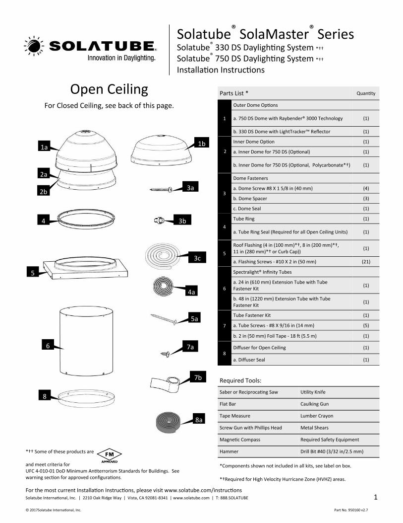
Open Ceiling
8
Solatube® SolaMaster® Series Solatube® 330 DS Daylighting System *†† Solatube® 750 DS Daylighting System *†† Installation Instructions
For Closed Ceiling, see back of this page.
8a
Parts List * Quantity
1
Outer Dome Options
a. 750 DS Dome with Raybender® 3000 Technology (1)
b. 330 DS Dome with LightTracker™ Reflector (1)
2
Inner Dome Option (1)
a. Inner Dome for 750 DS (Optional) (1)
b. Inner Dome for 750 DS (Optional, Polycarbonate*†) (1)
3
Dome Fasteners
a. Dome Screw #8 X 1 5/8 in (40 mm) (4)
b. Dome Spacer (3)
c. Dome Seal (1)
4
Tube Ring (1)
a. Tube Ring Seal (Required for all Open Ceiling Units) (1)
5
Roof Flashing (4 in (100 mm)*†, 8 in (200 mm)*†, 11 in (280 mm)*† or Curb Cap))
(1)
a. Flashing Screws - #10 X 2 in (50 mm) (21)
6
Spectralight® Infinity Tubes
a. 24 in (610 mm) Extension Tube with Tube Fastener Kit
(1)
b. 48 in (1220 mm) Extension Tube with Tube Fastener Kit
(1)
7
Tube Fastener Kit (1)
a. Tube Screws - #8 X 9/16 in (14 mm) (5)
b. 2 in (50 mm) Foil Tape - 18 ft (5.5 m) (1)
8 Diffuser for Open Ceiling (1)
a. Diffuser Seal (1)
*†Required for High Velocity Hurricane Zone (HVHZ) areas.
Required Tools:
Saber or Reciprocating Saw Utility Knife
Flat Bar Caulking Gun
Tape Measure Lumber Crayon
Screw Gun with Phillips Head Metal Shears
Magnetic Compass Required Safety Equipment
Hammer Drill Bit #40 (3/32 in/2.5 mm)
*Components shown not included in all kits, see label on box.
*†† Some of these products are and meet criteria for UFC 4-010-01 DoD Minimum Antiterrorism Standards for Buildings. See warning section for approved configurations.
For the most current Installation Instructions, please visit www.solatube.com/instructions Solatube International, Inc. | 2210 Oak Ridge Way | Vista, CA 92081-8341 | www.solatube.com | T: 888.SOLATUBE
© 2017 Solatube International, Inc. Part No. 950160 v2.7
2
*†Required for High Velocity Hurricane Zone (HVHZ) areas. 9a
1b
9b
9d
4
2b
1a
2a
5
6a
8
6b
9
10
9c
7b
7a
5a
4a
3c
3b
3a
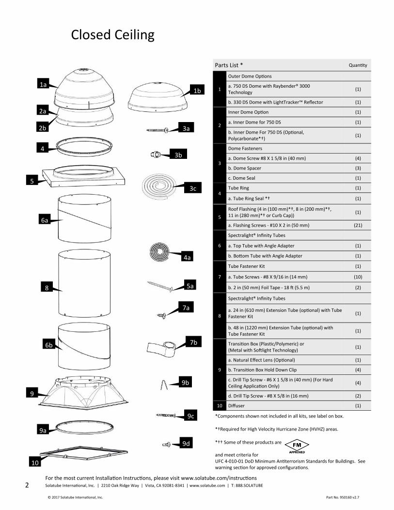
Closed Ceiling
*Components shown not included in all kits, see label on box.
Parts List * Quantity
1
Outer Dome Options
a. 750 DS Dome with Raybender® 3000 Technology
(1)
b. 330 DS Dome with LightTracker™ Reflector (1)
2
Inner Dome Option (1)
a. Inner Dome for 750 DS (1)
b. Inner Dome For 750 DS (Optional, Polycarbonate*†)
(1)
3
Dome Fasteners
a. Dome Screw #8 X 1 5/8 in (40 mm) (4)
b. Dome Spacer (3)
c. Dome Seal (1)
4 Tube Ring (1)
a. Tube Ring Seal *† (1)
5
Roof Flashing (4 in (100 mm)*†, 8 in (200 mm)*†, 11 in (280 mm)*† or Curb Cap))
(1)
a. Flashing Screws - #10 X 2 in (50 mm) (21)
6
Spectralight® Infinity Tubes
a. Top Tube with Angle Adapter (1)
b. Bottom Tube with Angle Adapter (1)
7
Tube Fastener Kit (1)
a. Tube Screws - #8 X 9/16 in (14 mm) (10)
b. 2 in (50 mm) Foil Tape - 18 ft (5.5 m) (2)
8
Spectralight® Infinity Tubes
a. 24 in (610 mm) Extension Tube (optional) with Tube Fastener Kit
(1)
b. 48 in (1220 mm) Extension Tube (optional) with Tube Fastener Kit
(1)
9
Transition Box (Plastic/Polymeric) or (Metal with Softlight Technology)
(1)
a. Natural Effect Lens (Optional) (1)
b. Transition Box Hold Down Clip (4)
c. Drill Tip Screw - #6 X 1 5/8 in (40 mm) (For Hard Ceiling Application Only)
(4)
d. Drill Tip Screw - #8 X 5/8 in (16 mm) (2)
10 Diffuser (1)
*†† Some of these products are and meet criteria for UFC 4-010-01 DoD Minimum Antiterrorism Standards for Buildings. See warning section for approved configurations.
For the most current Installation Instructions, please visit www.solatube.com/instructions Solatube International, Inc. | 2210 Oak Ridge Way | Vista, CA 92081-8341 | www.solatube.com | T: 888.SOLATUBE
© 2017Solatube International, Inc. Part No. 950160 v2.7
3
WARNING
Daylighting Systems Installation Tips
These instructions are a step-by-step guide for the installation of a Solatube Daylighting System in the following conditions. For other roof types,
please contact your Solatube International representative for additional information.
Built Up Flat Roof - Single Ply/Membrane - Asphalt Shingle - Low/No Pitched - Pitched - Prefabricated Curbs - Metal Roof Panels
Please refer to the installation tips for the appropriate product below:
Do not proceed with the installation until you have read the entire instructions, including these warnings. (Use of materials or methods not authorized by Solatube International will result in an invalid warranty.)
Solatube International, Inc. (seller) assumes no responsibility or obligation whatsoever for the failure of an architect, contractor, installer, or building owner to comply with all applicable laws, ordinances, building codes, electrical codes, energy codes, fire and safety codes and requirements, roof warranties and adequate safety precautions. Installation of this product should be attempted only by individuals skilled in the use of the tools and equipment necessary for installation. Protect yourself and all persons and property during installation. If you have any doubt concerning your competence or expertise, consult a qualified expert before proceeding.
Install at your own risk! Solatube product installations may be dangerous and include the potential for death, personal injury and property damage. The hazardous conditions include but are not limited to the following:
During installation, the Solatube Daylighting System’s reflective tubes may focus sunlight, causing intense heat or fire. Remove protective film only
after the parts have been installed. Prior to and during installation, do not leave tubes in contact with combustible materials or unattended,
especially near direct sunlight. Avoid skin burns. Do not leave debris from installation process unattended. Scrap from tubing and foil tape are highly reflective and if left unattended can focus
sunlight and can cause intense heat or fire. Clean up all unused material and trash and store or discard in proper covered locations.
Solatube Daylighting System and Solar Star products may have sharp edges. Always wear leather or canvas gloves while handling and installing
products.
Solatube product installations require climbing and working at dangerous heights, including on ladders, scaffolding, roofs and in attic spaces. Risk of
death, personal injury and property damage may result from a fall, or from falling objects. Use extreme caution to minimize risk of accidental injury,
including, but not limited to the following procedures:
Clear area below your work space of all people, animals and other items.
Avoid working on surfaces that are slippery or wet. Use foot-wear with excellent traction.
Use only strong, well supported ladders.
Work only in calm dry weather. When in the attic, ensure that your weight is supported at all times with structurally sound framing; drywall material is not designed to carry
a person’s weight.
To reduce the risk of fire, electric shock, and personal injury, basic safety precautions should always be followed when using electric tools, including
always wearing safety goggles or other suitable eye protection, and ensuring work area is clear of all electrical wires, gas pipes, water pipes, and other
obstacles.
When working in the attic or other dusty areas, use of a mask or respirator is recommended to avoid lung irritation. Attic spaces may be dark, confined,
and subject to extreme temperatures. Beware of sharp protruding objects. Do not attempt installation without having someone within range of your
voice or close enough to come to your aid if necessary.
Solatube products are not designed to withstand the weight of a person, tools or other objects. Walking or placing objects on the system could cause
personal injury and property damage. If the product is damaged, the structural capacity may be weakened; therefore the system should be repaired
immediately. For safe installation and use, do not deviate from these installation instructions.
Additional support is recommended for long vertical and all horizontal tube runs. Review local building requirements and consult with appropriate
building code official for proper material and placement of additional support. Avoid galvanic reaction (corrosion) if dissimilar metals are used.
Electrical Components Before installing, servicing, or cleaning unit, switch power off at service panel and lock service panel to prevent power from becoming switched on
accidentally. When the service disconnecting means cannot be locked, securely fasten a prominent warning device such as a tag to the service panel.
Re-Roofing Solatube products require special care if removed for re-roofing. In order to ensure proper removal and re-installation, please contact your Solatube
International representative.
For the most current Installation Instructions, please visit www.solatube.com/instructions Solatube International, Inc. | 2210 Oak Ridge Way | Vista, CA 92081-8341 | www.solatube.com | T: 888.SOLATUBE
© 2017 Solatube International, Inc. Part No. 950160 v2.7
4
Daylighting Systems Installation Tips (Continued)
Allow at least 2-3 hours for the installation, particularly if this is your first installation. During the day, turn off all the lights in the room to see how much natural light comes in through the windows, and determine the best position for the
Solatube Daylighting System. To light a specific area, place the system over the area, not in the center of the room. This will prevent the desired area
from being shaded by tall objects in the room. Measure the distance between the roof and the ceiling. If you don’t have enough tubing, contact your Solatube International representative for
additional tubing.
Avoid roof locations shaded by trees, ridges and chimneys, or near water channels or valleys. Also avoid roof areas with obstructions such as fire
sprinklers, HVAC equipment, gas, water or drain pipes, air ducts or flues and make sure that the roof is adequate to endure an installation without
damaging its waterproofing properties or weakening the building structure.
All adhesives, seals and tapes are recommended to be applied to a clean and dry surface at a minimum of 70°F (21°C) for maximum performance. Foil tape contains a pressure sensitive adhesive and pressure must be applied at all seams for proper bonding. Foil tape is not intended for use as
structural support of the extension tubes. For structural integrity use manufacturer supplied fasteners on all overlapping extension tube joints.
Uninstalled product that is stored and exposed to excessive heat and or humidity can experience damage. Store product prior to installation in a cool
dry place.
For installations where high levels of suit or debris may be present it may be necessary to use foil tape to seal the diffuser to the tubing to prevent
the excess debris from entering the tubing. FM (Factory Mutual): The 750 DS Dual Dome with Polycarbonate Inner Dome and the 330 DS with Polycarbonate Dome, when used with the Dome
Edge Protection Band, meet requirements for FM Approvals.
UFC-4-010-01: All SolaMaster assemblies meet requirements for United Facilities Criteria (UFC) DoD minimum antiterrorism standard for buildings.
Daylight Dimmer Installation Tips
Install Solatube Daylight Dimmer only on a properly aligned Solatube Daylighting System. Use only UL recognized components approved for this listing.

For the most current Installation Instructions, please visit www.solatube.com/instructions Solatube International, Inc. | 2210 Oak Ridge Way | Vista, CA 92081-8341 | www.solatube.com | T: 888.SOLATUBE
© 2017Solatube International, Inc. Part No. 950160 v2.7
5
a
b
c
Curb Cap Installation Instructions
T-bar ceiling
Hold Down Clip
b
27 in (685 mm) 27 in (685 mm)
c
Flashing screw
Curb by Others (allow for counter flashing roofing material) Roof opening must be
round with diameter 21 7/8 in (555 mm)
Sealant (1/4 in (5 mm)) thick
a
d
*For HVHZ apply 4 more screws to curb cap.
1 Install Curb Cap
Go to Page 10 for Open Ceiling instructions.
Closed Ceiling Installation Instructions
Set Transition Box For plastic polymeric or metal transition box.
2 Hold Down Clip

For the most current Installation Instructions, please visit www.solatube.com/instructions Solatube International, Inc. | 2210 Oak Ridge Way | Vista, CA 92081-8341 | www.solatube.com | T: 888.SOLATUBE
© 2017 Solatube International, Inc. Part No. 950160 v2.7
6
Minimum Overlap at Tube Seams 1 1/2 in (38 mm)
Minimum Overlap at Tube Seams 1 1/2 in (38 mm)
Tube length measurements should be equal
f
c
Install Top and Bottom Tube Angle Adapters; Measure Tube Run Tube ring can be installed on Top Tube with Angle Adapter or an Extension tube (see step 5).
b
Foil tape
a
Align tabs on Tube Ring with notches on Angle Adapter.
d
Bottom Tube Angle Adapter
3
Note: For use with Metal Transition Box
Install Spectralight Softlight Tubing at bottom of tube run for best results. Use no more than one (1) Softlight Extension Tube for each assembly.
Softlight Tube as Last Extension Tube
Angle Adaptor
Softlight Tube as Last Extension Tube
Tube Ring
Remove Protective Liner from Bottom Tube
e
For the most current Installation Instructions, please visit www.solatube.com/instructions Solatube International, Inc. | 2210 Oak Ridge Way | Vista, CA 92081-8341 | www.solatube.com | T: 888.SOLATUBE
© 2017Solatube International, Inc. Part No. 950160 v2.7
7
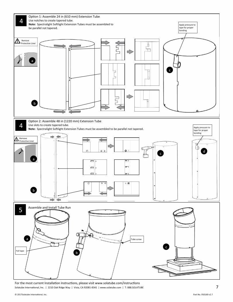
b
c
Apply pressure to tape for proper bonding
d
Option 2: Assemble 48 in (1220 mm) Extension Tube Use slots to create tapered tube.
Note: Spectralight Softlight Extension Tubes must be assembled to be parallel not tapered. 4
Remove Protective Liner
a
c
5 Assemble and Install Tube Run
b
a Tube screw
Foil tape
Option 1: Assemble 24 in (610 mm) Extension Tube Use notches to create tapered tube.
Note: Spectralight Softlight Extension Tubes must be assembled to be parallel not tapered.
b
c
Apply pressure to tape for proper bonding
Remove Protective Liner
a
4
For the most current Installation Instructions, please visit www.solatube.com/instructions Solatube International, Inc. | 2210 Oak Ridge Way | Vista, CA 92081-8341 | www.solatube.com | T: 888.SOLATUBE
© 2017 Solatube International, Inc. Part No. 950160 v2.7
8
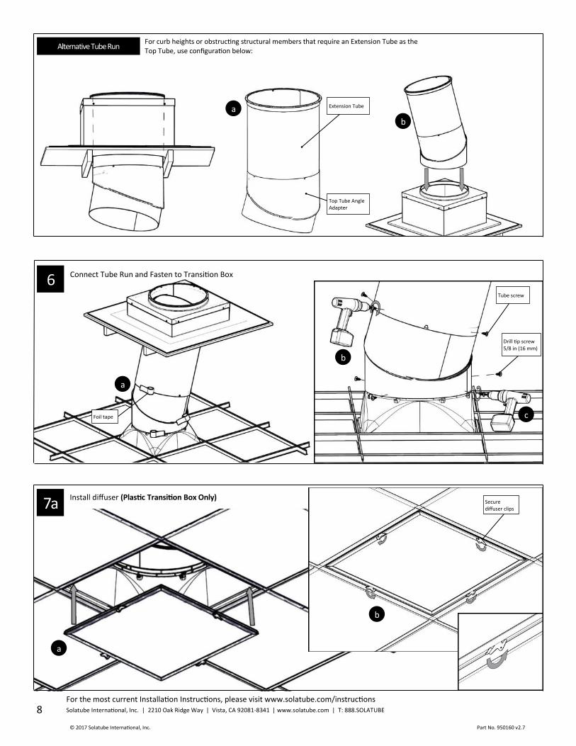
Install diffuser (Plastic Transition Box Only) 7a
a
b
Secure diffuser clips
Connect Tube Run and Fasten to Transition Box 6
a
b
c
Tube screw
Foil tape
Drill tip screw 5/8 in (16 mm)
a Extension Tube
b
Top Tube Angle Adapter
For curb heights or obstructing structural members that require an Extension Tube as the Top Tube, use configuration below:
Alternative Tube Run

For the most current Installation Instructions, please visit www.solatube.com/instructions Solatube International, Inc. | 2210 Oak Ridge Way | Vista, CA 92081-8341 | www.solatube.com | T: 888.SOLATUBE
© 2017Solatube International, Inc. Part No. 950160 v2.7
9
Install Dome Seal 8
Remove Protective Liner
Dome seal
For 750 DS or Dual Dome: 1/4 in (5 mm) above base of flashing landing.
For 330 DS Dome:1/4 in (5 mm) below top edge of flashing turret.
Tube Ring
a
b
Insert dome screws and spacers evenly leaving every other hole open.
a
b
Option 1: Install 330 DS dome Reflective side of LightTracker™ Reflector faces South in Northern Hemisphere (North in Southern Hemisphere).
LightTracker™ Reflector tabs fit between Top Tube and Tube Ring.
d
Dome screw
Pre-drill
e
c Insert dome spacer long end first.
9
Install diffuser (Metal Transition Box with Softlight Technology Only) 7b
Diffuser Clip
Note: Do not press diffuser into metal transition box too far. Ensure that diffuser is flush with transition box frame.
a
b
c
d
Secure diffuser clips

For the most current Installation Instructions, please visit www.solatube.com/instructions Solatube International, Inc. | 2210 Oak Ridge Way | Vista, CA 92081-8341 | www.solatube.com | T: 888.SOLATUBE
© 2017 Solatube International, Inc. Part No. 950160 v2.7
10
Option 3: Install 750 DS Outer Dome with Inner Dome* 9
a
Insert Dome spacer long end first leaving every other hole open.
e
d
Pre-drill
Dome screw
*Polycarbonate inner dome required for HVHZ areas; dip screw threads in sealant.
c
b
Inner Dome
Determine Tube Configuration NOTE: If utilizing Spectralight Softlight Tubing in open ceiling applications install at bottom of tube run (last extension tube) for best results.
Option 1: Single Extension Tube
Option 2: Additional length
Option 3: For pitched roofs
Open Ceiling Installation Instructions
Option 4: For tall curb heights
10
9
a
d
c
Pre-drill
Dome screw
Option 2: Install 750 DS Dome
b
Insert Dome spacer short end first from inside dome.
For the most current Installation Instructions, please visit www.solatube.com/instructions Solatube International, Inc. | 2210 Oak Ridge Way | Vista, CA 92081-8341 | www.solatube.com | T: 888.SOLATUBE
© 2017Solatube International, Inc. Part No. 950160 v2.7
11
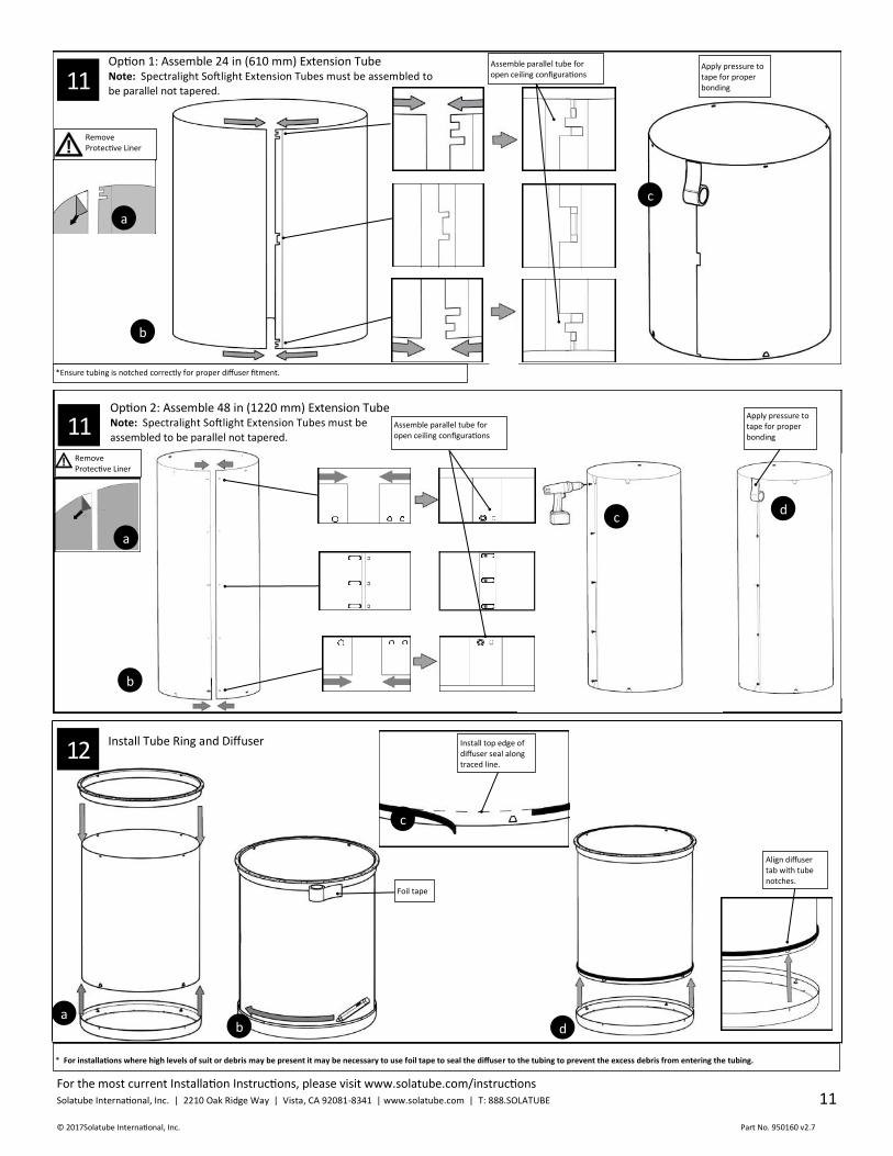
Assemble parallel tube for open ceiling configurations
Apply pressure to tape for proper bonding
b
c d
Option 2: Assemble 48 in (1220 mm) Extension Tube Note: Spectralight Softlight Extension Tubes must be
assembled to be parallel not tapered.
Remove Protective Liner
a
11
d
12 Install Tube Ring and Diffuser
b a
Align diffuser tab with tube notches.
Install top edge of diffuser seal along traced line.
c
Foil tape
* For installations where high levels of suit or debris may be present it may be necessary to use foil tape to seal the diffuser to the tubing to prevent the excess debris from entering the tubing.
*Ensure tubing is notched correctly for proper diffuser fitment.
11 Option 1: Assemble 24 in (610 mm) Extension Tube Note: Spectralight Softlight Extension Tubes must be assembled to
be parallel not tapered.
b
Apply pressure to tape for proper bonding
Assemble parallel tube for open ceiling configurations
Remove Protective Liner
a
c

For the most current Installation Instructions, please visit www.solatube.com/instructions Solatube International, Inc. | 2210 Oak Ridge Way | Vista, CA 92081-8341 | www.solatube.com | T: 888.SOLATUBE
© 2017 Solatube International, Inc. Part No. 950160 v2.7
12
Now you can enjoy the benefits of your Solatube Daylighting System and the high performance, natural lighting it provides. 14
Please refer to the following section for a list of alternative flashings and accessories.
Not all items shown in the following pages are available for all markets. Installation techniques shown may vary by region; please consult local building codes and Solatube International Representatives for guidelines.
13 Apply Tube Ring Seal and Install Tube Run
Tube ring seal for open ceiling only
Return to step 8 to complete Open Ceiling instructions.
For the most current Installation Instructions, please visit www.solatube.com/instructions Solatube International, Inc. | 2210 Oak Ridge Way | Vista, CA 92081-8341 | www.solatube.com | T: 888.SOLATUBE
© 2017Solatube International, Inc. Part No. 950160 v2.7
13
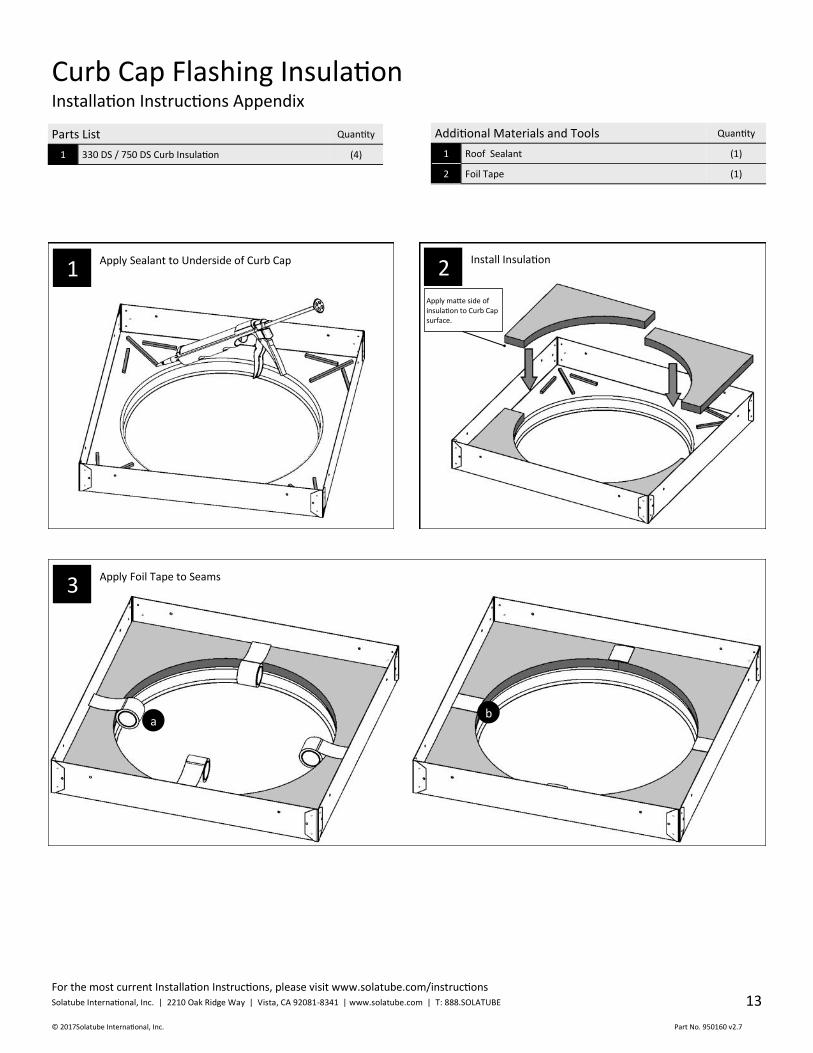
1 Apply Sealant to Underside of Curb Cap
2 Install Insulation
Apply Foil Tape to Seams
Curb Cap Flashing Insulation Installation Instructions Appendix
Parts List Quantity
1 330 DS / 750 DS Curb Insulation (4)
Additional Materials and Tools Quantity
1 Roof Sealant (1)
2 Foil Tape (1)
b
Apply matte side of insulation to Curb Cap surface.
3
a
For the most current Installation Instructions, please visit www.solatube.com/instructions Solatube International, Inc. | 2210 Oak Ridge Way | Vista, CA 92081-8341 | www.solatube.com | T: 888.SOLATUBE
© 2017 Solatube International, Inc. Part No. 950160 v2.7
14
Roof
a b
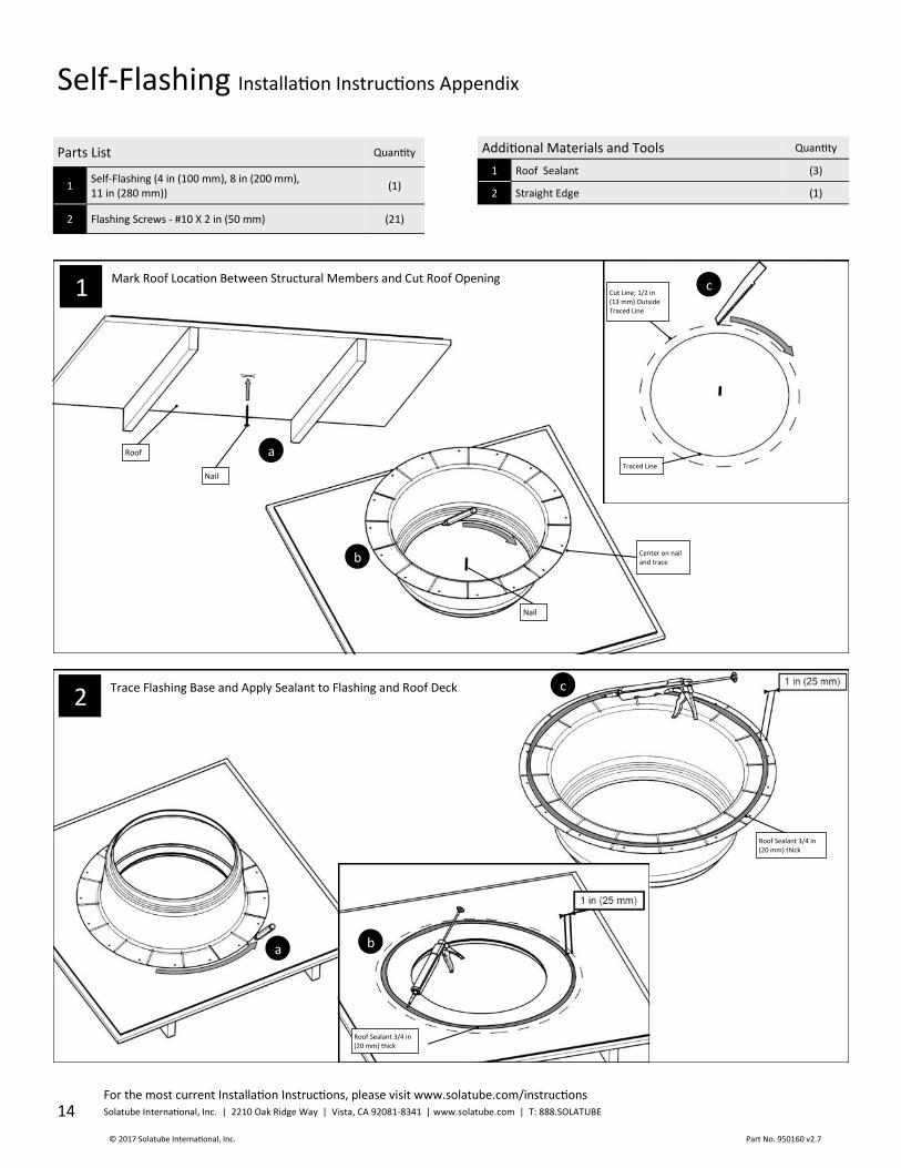
Self-Flashing Installation Instructions Appendix
Parts List Quantity
1 Self-Flashing (4 in (100 mm), 8 in (200 mm), 11 in (280 mm))
(1)
2 Flashing Screws - #10 X 2 in (50 mm) (21)
Additional Materials and Tools Quantity
1 Roof Sealant (3)
2 Straight Edge (1)
1 Mark Roof Location Between Structural Members and Cut Roof Opening
Trace Flashing Base and Apply Sealant to Flashing and Roof Deck
2
Roof Sealant 3/4 in (20 mm) thick
Roof Sealant 3/4 in (20 mm) thick
c
a
b
c Cut Line; 1/2 in (13 mm) Outside Traced Line
Traced Line
Nail
Nail
Center on nail and trace

For the most current Installation Instructions, please visit www.solatube.com/instructions Solatube International, Inc. | 2210 Oak Ridge Way | Vista, CA 92081-8341 | www.solatube.com | T: 888.SOLATUBE
© 2017Solatube International, Inc. Part No. 950160 v2.7
15
Round Concrete Curb Cap Installation Instructions Appendix Available for China Only
Parts List Quantity
1 Round Curb Cap (1)
2 Concrete Screw 3/16 in x 2 3/4 in (5 mm x 70 mm) Hex (8)
3 Concrete Drill Bit 5/32 in x 3 1/2 in (4 mm x 89 mm) (1)
Additional Materials and Tools Quantity
2 Sealant Paint (Not Provided)
Mark Fastening Holes
Apply Sealant Paint to the inside Walls and Top Sections of Concrete Curb
Curb section cut away to show detail.
Sealant paint on these surfaces
1
a
b
35 7/8 in (910 mm) inside dimension
22 1/2 in (572 mm) inside dimension
Pencil
2
a b
Straight edge
Flashing screw
d
c
Fasten Flashing to Roof. Apply Sealant and Spread Evenly Using Straight Edge.
Roof Sealant 3/4 in (20 mm) thick
3
Note: This product is not available for U.S. markets.
For the most current Installation Instructions, please visit www.solatube.com/instructions Solatube International, Inc. | 2210 Oak Ridge Way | Vista, CA 92081-8341 | www.solatube.com | T: 888.SOLATUBE
© 2017 Solatube International, Inc. Part No. 950160 v2.7
16
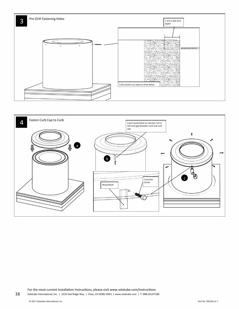
4 Fasten Curb Cap to Curb
a
b
c
Insert wood block to maintain 3/4 in (18 mm) gap between curb and curb cap.
Concrete Screw
Wood Block
3 Pre-Drill Fastening Holes
2 3/4 in (60 mm) depth
Curb section cut away to show detail.

For the most current Installation Instructions, please visit www.solatube.com/instructions Solatube International, Inc. | 2210 Oak Ridge Way | Vista, CA 92081-8341 | www.solatube.com | T: 888.SOLATUBE
© 2017Solatube International, Inc. Part No. 950160 v2.7
17
Align Turret Extension with Flashing and Fasten
Parts List Quantity
1 Turret Extension 12 in (300 mm), 24 in (600 mm), 36 in (900 mm), or 48 in (1200 m)
(1)
2 1/4 in (6 mm) screws*
(4)
Apply Sealant to Flashing and Inside of Turret Extension
Turret Extension Installation Instructions Appendix
Additional Materials and Tools Quantity
1 Roof Sealant (1)
a 1/4 in (6 mm)Screw
a
b
* 3/4 in (20 mm) screws for 48 in (1200 mm) Turret Extension Only
c b
0-90 Degree Extension Tube Installation Instructions Appendix
Parts List Quantity
1 Top Tube Angle Adaptor (1)
2 Inner Angle Adaptor (1)
3 Tube Screws - #8 X 9/16 in (14 mm) (8)
4 Foil Tape - 2 in (51 mm) X 6 ft (2 m) (2)
Additional Materials and Tools Quantity
1 None
Assemble 0-90 Degree Angle Adaptor
b
Minimum overlap at tube seams 1 1/2 in (38 mm)
a
Adjust Angle
Top Tube Angle Adaptor
Inner Angle Adaptor
c
d
Foil Tape
Tube Screw
1 2
1
Install turret extension bracket kit if installing 750 DS dome.
For the most current Installation Instructions, please visit www.solatube.com/instructions Solatube International, Inc. | 2210 Oak Ridge Way | Vista, CA 92081-8341 | www.solatube.com | T: 888.SOLATUBE
© 2017 Solatube International, Inc. Part No. 950160 v2.7
18
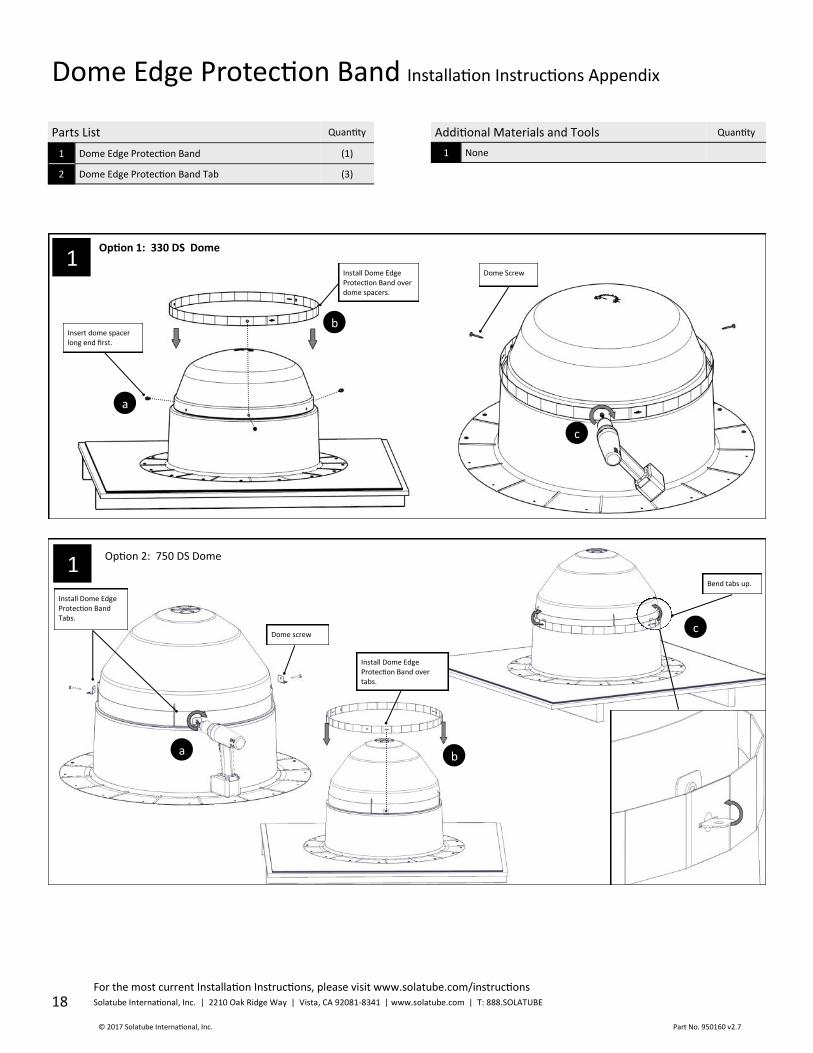
Dome Edge Protection Band Installation Instructions Appendix
Parts List Quantity
1 Dome Edge Protection Band (1)
2 Dome Edge Protection Band Tab (3)
Additional Materials and Tools Quantity
1 None
Option 1: 330 DS Dome
Option 2: 750 DS Dome
Insert dome spacer long end first.
a
b
Install Dome Edge Protection Band over dome spacers.
b
Install Dome Edge Protection Band over tabs.
Bend tabs up.
c
Dome Screw
c
Dome screw
Install Dome Edge Protection Band Tabs.
a
1
1
For the most current Installation Instructions, please visit www.solatube.com/instructions Solatube International, Inc. | 2210 Oak Ridge Way | Vista, CA 92081-8341 | www.solatube.com | T: 888.SOLATUBE
© 2017Solatube International, Inc. Part No. 950160 v2.7
19
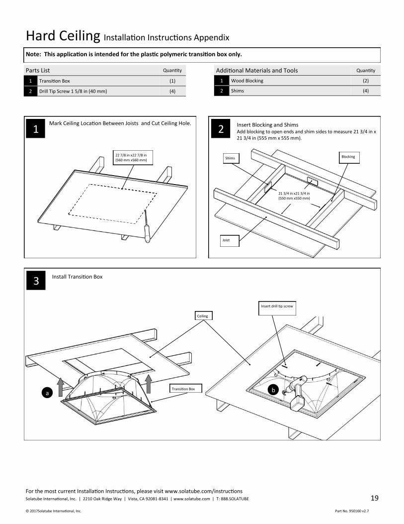
Hard Ceiling Installation Instructions Appendix
Parts List Quantity
1 Transition Box (1)
2 Drill Tip Screw 1 5/8 in (40 mm) (4)
Additional Materials and Tools Quantity
1 Wood Blocking (2)
2 Shims (4)
Mark Ceiling Location Between Joists and Cut Ceiling Hole.
22 7/8 in x22 7/8 in (560 mm x560 mm)
Insert Blocking and Shims Add blocking to open ends and shim sides to measure 21 3/4 in x 21 3/4 in (555 mm x 555 mm).
3 Install Transition Box
Blocking Shims
Insert drill tip screw
Ceiling
Transition Box
21 3/4 in x21 3/4 in (550 mm x550 mm)
a b
Joist
2 1
Note: This application is intended for the plastic polymeric transition box only.
For the most current Installation Instructions, please visit www.solatube.com/instructions Solatube International, Inc. | 2210 Oak Ridge Way | Vista, CA 92081-8341 | www.solatube.com | T: 888.SOLATUBE
© 2017 Solatube International, Inc. Part No. 950160 v2.7
20
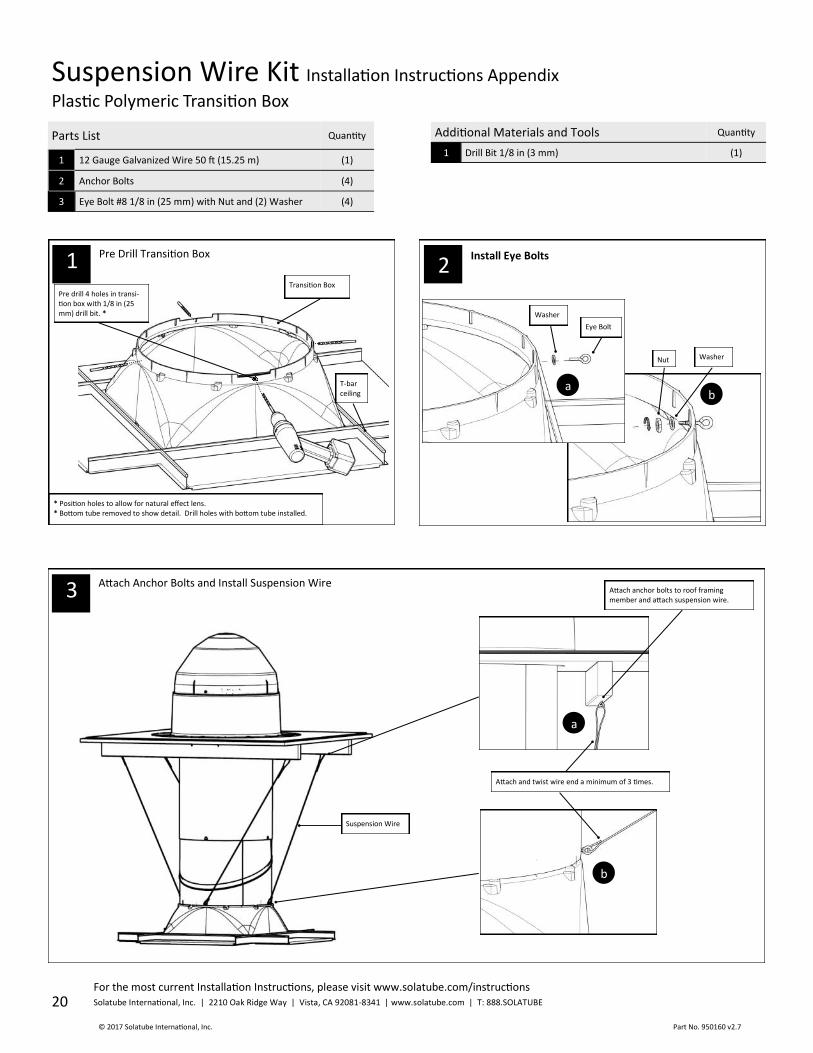
Suspension Wire Kit Installation Instructions Appendix
Plastic Polymeric Transition Box
Parts List Quantity
1 12 Gauge Galvanized Wire 50 ft (15.25 m) (1)
2 Anchor Bolts (4)
3 Eye Bolt #8 1/8 in (25 mm) with Nut and (2) Washer (4)
Additional Materials and Tools Quantity
1 Drill Bit 1/8 in (3 mm) (1)
1 Pre Drill Transition Box Install Eye Bolts
Attach Anchor Bolts and Install Suspension Wire
T-bar ceiling
Pre drill 4 holes in transi-tion box with 1/8 in (25 mm) drill bit. *
Attach anchor bolts to roof framing member and attach suspension wire.
b
Eye Bolt
Washer
Nut
a
b
a
Attach and twist wire end a minimum of 3 times.
Transition Box
Washer
Suspension Wire
* Position holes to allow for natural effect lens. * Bottom tube removed to show detail. Drill holes with bottom tube installed.
3
2
For the most current Installation Instructions, please visit www.solatube.com/instructions Solatube International, Inc. | 2210 Oak Ridge Way | Vista, CA 92081-8341 | www.solatube.com | T: 888.SOLATUBE
© 2017Solatube International, Inc. Part No. 950160 v2.7
21
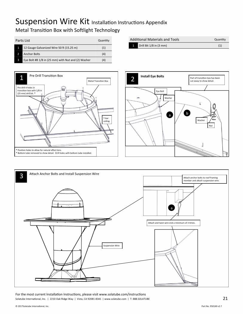
Suspension Wire Kit Installation Instructions Appendix
Metal Transition Box with Softlight Technology
Parts List Quantity
1 12 Gauge Galvanized Wire 50 ft (15.25 m) (1)
2 Anchor Bolts (4)
3 Eye Bolt #8 1/8 in (25 mm) with Nut and (2) Washer (4)
Additional Materials and Tools Quantity
1 Drill Bit 1/8 in (3 mm) (1)
1 Pre Drill Transition Box Install Eye Bolts
Attach Anchor Bolts and Install Suspension Wire
T-bar ceiling
Pre drill 4 holes in transition box with 1/8 in (25 mm) drill bit. *
b
Eye Bolt
Washer
Nut
a
b
a
Attach and twist wire end a minimum of 3 times.
Metal Transition Box
Washer
Suspension Wire
* Position holes to allow for natural effect lens. * Bottom tube removed to show detail. Drill holes with bottom tube installed.
3
2 Part of transition box has been cut-away to show detail.
Attach anchor bolts to roof framing member and attach suspension wire.
For the most current Installation Instructions, please visit www.solatube.com/instructions Solatube International, Inc. | 2210 Oak Ridge Way | Vista, CA 92081-8341 | www.solatube.com | T: 888.SOLATUBE
© 2017 Solatube International, Inc. Part No. 950160 v2.7
22
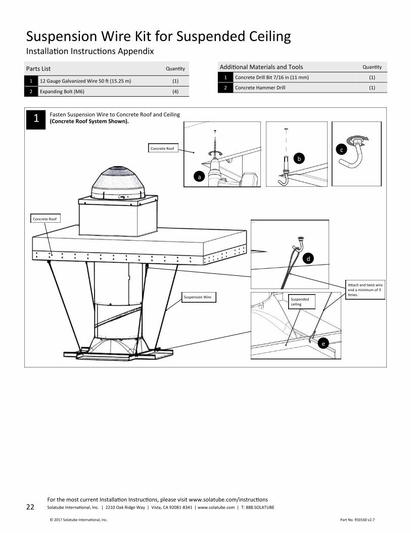
Suspension Wire Kit for Suspended Ceiling Installation Instructions Appendix
Parts List Quantity
1 12 Gauge Galvanized Wire 50 ft (15.25 m) (1)
2 Expanding Bolt (M6) (4)
Additional Materials and Tools Quantity
1 Concrete Drill Bit 7/16 in (11 mm) (1)
2 Concrete Hammer Drill (1)
d
e
Attach and twist wire end a minimum of 3 times.
Suspension Wire
Concrete Roof
Fasten Suspension Wire to Concrete Roof and Ceiling (Concrete Roof System Shown). 1
b
a
c Concrete Roof
Suspended ceiling

For the most current Installation Instructions, please visit www.solatube.com/instructions Solatube International, Inc. | 2210 Oak Ridge Way | Vista, CA 92081-8341 | www.solatube.com | T: 888.SOLATUBE
© 2017Solatube International, Inc. Part No. 950160 v2.7
23
Natural Effect Lens Installation Instructions Appendix
Plastic Polymeric Transition Box
Install Screws and Tabs; Insert Effect Lens and Engage Tabs
b
c
d Effect Lens
Seal
Tab
Screw
a
Parts List Quantity
1 330 DS/750 DS Natural Effect Lens (1)
2 Screw #6 X 3/8 in (10 mm) (8)
3 Natural Effect Lens Tab (8)
Additional Materials and Tools Quantity
1 None
Transition Box
Seal
Effect Lens
1
For the most current Installation Instructions, please visit www.solatube.com/instructions Solatube International, Inc. | 2210 Oak Ridge Way | Vista, CA 92081-8341 | www.solatube.com | T: 888.SOLATUBE
© 2017 Solatube International, Inc. Part No. 950160 v2.7
24
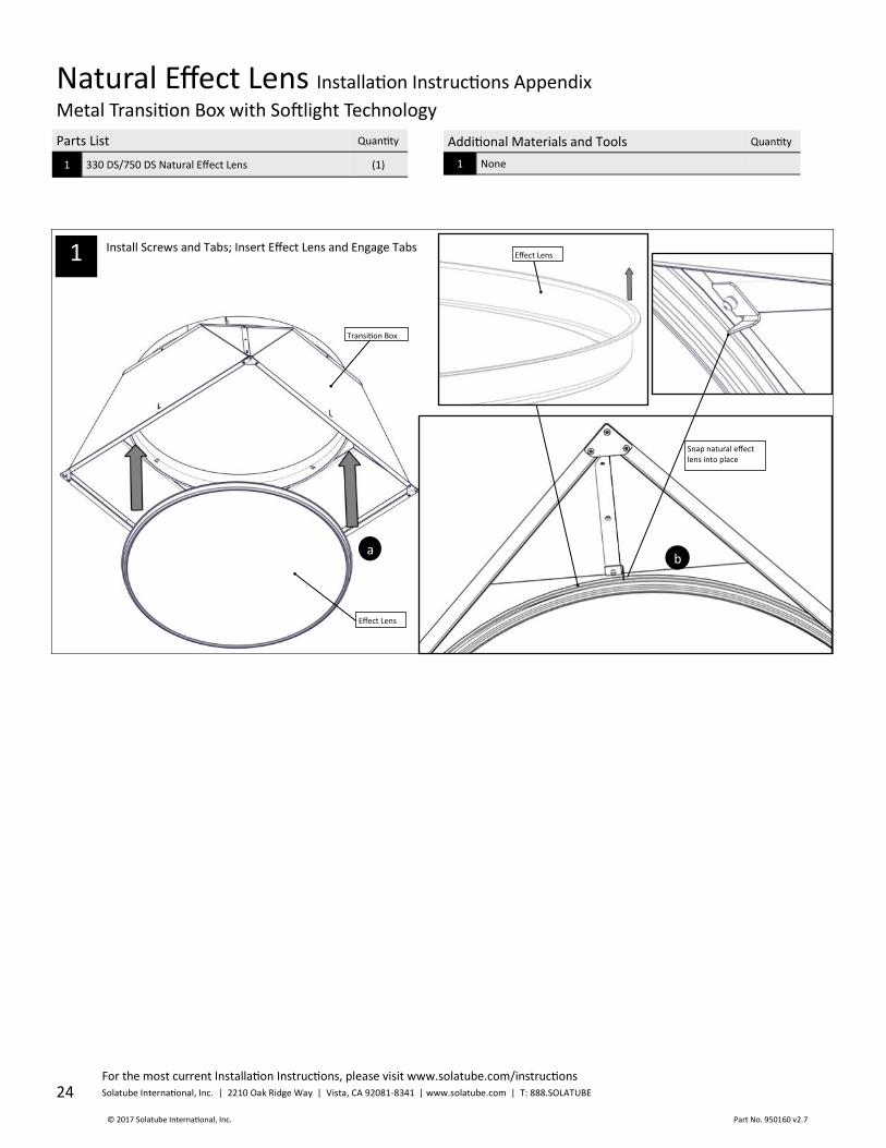
Natural Effect Lens Installation Instructions Appendix
Metal Transition Box with Softlight Technology
Install Screws and Tabs; Insert Effect Lens and Engage Tabs
Parts List Quantity
1 330 DS/750 DS Natural Effect Lens (1)
Additional Materials and Tools Quantity
1 None
1
Transition Box
Effect Lens
a
Effect Lens
Snap natural effect lens into place
b

For the most current Installation Instructions, please visit www.solatube.com/instructions Solatube International, Inc. | 2210 Oak Ridge Way | Vista, CA 92081-8341 | www.solatube.com | T: 888.SOLATUBE
© 2017Solatube International, Inc. Part No. 950160 v2.7
25
Thermal Insulation Panel (TIP) Installation Instructions Appendix
Refer to main set of instruction 950160 for extension tube assembly.
Parts List Quantity
1 Thermal Insulation Panel (TIP) (1)
2 Drill Tip Screw - #8 X 5/8 in (16 mm) (4)
3 Tube Screws - #8 X 9/16 in (14 mm) (6)
4 2 in (50 mm) Foil Tape - 6 ft (1.8 m) (2)
Additional Materials and Tools Quantity
1 None
Note: For best thermal performance, install the Thermal Insulation Panel within the buildings insulation level.
b
Foil tape
a
Align tabs on Tube Ring with notches on Angle Adapter.
3 Install Extension Tube onto TIP
Install Tube Ring
1
Open Ceiling TIP Installation Instructions For Applications with Insulation at Roof Level
Install Thermal Insulation Panel Turn top tube over and place TIP onto Top tube
2
b
Top Tube and Extension Tube will fit over the TIP and rest on edge of fastening straps.
4 Apply Foil Tape
b
a
Foil tape
Top Tube
For the most current Installation Instructions, please visit www.solatube.com/instructions Solatube International, Inc. | 2210 Oak Ridge Way | Vista, CA 92081-8341 | www.solatube.com | T: 888.SOLATUBE
© 2017 Solatube International, Inc. Part No. 950160 v2.7
26
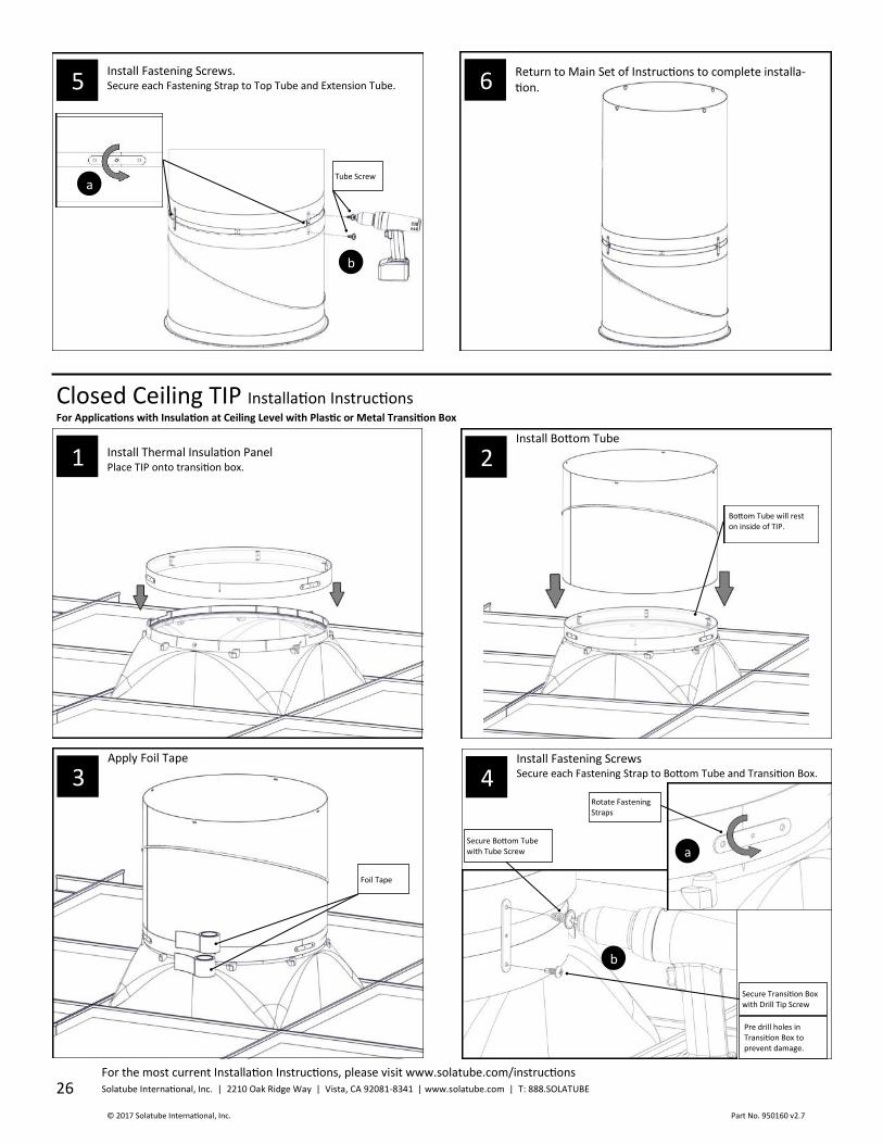
1 Install Thermal Insulation Panel Place TIP onto transition box.
Install Fastening Screws. Secure each Fastening Strap to Top Tube and Extension Tube.
5 Return to Main Set of Instructions to complete installa-tion.
6
2
a
b
b
Tube Screw
Closed Ceiling TIP Installation Instructions For Applications with Insulation at Ceiling Level with Plastic or Metal Transition Box
3 Apply Foil Tape
4 Install Fastening Screws Secure each Fastening Strap to Bottom Tube and Transition Box.
Foil Tape
a
Rotate Fastening Straps
Secure Bottom Tube with Tube Screw
Secure Transition Box with Drill Tip Screw
Bottom Tube will rest on inside of TIP.
Install Bottom Tube
Pre drill holes in Transition Box to prevent damage.

For the most current Installation Instructions, please visit www.solatube.com/instructions Solatube International, Inc. | 2210 Oak Ridge Way | Vista, CA 92081-8341 | www.solatube.com | T: 888.SOLATUBE
© 2017Solatube International, Inc. Part No. 950160 v2.7
27
3a
Install Thermal Insulation Panel Place TIP onto Metal Transition box. 2a
4a
b
Tube Screw
Apply Foil Tape
Install Bottom Tube
a
Install Fastening Screws Secure each Fastening Strap to Bottom Tube and Transition Box.
Rotate Fastening Straps
a
b
Secure Bottom Tube with Tube Screws
Foil Tape
Bottom Tube will rest on inside of TIP.
Return to Main Set of Instructions to complete installation.
5
Metal Transition Box Option
1a
For the most current Installation Instructions, please visit www.solatube.com/instructions Solatube International, Inc. | 2210 Oak Ridge Way | Vista, CA 92081-8341 | www.solatube.com | T: 888.SOLATUBE
© 2017 Solatube International, Inc. Part No. 950160 v2.7
28
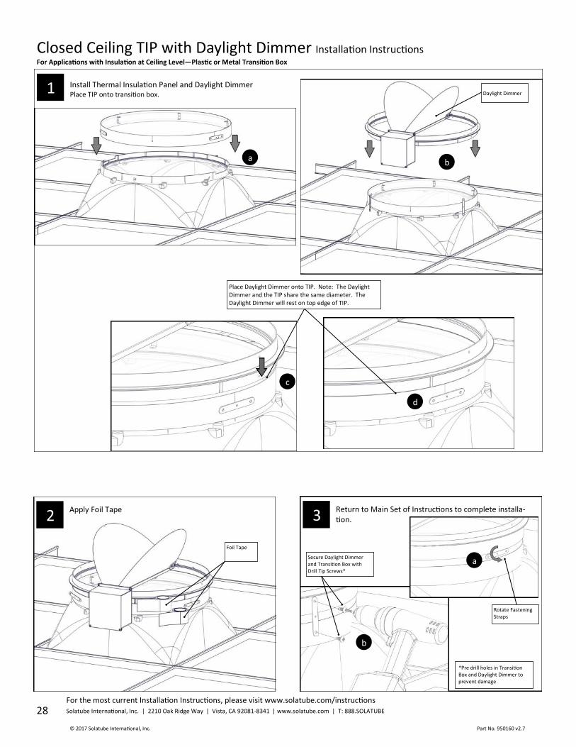
1 Install Thermal Insulation Panel and Daylight Dimmer Place TIP onto transition box.
b
Closed Ceiling TIP with Daylight Dimmer Installation Instructions For Applications with Insulation at Ceiling Level—Plastic or Metal Transition Box
Place Daylight Dimmer onto TIP. Note: The Daylight Dimmer and the TIP share the same diameter. The Daylight Dimmer will rest on top edge of TIP.
a
c
d
Daylight Dimmer
Foil Tape
Rotate Fastening Straps
Secure Daylight Dimmer and Transition Box with Drill Tip Screws*
Apply Foil Tape
2 Return to Main Set of Instructions to complete installa-tion.
3
a
b
*Pre drill holes in Transition Box and Daylight Dimmer to prevent damage
For the most current Installation Instructions, please visit www.solatube.com/instructions Solatube International, Inc. | 2210 Oak Ridge Way | Vista, CA 92081-8341 | www.solatube.com | T: 888.SOLATUBE
© 2017Solatube International, Inc. Part No. 950160 v2.7
29
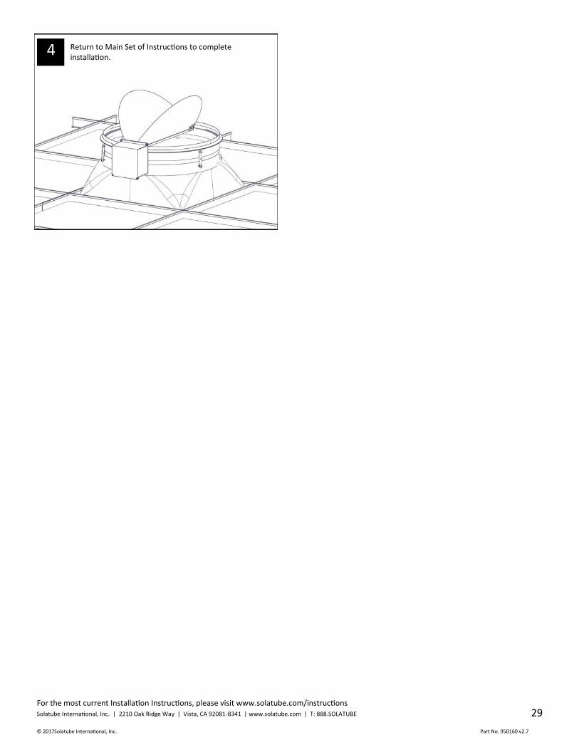
Return to Main Set of Instructions to complete installation.
4