solenoid valve type 3963 - axon automation inc. valves/pdf_en/t39630en.pdf · edition: november...
TRANSCRIPT

Edition: November 2004 T 3963 EN
Solenoid Valve Type 3963
Fig. 1
Type 3963-XX11 5/2-way Solenoid Valve
Type 3963-XX25 3/2-way Pilot Valvecombined withType 3756-1203 3/2-way Booster Valve G 1/2
Type 3963-XX76 3/2-way Pilot Valvescombined withType 3756-3327 5/2-way Booster Valve G 1/4/NAMUR
General notes
The Type 3963 Solenoid Valves ensure a high level of operationalreliability and fast response times for controlling pneumatic actuators in hazardous areas.
Intrinsically safe, low-power binary signals issued by automationor fieldbus systems can be used for controlling purposes.
The Type 3963 Solenoid Valves offer a variety of switching functions, flow rates and connections for all desired applications(Fig. 1).
Special features of the Type 3963 Solenoid Valves include:
● Suitable for safety shut-off valves with safety function according to SIL4/TÜV (optionally)
● Corrosion-resistant enclosure with degree of protection IP 54 or IP 65 for applications in humid, aggressive environments
● Versions free of silicone/compatible with paint (available on request)
● Service life � 2 �107 switching cycles● Ambient temperature �45 to �80 °C,
depending on the type of protection and temperature class● Rail mounting or wall mounting● Attachment to linear actuators with NAMUR rib according to
DIN EN 60534-6-1 or to rotary actuators with NAMUR inter-face according to VDI/VDE 3845
● E/P binary converter with flapper/nozzle assembly● Nominal signals 6 V DC, 12 V DC, 24 V DC, 24 V AC,
48 V AC, 115 V AC or 230 V AC● Type of protection II 2 G EEx ia IIC T6, CSA, FM and
II 3 G EEx nA II T6 for DC signals● Power consumption 6 to 27 mW or 0.04 to 0.46 VA,
depending on the nominal signal● Manual override as pushbutton or pushbutton switch
(optionally)● Air supply 1.4 to 6 bar● Electrical connection via cable gland M 20 �1.5 to terminals
or via a plug-type connector● Cable break protection device (accessory)
● Booster valve with diaphragm or piston, single or double actuated
● 3/2, 5/2, 5/3 or 6/2-way function● Exhaust air return (optionally)● Kvs value 0.16 to 4.3● Supply air/exhaust air restrictors for adjusting different
closing and opening times in a ratio of 1:15 (optionally)● Threaded connection G (NPT) 1/4 or 1/2/NAMUR

T 3963 EN – 2 –
Versions with threaded connection
Type 3963 Solenoid Valves for on-off/continuous actuators
81�82�
EP
1.54
1.3
9 2.5
2.3
Type 3963-XX14 Solenoid Valve● 5/2-way function● Kvs value 0.16● Connection G (NPT) 1/4● Safety function according to SIL4● Rail mounting or wall mounting
1.41.5
1.39
81�82�
EP
2.42.5
2.3
Type 3963-XX64 Solenoid Valve● 6/2-way function● Kvs value 0.16● Connection G (NPT) 1/4● Safety function according to SIL4● Rail mounting or wall mounting
9
3
81�82�
EP
Type 3963-XX27 Solenoid Valve● 3/2-way function● Kvs value 0.16● Connection G (NPT) 1/4● Safety function according to SIL4/TÜV● Rail mounting, wall mounting or
mounting with pipe fittings to on-off linear actuators, e. g. SAMSON’s Type 271/3277 Actuator
9
3
81�82�
EP
Type 3963-XX28 Solenoid Valve● 3/2-way function● Adjustable exhaust air restrictor● Kvs value 0.16● Connection G (NPT) 1/4● Rail mounting, wall mounting or
mounting with pipe fittings to on-off linear actuators, e. g. SAMSON’s Type 271/3277 Actuator
81�82�
EP
45
3
9
Type 3963-XX53 Solenoid Valve● 3/2-way function● Kvs value 0.32● Connection G (NPT) 1/4● Safety function according to SIL4/TÜV● Attachment to linear actuators with
NAMUR rib, e. g. SAMSON’s Type 271Actuator (see Fig. 3)
81�82�
EP
Type 3963-XX29 Solenoid Valve● 3/2-way function● Adjustable exhaust air restrictor● Kvs value 0.16● Attachment via a connection block to
SAMSON’s Type 3277 Linear Actuatorwith SAMSON’s Type 3730/3766/3767/378X Positioner (see Fig. 2)
81�82�
EP
Type 3963-XX55 Solenoid Valve● 3/2-way function● Kvs value 0.32● Safety function according to SIL4/TÜV● Attachment via a connection block to
SAMSON’s Type 3277 Linear Actuatorwith SAMSON’s Type 3730/3766/3767/378X Positioner (see Fig. 2)
81�82�
EP
45
3
9
Type 3963-XX54 Solenoid Valve● 3/2-way function● Kvs value 0.32● Connection G (NPT) 1/4● Safety function according to SIL4/TÜV● Rail mounting, wall mounting or
mounting with pipe fittings to on-off linear actuators, e. g. SAMSON’s Type 271/277 Actuator
Fig. 2 Fig. 3 Fig. 4 Fig. 5

– 3 – T 3963 EN
81� 81�82� 82�
EP
39 95
4
1
2
PE
Type 3963-XX76 Pilot Valves �/Type 3756-X325 Booster Valve �● 5/2-way function, detented
(two positions)● Kvs value 1.4● Connection G (NPT) 1/4● Safety function according to TÜV● Wall mounting
81� 81�82� 82�
EP
39 95
4
1
2
PE
Type 3963-XX76 Pilot Valves �/Type 3756-X335 Booster Valve �● 5/3-way function, spring centered
(ports 2 and 4 closed)● Kvs value 1.4● Connection G (NPT) 1/4● Wall mounting
81� 81�82� 82�
EP
39 95
4
1
2
PE
Type 3963-XX76 Pilot Valves �/Type 3756-X345 Booster Valve �● 5/3-way function, spring centered
(ports 2 and 4 vented)● Kvs value 1.4● Connection G (NPT) 1/4● Safety function according to TÜV● Wall mounting
9 981� 81�82� 82�
EP
35
4
1
2
PE
Type 3963-XX76 Pilot Valves �/Type 3756-X355 Booster Valve �● 5/3-way function, spring centered
(ports 2 and 4 to air supply)● Kvs value 1.4● Connection G (NPT) 1/4● Wall mounting
81�82�
EP
39 5
4
1
2
Type 3963-XX76 Pilot Valve �/Type 3756-X205 Booster Valve �● 5/2-way function● Kvs value 1.4● Connection G (NPT) 1/4● Wall mounting or mounting with pipe
fittings to linear actuators, e. g. SAMSON’s Type 271/3277 Actuator
81�82�
EP
39
4
1
2
Type 3963-XX76 Pilot Valve �/Type 3756-X206 Booster Valve �● 3/2-way function● Exhaust air return● Kvs value 1.4● Connection G (NPT) 1/4● Safety function according to TÜV● Wall mounting or mounting with pipe
fittings to linear actuators, e. g.SAMSON’s Type 271/3277 Actuator
81�82�
EP
1.41.5
1.3
9 2.52.4
2.3
Type 3963-XX25 Pilot Valve �/Type 3756-X209 Booster Valve �● 5/2-way function● Kvs value 4.3● Connection G (NPT) 1/2● Wall mounting
81�82�
EP
45
3
9
Type 3963-XX25 Pilot Valve �/Type 3756-X2X3 Booster Valve �● 3/2-way function● Kvs value 4.3● Connection G (NPT) 1/2● Safety function according to SIL4/TÜV● Wall mounting or mounting with pipe
fittings to linear actuators, e. g.SAMSON’s Type 271/3277 Actuator
81�82�
EP
1.41.5
1.3
9 2.42.5
2.3
Type 3963-XX25 Pilot Valve �/Type 3756-X210 Booster Valve �● 6/2-way function● Kvs value 4.3● Connection G (NPT) 1/2● Wall mounting
Fig. 6 Fig. 7 Fig. 8 Fig. 9
Versions with threaded connection (continued from page 2)
Solenoid valves consisting of Type 3963 Pilot Valve �/Type 3756 Booster Valve �, for on-off/continuous actuators

T 3963 EN – 4 –
Versions with NAMUR interface
Type 3963 Solenoid Valves for on-off/continuous actuators
4
1.3
81�82�
EP
2.3
2.39
Type 3963-XX23 Solenoid Valve● 3/2-way function● Adjustable supply air/exhaust air
restrictors● Kvs value 0.16● Connection G (NPT) 1/4/NAMUR● Attachment to on-off rotary actuators
with NAMUR interface or via adapter plate (Order No. 1400-6751) to linear actuators with NAMUR rib, e. g.SAMSON’s Type 241-1 (see Fig. 10)
81�82�
EP
4 2.3
1.3
9
2.3
Type 3963-XX52 Solenoid Valve● 3/2-way function● Kvs value 0.32● Connection G (NPT) 1/4/NAMUR● Safety function according to SIL4/TÜV● Attachment to rotary actuators with
NAMUR interface, e. g. SAMSON’s Type 3278 equipped with a SAMSON positioner (see Fig. 11)
4
1.3
81�82�
EP
2.3
Type 3963-XX11 Solenoid Valve● 5/2-way function● Kvs value 0.16● Connection G (NPT) 1/4/NAMUR● Safety function according to SIL4● Attachment to on-off rotary actuators
with NAMUR interface, e. g. SAMSON’s Type 3278 equipped with a SAMSON positioner (see Fig. 11)
1.41.5
1.39
81�82�
EP
2.42.5
2.3
Type 3963-XX62 Solenoid Valve● 6/2-way function● Kvs value 0.16● Connection G (NPT) 1/4/NAMUR● Safety function according to SIL4● Attachment to rotary actuators with
NAMUR interface or via adapter plate(Order No. 1400-6751) to linear actuators with NAMUR rib
4
1.3
81�82�
EP
2.3
Type 3963-XX21 Solenoid Valve● 3/2-way function● Kvs value 0.16● Connection G (NPT) 1/4/NAMUR● Safety function according to SIL4/TÜV● Attachment to on-off rotary actuators
with NAMUR interface or via adapter plate (Order No. 1400-6751) to linear actuators with NAMUR rib, e. g. SAMSON’s Type 241-1 (see Fig. 10)
4
1.3
81�82�
EP
2.3
Type 3963-XX22 Solenoid Valve● 3/2-way function● Adjustable exhaust air restrictor● Kvs value 0.16● Connection G (NPT) 1/4/NAMUR● Attachment to on-off rotary actuators
with NAMUR interface or via adapter plate (Order No. 1400-6751) to linear actuators with NAMUR rib, e. g. SAMSON’s Type 241-1 (see Fig. 10)
4
1.3
81�82�
EP
2.3
Type 3963-XX12 Solenoid Valve● 5/2-way function● Two adjustable exhaust air restrictors● Kvs value 0.16● Connection G (NPT) 1/4/NAMUR● Attachment to on-off rotary actuators
with NAMUR interface, e. g. SAMSON’s Type 3278 equipped with a SAMSON positioner (see Fig. 11)
Fig. 10 Fig. 12Fig. 11

– 5 – T 3963 EN
81� 81�82� 82�
EP
39 95
4
1
2
PE
Type 3963-XX76 Pilot Valves �/Type 3756-X327 Booster Valve �● 5/2-way function, detented
(two positions)● Kvs value 1.4● Connection G (NPT) 1/4/NAMUR● Safety function according to TÜV● Attachment to rotary actuators with
NAMUR interface
81�82�
EP
39 5
4
1
2
Type 3963-XX76 Pilot Valve �/Type 3756-X207 Booster Valve �● 5/2-way function● Kvs value 1.4● Connection G (NPT) 1/4/NAMUR● Attachment to rotary actuators with
NAMUR interface or via adapter plate (Order No. 1400-6751) to linear actuators with NAMUR rib
81� 81�82� 82�
EP
39 95
4
1
2
PE
Type 3963-XX76 Pilot Valves �/Type 3756-X337 Booster Valve �● 5/3-way function, spring centered
(ports 2 and 4 closed)● Kvs value 1.4● Connection G (NPT) 1/4/NAMUR● Attachment to rotary actuators with
NAMUR interface
81�82�
EP
39
4
1
2
Type 3963-XX76 Pilot Valve �/Type 3756-X208 Booster Valve �● 3/2-way function● Exhaust air return● Kvs value 1.4● Connection G (NPT) 1/4/NAMUR● Safety function according to TÜV● Attachment to rotary actuators with
NAMUR interface or via adapter plate (Order No. 1400-6751) to linear actuators with NAMUR rib
81� 81�82� 82�
EP
39 95
4
1
2
PE
Type 3963-XX76 Pilot Valves �/Type 3756-X347 Booster Valve �● 5/3-way function, spring centered
(ports 2 and 4 vented)● Kvs value 1.4● Connection G (NPT) 1/4/NAMUR● Safety function according to TÜV● Attachment to rotary actuators with
NAMUR interface
9 981� 81�82� 82�
EP
35
4
1
2
PE
Type 3963-XX76 Pilot Valves �/Type 3756-X357 Booster Valve �● 5/3-way function, spring centered
(ports 2 and 4 to air supply)● Kvs value 1.4● Connection G (NPT) 1/4/NAMUR● Attachment to rotary actuators with
NAMUR interface
Type 3963-XX76 Pilot Valve �/Type 3756-X207 Booster Valve �/Restrictor block (Order No. 1400-6763)● 5/2-way function● Kvs value 1.4● Connection G 1/4 (NPT)/NAMUR● Attachment to single-acting on-off rotary
actuators with NAMUR interface (see Fig. 14)
81�82�
EP
4 2
15
9
Fig. 13 Fig. 14 Fig. 15
Versions with NAMUR interface (continued from page 4)
Solenoid valves consisting of Type 3963 Pilot Valve �/Type 3756 Booster Valve �, for on-off/continuous actuators

T 3963 EN – 6 –
�81
�82
Nominalsignal
� �
�
� ��
�
�
�
�
9Change-overto externalair supply
5
3
4
Functional diagramFunction
Solenoid valves with single actuation
The solenoid valves consist of an E/P binary converter � withmanual override � (optionally) and a single-actuated boostervalve � with return spring (Fig. 16).
The booster valve � supplies the E/P binary converter � inter-nally with the supply air (delivery state). Rotating the flat gasketallows the E/P binary converter � to be supplied with externalsupply air via connection 9.
The pressure reducer � reduces the air supply pressure to 1.4 bar.
In the normal position, the flapper � is lifted off the outlet nozzle� by the spring �. As a result, a pressure lower than the switch-off pressure of the booster valve � builds up in the pressure divider that consists of a restriction � and an outlet nozzle �.
When the solenoid � is energized by an electrical binary signal,the outlet nozzle � is closed by the flapper � against the forceof the spring �. As a result, the pressure in the pressure divider rises above the switch-on pressure of the booster valve �, thusswitching it to the operating position.
After de-energizing the electrical binary signal, the booster valve� will be switched to the normal position by a return spring.
Solenoid valves with double actuation
The solenoid valves consist of two E/P binary converters � withmanual override � (optionally) and a detented or spring-centereddouble-actuated booster valve �.
The booster valve � supplies the E/P binary converters � inter-nally with the supply air (delivery state). Rotating the two flatgaskets allows the E/P binary converters � to be supplied withexternal supply air via connections 9.
The pressure reducer � reduces the air supply pressure to 1.4 bar.
In the normal position, the flapper � is lifted off the outlet nozzle� by the spring �. As a result, a pressure lower than the switch-off pressure of the booster valve � builds up in the pressure divider that consists of a restriction � and an outlet nozzle �.
When the solenoid � is energized by an electrical binary signal,the outlet nozzle � is closed by the flapper � against the forceof the spring �. As a result, the pressure in the pressure divider rises above the switch-on pressure of the booster valve �, thusswitching it to the operating position.
After de-energizing the electrical binary signal, the operating position of the detented booster valve � will be retained until areverse signal is received. After de-energizing the electricalbinary signal, the spring-centered booster valve � will be switched to the mid-position by a return spring.
Energizing both E/P binary converters � at the same time mustbe prevented by appropriate electrical control.
Fig. 16 · Solenoid valve with diaphragm element(Kvs value 0.16)

Type 3963 Solenoid ValvesGeneral dataConstruction Solenoid with flapper/nozzle assembly and diaphragm elementsDegree of protection IP 54 with filter,
IP 65 with filter check valveMaterial Enclosure Trogamid TG 35, glass-fiber reinforced, black
Connection plate Al Mg, powder-coated, grayish beige, RAL 1019, or stainless steel on request,Trogamid TG 35, glass-fiber reinforced, black (for Types 3963-XX11/-XX12/-XX21/-XX22)
Screws Stainless steelSprings Stainless steelGaskets Silicone rubber, PerbunanDiaphragms Chloroprene 57 Cr 868 (�25 to �80 °C),
silicone rubber (�45 to �80 °C)Ambient temperature See “Electrical data“Mounting position As desiredWeight approx. 570 gElectrical dataNominal signal Un 6 V DC 12 V DC 24 V DC 24 V AC 48 V AC 115 V AC 230 V AC
max. 27 V 1) max. 25 V 1) max. 32 V 1) max. 36 V 1) max. 80 V 1) max. 130 V 1) max. 255 V 1)f – 48 to 62 Hz
Switching point U�80 °C � 4.8 V � 9.6 V � 18 V 19 to 36 V 42 to 80 V 82 to 130 V 183 to 255 V“On“ I �20 °C � 1.41 mA � 1.52 mA � 1.57 mA � 1.9 mA � 1.9 mA � 2.2 mA � 2.6 mA
P �20 °C � 5.47 mW � 13.05 mW � 26.71 mW � 0.04 VA � 0.07 VA � 0.17 VA � 0.46 VA“Off“ U�25 °C � 1.0 V � 2.4 V � 4.7 V � 4.5 V � 9 V � 18 V � 36 V
Input impedance R �20 °C 2.6 k� 5.5 k� 10.7 k� Approx. 10 k� Approx. 24 k� Approx. 40 k� Approx. 80 k�
Temperature effect 0.4 %/°C 0.2 %/°C 0.1 %/°C 0.1 %/°C 0.1 %/°C 0.05 %/°C 0.03 %/°CType of protection 2) II 2 G EEx ia IIC T6 or II 3 G EEx nA II T6 Without explosion protectionOutput voltage 3) Ui 25 V 27 V 28 V 30 V 32 V –Output current 3) Ii 150 mA 125 mA 115 mA 100 mA 85 mA –Power dissipation 3) Pi 250 mW No limitation –External inductance 3) Li Negligible –External capacitance 3) Ci Negligible –Ambient temperature 4) �25 to �60 °C (temperature class T6), �25 to �80 °C
�25 to �70 °C (temperature class T5),�25 to �80 °C (temperature class T4)
Connection Connection to a terminal or via a plug-type connector (see “Versions and ordering data“, page 22)Pneumatic dataType 3963 -XX20/-XX22 -XX21 -XX50 -XX52/-XX53 -XX10 -XX11 -XX60 -XX62
-XX23/-XX28 -XX27 -XX54/-XX55 -XX12 -XX14 -XX64-XX29
Safety function – SIL45), TÜV6) – SIL45), TÜV6) – SIL45) – SIL45)Version 3/2-way function 3/2-way function 5/2-way function 6/2-way functionKvs value 7) 0.16 0.32 0.16 0.16Air supply Medium Instrument air, free of corrosive particles, or nitrogen
Pressure 1.4 to 6 barOperating medium Instrument air, free of corrosive particles 8), oil-containing air or noncorrosive gases 9)Operating pressure max. 6 barOutput signal Operating pressureAir consumption � 80 l/h at 1.4 bar air supply (normal position),
� 10 l/h at 1.4 bar air supply (operating position)Switching time 10) � 65 msSwitching cycles � 2 �107 (�25 to �80 °C),
� 2 �106 (�45 to �80 °C)Connection G (NPT) 1/4
– 7 – T 3963 EN
Technical data
1) Permissible maximum value at continuous duty. For Ex versions, the permissible maximum value Ui applies.2) According to EC-type-examination Certificate PTB 01 ATEX 2085 or Statement of Conformity PTB 01 ATEX 2086X.3) Permissible maximum values when connected to a certified intrinsically safe circuit.4) Permissible ambient temperature �45 °C with diaphragms made of silicone rubber.5) Safety Integrity Level SIL4 according to IEC 61508 (see Report No. V 60 2004 T1).6) Safety function for use on control valves according to DIN 3394 Part 1, DIN EN 161, DIN 32725, DIN EN 264 and DIN 32730 (see Report No. S63/00).7) Air flow at p1 = 2.4 bar and p2 = 1.0 bar can be calculated according to the following equation: Q = Kvs �36.22, expressed in m3/h.8) With internal air supply (delivery state).9) With external air supply (see mounting and operating instructions EB 3963 EN).
10) For Types 3963-XX12/-XX22/-XX23/-XX29 with supply air/exhaust air restrictors different closing and opening times can be adjusted in a ratio of 1:15.

T 3963 EN – 8 –
Technical data (continued from page 7)
Type 3963 Pilot Valves � for Type 3756 Booster Valves �General dataConstruction Solenoid with flapper/nozzle assembly and diaphragm elementDegree of protection IP 54 with filter,
IP 65 with filter check valveMaterial Enclosure Trogamid TG 35, glass-fiber reinforced, black
Connection plate Al Mg, powder-coated, grayish beige RAL 1019, or stainless steel on requestScrews Stainless steelSprings Stainless steelGaskets Silicone rubber, PerbunanDiaphragm Chloroprene 57 Cr 868 (�25 to �80 °C),
silicone rubber (�45 to �80 °C)Ambient temperature See “Electrical data“Mounting position As desiredWeight approx. 250 gElectrical dataNominal signal Un 6 V DC 12 V DC 24 V DC 24 V AC 48 V AC 115 V AC 230 V AC
max. 27 V 1) max. 25 V 1) max. 32 V 1) max. 36 V 1) max. 80 V 1) max. 130 V 1) max. 255 V 1)f – 48 to 62 Hz
Switching point U�80 °C � 4.8 V � 9.6 V � 18 V 19 to 36 V 42 to 80 V 82 to 130 V 183 to 255 V“On“ I �20 °C � 1.41 mA � 1.52 mA � 1.57 mA � 1.9 mA � 1.9 mA � 2.2 mA � 2.6 mA
P �20 °C � 5.47 mW � 13.05 mW � 26.71 mW � 0.04 VA � 0.07 VA � 0.17 VA � 0.46 VA“Off“ U�25 °C � 1.0 V � 2.4 V � 4.7 V � 4.5 V � 9 V � 18 V � 36 V
Input impedance R �20 °C 2.6 k� 5.5 k� 10.7 k� Approx. 10 k� Approx. 24 k� Approx. 40 k� Approx. 80 k�
Temperature effect 0.4 %/°C 0.2 %/°C 0.1 %/°C 0.1 %/°C 0.1 %/°C 0.05 %/°C 0.03 %/°CType of protection 2) II 2 G EEx ia IIC T6 or II 3 G EEx nA II T6 Without explosion protectionOutput voltage 3) Ui 25 V 27 V 28 V 30 V 32 V –Output current 3) Ii 150 mA 125 mA 115 mA 100 mA 85 mA –Power dissipation 3) Pi 250 mW No limitation –External inductance 3) Li Negligible –External capacitance 3) Ci Negligible –Ambient temperature 4) �25 to �60 °C (temperature class T6), �25 to �80 °C
�25 to �70 °C (temperature class T5),�25 to �80 °C (temperature class T4)
Connection Connection to a terminal or via a plug-type connector (see “Versions and ordering data“, page 23)Pneumatic dataType 3963 -XX25 -XX76Safety function SIL 5), TÜV 6) TÜV 6)Version 3/2-way functionKvs value 7) 0.16 0.01Air supply Medium Instrument air, free of corrosive particles, or nitrogen
Pressure 1.4 to 6 barOutput signal Air supply pressure � 1.2 barAir consumption � 80 l/h at 1.4 bar air supply (normal position),
� 10 l/h at 1.4 bar air supply (operating position)Switching time � 65 msSwitching cycles � 2 �107 (�25 to �80 °C), � 2 �107
� 2 �106 (�45 to �80 °C)Connection Without connection plate
1) Permissible maximum value at continuous duty. For Ex versions, the permissible maximum value Ui applies.2) According to EC-type-examination Certificate PTB 01 ATEX 2085 or Statement of Conformity PTB 01 ATEX 2086X.3) Permissible maximum values when connected to a certified intrinsically safe circuit.4) Permissible ambient temperature �45 °C with diaphragm made of silicone rubber.5) Safety Integrity Level SIL4 according to IEC 61508 (see Report No. V 60 2004 T1).6) Safety function for use on control valves according to DIN 3394 Part 1, DIN EN 161, DIN 32725, DIN EN 264 and DIN 32730 (see Report No. S63/00).7) Air flow at p1 = 2.4 bar and p2 = 1.0 bar can be calculated according to the following equation: Q = Kvs �36.22, expressed in m3/h.

– 9 – T 3963 EN
Type 3756 Booster Valves �, single actuated by one Type 3963-XX25 Pilot Valve �Type 3756 -X203 -X213 -X209 -X210Safety function SIL4 1), TÜV 2) SIL4 1), TÜV 2) – –Version 3/2-way function 3/2-way function 5/2-way function 6/2-way functionKvs value 3) 1.9 (4→3), 1.5 (3→4) 1.9 (4→3), 1.5 (3→4) 1.9 (4→3), 1.5 (3→4) 1.9 (4→3), 1.5 (3→4)(in direction of flow) 4.3 (3→5), 4.7 (5→3) 4.3 (3→5), 4.7 (5→3) 4.3 (3→5), 4.7 (5→3) 4.3 (3→5), 4.7 (5→3)Construction Seat valve, soft-seated type, with return springMaterial Enclosure GD AlSi 12, powder-coated, grayish beige RAL 1019, or stainless steel on request
Diaphragm Chloroprene Silicone rubber Chloroprene ChloropreneGaskets Chloroprene Silicone rubber Chloroprene ChloropreneScrews Stainless steel
Actuation Single actuated by one Type 3963-XX25 Pilot Valve � (see “Technical data“, page 8)Operating medium Instrument air, free of corrosive particles, or nitrogen 4),
instrument air, free of corrosive particles, oil-containing air or noncorrosive gases 5)Operating pressure max. 10 bar (4→3, 3→5) 10 bar (4→3, 3→5) 10 bar (as desired) 10 bar (as desired)(in direction of flow) 2 bar (as desired) 2 bar (as desired) 2 bar (as desired) 2 bar (as desired)Ambient temperature 6) �25 to �80 °C �40 to �80 °C �25 to �80 °C �25 to �80 °CSwitching cycles � 107 ( 6 bar) � 106 ( 6 bar) � 107 ( 6 bar) � 107 ( 6 bar)(operating pressure) � 106 (10 bar) � 105 (10 bar) � 106 (10 bar) � 106 (10 bar)Connection G (NPT) 1/2 G (NPT) 1/2 G (NPT) 1/2 G (NPT) 1/2
Mounting position As desiredWeight approx. 585 g 585 g 1 100 g 1 100 g
1) Safety Integrity Level SIL4 according to IEC 61508 (see Report No. V 60 2004 T1).2) Safety function for use on control valves according to DIN 3394 Part 1, DIN EN 161, DIN 32725, DIN EN 264 and DIN 32730 (see Report No. S63/00).3) Air flow at p1 = 2.4 bar and p2 = 1.0 bar can be calculated according to the following equation: Q = Kvs �36.22, expressed in m3/h.4) With internal air supply for pilot valve � (delivery state).5) With external air supply for pilot valve � (see mounting and operating instructions EB 3963 EN).6) The permissible ambient temperature can be limited by the pilot valve � (see “Technical data“, page 8).
Type 3756 Booster Valves �, single actuated by one Type 3963-XX76 Pilot Valve �Type 3756 -X205 -X206 -X207 -X208Safety function – TÜV 1) – TÜV 1)Version 5/2-way function 3/2-way function 5/2-way function 3/2-way function
with exhaust air return with exhaust air returnKvs value 2) 1.4Construction Piston, metal-to-metal seating, without overlapMaterial Enclosure GD AlSi 12, powder-coated, grayish beige RAL 1019, or stainless steel on request
Gaskets PerbunanFilter PolyethyleneScrews Stainless steel
Actuation Single actuated by one Type 3963-XX76 Pilot Valve � (see “Technical data“, page 8)Operating medium Instrument air, free of corrosive particles, or nitrogen 3),
instrument air, free of corrosive particles, oil-containing air or noncorrosive gases 4)Operating pressure max. 6 bar 3) or 10 bar 4)Ambient temperature 5) �45 to �80 °CSwitching cycles � 2 �107
Connection G (NPT) 1/4 G (NPT) 1/4 G (NPT) 1/4 G (NPT) 1/4NAMUR 6 ) NAMUR 6 )
Mounting position As desiredWeight approx. 485 g
1) Safety function for use on control valves according to DIN 3394 Part 1, DIN EN 161, DIN 32725, DIN EN 264 and DIN 32730 (see Report No. S63/00).2) Air flow at p1 = 2.4 bar and p2 = 1.0 bar can be calculated according to the following equation: Q = Kvs �36.22, expressed in m3/h.3) With internal air supply for pilot valve � (delivery state).4) With external air supply for pilot valve � (see mounting and operating instructions EB 3963 EN).5) The permissible ambient temperature can be limited by the pilot valve � (see “Technical data“, page 8).6) NAMUR interface according to VDI/VDE 3845.
Technical data (continued from page 8)
T 3963 EN – 10 –
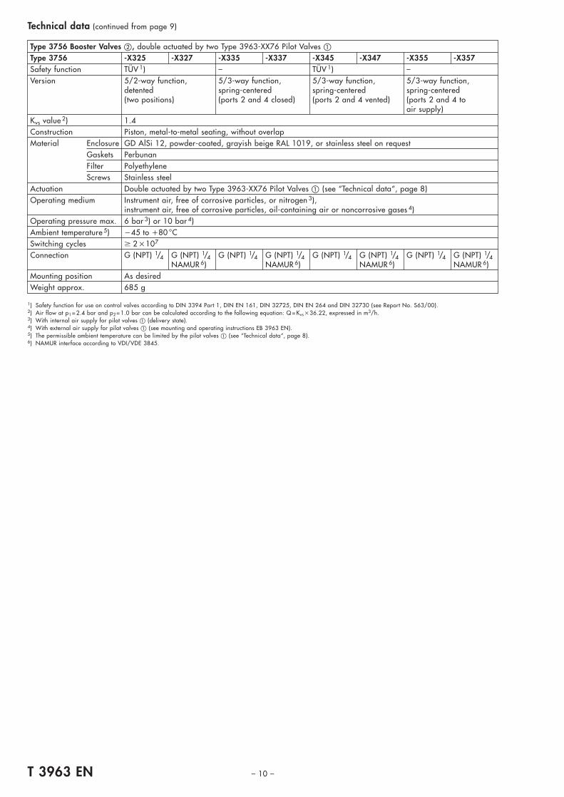
Type 3756 Booster Valves �, double actuated by two Type 3963-XX76 Pilot Valves �Type 3756 -X325 -X327 -X335 -X337 -X345 -X347 -X355 -X357Safety function TÜV 1) – TÜV 1) –Version 5/2-way function, 5/3-way function, 5/3-way function, 5/3-way function,
detented spring-centered spring-centered spring-centered(two positions) (ports 2 and 4 closed) (ports 2 and 4 vented) (ports 2 and 4 to
air supply)Kvs value 2) 1.4Construction Piston, metal-to-metal seating, without overlapMaterial Enclosure GD AlSi 12, powder-coated, grayish beige RAL 1019, or stainless steel on request
Gaskets PerbunanFilter PolyethyleneScrews Stainless steel
Actuation Double actuated by two Type 3963-XX76 Pilot Valves � (see “Technical data“, page 8)Operating medium Instrument air, free of corrosive particles, or nitrogen 3),
instrument air, free of corrosive particles, oil-containing air or noncorrosive gases 4)Operating pressure max. 6 bar 3) or 10 bar 4)Ambient temperature 5) �45 to �80 °CSwitching cycles � 2 �107
Connection G (NPT) 1/4 G (NPT) 1/4 G (NPT) 1/4 G (NPT) 1/4 G (NPT) 1/4 G (NPT) 1/4 G (NPT) 1/4 G (NPT) 1/4NAMUR 6) NAMUR 6) NAMUR 6) NAMUR 6)
Mounting position As desiredWeight approx. 685 g
1) Safety function for use on control valves according to DIN 3394 Part 1, DIN EN 161, DIN 32725, DIN EN 264 and DIN 32730 (see Report No. S63/00).2) Air flow at p1 = 2.4 bar and p2 = 1.0 bar can be calculated according to the following equation: Q = Kvs �36.22, expressed in m3/h.3) With internal air supply for pilot valves � (delivery state).4) With external air supply for pilot valves � (see mounting and operating instructions EB 3963 EN).5) The permissible ambient temperature can be limited by the pilot valves � (see “Technical data“, page 8).6) NAMUR interface according to VDI/VDE 3845.
Technical data (continued from page 9)

CableglandM 20�1.5
ThreadedplugM 20�1.5
61
� 62
31 38
80
� 62
31
CableglandM 20�1.5
ThreadedplugM 20�1.5
61
63
31 38 31
� 62 � 62
– 11 – T 3963 EN
Fig. 18 · Dimensions in mm
Type 3963-XX25 Pilot ValveTypes 3963-XX10/-XX20/-XX50/-XX60 Solenoid Valves
Type 3963-XX76 Pilot Valve
Dimensions of devices without threaded connection
Fig. 17 · Dimensions in mm

1919
3 959(4)
Connection 9 on Types 3963-XX27/-XX28Connection 4 on Type 3963-XX54
Connections 5 and 9 only on Type 3963-XX54
CableglandM 20�1.5
ThreadedplugM 20�1.5
31
109
61 31 38
10
29
10
� 62
40 40
62
28 38 48
123
321
1
2
3
M 4 / 7 mm depthM 3 / 6 mm depth 3 mm / 3.5 mm depth
Underneath view of connection plate
2.5 1.594
1.3 2.3
ThreadedplugM 20�1.5
CableglandM 20�1.5
� 62
25
10
31
124
61 31
10
25
38
40 40
28 38 48
123
1
2
3
M 4 / 7 mm depthM 3 / 6 mm depth 3 mm / 3.5 mm depth
Underneath view of connection plate
T 3963 EN – 12 –
Fig. 20 · Dimensions in mm
Dimensions of devices with threaded connection
Type 3963-XX14 Solenoid Valve
Types 3963-XX27/-XX28/-XX54 Solenoid Valves
Fig. 19 · Dimensions in mm

24
22.5
22.512
* Attachment to connection block with 2 hexagon socket head screws
60
61 31 38 31
108.
5
16
12
16 60
*
*
ThreadedplugM 20�1.5
CableglandM 20�1.5
CableglandM 20�1.5
1.4 2.4
1.3 2.32.5 1.5
9
ThreadedplugM 20�1.5
31
129
61 31 3834
10
49
� 62
39
24
25
42
40
� 62
28 38 48
123
1
1
2
3
M 4 / 7 mm depthM 3 / 6 mm depth 3 mm / 3.5 mm depth
Underneath view of connection plate
– 13 – T 3963 EN
Type 3963-XX64 Solenoid Valve
Types 3963-XX29/-XX55 Solenoid Valves
Dimensions of devices with threaded connection (continued from page 12)
Fig. 21 · Dimensions in mm
Fig. 22 · Dimensions in mm

Plug G 1/4
64
53
1/2" 21 21
29
35
65
7
1/2"
1/2"
193
31
5053
34
94.5
38
62
31
9
4
5
3
99
Int
CableglandM 20�1.5
ThreadedplugM 20�1.5
Type 3963-XX25 Pilot Valve � combined with Type 3756-X203/-X213 Booster Valve �
Dimensions of devices with threaded connection (continued from page 13)
Fig. 23 · Dimensions in mm
T 3963 EN – 14 –

43
64
38
100
135 11
22
34
53 35
194
65
21 21
53
94.5
5
31
50
64 29
ThreadedplugM 20�1.5
CableglandM 20�1.5
Plug G 1/4
G 1/2
G 1/2
G 1/2
M 6
– 15 – T 3963 EN
Type 3963-XX25 Pilot Valve � combined with Type 3756-X209 Booster Valve �
Dimensions of devices with threaded connection (continued from page 14)
Fig. 24 · Dimensions in mm
M 6
135
100
38
11
22
53
21 21
35
64 29
94.5
50
31 34
53
194
6465
43
5
ThreadedplugM 20�1.5
CableglandM 20�1.5
Plug G 1/4//
G 1/2
G 1/2
G 1/2
T 3963 EN – 16 –
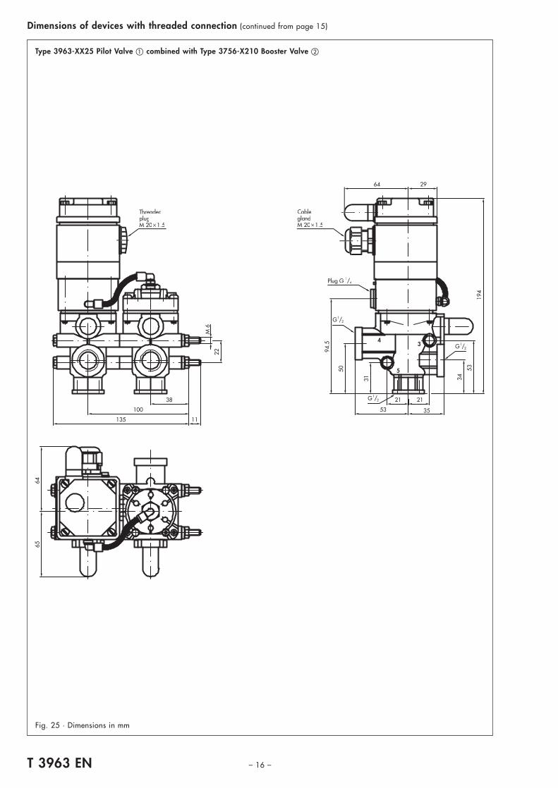
Fig. 25 · Dimensions in mm
Type 3963-XX25 Pilot Valve � combined with Type 3756-X210 Booster Valve �
Dimensions of devices with threaded connection (continued from page 15)
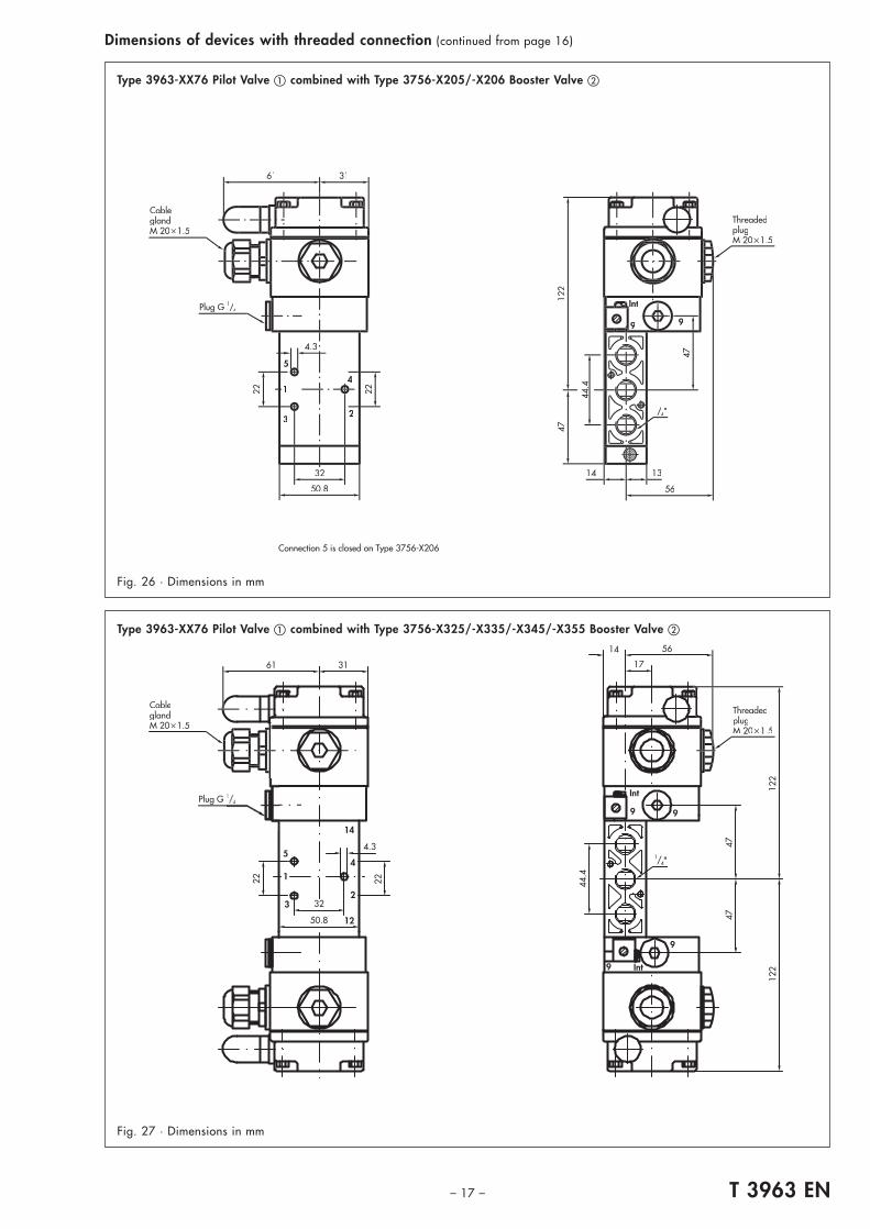
Connection 5 is closed on Type 3756-X206
5
1
3
4
2
9 9
Int
22
32
50.8
44.4
47
22
61 31
122
47
13
56
14
CableglandM 20�1.5
ThreadedplugM 20�1.5
Plug G 1/4//
1/4// "
4.3
56
17
14
61 31
4.3
2222
32
50.8
44.4
4747
122
122
Int
Int
99
9
9
1
5
3
14
12
4
2
CableglandM 20�1.5
Plug G 1
1/4"
ThreadedplugM 20�1.5
– 17 – T 3963 EN
Fig. 27 · Dimensions in mm
Type 3963-XX76 Pilot Valve � combined with Type 3756-X205/-X206 Booster Valve �
Type 3963-XX76 Pilot Valve � combined with Type 3756-X325/-X335/-X345/-X355 Booster Valve �
Dimensions of devices with threaded connection (continued from page 16)
Fig. 26 · Dimensions in mm

10
34 60 16.8
11
60
5.3
30
32 18
8.5
6
42
67
25
1212
1.3
2.3
1.32.3
30
G 1/4//
**
12
61 31
9
5
3
4
16.8
60
40
1419
8.4
62
23
80
40
10
19
70 12
62
6
109
38 31
G 1 /
4
ThreadedplugM 20�1.5
CableglandM 20�1.5
Underneath view of connection plate
Type 3963-XX53 Solenoid Valve
Dimensions of devices with threaded connection for linear actuators with NAMUR rib
Adapter plate NAMUR rib/NAMUR interface (Order No. 1400-6751)
Fig. 29 · Dimensions in mm
T 3963 EN – 18 –
Fig. 28 · Dimensions in mm

1.3 2.3
4
12.525
6232
61
62
88
63
31
69
25
96
24
36
38 31
CableglandM 20�1.5
ThreadedplugM 20�1.5
NAMUR fixing level
4
2.3
1.3 2.3
9
61
13
62
114
62
1738
3424
31 31
36
69
25
32 62
96
5
22.2
18.5
ThreadedplugM 20�1.5
CableglandM 20�1.5
NAMUR fixing level
– 19 – T 3963 EN
Fig. 31 · Dimensions in mm
Dimensions of devices with NAMUR interface for rotary actuators
Types 3963-XX11/-XX12/-XX21/-XX22 Solenoid Valves
Type 3963-XX52 Solenoid Valve
Fig. 30 · Dimensions in mm

1.4 2.4
9
2.5 1.5
1.3 2.3
32
61
102
31
25
10
2524
49
39
25
24
67
25
16
56
36
38 31
62
10
NAMURfixing level
CableglandM 20�1.5
ThreadedplugM 20�1.5
16
5
1
3
4
2
9
Int
32
50.8
12
5.3
72
122
4747
2936
22
38
44.4
3461 31
Connection 5 is closed on Type 3756-X208
CableglandM 20�1.5
ThreadedplugM 20�1.5
1/4// "
Type 3963-XX76 Pilot Valve � combined with Type 3756-X207/-X208 Booster Valve �
Type 3963-XX62 Solenoid Valve
T 3963 EN – 20 –
Dimensions of devices with NAMUR interface for rotary actuators (continued from page 19)
Fig. 32 · Dimensions in mm
Fig. 33 · Dimensions in mm

5
1
3
4
2
1
5
1
9
25.4
3831
55
97
122
47
75
61 31
ThreadedplugM 20�1.5
CableglandM 20�1.5
5
1
3
4
2
9 9
Int
9
9 Int
5.3
122
122
72
61 31 3834
12 44.4
4747
31
ThreadedplugM 20�1.5
CableglandM 20�1.5
1/4"
– 21 – T 3963 EN
Fig. 35 · Dimensions in mm
Dimensions of devices with NAMUR interface for rotary actuators (continued from page 20)
Type 3963-XX76 Pilot Valve � combined with Type 3756-X327/-X337/-X347/-X357 Booster Valve �
Fig. 34 · Dimensions in mm
Type 3963-XX76 Pilot Valve � combined with Type 3756-X207 Booster Valve � and restrictor block (Order No. 1400-6763)for single-acting rotary actuators with NAMUR interface

T 3963 EN – 22 –
Versions and ordering data
Type 3963 Solenoid Valve(Connection G (NPT) 1/4, Kvs value 0.16 or 0.32)
1) According to EC Type Examination Certificate PTB 01 ATEX 2085.2) Type of protection “Intrinsic safety“ for use in hazardous areas according to:
CSA approval for Class I; Divisions 1 and 2; Groups A, B, C and D;FM approval for Classes I, II and III; Divisions 1 and 2; Groups A, B, C, D, E, F and G.
3) According to Statement of Conformity PTB 01 ATEX 2086X.4) Air flow at p1 = 2.4 bar and p2 = 1.0 bar can be calculated according to the following equation: Q �Kvs �36.22, expressed in m3/h.5) Safety Integrity Level SIL4 according to IEC 61508 (see Report No. V 60 2004 T1).6) Safety function for use on control valves according to DIN 3394 Part 1, DIN EN 161, DIN 32725, DIN EN 264 and DIN 32730 (see Report No. S63/00).7) Permissible maximum ambient temperature for EExi versions according to temperature classes T4/T5/T6 (see EC type examination certificate).8) Silicone-free version with degree of protection IP 54 at permissible ambient temperature from �25 to �80 °C on request.9) The female connector is not included in the delivery.
10) Manual override lever accessible from outside on request.11) Filter check valve made of stainless steel with degree of protection IP 65 or NEMA 4 on request.
Solenoid valve Order No. 3963- . . . . . . . .Type of protection Without explosion protection (for DC nominal signal) 0 ▲ ▲ ▲ ▲ ▲ ▲
II 2 G EEx ia IIC T6 1) (for DC nominal signal) 1Without explosion protection (for AC nominal signal) 2CSA/FM 2) (for DC nominal signal) 3II 3 G EEx nA II T6 3) (for DC nominal signal) 8
Nominal signal 6 V DC, power consumption 5.47 mW 112 V DC, power consumption 13.05 mW 224 V DC, power consumption 26.71 mW 3
230 V AC, power consumption 0.46 VA (without explosion protection) 2 1115 V AC, power consumption 0.17 VA (without explosion protection) 2 2
48 V AC, power consumption 0.07 VA (without explosion protection) 2 324 V AC, power consumption 0.04 VA (without explosion protection) 2 4
Special version 9Version Kvs value4) Connection/attachment
3/2-way function 0.16 Without connection plate (as spare part for Type 3963-XX27) 20NAMUR interface for on-off rotary actuators SIL4 5), TÜV 6) 21NAMUR interface for on-off rotary actuators, with exhaust air restrictor 22NAMUR interface for on-off/continuous rotary actuators, with supply air/exhaust air restrictors 23Threaded connection (as E/P binary converter) SIL4 5), TÜV 6) 27Threaded connection, with exhaust air restrictor (as E/P binary converter) 28Connection block for Type 3277 Linear Actuator with Types 3766/3767/378X Positioner, with exhaust air restrictor 29
3/2-way function 0.32 Without connection plate (as spare part for Types 3963-XX52/-XX53/-XX54/-XX55) 50NAMUR interface for on-off/continuous rotary actuators SIL4 5), TÜV 6) 52For linear actuators with NAMUR rib SIL4 5), TÜV 6) 53Threaded connection, connection as desired SIL4 5), TÜV 6) 54Connection block for Type 3277 Linear Actuator with Types 3766/3767/378X Positioner SIL4 5), TÜV 6) 55
5/2-way function 0.16 Without connection plate (as spare part for Type 3963-XX14) 10NAMUR interface for on-off rotary actuators SIL4 5) 11NAMUR interface for on-off rotary actuators, with 2 exhaust air restrictors 12Threaded connection, connection as desired SIL4 5) 14
6/2-way function 0.16 Without connection plate (as spare part for Types 3963-XX62/-XX64) 60NAMUR interface for on-off/continuous rotary actuators SIL4 5) 62Threaded connection, connection as desired SIL4 5) 64
Ambient temperature 7) �25 to �80 °C 8) 0�45 to �80 °C 1
Electrical connection Cable gland M 20 �1.5 made of polyamide, black 0Cable gland M 20 �1.5 made of polyamide, blue 1Adapter M 20 �1.5/1/2 NPT made of aluminum, powder-coated, grayish beige RAL 1019 2Han 7 D male connector (manufactured by Harting), 7 poles, made of aluminum, silvery gray, IP 65 9) 3Round plug connector M 12 �1, 4 poles, made of brass, nickel-plated, IP 65 9) 4Male connector according to EN 175301-803, type A, made of polyamide, black, IP 65 9) 5Round plug connector (manufactured by Binder), 7 poles, made of PBT GV, black, IP 67 9) 6EExe cable gland M 20 �1.5 (manufactured by CEAG) made of polyamide, black 7Cable gland M 20 �1.5 made of brass, nickel-plated (required for Type 3963-8XXX1) 8Special version 9
Air connection Without threaded connection (for Types 3963-XX10/-XX20/-XX29/-XX50/-XX55/-XX60) 0G 1/4 11/4 NPT 2
Manual override None SIL4 4), TÜV 5) 0Degree of protection Pushbutton switch, screwdriver-actuated, accessible from outside 1IP 54 8) with filter Pushbutton, pin-actuated, accessible from outside 2made of polyethylene Pushbutton underneath enclosure cover 10) SIL4 4), TÜV 5) 3Degree of protection None SIL4 4), TÜV 5) 4IP 65 with filter check valve Pushbutton switch, screwdriver-actuated, accessible from outside 5made of polyamide 11) Pushbutton, pin-actuated, accessible from outside 6
Pushbutton underneath enclosure cover 10) SIL4 4), TÜV 5) 7

– 23 – T 3963 EN
Versions and ordering data (continued from page 22)
Type 3963 Pilot Valve � with single-actuated Type 3756 Booster Valve �(Connection G (NPT) 1/4 or 1/4/NAMUR or 1/2, Kvs value 1.4 or 4.3)
1) According to EC Type Examination Certificate PTB 01 ATEX 2085.2) Type of protection “Intrinsic safety“ for use in hazardous areas according to:
CSA approval for Class I; Divisions 1 and 2; Groups A, B, C and D;FM approval for Classes I, II and III; Divisions 1 and 2; Groups A, B, C, D, E, F and G.
3) According to Statement of Conformity PTB 01 ATEX 2086X.4) Safety Integrity Level SIL4 according to IEC 61508 (see Report No. V 60 2004 T1) substitutes safety function class AK 7 according to DIN V 19251.5) Safety function for use on control valves according to DIN 3394 Part 1, DIN EN 161, DIN 32725, DIN EN 264 and DIN 32730 (see Report No. S63/00).6) Permissible maximum ambient temperature for EExi versions according to temperature classes T4/T5/T6 (see EC type examination certificate).7) Silicone-free version with degree of protection IP 54 at permissible ambient temperature from �25 to �80 °C on request.8) The female connector is not included in the delivery.9) Manual override lever accessible from outside on request.
10) Filter check valve made of stainless steel with degree of protection IP 65 or NEMA 4 on request.11) Air flow at p1 = 2.4 bar and p2 = 1.0 bar can be calculated according to the following equation: Q �Kvs �36.22, expressed in m3/h.
Pilot valve � Order No. 3963- . . . . . . . . /3756- . . . .Type of protection Without explosion protection (for DC nominal signal) 0 ▲ ▲ ▲ ▲ ▲ ▲ ▲ ▲ ▲ ▲ ▲
II 2 G EEx ia IIC T6 1) (for DC nominal signal) 1Without explosion protection (for AC nominal signal) 2CSA/FM 2) (for DC nominal signal) 3II 3 G EEx nA II T6 3) (for DC nominal signal) 8
Nominal signal 6 V DC, power consumption 5.47 mW 112 V DC, power consumption 13.05 mW 224 V DC, power consumption 26.71 mW 3
230 V AC, power consumption 0.46 VA (without explosion protection) 2 1115 V AC, power consumption 0.17 VA (without explosion protection) 2 2
48 V AC, power consumption 0.07 VA (without explosion protection) 2 324 V AC, power consumption 0.04 VA (without explosion protection) 2 4
Special version 9Version Connection/attachment
3/2-way function For Types 3756-X205/-X206/-X207/-X208 Booster Valves G (NPT) 1/2 � TÜV 5) 76For Types 3756-X203/-X213/-X209/-X210 Booster Valves G (NPT) 1/4 � SIL4 4), TÜV 5) 25
Ambient temperature 6) �25 to �80 °C 7) 0�45 to �80 °C 1
Electrical connection Cable gland M 20 �1.5 made of polyamide, black 0Cable gland M 20 �1.5 made of polyamide, blue 1Adapter M 20 �1.5/1/2 NPT made of aluminum, powder-coated, grayish beige RAL 1019 2Han 7 D male connector (manufactured by Harting), 7 poles, made of aluminum, silvery gray, IP 65 8) 3Round plug connector M 12 �1, 4 poles, made of brass, nickel-plated, IP 65 8) 4Male connector according to EN 175301-803, type A, made of polyamide, black, IP 65 8) 5Round plug connector (manufactured by Binder), 7 poles, made of PBT GV, black, IP 67 8) 6EExe cable gland M 20 �1.5 (manufactured by CEAG) made of polyamide, black 7Cable gland M 20 �1.5 made of brass, nickel-plated (required for Type 3963-8XXX1) 8Special version 9
Air connection Without threaded connection 0Manual override None SIL4 4), TÜV 5) 0
Degree of protection Pushbutton switch, screwdriver-actuated, accessible from outside 1IP 54 7) with filter Pushbutton, pin-actuated, accessible from outside 2
made of polyethylene Pushbutton underneath enclosure cover 9) SIL4 4), TÜV 5) 3Degree of protection None SIL4 4), TÜV 5) 4IP 65 with filter check valve Pushbutton switch, screwdriver-actuated, accessible from outside 5made of polyamide 10) Pushbutton, pin-actuated, accessible from outside 6
Pushbutton underneath enclosure cover 9) SIL4 4), TÜV 5) 7Booster valve �, single-actuated Order No. 3756- . . . .Actuation Version Operating pressure Kvs value 11) Ambient temperature Air connection ▲ ▲ ▲ ▲
(in direction of flow) (in direction of flow)Type 3963-XX25 3/2-way function max. 10 bar 1.9 (4→3), 1.5 (3→4) �25 to �80 °C G 1/2 SIL4 4), TÜV 5) 1 2 0 3Pilot Valve � (3→5, 4→3) 4.3 (3→5), 4.7 (5→3) 1/2 NPT SIL4 4), TÜV 5) 6 2 0 3
max. 2 bar �45 to �80 °C G 1/2 SIL4 4), TÜV 5) 1 2 1 3(as desired) 1/2 NPT SIL4 4), TÜV 5) 6 2 1 3
5/2-way function max. 10 bar (at 4) 1.9 (4→3), 1.5 (3→4) �25 to �80 °C G 1/2 1 2 0 9max. 2 bar (as desired) 4.3 (3→5), 4.7 (5→3) 1/2 NPT 6 2 0 9
6/2-way function max. 10 bar (at 4) 1.9 (4→3), 1.5 (3→4) �25 to �80 °C G 1/2 1 2 1 0max. 2 bar (as desired) 4.3 (3→5), 4.7 (5→3) 1/2 NPT 6 2 1 0
Type 3963-XX76 5/2-way function max.10 bar 1.4 �45 to �80 °C G 1/4 3 2 0 5Pilot Valve � (as desired) (as desired) 1/4 NPT 8 2 0 5
3/2-way function max.10 bar 1.4 �45 to �80 °C G 1/4 TÜV 5) 3 2 0 6with exhaust air return (as desired) (as desired) 1/4 NPT TÜV 5) 8 2 0 65/2-way function max.10 bar 1.4 �45 to �80 °C G 1/4/NAMUR 3 2 0 7
(as desired) (as desired) 1/4 NPT/NAMUR 8 2 0 73/2-way function max.10 bar 1.4 �45 to �80 °C G 1/4/NAMUR TÜV 5) 3 2 0 8with exhaust air return (as desired) (as desired) 1/4 NPT/NAMUR TÜV 5) 8 2 0 8

T 3963 EN – 24 –
Versions and ordering data (continued from page 23)
Type 3963 Pilot Valves � with double-actuated Type 3756 Booster Valve �(Connection G (NPT) 1/4 or 1/4/NAMUR, Kvs value 1.4)
1) According to EC Type Examination Certificate PTB 01 ATEX 2085.2) Type of protection “Intrinsic safety“ for use in hazardous areas according to:
CSA approval for Class I; Divisions 1 and 2; Groups A, B, C and D;FM approval for Classes I, II and III; Divisions 1 and 2; Groups A, B, C, D, E, F and G.
3) According to Statement of Conformity PTB 01 ATEX 2086X.4) Safety function for use on control valves according to DIN 3394 Part 1, DIN EN 161, DIN 32725, DIN EN 264 and DIN 32730 (see Report No. S63/00).5) Permissible maximum ambient temperature for EExi versions according to temperature classes T4/T5/T6 (see EC type examination certificate).6) Silicone-free version with degree of protection IP 54 at permissible ambient temperature from �25 to �80 °C on request.7) The female connector is not included in the delivery.8) Manual override lever accessible from outside on request.9) Filter check valve made of stainless steel with degree of protection IP 65 or NEMA 4 on request.
10) Air flow at p1 = 2.4 bar and p2 = 1.0 bar can be calculated according to the following equation: Q �Kvs �36.22, expressed in m3/h.
Pilot valves � Order No. 3963- . . 76 . . . . /3756- . . . .Type of protection Without explosion protection (for DC nominal signal) 0 ▲ ▲ ▲ ▲ ▲ ▲ ▲ ▲ ▲ ▲ ▲
II 2 G EEx ia IIC T6 1) (for DC nominal signal) 1Without explosion protection (for AC nominal signal) 2CSA/FM 2) (for DC nominal signal) 3II 3 G EEx nA II T6 3) (for DC nominal signal) 8
Nominal signal 6 V DC, power consumption 5.47 mW 112 V DC, power consumption 13.05 mW 224 V DC, power consumption 26.71 mW 3
230 V AC, power consumption 0.46 VA (without explosion protection) 2 1115 V AC, power consumption 0.17 VA (without explosion protection) 2 2
48 V AC, power consumption 0.07 VA (without explosion protection) 2 324 V AC, power consumption 0.04 VA (without explosion protection) 2 4
Special version 9Version Connection/attachment
3/2-way function For booster valve G (NPT) 1/4 � TÜV 4) 76Ambient temperature 5) �25 to �80 °C 6) 0
�45 to �80 °C 1Electrical connection Cable gland M 20 �1.5 made of polyamide, black 0
Cable gland M 20 �1.5 made of polyamide, blue 1Adapter M 20 �1.5/NPT 1/2 made of aluminum, powder-coated, grayish beige RAL 1019 2Han 7 D male connector (manufactured by Harting), 7 poles, made of aluminum, silvery gray, IP 65 7) 3Round plug connector M 12 �1, 4 poles, made of brass, nickel-plated, IP 65 7) 4Male connector according to EN 175301-803, type A, made of polyamide, black, IP 65 7) 5Round plug connector (manufactured by Binder), 7 poles, made of PBT GV, black, IP 67 7) 6EExe cable gland M 20 �1.5 (manufactured by CEAG) made of polyamide, black 7Cable gland M 20 �1.5 made of brass, nickel-plated (required for Type 3963-8XXX1) 8Special version 9
Air connection Without threaded connection 0Manual override None 0
Degree of protection Pushbutton switch, screwdriver-actuated, accessible from outside 1IP 54 6) with filter Pushbutton, pin-actuated, accessible from outside 2made of polyethylene Pushbutton underneath enclosure cover 8) 3Degree of protection None 4IP 65 with filter check valve Pushbutton switch, screwdriver-actuated, accessible from outside 5made of polyamide 9) Pushbutton, pin-actuated, accessible from outside 6
Pushbutton underneath enclosure cover 8) 7Booster valve �, double-actuated Order No. 3756- . . . .Version Operating pressure Kvs value 10) Ambient temperature Air connection ▲ ▲ ▲ ▲
(in direction of flow) (in direction of flow)5/2-way function, max. 10 bar 1.4 �45 to �80 °C G 1/4 TÜV 4) 3 3 2 5detented (two positions) (as desired) (as desired) 1/4 NPT TÜV 4) 8 3 2 5
G 1/4/NAMUR TÜV 4) 3 3 2 71/4 NPT/NAMUR TÜV 4) 8 3 2 7
5/3-way function, max. 10 bar 1.4 �45 to �80 °C G 1/4 3 3 3 5spring-centered (as desired) (as desired) 1/4 NPT 8 3 3 5(ports 2 and 4 closed) G 1/4/NAMUR 3 3 3 7
1/4 NPT/NAMUR 8 3 3 75/3-way function, max. 10 bar 1.4 �45 to �80 °C G 1/4 TÜV 4) 3 3 4 5spring-centered (as desired) (as desired) 1/4 NPT TÜV 4) 8 3 4 5(ports 2 and 4 vented) G 1/4/NAMUR TÜV 4) 3 3 4 7
1/4 NPT/NAMUR TÜV 4) 8 3 4 75/3-way function, max. 10 bar 1.4 �45 to �80 °C G 1/4 3 3 5 5spring-centered (as desired) (as desired) 1/4 NPT 8 3 5 5(ports 2 and 4 to air supply) G 1/4/NAMUR 3 3 5 7
1/4 NPT/NAMUR 8 3 5 7

– 25 – T 3963 EN
Spare parts for Type 3963 Solenoid Valves, Type 3963 Pilot Valves and Type 3756 Booster ValvesOrder No. Designation0439-0358 Flat gasket (for connection plate for Type 3963, not for Types 3963-XX11/-XX21)8205-1091 Molded gasket (for air supply for Types 3756-X205/-X206/-X207/-X208)
0520-0620 Diaphragm made of chloroprene, �25 to �80 °C (for Types 3756-1203/-6203)0520-0622 Diaphragm made of chloroprene, �25 to �80 °C (for Type 3963, not for Type 3963-XX76)0520-1097 Diaphragm made of silicone rubber, �40 to �80 °C (for Type 3963, not for Type 3963-XX76)0520-1128 Diaphragm made of silicone rubber, �40 to �80 °C (for Types 3756-1203/-6203)
1180-8311 Actuating element insert, �25 to �80 °C (for Types 3756-1203/-6203)1180-8553 Actuating element insert, �40 to �80 °C (for Types 3756-1213/-6213)
8421-0010 O-ring 2 �1 (for connection plate for Types 3756-XXX5/-XXX6/-XXX7/-XXX8)8421-0364 O-ring 16 �2 (for NAMUR interface for Types 3963-XX11/-XX21/-XX52/-XX62 and 3756-X207/-X208)8421-0085 O-ring 26 �2, �25 to �80 °C (for Types 3756-1203/-6203/-1213/-6213)8421-0418 O-ring 26 �2, �40 to �80 °C (for Types 3756-1203/-6203/-1213/-6213)8421-0102 O-ring 36 �2, �25 to �80 °C (for Types 3756-1203/-6203/-1213/-6213)8421-0101 O-ring 36 �2, �40 to �80 °C (for Types 3756-1203/-6203/-1213/-6213)
Enclosure cover without filter (for Type 3963)1099-0673 without manual override1099-0674 with pushbutton switch, screwdriver-actuated, accessible from outside1099-0675 with pushbutton, pin-actuated, accessible from outside1099-1194 with lever switch, accessible from outside
0070-0799 Plug G 1/4 made of stainless steel (for connection 9 on Type 3963)8421-0070 Seal ring (for plug G 1/4)
Accessories for Type 3963 Solenoid Valves, Type 3963 Pilot Valves and Type 3756 Booster ValvesOrder No. Designation0790-6658 Female connector according to EN 175301-803, type A, made of polyamide, black, IP 651400-8298 Female connector (manufactured by Harting), 7 poles, made of aluminum, silvery gray, IP 658801-2810 Sensor connecting cable, 2 wires, length 3 m, blue, with angle connector M 12 �1, 4 poles, IP 688831-0716 Female connector (manufactured by Binder), 7 poles, made of PBT GV, black, IP 678831-0865 Female connector M 12 �1, 4 poles, angle type, made of polyamide, black, IP 67
3994-0158 Cable break protection device with enclosure for top hat rail 35, IP 20 (for Type 3963-X1 with 6 V DC solenoid)
1400-5268 Filter made of polyethylene, connection G 1/G 1/2, IP 54 (required for actuator size � 1 400 cm2!)8504-0066 Filter made of polyethylene, connection G 1/4, IP 548504-0068 Filter made of polyethylene, connection G 1/2, IP 54
Filter check valves made of polyamide or stainless steel, IP 65 or NEMA 4, see Data Sheet Z 900-7 EN
1400-3001 Mounting plate for Type 3353 Angle Seat Valve (for Type 3963-XX21)1400-5930 Mounting base for G profile 32 according to EN 50035
(for Types 3963-XX14/-XX27/-XX28/-XX54/-XX64 – 2 pieces are required!)1400-5931 Mounting base for top hat rail 35 according to EN 50022
(for Types 3963-XX14/-XX27/-XX28/-XX54/-XX64 – 2 pieces are required!)1400-6726 Mounting plate for wall mounting (for Types 3963-XX14/-XX27/-XX28/-XX54/-XX64)
1400-6763 Restrictor block with 2 restrictors for supply air and exhaust air for adjusting different closing and opening timesin a ratio of 1:15 (for Type 3756-X207) for single-acting rotary actuators with NAMUR interface
Connection blocks and accessories for attaching Types 3963-XX29/-XX55 Solenoid Valves to Type 3277 Linear ActuatorsOrder No. Designation
Connection block for Type 3277 Linear Actuators with integral Type 3766/3767/3780 Positioner attachment1400-6943 Actuator “Stem extends“, connection G 1/41400-6944 Actuator “Stem extends“, connection NPT 1/41400-6945 Actuator “Stem retracts“, connection G 1/41400-6946 Actuator “Stem retracts“, connection NPT 1/4
Piping kit for “Stem retracts“1400-6444 Actuator size 240 cm2, made of steel, galvanised1400-6445 Actuator size 240 cm2, made of stainless steel1400-6446 Actuator size 350 cm2, made of steel, galvanised1400-6447 Actuator size 350 cm2, made of stainless steel1400-6448 Actuator size 700 cm2, made of steel, galvanised1400-6449 Actuator size 700 cm2, made of stainless steel
1400-6376 Pressure gauge, 0 to 6 bar/75 psi
Spare parts and accessories

Mounting kits for Type 3963 Solenoid Valves with threaded connectionOrder No. Designation1400-6759 Mounting kit for linear actuators (actuator size 80/240 cm2, connection G 1/4)
with screwed pipe connection G 1/4/G 1/4, made of stainless steel
Mounting kit for linear actuators (actuator size 350/700 cm2, connection G 3/8)1400-6735 with screwed pipe connection G 1/2/G 3/8, made of stainless steel1400-6761 with screwed pipe connection G 1/4/G 3/8, made of stainless steel
1400-6736 Mounting kit for linear actuators (actuator size 1 400 cm2, connection G 3/4)with screwed pipe connection G 1/2/G 3/4, made of stainless steel
1400-6737 Mounting kit for linear actuators (actuator size 2 800 cm2, connection G 1)with screwed pipe connection G 1/2/G 1, made of stainless steel
Mounting kit for linear actuators (actuator size 80/240 cm2, connection G 1/4)with angle bracket made of stainless steel
1400-6749 and screwed joints for pipe 8 �1, connection G 1/4/G 1/4, made of steel, galvanised1400-6750 and screwed joints for pipe 8 �1, connection G 1/4/G 1/4, made of stainless steel
Mounting kit for linear actuators (actuator size 350/700 cm2, connection G 3/8)with angle bracket made of stainless steel
1400-6738 and screwed joints for pipe 8 �1, connection G 1/4/G 3/8, made of steel, galvanised1400-6739 and screwed joints for pipe 8 �1, connection G 1/4/G 3/8, made of stainless steel1400-6743 and screwed joints for pipe 12 �1, connection G 1/4/G 3/8, made of stainless steel1400-6744 and screwed joints for pipe 10 �1, connection G 1/2/G 3/8, made of polyamide1400-6745 and screwed joints for pipe 10 �1, connection G 1/4/G 3/8, made of polyamide
Mounting kit for linear actuators (actuator size 700 cm2, connection G 3/8)with angle bracket made of stainless steel
1400-6740 and screwed joints for pipe 12 �1, connection G 1/2/G 3/8, made of steel, galvanised1400-6741 and screwed joints for pipe 12 �1, connection G 1/4/G 3/8, made of steel, galvanised1400-6742 and screwed joints for pipe 12 �1, connection G 1/2/G 3/8, made of stainless steel
Spare parts and accessories (continued from page 25)
Mounting kits for Type 3963 Solenoid Valves with NAMUR interfaceOrder No. Designation
Mounting kit for linear actuators (actuator size 350/700 cm2, connection G 3/8) with NAMUR ribvia adapter plate NAMUR rib/NAMUR interface (Order No. 1400-6751)
1400-6746 with screwed joints for pipe 12 �1, connection G 1/4/G 3/8, made of steel, galvanised1400-6747 with screwed joints for pipe 12 �1, connection G 1/4/G 3/8, made of stainless steel1400-6748 with screwed joints for pipe 10 �1, connection G 1/4/G 3/8, made of polyamide
Mounting kit for linear actuators (actuator size 80/240 cm2, connection G 1/4) with NAMUR ribvia adapter plate NAMUR rib/NAMUR interface (Order No. 1400-6751)
1400-6752 with screwed joints for pipe 6 �1, connection G 1/4/G 1/4, made of steel, galvanised1400-6753 with screwed joints for pipe 6 �1, connection G 1/4/G 1/4, made of stainless steel1400-6756 with screwed joints for hose 10 �1, connection G 1/4/G 1/4, made of polyamide
Mounting kit for linear actuators (actuator size 350/700 cm2, connection G 3/8) with NAMUR ribvia adapter plate NAMUR rib/NAMUR interface (Order No. 1400-6751)
1400-6754 with screwed joints for pipe 8 �1, connection G 1/4/G 3/8, made of steel, galvanised1400-6755 with screwed joints for pipe 8 �1, connection G 1/4/G 3/8, made of stainless steel1400-6757 with screwed joints for pipe 10 �1, connection G 1/4/G 3/8, made of polyamide
1400-6759 Mounting kit for linear actuators (actuator size 80/240 cm2, connection G 1/4)with screwed pipe connection G 1/4/G 1/4, made of stainless steel
Accessories for mounting kitsOrder No. Designation0320-1416 Bracket for NAMUR rib
(required when a positioner or a limit switch is to be mounted to linear actuators with nominal size DN 50 at thesame time)
8320-0131 Hexagon socket head screw M 8 �60 – A 4 DIN 931
1400-6751 Adapter plate NAMUR rib/NAMUR interface
T 3963 EN – 26 –

(Specifications subject to change without notice.)
SAMSOMATICAUTOMATIONSSYSTEMEGMBH
– a subsidiary of SAMSON AG
Weismüllerstraße 20 – 2260314 Frankfurt am Main · Germany
Phone: �49 69 4009-0Fax: �49 69 4009-1644E-mail: [email protected]: http://www.samsomatic.de
2004
-11
A ·
T
3963
EN