solenoid valves - aerocon systems poppet design the sv series solenoid valves utilize a design that...
TRANSCRIPT

solenoid valvesSV Series2- and 3-way Solenoid Valves for Gas and LiquidSV10: Vacuum to 3000 psig SV430: Vacuum to 3000 psigSV20: Vacuum to 6000 psig SV460: Vacuum to 6000 psigSV30: Vacuum to 3000 psig
Features• Zero Leakage• Bi-directional fl ow• Versatile : 3-way 2-position, 2-way normally closed, or 2-way
normally open• Balanced poppet design• 303 stainless steel, brass or aluminum construction• Minimum current required• Rapid response• Explosion-proof per MIL-STD-810B• High pressure• Direct acting• Medium fl ow capacity
Technical DataBody Construction Materials 303 stainless steel, brass or aluminumSeat materials Nylatron®, polyimide (Vespel®), or Kel-F®Pressure Ratings SV10, SV30 & SV430: vacuum to 3000 psig (0 to 207 BAR)
SV20 & SV460: vacuum to 6000 psig (0 to 414 BAR)Temperature Range −65˚ to +165˚ F (−54˚ to +74˚ C)Port Size and Connections ¼˝, ⁄˝, ½˝ NPT or AND10050.
MS33656 (SV10 only)Flow Capacity SV10 & SV20: Cv=0.096 SV430: Cv=0.80
SV30: Cv=0.46 SV460: Cv=0.64
Circle Seal Controls2301 Wardlow Circle • Corona, CA 92880Phone (909) 270-6200 Fax (909) 270-6201www.circle-seal.com

2
SV Series
How it Works3-way, 2-position, Normally Closed
Balanced Poppet Design The SV Series Solenoid Valves utilize a design that employs a single poppet, two pressurized sliding seals, and two main valve seats. The diameter of these seals and the two seats which the poppet seals against, have the same diameter. The pressure forces are always balanced regardless of poppet position. The only new force acting on the poppet is the poppet return spring or the forces exerted on the armature by the magnet coil.
The De-energized Position With the valve in a de-energized position and pressure applied to Port B, the valve operates as a 3-way, 2-position, normally closed valve. In this position a fl ow pattern from Port A to Port C is established (fi gure 1). Pressure can be applied to either port. The forces aff ecting the poppet are on the normally closed seat resulting from the poppet return spring.
Energized Position With pressure applied to Port B and electrical energy applied to the coil, the armature is drawn up against the coil compressing the armature return spring, and pulling the poppet up tight against the normally open seat of the valve, in this condition, a fl ow pattern between Port B and Port C is established and Port A is isolated (fi gure 2).
When the valve is de-energized, the poppet return spring forces the poppet to return to the normally closed seat and reestab-lishes a fl ow pattern between Port C and Port A with Port B being closed.
3-Way, 2-Position, Normally Open In this confi guration pressure is applied to Port A rather than to Port B with the valve de-energized. Pressure is connected to Port C. When the valve is energized Port A is closed and Port C is connected to Port B.
2-Way, 2-Position Valves (Normally Closed or Normally Open) Any of the three ported valves may be converted to a two-way operation by plugging Port A or B. Plugging Port A provides a 2-way, 2-position, normally closed valve. Plugging Port B pro-vides a 2-way, normally open valve. As shown in the “How to Order” section, Circle Seal Controls can also provide this valve as a 2-way, normally open or normally closed valve with only 2 ports as a standard item.
Selector Valve The 3-way, 2-position valves can also be used as selector valves by connecting two separate pressure sources to Ports A and B and then selectively running them to Port C depending on whether the valve is energized or de-energized. A single fl uid source connected to Port C may also be diverted to Ports A or B selectively.
A
B
C
A
B
C
Fig. 1Coil De-energized
Fig. 2Coil Energized
Poppet Return Spring
Coil Cover
Electromagnet
Armature
N.O. Seat
N.C. Seat
2- & 3-way Solenoid Valve Series
Maximum Pressure PSIG
Maximum FlowCv ESEOD
SV10 3000 0.096 0.07SV20* 6000 0.096 0.07SV30 3000 0.46 0.16
SV430 3000 0.80 0.215SV460 6000 0.64 .019
* 3-way, 2-position in SV20 Series is limited to 5000 psig.
Circle Seal Controls Solenoid Valves
3
SV Series
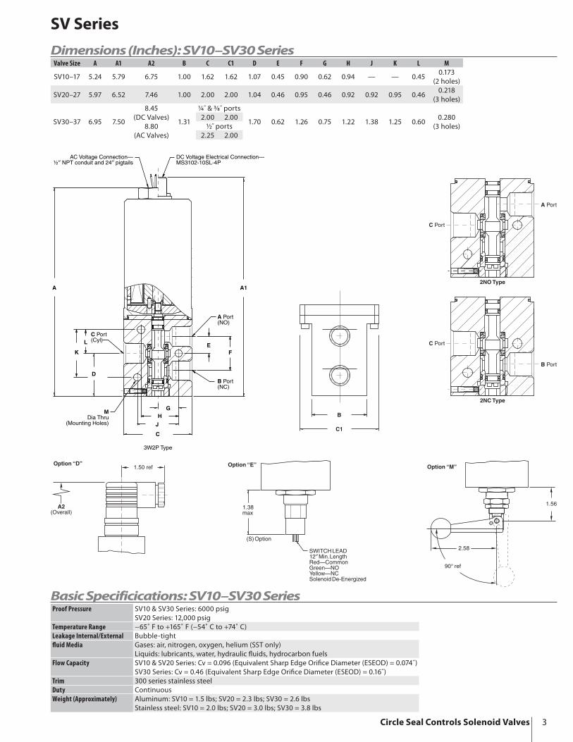
Dimensions (Inches): SV10–SV30 Series
C
D
K
L
FE
C Port(Cyl)
A Port(NO)
B Port(NC)
A A1
J
HG
MDia Thru
(Mounting Holes)
AC Voltage Connection—½″ NPT conduit and 24″ pigtails
DC Voltage Electrical Connection—MS3102-10SL-4P
3W2P Type
C1
B
Option “D”1.50 ref
A2(Overall)
1.38max
(S)Option
SWITCHLEAD12″ Min.LengthRed—CommonGreen—NOYellow—NCSolenoidDe-Energized
Option “E”
90° ref
1.56
2.58
Option “M”
C Port
B Port
2NC Type
C Port
A Port
2NO Type
Valve Size A A1 A2 B C C1 D E F G H J K L M
SV10–17 5.24 5.79 6.75 1.00 1.62 1.62 1.07 0.45 0.90 0.62 0.94 — — 0.450.173
(2 holes)
SV20–27 5.97 6.52 7.46 1.00 2.00 2.00 1.04 0.46 0.95 0.46 0.92 0.92 0.95 0.460.218
(3 holes)
SV30–37 6.95 7.50
8.45(DC Valves)
8.80(AC Valves)
1.31
¼˝ & ⁄˝ ports
1.70 0.62 1.26 0.75 1.22 1.38 1.25 0.600.280
(3 holes)2.00 2.00
½˝ ports2.25 2.00
Basic Specificications: SV10–SV30 SeriesProof Pressure SV10 & SV30 Series: 6000 psig
SV20 Series: 12,000 psigTemperature Range −65˚ F to +165˚ F (−54˚ C to +74˚ C)Leakage Internal/External Bubble-tightfl uid Media Gases: air, nitrogen, oxygen, helium (SST only)
Liquids: lubricants, water, hydraulic fl uids, hydrocarbon fuelsFlow Capacity SV10 & SV20 Series: Cv = 0.096 (Equivalent Sharp Edge Orifi ce Diameter (ESEOD) = 0.074˝)
SV30 Series: Cv = 0.46 (Equivalent Sharp Edge Orifi ce Diameter (ESEOD) = 0.16˝)Trim 300 series stainless steelDuty ContinuousWeight (Approximately) Aluminum: SV10 = 1.5 lbs; SV20 = 2.3 lbs; SV30 = 2.6 lbs
Stainless steel: SV10 = 2.0 lbs; SV20 = 3.0 lbs; SV30 = 3.8 lbs
Circle Seal Controls Solenoid Valves

4
SV Series
Dimensions (Inches): SV400 Series
2.50 sq.
1.5481.588
.875BSC
1.2451.255
.620
.630
C Port(Cyl)
A Port(NO)
B Port(NC)
7.63max
8.00max
1.500BSC
.750BSC2 Mounting holes
.281 dia. thru
AC Voltage Connection—½″ NPT conduit and 24″ pigtails
DC Voltage Electrical Connection—MS3102-10SL-4P
3W2P Type
Option “D”1.50 ref
9.06(Overall)
1.625max
¼″ PipeThreadSWITCHLEAD12″ Min.LengthRed—CommonGreen—NOYellow—NCSolenoidDe-Energized
Option “E”
1.375
Option “M”
90° ref
2.625
C Port
B Port
2NC Type
C Port
A Port
2NO Type
Basic Specificications: SV400 SeriesProof Pressure 9000 psigTemperature Range −65˚ F to +160˚ F (−54˚ C to +71˚ C)
‘C’ option: −58˚ F to +165˚ F (−50˚ C to +74˚ C)(Fluid: +225˚ F/107˚ C max.)
Leakage Internal/External Bubble-tightfl uid Media Gases: air, nitrogen, oxygen, helium (SS only)
Liquids: lubricants, water, hydraulic fl uids, hydrocarbon fuelsFlow Capacity SV43 Series: Cv = 0.86 (Equivalent Sharp Edge Orifi ce Diameter (ESEOD) = 0.215˝)
SV46 Series: Cv = 0.64 (Equivalent Sharp Edge Orifi ce Diameter (ESEOD) = 0.190˝)Trim 300 series stainless steelDuty ContinuousWeight (Approximately) Aluminum: 5.2 lbs
Stainless steel: 8.1 lbs
Circle Seal Controls Solenoid Valves

5
SV Series
How to Order: SV10–SV30 Series
SV3 1 T 32P 4 P 4 3 M
BASIC PART NUMBERSV1 3000 psigSV2 6000 psig (5000 psig for 32P)SV3 3000 psig
NOMINAL COIL VOLTAGE & CURRENT0 28 VDC1 115 VAC3 115 VDC5 220 VAC7 12 VDC
BODY MATERIALA Aluminum alloy (SV10 & SV30 only)B Brass (SV20 only)T 303 stainless steelT1 316 stainless steel
VALVE TYPE2NO 2-way, normally open2NC 2-way, normally closed32P 3-way, 2-position (standard)
OPTIONSD DIN 43650 electrical***E ½˝ pipe thread & 24˝ connector leads**M Manual override**S Electrical position indicator*
SEAT MATERIAL3 Nylatron® (standard)4 Kel-F® (limited to 3000 psig)6 Polyimide (Vespel® SP-21)
SEAL MATERIAL0 Ethylene propylene1 Neoprene3 Viton® A4 Buna N (standard)7 Fluorosilicone
PORT TYPEP Female pipeT AND10050M AS4395E04 (MS33656E4, SV10)
PORT SIZE2 ⁄˝ (SV10) AND10050 only4 ¼˝ (SV10, SV20, & SV30)6 ⁄˝ (SV20 & SV30)8 ½˝ (SV30)
* Manual override and electrical position indicator are not available on the same valve.** DC valves have MS3102-10SL-4P electrical connector. AC valves have 24˝ pigtails and ½˝ conduit.*** DIN connector furnished complete.
Please consult your Circle Seal Controls distributor or our factory for information on special connections, materials, larger sizes, o-rings, operating pressures and temperature ranges.
Repair KitsIn normal service, the only part(s) which may require replacement is(are) the seal(s). A repair kit may be ordered by placing a “K/” in front of the complete part number (i.e. K/SV30T32P4P43).
Circle Seal Controls Solenoid Valves

6
SV Series
* Manual override and electrical position indicator are not available on the same valve.** DC valves have MS3102-10SL-4P electrical connector. AC valves have 24˝ pigtails and ½˝ conduit.*** DIN connector furnished complete.**** The “C” option is only available with the following:
• Body material: aluminum alloy and stainless steel• Seat material: Nylatron® and Kel-F®
Please consult your Circle Seal Controls distributor or our factory for information on special connections, materials, larger sizes, o-rings, operating pressures and temperature ranges.
Repair KitsIn normal service, the only part(s) which may require replacement is(are) the seal(s). A repair kit may be ordered by placing a “K/” in front of the complete part number (i.e. K/SV431T32P8P43M).
For Your SafetyIt is solely the responsibility of the system designer and user to select products suitable for their specifi c application require-ments and to ensure proper installation, operation, and maintenance of these products. Material compatibility, product ratings and application details should be considered in the selection. Improper selection or use of products described herein can cause personal injury or property damage.
Viton® is a registered trademark of DuPont Dow Elastomers.Kel-F® is a registered trademark of 3M Company.Vespel®is a registered trademark of E.I. du Pont de Nemours and Company.Nylatron® is a registered trademark of DSM Engineering Plastic Products.
SV43 1 T 32P 8 P 4 3 M
BASIC PART NUMBERSV43 3000 psigSV46 6000 psig
NOMINAL COIL VOLTAGE & CURRENT1 28 VDC2 115 VAC3 220 VAC4 115 VDC5 12 VDC
BODY MATERIALA Aluminum alloyB Naval brassT 303 stainless steelT1 316 stainless steel
VALVE TYPE2NO 2-way, normally open2NC 2-way, normally closed32P 3-way, 2-position (standard)
PORT SIZE6 ⁄˝8 ½˝
OPTIONSD DIN 43650 electrical***E ½˝ pipe thread & 24˝ connector leads**M Manual override**S Electrical position indicator*C CSA-approved explosion-proof****
(SV431 & SV432 only—certifi cation # LR 7654-4)
SEAT MATERIAL3 Nylatron® (standard)4 Kel-F® (limited to 3000 psig)6 Polyimide (Vespel® SP-21)
SEAL MATERIAL0 Ethylene propylene1 Neoprene3 Viton®4 Buna N (standard)7 Fluorosilicone
PORT TYPEP Female pipeB Female tube, AND10050
How to Order: SV400 Series
Circle Seal Controls Solenoid Valves

7
SV Series
Circle Seal Controls Solenoid Valves

CSCSV • 4/04
CIRCOR Instrumentation Technologies405 Centura Court
PO Box 4866Spartanburg, SC 29303
Tel (864) 574-7966Fax (864) 587-5608
www.circortechnologies.com
Circle Seal Controls, Inc.2301 Wardlow Circle
PO Box 3300Corona, CA 92878Tel (909) 270-6200Fax (909) 270-6201
www.circle-seal.com
HOKE GmbHWeitzesweg 11Postfach 15 41
D-61118 Bad Vilbel–DortelweilTel +49 6101 82 56 0
Fax +49 6101 82 56 40www.hoke.de
CIRCOR Instrumentation, Ltd.1-3 Bouverie Road
HarrowMiddlesex, HA1 4HB
Tel +44 (0) 20 8423 0113Fax +44 (0) 20 8864 7008
www.circor.co.uk
HOKE, Inc.405 Centura Court
PO Box 4866Spartanburg, SC 29303
Tel (864) 574-7966Fax (864) 587-5608
www.hoke.com
CIRCOR Tech405 Centura Court
PO Box 4866Spartanburg, SC 29303
Tel (864) 574-7966Fax (864) 587-5608
www.circortech.com
Panels Plus1901 Lynx Place
Ontario, CA 91761Tel (909) 923-3770Fax (909) 923-2550
www.circor-panelsplus.com
GO Regulator405 Centura Court
PO Box 4866Spartanburg, SC 29303
Tel (864) 574-7966Fax (864) 587-5608
www.goreg.com
TOMCO51 Zima ParkPO Box 4866
Spartanburg, SC 29303Tel (864) 574-7966Fax (864) 587-5608
www.tomcoquickcouplers.com
Instrumentation
Technologies
LIMITED WARRANTYALL CIRCOR TECH, CIRCLE SEAL CONTROLS, INC., GO REGULATOR, HOKE INC., PANELS PLUS, AND TOMCO PROD UCTS ARE MADE TO EXACTING STANDARDS OF DESIGN, MATERIAL, WORK- MAN SHIP AND QUAL I TY CONTROL AND ARE WARRANTED TO BE FREE OF DEFECTS IN MATERIAL AND WORKMANSHIP AND REASONABLY FIT FOR THE USES SET FORTH IN SELLER’S CAT A LOG OR THE CONTRACT SPEC I FI CA TIONS FOR A PERIOD OF ONE YEAR AFTER SALE IF PROPERLY IN STALLED AND MAINTAINED AND UNDER THE NORMAL USE AND SERVICE FOR WHICH THE EQUIPMENT IS INTENDED. BUYER TO INSPECT THE GOODS WITHIN TEN DAYS OF DELIVERY AND TO THEN IMMEDIATELY NOTIFY SELLER OF ANY DEFECTS IN ORDER TO CLAIM A DEFECT. THIS WARRANTY IS IN LIEU OF ALL OTHER WARRANTIES WHETHER THEY ARE STATUTORY, EXPRESS OR IMPLIED, INCLUDING AMONG OTHER THINGS ANY IMPLIED WARRANTY OF MER CHANT ABIL I TY FITNESS FOR A PARTICULAR PURCHASE NOT SET FORTH IN SELLER’S CATALOG, AND ALSO DOES NOT APPLY TO ANY PRODUCTS OF SELLER WHICH HAVE BEEN REPAIRED, ALTERED OR MODIFIED OR HAVE BEEN SUBJECT TO MISUSE OR ABUSE. SELLER IS NOT LIABLE FOR ANY CONSEQUENTIAL, INCIDENTAL OR SPECIAL DAMAGES RESULTING DIRECTLY OR INDIRECTLY FROM THE DESIGN, MATERIAL, WORKMANSHIP, OPERATION OR INSTALLATION OF ANY OF ITS PRODUCTS AND NEITHER ASSUMES NOR AUTHORIZES ANY OTHER PERSON TO ASSUME FOR IT ANY OTHER LIABILITY IN CONNECTION THEREWITH. BUYER’S EXCLUSIVE REMEDY SHALL BE THE REPAIR OR REPLACEMENT OF ANY SUCH DEFECTIVE PRODUCT AFTER VERIFICATION BY SELLER. THIS WARRANTY IS IN EFFECT UNLESS SUPERSEDED BY LIMITED WARRANTY, FORM NO. 2299 (4/83)