solution combustion synthesis
TRANSCRIPT

Solution Combustion Synthesis
Impregnated Layer Combustion Synthesis is a Novel
Methodology to Prepare Multi-Component Catalysts,
Fundamentals and Experiments
Department of Chemical and Biomolecular
Engineering
University of Notre Dame University of Notre Dame

Outline:
Overview of combustion synthesis
Reaction system
Combustion front analaysis
Theoretical model results
Conclusions
Acknowledgements
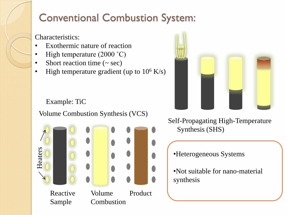
Conventional Combustion System:
Characteristics:
• Exothermic nature of reaction
• High temperature (2000 ˚C)
• Short reaction time (~ sec)
• High temperature gradient (up to 106 K/s)
Two modes of CS
•Heterogeneous Systems
•Not suitable for nano-material
synthesis
Reactive
Sample
Volume
Combustion
Product
Hea
ters
Self-Propagating High-Temperature
Synthesis (SHS)
Volume Combustion Synthesis (VCS)
Example: TiC
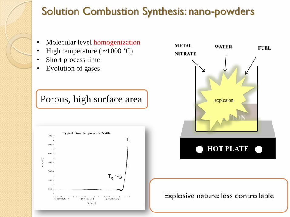
• Molecular level homogenization
• High temperature ( ~1000 ˚C)
• Short process time
• Evolution of gases
Solution Combustion Synthesis: nano-powders
Porous, high surface area
Tig
Tc
Explosive nature: less controllable
HOT PLATE
SOLUTION
METAL
NITRATE WATER FUEL
HOT PLATE
explosion

Initial
porous support
Solution
impregnation
Combustion Product:
supported catalyst
Catalytic
layer
Combustion
High specific surface
area of active sites
Impregnated Support Combustion Synthesis:
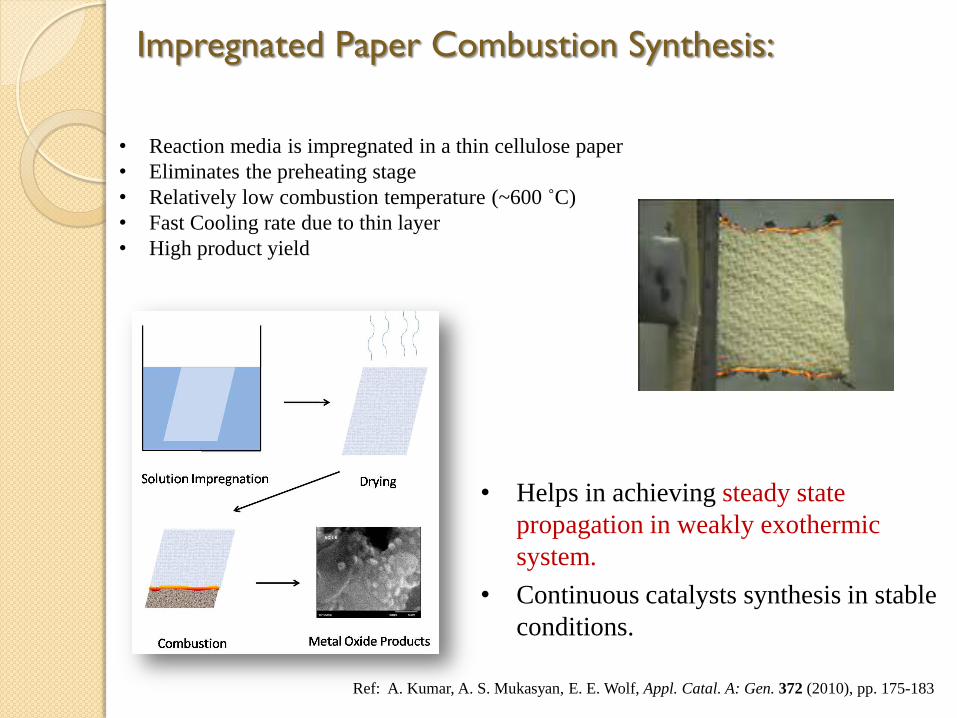
• Reaction media is impregnated in a thin cellulose paper
• Eliminates the preheating stage
• Relatively low combustion temperature (~600 ˚C)
• Fast Cooling rate due to thin layer
• High product yield
• Helps in achieving steady state
propagation in weakly exothermic
system.
• Continuous catalysts synthesis in stable
conditions.
Impregnated Paper Combustion Synthesis:
Ref: A. Kumar, A. S. Mukasyan, E. E. Wolf, Appl. Catal. A: Gen. 372 (2010), pp. 175-183

Mev(NO3)v
Catalyst Synthesis: reaction mixture
Metal Nitrate
5/9 v φ NH2CH2COOH
Fuel: Glycine,
Urea,
Hydrazine…
5/4 v(φ-1)O2
Oxygen
+ +
MeOv/2 10/9 v φ CO2 + 25/18 v φ H2O + {(5φ+9)/18} vN2
Metal
Oxide Gas Phase
products
φ = 1 : stoichiometric φ > 1 : fuel rich φ < 1 : fuel lean
+

Catalyst Synthesis: combustion regimes
Flame mode
Smoldering mode
Cellulose Combustion Regimes:
•Flame : Uncontrolled, high temperature
•Smoldering : Controlled, low temperature
Combustion
Mode
Pure
Cellulose
Impregnated
Cellulose
Smoldering No Yes
Flame Yes Yes
Critical:
Temperature measurement
Decisive factors:
• Fuel layer thickness
• Oxygen concentration
• Heat transfer effects
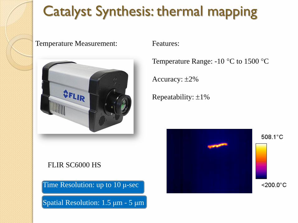
Catalyst Synthesis: thermal mapping
Temperature Measurement:
FLIR SC6000 HS
Features:
Temperature Range: -10 °C to 1500 °C
Accuracy: 2%
Repeatability: 1%
Time Resolution: up to 10 μ-sec
Spatial Resolution: 1.5 μm - 5 μm
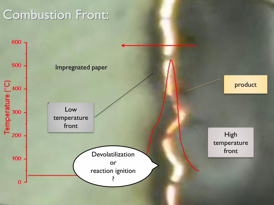
Combustion Front:
Low
temperature
front
High
temperature
front
Impregnated paper
product
Devolatilization
or
reaction ignition
?
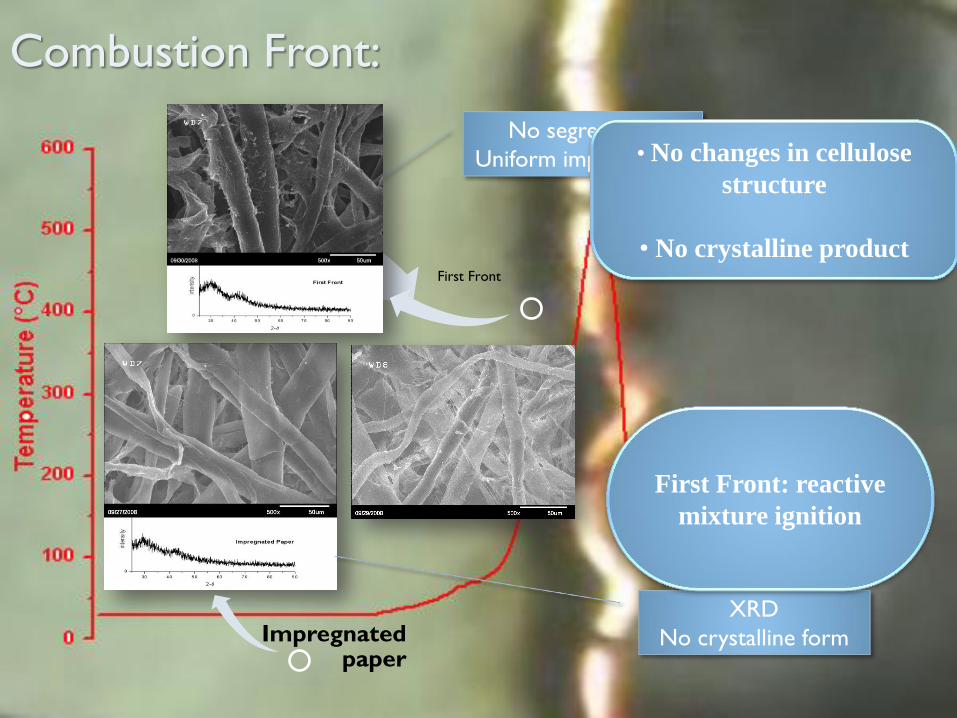
Impregnated paper
Pure Cellulose
No segregation
Uniform impregnation
XRD
No crystalline form
First Front
• No changes in cellulose
structure
• No crystalline product
First Front: reactive
mixture ignition
Combustion Front:
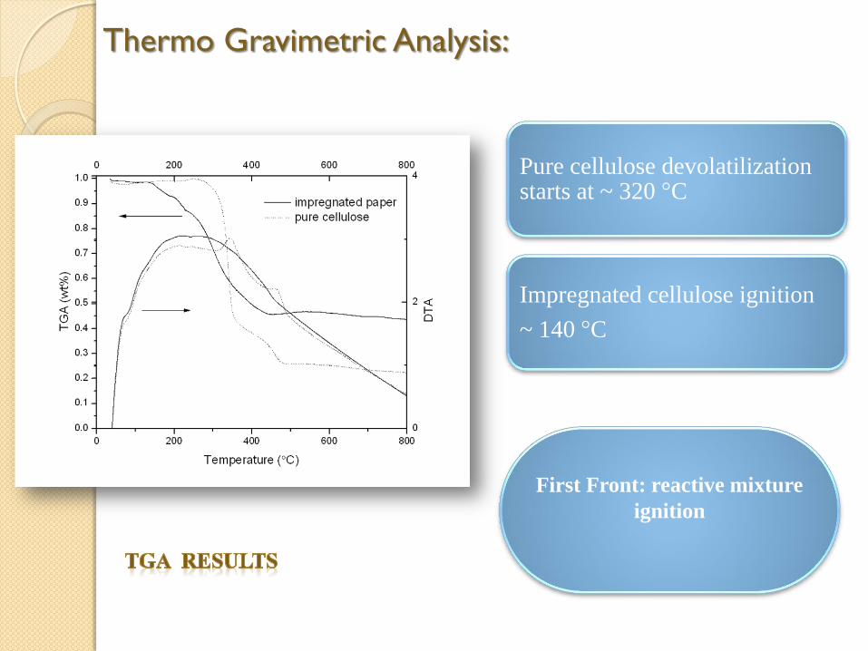
Thermo Gravimetric Analysis:
Pure cellulose devolatilization starts at ~ 320 °C
Impregnated cellulose ignition
~ 140 °C
First Front: reactive mixture
ignition
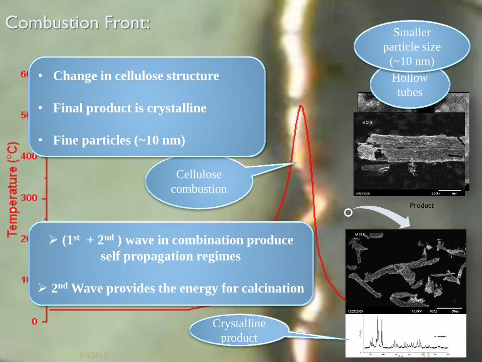
Product
Crystalline
product
Cellulose
combustion
• Change in cellulose structure
• Final product is crystalline
• Fine particles (~10 nm)
(1st + 2nd ) wave in combination produce
self propagation regimes
2nd Wave provides the energy for calcination
Hollow
tubes
Smaller
particle size
(~10 nm)
8/3/2013 13
Combustion Front:

Model Description
Reactants:
Products:
Where
ICs:
BCs:
and
and
A(s) + B(s) C(s) + ng∙D(g)
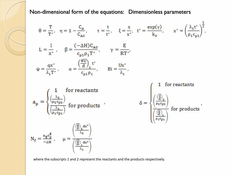
Non-dimensional form of the equations: Dimensionless parameters
where the subscripts 1 and 2 represent the reactants and the products respectively.

Reactants:
Where:
ICs:
BCs:
Final form of the equations:
Products:
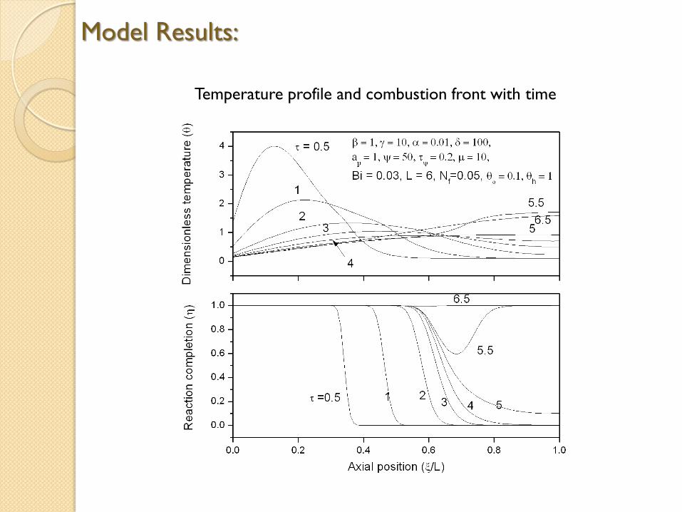
Model Results:
Temperature profile and combustion front with time

Location of combustion front with gas
phase products Effect of gas phase products on
combustion temperature profile
Effect of gas phase products:
Gas phase products lower the combustion temperature as well
as combustion front velocity
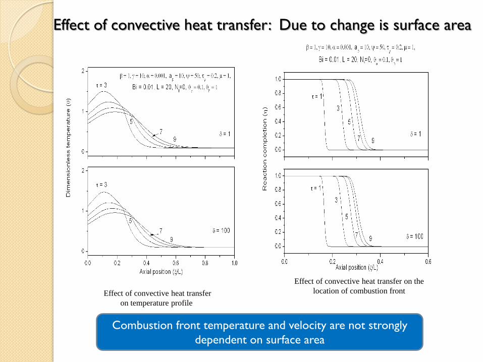
Effect of convective heat transfer: Due to change is surface area
Effect of convective heat transfer
on temperature profile
Effect of convective heat transfer on the
location of combustion front
Combustion front temperature and velocity are not strongly
dependent on surface area
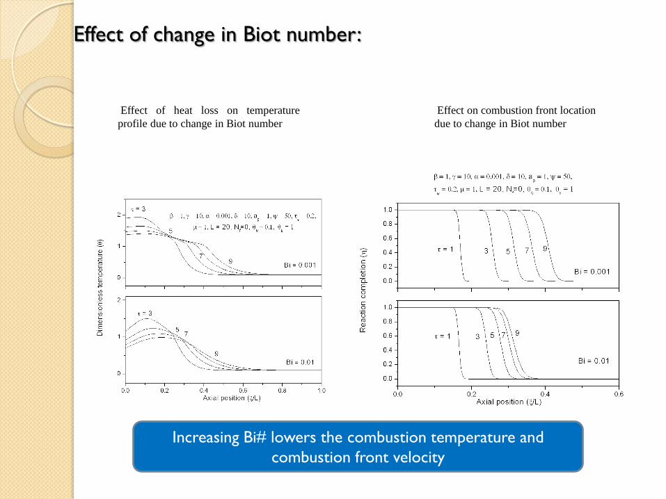
Effect of change in Biot number:
Effect of heat loss on temperature
profile due to change in Biot number
Effect on combustion front location
due to change in Biot number
Increasing Bi# lowers the combustion temperature and
combustion front velocity
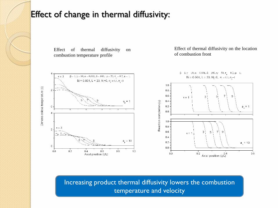
Effect of change in thermal diffusivity:
Effect of thermal diffusivity on
combustion temperature profile
Effect of thermal diffusivity on the location
of combustion front
Increasing product thermal diffusivity lowers the combustion
temperature and velocity
Summary: Model Results
In a typical self propagating process, the product gases evolved
reduce the combustion temperature and slow down the front
velocity.
The pores generated by these gases increase the total surface area
and in turn further increases heat loss to the environment.
High thermal diffusivity of the product decreases the combustion
front velocity and increases the width of combustion peak.
Heat loss from the product boundary increase the sharpness of the
combustion peak.