solution for wastewater & waste management - espp · solution for wastewater & waste...
TRANSCRIPT

Solution for Wastewater & Waste Management
Kubota Surface Melting Furnace
Our Concept Waste to Energy & Waste to Resource / Zero Landfill by 100% Recycle
Key technology for separation and purification from wide variety of wastes.
► Wide variety of wastes are acceptable.Wet / DryCombustible / IncombustibleBulky wastes : after pretreatment ( < 30mm)
► Continuous and stable feed:The waste are fed into the furnace by continuous outer cylinder rotation.
► High temperature treatment:1250~1350℃ Organic hazardous substances such as DXNs, PCBs, POPs are decomposed in the furnace.
► Recovery of Resourcesü Separation of heavy metals from slag : Heavy metals such as Pb, Cd, Zn, Hg are separated from slag and condensed into fly ash.ü Immobilization of phosphorus in slag with
high recovery rate (> 80%).
Schematic diagram of KUBOTA Surface Melting Furnaceü 40 years history, More than 30 track records
How can we melt Sludge/Waste with no fuel ? History of Kubota Surface Melting Furnace
Reference
Melting System
~1990s 2000s 2010sSuit for various waste
Construction Materials (safety sand)
Long-term operation(336days/yr) Separation of heavy metals
Decomposition of DXNs
Utilization of Slag Separation of metal
particles from the slag (including Au, Ag, Cu)
Phosphorus Fertilizer
Reduction of Fuel Consumption (Utilization of waste plastics as fuel)
Utilization of Fly Ash
Utilization of fly ash as secondary ore of Zn, Pb or Cu (Non-ferrous refinery plant)
・MSW incineration ash ・Sewage Sludge ・Landfill waste(including Soil)
・Cesium contaminated soil
Separation of Cesium
Energy recovery (combustion air heater , steam boiler ,power generation)
1974~
Upgrading
350
300
250
200
150
100
50
00 2,000 4,000 6,000 8,000 10,000 12,000
Heat value of waste to be treated(kJ/kg)
Fuel(
kero
sene
)co
nsum
ption
rate
(l/m
elte
d-t)
Relationship between heat value of waste to be incineratedand fuel(kerosene)consumption rate
・Sewage(30%-moist)・Mix. of Incineration Ash and Waste Plastics
Incineration Ash(bottom&fly)
300
250
►Combustible wastes such as sewage sludge, waste plastics are energy source to keep furnace high temperature.
(more than 30%)
Project Example -Illegal Dumping Site Remediation by Melting System-
[Teshima project(Japan)]
► Outline of the projectü Commissioned: 2003
ü Capacity: 200t/d (100t x 2)
ü Waste type:
Illegally dumped waste: 96%
Municipal solid waste: 4%
ü Energy recovery
The exhaust heat is collected
as steam and reused
► All by- products are recycled
Jan.2001 Apr.2014
Illegal dumping site
Melting treatment plant
Unit:tons
FY2003 FY2004 FY2005 FY2006 FY2007 FY2008 FY2009 FY2010 FY2011 FY2012 FY2013 Total Reused to
Melt(KSMF) 26,472 52,243 53,186 51,261 53,183 58,983 66,130 68,653 65,181 65,057 64,428 624,777 -
Incinerator(Kiln-type)
136 836 759 936 1,027 1,521 3,885 6,089 5,538 5,638 4,402 30,767 -
Rocks(Wash) 73 219 81 24 17 93 138 201 276 257 633 2,012 -
Total 26,681 53,298 54,026 52,221 54,227 60,597 70,153 74,943 70,995 70,952 69,463 657,556 -
Slag 11,095 32,399 34,706 32,114 31,428 30,751 34,851 33,843 34,709 33,950 34,317 344,162 ⇒Concrete aggregate
Copper 273 405 450 626 519 492 609 790 851 966 941 6,922 ⇒Non Ferrous Smelting
Ferrous materials 17 324 330 348 322 381 581 770 653 619 587 4,933 ⇒Steel making
Alminium 88 48 58 58 215 232 409 291 418 495 336 2,650 ⇒Al Smelting
Fly ash 1,180 2,404 2,355 1,976 2,118 2,295 2,496 2,958 2,563 2,732 2,251 25,327 ⇒Non Ferrous Smelting
Rocks 63 200 75 21 16 81 104 104 267 251 609 1,789 ⇒Backfilling material
※:FY2013:data at the end of Feb.2014
TeshimaWaste(input)
Products
Table: Actual achievement of treatment and the state of effective utilization
Metal Particle
► More than 600kt wastes were treated► All by-products are reused : Landfill site is Urban Mine !!
SlagCopper wire Roadbed material
No. Customer Melting furnace
throughput capacity Wastes to be melted Fuel type Inner diameter offurnace (mφ) Facility (furnace) size Completion of
construction
1Kagawa PrefectureKagawa Prefecture Naoshima Environmental Center 100t/d × two furnaces landfilled solid waste Bunker A 8.5
200t/day(100t/24h × two furnaces) September, 2003
No. Customer Melting furnacethroughput capacity Wastes to be melted Fuel type Inner diameter of
furnace (mφ) Facility (furnace) size Completion ofconstruction
1Sincere CorporationR.C. Center 25t/d × two furnaces Incinerated ash, fly ash Kerosene 3.0
130t/day(65t/24h × two furnaces) May, 1998
2Kubota Retechs IncorporatedKitakami Recycling Center 18t/d × one furnace Incinerated ash, fly ash Bunker A 3.4
101.6t/day(101.6t/24h × one furnace) October, 2003
3Saga Prefecture Environment Clean FoundationClean Park Saga 23t/d × one furnace Pyrolysis residues Kerosene 3.8
84t/day(42t/24 × two furnaces) March, 2009
No. CustomerMelting furnace
throughput capacity Wastes to be melted Fuel type Inner diameter offurnace (mφ) Facility (furnace) size Completion of
construction
1Kobe CitySeibu Disposal Plant 1.7t-ds/d x one furnace Sewage sludge Kerosene 1.2
3t/day(3t/24h × one system) 1979
2Toyama Prefecture Japan Sewage Works AgencyFutagami Clean Center for Oyabe River Basin Sewage system 5.3t-ds/d × one furnace Sewage sludge Bunker A 2.7
27t/day(27t/24h × one system) August, 1988
3Japan Sewage Works AgencyOsaka Minami Waste Disposal Center 25t-ds/d × two furnaces Sewage sludge Kerosene 6.0
228t/day(114t/24h × two systems) December, 1990
4Japan Sewage Works AgencyOsaka Minami Waste Disposal Center 12.5t-ds/d × one furnace Sewage sludge Kerosene 4.2
57t/day(57t/24h × one system) 1991
5Toyama Prefecture Japan Sewage Works AgencyFutagami Clean Center for Oyabe River Basin Sewage System 12t-ds/d × one furnace Sewage sludge Bunker A 4.0
60t/day(60t/24h × one system) March, 1993
6Japan Sewage Works AgencyOsaka Minami Waste Disposal Center 35t-ds/d × one furnace Sewage sludge Kerosene 7.0
159t/day(159t/24h × one system) December, 1995
7Fukuoka PrefectureMikasa River and Naka River Basin Sewage SystemMikasa River Clean Center
20t-ds/d × one furnace Sewage sludgeDigestion gas+Kerosene 5.4
100t/day(100t/24h × one system) April, 1997
8Toyama Prefecture Japan Sewage Works AgencyJintsu River Left Bank Basin Sewage SystemJintsu River Left Bank Clean Center
9t-ds/d × one furnace Sewage sludge Bunker A 3.4 45t/day(45t/24h × one system)
March, 2001
9Toyama Prefecture Japan Sewage Works AgencyFutagami Clean Center for Oyabe River Basin Sewage system 16t-ds/d × one furnace Sewage sludge Bunker A 4.7
80t/day(70t/24h × one system) March, 2006
10Toyama Prefecture Japan Sewage Works AgencyJintsu River Left Bank Basin Sewage SystemJintsu River Left Bank Clean Center
12t-ds/d × one furnace Sewage sludge Bunker A 460t/day
(60t/24h × one system) March, 2012
11 Toyama Prefecture Japan Sewage Works AgencyFutagami Clean Center for Oyabe River Basin Sewage system
16t-ds/d × one furnace Sewage sludge City gas 4.7 80t/day(70t/24h × one system)
March, 2017(planned)
Note: Sewage sludge is loaded into the melting furnace with 20-30% water content, making actual loading volume 1.25-1.43 times larger than throughput capacity.
4. Melting landfilled solid waste (illegally dumped waste)
5. Melting industrial waste incineration residue
6. Melting sewage sludge
Contact : Fumiki Hosho Kubota Corporation Water and Environment R&D Dept. III Address : 1-1-1, Hama, Amagasaki-city, Hyogo, 661-8567, Japan Tel : +81-80-8549-4529 E-mail : [email protected]
No. Customer Melting furnacethroughput capacity Waste to be melted Fuel type Inner diameter of
furnace (mφ) Facility (furnace) size Constructioncompletion date
1Isahaya CityIsahaya City Environmental Center
12.3t/16h × one furnace(18.5t/24h)
Incinerated ash: 55%Fly ash: 45% Kerosene 3.2
118t/day(59t/16h × two furnaces) March, 1987
2Sayama CitySayama City Clean Center 15t/d × one furnace
Incinerated ash: 67%Crushed bulky wastes: 33% Kerosene 3.5
100t/day(50t/24h × two furnaces) March, 1991
3Niigata City (old Shirone Sanitary Center Associations)Shirone Green Tower
7t/16h × one furnace(10.5t/24h) Incinerated ash: 100% Bunker A 2.8
100t/day(50t/16h × two furnaces) October, 1994
4JFE Kankyo Solutions Corporation Ryugasaki Local Refuse Disposal Associations Clean Plaza Ryu
12t/d × two furnaces Incinerated ash: 59.6%Fly ash: 40.4%
Bunker A 2.8 180t/day(90t/24h × two furnaces)
July, 1999
5Isahaya CityIsahaya City Environmental Center 24t/d × one furnace
Incinerated ash: 18.7%Fly ash: 13.4%
landfilled solid waste: 67.9%Bunker A 3.8
118t/day(59t/24h × two furnaces) January, 2000
6Hitachi Zosen Corporation Nishimurayama Wide Area Administrative Affairs Associations Sagae District Clean Center
14t/d × one furnaceIncinerated ash: 58.5%
Fly ash: 21.9%Other plastics: 19.6%
Bunker A 3.0 100t/day(50t/24h × two furnaces)
March, 2001
7JFE Kankyo Solutions Corporation Urazoe City Urazoe City Clean Center
16.3t/d × one furnace Incinerated ash: 83.9%Fly ash: 16.1%
Bunker A 3.0 150t/day(75t/24h × two furnaces)
March, 2002
8JFE Kankyo Solutions Corporation Sasayama City Sasayama City Clean Center
8t/d × one furnace Incinerated ash: 60%fly ash: 40%
Kerosene 2.3 80t/day(40t/24h × two furnaces)
November, 2002
9Mogami Wide Area Municipal Administrative Affairs AssociationsEco-Plaza Mogami 14t/d × one furnace
Incinerated ash: 66.3%Fly ash: 33.7% Kerosene 3.0
90t/day(45t/24h × two furnaces) February, 2003
10Ritto CityRitto City Environmental Center 10t/d × one furnace
Incinerated ash: 53.9%Fly ash: 46.1% Kerosene 2.6
76t/day(38t/24h × two furnaces) March, 2003
11IHI Corporation Waste Disposal of Tokyo's 23 Cities Administrative Affairs Associations Tamagawa Clean Plant
30t/d × one furnace Incinerated ash: 63.1%Fly ash: 36.9%
City gas 4.4 300t/day(150t/24h × two furnaces)
June, 2003
12Kawasaki Plant Systems Ltd. Hirakata City Hirakata City Tobu Clean Plant
24t/d × two furnaces(including one spare
furnace)
Incinerated ash: 78%Fly ash: 22%
City gas 3.6 240t/day(120t/24h × two furnaces)
December, 2008
No. Customer Melting furnacethroughput capacity Wastes to be melted Fuel type Inner diameter of
furnace (mφ) Facility (furnace) size Completion ofconstruction
1Mie Prefecture Environmental Conservation AgencyWaste Disposal Center 66.5t/d × three furnaces
Incinerated residue: 93.4%Pyrolysis residue: 5.1%
Animal and plant residues: 1.5%Kerosene 6.5
240t/day(80t/24h × three systems) December, 2002
No. Customer Melting furnacethroughput capacity Wastes to be melted Fuel type Inner diameter of
furnace (mφ) Facility (furnace) size Completion ofconstruction
1Isakita Aira Environment Management AssociationsMiraikan Public Center 7.6t/d × two furnaces Pyrolysis residues Kerosene 3.0
80t/day(40t/24h × two furnaces) March, 2003
2IHI Corporation Chita City Chita Clean Center
14t/d × two furnaces Pyrolysis residues Kerosene 3.8 130t/day(65t/24h × two furnaces)
March, 2003
1. Melting municipal waste incineration residue
2. Melting incineration residue of municipal waste and pyrolysis residue
3. Gasification melting furnace
MethaneFermentation Plant
Sewage Sludge
Renewable Materials(Metals, Plastics)
Residues
Fertilizer (Rich Phosphorus,little hazardous chemicals & heavy metals)
Slag (slightly heavy metals)
Metal particles (incl. Au, Ag, Cu, etc.)
Fly Ash (incl. Zn, Pb, etc.)Residues(Waste Plastics)
Energy Resources
E-Waste
Sewage
Sludge Melting System (no need for fuel except start-up)
Waste Melting System (no need for fuel except start-up)
Sorting Plant
WastewaterTreatmentPlant
Sorting
Non-ferrous Refinery Recycling Plant
Renewable Materials
Residues
Residues(Waste Plastics)
Heat
stem except start-up)
HeatOrganic Waste
Slag (slightly heavy metals)
Landfill
Roadbed material
MunicipalSolid Waste
MethaneFermentation Plant
Sewage SludgeSewage Sludge
BiogasFarm
Zero Landfill
Sludge
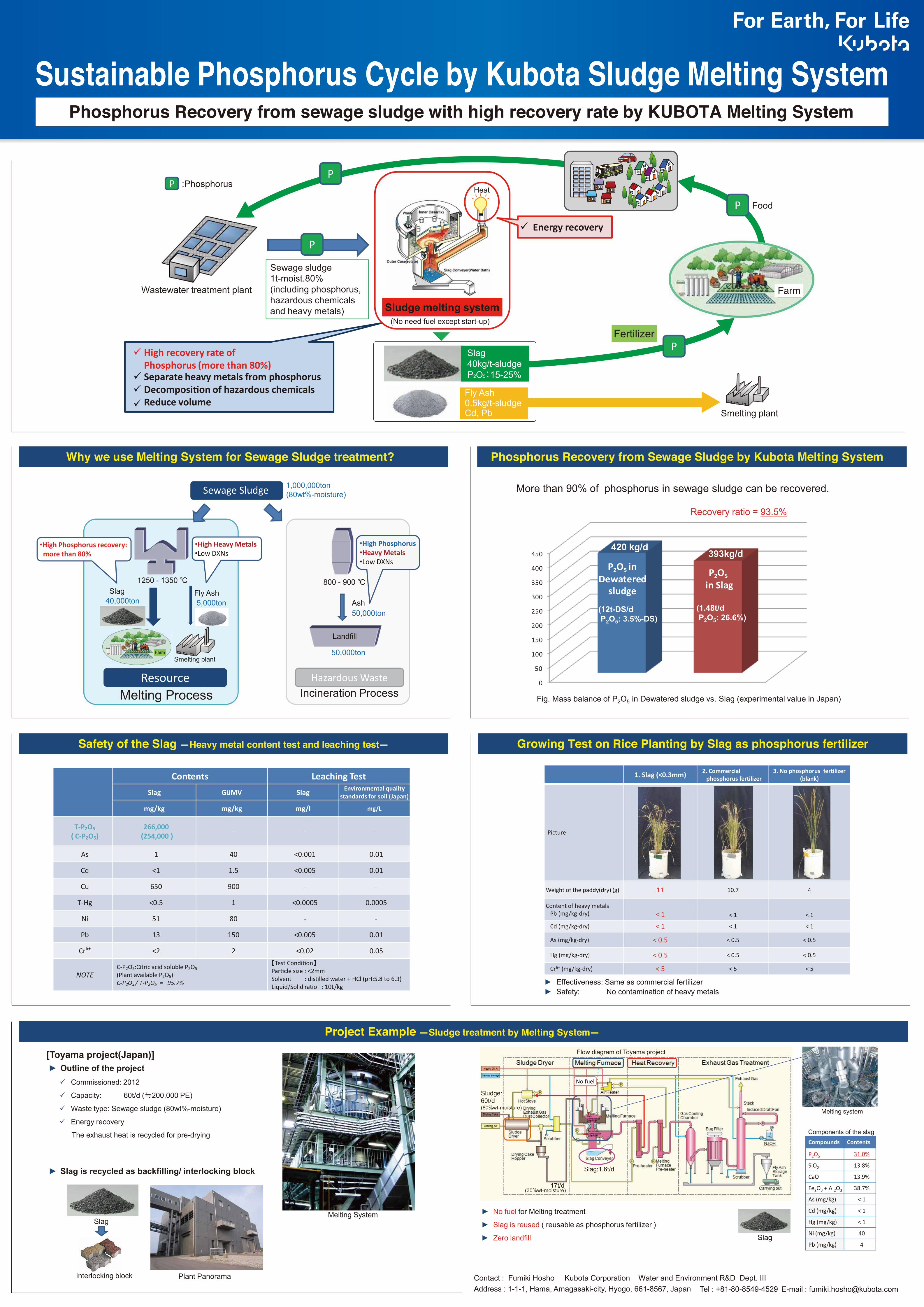
Sustainable Phosphorus Cycle by Kubota Sludge Melting System
Phosphorus Recovery from sewage sludge with high recovery rate by KUBOTA Melting System
Contact : Fumiki Hosho Kubota Corporation Water and Environment R&D Dept. III Address : 1-1-1, Hama, Amagasaki-city, Hyogo, 661-8567, Japan Tel : +81-80-8549-4529 E-mail : [email protected]
Phosphorus Recovery from Sewage Sludge by Kubota Melting System Why we use Melting System for Sewage Sludge treatment?
Project Example -Sludge treatment by Melting System-
Safety of the Slag -Heavy metal content test and leaching test- Growing Test on Rice Planting by Slag as phosphorus fertilizer
ü High recovery rate of
Phosphorus (more than 80%) ü Separate heavy metals from phosphorus ü Decomposition of hazardous chemicals ü Reduce volume
Wastewater treatment plant
Sludge melting system
P
P Heat
ü Energy recovery
Sewage sludge1t-moist.80%(including phosphorus, hazardous chemicals and heavy metals)
Fertilizer
Smelting plant
(No need fuel except start-up)
P :Phosphorus
Sewage Sludge
1250 - 1350 ℃ Slag Fly Ash
1,000,000ton(80wt%-moisture)
40,000ton 5,000ton
Resource Melting Process
• High Heavy Metals • Low DXNs
800 - 900 ℃
Ash 50,000ton
50,000ton
Incineration Process
Landfill
Hazardous Waste
• High Phosphorus • Heavy Metals • Low DXNs
Smelting plantFarm
• High Phosphorus recovery: more than 80%
More than 90% of phosphorus in sewage sludge can be recovered.
1. Slag (<0.3mm) 2. Commercial phosphorus fertilizer
3. No phosphorus fertilizer (blank)
Picture
Weight of the paddy(dry) (g) 11 10.7 4
Content of heavy metals Pb (mg/kg-dry) < 1 < 1 < 1
Cd (mg/kg-dry) < 1 < 1 < 1
As (mg/kg-dry) < 0.5 < 0.5 < 0.5
Hg (mg/kg-dry) < 0.5 < 0.5 < 0.5
Cr6+ (mg/kg-dry) < 5 < 5 < 5
► Effectiveness: Same as commercial fertilizer► Safety: No contamination of heavy metals
[Toyama project(Japan)]► Outline of the projectü Commissioned: 2012
ü Capacity: 60t/d (≒200,000 PE)
ü Waste type: Sewage sludge (80wt%-moisture)
ü Energy recovery
The exhaust heat is recycled for pre-drying
► Slag is recycled as backfilling/ interlocking block
Melting SystemSlag
Interlocking block Plant Panorama
Flow diagram of Toyama project
Melting system
Compounds Contents
P2O5 31.0%
SiO2 13.8%
CaO 13.9%
Fe2O3 + Al2O3 38.7%
As (mg/kg) < 1
Cd (mg/kg) < 1
Hg (mg/kg) < 1
Ni (mg/kg) 40
Pb (mg/kg) 4
Sludge:60t/d(80%wt-moisture)
17t/d(30%wt-moisture)
Slag:1.6t/d
► No fuel for Melting treatment
► Slag is reused ( reusable as phosphorus fertilizer )
► Zero landfill
Components of the slag
No fuel
Slag
FoodP
P
0
50
100
150
200
250
300
350
400
450
P2O5 in Dewatered
sludge
P2O5
in Slag
420 kg/d393kg/d
Recovery ratio = 93.5%
Fig. Mass balance of P2O5 in Dewatered sludge vs. Slag (experimental value in Japan)
(12t-DS/d P2O5: 3.5%-DS)
(1.48t/d P2O5: 26.6%)
Farm
Fly Ash0.5kg/t-sludgeCd, Pb
Slag40kg/t-sludgeP2O5:15-25%
Contents Leaching Test Slag GüMV Slag Environmental quality
standards for soil (Japan)
mg/kg mg/kg mg/l mg/L
T-P2O5
( C-P2O5)
266,000 (254,000 ) - - -
As 1 40 <0.001 0.01
Cd <1 1.5 <0.005 0.01
Cu 650 900 - -
T-Hg <0.5 1 <0.0005 0.0005
Ni 51 80 - -
Pb 13 150 <0.005 0.01
Cr6+ <2 2 <0.02 0.05
NOTE C-P2O5:Citric acid soluble P2O5
(Plant available P2O5) C-P2O5 / T-P2O5 = 95.7%
【Test Condition】 Particle size : <2mm Solvent : distilled water + HCl (pH:5.8 to 6.3) Liquid/Solid ratio : 10L/kg