solutions for automated bending
TRANSCRIPT

GB XB
SOLUTIONS FOR AUTOMATED BENDING

2
With FINN-POWER EB the machine operation cycle isfully automatic and includes the following stages: loading,rotation during the bending sequence, bending, andunloading.
Operation
The machine is operated by a CNC and a PLC (Program-mable Logic Controller). The CNC and the PLC exchangeinformation and synchronism through digital I/O. Themachine’s main functions as well as all the axes involved inthe bending are controlled by the CNC.
Bending generally starts from the outside edge of the sheetand continues towards the inside of the sheet, working oneside after another in sequence. The sheet is loaded auto-matically onto the working table by a robot where a mani-pulator pushes it against the positioning pins. The mani-pulator holds the work piece firmly during all the manipu-lation phases.
The bending tool holds the required portion of sheet inposition during the bending action. Two blades manipulatethe portion protruding from between the counter-bladeand the upper tool, upwards or downwards according tothe nature of the bend (positive or negative) and the re-quired angle, CNC programmable.The ready-bent component isautomatically exited and thenext flat work piece loaded.
FINN-POWER EB
In many cases the press brake, the standard technical solu-tion for the bending of sheet metal components, is notonly the typical but also the most productive manufacturingmethod.
Yet, there are many manufacturing situations where anautomated bending cell offers benefits far superior interms of• total manufacturing cost• component quality• automation level.
FINN-POWER’s new EB bending cell is your optimalsolution for bending• large components• from thin sheets• in long series• automatically
INGENIOUS BASIC PRINCIPLE– ROBUST, CAREFULLY ENGINEEREDCONSTRUCTION
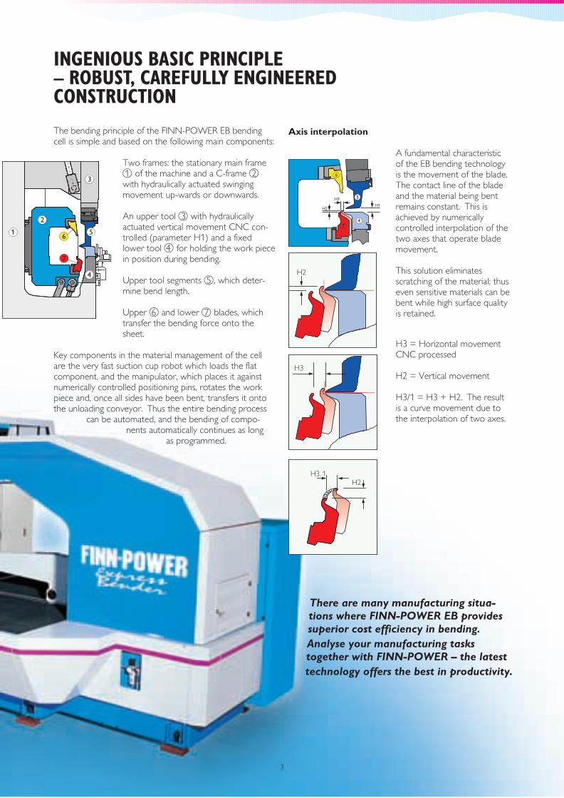
The bending principle of the FINN-POWER EB bendingcell is simple and based on the following main components:
Two frames: the stationary main frameof the machine and a C-frame
with hydraulically actuated swingingmovement up-wards or downwards.
An upper tool with hydraulicallyactuated vertical movement
and a fixedlower tool for holding the work piecein position during bending.
Upper tool segments , which deter-mine bend length.
Upper and lower blades, whichtransfer the bending force onto thesheet.
Key components in the material management of the cellare the very fast suction cup robot which loads the flatcomponent, and the manipulator, which places it againstnumerically controlled positioning pins, rotates the workpiece and, once all sides have been bent, transfers it ontothe unloading conveyor. Thus the entire bending process
can be automated, and the bending of compo-nents automatically continues as long
as programmed.
1 2
3
4
5
6 7
CNC con-trolled (parameter H1)
Axis interpolation
A fundamental characteristicof the EB bending technologyis the movement of the blade.The contact line of the bladeand the material being bentremains constant. This isachieved by numericallycontrolled interpolation of thetwo axes that operate blademovement.
This solution eliminatesscratching of the material; thuseven sensitive materials can bebent while high surface qualityis retained.
H3 = Horizontal movementCNC processed
H2 = Vertical movement
H3/1 = H3 + H2. The resultis a curve movement due tothe interpolation of two axes.
H2
H3
H2H3.1
H1H2
H3
6
74
5
There are many manufacturing situa-tions where FINN-POWER EB providessuperior cost efficiency in bending.Analyse your manufacturing taskstogether with FINN-POWER – the latesttechnology offers the best in productivity.
3
CONTROL CABIN COOLER
Acceptable ambient temperaturefor the standard bending cell are:temperature +15° . . . +30° C.For operation in warmertemperatures a control cabinetcooler is required.
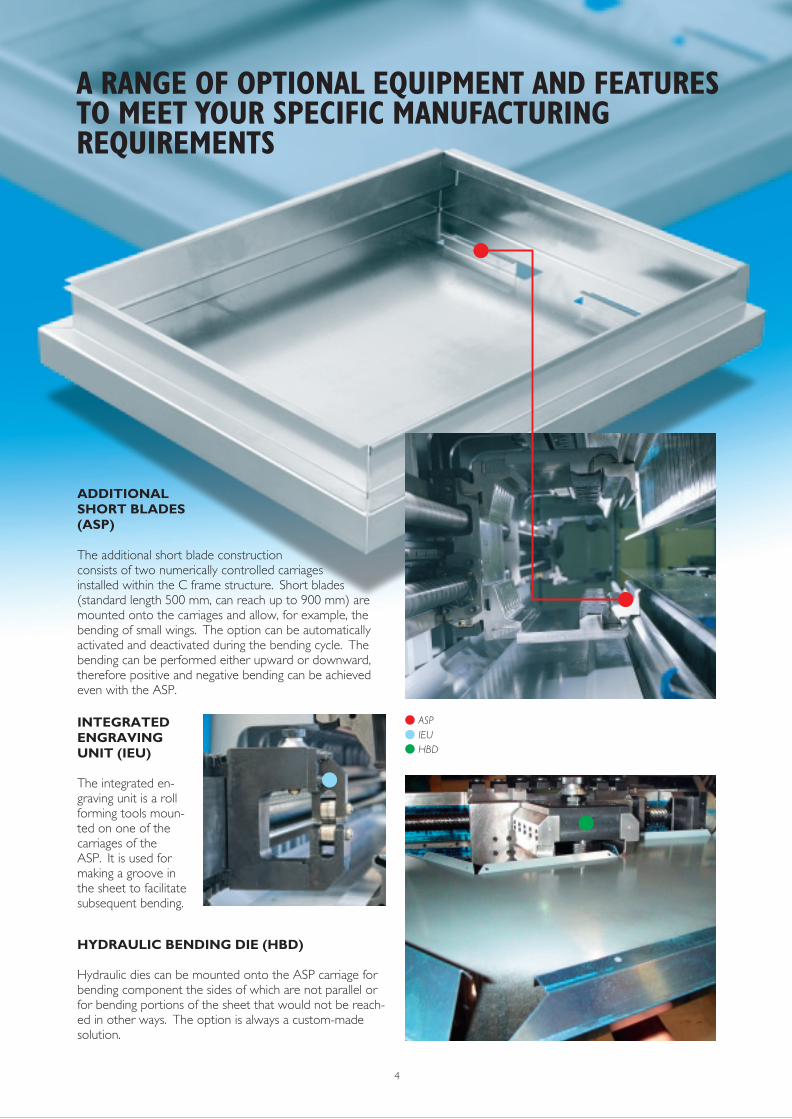
INTEGRATEDENGRAVINGUNIT (IEU)
The integrated en-graving unit is a rollforming tools moun-ted on one of thecarriages of theASP. It is used formaking a groove inthe sheet to facilitatesubsequent bending.
HYDRAULIC BENDING DIE (HBD)
Hydraulic dies can be mounted onto the ASP carriage forbending component the sides of which are not parallel orfor bending portions of the sheet that would not be reach-ed in other ways. The option is always a custom-madesolution.
HYDRAULIC TOOLCLAMPING (HTC)
Changing upper tool dimensions isfacilitated and made faster by thehydraulic tool clamping option. Inorder to change the upper tooldimension the operator simplyneeds to unlock the hydraulic clampand press a clip to be able to movethe segment into desired position.
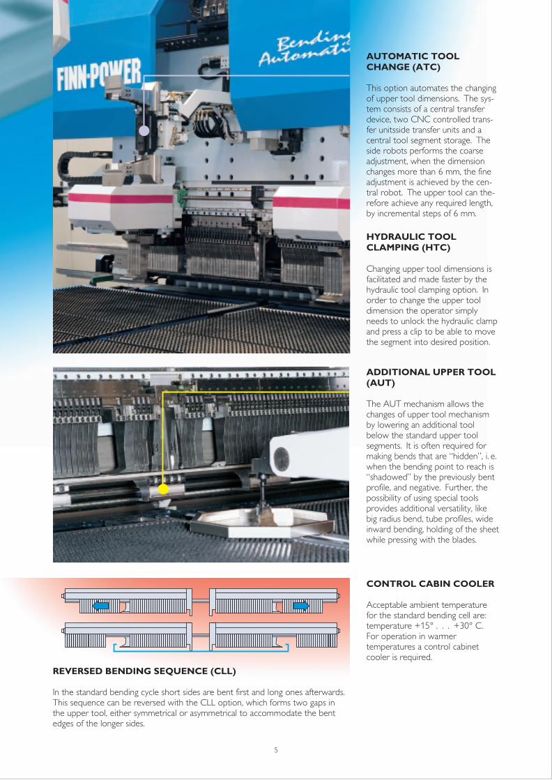
AUTOMATIC TOOLCHANGE (ATC)
This option automates the changingof upper tool dimensions. The sys-tem consists of a central transferdevice, two CNC controlled trans-fer unitsside transfer units and acentral tool segment storage. Theside robots performs the coarseadjustment, when the dimensionchanges more than 6 mm, the fineadjustment is achieved by the cen-tral robot. The upper tool can the-refore achieve any required length,by incremental steps of 6 mm.
REVERSED BENDING SEQUENCE (CLL)
In the standard bending cycle short sides are bent first and long ones afterwards.This sequence can be reversed with the CLL option, which forms two gaps inthe upper tool, either symmetrical or asymmetrical to accommodate the bentedges of the longer sides.
ADDITIONAL UPPER TOOL(AUT)
The AUT mechanism allows thechanges of upper tool mechanismby lowering an additional toolbelow the standard upper toolsegments. It is often required formaking bends that are “hidden”, i.e.when the bending point to reach is“shadowed” by the previously bentprofile, and negative. Further, thepossibility of using special toolsprovides additional versatility, likebig radius bend, tube profiles, wideinward bending, holding of the sheetwhile pressing with the blades.
4 5
ADDITIONALSHORT BLADES(ASP)
The additional short blade constructionconsists of two numerically controlled carriagesinstalled within the C frame structure. Short blades(standard length 500 mm, can reach up to 900 mm) aremounted onto the carriages and allow, for example, thebending of small wings. The option can be automaticallyactivated and deactivated during the bending cycle. Thebending can be performed either upward or downward,therefore positive and negative bending can be achievedeven with the ASP.
A RANGE OF OPTIONAL EQUIPMENT AND FEATURESTO MEET YOUR SPECIFIC MANUFACTURINGREQUIREMENTS
ASPIEUHBD
CONTROL CABIN COOLER
Acceptable ambient temperaturefor the standard bending cell are:temperature +15° . . . +30° C.For operation in warmertemperatures a control cabinetcooler is required.
INTEGRATEDENGRAVINGUNIT (IEU)
The integrated en-graving unit is a rollforming tools moun-ted on one of thecarriages of theASP. It is used formaking a groove inthe sheet tofacilitate subsequent
HYDRAULIC BENDING DIE (HBD)
Hydraulic dies can be mounted onto the ASP carriage forbending component the sides of which are not parallel orfor bending portions of the sheet that would not be reach-ed in other ways. The option is always a custom-madesolution.
HYDRAULIC TOOLCLAMPING (HTC)
Changing upper tool dimensions isfacilitated and made faster by thehydraulic tool clamping option. Inorder to change the upper tooldimension the operator simplyneeds to unlock the hydraulic clampand press a clip to be able to movethe segment into desired position.
AUTOMATIC TOOLCHANGE (ATC)
This option automates the changingof upper tool dimensions. The sys-tem consists of a central transferdevice, two CNC controlled trans-fer unitsside transfer units and acentral tool segment storage. Theside robots performs the coarseadjustment, when the dimensionchanges more than 6 mm, the fineadjustment is achieved by the cen-tral robot. The upper tool can the-refore achieve any required length,by incremental steps of 6 mm.
REVERSED BENDING SEQUENCE (CLL)
In the standard bending cycle short sides are bent first and long ones afterwards.This sequence can be reversed with the CLL option, which forms two gaps inthe upper tool, either symmetrical or asymmetrical to accommodate the bentedges of the longer sides.
ADDITIONAL UPPER TOOL(AUT)
The AUT mechanism allows thechanges of upper tool mechanismby lowering an additional toolbelow the standard upper toolsegments. It is often required formaking bends that are “hidden”, i.e.when the bending point to reach is“shadowed” by the previously bentprofile, and negative. Further, thepossibility of using special toolsprovides additional versatility, likebig radius bend, tube profiles, wideinward bending, holding of the sheetwhile pressing with the blades.
4 5
ADDITIONALSHORT BLADES(ASP)
The additional short blade constructionconsists of two numerically controlled carriagesinstalled within the C frame structure. Short blades(standard length 500 mm, can reach up to 900 mm) aremounted onto the carriages and allow, for example, thebending of small wings. The option can be automaticallyactivated and deactivated during the bending cycle. Thebending can be performed either upward or downward,therefore positive and negative bending can be achievedeven with the ASP.
A RANGE OF OPTIONAL EQUIPMENT AND FEATURESTO MEET YOUR SPECIFIC MANUFACTURINGREQUIREMENTS
NONMAGNETIC MATERIAL SEPARATION(NMS)
With plastic coated sheets and under conditions wherestatic electricity may be a problem, the NMS option elimi-nates it. The suction cup rows closest to the edges of thesheet operate at first to lift the edges for better sheetseparation. Blowing compressed air between the sheetsand additional steel brushes finally contribute to theseparation. The option is for Stand-alone machines only.
DOUBLE LOADING TABLE (DLT)
When the double loading table is used, a new stack of flatcomponents can be loaded onto one table while themachine continues to operate using components from theother table. Available only for EB 3 machines.
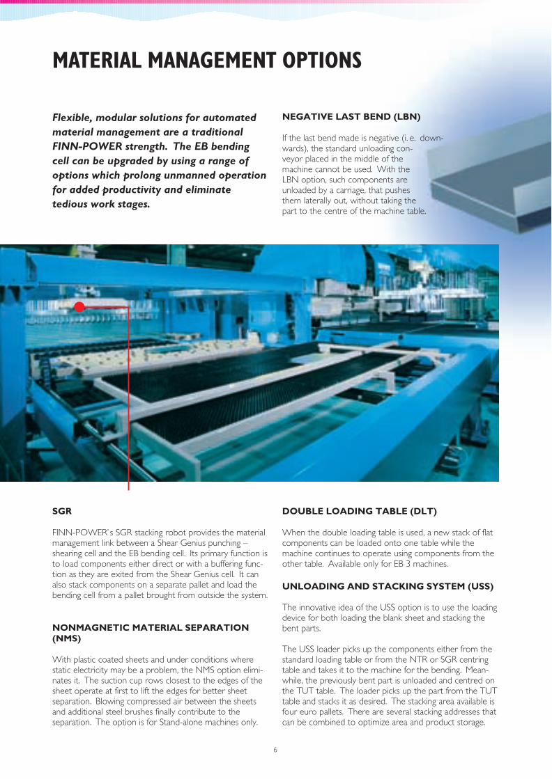
SGR
FINN-POWER’s SGR stacking robot provides the materialmanagement link between a Shear Genius punching –shearing cell and the EB bending cell. Its primary function isto load components either direct or with a buffering func-tion as they are exited from the Shear Genius cell. It canalso stack components on a separate pallet and load thebending cell from a pallet brought from outside the system.
UNLOADING AND STACKING SYSTEM (USS)
The innovative idea of the USS option is to use the loadingdevice for both loading the blank sheet and stacking thebent parts.
The USS loader picks up the components either from thestandard loading table or from the NTR or SGR centringtable and takes it to the machine for the bending. Mean-while, the previously bent part is unloaded and centred onthe TUT table. The loader picks up the part from the TUTtable and stacks it as desired. The stacking area available isfour euro pallets. There are several stacking addresses thatcan be combined to optimize area and product storage.
6
Flexible, modular solutions for automatedmaterial management are a traditionalFINN-POWER strength. The EB bendingcell can be upgraded by using a range ofoptions which prolong unmanned operationfor added productivity and eliminatetedious work stages.
NEGATIVE LAST BEND (LBN)
If the last bend made is negative (i.e. down-wards), the standard unloading con-veyor placed in the middle of themachine cannot be used. With theLBN option, such components areunloaded by a carriage, that pushesthem laterally out, without taking thepart to the centre of the machine table.
MATERIAL MANAGEMENT OPTIONS
FOR
EXAMPLE...
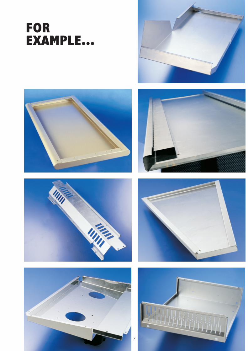
FOR
EXAMPLE...
7

8

TILTING UNLOADING TABLE (TUT)
Instead of the standard table, a tilting unloading table canbe used. This table is designed to allow the bent panels tobe unloaded towards the operator side and grant a smallbuffering function (2-3 relatively small pieces). After theready-bent component reaches the TUT table, a rollmechanism transfers the part to the end of the table, alocation from which it is brought by conveyor belts to theoperator side of the table.
BUFFER STORAGES
FINN-POWER EB can be equipped with a buffer systemfor bent components to prolong periods of unmannedoperation. The components are temporarily stored invertical position on a buffer which is installed at right anglesto the unloading conveyor.
1. Bending Cell2. Unloading Roll Table3. Buffer4. Safety Fencing5. Sheet Pusher
ALT SET-UP
This option provides automatic adjustment of the loadingunit and the positioning bars on the loading table. It short-ens set-up times and facilitates the loading of a new stack.
9

2
1
3
4
Lillbacka CorporationP.O. Box 38FIN-62201 KauhavaFinlandTel. + 358 6 428 2111Fax + 358 6 428 2244www.finn-power.com
FINN-POWER International, Inc.710 Remington RoadSchaumburg, Illinois 60173USATel. + 1 847 885 3200Fax + 1 847 885 9692www.finnpower.com
FINN-POWER Lillbacka GmbHPostfach 54D-85399 HallbergmoosGermanyTel. + 49 811 55330Fax + 49 811 1667www.finn-power.de
FINN-POWER Lillbacka SARLTechniparc.- 5, rue BooleF-91240 Saint Michel Sur OrgeFranceTél. + 33 1 69 46 55 80Fax + 33 1 69 46 55 81www.finn-power.fr
FINN-POWER Italia S.r.l.Via Papa Giovanni XXIII, 79IT-25015 Desenzano del Garda (BS)ItalyTel. + 39 0 30 911 8111Fax + 39 0 30 911 8119
Technical information
FIN
N-
POW
ER B
endi
ng C
ells,
IT
EM10
82.
Subj
ect
to c
hang
es w
ithou
t pr
ior
notic
e.C
opyr
ight
Lill
back
a C
orpo
ratio
n M
ay 2
000
Bending Cell EB EB3 EB4 EB5 BC 32
Maximum bending length (mm) 1650 2150 2550 3250
Minimum length between the bends (mm) 350
Maximum width between the bends (mm) 140 160 160 180
Sheet length, min max (mm) 370 1800 370 2450 370 2850 370 3500
Sheet width, min max (mm) 160 1200 180 1500 200 . . . 1650
Maximum panel diagonal 1900 2700 3000 3600
Maximum bend height SH type 200 (127 mm type N)
Maximum re-entering bend 55 55 55 55
Maximum stack height 220
Maximum pack weight (kg) * 3000
Sheet planarity 10
Maximum material thickness
Fe 37 steel 3.2 2.5
Stainless steel 1.8 2.2 1.8
Aluminium 3.5 4.0 3.0
Minimum material thickness 0.5 0.6
Minimum external radius 1.5 . . . 2 x sheet thickness
Bend angle (degrees) –135 . . . +135
Max. number of bends per side 20
Angle tolerance ± 0°40' ± 0°40'
Bend dimension tolerance (mm) ± 0.2 ± 0.2
Straightness and parallelism (mm) 0.4 0.4
Average absorbed (kW) 22 30 30 30
Voltage (V) 400 (50 / 60 Hz)
Main switch (A) 160
Compressed air consumption (½", Nl/min) 12
Compressed air pressure (bar) 6
350 350 350
. . . . . . . . . . . . . . .
. . . . . . 180 . . . 1500 . . .
(mm)
(mm) 200 (127 mm type N) 200 (127 mm type N) 200 (127 mm type N)
(mm)
(mm) * 220 220 220
3000 3000 3000
(mm) 10 10 10
(mm)
2.0 2.5
1.5
3.0
(mm) 0.5 0.5
1.5 . . . 2 x sheet thickness 1.5 . . . 2 x sheet thickness 1.5 . . . 2 x sheet thickness
–135 . . . +135 –135 . . . +135 –135 . . . +135
20 20 20
± 0°40' ± 0°40'
± 0.2 ± 0.2
0.6 0.6
Power: max installed (kW) 58 66 66 66
400 (50 / 60 Hz) 400 (50 / 60 Hz) 400 (50 / 60 Hz)
160 160 160
12 12 12
6 6 6
* Stand alone machines only