solutions for diverse application. - larsen & · pdf filein every industry, big or small,...
TRANSCRIPT

Solutions for diverse application.
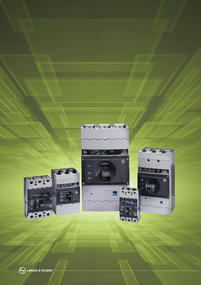
Moulded Case Circuit Breakers

Stability: Activated

In every industry, big or small, electrical power supply The dsine range, a new generation of MCCBs, is a is critical. Even a few seconds of interruption or combination of state-of-the-art design and modern instability can result in huge financial losses, even loss user-friendly features. It also boasts a wide choice of of life. We have little or no control over the nature or protective releases, ergonomics, aesthetics and
compactness. The range, designed to meet the stability of power supply. The unpredictable nature of changing needs of users after extensive analysis and power makes it important to take appropriate steps user feedback, can satisfy the most demanding for the protection and safety of your organisation’s system requirements.employees and equipment.
Complemented by a wide array of accessories, the In line with this objective, Larsen & Toubro presents dsine range offers comprehensive solutions to dsine – a highly advanced and sophisticated range of customer applications ensuring operational safety, Moulded Case Circuit Breakers (MCCBs).reliability and versatility.
1Up and Running, Uninterrupted
Over the last five decades, L&T has earned a place selection, installation and effective after-sales
among the world’s leading manufacturers of Low service, across the country.
Voltage Switchgear with the scale, sophistication and L&T is one of the first companies to introduce MCCBs
range to meet global benchmarks. in India. Over the years, we have developed our products to meet the ever-evolving demands of the In keeping with our leadership position in the Indian market.market, we also provide expert assistance in product
L&T – Turning technology to your advantage
Moulded Case Circuit Breakers

Obstacles: Deleted

Overcoming Challenges
For Original Equipment Manufacturers (OEMs), every offer neutral and earth fault protection with 3P moment poses a new challenge. The dsine range of MCCBs. Equipped with common accessories for the MCCBs has been created keeping this in mind. Built in entire range, these MCCBs assure excellent savings by accordance with the highest technical standards, reducing your inventory costs.
dsine MCCBs assure reliable and maintenance-free What’s more, our experienced sales & service team is operation. They have been designed to adapt to just a call away. Our team is adept at handling changes and overcome the challenges of your day-to- queries and complaints and is trained to offer you day operations. techno-commercial solutions… on time, every time.
Besides being available in 4P version to serve OEMs, After all, forging long-term associations has always such as DG sets, dsine MCCBs come with an external been the cornerstone of our business.neutral CT for the microprocessor-based version to
Moulded Case Circuit Breakers
Original Equipment Manufacturers (OEMs)
3
Versatility: Downloaded
Oil Industry
Paper Industry
Sugar Industry
Gas Industry
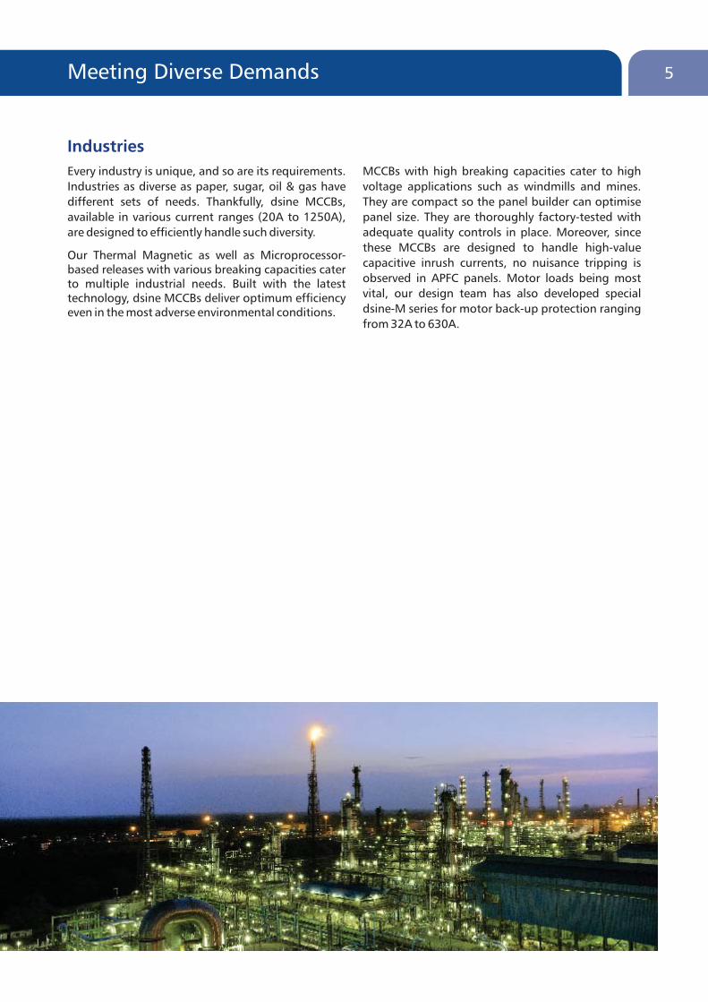
Every industry is unique, and so are its requirements. MCCBs with high breaking capacities cater to high
Industries as diverse as paper, sugar, oil & gas have voltage applications such as windmills and mines.
different sets of needs. Thankfully, dsine MCCBs, They are compact so the panel builder can optimise
available in various current ranges (20A to 1250A), panel size. They are thoroughly factory-tested with
are designed to efficiently handle such diversity. adequate quality controls in place. Moreover, since
these MCCBs are designed to handle high-value Our Thermal Magnetic as well as Microprocessor-
capacitive inrush currents, no nuisance tripping is based releases with various breaking capacities cater
observed in APFC panels. Motor loads being most to multiple industrial needs. Built with the latest vital, our design team has also developed special technology, dsine MCCBs deliver optimum efficiency dsine-M series for motor back-up protection ranging even in the most adverse environmental conditions.from 32A to 630A.
5Meeting Diverse Demands
Industries
Efficiency: Initiated
7Paving The Path to Progress
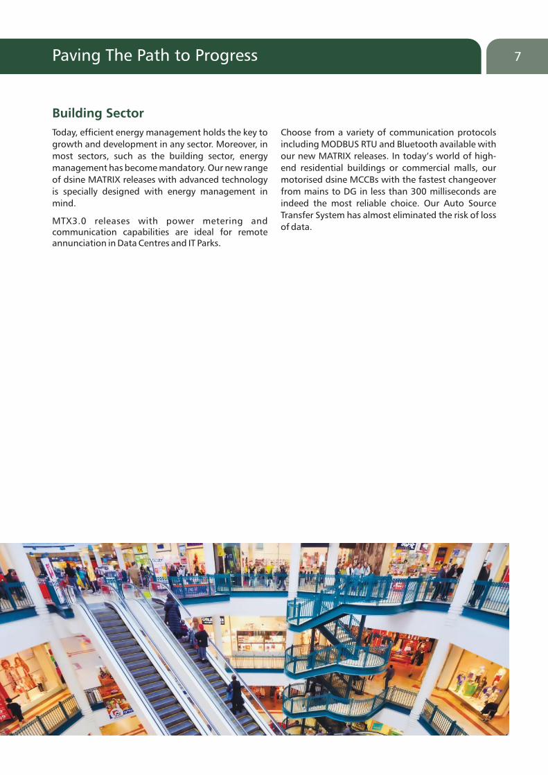
Today, efficient energy management holds the key to Choose from a variety of communication protocols
growth and development in any sector. Moreover, in including MODBUS RTU and Bluetooth available with
most sectors, such as the building sector, energy our new MATRIX releases. In today’s world of high-
management has become mandatory. Our new range end residential buildings or commercial malls, our
of dsine MATRIX releases with advanced technology motorised dsine MCCBs with the fastest changeover
is specially designed with energy management in from mains to DG in less than 300 milliseconds are
mind. indeed the most reliable choice. Our Auto Source
Transfer System has almost eliminated the risk of loss MTX3.0 releases with power metering and
of data.communication capabilities are ideal for remote annunciation in Data Centres and IT Parks.
Building Sector

Performance: Delivered

9Delivering Unparalleled Results
Unlike AC breaking, DC breaking is a critical They are also available for lower DC voltages such as
phenomenon that causes severe damage. That’s why, battery chargers.
we offer DC MCCBs from the dsine family. A range The SD (Switch Disconnector) version of dsine MCCBs
that has been designed and developed specially for can be used at the incoming and outgoing terminals
DC applications such as UPS and battery chargers. of UPS for isolation. Our SD is designed to withstand high currents without compromising on Service Choose from a wide range of DC voltages (up to Performance. 500V) and DC breaking capacities (up to 36kA)
available as per various application requirements.
DC Systems, UPS, Battery Chargers

Reliability: Ensured
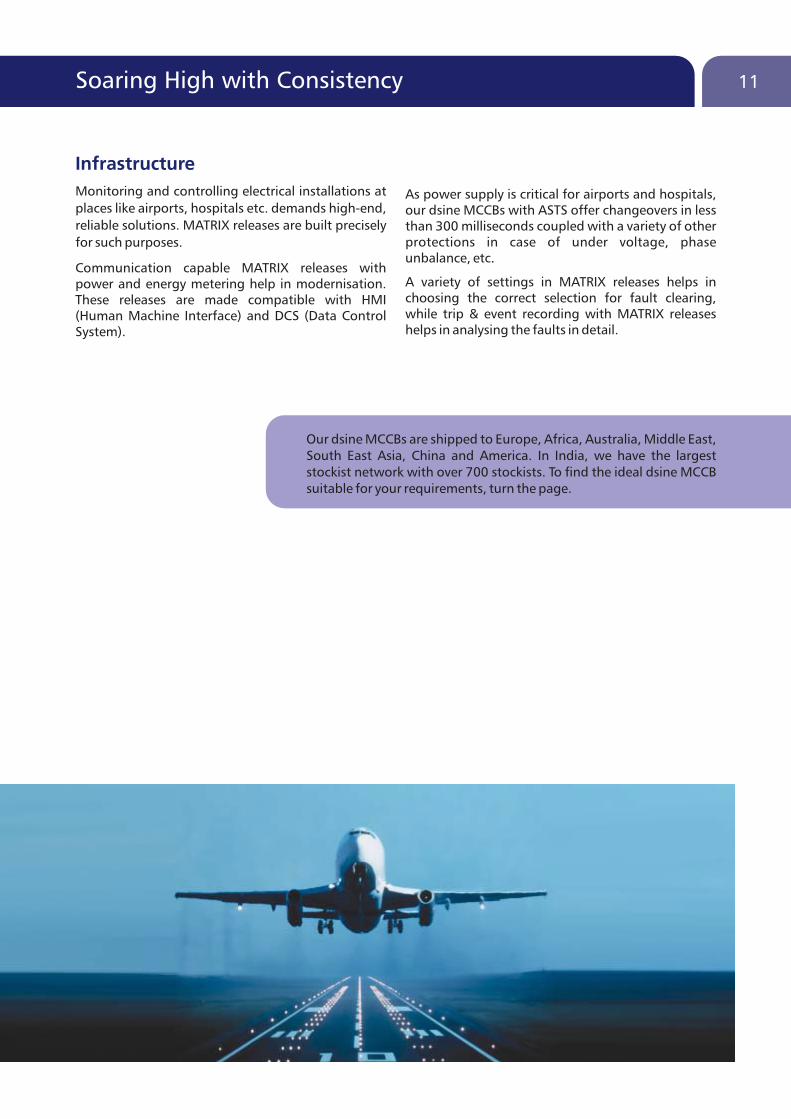
Monitoring and controlling electrical installations at As power supply is critical for airports and hospitals, places like airports, hospitals etc. demands high-end, our dsine MCCBs with ASTS offer changeovers in less reliable solutions. MATRIX releases are built precisely than 300 milliseconds coupled with a variety of other for such purposes. protections in case of under voltage, phase
unbalance, etc. Communication capable MATRIX releases with
A variety of settings in MATRIX releases helps in power and energy metering help in modernisation. choosing the correct selection for fault clearing, These releases are made compatible with HMI while trip & event recording with MATRIX releases (Human Machine Interface) and DCS (Data Control helps in analysing the faults in detail.System).
11Soaring High with Consistency
Our dsine MCCBs are shipped to Europe, Africa, Australia, Middle East, South East Asia, China and America. In India, we have the largest stockist network with over 700 stockists. To find the ideal dsine MCCB suitable for your requirements, turn the page.
Infrastructure


Characteristic Curves
Wiring Diagrams
INDEX
Accessories
Overview
Dimensions
Product Data
Overview
�
�
�
�
�
�
Range
Standards & Approvals
Structure & Features
Marking & Configuration
Trip Units
Accessories
16
18
19
20
21
22

State-of-the-art design, user-friendly features and a wide spectrum of protection releases form the hallmarks of the dsine range. Also recognised for its ergonomics, aesthetics and compactness, it belongs to a new generation of MCCBs. Specially designed and developed for extreme tropical conditions, it promises reliable performance at high ambient and humid environment.
dsine, unfailingly, caters to the ever-evolving needs of customers, derived after in-depth analysis and customer feedback. Because we understand our customers' requirements and demands, our contemporary range of MCCBs never fall short of ensuring complete customer satisfaction. Moreover, complemented by a host of accessories, the dsine range delivers comprehensive solutions to customer applications ensuring operational safety, reliability and versatility.
16 Range
DN4 DN3 DN2 DN1 DN0

17
Features
�Range available f
�Available in 3 pole & 4 pole
�Range of 25kA / 36kA / 50kA / 70kA / 100kA breaking capacities
�Microprocessor and Thermal-Magnetic based protection releases
�MCCBs for Motor backup protection
�MCCBs for Distribution and SD versions
�Manual, Rotary or Motorised versions
�Wide range of common Internal and External accessories
rom 20A to 1250A
�Suitable for DC application
Breaking Capacities (I )cu
Range
* Available only in DN0-D
DN0
20, 25, 32, 40, 50, 63, 80, 100, 125*AThermal-Magnetic
DN1
125, 160, 200, 250AThermal-Magnetic
DN2
DN3B
320, 400AThermal-Magnetic
DN3
DN4
800, 1000, 1250AMicroprocessor
Rated Current
Release
Rated Current
Release
Rated Current
Release
Rated Current
Release
Rated Current
Release
Rated Current
Release
40, 63, 100, 160, 250AMicroprocessor
63, 80, 100, 125, 160, 200, 250AThermal-Magnetic
400, 630AMicroprocessor
320, 400, 500, 630AThermal-Magnetic
18 Standards & Approvals
NABL
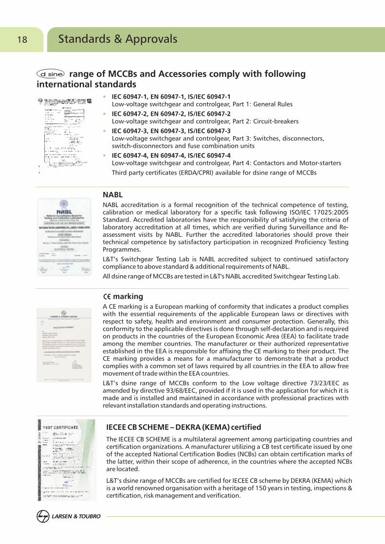
NABL accreditation is a formal recognition of the technical competence of testing, calibration or medical laboratory for a specific task following ISO/IEC 17025:2005 Standard. Accredited laboratories have the responsibility of satisfying the criteria of laboratory accreditation at all times, which are verified during Surveillance and Re-assessment visits by NABL. Further the accredited laboratories should prove their technical competence by satisfactory participation in recognized Proficiency Testing Programmes.
L&T’s Switchgear Testing Lab is NABL accredited subject to continued satisfactory compliance to above standard & additional requirements of NABL.
All dsine range of MCCBs are tested in L&T's NABL accredited Switchgear Testing Lab.
IECEE CB SCHEME – DEKRA (KEMA) certified
The IECEE CB SCHEME is a multilateral agreement among participating countries and certification organizations. A manufacturer utilizing a CB test certificate issued by one of the accepted National Certification Bodies (NCBs) can obtain certification marks of the latter, within their scope of adherence, in the countries where the accepted NCBs are located.
L&T’s dsine range of MCCBs are certified for IECEE CB scheme by DEKRA (KEMA) which is a world renowned organisation with a heritage of 150 years in testing, inspections & certification, risk management and verification.
•
•
•
•
IEC 60947-1, EN 60947-1, IS/IEC 60947-1Low-voltage switchgear and controlgear, Part 1: General Rules
IEC 60947-2, EN 60947-2, IS/IEC 60947-2Low-voltage switchgear and controlgear, Part 2: Circuit-breakers
IEC 60947-3, EN 60947-3, IS/IEC 60947-3Low-voltage switchgear and controlgear, Part 3: Switches, disconnectors, switch-disconnectors and fuse combination units
IEC 60947-4, EN 60947-4, IS/IEC 60947-4Low-voltage switchgear and controlgear, Part 4: Contactors and Motor-starters
Third party certificates (ERDA/CPRI) available for dsine range of MCCBs
marking
A CE marking is a European marking of conformity that indicates a product complies with the essential requirements of the applicable European laws or directives with respect to safety, health and environment and consumer protection. Generally, this conformity to the applicable directives is done through self-declaration and is required on products in the countries of the European Economic Area (EEA) to facilitate trade among the member countries. The manufacturer or their authorized representative established in the EEA is responsible for affixing the CE marking to their product. The CE marking provides a means for a manufacturer to demonstrate that a product complies with a common set of laws required by all countries in the EEA to allow free movement of trade within the EEA countries.
L&T’s dsine range of MCCBs conform to the Low voltage directive 73/23/EEC as amended by directive 93/68/EEC, provided if it is used in the application for which it is made and is installed and maintained in accordance with professional practices with relevant installation standards and operating instructions.
range of MCCBs and Accessories comply with following international standards

19Structure & Features
Low Watt Loss
• The entire current carrying path is optimally designed to achieve low watt loss
• Silver contacts offer low contact resistance thus helping in low watt loss
Release
• Thermal & Microprocessor based releases are available
Positive Isolation
• Indicates the true position of the contacts - ensures operator safety
No Load Line Bias
• Either side of MCCB terminals can be used as load or line
Knob
• Designed for better grip
• Indicates "ON", “OFF" and“TRIP" position of MCCB
MCCB Mechanism
• Quick make, quick break & trip free mechanism
Current Limiting MCCBs
• The unique speed contact system with current limiting feature accelerates the opening of contacts during short circuit resulting in very low let through energy
Arc Chutes
• Arc chutes are designed for efficient and faster arc quenching

20 Marking & Configuration
Terminal Connections
Indication of Open (O/OFF)
Indication of Closed (I/ON)
Standards
Release Settings
Release
Brand
Operating Knob
"Push to Trip" button
Utilization Category
Company Logo
Terminal Shroud
Release name
Current Rating of MCCB
Frame Size
Symbol of suitability for Isolation
Mark
Standard Characteristics
�U : Impulse withstand voltageimp
�U : Rated operational voltagee
�I : Rated Ultimate breakingcu
capacity
�I : Rated Service breaking capacitycs

21Trip Units
Thermal Magnetic Releases
Microprocessor Releases
Variable Thermal,
Fixed Magnetic
(DN0, DN1, DN3B)
Variable Thermal, Variable Magnetic (DN2, DN3)
Isolator
MTX1.0 with LSI (DN2, DN3, DN4)
Inst
MTX2.0 with LSING + Current Metering (DN2, DN3, DN4)
Inst
MTX3.0 with LSING + Communication capable +Power Metering (DN2, DN3, DN4)
Magnetic Release
Motor Protection Release (DN0, DN1, DN2, DN3 - Magnetic Protection only)
In 630 A
Switch Disconnector (DN0, DN2, DN3, DN4)
DN3-M

22 Accessories
Spreader Terminals1
Phase Barriers2
3
4
5
10
8
9
11
12
13
14
15
6
7
Stored Energy Electrically Operated Mechanism
Undervoltage Release
Shunt Release
Auxiliary Contact
Panel Mounted Keylock
Direct Rotary Handle
Extended Rotary Handle
Mechanical Interlock Kit
Communication Module
Voltage Module
Display Module
Trip Alarm Contact
Auxiliary + Trip Alarm Contact
External Neutral CT (with Adaptor Kit)
16
8
2
1
34
12
16

9
1011
1
2
5 6 7
1314
15
23


Product Data
MCCBs for Power Distribution
Technical Datasheet
Motor Backup Protection
Isolator Application
MCCBs for DC Applications
Protection Releases
26
42MCCBs for Different Applications
Auto Source Transfer Application

26 MCCBs for Power Distribution 27
Technical Datasheet
Note:• Any two internal accessories can be mounted at a time• V version MCCBs, to be used with extended ROM only• Separate earth fault module required for earth fault protection using TM releases• I : Rated ultimate short-circuit breaking capacitycu
I : Rated service short-circuit breaking capacitycsO O• Reference temperature 40 C & 50 C
$ : 'NO' of control contactor to be connected in series for 220V DC, 24V DC@: Contains display module & metering module, separate cable required for connection# : Only Extended ROM available* : at 415V
DN2 - 1500 @ 690VDN3 - 1000 @ 690VDN4 - 800A - 2500 @ 415V
Frame
Poles
Impulse withstand Voltage U (kV)imp
Rated Operational Voltage U (V) (MAX)e
Rated Insulation Voltage U (V)i
Utilization Category
Standard
Operating Frequency (Hz)
Total Opening Time
Finger-proof Terminals
Suitable for Isolation
IP class
Pollution Degree
Load Line Bias
Ambient Temperature
Storage Temperature
Mounting Positions in Vertical Plane
Weight (kg) (3/4 Pole)
Type
Release
Current Range (A)I n
240 VAC
415 VAC
480 VAC
550 VAC
600 VAC
690 VAC
240 VAC
415 VAC
480 VAC
550 VAC
600 VAC
690 VAC
3-Pole
4-Pole
Auxiliary Contact
Trip Alarm Contact
Auxiliary & Trip Alarm Contact
Shunt Release
Under Voltage Release
Rotary Operating Mechanism (Direct/Extended)
Electrical Operating Mechanism
Mechanical Interlock Kit
Spreader Terminals
Key lock
Neutral CT with Adaptor kit
Current Metering Module
Display, Communication and Voltage Module
Mechanical
Electrical @1.0 In
Life
RatedShortCircuitBreakingCapacity
I (kA)cu
I as % Ics cu
Dimensions (WxDxH) mm
INTERNAL
EXTERNAL
ACCESSORIES
100A
DN0-100
250A
DN1-250
250A
DN2-250
125A
DN0-125
C
40
25
10
8
5
-
100%
100%
100%
100%
100%
-
52.5
0.8/1.1
D
65
36
10
8
5
-
50%
50%
50%
50%
50%
-
75.6
0.73/1
N
65
50
10
8
5
-
50%
50%
50%
50%
50%
105
D
50
36
25
18
16
-
100%
100%
100%
100%
100%
-
75.6
N
70
50
36
25
18
-
100%
100%
100%
100%
100%
-
105
S
100
70
42
36
22
-
100%
100%
100%
100%
100%
-
154
V
-
100
65
-
-
36
-
100%
100%
-
-
50%
25000
10000*
220
C
65
25
10
8
5
-
50%
100%
50%
50%
50%
52.5
H
-
80
65
-
-
-
-
100%
100%
-
-
-
176
D
65
36
10
8
5
-
50%
50%
50%
50%
50%
-
40000
2500
75.6
0.73/1
400A
DN3B-400
400A
DN3-400
630A
DN3-630
1250A
DN4-1250
D
75.6
D
50
36
25
15
12
-
100%
100%
100%
100%
100%
-
75.6
N
70
50
36
20
18
-
100%
100%
100%
100%
100%
-
S
100
70
42
25
22
-
100%
100%
100%
100%
100%
-
154
D
50
36
25
15
12
-
100%
100%
100%
100%
100%
-
75.6
N
70
50
36
20
18
-
100%
100%
100%
100%
100%
-
S
100
70
42
25
22
-
100%
100%
100%
100%
100%
-
154
V
-
100
65
-
-
50
-
100%
100%
-
-
50%
15000
4000*
220
6.3/8
N
70
50
25
20
16
-
100%
100%
100%
100%
100%
-
105
S
100
70
36
25
20
-
100%
100%
100%
100%
100%
-
V
-
100
65
-
-
50
-
100%
100%
-
-
50%
220
TM TMTM/MP
(MTX1.0/2.0/3.0)TM
20, 25, 32, 40, 50, 63, 80, 100
125, 160,200, 250
40, 63, 80,100, 125, 160,
200, 250 125
3/4
6
600
690
A
40000
4000
3/4
6
600
690
A
3/4
6
600
690
A
-
10000
3000
3/4
8
690
800
A
75 x 60 x 130
100 x 60 x 130
105 x 60 x 165
140 x 60 x 165
1.55/2
105 x 96 x 179
140 x 96 x 179
2.5/3.3
25000
10000
1 C/O or 2 C/O
240/415 V AC 50 Hz
TM TM/MP (MTX1.0/2.0/3.0) TM/MP (MTX1.0/2.0/3.0) MP (MTX1.0/2.0/3.0)MP (MTX1.0/2.0/3.0)
320, 400 320, 400 800, 1000, 1250500, 630 400, 630
3/4
8
690
800
A
50
36
25
15
12
-
100%
100%
100%
100%
100%
-
10000
4000
140 x 111 x 205
184 x 111 x 205
4.0/5.0
3/4
8
690
800
A
15000
4000
105
3/4
8
690
800
A
15000
4000
105
3/4
8
690
800
A
20000
3000*
154
<20msec
210 x 143 x 370
278 x 143 x 370
17 / 22
50 / 60
<10msec
Yes
Yes
IP40
III
NOO O-5 C to 55 CO O-35 C to 70 C
Vertical and 90 deg in both directions140 x 111.5 x 266
183.5 x 111.5 x 266
5.5/7.2
140 x 111.5 x 266
183.5 x 111.5 x 266
6/7.8
1 C/O or 2 C/O
1 C/O
Available for 3P MCCBs with MTX2.0 & MTX3.0 release only
Available for MTX2.0 release for current metering only @
Available for MTX3.0 release for Communication & Power metering
1 C/O + 1 C/O
110 / 415 V AC 50 Hz, 110 / 220 V DC, 24 V DC $
240 V AC 50 Hz
�
�
�
�
�
�
�
�
�
�
�
�
�
�
�
�
�
�
�
�
�
�
�
�
�
�
�
�
�#
�
�
�
�
�
IS/IEC60947-2, &IEC60947-2 EN60947-2
Making Capacity (kA)
MP (MTX1.0/2.0/3.0)
40, 63, 100, 160,
250

28 MCCBs for Motor & Isolator
Isolator Applicationdsine MCCBs with Switch Disconnector version offer solution for switching various loads such as UPS, Battery Banks etc. with various advantages. These MCCBs differ from regular MCCBs only in terms of absence of protection trip units. These MCCBs can be used for following applications for isolation purpose:
• For local isolation- such as very close to Motor load
• Generally used at the incoming of any sub-distribution
• As an Isolator for Bus coupler
• As an automatic switch
• For switching applications of motors with VFDs, soft starters
SD MCCBs are always backed up by the Short Circuit Protection Device (SCPD) to protect downstream loads/installations against short circuit. Our dsine SD MCCBs offer following advantages.
• Suitable for Positive isolation
• Available with 3P & 4P versions
• Can be used with Under Voltage Protection
• Remote tripping through Shunt release
• Motor operated MCCBs
• Status feedback possible
Following are the specifications of SD MCCBs
Note: MV version MCCBs to be used with extended ROM only.
DN3-M
Note: Icw - Rated short-time withstand current
* To be set at 10In only
160A
DN0-160SD
32-160
3/4
2
1
250A
DN2-250SD
100-250
3/4
3.6
1
800A
800
3/4
10
1
1000A
1000
3/4
12
0.5
1250A
1250
3/4
15
0.1
DN4-1250SD
400A
DN3B-400SD
320-400
3/4
5.5
1
Frame
Type
Current Range (A)
Poles
I (kA)CW
Duration (sec)
400A
DN3-400SD
320-400
3/4
5.5
1
630A
DN3-630SD
500-630
3/4
7.6
1
M
3
50
36
10
50
-
100%
100%
100%
500-630
630A
DN3-630
400A
DN3-400
M
3
50
36
15
50
-
100%
100%
100%
320-400
250A
DN2-250
MH
3
80
65
-
80
65
100%
100%
-
32-250
M
3
50
36
15
50
-
100%
100%
100%
100-250
160A
DN1-160
M
3
50
-
-
50
-
50%
-
-
10In
100-160
6-10I *n
400 / 415 V
480 V
690 V
415 V
480 V
400 / 415 V
480 V
690 V
Frame
Type
Current range (A)
Poles
Magnetic Setting
RatedShortCircuitBreakingCapacity
I (kA)cu
I (kA)q
I as % Icucs
Motor Backup ProtectionAC induction motors are the vital elements in any production process and hence constitute majority of loads in Industry and other installations. The M version MCCBs in dsine range are developed specially to give short circuit protection for all types of motors. Selection of MCCB using our type 2 charts give reliable performance of the motors.
MV
3
100
65
50
100
65
100%
100%
50%
320-630
100A
DN0-100
M
3
50
-
-
50
-
25%
-
-
9In
32-100

MCCBs for DC Applications
DC power distribution is an upcoming technology in this modern era due to its most rigorous network power applications such as
• AC-DC Power System
• DC-DC Converter Systems
• DC-AC Inverter Systems
• DC UPS
• Batteries & Accessories
• Solution to alternative energy-Solar Power
We offer dsine MCCBs for the protection of DC systems in variety of current ratings from 20A-630A, voltage ratings upto 750V and various breaking capacities ranging from 5kA to 36kA.
Switching of DC currents is much severe phenomenon than switching AC currents due to non occurrence of natural zero. Hence DC MCCBs are desired to give less breaking capacity than AC MCCBs for the same voltage & currents. As per the earthing of the system, we recommend following connections for breaking the fault currents.
Any one polarity is earthed Midpoint of the system is earthed No earthing
Earthed system Insulated system
No. of poles required toperform the break must
be in series on one polarity
No. of poles required toperform the break must be on both the polarities
No. of poles required toperform the break can be
shared between two polarities
+
-
25
0/5
00
V
LOAD
+
-
25
0/5
00
V
+
-
25
0/5
00
V
Earthed system
LOAD LOAD
Note: Suitable for Thermal Magnetic release only
Rated current In (A)
Frame
Type
Release
Poles
Type of connection
L/R (msec)
250 V DC
500 V DC
750 V DC
I (kA rms)cu
DN0-125*
C D
20, 25, 32, 40, 50, 63,
80, 100, 125
20
15
-
DN1-250
NC
125, 160, 200, 250
20
15
-
DN2-250 DN3-400 DN3B-400 DN3-630
N
30
20
15
D
20
15
10
S
36
25
20
N
30
20
15
D
20
15
10
S
36
25
20
N
30
20
15
D
20
15
10
S
36
25
20
D
25
10
-
63, 80, 100, 125, 160, 200, 250
320, 400 320, 400 500, 630
TM
3 or 4
3P in series
<15msec
29
*Available only in DN0-125D

Microprocessor Release
Features of MTX1.0
� inverse time delay
�Adjustable Trip class
�Short Circuit Protection with selectable time delay
�Provision of Thermal memory defeat
�Provision for release testing
�Overload indication
�Power ON LED
�Self powered
�True RMS sensing
�“Push to Trip” button
Overload Protection with
Note: •
• Release provides in-built instantaneous override protection fixed @ 10In
* Refer page 51
Factory Settings - O/L: 100%I , Curves: 6I @10s, Thermal Memory: Off, S/C: 5.5I @ Instantaneousn r r
30 Protection Release for MCCBs
Thermal-Magnetic Release
Features of Thermal-Magnetic Release
�Adjustable overload settings
�Fixed / Adjustable short circuit settings
�True RMS sensing
�“Push to Trip” buttonProtection
Overload
Short Circuit
Earth fault
DN0 & DN1
9I (fixed)n
80% - 100%In
DN2 & DN3
6 - 10In
80% - 100%In
DN3B
9 (fixed)
80% - 100%In
In
External GF Module required*
Settings
Rated Current,
Current setting, I (I = x )r r
Time delay, t (Inverse)r
Protection mode
Thermal memory
Current setting, I (I = x I )s s r
Time delay, ts
Protection mode
In
In
MTX1.0
Short Circuit
Overload (Phase)
From 40 to 1250A
40% to 100%I in steps of 5%n
10s at 6I , 3s at 6I , 10s at 7.2I , 3s at 7.2Ir r r r
ON / OFF
Enable / Disable
1.5, 2.5, 4.0, 5.5, 6.5, 8.0Ir
Instantaneous / 100ms
ON / OFF

Inst
Note: •
• Release provides in-built instantaneous override protection fixed @ 10In
Factory Settings - O/L: 100%I , Curves: 6I @10s, S/C: 5.5I @ Instantaneous, Thermal Memory: Off, E/F: Off, Neutral: Off.n r r
Microprocessor Release
Features of MTX2.0
� inverse time delay
�Adjustable Trip class
�Short Circuit Protection with selectable time delay
�Inbuilt Earth fault and Neutral overload
protection
�Provision of Thermal memory defeat
�Provision for release testing
�Overload indication
�Power ON LED
�Panel mounted O-LED display for current metering
�Self powered
�True RMS sensing
�“Push to Trip” button
�Latest trip record
Overload Protection with
Overload (Phase)
Short Circuit
Overload (Neutral)
Earth Fault
MTX2.0
Rated Current, In
Current setting, I (I = x I )r r n
Time delay, t (Inverse)r
Protection mode
Thermal memory
Current setting, I ( = x )N N r
Time delay, tN
Protection mode
Current setting, ( = x )s s r
Time delay, ts
Protection mode
Current setting, ( = x )g g n
Time delay, tg
Protection mode
I I
I I I
I I I
From 40 to 1250A
40% to 100% in steps of 5%n
10s at 6 , 3s at 6 , 10s at 7.2 , 3s at 7.2r r r r
ON / OFF
Enable / Disable
50%, 100% and 150% r
200ms / Same as overload
ON / OFF
1.5, 2.5, 4.0, 5.5, 6.5, 8.0 r
Instantaneous / 100ms
ON / OFF
20% to 50%I in steps of 10%n
100ms / 200ms
ON / OFF
I
I I I I
I
I
31Protection Release for MCCBs

�Digital Current Metering
MTX releases are designed with protection class CTs which measure true RMS values. Inbuilt current metering does not require separate CTs hence maintenance is easy.
�O-LED Display
O-LED display allows the operator a wide viewing angle.
O-LEDs showing current metering has got faster response time and also consumes less power, hence saves energy. It has better contrast ratio as well. Display Module
�Port with Polarized Connector
MTX2.0 release with metering port is implemented with poka-yoke technology using polarized connector to ensure correct insertion of metering harness, thus avoiding unnecessary errors.
Advanced features of MTX2.0
�Panel Mounted Display for Current Metering & Trip Record
System currents & latest trip record can be viewed with panel door closed.
Metering Module
Power Supply Module
32 Protection Release for MCCBs

�Inbuilt Earth Fault Protection
Inbuilt earth fault protection function does not require any separate trip coil & external CBCT, thus saving panel space, cost & improving the overall hygiene. Earth fault protection limits expenses by preventing damage to other equipment.
�Thermal Memory
Thermal memory protects the system from thermal stresses generated by cumulative heating caused by cyclic overload conditions thus allowing the system to return to a safe operating temperature. This function also allows an optimization of cables or bus bar protection in case of low amplitude repetitive faults. Advance tripping increases the overall life and eliminates the production downtime incase of severe faults.
�Multiple Trip Class
Enhances adjustability for better enhanced coordination with other devices to achieve correct motor switching and ensures protection of the starter elements in order to guarantee the plant safety.
�Precise Selection of Parameters
Overload & short circuit settings with minimum step change helps to maintain balance between nuisance tripping and optimal protection resulting in high continuity of service and reduced call back periods. MTX release can be adapted to specific requirements of OEM or end-user.
�DIP Switches
DIP switches are provided on front side of the release for easy operations. These switches give you quicker option to precisely change selection, offering high life.
�Overload Indication
Improves uptime and productivity by setting alarms for unbalanced loads so that proactive measures can be taken to avoid overload conditions.
�Self Powered
MTX releases do not need any external power supply hence require no extra devices and wires to power up.
1
2
3
4
Note: For wiring diagram, please refer page no. 62
132
4
Inst
@6Ir
@7.2
Ir
10s
3s
% of Ir
30%
85%
115%
Overload LED indication
Green LED
Faster blinking of green LED
Sequential ON/OFF of green LED
33Protection Release for MCCBs

Inst
@6
Ir@
7.2
Ir
10s
3s
Overload Protection, (I = x I )r n
Various Protection Settings
Bypass 40% 45% 50% 55% 60% 65%
0.4
�
rr
0.4
�
rr
0.4
�
rr
0.4
�
rr
0.4
�
rr
0.4
�
rr
DIP Switch Position
Setting
0.4
�
rr
Bypass ON
0.4
�
rr
0.4
�
rr
DIP Switch Position
Setting
Thermal Memory
DIP Switch Position
Setting
Overload Curves
3s @ 6Ir 10s @ 6Ir 3s @ 7.2Ir 10s @ 7.2Ir
0.4
�
rr
0.4
�
rr
0.4
�
rr
0.4
�
rr
DIP Switch Position
Setting
Short Circuit Setting, (I = x I )s r
1.5
Inst
2.5 4.0 5.5 6.5 8.0
Inst
Inst
Inst
Inst
Inst
Bypass
70% 75% 80%
0.4
�
rr
0.4
�
rr
0.4
�
rr
85% 90% 100%
0.4
�
rr
0.4
�r
r
0.4
�
rr
DIP Switch Position
Setting 95%
0.4
�
rr
Inst
Protection Release for MCCBs34
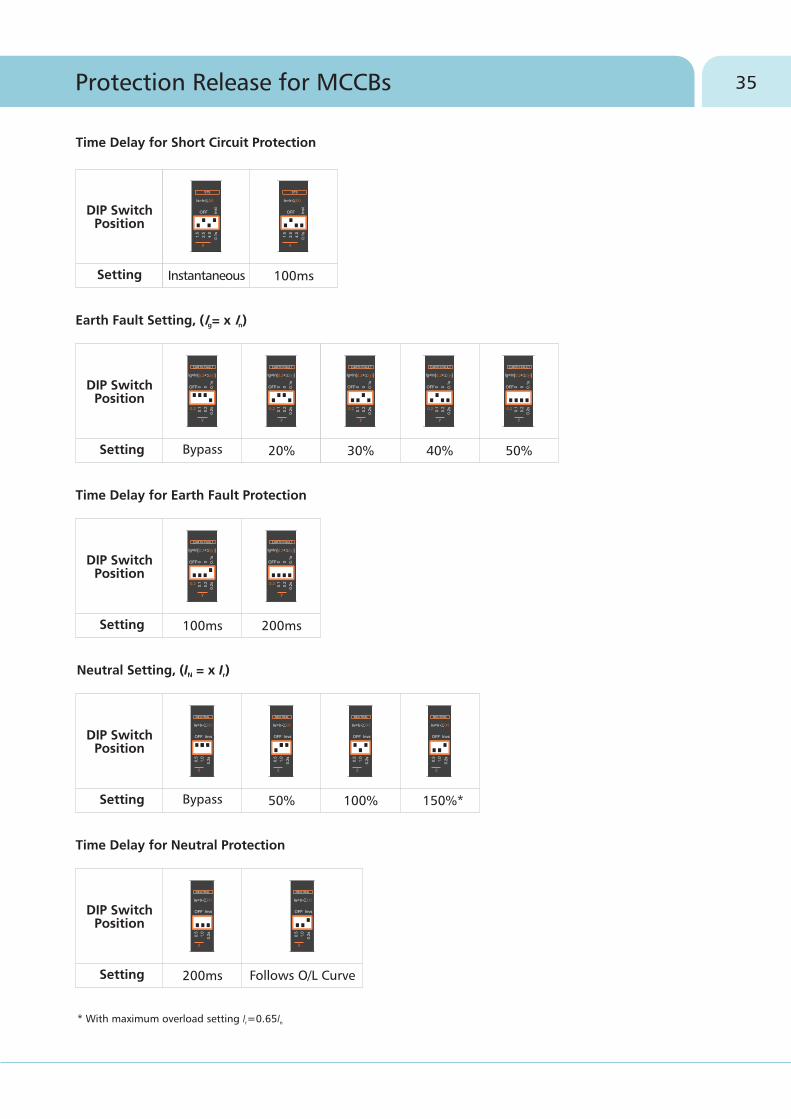
* With maximum overload setting I =0.65Ir n
Bypass 20% 30%
0.2 0.2 0.2
40% 50%
0.2 0.2
DIP Switch Position
Setting
Earth Fault Setting, (I = x I )g n
100ms 200ms
0.2 0.2
DIP Switch Position
Setting
Time Delay for Earth Fault Protection
Bypass 50% 100% 150%*
0.5
1.0
Ir*
0.5
1.0
Ir*
0.5
1.0
Ir*
0.5
1.0
Ir*
DIP Switch Position
Setting
Neutral Setting, (I = x I )N r
0.5
1.0
Ir*
200ms
0.5
1.0
Ir*
Follows O/L Curve
DIP Switch Position
Setting
Time Delay for Neutral Protection
Instantaneous 100ms
Inst
InstDIP Switch
Position
Setting
Time Delay for Short Circuit Protection
35Protection Release for MCCBs

Inst
* Can be set using display module
Microprocessor Release
Features of MTX3.0
�Overload Protection with inverse time delay2 4
�I t, I t, SI, LI-VI based over load curves
�Short Circuit Protection with selectable time delay
�Instantaneous protection with fine settings
�Advanced current and voltage based protection function
�Protection against current unbalance and single phasing
�Comprehensive current, power and energy metering
�Inbuilt Earth fault and Neutral overload protection
�Provision of Thermal memory defeat
�Panel mounted O-LED display
�Communication through MODBUS RTU
�Pre-trip alarms
�True RMS sensing
�Power on LED
�“Push to Trip” button
�Self powered
Note:
Neutral: Off.
• Release provides in-built instantaneous override protection fixed @ 10In
• Factory Settings - Address:0000, O/L: 100%I , Curves: 6I @10s, S/C: 5.5I @ Instantaneous, Thermal Memory: Off, E/F: Off, n r r
MTX3.0
Short Circuit
Overload (Neutral)
Earth Fault
Instantaneous
Overload (Phase)
Rated Current, In
Current setting, I (I = x I )r r n
Time delay, t (Inverse)r
Protection mode
Preset trip alarm setting
Thermal memory
Current setting, I (I = x I )N N r
Time delay, tN
Protection mode
Current setting, I (I = x I )s s r
Time delay, ts
Protection mode
Preset trip alarm setting
Current setting, I (I = x I )i i n
Protection mode
Preset trip alarm setting
Current setting, I (I = x I )g g n
Time delay, tg
Protection mode
From 40 to 1250A
40% to 100%I in steps of 1%*n
0.5s to 30s in steps of 0.1s*
ON / OFF
50% to 90% I in steps of 1%*r
Enable/Disable
50% to 150% I in steps of 1%*r
0.2s / same as overload
ON / OFF
1.5 to 8 I in steps of 0.1*r
100ms, 200ms, 300ms, 400ms*
ON / OFF
50% to 90% I in steps of 1%*s
1.5 to 8 I in steps of 0.1*n
ON / OFF
50% to 90% I in steps of 1%*i
10% to 50% I in steps of 5%*n
100ms to 500ms in steps of 50ms*
ON / OFF
36 Protection Release for MCCBs
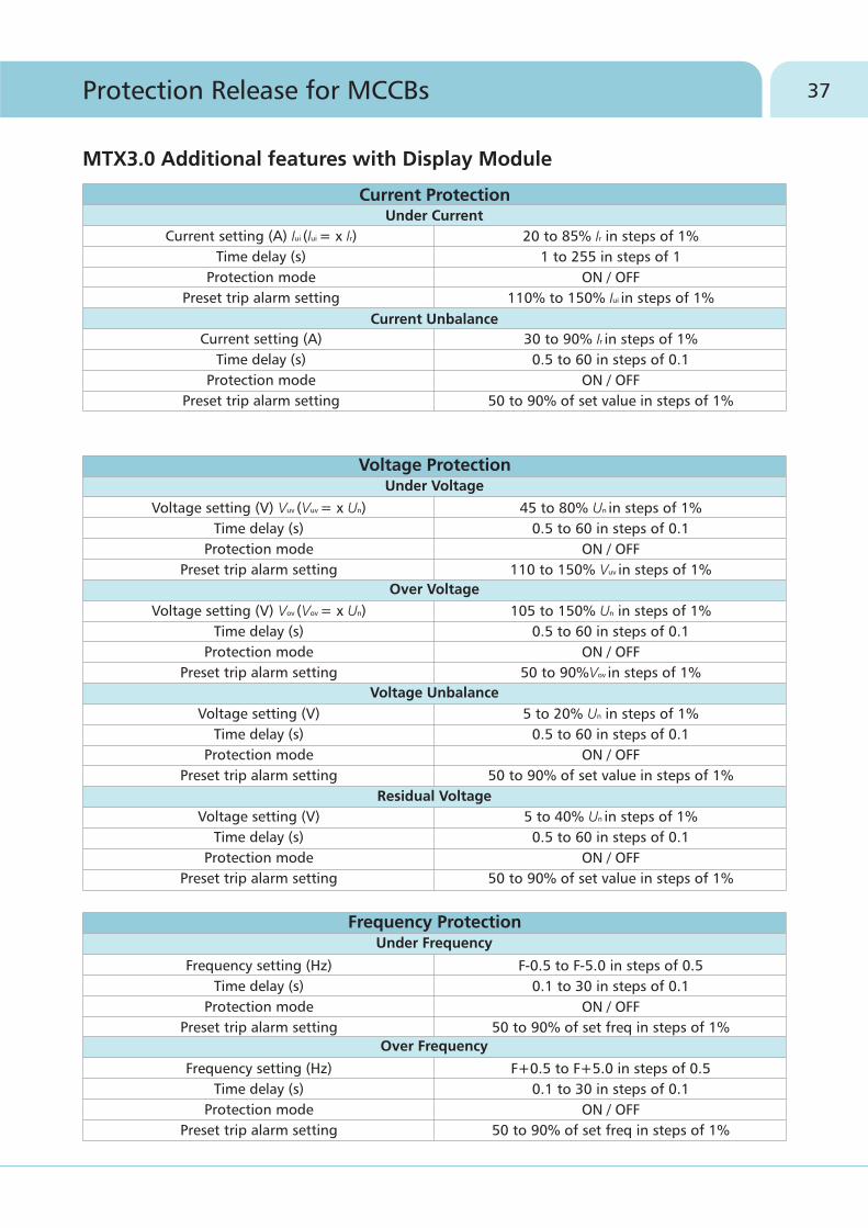
MTX3.0 Additional features with Display Module
Current ProtectionUnder Current
Current Unbalance
Voltage ProtectionUnder Voltage
Over Voltage
Voltage Unbalance
Residual Voltage
Frequency ProtectionUnder Frequency
Over Frequency
Frequency setting (Hz)
Time delay (s)
Protection mode
Preset trip alarm setting
Frequency setting (Hz)
Time delay (s)
Protection mode
Preset trip alarm setting
F-0.5 to F-5.0 in steps of 0.5
0.1 to 30 in steps of 0.1
ON / OFF
50 to 90% of set freq in steps of 1%
F+0.5 to F+5.0 in steps of 0.5
0.1 to 30 in steps of 0.1
ON / OFF
50 to 90% of set freq in steps of 1%
Voltage setting (V) V
Time delay (s)
Protection mode
Preset trip alarm setting
uv (Vuv = x Un)
Voltage setting (V) Vov (Vov = x Un)
Time delay (s)
Protection mode
Preset trip alarm setting
Voltage setting (V)
Time delay (s)
Protection mode
Preset trip alarm setting
Voltage setting (V)
Time delay (s)
Protection mode
Preset trip alarm setting
45 to 80% U in steps of 1%
0.5 to 60 in steps of 0.1
ON / OFF
110 to 150% Vuv in steps of 1%
n
105 to 150% Un in steps of 1%
0.5 to 60 in steps of 0.1
ON / OFF
50 to 90%Vov in steps of 1%
5 to 20% Un in steps of 1%
0.5 to 60 in steps of 0.1
ON / OFF
50 to 90% of set value in steps of 1%
5 to 40% Un in steps of 1%
0.5 to 60 in steps of 0.1
ON / OFF
50 to 90% of set value in steps of 1%
Current setting (A) Iui (Iui = x Ir)
Time delay (s)
Protection mode
Preset trip alarm setting
Current setting (A)
Time delay (s)
Protection mode
Preset trip alarm setting
20 to 85% I in steps of 1%r
1 to 255 in steps of 1
ON / OFF
110% to 150% Iui in steps of 1%
30 to 90% Ir in steps of 1%
0.5 to 60 in steps of 0.1
ON / OFF
50 to 90% of set value in steps of 1%
37Protection Release for MCCBs
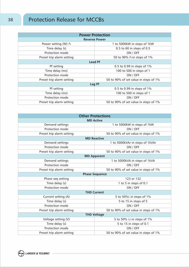
Lead Pf
Lag Pf
Power ProtectionReverse Power
MD Active
MD Reactive
MD Apparent
Phase Sequence
THD Current
Other Protections
THD Voltage
Power setting (W) P
Time delay (s)
Protection mode
Preset trip alarm setting
Pf setting
Time delay (ms)
Protection mode
Preset trip alarm setting
Pf setting
Time delay (ms)
Protection mode
Preset trip alarm setting
R 1 to 5000kW in steps of 1kW
0.5 to 60 in steps of 0.5
ON / OFF
50 to 90% PR in steps of 1%
0.5 to 0.99 in steps of 1%
100 to 500 in steps of 1
ON / OFF
50 to 90% of set value in steps of 1%
0.5 to 0.99 in steps of 1%
100 to 500 in steps of 1
ON / OFF
50 to 90% of set value in steps of 1%
Demand settings
Protection mode
Preset trip alarm setting
Demand settings
Protection mode
Preset trip alarm setting
Demand settings
Protection mode
Preset trip alarm setting
Phase seq setting
Time delay (s)
Protection mode
Current setting (A)
Time delay (s)
Protection mode
Preset trip alarm setting
Voltage setting (V)
Time delay (s)
Protection mode
Preset trip alarm setting
1 to 5000kW in steps of 1kW
ON / OFF
50 to 90% of set value in steps of 1%
1 to 5000kVAr in steps of 1kVAr
ON / OFF
50 to 90% of set value in steps of 1%
1 to 5000kVA in steps of 1kVA
ON / OFF
50 to 90% of set value in steps of 1%
123 or 132
1 to 5 in steps of 0.1
ON / OFF
5 to 50%Ir in steps of 1%
5 to 15 in steps of 5
ON / OFF
50 to 90% of set value in steps of 1%
5 to 50% Un in steps of 1%
5 to 15 in steps of 0.1
ON / OFF
50 to 90% of set value in steps of 1%
38 Protection Release for MCCBs

Energy and Power management functionality using voltage module
Display Module
Power Supply Module
Communication Module
MCCB with MTX3.0 release
Voltage Module
3 ph 4 wire AC supply
History
Communication
Metering & DisplayCurrent
Voltage
Frequency & power factor
Power
Energy
Maximum demand
THD
Protocol
Trip history
Event history
Phase, Neutral & Earth
Phase & Line
True RMS
Active, Reactive & Apparent
Active, Reactive & Apparent
Active, Reactive & Apparent
Current and voltage
MODBUS RTU
Last 10 trip records with non volatile memory
Last 10 event records with non volatile memory
Advanced Features of MTX3.0
Energy & Power Measurement
�
release, in addition to current & voltage measurement, active, reactive and apparent energy &
power can also be measured. This would enable monitoring energy at individual feeder level and
thus help in implementing effective energy management practices in the plant. Moreover, using
communication module, different parameters reading can be viewed on display module.
One of the first steps towards energy efficiency is energy ana power measurement. In MTX 3.0
39Protection Release for MCCBs

�Communication Capable
Most advanced release of MTX series, MTX3.0 is communication capable on MODBUS RTU network. Using
MODBUS com module the MCCB release can be connected to a Personal Computer. The metering values can be
read remotely. The settings configuration on the other hand can both be read and changed remotely. These
releases are also made compatible with HMI (Human Machine Interface) & DCS (Data Control Systems)
Laptop or HMI
�Advanced Current and Voltage based protections
• Reverse Phase:
This function detects the phase reversal of current from the set sequence. It is especially important in motor feeder applications
• Reverse Power:
One can set the direction of power flow in a system from source to load and in case the direction of power flow reverses, the reverse power protection can be activated to trip the system. This is especially important in a DG set or in a ring mains system.
Convertor (RS485 to RS232)
�Power Quality Control
MTX3.0 release measures the frequency, power factor and offers protection against leading and lagging values therebyassisting in maintaining the power quality. This release measures THD of current & voltage and gives an alarm / trip in case it exceeds the set thresholds.
40 Protection Release for MCCBs

�Multi-looping
Note: For wiring diagram, please refer page no. 63
MODBUS Communication through MODBUS looping
�Maintenance Functionality
MTX3.0 release can store last 10 trip records & last 10 event records which can be used for the system analysis later on. These recorded values can be viewed from display unit as well as PC.
Laptop or HMI
Convertor (RS485 to RS232)
A single display module can be used to connect upto 15 MCCBs with MTX3.0 release through MODBUS network. Highly reliable data yet extremely simple looping reduces operational headaches and enhancesremote accessibility.
41Protection Release for MCCBs

Auto Source Transfer ApplicationIn this modern era of automation, ASTS (Automatic Source Transfer Systems) are very widely used in many places such as commercial buildings, IT parks for quick changeovers and also in Utilities for uninterrupted supplies for critical loads.
These solutions can give you optimum energy management.
ASTS solution basically consists of
• Motorised MCCBs
• Mechanical Interlocking device (usually a base plate)
• Automatic Transfer Controller
ASTS with AuXC-1000 controller
The AuXC-1000 controller brings simplicity and flexibility to an auto source transfer system. It has been developed to control and supervise the automatic or manual transfer of a utility load from a principal power supply source to a stand-by and vice-versa. It sets a new benchmark in Auto Source Transfer Switch Controller technology. It includes all the necessary features to supervise and control power supply sources, composed by energy distribution systems or generating sets, and the relative transfer equipment, such as contactors, motorized moulded case circuit breakers and air circuit breakers.
Note: For wiring diagram, please refer page no.60
MIL with Base Plate & EOM
+
AuXC-1000
Key Features:
• Utility-to-utility, utility-to-generator or generator-to-generator changeover possible
• Three-phase, two-phase or single-phase voltage controls
• Controls of minimum voltage, maximum voltage, phase loss, asymmetry, minimum frequency, maximum frequency, with independent enable and delay
• Voltage thresholds with programmable hysteresis
• Manual control of Circuit Breakers
• Main line failure simulation
• Communication Capable
• Front display for monitoring the system voltage and frequency and for onsite controller programming
• Six programmable inputs and five programmable outputs
• Front test feature to simulate the operation of the diesel generator set
• Status indication through 22 LEDs
• Flush mounting arrangement
42 MCCBs for Different Applications

With the new AuXC-1000L controller in addition to its predecessor, ASTS has become a lot simpler & easier. Some of the salient features of the controller are as follows:
• Utility-to-utility, utility-to-generator changeover facility
• Single supply input from battery supply 12-48V DC
• Display to view main and secondary line parameters
• 15 status LED indicators
• 6 programmable digital inputs
• 3 programmable relay outputs
• RS232 communication interface
• Modbus RTU and Modbus-ASCII communication protocols
• Status display of circuit breakers
• Emergency demand supervision parameter programming for stand by generator sets
• Event logging
• Alarm code & description display
The automatic transfer takes place through AuXC-1000L / AuXC-1000 whenever following conditions are predefined by the user
• System Voltage not in line with programmed limits
• The need to have a very reliable power source
• The need to use the most economical power source
These controllers are compatible with U-POWER OMEGA range of Electrical ACBs, dsine range of Motorized MCCBs and MCX range of contactors.
ASTS with AuXC-1000L Controller – Smarter, Simpler, Easier
MIL with Base Plate & EOM
+
AuXC-1000L
43MCCBs for Different Applications

Accessories
Internal Accessories
- Auxiliary Contact
- Trip Alarm Contact
- Auxiliary Trip Alarm Contact
- Shunt Release
- Under Voltage Release
External Accessories
- Rotary Operating Mechanism
- Mechanical Interlocking Kit
- Keylock
- Spreader Terminals
- External Neutral CT
- Stored Energy Electrically Operated
Mechanism
- MTX Modules
- Earth Fault Module
46
47

46 Accessories
Internal Accessories
Shunt Release UV ReleaseAuxiliary Contact TACMCCB with mid cover opened & Internal
accessories fitted
dsine range of MCCBs are offered with -fit type, easily installable internal accessories. There is no need to open main cover and no live parts are accessed during installation. TAC, Aux+TAC to be fitted in the right cavity & under voltage release to be fitted in left cavity.
Double Insulation: The internal accessories are housed in insulated casings to ensure first level of insulation. When the front cover is opened for the fixing of internal accessories, the MCCB is totally insulated ensuring the double insulation.
snap
Shunt Release
It allows opening of MCCB by means of an electrical command. Operation of the release is guaranteed for a voltage between 70% and 110% of the rated power supply voltage value Ue, both in AC & DC.
FrameContacts/Supply Voltage Cavity
DN0, DN1
DN2, DN3, DN3B, DN4
DN0, DN1
DN2, DN3, DN3B, DN4
DN0, DN1
DN2, DN3, DN3B, DN4
DN0, DN1
DN0, DN1
DN2, DN3, DN3B, DN4
DN0, DN1
DN2, DN3, DN3B, DN4
DN0, DN1
DN2, DN3, DN3B
DN4
Right
Right/Left
Right
Right/Left
Right
Right
Right
Right
Right
Left
Right/Left
Left
Internal Accessories
Auxiliary Contact
Trip Alarm Contact
Under Voltage Release
Shunt Release
Auxiliary + Trip Alarm Contact
1 C/O
1 C/O + 1 C/O
2 C/O
2 C/O
1 C/O
240/415V AC 50Hz
110/415V AC 50Hz, 110/220V, 24V DC
240V AC
Frame
DN0 / DN1
Operational Voltage Power Consumption
1500VA
1500VA
85W
10W
DN2 / DN3 /DN3B / DN4
240 / 415V AC, 50Hz
110 - 415V AC, 50Hz
110 / 220V DC
24V DC
47Accessories
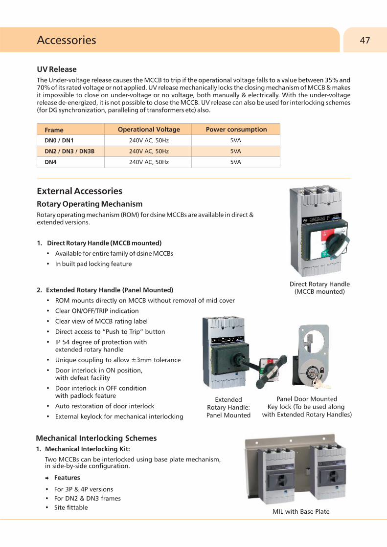
Direct Rotary Handle (MCCB mounted)2.
•
• Clear ON/OFF/TRIP indication
• Clear view of MCCB rating label
• Direct access to “Push to Trip” button
• IP 54 degree of protection with extended rotary handle
• Unique coupling to allow ±3mm tolerance
• Door interlock in ON position, with defeat facility
• Door interlock in OFF condition with padlock feature
• Auto restoration of door interlock
• External keylock for mechanical interlocking
Extended Rotary Handle (Panel Mounted)
ROM mounts directly on MCCB without removal of mid cover
Extended Rotary Handle: Panel Mounted
Panel Door Mounted Key lock (To be used along
with Extended Rotary Handles)
MIL with Base Plate
Mechanical Interlocking Schemes
1. Mechanical Interlocking Kit:
Two MCCBs can be interlocked using base plate mechanism, in side-by-side configuration.
�Features
• For 3P & 4P versions
• For DN2 & DN3 frames
• Site fittable
UV Release
The Under-voltage release causes the MCCB to trip if the operational voltage falls to a value between 35% and 70% of its rated voltage or not applied. UV release mechanically locks the closing mechanism of MCCB & makes it impossible to close on under-voltage or no voltage, both manually & electrically. With the under-voltage release de-energized, it is not possible to close the MCCB. UV release can also be used for interlocking schemes (for DG synchronization, paralleling of transformers etc) also.
240V AC, 50Hz
240V AC, 50Hz
240V AC, 50Hz
Operational VoltageFrame
DN0 / DN1
DN2 / DN3 / DN3B
DN4
Power consumption
5VA
5VA
5VA
External Accessories
Rotary Operating Mechanism
Rotary operating mechanism (ROM) for dsine MCCBs are available in direct &extended versions.
1. Direct Rotary Handle (MCCB mounted)
• Available for entire family of dsine MCCBs
• In built pad locking feature

48 Accessories
Terminal capacity without spreader terminals
* DN3B available in 320A and 400A only Note: Phase barriers are supplied along with MCCBs ; Copper termination recommended for enhanced performance
Terminal capacity with spreader terminals
Lock 1
Incommers(I/C)
Bus couplers(B/C)
I/C1 I/C2 I/C3
B/C1 B/C2
Lock 2 Lock 3
Lock 12 Lock 23
Key Lock Selection:
Any 1 type of lock for both MCCBs
Lock 1 and Lock 2 for I/C and Lock 12 for B/C
Locks 1, 2, 3 for I/Cs and Locks 12, 23 for B/Cs
2 l/C
2 I/C and 1 B/C
3 I/C and 2 B/C
I/C or B/C Key Lock
Type of lock
1
2
3
1, 2 & 12
2, 3 & 23
Exclusively operable by key nos.
1
2
3
12
23
Link (mm)2
Cable (mm )Link (mm)2
Cable (mm )Link (mm)2
Cable (mm )Link (mm)2
Cable (mm )
800-1250320-630125-25016-100Rating (A)
50 22
185
185
35
35
2 x 240 2 x 40
DN0
DN1
DN2
DN3
DN3B*
DN4 2 x 300 2 x 60
2 x 240 2 x 40
dsine Frame
800-1250320-630125-25016-100
2Cable (mm ) Link(mm)
2Cable (mm ) Link(mm)dsine Frame
Rating (A)
2Cable (mm ) Link(mm)
2Cable (mm ) Link(mm)
35 17
120
95
26
25
DN0
DN1
DN2
DN3
DN3B*
DN4 - 2 x 40
120
185
$27
32
2.
For mechanical interlocking through extended rotary operating mechanism, a panel mounted key lock is available. The selection of the key lock as per the table:
Mechanical Interlocking using Key Locks:
Spreader Terminal
• Available for enhancing termination capacity
• Made of silver plated copper
$ 30mm on request

240V AC
85-110%
90
450
500
15000
96 x 96
IP30
1/min
450
DN3
240V AC
85-110%
60
300
350
16000
96 x 96
IP30
2/min
300
DN2Specification
Operating voltage (V AC)
Operating voltage (%)
Closing time (ms)
Opening time (ms)
Power consumption (VA)
Life / No. of operations2Door cut out (mm )
IP protection, on the front
Operating frequency
Min. control impulse time (ms)*
49Accessories
Stored Energy Electrically Operated Mechanism
• ON / OFF & Charged/Discharged indication
• Foolproof mounting
• Selector switch for Auto/Manual operation
• Padlock facility for locking in OFF position (3 nos. locks)
• Higher mechanical & electrical endurance
• Back up fuse for extended motor protection
• Easy access to the protection setting on MCCB
• True indication for ON/OFF & Trip
External Neutral CTs
• Used to provide neutral protection to 3P MCCBs in 3 phase 4 wire system
• Available for 3P MCCBs with MTX2.0 & 3.0 releases
• Adapters for NCT available
Power Supply (PS) Module
PS module is used to power ON dsine MTX modules when auxiliary 24Vdc supply is not available.
# For using Output 1, Output 2 should be loaded
Note: For wiring diagram, please refer page no. 63
* At rated voltage
125-300V
200mA at 24V DC
mA at 24V DC650
Specifications AC DC
Input
Output 1
Output 2
#
85-265V
-
-

50 Accessories
�Current Metering Module for MTX2.0
It consists of 2 parts viz. Metering module & Display module. Metering module collects the data from the release and sends the same to the Display module. The panel mounted O-LED Display module shows various parameters viz. 3 phase currents, neutral and ground fault currents, if any. We can also view last trip records.
Note: For wiring diagram, please refer page no. 63
�MTX Test Kit
• Universal Test Kit for all MTX releases
• Simulation of overload, short-circuit & earth fault
• Single phase AC supply
�Com
The Communication module is solutions for connecting dsineMCCBs to Modbus network for remote supervision andcontrol of circuit breaker. It is suitable for the MTX3.0 electronictrip units across DN2/DN3/DN4 frames. It is available with DINrail mounting facility. 2 LEDs in front fo the module indicates
• The Power LED - the presence of auxiliary power supply to the module
• The Data LED - transmission of dataO OIts operating temperature is -25 C to 70 C and consumption is 43mA
�Voltage Module for MTX3.0
This accessory when connected to MTX 3.0 release in DN2/DN3/DN4frames is able to provide the various measurements of the electrical values of the plant. It has to be mounted just beside the MCCB on a
O ODIN plate. Its operating temperature is -25 C to 70 C.
�Display Module for MTX3.0
It is a panel mounted O-LED display unit that can be integrated with MTX3.0 release in DN2/DN3/DN4 frames. It has one navigation key, a select button a an exit button. Its operating temperature is
O O -25 C to 70 C and consumption is 12mA
The module displays wide range of parameters as follows
• Phase current, ground current, earth leakage current
• Phase / Line voltage
• Active / Reactive / Apparent Power
• Power factor, Frequency
• Energy
• Maximum demand
• THD
munication Module for MTX3.0
51Accessories
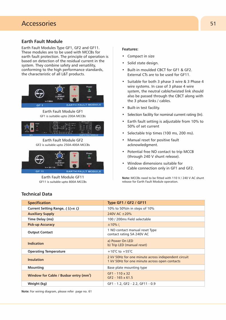
Features:
• Compact in size
• Solid state design.
• Built-in moulded CBCT for GF1 & GF2.External CTs are to be used for GF11.
• Suitable for both 3 phase 3 wire & 3 Phase 4 wire systems. In case of 3 phase 4 wire system, the neutral cable/twisted link should also be passed through the CBCT along with the 3 phase links / cables.
• Built-in test facility.
• Selection facility for nominal current rating (In).
• Earth fault setting is adjustable from 10% to 50% of set current
• Selectable trip times (100 ms, 200 ms).
• Manual reset for positive fault acknowledgment.
• Potential free NO contact to trip MCCB (through 240 V shunt release).
• Window dimensions suitable forCable connection only in GF1 and GF2.
Earth Fault Module GF1GF1 is suitable upto 200A MCCBs
Earth Fault Module GF11GF11 is suitable upto 800A MCCBs
Earth Fault Module GF2GF2 is suitable upto 250A-400A MCCBs
release for Earth Fault Module operation.Note: MCCBs need to be fitted with 110 V / 240 V AC shunt
Note: For wiring diagram, please refer page no. 61
Technical Data
Specification
Current Setting Range, I (I =x I )s s n
Auxiliary Supply
Time Delay (ms)
Pick-up Accuracy
Operating Temperature
Mounting
Weight (kg)
Output Contact
Indication
Insulation
2Window for Cable / Busbar entry (mm )
Type GF1 / GF2 / GF11
1 NO contact manual reset Typecontact rating 5A 240V AC
a) Power On LEDb) Trip LED (manual reset)
2 kV 50Hz for one minute across independent circuit1 kV 50Hz for one minute across open contacts
GF1 - 110 x 32GF2 - 165 x 61.5
10% to 50%In in steps of 10%
240V AC ±20%
100 / 200ms Field selectable
±10% Is
o o+10 C to +55 C
Base plate mounting type
GF1 - 1.2, GF2 - 2.2, GF11 - 0.9
Earth Fault Module
Earth Fault Modules Type GF1, GF2 and GF11.These modules are to be used with MCCBs forearth fault protection. The principle of operation is based on detection of the residual current in the system. They combine safety and versatility, conforming to the high performance standards, the characteristic of all L&T products.

�Thermal Magnetic Release
�
�DN1
�DN2
�DN3B
�DN3
�Microprocessor Release�MTX1.0-2.0 (O/L curves)
2- I T at 6 , 7.2
�MTX3.0 (O/L curves)2- I T at 1.5I , 6I , 7.2Ir r r4- I T at 1.5I , 6I , 7.2Ir r r
- SI at 1.5I , 6I , 7.2Ir r r
- LI-VI at 1.5I , 6I , 7.2Ir r r
- Short circuit, Earth fault & Neutral
curves For MTX1.0-2.0-3.0
DN0
I Ir r
54
55
Characteristic Curves

54 Characteristic Curves
Current multiples (xI )n
-110 1 10 210 3100.001
0.01
0.1
1
10
100
1000
10000
6-10In
Trip
Tim
e (
s)
t<10ms
Current multiples (xI )n
t<10 ms
9In
0.001-110 1
210 31010
0.01
0.1
10000
1000
100
10
1
Trip
Tim
e (
s)
Current multiples (xI )n
-110 1 10 210 3100.001
0.01
0.1
1
10
100
1000
10000
6-10In
Trip
Tim
e (
s)
t<10ms
-110 1 10 210 3100.001
0.01
0.1
1
10
100
1000
10000
9In
Current multiples (xI )n
Trip
Tim
e (
s)
t<10ms
9In
-110 1 10 210 3100.001
0.01
0.1
1
10
100
1000
10000
Current multiples (xI )n
Trip
Tim
e (
s)
t<10ms
Thermal-Magnetic Release
Note: Curves are Ir based till overload zone.
DN3 MCCBDN3B MCCBDN2 MCCB
DN1 MCCBDN0 MCCB

0.1
1
10
100
1000
10000
1 10
10s
3s
Current multiples (xI )r
2 I T @ 6I r
Trip
Tim
e (
s)
0.1
1
10
100
1000
10000
1 10
10s
3s
Current multiples (xI )r
2 I T @ 7.2Ir
Trip
Tim
e (
s)
30s
20s
10s
0.01
0.1
1
10
100
1000
1 10
5s
3s
2 I T @ 1.5Ir
Current multiples (xI )r
Trip
Tim
e (
s)
0.1
1
10
100
1000
10000
1 10
30s
20s
10s
5s
3s
2 I T @ 6 Ir
Current multiples (xI )r
Trip
Tim
e (
s)
10000
0.1
1
10
100
1000
1 10
30s20s
10s
5s3s
Current multiples (xI )r
2 I T @ 7.2Ir
Trip
Tim
e (
s)
55Characteristic Curves
Microprocessor Release
2MTX1.0 / 2.0 - DN2 / DN3 / DN4 (O/L curves - I t)
2MTX3.0 - DN2 / DN3 / DN4 (O/L curves - I t)

Trip
Tim
e (
s)
0.1
1
10
100
1000
10000
100000
1 10
30s18s10s6s
3s
Current multiples (x )Ir
4 I T @7.2Ir
0.1
1
10
100
1000
10000
100000
1 10
30s18s10s6s3s
Current multiples (x )Ir
4 I T @ 6Ir
Trip
Tim
e (
s)
0.01
0.1
1
10
100
1000
1 10
30s18s
10s6s
3s
Current multiples (xI )r
4 I T @ 1.5Ir
Trip
Tim
e (
s)56 Characteristic Curves
Microprocessor Release
4 MTX3.0 - DN2 / DN3 / DN4 (O/L curves - I t)
MTX3.0 - DN2 / DN3 / DN4 (O/L curves - Short Inverse)
Trip
Tim
e (
s)
1
10
100
1 10
30s
24s
12s
4s
Current multiples (x )Ir
SI @ 7.2Ir
1
10
100
1 10
30s
24s
12s
4s
Current multiples (x )Ir
SI @ 6Ir
Trip
Tim
e (
s)
1
10
100
1 10
30s
24s
12s
4s
Current multiples (x )Ir
SI @1.5Ir
Trip
Tim
e (
s)

57Characteristic Curves
* Only Short Circuit setting available in MTX1.0• Under Short Circuit fault conditions, MCCBs will clear the fault in less then 10 msec
Microprocessor Release
MTX3.0 - DN2 / DN3 / DN4 (O/L curves - Long Inverse / Very Inverse)
MTX1.0* / 2.0 / 3.0 (S/C, E/F & Neutral Curves)
0.1
1
10
100
1 10
Current multiples (xI )r
30s24s
12s
4s
LI-VI @ 1.5Ir
1
10
100
1000
1 10
Current multiples (xI )r
30s
24s
12s
4s
LI-VI @ 6 Ir
30s24s
12s
1
10
100
1000
1 10
Current multiples (xI )r
4s
LI-VI @ 7.2Ir
Trip
Tim
e (
s)
Trip
Tim
e (
s)
Trip
Tim
e (
s)
Inst
100ms
200ms
300ms
400ms
1 10
1
0.1
0.011.5 8
For MTX3.0 only
Short Circuit Curves
1
0.1
0.010.1 1
200ms
100ms
500ms
For MTX3.0 only
0.2 0.5
Earth Fault Curves
Current multiples (xI )r Current multiples (xI )r Current multiples (xI )r
0.1 1 10
*: IDMT disable in case of MTX3.0
0.5 1.50.01
0.1
1
200ms
Neutral Curves
Trip
Tim
e (
s)
Trip
Tim
e (
s)
Trip
Tim
e (
s)
Invs OFF*
Wiring Diagrams
�Motorised Circuit Breakers Control
through AuXC - 1000 & AuXC - 1000L
�Earth Fault Modules
�MTX2.0 with Current Metering Module
�MTX3.0 with Communication
through Modbus
60
61
62
63

31 4 2
5
CLO
SIN
G
PO
WER S
UPPLY
INTE
RLO
CK
OPEN
ING
TRIP
CO
MM
ON
STA
TUS
31 4 2
CLO
SIN
G
PO
WER S
UPPLY
INTE
RLO
CK
OPEN
ING
TRIP
CO
MM
ON
STA
TUS
5
Contactors
Mechanical Interlocking
Circuit Breaker(Q1, Q2)
MCB
DIGITAL INPUT S
4.1
4.2
4.3
5.1
5.2
5.3
3.1
3.2
3.3
3.4
3.5
2.1
2.2
2.3
2.4
2.5
2.6 1.1
1.2
DCSUPPLY
AUXLINE1 LINE2
LINE2
7.4 N
7.3 L3
7.2 L2
7.1 L1
6.4 N
6.3 L3
6.2 L2
6.1 L1
LINE1
AuXC - 1000L
RS232
N
L
L NL N
LINE1 LINE2
DUALPOWERSUPPLY OUT
L N L N
Q2Q1
QF2
QF1
LINE2
L1 L2 L3 N
LINE1
L1 L2 L3 N
LOADL1 L2 L3 N
Parameter setting for the wiring diagram in picture.
4.1
4.3
5.1
5.3
2.1
2.2
2.3
2.4
Terminal
P6.1.1
P6.2.1
P6.3.1
P6.4.1
P5.1.1
P5.2.1
P5.3.1
P5.4.1
Parameter code Setting
OP.1
CL.1
OP.2
CL.2
Fb.1
Fb.2
Tr.1
Tr.2
1.1
1.2
1.3
2.1
2.2
2.3
3.1
3.2
3.3
3.4
3.5
3.8
3.7
3.6
4.5
4.4
4.3
4.2
4.1
4.6
4.7
4.8
5.2
5.1
5.3
9.4
9.3
9.2
9.1
8.4
8.3
8.2
8.1
7.1
7.2
DIGITAL INPUT S SUPPLYDC
+_ _
L1 L2 L3 NLINE 1
L1LINE 2
L3L2 N
L2L1 L3 NLOAD
Q2Q1
K2
K2K1
K1
K2 K2 K1 K1
QF1
QF2
WITHDRAWN
CLO
SIN
G
PO
WER S
UPPLY
INTE
RLO
CK
OPEN
ING
TRIP
SE-EOM Q1
31
5
4 2
CO
MM
ON
WITHDRAWN
CLO
SIN
G
PO
WER S
UPPLY
INTE
RLO
CK
OPEN
ING
TRIP
SE-EOM Q2
31
5
4 2
CO
MM
ON
STA
TUS
STA
TUSContactors
Mechanical Interlocking
Circuit Breaker(Q1, Q2)
MCB
RS232
AuXc - 1000
Parameter setting for the wiring diagram in picture.
1.1
1.3
2.1
2.3
4.1
4.2
4.3
4.4
Terminal
P6.01
P6.02
P6.03
P6.04
P5.01
P5.02
P5.03
P5.04
Parameter code Setting
OP.1
CL.1
OP.2
CL.2
Fb.1
Fb.2
Tr.1
Tr.2
60 Wiring Diagrams
Motorised Circuit Breakers Control through AuXC - 1000L
Motorised Circuit Breakers Control through AuXC - 1000

R Y B N
FROM MCCB
SENSINGCIRCUIT
RELAY
RECTIFIER
TO LOAD
240 Vac
MCCB
SHUNT
RELEASE
AUX.
SUPPLY
240 Vac
1
2
5
3
4
L
N
TO LOAD
S1
S2
S1
S2
S1
S2
S1
S2
R Y B N
FROM MCCB
CT Sec.
SENSINGCIRCUIT
RELAY
240 Vac
MCCBSHUNTRELEASE
1
2
5
3
4
L
N
RECTIFIER
AUXSUPPLY240 Vac
61Wiring Diagrams
Earth Fault Modules
GF1 & GF2
GF11
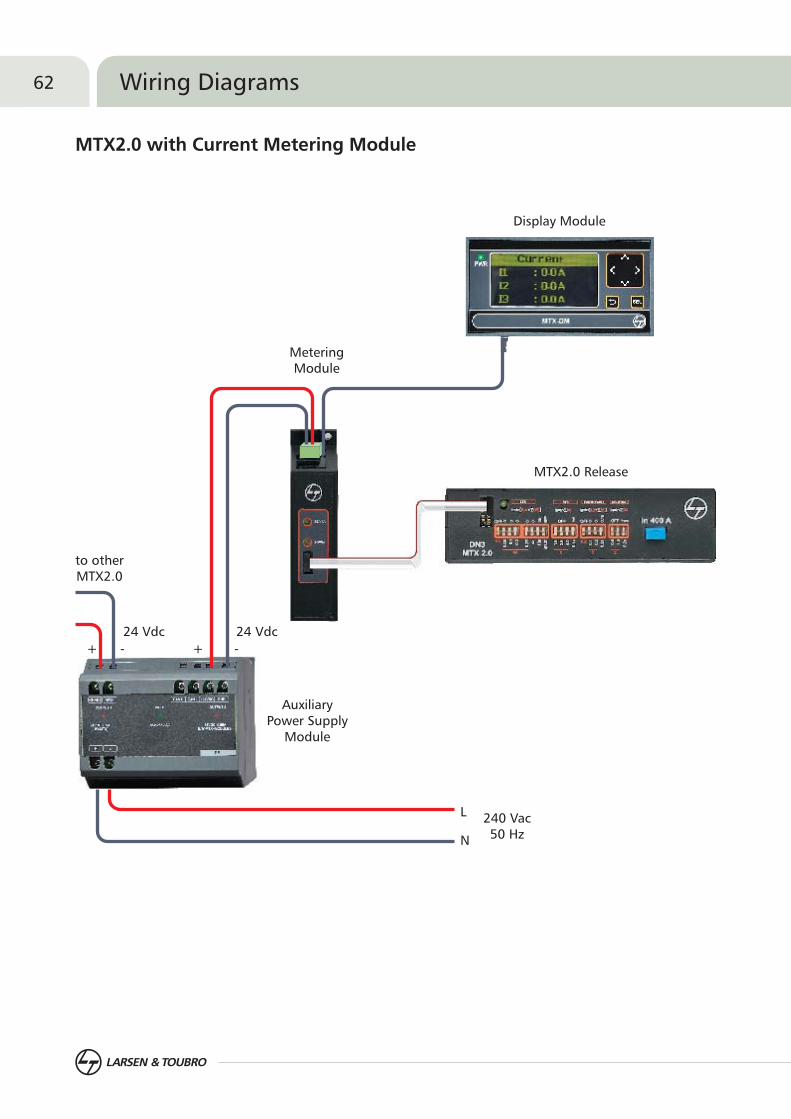
Display Module
Metering Module
L
N
240 Vac50 Hz
AuxiliaryPower Supply
Module
MTX2.0 Release
Inst
to other MTX2.0
24 Vdc
+ - + -
24 Vdc
62 Wiring Diagrams
MTX2.0 with Current Metering Module

Display Module
Communication Module
AuxiliaryPower Supply
Module
Laptop / SCADASystem
L
N
240 Vac50 Hz
D+
Gnd
D- Convertor
+VsRS232RS485
Inst
MTX3.0 Release
Voltage Module
3 Phase 415 Vac Supply
24 Vdc24 Vdc+ - + -
63Wiring Diagrams
MTX3.0 with Communication through Modbus


Dimensions
�
�
�
�
�
�
�
�
�
�
�
�
�
�
�
�
Dimensions of MCCB
DN1
DN2
DN3B
DN3
DN4
Dimensions of Accessory
Rotary Operating Mechanism
Stored Energy Electrically
Operated Mechanism
Panel Mounted Key Lock
Mechanical Interlock Kit
External Neutral CTs
MTX Modules
Auto Source Transfer Switch: AuXC-1000
and AuXC-1000L
Earth Fault Modules
DN0
66
72

All dimensions are in mm
25 25 25
25 25 25 12.51
30
11
6.4
11
2
0 P10 (4 )
75 (3P)
N
Mounting & Door Cut-out Details
9.2 5
2.25
48
.55
23
94
61
21
50.5 5 50.
101
CUT OUT 1
M U HOMCCB O NTING LESEM3 SCR W 6 Nos.
U T 2C T OU
76
27.25
N
25.5
25 25
13 31
92
2.2
17 94
.21
22
Ø9
35 35
28
11
N
28
11
127.235 35 35
22
.23
0
17
2.2
94
1.2
13 13 13Ø8.5
8646
60
23
220
220
.23
2
58
4
5
17
13
.5
7561
.53
8
DIN rail kit
10
8646
60
2
32
20
220
.23
2
58
4
5
17
13
.5
751
.56
38
DIN rail kit
10
DN0-125 MCCB
DN0-125 with Spreader Links
66 Dimensions of MCCB
Note: • • It is recommended to use spreader links for enhancing termination capacity• Frame size is same for DN0 / DN0-SD / DN0-M
Spreaders are available as spare
Recommended cat. nos. for DN0 spreaders
4PCM97921OOOO
CM90688OOLO
3PCurrentCM97785OOOO
CM90687OOLO
upto 100A
125A
67Dimensions of MCCB
Ø10.2 19.5 19.5
54.5 54.5
22
1
25
7
38
18
35
144
18
46
46
18
64.5
604
4
93.7
45
78
.65
95
.7
Mounting & Door Cut-out Details
12
6
3535
141
58
.64
6
70.5 70.5
17.5 17.5
88 53
MCCB MOUNTINGHOLES 6 Nos.
N
54 54 54
25
7
14
7
Ø10.2
18
47
.54
7.5
35
22
1
197
191919
64.5
60
93.7
45
78
.65
95
.7
N
35 35 35 17.51
45
16
5
140 (4P)
35 35 35
12
6105 (3P)
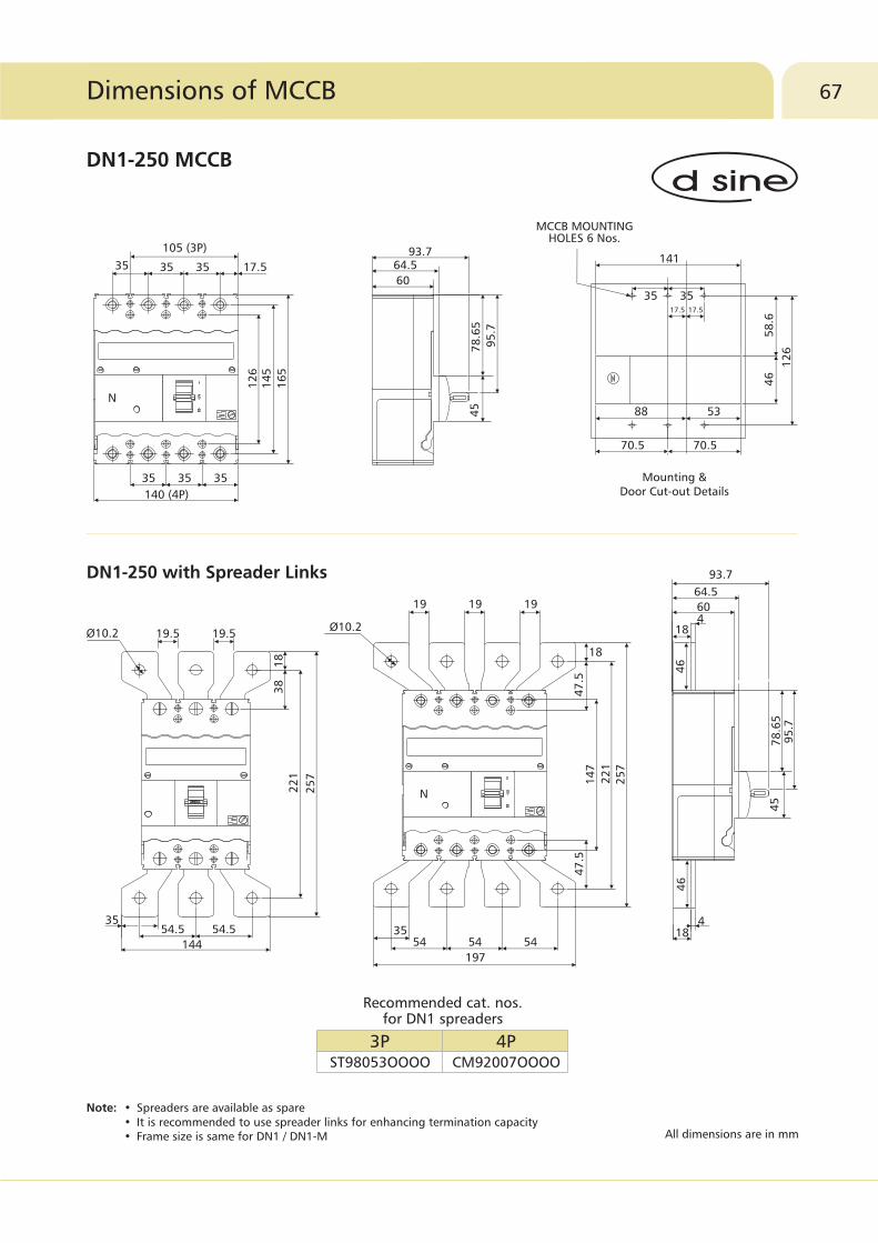
Recommended cat. nos. for DN1 spreaders
4PCM92007OOOO
3PST98053OOOO
DN1-250 with Spreader Links
All dimensions are in mm
Note: •• It is recommended to use spreader links for enhancing termination capacity• Frame size is same for DN1 / DN1-M
Spreaders are available as spare
DN1-250 MCCB

144
54.5 54.5
27
5
23
93
81
8
19.5 19.5
35
Ø10.2
41
19 19 19
27
5
23
9
Ø10.2
54 54 54
197
18
38
35
N
28.654
72
.745
A4
48
96.5
48
119.57
89
.27
35 35 35
140 (4P)
17.5
8
35 35 35
17
9
16
3
15
7105 (3P)
N
72
.7
45
96.5
119.57
89
.27
Mounting & Door Cut-out Details
46
.56
1
35
60.5
15
7
25.5
86
CUT OUT
MCCB MOUNTING HOLES M4 SCREW 6 Nos.
35
68 Dimensions of MCCB
DN2-250 MCCB
Note: • Spreaders are available as spare• • Frame size is same for DN2 / DN2-SD / DN2-M
It is recommended to use spreader links for enhancing termination capacity
DN2-250 with Spreader Links
All dimensions are in mm
Recommended cat. nos. for DN2 spreaders
4PCM92007OOOO
3PST98053OOOO
Rating125-250A TM
63-100A TM
32-50A TM
MTX breakers
Dimension (A)26
25.5
26.25
28
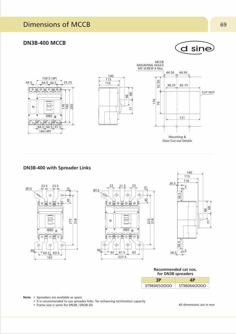
69Dimensions of MCCB
DN3B-400 MCCB
Note: • Spreaders are available as spare • It is recommended to use spreader links for enhancing termination capacity
• Frame size is same for DN3B / DN3B-SD
DN3B-400 with Spreader Links
All dimensions are in mm
Recommended cat nos. for DN3B spreaders
4PST98066OOOO
3PST98065OOOO
44.544.544.5 25.25
44.5 44.5 47.5
184 (4P)
17
61
82
20
5
139.5 (3P)
44.50 44.50
52
.50
MCCB MOUNTING HOLESM5 SCREW 6 Nos.
17
6
79
CUT OUT
121
38.25 82.75110115
140
68
98
77
Mounting & Door Cut-out Details
Ø13
23 21.5 23
23
45
31
82
72
6361.540
227.5
63
23.5 23.5Ø13 2
34
52
72
31
8
63.540
63.5
167
56
.5
26.55
26.55
110
115140
68
98
77
56
.5
N
N
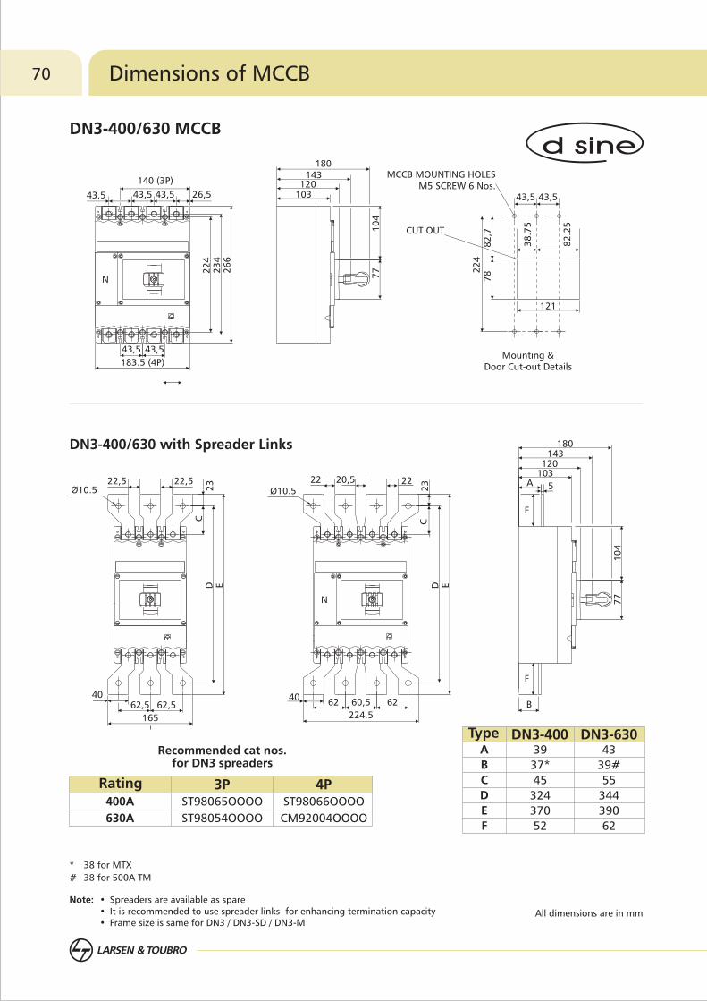
70 Dimensions of MCCB
DN3-400/630 MCCB
Note: • Spreaders are available as spare• It is recommended to use spreader links for enhancing termination capacity• Frame size is same for DN3 / DN3-SD / DN3-M
All dimensions are in mm
DN3-400/630 with Spreader Links
* 38 for MTX
# 38 for 500A TM
Recommended cat nos. for DN3 spreaders
Rating400A
630A
4PST98066OOOO
CM92004OOOO
3PST98065OOOO
ST98054OOOO
Type DN3-400 DN3-630A
B
C
D
E
F
39
37*
45
324
370
52
43
39#
55
344
390
62
43,5 43,5 43,5
26
6
183.5 (4P)
43,5
22
42
34
26,5
43,5
140 (3P)
Mounting & Door Cut-out Details
22
47
88
2,7
121
43,5 43,5
CUT OUT
MCCB MOUNTING HOLES M5 SCREW 6 Nos.
82
.25
38
.75
143
103120
180
77
10
4
165
E
40
Ø10.522,522,5
62,5
CD
23
62,5
22 20,5 22
23
62 60,5 6240
C
ED
Ø10.5
224,5B
143
A103120
5
180
77
10
4
F
F
N
N

Note: • Spreaders are available as spare• It is recommended to use spreader links for enhancing termination capacity• Frame size is same for DN4 / DN4-SD
All dimensions are in mm
DN4-800/1000/1250 MCCB
DN4-800/1000/1250 with Spreader Links
71Dimensions of MCCB
3/4P Frame3P Frame 4P Frame
Recommended cat nos. for DN4 spreaders
98
98
86
256
256
232
6
12
20
800A
1000A
1250A
38
38
26
A B CType D
88
88
80
324
324
300
6
12
20
800A
1000A
1250A
28
28
20
A B CType D
N version
S version
Y
46
42
Type
ST90362OOOO
CM90064OOVO
ST98058OOOO
CM91161OOUO
CM91161OOVO
CM91161OOAO
800A
1000A
1250A
4P3PRating
278 (4P)
210 (3P)
6868 68
246871 68 71
180
32
6
33
03
70
13
2.5
197
143
10
51
98
.5
Mounting & Door Cut-out Details
68 68
57
32
6
182
10
71
09
.5
CUT OUT
MCCB MOUNTING HOLESM5 SCREW 6 Nos.
125
N
A A A
B
D
Ø12.5
24 1560
N 51
01
5
B
D
Ø12.5
2460
C
Y
198
143
85
37
08
5
46
10
51
32
.5
A A
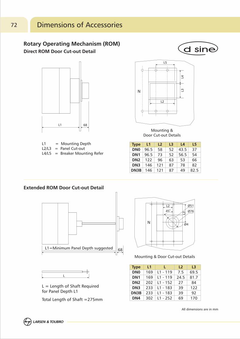
72 Dimensions of Accessories
All dimensions are in mm
Rotary Operating Mechanism (ROM)
Direct ROM Door Cut-out Detail
L = Length of Shaft Required for Panel Depth L1
Total Length of Shaft =275mm
L
L1
96.5
122
146
146
96.5
L2
73
96
121
121
58
L3
52
63
87
87
52
Type
DN0
DN1
DN2
DN3
DN3B
L4
56.5
53
78
49
43.5
L5
54
66
82
82.5
37
L1
169
202
233
233
302
169
L
L1 - 119
L1 - 119
L1 - 152
L1 - 183
L1 - 183
L1 - 252
L2
24.5
27
39
39
69
7.5
Type
DN0
DN1
DN2
DN3
DN3B
DN4
L3
81.7
84
122
92
170
69.5
Extended ROM Door Cut-out Detail
L1 = Mounting DepthL2/L3 = Panel Cut-outL4/L5 = Breaker Mounting Refer
Mounting & Door Cut-out Details
L1
L2
L4L3
L5
N
Mounting & Door Cut-out Details
L1=Minimum Panel Depth suggested
L2
L3
045
Ø51
N
Ø76
Ø4
68
68
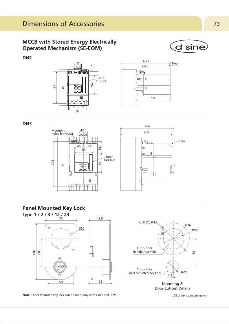
All dimensions are in mmNote: Panel Mounted key lock can be used only with extended ROM
Mounting & Door Cut-out Details
12
72
Ø50
13
6
68
58
48.5
52
045
2 Holes, Ø4.2Ø76
Ø50
68
Ø292.2
Cut-out for Handle Assembly
Cut-out for Panel Mounted Key Lock
237.5
245.5
156
Door
94
35
Door Cut-out
N
=
=
=
=
ON TRIP
256
264
Door
43.5
22
4
62
.19
4
94
Mounting holes for MCCB
Door Cut-out
N
= =
ON TRIP
94
18
.7
15
7
73Dimensions of Accessories
MCCB with Stored Energy Electrically Operated Mechanism (SE-EOM)
Panel Mounted Key Lock Type 1 / 2 / 3 / 12 / 23
DN2
DN3
4945

All dimensions are in mm
26
656
Holes for Breaker Mounting
Ø10 Mounting Holes 436
161 161
161 161
31
6
34
6
Mounting Details
Holes for Breaker Mounting
Ø10 Mounting Holes
17
7
35
372
141
141
141
141
20
9
23
9
Mounting Details
149
152.5
74 Dimensions of Accessories
DN2
DN3
Mechanical Interlocking Kit
53 53
22
.5
10
41.5
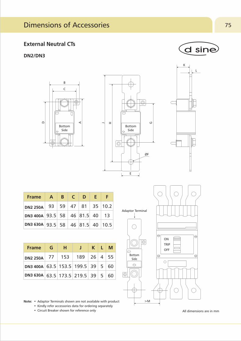
75
All dimensions are in mm
K
L
Bottom Side
D AB
C
ØF
E
J H G
BottomSide
ON
TRIP
OFF
>M
Bottom Side
Adaptor Terminal
Dimensions of Accessories
External Neutral CTs
Note: • Adaptor Terminals shown are not available with product
• Kindly refer accessories data for ordering separately
• Circuit Breaker shown for reference only
DN2/DN3
Frame
DN2 250A
DN3 400A
DN3 630A
A
93
93.5
93.5
B
59
58
58
C
47
46
46
D
81
81.5
81.5
E
35
40
40
F
10.2
13
10.5
Frame
DN2 250A
DN3 400A
DN3 630A
G
77
63.5
63.5
H
153
153.5
173.5
J
189
199.5
219.5
K
26
39
39
L
4
5
5
M
55
60
60
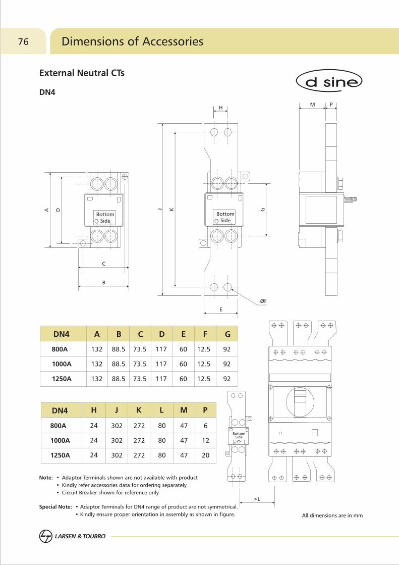
76
All dimensions are in mm
Special Note: • Adaptor Terminals for DN4 range of product are not symmetrical.
• Kindly ensure proper orientation in assembly as shown in figure.
Note: • Adaptor Terminals shown are not available with product
• Kindly refer accessories data for ordering separately
• Circuit Breaker shown for reference only
M P
A D
C
B
J K G
H
E
ØF
>L
Bottom Side
Bottom Side
Bottom Side
Dimensions of Accessories
DN4
External Neutral CTs
A B C D E F GDN4
132
132
132
88.5
88.5
88.5
73.5
73.5
73.5
117
117
117
60
60
60
12.5
12.5
12.5
92
92
92
800A
1000A
1250A
H J K L M PDN4
24
24
24
302
302
302
272
272
272
80
80
80
47
47
47
6
12
20
800A
1000A
1250A

77
All dimensions are in mm
23
38
1
3
14.3
73
.3
23
Door Cut-outDetails
65
60
73
.3
87
51
96
44
.5
10
36
91.5
44
.5
91.5
Door Cut-out Details
Dimensions of Accessories
Display Module
Voltage/Communication/Metering Module
MTX Modules
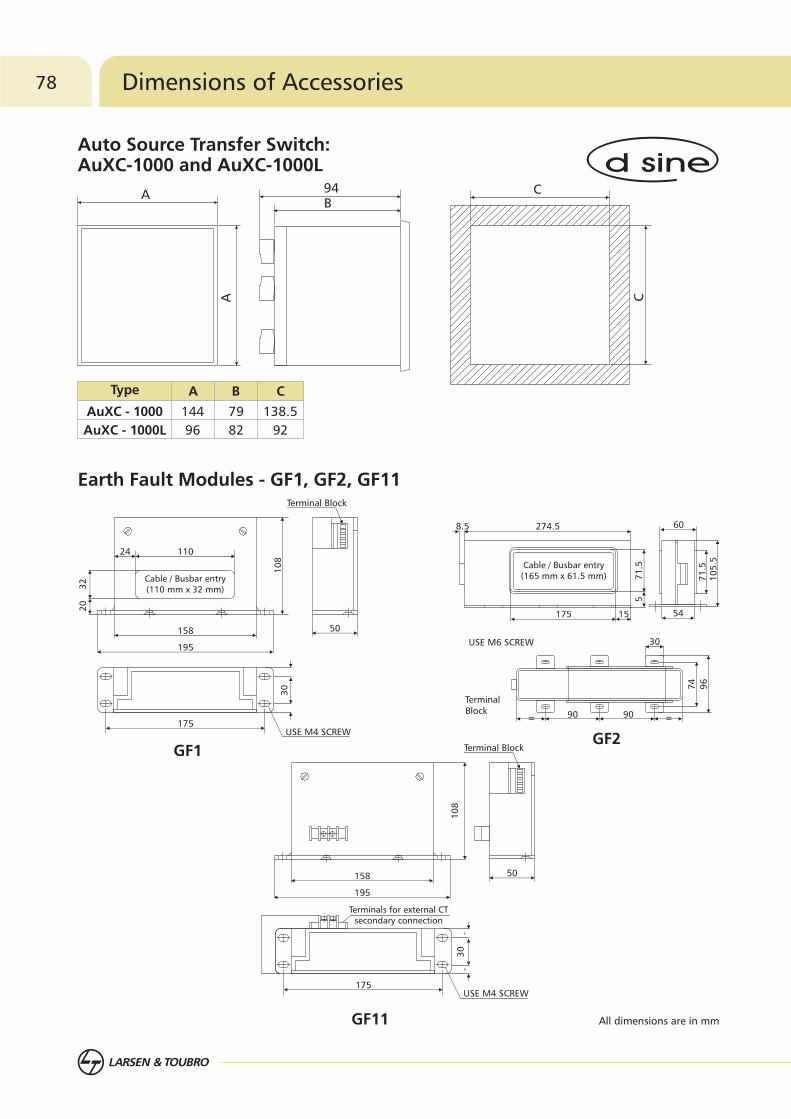
All dimensions are in mm
B94 C
C
A
A
Cable / Busbar entry(165 mm x 61.5 mm)
175 15
274.58.5
71
.55
54
71
.51
05
.5
60
50
Terminal Block
158
195
24 110
10
8
Cable / Busbar entry(110 mm x 32 mm)3
22
0
175USE M4 SCREW
30
=90= 90
30
74
96
USE M6 SCREW
Terminal Block
50
Terminal Block
158
195
10
8
175USE M4 SCREW
30
Terminals for external CTsecondary connection
78 Dimensions of Accessories
Auto Source Transfer Switch: AuXC-1000 and AuXC-1000L
Earth Fault Modules - GF1, GF2, GF11
GF1GF2
GF11
AuXC - 1000
AuXC - 1000L
144
96
79
82
138.5
92
AType B C

Notes 79
Notes80

Please contact any of the training centres for participation and detailed training programme schedule.
So gain the advantage and go the extra mile with:
�
�
�
�
The typical training programmes cover:
�
�
�
�
�
22 courses on contemporary topicsCourses applicable to all switchgear brandsTraining Centers in Pune, Lucknow, Coonoor, Vadodara, Delhi & KolkataBlend of theory and practical experience
Low Voltage & Medium Voltage SwitchgearSwitchboard Electrical DesignAC Drives & Building Management Solutions Protective Relays, Earthing, Reactive Power Management & HarmonicsEnergy Conservation & Management
Aimed at maximizing productivity, conserving energy, minimizing costs and enhancing safety, our
Electrical & Automation training programmes have benefitted over 1.35 Lakh professionals in the
last 28 years. These training programmes are highly beneficial as they provide right exposure and
impart knowledge on selection, installation, maintenance and testing of Electrical & Automation
Products.
PuneLarsen & Toubro LimitedSwitchgear Training Centre, T-156/157, MIDCBhosari, Pune - 411 026Tel: 020 2712 0037 / 2712 0653 Fax: 020 2712 2933 E-mail: [email protected]
LucknowLarsen & Toubro LimitedSwitchgear Training Centre, C - 6 & 7, UPSIDCP. O. Sarojininagar, Lucknow - 226 008Tel: 0522 247 6015 / 97944 54455 Fax: 0522 247 6015 E-mail: [email protected]
CoonoorLarsen & Toubro LimitedSwitchgear Training Centre, Ooty-Coonoor Main RoadYellanahalli P.O., The Nilgiris - 643 243Tel. : 0423 251 7107Fax : 0423 251 7158E-mail: [email protected]
VadodaraLarsen & Toubro LimitedSwitchgear Training CentreBehind L&T Knowledge City, Near Village Ankhol, Vadodara - 390019Tel: 0265 2457805E-mail: [email protected]
DelhiLarsen & Toubro LtdSwitchgear Training Centre32, Shivaji Marg,Near Motinagar Metro Station,New Delhi - 110015 Tel: 011 41419515 / 41419695 / 41419500Fax: 011 41419600E-mail: [email protected]
KolkataLarsen & Toubro LimitedSwitchgear Training Centre4th Floor, 3B, Shakespeare Sarani, Kolkata - 700071Tel: 033 42005975 / 42005978E-mail: [email protected]
SP 50584 R7
Khairasol, Degaul AvenueDurgapur 713 212Tel: 0343-2540448 / 2540449 / 2540443Fax: 0343-2540442e-mail: [email protected]
5, Milanpur Road, Bamuni MaidanGuwahati 781 021Tel: +91 8876554410 / 8876554417Fax: 361-2551308e-mail: [email protected]
II Floor, Vasantha Chambers5-10-173, Fateh Maidan RoadHyderabad 500 004Tel: 040-67015052Fax: 040-23296468e-mail: [email protected]
Monarch Building, 1st FloorD-236 & 237, Amrapali MargVaishali NagarJaipur 302 021Tel: 0141-4385914 to 18Fax: 0141-4385925e-mail: [email protected]
Akashdeep Plaza, 2nd FloorP. O. GolmuriJamshedpur 831 003JharkhandTel: 0657-2312205 / 38Fax: 0657-2341250e-mail: [email protected]
Skybright Bldg; M. G. RoadRavipuram Junction, ErnakulamKochi 682 016Tel: 0484-4409420 / 4 / 5 / 7Fax: 0484-4409426e-mail: [email protected]
3-B, Shakespeare SaraniKolkata 700 071Tel: 033-42005982Fax: 033-22821025 / 7587e-mail: [email protected]
A28, Indira Nagar, Faizabad Road Lucknow 226 016Tel: 0522-4929905 / 04Fax: 0522-2311671e-mail: [email protected]
No: 73, Karpaga Nagar, 8th StreetK. PudurMadurai 625 007Tel: 0452-2567405 / 2561068 / 2561657Fax: 0452-2567552e-mail: [email protected]
Product improvement is a continuous process. For the latest information and special applications, please contact any of our offices listed here.
Electrical Standard Products (ESP) Offices:
HEAD OFFICEL&T Business Park,Tower 'B' / 3rd FloorSaki Vihar Road, PowaiMumbai 400 072Tel: 022-67053229 Fax: 022-67051112e-mail: [email protected]
BRANCH OFFICES501, Sakar Complex I Opp. Gandhigram Rly. Station Ashram RoadAhmedabad 380 009Tel: 079-66304006-11Fax: 079-66304025e-mail: [email protected]
38, Cubbon Road, P. O. Box 5098Bengaluru 560 001Tel: 080-25020100 / 25020324Fax: 080-25580525e-mail: [email protected]
131/1, Zone IIMaharana Pratap NagarBhopal 462 011Tel: 0755-3080511 / 05 / 08 / 13 / 17 / 19 Fax: 0755-3080502e-mail: [email protected]
Plot No. 559, Annapurna ComplexLewis RoadBhubaneswar 751 014Tel: 0674-6451342 / 2436690 / 2436696Fax: 0674-2537309e-mail: [email protected]
Aspire Towers, 4th FloorPlot No. 55, Phase-IIndustrial & Business ParkChandigarh-160 002Tel: 0172-4646840 / 41 / 42 / 46 / 53Fax: 0172-4646802Email: [email protected]
L&T Construction CampusTC-1 Building, II FloorMount-Poonamallee RoadManapakkamChennai 600 089Tel: 044-2270 6800Fax: 044-22706940e-mail: [email protected]
67, Appuswamy RoadPost Bag 7156 Opp. Nirmala CollegeCoimbatore 641 045Tel: 0422-2588120 / 1 / 5Fax: 0422-2588148e-mail: [email protected]
L&T Business Park,Tower 'B' / 5th FloorSaki Vihar Road, PowaiMumbai 400 072Tel: 022-67052874 / 2737 / 1156Fax: 022-67051112e-mail: [email protected]
12, Shivaji NagarNorth Ambajhari RoadNagpur 440 010Tel: 0712-2260012 / 6606421Fax: 2260030 / 6606434e-mail: [email protected]
32, Shivaji Marg P. O. Box 6223New Delhi 110 015Tel: 011-41419514 / 5 / 6Fax: 011-41419600e-mail: [email protected]
L&T House P. O. Box 119 191/1, Dhole Patil RoadPune 411 001Tel: 020-66033395 / 66033279Fax: 020-26164048 / 26164910e-mail: [email protected]
Crystal Tower, 4th Floor, G. E. RoadTelibandhaRaipur - 492 006Tel: 0771-4283214e-mail: [email protected]
3rd Floor Vishwakarma ChambersMajura Gate, Ring RoadSurat 395 002Tel: 0261-2473726Fax: 0261-2477078e-mail: [email protected]
Radhadaya ComplexOld Padra RoadNear Charotar SocietyVadodara 390 007Tel: 0265-6613610 / 1 / 2Fax: 0265-2336184e-mail: [email protected]
Door No. 49-38-14/3/2, 1st floor,NGGO's Colony, Akkayyapalem,Visakhapatnam - 530 016Tel: 0891-2791126 / 2711125Fax: 0891-2791100Email: [email protected]
Larsen & Toubro Limited, Electrical Standard Products
Powai Campus, Mumbai 400 072
Customer Interaction Center (CIC)
BSNL / MTNL (toll free) : 1800 233 5858 Reliance (toll free) : 1800 200 5858
Tel : 022 6774 5858, Fax : 022 6774 5859
E-mail : [email protected] / Website www.Lntebg.com
Registered Office: L&T House, N. M. Marg, Ballard Estate, Mumbai 400 001, INDIA CIN: L99999MH1946PLC004768