sonet transmission products s/dms transportnode oc-3…npatrick/nortel-sdms-docs/n3rls8cd.pdf ·...
TRANSCRIPT

NT7E65DJ 323-1111-180
SONET Transmission Products
S/DMS TransportNodeOC-3/OC-12 NE—TBM
Technical Specifications
Standard Rel 14 February 2001
What’s inside...
SONET specificationsSystem performance specificationsOptical link engineeringData communications and OPC engineering guidelines

Copyright
1992–2001 Nortel Networks, All Rights Reserved
The information contained herein is the property of Nortel Networks and is strictly confidential. Except as expressly authorized in writing by Nortel Networks, the holder shall keep all information contained herein confidential, shall disclose it only to its employees with a need to know, and shall protect it, in whole or in part, from disclosure and dissemination to third parties with the same degree of care it uses to protect its own confidential information, but with no less than reasonable care. Except as expressly authorized in writing by Nortel Networks, the holder is granted no rights to use the information contained herein.
Nortel Networks and S/DMS TransportNode are trademarks of Nortel Networks. VT100 is a trademark of Digital Equipment Corporation. UNIX is a trademark of X/Open Company Ltd.
Printed in Canada

iii
ContentsAbout this document vii
SONET specifications 1-1Automatic protection switching (APS) 1-1Synchronization-status messages 1-1STS pointer 1-2Path trace 1-2Message-oriented data communication channels 1-2
System performance specifications 2-1Site engineering standards and mechanical specifications 2-1
Site engineering standards 2-1Mechanical specifications 2-1
Environmental specifications 2-3Ambient temperature 2-3Relative humidity 2-4Altitude 2-4Atmospheric dust 2-4Mechanical shock and vibration 2-5
Power requirements 2-6Battery voltage requirements 2-6Power distribution 2-6Grounding and battery isolation 2-6Internal grounding and battery isolation 2-7Power dissipation 2-7
Electromagnetic compatibility 2-9Emission 2-9Susceptibility 2-9Electrostatic discharge 2-9
Digital interface specifications 2-10Cross-connect specifications 2-10Jitter specifications 2-10DS1 interface specifications 2-11DS3 interface specifications 2-14STS-1 interface specifications 2-17
Optical interface specifications 2-18Rates and format specifications 2-18OC-12 networking optical interface specifications 2-19
Technical Specifications 323-1111-180 Rel 14 Standard Feb 2001

iv
Contents
OC-12 VTM optical interface specifications 2-23OC-3 optical interface specifications 2-27
STS -12 electrical interface specifications 2-30STS-12 electrical interface specifications 2-30
Control network (CNet) specifications 2-31Protection switch specifications 2-31Network synchronization specifications 2-32Orderwire specifications 2-33System availability 2-34Safety specifications 2-34
Flammability 2-35Acoustic noise 2-35
Optical link engineering 3-1Engineering the optical link 3-1
Engineering the optical patchcords and connectors 3-1Optical link attenuation 3-1System gain 3-2Link loss calculation 3-2Estimating the number of splices 3-5Fiber loss calculation sheet 3-6Optical link design example 3-7
Attenuation-limited reach calculations 3-12
Data communications and OPC engineering guidelines 4-1Data communications guidelines 4-1
Maximum number of network elements in a network 4-2Protection parameters 4-2Default SDCC assignments 4-5Software download 4-6CNet LAN 4-7
OPC engineering guidelines 4-8Span of control 4-8Summary of S/DMS TransportNode data communication limits 4-8Locating the OPC terminal access line 4-10Locating OPCs in a network 4-11Locating OPCs in an OC-12 linear network 4-11Locating OPCs in an OC-12 network with multiple spans of control 4-12OC-12 multishelf terminal 4-14
Example systems 4-15OC-12 linear systems 4-15OC-12 route-diverse system 4-17OC-12 NWK configuration 4-19OC-12 VTM ring configuration 4-21ADM applications for OC-3 tributaries on the OC-12 TBM shelf 4-22OC-12 tributary system 4-23
TL1/X.25 and performance monitoring data collection 4-26PM collection 4-26PM general comments 4-27
Remote telemetry—TBOS 4-27
S/DMS TransportNode OC-3/OC-12 NE—TBM Vol 2 323-1111-180 Rel 14 Standard Feb 2001

Contents
v
General description 4-28Provisioning characteristics 4-28
OPC user interface and tools 4-30User and tool limitations within a span of control 4-30User logins and tool sets 4-30System security 4-35System configurations 4-35Login times 4-36OPC performance related to number of nodes 4-36OPC tool usage 4-37
Tips for maximizing OPC performance 4-38Network element numbering proposal 4-40
Technical Specifications 323-1111-180 Rel 14 Standard Feb 2001

vi
Contents
S/DMS TransportNode OC-3/OC-12 NE—TBM Vol 2 323-1111-180 Rel 14 Standard Feb 2001

vii
About this documentThis document provides the performance specifications for OC-3 and OC-12 network elements and presents the methodology for engineering single-mode fiber optic links.
AudienceThis document is for the following members of the operating company:
• planners
• system lineup and testing (SLAT) personnel
References in this documentThis document refers to the following documents:
• System Description, 323-1111-100
• Alarms and Surveillance Description, 323-1111-104
• TL1 Interface Description, 323-1111-190
• S/DMS Network Manager User Guide, 323-2001-050
Technical Specifications 323-1111-180 Rel 14 Standard Feb 2001

viii
About this document
S/DMS TransportNode OC-3/OC-12 NE—TBM Vol 2 323-1111-180 Rel 14 Standard Feb 2001
1-1
SONET specifications 1-The S/DMS TransportNode OC-3/OC-12 system conforms to the Synchronous Optical Network (SONET) specifications, which define standard optical signals and synchronous frame format for multiplexed digital traffic and the use of overhead bytes for operation, administration, and maintenance functions.
The Bellcore publication TR-TSY-000253, SONET Transport Systems; Common Generic Criteria defines the purpose of each byte in the Transport Overhead. This chapter describes variations from the defined use of these bytes, as implemented in the TransportNode OC-3/OC-12 network element.
Automatic protection switching (APS)Unidirectional and bidirectional protection switching strategies are implemented in accordance with the Bellcore publication. The K1 and K2 bytes in the line overhead are used to indicate the protection switching status, as defined in the Bellcore publication, with the following exceptions:
1 K2 byte, bits 1–4: The S/DMS TransportNode OC-3/OC-12 network elements permanently set these bits to the pattern ‘0000’ on the protection fiber, and ‘0001’ on the working fiber. These bits are used to facilitate a proprietary fiber connection error alarm that is raised in the event that the protection and working fibers are crossed. Since it is a requirement that the K2 bits 1–4 be ignored on the working channel, vendor interoperability is not affected. The S/DMS TransportNode fiber connection error alarm must be disabled in a mid-span-meet situation.
2 The S/DMS TransportNode OC-3/OC-12 equipment does not support 1:N protection switching.
Synchronization-status messagesSynchronization-status messages are carried in bits five to eight of the S1 byte in the SONET line overhead. These messages travel from one network element to the next network element. Synchronization-status messages indicate the quality of the timing sources currently available to a network element.
Technical Specifications 323-1111-180 Rel 14 Standard Feb 2001

1-2
SONET specifications
When a network element must decide on a timing source, it may have to choose among multiple candidates. For example, candidates may include external timing from a BITS, timing derived from SONET interfaces, and the network element internal clock. To select the most suitable timing source from available candidates, the network element requires knowledge of the quality level of each candidate. Synchronization-status messages carry that information.
For detailed information on synchronization-status messaging, see the chapter on network synchronization in System Description, 323-1111-100.
STS pointerThe STS payload pointer contained in the H1 and H2 bytes of the line overhead designates the location of the byte at which the STS Synchronous Payload Envelope (SPE) begins. The content of the STS pointer follows the requirements of Bellcore publication TR-TSY-000253, SONET Transport Systems; Common Generic Criteria, except in the case of STS-1s that are designated as out-of-service (OOS). The S/DMS TransportNode equipment currently sets all bytes in OOS STS-1s to zero, and also sets the bits in the H1 and H2 bytes to zero. Since the Bellcore publication requires a valid pointer to be maintained even for STS-1s that are designated as OOS, any non-S/DMS receiver that does not automatically mask the alarms from OOS STS-1s shows a loss of pointer alarm for these STS-1s.
Since an S/DMS TransportNode receiver ignores all STS-1s designated as OOS, no loss of pointer alarm is raised on these STS-1s.
Path traceThe S/DMS TransportNode equipment uses the J1 byte on the path overhead to transmit repetitively a 64-byte fixed length path trace pattern. Path trace is supported in networking schemes comprising multiple product platforms engineered correctly to carry traffic from one end to another. In a mid-span meet, the path trace alarm is not disabled on either the S/DMS TransportNode equipment or non-S/DMS TransportNode equipment (if used), since the standardized messaging is understood by all equipment.
Message-oriented data communication channelsThe bytes D1 through D3 in the section overhead and the bytes D4 through D12 in the line overhead are used to provide message-oriented data communication channels (DCC). The S/DMS TransportNode does not use the D4 through D12 bytes in the line overhead, since standards are not yet available to define permissible uses of this channel.
The S/DMS TransportNode uses the 192 kbit/s bandwidth provided by the section overhead bytes D1 through D3 to implement a general purpose wide area network, linking all network elements together for non-traffic
S/DMS TransportNode OC-3/OC-12 NE—TBM Vol 2 323-1111-180 Rel 14 Standard Feb 2001

SONET specifications
1-3
communications. Communications are implemented using all seven layers of the International Standards Organization Open Systems Interconnection (OSI) Basic Reference Model, and a Common Management Information Service Element (CMISE)-based, object-oriented message set. The first six layers of the model are compliant with standards. The seventh (application) layer uses proprietary message format because standards in this area are preliminary.
Table 1-1 illustrates the communications techniques and protocols implemented by S/DMS TransportNode equipment in each of the seven layers of the OSI model.
Table 1-1Protocols implemented on data communication channels
Layer 7(Application)
TELNET CMISEROSEACSE
DAPROSEASCE
FTAM
ASCE
SDP
Layer 6(Presentation)
ASN.1 (X.209), X.216, X.226
Layer 5(Session)
X.215, X.225
Layer 4(Transport)
COTP (ISO 8073, ISO 8073–DAD2 TP4, X.214, X.224 CLTP
Layer 3(Network)
CLNP (ISO 8473) Automatic Routing Table Generation
Layer 2(Data Link)
LAPD LLC2 Token Bus
Layer 1(Physical)
SONET DCC Twisted pair (CNet)
Technical Specifications 323-1111-180 Rel 14 Standard Feb 2001

1-4
SONET specifications
Acronyms and abbreviationsAll of the following protocols are defined by ISO, except as noted.
ACSE Association Control Service Element
ASN.1 Abstract Syntax Notation No. 1
CLNP Connection-Less Network Protocol
CLTP Connection-Less Transport Protocol
CMISE Common Management Information Service Element
CNET Control NETwork (Nortel Networks proprietary)
COTP Connection-Oriented Transport Protocol
DAP Directory Access Protocol
DCC Data Communication Channel
FTAM File Transfer and Access Management
LAPD Link Access Procedure on D-channel
LLC2 Logical Link Control, type 2
ROSE Remote Operations Service Element
SDP Software Download Protocol (Nortel Networks proprietary)
S/DMS TransportNode OC-3/OC-12 NE—TBM Vol 2 323-1111-180 Rel 14 Standard Feb 2001

2-1
System performance specifications 2-This chapter provides performance specifications for the S/DMS TransportNode OC-3/OC-12 system. Most specifications apply to all applications. However, where specifications do not apply to all applications, they are described separately.
For information concerning the maximum quantity of network elements in a system, see Chapter 4.
Site engineering standards and mechanical specifications This section provides a description of bay floor layout and loading, bay, shelf and module weights and dimensions, and bay thermal loading.
Site engineering standards The OC-3 and OC-12 transport bandwidth manager (TBM) network elements meet the network equipment building system (NEBS) standard 6-bay lineup floor plan for 305 mm (12 in.) deep equipment. This layout provides a 762 mm (2.5 ft) maintenance and wiring front aisle and a 610 mm (2.0 ft) rear aisle.
Mechanical specifications The following table provides the shelf size dimensions.
Shelf dimensions mm in.
Width 533 21.0
Depth 305 12.0
Height 419 16.5
Technical Specifications 323-1111-180 Rel 14 Standard Feb 2001

2-2
System performance specifications
The following table provides the shelf weight dimensions.
The following table provides the bay frame dimensions.
Floor loadingUsing Bellcore methods (resulting in an occupied floor area of 0.65 m2 or 7.0 ft2), the floor loading of a fully loaded configuration of three shelves in one bay is 341 kg/m2 (70 lbs/ft2). The floor loading is within the Bellcore-suggested maximum loading (TR-NWT-000063, section 2.1.8) of 561 kg/m2 (115 lbs/ft2).
Thermal loading The thermal loading of a maximum dissipation configuration of three NWK TBM shelves each equipped with four DS3 STS1 mapper circuit packs (12 DS3 channels) is 1.7 kW/m2 (158 W/ft2). The thermal loading of a maximum dissipation configuration of three VTMTBM shelves each equipped with four DS3 STS1 mapper circuit packs (12 DS3 channels) is 2.2 kW/m2 (158 W/ft2). The TBM product qualifies as a bay-based product as opposed to a multiple-bay system. The actual bay dissipation depends on the shelves equipped (see the configuration power estimates, in the power requirements section of this chapter).
Weight kg lb
Empty shelf assembly 23 50
Fully loaded shelf assembly 46 102
Bay frame 70 154
Breaker interface panel 9.5 21
Modem (optional) 0.9 2
Fiber storage panel 3.5 7.7
Fiber splice tray 4.5 10
Through-flow cooling unit 16.5 36
COP cooling unit (with LCAP) 8 17
COP cooling unit (without LCAP) 6.5 14
Air filter (NT4K15AA/CA) 0.7 1.5
Bay frame dimensions — 2.13 m (7 ft) high mm in.
Width 659 25.9
Depth 305 12.0
Clearance between uprights 546 21.5
Horizontal mounting centers 592 23.3
Vertical mounting centers 45 and 25 1.75 and 1.0
Maximum base height 134 5.3
S/DMS TransportNode OC-3/OC-12 NE—TBM Vol 2 323-1111-180 Rel 14 Standard Feb 2001

System performance specifications
2-3
Environmental specifications This section provides specifications for ambient temperature, relative humidity, altitude, and atmospheric dust.
Ambient temperatureThis section provides ambient temperature specifications for both operating and non-operating (shipping/storage) situations.
OperatingThe TBM shelf components and circuit packs can operate in a central office environment. This applies to the following configurations:
• the standard TBM bay with the NT4K18AA cooling unit equipped with NT4K17AA fan modules
• the enhanced TBM bay (two-shelf system) with the NT4K18BA cooling unit equipped with NT4K17BA fan modules
• the enhanced TBM bay (three-shelf system) with the NT4K18BA cooling unit equipped with NT4K17BA fan modules, and the NT7E7802 cooling unit
The TBM shelf components and circuit packs can (except the OPC and STS-12 electrical interface) can operate in an outside plant environment when used in conjunction with an appropriately engineered cooling unit.
Shipping/storageThe equipment can withstand non-operational temperatures between -50˚C and +70˚C (-58˚F and +158˚F) when tested (unpacked) according to TR-NWT-000063, section 4.4.
Central office environment operating temperature range ˚C ˚F
Normal operating temperatureShort term operating (see Note)
0 to 400 to 50
32 to 10232 to 122
Note: Short term is defined to be no more than 72 consecutive hours, no more than 15 days per year total.
Outside plant environment operating temperature range
˚C ˚F
Extended operating temperature -40 to 65 -40 to 149
Non operational ambient temperature
Low temperature IEC 68 2-1 Test Aa-Cold -50°C (-58°F), 16-hour duration
High temperature High IEC 68-2-2 Test Ba-Dry Heat +70°C (+158°F)
Technical Specifications 323-1111-180 Rel 14 Standard Feb 2001

2-4
System performance specifications
Relative humidity This section provides relative humidity specifications for both operating and non-operating (shipping/storage) situations.
Operating The relative humidity for operational systems is as follows:
• 20% to 95% relative humidity or 3.6 kPa (0.52 lb/sq. in.) water vapor pressure, whichever is less, over normal temperature range
• no condensation
Shipping/storage The relative humidity for non-operational systems is as follows:
• 20% to 95% relative humidity for temperatures up to +35˚C (+95˚F) and 5.3 kPa (0.77 lb/sq. in.) water vapor pressure for temperatures above +35˚C (+95˚F)
• no condensation
AltitudeThe following table provides the altitude performance of the TBM equipment.
Atmospheric dust The OC-3 and OC-12 shelves above the cooling unit, as well as the bottom shelf, must be equipped with an air filter.
The equipment remains operational with a filter equipped when subjected to the requirements of the following:
• Telecom Canada Technical Specification for FOTS, Section 11.8: “Industrial Atmosphere — Particle”
• NEBS, Section 4.6: “Airborne Contaminants”
Operating Up to 4000 m (see Note) (13,000 ft)
Shipping/storage Up to 15,000 m (50,000 ft)
Note: The equipment meets the long-term and short-term operating temperature range at altitudes of 61 m (200 ft) below sea level to 2133 m (7000 ft) above sea level. For altitudes above 2133 m (7000 ft), the specified temperature range is derated by 2°C (1.1°F) for each additional 305 m (1000 ft) up to 4000 m (13,000 ft). At 4000 m (13,000 ft), the long-term temperature range is limited to 28°C (82°F) and the short-term temperature range is limited to 38°C (100°F).
S/DMS TransportNode OC-3/OC-12 NE—TBM Vol 2 323-1111-180 Rel 14 Standard Feb 2001

System performance specifications
2-5
Mechanical shock and vibrationThe equipment withstands shock and vibration experienced during normal operation, transportation (in its packed state), and earthquake, as shown in Table 2-1 and Table 2-2.
Transportation bounce The equipment withstands transportation bounce in accordance with IEC 68-2-55.
EarthquakeThe equipment remains operational when subjected to floor response spectra simulating Zone 4 earthquake loading (NEBS specification TR-NWT-000063, section 4.5) when mounted in a recommended bay frame (such as Nortel Networks frames).
Table 2-1 Shock conditions
Unit Maximum shock condition
Shelf
Packed for shipping Drop height is 457 mm (18 in.) to 762 mm (30 in.), dependent on weight
Installation (unpacked) Drop height 76 mm (3 in.) or 51 mm (2 in.) dependent on weight (NEBS, Issue 5, Section 5.4.3 Test 3C)
Circuit packs
Packed for shipping Drop height 750 mm (30 in.)
Installation (unpacked) Drop height 102 mm (4 in.) (NEBS, Issue 5, Section 5.4.3 Test 3C)
Table 2-2Vibration conditions
Situation Unit Vibration condition
Operating Shelf or circuit packs 0.1 g (5 to 200 Hz, 3 axes) (NEBS, Issue 5, Section 5.6.3 Test 5C)
Shipping/storage
Shelf (packed for shipping – 3 axes)
5 to 500 Hz (NEBS, Issue 5, Section 5.4.4, Test 4)
Circuit pack (packed for shipping – 3 axes)
5 to 500 Hz (NEBS, Issue 5, Section 5.4.4, Test 4)
Technical Specifications 323-1111-180 Rel 14 Standard Feb 2001

2-6 System performance specifications
Power requirements This section describes the power requirements for an OC-3/OC-12 network element.
Battery voltage requirementsThe battery voltage requirements for the OC-3/OC-12 network element are as follows.
Power distribution Shelf and circuit pack power is provided by means of redundant -48 V dc feeds. Failure of one power feed such as an open circuit or a short circuit to ground does not affect the system.
All circuit packs are individually fused.
Grounding and battery isolationS/DMS TransportNode equipment is designed to be installed in Transport System office configurations which are compliant with the following standards for Isolated Bonding Networks (IBN):
— Nortel Networks CS 4122 (Corporate Grounding Standard)
— Bellcore GR-1089-CORE.
IBN configurations are those in which -48 V and Battery Return (BR) are completely separated from frame ground and logic ground. The separation is usually achieved by:
— isolation of framework from unintentional contact with ground,
— isolation of communication links to other equipment and systems
Additionally, the dc power system is configured to ensure that there is only one point of ground reference for the Battery Return and that the point of ground reference is located no more than one floor away from the equipment and systems that it is powering.
S/DMS TransportNode equipment is also designed to be installed in Transport System office configurations which are compliant to Common Bonding Networks (CBN) practises.
for a VTM ring ADM for other equipment
Range -42.5 to -56.5 V dc -40 to -60 V dc
Transient overload voltage to -60 V dc for up to 0.5 s to -64 V dc for up to 0.5 s
Battery step change 5 V 5 V
Battery amplitude slew rate
1 V/ms 1 V/ms
S/DMS TransportNode OC-3/OC-12 NE—TBM Vol 2 323-1111-180 Rel 14 Standard Feb 2001

System performance specifications 2-7
CBN configurations are those in which Battery Return (BR) may make contact indiscriminately with frame ground at several points in the network, thus allowing battery return current to flow over frame ground conductors. In this case, separation between battery returns and equipment grounds is not well controlled.
In all cases, Nortel Networks NTPs, and operating company guidelines, should be followed to ensure that the integrity of any isolation is maintained.
Internal grounding and battery isolationWithin TransportNode equipment, the -48 V and BR inputs feed DC isolated point-of-use power supply modules (PUPS), which generate local power for each circuit pack. Although the local power supplies are referenced to frame ground, there is no dc current flow into frame ground (industry requirement). The converter transformers and optical coupling devices provide dc isolation between the incoming power (-48 V and BR) and the converter outputs or frame ground. Circuit packs use a commonly connected system, shelf, and frame ground as reference for all signals.
Note 1: DS3 and other coaxial cable shielding are terminated on the common system/shelf ground.
Note 2: RS-232C grounding pins are connected to common system/shelf ground.
Power dissipation At the nominal battery voltage, the maximum power dissipation of each circuit pack is shown in Table 2-3.
Technical Specifications 323-1111-180 Rel 14 Standard Feb 2001

2-8 System performance specifications
Table 2-3 Circuit pack power estimates
Circuit pack Maximumpower (W)
DS1 VT mapper 15.3
DS3 STS mapper 15.7
Protection switcher (see Note) 0.0
STS-1 electrical interface 30.0
OC-3 interface 35.8
STS-12 electrical interface 37.5
OC-12 interface (Intermediate reach–1310 nm) 35.8
OC-12 interface (Long reach–1310 nm) 45.0
OC-12 interface (Extended long reach–1550 nm) 46.0
OC-12 VTM (Intermediate reach–1310 nm) 49.0
OC-12 VTM (Long reach–1310 nm) 49.0
OC-12 ring loopback circuit pack 28.1
Overhead bridge 0.0
Processor circuit pack 16.0
Maintenance interface controller (MIC) circuit pack 10.9
Operations controller• with tape drive• without tape drive
42.736.0
External synchronization interface (ESI) carrier and two ESI circuit pack units
11.2
Through-flow cooling unit 105.0
COP cooling unit 70.0
Breaker interface panel 16.4
Note: The protection switcher requires power during switching transitions only.
S/DMS TransportNode OC-3/OC-12 NE—TBM Vol 2 323-1111-180 Rel 14 Standard Feb 2001

System performance specifications 2-9
Electromagnetic compatibility This section provides the specifications for electromagnetic compatibility, and includes figures for emission and electrostatic discharge.
Emission Both radiated and conducted emissions are described below, as well as the immunity of S/DMS TransportNode to narrow-band interference.
RadiatedThe system, with the front covers on, meets the requirements of FCC Regulations, Part 15, Subpart B; Class A (commercial/industrial) limits. S/DMS TransportNode equipment also meets the requirements of Bellcore GR-1089-CORE and IECS 003, Issue 2.
In addition, S/DMS TransportNode equipment meets both the broadband and narrowband emissions of Bell Canada DS-8465.
ConductedConducted emissions onto -48 V battery leads meets the requirements set out in Bell Canada DS-8465 for broadband and narrowband emissions. The common mode conducted emissions on -48 V battery and signal leads meet the requirements of Bellcore GR-1089-CORE.
SusceptibilityThe system meets the immunity specifications of Bell Canada DS-8465 and Bellcore GR-1089-CORE for narrowband conducted interference and narrowband radiated fields. The system also meets the EFT requirements of Bell Canada DS 8161.
Note: Equipment produced before November 1994 meets the requirements of Bellcore TR-NWT-1089.
Electrostatic discharge Susceptibility to broadband electric and magnetic radiation is specified in terms of an immunity to electrostatic discharge (ESD).
Using the test method and probe in accordance with IEC 801-2 (1991), and environment and voltage levels (IEC 801-2, Level 2 [4 kV] and Level 4 [15 kV]) in accordance with Bellcore GR-1089-CORE, the level of immunity is as shown in Table 2-4. In addition, the system meets the ESD requirements of Bell Canada DS 8161.
Note: The IEC test probe has the following values: R = 330 Ω, C = 150 pF.
Technical Specifications 323-1111-180 Rel 14 Standard Feb 2001

2-10 System performance specifications
Digital interface specificationsThe digital interfaces specified in this section are DS1, DS3, and STS-1.
Cross-connect specificationsS/DMS TransportNode electrical signal interfaces meet the cross-connect signal requirements of ANSI TI.102-1987 and TR-TSY-000499.
Jitter specificationsInput jitter tolerance The jitter tolerance of any electrical S/DMS TransportNode port is in accordance with TR-TSY-000253, Issue 2, section 5.6.4.
Jitter transfer function The jitter transfer function of S/DMS TransportNode equipment is in accordance with TR-TSY-000253, Issue 2, section 5.6.3.
Jitter generation The jitter generation on any path through S/DMS TransportNode equipment is in accordance with TR-TSY-000253, Issue 2, section 5.6.5.
Table 2-4Level of immunity (IEC 801-2)
Performance effect Level of immunity with front covers installed
Less than 500 errors Up to 15 kV
No frame loss Up to 15 kV
No processor reset Up to 15 kV
S/DMS TransportNode OC-3/OC-12 NE—TBM Vol 2 323-1111-180 Rel 14 Standard Feb 2001

System performance specifications 2-11
DS1 interface specificationsThe DS1 VT mapper circuit pack accepts electrical asynchronous DS1 inputs and transports these signals in an asynchronous, frame transparent manner. The specifications for the DSX-1 cross-connect interface are provided in Table 2-5 through Table 2-8.
Table 2-5Distance to cross-connect
Cable type Maximum length
608 (NT7E40BX) 200 m (655 ft)
1249C (NT7E40CX) 137 m (450 ft)
Table 2-6DS1 line build-out (LBO) ranges
Range Distance using 608 cable Distance using 1249C cable
Short 0 to 45.7 m (0 to 150 ft) 0 to 30.5 m (0 to 100 ft)
Medium 45.7 to 137 m (150 to 450 ft) 30.5 to 76 m (100 to 250 ft)
Long 137 to 200 m (450 to 655 ft) 76 to 137 m (250 to 450 ft)
Table 2-7Interconnect specifications
Attribute Value
Line rate 1.544 Mbit/s ± 130 ppm (input)1.544 Mbit/s ± 32 ppm (output)
Line code AMI, AMIZCS, or B8ZS
Test load 100 Ω ±5%, resistive
Technical Specifications 323-1111-180 Rel 14 Standard Feb 2001

2-12 System performance specifications
Table 2-8Pulse characteristics
Attribute Value
Shape An isolated pulse shape is defined to fit the template shown in Figure 2-1.
Amplitude This is 2.4 V to 3.6 V as measured at the center of the pulse. The amplitude may be scaled by a constant factor to fit the template.
Power level(for all-ones transmitted pattern)
In a band not wider than 3 kHz, centered at 772 kHz, the power level is between 12.6 and 17.9 dBm.
In a band not wider than 3 kHz, centered at 1544 kHz, the power level is at least 29 dB below the power level centered at 772 kHz.
Imbalance There is less than 0.5 dB difference between the total power of the positive and the negative pulses.
S/DMS TransportNode OC-3/OC-12 NE—TBM Vol 2 323-1111-180 Rel 14 Standard Feb 2001

System performance specifications 2-13
Figure 2-1DSX-1 isolated outgoing pulse shape
FW-0056
Time, in Unit Intervals
Normalized Amplitude
-0.77 -0.39 -0.27 -0.27 -0.12 0.0 0.27 0.35 0.93 1.16
0.05 0.05 0.8 1.15 1.15 1.05 1.05 -0.07 0.05 0.05
MINIMUM CURVE
Time, in Unit Intervals
Normalized Amplitude
-0.77 -0.23 -0.23 -0.15 0.0 0.15 0.23 0.23 0.46 0.66
-0.05 -0.05 0.5 0.95 0.95 0.9 0.5 -0.45 -0.45 -0.2
1.160.93
-0.05 -0.05
1.0
0.5
0.0
-0.5
Time, in Unit Intervals
Nor
mal
ized
Am
plitu
de
1.5
-1.0
0.50.0-0.5-1.0 1.0 1.5
MaximumCurve
MinimumCurve
DSX-1 PULSE TEMPLATE CORNER POINTS
MAXIMUM CURVE
Technical Specifications 323-1111-180 Rel 14 Standard Feb 2001

2-14 System performance specifications
DS3 interface specifications The DS3 STS mapper circuit pack accepts standard asynchronous DS3 inputs and transports these signals in STS-1 synchronous payload envelope (SPE) format. It supports both framed and unframed (clear channel) DS3 signals. The specifications for the DSX-3 cross-connect interface are provided in Table 2-9 through Table 2-12.
Table 2-9Distance to cross-connect
Cable type Maximum length
RG-59/U (NT742AX) 76 m (250 ft)
728A (NT7E43AX) 137 m (450 ft)
734A (NT7E43AX) 137 m (450 ft)
735A (NT7E43BX) 68 m (225 ft)
Table 2-10DS3 line build-out (LBO) ranges
Range Distance using RG-59B/U
Distance using 734 or 728
Distance using 735
Short 0 to 50 m(0 to 164 ft)
0 to 68 m(0 to 225 ft)
0 to 34 m0 to 112 ft
Long 50 to 76 m(164 to 250 ft)
68 to 137 m (225 to 450 ft)
34 to 68 m(112 to 225 ft)
Table 2-11Interconnect specifications
Attribute Value
Line rate 44.736 Mbit/s ± 20 ppm
Line code bipolar with B3Zs
Test load 75 Ω ±5%, resistive
Table 2-12Pulse characteristics
Attribute Value
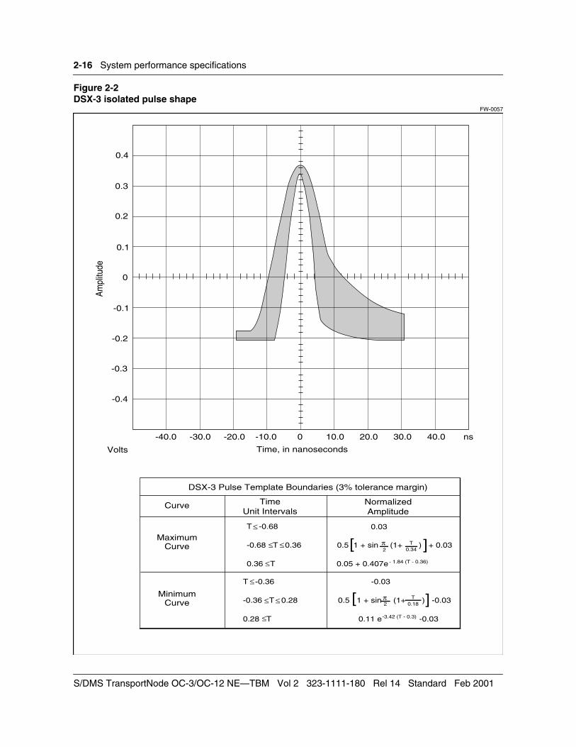
Shape An isolated pulse shape is defined to fit the template shown in Figure 2-2.
S/DMS TransportNode OC-3/OC-12 NE—TBM Vol 2 323-1111-180 Rel 14 Standard Feb 2001

System performance specifications 2-15
Amplitude This is 0.36 V to 0.85 V peak, scaled to fit the template in Figure 2-2.
Power level(for all ones transmitted pattern)
In a band not wider than 3 kHz, centered at 22.368 MHz, the power level is -1.8 to +5.7 dBm.
In a band not wider than 3 kHz, centered at 44.736 MHz, the power level is at least 20 dB below the power level centered at 22.368 MHz.
Imbalance There is less than 3.5 dB difference between the total power of the positive and the negative pulses.
Table 2-12Pulse characteristics
Technical Specifications 323-1111-180 Rel 14 Standard Feb 2001
2-16 System performance specifications
Figure 2-2DSX-3 isolated pulse shape
FW-0057
NormalizedAmplitude
DSX-3 Pulse Template Boundaries (3% tolerance margin)
TimeUnit Intervals
MaximumCurve
T -0.68
-0.68 T 0.36
0.36 T
0.5 1 + sin (1+ ) + 0.03
0.05 + 0.407e- 1.84 (T - 0.36)
≤
≤
≤ ≤ [ ]T0.342
π
Curve
MinimumCurve
T -0.36
-0.36 T 0.28
0.28 T 0.11 e -0.03-3.42 (T - 0.3)
-0.03≤
≤ ≤
≤
][0.5 1 + sin (1+ ) -0.03π2
T0.18
0.03
Am
plitu
de
Time, in nanoseconds
-40.0 -30.0 -20.0 -10.0 0 10.0 20.0 30.0 40.0 ns
0.4
0.3
0.2
0.1
0
-0.1
-0.2
-0.3
-0.4
Volts
S/DMS TransportNode OC-3/OC-12 NE—TBM Vol 2 323-1111-180 Rel 14 Standard Feb 2001
System performance specifications 2-17
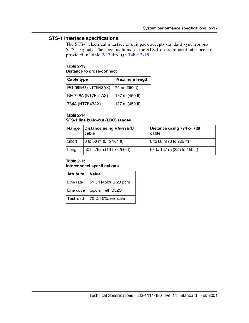
STS-1 interface specificationsThe STS-1 electrical interface circuit pack accepts standard synchronous STS-1 signals. The specifications for the STS-1 cross-connect interface are provided in Table 2-13 through Table 2-15.
Table 2-13Distance to cross-connect
Cable type Maximum length
RG-59B/U (NT7E42AX) 76 m (250 ft)
NE-728A (NT7E41AX) 137 m (450 ft)
734A (NT7E43AX) 137 m (450 ft)
Table 2-14STS-1 line build-out (LBO) ranges
Range Distance using RG-59B/Ucable
Distance using 734 or 728cable
Short 0 to 50 m (0 to 164 ft) 0 to 68 m (0 to 225 ft)
Long 50 to 76 m (164 to 250 ft) 68 to 137 m (225 to 450 ft)
Table 2-15Interconnect specifications
Attribute Value
Line rate 51.84 Mbit/s ± 20 ppm
Line code bipolar with B3ZS
Test load 75 Ω ±5%, resistive
Technical Specifications 323-1111-180 Rel 14 Standard Feb 2001
2-18 System performance specifications
Optical interface specifications The optical interfaces specified in this section are OC-3 and OC-12.
The S/DMS TransportNode OC-3 and OC-12 optical interface circuit packs comply with the SONET optical interface specifications. The transmitter can operate into a receiver that is a non-S/DMS receiver, and similarly, the receiver can accept signals from a non-S/DMS transmitter. However, the full S/DMS TransportNode link specifications may not be met when S/DMS and non-S/DMS equipment are interworking over the same link.
The specifications provided in this chapter apply to the worst case production units, operating at environmental extremes and end-of-life limits. All parameters apply on the line side of the optical connector, as specified in Bellcore document TR-NWT-000253, Issue 2.
Note: The OC-3/OC-12 TBM system does not support multimode fiber.
Rates and format specifications The S/DMS TransportNode OC-3 and OC-12 equipment meets the requirements of the SONET rates and format specifications as defined by ECSA committee T1X1.4 in the document T1.105, Optical Interface Rates and Format Specifications, March 1988.
S/DMS TransportNode OC-3/OC-12 NE—TBM Vol 2 323-1111-180 Rel 14 Standard Feb 2001

System performance specifications 2-19
OC-12 networking optical interface specificationsThe specifications for the OC-12 networking (NWK) optical interface are provided in Table 2-16 and Table 2-17.
Table 2-16 OC-12 NWK transmitter specifications (BER of 10-10) (Notes 1, 2)
Parameter 1310 nm Intra-office
1310 nm Intermediate reach
1310 nm Long reach
1550 nmExtended long reach
Product engineering code
NT7E02NANT7E02PA
NT7E02NBNT7E02PBNT7E02FBNT7E02FCNT7E02FDNT7E02LBNT7E02LD
NT7E02PCNT7E02EBNT7E02ECNT7E02EDNT7E02KBNT7E02KCNT7E02KD
NT7E02PDNT7E02JBNT7E02JCNT7E02JDNT7E02MBNT7E02MCNT7E02MD
Connector type ferrule (FC)subscriber (SC)straight (ST)
ferrule (FC)subscriber (SC)straight (ST)
ferrule (FC)subscriber (SC)straight (ST)
ferrule (FC)subscriber (SC)straight (ST)
Pigtail Single mode(SM)
Single mode (SM)
Single mode (SM) Single mode (SM)
Transmitter MLM MLM MLM SLM
Spectral characteristics
Central wavelength (λTnom)
1310 nm 1310 nm 1310 nm 1550 nm
Central wavelength range (i) (Note 5) (λT min - λT max)
N/A 1288 – 1335 nm N/A N/A
Central wavelength range (ii) (Note 6) (λT min - λT max)
1260 – 1360 nm 1270 – 1347 nm 1300 – 1325 nm 1525 – 1575 nm
Spectral width 14 nm (∆λrms) 2.0 nm (∆λrms) 2.0 nm (∆λrms) 0.5nm (∆λ20)
Side-mode suppression ratio (SSR min)
N/A N/A N/A 38 dB
—continued—
Technical Specifications 323-1111-180 Rel 14 Standard Feb 2001

2-20 System performance specifications
Optical signal
Line rate OC-12 (622.08 Mbit/s)
OC-12 (622.08 Mbit/s)
OC-12 (622.08 Mbit/s)
OC-12 (622.08 Mbit/s)
Line code NRZ NRZ NRZ NRZ
Maximum tolerable optical reflection (Note 3)
-10 dB -10 dB -10 dB -20 dB
Extinction ratio(RE min)
8.2 dB 8.2 dB 10 dB 10 dB
Optical power
Guaranteed launch power(PT min) Midspan meet NT-NT proprietary (Note 4)
(N/A)-17 dBm
(N/A)-4.5 dBm
-3.0 dBm-3.0 dBm
-3.0 dBm-3.0 dBm
Maximum launch power (PT max)
-11 dBm +1.5 dBm +2.0 dBm +2.0 dBm
Note 1: All parameters apply on the line side of the optical connector, as specified in Bellcore Specification TR-NWT-000253, Issue 2.
Note 2: All parameters are valid over the full range of operating, environmental, and aging conditions.
Note 3: For a 1 dB receiver power penalty at a bit error rate (BER) of 10-10.
Note 4: The “NT-NT proprietary” values apply if Nortel Networks equipment is in use at each end.
Note 5: Temperature range of 0 to 50 degrees C Ambient.
Note 6: Temperature range of -40 to 65 degrees C Ambient.
Table 2-16 (continued)OC-12 NWK transmitter specifications (BER of 10-10) (Notes 1, 2)
Parameter 1310 nm Intra-office
1310 nm Intermediate reach
1310 nm Long reach
1550 nmExtended long reach
S/DMS TransportNode OC-3/OC-12 NE—TBM Vol 2 323-1111-180 Rel 14 Standard Feb 2001

System performance specifications 2-21
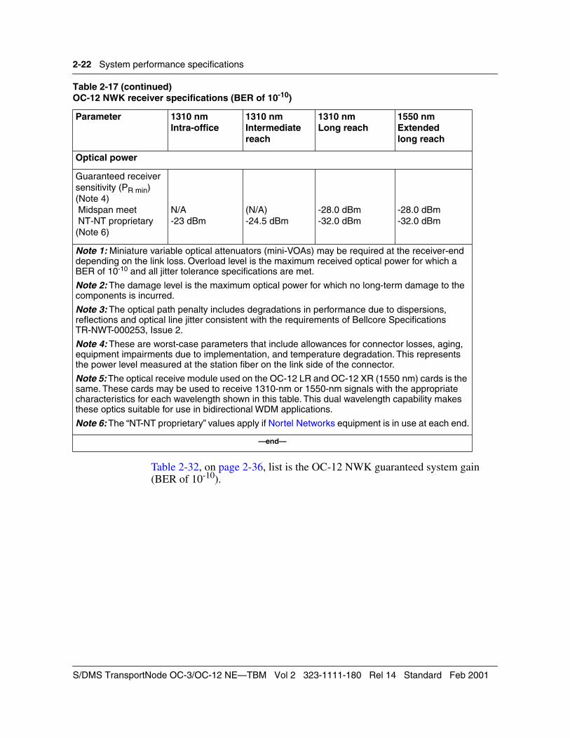
Table 2-17 OC-12 NWK receiver specifications (BER of 10-10)
Parameter 1310 nm Intra-office
1310 nm Intermediate reach
1310 nmLong reach
1550 nmExtendedlong reach
Product engineering code
NT7E02NANT7E02PA
NT7E02NBNT7E02PBNT7E02FBNT7E02FCNT7E02FDNT7E02LBNT7E02LD
NT7E02PCNT7E02EBNT7E02ECNT7E02EDNT7E02KBNT7E02KCNT7E02KD
NT7E02PDNT7E02JBNT7E02JCNT7E02JDNT7E02MBNT7E02MCNT7E02MD
Connector type ferrule (FC)subscriber (SC)straight (ST)
ferrule (FC)subscriber (SC)straight (ST)
ferrule (FC)subscriber (SC)straight (ST)
ferrule (FC)subscriber (SC)straight (ST)
Pigtail Multimode Multimode Single mode (SM) Single mode (SM)
Receiver detector PIN PIN APD APD
Spectral characteristics
Wavelength of operation
1260 –1370 nm 1265 – 1355 nm 1300 – 1325 nm or 1485 – 1575 nm
1300 – 1325 nm or 1485 – 1575 nm
Optical Signal
Line rate OC-12 (622.08 Mbit/s)
OC-12 (622.08 Mbit/s)
OC-12 (622.08 Mbit/s)
OC-12 (622.08 Mbit/s)
Line code NRZ NRZ NRZ NRZ
Overload level (PR
max) (Note1) Midspan meet NT-NT proprietary (Note 6)
N/A- 11 dBm
(N/A)-4.0 dBm
-7.0 dBm-7.0 dBm
-8.0 dBm-8.0 dBm
Damage level (Note 2)
N/A N/A -6.0 dBm -6.0 dBm
Maximum receiver reflectance
-14.0 dB -14.0 dB -14.0 dB -20.0 dB
Optical path penalty (max)(Note 3)
1.0 dB 1.0 dB 1.0 dB 1.0 dB
—continued—
Technical Specifications 323-1111-180 Rel 14 Standard Feb 2001
2-22 System performance specifications
Table 2-32, on page 2-36, list is the OC-12 NWK guaranteed system gain (BER of 10-10).
Optical power
Guaranteed receiver sensitivity (PR min) (Note 4) Midspan meet NT-NT proprietary (Note 6)
N/A-23 dBm
(N/A)-24.5 dBm
-28.0 dBm-32.0 dBm
-28.0 dBm-32.0 dBm
Note 1: Miniature variable optical attenuators (mini-VOAs) may be required at the receiver-end depending on the link loss. Overload level is the maximum received optical power for which a BER of 10-10 and all jitter tolerance specifications are met.
Note 2: The damage level is the maximum optical power for which no long-term damage to the components is incurred.
Note 3: The optical path penalty includes degradations in performance due to dispersions, reflections and optical line jitter consistent with the requirements of Bellcore Specifications TR-NWT-000253, Issue 2.
Note 4: These are worst-case parameters that include allowances for connector losses, aging, equipment impairments due to implementation, and temperature degradation. This represents the power level measured at the station fiber on the link side of the connector.
Note 5: The optical receive module used on the OC-12 LR and OC-12 XR (1550 nm) cards is the same. These cards may be used to receive 1310-nm or 1550-nm signals with the appropriate characteristics for each wavelength shown in this table. This dual wavelength capability makes these optics suitable for use in bidirectional WDM applications.
Note 6: The “NT-NT proprietary” values apply if Nortel Networks equipment is in use at each end.
—end—
Table 2-17 (continued)OC-12 NWK receiver specifications (BER of 10-10)
Parameter 1310 nm Intra-office
1310 nm Intermediate reach
1310 nmLong reach
1550 nmExtendedlong reach
S/DMS TransportNode OC-3/OC-12 NE—TBM Vol 2 323-1111-180 Rel 14 Standard Feb 2001

System performance specifications 2-23
OC-12 VTM optical interface specificationsThe specifications for the OC-12 VTM optical interface are provided in Table 2-18 through Table 2-20.
Table 2-18 OC-12 VTM transmitter specifications (BER of 10-10) (Notes 1, 2)
Parameter 1310 nm Intermediate reach
1310 nm Long reach
Product engineering code NT7E05JB NT7E05JC
Connector type (Note 3) FC-PC/ST-PC/SC FC-PC/ST-PC/SC
Pigtail Single mode (SM) Single mode (SM)
Transmitter MLM MLM
Spectral characteristics
Central wavelength (λTnom) 1310 nm 1310 nm
Central wavelength range (λT min - λT max)
1274-1356 nm 1300-1325 nm
Spectral width 2.5 nm (∆λrms) 2.0 nm (∆λrms)
Side-mode suppression ratio (SSR min)
N/A N/A
Optical signal
Line rate OC-12 (622.08 Mbit/s) OC-12 (622.08 Mbit/s)
Line code NRZ NRZ
Maximum tolerable optical reflection (Note 4)
-10 dB -10 dB
Extinction ratio (re min) 8.2 dB 10 dB
—continued—
Technical Specifications 323-1111-180 Rel 14 Standard Feb 2001

2-24 System performance specifications
Optical power
Guaranteed launch power(PT min) -15.0 dBm -3.0 dBm
Maximum launch power (PTmax)
-8.0 dBm +2.0 dBm
Note 1: All parameters apply to the line side of the optical connector, as specified in Bellcore Specification TR-NWT-000253, Issue 2.
Note 2: All parameters are valid over the full range of operating, environmental, and aging conditions.
Note 3: All parameters are valid for each of the appropriate connector options.
Note 4: For a 1 dB receiver power penalty at a BER of 10-10.
Table 2-18 (continued)OC-12 VTM transmitter specifications (BER of 10-10) (Notes 1, 2)
Parameter 1310 nm Intermediate reach
1310 nm Long reach
S/DMS TransportNode OC-3/OC-12 NE—TBM Vol 2 323-1111-180 Rel 14 Standard Feb 2001

System performance specifications 2-25
Table 2-19 OC-12 VTM receiver specifications (BER of 10-10)
Parameter 1310 nm Intermediate reach
1310 nm Long reach
Product engineering code NT7E05JB NT7E05JC
Connector type FC-PC/ST-PC/SC FC-PC/ST-PC/SC
Pigtail Multimode Multimode
Receiver detector PIN PIN
Spectral characteristics
Wavelength of operation 1274-1356 nm 1300-1325 nm
Optical signal
Line rate OC-12 (622.08 Mbit/s) OC-12 (622.08 Mbit/s)
Line code NRZ NRZ
Overload level (PR max) (Note1) Midspan meet NT-NT proprietary (Note 5)
-8.0 dBm0 dBm
-8.0 dBm0 dBm
Damage level (Note 2) N/A N/A
Maximum receiver reflectance N/A -14.0 dB
Optical path penalty (PO) (Note 3)
1.0 dB 1.0 dB
Optical power
Guaranteed receiver sensitivity (PR min) (Note 4) Midspan meet NT-NT proprietary (Note 5)
-28.0 dBm-28.0 dBm
-28.0 dBm-29.5 dBm
Note 1: Miniature variable optical attenuators (mini-VOAs) may be required at the receiver end, depending on the link loss for long reach and extended reach. Overload level is the maximum received optical power for which a BER of 10-10 and all jitter tolerance specifications are met.
Note 2: The damage level is the maximum optical power for which no long-term damage to the components is incurred.
Note 3: The optical path penalty includes degradation in performance due to dispersions, reflections, and optical line jitter consistent with the requirements of Bellcore Specifications TR-NWT-000253, Issue 2.
Note 4: These worst-case parameters include allowances for connector losses, aging, equipment impairments due to implementation, and temperature degradation. This represents the power level measured at the station fiber on the link side of the connector.
Note 5: The “NT-NT proprietary” values apply if Nortel Networks equipment is in use at each end.
Technical Specifications 323-1111-180 Rel 14 Standard Feb 2001

2-26 System performance specifications
Table 2-20 OC-12 VTM guaranteed system gain (BER of 10-10).
Parameter 1310 nm Intermediate reach
1310 nm Long reach
Product engineering code NT7E05JB NT7E05JC
Connector type FC-PC/ST-PC/SC FC-PC/ST-PC/SC
Dispersion (DSRmax) 74 ps/nm 92 ps/nm
System optical return loss (ORLmin)
N/A 20.0 dB
Attenuation 0 to 12.0 dB 10.0 to 24.0 dB
Guaranteed launch power (PT min) -15.0 dBm -3.0 dBm
Guaranteed receiver sensitivity (PR min)- Midspan meet- NT-NT proprietary
-28.0 dBm-28.0 dBm
-28.0 dBm-28.0 dBm
Optical Path Penalty (PO) 1.0 dB 1.0 dB
Guaranteed receiver sensitivity over link(PRL) = PR - PO
-27.0 dBm (Midspan meet)-27.0 dBm (NT-NT proprietary)
-27.0 dBm (Midspan meet)-27.0 dBm (NT-NT proprietary)
Guaranteed system gain (G = PT - PR) (see note)- Midspan meet- NT-NT proprietary
12.0 dB12.0 dB
24.0 dB25.5 dB
Note:These are worst-case parameters that include allowances for connector losses, aging, equipment impairments due to implementation, and temperature degradation. These figures do not include the customer unallocated link margin.
S/DMS TransportNode OC-3/OC-12 NE—TBM Vol 2 323-1111-180 Rel 14 Standard Feb 2001

System performance specifications 2-27
OC-3 optical interface specificationsThe specifications for the OC-3 optical interface are provided in Table 2-21 through Table 2-23.
Table 2-21 OC-3 transmitter specifications (BER of 10-10) (Notes 1 and 2)
Parameter 1310 nmIntermediate reach
1310 nmLong reach
Product engineering code NT7E01DA/DB/DC/DDNT7E01GA
NT7E01CA/CB/CC/CDNT7E01GB
Connector type ferrule (FC)subscriber (SC)straight (ST)
ferrule (FC)subscriber (SC)straight (ST)
Pigtail Singlemode (SM) Singlemode (SM)
Transmitter MLM MLM
Spectral characteristics
Central wavelength (λTnom) 1310 nm 1310 nm
Central wavelength range (λT min - λT max) 1261 – 1360 nm 1280 – 1335 nm
Spectral width 7.7 nm 4 nm
Optical signal
Line rate OC-3 (155.52 Mbit/s) OC-3 (155.52 Mbit/s)
Line code NRZ NRZ
Maximum tolerable optical reflection (Note 4)
10 dB 10 dB
Extinction ratio (RE min) 8.2 dB 10 dB
Optical power
Guaranteed launch power (PT min) -15 dBm -5 dBm
Maximum launch power (PT max) -8 dBm 0 dBm
Note 1: All parameters apply on the line side of the optical connector, as specified in Bellcore Specifications TR-NWT-000253, Issue 2.
Note 2: All parameters are valid over the full range of operating, environmental, and aging conditions.
Note 3: For a 1 dB receiver power penalty at a BER of 10-10.
Technical Specifications 323-1111-180 Rel 14 Standard Feb 2001

2-28 System performance specifications
Table 2-22 OC-3 receiver specifications (BER of 10-10)
Parameter 1310 nmIntermediate reach
1310 nmLong reach
Product engineering code NT7E01DA, NT7E01DB, NT7E01DC, NT7E01DD, NT7E01GA
NT7E01CA, NT7E01CB, NT7E01CC, NT7E01CD, NT7E01GB
Connector type ferrule (FC)subscriber (SC)straight (ST)
ferrule (FC)subscriber (SC)straight (ST)
Pigtail Multimode Multimode
Receiver detector PIN PIN
Spectral characteristics
Wavelength of operation 1261 – 1355 nm 1280 – 1335 nm
Optical signal
Line rate OC-3 (155.52 Mbit/s) OC-3 (155.52 Mbit/s)
Line code NRZ NRZ
Overload level (PRmax) (Note 1) -8 dBm -10 dBm
Damage level (Note 2) N/A N/A
Maximum tolerable optical reflection 14 dB 14 dB
Optical path penalty (max) (Note 3) 1.0 dB 1.0 dB
Optical power
Guaranteed receiver sensitivity (PRmin) (Note 4)
-28 dBm -34 dBm
Note 1: Miniature variable optical attenuators (mini-VOAs) may be required at the receiver end depending on the link loss. Overload level is the maximum received optical power for which a BER of 10-10 and all jitter tolerance specifications are met.
Note 2: The damage level is the maximum optical power for which no long-term damage to the components is incurred.
Note 3: The optical path penalty includes degradations in performance due to dispersions, reflections and optical line jitter consistent with the requirements of Bellcore Specification TR-NWT-000253, Issue 2.
Note 4: These are worst-case parameters that include allowances for connector losses, aging, equipment impairments due to implementation, and temperature degradation. This represents the power level measured at the station fiber on the link side of the connector.
S/DMS TransportNode OC-3/OC-12 NE—TBM Vol 2 323-1111-180 Rel 14 Standard Feb 2001

System performance specifications 2-29
Table 2-23OC-3 guaranteed system gain (BER of 10-10)
Parameter 1310 nmIntermediate reach
1310 nmLong reach
Product engineering code NT7E01DA, NT7E01DB, NT7E01DC, NT7E01DD, NT7E01GA
NT7E01CA, NT7E01CB, NT7E01CC, NT7E01CD, NT7E01GB
Connector type ferrule (FC)subscriber (SC)straight (ST)
ferrule (FC)subscriber (SC)straight (ST)
Dispersion (max) 96 ps/nm 185 ps/nm
Optical return loss (min) 14 dB 24 dB
Attenuation 0 to 12 dB 10 to 28 dB
Guaranteed launch power (PT min) -15 dBm -5 dBm
Guaranteed receiver sensitivity (PRmin) -28 dBm -34 dBm
Path penalty (PP) 1 dB 1 dB
Guaranteed receiver sensitivity over link (PRL) (PRL=PR min + PO)
–27 dBm –33 dBm
Guaranteed system gain (G = PT – PRL)(Note)
12 dB 28 dB
Note:These are worst-case parameters that include allowances for connector losses, aging, equipment impairments due to implementation and temperature degradation. The system gain does not include the customer unallocated link margin.
Technical Specifications 323-1111-180 Rel 14 Standard Feb 2001
2-30 System performance specifications
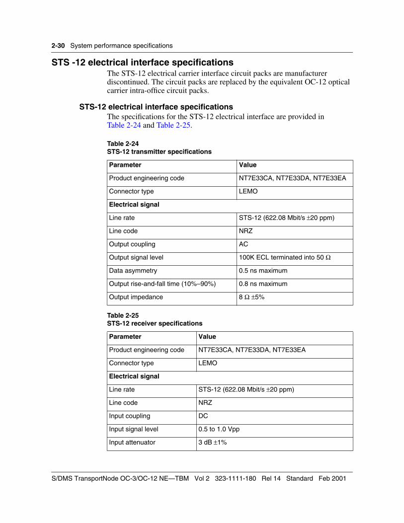
STS -12 electrical interface specificationsThe STS-12 electrical carrier interface circuit packs are manufacturer discontinued. The circuit packs are replaced by the equivalent OC-12 optical carrier intra-office circuit packs.
STS-12 electrical interface specificationsThe specifications for the STS-12 electrical interface are provided in Table 2-24 and Table 2-25.
Table 2-24STS-12 transmitter specifications
Parameter Value
Product engineering code NT7E33CA, NT7E33DA, NT7E33EA
Connector type LEMO
Electrical signal
Line rate STS-12 (622.08 Mbit/s ±20 ppm)
Line code NRZ
Output coupling AC
Output signal level 100K ECL terminated into 50 Ω
Data asymmetry 0.5 ns maximum
Output rise-and-fall time (10%–90%) 0.8 ns maximum
Output impedance 8 Ω ±5%
Table 2-25 STS-12 receiver specifications
Parameter Value
Product engineering code NT7E33CA, NT7E33DA, NT7E33EA
Connector type LEMO
Electrical signal
Line rate STS-12 (622.08 Mbit/s ±20 ppm)
Line code NRZ
Input coupling DC
Input signal level 0.5 to 1.0 Vpp
Input attenuator 3 dB ±1%
S/DMS TransportNode OC-3/OC-12 NE—TBM Vol 2 323-1111-180 Rel 14 Standard Feb 2001

System performance specifications 2-31
Control network (CNet) specifications The total number of OC-3 or OC-12 shelves connected by a single control network must not exceed ten.
The total number of stations in a single control network must not exceed 32. A station refers to a control network driver on a circuit pack. The processor circuit pack has two control network drivers, since it can handle two control network ports. A single shelf might therefore require two stations on the control network.
The total length of the control network bus (cables and backplane tracing) must not exceed 122 m (400 ft). When calculating bus length, use the following formula:
Protection switch specifications Protection switching is provided for both digital and optical interfaces.Digital interface protectionDS1, DS3, and STS-1 protection options are as follows:
• revertive 1:N (up to N = 12 for DS1, N = 4 for DS3 or STS-1). The protection path is shared by the DS3 and STS-1 working circuit packs.
• wait-to-restore (WTR) period of 200 seconds or 300 seconds
Optical interface protectionOC-3 and OC-12 protection options are as follows:
• nonrevertive 1+1 for linear configurations and for OC-3 tributaries
• revertive with a WTR period of 300 seconds on NWK rings and a provisionable WTR period of 5 to 12 minutes on VTM rings
• SD thresholds selectable between 10-4 and 10-10; independently selectable on all optical links
Input equalizer range 0 to 30.5 m (0 to 100 ft) using RG142B/U cable
Input return loss >15 dB (100 MHz to 500 MHz)
Gain 8 dB (100 MHz to 625 MHz)
C/I worst case 18 dB
Input impedance 50 Ω ±5% (single ended)
Total bus length (feet) = Total cable interconnect length (feet) +(10 feet x number of shelves connected by CNet)
Table 2-25 (continued)STS-12 receiver specifications
Parameter Value
Technical Specifications 323-1111-180 Rel 14 Standard Feb 2001

2-32 System performance specifications
• SF thresholds selectable between 10-3 and 10-5 (for VTM ring ADMs only); independently selectable on all optical links
• provisionable unidirectional/bidirectional for linear systems
All manual protection systems and exerciser functions can be controlled through the user interface.
Matched-nodes protectionThe matched nodes protection options on OC-12 rings are as follows:
• links between OC-12 rings have 1:1 revertive path-switched protection at the STS level
• wait-to-restore (WTR) period of 300 seconds
Protection switch times Protection switching is completed within 50 ms following a 10 ms detect interval for both low-speed and high-speed protection (single failure case only).
Network synchronization specifications S/DMS TransportNode equipment complies with the network synchronization requirements described in TA-NPL-000436, Digital Synchronization Network Plan; Issue 1, November 1986, section 3.3.
External synchronization interface (ESI) internal clock specifications The external synchronization interface (ESI) meets Stratum 3 requirements and is fully compatible with building-integrated timing supply (BITS) clock applications. The ESI characteristics are shown in Table 2-26.
The ESI timing reference inputs accept framed DS1 signals. The timing reference output provides a framed all-1s DS1 or unframed all-1s DS1 (AIS).
OC-12 VTM circuit pack internal clock specificationsA network element that contains OC-12 VTM circuit packs can maintain synchronization based on the incoming SONET signals. The OC-12 VTM circuit pack meets the clock accuracy specifications shown in Table 2-27.
Table 2-26ESI characteristics
ESI characteristic Value
Long-term stability ±4.6 ppm
Holdover stability ±0.37 ppm in first 24 hr (0°C to +50°C)±2 ppm in first 24 hr (-40°C to +65°C)
Minimum pull-in range ±4.6 ppm
S/DMS TransportNode OC-3/OC-12 NE—TBM Vol 2 323-1111-180 Rel 14 Standard Feb 2001

System performance specifications 2-33
DS1 timing interface specifications The ESI DS1 timing interfaces comply with the DSX-1 specification defined in ANSI TI.102-1987 and Bellcore TR-TSY-000253. The DS1 interconnect characteristics and line build-out ranges are shown in Table 2-28 and Table 2-29 respectively.
Orderwire specificationsSpecifications for the OC-3/OC-12 NE—TBM orderwire are provided in the following paragraph and Table 2-30 and Table 2-31.
Handset/headset interfaceBiasing levels and input/output impedances are suitable for standard carbon transmitter type handset/headset.
Table 2-27OC-12 VTM clock characteristics
Characteristic
Long-term stability Long-term freerun accuracy of ±20 ppm
Holdover stability ±4.6 ppm for up to 24 hours. During this period, the clock can tolerate a variation of up to 17°C from the temperature at which the NE entered holdover, with a maximum rate of change of 8°C per hour.
Table 2-28Interconnect characteristics
Interconnect characteristic Value
Line code B8ZS or AMI
Frame format SF or ESF
Test load 100 Ω ±5%, resistive
DS1 output AIS line rate 1.544 Mbit/s ±32 ppm
Table 2-29DS1 line build-out ranges for the ESI timing reference output
DS1 LBO range Value
Short 0 to 46 m (0 to 150 ft)
Medium 46 to 137 m (150 to 450 ft)
Long 137 to 200 m (450 to 655 ft)
Technical Specifications 323-1111-180 Rel 14 Standard Feb 2001

2-34 System performance specifications
System availability The OC-3/OC-12 NE—TBM systems meet Bellcore specifications, which state that the operational availability of an asynchronous fiber optic transmission system is 99.98% for a two-way 400 km (250 mi) DSX-1 to DSX-1 Hypothetical Reference Digital Path (HRDP). Of the total allowed outage, 75% is allocated to DSX-3 to DSX-3, equivalent to 79 min/yr. Taking into account downtime due to transmission medium and procedural errors, the availability specification is 99.997% or a maximum downtime of 15 min/yr.
The HRC model is assumed to consist of a single 129 km (80 mi) protection switching section with two multiplex terminals. Assuming a maximum span of 45 km (28 mi), the S/DMS system is modeled as two terminals with two regenerator sites in between. Using the HRC, the HRDP model can be developed by cascading together 3.25 HRC sections to produce the 402 km (250 mi) HRDP.
Safety specifications The OC-3/OC-12 NE—TBM complies with the applicable performance requirements, labeling requirements, and informational requirements outlined in the following documents:
• Canadian Standards Association standard CSA 22.2 #7 (Equipment Electrically Connected to a Telecommunication Network)
• Underwriter Laboratories standard UL1459 (Telephone Equipment)
Table 2-30Configuration
Configuration Accessibility
Local orderwire circuit Accessible at all sites
Express orderwire circuit Accessible at terminal and ADM sites, optionally at all sites (not accessible at regenerators)
Table 2-31VF-300 interface specifications
Specification Value
Nominal input level 0 dBm
Nominal output level 0 dBm
Input/output impedance 600 Ω balanced
Signal-to-quantization noise >30 dB, 0 to -30 dBm>24 dB, -40 dBm>20 dB, -45 dBm
Frequency response ±1 dB, 300 Hz – 3 kHz
S/DMS TransportNode OC-3/OC-12 NE—TBM Vol 2 323-1111-180 Rel 14 Standard Feb 2001

System performance specifications 2-35
• Underwriter Laboratories standard UL478 (Standard for Safety Information Processing and Business Equipment)
• Part 1910 Occupational Safety and Health Standards (Title 29 Labor, Chapter XVII-OSHA, Dept. of Labor)
• Department of Health, Education and Welfare Bureau of Radiological Health (BRH), 21 CFR 1040.10
• Laser safety performance per 21 CFR, Chapter 1, Subchapter J, as a class 1 laser product
Flammability All combustible materials, components and cabling used in the S/DMS TransportNode OC-3 and OC-12 systems are fire-resistant, to meet the requirements outlined in NEBS TR-NWT-000063, Issue 4, section 4.3, and have a minimum rating of 94-V1 according to Underwriter Laboratories Standard UL94 and a minimum oxygen index rating of 28% when tested to ASTM D2863-77. In addition, all shelf and cable distribution assemblies comply with the flammability requirements outlined in NEBS, TR-NWT-000063, issue 4, section 4.3.3.
Acoustic noise Under all operating conditions, the system will not produce a sound level above 65 dBA, as specified in the Occupational Safety and Health Act of 1970.
Note: Table 2-32, on page 2-36, lists the OC-12 NWK guaranteed system gain (BER of 10-10), referred to in section, “OC-12 networking optical interface specifications” on page 2-19.
Technical Specifications 323-1111-180 Rel 14 Standard Feb 2001

2-36 System performance specifications
Table 2-32OC-12 NWK guaranteed system gain (BER of 10-10)
Parameter 1310 nmIntra-office
1310 nmIntermediate reach
1310 nmLong reach
1550 nmExtendedlong reach
Product engineering code
NT7E02NANT7E02PA
NT7E02NBNT7E02PBNT7E02FBNT7E02FCNT7E02FDNT7E02LBNT7E02LD
NT7E02PCNT7E02EBNT7E02ECNT7E02EDNT7E02KBNT7E02KCNT7E02KD
NT7E02PDNT7E02JBNT7E02JCNT7E02JDNT7E02MBNT7E02MCNT7E02MD
Connector kits available
ferrule (FC)subscriber (SC)straight (ST)
ferrule (FC)subscriber (SC)straight (ST)
ferrule (FC)subscriber (SC)straight (ST)
ferrule (FC)subscriber (SC)straight (ST)
Dispersion (max) N/A 92 ps/nm 92 ps/nm 1700 ps/nm
Optical return loss (min)
20 dB 20 dB 20 dB 24 dB
Attenuation 0 to 6 dB 5.5 to 19 dB 9 to 28 dB 10 to 28.2 dB
Guaranteed launch power (PT min)
–17 dBm –4.5 dBm –3.0 dBm –3.0 dBm
Guaranteed receiver sensitivity (back to back) (PRBB)
Midspan meet NT-NT proprietary
N/A–23 dBm
N/A–24.5 dBm
–28 dBm–32.0 dBm
–28.2 dBm–32.2 dBm
Path penalty (Pp) 1 dB 1 dB 1 dB 1 dB
Guaranteed receiver sensitivity over link (PRL) (PRL = PRBB+ PP)
Midspan meetNT-NT proprietary
N/A–22 dBm
N/A–23.5 dBm
–27 dBm–31 dBm
–27.2dBm–31.2 dBm
Guaranteed system gain (G = PT - PRL) (Note 1) Midspan meet NT-NT proprietary
N/A5 dB
N/A19 dB
24 dB28 dB
24.2 dB28.2 dB
Note 1: These worst-case parameters include allowances for connector losses, aging, equipment impairments due to implementation, and temperature degradation. These figures do not include the customer unallocated link margin.
Note 2: The NT-NT proprietary values apply if Nortel Networks equipment is in use at each end.
S/DMS TransportNode OC-3/OC-12 NE—TBM Vol 2 323-1111-180 Rel 14 Standard Feb 2001

3-1
Optical link engineering 3-This chapter describes how the transmission parameters provided in Chapter 2, “System performance specifications” are to be used in the design of optical links. The computational algorithms are based on two constraint relations: the system’s loss budget, and the system’s dispersion limitations.
Engineering the optical linkThis chapter provides a methodology on engineering standard single-mode optical link for the OC-3 and OC-12 network elements (NE). To ensure the proper operation of OC-3 and OC-12 systems at a predetermined BER level, the link attenuation and dispersion parameters must be taken into consideration.
Information included in this chapter is as follows:
• optical link attenuation
• optical link design example
Engineering the optical patchcords and connectorsAlthough the use of low-reflection connectors and patchcords is not a requirement for the OC-3 and OC-12 optical link, operating companies can find benefits in deploying low-reflection connectors throughout their networks. When optical networks are consistent in the use of the low-reflection connectors, penalties due to reflection are minimized. In addition, fiber links can easily be cut over to higher bit-rate systems (for example, OC-48) without the need to upgrade the existing link.
The optical interfaces and patchcords of the OC-3 and OC-12 NEs use FC-PC, SC-PC, and ST-PC connectors, which typically exhibit a return loss of 30 dB.
Note: Multimode fibers must not be used with OC-3 or OC-12 TBM systems; only single-mode fibers must be used.
Optical link attenuation Each section of the overall system must be designed on an individual basis, taking into account the specific station facility layout, optical devices, and cable parameters.
Technical Specifications 323-1111-180 Rel 14 Standard Feb 2001

3-2 Optical link engineering
The system designer must determine if the transmission equipment, the optical devices, and the cable combinations allow transmission at the desired BER level, without exceeding the loss limitation constraint.
Optical link attenuation involves the following:
• derivation of the available optical system gain budget, given a specified BER level
• link loss calculations to ensure that bay-to-bay losses do not exceed the available optical system gain budget
System gain The optical system gain for a specified BER level is provided in Chapter 2, “System performance specifications.”
The optical system gain includes all losses from the transmit connector to the receiver connector, including the connectors equipped on the receive and transmit units themselves. This parameter also includes factors such as the receiver sensitivity, receiver impairments, laser noise, modulation, dispersion, and reflection penalties. Therefore, these factors need not be considered for the purpose of the link loss calculation.
Link loss calculation Link loss calculations are performed to determine the required cable parameters. Each optical section of a system must be examined on an individual basis. An optical section schematic is shown in Figure 3-1. Figure 3-2 shows possible station facility configurations. The idea behind link loss calculations is to ensure that the sum of the individual losses from bay to bay does not exceed the available optical link loss budget.
S/DMS TransportNode OC-3/OC-12 NE—TBM Vol 2 323-1111-180 Rel 14 Standard Feb 2001

Optical link engineering 3-3
Figure 3-1Optical section schematic
FW-0058
FPPASourceTx Rx
Detector
Station Facility Station FacilityCableFacility
(Outside plantfiber cablesections)
Bay-to-Bay Losses
Station Facility Losses
Cable Facility Losses
l
l sm = l sm1 + l sm2 + l sm3 + l sm4 = Total length (in km) of single-mode station cable.
l t = Total sheath length (in km) of outside plant single-mode cable.
Station Facility Losses
l tl sm2 l sm3 l sm4
l = l sm + l t
Splices(Typical)
l sm1
Legend:
FPPA = Fiber Patch Panel Assembly
FPPA
Technical Specifications 323-1111-180 Rel 14 Standard Feb 2001

3-4 Optical link engineering
Figure 3-2Station facility layout
FW-0059
Tx/Rx
FPPAPatchcordSource/Detector
Vault SpliceOutside Plant Cable
Intra-office Cable (Typical)
(Typical)
FPPAPatchcordSource/Detector
Tx/Rx(Typical)
FPPAPigtailSource/Detector
Tx/Rx(Typical)
Special Case C.O. Configuration
FPPAPigtailSource/Detector
Special Case Hut Configuration
Tx/Rx(Typical)
Standard C.O. Configuration
Standard Hut or Customer Configuration
Station Facility Losses
Bay-to-Bay Losses
Cable Facility Outside Plant Cable(Ducted, Buried, and/or Aerial)
Note: Use single-mode fiber only.
S/DMS TransportNode OC-3/OC-12 NE—TBM Vol 2 323-1111-180 Rel 14 Standard Feb 2001

Optical link engineering 3-5
The following information is needed for the link loss calculation:
• the system gain budget for a specified BER level
• the number of connectors, and connector losses (for example, fiber patch panel assembly [FPPA] applications). Only single-mode low reflection connectors must be used. Do not include receive and transmit unit connectors since their contribution has already been taken into account in the system gain figure.
• the maximum connector insertion loss for a SC, ST, or FC connector is 0.7 dB.
• the number of outside plant splices, and number of maintenance splices (assume six, unless otherwise specified)
• the average splice loss
Note: Assume a loss of 0.2 dB for each mechanical splice, and 0.05 dB for each fusion splice.
• the temperature loss effect for aerial cable
• the intraoffice cable loss, if required
• the cable facility link length
• the customer specified unallocated link margin, which is recommended to be up to 3 dB
Estimating the number of splices If it is not possible to determine the number of splices precisely, use the following formula:
Note: If NS is not an integer, round up to the next integer.
where
NS lt lr NE
NF
= total number of splices= span length (km)= standard reeled cable length (km)= number of extra splices required by physical outside plant configuration (for example, FPPA and vault splices for aerial-to-buried transition)= number of maintenance splices (future)
NS = + 1 + NE + NFItIr
Technical Specifications 323-1111-180 Rel 14 Standard Feb 2001

3-6 Optical link engineering
Fiber loss calculation sheet Use the fiber loss calculation sheet (see Table 3-1) to determine the maximum fiber cable attenuation in decibels per kilometer. The fiber selected must be equal to, or less than, this requirement. The sheet provides a brief explanation of each item for ease of use. A fiber loss calculation sheet must be prepared for each optical section of the fiber system (for example, terminal to linear ADM).
Table 3-1 Fiber loss calculation sheet
Project:___________________________________ Issue:______________________________
System section: Site A:_______________________ to Site B:____________________________
Prepared by:_____________________________________________________________________
Transmission equipment ______________________ BER level ___________________________
Operation wavelength ________________________ Optics (Intermediate/long reach) _________
Item Description Values
1 Guaranteed system gain _______________ dB
2 Customer allocated margin _______________ dB
3 Available gain(subtract item 2 from item 1) _______________ dB
4 Number of splices(if unknown, estimate using the equation provided on the previous page) _______________ splices
5 Loss for each splice _______________ dB/splice
6 Splice losses (multiply item 4 by item 5) _______________ dB
7 Number of FPPA connectors _______________ connectors
8 Loss for each connector _______________ dB/connector
9 Connector loss (multiply item 7 by item 8) _______________ dB
10 Connector and splice losses(add item 6 and item 9) _______________ dB
11 Allowable fiber loss, bay-to-bay(subtract item 10 from item 13) _______________ dB
12 Fiber attenuation/km (see Note) _______________ dB/km
13 Projected fiber reach(divide item 11 by item 12) _______________ km
Note: Add 0.1 dB/km to the fiber attenuation, for temperature effect allowance on aerial spans. The temperature effect can be neglected in buried fiber spans.
S/DMS TransportNode OC-3/OC-12 NE—TBM Vol 2 323-1111-180 Rel 14 Standard Feb 2001

Optical link engineering 3-7
Optical link design example TelcoNet is planning to install a single-mode S/DMS OC-12 NE—TBM system between Centerville and Midtown, which are 45 km (28 mi) apart.
The entire span is to be installed aerially and terminates in a vault at each end. Splices are required every 6 km along the route. In addition, two maintenance splices and two vault splices are to be used.
Assuming a 0.7-dB loss for two connectors (one at each end), a 2-dB system margin, and a 0.1-dB/km aerial temperature loss allowance, calculate the maximum allowable fiber cable attenuation. Assume that additional fiber attenuation (aside from temperature) for each kilometer is equal to 0.25 dB. See Table 3-2 for an example of the fiber loss calculations.
Technical Specifications 323-1111-180 Rel 14 Standard Feb 2001

3-8 Optical link engineering
Table 3-2 Example fiber loss calculation sheet
Project:___________________________________ Issue:______________________________
System section: Site A: ____Centerville_________ to Site B: _____Midtown________________
Prepared by:_____________________________ Date: ____________________________
Transmission equipment _OC-12_______________ BER level _10-10______________________
Operation wavelength _1310 nm________________ Optics (Intermediate/long reach) _Long____
Item Description Values
1 Guaranteed system gain _____29.0______ dB
2 Customer allocated margin ______2.0 ______ dB
3 Available gain(subtract item 2 from item 1) ______27.0_____ dB
4 Number of splices(if unknown, estimate using the equation provided on the previous page) ______11_______ splices
5 Loss for each splice _______0.05____ dB/splice
6 Splice losses(multiply item 4 by item 5) _______0.55____ dB
7 Number of FPPA connectors _______2_______ connectors
8 Loss for each connector _______0.7______ dB/connector
9 Connector loss(multiply item 7 by item 8) _______1.4_____ dB
10 Connector and splice losses(add item 6 and item 9) _______1.95____ dB
11 Allowable fiber loss, bay-to-bay(subtract item 10 from item 3) ______25.05____ dB
12 Fiber attenuation/km (see Note) _______0.35____ dB/km
13 Projected fiber reach(divide item 11 by item 12) _______71.57___ km
Note: Add 0.1 dB/km to the fiber attenuation, for temperature effect allowance on aerial spans. The temperature effect can be neglected in buried fiber spans.
S/DMS TransportNode OC-3/OC-12 NE—TBM Vol 2 323-1111-180 Rel 14 Standard Feb 2001

Optical link engineering 3-9
Maximum received signal level The link loss calculations described earlier include allowance for future losses (for example, maintenance splices, and customer margins), which may not necessarily reflect the current losses of the system. Therefore, calculations of the maximum received signal level are used to determine if a variable optical attenuator is required to prevent overloading of the optical receiver.
If the value calculated is greater than the receiver overload level, an attenuator is required. The information needed for the calculations includes the following (see Table 3-3):
• fiber attenuation (dB/km)
• length of link
• losses (only includes current splice losses, connector losses and intraoffice cable losses, but excludes the customer margin)
See Table 3-4 for an example of the calculation of the maximum received signal level.
Technical Specifications 323-1111-180 Rel 14 Standard Feb 2001

3-10 Optical link engineering
Table 3-3 Calculation of the maximum received signal level
Project:___________________________________ Issue:______________________________
System section: Site A: _____________________ to Site B: __________________________
Prepared by: _____________________________ Date: ____________________________
Transmission equipment ______________________ BER level ___________________________
Operation wavelength ________________________ Optics (Intermediate/long reach) _________
Item Description Values
1 Maximum laser output power _______________ dBm
Current losses
2 Number of splices _______________ splices
3 Loss for each splice _______________ dB
4 Splice losses(Multiply item 2 by item 3)
_______________ dB
5 Number of FPP connectors _______________ connectors
6 Loss for each connector _______________ dB
7 Connector losses(Multiply item 5 by item 6) _______________ dB
8 Fiber attenuation _______________ dB/km
9 Fiber length of the span _______________ km
10 Fiber loss _______________ dB
11 If an attenuator is used, add attenuator loss _______________ dB
12 Total current losses(Add item 4, item 7, item 10, and item 11)
_______________ dB
13 Received signal level(Subtract item 12 from item 1)
_______________ dBm
14 Receiver overload level _______________ dBm
Note 1: If the received signal level is smaller than the receiver overload level, an optical attenuator must be added to the receiving path so that the received signal level is bounded by the receiver’s overload level and its guaranteed sensitivity:
Receiver guaranteed sensitivity < Received Signal level < Receiver Overload level
Note 2: Since the laser output power, fiber attenuation, connector and splice losses are taken at their nominal values, the calculated received signal level is used for planning purposes only. The calculated received signal level might be different from the value obtained by measurement in the field.
S/DMS TransportNode OC-3/OC-12 NE—TBM Vol 2 323-1111-180 Rel 14 Standard Feb 2001

Optical link engineering 3-11
Table 3-4Example calculation of the maximum received signal level
Project:___________________________________ Issue:______________________________
System section: Site A:____Centerville_________ to Site B ____Midtown_______________
Prepared by: _______________________________ Date: ____________________________
Transmission equipment ____OC-12___________ BER level ___ _≤10-10_______________
Operation wavelength ____1310 nm___________ Optics (Intermediate/long reach)____long reach_________
Item Description Values
1 Maximum Laser output power ____+2_________dBm
Current losses
2 Number of splices ____11_________splices
3 Loss for each splice ____0.05_______dB
4 Splice losses(Multiply item 2 by item 3)
____0.55_______dB
5 Number of FPP connectors ____2__________connectors
6 Loss for each connector ____0________dB
7 Connector losses(Multiply item 5 by item 6)
____0________dB
8 Fiber attenuation ____0.35_______dB/km
9 Fiber length of the span ____45_________km
10 Fiber loss ____15.75______dB
11 If an attenuator is used, add attenuator loss. _______________dB
12 Total current losses(Add item 4, item 7, item 10, and item 11)
____16.3_______dB
13 Received signal level(Subtract item 12 from item 1)
____-14.3______dBm
14 Receiver overload level ____-7.0_______dBm
Note 1: If the received signal level (-16.3 dBm) is smaller than the receiver overload level (-7.0 dBm), an optical attenuator must be added to the receiving path so that the received signal level is bounded by the receiver’s overload level and its guaranteed sensitivity:
32.0 dB < -14.3 dBm < -7.0 dBm
Note 2: Since the laser output power, fiber attenuation, connector and splice losses are taken at their nominal values, the calculated received signal level is used for planning purposes only. The calculated received signal level might be different from the value obtained by measurement in the field.
Technical Specifications 323-1111-180 Rel 14 Standard Feb 2001

3-12 Optical link engineering
Attenuation-limited reach calculationsThe following calculations show that for an OC-12 NE—TBM optical link using 1310-nm optics, the reach limiting factor is always attenuation. For example, more than 99.9% of the spans of length of 65 km (40 mi) comprising Nortel Networks, Corning, or AT&T fiber have a dispersion of less than 150 ps/nm over the 1310 ±10 nm wavelength range.
Dispersion calculationAssume a worst-case, maximum laser fiber mismatch of 2.0 ps/nm.km, and estimated outside plant cable loss of 0.35 dB/km.
System gain is 29.0 dB at BER of 10-10. The dispersion penalty is already included in the specified system gain.
According to the preceding calculations, the link is attenuation-limited with a maximum reach of 71.57 km (44.7 mi).
For spans where the total dispersion exceeds 150 ps/nm, the system gain figure of 29.0 is reduced by the corresponding incremental optical path penalty of 0.5 dB, as specified for the 150 to 250 ps/nm fiber dispersion range.
In general, for single-mode systems operating at the OC-12 rate, the section length is expected to be limited by loss and not by dispersion.
Fiber dispersion Optical path penalty System gain (BER of 10-10)
0 - 75 ps/nm75 - 150 ps/nm150 - 250 ps/nm
0.1 dB0.2 dB (Note)0.5 dB
28.9 dB28.8 dB28.5 dB
Note: See the “Dispersion calculation” section.
Attenuation limiting reach 29.0 dB0.35 dB/km
= 71.57 km (44.7 mi)
Dispersion limiting reach 150 ps/nm1.5 ps/nm.km
= 75 km (46.9 mi)
S/DMS TransportNode OC-3/OC-12 NE—TBM Vol 2 323-1111-180 Rel 14 Standard Feb 2001

4-1
Data communications and OPC engineering guidelines 4-
This chapter provides the engineering guidelines for the SONET data communications and the operations controller (OPC) used in the SONET Transmission Products. Data communications are used for operations, administration, maintenance, and provisioning (OAM&P) for the network elements within the SONET network. These guidelines define how you can engineer the network so that all network elements can communicate with each other for OAM&P purposes.
The operations controller (OPC) provides OAM&P control functions for a portion of the network referred to as the OPC’s span of control. It exchanges data communications with the shelf processors of individual network elements within the span of control. A higher level of network management is provided by the Network Manager, which manages a number of OPCs. The Network Manager thereby provides consolidated OAM&P access to a large number of network elements. For more information on the Network Manager, see Network Manager User Guide, 323-4001-050.
Data communications guidelinesThis section describes the data communications network that interconnects all SONET Transmission Products network elements and OPCs, each of which is considered a data communications node. The data communications network carries messages that are exchanged between data communications nodes that are visible to one another for the following purposes:
• downloading software from OPCs to network elements
• intersite OAM&P (single-ended operations), including login to network elements from the OPC and access from one network element to another
• backing up and restoring the network element database
• synchronizing the time-of-day
• reporting network element performance data, alarms, and other events to an OPC
• exchanging any messages or information between network elements and the OPC
Technical Specifications 323-1111-180 Rel 14 Standard Feb 2001

4-2 Data communications and OPC engineering guidelines
Intrasite data is carried on a CNet LAN, while intersite data is carried on a data communication channel (DCC) link embedded in the SONET section overhead.
Maximum number of network elements in a network Routing information is required for network data communications. This information is stored in the form of a forwarding database on the OPC that must be calculated whenever there is a change in the network configuration (that is, through the addition or removal of network elements). This database is called the Network Name Service and allows all of the data communications nodes in the SONET Transmission Products network to be visible to each other.
Any change in the topology of the network causes update messages to be sent to the OPCs in the network. Because this messaging consumes processing time on the OPC, to maintain optimal OPC performance it is recommended that there be no more than 150 network elements in a SONET Transmission Products data communications network. (The data communications network is defined as all those network elements that can communicate with one another through a combination of CNet and SONET SDCC connections.
Note: The Network Manager defines its own views of the network, which can include multiple SONET Transmission Products data communications networks. The control hierarchy is such that the Network Manager views its network (or subnetworks) by way of the various OPC spans of control to which it is connected. Although the Network Manager collects alarms and other information from all the network elements belonging to all the OPC spans of control to which it is connected, the network elements in any given TransportNode system or span of control might or might not be visible for data communications purposes to network elements in another of the TransportNode systems or OPC spans of control.
Protection parametersThere are three system protection parameters that determine the protection switching and DCC switching as follows:
• route diversity: ON or OFF
• scheme: revertive or non-revertive
• mode: unidirectional or bidirectional
Note: If the system protection parameters are not identical for all terminal shelves in the same span of control, data communications can be lost with some or all of the network elements.
S/DMS TransportNode OC-3/OC-12 NE—TBM Vol 2 323-1111-180 Rel 14 Standard Feb 2001

Data communications and OPC engineering guidelines 4-3
Route diversityEach terminal and regenerator has two Section Data Communication Channel ports. These terminate the DCC in the SONET section overhead. In a 1:1 and 1+1 system, the route diversity parameter determines on which fiber the data is carried. This parameter can be altered on the OC-12 communication facility screen of the network element user interface. It can have the value OFF or ON (default is ON).
The route diversity parameter determines whether all the fibers connected to a terminal are connected to the same regenerator shelf. If they are not all connected to the same regenerator, the fibers are said to be diversely routed (requiring the route diversity parameter to be set to ON).
In Figure 4-1, Situation A shows a non-diversely routed system in a normal state. Situation B shows the same system after a fiber cut has occurred. Figure 4-2 shows an example of a diversely routed system.
Figure 4-1Non-diversely routed system
FW-2677(TBM)
NE 1
SPSDCC 5/6
NE 2SP
SDCC5 SDCC6G2G1 G2 G1
G1G2
NE 3
G1 G2
Normal condition
NE 1
NE 2
G2G1 G2 G1
G1G2
NE 3
G1 G2
Bidirectional protection switch
Legend:= Traffic-carrying fiber
= Non-traffic-carrying fiber
Fiber cut
SP
SP SPSP
SDCC5 SDCC6
Regenerator
Regenerator
SDCC 5/6
SDCC 5/6
SDCC 5/6
Technical Specifications 323-1111-180 Rel 14 Standard Feb 2001
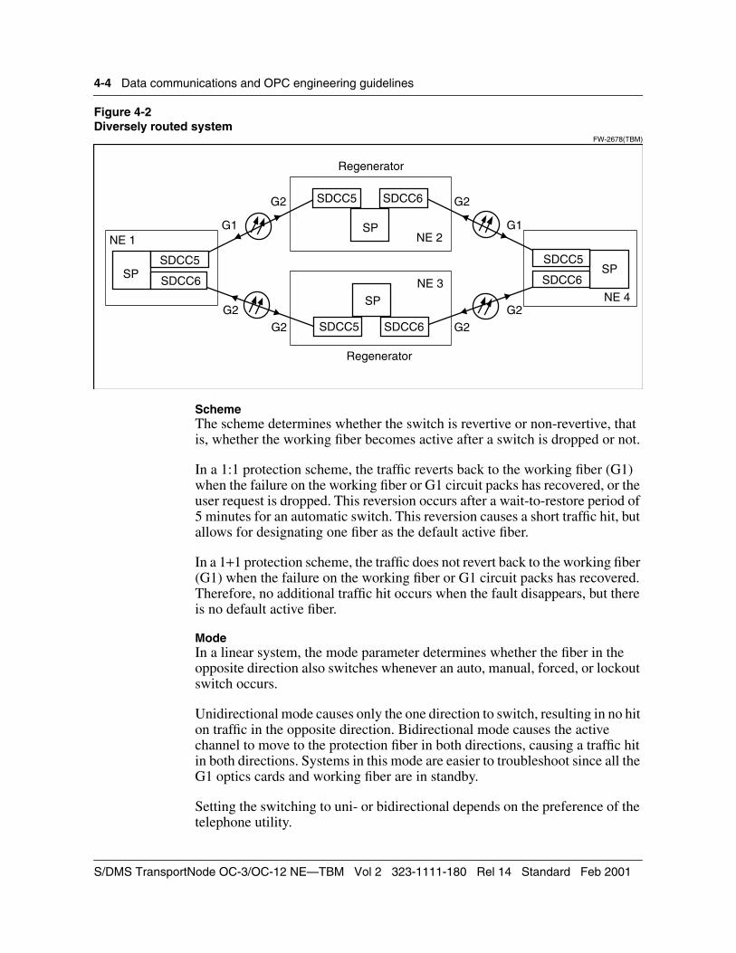
4-4 Data communications and OPC engineering guidelines
Figure 4-2Diversely routed system
FW-2678(TBM)
SchemeThe scheme determines whether the switch is revertive or non-revertive, that is, whether the working fiber becomes active after a switch is dropped or not.
In a 1:1 protection scheme, the traffic reverts back to the working fiber (G1) when the failure on the working fiber or G1 circuit packs has recovered, or the user request is dropped. This reversion occurs after a wait-to-restore period of 5 minutes for an automatic switch. This reversion causes a short traffic hit, but allows for designating one fiber as the default active fiber.
In a 1+1 protection scheme, the traffic does not revert back to the working fiber (G1) when the failure on the working fiber or G1 circuit packs has recovered. Therefore, no additional traffic hit occurs when the fault disappears, but there is no default active fiber.
ModeIn a linear system, the mode parameter determines whether the fiber in the opposite direction also switches whenever an auto, manual, forced, or lockout switch occurs.
Unidirectional mode causes only the one direction to switch, resulting in no hit on traffic in the opposite direction. Bidirectional mode causes the active channel to move to the protection fiber in both directions, causing a traffic hit in both directions. Systems in this mode are easier to troubleshoot since all the G1 optics cards and working fiber are in standby.
Setting the switching to uni- or bidirectional depends on the preference of the telephone utility.
NE 1
NE 4
NE 2
NE 3
G2
G1 G1
G2
G2
G2
G2
G2
(FW-2678 (TBM)
SP
SDCC5 SDCC6
SP
SDCC5 SDCC6
SPSDCC5
SDCC6SP
SDCC5
SDCC6
Regenerator
Regenerator
S/DMS TransportNode OC-3/OC-12 NE—TBM Vol 2 323-1111-180 Rel 14 Standard Feb 2001

Data communications and OPC engineering guidelines 4-5
Default SDCC assignmentsTable 4-1 shows the default SDCC assignments for each TBM node type. The default SDCCs provision in the transport optic slots (5, 7, 9, 10). The defaults are shown for each possible route diversity setting for the primary and secondary optics. The default route diversity setting for each NE type is shown shaded.
An SDCC may be either protected or diversely routed. A protected SDCC may be provisioned on either card of the pair (A or B card).
The other SDCC ports are only used for tributary optics, and these SDCCs are not provisioned by default. This includes SDCC 1, 2, 7, 8, 9, 10.
Table 4-1Default SDCC assignments for OC-12
NE Type
Route Diversity Secondary Optics Primary Optics
Secondary Optics
Primary Optics
SDCC 3 G1S
SDCC 4 G2S
SDCC 5G1
SDCC 6G2
Terminal n/a OFF OOS OOS IS (or OOS if sdcc 6 is IS)
OOS (or IS if sdcc 5 is OOS)
Terminal n/a ON OOS OOS IS IS
Linear ADM
OFF OFF IS (or OOS if sdcc 4 is IS)
OOS (or IS if sdcc 3 is OOS)
IS (or OOS if sdcc 6 is IS)
OOS (or IS if sdcc 5 is OOS)
Linear ADM
OFF ON IS (or OOS if sdcc 4 is IS)
OOS (or IS if sdcc 3 is OOS)
IS IS
Linear ADM
ON OFF IS IS IS (or OOS if sdcc 6 is IS)
OOS (or IS if sdcc 5 is OOS)
Linear ADM
ON ON IS IS IS IS
NWK ring ADM
n/a n/a IS OOS IS OOS
VTM ring ADM
n/a n/a n/a n/a IS IS
REGEN n/a n/a IS (connected to G1W)
OOS IS (connected to G1E)
OOS
Technical Specifications 323-1111-180 Rel 14 Standard Feb 2001

4-6 Data communications and OPC engineering guidelines
Software downloadWhile software is being downloaded to a network element, the network element operates in firmware. Network element firmware provides the ability to terminate DCCs but does not provide the ability to passthrough DCC. The result is that DCC communication is lost to downstream network elements in a point-to-point system when a software download is in progress.
Software download time is a function of the following three parameters: the CNet download time, the number of SONET hops to the destination network element, and the number of network elements in the system.
Table 4-2 provides formulas for estimating download times for an OC-12 span of control. These formulas are derived from download statistics gathered from field trials. The times indicated in this table are only applicable to systems that are operating under idle conditions without any other ongoing OAM activity.
When loading over 0 hops (that is, to the network element containing the OPC), the download proceeds at a rate that is limited by the speed at which information can be transferred from the OPC hard disk. For ten or fewer hops over SONET, the download rate is limited by the bandwidth of the SDCC connection.
The download protocol requires that load packets that are sent by the OPC to the network element be acknowledged by the network element. Up to 14 packets can be sent without the network element acknowledging receipt. If 14 acknowledgments are outstanding, no more packets are sent.
Table 4-2Software download times
Range Upper limit for download time Limited by
0 hops 400 seconds OPC hard disk transfer rate
1 to 10 hops between 11 and 35 minutes DCC bandwidth
>10 hops download time for 10 hops + 30 seconds for each additional hop
Packet acknowledgment return time
S/DMS TransportNode OC-3/OC-12 NE—TBM Vol 2 323-1111-180 Rel 14 Standard Feb 2001

Data communications and OPC engineering guidelines 4-7
The time required to receive an acknowledgment from the loading network element increases with the number of hops. This constraint limits the download rates when the distance between the OPC and the network element is more than ten SONET hops.
For example, if the OPC is located 23 hops from the network element, the download time is as follows:
500 + (23 − 10) × 30 = 890 seconds (approximately 15 minutes)
Note: Treat a CNet connection as a SONET hop in calculations. Delay is less for CNet than for a SONET hop.
The times indicated represent only the time required for software download and not the total time for the system to return to an active state. The total time includes system initialization, database recovery, and restoration of full DS3 services.
On an OC-12 system, the download times are similar but there are a maximum of five hops on a single OC-12 system. However, more than one OC-12 system might be contained in the OPCs span of control.
CNet LANThe control net (CNet) is a LAN providing intrasite communications between shelf processors and OPC modules in different network elements. Any network management data transferred within a shelf also occurs over the CNet. CNet serves as a bridge for forwarding communications data from the SONET section overhead on one shelf to the SONET section overhead on another shelf at the same site. This bridge is called a SONET DCC bridge.
Physical constraints imposed by CNet include the following:
• The recommended maximum number of OC-12 and OC-48 shelves connected by the same CNet LAN should not exceed 10.
• The CNet LAN bus (cables and backplane tracking) must not exceed 400 ft. (122 m) in length. A guideline for calculating the length of the CNet cable is as follows:
Total bus length (feet) = Total cable interconnect length (feet) + 10 feet × number of shelves connected by CNet)
• The ends of the CNet LAN bus must be terminated with CNet terminators.
• When using CNet cables to connect shelves, shelves must be grounded to the same transmission ground reference (TGR).
Technical Specifications 323-1111-180 Rel 14 Standard Feb 2001

4-8 Data communications and OPC engineering guidelines
OPC engineering guidelinesThe operations controller (OPC) is a part of the SONET Transmission Products family that provides operations, administration, maintenance and provisioning (OAM&P) functionality in a SONET network. Its capabilities include system administration, network surveillance, and software management services.
The OPC provides remote access to, and consistent control of, all Nortel Networks S/DMS products, including TransportNode (fiber and radio) and AccessNode network elements. As a centralized control point, the OPC supports a standard, terminal-based user interface and serves as a network surveillance center.
Because the performance of any OPC is key to system effectiveness, this chapter describes the factors that can affect the OPC performance, and identifies measures that can be taken to optimize performance.
Span of controlA span of control consists of the network elements that can be directly controlled or monitored by a single OPC or a pair of OPCs.
Normally, a span of control is monitored by a pair of OPCs, one primary OPC that actively controls the network, and one backup OPC that is available to take over control if the primary OPC fails or if communication between the primary and the backup OPC is interrupted. A span of control can also be monitored by a single OPC though this is not recommended.
A network element, in the current software release, is defined as an S/DMS TransportNode regenerator or a line terminating equipment (LTE) node. An LTE can be either a terminal or an add-drop multiplexer (ADM). Defining a span of control makes distribution of network element software from a single OPC location easy and controllable. In addition, it allows for better system analysis because it allows for the centralized gathering of surveillance data.
Summary of S/DMS TransportNode data communication limitsTable 4-3 provides a summary of the recommended overall network element and OPC span of control characteristics for a TransportNode data communications network. Explanations of these numbers are provided following the table.
S/DMS TransportNode OC-3/OC-12 NE—TBM Vol 2 323-1111-180 Rel 14 Standard Feb 2001
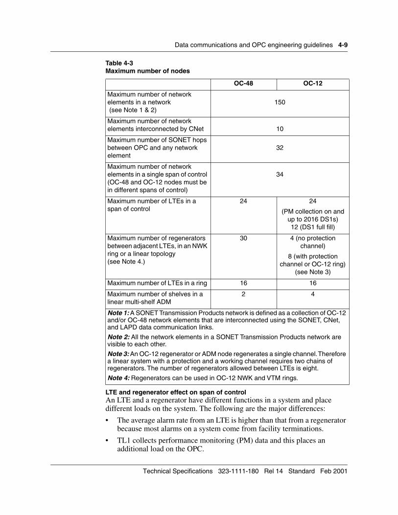
Data communications and OPC engineering guidelines 4-9
LTE and regenerator effect on span of controlAn LTE and a regenerator have different functions in a system and place different loads on the system. The following are the major differences:
• The average alarm rate from an LTE is higher than that from a regenerator because most alarms on a system come from facility terminations.
• TL1 collects performance monitoring (PM) data and this places an additional load on the OPC.
Table 4-3Maximum number of nodes
OC-48 OC-12
Maximum number of network elements in a network (see Note 1 & 2)
150
Maximum number of network elements interconnected by CNet 10
Maximum number of SONET hops between OPC and any network element
32
Maximum number of network elements in a single span of control (OC-48 and OC-12 nodes must be in different spans of control)
34
Maximum number of LTEs in a span of control
24 24
(PM collection on and up to 2016 DS1s)12 (DS1 full fill)
Maximum number of regenerators between adjacent LTEs, in an NWK ring or a linear topology(see Note 4.)
30 4 (no protection channel)
8 (with protection channel or OC-12 ring)
(see Note 3)
Maximum number of LTEs in a ring 16 16
Maximum number of shelves in a linear multi-shelf ADM
2 4
Note 1: A SONET Transmission Products network is defined as a collection of OC-12 and/or OC-48 network elements that are interconnected using the SONET, CNet, and LAPD data communication links.
Note 2: All the network elements in a SONET Transmission Products network are visible to each other.
Note 3: An OC-12 regenerator or ADM node regenerates a single channel. Therefore a linear system with a protection and a working channel requires two chains of regenerators. The number of regenerators allowed between LTEs is eight.
Note 4: Regenerators can be used in OC-12 NWK and VTM rings.
Technical Specifications 323-1111-180 Rel 14 Standard Feb 2001

4-10 Data communications and OPC engineering guidelines
• DS1 information accounts for approximately 80 percent of the messaging generated by PM collection from an LTE. Overall PM messaging from a regenerator is about 15 times less than that from an LTE.
The pmstate command (run at the UNIX prompt of the OPC) accesses an interactive utility that allows the setting of one of the following three states for a system:
• all PM collection off
• all PM collection on
• all PM collection on except for DS3 performance data
In an OC-12 span of control, overall performance is limited by the following:
• overall number of network elements = 34
• number of LTEs = 24 (with PM collection on and up to 2016 DS1s) or 12 (with PM collection on and each LTE completely filled with DS1s)
In an OC-12 span of control, there can be a maximum of 16 DS3-filled OC-12 terminals in any span of control.
Distance between OPCs and network elements in a span of controlThe distance between an OPC and any network element in its span of control should be less than 32 SONET hops. Any CNet connection should be counted as a single SONET hop. Although a CNet connection introduces less delay than a SONET hop, it should be counted as a hop when optimizing network topology.
An OPC can operate over greater distances, but system performance will degrade as the number of hops increases, due to the time required to transmit system data from the OPC to the distant node.
Setting time on a span of controlThe local time is defined as the Greenwich Mean Time (GMT), plus or minus the time zone difference provisioned during commissioning. When viewing the network element data (locally or remotely), the alarms are reported at the local time of the network element. The network element reports the alarms to the active OPC at GMT, not at its local time. When viewing the OPC data, the alarms are reported at the local time of the active OPC.
If the network includes network elements in different time zones, consider setting all network elements and OPC to the same time zone to assist the operator when operating and troubleshooting the system.
Locating the OPC terminal access lineThe purpose of the OPC is to provide a centralized view and control point for the network elements that are contained within its span of control. For best performance, VT100-compatible terminal access to the OPC must be direct. It
S/DMS TransportNode OC-3/OC-12 NE—TBM Vol 2 323-1111-180 Rel 14 Standard Feb 2001
Data communications and OPC engineering guidelines 4-11
is therefore best for the OPC to be located near manned VT100-compatible terminals or workstations. Since the primary OPC also contains the tape drive used for data backups and software upgrades, the OPC should be located in an accessible or manned site.
If TL1 is in operation on the system, the OPC must also be located near an X.25 connection. In addition, if the OPC is to be connected to a LAN, the OPC must be located near an Ethernet drop.
Where there is a need for VT100-compatible terminal access to the OPC, it is recommended that the user interface port on one of the network elements in the span of control be used instead of direct connection to port 1. In addition, the number of hops between the network element that is being used for the terminal access and the OPC should be kept to a minimum.
This arrangement provides the following advantages:
• If there is a warm standby and the backup OPC takes over control of the system, access to the backup is possible over the same VT100-compatible terminal access line. The network element routes the login to the currently active OPC.
• Port 1 on the OPC is available for use with other devices such as a printer or an X.25 connection for the TL1 interface.
Locating OPCs in a networkThis section describes how to optimize the location of the OPCs in a span of control. It also describes how to optimize the placement of the VT100-compatible terminal to access the OPC.
Locating OPCs in an OC-12 linear networkIn an OC-12 linear system with one span of control, the OPCs are normally mounted in the terminals at the ends of the network as shown in Figure 4-3. This configuration is the most reliable system for all system failures.
In the worst case, a fiber cut or equipment failure could partition the span into two subsystems, each under the control of one OPC (primary or backup). The backup OPC automatically becomes active to control all network elements up to the failure partition from its end. In this case, no network elements are isolated from an OPC.
Technical Specifications 323-1111-180 Rel 14 Standard Feb 2001

4-12 Data communications and OPC engineering guidelines
Figure 4-3OC-12 linear system contained within a single span of control
FW-0508 (REGEN TBM)
Note: OPCs are placed in the terminals at the ends of the span.
Locating OPCs in an OC-12 network with multiple spans of controlTo optimize the placement of the OPCs in networks with multiple spans of control, a planner must consider the following system characteristics. Some example system configurations are provided in the following section.
Configure terminals in the same span of controlIn a network with more than one OPC span of control, it is recommended that all the terminals or ADMs be placed in the same span of control for the following reasons:
• Only the terminals and ADMs can provide detailed protection status information on optical and low speed (STS-1, DS1, or DS3) circuits. To consolidate the end-to-end traffic data on a single user interface requires that all terminals be put in the same span of control.
• Optical and low-speed protection activity alarms are only reported from the terminals and ADMs. Correlation of events is much easier if terminals and ADMs report their alarms to the same OPC.
• Most network control operations occur on the terminals and ADMs. If the terminals and ADMs are put in the same span of control, the coordination of control operations is simplified.
To support putting all terminals and ADMs in one span of control in a multiple span-of-control network, the following partitioning of an OC-12 transmission network is recommended:
• The LTEs and up to half of the regenerators (as many as possible) should be put in one span of control. The remaining regenerators should be put in other spans of control.
• Except for the far end terminals, the network elements within each span should be contiguous or adjacent (in a diversely routed system).
OC-12regenerator
OC-12regenerator
FW-0508 (regen)
OC-12terminal
OPC
Primary OPC Backup OPC
OC-12terminal
OPC
• • •
S/DMS TransportNode OC-3/OC-12 NE—TBM Vol 2 323-1111-180 Rel 14 Standard Feb 2001

Data communications and OPC engineering guidelines 4-13
• The primary OPC for the span of control containing the terminals and ADMs should be placed in the terminal shelf that is contiguous with the regenerators in the span. (That is, the number of hops to the regenerators is kept to a minimum.) The backup OPC for this span of control should be placed in the regenerator at the far end of the span.
• The primary and backup OPCs for each remaining span of control should be placed in the regenerators at each end of their respective SONET lines.
Minimize spans of controlTo optimize performance it is recommended that network elements in a multi-span network be split into equally sized spans of control. The following performance benefits can be realized if the spans of control are minimized:
• The number and length of the communications links between the OPCs and the network elements is made as small as possible. This arrangement minimizes the delay of messages, allowing optimum response to asynchronous events, such as alarms.
• The software download time to the farthest network element in the span of control is minimized.
Note: If the number of network elements cannot be divided evenly into the number of spans of control, place fewer regenerators in the span containing the terminals.
Locate the OPCs on network elements within the span of controlThe OPC modules can be located in a network element that is not in the span of control. To optimize performance, this should be avoided if possible as it increases the length of the communication channel. If the OPC is located in its span of control:
• Messaging is retained within the span of control. This simplifies communications, minimizes interference, and therefore maximizes system performance.
• OPC communication with the local shelf is over the CNet backplane and is therefore very fast. This improves the performance of software download and surveillance of the local shelf.
If the primary OPC for span of control A is placed in a shelf contained in span of control B, an alarm raised when the OPC fails is generated on the alarm monitor of span of control B rather than on the alarm monitor of span of control A. This might confuse the operator.
Locate OPCs at opposite ends of the span of controlIn non-diversely routed linear systems, the primary and backup OPCs should be located at opposite ends of the span of control where possible. This arrangement ensures that all network elements continue to be visible in the
Technical Specifications 323-1111-180 Rel 14 Standard Feb 2001

4-14 Data communications and OPC engineering guidelines
event of a fiber cut or any other major communications failure. In a diversely routed system, all network elements are visible after a single failure, regardless of the location of the OPC.
Minimize the distance between network elements in the span ofcontrol and the OPCWhere possible, the number of hops between each network element in the span of control and the OPC modules must be minimized. This arrangement helps reduce software download times, maximize MAPCI performance, and reduce network element database backup time.
Locate OPC close to the LTEs, where possibleThe OPC must be located as close as possible to LTEs within its span of control. When software is being downloaded to an LTE, the STS-1/DS1/DS3 service the LTE provides is unprotected during the time of the download. Keeping the OPC as close to LTEs as possible reduces the length of time required for download.
Locate ADM nodes in a ring in the same span of controlThe ADM nodes in a ring configuration should all be located in the same span of control since provisioning and configuration information for the ring must be maintained in all the spans of control within the ring.
If the ADM nodes are located in separate spans of control, the provisioning and configuration information must be manually maintained across spans. This data could be erroneously added and this may lead to operating problems.
OC-12 multishelf terminalIt is possible to have an OC-12 terminal in a multishelf configuration that allows multiple DS3 and DS1 facilities. Up to four shelves can be connected (using STS-12 connections between shelves) to allow a greater number of DS1s than is possible on one shelf. Up to two shelves can be connected to provide a mix of DS1 and DS3 facilities. Table 4-4 shows the possible configurations.
Table 4-4 Example of multishelf configurations
Shelf 1 Shelf 2
DS3 DS1 DS1
1 84 168
2 84 168
3 84 168
4 56 168
5 56 140
6 56 112
S/DMS TransportNode OC-3/OC-12 NE—TBM Vol 2 323-1111-180 Rel 14 Standard Feb 2001

Data communications and OPC engineering guidelines 4-15
With a multishelf configuration, the OPC can be located in the space that is taken up with the secondary optics or STS channel on a single shelf.
Example systemsThis section provides examples of several systems and the optimal location of the OPCs in these systems.
OC-12 linear systemsFigure 4-4 shows an example of an OC-12 linear system consisting of two OC-12 terminal shelves and eight OC-12 ADMs.
Figure 4-4Example of an OC-12 linear system
FW-2252.1
7 28 112
8 28 84
9 28 56
10 0 56
11 0 28
12 (see Note) 0 0
Note:With 12 DS3 facilities, only 1 shelf is required.
Table 4-4 (continued)Example of multishelf configurations
Shelf 1 Shelf 2
DS3 DS1 DS1
FW-2252.1
Primary OPC
OC-12terminal
OPC
OC-12terminal
Backup OPC
OC-12ADM
OC-12ADM
OC-12ADM
OPC
OC-12ADM
Technical Specifications 323-1111-180 Rel 14 Standard Feb 2001

4-16 Data communications and OPC engineering guidelines
This type of system can be described as follows:
• Each OC-12 channel requires its own chain of ADMs. Each ADM can only handle one channel.
• There are a maximum of four ADMs in each chain.
• The OPCs should be placed in the ADM nearest to the terminal if there is no room on the terminal for an OPC.
This configuration has the following advantages:
• Having two chains of ADMs means that the OC-12 linear system is inherently diversely routed. Under such circumstances, two simultaneous failures are required to isolate any part of the system.
• The OPCs are located on shelves in their span of control.
• The OPCs are located near terminals.
If required, connections to X.25 for TL1 or to a LAN can be made available at the ADM site.
The OPCs could be located in a spare shelf at the site of the terminal rather than in the ADM node. Up to four OPCs can be contained in one shelf. Alternatively, the OPC can be located on a shelf of a different system. Figure 4-5 shows a system in which the OC-12 OPC is located in an OC-48 shelf at the same site.
More than one OC-12 system can be consolidated into the same span of control. If the new system does not have room for an OPC and it is located close to another OC-12 system that already has OPCs, the new system can be added to this span of control (see Figure 4-6).
S/DMS TransportNode OC-3/OC-12 NE—TBM Vol 2 323-1111-180 Rel 14 Standard Feb 2001

Data communications and OPC engineering guidelines 4-17
Figure 4-5Locating an OC-12 OPC in an OC-48 shelf
FW-2682
Figure 4-6Locating an OC-12 OPC in a nearby shelf
FW-2664.1
OC-12 route-diverse systemFigure 4-7 shows a diversely-routed system with two terminals with two routes (upper and lower) between them.
OC-3 orOC-12
terminal
OC-3 orOC-12
terminal
OC-3 orOC-12
terminal
OC-3 orOC-12
terminal
FW-2682
DS3 orDS1
OC-3 orOC-48
terminal
OPC
DS3 orDS1
CNet
CNet
CNet
CNetOC-48
DS3/STS-1 OC-3 orOC-12
terminal
OC-3 orOC-12
terminal
OC-3 orOC-12
terminal
OC-3 orOC-12
terminal
DS1
OPC
DS3/STS-1
DS1
DS3/STS-1
DS3/STS-1
DS3/STS-1
DS3/STS-1
CNet
(FW-2664.1)
Primary OPC
Technical Specifications 323-1111-180 Rel 14 Standard Feb 2001

4-18 Data communications and OPC engineering guidelines
Figure 4-7Example of a diversely-routed system
FW-2680 (TBM)
This type of system can be described as follows:
• Both terminals are in the same span of control.
• The span of controls are approximately the same size (22 and 20 network elements).
• The primary OPCs are placed in the terminals at either end of the network, at sites that are usually manned.
• Both spans of control are contiguous except for the second terminal (network element 1561), which is included in span of control 1 rather than span of control 2 for the reasons given in “Locating OPCs in an OC-12 network with multiple spans of control”.
• Except for the primary OPC in span of control 2, the OPCs are located in network elements within their span of control.
• The number of hops between network elements and their controlling OPCs is minimized.
OC-12regenerator
OC-12regenerator
FW-2680
Primary OPCSpan of control 1
• • •
OC-12regenerator
OC-12regenerator
Lower route
OC-12terminal
OPC
• • •
Span of control 1
Span of control 2
• • •
• • •
OC-12terminal
OPC
Primary OPCSpan of control 2
Backup OPCSpan of control 1
Upper routeOPC
OPC
Backup OPCSpan of control 2
NE 1562 NE 1570 NE 1571
NE 1572 NE 1581
NE 1592 NE 1583
NE 1561
NE 1593
NE 1561
NE 1502 NE 1594
S/DMS TransportNode OC-3/OC-12 NE—TBM Vol 2 323-1111-180 Rel 14 Standard Feb 2001

Data communications and OPC engineering guidelines 4-19
This configuration has the following advantages:
• Because the primary OPC is not configured at the end of its span of control, the download times for all of the network elements are minimized.
• Diverse routing allows all nodes to be visible in the event of a single communications failure.
• The primary OPCs are accessible and located at sites that are usually manned.
Because the primary OPC for span of control 2 is not in a network element in the span of control, this could reduce messaging efficiency. In the event of a failure, some information may be inconsistent between spans.
In the event of a primary OPC failure, download times to certain network elements might increase. This is because messaging relies on diverse routing rather than both the backup and primary being able to monitor all the network elements in their span of control.
OC-12 NWK configurationThe OC-12 NWK ring configuration is a bidirectional linked circular chain of network elements. When a failure occurs, the software re-routes traffic and the DCC around the loop in the opposite direction to maintain communications at all times. Figure 4-8 shows an example of a ring configuration.
Technical Specifications 323-1111-180 Rel 14 Standard Feb 2001

4-20 Data communications and OPC engineering guidelines
Figure 4-8Example of a ring configuration
FW-2988(TBM)
This type of system can be described as follows:
• This example has six ADM nodes with four regenerators in each span.
• All of the ADM nodes are in the same span of control to maintain consistent provisioning information.
• The regenerators are all in the other span of control.
• The primary and backup OPCs are located at opposite sides of the ring at the maximum number of hops apart.
• OPCs are located in nodes that are within their span of control.
This configuration has the following advantages:
• Provisioned configuration data is consistent because all of the ADM nodes are in the same span of control. There is only one pair of primary and backup OPCs controlling the ring. On systems where the ADM nodes are split between multiple spans, provisioning data must be maintained accurately on all of the OPCs involved. Each provisioned STS-1 connection must be entered into the primary OPC of each span in the network, whether or not the connection intersects that span.
FW-2988 (TBM)
Regenerator(span of control 1)
OC-12Ring ADM
(span of control 2)Regenerator
(span of control 1)
OC-12Ring ADM(span of control 2)
PrimaryOPC
OC-12Ring ADM
(span of control 2)
Regenerator(span of control 1)
OC-12Ring ADM
(span of control 2)Regenerator
(span of control 1)
OC-12Ring ADM
(span of control 2)Regenerator
(span of control 1)
OC-12Ring ADM(span of control 2)
BackupOPC
PrimaryOPC
Regenerator(span of control 1) Backup
OPC
S/DMS TransportNode OC-3/OC-12 NE—TBM Vol 2 323-1111-180 Rel 14 Standard Feb 2001
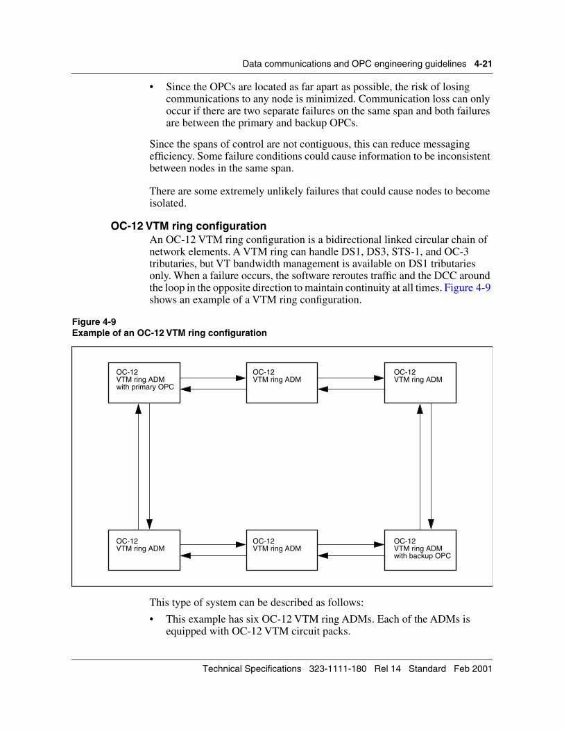
Data communications and OPC engineering guidelines 4-21
• Since the OPCs are located as far apart as possible, the risk of losing communications to any node is minimized. Communication loss can only occur if there are two separate failures on the same span and both failures are between the primary and backup OPCs.
Since the spans of control are not contiguous, this can reduce messaging efficiency. Some failure conditions could cause information to be inconsistent between nodes in the same span.
There are some extremely unlikely failures that could cause nodes to become isolated.
OC-12 VTM ring configurationAn OC-12 VTM ring configuration is a bidirectional linked circular chain of network elements. A VTM ring can handle DS1, DS3, STS-1, and OC-3 tributaries, but VT bandwidth management is available on DS1 tributaries only. When a failure occurs, the software reroutes traffic and the DCC around the loop in the opposite direction to maintain continuity at all times. Figure 4-9 shows an example of a VTM ring configuration.
Figure 4-9Example of an OC-12 VTM ring configuration
This type of system can be described as follows:
• This example has six OC-12 VTM ring ADMs. Each of the ADMs is equipped with OC-12 VTM circuit packs.
OC-12VTM ring ADM
OC-12VTM ring ADM
OC-12VTM ring ADM
OC-12VTM ring ADM
OC-12VTM ring ADM
OC-12VTM ring ADM
with primary OPC
with backup OPC
Technical Specifications 323-1111-180 Rel 14 Standard Feb 2001

4-22 Data communications and OPC engineering guidelines
• All of the ADM nodes are in the same span of control to maintain consistent provisioning information.
• The primary and backup OPCs are located at opposite sides of the ring.
• The OPCs are located in nodes that are within their span of control.
Advantages of the VTM ringThe VTM ring configuration has the following advantages:
• Provisioned configuration data is consistent because all of the ADM nodes are in the same span of control. There is only one pair of primary and backup OPCs controlling the ring. On systems where the ADM nodes are split between multiple spans, provisioning data must be maintained accurately on all of the OPCs involved. Each provisioned STS-1 connection and VT connection must be entered into the primary OPC of each span in the network, whether or not the connection intersects that span.
• Since the OPCs are located as far apart as possible, the risk of losing communications to any node is minimized. Communication loss can occur only if there are two separate failures on the same span and both failures are between the primary and backup OPCs.
The OC-12 VTM ring configuration has the following advantages over the OC-12 NWK ring configuration:
• VT bandwidth management (VTM) is available in a VTM ring.
• In the VTM ring, only the two VTM optical circuit packs are required because the optical circuit packs incorporate the ring loopback and overhead bridge functionality. In a NWK ring, separate circuit packs are required to provide the ring loopback and overhead bridge functionality.
ADM applications for OC-3 tributaries on the OC-12 TBM shelfFigure 4-10 shows OC-3 tributaries on an OC-12 ADM shelf. The use of OC-12/STS-12 connections to other TBM shelves allows the system to handle DS1, DS3, and STS-1 traffic as well as mixed DS1/DS3/STS-1 traffic.
S/DMS TransportNode OC-3/OC-12 NE—TBM Vol 2 323-1111-180 Rel 14 Standard Feb 2001

Data communications and OPC engineering guidelines 4-23
Figure 4-10OC-12 ADM application (DS1/DS3/STS-1 traffic)
FW-2304 (TBM R8)
OC-12 tributary systemFigure 4-11 shows one side of an OC-48 1:3 protected system that has OC-12 tributaries. The OC-12 shelves are 336 DS1 terminals in a multi-shelf configuration consisting of a DS1 ADM and a DS1 TBM.
This type of system can be described as follows:
• The OC-12 terminals are located in two spans of control, which are the same size.
• The OPCs for the OC-12 spans of control are located in the OC-12 terminal shelves that provide the OC-12 tributary to the fourth quadrant of the OC-48 shelves.
• All eight OC-12 shelves that are tributaries from the same OC-48 shelf are connected using CNet.
Note: The CNet connection is not required if the OC-48 shelves are equipped with Phoenix shelf processors.
• DCC is passed over the fourth quadrant tributary between the groups of OC-12 systems and the OC-48 shelves. If the OC-48 shelves are equipped with Phoenix shelf processors, DCC is passed over all four quadrant tributaries.
• There are eight shelves on each of the CNets.
This configuration has the following advantages:
• Communication between the OC-12 systems is very fast over the CNet links between the groups of eight shelves connected to the same OC-48 terminal. Local download times and MAPCI response are also very fast.
OC-12TBM
OC-12
OC-3TBM
OC-3
OC-12ADM
OC-3TBM
OC-3
OC-3TBM
OC-3
OC-12OC-12TBM
OC-3TBM
OC-3
DS1/3,STS-1
DS1/3,STS-1
DS1/3,STS-1
DS1/3,STS-1
DS1/3,STS-1
DS1/3,STS-1
DS1/3,STS-1
Technical Specifications 323-1111-180 Rel 14 Standard Feb 2001

4-24 Data communications and OPC engineering guidelines
Communications to other groups over the fourth quadrant DCC on the same side of a 1:N system are also good, since there are only two SONET hops and three CNet links.
• In the event of an OC-48 shelf failure, every OC-12 shelf is still under the control of either a primary or backup OPC.
In the event of a loss of communication over the fourth quadrant to any of the groups of eight OC-12 shelves, these shelves could become isolated. They are, however, still under the control of an OPC.
S/DMS TransportNode OC-3/OC-12 NE—TBM Vol 2 323-1111-180 Rel 14 Standard Feb 2001

Data communications and OPC engineering guidelines 4-25
Figure 4-11Example of a OC-12 tributary configuration
FW-2683
Primary OPC
OC-48terminal
OPC
OC-12terminal
OC-12ADM
OC-48
OC-12ADM
OC-12terminal
OC-12terminal
OC-12ADM
OC-12ADM
OC-12terminal
Backup OPC
OC-48terminal
OPC
OC-12terminal
OC-12ADM
OC-48
OC-12ADM
OC-12terminal
OC-12terminal
OC-12ADM
OC-12ADM
OC-12terminal
Primary OPC
OC-48terminal
OPC
OC-12terminal
OC-12ADM
OC-48
OC-12ADM
OC-12terminal
OC-12terminal
OC-12ADM
OC-12ADM
OC-12terminal
Backup OPC
OC-48terminal
OPC
OC-12terminal
OC-12ADM
OC-48
OC-12ADM
OC-12terminal
OC-12terminal
OC-12ADM
OC-12ADM
OC-12terminal
OPC
Span of control 1
Span of control 2
Legend:= CNet= STS-12 link= OC-12 link
(FW-2683)
Span of control 3
SDCC
SDCC
SDCC
SDCC
SDCC
SDCC
SDCC
SDCC
Technical Specifications 323-1111-180 Rel 14 Standard Feb 2001

4-26 Data communications and OPC engineering guidelines
TL1/X.25 and performance monitoring data collectionThe TL1 feature provides the facility for the delivery of alarms, logs and performance monitoring (PM) data from an OPC to an operations system such as the Network Monitoring and Analysis Operations System (NMA OS). In addition, there are facilities for network element identification inquiries and protection switch queries and commands. TL1 communication is provided through the port B X.25 connection of the shelf containing the OPC for OC-48 and through port 1 or 2, depending on the OPC model, for OC-12.
PM collectionThe OC-12 and OC-48 products have identical PM and alarm collection systems under TL1. For more details about TL1, see TL1 Interface Description, 323-1111-190.
When active, TL1 imposes four types of load upon the OPC. The first is evenly distributed over an hour and is a consequence of passing PM data and currently active network element alarms over the link to the NMA operations system.
Active alarm information for each of the network elements in the system is sent from the network elements to the OPC at the top of each hour.
The amount of activity depends on the number of PM values that are reported, and the number of active alarms on any particular network element. It is possible to configure the PM collection in the following three states:
• collection enabled for all PM data
• no PM data collection enabled
• no DS3 PM collection enabled, but all other PM values collected
The pmstate tool is run from a UNIX shell and can be used to interactively monitor what mode PM collection is in and to modify the mode, if necessary.
The TL1 command inhibit_pm can be used to prevent PMs being reported to the operations system for network elements that are of no interest.
The second type of load depends on the rate at which alarms are being generated. Since incoming alarms are passed asynchronously through the TL1 interface to the operations system, the greater the rate of alarms, the more impact TL1 has on the system.
The third load that can be experienced on the span of control as a result of TL1 activity is the load that is generated when non-autonomous TL1 commands are issued from the operations system.
S/DMS TransportNode OC-3/OC-12 NE—TBM Vol 2 323-1111-180 Rel 14 Standard Feb 2001

Data communications and OPC engineering guidelines 4-27
If the rtrv-pm-all command is sent, the OPC has to search through the entire PM database to locate valid data. The time taken and the precise load depends on the number of nodes in the system and the number of facilities in the system. When using this command, the available bandwidth on the TL1 link is the restricting factor.
It is important that the impact of the rtrv-pm-all command is understood by all operators on the system. It should be used selectively.
Note: The system blocks any outgoing autonomous messages until the incoming non-autonomous command is completed. Any alarms that are raised while processing a non-autonomous command are buffered and sent once that command has finished.
The fourth type of load on a system is the result of PM reports. PM reports are generated as soon as the PM collector finishes collecting the PM counts for an object termination class. For example, for a DS1 line, DS3 line, DS3 path, or an OC-n span for a particular network element.
A large number of PM reports are generated in rapid succession starting at approximately 5 minutes past the hour. PM reporting is triggered by the PM collector each time a particular termination class (for example, DS3 line) for a specific network element is updated in the PM database on the OPC. PM collection and TL1 reporting can occur concurrently.
PM counts are collected in 15-minute slots, so there might be four separate entries for each PM parameter for the past hour for which data was collected.
PM general commentsThe OPC port on the shelf can be configured as a standard universal asynchronous receiver transmit (UART) port for use with a direct terminal connection or as an X.25 port, which is required for use with the TL1 feature. The port can handle data rates up to 19 200 bit/s.
TL1 must transfer data from the OPC to an operations system. The amount of data transferred depends on the number of alarms received and the amount of PM messaging.
The total amount of information transferred over TL1 can be handled by systems operating at the lower X.25 baud rates (300 bit/s, 1200 bit/s, 2400 bit/s). However, with large systems, the higher rate of 9600 bit/s is recommended.
Remote telemetry—TBOSThis section provides a general description on remote telemetry—TBOS and details about provisioning characteristics. For more detail about remote telemetry—TBOS, see Alarms and Surveillance Description, 323-1111-104.
Technical Specifications 323-1111-180 Rel 14 Standard Feb 2001

4-28 Data communications and OPC engineering guidelines
General descriptionRemote telemetry is used to centralize serial telemetry surveillance for multiple network elements within the OPC span of control. It can also be used to display the provisioning details of the serial telemetry ports (also called telemetry byte-oriented serial (TBOS) ports) of the network elements.
Remote telemetry allows any network element to provision displays to a remote display. This remote display can be Display Monitor 2 of any other network elements in the same span of control or it can be the Network Summary Display.
With this provisioning ability, the TBOS port of a network element can report information about multiple network elements in addition to information about the network element on which the port is physically located.
There are only two types of displays that remote telemetry allows the user to provision across network elements as previously described (also referred to as provisioning display remotely). They are as follows:
• Network Summary Display This display contains Boolean representations of the global network alarms as categorized by severity (Critical, Major, minor, warning, or clear). This display also contains a flag used to indicate when communications between the OPC and one or more network elements has failed. There is only one Network Summary Display for each OPC span of control.
• Monitor Display 2 This display contains a Boolean summary of the status of an individual network element. For example, information about equipment failures, facility failures, environmental alarms, protection switches and threshold crossing is usually contained in this display. The format of this display depends on the product type and the shelf type (for example, ADM node as opposed to terminal). There is a predefined format Monitor Display 2 for every network element in the OPC span of control, and each is considered a unique instance.
Provisioning characteristicsThe following characteristics apply to provisioning telemetry displays across network elements through the remote telemetry tool. These characteristics are designed to optimize system performance. The network element telemetry user interface is used to perform provisioning.
A display can only be associated with one network element and one physical TBOS port, regardless of the number of TBOS ports it possesses. Specifically, a display cannot be assigned to more than one TBOS port position for any network element. This applies to both the Network Summary Display and Monitor Display 2.
S/DMS TransportNode OC-3/OC-12 NE—TBM Vol 2 323-1111-180 Rel 14 Standard Feb 2001

Data communications and OPC engineering guidelines 4-29
For example, if Monitor Display 2 of NE 1 is assigned to TBOS port 3, position 8 of NE 2, then Monitor Display 2 of NE 1 cannot also be assigned to any other position of TBOS port 3 or to any other TBOS ports of NE 2.
The previous assignment must be deleted before making another assignment of Monitor Display 2 of NE 1 to NE 2. The assignment can be deleted using the remote telemetry tool or from the network element user interface.
A display can be provisioned to no more than two network elements in the span of control. This restriction applies to both the Network Summary Display and Monitor Display 2. To optimize performance, the number of destination displays that are provisioned must be kept as small as possible.
Any network element with TBOS ports can be provisioned as a central surveillance network element with remote telemetry. Within the span of control of an OPC, there might be multiple serial telemetry surveillance network elements. All remote provisioning is performed manually.
TBOS ports are not automatically created on a network element. These ports are added manually from the network element user interface of any potential surveillance network element.
The remote telemetry provisioning at the OPC must be done prior to provisioning the network element. Any time the remote telemetry provisioning is altered, the parallel telemetry provisioning dependent upon it must be modified through the network element user interface.
When a display is provisioned from a network element (source network element) to another network element (destination network element) through remote telemetry, the OPC must be able to communicate with both source and destination network elements.
This allows the OPC to retrieve the contents of the display from the source network element and be continually notified of any changes to the display. The OPC is also used to continually update the destination network element with the content of the display as it changes.
At the destination network element, a display that is provisioned across network elements through remote telemetry is stored locally in remote displays. Every network element has a pool of 32 remote displays for this purpose.
The OPC retains and manages the source of the remote display. The network element only supplies a type of pipe for the information to reach the physical serial telemetry interface. Remote Display 1 is always reserved for the
Technical Specifications 323-1111-180 Rel 14 Standard Feb 2001

4-30 Data communications and OPC engineering guidelines
Network Summary Display (although it might not be provisioned), and Remote Display 2 is not used. The 30 remaining remote displays are for customer mapping.
The remote telemetry tool identifies the source network element and source display for every remote display assigned to a TBOS port. With this information, the parallel telemetry outputs of the destination network element can be used to convey any information contained in the source display, if required.
OPC user interface and toolsThis section describes user logins and tool sets, system security, system configurations, login times, performance related to number of nodes, tool start-up times, and OPC tool usage limitations.
User and tool limitations within a span of controlThe maximum number of users that can be logged into an OPC at any one time is four. Users are defined as User Session Managers. Two TL1 sessions should be counted as a single user. The user session manager is not started automatically when logging in as root.
Any user can open up to 15 tools. The maximum number of tools that can be open in total for all users within the same span of control is approximately 20. The actual number depends on which tools are opened.
User logins and tool setsThe OPC tools are issued as nine standard tool sets that are shown in Table 4-5.
Table 4-5 Standard toolsets
Toolset name Tools
Software Admin Reboot /Load Manager
Backup/Restore Manager
Alarm Monitor
Event Browser
Network Upgrade Manager
OPC Admin Centralized User Administration
OPC Save and Restore
OPC Shutdown
OPC Date
Port Configuration
IP Routing Admin
UNIX Shell—continued—
S/DMS TransportNode OC-3/OC-12 NE—TBM Vol 2 323-1111-180 Rel 14 Standard Feb 2001

Data communications and OPC engineering guidelines 4-31
OPC PM Collection Filter
TL1 Configuration
Log Archive
OPC Alarm Provisioning
Event Browser (SEC)
Security Log Dump
Network Admin Remote Telemetry
Configuration Manager
Connection Manager (AC)
Utilities NE Login Manager
Password Update
Hardware Baseline
Logout
Remote OPC Login (Only X-terminal)
Master Admin OPC Shutdown
OPC Save and Restore
OPC Date
Commissioning Manager
Unix Shell
OPC PM Collection Filter
OPC Alarm Provisioning
Network Surveillance Alarm Monitor
Network Summary
Event Browser
Network Browser
Protection Manager
Connection Manager (Read Only)
SLAT Commissioning Manager
Event Browser
Reboot/Load Manager
OPC Save and Restore
OPC Shutdown
OPC Date
OPC Alarm Provisioning—continued—
Table 4-5 (continued)Standard toolsets
Toolset name Tools
Technical Specifications 323-1111-180 Rel 14 Standard Feb 2001
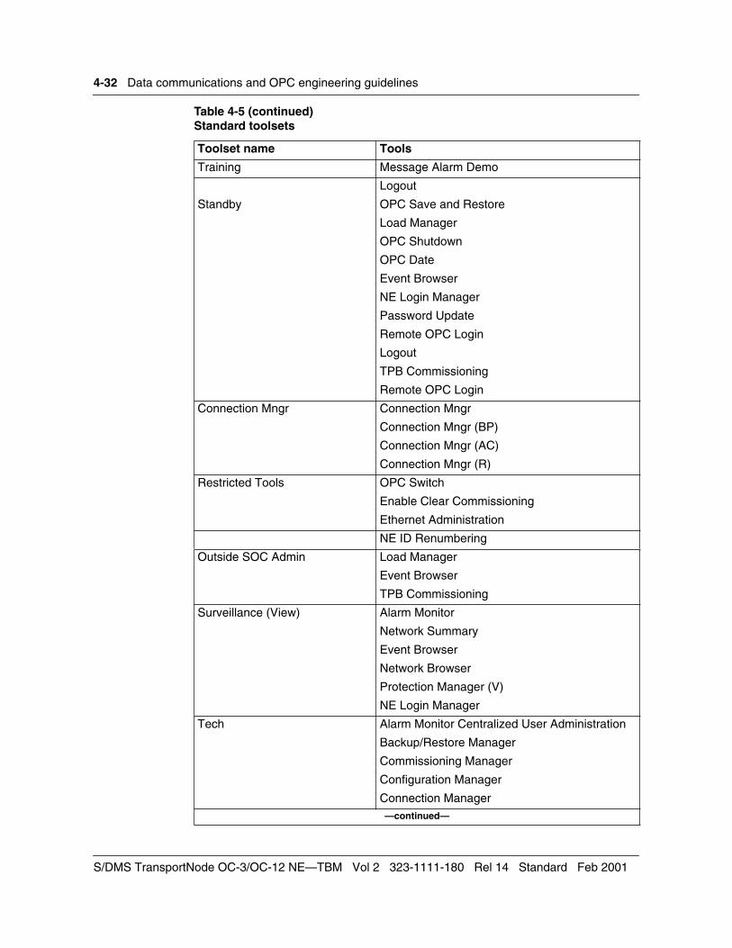
4-32 Data communications and OPC engineering guidelines
Training Message Alarm Demo
Logout
Standby OPC Save and Restore
Load Manager
OPC Shutdown
OPC Date
Event Browser
NE Login Manager
Password Update
Remote OPC Login
Logout
TPB Commissioning
Remote OPC Login
Connection Mngr Connection Mngr
Connection Mngr (BP)
Connection Mngr (AC)
Connection Mngr (R)
Restricted Tools OPC Switch
Enable Clear Commissioning
Ethernet Administration
NE ID Renumbering
Outside SOC Admin Load Manager
Event Browser
TPB Commissioning
Surveillance (View) Alarm Monitor
Network Summary
Event Browser
Network Browser
Protection Manager (V)
NE Login Manager
Tech Alarm Monitor Centralized User Administration
Backup/Restore Manager
Commissioning Manager
Configuration Manager
Connection Manager—continued—
Table 4-5 (continued)Standard toolsets
Toolset name Tools
S/DMS TransportNode OC-3/OC-12 NE—TBM Vol 2 323-1111-180 Rel 14 Standard Feb 2001

Data communications and OPC engineering guidelines 4-33
The OPC provides the following user login levels: netsurv, admin, master, slat, demo, standby, oc3admin, techsupp, viewsurv, and root. For each login level, a number of tool sets are available and one or more tools are started automatically in the user session manager. Table 4-6 summarizes the user login levels, available tool sets and user session manager auto-start tools.
Event Browser
Hardware Baseline
Load Manager
Log Archive
Logout
NE Login Manager
Network Browser
Network Summary
Network Upgrade Manager
OPC Date
OPC Save and Restore
OPC Shutdown
OPC Switch
Protection Manager
Reboot/Load Manager
Remote OPC Login
TPB Commissioning—end—
Table 4-5 (continued)Standard toolsets
Toolset name Tools
Technical Specifications 323-1111-180 Rel 14 Standard Feb 2001

4-34 Data communications and OPC engineering guidelines
Table 4-6Summary of user login levels and available tools
User Available tool sets Automatically opens
Master User Network Surveillance Status Tool
Master Admin Alarm Monitor
Utilities Network Summary
Admin User Software Admin Status Tool
OPC Admin
Network Admin
Utilities
Netsurv User Network Surveillance Status Tool
Utilities Alarm Monitor
NE Login Manager
Network Summary
Root User Software Admin Status Tool
OPC Admin Unix shell
Network Admin
Outside SOC Admin
Network Surveillance
SLAT
Training
Utilities
Connection Mngr
Surveillance (View)
Restricted Tools
SLAT user SLAT Status Tool
Network Admin Commissioning Manager
Utilities
Standby User Standby Status Tool
tech Tech Status Tool
Demo User Training Status Tool
osocad Outside SOC Admin Status Tool
Utilities
viewsurv Surveillance (View) Status Tool
Utilities NE Login Manager
Alarm Monitor
Network Summary
—continued—
S/DMS TransportNode OC-3/OC-12 NE—TBM Vol 2 323-1111-180 Rel 14 Standard Feb 2001
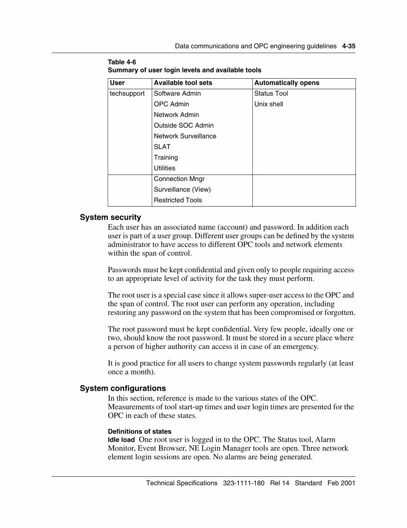
Data communications and OPC engineering guidelines 4-35
System securityEach user has an associated name (account) and password. In addition each user is part of a user group. Different user groups can be defined by the system administrator to have access to different OPC tools and network elements within the span of control.
Passwords must be kept confidential and given only to people requiring access to an appropriate level of activity for the task they must perform.
The root user is a special case since it allows super-user access to the OPC and the span of control. The root user can perform any operation, including restoring any password on the system that has been compromised or forgotten.
The root password must be kept confidential. Very few people, ideally one or two, should know the root password. It must be stored in a secure place where a person of higher authority can access it in case of an emergency.
It is good practice for all users to change system passwords regularly (at least once a month).
System configurationsIn this section, reference is made to the various states of the OPC. Measurements of tool start-up times and user login times are presented for the OPC in each of these states.
Definitions of statesIdle load One root user is logged in to the OPC. The Status tool, Alarm Monitor, Event Browser, NE Login Manager tools are open. Three network element login sessions are open. No alarms are being generated.
techsupport Software Admin Status Tool
OPC Admin Unix shell
Network Admin
Outside SOC Admin
Network Surveillance
SLAT
Training
Utilities
Connection Mngr
Surveillance (View)
Restricted Tools
Table 4-6Summary of user login levels and available tools
User Available tool sets Automatically opens
Technical Specifications 323-1111-180 Rel 14 Standard Feb 2001

4-36 Data communications and OPC engineering guidelines
Busy load A root user is logged in as described in the idle load state. In addition, a netsurv user is logged in to the OPC with the Status, Alarm Monitor, Network Summary, and NE Login Manager tools open. Three network element login sessions are open. One alarm is being generated every 8 seconds.
Very busy load A root user and netsurv user as previously described are logged in. In addition, two netsurv users are logged in with only their automatically opened tools. One alarm is being generated every 2 seconds. A software download to a network element (over SONET) is in progress.
The states of activity previously described are not expected in the field. Sustained alarm rates of one alarm every 1 or 2 seconds are highly improbable. The states are chosen to reflect the differences between system behavior for totally different load levels.
Login timesLogin times are similar for all of the six user types that automatically start a User Session Manager when they log in (login time is defined as the delay between entering the login password and obtaining an alarm status line in the User Session Manager).
The actual login time can vary depending on other system activity (what stage PM collection is at, for example). However, opening a User Session Manager takes under 40 seconds no matter what load is on the OPC. Login time does vary slightly with the number of tools that are opened automatically.
Login time for the root user is less since this user does not automatically open a User Session Manager or any tools.
OPC performance related to number of nodesPerformance of the OPC varies depending on the number of nodes that the OPC has in its span of control. The more nodes there are, the more messaging is required to initialize the system and maintain current information.
On large OC-48 long-haul systems, for example, systems over a span of 30 SONET hops, performance of remote logins and network element logins can be reduced. This reduction is mainly due to the increased distance over which messages must travel.
The size of the system can also affect certain tool start-up times, specifically those tools that show information on a node-by-node basis. For example, the Network Alarm Summary or the Network Browser. These tools have an initialization procedure for each node, so the more nodes there are, the longer they take to start up. Tool start up times on a 32-node system can be up to 50 percent longer than those on a 2-node system.
S/DMS TransportNode OC-3/OC-12 NE—TBM Vol 2 323-1111-180 Rel 14 Standard Feb 2001

Data communications and OPC engineering guidelines 4-37
OPC tool usage There is a maximum number of instances of each tool type that can be open on an OPC. The number of instances that a tool can be opened within a single user session depends on the tool type. Table 4-7 provides these limits.
To interpret the table, the following examples are given:
• Only one instance of the Commissioning Manager can be opened by a user. In addition, only one user can open the Commissioning Manager.
• The Network Browser can be opened by four users who can each open a single instance of the tool. Therefore, a total of four can be opened on an OPC.
Table 4-7 Tool instance limits
Tool name Maximum instances for each OPC
Maximum instances for each user session (see note 1)
Alarm Monitor 4 1
Backup/Restore 1 1
Centralized User Administration
1 1
Commissioning Manager 1 1
Configuration Manager 1 1
Connection Manager 3 3
Connection Manager (BP) 3 3
Connection Manager (AC) 3 3
Connection Manager (R) 3 3
Enable Clear Commissioning 1 1
Ethernet Admin 1 1
Event Browser 4 1
Hardware Baeline 3 1
Logout (Note 4)
Message Alarm Demo 4 1
NE ID Renumbering 1 1
NE Login Manager (Note 2) 4 1
Network Browser 4 1
Network Summary 4 1
Network Upgrade Manager 1 1
Load Manager 1 1
OPC Date 1 1
OPC Shutdown 1 1
OPC PM Collection Filter 1 1—continued—
Technical Specifications 323-1111-180 Rel 14 Standard Feb 2001

4-38 Data communications and OPC engineering guidelines
Note 1: This number is a recommended maximum. These values are not enforced. Only the maximum for each OPC is enforced.
Note 2: The tool is automatically opened and displayed in the Open tools list in the User Session Manager window when the user account logs in.
Note 3: Two instances of the tool are automatically opened and displayed.
Note 4: These tools are available only on the graphics user interface on UNIX workstations.
Tips for maximizing OPC performanceThe OPC is self-administering. No user action is required to minimize disk usage, delete files or logs, or tune the OPC for performance. This section provides a summary of the ways in which you can get the best performance from the OPC.
The system will work adequately if you do not follow these hints but will not reach optimal performance. Like all computer systems, the majority of these hints rely on good discipline by the operators rather than engineering rules. To optimize performance, you should do the following:
• Minimize the number of hops between any network element and the OPC that is controlling it. (This minimizes software download time and maximizes MAPCI performance when logged into a network element from the OPC.)
OPC Save and Restore 1 1
OPC Switch 1 1
Password Update 4 1
Protection Manager 4 1
Protection Manager (V) 4 1
Reboot/Load Manager 1 1
Remote OPC SW installation 1 1
Remote Telemetry — TBOS 1 1
Remote OPC Login (Note 4)
Status Tool 4 1
TL1 Configuration 1 1
TPB Commissioning 1 1
UNIX Shell (Note 3) 12 5
Xterm 12 5—end—
Table 4-7 (continued)Tool instance limits
Tool name Maximum instances for each OPC
Maximum instances for each user session (see note 1)
S/DMS TransportNode OC-3/OC-12 NE—TBM Vol 2 323-1111-180 Rel 14 Standard Feb 2001

Data communications and OPC engineering guidelines 4-39
• Minimize the number of hops between primary and standby OPCs (minimizes the time required for OPC-OPC data synchronization and remote software delivery).
• When accessing the OPC through a network element user interface port, minimize the number of hops between the network element that the serial line is connected to and the OPC. (This improves user interface response time.)
When a local network element user interface session is started, or you log in to a network element from the OPC, network surveillance counts are broadcast to the network element. Therefore, you can minimize the number of network element user interface sessions that are open on a network as follows:
• Do not leave MAPCI sessions running unnecessarily. (Removing the serial cable from the network element user interface port logs out the user automatically.) Always log out when not using the user interface.
• Periodically audit all network elements to ensure that users no longer operating the network have logged out.
• Do not log in to a network element from the OPC unnecessarily.
• Use the OPC tools to operate the system rather than using unnecessary network element user interface sessions.
The OPC gives the very best performance with two users and one OS (TL1) session active. You can have up to four simultaneous users. Minimize the number of users logged into the OPC by logging out when not using the OPC.
Each additional tool places a load on the OPC. All tools use up virtual memory thereby increasing paging to disk and reducing overall performance.
Close all tools that you are not using. Periodically audit all logged in OPC users to ensure that users no longer operating the network have logged out.
Ensure that only the required level of performance monitoring (PM) collection is in operation. Do not collect DS3 PM values if it is not necessary, and do not have PM collection on at all if it is not required or if there is no X.25 connection over which to run TL1.
Only report PM values over TL1 that are required. Use the TL1 inhibit_pm command to avoid sending non-essential PM data from individual network elements.
Verify that the PM threshold settings on the network elements are set to the required values. If the thresholds are needlessly low, excess PM data collection occurs.
The non-autonomous TL1 rtrv-pm-all command should only be used when required.
Technical Specifications 323-1111-180 Rel 14 Standard Feb 2001

4-40 Data communications and OPC engineering guidelines
Configure the X.25 baud rate to 19 200.
Network element numbering proposalThis section describes a network element numbering proposal. The available network element numbers (1 through 65534) can be divided into blocks and allotted for use to the planning groups within each telco region. Assignment of the network element numbers can be controlled and recorded by a planner within each area of responsibility.
An example of assignments for network element numbers is as follows:
• Interstate/provincial systems: 1 to 999
• Metropolitan systems: 1000 to 3999
• Intertoll systems: 5000 to 7999
The remaining blocks of numbers 4000 to 4999 and 8000 to 65534 can be held in reserve and allotted on a per-demand basis.
The preceding allocation example ensures that network element numbers are not duplicated within a planning area. However, systems crossing state or provincial boundaries require discussion between the two planning groups to ensure that network element numbers are not duplicated in the current or future network.
When assigning network element numbers, the following guidelines can be followed:
• Network element numbers can be unique within a planning territory.
• Network element numbers can be controlled and assigned by the area planner.
• On systems crossing state or provincial borders the planners (designers) in each state or province can discuss and agree on unique network element numbering for current and future growth.
• Where practical, network element numbers can be assigned sequentially on a system from west to east.
• In the case of diverse routes, consecutive network element numbering can start west to east and be carried out in a clockwise direction until all network elements in the diversely routed system are covered.
S/DMS TransportNode OC-3/OC-12 NE—TBM Vol 2 323-1111-180 Rel 14 Standard Feb 2001


SONET Transmission Products
S/DMS TransportNodeOC-3/OC-12 NE—TBMTechnical Specifications
Copyright 1992–2001 Nortel Networks, All Rights Reserved
The information contained herein is the property of Nortel Networks and is strictly confidential. Except as expressly authorized in writing by Nortel Networks, the holder shall keep all information contained herein confidential, shall disclose it only to its employees with a need to know, and shall protect it, in whole or in part, from disclosure and dissemination to third parties with the same degree of care it uses to protect its own confidential information, but with no less than reasonable care. Except as expressly authorized in writing by Nortel Networks, the holder is granted no rights to use the information contained herein.
Nortel Networks and S/DMS TransportNode are trademarks of Nortel Networks. VT100 is a trademark of Digital Equipment Corporation. UNIX is a trademark of X/Open Company Ltd.
323-1111-180Rel 14 StandardFebruary 2001Printed in Canada