sop da42-tdi gfc700 - oslo flyklubbosloflyklubb.org/wp-content/uploads/2015/03/da-42-sop-.pdf ·...
TRANSCRIPT

SOP DA42-TDI GFC700


Diamond Flight Academy Scandinavia SOP DA42 - TDI GFC700
1-1 01.08.2011
1 PREFACE
These flight procedures are used at DFAS as a tool for standardisation of school procedures during training flights. However, this does not overrule the AFM recommendations or the use of common sense. The DA42 is a category A aircraft with regard to DOC 8168 and should be operated as such.

Diamond Flight Academy Scandinavia SOP DA42 - TDI GFC700
1-2 01.08.2011
INTENTIONALLY LEFT BLANK

Diamond Flight Academy Scandinavia SOP DA42 - TDI GFC700
2-1 01.08.2011
2 PREFLIGHT
2.1 WEATHER INFORMAION
Retrieve weather, NOTAM, SNOWTAM and SIGMETS from www.ippc.no/ippc/aerodromes.jsp . By using this web page you can select the FIR(s) and / or the specific aerodrome(s) that you require information weather information for. This briefing should always be printed and presented to your instructor. You will find more charts, winds aloft and radar images on AROWeb www.aro.lfv.se/MET/MET.aspx . Use a combination of these sources when preparing your flight and preparing the briefing of your instructor.
2.1.1 WEATHER LIMITATIONS
Maximum wind including gusts: 45 knots. Maximum crosswind as stated in the AFM is to be considered a hard limit including gusts, even though it may be referred to as maximum demonstrated crosswind. When the FC is below 0.40 reduce max crosswind using the following rule:
For every 1/100 reduce max crosswind by 1 knot; and When FC below 0.25; takeoff, landing and taxi is prohibited.
When braking action is expressed in plain language reduce max crosswind using the following rule:
Medium to good: Reduce with 5 knots; Medium: Reduce with 10 knots; and Medium to poor: Reduce with 15 knots
When braking action is reported poor takeoff, landing and taxi is prohibited. For determination of maximum crosswind: use the lowest value for the whole runway. If the required runway length is less than the available runway, the limitations may be based on the lowest value for the required runway length. For further weather restraints see DFAS Operating Manual.

Diamond Flight Academy Scandinavia SOP DA42 - TDI GFC700
2-2 01.08.2011
2.2 OPERATIONAL FLIGHT PLAN
An operational flight plan must be prepared for every flight at DFAS. There are two different types of flight plan forms: VFR and IFR. Prepare one flight plan form for each leg to be flown.
2.3 MASS AND BALANCE
Mass and balance is mandatory for every flight and must be prepared with actual masses. Use DFAS standard mass and balance form for DA 42. Make sure that you have the correct empty mass for the specific aircraft to be flown. The empty mass can be derived from the AFM.
2.4 ATS FLIGHT PLAN
All flight plans should be filed through AROWeb www.aro.lfv.se/FlightPlanning/FlightPlanning.aspx . You need to be logged in to file an ATS flight plan. Only one user is can be logged in on the same account at any given time. The only account that should be used for filing ATS flight plans at DFAS is the following account: User name: DFAS Password: DFAS-2010 There is a dedicated AROWeb computer in the Operations room.
2.5 AIP
You can gain access to all AIP in Europe using the following login page: http://www.ead.eurocontrol.int/publicuser/public/pu/login.jsp User name: Flygskola Password: DFAS2010 When you are logged in click on ”enter applications” and then ”PAMS LIGHT AIP”.
2.6 VISUAL INSPECTION (WALK AROUND)
External inspection shall be carried out in accordance with the procedure described in the AFM.
Diamond Flight Academy Scandinavia SOP DA42 - TDI GFC700
3-1 01.08.2011
3 CHECKLIST
3.1 PHILOSOPHY
There are two dominant methods of conducting a checklist—the “read and do” and the “challenge-response”. Each is the product of a different operational philosophy. Read and do - This method can be better termed “call-do-response.” The checklist itself is used to lead and direct the pilot in configuring the aircraft, using a step-by-step “cookbook” approach. The setup redundancy is eliminated here, and therefore, a skipped item can easily pass unnoticed once the sequence is interrupted. Challenge-response - In this method, which can be more accurately termed “challenge verification-response,” the checklist is a backup procedure. First, the pilots configure the plane according to memory. Only then, the pilots use the checklist to verify that all the items listed on the checklist have been correctly accomplished. This is the most common checklist method used today by commercial operators.
3.2 INTERPRETATION
When the term “AS REQUIRED” or “SET” is used in the checklist you should specify your action. E.g. “TAXI LIGHT ON”. Checklists where “read and do” are applicable, shall be performed in the following manner:
Read the “ITEM” on the checklist; Perform the prescribed procedure; Confirm that the procedure is completed with the appropriate word according to the checklist,
e.g. “CHECKED” or “SET”. When completed this shall be called out. E.g. “BEFORE STARTING CHECKLIST COMPLETED”.
3.3 USAGE
Checklists are to be performed at the appropriate time, but must never interfere with the safe operation of the aircraft. Hence, checklist reading while taxiing is to be avoided if possible. Common for all checklists are that no checklist reading shall take place below 1000 feet AGL, memory items excluded. Exception is if cruising level is below this altitude. If reading of a checklist has to be interrupted for any reason, the checklist shall be positioned in a conspicuous place (between throttles in DA 42) as a reminder that the checklist has not been completed. If there are any uncertainties of if the checklist was completed or where it was interrupted, the checklist shall be performed all over again from the beginning.

Diamond Flight Academy Scandinavia SOP DA42 - TDI GFC700
3-2 01.08.2011
The checklists listed under “Challenge and response” are performed as a flow and then verified with the help of the checklist. This implies that the “flow” preceding a “Challenge and response” checklists must be known by heart. In the expanded checklist you will find a detailed explanation of all the items to be performed.
‘Do-list’ ‘Challenge and response’
BEFORE STARTING (EXCEPT FLOWCHECK)
STARTING BEFORE TAKE OFF
PARKING
CLIMB
DESCEND APPROACH
GO AROUND AFTER LANDING
3.4 GENERAL POLICIES
The following procedures shall be followed although not explicitly expressed in the checklist:
Taxi light is turned on when the aircraft starts moving and switched off when stopping; Landing light is turned on when “cleared for take-off” or “cleared to land”;
3.5 EMERGENCY- AND ABNORMAL CHECKLISTS
In each emergency, the control over flight attitude and the preparation of a possible emergency landing have priority over attempts to solve the current problem (“first fly the aircraft”). During emergency and/or abnormal situations training, switches and fuel levers shall only be touched and the appropriate intended action shall be called out loud, if not otherwise instructed. The switches/levers/controls etc. must always be referred to as LEFT or RIGHT. E.g. “LEFT ENGINE MASTER OFF”. All “ONE ENGINE INOPERATIVE PROCEDURES” and “SMOKE AND FIRE” emergency checklist for the DA 42 shall be known by heart.
Diamond Flight Academy Scandinavia SOP DA42 - TDI GFC700
4-1 01.08.2011
4 BRIEFINGS
4.1 PASSENGER
Before starting to taxi the passenger briefing shall be performed. At least the following items should be addressed:
No smoking; Operation of seatbelts (demonstrate) and when to wear them; Operation of normal and emergency exits; Electronic devices; Fire extinguisher; First aid kit; and Interfering with the controls (if carrying passengers in the front seat).
Example of a passenger briefing:
Ladies and gentlemen, boys and girls welcome to this Diamond flight bound for Ronneby. Please observe that this is a non smoking flight and that seatbelts should be worn from the start of taxiing until parked at our destination. Seatbelts are fastened like this and released by pushing here (demonstrate). There are 2 normal exits which are opened and closed like this (demonstrate front canopy opening procedure and point and describe how to open the back door). Emergency release handle is operated like this (describe) and then the hole door section can be pushed out. All electronic devices must be switched off during T/O and landing. The fire extinguisher is located behind the right hand front seat and the first aid kit is found in the back of the aircraft under the floor of the luggage compartment. Please keep your feet of the rudder pedals (push the co-pilot pedals all the way forward) and do not touch the stick.

Diamond Flight Academy Scandinavia SOP DA42 - TDI GFC700
4-2 01.08.2011
4.2 DEPARTURE - APPROACH
Before commencing the departure / approach briefing, the pilot should check weather (ATIS if applicable) and set up the navigational aids according to clearance or expected routing. This procedure should be commenced without the use of callouts, as the set up of the navigational aids will be covered in the upcoming briefing. The set up should cover the following:
Frequency; Course selector / ADF / RMI needles Ident; and Stby frequencies
The navigational set up should be included as an integrated part of the briefing, se examples below. Every departure / approach is unique and the pilot and you must give a briefing suitable for the actual situation. It is important that the briefing is adjusted to fit the present conditions and / or clearance.

Diamond Flight Academy Scandinavia SOP DA42 - TDI GFC700
4-3 01.08.2011
4.2.1 DEPARTURE
A departure briefing should always be performed and actions in connection with an emergency should also be included. The following items shall be included in the briefing:
Plate header including airport name and effective date; Runway including condition (dry, wet or contaminated); Rotation speed and climb speed; Entire SID or Omni Directional departure procedure; Clearance; and
o Initial track; o Turning point / altitude; and o Altitude restriction / clearance limit
MSA Example departure briefing: My departure (left seat), dry runway cross wind from right. Rotate speed 76 knots and climb speed 90 knots up to 420 were we will reduce power to 90 % and accelerate to 100 knots Omni directional departure runway 16, climb to minimum 500ft turn right to KM 366 set (and identified) and climb to 3000 ft. MSA 2 800 feet in western sector. Localiser frequency 108,7 set (and identified) on NAV 1, course 148, KAL 111,6 set(and identified) on NAV 2, DME set to NAV 2, altitude set to 3000’, HDG set to 148 (RWY HDG), transponder 1234 set. ’ On ground emergency (OGE): ENGINE MASTERS OFF – FUEL OFF – CALL ATC – ELECTRIC MASTER OFF – EVECAUATE IF NECESSARY Before rotate; any CAUTION, WARNING, FIRE or ENGINE FAILURE: STOP – THROTTLES IDLE – BRAKE – CALL ATC (STOPPING) – IF NECESSARY CONTINUE WITH OGE Airborne with gear extended; any WARNING, FIRE or ENGINE FAILURE: RELAND – POWER OFF – 3 GREEN CHECKED – BRAKES - IF NECESSARY CONTINUE WITH OGE Any malfunction with gear up: CONTINUE – PWR UP – BLUE LINE SPEED – GEAR UP – FLAPS UP IDENTIFY (by foot) – VERIFY (by throttle) – FEATHER (engine master off) – SECURE (alternator and fuel off) MAY DAY call with intention and today it will a left hand visual circuit back for landing runway 16.

Diamond Flight Academy Scandinavia SOP DA42 - TDI GFC700
4-4 01.08.2011
4.2.2 APPROACH
An approach briefing should contain the following:
STAR (if used) Plate header including airport name and effective date; Runway; Type of approach; MSA In case of full procedure approach;
o Type of entry (if applicable) o Outbound course (if applicable); o Outbound timing/distance
Final course; Minimum approach altitudes, MSA, initial approach altitude if an inbound route is given; Descent angle / rate; Crossing altitude at outer marker or equivalent position; Minimum Descent Altitude / Decision Altitude; Timing to or DME distance at “Decision Point” (if applicable); MAPt (non precision) PAPI, approach lights, runway length and expected taxiway to vacate at; and Missed approach procedure.
Example of approach briefing for the ILS RWY 16 at Kalmar: ILS approach runway 16 at Kalmar, 3º Glide slope. Minimum sector altitude 2800 feet (in the western sector) based on KAL. Localiser frequency 108.7 set and identified on NAV 1. Minimum glide slope interception altitude 2000 feet. Expect the glide slope at 6.8 DME KAL 111.6, set and identified on NAV 2. Outer marker crossing altitude 1170 feet. Minima (DA) 200 ft. Minimum RVR 550 meter (800 meters single pilot no autopilot). PAPI 3º on the left hand side, 900 meters of high intensity approach lights. 2050 meters of DRY runway. Expect to vacate via A8 taxiway and continue on A taxiway to apron 2. In case of Missed Approach climb straight ahead to 1500 ft, then turn right to KM 366, set and identified on ADF, climbing 2000 ft. Suggested setup of navigational aids: MQ 108.7 set on NAV 1, Course selector set to 148 and KAL 111.6 standby. KAL 111.6 set on NAV 2, Course selector set to 148, MQ Localiser standby, DME set to NAV 2. KM 366 set on the ADF. Note 1: The setup of navigational aids is to be briefed and checked (including frequencies) during the briefing. Note 2: Calculate DP in order to continue on approximately a 3° profile to be overhead threshold at 50’. As a rule of thumb do this by subtracting 10% of MDH from the timing to MAPt if the MAPt is situated at the touchdown point, or by using the principle that 1 NM corresponds to 300 feet.
Diamond Flight Academy Scandinavia SOP DA42 - TDI GFC700
5-1 01.08.2011
5 CALL OUTS
5.1 INTRODUCTION
As all basic training is meant to lead to a pilot position in multi pilot aeroplanes, it is important to adapt correct cockpit communication. It is paramount that all selection and system operations are performed together with a call, and when required followed up by a check. E.g. “Speed checked, flaps approach selected’ and when the flaps are set “Flaps approach set”. Always check speed before configuring the aircraft in order not to over speed the flaps and landing gear.
5.1.1 CALL OUTS
Taxi:
‘Brakes checked’ ‘Taxiway clear’ ‘Cleared to cross runway XX’ ‘Right turn - horizons steady, compasses increasing and ball to the left’ ‘Final clear’ ‘Lining up runway XX, intersection X / full length, compasses checked’
Takeoff:
‘Power set, engine instruments checked and airspeed alive’ Climb:
‘Positive climb gear up selected - gear is up’ ‘Flaps up checked’ ‘Transition altitude, standard set, FL 53 crosschecked’ ‘One thousand to go, FL 70 set (and armed), 1013’
Descent:
‘One thousand to go, 3000’ set (and armed), 1011’

Diamond Flight Academy Scandinavia SOP DA42 - TDI GFC700
5-2 01.08.2011
Approach:
‘Localiser alive / Radial alive’ ‘Glide slope alive’ ‘Speed checked, gear down selected - gear down and checked’ ‘Speed checked, flaps approach selected - flaps approach set’ ‘Glide slope capture – G/A altitude XXXX set’ ‘Distance 6,5 (FAF) starting descent’ ‘Next distance 6 – 1860 feet’ ‘Distance 6 – on profile (within 50 feet of target altitude)’ ‘Distance 5 – slightly high / low (within 50 – 100 feet of target altitude)’ ‘Distance 4 – high / low (deviating more than 100 feet from target altitude) ‘Outer marker XXXX feet checked’ ‘One hundred to go’ ‘Minima – contact landing / no contact going around’ ‘Decision point – contact landing / no contact going around’
Final check:
‘Speed checked, flaps LDG selected – flaps LDG set’ ‘Gear down and three green checked’
Go-around:
‘Going around, full power, flaps approach, positive climb, gear up, flaps up’ Deviations:
‘Speed high – reducing’ ‘Altitude high – correcting’ ‘High on glide slope – correcting’
Emergencies: Call out the type of emergency and proceed with the emergency checklist / by heart items. Call out any by heart items loud and then read the emergency checklist out loud.

Diamond Flight Academy Scandinavia SOP DA42 - TDI GFC700
6-1 01.08.2011
6 COM AND NAV RADIOS
6.1 GENERAL
Generally there should be no radio communication below 1000ft AGL during departure, except for emergency reasons. Change to departure frequency after having set “CLIMB POWER” if departure procedure states: “After departure contact 123,450” in order to monitor the frequency. An initial call to ATC should as a basic rule contain the following:
Location (if on a SID state which one); Altitude (present and climbing/descending to); Speed and heading if given by previous controller; and Intention (request).
6.2 SETUP
This is the normal setup and usage of COM 1 and 2:
COM 1 for normal ATC communication; and COM 2 should be used to monitor 121.500 except when used for ATIS, VOLMET, HANDLING or
COMPANY. Normally the volume should be turned down not to interfere with normal ATC communications.
Try to select the next anticipated frequency as stand by after you have made contact on the frequency in use. This is the normal setup and usage of NAV 1 and 2:
NAV 1 is used for primary navigation. NAV 2 is used to the extent possible, in order to reduce workload.
If the stand by position of NAV 1 and 2 is not used for the SID or departure, set the frequency for a eventual return to the departure aerodrome. If the ADF is not used for the SID or departure, it should be tuned at a local approach beacon.

Diamond Flight Academy Scandinavia SOP DA42 - TDI GFC700
6-2 01.08.2011
INTENTIONALLY LEFT BLANK
Diamond Flight Academy Scandinavia SOP DA42 - TDI GFC700
7-1 01.08.2011
7 TAXI
7.1 GENERAL
Plan ahead; as the taxiway layout may be rather complicated, study the most probable route carefully in order to anticipate your taxi clearance. Select WAYPOINT on G1000 and insert appropriate airport. Write down the taxi clearance and study the taxi route before first movement. When ready to taxi switch taxi light on and check that all is clear around the aircraft. When first beginning to taxi, the brakes should be tested for proper operation as soon as the airplane is put in motion. Check the brakes when the aircraft has just started rolling; idle power and apply brakes smoothly. Do not make a full stop. Always taxi on the centre of the taxiways, which is on the yellow centreline on most major airports. The best way to achieve this is to position yourself on top of the centreline. It is difficult to set any rule for a single, safe taxiing speed. What is reasonable and prudent under some conditions may be imprudent or hazardous under others. The primary requirements for safe taxiing are positive control, the ability to recognize potential hazards in time to avoid them, and the ability to stop or turn where and when desired, without undue reliance on the brakes. At DFAS the following speeds are considered maximum speeds when taxiing:
10 knots on ramp or taxiway; and 20 knots when backtracking on the runway.
To avoid overheating the brakes when taxiing, keep engine power to a minimum. Rather than continuously riding the brakes to control speed, it is better to apply brakes only occasionally. Make sure that the throttles are at idle before the brakes are applied. Apply a steady pressure to the brakes and keep it until you reach your desired speed. If taxiing in tailwind conditions, slow to a speed that is lower than your desired taxi speed and then let the aircraft accelerate by means of the wind. When again reaching maximum taxiing speed, repeat the procedure. When taxiing at appropriate speeds in no-wind conditions, the aileron and elevator control surfaces have little or no effect on directional control of the aeroplane and should therefore be held in neutral position. When taxiing with a quartering headwind, the wing on the upwind side will tend to be lifted by the wind unless the aileron control is held in that direction. Moving the aileron into the UP position reduces the effect of the wind striking that wing, thus reducing the lifting action. This control movement will also cause the downwind aileron to be placed in the DOWN position, thus a small amount of lift and drag on the downwind wing, further reducing the tendency of the upwind wing to rise. When taxiing with a quartering tailwind, the elevator should be held in the DOWN position and the upwind aileron DOWN. Since the wind is striking the airplane from behind, these control positions reduce the tendency of the wind to get under the tail and the wing and to nose the airplane over. The application of these crosswind taxi corrections helps to minimize the tendency to weathervane and ultimately results in an aeroplane that is easier to control.
Diamond Flight Academy Scandinavia SOP DA42 - TDI GFC700
7-2 01.08.2011
7.2 CONSIDERATIONS
One ground handling advantage of the multiengine airplane over single engine airplanes is the differential power capability. Turning with an assist from differential power minimizes both the need for brakes during turns and the turning radius.
Primarily use rudder pedals to turn the aircraft; If a smaller turning radius is required, assist with differential power; and If needed get the turn started with a tap on the brake.
Making a sharp turn assisted by brakes and differential power can cause the airplane to pivot about a stationary inboard wheel and landing gear. This is abuse for which the airplane was not designed for. If during taxiing you become unsure of your position, stop, check the airport layout and/or request further instructions. Do not continue until you are absolutely sure of the routing. Remember that the pilot in command is responsible for avoiding collision and not entering the active runway without prior permission. Never do paperwork or read checklists while taxiing. When stopping switch the taxi light OFF.
7.3 COMMUNICATION
Request taxi by giving your location and intention. Typical call to ATC: “XXX GROUND, DMN 101 STAND 1, REQUEST TAXI (TO DE-ICING AREA)”

Diamond Flight Academy Scandinavia SOP DA42 - TDI GFC700
8-1 01.08.2011
8 TAKE OFF
8.1 GENERAL
Do not report ready for departure before having performed all checks, ATC clearance is received and departure briefing is completed. Before lining up on the runway make sure the final is clear and call “Approach clear”. When lining up, call out runway number and position, e.g. “Lining up runway 16 - full length”. Line-up the aircraft with the runway centreline and cross check the runway direction with the gyro and compass. Call “Compasses checked”. Search for a reference point in the extended centreline direction and maintain this reference in the climb out. Strobe lights should be turned on when entering the runway. Taxi light is turned ON when the aircraft is brought in motion and landing light when cleared for take-off. The flight controls should be positioned for a crosswind, if present. Start with full aileron displacement in the direction of the crosswind and reduce the displacement to keep wings level during take-off run. The elevator control should be held neutral. Take-off power should be 100 % indicted power. This is full throttle in the DA 42. Allow approximately 3 seconds for the throttles to be advanced from idle to full power. Call out “Power set”. As takeoff power is established, initial attention should be divided between tracking the runway centreline and monitoring the engine instruments. The pilot should confirm that both engines are developing full power (100 %) and that the engine instruments are in their normal ranges. Call out “Engine instruments checked". The rotation to a takeoff pitch attitude is done smoothly. Right rudder must be used when increasing the pitch during rotation. After lift-off, the next consideration is to gain altitude as rapidly as possible. After leaving the ground, altitude gain is more important than achieving an excess of airspeed. The aeroplane should be allowed to accelerate in a shallow climb to attain 90 knots. This speed should then be maintained until a safe single-engine manoeuvring altitude, considering terrain and obstructions, is achieved. Landing gear retraction should normally occur after a positive rate of climb is established and a relanding is no longer possible onto the runway. By selecting landing gear up the decision to continue the take-off, in case of any failures, is made. Wheel brakes should by applied momentarily after lift-off to stop wheel rotation prior to landing gear retraction. Once a safe single-engine manoeuvring altitude (all obstacles cleared) has been reached, minimum of 400 feet AGL, the transition to an enroute climb can be made. Power is reduced to 90 % as the transition to enroute climb is made. If in VMC, accelerate to 100 - 110 knots to improve forward visibility. If flying above transition level the climb checklist should be completed after standard (1013 hPa) is set.

Diamond Flight Academy Scandinavia SOP DA42 - TDI GFC700
8-2 01.08.2011
At 1000’ prior to assign level crosscheck the altimeters. Call out ‘One thousand to go, FL70 set (and armed), 1013’ Adjust rate-of-climb to maximum 1000 ft/min.
8.2 CONSIDERATIONS
The On Ground Emergency Checklist is used in case of an emergency on the ground which requires an evacuation e.g. fire or smoke. The On Ground Emergency checklist should also be used after a landing / relanding with an engine fire, cabin fire or smoke that has not been extinguished.
8.2.1 REJECTED TAKE-OFF
A take-off is normally rejected for any of the following reasons (final decision to reject or not is always made by PIC):
CAUTION; WARNING; ENGINE FAILURE; FIRE; FLIGHT CONTROL MALFUNCTION; and BIRD STRIKE.
Exceptions may be made from the above (e.g. short runways); this should be briefed before take-off. Once the decision to reject a takeoff is made, the pilot should promptly close both throttles and maintain directional control with the rudder, nose wheel steering, and brakes. Aggressive use of rudder, nose wheel steering, and brakes may be required to keep the airplane on the runway. Particularly, if an engine failure is not immediately recognized and accompanied by prompt closure of both throttles. However, the primary objective is not necessarily to stop the airplane in the shortest distance, but to maintain control of the airplane as it decelerates. In some situations, it may be preferable to continue into the overrun area under control, rather than risk directional control loss, landing gear collapse, or tire/brake failure in an attempt to stop the airplane in the shortest possible distance.
8.2.2 RELANDING
A takeoff or go-around is the most critical time to suffer an engine failure. The airplane will be slow, close to the ground, and may even have landing gear and flaps extended. Altitude and time will be minimal. Until feathered, the propeller of the failed engine will be wind milling, producing a great deal of drag and yawing tendency. Airplane climb performance will be marginal or even non-existent. Add the element of surprise and the need for a plan of action before every takeoff is obvious. With loss of an engine, it is paramount to maintain airplane control and comply with the emergency procedures. If a failure occurs prior to selecting the landing gear to the UP position, a relanding shall be made. Close both throttles and land on the remaining runway or overrun. Relanding is normally made for the following reasons (final decision to reland or not is always made by PIC):
WARNING; ENGINE FAILURE; FIRE; and COMPLETE ELECTRICAL FAILURE.
After experiencing an engine failure and retarding the throttles for relanding there will be a yaw also when retarding the throttles, not only during the engine failure.

Diamond Flight Academy Scandinavia SOP DA42 - TDI GFC700
8-3 01.08.2011
8.2.3 CONTINUED TAKE-OFF
When the gear is selected up the decision to continue the take-off is made. There are three main areas of concern:
CONTROL; CONFIGURATION; and CLIMB.
CONTROL The first consideration following engine failure during takeoff is control of the airplane. Upon detecting an engine failure, aileron should be used to bank the airplane and rudder pressure applied, aggressively if necessary, to counteract the yaw and roll from asymmetrical thrust. The control forces, particularly on the rudder, may be high. The pitch attitude will have to be lowered in order to maintain VYSE.
A bank should be used, if necessary, to stop the yaw and maintain directional control. This initial bank input is held only momentarily, just long enough to establish or ensure directional control. Climb
performance suffers when bank angles exceed approximately 5 , but obtaining and maintaining VYSE and directional control are paramount. Trim should be adjusted to lower the control forces.
CONFIGURATION The following items should be promptly executed to configure the airplane for climb:
Assume VYSE (Blue line speed);
Takeoff power; Landing gear and flaps UP; Identify by foot (dead foot – dead engine); Verify by throttle; and Feather (engine master OFF).
The “identify” step is for the pilot to initially identify the failed engine. Confirmation on the engine instruments may or may not be possible, depending upon the failure mode. Identification should be primarily through the control inputs required to maintain straight flight, not the engine instruments. In maintaining directional control, rudder pressure will be exerted on the side (left or right) of the airplane with the operating engine. Thus, the “dead foot” is on the same side as the “dead engine”. The “verify” step directs the pilot to retard the throttle of the engine thought to have failed. No change in performance and no yaw when the suspected throttle is retarded is verification that the correct engine has been identified as failed. The corresponding engine master should be brought to OFF to feather the engine. Once the flight path is under control, the engine should be secured by switching the alternator and fuel OFF for the failed engine. Once this is completed a MAY DAY call should be made. See COMMUNICATION.

Diamond Flight Academy Scandinavia SOP DA42 - TDI GFC700
8-4 01.08.2011
CLIMB As soon as directional control is established and the airplane configured for climb, the bank angle should be reduced to that producing best climb performance. Zero sideslip in the DA 42 is achieved through a
bank of 3 - 5 and one-half ball deflection on the slip/skid indicator towards the running engine. VYSE is maintained with pitch control. As turning flight reduces climb performance, climb should be made straight ahead, or with shallow turns to avoid obstacles, to an altitude of at least 400 feet AGL before attempting a return to the airport. Not all engine power losses are complete failures. Sometimes the failure mode is such that partial power may be available. If there is a performance loss when the throttle of the affected engine is retarded, the pilot should consider allowing it to run until altitude and airspeed permit safe single engine flight, if this can be done without compromising safety. Attempts to save a malfunctioning engine can lead to a loss of the entire aeroplane. When operating near or above the single engine ceiling and an engine failure is experienced shortly after lift-off, a landing must be accomplished on whatever essentially lies ahead. There is also the option of continuing ahead, in a descent at VYSE with the remaining engine producing power, as long as the pilot is not tempted to remain airborne beyond the airplane’s performance capability. Remaining airborne, bleeding off airspeed in a futile attempt to maintain altitude is almost invariably fatal. Landing under control is paramount. The greatest hazard in a single-engine takeoff is attempting to fly when it is not within the performance capability of the airplane to do so. An accident is inevitable.
8.3 COMMUNICATION
Never mention the word “take-off” unless reading back an ATC clearance, reefer to take-off as departure. E.g. “DMN 101 ready for departure”. Be aware of conditional clearances, e.g. “behind landing, line up behind”, “in sequence line up” or “number two for departure” On the SID you may sometimes find “when airborne contact xxx”. If so contact departure after the transition to enroute climb is made.

Diamond Flight Academy Scandinavia SOP DA42 - TDI GFC700
9-1 01.08.2011
9 ENROUTE
9.1 GENERAL
9.1.1 CLIMB
Full power, stay on course and set the attitude to a position which is known to give the desired speed. If the speed is too high, lift the nose slightly and keep it there until the speed drops. Lower the nose slightly and check the airspeed indicator for desired speed. Trim the aircraft. Start levelling off at 30’-50’ before reaching the new altitude. Lower the nose as speed increases. When reaching cruise speed reduce power to desired setting. Remember to trim while speed increases. Enroute climb is performed with 90% power and an IAS of 100 knots.
9.1.2 STRAIGHT AND LEVEL FLIGHT
Adjust control input, so that the attitude is steady on a point on the horizon that gives level flight and wings are level. If the Altimeter indicates a climb, the attitude should be lowered a little and held steady. Recheck the Altimeter. If it does not indicate a climb any more, you will know that the new position is the correct one for horizontal flying. Lower the attitude a little to get back to initial level. When this is reached, move the attitude back to horizontal position. Use the same procedure if the Altimeter indicates loss of altitude. Load is held constant. To maintain heading, keep the wings parallel with the horizon line and check the directional gyro regularly. Normally straight and level is flown with 50% power.

Diamond Flight Academy Scandinavia SOP DA42 - TDI GFC700
9-2 01.08.2011
9.2 CONSIDERATIONS
9.2.1 ENGINE FAILURE
Engine failures well above the ground are handled differently than those occurring at lower speeds and altitudes. Cruise airspeed allows better airplane control, and altitude may permit time for a possible diagnosis and remedy of the failure. Maintaining airplane control, however, is still paramount. Airplanes have been lost at altitude due to apparent fixation on the engine problem to the detriment of flying the airplane. Not all engine failures or malfunctions are catastrophic in nature (catastrophic meaning a major mechanical failure that damages the engine and precludes further engine operation). Above 3000 feet AGL proceed with “ENGINE TROUBLESHOOTING” checklist if you experience a partial power loss or roughness. If experiencing an engine failure in cruise or descent when the airspeed is 100 knots or more the power should be set to maintain 100 knots in order to save the running engine and minimize the yaw. Catastrophic failure accompanied by heavy vibration, smoke, blistering paint, or large trails of oil, on the other hand, indicate a critical situation. Immediately proceed with the “ENGINE FAILURE/FIRE” checklist. Divert to the nearest suitable airport and declare an emergency with ATC for priority handling. Fuel cross feed is a method of getting fuel from a tank on one side of the airplane to an operating engine on the other. Cross feed is used for extended single-engine operation. If a suitable airport is close at hand, there is no need to consider cross feed. If prolonged flight on a single-engine is inevitable due to airport non-availability, then cross feed allows use of fuel that would otherwise be unavailable to the operating engine. It also permits the pilot to balance the fuel consumption to avoid an out-of-balance wing heaviness. If remaining flight time is less than approximately 30 minutes there is no need for cross feed due to fuel imbalance. Prior to landing, cross feed should be terminated and the operating engine returned to its main tank fuel supply. If the airplane is above its single-engine absolute ceiling at the time of engine failure, it will slowly lose altitude. The pilot should maintain VYSE to minimize the rate of altitude loss. This “drift down” rate will be greatest immediately following the failure and will decrease as the single-engine ceiling is approached. Due to performance variations caused by engine and propeller wear, turbulence, and pilot technique, the airplane may not maintain altitude even at its published single-engine ceiling. Any further rate of sink, however, would likely be modest. An engine failure in a descent or other low power setting can be deceiving. The dramatic yaw and performance loss will be absent. At very low power settings, the pilot may not even be aware of a failure. If a failure is suspected, the pilot should advance both throttles significantly to correctly identify the failed engine. The power on the operating engine can always be reduced later.
Set sufficient power, select gear and flaps up and identify failed engine by foot. Verify by retarding affected throttle to idle then set full power, perform the trouble shooting by heart according to checklist. If no restart, shut down failed engine by heart. When by heart items are complete and time permits read the emergency checklist, consider terrain, one engine out service ceiling, speed, fuel, range and land as soon as possible. Advice ATC - don’t hesitate to use mayday call if needed.

Diamond Flight Academy Scandinavia SOP DA42 - TDI GFC700
9-3 01.08.2011
9.2.2 ENGINE FIRE ENROUTE
Engine fire en-route is handled exactly the same way as during departure. Always use mayday call and land as soon as possible. If fire still burning after emergency checklist is complete consider an emergency landing in the terrain or a ditching.

Diamond Flight Academy Scandinavia SOP DA42 - TDI GFC700
9-4 01.08.2011
INTENTIONALLY LEFT BLANK

Diamond Flight Academy Scandinavia SOP DA42 - TDI GFC700
10-1 01.08.2011
10 AIRWORK
10.1 GENERAL
Stall exercises and VMCA demonstrations are to be performed VMC and above 3000 feet AGL. Air work speed: 120 knots Power: Approximately 50 % Before starting airwork check your surroundings for other traffic. Pick a landmark (if the airwork is performed in VMC) that is clearly visible and easy to identify. Note your heading, altitude and speed.

Diamond Flight Academy Scandinavia SOP DA42 - TDI GFC700
10-2 01.08.2011
10.2 SLOW FLIGHT
Slow flight is usually considered to be flight at a speed close to the stall speed so that if the throttles were reduced to idle power, you would get immediate indications of a stall. You should also be familiar with the effect of flaps, power and angle of bank at low speed. The aircraft is decelerated by:
1) Clean configuration: Set 20% PWR (if gear warning horn sounds - increase power slightly).While the speed is reduced the pitch attitude must be increased to approximately 5° ANU, in order to maintain altitude. When near desired airspeed, add power to between 25 – 30 %, simultaneously the right rudder pressure must be increased.
2) Approach configuration: Select flaps APP and aim for approximately 2, 5° ANU. Select gear DOWN and increase power to about 45 % when approaching desired airspeed. Remember right rudder when adding power.
3) Landing configuration: Select flaps LDG and decrease the pitch to 0° ANU. When near desired airspeed add power to approximately 60 % and increase the amount of right rudder.
If turning in slow flight power needs to be increased to maintain airspeed, normally not more than 5 %. From slow flight, the aircraft is accelerated by:
1) Landing configuration: FULL power, flaps APP and a big portion of right rudder.
2) Approach configuration: FULL power, gear UP, flaps UP (above 85).
3) Clean configuration: FULL power decrease the pitch attitude as the aircraft is accelerating. Reduce to cruise power when cruise speed is attained.
Diamond Flight Academy Scandinavia SOP DA42 - TDI GFC700
10-3 01.08.2011
10.3 TURNS
To turn 10° use a 10° bank - to turn 15° use a 15° bank. This is effective up to max 25° of bank, which is normally not exceeded during instrument flying, 30° during VFR. To check the exact bank you will find marks on the artificial horizon showing 10°, 20°, 30°, 45° 60° and 90° of bank. Altitude is normally kept by raising or lowering the attitude after checking the altimeter. Remember to always check the position of the nose before corrections are made. Normally turns are done with 30° of bank during VFR flights, while standard rate turns are used for instrument flights and steep turns are used for air work practice. It is important that you know the position of the nose on the horizon for level flight during each type of turn.
10.3.1 STANDARD RATE TURNS
To make a standard rate turn (also referred to as rate one turn) start bank at 20° when flying between 110 – 120 knots. A good rule of thumb: 10% of IAS + 7 = bank angle for standard rate turns. Check the turn indicator if a standard turn is reached. If not, correct the bank angle on the artificial horizon. You must adjust bank angle according to the aircraft speed in order to obtain a standard turn. When the correct bank is found, use this for standard turn, and it is only necessary to check the turn coordinator once.
10.3.2 STEEP TURNS
In steep turns the over banking tendency is greater than the tendency toward inherent stability and causes the bank to increase if not checked by opposite pressure on the aileron controls. The over-banking tendency increases up to the degree of bank at which the difference in airspeed between the two wings - the faster outside wing on one hand and the slower inside wing on the other – is greatest, at somewhere above 45°. The proper execution of steep turns requires the smooth and constant use of control pressures more than any other fundamental manoeuvre. One of the most common errors made upon entering the turn is to turn the controls to one side, wait for the bank to attain the desired degree, and then apply back pressure. This permits slipping during the wait for the bank to reach the desired steepness. As a result, when the pressure is applied to the elevators it must be over-applied to stop the slip. This in turn causes a too tight turn, with a consequent loss of airspeed and a feeling that all is not right, which results in a release of pressure that is invariably too great. As the bank is increased in a steep turn, considerable elevator force is required in order to maintain level flight i.e. to maintain altitude. Because of this increase in the force applied to the elevators, the load factor increases rapidly as the bank is increased. In addition, increased back pressure also increases the angle of attack, and drag is similarly increased, until eventually a combination of load factor plus drag becomes greater than the limits of the aircraft's performance. The aircraft either looses altitude, stalls, or, if in excess of manoeuvring speed, suffers structural damage. Start the turn by look out in the direction of the turn. Roll the aircraft with aileron and support with rudder. As the bank passes 20°, add power and apply backpressure in order to increase lift production and to maintain speed and altitude. Start the roll out approximately 20° prior to required heading and reduce power and backpressure.

Diamond Flight Academy Scandinavia SOP DA42 - TDI GFC700
10-4 01.08.2011
10.4 STALLS
The application of power upon stall recovery has a significantly greater effect during stalls in a twin than a single-engine airplane. In the twin, an application of power blows large masses of air from the propellers directly over the wings, producing a significant amount of lift in addition to the expected thrust. The multiengine airplane, particularly at light operating weights, typically has a higher thrust-to weight ratio, making it quicker to accelerate out of a stalled condition. Stall training should be limited to approaches to stalls and when a stall condition occurs. Recoveries are to be initiated at the latest of onset, or decay of control effectiveness, or when the first physical indication of the stall occurs.
10.4.1 CLEAN CONFIGURATION
Reduce power to idle maintain altitude and heading.
10.4.2 APPROACH CONFIGURATION
Reduce power to 20%; select flaps approach, gear down and start a 500 feet/minute descent. Establish a 30 ° bank (simulating a turn from base to final). Start pitching up to decrease speed with 2-3 knots per second.
10.4.3 LANDING CONFIGURATION
Reduce power to 30%, select flaps approach, gear down, flaps landing, reduce power to idle. Maintain altitude and heading.
Diamond Flight Academy Scandinavia SOP DA42 - TDI GFC700
10-5 01.08.2011
10.4.4 STALL RECOVERY
When the airplane reaches a stalled condition, the recovery is accomplished by simultaneously reducing the angle of attack with coordinated use of the flight controls and smoothly applying 100 % power. The flap setting should be reduced from LDG to APP. Then with a positive rate of climb, the landing gear is selected up. The remaining flaps are then retracted as a climb has commenced. This recovery process should be completed with a minimum loss of altitude, appropriate to the aircraft characteristics. Power-off stalls may be performed with wings level, or from shallow and medium banked turns. When recovering from a stall performed from turning flight, the angle of attack should be reduced prior to leveling the wings. Flight control inputs should be coordinated. Remember to apply right rudder when increasing power upon the recovery. Be careful not to raise the nose to fast after the initial recovery, it may result in a secondary stall or a wing drop. If a wing drops; use rudder to counteract not aileron.
1) Call out “Stall - full power”; 2) Lower the nose slightly (if in a turn - level your wings) and simultaneously apply full power; 3) If in landing configuration; select and call out “Flaps APP”; 4) At VMC obtain climb attitude, when a climb is established call “Positive rate - gear up”; and 5) If in approach configuration; at VYSE select and call out “Flaps UP”.
10.4.5 SINGLE ENGINE STALL RECOVERY
Only to be practised in FNPTII! Recovery is different as you need to decrease the angle of attack rather than applying power. At the stall warning the aircraft may be below or near VMC therefore application of 100 % power on the running engine may put you in a worse situation. Apply only approximately 50 % power and check speed to be above VMC then tart adding full power
1) Call out “Stall - 50 % power”; 2) Lower the nose (if in a turn - level your wings) and simultaneously apply 50 % power; 3) If in landing configuration; select and call out “Flaps APP – gear UP”; 4) At VMC obtain climb attitude and slowly increase to full power; 5) If in approach configuration; at VYSE select and call out “Flaps UP”.

Diamond Flight Academy Scandinavia SOP DA42 - TDI GFC700
10-6 01.08.2011
10.5 OTHER
10.5.1 VMC DEMONSTRATION
One engine inoperative—loss of directional control demonstration, often referred to as a “VMC demonstration”. VMC is a speed established by the manufacturer, published in the AFM, and marked on the speed tape with a red radial line. VMC is not a fixed airspeed under all conditions. VMC is a fixed airspeed only for the very specific set of circumstances under which it was determined during aircraft certification. In reality, VMC varies with a variety of factors as outlined below. The VMC noted in practice and demonstration, or in actual single-engine operation, could be less or even greater than the published value, depending upon conditions and technique. In aircraft certification, VMC is the sea level calibrated airspeed at which, when the critical engine is suddenly made inoperative, it is possible to maintain control of the airplane with that engine still
inoperative and then maintain straight flight at the same speed with an angle of bank of not more than 5 . In aircraft certification, there is also a determination of VMC under static or steady-state conditions. If there is a difference between the dynamic and static speeds, the higher of the two is published as VMC. The static determination is simply the ability to maintain straight flight at VMC with a bank angle of not
more than 5 . The AFM published VMC is determined with the “critical” engine inoperative. The critical engine is the engine whose failure has the most adverse effect on directional control. On twins with each engine rotating in conventional, clockwise rotation as viewed from the pilot’s seat, the critical engine will be the left engine. Multiengine airplanes are subject to P-factor just as single-engine airplanes are. The descending propeller blade of each engine will produce greater thrust than the ascending blade when the airplane is operated under power and at positive angles of attack. The descending propeller blade of the right engine is also a greater distance from the center of gravity, and therefore has a longer moment arm than the descending propeller blade of the left engine. As a result, failure of the left engine will result in the most asymmetrical thrust (adverse yaw) as the right engine will be providing the remaining thrust.

Diamond Flight Academy Scandinavia SOP DA42 - TDI GFC700
10-7 01.08.2011
In aircraft certification, dynamic VMC is determined under the following conditions: Maximum available takeoff power VMC increases as power is increased on the operating engine. With normally aspirated engines, VMC is highest at takeoff power and sea level, and decreases with altitude. With turbocharged engines, takeoff power, and therefore VMC, remains constant with increases in altitude up to the engine’s critical altitude (the altitude where the engine can no longer maintain 100 percent power). Above the critical altitude, VMC decreases just as it would with a normally aspirated engine, whose critical altitude is sea level. VMC tests are conducted at a variety of altitudes. The results of those tests are then extrapolated to a single, sea level value. Windmilling propeller VMC increases with increased drag on the inoperative engine. VMC is highest, therefore, when the critical engine propeller is windmilling at the low pitch, high r.p.m. blade angle. VMC is determined with the critical engine propeller windmilling in the takeoff position, unless the engine is equipped with an autofeather system.
Most unfavorable weight and center-of-gravity Position VMC increases as the center of gravity is moved aft. The moment arm of the rudder is reduced, and therefore its efficiency is reduced, as the center of gravity is moved aft. At the same time, the moment arm of the propeller blade is increased, aggravating asymmetrical thrust. Invariably, the aft-most CG limit is the most unfavorable CG position. Landing gear retracted VMC increases when the landing gear is retracted. Extended landing gear aids directional stability, which tends to decrease VMC. Wing flaps in the takeoff position Airplane trimmed for takeoff Airplane airborne and the ground effect negligible
Maximum of 5 angle of bank VMC is highly sensitive to bank angle. To prevent claims of an unrealistically low VMC speed in aircraft
certification, the manufacturer is permitted to use a maximum of a 5 bank angle toward the operative engine. The horizontal component of lift generated by the bank assists the rudder in counteracting the asymmetrical thrust of the operative engine. The bank angle works in the manufacturer’s favor in lowering VMC.

Diamond Flight Academy Scandinavia SOP DA42 - TDI GFC700
10-8 01.08.2011
10.5.1.1 DEMONSTRATION AND RECOVERY
For this demonstration an altitude that will allow completion of the maneuver at least 3,000 feet AGL should be selected. With the landing gear retracted and the flaps UP, the airplane should be slowed to approximately 90 knots and trimmed for takeoff (neutral). For the remainder of the maneuver, the trim setting should not be altered. An entry heading should be selected. Power on the left engine should be throttled back to idle as the right engine power is advanced to the takeoff setting. The landing gear warning horn will sound as long as a throttle is retarded. Continue to carefully listen, however, for the stall warning horn. The left yawing and rolling moment of the asymmetrical thrust is counteracted primarily with right rudder. The wings should be kept level, zero degree of bank. While maintaining entry heading, the pitch attitude is slowly increased to decelerate at a rate of 1 knot per second. As the airplane slows and control efficiency decays, the increasing yawing tendency should be counteracted with additional rudder pressure. An airspeed is soon reached where full right rudder travel can no longer counteract the asymmetrical thrust, and the airplane will begin to yaw uncontrollably to the left. The moment the pilot first recognizes the uncontrollable yaw, or experiences any symptom associated with a stall, a recovery should be initiated promptly. The recovery should be made according to the procedure found in the AFM page 3-26. Note: If there are any symptoms of an impending stall such as a stall warning horn, airframe or elevator buffet, or rapid decay in control effectiveness, the maneuver should be terminated immediately, the angle of attack reduced as the throttle is retarded, and the airplane returned to the entry airspeed.
Diamond Flight Academy Scandinavia SOP DA42 - TDI GFC700
10-9 01.08.2011
10.5.2 UNUSUAL ATTITUDES
If you for any reason end up in an unusual attitude IMC or VMC use the following procedure: First look at the airspeed indicator: If speed is increasing or high – retard power to idle. If speed is decreasing or low – apply full power. Level the wings. Set the aircraft nose on the horizon. Adjust power

Diamond Flight Academy Scandinavia SOP DA42 - TDI GFC700
10-10 01.08.2011
INTENTIONALLY LEFT BLANK

Diamond Flight Academy Scandinavia SOP DA42 - TDI GFC700
11-1 01.08.2011
11 APPROACH AND LANDING
11.1 GENERAL
An approach should be stabilised at 1000 feet AGL in IMC and 500 feet AGL VMC. This means the aircraft is correctly configured and at a normal approach speed and power setting. The following criteria’s shall be met to call the approach stabilised:
Gear down and flaps APP; Speed 100 knots ± 10 knots; Power 35% ± 15%; and On a normal approach angle.
If the aircraft is not stabilised according to the above criteria a go around must be initiated promptly.
11.2 DESCENT
In order to cause a smooth and safe approach and landing all approaches must be planned ahead. Rule of thumb: Descending 500 feet per minute you will travel 4 NM per 1000’ altitude with a ground speed of 120 knot. In turbulent air or if turbulence is expected maximum IAS speed is VA. Normal descent power is 25 %. In good time check ATIS and perform the approach briefing. Descent checklist is to be performed at the latest when initiating descent. Approach checklist should be performed when cleared below Transition Level or approximately 10 NM before FAP/FAF (when entering the control zone when flying VFR). At 1000’ prior to assigned altitude crosscheck the altimeters, Call out “one thousand to go, 3000’ set (and armed), 1011”. NOTE: Minimum descent rate according to DOC 4444 is 500’/min. Otherwise ATC shall be advised.
Diamond Flight Academy Scandinavia SOP DA42 - TDI GFC700
11-2 01.08.2011
11.3 IFR APPROACH
11.3.1 INITIAL / INTERMEDIATE APPROACH
Initial approach is flown with maximum speed of 150 Knots. Reversal procedures and racetracks are flown in clean configuration at 110 Knots.
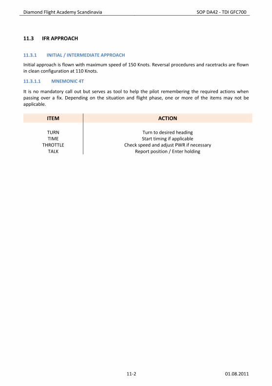
11.3.1.1 MNEMONIC 4T
It is no mandatory call out but serves as tool to help the pilot remembering the required actions when passing over a fix. Depending on the situation and flight phase, one or more of the items may not be applicable.
ITEM ACTION
TURN TIME
THROTTLE TALK
Turn to desired heading Start timing if applicable
Check speed and adjust PWR if necessary Report position / Enter holding

Diamond Flight Academy Scandinavia SOP DA42 - TDI GFC700
11-3 01.08.2011
11.3.2 FINAL APPROACH
When on intercept heading and the CDI needle starts moving call out “localizer alive”. When glide slope pointer starts moving call out “glide slope alive”. If performing a VOR approach, call out “radial alive”, when the CDI needle starts moving. Precision and non-precision approaches are flown at same configuration and speed. When half a dot below the glide slope (or approximately 0.5 Nm from FAF on a non precision approach) configure the aircraft with gear down and flaps APP. Check speed and call out “speed checked, gear down selected”. Check that you have three green lights and call out “gear down, three green”. Check speed and select flaps APP. Call out “speed checked, flaps APP selected”. Check flap light and call out “flaps APP set”. Reduce power to 35% and lower the pitch to -5°. When the final descent is initiated, set go around altitude with the altimeter bug and call out “go around altitude XXXX feet set”. Do not commence the final descent if you are not established. The criteria for being established:
Half scale CDI deflection on a ILS, LOC or VOR approach; Half scale GS deflection on an ILS approach; or ±5 ° from desired QDM/QDR on a NDB approach.
If the aircraft, during any part of the approach, is not established according to the above criteria a go around must be initiated promptly When passing over the outer marker or equivalent position an altitude check should be performed. Check that the altitude is within ±100 feet of the published altitude (remember to correct for temperature) and call out your actual altitude when crossing overhead. Call out “outer marker 1170 feet – checked”. At DA/MDA + 100 feet call out “one hundred to go”. At DA/MDA call out “minima contact – landing” or “minima no contact - going around”. When reaching DP (if applicable) call out ”decision point contact – landing” or “decision point no contact - going around”. When contact is obtained before reaching DA/MDA/DP call ”contact - landing” and omit further calls. If contact is obtained and landing assured check speed and select flaps LDG. Call out “speed checked, flaps LDG selected”. Check flap light and call out “flaps LDG set”. Check that the gear is down and that there are three green lights. Call out “gear down, three green checked”. Reduce to 80 knots over the threshold.

Diamond Flight Academy Scandinavia SOP DA42 - TDI GFC700
11-4 01.08.2011
11.3.3 CIRCLING
Descend to MDA in order to establish visual contact with the runway as early as possible. If meteorological conditions are well above minima, a higher circling altitude may be maintained (maximum 1000 ft AGL). At MDA + 100 feet call out “one hundred to go”, select gear UP and call out “gear UP selected”. At MDA call out “minima contact – landing” or “minima no contact - going around”. If contact is obtained before reaching MDA call ”contact - landing” and omit further calls. Break 45° right or left, according to procedure. Maintain maximum 100 knots during the circling manoeuvre. Start timing abeam threshold for 3 seconds per 100 feet AGL. Adjust for actual tailwind component. Initially establish a 30° of bank angle and then decrease as necessary. Final descent shall be initiated on base leg, when within 45° of centreline intercept a continuous 3° flight path. When entering final approach area and runway is visible in the front window, check speed and select flaps LDG. Call out “speed checked, flaps LDG selected”. Check flap light and call out “flaps LDG set”. Check that the gear is down and that there are three green lights. Call out “gear down, three green checked”. Reduce to 80 knots over the threshold.

Diamond Flight Academy Scandinavia SOP DA42 - TDI GFC700
11-5 01.08.2011
11.3.4 MISSED APPROACH
Missed approach must be commenced whenever:
The criteria’s for the stabilised concept are not fulfilled; The aircraft is no longer established on the approach; The required visual reference is not obtained at DA/DP or lost after passing DA/DP; When contact with the airport is lost during a visual approach, or if the visual reference to the
runway environment is lost during circling; or Any other reasons deemed necessary by the crew.
Note: Any crewmember can call for a go around. The go around should then be initiated promptly. The go around is executed in the following way. Apply full power, check/select flaps APP and call out “going around, full power, flaps APP”. When positive rate of climb is established select and call out “gear up, flaps up”. Accelerate to and maintain VYSE and follow the missed approach procedure. Maintain VYSE to missed approach altitude/minimum sector altitude (MSA). In case of a one engine out missed approach obtain VYSE climb attitude, select and call out “gear up, flaps up” when descent has stopped. Do not wait for positive rate of climb.
11.3.5 GO AROUND FROM CIRCLING.
Go around before passing abeam Missed Approach Point (normally the threshold to which the approach is made): Turn towards the inbound track and follow the missed approach procedure for the runway to which the instrument approach was executed. Go around after passing the Missed Approach Point: Turn towards the runway in a climbing turn. Continue the turn to intercept the Missed Approach procedure for the runway to which the instrument approach was executed. Climb to Missed Approach altitude.

Diamond Flight Academy Scandinavia SOP DA42 - TDI GFC700
11-6 01.08.2011
11.4 VFR APPROACH
11.4.1 APPROACH BRIEFING
Brief on: o Runway in use; o Entry point; and o Entry to landing circuit.
Example of approach briefing for joining right hand base runway 16 at Kalmar: ‘Entry via Trekanten for right hand base runway 16’.
11.4.2 LANDING CIRCUIT
Approach the airport at an appropriate speed with relevant checklists performed. Maintain a vigilant look out at all times. Abeam threshold check speed and call out “speed checked, gear down selected”. Check that you have three green lights and call out “gear down, three green”. Check speed and select flaps APP. Call out “speed checked, flaps APP selected”. Check flap light and call out “flaps APP set”. Reduce power to 35% and lower the pitch to -5°. When established on final and landing assured check speed and select flaps LDG. Call out “speed checked, flaps LDG selected”. Check flap light and call out “flaps LDG set”. Check that the gear is down and that there are three green lights. Call out “gear down, three green checked”. Reduce to 80 knots over the threshold.
11.4.3 APPROACHING AN UNCONTROLLED AIRFIELD
Check AIP for local restrictions and airport data. 5 minutes before landing perform:
Descent and approach checklist; Radio call; and Climb or descend to 1500 ft AGL.
At aerodromes with AFIS follow the instructions or information given. At uncontrolled airfields use the following procedure:
Approach the airfield at 1500 ft AGL and look out for traffic; Overfly the windsock and signal area at 1500 ft AGL check for wind, signals and traffic; On the side opposite normal downwind of the runway start a descent to 1000 ft AGL; and Join the normal traffic circuit - look out for traffic.
11.4.4 GO AROUND
Apply full power, check/select flaps APP and call out “going around, full power, flaps APP”. When positive rate of climb is established select and call out “gear up, flaps up”. Accelerate to and maintain VYSE and climb to traffic circuit altitude for a new approach. In case of a one engine out missed approach obtain VYSE climb attitude, select and call out “gear up, flaps up” when descent has stopped. Do not wait for positive rate of climb.
Diamond Flight Academy Scandinavia SOP DA42 - TDI GFC700
11-7 01.08.2011
11.5 LANDING
11.5.1 GENERAL
In the roundout for landing, residual power is gradually reduced to idle. With the higher wing loading of multiengine airplanes and with the drag from two wind milling propellers, there will be minimal float. Full stall landings are generally undesirable in twins. The airplane should be held off, allowing touchdown of the main wheels prior to a full stall. When the nose wheel is gently lowered to the runway centerline, continued elevator back pressure will greatly assist the wheel brakes in stopping the airplane.
If runway length is critical, or with a strong crosswind, or if the surface is contaminated with water, ice or snow, the full weight of the airplane should be placed on the wheels as soon as practicable. The wheel brakes will be more effective. Once on the ground, elevator back pressure should be used to place additional weight on the main wheels and to add additional drag. When necessary, wing flap retraction will also add additional weight to the wheels and improve braking efficiency. Flap retraction during the landing rollout is discouraged, however, unless there is a clear, operational need. It should not be accomplished as routine with each landing.
11.5.2 LANDING WITH REDUCED FLAP SETTING
First make sure the runway has sufficiently length for landing. As a rule of thumb add 300 meters for flaps APP and 600 meters for flaps up. The circuit for a flapless landing is the same as for a normal landing, but adjust the power to compensate for the missing drag. The attitude during the approach and landing will be significantly higher than normal. If maintaining a normal attitude during approach the descent rate will much greater than normal. Threshold speed should be increased to 83 knots for flaps APP and 87 knots for flaps up. The landing attitude is much higher than normal. Be careful not to strike the tail during the roundout.

Diamond Flight Academy Scandinavia SOP DA42 - TDI GFC700
11-8 01.08.2011
11.5.3 CROSSWIND LANDING
The heading on the final approach will have to be slightly into the direction the wind is coming from to ensure a straight track down the approach path and keep the aeroplane on the centreline. Prior to touchdown, the longitudinal axis must be aligned with the runway centerline to avoid landing gear side loads. The two primary methods, crab and wing-low, are typically used in conjunction with each other. As soon as the airplane rolls out onto final approach, the crab angle to track the extended runway centerline is established. This is coordinated flight with adjustments to heading to compensate for wind drift either left or right. Prior to touchdown, the transition to a sideslip is made with the upwind wing lowered and opposite rudder applied to prevent a turn. The airplane touches down on the landing gear of the upwind wing first, followed by that of the downwind wing, and then the nose gear. Follow-through with the flight controls involves an increasing application of aileron into the wind until full control deflection is reached. The point at which the transition from the crab to the sideslip is made is dependent upon pilot familiarity with the airplane and experience. With high skill and experience levels, the transition can be made during the roundout just before touchdown. With lesser skill and experience levels, the transition is made at increasing distances from the runway.
11.5.4 TOUCH AND GO
Touch and go is a landing immediately followed by a takeoff. After touchdown, select flaps up, re-trim and set full power while you keep your attention on the runway in order to stay on the centreline.
11.5.5 POST FLIGHT
Do not initiate after landing procedures before clear of the active runway and remember no checklist reading during taxi. Take proper care for parking position. When parking brake is set, read the after landing checklist and then the parking checklist. Leave the aeroplane to fellow airmen in a clean and tidy way.

Diamond Flight Academy Scandinavia SOP DA42 - TDI GFC700
11-9 01.08.2011
11.6 CONSIDERATIONS
11.6.1 ENGINE FAILURE OR FIRE DURING APPROACH
An engine failure in a descent or other low power setting can be deceiving. The dramatic yaw and performance loss will be absent. At very low power settings, the pilot may not even be aware of a failure. If a failure is suspected, the pilot should advance both throttles significantly to correctly identify the failed engine. The power on the operating engine can always be reduced later. Set sufficient power (60% on a normal 3° GS in no wind), select gear and flaps up and identify failed engine by foot. Verify by retarding affected throttle to idle, select appropriate engine master to OFF, alternator OFF and fuel OFF. When the by heart items are complete advice ATC - don’t hesitate to use mayday call if needed. Note: If on base or final passed FAF/FAP or equivalent position, leave the gear in the down position if already configured that way. When an engine failure or fire is recognized proceed as follows: If experiencing an engine fire going below 500 ft AGL established on final, consider to continue flight with no action. Focus on staying established and make a landing followed by On Ground Emergency Checklist. Do not vacate the runway, but stop the aircraft and position it so that smoke or fire is blown away from the cabin area and evacuate as fast as possible. It is allowed to read checklists when above 1000 ft AGL, however it is recommended just to perform the by heart items whenever established on final.

Diamond Flight Academy Scandinavia SOP DA42 - TDI GFC700
11-10 01.08.2011
INTENTIONALLY LEFT BLANK

Diamond Flight Academy Scandinavia SOP DA42 - TDI GFC700
12-1 01.08.2011
12 APPENDICIES

Diamond Flight Academy Scandinavia SOP DA42 - TDI GFC700
12-2 01.08.2011
INTENTIONALLY LEFT BLANK