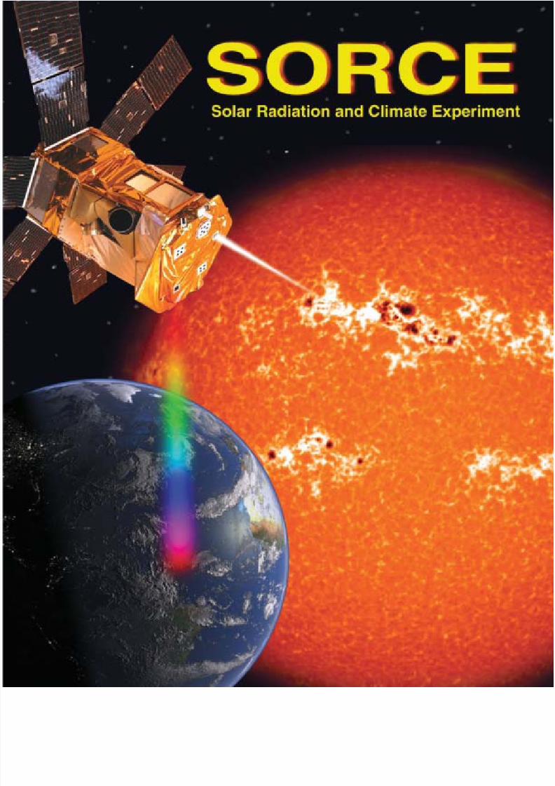
sorce brochure
TRANSCRIPT
8/7/2019 SORCE Brochure
http://slidepdf.com/reader/full/sorce-brochure 1/28

8/7/2019 SORCE Brochure
http://slidepdf.com/reader/full/sorce-brochure 2/28
Key I nd ivi dual s Associat ed wit h t he SORCE Mi ssion
SORCE Principal Inv estigator:
Gary Rottman, Laboratory for Atmospheric and Space Physics (LASP), University of Colorado, Boulder
SORCE Co-Investigators:
Tom Woods, SORCE Project Scientist, XPS Instrument Scientist, LASP, University of Colorado, Boulder
Jerry Harder, SIM Instrum ent Scientist, LASP, University of Colora do, Boulder
Greg Kopp , TIM Instru men t Scientist, LASP, University of Colorad o, Bould er
George Lawrence, Instrum ent Scientist, LASP, University of Colorad o, Bould er
William McClintock, SOLSTICE Instrum ent Scientist, LASP, University of Colorado, Bould er
Dominique Crommelynck, Royal Meteorological Institute of Belgium, Brussels
Peter Fox, National Center for Atmospheric Research, High Altitude Observatory (HAO), Boulder, Colorado
Claus Fröhlich, World Radiation Center, Davos, Switzerland
Judith Lean, Naval Research Laboratory, Washington, DCJulius London, Astrophysical, Planetary, and Atmospheric Sciences, University of Colorado, Boulder
Peter Pilewskie, NASA Ames Research Center, Moffett Field, California
Ray Roble, National Center for Atmospheric Research, HAO, Boulder, Colorado
Pau l Simon , Institute d ’Aeronom ie Spat iale, Brussels, Belgium
Oran White, National Center for Atmospheric Research, HAO, Boulder, Colorado
SORCE Program M anagemen t:
Tom Sparn, SORCE Program Manager, LASP, University of Colora do, Boulder
Mike Anfinson, LASP, University of Colorad o, Bould er
Brian Boyle, LASP, Univer sity of Colorad o, Boulder
Tim H olden , LASP, University of Colorado, Boulder
Rick Kohnert, LASP, University of Colorad o, Bould erChris Pankra tz, LASP, University of Colorad o, Bould er
Sean Ryan, LASP, University of Colorad o, Bould er
Rob Fulton, Spacecraft Program Manager, Orbital Sciences Corporat ion, Dulles, Virginia
Philip Burkh older, Orbital Sciences Corp oration, Du lles, Virginia
Ed Kozlosky, Orbital Sciences Corporation, Du lles, Virginia
Dave Oberg, Orbital Sciences Corpora tion, Dulles, Virginia
SORCE NASA Management:
William Ochs, SORCE Project Manager, NASA Godd ard Space Flight Center
Robert Cahalan , SORCE Project Scientist, NASA Godd ard Space Flight Center
Doug Rabin, SORCE Deputy Project Scientist, NASA Godd ard Space Flight Center
Debbie Dodson, Mission Business Manager, NASA Goddard Space Flight Center
Michael King, Earth Oberving System Senior Project Scientist, NASA Godd ard Space Flight Center
Don Anderson, SORCE Program Manager, NASA Headqu arters
The SORCE mission is the result of the dedication and contributions of the entire Operations, Engineering, and
Technical staff at LASP, Orbital Sciences Corporation, and NASA.
8/7/2019 SORCE Brochure
http://slidepdf.com/reader/full/sorce-brochure 3/28
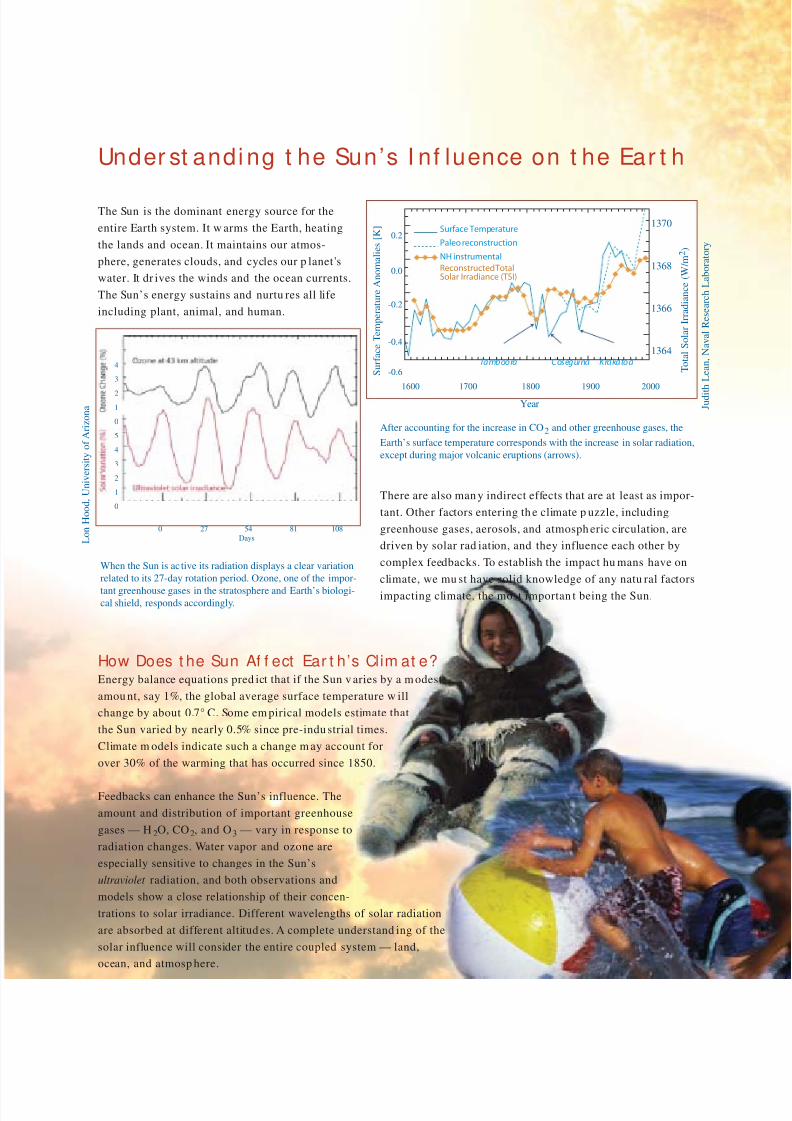
Under st andi ng t he Sun’s I nf luence on t he Ear t h
The Sun is the dominant energy source for the
entire Earth system. It w arms the Earth, heating
the lands and ocean. It maintains our atmos-
phere, generates clouds, and cycles our p lanet’s
water. It dr ives the winds and the ocean currents.
The Sun’s energy sustains and nurtu res all life
including plant, animal, and human.
There are also man y indirect effects that are at least as impor-
tant. Other factors entering th e climate p uzzle, including
greenhouse gases, aerosols, and atmosph eric circulation, are
driven by solar rad iation, and they influence each other by
complex feedbacks. To establish the impact hu mans have on
climate, we mu st have solid knowledge of any natu ral factors
impacting climate, the most importan t being the Sun.
How Does t he Sun Af f ect Ear t h’s Clim at e?Energy balance equations pred ict that if the Sun v aries by a m odest
amou nt, say 1%, the global average surface temperature w ill
change by about 0.7° C. Some em pirical models estimate that
the Sun varied by nearly 0.5% since pre-indu strial times.
Climate m odels indicate such a change m ay account for
over 30% of the warming that has occurred since 1850.
Feedbacks can enhance the Sun’s influence. The
amount and distribution of important greenhouse
gases — H 2O, CO2, and O3 — vary in response to
radiation changes. Water vapor and ozone are
especially sensitive to changes in the Sun’s
ultraviolet radiation, and both observations and
models show a close relationship of their concen-
trations to solar irradiance. Different wavelengths of solar radiation
are absorbed at different altitud es. A complete understand ing of the
solar influence will consider the entire coupled system — land,
ocean, and atmosp here.
Paleo reconstruction
NH instrumental
Reconstructed TotalSolar Irradiance (TSI)
Surface Temperature
Tamboora Coseguina Krakatoa
1600 1700 1800 1900 2000
Year
After accounting for the increase in CO2 and other greenhouse gases, the
Earth’s surface temperature corresponds with the increase in solar radiation,
except during major volcanic eruptions (arrows).
J u d i t h L e a n ,
N a v a l R e s e a r c h L a b o r a t o r y
When the Sun is active its radiation displays a clear variation
related to its 27-day rotation period. Ozone, one of the impor-
tant greenhouse gases in the stratosphere and Earth’s biologi-cal shield, responds accordingly.
0.2
L o n H o o d ,
U n i v e r s i t y o f A r i z o n a
0.0
-0.2
-0.4
-0.6
1370
1368
1366
1364
S u r f a c e T e m p e r a t u r e A n o m a l i e s [ K ]
T o t a l S o l a r I r r a d i a n c e ( W / m 2 )
4
3
2
1
0
5
4
3
2
1
0
0 27 54 81 108
Days
8/7/2019 SORCE Brochure
http://slidepdf.com/reader/full/sorce-brochure 4/28
The 23.5° angle betw een Earth’s spin axis and its orbit abou t the Sun gives rise to the seasonal cycle, causing the
length of the day and th e sunlight angle to vary during th e year. As a result, sum mer is mu ch warm er than w inter,
and polar regions are dramatically colder than the tropics. Also, Earth’s orbit about the Sun is an ellipse, not a circle,
with the Earth slightly closer to the Sun in early January than it is in July. This results in about 7% more sunlight
reaching the Earth in January than in July. Both of these seasonal effects, the tilt of the Earth’s axis and the orbital
distance to the Sun, are stable and very pred ictable, and the resulting annu al cycle in sunlight remains essentially
the same year after year d uring recent centuries, though th e Earth’s orbit and the Sun’s brightness (TSI) have both
evolved over m uch longer time scales.
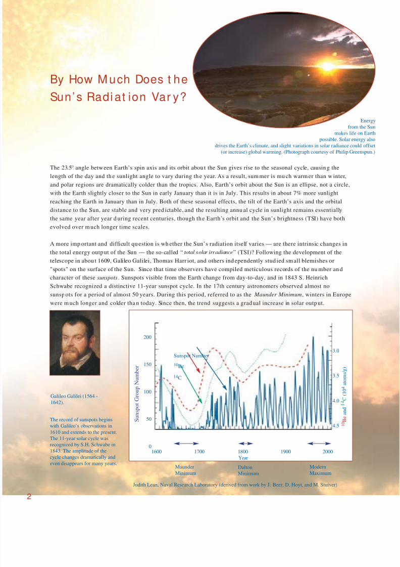
A more imp ortant and difficult qu estion is wh ether the Sun’s radiation itself varies — are there intrinsic changes in
the total energy outp ut of the Sun — the so-called “total solar irradiance” (TSI)? Following the development of the
telescope in abou t 1609, Galileo Galilei, Thomas Harr iot, and others ind ependently stud ied sm all blemishes or
"spots" on the surface of the Sun. Since that time observers have compiled meticulous records of the nu mber an d
character of these sunspots. Sunspots visible from the Earth change from day-to-day, and in 1843 S. Heinrich
Schwabe recognized a distinctive 11-year sunspot cycle. In the 17th century astronomers observed almost no
sunsp ots for a period of almost 50 years. During this period, referred to as the Maunder Minimum, winters in Europe
were m uch longer and colder tha n today. Since then, the trend suggests a grad ual increase in solar outp ut.
Energy
from the Sun
makes life on Earth
possible. Solar energy also
drives the Earth’s climate, and slight variations in solar radiance could offse
(or increase) global warming. (Photograph courtesy of Philip Greenspun.
The record of sunspots begins
with Galileo’s observations in
1610 and extends to the present.
The 11-year solar cycle was
recognized by S.H. Schwabe in
1843. The amplitude of the
cycle changes dramatically and
even disappears for many years.
1600 1700 1800 1900 2000
Year
200
150
100
50
0
Sunspot Number
Maunder
MinimumDalton
Minimum
Modern
Maximum
3.0
3.5
4.0
4.5 1 0 B e a n d 1 4 C
( 1 0 4 a t o m s / g )
S u n s p o t G r o u p N u m b e r
Galileo Galilei (1564 -1642).
Judith Lean, Naval Research Laboratory (derived from work by J. Beer, D. Hoyt, and M. Stuiver)
10Be
14C
2
By How M uch Does t he
Sun’s Radi at ion Var y?

8/7/2019 SORCE Brochure
http://slidepdf.com/reader/full/sorce-brochure 5/28
Understanding Solar IrradianceOne often confusing fact is that the Sun is brighter du ring times when it displays more d ark sunsp ots! The total
radiation from the Sun can be approximated by a background or “qu iet sun” value, diminished by dar k sunspots
and au gmented by bright faculae and bright network. When averaged over the Sun’s surface, the subtle facular
brightening du ring the Sun’s 11-year activity cycle dom inates over the more obvious sunsp ot dar kening. Empirical
mod els of the TSI based on these three indices - sunspot dar kening, and facular and network brightening - compare
favorably with the actual TSI observations. Such
empirical models provide one ap proach for
validating irradiance time series from d ata sets of
different observations, and m oreover these mod els
provide a technique to estimate solar irradiance
over previous time periods when only the
sunsp ots, not the faculae, were observed.
342
67
24
168
REFLECTED SOLARRADIATION107W m-2
24
REFLECTED BYCLOUDS, AEROSOL
AND ATMOSPHERE77
235
165 30
ABSORBED BYTHE SURFACE
EVAPO-TRANSPIRATION
78
EMITTED BY THE
ATMOSPHERE
SURFACERADIATION
INCOMING SOLARRADIATION342W m-2
OUTGOINGLONGWAVE235W m-2
ATMOSPHERICWINDOW
40
ABSORBED BY THEATMOSPHERE
LATENTHEAT
350
390 324
40
324BACK
RADIATION
GREENHOUSEGASES
REFLECTED BYTHE SURFACE
30
This radiation balance picture shows how incoming solar energy is
distributed among parts of the Earth's atmosphere and surface.
2
0
-2
-4
W m - 2
1368
1367
1366
1365
1364
1363
W m - 2
1980 1985 1990 1995 2000
Observations of TSI are approximated quite well by a con-
stant value of solar radiation minus the darkening of
sunspots and augmented by the amount of bright faculae and
network. Though sunspots darken the sun, faculae more than
compensate in their brightness, so that on average the Sun is
brighter in years having more sunspots.
Bright Faculae or Plage
Dark sunspot
Judith Lean, Naval Research Laboratory
Network
3
J e f f K i e h l a n d K e v i n T r e n b e r t h ,
N a t i o n a l C e n t e r f o r A t m o s p h e r i c R e s e a r c h
8/7/2019 SORCE Brochure
http://slidepdf.com/reader/full/sorce-brochure 6/28
SORCE Wil l M oni t or Sola r I r r ad iance Dai ly“One activity ranks above all others for determining solar influences on
global change: Monitor the total and spectral solar irradiance from an
uninterrupted series of spacecraft radiometers employing in-flight
sensitivity tracking.” — 1994 NRC Report
Hist ory of Solar I r r adiance Obser vat ionsOnly a p ortion of the Sun’s rad iation p enetrates the Earth’s atmos-
phere to its surface, and at some w avelengths the radiation is
absorbed entirely. It is therefore not possible to use ground-based
observations of the Sun to estimate th e top-of-the-atmosphere
radiation. Although there was an ambitious ground observing
program du ring most of the 20th century, it provided only
ambiguous estimates of irrad iance, and little or no information on
whether the Sun varied.
Observations of solar irrad iance from space began in the 1960s and reached some level of maturity and reliability in
the late 1970s, providing the first view of the full solar spectrum. The more energetic ultraviolet part of the spectrum
was a d iscovery that provided new insight into the comp lexities of solar physics and improved our u nderstand ing
of the temperatu re and structure of the Earth’s upp er atm osphere. By the m id-1970s observations were ind icating
that the u ltraviolet varied by large amou nts - perhap s factors of 2 near 120 nm and factors app roaching an order of
magnitud e for mu ch of the extreme ultraviolet (EUV) at wavelengths below 30 nm.
Today’s Recor d of Tot al Solar I r r adi anceTotal Solar Irradiance monitoring using electrical substitution radiometers (ESRs) from the vantage point of space
began w ith the lau nch of the N imbus 7 satellite in Novem ber 1978. This was soon followed by an Active Cavity
Radiometer Irradiance Monitor (ACRIM) instrum ent on the Solar Maximum Mission and by the Earth Radiation
Budget Experiment (ERBE). More recently, second and third ACRIM instruments have been launched, in addition to
the launch of two instrum ents on the
NASA/ ESA Solar and Heliospheric
Observatory (SOHO). The var ious
data sets are offset, but they are in
basic agreement and show conclu-
sively that variations of TSI track the
passage of sunsp ots across the solar
disk with an amp litud e of about
0.2%, and that long-term solar cycle
variations are on the order of 0.1%.The offset between the early obser-
vations are on the order of ±0.3%,
which is attributed to un certainties
in instrum ent calibrations. The
agreement between m ore recent
observations has imp roved to about
±0.05%. The SORCE will continue
these imp ortant TSI observations,
and w ill further improve their
accuracy to t he ord er of ±0.01%.
4
Record of TSI observations since 1978 from 9 independent instruments. The instruments
agree in the amount of variation during each solar cycle, but the averages over each solar
cycle disagree because of different calibration scales of the instruments. Disagreements are
getting smaller as calibration methods improve.
The evolution of active regions on the Sun is the
primary cause for solar variability. The active regions
change over all time scales - seconds to centuries.
1376
1374
1372
1370
1368
1366
1364
T o t a l S o l a r I r r a d i a n c e ( W / m 2 )
1975 1980 1985 1990 1995 2000 2005
Year
400
200
0
A v e r a g e D a i l y S un s p o t N um b e r
8/7/2019 SORCE Brochure
http://slidepdf.com/reader/full/sorce-brochure 7/28
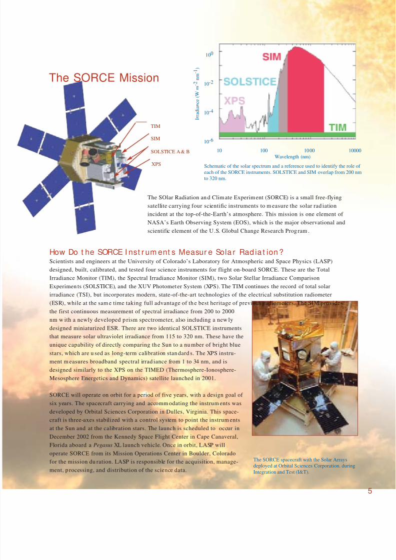
Schematic of the solar spectrum and a reference used to identify the role of
each of the SORCE instruments. SOLSTICE and SIM overlap from 200 nm
to 320 nm.
100
10-2
10-4
10-6
I r r a d i a n c e ( W
m - 2 n m - 1 )
10 100 1000 10000
Wavelength (nm)
The SOlar Radiation an d Climate Experiment (SORCE) is a small free-flying
satellite carrying four scientific instruments to m easure the solar rad iation
incident at the top-of-the-Earth’s atmosphere. This mission is one element of
NASA’s Earth Observing System (EOS), which is the major observational and
scientific element of the U .S. Global Change Research Prog ram .
How Do t he SORCE I nst r um ent s Measur e Sola r Rad ia t ion ?Scientists and engineers at the University of Colorado’s Laboratory for Atmospheric and Space Physics (LASP)
designed, built, calibrated, and tested four science instruments for flight on-board SORCE. These are the Total
Irradiance Monitor (TIM), the Spectral Irradiance Monitor (SIM), two Solar Stellar Irradiance Comparison
Experimen ts (SOLSTICE), and the XUV Photometer System (XPS). The TIM continues the record of total solar
irradiance (TSI), but incorporates modern, state-of-the-art technologies of the electrical substitution radiometer(ESR), while at the sam e time taking full advantage of th e best heritage of previous radiometers. The SIM provides
the first continuous measurement of spectral irradiance from 200 to 2000
nm w ith a newly developed p rism spectrometer, also including a new ly
designed miniaturized ESR. There are two identical SOLSTICE instruments
that measure solar ultraviolet irradiance from 115 to 320 nm. These have the
unique capability of directly comparing th e Sun to a nu mber of bright blue
stars, which are u sed as long-term calibration stan dard s. The XPS instru-
ment m easures broadband spectral irrad iance from 1 to 34 nm, and is
designed similarly to the XPS on the TIMED (Thermosphere-Ionosphere-
Mesosphere Energetics and Dynamics) satellite launched in 2001.
SORCE will operate on orbit for a period of five years, with a design goal of
six years. The spacecraft carrying and accomm odating the instrum ents was
developed by Orbital Sciences Corporation in Dulles, Virginia. This space-
craft is three-axes stabilized with a control system to point the instrum ents
at the Sun and at the calibration stars. The launch is scheduled to occur in
December 2002 from the Kennedy Space Flight Center in Cape Canaveral,
Florida aboard a Pegasus XL launch vehicle. Once in orbit, LASP will
operate SORCE from its Mission Operations Center in Boulder, Colorado
for the mission du ration. LASP is responsible for the acquisition, manage-
ment, p rocessing, and distribution of the science data.
The SORCE spacecraft with the Solar Arrays
deployed at Orbital Sciences Corporation. during
Integration and Test (I&T).
The SORCE Mission
TIM
SIM
SOLSTICE A& B
XPS
5
8/7/2019 SORCE Brochure
http://slidepdf.com/reader/full/sorce-brochure 8/28
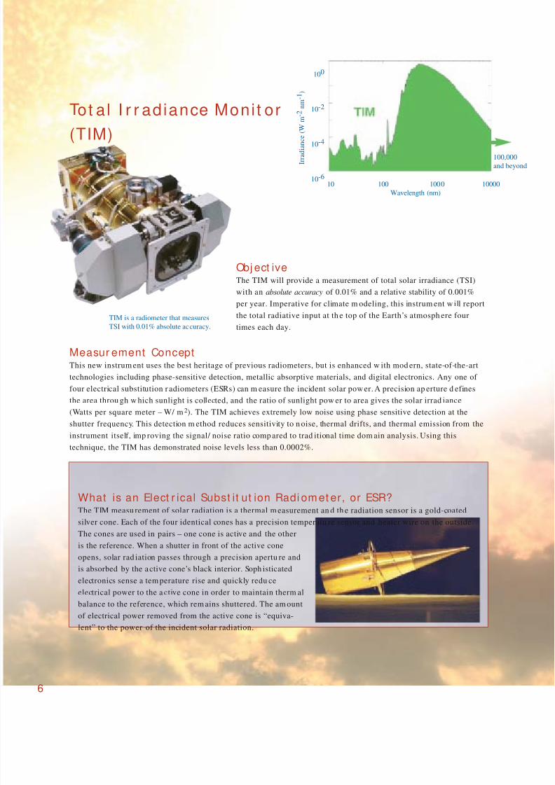
Obj ect iveThe TIM will provide a measurement of total solar irradiance (TSI)
with an absolute accuracy of 0.01% and a relative stability of 0.001%
per year. Imperative for climate m odeling, this instrum ent w ill report
the total radiative input at th e top of the Earth’s atmosph ere four
times each day.
Measur ement ConceptThis new instrum ent uses the best heritage of previous radiometers, but is enhanced w ith mod ern, state-of-the-art
technologies including phase-sensitive detection, metallic absorptive materials, and digital electronics. Any one of
four electrical substitution r adiometers (ESRs) can m easure the incident solar pow er. A precision ap erture d efines
the area throu gh w hich sunlight is collected, and the ratio of sunlight pow er to area gives the solar irrad iance
(Watts per square meter – W/ m2). The TIM achieves extremely low noise using phase sensitive detection at theshutter frequency. This detection m ethod reduces sensitivity to n oise, thermal drifts, and thermal emission from the
instrument itself, imp roving the signal/ noise ratio comp ared to trad itional time dom ain analysis. Using this
technique, the TIM has demonstrated noise levels less than 0.0002%.
6
What is an Elect r ical Subst it ut ion Radi om et er, or ESR?The TIM measu rement of solar radiation is a thermal m easurement an d th e radiation sensor is a gold-coated
silver cone. Each of the four identical cones has a precision temperatu re sensor and heater wire on the outside.
The cones are used in pairs – one cone is active and the other
is the reference. When a shutter in front of the active cone
opens, solar rad iation passes through a precision apertu re and
is absorbed by the active cone’s black interior. Soph isticated
electronics sense a tem perature rise and quickly redu ce
electrical power to the a ctive cone in order to maintain therm al
balance to the reference, which rem ains shuttered. The am ount
of electrical power removed from the active cone is “equiva-
lent” to the power of the incident solar radiation.
Tot al I r r adiance Moni t or
(TIM)
100
10-2
10-4
10-6
I r r a d i a n c e
( W
m - 2 n m - 1 )
10 100 1000 10000
Wavelength (nm)
TIM is a radiometer that measures
TSI with 0.01% absolute accuracy.
100,000
and beyo

8/7/2019 SORCE Brochure
http://slidepdf.com/reader/full/sorce-brochure 9/287
I r r ad iance: The TI M M easur es Power
Over a Kn own Ar eaSunlight entering an y one of the four ESRs is modu lated by
a shu tter (the rightmost one is shown in its open position).
A precision aperture behind each shutter accurately deter-
mines the area over w hich sunlight is collected. This rad iant
pow er is then measu red by a black absorptive ESR.
The ratio of power to area gives the total solar irradiance.
• Sunlight enters through vacuum doors that open on orbit and maintain cleanliness during ground tests
and instrument integration.
• Entering sunlight is modulated by a shutter, one for each of the four ESRs.
• Precision apertures determine th e area throu gh w hich sunlight is collected.
• Four internal baffle sections reduce off-axis light.
• The selected active ESR measures incident sunlight power, while an ad jacent reference ESR behind a
closed shutter comp ensates instrum ent thermal d rifts and noise.
What I s I nside t he TI M?
How Do t he TI M ESRs Wor k?
The TIM is an ambient temp erature solar rad iometer using four absorp tiveESRs. Each ESR has an independent shutter and a NIST-calibrated precision
aperture. Each sensor is an electrodeposited silver cone with an interior coating
of nickel phosphorus (NiP), a metallic black absorbing layer stable under exposure
to solar ultraviolet light. Several temperature sensors in the TIM allow
corrections for therm al changes. The thermal background from the instrum ent
itself is established from m easurements of dar k space du ring the night p ortion
of each orbit.
Four ESRs provide redundancy and calibration comparisons. To monitor the stability of the ESR absorptance,
the TIM will use the four ESRs to characterize instrum ent d egradation w ith varying d uty cycles. Comparisons
between nearly simultaneous m easurements of the TSI from the different ESRs indicate absorptan ce changes
attributable to solar exposure.
NiP is the robust, metallic
absorptive layer inside the
ESRs.
Custom Microw 10/21/98
x1000 20kv 16b #001310 µm
8/7/2019 SORCE Brochure
http://slidepdf.com/reader/full/sorce-brochure 10/288
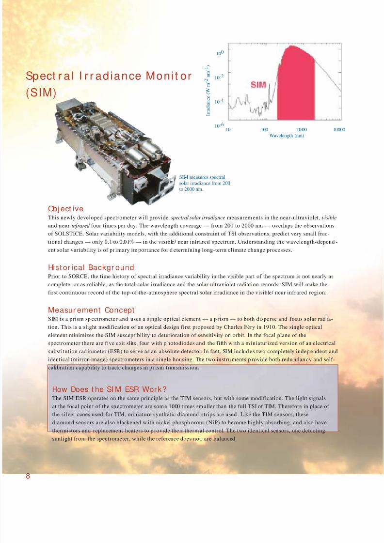
SIM measures spectral
solar irradiance from 200
to 2000 nm.
Spect r a l I r r adiance Moni t or
(SIM)
100
10-2
10-4
10-6
I r r a d i a n c e ( W
m - 2 n m - 1 )
10 100 1000 10000
Wavelength (nm)
How Does t he SI M ESR Work?The SIM ESR operates on the same principle as the TIM sensors, but with some modification. The light signals
at the focal poin t of the spectrometer are som e 1000 times smaller than the full TSI of TIM. Therefore in place of
the silver cones used for TIM, miniature synthetic diamond strips are used . Like the TIM sensors, these
diamon d sensors are also blackened w ith nickel phosph orous (NiP) to become highly absorbing, and also have
thermistors and replacement heaters to p rovide their therm al control. The two identical sensors, one detecting
sunlight from the spectrometer, while the reference does not, are balanced.
Obj ect iveThis newly developed spectrometer will provide spectral solar irradiance measurem ents in the near-ultraviolet, visible
and near infrared four times per day. The wavelength coverage — from 200 to 2000 nm — overlaps the observations
of SOLSTICE. Solar variability models, with the additional constraint of TSI observations, predict very small frac-
tional changes — only 0.1 to 0.01% — in the visible/ near infrared spectrum. Und erstanding th e wavelength-depend -
ent solar variability is of pr imary im portance for d etermining long-term climate change processes.
Hist or ical Backgr oundPrior to SORCE, the time history of spectral irradiance variability in the visible part of the spectrum is not nearly as
complete, or as reliable, as the total solar irradiance and the solar ultraviolet radiation records. SIM will make thefirst continuous record of the top-of-the-atmosphere spectral solar irradiance in the visible/ near infrared region.
Measur ement ConceptSIM is a prism sp ectrometer and uses a single optical element — a p rism — to both disperse and focus solar rad ia-
tion. This is a slight modification of an optical design first proposed by Charles Fèry in 1910. The single optical
element minimizes the SIM susceptibility to deterioration of sensitivity on orbit. In the focal plane of the
spectrometer there are five exit slits, four with p hotodiodes and the fifth w ith a m iniaturized version of an electrical
substitution rad iometer (ESR) to serve as an absolute detector. In fact, SIM includ es two completely indep endent and
identical (mirror-image) spectrometers in a single housing. The two instru ments p rovide both redu ndan cy and self-
calibration capability to track changes in p rism transmission.

8/7/2019 SORCE Brochure
http://slidepdf.com/reader/full/sorce-brochure 11/289
SIM covers 200 - 2000 nm with sufficient resolution to resolve the more prominent features in the solar spectrum.
How does t he SI M Pr ism Spect r om et er Work ?The Fèry prism has a concave front surface and a con-
vex aluminized back sur face. The prism is m ade of a
special quartz (Suprasil 300) that is expected to
remain very stable in the harsh environment of
space. The prism is on a precisely controlled rotation
table, and tur ning the p rism d isperses different color
(wavelength) to each detector. The prism can slowly
scan the entire solar spectrum, or it can be p osi-
tioned to dw ell at a single wavelength. The wave-
length of the r adiation that falls at each d etector is
accurately determ ined from the p rism’s index of
refraction and angle of rotation. The spectrometer ’s
resolution is a fun ction of wavelength an d varies
from 0.5 nm in the u ltraviolet to about 33 nm in the
near infrared.
8/7/2019 SORCE Brochure
http://slidepdf.com/reader/full/sorce-brochure 12/28
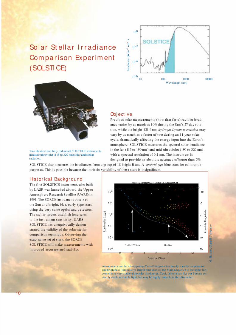
Solar St el lar I r r adiance
Com par ison Exper im ent(SOLSTI CE)
Obj ect ivePrevious solar measu rements show th at far ultraviolet irradi-
ance varies by as mu ch as 10% du ring the Sun’s 27-day rota-
tion, wh ile the bright 121.6 nm hydrogen Lyman-α emission may
vary by as m uch as a factor of two du ring an 11-year solar
cycle, dramatically affecting the energy input into the Earth’s
atmosphere. SOLSTICE measures the spectral solar irradiance
in the far (115 to 190 nm ) and mid ultraviolet (190 to 320 nm)
with a spectral resolution of 0.1 nm. The instrum ent is
designed to provide an absolute accuracy of better than 5%.
SOLSTICE also measures the irradiances from a group of 18 bright B and A spectral type blue stars for calibration
purposes. This is possible because the intrinsic variability of these stars is insignificant.
Hist or ical Backgr oundThe first SOLSTICE instru men t, also built
by LASP, was laun ched aboard the Upp er
Atmosph ere Research Satellite (UARS) in
1991. The SORCE instru men t observes
the Sun an d br ight, blue, early-type stars
using the very same op tics and d etectors.
The stellar targets establish long-term
to the instrument sensitivity. UARS
SOLSTICE has unequivocally demon-
strated the validity of the solar-stellar
comparison technique. Observing theexact same set of star s, the SORCE
SOLSTICE will make measurements with
improved accuracy an d stability.
10
Two identical and fully redundant SOLSTICE instruments
measure ultraviolet (115 to 320 nm) solar and stellar
radiation.
40,000
O B A F
Spectral Class
A b s o l u t e M a g n i t u d e
L u m i n o s i t y ( L s u n
)
G K M
106
104
102
101
10-2
10-4
-10
-5
0
5
10
15
20,000 10,000 7500
HERTZSPRUNG-RUSSELL DIAGRAM
5500 4500 3000 (K)
Stable UV Stars Our Sun
Astronomers use the Hertzsprung-Russell diagram to classify stars by temperature
and brightness (luminosity). Bright blue stars on the Main Sequence in the upper left
corner have very stable ultraviolet irradiances. Cool, fainter stars like our Sun are rel-
atively stable in visible light, but may be highly variable in the ultraviolet.
100
10-2
10-4
10-6
I r r a d i a n c e
( W
m - 2 n m - 1 )
10 100 1000 10000
Wavelength (nm)
M a i n S e q u e n c e
M .
H a y n e s ,
C o r n e l l U n
i v e r s i t y

8/7/2019 SORCE Brochure
http://slidepdf.com/reader/full/sorce-brochure 13/28
Measur ement ConceptThe in-flight calibration technique establishes
the instrum ent response as a fun ction of time
throughou t the SORCE mission, providing solar
data th at are fully corrected for instrum ental
effects to an accuracy of better th an 1%.
Moreover, the SOLSTICE technique prov ides a
method of directly comp aring solar irradiance
measurem ents mad e dur ing the SORCE mission
with previous and subsequent observations.
Future generations of observers w ill be able to
repeat this experiment and directly compare
their ultraviolet solar-stellar irradiance ratios,
thereby establishing solar variability over
arbitrarily long time p eriods.
11
One of the largest young fields of stars inside our Milky Way galaxy. The false
colors correspond to the temperatures of the stars. Blue stars are monitored by
SOLSTICE to determine the changing transmission of the SOLSTICE
spectrometer to ultraviolet radiation.
How Does t he SOLSTI CE Spect r om et er Wor k?SORCE has two identical SOLSTICE instruments on-board – for redundancy and for cross calibration. Solar or
stellar light passes through the instru ment entr ance aperture an d is d irected to a p lane diffraction grating by a
plane fold mirror. The grating diffracts a
narrow w avelength band of the original
beam to a second p lane fold m irror, and
then to th e camera or focusing m irror.
The camera m irror images that narrow
wavelength band through an exit slit and
onto one of two detectors. A mechanism
adjusts the camera mirror to select either
the outboard (far u ltraviolet) or inboard
(near ultraviolet) exit slit-detector pair.
The large aperture increases the instru-
men t sensitivity by 20,000 enabling
SOLSTICE to measure the stars with the
same optical-detector system that
observes the Sun.
Entrance SlitAssembly
Grating Drive Assembly Fold Mirror Assembly
Camera Mirror Assembly Exit Slit Assembly Detector Head
A cross sectional view of the SOLSTICE instrument showing the optical path.
Each channel is equipped with a pair of detectors for redundancy over the
5-year SORCE mission life. The camera mirror is mounted on a mechanism that
selects either the far or mid ultraviolet detector by ground command.

8/7/2019 SORCE Brochure
http://slidepdf.com/reader/full/sorce-brochure 14/28
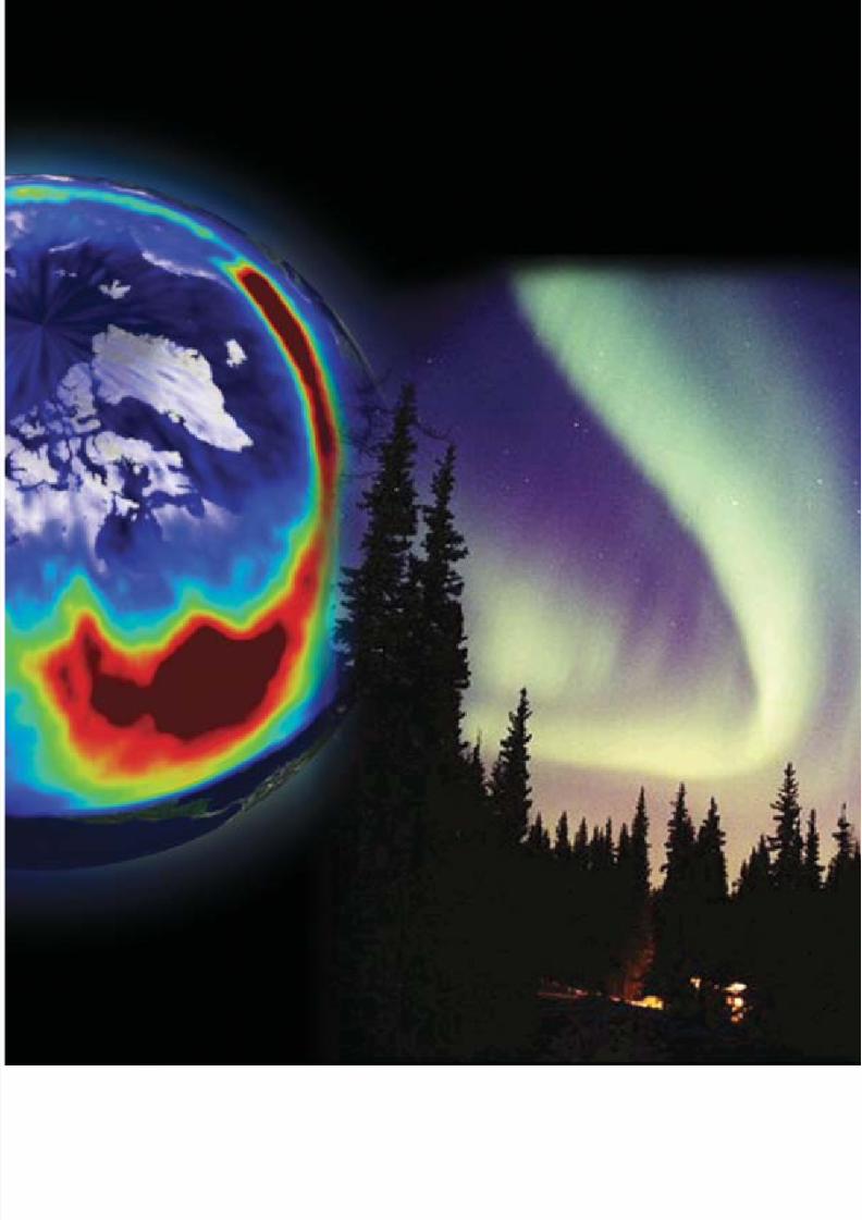
Left: Sun image from EIT (Extreme ultraviolet Imaging Telescope, 30.4 nm) superimposed on a LASCO (Large Angle
Coronagraph) image of the corona. Center: strong geomagnetic storm from space in UV from NASA's Polar mission
superimposed on a static image of Earth, with red indicating greatest UV intensity. Right: aurora image courtesy of
Jan Curtis. The solar wind that produces Earth aurora consists of charged particles which each carry high energy but
these are so few that their total energy is much smaller than the energy of the electromagnetic radiation measured by
SORCE. (Composite by Steele Hill, NASAGoddard Space Flight Center)
8/7/2019 SORCE Brochure
http://slidepdf.com/reader/full/sorce-brochure 15/28
8/7/2019 SORCE Brochure
http://slidepdf.com/reader/full/sorce-brochure 16/2814
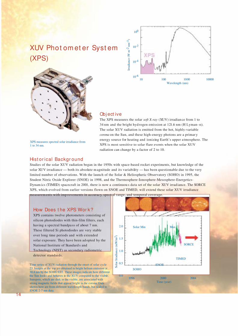
XUV Phot om et er Syst em
(XPS)
Obj ect iveThe XPS measures the solar soft X-ray (XUV) irradian ce from 1 to
34 nm and the bright hyd rogen emission at 121.6 nm (H Lyman-α).
The solar XUV radiation is emitted from the hot, highly-variable
corona on the Sun, and these high-energy photons are a primar y
energy source for heating and ionizing Earth’s upper a tmosphere. The
XPS is most sensitive to solar flare events when the solar XUV
radiation can change by a factor of 2 to 10.
Hist or ical Backgr oundStudies of the solar XUV radiation began in the 1950s with space-based rocket experiments, but knowledge of the
solar XUV irradiance — both its absolute m agnitude and its variability — has been questionable due to the very
limited number of observations. With the launch of the Solar & Heliospheric Observatory (SOHO) in 1995, the
Student Nitric Oxide Explorer (SNOE) in 1998, and the Thermosphere-Ionosphere-Mesosphere-Energetics-
Dynam ics (TIMED) spacecraft in 2001, there is now a continuou s da ta set of the solar XUV irrad iance. The SORCE
XPS, which evolved from earlier versions flown on SNOE and TIMED, will extend these solar XUV irradiance
measurem ents with imp rovements in accuracy, spectral range, and temporal coverage.
Time series of XUV radiation through the onset of solar cycle
23. Images at the top are obtained in bright helium emission at
30.4 nm by the SOHO EIT. These images indicate how different
the Sun looks and behaves in the XUV compared to the visible.
Sunspots, which are dark in the visible, are associated with
strong magnetic fields that appear bright in the corona. Data
shown here are from different wavelength bands, but scaled to
SNOE 2-7 nm data.
2.0
1.5
1.0
0.5
0.0
S o l a r I r r a d i a n c e ( m W / m 2 )
1996 2000 2004
Time (year)
Solar Min Max
SORCE
TIMED
SNOE
SOHO
XPS measures spectral solar irradiance from
1 to 34 nm.
100
10-2
10-4
10-6
I r r a d i a n c e
( W
m - 2 n m - 1 )
10 100 1000 10000
Wavelength (nm)
How Does t he XPS Wor k?XPS contains twelve photometers consisting of
silicon photodiodes with thin-film filters, each
having a spectral bandpa ss of about 7 nm.
These filtered Si photodiodes are very stable
over long time periods and with extendedsolar exposure. They have been ad opted by the
National Institute of Standard s and
Technology (NIST) as secondary radiometric
detector standards.
8/7/2019 SORCE Brochure
http://slidepdf.com/reader/full/sorce-brochure 17/28
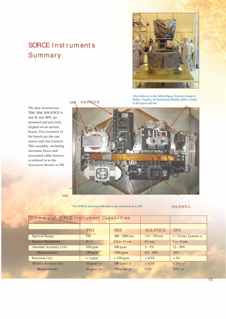
The four instrum ents,
TIM, SIM, SOLSTICE A
and B, and XPS, are
mounted and precisely
aligned on an op tical
bench. Also mounted to
the bench are the sun
sensor and star tr ackers.
This assembly, includ ing
electronic boxes and
associated cable harness,
is referred to as the
Instrument Module or IM.
SORCE I nst r um ent s
Summary
TIM SIM SOLSTICE XPS
Spectral Range TSI 200 - 2000 nm 115 - 320 nm 1 - 34 nm, Lyman-α
Spectral Resolution N/ A 0.2 to 33 nm 0.1 nm 5 to 10 nm
Absolute Accuracy (1σ) 100 ppm 300 ppm 3 - 5% 12 - 20%
(Requirement) 150 ppm 1500 ppm 0.5 - 10% 30%
Precision (1σ) < 1 ppm < 150 ppm < 0.5% < 2%
Relative Accuracy (1σ) 10 ppm/ yr 100 ppm/ yr < 0.5% < 3%/ yr
(Requirement) 10 ppm/ yr 100 ppm/ yr 0.5% 10%/ yr
Sum m ar y of SORCE I nst r um ent Capa bil it ies
The SORCE Instrument Module in the cleanroom at LASP.
After delivery to the Orbital Space Systems Group in
Dulles, Virginia, the Instrument Module (IM) is mated
to the spacecraft bus.
15
SOLSTICE B
SIM
TIM
XPS
SOLSTICE A

8/7/2019 SORCE Brochure
http://slidepdf.com/reader/full/sorce-brochure 18/28
The bus module of the
spacecraft provides all of
the on-orbit support
required for the instru-
ment su ite to obtain the
mission science data and
transmit them to the
ground for processing
and distribution. The bus
and the instrument
mod ule (IM) were developed and integrated separately at the Orbital
Sciences Corporation and LASP facilities prior to their system level
integration and environmental testing at Orbital.
The SORCE satellite bus is based on Or bital’s LEOStar-2TM
satellite
platform and was customized to meet SORCE mission specific
requirements. Engineers and scientists from LASP, Orbital, and NASA
worked together throughout the design phase to optimize the hard-
ware comp onents and to maximize performan ce and reliability.
SORCE Technica l Over vi ewThe SORCE satellite uses a 3-axis inertially stabilized , zero mom en-
tum design that is capable of precision pointing and attitude know l-
edge during science observations. The satellite bus includes:
• S-Band communications, compatible with NASA’s
ground network.
• Science data storage with capacity for more than
24 hours of spacecraft data.
• Six solar array wings for power generation.
• Reaction wheels, star trackers, sun sensors,
magnetometer s and torque rods for attitude control.
SORCE Spacecr af t
SORCE Gener al Cap ab il it ies
Satellite Mass: 284 kg
Power: 348 watts
Communications: Redundant S-Band Transceivers
Iner tia l Poin ting: Slew Rate >1°/ sec;
Knowledge <60 arcsec
Solar Arrays: Fixed GaAs
Redundancy: Nearly Complete
Orbit: 645 km, 40° inclination
Mission Life: 5-year, 6-year goal
16
8/7/2019 SORCE Brochure
http://slidepdf.com/reader/full/sorce-brochure 19/28
The SORCE power system generates,
stores, and distributes electrical power
to the spacecraft bus and the science
instruments. The spacecraft generates itsown electrical power th rough strings of
high efficiency solar cells that conver t
sunlight into electrical power. In sun-
light, the solar array delivers sufficient
power to recharge the battery in prepa-
ration for the next eclipse period.
Attitude control is accomplished by a
combination of reaction w heels, two star
trackers, a fine sun sensor, a control
processor, and torque rods and magne-
tometers.
The spacecraft provides rad io comm uni-
cations for space-to-ground and space-
to-space interfaces. The subsystem uses
dual transceivers and a p air of omni-
directional antennas and is completely
redundant .
The SORCE Comm and and Data Han dling (C&DH) subsystem controls all aspects of the bus operations.
Comma nds from the ground are received within the C&DH system by way of the rad io frequency (RF) subsystem,
and acted upon by the spacecraft compu ter, or passed directly to the IM microprocessor for instrument op erations.
Data collected d uring the sp acecraft operations are stored and processed through the RF subsystem back to the
ground two times each day.
The SORCE satellite bu s u ses both off-the-shelf comp onents m anufactured world-wide, as well as custom ized
components d eveloped in Orbital’s ma nufacturing facility. The spacecraft is integrated an d tested for the rigors of
space flight in Orbital’s cleanroom and environmental test facility in Dulles, Virginia. SORCE takes advantage of
Orbital’s proven experience in the
design, manufacture, and launch of
highly reliable quality satellites.
LASP, NASA, and Orbital scientists discuss the SORCE integration progress.
A SORCE engineer is checking the bolts connecting the IM platform to the spacecraft bus.
17
Instrument Module
Bus Module

8/7/2019 SORCE Brochure
http://slidepdf.com/reader/full/sorce-brochure 20/2818
Pegasus Air Laun ch Syst emThe SORCE satellite will be boosted into orbit by
a Pegasus® XL space launch vehicle in a m ission
originating from the Kennedy Space Center,Cape Canaveral, Florida. Pegasus is a w inged,
three stage solid rocket booster capable of
launching up to 1,000 pound s into Low Earth
Orbit (LEO).
Pegasus is mated to a specially modified L-1011
carrier aircraft and drop ped at ap proximately
39,000 feet. As a result of th is pat ented air-launch
system, Pegasus can be launched from virtually
anywh ere around the globe. To date Pegasus h as
conducted 31 missions, launching more th an 70
satellites from six different sites worldwide.
Takeoff of the Pegasus XL space launch vehicle
and its L-1011 carrier aircraft.
The SORCE Launch
Expanded view
of the Pegasus
XL vehicle.
Pegasus in flight
Pegasus XL L-1011
Aft Skirt
Assembly
Payload
Separation
System
Avionics
Section
Payload
Fairing
Stage 2 Motor
Interstage
Wing
Fin
Stage 1 Motor
*Optional 4th Stage Available for Precision Injection
*Stage 3 Motor
8/7/2019 SORCE Brochure
http://slidepdf.com/reader/full/sorce-brochure 21/28
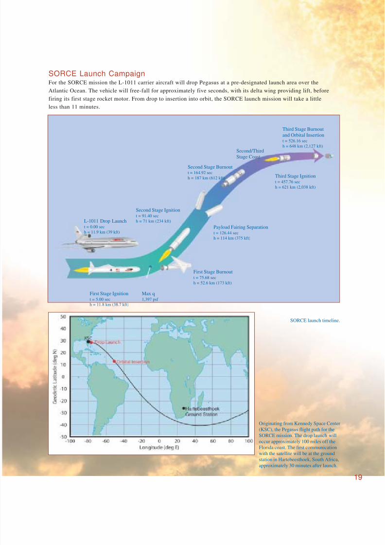
SORCE launch timeline.
Originating from Kennedy Space Center
(KSC), the Pegasus flight path for the
SORCE mission. The drop launch will
occur approximately 100 miles off the
Florida coast. The first communication
with the satellite will be at the ground
station in Hartebeesthoek, South Africa,
approximately 30 minutes after launch.
SORCE Launch CampaignFor the SORCE mission the L-1011 carrier aircraft will drop Pegasus at a pre-designated launch area over the
Atlantic Ocean. The vehicle will free-fall for approximately five seconds, with its delta wing providing lift, before
firing its first stage rocket motor. From drop to insertion into orbit, the SORCE launch mission will take a little
less than 11 minutes.
19
L-1011 Drop Launcht = 0.00 sec
h = 11.9 km (39 kft)
Second Stage Ignitiont = 91.40 sec
h = 71 km (234 kft)
Second Stage Burnoutt = 164.92 sec
h = 187 km (612 kft)
Second/Third
Stage Coast
Third Stage Burnout
and Orbital Insertiont = 526.16 sec
h = 648 km (2,127 kft)
Third Stage Ignitiont = 457.76 sec
h = 621 km (2,038 kft)
First Stage Ignitiont = 5.00 sec
h = 11.8 km (38.7 kft)
First Stage Burnoutt = 75.68 sec
h = 52.6 km (173 kft)
Payload Fairing Separationt = 126.44 sec
h = 114 km (375 kft)
Max q1,397 psf
8/7/2019 SORCE Brochure
http://slidepdf.com/reader/full/sorce-brochure 22/28
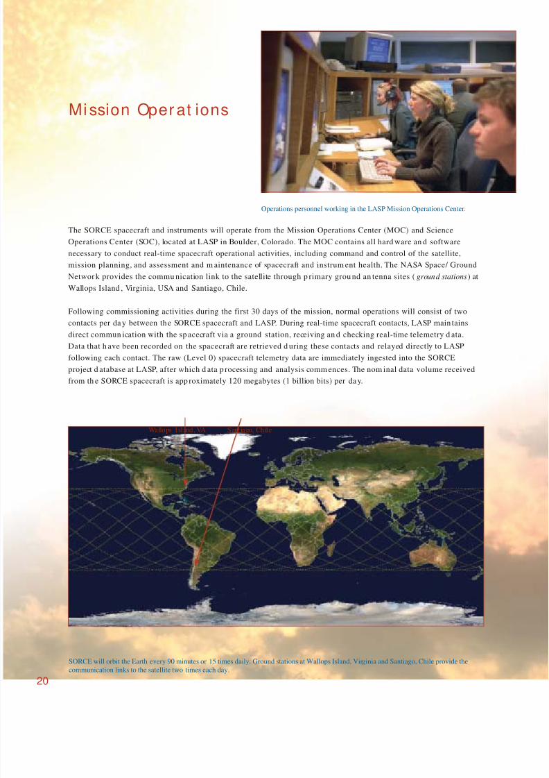
The SORCE spacecraft and instruments will operate from the Mission Operations Center (MOC) and Science
Operations Center (SOC), located at LASP in Boulder, Colorado. The MOC contains all hard ware an d software
necessary to conduct real-time spacecraft operational activities, including command and control of the satellite,
mission planning, and assessment and m aintenance of spacecraft and instrum ent health. The NASA Space/ Ground
Networ k provides the commu nication link to the satellite through p rimary grou nd an tenna sites (ground stations) at
Wallops Island , Virginia, USA and Santiago, Chile.
Following commissioning activities during the first 30 days of the mission, normal operations will consist of two
contacts per da y between the SORCE spacecraft and LASP. During real-time spacecraft contacts, LASP main tains
direct commun ication with the sp acecraft via a ground station, receiving an d checking real-time telemetry d ata.
Data that h ave been recorded on the spacecraft are retrieved d uring these contacts and relayed directly to LASP
following each contact. The raw (Level 0) spacecraft telemetry data are immediately ingested into the SORCE
project d atabase at LASP, after which d ata p rocessing and analysis comm ences. The nom inal data volume received
from th e SORCE spacecraft is app roximately 120 megabytes (1 billion bits) per day.
Operations personnel working in the LASP Mission Operations Center.
Mission Oper at ions
SORCE will orbit the Earth every 90 minutes or 15 times daily. Ground stations at Wallops Island, Virginia and Santiago, Chile provide the
communication links to the satellite two times each day.
Wallops Island, VA Santiago, Chile
20
8/7/2019 SORCE Brochure
http://slidepdf.com/reader/full/sorce-brochure 23/28
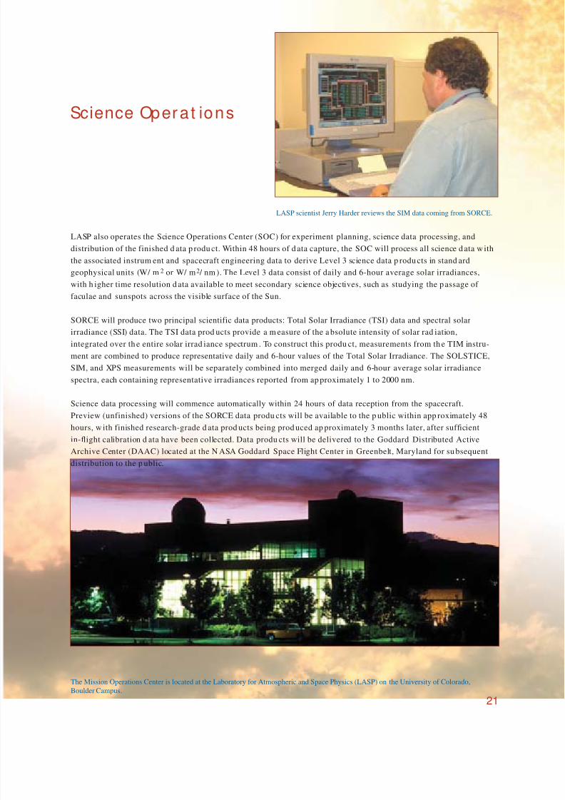
LASP also operates the Science Operations Center (SOC) for experiment planning, science data processing, and
distribution of the finished d ata p rodu ct. Within 48 hours of d ata capture, the SOC will process all science d ata w ith
the associated instrum ent and spacecraft engineering data to derive Level 3 science data p rodu cts in stand ard
geophysical units (W/ m2 or W/ m2 / nm ). The Level 3 data consist of daily and 6-hour average solar irradiances,
with h igher time resolution d ata available to meet secondary science objectives, such as studying the p assage of
faculae and sunspots across the visible surface of the Sun.
SORCE will produce two principal scientific data products: Total Solar Irradiance (TSI) data and spectral solar
irradiance (SSI) data. The TSI data prod ucts provide a m easure of the a bsolute intensity of solar rad iation,
integrated over th e entire solar irrad iance spectrum . To construct this produ ct, measurements from th e TIM instru-
ment are combined to produce representative daily and 6-hour values of the Total Solar Irradiance. The SOLSTICE,
SIM, and XPS measurements will be separately combined into merged daily and 6-hour average solar irradiance
spectra, each containing representative irradiances reported from ap proximately 1 to 2000 nm.
Science data processing will commence automatically within 24 hours of data reception from the spacecraft.
Preview (unfinished) versions of the SORCE data produ cts will be available to the p ublic within app roximately 48
hours, w ith finished research-grade d ata prod ucts being prod uced ap proximately 3 months later, after sufficient
in-flight calibration d ata have been collected. Data produ cts will be delivered to the Goddard Distributed Active
Archive Center (DAAC) located at the N ASA Goddard Space Flight Center in Greenbelt, Maryland for su bsequent
distribution to the p ublic.
Science Operat ions
LASP scientist Jerry Harder reviews the SIM data coming from SORCE.
The Mission Operations Center is located at the Laboratory for Atmospheric and Space Physics (LASP) on the University of Colorado,
Boulder Campus.
21
8/7/2019 SORCE Brochure
http://slidepdf.com/reader/full/sorce-brochure 24/28
Educat ion and Out r each
The ultimate goal of SORCE and of NASA’s Earth Observing System (EOS) Program is to increase scientific understanding
of our planet. According to the Earth Science Strategic Plan, one of the four goals of EOS is to “foster the development of an
informed and environmentally aware public.” Contributions to the advancement of public knowledge about the Earth are
key to the program ’s success.
SORCE has formal ed ucational initiatives designed for kind ergarten throu gh grad uate levels that includ e program s to
enhance teacher knowledge and research skills; provide sup port in the form of instructional curriculum, provide earth
science research experiences for students; and promote educational activities involving collaborative efforts with partners in
the pu blic and p rivate sectors.
The SORCE informal education efforts are directed toward the scientific community and the general public. Mission litera-
ture addresses the basic science questions that SORCE will address and specifically what SORCE will accomplish concerning
the Sun’s influence on climate. This literatu re includes brochu res, NASA Fact Sheets, fact books, hand books, newsletters , and
worldw ide w ebsites – all comp rising a wealth of information and images, using interactivity and data visualization
techniques to encourage an interesting han ds-on app roach.
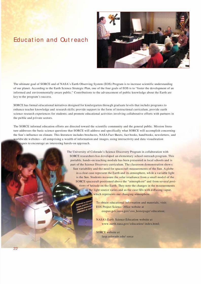
The University of Colorado’s Science Discovery Program in collaboration with
SORCE researchers h as d eveloped an elementary school outreach p rogram. This
portable, hands-on teaching mod ule has been p resented in local schools and is
part of the Science Discovery curriculum. The classroom d emonstration show s
Sun variability and th e need for spacecraft measurements of the Sun. A globe
in a clear case represent the Earth and its atmosphere, wh ile a var iable light
is the Sun. Students m easure the solar irradiance from a small mod el of the
SORCE spacecraft positioned above the “atmosph ere” and from several posi-
tions of latitude on th e Earth. They note the changes in the m easurements
as the light source varies and as the case fills with d iffusing vapor,
which represents our changing atmosphere.
To obtain educational information and materials, visit:
EOS Project Science Office website at
eospso.gsfc.nasa.gov/ eos_homep age/ education;
NASA’s Earth Science Education website a t
www.earth.nasa.gov/ education/ index.html;
SORCE website a t
lasp.colorado.edu/ sorce
22
8/7/2019 SORCE Brochure
http://slidepdf.com/reader/full/sorce-brochure 25/28
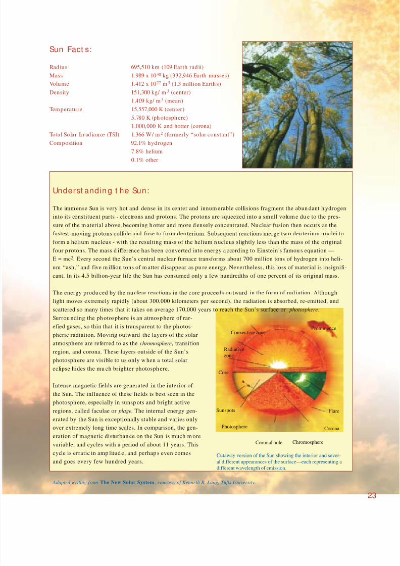
Sun Fact s:
Radius 695,510 km (109 Earth rad ii)
Mass 1.989 x 1030 kg (332,946 Earth masses)
Volume 1.412 x 1027 m3 (1.3 million Earth s)
Density 151,300 kg/ m3 (center)
1,409 kg/ m3 (mean)
Temperature 15,557,000 K (center)
5,780 K (ph otosph ere)
1,000,000 K and hotter (corona)
Total Solar Irradiance (TSI) 1,366 W/ m2 (formerly “solar constant”)
Composition 92.1% hydrogen
7.8% helium
0.1% other
Underst andin g t he Sun:
The imm ense Sun is very hot and dense in its center and innum erable collisions fragment the abun dant h ydrogen
into its constituent parts - electrons and protons. The protons are squeezed into a sm all volum e du e to the pres-
sure of the m aterial above, becoming h otter and more d ensely concentrated. Nu clear fusion then occurs as the
fastest-moving protons collide and fuse to form deu terium. Subsequent reactions merge tw o deu terium n uclei to
form a helium nucleus - with the resulting mass of the helium n ucleus slightly less than the mass of the original
four p rotons. The mass d ifference has been converted into energy a ccording to Einstein’s famou s equation —
E = mc2. Every second the Sun’s central nuclear furnace transforms about 700 million tons of hydrogen into heli-
um “ash,” and five m illion tons of m atter d isappear as pu re energy. Nevertheless, this loss of material is insignifi-
cant. In its 4.5 billion-year life the Sun has consumed only a few hundredths of one percent of its original mass.
The energy produ ced by the nu clear reactions in the core proceeds ou tward in the form of rad iation. Although
light moves extremely rapidly (about 300,000 kilometers per second), the radiation is absorbed, re-emitted, and
scattered so many times that it takes on average 170,000 years to reach the Sun’s surface or photosphere.
Surrou nding the ph otosphere is an atmosp here of rar-
efied gases, so thin that it is transparent to the ph otos-
pheric radiation. Moving outward the layers of the solar
atmosph ere are referred to as the chromosphere, transition
region, and corona. These layers outside of the Sun’s
photosph ere are visible to us only w hen a total solar
eclipse hides the mu ch brighter photosph ere.
Intense magnetic fields are generated in the interior of
the Sun. The influence of these fields is best seen in thephotosph ere, especially in sunsp ots and bright active
regions, called faculae or plage. The internal energy gen-
erated by the Sun is exceptionally stable and varies only
over extremely long time scales. In comparison, the gen-
eration of magnetic disturban ce on the Sun is much m ore
variable, and cycles with a period of about 11 years. This
cycle is erratic in amp litud e, and perhap s even comes
and goes every few hundred years.Cutaway version of the Sun showing the interior and sever-
al different appearances of the surface—each representing a
different wavelength of emission.
ProminenceConvective zone
Radiative
zone
Core
Sunspots
Photosphere
Coronal hole Chromosphere
Corona
Flare
23
Adapted writing from The New Solar System , courtesy of Kenneth R. Lang, Tufts University.

8/7/2019 SORCE Brochure
http://slidepdf.com/reader/full/sorce-brochure 26/28
SORCE Glossar y *Absolute accuracy The extent to which a value or measurement ap proaches the true value or measurement.
Aperture The portion of the plane surface perpen dicular to the direction of radiation and through w hich the radiation passes.
Attitude control Spacecraft subsystem capable of p ointing th e spacecraft toward a selected target.
Bus module That portion of the spacecraft not including the science instrumen ts but sup porting their operation. The bus
mod ule includes the pow er system, radio system, computer and data han dling, and attitude control system.
Chromosphere Hot layer of solar atmosph ere immediately above the photosphere.
Corona Outermost an d h ottest layer of the Sun’s atmosphere.
Dual transceivers Redunda nt radio system capable of receiving command s and send ing data.Electrical Substitution Radiation sensor that maintains a constant temperatu re by sup plying add itional electrical heater p ower if light is
Radiometer (ESR) removed from the sensor, and conversely removes such power w hen m ore light is added to the sensor.
Faculae Irregular bright patches in the solar photosphere, usually accompanying sunsp ots.
Facular brightenin g Brighter faculae seen against the quiet Sun — especially obvious when faculae are near the limb (edge) of the Sun.
Fèry prism A wedge of glass that disperses light into its component colors, but w ith the add itional feature that one face is
slightly concave and the other convex so that it focuses the light as well.
Ground station A radio receiving and transmitting station capable of commun icating with a satellite as it passes overhead.
Hertzsprung-Russell diagram Plot of stars’ absolute magnitud e plotted aga inst their surface temperature or color, used to study stellar evolution.
Hydrogen Lyman-α emission Spectral line w ith energy corresponding to the transition of the hydrogen a tom from its ground energy state to its
lowest excited state.
Index o f refraction Ratio of the speed of light in a vacuu m to the sp eed of light in another m edium — an indication of how m uch a
ray of light is bent as it passes from one m edium into vacuum.
Infrared The portion of the electromagnetic spectrum (light) between visible light and microwaves, invisible to the human eye
Instrument mo dule (IM) Portion of the SORCE spacecraft that includes the four scientific instruments and their support electronics and
thermal control systems. The IM serves as an optical bench aligning all instruments to a common axis.
Low Earth Orbit (LEO) An orbital altitude typically around 350 - 1400 km above the Earth's surface.
Magnetometer A device for measuring the m agnitude an d d irection of the Earth’s magnetic field.
Maunder minimum Historical period roughly from 1645 to 1715 A.D. when sunspots were exceedingly rare.
Nickel Phosphorous (NiP) Metallic black absorbing layer, stable under ultraviolet exposure.
Pegasus Orbital Sciences Corp oration rocket v ehicle that is carried a loft by an airp lane (L-1011) and is then released. After a
short fall the m otor ignites and propels the p ayload to orbit.
Photosphere The layer of solar atmosphere that radiates directly to space. In visible light this is the visible “surface” of the Sun.
Plage Irregular areas of intense brightness seen in the Sun’s chromosphere — these regions generally correspond to the
faculae and sunspots that lie directly below in the photosphere.
Precision The quality of being exactly defined. Indicated by the m inimum num ber of significant digits required for an adequat
representation of a measu rement.
Reaction wh eel A massive wheel on a motor shaft that can be spun one d irection or the other to imp art angular momen tum to thespacecraft, turning the spacecraft about the wheel’s axis of rotation.
Redundant A second (or third) system that can substitute for the primary system if the primary fails.
Relative accuracy An estimate of how well two measu rements compare to each other. Systematic errors in the tw o measurem ents will
cancel, and the relative accuracy will therefore be better than the absolute accuracy.
S-band Range of rad io frequencies from 1.55 GHz to 3.9 GHz .
Soft X-ray (XUV) Photon rad iation with w avelength of 1 to 200 nm.
Solar array Area covered by photovoltaic cells that collects solar energy and converts it to spacecraft electrical power.
Solar cycle The magnetic field strength app arent at the Sun’s surface and in its atmosphere rises and falls with an approximate
11-year cycle. Most solar phenomena adhere to this 11-year solar cycle and vary accordingly.
Spectral S olar Irradiance (SSI) Solar energy per u nit time over a u nit area perpen dicular to the Sun’s rays at the top of Earth’s atmosph ere at a
particular wavelength.
Spectral type (OBAFGKM) Star classification according to its su rface temp eratu re (color). The Sun is spectral typ e G.
Star tracker An optical device that when pointed to a star or arbitrary star field determines the direction of its line-of-sight.
Sun sensor An optical device that when pointed at the Sun determines the direction of its line-of-sight toward the Sun’s center.
Sunspots Dark areas on the Sun's ph otosphere, cooler than th eir surround ings, associated with intense magnetic fields, and
varying in nu mber w ith a period of approximately 11 years.
Suprasil 300 Synthetic quartz glass free from bubbles and inclusions, characterized by a very high op tical transmission in the UV
and the visible spectral ranges. Supra sil 300 has the widest transm ission range of all known grades of quar tz.
Torque rod Magnetic rod fixed to the sp acecraft that wh en turn ed on couples to the Earth’s magn etic field and imparts a torque t
turn the spacecraft. These can be used to control the attitude of a spacecraft.
Total Solar Irradiance (TSI) Solar energy per u nit time over a u nit area perpen dicular to the Sun’s rays at the top of Earth’s atmosph ere.
Ultraviolet Radiation of wavelength shorter than visible, down to about 0.1 nanometers. This radiation is invisible to the
hum an eye an d is generally harmful to biological systems.
Visible Radiation detectable by the human eye, from 400 to 700 nanometers.
24
* First usage of these terms in the text is italicized.
8/7/2019 SORCE Brochure
http://slidepdf.com/reader/full/sorce-brochure 27/28
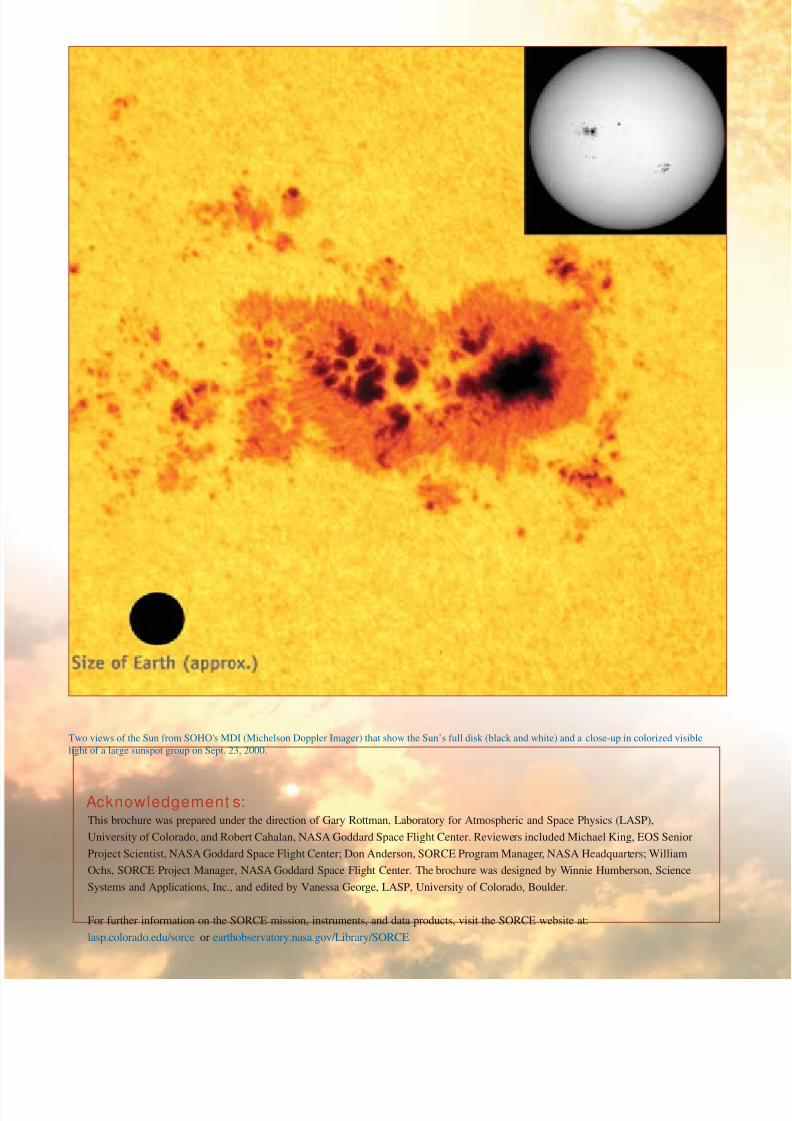
Two views of the Sun from SOHO's MDI (Michelson Doppler Imager) that show the Sun’s full disk (black and white) and a close-up in colorized visible
light of a large sunspot group on Sept. 23, 2000.
Acknowledgement s:This brochure was prepared under the direction of Gary Rottman, Laboratory for Atmospheric and Space Physics (LASP),
University of Colorado, and Robert Cahalan, NASA Goddard Space Flight Center. Reviewers included Michael King, EOS Senior
Project Scientist, NASA Goddard Space Flight Center; Don Anderson, SORCE Program Manager, NASA Headquarters; William
Ochs, SORCE Project Manager, NASA Goddard Space Flight Center. The brochure was designed by Winnie Humberson, Science
Systems and Applications, Inc., and edited by Vanessa George, LASP, University of Colorado, Boulder.
For further information on the SORCE mission, instruments, and data products, visit the SORCE website at:
lasp.colorado.edu/sorce or earthobservatory.nasa.gov/Library/SORCE
8/7/2019 SORCE Brochure
http://slidepdf.com/reader/full/sorce-brochure 28/28
A s there is only one object in the sky on whom we
utterly depend, there can be no astronomical question
of more practical significance to mankind than that
of the S un’s variability. To determine whether the
solar constant is varying . . . requires long-term
monitoring of both the bulk solar radiation and its
terrestrially important spectral components. This
assignment is not an easy one, for it demands a capa-
bility of sensing changes of no more than 0.1% in a
decade, carried out over many decades. I n the real
world of science the greater challenge may be that of
insuring the continuance of such a program.
— J ohn A . Eddy, “C limate and the Changing S un,”
in C limate C hange 1, 1977, D . R eidel P ublishing Company,
D ordrecht-H olland, pp.173-190.
Goddard Space Flight CenterGreenbelt, Maryland 20771