space shutl'le main engine structural … shutl'le main engine structural analysis and...
TRANSCRIPT

LMSC-HEC TR F268584-I118
FINAL REPORT
SPACE SHUTl'LE MAIN ENGINE STRUCTURAL ANALYSIS AND DATA REDUCTION/EVALUATION
VOLUME 38: HIGH PRESSURE FUEL TURBO-PUMP PREBURNER PUMP BEARING ASSEMBLY ANALYSIS
April 1989
Contract NAS8-37282
Prepared for 0 u 5
O a N U 06
NATIONAL AERONAUTICS AND SPACE ADMINISTRATION GEORGE C. MARSHALL SPACE FLIGHT CENTER, AL 35812
0
ct
d c ] b n
by
Gloria B. Power Rebeca S. Violett
https://ntrs.nasa.gov/search.jsp?R=19890018324 2018-06-17T13:28:28+00:00Z

1 I I I 1 I I I I I I I I I I 1 I I I
LHSC-HEC TR F268584-IIIB
FINAL REPORT
SPACE SHUTTLE HAIN ENGINE STRUCTURAL MALYSIS AM) DATA BEDUCTION/EVALUATIOI
VOLUME 3B: HIGH PRESSURE FUEL TURBO-PUMP PREBUEWER PUWP BEARING ASSEMBLY ANALYSIS
April 1989
Contract WAS8-37282
Prepared €or
NATIONAL AERONAUTICS MID SPACE ADklIIJISTBATIOIJ GEORGE C. MRSHALL SPACE FLIGHT CENTER, AL 35812
Gloria B . Power Rebeca S. Violet t
LOCKHEED-HUNTSVILLE ENGINEERING CENTER 4800 Bradford Boulevard Huntsville, AL 35807

LMSC-HEC TR F268584-TIIB
FOREWORD
This final report srimmarizes the analysis performed on
the HPOTP Preburner Pump Bearing assembly located on the Space Shuttle Main Engine. An ANSYS finite element model for the inlet assembly was built and executed by Gloria B. Power and Rebeca S . Violett in the Structures & Mechanics Section of the Lockheed-Huntsville Engineering Center under Contract NAS8-37282.
Rebeca S. Violett. Thermal and static analyses were performed by
ii
LOCKHEED--HUNTSVILLE ENGINEERING CENTER
~ ~~
LMSC-HEC TR F268584-IIIB
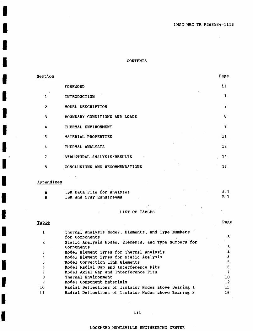
CONTENTS
B a
FOREWORD
1 INTRODUCTION
2 MODEL DESCRIPTION
3 BOUNDARY CONDITIONS AND LOADS
4 THERNAL ENVIRONMENT
5 MATERIAL PROPERTIES
6 THERMAL ANALYSIS
7 STRUCTURAL ANALYSISIRESULTS
8 CONCLUSIONS AND RECOMMENDATIONS
ATpend ixes
A IBM Data File for Analyses B IBM and Cray Runstreams
LIST OF TABLES
Tab le
1
2
3 4 5 6 7 8 9 10 1 1
Thermal Analysis Nodes, Elements, and Type Numbers for Components Static Analysis Nodes, Elements, and Type Numbers for Components Model Element Types f o r Thermal Analysis Model Element Types f o r Static Analysis Model Convection Link Elements Model Radial Gap and Interference Fits Model Axial Gap and Interference Fits Thermal Environment Model Component Materials Radial Deflections of Isolator Nodes above Bearing 1 Radial Deflections of Isolator Nodes above Bearing 2
iii
LOCKHEED-HUNTSVILLE ENGINEERING CENTER
Page
ii
1
2
8
9
11
13
14
17
A- 1 B-1
Page
3
3 4 4 5 6 7
10 12 15 16
Figure
1 2 3 4 5 6 7 8 9 10
11
12
13
14 15 16 17
LMSC-HEC TR F268584-IIIB
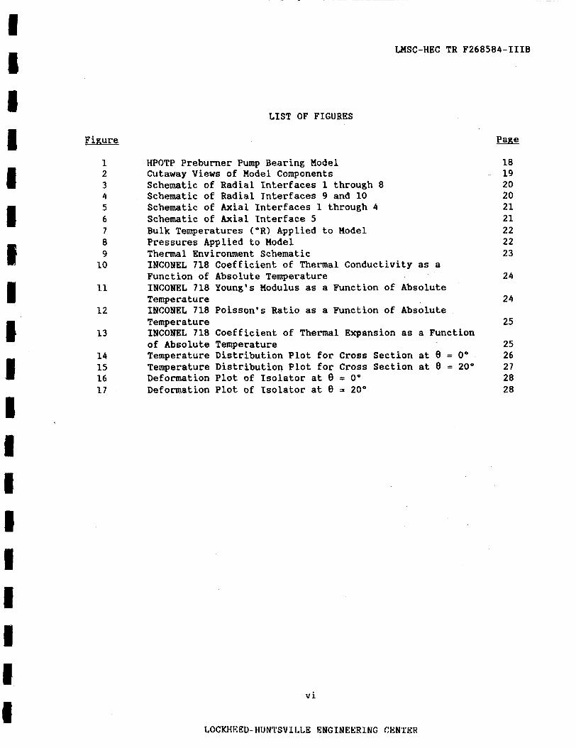
LIST OF FIGURES
HPOTP Preburner Pump Bearing Model Cutaway Views of Model Components Schematic of Radial Interfaces 1 through 8 Schematic of Radial Tnterfaces 9 and 10 Schematic of Axial Interfaces 1 through 4 Schematic of Axial Interface 5 Bulk Temperatures (OR) Applied to Model Pressures Applied to Model Thermal Environment Schematic INCONEL 718 Coefficient of Thermal Conductivity as a Function of Absolute Temperature INCONEL 718 Young's Modulus as a Function of Absolute Tempera tu re INCONEL 718 Poisson's Ratio as a Function of Absolute Temperature INCONEL 718 Coefficient of Thermal Expansion as a Function of Absolute Temperature Temperature Distribution Plot for Cross Section at 8 = 0" Temperature Distribution Plot for Cross Section at 8 = 20" Deformation Plot of Isolator at 8 = 0" Deformation Plot of Isolator at 8 = 20"
v i
LOCKHlCED-HUN'l'SVII,LE ENGINEERING CENTER
PaRe
18 19 20 20 21 21 22 22 23
24
24
25
25 26 27 28 28
LHSC-HEC TR F268584-IIIB
1. IlYTRODUCTIOlJ
The high-pressure oxidizer turbo--pump (HPOTP) consists of two
single-stage centrifugal pumps, the main pump and the preburner pump, that are directly driven by a two-stage hot-gas turbine. The main pump supplies the preburner pump with liquid oxygen. The pump-end bearings are cooled by liquid oxygen flowing from the preburner pump through the hub seal to the bearings and then to the main pump inducer/impeller inlet.
Thermal and static analyses were performed on the HPOTP preburner pump bearing assembly to calculate the radial displacements of the assembly components. The static analysis load case consisted of thermal loads (obtained from the thermal analysis), interference fits, pressure loads, and bolt preloads.
An ANSYS three-dimensional finite element model was generated to perform
the t.herma1 and stress analyses. The model was generated on Lockheed's VAX '1.1/785 computer and executed on the Marshall Space Flight Center's Engineering Analysis and Data System (RADS).
The remaining sections of this report consist of descriptions of the
model, boundary conditions and loads, material properties, thermal environment, thermal analysis, structural analysis, and recommendations.
1
LOCKHEED-HUNTSVILLE ENGINEERING CEWTER
LMSC-HEC TR F268584-IIIB
2 , MODEL DESCRIPTION
A finite element, cyclic symmetric model of a 40" sector of the HPOTP preburner pump bearing assembly was generated using ANSYS.
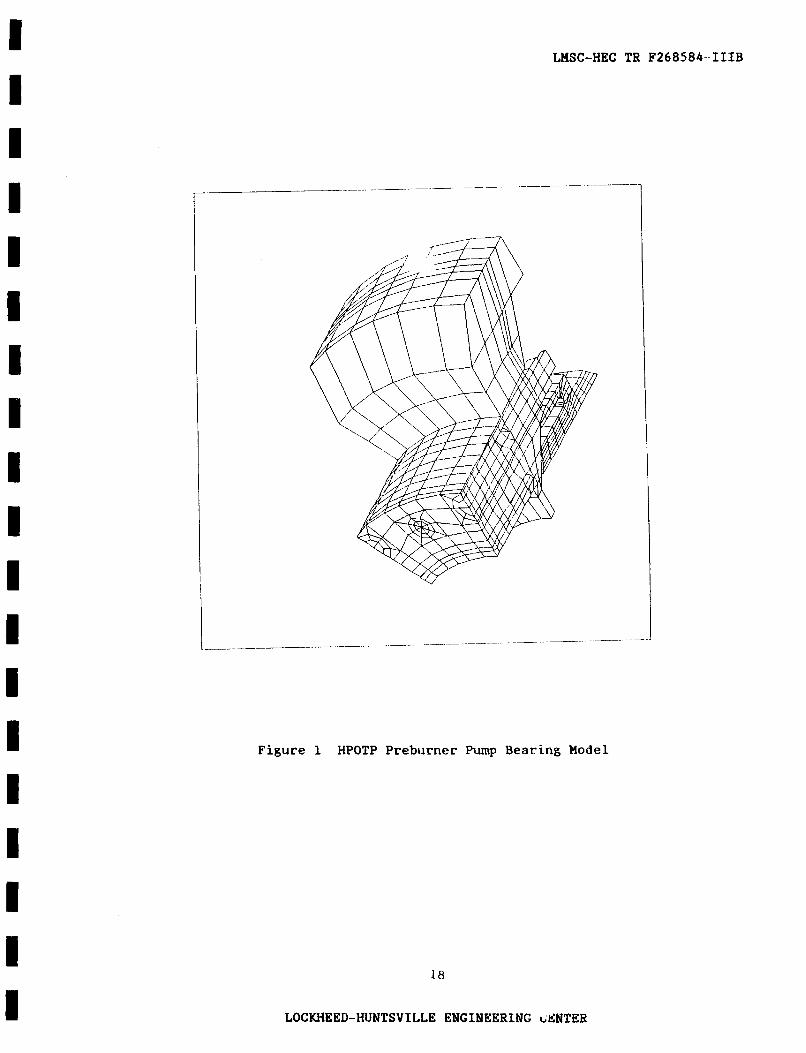
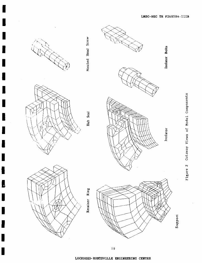
defined from 8=Oo to 8=40° in a cylindrical coordinate system with its origin located at the center of the HPOTP volute. Figure 1 is a hidden line
plot of the ANSYS finite element model. In this and all the remaining plots in this section, the view is from the pump end to the turbine end of the HPOTP. The preburner pump bearing assembly model consists of six components: the isolator, the isolator bolts, the hub seal, the hub seal retainer ring, the notched head screw, and the housing support. Figure 2 shows cutaway views of a l l these components.
The 40° section is
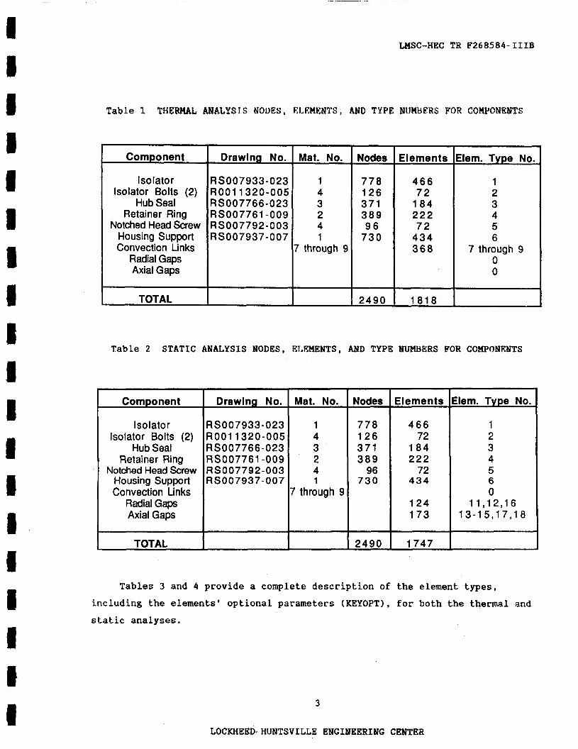
Lists of the model components, identification of the element material and type numbers, and a count of the number of nodes and elements of each listed component appear in the tables that follow. Table 1 applies to the heat trans- fer thermal analysis, and Table 2 applies to the structural static analysis. The radial and axial gap elements are null for the thermal analysis, while the convection l i n k elements are null for the static analysis. The element type number information is useful €or selecting all the nodes and elements in a component. For example, to select all the isolator nodes and elements, the following ANSYS commands would be issued:
ERSEL,TYPE,l NELEH
These command can be issued in either the PREP7 or POST1 routines.
2
LOCKHEED-HUNTSVILLE ENGINEERING CENTER
~ ~ ~ _ _ _ - ~~
LMSC-HEC TR F268584-IIIB
Table 1 T H E W L ANALYSJS NODES, EI,EWENTS, AND TYPE NIJHBEHS FOR COMPONELTTS
Nodes
Componen t
Is0 lato r Isolator Bolts (2)
Hub Seal Ret ai ner Ring
Notched Head Screw Housing Support Convection Links
Radial Gaps Axial Gaps
Elements Elem. Type No.
I ~~
TOTAL
Drawing No.
RSOO7933-023 ROO1 1320-005 RSOO7766-023 RS007761-009 RS007792-003 RS007937-007
1 4 3 2 4 1
7 through 9
778 126 371 389 96 730
12490
Elements
466 72 184 222 72 434 368
1
1818
Elem. Type No.
1 2 3 4 5 6
7 through 9 0 0
Table 2 STATIC ANALYSIS NODES, ELEMENTS, AND TYPE MIME)ERS FOR COMPONEUTS
Component
Isolator Isolator Bolts (2)
Hub Seal Retainer Ring
Notched Head Screw Housing Support Convection Links
Radial Gaps Axial Gaps
Drawing No.
RS007933-023 ROO1 1320-005 RS007766-023 RS007761-009 RS007792-003 RS007937-007
Mat. No.
1 4 3 2 4 1
7 through 9
778 126 371 389 96
730
466 72
184 222 72
434
124 173
1 2 3 4 5 6 0
11,12,16 13-1 5,17,18
2490 1747 I
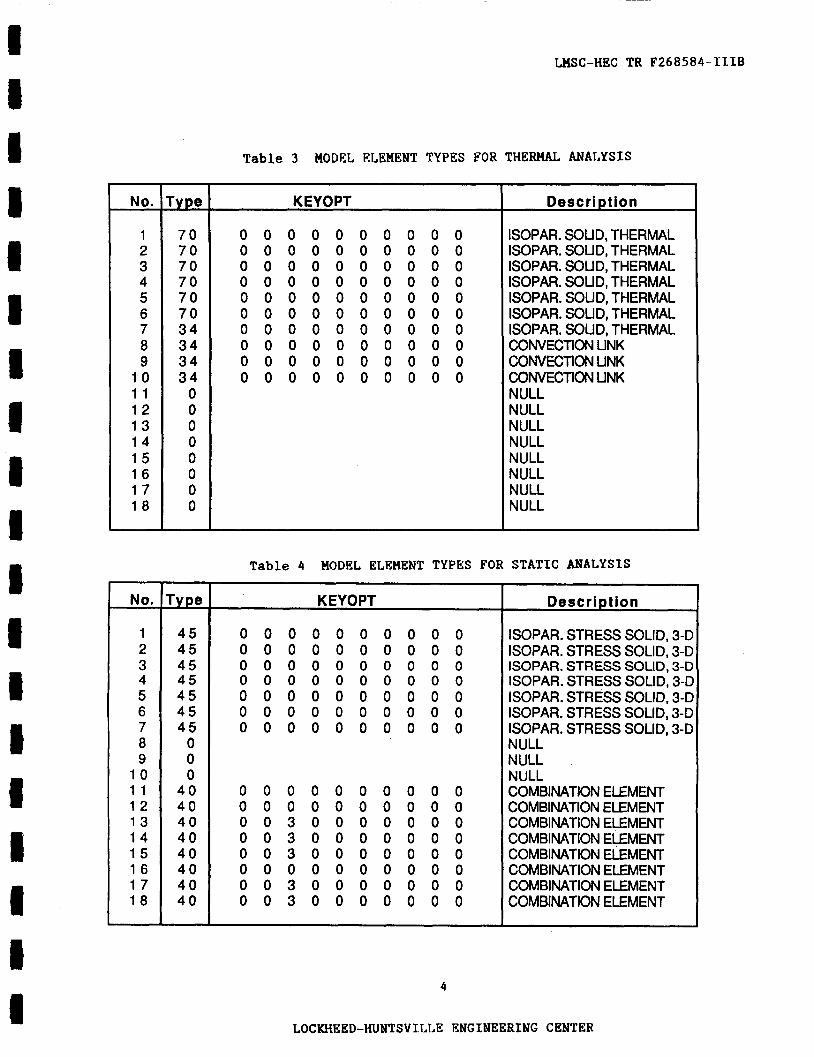
Tables 3 and 4 provide a complete description of the element types, including the elements' optional parameters (KEYOPT), for both the thermal and
static analyses.
3
LOCKHEED-HUNTSVILLE ENGINEERING CENTER
- No. -
1 2 3 4 5 6 7 8 9
1 0 1 1 1 2 1 3 1 4 1 5 1 6 1 7 1 8
No.
1 2 3 4 5 6 7 8 9
1 0 1 1 1 2 1 3 1 4 1 5 1 6 1 7 1 8
- Type
7 0 7 0 7 0 7 0 7 0 7 0 34 34 34 3 4 0 0 0 0 0 0 0 0
- rype 45 45 45 45 45 45 45 0 0 0
40 40 40 40 40 40 40 40 -
~~ ~~
WSC-HEC TR F268584-IIIB
Table 3 MODEL ELEMENT TYPES FOR THERHAL ANALYSIS
KEYOPT
0 0 0 0 0 0 0 0 0 0 0 0 0 0 0 0 0 0 0 0 0 0 0 0 0 0 0 0 0 0 0 0 0 0 0 0 0 0 0 0 0 0 0 0 0 0 0 0 0 0 0 0 0 0 0 0 0 0 0 0 0 0 0 0 0 0 0 0 0 0 0 0 0 0 0 0 0 0 0 0 0 0 0 0 0 0 0 0 0 0 0 0 0 0 0 0 0 0 0 0
Description
ISOPAR. SOLID, THERMAL ISOPAR. SOUD, THERMAL ISOPAR. SOUD, THERMAL ISOPAR. SOLID, THERMAL ISOPAR. SOUD, THERMAL ISOPAR. SOUD, THERMAL ISOPAR. SOLID, THERMAL CONVECTION LINK CONVECTION UNK
NULL NULL NULL NULL NULL NULL NULL NULL
CowcnoN UNK
Table 4 MODEL ELEMENT TYPES FOR STATIC ANALYSIS
KEYOPT
0 0 0 0 0 0 0 0 0 0 0 0 0 0 0 0 0 0 0 0 0 0 0 0 0 0 0 0 0 0 0 0 0 0 0 0 0 0 0 0 0 0 0 0 0 0 0 0 0 0 0 0 0 0 0 0 0 0 0 0 0 0 0 0 0 0 0 0 0 0
0 0 0 0 0 0 0 0 0 0 0 0 0 0 0 0 0 0 0 0 0 0 3 0 0 0 0 0 0 0 0 0 3 0 0 0 0 0 0 0 0 0 3 0 0 0 0 0 0 0 0 0 0 0 0 0 0 0 0 0 0 0 3 0 0 0 0 0 0 0 0 0 3 0 0 0 0 0 0 0
Description
ISOPAR. STRESS SOLID, 3-C ISOPAR. STRESS SOLID, 3-0 ISOPAR. STRESS SOUD, 3-0 ISOPAR. STRESS SOLID, 3-C ISOPAR. STRESS SOLID, 3-C ISOPAR. STRESS SOLID, 3-0 ISOPAR. STRESS SOLID, 3-D NULL NULL NULL COMBINATION ELEMENT COMBINATION ELEMENT COMBINATION ELEMENT COMBINATION ELEMENT COMBINATION ELEMENT COMBINATION ELEMENT COMBINATION ELEMENT COMBINATION ELEMENT
4
LOCKHE ED-HUNTSV T.LLE ENGINEERING C ENTER

~~
LHSC-HEC TR F 2 6 8 5 8 4 - I I IB
I I 8 I I 1 I
All elements listed i n Tables 1 and 2 are stored in a single ANSYS FILE16.
Both the thermal and static analyses files (FILE271 were written from FILE16.
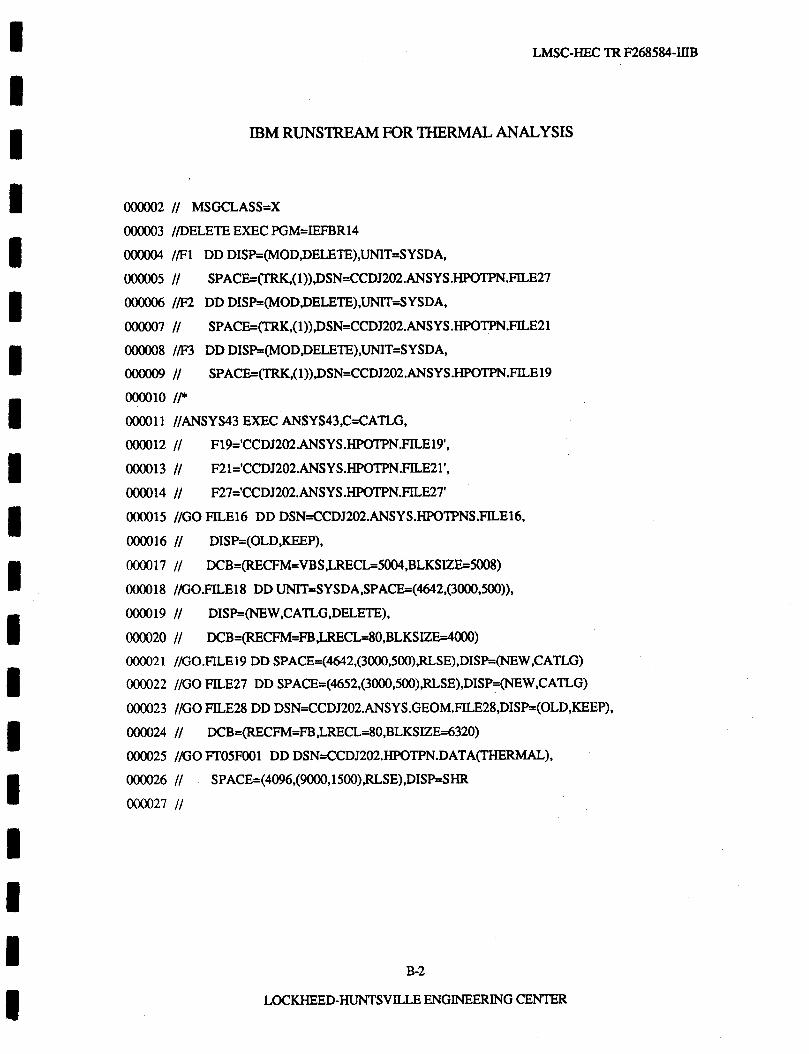
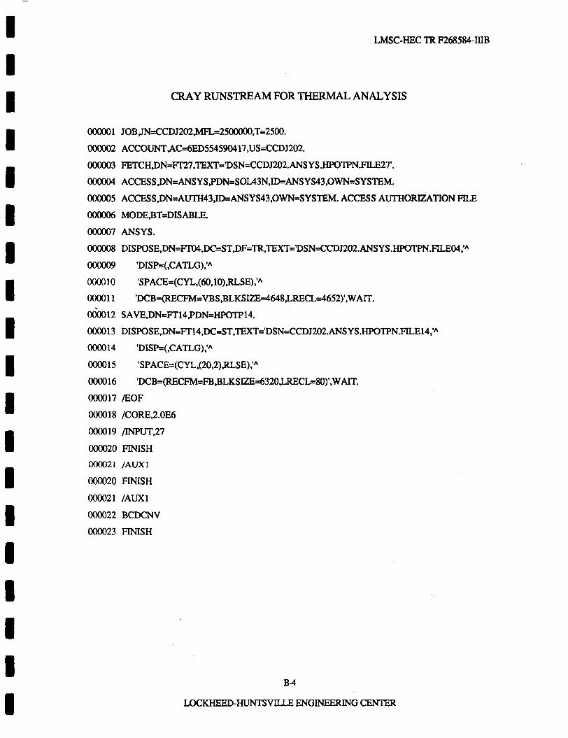
The IBH data file which generated the thermal and static analyses files appears in Appendix A. static analyses are provided in Appendix B.
The IBH and Cray runstreams which execute the thermal and
Table 5 identifies the convection link elements used for the HPOTP pre- burner pump bearing interfaces and provides the number of elements, material constant, element type, and real constant numbers used for each interface. These elements correspond to the contact and gap conductances given in Section 4 , Thermal Environment; that information applies to the thermal analysis only.
Table 6 identifies the radial gap and interference elements used for the HPOTP preburner pump bearing interfaces and provides the clearance, number of elements, element type, and real constant numbers used for each interface. The interface descriptions are schematically presented in Figures 3 and 4 . The circled numbers correspond to the interface numbers provided in Table 6 .
Table 5 MODEL CONVECTION LINK ELEHENTS
5
LOCKHEED-HUNTSVILLE ENGINEERING CENTER ~~~

~~
LMSC -HEC TR F 2 6 8 5 8 4 -- I I IB
9
1 0
TOTAL
Table 6 MODEL RADIAL GAP AND INTERFERENCE FITS
Support/ 1 E - 6 8 1 6 335 Isolator Bolts
Isolator Bolts I so lato r l 1 E - 6 8 1 6 335
1 2 4
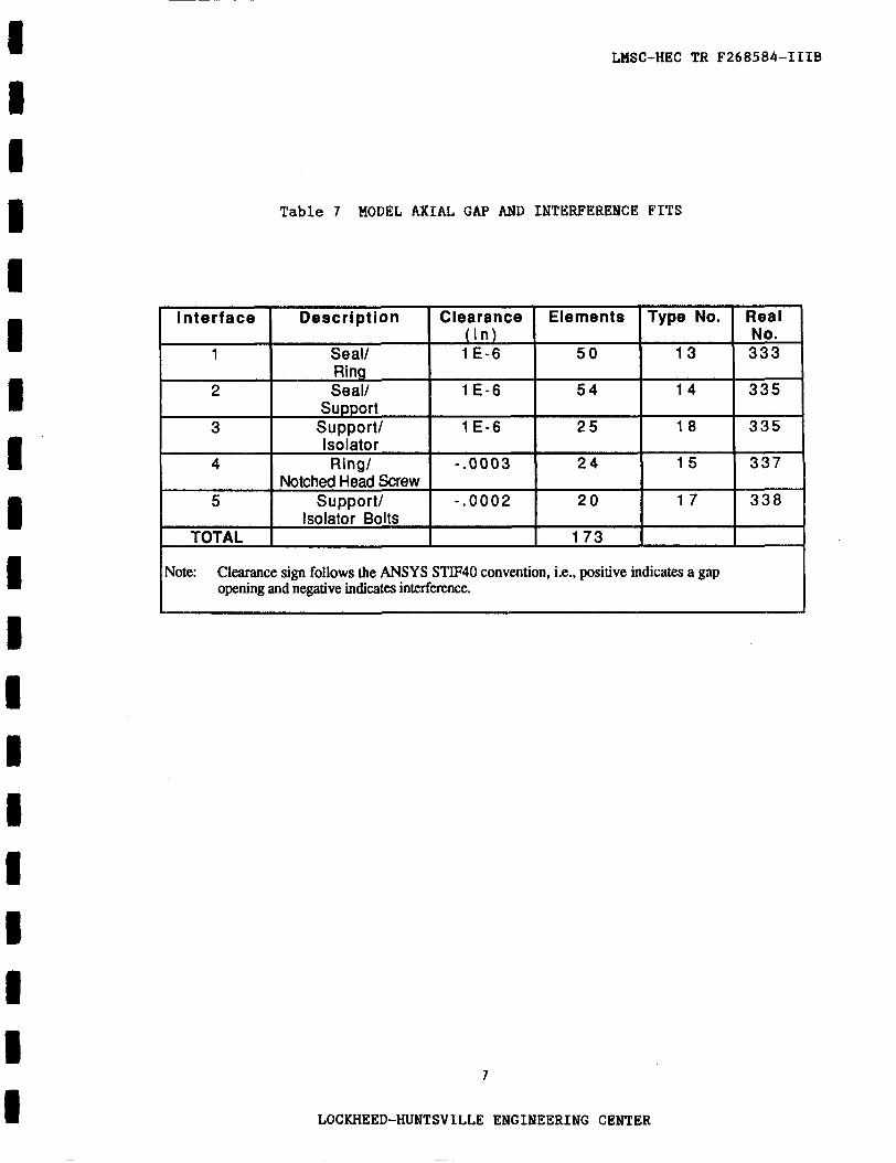
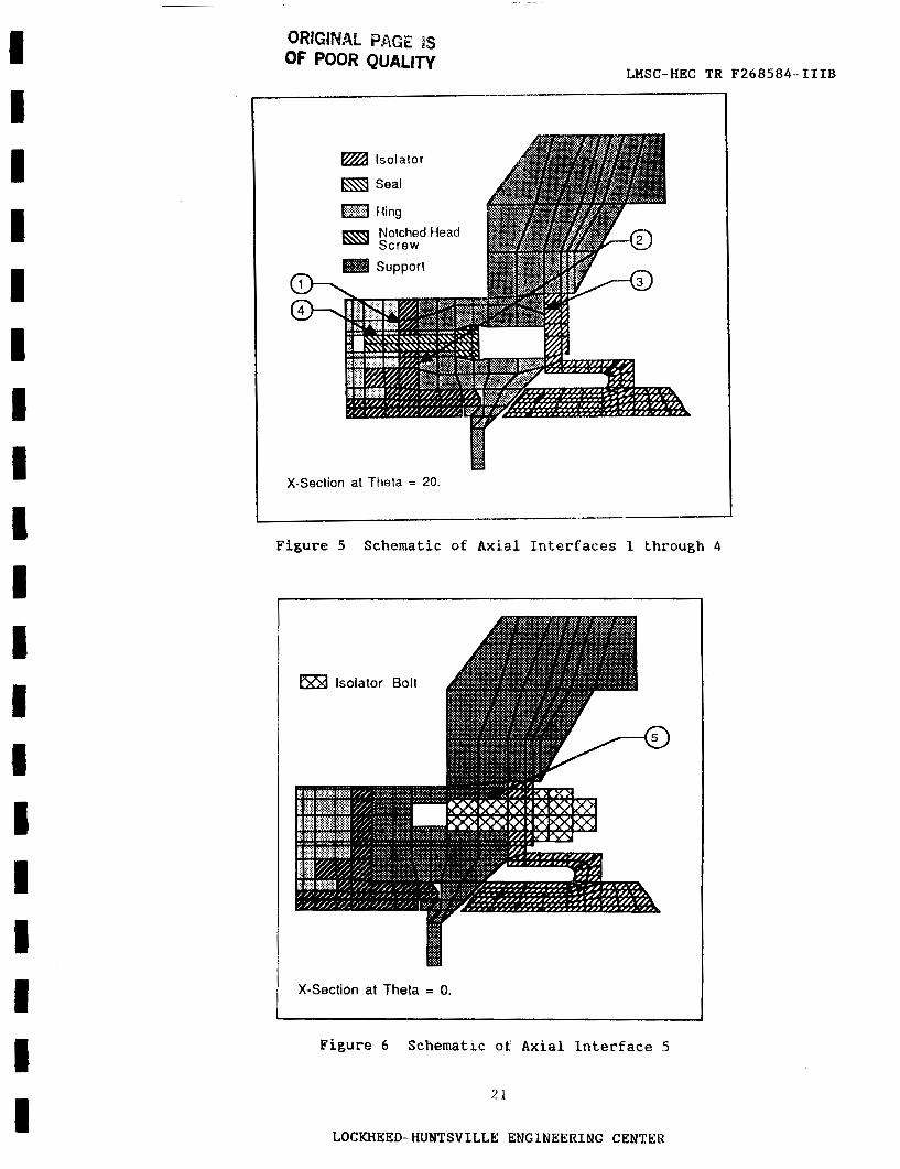
Table 7 identifies the axial gap and interference elements used for the HPOTP preburner pump bearing interfaces. In addition, the clearance, number of elements, element type, and real constant numbers are given for each inter- face. The interface descriptions are schematically presented in Figures 5 and 6 . Again, the circled numbers correspond to the interface numbers provided i n
Table 7 . The gap elements for interfaces 1 through 3 were used as contact elements, while the interference elements for interfaces 4 and 5 were used to preload the bolts. interference on the combination element. The bolt preload is further explained in Section 3 , Boundary Conditions.
The preload on the bolts was approximated by imposing an
6
LOCKHEED-HUNTSVILLE ENGINEERING CENTER
LHSC-HEC TR F268584-IIIB
I I
B 1 I
Table 7 MODEL AXIAL GAP AND INTERFERENCE FITS
Note: Clearance sign follows the ANSYS STIF40 convention, i.e., positive indicates a gap opening and negative indicates interference.
7
LOCKHEED-HUNTSVILLE ENGINEERING CENTER
LHSC-HEC TR F268584-IIIB
3 . BOIJNDARY CONDITIONS AND LOADS
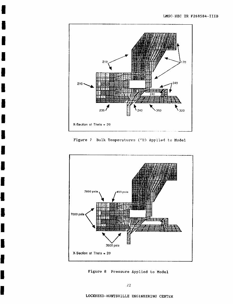
For the thermal analysis, the boundary conditions on the HPOTP preburner pump bearing model consisted of exterior surface heat transfer coefficients and bulk temperatures, presented in Section 4 of this document, Thermal
Environment. The heat transfer coefficients and bulk temperatures were applied as shown in Figure 7 .
For the static analysis, the HPOTP preburner pump bearing model was constrained in the translational y direction at 8 = 0" and 8 = 4 0 " . In addition, the nodes on the support, where the support bolts are located (not modeled), were constrained in the translational x direction.
The loading on the model for the static analysis consisted of thermal loads obtained from the thermal analysis, pressure loads, and a preload on the bolts. The pressure loads were applied as shown in Figure 8. The bolt preload was approximated by imposing an interference on the axial gap elements located at the isolator bolts/isolator interface and at the notched head screw/seal interface. The interference was calculated from the torque specified in the bolt drawings.
8
LOCKHEED-HUNTSVILLE ENGINEERING CENTER
I I I I I I I I I I I I I I I I I I 1
~~
LHSC-HEC TR F268584-IIIB
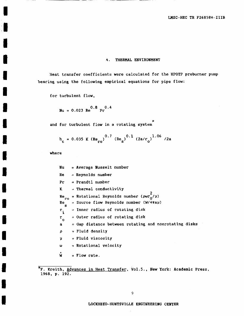
4 . THERMAL ENVIRONMENT
Heat transfer coefficients were calculated for the HPOTP preburner pump bearing using the following empirical equations for pipe flow:
for turbulent flow,
0.8 0 . 4 Nu = 0,023 Re Pr
* and for turbulent flow in a rotating system
0.1 1.06 / 2a 0.7 h = 0.035 K (Rero) (Res 1 (2a/ro)
C
where
Nu = Average Nusselt number Re = Reynolds number
Pr = Prandtl number K = Thermal conductivity
2 = Rotational Reynolds number (pwro/v)
Re = Source flow Reynolds number (W/4nau) r = Inner radius of rotating disk r = Outer radius of rotating disk a
S
i 0
= Gap distance between rotating and nonrotating disks P = Fluid density v = Fluid viscosity w = Rotational velocity . W = Flow rate.
5. Kreith, Advances in Heat Transfer, Vo1.5., New York: Academic Press, 1968, p. 192.
9
LOCKHEED-HUNTSVILLE ENGINEERING CENTER

I I I
~
LHSC-HEC TR F268584-IIIB
Computation of the thermal environment for the HPOTP preburner pump
bearing was performed by Gene Teal, LMSC-HEC. Pressures, temperatures, and
flow rates €or steady state fiill power level operation were obtained from the
Rocketdyne power balance data.
flow equation and bearing tester data correlation, a pressure drop across the
bearings was computed using the coolant flow rate from the power balance data. This pressure drop was then used to calculate the coolant flow rate between
the bearing shield and the isolator. Table 8 gives the pressures, tempera-
tures, and heat transfer coefficients at the preburner pump locations shown in
Figure 9. Thermal boundary coefficients at locations 20 and 21 are simplifica-
tions designed to simulate the outer race to isolator heat fluxes. These data
were derived from an analysis performed by Joe Cody of SRS Technologies.
In conjunction with the Rocketdyne bearing
Table 8 THERMAL ENVIRONMENT
I I I 1 Node 1 Description
8 9 10 11 12 13 14 15
I I I 1
16 17 18 19
Film Coefficient Film Coefficient Film Coefficient Film Coefficient Film Coefficient Film Coefficient Film Coefficient
Contact Conductance Contact Conductance Contact Conductance Contact Conductance Contact Conductance Contact Conductance Contact Conductance Contact Conductance
Gap Conductance Gap Conductance Gap Conductance Gap Conductance
Conductance from Bearing Race to Isolator
P (psia)
350 350 350 400 400 7000 3500
- - - - - - - -
7000 400 7000 400
385
365
10
T (OR)
170 240 240 240 240 210 235
- - - -. - - - -
- - - -
320
360 I
hc (Btu/in2/s/OR)
0.0018 0.0012 0.00021 0.00056 0.0001 0.017 0.05
0.0048 0.0048 0.0048 0.0048 0.0048 0.0048 0.0048 0.0048
0.0018 0.0015 0.0018 0.0015
0.00024
0.00024
LOCKHEED-HUNTSVILLE ENGINEERING CENTER
I I I I I I I I 8 I 1 1 I M I I I I (I
_ _ _ ~ _ _ _
LMSC-HEC TR F268584-l'fIB
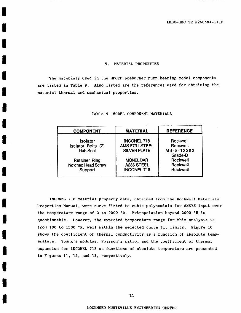
5 . MATERIAL PROPERTIES
The materials used in the HPOTP preburner pump bearing model components are listed in Table 9 .
material thermal and mechanical properties. A l s o listed are the references used for obtaining the
Table 9 MODEL COWONENT MATERIALS
COMPONENT
Isolator Isolator Bolts (2)
Hub Seal
Retainer Ring Notched Head Screw
Support
MATER I AL
INCONEL 718 AMS 5731 STEEL
SILVER PLATE
MONEL BAR A286 STEEL INCONEL 71 8
REFERENCE
M
-
Rockwell Rockwell
Grade-B Rockwell Rockwell Rockwell
I -S-13282
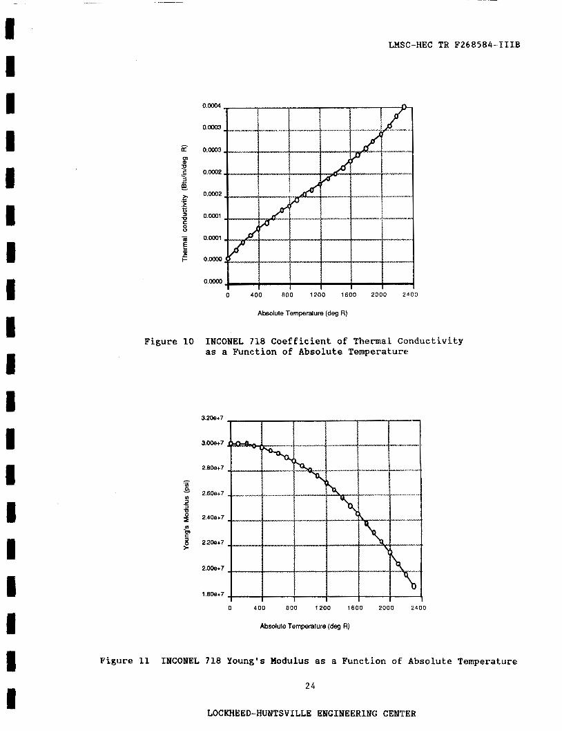
INCONEL 718 material property data, obtained from the Rockwell Haterials
Properties Manual, were curve fitted to cubic polynomials for ANSYS input over the temperature range of 0 to 2000 OR. questionable. However, the expected temperature range for this analysis is
from 100 to 1500 "R, well within the selected curve fit limits. shows the coefficient of thermal conductivity as a function of absolute temp- erature. Young's modulus, Poisson's ratio, and the coefficient of thermal
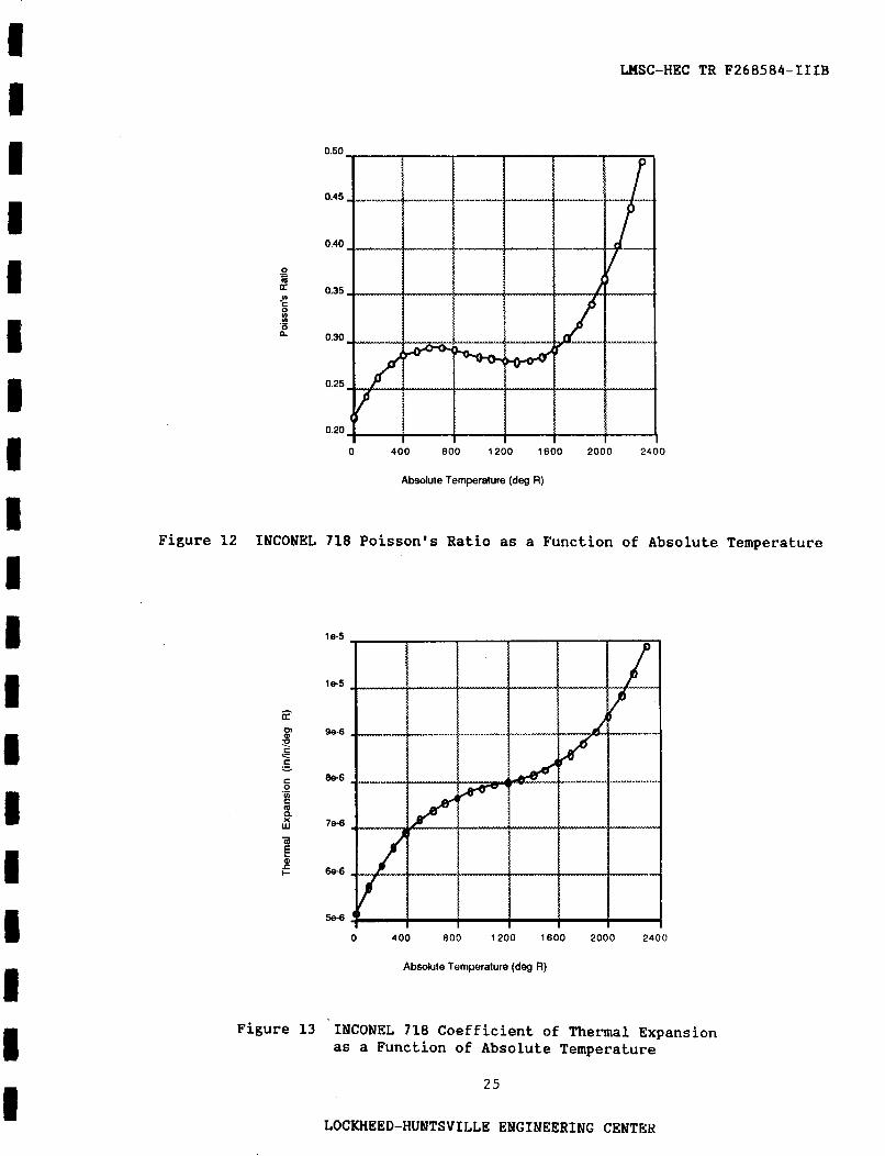
expansion f o r INCONEL 718 as functions of absolute temperature are presented in Figures 11, 12, and 13, respectively.
Extrapolation beyond 2000 OR is
Figure 10
11
LOCKHEED-HIJNTSVILLE ENGINEERING CENTER

LMSC-HEC TR F268584-IIIB
I I I i I I
D I I
In addition, the following material properties for the A286 steel bolts
are used:
Coefficient of Thermal Conductivity (k) = 8.68 Btu/in/"R
Young's Modulus (E) = 29.1 x 10 lbf/in Poisson's Ratio (u) = 0.29
Coefficient of Thermal Expansion (a) = 0.917 x 10 in/in/"R
6 2
-5
These are assumed constant over the absolute temperature range from 0 to
2300 OR.
I II 12
LOCKHEED-HUNTSVILLE ENGINEERING CENTER

LHSC-HEC TR F268584-IIIB
6 . THERMAL ANALYSIS
The nonlinear thermal analysis performed on the HPOTP preburner pump bearing model converged in three iterations using the automatic ANSYS con- vergence criterion of 1". Temperature distributions for cross sections of the model at 8 = 0" and at 8 = 20" are shown in Figures 14 and 15, re-
spectively. The thermal distribution at these cross sections is representa- tive of the thermal distribution in the rest of the model. gradients occur at the isolator/bearing race interface. results are used for nodal temperature input to the structural analysis presented in Section 7 .
Large thermal The thermal analysis
1 3
LOCKHEED-HUNTSVILLE ENGINEERING CENTER
LnSC-HEC TR F268584-ITIB
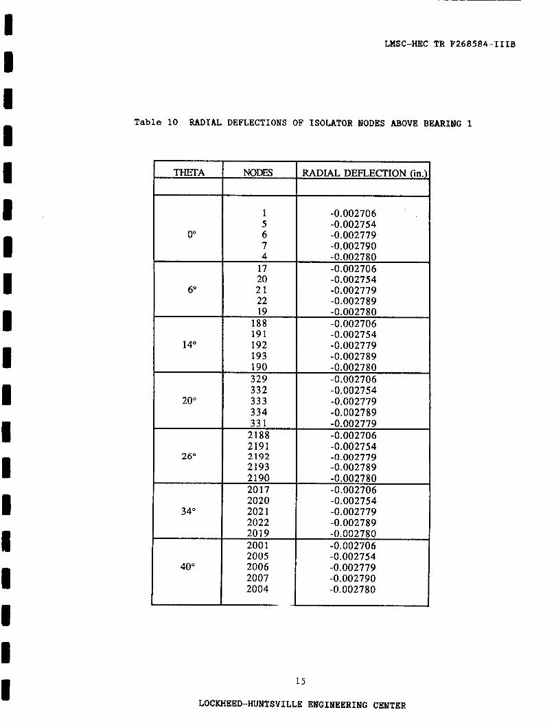
7 . STRUCTURAL ANALYSIS/RESULTS
A static analysis was performed on the HPOTP preburner pump bearing model to determine the radial deflection of the isolator under the load case described in Section 3 , Boundary Conditions and Loads.
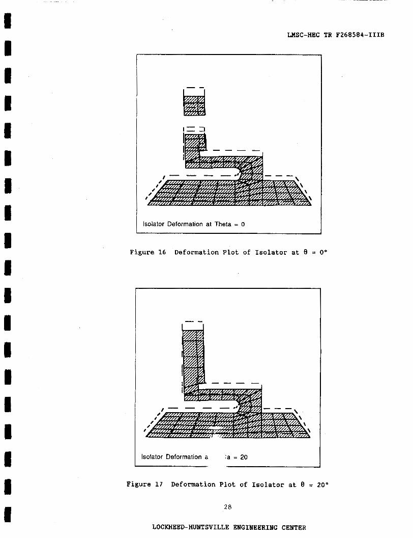
Exaggerated deformation plots of the isolator at cross sections 8 = 0"
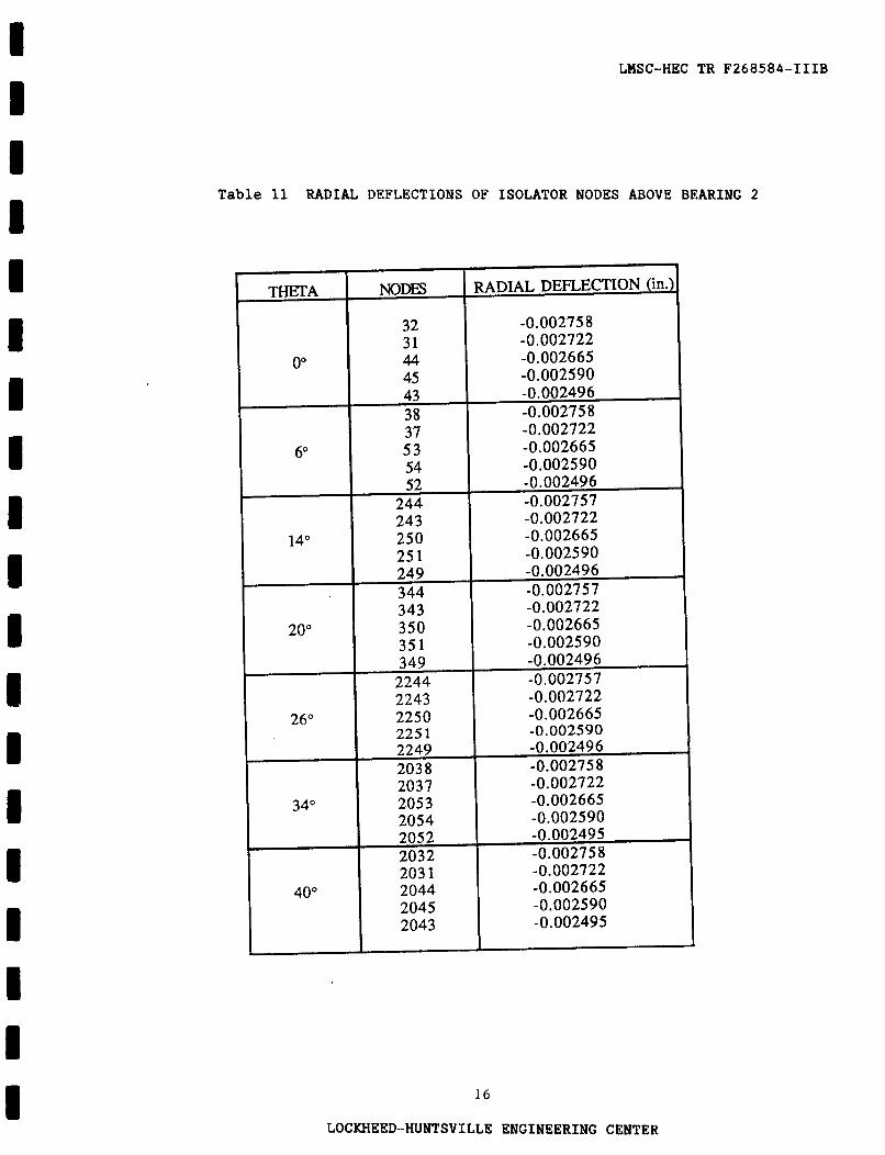
and 8 = 20" are shown in Figures 16 and 17, Dashed lines on the deformation plots represent the undeformed structure. Listed in Tables 10 and 11 are the radial deflection of the isolator nodes above bearings 1 and 2 , respectively.
1 4
LOCKHEED-HUNTSVILLE ENGINEERING CENTER
~ ~ ~ _ _ _ _ _ _ _ ~ ~
LHSC-HEC TR F268584-ZIIB
NODES
Table 10 RADIAL DEFLECTIONS OF ISOLATOR NODES ABOVE BEARING 1
RADIAL DEFLECTION (in. THETA
0"
6"
14"
20"
26"
34"
40"
1 5 6 7 4
17 20 21 22
-0.002706 -0.002754 -0.002779 -0.002790 -0.0027 80 -0.002706 -0.002754 -0.002779 -0.002789
I
19 188
-0.002780 -0.002706
191 192 193
-0.002754 -0.002779 -0.002789
190 329
-0.002780 -0.002706
332 333 334
2191 -0.002754 2192 I -0.002779 2193 -0.002789
-0.002754 -0.002779 -0.0027 89
33 1 2188
-0.002754 -0.002779 -0.002789 -0.002780 -0.002706
-0.002779 -0.002706
2005 2006 2007 2004
2190 2017
-0.002754 -0.002779 -0.002790 -0.002780
-0.002780 -0.002706
15
LOCKHEED-HUNTSVILLE ENGINEERING CENTER
I I I 1 I I I I I I I I I 1 I I I I I
THETA NODES
LMSC-HEC TR F268584-IIIB
RADIAL DEFLECTION (in.)
Table 11 RADIAL DEFLECTIONS OF ISOLATOR NODES ABOVE BEARING 2
0"
32 31 44 45
-0.002758
-0.002665 -0.002722
-0.002590
I I I 1
16
LOCKHEED--HUNTSVILLE ENGINEERING CENTER
I I I I I I I I I I I I I I I I I I I
LHSC-HEC TR F268584-IIIB
8. CONCLUSIONS AND RECOMMENDATIONS
The static analysis of the HPOTP preburner pump bearing assembly shows that the isolator deflects inward due to the operating environment. The assembly clearance between the isolator and the bearing outer races is 0.0024 in. The maximum radial displacement of the isolator is 0.00279. No conclusions can be drawn from this since the bearing deflection is not known at the operational level.
In a further analysis, the stiffness of the outer bearing races and the
stiffness of the preburner pump housing should be included in the model.
17
LOCKHEED-HUNTSVILLE ENGINEERING CENTER
I I I I I I I I I I I I I I I 1 I I 1
~
LMSC-HEC TR F268584-IIIB
18
LOCKHEED-HUNTSVILLE ENGINEERING GINTER
LHSC-HEC TR F268584-TIIB I I I
I I I I I I
3 2 u CA
m I
(u
0
N
1 9
LOCKHEED-HUNTSVILLE ENGINEERING CENTER

4
I I I I I I I I I I I I I I I I
~~
WSC-HEC TR F268584-1118
Isolator
Notched Head
X-Section at Theta = 20.
Figure 3 Schematic of Radial Interfaces 1 through 8
1
Isolator Bolt
I I X-Section at Theta = 0.
Figure 4 Schematic of Radial Interfaces 9 and 10
20
LOCKHEED-HUNTSVILLE ENGINEERING CENTER
4 I I I I I I I I I I 4 I I I I I I I
ORIGINAL PAGE %S OF POOR QUALITY
LHSC-HEC TR F268584-IIIB
a- @
isolator
Notched Head
X-Section at Theta = 20.
Figure 5 Schematic of Axial Interfaces Z through 4
I 1
X-Section at Theta = 0.
Figure 6 Schematic of Axial Interface 5
2 1
LOCKHEED-HUNTSVILLE ENGlNEERING CENTER
~ ~~
LMSC-HEC TR F268584-IIIB
210
170
235 320
X-Sectlon at Theta = 20
Figure 7 Bulk Temperatures ("1.';) A p p l i e d t o Model
--._______
7000 psla
7000 ps
< "v*r 3500 psia
X-Section at Theta = 20
Figure 8 Pressure Applied to Model
2 2
LOCKHEED-HUNTSVILLE ENGINEERING CENTER

LMSC-HEC TR F268584-TIIB
HPOTP Preburner Pump Bearing Thermal Environment Schematic
Figure 9 Thermal E n v i r o n m e n t Schematic
2 3
LOCKHEED-HUNTSVILLE ENGINEERING CENTER
I I I 1 I I E I 1 I I I 8 I B I I 1 I
0.0004
O.ooo3
0.0003
0 . m 2
0.0002
0.0001
0.m1
0.OoM)
O.oo00
~ ~~ ~~
LMSC-HEC TR F268584-IIIB
0 400 800 1200 1600 2000 2400
Absolute Temperature (deg R)
INCONEL 718 Coefficient of Thermal Conductivity as a Function of Absolute Temnerature
3.2Oe+7
3.ooe+7
2.8Oe+7
- .- u)
v) 3 
n 2.6Oe+7 v
- 3 2.4Oe+7
-m
=I 2.2Oe+7
ul
?
2.0Oe+7
1.8Oe+7
0 400 800 1200 1600 7000 2400
Absolute Temperature (deg R)
Figure 11 INCONEL 718 Young's Modulus as a Function of Absolute Temperature
2 4
LOCKHEED-HUNTSVILLE ENGINEERING CENTER
LHSC-HEC TR F268584-IIIB
Absolute Temperature (deg R)
Figure 12 INCONEL 718 Poisson's Ratio as a Function of Absolute Temperature
1 e-5
1 e 5
9e-6
Bs6
78-0
6e-6
I I I I I I I
0 400 800 1200 1600 2000 2400
Absolute Temperature (deg R)
Figure 13 INCONEL 718 Coefficient of Thermal Expansion as a Function of Absolute Temperature
25
LOCKHEED-HUNTSVILLE ENGINEERING CENTER

~
LHSC-HEC TR F268584-IIIB
Thermal Distribution at Theta = 0
Figure 14 Temperature Distribution P lo t €or Cross Section at 8 = 0"
26
LOCKHEED-HUNTSVILLE ENGINEERING CENTER

~~~
LNSC-HEC TR F268584-IIIB
I I i D I I I I
__ Thermal Distribution at Theta = 20
Figure 15 Temperature Distribution Plot for Cross Section at 6 = 20"
2 7
LOCKHEED-HUNTSVILLE ENGINEERING CENTER
LHSC-HEC TR F268584-IIIB
I I
- - I, -I
I I
Isolator Deformation at Theta = 0
Figure 16 Deformation Plot of Isolator at 8 = 0"
Isolator Deformation a :a = 20
Figure 17 Deformation Plot of Isolator at 8 = 20"
28
LOCKHEED-HUNTSVILLE ENGINEERING CENTER

~~
LHSC-HEC TR F268584-IIIE
Appendix A
IBM DATA FILE FOR ANALYSES
LOCKHEED-HUNTSVILLE ENGINEERING CENTER

/CORE,3E6
PREP7 C***
RESUME
/TITLE,STATIC A
KAN,O
CSYS,1 C***
JAL
LMSC-HEC TR F268584-IIIB
DATA INPUT FOR STATIC ANALYSIS
51s
C*** SET CONVECTION LINK ELEMENTS TO NULL ELEMENTS C***
ET,7.0
RP3,l C***
C*** SET ELEMENT TYPES 11 THRU 18 TO STIF40 C***
ET,] 1.40
RP2,l
ET,13,40,,,3
RP3,l
ET, 16.40
ET,] 7,40,,,3
RP2,l C***
C*** DELETE ELEMENT CONVECTIONS AND TEMPERATURE NODE COUPLING C***
CVDELE.ALL
CPDELE,401,508 C***
EALL
NALL
KTEMP,l,lO
ITER,-40,40,40
AFWRITE
EOF
A- 1
LOCKHEED-"TSVILLE ENGINEERING CENTER

LMSC-HEC TR F268584-IIIB
DATA INPUT FOR THERMAL ANALYSIS
/CORE,3E6
PREP7 C***
/RESUME /TITLE, THE- ANALYSIS C***
KAN,- 1 C***
C*** SET GAP ELEMENTS (STIF40S) TO NULL ELEMENTS
C*** FOR THERMAL, ANALYSIS C***
ET, 1 1 ,O RP8.1 C***
C*** SET ELEMENT TYPES 7 THRU 9 TO STIF34 C***
ET,7,34
RP3,l
C*** DELETE ELEMENT PRESSURES, STRUCTUR. L
C*** IMPOSED DISPLACEMENTS
EPDELE,ALL,,,ALL CPDELE, 1,347
DDELE,ALL,ALL C***
EALL
NALL
KBC.1
ITER,-10,10,10
AFWRITE
/EOF
JODE COUPLING .ND
A-2
LOCKHEED-HUNTSVILLE ENGINEERING CENTER

LMSC-HEC TR F268584-XIIB
Appendix B
IBM AND CRAY RUNSTREAMS
COCKHEED-HUNTSVILLE ENGINEERING CENTER

I I
LMSC-HEC TR F268584-IHB
IBM RUNSTREAM FOR STATIC ANALYSIS
000002 // MSGCLASS=X 000003 //DELETE EXEC PGM=IEFBR14 000004 //F1 DD DISP=(MOD,DELETE),U"=SYSDA,
000005 // 000006 //F2 DD DISP=(MOD,DELETE),USYSDA,
000007 // SPACE=(TRK,( l)),DSN=CCDJ202.ANSYS.HPOTPNSFILE21 000008 //F3 DD DISP=(MOD,DELETE),UNIT=SYSDA, 000009 // SPACE=(TRK,(l)),DSN=CCDJ202.ANSYS.HPOTPNS.FILE19
ooo010 /r oooO11 //ANSYS43 EXEC ANSYS43C=CATLG, oooO12 // F19='CCDJ202.ANSY S .HPOTPNS .FILE 19'. oooO13 // F2l='CCDJ202.ANSYS.HS.FILE21',
oooO14 // F27='CCDJ202.ANSYS.HPOTPNS.FILE27', oooO15 //GO.FILW DD DSN=CCDJ202.ANSYS.HPOTPN.FILE04, oooO16 // DISP=(OLD,KEEF'), oooO17 // DCB=(RECFM=VBS,LREC652,BLKSIZE=4648)
oooO18 //GO.FILElB DD DSN=CCDJ202.ANSYS.HPOTPNS.FILEl6, oooO19 // DISP=(OLD,KEEP), oooO20 // DCB=(RECEM=VBS~CL=5004,BLKSIZE=5008) oooO21 //GO.FJLE18 DD UNIT=SYSDA,SPACE=(4642,(3000,%0)), oooO22 // DISP=(NEW,CATLG,DELETE),
oooO23 // DCB=(RECFM=FB,LRECL=80,BLKSIZE=4000)
SPACE=(TRK,( l)),DSN=CCDJ202.ANSY S .HPOTPNS .FILE27
oooO24 //GO .FILE 19 DD SPACE=(4642,(3000,5OO),RLSE) ,DISP=(NEW,CATLG) oooO25 //GO.FII;E27 DD SPACE=(4652 ,(3000,5OO),RLSE) ,DISP=(NEW ,CATLG) oooO26 /KiO.FlB5F001 DD DSN=CCDJ202.HPOTPNS.DATA(STATIC), oooO27 // SPACE=(4096,(9000,1SOO),RLSE),DISP=SHR oooO28 //
B-1
LOCKHEED-HUNTSVILLE ENGINEERING CENTER
000002 // rsGcL
LMSC-HEC TR F268584-IIIB
IBM RUNSTREAM FOR THERMAL ANALYSIS
ss=x 000003 //DELETE EXEC PGM=IEFBR14 000004 //F1 DD DISP=(MOD,DELETE),WT=SYSDA,
000005 // SPACE=(TRK,( l)),DSN=CCDJ202.ANSYS .HPOTPN.FILE27 000006 //F2 DD DISP=(MOD,DELETE),UNIT=SYSDA, 000007 // SPACE=(TRK,(l)),DSN=CCDJ202.ANSYS.HPOTPN.FILE21 000008 //n DD DISP=(MOD,DELETE),UNIT=SYSDA, 000009 // SPACE=(TRK,( l)),DSN=CCDJ202.ANSYS.HPOTPN.FILE19 oooO10 /P oooO11 //ANSYS43 EXEC ANSYS43C=CATLG, oooO12 // F 19='CCDJ202.ANSY S .I-IPOTPN.FILE 19, oooO13 // F2 l='CCDJ202.ANSY S .HPOTPNFILE21', oooO14 // F27='CCDJ202.ANSYS.HPOTPN.FILE27' oooO15 //GO FILE16 DD DSN=CCDJ202.ANSYS.HPOTPNS.FILE16, oooO16 // DISF'=(OLD,KEEP), oooO17 I/ DCB=(RECFM=VBS,LRECL=5004,BLKSIZE=%O8) oooO 18 //GO.FILE 18 DD UNIT=SYSDA,SPACE-(4642,(3000,5)), oooO19 // DISP=(NEW,CATLG,DELETE), oooO20 // DCB=(RECFM=FB,LRECL=80,BLKSIZE=4000) oooO21 //GOFILE19 DD SPACE=(4642,(3000,500),RLSE),DISP=(NEW,CATLG) oooO22 //GO FILE27 DD SPACE=(4652,(3000,5),RLSE),DISP=(NElW,CATLG) oooO23 //GO FILE28 DD DSN=CCDJ202.ANSYS.GEOM.FILE28,DISP=(OLD,KEEP), oooO24 // DCB=(RECFM=FB,LRECL=80,BLKSIZE=6320) oooO25 //GO lT05FOO1 DD DSN=CCDJ202.HPoTPN.DATA(THERMAL), oooO26 // SPACE=(4096,(9000,15OO),RLSE),DISP=SHR
oooO27 11
B-2
LOCKHEED-HUNTSVILLE ENGINEERING CENTER

I I I I I I I I I I I I I I I I I I I
LMSC-HEC TR F268584-IIIB
CRAY RUNSTREAM FOR STATIC ANALYSIS
00000 1 JOB ,JN<CDJ202,MFL=25O,T= 1OOO. 000002 ACCOUNT,AC=6ED55459017,US=CCDJ202. 000003 FETCH,DN=Fn7,TEXT='DSN=CCDJ202.ANSYS.HPOTPNSFILE27,DISP=SHR'. 000004 FETCHPN=FT04,DF=TR,TEXT='DSN=CCDJ202.ANSYS.HPOTPN~04,DISP=SHR'. 000005 ACCESS,DN=ANSYS,PDN=SOLA3N,ID=ANSYS43,0WN=SYSTEM. 000006 ACCESS ,DN=AUTH43 JD=ANSY S43,0WN=SY STEM. ACCESS AUTHORIZATION FlLE 000007 MODE,BT=DISABLE. OOOOO8 ANSYS. 000009 SAVE~N=FT14,PDN="OTPNl4.
ooOo10 DISPOSE,DN=~14PC=ST,TEXT='DSN=CCDJ202.ANSYS.HPOTPNS.FILE14,'A ooOo11 'DISP=(,CATLG),'A ooOo12 'SPACE=(CYL,(20,2),RLSE),'A oooOl3 'DCB=(RECFM=FB,BLKSIZE=6320~~CL=80)',WAIT. oooO14 /EOF
oooO15 /CORE,2.OE6 ooOo16 NUT.27 oooO17 m S H
oooO18 / A w l oooO19 BCDCNV 000020 FINISH
B-3
LOCKHEED-"TSVILLEENGINEERING CENTER
LMSC-HEC TR F268584-IIIB
CRAY RUNSTREAM FOR THERMAL ANALYSIS
00000 1 JOB JN=CCDJ202,MFL=25O,T=2500.
000002 ACCOUNT,AC=6ED554590417,US=CCDJ202. 000003 FETCH,DN=Fn7,TEXT='DSN=CCDJ202.ANSYS.HPOTPN.FILE27'. 000004 ACCESS ,DN=ANSYS ,PDN=SOL43N,ID=ANSYS43 ,OWN=SY STEM.
000005 ACCESS,DN=AUTH43,ID=ANSYS43,OWN=SYSTEM. ACCESS AUTHORIZATION FILE
000006 MODE,BT=DISABLE. 000007 ANSYS.
000008 DISPOSE,DN=FIY)I1,DC=ST,DF=TR,TEXT='DSN=CCDJ202.ANSYS.HPOTPN.FILEOQ,'A 000009 'DISF'=(,CATLG),'A oo00 10 'SPACE=(CYL,(60,1O),RLSE),"' ooOo11 'DCB=(RECFM=VBS,BLKSIZE=4648CRECL=4652)'.WAIT. &12 SAVE,DN=FI'l4QDN=HPOTP14.
oooO 1 3 DISF'OSE,DN=FI'14 ,DC=ST,TEXT='DSN=CCDJ202./"!3 Y S .HPOTPN.FLE 14 ,'A
oo00 14 'DISF'=( ,CATLG),'A oooO15 'SPACEk(CYL,(20,2),RLSE),'A oooO16 'DCB=(RECFM=FB,BLKSIZE=6320,LRECL=80)',WAIT. oooO17 /EOF oooO18 /CORE,2.OE6 oooO19 /INPUT,27 oooO20 FINISH oooO21 / A m 1
oooO20 FINISH
oooO21 /Am1 oooO22 BCDCNV oooO23 FINISH
B-4
LOCKHEED-HUNTSVILLE ENGINEERING CE-