space system design, mae 342, princeton university robert ... · –landing gear –orbital...
TRANSCRIPT
1
Launch VehiclesSpace System Design, MAE 342, Princeton University
Robert Stengel
Copyright 2016 by Robert Stengel. All rights reserved. For educational use only.http://www.princeton.edu/~stengel/MAE342.html 1
1
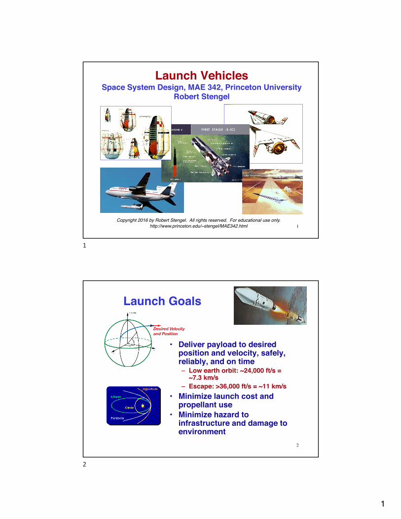
Launch Goals
• Deliver payload to desired position and velocity, safely, reliably, and on time– Low earth orbit: ~24,000 ft/s =
~7.3 km/s– Escape: >36,000 ft/s = ~11 km/s
• Minimize launch cost and propellant use
• Minimize hazard to infrastructure and damage to environment
2
2
2
Launch Vehicle Systems
• Structure–Skin, frames, ribs,
stringers, bulkheads–Propellant tanks–Fins, control surfaces–Inter-stage adapters,
fairings–Heat shields,
insulation
• Propulsion and Power–Main engines–Attitude-control
thrusters–Retro-rockets–Ullage rockets–Turbo-pumps–Batteries, fuel cells–Pressurizing bottles–Escape/destruct
systems
• Electronics–Guidance and control
computers–Sensors and actuators–Radio transmitters and
receivers–Radar transponders–Antennas
• Reusable launchers/ orbiters
–Wings, parachutes–Landing gear–Orbital maneuvering
units–Robot arms–Life support systems
(manned vehicle)
3
3
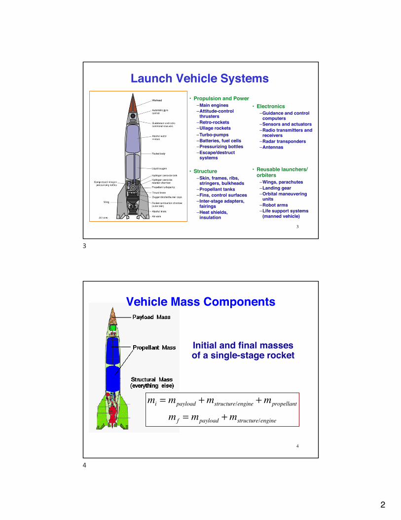
Initial and final masses of a single-stage rocket
Vehicle Mass Components
mi = mpayload +mstructure/engine +mpropellant
m f = mpayload +mstructure/engine
4
4
3
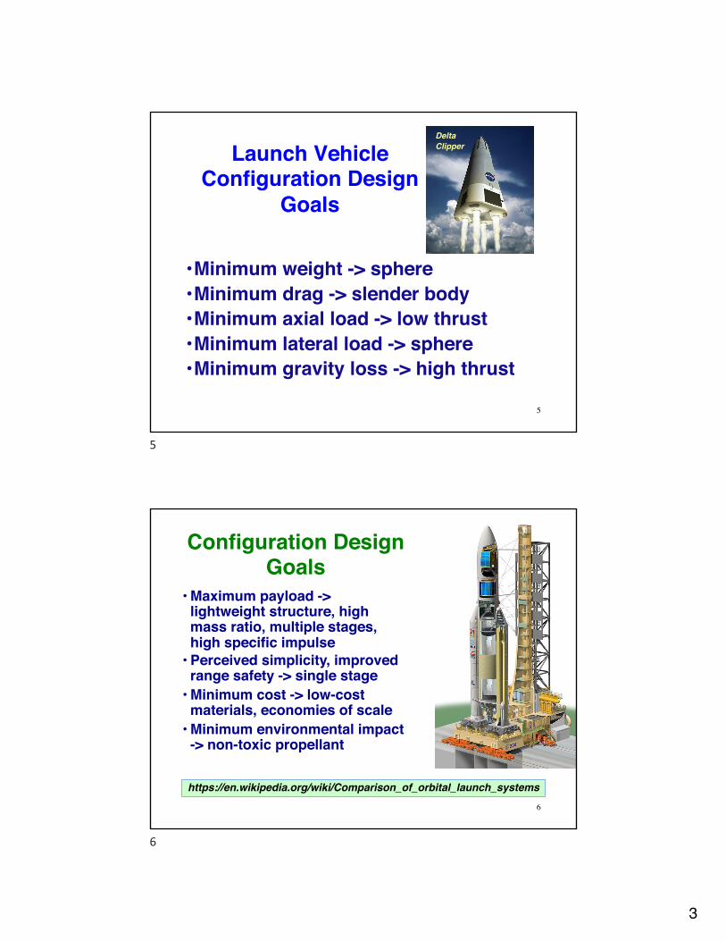
Launch Vehicle Configuration Design
Goals
•Minimum weight -> sphere•Minimum drag -> slender body•Minimum axial load -> low thrust•Minimum lateral load -> sphere•Minimum gravity loss -> high thrust
Delta Clipper
5
5
Configuration Design Goals
• Maximum payload -> lightweight structure, high mass ratio, multiple stages, high specific impulse
• Perceived simplicity, improved range safety -> single stage
• Minimum cost -> low-cost materials, economies of scale
• Minimum environmental impact -> non-toxic propellant
6
https://en.wikipedia.org/wiki/Comparison_of_orbital_launch_systems
6

4
The Rocket EquationIdeal velocity increment of a rocket stage, ΔVI (gravity
and aerodynamic effects neglected)
Vf −Vi( ) ≡ ΔVI = Ispgo lnmi
mf
⎛
⎝⎜⎞
⎠⎟≡ Ispgo lnµ
7
mi = mpayload +mstructure/engine +mpropellant
m f = mpayload +mstructure/engine
ΔVI = Ispgo lnmi
mf
⎛
⎝⎜⎞
⎠⎟= Ispgo ln
mf +mpropellant
m f
µ ! mi
mf
: Mass Ratio
7
Ideal Velocity Increment for Single Stage with Various Specific Impulses
Single stage to orbit with payload (ΔVI ~ 7.3 km/s)?
µrequired = eΔVI /Ispg0
8
Ideal Velocity Increment, km/sMass Ratio Isp = 220 s = 275 s = 400 s = 500 s = 850 s
2 1.50 1.90 2.70 3.40 5.78
3 2.40 3.00 4.30 5.30 9.164 3.00 3.80 5.40 6.80 11.565 3.50 4.30 6.30 7.90 13.42
8

5
Required Mass Ratio for Various Velocity Increments
µrequired = eΔVI /Ispg0
... and there are velocity losses due to gravity and aerodynamic drag
Required Mass RatioIdeal Velocity Increment, km/s Isp = 240 s = 400 s7 19.6 6.08 29.9 7.79 45.7 9.910 69.9 12.811 106.9 16.512 163.5 21.3
9
9
Ratios Characterizing a Rocket Stageµ = minitial
m final
λ = mpayloadminitial
η = mstructure/engineminitial
ε = mpropellantminitial
= µ −1µ
λ +η + ε = 1
Mass ratio
Payload ratio (as large as possible)
Structural ratio (typically 0.1 - 0.2)
Propellant ratio
Payload is what’s left after propellant and structure are subtracted10
10

6
Ideal Velocity Increment for a Two-Stage Rocket
ΔVI = ΔVI1 + ΔVI2
= Isp1go lnmpay1
+ ms/e1+mprop1( )
mpay1+ms/e1
+ Isp2go lnmpay2
+ms/e2+mprop2
mpay2+ms/e2
= Isp1go lnminit2
+ ms/e1+mprop1( )
minit2+ms/e1
+ Isp2go lnmpay2
+ms/e2+mprop2( )
mpay2+ms/e2
= go Isp1 lnµ1 + Isp2 lnµ2⎡⎣ ⎤⎦ 11
ΔVI j = Ispj go lnmpay j
+ms/ej+mpropj
mpayj+ms/ej
, j = 1,2
For each stage
For both stages
11
Ideal Velocity Increment for a Multiple-Stage Rocket• Ideal velocity increment of an n-
stage rocket
ΔVI = go Ispj lnµ jj=1
n
∑Scout• With equal specific impulses
ΔVI = Ispgo ln µ1 • µ2 • ...µn( ) ≡ Ispgo ln µoverall( )= Ispgo ln µ
n
12
12

7
Required Mass Ratios for Multiple-Stage Rockets
• Staging reduces individual mass ratios to achievable values
• With equal specific impulses for each stage
13https://en.wikipedia.org/wiki/Multistage_rocket
Required Individual Mass Ratio
Single Stage Two Stages Three StagesIdeal Velocity Increment, km/s Isp = 240 s = 400 s = 850 s Isp = 240 s = 400 s = 850 s Isp = 240 s = 400 s = 850 s
7 19.55 5.95 2.32 4.42 2.44 1.52 2.69 1.81 1.32
8 29.90 7.68 2.61 5.47 2.77 1.62 3.10 1.97 1.389 45.72 9.91 2.94 6.76 3.15 1.72 3.58 2.15 1.4310 69.92 12.79 3.32 8.36 3.58 1.82 4.12 2.34 1.4911 106.92 16.50 3.74 10.34 4.06 1.93 4.75 2.55 1.5512 163.50 21.29 4.22 12.79 4.61 2.05 5.47 2.77 1.62
13
Mass-Ratio Effect on Final Load Factor
ThrustWeight
= n (load factor) = Thrustmgo
ninitial =Thrustminitialgo
; nfinal =Thrustmfinalgo
• Thrust-to-weight ratio = load factor
• If thrust is constantnfinalninital
= minitial
m final
= µ
Final Load Factor, g
Initial Load Factor
Mass Ratio = 2
Mass Ratio = 5
1.3 2.6 6.52 4 103 6 15
• If thrust is reduced, limit load factor can be enforced
14
14
8
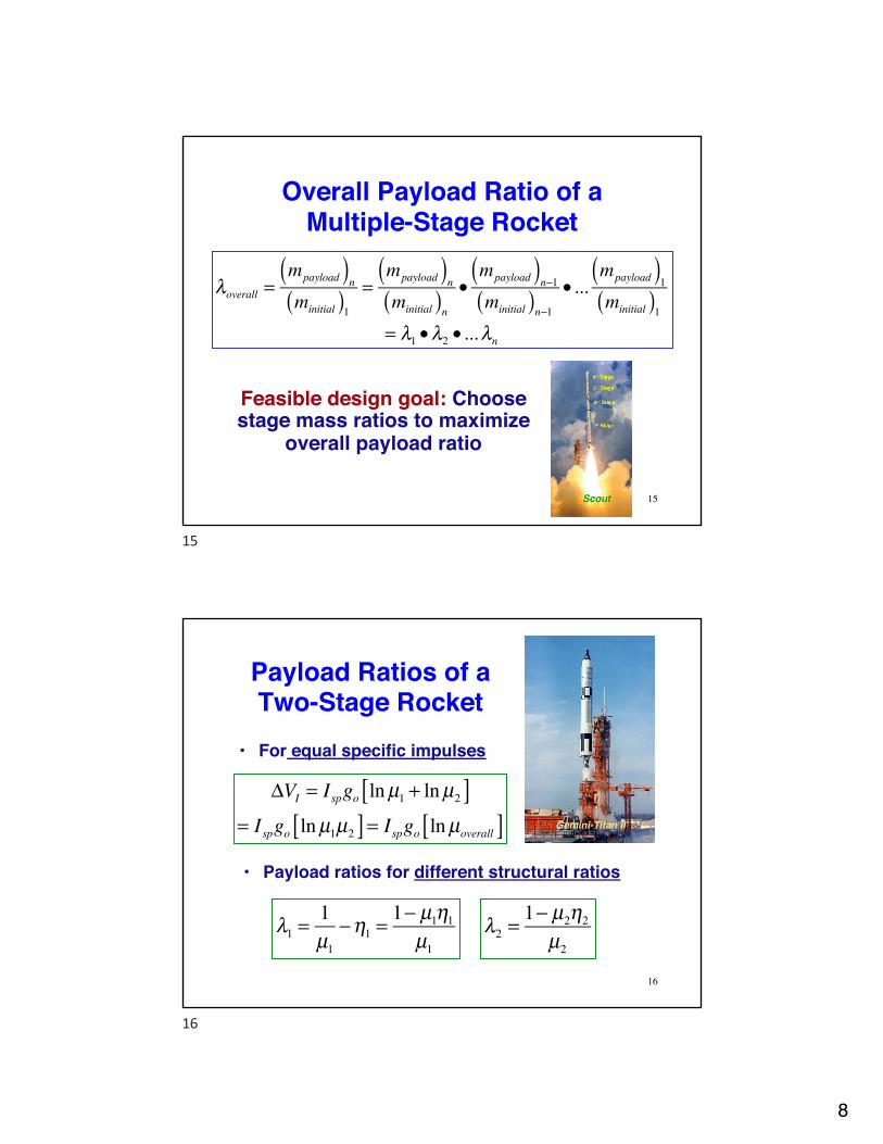
Overall Payload Ratio of a Multiple-Stage Rocket
Scout
λoverall =mpayload( )nminitial( )1
=mpayload( )nminitial( )n
•mpayload( )n−1minitial( )n−1
• ...mpayload( )1minitial( )1
= λ1 •λ2 • ...λn
Feasible design goal: Choose stage mass ratios to maximize
overall payload ratio
15
15
Payload Ratios of a Two-Stage Rocket
Gemini-Titan II
ΔVI = Ispgo lnµ1 + lnµ2[ ]= Ispgo lnµ1µ2[ ] = Ispgo lnµoverall[ ]
• For equal specific impulses
• Payload ratios for different structural ratios
λ1 =1µ1
−η1 =1− µ1η1
µ116
λ2 =1− µ2η2
µ2
16
9
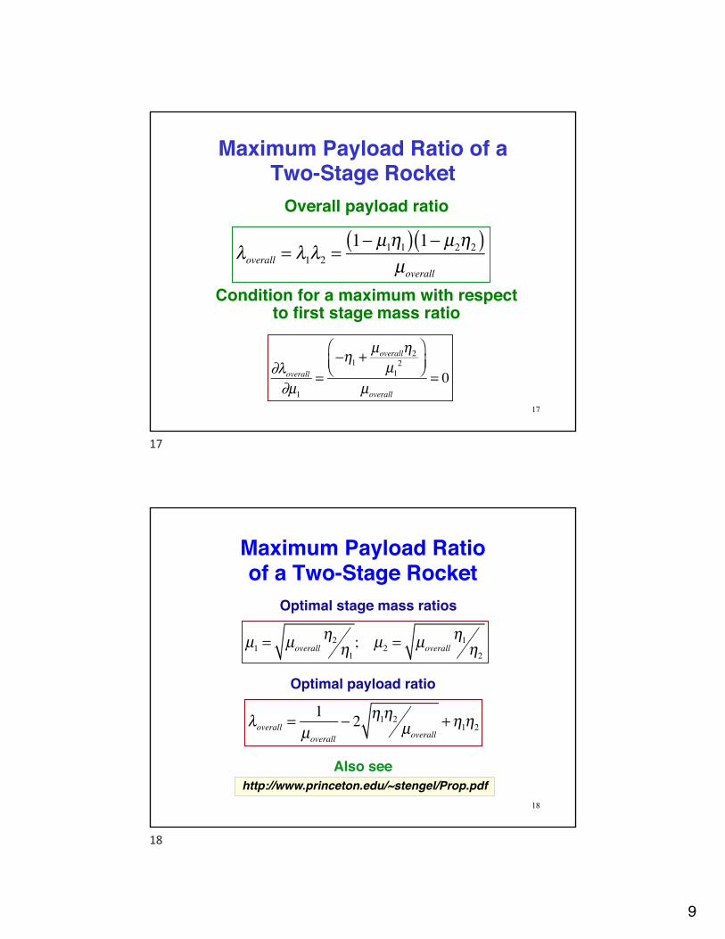
Maximum Payload Ratio of a Two-Stage Rocket
λoverall = λ1λ2 =1− µ1η1( ) 1− µ2η2( )
µoverall
Overall payload ratio
Condition for a maximum with respect to first stage mass ratio
∂λoverall
∂µ1=
−η1 +µoverallη2µ1
2
⎛⎝⎜
⎞⎠⎟
µoverall
= 0
17
17
Maximum Payload Ratio of a Two-Stage Rocket
Optimal stage mass ratios
µ1 = µoverallη2
η1; µ2 = µoverall
η1η2
http://www.princeton.edu/~stengel/Prop.pdfAlso see
18
λoverall =1
µoverall
− 2 η1η2µoverall
+η1η2
Optimal payload ratio
18
10
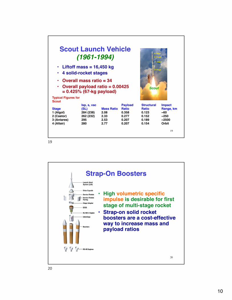
Scout Launch Vehicle(1961-1994)
• Liftoff mass = 16,450 kg• 4 solid-rocket stages
Scout
• Overall mass ratio = 34• Overall payload ratio = 0.00425
= 0.425% (67-kg payload)Typical Figures for Scout
StageIsp, s, vac (SL) Mass Ratio
Payload Ratio
Structural Ratio
Impact Range, km
1 (Algol) 284 (238) 2.08 0.358 0.123 ~602 (Castor) 262 (232) 2.33 0.277 0.152 ~2503 (Antares) 295 2.53 0.207 0.189 ~25004 (Altair) 280 2.77 0.207 0.154 Orbit
19
19
• High volumetric specific impulse is desirable for first stage of multi-stage rocket
• Strap-on solid rocket boosters are a cost-effective way to increase mass and payload ratios
20
Strap-On Boosters
20

11
Expendable vs. Reusable Launch Vehicles
• Expendable Vehicle– Low cost per vehicle– New vehicle for each
launch– Low structural ratio– Continued production– Launch preparation– Upgrade in production
• Reusable Vehicle– High initial cost– High structural ratio– Maintenance and repair– Non-reusable parts and
supplies– Launch preparation– Return to launch site– Upgrade– Replacement cost
21
21
Heavy-Lift “Big Dumb Boosters”c. 1963
Douglas Single-Stage-to-Orbit
General Dynamics, Martin, and Douglas Concepts
• Plug nozzle• Nozzle = Reentry Heat Shield• Fully recoverable
• 1-1/2 stage, fully recoverable• Recovery at sea• Ducted rocket
Objective: 450,000 kg to low earth orbit
22
22
12
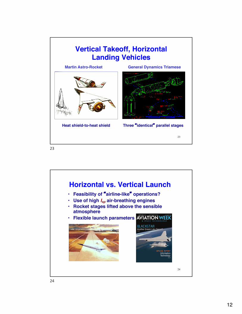
Vertical Takeoff, Horizontal Landing Vehicles
Martin Astro-Rocket General Dynamics Triamese
Heat shield-to-heat shield Three “identical” parallel stages
23
23
Horizontal vs. Vertical Launch• Feasibility of “airline-like” operations?• Use of high Isp air-breathing engines• Rocket stages lifted above the sensible
atmosphere• Flexible launch parameters
24
24

13
Pegasus Air-Launched Rocket
• Orbital-ATK• Three solid-rocket
stages launched from an aircraft
• Aerodynamic lift used to rotate vehicle for climb
• Initial mass: 18,000 to 23,000 kg
• Payload mass: 440 kg
25
25
Virgin Galactic LauncherOne and Vulcan Aerospace Stratolauncher
26
B747-400 CarrierLauncherOne
Two mated B747-400sPegasus 2
26
14
Specific Energy Contributed in Boost Phase
Total Energy = Kinetic plus Potential Energy (relative to flat earth)
Specific Total Energy = Energy per unit weight = Energy Height (km)
E = mV
2
2+mgh
E ' = V
2
2g+ h
27
27
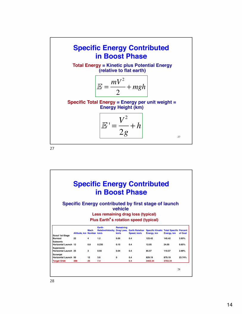
Specific Energy Contributed in Boost Phase
Specific Energy contributed by first stage of launch vehicle
Less remaining drag loss (typical)Plus Earth’s rotation speed (typical)
Altitude, kmMach Number
Earth-RelativeVelocity, km/s
Remaining Drag Loss, km/s
Earth Rotation Speed, km/s
Specific Kinetic Energy, km
Total Specific Energy, km
Percent of Goal
Scout 1st-Stage Burnout 22 4 1.2 0.05 0.4 123.42 145.42 3.93%Subsonic Horizontal Launch 12 0.8 0.235 0.15 0.4 12.05 24.05 0.65%Supersonic Horizontal Launch 25 3 0.93 0.04 0.4 85.57 110.57 2.99%Scramjet Horizontal Launch 50 12 3.6 0 0.4 829.19 879.19 23.74%Target Orbit 300 25 7.4 0.4 3403.34 3703.34
28
28

15
Trans-Atmospheric Vehicles(Aerospace Planes)
• Power for takeoff– Turbojet/fans– Multi-cycle air-breathing
engines/scramjets– Rockets
• Single-stage-to-orbit– Carrying dead weight into
orbit– High structural ratio for
wings, powerplants, and reusability
– SSTO has very low payload ratio
29
29
Trans-Atmospheric Vehicle Concepts
Boeing TAV Rockwell TAV Rockwell StarRaker
Lockheed Clipper Lockheed TAV
Various approaches to staging
30
30
16
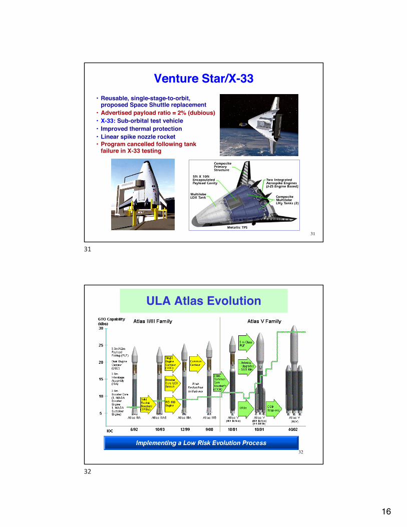
Venture Star/X-33• Reusable, single-stage-to-orbit,
proposed Space Shuttle replacement• Advertised payload ratio = 2% (dubious)• X-33: Sub-orbital test vehicle• Improved thermal protection• Linear spike nozzle rocket• Program cancelled following tank
failure in X-33 testing
31
31
32
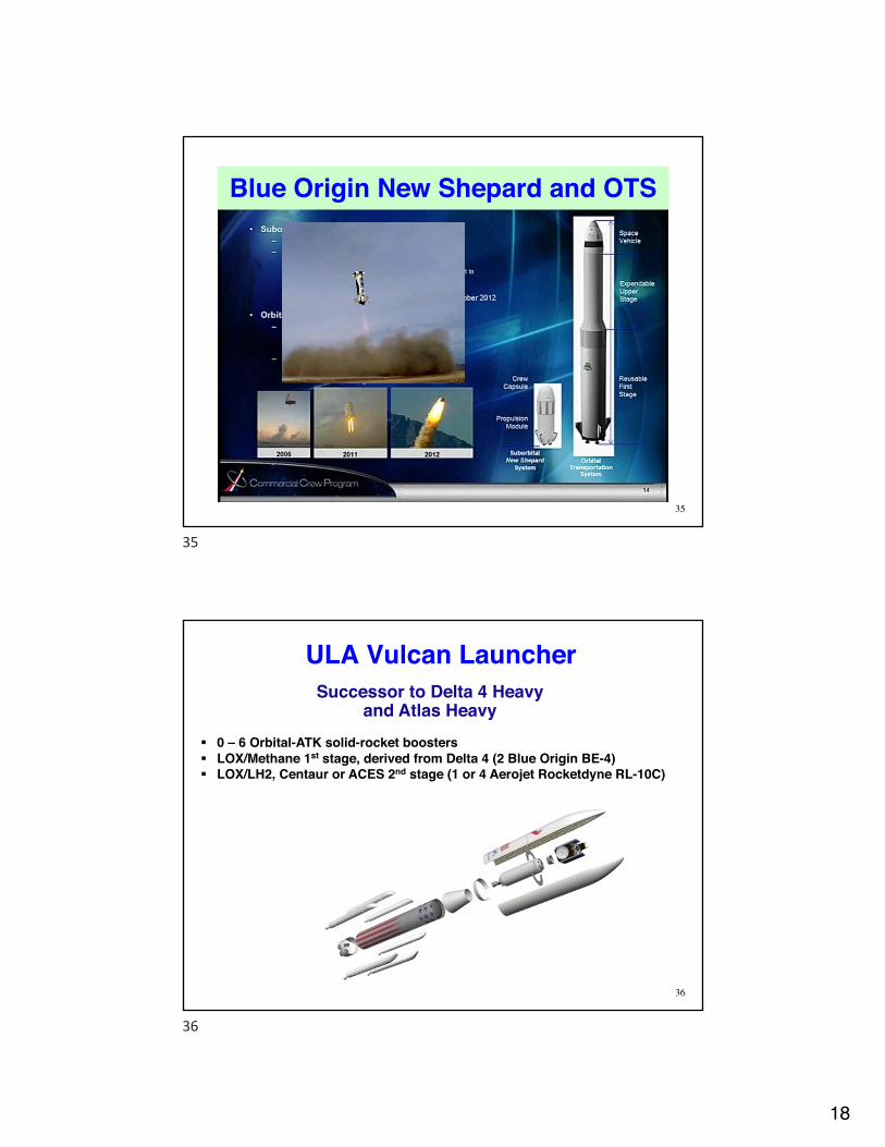
ULA Atlas Evolution
32

17
ULA Delta Evolution
33
33
Orbital-ATK Minotaur and Antares
34
Minuteman ICBM Derivative
RD-181 Motor
10/28/2014 Failure https://www.youtube.com/watch?v=9V1_BiTkHJ4
34
18
35
Blue Origin New Shepard and OTS
35
ULA Vulcan LauncherSuccessor to Delta 4 Heavy
and Atlas Heavy
36
§ 0 – 6 Orbital-ATK solid-rocket boosters§ LOX/Methane 1st stage, derived from Delta 4 (2 Blue Origin BE-4)§ LOX/LH2, Centaur or ACES 2nd stage (1 or 4 Aerojet Rocketdyne RL-10C)
36

19
Firefly Launch Vehicle and Aero-Plug Motor
37
37
SpaceX Falcon 9, Heavy
38
§ Falcon Heavy§ Payload to Low Earth Orbit –
53,000 kg§ Payload to Geosynchronous
Orbit = 21,200 kg§ Liftoff Mass = 1.462 x 10⁶
§ 2 stages, plus 2 boosters, all LOX/RP-1
§ 27 Merlin 1D (SL) 1st stage rockets
§ 1 Merlin 1D (vac) 2nd stage rocket
Falcon 9 Falcon Heavy
Falcon 9 Landing
38

20
Space Launch System
39
39
Launch Vehicle Structural Loads• Static/quasi-static loads
– Gravity and thrust– Propellant tank internal pressure– Thermal effects
• Rocket• Cryogenic propellant• Aerodynamic heating
• Dynamic loads– Bending and torsion– “Pogo” oscillations– Fuel sloshing– Aerodynamics and thrust vectoring
• Acoustic and mechanical vibration loads– Rocket engine– Aerodynamic noise
40
40

21
Structural Material Properties• Stress, σ: Force per unit area• Strain, ε: Elongation per unit length σ = E εProportionality factor, E: Modulus of elasticity, or Young’s Modulus
Strain deformation is reversible below the elastic limitElastic limit = yield strength
Proportional limit ill-defined for many materials
41
41
Structural Material Properties
Material Properties (Wikipedia)Young's Modulus, GPa
Elastic Limit, MPa
Density, g/cm^3
Aluminum Alloy 69 400 2.7Carbon-Fiber Composite 530 - 1.8Fiber-Glass Composite 125-150 - 2.5Magnesium 45 100 1.7Steel 200 250-700 7.8Titanium 105-120 830 4.5
42
42

22
Structural Stiffness• Geometric stiffness of a structure that bends about its x axis
is portrayed by its area moment of inertia
Ix = x z( )z2 dzzmin
zmax
∫
Area moment of inertia for simple cross-sectional shapes
• Solid rectangle of height, h, and width, w:
• Solid circle of radius, r:• Circular cylindrical tube with inner
radius, ri, and outer radius, ro: �
Ix = wh3 /12
�
Ix = πr4 /4
�
Ix = π ro4 − ri
4( ) /4
43
43
Structural Stiffeners• Axial stiffeners provide
high Ix per unit of cross-sectional area
• Circular stiffeners increase resistance to buckling
• Honeycomb and waffled surfaces remove weight while retaining Ix
44
44

23
Propellant Tank Configurationsfor Launch Vehicles
Serial tanks with common bulkhead
Separate serial tanks Parallel tanks
45
45
Mercury-Redstone Structure
Semi-monocoque structure (load-bearing skin stiffened by internal components)
External skin, internal tanks separated by longerons and circular stiffeners
Aerodynamic and exhaust vanes for thrust vectoring 46
46

24
Saturn IB First StageParallel tanks, external bracing
47
47
Saturn V First StageSeparate serial tanks within semi-
monocoque structure
48
48
25
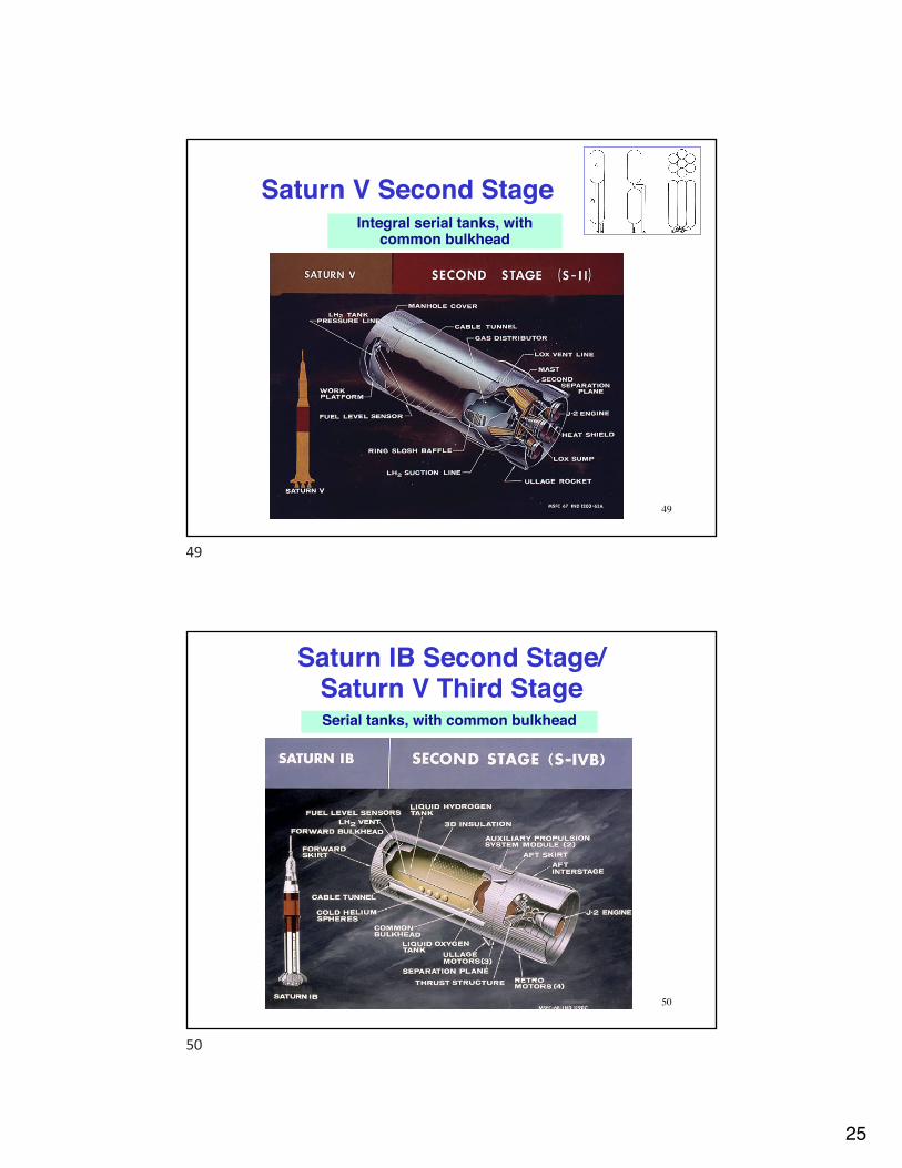
Saturn V Second StageIntegral serial tanks, with
common bulkhead
49
49
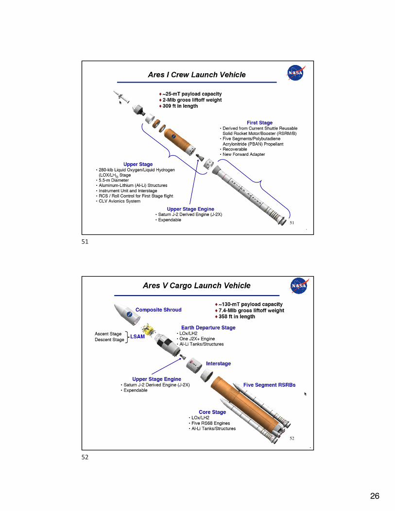
Saturn IB Second Stage/ Saturn V Third StageSerial tanks, with common bulkhead
50
50
26
51
51
52
52

27
Next Time:Spacecraft Structures
53
53