space technologies product catalogmediakit.sncorp.com/api/mediakit/sncspace/146/snc's... ·...
TRANSCRIPT


Sierra Nevada Corporation Space Technologies Product Catalog
Contact: SNC’s Space Systems, Space Technologies 1722 Boxelder Street • Louisville, CO 80027 USA • 303-530-1925
http://www.sncspace.com/ss_space_technologies.php
©2015 Sierra Nevada Corporation
Sierra Nevada Corporation’s Space Systems
Space Technologies Product Catalog 2015, Rev 3

Sierra Nevada Corporation Space Technologies Product Catalog
Contact: SNC’s Space Systems, Space Technologies 1722 Boxelder Street • Louisville, CO 80027 USA • 303-530-1925
http://www.sncspace.com/ss_space_technologies.php
©2015 Sierra Nevada Corporation iii
Table of Contents 2015 Space Technologies Product Catalog Introduction ............................................................................................................. 1
Product Catalog Summary ........................................................................................................................................................... 1
Space Technologies Product Line ................................................................................................................................................ 2
Facilities ............................................................................................................................................................................ 2
Engineering ............................................................................................................................................................................ 3
Disciplines ............................................................................................................................................................................ 3
Tools ............................................................................................................................................................................ 4
Deployable Systems .................................................................................................................................................................... 5
Jackscrew Deployed Boom .......................................................................................................................................................... 6
K-truss Boom ............................................................................................................................................................................ 8
Docking and Berthing Systems .................................................................................................................................................... 9
Electrical Power Systems ........................................................................................................................................................... 10
Cell Shorting Device Battery Switch ........................................................................................................................................... 11
Solar Array Assembly ................................................................................................................................................................. 13
Electronics .......................................................................................................................................................................... 15
Rotary Drive Electronics ............................................................................................................................................................. 16
Universal Microstepping Control Driver ...................................................................................................................................... 18
Flight and Thrust Vector Control Systems .................................................................................................................................. 20
Launch Support Products and Services ..................................................................................................................................... 21
Fast-Acting Shockless Separation Nut (FASSN) 30K ................................................................................................................ 22
Hold Down Release Mechanism (HDRM) 4K ............................................................................................................................. 24
QwkSep 15 Low-Profile Separation System .............................................................................................................................. 26
QwkSep 24 Low-Profile Separation System .............................................................................................................................. 28
Mechanical and Structural Systems ........................................................................................................................................... 30
EH-3525 HOP Actuator .............................................................................................................................................................. 31
IH-5055 High Output Paraffin (HOP) Actuator ........................................................................................................................... 33
SP-5025 High Output Paraffin (HOP) Actuator .......................................................................................................................... 35
Pointing Systems and Motion Control ........................................................................................................................................ 37
C14 Solar Array Drive Assembly ................................................................................................................................................ 38
C20 Incremental Rotary Actuator ............................................................................................................................................... 40
C50 Incremental Rotary Actuator ............................................................................................................................................... 42
EH25 Bi-Axis Gimbal, 3-Phase .................................................................................................................................................. 44
EH25 Incremental Rotary Actuator, 3-Phase ............................................................................................................................. 46

Sierra Nevada Corporation Space Technologies Product Catalog
Contact: SNC’s Space Systems, Space Technologies 1722 Boxelder Street • Louisville, CO 80027 USA • 303-530-1925
http://www.sncspace.com/ss_space_technologies.php
©2015 Sierra Nevada Corporation iv
eMotor .......................................................................................................................................................................... 48
H25 Bi-Axis Gimbal, 4-Phase ..................................................................................................................................................... 50
Lightweight 2-Axis Mini Gimbal .................................................................................................................................................. 52
Size 23 Rotary Actuator ............................................................................................................................................................. 54
T25 Incremental Rotary Actuator ............................................................................................................................................... 56
Thermal Control Systems ........................................................................................................................................................... 58
Sierra Nevada Corporation Space Technologies Product Catalog
Contact: SNC’s Space Systems, Space Technologies 1722 Boxelder Street • Louisville, CO 80027 USA • 303-530-1925
http://www.sncspace.com/ss_space_technologies.php
©2015 Sierra Nevada Corporation 1
Introduction Product Catalog Summary
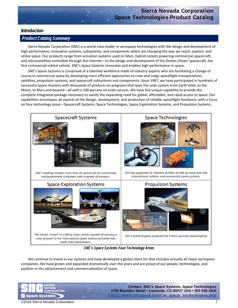
Sierra Nevada Corporation (SNC) is a world-class leader in aerospace technologies with the design and development of high performance, innovative systems, subsystems, and components which are changing the way we reach, explore, and utilize space. Our products range from actuation systems used on Mars, hybrid rockets powering commercial spacecraft, and microsatellites controlled through the Internet—to the design and development of the Dream Chaser®spacecraft, the first commercial orbital vehicle. SNC's Space Systems innovates and enables high performance in space.
SNC's Space Systems is comprised of a talented workforce made of industry experts who are facilitating a change of course in commercial space by developing more efficient approaches to crew and cargo spaceflight transportation, satellites, propulsion systems, and spacecraft subsystems and components. Since 1987, we have participated in hundreds of successful space missions with thousands of products on programs that span the solar system from Earth orbit, to the Moon, to Mars and beyond—all with a 100 percent on-orbit success. We have the unique capability to provide the complete integrated package necessary to satisfy the expanding need for global, affordable, and rapid access to space. Our capabilities encompass all aspects of the design, development, and production of reliable spaceflight hardware, with a focus on four technology areas—Spacecraft Systems, Space Technologies, Space Exploration Systems, and Propulsion Systems.
We continue to invest in our systems and have developed a global client list that includes virtually all major aerospace companies. We have grown and expanded dramatically over the years and are proud of our people, technologies, and position in the advancement and commercialization of space.
SNC's Space Systems Four Technology Areas
Credit: NASA
Credit: NASA

Sierra Nevada Corporation Space Technologies Product Catalog
Contact: SNC’s Space Systems, Space Technologies 1722 Boxelder Street • Louisville, CO 80027 USA • 303-530-1925
http://www.sncspace.com/ss_space_technologies.php
©2015 Sierra Nevada Corporation 2
Space Technologies Product Line SNC’s Space Systems was formed as a Business Area in
early 2009 through the consolidation of SpaceDev, Inc. (including SpaceDev’s subsidiary Starsys Research) and MicroSat Systems, Inc. SNC is an industry leader in precision space mechanisms and complex spacecraft subsystems. Our heritage of products that include thousands of devices successfully flown on hundreds of spacecraft are unmatched within the spaceflight community. Under the ownership of SNC, we have grown to become a supplier of choice offering an expanding portfolio of space-qualified products and subsystems. In summary, we are a spacecraft subsystems and components provider with significant flight heritage in:
• Deployable Systems • Docking and Berthing Systems • Electrical Power Systems • Electronics • Flight and Thrust Vector Control Systems • Launch Support Products and Services • Mechanical and Structural Systems • Pointing Systems and Motion Control • Thermal Control Systems
Facilities
SNC’s Space Systems is located in Louisville, CO, situated just southeast of Boulder, CO and is an easy drive from the Denver International Airport. In Louisville we have more than 100,000 square feet of office and manufacturing facilities that are dedicated to spaceflight subsystem and component assembly and test, small satellite end-to-end production, and the fabrication of our Dream Chaser® commercial crew and cargo vehicle. Our facility features:
• AS9100 certification • Precision temperature and humidity control • ISO 8 modular production floor • ISO 7 clean rooms • ISO 5 laminar flow benches • Specialized facilities for the handling, cleaning, and
assembly, and cleanliness verification of optical-grade products
• End-to-end testing capabilities including vibration, shock, radio frequency, thermal, thermal-vacuum, stiffness, and functional tests
• Large area pulsed solar simulator for solar array (SA) testing
Space Technologies Product Areas
Louisville, Colorado Facility ISO 8 Production Floor
Louisville, Colorado Thermal and Vacuum Chambers

Sierra Nevada Corporation Space Technologies Product Catalog
Contact: SNC’s Space Systems, Space Technologies 1722 Boxelder Street • Louisville, CO 80027 USA • 303-530-1925
http://www.sncspace.com/ss_space_technologies.php
©2015 Sierra Nevada Corporation 3
We employ a highly skilled team of industry experts leading the aerospace industry’s center of excellence in electro-mechanical motion control, located in Durham, NC. This tenured team of engineers and technicians focus on the design, development, and production of spaceflight motors, actuators, and electro-mechanical devices with unmatched experience and technology diversity. The Durham facility is located within minutes of the Raleigh-Durham International Airport and features:
• AS9100 certification • Precision temperature and humidity control • ISO 8 modular production floor • ISO 7 clean rooms • ISO 5 laminar flow benches • End-to-end testing capabilities including vibration,
thermal, thermal-vacuum, stiffness, motor/actuator speed-torque-accuracy, and functional testing
The Durham and Louisville locations share personnel and facility resources to optimize program execution based on our customers’ needs.
Other facilities include a dedicated propulsion group located in Madison, Wisconsin, and local business development offices in Washington D.C.; Houston, Texas; Huntsville, Alabama; and Exploration Park, Florida. Engineering
SNC’s Space Systems comprises a highly technical team of industry experts across a broad range of specialties. Our engineering group breadth and depth sets SNC apart from the competition and allows us to thoroughly and efficiently respond to our customers’ needs, both on production type programs, as well as custom engineered solutions. Our engineering disciplines and tools are summarized below: Disciplines
• Mechanical Engineering • Electrical Engineering • Structural Engineering • Systems Safety • Thermal Engineering • Quality Assurance • Radio Frequency Engineering • Structural Analysis • Guidance, Navigation, and Control Engineering • Reliability Assurance • Thermal Analysis • Finite Element Modeling
Dual-axis Vibration Table Testing

Sierra Nevada Corporation Space Technologies Product Catalog
Contact: SNC’s Space Systems, Space Technologies 1722 Boxelder Street • Louisville, CO 80027 USA • 303-530-1925
http://www.sncspace.com/ss_space_technologies.php
©2015 Sierra Nevada Corporation 4
Tools CAD • AutoCAD
• SolidWorks • Siemans NX
Structural Analysis • Thermal Desktop • SINDA G
Thermal • Thermal Desktop • SINDA G
Numerical Analysis • MATLAB • Simulink • Mathcad
Electrical Simulations • Pspice Electrical Design • OrCAD Magnetic/Motor Analysis • Speed
• EM Works • In-house design tools
Bearing Analysis • Bearings 10+ • Cobra • AB Jones
Gear Analysis • UTS Integrated Gear

Sierra Nevada Corporation Deployable Systems
Contact: SNC’s Space Systems, Space Technologies 1722 Boxelder Street • Louisville, CO 80027 USA • 303-530-1925
http://www.sncspace.com/ss_space_technologies.php
©2015 Sierra Nevada Corporation 5
Deployable Systems
While many spacecraft are decreasing in size, physics will maintain the demand for large aperture subsystems. For that reason, SNC considers deployable structures to be a critical element in the future of microsatellite systems. Our Jackscrew boom system utilizes high strength, high stiffness articulated truss elements that ensure low-risk linear deployment. The structure and deployment system is readily integrated into mass- and volume-efficient super structures for planar arrays. Our K-truss booms are engineered with a strain-energy deployment system that reduces cost and is constructed with a nonconductive material that enables antenna integration.
Catalog data sheets for the SNC’s Space Systems, Space Technologies Deployable Systems technology area include: • Jackscrew Deployed Boom • K-truss Boom

Sierra Nevada Corporation Jackscrew Deployed Boom
Contact: SNC’s Space Systems, Space Technologies 1722 Boxelder Street • Louisville, CO 80027 USA • 303-530-1925
http://www.sncspace.com/ss_space_technologies.php
©2015 Sierra Nevada Corporation 6
Jackscrew Deployed Boom Design Description
Sierra Nevada Corporation’s (SNC) Space Systems Jackscrew Deployed Boom is a motor deployed high stiffness and high strength articulated truss. The jackscrew boom deploys in a purely linear/axial manner without the use of deployment canisters for de-spin as required for motorized coilable booms. Therefore, the jackscrew boom provides multiple payload or cabling attachment points along the length of the boom with a deadband-free, high mechanically advantaged deployment without the parasitic mass of a canister. The jackscrew drive system offers mass and volume efficiency improvements over canister-deployed booms
The jackscrew boom deployment method also provides full structural integrity throughout deployment, thus allowing mid-deployment spacecraft maneuvering or other loading without the risk of collapsing the boom. The jackscrew boom can be re-stowed after deployment by reversal of the deployer motor.
The jackscrew boom system is composed of the deployable boom assembly and the deployer assembly. The deployer assembly uses a system of redundant belts driven by an electric motor to synchronize and drive a series of jackscrews. The deployer also includes four structural tubes that position the stowed boom and enclose the jackscrew drive shafts, a detent at each corner of the deployer, and four foldable jackscrews.
These components are illustrated in the Overview figures that follow. The triangular cross-section booms are also possible using three jackscrews. During deployment, the jackscrews (aka elevator screws) and deployment detent work together to sequentially expand and form each bay of the boom as it is deployed. At least one batten frame of the boom is engaged with the jackscrews at any point in time during deployment providing full structural integrity throughout deployment. The deployer jackscrews are restrained in their folded, stowed configuration during launch and prior to boom deployment. Following a signal to initiate deployment, the jackscrews are released and transition to their deployed, locked configuration. A brushless D/C motor provides power to the system and limit switches identify first motion and successful deployment of the boom.
Features • Purely linear/axial deployment • High force deployment/retraction • Exposed payload interfaces throughout
deployment and during pre-flight integration • Highly scalable and mass optimized
• Highly tailorable for thermal stability, strength, and stiffness • Full stiffness and strength during deployment • Simple, high reliability, high tension deployment
Jackscrew Deployed Boom under Test

Sierra Nevada Corporation Jackscrew Deployed Boom
Contact: SNC’s Space Systems, Space Technologies 1722 Boxelder Street • Louisville, CO 80027 USA • 303-530-1925
http://www.sncspace.com/ss_space_technologies.php
©2015 Sierra Nevada Corporation 7
Overview
10-Bay Jackscrew Stowed Boom Deployed Boom Cantilevered with 11-lb Tip Mass (no offloading) Product Specifications for a 10-Bay Jackscrew Boom
• Dimensions: 190” long x 15.5” diameter
• 1st Bending Mode: 6.9 Hz • Tip Torsion Stiffness: 13,594 in-lb/rad
• Mass: 11.7 lb • 1st Torsion Mode: 16.4 Hz • Tip Shear Stiffness: 25 lb/in Typical Applications
• Solar Array/Solar-Sail Deployment/Retraction
• Synthetic Aperture Radar (SAR) Deployment/Retraction
• Gravity Gradient Mass Deployment/Retraction
• Antenna Deployment/Retraction • Instrument Deployment/Retraction • Spacecraft Separation

Sierra Nevada Corporation K-truss Boom
Contact: SNC’s Space Systems, Space Technologies 1722 Boxelder Street • Louisville, CO 80027 USA • 303-530-1925
http://www.sncspace.com/ss_space_technologies.php
©2015 Sierra Nevada Corporation 8
K-truss Boom Design Description
Sierra Nevada Corporation’s (SNC) Space Systems K-truss Boom is an elastically deployed boom which utilizes stowed energy for deployment. The K-truss boom deploys in a purely linear/axial manner unlike a conventional lanyard deployed coilable boom. Therefore the K-truss boom provides multiple payload or cabling attachment points to allow the deployment of objects along the length of the boom before, during, and after deployment.
This type of boom simplifies deployable structures on small satellites by eliminating the need for a drive motor and electronics. The resulting boom provides a nonrotating deployment with unprecedented thermal stability, precision, and repeatability, in addition to high stiffness and high strength. This type of deployed structure is applicable to many spacecraft that have been traditionally limited to fiberglass coilable type booms. This enabling boom technology can increase satellite application capabilities, improve reliability, and reduce costs.
Features • Exposed payload interfaces throughout deployment and
during pre-flight integration • Highly tailorable for thermal stability, strength, and stiffness • Predictable deployment behavior • Elastically deployed “tape” joints eliminate motorized
actuation mass
• Nonconductive/magnetically “clean” materials available for integrated antennae or magnetometers
• Highly scalable and mass optimized • Zero deadband monolithic structure • Precision deployment and pointing accuracy of the
payload Overview
Stowed K-truss Boom Deployed K-truss Boom Section
Product Specifications for an 8-Bay K-truss Boom • Dimensions: 101.5” long x 9.5” dia. • 1st Bending Mode: 3.5 Hz • System Mass: <15 lb • Bending Stiffness: 1.14 lb/in
Typical Applications • Solar Array/ Solar-Sail Deployment • Attitude Control Thrusters • Gravity Gradient Mass Deployment • Antenna Deployment • Instrument Deployment • Magnetometer Deployment
K-truss Boom with Quadrifilar Helical Antenna under Test
Sierra Nevada Corporation Docking and Berthing Systems
Contact: SNC’s Space Systems, Space Technologies 1722 Boxelder Street • Louisville, CO 80027 USA • 303-530-1925
http://www.sncspace.com/ss_space_technologies.php
©2015 Sierra Nevada Corporation 9
Docking and Berthing Systems
SNC solidified our docking and berthing technology by being a major subcontractor on the Orbital Express program, providing the system that captured and docked two spacecraft together on-orbit to allow for remote servicing such as refueling and replacement of outdated and expended components. We were then able to leverage that mechanical systems experience into becoming the go-to supplier for the industry standard Passive Common Berthing Mechanism (PCBM), required for spacecraft such as the Orbital Cygnus Advanced Maneuvering Vehicle and the Bigelow Expandable Activity Module to berth with the International Space Station.
Catalog data sheets for SNC’s Space Systems, Space Technologies Docking and Berthing Systems technology area include:
• Passive Common Berthing Mechanism (PCBM) coming soon

Sierra Nevada Corporation Electrical Power Systems
Contact: SNC’s Space Systems, Space Technologies 1722 Boxelder Street • Louisville, CO 80027 USA • 303-530-1925
http://www.sncspace.com/ss_space_technologies.php
©2015 Sierra Nevada Corporation 10
Electrical Power Systems
SNC provides low-cost, highly scalable power systems with power ranges from 100 W to 10 kW. SNC offers end-to-end electric power solutions (EPS) consisting of fully assembled and tested solar arrays, solar array drives, slip rings, hinges, hold down mechanisms, power electronics, batteries, and motor control electronics. Our engineering teams have the expertise and experience to define, analyze, and test complete power systems utilizing state of the art tools and integration equipment. Our heritage and scalable power systems can be tailored to fit a wide variety of mission options with reduced cost and risk by incorporating existing qualified and flight-proven designs. SNC has heritage EPS designs ranging from 28 V to 125 V, with power from 750 W to 3,000 W.
Catalog data sheets for SNC’s Space Systems, Space Technologies Electrical Power Systems technology area include: • C14 Solar Array Drive Assembly (SADA) • Cell Shorting Device (CSD) Battery Switch • Solar Array Assembly • T25 Incremental Rotary Actuator

Sierra Nevada Corporation Cell Shorting Device Battery Switch
Contact: SNC’s Space Systems, Space Technologies 1722 Boxelder Street • Louisville, CO 80027 USA • 303-530-1925
http://www.sncspace.com/ss_space_technologies.php
©2015 Sierra Nevada Corporation 11
Cell Shorting Device Battery Switch Design Description
Sierra Nevada Corporation’s (SNC) Space Systems Cell Shorting Device (CSD) Battery Switch is a robust, spaceflight proven mechanism that passively removes a cell from a spacecraft battery’s electrical circuit. The CSD shorts across the cell terminals once the cell has begun to fail (or has failed) and the voltage has been driven into reversal.
The device is a mechanical switch that closes when a spring-loaded latch is released by a small paraffin actuator. Different from standard SNC actuators, which use a heater to melt the paraffin, the CSD actuator uses diodes directly attached to the actuator body. Since the diodes only allow current to flow in one direction, during normal operation no current flows through the CSD. When the cell goes into voltage reversal, current is allowed to flow through the CSD and the diodes. As the current level increases, the temperature of the diodes increases and melts the paraffin. The expanding paraffin extends the actuator output shaft, which releases the latch mechanism after a period of 10 seconds to 1 minute (depending on temperature and current level). Once the latch is released, a compression spring drives a wedge contact between the two fixed contacts, closing the circuit and shorting the cell across the terminals.
Initially designed to attach directly to the terminals, the mounting options for the CSD can be changed depending on the cell configuration and customer requirements. The CSD works on both Ni-H2 and Li-ion batteries.
Features • Mounting interface easily configurable • Simple, high reliability operation • Passive operation requires no control electronics • Small size and low-mass package
Dimensions
Note: All length dimensions above are in inches.
Cell Shorting Device Battery Switch

Sierra Nevada Corporation Cell Shorting Device Battery Switch
Contact: SNC’s Space Systems, Space Technologies 1722 Boxelder Street • Louisville, CO 80027 USA • 303-530-1925
http://www.sncspace.com/ss_space_technologies.php
©2015 Sierra Nevada Corporation 12
Heritage Programs • Amazonas 3 (an Hispasat group
of Spanish communication satellites)
• Intermediate Circular Orbit (ICO) communications satellite
• Satmex 6 and 8 (Satélites Mexicanos)
• Anik G1 (a fixed satellite services multi-mission satellite; Telesat, Canada)
• Intelsat 14, 17, 19, and 20 (International Telecommunications communication satellites)
• SES Sirius 5 (a Société Européenne des Satellites, German communication satellite)
• AsiaSat 5 and 7 (Chinese communication satellites)
• iPSTAR (a Thailand geostationary communications satellite)
• Spainsat (Spanish Ministry of Defense communications satellite)
• DirecTV-9 (U.S. geostationary communications satellite)
• Jupiter (Hughes Network Systems, U.S. communications satellite)
• Superbird 7 (a Japanese communications satellite)
• EchoStar XI, XIV, XV, and XVI (U.S. communications satellites)
• New Skies Satellites (NSS) 12 and 14 (now SES World Skies; Dutch communications satellites)
• Telstar 11N and 14R (broad Ku-band communications satellites Telesat, Canada)
• Galaxy 16, 18, and 19 (U.S. communications satellites)
• Nimiq 5 and 6 (Telesat, Canada communications satellites)
• XM5 (a digital audio radio service satellite)
• Hispasat 1E (a Spanish communications satellite)
• QuetzSat (a Mexican geostationary communications satellite)
Product Specifications U.S. SI Mechanical Envelope dimensions 1.85” x 3.26” x 0.63” 4.69 cm x 8.27 cm x 1.59 cm Mass < 2.3 oz < 65 grams Life cycles Single on-orbit operation Operation time (with 60 amps @ ambient temp/pressure) ~ 25 seconds Electrical Forward voltage drop, Vf (at 100 amps, 300 µsec pulse) < 0.65 Vdc Reverse leakage current, Ir (at 30 Vdc) < 30 mA Case insulation (at 250 Vdc) > 100 MΩ Closed circuit resistance (at 60 amps, ambient temp/pressure) < 0.54 mΩ Switch may activate voltage (at 95 amps) > 0.16 Vdc but < 0.70 Vdc Switch must activate current ≥ 20 amps Fuse no blow Continuously at 110 amps Fuse must blow < 1 sec at 1,300 amps; < 0.1 sec at 2,500 amp Thermal Operating temperatures +14 °F to +113 °F -10 °C to +45 °C Nonoperating temperatures -13 °F to +167 °F -25 °C to +75 °C Paraffin non-op temp (standard) +176 °F +80 °C History More than 100 million hours on-orbit (through May 2013) More than 2,900 units on 42 spacecraft (through May 2013) Note: This data is for information only and subject to change. Contact SNC’s Space Systems, Space Technologies for design data.

Sierra Nevada Corporation Solar Array Assembly
Contact: SNC’s Space Systems, Space Technologies 1722 Boxelder Street • Louisville, CO 80027 USA • 303-530-1925
http://www.sncspace.com/ss_space_technologies.php
©2015 Sierra Nevada Corporation 13
Solar Array Assembly Design Description
Sierra Nevada Corporation’s (SNC) Space Systems provides low-cost, highly scalable satellite power systems with power ranges from 100 W to 10 kW. SNC offers end-to-end electric power solutions consisting of fully assembled and tested solar array wings, solar array drives, slip rings, power control and distribution electronics, batteries, and motor control electronics in a wide variety of options to meet various mission requirements. SNC has provided systems, subsystems, and components on more than 450 space missions.
SNC has developed and qualified a solar array assembly capable of delivering 780 W at the beginning of life. More than 18 of these assemblies have been delivered to ORBCOMM for the OG2 program.
Our in-house experts can modify the OG2 array to meet specific requirements or design a new system depending on mission constraints. Our power engineers have developed standardized tools and processes for performing rapid power analysis while incorporating detailed thermal and radiation models.
The SNC solar array utilizes Emcore Gallium Arsenide ZTJ cells with an effective area of 27.5 cm2 and 59.7 cm2 operating with efficiency greater than 29.2 percent. These cells have been qualified for 22,000 cycles at a temperature range of -165 °C to +125 °C. SNC has also designed arrays with the new larger cells provided by Spectrolab and Emcore to reduce the overall recurring cost of solar power.
The substrate panels are a typical construction of M55J/EX1515 face sheets bonded to a 0.515 inch low density 5056 aluminum perforated honeycomb core with a Kapton cover for the cell installation surface. The panels for this array are approximately 40.6 inches by 33.4 inches with an overall array deployed length of 105.2 inches.
Four hold down and release mechanisms (HDRM) restrain each wing in the stowed condition through cup/cone shear features incorporated in each panel. Following release, spring-driven hinges with integral dampers passively extend the array in a controlled and predictable fashion. Each solar array wing stows completely within the allowable envelope with a predicted stowed first mode frequency of 60 Hz. SNC can tailor the Yoke design, HDRM locations and panel aspect ratio to accommodate the spacecraft bus design.
The array will undergo rigorous environmental, deployment, and electrical tests at SNC. Depending on the size of the array, SNC can perform in-house random and sine vibration testing, thermal vacuum testing, and thermal cycle testing. Before and after each test, the array will be subjected to a Large Area Pulsed Solar Simulator (LAPSS). SNC has the capability in-house to perform LAPSS testing on a variety of panel sizes.
Features • Scalable power system based on existing design • High efficiency Gallium Arsenide cells • Complete power system solution • Low mass • Heritage flight-proven design minimizes NRE • Customizable • High reliability solar cells • Heritage mechanisms
OG2 Deployed Array

Sierra Nevada Corporation Solar Array Assembly
Contact: SNC’s Space Systems, Space Technologies 1722 Boxelder Street • Louisville, CO 80027 USA • 303-530-1925
http://www.sncspace.com/ss_space_technologies.php
©2015 Sierra Nevada Corporation 14
Note: All length dimensions above are in inches.
Heritage Programs • ORBCOMM (OG2) • TacSat-2 • Demonstration Science Experiment (DSX) • CYGNSS (ongoing contract)
Dimensions
Product Specifications U.S. SI Mechanical Envelope dimensions (deployed) 105.2” x 40.6” 2,672 mm x 1,031 mm Envelope dimensions (stowed) 33.4” x 40.6” 848 mm x 1,031 mm Mass 35.3 lb 16 kg Life cycles 22,000 thermal cycles Coverglass Qioptiq 6 mil CMG/AR Substrates M55J 15 mil facesheets, .375” perforated core, 2 mil Kapton Temperatures sensors 1 PRT per Panel Electrical Cell type Emcore ZTJ (27.55 cm2) Number of strings 15 Number of cells per string 17 Cells in Series Number of panels 3 Power end of life (EOL) (OG2 mission) 636 W Cell efficiency beginning of life (BOL) 29.2% Voc @ 60C EOL 38.5 V Isc @ 60C EOL 13.3 A Vmp @ 60C EOL 33.8 V Imp @ 60C EOL 12.8 A Pmax @ 60C EOL 432.9 W Thermal Test temperature range -265 °F to +257 °F -165 °C to +125 °C Note: This data is for information only and subject to change. Contact SNC’s Space Systems, Space Technologies for design data.
Deployed Stowed

Sierra Nevada Corporation Electronics
Contact: SNC’s Space Systems, Space Technologies 1722 Boxelder Street • Louisville, CO 80027 USA • 303-530-1925
http://www.sncspace.com/ss_space_technologies.php
©2015 Sierra Nevada Corporation 15
Electronics
SNC has designed and developed space heritage motor controllers and electronics to complement its qualified array of flight motors, actuators, and gimbals. Based upon flight industry standards and typical stepper motor applications, SNC electronics provide multi-channel motor control with enhanced microstepping, current limiting and acceleration/deceleration capability. Each channel can be programmed independently for customized biaxial actuator control. The command interfaces are configurable for 2 or 3 bipolar and 4-phase stepper motors, and can provide peak current and constant torque over full input voltage range and variations in motor resistance over temperature. Heritage controller offerings include basic motor operation control with selectable microstep resolution and current limit, as well as telemetry update and processing capability (position and temperature) on more customized, flight-proven electronic control units.
Catalog data sheets for SNC’s Space Systems, Space Technologies Electronics technology area include: • Rotary Drive Electronics (RDE) • Universal Microstepping Control Driver

Sierra Nevada Corporation Rotary Drive Electronics (RDE)
Contact: SNC’s Space Systems, Space Technologies 1722 Boxelder Street • Louisville, CO 80027 USA • 303-530-1925
http://www.sncspace.com/ss_space_technologies.php
©2015 Sierra Nevada Corporation 16
Rotary Drive Electronics Design Description
Sierra Nevada Corporation’s (SNC) Rotary Drive Electronics (RDE) is a robust redundant motor controller designed to operate in the extreme environments of space. The RDE provides the interface platform between spacecraft commands and the permanent magnet stepper motor of the Rotary Drive Assembly (RDA).
As a stand-alone unit, the RDE receives commands and transmits telemetry via a Mil-Std-1553 serial data bus. The I/O through the 1553 bus is controlled by an internal Field Programmable Gate Array (FPGA). Commands are received and processed to determine the appropriate RDA motion sequence. The FPGA controls motion through a collection of control signals and data lines that in turn control output amplifiers. The RDE can also process RDA status information (i.e., rotational position telemetry) and transmit collected information when requested via the 1553 interface.
In the microstep operational mode, the RDE controls individual motor phases with two quadrature sinusoidal signals. The phase and frequency of the sinusoidal drive signals are controlled by a commanded step rate. This ability to drive stepper motors in microstep mode provides the added benefits of control stability and low disturbance torque.
Features • 4-phase stepper motor controller, redundant • Flight-qualified; heritage design • 1553 command Interface • EMI/EMC compliant enclosure • Telemetry processing (rotary potentiometer) • Radiation-hardened components
Dimensions
Note: All length dimensions above are in inches.
Rotary Drive Electronics
Sierra Nevada Corporation Rotary Drive Electronics (RDE)
Contact: SNC’s Space Systems, Space Technologies 1722 Boxelder Street • Louisville, CO 80027 USA • 303-530-1925
http://www.sncspace.com/ss_space_technologies.php
©2015 Sierra Nevada Corporation 17
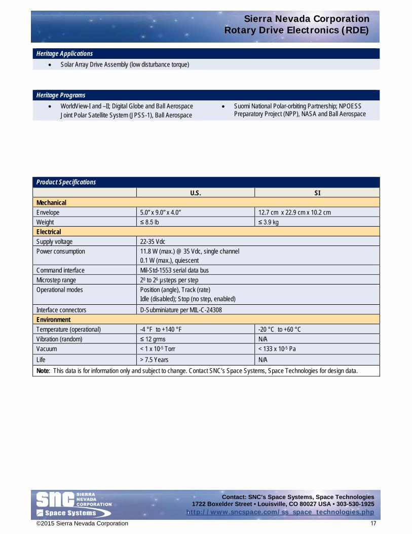
Heritage Applications • Solar Array Drive Assembly (low disturbance torque)
Heritage Programs
• WorldView-I and –II; Digital Globe and Ball Aerospace Joint Polar Satellite System (JPSS-1), Ball Aerospace
• Suomi National Polar-orbiting Partnership; NPOESS Preparatory Project (NPP), NASA and Ball Aerospace
Product Specifications U.S. SI Mechanical Envelope 5.0” x 9.0” x 4.0” 12.7 cm x 22.9 cm x 10.2 cm Weight ≤ 8.5 lb ≤ 3.9 kg Electrical Supply voltage 22-35 Vdc Power consumption 11.8 W (max.) @ 35 Vdc, single channel
0.1 W (max.), quiescent Command interface Mil-Std-1553 serial data bus Microstep range 20 to 26 µsteps per step Operational modes Position (angle), Track (rate)
Idle (disabled); Stop (no step, enabled) Interface connectors D-Subminiature per MIL-C-24308 Environment Temperature (operational) -4 °F to +140 °F -20 °C to +60 °C Vibration (random) ≤ 12 grms N/A Vacuum < 1 x 10⁻⁵ Torr < 133 x 10-5 Pa Life > 7.5 Years N/A Note: This data is for information only and subject to change. Contact SNC’s Space Systems, Space Technologies for design data.

Sierra Nevada Corporation Universal Microstepping Control Driver
Contact: SNC’s Space Systems, Space Technologies 1722 Boxelder Street • Louisville, CO 80027 USA • 303-530-1925
http://www.sncspace.com/ss_space_technologies.php
©2015 Sierra Nevada Corporation 18
Universal Microstepping Control Driver Design Description
Sierra Nevada Corporation’s (SNC) Space Systems Universal Microstepping Control Driver (UMCD) is a versatile stepper motor driver providing two channels of motor control with selectable microstep resolution and current limit.
The UMCD’s microstepping capability enables smooth motion for open-loop control of a stepper motor driven mechanism. The microstep resolution can be configured independently for each channel to 1, 2, 4, 8, 16, 32, and 64 microsteps per motor detent.
Torque disturbances generated by stepper motor operation can be reduced by 1 to 3 orders of magnitude depending on the motor and actuator characteristics. SNC specializes in the optimization of motors, gearing, and drives for low-torque disturbance applications.
The UMCD is configurable for 2- or 3-phase bipolar stepper motor control. The UMCD provides up to 1.2 amps of peak current on each channel and operates directly from spacecraft bus voltages of 22 Vdc to 36 Vdc. Current regulation maintains constant peak torque over full input voltage range and variations in motor resistance over temperature. The opto-isolated logic level inputs include commands to provide power to the motor and select the direction of rotation. In addition, a step command enables the motor to advance by one step or microstep per input pulse.
Features • Optically coupled command lines for use in noisy
environments • Standard STEP, DIRECTION, ENABLE commands optically
isolated for each channel • Two channels independently enabled • Each channel drives one motor
Dimensions
Note: All length dimensions above are in inches.
Universal Microstepping Control Driver

Sierra Nevada Corporation Universal Microstepping Control Driver
Contact: SNC’s Space Systems, Space Technologies 1722 Boxelder Street • Louisville, CO 80027 USA • 303-530-1925
http://www.sncspace.com/ss_space_technologies.php
©2015 Sierra Nevada Corporation 19
Heritage Applications • Antenna Pointing • Solar Array Drives
Heritage Programs
• GeoEye 1 • Samaritan • Tenacious
Product Specifications U.S. SI Mechanical Envelope dimensions 4.5” x 4.5” x 1.75” 11.4 cm x 11.4 cm x 4.4 cm Mass 2.0 lb 0.9 kg Electrical Input operating voltage 28 Vdc ± 6 Vdc Power Dissipation (excluding pass thru power) ≤1.0 W Inrush current ≤1.5 amp for 7.5 ms Power isolation ≥ 10 mΩ power to chassis ground Operation Input commands Enable, Direction, Step Logic ‘1’ input level 3.8 V ≤ V in ‘1’ ≤ 5.5 V, 5.1 ma ≤ I in '1' ≤ 18 ma Logic ‘0’ input level 0 V ≤ V in ‘0’ ≤ 0.7 Vdc, Iin ≤ 50 μa Step mode Cardinal stepping or microstepping Resolution 1, 2, 4, 8, 16, 32, or 64 μ-step per step (configurable) Step rate 10,000 μ-steps per second (maximum) Number of phases 2- or 3-phase (bipolar, configurable) Direction command sense Logic ‘1’ or Logic ‘0’ (configurable, each channel) Output current/channel Settable from 200 ma to 850 mA peak, each phase
2-phase mode, 16, 32, and 64 μ-step resolution Settable from 200 ma to 600 mA peak, each phase 2-phase mode, 1, 2, and 8 μ-step resolution Settable from 200 ma to 1.2 A (max) peak, L-2L, 3-phase mode, all resolutions
Environmental Operating temperature -40 °F to +140 °F -40 °C to +60 °C Nonoperating temperature -58 °F to +158 °F -50 °C to +70 °C Radiation 100 Krad TID (SI) Vibration 25 g (sine sweep) 35 to 70 Hz Note: This data is for information only and subject to change. Contact SNC’s Space Systems, Space Technologies for design data.

Sierra Nevada Corporation Flight and Thrust Vector Control Systems
Contact: SNC’s Space Systems, Space Technologies 1722 Boxelder Street • Louisville, CO 80027 USA • 303-530-1925
http://www.sncspace.com/ss_space_technologies.php
©2015 Sierra Nevada Corporation 20
Flight and Thrust Vector Control Systems
SNC's Thrust Vector Control (TVC) Systems leverage our extensive experience in space-qualified actuator and electronics design. The Dream Chaser® vehicle’s electro-mechanical TVC and Flight Control Systems were designed in-house at SNC to very demanding requirements leveraging spaceflight-proven hardware and engineering methods. SNC TVC Systems are designed to meet complete vehicle control requirements with highly scalable actuators and electronics thus minimizing cost and schedule. In addition to entire TVC systems, SNC's TVC actuators can be used as a cost-effective and reliable replacement for existing TVC system actuators.
Catalog data sheets for SNC’s Space Systems, Space Technologies Flight and Thrust Vector Control Systems technology area include:
• Flight and Thrust Vector Control Systems catalog sheets coming soon

Sierra Nevada Corporation Launch Adapters and Separation Systems
Contact: SNC’s Space Systems, Space Technologies 1722 Boxelder Street • Louisville, CO 80027 USA • 303-530-1925
http://www.sncspace.com/ss_space_technologies.php
©2015 Sierra Nevada Corporation 21
Launch Adapters and Separation Systems
SNC has supported both U.S. and international launch services for decades with a variety of technologies needed for reliable and gentle deployment of payloads and spacecraft into proper orbit. Devices such as our low-shock Clamp Band Opening Devices (CBOD) are now used to release dozens of primary payloads each year on nearly every major launch vehicle in the world. Other products such as our Fast Acting Shock-less Separation Nuts (FASSN) have become the go-to method for safely restraining and releasing the cargo pallet on every H2 Transfer Vehicle to assist in delivering critical equipment and supplies to the International Space Station. At a higher subsystem level, our Qwksep clamp-band type separation systems are quickly becoming recognized as a new, robust industry standard to deploy smaller satellites and constellations at lower cost and higher reliability. And with the backing and resources of a prime integrator such as SNC, we are now able to offer larger structural systems such as our own Dream Chaser® Launch Vehicle Integration System as well as dispensers, adapters, and integration services required for carrying both single and multiple spacecraft onward to their mission in space.
Catalog data sheets for the SNC’s Space Systems, Space Technologies Launch Support Products and Services technology area include:
• Fast-Acting Shockless Separation Nut (FASSN) 30K • Hold Down Release Mechanism 4K • QwkSep 15 Low-Shock Separation System • QwkSep 24 Low Shock Separation System
Sierra Nevada Corporation Fast-Acting Shockless Separation Nut (FASSN) 30K
Contact: SNC’s Space Systems, Space Technologies 1722 Boxelder Street • Louisville, CO 80027 USA • 303-530-1925
http://www.sncspace.com/ss_space_technologies.php
©2015 Sierra Nevada Corporation 22
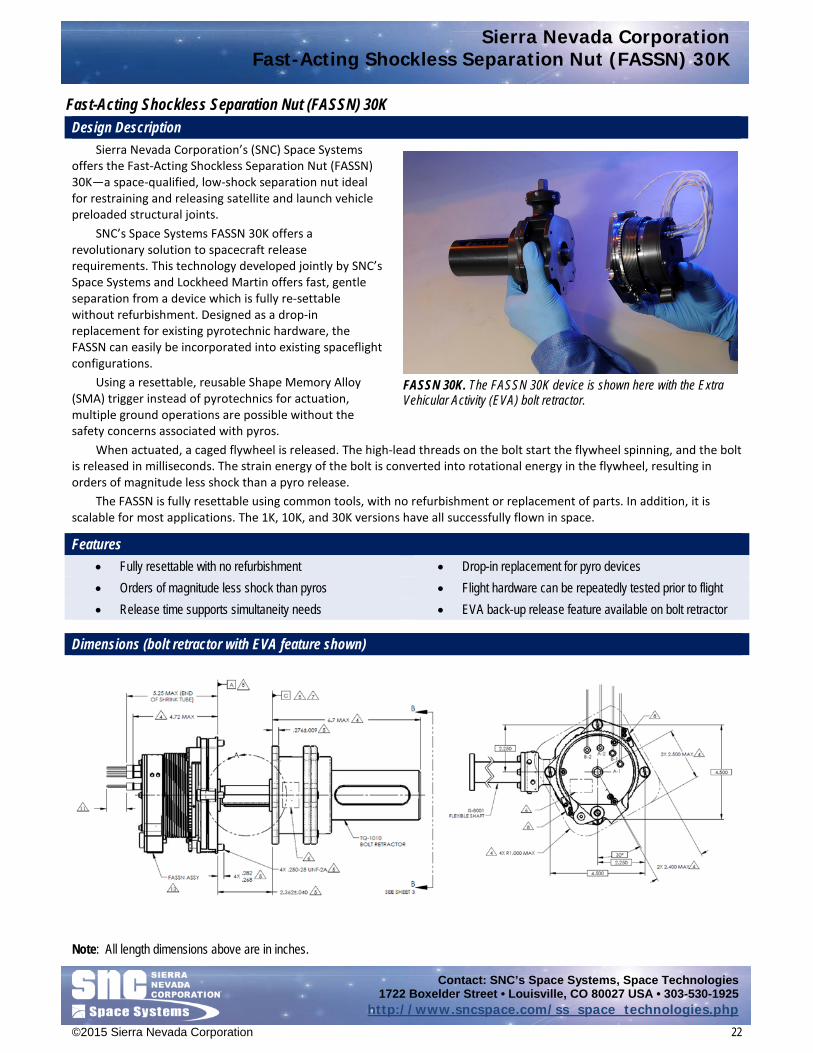
Fast-Acting Shockless Separation Nut (FASSN) 30K Design Description
Sierra Nevada Corporation’s (SNC) Space Systems offers the Fast-Acting Shockless Separation Nut (FASSN) 30K—a space-qualified, low-shock separation nut ideal for restraining and releasing satellite and launch vehicle preloaded structural joints.
SNC’s Space Systems FASSN 30K offers a revolutionary solution to spacecraft release requirements. This technology developed jointly by SNC’s Space Systems and Lockheed Martin offers fast, gentle separation from a device which is fully re-settable without refurbishment. Designed as a drop-in replacement for existing pyrotechnic hardware, the FASSN can easily be incorporated into existing spaceflight configurations.
Using a resettable, reusable Shape Memory Alloy (SMA) trigger instead of pyrotechnics for actuation, multiple ground operations are possible without the safety concerns associated with pyros.
When actuated, a caged flywheel is released. The high-lead threads on the bolt start the flywheel spinning, and the bolt is released in milliseconds. The strain energy of the bolt is converted into rotational energy in the flywheel, resulting in orders of magnitude less shock than a pyro release.
The FASSN is fully resettable using common tools, with no refurbishment or replacement of parts. In addition, it is scalable for most applications. The 1K, 10K, and 30K versions have all successfully flown in space.
Features • Fully resettable with no refurbishment • Drop-in replacement for pyro devices • Orders of magnitude less shock than pyros • Flight hardware can be repeatedly tested prior to flight • Release time supports simultaneity needs • EVA back-up release feature available on bolt retractor
Dimensions (bolt retractor with EVA feature shown)
Note: All length dimensions above are in inches.
FASSN 30K. The FASSN 30K device is shown here with the Extra Vehicular Activity (EVA) bolt retractor.

Sierra Nevada Corporation Fast-Acting Shockless Separation Nut (FASSN) 30K
Contact: SNC’s Space Systems, Space Technologies 1722 Boxelder Street • Louisville, CO 80027 USA • 303-530-1925
http://www.sncspace.com/ss_space_technologies.php
©2015 Sierra Nevada Corporation 23
Heritage Applications • H2 Transfer Vehicle (HTV) Cargo Pallet Restraint System
(30K version) • Spacecraft Separation (10K version)
• Large Telescope Barrel Cover Release (1K version) Heritage Programs
• H2 Transfer Vehicle (HTV) -1, -2, -3 • Undisclosed
Product Specifications (30K Version) U.S. SI Envelope Dimensions: Nut:
Bolt Retractor:
5” x 5” x 5” 5-in diameter x 7-in tall
127 mm x 127 mm x 127 mm 127-mm diameter x 178-mm tall
Mass: Nut:
Bolt Retractor (EVA feature):
6.5 lbm maximum 4.5 lbm maximum
2.9 kg maximum 2.0 kg maximum
Preload 10,000 to 30,000 lbf 44.5 to 133.4 kN Life Cycles >50 full load releases Redundancy Full electrical Release signal 3.6 A for 75 milliseconds Release time 200 msec maximum Source shock <100 G Operating and nonoperating temperature range
-62 °F to +158 °F -52 °C to 70 °C
Vibration 16.8 Grms for 2 min per axis Reset Reset tools provided by SNC. Requires access from sides and top of FASSN nut to reset
the latch and redundant actuators, and from the top of bolt retractor to insert and then preload the bolt. Super-nut provided for simple pre-load application. Force-sensing bolt (“Strainsert”) provided for real-time preload reading.
Note: This data is for information only and subject to change. Contact SNC’s Space Systems, Space Technologies for design data.

Sierra Nevada Corporation Hold Down Release Mechanism (HDRM) 4K
Contact: SNC’s Space Systems, Space Technologies 1722 Boxelder Street • Louisville, CO 80027 USA • 303-530-1925
http://www.sncspace.com/ss_space_technologies.php
©2015 Sierra Nevada Corporation 24
Hold Down Release Mechanism (HDRM) 4K Design Description
Sierra Nevada Corporation’s (SNC) Space Systems Hold Down Release Mechanism (HDRM) 4K is a fast-acting separation nut rated up to 4,000 lbf preload. The HDRM 4K uses a conventional segmented separation nut with a redundant shape memory alloy (SMA) trigger, which responds to a standard pyrotechnic firing pulse. The SMA trigger allows for fast response times with low release shock. Integral circuit interrupts open trigger circuits upon release, simplifying ground operations and flight control requirements. The HDRM 4K resets in less than 1 minute with the supplied reset pin.
The HDRM 4K releases a standard ¼-28 UNF high-strength bolt. In addition, the SNC’s HDRM Bolt Retractor (sold separately) is a flight-qualified option, offers preload measurement through a calibrated load cell and spherical washer sets to accommodate angular misalignment, and features an easily removable cover to facilitate reset.
Features • Uses wide range of initiation pulse • Millisecond release • Circuit interrupt feature for simple control • Low shock • Eliminates pyrotechnic safety concerns • Easily reset with a simple tool—no refurbishment • Low mass • Flight hardware can be repeatedly tested prior to flight • Redundant, resettable shape memory alloy triggers • High dynamic load capability
Dimensions
Note: All length dimensions above are in inches.
Hold Down Release Mechanism (HDRM) 4K
1/4 -28 UNF
Sierra Nevada Corporation Hold Down Release Mechanism (HDRM) 4K
Contact: SNC’s Space Systems, Space Technologies 1722 Boxelder Street • Louisville, CO 80027 USA • 303-530-1925
http://www.sncspace.com/ss_space_technologies.php
©2015 Sierra Nevada Corporation 25
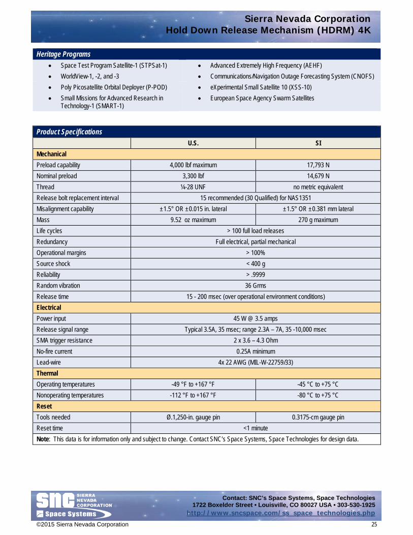
Heritage Programs • Space Test Program Satellite-1 (STPSat-1) • Advanced Extremely High Frequency (AEHF) • WorldView-1, -2, and -3 • Communications/Navigation Outage Forecasting System (CNOFS) • Poly Picosatellite Orbital Deployer (P-POD) • eXperimental Small Satellite 10 (XSS-10) • Small Missions for Advanced Research in
Technology-1 (SMART-1) • European Space Agency Swarm Satellites
Product Specifications U.S. SI Mechanical Preload capability 4,000 lbf maximum 17,793 N Nominal preload 3,300 lbf 14,679 N Thread ¼-28 UNF no metric equivalent Release bolt replacement interval 15 recommended (30 Qualified) for NAS1351 Misalignment capability ±1.5° OR ±0.015 in. lateral ±1.5° OR ±0.381 mm lateral Mass 9.52 oz maximum 270 g maximum Life cycles > 100 full load releases Redundancy Full electrical, partial mechanical Operational margins > 100% Source shock < 400 g Reliability > .9999 Random vibration 36 Grms Release time 15 - 200 msec (over operational environment conditions) Electrical Power input 45 W @ 3.5 amps Release signal range Typical 3.5A, 35 msec; range 2.3A – 7A, 35 -10,000 msec SMA trigger resistance 2 x 3.6 – 4.3 Ohm No-fire current 0.25A minimum Lead-wire 4x 22 AWG (MIL-W-22759/33) Thermal Operating temperatures -49 °F to +167 °F -45 °C to +75 °C Nonoperating temperatures -112 °F to +167 °F -80 °C to +75 °C Reset Tools needed Ø.1,250-in. gauge pin 0.3175-cm gauge pin Reset time <1 minute Note: This data is for information only and subject to change. Contact SNC’s Space Systems, Space Technologies for design data.

Sierra Nevada Corporation QwkSep 15 Low-Profile Separation System (LPSS)
Contact: SNC’s Space Systems, Space Technologies 1722 Boxelder Street • Louisville, CO 80027 USA • 303-530-1925
http://www.sncspace.com/ss_space_technologies.php
©2015 Sierra Nevada Corporation 26
QwkSep 15 Low-Profile Separation System Design Description
Sierra Nevada Corporation’s (SNC) Space Systems QwkSep-15 Low-Profile Separation System (LPSS) provides a low-shock solution to small satellite separation in an extremely low profile. The system is designed for standard ESPA (EELV Secondary Payload Adapter) with a 15-inch satellite interface launch configuration (orthogonal to thrust axis). The interface rings have integrated adjustable kick off springs, pass-through separation connectors and redundant telemetry indication of positive separation. The system is released with a mini, low-shock clamp band opening device (CBOD). This design configuration has heritage in more than 100 successful flight releases.
The CBOD features redundant circuits driven by a typical pyrotechnic firing pulse. Based on our patented Fast-Acting Shockless Separation Nut (FASSN) technology, the CBOD restrains the band tension bolts with a double helix, flywheel nut. The back drive torque of the high lead, band tension bolts is reacted through the CBOD by the latched flywheel nut. A pyro-compatible pulse releases the flywheel nut, which spins up and ejects the tension bolts. The strain energy in the band is converted to rotational energy in the flywheel nut allowing the two mating halves to separate with extremely low shock. Features • Ultra-high reliability payload separation • Redundant electrical trigger circuits • >25% stiffer and >40% more load capability
than comparable, alternative solutions • Utilizes heritage release technology of CBOD with redundant NASA
standard initiator-driven pin puller • Low-shock operation • Scalable between 12-inch and 24-inch sizes • No generated debris • Optional nonpyrotechnic mini-CBOD release mechanism available for
extremely low-shock release • Straightforward integration and operation • Designed for full ESPA payload weight and ESPA dynamic environments • Resettable for multiple ground operations • Based on extensive clamp band heritage
Dimensions
Note: All length dimensions above are in inches.
QwkSep-15 Low-Shock Clamp Band. The QwkSep 15 clamp band system provides a small satellite separation solution.
Sierra Nevada Corporation QwkSep 15 Low-Profile Separation System (LPSS)
Contact: SNC’s Space Systems, Space Technologies 1722 Boxelder Street • Louisville, CO 80027 USA • 303-530-1925
http://www.sncspace.com/ss_space_technologies.php
©2015 Sierra Nevada Corporation 27
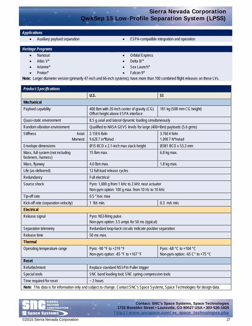
Applications • Auxiliary payload separation • ESPA-compatible integration and operation
Heritage Programs
• Nanosat • Orbital Express • Atlas V* • Delta IV* • Arianne* • Sea Launch* • Proton* • Falcon 9*
Note: Larger diameter version (primarily 47-inch and 66-inch systems); have more than 100 combined flight releases on these LVs. Product Specifications
U.S. SI Mechanical Payload capability 400 lbm with 20-inch center of gravity (CG)
Offset height above ESPA interface 181 kg (508 mm CG height)
Quasi-static environment 8.5 g axial and lateral dynamic loading simultaneously Random vibration environment Qualified to NASA GEVS levels for large (400+lbm) payloads (5.6 grms) Stiffness Axial: Moment:
2.15E6 lb/in 9.62E7 in*lb/rad
3.76E4 N/m 1.09E7 N*m/rad
Envelope dimensions Ø15 BCD x 2.1-inch max stack height Ø381 BCD x 53.3 mm Mass, full system (not including fasteners, harness)
15 lbm max. 6.8 kg max.
Mass, flyaway 4.0 lbm max. 1.8 kg max. Life (as-delivered) 12 full-load release cycles Redundancy Full electrical Source shock Pyro: 1,000 g from 1 kHz to 2 kHz near actuator
Non-pyro option: 100 g max. from 10 Hz to 10 kHz Tip-off rate 0.5 °/sec max Kick-off rate (separation velocity) 1 ft/s min. 0.3 m/s min. Electrical Release signal Pyro: NSI-firing pulse
Non-pyro option: 3.5 amps for 50 ms (typical) Separation telemetry Redundant loop-back circuits indicate positive separation Release time 50 ms max. Thermal Operating temperature range Pyro: -90 °F to +219 °F
Non-pyro option: -85 °F to +167 °F Pyro: -68 °C to +104 °C Non-pyro option: -65 C° to +75 °C
Reset Refurbishment Replace standard NSI-Pin Puller trigger Special tools SNC band loading tool; SNC spring compression tools Time required for reset ~ 2 hours Note: This data is for information only and subject to change. Contact SNC’s Space Systems, Space Technologies for design data.

Sierra Nevada Corporation QwkSep 24 Low-Profile Separation System
Contact: SNC’s Space Systems, Space Technologies 1722 Boxelder Street • Louisville, CO 80027 USA • 303-530-1925
http://www.sncspace.com/ss_space_technologies.php
©2015 Sierra Nevada Corporation 28
QwkSep 24 Low-Profile Separation System
Sierra Nevada Corporation’s (SNC) Space Systems QwkSep-24 Low-Profile Separation System (LPSS) provides a low-shock solution to small satellite separation in an extremely low profile. The system is designed for standard ESPA-Grande (EELV Secondary Payload Adapter) with a 24-inch satellite interface launch configurations (orthogonal to thrust axis). The interface rings have integrated adjustable kick off springs, pass-through separation connectors and redundant telemetry indication of positive separation. The system is released ±(CBOD). This design configuration has heritage in more than 100 successful flight releases.
The CBOD features redundant circuits driven by a typical pyrotechnic firing pulse. Based on our patented Fast-Acting Shockless Separation Nut (FASSN) technology, the CBOD restrains the band tension bolts with a double helix, flywheel nut. The back drive torque of the high lead, band tension bolts is reacted through the CBOD by the latched flywheel nut. A pyro-compatible pulse releases the flywheel nut, which spins up and ejects the tension bolts. The strain energy in the band is converted to rotational energy in the flywheel nut allowing the two mating halves to separate with extremely low shock. Features • Ultra-high reliability payload separation • Redundant electrical trigger circuits • >25% stiffer and >40% more load capability
than comparable, alternative solutions • Utilizes heritage release technology of CBOD with redundant NASA standard
initiator-driven pin puller • Low-shock operation • Scalable between 12-inch and 24-inch sizes • No generated debris • Optional nonpyrotechnic mini-CBOD release mechanism available for
extremely low-shock release • Straightforward integration and operation • Designed for full ESPA-grande payload weight and ESPA dynamic
environments • Resettable for multiple ground operations • Based on extensive clamp band heritage
Dimensions
Note: All length dimensions above are in inches.
Design Description
QwkSep 24 Low-Shock Clamp Band. SNC’s QwkSep 24 clamp band system provides a small satellite separation solution.

Sierra Nevada Corporation QwkSep 24 Low-Profile Separation System
Contact: SNC’s Space Systems, Space Technologies 1722 Boxelder Street • Louisville, CO 80027 USA • 303-530-1925
http://www.sncspace.com/ss_space_technologies.php
©2015 Sierra Nevada Corporation 29
Applications • Auxiliary payload separation • ESPA-compatible integration and operation
Heritage Programs • Nanosat • Orbital Express • Atlas V* • Delta IV* • Arianne* • Sea Launch* • Proton* • Falcon 9*
Note: Larger diameter version (primarily 47-inch and 66-inch systems); have more than 100 combined flight releases on these LVs.
Product Specifications
U.S. SI Mechanical Payload capability 660 lbm with 20-inch center of gravity (CG)
Offset height above ESPA interface 300 kg (508 mm CG height)
Quasi-static environment 8.5 g axial and lateral dynamic loading simultaneously Random vibration environment Qualified to NASA GEVS levels for large (400+lbm) payloads (5.6 grms) Stiffness Axial: Moment:
6.23E6 lb/in 4.45E8 lb*in/rad
1.09E3 N/m 5.03E7 N*m/rad
Envelope dimensions Ø24 BCD x 2.1-inch max stack height Ø610 BCD x 53.3 mm Mass, full system (not including fasteners, harness)
21 lbm max. 9.5 kg max.
Mass, flyaway 5.0 lbm max. 2.3 kg max. Life (as-delivered) 12 full-load release cycles Redundancy Full electrical Source shock Pyro: 1,000 g from 1 kHz to 2 kHz near actuator
Non-pyro option: 100 g max. from 10 Hz to 10 kHz Tip-off rate 0.5 °/sec max. Kick-off rate (separation velocity) 1 ft/s min. 0.3 m/s min. Electrical Release signal Pyro: NSI-firing pulse
Non-pyro option: 3.5 amps for 50 ms (typical) Separation telemetry Redundant loop-back circuits indicate positive separation Release time 50 ms max. Thermal Operating temperature range Pyro: -90 °F to +219 °F
Non-pyro option: -85 °F to +167 °F Pyro: -68 °C to +104 °C Non-pyro option: -65 °C to +75 °C
Reset Refurbishment Replace standard NSI-Pin Puller trigger Special tools SNC band loading tool; SNC spring compression tools Time required for reset ~ 2 hours Note: This data is for information only and subject to change. Contact SNC’s Space Systems, Space Technologies for design data.

Sierra Nevada Corporation Mechanical and Structural Systems
Contact: SNC’s Space Systems, Space Technologies 1722 Boxelder Street • Louisville, CO 80027 USA • 303-530-1925
http://www.sncspace.com/ss_space_technologies.php
©2015 Sierra Nevada Corporation 30
Mechanical and Structural Systems
Since 1987, our Space Technologies product line has flown thousands of mechanisms on hundreds of space missions with 100 percent on-orbit operational success. Our very first product, the High Output Paraffin Actuator (HOPA) has become an industry standard for the gentle, low-shock release of critical spacecraft applications such as solar arrays, antennas, and payloads. Over the years we have been able to leverage technologies such as the HOPA into larger subsystem offerings such as custom Instrument Covers and Optical Barrel Assemblies.
Catalog data sheets for the SNC’s Space Systems, Space Technologies Mechanical and Structural Systems technology area include:
• EH-3525 HOP Actuator • IH-5055 HOP Actuator • SP-5025 HOP Actuator
Sierra Nevada Corporation EH-3525 High Output Paraffin (HOP) Actuator
Contact: SNC’s Space Systems, Space Technologies 1722 Boxelder Street • Louisville, CO 80027 USA • 303-530-1925
http://www.sncspace.com/ss_space_technologies.php
©2015 Sierra Nevada Corporation 31
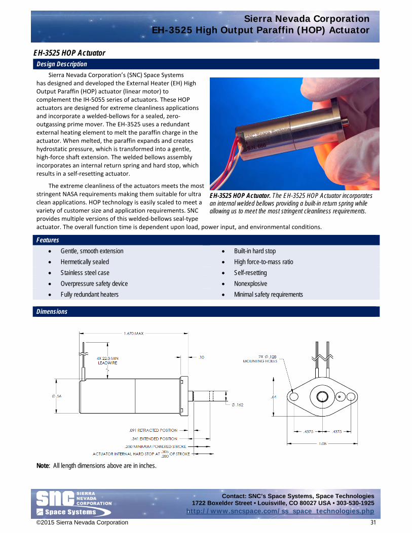
EH-3525 HOP Actuator Design Description
Sierra Nevada Corporation’s (SNC) Space Systems has designed and developed the External Heater (EH) High Output Paraffin (HOP) actuator (linear motor) to complement the IH-5055 series of actuators. These HOP actuators are designed for extreme cleanliness applications and incorporate a welded-bellows for a sealed, zero-outgassing prime mover. The EH-3525 uses a redundant external heating element to melt the paraffin charge in the actuator. When melted, the paraffin expands and creates hydrostatic pressure, which is transformed into a gentle, high-force shaft extension. The welded bellows assembly incorporates an internal return spring and hard stop, which results in a self-resetting actuator.
The extreme cleanliness of the actuators meets the most stringent NASA requirements making them suitable for ultra clean applications. HOP technology is easily scaled to meet a variety of customer size and application requirements. SNC provides multiple versions of this welded-bellows seal-type actuator. The overall function time is dependent upon load, power input, and environmental conditions.
Features • Gentle, smooth extension • Built-in hard stop • Hermetically sealed • High force-to-mass ratio • Stainless steel case • Self-resetting • Overpressure safety device • Nonexplosive • Fully redundant heaters • Minimal safety requirements
Dimensions
Note: All length dimensions above are in inches.
EH-3525 HOP Actuator. The EH-3525 HOP Actuator incorporates an internal welded bellows providing a built-in return spring while allowing us to meet the most stringent cleanliness requirements.
Sierra Nevada Corporation EH-3525 High Output Paraffin (HOP) Actuator
Contact: SNC’s Space Systems, Space Technologies 1722 Boxelder Street • Louisville, CO 80027 USA • 303-530-1925
http://www.sncspace.com/ss_space_technologies.php
©2015 Sierra Nevada Corporation 32
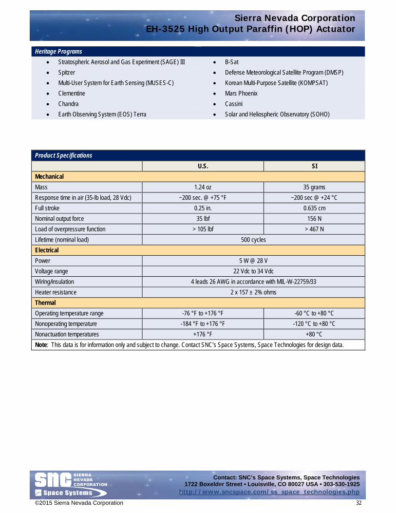
Heritage Programs • Stratospheric Aerosol and Gas Experiment (SAGE) III • B-Sat • Spitzer • Defense Meteorological Satellite Program (DMSP) • Multi-User System for Earth Sensing (MUSES-C) • Korean Multi-Purpose Satellite (KOMPSAT) • Clementine • Mars Phoenix • Chandra • Cassini • Earth Observing System (EOS) Terra • Solar and Heliospheric Observatory (SOHO)
Product Specifications
U.S. SI Mechanical Mass 1.24 oz 35 grams Response time in air (35-lb load, 28 Vdc) ~200 sec. @ +75 °F ~200 sec @ +24 °C Full stroke 0.25 in. 0.635 cm Nominal output force 35 lbf 156 N Load of overpressure function > 105 lbf > 467 N Lifetime (nominal load) 500 cycles Electrical Power 5 W @ 28 V Voltage range 22 Vdc to 34 Vdc Wiring/insulation 4 leads 26 AWG in accordance with MIL-W-22759/33 Heater resistance 2 x 157 ± 2% ohms Thermal Operating temperature range -76 °F to +176 °F -60 °C to +80 °C Nonoperating temperature -184 °F to +176 °F -120 °C to +80 °C Nonactuation temperatures +176 °F +80 °C Note: This data is for information only and subject to change. Contact SNC’s Space Systems, Space Technologies for design data.

Sierra Nevada Corporation IH-5055/ -10055 High Output Paraffin (HOP) Actuators
Contact: SNC’s Space Systems, Space Technologies 1722 Boxelder Street • Louisville, CO 80027 USA • 303-530-1925
http://www.sncspace.com/ss_space_technologies.php
©2015 Sierra Nevada Corporation 33
IH-5055/-10055 High Output Paraffin (HOP) Actuators Design Description
Sierra Nevada Corporation’s (SNC) Space Systems IH-5055/-10055 High Output Paraffin (HOP) actuators (or linear motors) are electrically powered resettable devices that generate high force and long-stroke linear motion.
Redundant internal heaters melt a paraffin charge inside the actuator. When melted, the paraffin expands and creates hydrostatic pressure which is transformed into a gentle, high-force shaft extension. A proprietary design incorporating a squeeze boot seals the paraffin and prevents any possibility of material release. Negligible outgassing makes these actuators suitable for most contamination-sensitive applications.
This HOP technology is easily scaled to meet a variety of customer size and application requirements. SNC provides multiple versions of this squeeze boot seal-type actuator.
The overall function time is dependent upon load, power input, and environmental conditions. Features
• Gentle, smooth extension • High force-to-mass ratio • Titanium case • Easily reset with no disassembly or refurbishment • Overpressure safety device • Nonexplosive • Fully redundant heaters • Minimal safety requirements • Ferrule or flange mount available
Dimensions
Note: All length dimensions above are in inches.
IH-5055/-10055 HOP Actuator. The IH-5055/-10055 HOP Actuator is shown with standard thermal insulation mounting ferrule. This actuator is also available with optional flange mount.

Sierra Nevada Corporation IH-5055/ -10055 High Output Paraffin (HOP) Actuators
Contact: SNC’s Space Systems, Space Technologies 1722 Boxelder Street • Louisville, CO 80027 USA • 303-530-1925
http://www.sncspace.com/ss_space_technologies.php
©2015 Sierra Nevada Corporation 34
Heritage Programs(IH-5055) • Global Positioning System (GPS-2F) • Earth Observing System (EOS) • Mars Phoenix Lander • Television Infrared Observation Satellite (TIROS) • Indostar II • Thermal Emission Spectrometer (TES) • Spitzer • Solar Terrestrial Relations Observatory (STEREO) • Cassini • Galaxy • Intelset • SES
• Solar and Heliospheric Observatory (SOHO) • Koreasat • MEXSAT • Thaicom
Product Specifications
U.S. SI Mechanical Mass 1.76 oz 50 grams Response time in air (50-lb load, 28 Vdc) ~210 sec. @ +75 °F ~210 sec @ +24 °C Full stroke 0.55 in 1.40 cm Nominal output force IH-5055 = 50 lbf, IH-10055 = 100 lbf 444.8 N Load of overpressure function IH-5055 > 100 lbf, IH-10055 > 150 lbf > 667 N Lifetime 1,000 cycles at 50 lbf, 100 cycles at 100 lbf Electrical Power 10 W @ 28 V Voltage range 22 to 44 Vdc Wiring/insulation 4 leads 26 AWG in accordance with MIL-W-22759/33 Heater resistance 2x 78 ± 3% Ω Thermal Operating temperature range -85 °F to +176 °F -65 °C to +80 °C Nonoperating temperature -319 °F to +176 °F -195 °C to +80 °C Nonactuation temperatures +176 °F +80 °C Note: This data is for information only and subject to change. Contact SNC’s Space Systems, Space Technologies for design data.

Sierra Nevada Corporation SP-5025 High Output Paraffin (HOP) Actuator
Contact: SNC’s Space Systems, Space Technologies 1722 Boxelder Street • Louisville, CO 80027 USA • 303-530-1925
http://www.sncspace.com/ss_space_technologies.php
©2015 Sierra Nevada Corporation 35
SP-5025 High Output Paraffin (HOP) Actuator Design Description
Sierra Nevada Corporation’s (SNC) Space Systems SP-5025 High Output Paraffin (HOP) actuator is an auto shut-off pin puller. The SP-5025 uses a redundant external heating element to melt the paraffin charge in the actuator. When melted, the paraffin expands and creates hydrostatic pressure which is transformed into a gentle, high-force pin retraction. The SP-5025 includes fully redundant internal circuit interrupts that can discontinue power to the actuator once full retraction has been reached. Alternatively, the circuit interrupts can provide a switch signal to allow the user to power off the actuator, depending upon the chosen wiring configuration.
This design reduces overall system cost by simplifying control requirements. The SP-5025 may be powered by a single timed power pulse to one of the fully redundant heater circuits. The dual heaters and dual circuit interrupts can be wired by the user to provide for autonomous or interactive control system designs.
The pin puller is resettable in place using the appropriate reset tool. The overall function time is dependent upon load, power input, and environmental conditions.
Features • Integral circuit interrupts • Resettable without refurbishment • Simple control system • Nonexplosive • Gentle, high-force retraction • Minimal safety requirements • Fully redundant heaters • Includes thermal isolation washers
Dimensions
Note: All length dimensions above are in inches.
SP-5025 High Output Paraffin (HOP) Actuator

Sierra Nevada Corporation SP-5025 High Output Paraffin (HOP) Actuator
Contact: SNC’s Space Systems, Space Technologies 1722 Boxelder Street • Louisville, CO 80027 USA • 303-530-1925
http://www.sncspace.com/ss_space_technologies.php
©2015 Sierra Nevada Corporation 36
Heritage Programs • Thermal Emission Spectrometer (TES) • Rocsat II • Space-Based Infrared System (SBIRS) Highly Elliptical Orbit (HEO) • GeoEye 1 • SBIRS Geosynchronous Earth Orbit (GEO) • HI Transfer Vehicle (HTV) • Galex • Cassiope • Orbview 3 & 4
Product Specifications U.S. SI Mechanical Mass 2.82 oz 80.0 g Response time in air (50 lb, 28 Vdc) ~150 sec @ +75 °F ~150 sec @ +24 °C Stroke 0.310 in. 0.787 cm Maximum retraction force 140 lbf 623 N Maximum reset force required 15 lbf 66.7 N
Shear load capability 350 lbf quasi-static 260 lbf dynamic
1557 N 1157 N
Reset tools needed Manual reset tool EP-7032 or Pneumatic tool EP-7056
Reset time <10 minutes Lifetime (nominal load) 500 cycles Electrical Power 15 W @ 28 V Voltage range 22 Vdc to 34 Vdc Heater resistance 2x 52.3 ± 5% ohms Wiring/insulation 8 leads 26 AWG in accordance with MIL-W-22759/33 Redundancy Heaters and circuit interrupts Thermal Operating temperatures -85 °F to + 176 °F -65 °C to +80 °C Nonoperating temperatures -319 °F to +176 °F -195 °C to +80 °C Nonactuation temperatures +176 °F +80 °C Note: This data is for information only and subject to change. Contact SNC’s Space Systems, Space Technologies for design data.

Sierra Nevada Corporation Pointing Systems and Motion Control
Contact: SNC’s Space Systems, Space Technologies 1722 Boxelder Street • Louisville, CO 80027 USA • 303-530-1925
http://www.sncspace.com/ss_space_technologies.php
©2015 Sierra Nevada Corporation 37
Pointing Systems and Motion Control
SNC is an industry leader in precision, low-disturbance pointing systems for space applications and has developed a number of single- and dual-axis pointing systems for spaceflight tracking and navigation, as well as positioning functions for antennae, solar array drives and mechanisms, optical telescopes, and instrument mechanisms. Each axis of the pointing system is typically driven by a precision rotary actuator, which features a redundant stepper motor, harmonic drive and/or hybrid transmission, with various position telemetry options. The rotary actuator is configurable with multiple options, through holes for cable management, slip rings, twist capsules, RF Rotary joints, telemetry sensors and adjustable hard stops. The biaxial brackets have been designed for very minimal orthogonal distortion, high stiffness and low mass. SNC pointing systems are qualified and flight proven with NASA programs, commercial and military satellites and the International Space Station. Although we specialize in custom engineered open- and closed-loop solutions, our list of qualified motors, actuators, gimbals, and drive electronics has grown into a substantial portfolio that is capable of supporting a wide range of applications and sizes with minimal nonrecurring effort required.
Catalog data sheets for the SNC’s Space Systems, Space Technologies Pointing Systems and Motion Control technology area include:
• C14 Solar Array Drive Assembly • C20 Incremental Rotary Actuator • C50 Incremental Rotary Actuator • EH25 Bi-Axis Gimbal, 3-Phase • EH25 Incremental Rotary Actuator, 3-Phase • eMotor • H25 Bi-axis Gimbal, 4 phase • Lightweight 2-axis Mini Gimbal • Size 23 Incremental Rotary Actuator • T25 Rotary Actuator

Sierra Nevada Corporation C14 Solar Array Drive Assembly
Contact: SNC’s Space Systems, Space Technologies 1722 Boxelder Street • Louisville, CO 80027 USA • 303-530-1925
http://www.sncspace.com/ss_space_technologies.php
©2015 Sierra Nevada Corporation 38
C14 Solar Array Drive Assembly Design Description
Sierra Nevada Corporation’s (SNC) Space Systems offers a lightweight, incremental Solar Array Drive Assembly (SADA) developed specifically for spacecraft solar array deployment and pointing applications. The C14 SADA is derived from an actuator that has many years of flight heritage and a slip ring assembly that has been used on multiple spacecraft as well.
The actuator uses a 2-phase permanent magnet stepper motor to drive a zero backlash harmonic drive. An optional 3-phase motor is also available. Magnetic modeling and optimization ensure the permanent magnet stepper motor takes full advantage of the available volume for maximum performance per unit weight. Redundant versions are fully isolated with Nomex-Kapton insulators to prevent failure propagation. High capacity 440C stainless steel ball bearings support the output shaft for maximum stiffness and life. The actuator’s all-titanium construction ensures high strength and consistent performance over a wide temperature range.
A high stiffness, stainless steel harmonic drive with modified tooth profile and circular spline provide outstanding stiffness and torque capability with extremely low weight. A custom Oldham coupling between the motor assembly and transmission allows for a large through hole that can be used for wire routing, RF rotary joints, or waveguides. The motor and transmission are designed as freestanding units that allow for modular combinations of motors and transmissions to easily adapt the assembly to a variety of applications. The slip ring assembly is built in the USA in accordance with SNC specifications. The slip ring is a monofilament gold-on-gold design with many years of successful flight heritage. Each ring is contacted by four brushes and has 2A capacity after derating for vacuum operation.
Features • Compact design, volume-, and mass-efficient configuration • Light weight, all-titanium construction • High performance, 2-phase motor windings • 440C stainless steel harmonic drive / ABEC 7 ball bearings • 3-phase or 4-phase winding configurations available • High stiffness and load capacity in a small package • Potentiometer for position telemetry • Electrical redundancy available • Internal heaters and thermistor • Monofilament gold-on-gold slip ring assembly
Dimensions
Note: All dimensions above are in inches.
C14 Solar Array Drive Assembly with Slip Rings

Sierra Nevada Corporation C14 Solar Array Drive Assembly
Contact: SNC’s Space Systems, Space Technologies 1722 Boxelder Street • Louisville, CO 80027 USA • 303-530-1925
http://www.sncspace.com/ss_space_technologies.php
©2015 Sierra Nevada Corporation 39
Applications • Solar Array Drives
Heritage Programs
• Orbview 3 & 4 (actuator) • Multiple Undisclosed Satellites
(slip rings)
• Tenacious 1, 2, 3, and 4 (actuator) • Samaritan (actuator)
Product Specifications U.S. SI Mechanical Mass 2.5 lb 1.14 kg Step size 0.0625° Slew rate >9 °/s at no load Output torque @ 4 °/s 125 in-lb typical at 77 °F 14 N-m typical at 25 °C Unpowered holding torque 8 in-lb min 0.9 N-m min Torsional stiffness 20,000 In-lb/rad 2,260 N-m/rad Electrical Slip ring capacity 30 transfers, each derated to 2 A Motor winding resistance 57 Ohms (nominal, 2 phase) Motor winding inductance 30 mH typical Motor torque constant 0.636 Nm/A Potentiometer linearity 0.25% over 350° (357° total electrical range) Independent Load Ratings (consult SNC engineering for combined loads) Axial load capacity 2,300 lb 10.2 kN Radial load capacity 290 lb 1.3 kN Moment load capacity 800 in-lb 90 Nm Thermal Environment Operating temperatures -40 °F to +158 °F -40 °C to +70 °C Nonoperating temperatures -139 °F to +185 °F -95 °C to +85 °C Note: This data is for information only and subject to change. Contact SNC’s Space Systems, Space Technologies for design data.

Sierra Nevada Corporation C20 Incremental Rotary Actuator
Contact: SNC’s Space Systems, Space Technologies 1722 Boxelder Street • Louisville, CO 80027 USA • 303-530-1925
http://www.sncspace.com/ss_space_technologies.php
©2015 Sierra Nevada Corporation 40
C20 Incremental Rotary Actuator Design Description
Sierra Nevada Corporation’s (SNC) Space Systems, in support of Earth observation satellites, has designed, developed, and delivered an Antenna Pointing Mechanism (APM) utilizing the C20 Incremental Rotary Actuators (RA) for its axis drives. The C20 RAs are very low disturbance actuators, ideal for low jitter, high resolution applications in an open-loop stepper motor-driven system.
SNC’s C20 unit is composed of a 3-phase, bipolar, 15 deg stepper motor with redundant windings that are insulated from one another to prevent failure propagation. The motor is directly coupled to a 50:1 harmonic drive gear reducer which features maximum stiffness, strength, and zero backlash. Output position feedback is provided by integral redundant potentiometers with absolute accuracy to ±0.1 percent over electrical travel. A single-channel RF rotary joint, redundant heaters and thermistors, and internal hard stops complement the actuators’ operational features.
A space-qualified twist capsule is available to carry signal and power currents through the actuator, simplifying wiring in the assembly and negating wire stress concentrations caused by actuator or gimbal motion. The RF joints carry RF signals through the actuators’ axis of rotation; the RF cabling routes the RF signal through the actuator to the spacecraft antenna.
Features • A low-torque disturbance, 3-phase 15° stepper motor • Redundant heaters and thermistors • Redundant stator windings • Redundant output position potentiometers • 50:1 no-backlash, high stiffness, harmonic drive gear set • RF rotary joint and internal hard stops are available
Dimensions
Note: All length dimensions above are in inches.
C20 Incremental Rotary Actuator

Sierra Nevada Corporation C20 Incremental Rotary Actuator
Contact: SNC’s Space Systems, Space Technologies 1722 Boxelder Street • Louisville, CO 80027 USA • 303-530-1925
http://www.sncspace.com/ss_space_technologies.php
©2015 Sierra Nevada Corporation 41
Heritage Applications • Antenna Pointing Mechanisms • Gimbals
Heritage Programs
• GeoEye-1
Product Specifications U.S. SI Mechanical Actuator size (OD x L) Ø4.0” x 4.5” Ø101.6 mm x 114.3 mm Actuator weight 4.1 lb 1.86 kg Through hole ID Ø.375” Ø9.5 mm Step size 0.3°, .007° with microstepper control Electrical Motor type 3-phase, wye-connected, redundant, 15° stepper Voltage, nominal 28 Vdc Resistance, at ambient temperature 22.6 Ω Driver type Microstepper with current control Potentiometer resistance 5k Ω ± 5% Potentiometer electrical travel 200° min. on each resistive track Potentiometer linearity ± 0.1% over electrical travel Thermal Heater resistance 78 Ω ± 2% (each heater) Temperature, operating -13 °F to +149 °F -25 °C to +65 °C Temperature, survival -130 °F to 176 °F -90 °C to +80 °C Note: This data is for information only and subject to change. Contact SNC’s Space Systems, Space Technologies for design data.

Sierra Nevada Corporation C50 Incremental Rotary Actuator
Contact: SNC’s Space Systems, Space Technologies 1722 Boxelder Street • Louisville, CO 80027 USA • 303-530-1925
http://www.sncspace.com/ss_space_technologies.php
©2015 Sierra Nevada Corporation 42
C50 Incremental Rotary Actuator Design Description
Sierra Nevada Corporation’s (SNC) Space Systems has designed and developed a new, robust C50 rotary actuator for spaceflight and satellite applications. Featuring a 6 deg stepper motor, 100:1 C50 Harmonic drive gear reducer, motor and output resolvers in a stiff, but low-mass package, the actuator combines relatively high output slew rates, accuracy, and torque margin.
The C50 Actuator features a 3-phase, wye connected, 6 deg stepper motor with redundant windings that are fully isolated to prevent failure propagation. The 20-pole motor has minimal cyclic torque for ultra-smooth actuation. A nonredundant incremental motor resolver accurately tracks motor position to ±0.4 deg for testing feedback or possible commutation.
The 100:1 C50 Harmonic Drive Unit is fabricated from corrosion-resistant stainless steel, which is heat treated for strength and manufacturability. Its torque rating is 3,328 in-lb at 200 rpm, with a torsional stiffness of approximately 1.8 x 10⁶ in-lb/rad. Oversized 440C stainless steel ABEC 7 ball bearings in a DB configuration support the output shaft for maximum stiffness and life. The space-rated lubricant is Nye oil 2001 with 3 percent PbNp.
The nominal output slew rate is 2.7 deg/sec at a motor pulse rate of 45 pps. Running torque is typically 1,000 in-lb.; unpowered holding torque is greater than 250 in-lb. Redundant coarse variable reluctance resolvers provide output telemetry to within ±0.1 deg.
Features • 3-phase, redundantly wound, 6° stepper motor • Spaced-rated lubricant: Nye 2001-3PbNp • 100:1 C50 harmonic drive reducer • High torsional and moment output stiffness • Motor resolver feedback to ±0.4° at motor shaft • Output resolver telemetry to ±0.1°
Dimensions
Note: All length dimensions above are in inches.
C50 Incremental Rotary Actuator

Sierra Nevada Corporation C50 Incremental Rotary Actuator
Contact: SNC’s Space Systems, Space Technologies 1722 Boxelder Street • Louisville, CO 80027 USA • 303-530-1925
http://www.sncspace.com/ss_space_technologies.php
©2015 Sierra Nevada Corporation 43
Heritage Applications • High Torque, Precision Actuation
Heritage Programs
• Classified
Product Specifications U.S. SI Mechanical Size (OD x L), including connector boss Ø8.0” x 13” Ø203.2 mm x 330.2 mm Weight 40.0 lb 18.2 kg Torsional stiffness 1,200,000 in-lb./rad, min 135,600 N-m/rad Qual-level random vibration 24.7 Grms (Y axis) ; 20.4 Grms (X-Z axes) Electrical Motor type 3-phase, wye-wound, redundant, 6° stepper motor Voltage, minimum 20 Vdc Resistance (room temperature) 1.7 Ω ± 5% Output resolver input 4 Vrms ± 10%, 5 kHz ± 10% Thermal Temperature, operational 32 °F to 140 °F 0 °C to +60 °C Temperature, survival -24.8 °F to 175.2 °F -31 °C to +74 °C Note: This data is for information only and subject to change. Contact SNC’s Space Systems, Space Technologies for design data.

Sierra Nevada Corporation EH25 Bi-Axis Gimbal, 3-Phase
Contact: SNC’s Space Systems, Space Technologies 1722 Boxelder Street • Louisville, CO 80027 USA • 303-530-1925
http://www.sncspace.com/ss_space_technologies.php
©2015 Sierra Nevada Corporation 44
EH25 Bi-Axis Gimbal, 3-Phase Design Description
Sierra Nevada Corporation’s (SNC) Space Systems has developed an Enhanced H25 (EH25) Bi-Axis Gimbal that has improved stiffness and torque capability closely modeled after our standard H25 gimbal. The EH25 Gimbal features very fine pointing resolution, position telemetry precise to within a single step, infinitely adjustable hard stops, internal heaters and temperature sensors, and extremely long-life capability.
The gimbal actuator features an innovative hybrid transmission consisting of a planetary gearbox designed to fit completely within a high stiffness, zero backlash harmonic drive. The combined transmission provides high internal torque margins throughout the operational range and enables enhanced performance.
Telemetry is provided by redundant potentiometers that use an SNC proprietary process, yielding previously unattainable potentiometer life in a spaceflight environment. Redundant potentiometers monitor motor and output shaft position with sufficient accuracy to resolve position within a single step over the full operating range.
SNC fabricates the gimbal structural components from lightweight high stiffness titanium and high strength aluminum alloys. Careful selection of materials and use of precision machined components ensure consistent performance over a broad temperature range. Oversized 440C stainless steel ABEC 7 ball bearings support the output shaft for maximum stiffness and life. The gimbal actuators are capable of full 360-deg rotation and adjustable hard stops are available to limit gimbal travel to any customer requirement.
Features • High stiffness and load capacity • High-powered and unpowered torque capability • Fine-pointing resolution, 0.0025° per step • Long life, qualified for more than 1 million dithering cycles • 200% minimum torque margin motor design • Redundant, accurate, potentiometer telemetry • Internal heaters with temperature sensors • Space-qualified Pennzane lubricant • Motor available as 2-, 3-, or 4-phase stepper • Extreme environmental capability • Low power consumption • Full rotation; field-adjustable, hard stop placement
Dimensions
Note: All length dimensions above are in inches.
EH25 Bi-Axis Antenna Gimbal, 3-Phase
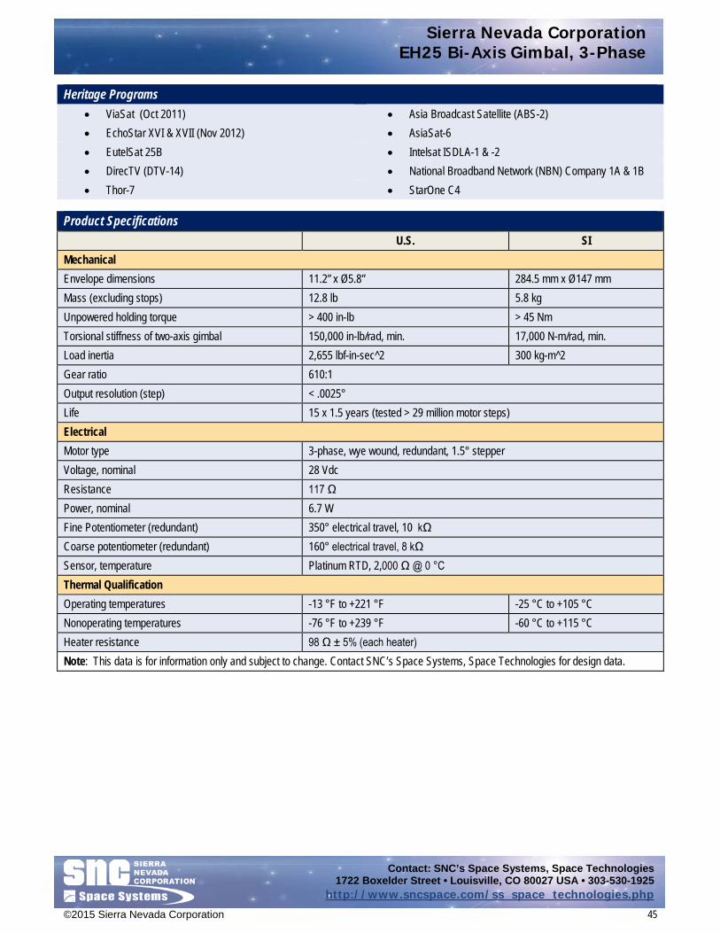
Sierra Nevada Corporation EH25 Bi-Axis Gimbal, 3-Phase
Contact: SNC’s Space Systems, Space Technologies 1722 Boxelder Street • Louisville, CO 80027 USA • 303-530-1925
http://www.sncspace.com/ss_space_technologies.php
©2015 Sierra Nevada Corporation 45
Heritage Programs • ViaSat (Oct 2011) • Asia Broadcast Satellite (ABS-2) • EchoStar XVI & XVII (Nov 2012) • AsiaSat-6 • EutelSat 25B • Intelsat ISDLA-1 & -2 • DirecTV (DTV-14) • National Broadband Network (NBN) Company 1A & 1B • Thor-7 • StarOne C4
Product Specifications U.S. SI Mechanical Envelope dimensions 11.2” x Ø5.8” 284.5 mm x Ø147 mm Mass (excluding stops) 12.8 lb 5.8 kg Unpowered holding torque > 400 in-lb > 45 Nm Torsional stiffness of two-axis gimbal 150,000 in-lb/rad, min. 17,000 N-m/rad, min. Load inertia 2,655 lbf-in-sec^2 300 kg-m^2 Gear ratio 610:1 Output resolution (step) < .0025° Life 15 x 1.5 years (tested > 29 million motor steps) Electrical Motor type 3-phase, wye wound, redundant, 1.5° stepper Voltage, nominal 28 Vdc Resistance 117 Ω Power, nominal 6.7 W Fine Potentiometer (redundant) 350° electrical travel, 10 kΩ Coarse potentiometer (redundant) 160° electrical travel, 8 kΩ Sensor, temperature Platinum RTD, 2,000 Ω @ 0 °C Thermal Qualification Operating temperatures -13 °F to +221 °F -25 °C to +105 °C Nonoperating temperatures -76 °F to +239 °F -60 °C to +115 °C Heater resistance 98 Ω ± 5% (each heater) Note: This data is for information only and subject to change. Contact SNC’s Space Systems, Space Technologies for design data.

Sierra Nevada Corporation EH25 Incremental Rotary Actuator, 3-Phase
Contact: SNC’s Space Systems, Space Technologies 1722 Boxelder Street • Louisville, CO 80027 USA • 303-530-1925
http://www.sncspace.com/ss_space_technologies.php
©2015 Sierra Nevada Corporation 46
EH25 Incremental Rotary Actuator, 3-Phase Design Description
Sierra Nevada Corporation’s (SNC) Space Systems brings a long history of manufacturing space-qualified motors and actuators both in one-off and multiple unit production runs. The EH25 Incremental Rotary Actuator (RA), in continuous production for several years, utilizes flight-proven design, assembly, and test heritage. SNC maintains an inventory of EH25 long-lead parts in stock.
The EH25 Incremental Gimbal RA features an advanced hybrid transmission consisting of a planetary gearbox manufactured to fit completely within a high stiffness, zero backlash harmonic drive. The combined transmission provides high internal torque margins throughout the performance range, allowing reduction in the required motor size, and resulting in a significantly lighter actuator with exceptional output capability.
The RA features a 28 Vdc, 3-phase, permanent magnet 1.5 deg stepper motor with redundant windings that are insulated from one another to prevent failure propagation. Magnetic modeling and optimization ensures the stepper motor’s maximum performance per unit weight. Telemetry is provided by redundant potentiometers that use an SNC proprietary process, yielding previously unattainable potentiometer life in a spaceflight environment. Redundant potentiometers monitor motor and output shaft position with sufficient accuracy to provide absolute position to within a single step over the full operating range. Oversized 440C stainless steel ABEC 7 ball bearings support the output shaft for maximum stiffness and life. The RA’s structural components are fabricated from lightweight high stiffness titanium and high strength aluminum alloys. Careful selection of materials and precision machined components ensure consistent performance over a broad temperature range. The RA is capable of full 360° rotation and adjustable hard stops are available to limit travel to any customer requirement.
Features • High stiffness and load capacity • High-powered and unpowered torque capability • Fine-pointing resolution, 0.0025° per step • Long life, qualified for more than 1 million dithering cycles • 200% minimum torque margin motor design • Redundant, accurate, potentiometer telemetry • Internal heaters with temperature sensors • Space-qualified Pennzane lubricant • Motor available as 2-, 3-, or 4-phase stepper • Extreme environmental capability • Low power consumption • Full rotation; field-adjustable, hard stop placement
Note: All length dimensions are in inches.
EH25 Incremental Rotary Actuator
Dimensions

Sierra Nevada Corporation EH25 Incremental Rotary Actuator, 3-Phase
Contact: SNC’s Space Systems, Space Technologies 1722 Boxelder Street • Louisville, CO 80027 USA • 303-530-1925
http://www.sncspace.com/ss_space_technologies.php
©2015 Sierra Nevada Corporation 47
Heritage Applications • Antenna pointing mechanisms • Deployment mechanisms • Camera pointing mechanisms • Robotics applications • Solar array drives
Heritage Programs
• ViaSat (Oct 2011) • Asia Broadcast Satellite (ABS-2) • EchoStar XVI & XVII (Nov 2012) • AsiaSat-6 • EutelSat 25B • Intelsat ISDLA-1 & -2 • DirecTV (DTV-14) • National Broadband Network (NBN) Company 1A & 1B • Thor-7 • StarOne C4
Product Specifications U.S. SI Mechanical Envelope dimensions 5.0” x Ø5.8” 126 mm x Ø147 mm Mass 5.8 lb 2.6 kg Unpowered holding torque >400 in-lb >45 Nm Gear ratio 610:1 Output resolution <.0025° Life 15 x 1.5 years (>29 million motor steps) Electrical Motor type 3-phase, wye-wound, redundant, 1.5° stepper Voltage, nominal 28 Vdc Resistance 117 Ω Power, nominal 6.7 W Fine potentiometer (redundant) 350° electrical travel, 10 kΩ Coarse potentiometer (redundant) 160° electrical travel, 8 kΩ Sensor, temperature Platinum RTD 2000 Ω @ 0 °C Thermal Operating temperatures -13 °F to +221 °F -25 °C to +105 °C Nonoperating temperatures -76 °F to +239 °F -60 °C to +115 °C Heater resistance 98 Ω ± 5% (each heater) Note: This data is for information only and subject to change. Contact SNC’s Space Systems, Space Technologies for design data.
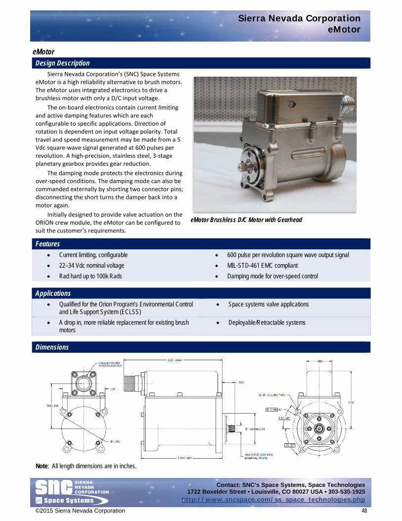
Sierra Nevada Corporation eMotor
Contact: SNC’s Space Systems, Space Technologies 1722 Boxelder Street • Louisville, CO 80027 USA • 303-530-1925
http://www.sncspace.com/ss_space_technologies.php
©2015 Sierra Nevada Corporation 48
eMotor Design Description
Sierra Nevada Corporation’s (SNC) Space Systems eMotor is a high reliability alternative to brush motors. The eMotor uses integrated electronics to drive a brushless motor with only a D/C input voltage.
The on-board electronics contain current limiting and active damping features which are each configurable to specific applications. Direction of rotation is dependent on input voltage polarity. Total travel and speed measurement may be made from a 5 Vdc square-wave signal generated at 600 pulses per revolution. A high-precision, stainless steel, 3-stage planetary gearbox provides gear reduction.
The damping mode protects the electronics during over-speed conditions. The damping mode can also be commanded externally by shorting two connector pins; disconnecting the short turns the damper back into a motor again.
Initially designed to provide valve actuation on the ORION crew module, the eMotor can be configured to suit the customer’s requirements.
Features • Current limiting, configurable • 600 pulse per revolution square wave output signal • 22–34 Vdc nominal voltage • MIL-STD-461 EMC compliant • Rad hard up to 100k Rads • Damping mode for over-speed control
Applications • Qualified for the Orion Program’s Environmental Control
and Life Support System (ECLSS) • Space systems valve applications
• A drop in, more reliable replacement for existing brush motors
• Deployable/Retractable systems
Dimensions
Note: All length dimensions are in inches.
eMotor Brushless D/C Motor with Gearhead
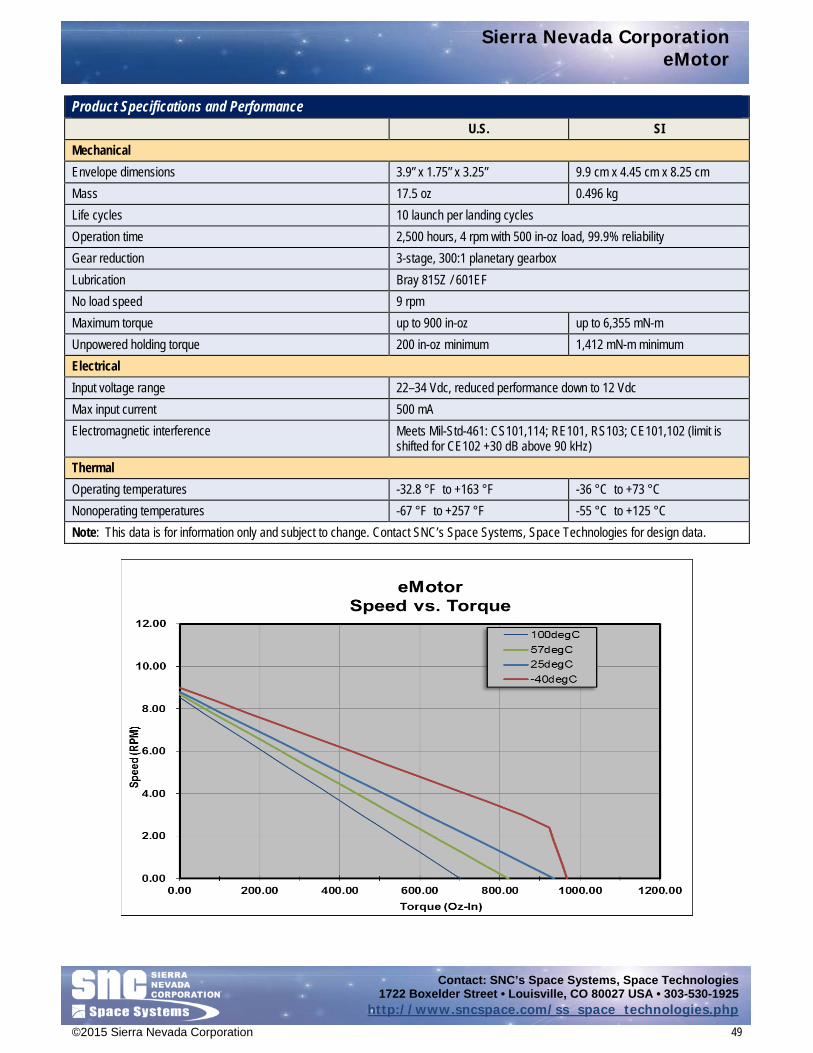
Sierra Nevada Corporation eMotor
Contact: SNC’s Space Systems, Space Technologies 1722 Boxelder Street • Louisville, CO 80027 USA • 303-530-1925
http://www.sncspace.com/ss_space_technologies.php
©2015 Sierra Nevada Corporation 49
Product Specifications and Performance U.S. SI Mechanical Envelope dimensions 3.9” x 1.75” x 3.25” 9.9 cm x 4.45 cm x 8.25 cm Mass 17.5 oz 0.496 kg Life cycles 10 launch per landing cycles Operation time 2,500 hours, 4 rpm with 500 in-oz load, 99.9% reliability Gear reduction 3-stage, 300:1 planetary gearbox Lubrication Bray 815Z / 601EF No load speed 9 rpm Maximum torque up to 900 in-oz up to 6,355 mN-m Unpowered holding torque 200 in-oz minimum 1,412 mN-m minimum Electrical Input voltage range 22–34 Vdc, reduced performance down to 12 Vdc Max input current 500 mA Electromagnetic interference Meets Mil-Std-461: CS101,114; RE101, RS103; CE101,102 (limit is
shifted for CE102 +30 dB above 90 kHz) Thermal Operating temperatures -32.8 °F to +163 °F -36 °C to +73 °C Nonoperating temperatures -67 °F to +257 °F -55 °C to +125 °C Note: This data is for information only and subject to change. Contact SNC’s Space Systems, Space Technologies for design data.

Sierra Nevada Corporation H25 Bi-Axis Gimbal, 4-Phase
Contact: SNC’s Space Systems, Space Technologies 1722 Boxelder Street • Louisville, CO 80027 USA • 303-530-1925
http://www.sncspace.com/ss_space_technologies.php
©2015 Sierra Nevada Corporation 50
H25 Bi-Axis Gimbal, 4-Phase Design Description
Sierra Nevada Corporation’s (SNC) Space Systems H25 Gimbal features very fine pointing resolution, position telemetry precise to within a single step, adjustable hard stops, and extremely long-life capability.
The gimbal actuator features a state-of-the-art hybrid transmission consisting of a planetary gearbox that is designed to fit completely within a high stiffness, zero backlash harmonic drive. The combined transmission provides high internal torque margins throughout the operational range and enables optimal performance.
Telemetry is provided by redundant potentiometers that have been treated using an SNC proprietary process, yielding previously unattainable potentiometer life in a spaceflight environment. Redundant potentiometers monitor motor and output shaft position with sufficient accuracy to resolve position within a single step over the full operating range.
The gimbal structural components are fabricated from lightweight high stiffness titanium and high strength aluminum alloys. Careful selection of materials and precision-machined components ensure consistent performance over a broad temperature range. Oversized 440C stainless steel ABEC 7 ball bearings support the output shaft for maximum stiffness and life. The gimbal actuators are capable of full 360-deg rotation and adjustable hard stops are available to limit gimbal travel to any customer requirement.
Features • High stiffness and load capacity • Fine pointing resolution, 0.003° per step • 200% minimum torque margin motor design • Motor available as 2- or 4-phase stepper • Low power consumption • High powered and unpowered torque capability
• Long life, qualified for more than 1 million dithering cycles • Redundant, accurate, potentiometer telemetry • Space-qualified Pennzane lubricant • Extreme environmental capability • Full rotation, removable hard stops
Dimensions
Note: All length dimensions above are in inches.
H25 Bi-Axis Antenna Gimbal, 4-Phase

Sierra Nevada Corporation H25 Bi-Axis Gimbal, 4-Phase
Contact: SNC’s Space Systems, Space Technologies 1722 Boxelder Street • Louisville, CO 80027 USA • 303-530-1925
http://www.sncspace.com/ss_space_technologies.php
©2015 Sierra Nevada Corporation 51
Heritage Programs • Japanese Communications Satellites (JCSAT-9 through -12) • Vietnam Satellite (Vinasat-1 and -2) • EchoStar 10 • Geostationary Operational Environmental Satellite (GOES-R) • Broadcasting and Telecommunications Satellite (BSAT-3C)
• Mobile User Objective System (MUOS-1–5) • Americom Communications Satellite (AMC-14) • PAN (USA-207) • Clio Satellite • Jabiru
Product Specifications U.S. SI Mechanical Envelope dimensions 11.6 x Ø5.8 in 295 x Ø147 mm Mass (excluding stops) 10.7 lb 4.9 kg Unpowered holding torque > 650 in-lb > 70 Nm Torsional stiffness of two-axis gimbal 100,000 in-lb/rad, min 11,300 N-m/rad, min Load inertia 266,000 lbf-in-sec^2 30,000 kg-m^2 Gear ratio 1246.75:1 Output resolution (step) 0.003° Life 15 x 1.5 years , 55,000 cycles, 775,000 motor revs Electrical Motor Type 4-phase, wye wound, redundant, 3.75° stepper Voltage, nominal 70 Vdc Resistance 323 Ω Power, nominal 15 W Fine potentiometer (redundant) 350° electrical travel, 10 Ω Coarse potentiometer (redundant) 350° electrical travel, 10 Ω Environmental Qualification Operating temperatures -13 °F to +207 °F -25 °C to +97 °C Nonoperating temperatures -47 °F to +212 °F -44 °C to +100 °C Random vibration 27 Grms Sine vibration 20 G Note: This data is for information only and subject to change. Contact SNC’s Space Systems, Space Technologies for design data.

Sierra Nevada Corporation Lightweight 2-Axis Mini Gimbal
Contact: SNC’s Space Systems, Space Technologies 1722 Boxelder Street • Louisville, CO 80027 USA • 303-530-1925
http://www.sncspace.com/ss_space_technologies.php
©2015 Sierra Nevada Corporation 52
Lightweight 2-Axis Mini Gimbal Design Description
Sierra Nevada Corporation’s (SNC) Space Systems Lightweight 2-Axis Mini Gimbal is a simple X/Y gimbal designed for spacecraft requiring a small, fast-moving antenna or other payload. The interface brackets and cable wrap spools are removable, providing excellent adaptability to many applications requiring a small gimbal with moderate pointing accuracy for 1- or 2-axis motion.
Each of the two axes uses identical actuators that can be used individually for a single-axis gimbal or coupled together with interface brackets to operate as a two-axis gimbal. Each actuator is outfitted with a nonredundant three-phase stepper motor, heater, temperature sensor, and potentiometer output position feedback.
The gimbal shown has a short interface bracket connecting it to the upper axis while the upper actuator bracket has an extended length in order to position the antenna higher above the deck. A high-flex coaxial cable with SMA connectors is provided for antenna connections. The interface brackets and cable spools shown were sized to allow ±90 deg of rotation on each axis with continuous position telemetry and without self-interference. Features
• As little as 7.75” tall (8.4” as shown) when fully upright
• Maximum output speed 9°/sec • Output Cardinal Step Size 0.3° • Gimbal mass of 3.5 lb as shown • Actuator mass of 1.3 lb without connectors or brackets
• 22–34 Vdc nominal voltage range • ±90° rotation on each axis, hard-stop limited • Actuator capable of continuous rotation • Potentiometer accurate to ±0.5°, continuous
over ±90° • Minimum output torque 20 in-lb from -30 °C to +100 °C • Tested life of 60 k cycles
Dimensions
Note: All length dimensions above are in inches.
Lightweight 2-Axis Mini Gimbal

Sierra Nevada Corporation Lightweight 2-Axis Mini Gimbal
Contact: SNC’s Space Systems, Space Technologies 1722 Boxelder Street • Louisville, CO 80027 USA • 303-530-1925
http://www.sncspace.com/ss_space_technologies.php
©2015 Sierra Nevada Corporation 53
Product Specifications—Single Actuator U.S. SI Mechanical Mass (without brackets or connectors) 1.3 lb 0.59 kg Step size 0.3°±15% Output torque 20–45 in-lb 2.25 to 5.08 Nm Unpowered holding torque 60 in-oz min 424 mN-m min Torsional stiffness 4,500 in-lb/rad nominal 508 N-m/rad nominal Electrical Voltage range 22 to 34 Vdc Motor 3 Phase Winding resistance 52 Ohms nominal (L-2L) Winding inductance 13 mH nominal (L-2L) Potentiometer resistance 1,000 ±10% Ohms Thermal Operating temperature -22 °F to 212 °F -30 °C to 100 °C Nonoperating temperature -49 °F to 239 °F -45 °C to 115 °C Heater resistance, single or dual configuration 112 Ω or 224 Ω 112 Ω or 224 Ω Heater power, 28 V 7 W or 3.5 W 7 W or 3.5 W Thermistor, S-310-P18 10,000 Ω @ 77 °F 10,000 Ω @ 25 °C Note: This data is for information only and subject to change. Contact SNC’s Space Systems, Space Technologies for design data. Product Specifications—Biax Gimbal with Coax Cable Spools U.S. SI Mechanical Mass 3.5 lb 1.58 kg Rotational stiffness, X axis (lower axis) 3,800 in-lb/rad nominal 430 N-m/rad nominal Rotational stiffness, Y axis (upper axis) 4,425 in-lb/rad nominal 500 N-m/rad nominal Electrical Connectors, Motors Connector: Positronics PN: SDD15M00200G
Backshell: Glenair PN: 550T100M1R8B Connector, Heaters and Telemetry Connector: Positronics PN: SDD26M00200G
Backshell: Glenair PN: 550T100M2R8B Coax Cable Connectors MIL-C-39012 and MIL-STD-348 Thermal Operating temperature -22 °F to 212 °F -30 °C to 100 °C Nonoperating temperature -49 °F to 239 °F -45 °C to 115 °C Note: This data is for information only and subject to change. Contact SNC’s Space Systems, Space Technologies for design data.

Sierra Nevada Corporation Size 23 Rotary Actuator
Contact: SNC’s Space Systems, Space Technologies 1722 Boxelder Street • Louisville, CO 80027 USA • 303-530-1925
http://www.sncspace.com/ss_space_technologies.php
©2015 Sierra Nevada Corporation 54
Size 23 Rotary Actuator Design Description
Sierra Nevada Corporation’s (SNC) Space Systems has designed, developed, and delivered an incremental actuator configured around a Size 23 hybrid stepper motor and a 10:1 planetary gearhead, providing output step resolution of 0.18 deg per motor step. The Size 23 Rotary Actuator was originally developed and qualified for a solar array drive application but is useful for any open-loop stepper motor driven system that needs fine incremental motion but can tolerate a small amount of backlash.
SNC’s Size 23 actuator is composed of a 2-phase, bipolar, 1.8 deg hybrid stepper motor with redundant windings that are insulated from one another to prevent failure propagation. The motor is directly coupled to a 10:1 planetary gear reducer which features high strength and low backlash. The motor can be provided without the planetary stage and has a detachable shaft so that it can be mated to a different transmission or used as a direct drive motor. The output shaft can be provided with a spur gear, splined interface or other configuration. The redundant motor leads exit through the rear of the motor in two locations and are continuously shielded from the housing to the ends of the cables.
Features • High torque density, 2-phase 1.8° hybrid stepper motor • Removable transmission assembly • Redundant stator windings • Replaceable motor shaft extension • 10:1 low-backlash, high strength planetary gear set • Fully shielded flying lead cabling
Dimensions
Note: All length dimensions above are in inches.
Size 23 Incremental Rotary Actuator

Sierra Nevada Corporation Size 23 Rotary Actuator
Contact: SNC’s Space Systems, Space Technologies 1722 Boxelder Street • Louisville, CO 80027 USA • 303-530-1925
http://www.sncspace.com/ss_space_technologies.php
©2015 Sierra Nevada Corporation 55
Heritage Applications • Solar Array Drives • Antenna Gimbals
Heritage Programs
• Qualified but not yet flown for a SADA application
Product Specifications
U.S. SI Mechanical Actuator size (OD x L) Ø2.8” x 4.5” Ø71.1 mm x 114.3 mm Actuator mass 2.0 lb 0.9 kg Motor mass 1.3 lb 0.6 kg Output Torque, maximum 58.0 in-lb 6.6 Nm Step size 0.18° with gearhead, 1.8° without gearing Backlash 0.2° typical, 0.4° max. Electrical Motor type 2-phase, bipolar, redundant, 1.8° stepper Voltage, nominal 28 Vdc Resistance, at ambient temperature 120 Ω Driver type 2-phase, bipolar (or 4 phase unipolar with reduced torque) Qualified Environments Random vibration 10.5 Grms; 180 seconds per axis Sine vibration 13.0 g; 2 octaves/minute per axis Pyrotechnic shock 1,865 g; 3 events per axis Temperature, operating -4 °F to +176 °F -20 °C to +80 °C Temperature, survival -40 °F to 185 °F -40 °C to +85 °C Note: This data is for information only and subject to change. Contact SNC’s Space Systems, Space Technologies for design data.

Sierra Nevada Corporation T25 Incremental Rotary Actuator
Contact: SNC’s Space Systems, Space Technologies 1722 Boxelder Street • Louisville, CO 80027 USA • 303-530-1925
http://www.sncspace.com/ss_space_technologies.php
©2015 Sierra Nevada Corporation 56
T25 Incremental Rotary Actuator Design Description
Sierra Nevada Corporation’s (SNC) Space Systems has designed and manufactured the T25 Incremental Rotary Actuator (RA) to meet the demands for a standard, low-cost, space-rated RA. Used for antenna pointing assemblies or to for solar arrays to maintain proper tracking, these T25 RAs meet multiple application requirements with the same design.
The T25 RA features a 24 Vdc, 3-phase, permanent magnet, 1.5 deg stepper motor with redundant windings that are insulated from one another to prevent failure propagation. The motor has been sized with abundant torque margin, based on magnetic modeling and optimization which ensures that it provides maximum performance per unit weight.
The motor is directly coupled to a 200:1 T-Cup harmonic drive gearbox for maximum stiffness and zero backlash. The high gear ratio provides high internal torque margins throughout the performance range and allows for a significant reduction in the required motor size. Thus, the T25 RA is a significantly lighter actuator with exceptional output capability. Motor position is provided by a fine optical incremental encoder, while position telemetry is sensed by redundant coarse encoders attached to the output. The position accuracy is within a single motor step (.0075°) over the full operating range. Oversized 440C stainless steel ABEC 7 ball bearings support the output shaft for maximum stiffness and life. For more severe bending moment/load applications, an enhanced T25 design with strength optimized cross-sections is also offered and qualified. SNC fabricates the RA’s structural components from lightweight high stiffness titanium and high-strength aluminum alloys. Careful selection of materials and precison-machined components ensures consistent performance over a broad temperature range. The RA is capable of full 360° rotation and adjustable hard stops are available to limit travel to any customer requirement. A center thru hole with an inside diameter (ID) of 0.9 inches comes standard with the T25 RA. The center hole is designed for use with an RF rotary joint, cabling, or other access from spacecraft to mechanism.
Dimensions
Note: All length dimensions above are in inches.
Global Precipitation Measurement (GPM) High Gain Antenna System (HGAS) T25 Incremental Rotary Actuator
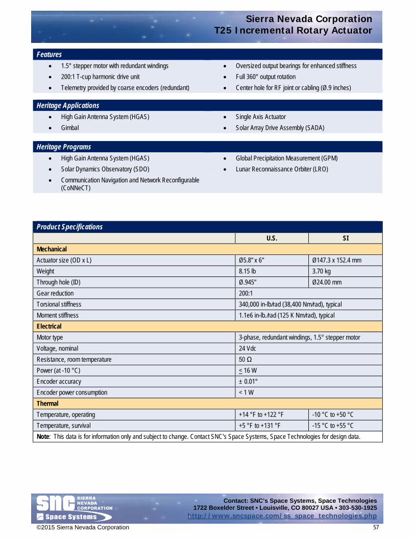
Sierra Nevada Corporation T25 Incremental Rotary Actuator
Contact: SNC’s Space Systems, Space Technologies 1722 Boxelder Street • Louisville, CO 80027 USA • 303-530-1925
http://www.sncspace.com/ss_space_technologies.php
©2015 Sierra Nevada Corporation 57
Features • 1.5° stepper motor with redundant windings • Oversized output bearings for enhanced stiffness • 200:1 T-cup harmonic drive unit • Full 360° output rotation • Telemetry provided by coarse encoders (redundant) • Center hole for RF joint or cabling (Ø.9 inches)
Heritage Applications
• High Gain Antenna System (HGAS) • Single Axis Actuator • Gimbal • Solar Array Drive Assembly (SADA)
Heritage Programs • High Gain Antenna System (HGAS) • Global Precipitation Measurement (GPM) • Solar Dynamics Observatory (SDO) • Lunar Reconnaissance Orbiter (LRO) • Communication Navigation and Network Reconfigurable
(CoNNeCT)
Product Specifications U.S. SI Mechanical Actuator size (OD x L) Ø5.8” x 6” Ø147.3 x 152.4 mm Weight 8.15 lb 3.70 kg Through hole (ID) Ø.945” Ø24.00 mm Gear reduction 200:1 Torsional stiffness 340,000 in-lb/rad (38,400 Nm/rad), typical Moment stiffness 1.1e6 in-lb./rad (125 K Nm/rad), typical Electrical Motor type 3-phase, redundant windings, 1.5° stepper motor Voltage, nominal 24 Vdc Resistance, room temperature 50 Ω Power (at -10 °C) < 16 W Encoder accuracy ± 0.01° Encoder power consumption < 1 W Thermal Temperature, operating +14 °F to +122 °F -10 °C to +50 °C Temperature, survival +5 °F to +131 °F -15 °C to +55 °C Note: This data is for information only and subject to change. Contact SNC’s Space Systems, Space Technologies for design data.

Sierra Nevada Corporation Thermal Control Systems
Contact: SNC’s Space Systems, Space Technologies 1722 Boxelder Street • Louisville, CO 80027 USA • 303-530-1925
http://www.sncspace.com/ss_space_technologies.php
©2015 Sierra Nevada Corporation 58
Thermal Control Systems
SNC has extensive experience in the area of spacecraft thermal control. Our portfolio includes thermal louvers that draw from decades of NASA/JPL heritage and are currently supporting a number of interplanetary spacecraft, and heat switches, which for years reliably controlled the main battery temperature on the Mars Exploration Rovers Spirit and Opportunity. Both technologies are considered passive approaches that require no externally supplied power to operate, allowing valuable spacecraft power to be reserved for other needs.
Catalog data sheets for SNC’s Space Systems, Space Technologies Thermal Control Systems technology area include: • Thermal Control catalog sheets coming soon
