spacecraft system failures and anomalies attributed to...
TRANSCRIPT
Spacecraft System Failures and AnomaliesAttributed to the Natural Space Environment
August 1996
NASA Reference Publication 1390
K.L. Bedingfield, R.D. Leach, and M.B. Alexander, Editor
������
����
Neutral ThermosphereThermal
Environment
PlasmaPlasma
Meteoroid/ Orbital Debris
����
����
Solar Environment
Ionizing Radiation
Geomagnetic Field
Gravitational Field
The
Nat
ural Space Environm
ents
The
Nat
ural Space
Environm
ents
Neutral ThermosphereThermal
Environment
Meteoroid/ Orbital Debris
Solar Environment
Ionizing Radiation
Geomagnetic Field
Gravitational Field
i
Spacecraft System Failures and AnomaliesAttributed to the Natural Space Environment
National Aeronautics and Space AdministrationMarshall Space Flight Center • MSFC, Alabama 35812
NASA Reference Publication 1390
August 1996
K.L. BedingfieldUniversities Space Research Association • Huntsville, Alabama
R.D. LeachComputer Sciences Corporation • Huntsville, Alabama
M.B. Alexander, EditorMarshall Space Flight Center • MSFC, Alabama
iii
PREFACE
The effects of the natural space environment on spacecraft design, development, andoperation are the topic of a series of NASA Reference Publications currently being developed by theElectromagnetics and Aerospace Environments Branch, Systems Analysis and IntegrationLaboratory, Marshall Space Flight Center.
This primer provides an overview of seven major areas of the natural space environmentincluding brief definitions, related programmatic issues, and effects on various spacecraftsubsystems. The primary focus is to present more than 100 case histories of spacecraft failures andanomalies documented from 1974 through 1994 attributed to the natural space environment. A betterunderstanding of the natural space environment and its effects will enable spacecraft designers andmanagers to more effectively minimize program risks and costs, optimize design quality, and achievemission objectives.

iv
v
TABLE OF CONTENTS
Page
INTRODUCTION ............................................................................................................................... 1
Purpose and Scope ......................................................................................................................... 1Recent Case Histories .................................................................................................................... 1
Environmental Effects on Communication Satellites .............................................................. 1Solar-Terrestrial Phenomena ................................................................................................... 5
SPECIFIC ENVIRONMENTS............................................................................................................ 7
Neutral Thermosphere ................................................................................................................... 7Environment Definition ........................................................................................................... 7Spacecraft Effects .................................................................................................................... 7Representative Cases ............................................................................................................... 9
Skylab.................................................................................................................................9Long Duration Exposure Facility (LDEF)......................................................................... 9
Thermal .......................................................................................................................................... 9Environment Definition ........................................................................................................... 9Spacecraft Effects .................................................................................................................. 10Representative Cases ............................................................................................................. 12
Hubble Space Telescope (HST) ....................................................................................... 12Galileo .............................................................................................................................12GOES-7 ........................................................................................................................... 12
Plasma ......................................................................................................................................... 13Environment Definition ......................................................................................................... 13Spacecraft Effects .................................................................................................................. 13Representative Case ............................................................................................................... 15
Intelsat K ......................................................................................................................... 15
Meteoroids/Orbital Debris ........................................................................................................... 15Environment Definition ......................................................................................................... 15Spacecraft Effects .................................................................................................................. 17Representative Cases ............................................................................................................. 17
Space Shuttle (STS-45) ................................................................................................... 17Shuttle Windshield Replacement ..................................................................................... 18HST (STS-31) .................................................................................................................. 18KOSMOS-1275 ............................................................................................................... 18
Solar ......................................................................................................................................... 18Environment Definition ......................................................................................................... 18Spacecraft Effects .................................................................................................................. 20
vi
Representative Cases ............................................................................................................. 20GOES-7 ........................................................................................................................... 20NOAA-10 ........................................................................................................................ 20GOES-5 ........................................................................................................................... 20
Ionizing Radiation ....................................................................................................................... 21Environment Definition ......................................................................................................... 21Spacecraft Effects .................................................................................................................. 22Representative Cases ............................................................................................................. 22
Hipparcos ......................................................................................................................... 22ETS-6 ............................................................................................................................... 22HST (STS-31) .................................................................................................................. 22
Geomagnetic Field ....................................................................................................................... 23Environment Definition ......................................................................................................... 23Spacecraft Effects .................................................................................................................. 24Representative Cases ............................................................................................................. 25
ANIK-B ........................................................................................................................... 25Landsat-3 ......................................................................................................................... 25
CONCLUSION ................................................................................................................................. 26
REFERENCES .................................................................................................................................. 27
BIBLIOGRAPHY ............................................................................................................................. 29
APPENDIX ........................................................................................................................................ 30
Appendix References................................................................................................................... 41
vii
LIST OF ILLUSTRATIONS
Figure Title Page
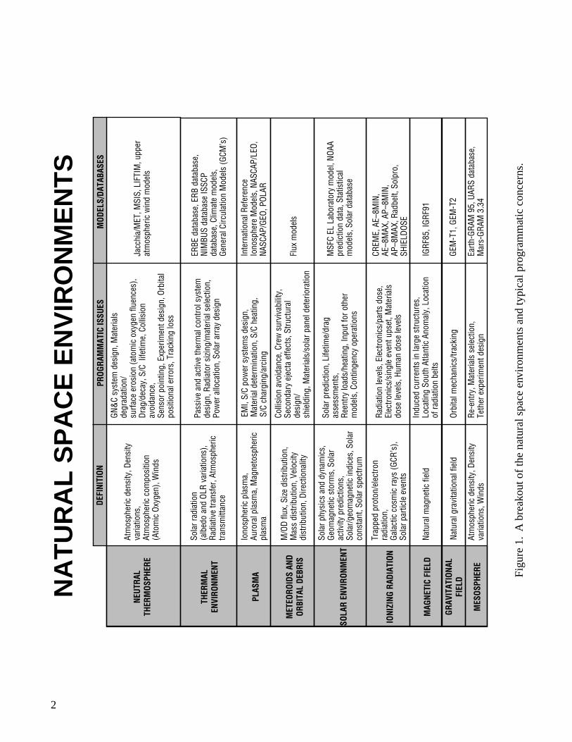
1. A breakout of the natural space environments and typical programmatic concerns. ............ 2
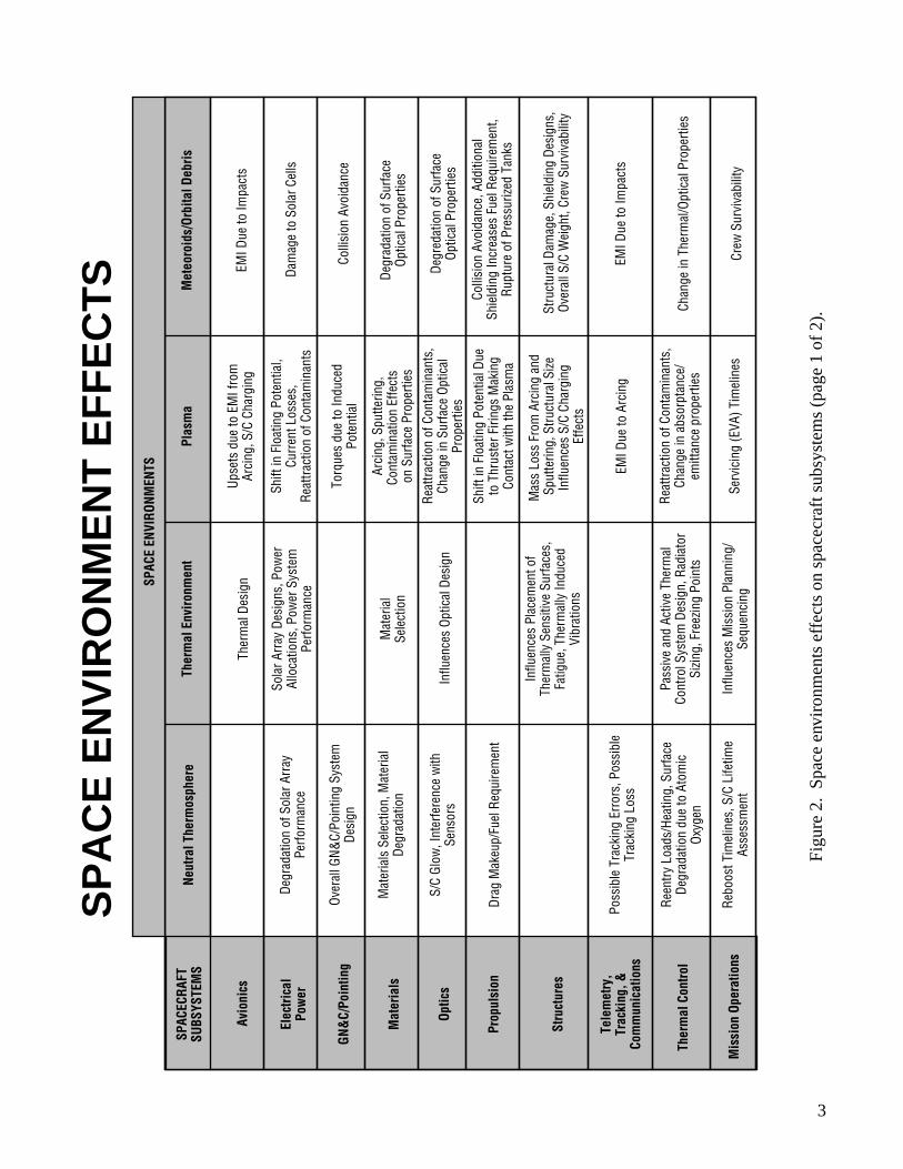
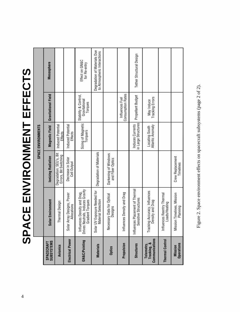
2. Space environment effects on spacecraft subsystems. ........................................................... 3
3. The layers of the Earth’s atmosphere. ................................................................................... 8
4. Skylab. ....................................................................................................................................9
5. A sample of the solar constant measurements from an instrument on the solarmaximum satellite and an instrument flying on a Nimbus satellite. ................................... 10
6. New engineering thermal model results for polar orbits. .................................................... 11
7. HST. ..................................................................................................................................... 12
8. An example of the type of charging events encountered by the DMSP satellite F7on November 26, 1983. ....................................................................................................... 14
9. Properties of the natural space plasma. ............................................................................... 14
10. Cause of spacecraft charging. .............................................................................................. 15
11. Sources of the catalogued debris population. ...................................................................... 16
12. The state of the Earth debris environment is illustrated in this snapshot of allcatalogued objects in July 1987. .......................................................................................... 16
13. Orbiter Atlantis (STS-45) right wing leading edge gouges. ................................................ 17
14. Solar cycle history. .............................................................................................................. 19
15. Trapped particles spiral back and forth along magnetic field lines. .................................... 21
16. Geomagnetic field at sea level. ............................................................................................ 23
17. Geomagnetic field at 650-km altitude. ................................................................................ 24
viii
ABBREVIATIONS AND ACRONYMS
AO atomic oxygen
CDA command and data acquisition
CRRES Combined Release and Radiation Effects Satellite
CTU central telemetry unit
DC direct current
DCPI data collection platform interrogation
EL23 mail code for Electromagnetics and Aerospace Environments Branch
EMI electromagnetic interference
ESA European Space Agency
ESD electrostatic discharge
ETS Engineering Test Satellite
EUV extreme ultraviolet
FGS fine guidance system
GN&C guidance, navigation, and control
GOES Geostationary Operational Environmental Satellite
HST Hubble Space Telescope
IGRF International Geomagnetic Reference Field
IR infrared
JSC Johnson Space Center
kHz kilohertz
LDEF Long Duration Exposure Facility
LEO low-Earth orbit
MARECS Maritime European Communications Satellite
MJ megajoule(s)
MSFC Marshall Space Flight Center
NASA National Aeronautics and Space Administration
NOAA National Oceanic and Atmospheric Administration
NORAD North American Air Defense Command
NSE natural space environment
OLR outgoing long-wave radiation
PMT photomultiplier tube
RAM random access memory
SAA South Atlantic Anomaly
SEU single event upset
STS Space Transportation System
TDRS Tracking and Data Relay Satellite
USA United States of America
1
REFERENCE PUBLICATION
SPACECRAFT SYSTEM FAILURES AND ANOMALIES ATTRIBUTEDTO THE NATURAL SPACE ENVIRONMENT
INTRODUCTION
Purpose and Scope
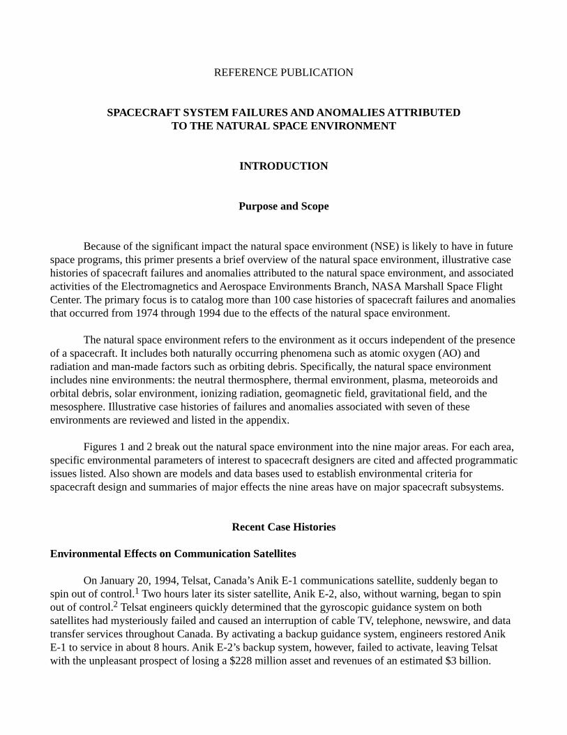
Because of the significant impact the natural space environment (NSE) is likely to have in futurespace programs, this primer presents a brief overview of the natural space environment, illustrative casehistories of spacecraft failures and anomalies attributed to the natural space environment, and associatedactivities of the Electromagnetics and Aerospace Environments Branch, NASA Marshall Space FlightCenter. The primary focus is to catalog more than 100 case histories of spacecraft failures and anomaliesthat occurred from 1974 through 1994 due to the effects of the natural space environment.
The natural space environment refers to the environment as it occurs independent of the presenceof a spacecraft. It includes both naturally occurring phenomena such as atomic oxygen (AO) andradiation and man-made factors such as orbiting debris. Specifically, the natural space environmentincludes nine environments: the neutral thermosphere, thermal environment, plasma, meteoroids andorbital debris, solar environment, ionizing radiation, geomagnetic field, gravitational field, and themesosphere. Illustrative case histories of failures and anomalies associated with seven of theseenvironments are reviewed and listed in the appendix.
Figures 1 and 2 break out the natural space environment into the nine major areas. For each area,specific environmental parameters of interest to spacecraft designers are cited and affected programmaticissues listed. Also shown are models and data bases used to establish environmental criteria forspacecraft design and summaries of major effects the nine areas have on major spacecraft subsystems.
Recent Case Histories
Environmental Effects on Communication Satellites
On January 20, 1994, Telsat, Canada’s Anik E-1 communications satellite, suddenly began tospin out of control.1 Two hours later its sister satellite, Anik E-2, also, without warning, began to spinout of control.2 Telsat engineers quickly determined that the gyroscopic guidance system on bothsatellites had mysteriously failed and caused an interruption of cable TV, telephone, newswire, and datatransfer services throughout Canada. By activating a backup guidance system, engineers restored AnikE-1 to service in about 8 hours. Anik E-2’s backup system, however, failed to activate, leaving Telsatwith the unpleasant prospect of losing a $228 million asset and revenues of an estimated $3 billion.
2
Fig
ure
1. A
bre
akou
t of t
he n
atur
al s
pace
env
ironm
ents
and
typi
cal p
rogr
amm
atic
con
cern
s.
NEUT
RAL
THER
MOS
PHER
E
THER
MAL
EN
VIRO
NMEN
T
PLAS
MA
MET
EORO
IDS
AND
ORBI
TAL
DEBR
IS
SOLA
R EN
VIRO
NMEN
T
IONI
ZING
RAD
IATI
ON
MAG
NETI
C FI
ELD
GRAV
ITAT
IONA
L FI
ELD
MES
OSPH
ERE
Atm
osph
eric
den
sity
, Den
sity
va
riatio
ns,
Atm
osph
eric
com
posi
tion
(Ato
mic
Oxy
gen)
, Win
ds
Sola
r rad
iatio
n (a
lbed
o an
d OL
R va
riatio
ns),
Radi
ativ
e tra
nsfe
r, At
mos
pher
ic
trans
mitt
ance
Io
nosp
heric
pla
sma,
Au
rora
l pla
sma,
Mag
neto
sphe
ric
plas
ma
M/O
D flu
x, S
ize d
istri
butio
n,
Mas
s di
strib
utio
n, V
eloc
ity
dist
ribut
ion,
Dire
ctio
nalit
y
So
lar p
hysi
cs a
nd d
ynam
ics,
Ge
omag
netic
sto
rms,
Sol
ar
activ
ity p
redi
ctio
ns,
Sola
r/geo
mag
netic
indi
ces,
Sol
ar
cons
tant
, Sol
ar s
pect
rum
Tr
appe
d pr
oton
/ele
ctro
n ra
diat
ion,
Ga
lact
ic c
osm
ic ra
ys (G
CR’s
), So
lar p
artic
le e
vent
s Na
tura
l mag
netic
fiel
d
Natu
ral g
ravi
tatio
nal f
ield
Atm
osph
eric
den
sity
, Den
sity
va
riatio
ns, W
inds
GN&
C sy
stem
des
ign,
Mat
eria
ls
degr
adat
ion/
su
rface
ero
sion
(ato
mic
oxy
gen
fluen
ces)
, Dr
ag/d
ecay
, S/C
life
time,
Col
lisio
n av
oida
nce,
Se
nsor
poi
ntin
g, E
xper
imen
t des
ign,
Orb
ital
posi
tiona
l err
ors,
Tra
ckin
g lo
ss
Pass
ive
and
activ
e th
erm
al c
ontro
l sys
tem
de
sign
, Rad
iato
r sizi
ng/m
ater
ial s
elec
tion,
Po
wer
allo
catio
n, S
olar
arr
ay d
esig
n
EMI,
S/C
pow
er s
yste
ms
desi
gn,
Mat
eria
l det
erm
inat
ion,
S/C
hea
ting,
S/
C ch
argi
ng/a
rcin
g Co
llisi
on a
void
ance
, Cre
w s
urvi
vabi
lity,
Se
cond
ary
ejec
ta e
ffect
s, S
truct
ural
de
sign
/ sh
ield
ing,
Mat
eria
ls/s
olar
pan
el d
eter
iora
tion
Radi
atio
n le
vels
, Ele
ctro
nics
/par
ts d
ose,
El
ectro
nics
/sin
gle
even
t ups
et, M
ater
ials
do
se le
vels
, Hum
an d
ose
leve
ls
Indu
ced
curr
ents
in la
rge
stru
ctur
es,
Loca
ting
Sout
h At
lant
ic A
nom
aly,
Loc
atio
n of
radi
atio
n be
lts
Orbi
tal m
echa
nics
/trac
king
Re-e
ntry
, Mat
eria
ls s
elec
tion,
Te
ther
exp
erim
ent d
esig
n So
lar p
redi
ctio
n, L
ifetim
e/dr
ag
asse
ssm
ents
, Re
entry
load
s/he
atin
g, In
put f
or o
ther
m
odel
s, C
ontin
genc
y op
erat
ions
Jacc
hia/
MET
, MSI
S, L
IFTI
M, u
pper
at
mos
pher
ic w
ind
mod
els
ERBE
dat
abas
e, E
RB d
atab
ase,
NI
MBU
S da
taba
se IS
SCP
data
base
, Clim
ate
mod
els,
Ge
nera
l Circ
ulat
ion
Mod
els
(GCM
’s)
Inte
rnat
iona
l Ref
eren
ce
Iono
sphe
re M
odel
s, N
ASCA
P/LE
O,
NASC
AP/G
EO, P
OLAR
Flux
mod
els
MSF
C EL
Lab
orat
ory
mod
el, N
OAA
pred
ictio
n da
ta, S
tatis
tical
m
odel
s, S
olar
dat
abas
e CR
EME,
AE–
8MIN
, AE
–8M
AX, A
P–8M
IN,
AP–8
MAX
, Rad
belt,
Sol
pro,
SH
IELD
OSE
IGRF
85, I
GRF9
1
GEM
-T1,
GEM
-T2
Earth
-GRA
M 9
5, U
ARS
data
base
, M
ars-
GRAM
3.3
4
DEFI
NITI
ONPR
OGRA
MM
ATIC
ISSU
ESM
ODEL
S/DA
TABA
SES
NA
TU
RA
L S
PA
CE
EN
VIR
ON
ME
NT
S
3
SPAC
ECRA
FT
SUBS
YSTE
MS
Avio
nics
Elec
trica
l Po
wer
GN&
C/Po
intin
g
Mat
eria
ls
Optic
s
Prop
ulsi
on
Stru
ctur
es
Tele
met
ry,
Trac
king
, &
Com
mun
icat
ions
Ther
mal
Con
trol
Mis
sion
Ope
ratio
ns
Neut
ral T
herm
osph
ere
Degr
adat
ion
of S
olar
Arr
ay
Perfo
rman
ce
Over
all G
N&C/
Poin
ting
Syst
em
Desi
gn
M
ater
ials
Sel
ectio
n, M
ater
ial
Degr
adat
ion
S/C
Glow
, Int
erfe
renc
e w
ith
Sens
ors
Drag
Mak
eup/
Fuel
Req
uire
men
t
Poss
ible
Tra
ckin
g Er
rors
, Pos
sibl
e Tr
acki
ng L
oss
Reen
try L
oads
/Hea
ting,
Sur
face
De
grad
atio
n du
e to
Ato
mic
Ox
ygen
Rebo
ost T
imel
ines
, S/C
Life
time
Asse
ssm
ent
Ther
mal
Env
ironm
ent
Ther
mal
Des
ign
So
lar A
rray
Des
igns
, Pow
er
Allo
catio
ns, P
ower
Sys
tem
Pe
rform
ance
Mat
eria
l Se
lect
ion
Influ
ence
s Op
tical
Des
ign
Influ
ence
s Pl
acem
ent o
f Th
erm
ally
Sen
sitiv
e Su
rface
s,
Fatig
ue, T
herm
ally
Indu
ced
Vibr
atio
ns
Pass
ive
and
Activ
e Th
erm
al
Cont
rol S
yste
m D
esig
n, R
adia
tor
Sizin
g, F
reez
ing
Poin
ts
In
fluen
ces
Mis
sion
Pla
nnin
g/
Sequ
enci
ng
Plas
ma
Upse
ts d
ue to
EM
I fro
m
Arci
ng, S
/C C
harg
ing
Shift
in F
loat
ing
Pote
ntia
l, Cu
rren
t Los
ses,
Re
attra
ctio
n of
Con
tam
inan
ts
To
rque
s du
e to
Indu
ced
Pote
ntia
l
Arci
ng, S
putte
ring,
Co
ntam
inat
ion
Effe
cts
on
Sur
face
Pro
perti
es
Re
attra
ctio
n of
Con
tam
inan
ts,
Chan
ge in
Sur
face
Opt
ical
Pr
oper
ties
Mas
s Lo
ss F
rom
Arc
ing
and
Sp
utte
ring,
Stru
ctur
al S
ize
Influ
ence
s S/
C Ch
argi
ng
Effe
cts
Shift
in F
loat
ing
Pote
ntia
l Due
to
Thr
uste
r Firi
ngs
Mak
ing
Cont
act w
ith th
e Pl
asm
a
EMI D
ue to
Arc
ing
Reat
tract
ion
of C
onta
min
ants
, Ch
ange
in a
bsor
ptan
ce/
emitt
ance
pro
perti
es
Serv
icin
g (E
VA) T
imel
ines
Met
eoro
ids/
Orbi
tal D
ebris
EMI D
ue to
Impa
cts
Dam
age
to S
olar
Cel
ls
Colli
sion
Avo
idan
ce
Degr
adat
ion
of S
urfa
ce
Optic
al P
rope
rties
Colli
sion
Avo
idan
ce, A
dditi
onal
Sh
ield
ing
Incr
ease
s Fu
el R
equi
rem
ent,
Rupt
ure
of P
ress
urize
d Ta
nks
Stru
ctur
al D
amag
e, S
hiel
ding
Des
igns
, Ov
eral
l S/C
Wei
ght,
Crew
Sur
viva
bilit
y
EMI D
ue to
Impa
cts
Chan
ge in
The
rmal
/Opt
ical
Pro
perti
es
Degr
edat
ion
of S
urfa
ce
Optic
al P
rope
rties
Crew
Sur
viva
bilit
y
SPAC
E EN
VIRO
NMEN
TS
SP
AC
E E
NV
IRO
NM
EN
T E
FF
EC
TS
Fig
ure
2. S
pace
env
ironm
ents
effe
cts
on s
pace
craf
t sub
syst
ems
(pa
ge 1
of 2
).
4
SP
AC
E E
NV
IRO
NM
EN
T E
FF
EC
TS
SPAC
ECRA
FT
SUBS
YSTE
MS
Avio
nics
Elec
trica
l Pow
er
GN&
C/Po
intin
g
Mat
eria
ls
Optic
s
Prop
ulsi
on
Stru
ctur
es
Tele
met
ry,
Trac
king
, &
Com
mun
icat
ions
Ther
mal
Con
trol
Mis
sion
Op
erat
ions
SPAC
E EN
VIRO
NMEN
TS
Sola
r Env
ironm
ent
Th
erm
al D
esig
n
Sola
r Arr
ay D
esig
ns, P
ower
Al
loca
tions
Influ
ence
s De
nsity
and
Dra
g,
Driv
es N
eutra
ls, I
nduc
es G
ravi
ty
Grad
ient
Tor
ques
Sola
r UV
Expo
sure
Nee
ded
for
Mat
eria
l Sel
ectio
n
Nece
ssar
y Da
ta fo
r Opt
ical
De
sign
s
Influ
ence
s De
nsity
and
Dra
g
Influ
ence
s Pl
acem
ent o
f The
rmal
Se
nsiti
ve S
truct
ures
Trac
king
Acc
urac
y, In
fluen
ces
Dens
ity a
nd D
rag
Influ
ence
s Re
entry
The
rmal
Lo
ads/
Heat
ing
M
issi
on T
imel
ines
, Mis
sion
Pl
anni
ng
Ioni
zing
Rad
iatio
n
Degr
adat
ion:
SEU
’s, B
it Er
rors
, Bit
Switc
hing
Decr
ease
in S
olar
Ce
ll Ou
tput
Degr
adat
ion
of M
ater
ials
Dark
enin
g of
Win
dow
s an
d Fi
ber O
ptic
s
Crew
Rep
lace
men
t Ti
mel
ines
Mag
netic
Fie
ld
In
duce
d Po
tent
ial
Effe
cts
In
duce
d Po
tent
ial
Effe
cts
Sizin
g of
Mag
netic
To
rque
rs
Indu
ces
Curr
ents
in
Lar
ge S
truct
ures
Loca
ting
Sout
h At
lant
ic A
nom
aly
Grav
itatio
nal F
ield
Stab
ility
& C
ontro
l, Gr
avita
tiona
l To
rque
s
Influ
ence
s Fu
el
Cons
umpt
ion
Rate
s
Prop
ella
nt B
udge
t
May
Indu
ce
Trac
king
Err
ors
Mes
osph
ere
Effe
ct o
n GN
&C
for R
e-en
try
Degr
adat
ion
of M
ater
ials
Due
to
Atm
osph
eric
Inte
ract
ions
Teth
er S
truct
ural
Des
ign
Fig
ure
2. S
pace
env
ironm
ent e
ffect
s on
spa
cecr
aft s
ubsy
stem
s (p
age
2 of
2).
5
The days immediately following these failures were a nightmare for public relations andoperations management. Services were switched to other satellites, ground station antennas wererealigned, backup transponders were activated, “retired” satellites were recalled to service, backup landlinks were established, frequencies were changed, and irate customers were reassured that life as theyknew it was not ending. Eventually when telecommunications were reestablished, service was reducedby 10 full channels and 14 occasional-use channels.3 In early press accounts, Telsat stated there hadnever been a satellite failure of this magnitude.4 Much to their credit, Telsat engineers restored Anik E-2to service in August 1994. They had developed an innovative first-of-a-kind ground control system thatutilizes the 22 thruster motors located on the satellite to reposition the spacecraft. A computer programusing data received from onboard sensors automatically determines the thruster firing sequence tomaintain proper orientation.
Although Telsat did not lose Anik E-2 and future revenues, an estimated $50 to $70 million inrecovery, repair costs, and lost revenues were realized. This included a 1-year decrease in the satellite’sprojected 10-year service life caused by an increase in the fuel required to fire the 22 thrusters to keepthe satellite stable. This decreases the supply of fuel that can be used for station keeping. Also, operatingcosts over the satellite’s remaining 9-year lifetime could be an additional $30 million.3–6 Because theprobability of an on-orbit mission failure is too low to justify the high annual insurance premiums, Telsatdoes not insure its satellites against on-orbit failures—a position many spacecraft operators take.
A determination was subsequently made that the events of January 20, 1994, were caused by aphenomenon known as spacecraft charging—a process through which a spacecraft charges to anelectrical potential relative to its surroundings. In each Anik satellite, electrostatic discharge (ESD)created electromagnetic impulses within the primary gyroscopic guidance system control circuitry thatpermanently damaged critical components, rapidly degraded the satellites’ stability, and severelyjeopardized their missions.
Solar-Terrestrial Phenomena
An intense period of solar activity in March 1991 initiated a sequence of major terrestrial effectsthat included the generation of a second inner radiation belt, satellite anomalies, and power surges onelectrical power grids. The rapidly changing geophysical environment in late March was the result of asevere storm in space that began in the outer atmosphere of the Sun. A giant loop of hot ionized gas(plasma) many times larger than Earth, arched high above the solar corona, expanded slowly, gainedspeed, and blasted outward through interplanetary space toward the Earth.
During this powerful solar X-ray event, the sunlit ionosphere was strongly ionized; i.e., atomshad electrons ejected from their outer shells. This increase in electron density resulted in degradation ofshort-wave radio frequency communication. With the arrival of high energy solar radiation, a disruptionin high latitude point-to-point communication occurred and solar panel degradation was evident onGeostationary Operational Environmental Satellites (GOES)-6 and -7. The GOES-7 power degradationtranslated to a decrease of 2 to 3 years in expected satellite lifetime. Also, the presence of high energysolar particles increased the frequency of single event upsets (SEU) recorded by spacecraft. These upsetsare aberrations in analog, digital, or even power circuits caused by the interaction of a single solar
6
particle within the circuit. Six geostationary satellites, including GOES-6 and -7, and the Tracking andData Relay Satellite (TDRS)-1 had 37 reported single event upsets during the major part of the solaractivity.
Additional problems occurred during the geomagnetic storm portion of this period. Thecombination of solar events mentioned previously resulted in an interplanetary magnetic shock travelingfrom the Sun to Earth. Within seconds of the arrival of the interplanetary disturbance, an immediateinflux of electrons and protons into the Earth’s magnetosphere, measured by the Combined Release andRadiation Effects Satellite (CRRES), created a second and long lasting (i.e., months) inner radiation belt.
With the arrival of the interplanetary shock and the ensuing geomagnetic disturbance, auroralsightings were reported in the Northern Hemisphere as far south as the state of Georgia, United States ofAmerica (USA), and in the Southern Hemisphere as far north as the Blue Mountain region of New SouthWales, Australia. This resulted in low-latitude communication disruption as the polar ionosphericconditions extended to mid and low latitudes. Hydro-Quebec experienced several power surges in itspower grid. Tripping of power relay systems and damage to electrical distribution transformers andequipment in the eastern United States and Canada caused major power outages.
In addition, a loss of automatic attitude control of the National Oceanic and AtmosphericAdministration (NOAA)-11 satellite occurred, and increased satellite drag due to the heated atmospherenecessitated a massive update of the North American Air Defense Command (NORAD) catalog oforbiting objects. Of more serious consequence was the complete failure of the geosynchronous orbitingMaritime European Communication Satellite (MARECS)-1 on March 25, 1991, due to serious damageto its solar panels that occurred during this period of intense solar activity.3
These cases show some of the effects of the natural space environment on spacecraft and groundoperations. The remainder of this primer will be devoted to additional case histories associated with thedifferent areas of the natural space environment.
7
SPECIFIC ENVIRONMENTS
Neutral Thermosphere
Environment Definition
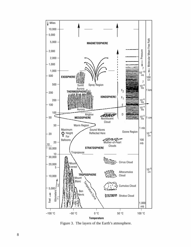
The region of the Earth’s atmosphere containing neutral atmospheric constituents and locatedabove 90 km is known as the neutral thermosphere, while that region above 600 km or so is known asthe thermosphere (fig. 3). The thermosphere is composed primarily of neutral gas particles that tend tostratify based on their molecular weight. AO is the dominant constituent in the lower thermosphere, withhelium and hydrogen dominating the higher regions. As figure 3 shows, the temperature in the lowerthermosphere increases rapidly with increasing altitude from a minimum at 90 km. Eventually, itbecomes altitude independent and approaches an asymptotic temperature known as the exospherictemperature. Thermospheric temperature, as well as density and composition, is very sensitive to thesolar cycle because of heating by absorption of the solar extreme ultraviolet (EUV) radiation. Thisprocess has been effectively modeled using a proxy parameter, the 10.7-cm solar radio flux (F10.7).
Spacecraft Effects
Density of the neutral gas is the primary atmospheric property that affects spacecraft orbitalaltitude, lifetime, and motion. Even though space is thought of as a vacuum, there is enough matter toimpart a substantial drag force on orbiting spacecraft. Unless this drag force is compensated for by thevehicle’s propulsion system, the altitude will decay until reentry occurs. Density effects also directlycontribute to the torques experienced by the spacecraft due to the aerodynamic interaction between thespacecraft and the atmosphere, and thus, must be considered in the design of the spacecraft attitudecontrol systems.
Many materials used on spacecraft surfaces are susceptible to attack by AO, a major constituentof the low-Earth orbit (LEO) thermosphere region. Due to photodissociation, oxygen existspredominantly in the atomic form. The density of AO varies with altitude and solar activity and is thepredominant neutral species at altitudes of about 200 to 400 km during low solar activity. Simultaneousexposure to the solar ultraviolet radiation, micrometeoroid impact damage, sputtering, or contaminationeffects can aggravate the AO effects, leading to serious deterioration of mechanical, optical, and thermalproperties of some material surfaces. A related phenomenon that may be of concern for opticallysensitive experiments is spacecraft glow. Optical emissions are generated from metastable molecules thathave been excited by impact on the surface of the spacecraft. Investigations show that the surface acts asa catalyst, thus the intensity is dependent on the type of surface material.
8
Figure 3. The layers of the Earth’s atmosphere.
5,000
Miles
2,000
1,000
500
200
100
50
20
50,00010
30,000
20,000
10,000
5,000
–100 °C –50 °C 0 °C
Temperature
50 °C 100 °C
Feet Kilo
met
ers
10,000
5,000
2,000
1,000
500
200
100
50
20
10
5
2
1
Mount Everest
Mount Blanc
Ben Nevis
STRATOSPHERE
MESOSPHERE
IONOSPHERE
EXOSPHERE
MAGNETOSPHERE
Spray Region
Pres
sure
Mol
ecul
ar M
ean
Free
Pat
h
Aurora
AirglowNoctilucent
Cloud
F2
F1
E
D
Warm Region
Sound Waves Reflected Here
Maximum Height For
BalloonsMother-of-Pearl
Clouds
Tropopause
Cirrus Cloud
Altocumulus Cloud
Cumulus Cloud
Temperature Curve
Stratus Cloud
Ozone Region
10–107
mb100
7
km
10–87
mb
10–6mb
10–4mb
10–2mb
10–4cm
10–5
cm
1 mb
100 mb
1,000 mb
1 km
1 cm
THERMOSPHERE
Sunlit Aurora
TROPOSPHERE
9
Representative Cases
Skylab
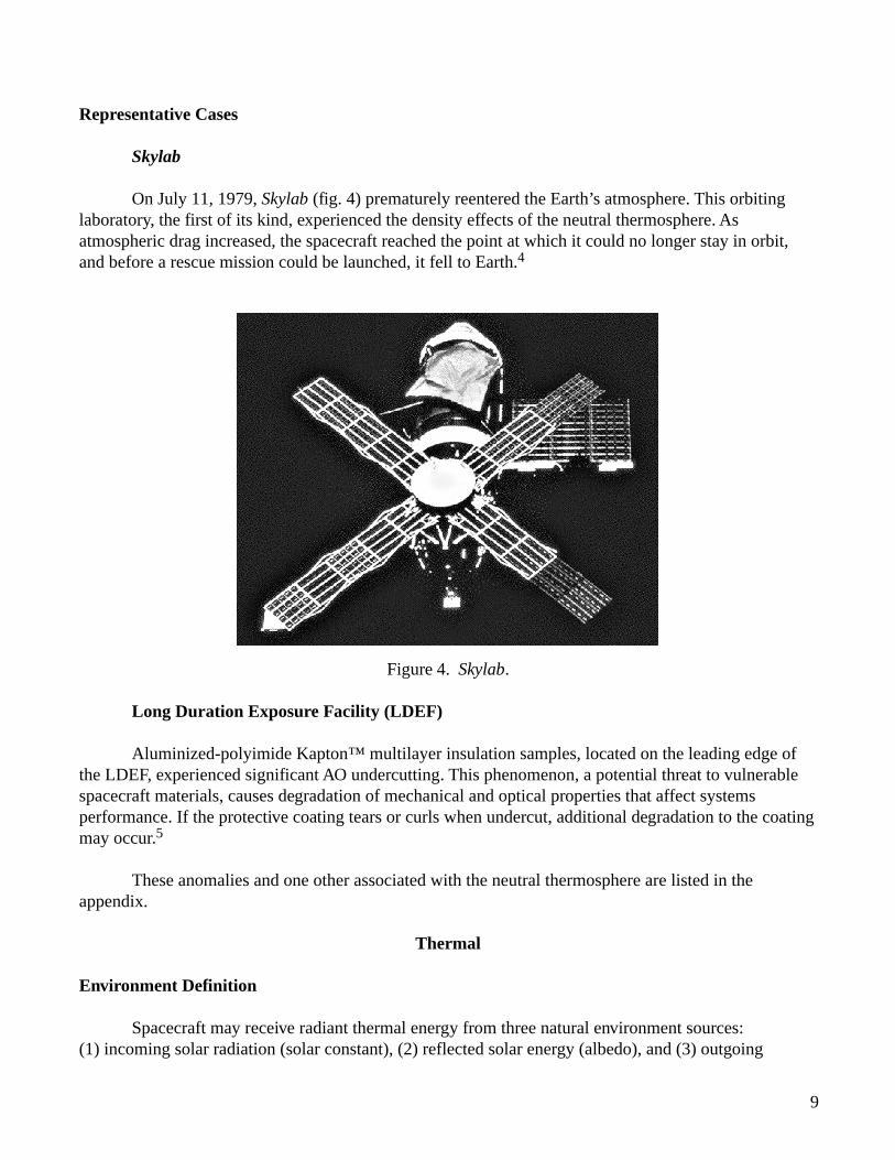
On July 11, 1979, Skylab (fig. 4) prematurely reentered the Earth’s atmosphere. This orbitinglaboratory, the first of its kind, experienced the density effects of the neutral thermosphere. Asatmospheric drag increased, the spacecraft reached the point at which it could no longer stay in orbit,and before a rescue mission could be launched, it fell to Earth.4
Figure 4. Skylab.
Long Duration Exposure Facility (LDEF)
Aluminized-polyimide Kapton™ multilayer insulation samples, located on the leading edge ofthe LDEF, experienced significant AO undercutting. This phenomenon, a potential threat to vulnerablespacecraft materials, causes degradation of mechanical and optical properties that affect systemsperformance. If the protective coating tears or curls when undercut, additional degradation to the coatingmay occur.5
These anomalies and one other associated with the neutral thermosphere are listed in theappendix.
Thermal
Environment Definition
Spacecraft may receive radiant thermal energy from three natural environment sources:(1) incoming solar radiation (solar constant), (2) reflected solar energy (albedo), and (3) outgoing
10
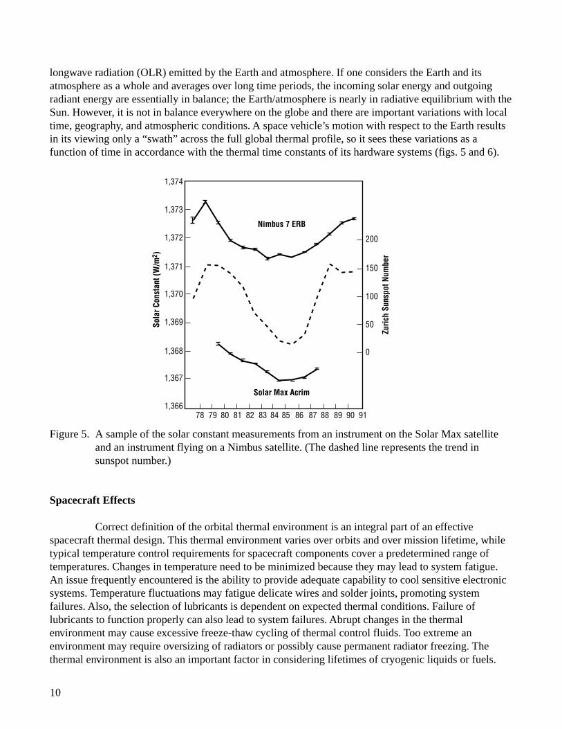
longwave radiation (OLR) emitted by the Earth and atmosphere. If one considers the Earth and itsatmosphere as a whole and averages over long time periods, the incoming solar energy and outgoingradiant energy are essentially in balance; the Earth/atmosphere is nearly in radiative equilibrium with theSun. However, it is not in balance everywhere on the globe and there are important variations with localtime, geography, and atmospheric conditions. A space vehicle’s motion with respect to the Earth resultsin its viewing only a “swath” across the full global thermal profile, so it sees these variations as afunction of time in accordance with the thermal time constants of its hardware systems (figs. 5 and 6).
Figure 5. A sample of the solar constant measurements from an instrument on the Solar Max satelliteand an instrument flying on a Nimbus satellite. (The dashed line represents the trend insunspot number.)
Spacecraft Effects
Correct definition of the orbital thermal environment is an integral part of an effectivespacecraft thermal design. This thermal environment varies over orbits and over mission lifetime, whiletypical temperature control requirements for spacecraft components cover a predetermined range oftemperatures. Changes in temperature need to be minimized because they may lead to system fatigue.An issue frequently encountered is the ability to provide adequate capability to cool sensitive electronicsystems. Temperature fluctuations may fatigue delicate wires and solder joints, promoting systemfailures. Also, the selection of lubricants is dependent on expected thermal conditions. Failure oflubricants to function properly can also lead to system failures. Abrupt changes in the thermalenvironment may cause excessive freeze-thaw cycling of thermal control fluids. Too extreme anenvironment may require oversizing of radiators or possibly cause permanent radiator freezing. Thethermal environment is also an important factor in considering lifetimes of cryogenic liquids or fuels.
781,366
1,367
1,368
1,369
1,370
1,371
1,372 200
150
100
50
0
1,373
1,374
79 80 81 82 83
Sola
r Con
stan
t (W
/m2 )
Zuric
h Su
nspo
t Num
ber
84 85
Solar Max Acrim
Nimbus 7 ERB
86 87 88 89 90 91
11
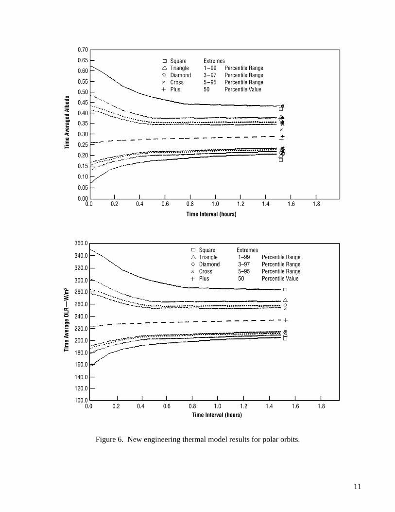
Figure 6. New engineering thermal model results for polar orbits.
Square Triangle Diamond Cross Plus
Extremes 1–99 3–97 5–95 50
Percentile Range Percentile Range Percentile Range Percentile Value
0.70
0.65
0.60
0.55
0.50
0.45
0.40
0.35
0.30
0.25
0.20
0.15
0.10
0.05
0.000.0 0.2 0.4 0.6 0.8 1.0
Time Interval (hours)
Tim
e Av
erag
ed A
lbed
o
1.2 1.4 1.6 1.8
Square Triangle Diamond Cross Plus
Extremes 1–99 3–97 5–95 50
Percentile Range Percentile Range Percentile Range Percentile Value
360.0
340.0
320.0
300.0
280.0
260.0
240.0
220.0
200.0
180.0
160.0
140.0
120.0
100.00.0 0.2 0.4 0.6 0.8 1.0
Time Interval (hours)
Tim
e Av
erag
e OL
R—
W/m
2
1.2 1.4 1.6 1.8
12
Representative Cases
Hubble Space Telescope (HST)
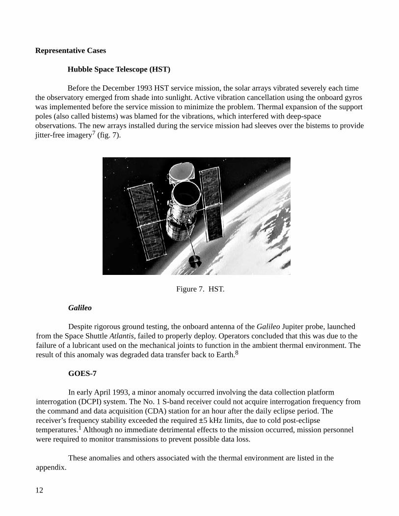
Before the December 1993 HST service mission, the solar arrays vibrated severely each timethe observatory emerged from shade into sunlight. Active vibration cancellation using the onboard gyroswas implemented before the service mission to minimize the problem. Thermal expansion of the supportpoles (also called bistems) was blamed for the vibrations, which interfered with deep-spaceobservations. The new arrays installed during the service mission had sleeves over the bistems to providejitter-free imagery7 (fig. 7).
Figure 7. HST.
Galileo
Despite rigorous ground testing, the onboard antenna of the Galileo Jupiter probe, launchedfrom the Space Shuttle Atlantis, failed to properly deploy. Operators concluded that this was due to thefailure of a lubricant used on the mechanical joints to function in the ambient thermal environment. Theresult of this anomaly was degraded data transfer back to Earth.8
GOES-7
In early April 1993, a minor anomaly occurred involving the data collection platforminterrogation (DCPI) system. The No. 1 S-band receiver could not acquire interrogation frequency fromthe command and data acquisition (CDA) station for an hour after the daily eclipse period. Thereceiver’s frequency stability exceeded the required ±5 kHz limits, due to cold post-eclipsetemperatures.1 Although no immediate detrimental effects to the mission occurred, mission personnelwere required to monitor transmissions to prevent possible data loss.
These anomalies and others associated with the thermal environment are listed in theappendix.
13
Plasma
Environment Definition
The major constituents of the Earth’s atmosphere remain virtually unchanged up to an altitudeof 90 km, but above this level the relative amounts and types of gases are no longer constant withaltitude. Within this upper zone of thin air, shortwave solar radiation causes various photochemicaleffects on the gases. A photochemical effect is one in which the structure of a molecule is changed whenit absorbs radiant energy. One of the most common of these effects is the splitting of diatomic oxygeninto atoms. Another common effect is that atoms will have electrons ejected from their outer shells.These atoms are said to be ionized. A small part of the air in the upper atmosphere consists of thesepositively charged ions and free electrons which cause significant physical effects. The electron densitiesare approximately equal to the ion densities everywhere in the region. An ionized gas composed of equalnumbers of positively and negatively charged particles is termed a plasma. The electron and ion densitiesvary dramatically with altitude, latitude, magnetic field strength, and solar activity.
Spacecraft Effects
As a spacecraft flies through this ionized portion of the atmosphere, it may be subjected to anunequal flux of ions and electrons and may develop an induced charge. Plasma flux to the spacecraftsurface can charge the surface and disrupt the operation of electrically biased instruments. In LEO,vehicles travel through dense but low-energy plasma. These spacecraft are negatively charged becausetheir orbital velocity is greater than the ion thermal velocity but slower than the electron thermalvelocity. Thus, electrons can impact all surfaces, while ions can impact only ram surfaces. LEOspacecrafts have been known to charge to thousands of volts; however, charging at geosynchronousorbits is typically a greater concern. Biased surfaces, such as solar arrays, can affect the floatingpotential. The magnitude of charge depends on the type of grounding configuration used. Spacecraftcharging may cause biasing of spacecraft instrument readings, arcing which may cause upsets tosensitive electronics, increased current collection, reattraction of contaminants, and ion sputtering whichmay cause accelerated erosion of materials. High-magnitude charging will cause arcing and otherelectrical distrubances on spacecraft (figs. 8, 9, and 10).
Spacecraft charging is presented in detail in NASA Reference Publication 1354, “SpacecraftEnvironments Interactions: Protecting Against the Effects of Spacecraft Charging,” and NASAReference Publication 1375, “Failures and Anomalies Attributed to Spacecraft Charging.” Also,numerous case histories of spacecraft failures and anomalies attributed to electromagnetic interference(EMI) due to the effects of spacecraft charging, are presented in detail in NASA Reference Publication1374, “Electronic Systems Failures and Anomalies Attributed to Electromagnetic Interference.”
14
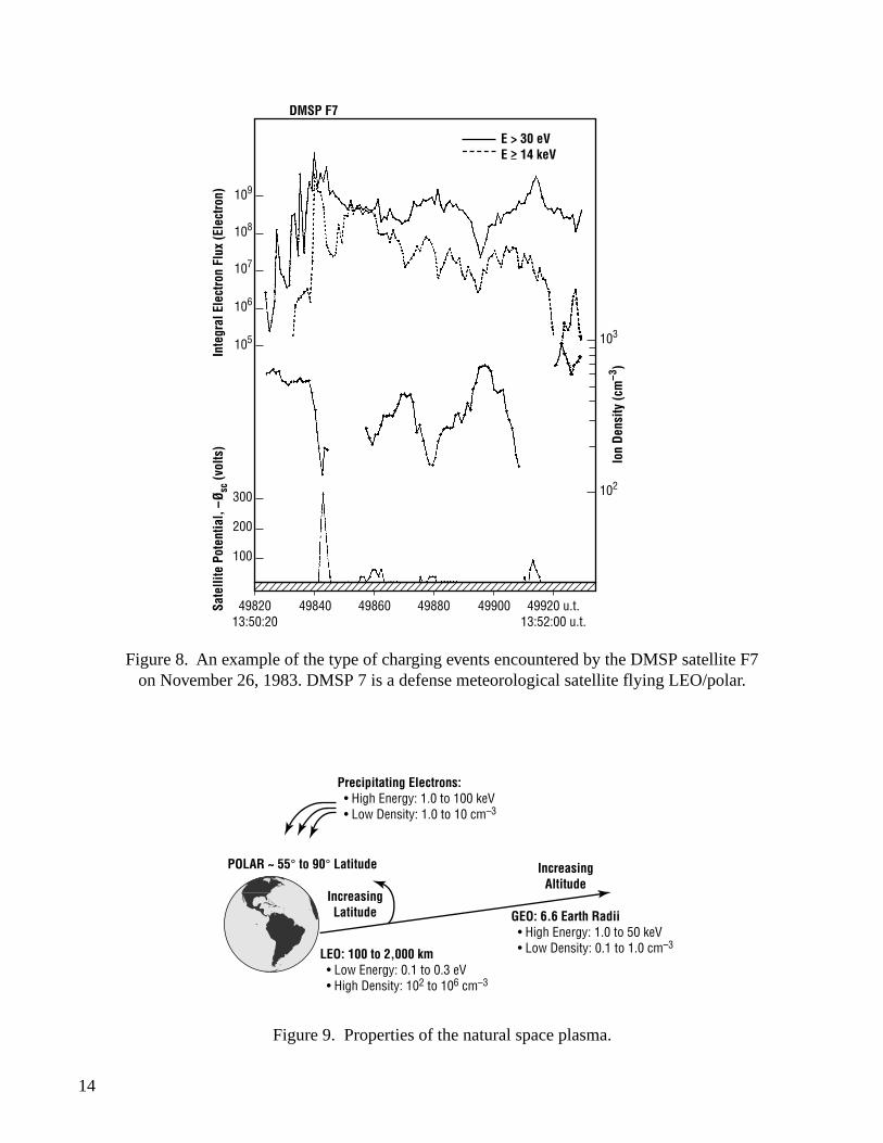
Figure 8. An example of the type of charging events encountered by the DMSP satellite F7on November 26, 1983. DMSP 7 is a defense meteorological satellite flying LEO/polar.
109
108
107
106
105
102
103
300
200
100
49820 13:50:20
49840 49860 49880 49900 49920 u.t. 13:52:00 u.t.
Ion
Dens
ity (c
m–3
)
Sate
llite
Pot
entia
l, –Ø
sc (v
olts
)In
tegr
al E
lect
ron
Flux
(Ele
ctro
n)
DMSP F7
E > 30 eV E > 14 keV
POLAR ~ 55° to 90° Latitude
Increasing Latitude
Increasing Altitude
Precipitating Electrons: • High Energy: 1.0 to 100 keV • Low Density: 1.0 to 10 cm–3
LEO: 100 to 2,000 km • Low Energy: 0.1 to 0.3 eV • High Density: 102 to 106 cm–3
GEO: 6.6 Earth Radii • High Energy: 1.0 to 50 keV • Low Density: 0.1 to 1.0 cm–3
Figure 9. Properties of the natural space plasma.
15
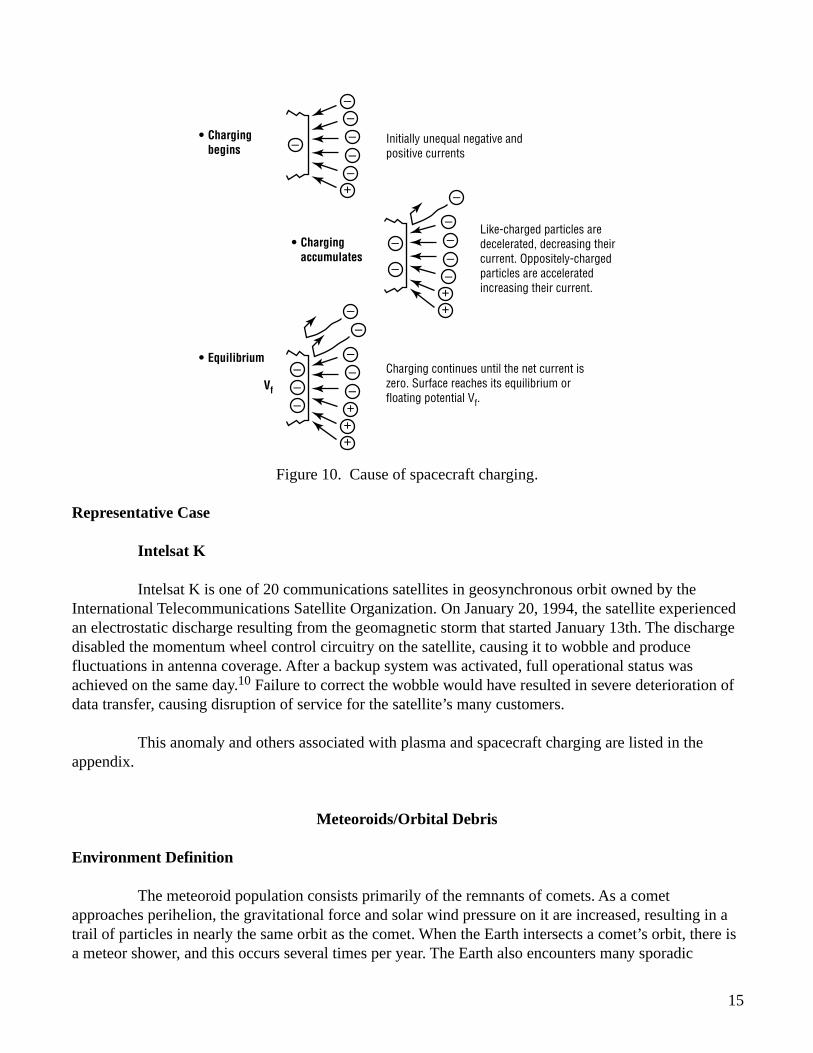
Figure 10. Cause of spacecraft charging.
Representative Case
Intelsat K
Intelsat K is one of 20 communications satellites in geosynchronous orbit owned by theInternational Telecommunications Satellite Organization. On January 20, 1994, the satellite experiencedan electrostatic discharge resulting from the geomagnetic storm that started January 13th. The dischargedisabled the momentum wheel control circuitry on the satellite, causing it to wobble and producefluctuations in antenna coverage. After a backup system was activated, full operational status wasachieved on the same day.10 Failure to correct the wobble would have resulted in severe deterioration ofdata transfer, causing disruption of service for the satellite’s many customers.
This anomaly and others associated with plasma and spacecraft charging are listed in theappendix.
Meteoroids/Orbital Debris
Environment Definition
The meteoroid population consists primarily of the remnants of comets. As a cometapproaches perihelion, the gravitational force and solar wind pressure on it are increased, resulting in atrail of particles in nearly the same orbit as the comet. When the Earth intersects a comet’s orbit, there isa meteor shower, and this occurs several times per year. The Earth also encounters many sporadic
• Charging begins
Initially unequal negative and positive currents
–
–
+
–
–
––
• EquilibriumCharging continues until the net current is zero. Surface reaches its equilibrium or floating potential Vf.
Vf
• Charging accumulates
Like-charged particles are decelerated, decreasing their current. Oppositely-charged particles are accelerated increasing their current.
–
–
–
++
–
–
––
––
–
–
++
–
+
––
–
16
particles on a daily basis. These particles originate in the asteroid belt, and are themselves the smallestasteroids. Radiation pressure from the Sun causes a drag force on the smallest particles in the asteroidbelt. In time, these particles lose their orbital energy and spiral into the Sun.
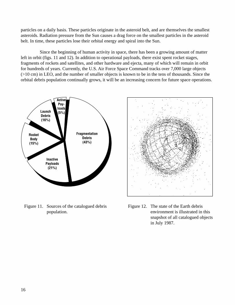
Since the beginning of human activity in space, there has been a growing amount of matterleft in orbit (figs. 11 and 12). In addition to operational payloads, there exist spent rocket stages,fragments of rockets and satellites, and other hardware and ejecta, many of which will remain in orbitfor hundreds of years. Currently, the U.S. Air Force Space Command tracks over 7,000 large objects(>10 cm) in LEO, and the number of smaller objects is known to be in the tens of thousands. Since theorbital debris population continually grows, it will be an increasing concern for future space operations.
Figure 11. Sources of the catalogued debrispopulation.
Fragmentation Debris (43%)
Active Pay- loads (5%)Launch
Debris (16%)
Rocket Body (15%)
Inactive Payloads
(21%)
Figure 12. The state of the Earth debrisenvironment is illustrated in thissnapshot of all catalogued objectsin July 1987.
17
Spacecraft Effects
Meteoroids and orbital debris pose a serious damage and decompression threat to spacevehicles. In the orbital velocity regime, collisions are referred to as hypervelocity impacts. Such animpact, for example, by a 90-gram particle, will impart over 1 MJ of energy to the vehicle. Thus,practically any spacecraft will suffer catastrophic damage or decompression if it receives a hypervelocityimpact from an object larger than a few grams. Collisions with smaller objects cause serious surfaceerosion with subsequent effects on the surface thermal, electrical, and optical properties. Net risk to amission depends on the orbit duration, vehicle size and design, launch date (solar cycle phase), orbitaltitude, and inclination. Protective shielding is often necessary to minimize the threat from themeteoroid/orbital debris environment. If a system cannot be shielded, operational constraints orprocedures may be imposed to reduce the threat of damage. The debris threat is highly directional, sorisk can also be mitigated by careful arrangement of critical components.
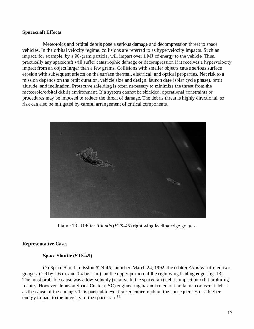
Figure 13. Orbiter Atlantis (STS-45) right wing leading edge gouges.
Representative Cases
Space Shuttle (STS-45)
On Space Shuttle mission STS-45, launched March 24, 1992, the orbiter Atlantis suffered twogouges, (1.9 by 1.6 in. and 0.4 by 1 in.), on the upper portion of the right wing leading edge (fig. 13).The most probable cause was a low-velocity (relative to the spacecraft) debris impact on orbit or duringreentry. However, Johnson Space Center (JSC) engineering has not ruled out prelaunch or ascent debrisas the cause of the damage. This particular event raised concern about the consequences of a higherenergy impact to the integrity of the spacecraft.11
18
Shuttle Windshield Replacement
The shuttle program has had to replace 46 orbiter windshields due to impact pits (total throughSTS-68 launch in September 1994). While no impact has been mission critical, collected data indicatethat the threat from meteoroids and orbital debris is real and must be accounted for in mission planningguidelines, flight rules, and operating procedures. NASA is currently reevaluating orbiter meteoroid andorbital debris risk-reduction strategies, including predictive modeling of impacts not only to windshieldsbut also to radiators and other surfaces. These risk reduction strategies also include improved inspectionand repair techniques and development of techniques and materials to provide better impact protection.
HST (STS-31)
After the December 1993 Hubble service mission, British Aerospace inspection of theretrieved HST array revealed that the whole wing suffered between 5000 and 6000 micrometeoroidimpacts in its 4-year life. The effect of these impacts range from slight grazing to puncture of cells andblankets.12
KOSMOS-1275
At an altitude of 977 km on July 24, 1981, the Russian satellite Kosmos-1275 broke up intoover 200 trackable fragments. Speculation is it was the result of a hypervelocity collision with a piece ofspace debris. This was based on the following: this type satellite has shown no capability to maneuverand may have been a gravity gradient stabilized spacecraft, no pressurized vessels or onboard propellantsare standard on this type, the satellite resided in the altitude region most densely populated with debrisfrom earlier satellite breakups, and the satellite was in a high inclination orbit (83 degrees), whichsuggests higher relative velocities between a satellite and the general debris population.13
These anomalies and others associated with meteoroids and orbital debris are listed in theappendix.
Solar
Environment Definition
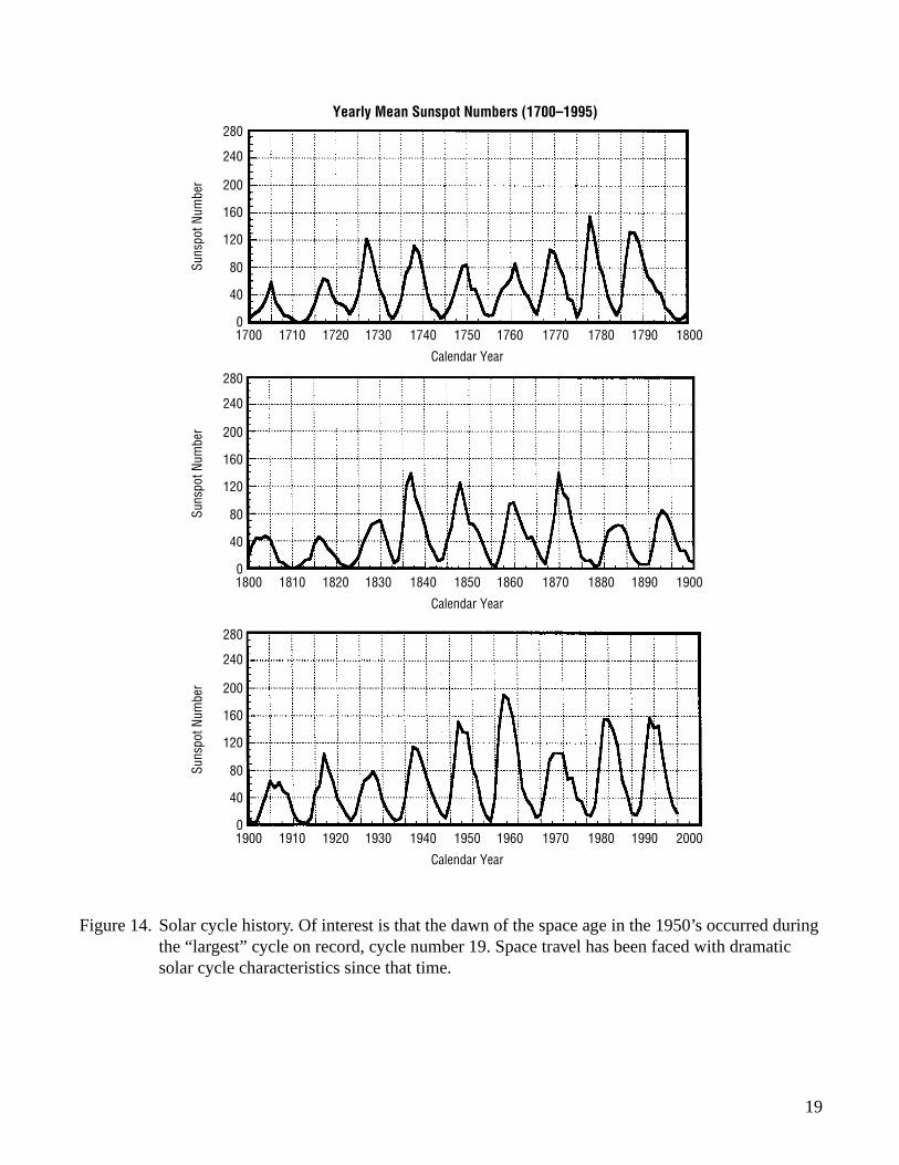
The Sun emits huge amounts of mass and energy. This tremendous emission of energy hasimportant consequences to spacecraft design, development, and operation. Over short periods of timeand in certain locations, solar intensity can fluctuate rapidly. It is thought that a major factor causingthese fluctuations is the distortion of the Sun’s large magnetic field due to its differential rotation. Two ofthe most common indicators of locally enhanced magnetic fields are sunspots and flares. Sunspots areprobably the most commonly known solar activity feature. The average sunspot number is known to varywith a period of about 11 years (fig. 14). Each cycle is defined as beginning with solar minimum (thetime of lowest sunspot number) and lasting until the following solar minimum. For example, cycle 22,which began in late 1986, reached solar maximum in 1991. A solar flare is a highly concentratedexplosive release of energy within the solar atmosphere. The radiation from a solar flare extends from
19
280
1700 1710 1720 1730 1740 1750
Calendar Year
Suns
pot N
umbe
r
1760 1770 1780 1790 1800
1800 1810 1820 1830 1840 1850
Calendar Year
1860 1870 1880 1890 1900
240
200
160
120
80
40
0
280
Suns
pot N
umbe
r
240
200
160
120
80
40
0
1900 1910 1920 1930 1940 1950
Calendar Year
1960 1970 1980 1990 2000
280
Suns
pot N
umbe
r
240
200
160
120
80
40
0
Yearly Mean Sunspot Numbers (1700–1995)
Figure 14. Solar cycle history. Of interest is that the dawn of the space age in the 1950’s occurred duringthe “largest” cycle on record, cycle number 19. Space travel has been faced with dramaticsolar cycle characteristics since that time.
20
radio to X-ray frequencies. Solar flares are differentiated according to total energy released. Ultimately,the total energy emitted is the deciding factor in the severity of a flare’s effects on the spaceenvironment.
Spacecraft Effects
The solar environment has a critical impact on most elements within the natural spaceenvironment. Variations in the solar environment impact thermospheric density levels, overall thermalenvironment a spacecraft will experience, plasma density levels, meteoroids/orbital debris levels,severity of the ionizing radiation environment, and characteristics of the Earth’s magnetic field. Thesolar cycle also plays an important role in mission planning and operations activities. For instance, whensolar activity is high, ultraviolet and extreme ultraviolet radiation from the Sun heats and expands theEarth’s upper atmosphere, increasing atmospheric drag and orbital decay rate of spacecraft. Solar flaresare a major contributor to the overall radiation environment and can add to the dose of accumulatedradiation levels and to single event phenomena that can greatly affect electronic systems.
Representative Cases
GOES-7
During a period of intense solar X-rays from March 22 to 24, 1991, researchers foundevidence of solar panel degradation on GOES-7. The spacecraft is designed to accommodate a gradualdecline in solar panel power output caused by the space environment. The intense high-energy radiationfrom this particular solar event permanently damaged solar panel electronics and caused an acceleratedpower degradation above design expectations that decreased the life expectancy of the satellite by2 or 3 years.3
NOAA-10
On March 13, 1989, this NOAA satellite experienced excessive x-axis gyro speeds due tomagnetic momentum unloading that caused the roll/yaw coil to switch into backup mode. Operatorssuspected the anomaly was caused by solar activity.
On October 1, 1989, a 28-volt power switch indicated an undesired “on” reading requiringcontrollers to reset the switch. Solar influence was determined to be a probable cause.14
GOES-5
The central telemetry unit (CTU) of this geostationary satellite experienced 10 SEU’s during1989, six of which were associated with solar flares. Also, a major solar flare on October 19, 1989,damaged solar array electronics and decreased by 0.5 amps current output of the array.
These anomalies and others associated with the solar environment are listed in the appendix.
21
Ionizing Radiation
Environment Definition
The particles associated with ionizing radiation are categorized into three main groupsrelating to the source of the radiation: trapped radiation belt particles, cosmic rays, and solar flareparticles. Results from recent satellite studies suggest that the source of the trapped radiation belt (or VanAllen belts) particles seems to be from a variety of physical mechanisms: from the acceleration of lower-energy particles by magnetic storm activity, from the trapping of decay products of energetic neutronsproduced in the upper atmosphere by collisions of cosmic rays with atmospheric particles, and fromsolar flares. Solar proton events are associated with solar flares. Cosmic rays originate outside the solarsystem from other solar flares, nova/supernova explosions, or quasars.
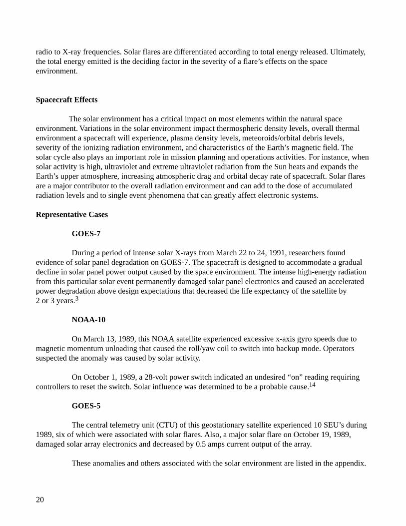
The Earth’s magnetic field concentrates large fluxes of high-energy, ionizing particlesincluding electrons, protons, and heavier ions. The Earth’s magnetic field provides the mechanism thattraps these charged particles within specific regions, called the Van Allen belts. The belts arecharacterized by a region of trapped protons, an inner, and outer electron belt. The radiation beltparticles spiral back and forth along the magnetic field lines (fig. 15). Because the Earth’s approximatedipolar field is displaced from the Earth’s center, the ionizing radiation belts reach their lowest altitudeoff the eastern coast of South America. This means as particles travel into the region, they reach loweraltitudes, and particle densities are anomalously high. This area is termed the South Atlantic Anomaly(SAA). In this document, the term “cosmic rays” applies to electrons, protons, and the nuclei of allelements from other than solar origins. Satellites at low inclination and low altitude experience asignificant amount of natural shielding from cosmic rays due to the Earth’s magnetic field. A smallpercentage of solar flares are accompanied by the ejection of significant numbers of protons. Solarproton events occur sporadically, but are most likely near solar maximum. Events may last for hours orup to more than a week, but typically the effects last 2 to 3 days. Solar protons add to the total dose andmay also cause single event effects in some cases.
Flux Tube
Trajectory of Trapped Particle
Mirror Point
Magnetic Conjugate Point
North
Drift of Protons
Magnetic Field Line
Figure 15. Trapped particles spiral back and forth along magnetic field lines.
22
Spacecraft Effects
The high-energy particles comprising the radiation environment can travel through spacecraftmaterial and deposit kinetic energy. This process causes atomic displacement or leaves a stream ofcharged atoms in the incident particles’ wake. Spacecraft damage includes decreased power productionby solar arrays, failure of sensitive electronics, increased background noise in sensors, and radiationexposure to the spacecraft crew. Modern electronics are becoming increasingly sensitive to ionizingradiation.
Representative Cases
Hipparcos
After more than 3 years of efficient and successful operations, communications with theEuropean Space Agency (ESA) Hipparcos astronomy satellite were terminated on August 15, 1993. InJune 1993, the satellite experienced difficulties in communications between the ground and the onboardcomputer. Cause of the problem was attributed to radiation damage to certain components. Afterattempts to restart operations proved unsuccessful, mission operations were terminated.15
ETS-6
Because solar radiation reduced the effectiveness of its solar panels, Japan’s Engineering TestSatellite (ETS-6) faced failure within a year. The $415-million satellite did not reach its geostationaryorbit because its apogee kick motor failed to achieve proper pressure. Its 98-ft solar array was deployedon September 3, 1994, as were six antennas, including one with a 12-ft diameter dish. High radiationlevels from the Van Allen belts, however, quickly eroded efficiency of the solar panels. The panelsproduced 5800 watts of power on deployment day, but 10 days later this dropped to 5300 watts.Projections were a power drop to 4700 watts by the end of September 1994, and below 2000 watts ina year—too low to support experiments.16
HST (STS-31)
On May 7, 1990, bit flips occurred in the random access memory (RAM) of the fine guidanceelectronics and affected the guidance system while HST was passing through the SAA. The onboardsoftware was modified to compensate for the flips. On June 20, 1990, the SAA also caused high photo-multiplier tube (PMT) counts in the fine guidance system (FGS). This resulted in guide star acquisitionfailures. Subsequently, FGS use was suspended in the SAA. Both incidents are suspected to be due toincreased radiation effects.17
These anomalies and others associated with ionizing radiation are listed in the appendix.
23
Geomagnetic Field
Environment Definition
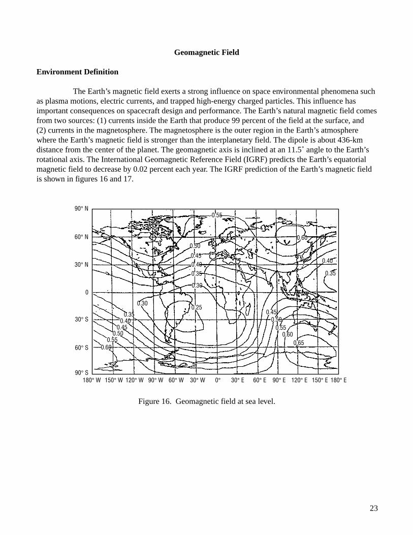
The Earth’s magnetic field exerts a strong influence on space environmental phenomena suchas plasma motions, electric currents, and trapped high-energy charged particles. This influence hasimportant consequences on spacecraft design and performance. The Earth’s natural magnetic field comesfrom two sources: (1) currents inside the Earth that produce 99 percent of the field at the surface, and(2) currents in the magnetosphere. The magnetosphere is the outer region in the Earth’s atmospherewhere the Earth’s magnetic field is stronger than the interplanetary field. The dipole is about 436-kmdistance from the center of the planet. The geomagnetic axis is inclined at an 11.5˚ angle to the Earth’srotational axis. The International Geomagnetic Reference Field (IGRF) predicts the Earth’s equatorialmagnetic field to decrease by 0.02 percent each year. The IGRF prediction of the Earth’s magnetic fieldis shown in figures 16 and 17.
Figure 16. Geomagnetic field at sea level.
180° W
90° N
60° N
30° N
0
30° S
60° S
90° S150° W 120° W 90° W 60° W 30° W 0° 30° E 60° E 90° E 120° E 150° E 180° E
0.55
0.60
0.55
0.50
0.50
0.500.55
0.60
0.600.65
0.45
0.45
0.45
0.40
0.40
0.40
0.35
0.35
0.35
0.30
0.300.25
24
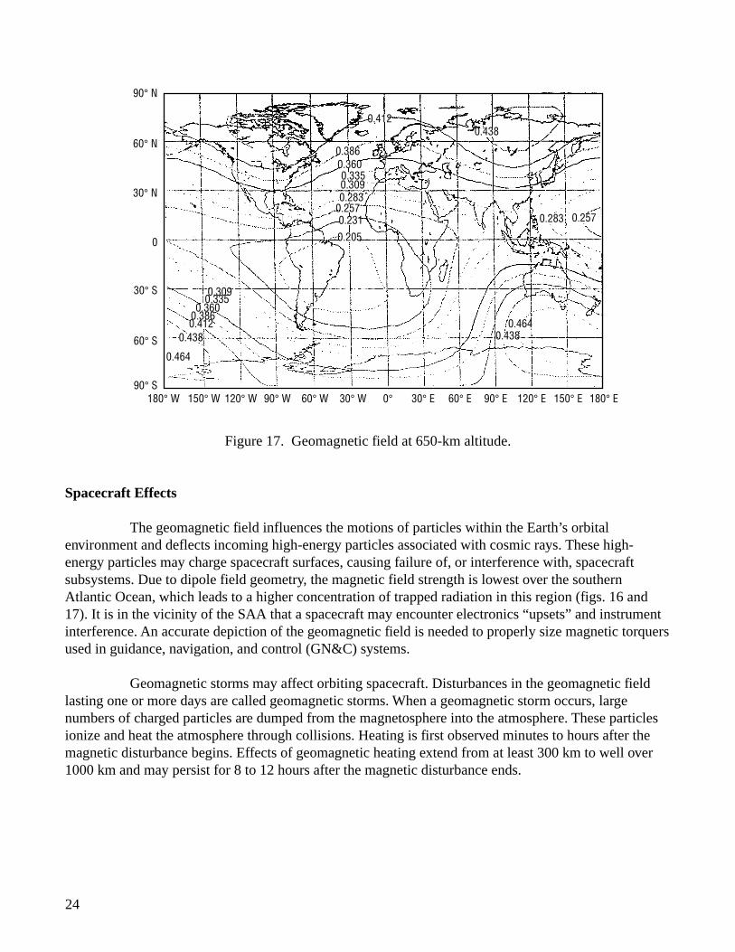
Figure 17. Geomagnetic field at 650-km altitude.
Spacecraft Effects
The geomagnetic field influences the motions of particles within the Earth’s orbitalenvironment and deflects incoming high-energy particles associated with cosmic rays. These high-energy particles may charge spacecraft surfaces, causing failure of, or interference with, spacecraftsubsystems. Due to dipole field geometry, the magnetic field strength is lowest over the southernAtlantic Ocean, which leads to a higher concentration of trapped radiation in this region (figs. 16 and17). It is in the vicinity of the SAA that a spacecraft may encounter electronics “upsets” and instrumentinterference. An accurate depiction of the geomagnetic field is needed to properly size magnetic torquersused in guidance, navigation, and control (GN&C) systems.
Geomagnetic storms may affect orbiting spacecraft. Disturbances in the geomagnetic fieldlasting one or more days are called geomagnetic storms. When a geomagnetic storm occurs, largenumbers of charged particles are dumped from the magnetosphere into the atmosphere. These particlesionize and heat the atmosphere through collisions. Heating is first observed minutes to hours after themagnetic disturbance begins. Effects of geomagnetic heating extend from at least 300 km to well over1000 km and may persist for 8 to 12 hours after the magnetic disturbance ends.
180° W
90° N
60° N
30° N
0
30° S
60° S
90° S150° W 120° W 90° W 60° W 30° W 0° 30° E 60° E 90° E 120° E 150° E 180° E
0.412
0.4120.438
0.438
0.464
0.3860.360
0.3600.386
0.335
0.335
0.309
0.309
0.283
0.283 0.257
0.4640.438
0.2570.231
0.205
25
Representative Cases
Anik-B
Operation of Telsat’s Anik-B satellite can be heavily influenced by the magnetosphericenvironment. Control of the roll and yaw of the satellite requires electromagnetic torquing coils. Directcurrent (DC) passed through the coils is controlled by a circuit that switches the current on with theappropriate polarity when the roll sensor output exceeds a preset threshold. The system’selectromagnetic field interacts with the Earth’s magnetic field to provide the necessary control torquesabout the roll and yaw axes. After a large disturbance in the Earth’s field, especially a field reversal,these coils can drive the satellite to an increasing roll error instead of correcting it. Such an eventoccurred on February 8, 1986, when K-indices recorded at Anchorage, Alaska, USA, remained at eightfor about 18 hours. This has occurred only twice during more than 7 years of Anik-B service. In eachcase, roll control was maintained using thrusters when necessary.18
Landsat-3
The multispectral scanner on board the Landsat-3 satellite experienced extra scan monitorpulses that caused early line starts or extra end-of-line codes. These events, attributed to magneticanomalies, make it difficult for operators to supply high-quality, reliable images to customers.6
These anomalies associated with the geomagnetic field are listed in the appendix.
26
CONCLUSION
Documented episodes of disrupted communications, major power losses, and satellite failuresshow that the natural space environment has caused adverse effects in orbiting spacecraft and groundoperations. Major perturbations in the near-Earth space environment have adversely affected space andground based systems for years. Substantial research into the consequences of the natural spaceenvironment on programs and numerous case histories, emphasize the importance of continuing thedevelopment of better design procedures and processes to ensure successful in-flight experiments andmissions.
Because of known effects the natural space environment has on spacecraft, this primer wasprepared by the Universities Space Research Association and Computer Sciences Corporation to addressconcerns of the Marshall Space Flight Center’s Electromagnetics and Aerospace Environments Branch,Code EL23. A brief overview of the natural space environment and illustrative case histories ofanomalies attributed to this environment are presented. This primer is to reinforce the importance ofproper consideration of the natural space environment, to provide a better understanding of failures,anomalies, and related cause(s), and to assist NASA engineers and program managers in effectivelyminimizing program risks and costs, optimizing design quality, and achieving mission objectives. As useof composite materials and smaller, faster electronincs increases, spacecraft systems are becoming morecomplex and susceptible to the potentially catastrophic effects of the natural space environment. Also,tighter program budgets and closer public scrutiny make mission failures not an option.
If you have questions or comments, contact the MSFC Systems Analysis and IntegrationLaboratory, Steven D. Pearson at 205–544–2350.
27
REFERENCES
1. “Orbital Anomalies in Goddard Spacecraft for CY 1992.” Office of Flight Assurrance, GoddardSpace Flight Center, October 1993.
2. Knapp, B.: “Telsat Ponders Using Thrusters To Salvage Anik.” Space News, vol. 5, No. 5,January 31–February 6, 1994, p. 1.
3. Shea, M.A., Smart, D.F., Allen, J.H., and Wilkinson, D.L.: “Spacecraft Problems in Associationwith Episodes of Intense Solar Activity and Related Terrestrial Phenomena During March 1991.”IEEE Transactions in Nuclear Science, vol. 39, December 1992.
4. Tribble, A.C.: “Spacecraft Interactions with the Space Environment.” AIAA 33rd AerospaceSciences Meeting and Exhibit, January 9–12, 1995, Reno, NV.
5. De Groh, K.K., and Banks, B.A.: “Atomic Oxygen Undercutting of Long Duration ExposureFacility Aluminized-Kapton Multilayer Insulation.” Journal of Spacecraft and Rockets, vol. 31,No. 4, July–August 1994, pp. 656–664.
6. “Analysis of Spacecraft On-Orbit Anomalies and Lifetimes.” Goddard Space Flight Center,February 10, 1983.
7. Carts, Y.A.: “Astronomers Report Benefit of Hubble Fix.” Laser Focus World, September 22, 1994,pp. 15–17.
8. Freeman, M.T.: “Spacecraft On-Orbit Deployment Anomalies: What Can be Done?” IEEE AESSystems Magazine, April 1993, pp. 3–15.
9. Hughes, D.: “Telsat Succeeds in Anik E2 Rescue.” Aviation Week & Space Technology, July 4, 1994,p. 32.
10. “Electromagnetic Storm Hits Intelsat Satellite.” Space News, vol. 5, No. 5, January 31–February 6,1994, p. 3.
11. STS-45 In-Flight Anomaly Report.
12. Hempsell, M.: “Hubble Array Impacts.” Spaceflight, vol. 36, November 1994.
13. McKnight, D.: “Determining the Cause of a Satellite Fragmentation: A Case Study of the Kosmos1275 Breakup.” 38th Congress of the International Astronautical Federation, Brighton, UnitedKingdom, October 10–17, 1987.
14. Elsen, W.G.: “Orbital Anomalies in Goddard Spacecraft for CY 1989.” Office of Flight Assurrance,Goddard Space Flight Center, July 1990.
28
15. “ESA Bulletin.” August 1993, No. 75, p. 14.
16. “Solar Radiation Strikes Another Blow to ETS-6.” Aviation Week & Space Technology,October 3, 1994, p. 66.
17. Elsen, W.G.: “Orbital Anomalies in Goddard Spacecraft for CY 1990.” Office of Flight Assurrance,Goddard Space Flight Center, September 1991.
18. Wadham, P.N.: “The Effects of Electrostatic Discharge Phenomena on Telesat’s DomesticCommunications Satellites.” Satellite Engineering Group, Telesat Canada, pp. 25-1 to 25-5,November 1992.
29
BIBLIOGRAPHY
Herr, J.L., and McCollum M.B.: “Spacecraft Environments Interactions: Protecting Against the Effectsof Spacecraft Charging.” NASA Reference Publication 1354, Marshall Space Flight Center, November1994.
James, Bonnie F., Norton, O.A., Jr., and Alexander, M.B.: “The Natural Space Environment: Effects onSpacecraft.” NASA Reference Publication 1350, Marshall Space Flight Center, November 1994.
Leach, Richard D., and Alexander, M.B.: “Electronic Systems Failures and Anomalies Attributed toElectromagnetic Interference.” NASA Reference Publication 1374, Marshall Space Flight Center,July 1995.
Leach, Richard D., and Alexander, M.B.: “Failures and Anomalies Attributed to Spacecraft Charging.”NASA Reference Publication 1375, Marshall Space Flight Center, August 1995.
Wong, Yan Chun: “Satellite Anomalies and Electrostatic Surface Discharges.” Thesis, Naval PostGraduate School, Monterey, California, September 1991.
30
APPENDIX
As part of the efforts of the MSFC Electromagnetics and Aerospace Environments Branch to makeengineers and managers aware of the importance of the space environment, a list of documentedanomalies and failures attributed to the natural space environment is presented in this appendix toillustrate the consequences of ignoring the environment.
The anomalous incidents listed are intended as a representative list—not a complete one—of thenature and severity of problems caused by the natural space environment. No special attempt was madeto research details from operational reports or project personnel. Events were recorded as they werefound in the various sources. Only included are those instances investigators felt sufficient evidenceexisted to attribute the anomaly to the space environment. If a particular anomaly cause was listed asunknown or the spacecraft unidentified, the event was not included. In some cases, a listed incident mayillustrate a design or operational accommodation to the effects of the environment. While these are notanomalies per se, they illustrate the importance of environmental effects.
Not all anomalies listed herein caused catastrophic failure of subsystem or mission. In many casesthese anomalies required the reloading of memories, tolerating noisy data, switching to redundantsystems, reissuing command sequences, and updating real-time attitude control commands. All these“small” anomalies, however, require additional operating costs which in the current climate of better,cheaper, faster could jeopardize funding for future projects. Furthermore, a series of “small” anomaliesincreases the chances for more significant problems. Any anomaly or series of anomalies carries thepotential of turning into serious problems. Hence a goal of mission managers should be to hold to aminimum all anomalous events attributed to the natural space environment.
31
SPACECRAFT FAILURES AND ANOMALIESDUE TO THE NATURAL SPACE ENVIRONMENT
Record Layout:Spacecraft Type of Anomaly Launch Date
Anomaly Description
Type Code:P-Plasma/M/OD -Meteroid & Orbital Debris/N- NeutralThermosphere/R-Radiation/S-Solar/T-Thermal /G-Geomagnetic
Telstar 401 P 12/16/93On October 9, 1994 this AT&T communications satelliteexperienced a 1-hour disruption in service due to anelectrostatic discharge that caused ground controllers tobriefly lose stabilization of the satellite 1 .
Intelsat K P 06/09/92This satellite is one of 20 communications satellites ingeosynchronous orbit owned by the InternationalTelecommunications Satellite Organization. On January20, 1994 the satellite experienced an electrostaticdischarge resulting from a geomagnetic storm that hadstarted on January 13th. The discharge disabled themomentum wheel control circuitry on the satellite causingit to wobble and produce fluctuations in antenna coverage.Full operational status was achieved on the same day aftera backup system was activated. The Anik E-1 and E-2satellites also were affected by this storm on that date 2.
Anik E-1 P 09/26/91On January 20, 1994 this Telsat Canada communicationssatellite began to spin out of control because of damage toits gyroscopic guidance system (momentum wheelcontrol) due to electrostatic discharge caused by chargebuildup created by the same geomagnetic storm thatcaused damage to Intelsat K. Backup systems wereactivated and the satellite was brought under control andstabilized in about 8 hours 3,4.
Anik E-2 P 04/04/91About 2 hours after Anik E-1 began to spin out of controlon January 20, 1994 Anik E-2 ,also owned by TelsatCanada, began to spin out of control. As with Anik E-1,the gyroscopic guidance system failed due to electrostaticdischarge. Unlike Anik E-1 the backup guidance systemsfailed to operate and it appeared that Anik E-2 would be atotal loss. Telsat engineers, however, devised a groundbased control system using the satellite’s thruster motorsto bring the satellite under control on June 21, 1994 andrestore it to useful service in August 1994 3.
BS-3A P 08/28/90This Japanese Broadcasting satellite suffered a 60-minutetelemetry outage on February 22, 1994 due to anelectrostatic discharge 2,5,6.
GMS-4 (Himawari 4) P 09/05/89On this Japanese Geostationary Meteorological Satellite(Himawari 4) the Visible Infrared Spin Scan Radiometergain setting experienced an anomalous change in state inJanuary and in July 1991 due to electrostatic discharges 7.
FY-1 (FENGYUN-1) P 06/09/88This Chinese experimental weather satellite failed after 39days in orbit. It has been postulated that an electrostaticdischarge caused a failure of the attitude control systemending the mission 7,8.
AUSSAT-A3 P 09/06/87This Australian Domestic Telecommunications Satellitejust like AUSSAT-A1 and -A2 suffered anomalousphantom commands that affected the telemetrysubcommutator and attitude control system. 19 suchevents have occurred from October 1987 to October 1990.These anomalous events were reported to be due toelectrostatic charging 7.
FLTSATCOM 6071 P 03/26/87This satellite was part of Fleet Satellite Communicationsconstellation of satellites utilized by the US Navy, US AirForce, and the presidential command network. Itexperienced five deep dielectric charging events thatresulted in low level logic anomalies from March to June1987 7.
GOES-7 P 02/26/87On February 26, 1989 the VAS digital multiplexer bitmode command failed after the satellite came out ofeclipse. This was attributed to a discharge event. Also thisspacecraft experienced several discharge events in 1987-89 that resulted in phantom commands 7,9.
AUSSAT-A2 P 11/28/85This Australian Domestic Telecommunications Satellitejust like AUSSAT-A1 experienced anomalous phantomcommands that have affected the telemetrysubcommutator and attitude control system. 33 suchevents have occurred from May 1986 to June 1990. Theseevents were reported due to electrostatic charging 7.
AUSSAT-A1 P 08/27/85This Australian Domestic Telecommunications Satelliteexperienced phantom commands events from January,1986 to June 1989 that changed modes in the telemetry
32
system and the attitude control system. These events werereported to be due to electrostatic charging 7.
Intelsat 511 P 06/30/85During the month of August 1993, this communicationssatellite experienced electrostatic charging events thatdisrupted the attitude control system and causeduncommanded status changes 7.
Telecom 1B P 05/08/85On January 15, 1988 this French Civil and Militarysatellite experienced a failure of both attitude controlsystems (prime and backup) and was unable to carry outits mission. Researchers postulated that the anomaly wascaused by electrostatic discharges coupling with exposedelectrical wiring 10.
Intelsat 510 P 03/22/85In August 1993 this International TelecommunicationsSatellite communications satellite experienced anelectrostatic discharge that affected the attitude controlsystem and produced various uncommanded statuschanges 7.
Arabsat 1-A P 02/08/85On March 15, 1985, shortly after launch, this Arab leaguecommunications satellite lost power, attitude control, andorbit gyros, necessitating manual North-South stationkeeping. On June 1, 1986 the satellite experienced loss ofEarth lock in the attitude control system and wasdesignated an orbital spare. Investigators believed theproblems were due to electrostatic discharges 7,11.
Anik D2 (ARABSAT 1D) P 11/09/84This Telsat Canada satellite was launched from the SpaceShuttle Discovery STS-14. On the morning of March 8,1985 the despin control system malfunctioned and theplatform on which the communications antenna wasmounted began to spin, interrupting data transmission.The problem was postulated to be a large arc-dischargeoriginating on the reflector at the back of the antenna oron the thermal shield at the front of the antenna.Unusually high activity occurred in the magnetosphereeight hours prior to the anomaly. Although the satellitewas eventually brought under control, fuel was used tocorrect the resulting wobble and a year of station keepingwas lost. The satellite also experienced greater thanexpected degradation to mirrored surfaces which wasattributed to surface discharges in the thermal blanket.This satellite was sold to Arabsat in May of 1994 andrenamed ARABSAT 1D 12.
AMPTE/CCE P 08/16/84The Active Magnetic Particle Tracer Experiment/ChargeComposition Explorer was an international program(U.K., Germany, and the US) consisting of three satelliteslaunched at the same time. On November 11, 1984 theAMPTE satellite lost data modulation due to a phantomcommand caused by spacecraft charging. Operatingprocedures had to be changed to remain operational 13.
Telecom 1A P 08/04/84This French telecommunications satellite experiencedfrequent electrostatic discharges which interrupted datatransmissions causing it to be removed from service andused as a backup. Subsequent testing showed thatequipment anomalies were due to electrostatic discharges10,14.
GMS-3 (Himawari 3) P 08/03/84In December 1984 this Japanese GeostationaryMeteorological Satellite (Himawari 3) experienced twoanomalous switching events in the accelerometer. Thisanomaly reoccurred in March and in April 1985. TheVisible Infrared Spin Scan Radiometer experiencedanomalous gain level stepping in June, July, and August1985. All these events were attributed to electrostaticdischarges 7.
GOES-6 P 04/28/83On September 27, 1986 this GOES satellite, which isoperated by NASA for NOAA, experienced anuncommanded shift in its Visible Infrared Spin ScanRadiometer Atmospheric Sounder (VAS) Earth window.Also on March 17, 1986 the X-ray scan shifted tocalibration mode. These anomalies were judged to becaused by electrostatic discharges 7,15.
TDRSS P 04/05/83The Tracking and Data Relay Satellite System is presentlycomprised of four satellites: TDRS -1 launched fromSTS-6 in April 1983, TDRS-3 launched from STS-26 inSeptember 1988, TDRS-4 launched from STS-28 in May1989, and TDRS-5 launched from STS-42 in August1991. These spacecraft have experienced arcing anomaliesin several different subsystems over their operating lifetimes. The most serious incidents were those related to theattitude control system processor electronics. Rapidmanual intervention was required to prevent loss ofcontrol of the satellites. Several studies concluded thatthese anomalies were due to surface charging 16,17.
33
DSCS-III (4524) P 10/30/82This Air Force Defense Space Communications Satelliteexperienced ten deep dielectric charging events thatcaused glitches in the tachometer system from December1986 to January 1987 7.
MARECS-A P 12/20/81Soon after this Maritime European CommunicationsSatellite was launched by the European Space Agency, itexperienced spurious anomalies in its telemetry systemrequiring onboard processors to be manually reset. OnFebruary 27, 1982, however, the satellite’s pointingsystem suddenly went into an energy conserving“safeing” mode shutting down all communicationssubsystems. A special team was assigned to investigate forthe benefit of future geostationary missions. Electrostaticdischarges were determined responsible not only for thisincident, but also for the other observed anomalousbehavior. These anomaly events corresponded closelywith geomagnetic activity studied from 1982 to 1985.Spacecraft charging was deemed responsible for thedischarges. On March 25, 1991 MARECS-A was takenout of service due to serious damage to its solar panels.Localized arcing, caused by surface charging while thesatellite was in eclipse, degraded the panel surfaces to thepoint that power output dropped to unacceptable operatinglevels. This occurred during a period of intense solar andsubstorm activity. Information gathered in the chargingstudy was used to improve the design of subsequentsatellites in this series. These satellites did experiencesome anomalous behavior, but not to the extent observedon MARECS-A 18,19.
SBS 1 P 11/15/81Soon after the launch of this Satellite Business Systemstelecommunications satellite, it began to experienceelectrostatic discharges affecting the attitude controlelectronics. This satellite experienced hundreds of eventsover an eight year period 7.
GOES-4 P 09/09/80This Geostationary Operational Environmental Satellitewas operated by NASA for NOAA. On March 29,1981the mirror used with the Visible Spin Scan Radiometer-Atmospheric Sounder (VAS), the principle instrument onthe spacecraft, suffered phantom commands that began asudden, undesired repositioning making it impossible totrack the Earth’s weather until a new series of commandswas issued by controllers on Earth. The satellite continuedto experience similar events throughout its operationallifetime. An investigation of these events concluded that aportion of the VAS second stage radiation cooler wasungrounded and built up potential from the surroundingplasma until it discharged, creating a large
electromagnetic pulse. This pulse created large currentsurges that flowed along the wiring to the VAS. OnNovember 25, 1982 the VAS failed completely, requiringthe satellite to be taken out of service. It becameessentially a standby unit to be replaced later by GOES- I.The ungrounded radiator was redesigned on GOES-5before its launch on May 5, 1981. Although similaranomalies due to electrostatic charging did occur onGOES-5, no serious problems were experienced 20,21.
GPS 5118 P 02/09/80This satellite, part of the Global Positioning SatelliteSystem, was launched into a 20,000 km circular orbit andexperienced unexpected switch settings within the motorcontrol electronics on July 17, 1985 due to an electrostaticdischarge 6.
DSCS-II (9443) P 11/21/79This Air Force Defense Space Communications Satelliteexperienced low level logic glitches in March and July of1987 due to deep dielectric charging 7.
SCATHA(P78-2) P 01/30/79The Spacecraft Charging at High Altitude satellite waslaunched by the US Air Force in an elliptical orbit 185 x43905 km for the purpose of understanding the source ofspacecraft charging anomalies. The major impetus for thisscience mission was the failure of DSCS-II 9431 in 1973.SCATHA’s major objectives were to measure chargingcharacteristics and increase the understanding of therelationship between the space plasma environment andspacecraft charging and to use data gathered to developcomputer models of the charging phenomenon.Throughout its operational lifetime, SCATHAexperienced many electrostatic discharges whichscientists studied closely. On September 22, 1982 aparticularly large number of arcing events was observed.Three different satellite operational anomalies wereobserved that day: 1. A 2-minute loss of data believed tobe caused by a discharge event. 2. A filter change of statein one of the magnetic field monitors. 3. Timing errors inthe Plasma Wave Analyzer 22.
Anik B-1 P 12/16/78This satellite was Telsat Canada’s first three-axis-stabilized spacecraft. The satellite had only one minoranomalous switching event attributed to spacecraftcharging. The satellite did, however, experience asignificant increase in the operating temperature ofvarious components. Thermal surfaces (mirrors thatradiate heat away from critical electronic components andreflect direct sunlight away from them) were degraded bylocalized discharges when the satellite was in eclipse 12.
34
NATO-3C P 11/19/78This military communications satellite for the NorthAmerican Treaty Organization experienced five attitudecontrol anomalies similar to those experienced in NATO-3A and 3B from December 1986 to September 1987 7.
NATO-3B P 11/28/77On January 11, 1987 this military communicationssatellite for the North American Treaty Organizationexperienced three attitude control anomalies. Also inAugust and September of that same year three phantomcommand anomalies were recorded. All these anomalieswere attributed to deep dielectric charging 7.
Meteosat -F1 P 11/23/77The European Space Agency Meteorological Satellitesuffered a series of anomalies throughout its operationallifetime. During the first year 119 anomalies wererecorded that interfered with the operation of theradiometer, power system, and the attitude control system.150 anomalies were recorded in the first 3 years. Theseanomalies were evaluated by several researchers whoconcluded that they were being caused by electrostaticdischarges due to spacecraft charging. Using theinformation gathered from Meteosat F-1, Meteosat F-2was modified prior to launch on June 18, 1994 toeliminate some of the problems that F-1 experienced.Additionally F-2 was equipped with instrumentation totake measurements of electrons in the energy range thatcould cause spacecraft charging. Although the F-2experienced fewer but similar anomalies to the F-1, theyalso were caused by spacecraft charging 23,24,25.
DSCS-II (9438) P 5/12/77This Air Force Defense Space Communications Satelliteexperienced in November and December 1986 low levellogic glitches due to deep dielectric charging 7.
DSCS-II (9442) P 12/14/76This Air Force Defense Space Communications Satelliteexperienced in November 1986 and March 1987 low levellogic glitches due to Deep Dielectric Charging 7.
NATO-3A P 04/20/76This military communications satellite for the NorthAmerican Treaty Organization experienced on January 11,1987 attitude control problems due to deep dielectriccharging . A bit flip error was also reported on April 4,1990 7.
CTS (Hermes) P 01/17/76The purpose of the Canadian-American CommunicationsTechnology Satellite was to demonstrate the technologyof using a high power, high frequency transponder in
conjunction with small low cost Earth terminals. Becauseengineers anticipated the possibility of charge buildup onthe satellite, it was equipped with a transient event counter(TEC), the first known device of this type on ageosynchronous satellite. The TEC recorded 215 transientevents in the wiring harnesses in the first year; 65% weremultiple transients. Scientists concluded from this datathat discharges could occur at any time during the localday and that many discharges could occur within a shortperiod of time. The satellite itself did suffer some adversecharging effects when a power diode (exposed directly tothe space environment) failed causing a power busburnout. This event occurred shortly after a moderatesubstorm 26,27.
Viking Lander 1 P 08/20/75This spacecraft suffered variations in its GasChromatograph Mass Spectrometer Ion Pump current dueto arcing events. These prompted a modification of itsatmospheric analysis experiments 28.
Symphonie A P 12/19/74This French-German experimental communicationssatellite, along with its sister satellite Symphonie Blaunched 8/27/75, had a history over their operationallifetimes of non-critical anomalies (i.e., modulation lossesand logic upsets) attributed to arcing events 29.
Skynet 2B P 11/23/74This satellite was part of the United Kingdom’s DefenseCommunications Network. Shortly after launch thesatellite began experiencing anomalies in the timingcircuits of the telemetry and command subsystem. Asystematic study of the anomalies concluded they weredue to spacecraft charging. In a 2-year period, 1975-76,300 anomalies were investigated 30.
DSCS-II (9431) P 11/01/71On June 2, 1973 the Air Force Defense SpaceCommunications Satellite 9431 failed because power toits communications subsystem was suddenly interrupted.The review board found that the failure was due to a highenergy discharge caused by spacecraft charging as a resultof a geomagnetic substorm. Both 9431 and its sisterspacecraft 9432 experienced a series of nuisanceelectronic anomalies before the failure, but nothing thatwould have predicted it. This incident resulted in a jointNASA and Air Force Spacecraft Charging Investigation toevaluate and understand the spacecraft chargingphenomenon. DSCS-II 9433 and 9434 were launched in1973 and both experienced arcing anomalies, but sufferedno serious consequences 31,32.
35
SEDS-2 M/OD 03/10/94This Small Expendable Deployer Satellite (SEDS)deployed a tether some 20 km in length. On the fourth dayafter launch, the tether was severed by particle impactending the experiment prematurely 62.
MSTI-2 M/OD 05/8/94On 9/5/94 contact was lost to this Miniature SensorTechnology Integration (MSTI) satellite. While the actualcause of the failure may never be known, the failureassessment and follow-up indicated that probabilityexisted for the failure to have been caused by orbitaldebris impact to a wire bundle causing an electrical short.There was also the possibility that spacecraft chargingcaused the failure. One proposed failure mechanismsuggested that the debris impact allowed charge that hadbeen stored in the Teflon coating on the wire todischarge causing a transient current that damaged thesatellite beyond repair 67.
SAMPEX M/OD 07/03/92In mid-August 1993, the door of the Heavy Ion LargeTelescope (HILT) instrument was closed for a few hourswhile the spacecraft was exposed to the Perseid MeteorShower. No known meteor hits were encountered by thespacecraft 33.
STS-45 M/OD 03/24/92The Space Shuttle Atlantis suffered two gouges, (1.9 in ×1.6 in and 0.4 in × 1 in), on the upper portion of the rightwing leading edge. It has been determined that the mostprobable cause was a low velocity (relative to thespacecraft) debris impact on-orbit or during re-entry.However, JSC Engineering has not ruled out prelaunch orascent debris as being the cause of the damage. Thisparticular event raised concern about the consequences ofa higher energy impact to the integrity of the spacecraft 64
.STS-49 M/OD 05/07/92The crew documented a chip in the upper right handcorner of the thermal window pane. The crew reportedthat impact occurred on or around flight day 8 34.
Solar A (Yohkoh) M/OD 08/30/91This Japanese Solar x-ray telescope mission satelliteexperienced a micrometeroid hit on the thin filmmembrane covering its optical system. This impact causeda 0.05 mm hole that resulted in the loss of the visualportion of the telescope 63.
HST (STS-31) M/OD 04/24/90In order to protect the Hubble Space Telescope (HST)from any possible damage during the annual PerseidMeteor Shower (mid-August, 1993), it was placed in an
attitude that minimized the possibility of damage. Thesolar arrays were also adjusted to minimize their exposureto possible meteors. Apparently no meteor hits wereencountered 33.
HST (STS-31) M/OD 04/24/90British Aerospace inspection of the old HST arrayindicated that the whole wing suffered between 5000 and6000 micrometeoroid impacts in its four year life. Theeffect of these impacts range from slight grazing to thepuncture of the cells and blankets 35.
Mir SS M/OD 02/19/86The Russian space station Mir has had chronic powershortages due, primarily, to its aging solar panels, whichhave been battered over the years by tiny meteorites,space debris and atomic oxygen particles 36.
KOSMOS-1275 M/OD 06/04/81Kosmos-1275 broke up into over 200 trackable fragmentson 7/24/81 while at an altitude of 977 km. It has beenhighly speculated that this was the result of ahypervelocity collision with a piece of space debris. Thisconclusion was based on the following factors: This typeof satellite has not shown any capability to maneuver andmay have been a gravity gradient stabilized spacecraft. Itappears that no pressurized vessels or onboard propellantsare standard on these types of Soviet satellites. Thesatellite resided in the altitude region most denselypopulated with debris from earlier satellite breakups. Thesatellite was in a high inclination orbit (83 degrees),which suggests higher relative velocities between asatellite and the general debris population 37.
ISEE-1 M/OD 10/22/77The detector window of this low energy cosmic rayexperiment aboard the International Sun Earth Explorer(ISEE) was punctured due to micrometeroid impact. Thisresulted in a 25% data loss. (No dates were given) 38.
ANIK-B G 12/16/78The operation of Telsats’ ANIK-B satellite can be heavilyinfluenced by the magnetospheric environment. Thisinvolves the control of the roll and yaw of the satellite byelectromagnetic torquing coils. These are coils about theroll and yaw axes through which DC current is passed andcontrolled by a circuit which switches the current on withthe appropriate polarity when the roll sensor outputexceeds a preset threshold. The systems electromagneticfield interacts with the earth’s magnetic field to providethe necessary control torques about the roll and yaw axes.Where there is a large disturbance in the earth’s field,especially a field reversal, these coils can drive thesatellite to an increasing roll error instead of correcting it.
36
Such an event occurred on 2/8/86, when the k-indicesrecorded at Anchorage remained at 8 for about 18 hours.This type of event has occurred only twice over the morethan 7 years that ANIK-B has been in service. In eachcase, roll control was maintained, using thrusters ifnecessary 39.
Landsat-3 G 03/05/78The multispectral scanner on board the Landsat-3 satelliteexperienced extra scan monitor pulses that caused earlyline starts or extra end-of-line codes. These eventsoccurred over magnetic anomalies. (No dates were given)38.
LDEF (STS-41C) N 04/06/84An aluminized-polyimide Kapton multilayer insulationsample was located on the leading edge of the LongDuration Exposure Facility (LDEF) and was subjected tolow Earth orbit atomic-oxygen undercutting 40.
Landsat-3 N 03/05/78Landsat-3 experienced degradation to onboard sensorswhich was attributed to contamination from residual gasmolecules. This resulted in the loss of IR data. (No dateswere given) 38
Skylab N 05/14/73On 7/11/79 Skylab re-entered the earth’s atmosphereprematurely as the result of atmospheric drag 41.
ETS-6 R 08/28/94Japan’s Engineering Test Satellite-6 (ETS-6) could failwithin a year because solar radiation has reduced theeffectiveness of its solar panels. The $415-million satellitewas unable to reach its geostationary orbit when itsapogee kick motor failed to achieve proper pressure. Its98-ft. solar array was deployed on 9/3/94, as were its sixantennas, including one with a 12 ft. diameter dish. Buthigh radiation levels from the Van Allen belt are quicklyeroding the efficiency of its solar panels. They produced5,800 w. of power on 9/3/94, but 10 days later thisdropped to 5,300 w. Projections are that power will dropto 4,700 w. by the end of September 1994 and could bebelow 2,000 w. in a year—too low to supportexperiments 42.
STS-61 R 12/02/93On 12/6/93 the Y star tracker failed to acquire navigationstars for approximately 5 hours. Following a power cycle,the star tracker successfully passed a self test andfunctioned nominally for the remainder of the mission.The cause of the failure is believed to be a single event
upset. The time noted for the beginning of the anomalousbehavior of the tracker coincides with the Orbiter passingthrough the South Atlantic Anomaly (SAA), an area ofhigh radiation. The high altitude flown on STS-61resulted in increased radiation exposure when comparedwith flights at lower altitudes 43.
TDRS-6 R 01/13/93On 7/10/93 this Tracking and Data Relay Satellite(TDRS) Earth Sensor Assembly A Pitch Channel outputcautioned at 0/.3199 deg. for one update period. The causewas probably due to a single event upset (SEU) inCommand and Telemetry Electronics (CTE) buffer 33.
EUVE R 06/07/92In early November 1993 the Extreme Ultra VioletExplorer (EUVE) satellite experienced a “clam-up” (alldetector doors shut). This was probably caused by a SEU.Things were restored to normal in four hours. Later thatsame month another suspected SEU occurred in theCentral Data Processor (CDP) which put the payload intoa pre-launch mode (i.e. Ion Pumps On). Systems wererestored to normal the same day with no damage done 33.
TDRS-5 R 08/02/91On 8/10/91 an apparent SEU-event on this tracking anddata relay satellite caused a control sensor parameter tomomentarily exceed its caution limit. This “pitch glitch”was probably caused by hit in the CTE buffer 44.
TDRS-5 R 08/02/91 On 12/12/93 normal mode outputs from the ControlProcessing Electronics (CPE) on this tracking and datarelay satellite went into disabled state, with numerousAttitude Control System (ACS) parameters out of limits.The cause was determined to most likely be a SEU in theCPE processor 33.
ERS-1 R 07/17/91A Precision Range and Range Rate Equipment (PRARE)instrument failed on this European Space Agency RemoteSensing Satellite (ERS) following a transient high currentevent. The failure was found to have occurred close to thecenter of the South Atlantic Anomaly. Ground testsshowed certain memories to be sensitive to protoninduced latch-ups. It was concluded that the failure wasdue to latch-ups during exposure to South AtlanticAnomaly protons. This is believed to be the first time averified proton-induced latch-up in space was reported 45.
37
CRRES R 07/25/90Analysis of SEU data from the Chemical RealeaseRadiation Effects Satellite (CRRES) MicroelectronicsPackage Space Experiment (MEP) from 7/27/90 to 3/26/91 showed that upsets were observed each orbit with the93422 and 93L422 bipolar random access memories(RAM) being the most sensitive devices 46.
HST (STS-31) R 04/24/90On 5/7/90 bit flips occurred in the RAM of the FineGuidance Electronics when the telescope was passingthrough the South Atlantic Anomaly (SAA) whichaffected the guidance system. On 6/20/90 the SAA causedhigh photomultiplier tube (PMT) counts in the fineguidance system. This resulted in guide star acquisitionfailures. Both incidents were suspected to be due toincreased radiation effects 47.
HST (STS-31) R 04/24/90On 7/4/91 six of the telescopes’ status monitors failed inthe SAA due to possible radiation damage 44.
HST (STS-31) R 04/24/90On 12/9/93 the Data Interface Unit-2 (DIU-2), ‘A’ sidepresented faulty telemetry readings for specific HSTparameters. The suspected cause was radiation damage 33.
Hipparcos R 08/08/89Communications with the European Space Agency (ESA)Hipparcos astronomy satellite was terminated on 8/15/93after more than three years of efficient and successfuloperations. At the end of June 1993, the satelliteexperienced further difficulties in communicationsbetween the ground and the onboard computer. This wasattributed to radiation damage to certain components.Attempts to restart operations proved unsuccessful, andmission operations were terminated 48.
TDRS-4 R 03/13/89On 5/8/89 a possible SEU caused an Earth SensorAssembly (ESA) roll output alarm 49.
TDRS-4 R 03/13/89On 8/1/93 telemetry indicated erratic ACS data and thespacecraft slowly started to diverge from earth pointing.The cause was determined to be an SEU in one of thecontrol processing or command and telemetry chips 33.
TDRS-4 R 03/13/89On 8/26/93 an earth sensor assembly roll & pitch “glitch”occurred lasting 2 seconds which caused ESA “Fail-Safe”to occur. One possible cause was suspected to be an SEU33.
GOES-7 R 02/26/87In early June 1988, the first and only SEU anomalyoccurred on Geostationary Operational EnvironmentalSatellite - 7 (GOES-7) when the REPLY BUS switcheduncommanded from A to B channel in the CentralTelemetry Unit (CTU-1) 50.
ERBS R 10/05/84On 11/1/84 the Earth Radiation Budget Satellite (ERBS)experienced radiation that caused bit changes in block(delta time) section of both command memories. Therwere 142 “hits” recorded to date 51.
ERBS R 10/05/84On 7/22/93 anomalous changes occurred in chips locatedin the in Command. Storage Memory. It was believed thatthese chips were susceptible to noise and radiation 33.
AMPTE/CCE R 08/16/84On 9/11/84 the magnetometer of the Active MagneticParticle Traces Explorer/Charge Composition Explorer(AMPTE/CEE) Satellite changed modes on 4 occasions.Operators determined these incidents to be due to externalradiation “hits”.
17 temperature measuring devices also failed on thissatellite. evidence indicates that these failures were due toradiation 51.
AMPTE/CCE R 08/16/84In April 1988 the Command Processor System (CPS) No.1 failed, resulting in a switch to CPSNo. 2 by theoperators. The cause of this failure is thought to be thefailure of a CMOS PROM, caused by cumulativeradiation damage after over 3.5 years in orbit 50.
UOSAT-2 R 03/02/84SEUs occured in large dynamic NMOS and static CMOSmemories on-board this low altitude, polar orbitingsatellite. The strong localization of these upsets to theSouth Atlantic region lead to the conclusion that themajority of the upsets were caused by nuclear reactionsinvolving energetic radiation-belt protons encountered inthe South Atlantic Anomaly 52.
GOES-6 R 04/28/83On 7/7/84 This satellite experienced the loss of pulse codemodulated telemetry due to an SEU. This was a first timeoccurrence time occurrence on GOES-6 51.
38
GOES-6 R04/28/83On 3/9/88 the telemetry system of the satellites waspermanently degraded due to an SEU. Five SEU’s hadpreceded this one, all being corrected by groundcommand. The degradation consisted of the loss ofseveral analog and digital channels 50.
TDRS-1 R04/04/83The systematic recording of Single Event Upsets onTDRS-1 from 1984 to 1990 allowed correlations to bedrawn between those upsets and the space environment.During the transfer orbit, the first anomalous responseswere observed in the Attitude Control System (ACS).These anomalies were traced to state changes in theRandom Access Memory (RAM) in the ACS caused bySEUs. The most serious ACS anomalies were consideredmission-threatening by operators because they couldcause the satellite to tumble. Ground control was requiredto maintain the satellite’s proper attitude 53.
TDRS-1 R 04/04/83On 11/2/89 command processor electronics of thistracking, data, and relay satellite had a probable SEU,causing temporary loss of attitude control 49.
TDRS-1 R 04/04/83On 4/1/92 the Control Processing Electronics (CPE)stopped running due to CPE/CTE sync failure. Operatorsfelt that the most likely cause was an SEU in the CPEchip 54.
INSAT-1 R 04/10/82From 9-13-87 to 4-26-88 this satellite experienced a totalof 6 bit flip errors most likely due to radiation 55.
DE-1 R 08/03/81At the beginning of 1982 the Dynamic Explorer (DE-1)satellite was operating in a slightly degraded mode due tofailure of the high voltage power supply on the HighAltitude Plasma Indicator (HAPI). Probably the mostsignificant anomaly was the effect of periodic “radiation”hits which caused periodic “glitches” in spacecraftoperations 56.
DE-1 R 08/03/81There was an unexplained 7 to 10 watt power increase onspacecraft bus and apparent loss of microprocessor in thecommand and telemetry processor due to radiation “hits”impinging spacecraft clock, etc.(No dates were given) 38.
SMM R 02/14/80A possible SEU reported on the Solar Maximum Mission(SMM) in 1985 caused an anomaly in the On BoardComputer (OBC), placing the spacecraft in a “safe hold”condition that interrupted science data for 8 days 57.
SMM R 02/14/80In early January 1986 there were some “safe-holds”during spacecraft operation due to problems in the OBC .Evidence indicates that 8K of memory (out of 48K total)was lost due to “hard hits” by cosmic rays 58.
SMM R 02/14/80The C Gyro failed due to the transient radiationsusceptibility of complementary MOS semi-conductors inthe electronics. Control was regained and the B Gyro wasused. (No dates were given) 38.
NIMBUS-7 R 10/24/78A digital data channel became noisy and went intosaturation. Operators speculated on the possibly that highenergy particles caused electrical component damage 54.
Voyager-1 R 09/05/77An on board clock lost 8 seconds due to 40 spuriouspower-on reset signals which were probably caused byJovian radiation. (No dates were given) 38.
Voyager-1 R 09/05/77Star tracker #2 could not be commanded into cone anglesettings 3, 4 or 5. Possibly due to transistor leakagecaused by 2 or more Delrin insulating sleevesdecomposing due to high intensity radiation. (No dateswere given) 38.
ATS-6 R 05/30/74On this American Test Satellite (ATS) the heat pipe gasreservoir ran hotter than normal due to degradation of thesecond surface mirrors (optical solar reflectors) that coverthe reservoir’s radiation. No dates were given) 38.
GPS 9521 RFrom 1-30-87 to 7-5-90 this global positioning satelliteexperienced a total of 62 bit flip errors 55.
GPS 9783 RFrom 12-27-84 to 7-1-90 this global positioning satelliteexperienced a total of 113 bit flip errors 55.
GPS 9794 RFrom 1-13-85 to 8-6-90 this global positioning satelliteexperienced a total of 123 bit flip errors 55.
39
GOES -7 S 02/26/87During a period of intense Solar x-rays which occurredfrom March 22 to 24, 1995, researchers found evidence ofsolar panel degradation. This power degradation translatedto a 2 to 3 year decrease in the expected life of thesatellite 61.
NOAA-10 S 09/17/86On 3/13/89 this National Oceanic and AtmosphericAgency (NOAA) satellite experienced excessive x-axisgyro speed after magnetic momentum unloading. Thiscaused the roll/yaw coil to switch to backup mode.Operators suspected the anomaly was caused by solaractivity.
On 10/1/89 the SCU 28 volt switch power indicated an onreading. Command line glitch or solar influence was thepossible cause 49.
NOAA-9 S 12/12/84High solar activity in mid-March 1989 caused unusualmomentum wheel activity that resulted in the roll/yaw coilswitching to its backup mode. However, proper attitudecontrol was maintained throughout the event. The mid-March high solar activity also affected NOAA-10 andNOAA-11 in the same way 49.
NOAA-7 S 06/23/81Magnetic coil unloadings were not completely effective.This was attributed to higher than expected torque fromsolar pressure. ( No dates given) 38.
GOES-5 S 05/22/81The Central Telemetry Unit (CTU) experienced ten SEU’sduring 1989, six of which were associated with solarflares. A major solar flare on 10-19-89 degraded the solararray by about 0.5 amps 49.
GOES-5 S 05/22/81Solar array output dropped abruptly due to high levelsolar particle event. (No date given) 38.
Meteosat 6 T 11/20/93This European meteorological satellite (Meteosat) hasexperienced continuing problems with its radiometer.Operators feel that the problem is caused by ice formingon the instrument and contaminating the optical surfaces65.
JERS-l T 02/11/92The Radar antenna failed to deploy in this Japanese EarthResources Satellite (JERS). It was determined that coldwelding of the deployment pins due to faulty lubricationcaused the failure 66.
HST (STS-31) T 04/24/90Before the December 1993 service mission, the solararrays vibrated severely every time the observatoryemerged from shade into sunlight. Active vibrationcancellation using the gyros had been implemented beforethe mission to minimize the problem. Thermal expansionof the support poles (also called bistems) was blamed forthe vibrations, which interfered with observations 59.
HST (STS-31) T 04/24/90On 5/1/90, a low frequency vibration manifested itself.This vibration was determined to be thermally induced,involving the solar array during the transition from day tonight and night to day. This anomaly affected gyrooperations 47.
Galileo T 10/18/89Despite rigorous ground testing, the on board antenna ofthe Galileo Jupiter probe, launched from the SpaceShuttle Atlantis, failed to properly deploy. Operatorsconcluded that the failure was due to the failure of alubricant used on the mechanical joints. This resulted indegraded data transfer back to Earth 66.
GOES-7 T 02/26/87In early April 1993 there was a minor anomaly involvingthe Data Collection Platform Interrogation (DCPI)System. The No. 1 S-Band Receiver could not acquireinterrogation frequency from the Command and DataAcquisition (CDA).
Station for an hour after the daily eclipse period. It wasfound that Receiver’s frequency stability exceeded therequired +/- 5 KHz limits, due to cold post-eclipsetemperatures 60.
Insat IB T 08/31/83The solar sail failed to deploy on this Indiancommunication satellite launched from the Space ShuttleChallenger. The failure was due to thermal binding of thedeployment mechanism caused by failure of the lubricant66.
Landsat-4 T 07/16/82Power cables on two of the four solar arrays failed. Theproblem began as an intermittent power loss in one of thefour cables on 3-18-83. By mid-May, one cable had failedand a second was intermittent. The cause of the problemwas attributed to stresses in the conductors due to thermalcycling. By 6-5-83, the second array had also failed 56.
40
MAGSAT T 10/30/79This spacecraft suffered the loss of star camera data forperiods of 30-40 minutes due to direct sunlight on thesides of the sunshades that penetrated their black plasticskin. (No date given)38.
NIMBUS-7 T 10/24/78Unexpected high temperature of the Coastal Zone ColorScanner cooler door and cone occurred. Operatorsconcluded this could have been caused by a higher earthalbedo in orbit than was simulated during design. (Nodate given) 38.
IUE T 01/26/78The on-board computer of the International UltravioletExplorer experienced a 4k and 8k memory crash, due topossible faulty thermal design. (No date given) 38.
Landsat-2 T 01/22/75Array current notching was attributed to sets of parallelsolar cells with intermittent electrical connections in anarea of probable high temperature. (No date given) 38.
41
Appendix References
1. The Space Review, Airclaims, October 25, 1994, p.ATLAS 5/D
2. “Electromagnetic Storm Hits Intelsat Satellite,”Space News, Vol. 5, No 5, January 31-February 6,1994, p. 3.
3. Knapp, Bill, “Telsat Ponders Using Thrusters ToSalvage Anik,” Space News, Vol. 5, No. 5, January31- February 6, 1994, p. 1.
4. Hughes, David, “Telsat Succeeds in Anik E2Rescue,” Aviation Week & Space Technology, July 4,1994, p. 32.
5. “Mobile Satellite Reports,” Vol. 15, No. 12, June21,1991
6. The Space Review, Airclaims, September 21, 1994,p. N&H 4/B.
7. Spacecraft Anomaly Database, Version. ANOM5I,National Geophysical Data Center, Solar-TerrestrialPhysics Division, Boulder CO, March 1994.
8. Garret, Henry, Berry, “The Charging Of SpacecraftSurfaces,” Reviews of Geophysics and SpacePhysics, Vol. 19, No. 4, November, 1981, p. 577-616.
9. Elsen, William, G., Orbital Anomalies in GoddardSpacecraft for CY 1989, Assurance RequirementsOffice, Office of Flight Assurance, NASA GoddardSpace Flight Center, July 1990.
10. DBS News, Phillips Publishing Co.. February 1,1988.
11. Lenorovitz, Jeffrey, M., “Arabsat CommunicationsSatellite Experiences Cryo-Control Problems,”Aviation Week & Space Technology, March 25,1985, p. 22.
12. Wadham, P., N., “ The Effects of ElectrostaticDischarge Phenomena on Telsat’s DomesticCommunications Satellites,” AGARD, TheAerospace Environment at Altitude and ItsImplications for Spacecraft Charging,” 1987, p. 21-18.
13. Shockley, Edward, F., Orbital Anomalies inGoddard Spacecraft 1984, Assurance Requirements
Office, Office of Flight Assurance, NASA GoddardSpace Flight Center, September 1985.
14. The Space Review, Airclaims, October 25, 1994, p.ARIANE 3/A.
15. Elsen, William, G., Orbital Anomalies in GoddardSpacecraft for CY 1986, Assurance RequirementsOffice, Office of Flight Assurance, NASA GoddardSpace Flight Center, April 1987.
16. Garret, H., and Whittlesey, “Environment InducedAnomalies on the TDRSS and the Role ofSpacecraft Charging,” 28th Aerospace SciencesMeeting, January 8-11, Reno, Nevada.
17. Orbital Anomalies in Goddard Spacecraft annualreports prepared for the System Reliability andSafety Office, NASA Goddard Space Flight Center,1983-1993.
18. Capart, J., J., and Dumesnil, J., J., “TheElectrostatic Discharge Phenomena on Marces-A,”ESA Bulletin, No. 34, May 1983, p. 22-27.
19. Frezet, M., et.al., “Assessment of ElectrostaticCharging of Satellites in the GeostationaryEnvironment,” ESA Journal, Vol. 13, No. 2, 1989,p.89-116.
20. Farthing, Winifred, H., Brown, James, P., andBryant, William, C., Differential SpacecraftCharging on the Geostationary OperationalEnvironmental Satellites, NASA TechnicalMemorandum 83908, Goddard Space Flight Center,Greenbelt Maryland, March 1982.
21. Shockley, Edward, F., Orbital Anomalies inGoddard Spacecraft 1982-1983, AssuranceRequirements Office, Office of Flight Assurance,NASA Goddard Space Flight Center, July 1984.
22. Koons, Harry, C., and Gorney, David, J.“Relationship Between Electrostatic Discharges onSpacecraft P78-2 and the Electron Environment,”Journal of Spacecraft and Rockets, Vol. 28, No. 6,November-December 1991, p. 683-688.
23. Hodge, D., and Leverington, D., “Investigation ofElectrostatic Discharge Phenomena on the MeteosatSpacecraft,” ESA Journal, Vol. 13, 1979, p. 101-113.
42
24. Frezet, M., et.al., “Assessment of ElectrostaticCharging of Meteosat Satellite in the GeostationaryEnvironment,” IEEE Transactions on NuclearScience, Vol. 35, No. 6, 1988, p. 1400-1406.
25. Sims, Andrew, J., Electrostatic Charging ofSpacecraft in Geosynchronous Orbit, DefenseResearch Agency Tech. Memo SPACE 389,Fambough, Hampshire, U.K., December 1992.
26. Stevens, N., John, “Preliminary Report on the CTSTransient Event Counter Performance through the1976 Spring Eclipse Season,” Proceedings of theSpacecraft Charging Technology Conference,NASA Lewis Research Center, February, 1977,p.81-105.
27. Gore, J., Victor, “Design Construction and Testingof the Communications Technology SatelliteProtection Against Spacecraft Charging,”Proceedings of the Spacecraft Charging TechnologyConference, NASA Lewis Research Center,February, 1977, p.773-787.
28. Bloomquist, Charles, and Graham, Winifred,Analysis of Spacecraft On-Orbit anomalies andLifetimes, NASA Contract NAS-27229, NASAGoddard Space Flight Center, February 10,1983.
29. Dechezelles, J.,J., “ Some Knowledge of Dynamicsand Space Materials Derived from InFlightPerformance of Symphonie Satellites,”International Astronautics Federation InternationalAstronautics Congress, 27th, Anaheim, CA,October 10-16, 1976.
30. Robbins, A., and Short, C., D., “SpaceEnvironmental Effects in the SKYNET 2BSpacecraft,” Proceedings of the SpacecraftCharging Technology Conference, NASA LewisResearch Center, February, 1977, p.853-863.
31. Inouye, George, T., “Spacecraft ChargingAnomalies on the DSCS II Launch 2 Satellites,”Proceedings of the Spacecraft Charging TechnologyConference, NASA Lewis Research Center,February, 1977, p. 829-852.
32. Stevens, N., John; Rosen, Alan, and Inouye,George, T., “Communication Satellite Experience inthe Seventies,” AIAA 25th Aerospace SciencesConference, Reno, Nevada, January, 1987.
33. “Orbital Anomalies in Goddard Spacecraft for CY1993,” Office of Flight Assurrance, Goddard SpaceFlight Center, June 1994.
34. “STS-49 In-Flight Anomaly Report, # STS-49-V-36.
35. Hempsell, M., “Hubble Array Impacts,” Spaceflight,Vol. 36, November 1994.
36. Iannotta, B., “Power Shortage Forces Crew at Mirto Rely on Backup, “Space News, October 24-301992.
37. McKnight, D., “Determining the Cause of aSatellite Fragmentation: A Case Study of theKosmos 1275 Breakup,” 38th Congress of theInternational Astronautical Federation, Brighton,United Kingdom October 10-17, 1987.
38. “Analysis of Spacecraft On-Orbit Anomalies andLifetimes,” Goddard Space Flight Center, February10, 1983.
39. Wadham, P.N., “The Effects of ElectrostaticDischarge Phenomena on Telesat’s DomesticCommunications Satellites, “Satellite EngineeringGroup, Telesat Canada, pp. 25-1/25-5.
40. De Groh, Kim K., Banks, Bruce A., “AtomicOxygen Undercutting of Long Duration ExposureFacility Aluminized-Kapton Multilayer Insulation,”Journal of Spacecraft and Rockets, Vol. 31, No. 4,July-August 1994 pp. 656-664.
41. Tribble, A. C., “Spacecraft Interactions with theSpace Environment,” AIAA 33rd AerospaceSciences Meeting and Exhibit, January 9-12, 1995,Reno, NV.
42. “Solar Radiation Strikes Another Blow to ETS-6,”Aviation Week & Space Technology, October 3,1994. p. 66.
43. “STS-61 (OV-105, FLT #5) Official InFlightAnomaly Report.
44. Elsen, William G., “Orbital Anomalies in GoddardSpacecraft for CY 1991,” Office of FlightAssurrance, Goddard Space Flight Center, October1992.
43
45. Adams, L.,”A Verified Proton Induced Latch-Up inSpace,” IEEE Transactions on Nuclear Science NS-39, pp. 1804-1808.
46. Campbell, A. B., “SEU Flight Data From CRRESMEP, “IEEE Transactions on Nuclear Science, Vol.38, No. 6, December 1991, pp. 1647-1654.
47. Elsen, William G., “Orbital Anomalies in GoddardSpacecraft for CY 1990,” Office of FlightAssurrance, Goddard Space Flight Center,September 1991.
48. “ESA Bulletin,” August 1993, #75, p. 14.
49. Elsen, William G., “Orbital Anomalies in GoddardSpacecraft for CY 1989,” Office of FlightAssurrance, Goddard Space Flight Center, July1990.
50. Elsen, William G., “Orbital Anomalies in GoddardSpacecraft for CY 1988,” Office of FlightAssurrance, Goddard Space Flight Center,November 1989.
51. Shockey, Edward F., “Orbital Anomalies inGoddard Spacecraft 1984,” Office of FlightAssurrance, Goddard Space Flight Center,September 1985.
52. Adams, L., “Proton Induced Upsets in the LowAltitude Polar Orbit,” IEEE Transations on NuclearScience, Vol. 36, No. 6, December 1989, pp. 2339-2343.
53. Wilkinson, D., “TDRS-1 Single Event Upsets andthe Effect of the Space Environment,” IEEETransactions on Nuclear Science, Vol. 38, No. 6,December 1991.
54. “Orbital Anomalies in Goddard Spacecraft for CY1992,” Office of Flight Assurrance, Goddard SpaceFlight Center, October 1993.
55. “Spacecraft Anomaly Database,” National Oceanic& Atmospheric Administration, NationalGeophysical Data Center, Solar-Terrestrial PhysicsDivision.
56. Shockey, Edward F., “Orbital Anomalies inGoddard Spacecraft 1982-1983,” Office of FlightAssurrance, Goddard Space Flight Center, July1984.
57. Elsen, William G., “Orbital Anomalies in GoddardSpacecraft 1985,” Office of Flight Assurrance,Goddard Space Flight Center, September 1986.
58. Elsen, William G., “Orbital Anomalies in GoddardSpacecraft for CY 1986,” Office of FlightAssurrance, Goddard Space Flight Center, April1987.
59. Carts, Yvonne A., “Astronomers Report Benefit ofHubble Fix,” Laser Focus World, September 22,1994. P.15-17.
60. “Orbital Anomalies in Goddard Spacecraft for CY1992,” Office of Flight Assurrance, Goddard SpaceFlight Center, October 1993
61. Shea, M.A., Smart, D.F., Allen, J.H. and Wilkinson,D.L., “Spacecraft Problems in Association withEpisodes of Intense Solar Activity and RelatedTerrestrial Phenomena During March 1991,” IEEETransactions in Nuclear Science, Vol. 39, No.,December 1992.
62. Space Flight Environment InternationalEngineering Newsletter, Vol. VI, No. 2, May-June,1995, p. 9.
63. Internal Memorandum, Jeff Anderson to RichardLeach, NASA Marshall Space Flight Center,February 24, 1995.
64. STS-45 In-Flight Anomaly Report
65. Space News, December 12-18, 1994, p. 23.
66. Freeman, Michael, T., “Spacecraft On-OrbitDeployment Anomalies: What Can be Done?” IEEEAES Systems Magazine, April, 1993, p. 3-15.
67. Herr, Joel, L., Review and Comments On MSTI-2Failure Report, NASA Marshall Space FlightCenter, Report No. 212-010-94-017, SverdrupCorporation, December 1994.