spacenet preliminary design review
TRANSCRIPT

SpaceNet
Preliminary Design ReviewSpring 2020
+
2
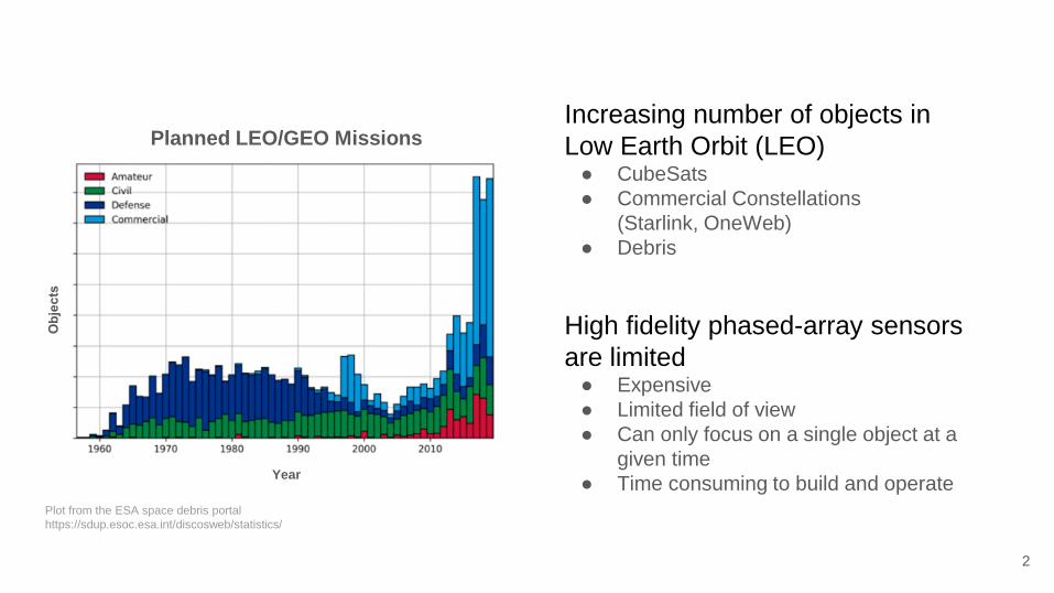
Plot from the ESA space debris portal
https://sdup.esoc.esa.int/discosweb/statistics/
Planned LEO/GEO Missions
Year
Increasing number of objects in
Low Earth Orbit (LEO)● CubeSats
● Commercial Constellations
(Starlink, OneWeb)
● Debris
High fidelity phased-array sensors
are limited● Expensive
● Limited field of view
● Can only focus on a single object at a
given time
● Time consuming to build and operate

3
What is SpaceNet?A Low-Cost network of Software Defined Radio(SDR)
equipt ground stations for monitoring LEO space domain
This type of network could be used to monitor LEO space
domain relieving high fidelity sensors
The system would produce two-line element sets(TLE) that
could be compared to expected orbits to determine if
something is out of place

4
This Project4 unit proof of concept for this type of low-cost, low-
fidelity ground station network
This project will produce 4 functional ground units that can
record UHF/L-Band satellite Quadrature signal (IQ) data
from 2 target satellites
The recorded data will be used to produce both a orbital
position estimation and Two-line element set.
5
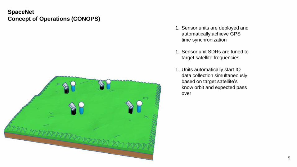
SpaceNet
Concept of Operations (CONOPS)
1. Sensor units are deployed and
automatically achieve GPS
time synchronization
1. Sensor unit SDRs are tuned to
target satellite frequencies
1. Units automatically start IQ
data collection simultaneously
based on target satellite’s
know orbit and expected pass
over
6
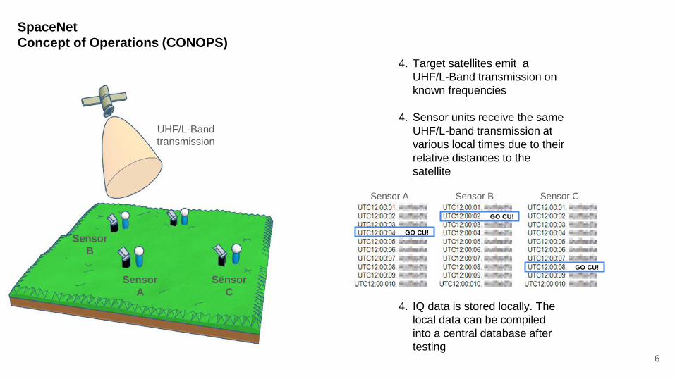
SpaceNet
Concept of Operations (CONOPS)
4. Target satellites emit a
UHF/L-Band transmission on
known frequencies
4. Sensor units receive the same
UHF/L-band transmission at
various local times due to their
relative distances to the
satellite
4. IQ data is stored locally. The
local data can be compiled
into a central database after
testing
Sensor A Sensor B Sensor C
GO CU!
GO CU!
GO CU!
UHF/L-Band
transmission
Sensor
A
Sensor
B
Sensor
C

7
SpaceNet
Concept of Operations (CONOPS)
Sensor A Sensor B Sensor C
GO CU!
GO CU!
GO CU! Time
Delay7. The compiled data can be
parsed on a central machine
to produce a orbital position
via TDoA and a TLE
7. The estimated position and
TLE can be compared to the
know orbits for verificationEstimated
Orbit
Estimated
Position
Known
OrbitError
envelope
Time zero

8
SpaceNet
Concept of Operations (CONOPS)
1. Sensor units are deployed and
automatically achieve GPS time
synchronization
1. Sensor unit SDRs are tuned to
target satellite frequencies
1. Units automatically start IQ data
collection simultaneously based on
target satellite’s know orbit and
expected pass over
Sensor A Sensor B Sensor C
GO CU!
GO CU!
GO CU!
4. Target satellites emit a UHF/L-Band
transmission on known frequencies
4. Sensor units receive the same UHF/L-band
transmission at various local times due to
their relative distances to the satellite
4. IQ data is stored locally. The local data can
be compiled into a central database after
testing
7. The compiled data can be parsed
on a central machine to produce a
orbital position via TDoA and a
TLE
7. The estimated position and TLE
can be compared to the know
orbits for verification
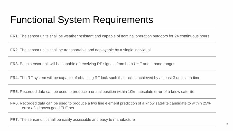
Functional System Requirements
9
FR1. The sensor units shall be weather resistant and capable of nominal operation outdoors for 24 continuous hours.
FR2. The sensor units shall be transportable and deployable by a single individual
FR3. Each sensor unit will be capable of receiving RF signals from both UHF and L band ranges
FR4. The RF system will be capable of obtaining RF lock such that lock is achieved by at least 3 units at a time
FR5. Recorded data can be used to produce a orbital position within 10km absolute error of a know satellite
FR6. Recorded data can be used to produce a two line element prediction of a know satellite candidate to within 25%
error of a known good TLE set
FR7. The sensor unit shall be easily accessible and easy to manufacture
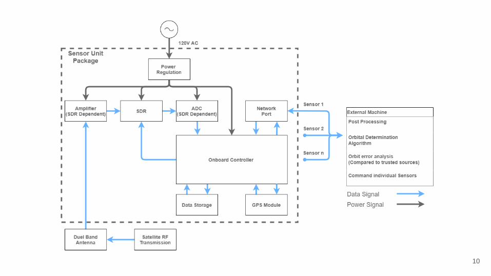
10

11
LimeSDR MiniSDR that will handle RF communications
Raspberry Pi 4On Board Computer for data collection
and transfer
Neo-7M GPS
Breakout BoardUsed to synchronize data timestamps
Nema 4 EnclosureRated housing ensures component
protection. Clear top enables GPS lock
Baseline Sensor Unit Design
LNAUsed to improve G/T metric ensuring
adequate reception of satellite transmission

Feasibility Concerns
12
13
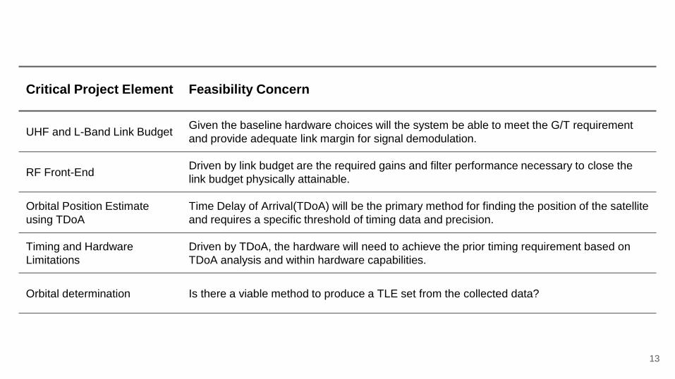
Critical Project Element Feasibility Concern
UHF and L-Band Link BudgetGiven the baseline hardware choices will the system be able to meet the G/T requirement
and provide adequate link margin for signal demodulation.
RF Front-EndDriven by link budget are the required gains and filter performance necessary to close the
link budget physically attainable.
Orbital Position Estimate
using TDoA
Time Delay of Arrival(TDoA) will be the primary method for finding the position of the satellite
and requires a specific threshold of timing data and precision.
Timing and Hardware
Limitations
Driven by TDoA, the hardware will need to achieve the prior timing requirement based on
TDoA analysis and within hardware capabilities.
Orbital determination Is there a viable method to produce a TLE set from the collected data?

UHF and L-Band Link Budget
14
Given the baseline hardware choices will the
system be able to meet the G/T requirement and
provide adequate link margin for signal
demodulation.

Communication Flowdown
15
Noise temperature
FeasibilityDoes the selected hardware
meet the system noise
requirements
Link Margin
FeasibilityWith the expected G/T and
satellite candidates can the
communication link be closed
RF Front-End
FeasibilityCan the required
antenna/LNA/filters be built or
bought
Link Budget

Communication Flowdown
16
Noise temperature
FeasibilityDoes the selected hardware
meet the system noise
requirements
Link Margin
FeasibilityWith the expected G/T and
satellite candidates can the
communication link be closed
RF Front-End
FeasibilityCan the required
antenna/LNA/filters be built or
bought
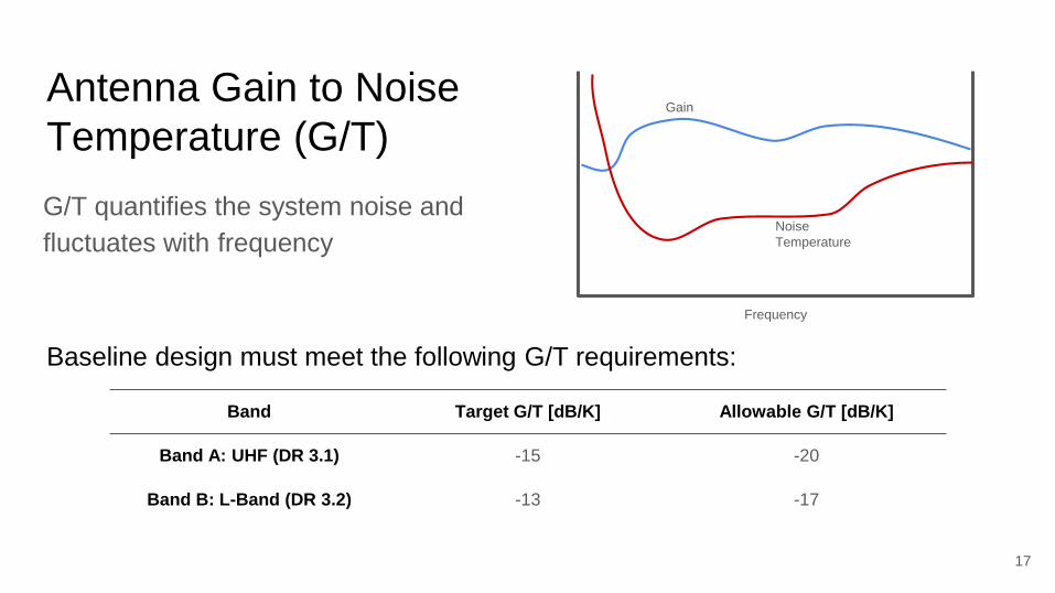
Antenna Gain to Noise
Temperature (G/T)
G/T quantifies the system noise and
fluctuates with frequency
17
Band Target G/T [dB/K] Allowable G/T [dB/K]
Band A: UHF (DR 3.1) -15 -20
Band B: L-Band (DR 3.2) -13 -17
Baseline design must meet the following G/T requirements:
Gain
Noise
Temperature
Frequency

G/T is defined as:
Where:
● Ga is the antenna gain
● L is the line loss (UHF:1.8dB, L-Band:1.8dB)
● Ts is system noise temperature (UHF:305K, L-Band:170K )
18
Band Gain for Target G/T [dBi] Gain for Allowable G/T [dBi]
Band A: UHF (DR 3.1) 11.6 6.6
Band B: L-Band (DR 3.2) 11.1 7.1
Antenna Gains required to validate G/T analysis:

Communication Flowdown
19
Noise temperature
FeasibilityDoes the selected hardware
meet the system noise
requirements
Link Margin
FeasibilityWith the expected G/T and
satellite candidates can the
communication link be closed
RF Front-End
FeasibilityCan the required
antenna/LNA/filters be built or
bought
Feasible
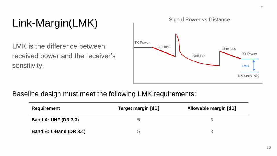
Link-Margin(LMK)
LMK is the difference between
received power and the receiver’s
sensitivity.
20
Requirement Target margin [dB] Allowable margin [dB]
Band A: UHF (DR 3.3) 5 3
Band B: L-Band (DR 3.4) 5 3
Baseline design must meet the following LMK requirements:
TX Power
RX Power
RX Sensitivity
Path loss
Line loss
LMK
Line loss
Signal Power vs Distance

Link-Margin is derived:
Where:
● ISL is the Isotropic Signal Level at the ground station(UHF:143.8dBW L-
Band:-154.2dBW
● G/T is the same a prior calculated G/T(UHF:-20dB/K, L-Band:-17dB/K)
● Lpointing is the pointing loss of the antenna(UHF:9.5dB, L-band: 9.5dB)
● KB is Boltzmann Constant(-228.6dW/K/Hz)
● Z is the data rate(UHF:9.7kbps, L-band:2.4kbps)
● Eb/No|min is the required signal to noise ratio to detect the modulation
technique(UHF:8.4dB, L-band:15.7dB)
21

22
Requirement Calculated margin w/ target
antenna gain [dB]
Calculated margin w/ min req
antenna gain [dB]
Band A: UHF (DR 3.3) 11.9 7.5
Band B: L-Band (DR 3.4) 9.1 5.5
Link margins based on G/T values:
Link closes for both UHF and L-band given both target and
min required antenna gain
Link Budget with baseline hardware is feasible

RF Front-End Feasibility
23
Driven by link budget are the required gains and
filter performance necessary to close the link
budget physically attainable.

Communication Flowdown
24
Noise temperature
FeasibilityDoes the selected hardware
meet the system noise
requirements
Link Margin
FeasibilityWith the expected G/T and
satellite candidates can the
communication link be closed
RF Front-End
FeasibilityCan the required
antenna/LNA/filters be built or
bought
Feasible Feasible

The RF Front-End must satisfy the following:
25
Required to validate
link-budget analysis
Required to satisfy
system requirements
UHF Antenna Gain
> 6.6 dBiL-Band Antenna Gain
> 7.1 dBiUHF LNA Gain
> 24 dBL-Band LNA Gain > 14dB
DR4.1.
Antenna(s) will have have 360°
azimuth field of view
DR3.6./DR3.7.
Antenna(s) will cover +/- 10MHz of the target frequencies
20 MHz3 GHZ300 MHz
Target
Frequencies
20 MHz
Linx Technologies

Method 1: Store Bought
Two antennas could be purchased, one for
each band
Antennas could be paired with a RF switch
Feasible
26

27
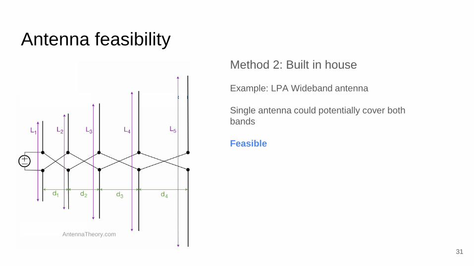
Method 2: Built in house
LPA Wideband antenna
Single antenna could potentially cover both
bands
AntennaTheory.com

28
Poles are distributed based on 𝛕:
Shortest dipoles cover
Highest frequencies
Longest dipoles cover
lowest frequencies
AntennaTheory.com

29
𝛕 is optimized based on desired
length and gain

30
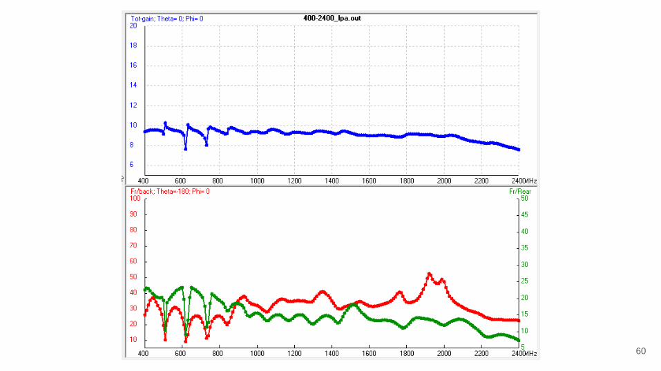
400 MHz - 2.4 GHz
20 element, 3.3ft LPAModeled using LPCAD
Smallest element: 2”
Largest element: 14”
Gain required for G/T
and Link Budget
Antenna feasibility
31
Method 2: Built in house
Example: LPA Wideband antenna
Single antenna could potentially cover both
bands
Feasible
AntennaTheory.com
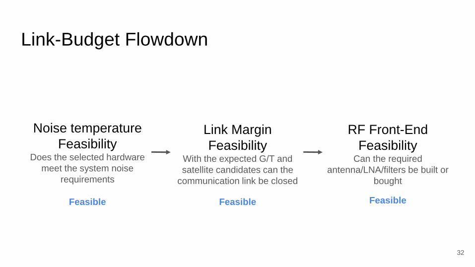
Link-Budget Flowdown
32
Noise temperature
FeasibilityDoes the selected hardware
meet the system noise
requirements
Link Margin
FeasibilityWith the expected G/T and
satellite candidates can the
communication link be closed
RF Front-End
FeasibilityCan the required
antenna/LNA/filters be built or
bought
Feasible Feasible Feasible

Orbital Position estimation using TDoA
33
Time Delay of Arrival(TDoA) will be the primary
method for finding the position of the satellite and
requires a specific threshold of timing data and
precision.
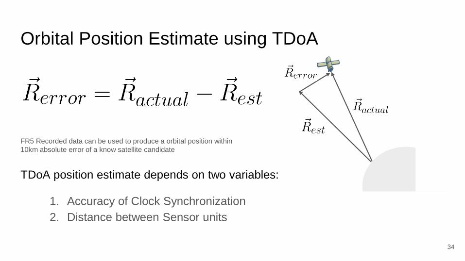
Orbital Position Estimate using TDoA
TDoA position estimate depends on two variables:
1. Accuracy of Clock Synchronization
2. Distance between Sensor units
34
R actu
FR5 Recorded data can be used to produce a orbital position within
10km absolute error of a know satellite candidate
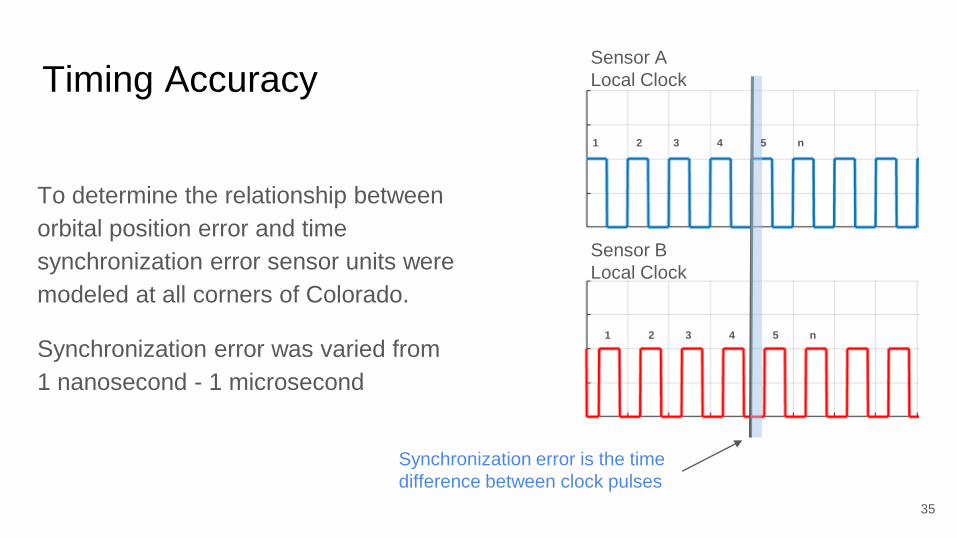
Timing Accuracy
To determine the relationship between
orbital position error and time
synchronization error sensor units were
modeled at all corners of Colorado.
Synchronization error was varied from
1 nanosecond - 1 microsecond
35
Sensor A
Local Clock
Sensor B
Local Clock
Synchronization error is the time
difference between clock pulses
1 2 3 4 5 n
1 2 3 4 5 n
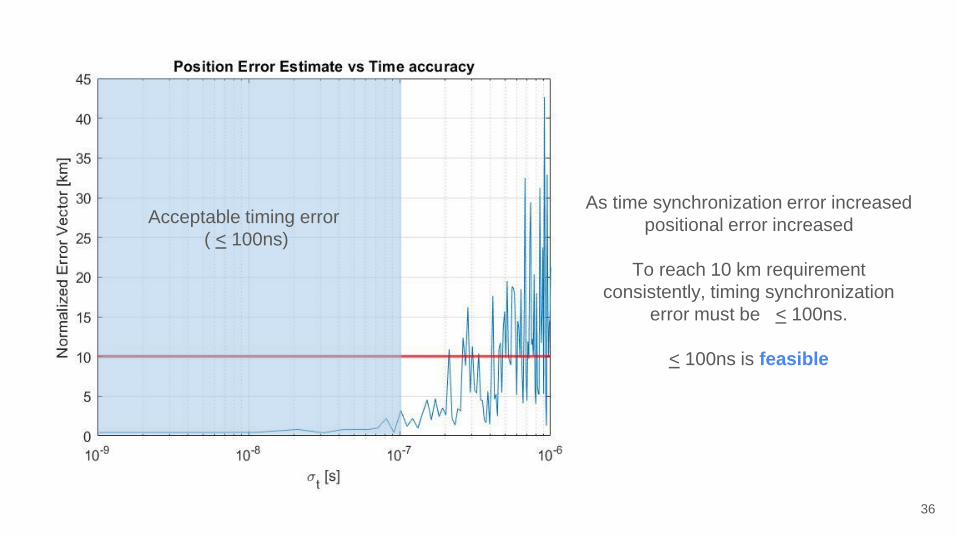
Timing Accuracy
36
Acceptable timing error
( < 100ns)
As time synchronization error increased
positional error increased
To reach 10 km requirement
consistently, timing synchronization
error must be < 100ns.
< 100ns is feasible

Sensor Separation
Separation affects time delay of
arrival for each sensor.
The sensors were placed on
circles of radius Rn at cardinal
directions(North, East, South,
West).
37
R1 R2 Rn

As sensor unit separation increase,
positional error decreases.
To reach the 10 km requirement, the sensor
must be placed on a circle with radius 60 km
60km separation is feasible
38
Acceptable Sensor Separation
( > 60 km)

Timing and Hardware Limitations
39
Driven by TDoA, the hardware will need to achieve
the prior timing requirement based on TDoA
analysis and within hardware capabilities.
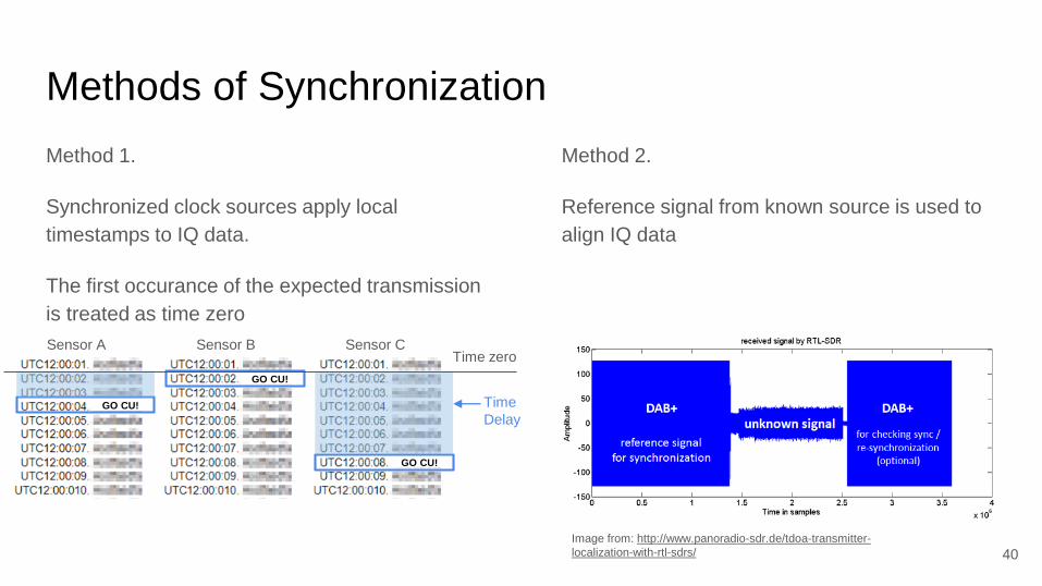
Methods of Synchronization
Method 1.
Synchronized clock sources apply local
timestamps to IQ data.
The first occurance of the expected transmission
is treated as time zero
Method 2.
Reference signal from known source is used to
align IQ data
40
Image from: http://www.panoradio-sdr.de/tdoa-transmitter-
localization-with-rtl-sdrs/
Sensor A Sensor B Sensor C
GO CU!
GO CU!
GO CU! Time
Delay
Time zero

Methods of Synchronization
Method 1.
Use synchronized clock sources across all units
to apply local timestamps to the RF data as it is
received by the SDR. The first occurance of the
expected transmission is treated as time zero
Method 2.
Use a reference signal that is being transmitted
from a know location. This known pattern and
expected delay can be used to align the data
post testing.
41
Image from: http://www.panoradio-sdr.de/tdoa-transmitter-
localization-with-rtl-sdrs/
Sensor A Sensor B Sensor C
GO CU!
GO CU!
GO CU! Time
Delay
Time zero

42
From TDoA analysis timing error
must be <100 nanoseconds
Acceptable timing error
( < 100ns)
FR5. Recorded data can be used to
produce a orbital position within
10km absolute error of a know
satellite candidate
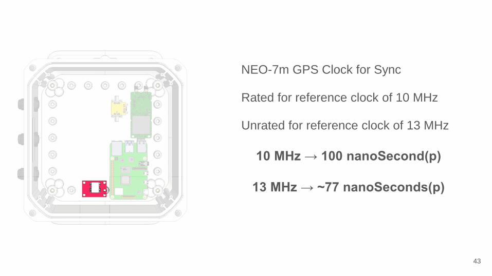
43
NEO-7m GPS Clock for Sync
Rated for reference clock of 10 MHz
Unrated for reference clock of 13 MHz
10 MHz → 100 nanoSecond(p)
13 MHz → ~77 nanoSeconds(p)
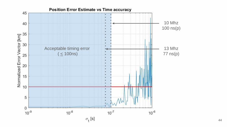
44
Acceptable timing error
( < 100ns)
10 Mhz
100 ns(p)
13 Mhz
77 ns(p)

The GPS PPS signal and RF IQ data
are recorded separately and paired up
by the computer
Not Feasible
● USB protocol will induce some
unknown error.
● This error could theoretically be
predicted and reduced but will
require extensive research into
the Pi 4’s 500+ page data sheet.
45
Original Pipeline
RF data sent
over USB 3.0
GPS PPS time signal
sent over GPIO
Time stamps applied by
computer

46
New Pipeline
RF and time data
sent over USB
3.0
GPS PPS time signal
injected into SDR and
Onboard computer
GPS PPS signal is used to
synchronize the sampling rate of the
SDRs across all units.
Not Feasible Feasible
● Time delay can be extracted from
known PPS sample rate
● Avoids USB protocol

Orbital Determination
47
Is there a viable method to produce a TLE set from
the collected data?

Two Line Element (TLE)
48
Keplerian Elements:
● Inclination (i) [deg]
● RAAN (Ω) [deg]
● Eccentricity (e) [~]
● Arg. of Perigee (⍵) [deg]
● Mean Anomaly (M) [deg]
● Mean Motion (n) [rev/day]
Image from:
https://spaceflight.nasa.gov/realdata/sightings/SSapplications/Post/JavaSSOP/SSOP_Help/tle_def.html
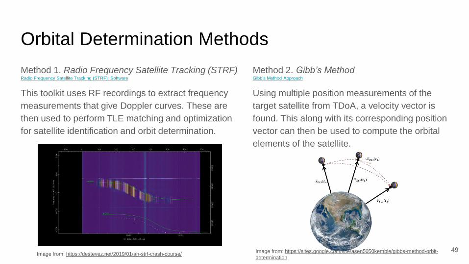
Orbital Determination Methods
Method 1. Radio Frequency Satellite Tracking (STRF)
This toolkit uses RF recordings to extract frequency
measurements that give Doppler curves. These are
then used to perform TLE matching and optimization
for satellite identification and orbit determination.
Method 2. Gibb’s Method
Using multiple position measurements of the
target satellite from TDoA, a velocity vector is
found. This along with its corresponding position
vector can then be used to compute the orbital
elements of the satellite.
49
Gibb’s Method ApproachRadio Frequency Satellite Tracking (STRF): Software
Image from: https://destevez.net/2019/01/an-strf-crash-course/Image from: https://sites.google.com/site/asen5050kemble/gibbs-method-orbit-
determination

Recap
50

51
Critical Project Element Feasibility Results
UHF and L-Band Link BudgetFeasible, The G/T requirement for the system can be met through a combination of LNA
and antenna gain. Given these restriction the Link-margin requirement can still be satisfied.
RF Front-EndFeasible, The antenna gain, LNA and RF system requirements can all be fulfilled in a
number of ways either through off the shelf or theoretically in-house built components
Orbital Position Estimate
using TDoA
Feasible, TDoA will a position within the required error bounds given we can achieve a time
resolution and that the units can be space out over 100 kilometers apart
Timing and Hardware
Limitations
Feasible, Given the new pipeline method there should be no hardware bottlenecks. As long
as the GPS can produce a 10MHz > reference signal the required timing can be achieved
Orbital determinationFeasible, Determination methods such as STRF and Gibbs method should be able to
identify the satellite and produce a TLE.
52

Backup Slides

CSIM
The first of the LASP payloads is the CSIM cubesat. It will be
measuring the wavelengths from the sun from the near-
ultraviolet to the near infrared – a wavelength range
encompassing 96% of the total output of the sun. It’s a 6U
cubesat that will measure solar spectral irradiance (SSI) to
understand how solar variability impacts the Earth’s climate and
to validate climate model sensitivities.
spaceflight.com
● UHF 437.35 MHZ
● GMSK Modulation
● 2.7kbps
● Sun-Synchronous Orbit (575km)
Baseline Satellite Choices
Iridium-169
The Iridium satellite constellation provides L band voice and
data information coverage to satellite phones, pagers and
integrated transceivers over the entire Earth surface. Iridium
Communications owns and operates the constellation,
additionally selling equipment and access to its services.
Wikipedia
● L-Band 1626 MHz
● QPSK Modulation
● 2.4kbps
● 7.0 Watt Transmitter
● Sun-Synchronous Orbit (770km)
54
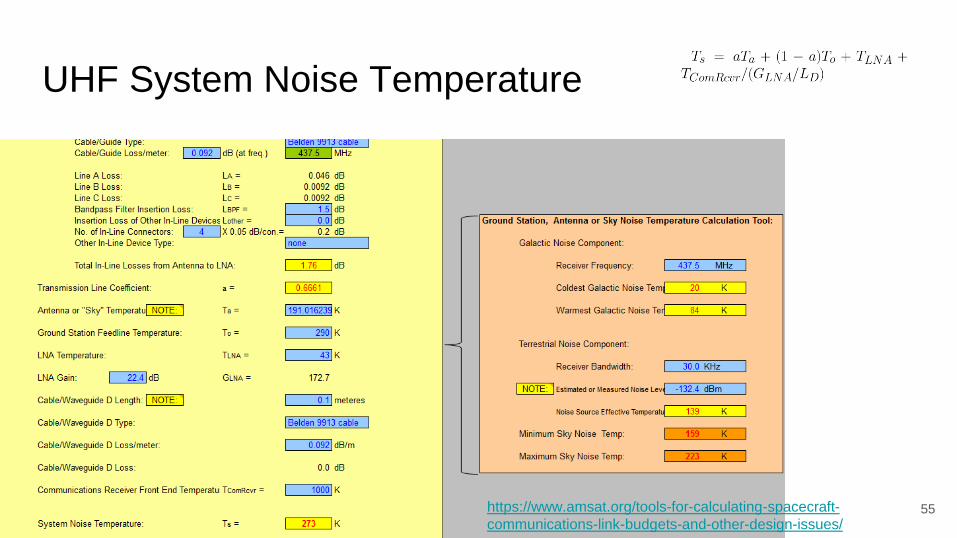
UHF System Noise Temperature
55https://www.amsat.org/tools-for-calculating-spacecraft-
communications-link-budgets-and-other-design-issues/
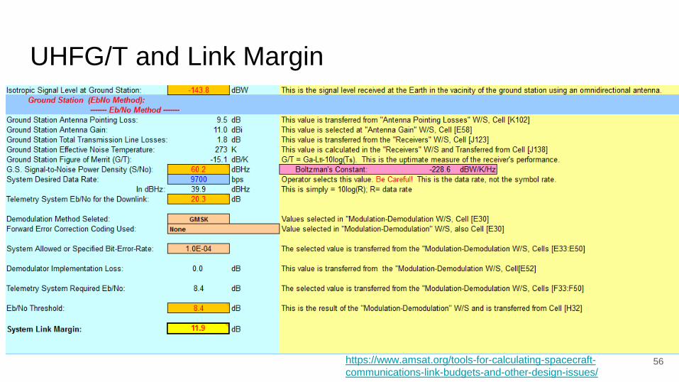
UHFG/T and Link Margin
56https://www.amsat.org/tools-for-calculating-spacecraft-
communications-link-budgets-and-other-design-issues/
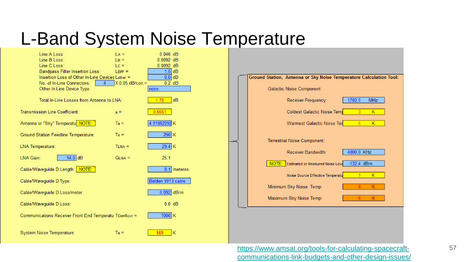
L-Band System Noise Temperature
57https://www.amsat.org/tools-for-calculating-spacecraft-
communications-link-budgets-and-other-design-issues/

L-Band: G/T and Link Margin
58https://www.amsat.org/tools-for-calculating-spacecraft-
communications-link-budgets-and-other-design-issues/

Minimum required FOV
59
~100km
~570 km
10�
TDoA study drives
FOV requirement of
20°
60

LNA options
UHF: 22.372dB Gain, NF 0.6dB L-Band: 14.0dB Gain, NF 0.4dB
61
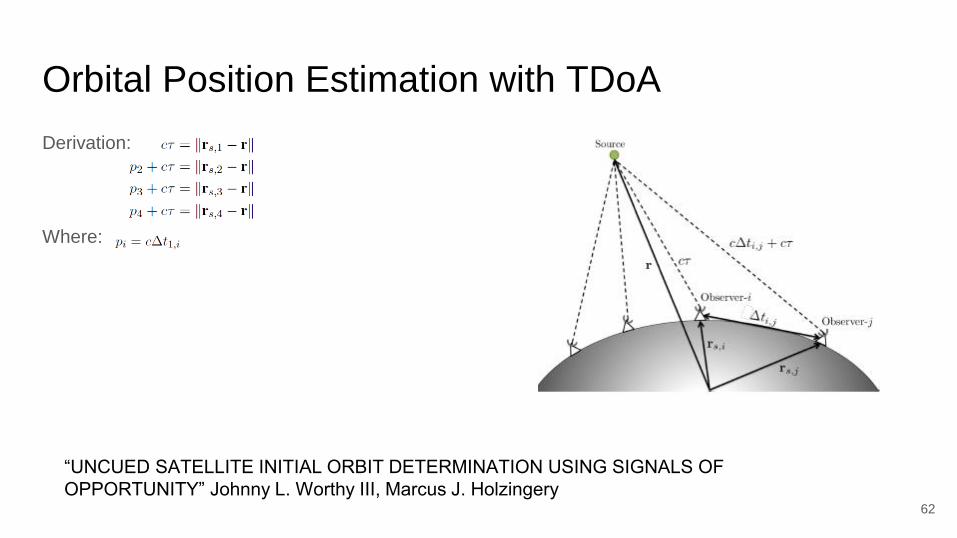
Orbital Position Estimation with TDoA
Derivation:
Where:
62
“UNCUED SATELLITE INITIAL ORBIT DETERMINATION USING SIGNALS OF
OPPORTUNITY” Johnny L. Worthy III, Marcus J. Holzingery

Orbital Position Estimation with TDoA
● Time accuracy of 30ns
● Position accuracy of 1m
● Satellite location of R =[-1381.1, -
5289.2, 4283.7] km in ECEF
63
“UNCUED SATELLITE INITIAL ORBIT DETERMINATION USING SIGNALS OF
OPPORTUNITY” Johnny L. Worthy III, Marcus J. Holzingery
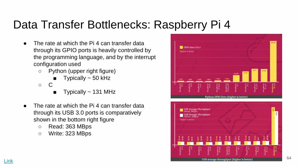
Data Transfer Bottlenecks: Raspberry Pi 4
64
● The rate at which the Pi 4 can transfer data
through its GPIO ports is heavily controlled by
the programming language, and by the interrupt
configuration used
○ Python (upper right figure)
■ Typically ~ 50 kHz
○ C
■ Typically ~ 131 MHz
● The rate at which the Pi 4 can transfer data
through its USB 3.0 ports is comparatively
shown in the bottom right figure
○ Read: 363 MBps
○ Write: 323 MBps
Link
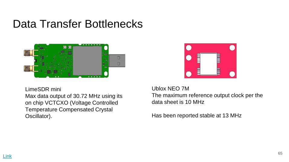
Data Transfer Bottlenecks
65
LimeSDR mini
Max data output of 30.72 MHz using its
on chip VCTCXO (Voltage Controlled
Temperature Compensated Crystal
Oscillator).
Ublox NEO 7M
The maximum reference output clock per the
data sheet is 10 MHz
Has been reported stable at 13 MHz
Link

66
USB Polling occurs
This graphic doesn't tell the
whole story but is useful for
visualizing the error
The “lag” due to polling will be
different in each unit depending
on the state of the bus registers
Original Pipeline

67
USB Polling occurs
Even if the received signals lag
due to USB polling in real time
all units continue to remain
synchronized as they sample
based on the GPS signal
New Pipeline
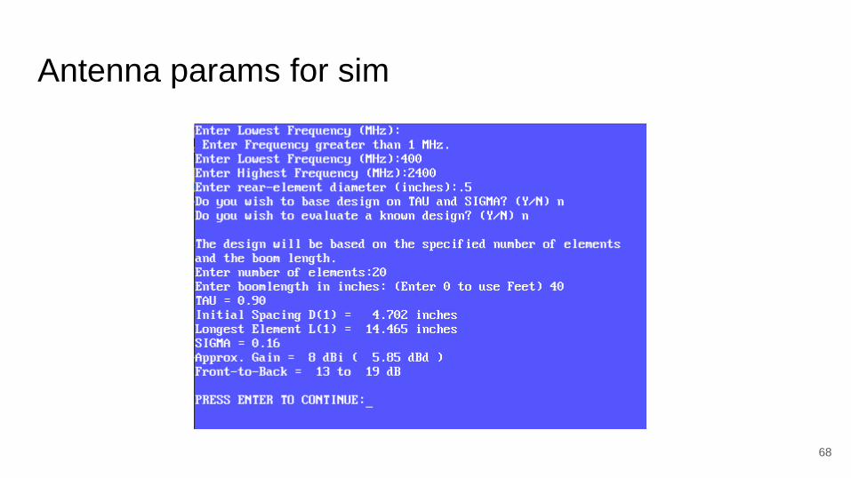
Antenna params for sim
68

Radio Frequency Satellite Tracking (STRF):
Software
69
STRF:
● Resources
○ TLE Database
○ Doppler shift Database
● Processing
○ Converts IQ data to doppler shift
○ Matches to recorded doppler shift
to database
Input:
IQ data from SDR
Outputs:
● Matched TLE from IQ data
● Doppler curve from IQ data
- Open source, Linux based software satellite tracking solution
- Can be run local on one sensor

Gibb’s Method Approach
TDoA → rn-1 , rn , rn+1 (for given time n)
↳ Gibb’s Method (Alg. 5.1) → vn
Now with rn and vn can back out orbital elements
(Alg. 4.2)
↳ can get (h, i, Ω, e, ⍵, 𝜈) → want for TLE (i, Ω, e, ⍵, M, n)
Can use:
70

Size Feasibility
Baseline design fits within a 5’x5’x5’ cube.
FR2, DR2.1
71
5’ 9”

Durability Concerns
Weather Resistance
Testing will occur outside on a fixed schedule
due to the satellites orbit.
The electronics must be protected from rain and
snow
FR1, DR1.1, DR1.3
Thermal Control
The electronic components and internal storage
have a limited range of operating temperatures.
The electronics must stay within 5 - 50 ℃ for a
24 hour test day
FR1, DR1.2
72
73
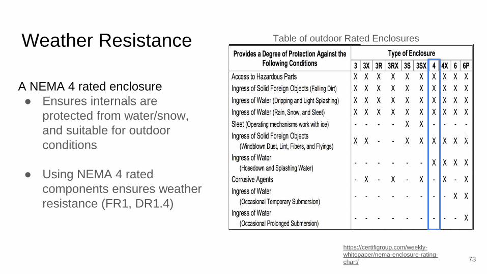
https://certifigroup.com/weekly-
whitepaper/nema-enclosure-rating-
chart/
A NEMA 4 rated enclosure
● Ensures internals are
protected from water/snow,
and suitable for outdoor
conditions
● Using NEMA 4 rated
components ensures weather
resistance (FR1, DR1.4)
Weather Resistance Table of outdoor Rated Enclosures

Maximum recorded temperature in Colorado: 46°C
Minimum recorded temperature in Denver: -32°C
Area of lid: ~0.04 m^2
Thermal conductivity of polycarbonate: ~0.2
Thickness of lid: ~4.9mm
Assuming only conduction on hottest and coldest days
Conclusions:
● May need heater for coldest day
● Electronics will not overheat even on hottest day74
Thermal Control
Cold Day
Hot Day
T1 = 50°C
T1 = 5°C
T2 = 46°C
T2 = -32°CQdot = 60.4 W
Qdot = 6.53 W

Cost Feasibility
Per Unit Part Costs:
● Raspberry Pi 4 Model B(8GB) - $75
● LimeSDR mini - $175
● Acrobotic NEO-6M breakout board - $14.95
● Case Plus Hardware - $70
● Antenna - Max ~$200 (4 Yagi Antennas per unit)
● LNA - Max ~$50
● BandPass Filter - Max ~$50
● Misc Cables - $20
● Total: $654.95
75
Four Unit Suite Cost: $2619.8