spatial mechanism design in virtual reality with networking
TRANSCRIPT

Proceedings of DETC’01 ASME 2001 Design Engineering Technical Conferences and
Computers and Information in Engineering Conference Pittsburgh, Pennsylvania, September 9-12, 2001
DETC2001/21136
SPATIAL MECHANISM DESIGN IN VIRTUAL REALITY WITH NETWORKING
John N. Kihonge Virtual Reality Application
Center Iowa State University Ames, IA 50011-2274
Judy M. Vance Mechanical Engineering Dept.
Virtual Reality Applications Center Iowa State University Ames, IA 50011-2274 [email protected]
Pierre M. Larochelle Mechanical Engineering Dept. Florida Institute of Technology
Melbourne, FL 32901-6975 [email protected]
ABSTRACT Mechanisms are used in many devices to move a
rigid body through a finite sequence of prescribed locations in space. The most commonly used mechanisms are four-bar planar mechanisms that move an object in one plane in space. Spatial mechanisms allow motion in three-dimensions (3D). Spatial 4C mechanisms are two degree of freedom kinematic closed-chains consisting of four rigid links simply connected in series by cylindrical (C) joints. A cylindrical joint is a two degree of freedom joint which allows translation along and rotation about a line in space. This paper describes a synthesis process for the design of 4C spatial mechanisms in a virtual environment. Virtual reality allows the user to view and interact with digital models in a more intuitive way than using the traditional human-computer interface (HCI). The software developed as part of this research also allows multiple users to network and share the designed mechanism. Networking tools have the potential to greatly enhance communication between members of the design team at different industrial sites and therefore reduce design costs.
INTRODUCTION Motion synthesis of mechanisms relies on the
designer’s ability to specify desired locations of an object and visualize relative motion of the resultant mechanism. Traditionally, mechanism design has concentrated on synthesis of planar motion
1
mechanisms. Planar mechanism synthesis involves two-dimensional (2D) display and interaction, and this is well suited to the traditional HCI of a computer monitor, keyboard and mouse. However, designing spatial mechanisms requires the designer to visualize and interact with the mechanism in three-dimensions, which is difficult using the traditional HCI. Virtual Reality (VR) technology provides a three-dimensional environment in which to interact with digital models. Thus, this research focuses on the use of VR for the design of spatial mechanisms.
Models viewed using a traditional HCI are not drawn in real size and cannot be manipulated in a natural way. VR allows the user to view the real size models and interact with the models through the use of a position sensor to track head motion and a wand or instrumented glove, which would also be equipped with a position sensor. The head position and orientation are used to compute the viewing perspective for the computer display. This is in contrast to the traditional HCI where the user manipulates a desktop mouse and types on a keyboard to interact with digital models.
Osborn and Vance [1] developed SphereVR as the first VR environment for the design of spherical four-bar mechanisms. SphereVR had the user place coordinate frames on a sphere. The solution code for the mechanism synthesis of SphereVR was based on Suh and Radcliffe's displacement matrix method [2]. The SphereVR spherical mechanism design program was followed by VEMECS (Virtual Environment for MEChanism Synthesis) [3]. VEMECS used solution
Copyright © 2001 by ASME

algorithms from SPHINX, a monitor based spherical mechanism design program developed at the University of California, Irvine [4]. In related work, VEMECS and SPHINX were used to evaluate the effectiveness of monitor-based software applications compared to virtual reality applications [5].
Isis followed VEMECS as a design tool for spherical mechanism synthesis in a VR environment [6]. Isis, like VEMECS, uses SPHINX synthesis and analysis routines. Isis improved upon VEMECS by providing users the ability to use Iowa State University's C2 virtual environment and the ability to import digital models of the surroundings and the part geometry to aid in the design task. The C2 facility is a 12 foot by 12 foot virtual environment room where stereo images are projected on three walls and the floor. These two features made the design environment more closely resemble the actual operating environment for the final mechanism.
The program described here, VRSpatial, is a VR software program developed at Iowa State University and Florida Institute of Technology to design spatial 4C mechanisms. The task is to design a spatial 4C mechanism in a VR environment and to share the designed mechanism with another user through a network. Four locations are prescribed and then a set of solutions for the spatial motion generation task is computed. The user can select a solution and watch as the mechanism is animated. Users at a remote site are then able to also watch as the mechanism is animated. The solution routines used here are the most current routines from SPADES, a monitor, mouse and keyboard-based spatial 4C mechanism design application developed at Florida Institute of Technology [7].
VRSpatial was developed to allow the user to walk into a three dimensional space, specify the four locations using three dimensional hand movements, synthesize the mechanism and then move around in the space to evaluate the mechanism's motion. All this is performed in a virtual environment where geometric models of objects in the design space are displayed. In this way the user is designing the mechanism while in a virtual representation of the working space of the final design.
SPATIAL 4C MECHANISMS A spatial 4C mechanism consists of a closed
linkage with four rigid links connected by four cylindrical (CCCC) joints (Fig. 1). A cylindrical joint rotates and slides along its axis and therefore has two degrees of freedom. The VRSpatial program is developed for four location motion generation of spatial 4C mechanisms.
2
Figure 1: A Spatial 4C Mechanism
VRSPATIAL VIRTUAL ENVIRONMENT AND INTERACTIONS
The VRSpatial program was designed for display in Iowa State University's C2 facility (Fig. 2). The C2 is a 12x12 foot room where stereo images are projected on three walls and the floor. Left and right eye images are displayed alternately on the screens. CrystalEyes shutter glasses are used to perceive images in three dimensions. The C2 has a three-dimensional sound system and 3D interaction capabilities. Two Silicon Graphics Power Onyx computers provide the computer capacity for the C2.
Figure 2: Iowa State University's C2 Facility
Copyright © 2001 by ASME

For tracking purposes, one pair of glasses has a sensor on it and is tracked by an Ascension Flock of Birds magnetic tracker. The user's view and head orientation are used to compute the viewing perspective for display of images on the screens so that the four screens are perceived as a single environment. All the other users in the C2 will see the view of the person wearing the tracked glasses.
The C2 environment works well where collaboration with other users in a virtual environment is desired. Multiple users can be present in the C2 facility at the same time. Figure 3 shows two users in the C2 during the design of a spatial 4C mechanism. Because all users wear simple stereo glasses, participants can see both the stereo images and the other people in the C2 environment. This allows for easy interaction among users and fosters collaboration within the VR environment.
In VRSpatial, interaction is performed using a Fakespace PINCH Glove. The PINCH Glove has conductive material placed on the finger tips, thumb and palm of the glove to register contact between a user's fingers, palm and thumb. Gestures are used to control actions in the virtual environment. Because a person's real hand sometimes obstructs the virtual objects, a digital hand model is used in the environment to correspond to the location of the participant's hand in space.
Figure 3: Collaboration in the C2 Facility
The software platform for VRSpatial is
WorldTooKit. Menus are used to provide more options for interaction with the VR environment. The menus are 3D objects consisting of a menu bar and text items (Fig. 4). The main menu can be opened at any time during the design process by contacting the pinky finger and the thumb. A menu can be repositioned in space by intersecting the virtual hand model with the menu bar and grasping the menu bar using the first finger and the thumb.
3
This allows the user to move the menu to a location in the virtual environment that is convenient. A menu option is selected by intersecting the virtual hand model with the menu option and then making a gesture of touching the second finger to the thumb. These menus are used to control the tasks in the virtual environment.
Figure 4: VRSpatial Main Menu
KINEMATIC SYNTHESIS OF SPATIAL 4C MECHANISMS
Synthesis of spatial 4C mechanisms is based on the spatial generalization of the classical Burmester center and circle point curves of planar kinematics and the center and circle axis cones of spherical kinematics [8]. The results of the spatial generalization are referred to as the fixed and moving congruences. These congruences are sets of lines that define the axes of CC dyads that guide a body through four prescribed locations in space. A compatible pair of fixed and moving lines or axes maintain a constant normal distance and angle in each of the four locations of the moving body. The spatial triangle technique by Murray and McCarthy [9] and Larochelle [8] is used to compute the congruences resulting in a parameterized set of lines.
To define the mechanism design problem, first, models of objects that will be in the vicinity of the final mechanism are loaded into the environment. These could be machine tools, other parts on an adjacent product, assembly fixtures, etc. Then, the part that is to be moved by the mechanism is loaded. Once this part is placed in a desired location, another instance of the part is generated and the user places this part in the next location. This continues until four representations of the part that is to be moved by the mechanism have been located (Fig. 5). The locations can be modified and then numbered 1, 2, 3 and 4 to indicate the order of the movement.
Copyright © 2001 by ASME

The program calculates all possible mechanisms for the four locations specified and displays the results in the form of either a type map or congruence planes. These options are explained in the following sections.
Figure 5: Location Placement
Type Map
The synthesis solution can be presented in a 2D plot referred to as a “type map”. The type map displays the solutions from the synthesis in a color-coded format showing the mechanism types [10]. Spatial mechanisms are classified according to the mechanism type of their corresponding spherical image. The spherical image is a spherical four-bar mechanism with link lengths equal to the angular twist of the links of the spatial 4C mechanism [11]. The type map generated by VRSpatial for one set of four locations is shown in Fig. 6. One axis of the map represents one choice of dyad and the other axis represents the second choice. Choosing a point on the type map is equivalent to selecting two pairs of corresponding planes from the fixed and moving congruences. Each pair of planes defines a CC dyad with one fixed C joint axis and one moving C joint axis.
To select a point from the type map, a pointer is drawn from the virtual hand model after the pointer gesture, thumb to third finger, has been made by the user. A user moves the pointer in contact with an area of the type map to select a mechanism. Releasing the gesture selects the mechanism from the type map. Once a mechanism has been selected, the solution is drawn on the models in the virtual environment. Different mechanisms can be chosen until the user gets a satisfactory mechanism.
4
Figure 6: Type Map For the type map representation of the four
location synthesis solutions, spatial 4C mechanisms are analyzed to eliminate order, branch and circuit defects in motion generation tasks [12]. A mechanism is said to suffer from branch defects if it enters a stationery configuration that requires an additional mechanical input to guide the moving body as desired. Circuit defects occur when a solution exists but the mechanism must be disassembled and reassembled to move between two desired locations. Mechanisms that have these defects are filtered so that the type map is darkened where these defects occur. Solutions which pass the branch and circuit defect tests remain bright on the type map, guiding the user to select good solutions. Fixed and Moving Congruences
The solution from the synthesis can also be presented as fixed and moving line congruences [8]. The moving line congruence is the set of all moving C joint axes that can be used in a 4C mechanism to guide a body through the four locations. The fixed line congruence are the set of all corresponding fixed C joint axes. There is a one to one correspondence between the fixed and moving line congruences associated with the four spatial locations. Therefore, selecting one line from either congruence defines a CC dyad, or half of the 4C mechanism.
The fixed and moving line congruences are represented as sets of planes in the virtual environment with a single central line. The moving congruences are represented by yellow planes and the fixed congruences are represented by red planes (Fig. 7). The user has to make two selections from the congruence planes to completely define a solution mechanism.
Copyright © 2001 by ASME
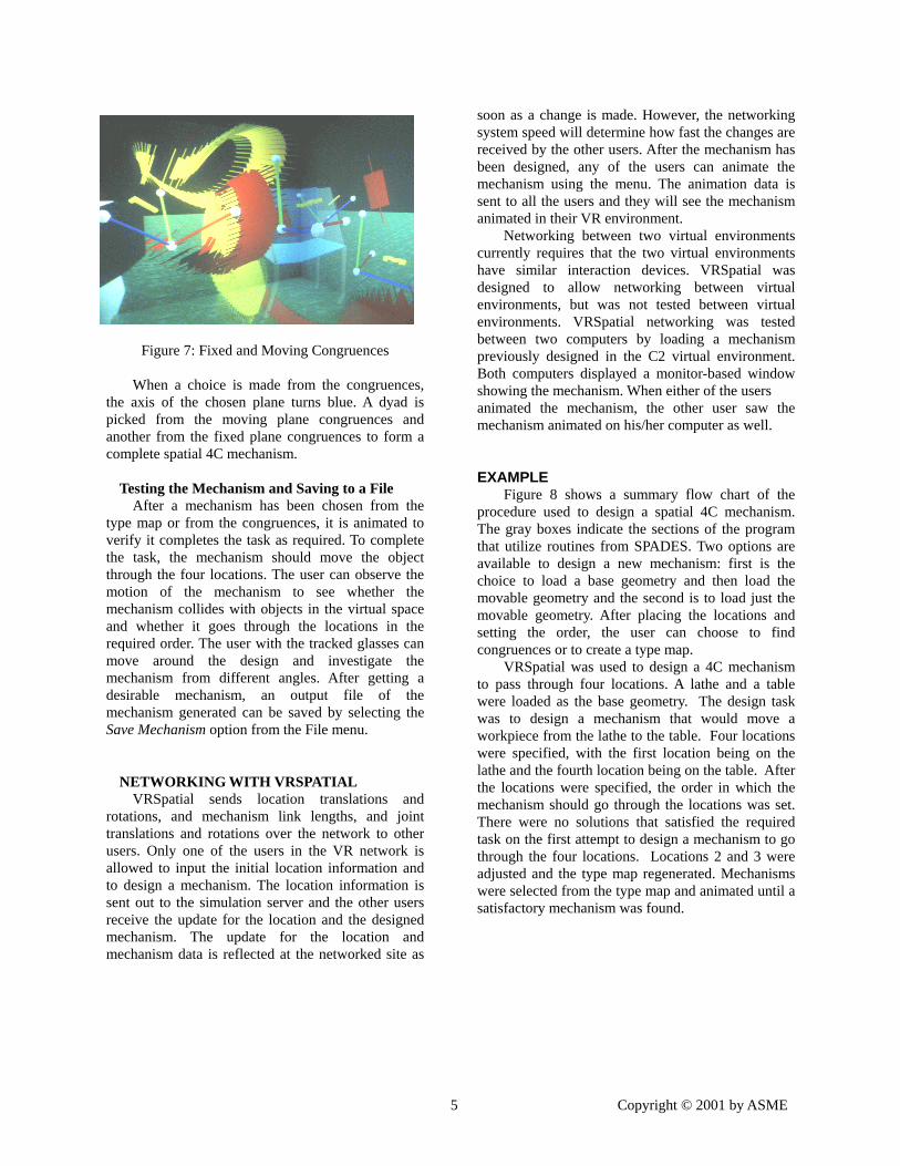
Figure 7: Fixed and Moving Congruences
When a choice is made from the congruences,
the axis of the chosen plane turns blue. A dyad is picked from the moving plane congruences and another from the fixed plane congruences to form a complete spatial 4C mechanism.
Testing the Mechanism and Saving to a File
After a mechanism has been chosen from the type map or from the congruences, it is animated to verify it completes the task as required. To complete the task, the mechanism should move the object through the four locations. The user can observe the motion of the mechanism to see whether the mechanism collides with objects in the virtual space and whether it goes through the locations in the required order. The user with the tracked glasses can move around the design and investigate the mechanism from different angles. After getting a desirable mechanism, an output file of the mechanism generated can be saved by selecting the Save Mechanism option from the File menu.
NETWORKING WITH VRSPATIAL VRSpatial sends location translations and
rotations, and mechanism link lengths, and joint translations and rotations over the network to other users. Only one of the users in the VR network is allowed to input the initial location information and to design a mechanism. The location information is sent out to the simulation server and the other users receive the update for the location and the designed mechanism. The update for the location and mechanism data is reflected at the networked site as
5
soon as a change is made. However, the networking system speed will determine how fast the changes are received by the other users. After the mechanism has been designed, any of the users can animate the mechanism using the menu. The animation data is sent to all the users and they will see the mechanism animated in their VR environment.
Networking between two virtual environments currently requires that the two virtual environments have similar interaction devices. VRSpatial was designed to allow networking between virtual environments, but was not tested between virtual environments. VRSpatial networking was tested between two computers by loading a mechanism previously designed in the C2 virtual environment. Both computers displayed a monitor-based window showing the mechanism. When either of the users animated the mechanism, the other user saw the mechanism animated on his/her computer as well.
EXAMPLE Figure 8 shows a summary flow chart of the
procedure used to design a spatial 4C mechanism. The gray boxes indicate the sections of the program that utilize routines from SPADES. Two options are available to design a new mechanism: first is the choice to load a base geometry and then load the movable geometry and the second is to load just the movable geometry. After placing the locations and setting the order, the user can choose to find congruences or to create a type map.
VRSpatial was used to design a 4C mechanism to pass through four locations. A lathe and a table were loaded as the base geometry. The design task was to design a mechanism that would move a workpiece from the lathe to the table. Four locations were specified, with the first location being on the lathe and the fourth location being on the table. After the locations were specified, the order in which the mechanism should go through the locations was set. There were no solutions that satisfied the required task on the first attempt to design a mechanism to go through the four locations. Locations 2 and 3 were adjusted and the type map regenerated. Mechanisms were selected from the type map and animated until a satisfactory mechanism was found.
Copyright © 2001 by ASME

Figure 8. Flowchart
Adjust positions
START
Load movable geometry Load mechanism - File Load base geometry
Place positions 1, 2, 3 and 4
Set position order
Spades Routines
Select a driving dyad
Select driven dyad
END
Animate mechanism
Save mechanism
Analyze mechanism
Display mechanism
Create type map
Choose a mechanism
Generate congruences
Adjust positions
6 Copyright © 2001 by ASME
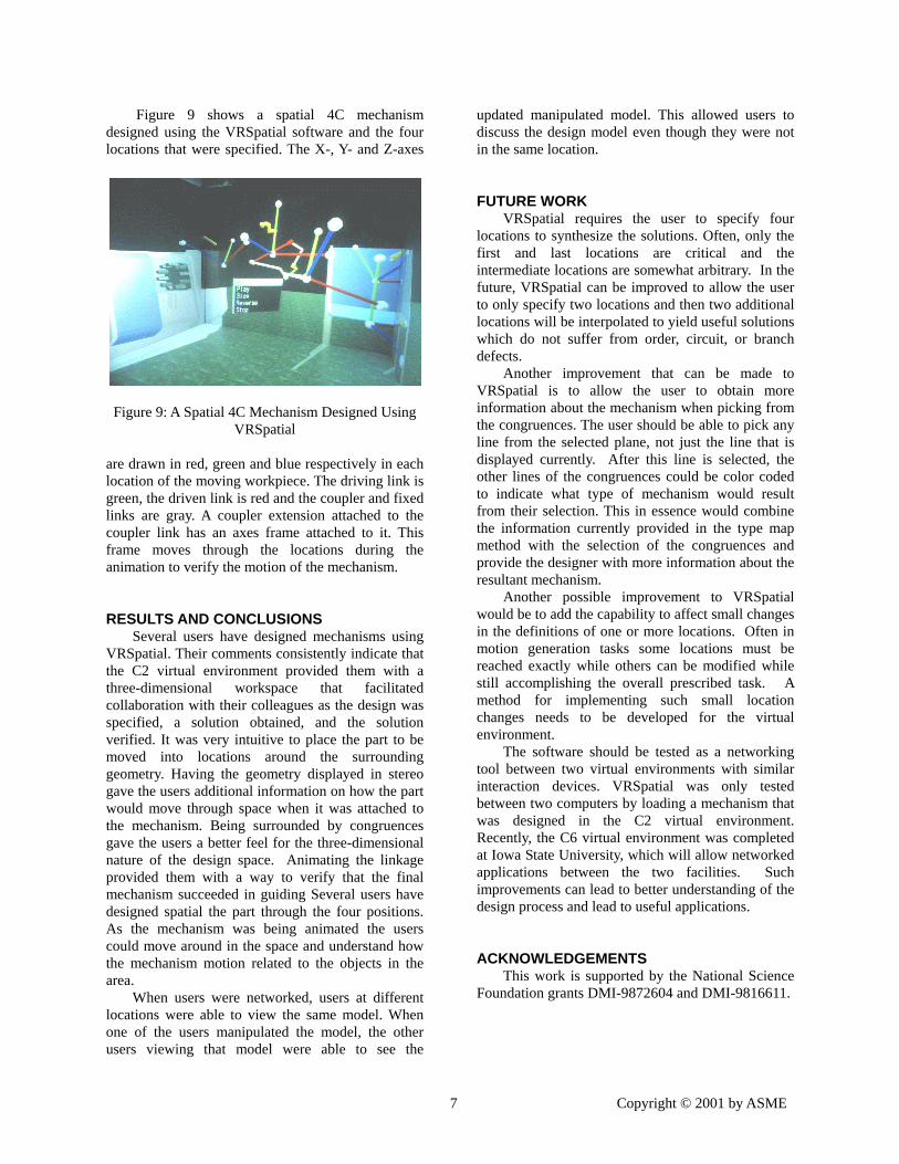
Figure 9 shows a spatial 4C mechanism designed using the VRSpatial software and the four locations that were specified. The X-, Y- and Z-axes
Figure 9: A Spatial 4C Mechanism Designed Using
VRSpatial are drawn in red, green and blue respectively in each location of the moving workpiece. The driving link is green, the driven link is red and the coupler and fixed links are gray. A coupler extension attached to the coupler link has an axes frame attached to it. This frame moves through the locations during the animation to verify the motion of the mechanism.
RESULTS AND CONCLUSIONS Several users have designed mechanisms using
VRSpatial. Their comments consistently indicate that the C2 virtual environment provided them with a three-dimensional workspace that facilitated collaboration with their colleagues as the design was specified, a solution obtained, and the solution verified. It was very intuitive to place the part to be moved into locations around the surrounding geometry. Having the geometry displayed in stereo gave the users additional information on how the part would move through space when it was attached to the mechanism. Being surrounded by congruences gave the users a better feel for the three-dimensional nature of the design space. Animating the linkage provided them with a way to verify that the final mechanism succeeded in guiding Several users have designed spatial the part through the four positions. As the mechanism was being animated the users could move around in the space and understand how the mechanism motion related to the objects in the area.
When users were networked, users at different locations were able to view the same model. When one of the users manipulated the model, the other users viewing that model were able to see the
7
updated manipulated model. This allowed users to discuss the design model even though they were not in the same location.
FUTURE WORK VRSpatial requires the user to specify four
locations to synthesize the solutions. Often, only the first and last locations are critical and the intermediate locations are somewhat arbitrary. In the future, VRSpatial can be improved to allow the user to only specify two locations and then two additional locations will be interpolated to yield useful solutions which do not suffer from order, circuit, or branch defects.
Another improvement that can be made to VRSpatial is to allow the user to obtain more information about the mechanism when picking from the congruences. The user should be able to pick any line from the selected plane, not just the line that is displayed currently. After this line is selected, the other lines of the congruences could be color coded to indicate what type of mechanism would result from their selection. This in essence would combine the information currently provided in the type map method with the selection of the congruences and provide the designer with more information about the resultant mechanism.
Another possible improvement to VRSpatial would be to add the capability to affect small changes in the definitions of one or more locations. Often in motion generation tasks some locations must be reached exactly while others can be modified while still accomplishing the overall prescribed task. A method for implementing such small location changes needs to be developed for the virtual environment.
The software should be tested as a networking tool between two virtual environments with similar interaction devices. VRSpatial was only tested between two computers by loading a mechanism that was designed in the C2 virtual environment. Recently, the C6 virtual environment was completed at Iowa State University, which will allow networked applications between the two facilities. Such improvements can lead to better understanding of the design process and lead to useful applications.
ACKNOWLEDGEMENTS This work is supported by the National Science
Foundation grants DMI-9872604 and DMI-9816611.
Copyright © 2001 by ASME

REFERENCES [1] Osborn, S. W., Vance, J. M., 1995, "A Virtual reality Environment for Synthesizing Spherical Four-bar Mechanisms", Proceedings of the 1995 Design Engineering Technical Conference, Boston, MA, DE-83: 885-892, September 1995. [2] Suh, C. H., Radcliffe, C. W., 1967, "Synthesis of Spherical Linkages With Use of the Displacement Matrix", Journal of Engineering for Industry, Trans. ASME, Series B, Vol. 89, 1967, 215-221. [3] Kraal, J. C., 1996, "An Application of Virtual Reality to Engineering Design: Synthesis of Spherical Mechanisms", Master's Thesis, Iowa State University, Ames, IA, 1996. [4] Larochelle, P., Dooley, J., Murray, A., and McCarthy, J. M., 1993, ``SPHINX- Software for synthesizing spherical mechanisms'', Proceedings of the 1993 NSF Design and Manufacturing Systems Conference, Charlotte, North Carolina, January 6-8, 1993. [5] Evans, P. T., Vance, J. M., Dark, V. J., 1999, "Assessing the Effectiveness of Traditional and Virtual Reality Interfaces in Spherical Mechanism Design", ASME Journal of Mechanical Design, Vol. 121: 507-514. [6] Furlong, T. J., Vance, J. M., Larochelle, P. M., 1999, "Spherical Mechanism Synthesis in Virtual Reality", Journal of Mechanical Design, vol. 121:515-520. [7] Larochelle, P. M., 1998, "SPADES: Software for Synthesizing Spatial 4C Mechanisms", Proceedings of DETC’98: 1998 ASME Design Engineering Technical Conferences, DETC98/MECH-5889, Atlanta, GA, September 13-16. [8] Larochelle, P. M., 1995, "On the Design of Spatial 4C Mechanisms for Rigid-Body Guidance Through 4 Positions", Proceedings of the 1995 ASME Design Engineering Technical Conferences, Boston, MA, DE-82: 825-832. [9] Murray, A., and McCarthy, J., 1994, "Five Position Synthesis of Spatial CC Dyads", Proceedings of the 1994 ASME Design Engineering Technical Conferences. Mechanism Synthesis and Analysis, September 1994, DE-70: 143-152. [10] Murray, A., and Larochelle, P. M., 1998, "A Classification Scheme for Planar 4R, Spherical 4R,
8
and Spatial RCCC Linkages to Facilitate Computer Animation", Proceedings of the 1998 ASME Design Engineering Technical Conferences, Atlanta, GA, September 13-16. [11] Duffy, J., 1980, Analysis of Mechanisms and Robotic Manipulators, Wiley and Sons, New York, NY. [12] Larochelle, P. M., 2000, "Branch and Circuit Rectification of the Spatial 4C Mechanisms", Proceedings of ASME Design Engineering Technical Conferences, Baltimore, MD, September 10-13.
Copyright © 2001 by ASME