spec edit rev2.1
TRANSCRIPT
BEAUFORT-JASPER WATER & SEWER AUTHORITY
TECHNICAL SPECIFICATIONS
REVISED JULY 2009

BJWSA TECHNICAL SPECIFICATIONS REVISED JULY 2009
DHEC APPROVAL PAGE

BJWSA TECHNICAL SPECIFICATIONS REVISED JULY 2009
i
TABLE OF CONTENTS CHAPTER 1 SAFETY DESIGN CONSIDERATIONS ..........................................................................1
CHAPTER 2 EARTHWORK ....................................................................................................................2 2.1 SCOPE:.........................................................................................................................................................2 2.2 GENERAL:...................................................................................................................................................2 2.3 CLEARING AND GRUBBING:..................................................................................................................2 2.4 STRUCTURE EXCAVATION AND BACKFILL: .....................................................................................3 2.5 TRENCH EXCAVATION AND BACKFILL:.............................................................................................4 2.6 SITE GRADING: .........................................................................................................................................6 CHAPTER 3 GRASSING AND SITE RESTORATION ........................................................................8 3.1 SCOPE..........................................................................................................................................................8 3.2 GENERAL....................................................................................................................................................8 3.3 FERTILIZING AND GRASSING...............................................................................................................8 CHAPTER 4 ROADWAY REPAIR AND RESURFACING................................................................10 4.1 AGGREGATE SURFACING: ...................................................................................................................10 4.2 CUTTING AND REPLACING PAVEMENT:..........................................................................................10 4.3 RESURFACING OF EXISTING PAVEMENT: ......................................................................................11 CHAPTER 5 PIPELINE DRILLING, BORING AND JACKING ......................................................13 5.1 SCOPE:.......................................................................................................................................................13 5.2 GENERAL REQUIREMENTS: ................................................................................................................13 5.3 MATERIALS:.............................................................................................................................................13 5.4 INSTALLATION:.......................................................................................................................................14 CHAPTER 6 PIPELINE MATERIALS, VALVES AND APPURTENANCES .................................16 6.1 PIPELINE MATERIALS ..........................................................................................................................16 6.2 VALVES......................................................................................................................................................21 6.3 FITTINGS, APPURTENANCES AND SPECIALTIES: .........................................................................24 CHAPTER 7 WATER SYSTEM STANDARDS....................................................................................29 7.1 SCOPE........................................................................................................................................................29 7.2 WATER SYSTEM DESIGN GUIDELINES:............................................................................................29 7.3 FIRE HYDRANTS AND POST TYPE FLUSHING HYDRANTS:.........................................................30 7.4 POTABLE WATER SERVICE CONNECTIONS: ...................................................................................31 7.5 WATER PIPELINE INSTALLATION: ....................................................................................................33 7.6 PIPELINE TESTING AND DISINFECTION PROCEDURES: ............................................................36 CHAPTER 8 WASTEWATER SYSTEM STANDARDS .....................................................................38 8.1 SCOPE........................................................................................................................................................38 8.2 INSTALLATION GUIDELINES ..............................................................................................................38 8.3 PIPELINE TESTING PROCEDURES.....................................................................................................44 CHAPTER 9 CONCRETE STRUCTURES, MANHOLES AND APPURTENANCES ....................46 9.1 SCOPE........................................................................................................................................................46 9.2 MATERIALS ..............................................................................................................................................46 9.3 TESTS OF STRUCTURES: ......................................................................................................................49 CHAPTER 10 SEWER PUMP STATIONS AND APPURTENANCES..............................................50 10.1 SCOPE........................................................................................................................................................50 10.2 DESIGN CONSIDERATIONS..................................................................................................................50
BJWSA TECHNICAL SPECIFICATIONS REVISED JULY 2009
ii
10.3 PUMPS AND MOTORS ............................................................................................................................54 10.4 TESTING AND STARTUP........................................................................................................................57 10.5 CLOSEOUT REQUIREMENTS ...............................................................................................................58 CHAPTER 11 ELECTRICAL .................................................................................................................59 11.1 GENERAL..................................................................................................................................................59 11.2 MAIN CONTROL PANEL ........................................................................................................................60 11.3 SUBMERSIBLE PUMP STATIONS ........................................................................................................62 11.4 ABOVE GROUND SUCTION LIFT PUMP STATION...........................................................................63 11.5 QUALITY ASSURANCE ...........................................................................................................................63 11.6 SUBMITTALS............................................................................................................................................63 11.7 PRODUCTS/MATERIALS........................................................................................................................63 11.8 INSTALLATION........................................................................................................................................64 11.9 ELECTRICAL SPARE PARTS .................................................................................................................64 CHAPTER 12 PUMP STATION SCADA SYSTEMS...........................................................................65 12.1 SCADA DEFINITIONS.............................................................................................................................65 12.2 SCADA I/O .................................................................................................................................................66 CHAPTER 13 APPROVED MANUFACTURERS................................................................................68 13.1 GENERAL..................................................................................................................................................68 13.2 PUMP STATIONS .....................................................................................................................................72 13.3 SEWER .......................................................................................................................................................75 13.4 WATER.......................................................................................................................................................77 APPENDIX A – GENERAL STANDARD DETAIL DRAWINGS.......................................................A
APPENDIX B – WASTEWATER/SEWER STANDARD DETAIL DRAWINGS..............................B
APPENDIX C – WATER STANDARD DETAIL DRAWINGS............................................................C
APPENDIX D – SAFETY STANDARD DETAIL DRAWINGS...........................................................D

BJWSA TECHNICAL SPECIFICATIONS REVISED JULY 2009
CHAPTER 1 SAFETY 1
CHAPTER 1 SAFETY DESIGN CONSIDERATIONS
Reserved for Safety Chapter
END OF SECTION

BJWSA TECHNICAL SPECIFICATIONS REVISED JULY 2009
CHAPTER 2 EARTHWORK 2
CHAPTER 2 EARTHWORK
2.1 SCOPE:
Earthwork shall consist of all necessary site clearing and grubbing, excavation and backfill for structures and trenches, site grading, grassing and restoration, as well as related work as shown on the plans and as specified herein.
2.2 GENERAL:
All earthwork shall be confined to the construction area as shown on the plans, and shall be done in an approved manner with proper equipment. Earthwork shall be suspended during rain and inclement weather, or when unsatisfactory field conditions are encountered, unless otherwise directed by the ENGINEER. At all times during construction, the CONTRACTOR shall maintain proper drainage in the construction area, and shall take all measures necessary for erosion and sediment control. A. Classification of earthwork: All excavation will be unclassified, for payment purposes,
unless otherwise specified. B. Existing Utilities: CONTRACTOR shall take every precaution to protect existing utility
services from damage during construction operations. If damage occurs, the OWNER of the utility shall be notified immediately and repairs shall be made promptly at the CONTRACTOR’S expense. All repair work shall be satisfactory to the ENGINEER and the OWNER of the utility. When interruptions of existing utilities occur, temporary service shall be provided as approved by the ENGINEER and OWNER of the utility.
2.3 CLEARING AND GRUBBING:
A. General: 1. The CONTRACTOR shall consult with the OWNER and ENGINEER prior to
beginning clearing, and a full understanding is to be reached as to procedure. The CONTRACTOR shall then conduct clearing and grubbing operations in strict accordance with these agreements.
2. The CONTRACTOR’S operations shall be conducted with full consideration of all proper and legal rights of the OWNER, adjacent property OWNER’S and the public, and with the least possible amount of inconvenience to them.
B. Construction Sites: The work shall consist of clearing and grubbing within the limits of construction sites, road rights-of-way and elsewhere as indicated or necessary to complete the work, except pipelines. All trees, stumps, roots, shrubs and brush shall be removed as required for construction. Stumps and roots shall be grubbed and completely removed. The resulting depressions shall be filled with suitable material placed and compacted in accordance with Chapter 3, “Grassing and Site Restoration”. Sound trees and shrubs, which do not interfere with construction, shall remain in place and shall be adequately protected from damage. Cleared and grubbed material, including debris and rubbish, shall be completely burned or otherwise disposed of as directed by the ENGINEER.
C. Pipelines: Clearing and grubbing along pipelines shall be done prior to pipe installation, and shall be confined to the right-of-way limits as specified below. Adjacent property outside the right-of-way limits shall be protected against damage. All trees, stumps, roots, shrubs, and brush shall be removed as required for construction. Stumps and roots shall be grubbed and completely removed. Sound trees and shrubs, which do not interfere with

BJWSA TECHNICAL SPECIFICATIONS REVISED JULY 2009
CHAPTER 2 EARTHWORK 3
construction, shall remain in place and shall be adequately protected from damage. Cleared and grubbed material, including debris and rubbish, shall be disposed of as directed by the ENGINEER; burning within pipeline rights-of-way will not be allowed.
1. Trees 6-inches and larger in diameter shall be trimmed into normal 63-inch lengths, unless otherwise directed by the property OWNER. The logs shall be neatly stacked along the edge of the right-of-way in accessible locations for the property OWNER’S use.
2. Limits of the pipe-laying operation shall be confined to the right-of-way. The width of clearing shall be held to a minimum and shall be no more than specified on the plans, without written consent of the ENGINEER.
D. Structures: Minor structures shall be removed and disposed of as directed by the ENGINEER.
E. Burning: Burning of Cleared Material shall be accomplished in strict compliance with all applicable local, state and federal regulations pertaining to open burning and smoke abatement.
2.4 STRUCTURE EXCAVATION AND BACKFILL:
A. General: Excavations shall be in compliance with current OSHA regulations. Structure Excavation shall be made to the elevations, slopes and limits shown on the plans. Bottom of excavations shall be level and in firm, solid material; where soft or otherwise unsuitable material is encountered, such material shall be removed and replaced with properly compacted earth material, stone or flowable fill, as directed by the ENGINEER. Topsoil and other excavated material suitable for fill or backfill shall be stockpiled on the site for future use. Excess material and unsuitable material shall be properly disposed of. Excavated areas shall be kept free of water during construction. Where necessary, excavations shall be protected by shoring, sheeting, cofferdams or other suitable methods. Where earth will stand, footing trenches may be cut to the exact size of the footings; otherwise, forms shall be used.
1. Unauthorized or excessive excavation shall be corrected by providing properly compacted earth backfill, stone or Class C concrete, as directed by the ENGINEER, at the CONTRACTOR’S expense.
2. Wherever excavation for a foundation extends below the water table or where specifically indicated on the plans, a 12-inch layer (unless otherwise noted) of crushed stone or gravel shall be spread and compacted in the excavation bottom prior to placing the foundation. Crushed stone or gravel shall conform to ASTM C33, Size 57. A non-woven filter fabric, Mirafi 140N or equivalent shall be placed beneath the stone layer.
3. An adequate dewatering system shall be provided at all structure excavations and elsewhere as directed by the ENGINEER. The system shall be capable of removing any water that accumulates in the excavation and maintaining the excavation in a dry condition while construction is in progress. The surface of the ground shall be sloped away from the excavation or piping provided to prevent surface water from entering the excavation. Disposal of water resulting from the dewatering operation shall be done in a manner that does not interfere with normal drainage, and does not cause damage to any portion of the work or adjacent property. All drains, culverts, storm sewers and inlets subject to the dewatering operation shall be kept clean and open for normal surface drainage. The dewatering system shall be maintained until backfilling is complete or as otherwise directed by the ENGINEER. All damages resulting from the dewatering operation shall be repaired by the CONTRACTOR to the satisfaction of the

BJWSA TECHNICAL SPECIFICATIONS REVISED JULY 2009
CHAPTER 2 EARTHWORK 4
ENGINEER and at no cost to the OWNER. 4. Limit of structure excavation, for payment purposes, shall be 3 FT from the outside wall
line of structures. Material removed beyond this limit to facilitate work shall be at the CONTRACTOR’S expense.
B. Backfill Around Structures: Backfill around structures shall be placed as soon as possible, but not until construction below finish grade has been completed and accepted, underground piping and other utilities have been properly installed and tested, forms have been removed, and the excavation cleaned of trash and debris. Foundations and walls shall be braced and supported as required to withstand the forces imposed by the backfilling operation. Care shall be taken to protect piping and other utilities during backfill.
1. Backfill shall consist of suitable material from the excavation free of roots, wood, other vegetable matter, trash, debris, frozen material, rocks larger than 4 inches in any dimension, and other objectionable material. Backfill shall be brought to the indicated finish grade and sloped to drain away from walls. Backfill shall be placed in 8-inch layers and thoroughly compacted as specified below. Any subsequent settlement that may occur during the construction period shall be corrected.
2. Excessively wet, porous, spongy or mucky material shall be removed from around structures prior to placing backfill. No such material shall be used for backfill.
3. Unless otherwise directed by the ENGINEER, liquid-retaining structures shall not be backfilled until tested for leakage and accepted. All structures shall be protected against damage or flotation prior to placing backfill.
2.5 TRENCH EXCAVATION AND BACKFILL:
A. Pipe Bedding and Backfill Material: Select material shall be material free of large stones, hard lumps, frozen matter, organic material, debris and other objectionable material. If necessary, suitable material shall be provided by the CONTRACTOR from other sources at CONTRACTOR’s expense. All material from the excavation unsuitable for bedding and backfill shall be removed and disposed of by the CONTRACTOR. Angular Material shall be crushed stone or gravel conforming to ASTM C33, Size No. 57, with size range of ¼ to ¾-inch.
B. Trench Excavation: ALL EXCAVATION SHALL BE IN COMPLIANCE WITH CURRENT OSHA REQUIREMENTS. Trenches for pipe and other utilities shall be excavated true to line and grade. Unless otherwise indicated or specified, trenches shall be of a depth to provide a minimum cover of 3 FT over the top of pipelines.
1. Sidewalls of trenches shall comply with current OSHA requirements. Unless otherwise specified, trenches shall be between 12 and 18 inches wider than the outside diameter of the pipe, plus sheeting where necessary. Pavement shall be cut 12 inches wider than the required trench width on each side. For gravity sewer lines the maximum trench width shall be up to a level 12 inches above the top of the pipe or shall be as noted on the plans. Sheeting or shoring shall be used where necessary.
2. Where soil conditions preclude vertical walls, the trench width shall be as specified above with the upper part of the trench limited to the least possible width greater than that specified. Where excessive trench widths are necessary, or where directed by the ENGINEER, sheeting or shoring shall be used to support trench walls.
3. Pressure Pipelines: For pressure pipelines, prepare trench bottoms as follows: a) Trench bottoms shall be graded to provide uniform and continuous bearing for the
pipe along its entire length. Bell holes shall be provided for completion of joints. No ridges, sags or undercutting will be allowed.

BJWSA TECHNICAL SPECIFICATIONS REVISED JULY 2009
CHAPTER 2 EARTHWORK 5
b) If approved by the ENGINEER and subject to suitable soil conditions, trenches may be excavated a few inches below the established subgrade and backfilled to subgrade with select material, well compacted and graded to provide uniform and continuous bearing for the entire length of pipe. Bedding material shall be well compacted up to the springline of the pipe, shovel sliced and shaped so that the load is supported throughout the entire length of pipe barrel and not at the pipe bells. Bell holes shall be provided for completion of joints.
c) In rock or other unyielding material, excavation shall be made at least 6”below the established subgrade and the trench backfilled to subgrade with select material. Bedding material shall be well compacted up to the springline of the pipe, shovel sliced and shaped so that the load is supported throughout the entire length of pipe barrel and not at the pipe bells.
d) Where material at subgrade is unstable, soft and incapable of supporting the pipe, trenches shall be excavated below subgrade to a depth as required by soil conditions, and backfilled to subgrade with angular material. The material shall be compacted and graded to provide a stable foundation and uniform bearing for the pipe. Bedding material shall be well compacted up to the springline of the pipe, shovel sliced and shaped so that the load is supported throughout the entire length of pipe barrel and not at the pipe bells.
e) Debris encountered in trench excavation for water and other pipelines shall be removed for the overall width of the trench. It shall be removed to a depth of 6” below the bottom of the pipe for pipes smaller than 24” in size; 8” below the bottom of the pipe for pipes 24” to 36” in size; and 12” below the bottom of the pipe for pipes larger than 36” in size, if debris extends to such depth.
4. Pipe on Grade Pipelines: For gravity sewer lines, prepare trench bottoms as follows: a) Trenches shall be excavated below the established subgrade as required to provide
for preparation of flat trench bottoms in strict accordance with the trench bedding details as shown. Pipe backfill shall be #57 stone unless specifically noted on the plans or where directed by the ENGINEER.
b) Angular material consisting of #57 stone shall be used for sewer pipe bedding. Excavation below pipe shall be to a minimum depth of 4” or as required to obtain suitable pipe foundation. Overcutting of the trench shall be bedded with crushed stone. Bedding material shall be well compacted up to the springline of the pipe, shovel sliced and shaped so that the load is supported throughout the entire length of pipe barrel and not at the pipe bells. Angular material shall meet the requirements of the SCDOT specification 406.08. Stone size shall be No. 57. The use of fossil limestone will not be allowed.
c) Soft, unstable or otherwise unsuitable material encountered below the normal bedding depth shown on the plans shall be removed and backfilled with crushed stone. All such unsuitable material shall be disposed of by the CONTRACTOR. The depth of cut below the normal bedding depth shall be kept to a minimum, but shall be as required to provide a suitable pipe foundation as directed by the ENGINEER.
5. Trenches shall be kept free of water during pipe installation. Water shall be removed from trenches and disposed of by the CONTRACTOR to the satisfaction of the ENGINEER.
6. Where required, and as approved by the ENGINEER, sheeting, shoring and bracing shall be used to comply with current OSHA requirements and to prevent injury to personnel and caving of trench walls. Sheeting, shoring and bracing shall be left in

BJWSA TECHNICAL SPECIFICATIONS REVISED JULY 2009
CHAPTER 2 EARTHWORK 6
place until the trench is refilled to a safe limit. A trench box may be used if trench widths do not exceed the maximum indicated in the pipe bedding details.
C. Trench Backfill: Trench Backfill shall progress as rapidly as pipe laying and testing will permit. The remainder of the backfill material shall be placed as specified below. No debris or rocks larger than 2 inches in any dimension shall be used in this portion of the backfill.
1. Paved Roads and Streets: Backfill shall be flowable fill, which shall extend beyond pavement edge at least 4 feet.
2. In unpaved roads / shoulders within 5’ of the tread line, backfill shall be placed in layers not more than 8 inches thick, and thoroughly compacted with mechanical tampers to 95% of maximum as determined by the Standard Proctor test (ASTM D698) or Modified Proctor test (ASTM D1557, Method A). On road shoulders, the top 18 inches of the trench shall be filled with well-compacted fill.
3. For cross-country lines, outfall lines and at other locations where damage to the system or property will not occur, backfill shall be placed in 12-inch layers and compacted with mechanical tampers. The upper 3 FT portion of the backfill may be compacted by rolling with wheeled equipment.
4. Tops of trenches shall be flush with existing ground elevation. The CONTRACTOR shall, promptly correct all settlement below finish grade occurring as a result of construction. Trenches shall be protected against scour due to surface drainage.
5. Backfilling around manholes shall, in general, conform to the requirements for backfilling trenches, except that backfill shall not be placed around manholes until all mortar has properly set.
6. CONTRACTOR shall correct any future settlement within the warranty period.
2.6 SITE GRADING:
Site grading shall conform to the lines and grades indicated by the finish contours on the plans. Where topsoil, pavement, aggregate surfacing, and other items are shown, rough grade shall be finished to such depth below finish grade as necessary to accommodate these items. All areas where structures are to be built on fill shall be stripped to such depth as necessary to remove turf, roots, organic matter and other objectionable materials. A. Excavation: Excavation shall be made to the exact elevations, slopes, and limits shown on
the plans. B. Fill: Material to be used for fill shall be classified as “ML” (low plasticity silts), “SM”
(silty sands), or better, in accordance with the Unified Soil Classification System. Fill material shall exhibit a plasticity index of less than 20 and a standard Proctor maximum dry density greater than 90 pounds per cubic foot. Fill shall not contain organic material, debris, or rock larger than 6 inches in any dimension.
1. Where fill is to be placed all existing vegetation, roots and other organic matter down to 12 inches below grade shall be stripped and disposed of as directed.
2. Fill shall be placed in successive layers of not more than 8 inches loose thickness. Each layer shall be spread evenly and compacted as specified below before the next layer is placed.
3. Rock shall not be incorporated in fill sections supporting pavement or structures. Rock shall be evenly distributed. Rock larger than 4 inches in any dimension will not be allowed in the top 12 inches of fills or slopes. Voids between rock material shall be well filled with suitable fill material, and all rock shall be covered with at least 6 inches of fill material.

BJWSA TECHNICAL SPECIFICATIONS REVISED JULY 2009
CHAPTER 2 EARTHWORK 7
4. Where natural slopes exceed 3:1, horizontal benches shall be cut to receive fill material. Slopes of less than 3:1 and other areas shall be scarified prior to placing fill.
5. Borrow material, as required, shall be obtained from the work site or other acceptable source, at the CONTRACTOR’S expense.
C. Compaction: Unless otherwise noted, each layer of fill and backfill and the top 12 inches of existing sub grade material in cuts shall be compacted by approved equipment as specified below. The degree of compaction and the density shall be determined by the Standard Proctor test (ASTM D698) or by the Modified Proctor test (ASTM D1557, Method A).
1. Min. Compaction of Max. Dry Density at Optimum Moisture Content a) Fill or cut under structures and backfill adjacent to structures - 98% b) Top 8 inches of fill or cut under pavement or aggregate surfacing - 98% c) Fill and backfill for highways or shoulders within 5 inches of travel surface - 95% d) Fill and backfill in other areas - 90%
2. Material too dry for proper compaction shall be moistened by suitable watering devices, turned and harrowed to distribute moisture, and then properly compacted. When material is too wet for proper compaction, operations shall stop until such material has sufficiently dried.
3. All compaction tests, including additional tests required due to failure of materials and work to conform to the specified requirements, shall be done at the CONTRACTOR’S expense. Compaction tests shall be conducted by an independent testing agency acceptable to the ENGINEER. The CONTRACTOR shall be responsible for correcting all deficiencies in the work at his expense. Compaction testing shall continue until test results are satisfactory to the ENGINEER. Copies of all test results shall be promptly submitted to the ENGINEER.
4. Tests shall be made in randomly selected locations as follows: Material Frequency Fill and backfill 1 per layer (lift) per 1000 sq. ft. Sub grade (cuts) 1 per layer (lift) per 2500 sq. ft. Road Crossings 1 per layer
D. Dressing Off: All cuts, fills and slopes shall be neatly dressed off to the required grade or subgrade, as indicated on the plans.
E. Cleanup: Cleanup of the site shall be made upon completion of grading work or any major part thereof. Unless otherwise noted, excess or surplus material shall be wasted and dressed off on the site, or adjacent thereto, to the ENGINEER’S satisfaction. Excess or surplus material wasted in off-site spoil areas shall be spread and leveled as directed.
F. Topsoil Placement: Topsoil shall consist of a natural friable loam, occurring usually in a surface layer 6 to 18 inches thick, and free of roots, grass, weeds, stone and other foreign matter. Topsoil may be obtained from the graded area, if available, and stockpiled for future use. Otherwise, the CONTRACTOR shall provide topsoil from other sources at his own expense. All topsoil shall be acceptable to the ENGINEER. Topsoil shall be placed on the entire graded area as shown on the plans, or as directed by the ENGINEER. Topsoil shall be distributed to a depth of 4 inches, measured loose, and dressed off neatly to finish grade, with all debris removed.
END OF SECTION

BJWSA TECHNICAL SPECIFICATIONS REVISED JULY 2009
CHAPTER 3 GRASSING & SITE RESTORATION 8
CHAPTER 3 GRASSING AND SITE RESTORATION
3.1 SCOPE
This section covers cultivating, fertilizing and planting grass on all pipeline rights-of-way, and on all fill slopes, cut slopes, graded areas and disturbed areas as shown on the plans or as directed by the ENGINEER.
3.2 GENERAL
A complete permanent grass cover of all areas to be grassed shall be obtained before these areas will be acceptable. All such areas shall be seeded within 30 days after completion of grading. All eroded areas shall be refilled and completely covered with grass before being acceptable. An acceptable grass cover is defined as a minimum 2-inch stand with bare spots less than 1 square foot after first mowing.
3.3 FERTILIZING AND GRASSING
A. General: Material shall be acceptable to the ENGINEER prior to use. Fertilizer shall be delivered in undamaged waterproof bags showing weight, chemical analysis and manufacturer. Lime shall be delivered in bags with a tag or label showing brand or trade name, magnesium carbonate equivalent and other pertinent information. Seed shall be delivered in original undamaged containers showing name of seed, net weight, percentage of pure seed and germination, origin, and date of packaging.
1. Fertilizer: Commercial type 4-12-12 or equivalent, conforming to state law. 2. Lime: Agricultural grade ground limestone, containing at least 34% magnesium
carbonate. 3. Seed: Fescue, Bermuda or Pensacola Bahia, as required by seasonal or soil conditions,
with at least 90% purity and 80% germination, conforming to state law. B. Planting: Topsoil shall be as specified in Chapter 2, “Earthwork”.
1. Areas to be grassed shall be cultivated to a depth of 4 inches by mechanical tiller, with all clods or clumps broken up and foreign material and debris removed.
2. Fertilizer shall be applied at a minimum rate of 1000 LB/acre, and lime applied at a minimum rate of 2000 LB/acre. Fertilizer and lime shall be thoroughly incorporated into the top 3 to 4 inches of soil, and the surface raked smooth before applying seed. Fertilizer and lime may be applied in one operation.
3. Seed shall be applied evenly by a commercial applicator and raked in lightly. Seed shall not be sown immediately following rain, when the ground is too dry, or during windy periods. Seeded areas shall be compacted and dressed smooth with a roller or other means acceptable to the ENGINEER. Hydro-seeding is an acceptable method of grassing. Minimum application rates of seed shall be as specified below; heavier applications shall be made where necessary to provide an acceptable cover.
Fescue 200 LB/acre Bermuda 40 LB/acre Pensacola Bahia 40 LB/acre
4. Immediately after seeding, the area shall be sprayed with asphalt emulsion or covered with a suitable erosion control fabric or other acceptable material. Asphalt emulsion shall be a type specifically designed for mulching of seeded areas. Erosion control
BJWSA TECHNICAL SPECIFICATIONS REVISED JULY 2009
CHAPTER 3 GRASSING & SITE RESTORATION 9
fabric shall be manufactured of materials that are biodegradable within 4 to 8 months of outdoor exposure, and shall be applied per the manufacturer’s recommendations.
5. After seeding is completed, seeded areas shall be watered as necessary until an acceptable grass cover is obtained.
C. Temporary Cover: If areas to be grassed are ready for seeding at a time inappropriate for establishing the permanent grass cover, a temporary cover shall be provided for protection of such areas until the permanent cover can be established. At the appropriate time, the CONTRACTOR shall return to the site and provide the permanent cover as specified above.
1. Temporary cover shall be provided as specified above for the permanent cover, with the following exceptions: a) Fertilizer shall be applied at one-half the rate specified for permanent cover. b) Seed shall be Rye or Sudan Grass applied at rates to provide an adequate and
acceptable temporary cover. 2. After temporary seeding is completed, the seeded areas shall be watered until an
acceptable grass cover is obtained. D. Maintenance: During the period of the guarantee, the CONTRACTOR shall repair all
damage due to erosion and other causes, and shall maintain all grassed areas in an acceptable condition. During the maintenance period, grass shall be mowed at regular intervals and watered as required to prevent grass and soil from drying out. Maintenance instructions shall be furnished to the OWNER, and shall include cutting method and maximum grass height, and types, application frequency and recommended coverage of fertilizer and lime.
E. In SCDOT right-of-ways, SCDOT 2007 Standard Specifications for Highway Construction Section 810 “Seeding” shall take precedence.
END OF SECTION
BJWSA TECHNICAL SPECIFICATIONS REVISED JULY 2009
CHAPTER 4 ROADWAY REPAIR & RESURFACING 10
CHAPTER 4 ROADWAY REPAIR AND RESURFACING
4.1 AGGREGATE SURFACING:
This section covers gravel or crushed stone surfacing for roads, drives and parking areas as shown on the plans and as specified herein. A. Materials:
1. Drainage Structures and Pipe Material shall conform to requirements shown on the plans, and shall be as specified in other sections.
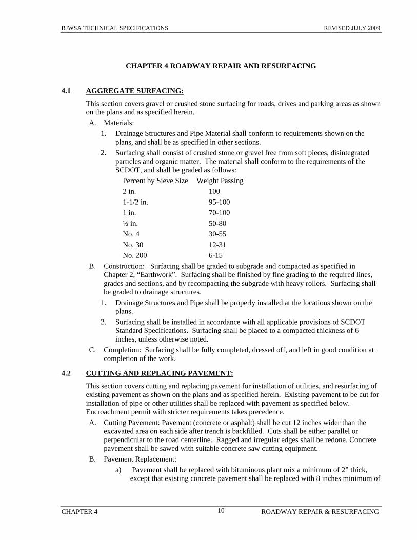
2. Surfacing shall consist of crushed stone or gravel free from soft pieces, disintegrated particles and organic matter. The material shall conform to the requirements of the SCDOT, and shall be graded as follows:
Percent by Sieve Size Weight Passing 2 in. 100 1-1/2 in. 95-100 1 in. 70-100 ½ in. 50-80 No. 4 30-55 No. 30 12-31 No. 200 6-15
B. Construction: Surfacing shall be graded to subgrade and compacted as specified in Chapter 2, “Earthwork”. Surfacing shall be finished by fine grading to the required lines, grades and sections, and by recompacting the subgrade with heavy rollers. Surfacing shall be graded to drainage structures.
1. Drainage Structures and Pipe shall be properly installed at the locations shown on the plans.
2. Surfacing shall be installed in accordance with all applicable provisions of SCDOT Standard Specifications. Surfacing shall be placed to a compacted thickness of 6 inches, unless otherwise noted.
C. Completion: Surfacing shall be fully completed, dressed off, and left in good condition at completion of the work.
4.2 CUTTING AND REPLACING PAVEMENT:
This section covers cutting and replacing pavement for installation of utilities, and resurfacing of existing pavement as shown on the plans and as specified herein. Existing pavement to be cut for installation of pipe or other utilities shall be replaced with pavement as specified below. Encroachment permit with stricter requirements takes precedence. A. Cutting Pavement: Pavement (concrete or asphalt) shall be cut 12 inches wider than the
excavated area on each side after trench is backfilled. Cuts shall be either parallel or perpendicular to the road centerline. Ragged and irregular edges shall be redone. Concrete pavement shall be sawed with suitable concrete saw cutting equipment.
B. Pavement Replacement: a) Pavement shall be replaced with bituminous plant mix a minimum of 2” thick,
except that existing concrete pavement shall be replaced with 8 inches minimum of

BJWSA TECHNICAL SPECIFICATIONS REVISED JULY 2009
CHAPTER 4 ROADWAY REPAIR & RESURFACING 11
Portland cement ready mix 4,000 psi concrete. Pavement shall conform to the applicable SCDOT specifications for each type.
b) Pavement shall be repaired within the same week that it is cut. If inclement weather delays pavement replacement, CONTRACTOR shall not cut additional pavement until he has notified the ENGINEER and received specific permission to proceed.
c) Asphalt pavement: i) The entire area to be resurfaced (including edges of existing pavement) shall
be tack primed with an acceptable asphalt tack coat just prior to placing the new pavement.
ii) A 1.5” overlay is to extend 5’ beyond the trim limit over perpendicular cuts to roads and driveways.
iii) New pavement surfaces shall be smooth, true to grade and shall provide a smooth transition with existing surfaces. All settlement and/or damage occurring during construction and the warranty period shall be repaired by the CONTRACTOR.
2. All Work on State Highways shall be done in strict accordance with State Department of Transportation requirements. CONTRACTOR shall familiarize himself with all such requirements. He shall obtain from the OWNER a copy of all required encroachment permits, and shall conform to all requirements and stipulations therein. In case of conflict between the plans and encroachment permits, the encroachment permits will govern if stricter.
4.3 RESURFACING OF EXISTING PAVEMENT:
Work consists of the resurfacing of existing pavement as indicated on the plans and as specified herein. Unless otherwise specified, all work shall be in accordance with applicable state department of transportation specifications. A. General: Proper surface drainage shall be maintained at all times, especially at private
driveways. Concrete curbs and other items, where damaged, shall be repaired to the satisfaction of the ENGINEER and to match existing. Manhole covers and valve boxes shall be raised as required to final surface. All potholes and other large depressions shall be filled to the satisfaction of the ENGINEER.
B. Preparation: Existing pavement shall be thoroughly swept and scraped clean, free from dust and foreign material, and so maintained until the bituminous mixture is laid.
C. Leveling Course: Where the surface of existing pavement is irregular, it shall be brought to uniform contour by leveling with a bituminous mixture. The leveling course shall be thoroughly compacted until it conforms with the surrounding surface.
D. Tack Coat: A tack Coat shall be applied to existing pavement and to the leveling course before the surface course is laid. Tack coat shall be asphalt cement, emulsified asphalt, or rapid curing type cutback asphalt. Contact surfaces of curbs, manholes and other items shall be painted with asphalt cement before the bituminous mixture is placed against them.
E. Surface Course: Surface Course shall be hot laid Type 1 asphalt placed over the leveling course to a compacted thickness of 1-1/2 inch. After compaction, the pavement surface shall be smooth and true to the established crown and grade. Defects shall be neatly cut out and replaced to the satisfaction of the ENGINEER. Sections of new pavement shall be protected from traffic until they have properly hardened. All settlement and damage shall be repaired by the CONTRACTOR.
F. Warranty Period: The warranty period on all pavement work shall be 2 years. The

BJWSA TECHNICAL SPECIFICATIONS REVISED JULY 2009
CHAPTER 4 ROADWAY REPAIR & RESURFACING 12
warranty period starts upon acceptance by the governing body or final acceptance by BJWSA, if not under the jurisdiction of a governing body.
END OF SECTION

BJWSA TECHNICAL SPECIFICATIONS REVISED JULY 2009
CHAPTER 5 PIPELINE DRILLING, BORING & JACKING
13
CHAPTER 5 PIPELINE DRILLING, BORING AND JACKING
5.1 SCOPE:
Boring and jacking of utility pipelines under highways and railroads shall be as shown on the plans and as specified herein.
5.2 GENERAL REQUIREMENTS:
Boring and tunneling operations shall be performed in accordance with all requirements of the SCDOT or the railroad, as applicable, including insurance, inspection, temporary work, watchmen, flagmen, protection of personnel and property, work restrictions, and work scheduling. Unless otherwise specified or directed, the CONTRACTOR shall pay for all costs in connection with meeting these requirements. The CONTRACTOR shall be responsible for repair or replacement of all existing structures and facilities, including roadways damaged or disturbed as a result of the work within a period of two years after completion of boring and tunneling operations. Repairs shall be performed at no additional cost to the OWNER, Department of Transportation or railroad. All work shall be completed to the full satisfaction of the OWNER, Department of Transportation or railroad. A. Inspection: Boring and tunneling operations will be subject to inspection by the
ENGINEER and by the SCDOT, County Engineer, or railroad, as applicable. The SCDOT, County or railroad inspector will have full authority to stop work if, in his opinion, it may cause damage to the highway or railroad or endanger traffic. CONTRACTOR shall notify the ENGINEER and BJWSA a minimum of 72 hours prior to performing work.
B. Railroad Right-of-Way: For all work on railroad right-of-way, the CONTRACTOR shall notify the railroad at least 72 hours prior to beginning construction.
C. Experience: Before starting boring and tunneling operations, the CONTRACTOR shall submit to the ENGINEER an experience record of the proposed boring and tunneling sub-CONTRACTOR. Such record shall include a list of equipment and personnel to be used, and a list of at least five previous successful similar installations under highways or railroads within the past five years. Failure to submit an experience record or submittal of a record not meeting these requirements will be cause for rejection of the boring and tunneling subcontractor.
5.3 MATERIALS:
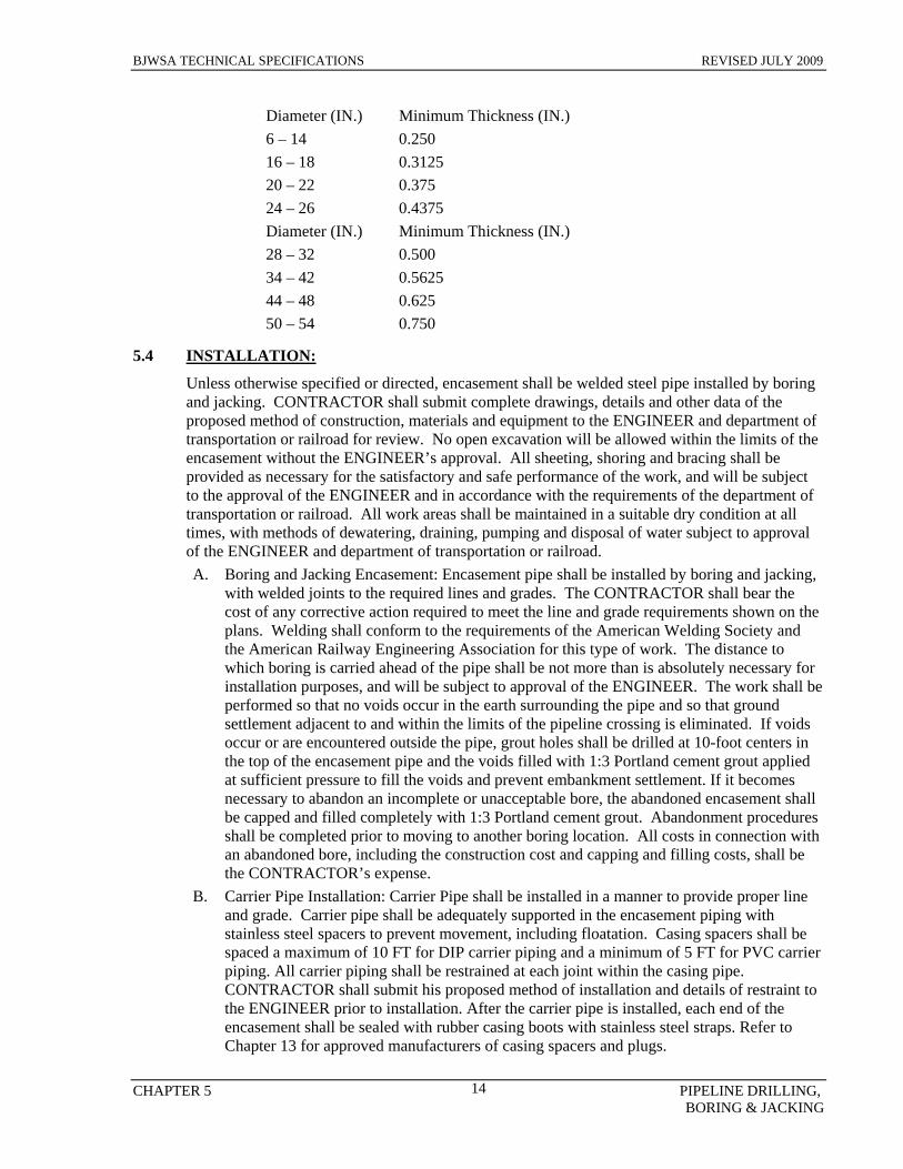
A. Carrier Pipe: Carrier Pipe shall be as specified in Chapter 6, “Pipeline Materials”. B. Encasement Pipe: Encasement Pipe installed by boring and jacking shall be welded steel
pipe conforming to ASTM A139, Grade B, 35,000 PSI minimum yield, and shall be the size shown on the plans. Pipe shall be bituminous coated on the outside. Minimum wall thickness shall be as follows:
BJWSA TECHNICAL SPECIFICATIONS REVISED JULY 2009
CHAPTER 5 PIPELINE DRILLING, BORING & JACKING
14
Diameter (IN.) Minimum Thickness (IN.) 6 – 14 0.250 16 – 18 0.3125 20 – 22 0.375 24 – 26 0.4375 Diameter (IN.) Minimum Thickness (IN.) 28 – 32 0.500 34 – 42 0.5625 44 – 48 0.625 50 – 54 0.750
5.4 INSTALLATION:
Unless otherwise specified or directed, encasement shall be welded steel pipe installed by boring and jacking. CONTRACTOR shall submit complete drawings, details and other data of the proposed method of construction, materials and equipment to the ENGINEER and department of transportation or railroad for review. No open excavation will be allowed within the limits of the encasement without the ENGINEER’s approval. All sheeting, shoring and bracing shall be provided as necessary for the satisfactory and safe performance of the work, and will be subject to the approval of the ENGINEER and in accordance with the requirements of the department of transportation or railroad. All work areas shall be maintained in a suitable dry condition at all times, with methods of dewatering, draining, pumping and disposal of water subject to approval of the ENGINEER and department of transportation or railroad. A. Boring and Jacking Encasement: Encasement pipe shall be installed by boring and jacking,
with welded joints to the required lines and grades. The CONTRACTOR shall bear the cost of any corrective action required to meet the line and grade requirements shown on the plans. Welding shall conform to the requirements of the American Welding Society and the American Railway Engineering Association for this type of work. The distance to which boring is carried ahead of the pipe shall be not more than is absolutely necessary for installation purposes, and will be subject to approval of the ENGINEER. The work shall be performed so that no voids occur in the earth surrounding the pipe and so that ground settlement adjacent to and within the limits of the pipeline crossing is eliminated. If voids occur or are encountered outside the pipe, grout holes shall be drilled at 10-foot centers in the top of the encasement pipe and the voids filled with 1:3 Portland cement grout applied at sufficient pressure to fill the voids and prevent embankment settlement. If it becomes necessary to abandon an incomplete or unacceptable bore, the abandoned encasement shall be capped and filled completely with 1:3 Portland cement grout. Abandonment procedures shall be completed prior to moving to another boring location. All costs in connection with an abandoned bore, including the construction cost and capping and filling costs, shall be the CONTRACTOR’s expense.
B. Carrier Pipe Installation: Carrier Pipe shall be installed in a manner to provide proper line and grade. Carrier pipe shall be adequately supported in the encasement piping with stainless steel spacers to prevent movement, including floatation. Casing spacers shall be spaced a maximum of 10 FT for DIP carrier piping and a minimum of 5 FT for PVC carrier piping. All carrier piping shall be restrained at each joint within the casing pipe. CONTRACTOR shall submit his proposed method of installation and details of restraint to the ENGINEER prior to installation. After the carrier pipe is installed, each end of the encasement shall be sealed with rubber casing boots with stainless steel straps. Refer to Chapter 13 for approved manufacturers of casing spacers and plugs.

BJWSA TECHNICAL SPECIFICATIONS REVISED JULY 2009
CHAPTER 5 PIPELINE DRILLING, BORING & JACKING
15
C. Directional Drilling: Where directionally drilled (without casing) pipe under highways or railroads is indicated and permitted, the bore diameter shall be essentially the same as the outside diameter of the pipe to prevent settlement or caving. All borings under public roads shall comply with SCDOT regulations. If voids develop or if the bore diameter is greater than the outside diameter of the pipe by more than 1 inch, the voids shall be pressure grouted or other remedial measures as approved by the ENGINEER shall be taken at the CONTRACTOR’s expense. Tracer wire per Section 6 shall be installed within the casing pipe and connected to the tracer wire for the non cased pipeline sections. Tracer wire shall be taped securely to the carrier piping prior to insertion in the casing.
D. Appurtenances: Vents and drains, where required, shall be provided where indicated on the plans. Vents shall consist of pipe as noted, and shall be located so as not to interfere with highway maintenance or be concealed by vegetation. Drains shall be provided at the lower end and shall consist of stone as noted on the plans.
E. Warranty Period: The CONTRACTOR shall be responsible for repair or replacement of all existing structures and facilities, including roadways damaged or disturbed as a result of the work within a period of two (2) years after completion of boring and tunneling operations. Repairs shall be performed at no additional cost to the OWNER, Department of Transportation or railroad. All work shall be completed to the full satisfaction of the OWNER, Department of Transportation or railroad.
END OF SECTION

BJWSA TECHNICAL SPECIFICATIONS REVISED JULY 2009
CHAPTER 6 PIPELINE MATERIALS, VALVES & APPURTENANCES
16
CHAPTER 6 PIPELINE MATERIALS, VALVES AND APPURTENANCES
6.1 PIPELINE MATERIALS
All pipe, fittings, packing, jointing material, valves, and fire hydrants shall be new and conform to Section C of AWWA Standards. All pipe material, solder and flux shall be lead free (less than 0.2% lead in solder and flux and less than 8.0% lead in pipes and fittings). All standards cited in the text refer to the latest revision of that standard under the same specification number or to the superseding specifications under a new number Only the materials specified below may be used for pipeline. Steel and cast iron are not permitted for pipelines although steel pipe is permissible for boring casings per Chapter 5. A. Polyvinyl Chloride (PVC) Pipe: PVC pipes for utilities shall be provided as shown on the
plans and as specified herein. 1. Shop Drawings: Catalog cuts and related data for all pipe and fitting material shall be
submitted to the ENGINEER for review. Electronic copies of the approved submittals shall be forwarded to the AUTHORITY.
2. Materials: All material under this section shall meet Made in America Criteria. PVC Pressure Pipe shall be as specified below. Fittings and adapters shall conform to the same requirements as for pipe, and shall be compatible with pipe. a) General
i) Pipe shall be marked as to the type, class or nominal thickness, weight, manufacturer and date of production.
ii) PVC pressure pipe shall be installed in strict accordance with the manufacturer’s instructions. Minimum depth of cover shall be 36 inches. Adapters shall be provided as required when connections are made to other types of pipe. Refer to Chapter 13 for list of approved manufacturers.
iii) All wastewater pressure force main pipe shall be factory dyed industry standard green to aid in identification. Potable water pressure pipe shall be factory dyed industry standard blue. Effluent transmission pipe shall be factory dyed industry standard purple. Polyethylene pipe shall be striped in the appropriate color for intended use.
iv) For pressurized pipe, fittings 3” and larger shall be mechanical joint type utilizing synthetic rubber ring gasket and shall conform to the requirements of AWWA/ANSI C110 /A21.10. For gravity sewer, pipe fittings may be ductile iron as above or PVC conforming to AWWA C900.
b) Water i) All potable water pipe shall bear the National Sanitation Foundation (NSF)
seal of approval stating compliance with ANSI/NSF Standard 61. PVC piping shall comply with ASTM D1785 and shall be UL/FM approved.
ii) Pipe for water mains 4” through 10” in diameter shall conform to AWWA C900, DR 18 or C909 (150 PSI), with pipe made to ductile iron outside diameters.
iii) Pipe 12” and larger in diameter shall be ductile iron pipe. c) Sewer
i) Pipe for sewer pressure force mains 4” through 10” in diameter shall conform to C900/DR25. Pipe 12” and larger in diameter shall be ductile iron.

BJWSA TECHNICAL SPECIFICATIONS REVISED JULY 2009
CHAPTER 6 PIPELINE MATERIALS, VALVES & APPURTENANCES
17
ii) All gravity sewer pipes, 4” and larger in diameter, shall be Type PSM pipe conforming to ASTM D3034, with integral bell and spigot rubber O-ring gasket joints. SDR 26 shall be used. Gasketed fittings and accessories shall be compatible with pipe. Refer to Chapter 13 for a list of approved manufacturers.
3. Material Testing: a) Potable Water and Wastewater Pressure Forcemain Pipe: Each joint of pressure
pipe shall be subjected to and successfully meet a hydrostatic proof test at the factory in accordance with the requirements for each type. Certified test results shall be furnished to the ENGINEER for each shipment of pipe. Pipe fittings shall be subject to inspection and testing in accordance with standard manufacturing practice.
b) Gravity Sewer Pipe: PVC gravity sewer pipe, 4”and larger in diameter shall be tested by the manufacturer for pipe flattening, impact resistance, pipe stiffness, joint tightness and extrusion quality (acetone immersion) in accordance with ASTM D3034. Test certificates showing that the pipe conforms to these specifications shall be furnished to the ENGINEER for each shipment of pipe. PVC Gravity Sewer Pipe shall be installed with all pipe sections assembled in accordance with the manufacturer’s instructions to form tight joints. All pipe shall pass the deflection test as specified below.
c) Deflection Test: All PVC gravity sewer pipe 8” diameter and larger shall be tested after installation and backfill by the CONTRACTOR using methods and equipment approved in writing by the ENGINEER. Testing shall be performed at the CONTRACTOR’s expense using a 5% mandrel acceptable to the ENGINEER and BJWSA to insure that initial deflection of pipe does not exceed 5%. All deflection testing shall be performed in the presence of the ENGINEER and BJWSA. CONTRACTOR shall notify the ENGINEER and BJWSA in sufficient time to insure that the both will be present during deflection tests. Deflection testing shall not occur until roadbed sub base has been installed and compacted to its final density. Deflection test records shall identify the location and deflection amount at all points where deflection exceeds the specified limit. Such records shall be certified by the CONTRACTOR, and shall be furnished to the ENGINEER prior to acceptance and payment. Pipe with initial deflection exceeding the specified limit will be unacceptable, and shall be re-bedded to the correct deflection and retested for deflection, at the CONTRACTOR’s expense.
d) Air Test: Air testing as specified in Section 8 shall not occur until all dry utilities have been installed. Air testing shall not occur until roadbed sub base has been installed and compacted to its final density.
4. Installation: Pipe and fittings shall be installed in accordance with the requirements specified in other Chapters and the manufacturer’s instructions. Minimum depth of cover shall be 36 inches. All adapters necessary for the proper jointing of pipe and fittings shall be provided. Connections to other types of pipe shall be made as detailed on the plans. Underground fittings shall be well restrained as detailed on the plans and as specified in this section. Mark pipeline with tracer wire and marking tape. Tracer wire shall be extended from the main wire above the pipe to 12” above ground level at all valve boxes to facilitate attachment to tracing equipment.
B. Ductile Iron Pipe (DIP): Ductile iron pipe and fittings shall be provided as shown on the plans and as specified herein.
1. Shop Drawings: Catalog cuts and related data for all pipe and fitting material shall be

BJWSA TECHNICAL SPECIFICATIONS REVISED JULY 2009
CHAPTER 6 PIPELINE MATERIALS, VALVES & APPURTENANCES
18
submitted to the ENGINEER for review. Electronic copies of the approved submittals shall be forwarded to the AUTHORITY.
2. Material: All material under this section shall meet Made in America Criteria. Ductile Iron Pipe shall conform to AWWA C150 and ANSI A21.50, shall be designed for pressure class as follows unless otherwise noted: a) 4-12” 350 b) 14-20” 250 c) 24”-26” 200 d) 30” & greater 150
3. Ductile iron pressure pipe shall conform to ASTM A377. Pipe shall have push-on or mechanical joint ends conforming to AWWA C111 and ANSI A21.11, except where flanged or other type ends are shown or specified. Flanged piping shall conform to AWWA C115 and ANSI A21.15. a) Pipe shall be marked as Type, Class or nominal thickness, weight, manufacturer,
and date of production. b) Pipe wall thickness shall be designed in accordance to bury depth. c) Pipe shall be coated on the outside with a standard bituminous coating in
compliance to AWWA C104. d) All potable water piping shall be lined on interior surface with high speed cement
conforming to AWWA C104 and ANSI A21.4, 45 mil dry film thickness minimum. Water pipe shall bear the National Sanitation Foundation (NSF) seal of approval stating compliance with ANSI/NSF Standard 61.
e) All sewer piping shall be factory lined with a hydrogen sulfide resistant coating specifically designed for sanitary sewer service. Coating shall consist of amine cured Novalec Epoxy polymeric lining, 40 mil nominal thickness. Acceptable products are: i) Protecto 401 by Vulcan Painters, Birmingham, Alabama. Nominal thickness
is 40 mil. ii) Corrosion-Clad Polymer Lining No. 201 by Sauereisen Cements, Pittsburgh,
Pennsylvania. Nominal thickness is 1/8” (3.175 mm). 4. Material Testing: Each joint of ductile iron pipe, prior to lining, shall be subjected to
and successfully meet a hydrostatic test at the factory in accordance with ANSI/AWWA C151/A21.51. Certified test results shall be furnished to the ENGINEER for each shipment of pipe.
5. Installation: Pipe and fittings shall be installed in accordance with the manufacturer’s instructions and the requirements specified in other sections. Ductile iron pressure pipe shall be installed in accordance with all applicable requirements of AWWA C600. Underground pipe and fittings shall be installed using push-on joints or mechanical joints, except where other type joints are specifically noted. Exposed pipe and fittings shall have Class 125 flanged joints except where Class 250 is specifically noted, or other type joints as shown or specified. All adapters necessary for the proper jointing of pipe and fittings shall be provided. Connections to other types of pipe shall be made as detailed on the plans. Underground fittings shall be well restrained as detailed on the plans and as specified in this Chapter. Detectable marking tape and tracer wire for identification, location, protection, and detection of utility pipelines shall be installed over all lines as specified in this Chapter. Tracer wire shall be extended from the main wire above the pipe to 12” above ground level at all valve boxes to facilitate attachment to tracing equipment. Pipe supports, hangers, and anchors shall be provided as

BJWSA TECHNICAL SPECIFICATIONS REVISED JULY 2009
CHAPTER 6 PIPELINE MATERIALS, VALVES & APPURTENANCES
19
required. C. Polyethylene (HDPE) Pipe:
1. General: The pipe supplied under this specification shall be cast iron outside diameter (DIPS), SDR 11 high performance, high molecular weight, high density polyethylene pipe, and shall conform to ASTM D 1248 (Type III C, Category 5, P34). Minimum cell classification values shall be 345434C as referenced in ASTM D 3350. All pipe resin shall be manufactured by the same company that manufactures the pipe itself in accordance with these specifications to insure complete resin compatibility and total product accountability. The fittings supplied in this specification shall be molded or manufactured from a polyethylene compound having a cell classification equal to or exceeding the compound used in the pipe. a) All potable water pipe shall bear the National Sanitation Foundation (NSF) seal of
approval stating compliance with ANSI/NSF Standard 61. i) 1” and 2” service pipe: see Water Service, Section 7.4 ii) 4” and larger shall comply with ASTM D 3035 dimension rating. HDPE
mains may be installed along certain routes in areas where taps will not occur; such as wetland, creek, and river crossings and other non-developable areas.
b) HDPE sewer pressure force mains: i) All HDPE sewer pressure pipe shall comply with ASTM D-3035 dimension
ratings and shall be rated for 200 PSI. 2. 2” sewer pressure force mains shall consist of IPS OD High Density Polyethylene, PE
3408, SDR 7. Pipe shall be supplied on roll spool to minimize joints. Connections shall be made utilizing brass compression type couplings or heat fusion butt welds. Refer to Chapter 13 for a list of approved manufacturersShop Drawings: Catalog cuts and related data for all pipe and fitting material shall be submitted to the ENGINEER for review. Electronic copies of the approved submittals shall be forwarded to the AUTHORITY.
3. Physical Properties: Pipe shall conform to the physical properties described below: a) Typical Physical Properties:
PROPERTY TEST METHOD UNIT VALUE Density ASTM Method gms/cc 0.955 Melt Index ASTM D 1238 gms/10 min 0.14
b) Coefficient of Linear Thermal Expansion:
PROPERTY TEST METHOD UNIT VALUE Molded Specimen ASTM D 696 in./in./deg. F 8.3x10⁻⁵ Extruded Pipe 1.2x10⁻⁴ Conductivity Dynatech-Colora BTU-IN/FT/degF 2.7
c) Long Term Strength:
PROPERTY TEST METHOD UNIT VALUE 73 degrees F ASTM D 2837 PSI 1600 140 degrees F PSI 800 Material Cell Class ASTM D 3350 345434c Material Description PPI recommendation PE 3408
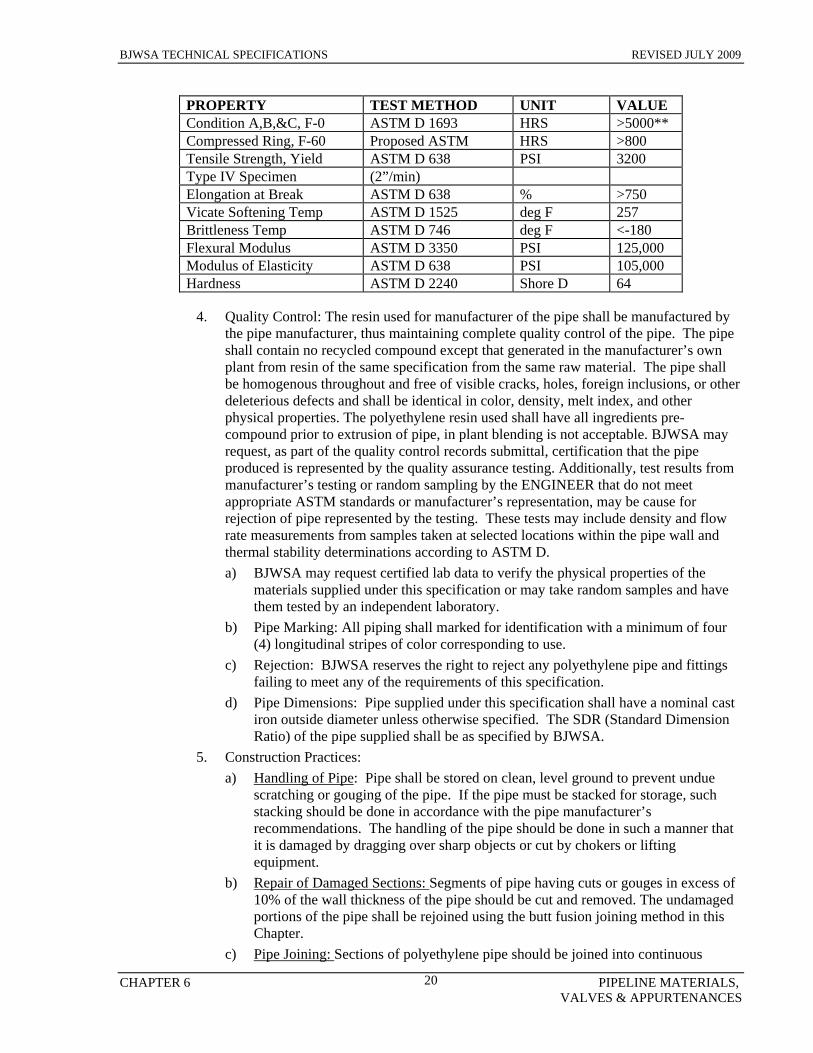
d) Environmental Stress Cracking Resistance:
BJWSA TECHNICAL SPECIFICATIONS REVISED JULY 2009
CHAPTER 6 PIPELINE MATERIALS, VALVES & APPURTENANCES
20
PROPERTY TEST METHOD UNIT VALUE Condition A,B,&C, F-0 ASTM D 1693 HRS >5000** Compressed Ring, F-60 Proposed ASTM HRS >800 Tensile Strength, Yield ASTM D 638 PSI 3200 Type IV Specimen (2”/min) Elongation at Break ASTM D 638 % >750 Vicate Softening Temp ASTM D 1525 deg F 257 Brittleness Temp ASTM D 746 deg F <-180 Flexural Modulus ASTM D 3350 PSI 125,000 Modulus of Elasticity ASTM D 638 PSI 105,000 Hardness ASTM D 2240 Shore D 64
4. Quality Control: The resin used for manufacturer of the pipe shall be manufactured by
the pipe manufacturer, thus maintaining complete quality control of the pipe. The pipe shall contain no recycled compound except that generated in the manufacturer’s own plant from resin of the same specification from the same raw material. The pipe shall be homogenous throughout and free of visible cracks, holes, foreign inclusions, or other deleterious defects and shall be identical in color, density, melt index, and other physical properties. The polyethylene resin used shall have all ingredients pre-compound prior to extrusion of pipe, in plant blending is not acceptable. BJWSA may request, as part of the quality control records submittal, certification that the pipe produced is represented by the quality assurance testing. Additionally, test results from manufacturer’s testing or random sampling by the ENGINEER that do not meet appropriate ASTM standards or manufacturer’s representation, may be cause for rejection of pipe represented by the testing. These tests may include density and flow rate measurements from samples taken at selected locations within the pipe wall and thermal stability determinations according to ASTM D. a) BJWSA may request certified lab data to verify the physical properties of the
materials supplied under this specification or may take random samples and have them tested by an independent laboratory.
b) Pipe Marking: All piping shall marked for identification with a minimum of four (4) longitudinal stripes of color corresponding to use.
c) Rejection: BJWSA reserves the right to reject any polyethylene pipe and fittings failing to meet any of the requirements of this specification.
d) Pipe Dimensions: Pipe supplied under this specification shall have a nominal cast iron outside diameter unless otherwise specified. The SDR (Standard Dimension Ratio) of the pipe supplied shall be as specified by BJWSA.
5. Construction Practices: a) Handling of Pipe: Pipe shall be stored on clean, level ground to prevent undue
scratching or gouging of the pipe. If the pipe must be stacked for storage, such stacking should be done in accordance with the pipe manufacturer’s recommendations. The handling of the pipe should be done in such a manner that it is damaged by dragging over sharp objects or cut by chokers or lifting equipment.
b) Repair of Damaged Sections: Segments of pipe having cuts or gouges in excess of 10% of the wall thickness of the pipe should be cut and removed. The undamaged portions of the pipe shall be rejoined using the butt fusion joining method in this Chapter.
c) Pipe Joining: Sections of polyethylene pipe should be joined into continuous

BJWSA TECHNICAL SPECIFICATIONS REVISED JULY 2009
CHAPTER 6 PIPELINE MATERIALS, VALVES & APPURTENANCES
21
lengths on the job site above ground. The joining method shall be the butt fusion method and shall be performed according to the manufacturer’s recommendations. The butt fusion equipment used in the joining procedures should be capable of meeting all conditions recommended by the pipe manufacturer, including, but not limited to, temperature requirements, alignment, fusion pressures, the technicians and approved fusion equipment. Prior approval of equipment and personnel shall be obtained from BJWSA before fusion begins. The completed pipe joints shall be guaranteed for five years in writing to BJWSA and its CONTRACTOR.
d) End Connections: Pipes 12 inches and larger shall have flanged ends. Pipes less than 12 inches may be flanged or MJ adapters with insert sleeves.
e) Expansion and contraction: HDPE expansion and contraction must be considered in the design.
f) Handling of Fused Pipe: Fused segments of pipe shall be handled so to avoid damage to the pipe. When lifting fused sections of pipe, chains or cable type chokers should be avoided. Nylon slings are preferred. Spreader bars should be used when lifting long fused sections. Care should be exercised to avoid cutting or gouging the pipe.
g) Installation: Trenching, installation, backfill and testing shall be in accordance with BJWSA specifications and drawings and special method of installation developed for a specific project.
h) Directional Drilling: Polyethylene pipe installed by directional drilling shall be installed as directed by the ENGINEER. Directional drilled HDPE pipe shall be pulled in continuous fused sections and connected as outlined above. #8 gauge tracer wire shall be pulled with all directional drills and connected to tracer wiring at interconnection of connecting piping. Directional drills shall not be removed from bore hole once drilling commences. Directional drills that fail once drilling commences shall be abandoned and filled with pressure grout at the CONTRACTORS expense. Directional drilling of polyethylene pipe under public right of ways shall comply with Encroachment permit requirements of appropriate jurisdictional AUTHORITY.
6. Final Testing: After polyethylene piping is installed, backfilled and all air removed, the CONTRACTOR shall apply a hydrostatic pressure of 150 PSI min. to the pipe. The test pressure shall be allowed to stand without make-up pressure for a period of time as required by the pipe manufacturer and approved by the ENGINEER to allow for diameter expansion or pipe stretching to stabilize. After the required equilibrium period the test section shall be returned to the original test pressure. All final testing shall be in conformance with BJWSA specifications.
6.2 VALVES
A. General: Gate valves shall be used for all sizes 2” through 12”. Butterfly valves may be used where the diameter exceeds 12” or if determined necessary by the Authority. All valves shall open left (counter clockwise). All buried valves shall have a 2” square operating nut. Valves with operating nuts greater than 4 FT deep shall have approved valve nut extenders bringing the operating nut up to three feet below grade. All butterfly valves shall have a minimum 450 FT-LB. actuator. All valves are to be designed for a minimum working pressure of not less than 150 PSI unless otherwise specified. All potable water appurtenances that contact potable water shall bear the National Sanitation Foundation (NSF) seal of approval stating compliance with ANSI/NSF Standard 61.
1. Chambers, pits or manholes containing valves, blowoffs, meters, air relief valves, or

BJWSA TECHNICAL SPECIFICATIONS REVISED JULY 2009
CHAPTER 6 PIPELINE MATERIALS, VALVES & APPURTENANCES
22
other such appurtenances to a distribution system, shall not be connected directly to any storm drain or sanitary sewer.
2. Shop Drawings: Catalog cuts and related data for all valves and fitting material shall be submitted to the ENGINEER for review. Electronic copies of the approved submittals shall be forwarded to the AUTHORITY.
B. Gate Valves: All resilient wedge gate valves shall comply with all requirements of AWWA C509, latest revision, and with the below listed requirements. Valves shall be designed for 250 PSI working pressure, factory seat tested at 250 PSI with no leakage past the seat from either side of the disc, and shell tested at 500 PSI. Minimum body and bonnet wall thickness shall be as set forth in Table 2, Section 4.3.1 of AWWA C509. Body and bonnet wall thickness less than the minimum thickness shall not be acceptable. Bonnet to body seal shall be effected by a flat neoprene gasket. Bonnet and body flanges shall be fully machined to assure proper sealing of the gasket. Valve body interior and exterior shall be coated with a minimum of 10 mil of fusion bond epoxy or nylon coating. End connections shall be flanged in accordance with Class 125, ANSI B16.1 for above ground installation, and mechanical joint for underground installation in accordance with AWWA C110/111 or slip-on for use with cast iron OD pipe. Valves shall be of the non-rising stem (N.R.S.) design and shall open left (counter-clockwise). Valves installed above ground and in underground vaults, where specified, shall be furnished with gear actuated hand wheels. All buried valves shall be furnished with 2” square operating nuts. Maximum bury depth to nut shall be 4 FT or valve nut extensions shall be provided. Valves shall have O-Ring sealed stems with one O-Ring located below the thrust collar and with two O-Rings located above the thrust collar. The thrust collar area between the two lower O-Rings shall be factory filled with a lubricant to provide permanent lubrication of the thrust collar area. Valve stems shall be of bronze rolled bar stock and shall have a forged thrust collar. The stem material shall provide 70,000 PSI tensile strength with 15% elongation and a yield strength of 30,000 PSI. Cast stems shall not be acceptable. Stems shall have acme form threads for strength and efficiency. An anti-friction thrust washer shall be provided both above and below the thrust collar for ease of operation. The resilient-seated disc wedge shall be of the resilient wedge fully supported type. Solid guide lugs shall travel within channels in the body of the valve. The disc and guide lugs shall be fully (100%) encapsulated in EPDM rubber. All appurtenances that contact potable water shall bear the National Sanitation Foundation (NSF) seal of approval stating compliance with ANSI/NSF Standard 61. Refer to Chapter 13 for a list of approved manufacturers.
C. Butterfly Valves: All butterfly valves, except as herein otherwise noted, shall conform to AWWA C504, latest revision. Valve body interior and exterior shall be coated with a minimum of 10 mil of fusion bond epoxy or nylon coating. All valve shafts shall be connected to operators by the use of keys and keyways. The use of compression or friction connections is not acceptable. The seat on disc valves shall be continuous around the periphery of the disc and shall not be penetrated by the valve shaft. Buried service butterfly valves shall be integrally cast mechanical joint ends, short body type, AWWA Class 150B with totally enclosed geared operator and a 2” square operating nut. Valves shall have ASTM A 126, Class 40 cast iron valve body with 125 PSI full faced flanges drilled in accordance with ANSI B16.1. Valve disc shall be contoured cast iron or ductile iron. Standard service above ground butterfly valves shall be flanged end, short body type with enclosed gear actuated hand wheel operators. Valve shaft shall be Type 304 stainless steel with self-lubricating, corrosion resistant sleeve type bearings. Operators shall be 450 FT-LB. gear actuators and be fully gasketed and grease packed to withstand an external ground water pressure of 10 PSI minimum. A valve position indicator shall be furnished for installation in each valve box. The indicator shall be hermetically sealed for installation inside a cast iron valve box and shall show valve disc position, direction of rotation, and

BJWSA TECHNICAL SPECIFICATIONS REVISED JULY 2009
CHAPTER 6 PIPELINE MATERIALS, VALVES & APPURTENANCES
23
number of turns from fully opened to fully closed. This indicator shall be provided by the valve manufacturer, complete. Appurtenances that contact potable water shall bear the National Sanitation Foundation (NSF) seal of approval stating compliance with ANSI/NSF Standard 61. Refer to Chapter 13 for a list of approved manufacturers.
D. Plug Valves: Plug valves shall be used on all sewer applications unless approved otherwise by the AUTHORITY. Valves shall be used for installations above ground, direct bury, in concrete vaults or for installations in manholes. Valves installed above ground, in concrete vaults or installed in manholes shall be provided with hand wheel actuators. Valves 4” and larger shall have a minimum 450 FT-LB gear driven actuator and shall be capable of opening valve at rated pressure of 150 PSI. All direct buried sewer pressure force main valves shall have gear actuators with a 2” square operating nut located at a depth not to exceed 4 FT in valve box and concrete collar. Valves on sewer pressure force mains shall be installed at maximum intervals of 2000 FT or as directed by the AUTHORITY. Valves shall open left (counter clockwise). Valves are to be designed for a minimum working pressure of not less than 150 PSI. Valves shall be the non-lubricated eccentric plug type with a resilient seat seal unless otherwise specified and shall be furnished with mechanical joint ends in accordance with ANSI Standard A21.11, unless specified otherwise on the plans. Port area for valves shall be a minimum of 80% of the full pipe area. Valve bodies shall be of ASTM A-126 Class B cast iron. Resilient seat seals shall be of Buna-N or Neoprene, suitable for use in sewage service. Seats shall be of non-metallic with seat coating thermally bonded and in full conformance to AWWA Standard C550. Valves shall be furnished with permanent corrosion resistant bearing surfaces in the upper and lower journals designated to withstand full rated bearing loads and provide long life in sewage service. Valves shall have their internal and external surface protected by fusion bond epoxy or nylon coatings factory applied, thermally bonded and in full conformance to AWWA Standard C550. Nominal valve pressure ratings, body flanges and wall thickness shall be in full conformance to ANSI B16.1-1975. Valves shall seal leak-tight against full rated pressure in both directions. Valve seats shall be tested and provide leak-tight shut-off to 175 PSI for valves 14” and larger, with pressure in each direction. A hydrostatic shell test at twice the rating shall be performed with plug open to demonstrate overall pressure envelope integrity. All gearing shall be fully enclosed in a suitable housing and be suitable for running in a lubricant with seals provided on all shafts to prevent entry of dirt and water into the actuator. A suitable stop shall be set to provide watertight shut off in the closed position at full rated pressure. Valve actuators for buried or submerged service shall have seals on all shafts and gaskets on the valve and actuator covers to prevent the entry of water. Actuator mounting brackets for buried or submerged service shall be totally enclosed and shall have gasket or o-ring seals. All exposed nuts, bolts, springs, and washer used in buried service shall be type 316 stainless steel. Refer to Chapter 13 for list of approved manufacturers.
E. Swing Check Valves (above ground or in vault): The CONTRACTOR will furnish and install swing check valves as shown on the plans and in accordance with these specifications. Swing check valves shall comply with all requirements of AWWA C508, latest revision, and with the requirements listed below.
1. Valve body interior and exterior shall be coated with a minimum of 10 mil of fusion bond epoxy or nylon coating.
2. All potable water appurtenances that contact potable water shall bear the National Sanitation Foundation (NSF) seal of approval stating compliance with ANSI/NSF Standard 61.
3. For swing check valves 4” and larger, bodies and bonnets will consist of ductile iron and will be designed to allow removal of the clapper arm and disc assembly through the

BJWSA TECHNICAL SPECIFICATIONS REVISED JULY 2009
CHAPTER 6 PIPELINE MATERIALS, VALVES & APPURTENANCES
24
bonnet opening without requiring removal of the valve from the line. Disc will be of ductile iron with bronze or alloy disc rings machined into the disc. The seat ring will be bronze or stainless steel and will be threaded for removal with the valve body in line. Clapper arm shafts will be manufactured of stainless steel, bronze or high tensile aluminum and shall extended through the body for attachment of the weight or spring and will be capable of being field adjusted. Shaft shall be sealed using a packing gland, “O-ring” seals will NOT be allowed. Flanged ends will be faced and drilled in accordance with ANSI B 16.1 Class 125. Valves 12” and smaller will have a minimum working pressure rating of 175 PSI and 350 PSI hydrostatic test pressure and valves larger than twelve inches will have a corresponding pressure of 150 PSI and 300 PSI. Swing check valves may be operated by stainless steel spring unless other wise directed by the ENGINEER. Refer to Chapter 13 for a list of approved manufacturers.
F. Ball Check Valves: Ball check valves shall not be used, except on 2” force mains in pit. G. Air release valves (ARV) shall be provided in accordance with sound engineering practice
at high points in water mains as required. ARV must comply with AWWA Section C and shall be designed to operate under a working pressure of 150 PSI, and shall have been tested at a pressure of not less than 300 PSI. ARV shall have a stainless steel body and conical shape or have a cast iron body and cover and shall be 2” in size with IPS inlet threads. Vent piping shall consist of a downward facing screened pipe. Float guides, bushings, lever pins, and all internal parts shall be stainless steel or bronze. Cylindrical stainless steel ARV shall be installed above grade as a pedestal assembly or in a manhole. If installed as a pedestal, the ARV piping must maintain a positive slope if offset from the main. Cast iron conical ARV shall be installed in a manhole. If installed in a manhole, ARV shall be installed in a watertight, flat top manhole a minimum of 4 FT in interior diameter. ARV manholes shall be sited to prevent flooding. Automatic air relief valves shall not be used in situations where flooding of the manhole may occur. Refer to Chapter 13 for a list of approved manufacturers.
6.3 FITTINGS, APPURTENANCES AND SPECIALTIES:
A. Pipe Fittings: Pipe fittings 4” and larger shall be ductile iron conforming to ANSI/AWWA C110/A21.10 or ANSI/AWWA C153/A21.53. Ductile iron fittings shall be Class 350 for 24-inch and under, and Class 250 for larger than 24”. Ductile iron shall conform to ASTM A536, minimum grade 70-50-05. Fittings shall have mechanical joint connections conforming to ANSI/AWWA C111/A21.11, except where flanged or other type ends are shown or specified. Fittings shall be coated/lined specific to use. Ductile iron fittings shall be used on pipe sized 4“ or larger. All potable water appurtenances that contact potable water shall bear the National Sanitation Foundation (NSF) seal of approval stating compliance with ANSI/NSF Standard 61.
1. Pressure Pipe Fittings: Pressure pipe fittings 4” and larger shall be gray cast iron or ductile iron conforming to ANSI A21.10. Cast iron is only to be used if ductile iron fittings are not available. Cast iron fittings shall be Class 250 for 12” and under, and Class 150 for larger than 12”. Ductile iron fittings shall be Class 350 for 24” and under, and Class 250 for larger than 24”. Ductile iron shall conform to ASTM A536, minimum grade 70-50-05. Fittings shall have mechanical joints conforming to ANSI/AWWA C111/A21.11, except where flanged or other type ends are shown or specified. Fittings shall be coated interior and exterior with a minimum 12 mil of fusion bond epoxy or nylon. Fittings for 2” diameter piping shall be IPT brass with compression adapters suitable for use on ASTM D-3035 (OD-Controlled) pipe.
2. Full circle and bell repair clamps are not approved for use in a new system. 3. Gravity Sewer Fittings: Gravity sewer fittings 4” through 10” shall be SDR 26 heavy

BJWSA TECHNICAL SPECIFICATIONS REVISED JULY 2009
CHAPTER 6 PIPELINE MATERIALS, VALVES & APPURTENANCES
25
wall gasketed fittings of a molded, one piece construction. Gravity sewer fittings 12” and larger shall be SDR 26 fabricated or molded one piece heavy wall. Service fittings to the main shall utilize true wye style fittings. All fittings shall comply with UNIBELL standards and shall be installed per UNIBELL and manufacturers recommendations.
B. Flanges: Flanges for pipe and fittings shall be Class 125 except where Class 250 is specifically noted, and shall conform to ANSI/AWWA C110/A21.10. Drilling and facing of flanges shall be in accordance with ANSI B16.1.
C. Mechanical Restraints: All joints, fittings, tees and hydrant attachments shall be mechanically restrained. Restrained joints for pipe and fittings shall be the ductile iron mechanical joint type designed for a working pressure of 350 PSI for 24” and under and 250 PSI for 30” and larger. Restrained joint pipe and fittings shall be capable of being deflected after assembly. Refer to Chapter 13 for a list of approved manufacturers.
D. Pipeline Marking: Detectable marking tape and tracer wire for identification, location, protection and detection of utility pipelines shall be installed over all water lines. Shop drawings and related data shall be submitted to the ENGINEER for review.
1. Marking Tape: Detectable marking tape shall consist of a metalized foil laminated between two layers of color coded inert plastic film suitable for lasting as long as the pipe and shall be resistant to alkalis, acids and other destructive agents found in the soil. The plastic film shall be imprinted with a continuous message, see below. The message shall be in permanent ink. Marking tape shall be not less than 2” wide and not less than 5.5 mil thick with a tensile strength of not less than 120 grams per 1.5 mil. Detectable marking tape shall be the type that can be located by any standard electronic pipe locator. Refer to Chapter 13 for a list of approved manufacturers.
Marker tape should be color coded as follows: a) Blue Water Caution: Water line buried below b) Green Sewer Gravity Caution: Sewer line buried below c) Brown Sewer FM Influent Caution: Sewer line buried below d) Purple Sewer FM Effluent Caution: Sewer line buried below
2. Tracer Wire: Tracer wire shall be installed on all pressure pipelines and service lines in a continuous fashion. Tracer wire shall be extended from the main wire above the pipe to 12” above ground level at all valve boxes to facilitate attachment to tracing equipment. It shall be brought to the surface at maximum distance of 700 feet. It shall be accessible from surface at all valve and meter boxes. At locations where tracer wire surfaces between valves, a regular valve box with plain lid and collar shall be installed between a pipeline marker pair. Tracer wire shall be 12 GA single strand or up to 7 strands, copper with insulation UL rated for direct bury underground service. Splices shall be UL rated for direct bury and shall be minimized. Wire for directionally drilled bores shall be a minimum of #8 gauge.
3. Installation: Marking tape shall be buried a minimum of 12” and a maximum of 18” below finish grade. The tape shall be placed during backfill or installed in any other manner acceptable to the AUTHORITY. Tracer wire will be installed on the top of the pipe and extended up to surface level in all valve boxes and at all service laterals. No loops will be allowed in the tracer wire.Tracer wire shall be taped to the top of pipelines at a minimum of 5 FT intervals in a uniform, continuous manner.
E. Curb Marking: In projects with curb and gutter, all valves, 45 degree bends, and service laterals shall be clearly marked by embossing letters in curb perpendicular to the appurtenance. An embossed letter shall be stamped in the curb during curb installation and

BJWSA TECHNICAL SPECIFICATIONS REVISED JULY 2009
CHAPTER 6 PIPELINE MATERIALS, VALVES & APPURTENANCES
26
shall consist of a minimum 3” tall. Lettering shall be “S” for sewer services, “V” for valves, “ B” for bend in main, and “W” for water services. Curb marking is in addition to valve and pipe line markers unless 2” diameter brass surveyor’s disks are imbedded beside letter with appropriate stamped details.
F. Tapping Sleeves: Size on size pipeline taps are NOT approved for installations in the BJWSA system. Tapping sleeves shall be fabricated stainless steel with stainless steel bolts. Tapping sleeves shall have outlet flange counter bored to accept a mating tapping valve per MSS SP-60 for true alignment of tapping valve and tapping machine. Sleeve shall have a stepped stainless steel valve flange complying with AWWA C207 Class D, ANSI 316.5, 150 LB drilling. Refer to Chapter 13 for a list of approved manufacturers.
G. Miscellaneous Appurtenances and Specialties: All material and products under this section must comply with AWWA Section C and shall meet Made in America Criteria. Miscellaneous piping appurtenances and specialties shall be provided where shown on the plans and as required for a complete installation. All appurtenances that contact potable water shall bear the National Sanitation Foundation (NSF) seal of approval for compliance with ANSI/NSF Standard 61.
1. Mechanical Couplings and Adapters: Mechanical couplings and adapters shall be the type and size as shown on the plans, complete with rings, followers, gaskets, bolts, nuts and other items necessary for a complete installation. Couplings and adapters shall be installed in accordance with the manufacturer’s instructions to provide permanently tight joints under all reasonable conditions of expansion, contraction, shifting and settlement.
2. Gaskets: Gaskets for water pipe and fittings shall be vulcanized synthetic rubber free of porous areas, foreign material and visible defects. Gaskets shall be designed to provide a permanent watertight seal at all joints. Rubber gaskets shall conform to all applicable provisions of ASTM F477 and must comply with AWWA Section C. Gasket lubricant shall be non-toxic, shall not support growth of bacteria, shall not impart taste or odor to water, must be NSF certified, and shall have no deteriorating effects on gaskets. Lubricant shall be suitable for the intended use, and shall remain in a usable stage throughout the range of temperature in which the pipe is normally installed. Lubricant shall be delivered to the job site in unopened containers bearing the manufacturer’s name and trade name or trademark. Lubricant shall not be vegetable shortening.
3. Pre-cast Utility Boxes: Pre-cast utility boxes or vaults shall be provided where noted on the plans. Pre-cast concrete shall have a minimum compressive strength of 4000 PSI. Unless otherwise indicated, boxes and vaults shall be provided with traffic type aluminum frames and covers, hinged access doors, and cast iron or composite plastic-steel steps. Pre-cast boxes or vaults shall be installed level and plumb with pipe openings at the proper elevation. Joint sealant shall be rubber, cement, or other type standard with the manufacturer. All pre-cast boxes and vaults shall be designed for heavy traffic loading in accordance with ASTM C857. Pre-cast boxes or vaults used as liquid retaining structures shall be tested for leakage; all leaks shall be repaired prior to final acceptance. All boxes shall contain pump out sump and be sloped to sump.
4. Utility Manholes: Utility manholes for valves and other equipment shall be constructed of pre-cast or cast-in-place concrete. Unless otherwise indicated, manholes shall be provided with a traffic type aluminum frame and cover and cast iron or composite plastic-steel steps. Joint sealant in pre-cast manholes shall be rubber, cement, or other type standard with the manufacturer. Where noted, valves and other equipment shall be installed in a concrete pipe vault with cast iron manhole frame and cover. Manhole tops shall be set flush with grade or pavement, unless otherwise directed.
5. Valve Extensions: Valve nut extensions shall have the following properties:

BJWSA TECHNICAL SPECIFICATIONS REVISED JULY 2009
CHAPTER 6 PIPELINE MATERIALS, VALVES & APPURTENANCES
27
a) All extensions must be pre-approved for use in BJWSA’s system. b) Stem: Must not corrode faster than the stem of the valve. Hot Dipped Galvanized,
anticorrosive steel alloy, or stainless steel would be acceptable. c) Attachment: The extension attachment is to bolt to the valve shaft with shear
resistance equal or greater to that of the valve shaft, or be physically bolted through the valve operating nut.
d) All valve nut extensions installations are to be preformed in the presence of the engineer or BJWSA inspector.
6. Valve Boxes: A gray iron valve box shall be installed on each valve 2” and larger. Valve boxes shall have screw type adjustment. All valve box components shall meet material requirements of ASTM A48 Cl 35. Valve box lids shall indicate use designation (“WATER”, “SEWER”, FIRE or Plain) cast in the lid. Lids on fire line valves shall be lockable. Gross valve box height adjustment may be accomplished using a single piece of 6” C900 PVC pipe resting on valve box bottom and extending into the bottom of a complete valve box. a) Valves in pavement
i) Each lid shall weight approximately 11 pounds. ii) Shall have slip type adjustment iii) Box top shall be a minimum of 12” in length, designed to support road load,
and be adjustable to future changes in pavement overlays. b) Valves not in pavement
i) Each valve box shall be installed with a four inch (4”) thick by twenty-four (24”) diameter round pre-cast concrete collar per Standard Detail Drawings. Concrete collar top shall be installed flush with final grade and valve box lid shall not extend above collar.
ii) Valve boxes shall have screw type adjustment.
7. Valve and Pipeline Markers: All bends and valves except hydrant valves shall be marked with a concrete marker. Valve and pipeline markers installed in landscaped areas shall consist of a reinforced 4” square by 54” long reinforced concrete post with round 2” (min.) round cast bronze or brass survey marker imbedded in the top. Markers located in lawn areas shall not extend above final grade more than 18”. Pipe lines located in easements, rural areas, or in right-of-ways shall be marked by paired 6” square by 10 feet reinforced concrete rural markers placed at right of way line. Maximum line lay distance between markers is 700 feet. A 2”(min.) round cast bronze or brass survey benchmark with anchoring lug shall be formed into the side perpendicular to rural marker face between 50 and 60” above final grade. Stamp disk with the distance in feet and direction to the feature. Valve and pipeline markers shall be cast with designation on the face as to its purpose. Water line marker need not be painted. Sewer feature markings shall have the top 4” painted with industrial enamel of the appropriate color. Refer to Standard Detail Drawings for dimensions, designations, and installation practices. An approved alternate permanent marking system may be used to reference location of bends and valves.
8. Yard Hydrants: Yard Hydrants shall have locking capability and installed with an approved vacuum breaker. Yard hydrants must have a BJWSA furnished meter installed before each hydrant. At sewer pump stations, the yard hydrant must be placed adjacent to the wet well. Refer to Chapter 13 for a list of approved manufacturers.

BJWSA TECHNICAL SPECIFICATIONS REVISED JULY 2009
CHAPTER 6 PIPELINE MATERIALS, VALVES & APPURTENANCES
28
9. Blow-off Assemblies: All dead end lines shall have blow-off assemblies sized to provide a minimum of 2.5 FPS flushing velocity. No flushing device shall be directly connected to any type of sanitary sewer. Pipelines 4” in diameter shall be equipped with a self-draining post-type flushing hydrant. Pipelines 6” and larger shall be terminated with full size fire hydrants. Long dead end pipeline runs with insufficient demands to maintain water quality shall be equipped with an approved metered automatic flushing device, which shall be installed to discharge into the storm sewer system. An air gap of at least six (6) inches must be maintained between the blowoff discharge and the storm drain. Refer to Chapter 13 for a list of approved manufacturers.
10. Backflow Prevention Devices: All service connections shall contain an approved backflow preventer at the point of connection to the AUTHORITY’s system. Type of backflow preventer required will be determined based upon use and risk of potential contamination. All dedicated fire lines shall contain a minimum of a double check valve backflow prevention device. a) There shall be no connection between the distribution system and any pipes,
pumps, hydrants, or tanks whereby unsafe water or other contamination materials may be discharge or drawn into the system.
b) No bypasses shall be allowed, unless the bypass is also equipped with an equal, approved back-flow prevention device.
c) High hazard category cross connections shall require an air gap separation or an approved reduced pressure backflow preventer.
d) All piping up to the inlet of the backflow prevention device must be suitable for potable water. The pipe must be AWWA or NSF approved. Black steel pipe cannot be used on the inlet side of the device
e) Reduced pressure principle backflow prevention devices shall not be installed in pits or vaults or areas in which the device could be submerged or flooded.
END OF SECTION

BJWSA TECHNICAL SPECIFICATIONS REVISED JULY 2009
CHAPTER 7 WATER SYSTEM STANDARDS 29
CHAPTER 7 WATER SYSTEM STANDARDS
7.1 SCOPE
Water pipelines and appurtenances shall be provided as shown on the plans and as specified herein. Clearing, grubbing, trench excavation and backfill, pipe material, fire hydrants, valves, cutting and replacing pavement, and removing and replacing sidewalk shall be as specified in other chapters. All applicable provisions shall be binding upon work covered in this section.
7.2 WATER SYSTEM DESIGN GUIDELINES:
These guidelines are based on Federal, State, and local health requirements and BJWSA design criteria. Design Criteria not indicated herein shall comply with “Ten State Standards” where applicable. All installations shall meet quality standards of the South Carolina Department of Health and Environmental Control (SCDHEC). A. Water System Design Criteria:
1. Distribution Main Size: Minimum 4” diameter unless otherwise approved by the AUTHORITY. Water mains providing fire service shall be a minimum of 6” diameter.
2. Sizing of Lines: For pipelines 6” and larger, sizes shall be based on either 1/5th the instantaneous maximum flow plus the fire flow or maximum instantaneous demand, which ever is greater. The minimum design fire flow in the BJWSA system shall be 1,000 GPM with a minimum residual pressure of 20 PSI. For pipe sizes 4” and smaller, sizes shall be based on either 1/5th the instantaneous maximum flow plus the blow off flow or maximum instantaneous demand, which ever is greater.
3. Valves: Provide three (3) valves for a tee intersection, four (4) valves for a cross intersection. Sufficient valves shall be provided on water mains so that public inconvenience and sanitary hazards will be minimized during repairs. Valves should be located at not more than 500 FT intervals in commercial areas and at not more than one block or 800 FT intervals in residential areas. Valves on transmission mains and rural distribution mains shall be installed in intervals no greater than 2000 ft. Valves should be placed to minimize the number of BJWSA customers out of service due to a main break or any other maintenance operation. The AUTHORITY reserves the right to require additional valves if it is deemed in the best interest of current and future BJWSA customers.
4. Dead ends: Dead ends shall be minimized by designing mains so they are looped and interconnected at intersections. The AUTHORITY reserves the right to reject any dead end pipeline greater than 4” diameter if the possibility exists for stagnation of water due to non-use. The maximum length of 4” water pipelines shall be 1000 FT.
B. Water Pipeline Considerations: All materials and products shall meet Made in America Criteria. Materials not meeting this requirement shall only be acceptable with prior written approval from the AUTHORITY. Natural rubber or other materials, which are capable of supporting microbiological growth, may not be used in any appurtenance in direct contact with potable water. Water mains shall be located out of contaminated areas, unless using pipe materials that will protect (i.e. DIP with chemical resistant gaskets.) Reroute line if possible.
C. Waterlines 4” through 10” may be DIP or PVC. All fittings shall be DIP. Pipe Sizes of 1-1/4”, 1-1/2”, 2-1/2”, and 3” are not approved for installation in BJWSA systems. 1” and 2” pipe shall only be approved for service taps. Asbestos cement, concrete and steel piping is not allowed. Refer to Chapter 6: Pipeline Materials and Appurtenances for relevant
BJWSA TECHNICAL SPECIFICATIONS REVISED JULY 2009
CHAPTER 7 WATER SYSTEM STANDARDS 30
material specifications.
7.3 FIRE HYDRANTS AND POST TYPE FLUSHING HYDRANTS:
A. General: Fire hydrants shall be provided as shown on the plans and as specified herein. Fire hydrants shall only be installed on 6” and larger pipelines capable of supporting fire flows of 1,000 GPM in addition to 1/5 maximum instantaneous demand. All pipelines 6” and larger shall be terminated with a fire hydrant for flushing purposes. 4” pipelines shall be terminated with a post type flushing hydrant with a single 2½” nozzle. All hydrants shall be equipped with an isolation valve to allow for servicing without interruption of system flows. All potable water appurtenances that come in contact with potable water shall bear the National Sanitation Foundation (NSF) seal of approval stating compliance with ANSI/NSF Standard 61. Post type hydrants shall not be used to support or provide fire flows.
B. Materials: Shop drawings and related data shall be submitted electronically to the ENGINEER for review.
1. Fire Hydrants shall be the cast iron, compression type, opening against pressure, and shall conform to ANSI/AWWA C502. Hydrants shall have a minimum 6” restrained mechanical joint connections with a minimum 5-1/4” main valve. Each fire hydrant shall have two 2-1/2” hose nozzles and one 4-1/2” pumper nozzle. Post type flushing hydrant shall be equipped with a single 2-1/2” nozzle. Hose connections shall have NST threads and comply with ANSI B26, but will not have chains attaching the caps to the upper barrel. Barrel lengths shall be for a 3-1/2 FT bury, except where other lengths are necessitated by the hydrant location and approved by BJWSA. Threads and operating nuts shall be identical to that of existing hydrants on the system. Refer to Chapter 13 for a list of approved manufacturers.
2. Hydrants shall be furnished with an O-ring sealed reservoir located in the bonnet so that all threaded and bearing surfaces are automatically lubricated when the hydrant is operated. Hydrant nozzles shall be O-ring sealed, threaded in place, and retained by stainless steel set screws or clips. Hydrant shall have a bronze seat ring that threads into a bronze drain ring. All working parts shall be removable without disconnecting the hydrant.
3. Hydrants shall be furnished with a breakable feature designed to break cleanly upon impact and consisting of a two-part breakable safety flange or breakable lugs with a breakable stem coupling.
4. All retaining bolts and hardware shall be stainless steel. • Above ground may be 304, 410, or 316 • Below ground shall be 410 or 316
5. All bronze or brass internal working parts in contact with service water shall be a maximum of 16% in zinc content and 79% minimum in copper.
6. EPDM rubber shall be provided on hydrant main valves. 7. Interior coating of shoe and main valve shall be two part thermosetting or fusion
bonded epoxy coated, holiday-free to a minimum thickness of 4 mil, and conforming to “AWWA C550.
8. Exterior casting shall indicate type, main valve size, design, date of manufacture, and location of manufacture.
9. Opening direction (rotate clockwise or counterclockwise) shall be determined by the local fire department.

BJWSA TECHNICAL SPECIFICATIONS REVISED JULY 2009
CHAPTER 7 WATER SYSTEM STANDARDS 31
10. Exterior coating shall be factory coated and based on the opening direction as determined by the local fire department. a) Hydrants which open counterclockwise or left shall be painted silver (Sherwin-
Williams – Silver Bright Code – B596511) with red (Sherwin-Williams – Steel Master line #9500 Code – B56R300) bonnet and nozzle caps. Generally, such hydrants are located in the City of Beaufort, Town of Port Royal, Military Bases, and Town of Hardeeville areas.
b) Hydrants which open clockwise or right shall be painted Safety Yellow (Sherwin-Williams—Steel Master line #9500 Code- Safety Yellow B56Y300). Generally, these hydrants are located in areas outside the City of Beaufort, Town of Port Royal, Military Bases, and Town of Hardeeville.
c) Developer may choose a different fire hydrant color if developer maintains fire hydrant, and color is approved with BJWSA.
11. Post hydrants painted white and open counterclockwise. 12. All fire hydrant installations on paved roadways shall be provided with industry
standard “blue hydrant reflector” installed in the center of the closest travel lane. Reflectors shall be SCDOT approved.
13. Refer to Chapter 13 for a list of approved manufacturers. C. Installation:
1. Fire hydrants shall, in general, be set well back of the curb or ditch line at the property line, with the break ring approximately 2” above finished grade or pavement elevation.
2. Fire hydrants shall not be lifted in a manner as to damage the factory-applied coatings. Fire hydrants damaged during installation shall be rejected.
3. Each hydrant shall be connected to an individual hydrant gate valve attached to a hydrant tee on the main line. Hydrants shall be restrained, as specified in Chapter 7. Mechanical joint restraints shall be used on all fittings. Restraint rods or thrust blocking shall not be used unless approved by the AUTHORITY.
4. Pipeline from hydrant tee and gate valve assembly to fire hydrant shall be a minimum of 6-inch diameter and constructed of ductile iron.
5. A minimum of 2 cubic feet of crushed stone shall be placed under and around the bottom of each hydrant to facilitate drainage. Crushed stone for the hydrant foundation shall be #57 stone.
6. Hydrant drains shall not be connected to or installed within 10 feet of sanitary sewer systems.
7.4 POTABLE WATER SERVICE CONNECTIONS:
A. General: Water service connections shall include tapping the main line and providing all saddles, corporation stops, fittings, piping, curb stops, meters, meter boxes and other materials required for proper installation. Maximum length of 1” service lines shall be 100 FT.
B. Material: All material and products must comply with AWWA Section C and shall meet Made in America Criteria. Shop drawings, catalog cuts and related data for service pipe, and appurtenances shall be submitted electronically to the ENGINEER for review.
1. Service Saddles: Service saddles shall comply with all applicable parts of ANSI/AWWA C800. Service saddles shall have fusion bond epoxy or nylon coated ductile iron body meeting the requirements of ASTM A395 with 304 stainless steel straps. Service saddles on mains greater than 8” and on 2” services shall have a minimum of 4 bolts. Seal shall consist of a nitrile o-ring gasket securely affixed to the

BJWSA TECHNICAL SPECIFICATIONS REVISED JULY 2009
CHAPTER 7 WATER SYSTEM STANDARDS 32
body. 2” service outlets shall be tapped with AWWA iron pipe thread (FIPT). 1” outlets shall be tapped with CC threads. Refer to Chapter 13 for a list of approved manufacturers.
2. Taps: Tap diameter shall be within 1/8 inch of exiting pipe diameter. 3. Service Termination Fitting: Service termination fitting shall allow for flushing and
withstand pressure test. 4. Service Pipe: Service pipe shall be flexible high density polyethylene PE-3408. 1”
service tubing shall be iron pipe size (IPS – ID controlled) SIDR rated conforming to ASTM D2239. 2” service tubing shall be iron pipe size (IPS – OD Controlled) conforming to ASTM D-3035-SDR rated. Both size pipes shall be designated for 200 PSI. Well pipe shall not be used. Service pipe shall bear the manufacturer’s name, pipe size, ASTM specification, NSF approval, working pressure and production code; letters shall be at least 3/16-inch high and repeated on the pipe at 24” intervals. Pipe shall be coiled and suitably packaged for protection during shipment, handling, and storage. Packages shall be labeled with the manufacturer’s name, NSF seal, pipe size, coil length and part number. Service pipe to 1” and 2” shall be blue in color or designated with a longitudinal blue strip. Refer to Chapter 13 for a list of approved manufacturers.
5. Meter Boxes: Meter Boxes shall be at the discretion of BJWSA. Refer to Chapter 13 for a list of approved manufacturers.
6. Backflow Preventers: Dual check valve backflow devices for residential meter installation shall be provided in accordance with Chapter 13.
7. Bypasses: Meters 3” and larger shall have a bypass line. 2” commercial meters shall have a bypass line if deemed necessary by BJWSA.
C. Installation: Service connections shall be installed at locations as designated by the
AUTHORITY. Service lines shall have a minimum of 36” cover, which shall reduce to 12” at point of connection to the meter 1-FT outside the property line. A ½” x 3 FT long steel rod shall be driven into the ground at each service with 1 foot protruding out the ground and encased with 24” of blue PVC sleeve. The locations and measurements of services from lot corners must appear on record drawings. Where curb and gutter storm drainage is installed in new subdivisions, each service location shall be designated by a curb marking (consisting of a minimum 3” tall “W”) located perpendicular to the service location. Curb marking shall be embossed in the curb at time of installation of the curbing.
1. Taps: Appropriate size taps shall be made on the distribution line. A tapping saddle shall be used on all plastic pipe. A corporation stop, with the proper bend and pipe adapter, shall be installed in the tap.
2. Service Pipe: Each service shall have a separate service connection, and shall run perpendicular to the roadway to its termination. Service pipe shall be cut to the required length and properly laid in the service ditch. Adequate provisions shall be made to protect against expansion and contraction. Locator wire shall be wrapped around service pipe and terminate above the ground being wrapped around locator rod. Services shall terminate in a HDPE by IPT adapter and valve. a) 1” service pipe shall be connected to the service termination fitting adapter. b) 2” service pipe shall be connected via a PE x male IPS grip joint or compression
adapter to a 2” iron body gate valve tap off the distribution main. 3. Meter Box with integral curb stop and ball valve (PVC Schedule 40) shall be connected
to each service pipe. Meter box shall be properly installed by a utility contractor approved by the Authority and adjusted so that the top is flush with final grade. Meter

BJWSA TECHNICAL SPECIFICATIONS REVISED JULY 2009
CHAPTER 7 WATER SYSTEM STANDARDS 33
and backflow assembly shall be installed by the AUTHORITY. A brass nipple shall be used between the Meter box and the ball valve. A turf box shall be properly installed over ball valve so that top is level with the final grade.
7.5 WATER PIPELINE INSTALLATION:
Piping and appurtenances shall be installed in accordance with applicable AWWA Codes, best practices, manufacturer’s instructions, and ENGINEER’s direction. Where the pipeline crosses under or is installed on highway or railroad right-of-way, the work shall be done in accordance with requirements specified in other sections. A. Locations: Piping and appurtenances shall be installed at the locations shown on the plans
and to the position, alignment, and grade shown. Prior to beginning work at any location, the CONTRACTOR shall consult with the AUTHORITY and ENGINEER to determine that all rights-of-way, permits, and other legalities are in order. CONTRACTOR shall familiarize himself with all conditions and/or limitations of such rights-of-way or permits, and shall fully comply with all requirements. All work shall be confined to rights-of-way or permit limits and any encroachment beyond such limits shall be the CONTRACTOR’s liability.
B. Installation of Pipe and Appurtenances: Earthwork along pipelines shall be as specified in Chapter 2. Trenches for water lines shall follow the contour of the ground so as to provide a minimum cover of 36” and a maximum cover of 60”, unless otherwise noted. Pipelines installed under berms, hardscaped areas, decorative signs, or fences shall be installed in casing as specified in Chapter 5 for a distance of 5’ beyond the area in question. Where allowed by the AUTHORITY, pipe and appurtenances shall be hauled to the work site and distributed neatly along the trench prior to laying. Pipe shall be carefully handled to prevent damage by using mechanical hoists or other approved methods. All damaged pipe and appurtenances shall be rejected and removed from the work site. Installation shall proceed as follows:
1. Pipe and appurtenances shall be kept clean and open ends securely plugged when pipe laying is not in progress. The inside of pipe, bells and spigots shall be thoroughly inspected and cleaned prior to lowering into the ditch. Care shall be exercised after the pipe is in place to prevent dirt or other extraneous material from getting into the pipe, bells, and spigots.
2. Spigots shall be seated in bells per manufacturers instructions and the pipe shall be uniformly bedded on the bottom of the trench for its entire length, with bells laying in previously dug bell holes sufficiently large to allow for proper bedding and jointing. Pipe shall be cut where necessary. After jointing, a reasonable amount of deflection may be made in the joint. Such deflection shall not exceed 50% of the maximum allowable amount recommended by the manufacturer of the pipe.
3. Pipe on piers or supported from bridge shall be ductile iron unless otherwise noted, and shall be properly installed in accordance with the details shown on the plans. Pipe shall be carefully placed in position to the required line and grade. Pipe shall be adequately supported and anchored, accessible for repair or replacement, and protected from damage and freezing if a freezing risk exists. Joints shall be flanged or restrained mechanical joints unless otherwise noted, and shall be watertight and trouble-free. All fittings and connections, including transition pieces, shall be provided as required for a complete installation. All hangers, supports, straps, bracing, anchors, and other appurtenances shall be provided as detailed or required for proper alignment and support of the pipe.
4. River crossing pipe shall be laid as shown on the plans. Trenching shall be as shown and shall produce a suitable bearing surface for the pipe throughout the length of the

BJWSA TECHNICAL SPECIFICATIONS REVISED JULY 2009
CHAPTER 7 WATER SYSTEM STANDARDS 34
trench. After pipe laying has been completed, the trench shall be backfilled. Installation of river crossing pipe shall proceed as follows: a) Concrete anchor collars, where approved, shall be constructed in accordance with
the plans. b) Appropriate end of the run fittings shall be provided at each end of the river-
crossing run to mate with the pipe approaching and leaving the river. c) A minimum cover of 48” shall be provided over the pipe. When crossing water
courses that are greater than 15 FT in width, the following shall be provided: i) The pipe shall be ductile iron of special construction having flexible
watertight joints or fuse butt-welded polyethylene with concrete anti-flotation collars. DIP shall be used for any lines being installed in rock.
ii) Valves shall be provided at both ends of the water crossing so that the section can be isolated for testing or repair. The valves shall be easily accessible and not subject to flooding.
iii) Adequately sized blow-offs shall be provided downstream of the source to allow for flushing and sampling.
iv) Permanent taps shall be made on each side of the valve on the source side to allow insertion of a small meter to determine leakage and for sampling purposes.
d) Refer to Chapter 5, for installation procedures for drilling, boring and jacking or water mains.
5. Fittings, valves, fire hydrants and other appurtenances shall be installed where shown on the plans or as directed by the ENGINEER. Fittings and hydrants shall be well restrained as specified in Chapter 6.
6. Flushing hydrants shall be provided where shown on the plans or directed by the ENGINEER and shall be carefully installed in accordance with applicable portions of these specifications. All pipelines shall be provided with a readily accessible means of flushing at a minimum velocity of 2.5 FPS while maintaining a minimum pressure of 20 PSI on lines with fire flow and 25 PSI on lines without fire flow. Pipelines 6” and larger shall be flushed via a standard fire hydrant at its termination. Pipelines less than 6” shall be provided with a post type flushing hydrant.
7. Connections to existing facilities shall be made where shown on the plans or where directed by the ENGINEER. All connections to existing system shall be performed in the presence of the AUTHORITY Inspector unless prior written approval is granted. The CONTRACTOR must make arrangements with THE AUTHORITY to install a jumper and meter at one end of each connection to existing system. Under no circumstances shall the interconnecting valve be opened. Only AUTHORITY personnel are authorized to open valves between existing systems and non-approved systems. Violation of this policy will result in fines or criminal prosecution or both. Connections shall be made with tapping sleeves and valves, except where other type connections are specifically shown.
8. Waterlines shall be installed in accordance with “State Primary Drinking Water Regulations” Section R.61-58.4(D)(12). Where the new water line crosses under or over a sewer forcemain, sanitary sewer, or storm sewer, the waterline shall be a full joint of ductile iron pipe centered on the sewer. Whenever possible, the water main shall be located above the sewer line. Water mains crossing sewers shall be laid to provide a minimum of 18 inches between the outside of the water main and the outside of the sewer. During replacement of sewer pipe, all work shall be performed in a manner to
BJWSA TECHNICAL SPECIFICATIONS REVISED JULY 2009
CHAPTER 7 WATER SYSTEM STANDARDS 35
cause the least interference with the operation of existing sewer lines. CONTRACTOR shall take measures to insure that at no time will raw sewage be discharged on the premises.
9. Water mains shall be laid: a) At least 10 FT horizontally from any force main, sanitary sewer or sewer manhole,
or b) At least 18 inches above and 3’ horizontally and in a separate trench from any,
sanitary sewer, or sewer manhole. c) At least 3’ horizontally from Storm Drain structures d) At least 5’ horizontally from Gas Mains and underground electric utilities. e) The distance shall be measured edge-to-edge.
10. Potable water lines shall not be laid within 25 FT of any wastewater tile field or spray field.
11. Water lines shall not pass through storm drain structures unless approved by the Authority.
12. High point in the water mains shall be noted on the plans and air release valves shall be installed at these points. If obstructions are encountered which would require a change in the grade of the work, the AUTHORITY shall be notified immediately.
13. Where angular deflections from a straight line or grade are made necessary by vertical or horizontal curves of offsets in the pipe, the deflection shall not exceed 50% of the manufacturers recommendation.
14. Pipes shall be laid with the bell facing the direction of laying. For lines of appreciable grade, the joints shall be facing upgrade.
15. Mechanical thrust restraints shall be applied on all pressure pipelines 4” in diameter or larger at all bends, tees, valves, hydrants, and plugs. Concrete blocking shall only be used if mechanical thrust restraints are not feasible. Use of concrete thrust blocking will require prior approval by the AUTHORITY.
16. Hatch covers and vaults for manholes, pits, or vaults containing valves, blow-offs, meters, pressure reducing valves, or other appurtenances in the distribution system shall drain to the surface of the ground where they are not subject to flooding by surface water, or to absorption pits underground. All vaults, pits, etc. shall be sealed or provided with an approved sump pump. Under no circumstances shall sump pumps be connected to storm sewer system.
17. Backfilling of trenches shall be as specified in Chapter 2. 18. Cutting and replacing pavement shall be as specified in Chapter 4. 19. Pipeline marking shall be as specified in this Chapter 6.
C. Inspection and Acceptance: All work shall be subject to inspection and approval prior to final acceptance and payment.
1. Pressure and Leakage Tests shall be as specified in this Section. 2. Disinfection of potable water lines shall be as specified in this Section. 3. Cleanup and site restoration shall be as specified in Chapter 3. 4. Closeout documentation, including engineer’s certification, test results, as-built record
drawings, easement and conveyance documents, shall be as specified in the AUTHORITY’s Development Policy and Procedures Manual, latest edition.
BJWSA TECHNICAL SPECIFICATIONS REVISED JULY 2009
CHAPTER 7 WATER SYSTEM STANDARDS 36
7.6 PIPELINE TESTING AND DISINFECTION PROCEDURES:
The CONTRACTOR shall test all pressure piping as specified herein and as directed by the ENGINEER. Testing shall be conducted so as to minimize interference with the progress of the work. A. Hydrostatic Testing of Pipelines: Each pressure pipeline or valved section thereof shall be
subjected to hydrostatic testing in accordance with all applicable provisions of AWWA C600 for ductile iron pipe and AWWA C605 for PVC pipe, latest edition.
1. Pressure Test: Unless otherwise specified, pressure lines shall be tested to 1.5 times the working pressure but not less than 150 PSI or greater than pressure rating of pipe based on the lowest point of the section under pressure. Before applying the test pressure, all air, dirt, and foreign matter shall be expelled completely from the line. The test shall be maintained at full pressure for two hours. All damaged or defective pipe, fittings, joints, valves, hydrants and appurtenances discovered after the pressure test shall be repaired or replaced, and the pressure test repeated until satisfactory to the ENGINEER. Pressure gauges on test apparatus shall be a minimum of 4” diameter with a minimum of 1-PSI graduations. a) No leakage will be allowed. Pipeline must maintain test pressure for 2 hours. b) If during the test a pressure drop occurs, the CONTRACTOR shall, at his own
expense, locate, and repair all defects until there is no leakage or drop in pressure. All visible leaks shall be repaired regardless of the amount of leakage.
c) Water for testing will be furnished by the CONTRACTOR, who shall furnish the test pump, measuring devices and all necessary pipe or hose extensions or transportation to the point of use, and shall exercise care in the use of water.
d) All valves within the test section shall be exercised during the test period. B. Disinfection Procedures: Before placing in service, each potable water line and each tank
or other structure utilized for potable water storage shall be disinfected by the CONTRACTOR in accordance with AWWA C651 and as specified herein and as directed by the ENGINEER. All chemicals or products added to the potable water supply shall be third party certified as meeting the specification of ANSI/NSF Standard 60.
1. Pipeline Disinfection: All pressure and leakage tests shall be completed prior to disinfection. When flushing, the CONTRACTOR shall make arrangements with the AUTHORITY to meter the water used. The CONTRACTOR shall be invoiced the standing wholesale rate for the amount used. The CONTRACTOR shall furnish all chemicals required for disinfection, and all necessary pipe or hose extensions or transportation to the point of use, and shall exercise care in the use of water. Disposal of water after disinfection shall be by methods acceptable to the ENGINEER.
2. Prior to disinfection, water lines shall be thoroughly flushed at a minimum velocity of 2.5 ft/sec to remove dirt, sediment, and other foreign matter. At the CONTRACTOR’s option, water lines may be disinfected in sections isolated by means of valves or other approved methods.
3. All new potable water lines shall be thoroughly disinfected by means of sodium hypochlorite or chlorine solutions. Water from the existing distribution system shall be controlled so as to flow slowly into the newly laid pipeline during the application of chlorine. The chlorine solution shall be added and dispersed in concentrations sufficient to produce a chlorine residual of at least 50 mg/l (PPM) throughout the system. The chlorine solution shall remain in the system for a period of 24 hours. At the end of the 24 hour period, the treated water in the system shall have a chlorine residual of at least 10 mg/l (PPM), or the disinfection process shall be repeated until

BJWSA TECHNICAL SPECIFICATIONS REVISED JULY 2009
CHAPTER 7 WATER SYSTEM STANDARDS 37
results are satisfactory. After disinfection, the system shall be flushed with fresh water from an approved source until the chlorine solution is dispelled.
4. After disinfection is completed and before the water line is placed in service, DHEC certified lab personnel shall collect bacteriological samples from locations satisfactory to and plumbed in a manner satisfactory to DHEC. At least two (2) samples shall be taken. The total number of samples depends on the amount and layout of the pipe. All dead end lines shall be tested and long pipeline segments shall be sampled at a maximum distance of 1200 LF along its length to obtain a representative analysis of its water quality. Chlorine residuals must be measured and recorded at the time the sample is taken and results furnished to the ENGINEER for submission to SCDHEC. The contractor is responsible to flush lines until chlorine is present before sample is taken. All cost associated with sample collection and testing shall be paid by the CONTRACTOR. a) Bacteriological Sampling:
i) Samples must be collected at least twenty-four (24) hours apart and must show the water line to be absent of total coliform bacteria.
ii) The chlorine residual must also be measured and reported. If the membrane filter method of analysis is used for the coliform analysis, non-coliform growth must also be reported. If the non-coliform growth is greater than eighty (80) colonies per one hundred (100) milliliters, the sample result is invalid and must be repeated.
5. Disinfecting Tanks and Other Structures: Painting of tanks and structures shall be completed. Prior to disinfection, tanks and structures shall be thoroughly flushed or cleaned to remove dirt, sediment and other foreign matter. a) Each tank shall be disinfected using either one of the following methods:
i) Contact with a chlorine solution of concentration not less than 50 mg/l (or PPM) for a minimum contact period of 24 hours.
ii) A thorough wetting of the surface to be disinfected by means of brush or spray application of a chlorine solution of concentration not less than 200 mg/l (or PPM) for a minimum contact time of 2 hours.
b) After disinfection is completed and before the tank is placed into service, at least two satisfactory bacteriological samples shall be collected 24 hours apart from the tank and tested by BJWSA or a state approved private laboratory. Samples shall be collected and tested at the CONTRACTOR’s expense.
6. Bacteriological Laboratory Test: Only personnel from a SCDHEC certified lab shall be used to collect bacteriological samples. The lab collecting the sample shall perform the required SCDHEC testing and reporting and shall be SCDHEC certified.
7. Removal of Temporary Connections: The Contractor is responsible for removal of all construction jumpers and sampling points. BJWSA inspector is to witness the removal and plugging of temporary connection points. a) Jumper removal includes the installation of a brass plug/cap on the tapping valve
to the existing system and the installation of brass plug into the saddle on the new line.
b) Sampling points that are not service points shall be removed. Install brass plug in the tapping saddle.
END OF SECTION

BJWSA TECHNICAL SPECIFICATIONS REVISED JULY 2009
CHAPTER 8 WASTEWATER SYSTEM STANDARDS 38
CHAPTER 8 WASTEWATER SYSTEM STANDARDS
8.1 SCOPE
Wastewater pipelines and appurtenances shall be provided as shown on the plans and as specified herein. Clearing, grubbing, trench excavation and backfill, pipe material, valves, cutting and replacing pavement, and removing and replacing sidewalk shall be as specified in other chapters. All applicable provisions shall be binding upon work covered in this section.
8.2 INSTALLATION GUIDELINES
Piping and appurtenances shall be installed in accordance with the best practice, manufacturer’s instructions, and ENGINEER’S direction. Where the pipeline crosses under or is installed on highway or railroad right-of-way, the work shall be done in accordance with such requirements specified in other chapters. There shall be no physical connections between a public or private potable water supply system and a sewer, or appurtenance thereto which may permit the passage of any sewage or polluted water into the potable supply. No potable water pipe shall pass through or come into contact with any part of a sewer manhole. Locations: Piping and appurtenances shall be installed at the locations shown on the plans and to the position, alignment, and grade shown thereon. Prior to beginning work at any location, the CONTRACTOR shall consult with the AUTHORITY and ENGINEER to determine that all rights-of-way, permits and other legalities are in order. CONTRACTOR shall familiarize himself with all conditions and/or limitations of such rights-of-way or permits, and shall fully comply with all such requirements. All work shall be confined to rights-of-way or permit limits and any encroachment beyond such limits shall be the CONTRACTOR’S liability. Excavation along pipelines shall be as specified in Chapter 2. Pipe and appurtenances shall be hauled to the work site and distributed neatly along the trench prior to installation. Pipe shall be carefully handled to prevent damage by using mechanical hoists or other approved methods. All damaged pipe and appurtenances shall be rejected and removed from the work site. Sewer lines shall be laid no closer than 10 feet horizontally from any water main. The distance shall be measured edge-to-edge. Where it is impossible to maintain the prescribed 10 feet of separation, the AUTHORITY may at its discretion allow deviation from the 10 foot requirement provided both the water and sewer line shall be constructed to water system standards and pressure tested to a minimum of 150 PSI in accordance with the SCDHEC Standards. Prior approval must be obtained from the AUTHORITY before proceeding. Sewer lines crossing water mains shall maintain a minimum separation of 18” vertically. Where it is impossible to maintain the prescribed 18 inches of vertical separation, the water line shall be constructed of ductile iron pipe and the sewer line shall be constructed to water system standards and pressure tested to a minimum of 150 PSI in accordance with the SCDHEC Standards. Installation shall proceed as follows: A. Installation of Wastewater Forcemains: Pipe and Appurtenances:
1. PVC sewer force mains must be installed in accordance with ASTM D-2321, latest revision.
2. Fittings, valves, and other appurtenances shall be installed where shown on the plans or as directed by the ENGINEER. Fittings shall be well restrained as specified on the plans.

BJWSA TECHNICAL SPECIFICATIONS REVISED JULY 2009
CHAPTER 8 WASTEWATER SYSTEM STANDARDS 39
3. Connections to existing facilities shall be made where shown on the plans or where directed by the ENGINEER. All connections to existing system shall be performed in the presence of the AUTHORITY Inspector.
4. Pipe and appurtenances shall be kept clean and open ends securely plugged when pipe installation is not in progress. The inside of pipe, bells, and spigots shall be thoroughly inspected and cleaned prior to lowering into the ditch. Care shall be exercised after the pipe is in place to prevent dirt or other extraneous material from getting into the pipe, bells, and spigots.
5. Spigots shall be fully seated in bells, and the pipe shall be uniformly bedded on the bottom of the trench for its entire length, with bells laying in previously dug bell holes sufficiently large to allow for proper bedding and jointing. Pipe shall be cut where necessary. After jointing, a reasonable amount of deflection may be made in the joint. Such deflection shall not exceed 50% of the maximum allowable amount recommended by the manufacturer for each size of pipe.
6. Pipe on piers or supported from bridge shall be ductile iron unless otherwise noted, and shall be properly installed in accordance with the details shown on the plans. Pipe shall be carefully placed in position to the required line and grade. Joints shall be restrained mechanical joints unless otherwise noted, and shall be watertight and trouble-free. All fittings and connections, including transition pieces, shall be provided as required for a complete installation. All hangers, supports, straps, bracing, anchors and other appurtenances shall be a minimum of type 304 stainless steel and shall be provided as detailed or required for proper alignment and support of the pipe.
7. River crossing pipe shall be laid as shown on the plans. Trenching shall be as shown and shall produce a suitable bearing surface for the pipe throughout the length of the trench. After pipe laying has been completed the trench shall be backfilled. Installation of river crossing pipe shall proceed as follows: a) Concrete anchor collars shall be constructed in accordance with the plans. b) Appropriate end of the run fittings shall be provided at each end of the river-
crossing run to mate with the pipe approaching and leaving the river. c) A minimum cover of 48” (4 feet) shall be provided over the pipe. When crossing
watercourses, which are greater than fifteen feet (15’) in width, the following shall be provided. i) The pipe shall be ductile iron of special construction, having flexible
watertight joints or of fuse butt-welded polyethylene with concrete anti-flotation collars.
ii) Valves shall be provided at both ends of the water crossing so that the section can be isolated for testing or repair. The valves shall be easily accessible and not subject to flooding. The valves shall be installed in a watertight manhole or vault.
iii) Permanent taps shall be made on each side of the valve on the source side to allow insertion of a small meter to determine leakage and for sampling purposes.
8. Connections shall be made with tapping sleeves and valves, except where other type connections are specifically shown.
9. Wastewater force mains shall not be installed closer than 18” to a water main. Wherever possible, the water main shall be located above the sewer.
10. Profile force main after installation to determine high points. At high points install an ARV in such a way to prevent air pockets of more than ½ pipe diameter. Install ARVs

BJWSA TECHNICAL SPECIFICATIONS REVISED JULY 2009
CHAPTER 8 WASTEWATER SYSTEM STANDARDS 40
when more than ½ pipe diameter change downward. If an obstruction is encountered which would require a change in the grade of the work, the AUTHORITY and the ENGINEER shall be notified immediately. Air release valves shall be provided where shown on the plans or directed by the ENGINEER and shall be carefully installed in accordance with applicable portions of these specifications.
11. Trenches for wastewater forcemains shall generally follow the final contour of the ground so as to provide a minimum cover of 36” and a maximum cover of 60”, unless approved by the AUTHORITY. Force mains crossing hardscapes shall be installed in casing to a distance of 5’ outside.
12. Except where necessary to make connections with other lines, pipes shall be laid with the bell facing the direction of installation. For lines of appreciable grade, the bells shall be facing upgrade.
13. Mechanical thrust restraints shall be applied on all pressure pipelines four inches (4”) in diameter or larger at all bends tees, valves, and plugs.
14. Manholes, pits, or vaults containing valves, air release valves, or other appurtenances in the collection system shall be sealed watertight with sumps and shall be located where they are not subject to flooding by surface water. Under no circumstances are drains to be connected to any storm or sanitary sewer system.
15. Backfilling of trenches shall be as specified in Chapter 2. 16. Cutting and replacing of pavement shall be as specified in Chapter 4. 17. Force main shall have inline valves at a minimum of 2000' on center. Locate inline
valves near ARV or road intersections. 18. Tie-ins to force mains must be made with a valve. Tie-ins of 6” and larger shall also
include installation of upstream inline valves 19. All tie-ins shall require flex disc design check valves. Check valves larger than 2” shall
be in a vault. 20. Force mains greater than 2”, which terminate into gravity system, must discharge into
control manhole. B. Installation of Wastewater Gravity: Pipe and Appurtenances
1. PVC gravity sewer pipe must be installed in accordance with ASTM D-2321, latest revision.
2. Pipe and appurtenance shall be kept clean and open ends securely plugged when pipe installation is not in progress. The inside of pipe, bells and spigots shall be thoroughly inspected and cleaned prior to lowering into the ditch. Care shall be exercised after the pipe is in place to prevent dirt or other extraneous material from getting into the pipe, bells and spigots.
3. Each section of sewer pipe shall be specified to be laid to the appropriate line and grade on #57 stone, as designed, working in the upstream direction with the bell end laid upgrade.
4. Gravity sewer crossing storm drains shall maintain a minimum vertical separation of 12”. When crossing seperation is less than 18” #57 stone shall be installed between the Storm drain invert and the Gravity Sewer invert.
5. Pipe on piers or supported from bridge shall be ductile iron with stainless steel hardware, and shall be properly installed in accordance with the details shown on the plans.
6. Connections to Existing Facilities shall be made where shown on the plans or where directed by the ENGINEER. All connections to existing system shall be performed in
BJWSA TECHNICAL SPECIFICATIONS REVISED JULY 2009
CHAPTER 8 WASTEWATER SYSTEM STANDARDS 41
the presence of the AUTHORITY Inspector. Connections to existing manholes shall be made by core drilling and installation of flexible boots.
7. Where a water line crosses under gravity sewer or within 18 inches above the sewer, sewer lines shall be constructed of C900/DR25 (no joint shall be allowed within 7’ of the sewer line) at the crossing. In this case, gravity sewer shall be water pressure pipe from manhole to manhole in accordance with the SCDHEC Standards. Transition from water pipe to SDR class pipe must be in a manhole. Prior approval must be obtained from the AUTHORITY before proceeding. All replacement of sewer pipe shall be performed in a manner to cause the least interference with the operation of existing pipelines.
8. Gravity sewer crossing storm drains shall maintain a minimum vertical separation of 12”. Gravity sewer crossing storm drain with separation less than 18” shall be installed as follows: a) The entire area between the bottom of the lower pipe to the bottom of the upper
pipe shall be bedded in # 57 stone. The Engineer must certify to BJWSA that stone was installed at such locations.
b) Prior approval by BJWSA must be obtained to install a gravity line with less than 12” separation between storm or water line.
9. Gravity sewer and manholes shall be laid a minimum of 10 feet horizontally from any water main. The distance shall be measured edge-to-edge. Where it is impossible to maintain the prescribed 10 feet of separation, the AUTHORITY may at its discretion allow deviation provided both the water and sewer line shall be constructed of pipe which conforms to SCDHEC drinking water standards for material and pressure testing. Prior approval must be obtained from the AUTHORITY before proceeding.
10. Manholes in the collection system shall be sealed watertight and shall be located where they are not subject to flooding by surface water. Manhole top elevations shall be greater than or equal to the 50 year flood elevation, unless watertight covers are provided.
11. Backfilling of trenches shall be as specified in Chapter 2. 12. Cutting and replacing of pavement shall be as specified in Chapter 4.
C. Installation of Sewer Service Laterals: The intent of this Section is to ensure that every service lateral connected to BJWSA’s sewer collection system will perform properly for the life of the building it serves. Inspections will emphasize the following criteria: quality of materials used, grade maintained along the full length of the pipe, access to the pipe in the event that service is needed, conformance to all applicable county codes, and construction techniques.
1. If a preexisting sewer lateral is stubbed out at a lot property line, the CONTRACTOR must connect to this pipe at an approved grade. No other taps to the gravity main or manholes shall be made without the approval of the AUTHORITY. The location and elevation of this lateral must be verified before laying out the plumbing plans. The AUTHORITY reserves the right to determine the size of the service lateral to any property. The AUTHORITY shall also determine the extent of piping that is to be deeded to BJWSA for operation and maintenance.
2. Installation of services on existing lines shall normally be accomplished by cutting “Wye” into the line. Only with prior written approval from the Authority, may existing mains be tapped for new services.
3. BJWSA Sewer lateral shall be either 4-inch or 6-inch diameter SDR-25 ASTM-3034 PVC. Private laterals shall be constructed using either gasketed sewer pipe with SDR-
BJWSA TECHNICAL SPECIFICATIONS REVISED JULY 2009
CHAPTER 8 WASTEWATER SYSTEM STANDARDS 42
35 gasketed pipefittings or Schedule 40 glue jointed pipe and fittings. Primer is to be purple and glue gray. Petroleum-based pipe lube cannot be used.
4. The slope of the lateral must be at least ¼-inch per foot with no more than 5%deflection. The AUTHORITY will determine if this grade can be modified. A minimum 12 inches of earth cover is required for all lateral piping. Bedding may be required depending on soil conditions.
5. Clean Outs: A dual sweep tee with a cleanout plug must be installed at the building for cleaning in both directions The dual sweep tee may be waived if cleanouts existing inside the building are turned toward the main. All cleanouts shall be 4” regardless of lateral size and shall terminate with screw cap at final grade. All clean outs, except the dual sweep, are to be installed inside a valve box top with a Sewer lid. The lateral must be constructed in such a way to reduce the number of bends from the building to the street connection. 90 degree bends will not be allowed. If it is determined that an excessive number of bends has been used, the AUTHORITY will require cleanouts to be installed at each bend. All required cleanouts must be turned toward the sewer main. Maximum distance between cleanouts shall not exceed 70 feet.
6. When laying pipe, the CONTRACTOR shall run the pipe as straight as possible with the bell end uphill.
7. The CONTRACTOR must call the BJWSA Field Operations Office at 843-987-7980 between the hours of 7:30 a.m. and 4:00 p.m. to schedule sewer lateral inspections for completed taps. Barring emergencies, inspections will be done on Mondays, Wednesdays, and Fridays only. The AUTHORITY cannot guarantee a specific time for an inspection. The entire lateral from the building to the street connection must be exposed for the inspection; however, in the case of rain, the CONTRACTOR may cover short sections of pipe to keep it from floating up, providing the bells are not covered. If an inspection fails or is not complete, the CONTRACTOR is responsible for correcting the problem(s) and calling the Field Operations Office for a re-inspection. The re-inspection will be scheduled according the above schedule. The inspection form will be left in the CONTRACTORS plan tube or at the clean-out at the street. A copy of the approved inspection form will be mailed to the appropriate approved Building Codes Department on the next business day. Permanent power connection will not be allowed until the County is notified of the approved sewer inspection.
D. Installation of Sand, Oil & Grease Interceptors: Sand, oil, or grease interceptors shall beprovided when, in the opinion of BJWSA, they are necessary for the proper handling ofliquid waste containing, sand, oil, grease or other harmful ingredients in excessive amounts.All interceptors shall be of a type approved by the BJWSA and shall be located as to bereadily and easily accessible for cleaning and inspection. All interceptors shall be suppliedand properly maintained continuously in satisfactory and effective operation by theOWNER at his expense. Sand, oil, and grease shall be removed when approximately 75%of the capacity of the system have been reached. Chemical additives shall not be added tothe interceptor system for removal or cleaning of the system without prior approval ofBJWSA.
1. Design Criteria:a) The minimum size shall be 1000 gallons. (See Standard Detail S-04.)b) Traps shall be designed to fail closed.c) Sizing shall be based on the volume of wastewater through the unit and shall retain
90% of the oil and grease and 100% of the sand; with a solid retention capacity inpounds equal to at least twice the flow capacity in GPM.

BJWSA TECHNICAL SPECIFICATIONS REVISED JULY 2009
CHAPTER 8 WASTEWATER SYSTEM STANDARDS 43
d) Restaurants, hospitals, nursing homes and other commercial kitchens with varied seating capacity shall be computed utilizing the following design guidelines:
Size of Interceptor = (M) x (Q) x (T) x (S) M = Number of meals per peak hour
= Seating Capacity x Meal Factor Establishment Type: Meal Factor Fast Food (45 min) 1.33 Restaurant (60 min) 1.00 Leisure Dining (90 min) 0.67 Dinner Club (120 min) 0.50 Q = Waste Flow Rate Condition Flow Rate With a Dishwashing Machine 6 Gallons Without a Dishwashing Machine 5 Gallons Single Service Kitchen 2 Gallons Food Waste Disposer Only 1 Gallon T = Retention Time Commercial Kitchen Waste Dishwasher 2.5 Hours Single Service Kitchen Single Serving 1.5 Hours
S = Storage Factor Kitchen Type Storage Factor Fully Equipped Commercial Hours of Operation 8 Hours 1.00 12 Hours 1.50 16 Hours 2.00 24 Hours 3.00 Single Service Kitchen 1.50
2. Single Service Kitchen is defined as no food preparation (heat/serve only), and which use only paper service items.
3. Should the potential exist for commercial properties to need a grease trap facility, the OWNER/developer must incorporate the space requirements in the original site plan. The minimum space requirement is 20’ X 20’ and the site must be located in line with building discharge lateral and trap shall be sized according to BJWSA Specifications. Plans and sizing calculations for the installation of any grease trap must be submitted to the AUTHORITY by a licensed engineer and approved prior to initiating construction. A cleanout shall be installed in the lateral on both sides of the grease trap turned toward the manhole.
4.

BJWSA TECHNICAL SPECIFICATIONS REVISED JULY 2009
CHAPTER 8 WASTEWATER SYSTEM STANDARDS 44
8.3 PIPELINE TESTING PROCEDURES
All pressure piping and gravity sewer piping shall be tested by the CONTRACTOR as specified herein and as directed by the ENGINEER. Testing shall be conducted in the presence of the AUTHORITY or the ENGINEERS representative in a manner to minimize interference with the progress of the work. A. Hydrostatic Testing of Pressure Pipelines: Each pressure pipeline or valved section thereof
shall be subjected to hydrostatic testing in accordance with all applicable provisions of AWWA C600, Section 4, latest edition.
B. Pressure Test: Unless otherwise specified pressure lines shall be tested to the working pressure but not less than 100 PSI or greater than pressure rating of pipe based on the lowest point of the section under pressure. Before applying the test pressure, all air, dirt and foreign material shall be expelled completely from the line through air valves, flushing and other means. The test shall be maintained at full pressure for at least two hours. Pressure gauges on test apparatus shall be a minimum of 4” diameter with a minimum of 1 PSI graduations. All damaged or defective pipe, fittings, joints, valves, hydrants and appurtenances discovered after the pressure test shall be repaired or replaced with sound material, and the pressure test repeated until satisfactory to the ENGINEER.
1. Pressure lines shall be tested to 150% of the working pressure but not less than 100 psi. for a period of 2 hours. No leakage will be allowed. Pipeline must maintain test pressure for 2 hours.
2. If during the test a pressure drop occurs, the CONTRACTOR shall, at his own expense, locate and repair all defects until there is no leakage or drop in pressure. All visible leaks shall be repaired regardless of the amount of leakage.
3. Water for testing will be furnished by the CONTRACTOR, who shall furnish the test pump, measuring devices and all necessary pipe or hose extensions or transportation to the point of use, and shall exercise care in the use of water.
4. If large amounts of water are needed for flushing, the CONTRACTOR must make arrangements with THE AUTHORITY to measure water used.
5. All valves within the test section shall be completely opened and closed several times during the test period.
C. Gravity Sewer Testing: Air Testing: Air testing of gravity sewer pipelines shall be done in accordance with applicable provisions of ASTM F-1417. All lines shall pass the air test before they will be accepted by the ENGINEER. Lines not passing the test shall be repaired and retested as required. Air testing shall not occur until all underground dry and wet utilities have been installed and roads have been subgraded. 1. Air test shall be conducted in strict accordance with the testing equipment
manufacturer’s instructions, including all recommended safety precautions. Equipment used for air testing shall be specifically designed for this type of test, and is subject to approval of the ENGINEER.
2. The CONTRACTOR shall furnish an air compressor which will provide at least three hundred cubic feet of air per minute at one hundred pounds per square inch along with all necessary plugs, valves, air hoses, connections and other equipment necessary to conduct the air test. Pressure gauges on test apparatus shall be a minimum of 4” diameter with a minimum of 1 psi graduations and a maximum range of 0-10 psi. Plugs in sewer eighteen inches (18”) in size and larger shall be connected by cable for thrust reaction.

BJWSA TECHNICAL SPECIFICATIONS REVISED JULY 2009
CHAPTER 8 WASTEWATER SYSTEM STANDARDS 45
3. For sewer lines 12” and smaller the following procedure shall be used: The sewer section shall be plugged at both ends and air pressure shall be applied until the pressure inside the pipe reaches 4 PSIG. The pipe shall hold this pressure with no loss for 6 minutes. No leakage will be allowed. If any pressure loss is observed, pipe breakage, joint leakage, or leaking plugs are indicated and the cause must be determined and corrected. After repairs have been made, the sewer sections shall be retested. This process shall be repeated until all sewer sections pass.
4. For sewer lines greater than 12” the ENGINEER shall submit testing procedures. The procedure must be approved by BJWSA before testing.
D. Pipe Deflection Test: All PVC gravity sewer pipe, 8-inch diameter and larger, shall be tested after installation and backfill by the CONTRACTOR. Testing shall be performed at the CONTRACTOR’s expense using a 5% mandrel acceptable to the AUTHORITY to insure that initial deflection of pipe does not exceed 5.0%. All deflection testing shall be performed in the presence of the ENGINEER and the AUTHORITY. CONTRACTOR shall notify the ENGINEER and the AUTHORITY in sufficient time to insure that the both will be present during deflection tests. . Deflection testing shall not occur until roadbed sub base has been installed and compacted to its final density. Deflection test records shall identify the location of each test. Pipe with deflection exceeding the specified limit will be unacceptable, shall be re-bedded to the correct deflection and retested for deflection at the CONTRACTOR’s expense. Test records shall be certified by the CONTRACTOR, and shall be furnished to the ENGINEER prior to acceptance.
E. Visual Inspection: All gravity sewer manholes and pipelines shall be visually inspected by the AUTHORITY’S Inspector. This inspection shall be on a wet system prior to acceptance. Gravity sewer manholes shall be to final grade, have no visible infiltration, contain properly formed and sloped inverts, and be properly coated as outlined in Chapter 9. Gravity sewer pipelines shall be of uniform slope with no portion holding water. Repairs to gravity sewer pipelines shall be performed in manner equivalent to new construction. Flexible style couplings or repair bands shall not be used. If the AUTHORITY suspects that the gravity sewer pipeline does not meet the design criteria, a video inspection, at the CONTRACTOR’S expense, may be required.
F. Video Inspection: Where, in the opinion of the AUTHORITY, the integrity of the system cannot be determined by the procedures outlined afore, video inspection of all lines in question by an independent sewer inspection service approved by the AUTHORITY will be required prior to issuance of the Service Authorization. The cost of said video inspection and subsequent repair shall be incurred by the CONTRACTOR.
G. Soil Compaction Test: All trenches suspected of not meeting the compaction requirements stated previously shall be tested for conformance by a BJWSA approved testing laboratory and at the locations and depths requested by the AUTHORITY.
H. Inspection and Acceptance: All work shall be subject to inspection and approval prior to final acceptance and payment.
1. Pressure and Leakage Tests shall be as specified in this Chapter. 2. Cleanup and site restoration shall be as specified in Chapter 3. 3. Closeout documentation, including as-built record drawings, easement and conveyance
documents, shall be as specified in the AUTHORITY’s Development Policy and Procedures Manual, latest edition.
END OF SECTION
BJWSA TECHNICAL SPECIFICATIONS REVISED JULY 2009
CHAPTER 9 CONCRETE STRUCTURES, MANHOLES & APPURTENANCES
46
CHAPTER 9 CONCRETE STRUCTURES, MANHOLES AND APPURTENANCES
9.1 SCOPE
This section covers the construction of wastewater pump station wetwells, manholes, including frames, covers and steps, as shown on the plans, Standard Detail Drawings, and as specified herein.
9.2 MATERIALS
All materials in this section shall meet Made in America Criteria. Shop drawings and related data for manhole material, frames, covers and steps shall be submitted to the ENGINEER for review. A. Concrete Structures: Structures with diameter of 10’ or less shall be pre-cast reinforced
Portland cement concrete sections complying with ASTM C150, Type II, 5,000 PSI with an absorption rate not exceeding 6%. Concrete shall be manufactured with granite stone. Calcium chloride or admixtures of calcium chloride shall not be used. Sections shall be cast with tongue and groove joints conforming to ASTM C478, latest revision. The riser sections shall be made as long as practical to minimize the number of joints. Sections shall be scored or stamped with the date of castings and the date shall appear on the inside of the each section.
B. Manhole Wall Thickness: The minimum wall thickness of the manhole riser section shall be:
4’ Diameter – 5” min. wall thickness 5’ Diameter – 6” min. wall thickness 6’ Diameter – 7” min. wall thickness 8’ Diameter – 9” min. wall thickness 10’ Diameter - 11” min. wall thickness
All manholes shall have pre-cast base sections. Doghouse style manholes shall not be used without written permission from the BJWSA Engineering Department. Base riser sections shall be monolithically cast and have minimum bottom thickness of:
4’ Diameter – 6” min. bottom thickness 5’ Diameter – 8” min. bottom thickness 6’ Diameter – 10” min. bottom thickness 7’ Diameter – 10” min. bottom thickness 8’ Diameter – 12” min. bottom thickness
C. Wetwells, receiving manholes, manholes adjacent to receiving manhole, control manholes, and manholes adjacent to control manhole shall be coated on the interior with hydrogen sulfide resistant coatings. Refer to Chapter 9.2.L (Interior Protective Coatings).
D. Cone sections shall be eccentric and have a minimum wall thickness of 8” at the top. Manhole sections shall be scored or stamped with date of casting and the cone section shall show date on the inside.
E. The tongue and grove joints shall not be less than the wall thickness. F. Joint sealant shall be factory-extruded formulation of 100% solids with top quality partially
vulcanized butyl rubber. G. Exterior joint shall be primed and sealed with a 12” wide butyl rubber wrap. Joint sealant

BJWSA TECHNICAL SPECIFICATIONS REVISED JULY 2009
CHAPTER 9 CONCRETE STRUCTURES, MANHOLES & APPURTENANCES
47
material shall be resistant to sewage and industrial wastes, including oils, and shall provide a permanent watertight joint.
H. Manhole Frames and Covers: Manhole frames and covers shall be gray cast iron conforming to minimum requirements ASTM A48, Class 35, and shall conform in general to the details for each type shown on the plans. Castings shall be of uniform quality, and free from blowholes, porosity, hard spots, shrinkage distortion and other defects. Frames and covers shall be smooth, well-cleaned by shot blasting and shall remain unpainted. All castings shall be manufactured true to pattern, and component parts shall fit together in a satisfactory manner. Frames shall have a clear opening of 23-3/4”. There shall be no holes or perforations in the cover. The frame and cover shall have a rubber gasket that is fitted in a machined groove manufactured in the bottom of the cover. Manholes in pavement shall be designed to carry road loading without loading the manhole and to be adjustable to changes in final pavement elevation without the use of spaces or rings. Manholes in non-public right of ways shall have rim elevations 6” higher than first up stream manhole in public area and shall be marked with a pair of rural markers. Refer to Chapter 13 for a list of approved manufacturers.
I. Steps: Manhole steps will NOT be permitted in structures requiring coating or lining. Manhole steps are NOT required by BJWSA. If steps are installed in approved manholes, they must meet the following spec:
1. ASTM C478-02 16. Steps and Ladders. 2. Composite plastic steel steps shall consist of a ½” deformed steel-reinforcing rod
encapsulated in a co-polymer polypropylene plastic. 3. Minimum design live load of steps shall be a single concentrated load of 300 LB. 4. Steps shall have non-skid top surfaces, and shall be designed so that the foot cannot slip
off the end. 5. Steps shall have a minimum cross sectional dimension of 1”, and a minimum length of
9.25”. 6. Steps shall be of the drop-front design. 7. Reinforcing rods shall conform to ASTM A615, Grade 60, and polypropylene plastic
shall conform to ASTM D2146, Type II, Grade 16906. 8. Shall be aligned to form a continuous ladder with steps equally spaced vertically at not
more than 16” on center. J. Resilient Pipe Connections: Resilient pipe connections will be provided in manholes. Such
connections shall have a minimum thickness of 3/8” and conform to ASTM C923, and shall consist of a natural or synthetic rubber connector complete with stainless steel mechanical devices designed to provide a positive flexible watertight connection.
K. Installation: Each section shall be handled and installed in such a manner and by such means as to prevent damage. All manhole sections damaged during handling and installation will be rejected as directed by the ENGINEER, and replaced at no additional cost to the OWNER. All lifting holes shall be plugged and sealed watertight as recommended by the manufacturer.
1. Base sections shall be installed on a minimum of 12” foundation of compacted #57 stone embedment so prepared to prevent settlement and misalignment. Pipe openings shall be placed at the exact elevation and location to receive entering pipes. All inlets and outlets shall be cast in or core drilled.
2. Risers and top sections shall be installed level and plumb, and such that all manhole steps are in alignment. Joint sealant shall be of the type specified above. Joints shall be

BJWSA TECHNICAL SPECIFICATIONS REVISED JULY 2009
CHAPTER 9 CONCRETE STRUCTURES, MANHOLES & APPURTENANCES
48
made in accordance with the manufacturer’s recommendations, and to insure a watertight installation. Exterior shall receive a 12” wide butyl rubber wrap over the grout area.
3. Entering pipes shall be secured in the resilient pipe connectors, properly aligned, and set to grade. Pipe shall be firmly held in place and the annular space between the pipe and opening sealed watertight with a non-shrink catalyzed metallic aggregate mortar.
4. Leveling and final grading of manhole frames and covers shall be accomplished by using a maximum of two (2) concrete grade rings except in pavement where leveling grade rings are not allowed. Concrete grade rings shall not exceed 4” in thickness. Grade rings shall be laid in a full bed of non-shrink grout and covered after laying with a smooth coating of non-shrink grout or hydraulic cement a minimum of 2” thick. Deviation from this requirement shall require prior approval from the AUTHORITY.
5. Mortar Mix: Mortar used in manhole invert construction shall consist of 1 part Portland cement and 2 parts clean washed sand, with the required amount of potable water added to produce a workable mixture. Sand shall be uniformly graded from fine to coarse, and when dry shall pass a screen having 8 meshes per inch. Mortar shall be used before initial set has occurred. Re-tempering of mortar will not be permitted.
6. Drop Manholes: Manhole drops shall be external to the manhole sections. Drop piping shall be constructed of sewer grade PVC, properly supported and encased in concrete as detailed, and the backfill thoroughly compacted. Drop manholes are required where the invert differential is 20 inches or more.
7. Manhole Top Grade: Manhole tops shall be set to the proper elevation as required by the location, or as directed by the ENGINEER.
8. Where manholes are located in streets, roads, drives or parking areas, tops shall be set to conform to the finished grade of the pavement or surfacing and installed to prevent storm water runoff from entering the system.
9. Where manholes are placed in unpaved roads, the tops shall be 4 inches below road grade. Manholes this section shall be identified by markers adjacent to the location on each side of the right of way.
10. In fields, wooded areas, and rural easements or Right-of-ways manhole tops shall be set approximately 2” above final ground elevation. Cast in place sloped concrete collars shall be installed as shown in drawings. In locations subjected to flooding manhole tops shall be bolt down lids. Manholes of this section shall be marked with “Rural Marker”
L. Interior Protective Coatings: 1. Protective coating shall be applied to the interior of wetwells, receiving manholes,
manholes adjacent to receiving manhole, control manholes, and manholes adjacent to control manhole. Protective coating shall be either a HDPE form cast/field completed system or high build epoxy system. Coating shall be applied according to manufacturer’s specifications. Only coating systems pre approved by BJWSA may be used.
2. Any ductile iron interior wetwell piping and fittings shall be coated with a system compatible with interior coating selected for the wetwell.
M. Inspection and Acceptance: 1. Manholes and Wetwells shall be plumb. Structures out of plumb more than 1” in 20’
are not allowed and shall be removed to the base and replaced on sound level foundation.

BJWSA TECHNICAL SPECIFICATIONS REVISED JULY 2009
CHAPTER 9 CONCRETE STRUCTURES, MANHOLES & APPURTENANCES
49
2. Manholes shall be true circles of acceptable concrete work with properly corbel tops, satisfactory inverts, complete interior coatings where required and properly placed frames, covers and steps. All leaks in manholes shall be repaired to the satisfaction of the AUTHORITY, prior to acceptance.
9.3 TESTS OF STRUCTURES:
A. Prior to backfill, each cast-in-place or prestressed concrete tank, basin or other liquid retaining structure shall be tested by filling the structure with clear water to its intended operating level or a greater level as directed by the ENGINEER, and letting it stand for at least 24 hours. All wall castings, sleeves, and other openings shall be plugged temporarily during the test period.
B. During cold weather, the CONTRACTOR shall take measures to insure that ice does not form on or in the structure prior to installation. These measures shall be submitted to the ENGINEER for approval.
C. All exterior surfaces shall be examined for leakage. Leakage is not allowed. If leakage exceeds 0.3% in 24 hours, the work shall be repaired by draining the structure and removing and replacing the defective areas, or by other methods as approved by the ENGINEER, and then performing a second leakage test.
D. In cast-in-place structures, hairline cracks that leak shall be enlarged to a V-shaped groove, 1-inch wide at the surface by 1-inch deep, and repaired to the satisfaction of the ENGINEER. Cracks may also be pressure grouted if required by the ENGINEER.
E. All repairs to prestressed tanks shall be made in strict accordance with the recommendations of the tank constructor.
F. Disposal of water after testing shall be satisfactory to the ENGINEER. G. Repair and retesting of the structure shall continue until leakage is within the allowable
limits and all leaks are repaired to the satisfaction of the ENGINEER. H. Unless otherwise specified, all expenses of the leakage test, including measuring devices,
temporary plugs, repairs and retesting, shall be paid for by the CONTRACTOR at no additional cost to the OWNER. Water necessary for the first leak test will be furnished by the OWNER, at no cost to the CONTRACTOR. Water used in retesting shall be paid for by the CONTRACTOR.
I. If any structure fails to pass the leakage test after five times, the entire structure shall be removed and rebuilt at no additional cost to the OWNER; such rebuilt structure shall be subject to all leakage test requirements as specified herein.
END OF SECTION

BJWSA TECHNICAL SPECIFICATIONS REVISED JULY 2009
CHAPTER 10 SEWER PUMP STATIONS & APPURTENANCES
50
CHAPTER 10 SEWER PUMP STATIONS AND APPURTENANCES
10.1 SCOPE
This section is provided for the purpose of outlining items required in lift stations but is not intended to cover all special conditions or the ENGINEER’S special requirements.
10.2 DESIGN CONSIDERATIONS
A. General 1. The ENGINEER shall submit the following design considerations:
a) Loading calculations indicating pump station service area and build-out flows. b) System hydraulic analysis with system curve for recommended pump. c) Flotation calculation (weight of station without pumps vs. uplift). d) Cycle time calculation shall provide for a maximum five (5) cycles/hour and a
minimum run time of 1 minute at zero inflow. e) Motor and control circuit shall be rated for 10 cycles/hour. f) Calculations showing that system at full build-out shall have capacity for 24 hours
hold time. g) Control panel bottom shall be 6” above the 25 year flood elevation calculated at
the pump station site. 2. Pump Station Classification
All pump stations shall be monitored. The extent of monitoring required will be determined by the discharge capacity of the pump station, and the designation will be assigned by BJWSA. See Chapter 12 for SCADA requirement for each classification. The pump station classifications are generally:
a) Local Station: flows from gravity and discharges into a gravity system. b) Master Station: receives flow from other pump stations. c) Regional Station: discharges directly to a waster water treatment plant or is on a
common force main. 3. Site Requirements
a) Site size: Minimum site dimensions shall be as follows: i) 6’ and 8’ diameter wetwells - 40 feet by 40 feet. ii) 10’ diameter wetwells minimum of 50 feet by 50 feet. iii) Stations with wetwells larger than 10’ shall have sites proportionally larger.
Actual sized will be determined on a case by case basis. b) Yard hydrant, water meter, and sampling station shall be installed at each pump
station. Yard hydrants are to have locking capability and have an approved vacuum breaker installed on outlet. Contractor shall install meter furnished by BJWSA. Yard hydrant is to be installed adjacent to wetwell.
4. Vehicular Access to Pump Station a) Provide road access to pump station sufficient for a tandem axle truck with 250”
wheel base. b) Provide circular access or turn around area sufficient for delivery and removal of
portable trailer-mounted generator, vacuum truck or 18-wheeler.

BJWSA TECHNICAL SPECIFICATIONS REVISED JULY 2009
CHAPTER 10 SEWER PUMP STATIONS & APPURTENANCES
51
c) All turning radii should be set at 60’. d) Site shall be serviced by an all weather road with top of site a minimum of 6”
above adjacent paved road. 5. Design and Construction considerations:
a) Wetwell (this section applies to submersible and above ground) i) Concrete shall meet the requirements as specified in Chapter 9. Interior
surface of the wet well and exterior of discharge piping shall be coated with hydrogen sulfide resistant coating. Refer to Interior Protective Coatings of Chapter 9.
ii) Bottom slab of the wet well shall be set on a minimum of 12” base made of crushed stone. All over-excavated area below the wet well bottom shall be filled with crushed stone or flowable fill as directed by the ENGINEER.
iii) Wet well bottom shall be constructed to provide a hopper or fillet bottom. Concrete bricks may be used as filler to form hopper bottom provided minimum of 6” grout cover over bricks is maintained.
iv) Top of wetwell shall be one foot (1’) above adjacent paved road or surrounding grade. A Registered Land Surveyor shall confirm the difference and stamp the elevation on a 2” diameter Standard Brass Benchmark embedded into the wetwell top. Pump station site is to be higher than final grade within adjacent 10’ of the pump station. Drainage across the pump station is not allowed.
v) Wet well hatches shall be of heavy gauge aluminum with aluminum or 316 stainless steel support bracing, accessories. Minimum clear opening size shall be 32” by 48” single door style. All hatches shall be equipped with a hinged safety grate. Refer to Chapter 13 for a list of approved manufacturers.
vi) Flush vent shall be a 4.75” square opening framed with ¼”x1”x 1” angle and covered by 1”x 1” x 1” aluminum grating 6” square.
vii) Wet well level sensor hangers shall be hung on the edge of the safety grate hatch away from inlet piping and shall be supplied in accordance with the approved manufacturers in Chapter 13.
viii) All bolts, nuts, anchors, washers, and other hardware utilized in the wet well shall be 316 stainless steel.
b) Influent pipe shall extend a minimum of 2” and a maximum of 3” inside the basin. c) The bypass suction leg (4” PVC) shall terminate in a MJ 90 anchored in fillet. It
shall extend up through Wetwell top. The bypass piping shall turn 90 degrees and terminate with a male quick disconnect fitting with cap just under discharge piping.
d) All piping in wet well shall be coated with hydrogen sulfide resistant coating. Refer to: Interior Protective Coatings of Chapter 9.
e) Pump station location shall be optimized for both elevation and power supply. 6. Piping and Fittings
a) Piping within wet well shall be flanged. b) All valves shall be resilient seat, plug type, and open left (counter-clockwise).
Valves located above ground shall be hand-wheel operated. c) Discharge riser piping shall be C900 SDR 18 d) Above ground pipes shall be supported with a 304 SS or HD Galvanized adjustable
BJWSA TECHNICAL SPECIFICATIONS REVISED JULY 2009
CHAPTER 10 SEWER PUMP STATIONS & APPURTENANCES
52
pipe support. The Support base shall have screw adjustment range of not less than 12 inches, and 4 bolt holes with minimum diameter of 9/16 inches, and the saddle shall match the curvature of the pipe to be supported.
e) The pump discharge shall be equipped with a pressure gauge plug in assembly: i) All components are to be Stainless Steel ii) Piping to owner gauge shall be 2” x 1” tee, 1” x 1” nipple, 1” ball valve, 1”
make NPT Universal coupling, and Universal blank with seciring nylon lanyard attached to piping. Universal coupling must be resistant to corrosion by sewer gasses (brass, SS, and HDG are acceptable)
f) All above ground piping shall be coated with a minimum of three coats of Tnemec epoxy paint. The topcoat shall be color “Hunter Green”. Total system minimum dry film thickness of 16 mils is to be achieved. Piping surface shall be prepared, primed, intermediate coated, and topcoated per manufacturer’s instructions. See Chapter 13 for approved epoxy coatings.
B. Submersible Pump Station Site Requirements 1. All design considerations from 10.2.A apply to this section. 2. Site Requirements
a) A night area light and alarm light shall be installed a minimum of 12-FT above finished grade and mounted on a timber light pole treated to 2.5-LB CCA. Yard light shall be 120V 500W Quartz or Halogen floodlight pointed at the control panel. Light shall be controlled by a switch mounted in control panel, not the circuit breaker.
b) The motor control center shall be located outside and facing toward the wet well with an adequate distance from the wet well to avoid accidental fall.
c) Fencing of Lift Station Site is required. i) Area to be fenced shall start 1.5’ inside property line. ii) Fence Materials
1. All material shall be Class I Hot-dipped Galvanized Coated. Vinyl coated fencing may be installed for aesthetic purposes.
2. Fabric shall be six (6) feet high, ends barbed, commercial grade nine (9) gauge, two inch (2”) mesh installed between 1” and 3” above finished grade.
3. End, corner, and pull post shall be 3” OD Schedule 40 steel pipe. Provide water tight closure caps on all posts.
4. Line posts shall be 2-1/2” OD Schedule 40 steel pipe. Provide water tight closure caps on all post. Top posts shall be 1-5/8” OD Schedule 40 steel pipe.
5. Bottom tension wire shall be 7-gauge spring coil wire. 6. Gatepost shall be 3” OD Schedule 40 steel pipe. Provide water tight
closure caps on all post. 7. Gate shall be a pair of 8’-0” long (16’ total width) 6 feet high sections
constructed of 2 inch OD pipe. Gate shall be equipped with a prop post center latch and hasp assembly. A ground anchor cast in concrete shall be provided. Gates shall be factory fabricated, coated, and equipped with gate holders. Duckbill backstops shall be provided for swing side of both gate sections.
BJWSA TECHNICAL SPECIFICATIONS REVISED JULY 2009
CHAPTER 10 SEWER PUMP STATIONS & APPURTENANCES
53
3. Design and Construction Considerations a) Wet well Appurtenances
i) Guide rails shall be 316 stainless steel. Guide rails shall be compatible with ABS guide rail system. All of the metal parts associated with the wetwell shall be 316 stainless steel, including guide rail top brackets and intermediate guide rail brackets. No splices or welds are allowed in guide rails.
ii) Pump manufacture shall specify minimum opening size required for wetwell hatch. Engineer is to size hatch opening 2” greater than required by manufacture on each side. Larger size hatches shall be specified to support larger pumps, if an up grade is probable. All hatch support bracing should incorporate a self-locking hinge mechanism to lock in the open position. All hatches shall have a pad-lockable recessed locking mechanism.
iii) Stainless Steel (316) support grips shall be provided on power cables for pumps 10 HP and larger.
4. Other Requirements a) The entire site shall be covered with MIRAFIX 600X filter fabric covered with 4”
of crusher run stone, and 2” of #57 stone. Stone shall be clean with no soil or foreign material present.
b) Fenced area of site is to be at an elevation not more than 2” below wetwell top. c) Site drainage shall be approved by BJWSA. d) A receiving manhole must be located in the fenced area of each pump station for
by-pass pumping. C. Above Ground Pump Station Site Requirements
1. All design considerations from 10.2.A apply to this section. 2. 6’x6’ Above Ground Pump Stations
a) Enclosure Requirements i) Access panels must be on all sides of enclosure. ii) A vent in one access panel shall allow free air-flow for enclosure ventilation. iii) The complete station enclosure, less base, must be completely removable after
disengaging reusable hardware. iv) Disassemble and removal of the enclosure shall take less than 15 minutes and
no more than two people working without assistance of lifting equipment. v) A blower mounted in the station roof shall be sized to exchange station air
volume at least once every two minutes. vi) Pump Station shall be provided with a 1300/1500 watt, 115 volt electric
heater with cord and grounding plug. vii) Pump Station shall be provided with a 250/500 watt, 115 volt AC quartz
halogen hand lamp with 12 feet of cord and grounding plug. Hand lamp shall be constructed of corrosion resistant materials and shall be equipped with a guard and an adjustable stand.
b) Other Requirements i) Yard light shall be 120V 500W Quartz or Halogen floodlight pointed at the
control panel. Light shall be controlled by a switch mounted in control panel, not the circuit breaker.
3. Custom Built or Prefabricated buildings larger than 6’x6’

BJWSA TECHNICAL SPECIFICATIONS REVISED JULY 2009
CHAPTER 10 SEWER PUMP STATIONS & APPURTENANCES
54
a) Access to Pump Station i) Layout site to allow
1. Access of boom truck to double doors or rollup door. 2. Access by vacuum truck or tanker with 40’ trailer to within 15’ of
wetwell hatch. ii) Pump Station enclosure is to be accessible with truck to side of building with
rollup door and side of building with swing door. b) Enclosure Requirements
i) Enclosure shall have a minimum R-13 insulation factor and shall be capable of withstanding 125 mph wind loads.
ii) The pitch of the roof shall be sufficient for good moisture drainage. iii) Enclosure shall be provided with one 3’-0” wide x 6’-8” entrance door. iv) Enclosure shall be provided with one 8’ wide x 6’-8” high rolling service
door. v) Enclosure shall have floor sloped to a drain. vi) Lighting inside enclosure shall provide a minimum of two (2) watts
illumination per square foot in most dimly lit area. vii) Enclosure shall be provided with two (2), duplex, GFCI receptacles, internal
and external, mounted 48” above finished floor. External receptacle shall be located adjacent to WW hatch.
viii) Enclosure shall have a thermostatically controlled, 120 VAC, exhaust fan with screen and weatherproof shutters installed in the wall approximately opposite a fresh air intake vent. The fan shall have a minimum capacity of 1600 CFM at free air and be capable of changing the air in the enclosure a minimum of six times per hour.
ix) Enclosure shall be provided with high capacity electric blower type heater for protection of the internal equipment. The heater shall maintain an inside/outside differential temperature of 30 degrees F.
x) Enclosure shall have engine assembly and space for one additional pump and motor to be added in the future. This space shall be shown as “future” on plans.
c) Other Requirements i) Concrete bollards shall be placed around buried fuel tank and generator. ii) A receiving manhole must be located within 15’ of wetwell and within
vehicle access area. iii) Provide a flow meter with transmitter inside of building. iv) Provide a pressure transmitter inside of building. v) Provide an external light on all side of the enclosure.
10.3 PUMPS AND MOTORS
A. General 1. Pump and motor shall be shipped with non-wicking electrical power cable, over-heat
cable, and seal-failure cable, factory installed and tested. Cut ends are to be factory sealed and tagged for shopping. Each pump shall have only one cable.
2. Pump station system design shall require the selected motor to operate within 10
BJWSA TECHNICAL SPECIFICATIONS REVISED JULY 2009
CHAPTER 10 SEWER PUMP STATIONS & APPURTENANCES
55
percentage points of its maximum efficiency 3. Acceptable manufactures for lift station pumps are shown in Chapter 13. 4. Pump motors shall have a five- (5) year written manufacturer’s warranty. 5. Pumps station system shall be designed to handle peak flow with the largest pump out
of service. Minimum design peaking factor shall be 2.5. 6. Pump and motor shall have a minimum of 400 series stainless steel shaft on motors
under 10 HP. On motors over 10 HP, the shaft may be chrome-plated steel. 7. Impeller shall be keyed to shaft and shall be the single vane non-clogging design. The
impeller shall be gray cast iron capable of passing a 3” sphere. Impellers shall not be trimmed to meet the design flow and TDH; they shall be dynamically balanced to the manufacturers design specification for the pump supplied.
8. Pump volute shall have replaceable stainless steel wear rings or plates. 9. Seals shall be tungsten carbide to silicon carbide or tungsten carbide. 10. B-10 bearing life shall be a minimum of 50,000 hours. 11. Pump housing shall be equipped with moisture detection probe and have moisture
detection lamp mounted on the control panel. Moisture detection shall cause the motor to shut down and activate the ALARM light.
12. Motor shall be a minimum of 4.6 HP and shall be equipped with overheat sensors activating an overheat lamp mounted on the control panel. Overheat detection shall shut down the motor and activate the ALARM light. a) Electrical
i) Motors shall be non-overloading over entire pumping range and have a 1.15 service factor.
ii) Motors shall have Class F (155 degree C) insulation and withstand Class B (130 degree C) temperature rise with a service factor of 1.0.
iii) Motors shall not exceed 1800 RPM. iv) Unbalanced voltages on motors under load shall not exceed 3.0% when
measured at the motor disconnect terminals. Voltage measurements shall be read with an accurate digital voltmeter; and readings shall be recorded as part of the final inspection. Systems will not be accepted until unbalance has been corrected.
v) Systems that are metered with a KVA meter supplied by the power company shall have power factor correction to 95%.
13. Stand-by pumping systems will be required for the following: a) Pump stations that have Type III SCADA. b) Pump stations that are located in environmentally vulnerable areas. c) Systems that have less than 24 hours holding time.
14. Pumps rated at 25 HP and above shall require solid state reduced voltage starters. Starters shall be ASTAT CD Plus manufactured by General Electric.
B. Submersible 1. All design considerations from 10.3.A apply to this section 2. Pumps
a) Stainless Steel Lifting cables shall be adequately sized and be of a length to reach the tip of station plus an additional 2 feet. Cables end loops shall be formed by Flemish eye splice secured by SS swaged sleeve.
BJWSA TECHNICAL SPECIFICATIONS REVISED JULY 2009
CHAPTER 10 SEWER PUMP STATIONS & APPURTENANCES
56
Minimum requirement and size is as follows: i) Cable, 3/16” SS ii) Chain, 18” – 1/4” SS iii) Shackle, 5/16” SS screw pin iv) Thimble SS, and Nicro press sleeve to fit Grip Eye System by ABS
3. Pumps shall mount on single stainless steel guide rail system compatible to ABS pumps.
4. Wetwell Depth of wetwell shall be set to accommodate all conditions set forth in Chapter 10.2 and the following Level Control System parameters:
a) ALARM (Low): Set at the higher of 12” below OFF and 8” above the minimum submergence recommended by pump manufacturer.
b) OFF: Set no lower than the lifting eye of the pump. c) LEAD ON: Minimum elevation determined by minimum run time allowed and
OFF. d) LAG ON: Provide a minimum of one-foot (1’) above LEAD ON e) ALARM (High): Set one-foot (1’) minimum above the LAG ON. f) INFLUENT PIPE: Set a minimum of six inches (6”) above the ALARM (high).
C. Above Ground 1. All design considerations from 10.3.A apply to this section 2. Pumps
a) Pumps shall be horizontal, self-priming sewage pumps, specifically designed for pumping raw, unscreened, domestic sanitary sewage.
3. Wet Well Depth of wetwell shall be set to accommodate all conditions set forth in Chapter 10.2 and the following Level Control System parameters. a) ALARM (Low) Set at 2” above top of minimum cover required over suction pipe
opening b) OFF: Minimum as specified by the pump manufacturer c) LEAD ON: Minimum as specified by the pump manufacturer d) LAG ON: 6” minimum above LEAD ON e) ALARM (High): Set one-foot (1’) minimum above the LAG ON f) INFLUENT PIPE: Set a minimum of six inches (6”) above the ALARM (high).
4. Drive Motors – Electric a) General Description
i) Motor to be horizontal, totally enclosed, fan cooled (TEFC), induction type, with Class F insulation, normal starting torque and low starting current characteristics, NEMA Design B, 1.15 service factor.
ii) Motor shall not be overloaded at the design condition or at any head in the operating range as specified.
iii) Equip all motors intended for outdoor installation with 120-volt space heaters having leads terminating in the main terminal box.
iv) Provide motor in current NEMA design cast iron frame with copper windings,
BJWSA TECHNICAL SPECIFICATIONS REVISED JULY 2009
CHAPTER 10 SEWER PUMP STATIONS & APPURTENANCES
57
and having a minimum efficiency rating of 90% and a minimum power factor rating of 85%.
b) Drive transmission i) Transmit power from motor to pump by means of V-belt drive assembly,
using not less than 2 V-belts. ii) Select drive assembly to establish proper pump speed to meet the specified
pump operating conditions. 5. Auxiliary Drive Engine
a) Provide standby engine, LP gas fueled with a continuous duty power rating suitable for the horsepower requirements of the pump.
b) Furnish engine with integral water or forced air cooling system capable of maintaining safe engine operating temperature under the expected operating loads, and subject to the expected maximum ambient temperatures in the pump station enclosure.
D. Commercial Duplex Grinder Pump Station 1. Authorized Usage: If conditions arise where normal installation of the standard solids
handling pump station cannot be implemented, the AUTHORITY’S Engineering Department will consider such installations. Commercial duplex grinder pumps stations will not be allowed if: a) Loading on pump station is above 20 REU’s. b) Gravity can be extended to the property.
2. If approved, the following criteria shall be used: a) Duplex station only, with full size 2” guide rails. b) No motors smaller than 2 HP. c) Motors 2 HP to 3 HP may be single phase conventional start. d) Refer to Chapter 13 for approved manufacturers. e) Separate box is required to house plug & check valves, pressure gauge, and unions
as shown in Standard Detail Drawings. It must be sized to allow 12” working space between components and edge of box. Box shall be no more than 4’ deep and drain the wet well. Access hatch opening shall weigh no more than 50#s and have a permanently attached lifting handle.
f) Wet well shall be pre-cast and designed as described in Chapter 9, Wet Well Design and Construction.
g) The Developer shall pay all fees and permits. h) Control panel shall be as specified in Chapter 11. i) Spare parts: Provide one- (1) additional grinder pumps with electrical cables for
inventory. 3. Site Considerations: All site construction is to comply with Chapter 9 and design
considerations are to comply with Chapter 10.
10.4 TESTING AND STARTUP
A. Start up service shall be provided by the manufacturer’s representative prior to acceptance of the pump station.
B. Draw-down test shall be performed by the ENGINEER prior to final acceptance of the pump station. Specifications to include completion of pump station start-up procedures in

BJWSA TECHNICAL SPECIFICATIONS REVISED JULY 2009
CHAPTER 10 SEWER PUMP STATIONS & APPURTENANCES
58
presence of an AUTHORITY representative and pump supplier. C. The ENGINEER shall provide a Certification that the work has been completed in
accordance with approved plans, specifications, and good engineering practice. The CONTRACTOR shall provide a Certification that all material suppliers and Subcontractors have been paid and that no lien is in force against the work.
D. CONTRACTOR shall supply a one (1) year written warranty on all work and material except pumps. Pumps shall be supplied with a five- (5) year manufacturer’s warranty.
10.5 CLOSEOUT REQUIREMENTS
A. CONTRACTOR shall furnish on or before final inspection each of the following: 1. Deliver to designated BJWSA location:
a) For submersible stations: One (1) complete pump and motor. b) For above ground stations
i) One (1) cover plate O-ring; ii) One (1) rotating assembly; iii) One (1) rotating assembly O-ring; iv) One (1) mechanical seal; v) One (1) set rotating assembly shims. vi) Electrical spare parts listed in10.5.A.3 below.
2. The Contractor shall provide two (2) bound copies and one electronic copy of the following pump station documentation: a) Pump Engineering Data Sheet b) Certified Pump Curve – note a copy of this curve is also to be posted in the control
panel c) Pump Operation, Parts & Maintenance Manual d) Operation & Maintenance sheet on each component (including but not limited to
valves, check valves, air release valves, PLC, motor starters, breakers etc.) at pump station including detailed parts list.
e) Electrical one line diagram f) Electronic schematics schematic. g) Pump Station as-built drawings Plan & Profile h) All certified test and inspection data. i) A completed start-up report by the pump manufacturer.
3. Electrical Spare Parts a) One box (2 min) of fuses for each size that is in control panel. b) One complete set of motor starter contactor kit. c) One box (4 min) of spare bulbs of each size used in the control panel. d) Motor starter coil. e) One spare relay and timer for each type used. f) One VFD or ASTAT if so equipped.
END OF SECTION

BJWSA TECHNICAL SPECIFICATIONS REVISED JULY 2009
CHAPTER 11 SEWER PUMP STATION ELECTRICAL 59
CHAPTER 11 SEWER PUMP STATION ELECTRICAL
11.1 GENERAL
A. Electrical work shall be as indicated on the drawings, including all items which may be reasonably implied in order to provide a complete and operational system
B. All work shall be in accordance with the most current edition of the National Electric Code, as well as local Inspection Department requirements that has jurisdiction.
C. All work must be performed using a licensed electrician. D. Obtain necessary permits and pay associated fees prior to starting work. E. Make necessary arrangements with the utility for power service and arrange for temporary
power as required. F. Power Supply
1. Single phase power is allowed for motors 5 hp or less. 2. 3 phase is required on all pumps greater than 5 hp, if pumps are optimized for elevation
& 3 phase power is not available, then VFD’s will be approved on a case by case basis by BJWSA.
G. All power lines within the site shall be underground. No overhead power line will be allowed to cross the site.
H. Main power lines shall be stranded copper and shall either be THHN, THWN, RHW, or XHHW.
I. Underground conduit from junction boxes shall be a minimum of 2-inch Schedule 80 PVC. Schedule 40 PVC may also be used if encased in concrete. Above ground conduit shall be schedule 40 hot dipped galvanized conduit. Separate conduits shall be provided for each pump power cable and one conduit for all float wires. Conduits inside the pump station wet well shall extend to the closest end of the access hatch and terminate with bell ends or bushings.
J. Motor starting equipment and circuit breakers shall be G.E. Main circuit breaker disconnect shall be housed in a separate locking NEMA 4x stainless steel enclosure mounted on the control panel bracket. Main breaker shall have a lockable externally mounted control lever and shall be rated for service entrance application. The minimum size shall be 20X16X8 for 100 amp and 24X16X8 over 100 amp. Voltage shall be clearly labeled on disconnect.
K. A generator receptacle shall be provided and mounted on a separate cast aluminum enclosure and wired to match existing generator. Generation system shall be tested utilizing BJWSA’s generator prior to acceptance. A receptacle cover plate must be screwed or bolted on with draw down bolts. All mounting hardware shall be stainless steel.
1. 100 amp receptacle (4 wire – 4 pole) with stainless steel hooks and wing nuts for less than 9.5 HP
2. 200 amp receptacle (4 wire – 4 pole) for 9.5 HP and larger L. Stainless Steel Enclosed Lightning/Surge Arrestors
1. Shall be connected to the main disconnect for each phase of incoming service. 2. Shall to be mounted outside the main control panel 3. Shall have a 160,000 surge current rating,

BJWSA TECHNICAL SPECIFICATIONS REVISED JULY 2009
CHAPTER 11 SEWER PUMP STATION ELECTRICAL 60
4. LED indication lights per phase and integral fused disconnect. 5. Shall be PTX 160 as manufactured by IT in a NEMA 4X stainless steel enclosure or
pre-approved equipment. M. Electrical grounding shall consist of 3-5/8” diameter, 10-FT long copper clad ground rods,
set in a 6’ triangular spacing. N. Electrical supply, control, and alarm circuits shall be designed to provide strain relief and to
allow disconnection from outside of the wet well. Terminals and connectors shall be protected from corrosion by location outside the wet well and through use of watertight seals. No connections or terminals are allowed within the wet well. If located outside, weather proof equipment shall be used.
11.2 MAIN CONTROL PANEL
A. Enclosure shall be NEMA 4x stainless steel with toggle latches, drip shield, and a single handled three-point latch system with padlocking provisions. Screw-type latches nor wall mounting through the enclosure will not be accepted. Print pocket shall be provided on the inside of exterior door.
B. Electrical schematic shall be plastic laminate affixed inside the control panel door. C. Electrical control panels shall be of sufficient size to house all control equipment. All panel
penetrations for conduit shall be from the bottom. D. A double throw walking beam transfer switch shall be mounted inside the main control
panel. Transfer switch shall be wired to provide power from either the main power source or from the remote generator receptacle. A NEMA 4X SS Transfer switch mounted on the control panel rack is an acceptable alternate control.
E. The enclosure shall be fully gasketed. The enclosure shall be equipped with a removable hinged inner door constructed on minimum .090” 5052 H-32 marine alloy aluminum. A minimum of the following components shall be installed on the aluminum inner door:
1. Pump motor circuit breakers by General Electric with operators 2. Main and emergency breakers by General Electric with walking beam mechanical
interlock. 3. Hand-Off-Automatic (HOA) selector switches shall be non-spring loaded and oil tight. 4. Test-Normal-Reset spring return selector switches for overtemp 5. Test-Normal-Reset spring return selector switches for seal failure 6. Lead 1 – Lead 2 – Automatic alternator selector switch 7. Six digit elapse time meter without reset for each motor 8. Two ammeters with Off-L1-L2-L3 selector switches, with appropriate scale ranges.
One ammeter for each pump motor. 9. 25 HP and larger motors shall have a voltmeter with Off-L1-L2-L3 selector switches 10. On/Off switch for yard light 11. The following LED indicating lamps:
a) Pump Running (green) b) Seal Failure (red) c) Overheat Failure (red) d) High Level Alarm (red) e) Phase Failure (red) f) Float Levels (yellow)

BJWSA TECHNICAL SPECIFICATIONS REVISED JULY 2009
CHAPTER 11 SEWER PUMP STATION ELECTRICAL 61
g) Lag Pump Operation (red) h) Power On (white) i) Power on Led light on each power leg
12. Pushbuttons for: a) Alarm horn silence (internally mounted) b) Reset motor overload c) Lag pump operation reset d) Float level test
13. Bubbler type level control system consisting of Solid State Level Controller with the including, but not limited to, the following functions: a) LCD level display b) 4 adjustable setpoints with LED trip indication c) Level simulator d) Plug in pressure transducer with 4-20mA output e) Air Flow Meter f) Dual Air Pump with selector switch
F. Seal failure relays shall be plug in pin type with indicator lights. G. Control wire to be MTW 90 degree C, #14 AWG. Color code and number all wiring as
indicated on the factory-wiring diagram. All wiring shall be neatly grouped in plastic wire troughs except wiring from bookplate to the door shall be done in separate bundled harness. All wires shall have a wrap-around wire identification number at both ends of the wire as shown in the wiring diagram. All components shall be identified with the same number shown in the wiring diagram. All door-mounted components shall have engraved nameplates that are white with black lettering.
H. Analog field wiring shall be #16 AWG TSP and should not be bundled with 120 VAC discrete or power wiring.
I. A time delay relay to prevent the pumps (duplex) from starting simultaneously after power failure.
J. All Pilot devices shall be heavy duty 30mm and shall be manufactured by General Electric. K. A minimum of the following components shall be mounted on the minimum 0.25”
aluminum back plate: 1. Fuseless NEMA rated combination motor starters with thermal magnetic circuit
breakers. Starters shall be heavy duty industrial contactors, minimum size 1 (Definite Purpose contactors are not acceptable), with 3 phase adjustable bimetallic overload protection. Manufacturer shall be General Electric.
2. 24 VAC transformer shall be provided for float operation. 3. 3 KVA, 115 VAC control circuit transformers with primary circuit breaker and
secondary circuit breaker (when required) 4. Circuit breakers shall be provided for:
a) Control Panel Power b) Duplex receptacle 20 amp c) Yard Light d) SCADA/Dialer e) Spare

BJWSA TECHNICAL SPECIFICATIONS REVISED JULY 2009
CHAPTER 11 SEWER PUMP STATION ELECTRICAL 62
5. Automatic electrical pump alternator 6. Control relays shall be plug-and socket solid state with indicator light manufactured by
Square D, Allen Bradley, or G.E. 7. Surge Suppressor 8. Power terminals and control terminals, each shall have minimum of ¼” flat head set
screws. 9. Condensation protective space heater with adjustable thermostat 10. Phase failure relay shall monitor:
a) Phase failure b) Phase reversal c) Low voltage (Brown Outs)
11. Dual heavy duty vibrating reed type air compressors with all necessary valves, fittings, tubing and bulkheads
L. A separately mounted weather proof alarm light with junction box and red globe shall be provided so that it is prominently viewed.
M. A separately mounted 4” diameter air bell assembly constructed of schedule 80 – 316 stainless steel shall be provided. Air bell assembly shall be supported by ¼” – 316 stainless steel cable. Air tube shall be 3/8” Kynar secured to cable mounting bracket. Air tubing from the junction box into the bottom of the control panel shall be 3/8” - 316 stainless steel.
N. All conduits entering the control panels or other enclosures from the wet well shall be sealed with gas-tight fittings (Myers type hubs) & sloped to the wet well.
O. A minimum of 3 NEMA 4X junction boxes with hinges, toggle latches, and terminal blocks shall be provided for pumps, air bubbler tubing, and floats.
P. Control sequence shall be designed so that panel returns to normal automatic operation after a power failure. Manual reset shall not be necessary. The control sequence shall also be designed to allow back up float operation in the event of a level controller failure.
11.3 SUBMERSIBLE PUMP STATIONS
A. Control Panel 1. Electrical control panel bracket shall be made of hot-dipped galvanized steel unistrut
with 316 stainless steel hardware and shall be adequately grounded. Support/bracket design shall provide for no deflection.
2. Concrete pad shall be provided for the electrical control panel and shall extend a minimum of three feet (3’) measured from the face of all panel components and supports. [Detail shows on 1 ft from panel to edge of concrete pad.] Concrete pad shall be a minimum of 5.5” thick, faced with ½” expansion material between precast structures, and shall be flush with the wetwell top.
3. A weatherproof alarm horn with weatherproof box shall be mounted on the side of the control panel. Horn shall be activated at high water level. All installations requiring penetration of the control panel shall be made in such a manner and with approved devices that will maintain the panel’s rating. Panels shall be factory assembled and shall bear a UL label certifying this rating.
4. Yard light shall be 120V 500W Quartz or Halogen floodlight pointed at the control panel. Light shall be controlled by a switch mounted in control panel, not the circuit breaker.
5. A 20 amp, 115/120 volt GFI Duplex Receptacle shall be mounted on the side of the

BJWSA TECHNICAL SPECIFICATIONS REVISED JULY 2009
CHAPTER 11 SEWER PUMP STATION ELECTRICAL 63
panel and equipped with in-use weatherproof cover. B. Pumps
1. Pump motor power cables shall be designed for flexibility and serviceability under conditions of severe usage and shall meet the requirements of the Mine Safety and Health Administration for trailing cables. Power cable terminal fittings shall be corrosive-resistant and constructed in a manner to prevent the entry of moisture into the cable. They shall be provided with stain relief appurtenances and shall be designed to facilitate field connection.
2. Provide power and control cables of adequate length to reach the junction box without splicing.
11.4 ABOVE GROUND SUCTION LIFT PUMP STATION
A. All electrical conduits shall be installed in the slab B. Conduits will be installed so they exit the slab and run to the bottom of the panel C. No conduits can be installed horizontally along the walls of the building, unless installed by
the manufacturer in the case of premanufactured buildings. D. Control panels and other electrical enclosures should be wall mounted so the door can be
opened pass 90 degrees with a person standing in front of the enclosure. See safety drawing.
E. Main disconnect shall be located outside of the building and be lockable in both the on and off position.
F. Conduit from the wet well shall terminate in a junction box outside of the building with seal offs before conduit is installed in the slab under the building.
G. Inside the building there shall be a minimum of 4duplex receptacles, one mounted on each wall. There shall also be a receptacle mounted on the outside of the building by the door near wet well hatch.
H. Provide lighting in the building to provide a minimum of 2 watts illumination per square foot.
11.5 QUALITY ASSURANCE
A. All work must be performed using licensed electrical contractors approved by BJWSA. B. Must comply with the requirements of the National Electrical Code and with local codes
and ordinances. C. Electrical permit shall be obtained for at the Beaufort or Jasper County Codes Department.
11.6 SUBMITTALS
A. Submit shop drawings and manufacturer’s data on all products. B. No equipment may be installed prior to submittal approval by the OWNER’S
representative.
11.7 PRODUCTS/MATERIALS
A. Standards: Use only new materials conforming to the standards of Underwriters Laboratories.
B. Wiring: Copper, #12 AWG minimum, type THWN. For runs over 100’, use #10 AWG in lieu of #12. In the control panel, #16 AWG is permitted. All wiring to be stranded conductor type.

BJWSA TECHNICAL SPECIFICATIONS REVISED JULY 2009
CHAPTER 11 SEWER PUMP STATION ELECTRICAL 64
C. Support Channel: Hot dipped galvanized steel, stainless steel, or aluminum with stainless steel hardware or stainless steel.
11.8 INSTALLATION
A. Install all wiring in conduit. Use galvanized rigid steel, IMC, or stainless steel channel for all exposed runs, and Schedule 80 PVC for all underground conduit or Schedule 40 PVC for underground conduits embedded in concrete. Use flexible liquid tight conduit for connections to transformers and other vibrating equipment.
B. Provide a separate ground conductor in addition to the raceway where indicated on the Drawings.
C. The following minimum information on laminated water proof and UV stable media shall be permanently attached to the inside of control panel outer door:
1. Complete wiring Schematic including remote communication. 2. Certified pump Curve with design flow and head indicated.
11.9 ELECTRICAL SPARE PARTS
See spare parts requirements for Sewer Pump Stations and Appurtenances Chapter: 10.6.
END OF SECTION
BJWSA TECHNICAL SPECIFICATIONS REVISED JULY 2009
CHAPTER 12 PUMP STATION SCADA SYSTEMS 65
CHAPTER 12 PUMP STATION SCADA SYSTEMS
12.1 SCADA DEFINITIONS
A. TYPE I 1. Minimum requirement when a local pump station flows from gravity and discharges
into a gravity system. 2. Type I SCADA consists of event alarm cellular monitoring only; provide Mission
M110 system. In addition to the standard Mission M110 cellular telemetry unit, provide and install a Mission Wetwell Module as part of the telemetry system. Wire pump run status signals and wetwell high level float through the Wetwell Module.
3. SCADA shall monitor the following: a) Report/Record
i) Pump 1 Runtime ii) Pump 2 Runtime
b) Event Alarms i) High Water Alarm ii) Low Water Alarm iii) Phase Failure iv) Pump 1 Failure v) Pump 2 Failure
B. TYPE II 1. Minimum requirement when a master pump station that receives flow from other pump
station and discharges into a force main. 2. Type II consists of near Real-time cellular monitoring; provide Mission M800 system.
In addition to the standard Mission M800 cellular telemetry unit, provide and install a Mission Wetwell Module and a two-point Mission Pulse Adapter Board as part of the telemetry system. Wire pump run status signals and wetwell high level float through the Wetwell Module. Wire totalized pulse signal from flow meter into the Pulse Adapter Board.
3. SCADA shall monitor the following: a) Report/Record
i) Pump 1 Runtime ii) Pump 2 Runtime
b) Event Alarms i) Wet Well Level ii) Phase Failure iii) Pump 1 Failure iv) Pump 2 Failure v) Backup System Status
c) Near Real-Time i) Wet Well Level

BJWSA TECHNICAL SPECIFICATIONS REVISED JULY 2009
CHAPTER 12 PUMP STATION SCADA SYSTEMS 66
ii) Pump Station Flow Rate
d) Optional Remote Control of: i) High Level Float Trip
C. TYPE III 1. Minimum requirement when a regional pump station discharges directly to a waster
water treatment plant through, or is on a common force main. 2. Type III SCADA is site specific will be designed by an engineer and approved by
BJWSA. 3. Type III consists of Real-time Radio SCADA with antenna for full monitoring and
control by MR Systems as described below. 4. SCADA shall perform the following:
a) Record/Report i) Pump 1 Runtime ii) Pump 2 Runtime
b) Live Monitoring of: i) Pump/Power Status ii) Wet Well Level iii) Pump Head Condition iv) Pump Station Flow Rate
c) Remote Control of: i) Pump(s) on/off ii) Valves
12.2 SCADA I/O
A. Type I SCADA I/O for Mission M 110 I/O Type
SCADA Panel Module No.
I/O No. Description
DI Mission Unit No.1 IN Pump No.1 Run DI Mission Unit No.1 IN Pump No.2 Run DI Mission Unit No.1 IN Pump No.3 Run (reserve if not used) DI Mission Unit No.1 IN High-High Level Float DI Mission Unit No.1 IN Low Level Float DI Mission Unit No.1 IN Pump No.1 or No.2 Fail (Overtemp/ Seal Fail) DI Mission Unit No.1 IN Phase Fail DI Mission Unit No.1 IN

BJWSA TECHNICAL SPECIFICATIONS REVISED JULY 2009
CHAPTER 12 PUMP STATION SCADA SYSTEMS 67
B. Type II SCADA I/O for Mission M 800
I/O Type
SCADA Panel Module No.
I/O No. Description
DI Mission Unit No.1 IN Pump No.1 Run DI Mission Unit No.1 IN Pump No.2 Run DI Mission Unit No.1 IN Pump No.3 Run (reserve if not used) DI Mission Unit No.1 IN High-High Level Float DI Mission Unit No.1 IN Low Level Float DI Mission Unit No.1 IN Pump No.1 or No.2 Fail (Overtemp/ *Seal Fail) DI Mission Unit No.1 IN Phase Fail DI Mission Unit No.1 IN Reserved for Back Up System** if Necessary DO Mission Unit No.1 OUT Pump Disable DO Mission Unit No.1 OUT Pump Remote Call-to-Run AI Mission Unit No.1 AI Wetwell Level AI Mission Unit No.1 AI Flow Meter
* Seal sensor will not be required for self priming stations. ** Back up system could be back up pumps or a back up generator. All SCADA systems will include the built in monitoring of AC fail, battery fail, and input wiring fault. Installation of SCADA conduits/cables adhere to control panel penetration restrictions addressed else where in this Specifications. Record Drawings: Communication/Control module used is to be included in Record Drawings along with AsB SCADA schematic.
END OF SECTION

BJWSA TECHNICAL SPECIFICATIONS REVISED JULY 2009
CHAPTER 13 APPROVED MANUFACTURERS 68
CHAPTER 13 APPROVED MANUFACTURERS
13.1 General A. Adapter
1. HDPE to Thread 2” ONLY a) Ford C-87-??-
2. HDPE to spigot end on DIPS diameter a) 4” to 10”fused on MJ adapter ONLY b) 12” and larger fused on flange
3. DIP and/or PVC Plain End to Flange: 2 Gaskets only (Flange & MJ) a) Ebaa Iron Works Megaflange Series 2100 b) Smith Blair #912 c) Romac
B. Bore Materials 1. Casing Plugs
a) Cascade 2. Casing Spacers (SS W/ nylon runners)
a) Cascade b) Smith-Blair c) BWM
i) BWM SS-8 ii) KP Ductile Size through KP-9.05
C. Box, Valve Extensions may be made with addition of valve box bottom and 6" C900 PVC pipe sandwiched between the two valve box bottoms 1. Not in Pavement
a) East Jordan Iron Works b) US Pipe c) Tyler Union d) Ford
2. In Pavement a) Mueller – MVB Composite Valve box
D. Concrete Collar 1. RNM LLC Model R2 2. Hosch Concrete Products 3. CCP
E. Extensions (shop drawing approval required on all proposed extensions 1. Valve stem
a) Custom Fab

BJWSA TECHNICAL SPECIFICATIONS REVISED JULY 2009
CHAPTER 13 APPROVED MANUFACTURERS 69
13.1 General F. Flowmeters
1. Flowtube Sensors a) Rosemount 8700 Series
2. Transmitter a) Rosemount 8712
G. Hatches 1. Aluminum w/ recessed pad-lockable provision & hinged safety grate
a) Bilco b) USF Fabrication Inc. c) Halliday
H. Manhole 1. Gravity- w/Granite Stone, 5,000 PSI
a) Knight Precast b) Tindall Concrete c) Hanson Pipe Products d) Parker Precast
2. Manhole Steps a) M.A. Industries Inc. PSI-PF b) American Step Company, Inc. ML-10
3. Frame & Lid with BJWSA Logo a) East Jordan Iron Works V1327 b) US Foundry USF-195-E-ORS
4. Seal, Exterior (12”) a) Mar-Mac Manufacturing b) ConSeal c) Cretex
5. Vent a) Hanson Pipe Products
I. Markers 1. Urban 4” x 54”
a) RNM LLC b) Hosch Concrete Products
2. Rural 6” x 10’ in Concrete footing J. Restraint (Mechanical)
1. Restraint, Gland a) DIP
i) Ebaa Iron Works 1100 Series Megalug ii) Ford Series 1400 iii) Romac RomaGrip

BJWSA TECHNICAL SPECIFICATIONS REVISED JULY 2009
CHAPTER 13 APPROVED MANUFACTURERS 70
13.1 General iv) Mueller Series 2361
b) PVC i) Ford Series 1350, 1390, 1500 ii) Ebaa Iron Works Series 2000PV iii) Romac Industries, Inc. RomaGrip for PVC iv) Mueller Series 2361
2. Restraint, Bell a) Both DIP & PVC
i) Romac - Series 600 ii) Ebaa Iron Works – Series 1500TD
b) DIP i) US Pipe - FIELD LOK 350 ii) Ford - Series 1450 iii) Smith-Blair Series 982 iv) Ford Uniflange Series 1450 v) Ebaa Iron Works 1700 Series vi) Sigma - One Lok SLD
c) PVC i) Ford - Series 1350, 1390 ii) Ebaa Iron Works - Series 6500 iii) Sigma - PVLok PVP
K. Tape 1. Width - 2” Minimum.
a) Harris Harris DU Series L. Tapping
1. Tapping Sleeves (All Stainless Steel, full wrap a round, removable bolts) a) Smith Blair 665 b) Mueller Co. H304 SS c) Romac Industries, Inc. SST III ??x??xSS d) Cascade CST-EX e) JCM 432 f) Ford FTSS-*with SS Flange
2. Tapping Gate Valves 250 PSI (4”-12”) a) American Flow Control Series 2500 b) AVK c) Clow 6100 Series d) Kennedy e) M&H f) Mueller A-2360-23
BJWSA TECHNICAL SPECIFICATIONS REVISED JULY 2009
CHAPTER 13 APPROVED MANUFACTURERS 71
13.1 General M. Valves – See Water and Sewer for use specific valves
1. Resilient Seat a) Gate (2”) w/ IPT
i) AVK ii) Clow Model 2369 iii) Mueller A-2360
N. Wire 1. Splice: Direct Bury
a) 3M DBR-6 2. Tracer
a) Bore (#8) b) General (#12)
i) Kris-Tech Wire Co.

BJWSA TECHNICAL SPECIFICATIONS REVISED JULY 2009
CHAPTER 13 APPROVED MANUFACTURERS 72
13.2 Pump Stations A. Alternator
1. Automatic electrical a) Diversified ARA120ABA
B. Box, Junction 1. NEMA 4X, Hinged & Lockable (6”x 8”x 4” min.)
a) Stahlin Enclosures J-HPL b) Scepter c) Rob-Roy Industries
C. Breaker 1. Circuit
a) General Electric D. Coating
1. Paint a) Exposed piping
i) Tnemec Company Series 66 Hi-Build Epoxoline w/Series 73 Endura Shield ii) Sherwin Williams - Macropoxy 646 w/Acrolon 218HS iii) Sauereisen
b) Concrete Structure – Internal – See Sewer i) HDPE
1. Hanson – Agru – Sure Grip c) High build Epoxy – Piping also
i) Raven ii) Tnemec iii) Sherwin-Williams – on trial
E. Communications 1. Remote Monitoring – Local PS (All Duplex non-residential pump stations)
a) Cellular - Misson 2. Partial Control – as assigned, and Master PS
a) Cellular - Misson 3. Full SCADA – as assigned and Regional PS
a) Radio – MR System F. Compressor
1. Bubbler Compressor a) Ingram Products HR10WB3
G. Controller, Liquid Level 1. 120V 4 Relay 4-20MA
a) Time Mark Corporation 4042 H. Coupling, Quick Disconnect
BJWSA TECHNICAL SPECIFICATIONS REVISED JULY 2009
CHAPTER 13 APPROVED MANUFACTURERS 73
13.2 Pump Stations 1. Pressure Gauage
a) Universal Coupling (1”) male NPT, ½” female NPT, and Blank end i) Granger NPT ½” male (3LX91), NPT (1”) female (3LX90), Blank
(3LX85), and Nylon Lanyard (3LX84). 2. By-Pass
a) Bauer 4” i) Bauer # 105-0511 - Male NPT threaded end by socket
I. Disconnect – Electrical: NEMA 4x stainless steel enclosure. GE Main breaker shall have a lockable externally mounted control lever
1. Enclosure a) Hoffman
2. Breaker a) GE
J. Float 1. Weighted
a) RotoFloat K. Flowmeter
1. Air – 5 SCFH a) Dwyer Visi-Float VFA-3-BV
2. Liquid a) Rosemount
i) Meter/Transmitter 8712D ii) Flow Tube 8705 PTFE Teflon
L. Gauge (NOT generally required) 1. Stainless Steel, glycerin filled, with 4.5” dial in phenolic case
a) Ashcroft M. Hanger
1. Float a) Electric Specialty DORS -3
N. Horn 1. Alarm, external
a) Federal Signal 350, 115 VAC O. Pressure Transducer
1. 24VDC0-15PSI go a) Time Mark Corporation 450
P. Pumps 1. System
a) Self-priming i) Solids Handling
1. Gorman Rupp Co. Super T series
BJWSA TECHNICAL SPECIFICATIONS REVISED JULY 2009
CHAPTER 13 APPROVED MANUFACTURERS 74
13.2 Pump Stations b) Submersible
i) Grinder 1. ABS Piranha
ii) Solids Handling 1. ABS
2. Emergency Bypass a) Gorman Rupp b) Godwin
Q. Receptacle 1. Generator, (100 amp)(4) w/ Spring Door
a) Crouse-Hinds AR 1041 b) Appleton ADR1044
2. Generator, (200 amp)(4); door to have locking studs at 180 degrees at 3 & 9 o’clock a) Crouse-Hinds AR 2041 b) Appleton AR20044
R. Relay 1. Control, 3-pole blade w/
a) Allen Bradley 2. Phase
a) Sycom 102A 3. Phase Failure
a) Diversified SLA***ASA S. Starter
1. Motor a) General Electric
T. Surge Protection 1. Lightning surge
a) Innovative Technology PTX160 b) Joslyn
U. Surge Suppressor 1. Low voltage
a) Innovative Technology HS-120-10A V. Valve
1. Ball a) 1”, Stainless Steel Body
i) Matco-Norca Model 760 ii) FNW 200X iii) Merit Brass 800 WOG
b) 2”, Iron body

BJWSA TECHNICAL SPECIFICATIONS REVISED JULY 2009
CHAPTER 13 APPROVED MANUFACTURERS 75
13.2 Pump Stations i) Crane ii) Hammond 8433 iii) Inline 302F
2. Check Valve (Vault or above Ground) a) Swing (2” only)
i) Matco-Norca 115S ii) Legend Valve (Brass) T-451/S-451
b) Swing 4” and larger i) Golden Anderson ii) Flomatic Model 90LS iii) Clow F-5381 style 106SL
W. Wetwell 1. Structure Granite Stone, 5,000 PSI
a) Knight Precast b) Tindall Concrete c) Hanson Pipe Products d) Parker Precast
2. Vent (4.75 square SS or Aluminum Frame w/1/4x1x1 covered w/1x1x1 6” square grate) a) Hanson Pipe Products
13.3 Sewer A. Clean Out
1. Traffic or 6” a) US Foundry USF 7621
2. Non Traffic 4” a) Valve Box Tap w/ Sewer Lid
B. Coatings Structure Interior 1. HDPE
a) Hanson Agru Sure-Grip b) C.I.M. Industry Inc. CIM-2000 c) GSE Studliner
2. High build Epoxy a) Raven 405 b) Tnemec c) Sherwin-Williams – on trial d) Sauereisen
C. Fittings 1. PVC: SDR 26 Heavy wall
a) Multi Fittings

BJWSA TECHNICAL SPECIFICATIONS REVISED JULY 2009
CHAPTER 13 APPROVED MANUFACTURERS 76
13.3 Sewer b) Harco
2. DIP (w/exterior FBE Coating & Class 350) a) 401 interior coating
i) Custom Fab 3. Adapter (w/ exterior FBE Coating & Class 350 and 401 interior coating)
a) MJ to Flange i) Romac Industries, Inc. RFCA
D. Pipe 1. Pressure Pipe
a) Ductile Iron Pressure (See DIP Manufactures) i) 401 interior lining
1. Custom Fab b) HDPE 200 PSI (DR) 2” stripped color to match use.
i) Charter Plastic ii) Endot Industries
c) HDPE 160 PSI (SDR 11 min.) ASTM D-3035 (OD controlled) stripped color to match use for pipe with diameters 4”and larger i) Plexco
d) PVC (C909) Pressure Main i) PWEagle
e) PVC (Fusible) Pressure Main i) Underground Solutions
2. Gravity (PVC) a) Bell and Spigot joints SDR 26
i) Hawk ii) Diamond iii) Certainteed iv) PWEagle v) National vi) North American vii) JM viii) Harco
b) Fusion joints – Fusible C900 or C905 - Certified video required i) Underground Solutions
E. Saddles, Tapping - Gravity a) Romac Industries Inc. “CB” Sewer Saddle
F. Trap, Grease/Sand Oil Separator – Failure stops discharge to sewer system a) See Precast structure Manufactures in General, Manholes b) Proceptor
G. Valves

BJWSA TECHNICAL SPECIFICATIONS REVISED JULY 2009
CHAPTER 13 APPROVED MANUFACTURERS 77
13.3 Sewer 1. Air Release
a) 2” i) ARI D-025 SAAR with vacuum check (Nylon below - SS above) ii) Golden Anderson Model 929 iii) Val-matic # 48A
2. Check a) Direct Bury 2” only/flapper
i) Crispin RF Series ii) Val-matic Swing-Flex (VM-502A) iii) Mueller Flexible Disc
b) In pit or Manhole outside PS Swing flapper - No external moving parts i) Mueller Flexible Disc ii) Val-matic Swing-Flex (VM-502A) - Resilient Lining iii) Crispin RF Series iv) Clow Valve Company Style 306AS
3. Plug a) 4” and greater with actuator
i) Clow ii) Dezurik Series 100 iii) Mueller
13.4 Water A. Blowoff, Post (White, open left, 3’ bury depth)
a) Mueller A-411, 3” MJ shoe b) Kupferle Foundry Eclipse No. 2 w/ 4” MJ shoe
B. Box Valve - Lockable 1. Insert
a) SWServices Debris Cap 2. Lid
a) East Jordan Iron Works 4904L b) Tyler Pipe 145462 c) American Flow Control
C. Corporation Stops 1. (1” taps)(AWWA/CC
a) Mueller H15005 or H15009 b) Ford F1000-G
D. Fittings 1. DIP (w/exterior FBE Coating)
a) MJ Compact

BJWSA TECHNICAL SPECIFICATIONS REVISED JULY 2009
CHAPTER 13 APPROVED MANUFACTURERS 78
13.4 Water i) Griffin ii) US Pipe iii) ACIPCO iv) Sigma v) Tyler vi) Union Foundry
2. Tapping Sleeve a) Fabricated (Weld on)
i) Romac FT E. Flushing Devices
1. Automatic, 2” a) Hydro-Guard b) Kupferle Foundry Eclipse # 9600
F. Hydrants 1. Yard Hydrant (1” Inlet and 3’ bury depth)
a) Woodford Y1 2. Fire Hydrant
a) Mueller Super Centurion 250 A423 i) Open Left/Silver Red/3’ bury 523-1-036-623-1085-00-40560-27-533 ii) Open Right/Yellow/3’ bury 523-2-036-623-1085-00-40560-M7-533
b) AVK i) Open Left/Silver Red/3’bury 27AJ-AC905-0010B-V ii) Open Right/Yellow/3’bury 27AH-AC905-0010B-AN
c) Clow Medallion i) Open Left/Silver Red/3’bury 3953DJJ14AG031 ii) Open Right/Yellow/3’bury 3953DJJ54AG002
G. Meters 1. Badger 2. Hersey
H. Pipe 1. Ductile Iron, Pressure
a) US Pipe b) Griffin c) American
2. HDPE 200 PSI (DR) 2” stripped color to match use. i) Charter Plastic ii) Endot Industries
3. HDPE (SDR 11 160 PSI) 4” and larger w/stripe to match use a) Plexco

BJWSA TECHNICAL SPECIFICATIONS REVISED JULY 2009
CHAPTER 13 APPROVED MANUFACTURERS 79
13.4 Water b) Charter
4. PVC Potable Water (C900 DR18) a) Certainteed b) Napco c) PWEagle d) JM e) Diamond f) Sanderson Pipe
I. Saddles, Service (<8” 2 bolts otherwise 4 bolts) 1. (1” CC thread Outlet)
a) Romac b) Ford FC 101 & FC 202 c) Mueller DE1S d) Smith Blair 315
2. (2” IPT thread Outlet) a) Smith Blair 317 b) Ford FC 202 & FC 101 c) Romac 101N
J. Sampling Station 1. Insulated w/ 3’ bury depth
a) Kupferle Foundry Eclipse 88WC K. Tubing, Service
1. Service, 1” 200 PSI SIDR 7 ASTM D2239 (blue & w/ blue strip) a) Endot Industries b) Charter Plastics c) Silver-Line Plastics
2. Service, 2” 200 PSI SDR rated (IPS-OD) ASTM D3035 (w/ blue strips or blue) a) Endot Industries b) Charter Plastics c) Silver-Line Plastics
L. Valve 1. Air Release
a) 2” i) ARI D-040 with vacuum check ii) Val-matic # 38S
2. Ball a) Ford b) Mueller B-20200
3. Butterfly

BJWSA TECHNICAL SPECIFICATIONS REVISED JULY 2009
CHAPTER 13 APPROVED MANUFACTURERS 80
13.4 Water a) 14” and larger
i) Pratt ii) Clow Series 4500 iii) Mueller Lineseal III 3211 iv) Dezurik AWWA C504
4. Check a) Rubber disk facing
i) Golden Anderson (HDL ASA 125) ii) Flomatic iii) Val-matic iv) Mueller A-2602-6-02 (Flange)
5. Gate 250 PSI (4” - 12”) i) American Flow Control Series 500 ii) AVK iii) Clow 6100 Series iv) Kennedy v) M&H 4067 vi) Mueller A-2360-23
END OF SECTION

BJWSA TECHNICAL SPECIFICATIONS REVISED JULY 2009
APPENDIX GENERAL DETAILS A
APPENDIX A – GENERAL STANDARD DETAIL DRAWINGS
DRAWING NUMBER TITLE G-01 Air Release Valve G-02 Bedding Detail – Pressure Pipe G-03 Bore and Jack Detail G-04 Bridge Attachment – Typical G-05 Bridge Attachment – Detail G-06 Piling Pipeline Support G-07 Curb Marking Detail G-08 Restraint - Mechanical G-09 Restraint – Thrust Blocking G-10 Typical Service Tie-in G-11 Submerged Crossings G-12 Standard Valve Detail G-13 Tapping Sleeve & Valve Detail G-14 2” Connection G-15 Tee and Valves


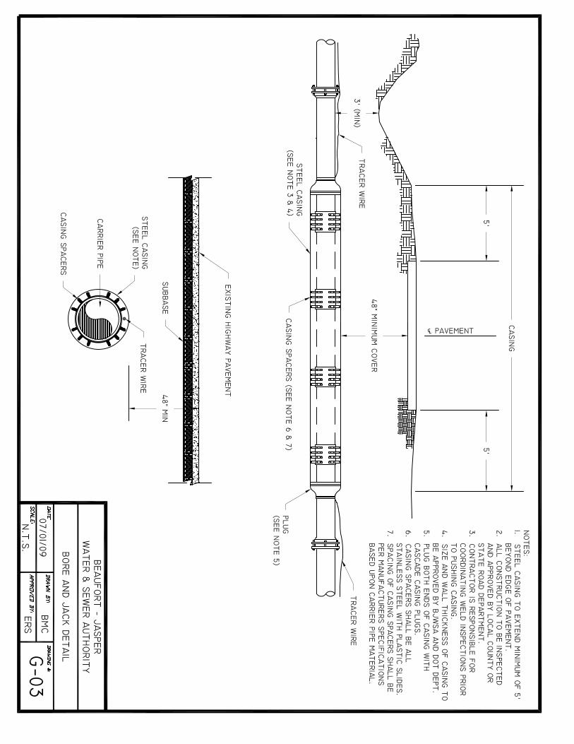


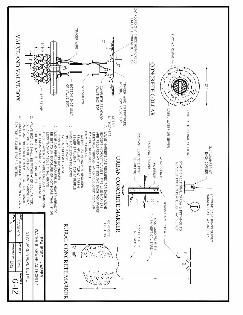

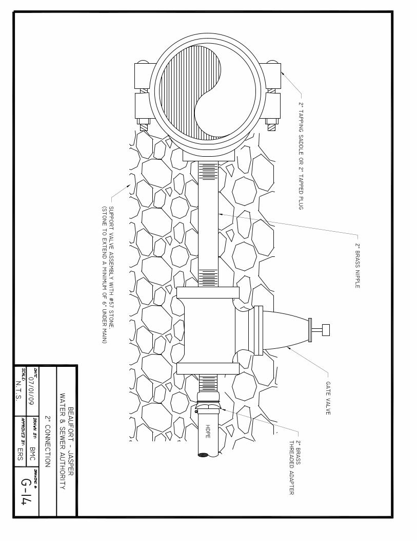


BJWSA TECHNICAL SPECIFICATIONS REVISED JULY 2009
APPENDIX WASTEWATER/SEWER STANDARD DETAILS
B
APPENDIX B – WASTEWATER/SEWER STANDARD DETAIL DRAWINGS
DRAWING NUMBER TITLE
S-01 Bedding Detail – Gravity Pipe S-02 Force Main Crossing S-03 Gravity Main Crossing S-04 Grease Trap Detail S-05 Manhole – Cover and Frame S-06 Manhole - Drop S-07 Manhole – Flat Top S-08 Manhole – Force Main Control S-09 Manhole - Standard S-10 Sewer Service Double S-11 Sewer Service - Single S-12 Pump Station Site Plan S-13A Pump Station Section I S-13B Pump Station Section II S-14 Pump Station Wet Well Detail S-15 Pump Station Fencing Detail S-16 Pump Station Electrical Layout S-17 Pump Station Control Panel & Main Disconnect S-18 Pump Station Bubbler S-19 Pump Station Hatch Detail S-20A Pump Station 2” Duplex Grinder, Plan S-20B Pump Station 2” Duplex Grinder, Section S-21 Pump Station Residential Control Panel S-22 Pump Station, Simplex Grinder S-23A Pump Station (Above Ground – 6x6), Site Plan S-23B Pump Station (Above Ground – 6x6), Detail #1 S-23C Pump Station (Above Ground – 6x6), Detail #2 S-23D Pump Station (Above Ground – 6x6), Detail #3 S-24 Sewer Check Valve S-25 Sewer Air Release Pedestal Assembly S-26 Duplex Residential Grinder Layout S-27 Pump Station Residential Duplex Control Panel S-28 Pump Station 6x6 Grate Detail


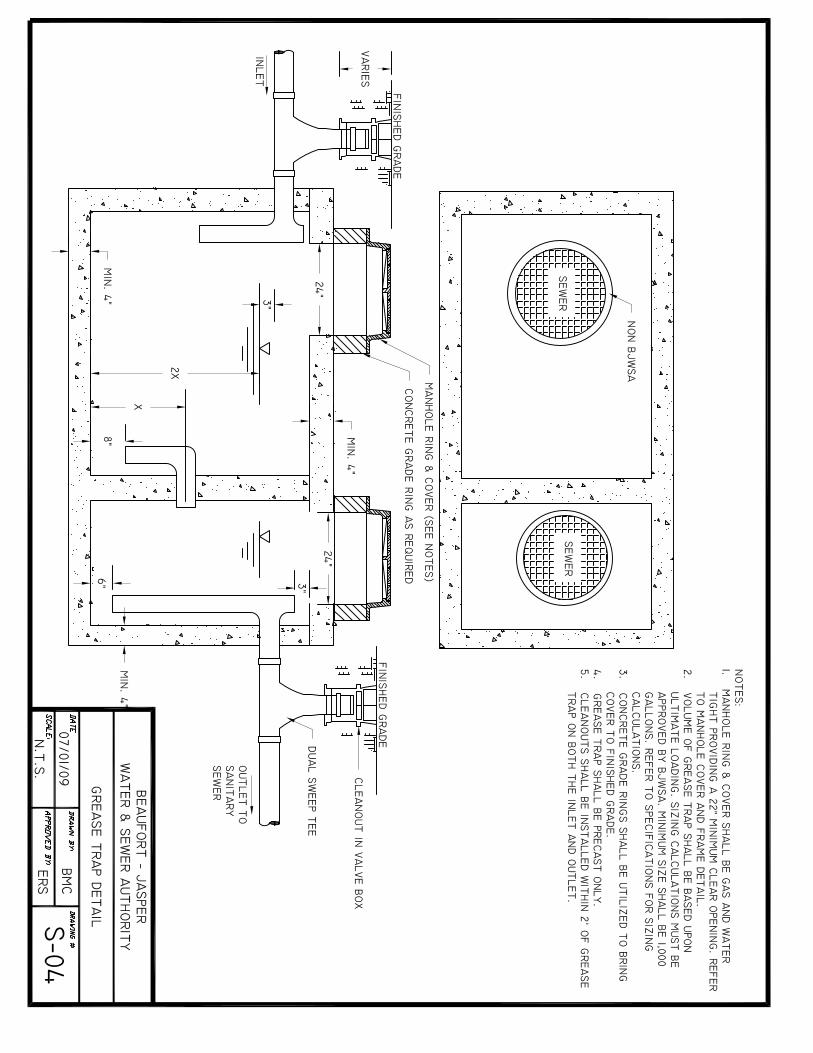

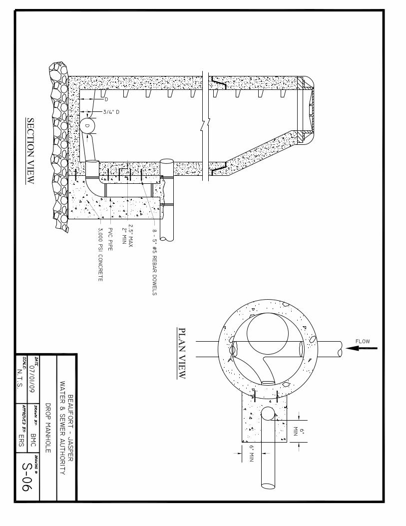


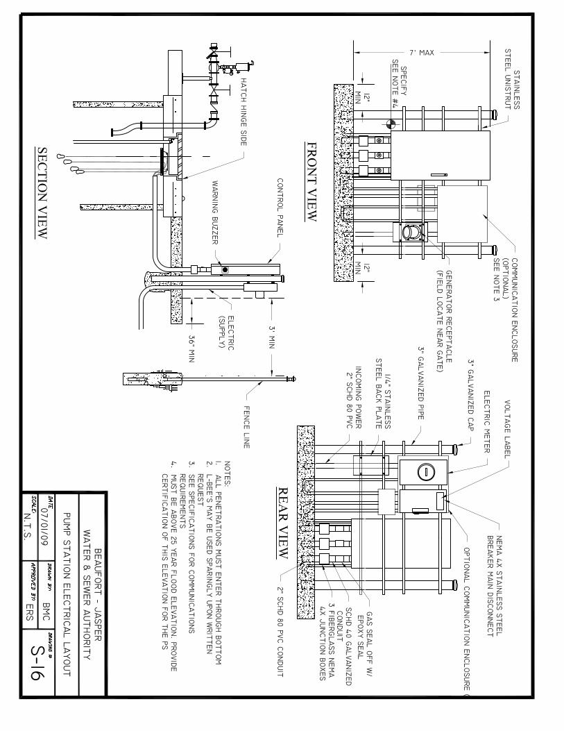


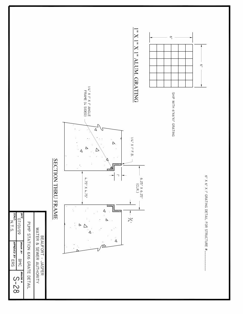
BJWSA TECHNICAL SPECIFICATIONS REVISED JULY 2009
APPENDIX WASTEWATER/SEWER STANDARD DETAILS
C
APPENDIX C – WATER STANDARD DETAIL DRAWINGS
DRAWING NUMBER TITLE
W-01 Backflow Prevention Detail W-02 Blow-off Hydrant Detail W-03 Fire Hydrant - Standard W-04 Fire Hydrant Detail – Under Ditch W-05 Jumper Connection Ditch W-06 Meter Vault Detail - Large W-07 Water Line Crossing Detail W-08 Water Service – Plan View W-09 Water Service Profile W-10 Water Sampling Station W-11 Meter Bank Detail; 6 Meter Max