special issue paper 633 percutaneous inner-ear access via an...
TRANSCRIPT

Percutaneous inner-ear access via an image-guidedindustrial robot systemS Baron1, H Eilers1, B Munske1, J L Toennies2, R Balachandran3, R F Labadie3, T Ortmaier1*, and R J Webster III2
1Institute of Mechatronic Systems (former Institute of Robotics), Leibniz Universitat Hannover, Hannover, Germany2Department of Mechanical Engineering, Vanderbilt University, Nashville, Tennessee, USA3Department of Otolaryngology – Head and Neck Surgery, Vanderbilt University Medical Center, Nashville, Tennessee,
USA
The manuscript was received on 26 November 2009 and was accepted after revision for publication on 26 February 2010.
DOI: 10.1243/09544119JEIM781
Abstract: Image-guided robots have been widely used for bone shaping and percutaneousaccess to interventional sites. However, due to high-accuracy requirements and proximity tosensitive nerves and brain tissues, the adoption of robots in inner-ear surgery has been slower.In this paper the authors present their recent work towards developing two image-guidedindustrial robot systems for accessing challenging inner-ear targets. Features of the systemsinclude optical tracking of the robot base and tool relative to the patient and Kalman filter-based data fusion of redundant sensory information (from encoders and optical trackingsystems) for enhanced patient safety. The approach enables control of differential robotpositions rather than absolute positions, permitting simplified calibration procedures andreducing the reliance of the system on robot calibration in order to ensure overall accuracy.Lastly, the authors present the results of two phantom validation experiments simulating theuse of image-guided robots in inner-ear surgeries such as cochlear implantation and petrousapex access.
Keywords: percutaneous inner-ear access, image-guided industrial robot systems, opticaltracking, Kalman filter-based data fusion, cochlear implantation, petrous apex access
1 INTRODUCTION
The surgical robot systems existing today can be
classified in many ways. One kind of classification is
based on the manner in which the user interacts
with the robot, leading to two main categories –
surgical assistant systems and surgical computer
aided design/computer aided manufacturing (CAD/
CAM) systems [1, 2]. Surgical assistant robots are
either teleoperated devices that mimic the surgeon’s
motions in real-time or cooperative devices manip-
ulating the instrument simultaneously by both robot
and surgeon. In contrast, surgical CAD/CAM sys-
tems are characterized by a high degree of auton-
omy. They typically take as inputs certain prespeci-
fied coordinates, trajectories, or surfaces (e.g. based
on preoperative planning), and then utilize a robot
to transfer these actions into the operating room
with accuracy and a high degree of automation.
An example of a teleoperated system is the widely-
known da VinciH Surgical System of Intuitive Surgi-
cal, Inc. (Sunnyvale, CA, USA). It was designed for
cardiologic interventions and is nowadays very
successfully used for radical prostatectomy. The
DLR MiroSurge system is another example of tele-
manipulated minimally invasive surgery [3]. The
system implements three kinematically redundant
torque controlled DLR MIRO robots [4, 5]. The
actuated instruments are equipped with miniatur-
ized force/torque sensors enabling haptic feedback.
The cooperative robotic system modiCASH for total
hip replacement surgery is presented in reference
[6]. It uses optical tracking for guidance of the
robotic arm, and a force/torque sensor mounted at
the end effector, allowing for intuitive interaction.
Further cooperative systems include the robotic
*Corresponding author: Institute of Mechatronic Systems, Leibniz
Universitat Hannover, Appelstr. 11A, 30167 Hannover, Germany.
email: [email protected]
SPECIAL ISSUE PAPER 633
JEIM781 Proc. IMechE Vol. 224 Part H: J. Engineering in Medicine

system developed by Xia et al. [7]. It integrates a
StealthStationH (Medtronic Inc., Minneapolis, MN)
navigation system, a neuromateH (Renishaw plc,
Gloucestershire, United Kingdom) robotic arm with
a force/torque sensor, and the 3D Slicer [8] visuali-
zation software to allow the tool to be cooperatively
controlled. This approach is similar to the former
Acrobot system, which also employs cooperative
control [9, 10]. A very recent cooperative robotic
system is the Kinemedic [11], which is capable of
impedance control in both Cartesian space and joint
space, and was designed for biopsy and drilling pilot
holes for pedicle screw placement.
The robot systems described in this paper belong
to the Surgical CAD/CAM type, as many of the
robots in the advent of robotic surgery. The system
described in reference [12] led to the first commer-
cial surgical robot, the RobodocH system (Curexo
Technology Corp., Fremont, CA). Initial versions of
the RobodocH developed by Taylor et al. [12] used
rigid registration and pre-planned tool paths to
produce precise implant pockets in knee and hip
replacement procedures. Since the pioneering Ro-
bodocH, robotic bone drilling and milling systems
have been developed for a number of other surgical
applications, including joint replacements, skull-
base procedures, and spine surgeries. In addition
to the robot itself, these systems include some or all
of the following: (1) methods for image acquisition,
segmentation, and human definition of surgical
objectives based on images and/or computer mod-
els, (2) automated and/or interactive preoperative
planning of tool trajectories, (3) real-time tool
tracking during drilling or milling, and (4) post-
surgical quality control analysis. While these general
tasks remain the same, the specifics of hardware and
software employed can vary significantly across
different systems.
In most of the systems mentioned above, ‘virtual
fixtures’ [13, 14] can be employed to guide tools or
enforce ‘no-fly zones’, constraining the surgeon’s
motion to safe areas while allowing him or her to
maintain control of manipulation. Advantages of this
method with respect to automated cutting/drilling
as implemented, for example, by RobodocH and the
systems described in this paper, among others,
include the ability of the surgeon to maintain a level
of shared control during the procedure. However, it
is unlikely that cooperative control will enable the
surgery to be accomplished as rapidly or repeatably
as a fully automated robotic solution.
In this paper the authors describe their recent
results in creating an image-guided robot system for
drilling and milling procedures in the skull, which is
an evolution of a prior system described in reference
[15]. The enhanced system proposed here (Fig. 1)
was also replicated at Vanderbilt University to create
a mirror system, using a similar robot and the same
system architecture and control strategies. Commer-
cially available industrial robots are used to create a
surgical CAD/CAM system that shares many aspects
with the previous CAD/CAM robots described above,
but addresses new and highly challenging applica-
tions, namely percutaneous access to inner-ear
structures such as the cochlea and the petrous apex.
Features of the system include optical tracking of the
robot base and tool relative to the patient and
Kalman filter-based data fusion of redundant sensor
information (from encoders and optical tracking
system) for enhanced accuracy and patient safety.
Control is implemented based on differential robot
positions rather than absolute positions, which
simplifies necessary calibration procedures and
reduces the dependence of the overall system
accuracy on calibration accuracy.
This paper is organized as follows. The challenging
clinical requirements due to the new inner-ear
applications are discussed in section 2. Section 3
describes the image-guided robot system designed
to meet these requirements. Section 4 deals with
image guidance, planning, and registration aspects.
In section 5 the details of vision-based control,
filtering, and data fusion are given. Section 6
describes initial experiments and their results in
phantom studies representing targeting of inner-ear
Fig. 1 The robotic system at Hannover with the KUKAKR 3, the ARTtrack2, and the mounting device
634 S Baron, H Eilers, B Munske, J L Toennies, R Balachandran, et al.
Proc. IMechE Vol. 224 Part H: J. Engineering in Medicine JEIM781
structures. The results are discussed in section 7, and
a conclusion is given in section 8.
2 CLINICAL REQUIREMENTS OF A CAD/CAMROBOT FOR INNER EAR SURGERY
There are a number of possible locations in the inner
ear where percutaneous access from the lateral skull
is potentially useful. Two examples (among many
possible surgical targets) that have been studied in
depth to date are the cochlea and the petrous apex
[16, 17].
2.1 Cochlear implantation
Cochlear implants can restore hearing to deaf
patients. The implantation surgery involves inserting
an electrode into the cochlea and connecting it to a
receiver implanted under the skin. The challenging
aspect of the surgery is accessing the cochlea, which
is embedded at a depth of approximately 35 mm in
the temporal bone. Accessing the cochlea requires
passing between two bone-embedded nerves – the
facial nerve, which if violated will cause paralysis to
the ipsilateral side of the patient’s face, and the
chorda tympani, which if violated will result in less
sensitivity to the ipsilateral tongue tip. The space
between these nerves is approximately 2 mm. Thus,
standard manual procedure involves a mastoidect-
omy procedure, where the bone of the skull behind
the ear is gradually shaved down using a drill to
permit access to the cochlea between the nerves.
During the mastoidectomy, the surgeon must expose
other important anatomical structures embedded in
the temporal bone, including the sigmoid sinus,
carotid artery, and labyrinth. It is, thus, highly
desirable to reduce reliance on human hand–eye
coordination in this procedure. A single-channel
approach where a hole is drilled percutaneously
directly to the cochlea would reduce invasiveness
and the time the patient must remain under
anesthesia [16, 18–21].
2.2 Petrous apex access
The petrous apex is the most medial portion of the
temporal bone and lies in close proximity to the
cochlea, carotid artery, facial nerve, and internal
jugular vein. The number of reported cases of
petrous apex lesions are increasing with advance-
ment in imaging technology [22–24] of which 90 per
cent are inflammatory/cystic lesions [25]. Surgical
access to the petrous apex involves providing a
drainage channel that avoids critical structures. An
optimal surgical approach would be to provide the
drainage channel via a single drill pass from the
lateral cortex of the mastoid to the petrous apex,
avoiding critical structures. For this approach,
accuracy on the order of 1 mm or less is required.
The feasibility of such a ‘minimally invasive ap-
proach’ to the petrous apex has been reported in
vitro using customized, microstereotactic frames
[17].
3 SYSTEM DESCRIPTION
To create this CAD/CAM surgical robot system for
inner-ear procedures, three main hardware compo-
nents are necessary: a positioning system (e.g.
industrial robot), a tracking system (e.g. optical
tracker), and a control workstation for processing
the data and controlling the robot (see Fig. 1). To
adapt for any relative motion between the patient
and robot base that may occur during surgery, three
locations are tracked: robot base, tool frame, and
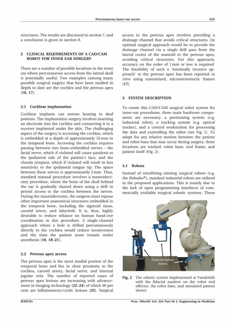
patient itself (Fig. 2).
3.1 Robots
Instead of retrofitting existing surgical robots (e.g.
the RobodocH), standard industrial robots are utilized
in the proposed applications. This is mainly due to
the lack of open programming interfaces of com-
mercially available surgical robotic systems. Those
Fig. 2 The robotic system implemented at Vanderbiltwith the fiducial markers on the robot endeffector, the robot base, and simulated patientshown
Percutaneous inner-ear access 635
JEIM781 Proc. IMechE Vol. 224 Part H: J. Engineering in Medicine

are a prerequisite for developing new surgical
applications in an academic area. Furthermore,
standard industrial robots offer high precision and
stiffness at relatively low costs.
Serial robots possess excellent repeatability (this is
the specification always quoted by manufacturers),
but their absolute positioning accuracy is generally
lower because any small modelling errors in their
kinematics (e.g. dimensional tolerances in fabrica-
tion) have more impact on absolute motions than on
small differential motions. While it is possible to
calibrate a robot system to enhance accuracy, it was
decided instead to track the tool centre point (TCP)
and implement control in the task space using
differential motion commands to the robot based
on external optical navigation data. Using this
framework, there is no need to solve the inverse
kinematics problem with high accuracy. Instead, the
control computer computes a new position and
orientation (relative to the current position and
orientation of the robot) and transmits this to the
robot control box. The control box then handles low-
level control for moving the robot from its current
configuration to the new desired configuration.
Two similar systems have been constructed, one at
Leibniz Universitat Hannover and one at Vanderbilt
University, which are nearly identical in terms of
system architecture, control, and registration. The two
systems differ in terms of the properties of robots and
the optical tracking hardware used. Both employ
standard six-degrees-of-freedom (DoF) off-the-shelf
industrial robots. The Hannover system implements a
KUKA KR 3 (KUKA Roboter GmbH, Augsburg, Ger-
many), while the Vanderbilt system uses a Mitsubishi
RV-3S (Mitsubishi Electric Europe B.V., Ratingen,
Germany). Each robot has a maximum workspace
radius of about 650 mm, can easily be mounted on a
tabletop or cart for transportation, and possesses a
maximum payload of 3 kg as well as excellent
repeatability (KR 3: 0.05 mm; RV-3S: 0.02 mm).
In both systems, an external control computer
interfaces the robot control box using an Ethernet
connection. To enable real-time control over the
Ethernet, the control box of the KR 3 was upgraded
with KUKA’s Remote Sensor Interface (RSI) and the
Ethernet Remote Sensor Interface (Kuka.Ethernet KRL
XML), while the RV-3S contains a built-in applica-
tion (CRn-500). Consequently, robot motion can be
dynamically adjusted externally by a computer and
all relevant robot data (e.g. the current pose and
encoder values) can be read over the same link. Data
are exchanged via the TCP/IP protocol in a 12 ms
cycle (KUKA KR 3) and via UPD/IP in a 40 ms cycle
(Mitsubishi RV-3S). To ensure safety, the robot
control boxes are set to expect periodic handshake
signals from the external control computer. The
communication will be shut down and robot motion
will be stopped if the expected handshake signal is
not received within a given time period.
3.2 Optical tracking
Optical tracking is used to measure the poses of
several coordinate frames of the set-up, as described
above. The Hannover system employs an ARTtrack2
(Advanced Realtime Tracking GmbH, Weilheim,
Germany) and the Vanderbilt system uses a Polaris
SpectraH (NDI Inc., Waterloo, Ontario, Canada).
Using optical markers placed accordingly to a known
geometry, the position and orientation of the
associated coordinate frame can be measured. The
position of a marker in the tracking area can be
determined with a remaining root mean squared
(r.m.s.) error of less than 0.25 mm (Polaris SpectraH).
For the ARTtrack2 no comparable value can be
given, due to the customized assembly of the system.
The data derived from the cameras contain the
translation x, y, zð Þ and the orientation represented
in unit quaternion format q0, qx, qy, qz
� �[26]. For
example, the pose of the TCP coordinate frame is
given with respect to the optical tracking system
coordinate frame by
(cam)xtcp~ x, y, z, q0, qx, qy, qx
� �T ð1Þ
Given this information, one can easily convert
equation (1) to the corresponding homogeneous
transformation camTtcp (see references [27] and [28]).
Thereafter, an object pose can be transformed from
one coordinate frame (e.g. the TCP frame) into the
optical tracking frame by
(cam)xobj~camTtcp(tcp)xobj ð2Þ
The Polaris SpectraH is connected to the computer
via a modified serial interface as USB is usually not
supported in real-time environments. The ARTtrack2
interfaces using the UDP protocol via Ethernet.
Because of hardware and interface limitations the
measurement rate for both optical tracking systems
was set to 25 Hz. Additionally, the systems have a
time lag of two working cycles due to the internal
signal processing. Since measurement values con-
tain significant noise, filtering is important and is
discussed in sections 5.2 and 5.3. A major drawback
of optical tracking systems is the so-called line-of-
sight problem, i.e. a direct line of sight between
636 S Baron, H Eilers, B Munske, J L Toennies, R Balachandran, et al.
Proc. IMechE Vol. 224 Part H: J. Engineering in Medicine JEIM781

cameras and tracking markers must always be
maintained. Thus, to ensure safety in the event of
short occlusions, the system shuts down and no
movement of the robot will occur. Possible solutions
exploiting data fusion are presented in reference
[29]. However, they were not incorporated into the
experimental set-ups described in this paper.
3.3 Control workstation
The external control computers used in both the
Hannover and Vanderbilt systems are standard PCs
(Pentium IV-class) running a Linux operating sys-
tem. Real-time control was implemented via the
RTAI extension [30]. Using the rapid prototyping
development environment MATLABH/SimulinkH(The MathWorks Inc., Natick, MA, USA), a library
for accessing optical tracking systems, robots, and
other peripherals was established, called mediLAB.
Using the model-based development environment,
even an inexperienced user without deep real-time
programming knowledge can rapidly create a control
circuit model. By building the model using the
integrated Real Time Workshop, a real-time capable
C program is generated, which is to be compiled into
a real-time compatible executable file. This allows
for a convenient development process.
4 IMAGE GUIDANCE, PLANNING, ANDREGISTRATION
The three main components (patient, robot, and
optical tracking system) of the image guided system
(IGS), described in detail in section 3, are shown in
Fig. 3. There are several different coordinate frames
of the system, which can be considered embedded in
each component. The coordinate frame CFð Þcam is
associated with the optical tracking system. There-
fore, the poses of the reference marker frames
attached rigidly to the robot base CFð Þrob, the tool
CFð Þtool, which is mounted on the robot end effector
(EE), and the patient CFð Þpat are measured in the
optical tracking system, CFð Þcam, and processed to
get the homogeneous transformations camTtool,camTrob, and camTpat.
The transformation eeTtool between the end effec-
tor and the tool reference marker frame as well astoolTtcp between the tool and the tool centre point,
which is located at the manipulated surgical instru-
ment tip, can be determined by a calibration
procedure (see section 4.3). The transformation
between the image space and the physical spacepatTimg can be computed by performing the registra-
tion (see section 4.2) between these two spaces. The
transformations eeTtool,toolTtcp, and patTimg are con-
sidered to be constant during the robot operation.
4.1 Planning and trajectory executing
As described in section 2, percutaneous access to
inner-ear targets requires high accuracy and must
use trajectories that achieve the desired target while
avoiding sensitive structures (e.g. nerves embedded
in the bone of the skull). To plan a trajectory for
percutaneous inner-ear access only, two coordinates
in the image data set are required, the entry point on
Fig. 3 The components and transformations used in our IGS system. Pictured are the three maincomponents of the system, namely the patient, robot, and optical tracking system, as wellas their spatial relationships
Percutaneous inner-ear access 637
JEIM781 Proc. IMechE Vol. 224 Part H: J. Engineering in Medicine

the skull (img)xe and the target point at the end of the
drill canal (img)xt. The direct line between these
points defines the trajectory.
It is also crucial to maximize the distances
between the drill and all adjacent critical anatomical
structures. To assist the surgeon with selecting the
optimal drill trajectory, a path planner can be used
to compute statistically optimal trajectories and then
display them for approval (or modification) by the
surgeon [31, 32]. In the phantom experiments
included in section 6, desired target and entry
positions within the phantom were selected manu-
ally by the experimenters.
To generate sequential pose values (img)xtcp, des of
the TCP in the image coordinate frame along the
pre-planned trajectory, a human machine interface
(HMI) device (i.e. Logitech Marblemouse) was used.
This device allows the human user (e.g. the surgeon)
to manually control the insertion of the drill along
the preplanned trajectory, providing a level of shared
control. Since the orientation of the drill around the
drill axis is arbitrary, the robot was programmed to
keep the optical tracking fiducial mounted to its EE
aimed towards the optical tracker, as good as
possible.
4.2 Registration
The transformation between the image space and
the physical space patTimg is derived by performing a
point-based registration process with artificial land-
marks. In these experiments, embedded metal
spheres as well as embedded bone anchors with
attached spheres were used for this purpose. These
spheres were detected in computer tomography (CT)
images with subpixel accuracy using an automatic
segmentation algorithm [33]. To determine their
location in optical tracker space, a tracked, cali-
brated pointer with a detent at its tip was used to
identify their locations precisely (see Figs 4(d) and
(e)).
The patient reference adapter pose (cam)xpat and
the anchor positions (cam)panchor, i are measured at
the same time, with the adapter’s pose converted to
the corresponding homogenous transformationcamTpat. Therefore, the position of the landmarks
can be transformed into the patient coordinate
frame by
(pat)panchor, i~camTpat
� �{1(cam)panchor, i ð3Þ
After measuring all landmarks with respect to the
patient coordinate frame, a homogeneous transfor-
mation imgTpat can be calculated using the standard
point-based rigid registration algorithm [34]. It
minimizes the squared distances of the registration
error
e~XN
i~1
(img)panchor, i{imgTpat(pat)panchor, i
�� ��2
2ð4Þ
of N anchor points by using a singular value
decomposition. Since the desired drill trajectory is
planned relative to these anchors in image space, the
drill trajectory is now known with respect to the
physical patient space.
4.3 Calibration
Calibration is used to determine two fixed transfor-
mations that relate the various frames associated
with the drill (see Fig. 5). The robot tool frame is
defined as the coordinate frame of the optical
tracking fiducial attached to the drill. The position
and orientation of this tool frame with respect to the
physical drill tip (the TCP as referred to throughout
this paper) is toolTtcp. The other relevant transforma-
tion is the transformation from the tool frame to the
robot’s internally defined EE frame eeTtool, which lies
at the intersection of its revolute wrist joints and is
used to command the differential movements
described in section 3.1.
Fig. 4 (a) Surgical drill, (b) and (c) calibration drills,(d) spherical bone anchor, and (e) calibratedpointer tool
638 S Baron, H Eilers, B Munske, J L Toennies, R Balachandran, et al.
Proc. IMechE Vol. 224 Part H: J. Engineering in Medicine JEIM781
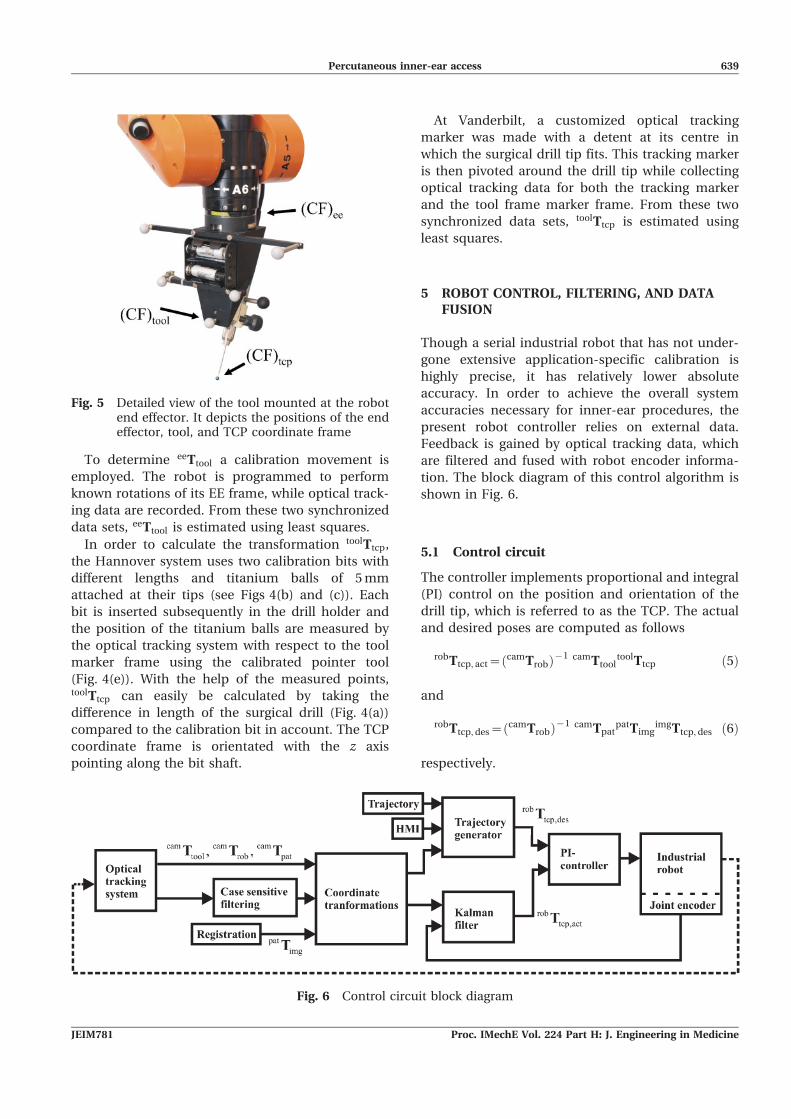
To determine eeTtool a calibration movement is
employed. The robot is programmed to perform
known rotations of its EE frame, while optical track-
ing data are recorded. From these two synchronized
data sets, eeTtool is estimated using least squares.
In order to calculate the transformation toolTtcp,
the Hannover system uses two calibration bits with
different lengths and titanium balls of 5 mm
attached at their tips (see Figs 4(b) and (c)). Each
bit is inserted subsequently in the drill holder and
the position of the titanium balls are measured by
the optical tracking system with respect to the tool
marker frame using the calibrated pointer tool
(Fig. 4(e)). With the help of the measured points,toolTtcp can easily be calculated by taking the
difference in length of the surgical drill (Fig. 4(a))
compared to the calibration bit in account. The TCP
coordinate frame is orientated with the z axis
pointing along the bit shaft.
At Vanderbilt, a customized optical tracking
marker was made with a detent at its centre in
which the surgical drill tip fits. This tracking marker
is then pivoted around the drill tip while collecting
optical tracking data for both the tracking marker
and the tool frame marker frame. From these two
synchronized data sets, toolTtcp is estimated using
least squares.
5 ROBOT CONTROL, FILTERING, AND DATAFUSION
Though a serial industrial robot that has not under-
gone extensive application-specific calibration is
highly precise, it has relatively lower absolute
accuracy. In order to achieve the overall system
accuracies necessary for inner-ear procedures, the
present robot controller relies on external data.
Feedback is gained by optical tracking data, which
are filtered and fused with robot encoder informa-
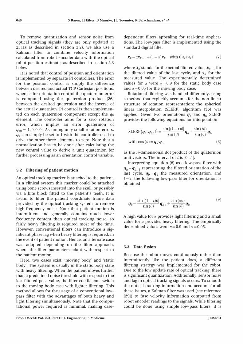
tion. The block diagram of this control algorithm is
shown in Fig. 6.
5.1 Control circuit
The controller implements proportional and integral
(PI) control on the position and orientation of the
drill tip, which is referred to as the TCP. The actual
and desired poses are computed as follows
robTtcp, act~camTrobð Þ{1 camTtool
toolTtcp ð5Þ
and
robTtcp, des~camTrobð Þ{1 camTpat
patTimgimgTtcp, des ð6Þ
respectively.
Fig. 5 Detailed view of the tool mounted at the robotend effector. It depicts the positions of the endeffector, tool, and TCP coordinate frame
Fig. 6 Control circuit block diagram
Percutaneous inner-ear access 639
JEIM781 Proc. IMechE Vol. 224 Part H: J. Engineering in Medicine
To remove quantization and sensor noise from
optical tracking signals (they are only updated at
25 Hz as described in section 3.2), we also use a
Kalman filter to combine velocity information
calculated from robot encoder data with the optical
robot position estimate, as described in section 5.3
below.
It is noted that control of position and orientation
is implemented by separate PI controllers. The error
for the position control is simply the difference
between desired and actual TCP Cartesian positions,
whereas for orientation control the quaternion error
is computed using the quaternion product [26]
between the desired quaternion and the inverse of
the actual quaternion. PI control is then implemen-
ted on each quaternion component except the q0
element. The controller aims for a zero rotation
error, which implies an error quaternion of
qerr~ 1, 0, 0, 0½ �. Assuming only small rotation errors,
q0 can simply be set to 1 with the controller used to
drive the other three elements to zero. Note that a
normalization has to be done after calculating the
new control value to derive a unit quaternion for
further processing as an orientation control variable.
5.2 Filtering of patient motion
An optical tracking marker is attached to the patient.
In a clinical system this marker could be attached
using bone screws inserted into the skull, or possibly
via a bite block fitted to the patient’s teeth. It is
useful to filter the patient coordinate frame data
provided by the optical tracking system to remove
high-frequency noise. Note that patient motion is
intermittent and generally contains much lower
frequency content than optical tracking noise, so
fairly heavy filtering is required most of the time.
However, conventional filters can introduce a sig-
nificant phase lag when heavy filtering is required, in
the event of patient motion. Hence, an alternate case
was adopted depending on the filter approach,
where the filter parameters adapt with respect to
the patient motion.
Here, two cases exist: ‘moving body’ and ‘static
body’. The system is usually in the static body state
with heavy filtering. When the patient moves further
than a predefined noise threshold with respect to the
last filtered pose value, the filter coefficients switch
to the moving body case with lighter filtering. This
method allows for the usage of a conventional low-
pass filter with the advantages of both heavy and
light filtering simultaneously. Note that the compu-
tational power required is minimal, making case-
dependent filters appealing for real-time applica-
tions. The low-pass filter is implemented using the
standard digital filter
�xxk~a�xxk{1z 1{að Þxk with 0¡a¡1 ð7Þ
where �xxk stands for the actual filtered value, �xxk{1 for
the filtered value of the last cycle, and xk for the
measured value. The experimentally determined
values for a were a~0:9 for the static body case
and a~0:05 for the moving body case.
Rotational filtering was handled differently, using
a method that explicitly accounts for the non-linear
structure of rotation representation: the spherical
linear interpolation (SLERP) algorithm [35] was
applied. Given two orientations qa and qb SLERP
provides the following equations for interpolation
SLERP qa, qb, t� �
~sin 1{tð Þh½ �
sin hð Þ qazsin thð Þsin hð Þ qb
with cos hð Þ~qa:qb ð8Þ
as the n-dimensional dot product of the quaternion
unit vectors. The interval of t is ½0:::1�.Interpreting equation (8) as a low-pass filter with
qa~�qqk{1 representing the filtered orientation of the
last cycle, qb~qk the measured orientation, and
t~a, the following low-pass filter for orientation is
obtained
�qqk~sin 1{að Þh½ �
sin hð Þ�qqk-1z
sin ahð Þsin hð Þ qk
ð9Þ
A high value for a provides light filtering and a small
value for a provides heavy filtering. The empirically
determined values were a~0:9 and a~0:05.
5.3 Data fusion
Because the robot moves continuously rather than
intermittently like the patient does, a different
filtering strategy was implemented for the robot.
Due to the low update rate of optical tracking, there
is significant quantization. Additionally, sensor noise
and lag in optical tracking signals occurs. To smooth
the optical tracking information and account for all
these issues, a Kalman filter was used (see reference
[29]) to fuse velocity information computed from
robot encoder readings to the signals. While filtering
could be done using simple low-pass filters, it is
640 S Baron, H Eilers, B Munske, J L Toennies, R Balachandran, et al.
Proc. IMechE Vol. 224 Part H: J. Engineering in Medicine JEIM781

possible to obtain better results (e.g. reducing phase
lag) via this sensor fusion approach.
To accomplish this, we handle translation and
orientation separately, each with their own Kalman
filters, which differ only in their state vectors and
corresponding parameters. For the translational
components, the Kalman filter is implemented as
follows. The 12|1 state vector is
xk~½pk-2, pk-1, pk, _ppk �T ð10Þ
where pk, pk-1, and pk-2 denote the Cartesian
positions of the tool at sample time k, k{1, and
k{2 respectively and _ppk gives the velocity of the TCP
at sample time k. Note that these additional sample
times account for a latency of two cycles due to the
time delay between acquiring data from the robot
and optical tracking system (see reference [36] for
further information about time delay modelling).
The governing equations of the Kalman filter are the
general state-space equations of a dynamic system
with no inputs or disturbances
_xx~Ax and y~Cx ð11Þ
The 12|12 system matrix A and the 6|12 observermatrix C are
A~
0 1 0 0
0 0 1 0
0 0 1 T
0 0 0 1
26664
37775, C~
1 0 0 0
0 0 0 1
� �ð12Þ
where 0 denotes a 3|3 null matrix, 1 a 3|3 identity
matrix, and T a 3|3 diagonal matrix containing the
sample time of the Kalman filter (0.02 seconds, in
this implementation).
The Kalman filter for orientation works in exactly
the same way as the translational filter described
above. Rotation is parameterized using quaternions,
which are converted to Euler angles before filtering
and then converted back to quaternions after
filtering. Redefining the state vector to contain these
Euler angles, equations (10) to (12) hold for the
rotational Kalman filter exactly as written.
The further processing of the data in a prediction
and correction step is a standard procedure, as
discussed in reference [37]. The optimal Kalman
filter gain is a measurement of trust in sensor values
versus model prediction, and such trust depends
upon the noise present in the system. The gain is
adjusted according to the error covariance, consist-
ing of both the process noise covariance and the
measurement noise covariance.
The measurement noise covariance is a diagonal
matrix computed from noise readings of the optical
tracking system. The values of the process noise
covariance represent uncertainty in the model. They
were empirically chosen, but smaller than the
measurement noise covariance; i.e. measured values
are trusted somewhat more than model predictions,
but a combination of the two is the most effective
estimate of the robot position.
In our systems, the Kalman filter implementation
performs sensor fusion, combining noisy tool posi-
tion data from the optical tracking system and
smoother velocity data from the robot. By doing so,
it was possible to lower the overall noise and to
enhance the robustness of the system. Additionally,
the system benefits from the lower delay due to
earlier arriving signals from the robot compared to
the above-mentioned delay of two sample times
from the optical tracking system.
To illustrate the advantages of this Kalman sensor
fusion technique in comparison to the standard low-
pass filter, the robot performed motions with
changes in direction of the movement. Since all
degrees of freedom produced similar results, one
representative degree of freedom is shown in Fig. 7.
It depicts the position in the x direction derived from
the unfiltered optical tracking system, the same
values low-pass filtered with a corner frequency of
3 Hz, and the Kalman filtered position data.
It is easy to see that the Kalman filter performs
with higher dynamics than the low-pass filter giving
similar smoothed values. Even more, the applied
low-pass filter incorporates a significant phase lag.
The robot data have a delay of 12 ms whereas the
optical tracking system introduces a delay of
approximately 40 ms. Therefore, the Kalman filter
(taking both signals into account) reacts earlier to
changes in the robot motion as the unfiltered optical
tracking data. After a short time the Kalman signal
converges towards the value of the tracking system,
gaining back absolute accuracy.
6 EXPERIMENTS
Two types of phantom experiments were conducted
to analyse the performance of the two robot systems
described in previous sections of this paper. The first
experiment did not involve any imaging and was
performed with both the Hannover system and the
Vanderbilt system. For this experiment, a phantom
was made using a computer numerically controlled
Percutaneous inner-ear access 641
JEIM781 Proc. IMechE Vol. 224 Part H: J. Engineering in Medicine

(CNC) milling machine such that the outer dimen-
sions are fabricated precisely (¡0.1 mm). The sec-
ond experiment includes the CT imaging of a dif-
ferent phantom. The markers and the trajectories
were determined from the CT scan in a manner
envisaged for use in real otologic surgery. This
experiment was only performed at Vanderbilt where
a portable intraoperative CT machine was available.
In order to determine the accuracy of the image
guided robots, the deviation of the drilled holes was
measured in both experiments, and a statistical
analysis was performed.
6.1 Lateral accuracy experiment
An accurately fabricated aluminium block (125675635 mm3) was equipped with 24 drilled holes with
a diameter of 10 mm in a grid pattern (see Fig. 8).
Each hole was filled with plaster (Hannover) and
body filler (Vanderbilt), respectively. Additionally,
five threaded holes were added to mount 5 mm
titanium spheres for registering the block to physical
space. The exact positions of the spheres relative to
the block were determined using a calliper (resolu-
tion 0.01 mm). Optical tracking markers were fixed to
the block using a custom-made base. To register the
markers to the block, the point-based registration
process was applied (see section 4.2). Subsequently,
the milling tool (Lindemann burr NS1808.036,
KOMET MEDICAL, Lemgo, Germany) was calibrated
Fig. 7 Kalman filtered optical tracking data are nearly as smooth as low-pass filtered values witha 3 Hz corner frequency and do not suffer from the low-pass phase shift. Additionally, itreduces the time lag introduced by the optical tracking system
Fig. 8 The experimental set-up for the lateral accuracyexperiment consists of an aluminium blockwith 24 plaster-filled holes in it, fixed relative tothe robot, and optically tracked
642 S Baron, H Eilers, B Munske, J L Toennies, R Balachandran, et al.
Proc. IMechE Vol. 224 Part H: J. Engineering in Medicine JEIM781

as described in section 4.3 using the calibration pins
in Hannover and the calibration frame in Vanderbilt.
For trajectory planning 24 desired trajectories
were defined to drill along the centres of the filled
bore holes. The centre of the hole on the top side was
specified as the entry point (img)xe and the centre on
the bottom side as the target point (img)xt, adding an
additional 2 mm to ensure that the drill bit reached
the outside of the block. During the experiment, the
24 holes were drilled in a sequence while the optical
tracking system and the block remained motionless.
The progression of the TCP along the trajectory was
commanded manually using the HMI. While the
trajectory execution could have been performed
completely pre-programmed, it seems to be desir-
able that a human user (the surgeon in the clinical
setting) maintains control of the drill progress. The
rotational speed of the drilling tool was adjusted to
10 000 r/min and held constant during both drilling
and retraction.
After drilling, the positions of the centres of each
hole were determined at the top and at the bottom of
the block (the drill bit passed all the way through it),
using a coordinate measuring machine (CMM) Zeiss
ZMC 530 (Carl Zeiss IMT GmbH, Oberkochen,
Germany) with an accuracy of approximately 1 mm.
This experiment enables precise assessment of x-
and y-direction accuracy of drilling, although drill
depth cannot be evaluated by this procedure.
6.2 Lateral accuracy experiment results
Figures 9 and 10 depict the measured deviations Dx
and Dy of the drilled holes within the aluminium
block. The mean error is indicated by a red cross
and the deviations are marked with a small dot. Fur-
thermore, the plot shows the histograms as well as
the corresponding Gaussian distribution in the x and
y directions. Assuming a two-dimensional normal
distribution, a confidence region for the system
accuracy can be calculated using the covariance of
the deviation results. Also, 99.9 per cent confidence
ellipses are shown on the plots.
Table 1 summarizes the performed experiments
on both systems. Since the standard deviation varies
with respect to the direction, its value is given not
only in the x and y directions but also in the
direction of its principle axes. It can be seen that the
Hannover experiments were performed with a lower
mean value and the Vanderbilt experiments with a
lower standard deviation. See section 7 for a
discussion of the significance of these results with
respect to otolaryngology surgery.
6.3 Absolute accuracy experiment
To assess the absolute accuracy of the system, a
phantom made of an acrylic block with three em-
bedded spherical fiducial markers was used (see
Fig. 11). The three spheres enable registration
between the image and physical space. They were
immobilized by embedding them in epoxy. A CT
scan of the phantom with the spherical markers was
acquired using the xCATTM ENT mobile CT scanner
(Xoran Technologies, Ann Arbor, MI, USA). The
locations of the spheres in the image space were
determined by identifying their centres in the CT
scan using automatic image processing techniques.
Six arbitrary drill trajectories relative to these
spheres were then defined in the image space.
An optical tracking marker frame was then
attached to the phantom and the locations of the
respective spheres in the physical space were
acquired using a calibrated probe. A point-based
rigid registration was then applied to register image
space to physical space, as mentioned in section 4.2.
The robot was then programmed to align the drill
with the desired trajectory and advance along it
under the control of an HMI consisting of a marble
mouse (the HMI was included here for the same
reason as in the lateral accuracy experiment above).
The drill was maintained at 20 000 r/min until the
robot reached the target. The drill was then stopped
and retracted in the same manner in which it was
inserted.
To assess the accuracy of the drilled hole, the
phantom was scanned again after drilling using the
xCATTM ENT CT scanner. To determine accuracy, the
pre- and post-drill CT scans were registered to each
other using the fiducial sphere locations in both the
scans. The desired trajectory from the pre-drill scan
was transformed to the post-drill scan and compared
to the actual drill path.
6.4 Absolute accuracy experiment results
Figure 12 shows one desired drill trajectory trans-
formed to the post-drill CT scan. It can be seen that
the drilled path is along the desired trajectory. The
distance between the drilled target and desired
target (img)xt and between the mid-axis of the drilled
trajectory and the mid-axis of the desired trajectory
at the target were measured for each trajectory. The
mean ¡ standard deviations of these distances were
measured to be 0.62 ¡ 0.25 mm and 0.56 ¡ 0.27 mm,
respectively.
These results demonstrate how an image-guided
robot system such as the ones proposed here might
Percutaneous inner-ear access 643
JEIM781 Proc. IMechE Vol. 224 Part H: J. Engineering in Medicine

Fig. 9 Deviations and 99.9 per cent confidence region for the drilling experiments performed atHannover using the KUKA KR3 robot and ARTtrack2 optical tracker. (a) top side, (b)bottom side
644 S Baron, H Eilers, B Munske, J L Toennies, R Balachandran, et al.
Proc. IMechE Vol. 224 Part H: J. Engineering in Medicine JEIM781

Fig. 10 Deviations and 99.9 per cent confidence region for the drilling experiments performed atVanderbilt using the Mitsubishi RV-3S and Polaris SpectraH optical tracker. (a) top side,(b) bottom side
Percutaneous inner-ear access 645
JEIM781 Proc. IMechE Vol. 224 Part H: J. Engineering in Medicine

be used in a real clinical setting. In summary, it has
been shown that submillimetric absolute accuracy
can be achieved using established registration
procedures and a workflow equivalent to the one
that is envisaged for real surgery.
7 DISCUSSION
The results of both experiments described in section
6 demonstrate submillimetric accuracy. The levels of
accuracy currently seen in these experimental
systems are likely to be sufficient for some applica-
tions in inner-ear surgery (e.g. petrous apex access),
and may need some enhancement in future work
before they are sufficient for other applications (e.g.
percutaneous cochlear implantation, where only a
2 mm window is available between the nerves
through which the drill must pass). Fortunately,
there are several promising areas for possible future
work that may enhance the accuracy of our systems
even further.
For example, the Hannover system (KR3/ARTtrack2)
exhibited a higher standard deviation in the lateral
accuracy experiment than the Vanderbilt system
(RV-3S/Polaris SpectraH), which is affected by the
system noise. This may rely on the use of a camera
with a higher noise level. Furthermore, mistuned
Kalman filter parameters lead to the same effect.
Further experiments have to be performed to figure
out the problem. In contrast, the lower mean errors
may indicate that the registration procedures were
accomplished more accurately, which may be due
to the calibration procedures used.
We note furthermore that one potential explana-
tion for the relatively high bias in the x direction in
the Vanderbilt experiments is that this corresponds
to the direction in which the calibration frame was
oriented towards the tool tip during the calibration
process, and it is possible that some small inad-
vertent force was applied during calibration that
deflected the drill tip.
The results of the statistical analysis are very
important in order to propose safety margins of the
drill channel to the critical anatomic structures
during the planning process. In this way, maximal
safety of these structures can be predicted and no
violation of the nerves or blood vessels takes place.
For instance, the 99 per cent confidence radius was
used for planning the incision on temporal bone
specimens in the authors’ recent experiments.
Table 1 Mean and standard deviation of the drilling results
Experiment
Mean value (mm) Standard deviation (mm) 99.9% confidenceregion (mm), majoraxis
Mean + confidenceregion (mm),maximumx y x axis y axis Major axis Minor axis
Hannover, top side 20.167 20.080 0.107 0.121 0.135 0.089 0.444 0.629Hannover, bottom side 20.113 20.125 0.115 0.128 0.138 0.103 0.455 0.624Vanderbilt, top side 0.562 0.105 0.077 0.041 0.082 0.031 0.268 0.840Vanderbilt, bottom side 0.477 20.087 0.116 0.088 0.124 0.076 0.408 0.893
Fig. 11 Phantom with three spherical fiducial markersused for the absolute accuracy experiments
Fig. 12 A drilled trajectory as seen in the post-drill CTscan. The dotted line indicates the desired drillpath and the cross indicates the desired targetlocation
646 S Baron, H Eilers, B Munske, J L Toennies, R Balachandran, et al.
Proc. IMechE Vol. 224 Part H: J. Engineering in Medicine JEIM781

8 CONCLUSION
This paper has reported the authors’ initial work to
build robotic systems with sufficient accuracy for
percutaneous access to challenging targets in the
inner ear, including percutaneous cochlear implan-
tation and petrous apex access. These applications
impose challenging accuracy requirements on sur-
gical CAD/CAM robots. In this paper a system
architecture designed to meet these challenging
requirements has been described. It consists of an
external control computer that interfaces with the
industrial robot control box and makes use of
differential motion commands for Cartesian control
based on feedback from optical tracking of the robot
and patient. Also described are various filtering
strategies designed to deal with sensor latency, slow
sensor update rates, and sensor noise, as well as
segmentation, planning, and registration strategies.
Two physical mirror systems implementing the
proposed architecture and control methods were
constructed, one using a KUKA KR3 robot with an
ARTtrack2 optical tracker, and the other using a
Mitsubishi RV-3S robot with a Polaris SpectraHoptical tracker. Using these systems, two feasibility
studies for image-guided CAD/CAM robots in inner-
ear surgery were performed – both designed to
assess system accuracy. The results of these experi-
ments show that CAD/CAM robots are a promising
alternative to manual milling in otolaryngology
procedures. A robotic approach has the potential to
enable percutaneous access to targets in the inner
ear, without requiring a mastoidectomy. In these
initial feasibility studies, submillimetric overall sys-
tem accuracy was found. However, from the statis-
tical point of view, the mean values and the
confidence regions of the experimental results show
that the navigated robots are not able to assure an
accuracy of better than 0.5 mm in 99.9 per cent of all
cases.
Whether the accuracies achieved in these initial
experiments are sufficient for various inner-ear
applications is a topic of ongoing study by the
authors. In general, they believe that the accuracies
they have reached so far are sufficient for some
inner-ear applications, and that further research will
be needed to enable others. Furthermore, before an
industrial robot can be moved from the research lab
to an operating room, many layers of redundant
sensing and failsafe software must be implemented,
which are topics of ongoing work by the authors.
They are also continuing to work towards enhancing
overall system accuracy and believe that accuracy
enhancement will be possible. Strategies for this,
which are currently being investigated, include non-
contact calibration, data fusion, other sources of
information including inertial measurement units,
improved optical tracking hardware, and the poten-
tial use of redundant optical trackers to reduce the
possibility of fiducial occlusion.
In summary, the initial results reported in this
paper illustrate the authors’ early efforts towards
applying image-guided CAD/CAM robots to inner-
ear surgical procedures. This work lays the founda-
tion for bringing the advantages of robots (e.g.
precision and ability to accurately apply preopera-
tive image information to guide surgical tools to sub-
surface targets in the presence of obstacles) to many
new surgical procedures for which robotic assistance
has not yet been attempted.
ACKNOWLEDGEMENTS
The project was funded by the German ResearchAssociation (DFG) in the special research clusterSPP1124, ‘Medical Navigation and Robotics’ (MA-4038/1-1, HE-2445/19-1). This work was also sup-ported by Grant R21 EB006044-01A1 from theNational Institute of Biomedical Imaging and Bioen-gineering.
F Authors 2010
REFERENCES
1 Taylor, R. and Stoianovici, D. Medical robotics incomputer-integrated surgery. IEEE Trans. on Ro-botics and Automn, October 2003, 19(5), 765–781.
2 Taylor, R. A perspective on medical robotics. Proc.IEEE, September 2006, 94(9), 1652–1664.
3 Konietschke, R., Hagn, U., Nickl, M., Jorg, S.,Tobergte, A., Passig, G., Seibold, U., Le-Tien, L.,Kubler, B., Groger, M., Frohlich, F., Rink, C.,Albu-Schaffer, A., Grebenstein, M., Ortmaier, T.,and Hirzinger, G. The DLR MiroSurge – a roboticsystem for surgery. In Proceedings of the IEEEInternational Conference on Robotics and Automa-tion ICRA ’09, Kobe, Japan, 12–17 May 2009, pp.1589–1590.
4 Hagn, U., Nickl, M., Jorg, S., Passig, G., Bahls, T.,Nothhelfer, A., Hacker, F., Le-Tien, L., Albu-Schaffer, A., Konietschke, R., Grebenstein, M.,Warpup, R., Haslinger, R., Frommberger, M., andHirzinger, G. The DLR MIRO: a versatile light-weight robot for surgical applications. IndustrialRobot: An Int. J., 2008, 35(4), 324–336.
5 Burgner, J. 2009, p. 10; http://wwwipr.ira.uka.de/accurobas.
6 Castillo Cruces, R. A., Christian Schneider, H.,and Wahrburg, J. Cooperative robotic system to
Percutaneous inner-ear access 647
JEIM781 Proc. IMechE Vol. 224 Part H: J. Engineering in Medicine

support surgical interventions. In Medical Robotics,2008, pp. 481–490 (I-Tech Education and Publish-ing, Vienna, Austria).
7 Xia, T., Baird, C., Jallo, G., Hayes, K., Nakajima,N., Hata, N., and Kazanzides, P. An integratedsystem for planning, navigation and robotic assis-tance for skull base surgery. Int. J. Med. Robot,December 2008, 4(4), 321–330.
8 Pieper, S. 2009, p. 10; http://www.slicer.org.9 Cobb, J., Henckel, J., Gomes, P., Harris, S.,
Jakopec, M., Rodriguez, F., Barrett, A., andDavies, B. Hands-on robotic unicompartmentalknee replacement: a prospective, randomised con-trolled study of the acrobot system. J. Bone Jt Surg.(Br.), 2006, 88–B, 188–197.
10 Jakopec, M., Rodriguez y Baena, F., Harris, S.,Gomes, P., Cobb, J., and Davies, B. The hands-onorthopaedic robot ‘acrobot’: early clinical trials oftotal knee replacement surgery. IEEE Trans. onRobotics and Automn, October 2003, 19(5), 902–911.
11 Ortmaier, T., Weiss, H., Hagn, U., Grebenstein,M., Nickl, M., Albu-Schaffer, A., Ott, C., Jorg, S.,Konietschke, R., Le-Tien, L., and Hirzinger, G. Ahands-on-robot for accurate placement of pediclescrews. In Proceedings of the IEEE InternationalConference on Robotics and Automation ICRA2006, Orlando, Florida, 15–19 May 2006, pp.4179–4186.
12 Taylor, R., Paul, H., Mittelstadt, B., Hanson, W.,Kazanzides, Zuhars, J., Glassman, E., Musits, B.,Williamson, W., and Bargar, W. An image-directedrobotic system for precise orthopaedic surgery.IEEE Trans. Robotics and Automn, June 1994, 10(3),1928–1930.
13 Abbott, J. J. and Okamura, A. M. Analysis of virtualfixture contact stability for telemanipulation.Trans. ASME, J. Dynamic Systems, Measmt, andControl, 2006, 128, 53–64.
14 Marayong, P. and Okamura, A. M. Speed-accuracycharacteristics of human–machine cooperativemanipulation using virtual fixtures with variableadmittance. Human Factors, 2004, 46(3), 518–532.
15 Baron, S., Eilers, H., Hornung, O., Heimann, B.,Leinung, M., Bartling, S., Lenarz, T., and Majdani,O. Conception of a robot assisted cochleostomy:first experimental results. In Proceedings of the 7thInternational Workshop on Research and Educationin Mechatronics, Stockholm, 2006.
16 Labadie, R. F., Noble, J. H., Dawant, B. M.,Balachandran, R., Majdani, O., and Fitzpatrick,J. M. Clinical validation of percutaneous cochlearimplant surgery: initial report. Laryngoscope, June2008, 118(6), 1031–1039.
17 Wanna, G., Balachandran, R., Majdani, O., Mitch-ell, J., and Labadie, R. Percutaneous access of thepetrous apex in vitro using customized drill guidesbased on image guided surgical technology. ActaOto-Laryngologica, 2009, Aug 25:1–6 [EPub aheadof print].
18 Brett, P., Taylor, R., Proops, D., Coulson, C., Reid,A., and Griffiths, M. A surgical robot for cochleost-omy. In 29th Annual International Conference ofthe IEEE, Engineering in Medicine and BiologySociety, EMBS 2007, Lyon, France, August 2007, pp.1229–1232.
19 Kronenberg, J., Migirov, L., and Dagan, T. Supra-meatal approach: new surgical approach for co-chlear implantation. J. Laryngology and Otology,2001, 115(04), 283–285.
20 Majdani, O., Bartling, S. H., Leinung, M., Stover,T., Lenarz, M., Dullin, C., and Lenarz, T. Image-guided minimal-invasive cochlear implantation –experiments on cadavers. Laryngorhinootologie,January 2008, 87(1), 18–22.
21 Klenzner, T., Ngan, C. C., Knapp, F. B., Knoop, H.,Kromeier, J., Aschendorff, A., Papastathopoulos,E., Raczkowsky, J., Worn, H., and Schipper, J. Newstrategies for high precision surgery of the tem-poral bone using a robotic approach for cochlearimplantation. Eur. Arch. Otorhinolaryngol, July2009, 266(7), 955–960.
22 Valvassori, G. and Guzman, M. Magnetic reso-nance imaging of the posterior cranial fossa. Ann.Otol. Rhinol. Laryngol., 1988, 97, 594–598.
23 Thedinger, B. A., Nadol, J. B., Montgomery, W. W.,Thedinger, B. S., and Greenberg, J. J. Radiographicdiagnosis, surgical treatment, and long-term fol-low-up of cholesterol granulomas of the petrousapex. Laryngoscope, September 1989, 99(9), 896–907.
24 Jackler, R. K. and Parker, D. A. Radiographicdifferential diagnosis of petrous apex lesions.. Am.J. Otol., November 1992, 13(6), 561–574.
25 Tsai, T.-C. and Hsu, Y.-L. Development of aparallel surgical robot with automatic bone drillingcarriage for stereotactic neurosurgery. Biomed.Engng, Applications, Basis, and Communications,2007, 19, 269–277.
26 Natale, C. Quaternion-based representation ofrigid bodies orientation. PRISMA Technical Report,No. 97-05, 1997.
27 Chou, J. C. K. Quaternion kinematic and dynamicdifferential equations. IEEE Trans. Robotics andAutomn, June 1992, 8(1), 53–64.
28 Murray, R. M., Sastry, S. S., and Li, Z. AMathematical Introduction to Robotic Manipula-tion, 1994 (CRC Press, Inc., Boca Raton, Florida).
29 Kotlarski, J., Baron, S., Eilers, H., Hofschulte, J.,and Heimann, B. Improving the performance of anoptical tracking system using data fusion with aninertial measurement unit. In 11th Conference onMechatronics Technology, Ulsan, Korea, November2007, pp. 225–230.
30 RTAI, 2009, p. 10; https://www.rtai.org.31 Eilers, H., Baron, S., Ortmaier, T., Heimann, B.,
Baier, C., Rau, T. S., Leinung, M., and Majdani, O.Navigated, robot assisted drilling of a minimallyinvasive cochlear access. In Proceedings of theIEEE International Conference on MechatronicsICM 2009, Malaga, Spain, 14–17 April 2009, pp. 1–6.
648 S Baron, H Eilers, B Munske, J L Toennies, R Balachandran, et al.
Proc. IMechE Vol. 224 Part H: J. Engineering in Medicine JEIM781

32 Noble, J. H., Warren, F. M., Labadie, R. F.,Dawant, B., and Fitzpatrick, J. M. Determinationof drill paths for percutaneous cochlear accessaccounting for target positioning error. In Society ofPhoto-Optical Instrumentation Engineers (SPIE)Conference Series, Presented at the Society ofPhoto-Optical Instrumentation Engineers (SPIE)Conference, vol. 6509, March 2007.
33 Noble, J. H., Dawant, B. M., Warren, F. M., andLabadie, R. F. Automatic identification and 3Drendering of temporal bone anatomy. Otol. Neuro-tol., June 2009, 30(4), 436–442.
34 Fitzpatrick, J. M., West, J. B., and Maurer Jr, C. R.Predicting error in rigid-body point-based registra-
tion. IEEE Trans Medical Imgng, 1998, 17(5), 694–702.
35 Shoemaker, K. Animating rotation with quaternioncurves. SIGGRAPH Comput. Graph., 1985, 19(3),245–254.
36 Choset, H., Lynch, K. M., Hutchinson, S., Kantor,G., Burgard, W., Kavraki, L. E., and Thrun, S.Principles of Robot Motion: Theory, Algorithms, andImplementations, 2005 (MIT Press, Cambridge,Massachusetts).
37 Welch, G. and Bishop, G. An introduction to theKalman filter. Department of Computer Science,University of North Carolina at Chapel Hill, 2006.
Percutaneous inner-ear access 649
JEIM781 Proc. IMechE Vol. 224 Part H: J. Engineering in Medicine