special topics in power - sharif
TRANSCRIPT
Electrical Transients in Power System
January 2009 Mehdi Vakilian

Text Books:
1-Transients in Power Systems by: Lou van der Slius, 2001
2- Electrical Transients in Power System
by: Allan Greenwood, 1991

COURSE OUTLINE Fundamental Notions About Electrical Transients
Basic Concepts and Simple Switching Transients
Damping Effect on Switching Transients
Abnormal Switching Transients
Testing of Circuit Breakers
Transient Analysis of 3Ph Power Systems
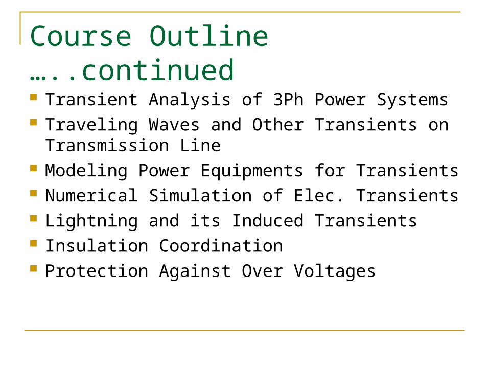
Course Outline …..continued
Transient Analysis of 3Ph Power Systems Traveling Waves and Other Transients on
Transmission Line Modeling Power Equipments for Transients Numerical Simulation of Elec. Transients Lightning and its Induced Transients Insulation Coordination Protection Against Over Voltages

Evaluation System
Assignments : 10% Mid Term One (items 1 to 4) : 10% Mid Term Two (items 5 to 7) : 10% Final : 60% Class Project : 10%
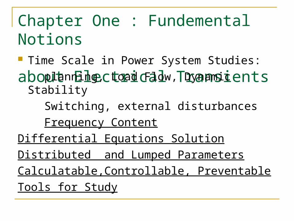
Chapter One : Fundemental Notions about Electrical Transients Time Scale in Power System Studies: planning, Load Flow, Dynamic Stability Switching, external disturbances Frequency ContentDifferential Equations SolutionDistributed and Lumped ParametersCalculatable,Controllable, PreventableTools for Study

CCT Parameters
In Steady State and Transient
Mathematical Presentation & Physical Interpretation
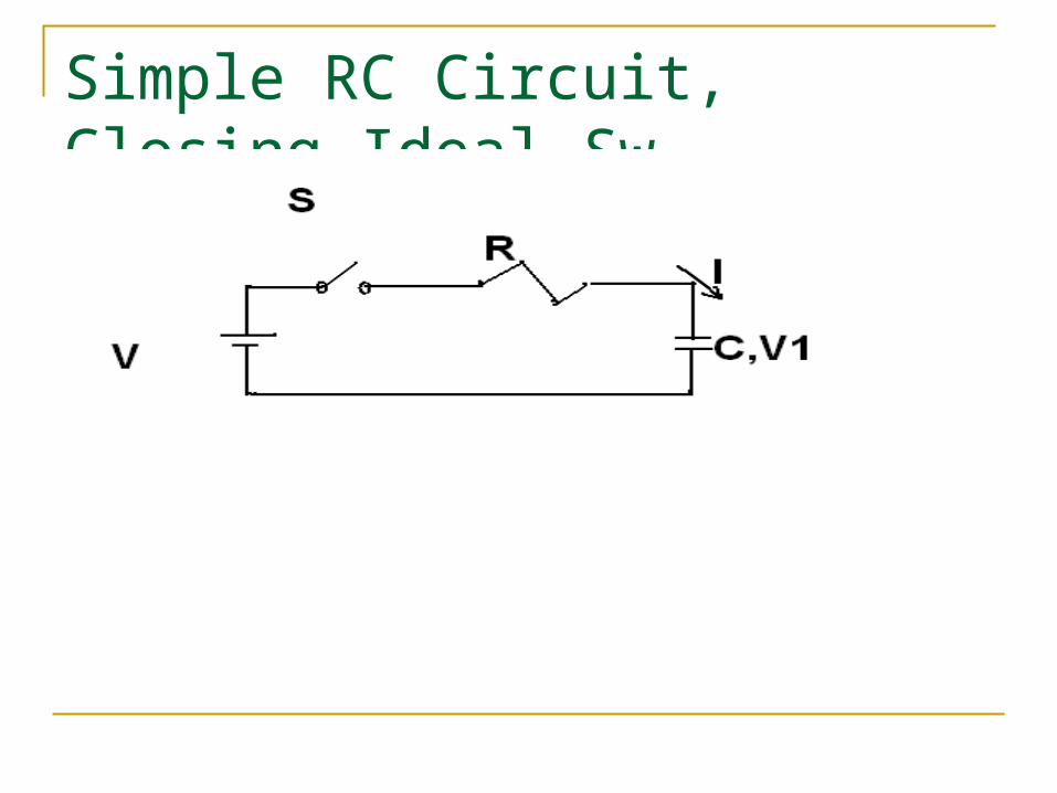
Simple RC Circuit, Closing Ideal Sw.
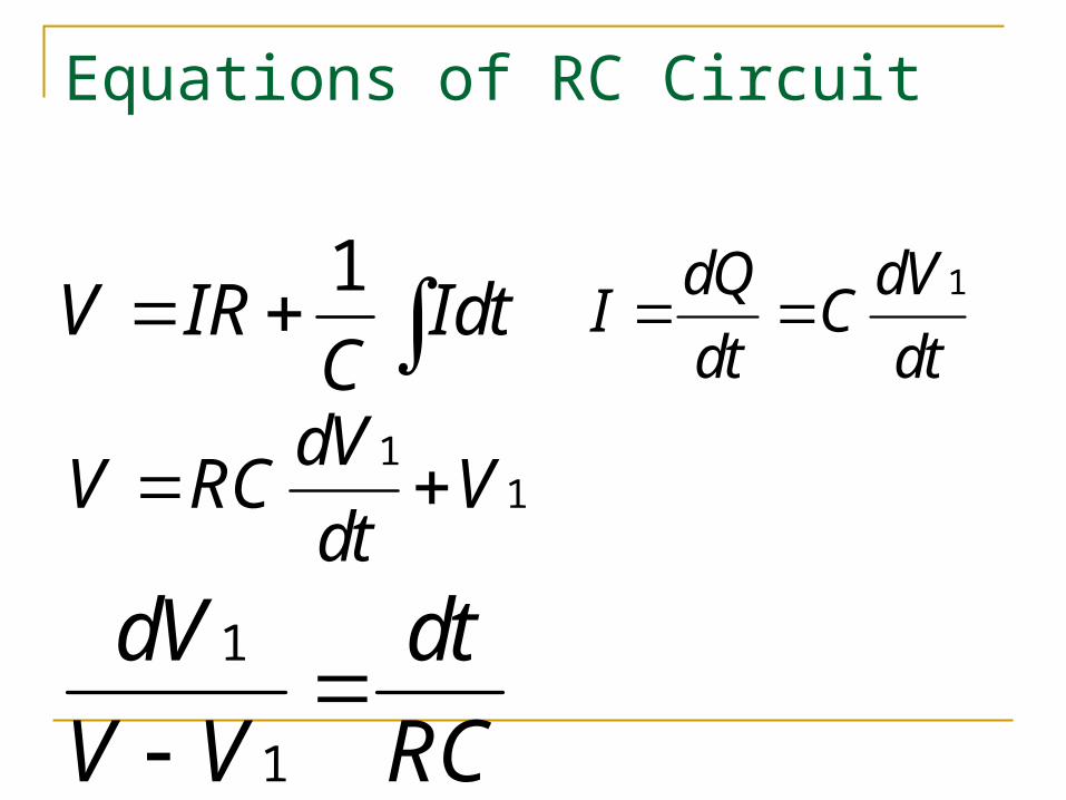
Equations of RC Circuit
1dQ dVI Cdt dt
11
dVV RC Vdt
1
1
dV dtV V RC
1V IR IdtC
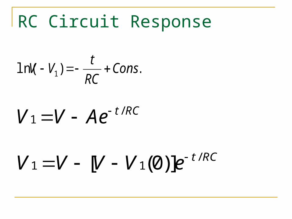
RC Circuit Response
/1
t RCV V Ae
/1 1[ (0)] t RCV V V V e
.)ln( 1 ConsRCtVV
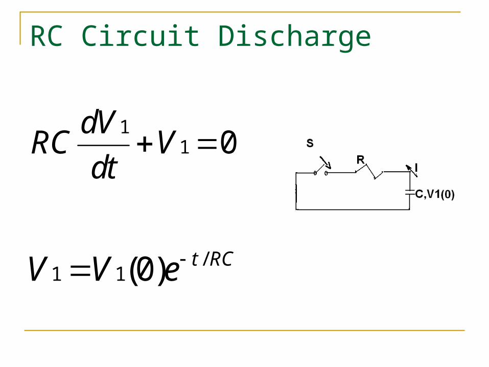
RC Circuit Discharge
11 0dVRC V
dt
/1 1(0) t RCV V e
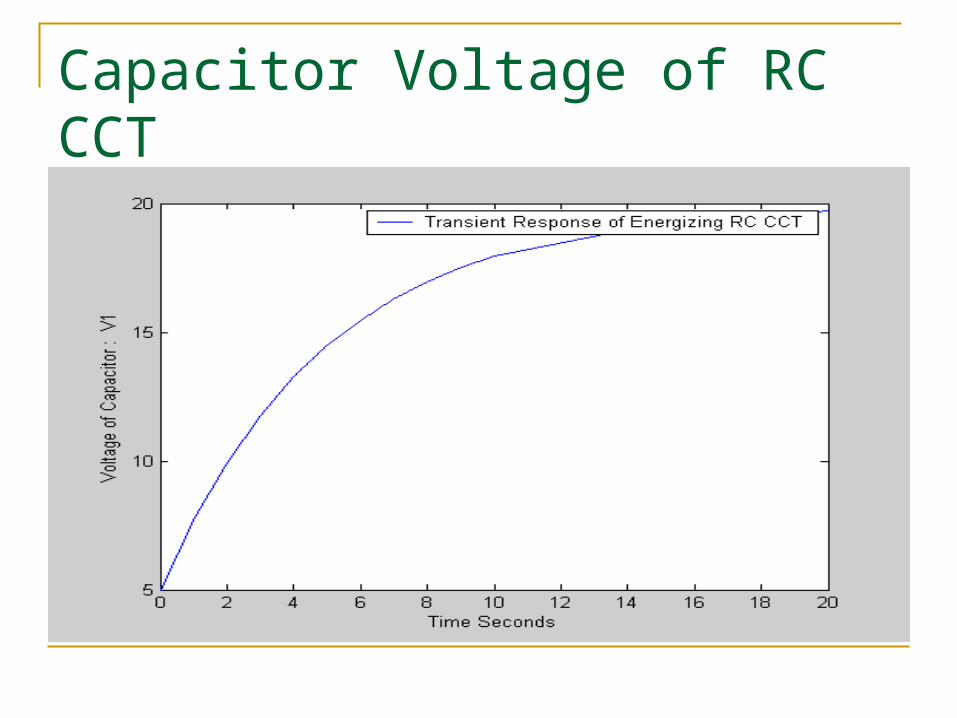
Capacitor Voltage of RC CCT
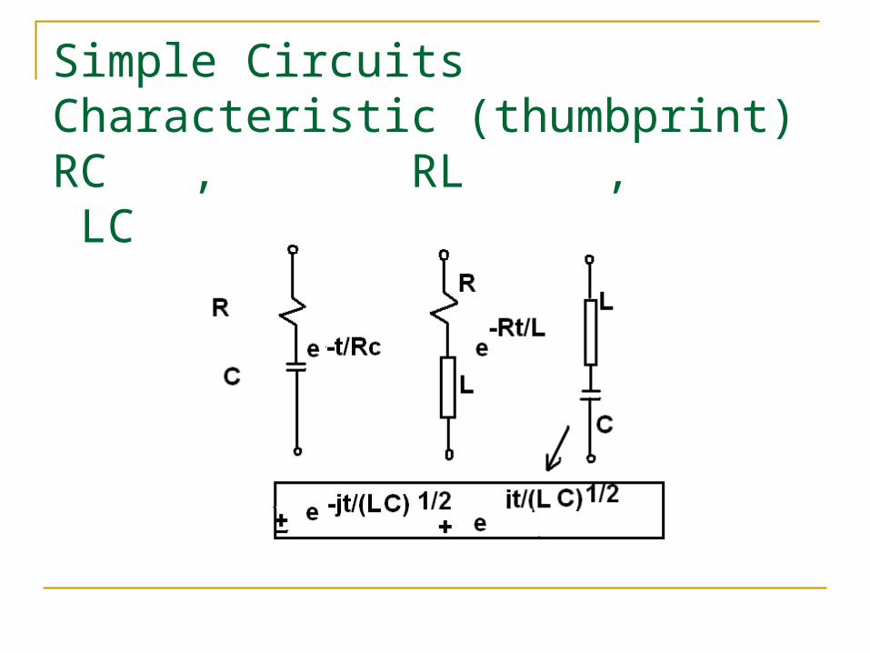
Simple Circuits Characteristic (thumbprint)RC , RL , LC Circuits
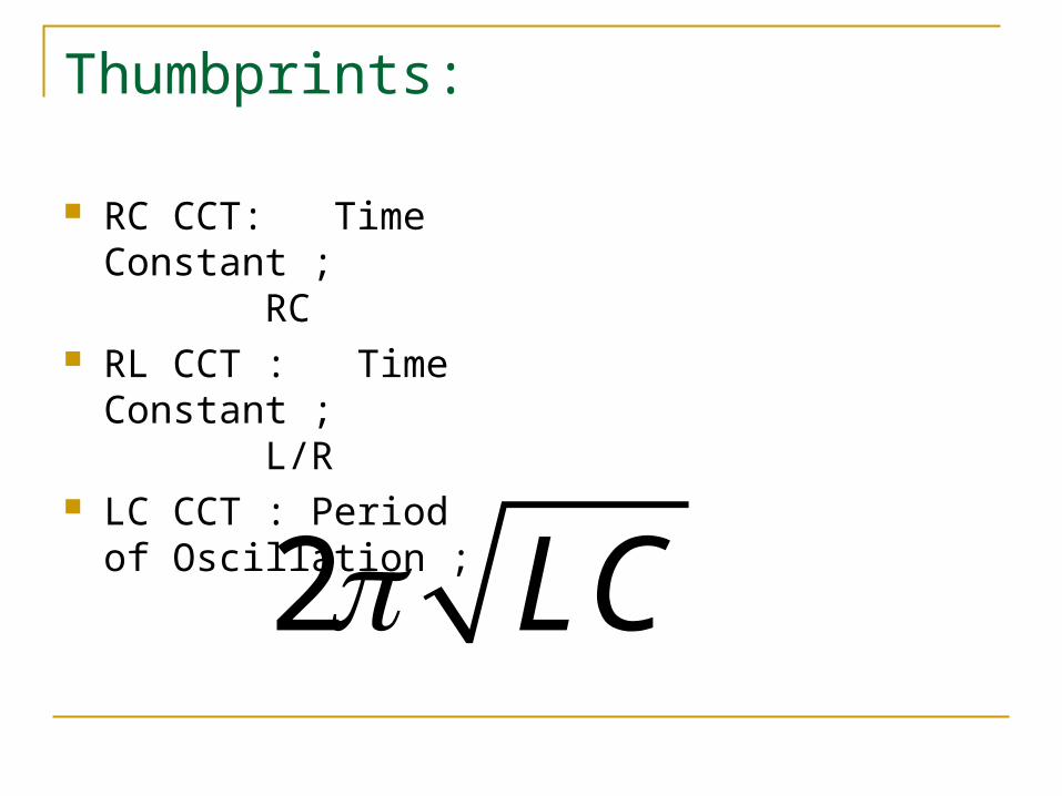
Thumbprints:
RC CCT: Time Constant ; RC
RL CCT : Time Constant ; L/R
LC CCT : Period of Oscillation ;
2 LC

Principle of Superposition
If stimulus s1 produces R1 & s2 produces R2 applying s1+ s2 simultaneously responds R1+R2 in Linear System
Linear System: response proportional to : stimulus
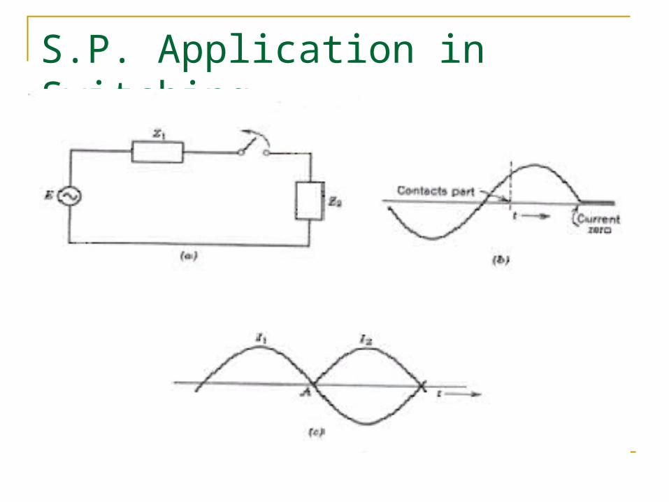
S.P. Application in Switching

CCT Detail I1: Pre-opening current I2: Superposed current to simulate current cease
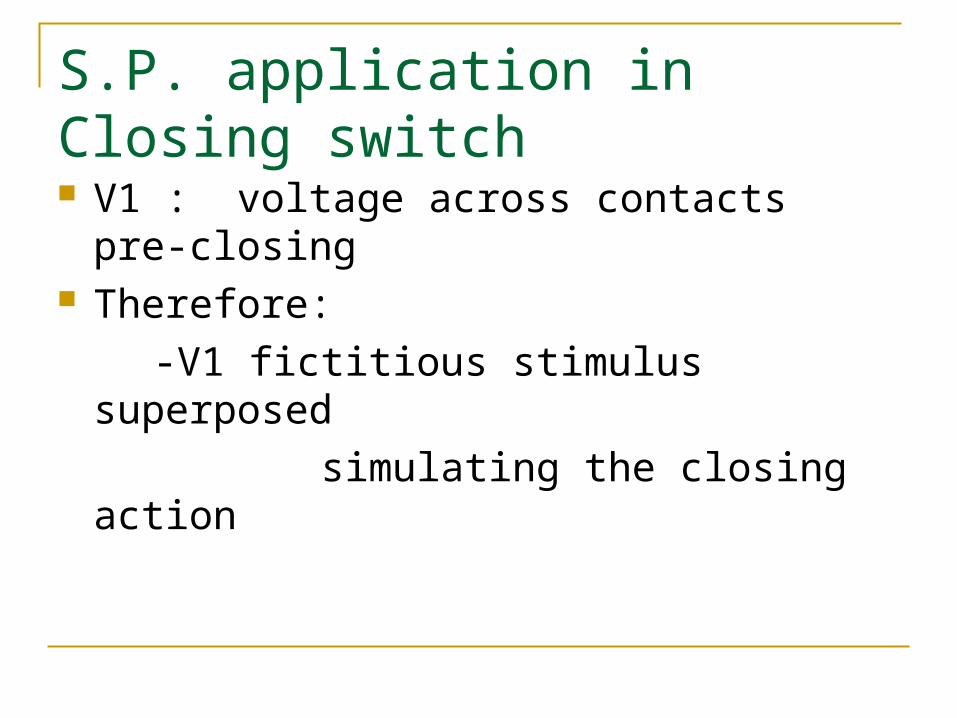
S.P. application in Closing switch V1 : voltage across contacts pre-closing Therefore: -V1 fictitious stimulus superposed simulating the closing action

The LaplaceTransform Method
0
, 0
( ) ( )
lim ( )
st
sta
F t F t e dt
F t e dt

Laplace Transform Continued
1 2 1 2
( ) ( )( ) ( )( ) ( )[ ( ) ( )] ( ) ( )
s jF t f sI t i sV t v sF t F t F t F t

Transform of Simple Functions
00 0
'
'' ' '
20 0
.
( )
stst st
st st
consV
e VV V e dt V e dt Vs s
I t I t
II t I t e dt I te dts
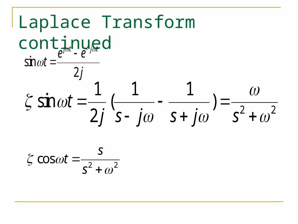
Laplace Transform continued
sin2
j t j te etj
2 2
1 1 1sin ( )2
tj s j s j s
2 2cos sts
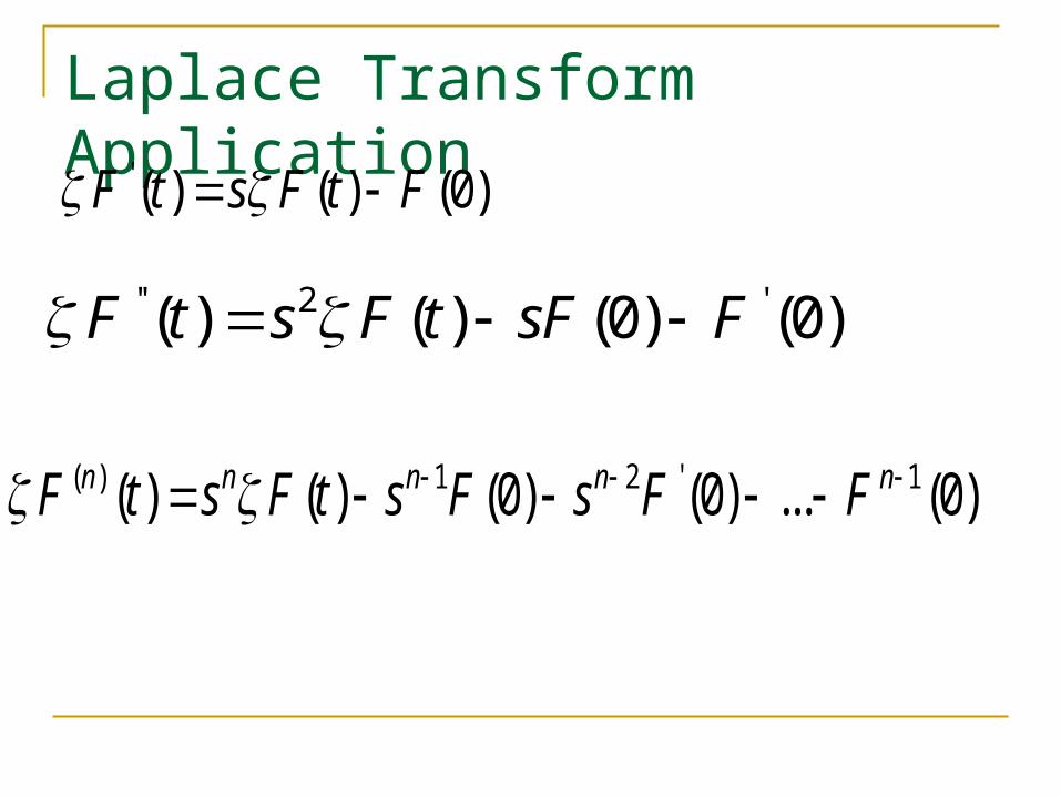
Laplace Transform Application'( ) ( ) (0)F t s F t F
'' 2 '( ) ( ) (0) (0)F t s F t sF F
( ) 1 2 ' 1( ) ( ) (0) (0) ... (0)n n n n nF t s F t s F s F F

Laplace Transform Continued 01 1[ ( ) ] ( ) ( )
t
F t dt F t F ds s
01 1[ ( ) ] ( ) ( ) ( )t
I t dt I t I t dt Q ts s
( ) (0)[ ( ) ] ( )t i s QI t dt q s
s s
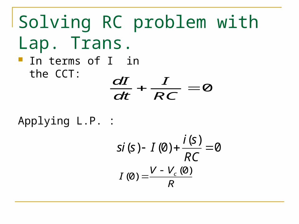
Solving RC problem with Lap. Trans. In terms of I in the
CCT:
Applying L.P. :
0dI Idt RC
( )( ) (0) 0i ssi s IRC
(0)(0) cV VIR

Continuing RC CCT solution
The L.T. solution:
The time solution:
(0) 1( ) 1cV Vi sR s RC
(0)( ) [ ]t
c RCV VI t eR

RL CCT excited by Battery V
Solving for I in CCT
The L.T. of Eq.:
The response:
dIRI L Vdt
( ) ( ) (0) VRi s Lsi s LIs
1( ) ........ (0) 0[ ]
Vi s IRL s s L
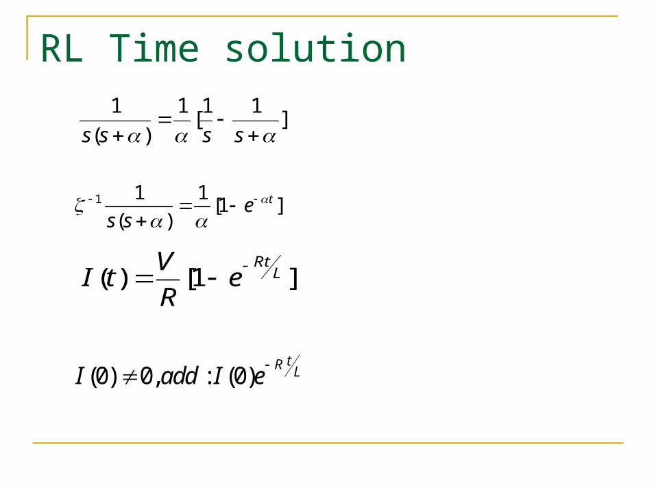
RL Time solution1 1 1 1[ ]
( )s s s s
1 1 1 [1 ]( )
tes s
( ) [1 ]RtLVI t e
R
(0) 0, : (0)tR LI add I e

Example: 377 MVA Gen field windingL=0.638H, Exciter noload:1.2 MW(480V) Energy stored in F.W.:
61.2 10 2500480
I A
2 2 61 1 0.638 2.5 10 1.9942 2
E LI MJ
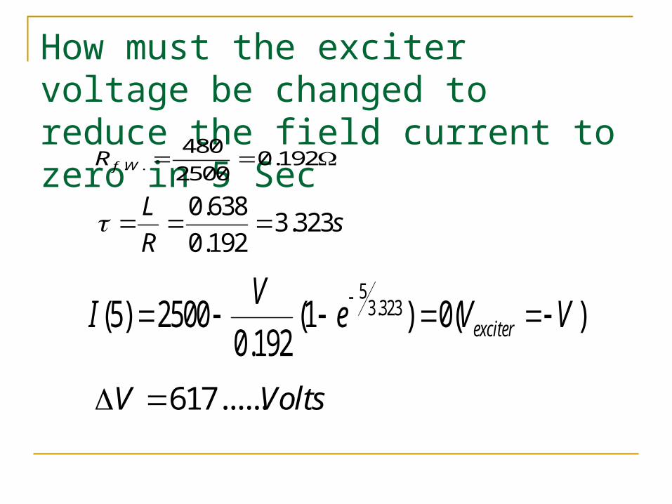
How must the exciter voltage be changed to reduce the field current to zero in 5 Sec
. .480 0.1922500f WR
0.638 3.3230.192
L sR
53.323(5) 2500 (1 ) 0( )
0.192 exciterVI e V V
617......V Volts
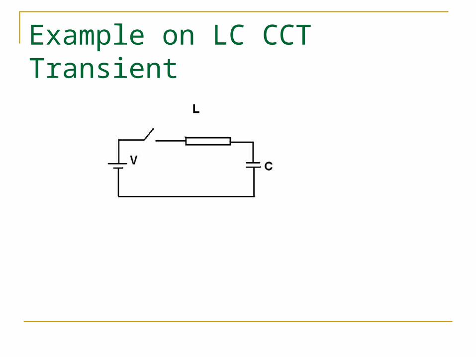
Example on LC CCT Transient
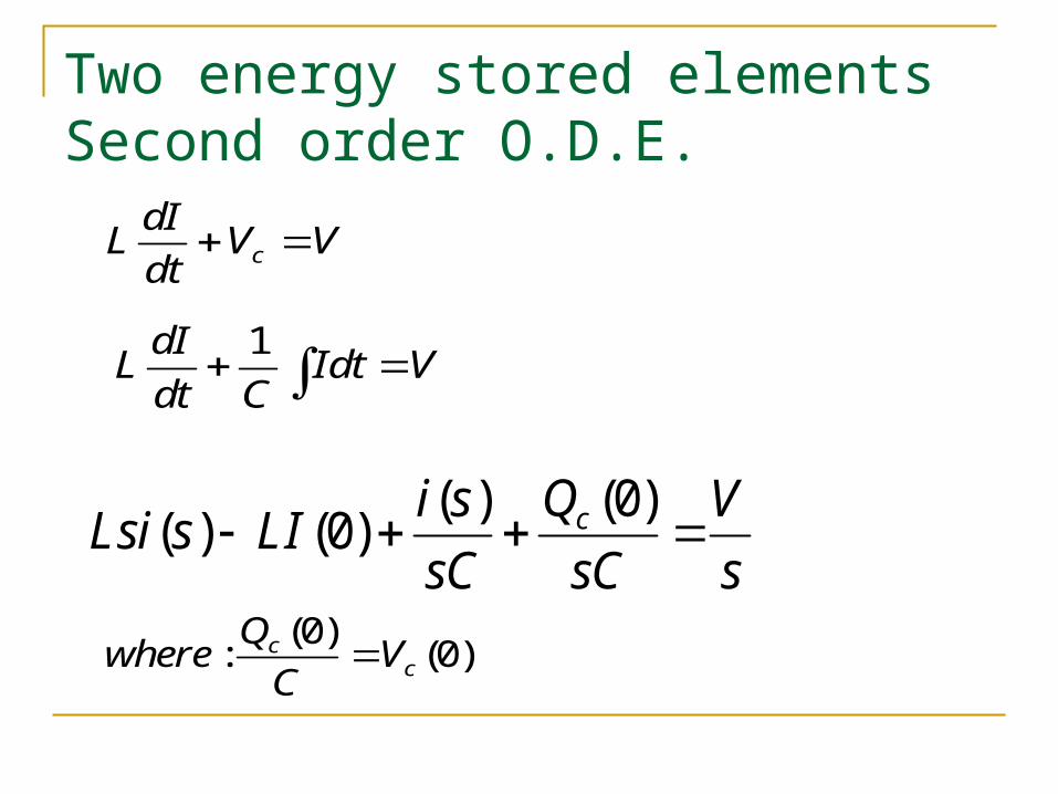
Two energy stored elementsSecond order O.D.E.
cdIL V Vdt
1dIL Idt Vdt C
(0)( )( ) (0) cQi s VLsi s LIsC sC s
(0): (0)cc
Qwhere VC
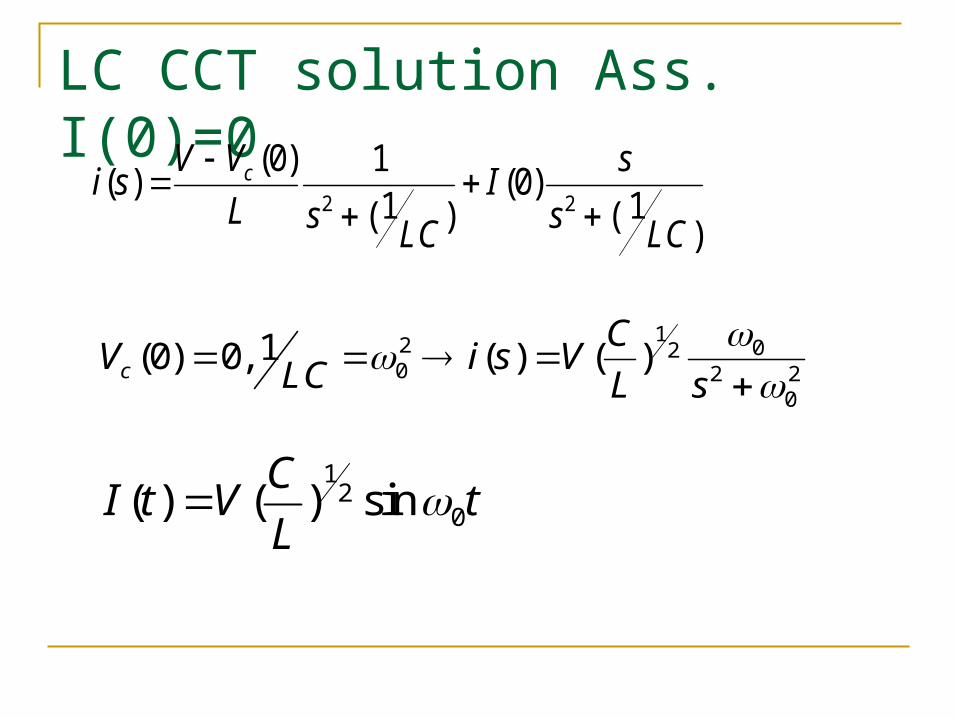
LC CCT solution Ass. I(0)=0
2 2
(0) 1( ) (0)1 1( ) ( )
cV V si s IL s sLC LC
12 020 2 2
0
1(0) 0, ( ) ( )cCV i s VLC L s
12
0( ) ( ) sinCI t V tL
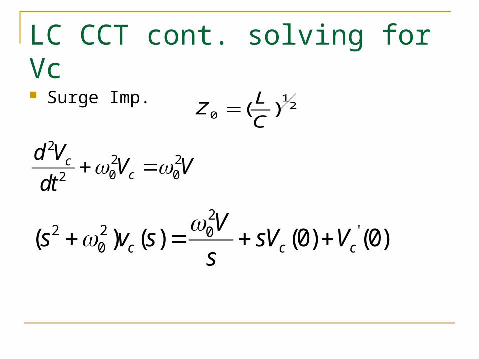
LC CCT cont. solving for Vc
Surge Imp. 12
0 ( )LZC
22 20 02
cc
d V V Vdt
22 2 '0
0( ) ( ) (0) (0)c c cVs v s sV Vs
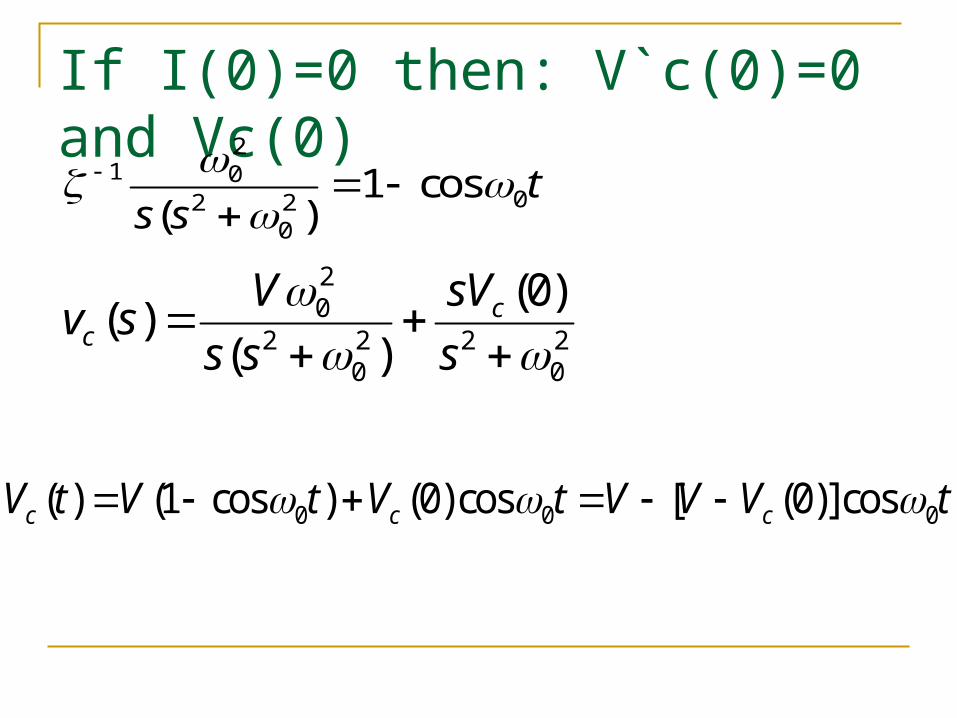
If I(0)=0 then: V`c(0)=0 and Vc(0)
20
2 2 2 20 0
(0)( )( )
cc
V sVv ss s s
21 0
02 20
1 cos( )
ts s
0 0 0( ) (1 cos ) (0)cos [ (0)]cosc c cV t V t V t V V V t

Vc characteristic
Vc Osc. Amp depend on V-Vc(0) Vc starts at Vc(0) as expected Response for : 1-Vc(0)=-V 2-Vc(0)=0 3-Vc(0)=+V/2Voltage and Current Relation
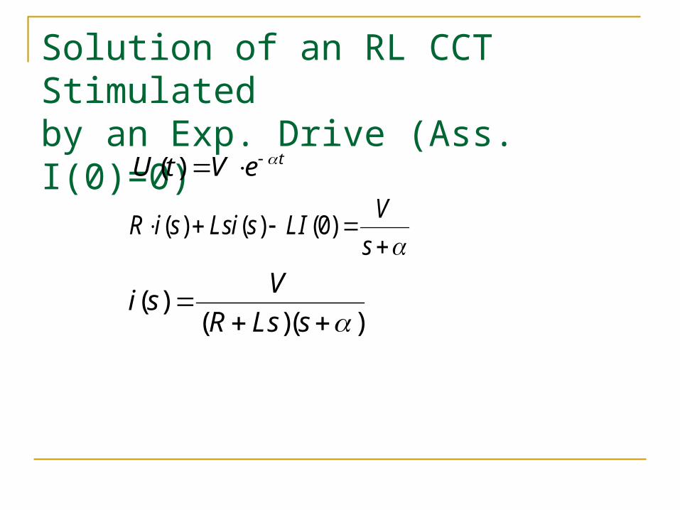
Solution of an RL CCT Stimulatedby an Exp. Drive (Ass. I(0)=0)
( ) tU t V e
( ) ( ) (0) VR i s Lsi s LIs
( )( )( )
Vi sR Ls s

Exp. Stimulated RL CCT, Cont. If /R L
1 1( ) ( )( )Vi s
L s s
( ) ( )( )
t tVI t e eL