specification for fabrication of stainless...
TRANSCRIPT
Page 1 of 36 Technical Specification No. RP/TSE/R0, Dt. 16-10-2014.
SPECIFICATION FOR FABRICATION OF STAINLESS STEEL HEAT EXCHANGER (PART OF
THERMO SYPHON EVAPORATORS)
CONTENTS SR. No TITLE Page No.
1. SCOPE ............................................................................................................................. 2 2. LIST OF EQUIPMENT & APPLICABLE DRAWINGS : ...................................................... 2 3. GENERAL REQUIREMENTS .......................................................................................... 3 4. MATERIALS ..................................................................................................................... 4 5. FABRICATION REQUIREMENTS ................................................................................... 5 6. WELDING ......................................................................................................................... 7 7. FIT-UP & ATTACHMENTS ............................................................................................. 11 8. CLEANLINESS & SURFACE FINISH .......................................................................... 12 9. INSPECTION & TESTING ............................................................................................ 13 10. PACKAGING & SHIPMENT .......................................................................................... 17 11. DOCUMENTATION ........................................................................................................ 18 12. TIME SCHEDULE: .......................................................................................................... 20 13. SPECIAL NOTES: ......................................................................................................... 20 14. PRICE SCHEDULE: ....................................................................................................... 20 15. VENDOR EVALUATION: .............................................................................................. 21 16. ANNEXURE – I FREE ISSUE MATERIAL (FIM) ............................................................ 22 17. ANNEXURE- II INSTRUCTIONS FOR FREE ISSUE MATERIALS (FIM) ....................... 23 18. ANNEXURE- III INSTRUCTIONS & DETAILS FOR HX MANUFACTURE ...................... 24
19. APPENDIX - I WELDING, INSPECTION & TESTING REQUIREMENTS ……………25 20. APPENDIX – II SUPPLEMENTARY REQUIREMENTS- HEAT EXCHANGER ............... 28 21. APPENDIX – III FABRICATION REQUIREMENTS GENERAL NOTES ......................... 32 22. APPENDIX – IV VENDOR EVALUATION PROFORMA ................................................. 35
Technical Specification No: RP/TSE/R0, Dt. 16/10/2014 TENDER No: NRBPSU/01/ENG/PT/1101
SPECIFICATIONS FOR FABRICATION OF STAINLESS STEEL HEAT EXCHANGER (PART OF
THERMO SYPHON EVAPORATORS)
Page 2 of 36 Technical Specification No. RP/TSE/R0, Dt. 16-10-2014.
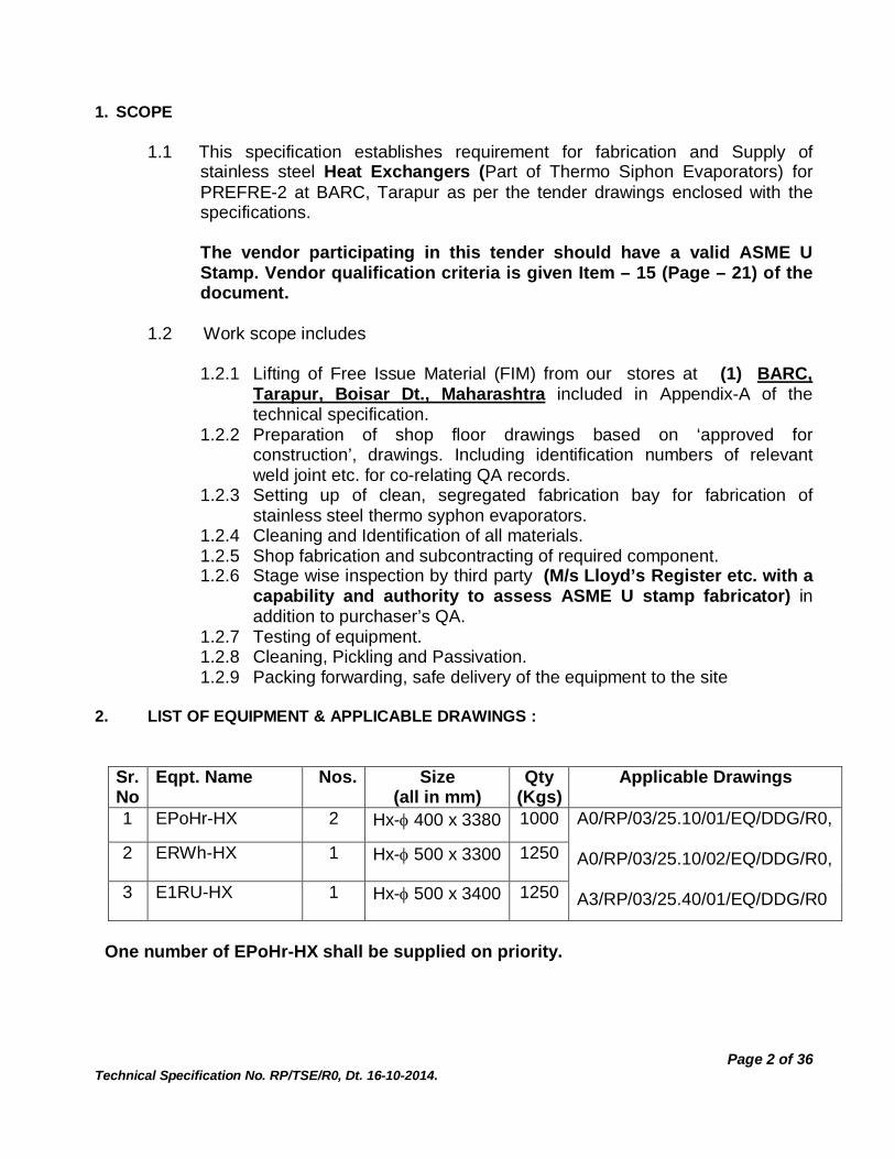
1. SCOPE
1.1 This specification establishes requirement for fabrication and Supply of stainless steel Heat Exchangers (Part of Thermo Siphon Evaporators) for PREFRE-2 at BARC, Tarapur as per the tender drawings enclosed with the specifications.
The vendor participating in this tender should have a valid ASME U Stamp. Vendor qualification criteria is given Item – 15 (Page – 21) of the document.
1.2 Work scope includes
1.2.1 Lifting of Free Issue Material (FIM) from our stores at (1) BARC,
Tarapur, Boisar Dt., Maharashtra included in Appendix-A of the technical specification.
1.2.2 Preparation of shop floor drawings based on ‘approved for construction’, drawings. Including identification numbers of relevant weld joint etc. for co-relating QA records.
1.2.3 Setting up of clean, segregated fabrication bay for fabrication of stainless steel thermo syphon evaporators.
1.2.4 Cleaning and Identification of all materials. 1.2.5 Shop fabrication and subcontracting of required component. 1.2.6 Stage wise inspection by third party (M/s Lloyd’s Register etc. with a
capability and authority to assess ASME U stamp fabricator) in addition to purchaser’s QA.
1.2.7 Testing of equipment. 1.2.8 Cleaning, Pickling and Passivation. 1.2.9 Packing forwarding, safe delivery of the equipment to the site
2. LIST OF EQUIPMENT & APPLICABLE DRAWINGS :
Sr. No
Eqpt. Name Nos. Size (all in mm)
Qty (Kgs)
Applicable Drawings
1
EPoHr-HX 2
Hx- 400 x 3380 1000 A0/RP/03/25.10/01/EQ/DDG/R0, A0/RP/03/25.10/02/EQ/DDG/R0,
A3/RP/03/25.40/01/EQ/DDG/R0
2 ERWh-HX
1 Hx- 500 x 3300 1250
3 E1RU-HX 1 Hx- 500 x 3400 1250
One number of EPoHr-HX shall be supplied on priority.

Page 3 of 36 Technical Specification No. RP/TSE/R0, Dt. 16-10-2014.
3. GENERAL REQUIREMENTS 3.1 Drawings :
3.1.1 All the Heat Exchangers shall be fabricated strictly in accordance with the approved drawing for construction provided by engineer and complying to documents/codes/standards mentioned in the specifications.
3.1.2 For the purpose of bid preparation typical design drawings are enclosed with this enquiry, which contain all details. Bidders shall get all their queries duly clarified before submitting their offer.
3.1.3 Successful bidder shall prepare shop floor drawings complete with all details for fabrication and QA correlation. The same shall be submitted for review/approval of ENGINEER before taking up fabrication.
3.1.4 All nozzle sizes, quantities etc. are final in the tender drawing. However minor changes in these may be incorporated
3.1.5 The Purchaser reserves the right to make, wherever found necessary, to make minor changes in the fabrication drawings and such changes shall be considered as within the scope of the specified work and shall not be considered as extra work.
3.1.6 The fabricator shall submit 2 (two) prints of the drawings to the Purchaser after final approval. It may be noted that each equipment shall have separate fabrication drawing and QA document folder. The fabrication drawings shall be generated on computer using Autocad software and soft copy of the same should also be submitted to purchaser on CD or DVD.
3.2 APPLICABLE CODES / STANDARDS
i) Fabrication and Design: ASME Section III Div 1 Sub Section NC (Class 2 ) ii) ASME Section II : Part A (ferrous materials) & Part C
(welding rods, electrodes and filler wires) iii) ASME Section V : Non-destructive tests iv) ASME Section IX : Welding/welder qualification v) ASTM - E - 165 : Liquid penetrant test vi) ASTM - E - 94 : Standard guide for radiographic testing. vii) ASTM - E - 142 : Radiography viii) ASTM - A - 262 : Inter Granular Corrosion (IGC) tests. ix) ASTM – E -112 : Grain size x) ASTM - E- 45 : Inclusion rating xi) ASTM E-388/A388M : Ultrasonic Testing xii) ASTM-D-808 : Measurement of chlorine content xiii) ASTM - A - 380 : Cleaning of stainless steel. xiv) ASTM – A -577 : Ultrasonic Testing xv) ASTM – A – 578 : Ultrasonic Testing xvi) ASTM - E - 1003 : Hydrostatic test xvii) ANSI - B - 16.25 : Butt welded ends xviii) ANSI - B - 16.5 : Fittings xix) ANSI - B - 36.19 : Pipes

Page 4 of 36 Technical Specification No. RP/TSE/R0, Dt. 16-10-2014.
xx) IS – 2102 : Dimensional Tolerances (for dimensions without specific tolerance covered by ASME Section –III
Subsection NC) xxi) ASTM A240 : Stainless Steel plates xxii) ASTM A 312 : Seamless SS Pipes xxiii) ASTM A 479 : SS Round bars. xxiv) ASTM A 403 : SS Fittings. xxv) ASTM A 182 : SS Forgings.
3.2.1 Codes and standards applicable shall be of latest editions along with the applicable
addenda. 3.2.2 In case of conflict between this specification and any of code and standard the
contractor shall bring the same to the notice of the Engineer for resolution and decision by engineer will be final.
3.3 SUB-CONTRACTORS/ SUB-VENDORS : 3.3.1 Sub-contracting of the entire work shall not be permitted. No sub-contracting shall be
permitted for pressure parts or primary parts that come in contact with process fluids or radiographic quality weldments. Fabricator shall clearly state in his offer the name and details of the sub vendors whom they propose to employ for part work and also specify those parts of the work which are proposed to be sub-contracted.
3.3.2 The facilities of the sub-vendor shall be subject to inspection and approval of the
Purchaser before start of fabrication. Written procedures with regard to the work to be carried out by the sub-vendor shall be submitted by him which will be subject to approval by the Purchaser.
3.4 FREE ISSUE MATERIAL (FIM) :
Appendix - A gives a list of FIM’s to be supplied to the fabricator. Instructions regarding FIM are given in Appendix B. Free issue materials to be issued by the purchaser to the fabricator shall be covered by an insurance policy to be taken by the fabricator at his own cost for its full value.
4. MATERIALS
Free Issue (FIM) will be supplied by BARC as per Appendix-A. All the balance material procurement is in the scope of supplier.
4.1 All the Materials and standard parts are under the scope of supply of the fabricator
shall be of genuine quality and in accordance with good practice pertinent to the manufacture of austenitic stainless steel HX and shall also be subject to approval by the Purchaser.
4.2 Unless otherwise specified in the drawings, the material of construction for all the HXs
covered by this tender shall be austenitic stainless steel of AISI 304L grade and of relevant standards of ASTM for the particular product form.

Page 5 of 36 Technical Specification No. RP/TSE/R0, Dt. 16-10-2014.
4.3 In case of any defective materials (plates, pipes etc.) being received by the fabricator,
it shall be the responsibility of the fabricator to obtain proper replacement from his supplier. All the materials may also require cleaning (acid/water) before use. Use of any defective material shall not be permitted.
4.4 FIM material issued for Tube sheet shall be subjected to 100% UT with grid marking on complete surface. The UT qualified portions shall only be utilised for tube sheets.
4.5 Plate, pipe & tubes shall be cut only as per approved plate cutting layouts and with
material identification markings. 4.5 Welding filler wire to be used in fabrication is SPECIAL (Ferrite & IGC controlled)
filler wire conforming to AWS - A.5.9 ER- 308L. Tungsten electrodes used for TIG welding shall conform to ASME Sec II Part C, SFA–5.12, EWTh – 2, both the items shall be supplied by the fabricator. The material and filler wire shall be properly identified, segregated and stored separately during fabrication
5. FABRICATION REQUIREMENTS 5.1 General: 5.1.1 Fabricator shall prepare the shop drawings, bill of materials and plate cutting layouts,
and shall fabricate, inspect, test, package and deliver the vessels at site as per details given in this specification. Fabricator's scope of work shall terminate only when the equipment with attachments and supports are delivered in good condition, without any damage, at the Project Site.
5.1.2 Detailed manufacturing plans and sequence of assembly to be adopted for fabrication
of these vessels shall be submitted for approval of the Purchaser. A firm manufacturing schedule in the form of Bar Chart shall be submitted along with the offer.
5.1.3 The Heat exchanger is inter connected with its Vapour separator at site. The tendered
item (Heat exchanger) is meant for replacement hence the manufactured equipment (Heat exchanger) Hot (Nozzle A) & Cold limb (Nozzle B) center to centre distance shall be maintained as per as built drawing within + 0.5 mm, further the extended portion of the limbs shall be 100 mm greater than the dimension provided in the as built drawing. As built drawings will be provided to the successful bidder. He will submit detailed manufacturing process plans for approval. Requirements for fabrication / inspection are given in Appendix I & II.
5.1.4 General notes on fabrication requirements are given in Appendix III. Relevant
portions of these requirements should appear as notes in the fabrication drawings. 5.1.5 The fabrication of equipment shall be carried out in a separate enclosed clean area,
specially reserved for tendered jobs. The area will be reserved for Stainless Steel Fabrication exclusively ensuring full protection against cross contamination, airborne

Page 6 of 36 Technical Specification No. RP/TSE/R0, Dt. 16-10-2014.
or through tools. The cutting, grinding tools & tackles employed for this job shall be new and shall be of compatible grade & MOC. Utmost care shall be taken in upkeep of fabrication environment to ensure clean surfaces. Every cutting, grinding, welding, shifting operation shall be proceeded and preceded by thorough cleaning of the surface by approved cleaning agents to ensure ingress free weld joints and deposit free equipment surface.
5.2 Materials & Material Identification: 5.2.1 All materials for fabrication work shall conform to the specifications issued by
Purchaser. No substitution of equivalent material is permissible unless specifically authorized by the purchaser through a ‘Design Change Request’ (DCR).
5.2.2 Fabricator shall maintain a positive system of identification for the materials used in
fabrication in order that all materials in the completed work shall be easily traceable to its origin. The Purchaser shall approve the system.
5.2.3 Identification reference markings on materials shall be transferred prior to cutting of
materials. The markings shall be located as to be clearly visible on the outside after completed fabrication. However, markings made, if any, on surfaces exposed to corrosive service shall be removed.
5.3 Shell Sections & Dished Ends: 5.3.1 Shell sections shall be formed as per purchaser approved procedure. Direct contact
between the carbon steel roller surface and stainless steel plates shall be avoided by suitable means during rolling to prevent contamination of stainless steel plate surfaces.
5.3.2 The dished end shall be formed by cold working from the blanks of suitable
dimensions. Procedure for dished end formation shall be established, and shall have to be approved by the purchaser, before taking up mass production. DP examination of the cut edges and knuckle areas (inside & outside surfaces) shall be carried out to ensure defect-free surface.
5.3.3 The plate sizes supplied are based on fabrication of dished ends free of joints. In the
event of non availability of such plates, joints conforming to codal requirement may be permitted.
5.3.4 FORMING OF STAINLESS STEEL EXPANSION BELLOWS :
The contractor will submit detail procedure for cold forming of expansion bellows. Procedure must be based on use of proper presses and tooling to avoid cold work and damage to the material. The contractor will arrange for inspection and testing of bellows for dimensional and procedural compliances. One assembly will be got approved before fabrication of total requirement.
Page 7 of 36 Technical Specification No. RP/TSE/R0, Dt. 16-10-2014.
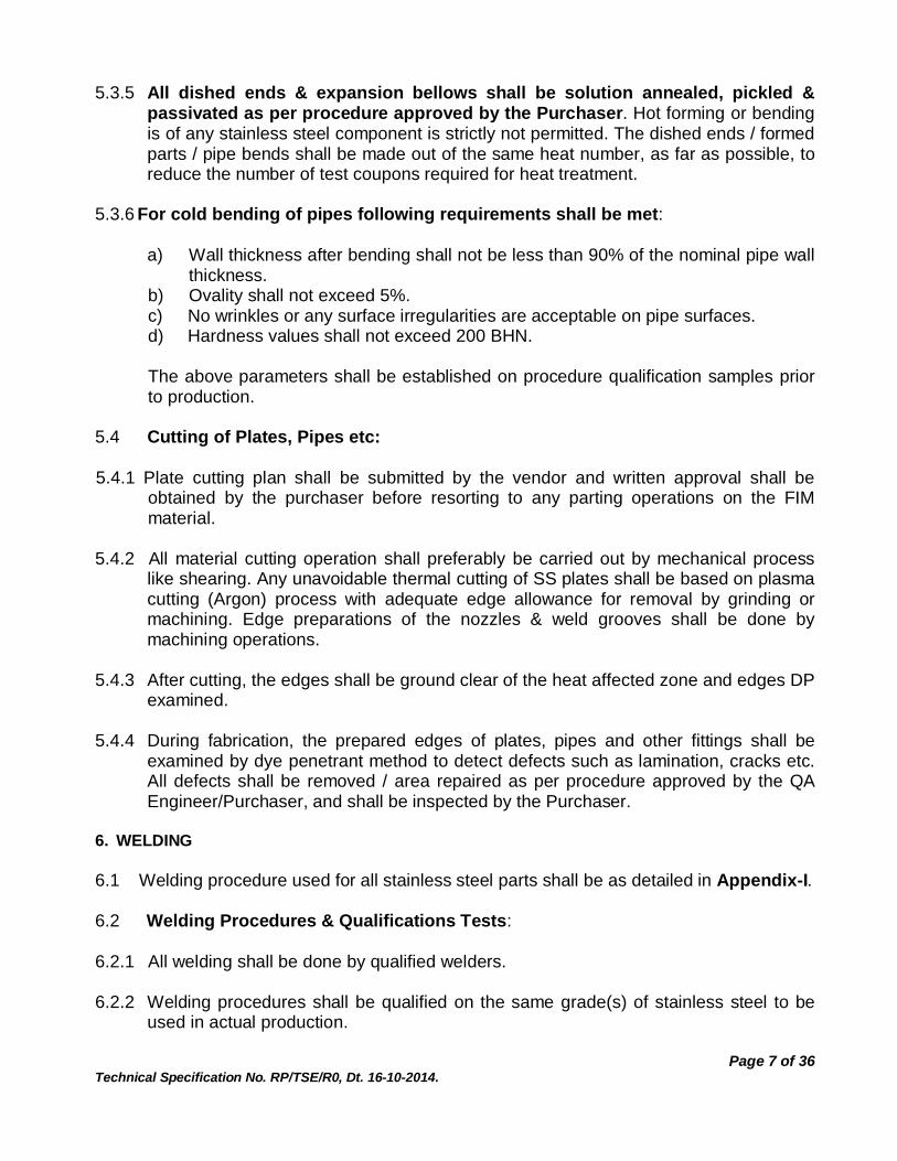
5.3.5 All dished ends & expansion bellows shall be solution annealed, pickled & passivated as per procedure approved by the Purchaser. Hot forming or bending is of any stainless steel component is strictly not permitted. The dished ends / formed parts / pipe bends shall be made out of the same heat number, as far as possible, to reduce the number of test coupons required for heat treatment.
5.3.6 For cold bending of pipes following requirements shall be met:
a) Wall thickness after bending shall not be less than 90% of the nominal pipe wall
thickness. b) Ovality shall not exceed 5%. c) No wrinkles or any surface irregularities are acceptable on pipe surfaces. d) Hardness values shall not exceed 200 BHN. The above parameters shall be established on procedure qualification samples prior to production.
5.4 Cutting of Plates, Pipes etc: 5.4.1 Plate cutting plan shall be submitted by the vendor and written approval shall be
obtained by the purchaser before resorting to any parting operations on the FIM material.
5.4.2 All material cutting operation shall preferably be carried out by mechanical process
like shearing. Any unavoidable thermal cutting of SS plates shall be based on plasma cutting (Argon) process with adequate edge allowance for removal by grinding or machining. Edge preparations of the nozzles & weld grooves shall be done by machining operations.
5.4.3 After cutting, the edges shall be ground clear of the heat affected zone and edges DP
examined. 5.4.4 During fabrication, the prepared edges of plates, pipes and other fittings shall be
examined by dye penetrant method to detect defects such as lamination, cracks etc. All defects shall be removed / area repaired as per procedure approved by the QA Engineer/Purchaser, and shall be inspected by the Purchaser.
6. WELDING 6.1 Welding procedure used for all stainless steel parts shall be as detailed in Appendix-I. 6.2 Welding Procedures & Qualifications Tests: 6.2.1 All welding shall be done by qualified welders. 6.2.2 Welding procedures shall be qualified on the same grade(s) of stainless steel to be
used in actual production.

Page 8 of 36 Technical Specification No. RP/TSE/R0, Dt. 16-10-2014.
6.2.3 Production welding shall not commence until procedure qualification is completed and approved by the Purchaser/Quality surveyor. Fabricator shall submit to the Purchaser four copies of the approved procedure and performance qualification reports. All test coupons/specimens shall be properly stamped and retained by the fabricator till completion of work and all such coupons/specimens shall be kept in safe custody and shall form part of final supply.
6.2.4 Cost of conducting all the tests shall be borne by the fabricator. Purchaser shall have
the right to call further qualification tests from time to time for any welder who is not producing finished welds of required quality or who has discontinued welding by the particular process for more than three months.
6.2.5 Tests for welding procedure & performance qualification shall be carried out in
conformance with requirements of ASME Sec IX together with additional requirements included in this specification in Appendix I & II. Even in case the welder being deployed is already qualified all the welders employed for this tendered job shall be qualified afresh.
6.2.6 To cover any welded joint coming on the dished end, one welding procedure test
coupon shall undergo the same heat treatment prescribed for the cold formed components.
6.2.7 Acceptance Standards for IGC and Delta ferrite shall be as follows:
(1) As per ASTM A 262 Practice ‘A’: microstructure will be acceptable etch structure. As per ASTM A 262 Practice ‘C’: Average corrosion rate for 5 cycles shall not be more than 12 mpy as specified for base material. Each leg of corrosion cycle will not show abruptly high value (18 mpy max)
(2) Delta Ferrite on Welds (Measured by using a calibrated Ferrite Gauge) shall be in the range of 4FN to 10 FN.
Note: IGC test piece for PQR (Procedure Qualification Record) shall include Parent metal + weld area + Heat Affected Zone (HAZ).
6.3 Welding Requirements: 6.3.1 Welding fixtures, clamps or manipulators should not have any surfaces made from
lead, zinc or copper/copper alloy that can cause contamination of the stainless steel work-piece.
6.3.2 Welding power sources and associated control devices like HF units shall be of
reputed and standard makes. The fabricator shall be required to produce documents, if desired, by the Purchaser's Quality Surveyor, in support of proper calibration of the equipment.

Page 9 of 36 Technical Specification No. RP/TSE/R0, Dt. 16-10-2014.
6.3.3 Fabricator shall ensure that there is a regular and systematic supervision of all welding work. The fabricator shall institute a system whereby all welds can be traced to the welder responsible for their production.
6.3.4 All vessel internal welds (LS & CS) must be preferably carried out by providing
suitable arrangement for back purging even where shell diameter permits access for back chipping. This is to ensure minimal removal of metal during back chipping and seal welding.
6.3.5 Surfaces to be welded shall be free from paint, oil, grease, dust or any other
contamination. Cleaning of surfaces/weld edge preparations/ completed weldments shall be done only by use of approved solvents. Weld craters shall be examined for defects that shall be removed by grinding. Wire brushes used shall be of stainless steel to avoid contamination of the weld surfaces and these brushes shall not be used for cleaning any Carbon steel material.
6.3.6 Haphazard striking of electrode on base metal for establishment of arc shall not be
permitted. High Frequency unit shall always be used for arc starting. In case inadvertent arc strikes occur, the affected area shall be ground flush and surface examined by dye penetrant test.
6.3.7 Tack welds shall be DP examined for defects before continuing with further welding
and any defect observed shall be rectified using the approved procedure. Qualified welders only shall be allowed for performing tack welding.
6.3.8 Necessary precautions like skip welding, back step welding etc. shall be taken to
avoid distortion. 6.3.9 Mock up shall be carried out in presence of third part inspector and our QA
inspector, simulating Shell to tube sheet joint in Heat Exchanger to assess the weld metal penetration, root fusion etc. TTS joints mock up shall be carried out for welder qualification.
6.3.10 Flush welding of tube face with tube sheet shall be done at each alternate radius for top tube sheet to avoid concentration of fluid contents during Hx operation starting from centre to allow easy draining of the contents/ recirculation during operation.
6.3.11 Suitable welding fixtures manufactured from compatible MOC shall be used in
achieving the requisite fit-ups for welding as per approved WPS & PQRs. All such welding fixtures shall preferably be made by machining rather than fabrication to smoothen sharp corners which shall be detrimental in leaving scratches.
6.3.12 Due care shall be taken in weld edge preparation and the same shall be achieved by
edge preparation machines. Weld edge preparation by grinding shall be avoided and if need be used, prior approval of BARC shall be obtained.
6.4. Repairs:
Page 10 of 36 Technical Specification No. RP/TSE/R0, Dt. 16-10-2014.
6.4.1 All defective areas, as revealed by visual, dye penetrant, radiographic and ultrasonic
inspections, shall be repaired as per standard procedure submitted by the fabricator and approved by the Purchaser. Re-inspection of the repaired area shall be fully at the fabricator's cost and method of inspection used for the repaired area shall be the same as used for the original area. Repair welding at any spot shall be restricted to one time.
6.5 Welding Documentation 6.5.1 Fabricator shall supply to the Purchaser for his perusal / approval and retention, a
complete set of welding records whereby any weld can be traced to the welder responsible for its production, together with the heat / batch number (s) of the electrodes / filler wires used and the welding technique adopted.
6.6 Heat Treatment 6.6.1 The vessel as a whole needs no heat treatment. However, all dished ends, bellows,
pipe bends, with less than 5D radius and other formed components shall be solution annealed after forming as per approved procedure.
6.6.2 Heat treatment (solution annealing) shall be carried out wherever required, only in
accordance with an approved procedure which shall include the salient features of the process viz. temperature, soaking time, rate of heating, job loading temperature, method of heating, cooling rate, details of job support inside the furnace etc.
6.6.3 The furnace may be heated using electricity, oil or gas but the item must be protected
from all possibility of flame impingement. When gas firing is used the sulfur content of the gas shall not exceed 518 mg/m3 and for oil fired furnace the sulfur content of the fuel shall not exceed 0.5% by weight. Electrically heated furnace will be preferred.
6.6.4 Item shall be maintained at requisite temperature for an adequate time as per
material thickness. Time / temperature charts recorded by an automatic instrument of proved (calibrated) accuracy are required for the heat treatment which shall be approved by the Inspector.
6.6.5 De-scaling of the heat treated part shall be carried out by chemical procedure which
shall be submitted by the fabricator and approved by the purchaser. Chemical de-scaling shall normally be carried out using a nitric acid solution (pickling). Sand/Shot blasting in any case shall not be used to remove the scales.
6.6.6 Representative test coupons shall also be heat treated together with the formed
components. The test coupons shall have welds in case components with welds are solution annealed. The coupons shall be examined for microstructure, hardness and inter granular corrosion (IGC) after the heat treatment to check its conformity with required values. The acceptance criteria/ testing requirements for solution annealing sample coupons is as follows:

Page 11 of 36 Technical Specification No. RP/TSE/R0, Dt. 16-10-2014.
The solution annealed test coupon (with or without weld as the case may be) shall be examined for microstructure in conformity with ASTM A 262 practice ‘A’ (without sensitization). The test coupon shall be acceptable etch structure. If the structure is found ditched, the sample shall be evaluated for IGC practice ‘C’. If corrosion rate exceeds acceptable value as stipulated above, then the same shall be investigated and reviewed by purchaser for further processing. Hardness value after solution annealing shall not exceed the hardness of base material.
7. FIT-UP & ATTACHMENTS 7.1 Temporary Attachments: 7.1.1 As far as possible mechanical clamping (without welding) shall be used for making fit
ups. Temporary fittings such as tacking strips, cleats etc. shall be carefully removed to prevent damage to the parent plate. Fit up brackets shall be used only on the vessel outside. Any blemishes on the parent material shall be rectified and the area tested/ examined by liquid penetrant method for detection of cracks or any other defects, and if required, it will also be radiographed as per applicable codes and acceptance requirements as per Clause 9.5.2. Heavy clamps/ cleats shall only be fixed to the additionally provided pad plates to safeguard parent vessel surfaces.
7.1.2 Carbon steel members shall not be attached to stainless steel for aligning/restraining
purposes, instead suitable thick stainless steel members shall be employed. 7.2 Fit-ups: 7.2.1 Hammering directly on plates or the use of excessive force otherwise shall not be
permitted to achieve a fit up. In the event of excessive cold work, which in the opinion of the Purchaser shall adversely affect the corrosion resistance of the component, the fabricator shall carry out suitable heat treatment as advised by the Purchaser.
7.2.2 Written clearance/approval shall be obtained for each vessel before its final closure.
Final closure joint shall be the top dished end to main shell joint. 7.3 Nozzle Attachments: 7.3.1 All nozzle pipes and other wall penetrations coming on the vessel shall be attached
by full penetration welds and checked by radiography (for flush nozzles) and dye penetrant inspection as indicated in the fabrication drawings and manufacturing plan approved by the Purchaser.
7.3.2 Before final closure of the vessel, nozzle lengths inside the vessel shall be checked to
ensure conformity with the drawings. A record of actual lengths as fabricated shall be maintained for all nozzles. The nozzle assembly shall be checked for its perpendicularity, with respect to shell / dished end.
No nozzle shall be capped / weld closed at the internal portion of the vessel except for Nozzle I 6” which is a thermocouple nozzle. This shall be checked & recorded by the third party inspector & purchaser inspector. This checking and record will be a
Page 12 of 36 Technical Specification No. RP/TSE/R0, Dt. 16-10-2014.
hold point to be confirmed for tank closure apart from protruded nozzle length check as detailed above.
7.3.3 Special care shall be exercised while welding of nozzles to ensure that the pipe wall
inside surface is free from oxide formation due to welding heat. Mock-up tests are to be carried out to arrive at the correct welding procedures to be adopted for welding the nozzles. All nozzle attachment welding including tube to tube sheet welding shall be carried out with Argon gas (inside pipe) purging to avoid oxidation. All production nozzle welds shall be examined using fibroscope to check for oxidation / burn through etc.
7.3.4 The thick pipe ends shall have to be machined to match the corresponding diameters
for butt welding. 7.3.5 All vessel jackets shall be hydrostatic tested and all nozzle jackets shall be
pneumatically tested to check for leak tightness. All reinforcement or bearing pads on equipment shall be pneumatically tested to ensure leak tightness and design conformance for intended design pressure.
8. CLEANLINESS & SURFACE FINISH 8.1 All welds shall have smooth contour and merge smoothly into the parent metals. If
required the welds on the inside surface of vessel are to be ground smooth and flush with the parent metal, unless other wise specified, or other marks which occur during fabrication shall be repaired to the satisfaction of the Purchaser. The general surface finish shall be equal to or better than a standard pickle and passivated finish.
8.2 All scales, dents, burrs, weld spatter, oxide, oil and other foreign materials shall be
completely removed from inside and outside of the vessel. Items that will not permit their cleaning after complete fabrication shall be cleaned prior to assembly.
8.3 Fabricator shall take care to see that all chemicals/materials used for cleaning,
marking and degreasing etc are halogen and sulfur free. They shall not contain more than 25 ppm of total halogens and 100 ppm of total ionic content.
8.4 All stainless steel components and vessels shall be thoroughly cleaned pickled and
passivated. Hydro Fluoric Acid (HF) shall not be used as pickling reagent in any concentration.
8.5 Surface finish of welded joints shall be free from irregular, unevenness of deposition
and under cutting and shall be ground to a smooth regular contour. Hammering on completed weld is not permitted. Reinforcement on welds in plates & sheets shall not generally exceed 10% of the material thickness. Removal of undercut when carried out shall not result in thinning of the parent material.
8.6 Handling:

Page 13 of 36 Technical Specification No. RP/TSE/R0, Dt. 16-10-2014.
8.6.1 Care shall be taken in handling of the equipment at all stages of manufacture, testing, inspection and shipping. All necessary precautions shall be taken to protect the surface and equipment from damage. Permanent / non-repairable deformation as a result of faulty handling during any manufacturing stage or during transportation shall be a cause for rejection of the equipment.
8.6.2 Nylon web slings of suitable rating shall be employed for handling FIM & finished material.
9. INSPECTION & TESTING 9.1 General Requirements: 9.1.1 The fabricator shall be responsible for and shall provide for and perform all the
inspection and testing required as per this specification. The fabricator shall have a full fledged quality assurance set-up along with adequate instruments including that for radiographic, ultrasonic and Helium leak test and qualified staff to carryout the work. The contractor shall employ a qualified approved third party inspector Lloyds for QA activities as per ASME ‘U’ stamp requirements apart from his own and purchaser’s QA team. This shall be clearly mentioned in the offer. The fabricator shall submit for Purchaser's approval a detailed Quality Assurance Plan (QAP) for fabrication of these vessels wetted by third party quality surveyor.
9.1.2 The Quality Surveyor designated by the Purchaser and the third party quality
surveyor shall have complete access to the works of the fabricator as well as his sub-contractor and shall have the right to intervene wherever incorrect practices are detected. He shall also have the right to conduct or instruct the fabricator to perform any additional inspection or testing he deems necessary for compliance with the specifications. Any deviations recorded & corrected or additional enforcement on QA part shall be recorded in detail along with the operators details who deviated the set procedure shall form the final documentation.
9.1.3 The surveillance provided by the Purchaser's Quality Surveyor shall not relieve
fabricator of any of his responsibilities and that of his sub-vendor under this specification. Rejection of work not up to the specifications is possible at any time, and it shall be fabricator's endeavor to avoid such occurrences.
9.1.4 The fabricator shall maintain quality control/inspection records that shall indicate the
particulars of the quality control operations carried out. The Purchaser's Quality Surveyor shall have the right to witness any or all such operations.
9.1.5 When testing is not carried out in the fabricator's works, the vendor shall arrange to
have such tests carried out at outside agency duly approved by the Purchaser's Quality Surveyor and the vendor shall bear in full the cost of all such tests and re-tests.
9.1.6 Purchaser reserves the right to witness all radiographic exposures on weldments,
ultrasonic tests and Helium leak tests & hence these activities shall be carried out strictly under advance written intimation to the Purchaser.

Page 14 of 36 Technical Specification No. RP/TSE/R0, Dt. 16-10-2014.
9.1.7 The vendor shall submit to the purchaser all radiography films & UT records duly signed the authorized approving authority.
9.1.8 SS plates issued as FIM for use as tube sheets shall be subjected to 100% UT in grid
method. The portion which qualifies 100% shall only be employed as tube sheet. 9.1.9 Tube to tube sheet welding shall be subjected to 100 % RT. 9.2 Discrepancies & Field Changes: 9.2.1 Any discrepancies or omission from drawings, specifications or other documents or
any doubts arising as to the meaning or intent of any part thereof shall be referred to the Purchaser for which written clarifications will be issued by the Purchaser. Verbal communications shall be avoided.
9.3 Inspection & Test Failure: 9.3.1 In the event of failure of the vessel to meet any inspection or test requirement
specified herein, the fabricator shall notify the same to the Purchaser or to his authorized representative.
9.3.2 Fabricator shall obtain written permission from the Purchaser before undertaking any
repair work. The repair procedure shall be prepared by the fabricator and got approved by QA prior to start the repair work.
9.3.3 If repairs are likely to affect the result of work previously completed, appropriate re-
inspection/ re-testing shall be carried out. The quality assurance procedures to be followed in carrying out the repair work should have prior approval of Purchaser.
9.3.4 All such repair works shall be documented; the document shall contain the cause of
repair, the lapse at which stage caused the repair, what procedural changes have been implemented to avoid recurrence of the same. What is the extent of effect on the final product due to the repair shall also be documented. Such note shall be prepared and approved by the purchaser.
9.4 Material Inspection & Tests: 9.4.1 All materials including welding consumables procured by the fabricator for
manufacture of equipment under this specification shall be inspected and tested to the requirement of appropriate material specifications / standard and as per an approved quality assurance plan (QAP). Mill test certificates will be acceptable but where such documents are not available, the fabricator at his cost shall conduct the requisite tests. Separate tests have to be carried out for each material heat. In case any material fails in check-tests the fabricator shall replace the complete lot.
9.5 Radiographic and Ultrasonic Examination:

Page 15 of 36 Technical Specification No. RP/TSE/R0, Dt. 16-10-2014.
9.5.1 Radiographic examination of the welds shall be carried out in the finished condition (e.g. after heat treatment if any or after flushing the welds from inside etc). Examination will in accordance with the requirements of ASME Sec. III Div 1 NC. For all thickness X-rays shall be used as the source of radiation. Gamma rays shall be employed only when use of X-ray is not feasible and this shall be with the written clearance from the Purchaser's Quality Surveyor, who shall ensure that the radiography image quality and other requirements are fully met with the use of gamma ray radiography. Radiographic examination shall be carried out employing a procedure approved by the Purchaser.
9.5.2 Acceptance standards for defects / discontinuities as shown in radiographs shall be in
accordance with requirements of ASME Sec. III Div 1 NC together with following unacceptable indications:
a) Under cutting on either surface (inside or outside). b) Oxidation. c) Cracks, linear defects / indications etc. d) Root concavities if resulting in weld thickness becoming lesser than the parent plate e) Following rounded indications are not acceptable:
Single isolated indication > 1 mm size or ¼T whichever is smaller where ‘T’ is thickness of thinner plate / pipe
Cluster of any size and aligned indications. Five or more number of acceptable rounded indications in a length of
300mm
9.5.3 Through and through type nozzles welded to shell/dish and corner joints forming pressure parts for which RT examination is not possible, shall be UT tested by Angle Beam Technique with acceptance standard of 5% of plate thickness up to 10 mm & 3% for higher thicknesses. Sensitivity shall not be less than 50% amplitude, but not more than 75% of screen height. The defect signal shall be measured from one full skip position. UT shall be employed as per ASTM A577/A578. DAC with artificial defects technique shall only be followed. The procedure for UT testing shall be approved by BARC.
9.6 Dye Penetrant Examination: 9.6.1 Dye penetrant examination method shall conform to ASME Sec. III (NC). 9.6.2 Dye penetrant examination shall be carried out on the welded seams together with
their HAZ (minimum 1/2 on either side of the weld) as well as other areas wherever specified.
9.6.3 Only visible dye-penetrant solvent (removable type) method is envisaged to be
employed for all welds and other metallic surfaces. The residual amount of total sulfur in the penetrant, developer and cleaner used shall not exceed 1% by weight and

Page 16 of 36 Technical Specification No. RP/TSE/R0, Dt. 16-10-2014.
halogens shall not exceed 25 ppm. Fabricator shall obtain certification of these tests for the penetrant materials used giving batch numbers and test results.
9.6.4 Removal of penetrant shall be done by lint free cloth for assessment of defects. No cleaner shall be used for penetrant removal before defect assessment. Approved cleaner can be used at the final stage once the defect assessment has been done.
9.6.5 Acceptance Standards:
1. All linear indications are unacceptable. 2. Single rounded indications more than 0.8 mm dia on the outside surface or any
cluster indications are not acceptable. No rounded indications are permitted for the vessel inside wall surface.
Above defects shall be repaired using procedure duly approved by the Quality Surveyor.
9.7 Hydrostatic Test : 9.7.1 Hydrostatic test of the completed equipment, coil, jacket etc. shall be carried out in
accordance with ASME Sec. III (NC) and ASTM-E-1003 and test procedure shall be submitted by fabricator for purchaser’s approval. Clean demineralised (DM) water, meeting following specifications, shall be used for the test: Conductivity < 10 micro mho/cm pH - Neutral Total halogen content < 25 ppm.
The hydrostatic test pressure shall be as specified in the tender drawings. 9.7.2 Hammering on equipment surface when the testing is in progress is prohibited. 9.7.3 The jointing used on flanges and other attachments shall, unless otherwise specified
in the contract, be identical with those specified for operational duty. No leakage from temporary fittings shall be allowed during testing.
9.7.4 After completion of hydrostatic test the equipment / coil / jacket shall be fully drained /
cleaned and dried by passing clean, oil free hot air in a satisfactory manner. 9.8 Pneumatic Test: 9.8.1 Testing of components like jacketed pipes, pad plates etc. shall be carried out as per
the requirements of ASME Sec. III (NC) and Sec. V. Test procedure shall be submitted by the fabricator for the purchaser’s approval. Clean, filtered oil and moisture free air shall be used in pneumatic testing. Tell tale holes shall be plugged by welding and checked by dye penetrant test, after completion of test.
9.9 Helium Leak Test

Page 17 of 36 Technical Specification No. RP/TSE/R0, Dt. 16-10-2014.
9.9.1 Leak testing of components (viz., thermo-well, Tube to Tube Sheet joint, etc.), shall be carried out by Helium Mass Spectrometer testing as per requirements of Article 10 ASME Sec. V. The helium tracer gas concentration shall not be less than 25% by volume at the test pressure. The component shall not be tested at a pressure exceeding 25% of the design pressure but not lesser than 15 psig.
9.9.2 Testing shall be carried out using an approved leak detector capable of detecting
leaks of 1 x 10⁻⁸ std. cc/sec or better. All welds and joints shall be probed for leakage. The leakage shall not exceed 1 x 10⁻⁷ std. cc/sec (i.e. no deflection from the calibrated meter reading). A proposed detailed procedure for Helium leak testing for the component shall be submitted by the fabricator for the Purchaser’s scrutiny and approval.
9.9.3 For Tube to tube sheet joint, sniffer method of Helium leak test shall be
followed. 9.10 Check for Chloride Contamination: 9.10.1 All stainless steel surfaces which have come in contact with chemicals, oils or other
materials at any stage of fabrication are liable to be contaminated by halogens and shall be checked for chloride contamination at suitable stages as per procedure described below. The Purchaser’s Quality Surveyor shall decide the selection of spots for checking.
9.11 Check for Iron Contamination: 9.11.1 All stainless steel surfaces shall be examined after cleaning for iron contamination at
suitable stages as described below. The spot check for iron contamination of the surface shall be performed on areas designated by the Purchaser.
9.12 Final Inspection of Completed Fabrication: 9.12.1 An external and internal examination of the completed equipment shall be made by
the Inspector. The finished dimensions and cleanliness of the fabrication shall comply with the relevant drawings to the satisfaction of the inspector after completion of all the required tests.
9.13 Certificate of Manufacture & Inspection: 9.13.1 The case history of manufacture, certification and inspection shall be made up as a
continuous operation during manufacture. The fabricator shall, upon completion of each stage of the fabrication certify that it has been manufactured inspected & tested in accordance with these specifications, relevant drawings and applicable documents. If any deviations have been made during manufacture these shall be clearly stated and covered by authorized documents. This certificate shall form part of the completed documentation for the fabricated equipment.
10. PACKAGING & SHIPMENT 10.1 Packaging:

Page 18 of 36 Technical Specification No. RP/TSE/R0, Dt. 16-10-2014.
10.1.1 All vessels shall be in a thoroughly cleaned and dried condition before packaging for shipment. All metal surfaces shall be clean, dry and free from any other scratches/markings.
10.1.2 All openings on the vessel shall be completely plugged & seal welded as specified in their respective manufacturing drawings using caps/plates made out of the parent material. The vessels shall be completely filled with dry Nitrogen gas at 1 kg/cm2 (g) pressure. The fabricator shall provide the bourdon tube type pressure indicator along with the accessories to ensure the positive pressure of nitrogen gas inside the vessel/equipment. The fabricator shall use only SS pipe material for this subassembly attachment with the equipment.
10.1.3 All nozzles shall be identified with SS 304L plate tags. A name plate made out of stainless steel plate material and containing all relevant data of the equipment shall be affixed on the equipment in a suitable location. The name plate shall contain the following data:
Project Equipment Code Equipment Name Design Pressure Design Temperature Hydro Test Pressure Design/Fabrication Code Fabrication drg. no. Date of mfg. Inspection Date:
Details of Project, Equipment Name/Code, Design Pressure, Temperature etc will be provided by the Purchaser. The name plate shall be fixed as specified by purchaser.
10.1.4 All vessels shall be tropical packed, suitably boxed/crated and protected against cross contamination from incompatible material like MS etc. during transit to the delivery site. The packaging shall also include adequate cushioning, blocking, skidding, hoisting and tie down provisions. The adequacy of packaging shall be subject to Purchaser's approval prior to issue of shipping release for despatch to site.
10.2 Shipment: 10.2.1 The equipment shall be despatched to Stores Officer, PREFRE Stores, BARC,
Tarapur, Boisar, Maharashtra after obtaining a Shipping Release in the appropriate proforma from the Purchaser. The fabricator shall be fully responsible for the safe delivery of the vessels at their destination and fabricator shall satisfy the Purchaser that adequate measures have been taken for the same.
11. DOCUMENTATION

Page 19 of 36 Technical Specification No. RP/TSE/R0, Dt. 16-10-2014.
11.1 The fabricator shall compile a Completion Document (in bound volume) in respect of each vessel and submit 2 copies of the same to the Purchaser at the time of despatch of vessel. This document shall include the following:
a) A material utilization chart giving all the vessel part numbers/designations
along with the heat numbers of plates, pipes etc which have been used in its fabrication. Complete traceability of material heat numbers to each part/component of the equipment shall be available from the chart.
b) A complete radiographic inspection chart for the vessel showing all weld joints and their radiographic identification numbers matching to radiograph.
c) All test certificates relevant to the material heats used in fabrication of the vessel.
d) All test reports for mechanical tests, chemical analysis, leak tests, heat treatment reports, furnace charts, contamination check tests, mock-up tests etc. in respect of materials/ components/ complete vessel.
e) Two prints of the approved fabrication drawing, for each equipment. f) Three prints of the ‘As built’ drawing (after completion of fabrication) for each
equipment, and on RTF paper, plus a soft copy (on CD). g) One set of the following duly approved Documents/ Procedures/ Reports:
Detailed manufacturing Plan Detailed Inspection and Q.A. Plan Detailed procedure for fabrication of formed components Detailed procedure for Solution Annealing (Heat Treatment ) Detailed procedure for other tests such as hydro/pneumatic test,
contamination check-test, RT, UT, He-leak test etc. Procedure Qualification Reports and Welders Performance Qualification
reports. Details of stage-inspections carried out by purchaser, and DCR’s given, if
any. Radiograph test report chart. As built Nozzle fit-up chart indicating the nozzle position (angular) and
length/clearance etc. 11.2 In addition to the above completion documents for each equipment, all the
radiographs shall also be submitted by the fabricator at the time of delivery. All radiograph films of welded joints for each equipment suitably packed for long-term storage.
11.3 It may be specially noted that requirement of the aforementioned documents shall be
met within its entirety to the satisfaction of the Purchaser failing which Shipping Release for any equipment will not be issued by the Purchaser.
11.4 The fabricator shall also submit two copies of the full document in print and
one in soft copy form in CD/DVD. All drawings shall be submitted in ACAD format only. Submission of drawings in “.pdf” format is not acceptable. It may be noted that each equipment will have individual documents.

Page 20 of 36 Technical Specification No. RP/TSE/R0, Dt. 16-10-2014.
12. TIME SCHEDULE: 12.1 The fabricator shall submit a firm time schedule for the execution of this job viz.
preparation of fabrication drawings, stages of fabrication, inspection, testing and delivery of equipment at site.
12.2 Preparation of fabrication drawings shall commence immediately after release of the
purchase order and they shall be submitted progressively for approval together with detailed bill of material and plate cutting layout.
12.3 Fabrication of dished ends shall have to be taken up on priority. 12.4 The entire work will be completed within 6 (Six) calendar months from release of
purchase order. However one HX viz. EPoHr shall be supplied on priority as a first lot.
13. SPECIAL NOTES:
No advance payment will be made. In case of any advance required by the fabricator, interest as applicable will be charged on the advance payment made to the firm.
Fabricator shall manufacture one heat exchanger complete in all respects as approved by the purchaser and deliver it to site. The Manufacture of remaining heat exchangers shall be taken up incorporating all approved procedures and processes. The complete requirement shall be delivered within six months of approval of drawings.
Fabricator shall forward to the Purchaser their Manufacturing Schedule and
Manufacturing and Q.A. Plan for fabrication, inspection, testing of these equipment within two weeks after placement of the order by the Purchaser. The manufacture shall collect the FIM within 15 days of receipt of order. Fabricator shall forward manufacturing drawings of all components and assembly within one month of receipt of the order along with plate cut out plans for approval. The manufacture, inspection, testing and delivery of the first heat exchanger shall be completed within one month of receipt of FIM. Progress report shall be submitted every month. Any delay / slippage shall be informed in writing with reasons for delay and the Fabricator shall take immediate necessary steps to make up for the slippage period.
14. PRICE SCHEDULE: 14.1 Price shall be quoted as per the directions and format given in Schedule-A
(SCHEDULE OF QUANTITIES) of the tender. 14.2 The equipment shall also carry a guarantee against defective material, workmanship,
parts or components.

Page 21 of 36 Technical Specification No. RP/TSE/R0, Dt. 16-10-2014.
15. VENDOR EVALUATION CRITERIA
The following are the vendor qualification criteria
The firm should have a valid ASME U Stamp The firm should have adequate experience in the manufacture of similar type
of SS304L Shell & Tube heat exchanger including the quality assurance requirements for the above jobs.
The firm should have separate SS fabrication area, separate storage area for storing SS 304L FIM supplied by BARC, High Frequency GTAW welding setup (Minimum 2 nos.) and qualified GTAW welders having experience in TTS joints (Minimum 2 nos.)
The firm should have shell rolling machine, pickling and passivation setup and EOT cranes for handling the plates and equipments in their own premises. It is preferred to have in-house CNC machine for tube sheet drilling.
The firm should have a minimum average turnover of 1.25 Crore/year during the last three FYs.
The firm should have plasma cutting facility (up to 50 mm), manual grinding sets (3 nos.).
(Documentary evidence has to be sent with quotation for our evaluation) VENDOR EVALUATION:
Fabricator shall furnish in his quotation complete information regarding their
organizational facilities and activities as per the proforma given in this specification at APPENDIX-X for evaluation by Purchaser. The vendor should have a valid ASME U Stamp.

Page 22 of 36 Technical Specification No. RP/TSE/R0, Dt. 16-10-2014.
16. ANNEXURE – I FREE ISSUE MATERIAL (FIM) Free Issue Material (FIM) to be Supplied to the Fabricator
S. No
Material Qty (Max)
A PLATES conforming to SA 240 Grade SS 304L Size (mm x mm x mm) A1 6 x 1500 x 3000 9 no A2 10 x 1500 x 3000 4 no A3 40 x 1250 x 3000 1 no B Heat Exchanger Tubes conforming to SA 213 TP
304L
B1 25 mm OD x 4.064 mm thick x 2500 mm long 400 no. C Filler Wire conforming to AWS – A5.9 ER – 308L C1 1.6 mm 150 Kg C2 2.4 mm 100 Kg C3 3.2 mm 100 Kg D PIPES Conforming to SA 312 Grade SS 304L D1 25 NB SCH 40 Pipe 70 m D2 80 NB SCH 40 Pipe 1.5 m D3 100 NB SCH 40 Pipe 1.5 m D4 150 NB SCH 40 Pipe 2.5 m E Hollow Bar Nozzles (HBN) conforming to SA 312
Grade SS 304L
E1 HBN-25 4 m E2 HBN-20 4 m E3 HBN-15 2 m F SS 304L rod F1 20 or 25 rods 1.5 m
Total cost of FIM calculated is Rs 30,00,000 /- (Rupees Thirty lakhs only)

Page 23 of 36 Technical Specification No. RP/TSE/R0, Dt. 16-10-2014.
17. ANNEXURE-II INSTRUCTIONS FOR FREE ISSUE MATERIALS (FIM)
INSTRUCTIONS REGARDING FREE ISSUE MATERIALS (FIM)
1.0 The free issue materials to be issued by the purchaser to the fabricator shall be covered by an insurance policy to be taken by the fabricator at his own cost for its full value. The insurance policy shall cover any loss or damage to the purchaser's materials due to fire, theft, burglary, riot, civil commotion, strike etc. The insurance policy shall also cover any damage arising out of external sources, such as damages due to other materials falling on purchaser's materials. The insurance policy shall be valid till the delivery period of all the items covered by this tender. The insurance policy shall include name of purchaser as beneficiary.
2.0 The fabricator shall be responsible for the safety of the free issue materials after it is
received by them and all through the period during which the material will remain in their possession. They shall take all necessary precautions against any loss, deterioration or destruction of the free issue material from whatever cause arising whilst the said material remains in their possession and/or custody or control.
3.0 The Fabricator shall also not mix-up the material in question with any of their
materials and shall render true and proper account of the materials and shall render true and proper account of the materials actually used and return the balance remaining on hand unused along with the scrap materials, if any, within a period of three months from the date of delivery of materials covered by the purchase order.
4.0 The decision of the Director, Directorate of Purchase & Stores, Department of Atomic
Energy, as to whether the fabricator have occasioned any loss, deterioration or destruction of the free issue materials, while in their possession, custody or control from whatever cause arising as also the decision regarding quantum of the damage suffered by the Government shall be final and binding on the fabricator.
5.0 FIM shall be stored inside a building with concrete flooring. Material shall be
stacked on wooden logs and shall be covered with PVC sheets to avoid contamination. Material shall be stored without any contact with moisture, dust or any other type of contamination.
6.0 Plate cutting plan shall be submitted to the purchaser and written approval shall be
obtained before utilization of FIM. 7.0 The fabricator shall indemnify the purchaser and keep the purchaser indemnified to
the extent of the cost of the free issue materials till such time the entire contract is executed and proper account and return of balance free issue materials rendered.
The Fabricator shall make arrangements for collection of free issue material (FIM) at his own expense, from the Project Sites, (1) PREFRE Stores, BARC, Tarapur, Boisar, District Thane (Maharashtra).

Page 24 of 36 Technical Specification No. RP/TSE/R0, Dt. 16-10-2014.
18. ANNEXURE-III INSTRUCTIONS & DETAILS FOR HEAT EXCHANGER MANUFACTURE
I 1. FIM plate cutting plan shall be submitted and approval obtained before utilization of
FIM. 2. Cleaning with cleaner during D.P. Test before assessment of the indication shall be
avoided. 3. Cleaning shall be done only by lint free cloth thoroughly for defect identification and
assessment. Final cleaning can be carried out by approved cleaner. 4. Tube sheet holes shall be done on CNC machines. 5. Only 3 to 5% wall thinning is allowed in flaring operation. The flaring process shall be
qualified on mock up. 6. Tube rollers used for flaring shall be replaced after flaring every 60 tubes & new
rollers shall be employed. 7. Pre & Post operation cleaning shall be adopted for every operation on the material. 8. Tools & tackles employed shall be fresh and not from previous jobs. No tools and
tackles shall be employed which are incompatible with MOC and previously used for manufacture of Carbon steel works.
9. Handling of FIM shall be done with Nylon web slings instead of wire ropes. 10. Storage of SS FIM shall be done in clean area away from carbon steel
manufacturing, storing and handling sheds. 11. Flush welding of tube face with tube sheet shall be done at each alternate radius to
avoid concentration of fluid contents during Hx operation starting from centre to allow easy draining of the contents/ recirculation during operation.
12. ASME –U Stamp qualification with validity shall be attached with offer. 13. SS 304L tube flaring, welding & testing shall be documented in QA document. 14. Third party inspection by Lloyds as per ASME U stamp requirements shall be
employed by the vendor. 15. Segregation of areas for storage & fabrication of stainless steel and M.S. shall be
maintained. 16. Actions to be taken before tube to tube sheet welding:
- Mock-up welding / procedure qualification - Monitoring of welders test - Evaluation of test samples - Evaluation by cutting of tube to tube sheet expansion joint - Measurement of induced stress in tube expansion process. - FR factor of reliability assessment. - 100% grid UT on FIM of tube sheet and use only UT qualified portion for tube sheet. - Traceability of welder for each weld performed. 17. Third party QA by M/s Lloyd’s Register etc. with a capability and authority to assess
ASME U stamp fabricator, in addition to purchaser’s & vendor’s QA surveyors shall be employed by the vendor.

Page 25 of 36 Technical Specification No. RP/TSE/R0, Dt. 16-10-2014.
19. APPENDIX – I WELDING, INSPECTION & TESTING REQUIREMENT
WELDING, INSPECTION & TESTING REQUIREMENTS
Details of welding process to be employed, examination and test as well as other supplementary requirements, for the equipment, are as per the provisions of ASME Section –IX, Section –V and also as detailed below. Requirements for any other type of weld which may be interpreted as out side this classification shall be as specified by the purchaser for such cases. 1 Butt welds on pressure parts or parts in direct contact with the process fluids
viz. shells, dished ends, nozzles etc.
a) Welding process : Full (100%) GTAW (manual) with high purity argon gas (min. 99.995 % purity) with purging for root & subsequent pass using ER-308L filler wire (IGC & Ferrite Controlled).
b) Examination / tests : i. Radiography – 100% ii. Dye penetrant test : 100 % on root and final weld,
(For formed parts like dished ends etc. D.P.test has to be carried out on all cut edges and knuckle areas after forming operation).
iii. He-leak test : 100 % on all welds of thermo well.
c) Supplementary requirements:
i. Random check for ferrite content on welds. ii. Weld outside surface shall have smooth and uniform crown and weld inside
to be ground flush wherever accessible. For full penetration welds without backside access, the inside surface shall be free from oxide formation.
iii. Weld root penetration shall be either flush or shall not exceed 0.8 mm for pipe welds
2 Butt welds on non-pressure parts or parts not directly in contact with process
fluids viz. saddles / supports, pad plates, outside stiffener rings etc. a) Welding process : Full (100%) GTAW (manual) with high purity argon gas (min.
99.995 % purity) with purging for root & subsequent pass using ER-308L filler wire (IGC & Ferrite Controlled).
b) Examination / Test: i) DP test : 100 % on root and finished weld. c) Supplementary requirements : Weld surfaces to be ground smooth to uniform profile

Page 26 of 36 Technical Specification No. RP/TSE/R0, Dt. 16-10-2014.
3 Groove and fillet (attachment) welds connecting nozzles and other wall penetrations to pressure parts like shell, dished ends etc. a) Welding process: Full (100%) GTAW (manual) with high purity argon gas (min.
99.995 % purity) with purging for root & subsequent pass using ER-308L filler wire (IGC & Ferrite Controlled).
b) Examination / Tests : i) 100% RT on all flush nozzles (for nozzles with RF pad,
RT shall be done before putting the RF pad). ii) 100% Ultrasonic Testing for through and through nozzle and corner welds. iii) 100% DP test on root, two subsequent passes and finished weld.
c) Supplementary requirements : i) Weld surfaces to be ground smooth to uniform profile
ii) Random check for ferrite content iii) Weld surface / nozzle pipe inside shall be free from oxide formation.
4. Fillet (attachment) welds joining non-pressure parts like saddles, support pad plates, stiffener rings etc. to pressure parts and located on vessel outside. a) Welding process : Full (100%) GTAW (manual) with high purity argon gas
(min. 99.995 % purity) with purging for root & subsequent pass using ER-308L filler wire (IGC & Ferrite Controlled).
b) Examination / Test : D.P. test : 100 % on root and final weld layer.
c) Supplementary requirements : i) Weld surfaces to be ground smooth to uniform profile.
ii) Random check for ferrite content. iii) Under cut to be removed by grinding and recapped. iv) Reinforcement pad attachment joints to be tested pneumatically. v) For welding of attachments like pad plates, lugs etc. to main shell precautions
shall be taken to avoid oxidation of inside surface.

Page 27 of 36 Technical Specification No. RP/TSE/R0, Dt. 16-10-2014.
5. Fillet (attachment) welds joining pressure / non-pressure parts and located inside the equipment.
a) Welding process : Full (100%) GTAW (manual) with high purity argon gas
(min. 99.995 % purity) with purging for root & subsequent pass using ER-308L filler wire (IGC & Ferrite Controlled).
b) Examination / Test : D.P. test : 100 % on root and final weld layer. c) Supplementary requirements : i) Random check for ferrite content ii) Weld surfaces to be ground smooth to uniform profile
6. Test plates / coupons for welding procedure, Performance qualification, etc.
a) Welding process : Full (100%) GTAW (manual) with high purity argon gas
(min. 99.995 % purity) with purging for root & subsequent pass using ER-308L filler wire (IGC & Ferrite Controlled).
b) Examination / tests : All examinations / tests required for welding procedure and performance qualification tests as per ASME Sec. IX and ASME Section III Div-1 (NC) and as per the requirements of this technical specification.
c) Supplementary tests: i ) Visual examination for weld profile. ii) D.P. test on finished weld surfaces. iii) IGC corrosion tests - ASTM A- 262 Practice ‘A’ & ‘C’. iv) Delta Ferrite content checks on weld using a
calibrated ferrite meter. Notes : 1) Argon gas used for welding shall be of high purity (min. 99.995%) 2) Ultrasonic examination shall be carried out on welded joints in lieu of
radiography, with approval of Purchaser whenever the RT is either not feasible or when its results are not satisfactory (Refer Clause no.9.5 of technical specification). Procedure for the ultrasonic examination shall be approved by Purchaser.

Page 28 of 36 Technical Specification No. RP/TSE/R0, Dt. 16-10-2014.
20. APPENDIX – II SUPPLEMENTARY REQUIREMENTS- HEAT EXCHANGER
SUPPLEMENTARY REQUIREMENTS FOR HEAT EXCHANGER
1. SCOPE This Appendix covers supplementary requirements applicable for fabrication & inspection of heat exchangers / heat exchanger part of equipment in addition to requirements covered by ASME, TEMA-R & other technical specifications of the tender. These supplementary requirements specifically apply to tube sheet / baffle drilling, tube rolling and tube to tube sheet (TTS) welding in the fabrication of heat exchangers. For fabrication inspection and testing of other parts like shell, end cover, heads, nozzles etc, the requirements of ASME Sec.III (NC), TEMA-R and other requirements of this specification shall apply. 2. GENERAL REQUIREMENTS Individual tubes shall be checked for outside diameter and wall thickness and duly segregated and grouped. Discrepancies in dimensions of tube diameter, thickness etc shall be reported to the Purchaser for verifications and replacement if needed. Above verification of the ‘as received conditions’ w.r.t dimensions and surface quality is also applicable to other items like tube sheets before taking up fabrication work on these items. For heat exchanger tubes no internal or external machining work shall be undertaken for correction of any dimensional non-conformity in the ‘as received’ condition. 3. DRILLING OF TUBE SHEETS & BAFFLES Drilling of tube sheet / baffles shall be carried out preferably on a NC / CNC drilling machine in order to meet tube hole dimension, minimum drill drift & other tolerance and surface finish requirements as per referencing codes / standards. The specified tolerance values shall be available on the relevant shop drawings for ready reference and shall be checked on the job using calibrated gauges. Precautions shall be taken to ensure that no damages are caused to the machined surfaces of tube holes / tube sheets due to faulty operations. Only new tools shall be employed for all machining and drilling purposes. Complete machine shall be sanitized before taking up machining / drilling operations. 4. TUBE ROLLING/EXPANSION Rolling of tubes inside the tube holes shall start at a point 3 to 5mm from the tube sheet face on the shell side and end at a point flush with the tube sheet face on the channel side. Expansion shall be limited to 3–5 % of tube wall thickness. Expansion limit shall be computed from the measurement of tube inside diameters before and after expansion. Tube rolling shall be carried out using a calibrated tube expander in gradual steps and there shall not be any cracks or breaks in the tube wall due to either faulty tube expansion procedure or equipment. Adequacy of the expansion limit value chosen shall be verified by means of a mock up sample as described in the following paragraphs. For production tubes to tube sheet joints the achieved expansion limit in the case of each joint shall be computed by measurement of the tube inside diameters before and after expansion and these readings shall be recorded by supplier’s production / QA for final

Page 29 of 36 Technical Specification No. RP/TSE/R0, Dt. 16-10-2014.
documentation. All production tube to tube sheet joints shall be examined, inspected and tested as per requirements given in paragraphs given below. Tube expander rollers shall be calibrated after every 30 tube expansions and replaced after expansion of every 60 tubes. New expander rollers, expander set as a whole shall be employed. After complete expansion of the all the tubes pneumatic leak test from shall side be carried out to ascertain proper expansion of tubes. Hydro test on shell side at this stage shall not be carried out. Hydro test shall be carried out only after complete welding of tube to tube sheet joints their successful completion of QA by radiography & UT. 5. TUBE TO TUBE SHEET JOINTS All tube to tube sheet (TTS) joints shall be of the rolled and welded type. Rolling of tubes shall be done to specified tube expansion limits and Tube to tube sheet welding shall be by GTAW, manual or automatic, using high purity argon (min. 99.995%), with a minimum of 2 weld passes (with 1.6 filler wire) for each joint. Argon shall be purged through the tube inside during welding to avoid oxidation of the tube wall inside surface Welding of production joints shall be taken up only after satisfactory completion of tube to tube sheet rolling mock up procedure and performance qualification test samples and shell side pneumatic test as described in the following paragraphs. 6. ROLLING / EXPANSION MOCK UP SAMPLE The adequacy of the expansion limit value to be used in production as well as procedure & performance qualification test joints shall be verified by means of a rolling/expansion mock up test assembly consisting of a minimum of 6 rolled joints. The assembly shall be examined inspected and tested as described in following paragraphs. 7. PROCEDURE QUALIFICATION TEST SAMPLE Procedure qualification shall be made on a test assembly, which simulates the conditions to be used in production with respect to the tube-hole pattern, tube rolling parameters and the essential variables of the welding process. The minimum number of required weld joints shall be 10. Thickness of the tube sheet in the test assembly shall be the same as that of the production tube sheet. The procedure qualification test assembly shall be examined, inspected and tested as described in following paragraphs. 8. PERFORMANCE QUALIFICATION TEST SAMPLE The requirements for the welders / welding operator’s performance qualification test shall be same as those for the procedure qualification except that the minimum required number of tubes in the test assembly shall be 6. The assembly shall be examined inspected and tested as described in paragraphs given below. Each welder / welding operator shall carry out one performance qualification test by welding a test assembly for each equipment. After every 50 TTS production joints, the welder has to carryout performance qualification and re-qualify again. This frequency can be reduced in case of a satisfactory performance, to be decided by the QA of the purchaser.

Page 30 of 36 Technical Specification No. RP/TSE/R0, Dt. 16-10-2014.
9. EXAMINATION, INSPECTION & TEST FOR TUBE TO TUBE SHEET JOINTS
ROLLING / EXPANSION MOCK UP SAMPLE The joints shall be checked after rolling operation to ensure that the specified tube
expansion has been achieved. The adequacy of expansion limit specified shall be verified by subjecting the mock up test assembly to a shell side hydrostatic and pneumatic test. The rolled tubes shall be tested by sectioning to check if any water has entered between the tube and the tube sheet.
10. PROCEDURE QUALIFICATION TEST SAMPLE:
a) Visual examination All welds shall be examined visually and shall be free from any roughness, craters,
cracks, porosity or any such discontinuities. Size and geometry of the weld shall be as per specifications and drawings.
b) Liquid penetrant examination All weld layers shall be examined by liquid penetrant method as per an approved procedure and shall be shown to be free from any rounded or linear discontinuity. No chemical to be used for cleaning of liquid penetrant. Cleaning of penetrant should be done using clothes only.
c) Mean leak path (MLP) A minimum of 5 TTS joints shall be sectioned longitudinally through each tube. The four faces of each tube exposed by sectioning shall be polished and etched by a suitable etchant and shall be visually (macro) examined for cracks and minimum leak path (MLP). The weld shall be free from cracks and the measured value of MLP shall not be less than the nominal tube wall thickness.
d) Pull out test A minimum of 5 TTS joints shall be subjected to a pull out tensile test and the
stress values obtained shall meet the ASME Sec. VIII Div.I stipulations. e) Helium leak test The test assembly shall be subjected to a helium leak test conforming to ASME
section V specifications to measure the leak tightness of the weld and the leak rate shall not be more than 1x10⁻⁷ std cc / sec. Helium tracer gas concentration shall not be less than 25% by volume at test pressure. The test pressure shall not be more than 25% of the design pressure but shall not be less than 15 psig.
11. PERFORMANCE QUALIFICATION TEST SAMPLES
a) Visual examination b) Liquid penetrant examination c) Mean leak path d) Helium leak test

Page 31 of 36 Technical Specification No. RP/TSE/R0, Dt. 16-10-2014.
The requirement for all these above tests shall be same as for procedure qualification sample
12. PRODUCTION TUBE TO TUBE SHEET JOINTS
All production TTS weld joints shall be inspected as detailed below: a) After rolling the percentage expansion shall be checked and recorded in
respect of each joint by measurement of tube inside diameters before and after expansion as described in paragraphs given above.
b) Each weld joint shall be examined by visual and layer by layer dye penetrant
method and shall be free from defects. c) Pneumatic test shall be carried out on shell side after tube expansion. Bubble leak
tightness shall be achieved before proceeding for welding of tube to tube sheet. d) Helium leak test shall be carried out on all the production weld as per
the requirements given above.

Page 32 of 36 Technical Specification No. RP/TSE/R0, Dt. 16-10-2014.
21. APPENDIX – III FABRICATION REQUIREMENTS GENERAL NOTES GENERAL NOTES FOR FABRICATION REQUIREMENTS OF EQUIPMENT
1. Fabrication, inspection, testing shall be carried out only as per duly approved fabrication
drawings & written procedures. 2. Reference Code – ASME Section III Div 1 (NC). 3. Material of construction
- ASTM A240 304L for plates. - ASTM A312 TP304L for pipes. - ASTM A213 TP304L for tubes.
4. Welding filler wire - SFA 5.9 ER 308L (IGC & Ferrite controlled).
5. Design pressure & temperature – as given in relevant drawings 6. Weld symbols shown in the drawing are notional. 7. Empty and water filled weight of equipment. 8. All components shall be adequately supported during fabrication/ testing to avoid any
distortion, deflection, etc., and extreme care shall be taken in handling the materials at all stages of fabrication/ testing so as not to cause any damage or surface contamination. Nylon web slings shall be employed for handling of the raw material and finished product.
9. All welding shall be by manual GTAW using high purity Argon (min. 99.995%) gas for purging and shielding.
10. Dimensional tolerances for fabricated equipment shall be in accordance with IS-2102 (Medium grade) when not specifically mentioned in drawings or covered by the reference code or given by the purchaser at any stage of fabrication.
11. Any deviation from specification shall be communicated to the purchaser for acceptance / clearance before incorporation in the equipment during the fabrication.
12. Temporary lugs, cleats, etc., used if any during fabrication shall be removed only by grinding and no hammering or impact forces, thermal cutting etc shall be used at any stage of fabrication, inspection, testing, etc. Heavy sectional temporary lugs and cleats shall be preferably manufactured from SS only and padding on external surface of the equipment shall be provided where these are to be provided to avoid loss of parent metal thickness. All lugs & cleats shall be preferably of machined construction with edges rounded off.
13. All tori-spherical dished ends shall be fabricated with D as inside crown radius, where D is the inside diameter of equipment and shall have 10% of crown radius as inside knuckle radius. Dished ends shall have a minimum thickness as indicated in the respective equipment drawings and a straight face (SF) of minimum 50mm.
14. All the dished ends shall be DP tested on its edges (before & after forming operations) and knuckle regions both from inside and outside in the finished condition (i.e. after heat treatment).
15. All dished ends and pipe bends and other formed components with bend radius < 5D shall be solution annealed.
16. All butt welds shall be full penetration ‘V’ groove weld joints, back chipped & welded wherever accessible. All nozzle attachment welds shall be full penetration groove & fillet weld joints with seal welding from backside.
17. All fillet welds shall be continuous welds. 18. All welds shall be finished flush with the parent metal on inside of equipment and shall have
a smooth and uniform crown merging with the parent material on equipment outside. 19. Edge preparation of all welds shall be preferably machined edge preparation use of grinding
machine is not allowed.

Page 33 of 36 Technical Specification No. RP/TSE/R0, Dt. 16-10-2014.
20. Refer relevant drawings for nozzle, thermo-well and support details, as specified in equipment drawings.
21. All nozzles 25 NB size are Schedule 80 pipes. 22. Welding of nozzle / pipes shall be carried out only with Argon gas purging from inside of
nozzle to avoid any oxidation. The weld surfaces shall be thoroughly cleaned prior to after welding of the nozzles.
23. All welds on thermocouple nozzles shall be helium leak tested. 24. All thermo-well nozzles shall be mandrel tested across the weld joint. 25. All nozzles shall have suitable extra length to facilitate hydrostatic test/ hot air drying etc. 26. Nozzle designation shall be tagged on the nozzle pipe before hydro test. 27. De-ionized/de-mineralized water shall only be used for hydrostatic test. Adequacy of all
temporary fittings including flanged connections if any for testing shall be verified by fabricator prior to test.
28. All surfaces shall be thoroughly cleaned off scales, rust, oil, grease, etc., pickled and passivated.
29. All surfaces shall be checked for chloride and iron contamination after cleaning. 30. Nameplate made of SS 304 L material shall incorporate equipment designation and other
relevant equipment design/ fabrication data. 31. Due care shall be taken during packing and transportation of equipment to avoid any
damage to the equipment. 32. The forming of dish ends shall be completed prior to rolling of shells in order to achieve
better fit-ups. A) General Requirements :
1. The vendor must submit detailed process-plan sheet for fabrication of equipment detailing sequence of manufacture, welding, assembly etc.
2. All vessels internals will be inspected, checked, tested and then only cleared for insertion. 3. Vendor should submit in writing available manpower for engineering, supervision, handling,
cleaning, welding, fitting, stage inspection etc. 4. Vendor shall assure that the Instructions and corrective measures transmitted to shop floor
supervisors shall be effectively enforced, ensuring continuity of recommended instructions throughout the course of manufacture.
B) Requirements for Nozzle fit-ups :
1. For flush nozzles inside profile should be pre-matched by grinding with inside profile of vessel.
2. All nozzles openings will be made by drilling and finishing for sizes below 4”. Larger nozzles openings will be finished to final size by machine boring or manual grinding rough size can be cut by plasma ensuring minimum 3-5 mm of material removed by mechanical means.
3. The nozzle set-ups will be done with the inside profile matching and edge preparation of shell opening complying with technical specifications.
4. For through nozzles the penetrating nozzle set-up will be carried out after proper edge preparation on shell. Care should be taken to prevent burn through.
5. All internal welds shall be ground smooth and finished by sandering. 6. Large nozzles forming part of equipment-to-equipment interconnection or forming part of sub
assemblies required to be site welded, shall be preferably made from same long pipe or fabricated pipe shell. This is to ensure fit-ups standards and amenability to weld quality of site welds.
C) Requirements for Nozzle Welding :
1. All nozzle welds shall be carried out using appropriate arrangement for back purging.

Page 34 of 36 Technical Specification No. RP/TSE/R0, Dt. 16-10-2014.
2. It must be ensured that adequate penetration is achieved with uniform, clean, unoxidised penetration. The same material for through nozzles can be DP checked and then fused with additional filler to obtain proper weld fillet profile.
3. For flush nozzles the internal penetration after DP check must be ground and finished by sandering.
4. All vessel internal welds (LS & CS) must be preferably carried out by providing suitable arrangement for back purging even where shell diameter permits access for back chipping. This is to ensure minimal removal of metal during back chipping and seal welding.
5. All vessel internal welds (LS, CS etc.) must be carried out by back purging method ensuring adequate inert gas envelope on the reverse side. Weld penetration of such joints must be full, clean and of uniform profile. These welds penetration must only be ground flush and furnished by sandering.
D) Requirements for General Welding :
1. Weld edge preparations shall be strictly complying with approved geometries. The weld bevels shall be made by proper machining.
2. The reverse side of the Single ‘V’ butt joints shall be adequately ground to sound material, Checked by DPT and welded.
3. All internal weld surfaces shall be ground flush without damaging adjacent parent material. 4. External welds shall be smooth, even and clean to ensure proper radiographic interpretation. 5. No grinding is permitted adjacent to the weld seam. 6. Plates taken up for tube sheet hole drilling shall be kept free from dirt. Drilling of tube sheet holes
shall be done on CNC machines. Holes thus made shall be checked for dimensional accuracies and all such dimensions shall be logged for review by purchaser.
7. Tube rolling shall be preceded by cleaning of tube surfaces, tube sheet hole internals & rollers shall be cleaned properly before tube rolling. Expansion rollers shall be calibrated after every 30 tube expansions and shall be replaced after every 60 tube expansions.
8. All weld surfaces shall be thoroughly cleaned by approved cleaning agent prior to & after welding process.
9. Only stainless steel bristle brushes shall be employed. Brushes in use shall be stores in separate sealed SS boxes and shall not be kept open in racks trays etc.
10. Filler wire shall be thoroughly cleaned with approved cleaning agent before use.

Page 35 of 36 Technical Specification No. RP/TSE/R0, Dt. 16-10-2014.
22. APPENDIX –IV VENDOR EVALUATION PROFORMA
VENDOR EVALUATION PROFORMA (To be mandatorily submitted with tender offer)
Part – 1:COMMERCIAL/GENERAL 1. : Name of company 2. : Addresses Office & Works 3. : Telephone/Telex/Fax No/e-mail 4. : Details of ownership and contact persons 5. : Details of registration in case of a registered firm 6. : Date of inception of company 7. : Organization details containing manpower,
Department etc (Organization chart to be furnished)
8. : Financial performance particulars for the past three years (Pl. do not attach balance sheet)
Part – 2 : TECHNICAL a) : MATERIAL PROCUREMENT
i) : Procurement List of bulk Stainless Steel Material with high corrosion resistance along with source of supply (Product form wise)
ii) : List of Stainless Steel equipment of extra large size fabricated (during last 5 years)
b) : FABRICATION FACILITIES i) : Total available area ii) : Total covered, enclosed & clean shop area
exclusively for stainless steel fabrication
iii) : Maximum capacity of material handling (Tonnage) available inside the shop area
iv) : List of machinery, equipment & tools available (owned by the company)
v) : Number of welding machine units available for GTAW welding
vi) : No. of high frequency units in support of GTAW welding machines
vii) : Details of calibration checks on welding machines
viii) : Details of inspection tools/gauges/ instruments available for use in the shop
ix) : Electrical power availability (whether D.G. sets are in use)
x) : Duration of load shedding if any xi) : Facility for pickling & passivation and cleaning of
large size SS materials
c) : DESIGN & ENGINEERING i) : Organization details
: a) Design Dept. : b) Planning Dept.

Page 36 of 36 Technical Specification No. RP/TSE/R0, Dt. 16-10-2014.
: c) Purchase Dept. : d) Production Dept. : e) Materials/Stores Dept.
: f) Inspection and Q.A. Dept.(complete details, like the number of qualified and experienced
engineers, supervisory staff, and NDT technicians etc. shall be furnished)
ii) : Drafting /printing documentation facility availability iii) : Whether there had been any work stoppage due
to labour problem during previous 3 years
c) : Q.A. & DOCUMENTATION i) : Details of QA functions
- Carried in-house - Contracted out
ii) : Details of Production/Q.C. documentation system including Quality Systems Manual available for implementation of QAP to ASME Sec. III requirements.
iii) : Reference Codes / Standards availability iv) : Capability of generation of detailed (Part)
drawings.
v) : Availability of the following for the purchaser’s verification
: a) In-coming material Inspection records : b) In-process inspection Records : c) Final inspection records
Part – 3 : WORK EXPERIENCE i) : Previous experience in SS pressure vessels
fabrication under
: a) ASME SEC VIII code requirements : b) ASME SEC III code Requirements : c) Corrosion requirements
ii) : Details of previous orders executed/present orders under execution for Dept of Atomic Energy (Please refer attached format below)
Part – 4 : DETAILS OF PURCHASE ORDERS EXECUTED/UNDER EXECUTION Sr. No.
Purchase Order Details
Client Technical Details of equipment
Size & Wt.
Codes of Const.
Materials of Const.
Welding Process used
Inspection agency
Percentage & nature of work sub- contracted
Remarks

h ,