specification - dorsetforyou.gov.uk · specification for new streets october 2007 section no ......
TRANSCRIPT
Specification For New Streets October 2007
SPECIFICATION
FOR THE CONSTRUCTION AND DRAINAGE OF NEW STREETS (BEING OFFERED FOR ADOPTION PURSUANT TO
SECTION 38 OF THE HIGHWAYS ACT 1980)
Specification For New Streets October 2007
CONTENTS
Section No Section Title Clause No Clause Title
100 General 101 Introduction 102 Definitions 103 Commuted Sums104 Traffic Safety and Control 105 Temporary Diversion of Traffic 106 Privately Owned Services 107 Existing Ground Levels 108 Site Clearance
200 Drainage 201 General 202 Types of Pipe 203 Excavation for Pipes, Manholes and
Soakaways204 Bedding and Laying of Pipes 205 Jointing of Pipes 206 Back-filling of Trenches and French Drains 207 Connections to Existing Sewers, Drains,
Manholes and Soakaways 208 Manholes, Catch-pits, Inspection Chambers
and Soakaways 209 Gullies and Gully Connections 210 Testing and Cleaning211 Existing Land Drains 212 Ducts 213 Protection of Existing Drains, Sewers, et cetera 214 Reinstatement of Trenches
300 Earthworks 301 Excavation 302 Forming Embankments and Cuttings 303 Retaining Structures304 Compaction of Embankments and Other Areas
of Fill 305 Preparation and Surface Treatment of
Formation306 Protection of Earthworks from Water 307 Protection of Trees During Excavation 308 Soiling, Grassing and Turfing 309 Obstruction in Verges
400 Roadworks 401 Horizontal Alignment, Surface Levels and Surface Regularity of Pavement Courses
402 Adverse Weather Conditions 403 Use of Surfaces by Construction Traffic 404 Road Pavements – Bituminous Bound Materials 405 Construction Requirements for Materials to
Clauses 407 – 409 (inclusive)
Page 1 of 124
Specification For New Streets October 2007
Section No Section Title Clause No Clause Title
406 Materials for Sub-base, Base (or Road base), Flexible Surfacing and Footways
407 Capping Material 408 Granular Sub-base Material 409 Crusher-run Hardcore Base (or Road base) 410 Close Graded Bitumen Macadam Base (or
Road base) (SWC1 or SWC2) 411 Close Graded Tarmacadam Base (or Road
base) (SWC1 or SWC2) 412 Maintenance of Surface of Base (or Road base) 413 Regulating Course414 Close Graded Bitumen Macadam Binder
Course (or Base course) (SWC3) 415 Close Graded Tarmacadam Binder Course (or
Base course) (SWC3) 416 Bitumen Macadam Binder Course (or Base
course)417 Tarmacadam Binder Course (or Base course) 418 Rolled Asphalt Surface Course (or Wearing
course) (SWC6) 419 Stone Mastic Asphalt (Residential only) 420 Close Graded Bitumen Macadam Surface
Course (or Wearing course) (SWC5) 421 Close Graded Tarmacadam Surface Course (or
Wearing course) (SWC5) 422 Cold Asphalt (Fine) Surface Course (Footway
only)423 Coated Chippings for Application to Pre-mix
Surfacings424 Coated Grit for Blinding 425 Surface Dressing426 Bituminous Sprays427 Testing of Compaction for Bituminous Bound
Materials 428 Pre-cast Concrete Kerbs, Channels and
Edgings429 Countryside/Conservation Kerbs430 Pre-cast Concrete Block Pavers 431 Tactile Paving Flags 432 Geo-textile Membrane433 Soakaways 434 Tree Pits435 Bollards 436 Footways – Flexible Surfacing 437 Level access (Part M), Windows and Storm
Porches
500 Structures 501 Construction of Formwork 502 Formed Surfaces – Classes of Finish 503 Preparation of Formwork before Concreting 504 Removal of Formwork 505 Unformed Surfaces – Classes of Finish 506 Remedial Treatment of Surfaces
Page 2 of 124
Specification For New Streets October 2007
Section No Section Title Clause No Clause Title
507 Steel Reinforcement for Structures 508 Concrete Mixes for Structures
509 Concrete for Ancillary Purposes (ST2 Mix/C10 Grade)
510 Admixtures 511 Delivery and Storage of Materials 512 Mixing Concrete 513 Ready-mixed Concrete514 Sampling Concrete515 Transporting and Placing 516 Compaction of Concrete 517 Construction Joints518 Curing of Concrete 519 Early Loading
600 Materials 601 Submission of Samples and Test Certificates 602 Aggregates for Concrete 603 Bricks 604 Cement 605 Classification of Concrete Strengths and Mixes 606 Fertiliser 607 Grass Seed and Turf 608 Gullies, Gully Covers and Frames 609 Mortar 610 Pipes for Drainage and Ducts 611 Pre-cast Concrete Kerbs, Channels and
Edgings612 Countryside/Conservation Kerbs613 Pre-cast Concrete Block Pavers 614 Tactile Paving Flags 615 Sand 616 Steel Reinforcement617 Water for Use with Concrete 618 Weed killer619 Geo-textile Membrane620 Soakaways 621 Tree Grilles and Frames 622 Tree Guards623 Bollards
700 Street 701 Introduction Lighting 702 General
703 Design 704 Underground Electric Cables and Connections 705 Cable Ducting706 Lighting Columns and Brackets 707 Steel Lighting Columns and Brackets 708 Aluminium Lighting Columns and Brackets 709 Heritage/Victorian Style Columns 710 Steel Column and Bracket Protection System 711 Foundations
Page 3 of 124
Specification For New Streets October 2007
Section No Section Title Clause No Clause Title
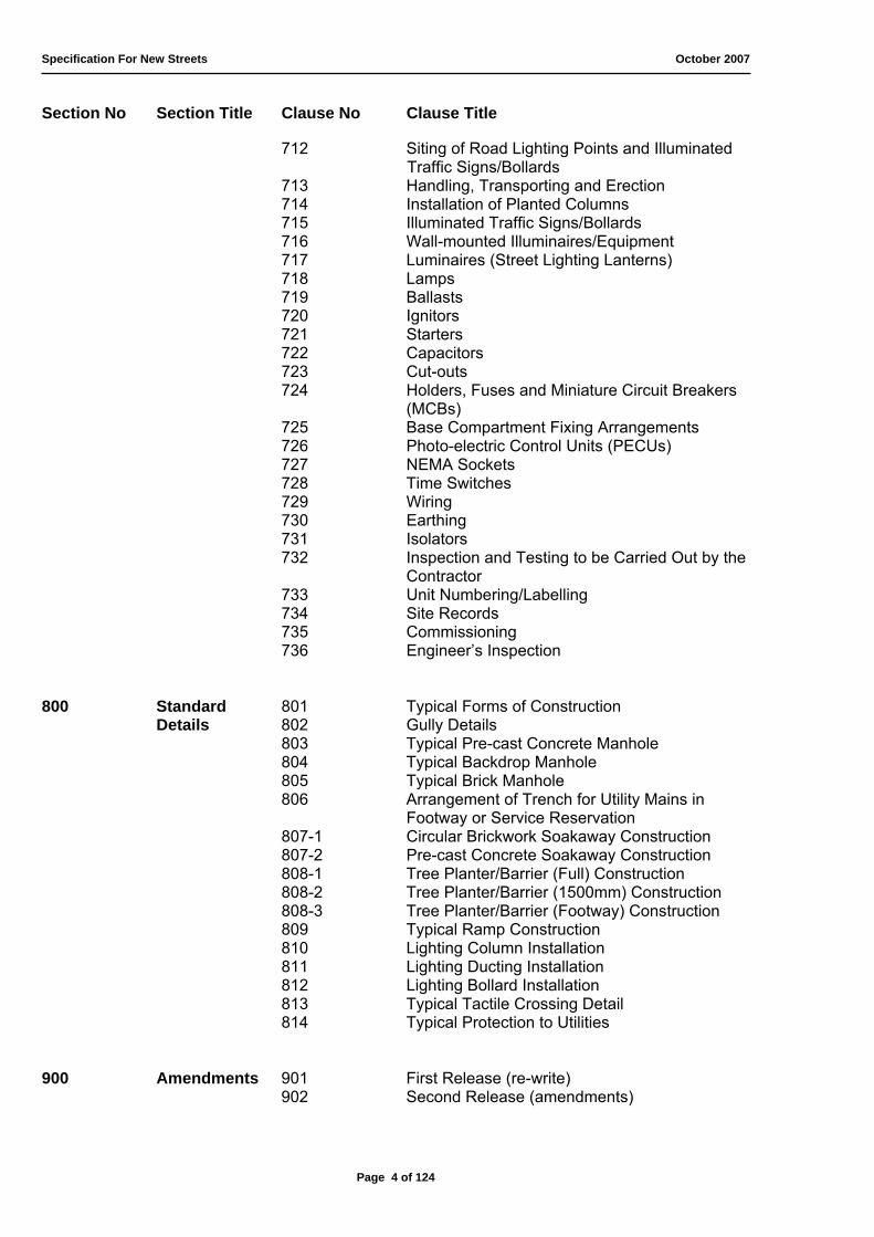
712 Siting of Road Lighting Points and Illuminated Traffic Signs/Bollards
713 Handling, Transporting and Erection 714 Installation of Planted Columns 715 Illuminated Traffic Signs/Bollards716 Wall-mounted Illuminaires/Equipment 717 Luminaires (Street Lighting Lanterns) 718 Lamps 719 Ballasts 720 Ignitors 721 Starters 722 Capacitors 723 Cut-outs 724 Holders, Fuses and Miniature Circuit Breakers
(MCBs)725 Base Compartment Fixing Arrangements 726 Photo-electric Control Units (PECUs) 727 NEMA Sockets728 Time Switches729 Wiring 730 Earthing 731 Isolators 732 Inspection and Testing to be Carried Out by the
Contractor733 Unit Numbering/Labelling 734 Site Records735 Commissioning 736 Engineer’s Inspection
800 Standard 801 Typical Forms of Construction Details 802 Gully Details
803 Typical Pre-cast Concrete Manhole 804 Typical Backdrop Manhole 805 Typical Brick Manhole 806 Arrangement of Trench for Utility Mains in
Footway or Service Reservation 807-1 Circular Brickwork Soakaway Construction 807-2 Pre-cast Concrete Soakaway Construction 808-1 Tree Planter/Barrier (Full) Construction 808-2 Tree Planter/Barrier (1500mm) Construction 808-3 Tree Planter/Barrier (Footway) Construction 809 Typical Ramp Construction 810 Lighting Column Installation 811 Lighting Ducting Installation 812 Lighting Bollard Installation 813 Typical Tactile Crossing Detail 814 Typical Protection to Utilities
900 Amendments 901 First Release (re-write) 902 Second Release (amendments)
Page 4 of 124

Specification For New Streets October 2007
Page 5 of 124

Specification For New Streets October 2007
100 GENERAL
101 INTRODUCTION
1. This specification should only be used for the construction of New Streets pursuant to Section 38 of the Highways Act 1980. Any works required by an agreement under Section 278 of the Highways Act 1980 must conform to the Department of Transport’s Design Manual for Roads and Bridges (DMRB). Before any design is carried out for works under Section 278, the Developer must contact the Client Projects Group of the Environment Directorate (01305 221000).
2. Any clauses in this Specification, which relate to work or materials not required by the Works, shall be deemed not to apply.
3. Unless stated to the contrary, any thickness of material described means thickness after full compaction.
4. The nomenclature adopted for this specification is that in the Glossary of Highway Engineering Terms BS6100-2 Section 2.4 (Highway and Railway Engineering): Sub-section 2.4.1: 1992 and abbreviations are in accordance with the recommendations given in BS5775.
5. Where a British Standard is in existence for design, equipment or material detailed hereinafter, the works shall comply with the relevant Standard whether or not it is referred to specifically in the document, unless otherwise approved by the Engineer. It is the Developer’s responsibility to ensure that the works comply with the current British Standard (BS) or British Standard European Number (BS EN) should the British Standard mentioned be superseded.
6. Wherever possible and practical, materials should be sourced from within the County of Dorset.
102 DEFINITIONS
1. ‘Engineer’ means the Proper Officer of the Environmental Services Directorate or his representative or the Engineer of the Agent Authority of Christchurch or Weymouth and Portland.
2. ‘Agent Authority’ means the Borough Councils of Christchurch and Weymouth and Portland.
3. ‘Agreement’ means an Agreement under Section 38 of the Highways Act 1980, together with any other documents bound with it.
4. ‘Developer’ means the person or persons, firm or company developing the site and constructing new streets in accordance with the Agreement.
5. ‘Works’ means the works to be executed in accordance with the Agreement.
Page 6 of 124

Specification For New Streets October 2007
6. ‘Specifications’ means the Specifications for the Construction and Drainage of New Streets.
7. ‘Formation’ means the surface of the ‘Sub-Grade’ with or without capping layer in its final shape after compaction of the earthworks.
8. ‘Capping Layer’ (required where CBR value is equal to or less than 5.0%) means the constructed top layer of the ‘Sub-Grade’.
9. ‘Sub-Grade’ means the upper part of the soil, natural or constructed which supports the loads transmitted by the ‘Sub-Base’
10. ‘Sub-base’ means the layer of material between the formation and the ‘Base’ or ‘ Road-base’
11. ‘Base’ or ‘Road-base’ means the bituminous Macadam, which constitutes the main structural elements of the pavement.
12. ‘Binder Course’ or ‘Base Course’ means a course forming part of the surfacing immediately below the ‘Surface course’.
13. ‘Surface Course’ or ‘Wearing Course’ means the part of the surfacing which directly supports the traffic.
14. ‘Surfacing’ means a ‘Surface’ or ‘Wearing’ course or a combination of ‘Surface’ or ‘Wearing’ course and ‘Binder’ or ‘Base’ course.
15. ‘Footway’ means pedestrian way adjacent to the carriageway.
16. ‘Footway Link’ means pedestrian way that is not associated with the carriageway.
103 COMMUTED SUMS
1. Commuted sums are required to pay for extra over normal maintenance costs. The commuted sum will be paid, in full, at the same time as the supervision and legal fees (prior to the signing of the Agreement). The commuted sum will not be index-linked and costs are an indicative minimum only. Commuted sums apply to the following items:
a) Emptying regime for bypass interceptors – minimum of £450.00 per single interceptor per annum. There is a additional charge of £58.00 for each extra hour (over the first hour) and an additional £55.00 for each extra tonne of waste (over the first five tonnes);
b) Retaining walls, or structures, that support the highway and exist solely for the benefit of adjoining plot(s), will incur a charge equal to the full construction cost of the structure (see Clause 303);
c) Areas of grass over and above that required for normal highway purposes (i.e. beyond service margins and visibility splays) – minimum of £1,040.40 per 100m ;
d) Trees planted within the carriageway, or footway, for maintenance of lower limbs until maturity – minimum of the combined initial planting and purchase costs (or a minimum of £1,000.00 per tree if no purchase or planting costs are provided);
Page 7 of 124
Specification For New Streets October 2007
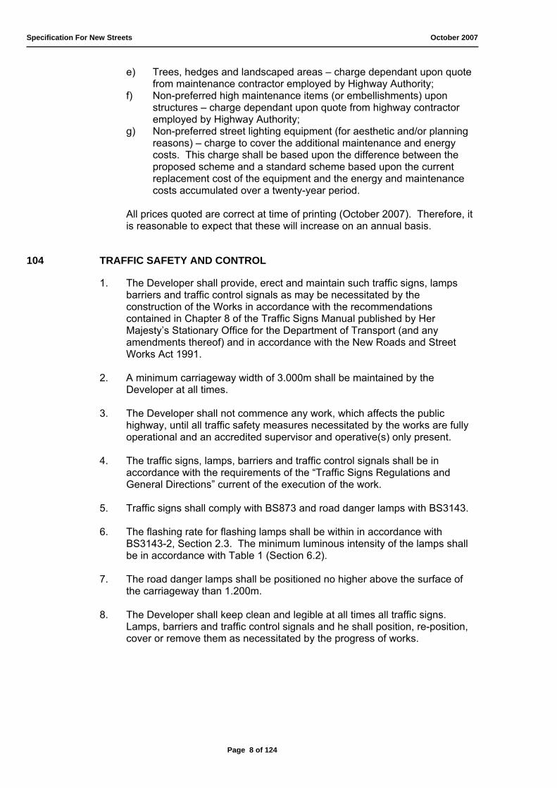
e) Trees, hedges and landscaped areas – charge dependant upon quote from maintenance contractor employed by Highway Authority;
f) Non-preferred high maintenance items (or embellishments) upon structures – charge dependant upon quote from highway contractor employed by Highway Authority;
g) Non-preferred street lighting equipment (for aesthetic and/or planning reasons) – charge to cover the additional maintenance and energy costs. This charge shall be based upon the difference between the proposed scheme and a standard scheme based upon the current replacement cost of the equipment and the energy and maintenance costs accumulated over a twenty-year period.
All prices quoted are correct at time of printing (October 2007). Therefore, it is reasonable to expect that these will increase on an annual basis.
104 TRAFFIC SAFETY AND CONTROL
1. The Developer shall provide, erect and maintain such traffic signs, lamps barriers and traffic control signals as may be necessitated by the construction of the Works in accordance with the recommendations contained in Chapter 8 of the Traffic Signs Manual published by Her Majesty’s Stationary Office for the Department of Transport (and any amendments thereof) and in accordance with the New Roads and Street Works Act 1991.
2. A minimum carriageway width of 3.000m shall be maintained by the Developer at all times.
3. The Developer shall not commence any work, which affects the public highway, until all traffic safety measures necessitated by the works are fully operational and an accredited supervisor and operative(s) only present.
4. The traffic signs, lamps, barriers and traffic control signals shall be in accordance with the requirements of the “Traffic Signs Regulations and General Directions” current of the execution of the work.
5. Traffic signs shall comply with BS873 and road danger lamps with BS3143.
6. The flashing rate for flashing lamps shall be within in accordance with BS3143-2, Section 2.3. The minimum luminous intensity of the lamps shall be in accordance with Table 1 (Section 6.2).
7. The road danger lamps shall be positioned no higher above the surface of the carriageway than 1.200m.
8. The Developer shall keep clean and legible at all times all traffic signs. Lamps, barriers and traffic control signals and he shall position, re-position, cover or remove them as necessitated by the progress of works.
Page 8 of 124

Specification For New Streets October 2007
105 TEMPORARY DIVERSION OF TRAFFIC
1. The Developer shall construct temporary diversion ways wherever the works will interfere with existing public or private roads or other ways, which there is a public or private right of way for any traffic.
2. The standard of construction shall be suitable in all respects for the class or classes of traffic using the existing ways and the width of the diversion shall not be less than that of the existing way.
3. Diversion ways must be constructed in advance of any interference with the existing ways and shall be maintained in a condition satisfactory to the Engineer for as long as required.
4. The provisions of this Clause shall not apply to any temporary access or accommodation works, which the Developer may construct for his sole use in the execution of the works.
106 PRIVATELY OWNED SERVICES
1. If any privately owned services for water, electricity, drainage, et cetera passing through the Site will be affected by the Works, the Developer shall provide a satisfactory alternative service in full working order to the satisfaction of the owner of the service and of the Engineer before cutting the existing service.
2. A license to register the existence of private apparatus in the carriageway must be obtained from the District Highways Engineer prior to technical approval of the site layout.
107 EXISTING GROUND LEVELS
1. The Developer shall satisfy himself that the existing ground levels as indicated on the Drawings or schedules of cross section levels are correct. Should the Developer wish to dispute any levels he shall submit to the Engineer a schedule of the position of the levels considered to be in error and a set of revised levels. The existing ground relevant to the disputed levels shall not be disturbed before the Engineer’s decision as to the correct levels is given.
108 SITE CLEARANCE
1. The Developer shall demolish, break up and remove buildings, structure and superficial obstructions on the Site in the way of or otherwise affected by the Works. He shall clear each part of the Site at times and to the extent required or approved by the Engineer.
2. Subject to the provisions of the Institution of Civil Engineers Conditions of Contract, all materials arising from the site clearance, which are surplus to or unsuitable for use in the Works, shall become the property of the Developer and shall be disposed of by him off the site to an appropriate licensed commercial site or commercial waste transfer site licensed by Environmental Agency.
Page 9 of 124

Specification For New Streets October 2007
3. It is the responsibility of the Developer to ascertain whether part, or all, of the site lies within a conservation area. In addition, it is the Developer’s responsibility to prove the status of trees and bushes with regard to Tree Preservation Orders (TPOs). This information can be obtained from the Local Planning Authority.
4. A plan for the protection of any existing bushes, hedgerows, undergrowth and trees within a conservation area, or protected by a Tree Preservation Order, must be agreed with the Tree Officer from the Local Planning Authority prior to the commencement of the Works.
5. In conservation areas, bushes, undergrowth or small trees, the trunks of which are less than 75mm in girth at 1.500m above ground level, tree stumps less than 75mm diameter and hedges shall be uprooted and disposed of.
6. Where TPOs do not exist and the site does not lie within a conservation area, bushes, undergrowth or small trees, the trunks of which are less than 300mm in girth at 1m above ground level, tree stumps less than 100mm diameter and hedges shall be uprooted and disposed of.
7. All trees within the limits of the highway shall be lopped and trimmed to provide a minimum vertical clearance of 5.105m (16’9”) under the supervision of the Tree Officer from the Local Planning Authority. Trees should only be removed where specifically identified by the Tree Officer as part of the planning process.
8. Stumps and tree roots shall, unless otherwise directed by the Engineer be grubbed up and deposited off the Site. Holes left by the stumps or roots shall within one week be filled with suitable material and properly compacted.
9. The disposal of any material off site shall be to an appropriate licensed commercial landfill site or commercial waste transfer site licensed by Environmental Agency.
Page 10 of 124

Specification For New Streets October 2007
Page 11 of 124

Specification For New Streets October 2007
200 DRAINAGE
201 GENERAL
1. Only surface water from the proposed highway is permitted to drain into the existing, or proposed, highway drainage system.
2. If the proposed surface water system takes surface water run off from other surfaces, the system is deemed to be a public surface water sewer and must be the subject of a Section 104 Agreement, Water Industry Act 1991 (to be adopted by the relevant Water Authority) before the highway drainage will be approved.
3. All works for a system deemed to be a public sewer, foul or surface water, must conform to current edition of Sewers for Adoption, or its successor.
4. If the surface water system, for other drained areas, is not to be adopted by the Water Authority, the highway drainage system must be entirely separate.
5. Separate highway drainage systems may discharge into a positive, adopted, drainage system, a watercourse (approved by the Environmental Agency and protected by interceptors), or soakaways (protected by interceptors).
6. The minimum clearance between the face of kerb and any parallel highway drain is to be 1.000m (with the exception of pipes of 900mm diameter, or more, as described in sub-clause 17, below).
7. Manholes, in accordance with Clause 208, must be constructed (to facilitate any of the following):
a) at the head of each highway drain, b) at every change of direction/alignment and gradient, c) at every change of pipe diameter, d) at every junction of two, or more, highway drains.
8. The maximum permitted length, or run, of highway drain between manholes is 60.000m, unless otherwise approved by the Engineer.
9. The maximum drained area per single gully shall not exceed 200m2.
10. Dispensation from the Environment Agency must be sought not to provide Class 1 Bypass Interceptors on outfalls to a watercourse or soakaways (either grouped or singly in areas of sensitivity). The South West Area Office of the Environment Agency is located in Blandford (general enquiry line 0645 333111).
11. Soakaways are to be constructed in accordance with Standard Detail Drawing 807-1 or 807-2, and Clause 620. Attention is drawn to the special order requirements for pre-cast concrete soakaway rings as this Authority will only accept 45mm diameter perforations.
12. Calculations for rainfall are included, automatically, within the Standard Detail Drawings for the two permissible types of soakaway construction.
Page 12 of 124
Specification For New Streets October 2007
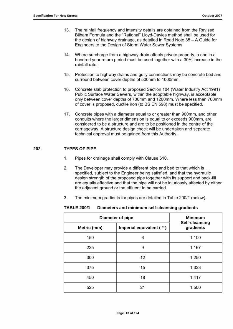
13. The rainfall frequency and intensity details are obtained from the Revised Bilham Formula and the “Rational” Lloyd-Davies method shall be used for the design of highway drainage, as detailed in Road Note 35 – A Guide for Engineers to the Design of Storm Water Sewer Systems.
14. Where surcharge from a highway drain affects private property, a one in a hundred year return period must be used together with a 30% increase in the rainfall rate.
15. Protection to highway drains and gully connections may be concrete bed and surround between cover depths of 500mm to 1000mm.
16. Concrete slab protection to proposed Section 104 (Water Industry Act 1991) Public Surface Water Sewers, within the adoptable highway, is acceptable only between cover depths of 700mm and 1200mm. Where less than 700mm of cover is proposed, ductile iron (to BS EN 598) must be specified.
17. Concrete pipes with a diameter equal to or greater than 900mm, and other conduits where the larger dimension is equal to or exceeds 900mm, are considered to be a structure and are to be positioned in the centre of the carriageway. A structure design check will be undertaken and separate technical approval must be gained from this Authority.
202 TYPES OF PIPE
1. Pipes for drainage shall comply with Clause 610.
2. The Developer may provide a different pipe and bed to that which is specified, subject to the Engineer being satisfied, and that the hydraulic design strength of the proposed pipe together with its support and back-fill are equally effective and that the pipe will not be injuriously affected by either the adjacent ground or the effluent to be carried.
3. The minimum gradients for pipes are detailed in Table 200/1 (below).
TABLE 200/1 Diameters and minimum self-cleansing gradients
Diameter of pipe
Metric (mm) Imperial equivalent ( “ )
MinimumSelf-cleansing
gradients
150 6 1:100
225 9 1:167
300 12 1:250
375 15 1:333
450 18 1:417
525 21 1:500
Page 13 of 124
Specification For New Streets October 2007
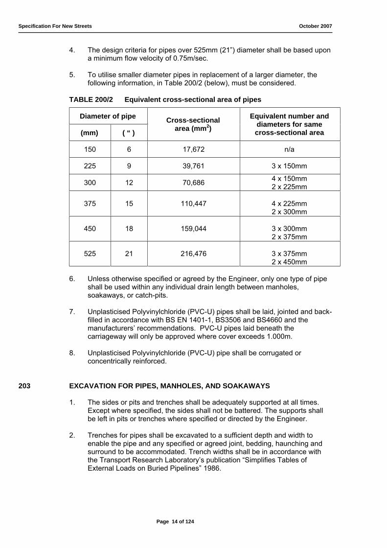
4. The design criteria for pipes over 525mm (21”) diameter shall be based upon a minimum flow velocity of 0.75m/sec.
5. To utilise smaller diameter pipes in replacement of a larger diameter, the following information, in Table 200/2 (below), must be considered.
TABLE 200/2 Equivalent cross-sectional area of pipes
Diameter of pipe
(mm) ( “ )
Cross-sectional area (mm2)
Equivalent number and diameters for samecross-sectional area
150 6 17,672 n/a
225 9 39,761 3 x 150mm
300 12 70,686 4 x 150mm 2 x 225mm
375 15 110,447 4 x 225mm 2 x 300mm
450 18 159,044 3 x 300mm 2 x 375mm
525 21 216,476 3 x 375mm 2 x 450mm
6. Unless otherwise specified or agreed by the Engineer, only one type of pipe shall be used within any individual drain length between manholes, soakaways, or catch-pits.
7. Unplasticised Polyvinylchloride (PVC-U) pipes shall be laid, jointed and back-filled in accordance with BS EN 1401-1, BS3506 and BS4660 and the manufacturers’ recommendations. PVC-U pipes laid beneath the carriageway will only be approved where cover exceeds 1.000m.
8. Unplasticised Polyvinylchloride (PVC-U) pipe shall be corrugated or concentrically reinforced.
203 EXCAVATION FOR PIPES, MANHOLES, AND SOAKAWAYS
1. The sides or pits and trenches shall be adequately supported at all times. Except where specified, the sides shall not be battered. The supports shall be left in pits or trenches where specified or directed by the Engineer.
2. Trenches for pipes shall be excavated to a sufficient depth and width to enable the pipe and any specified or agreed joint, bedding, haunching and surround to be accommodated. Trench widths shall be in accordance with the Transport Research Laboratory’s publication “Simplifies Tables of External Loads on Buried Pipelines” 1986.
Page 14 of 124
Specification For New Streets October 2007
3. Soft spots in the bottom of drainage excavations shall be removed and the resulting void immediately back-filled with Type 1 sub-base material or pipe bedding material to Clause 204 or with ST2 Mix/C10 Grade concrete to Clause 509 as directed by the Engineer.
4. The following shall be made good at the Developer’s expense with one of the materials described in sub-clause 3, above, as directed by the Engineer:
a) Any additional excavation at or below the bottom of drainage trenches if the Developer allows the trench to become soft or otherwise unsuitable for the construction of a pipeline;
b) Any excavation greater than the net volume required for the drainage works below the upper level of any pipe surround as described in sub- clause 2.
204 BEDDING AND LAYING OF PIPES
1. Immediately following the excavation of the trench, the pipes shall be laid and jointed on the pipe bed. Pipes shall be laid so that each one is in contact with the bed throughout the length of its barrel. The bed shall be cut away and removed at each socket and sleeve in the case of socketed, or sleeve jointed, pipes to give a clearance of at least 50mm so that the socket or sleeve does not bear on the bed.
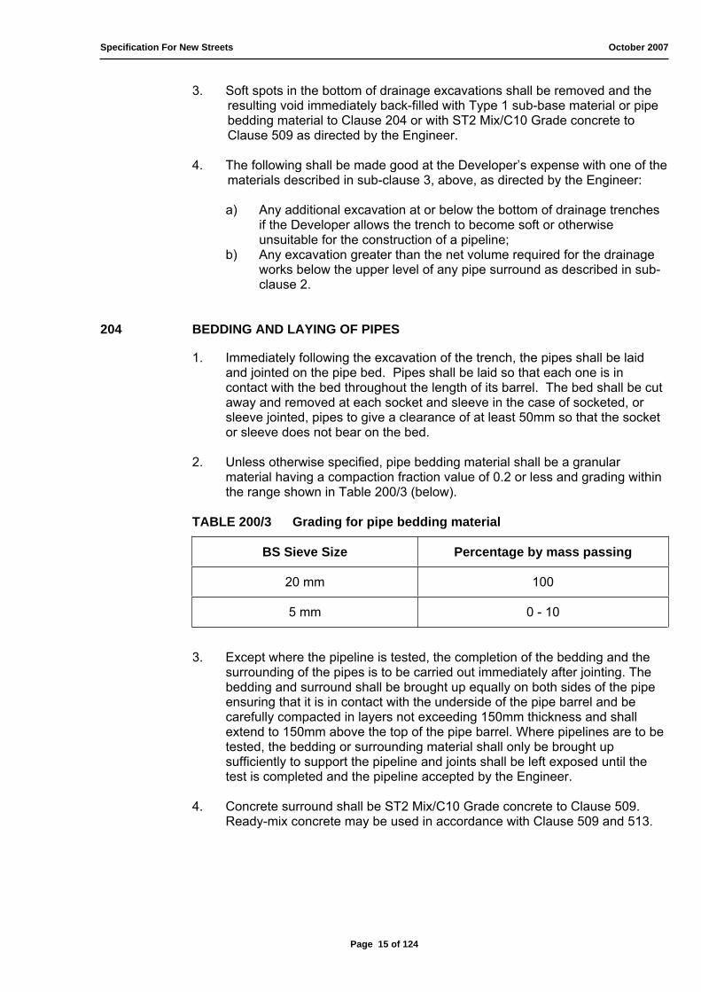
2. Unless otherwise specified, pipe bedding material shall be a granular material having a compaction fraction value of 0.2 or less and grading within the range shown in Table 200/3 (below).
TABLE 200/3 Grading for pipe bedding material
BS Sieve Size Percentage by mass passing
20 mm 100
5 mm 0 - 10
3. Except where the pipeline is tested, the completion of the bedding and the surrounding of the pipes is to be carried out immediately after jointing. The bedding and surround shall be brought up equally on both sides of the pipe ensuring that it is in contact with the underside of the pipe barrel and be carefully compacted in layers not exceeding 150mm thickness and shall extend to 150mm above the top of the pipe barrel. Where pipelines are to be tested, the bedding or surrounding material shall only be brought up sufficiently to support the pipeline and joints shall be left exposed until the test is completed and the pipeline accepted by the Engineer.
4. Concrete surround shall be ST2 Mix/C10 Grade concrete to Clause 509. Ready-mix concrete may be used in accordance with Clause 509 and 513.
Page 15 of 124
Specification For New Streets October 2007
5. Where a concrete bed or surround is used with a pipeline having flexible joints, a compressible board or a pre-formed joint filler shall be placed in contact with the end of the socket of the pipe joint and shall extend through the full thickness of any concrete in contact with the pipe. Such joints in any concrete bed or surround shall be at intervals not exceeding 5.000m.
6. Where pipelines are laid within 2.000m of each other they shall be protected as directly by the Engineer.
7. Concrete slab protection to sewers subject to Section 104 (Water Industry Act 1991) within the adoptable highway is acceptable only between cover depths of 700mm to 1.200m. Where less than 700mm of cover is proposed, ductile iron (to BS EN 598) must be specified.
205 JOINTING OF PIPES
1. All sewers and highway drains shall have watertight joints. French drains may have non-watertight joints, which must be close fitting to prevent any flow of water from the joint other than seepage.
2. Pipes shall be flexibly jointed in accordance with the recommendations of the manufacturers of the pipes and joints. A space shall be left between the ends of the pipe unless otherwise agreed by the Engineer. Clay pipes shall have joints that comply with BS EN 295 and BS65.
3. Where concrete bed and surround is used, a flexible joint/separator shall be inserted directly above the flexible joint in the pipe.
206 BACK-FILLING OF TRENCHES, FRENCH DRAINS, AND SOAKAWAYS
1. Back-filling shall wherever practicable be undertaken immediately the specified operating preceding it have been completed and approved by the Engineer.
2. Where concrete protection to the pipes has been provided, no back-filling shall be done until four days after placing the concrete.
3. Filling to the sides of pipes with no concrete protection, and the first 300mm of filling over the pipes, shall be pipe bedding material (Table 200/3) so that there is no displacement or damage.
4. Where the trench is situated in the carriageway suitable mechanical means of compaction shall be employed, except within 450mm of the pipes where compaction shall be by hand tools.
5. The material used for filling trenches shall be Type 1 Dorset Variant where pipes are not laid beneath the carriageway, back-fill maybe selected excavated material or approved fill. Refilling shall be in 225mm layers, each layer being thoroughly compacted before the succeeding layer is added. Material shall be deposited in even layers and shall not be heaped in the trench before spreading. Water may be used in cases where it will assist compaction.
Page 16 of 124
Specification For New Streets October 2007
6. Trench supports, to BS EN 13331-1, shall be drawn up as the filling and compaction proceeds so that no voids remain in the filling after their withdrawal.
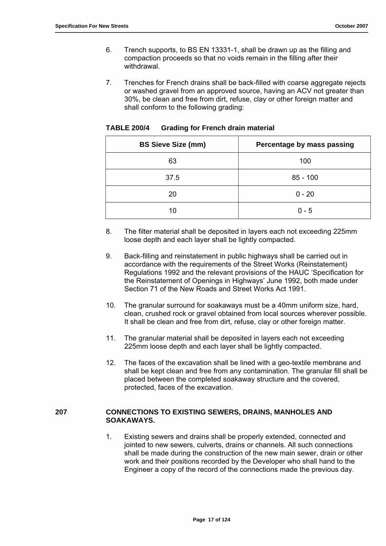
7. Trenches for French drains shall be back-filled with coarse aggregate rejects or washed gravel from an approved source, having an ACV not greater than 30%, be clean and free from dirt, refuse, clay or other foreign matter and shall conform to the following grading:
TABLE 200/4 Grading for French drain material
BS Sieve Size (mm) Percentage by mass passing
63 100
37.5 85 - 100
20 0 - 20
10 0 - 5
8. The filter material shall be deposited in layers each not exceeding 225mm loose depth and each layer shall be lightly compacted.
9. Back-filling and reinstatement in public highways shall be carried out in accordance with the requirements of the Street Works (Reinstatement) Regulations 1992 and the relevant provisions of the HAUC ‘Specification for the Reinstatement of Openings in Highways’ June 1992, both made under Section 71 of the New Roads and Street Works Act 1991.
10. The granular surround for soakaways must be a 40mm uniform size, hard, clean, crushed rock or gravel obtained from local sources wherever possible. It shall be clean and free from dirt, refuse, clay or other foreign matter.
11. The granular material shall be deposited in layers each not exceeding 225mm loose depth and each layer shall be lightly compacted.
12. The faces of the excavation shall be lined with a geo-textile membrane and shall be kept clean and free from any contamination. The granular fill shall be placed between the completed soakaway structure and the covered, protected, faces of the excavation.
207 CONNECTIONS TO EXISTING SEWERS, DRAINS, MANHOLES AND SOAKAWAYS.
1. Existing sewers and drains shall be properly extended, connected and jointed to new sewers, culverts, drains or channels. All such connections shall be made during the construction of the new main sewer, drain or other work and their positions recorded by the Developer who shall hand to the Engineer a copy of the record of the connections made the previous day.
Page 17 of 124

Specification For New Streets October 2007
2. Where the pipe connections made to a brick sewer, concrete culvert, stone built or lined channel, the pipes shall be well and tightly built into the concrete, brick or masonry work, and be so placed as to discharge at an angle no greater than 60º from direction of flow from main sewer, drain or channel and with the end of the pipe carefully cut to the necessary angle. Where the connections are between pipe sewers or drains, special connecting pipes shall be laid true and properly jointed.
3. Under no circumstances are saddle connections to be used. New manholes are to be constructed.
4. Before entering or breaking into an existing sewer or drain, the Developer shall give notice of his intention to do so to the Authority responsible for the pipeline to which the connection is to be made.
5. This work shall only be undertaken by appropriately certificated Supervisor and Operatives.
208 MANHOLES, CATCHPITS, INSPECTION CHAMBERS AND SOAKAWAYS
Manholes, inspection chambers and soakaways shall be constructed in accordance with Standard Detail Drawing number 803, 804, 805, 807-1 or 807-2 unless otherwise directed by the Engineer.
Foundations
1. The formation shall be properly levelled and, after approval by the Engineer, the C20 Grade Sulphate Resisting concrete foundation shall be laid thereon with a minimum thickness in accordance with Table 200/5.
TABLE 200/5 Thickness of foundation per depth of chamber
Depth of chamber (m) Thickness (mm)
< 1.500m 150
1.500 and 3.000 225
> 3.000 225 *
* The Engineer may request a greater thickness of foundation for chambers in excess of 3.000m depth.
Inverts and Benching
2. Inverts shall normally be formed with a half pipe of similar material to the main pipe. It shall be made to the required radius or taper as the case may be, and shall be laid on a bed of cement mortar. Close fitting, watertight joints with the incoming and outgoing pipes shall be made.
Page 18 of 124

Specification For New Streets October 2007
3. Inverts and benchings constructed in situ shall be formed in C20 Grade Sulphate Resisting concrete rendered with 40mm minimum thickness of granolithic rendering to a smooth hard surface, true to line, curves and falls. Benchings to pre-cast inverts shall be formed to the required size, shape and falls in concrete and the surface shall have a hard smooth finish.
Connections
4. All pipes shall be cut to fit flush with the internal walls of the manhole. All pipes shall be laid soffit to soffit and bedded in position before the manhole walls are built.
Pre-cast Chambers
5. Pre-cast chamber rings, cover slabs, corbel slabs, reducing slabs, landing slabs, cover seating rings and shaft rings shall comply with BS EN 1916 and BS5911-1, and BS EN 1917 and BS5911-3, BS5911-4 and be firmly bedded in cement mortar. The manhole shall be surrounded with ST4 Mix/C20 Grade concrete not less than 150mm thick. The minimum diameter of the chamber shall be 1.200m and the shaft diameter shall not be less than 900mm (step access) and (1.200m (ladder access), to comply with BS EN 752-3 Table 3.
6. The minimum diameter of a soakaway chamber shall be 1.200m to comply with Standard Detail Drawing 807-2 (or fixed at 2.400m to comply with
Standard Detail Drawing 807-1) and Clause 620.
7. The base, pipes and all benching shall be constructed first, with a minimum of 125mm C20 Grade Sulphate Resisting concrete over the highest pipe to receive the lower chamber ring.
8. The lower pre-cast chamber ring, of pre-cast concrete manholes and soakaways (strip foundation), shall be recessed into the concrete foundation by a minimum of 75mm.
9. If the Engineer approves the lower chamber to be cut to receive connecting pipes, holes shall be 25mm larger than the outside diameter of the pipe to be
received. C20 Grade Sulphate Resisting concrete shall be thoroughly compacted around inlet and outlet pipes and side connections.
Brick Chambers
10. Chamber walls shall be constructed in Class B Engineering bricks laid in cement mortar to English Bond. The joints shall be struck flush with the work as it proceeds. Two ring brick arches shall be formed over pipes larger than 300mm diameter. All joints shall be watertight. The inner surface of the manhole shall be plumb and smooth throughout.
11. Where a pipe of 300mm diameter, or larger, is to be joined to either new or existing brick manholes the opening and the pipe shall be protected by the construction of a brick arch of two rings of bricks on edge.
12. The space between the brickwork and the face of the excavation shall be filled with ST4 Mix/C20 Grade concrete as the work proceeds, and shall be of not less than 150mm thickness.
Page 19 of 124

Specification For New Streets October 2007
13. In-situ concrete shaft and chamber cover slabs shall be of not less than 150mm thickness of C30 Grade concrete to Clause 508(2) suitably reinforced to BS EN 1917 for its appropriate location and use.
Manhole covers and Frames
14. All manhole covers and frames shall be to BS EN 124. Double triangular covers must be securely bolted together at all times when in position.
15. Where manholes equal or exceed 1.500m to invert, covers and frames shall be Grade D400 cast iron, double triangular, non-ventilating type of an approved pattern with a minimum clear opening of 600mm x 600mm and coated with a bitu-mastic paint. Manholes less than 1.500m to invert require a minimum clear opening of 1200mm x 675mm.
16. Where manholes are situated in the footway or verge, and are less than 1.500m to invert, covers and frames may be to Grade C250. These shall be double triangular or rectangular solid cast iron and a minimum size of 1200mm x 675mm.
17. The minimum depth of cover and frame shall be 100mm for access roads, shared surface roads, courts, and squares only (BS EN 124 D400N). For all other categories of road (feeder, collector, local distributor, and industrial) the minimum depth of cover and frame shall be 150mm (BS EN 124 D400H).
18. Manhole covers and frames shall be set on at least two but no more than four courses of 215mm Class B Engineering brickwork or pre-cast concrete seating rings.
19. Covers in paths and verges shall conform to the level of the surrounding surface. Covers in fields and gardens shall be flush with a concrete apron 100mm deep and 300mm wide of ST2 Mix/C10 Grade concrete.
20. Covers and frames in the carriageway shall be permanently bedded on mortar and set at the level required for the surface course. The maximum thickness of mortar bed shall be 25mm. Permanent mortar haunching, no steeper than 45°, shall surround the frame. The haunching shall extend from the outside edge of the brickwork, or pre-cast concrete cover frame seating rings, to 30mm below the top of the frame.
21. Where the surface course is pre-cast concrete block pavers (see Clause 430 and Clause 613), the haunching must be a minimum of 80mm below the top of the frame. Temporary haunching shall be provided, in the same manner as sub-clause 20, and be broken out immediately prior to providing the laying layer and block pavers.
Step Iron and Ladders
22. Where the depth of invert of a chamber exceeds 900mm below the finished surface, double manhole step irons to BS1247-1, BS1247-2 (preferred), or BS1247-3 (or BS EN 13101-1 when applicable) shall be provided.
23. Where the depth of invert of a chamber exceeds 3.500m below the finished surface, a ladder to BS4211 (Class A) shall be provided.
Page 20 of 124

Specification For New Streets October 2007
24. Where the depth of invert of a chamber exceeds 6.000m, a landing slab(s) to BS EN 1916, BS EN 1917 and BS5911-1, BS5911-3, BS5911-4 shall be provided no more than 6.000m apart. Step irons or ladders shall be positioned so as to conform to BS EN 752-3.
25. Soakaways (to Standard Detail Drawing 807-1 or 807-2) are not intended for access other than by use of winch. To comply with BS EN 752-3, step irons and ladders must not be installed.
209 GULLIES AND GULLY CONNECTIONS
Gully Pots
1. Gully pots shall be trapped with rodding eyes and shall be 375 mm internal diameter by 910 mm deep:
a) Pre-cast concrete gully pots shall be un-reinforced and conform with BS5911-230;
b) Gully pots of polypropylene, polyethylene, PVC-U or other approved plastic materials of a pattern approved by the Engineer shall be permitted when used as permanent form work to an in-situ concrete gully as described in Clause 209(7) below.
Gully Gratings and Frames
2. Gully gratings are not to be installed by pedestrian crossing points. If such positioning is unavoidable then “mesh” covered gullies must be used.
3 Gully gratings and frames shall be GA2 450 square in cast or ductile iron, size approximately 450mm x 450mm obtained from an approved manufacturer in accordance with BS EN 124 D400.
4. Footway gully gratings shall be a minimum of 300mm square and fixed down securely (fixed grating).
5. Gully pots shall be set on a 150mm thick foundation and surrounded with a minimum of 150mm thickness of ST2 Mix/C10 Grade concrete which shall be brought up to the top of the pot and stuck level. At least two courses of 215mm Class B Engineering brickwork or square gully cover slab(s) (to comply with BS5911-230) shall be laid on the concrete to form a base for the grating and frame.
6. Brick gullies shall be built on a 150mm thick foundation of ST2 Mix/C10 Grade concrete. Carriageway gullies shall be 215mm engineering brickwork with internal dimensions 500mm x 350mm x 1.000m deep. Footway gullies shall be 115mm brickwork with internal dimensions 340mm x 340mm x 600mm deep. Back-filling shall be of ST2 Mix/C10 Grade concrete.
7. Alternatively gullies maybe constructed of in-situ concrete C30 Grade to Clause 508(2) of 150mm minimum thickness using polyethylene or PVC-U gullies as permanent formwork.
Page 21 of 124
Specification For New Streets October 2007
8. Gratings and Frames shall be set at level of binder course laid for the Part I roads and raised immediately prior to surfacing, concreted into position. The level of the grating shall be set 15-20mm below finish surface line.
9. Junction pipes, which are laid but not immediately connected, shall be fitted with temporary stoppers or seals and the position of all such junctions shall be clearly defined by means of stakes or tracing wires properly marked and labelled. Junction pipes shall be manufactured of the same type and class of material as the remainder of the pipes in the run or shall be in accordance with the manufacturer’s recommendations.
210 TESTING AND CLEANING
1. All sewers and drains with watertight joints shall be tested as directed by the Engineer, in sections, e.g. between manholes, before the pipes are covered or surrounded by means of the air test described below. Alternatively, they shall be tested by the water test described below. Before testing, the ends of the pipeline to be tested, including those of short branches, shall be plugged and sealed to the satisfaction of the Engineer. Any section not passing any of the tests shall have the defects made good and shall be re-tested, using either of the alternative tests given below chosen by the Engineer.
2. For the air test, air shall be pumped in by suitable means until a stable pressure of 100mm head of water is indicated in a U-tube connected to the system. The air pressure shall not fall to less than 75mm head of water during a period of 5 minutes without further pumping after an initial period to allow stabilisation. Drains with traps shall be tested to 500mm head of water and the permissible loss shall then be no more than 13mm head of water in 5 minutes after the initial stabilising period.
3. For the water test, the pipes shall be filled with water under a head of not less than 1.200m above the crown of the pipe at the high end and not more than 6.000m above the pipe at the low end. Steeply graded pipelines shall be tested in sections so that the above maximum shall not be exceeded. Unless otherwise agreed by the Engineer the test shall commence one hour after filling the test section at which time the level of water at the vertical feed pipe shall be made up to produce the required 1.200 m minimum test head. The loss of water over a 30 minute period shall be measured by adding water at regular 10 minute intervals to maintain the original water level and recording the amounts added. The drain will have passed the test if the volume of water added does not exceed 0.12 litres per hour per 100m of drain per mm of nominal internal diameter.
4. On completion of the Works, or earlier if the Engineer agrees, all manholes and drains (other than French drains) shall be flushed from end to end with water and left clean and free from obstructions to the satisfaction of the Engineer. Where in the opinion of the Engineer any part of the pipeline may have sustained damage or where back-filling has occurred in the absence of the Engineer’s approval, the Developer shall arrange for a television survey to be undertaken.
5. The pipes and the filler material of French drains shall at all times be kept free from silt and obstruction.
Page 22 of 124
Specification For New Streets October 2007
211 EXISTING LAND DRAINS
1. Existing land drains permanently severed by the Works shall be located and connected into a new drain, pipe or ditch. Existing drains remaining within the Works shall be cleaned out from the new drain trench face as necessary. Any pipe disturbed by the Works shall be re-laid to ensure a free discharge into the new drain. Disused ends of intercepted land drains shall be adequately sealed.
2. Where an existing land drain is exposed and severed by temporary trench excavation, the position of the drain shall be marked and recorded. The drain shall be diverted into an existing drain or watercourse. Alternatively, the formal functioning of the drain shall be continued by the construction of a pipeline or channel adequately supported across the excavation until permanent restoration is made on their original line or as otherwise agreed by the Engineer.
3. The Developer shall notify the Engineer of any land drain, which is blocked or is otherwise defective when the drain is first exposed.
212 DUCTS
1. Pipes used for service ducts shall comply with Clause 610(7), and shall have a smooth internal bore without any sharp edges to the ends of the pipes. All ducts shall be appropriately colour-coded for each utility and to the depth in accordance with arrangement of utilities (Standard Detail Drawing 806).
2. Pipes for cuts shall be joined so that no silt, grit, grout or concrete surround is able to enter the duct. Pipes with flush fit joints shall have a register to ensure that the joint is fully pushed home. Each duct shall be fitted with a pigmented, stranded polypropylene draw rope of 5.3kN breaking load, the ends of which shall be made fast as described in the Agreement. Immediately after laying, the position of the ducts shall be marked and the ends sealed by removable stoppers.
213 PROTECTION OF EXISTING DRAINS, SEWERS, ET CETERA
1. Adequate precautions shall be taken to prevent sand, silt or other matter entering existing pipes. The Developer will be held responsible for the cost removal of such material and for making good any damage caused by its presence. The Developer will be required to repair and make good any existing pipes, manholes, cables, services et cetera which are damaged or disturbed during the course of the Works, and no such repair shall be covered until it has been approved by the appropriate Authority or owner concerned.
Page 23 of 124

Specification For New Streets October 2007
214 REINSTATEMENT OF TRENCHES
1. Road and footway metalling and foundation, and also turf and top-soil, shall be carefully replaced and compacted in its original position to form temporary reinstatement. Reinstatement of carriageways and footways will be left flush with the adjoining surface and surfaced with 20mm nominal size bituminous Macadam which shall be compacted to a minimum thickness of 50mm. Paving, channel, kerbing, et cetera shall be replaced as accurately as possible but shall not be permanently fixed. The Developer shall make good all subsidence and maintain the original surface levels at all times until the final restoration is carried out.
2. The final reinstatement in the road offered for adoption shall comprise:
a) Consolidated excavated or approved fill material capped with 300mm Type 1 Material in accordance with Clause 408;
b) Binder course and a surface course to carriageways and footways in similar materials as existing surfaces;
c) Verges shall be restored to their former condition with similar materials and made good over the whole area disturbed;
d) All reinstatements (surface course) shall be the full width of the paving laid in one operation (no patches) for a minimum length of 15.000m (to comply with Clause 401(13 - 16). Where this affects the junction with a major road, the minimum length or reinstatement shall be 45.000m.
3. Where the excavation of a trench has cut through or damaged a sub-grade membrane, prior to back-filling the whole trench shall be lined with a membrane of similar grade to that damaged and the back-filling material shall be in accordance with Clause 408.
Page 24 of 124

Specification For New Streets October 2007
Page 25 of 124

Specification For New Streets October 2007
300 EARTHWORKS
301 EXCAVATION
1. Turf and topsoil shall be stripped from the whole of the area of the road works including areas of cutting or those to be covered by embankment. Excavation shall be to the lines, levels and contour shown on the Drawings. Any excess excavation shall be made up with capping material Clause 407 or approved filling material.
302 FORMING EMBANKMENTS AND CUTTINGS
1. Embankments and other areas of fill shall be formed of approved material deposited and spread in horizontal layers not exceeding 225mm in the loose. The fill material shall be laid over the full width of the embankment and compacted, as specified below, to the lines, levels and contours shown on the Drawings.
2. The filling of any embankment shall be level for at least 1.000m beyond the back of the footway.
3. In cutting the foot of any bank shall be level for at least 500mm from the back of the footway.
303 RETAINING STRUCTURES
1. Retaining walls, and other structures, that support the highway must undergo a full design check and must receive full specific approval prior to technical approval being issued for the entire site (see Clause 201).
2. Retaining walls, and other structures, that support third party land and abut the highway, greater than 1.000m in height, will be subjected to a full design calculation check for both structural integrity and suitability of design.
3. For retaining structures that are essential in supporting the highway due to the site topography, no commuted sum will be applicable.
4. For retaining structures that support the highway and exist as a direct benefit for any adjoining plot(s), then a commuted sum is charged (see Clause 103).
304 COMPACTION OF EMBANKMENTS AND OTHER AREAS OF FILL
1. The required compaction of the filing material specified shall be obtained by using a smooth wheel roller weighing not less than 8 tonnes or an approved vibrating roller.
2. Each layer shall be separately compacted to the satisfaction of the Engineer.
Page 26 of 124

Specification For New Streets October 2007
305 PREPARATION AND SURFACE TREATMENT OF FORMATION
1. The formation shall be regulated and trimmed to the requirements of Clause 401(10) and compacted with a roller weighing not less than 8 tonnes or an approved vibrating roller. The formation shall extend 450mm behind the face of the kerb (300mm beyond the concrete backing) or where there is an adjacent footway the formation shall be extended to 200mm beyond the edging kerb at the rear of footway (100mm beyond the concrete surround) as directed by the Engineer. Soft places in the formation shall be excavated to additional depth and back-filled with approved material and properly compacted prior to laying the sub-base.
2. Sub-base material shall be spread and compacted immediately following the excavation and preparation of the formation. Otherwise the Developer shall maintain the level of the bottom of the cutting 300mm above formation level until the day the sub-base is to be laid.
3. Where reinforcement of the sub-grade is required a purpose made membrane of a suitable grade material shall be provided and laid in accordance with the manufacturer’s directions.
4. Where directed the formation shall be treated with an approved weed-killer in the presence of the Engineer.
306 PROTECTION OF EARTHWORKS FROM WATER
1. The formation and excavations shall be kept free from water during the course of the work. The Developer shall provide all labour and equipment necessary for this purpose. Adequate means for trapping silt shall be provided on temporary systems discharging into permanent drainage systems.
307 PROTECTION OF TREES DURING EXCAVATION
1. Not more than 25% of any tree roots are to be disturbed or removed.
2. The reduction in root system must be balanced by branch thinning.
3. No compaction of soil within root spread is to take place.
4. No material is to be stored, nor spillage of fluids to occur, within the root spread.
5. The water table near trees should be checked before any adjacent excavation work begins and maintained at the correct level whilst the work is in progress. Excavated material should be replaced in the correct geological sequence as early as possible.
6. Fencing must be erected around the circumference of the tree canopy and maintained during the occupation of the site where trees are specifically required to be preserved.
Page 27 of 124
Specification For New Streets October 2007
7. The root spread of a tree is calculated as being the equivalent of 1.3 times its’ height.
308 SOILING, GRASS AND TURFING
1. The whole area shall be rotovated or dug over to a minimum depth of 150mm. If the existing ground at this stage is unsuitable for the sowing of grass or acceptance of turf, then at least 100mm of good quality top-soil shall be spread and levelled. The surface shall be broken down to a fine tilth and raked over to remove all stones, roots and other items exceeding 25mm in any dimension. Unless otherwise agreed all seedbeds shall be top dressed with approved base fertiliser as specified in Clause 606 at 50g/m² and raked in.
2. Verges shall be sown with grass seed with an even distribution using the grass mixture as specified in Clause 607 from an approved source, at a rate of application of 25g/m² or turfed with a good quality turf, a sample of which has been approved. After seeding or turfing the area shall be rolled to the satisfaction of the Engineer.
3. The Developer will be responsible for the safeguarding the grassed areas during the growth period and providing such fences and making good as necessary, and for the cutting during the period of the works and the maintenance period, so that it does not exceed 100mm in height.
309 OBSTRUCTION IN VERGES
1. All posts, distribution pillars, signposts, et cetera which stand in the grassed areas are to be surrounded with a concrete apron 100mm thick and 300mm wide finished to conform to the general levels of the area, but 25mm below the settled or compacted grass level.
2. Similar aprons, 300mm wide, shall be provided along all house and boundary walls, et cetera which adjoin grassed areas.
3. Attention is drawn to Clause 712(5) with regard to lamp columns in areas of soft landscaping.
Page 28 of 124

Specification For New Streets October 2007
Page 29 of 124
Specification For New Streets October 2007
400 ROADWORKS
401 HORIZONTAL ALIGNMENTS,SURFACE LEVELS AND SURFACE REGULARITY OF PAVEMENT COURSES
Horizontal alignments
1. Horizontal alignments shall be determined from one edge of the pavement surface as shown on the Drawings. The edge of the pavement as constructed and all other parallel alignments shall be correct within a tolerance of ± 13mm therefrom.
Surface Levels of Pavement Courses
2. The levels of pavement courses shall be determined from the true finished road surface calculated from the vertical profile and cross-falls as shown on the Drawings. The vertical depth below the true pavement surface of any point on the constructed surface of the formation or pavement courses shall be within the following appropriate tolerances.
Surface course ± 6mm Binder course ± 6mm Base ± 15mm Sub-base + 10mm - 30 mm Formation + 20 mm - 30 mm
3. The surface level of the pavement at any point shall not deviate vertically from the true finished road surface by more than ± 6mm. However, the combination of permitted tolerances in different pavement levels shall not result in a reduction of the surface course thickness by more than 5mm from that specified for a flexible road nor a reduction in the thickness of the whole pavement, excluding the sub-base, by more than 15mm from the specified thickness.
4. For checking compliance with the above tolerances, measurements of surface levels will be taken at points to be selected by the Engineer at 10.000m centres longitudinally and at 2.000m centres transversely. In any length of pavement, compliance with these requirements shall be regarded as met when not more than one measurement in any consecutive ten longitudinally or one in any transverse line, exceeds the above tolerances, but this one measurement shall not exceed 5mm more than the tolerance for the layer concerned.
Surface Regularity
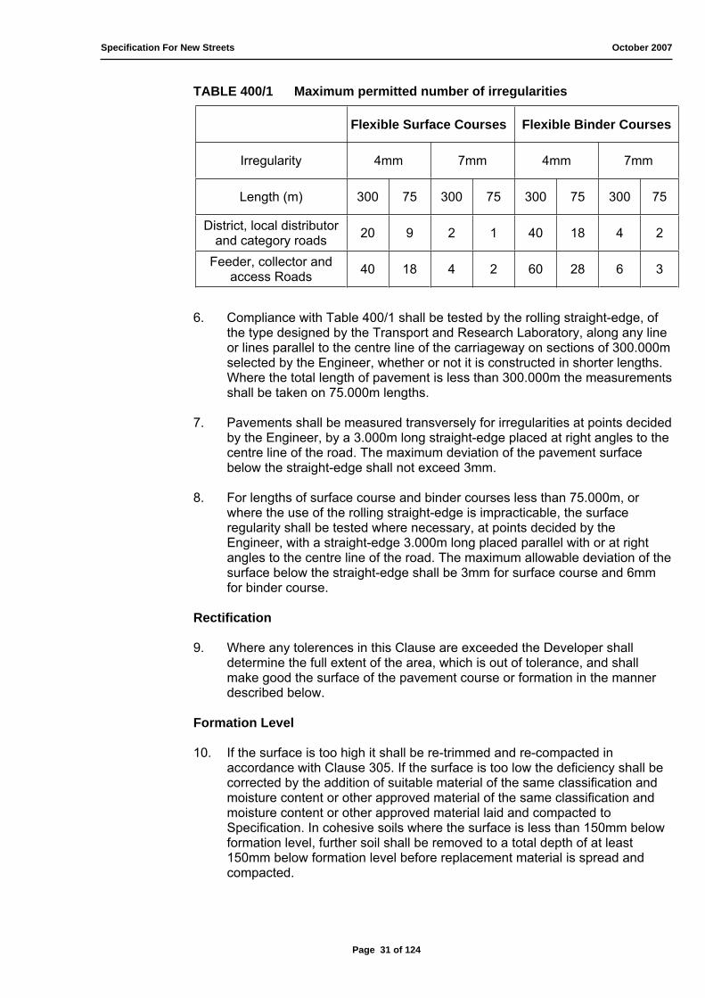
5. The longitudinal regularity of the surfaces of surface and binder courses shall be within the relevant tolerances stated in Table 400/1.
An irregularity is a variation not less than 4mm or 7mm of the profile of the road surface as measured by the rolling straight-edge, set at 4mm or 7mm as appropriate. No irregularity exceeding 10mm shall be permitted.
Page 30 of 124
Specification For New Streets October 2007
TABLE 400/1 Maximum permitted number of irregularities
Flexible Surface Courses Flexible Binder Courses
Irregularity 4mm 7mm 4mm 7mm
Length (m) 300 75 300 75 300 75 300 75
District, local distributor and category roads 20 9 2 1 40 18 4 2
Feeder, collector and access Roads 40 18 4 2 60 28 6 3
6. Compliance with Table 400/1 shall be tested by the rolling straight-edge, of the type designed by the Transport and Research Laboratory, along any line or lines parallel to the centre line of the carriageway on sections of 300.000m selected by the Engineer, whether or not it is constructed in shorter lengths. Where the total length of pavement is less than 300.000m the measurements shall be taken on 75.000m lengths.
7. Pavements shall be measured transversely for irregularities at points decided by the Engineer, by a 3.000m long straight-edge placed at right angles to the centre line of the road. The maximum deviation of the pavement surface below the straight-edge shall not exceed 3mm.
8. For lengths of surface course and binder courses less than 75.000m, or where the use of the rolling straight-edge is impracticable, the surface regularity shall be tested where necessary, at points decided by the Engineer, with a straight-edge 3.000m long placed parallel with or at right angles to the centre line of the road. The maximum allowable deviation of the surface below the straight-edge shall be 3mm for surface course and 6mm for binder course.
Rectification
9. Where any tolerences in this Clause are exceeded the Developer shall determine the full extent of the area, which is out of tolerance, and shall make good the surface of the pavement course or formation in the manner described below.
Formation Level
10. If the surface is too high it shall be re-trimmed and re-compacted in accordance with Clause 305. If the surface is too low the deficiency shall be corrected by the addition of suitable material of the same classification and moisture content or other approved material of the same classification and moisture content or other approved material laid and compacted to Specification. In cohesive soils where the surface is less than 150mm below formation level, further soil shall be removed to a total depth of at least 150mm below formation level before replacement material is spread and compacted.
Page 31 of 124

Specification For New Streets October 2007
Base and Sub-Bases
11. Where these consist of unbound material the top 75mm shall be scarified, re-shaped, with material added or removed as necessary and re-compacted all to Specification. The area treated shall be not less than 30.000m long and
2.000m wide or such area as to be determined by the Engineer as necessary to obtain compliance with the Specification.
12. With coated Macadam or asphalt road bases, the full depth of the top layer as laid shall be removed and replaced with fresh material laid and compacted to Specification. Any areas so treated shall be at least 5.000m long and the full width of the paving laid in one operation. Alternatively for low areas in flexible pavements the Developer may make up with the material of the layer immediately above the one being rectified, when the subsequent layer is laid.
Binder Courses and Surface Courses
13. These shall have the full depth of the layer removed and replaced with fresh material laid and compacted to Specification.
14. Where the surface level of a binder or surface course is too high or too low, the area rectified shall be the full width of the paving laid in one operation, and at least 5.000m long if binder course or 15.000m if surface course, (where this affects the junction with a major road, the minimum length will be 45.000m).
15. Where the number of surface irregularities exceeds the limits in Table 400/1, the area to be rectified shall be 300.000m or 75.000m long as appropriate and the full width of the lanes affected, or such lesser area to be determined by the Engineer as necessary to make the surface regularity conform with the limits.
16. Testing the surface course for compliance with sub-clause 3, above, and Table 400/1 shall be carried out as soon as practicable after completion of the surfacing, and remedial works completed before the road is opened to traffic.
17. Details of the appropriate PSV (Polished Stone Value) can be found in Table 400/18.
402 ADVERSE WEATHER CONDITIONS
1. No material in a frozen condition shall be incorporated in the Works but shall instead be retained on the Site for use if suitable when unfrozen.
2. Material for use in the road pavements shall not be laid on any surface, which is frozen or covered with ice.
3. Laying material containing tar or bitumen binders or mixtures thereof, shall cease if the temperature of the surface to be covered is at or falls below
+ 2ºC (36ºF). Where, however, the surface is dry, unfrozen and free from ice, laying may proceed at temperature at + 1ºC (34ºF) on a rising thermometer.
Page 32 of 124
Specification For New Streets October 2007
4. Laying of roadworks materials containing cement shall cease when descending air temperature in the shade falls below + 3ºC (37ºF).
5. Laying of bituminous materials shall be suspended while free-standing water is present on the surface to be covered. Laying should be avoided as far as practicable during heavy rain.
403 USE OF SURFACES BY CONSTRUCTION TRAFFIC
1. Construction traffic used on pavements under construction shall be suitable in relation to the thickness of the courses it traverses so that damage is not caused to the sub-grade or the material already constructed.
2. The wheels or tracks of plant moving over the various pavement courses shall be kept free from deleterious materials.
3. Bituminous binder course material shall be kept clean and uncontaminated for so long as it remains uncovered by a surface course or surface treatment. The only traffic permitted access to binder course material shall be that engaged in laying and compacting the surface course or, where the binder course is to be blinded and/or surface dressed that engaged on such surface treatment. Should the binder course become contaminated, the Developer shall make good by cleaning it to the satisfaction of the Engineer and if this proves impracticable by removing the layer and replacing it to Specification.
404 ROAD PAVEMENTS – BITMINOUS BOUND MATERIALS
Transporting and Storage before use.
1. Bituminous materials shall be transported in clean insulated vehicles, unless otherwise agreed by the Engineer, and shall be covered while in transit. Machine and hot handling material shall be kept, prior to laying, within the insulated vehicle, or be stock-piled on a site insulated from the ground and kept covered.
Laying
2. Road surfacing materials shall be laid in accordance with BS4987-2 for SWCs 1 to 5 and to BS594-2 for SWCs 6 and 8a and carried out only by a firm approved by the Engineer. The Developer shall give the Engineer seven days’ notice of the name of the firm for this work and the quarry from which the material is to be drawn.
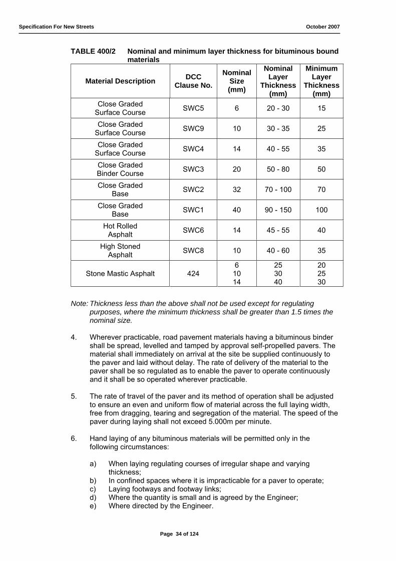
3. The materials shall be laid in one or more layers, by agreement with the Engineer, so that the compacted thickness of each layer shall be in accordance with Table 400/2 below and shall not normally exceed 150mm. Thickness in excess of those given in Table 400/2 may provide better compaction if adequate equipment is used by agreement with the Engineer, to avoid possible problems with surface irregularity and level control.
Page 33 of 124
Specification For New Streets October 2007
TABLE 400/2 Nominal and minimum layer thickness for bituminous bound materials
Material Description DCCClause No.
NominalSize(mm)
NominalLayer
Thickness(mm)
MinimumLayer
Thickness(mm)
Close Graded Surface Course SWC5 6 20 - 30 15
Close GradedSurface Course SWC9 10 30 - 35 25
Close GradedSurface Course SWC4 14 40 - 55 35
Close GradedBinder Course SWC3 20 50 - 80 50
Close Graded Base SWC2 32 70 - 100 70
Close GradedBase SWC1 40 90 - 150 100
Hot RolledAsphalt SWC6 14 45 - 55 40
High StonedAsphalt SWC8 10 40 - 60 35
Stone Mastic Asphalt 4246
1014
253040
202530
Note: Thickness less than the above shall not be used except for regulating purposes, where the minimum thickness shall be greater than 1.5 times the nominal size.
4. Wherever practicable, road pavement materials having a bituminous binder shall be spread, levelled and tamped by approval self-propelled pavers. The material shall immediately on arrival at the site be supplied continuously to the paver and laid without delay. The rate of delivery of the material to the paver shall be so regulated as to enable the paver to operate continuously and it shall be so operated wherever practicable.
5. The rate of travel of the paver and its method of operation shall be adjusted to ensure an even and uniform flow of material across the full laying width, free from dragging, tearing and segregation of the material. The speed of the paver during laying shall not exceed 5.000m per minute.
6. Hand laying of any bituminous materials will be permitted only in the following circumstances:
a) When laying regulating courses of irregular shape and varying thickness;
b) In confined spaces where it is impracticable for a paver to operate; c) Laying footways and footway links; d) Where the quantity is small and is agreed by the Engineer; e) Where directed by the Engineer.
Page 34 of 124

Specification For New Streets October 2007
Compaction
7. Bituminous materials shall be laid and compacted in layers which enable the specified thickness, surface level, regularity requirements and compaction to be achieved.
8. Material shall be compacted as soon as rolling can be effected without causing undue displacement or surface cracking of the material and while this has at least the minimum rolling temperature stated in Table 400/3. The material shall be uniformly compacted by an 8-10 tonnes smooth steel wheel roller having a width of roll not less than 450mm or by mutli-wheeled pneumatic tyred roller of equivalent weight except that surface course material shall be surface finished with a smooth wheel roller. In areas where the 8-10 tonnes, smooth steel wheel or equivalent multi-wheeled pneumatic tyred roller is precluded from operating by localised impediment, compaction must be effected by a smaller roller, pedestrian vibrator or other.
9. Temperatures of the materials supplied and laid shall be in accordance with BS594 and BS4987 and Table 400/3 below.
TABLE 400/3 Temperatures of materials (ºC)
Material GradeMaximum
Temp. at any Stage (ºC)
MinimumDelivery
Temp. (ºC)
MinimumRolling
Temp. (ºC)
Bitumen
50 pen B/C (40/60)
50 pen S/C (40/60)
125 pen (100/150)
190 pen (160/220)
170
190
160
150
120
140
120
110
85
85
75
60
Tar
C30/34
C34/42
C46
C50
C54
C58
60
70
100
105
110
125
50
60
60
80
80
90
30
40
40
60
60
70
Note: Care should be taken to guard against surface cracking occurring as a result of rolling temperature close to the appropriate minimum temperature. Finishing rolling may be carried out at a temperature below that given, where agreed by the Engineer, but vibration should not be employed.
10. With regard to bitumen macadam or tarmacadam surface courses, compaction will normally be obtained after a minimum of 5 passes of roller over any point of the carpet surface before the minimum rolling temperatures are reached by normal chilling. For hot rolled asphalt a minimum of 10 passes of the roller can usually be obtained, although compaction of the carpet containing pre-coated chippings should anticipate a final coverage of 1.5mm texture depth.
Page 35 of 124

Specification For New Streets October 2007
11. The material shall be rolled in a longitudinal direction working from the sides to the centre of the carriageway. Successive passes of the roller should compact to an echelon pattern to prevent the formation of a ridge. Notwithstanding the general side to centre rolling procedure, the centre joint of the second rip, which abuts the newly laid carpet, should always be nipped in first in order to prevent an open joint forming. This is of great importance in relation to high viscosity surface course macadams.
12. Rollers shall not stand on newly laid material while there is a risk that it will be deformed thereby.
13. Hand-raking of surface course material which has been laid by a paver and the addition of such material by hand-spreading to the paved area for adjustment of level will be permitted only in the following circumstances:
a) At the edge of the layers of material and at gullies and manholes; b) Where otherwise directed by the Engineer
14. Hand laid work shall conform to all the specification requirements of the Clause except those relating to the manner of operating pavers.
15. Where longitudinal joints between laying widths or transverse joints have to be made in surface courses, the material shall be fully compacted and the joint made flush in one of the following ways, method b) being always used for transverse joints:
a) By heating the joint with an approved joint heater at the time when the additional width is being laid but without cutting back or coating with binder. The heater shall raise the temperature of the full depth of the surface course to a figure within the specific range of minimum rolling temperature and maximum temperature at any stage as given in Table 400/3 above, for the material and for a width not less than 75mm on each side of the joint. The Developer shall have available for use in the event of breakdown, equipment necessary for operating method b);
b) By cutting back the exposed joints to a vertical face of not less than the specified layer thickness, discarding all loosened material and coating the vertical face completely with a grade of hot tar or bitumen suitable for the purpose before the adjacent width is laid.
16. All joints shall be offset at least 300mm from parallel joints in the layer beneath.
17. Where the binder course material is to be used as a running surface, it shall be blinded with coated grit complying with Clause 424.
18. If more than 24 hours elapse before surface course material is to be laid, a cationic bitumen emulsion tack coat shall be applied as directed by the Engineer. The tack coat shall comply with the requirements of BS434-1.
19. The laid carpet shall remain isolated from any form of trafficking until it has cooled to be ambient temperature.
Page 36 of 124

Specification For New Streets October 2007
20. Irrespective of the materials used or the method of compaction employed, the Engineer shall be satisfied that adequate compaction has been achieved. Where required by the Engineer the Developer shall arrange for this to be determined by either method of testing given in Appendix A to this Specification.
21. Where the requirements for compaction are not met, the Engineer will determine the area of defective material, which shall be removed and the pavement course rectified to the satisfaction of the Engineer.
405 CONSTRUCTION REQUIREMENTS FOR MATERIALS TO CLAUSES 407 - 409 (INCLUSIVE)
1. Materials complying with the above-mentioned clauses shall be used in the construction of the Works in the following manner:
Transporting
2. Transport vehicles carrying plant mixed material shall have a capacity suited to the output of the mixing plant and the site conditions and be capable of discharging cleanly. Material when mixed shall be removed at once from the mixer, transported directly to the point where it is laid and protected from the weather both during transit from the mixer to the laying site and whilst awaiting tipping.
Laying
3. All materials shall be placed and spread evenly. Spreading shall be undertaken either concurrently with placing or without delay. Base material shall be spread using a paving machine or spreader box operated with a mechanism which levels off the material to even depth. Except where otherwise specified in individual clauses, the material should be spread in one layer so that after compaction the total thickness is as specified. Before works proceeds against a longitudinal joint the edge compacted earlier, shall, if it has been exposed for more than one hour, be cut back vertically to produce a face of the specified thickness of layer and of properly compacted material.
Protection and Curing
4. The Developer shall in his choice of permitted base materials have regard to the nature of those materials and of the sub-base and sub-grade and the need to protect them from deterioration due to the ingress of water and the use of construction plant. The Developer shall programme the laying of the sub-base and the subsequent pavement courses and take such other steps as may be considered necessary to afford protection to the base, sub-base and sub-grade.
Page 37 of 124
Specification For New Streets October 2007
406 MATERIALS FOR SUB-BASE, BASE, FLEXIBLE SURFACING AND FOOTWAYS
1. Sub-bases, bases, flexible surfacing and footways shall be made and constructed using one or other of the materials as given in Table 400/17 for the appropriate Road Type specified in the Agreement, or the particular materials described in the Agreement.
2. The composition of the materials used in the sub-base, base, flexible surfacing and footways shall comply with the appropriate Clauses in this specification read in conjunction with Table 400/18.
3. The supplier of bituminous materials shall operate a Quality Assurance System, which shall comply with the requirement of BS ISO 9000-2 and BS EN ISO 9002. A list of approved suppliers may be obtained from the Engineer.
407 CAPPING MATERIAL
1. Capping shall only be provided in those areas and to extent as directed by the Engineer.
2. No unprotected sub-formation, which is to receive capping, shall remain continuously exposed to rain causing degradation, nor, unless permitted by the Engineer, be left uncovered overnight.
3. Capping shall have a maximum compacted layer thickness of 110mm.
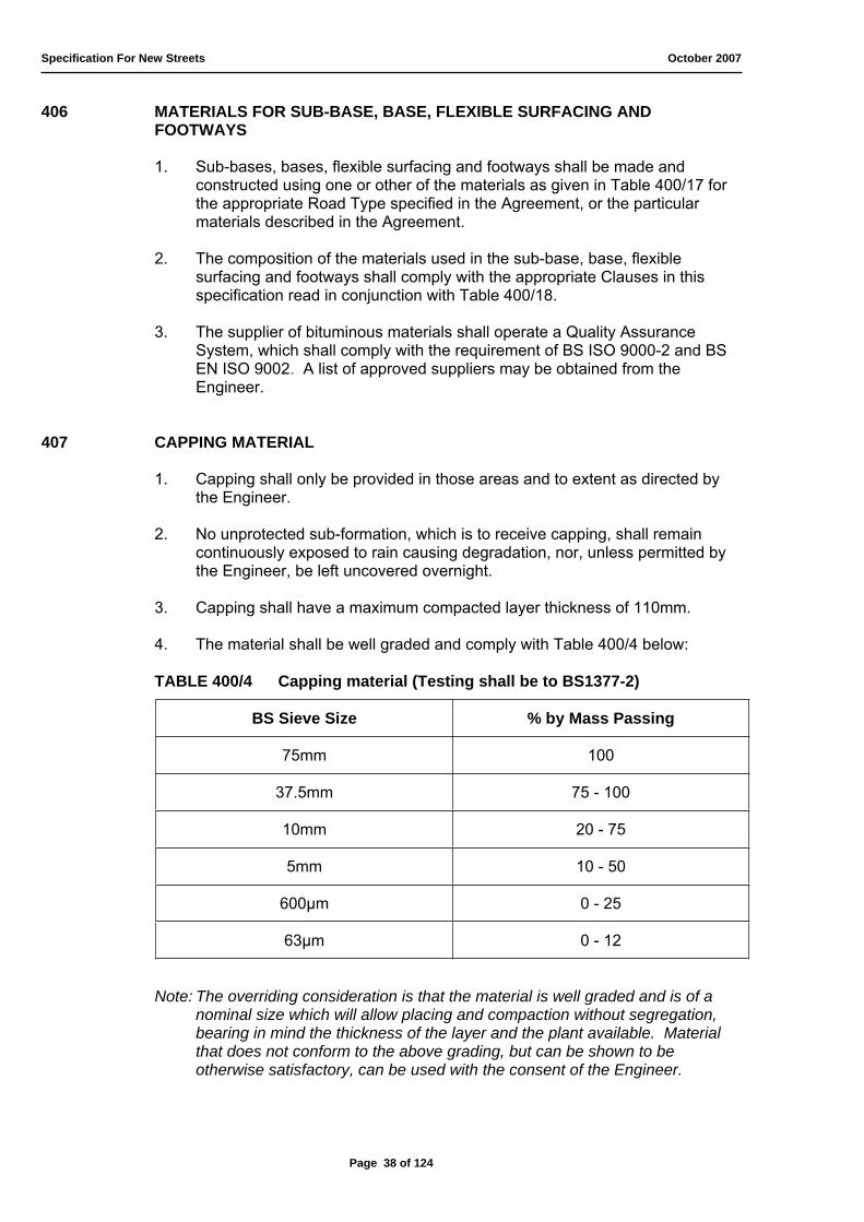
4. The material shall be well graded and comply with Table 400/4 below:
TABLE 400/4 Capping material (Testing shall be to BS1377-2)
BS Sieve Size % by Mass Passing
75mm 100
37.5mm 75 - 100
10mm 20 - 75
5mm 10 - 50
600μm 0 - 25
63μm 0 - 12
Note: The overriding consideration is that the material is well graded and is of a nominal size which will allow placing and compaction without segregation, bearing in mind the thickness of the layer and the plant available. Material that does not conform to the above grading, but can be shown to be otherwise satisfactory, can be used with the consent of the Engineer.
Page 38 of 124
Specification For New Streets October 2007
5. Capping material can be made of any material except un-burnt colliery spoil or chalk.
6. The material shall have a 10% fines value in excess of 30kN when tested in accordance with BS812 with the aggregate tested in a soaked condition.
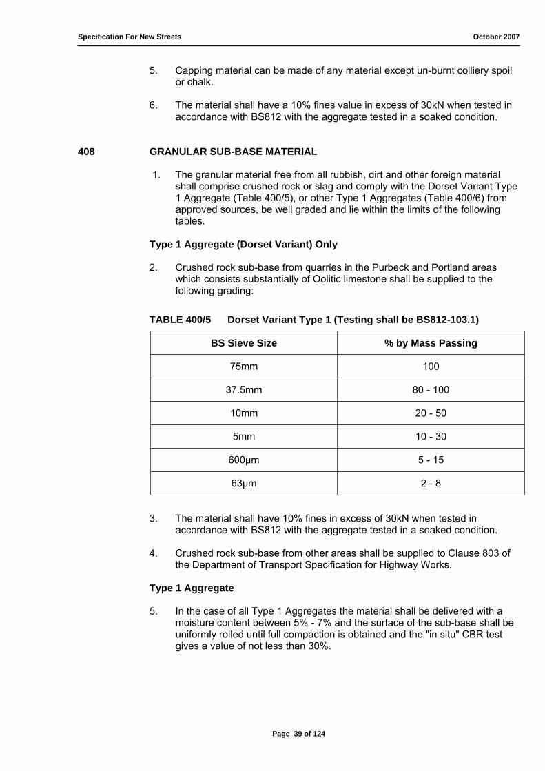
408 GRANULAR SUB-BASE MATERIAL
1. The granular material free from all rubbish, dirt and other foreign material shall comprise crushed rock or slag and comply with the Dorset Variant Type 1 Aggregate (Table 400/5), or other Type 1 Aggregates (Table 400/6) from approved sources, be well graded and lie within the limits of the following tables.
Type 1 Aggregate (Dorset Variant) Only
2. Crushed rock sub-base from quarries in the Purbeck and Portland areas which consists substantially of Oolitic limestone shall be supplied to the following grading:
TABLE 400/5 Dorset Variant Type 1 (Testing shall be BS812-103.1)
BS Sieve Size % by Mass Passing
75mm 100
37.5mm 80 - 100
10mm 20 - 50
5mm 10 - 30
600μm 5 - 15
63μm 2 - 8
3. The material shall have 10% fines in excess of 30kN when tested in accordance with BS812 with the aggregate tested in a soaked condition.
4. Crushed rock sub-base from other areas shall be supplied to Clause 803 of the Department of Transport Specification for Highway Works.
Type 1 Aggregate
5. In the case of all Type 1 Aggregates the material shall be delivered with a moisture content between 5% - 7% and the surface of the sub-base shall be uniformly rolled until full compaction is obtained and the "in situ" CBR test gives a value of not less than 30%.
Page 39 of 124

Specification For New Streets October 2007
TABLE 400/6 Type 1 Aggregates (crushed rock, crushed slag)
BS Sieve Size % by Mass Passing
75mm 100
37.5mm 85 - 100
10mm 40 - 70
5mm 25 - 45
600μm 8 - 22
63μm 0 - 10
6. The material shall be compacted in layers of not more than 150mm finished thickness at a moisture content of 5% - 7% and shall be carried out with either an 8 - 10 tonnes smooth wheel power roller or other plant approved by the Engineer to the required thickness.
7. Should any instability occur in the sub-base, the Developer shall cut out the affected area to such depths as directed, and make good the sub-base and finishes to conform to the adjacent surface.
8. A blinding layer of gravel shall, in addition, be compacted so as to provide a smooth and even surface.
409 CRUSHER-RUN HARDCORE BASE
1. Crusher-run material where permitted by the Engineer shall be the output of the crusher which has passed only through a 100mm screen crusher gap, or grizzly, to give a true representation of all subsequent sizes to dust acceptable to the Engineer.
2. The material shall be compacted in layers of not more than 150mm finished thickness and shall be carried out with either an 8 - 10 tonnes smooth-wheeled power roller or other plant approved by the Engineer to the required thickness.
3. Fine aggregates shall pass the 20mm BS sieve and be graded evenly (from 20mm down to dust).
4. If necessary, fine aggregate shall be spread on to a thickness of approximately 25mm, by a suitable spreading machine, and vibrated into the voids of the coarse aggregate by a vibrating plate compactor (having a mass per unit area of the base plate of at least 1400kg/m2) or a vibrating roller having a mass per metre width of vibrating roll of at least 1800kg.
Page 40 of 124
Specification For New Streets October 2007
5. The operation of spreading and vibrating the fine aggregate shall be repeated as necessary until no more will penetrate into the layer of coarse aggregate and no hungry patches are visible on the surface, when it shall be brushed to remove the excess fines and leave the coarse aggregate standing 3mm - 6mm proud. The layer shall then be rolled with a smooth-wheeled roller having a mass per metre width of at least 5000kg on at least one roll.
6. The whole operation shall be repeated as necessary to provide the full specified thickness of base.
410 CLOSE GRADED BITUMEN MACADAM BASE (SWC1 OR SWC2)
1. The materials shall be made in accordance with the general requirements of BS4987 subject to the following provisos, and shall comply with the appropriate tables and sections thereof for close graded base Macadam and Table 400/2 of this Specification. It shall be transported, laid and compacted to Clause 404.
Aggregate
2. The aggregate shall be in a surface dry condition prior to mixing.
Filler
3. When gravel, other than limestone gravel, is the aggregate, the material passing the 75μm BS sieve shall include 2% of Portland cement or hydrated lime by mass of the total aggregate.
Binder
4. The binder shall be petroleum bitumen complying with BS3690 or a mixture of 90% by mass of petroleum bitumen with 10% by mass of tar complying with BS76. The penetration of the bitumen or tar bitumen mixture shall be in accordance with the requirements of Table 400/18.
411 CLOSE GRADED TARMACADAM BASE (SWC1 OR SWC2)
1. The materials shall be made in accordance with the general requirements of BS4987 subject to the following provisos, and shall comply with the appropriate tables and sections thereof for close graded base Macadam and Table 400/2 of this Specification. It shall be transported, laid and compacted in accordance with Clauses 404.
Aggregate
2. The aggregate shall be in a surface dry condition prior to mixing.
Filler
3. When gravel, other than limestone gravel, is the aggregate, the material passing the 75μm BS sieve shall include 2% of Portland cement by mass of the total aggregate.
Page 41 of 124

Specification For New Streets October 2007
Binder
4. For gravel aggregates containing flint the binder shall be tar grade C58. For crushed rock or slag aggregates not containing flint the binder shall be tar grade C50 or C54.
412 MAINTENANCE OF THE SURFACE OF BASE
1. On completion of the base and until any surfacing is laid on it, the finished surface shall be maintained free from potholes, ruts and undulations, irregularities, depressions, loose material or other defects.
413 REGULATING COURSE
1. Regulating course material shall be made and laid in accordance with the requirements for one or other of the bituminous materials in this Specification. It shall include the appropriate nominal sized aggregate to ensure compliance with the requirements of Clause 404.
414 CLOSE GRADED BITUMEN MACADAM BINDER COURSE (SWC3)
1. The material shall be made in accordance with the general requirements of BS4987 subject to the following provisos. It shall comply with the appropriate tables and sections thereof for 32mm or 20mm nominal size close graded binder course Macadam and Table 400/2 of this Specification. It shall be transported, laid and compacted to Clause 404.
Aggregate
2. The aggregate shall be in a surface dry condition prior to mixing.
Filler
3. When gravel other than limestone gravel is the aggregate, the material passing the 75μm BS sieve shall include 2% of Portland cement or hydrated lime by mass of the total aggregate.
Binder
4. The binder shall be petroleum bitumen complying with BS3690 or a mixture of 90% by mass of petroleum bitumen with 10% by mass of tar complying with BS76. The penetration of the bitumen or tar bitumen mixture shall be in accordance with the requirements of Table 400/18.
415 CLOSE GRADED TARMACADAM BINDER COURSE (SWC3)
1. The material shall be made in accordance with the general requirements of BS4987 subject to the following provisos. It shall comply with the appropriate tables and sections thereof for 32mm, or 20mm nominal size close graded binder course Macadam and Table 400/2 of this Specification. It shall be transported, laid and compacted to Clause 404.
Page 42 of 124
Specification For New Streets October 2007
Aggregate
2. The aggregate shall be in a surface dry condition prior to mixing.
Filler
3. When gravel other than limestone gravel is the aggregate, the material passing the 75μm BS sieve shall include 2% of Portland cement or hydrated lime by mass of the total aggregate.
416 BITUMEN MACADAM BINDER COURSE
1. The material shall be made in accordance with the general requirements of BS4987 subject to the following provisos. It shall comply with the appropriate tables and sections thereof for 20mm nominal size material, with the exception that for machine laid material the binder shall be 190 pen (160/220) straight run bitumen. The traffic category shall be in accordance with Table 400/18. It shall be transported, laid and compacted to Clause 404.
Filler
2. When gravel other than limestone gravel is the aggregate, the material passing the 75μm BS sieve shall include 2% of Portland cement or hydrated lime by mass of the total aggregate.
417 TARMACADAM BINDER COURSE
1. The material shall be made in accordance with the general requirements of BS4987 subject to the following provisos. It shall comply with the appropriate tables and sections of the British Standard for 20mm nominal size material, with the exception that machine laid material the binder shall be C50 or C54 Tar. The traffic category shall be in accordance with Table 400/18. It shall be transported, laid and compacted to Clause 404.
Filler
2. When gravel other than limestone gravel is the aggregate, the material passing 75μm BS sieve shall include 2% Portland cement by mass of the total aggregate.
418 ROLLED ASPHALT SURFACE COURSE (SWC6)
1. The material shall be made in accordance with the requirements of BS594 for surface course mixtures, subject to the following provisos. Its composition shall be determined by the method described in BS594, Section 2 and Table 400/2 of this Specification. The material shall be transported, laid and compacted to Clause 404.
Asphaltic Cement
2. The asphaltic cement shall have the penetration in accordance with Table 400/18.
Page 43 of 124

Specification For New Streets October 2007
Coarse Aggregate Content
3. The coarse aggregate shall comply with the requirements of Table 400/18.
Binder Content/Bulk Density of Blast Furnace Slag Relationship
4. When the bulk density of the slag aggregate requires the soluble bitumen content to be increased, the percentage of aggregate passing the 2.36mm BS sieve and retained on the 75μm BS sieve shall be correspondingly reduced.
419 STONE MASTIC ASPHALT SURFACE COURSE (RESIDENTIAL ONLY)
1. This specification is based on the March 1998 version of Clause 942 of the Specification for Highway Works and Appendix A of TRL Project Report 65 with amendments and additions by Soil Mechanics, Dorset.
General
2. Stone mastic asphalt shall comply with sub-clauses 3 to 25 of this Clause and shall otherwise be manufactured and laid in accordance with BS4987.
Aggregates and Filler
3. Coarse aggregate shall be crushed rock complying with BS4987-1 and BS63-2 Table 2.
4. When tested in accordance with the procedures of BS812, the coarse aggregate shall additionally have the following properties:
a) Polished Stone Value (PSV) as specified in Table 400/18; b) Ten Per Cent Fines Value (TPV) not less than 180kN; c) Aggregate Abrasion Value (AAV) as specified in Table 400/18;
d) Flakiness Index (IF) not more than 25%.
5. Fine aggregate shall comply with BS4987-1 and shall be either crushed rock fines or natural sand or a blend of both. Fine aggregate shall be added as required to suit the particular design.
6. The filler shall be crushed limestone complying with the requirements of BS594-1. Filler shall be added as required to suit the particular design.
7. The target aggregate grading and target binder content shall fall within the envelope formed by the limits given in Table 400/7.
8. When sampled and tested in accordance with the procedures of BS598-100, BS598-101, BS598-102, the aggregate grading shall fall within the envelope formed by the targets provided by the Contractor and the tolerances given in Table 400/8.
9. The design and selection of aggregates, filler and bitumen proportions shall be the responsibility of the Contractor, who shall supply the necessary details to the Overseeing Organisation for record purposes together with the properties of the constituents.
Page 44 of 124
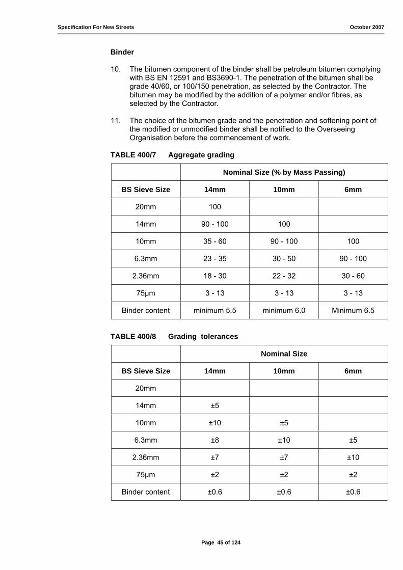
Specification For New Streets October 2007
Binder
10. The bitumen component of the binder shall be petroleum bitumen complying with BS EN 12591 and BS3690-1. The penetration of the bitumen shall be grade 40/60, or 100/150 penetration, as selected by the Contractor. The bitumen may be modified by the addition of a polymer and/or fibres, as selected by the Contractor.
11. The choice of the bitumen grade and the penetration and softening point of the modified or unmodified binder shall be notified to the Overseeing Organisation before the commencement of work.
TABLE 400/7 Aggregate grading
Nominal Size (% by Mass Passing)
BS Sieve Size 14mm 10mm 6mm
20mm 100
14mm 90 - 100 100
10mm 35 - 60 90 - 100 100
6.3mm 23 - 35 30 - 50 90 - 100
2.36mm 18 - 30 22 - 32 30 - 60
75μm 3 - 13 3 - 13 3 - 13
Binder content minimum 5.5 minimum 6.0 Minimum 6.5
TABLE 400/8 Grading tolerances
Nominal Size
BS Sieve Size 14mm 10mm 6mm
20mm
14mm ±5
10mm ±10 ±5
6.3mm ±8 ±10 ±5
2.36mm ±7 ±7 ±10
75μm ±2 ±2 ±2
Binder content ±0.6 ±0.6 ±0.6
Page 45 of 124

Specification For New Streets October 2007
12. Where appropriate to the system, the target binder content shall be determined by the binder drainage test in BS DD 232:1996, except that the range to be tested shall be amended to suit the grading of the aggregates proposed for use. The target binder content determined in the laboratory may be adjusted to suit the mixing plant and the aggregate type, which is used, subject to plant trial and delivery distance. The adjusted binder content shall be notified to the Overseeing Organisation prior to delivery and shall not be lower than that specified above.
Tack or Bond Coat
13. The tack or bond coat shall be a hot-applied cationic bitumen emulsion complying with BS434-1, with a minimum bitumen content of 38%. To suit the particular system, it may be modified with a polymer. The choice of tack or bond coat shall be notified to the Overseeing Organisation before commencement of work.
Surface Preparation
14. Existing surfaces shall be cleaned using steel brooms and suction sweeping or other appropriate means. The surface may be moist but not wet; standing water shall not be present. All mud, dust, dirt and other debris and organic material shall be removed.
15. Where necessary, existing surfaces shall be regulated.
16. Unless raised prior to surfacing, iron-work and reflecting road studs shall be located for lifting and relaying after completion of surfacing works. Gullies shall be covered prior to surfacing.
17. Where possible, existing road markings shall be removed.
Mixing
18. The material shall be mixed in accordance with the requirements of BS4987-1, such that an homogeneous mixture of aggregate, filler and
bitumen is produced at a temperature of 150 to 180 0C.
Transportation
19. Mixed materials shall be protected from contamination and undue heat loss by being transported to site in sheeted insulated lorries. To facilitate discharge of the materials, the floor of the lorry may be coated with the minimum of light vegetable oil or liquid soap or other non-solvent solution. When such coating is used, the lorry body shall be tipped to its fullest extent with the tailboard open to ensure drainage of any excess, prior to loading. The floor and sides of the lorry shall be free from adherent bituminous materials or other contaminants before loading the surfacing material.
Page 46 of 124
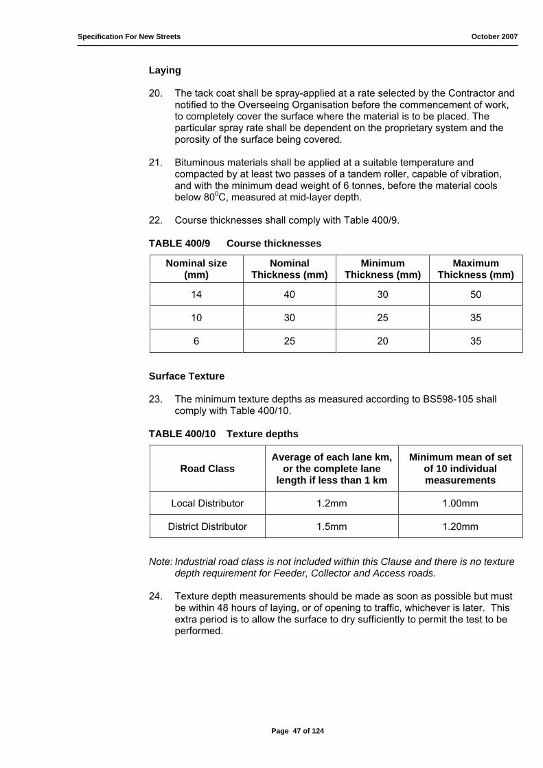
Specification For New Streets October 2007
Laying
20. The tack coat shall be spray-applied at a rate selected by the Contractor and notified to the Overseeing Organisation before the commencement of work, to completely cover the surface where the material is to be placed. The particular spray rate shall be dependent on the proprietary system and the porosity of the surface being covered.
21. Bituminous materials shall be applied at a suitable temperature and compacted by at least two passes of a tandem roller, capable of vibration, and with the minimum dead weight of 6 tonnes, before the material cools below 800C, measured at mid-layer depth.
22. Course thicknesses shall comply with Table 400/9.
TABLE 400/9 Course thicknesses
Nominal size (mm)
NominalThickness (mm)
MinimumThickness (mm)
MaximumThickness (mm)
14 40 30 50
10 30 25 35
6 25 20 35
Surface Texture
23. The minimum texture depths as measured according to BS598-105 shall comply with Table 400/10.
TABLE 400/10 Texture depths
Road Class Average of each lane km,
or the complete lane length if less than 1 km
Minimum mean of set of 10 individual measurements
Local Distributor 1.2mm 1.00mm
District Distributor 1.5mm 1.20mm
Note: Industrial road class is not included within this Clause and there is no texture depth requirement for Feeder, Collector and Access roads.
24. Texture depth measurements should be made as soon as possible but must be within 48 hours of laying, or of opening to traffic, whichever is later. This extra period is to allow the surface to dry sufficiently to permit the test to be performed.
Page 47 of 124
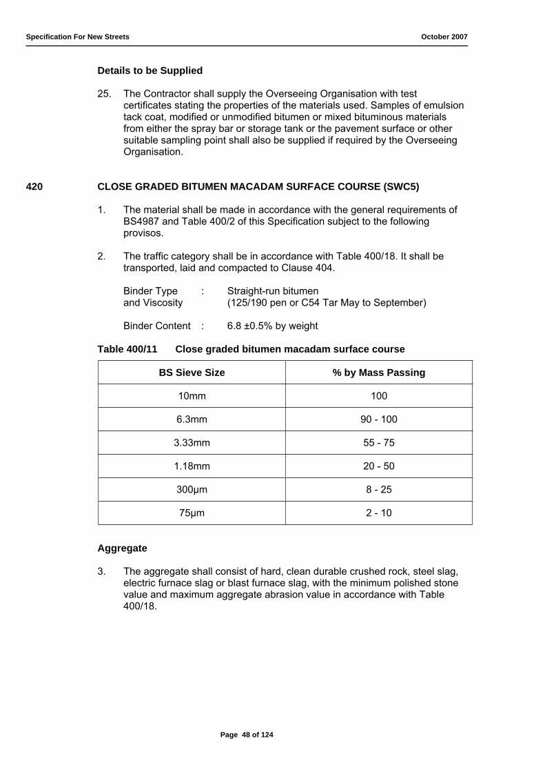
Specification For New Streets October 2007
Details to be Supplied
25. The Contractor shall supply the Overseeing Organisation with test certificates stating the properties of the materials used. Samples of emulsion tack coat, modified or unmodified bitumen or mixed bituminous materials from either the spray bar or storage tank or the pavement surface or other suitable sampling point shall also be supplied if required by the Overseeing Organisation.
420 CLOSE GRADED BITUMEN MACADAM SURFACE COURSE (SWC5)
1. The material shall be made in accordance with the general requirements of BS4987 and Table 400/2 of this Specification subject to the following provisos.
2. The traffic category shall be in accordance with Table 400/18. It shall be transported, laid and compacted to Clause 404.
Binder Type : Straight-run bitumen and Viscosity (125/190 pen or C54 Tar May to September)
Binder Content : 6.8 ±0.5% by weight
Table 400/11 Close graded bitumen macadam surface course
BS Sieve Size % by Mass Passing
10mm 100
6.3mm 90 - 100
3.33mm 55 - 75
1.18mm 20 - 50
300μm 8 - 25
75μm 2 - 10
Aggregate
3. The aggregate shall consist of hard, clean durable crushed rock, steel slag, electric furnace slag or blast furnace slag, with the minimum polished stone value and maximum aggregate abrasion value in accordance with Table 400/18.
Page 48 of 124

Specification For New Streets October 2007
421 CLOSE GRADED TARMACADAM SURFACE COURSE (SWC5)
1. The material shall be made in accordance with the general requirements of BS4987 and Table 400/2 of this Specification subject to the following provisos.
2. The traffic category shall be in accordance with Table 400/18. It shall be transported, laid and compacted to Clause 404.
Binder Type : Straight-run bitumen and Viscosity (125/190 pen or C54 Tar May to September)
Binder Content : 6.8 ±0.5% by weight
Table 400/12 Close graded tarmacadam surface course
BS Sieve Size % by Mass Passing
10mm 100
6.3mm 90 - 100
3.33mm 55 - 75
1.18mm 20 - 50
300μm 8 - 25
75μm 2 - 10
Aggregate
3. The aggregate shall consist of hard, clean durable crushed rock, steel slag, electric furnace slag or blast furnace slag, with the minimum polished stone value and maximum aggregate abrasion value in accordance with Table 400/18.
422 COLD ASPHALT (FINE) SURFACE COURSE (FOOTWAY ONLY)
1. The material shall be made in accordance with the general requirements of BS4987 subject to the following provisos.
2. It shall comply with the appropriate tables and sections thereof and the requirements of Table 400/18 of this specification.
3. The material shall be cold asphalt.
4. It shall be transported, laid, and compacted to Clause 404.
Page 49 of 124
Specification For New Streets October 2007
423 COATED CHIPPINGS FOR APPLICATIONS TO PRE-MIXED SURFACINGS
1. Coated Chippings shall be 20mm or 14mm nominal size and spread at the appropriate rate stated in BS594.
2. The chippings and the manner of coating when used for rolling into the surface of rolled asphalt shall be in accordance with BS594 subject to the following provisos.
3. The minimum polished stone value and the maximum aggregate abrasion value of the chippings shall be in accordance with Table 400/18.
4. Coated chippings shall comply with one of the following requirements:
a) Not more than 7.5% of chippings shall fail the Solvent Test; b) The mass of sand retained in the Hot Sand Test shall be not less than
40g/kg for 20mm chippings (50g/kg for 14mm chippings) and not more than 7.5% of chippings shall fail the visual assessment of sand cover.
The test to be used shall be that required by the Engineer.
424 COATED GRIT FOR BLINDING
1. Coated grit in accordance with BS4987 except that the soluble binder content table shall be 4.0% ± 0.5%. The material shall be deferred set 72 hours unless otherwise specified by the Engineer.
425 SURFACE DRESSING
1. Where surface dressing is permitted it shall be undertaken in accordance with the recommendations of the Transport Research Laboratory Road Note 39. The chippings, coated or un-coated shall comply with BS63 and be 6mm, 10mm or 14mm, Basalt, Quartzite or Grit-stone as directed by the Engineer. The binder should be either:
a) Road Tar in accordance with BS76; b) Bitumen Emulsion in accordance with BS434-1and BS434-2; c) Cut-back Bitumen in accordance with BS3690-1.
426 BITUMINOUS SPRAYS
1. The preparation of a surface for a bituminous spray, the application of a spray and binding when specified shall be carried out in accordance with the current recommendations of the Transport Research Laboratory Road Note 39 for Surface Dressing, where appropriate, to such work and in the case of bitumen emulsion sprays in accordance with BS434-2. The work shall also comply with the under-mentioned general requirements.
2. Road tar shall conform to the requirements of BS76, cut-back bitumen to BS3690, and bitumen emulsion to BS434-1. The binder shall be sprayed at the rate described in the Agreement.
Page 50 of 124
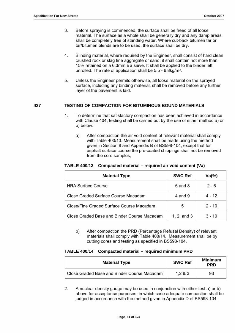
Specification For New Streets October 2007
3. Before spraying is commenced, the surface shall be freed of all loose material. The surface as a whole shall be generally dry and any damp areas shall be completely free of standing water. Where cut-back bitumen tar or tar/bitumen blends are to be used, the surface shall be dry.
4. Blinding material, where required by the Engineer, shall consist of hard clean crushed rock or slag fine aggregate or sand: it shall contain not more than 15% retained on a 6.3mm BS sieve. It shall be applied to the binder left unrolled. The rate of application shall be 5.5 - 6.8kg/m².
5. Unless the Engineer permits otherwise, all loose material on the sprayed surface, including any binding material, shall be removed before any further layer of the pavement is laid.
427 TESTING OF COMPACTION FOR BITUMINOUS BOUND MATERIALS
1. To determine that satisfactory compaction has been achieved in accordance with Clause 404, testing shall be carried out by the use of either method a) or b) below:
a) After compaction the air void content of relevant material shall comply with Table 400/13. Measurement shall be made using the method given in Section 8 and Appendix B of BS598-104, except that for asphalt surface course the pre-coated chippings shall not be removed from the core samples;
TABLE 400/13 Compacted material – required air void content (Va)
Material Type SWC Ref Va(%)
HRA Surface Course 6 and 8 2 - 6
Close Graded Surface Course Macadam 4 and 9 4 - 12
Close/Fine Graded Surface Course Macadam 5 2 - 10
Close Graded Base and Binder Course Macadam 1, 2, and 3 3 - 10
b) After compaction the PRD (Percentage Refusal Density) of relevant materials shall comply with Table 400/14. Measurement shall be by cutting cores and testing as specified in BS598-104.
TABLE 400/14 Compacted material – required minimum PRD
Material Type SWC Ref MinimumPRD
Close Graded Base and Binder Course Macadam 1,2 & 3 93
2. A nuclear density gauge may be used in conjunction with either test a) or b) above for acceptance purposes, in which case adequate compaction shall be judged in accordance with the method given in Appendix D of BS598-104.
Page 51 of 124

Specification For New Streets October 2007
428 PRE-CAST CONCRETE KERBS, CHANNELS AND EDGINGS
1. Pre-cast concrete kerbs, edging and quadrants shall comply with Clause 611 and shall be laid on a bed of ST2 Mix/C10 Grade concrete not less than 150mm deep and 200mm wider than the width of the kerb or kerb channel. The kerb is to be bedded and laid to the lines and levels shown on the Drawings and the 150mm wide concrete haunch is to be brought up to the back to within 50mm of the top of the kerb.
2. Pre-cast channels are to be bedded and laid as specified for kerb and they shall be jointed with cement mortar.
3. Precautions shall be taken to prevent kerbs being stained or damaged. All damaged, stained and broken kerbs are to be replaced before any arrangements are made for the surfacing of carriageway or footways.
4. Pre-cast concrete edging complying with Clause 611 shall be provided as support to the footway and laid true to line and level, bedded on and haunched to within 50mm of the top with 100mm ST2 Mix/C10 Grade concrete.
5. For radii of less than 12.000m, kerbs of appropriate radius will be used.
6. Any unit of kerb, channel edging and quadrant deviating more than 3mm in 3.000 m from line and level shall be made good by lifting and relaying.
429 COUNTRYSIDE/ CONSERVATION KERBS
1. Natural stone or re-constructed stone kerbing may only be used where permitted by the Engineer.
2. Natural stone or re-constructed stone kerbs shall comply with Clause 612.
430 PRE-CAST CONCRETE BLOCK PAVERS
1. Block pavers are to comply with Clause 613 and the following:
a) True rectangular in shape where the length is twice the width; b) A nominal length of 200mm; c) 80mm thick only.
2. The laying layer (blinding layer) is to be 50mm thick. It is not to be used as a regulating layer.
3. The laying layer and paver layer shall replace the surface course only.
4. The only accepted laying pattern will be Herringbone (a continuous 45º or 90º pattern will only be achievable on uniform areas).
5. Pavers are not to be laid on a saturated laying course or in inclement weather conditions.
6. At every channel edge of pavers, 3 bonded stretcher courses must be used.
Page 52 of 124
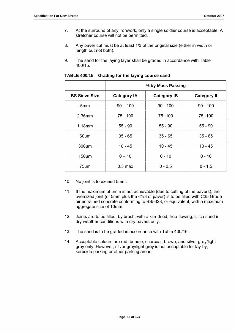
Specification For New Streets October 2007
7. At the surround of any ironwork, only a single soldier course is acceptable. A stretcher course will not be permitted.
8. Any paver cut must be at least 1/3 of the original size (either in width or length but not both).
9. The sand for the laying layer shall be graded in accordance with Table 400/15.
TABLE 400/15 Grading for the laying course sand
% by Mass Passing
BS Sieve Size Category IA Category IB Category II
5mm 90 – 100 90 - 100 90 - 100
2.36mm 75 –100 75 -100 75 -100
1.18mm 55 - 90 55 - 90 55 - 90
60μm 35 - 65 35 - 65 35 - 65
300μm 10 - 45 10 - 45 10 - 45
150μm 0 – 10 0 - 10 0 - 10
75μm 0.3 max 0 - 0.5 0 - 1.5
10. No joint is to exceed 5mm.
11. If the maximum of 5mm is not achievable (due to cutting of the pavers), the oversized joint (of 5mm plus the <1/3 of paver) is to be filled with C35 Grade air entrained concrete conforming to BS5328, or equivalent, with a maximum aggregate size of 10mm.
12. Joints are to be filled, by brush, with a kiln-dried, free-flowing, silica sand in dry weather conditions with dry pavers only.
13. The sand is to be graded in accordance with Table 400/16.
14. Acceptable colours are red, brindle, charcoal, brown, and silver grey/light grey only. However, silver grey/light grey is not acceptable for lay-by, kerbside parking or other parking areas.
Page 53 of 124
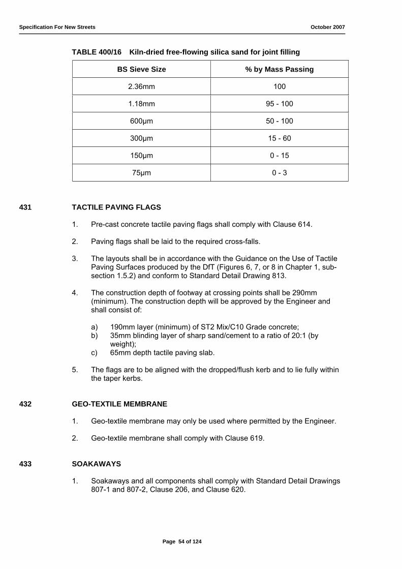
Specification For New Streets October 2007
TABLE 400/16 Kiln-dried free-flowing silica sand for joint filling
BS Sieve Size % by Mass Passing
2.36mm 100
1.18mm 95 - 100
600μm 50 - 100
300μm 15 - 60
150μm 0 - 15
75μm 0 - 3
431 TACTILE PAVING FLAGS
1. Pre-cast concrete tactile paving flags shall comply with Clause 614.
2. Paving flags shall be laid to the required cross-falls.
3. The layouts shall be in accordance with the Guidance on the Use of Tactile Paving Surfaces produced by the DfT (Figures 6, 7, or 8 in Chapter 1, sub-section 1.5.2) and conform to Standard Detail Drawing 813.
4. The construction depth of footway at crossing points shall be 290mm (minimum). The construction depth will be approved by the Engineer and shall consist of:
a) 190mm layer (minimum) of ST2 Mix/C10 Grade concrete; b) 35mm blinding layer of sharp sand/cement to a ratio of 20:1 (by
weight);c) 65mm depth tactile paving slab.
5. The flags are to be aligned with the dropped/flush kerb and to lie fully within the taper kerbs.
432 GEO-TEXTILE MEMBRANE
1. Geo-textile membrane may only be used where permitted by the Engineer.
2. Geo-textile membrane shall comply with Clause 619.
433 SOAKAWAYS
1. Soakaways and all components shall comply with Standard Detail Drawings 807-1 and 807-2, Clause 206, and Clause 620.
Page 54 of 124

Specification For New Streets October 2007
434 TREE PITS
1. Tree pit construction and all components shall comply with Standard Detail Drawings 808-1, 808-2, and 808-3 and Clause 621 - 622 (inclusive).
435 BOLLARDS
1. Bollards will only be used with the permission of the Engineer.
2. Unless otherwise specified, bollards are to be of the “socketed” type.
3. White is reserved for collapsible bollards only. There will be no deviation from this colour coding.
4. Retro-reflective tape (150mm depth) or roundels, must be affixed to the upper of the bollard to the correct colour for approaching traffic (red, white, or both as traffic direction and installation position dictates).
5. Details of the white collapsible bollard for the emergency link are shown in Standard Detail Drawing 809.
436 FOOTWAYS - FLEXIBLE SURFACING
1. The surface area of footways and footway links shall be treated with an appropriate weed killer to Clause 618, not more than 7 days prior to the surfacing. The work is to be undertaken in the presence of the Engineer.
2. Materials for flexible surfacing shall comply with Tables 400/17 and 400/18.
3. The flexible surfacing shall be laid to the specified levels and cross falls on a base compacted to be the thickness required and of a material complying with Table 400/18.
437 LEVEL ACCESS (PART M), WINDOWS, AND STORM PORCHES
1. Level access landings and ramps to private properties will not form part of the highway and will be constructed beyond the limit of the land to be offered as highway maintainable at public expense.
2. The width of the footway will not be compromised to cater for level accesses.
3. Casement windows will not open out over the highway. Windows will be either non-opening or fitted with restrictors, or a private margin will exist between the back of the footway and the building frontage.
4. Neither storm porches nor any part of the roof structure will overhang the highway.
5. Raised gas meter boxes will be set behind the limit of the footway or safety margin so as not to constitute either a trip or maintenance hazard.
6. Flying freeholds will not be accepted in any form whatsoever.
Page 55 of 124
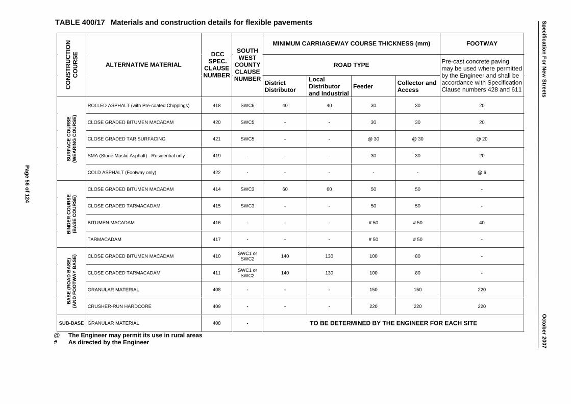
MINIMUM CARRIAGEWAY COURSE THICKNESS (mm) FOOTWAY
ROAD TYPE C
ON
STR
UC
TIO
NC
OU
RSE
ALTERNATIVE MATERIAL DCC
SPEC.CLAUSENUMBER
SOUTHWEST
COUNTYCLAUSENUMBER District
Distributor Local Distributor and Industrial
Feeder Collector and Access
Pre-cast concrete paving may be used where permitted by the Engineer and shall be accordance with Specification Clause numbers 428 and 611
ROLLED ASPHALT (with Pre-coated Chippings) 418 SWC6 40 40 30 30 20
CLOSE GRADED BITUMEN MACADAM 420 SWC5 - - 30 30 20
CLOSE GRADED TAR SURFACING 421 SWC5 - - @ 30 @ 30 @ 20
SMA (Stone Mastic Asphalt) - Residential only 419 - - - 30 30 20
SUR
FAC
E C
OU
RSE
(W
EAR
ING
CO
UR
SE)
COLD ASPHALT (Footway only) 422 - - - - - @ 6
CLOSE GRADED BITUMEN MACADAM 414 SWC3 60 60 50 50 -
CLOSE GRADED TARMACADAM 415 SWC3 - - 50 50 -
BITUMEN MACADAM 416 - - - # 50 # 50 40
BIN
DER
CO
UR
SE
(BA
SE C
OU
RSE
)
TARMACADAM 417 - - - # 50 # 50 -
CLOSE GRADED BITUMEN MACADAM 410 SWC1 or SWC2 140 130 100 80 -
CLOSE GRADED TARMACADAM 411 SWC1 or SWC2 140 130 100 80 -
GRANULAR MATERIAL 408 - - - 150 150 220
BA
SE (R
OA
D B
ASE
) (A
ND
FO
OTW
AY
BA
SE)
CRUSHER-RUN HARDCORE 409 - - - 220 220 220
SUB-BASE GRANULAR MATERIAL 408 - TO BE DETERMINED BY THE ENGINEER FOR EACH SITE
@ The Engineer may permit its use in rural areas # As directed by the Engineer
TABLE 400/17 Materials and construction details for flexible pavements Specification For New
Streets O
ctober2007
Page 56 of 124
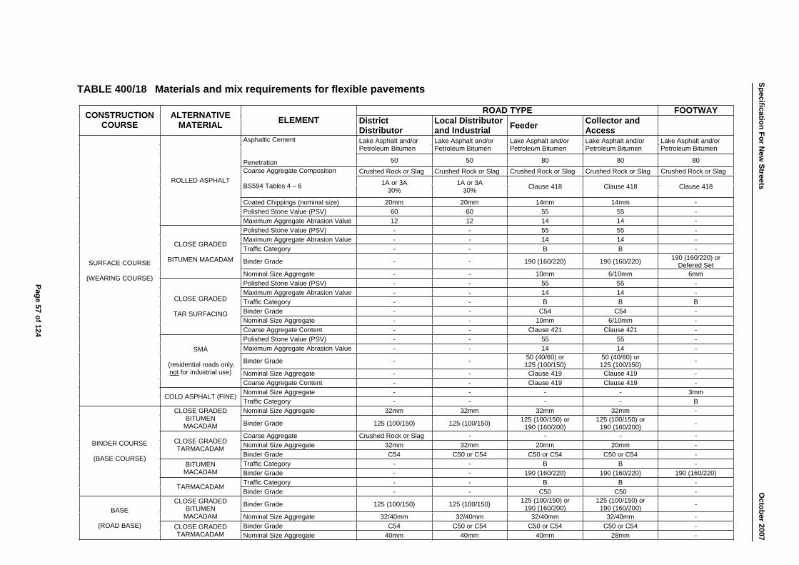
ROAD TYPE FOOTWAY CONSTRUCTIONCOURSE
ALTERNATIVE MATERIAL ELEMENT District
Distributor Local Distributor and Industrial Feeder Collector and
Access Lake Asphalt and/or Petroleum Bitumen
Lake Asphalt and/or Petroleum Bitumen
Lake Asphalt and/or Petroleum Bitumen
Lake Asphalt and/or Petroleum Bitumen
Lake Asphalt and/or Petroleum Bitumen
Asphaltic Cement
Penetration 50 50 80 80 80Crushed Rock or Slag Crushed Rock or Slag Crushed Rock or Slag Crushed Rock or Slag Crushed Rock or Slag Coarse Aggregate Composition
BS594 Tables 4 – 6 1A or 3A 30%
1A or 3A 30% Clause 418 Clause 418 Clause 418
Coated Chippings (nominal size) 20mm 20mm 14mm 14mm -Polished Stone Value (PSV) 60 60 55 55 -
ROLLED ASPHALT
Maximum Aggregate Abrasion Value 12 12 14 14 -Polished Stone Value (PSV) - - 55 55 -Maximum Aggregate Abrasion Value - - 14 14 -Traffic Category - - B B -
Binder Grade - - 190 (160/220) 190 (160/220) 190 (160/220) or Defered Set
CLOSE GRADED
BITUMEN MACADAM
Nominal Size Aggregate - - 10mm 6/10mm 6mmPolished Stone Value (PSV) - - 55 55 -Maximum Aggregate Abrasion Value - - 14 14 -Traffic Category - - B B BBinder Grade - - C54 C54 -Nominal Size Aggregate - - 10mm 6/10mm -
CLOSE GRADED
TAR SURFACING
Coarse Aggregate Content - - Clause 421 Clause 421 -Polished Stone Value (PSV) - - 55 55 -Maximum Aggregate Abrasion Value - - 14 14 -
Binder Grade - - 50 (40/60) or 125 (100/150)
50 (40/60) or 125 (100/150) -
Nominal Size Aggregate - - Clause 419 Clause 419 -
SMA
(residential roads only, not for industrial use)
Coarse Aggregate Content - - Clause 419 Clause 419 -Nominal Size Aggregate - - - - 3mm
SURFACE COURSE
(WEARING COURSE)
COLD ASPHALT (FINE) Traffic Category - - - - BNominal Size Aggregate 32mm 32mm 32mm 32mm -CLOSE GRADED
BITUMENMACADAM Binder Grade 125 (100/150) 125 (100/150) 125 (100/150) or
190 (160/200) 125 (100/150) or
190 (160/200) -
Coarse Aggregate Crushed Rock or Slag - - - -Nominal Size Aggregate 32mm 32mm 20mm 20mm -CLOSE GRADED
TARMACADAMBinder Grade C54 C50 or C54 C50 or C54 C50 or C54 -Traffic Category - - B B -BITUMEN
MACADAM Binder Grade - - 190 (160/220) 190 (160/220) 190 (160/220) Traffic Category - - B B -
BINDER COURSE
(BASE COURSE)
TARMACADAMBinder Grade - - C50 C50 -
Binder Grade 125 (100/150) 125 (100/150) 125 (100/150) or 190 (160/200)
125 (100/150) or 190 (160/200) -CLOSE GRADED
BITUMENMACADAM Nominal Size Aggregate 32/40mm 32/40mm 32/40mm 32/40mm -
Binder Grade C54 C50 or C54 C50 or C54 C50 or C54 -
BASE
(ROAD BASE) CLOSE GRADED TARMACADAM Nominal Size Aggregate 40mm 40mm 40mm 28mm -
Page 57 of 124
Specification For New
Streets
O
ctober2007
TABLE 400/18 Materials and mix requirements for flexible pavements
Specification For New Streets October 2007
500 ROADWORKS
501 CONSTRUCTION OF FORMWORK
1. Formwork shall include all temporary or permanent forms required for forming the concrete, together with all temporary construction required for their support.
2. All formwork shall be so constructed that there shall be no lost of material from the concrete. After hardening the concrete shall be in the position of the shape, dimensions and surface finish described in the Agreement or on the approved Drawings.
3. The formwork shall be so arranged as to be readily dismantled, and removed, from the cast concrete without shock, disturbance or damage.
4. Where internal metal ties are permitted, they or their removable parts shall be extracted without damage to the concrete and the remaining holes filled with mortar. No permanently embedded metal part shall have less than 40mm cover to the finished concrete surface.
502 FORMED SURFACES - CLASSES OF FINISH
1. The requirements extra to those given in Clause 501 to provide the class of finish described in the Agreement or on the approved Drawings, details shall be:
a) CLASS F2 - The irregularities in the finish shall be no greater than those obtained from the use of wrought thickness square edged boards arranged in a uniformed pattern. The finish is intended to be left as stuck but imperfections such as fins and surface discolouration shall, if required, be made good by methods approved by the Engineer;
b) CLASS F3 - The formwork shall be lined with material approved by the Engineer to provide a smooth finish of uniform texture and appearance. This material shall leave no stain on the concrete and shall be jointed and fixed to its backing that it imparts no blemishes. It shall be of the same type and obtained from only one source throughtout any one structure. The Developer shall make good any imperfections in the finish as required by the Engineer. Internal ties and embedded metal parts will not be allowed;
c) CLASS F4 - The requirements for Class F4 are as for Class F3 except that internal ties and embedded metal parts will be permitted. The ties shall be positioned only in rebates or in other positions agreed by the Engineer.
2. The Developer shall ensure that permanently exposed concrete surfaces, to Class F2, F3 and F4 finish, are protected from rust marks, spillage and stains of all kinds.
Page 58 of 124

Specification For New Streets October 2007
3. All formwork joints for exposed surfaces of concrete to Class F2, F3 and F4 finish shall form a regular pattern with horizontal and vertical lines continuous throughout each structure and all construction joints shall coincide with these horizontal and vertical lines.
503 PREPARATION OF FORMWORK BEFORE CONCRETING
1. The inside surfaces of forms shall, except for permanent formwork, or unless otherwise agreed by the Engineer, be coated with an approved material to prevent adhesion of the concrete. Release agents shall be applied strictly in accordance with the manufacturer's instructions and shall not come into contact with the reinforcement or pre-stressing tendons and anchorages. Different release agents shall not be used in formwork to concrete, which will be visible in the finished works. Immediately before concreting all forms shall be thoroughly cleaned.
504 REMOVAL OF FORMWORK
1. The Engineer shall be informed in advance when the Developer intends to strike any formwork.
2. The time at which the formwork is struck shall be the Developer's responsibility, but the minimum periods between concreting and the removal of forms shall be as set out in Table 500/1.
TABLE 500/1 – Minimum period before striking formwork
Type of Support Minimum Period Before Striking
+ 16°C (61°F) + 5°C (41°F)
Vertical formwork to columns, walls and beams 12 hours 24 hours
Soffit formwork to slabs 5 days 7 days
Props to slabs 10 days 15 days
Soffit formwork to beams 9 days 14 days
Props to beams 14 days 20 days
Arch Centres 9 days * 14 days *
* This period shall commence from the time of completion of the last shrinkage key.
Page 59 of 124

Specification For New Streets October 2007
3. The periods stated in Table 500/1 above are based on a constant surface temperature of the concrete of + 16°C (61°F) and + 5°C (41°F) and the use of Ordinary Portland Cement. They shall be increased during cold weather as directed by the Engineer and may be changed if other types of cement are used, subject to the Engineer's agreement.
4. Formwork shall be constructed so that the side forms of members can be removed without disturbing the soffit forms and, if props are to be left in place when the soffit forms are removed, these props shall not be disturbed during the striking.
5. For pre-stressed units the side forms shall be eased as early as possible and the soffit forms shall permit deformation of the member when the pre-stress is applied.
6. All formwork shall be removed without damage to the concrete.
7. Where it is intended that formwork is to be re-used it shall be cleaned and made good to the satisfaction of the Engineer.
505 UNIFORM SURFACES - CLASSES OF FINISH
1. Class U1 - The concrete shall be uniformly levelled and screeded to produce a plain textured or ridged surface. No further work shall be applied to the surface unless it is used as the first stage for a Class U2 or Class U3 finish.
2. Class U2 - After the concrete has hardened sufficiently, the concrete Class U1 surface shall be floated by hand or machine sufficiently only to produce a uniform surface free from screed marks.
3. Class U3 - When the moisture film has disappeared and the concrete has hardened sufficiently to prevent laitance from being worked to the surface, a Class U1 surface shall be steel-trowelled under firm pressure to produce a dense, smooth uniform surface free from trowel marks.
4. In addition, surface finish, which is to receive deck waterproofing, shall be to an accuracy such that when tested with a 3.000m straight edge the maximum depression does not exceed 10mm.
506 REMEDIAL TREATMENT OF SURFACES
1. Any remedial treatment to surface shall be agreed with the Engineer following inspection immediately after removing the formwork and shall be carried out without delay.
2. Any concrete, the surface of which has been treated before being inspected by the Engineer, shall be liable to rejection.
Page 60 of 124

Specification For New Streets October 2007
507 STEEL REINFORCEMENT FOR STRUCTURES
1. Steel reinforcement shall conform to BS4449 and shall be stored in clean conditions. It shall be clean and free from loose rust and mill scale at the time of fixing in position and subsequent concreting. It shall be bent or shaped in accordance with BS 8666.
2. Cover blocks required for ensuring that the reinforcement is correctly positioned, shall be as small as possible, consistent with their purpose, of a shape acceptable to the Engineer, and designed so that they will not overturn when the concrete is placed. They shall be made of concrete with 10mm maximum aggregate size and the mix proportions shall produce the same strength as the adjacent concrete. Stainless steel tying wire shall be cast in the block for the purpose of tying it to the reinforcement.
508 CONCRETE MIXES FOR STRUCTURES
1. All concrete shall, unless agreed with the Engineer, be composed of Ordinary Portland Cement and aggregate to BS EN 12620 and shall be mixed in the proportions and quantities described. If the Developer wishes to use an alternative mix this shall generally to the requirements of the current edition of the Department of Transport's "Specification for Highway Works", and shall not be used without the prior approval of the Engineer. All structural concrete mixes must be approved by the Engineer by the use of trial mixes.
2. Class C30 concrete shall be composed of aggregate not exceeding 20mm as appropriate and graded in accordance with BS EN 12620 and Ordinary Portland Cement, to such proportion as to give a minimum characteristic compressive cube strength of 30N/mm² 28 days after mixing, in accordance with BS EN 206-1 and BS5328.
3. The cement content shall not be less than 275kg/m³ nor exceed 550kg/m³ and the water cement ratio shall not exceed 0.65 but shall be sufficient to produce a concrete with suitable workability to be placed and compacted when required.
509 CONCRETE FOR ANCILLARY PUPOSES (ST2 MIX/C10 GRADE)
1. ST2 Mix/C10 Grade concrete shall be composed of Ordinary Portland Cement to BS EN 197-1 and aggregate complying with BS EN 12620 including all-in aggregate within the grading limits of Tables 3 and 5 of the British Standard. The nominal maximum size of aggregate shall be 20mm unless agreed by the Engineer.
2. The ratio of the combined or all-in aggregate to the cement shall not be more than 8:1 by volume or 10:1 by weight. No account need be taken of bulking.
3. The concrete shall be mixed by machine or by hand to a uniform colour and consistency before placing. The quality of water shall not exceed that required to produce a concrete with sufficient workability to be placed and compacted in the required location. The concrete mix shall have a slump of not more than 75mm.
Page 61 of 124

Specification For New Streets October 2007
4. The concrete shall be compacted by hand or by mechanical vibration.
5. Where sulphates are present in the soil or where required by the Engineer sulphate resisting cement shall be used.
510 ADMIXTURES
1. Admixtures or cements containing additives shall not be used unless agreed by the Engineer. The use of calcium chloride in any form is prohibited.
511 DELIVERY AND STORAGE OF MATERIALS
1. Cement shall be stored in a dry weatherproof shed with a raised wooden floor or in a silo and shall be delivered in quantities sufficient to ensure that there is no suspension or interruption of the work of concreting at any time. If stored in sheds, each consignment shall be kept separate and distinct. Any cement that has become contaminated by damp or other causes shall be removed from site immediately.
2. Coarse aggregates, unless otherwise agreed by the Engineer shall be delivered to the sites in separate sizes and stored in different stockpiles, which shall be separated from each other and kept free from contamination.
512 MIXING CONCRETE
1. The weighing and water-dispensing mechanisms shall be maintained in good order. Their accuracy shall be maintained within tolerances described in BS1305 and checked against accurate weights and volumes when required by the Engineer.
2. The mass of cement and each size of aggregate as indicated by the mechanisms employed shall be within tolerance of 2% of the respective mass per batch agreed by the Engineer.
3. Mixers, which have been out of use for more than 30 minutes, shall be thoroughly cleaned before any fresh concrete is mixed. Unless otherwise agreed by the Engineer, the first batch of concrete through the mixer shall then contain only two thirds of the normal quantity of coarse aggregate. Mixing plant shall be thoroughly cleaned before changing from one type of cement to another.
4. Concrete shall not be mixed when the air temperature in the shade is below + 3°C (37°F) unless special precautions are taken, which have been approved by the Engineer. No frozen material or materials containing ice shall be used.
5. During the hot weather the Developer shall ensure that the constituent materials of the concrete are sufficiently cool to prevent the concrete from stiffening in the interval between its discharge from the mixer and compaction in its final position.
Page 62 of 124

Specification For New Streets October 2007
513 READY-MIXED CONCRETE
1. Ready-mixed concrete as defined in BS EN 206-1, batched off the site, may be used subject to the Engineer's approval, and shall comply with all requirements of the Agreement.
2. Ready-mix concrete shall be carried in purpose-made agitators operating continuously, or truck mixers. The concrete shall be placed and compacted in its final position within 2 hours of the introduction of cement to the aggregate. This time shall be recorded on the delivery note together with the weight of the constituents of the mix.
3. When concrete is transported in a truck mixer, water shall be added under supervision either at the site or at the central batching plant as agreed by the Engineer. In no circumstances shall water be added in transit.
514 SAMPLING CONCRETE
1. Sampling shall be in accordance with the requirements given in BS EN 12350-1. A single batch sampling procedure shall be adopted and the number, frequency, and location of batches to be sampled shall be decided by the Engineer.
515 TRANSPORTING AND PLACING
1. The method of transporting and placing concrete shall be to the approval of the Engineer. The concrete mix shall be to the approval of the Engineer. Concrete shall be so transported and placed that contamination, segregation or loss of the constituent materials does not occur.
2. All formwork and reinforcement contained in it shall be clean and free from standing water, snow, or ice immediately before the placing of the concrete.
3. Concrete shall not be placed in any part of the works until the Engineer's approval has been given.
4. If concreting is not started within 24 hours of approved being given, approval shall again be obtained from the Engineer. Concreting shall then proceed continuously over the area between construction joints. Fresh concrete shall not be placed against in-situ concrete, which has been in position for more than 30 minutes unless a construction joint is formed in accordance with Clause 517. When in-situ concrete has been in place for 4 hours no further concrete shall be placed against it for a further 20 hours.
5. Concrete when deposited shall have a temperature of not less than + 5°C (41°F) and not more than + 32°C (90°F). It shall be compacted in its final position within 30 minutes of discharge from the mixer unless carried in purpose-made agitators, operating continuously, when the time shall be within 2 hours of the introduction of cement to the mix and within 30 minutes of discharge from the agitator.
Page 63 of 124
Specification For New Streets October 2007
6. Except where otherwise agreed by the Engineer, concrete shall be deposited in horizontal layers to a compacted depth not exceeding 450mm where internal vibrators are used or 300mm in all other cases.
7. Unless otherwise agreed by the Engineer, concrete shall not be dropped into place from a height exceeding 2.000m. When trunking or chutes are used they shall be kept clean and used in such a way as to avoid segregation.
8. No concrete shall be placed in flowing water. Underwater concrete shall be placed in position by Tremie tube or by pipeline from the mixer. Full details of the method proposed shall be submitted in advance to the Engineer and his approval obtained before placing begins. Where the concrete is placed by a Tremie tube, its size and method of operation shall be in accordance with BS8004. During and after concreting under water, pumping or de-watering operations in the immediate vicinity shall be suspended until the Engineer permits them to be continued.
516 COMPACTION OF CONCRETE
1. All concrete shall be compacted to produce a dense homogeneous mass. Unless otherwise agreed by the Engineer, it shall be compacted with assistance of vibrators. Sufficient vibrators in serviceable condition shall be on site so that spare equipment is always available in the event of breakdowns.
2. Vibration shall not be applied by way of reinforcement. Where vibrators of the immersion type are used, contact with reinforcements and all inserts shall be avoided, so far as is practicable.
3. Concrete shall not be subjected to vibration between 4 and 24 hours after compaction.
517 CONSTRUCTION JOINTS
1. The position and detail of any construction joints shall be subject to the approval of the Engineer, and shall be so arranged as to minimise the possibility of the occurrence of shrinkage cracks.
2. The upper surface of lifts of concrete walls and columns shall be horizontal and if the formwork extends above the joint on the exposed face it shall be cleaned of adhering concrete before the next lift is placed.
3. Where a construction joint contains a formed surface, that surface shall be roughened to expose the aggregate and the arrisses of the joint. The roughened surface shall then be washed with clean water to remove loose particles.
4. Where sections of the work are carried out in lifts, the reinforcement projecting above the lift being cast shall be adequately supported so as to prevent movement of the bars during the casting and setting of the concrete.
Page 64 of 124
Specification For New Streets October 2007
5. Wherever possible laitance and all loose material shall be removed while the concrete is still green and no further roughening shall be required. Where this is not possible, it shall be removed by mechanical means provided the concrete has been in position for more than 24 hours. The roughened surface shall then be washed with clear water.
518 CURING OF CONCRETE
1. Immediately after compaction and for 7 days thereafter, concrete shall be protected against harmful effects of weather, including rain, rapid temperature changes, frost and from drying out. The methods of protection used shall be subject to the approval of the Engineer.
2. Alternatively when elevated-temperature curing is used, 4 hours must elapse from the completion of the placing of the concrete before the temperature is raised. The rise in temperature within any period of 30 minutes shall not exceed + 10°C (50°F) and the maximum temperature attained shall not exceed + 70°C (158°F). The rate of subsequent cooling shall not exceed the rate of heating.
3. The method of curing used shall prevent loss of moisture from the concrete. On concrete surfaces, which are to be waterproofed, curing membranes shall be used. Details of all curing methods to be used shall be subject to the approval of the Engineer.
519 EARLY LOADING
1. Concrete shall, unless agreed by the Engineer, at no time be subjected to loading, including its own mass, which will induce a compressive stress in its exceeding 0.33 of its compressive strength at the time loading or of the specified 28 days strength.
2. For the purpose of this Clause, the assessment of the strength of the concrete and stresses produced by the loads shall be subject to the agreement of the Engineer.
Page 65 of 124
Specification For New Streets October 2007
600 MATERIALS
601 SUBMISSION OF SAMPLES AND TEST CERTIFICATES
1. The Developer shall submit to the Engineer a list of the suppliers from whom he proposes to purchase the materials necessary for the execution of the Works. Each supplier must be willing to admit the Engineer, or his representative, to his premises during ordinary working hours for the purpose of obtaining samples of the material in question. Alternatively, if required by the Engineer, the Developer shall deliver the samples of the materials to the Engineer's office. Samples shall be taken in accordance with the relevant British Standard where applicable. Materials subsequently supplied shall conform within any specific tolerances to the quality of samples which have been approved by the Engineer,
2. The information regarding the names of suppliers may be submitted at different times, as may be convenient, but no sources of supply shall be changed without the Engineer's prior approval.
3. When any material or article is required to comply with a British Standard, such material or article or its container shall bear the stamp of the registered certification trade mark of the British Standards Institution. Alternatively, the Developer shall submit to the Engineer test certificates furnished by the supplier or manufacturer of the material or article indicating compliance with the relevant British Standards.
602 AGGREGATES FOR CONCRETE
1. The aggregates for concrete shall consist of naturally occurring material complying with the requirements of the BS EN 12620.
603 BRICKS
1. Bricks for the construction of manholes, inspection chambers, catchpits, et cetera, shall be clay Engineering bricks conforming to BS EN 772 and BS3921 for Class B Engineering bricks (50N/mm²). Sandlime bricks shall conform to BS187 for Special Purpose Bricks and shall have a crushing strength of not less than 22.5N/mm². Concrete bricks shall conform to BS6073-1 and have a crushing strength of not less than 17.5N/mm².
2. Samples of all bricks intended for use in the Works shall be submitted to the Engineer for his approval.
604 CEMENT
1. Ordinary cement shall comply with BS EN 197-1 for Ordinary Portland Cement.
2. Sulphate resisting cement, in accordance with BS4027, shall be used for all manholes and soakaways. Class 3 ( 32.5N/mm2) is a minimum requirement.
Page 66 of 124
Specification For New Streets October 2007
3. All cement shall be delivered in the original sealed bags of the Manufacturer and shall be stored in a suitable building as required by Clause 511.
605 CLASSIFICATION OF CONCRETE STRENGTHS AND MIXES
1. The classification and testing of concrete shall comply with BS EN 206-1.
TABLE 600/1 Mixes, grades, and characteristic cube strengths of concrete
Standard Mix Grade/Class Minimum Characteristic
Cube Strength at 28 days (N/mm2)
ST1 - 7.5
ST2 C8/10 10
ST3 C12/15 15
ST4 C16/20 20
ST5 C20/25 25
- C25/30 30
- C30/37 37
- C35/45 45
606 FERTILISER
1. Fertiliser shall consist of an approved compound containing not less than:
a) 10% Nitrogen; b) 15% Phosphoric Acid; c) 10% Potash.
2. The Developer may add any additional plant nutrients, which he considers the constitution of the soil to warrant.
607 GRASS SEED AND TURF
1. The mixture for seeding verges shall consist of the following grass seed:
a) 50% Festuca Rubra (Creeping Red Fescue); b) 25% Pea Pratensis (Smooth Stalked Meadow Grass);
c) 15% Agrostis Tenuis (Brown Top); d) 10% Phleum Pratense (Timothy),
or other approved mixture.
Page 67 of 124

Specification For New Streets October 2007
2. Turves shall be, approximately, 300mm x 1.000m and 38mm thick. They shall be free from weeds.
608 GULLIES, GULLY COVERS AND FRAMES
1. Gully Pots shall be trapped with rodding eyes, 375mm internal diameter by 910mm deep.
2. Pre-cast concrete gullies shall be un-reinforced and conform to BS EN 1916 and BS5911-1.
3. Clayware gullies shall comply with the requirements for round street gullies of BS65.
4. Cast iron gullies shall be of approved manufacture and conform to the masses and dimensions as specified.
5. Gullies made of polypropylene, PVC-U or other approved plastic materials of a pattern approved by the Engineer shall be permitted when used as permanent formwork to an in-situ concrete gully as described in Clause 209(3).
6. Gully grating and frames shall be GA2 - 450 square in cast or ductile iron, size approximately 450mm x 450 mm obtained from an approved manufacturer in accordance with BS EN 124 D400.
7. Footway gully gratings shall be a minimum of 300mm square.
609 MORTAR
1. Cement mortar shall consist of Ordinary Portland Cement and sand in the following proportions:
a) For brickwork - 1 volume of OPC to 3 volumes of sand
b) For rendering, channels, - 1 volume of OPC to pointing setts, and pipe joints 2 volumes of sand
c) For granolithic rendering - 1 volume of OPC and 1 volume of granolithic chippings to 1 volume of sand d) For in-situ channels and - 1 volume of OPC to benching in manholes 1 volume of sand
2. The materials shall be measured in proper boxes and thoroughly mixed on a clean watertight platform three times in a dry state, and again while water is added to produce a consistent mix.
3. Any mortar mixed shall be used within 1 hour of mixing.
Page 68 of 124

Specification For New Streets October 2007
610 PIPES FOR DRAINAGE AND DUCTS
1. Protection to highway drains and gully connections may be concrete bed and surround between cover depths of 500mm to 1.000m.
2. Concrete slab protection to proposed Section 104 (Water Industry Act 1991) sewers is acceptable only between cover depths of 700mm and 1.200m. Where less than 700mm of cover is proposed, ductile iron (to BS EN 598) must be specified.
3. All pipes and joints for use in drains shall comply with the requirements of this Clause. Pipes for service ducts shall only be those specified in sub-clause 9, below.
Clay Pipes
4. a) Clay pipes to be used for sewage shall be British Standard pipes and pipes for surface water shall be either 'British Standard' or 'British Standard Surface Water' all manufactured to the requirements of BS EN 295 and BS65. The pipes shall be Type 1 sockets and supplied complete with the manufacturer's recommended flexible joints, or with Type 2 Sockets for cement mortar joints or plan ended pipes supplied with sleeve couplings;
b) Watertight Flexible Joints for clayware pipes shall comply with BS EN 295 and BS65.
Concrete Pipes
5. a) Concrete pipes for general drainage shall comply with the requirements of BS EN 1916 and BS5911-1, except that they may be
complete with watertight flexible joints, as supplied by the manufacturer;
b) Watertight Flexible Joints shall be so constructed as to tolerate a longitudinal movement of ±10mm without breaking the seal;
6. Concrete pipes for use in French drains shall be porous concrete pipes to BS EN 1916 and BS5911-1.
Strengthened Pipes
7. Strengthened pipes shall be specifically designed and made to withstand the loading specified.
8. Where less than 700mm cover is available, ductile iron (to BS EN 598) must be used.
Ducts
9. Service ducts shall have a smooth internal bore without any sharp edges to the ends of pipes. They shall be constructed of either of the following:
a) Vitrified clay ducts with self-aligning flexible sleeve joints manufactured in accordance with the tolerances, permeability and strength requirements of BS EN 295 and BS65. The internal ends of ducts shall be radiused to 3mm minimum;
Page 69 of 124
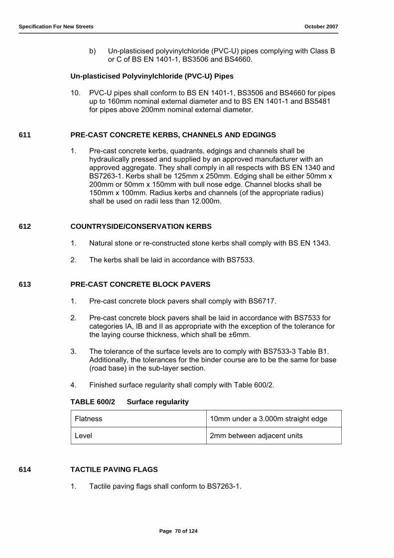
Specification For New Streets October 2007
b) Un-plasticised polyvinylchloride (PVC-U) pipes complying with Class B or C of BS EN 1401-1, BS3506 and BS4660.
Un-plasticised Polyvinylchloride (PVC-U) Pipes
10. PVC-U pipes shall conform to BS EN 1401-1, BS3506 and BS4660 for pipes up to 160mm nominal external diameter and to BS EN 1401-1 and BS5481 for pipes above 200mm nominal external diameter.
611 PRE-CAST CONCRETE KERBS, CHANNELS AND EDGINGS
1. Pre-cast concrete kerbs, quadrants, edgings and channels shall be hydraulically pressed and supplied by an approved manufacturer with an approved aggregate. They shall comply in all respects with BS EN 1340 and BS7263-1. Kerbs shall be 125mm x 250mm. Edging shall be either 50mm x 200mm or 50mm x 150mm with bull nose edge. Channel blocks shall be 150mm x 100mm. Radius kerbs and channels (of the appropriate radius) shall be used on radii less than 12.000m.
612 COUNTRYSIDE/CONSERVATION KERBS
1. Natural stone or re-constructed stone kerbs shall comply with BS EN 1343.
2. The kerbs shall be laid in accordance with BS7533.
613 PRE-CAST CONCRETE BLOCK PAVERS
1. Pre-cast concrete block pavers shall comply with BS6717.
2. Pre-cast concrete block pavers shall be laid in accordance with BS7533 for categories IA, IB and II as appropriate with the exception of the tolerance for the laying course thickness, which shall be ±6mm.
3. The tolerance of the surface levels are to comply with BS7533-3 Table B1. Additionally, the tolerances for the binder course are to be the same for base (road base) in the sub-layer section.
4. Finished surface regularity shall comply with Table 600/2.
TABLE 600/2 Surface regularity
Flatness 10mm under a 3.000m straight edge
Level 2mm between adjacent units
614 TACTILE PAVING FLAGS
1. Tactile paving flags shall conform to BS7263-1.
Page 70 of 124

Specification For New Streets October 2007
2. The size of the tactile paving flags shall comply with BS7263-1 Table 1 (designation F) and have a thickness of 65mm only (400mm x 400mm x 65mm).
3. The colour of the flags shall be buff or a contrasting colour to that of the surrounding paved area. Red is only to be used if the crossing point is a controlled crossing.
615 SAND
1. Sand for cement mortar and concrete shall be in accordance BS EN 13139.
2. Testing of all sand shall comply with requirements of BS812.
3. All sand shall be washed sand and shall be in accordance with BS882 and BS EN 13139.
4. The sand used for jointing block pavers shall be kiln-dried free-flowing silica sand. It shall comply with BS7533-3 Section 4.4.4 and Table D3.
616 STEEL REINFORCEMENT
1. Steel reinforcement shall comply with any of the following standards and be free from oil, dirt, loose rust or mill scale:
a) Steel fabric reinforcement with the requirements of BS4483 and shall be delivered to the Site in flat mats;
b) Hot rolled mild steel bars and hot rolled high yield bars shall comply with the requirements of BS4449;
c) Cold worked steel bars shall comply with the requirements of BS4461; d) Hard drawn stainless steel wire shall comply with the requirements of
BS4482.
617 WATER FOR USE WITH CEMENT
1. If water for the works is not available from a Public Utility Undertaking supply, the Engineer's approval shall be obtained regarding the source of supply and manner of its use. When required by the Engineer, the Developer shall arrange for tests of the water to be carried out in accordance with BS EN 1008. Water from the sea or tidal rivers shall not be used for structural concrete.
618 WEED KILLER
1. The Engineer will only approve the need for the use of a weed killer and will not approve any type or brand.
2. The weed killer shall be Glyphosate based only, and applied in accordance with the Manufacturer's instructions.
3. The weed killer is to be applied only by licensed operatives.
Page 71 of 124

Specification For New Streets October 2007
619 GEO-TEXTILE MEMBRANE
1. Geo-textile membrane shall conform to BS EN ISO 10319, BS EN ISO 11058, BS EN ISO 12236, BS EN ISO 12956.
2. The geo-textile membrane shall not be left exposed to direct sunlight. It shall be stored in the original coloured wrapper until required for use.
3. The Engineer is to be notified regarding the intended laying or lapping pattern.
620 SOAKAWAYS
1. Due to the varying geological characteristics within the County, specific approval is required for the proposal of a separate highway drainage system discharging to soakaways.
2. Class 1 by-pass interceptors are to be installed to protect the water table from pollution. It is the responsibility of the Developer to obtain the specific dispensation, from the Environment Agency, not to install such interceptors.
3. This Authority expresses no preference as to which soakaway design is proposed, or used, by the Developer.
4. The constructional dimensions and performance of the individual soakaway construction(s) or chamber(s) will comply with Standard Detail Drawings 807-1 or 807-2. The particular design(s) for the individual construction(s) or chamber(s) will be provided upon request.
5. The effective depth (depth of inlet invert to the base of the chamber) of the soakaway is fixed at 2.500m for the pre-cast concrete chamber construction (Standard Detail Drawings 807-2) or within the range of 0.750m to 1.950m for the circular brickwork soakaway construction (Standard Detail Drawing 807-1).
6. The minimum diameter of the pre-cast soakaway chamber shall be 1.200m to comply with Standard Detail Drawing 807-2 or, for the circular brickwork soakaway, fixed at 2.400m to comply with Standard Detail Drawing 807-1.
7. The permitted range of internal diameters for the pre-cast chambers permitted is 1.200m to 3.000m (inclusive) in steps of 300mm only. The chamber diameter of 1.350m is no longer acceptable, and does not conform, to BS EN 1917 and BS5911-3.
8. All pre-cast concrete components (perforated and non-perforated chamber rings, corbel slabs, cover slabs, landing slabs, reducing slabs, et cetera) shall conform to BS EN 1917, BS5911-3, and BS5911-4.
9. Only 45mm diameter perforations (or slits 110mm x 25mm) will be permitted by this Authority (conforming to BS EN 1917 and BS5911-3). This Authority will not accept 75mm diameter perforations in pre-cast concrete soakaway rings for use under paved surfaces.
Page 72 of 124
Specification For New Streets October 2007
10. It is to be expected that a long “lead in” time will be required for a manufacturer to produce pre-cast concrete chamber sections with 45mm diameter perforations.
11. Step irons, or ladders, are not to be installed. Access into the soakaway chamber is intended to be by winch. The soakaway chambers are not vented and all appropriate measures should be taken to conform to working in confined spaces procedures.
12. The access cover is to be of double triangular or single rectangular heavy ductile type and conform to BS EN 124 D400H with a minimum clear opening of 600mm x 600mm. The minimum weight of the cover is to be 70Kg.
621 TREE GRILLES AND FRAMES
1. Consideration must be given to BS5837 with regard to the intended position(s) of, and provision and protection for, the tree(s).
2. Tree grilles and frames are required for all tree pits that are constructed in paved areas (carriageway, footway, et cetera). There is no requirement for tree grilles or frames for trees planted in grass or verge areas.
3. Tree grilles and frames are to conform to the requirements in Standard Detail Drawings 808-1, 808-2, or 808-3.
4. Tree grilles shall be manufactured from iron and be capable of withstanding the following minimum load categories:
a) 15kN for pedestrian areas (not intended to be trafficked); b) 50kN for courtyard or street situations (areas which will be trafficked).
5. The central aperture in the tree grille must be suitable for the potential diameter of the trunk. An indication of probable trunk size is given in BS5837 Table 1.
6. The tree frame is to be fixed to the tree pit structure. It must be capable of being dismantled and removed without disturbing either the tree pit or the planted tree.
7. The tree grille is to be fixed to the tree frame. It must be capable of being dismantled and removed without disturbing the tree frame or the planted tree. Therefore, it is not to be welded to the frame.
622 TREE GUARDS
1. Tree guards are required for all trees planted in tree pit where the trunk (at the time of planting) is less than 300mm in diameter.
2. Tree guards are to conform to the requirements in Standard Detail Drawings 808-1, 808-2, or 808-3.
3. The tree guard shall be manufactured from galvanised steel. The finish and colour must match that of the tree grille.
Page 73 of 124

Specification For New Streets October 2007
4. The minimum internal diameter of the tree guard shall be 450mm.
5. The tree guard is to be fixed to the tree frame or grille. It must be capable of being dismantled and removed without disturbing the tree grille, frame, or the planted tree. Therefore, it is not to be welded to the grille or frame.
623 BOLLARDS
1. Bollards will only be used with the permission of the Engineer.
2. Unless otherwise specified, bollards are to be of the “socketed” type.
3. White is reserved for collapsible bollards only. There will be no deviation from this colour coding.
4. Retro-reflective tape (150mm depth), or roundels, must be affixed to the upper of the bollard to the correct colour for approaching traffic (red, white, or both as traffic direction and installation position dictates).
5. Details of the white collapsible bollard for the emergency link are shown in Standard Detail Drawing 809.
Page 74 of 124

Specification For New Streets October 2007
Page 75 of 124
Specification For New Streets October 2007
700 STREET LIGHTING AND ILLUMINATED TRAFFIC SIGNS/BOLLARDS
701 INTRODUCTION
1. This Specification details the requirements to be met for an installation to be of an adoptable standard and covers the design, supply, erection, wiring, testing, painting, inspection and commissioning of street lighting and illuminated traffic sign/bollard units as described hereafter. It is essentialthat Developers consult with the Engineer regarding likely street lighting requirements at an early stage in the design of the development.
2. Lighting will be required on all new developments except where there are no Trunk, Principal, Class I or Class II roads passing through a village or settlement, no lighting exists in other parts of the village or settlement and the Parish Council can provide sufficient reasons for the County Council to give specific dispensation on the grounds that lighting would be detrimental to the amenity of the area. In cases where new roads are not to be lit ducts will be laid for use if street lighting is subsequently installed in the future.
3. Street lighting must comply with the County Council's policy on street lighting – in particular the zoning system (the zone into which a development falls will be decided by the Engineer) the following is an extract from the policy:
Zone 1 World Heritage site, Areas of Outstanding Natural Beauty, Sites of Special Scientific Importance and other Dark Areas
Villages and settlements within this zone should only be provided with lighting when requested and funded by the Town or Parish Council. Such lighting should be limited to strategic locations such as telephone boxes, bus stops et cetera.
Lighting should only be installed outside of villages and settlements where there is a night-time safety issue that cannot be solved by other means.
Careful design will ensure not to urbanise a rural location by the provision of an unsuitable lighting scheme.
Luminaires should be well controlled and restrict the upward light ratio to 0%. Consideration will also be given to part night operation.
Zone 2 Areas of Low District Brightness (Rural locations outside Zone 1)
Villages and settlements within this zone will generally be provided with lighting in accordance with the relevant minimum standard applicable to type and use of the highway. Consideration will also be given to the lighting of footways and cycle tracks with high night-time use.
Page 76 of 124

Specification For New Streets October 2007
However, where a cycle track or footway link is remote from an adjacent highway or properties and an existing alternative lit route exists, regard will be given to whether it is safe to attract people on to isolated areas by the provision of lighting.
Roads between villages and settlements in this zone should only be provided with lighting where there is a known night-time safety issue that cannot be solved by other means.
Luminaires should be well controlled and restrict the upward light ratio to 0%.
Zone 3 Areas of Medium District Brightness (Urban Location)
Generally within an urban location all highways will be lit in accordance with the relevant standard applicable to the type and category of the highway:
a) Primary Routes; b) District Distributors; c) Local Distributors; d) Access Roads; e) Shared Access Roads;
f) Secondary Access Roads. Consideration will also be given to the lighting of footways and
cycle tracks with high night-time use. However, where a cycle track or footway link is remote from an adjacent highway or properties and an existing alternative lit route exists, regard will be given to whether it is safe to attract people on to isolated areas by the provision of lighting.
In special environmental interest, dark landscape and ecologically sensitive areas such as parks and woodlands, individual assessments will be carried out.
Luminaires should be well controlled and restrict the upward light ratio to 2.5%.
Zone 4 Areas of High Brightness (Urban centres with high night-time usage)
In urban centres with high night-time vehicle or pedestrian use, carefully designed lighting will not only provide adequate illumination for the motorist but also provide an interesting and attractive ambience for people to enjoy themselves.
Luminaires should be well controlled and restrict the upward light ratio to 15%, whilst allowing illumination of building facades.
For full details of the County Council’s policy on street lighting the Developer is referred to the current issue of the Dorset County Council Highway Maintenance Policy document.
Page 77 of 124

Specification For New Streets October 2007
4. For this section of the Specification only, all references to the Engineer shall mean the Engineer’s appointed representative who shall be the County Council’s Principal Engineer – Street Lighting.
702 GENERAL
1. Where a British Standard is in existence for design, equipment or material detailed hereinafter, the works shall comply with the relevant Standard whether or not it is referred to specifically in the document, unless otherwise approved by the Engineer.
2. All work relating to the installation of street lighting and illuminated traffic sign equipment shall be in accordance with BS 7671: Regulations for Electrical Installations (IEE Wiring Regulations), the rules and regulations of the Regional Electricity Company (henceforth referred to as the REC) and other relevant safety legislation.
3. The Developer’s Street Lighting Contractor (henceforth referred to as the Contractor) shall be registered under a nationally recognised Quality Assurance Scheme accredited in accordance with the requirements of ISO 9002 with a scope of registration which includes for the installation of electrical apparatus and cabling for highway lighting and highway signs.
4. The Contractor shall be a registered member of the Association of Street Lighting Electrical Contractors (ASLEC).
5. The Contractor shall take into account Engineering Recommendation G.39/1 ‘Model Code of Practice covering Electrical Safety in the Planning Installation, Commissioning and Maintenance of Public Lighting and Other Street Furniture’. Other relevant requirements are contained in the Electricity at Work Regulations.
6. The Contractor shall employ only competent personnel each of whom holds a “Competent Persons Authorisation Certificate” in accordance with the model form in Appendix B of the above document G.39/1, but modified as specified below, which has been duly completed by the Contractor and authorised by a designated responsible person in the Authority or company as defined in Clause 2 of G39/1, all in accordance with Clause 10 of G.39/1.
The form of certificate as specified above shall be modified on page B2 of G.39/1 by insertion of the following after the space for ‘Name and Address of Employer’:
“Name of Authority or Company ....................................................................”
In addition to the requirements of sub-clauses 10(2) and 10(3) of G.39/1, each Competent Person as defined in G.39/1, Clause 2, shall be provided by the Contractor with not less than one copy of the above certificate, duly completed and signed as Approved, and such certificate(s) shall be retained and be available at all times for inspection on the Works on request by the Engineer. A suitable Work Allocation Record shall be kept by the Contractor to enable works to be identified with the operatives and supervisors responsible for those works.
Page 78 of 124

Specification For New Streets October 2007
7. The Developer will be responsible for the integrity, security and safety of the system installed until the whole works are adopted by the County Council. However, routine maintenance and energy charges may be accepted upon commissioning by the REC and satisfactory inspection by the Engineer. This may happen prior to, but without prejudice to, the formal adoption process.
8. Supplies provided to electrical equipment and lighting units for a third party shall not be connected to the County Council’s dedicated supply.
9. No existing Lighting Unit shall be switched on or off, dismantled, re-sited, replaced or removed without prior approval of the Engineer.
10. Before any building on the development is occupied, all lighting columns must be installed and the REC services paid for each one.
11. Electrical equipment shall be installed so that levels of radio interference given in BS EN 55014 are not exceeded.
703 DESIGN
1. Street lighting shall be designed in accordance with BS EN 13201 and BS5489 and the County Council's policy on street lighting. The street lighting scheme shall either be designed by the Engineer (at no additional cost to the Developer) or by the Developer, in which case it shall be subject to approval of the Engineer.
2. The Engineer reserves the right to specify the manufacturer/catalogue number for any or all of the equipment to be installed. This will be based upon the exact design requirements for an individual development, compatibility with existing equipment and the minimisation of energy/maintenance liabilities.
3. The equipment shall be of a type and scale that is in keeping with the immediate environment and minimises light pollution. It will seek to minimise the whole life running and maintenance costs.
4. Extensions to existing systems will generally be carried out using equipment similar to that on adjacent streets. However, in the case of Developer-designed schemes it is highly recommended that this is checked with the Engineer at the outset.
5. The aesthetic design of wall brackets, lighting columns and luminaires including those with bracket arms shall be submitted to the Engineer for approval. The design shall comply with the general advice given in BS EN 13201 and BS5489 for the appearance of lighting installations by day and by night both from the viewpoint of the road and from the surrounding neighbourhood.
Page 79 of 124

Specification For New Streets October 2007
6. Street lighting designs which incorporate equipment of a non-preferred type (for aesthetic and/or planning reasons) shall only be permitted subject to payment of a commuted sum by the Developer. The sum will usually be based upon the difference in cost between the proposed scheme and a standard scheme - based on the current replacement cost of the equipment and the energy and maintenance costs accumulated over a twenty year period. (Further details should be obtained from the New Streets Manager).
7. For an Engineer-designed street lighting scheme the Developer shall provide 1:500 plans of the development, where possible in the form of computerised drawings of a .dxf format.
8. The Engineer’s design will include plans of the development indicating the number, location, type and height of lighting units together with lamp type and wattage, supported by an Engineer’s Design Certificate which shall be valid for six months from its issue date.
9. Developer-designed schemes shall consist of 1:500 scheme plans in computerised .dxf format which identify the location of all proposed lighting units and any units within 100 metres of the development. The plans shall be accompanied by a comprehensive schedule of proposed equipment and components (including manufacturer’s catalogue and reference number). In the case of adjustable luminaries their settings shall be detailed. Calculations to demonstrate that the proposed lighting scheme complies with the requirements of BS EN 13201 and BS5489 shall also be provided.
10. Upon satisfactory checking of a Developer-designed scheme the Engineer shall issue a Check Certificate which shall be valid for six months from its issue date.
11. The Developer shall not energise any lighting scheme which does not have a valid design or check certificate to confirm compliance with BS5489 and the County Council's street lighting policy.
12. Any variation in the location of the lighting units or the type of equipment proposed by the Developer shall require the issue of a revised Design or Check Certificate.
13. Failure to install street lighting as certified will result in the County Council’s refusal to adopt the lighting units.
14. Where the use or brackets attached to buildings is proposed (primarily in mews, courts or residential squares) then appropriate easements shall be provided to the Council prior to the dwellings being sold.
15. The Developer is to ensure that all homeowners are aware of the location of all proposed street lighting equipment.
16. Where alterations to existing lighting units are to be made the Developer will be responsible for all consultation with existing residents.
Page 80 of 124

Specification For New Streets October 2007
704 UNDERGROUND ELECTRICITY CABLES AND CONNECTIONS
1. The Council does not permit the use of service connections which will not be in the continuous ownership of the REC.
2. Underground cabling and the RECs connections are not included in the scope of this Specification and are deemed to be covered in the development brief. However, where cables are laid to provide a service to road lighting columns, illuminated signs and bollards on traffic islands in the road and on roundabouts, an independent means of isolation may, at the request of the REC, be provided for that circuit via a separate double-pole lockable switch. The switch shall be located in either a suitable road lighting column or in a separate mini-pillar conveniently situated in a safe position within the highway boundary along the side of the road at the rear of the footway or verge. Labels shall clearly show on the outside of the isolating column or pillar that it is the switch point and on the inside the units that are being serviced. In such cases the ownership of any switch, cable or cut-out shall remain with the REC.
3. Site Records prepared in accordance with Clause 734 shall include identification of points of independent isolation as described in sub-clause 2 above.
705 CABLE DUCTING
1. All underground cables for street lighting shall be enclosed in a duct system.
2. The duct layout shall be agreed with the Engineer and the REC.
3. The system of ducting and service duct chambers shall be for the sole use of Street Lighting equipment and must not be used by any other utilities without the prior agreement of the Engineer.
4. Street lighting ducts shall meet the requirements of BS EN 50086-2, BS EN 50086-3 and BS EN 50086-4 and shall be sufficiently rigid to experience no deformation during back-fill and compaction but be capable of bending to the radius required.
5. Ducts shall be manufactured from smooth bore Medium to High Density Polyethylene, with a minimum wall thickness as follows:
a) 50mm dia. - 3.5mm thickness; b) 75mm and 100mm dia. - 5.0mm thickness.
6. Ducts shall be jointed so that no silt, grit, grout or concrete surround is able to enter the duct, with the manufacturer’s approved ducting fittings being used for the coupling of sections.
7. Ends of ducts shall be sealed against the ingress of foreign matter using a suitable manufactured end cap
8. The continuous ducting should be installed on a level trench bed that is free from the presence of large stones or rock.
Page 81 of 124

Specification For New Streets October 2007
9. All ducting bends must be gradual and the ducting must be laid so that no twisting or snaking occurs. Before back-filling the trench back-fill shall be applied to the ducting at 10.000m intervals to secure ducting linearity.
10. ‘Straight Joints’ in ducting shall be kept to a minimum, and shall be undertaken in accordance with the manufacturer’s specification and product details. Junctions are NOT permitted (i.e. tee junctions or similar).
11. Ducts installed for the sole use of the REC shall be coloured Black.
12. Ducting installed in footways, footway links or grassed areas shall have a minimum internal diameter of 50mm and shall be laid in footways/grassed areas to a depth of 575mm to invert below the finished ground level. After laying, the duct shall be covered by sufficient stone dust to ensure a 75mm layer after tamping. All as shown in Standard Detail 811.
13. Ducting installed below carriageway/heavy duty hauling ways shall have a minimum internal diameter of 100mm and shall be laid at a depth of 900mm to invert below the finished ground level. The duct shall be encased in a 150mm concrete surround ST2 Mix/C10 Grade consolidated. The continuous 50mm bore ducting is to be installed within the larger duct without joints. All as shown in Standard Detail 811. All crossings shall have two 100mm ducts unless otherwise stated or agreed with the Engineer.
14. The Developer must ensure that any damage to the duct of any part of their make up during installation is prevented. All ducting damaged during the works shall be replaced by the Developer at his own expense.
15. A yellow, self-coloured PVC or polythene plastic tape for cable marking, not less than 0.1mm thick and 150mm wide, with the wording “Street Lighting Cables Below” or “Electricity Below” printed in black along the full length so as to occupy not less than 75% of its available length and occurring at least at 1.000m intervals, shall be laid approximately 250 mm above any power supply cable. Where several cables are laid in one trench, only one line of marker tape shall be installed.
16. A smoothbore flexible duct or hockey stick shall be used to connect each item of street furniture requiring an electrical supply as per Standard Detail 810.
17. Duct chambers shall be provided at changes in duct direction. Chamber construction details shall be agreed with the Engineer. Permitted constructions are:
a) Brick Construction Class B Engineering bricks to BS EN 772 and BS3921 surrounded by ST2 Mix/C10 Grade concrete - 150mm thick;
b) In-situ Concrete Proprietary plastic unit, surrounded by ST4 Mix/C20 Grade concrete - 150mm thick;
c) Pre-cast Concrete PCC chamber to BS EN 1917, BS5911-3 and BS5911-4, surrounded by ST2 Mix/C10 Grade concrete - 150mm thick.
Depth of invert not to exceed 900mm and chambers shall be aligned with the closest structure ie wall, kerb, pillar.
Page 82 of 124

Specification For New Streets October 2007
18. Duct chambers shall have Grade D covers and frames supported on all four walls unless otherwise agreed with the Engineer. The cover shall be embossed with the words “Street Lighting”.
706 LIGHTING COLUMNS AND BRACKETS
1. Lighting columns, brackets, the foundations of both planted columns and columns with flange plates, and the anchorages and attachment systems for columns with flange plates shall be designed, manufactured, supplied and installed to comply with the requirements of BS EN 40 and BS5649.
2. All carriageway lighting columns shall have a minimum nominal height of 5.000m.
3. Columns mounted on footway links, which do not have adequate structural capacity or a clear access width of at least 2.500m shall be of a hinged type approved by the Engineer. Footway bollard lighting shall only be used with the prior approval of the Engineer - its use is only likely to be acceptable in exceptional circumstances and would only be permitted subject to payment of a commuted sum by the Developer. (Further details should be obtained from the New Streets Manager.)
4. Design of all columns shall include for a sign of 18kg x 0.6m2 x 1.8 shape coefficient mounted 2.500m above ground level and eccentrically 300mm. Columns shall be designed for wind loading factors as defined in BS5649-6. Columns in Dorset will generally be acceptable if a “k” value of 2.2 is used for column in excess of 8.000m and 1.8 is used for columns of 8.000m or under.
5. All columns and brackets supplied must be manufactured by a company registered under the Quality Assurance scheme ISO 9002. The Developer must supply to the Engineer a copy of the appropriate registration documentation prior to any purchases or erection of lighting columns and brackets.
6. All lighting column/bracket combinations manufactured by the same manufacturer shall carry a unique identification mark which indicates the name of the manufacturer, the year of production and other design information to enable details of the column and bracket to be determined throughout its design life. This information shall be clearly visible after erection of the column. The unique identification consisting of alpha/numeric characters shall be stamped onto an aluminium tag wire fixed to an accessible bracket within the column base. Brackets supplied by a different manufacturer from the column shall be identified separately within the base as above.
7. Bracket sleeves shall fit over a reduced diameter spigot to maintain the smooth parallel line between the column and the bracket arm. The bracket arm will be held in position by stainless steel screws allowing fixing in any one of four 90o positions relative to the door opening.
8. Side entry luminaries on post-top spigots shall be fitted to the column using a suitable adapter.
Page 83 of 124

Specification For New Streets October 2007
9. A means of preventing undesired rotational movement of the bracket or spigot adapter once fixed in position to the column shaft shall be incorporated in the design.
10. The Developer shall provide a design and check certificate and suitable scale drawings detailing the appearance, and all measurements (including O/D diameters) of the proposed columns and brackets to the Engineer for approval prior to any purchase or erection.
11. The door shall be an overlapping type, rounded-rectangular in shape and provide a degree of protection not less than IP33. The door lock shall be of a single "anti-lift" clamp type fitted at the top of the door. The bottom of the door shall be provided with a means of anti-rotation.
12. The same pattern of door lock shall be used for all columns on the development unless agreed otherwise by the Engineer. Keys shall be provided for 10% of all columns installed and handed to the Engineer upon completion of the first phase of the street lighting works. The door shall have a triangular-head lock designed to not be operable by any device other than the key provided. On delivery the door shall come assembled on the column.
13. Door openings shall be free from irregularities and burrs and all doors shall have a suitable earthing lug on their internal face.
14. All columns shall be provided with earthing lugs positioned at the bottom of the gear compartment and on the inside near the bottom of each column door and these shall not be visible on the external faces of the column. The terminal is to be positioned so as to ensure that it does not cause an obstruction to REC equipment and is easily accessible. A connection between the door and column shall be made using 84/03mm tri rated cable, the length of which will allow the door to be placed flat on the ground during maintenance.
15. A cable entry slot 150mm long and 50mm wide shall be provided in line with the door position. The top of the cable entry slot shall be 350mm below ground level.
16. There shall be no sharp edges within the columns or bracket arms, which could damage electrical cables either during installation, or while in service and an anti-chafe ring shall be welded where the cables change direction from the horizontal to vertical within the bracket.
17. The lighting column base compartment shall comply with the requirements of BS EN 40 and BS5649 and shall have a minimum site opening of:
a) 500mm x 100mm for 5.000m and 6.000m columns; b) 600mm x 115mm for 8.000m to 12.000m columns.
18. A full-length baseboard of marine plywood or hardwood, at least equivalent to the door size, shall be provided and fixed in the base compartment and shall be of sufficient size to accommodate all control equipment and service cut-outs. The baseboard shall be positively secured to the column by two non-ferrous, flush fitting fixings.
Page 84 of 124
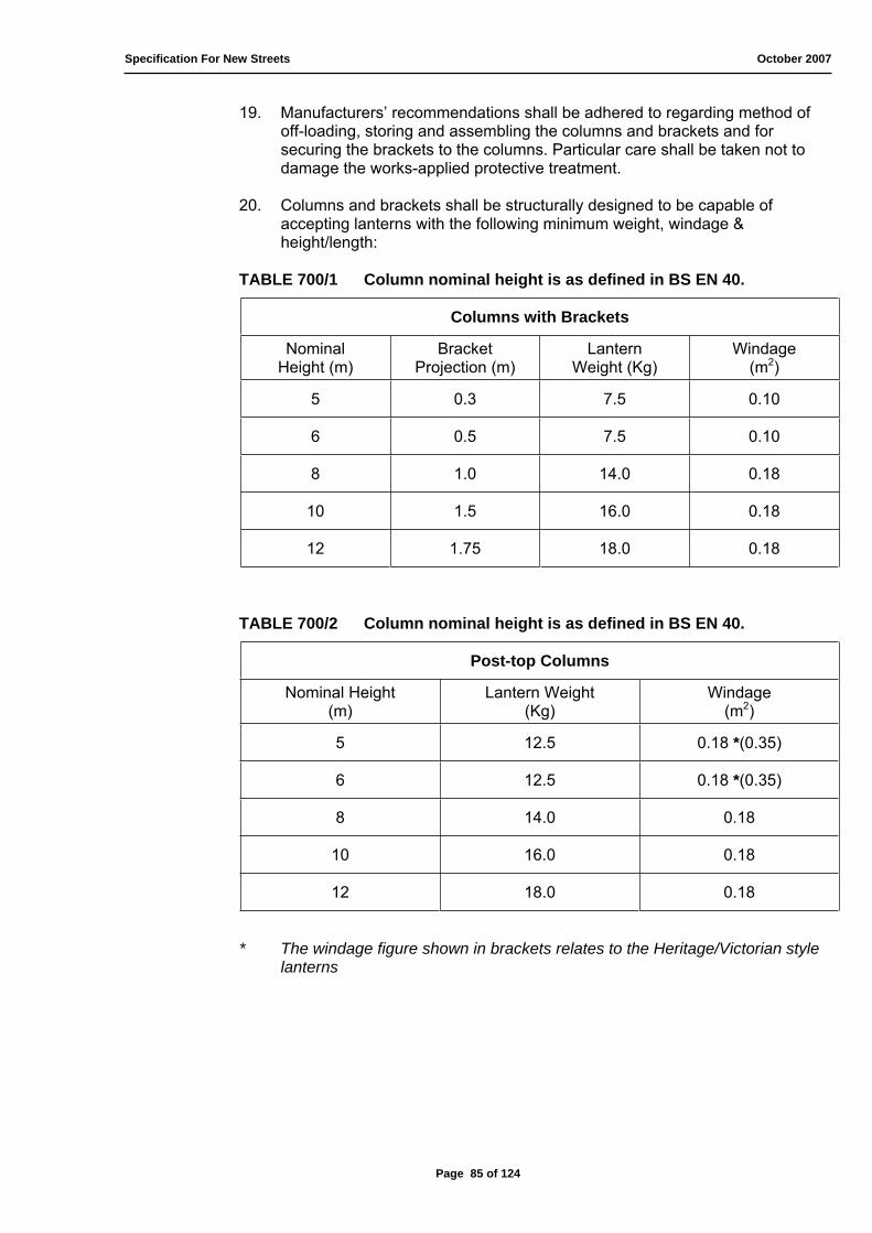
Specification For New Streets October 2007
19. Manufacturers’ recommendations shall be adhered to regarding method of off-loading, storing and assembling the columns and brackets and for securing the brackets to the columns. Particular care shall be taken not to damage the works-applied protective treatment.
20. Columns and brackets shall be structurally designed to be capable of accepting lanterns with the following minimum weight, windage & height/length:
TABLE 700/1 Column nominal height is as defined in BS EN 40.
Columns with Brackets
NominalHeight (m)
BracketProjection (m)
LanternWeight (Kg)
Windage(m2)
5 0.3 7.5 0.10
6 0.5 7.5 0.10
8 1.0 14.0 0.18
10 1.5 16.0 0.18
12 1.75 18.0 0.18
TABLE 700/2 Column nominal height is as defined in BS EN 40.
Post-top Columns
Nominal Height (m)
Lantern Weight (Kg)
Windage(m2)
5 12.5 0.18 *(0.35)
6 12.5 0.18 *(0.35)
8 14.0 0.18
10 16.0 0.18
12 18.0 0.18
* The windage figure shown in brackets relates to the Heritage/Victorian style lanterns
Page 85 of 124

Specification For New Streets October 2007
707 STEEL LIGHTING COLUMNS AND BRACKETS
1. The lighting columns and brackets shall be manufactured from steel, which meets the requirements of BS EN 40 and BS5649. All columns shall be of tubular steel design and shall be manufactured from the following:
a) Hot finished circular hollow sections to BS EN 10210 Grades S275J2H or S355J2H;
b) Cold formed circular hollow sections without subsequent heat treatment to the dimensional requirements of BS EN 10219-2 and the chemical and mechanical properties of BS EN 10219-1 Grade S275 J2H.
The hot finished feedstock material shall comply with the yield, tensile and elongation requirements of the required grade specified in BS EN 10025, Table 5. The thickness of the C.H.S. used in the manufacture of the columns shall be purchased such that the negative tolerance is limited to 4%.
2. The column base to shaft joint shall be of hot swaged and welded construction with an internal centralising washer.
3. Bracket arms, where specified, shall be of tubular steel and incorporate a welded web or be double welded and have an elevation of 5 . All lighting columns shall be constructed to meet the structural design criteria, but with the following minimum wall thickness:
a) 5.000m and 6.000m - Minimum base thickness 5.0mm Minimum shaft thickness 3.0mm
b) 8.000m to 12.000m - Minimum base thickness 6.0mm Minimum shaft thickness 3.0mm
4. A welded mark shall indicate the column planting depth.
5. All steel lighting column-welding procedures must be approved in accordance with the requirements of BS EN 288 and all welders must be approved to the requirements of BS EN 287. Welding is then carried out in accordance with BS EN 1011.
708 ALUMINIUM LIGHTING COLUMNS AND BRACKETS
1. The columns and brackets shall be manufactured in aluminium to meet the requirements of BS EN 40. All columns shall be of either single stepped tubular design or conical shape and shall not have any welds or joints within the construction.
2. Columns and brackets shall be manufactured from alloy designated BS EN 573-3, EN AW – A1Mg0,7Si.
3. All welding materials and consumables shall comply with BS2901-4.
4. The door opening shall be strengthened, using an internal, expansion fitted 360° sleeve, extending 250mm above and below the opening. The internal sleeve shall form the seating for the flush-fitting door.
Page 86 of 124

Specification For New Streets October 2007
5. The root section shall be protected with a grey thermoplastic co-polymer on both the inner and outer surfaces to a minimum of 100mm above ground level.
6. Only stainless steel bolts, nuts and washers shall be used in contact with aluminium columns and brackets.
709 HERITAGE/VICTORIAN STYLE COLUMNS
1. When permitted or specified by the Engineer, Heritage/Victorian style lamp columns shall be constructed using a cast iron base with cast iron decorations for a traditional effect, (including base, chamfer & shaft rings and ladder bar) and a steel shaft. It shall include a stainless steel or galvanised steel frog. Both the column and frog shall have a factory applied protection system with a colour to be approved by the Engineer on an individual scheme basis.
2. Variations in height may be permitted in exceptional cases if this will ensure greater compatibility with building heights. However, mounting heights shall be a minimum of 4.000m.
3. Standard columns shall not be enhanced by the use of embellishment kits comprising of base section, chamfer ring, shaft ring and ladder arms.
710 STEEL COLUMN AND BRACKET PROTECTION SYSTEM
1. All steel columns and brackets shall be galvanised to BS1461 and shall be free from imperfections including porosity. Galvanising shall be fettled and rasped to remove all spikes and sharp edges and leave a smooth finish prior to paint application.
2. The root of the column shall be protected by the application of a non-bituminous based system, to both the internal and external surfaces, applied to 250mm above finished ground level and which provides additional protection against corrosion but without the requirement for routine maintenance or re-application. The particular specification is available upon request.
3. Where a coloured finish is specified by the Engineer, or requested by the Developer, the whole column shall be coated by a system which also provides additional protection against corrosion but without the requirement for routine maintenance or re-application. The particular specification is available upon request.
4. All lighting columns and brackets shall be suitably protected during transportation. Wooden packing supports shall be used to provide added protection at the strapping points when the columns are bundled together.
Page 87 of 124
Specification For New Streets October 2007
711 FOUNDATIONS
1. Foundations for standard, planted root, columns shall be as described in Clause 714 and Standard Detail 809, except where unusual ground conditions are encountered or where flange plated columns are necessary. In such circumstances the Developer must produce designs for both columns and their foundations - to the approval of the Engineer.
2. The foundation detail given in Clause 714 & Standard Detail 809 is for general guidance and is a minimum requirement, which is likely to suit the majority of installations. It is the Developers responsibility to check the foundation dimensions required for each column.
3. Designs and checks shall be based on a soil type having a “G” factor of 230 unless otherwise agreed and submitted to the Engineer for approval. Planting depths shall be in accordance with the design but not less than as recommended by the column manufacturer.
712 SITING OF ROAD LIGHTING POINTS AND ILLUMINATED TRAFFIC SIGNS/BOLLARDS
1. Columns shall be positioned in the locations shown on the approved scheme plan for which an Engineer’s Design / Check Certificate has been provided and must be positioned in land to be dedicated to the highway. They must not be placed within areas designated for driver or pedestrian visibility.
2. Where columns are shown adjacent to the carriageway or parking area, clearance from the adjacent kerb to the column shall be either 1.500m or subject to site agreement with the Engineer.
3. Columns associated with footway lighting shall generally be placed within the first 150mm of the metalled edge of the footway.
4. Where it is necessary to locate columns beyond the limit of the proposed highway then a deed of grant will be required in favour of the County Council in respect of each installation.
5. Where lighting equipment is to be erected outside the area of the adoptable highway or in a grass verge/landscaped area then a 1.000sq.m concrete plinth shall be formed, with clean straight edges, around the equipment with the unit in the centre as a minimum requirement. This plinth shall then extend on one side only to the footway or carriageway, whichever is the shorter distance, maintaining a width of 1.000m, to enable access to the unit.
6. The concrete plinth shall be ST5 Mix/C25 Grade concrete, 100mm thick minimum and formed so as to be flush with the finished ground level. The concrete surface shall be float finished to slope away from the unit and the centre-line of the plinth at an angle of 10° to prevent water collecting or pooling. The plinth may be constructed of a footway material, similar to nearby surfaces, where agreed with the Engineer
7. Landscape planting of bushes or trees shall not be permitted in the immediate vicinity of columns which, in the opinion of the Engineer, might affect either the lighting design levels or access to the column base.
Page 88 of 124

Specification For New Streets October 2007
713 HANDLING, TRANSPORT AND ERECTION
1. Lighting columns and brackets shall be handled, transported and stored in such a way as to avoid any structural damage or damage to the surface protection system. Any damage incurred shall be made good in such a way that the structural performance and durability of the item is in no way reduced.
2. Lighting columns and brackets shall be stored clear of the ground in such a way that contact with cement, groundwater, soil or ash or other deleterious material is prevented and that water does not accumulate on any surfaces or inside sections. Suitable packing shall be placed between the columns to allow a free passage of air and dispersion of water.
3. All rivets, bolts, nuts, washers, screws, small plates and small articles generally shall be suitably packed and identified. All such items shall be stored under cover.
4. Columns shall be installed in accordance with the manufacturer’s recommendations.
5. The position of the column gear door, in relation to the kerb line, shall be such a way that any operative working in the gear compartment faces oncoming traffic, unless agreed otherwise with the Engineer.
6. Wall mounted lighting brackets and fixtures shall be fixed in accordance with the manufacture's instructions after confirming the structural suitability of the wall (see also Clause 716(3)).
7. Hinged columns must be sited so as to enable the column to be raised and lowered for maintenance purposes without encountering obstruction and without entering or overhanging either the carriageway or private land.
8. Columns shall be erected using a hydraulic arm and strop.
9. Column and bracket installation shall be completed before the luminaire is fitted.
10. Lamps shall not be fitted into luminaires until columns, brackets and signposts have been erected and the luminaires have been installed to the satisfaction of the Engineer.
714 INSTALLATION OF PLANTED COLUMNS
1. Columns shall be erected in accordance with the Code of Practice issued by The Association of Street Lighting Electrical Contractors (ASLEC), the Institution of Lighting Engineers (ILE) and as recommended by the manufacturer.
2. The following specification and that shown in Standard Detail 809 is given for general guidance and is likely to suit the majority of installations. This specification is a minimum requirement. It is the Developer's responsibility to check the foundation dimensions for each column.
Page 89 of 124

Specification For New Streets October 2007
3. Each hole for columns shall be dug by hand to the required planting depth (alternative excavation methods are to be submitted in writing to the Engineer for consideration). A 75mm thick layer of concrete ST2 Mix/C10 Grade shall be placed and compacted in the bottom of the excavation up to the base of the column. The hole shall be dug large enough for ease of erection and to enable 150mm minimum thickness (300mm for columns installed in the verge) of concrete to completely surround the column.
4. Following installation of the hockey stick or flexible duct connection the remaining area of the cable entry slot shall be temporarily plugged as necessary in order to prevent any ingress of concrete or filling material during the concrete and back-filling operations.
5. The hole into which the column is placed shall be back-filled with concrete to within 50mm of finished level.
6. Concrete back-fill shall be ST5 Mix/Grade C25, well compacted by vibration over the full planting depth of the column.
715 ILLUMINATED TRAFFIC SIGNS AND BOLLARDS
1. Warning, Regulatory, Direction and Informatory Signs shall be strictly in accordance with the current “Traffic Signs Regulations and General Directions” and the relevant Chapters of the “Traffic Signs Manual”.
2. Construction and materials must comply with the requirements of BS873.
3. The signs shall be fully reflective with the whole background in reflective Class 1 Hi-Intensity material. The sign plates shall be 11 gauge aluminium with the back stove-enamelled in grey. They shall be stiffened with extruded aluminium channel section riveted on the back of the sign panel without puncturing the reflective material.
4. The signs shall be mounted on either straight posts or large base posts when the sign is required to be lit. The straight posts shall be standard 76mm O/D and the large base shall be 140mm O/D with the shaft at 76mm.
5. External surfaces of traffic sign posts shall be protected in the same manner as specified in Clause 710 for street lighting columns. Plastic coated posts will not be permitted.
6. Standard stainless steel fixing clips designed exclusively for the specific use of traffic signs shall be used to attach the sign plate to the post.
7. When a sign is required to be lit, an external sign light unit shall be used. The sign light unit must be designed to DfT Reference A lighting standards. It shall be cast in LM6M aluminium to provide a purpose made post-top mounting. The housing shall incorporate a 3mm polycarbonate lens allowing easy access via a single tamperproof bolt to all internal parts, whilst providing a weatherproof assembly to IP56. The gear tray shall be easily removable via a plug and socket. Dual lamps shall be on twin circuits independently fused to BS1362 with starters to BS873-5 Categories 1 and 2 of paragraph 8.2. A photo-electric switch shall be fitted in accordance with Clause 725 of this specification.
Page 90 of 124

Specification For New Streets October 2007
8. All bollards shall be of a base lit type with flexible body shell.
9. The bollard shell shall be flexible with a 'memory', being able to self erect to its original shape. The shell base shall be reinforced with a one piece 3mm galvanised steel fixing plate, with a minimum of three fixings per side from the plastic shell to plate and four fixings from plate to bollard base with all fixings manufactured in stainless steel and in accordance with the manufacturer's requirements. The shell shall have moulded graphics, be non-porous, UV stabilised and carry a five year anti-fade guarantee.
10. The bollard shell shall be fixed to a hinged frame and de-mountable chassis which in turn is bolted to a gear housing and ducted foundation chamber, set flush with finished ground level.
11. The foundation chamber shall be at least 500mm deep and of UV stabilised MDP with a perforated base. It shall be founded on compacted hardcore and surrounded in ST5 Mix/Grade C25 concrete following connection of the necessary ducts to give a minimum 600mm x 600mm x 500mm foundation block. Bollard foundation chambers must be installed in accordance with the manufacturer’s instructions with particular attention paid to planting depth and orientation. With reference to Standard Detail 812, bollards shall be installed vertical with respect to the camber/cross-fall of the road and perpendicular to the road surface with respect to the road gradient.
12. All electrical gear and lamps for bollards shall be housed in a sealed base unit, consisting of the frame and chassis which shall both be die cast in
LM6-M alloy coupled with the gear housing of UV stabilised glass coupled polypropylene and shall include a treated hardwood or marine ply backboard. The external flanges of the unit shall include holes to be used for securing it to four M12 stainless steel studs on the top rim of the foundation chamber with stainless steel retainer nuts and washers.
13. Access to the electrical gear for the REC supply cable shall be through the bottom of the base unit. It is the Developer’s responsibility to ensure that the entry is sealed correctly by use of the IP68 rated compression cable gland fittings fitted by the bollard manufacturer.
14. The 5mm clear polycarbonate glazing panel shall be secured to the base unit using the hinged cover which when closed and fastened compresses a neoprene ring for positive sealing to IP67.
15. A suitable earth marshalling block shall be incorporated on or adjacent to the backboard on to which will be fixed the RECs fused cut-out.
16. A light and gear tray shall consist of parabolic reflectors formed as a single unit fitting into a flat stainless steel gear tray covering the top of the base unit. Two PL11W fluorescent lamps shall be fitted to the gear tray.
17. Particular attention must be made by the Developer to the independent means of isolation for illuminated traffic signs and bollards located on traffic islands or roundabouts, as indicated in Clause 704(2) of this Specification.
Page 91 of 124

Specification For New Streets October 2007
716 WALL-MOUNTED LUMINAIRES/EQUIPMENT
1. Wall-mounted lighting will only be approved in exceptional circumstances. Early consultation with the Engineer on proposals for wall-mounted equipment is essential. Approval is unlikely to be given for equipment proposed for locations where there is a risk of impact from high-sided vehicles.
2. Whenever any street lighting or illuminated traffic sign equipment is to be erected on buildings, an agreed form of easement shall be included in the conveyance documents, and the County Council’s copy passed to the Engineer prior to adoption.
3. Calculations shall be submitted to the Engineer to demonstrate the structural adequacy of the wall to accommodate the loading from the proposed equipment.
4. All wall-mounted luminaries shall be serviced from a separate REC service control box unless otherwise agreed with the Engineer. These shall be situated no higher than 3.000m above ground level with safe access.
5. REC service control boxes shall be of a size to accommodate the RECs cut-out, isolator and earth marshalling block and be of minimum dimensions 220mm x 170mm x 90mm and maximum dimensions 315mm x 220mm x 160mm. The box shall contain a securely fixed back-board of treated hardwood or marine ply.
6. The position of the photo-electric cell shall be such that overhanging eaves of the property or other obstructions shall not cause the lamps to be switched on prematurely.
7. Two forms of wall-mounted equipment installation are permitted. These are Surface Installation and Integrated Installation. Prior approval of Integrated Installation by the Engineer is essential and will be subject to the submission of drawings detailing the service boxes and cable ducting to be built into the wall.
8. Surface Installation shall include a fire-retardant GRP or galvanised or stainless steel REC service control box surface mounted on the wall in a suitably inconspicuous position. The REC will normally clip their suitably protected service supply cable neatly on the outside of the wall. The interconnecting cables between the REC service control box and the luminaire shall be contained in galvanised or stainless steel conduit fixed to the wall unless Heavy Duty Mineral Insulated cable is used. Conduits shall be fixed at not less than 250mm from each end, together with intermediate fixings at no more than 1.000m intervals. All clips/cleats shall be fastened with stainless steel screws and plastic plugs.
Page 92 of 124
Specification For New Streets October 2007
9. Notwithstanding the approval requirements of sub-clause 7, above, for Integrated Installation only stainless steel service boxes shall be used. These may be painted for cosmetic reasons or "dulled" by shot/grit blasting. A REC service box of limiting dimensions as stated in sub-clause 5, above, shall be recessed into the outer leaf of the wall with the REC service cable located in 25mm conduit fixed to the inner face of the outer leaf of the wall and connecting into its base. The interconnecting cables between the REC service control box and the luminaire shall also be contained in 25mm conduit fixed to the inner face of the outer leaf of the wall and terminating in a suitably sized stainless steel unit connection box as close to the luminaire as practicable. The Engineer shall be invited to inspect the conduit prior to wiring and witness the wiring. The short interconnecting cable between the unit connection box and the luminaire shall be as sub-clause 8, above. All cable entries shall be sealed with suitable cable glands with all materials complying with a minimum of IP54. The Developer shall be responsible for providing suitable cavity trays for integrated wall boxes.
717 LUMINAIRES (STREET LIGHTING LANTERNS)
1. Luminaires for road lighting shall comply with BS EN 60598-2.3 and have a minimum degree of protection rating of IP65 (optical compartment) and IP54 (gear compartment) to BS EN 60529 unless a higher rating is specified by the Engineer.
2. The luminaire optic system shall be capable of limiting the upward light to the correct ratio, as defined by the Engineer for the applicable development zone.
3. Luminaires for single arm outreach bracket mounting shall be designed to prevent ingress of water along the mounting spigot. The mounting spigot will be arranged to allow the luminaire to follow the profile alignment of the bracket arm without any offset or deviation. The luminaire will be securely fixed to the outreach bracket by screw threaded bolts or grub screws clamping onto the spigot arm. All lantern fixings to be torque set as per manufacturer's instructions. In some cases the luminaire must be installed with the optical system horizontal. The bracket arm or spigots chosen shall be compatible with this requirement.
4. Luminaires shall be fitted with a PECU socket located in the canopy unless otherwise agreed with the Engineer.
5. Luminaires shall be fitted with integral control gear and have a fuse holder adjacent to the terminal block with a cartridge fuse protecting each set of control gear. The terminal block provided for connection of the internal wiring shall facilitate maintenance, quick replacement and easy disconnection of individual components.
6. Luminaires shall have a smooth UV stabilised GRP or die cast LM6 aluminium canopy with die cast aluminium spigot suitable for the column bracket being used. Luminaires shall have either a toughened flat glass panel or a toughened glass shallow bowl unless otherwise agreed with the Engineer (see also sub-clause 2, above).
Page 93 of 124
Specification For New Streets October 2007
7. Luminaires shall be firmly fixed to the top of the column or bracket arm to minimise the possibility of wind rotation, or falling in the event of the column being subject to impact. There shall be no gap between the lantern and the shoulder of any bracket arm.
8. All equipment shall be designed and rated for operation at maximum 30°C (86°F) ambient temperature and between 50 - 100 % relative humidity with a temperature of 70°C (158°F) in direct sunlight with a high content of ultra-violet rays. The equipment shall be able to withstand full load operation when exposed to the sun, dust, corrosive agents, vermin and the like.
9. The component parts of each electrical system or piece of equipment shall be the latest standard product of a single manufacture.
10. All components shall be capable of being re-cycled at the end of their life and coded with the international symbol for re-cycling.
11. Post top luminaires shall comply generally with the above stated requirements as applicable. In addition or otherwise, the photo-metric distribution will be symmetrical. The luminaire spigot mounting will be compatible to the column spigot. The vandal resistant bowl will not be a clear acrylic but will be of a diffusing material. All luminaires shall have the control gear integral.
12. Where the use of Heritage/Victorian style luminaires has been agreed, the optics shall be of “pot optics” style or other high efficiency pattern and the bowl shall be a one piece moulded unit of polycarbonate or other equally vandal resistant material by prior approval of the Engineer.
13. All fixing components such as latches, clips, toggles, nuts, bolts, washers and the like shall be of stainless steel.
718 LAMPS
1. Lamps shall be in accordance with the appropriate British Standard and compatible with the luminaries used.
2. The initial luminous flux of a lamp multiplied by the lamp flux maintenance factor for the projected lamp life shall be taken as its light output for road lighting design.
3. The light output of a lamp at 100 hours shall be taken as its "initial" lumen output.
4. The light source shall be as agreed with the Engineer. Lamps shall generally be ceramic discharge metal halide (CDM-T or TT); compact or linear fluorescent (PLT or PLL) or high pressure tubular sodium (SON-T+).
5. All lamps will be without internal ignitors, relying on the external ignitor as part of the control gear.
Page 94 of 124
Specification For New Streets October 2007
6. Lamps shall have a nominal burning life of at least:
(a) 6,000hrs for ceramic discharge metal halide (CDM-TT); (b) 7,000hrs compact fluorescent (PLT); (c) 14,000hrs for linear fluorescent (PLL); (d) 12,000hrs for high pressure tubular sodium (SON-T+).
719 BALLASTS
1. Ballasts shall:
a) be one piece electronic construction wherever possible; b) have a power factor >0.95 without any additional capacitors; c) provide constant power to the lamp for an supply voltage range of 206-
254 volts; d) be designed to shut down for the following lamp faults: Short circuit,
open circuit, hot lamps and rectifying; e) have spike & surge protection; f) comply with BS EN 60920, BS EN 60921, BS EN 60922, BS EN
60926, BS EN 60928, BS EN 61347, BS EN 61000-3-2 or BS EN 60923 as appropriate;
g) have the terminals indelibly marked to indicate all wiring connections and operating voltages.
720 IGNITORS
1. Ignitors for Discharge Lamps shall be integrated into the ballast where possible and be mutually compatible with the ballast and lamp.
721 STARTERS
1. Starters for Fluorescent Lamps shall comply with BS EN 60155 and be incorporated in the ballast.
722 CAPACITORS
1. Where external capacitors are used they shall:
a) comply with BS EN 61048 and BS EN 61049; b) be supplied complete with fixing clips, discharge resistors, and either
sealed-in cable tails or shrouded terminal; c) correct the lamp circuit power factor to not less than 0.85 lagging; d) not be used with electronic ballasts.
Page 95 of 124
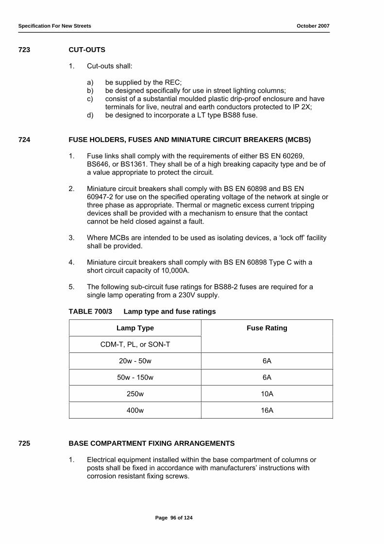
Specification For New Streets October 2007
723 CUT-OUTS
1. Cut-outs shall:
a) be supplied by the REC; b) be designed specifically for use in street lighting columns; c) consist of a substantial moulded plastic drip-proof enclosure and have
terminals for live, neutral and earth conductors protected to IP 2X; d) be designed to incorporate a LT type BS88 fuse.
724 FUSE HOLDERS, FUSES AND MINIATURE CIRCUIT BREAKERS (MCBS)
1. Fuse links shall comply with the requirements of either BS EN 60269, BS646, or BS1361. They shall be of a high breaking capacity type and be of a value appropriate to protect the circuit.
2. Miniature circuit breakers shall comply with BS EN 60898 and BS EN 60947-2 for use on the specified operating voltage of the network at single or three phase as appropriate. Thermal or magnetic excess current tripping devices shall be provided with a mechanism to ensure that the contact cannot be held closed against a fault.
3. Where MCBs are intended to be used as isolating devices, a ‘lock off’ facility shall be provided.
4. Miniature circuit breakers shall comply with BS EN 60898 Type C with a short circuit capacity of 10,000A.
5. The following sub-circuit fuse ratings for BS88-2 fuses are required for a single lamp operating from a 230V supply.
TABLE 700/3 Lamp type and fuse ratings
Lamp Type Fuse Rating
CDM-T, PL, or SON-T
20w - 50w 6A
50w - 150w 6A
250w 10A
400w 16A
725 BASE COMPARTMENT FIXING ARRANGEMENTS
1. Electrical equipment installed within the base compartment of columns or posts shall be fixed in accordance with manufacturers’ instructions with corrosion resistant fixing screws.
Page 96 of 124

Specification For New Streets October 2007
726 PHOTO-ELECTRIC CONTROL UNITS (PECUs)
1. All photoelectric switches and sockets shall be manufactured in accordance with BS5972.
2. PECUs shall:
a) be capable of switching a load of up to 500 watts inductive on a 230 volt, 50 Hertz electricity supply;
b) be set for 70 LUX 'on', and have and anti-oscillation time delay not exceeding 45 seconds;
c) have omni-directional, sealed filtered, silicon photodiode detector cells; d) comply with BS EN 60529 for protection IP 65; e) have the 'on' setting, and negative differential switching ratio of 1:0.5
clearly marked; f) have an installation date marking facility; g) "fail-safe" to the 'on' position if a fault occurs in the switching circuit; h) be fully solid state electronic; i) be manufactured to comply with the requirements of the Electricity
Companies Regime 1 tariff; j) be guaranteed for 6 years from the date of installation.
3. In addition, all one part units shall:
a) be housed in a moisture-proof and weatherproof container with an IP65 rating, which has "self-cleansing" configuration, made from an ultra-violet stabilized translucent polycarbonate material with high impact and crazing resistance which will not discolour. The detector cell shall be positioned so that no orientation of the unit is required;
b) fit any make of 3-pin NEMA socket and be fitted with a gasket to prevent moisture from entering the socket.
727 NEMA SOCKETS
1. NEMA sockets for one-piece switches shall:
a) be constructed from flame retardant glass-filled nylon, and capable of accepting any make of 3-pin photo cell;
b) have clearly marked and shrouded terminals to IP 2X; c) have not less than 4 non-corrosive fixing screws; d) have a weatherproof gasket to maintain the integrity of the IP rating of
the lantern. The socket shall have an IP 65 rating with dust cap fitted.
728 TIME SWITCHES
1. Time switches shall not be used unless agreed by the Engineer.
Page 97 of 124

Specification For New Streets October 2007
729 WIRING
1. The provision and installation of the whole wiring system shall be in accordance with BS7671 Requirements for Electrical Installations, the I.L.E. Code of Practice for Electrical Safety in Public Lighting Operations and as specified below.
2. Wiring between the terminal block in lantern and the components in the base of the column shall have copper conductors with a cross sectional area of 2.5mm² and be as follows:
a) ‘Live’ conductors – PVC insulated/PVC sheathed single cable of 600/1000 volt grade;
b) ‘Earth’ conductors – PVC insulated single cable of 600/1000 volt grade.
3. Phase, neutral and PECU cables are to have a surplus 600mm length within the base compartment. These cables are to be neatly looped and retained with a cable tie.
4. All wiring within the base compartment shall be PVC insulated/PVC sheathed single cable of 600/1000 volt grade with the sheath being taken into the cut out housing, except for the Green/Yellow non-sheathed protective conductor.
5. The final connection between equipment mounted in column base compartments (and REC wall service boxes) and the cut out shall be made using PVC double insulated cable to BS6004 having a minimum copper conductors size of 6mm2. Sufficient length shall be allowed for final connection between the isolator and the service cut out by REC personnel.
6. All cables shall be correctly colour-coded throughout their length.
7. All cables shall be ONE piece construction. Joints or connectors will NOT be permitted
8. Unsupported lengths of cable shall be kept to a minimum and shall not be allowed to come into contact with components by their freedom of movement. Where there is more than one cable they shall be secured together at one-metre intervals throughout the unsupported length. Vertical cables within posts or columns shall be adequately supported along their length at the top of the cable run.
9. Wiring shall generally be housed inside columns, wall brackets and posts. Where this is not possible, wiring shall either be housed in galvanised or stainless steel conduit which shall be waterproof and smooth internally or be Heavy Duty Mineral Insulated Cable.
730 EARTHING
1. All electrical installations shall be earthed in accordance with BS7671. All bolted connections throughout the earthing system shall be stainless steel, brass or silicon bronze.
Page 98 of 124

Specification For New Streets October 2007
2. Circuit protective and equi-potential conductors shall be green/yellow PVC or XLPE insulated or sleeved. Where bolted connections are required, these conductors shall be terminated in accordance with manufacturers’ instructions in correctly sized purpose made lugs.
3. A circuit protective conductor shall connect the earth terminal on each luminaire to the main earth terminal associated with the service cut-out unit.
4. A separate circuit protective conductor of not less than 2.5mm² cross-sectional area shall connect all metal enclosures of all electrical components to the main earth terminal.
5. All materials used throughout the "Earthing" installations shall be strictly in accordance with BS7671.
6. An earth-marshalling block shall be provided in each lighting unit and clearly labelled 'SAFETY ELECTRICAL CONNECTION DO NOT REMOVE'.
7. All extraneous conductive parts, as described in BS7671, and including doors to feeder pillars, lighting columns and lit sign units, shall be bonded to the main earth marshalling block using an equi-potential bonding conductor of 6mm² cross-sectional area when the lighting unit is directly serviced by a TN-C-S supply. Earth electrodes shall be installed where necessary.
8. The connection between the door and column shall be provided at a length, which will allow the door to be placed flat on the ground during maintenance.
9. All street lighting and other electrically supplied street furniture shall be earthed and bonded in compliance with BS7430.
731 ISOLATORS
1. In all lighting units a means of isolation shall be provided. A lockable safety isolator shall be interposed electrically between the outgoing side of the RECs cut-out and the control gear.
2. It shall be of all insulated moulded surface pattern, double pole, 32 amp rating, clearly marked ‘on’ and ‘off’ and incorporate a BS88 fuse of the correct rating, front loading. The cover must be held by a screw and incorporate a drip-proof cable exit channel.
3. The location of the isolator and other control gear et cetera on the backboard shall allow adequate space below it for the RECs cut-out to be mounted and the door lock to operate freely.
732 INSPECTION AND TESTING TO BE CARRIED OUT BY THE CONTRACTOR
1. The completed installation shall be tested to the satisfaction of the Engineer and in accordance with the applicable sections of the current edition of the Requirements for Electrical Installations published by The Institution of Electrical Engineers (BS7671).
Page 99 of 124
Specification For New Streets October 2007
733 UNIT NUMBERING/LABELLING
1. The Engineer will allocate identification numbers for each lighting point and illuminated traffic sign/bollard. These shall be applied to the lighting points as and when the acceptability of each unit is confirmed by the Engineer in accordance with Clause 736.
2. Column identification numbers shall be located on the shaft at 1.800m above finished ground level and applied at right angles to the carriageway. Wall luminaire identification numbers shall be fixed to the appropriate REC service control box.
3. Numbers on steel and aluminium columns shall be 50mm high, 40mm wide black digits on a white background using a proprietary system of premium grade adhesive PVC.
4. Suitable hazardous electricity warning notices for street furniture Ref HSE/1 in premium grade adhesive PVC, BS5378, shall be affixed on the column shaft just above the base compartment and also within the base on the backboard.
734 SITE RECORDS
1. In accordance with the requirements of the Electricity at Work Regulations the Developer shall, on the completion of the electrical work and prior to adoption, provide a set of as-installed drawings or transparencies showing as a minimum the position and identification mark (including luminaire type, modification status, lamp setting, lamp type and serial numbers) of equipment requiring electrical connections, ducts, underground cables and joints and the type and depth and cables. The Developer shall also supply equipment test certificates.
2. The Developer shall affix a Maintenance Record Card for each lighting unit. The card shall be obtained from the Engineer and placed in a waterproof plastic sleeve securely attached to the backboard of each lighting unit. Visits to the unit by the Contractor following commissioning shall be recorded on the card and clearly indicate the works carried out and components replaced.
735 COMMISSIONING
1. Following equipment installation and Contractor-inspection, each lighting unit and illuminated traffic sign/bollard shall be notified to the REC for servicing, testing and energising on an approved electrical test/completion form which may be obtained from the Engineer or the REC. The form shall be accompanied by a plan clearly showing the location of the completed units within the overall development. The form shall be completed in ink by the person responsible for the installation and authorised to sign on the Contractor’s or Developer’s behalf for the accuracy of such information contained thereon. These forms have a legal significance under the Electricity at Work Regulations and will not be accepted unless signed by an electrically qualified person.
Page 100 of 124

Specification For New Streets October 2007
2. Upon satisfactory inspection of the lighting units by the REC they shall be energised but the cost of electrical energy and any maintenance requirements will not be met by the County Council until the Engineer’s inspection has been carried out and the units accepted by the County Council.
3. Only the REC or its approved representative shall energise any lighting unit for the first time. The date of the initial connection shall be recorded on the unit maintenance card kept in the column/sign base compartment.
736 ENGINEER’S INSPECTION
1. When the lighting units have been commissioned the Developer shall forward a copy of the electrical test/completion form signed by the RECs representative to the Engineer as notification that they are ready for inspection. The form shall be accompanied by a plan clearly showing the location of the completed units within the overall development. The units will be inspected by the Engineer and if approved the units will be numbered by the Engineer (or Developer if so directed) and accepted by the County Council for routine maintenance and energy charges. Any subsequent damage caused by the Developer, his sub-contractors, or the public will not be repaired at the Council’s expense until the road has been finally adopted and any previous acceptance may be revoked.
Page 101 of 124

Specification For New Streets October 2007
Page 102 of 124

Specification For New Streets October 2007
Page 103 of 124
Specification For New Streets October 2007
800 STANDARD DETAILS
Drawing number Title 801 Typical Forms of Construction
802 Typical Gully Details
803 Typical Pre-cast Concrete Manhole
804 Typical Backdrop Manhole
805 Typical Brick Manhole
806 Arrangement of Trench for Utility Mains in Footway or
Service Reservation
807-1 Circular Brickwork Soakaway Construction
807-2 Pre-cast Concrete Soakaway Construction
808-1 Tree Planter/Barrier (Full) Construction
808-2 Tree Planter/Barrier (1500) Construction
808-3 Tree Planter/Barrier (Footway) Construction
809 Typical Ramp Construction
810 Lighting Column Installation
811 Lighting Ducting Installation
812 Lighting Bollard Installation
813 Typical Tactile Crossing Detail
814 Typical Protection to Utilities
Page 104 of 124
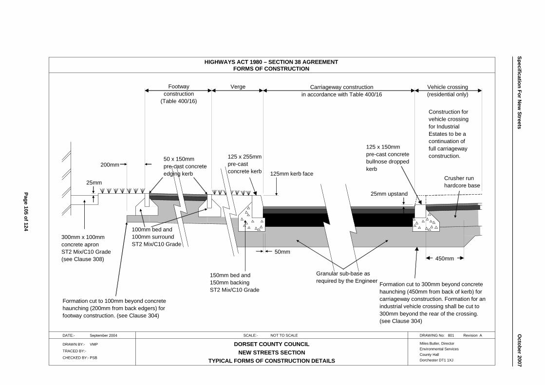
HIGHWAYS ACT 1980 – SECTION 38 AGREEMENTFORMS OF CONSTRUCTION
DATE:- September 2004 SCALE:- NOT TO SCALE DRAWING No: 801 Revision A
DRAWN BY:- VMP
TRACED BY:-
CHECKED BY:- PSB
DORSET COUNTY COUNCILNEW STREETS SECTION
TYPICAL FORMS OF CONSTRUCTION DETAILS
Miles Butler, DirectorEnvironmental ServicesCounty HallDorchester DT1 1XJ
Granular sub-base asrequired by the Engineer
150mm bed and150mm backingST2 Mix/C10 Grade
100mm bed and100mm surroundST2 Mix/C10 Grade
300mm x 100mmconcrete apronST2 Mix/C10 Grade(see Clause 308)
Crusher runhardcore base
Construction forvehicle crossingfor IndustrialEstates to be acontinuation offull carriagewayconstruction.
Vehicle crossing(residential only)
Carriageway constructionin accordance with Table 400/16
VergeFootway construction
(Table 400/16)
Formation cut to 100mm beyond concretehaunching (200mm from back edgers) forfootway construction. (see Clause 304)
450mm
Formation cut to 300mm beyond concretehaunching (450mm from back of kerb) forcarriageway construction. Formation for anindustrial vehicle crossing shall be cut to300mm beyond the rear of the crossing.(see Clause 304)
50mm
50 x 150mm pre-cast concreteedging kerb
125 x 255mmpre-castconcrete kerb
125 x 150mmpre-cast concretebullnose droppedkerb
25mm upstand
125mm kerb face200mm
25mm
Page 105 of 124
Specification For New
Streets
O
ctober2007
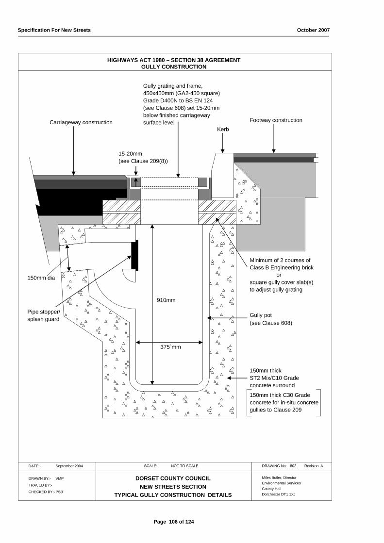
Specification For New Streets October 2007
HIGHWAYS ACT 1980 – SECTION 38 AGREEMENTGULLY CONSTRUCTION
DATE:- September 2004 SCALE:- NOT TO SCALE DRAWING No: 802 Revision A
DRAWN BY:- VMP
TRACED BY:-
CHECKED BY:- PSB
DORSET COUNTY COUNCILNEW STREETS SECTION
TYPICAL GULLY CONSTRUCTION DETAILS
Miles Butler, DirectorEnvironmental ServicesCounty HallDorchester DT1 1XJ
910mm
375`mm
Gully pot(see Clause 608)
150mm thick ST2 Mix/C10 Gradeconcrete surround
150mm thick C30 Gradeconcrete for in-situ concretegullies to Clause 209
150mm dia
Minimum of 2 courses ofClass B Engineering brick
orsquare gully cover slab(s)to adjust gully grating
Footway constructionCarriageway construction
Gully grating and frame,450x450mm (GA2-450 square)Grade D400N to BS EN 124(see Clause 608) set 15-20mmbelow finished carriagewaysurface level
15-20mm (see Clause 209(8))
Kerb
Pipe stopper/splash guard
Page 106 of 124
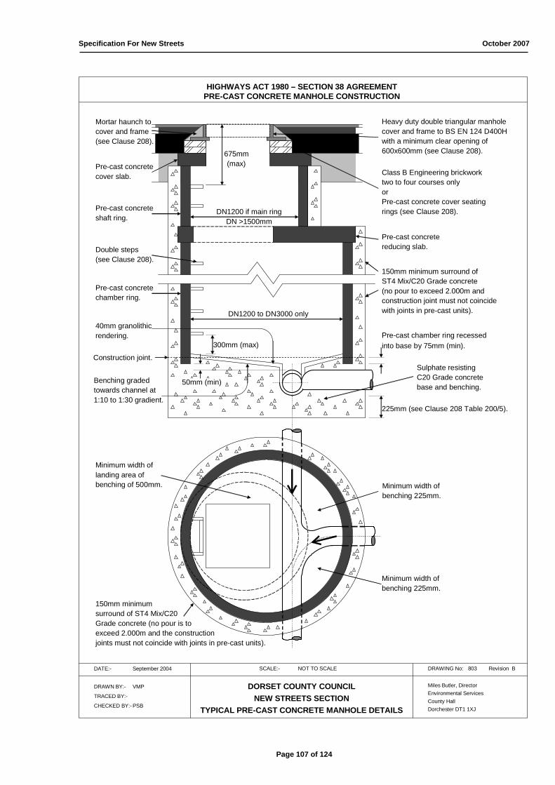
Specification For New Streets October 2007
HIGHWAYS ACT 1980 – SECTION 38 AGREEMENTPRE-CAST CONCRETE MANHOLE CONSTRUCTION
DATE:- September 2004 SCALE:- NOT TO SCALE DRAWING No: 803 Revision B
DRAWN BY:- VMP
TRACED BY:-
CHECKED BY:- PSB
DORSET COUNTY COUNCILNEW STREETS SECTION
TYPICAL PRE-CAST CONCRETE MANHOLE DETAILS
Miles Butler, DirectorEnvironmental ServicesCounty HallDorchester DT1 1XJ
Construction joint.
Pre-cast chamber ring recessedinto base by 75mm (min).
225mm (see Clause 208 Table 200/5).
Sulphate resistingC20 Grade concretebase and benching.
40mm granolithicrendering.
Minimum width oflanding area ofbenching of 500mm. Minimum width of
benching 225mm.
Pre-cast concretereducing slab.
Pre-cast concretecover slab.
Pre-cast concreteshaft ring.
DN1200 if main ringDN >1500mm
Double steps (see Clause 208).
300mm (max)
675mm(max)
Class B Engineering brickworktwo to four courses onlyorPre-cast concrete cover seatingrings (see Clause 208).
Heavy duty double triangular manholecover and frame to BS EN 124 D400Hwith a minimum clear opening of600x600mm (see Clause 208).
Benching gradedtowards channel at1:10 to 1:30 gradient.
Pre-cast concretechamber ring.
DN1200 to DN3000 only
150mm minimum surround ofST4 Mix/C20 Grade concrete(no pour to exceed 2.000m andconstruction joint must not coincidewith joints in pre-cast units).
Minimum width ofbenching 225mm.
Mortar haunch tocover and frame(see Clause 208).
150mm minimum surround of ST4 Mix/C20Grade concrete (no pour is toexceed 2.000m and the constructionjoints must not coincide with joints in pre-cast units).
50mm (min)
Page 107 of 124
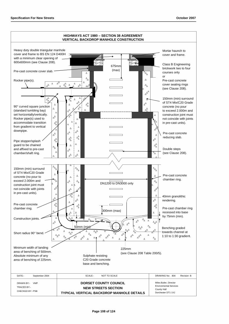
Specification For New Streets October 2007
HIGHWAYS ACT 1980 – SECTION 38 AGREEMENTVERTICAL BACKDROP MANHOLE CONSTRUCTION
DATE:- September 2004 SCALE:- NOT TO SCALE DRAWING No: 804 Revision B
DRAWN BY:- VMP
TRACED BY:-
CHECKED BY:- PSB
DORSET COUNTY COUNCILNEW STREETS SECTION
TYPICAL VERTICAL BACKDROP MANHOLE DETAILS
Miles Butler, DirectorEnvironmental ServicesCounty HallDorchester DT1 1XJ
Construction joints.
50mm (min)
Pre-cast chamber ringrecessed into baseby 75mm (min).
225mm (see Clause 208 Table 200/5).
Sulphate resistingC20 Grade concretebase and benching.
40mm granolithicrendering.
Pre-cast concretereducing slab.
Pre-cast concrete cover slab.
Pre-cast concretechamber ring.
Double steps (see Clause 208).
300mm (max)
675mm(max)
Class B Engineering brickwork two to fourcourses only orPre-cast concretecover seating rings(see Clause 208).
Heavy duty double triangular manholecover and frame to BS EN 124 D400Hwith a minimum clear opening of600x600mm (see Clause 208).
Benching gradedtowards channel at1:10 to 1:30 gradient.
Pre-cast concretechamber ring.
DN1200 to DN3000 only
150mm (min) surroundof ST4 Mix/C20 Gradeconcrete (no pourto exceed 2.000m and construction joint mustnot coincide with jointsin pre-cast units).
Mortar haunch tocover and frame.
90° curved square junction(standard tumbling bay)set horizontally/vertically.Rocker pipe(s) used to accommodate transitionfrom gradient to verticaldownpipe.
Rocker pipe(s).
°0000000
00
c
Pipe stopper/splashguard to be chainedand affixed to pre-castchamber/shaft ring.
150mm (min) surroundof ST4 Mix/C20 Gradeconcrete (no pour to exceed 2.000m andconstruction joint mustnot coincide with jointsin pre-cast units).
Short radius 90° bend.
Minimum width of landingarea of benching of 500mm.Absolute minimum of anyarea of benching of 225mm.
Page 108 of 124
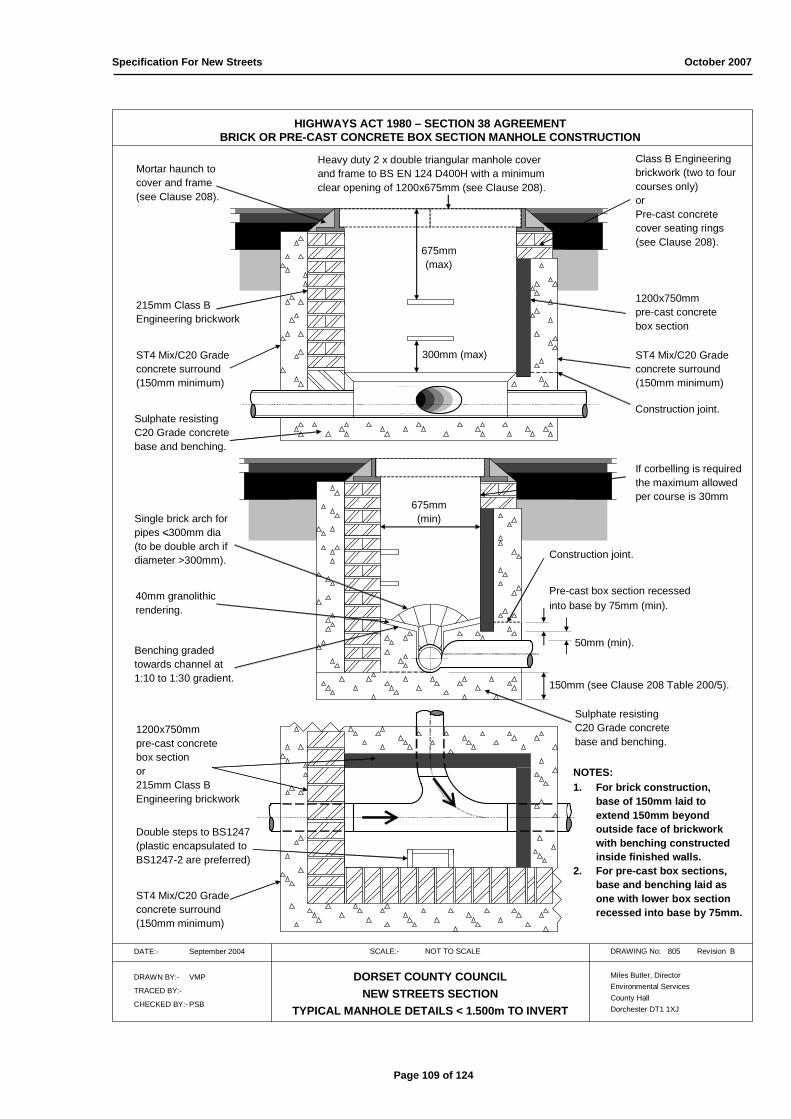
Specification For New Streets October 2007
HIGHWAYS ACT 1980 – SECTION 38 AGREEMENTBRICK OR PRE-CAST CONCRETE BOX SECTION MANHOLE CONSTRUCTION
DATE:- September 2004 SCALE:- NOT TO SCALE DRAWING No: 805 Revision B
DRAWN BY:- VMP
TRACED BY:-
CHECKED BY:- PSB
DORSET COUNTY COUNCILNEW STREETS SECTION
TYPICAL MANHOLE DETAILS < 1.500m TO INVERT
Miles Butler, DirectorEnvironmental ServicesCounty HallDorchester DT1 1XJ
Construction joint.
Pre-cast box section recessedinto base by 75mm (min).
150mm (see Clause 208 Table 200/5).
Sulphate resistingC20 Grade concretebase and benching.
40mm granolithicrendering.
300mm (max)
675mm(max)
Class B Engineeringbrickwork (two to fourcourses only)orPre-cast concrete cover seating rings(see Clause 208).
Heavy duty 2 x double triangular manhole cover and frame to BS EN 124 D400H with a minimum clear opening of 1200x675mm (see Clause 208).
Benching gradedtowards channel at1:10 to 1:30 gradient.
215mm Class BEngineering brickwork
675mm(min)
ST4 Mix/C20 Grade concrete surround(150mm minimum)
Mortar haunch tocover and frame(see Clause 208).
ST4 Mix/C20 Grade concrete surround(150mm minimum)
1200x750mmpre-cast concretebox section
50mm (min).
Single brick arch forpipes <300mm dia(to be double arch ifdiameter >300mm). Construction joint.
Sulphate resistingC20 Grade concretebase and benching.
ST4 Mix/C20 Grade concrete surround(150mm minimum)
1200x750mmpre-cast concretebox section or215mm Class BEngineering brickwork
NOTES:1. For brick construction,
base of 150mm laid toextend 150mm beyondoutside face of brickworkwith benching constructedinside finished walls.
2. For pre-cast box sections, base and benching laid asone with lower box sectionrecessed into base by 75mm.
Double steps to BS1247(plastic encapsulated to BS1247-2 are preferred)
If corbelling is requiredthe maximum allowedper course is 30mm
Page 109 of 124

HIGHWAYS ACT 1980 – SECTION 38 AGREEMENTARRANGEMENT OF UTILITY SERVICES
DATE:- September 2004 SCALE:- NOT TO SCALE DRAWING No: 806 Revision B
DRAWN BY:- VMP
TRACED BY:-
CHECKED BY:- PSB
DORSET COUNTY COUNCILNEW STREETS SECTION
TYPICAL ARRANGEMENT OF UTILITY SERVICES IN FOOTWAY/SERVICE MARGIN
Miles Butler, DirectorEnvironmental ServicesCounty HallDorchester DT1 1XJ
350m
m
900m
m
450m
m
600m
m
600m
m
450m
m
1.550m
1.375m1.000m
725mm425mm
h.v.
l.v.
Gas
Telephone
Electricity
Water
alternativepositionfor l.v.
NOTE: Reservation to be left ifany utility is unable to layservices at the same timeas the other utilities.
275mm2.000m – 3.000m450mm
450mm
Reserved for lighting columns,telegraph poles, road sign posts, water stop taps, et cetera.
Marker tape
300m
m
Page 110 of 124
Specification For New
Streets
O
ctober 2007

m 500
10
5 10 30 60
(Z 1 = 0.36) (Z 1 = 0.51) (Z 1 = 0.79) (Z 1 = 1.00) 400 0.750 3.830
1 4.18 5.92 9.17 11.60 2400
2 5.26 7.45 11.55 14.60 Exfiltrat io n
5 7.09 10.05 15.56 19.70 r ate
10 8.79 12.45 19.30 24.50 " f " M ax Em p tyin g M ax Em p tyin g M ax Em p tyin g M ax Em p tyin g
25 10.91 15.46 23.94 30.30 m /sec Rain fall T im e Rainfall T im e Rain fall T im e Rain fall T im e
50 14.30 20.28 31.37 39.70 ( x 10 - 5 ) (m m ) (h o u r s ) (m m ) (h o u r s ) (m m ) (h o u r s ) (m m ) (h o u r s )
100 17.21 24.39 37.77 47.80 1.0 13.20 12.68 13.20 16.93 13.20 25.44 13.20 50.96
100+30% 22.38 31.71 49.11 62.10 1.1 13.20 11.52 13.20 15.38 13.20 23.12 13.20 46.32
1.2 13.20 10.55 13.20 14.09 13.20 21.18 13.20 42.45
m 1.3 13.20 9.73 13.20 13.00 13.20 19.55 13.20 39.18
1.4 13.20 9.03 13.20 12.07 13.20 18.15 13.20 36.37
Filtr atio n Ove r all C ap acity o f Gr an u lar T otal 1.5 13.20 8.42 13.20 11.26 13.20 16.93 13.20 33.94
ar e a p e r m s iz e o f s o ak aw ay m ate r ial s o ak aw ay 1.6 13.20 7.89 13.20 10.55 13.20 15.87 13.20 31.82
d e p th p e r e xcavation ch am b e r r e q u ire d cap acity 1.7 13.20 7.42 13.20 9.92 13.20 14.93 13.20 29.94
m d ia (mm 2) w x b (m ) (litr e s ) (m 3) ( litr e s ) 1.8 13.20 7.01 13.20 9.37 13.20 14.09 13.20 28.27
1.9 13.20 6.63 13.20 8.87 13.20 13.35 13.20 26.78
2.0 13.20 6.30 13.20 8.42 13.20 12.68 13.20 25.44
2.1 13.20 5.99 13.20 8.02 13.20 12.07 13.20 24.22
2.2 13.20 5.72 13.20 7.65 13.20 11.52 13.20 23.12
2.3 13.20 5.46 13.20 7.31 13.20 11.01 13.20 22.11
Br ick w o r k Nu m b e r o f In te r n al Exte rn al Filtr at io n 2.4 13.20 5.23 13.20 7.01 13.20 10.55 13.20 21.18
w all ope n j oin ts s iz e o f s iz e o f ar e a o f 2.5 13.20 5.02 13.20 6.72 13.20 10.12 13.20 20.33
th ick n e s s in h e ad e r o p e n jo in t o p e n jo in t s o ak aw ay 2.6 13.20 4.82 13.20 6.46 13.20 9.73 13.20 19.55
(m m ) co u r s e s w x h (m m ) w x h (m m ) (m m 2) 2.7 13.20 4.64 13.20 6.22 13.20 8.50 13.20 18.82
2.8 13.20 4.47 13.20 5.99 13.20 9.03 13.20 18.15
2.9 13.20 4.32 13.20 5.78 13.20 8.72 13.20 17.52
0.75
0
16 x 85
De tails o f 40m m g r an u lar s u r r o u n d an d s o ak w ay cap acity
36 x 85
51,809
De tails o f o p e n jo in ts in b r ick w o r k (h e ad e r co u r s e s o n ly)
14.493 5,2783.830
87,040
Excavatio n s iz e (m ) >=
Re tu r n p e r io d in ye ar s (M )
3,393
Sto r m d u r atio n in M in u te s (D)
Rain fall (actu al) fo r var io u s s to r m in te n s it ie s (r rat io 0.36) M axim u m rain fall an d 50% e m p tyin g t im e fo r f ixe d s iz e o f ch am b e r , e xcavatio n , an d r u n -o ff ar e a
n o t e n clo s e d
16
In ar e as o f s e n s it iv ity (at th e d is cr e tio n o f th e Hig h w ay A u th o r ity) e ffe ctive de p th m ay b e in cr e as e d o r catch m e n t ar e a m ay b e r e d u ce d to cate r fo r a 1 in 100 ye ar s to r m (+30% fo r clim ate ch an g e ).
e n clo s e d o n 1 s id e e n clo s e d o n 2 s id e s e n clo s e d o n 3 s id e s
Effe ctive d e p th (m )C atch m e n t ar e a (m 2)
Fixe d in te r n al d iam e te r (DN) o f b r ick w or k ch am b e r (m m )
3.83
0
215
HIGHWAYS ACT 1980 – SECTION 38 AGREEMENTCIRCULAR BRICKWORK SOAKAWAY CONSTRUCTION DETAILS (WITH OR WITHOUT INTERCEPTORS)
DATE:- September 2007 SCALE:- NOT TO SCALE DRAWING No: 807-1 Revision
DRAWN BY:- VMP
TRACED BY:-
CHECKED BY:-
DORSET COUNTY COUNCILNEW STREETS SECTION
BRICKWORK SOAKAWAYS IN PERMEABLE SUB-SOIL (WITH OR WITHOUT INTERCEPTORS)
Miles Butler, DirectorEnvironmental ServicesCounty HallDorchester DT1 1XJ
IMPORTANT NOTES:-1. The brick chamber is to be formed by Class B Engineering brickwork.2. There will be an even number of course from the foundation ring to the cover slab.3. The brickwork is to be laid in English bond. The first course will be a double broken stretcher course, alternating (and to finish) with a header course with no open joints.4. Only the header courses (with the exception of the uppermost) will have the open joints.5. The mortar is to be in accordance with Clause 607.6. The standard storm situation is taken as M5-10 (5 year 10 minute storm) with 10.05mm of rainfall unless otherwise directed.7. The effective depth of the soakaway is fixed to 750mm below invert level (within the permeable strata) unless otherwise specifically approved.8. The performance (and capacity) of the soakaway is improved by the reducing the catchment/run-off area and/or by increasing the effective depth.9. The exfiltration rate only alters the emptying time of the soakaway (full to 50% capacity). A maximum time of 24 hours is permitted.10. Not more than 2 gullies to be connected to each soakaway (maximum of 400m2 drained surface) unless otherwise specifically approved.11. Soakaways should be a minimum of twice the effective depth from the nearest, or any, adjacent soakaway (to include the granular surround). 12. Should soakaways be closer than twice effective depth to each other, for example banked or grouped together (only if specifically approved) the table below applies with
regard to the number of sides of the soakaway construction which are “obstructed” or “enclosed” by the close proximity of other soakaways.13. No part of the soakaway to be constructed closer than the effective depth (2.500m minimum) to any part of carriageway construction (including footways).14. No soakaway to be constructed in any paved area without site-specific detailed approval.15. No part of the soakaway to be constructed closer than 5.000m to any tree planting or, with regard to buildings, no closer than 5.000m any part of building construction (unless
written dispensation from the relevant building control officer is given). It is the developer’s responsibility to obtain such dispensation.16. The excavation is to be lined with a geo-textile membrane before the granular fill is placed. The granular fill is to be covered with a geo-textile membrane.17. The granular drainage medium is to be 40mm nominal and regular size clean stone.18. The minimum surround is that shown to the left to match the chamber diameter and excavation size. It must not be less than 500mm.19. Minimum depth to the bottom of the upper non-perforated chamber ring is 1.050m, or, carriageway construction depth plus 250mm (which ever is the greater).20. Step irons or ladders are not to be installed. If access is required, it is intended to be by winch only with, at least, two operatives present.21. The soakaway chambers are not vented. As such, all appropriate measures should be taken for working in confined spaces.22. Cover to be a double triangular, or single rectangular, heavy-duty ductile (BS EN 124 D400 N), with a minimum cover weight of 70kg.
SECTION A-A
DN2400 Cover slab (min 150mm thick) ontonon-perforated 500m depth DN2400 chamber ring.Chamber ring onto two courses of Class B Engineering brickwork (header course upper-mostwith no open joints). To comply with BS EN 752-3,if required, the shaft diameter is DN1200.
Minimum of two courses 215mmClass B Engineering brickwork.
Ground level
Top of permeable strata.
DN2400x500mm chamber ring
750x600mm (eccentric)
DN2400 x 500 (fixed)
400x225mm (C20 Grade sulphate-resistingconcrete) in-situ concrete strip foundation(continuous ring).
Minimum of 225mm of 40mm nominal andregular size clean stone drainage mediumto DCC Clause 206.
Heavy-duty cover frame set andhaunched in cement mortar.
A
Excavation to be lined with geo-textile membraneto prevent the migration of “fines” into the granularfill and soakaway chamber.The brickwork ring must not be wrapped inthe membrane. The 40mm granular fill is tobe between the membrane and the rings.
INTERCEPTORS:-1. Class 1 Bypass Interceptors must be used unless written dispensation from the Environmental Agency is given. It is the developer’s responsibility to obtain such dispensation.2. In areas considered as sensitive, by the Environmental Agency and/or the Highway Authority, the rainfall rate may be M100-10+30% (100 year 10 minute storm + 30% for
climate change) 148.4mm/hr, or higher.3. Ordinarily, the bypass interceptor must have a minimum flow of 7.0 l/s (for the M5-10 rainfall rate (5 year 10 minute storm) 59.8mm/hr).4. If the area is considered sensitive (as described in point 2), the bypass interceptor must have a minimum flow of 22.0 l/s (for the M100-10 + 30%, 148.4mm/hr).5. The interceptors are to be vented. The level of the vent outlet is not to be lower than the cover of the interceptor.6. If soakaways are grouped in pairs (or more), interceptor capacity, or numbers, must be increased proportionally. See points 11 and 12 (below) in “IMPORTANT NOTES”.7. A commuted sum is required to ensure the cleansing programme is maintained for 20 years. This Authority does not have the expertise to dispose of the
controlled waste. The commuted sum is a direct reflection of the costs quoted by external companies.
Geo-textile membrane to be laidover top surface of granular fillto stop migration of fines frombackfill into soakaway. A
40mm nominal and regular size clean stonegranular drainage medium to DCC Clause 206with a minimum surround of mm.
STANDARD SOAKWAY DETAIL (BRICKWORK CONSTRUCTION SOAKAWAY CHAMBER WITH OPEN JOINTS IN HEADER COURSES ONLY)
STANDARD INTERCEPTOR VENT DETAILGround level
300mm
100mm
400mm 50mm
380x400mm
125mm
25m
m
Class B engineering brickwork with mortar to Class M10.
In-situ concrete bed and surround ST4 Mix/C20 Grade.
Centrally located 100mm diameter PVC-U vent pipe off to interceptor neck. Top of pipe to be 25mm clear of aggregate.
10mm nominal size clean stone drainage medium.
Cowl cap to prevent pipe blocking. Nominal 10mm gap to maintain exhaust.
Gully cover to be 380x400mm ductile (BS EN 124 C250 N).
OPEN JOINT PATTERN DETAIL (REPRESENTATIVE ONLY)
The pattern of the open joints is to be as indicated.Each header course of 64 bricks has an open joint every fourth brick (total of 16 open joints per course).All other joints are to be closed, properly mortared(class M10) and pointed.Each subsequent header course has joints offset byone brick so as to form the helix pattern as shown
Page 111 of 124
Specification For New
Streets
O
ctober2007

510
10
5 10 30 60
(Z1 = 0.36) (Z1 = 0.51) (Z1 = 0.79) (Z1 = 1.00) 400 2.500 2.400
m 1 4.18 5.92 9.17 11.60 1200
2 5.26 7.45 11.55 14.60 Exfilt r ation
5 7.09 10.05 15.56 19.70 rate
10 8.79 12.45 19.30 24.50 " f " M ax Em ptying M ax Em ptying M ax Em ptying M ax Em ptying
25 10.91 15.46 23.94 30.30 m /sec Rainfall T im e Rainfall T im e Rainfall T im e Rainfall T im e
50 14.30 20.28 31.37 39.70 ( x 10 - 5 ) (m m ) (hour s ) (m m ) (hours ) (m m ) (hour s ) (m m ) (hour s )
100 17.21 24.39 37.77 47.80 1.0 15.06 6.89 15.06 9.22 15.06 13.86 15.06 27.81
100+30% 22.38 31.71 49.11 62.10 1.1 15.06 6.26 15.06 8.37 15.06 12.60 15.06 25.28
1.2 15.06 5.73 15.06 7.67 15.06 11.54 15.06 23.16
1.3 15.06 5.28 15.06 7.07 15.06 10.65 15.06 21.38
1.4 15.06 4.90 15.06 6.56 15.06 9.88 15.06 19.84
Cham be r Num be r of Filt ration Ove r all Capacity o f Aggr e gate Total 1.5 15.06 4.57 15.06 6.12 15.06 9.22 15.06 18.51
w all 45m m dia ar e a p e r m s iz e of s oak aw ay req u ir ed fo r s oak aw ay 1.6 15.06 4.28 15.06 5.73 15.06 8.63 15.06 17.35
th ick ne s s hole s pe r de p th pe r e xcavation cham be r s s oak aw ay capacity 1.7 15.06 4.02 15.06 5.39 15.06 8.12 15.06 16.33
(m m ) m d e pth m d i a (m m 2) w x b (m ) (lit re s ) (m 3) ( litr e s ) 1.8 15.06 3.79 15.06 5.08 15.06 7.67 15.06 15.41
1.9 15.06 3.59 15.06 4.81 15.06 7.26 15.06 14.60
2.0 15.06 3.40 15.06 4.57 15.06 6.89 15.06 13.86
2.1 15.06 3.24 15.06 4.34 15.06 6.56 15.06 13.20
m 2.2 15.06 3.09 15.06 4.14 15.06 6.26 15.06 12.60
2.3 15.06 2.95 15.06 3.96 15.06 5.98 15.06 12.05
Cham be r Num be r of Filt ration Ove r all Capacity o f Aggr e gate Total 2.4 15.06 2.82 15.06 3.79 15.06 5.73 15.06 11.54
w all 110m m ar e a p e r m s iz e of s oak aw ay req u ir ed fo r s oak aw ay 2.5 15.06 2.71 15.06 3.64 15.06 5.50 15.06 11.08
th ick ne s s s lits pe r de p th pe r e xcavation cham be r s s oak aw ay capacity 2.6 15.06 2.60 15.06 3.49 15.06 5.28 15.06 10.65
(m m ) m d e pth m d i a (m m 2) w x b (m ) (lit re s ) (m 3) ( litr e s ) 2.7 15.06 2.50 15.06 3.36 15.06 4.21 15.06 10.25
2.8 15.06 2.41 15.06 3.24 15.06 4.90 15.06 9.88
2.9 15.06 2.32 15.06 3.12 15.06 4.73 15.06 9.54
40 53,000
Rainfall (actual) for var ious s tor m in te ns itie s (r r atio 0.36) M axim um r ain fall and 50% e m ptying t im e for fixe d s iz e of cham b e r , e xcavation , and r un -o ff are a
n ot e nclos e d e nclos e d on 1 s ide e nclos e d on 2 s ide s e nclos e d on 3 s ide s
Effe ctive de pth (m )
In ar e as of s e n s itivity (at the d is cre tio n of the High w ay Author ity) the catch m e nt ar e a m ay be re duce d to cate r for a 1 in 100 ye ar s to r m (+30% for clim ate chan ge ).
De tails o f m anufactur e d or cor e -dr ille d pe r for ations (45m m hole ) and granular fill r e quir e m e nts (40m m aggr e gate only) for an ind ividual s quar e s oak aw ay de s ign
Catchm e nt ar e a (m 2)
Fixe d d iam e te r (DN) o f pe rforate d cham be r (m m )
Fixe d s ize of p it (m )
Re turn pe r iod in ye ars (M )
2,827
Stor m dur ation in M inute s (D)
2.40
0
10.661 6,0262.40090
2.50
0
De tails o f m anufactur e d ape r tur e type (110m m x 25m m s lot) and gr anular fill r e quir e m e nts (40m m aggr e gate only) for an ind ividual s quar e s oak aw ay de s ign
90 24 52,320 2.400 2,827 10.661 6,026
HIGHWAYS ACT 1980 – SECTION 38 AGREEMENTPRE-CAST CONCRETE SOAKAWAY CONSTRUCTION DETAILS (WITH OR WITHOUT INTERCEPTORS)
DATE:- September 2007 SCALE:- NOT TO SCALE DRAWING No: 807-2 Revision E
DRAWN BY:- VMP
TRACED BY:-
CHECKED BY:-
DORSET COUNTY COUNCILNEW STREETS SECTION
PRE-CAST SOAKAWAYS IN PERMEABLE SUB-SOIL (WITH OR WITHOUT INTERCEPTORS)
Miles Butler, DirectorEnvironmental ServicesCounty HallDorchester DT1 1XJ
IMPORTANT NOTES:-1. Standard 75mm diameter soakaway holes are not accepted by this Authority. However, two different types of perforation are permitted in the concrete chamber ring to
conform to BS5911-3 and BS EN 1917. The 45mm diameter perforations are the preference of this Authority. Neither the 45mm hole nor 110mm slits are favoured by themanufacturers. To achieve 45mm holes, a standard chamber ring can be core-drilled upon site. Caution is advised with regard to the positioning of the reinforcing bars.i) Circular perforations in chamber rings are to be 45mm diameter only. The number per 1000mm depth can be obtained from the table (bottom left). Please note that
these circular perforations are a special order and, if an order is accepted, a severe delay is inevitable.ii) Slit perforations in chamber rings are to be 110mm x 25mm vertical slits. The 110mm includes a 25mm diameter finish top and bottom (for anti-crack). The number
per 1000mm depth is 24, 32, 36, 44, 48, 56, or 64 in four rows (12, 16, 18, 22, 24, 28, or 32 slits in two rows for 500mm section). Please note that the slits are aspecial order and, if an order is accepted, a severe delay is inevitable.
2. The standard storm situation is taken as M5-10 (5 year 10 minute storm) with a total of 10.05mm of rainfall.3. The effective depth of the soakaway is fixed to 2500mm below invert level (within the permeable strata) unless otherwise specifically approved.4. The performance (and capacity) of the soakaway is improved by the reducing the catchment/run-off area and/or by increasing the chamber ring and excavation size.5. The exfiltration rate only alters the emptying time of the soakaway (full to 50% capacity). A maximum time of 24 hours is permitted.6. Not more than 2 gullies to be connected to each soakaway (maximum of 400m2 drained surface) unless otherwise specifically approved.7. Soakaways should be a minimum of twice the effective depth from the nearest, or any, adjacent soakaway. 8. Should soakaways be closer than twice effective depth to each other (if specifically approved) the table below applies with regard to the number of sides of the soakaway
construction which are “obstructed” or “enclosed” by the close proximity of other soakaways.9. No part of the soakaway to be constructed closer than the effective depth (2500mm minimum) to any part of carriageway construction (including footways).10. No soakaway to be constructed in any paved area without site-specific detailed approval.11. No part of the soakaway to be constructed closer than 5000mm to any tree planting or, with regard to buildings, no closer than 5.000m any part of building construction (unless
written dispensation from the relevant building control officer is given). It is the developer’s responsibility to obtain such dispensation.12. The excavation is to be lined with a geo-textile membrane before the granular fill is placed.13. The minimum dimension of granular surround is that shown to the left to match the chamber diameter and excavation size. It must not be less than 500mm.14. Minimum depth to the bottom of the upper non-perforated chamber ring is 1000mm, or, carriageway construction depth plus 250mm (which ever is the greater).15. Step irons or ladders are not to be installed. Access is intended to be by winch only.16. The soakaway chambers are not vented. As such, all appropriate measures should be taken for working in confined spaces.17. Cover to be a double triangular, or single rectangular, heavy-duty ductile (BS EN 124 D400 N), with a minimum cover weight of 70kg.
SECTION A-A
i) chamber slab (min 150mm thick) onto full non-perforatedchamber ring (to comply with BS EN 752-3, no shaft isrequired if DN1200 or DN1500 is used).or
ii) second slab (min 150mm thick) with a smaller diameterchamber ring (to comply with BS EN 752-3, if main ringis DN1800 or more, the preferred shaft diameter isDN1200).
Minimum of two courses 215mmClass B Engineering brickwork.
Ground level
Top of permeable strata.
Chamber rings (manufacturedapertures or core drilled upon site). Lower ring to be set into baseconcrete by 75mm (minimum)
750x600mm (eccentric)
DN1200minimum
300x225mm (C20 Grade sulphate-resisting concrete)in-situ concrete strip foundation(continuous ring).
Minimum of 225mm of 40mm nominalregular size clean stone drainagemedium to DCC Clause 206
Heavy-duty cover frame set andhaunched in cement mortar.
A
Excavation to be lined with geo-textile membraneto prevent the migration of “fines” into the granularfill and soakaway chamber.The chamber rings must not be wrapped inthe membrane. The 40mm granular fill is tobe between the membrane and the rings.
INTERCEPTORS:-1. Class 1 Bypass Interceptors must be used unless written dispensation from the Environmental Agency is given. It is the developer’s responsibility to obtain such dispensation.2. In areas considered as sensitive, by the Environmental Agency and/or the Highway Authority, the rainfall rate may be M100-10+30% (100 year 10 minute storm + 30% for
climate change) 148.4mm/hr, or higher.3. Ordinarily, the bypass interceptor must have a minimum flow of 7.0 l/s (for the M5-10 rainfall rate (5 year 10 minute storm) 59.8mm/hr).4. If the area is considered sensitive (as described in point 2), the bypass interceptor must have a minimum flow of 22.0 l/s (for the M100-10 + 30%, 148.4mm/hr).5. The interceptors are to be vented. The level of the vent outlet is not to be lower than the cover of the interceptor.6. If soakaways are grouped in pairs (or more), interceptor capacity, or numbers, must be increased proportionally. See points 7 and 8 (below) in “IMPORTANT NOTES”.7. A commuted sum is required to ensure the cleansing programme is maintained for 20 years. This Authority does not have the expertise to dispose of the
controlled waste. The commuted sum is a direct reflection of the costs quoted by external companies.
Geo-textile membrane to be laidover top surface of granular fillto stop migration of fines frombackfill into soakaway.
A
40mm nominal and regular size clean stonedrainage medium to DCC Clause 206 with aminimum surround of mm.
STANDARD SOAKWAY DETAIL (PRE-CAST CHAMBER RING WITH MANUFACTURED OR CORE-DRILLED APERTURES)
STANDARD INTERCEPTOR VENT DETAIL
Ground level
300mm
100mm
400mm 50mm
380x400mm
125mm
25m
m
Class B engineering brickwork with mortar to Class M10.
In-situ concrete bed and surround ST4 Mix/C20 Grade.
Centrally located 100mm diameter PVC-U vent pipe off to interceptor neck. Top of pipe to be 25mm clear of aggregate.
10mm nominal size clean stone drainage medium.
Cowl cap to prevent pipe blocking. Nominal 10mm gap to maintain exhaust.
Gully cover to be 380x400mm ductile (BS EN 124 C250 N).
Specification For New
Streets
O
ctober 2007
Page 112 of 124
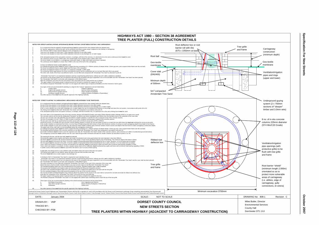
8 no: of in-situ concretecolumns 225mm diameter(ST4 Mix/C20 Grade)
Minimum depthof 500mm
HIGHWAYS ACT 1980 – SECTION 38 AGREEMENTTREE PLANTER (FULL) CONSTRUCTION DETAILS
DATE:- January 2004 SCALE:- NOT TO SCALE DRAWING No: 808-1 Revision C
DRAWN BY:- VMP
TRACED BY:-
CHECKED BY:-PSB
DORSET COUNTY COUNCILNEW STREETS SECTION
TREE PLANTERS WITHIN HIGHWAY (ADJACENT TO CARRIAGEWAY CONSTRUCTION)
Miles Butler, DirectorEnvironmental ServicesCounty HallDorchester DT1 1XJ
NOTES FOR “STREET PLANTING” IN CARRIAGEWAY AREAS WHICH ARE INTENDED TO BE TRAFFICKED
1. It is a requirement that the adopted carriageway/footway must be protected from trees planted within the adopted area. 2. No part of the trees planter is to be situated closer than 1.250m (absolute minimum) to any utility supply.3. No part of the trees planter is to be situated closer than 2.500m (absolute minimum) to any drainage run, or water supply.4. If two, or more, planters run in-line with a drainage run, or water supply, the use of a linking trench between to encourage and direct the root system, in accordance with points 28 to 30.5. The linking trench must be filled with “Amsterdam Tree Sand” and compacted in accordance with point 34.6. If the anticipated spread of the root system connects, or overlaps, with that of another tree, it is deemed to be a line and a linking trench must be used.
7. The cover slab is to be supported by way of 8 in-situ concrete columns (ST4 Mix/C20 Grade) cast inside 225mm diameter plastic drainage (which is cut away once cured). 8. The concrete columns are set into the undisturbed “formation” by 200mm (for friction foundation) and 500mm from the formation level to the underside of the cover slab.9. The pre-cast concrete cover slab (DN2400 only and 160mm in depth to BS5911-3 and BS EN 1917) is placed on top of the concrete columns.10. The size of excavation is to be 3.700m x 3.700m to leave a minimum of 600mm working space outside of the concrete columns.11. The pre-cast cover slab has an asymmetrical eccentric access with a minimum access size of 675 x 1200mm12. Around the access, is a smaller pre-cast concrete or brick chamber (square or round), the size and shape of which is to match the tree grille frame but must not overhang the access at any point.13. If the smaller chamber is constructed from brick, it is to be Class B Engineering brick with mortar to Class M10 (minimum number of courses to match carriageway depth minus depth of tree frame).14. If the smaller chamber is a pre-cast concrete ring, the minimum section depth is 250mm (plus minimum number of brick courses and depth of the tree frame to match carriageway construction depth).15. The upper level of the cover slab is to be immediately below the carriageway construction.16. An underground guying system must be used to support the tree (consisting of 2 x 750mm sections of sleeper timber, 3.0mm guy wire, and a square timber frame over the root ball)17. The disturbed ground (outside of the concrete columns) is to be filled with “Amsterdam Tree Sand” and compacted in accordance with point 34.18. Geo-textile membrane must be laid to cover the exposed cover slab, the “Amsterdam Tree Sand” outside of the concrete columns, and a minimum of 1.000m of undisturbed ground (formation).19. The carriageway construction must continue over the cover slab and geo-textile membrane and abut the smaller chamber (as described in points 12 to 14).
20. The opening for the tree, and the tree itself, must be protected.21. This protection must consist of grilles and frames (two levels of protection) and a tree guard (where the trunk diameter is less than 300mm).22. The frame must be secured to the structure (brickwork) of the planter. It must not be grouted by fixed by way of bolt fixings. The minimum depth of the frame is 50mm.23. The tree grille must be secured to the frame. It must be capable of being dismantled without disturbing the tree or frame, therefore, it is to be bolted and not welded.24. The tree guard must be secured to the grille. It must be capable of being dismantled without disturbing the tree or grille, therefore, it is to be bolted and not welded.25. Trees, which are located in footways (or areas not intended to be trafficked), must be protected by a grille and frame with a minimum load bearing capability of 15kN. 26. Trees, which are located in a courtyard, or street, situation (areas which will be trafficked), must be protected by a grille and frame with a minimum load bearing capability of 50kN.27. A soldier course of block paviours must be used when the frame is set in an area of block paving.
28. If applicable, the linking trench is to be 1000mm wide and 500mm deep and used to direct the root system.29. This linking trench depth is to be 500mm, below the base of the pre-cast concrete cover slab. 30. The trench must not cross a water supply or any drainage run
31. A minimum of 5m3 of “Amsterdam Tree Sand” is required for each individual tree pit.32. “Amsterdam Tree Sand” is an engineered substance and has a load-bearing performance; ordinary top-soil is not a satisfactory substitute.33. The anchors of the guying system are to be placed at the base of the excavation (the guys supported so as to be accessible once the “Amsterdam Tree Sand” and the cover slab has been placed).34. The “Amsterdam Tree Sand” is to be laid, and compacted, in 250-300mm layers.35. The entire excavation is to be filled with compacted “Amsterdam Tree Sand” to the level of the underside of the cover slab.36. Above this level, only the smaller chamber (brick or pre-cast concrete ring) is to be filled with “Amsterdam Tree Sand”. 37 The ventilation/irrigation pipes are to be manufactured for the purpose. Standard irrigation pipe is not acceptable. 38. The purpose built ventilation and irrigation pipes are laid prior/during the filling and compaction process. 39. The ends of the ventilation/irrigation pipes are to be terminated with a vandal proof grille/cover to be flush with the tree grille.40. The first ventilation/irrigation ring is laid around the periphery of the top of the concrete columns.41 The second (smaller) ventilation/irrigation ring is laid just above the position for the access in the cover slab to surround the root ball and inside the ribbed root deflector box. 42. Only after the compaction of the “Amsterdam Tree Sand” is the pit for the tree (root ball) dug. 43. The upper support of the guying system is placed around the root ball to complete the support for the tree.44. The finished compacted “Amsterdam Tree Sand” is to be topped with 150mm layer of blinding sand to reach the top of the tree grille.
45. Three types of tree are recommended for planting in the street/courtyard environment and are listed below.I) Red Maple (Caucasian) - Acer Cappadocicum Rubrumii) Silver Birch (upright versions) - Betula Pendula (Fastigiata or Dalecarlica)iii) Whitebeam - Sorbus Aria
46. Any other species of tree must have the specific approval of the Highway Authority.
NOTES FOR VERGE PLANTING (AVENUE APPEARANCE) BEHIND FOOTWAY OR BETWEEN FOOTWAY AND CARRIAGEWAY
1. It is a requirement that the adopted carriageway/footway must be protected from trees planted within the adopted area.2. An “avenue” appearance, without tree pits, can be achieved only where a grass verge is adjacent to the footway or carriageway.3. The minimum width of verge required adjacent to the carriageway is 3.000m4. Trees are to be situated no closer than 1.250m (absolute minimum) to any utility supply.5. Trees are to be situated no closer than 2.500m (absolute minimum) to any drainage run, or water supply.
6. If the anticipated spread of the root system connects, or overlaps, with that of the next tree, it is deemed to be a line and a continuous trench must be used.7. The continuous trench is to be 2.500m wide x the overall length of tree positions (plus 3.000m either end).8. The trench depth is to be 800mm, or carriageway construction depth, or utility invert depth (whichever is greater). 9. The continuous trench must be no closer than 0.400m to the rear of the kerb of the carriageway.
10. A linear root deflection barrier system must be used.11. An underground guying system must be used to support the tree (consisting of 2 x 750mm sections of sleeper timber, 3.0mm guy wire, and a square timber frame over the root ball). 12. The linear root deflection barrier system must reach the base of the excavation.13. The linear root deflection barrier is to be laid, in a continuous rectangle, 2.300m apart14. The remaining 100mm gap between the linear root deflection barrier and the undisturbed soil is to be back filled with 20mm pea gravel.15. The entire void, inside of the linear root deflection barrier, is to be filled and compacted with “Amsterdam Tree Sand” as directed in point 18.
16. “Amsterdam Tree Sand” is an engineered substance and has a load-bearing performance; ordinary top-soil is not a satisfactory substitute.17. The anchors of the guying system are to be placed at the base of the excavation (the guys supported so as to be accessible once the “Amsterdam Tree Sand” has been placed).18. The “Amsterdam Tree Sand” is to be laid, and compacted, in 250-300mm layers.19. After the compaction, the pit for the tree (root bowl) is then dug (within the tree sand) and the tree is planted.20. The upper support of the guying system is placed around the root ball to complete the support for the tree.21. The finished compacted “Amsterdam Tree Sand” is to be topped with 150mm layer of topsoil (to BS3882) to be then returned or laid to grass.
22. Four types of tree are recommended for planting in a verge for the “Avenue” appearance and are listed below.i) London Plane - Platanus Hispanicaii) English Oak (upright version) - Quercus Robur (Fastigiata)iii) Dawyck Beech (upright version) - Fagus Sylvatica (Fastigiata)iv) Hornbeam (upright version) - Carpinus Betulus (Fastigiata or Pyramidalus)
23. Any other species of tree must have the specific approval of the Highway Authority.
Carriagewayconstruction(minimum depth)
Ventilation/irrigationpipes and rings(upper and lower)
5m3 compacted Amsterdam Tree Sand
Root ball
Cover slab(DN2400)
Tree grille and frame
Ventilation/irrigationpipe openings (withprotective grille) to beflush with tree grille and frame
Tree grilleand frame
Root deflector box or rootbarrier roll with ribs(675 x 1050mm at base)
Root barrier “shield”(minimum length 2.000m)orientated so as toprotect more vulnerableareas of carriageway (i.e. utilities, edge of carriageway, gullyconnections, et cetera)
Minimum excavation 3700mm
Ribbed root deflector box
Geo-textilemembrane
Geo-textile membrane
Produced by Dorset County Council Highways and Transportation Division with the full co-operation of, and in full consultation with, the Dorset Local Government Landscape Group comprising representatives from BournemouthBorough Council, Christchurch Borough Council, East Dorset District Council, North Dorset District Council, Poole Borough Council, Purbeck District Council, West Dorset District Council and Weymouth and Portland Borough Council
Underground guyingsystem (2 x 750mm sections of “sleeper”timber and 3.0mm wire)
Page 113 of 124
Specification For New
Streets
O
ctober2007
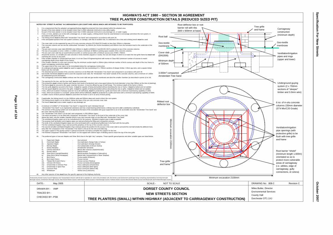
6 no: of in-situ concretecolumns 150mm diameter(ST4 Mix/C20 Grade)
Minimum depthof 500mm
HIGHWAYS ACT 1980 – SECTION 38 AGREEMENTTREE PLANTER CONSTRUCTION DETAILS (REDUCED SIZED PIT)
DATE:- May 2005 SCALE:- NOT TO SCALE DRAWING No: 808-2 Revision C
DRAWN BY:- VMP
TRACED BY:-
CHECKED BY:-PSB
DORSET COUNTY COUNCILNEW STREETS SECTION
TREE PLANTERS (SMALL) WITHIN HIGHWAY (ADJACENT TO CARRIAGEWAY CONSTRUCTION)
Miles Butler, DirectorEnvironmental ServicesCounty HallDorchester DT1 1XJ
NOTES FOR “STREET PLANTING” IN CARRIAGEWAYS (OR COURTYARD AREAS WHICH ARE INTENDED TO BE TRAFFICKED)
1. It is a requirement that the adopted carriageway/footway must be protected from trees planted within the adopted area. 2. No part of the trees planter is to be situated closer than 1.250m (absolute minimum) to any utility supply. 3. No part of the trees planter is to be situated closer than 2.500m (absolute minimum) to any drainage run, or water supply. 4. If two, or more, planters run in-line with a drainage run, or water supply, a linking trench must be used between to encourage and direct the root system, in
accordance with points 28 to 30.5. The linking trench must be filled with “Amsterdam Tree Sand” and compacted in accordance with point 34.6. If the anticipated spread of the root system connects, or overlaps, with that of another tree, it is deemed to be a line and a linking trench must be used.
7. The cover slab is to be supported by way of 6 in-situ concrete columns (ST4 Mix/C20 Grade) no less than 150mm in diameter. 8. The concrete columns are set into the undisturbed “formation” by 200mm (for friction foundation) and 500mm from the formation level to the underside of the
cover slab.9. The pre-cast concrete cover slab (DN1500 only (150mm in depth) to BS5911-3 and BS EN 1917) is placed on top of the concrete columns.
10. The size of excavation is to be 2.100m x 2.100m to leave a minimum of 300mm working space outside of the concrete columns.11. The pre-cast cover slab has an asymmetrical eccentric or central access with a minimum access size of 600 x 750mm12. Around the access, is a smaller pre-cast concrete or brick chamber (square or round), the size and shape of which is to match the tree grille frame but must not
overhang the access at any point.13. If the smaller chamber is constructed from brick, it is to be Class B Engineering brick with mortar to Class M10 (minimum number of courses to match
carriageway depth minus depth of tree frame).14. If the smaller chamber is a pre-cast concrete ring, the minimum section depth is 250mm (plus minimum number of brick courses and depth of the tree frame to
match carriageway construction depth).15. The upper level of the cover slab is to be immediately below the carriageway construction.16. An underground guying system must be used to support the tree (consisting of 2 x 750mm sections of sleeper timber, 3.0mm guy wire, and a square timber
frame over the root ball)17. The disturbed ground (outside of the concrete columns) is to be filled with “Amsterdam Tree Sand” and compacted in accordance with point 34.18. Geo-textile membrane must be laid to cover the exposed cover slab, the “Amsterdam Tree Sand” outside of the concrete columns, and a minimum of 1.000m
of undisturbed ground (formation).19. The carriageway construction must continue over the cover slab and geo-textile membrane and abut the smaller chamber (as described in points 12 to 14).
20. The opening for the tree, and the tree itself, must be protected.21. This protection must consist of grilles and frames (two levels of protection) and a tree guard (where the trunk diameter is less than 300mm at the time of planting).22. The frame must be secured to the upper chamber structure. It must be affixed by way of bolt fixings. The minimum depth of the frame is 50mm.23. The tree grille must be secured to the frame. It must be capable of being dismantled without disturbing the tree or frame, it must be bolted and not welded.24. The tree guard must be secured to the grille. It must be capable of being dismantled without disturbing the tree or grille, it must be bolted and not welded.25. Trees, which are located in footways (and are not to be trafficked), must be protected by a grille and frame with a minimum load bearing capability of 15kN. 26. Trees, which are located in a courtyard (areas which will be trafficked), must be protected by a grille and frame with a minimum load bearing capability of 50kN.27. A soldier course of block paviours must be used when the frame is set in an area of block paving.
28. If applicable, the linking trench is to be 1000mm wide and 500mm deep and used to direct the root system.29. This linking trench depth is to be 500mm, below the base of the pre-cast concrete cover slab. 30. The trench must not cross a water supply or any drainage run
31. A minimum of 3.000m3 of “Amsterdam Tree Sand” is required for each individual tree pit.32. “Amsterdam Tree Sand” is an engineered substance and has a load-bearing performance; ordinary top-soil is not a satisfactory substitute.33. The anchors of the guying system are to be placed at the base of the excavation (the guys supported so as to be accessible once the “Amsterdam Tree Sand” and
the cover slab has been placed).34. The “Amsterdam Tree Sand” is to be laid, and compacted, in 250-300mm layers.35. The entire excavation is to be filled with compacted “Amsterdam Tree Sand” to the level of the underside of the cover slab.36. Above this level, only the smaller chamber (brick or pre-cast concrete ring) is to be filled with “Amsterdam Tree Sand”. 37 The ventilation/irrigation pipes are to be manufactured for the purpose. Standard irrigation pipe is not acceptable. 38. The purpose built ventilation and irrigation pipes are laid prior/during the filling and compaction process. 39. The ends of the ventilation/irrigation pipes are to be terminated with a vandal proof grille/cover to be flush with the tree grille.40. The first ventilation/irrigation ring is laid around the periphery of the top of the concrete columns.41 The second (smaller) ventilation/irrigation ring is laid just above the position for the access in the cover slab to surround the root ball (inside the deflector box). 42. Only after the compaction of the “Amsterdam Tree Sand” is the pit for the tree (root ball) dug. 43. The upper support of the guying system is placed around the root ball to complete the support for the tree.44. The finished compacted “Amsterdam Tree Sand” is to be topped with 150mm layer of blinding sand to reach the top of the tree grille.
45. The preferred types of tree are Maples and Silver Birch due to the light “airy” canopies. Those specific genus/species and other suitable types are listed below.
i) Paper-bark Maple - Acer griseumii) Coral-bark Maple - Acer palmatum (Sango-Kaku or Seiryu)iii) Japanese Maple - Acer palmatum (Orange Dream)iv) Norway Maple - Acer platanoides (Crimson Sentry)v) Snowy Mespilus - Amelanchier lamarckiivi) Chinese Red Birch - Betula albo-sinensis (Septentrionalis)vii) Erman’s Birch - Betula ermaniiviii) Silver Birch (Upright/Swedish) - Betula pendula (Fastigiata or Dalecarlica)ix) Silver Birch (West Himalayan) - Betula utilis (Jacquemontii or Silver Shadow)x) Bird Cherry - Prunus padus (Watereri)xi) Birch-bark Cherry - Prunus serrulaxii) Tibetan Birch-bark Cherry - Prunus serrula (Tibetica)xiii) Chinese Hill Cherry - Prunus serrulata (Amanogawa)xiv) Ornamental or Chinese Pear - Pyrus calleryana (Chanticleer)xv) Ornamental or Spire Pear - Pyrus calleryana (Red Spire)xvi) Common Pear - Pyrus communis (Beech Hill)xvii) Whitebeam - Sorbus aria (Lutescens)
46. Any other species of tree must have the specific approval of the Highway Authority.
Carriagewayconstruction(minimum depth)
Ventilation/irrigationpipes and rings(upper and lower)
3.000m3 compacted Amsterdam Tree Sand
Root ball
Cover slab(DN1500)
Tree grille and frame
Ventilation/irrigationpipe openings (withprotective grille) to beflush with tree grille and frame
Tree grilleand frame
Root deflector box or rootbarrier roll with ribs(600 x 600mm at base)
Root barrier “shield”(minimum length 1.600m)orientated so as toprotect more vulnerableareas of carriageway (i.e. utilities, edge of carriageway, gullyconnections, et cetera)
Minimum excavation 2100mm
Ribbed root deflector box
Geo-textilemembrane
Geo-textile membrane
Produced by Dorset County Council Highways and Transportation Division with the full co-operation of, and in full consultation with, the Dorset Local Government Landscape Group comprising representatives from BournemouthBorough Council, Christchurch Borough Council, East Dorset District Council, North Dorset District Council, Poole Borough Council, Purbeck District Council, West Dorset District Council and Weymouth and Portland Borough Council
Underground guyingsystem (2 x 750mm sections of “sleeper”timber and 3.0mm wire)
Minim
um excavation 2100m
m
Page 114 of 124
Specification For New
Streets O
ctober 2007
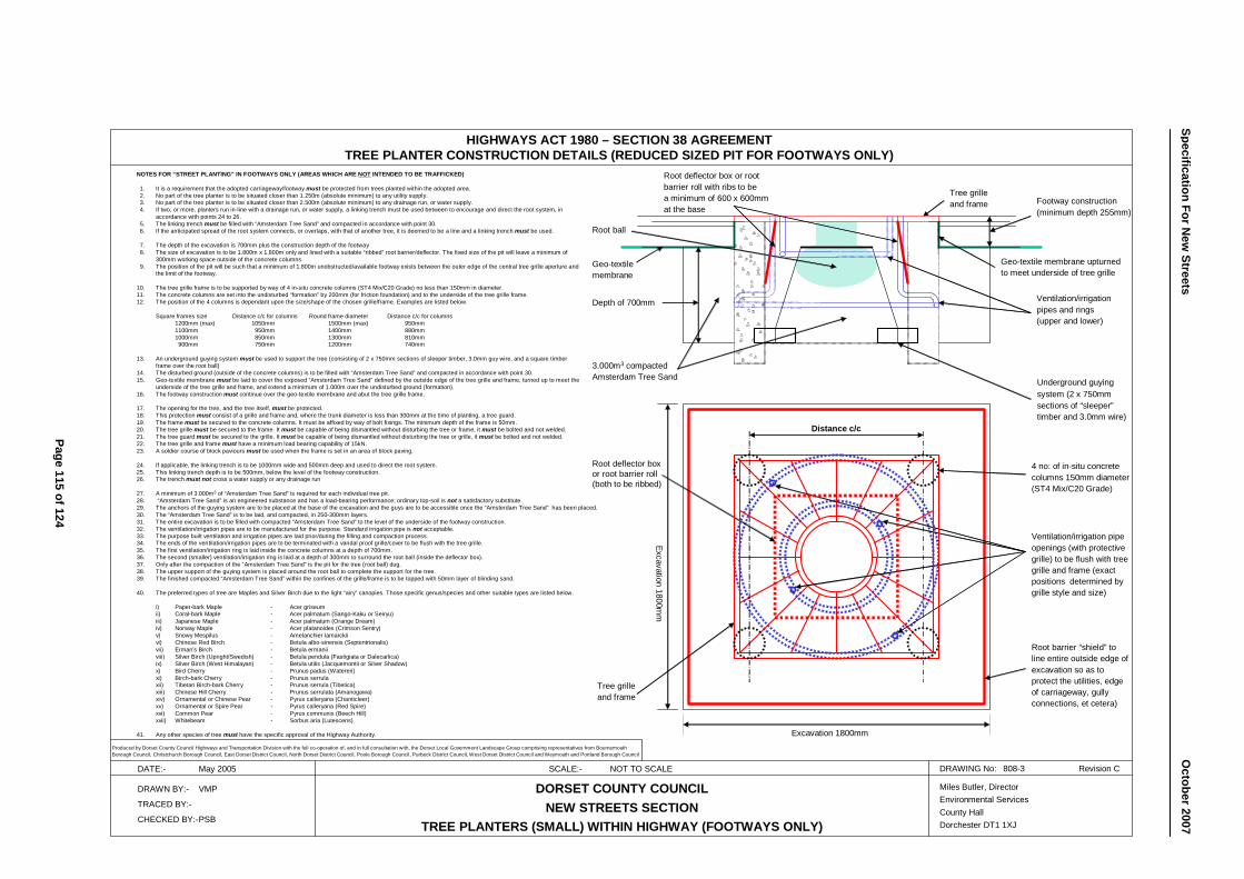
4 no: of in-situ concretecolumns 150mm diameter(ST4 Mix/C20 Grade)
Depth of 700mm
HIGHWAYS ACT 1980 – SECTION 38 AGREEMENTTREE PLANTER CONSTRUCTION DETAILS (REDUCED SIZED PIT FOR FOOTWAYS ONLY)
DATE:- May 2005 SCALE:- NOT TO SCALE DRAWING No: 808-3 Revision C
DRAWN BY:- VMP
TRACED BY:-
CHECKED BY:-PSB
DORSET COUNTY COUNCILNEW STREETS SECTION
TREE PLANTERS (SMALL) WITHIN HIGHWAY (FOOTWAYS ONLY)
Miles Butler, DirectorEnvironmental ServicesCounty HallDorchester DT1 1XJ
NOTES FOR “STREET PLANTING” IN FOOTWAYS ONLY (AREAS WHICH ARE NOT INTENDED TO BE TRAFFICKED)
1. It is a requirement that the adopted carriageway/footway must be protected from trees planted within the adopted area. 2. No part of the tree planter is to be situated closer than 1.250m (absolute minimum) to any utility supply. 3. No part of the tree planter is to be situated closer than 2.500m (absolute minimum) to any drainage run, or water supply. 4. If two, or more, planters run in-line with a drainage run, or water supply, a linking trench must be used between to encourage and direct the root system, in
accordance with points 24 to 26.5. The linking trench must be filled with “Amsterdam Tree Sand” and compacted in accordance with point 30.6. If the anticipated spread of the root system connects, or overlaps, with that of another tree, it is deemed to be a line and a linking trench must be used.
7. The depth of the excavation is 700mm plus the construction depth of the footway8. The size of excavation is to be 1.800m x 1.800m only and lined with a suitable “ribbed” root barrier/deflector. The fixed size of the pit will leave a minimum of
300mm working space outside of the concrete columns.9. The position of the pit will be such that a minimum of 1.800m unobstructed/available footway exists between the outer edge of the central tree grille aperture and
the limit of the footway.
10. The tree grille frame is to be supported by way of 4 in-situ concrete columns (ST4 Mix/C20 Grade) no less than 150mm in diameter. 11. The concrete columns are set into the undisturbed “formation” by 200mm (for friction foundation) and to the underside of the tree grille frame.12. The position of the 4 columns is dependant upon the size/shape of the chosen grille/frame. Examples are listed below.
Square frames size Distance c/c for columns Round frame diameter Distance c/c for columns1200mm (max) 1050mm 1500mm (max) 950mm1100mm 950mm 1400mm 880mm1000mm 850mm 1300mm 810mm900mm 750mm 1200mm 740mm
13. An underground guying system must be used to support the tree (consisting of 2 x 750mm sections of sleeper timber, 3.0mm guy wire, and a square timber frame over the root ball)
14. The disturbed ground (outside of the concrete columns) is to be filled with “Amsterdam Tree Sand” and compacted in accordance with point 30.15. Geo-textile membrane must be laid to cover the exposed “Amsterdam Tree Sand” defined by the outside edge of the tree grille and frame, turned up to meet the
underside of the tree grille and frame, and extend a minimum of 1.000m over the undisturbed ground (formation).16. The footway construction must continue over the geo-textile membrane and abut the tree grille frame.
17. The opening for the tree, and the tree itself, must be protected.18. This protection must consist of a grille and frame and, where the trunk diameter is less than 300mm at the time of planting, a tree guard.19. The frame must be secured to the concrete columns. It must be affixed by way of bolt fixings. The minimum depth of the frame is 50mm.20. The tree grille must be secured to the frame. It must be capable of being dismantled without disturbing the tree or frame, it must be bolted and not welded.21. The tree guard must be secured to the grille. It must be capable of being dismantled without disturbing the tree or grille, it must be bolted and not welded.22. The tree grille and frame must have a minimum load bearing capability of 15kN. 23. A soldier course of block paviours must be used when the frame is set in an area of block paving.
24. If applicable, the linking trench is to be 1000mm wide and 500mm deep and used to direct the root system.25. This linking trench depth is to be 500mm, below the level of the footway construction. 26. The trench must not cross a water supply or any drainage run
27. A minimum of 3.000m3 of “Amsterdam Tree Sand” is required for each individual tree pit.28. “Amsterdam Tree Sand” is an engineered substance and has a load-bearing performance; ordinary top-soil is not a satisfactory substitute.29. The anchors of the guying system are to be placed at the base of the excavation and the guys are to be accessible once the “Amsterdam Tree Sand” has been placed.30. The “Amsterdam Tree Sand” is to be laid, and compacted, in 250-300mm layers.31. The entire excavation is to be filled with compacted “Amsterdam Tree Sand” to the level of the underside of the footway construction.32. The ventilation/irrigation pipes are to be manufactured for the purpose. Standard irrigation pipe is not acceptable. 33. The purpose built ventilation and irrigation pipes are laid prior/during the filling and compaction process. 34. The ends of the ventilation/irrigation pipes are to be terminated with a vandal proof grille/cover to be flush with the tree grille.35. The first ventilation/irrigation ring is laid inside the concrete columns at a depth of 700mm.36. The second (smaller) ventilation/irrigation ring is laid at a depth of 300mm to surround the root ball (inside the deflector box). 37. Only after the compaction of the “Amsterdam Tree Sand” is the pit for the tree (root ball) dug. 38. The upper support of the guying system is placed around the root ball to complete the support for the tree.39. The finished compacted “Amsterdam Tree Sand” within the confines of the grille/frame is to be topped with 50mm layer of blinding sand.
40. The preferred types of tree are Maples and Silver Birch due to the light “airy” canopies. Those specific genus/species and other suitable types are listed below.
i) Paper-bark Maple - Acer griseumii) Coral-bark Maple - Acer palmatum (Sango-Kaku or Seiryu)iii) Japanese Maple - Acer palmatum (Orange Dream)iv) Norway Maple - Acer platanoides (Crimson Sentry)v) Snowy Mespilus - Amelanchier lamarckiivi) Chinese Red Birch - Betula albo-sinensis (Septentrionalis)vii) Erman’s Birch - Betula ermaniiviii) Silver Birch (Upright/Swedish) - Betula pendula (Fastigiata or Dalecarlica)ix) Silver Birch (West Himalayan) - Betula utilis (Jacquemontii or Silver Shadow)x) Bird Cherry - Prunus padus (Watereri)xi) Birch-bark Cherry - Prunus serrulaxii) Tibetan Birch-bark Cherry - Prunus serrula (Tibetica)xiii) Chinese Hill Cherry - Prunus serrulata (Amanogawa)xiv) Ornamental or Chinese Pear - Pyrus calleryana (Chanticleer)xv) Ornamental or Spire Pear - Pyrus calleryana (Red Spire)xvi) Common Pear - Pyrus communis (Beech Hill)xvii) Whitebeam - Sorbus aria (Lutescens)
41. Any other species of tree must have the specific approval of the Highway Authority.
Footway construction(minimum depth 255mm)
Ventilation/irrigationpipes and rings(upper and lower)
3.000m3 compacted Amsterdam Tree Sand
Root ball
Tree grille and frame
Ventilation/irrigation pipeopenings (with protectivegrille) to be flush with treegrille and frame (exactpositions determined bygrille style and size)
Tree grilleand frame
Root deflector box or rootbarrier roll with ribs to bea minimum of 600 x 600mmat the base
Root barrier “shield” toline entire outside edge ofexcavation so as toprotect the utilities, edgeof carriageway, gullyconnections, et cetera)
Excavation 1800mm
Root deflector box or root barrier roll (both to be ribbed)
Geo-textilemembrane
Geo-textile membrane upturnedto meet underside of tree grille
Produced by Dorset County Council Highways and Transportation Division with the full co-operation of, and in full consultation with, the Dorset Local Government Landscape Group comprising representatives from BournemouthBorough Council, Christchurch Borough Council, East Dorset District Council, North Dorset District Council, Poole Borough Council, Purbeck District Council, West Dorset District Council and Weymouth and Portland Borough Council
Underground guyingsystem (2 x 750mm sections of “sleeper”timber and 3.0mm wire)
Excavation 1800mm
Distance c/cPage 115 of 124
Specification For New
Streets
O
ctober2007
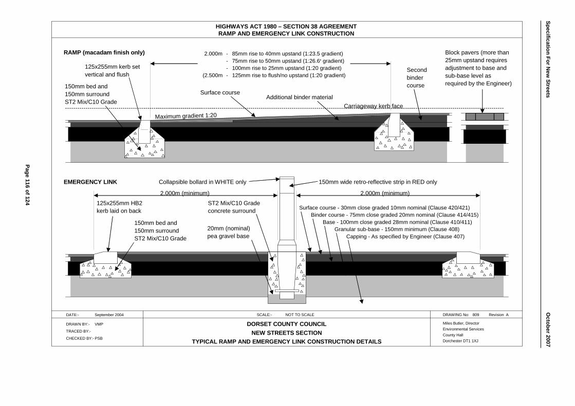
HIGHWAYS ACT 1980 – SECTION 38 AGREEMENTRAMP AND EMERGENCY LINK CONSTRUCTION
DATE:- September 2004 SCALE:- NOT TO SCALE DRAWING No: 809 Revision A
DRAWN BY:- VMP
TRACED BY:-
CHECKED BY:- PSB
DORSET COUNTY COUNCILNEW STREETS SECTION
TYPICAL RAMP AND EMERGENCY LINK CONSTRUCTION DETAILS
Miles Butler, DirectorEnvironmental ServicesCounty HallDorchester DT1 1XJ
Carriageway kerb face
Maximum gradient 1:20
2.000m - 85mm rise to 40mm upstand (1:23.5 gradient)- 75mm rise to 50mm upstand (1:26.6• gradient)- 100mm rise to 25mm upstand (1:20 gradient)
(2.500m - 125mm rise to flush/no upstand (1:20 gradient)
Block pavers (more than25mm upstand requires adjustment to base and sub-base level as required by the Engineer)
Secondbindercourse
125x255mm kerb setvertical and flush
150mm bed and150mm surroundST2 Mix/C10 Grade
Additional binder materialSurface course
150mm bed and150mm surroundST2 Mix/C10 Grade
125x255mm HB2kerb laid on back
ST2 Mix/C10 Gradeconcrete surround
20mm (nominal)pea gravel base
2.000m (minimum)2.000m (minimum)
Surface course - 30mm close graded 10mm nominal (Clause 420/421)Binder course - 75mm close graded 20mm nominal (Clause 414/415)
Base - 100mm close graded 28mm nominal (Clause 410/411)Granular sub-base - 150mm minimum (Clause 408)
Capping - As specified by Engineer (Clause 407)
Collapsible bollard in WHITE only 150mm wide retro-reflective strip in RED onlyEMERGENCY LINK
RAMP (macadam finish only)
Page 116 of 124
Specification For New
Streets O
ctober 2007
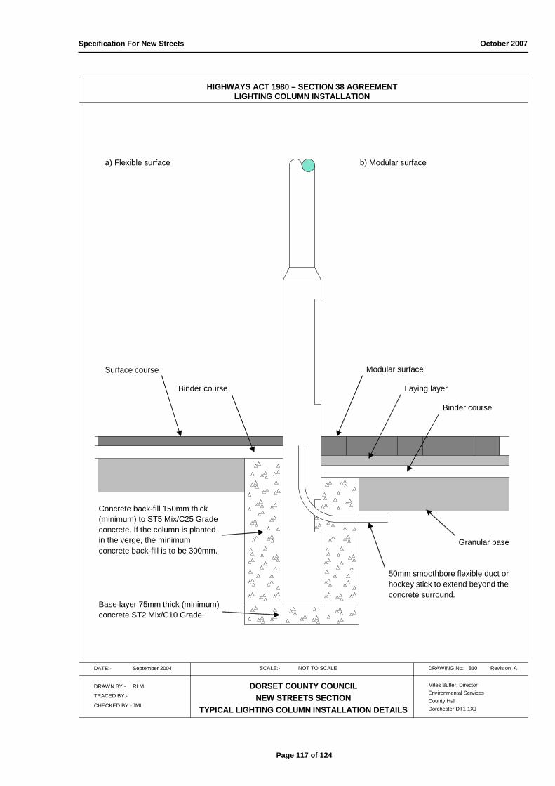
Specification For New Streets October 2007
HIGHWAYS ACT 1980 – SECTION 38 AGREEMENTLIGHTING COLUMN INSTALLATION
DATE:- September 2004 SCALE:- NOT TO SCALE DRAWING No: 810 Revision A
DRAWN BY:- RLM
TRACED BY:-
CHECKED BY:- JML
DORSET COUNTY COUNCILNEW STREETS SECTION
TYPICAL LIGHTING COLUMN INSTALLATION DETAILS
Miles Butler, DirectorEnvironmental ServicesCounty HallDorchester DT1 1XJ
a) Flexible surface b) Modular surface
Modular surface
Laying layer
Binder course
Granular base
50mm smoothbore flexible duct orhockey stick to extend beyond theconcrete surround.
Base layer 75mm thick (minimum)concrete ST2 Mix/C10 Grade.
Concrete back-fill 150mm thick(minimum) to ST5 Mix/C25 Gradeconcrete. If the column is plantedin the verge, the minimumconcrete back-fill is to be 300mm.
Surface course
Binder course
Page 117 of 124
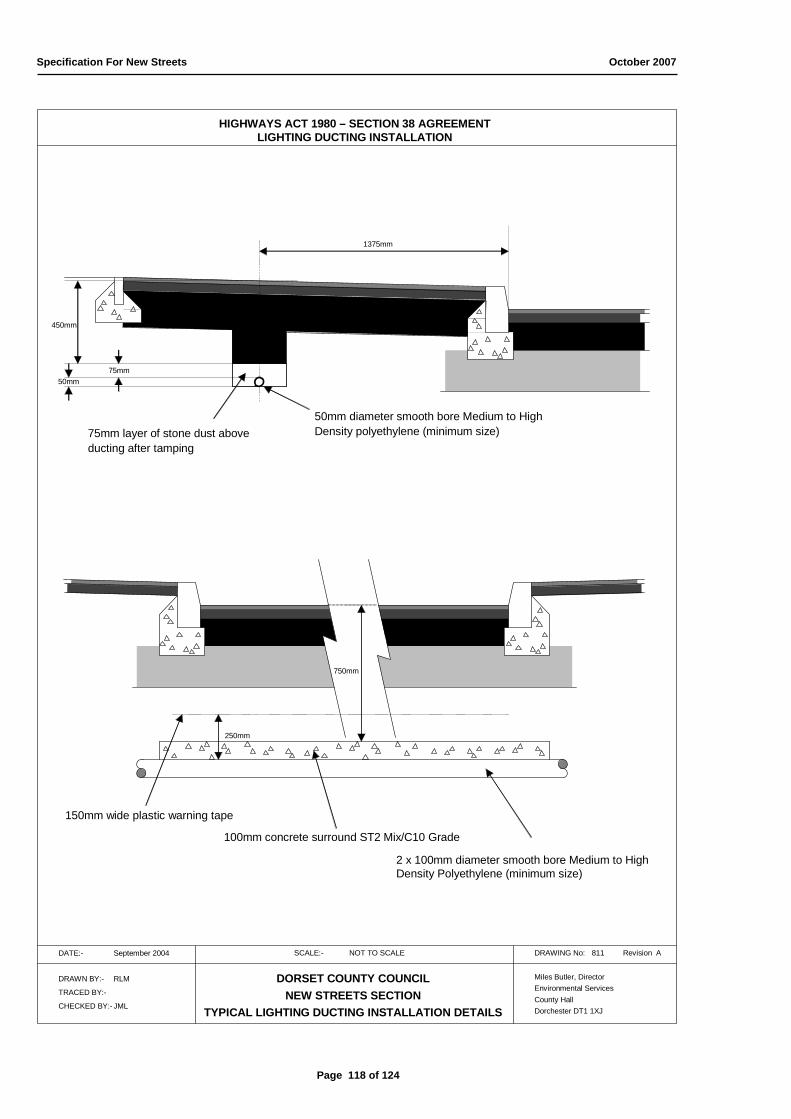
Specification For New Streets October 2007
HIGHWAYS ACT 1980 – SECTION 38 AGREEMENTLIGHTING DUCTING INSTALLATION
DATE:- September 2004 SCALE:- NOT TO SCALE DRAWING No: 811 Revision A
DRAWN BY:- RLM
TRACED BY:-
CHECKED BY:- JML
DORSET COUNTY COUNCILNEW STREETS SECTION
TYPICAL LIGHTING DUCTING INSTALLATION DETAILS
Miles Butler, DirectorEnvironmental ServicesCounty HallDorchester DT1 1XJ
50mm75mm
450mm
1375mm
50mm diameter smooth bore Medium to HighDensity polyethylene (minimum size)75mm layer of stone dust above
ducting after tamping
750mm
250mm
2 x 100mm diameter smooth bore Medium to High Density Polyethylene (minimum size)
150mm wide plastic warning tape
100mm concrete surround ST2 Mix/C10 Grade
Page 118 of 124
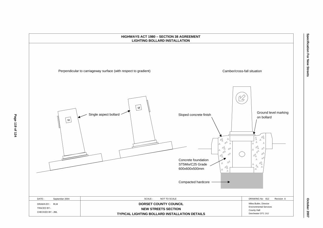
HIGHWAYS ACT 1980 – SECTION 38 AGREEMENTLIGHTING BOLLARD INSTALLATION
DATE:- September 2004 SCALE:- NOT TO SCALE DRAWING No: 812 Revision A
DRAWN BY:- RLM
TRACED BY:-
CHECKED BY:- JML
DORSET COUNTY COUNCILNEW STREETS SECTION
TYPICAL LIGHTING BOLLARD INSTALLATION DETAILS
Miles Butler, DirectorEnvironmental ServicesCounty HallDorchester DT1 1XJ
11
12
Perpendicular to carriageway surface (with respect to gradient) Camber/cross-fall situation
Single aspect bollard Sloped concrete finish Ground level markingon bollard
Concrete foundationST5Mix/C25 Grade600x600x500mm
Compacted hardcore
Page 119 of 124
Specification For New
Streets
O
ctober2007
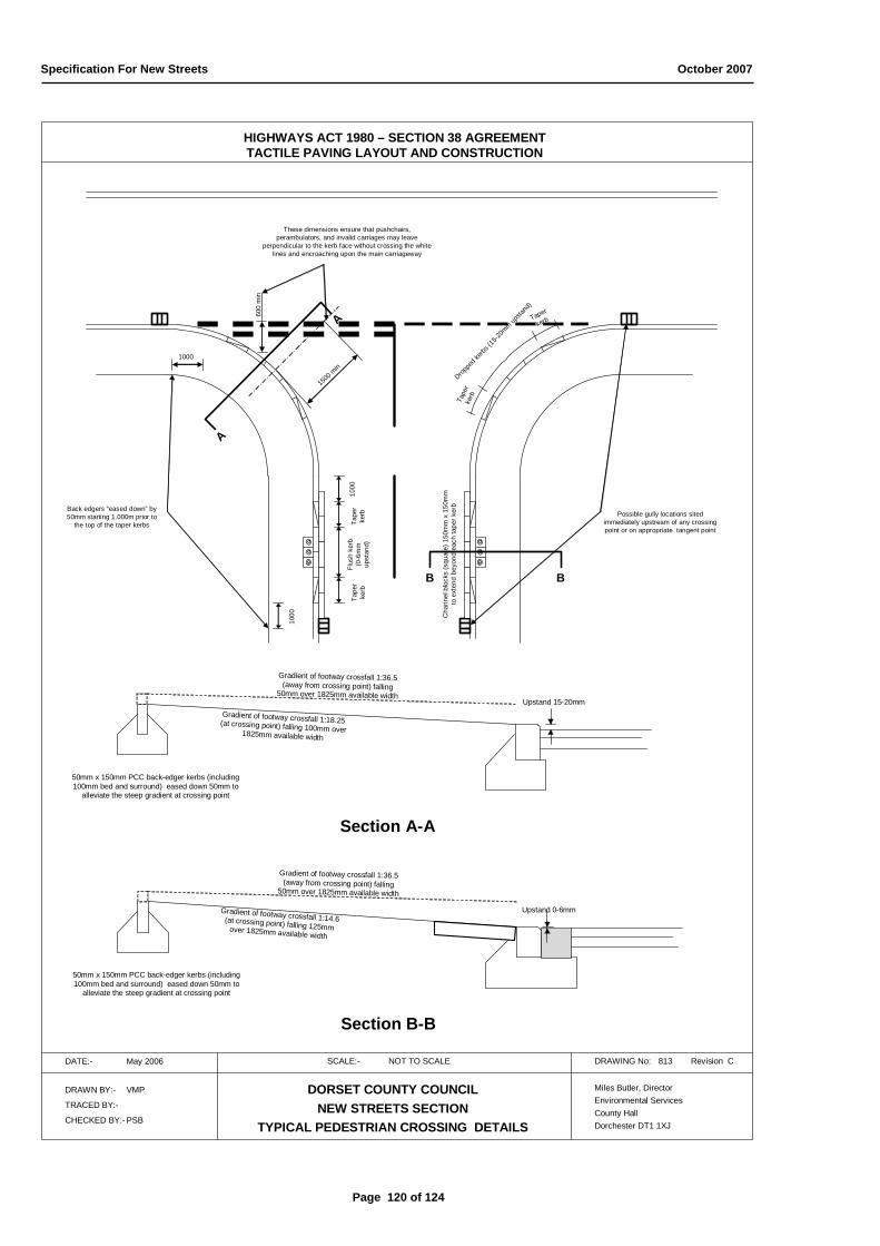
Specification For New Streets October 2007
HIGHWAYS ACT 1980 – SECTION 38 AGREEMENTTACTILE PAVING LAYOUT AND CONSTRUCTION
DATE:- May 2006 SCALE:- NOT TO SCALE DRAWING No: 813 Revision C
DRAWN BY:- VMP
TRACED BY:-
CHECKED BY:- PSB
DORSET COUNTY COUNCILNEW STREETS SECTION
TYPICAL PEDESTRIAN CROSSING DETAILS
Miles Butler, DirectorEnvironmental ServicesCounty HallDorchester DT1 1XJ
Back edgers “eased down” by 50mm starting 1.000m prior to
the top of the taper kerbs
1000
Tape
r ke
rbTa
per
kerb
Flus
h ke
rb
(0-6
mm
up
stan
d)
Cha
nnel
blo
cks
(squ
are)
150
mm
x 1
50m
m
to e
xten
d be
yond
eac
h ta
per k
erb
Taper
kerb
Tape
rke
rb
Droppe
d kerbs
(15-20
mmup
stand
)
Upstand 0-6mm
Gradient of footway crossfall 1:36.5(away from crossing point) falling
50mm over 1825mm available width
Gradient of footway crossfall 1:14.6(at crossing point) falling 125mmover 1825mm available width
50mm x 150mm PCC back-edger kerbs (including 100mm bed and surround) eased down 50mm to
alleviate the steep gradient at crossing point
Section B-B
A
A
B B
Upstand 15-20mm
Gradient of footway crossfall 1:36.5(away from crossing point) falling
50mm over 1825mm available width
Gradient of footway crossfall 1:18.25(at crossing point) falling 100mm over1825mm available width
50mm x 150mm PCC back-edger kerbs (including 100mm bed and surround) eased down 50mm to
alleviate the steep gradient at crossing point
Section A-A
1000
1000
600
min
1500 min
These dimensions ensure that pushchairs, perambulators, and invalid carriages may leave
perpendicular to the kerb face without crossing the white lines and encroaching upon the main carriageway
Possible gully locations sited immediately upstream of any crossing point or on appropriate tangent point
Page 120 of 124
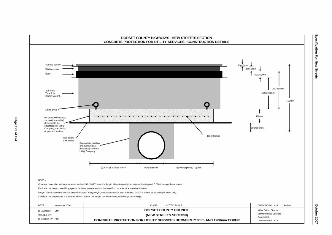
DORSET COUNTY HIGHWAYS - NEW STREETS SECTIONCONCRETE PROTECTION FOR UTILITY SERVICES - CONSTRUCTION DETAILS
DATE:- November 2006 SCALE:- NOT TO SCALE DRAWING No: 814 Revision
DRAWN BY:- VMP
TRACED BY:-
CHECKED BY:- PSB
DORSET COUNTY COUNCIL(NEW STREETS SECTION)
CONCRETE PROTECTION FOR UTILITY SERVICES BETWEEN 710mm AND 1200mm COVER
Miles Butler, DirectorEnvironmental ServicesCounty HallDorchester DT1 1XJ
Pipe diameter((1400*-pipe dia) / 2) mm
100mm (min)
150mm
300(220)mm
50(60)mm 30(40)mm
80(140)mm
710mm
Lifting eyes
Re-enforced concrete section (removable) designed to the satisfaction of Utility Company, cast in-situ or pre-cast section.
Sub-base Type 1 (or Dorset Variant)
Base
Binder course
Surface course
Geo-textile membrane
Appropriate bedding and surround as dictated by relevant Utility Company
Re-enforcing
NOTE:-
Concrete cover slab (either pre-cast or in-situ) 150 x 1400* x section length. Resulting weight of slab section (approx) 0.500 tonne per linear metre.
Each slab section to have lifting eyes to facilitate removal without the need for, or cause of, excessive vibration.
Length of concrete cover section dependant upon lifting weight, convenience upon site, et cetera. 1400* is shown as an example width only.
If Utility Company require a different width of section, the weight per linear metre, will change accordingly.
((1400*-pipe dia) / 2) mm
360-380mm
Page 121 of 124
Specification For New
Streets
O
ctober2007
Specification For New Streets October 2007
900 AMENDMENTS
901 FIRST RELEASE September 2004
1. Complete re-write
902 SECOND RELEASE (AMENDMENTS) October 2007
1. Clause 103 Commuted sums no longer apply to standard DCC soakaways, but will be required for additional maintenance costs for trees in carriageway/footway for pollarding. Commuted sums applicable for certain retaining structures (as defined in Clause 303).
2. Clause 201 Clearance distance between highway drain and face of kerb. Maximum distance specified between manholes. Large diameter pipes defined as structures; design checks and technical approval applicable.
3. Clause 202 Diameters and minimum gradient details for carrier drains. Reference to new soakaway Standard Detail Drawings.
4. Clause 206 Granular fill for soakaways detailed.
5. Clause 303 New clause for design checks and approvals given for retaining structures. Commuted sums defined to re-enforce Clause 103.
6. Clause 437 New clause for level access, windows, porches and flying freeholds.
7. Table 400/17 Binder course thicknesses for collector and access roads, base thicknesses for footways, bound base only for all roads except for feeder, collector/access roads.
8. Table 400/18 Nominal aggregate size corrected from 28mm to 32mm to conform to BS4987 2005.
9. Clause 620 Amendment to cater for circular brickwork soakaway chamber. Amendments to pre-cast soakaway chamber construction. Re-iteration of 45mm perforations only.
10. Clause 710 Painting specification enhanced for columns and brackets.
11. Clause 807 Amended soakaway construction details; Standard Detail Drawing 807-1 brickwork circular design and Standard Detail Drawing 807-2 pre-cast concrete chambers.
Page 122 of 124

Specification For New Streets October 2007
12. Clause 808 In addition to Standard Detail Drawing 808-1 (standard tree planter), extra tree planter/barrier designs for reduced size and for use in footways (non-trafficked areas), Standard Detail Drawing 808-2 reduced size, and Standard Detail Drawing 808-3 footway planter.
13. Clause 813 New Standard Detail Drawing 813 for pedestrian and tactile crossing points at junctions.
14. Clause 814 New Standard Detail Drawing 814 for protection to utilities.
Page 123 of 124

Specification For New Streets October 2007
Page 124 of 124