specification may 2008 - chte.org€¦ · specification heat treatment of parts in a vacuum ......
TRANSCRIPT
AEROSPACE
MATERIAL SPECIFICATION
Heat Treatment of Parts in a Vacuum
AMS 2769A®
Issued FEB 1996
Reaffirmed MAY 2008 Revised DEC 2004
Superseding AMS 2769
1. SCOPE:
1.1 Purpose:
This specification establishes the requirements and procedures for heat treating parts (See 8.4) in a vacuum/partial pressure.
1.2 Application:
This process has been used typically for the heat treatment of carbon and alloy steels, tool steels, corrosion-resistant steels, precipitation-hardening steels, super alloys, titanium, and other nonferrous alloys, but usage is not limited to such applications.
1.2.1 Heat treatment as used in this specification includes solution treatment, homogenizing, austenitizing, annealing, normalizing, hardening, tempering, aging, and stress relieving. This specification does not cover processes such as melting, brazing, diffusion bonding, coating, carburizing, or nitriding.
1.2.2 The objective of this process is to produce heat treated parts which are free from surface contamination and alloy depletion. Such parts may not necessarily have a bright surface.
1.3 Safety - Hazardous Materials:
While the materials, methods, applications, and processes described or referenced in this specification may involve the use of hazardous materials, this specification does not address the hazards which may be involved in such use. It is the sole responsibility of the user to ensure familiarity with the safe and proper use of any hazardous materials and to take necessary precautionary measures to ensure the health and safety of all personnel involved.
SAE Technical Standards Board Rules provide that: “This report is published by SAE to advance the state of technical and engineering sciences. The use of this report is entirely voluntary, and its applicability and suitability for any particular use, including any patent infringement arising therefrom, is the sole responsibility of the user.” SAE reviews each technical report at least every five years at which time it may be reaffirmed, revised, or cancelled. SAE invites your written comments and suggestions. Copyright © 2008 SAE International All rights reserved. No part of this publication may be reproduced, stored in a retrieval system or transmitted, in any form or by any means, electronic, mechanical, photocopying, recording, or otherwise, without the prior written permission of SAE. TO PLACE A DOCUMENT ORDER: Tel: 877-606-7323 (inside USA and Canada) Tel: 724-776-4970 (outside USA) Fax: 724-776-0790 Email: [email protected] SAE WEB ADDRESS: http://www.sae.org
SAE
- 2 -
AMS 2769A AMS 2769A
2. APPLICABLE DOCUMENTS:
The issue of the following documents in effect on the date of the purchase order forms a part of this specification to the extent specified herein. The supplier may work to a subsequent revision of a document unless a specific document issue is specified. When the referenced document has been cancelled and no superseding document has been specified, the last published issue of that document shall apply.
2.1 SAE Publications:
Available from SAE, 400 Commonwealth Drive, Warrendale, PA 15096-0001 or www.sae.org.
AMS 2750 Pyrometry ARP1962 Certification of Heat Treating Personnel
2.2 ASTM Publications:
Available from ASTM, 100 Barr Harbor Drive, P.O. Box C700, West Conshohocken, PA 19428-2959 or www.astm.org.
ASTM STP 470 Manual on the Use of Thermocouples
2.3 U.S. Government Publications:
Available from DODSSP, Subscription Services Desk, Building 4D, 700 Robbins Avenue, Philadelphia, PA 19111-5094 or www.dsp.dla.mil.
MIL-A-18455 Argon, Technical MIL-PRF-27201 Propellant, Hydrogen MIL-PRF-27401 Propellant, Pressuring Agent, Nitrogen MIL-PRF-27407 Propellant, Pressuring Agent, Helium MIL-PRF-27415 Propellant, Pressuring Agent, Argon
A-A-59503 Nitrogen, Technical BB-H-886 Hydrogen BB-H-1168 Helium, Technical
2.4 National Fire Protection Association (NFPA):
Available from the National Fire Protection Association, 1 Batterymarch Park, Quincy, MA 02169-7471 or www.nfpa.org.
NFPA 86D Standard for Industrial Furnaces Using Vacuum as an Atmosphere
SAE
- 3 -
AMS 2769A AMS 2769A
2.5 CGA Publications:
Available from Compressed Gas Association, 4221 Walney Road, 5th Floor, Chantilly, VA 20151-2923 or www.cganet.com.
CGA G-5.3 Commodity Specification for Hydrogen CGA G-9.1 Commodity Specification for Helium CGA G-10.1 Commodity Specification for Nitrogen CGA G-11.1 Commodity Specification for Argon
3. TECHNICAL REQUIREMENTS:
3.1 Furnace Equipment:
The equipment shall conform to the requirements of applicable heat treat specifications. The furnace components shall result in no detrimental metallurgical effects on the material processed during a normal production run as a result of vaporization or chemical reaction between the furnace components and the gases used to maintain partial pressure in the furnace.
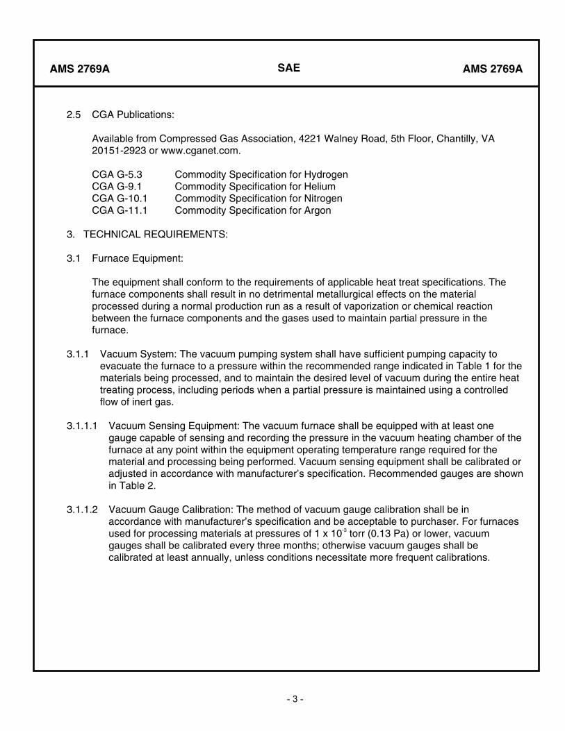
3.1.1 Vacuum System: The vacuum pumping system shall have sufficient pumping capacity to evacuate the furnace to a pressure within the recommended range indicated in Table 1 for the materials being processed, and to maintain the desired level of vacuum during the entire heat treating process, including periods when a partial pressure is maintained using a controlled flow of inert gas.
3.1.1.1 Vacuum Sensing Equipment: The vacuum furnace shall be equipped with at least one gauge capable of sensing and recording the pressure in the vacuum heating chamber of the furnace at any point within the equipment operating temperature range required for the material and processing being performed. Vacuum sensing equipment shall be calibrated or adjusted in accordance with manufacturer’s specification. Recommended gauges are shown in Table 2.
3.1.1.2 Vacuum Gauge Calibration: The method of vacuum gauge calibration shall be in accordance with manufacturer’s specification and be acceptable to purchaser. For furnaces used for processing materials at pressures of 1 x 10⁻³ torr (0.13 Pa) or lower, vacuum gauges shall be calibrated every three months; otherwise vacuum gauges shall be calibrated at least annually, unless conditions necessitate more frequent calibrations.
SAE
- 4 -
AMS 2769A AMS 2769A
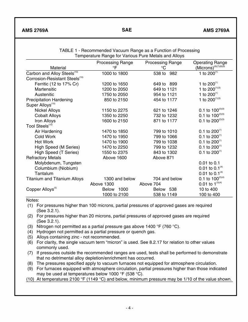
TABLE 1 - Recommended Vacuum Range as a Function of ProcessingTemperature Range for Various Pure Metals and Alloys
MaterialProcessing Range
°FProcessing Range
°COperating Range (Microns)(6)(7)(8)(9)
Carbon and Alloy Steels(10) 1000 to 1800 538 to 982 1 to 200(1)
Corrosion-Resistant Steels(10)
Ferritic (12 to 17% Cr) Martensitic Austenitic Precipitation Hardening
1200 to 1650 1200 to 2050 1750 to 2050
850 to 2150
649 to 899 649 to 1121 954 to 1121 454 to 1177
1 to 200(1)
1 to 200(1)(3)
1 to 200(1)
1 to 200(1)(3)
Super Alloys(10)
Nickel Alloys Cobalt Alloys Iron Alloys
1150 to 2275 1350 to 2250 1600 to 2150
621 to 1246 732 to 1232 871 to 1177
0.1 to 100(2)(3)
0.1 to 100(2)(3)
0.1 to 200(2)(3)
Tool Steels(10)
Air Hardening Cold Work Hot Work High Speed (M Series) High Speed (T Series)
1470 to 1850 1470 to 1950 1470 to 1900 1470 to 2250 1550 to 2375
799 to 1010 799 to 1066 799 to 1038 799 to 1232 843 to 1302
0.1 to 200(1)
0.1 to 200(1)
0.1 to 200(1)
0.1 to 200(1)
0.1 to 200(1)
Refractory Metals Molybdenum, Tungsten Columbium (Niobium) Tantalum
Above 1600 Above 871 0.01 to 0.1 0.01 to 0.1(4)
0.01 to 0.1(4)
Titanium and Titanium Alloys 1300 and below Above 1300
704 and below Above 704
0.1 to 100(2)(4)
0.01 to 1(3)(4)
Copper Alloys(5) Below 1000 1000 to 2100
Below 538 538 to 1149
10 to 400 100 to 400
Notes: (1) For pressures higher than 100 microns, partial pressures of approved gases are required
(See 3.2.1). (2) For pressures higher than 20 microns, partial pressures of approved gases are required
(See 3.2.1). (3) Nitrogen not permitted as a partial pressure gas above 1400 °F (760 °C). (4) Hydrogen not permitted as a partial pressure or quench gas. (5) Alloys containing zinc - not recommended. (6) For clarity, the single vacuum term “micron” is used. See 8.2.17 for relation to other values
commonly used. (7) If pressures outside the recommended ranges are used, tests shall be performed to demonstrate
that no detrimental alloy depletion/enrichment has occurred. (8) The pressures specified apply to vacuum furnaces not equipped for atmosphere circulation. (9) For furnaces equipped with atmosphere circulation, partial pressures higher than those indicated
may be used at temperatures below 1000 °F (538 °C). (10) At temperatures 2100 °F (1149 °C) and below, minimum pressure may be 1/10 of the value shown.
SAE
- 5 -
AMS 2769A AMS 2769A
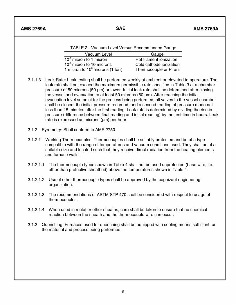
TABLE 2 - Vacuum Level Versus Recommended Gauge
Vacuum Level Gauge 10-6 micron to 1 micron 10-4 micron to 10 microns 1 micron to 103 microns (1 torr)
Hot filament ionization Cold cathode ionization Thermocouple or Pirani
3.1.1.3 Leak Rate: Leak testing shall be performed weekly at ambient or elevated temperature. The leak rate shall not exceed the maximum permissible rate specified in Table 3 at a chamber pressure of 50 microns (50 μm) or lower. Initial leak rate shall be determined after closing the vessel and evacuation to at least 50 microns (50 μm). After reaching the initial evacuation level setpoint for the process being performed, all valves to the vessel chamber shall be closed, the initial pressure recorded, and a second reading of pressure made not less than 15 minutes after the first reading. Leak rate is determined by dividing the rise in pressure (difference between final reading and initial reading) by the test time in hours. Leak rate is expressed as microns (μm) per hour.
3.1.2 Pyrometry: Shall conform to AMS 2750.
3.1.2.1 Working Thermocouples: Thermocouples shall be suitably protected and be of a type compatible with the range of temperatures and vacuum conditions used. They shall be of a suitable size and located such that they receive direct radiation from the heating elements and furnace walls.
3.1.2.1.1 The thermocouple types shown in Table 4 shall not be used unprotected (base wire, i.e. other than protective sheathed) above the temperatures shown in Table 4.
3.1.2.1.2 Use of other thermocouple types shall be approved by the cognizant engineering organization.
3.1.2.1.3 The recommendations of ASTM STP 470 shall be considered with respect to usage of thermocouples.
3.1.2.1.4 When used in metal or other sheaths, care shall be taken to ensure that no chemical reaction between the sheath and the thermocouple wire can occur.
3.1.3 Quenching: Furnaces used for quenching shall be equipped with cooling means sufficient for the material and process being performed.
SAE
- 6 -
AMS 2769A AMS 2769A
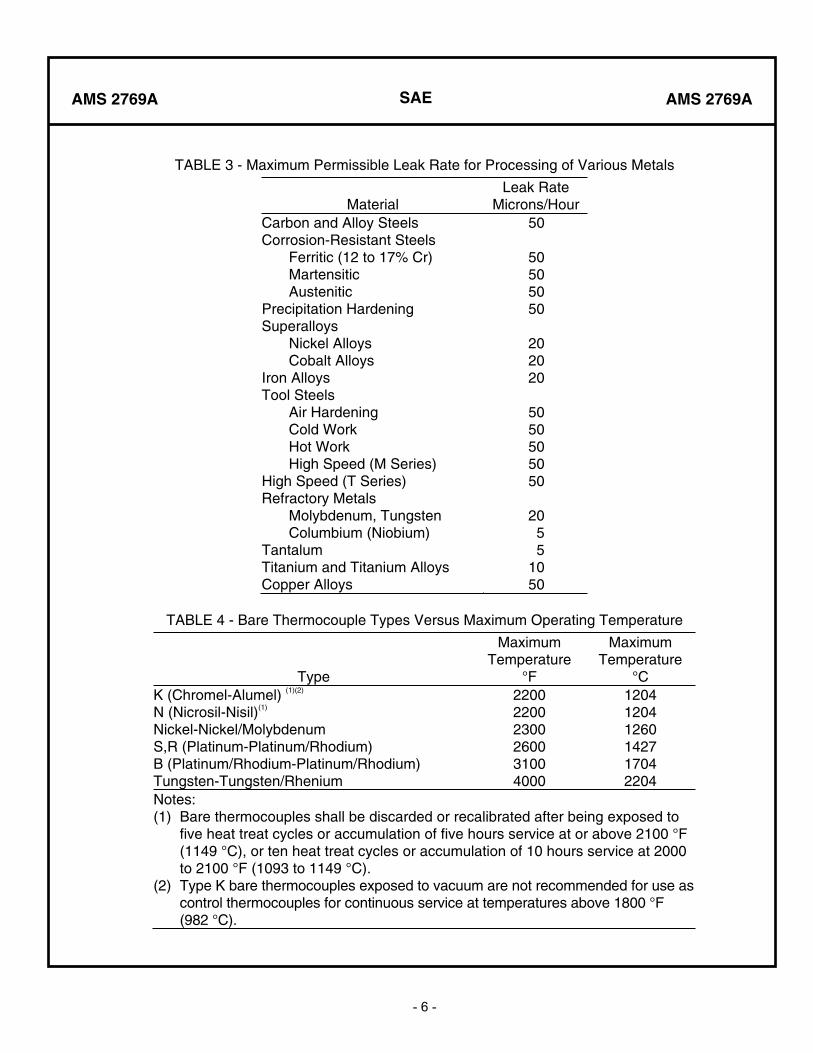
TABLE 3 - Maximum Permissible Leak Rate for Processing of Various Metals
MaterialLeak Rate
Microns/HourCarbon and Alloy Steels 50 Corrosion-Resistant Steels Ferritic (12 to 17% Cr) Martensitic Austenitic Precipitation Hardening
50505050
Superalloys Nickel Alloys Cobalt Alloys Iron Alloys
202020
Tool Steels Air Hardening Cold Work Hot Work High Speed (M Series) High Speed (T Series)
5050505050
Refractory Metals Molybdenum, Tungsten Columbium (Niobium) Tantalum
2055
Titanium and Titanium Alloys 10 Copper Alloys 50
TABLE 4 - Bare Thermocouple Types Versus Maximum Operating Temperature
Type
Maximum Temperature
°F
Maximum Temperature
°CK (Chromel-Alumel) (1)(2)
N (Nicrosil-Nisil)(1)
Nickel-Nickel/MolybdenumS,R (Platinum-Platinum/Rhodium) B (Platinum/Rhodium-Platinum/Rhodium) Tungsten-Tungsten/Rhenium
220022002300260031004000
120412041260142717042204
Notes:(1) Bare thermocouples shall be discarded or recalibrated after being exposed to
five heat treat cycles or accumulation of five hours service at or above 2100 °F (1149 °C), or ten heat treat cycles or accumulation of 10 hours service at 2000 to 2100 °F (1093 to 1149 °C).
(2) Type K bare thermocouples exposed to vacuum are not recommended for use as control thermocouples for continuous service at temperatures above 1800 °F (982 °C).

SAE
- 7 -
AMS 2769A AMS 2769A
3.1.3.1 Vacuum Cooling: Where there is a requirement for slow cooling after annealing or normalizing, cooling performed under vacuum or partial pressure using inert gas is permissible. Controlled cooling using a programmed heat input is permitted provided load thermocouples are used to measure the actual load temperature during the cooling period.
3.1.3.2 Gas Quenching: When gas quenching is specified, it shall be accomplished by backfilling the furnace with a gas which has no detrimental metallurgical effect on the material being processed or on the furnace equipment. The system and the pressure of the backfill gas selected shall be capable of cooling the parts at a rate sufficient to meet the material property requirements specified by the cognizant engineering organization. The use of hydrogen as a quenching gas must be approved by the cognizant engineering organization (See 3.2.3).
3.1.3.3 Oil Quenching: Oil quenching shall be performed by transferring the parts from the heating chamber to a separate chamber which has been backfilled with an inert gas, and immersing the parts in a circulating oil. The quenching chamber shall have a means to minimize the amount of oil vapors generated during quenching from entering the heating chamber to an amount which shall have no detrimental effect (carbon pickup) on the processed material. Quench oil shall be compatible with the vacuum level used during initial evacuation and shall be capable of quenching the parts at a rate sufficient to meet specified property requirements.
3.1.3.4 Furnaces equipped with integral oil quench tanks shall not be permitted for processing titanium and titanium alloys above 1000 °F (538 °C), or for processing corrosion-resistant steels above 1100 °F (593 °C), unless appropriate tests are conducted to ensure that no detrimental surface effects are caused by such treatments.
3.1.3.5 Bake-Out Cycle: If a furnace has been used for brazing with a brazing alloy which could detrimentally affect the parts to be heat treated, the furnace shall be subjected to a bake-out (clean-up) cycle before being used for heat treatment. If freedom from detrimental effects is not known from prior experience or data, the bake-out cycle shall not be omitted without concurrence of the cognizant engineering organization. The bake-out cycle shall be carried out at not less than 50 F (28 C) degrees above the maximum intended heat treatment temperature and the minimum achievable pressure of the furnace for not less than one hour. A bake-out cycle is not required if the heat treatment cycle is an integral part of a brazing operation.
SAE
- 8 -
AMS 2769A AMS 2769A
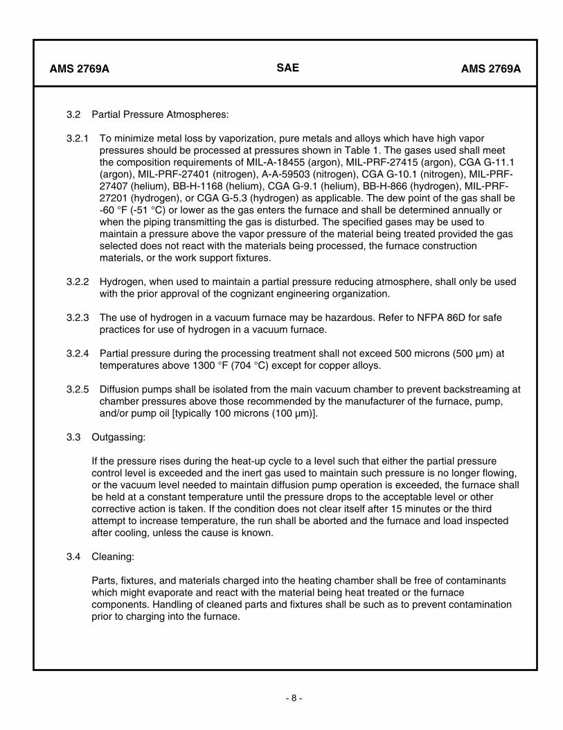
3.2 Partial Pressure Atmospheres:
3.2.1 To minimize metal loss by vaporization, pure metals and alloys which have high vapor pressures should be processed at pressures shown in Table 1. The gases used shall meet the composition requirements of MIL-A-18455 (argon), MIL-PRF-27415 (argon), CGA G-11.1 (argon), MIL-PRF-27401 (nitrogen), A-A-59503 (nitrogen), CGA G-10.1 (nitrogen), MIL-PRF-27407 (helium), BB-H-1168 (helium), CGA G-9.1 (helium), BB-H-866 (hydrogen), MIL-PRF-27201 (hydrogen), or CGA G-5.3 (hydrogen) as applicable. The dew point of the gas shall be-60 °F (-51 °C) or lower as the gas enters the furnace and shall be determined annually or when the piping transmitting the gas is disturbed. The specified gases may be used to maintain a pressure above the vapor pressure of the material being treated provided the gas selected does not react with the materials being processed, the furnace construction materials, or the work support fixtures.
3.2.2 Hydrogen, when used to maintain a partial pressure reducing atmosphere, shall only be used with the prior approval of the cognizant engineering organization.
3.2.3 The use of hydrogen in a vacuum furnace may be hazardous. Refer to NFPA 86D for safe practices for use of hydrogen in a vacuum furnace.
3.2.4 Partial pressure during the processing treatment shall not exceed 500 microns (500 μm) at temperatures above 1300 °F (704 °C) except for copper alloys.
3.2.5 Diffusion pumps shall be isolated from the main vacuum chamber to prevent backstreaming at chamber pressures above those recommended by the manufacturer of the furnace, pump, and/or pump oil [typically 100 microns (100 μm)].
3.3 Outgassing:
If the pressure rises during the heat-up cycle to a level such that either the partial pressure control level is exceeded and the inert gas used to maintain such pressure is no longer flowing, or the vacuum level needed to maintain diffusion pump operation is exceeded, the furnace shall be held at a constant temperature until the pressure drops to the acceptable level or other corrective action is taken. If the condition does not clear itself after 15 minutes or the third attempt to increase temperature, the run shall be aborted and the furnace and load inspected after cooling, unless the cause is known.
3.4 Cleaning:
Parts, fixtures, and materials charged into the heating chamber shall be free of contaminants which might evaporate and react with the material being heat treated or the furnace components. Handling of cleaned parts and fixtures shall be such as to prevent contamination prior to charging into the furnace.

SAE
- 9 -
AMS 2769A AMS 2769A
3.5 Heat Treatment:
Shall be performed in accordance with the applicable specification and as follows:
3.5.1 Vacuum Level: Should be as specified in Table 1 or as specified by the cognizant engineering organization.
3.5.2 Protective Coatings: May be used to prevent direct exposure of the part surfaces to the vacuum atmosphere provided they do not cause detrimental effects to parts and/or furnace components. If coatings or plating are used, compensation for changes in part emissivity shall be made in the heating time. Additional heating time shall be determined by preproduction testing. When copper plating is used, pressure shall not be lower than 150 microns (150 μm) at temperatures above 1600 °F (871 °C).
3.5.3 Part Loading: Parts shall be loaded to promote uniform heating and, when quenching is required, to permit uniform circulation of the quench medium.
3.5.4 Load Thermocouples: One or more load thermocouples shall be used with each load with the exception noted in 3.5.4.3. The load thermocouple(s) shall be compatible with the material being processed or adequately sheathed to prevent reaction with the parts. The thermocouple(s) shall be located in the portions of the load which are predicted to be the last to attain the desired temperature. The thermocouple(s) may be attached to the outer surface of the parts. If a thermocouple is placed in a hole to measure the core or interior of the part being processed, the thermocouple must make intimate contact with the surface at the bottom of the hole. To avoid errors due to conduction along the length of the thermocouple, the minimum depth of insertion of the thermocouple shall be at least ten times the diameter of the thermocouple.
3.5.4.1 In the event a thermocouple fails, the run need not be aborted as long as another thermocouple continues to record the correct temperature.
3.5.4.2 Once a load has been qualified with load thermocouple(s), subsequent loads can be run without load thermocouple(s) provided adequate records detailing the number of parts and distribution of parts in the first qualified load are kept on file, and provided that subsequent loads have an equal or fewer number of identical parts in the load, and the distribution of the parts is the same as the distribution in the first load.
3.5.4.3 When use of load thermocouple(s) is impracticable, such as with two or three chamber oil or gas quench furnaces, tests shall be conducted to establish the correct heat-up time for the load.
3.5.4.3.1 The test shall incorporate load thermocouple(s) in the actual or simulated load to establish the correct heat up time for a given batch of parts, as a forerunner to the production heat treatment cycle without load thermocouple(s). This procedure does not require quenching of the test load from the heat treatment temperature.
SAE
- 10 -
AMS 2769A AMS 2769A
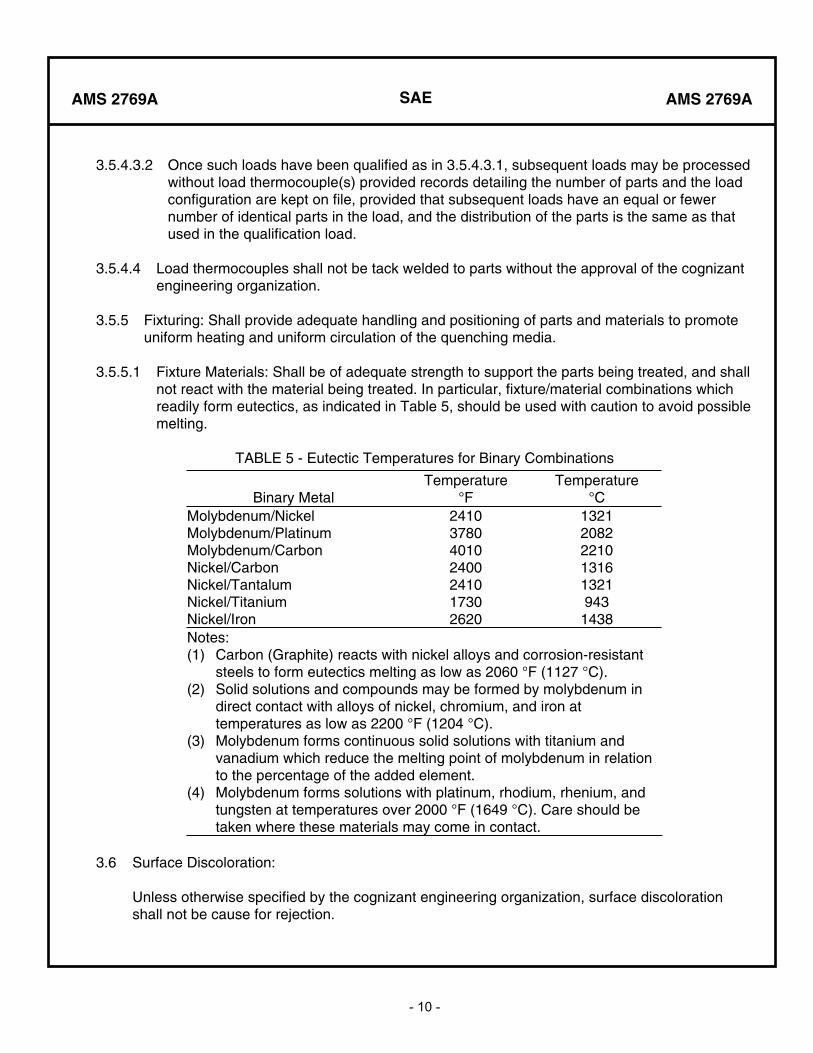
3.5.4.3.2 Once such loads have been qualified as in 3.5.4.3.1, subsequent loads may be processed without load thermocouple(s) provided records detailing the number of parts and the load configuration are kept on file, provided that subsequent loads have an equal or fewer number of identical parts in the load, and the distribution of the parts is the same as that used in the qualification load.
3.5.4.4 Load thermocouples shall not be tack welded to parts without the approval of the cognizant engineering organization.
3.5.5 Fixturing: Shall provide adequate handling and positioning of parts and materials to promote uniform heating and uniform circulation of the quenching media.
3.5.5.1 Fixture Materials: Shall be of adequate strength to support the parts being treated, and shall not react with the material being treated. In particular, fixture/material combinations which readily form eutectics, as indicated in Table 5, should be used with caution to avoid possible melting.
TABLE 5 - Eutectic Temperatures for Binary Combinations
Binary Metal Temperature
°FTemperature
°CMolybdenum/NickelMolybdenum/PlatinumMolybdenum/CarbonNickel/CarbonNickel/TantalumNickel/TitaniumNickel/Iron
2410378040102400241017302620
13212082221013161321943
1438Notes:(1) Carbon (Graphite) reacts with nickel alloys and corrosion-resistant
steels to form eutectics melting as low as 2060 °F (1127 °C). (2) Solid solutions and compounds may be formed by molybdenum in
direct contact with alloys of nickel, chromium, and iron at temperatures as low as 2200 °F (1204 °C).
(3) Molybdenum forms continuous solid solutions with titanium and vanadium which reduce the melting point of molybdenum in relation to the percentage of the added element.
(4) Molybdenum forms solutions with platinum, rhodium, rhenium, and tungsten at temperatures over 2000 °F (1649 °C). Care should be taken where these materials may come in contact.
3.6 Surface Discoloration:
Unless otherwise specified by the cognizant engineering organization, surface discoloration shall not be cause for rejection.
SAE
- 11 -
AMS 2769A AMS 2769A
4. QUALITY ASSURANCE PROVISIONS:
4.1 Responsibility for Inspection:
Unless otherwise specified by the cognizant quality assurance organization, the heat treatment processor shall be responsible for performance of all tests and inspections specified herein. The processor may use his own facilities or any commercial laboratory acceptable to the cognizant quality assurance organization.
4.1.1 The purchaser reserves the right to perform any surveillance, tests, or inspection of parts and to review heat treatment records and results of processor’s tests and inspections to verify that the heat treatment conformed to requirements of this specification.
4.2 Classification of Tests:
4.2.1 Acceptance Tests: Not applicable.
4.2.2 Periodic Tests: Vacuum gauge calibration (3.1.1.2), leak rate (3.1.1.3), pyrometry tests (3.1.2), and dew point (3.2.1) are periodic tests and shall be performed at the frequency specified herein.
4.2.3 Preproduction Tests: Vacuum gauge calibration (3.1.1.2), leak rate (3.1.1.3), and pyrometry tests (3.1.2) are preproduction tests and shall be performed prior to any production heat treating on each piece of equipment (furnace) to be used.
4.3 Approval of Heat Treat Processors:
Shall be accomplished by the cognizant quality assurance organization and will normally be based on the following:
4.3.1 Approval of the heat treat processor’s process procedures and process control documents which shall be used to meet the requirements of this specification.
4.3.2 Competence of heat treat processor’s personnel. Personnel performing or directing the performance of heat treatment in accordance with this specification shall be approved in accordance with ARP1962 or other established procedures.
SAE
- 12 -
AMS 2769A AMS 2769A
4.4 Logs:
A record (written or electronic storage media), traceable to temperature recording information (chart(s) or electronic storage media) and to shop travelers or other documentation, shall be kept for each furnace and load. The information on the combination of documents shall include: equipment identification, approved personnel’s identification, date; part number or product identification, number of parts, alloy, lot identification, AMS 2769 or other applicable specification, actual thermal processing times and temperatures used. When applicable, atmosphere control parameters, quench delay, quenchant type, polymer concentration and quenchant temperature shall also be recorded. The maximum thickness, when process parameters are based on thickness, shall be recorded and shall be taken as the minimum dimension of the heaviest section of the part. The log data shall be recorded in accordance with the heat treater’s documented procedures.
4.5 Records:
Shall be available to purchaser for not less than five years after heat treatment. The records shall contain all data necessary to verify conformance to the requirements of this specification.
4.6 Reports/Certification:
The heat treating processor shall furnish, with each shipment of parts, a certified quality assurance report, traceable to the heat treat control number(s), stating that the parts were processed in accordance with the requirements of AMS 2769A (or other applicable specification). The report shall include: purchase order number, part number or product identification, alloy, temper/strength designation, quantity of parts in the shipment, identification of furnace(s) used, actual thermal processing times and temperatures used. When applicable, the report shall also include: atmosphere type, quenchant (including polymer concentration range), hot straightening temperature and method of straightening (e.g. press, fixtures), actual test results, (e.g., hardness, conductivity, tensile, shear etc.) and a statement of their conformance/nonconformance to requirements. This data shall be reported in accordance with the heat treater’s documented procedures.
5. PREPARATION FOR DELIVERY:
5.1 Identification:
Not applicable.
5.2 Packaging:
5.2.1 Parts shall be packaged to ensure protection from damage during shipment and storage.
5.2.2 Packages of parts shall be prepared for shipment in accordance with commercial practice and in compliance with applicable rules and regulations pertaining to the handling, packaging, and transportation of the parts to ensure carrier acceptance and safe delivery.
SAE
- 13 -
AMS 2769A AMS 2769A
6. ACKNOWLEDGMENT:
The heat treatment processor shall mention this specification number in all quotations and when acknowledging purchase orders.
7. REJECTIONS:
Parts not heat treated in accordance with the requirements of this specification, or with modifications authorized by purchaser, will be subject to rejection.
8. NOTES:
8.1 A change bar (|) located in the left margin is for the convenience of the user in locating areas where technical revisions, not editorial changes, have been made to the previous issue of a specification. An (R) symbol to the left of the document title indicates a complete revision of the specification, including technical revision. Change bars and (R) are not used in original publications, nor in specifications that contain editorial changes only.
8.2 Definitions of terms used in AMS are presented in ARP1917 and as follows. The following list defines various terms commonly used in vacuum heat treating. These definitions are only presented to assist personnel not familiar with vacuum heat treatment. Some of the terms listed may not appear in the main body of the specification.
8.2.1 Residual Gases: Those gases remaining after a furnace is evacuated to its initial vacuum level. In a typical furnace, analysis of the residual atmosphere at a vacuum level of about 10-3
torr indicates that less than 0.1% of the original air remains. The residual gases usually consist mainly of water vapor with the other vapors being primarily organic from the seals, vacuum greases, and vacuum oils. The oxygen content, referenced to atmospheric pressure, is likely to be less than 1 ppm. If all of the residual gas in the vacuum furnace was water vapor, then referenced to standard atmospheric pressure and temperature, the water vapor content would be approximately 1.5 ppm or equivalent to a gas with a dewpoint of about -110 °F (-79 °C). At a vacuum level of 1 x 10⁻⁴ torr, the equivalent dewpoint of gas is estimated to be on the order of -130 °F (-90 °C) or less.
8.2.2 Roughing Pump: A positive displacement mechanical pump which may or may not be used in combination with a rotary lobe (Roots type) blower.
8.2.3 Holding Pump: A small mechanical pump automatically valved to the foreline of the diffusion pump at all times when the main mechanical pump(s) are serving elsewhere (roughing or partial pressure).
8.2.4 Pump Speed: A measure of a pump’s capability of handling gases. Expressed in volumetric units such as liters/second or cubic feet/minute.
8.2.5 Throughput: A measure of a pump’s actual pumping capability at a given pressure. Expressed in pressure-volumetric units, such as torr liters/second or micron cubic feet/minute.
SAE
- 14 -
AMS 2769A AMS 2769A
8.2.6 Virtual Leak: A source of gas in a vacuum system that acts like a leak in that the gas is trapped in a tight crevice, blind bolt hole, porous weld, etc and “leaks” out over a long period of time.
8.2.7 Real Leak: Any path through the wall of a vacuum chamber that allows a gas to pass through, however small the rate.
8.2.8 Outgassing: The evolution of gas(es) from the surfaces of a vacuum system and its content. Unless there is a known reason for excessive outgassing, such as binders and other volatiles in stop-off or shielding material, excessive outgassing should be taken as a sign of a potentially serious problem such as a water leak or foreign object left in the furnace.
8.2.9 Degassing: A technique of accelerating the outgassing, usually by the application of heat.
8.2.10 Leak Rate: A general indication of vacuum integrity of a system. The system is pumped into the high vacuum range, the pumping system is closed off, and the pressure rise over a given time of the closed system is observed. The rise will be the result of all sources of gas including outgassing of internal surfaces, virtual leaks, and any real leaks.
8.2.11 Backstreaming: A term used to describe the “upstream” motion of some oil vapor molecules, for example, for the top portions of a hot diffusion pump. Normal motion of gases is from high pressure (the furnace) to low pressure (the pump). In backstreaming, pump oil vapors move in the reverse direction, into the furnace.
8.2.12 Partial Pressure: The actual pressure of any single gas component of a vacuum atmosphere. The total pressure is the sum of all of the partial pressures of the gaseous constituents of the atmosphere.
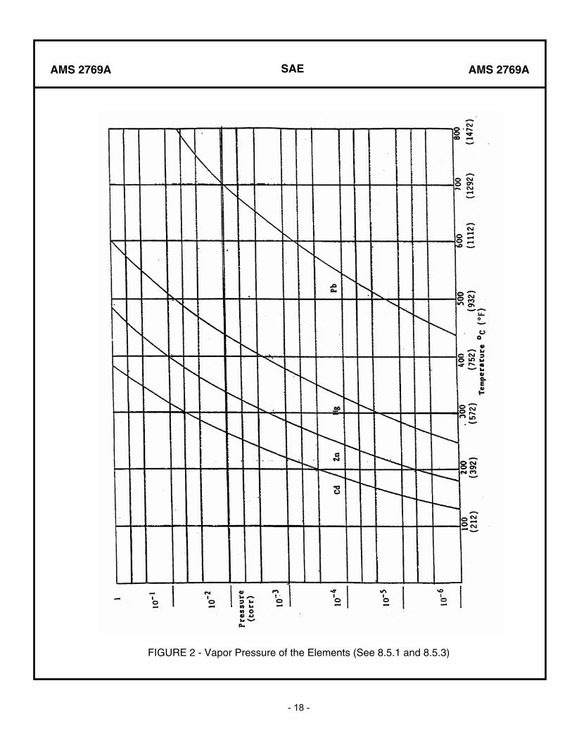
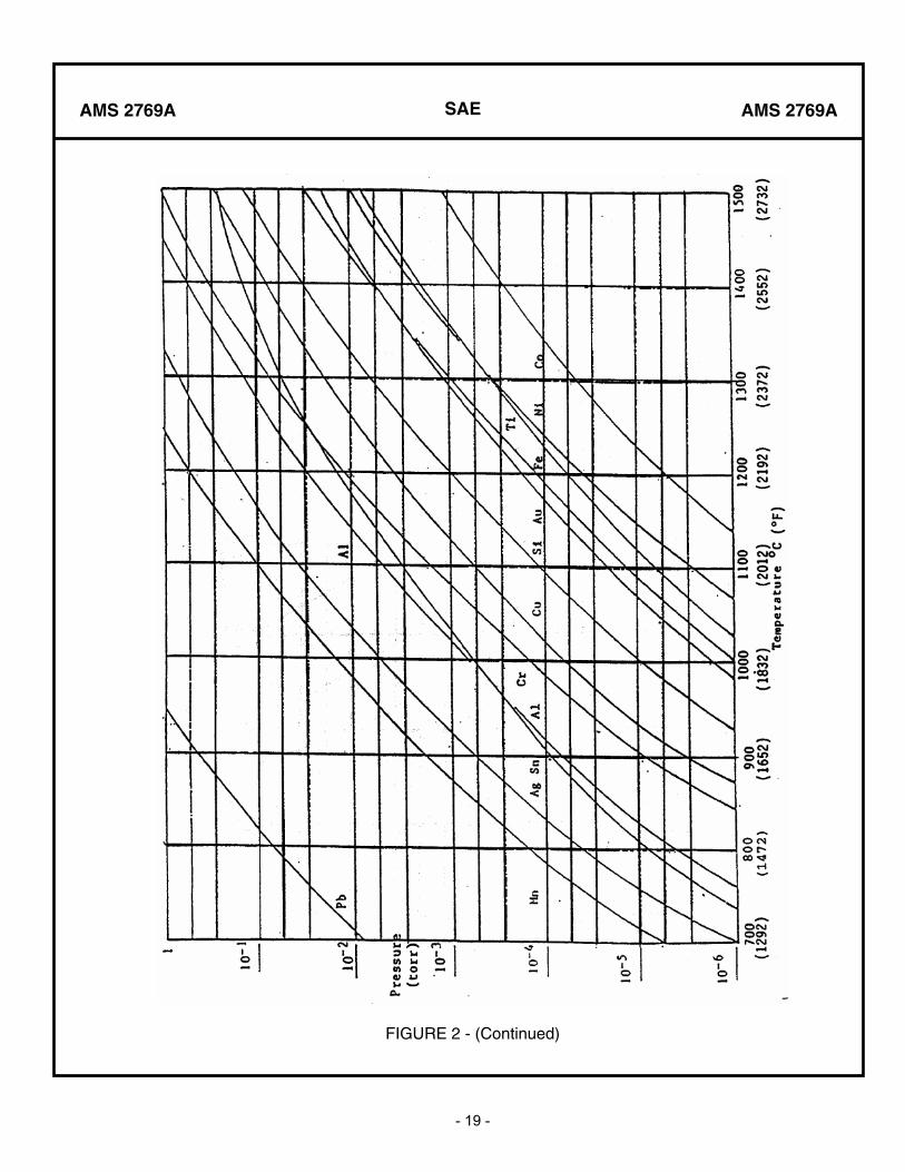
8.2.13 Vapor Pressure: The gas pressure exerted when a substance is in equilibrium with its own vapor. Vapor pressure is a function of temperature as shown in Figure 2 for pure metals. Vapor pressure of an alloy can be considered to be governed by Dalton’s law of partial pressures: The total vapor pressure of an alloy under ideal conditions is equal to the sum of the partial pressures of its constituents. The partial pressure of each element in an alloy is roughly proportional to its concentration. Vapor pressures of most oxides and compounds are lower than those of their pure elements, as shown in Figure 2 for unalloyed metals and pure metals.
8.2.14 Residual gas analysis by mass spectrometer may be used to identify the specific gases in the system.
8.2.15 A helium mass spectrometer leak detector may be used to determine if leaks are present in the system.
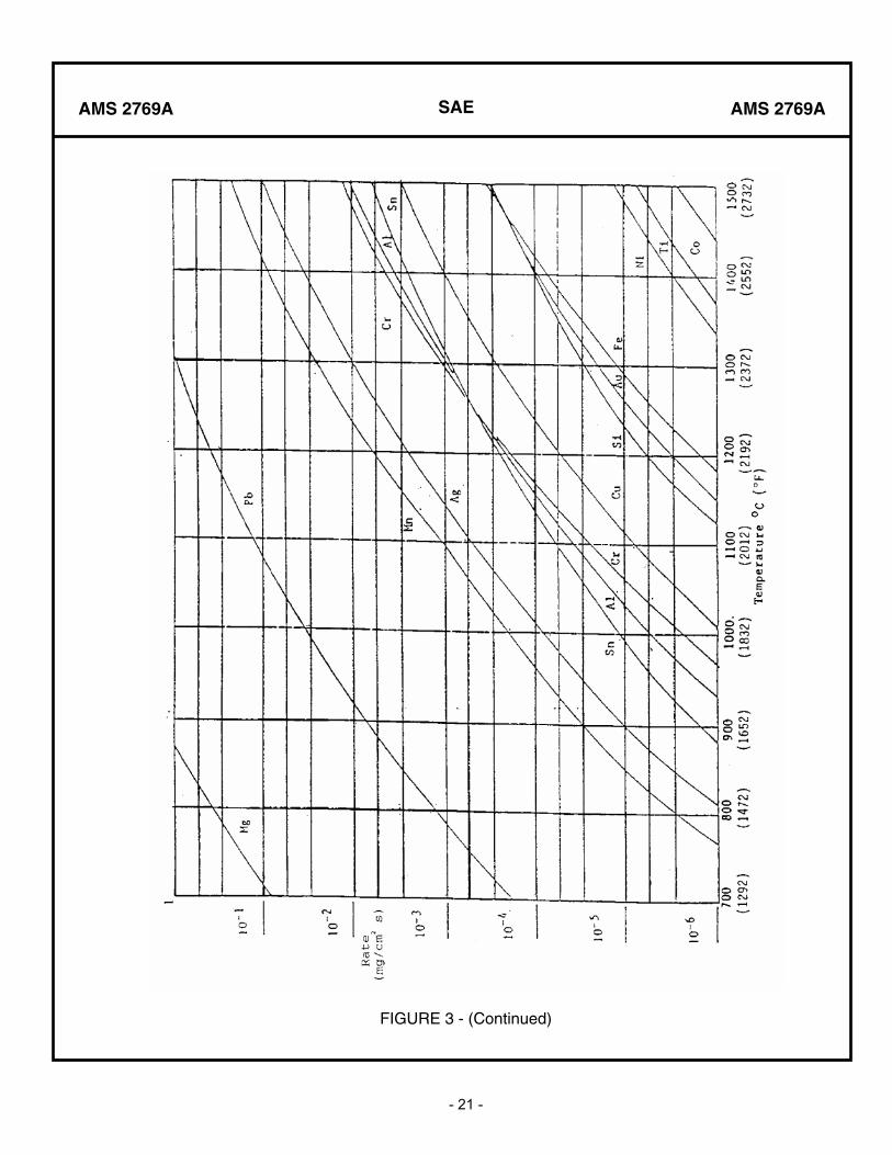
8.2.16 Vaporization Rate: The rate at which a substance vaporizes or attempts to reach its equilibrium vapor pressure. The relationship to temperature is shown in Figure 3.
SAE
- 15 -
AMS 2769A AMS 2769A
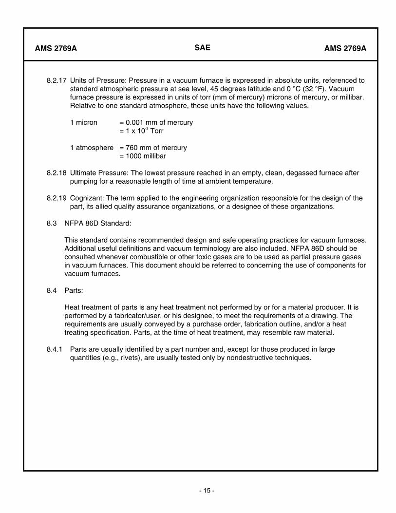
8.2.17 Units of Pressure: Pressure in a vacuum furnace is expressed in absolute units, referenced to standard atmospheric pressure at sea level, 45 degrees latitude and 0 °C (32 °F). Vacuum furnace pressure is expressed in units of torr (mm of mercury) microns of mercury, or millibar. Relative to one standard atmosphere, these units have the following values.
1 micron = 0.001 mm of mercury = 1 x 10⁻³ Torr
1 atmosphere = 760 mm of mercury = 1000 millibar
8.2.18 Ultimate Pressure: The lowest pressure reached in an empty, clean, degassed furnace after pumping for a reasonable length of time at ambient temperature.
8.2.19 Cognizant: The term applied to the engineering organization responsible for the design of the part, its allied quality assurance organizations, or a designee of these organizations.
8.3 NFPA 86D Standard:
This standard contains recommended design and safe operating practices for vacuum furnaces. Additional useful definitions and vacuum terminology are also included. NFPA 86D should be consulted whenever combustible or other toxic gases are to be used as partial pressure gases in vacuum furnaces. This document should be referred to concerning the use of components for vacuum furnaces.
8.4 Parts:
Heat treatment of parts is any heat treatment not performed by or for a material producer. It is performed by a fabricator/user, or his designee, to meet the requirements of a drawing. The requirements are usually conveyed by a purchase order, fabrication outline, and/or a heat treating specification. Parts, at the time of heat treatment, may resemble raw material.
8.4.1 Parts are usually identified by a part number and, except for those produced in large quantities (e.g., rivets), are usually tested only by nondestructive techniques.
SAE
- 16 -
AMS 2769A AMS 2769A
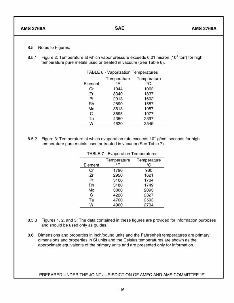
8.5 Notes to Figures:
8.5.1 Figure 2: Temperature at which vapor pressure exceeds 0.01 micron (10-5 torr) for high temperature pure metals used or treated in vacuum (See Table 6).
TABLE 6 - Vaporization Temperatures
ElementTemperature
°FTemperature
°CCrZrPtRhMoCTaW
19443340291328903613359543504620
10621837160215871987197723972549
8.5.2 Figure 3: Temperature at which evaporation rate exceeds 10-6 g/cm2 seconds for high temperature pure metals used or treated in vacuum (See Table 7).
TABLE 7 - Evaporation Temperatures
ElementTemperature
°FTemperature
°CCrZrPtRhMoCTaW
17962950310031803800422047004900
9801621170417492093232725932704
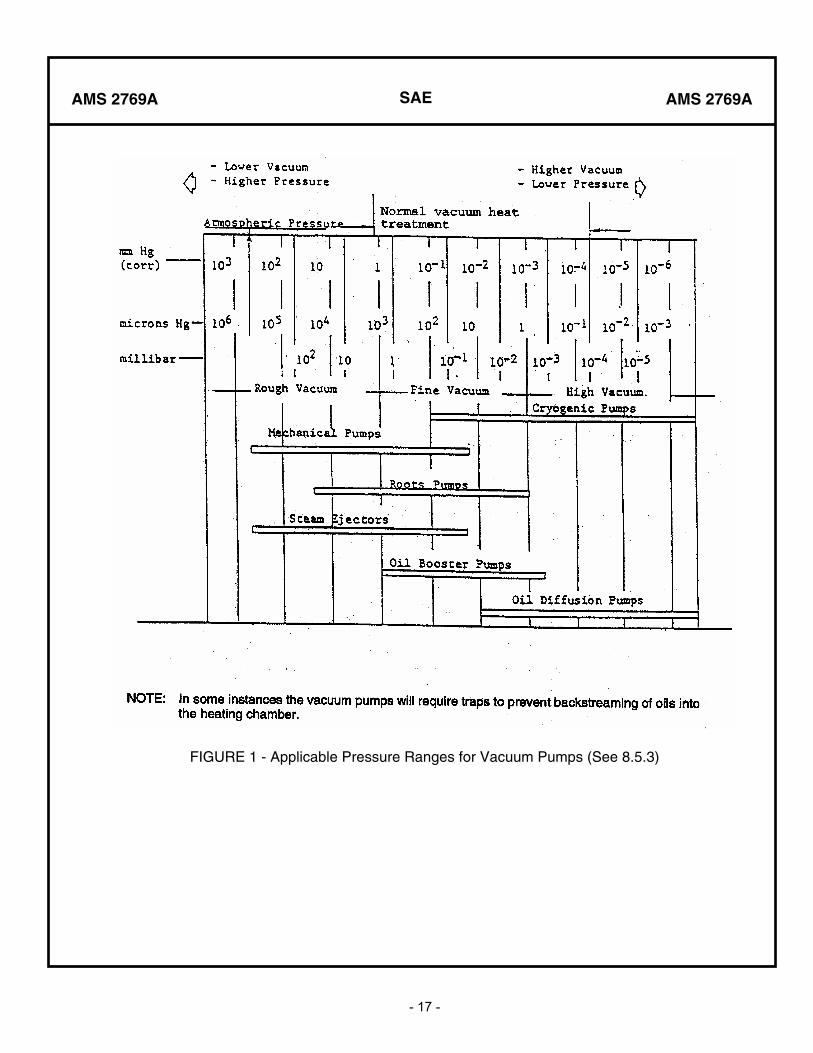
8.5.3 Figures 1, 2, and 3: The data contained in these figures are provided for information purposes and should be used only as guides.
8.6 Dimensions and properties in inch/pound units and the Fahrenheit temperatures are primary; dimensions and properties in SI units and the Celsius temperatures are shown as the approximate equivalents of the primary units and are presented only for information.
PREPARED UNDER THE JOINT JURISDICTION OF AMEC AND AMS COMMITTEE “F”
SAE
- 17 -
AMS 2769A AMS 2769A
FIGURE 1 - Applicable Pressure Ranges for Vacuum Pumps (See 8.5.3)
SAE
- 18 -
AMS 2769A AMS 2769A
FIGURE 2 - Vapor Pressure of the Elements (See 8.5.1 and 8.5.3)
SAE
- 19 -
AMS 2769A AMS 2769A
FIGURE 2 - (Continued)

SAE
- 20 -
AMS 2769A AMS 2769A
FIGURE 3 - Evaporation Rate of the Elements (See 8.5.2 and 8.5.3)
SAE
- 21 -
AMS 2769A AMS 2769A
FIGURE 3 - (Continued)