specification - ramos
TRANSCRIPT

Z-Power LED X10490
Z-Power LED X10490
Technical Data Sheet
Rev. 03Rev. 03
MAY, 2011MAY, 2011
Document No. : SSC- QP- 7- 07- 24
CUSTOMER
Approved byChecked by
SUPPLIER
Approved byDrawn by
SPECIFICATION[STW0Q2PA]

Z-Power LED X10490
Z-Power LED X10490
Technical Data Sheet
Rev. 03Rev. 03
MAY, 2011MAY, 2011
Document No. : SSC- QP- 7- 07- 24
1. Description
2. Absolute Maximum Ratings
3. Electro-Optical Characteristics
4. Optical characteristics
5. Reliability Test Items and Conditions
6. Color & Binning
7. Bin Code Description
8. Outline Dimension
9. Material Structure
10. Reel Structure
11. Packing
12. Soldering
13. Precaution for use
14. Handling of Silicone Resin LEDs
CONTENTS

Z-Power LED X10490
Technical Data Sheet
Document No. : SSC- QP- 7- 07- 24
Rev. 03Rev. 03
MAY, 2011MAY, 2011
STW0Q2PA
• White Back-light unit
• Electric Signs and Signals
• Office Automation, Electrical
Appliances, Industrial
Equipment
Features
Applications
1. Description
This surface-mount LED comes in standard package dimension. It has a substrate made up of a molded plastic reflector sitting on top of a bent lead frame. The die is attached within the reflector cavity and the cavity is encapsulated by silicone.
The package design coupled with careful selection of component materials allow these products to perform with high reliability.
White colored SMT package.
• Pb-free Reflow Soldering
Application
• Suitable for all SMT
assembly methods ;
Suitable for all soldering
methods
• RoHS Compliant

Z-Power LED X10490
Z-Power LED X10490
Technical Data Sheet
Rev. 03Rev. 03
MAY, 2011MAY, 2011
Document No. : SSC- QP- 7- 07- 24
2. Absolute maximum ratings*1
3. Electric characteristics
125TjJunction Temperature
-40~+100TstgStorage Temperature
-40~+85ToprOperating Temperature
mA300IFM [2]Peak Forward Current
mA160IFForward Current
mW592PdPower Dissipation
UnitValueSymbolParameter
KV--51.5kΩ;100pFESD (HBM)
ºC/W-15-IF=100mARthJSThermal resistance [4]
lm-31.8-IF=100mAΦLuminous flux
deg.-120-IF=100mA2Θ1/2Viewing Angle [3]
--68-IF=100mARaColor Rendering Index*
cd-10.59IF=100mAIvLuminous Intensity*[2]
(4700~7000K)
V1.20.9-IR=5mAVRReverse Voltage
V3.43.22.9IF=100mAVFForward Voltage *[1]
UnitMax.Typ.Min.ConditionSymbolParameter
[1] Forward current is 50mA per die for parallel inner circuit. Package Total Forward Current is 100mA
[2] The luminous intensity IV was measured at the peak of the spatial pattern which may not be aligned with the mechanical axis of the LED package.
[3] 2Θ1/2 is the off-axis where the luminous intensity is 1/2 of the peak intensity.[4] Thermal resistance: RthJS (Junction / solder), Metal PCB 25*25mm 1.6t* Tolerance : VF :± 0.1V, IV :± 10%, Ra :± 3, x,y :± 0.01
[Note] All measurements were made under the standardized environment of SSC.
[1] Care is to be taken that power dissipation does not exceed the absolute maximum rating of the product.[2] IFM was measured at Tw≤1 msec of pulse width and D≤1/10 of duty ratio.[3] LED’s properties might be different from suggested values like above and below tables if operation condition will be exceeded our parameter range.

Z-Power LED X10490
Z-Power LED X10490
Technical Data Sheet
Rev. 03Rev. 03
MAY, 2011MAY, 2011
Document No. : SSC- QP- 7- 07- 24
4. Optical characteristics
Forward Voltagevs. Forward Current
Ta=25
0 20 40 60 80 100 120 140 1600.0
0.2
0.4
0.6
0.8
1.0
1.2
1.4
1.6
Relative Luminous Intensity
Forward Current IF [mA]
Forward Currentvs. Relative Luminous Intensity
Ta=25
2.0 2.2 2.4 2.6 2.8 3.0 3.2 3.4 3.6 3.8 4.0
1
10
100
Forward Current I F [mA]
Forward Voltage VF [V]
Directivity
Ta=25
0
30
60
90
120
150
180
Forward Currentvs. Chromaticity Coordinate
Ta=25
0.285 0.286 0.287 0.288 0.289 0.290 0.2910.294
0.296
0.298
0.300
0.302
0.304
20mA
60mA
100mA
150mA
200mA
y
x

Z-Power LED X10490
Z-Power LED X10490
Technical Data Sheet
Rev. 03Rev. 03
MAY, 2011MAY, 2011
Document No. : SSC- QP- 7- 07- 24
4. Optical characteristics
Relative Light Outputvs. Junction Temperature
IF=100mA
Forward Voltage Shiftvs. Junction Temperature
IF=100mA
40 60 80 100 1200.0
0.2
0.4
0.6
0.8
1.0
Relative Light Output
Junction Temperation Tj (? )
40 60 80 100 1200.0
0.2
0.4
0.6
0.8
1.0
Relative Forw
ard Voltage
Junction Temperation Tj (? )
Junction Temperature ()vs. Chromaticity CoordinateIF=100mA
0.270 0.275 0.280 0.285 0.290 0.2950.280
0.285
0.290
0.295
0.300
0.305
0.310
25
44
64
84
104
y
x

Z-Power LED X10490
Z-Power LED X10490
Technical Data Sheet
Rev. 03Rev. 03
MAY, 2011MAY, 2011
Document No. : SSC- QP- 7- 07- 24
4. Optical characteristics
Spectrum
Ta=25, IF=100mA
300 400 500 600 700 8000.0
0.2
0.4
0.6
0.8
1.0
Relative Emission Intensity
Wavelength [nm]
Ambient Temperaturevs. Maximum Forward Current
-40 -20 0 20 40 60 80 1000
20
40
60
80
100
120
140
160
180
200
Forward Current I F[mA]
Ambient tem perature Ta(OC)
RthJ-A=100
oC /W

Z-Power LED X10490
Z-Power LED X10490
Technical Data Sheet
Rev. 03Rev. 03
MAY, 2011MAY, 2011
Document No. : SSC- QP- 7- 07- 24
5. Reliability Test Items and Conditions
0/223 Time260< 10sec. Reflow SolderingTsolReflow
0/223 Time5KV at 1.5kΩ; 100pFMIL-STD-883D
ESD(HBM)
0/221000 HoursTa=-40oC, I
F=100mA
InternalReference
Low Temperature Life Test
0/22500 HoursTa=85oC, I
F=100mA
InternalReference
High Temperature Life Test
0/22500 HoursTa=60oC, RH=90%, I
F=100mA
InternalReference
High Temperature
High Humidity Life Test
0/221000 HoursTa=25oC, I
F=100mA
InternalReference
Operating Endurance Test
0/221000 HoursTa=-40oC
EIAJ ED-4701
Low Temperature Storage
0/221000 HoursTa=60oC, RH=90%
EIAJ ED-4701
High Temp. High Humidity Storage
0/221000 HoursTa=100oC
EIAJ ED-4701
High Temperature Storage
0/22100 CycleTa=-40oC(30min) ~ 100oC(30min)
EIAJ ED-4701
Thermal Shock
Number of
Damaged
Duration / Cycle
Test ConditionsReferenceItem
-LSL [2] × 0.7IF=100mAI
VLuminous Intensity
USL [1] × 1.2-IF=100mAV
FForward Voltage
MAXMIN
Criteria for JudgmentConditionSymbolItem
Note : [1] USL : Upper Standard Level[2] LSL : Lower Standard Level
CRITERIA FOR JUDGING THE DAMAGE

Z-Power LED X10490
Z-Power LED X10490
Technical Data Sheet
Rev. 03Rev. 03
MAY, 2011MAY, 2011
Document No. : SSC- QP- 7- 07- 24
0.29 0.30 0.31 0.32 0.33 0.34 0.35 0.36 0.37 0.38 0.390.29
0.30
0.31
0.32
0.33
0.34
0.35
0.36
0.37
0.38
0.39
0.40
0.41
4200K
4500K4700K
5000K
7000K C6
B6
C4
B4
C2
B2
C0
B0
C8
A7
A6
A5
A4
A3
A2
A1
5300K
5600K
6000K
6500K
CIE Y
CIE X
A0
B8
B9
B1
B3
B5
B7
C9
C1
C3
C5
C7
D8
D0
D2
D4
D6
D9
D1
D3
D5
D7
6. Color & Binning
Energy Star RankEnergy Star Rank
AAAA
BBBB
CCCCDDDD

Z-Power LED X10490
Z-Power LED X10490
Technical Data Sheet
Rev. 03Rev. 03
MAY, 2011MAY, 2011
Document No. : SSC- QP- 7- 07- 24
COLOR RANK <IF=100mA, Ta=25>
6. Color & Binning
* Measurement Uncertainty of the Color Coordinates : ± 0.007
0.3740.33810.33690.33660.34510.33690.35340.33730.36160.3376
0.36160.33760.32880.33640.33690.33660.34510.33690.35340.3373
0.35390.32920.32340.32950.33060.32940.33840.32930.34610.3293
0.36560.3290.33060.32940.33840.32930.34610.32930.35390.3292
CIE YCIE XCIE YCIE XCIE YCIE XCIE YCIE XCIE YCIE X
B9B7B5B3B1
5300~5600K
0.36560.3290.33060.32940.33840.32930.34610.32930.35390.3292
0.35390.32920.32340.32950.33060.32940.33840.32930.34610.3293
0.34620.32070.31780.32260.32430.32220.33160.32170.33890.3212
0.35720.320.32430.32220.33160.32170.33890.32120.34620.3207
CIE YCIE XCIE YCIE XCIE YCIE XCIE YCIE XCIE YCIE X
B8B6B4B2B0
5600~6000K
0.33340.32160.34080.3210.34810.3205
0.32610.32210.33340.32160.34080.321
0.31870.31460.32560.31360.33240.3126
0.32560.31360.33240.31260.33930.3115
CIE YCIE XCIE YCIE XCIE YCIE X
A5A3A1
6000~6500K
0.3120.31550.31870.31460.32560.31360.33240.31260.33930.3115
0.30460.31640.3120.31550.31870.31460.32560.31360.33240.3126
0.2980.30960.30460.30820.31130.30680.31770.30550.3240.3041
0.30460.30820.31130.30680.31770.30550.3240.30410.33040.3028
CIE YCIE XCIE YCIE XCIE YCIE XCIE YCIE XCIE YCIE X
A8A6A4A2A0
6500~7000K

Z-Power LED X10490
Z-Power LED X10490
Technical Data Sheet
Rev. 03Rev. 03
MAY, 2011MAY, 2011
Document No. : SSC- QP- 7- 07- 24
6. Color & Binning COLOR RANK <IF=100mA, Ta=25>
* Measurement Uncertainty of the Color Coordinates : ± 0.007
0.39740.3760.35780.3670.36770.36920.37750.37140.38740.3736
0.38740.37360.34890.3650.35780.3670.36770.36920.37750.3714
0.38040.36410.34410.35750.35210.3590.36160.36080.37110.3625
0.390.36610.35210.3590.36160.36080.37110.36250.38040.3641
CIE YCIE XCIE YCIE XCIE YCIE XCIE YCIE XCIE YCIE X
D9D7D5D3D1
4200~4500K
0.390.36610.35210.3590.36160.36080.37110.36250.38040.3641
0.38040.36410.34410.35750.35210.3590.36160.36080.37110.3625
0.37360.35480.33850.34980.34650.35110.35550.35230.36460.3536
0.38260.35620.34650.35110.35550.35230.36460.35360.37360.3548
CIE YCIE XCIE YCIE XCIE YCIE XCIE YCIE XCIE YCIE X
D8D6D4D2D0
4500~4700K
0.36870.34630.34870.35140.35780.35260.36690.35390.3760.3552
0.3760.35520.340.350.34870.35140.35780.35260.36690.3539
0.38910.35720.33450.34330.34280.3440.35140.34480.36010.3456
0.3810.3470.34280.3440.35140.34480.36010.34560.36870.3463
CIE YCIE XCIE YCIE XCIE YCIE XCIE YCIE XCIE YCIE X
C9C7C5C3C1
4700~5000K
0.36160.33760.34280.3440.35140.34480.36010.34560.36870.3463
0.36870.34630.33450.34330.34280.3440.35140.34480.36010.3456
0.3810.3470.32880.33640.33690.33660.34510.33690.35340.3373
0.3740.33810.33690.33660.34510.33690.35340.33730.36160.3376
CIE YCIE XCIE YCIE XCIE YCIE XCIE YCIE XCIE YCIE X
C8C6C4C2C0
5000~5300K
Z-Power LED X10490
Z-Power LED X10490
Technical Data Sheet
Rev. 03Rev. 03
MAY, 2011MAY, 2011
Document No. : SSC- QP- 7- 07- 24
[Note] All measurements were made under the standardized environment of SSC.In order to ensure availability, single color rank will not be orderable.
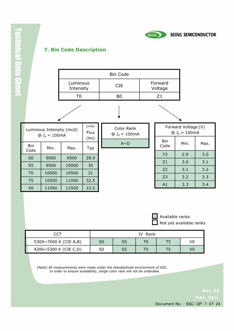
7. Bin Code Description
Z1B0T0
Forward Voltage
CIELuminousIntensity
Bin Code
A~D
Color Rank
@ IF = 100mA
3.43.3A1
3.02.9Y3
3.13.0Z1
3.23.1Z2
3.33.2Z3
Max.Min.Bin Code
Forward Voltage (V)
@ IF = 100mA
33.51150011000V0
311050010000T0
30100009500S5
32.51100010500T5
28.995009000S0
Typ
[note]
Flux
(lm)
Max.Min.Bin Code
Luminous Intensity (mcd)
@ IF = 100mA
IV Rank
V0
V0
T0
T0
S0
S0
S5
S5
T54200~5300 K (CIE C,D)
T55300~7000 K (CIE A,B)
CCT
Available ranks
Not yet available ranks

Z-Power LED X10490
Z-Power LED X10490
Technical Data Sheet
Rev. 03Rev. 03
MAY, 2011MAY, 2011
Document No. : SSC- QP- 7- 07- 24
8. Outline Dimension
A
C2C1
Slug (Anode)Slug (Anode)Slug (Anode)Slug (Anode)
N.CN.CN.CN.C
PackagePackagePackagePackageMarkingMarkingMarkingMarking
( Tolerance: ±0.1, Unit: mm )
[Note] Forward current is 50mA per die for parallel inner circuit. Package Total Forward Current is 100mA
0.65 2.80 0.65
1.10
1.10
0.40
1.80
4.100.95
[Recommended Solder Pattern]
9. Material Structure
Si
Thermo Plastic
Silicone
Metal
Blue LED
Metal
DescriptionDescriptionDescriptionDescription
-Zener Diode⑥ +PhosphorEncapsulation④ Gold WireWire③ GaN on SapphireChip Source②Heat- resistant PolymerBody⑤
Copper Alloy (Silver Plated)LEAD FRAME① MaterialsMaterialsMaterialsMaterialsNameNameNameNameParts No.Parts No.Parts No.Parts No.
①② ③ ④⑥⑤

Z-Power LED X10490
Z-Power LED X10490
Technical Data Sheet
Rev. 03Rev. 03
MAY, 2011MAY, 2011
Document No. : SSC- QP- 7- 07- 24
180
2
13
22
60
15.4± 1.0
13± 0.3
10. Reel Structure
( Tolerance: ±0.2, Unit: mm )
(1) Quantity : 3,500pcs/Reel(2) Cumulative Tolerance : Cumulative Tolerance/10 pitches to be ± 0.2mm(3) Adhesion Strength of Cover Tape : Adhesion strength to be 0.1-0.7N when the cover tape is turned off from
the carrier tape at the angle of 10º to the carrier tape(4) Package : P/N, Manufacturing data Code No. and quantity to be indicated on a damp proof Package

Z-Power LED X10490
Z-Power LED X10490
Technical Data Sheet
Rev. 03Rev. 03
MAY, 2011MAY, 2011
Document No. : SSC- QP- 7- 07- 24
11. Soldering
10 sec. Max.Soldering time Condition
240Max.Peak-Temperature
120 sec. Max.Pre-heat time
120~150Pre-heat
Lead Solder
10 sec. Max.Soldering time Condition
260Max.Peak-Temperature
120 sec. Max.Pre-heat time
150~200Pre-heat
Lead Free Solder
Lead Solder
2.5~5 C / sec.o
oo
Pre-heating
120~150 C
120sec. Max.
60sec. Max.
Above 200 C
o240 C Max.
10 sec. Max.
2.5~5 C / sec.
(1) Lead Solder
(2) Lead-Free Solder
(3) Hand Soldering conditionsDo not exceed 4 seconds at maximum 315ºC under soldering iron.
Lead-free Solder
1~5 C / sec.o
o oo1~5 C / sec.
Pre-heating
150~200 C
120sec. Max.
60sec. Max.Above 220 C
o260 C Max.
10 sec. Max.
(4) The encapsulated material of the LEDs is silicone.Precautions should be taken to avoid the strong pressure on the encapsulated part.So when using the chip mounter, the picking up nozzle that does not affect the silicone resign should be used.
(5) It is recommended that the customer use the nitrogen reflow method.
(6) Repairing should not be done after the LEDs have been soldered.
(7) Reflow soldering should not be done more than two times.In the case of more than 24 hours passed soldering after first, LEDs will be damaged.

Z-Power LED X10490
Z-Power LED X10490
Technical Data Sheet
Rev. 03Rev. 03
MAY, 2011MAY, 2011
Document No. : SSC- QP- 7- 07- 24
ca b
1 SIDE
7inch 245 220 142
SIZE (mm)
Outer Box Structure
Material : Paper(SW3B(B))
TYPE
a
b
c
1
HUMIDITY INDICATOR
Aluminum Vinyl Bag
Reel
DESI PAK
PART NUMBER :
LOT NUMBER : XXXXXXXXXX
QUANTITY : XXXX
SEOUL SEMICONDUCTOR CO., LTD.
PART NUMBER :
LOT NUMBER : XXXXXXXXXX
QUANTITY : XXXX
SEOUL SEMICONDUCTOR CO., LTD.
PART NUMBER :
LOT NUMBER : XXXXXXXXXX
QUANTITY : XXXX
SEOUL SEMICONDUCTOR CO., LTD.
RoHS
12. Packing
Z-Power LED X10490
Z-Power LED X10490
Technical Data Sheet
Rev. 03Rev. 03
MAY, 2011MAY, 2011
Document No. : SSC- QP- 7- 07- 24
13. precaution for use
(1) Storage
In order to avoid the absorption of moisture, it is recommended to store in a dry box (or adesicator) with a desiccant. Otherwise, to store them in the following environment isrecommended.Temperature : 5ºC ~30ºC Humidity : maximum 70%RH
(2) Attention after open.
LED is correspond to SMT, when LED be soldered dip, interfacial separation may affect the light transmission efficiency, causing the light intensity to drop. Attention in followed; Keeping of a fractionTemperature : 5 ~ 40ºC Humidity : less than 10%
(3) In the case of more than 1 week passed after opening or change color of indicator on desiccant, components shall be dried 10-12hr. at 60± 5ºC.
(4) Silver plating might be tarnished in the environment that contains corrosive gasesand materials. Also any product that has tarnished lead might be decreased the solder-ability and optical-electrical properties compare to normal ones. Please do not expose the product in the corrosive environment during the storage.
(5) Any mechanical force or any excess vibration shall not be accepted to apply duringcooling process to normal temperature after soldering.
(6) Quick cooling shall be avoided.
(7) Components shall not be mounted on warped direction of PCB.
(8) Anti radioactive ray design is not considered for the products.
(9) This device should not be used in any type of fluid such as water, oil, organic solvent etc. When washing is required, IPA should be used.
(10) When the LEDs are illuminating, operating current should be decided after consideringthe ambient maximum temperature.
(11) The LEDs must be soldered within seven days after opening the moisture-proof packing.
(12) Repack unused products with anti-moisture packing, fold to close any opening and thenstore in a dry place.
(13) The appearance and specifications of the product may be modified for improvementwithout notice.

Z-Power LED X10490
Z-Power LED X10490
Technical Data Sheet
Rev. 03Rev. 03
MAY, 2011MAY, 2011
Document No. : SSC- QP- 7- 07- 24
13. Handling of Silicone Resin LEDs
1) During processing, mechanical stress on the surface should be minimized as much as possible. Sharp objects of all types should not be used to pierce the sealing compound.
2) In general, LEDs should only be handled from the side. By the way, this also applies to LEDswithout a silicone sealant, since the surface can also become scratched.
3) When populating boards in SMT production, there are basically no restrictions regarding the form of the pick and place nozzle, except that mechanical pressure on the surface of the resin must be prevented. This is assured by choosing a pick and place nozzle which is larger than the LED’s reflector area.
4) Silicone differs from materials conventionally used for the manufacturing of LEDs. These conditions must be considered during the handling of such devices. Compared to standard encapsulants, silicone is generally softer, and the surface is more likely to attract dust.
As mentioned previously, the increased sensitivity to dust requires special care during processing.In cases where a minimal level of dirt and dust particles cannot be guaranteed, a suitable cleaning solution must be applied to the surface after thesoldering of components.
5) SSC suggests using isopropyl alcohol for cleaning. In case other solvents are used, itmust be assured that these solvents do not dissolve the package or resin.Ultrasonic cleaning is not recommended. Ultrasonic cleaning may cause damage to the LED.
6) Please do not mold this product into another resin (epoxy, urethane, etc) and do not handle this product with acid or sulfur material in sealed space.