spectrex inc. product training - cebeco
TRANSCRIPT

Spectrex Inc. Product Training5/12/16

[File Name or Event] • Emerson Confidential • 8/27/2018 • Slide 2
Spectrex Inc. Introduction • Headquarters: Cedar Grove, New Jersey USA• Sales Offices:
– MEA, US, LAM, & India: Houston, Texas USA– Europe: Glasgow, UK– Asia: Taiwan– Northern US & Canada: Chicago, Illinois USA
• Support and Training: – Houston, Texas USA– Taiwan
• Over 40 Years in the F&G Detection Industry– Originator of UV/IR (1980), IR3 (1995), and
Xenon OPGD (1996) Technology• Acquired by Emerson Process Management – Rosemount
September 2015

Flame Detection

[File Name or Event] • Emerson Confidential • 8/27/2018 • Slide 4
Technology Behind Flame Detection • Flame detectors utilize the
radiation from flames for detection, not the visible light
• Depending on the fuel source, a large of amount of hot CO2 and H20 gases are released, emitting radiation at specific wavelengths.
• Depending on the model, the sensors are filtered to detect this radiation.
• Typical Hydrocarbon Flame:

[File Name or Event] • Emerson Confidential • 8/27/2018 • Slide 5
Technology Behind Flame Detection
• In order for alarm, two things must be present:
– Valid radiation received from the detector sensors within the specific wavelength of the filter (UV, IR, or UV/IR depending on the model)
– Flicker Effect, this is represented by an approx 1-10Hz frequency at which the waves of radiation reach the sensors. Used to rule out other heat sources and false alarms
• Both of these factors are assessed through the detector algorithm which constantly monitors various thresholds and ratios for the radiation signal, in combination with the flicker effect.
• Typical Hydrocarbon Flame:

[File Name or Event] • Emerson Confidential • 8/27/2018 • Slide 6
Why Flame Detectors are “Solar Blind”
The Sun• High Intensity• Unique Radiation Peaks• A good Emitter is a good Absorber

[File Name or Event] • Emerson Confidential • 8/27/2018 • Slide 7
Sensitivity to different Fuel Types
DieselJP5/KeroseneMethane/LPG*
EthanolIPA
Methanol
65m (100%)
40m (60%)
45m (70%)
35m (55%)
* 0.75m Plume
Example: 40/40I IR3 Flame Detector at Maximum Sensitivity to 0.1m2 fire

[File Name or Event] • Emerson Confidential • 8/27/2018 • Slide 8
Flame Detection - Coverage• Field of View:
– 100*H x 95*V, with the exception of M/HR models.
– Detection performance decreases as you approach the edge of the field of view
• Detection Distance: – Stated distances are based
on 1x1 foot petrol flames– For every 4x in fire size,
detectors can see .25x longer distance (IR3 example below
• 1x1 ft petrol flame = 65m• 2x2 ft petrol flame = 81m• 4x4 ft petrol flame = 101m
Horizontal Field of View
Vertical Field of View

[File Name or Event] • Emerson Confidential • 8/27/2018 • Slide 9
Sensitivity and detection range are related to size of the fire.
If the detector is placed further from (or closer to) the source of fire, the detectable fire size will vary according to the Inverse Square Law.
Doubling the detection distanceresults in only 25% of the radiantenergy reaching the detector!
Conversely, for the same responsetime, the fire size needs to be4 times larger at this longer distance
Inverse Square Law

[File Name or Event] • Emerson Confidential • 8/27/2018 • Slide 10
- Cannot see smouldering fires
- Requires a “line of sight” to the fire,(cannot see through objects)
- Some technologies could be effected by obscuration
Optical Flame Detectors - Limitations

[File Name or Event] • Emerson Confidential • 8/27/2018 • Slide 11
Triple Infrared – IR3
• Spectrex PN: – 40/40I-xxxxx
• Spectral Range: – 3 IR sensors between
4.0 – 5.0 µm • Detection Range:
– Up to 65m for a 1x1 foot petrol fire
– 4 sensitivity levels• Field of View:
– 100*H x 95*V• Response time:
– Typically 5 seconds

[File Name or Event] • Emerson Confidential • 8/27/2018 • Slide 12
• Sensor Placement:
The IR3 is only focusing on the CO2spike, and there is no reference to H2O or UV wavelengths
Triple Infrared – IR3
• Applications: – Petrochemical, Onshore,
Offshore, Tank Farms, Hangars, etc.
– This will be the most widely used model for all installations.
• Highest combination of detection performance and false alarm immunity.
• The longest detection range of all models, most coverage per individual detector

[File Name or Event] • Emerson Confidential • 8/27/2018 • Slide 13
Ultra Fast Ultraviolet/Infrared – UF UV/IR
• Spectrex PN: – 40/40UFL-xxxxx
• Spectral Range: – UV at 0.185-0.260 µm, IR at
2.5-3.0 µm• Detection Range:
– Up to 20m for a 1x1 foot petrol fire
– 1 sensitivity level• Field of View:
– 100*H x 95*V• Response time:
– Typically 5 seconds, 20 msec for flash fire, high saturation events

[File Name or Event] • Emerson Confidential • 8/27/2018 • Slide 14
• Sensor Placement:
The UFL focuses on both UV radiation as well as radiation from hot H2O gases
Ultra Fast Ultraviolet/Infrared – UF UV/IR
• Applications: – Petrochemical, Onshore,
Offshore, Tank Farms, Power generation, etc.
– Best for general, non-hydrocarbon fuel applications
• Best detection performance for short range applications
• Capable of hydrogen flame detection up to 7m
• The longest detection range of UV/IR models
• Includes additional high speed voltage signal output for suppression systems

[File Name or Event] • Emerson Confidential • 8/27/2018 • Slide 15
Ultraviolet/Infrared (Wideband IR) – UV/IR
• Spectrex PN: – 40/40L4B-xxxxx
• Spectral Range: – UV at 0.185-0.260 µm, IR at
4.4-4.6 µm• Detection Range:
– Up to 20m for a 1x1 foot petrol fire
– 1 sensitivity level• Field of View:
– 100*H x 95*V• Response time:
– Typically 3 seconds

[File Name or Event] • Emerson Confidential • 8/27/2018 • Slide 16
• Sensor Placement:
The L4B focuses on both UV radiation as well as radiation from hot CO2gases
Ultraviolet/Infrared (Wideband IR) – UV/IR
• Applications: – Petrochemical, Onshore,
Offshore, Tank Farms, Power generation, etc.
– Perfect for short range hydrocarbon fuel applications
• Best detection performance for short range applications
• The longest detection range of UV/IR models

[File Name or Event] • Emerson Confidential • 8/27/2018 • Slide 17
Multi Infrared – Multi-IR
• Spectrex PN: – 40/40M-xxxxx
• Spectral Range: – IR sensors at 4.0–5.0 µm
and 2.5-3.0 µm• Detection Range:
– Up to 30m for 20”x8” hydrogen flame and 65m for a 1x1 foot petrol flame
– 4 sensitivity levels• Field of View:
– 80*H x 80*V• Response time:
– Typically 5 seconds

[File Name or Event] • Emerson Confidential • 8/27/2018 • Slide 18
• Sensor Placement:
The Multi-IR focuses on both the hot CO2 and hot H20 portions of the IR spectrum
Multi Infrared – Multi-IR
• Applications: – Should only be used for long
range hydrogen flame detection (distances over 7m)
• Capable of both hydrocarbon and hydrogen flame detection.
• **If there is no presence or possibility of hydrogen flame, use the IR3 model instead!

[File Name or Event] • Emerson Confidential • 8/27/2018 • Slide 19
Flame Detection – Approvals• Hazardous Area: Ex-Proof:
– FM: Class I Div. 1, B,C,D– ATEX: Ex de IIC T5
• Electrical Classification: – IECEx: Ex de IIC T5
• Ingress Protection:– IP66 IP67
• Reliability: – SIL2: TUV
• Performance: – FM: FM3260– VDS: EN54-10
• Marine: (IR3/MR and L4B/UR only)
– DNV: MED Wheelmark

[File Name or Event] • Emerson Confidential • 8/27/2018 • Slide 20
Flame Detection – Wiring • It is important to determine the
existing wiring option, however default option 1 is the most common.
• Power: – 24VDC to Terminal 1 & 2
• Relays:– Alarm to Terminal 6 & 7– Fault to Terminal 4 & 5
• Analog: – 4 Wire: Terminal 8 & 9– 3 Wire: Terminal 2 & 9 with jumper
between 1 & 8• Digital:
– HART: Along 0-20mA signal– RS485: Terminal 10, 11, & 12
• Manual Built in Test: – Close circuit between Terminal 3 &
2
Alarm N.O.Fault N.C.Fault N.C.24VDCRTNManual BIT
0-20mA Out0-20mA In
Alarm N.O.RS485+RS485-
RS485 Gnd
Jumper
Replaced with voltage output on UFL/UF

[File Name or Event] • Emerson Confidential • 8/27/2018 • Slide 21
Flame Detection – Diagnostics/Troubleshooting• Built-In-Test (BIT) Feature:
– Uses small reflector on exterior.
– Emitter inside lens sends a signal to the reflector, back to the sensors.
– This ensures the sensors are working properly and that the lens is clear of debris
– This is done automatically every 15 minutes but can be done manually
– Failure will result inBIT-Fault, and will remain until is cleared
– Still able to detect flames during BIT-Fault
Reflector
– If BIT-Fault is present, denoted by Fault relay or 2.0 mA signal, clean the lens and initiate a Manual BIT, fault should clear
– If the Fault does not clear, the sensors could be faulty and the unit should be sent in for checking

[File Name or Event] • Emerson Confidential • 8/27/2018 • Slide 22
Flame Detection – Diagnostics/Troubleshooting• Critical Fault
– Indicated by fault relay or 0.0mA signal
– This is a critical power failure or sensor failure with detector electronics
– Cannot be repaired in the field and the unit must be returned to factory
• No Analog Output– Usually incorrect wiring:
• If using 4-wire, 24VDC is not being provided to the signal from the controller
• If using 3-wire, the jumper is not placed between terminal 1 & 8
• No Response from Flame Simulator
– Ensure the correct simulator is being used, and the simulator is fully charged
• No Communication via RS485– Check cable connections,
and that RS485/232 USB Adapter is being used

[File Name or Event] • Emerson Confidential • 8/27/2018 • Slide 23
Flame Detection – Accessories • Tilt Mount
– Required for installation• Pole Mount
– 2” or 3” option• Duct Mount
– Tilt mount not required• Air Shield
– Compressed air line required• Cone Viewer
– Laser coverage area pointer• RS485 Software Kit
– For communication• St. Steel Weather Cover
– Optional, all detectors come with plastic version

[File Name or Event] • Emerson Confidential • 8/27/2018 • Slide 24
Flame Detection – Communication • RS485 Modbus
– Using PC, along with RS485/232 USB Adapter
• HART Communication– Digital signal accessible over
the analog 0-20mA wires– Compatible with Delta V and
AMS Suite (need to confirm)
• Either Option Allows for: – Changing sensitivity levels– Changing alarm time delays– Initiating Manual BIT– Changing any factory
configuration settings related to the particular detector

[File Name or Event] • Emerson Confidential • 8/27/2018 • Slide 25
Flame Detection – Basic Installation Guide• Height and Angle:
– Ensure the detectors are mounted at a height allowing for optimum aerial coverage
– Ensure the detectors are mounted with at least 30-45* downward angle
– This eliminates outside flame stimuli and false alarm possibilities
• Blind Spots: – Detectors cannot detect
flame through solid objects!
Good Example:
Bad Example:
Models Provided by:

[File Name or Event] • Emerson Confidential • 8/27/2018 • Slide 26
Flame Detection – Testing/Commissioning• Flame Simulators:
– For detector testing in Hazardous Areas
– Rechargeable with replaceable batteries
– IR3 Models: FS-1100– UV/IR Models: FS-1200– Multi IR Models: FS1400

Open Path Gas Detection

[File Name or Event] • Emerson Confidential • 8/27/2018 • Slide 28
Technology Behind Open Path Gas Detection• Beer-Lambert Law
– As light energy passes through a substance, the reduction of energy is proportionate to the concentration of the substance.
• Spectrophotometry– Utilization and Isolation of of
individual wavelengths amongst the Electromagnetic Spectrum:
• UV – For Toxic Gases• Visible – Not Used• IR – For Flammable Gases

[File Name or Event] • Emerson Confidential • 8/27/2018 • Slide 29
• Absorption Spectroscopy– The method of measuring
the amount of energy that a particular substance, or molecule of gas, will absorb based on the particular wavelength
– Used in OPGD to establish reference vs. signal
Tx
Technology Behind Open Path Gas DetectionReference: Signal:
– The gas will absorb a known amount of energy from the radiation from the signal wavelength, much less than the reference wavelength
Rx

[File Name or Event] • Emerson Confidential • 8/27/2018 • Slide 30
Technology Behind Open Path Gas Detection• Signal vs. Reference
– The energy from both the signal and reference wavelengths is constantly observed
– A “zero” calibration is established on installation and commissioning which creates a perfect ratio, 1:1, of the energy from signal:reference
– As gas is released and passes through the line-of-sight of the OPGD, the reduction of the signal energy, in correlation to the reference, is represented by a decrease in the ratio.
– This decrease in signal:reference ratio is directly proportionate to the level of gas concentration within the line-of-sight of the open path.
– This can be expressed either on a LEL.m or PPM.m scale

[File Name or Event] • Emerson Confidential • 8/27/2018 • Slide 31
During normal operation, the reference and signal have the same intensity.
The ratio is 1 which means no gas reading.
During fog, dust, smoke etc., the signals and the reference
are reduced. The ratio is 1 which means no gas reading.
During misalignment, the reference goes down and the
signals are less affected.The ratio is more than 1
which leads to a misalignment fault condition.
When gas is present, the signal is lower than the
reference. The ratio is less than 1, which leads to gas
reading.
Principle of Operation

[File Name or Event] • Emerson Confidential • 8/27/2018 • Slide 32
Flammable Open Path – IR Technology• Spectrex PN:
– Quasar 900 Series• Utilizes IR Flash Source
– Separate Signal and Reference between 2.0-3.0 µm
• Available Distances: – 901: 7-20m– 902: 15-40m– 903: 35-100m– 904: 80-200m
• Detectable Gases: – C1-C8 Hydrocarbon gases,
mixes, some exotics (TBD)

[File Name or Event] • Emerson Confidential • 8/27/2018 • Slide 33
• What is LEL.m?– Percentage LEL multiplied
by gas cloud width.• For Example: Methane has an
LEL of 5% per volume– 1m cloud 5% Methane
(100% LEL) = 1 LEL.m– 5m cloud 1% Methane (20%
LEL) = 1 LEL.m
• Available Calibrations:– Methane– Propane– Ethylene
• Detection Ranges: – 0-5 LEL.m (methane and
propane)– 0-8 LEL.m (ethylene).
• Minimum Detectable Level:– 0.15 LEL.m
• Response Time: – Typically 3 Seconds
Flammable Open Path – IR Technology
5m width @ 20% LEL
1m width @ 100% LEL
Both Equal 1 LEL.m

[File Name or Event] • Emerson Confidential • 8/27/2018 • Slide 34
Flammable Open Path – IR Technology

[File Name or Event] • Emerson Confidential • 8/27/2018 • Slide 35
Flammable Open Path – IR Technology• Applications:
– Perimeter monitoring, gas compressor stations, storage tank farms, large process areas, etc.
• Benefits: – Long Distance hydrocarbon gas
detection, up to 200m – IR technology, especially in the
2.0-3.0 µm wavelengths is very resilient
– Not affected by fog, rain, sand, oil, heat, etc.
– 10 Levels of automation gain from Receiver, able to operate under heavy obscuration.
– Rx is same for all models, Tx is interchangeable

[File Name or Event] • Emerson Confidential • 8/27/2018 • Slide 36
Toxic Open Path – UV Technology• Spectrex PN:
– Quasar 950 Series• Utilizes UV Flash Source
– Separate Signal (x2) and Reference between 200-300 nm
• Available Distances: – 951: 5-20m– 952: 15-40m– 953: 35-60m
• Detectable Gases: – Hydrogen Sulfide (H2S)
[File Name or Event] • Emerson Confidential • 8/27/2018 • Slide 37
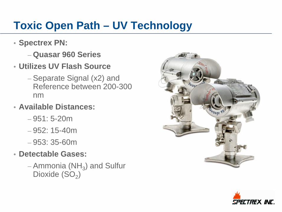
Toxic Open Path – UV Technology• Spectrex PN:
– Quasar 960 Series• Utilizes UV Flash Source
– Separate Signal (x2) and Reference between 200-300 nm
• Available Distances: – 951: 5-20m– 952: 15-40m– 953: 35-60m
• Detectable Gases: – Ammonia (NH3) and Sulfur
Dioxide (SO2)

[File Name or Event] • Emerson Confidential • 8/27/2018 • Slide 38
Toxic Open Path – UV Technology• Available Calibrations:
– H2S– NH3 (Also include SO2)
• Detection Ranges: – 0-500 PPM.m .
• Minimum Detectable Level:– 50 PPM.m
• Response Time: – Typically 5 Seconds
• What is PPM.m?– Cloud length multiplied by
the average gas concentration of the cloud.
• For Example: – 1m cloud 100 ppm = 100
PPM.m– 5m cloud with average
concentration of 20 ppm = 100 PPM.m

[File Name or Event] • Emerson Confidential • 8/27/2018 • Slide 39
Toxic Open Path – UV Technology• Applications:
– Perimeter monitoring, gas compressor stations, storage tank farms, large process areas, protection of safe areas etc.
• Benefits: – Long Distance toxic gas
detection, up to 60m – UV source offers better
performance in high heat applications
– Significant cost saving compared to laser models
– 4 Levels of automatic gain, able to operate with significant obscuration
– Rx is same for all models, Tx is interchangeable

[File Name or Event] • Emerson Confidential • 8/27/2018 • Slide 40
OPGD – Comparison with Single-Point
Tx Rx
Single Point Detectors
spaced 5m apart
OPGD Intersecting the Single
Point Coverage
Area
Single Points unable to detect either cloud, or not at very low concentrations
OPGD able to detect both gas clouds, and at much smaller
concentrations
Methane Leak

[File Name or Event] • Emerson Confidential • 8/27/2018 • Slide 41
OPGD – Approvals• Hazardous Area: Ex-Proof:
– FM: Class I Div. 1, B,C,D– ATEX: Ex d e ib [ib Gb] IIB + H2 T4
• Electrical Classification: – IECEx: Ex d e ib [ib Gb] IIB + H2 T4
• Ingress Protection:– IP66 IP68
• Reliability: – SIL2: TUV
• Performance: – FM: FM6325– FM: EN60079-29-4
• Marine: DNV: Type Approval

[File Name or Event] • Emerson Confidential • 8/27/2018 • Slide 42
OPGD – Wiring Receiver Terminals
Transmitter Terminals
• Separate Wiring for Rx and Tx Units• Power:
– Rx: 24VDC to Terminal 1 & 2– Tx: 24VDC to Terminal 1 & 2
• Analog: – 4 Wire: Terminal 3 & 4– 3 Wire: Terminal 2 & 4 with jumper
between 1 & 3• Digital:
– HART: Along 0-20mA signal– RS485: Rx: Terminal 5 & 6– RS485: Tx: Terminal 5 & 6
Jumper

[File Name or Event] • Emerson Confidential • 8/27/2018 • Slide 43
OPGD – Diagnostics/Troubleshooting• Misalignment:
– Denoted by 2.5mA signal – Check the alignment of the
Tx to the Rx• Maintenance Call:
– Denoted by 3.0mA signal – Check that the lenses of both
Tx and Rx are clear of debris• Beam Block:
– Denoted by 2.0mA– Most common fault– Check for persons,
equipment, fixed within the line of sight
– The OPGD has come out of alignment
• Critical Fault:– Denoted by 0.0mA– Ensure power has been
supplied to Tx and Rx– If so, unit must be sent back
for analysis and repair • No analog output signal
– Ensure power has been provided to the 0-20mA signal
• No Communication via RS485– Check cable connections,
and that RS485/232 USB Adapter is being used

[File Name or Event] • Emerson Confidential • 8/27/2018 • Slide 44
OPGD – Accessories • Commissioning Kit:
– Everything needed for installation, commissioning, and testing.
• Pole Mount:– 2-3” and 4-5” Options– Tilt mount required, included
in each OPGD set• L-Bracket:
– Used for mounting to flat vertical surfaces
– Tilt mount required, included in each OPGD set
• Sunshade– St. Steel cover or both Tx
and Rx units
[File Name or Event] • Emerson Confidential • 8/27/2018 • Slide 45
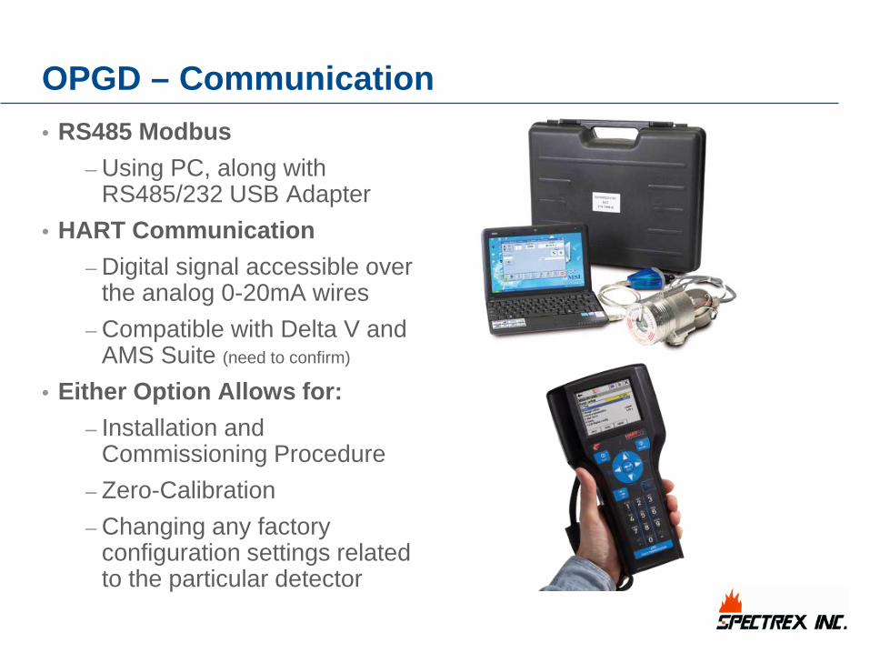
OPGD – Communication • RS485 Modbus
– Using PC, along with RS485/232 USB Adapter
• HART Communication– Digital signal accessible over
the analog 0-20mA wires– Compatible with Delta V and
AMS Suite (need to confirm)
• Either Option Allows for: – Installation and
Commissioning Procedure– Zero-Calibration – Changing any factory
configuration settings related to the particular detector

[File Name or Event] • Emerson Confidential • 8/27/2018 • Slide 46
OPGD – Basic Installation Guide• Mounting Location:
– This is always a case-by-case scenario based on:
• Distance• Available Structure• Environment• Gases Present
– Taking into account the weight of the gas and the environmental factors, i.e. wind, the mounting height should be determined for maximum detection capability
• Alignment:– Using the provided alignment
telescope, align the OPGD, with the crosshairs situated in the exact center of the opposite lens, in this order:
• Tx to Rx• Rx to Tx• Confirm Tx to Rx

[File Name or Event] • Emerson Confidential • 8/27/2018 • Slide 47
OPGD – Basic Installation Guide• Commissioning:
– Once alignment is complete, perform the Zero Calibration, using either:
• Provided Magnet • RS485 Modbus• HART Communication
• Testing: – Use the provided function
test filters in the commissioning kit. There will always be two filters:
• One for testing warning value 1.0 LEL.m < 2.9 LEL.m
• One for testing alarm value 3.0 LEL.m < 5.0 LEL.m