spectro series - sensorcentre.com · spectro-3 series • true color sensors data sheet...
TRANSCRIPT
Data Sheet SPECTRO-3-50-COFSPECTRO-3 Series • True Color Sensors
[email protected] • www.sensorinstruments.de (2014-01-28) SPECTRO-3-50-COF / Page 1 of 12
(0469.04)Subject to alteration
Sensor Instruments GmbH • D-94169 Thurmansbang • Schlinding 11Tel. +49 (0)8544 9719-0 • Fax +49 (0)8544 9719-13
Design
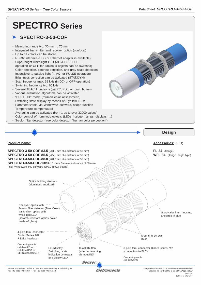
SPECTRO SeriesSPECTRO-3-50-COF
- Measuring range typ. 30 mm ... 70 mm- Integrated transmitter and receiver optics (confocal)- Up to 31 colors can be stored- RS232 interface (USB or Ethernet adapter is available)- Super-bright white-light LED (AC-/DC-/PULSE-
operation or OFF for luminous objects can be switched)- Color detection, contrast detection, and gray scale detection- Insensitive to outside light (in AC- or PULSE-operation)- Brightness correction can be activated (STAT/DYN)- Scan frequency max. 35 kHz (in DC- or OFF-operation)- Switching frequency typ. 60 kHz- Several TEACH functions (via PC, PLC, or push button)- Various evaluation algorithms can be activated- “BEST HIT“ mode (“human color assessment“)- Switching state display by means of 5 yellow LEDs- Parameterizable via Windows® software, scope function- Temperature compensated- Averaging can be activated (from 1 up to over 32000 values)- Color control of luminous objects (LEDs, halogen lamps, displays, ...)- 3-color filter detector (true color detector: “human color perception“)
Product name:
SPECTRO-3-50-COF-d3.5 (Ø 3.5 mm at a distance of 50 mm)SPECTRO-3-50-COF-d5.5 (Ø 5.5 mm at a distance of 50 mm)SPECTRO-3-50-COF-d8.0 (Ø 8.0 mm at a distance of 50 mm)SPECTRO-3-50-COF-13x3 (13 mm x 3 mm at a distance of 50 mm)(incl. Windows® PC software SPECTRO3-Scope)
Accessories: (p. 12)
FL-34 (flange)WFL-34 (flange, angle type)
4-pole fem. connectorBinder Series 707RS232 interface
Connecting cable:cab-las4/PC orcab-las4/USB orSI-RS232/Ethernet-4
TEACH button(external teachingvia input IN0)
LED display:Switching stateindication by meansof 5 yellow LED
Receiver optics with3-color filter detector (True Color)transmitter optics withwhite light LED(scratch-resistant optics covermade of glass)
Optics holding device(aluminum, anodized)
8-pole fem. connector Binder Series 712(connection to PLC)
Connecting cable:cab-las8/SPS
Mounting screws(M34)
Sturdy aluminum housing,anodized in blue

Data Sheet SPECTRO-3-50-COFSPECTRO-3 Series • True Color Sensors
[email protected] • www.sensorinstruments.de (2014-01-28) SPECTRO-3-50-COF / Page 2 of 12
(0469.04)Subject to alteration
Sensor Instruments GmbH • D-94169 Thurmansbang • Schlinding 11Tel. +49 (0)8544 9719-0 • Fax +49 (0)8544 9719-13
ledoM ...-FOC-05-3-ORTCEPS
ylppusegatloV detcetorptnerrucrevo,detcetorpytiralopesrever,)%01±(CDV42+
noitpmusnoctnerruC Am061<
tnerrucgnihctiws.xaM foorptiucrictrohs,Am001
noitacidnietatsgnihctiwS 4TUO...0TUOstuptuoehtfoetatslacisyhpehtezilausivDELwolley5
)x1(latigidtupnI gnisuohehttanottubhcaetro)V42+/V0(latigid,)3niP(0NI
)x5(latigidstuptuO )dehctiwsebnac,gnihctiws-krad/-thgirb(elba-pnp/-npn,)V42+/V0(latigid:)8...4niP(4TUO...0TUO
ecafretnI 232SR
gninehtgnelesluP erawtfosCPaivelbatsujda,sm001...0
gnigarevA erawtfosCPaivelbatsujda,seulav86723.xam
ycneuqerfnacS
:erawtfosCPaivdehctiwsebnac,noitarepoDEL)noitaziretemarapnosdneped(zHk02.xam:noitarepoCA
)noitaziretemarapnosdneped(zHk53.xam:noitarepoFFOdnaCD)noitaziretemarapnosdneped(zHk5.xam:noitarepoESLUP
ycneuqerfgnihctiwS zHk06.pyt
)ecruosthgil(rettimsnarT DELthgil-etihwthgirb-repus
lortnocrettimsnarT :erawtfosCPaivdehctiwsebnac)FFO-EDOMDEL(noitarepoFFO,)CD-EDOMDEL(noitarepoCD,)CA-EDOMDEL(noitarepoCA
egnargnirusaeM mm07...mm03.pyt
revieceR 1391EICot.ccasevrucretlifroloc,)“noitpecreprolocnamuh“,rotcetedROLOCEURT(rotcetedretlifroloc-3
gnittesniagrevieceR erawtfosCPaivelbatsujda,)8PMA...1PMA(spets8
thgiltneibmA xuL0005.xam
topsthgilfoeziS
-FOC-05-3-ORTCEPS 5.3d mm05foecnatsidatamm5.3Ø.pyt:-FOC-05-3-ORTCEPS 5.5d mm05foecnatsidatamm5.5Ø.pyt:-FOC-05-3-ORTCEPS 0.8d mm05foecnatsidatamm0.8Ø.pyt:
-FOC-05-3-ORTCEPS :3x31 mm05foecnatsidatamm3xmm31.pyt
ytilibicudorpeR noisrevnocD/Atib-21tatigid1hcaeegnarrolocY,Xehtni
Y,XtfirderutarepmeT ∆ /X ∆ ;T ∆ /Y ∆ )C°/%10,0<(C°/stigid2,0.pytT
ecnereffidroloC Ε∆ 5,0=>
ecapsroloC )baL(MisTNIYX
yticapacyromemroloC sroloc13.xamrofstesretemaraphtiwMORPEEelitalov-non
snoisnemidgnisuoH srotcennoctuohtiw,)ecivedgnidlohscitpo(mm43Øro)5.1x43Mdedaerht(mm23Øxmm351.xorppahtgnel
lairetamgnisuoH )dezidona,munimula:ecivedgnidlohscitpo(eulbnidezidona,munimula
gnitarerusolcnE )scinortcele(46PI,)scitpo(76PI
selbacgnitcennoC
w-SPS/8sal-bacroSPS/8sal-bac:CLPotw-CP/4sal-bacroCP/4sal-bac:ecafretni232SR/CPotw-BSU/4sal-bacroBSU/4sal-bac:ecafretniBSU/CPot
4-tenrehtE/232SR-IS:ecafretnitenrehtE/CPot
rotcennocfoepyT )707redniB(rotcennoc.mefelop-4:CPotnoitcennoc,)217redniB(rotcennoc.mefelop-8:CLPotnoitcennoc
egnar.pmetgnitarepO C°55+...C°02-
egnarerutarepmetegarotS C°58+...C°02-
ot.ccatsetCME 2-5-74906NENID
Technische DatenTechnical Data

Data Sheet SPECTRO-3-50-COFSPECTRO-3 Series • True Color Sensors
[email protected] • www.sensorinstruments.de (2014-01-28) SPECTRO-3-50-COF / Page 3 of 12
(0469.04)Subject to alteration
Sensor Instruments GmbH • D-94169 Thurmansbang • Schlinding 11Tel. +49 (0)8544 9719-0 • Fax +49 (0)8544 9719-13
Dimensions
All dimensions in mm
Data Sheet SPECTRO-3-50-COFSPECTRO-3 Series • True Color Sensors
[email protected] • www.sensorinstruments.de (2014-01-28) SPECTRO-3-50-COF / Page 4 of 12
(0469.04)Subject to alteration
Sensor Instruments GmbH • D-94169 Thurmansbang • Schlinding 11Tel. +49 (0)8544 9719-0 • Fax +49 (0)8544 9719-13
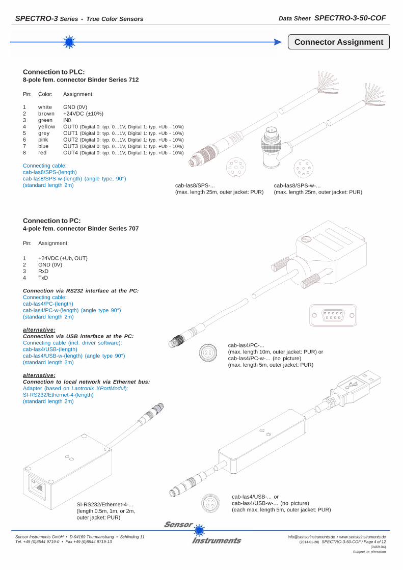
Connection to PC:4-pole fem. connector Binder Series 707
Pin: Assignment:
1 +24VDC (+Ub, OUT)2 GND (0V)3 RxD4 TxD
Connection via RS232 interface at the PC:Connecting cable:cab-las4/PC-(length)cab-las4/PC-w-(length) (angle type 90°)(standard length 2m)
alternative:Connection via USB interface at the PC:Connecting cable (incl. driver software):cab-las4/USB-(length)cab-las4/USB-w-(length) (angle type 90°)(standard length 2m)
alternative:Connection to local network via Ethernet bus:Adapter (based on Lantronix XPortModul):SI-RS232/Ethernet-4-(length)(standard length 2m)
SI-RS232/Ethernet-4-...(length 0.5m, 1m, or 2m,outer jacket: PUR)
Connector Assignment
Connection to PLC:8-pole fem. connector Binder Series 712
Pin: Color: Assignment:
1 white GND (0V)2 brown +24VDC (±10%)3 green IN04 yellow OUT0 (Digital 0: typ. 0…1V, Digital 1: typ. +Ub - 10%)5 grey OUT1 (Digital 0: typ. 0…1V, Digital 1: typ. +Ub - 10%)6 pink OUT2 (Digital 0: typ. 0…1V, Digital 1: typ. +Ub - 10%)7 blue OUT3 (Digital 0: typ. 0…1V, Digital 1: typ. +Ub - 10%)8 red OUT4 (Digital 0: typ. 0…1V, Digital 1: typ. +Ub - 10%)
Connecting cable:cab-las8/SPS-(length)cab-las8/SPS-w-(length) (angle type, 90°)(standard length 2m) cab-las8/SPS-...
(max. length 25m, outer jacket: PUR)
cab-las4/PC-...(max. length 10m, outer jacket: PUR) orcab-las4/PC-w-... (no picture)(max. length 5m, outer jacket: PUR)
cab-las4/USB-... orcab-las4/USB-w-... (no picture)(each max. length 5m, outer jacket: PUR)
cab-las8/SPS-w-...(max. length 25m, outer jacket: PUR)

Data Sheet SPECTRO-3-50-COFSPECTRO-3 Series • True Color Sensors
[email protected] • www.sensorinstruments.de (2014-01-28) SPECTRO-3-50-COF / Page 5 of 12
(0469.04)Subject to alteration
Sensor Instruments GmbH • D-94169 Thurmansbang • Schlinding 11Tel. +49 (0)8544 9719-0 • Fax +49 (0)8544 9719-13
Visualization
Visualization of the color code:
The color code is visualised by way of 5 yellow LEDs at the housing of the SPECTRO-3 color sensor. At the same time in the binarymode (OUT BINARY) the color code indicated on the LED display is output as 5-bit binary information at the digital outputs OUT0 toOUT4 of the 8-pin SPECTRO-3/PLC socket.
The SPECTRO-3 color sensor is able to process a maximum of 31 colors (color code 0 ... 30) in accordance with the correspondingrows in the COLOR TEACH TABLE. An "error" respectively a "not detected color" is displayed by the lighting of all LED (OUT0 ... OUT4digital outputs are set to HIGH-level).
In the DIRECT mode (OUT DIRECT HI or OUT DIRECT LO) the maximum numbers of colors to be taught is 5 (color no. 0, 1, 2, 3, 4).If DIRECT HI is activated, the specially digital output is set to HI, while the other 4 are set to LO. If the current color does notcorrespond with any of the teach-in colors, all digital outputs are set to LOW (no LED is lighting).
If DIRECT LO is activated, the specially digital output is set to LO, while the other 4 are set to HI. If the current color does notcorrespond with any of the teach-in colors, all digital outputs are set to HIGH (all LED are lighting).
Measuring Principle
Measuring principle of the color sensors of SPECTRO-3 series:
The SPECTRO-3 provides highly flexible signal acquisition. For example, the sensor can be operated in alternating-light mode(AC mode), which makes the sensor insensitive to extraneous light. It also can be set to constant-light mode (DC mode),which makes the sensor extremely fast and allows a scan-frequency of up to 35 kHz. An OFF function turns off the integratedlight source at the sensor and changes to DC operation. The sensor then can detect so-called „self-luminous objects“.In PULSE operation extremely dark surfaces can be reliably detected. With the stepless adjustment of the integrated lightsource as well as the selectable gain of the receiver signal and an INTEGRAL function the sensor can be set to almost anysurface or any “self-luminous object“.
When the integrated light source of the SPECTRO-3 color sensor is activated, the sensor detects the radiation that is diffuselyreflected from the object. As a light source the SPECTRO-3 color sensor uses a white-light LED with adjustable transmitterpower. An integrated 3-fold receiver for the red, green, and blue content of the light that is reflected from the object, or the lightthat is emitted by a „self-luminous object“, is used as a receiver.
The SPECTRO-3 color sensor can be „taught“ up to 31 colors. For each of these taught colors it is possible to set tolerances.In „X Y INT - 2D“ or „s i M - 2D“ mode these tolerances form a color cylinder in space. In „X Y INT - 3D“ or „s i M - 3D“ mode thetolerances form a color sphere in space. Color evaluation according to „s i M - 2D“ is based on the lab calculation method.All modes can be used in combination with several operating modes such as „FIRST HIT“ and „BEST HIT“. Raw data arerepresented with 12 bit resolution.
As a special feature the sensor can be taught two completely independent parameter sets. Input IN0 can then be used to tellthe sensor which parameter set it should work with.
Color detection either operates continuously or is started through an external PLC trigger signal. The respective detected coloreither is provided as a binary code at the 5 digital outputs or can be sent directly to the outputs, if only up to 5 colors are to bedetected. At the same time the detected color code is visualised by means of 5 LEDs at the housing of the SPECTRO-3.[Please note: Visualisation by means of LEDs not available with SPECTRO-3-…-JR types.]
With a TEACH button at the sensor housing the color sensor can be taught up to 31 colors. For this purpose the correspondingevaluation mode must be set with the software. The TEACH button is connected in parallel to the input IN0 (green wire at cablecab-las8/SPS). [Please note: TEACH button not available with SPECTRO-3-…-JR types.]
Parameters and measurement values can be exchanged between a PC and the SPECTRO-3 color sensor through the serialRS232 interface. All the parameters for color detection also can be saved to the non-volatile EEPROM of the SPECTRO-3 colorsensor through this serial RS232 interface. When parameterisation is finished, the color sensor continues to operate with thecurrent parameters in STAND-ALONE mode without a PC.
The sensors of the SPECTRO-3 series can be calibrated (white-light balancing). Balancing can be performed to any whitesurface. A ColorCheckerTM table with 24 color fields is available as an alternative. White-light balancing or calibration can beperformed to one of the white fields.

Data Sheet SPECTRO-3-50-COFSPECTRO-3 Series • True Color Sensors
[email protected] • www.sensorinstruments.de (2014-01-28) SPECTRO-3-50-COF / Page 6 of 12
(0469.04)Subject to alteration
Sensor Instruments GmbH • D-94169 Thurmansbang • Schlinding 11Tel. +49 (0)8544 9719-0 • Fax +49 (0)8544 9719-13
LED-Display
0
3
6
9
12
15
18
21
24
27
30
1 2
4
7
10
13
16
19
22
25
28
5
8
11
14
17
20
23
26
29
LED display:
The color code is visualized by means of 5 yellowLEDs at the housing of the color sensor. At thesame time the color code indicated at the LEDdisplay is output as 5-bit binary information at thedigital outputs OUT0 ... OUT4 of the 8-pole PLCconnector.
In the DIRECT mode the maximum number of colorcodes to be taught is 5. These 5 color codes can bedirectly output at the 5 digital outputs. Therespective detected color code is displayed bymeans of the 5 yellow LEDs at the color sensorhousing.
Error or„not detected“
OUT0 OUT1 OUT2 OUT3 OUT4
1 2 4 8 16

Data Sheet SPECTRO-3-50-COFSPECTRO-3 Series • True Color Sensors
[email protected] • www.sensorinstruments.de (2014-01-28) SPECTRO-3-50-COF / Page 7 of 12
(0469.04)Subject to alteration
Sensor Instruments GmbH • D-94169 Thurmansbang • Schlinding 11Tel. +49 (0)8544 9719-0 • Fax +49 (0)8544 9719-13
Parameterization
Windows® user interface:
The color sensor is parameterized under Windows® with the SPECTRO3-Scope software. The Windows® user interface facilitatesthe teach-in process at the color sensor and supports the operator in the task of adjustment and commissioning of the color sensor.
The RS232 interface (tab PARA1 or PARA2) is used for setting parameters such as:
- POWER MODE: Light power of the LED- LED MODE: Triggering of the internal light source- GAIN: Used for setting the gain of the receiver- AVERAGE: Averaging over a maximum of 32768 values- INTEGRAL: This function field is used to set the number of scan values (measurement values) over which the
raw signal measured at the receiver is summed up. This integral function allows the reliabledetection even of extremely weak signals
- MAXCOL-No.: Number of colors to be checked- OUTMODE: Triggering of the digital outputs- INTLIM: Minimum intensity required for color evaluation- EVALUATION MODE: Various evaluation modes to choose from (FIRST HIT, BEST HIT, MIN DIST, COL5, THD RGB)- CALCULATION MODE: There are 2 methods of teaching a color, which are selectable via CALCULATION MODE.
The CALCULATION MODE „X Y INT - 3D“ (or „s i M - 3D“) uses a color sphere in space withradius TOL. Contrary to this, the CALCULATION MODE „X Y INT - 2D“ (or „s i M - 2D“) uses a colorcylinder in space with radius CTO or siTO and with height ITO or M. The teach process is the samefor both methods. Color evaluation according to "s i M - 2D" uses the Lab calculation method
- EXTEACH: In all the evaluation modes teaching of a color can be performed externally through IN0 or by meansof the button at the sensor housing [Please note: TEACH button not available with SPECTRO-3-…-JRtypes.]
- TRIGGER: Continuous or external or self trigger
Under Windows®representation of thecolor value on a PC innumeric form and in acolor chart, andrepresentation of RGBvalues in a time chart.In addition the currentRGB values aredisplayed as a barchart.

Data Sheet SPECTRO-3-50-COFSPECTRO-3 Series • True Color Sensors
[email protected] • www.sensorinstruments.de (2014-01-28) SPECTRO-3-50-COF / Page 8 of 12
(0469.04)Subject to alteration
Sensor Instruments GmbH • D-94169 Thurmansbang • Schlinding 11Tel. +49 (0)8544 9719-0 • Fax +49 (0)8544 9719-13
Firmware update by means of software „ProgramLoader“ or „FirmwareLoader“:
The software „ProgramLoader“ or „FirmwareLoader“ allows theuser to perform an automatic firmware update.The update will be carried out through the RS232 interface.
An initialisation file (xxx.ini) and a firmware file (xxx.elf.S) arerequired for performing a firmware update. These files can beobtained from your supplier.In some cases an additional firmware file for the programmemory (xxx.elf.p.S) is also needed, and this file will beautomatically provided together with the other two files.
Firmware Update

Data Sheet SPECTRO-3-50-COFSPECTRO-3 Series • True Color Sensors
[email protected] • www.sensorinstruments.de (2014-01-28) SPECTRO-3-50-COF / Page 9 of 12
(0469.04)Subject to alteration
Sensor Instruments GmbH • D-94169 Thurmansbang • Schlinding 11Tel. +49 (0)8544 9719-0 • Fax +49 (0)8544 9719-13
Diagrams: SPOT DIAMETER and RELATIVE INTENSITYSPECTRO-3-50-COF-d3.5
Diagrams
Spot diameter:SPECTRO-3-50-COF-d3.5:3,5mm (typ.) at a working distance of 50 mm
Relative intensity:SPECTRO-3-50-COF-d3.5:100% at a working distance of 40 mm(INTENSITY 96)
Data Sheet SPECTRO-3-50-COFSPECTRO-3 Series • True Color Sensors
[email protected] • www.sensorinstruments.de (2014-01-28) SPECTRO-3-50-COF / Page 10 of 12
(0469.04)Subject to alteration
Sensor Instruments GmbH • D-94169 Thurmansbang • Schlinding 11Tel. +49 (0)8544 9719-0 • Fax +49 (0)8544 9719-13
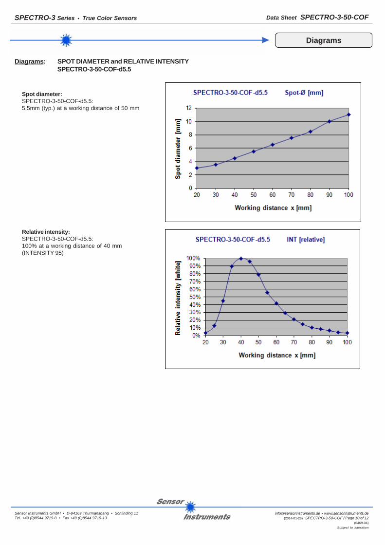
Diagrams: SPOT DIAMETER and RELATIVE INTENSITYSPECTRO-3-50-COF-d5.5
Diagrams
Spot diameter:SPECTRO-3-50-COF-d5.5:5,5mm (typ.) at a working distance of 50 mm
Relative intensity:SPECTRO-3-50-COF-d5.5:100% at a working distance of 40 mm(INTENSITY 95)
Data Sheet SPECTRO-3-50-COFSPECTRO-3 Series • True Color Sensors
[email protected] • www.sensorinstruments.de (2014-01-28) SPECTRO-3-50-COF / Page 11 of 12
(0469.04)Subject to alteration
Sensor Instruments GmbH • D-94169 Thurmansbang • Schlinding 11Tel. +49 (0)8544 9719-0 • Fax +49 (0)8544 9719-13
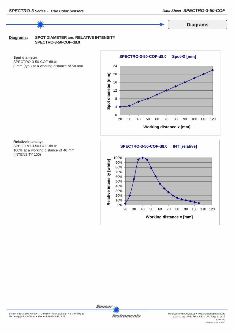
Diagrams: SPOT DIAMETER and RELATIVE INTENSITYSPECTRO-3-50-COF-d8.0
Diagrams
Spot diameterSPECTRO-3-50-COF-d8.0:8 mm (typ.) at a working distance of 50 mm
Relative intensity:SPECTRO-3-50-COF-d8.0:100% at a working distance of 40 mm(INTENSITY 100)
0
4
8
12
16
20
24
20 30 40 50 60 70 80 90 100 110 120
Spot
dia
met
er [m
m]
Working distance x [mm]
SPECTRO-3-50-COF-d8.0 Spot-Ø [mm]
0%10%20%30%40%50%60%70%80%90%
100%
20 30 40 50 60 70 80 90 100 110 120
Rel
ativ
e in
tens
ity [w
hite
]
Working distance x [mm]
SPECTRO-3-50-COF-d8.0 INT [relative]

Data Sheet SPECTRO-3-50-COFSPECTRO-3 Series • True Color Sensors
[email protected] • www.sensorinstruments.de (2014-01-28) SPECTRO-3-50-COF / Page 12 of 12
(0469.04)Subject to alteration
Sensor Instruments GmbH • D-94169 Thurmansbang • Schlinding 11Tel. +49 (0)8544 9719-0 • Fax +49 (0)8544 9719-13
Mounting Accessories
FL-34(flange)
WFL-34(flange, angle type 90°)
(All dimensions in mm)
Example: FL-34 withSPECTRO-3-30-DILmounted
Example: WFL-34 withSPECTRO-3-30-DILmounted