speed for sale llc website: … · speedforsale.com’s installation guide series: engine removal...
TRANSCRIPT

Speed For Sale LLC
Website: www.SpeedForSale.com/nissangtrparts
Email: [email protected]
Telephone: 770-777-4774
Location area: Atlanta, Georgia, USA
SpeedForSale.com’s Installation Guide Series:
Engine Removal and Reinstallation for 2009 GT-R
HUNDREDS OF GT-R PERFORMANCE AND OEM PARTS CAN BE FOUND
HERE:
www.SpeedForSale.com/nissangtrparts
YOU CAN ALSO VIEW OUR ‘STAGED POWER UPGRADES’ HERE:
https://www.speedforsale.com/nissangtrparts/speed-sale-speedforsale-staged-power-
upgrades-p-1030.html?osCsid=2airirkvjdgqclcjmqfiildbt3
Article written by Jared Pink with the assistance of Chinchi Chiang. Article revised
and converted to PDF by Jeremy Blackwell.
Time:
Varies depending on your equipment and experience. Expect more than 20 hours in full
removal and reinstallation the first time you perform the job.
Difficulty:
Moderate-Difficult
Description: This process outlines the installation steps required for removal and reinstallation of the
GT-R's VR38DETT engine assembly. This guide outlines the steps that are taken if you
remove the radiator core support when removing the engine. This is not required, but in
this particular situation we had to remove it anyway for some other work we did,
therefore we included the steps here. You can simply drop the engine out of the bottom
of the car without removing the support/etc.
Tools Needed:
• 8mm 10mm, 12mm, 14mm, 17mm, 19mm sockets
• 10mm, 12mm, 14mm, 17mm wrenches
• 45 degree pliers
• Ratchet
• 6” extension
• 45 degree pliers
• Blue thread lock (for reinstallation)
• Philips #2 screw driver
• Flat head screw driver
• Plastic pry tool
• Wheel socket
• A/C line special service tool
• R134 recovery machine

Preparation:
Disconnect the battery.
Raise and secure vehicle off the ground. A lift is obviously suggested, but not required.
Allow the vehicle to sit at least one hour to allow it to cool.
Step-by-step procedure:
1. Remove the intercooler pipes going to the throttle bodies by disconnecting the
MAP sensor, using the pliers to remove the wire locating clips, and removing the two
hoses from the air bypass valve. You will also need to loosen the clamps on the couplers
at the throttle body and the hard pipe inside the fender.

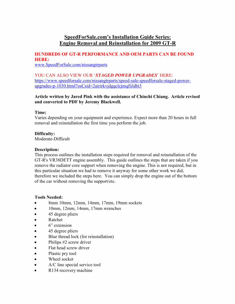
2. Remove the engine grounding strap that goes from the body to the engine.
Remove the 12mm bolt, and disengage the plastic locating tab.
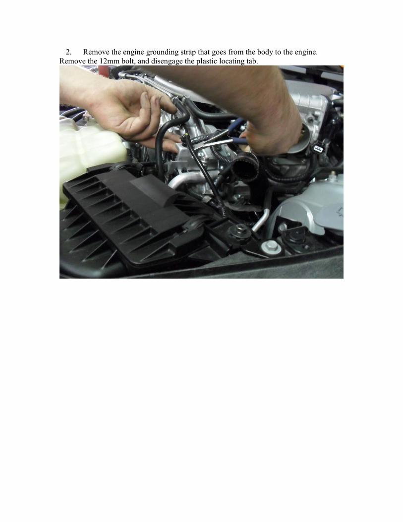
3. Disconnect the MAF sensor connector, and harness locating tab.
4. Loosen the hose that goes to the turbo by using the 8mm socket. Once loose, slide
the hose downward away from the air box.
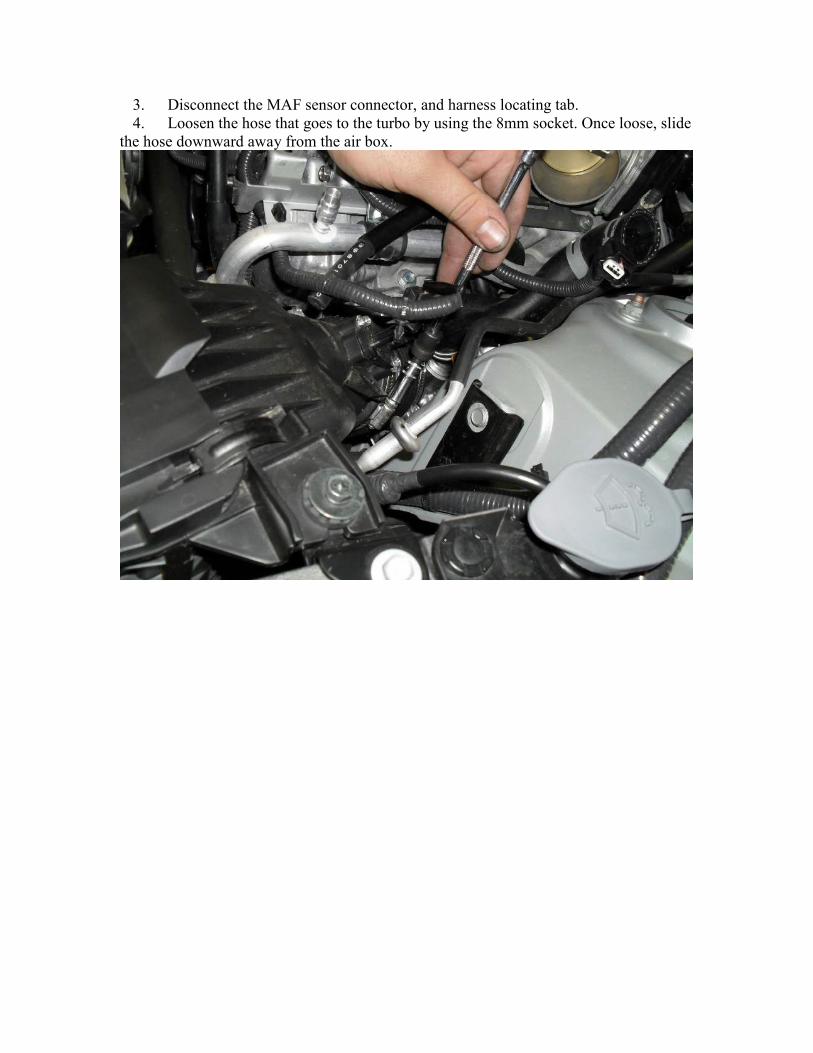
5. Remove the 2 10mm bolts that hold the air box to the radiator core support.
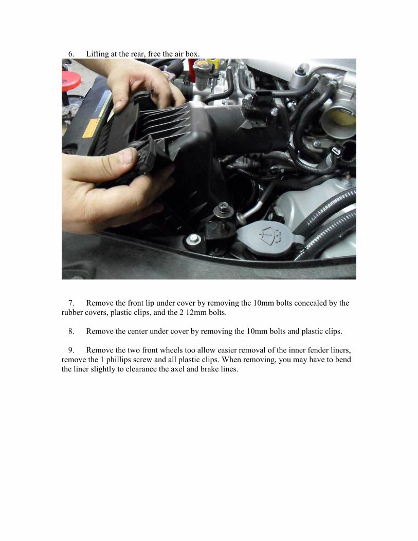
6. Lifting at the rear, free the air box.
7. Remove the front lip under cover by removing the 10mm bolts concealed by the
rubber covers, plastic clips, and the 2 12mm bolts.
8. Remove the center under cover by removing the 10mm bolts and plastic clips.
9. Remove the two front wheels too allow easier removal of the inner fender liners,
remove the 1 phillips screw and all plastic clips. When removing, you may have to bend
the liner slightly to clearance the axel and brake lines.


10. Remove the front side markers by using the plastic pry tool and gently pressing
inward on the metal lock clip. You can either disconnect the bulb connector or remove
the socket from the bulb housing.


11. Remove the radiator panel by removing the plastic clips.

12. Remove the 5 bumper plastic clips
13. Using a quality painters tape, tape the bumper and the fender along the seam to
protect against scratches.
14. Remove the 4 10mm bolts that hold the bumper. Once removed, holding the
corners of the bumper, pull outward firmly to disengage the clips holding the bumper.
Carefully slide the bumper forward and away from the vehicle.

15. Disconnect electrical connectors from the headlights, also remove the locating
tabs for the headlights.
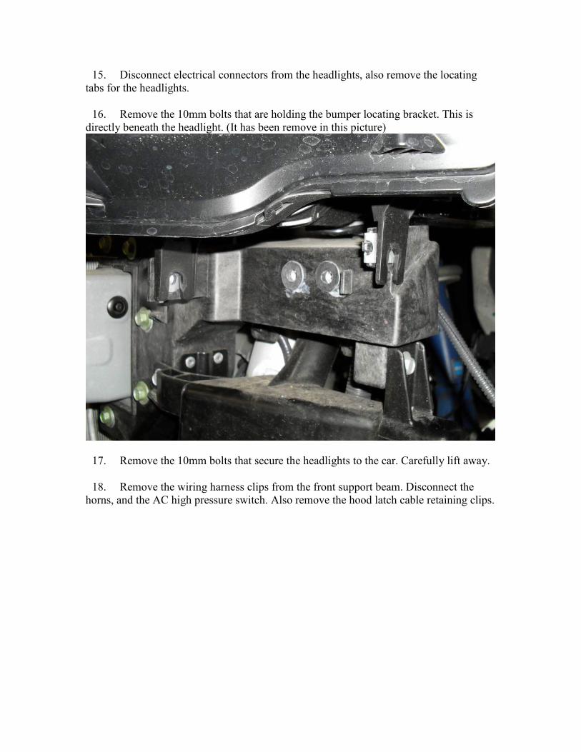
16. Remove the 10mm bolts that are holding the bumper locating bracket. This is
directly beneath the headlight. (It has been remove in this picture)
17. Remove the 10mm bolts that secure the headlights to the car. Carefully lift away.
18. Remove the wiring harness clips from the front support beam. Disconnect the
horns, and the AC high pressure switch. Also remove the hood latch cable retaining clips.


19. Remove the bumper support bracket removing 6 10mm bolts
20. Remove the air snorkels by removing the plastic lock clip
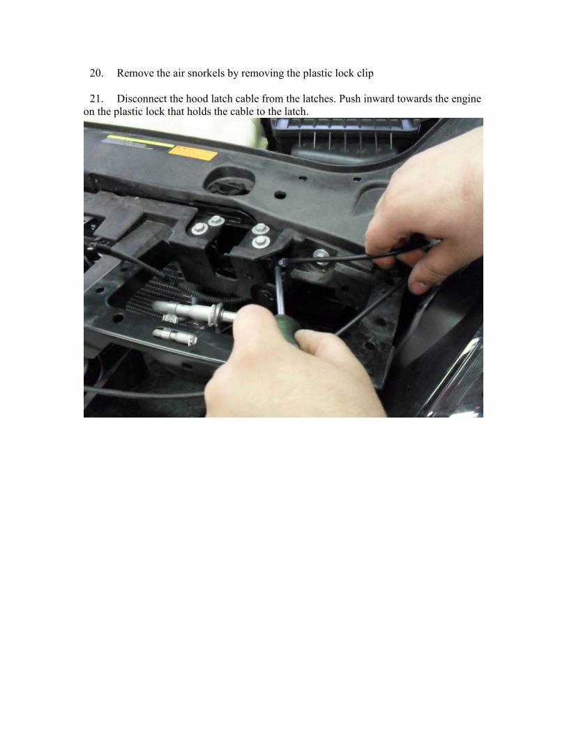
21. Disconnect the hood latch cable from the latches. Push inward towards the engine
on the plastic lock that holds the cable to the latch.
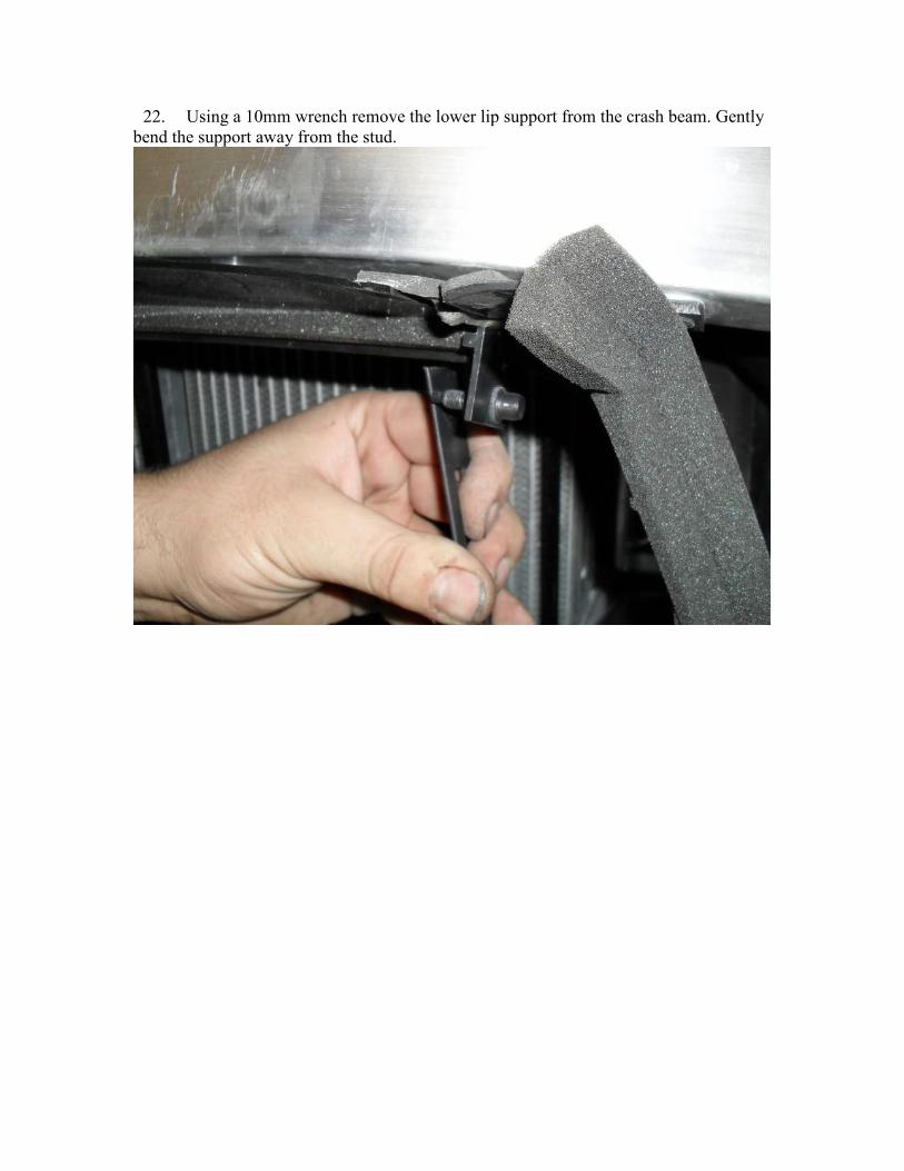
22. Using a 10mm wrench remove the lower lip support from the crash beam. Gently
bend the support away from the stud.

23. Remove crash beam by removing 8 12mm bolts. Once removed pull outward.
24. Remove all 10mm bolts that holds the support. The hood latch should only have
the two nearest the engine removed. (The picture shows 1 already removed). There are
two bolts at the bottom near the intercooler hard pipe bolt that are commonly missed.
There is also one bolt behind the A/C condenser piping that needs to be removed. Also
remove the 2 bolts holding the power steering cooler.


25. Remove intercooler piping from the intercooler.
26. Remove the intercooler assembly from the vehicle by first pulling the right
outwards (vehicle right, beside the oil cooler). As the piping clears the cooler the left side
can be pulled outward and the entire assembly removed from the vehicle.
27. Remove the air shroud by removing 4 plastic lock connectors.
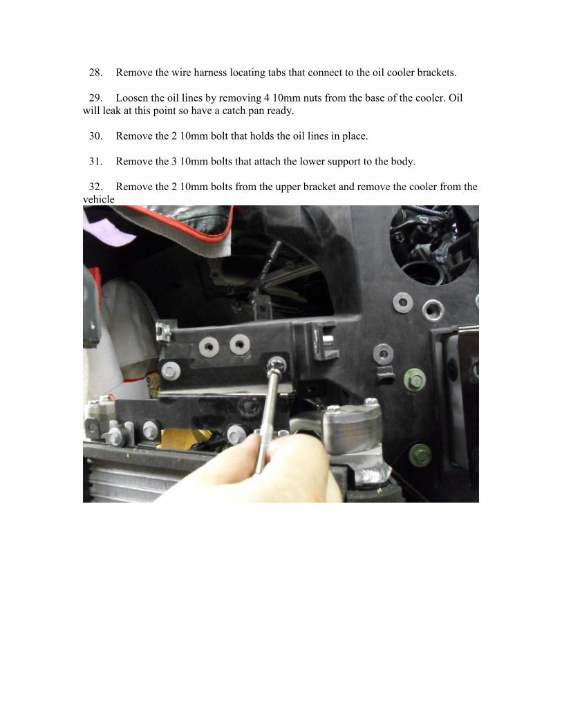
28. Remove the wire harness locating tabs that connect to the oil cooler brackets.
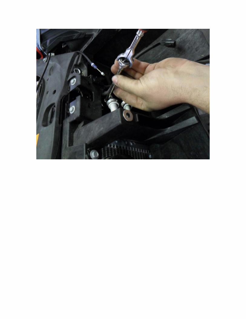
29. Loosen the oil lines by removing 4 10mm nuts from the base of the cooler. Oil
will leak at this point so have a catch pan ready.
30. Remove the 2 10mm bolt that holds the oil lines in place.
31. Remove the 3 10mm bolts that attach the lower support to the body.
32. Remove the 2 10mm bolts from the upper bracket and remove the cooler from the
vehicle
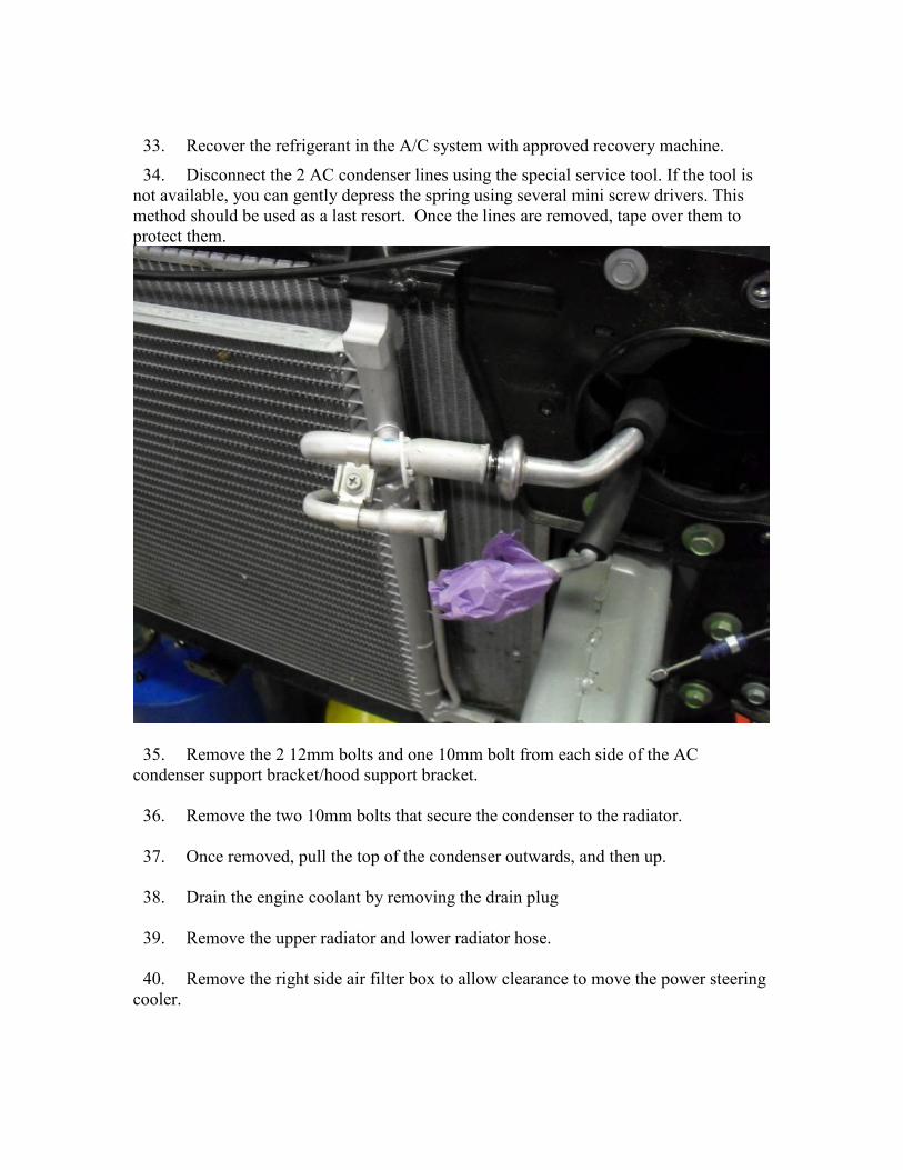
33. Recover the refrigerant in the A/C system with approved recovery machine.
34. Disconnect the 2 AC condenser lines using the special service tool. If the tool is
not available, you can gently depress the spring using several mini screw drivers. This
method should be used as a last resort. Once the lines are removed, tape over them to
protect them.
35. Remove the 2 12mm bolts and one 10mm bolt from each side of the AC
condenser support bracket/hood support bracket.
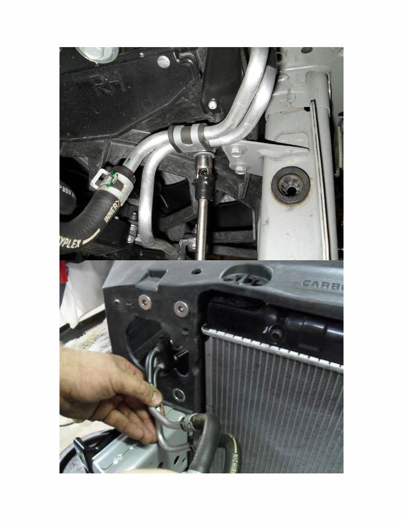
36. Remove the two 10mm bolts that secure the condenser to the radiator.
37. Once removed, pull the top of the condenser outwards, and then up.
38. Drain the engine coolant by removing the drain plug
39. Remove the upper radiator and lower radiator hose.
40. Remove the right side air filter box to allow clearance to move the power steering
cooler.

41. Remove the 10mm bolt that secures the power steering cooler lines. Push the
rubber insulator from the front radiator core support.
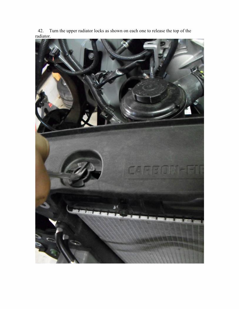
42. Turn the upper radiator locks as shown on each one to release the top of the
radiator.

43. Tilt the top of the radiator outward and lift free from the vehicle.
44. Follow the wire harness and disconnect all locating tabs.
45. Remove the upper fill adapter for the window washer jug by removing the plastic
lock clip and lifting upwards.
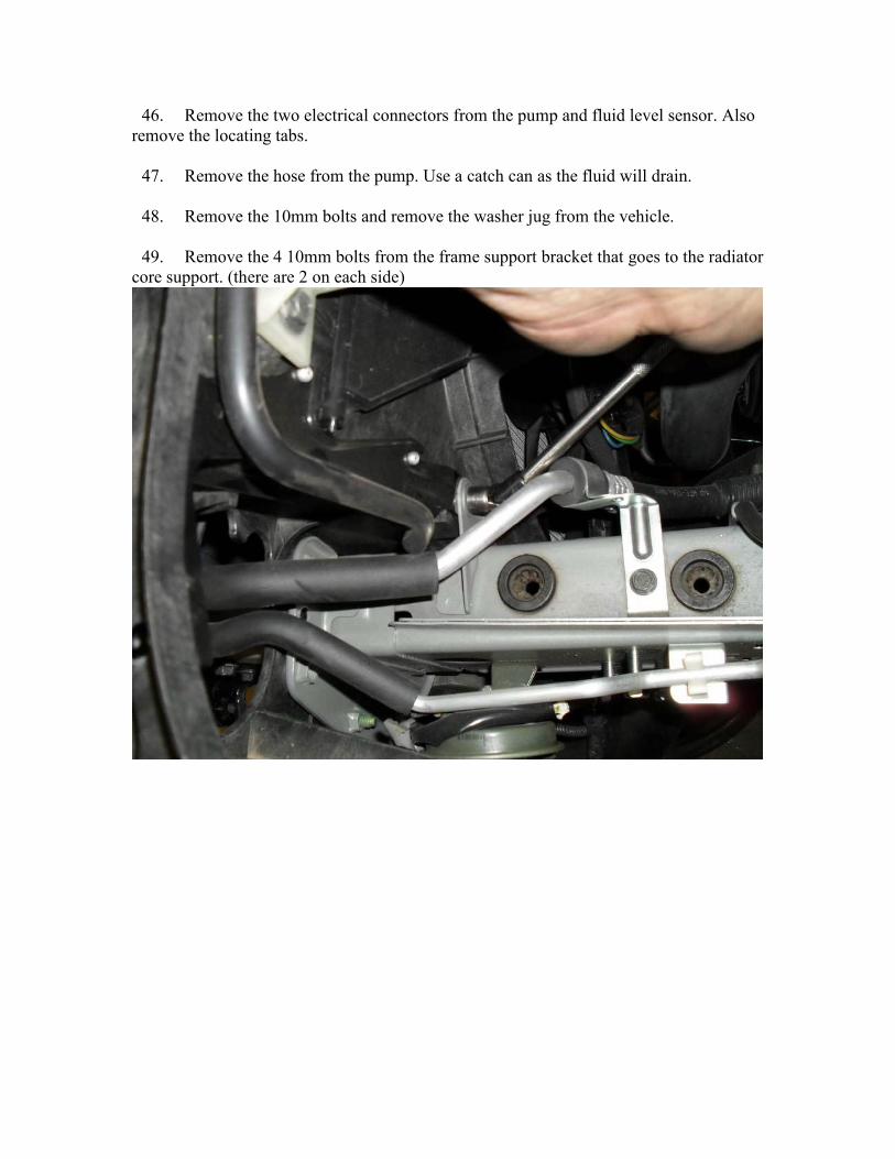
46. Remove the two electrical connectors from the pump and fluid level sensor. Also
remove the locating tabs.
47. Remove the hose from the pump. Use a catch can as the fluid will drain.
48. Remove the 10mm bolts and remove the washer jug from the vehicle.
49. Remove the 4 10mm bolts from the frame support bracket that goes to the radiator
core support. (there are 2 on each side)

50. Remove the radiator overflow bottle by removing the hoses and 2 10mm bolts on
each side.
51. Disconnect the electrical connectors and locating tabs on the cooling fan shroud.

52. Remove 2 10mm nuts from the air bag sensor. It is easier to remove the sensor
then risk damaging it while disconnecting it. When this is reinstalled, use blue thread
lock.

53. Unbolt the power steering cooler lines from the radiator support, and disconnect
the power steering cooler line coming from the steering rack (indicated by finger in
picture)

54. Disconnect the power steering feed line from the pump. Use several rags to catch
any fluid that would leak.
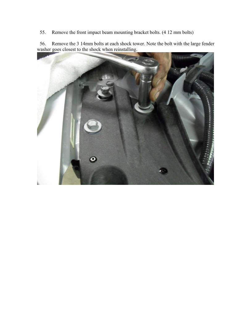
55. Remove the front impact beam mounting bracket bolts. (4 12 mm bolts)
56. Remove the 3 14mm bolts at each shock tower. Note the bolt with the large fender
washer goes closest to the shock when reinstalling.

57. Remove the final 12mm bolts holding the support to the frame rail.
58. Carefully slide the support forward and away from the vehicle.
59. Remove the engine plastic covers by removing the plastic locking tabs. You will
also need to remove the wiper arms by removing the decorative cap and then the 14mm
nut.
60. Remove the large hose going to the emissions air pump. Once disconnected pull
into the engine bay.
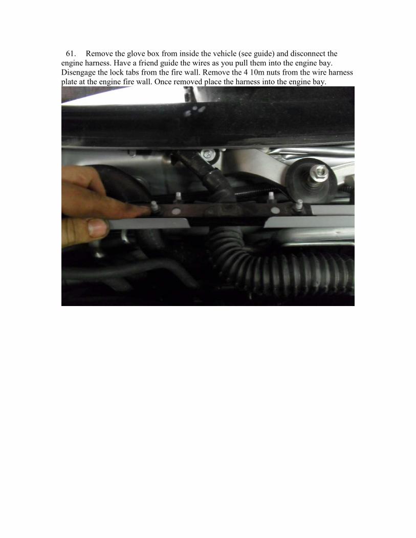
61. Remove the glove box from inside the vehicle (see guide) and disconnect the
engine harness. Have a friend guide the wires as you pull them into the engine bay.
Disengage the lock tabs from the fire wall. Remove the 4 10m nuts from the wire harness
plate at the engine fire wall. Once removed place the harness into the engine bay.

62. Remove the fuel lines by squeezing the tabs gently and pulling away from the
metal line. It is advisable to have a rag around them to prevent fuel spray.
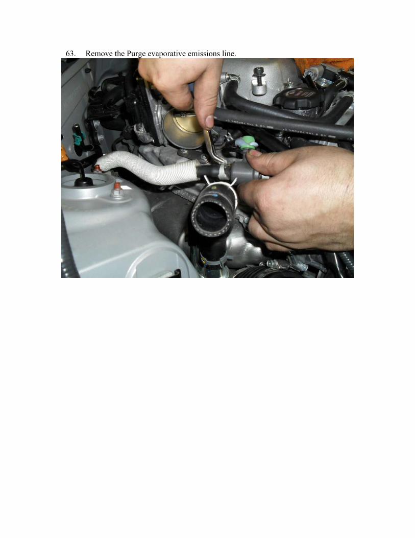
63. Remove the Purge evaporative emissions line.
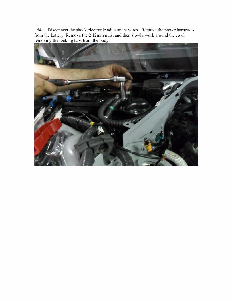
64. Disconnect the shock electronic adjustment wires. Remove the power harnesses
from the battery. Remove the 2 12mm nuts, and then slowly work around the cowl
removing the locking tabs from the body.
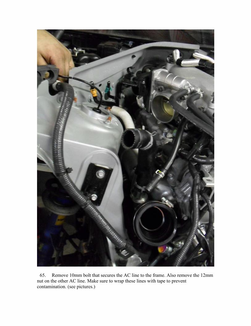
65. Remove 10mm bolt that secures the AC line to the frame. Also remove the 12mm
nut on the other AC line. Make sure to wrap these lines with tape to prevent
contamination. (see pictures.)


66. Remove two heater core hoses. Refer to the pictures.
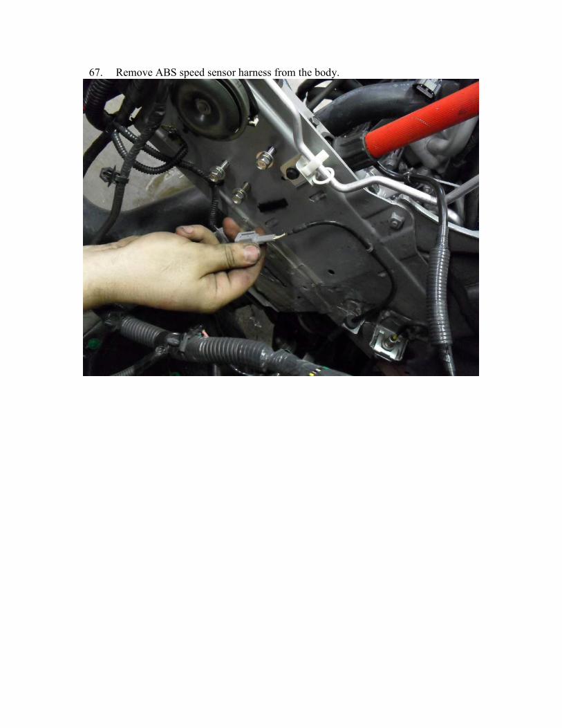
67. Remove ABS speed sensor harness from the body.

68. Disconnect the rubber brake line from the body where the hard line meets it.
69. Remove the mid pipe.
70. Remove the frame support by removing 6 12mm bolts.
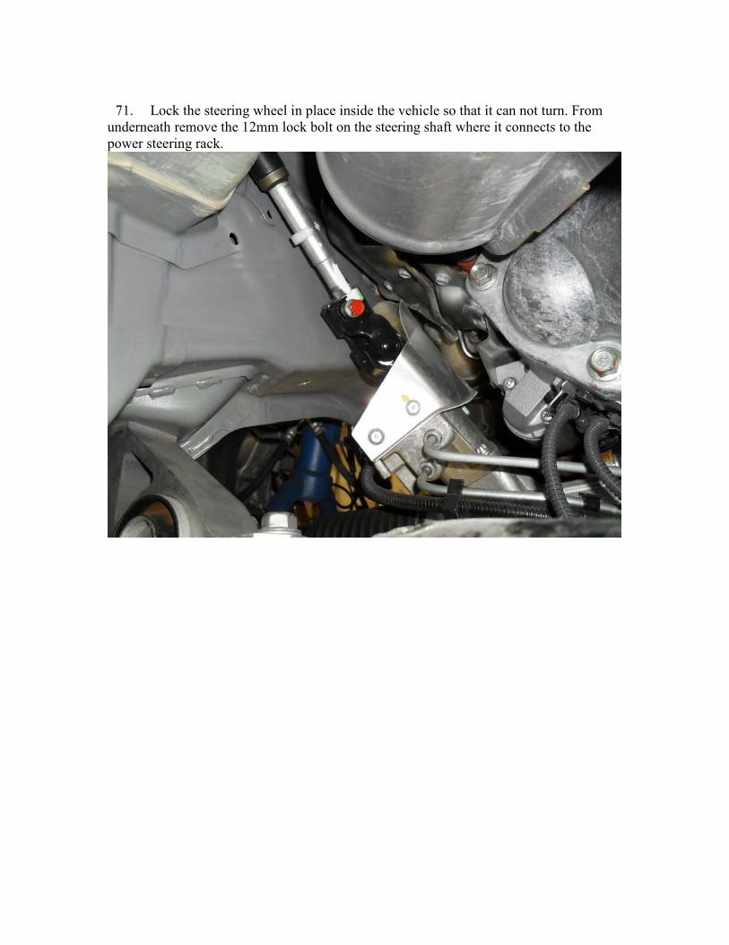
71. Lock the steering wheel in place inside the vehicle so that it can not turn. From
underneath remove the 12mm lock bolt on the steering shaft where it connects to the
power steering rack.

72. Disconnecting transmission cooler lines.
73. Remove the engine drive shaft going to the transmission and the driveshaft going
to the front differential (Loosen the driveshaft bolts where they meet the transmission
first, or else nothing will hold them still to allow removal.)
74. Loosen the upper coil over bolts from the body. Also remove the upper ball joint
by removing the 14 mm bolt and nut.
75. Remove the sway bar end links to allow the front sway bar to swing clear of the
front cradle bolts.
76. Support the engine cradle on either several high strength jack stands, or a cradle
made for the GT-R. Once secure, remove the 2 nuts, and 4 bolts that hold the cradle to
the body.
77. Slowly lift the vehicle free of the engine, paying close attention that nothing has
gotten caught.
78. Installation of the engine is reverse of removal. So, just start here and work your
way backward through this installation manual.
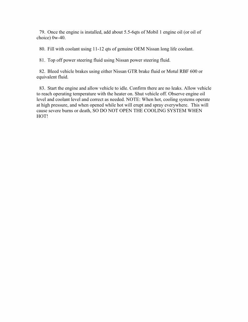
79. Once the engine is installed, add about 5.5-6qts of Mobil 1 engine oil (or oil of
choice) 0w-40.
80. Fill with coolant using 11-12 qts of genuine OEM Nissan long life coolant.
81. Top off power steering fluid using Nissan power steering fluid.
82. Bleed vehicle brakes using either Nissan GTR brake fluid or Motul RBF 600 or
equivalent fluid.
83. Start the engine and allow vehicle to idle. Confirm there are no leaks. Allow vehicle
to reach operating temperature with the heater on. Shut vehicle off. Observe engine oil
level and coolant level and correct as needed. NOTE: When hot, cooling systems operate
at high pressure, and when opened while hot will erupt and spray everywhere. This will
cause severe burns or death, SO DO NOT OPEN THE COOLING SYSTEM WHEN
HOT!