spiral machine operators manual
TRANSCRIPT

SPIRAL MACHINE OPERATORS MANUAL
CONTENTS
Page 2-3: Spiral Operating Tips
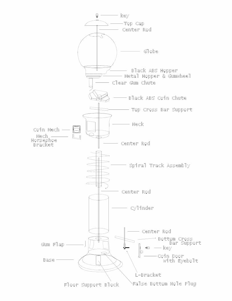
Page 4: Spiral Diagram
Page 5: Cylinder Cleaning Instructions
Page 6: Lock Instructions and Trouble Shooting
Page 7: Mechanism Replacement Instructions
Page 8: Beaver Mechanism Diagram
Page 9: Beaver Mechanism with Microswitch Diagram

SPIRAL MACHINE OPERATING TIPS
Your spiral gumball machine is fully assembled and ready to place onlocation.
1. Remove packing material from machine. Remove protective filmmasking from globe, cylinder and gumball flap.
2. Retain the snake eye driver bit found with the keys. It is required toremove security screws in face plate around the mechanism.
3. Test keys in both top lock, in top cap and bottom lock, in coin accessdoor. Caution: do not over tighten locks! Record key codenumber stamped on key.
4. To add weight to base, remove coin access door, remove 3" plugfrom coin floor and fill bottom with aquarium rock, sand or othermaterial to weigh machine down, replace plug & seal with silicone toprevent possible leakage.
5. Center coin tub in base under coin drop tube.
6. Unlock top lock remove cap and fill globe with gum. Watch forbroken, cut or mal-formed pieces of gumballs and remove. Recommend testing machine with 6 quarters for proper dispensingbefore filling globe full. Then fill to desired level and replace cap.
Maintenance
1. To clean track area: remove coin door, locate l-bracket, use ½" openend wrench on vertical rod coupler & unscrew turning to the left(maybe necessary to bend horizontal threaded rod of l-bracketdown½" so l-bracket can turn freely). Lift neck with globe attached up& lay aside. Now track can be lifted out for cleaning. Replace trackso top track aligns properly gum chute & seam on cylinder centeredin the rear. Replace center rod with neck & globe through hole inbase cross bar. Replace lock washer &/or spacers, then screw on l-bracket to original tight position and align or adjust horizontalthreaded rod for coin door replacement.
2. For general cleaning of all surfaces use "brillianize" anti-static cleaneror "novus 1". Ammonia based cleaners are not recommended.
3. For small scratch removal and polish on all surfaces use "novus 2".
Contact your dealer for the available options
1. Display sign for top of machine for winner promotional program.
2. Chasing rope light kit in red, blue, yellow, green, multi-colors or white. Ac only. Variable speed.
3. Other product dispensing wheels for smaller round gum or candyproducts.
Contact novus or brillianize for their closest dealer at:
Novus 800-548-6872Brillianize 800-445-9344
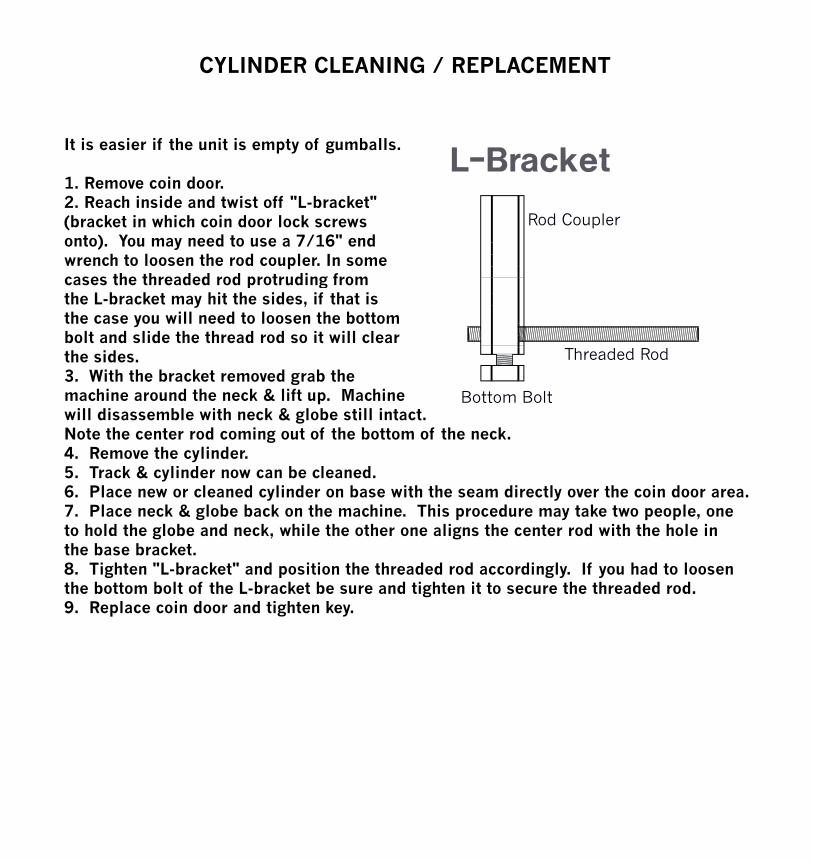
It is easier if the unit is empty of gumballs.
CYLINDER CLEANING / REPLACEMENT
Rod Coupler
1. Remove coin door.2. Reach inside and twist off "L-bracket"(bracket in which coin door lock screws onto). You may need to use a 7/16" endwrench to loosen the rod coupler. In somecases the threaded rod protruding from
Threaded Rod
cases the threaded rod protruding fromthe L-bracket may hit the sides, if that is the case you will need to loosen the bottombolt and slide the thread rod so it will clearthe sides.3. With the bracket removed grab the
hi d th k & lift M hi Bottom Boltmachine around the neck & lift up. Machinewill disassemble with neck & globe still intact.Note the center rod coming out of the bottom of the neck.4. Remove the cylinder.5. Track & cylinder now can be cleaned.6. Place new or cleaned cylinder on base with the seam directly over the coin door area.7. Place neck & globe back on the machine. This procedure may take two people, one to hold the globe and neck, while the other one aligns the center rod with the hole in the base bracket.8. Tighten "L-bracket" and position the threaded rod accordingly. If you had to loosenthe bottom bolt of the L-bracket be sure and tighten it to secure the threaded rod.9. Replace coin door and tighten key.

Key pull outs must always be lined up either at the noon or 6:00 o'clock position. If key pull outs are not lined up, file key stub off key, then key will line up with center postpull out and lock can then be removed.
LOCK
Tumblers
Key Code
Key StubCenter Post
If any tumblers have fallen out or if key will insert but lock will not turn, then the only way to remove the lock is to have it drilled out. This can be done by a locksmith or yourself.
If you do this yourself you will need a variable speed drill, a center punch or 1/8" drill bit, 1/4" drill bit. You will also need protective eye wear while you operate the drill.Procedure:1. Place protective eye wear on.2. Start with center punch or 1/8" drill bit, start small pilot hole in the lock center post so larger drill bit does not wander.3. Change bit to 1/4" size and drill out center post.4. Lock will fall off or apart after drilling about 7/8" to 1".5. Remove coin door or top cap.6. Unscrew brass portion of lock off rod.7. Place new lock on.
Noon
6:00 o'clock
LOCK TROUBLE SHOOTING
The majority of lock problems are due to over tightening the lock. Please do not tighten the locks too tight. The lock only needs to be tightenedjust enough to be snug where the top cap or coin door do not wiggle or have movement.Over tightening the lock only shortens the life span of the lock and can damage the tumblers or break the lock.
* If you do not have experience with a power drill or feel uncomfortable with this procedure, then do not attempt this procedure! Call an expert.

BEAVER
1 2
3 4
5 67 8
1. Remove snake eye screws labeled 1-6 from face plate using snake eye bit.2. Remove face plate with mechanism.3. Remove screws label 7 & 8 and pull horseshoe bracket from mechanism.4. Place horseshoe bracket onto new mech and place mech into face plate.5. Screw horseshoe bracket to face plate by replacing screws 7 & 8.6. Place face plate with mech into neck of the machine.7. Replace screws 1-6 by first starting screws 3 & 4 a few turns, then while pushing downward on mech handle, screws 1,2,5 & 6 can be started, then tighten all screws.
Snake Eye Bit
REMOVING AND REPLACING MECHANISM

