src pe software solutions guide
TRANSCRIPT
SRC PE Software
Solutions Guide
Release
4.8.x
Published: 2014-12-09
Copyright © 2014, Juniper Networks, Inc.

Juniper Networks, Inc.1194 North Mathilda AvenueSunnyvale, California 94089USA408-745-2000www.juniper.net
Copyright © 2014, Juniper Networks, Inc. All rights reserved.
Juniper Networks, Junos, Steel-Belted Radius, NetScreen, and ScreenOS are registered trademarks of Juniper Networks, Inc. in the UnitedStates and other countries. The Juniper Networks Logo, the Junos logo, and JunosE are trademarks of Juniper Networks, Inc. All othertrademarks, service marks, registered trademarks, or registered service marks are the property of their respective owners.
Juniper Networks assumes no responsibility for any inaccuracies in this document. Juniper Networks reserves the right to change, modify,transfer, or otherwise revise this publication without notice.
SRC PE Software Solutions GuideRelease 4.8.xCopyright © 2014, Juniper Networks, Inc.All rights reserved.
Revision HistoryDecember 2014—Revision 1
The information in this document is current as of the date on the title page.
YEAR 2000 NOTICE
Juniper Networks hardware and software products are Year 2000 compliant. Junos OS has no known time-related limitations through theyear 2038. However, the NTP application is known to have some difficulty in the year 2036.
SOFTWARE LICENSE
The terms and conditions for using this software are described in the software license contained in the acknowledgment to your purchaseorder or, to the extent applicable, to any reseller agreement or end-user purchase agreement executed between you and Juniper Networks.By using this software, you indicate that you understand and agree to be bound by those terms and conditions.
Generally speaking, the software license restricts the manner in which you are permitted to use the software and may contain prohibitionsagainst certain uses. The software license may state conditions under which the license is automatically terminated. You should consultthe license for further details.
For complete product documentation, please see the Juniper Networks Web site at www.juniper.net/techpubs.
ENDUSER LICENSE AGREEMENT
The Juniper Networks product that is the subject of this technical documentation consists of (or is intended for use with) Juniper Networkssoftware. Use of such software is subject to the terms and conditions of the End User License Agreement (“EULA”) posted athttp://www.juniper.net/support/eula.html. By downloading, installing or using such software, you agree to the terms and conditions ofthat EULA.
Copyright © 2014, Juniper Networks, Inc.ii
Abbreviated Table of Contents
About the Documentation . . . . . . . . . . . . . . . . . . . . . . . . . . . . . . . . . . . . . . . . . xvii
Part 1 Providing Specialized Services in an SRC Environment
Chapter 1 ManagingTieredandPremiumServiceswithQoSonJunosERouters(SRCCLI) . . . . . . . . . . . . . . . . . . . . . . . . . . . . . . . . . . . . . . . . . . . . . . . . . . . . . . . . . . . . . . . 3
Chapter 2 Managing Subscribers for a Wireless Roaming Environment . . . . . . . . . . . . 17
Chapter 3 Configuring VoIP Services in an SRC Network . . . . . . . . . . . . . . . . . . . . . . . . . 25
Chapter 4 Providing Packet Mirroring in an SRC Network . . . . . . . . . . . . . . . . . . . . . . . . 29
Part 2 Managing Services in a PCMM Environment
Chapter 5 Providing Premium Services in a PCMM Environment . . . . . . . . . . . . . . . . . . 41
Chapter 6 Configuring the SAE for a PCMM Environment (SRC CLI) . . . . . . . . . . . . . . . 57
Chapter 7 Adding Objects for CMTS Devices (SRC CLI) . . . . . . . . . . . . . . . . . . . . . . . . . 69
Chapter 8 Using the NIC Resolver in a PCMM Environment . . . . . . . . . . . . . . . . . . . . . . . 73
Chapter 9 Using PCMMPolicy Servers . . . . . . . . . . . . . . . . . . . . . . . . . . . . . . . . . . . . . . . . . 75
Chapter 10 Configuring the JPS (SRC CLI) . . . . . . . . . . . . . . . . . . . . . . . . . . . . . . . . . . . . . . 79
Chapter 11 Monitoring the JPS (SRC CLI) . . . . . . . . . . . . . . . . . . . . . . . . . . . . . . . . . . . . . . 105
Chapter 12 Monitoring the JPS (C-Web Interface) . . . . . . . . . . . . . . . . . . . . . . . . . . . . . . 109
Part 3 Managing Services on RADIUS and Diameter Devices
Chapter 13 Managing Services on Third-Party Devices in the SRC Network . . . . . . . . . 119
Chapter 14 Managing the SRC Diameter Server . . . . . . . . . . . . . . . . . . . . . . . . . . . . . . . . . 127
Chapter 15 Monitoring the SRC Diameter Server (SRC CLI) . . . . . . . . . . . . . . . . . . . . . . 135
Chapter 16 Managing Services with Diameter on MX Series Routers . . . . . . . . . . . . . . 139
Chapter 17 Managing an MX Series Router as a Service Node . . . . . . . . . . . . . . . . . . . . 155
Chapter 18 Managing Subscriber-Level Policies on MX Series Routers . . . . . . . . . . . . 165
Chapter 19 Managing Subscriber Sessions onMX Series Routers in an SRCNetwork . . . . . . . . . . . . . . . . . . . . . . . . . . . . . . . . . . . . . . . . . . . . . . . . . . . . . . . . 205
Chapter 20 Configuring Services for SRC-Managed Routers . . . . . . . . . . . . . . . . . . . . . . 223
Part 4 Using SRC ConfigurationWizards
Chapter 21 SRC Configuration Wizards Overview (SRC CLI) . . . . . . . . . . . . . . . . . . . . . 239
Chapter 22 SRC ConfigurationWizards Overview (C-Web Interface) . . . . . . . . . . . . . . 243
Chapter 23 Using the Fair Usage on MX Series Routers Configuration Wizard . . . . . . 247
iiiCopyright © 2014, Juniper Networks, Inc.

Part 5 Index
Index . . . . . . . . . . . . . . . . . . . . . . . . . . . . . . . . . . . . . . . . . . . . . . . . . . . . . . . . . . . 265
Copyright © 2014, Juniper Networks, Inc.iv
SRC PE 4.8.x Solutions Guide
Table of Contents
About the Documentation . . . . . . . . . . . . . . . . . . . . . . . . . . . . . . . . . . . . . . . . . xvii
SRC Documentation and Release Notes . . . . . . . . . . . . . . . . . . . . . . . . . . . . xvii
Audience . . . . . . . . . . . . . . . . . . . . . . . . . . . . . . . . . . . . . . . . . . . . . . . . . . . . . xvii
Documentation Conventions . . . . . . . . . . . . . . . . . . . . . . . . . . . . . . . . . . . . . xvii
Documentation Feedback . . . . . . . . . . . . . . . . . . . . . . . . . . . . . . . . . . . . . . . . xix
Requesting Technical Support . . . . . . . . . . . . . . . . . . . . . . . . . . . . . . . . . . . . . xix
Self-Help Online Tools and Resources . . . . . . . . . . . . . . . . . . . . . . . . . . . xx
Opening a Case with JTAC . . . . . . . . . . . . . . . . . . . . . . . . . . . . . . . . . . . . . xx
Part 1 Providing Specialized Services in an SRC Environment
Chapter 1 ManagingTieredandPremiumServiceswithQoSonJunosERouters(SRCCLI) . . . . . . . . . . . . . . . . . . . . . . . . . . . . . . . . . . . . . . . . . . . . . . . . . . . . . . . . . . . . . . . 3
QoS on JunosE Routers Overview . . . . . . . . . . . . . . . . . . . . . . . . . . . . . . . . . . . . . . . 3
Dynamically Managing QoS Profiles . . . . . . . . . . . . . . . . . . . . . . . . . . . . . . . . . . . . . 4
How QoS Profile Tracking Works . . . . . . . . . . . . . . . . . . . . . . . . . . . . . . . . . . . . 4
Identifying QoS Services . . . . . . . . . . . . . . . . . . . . . . . . . . . . . . . . . . . . . . . 4
Determining the QoS Profile . . . . . . . . . . . . . . . . . . . . . . . . . . . . . . . . . . . . 5
Setting Up Policy Groups . . . . . . . . . . . . . . . . . . . . . . . . . . . . . . . . . . . . . . . 6
Setting Up Services . . . . . . . . . . . . . . . . . . . . . . . . . . . . . . . . . . . . . . . . . . . 7
Reestablishing Default QoS Profile . . . . . . . . . . . . . . . . . . . . . . . . . . . . . . . 7
Example: How QTP Activates a QoS Service . . . . . . . . . . . . . . . . . . . . . . . . . . . 7
Configuring QoS Profile-Tracking Plug-Ins (SRC CLI) . . . . . . . . . . . . . . . . . . . . . . . 9
Configuring Search Filters for QoS Profile-Tracking Plug-Ins . . . . . . . . . . . . . . . . . 10
Updating QoS Profile Data in the Directory . . . . . . . . . . . . . . . . . . . . . . . . . . . . . . . 12
Query Fields . . . . . . . . . . . . . . . . . . . . . . . . . . . . . . . . . . . . . . . . . . . . . . . . . . . . . . . . 12
Examples: Searching for QoS Information . . . . . . . . . . . . . . . . . . . . . . . . . . . . . . . . 13
Chapter 2 Managing Subscribers for a Wireless Roaming Environment . . . . . . . . . . . . 17
Wireless Roaming Environment Overview . . . . . . . . . . . . . . . . . . . . . . . . . . . . . . . . 17
Subscriber Access in a Wireless Roaming Environment . . . . . . . . . . . . . . . . . . . . . 17
Configuring Subscriber Access for a Wireless Location . . . . . . . . . . . . . . . . . . . . . . 18
Configuring RADIUS Authentication . . . . . . . . . . . . . . . . . . . . . . . . . . . . . . . . . 19
Creating Subscriber Access to an ISP . . . . . . . . . . . . . . . . . . . . . . . . . . . . . . . . 21
Creating Web Access . . . . . . . . . . . . . . . . . . . . . . . . . . . . . . . . . . . . . . . . . . . . . 22
Setting Idle Timeout Options for the SAE . . . . . . . . . . . . . . . . . . . . . . . . . . . . 23
vCopyright © 2014, Juniper Networks, Inc.
Chapter 3 Configuring VoIP Services in an SRC Network . . . . . . . . . . . . . . . . . . . . . . . . . 25
Session Management for VoIP Services Overview . . . . . . . . . . . . . . . . . . . . . . . . . 25
Accounting and Tracking . . . . . . . . . . . . . . . . . . . . . . . . . . . . . . . . . . . . . . . . . 25
VoIP Call Setup . . . . . . . . . . . . . . . . . . . . . . . . . . . . . . . . . . . . . . . . . . . . . . . . . 26
Configuring Policies and Services for VoIP . . . . . . . . . . . . . . . . . . . . . . . . . . . . . . . 26
Activating VoIP Services for Assigned IP Subscribers . . . . . . . . . . . . . . . . . . . . . . . 27
Setting Timeouts for Assigned IP Subscriber Sessions . . . . . . . . . . . . . . . . . . . . . 28
Chapter 4 Providing Packet Mirroring in an SRC Network . . . . . . . . . . . . . . . . . . . . . . . . 29
Packet-Mirroring Services Overview . . . . . . . . . . . . . . . . . . . . . . . . . . . . . . . . . . . . 29
Configuring Packet-Mirroring Support in an SRC Network . . . . . . . . . . . . . . . . . . . 30
Configuring the Script Service for Packet Mirroring . . . . . . . . . . . . . . . . . . . . . . . . . 31
Configuring Parameters for the Script Service for Packet Mirroring . . . . . . . . . . . . 32
Specifying Maximum Number of RADIUS Peers (SRC CLI) . . . . . . . . . . . . . . . . . . 34
Example: Using the Sample Packet-Mirroring Application . . . . . . . . . . . . . . . . . . 35
Example: Packet Mirroring for PPP Subscribers . . . . . . . . . . . . . . . . . . . . . . . 35
Example: Packet Mirroring for DHCP Subscribers . . . . . . . . . . . . . . . . . . . . . . 36
Configuring DHCP Subscriber Sessions . . . . . . . . . . . . . . . . . . . . . . . . . . 36
Disabling RADIUS Authentication for DHCP Subscribers . . . . . . . . . . . . 36
Defining RADIUS Attributes for Dynamic Authorization Requests with the SAE
Core API . . . . . . . . . . . . . . . . . . . . . . . . . . . . . . . . . . . . . . . . . . . . . . . . . . . . . . . 37
Part 2 Managing Services in a PCMM Environment
Chapter 5 Providing Premium Services in a PCMM Environment . . . . . . . . . . . . . . . . . . 41
PCMM Environment Overview . . . . . . . . . . . . . . . . . . . . . . . . . . . . . . . . . . . . . . . . . 41
PCMM Architecture . . . . . . . . . . . . . . . . . . . . . . . . . . . . . . . . . . . . . . . . . . . . . . 41
DOCSIS Protocol . . . . . . . . . . . . . . . . . . . . . . . . . . . . . . . . . . . . . . . . . . . . 42
Service Flows . . . . . . . . . . . . . . . . . . . . . . . . . . . . . . . . . . . . . . . . . . . . . . . 43
Client Types . . . . . . . . . . . . . . . . . . . . . . . . . . . . . . . . . . . . . . . . . . . . . . . . 43
SRC Software in the PCMM Environment . . . . . . . . . . . . . . . . . . . . . . . . . . . . 45
Traffic Profiles . . . . . . . . . . . . . . . . . . . . . . . . . . . . . . . . . . . . . . . . . . . . . . 45
End-to-End QoS Architecture . . . . . . . . . . . . . . . . . . . . . . . . . . . . . . . . . . . . . 46
Extending QoS to the Subscriber Edge Domain . . . . . . . . . . . . . . . . . . . . 47
Extending QoS to the Service Edge Domain . . . . . . . . . . . . . . . . . . . . . . . 47
Provisioning End-to-End Services . . . . . . . . . . . . . . . . . . . . . . . . . . . . . . . 48
Example for Videoconferencing Services . . . . . . . . . . . . . . . . . . . . . . . . . 48
Example for Video-on-Demand Services . . . . . . . . . . . . . . . . . . . . . . . . . 49
Using the SAE in a PCMM Environment . . . . . . . . . . . . . . . . . . . . . . . . . . . . . . . . . 50
Logging In Subscribers and Creating Sessions . . . . . . . . . . . . . . . . . . . . . . . . 50
Assigned IP Subscribers . . . . . . . . . . . . . . . . . . . . . . . . . . . . . . . . . . . . . . . 51
Event Notification from an IP Address Manager . . . . . . . . . . . . . . . . . . . . 52
SAE Communities . . . . . . . . . . . . . . . . . . . . . . . . . . . . . . . . . . . . . . . . . . . . . . . 53
Storing Session Data . . . . . . . . . . . . . . . . . . . . . . . . . . . . . . . . . . . . . . . . . . . . 54
PCMM Record-Keeping Server Plug-In . . . . . . . . . . . . . . . . . . . . . . . . . . . . . . 54
Chapter 6 Configuring the SAE for a PCMM Environment (SRC CLI) . . . . . . . . . . . . . . . 57
Configuring the SAE for a Cable Network Environment (SRC CLI) . . . . . . . . . . . . 57
Configuring the SAE to Manage PCMM Devices (SRC CLI) . . . . . . . . . . . . . . . . . . 58
Setting Up SAE Communities (SRC CLI) . . . . . . . . . . . . . . . . . . . . . . . . . . . . . . . . . 61
Copyright © 2014, Juniper Networks, Inc.vi
SRC PE 4.8.x Solutions Guide
Configuring the SAE Community Manager . . . . . . . . . . . . . . . . . . . . . . . . . . . . . . . 61
Configuring SAE Properties for the Event Notification API (SRC CLI) . . . . . . . . . . 62
Configuring Record-Keeping Server Peers for Plug-Ins (SRC CLI) . . . . . . . . . . . . . 63
Configuring PCMM Record-Keeping Server Plug-Ins (SRC CLI) . . . . . . . . . . . . . . 64
Configuring CMTS-Specific RKS Plug-Ins (SRC CLI) . . . . . . . . . . . . . . . . . . . . . . . 66
Chapter 7 Adding Objects for CMTS Devices (SRC CLI) . . . . . . . . . . . . . . . . . . . . . . . . . 69
Adding Objects for CMTS Devices (SRC CLI) . . . . . . . . . . . . . . . . . . . . . . . . . . . . . 69
Creating Virtual Routers for the CMTS Device (SRC CLI) . . . . . . . . . . . . . . . . . . . . 70
Chapter 8 Using the NIC Resolver in a PCMM Environment . . . . . . . . . . . . . . . . . . . . . . . 73
Using the NIC Resolver in PCMM Environments . . . . . . . . . . . . . . . . . . . . . . . . . . . 73
Chapter 9 Using PCMMPolicy Servers . . . . . . . . . . . . . . . . . . . . . . . . . . . . . . . . . . . . . . . . . 75
JPS Overview . . . . . . . . . . . . . . . . . . . . . . . . . . . . . . . . . . . . . . . . . . . . . . . . . . . . . . 75
JPS Framework . . . . . . . . . . . . . . . . . . . . . . . . . . . . . . . . . . . . . . . . . . . . . . . . . . . . . 75
JPS Interfaces . . . . . . . . . . . . . . . . . . . . . . . . . . . . . . . . . . . . . . . . . . . . . . . . . . . . . . 76
Application Manager to Policy Server Interface . . . . . . . . . . . . . . . . . . . . . . . . 77
Policy Server to RKS Interface . . . . . . . . . . . . . . . . . . . . . . . . . . . . . . . . . . . . . . 77
Policy Server to CMTS Interface . . . . . . . . . . . . . . . . . . . . . . . . . . . . . . . . . . . . 77
Chapter 10 Configuring the JPS (SRC CLI) . . . . . . . . . . . . . . . . . . . . . . . . . . . . . . . . . . . . . . 79
Configuration Statements for the JPS . . . . . . . . . . . . . . . . . . . . . . . . . . . . . . . . . . . 79
Configuring the JPS (SRC CLI) . . . . . . . . . . . . . . . . . . . . . . . . . . . . . . . . . . . . . . . . . 81
Modifying the JPS Configuration (SRC CLI) . . . . . . . . . . . . . . . . . . . . . . . . . . . . . . 82
Configuring General Properties for the JPS (SRC CLI) . . . . . . . . . . . . . . . . . . . . . . 82
Specifying Policy Server Identifiers in Messages (SRC CLI) . . . . . . . . . . . . . . . . . . 83
Configuring Logging Destinations for the JPS (SRC CLI) . . . . . . . . . . . . . . . . . . . . 84
Configuring JPS to Store Log Messages in a File (SRC CLI) . . . . . . . . . . . . . . . . . . 85
Configuring JPS to Send Log Messages to System Logging Facility (SRC CLI) . . . 85
Specifying Connections to the Application Managers (SRC CLI) . . . . . . . . . . . . . 86
Configuring Connections to RKSs (SRC CLI) . . . . . . . . . . . . . . . . . . . . . . . . . . . . . 88
Specifying Connections to RKSs (SRC CLI) . . . . . . . . . . . . . . . . . . . . . . . . . . 88
Configuring RKS Pairs (SRC CLI) . . . . . . . . . . . . . . . . . . . . . . . . . . . . . . . . . . . 90
Configuring RKS Pairs for Associated Application Managers (SRC CLI) . . . . . . . . 91
Specifying Connections to CMTS Devices (SRC CLI) . . . . . . . . . . . . . . . . . . . . . . . 92
Modifying the Subscriber Configuration (SRC CLI) . . . . . . . . . . . . . . . . . . . . . . . . 95
Configuring Subscriber IP Pools as IP Address Ranges (SRC CLI) . . . . . . . . . . . . 96
Configuring Subscriber IP Pools as IP Subnets (SRC CLI) . . . . . . . . . . . . . . . . . . . 96
Configuring the SAE to Interact with the JPS (SRC CLI) . . . . . . . . . . . . . . . . . . . . . 97
Specifying Application Managers for the Policy Server (SRC CLI) . . . . . . . . . . . . 98
Specifying Application Manager Identifiers for Policy Servers (SRC CLI) . . . . . . . 99
Adding Objects for Policy Servers to the Directory (SRC CLI) . . . . . . . . . . . . . . . 100
Configuring Initialization Scripts (SRC CLI) . . . . . . . . . . . . . . . . . . . . . . . . . . . . . . 101
Enabling State Synchronization (SRC CLI) . . . . . . . . . . . . . . . . . . . . . . . . . . . . . . 101
Using the NIC Resolver . . . . . . . . . . . . . . . . . . . . . . . . . . . . . . . . . . . . . . . . . . . . . . 102
Managing the JPS . . . . . . . . . . . . . . . . . . . . . . . . . . . . . . . . . . . . . . . . . . . . . . . . . . 103
Starting the JPS (SRC CLI) . . . . . . . . . . . . . . . . . . . . . . . . . . . . . . . . . . . . . . . 103
Restarting the JPS (SRC CLI) . . . . . . . . . . . . . . . . . . . . . . . . . . . . . . . . . . . . . 103
viiCopyright © 2014, Juniper Networks, Inc.
Table of Contents
Stopping the JPS (SRC CLI) . . . . . . . . . . . . . . . . . . . . . . . . . . . . . . . . . . . . . . 104
Displaying JPS Status (SRC CLI) . . . . . . . . . . . . . . . . . . . . . . . . . . . . . . . . . . 104
Chapter 11 Monitoring the JPS (SRC CLI) . . . . . . . . . . . . . . . . . . . . . . . . . . . . . . . . . . . . . . 105
Monitoring the JPS . . . . . . . . . . . . . . . . . . . . . . . . . . . . . . . . . . . . . . . . . . . . . . . . . 105
Viewing Server Process Information . . . . . . . . . . . . . . . . . . . . . . . . . . . . . . . . . . . 105
Viewing JPS State . . . . . . . . . . . . . . . . . . . . . . . . . . . . . . . . . . . . . . . . . . . . . . . . . . 106
Viewing Performance Statistics for the JPS Interfaces . . . . . . . . . . . . . . . . . 106
Viewing Network Connections for the Application Manager . . . . . . . . . . . . . 106
Viewing Network Connections for the CMTS Device . . . . . . . . . . . . . . . . . . . 106
Viewing Performance Statistics for the CMTS Locator . . . . . . . . . . . . . . . . . 107
Viewing Message Handler Information . . . . . . . . . . . . . . . . . . . . . . . . . . . . . . 107
Chapter 12 Monitoring the JPS (C-Web Interface) . . . . . . . . . . . . . . . . . . . . . . . . . . . . . . 109
Viewing Information About the JPS Server Process (C-Web Interface) . . . . . . . 109
Viewing JPS AM Statistics (C-Web Interface) . . . . . . . . . . . . . . . . . . . . . . . . . . . . 110
Viewing JPS AM Connections (C-Web Interface) . . . . . . . . . . . . . . . . . . . . . . . . . 110
Viewing JPS CMTS Statistics (C-Web Interface) . . . . . . . . . . . . . . . . . . . . . . . . . . 111
Viewing JPS CMTS Connections (C-Web Interface) . . . . . . . . . . . . . . . . . . . . . . . 112
Viewing JPS CMTS Locator Statistics (C-Web Interface) . . . . . . . . . . . . . . . . . . . 112
Viewing JPS Message Handler Statistics (C-Web Interface) . . . . . . . . . . . . . . . . . 113
Viewing JPS Message Flow Statistics (C-Web Interface) . . . . . . . . . . . . . . . . . . . 114
Viewing JPS RKS Statistics (C-Web Interface) . . . . . . . . . . . . . . . . . . . . . . . . . . . 114
Part 3 Managing Services on RADIUS and Diameter Devices
Chapter 13 Managing Services on Third-Party Devices in the SRC Network . . . . . . . . . 119
COA Script Service Overview . . . . . . . . . . . . . . . . . . . . . . . . . . . . . . . . . . . . . . . . . 119
Configuring COA Script Services . . . . . . . . . . . . . . . . . . . . . . . . . . . . . . . . . . . . . . 120
Configuring Monitoring Agent to Receive RADIUS Accounting Messages . . . . . . 120
Creating the COA Script Service (SRC CLI) . . . . . . . . . . . . . . . . . . . . . . . . . . . . . . 121
Configuring the COA Script Service (SRC CLI) . . . . . . . . . . . . . . . . . . . . . . . . . . . . 122
Parameters for Sample COA Script Service . . . . . . . . . . . . . . . . . . . . . . . . . . . . . . 123
Configuring Subscriptions to the COA Script Service . . . . . . . . . . . . . . . . . . . . . . 124
Example: Using the Sample COA Script Service . . . . . . . . . . . . . . . . . . . . . . . . . . 124
Defining RADIUS Attributes for COA Requests with the API . . . . . . . . . . . . . . . . . 125
Chapter 14 Managing the SRC Diameter Server . . . . . . . . . . . . . . . . . . . . . . . . . . . . . . . . . 127
Configuring the Diameter Application (SRC CLI) . . . . . . . . . . . . . . . . . . . . . . . . . . 127
Configuring the Diameter Application Properties . . . . . . . . . . . . . . . . . . . . . . 127
Configuring the Diameter Client Properties . . . . . . . . . . . . . . . . . . . . . . . . . . 130
Configuring the Diameter Server Properties . . . . . . . . . . . . . . . . . . . . . . . . . . 131
Configuring Logging Destinations . . . . . . . . . . . . . . . . . . . . . . . . . . . . . . . . . . 131
Configuring Diameter Peers (SRC CLI) . . . . . . . . . . . . . . . . . . . . . . . . . . . . . . . . . . 132
Chapter 15 Monitoring the SRC Diameter Server (SRC CLI) . . . . . . . . . . . . . . . . . . . . . . 135
SRC CLI Commands to Monitor the SRC Diameter Server . . . . . . . . . . . . . . . . . . 135
Viewing Statistics for the SRC Diameter Server (SRC CLI) . . . . . . . . . . . . . . . . . . 136
Viewing Message Handler Information for the SRC Diameter Server (SRC
CLI) . . . . . . . . . . . . . . . . . . . . . . . . . . . . . . . . . . . . . . . . . . . . . . . . . . . . . . . . . . 136
Viewing Server Process Information for the SRC Diameter Server (SRC CLI) . . . 136
Copyright © 2014, Juniper Networks, Inc.viii
SRC PE 4.8.x Solutions Guide
Viewing Information About SRC Diameter Server Requests (SRC CLI) . . . . . . . . 137
Viewing SRC Diameter Server State (SRC CLI) . . . . . . . . . . . . . . . . . . . . . . . . . . . 137
Chapter 16 Managing Services with Diameter on MX Series Routers . . . . . . . . . . . . . . 139
SRC Peer Support on MX Series Routers Overview . . . . . . . . . . . . . . . . . . . . . . . . 139
Managing Services on MX Series Routers Using the Diameter Application . . . . . 140
Configuring JSRC on the MX Series Router . . . . . . . . . . . . . . . . . . . . . . . . . . . . . . . 141
Configuring the Diameter Application (SRC CLI) . . . . . . . . . . . . . . . . . . . . . . . . . . 141
Configuring the Diameter Application Properties . . . . . . . . . . . . . . . . . . . . . . 141
Configuring the Diameter Client Properties . . . . . . . . . . . . . . . . . . . . . . . . . . 145
Configuring the Diameter Server Properties . . . . . . . . . . . . . . . . . . . . . . . . . . 145
Configuring Logging Destinations . . . . . . . . . . . . . . . . . . . . . . . . . . . . . . . . . . 146
Adding Network Devices (SRC CLI) . . . . . . . . . . . . . . . . . . . . . . . . . . . . . . . . . . . . 146
Configuring Diameter Peers (SRC CLI) . . . . . . . . . . . . . . . . . . . . . . . . . . . . . . . . . . 147
Configuring the SAE to Manage Network Devices (SRC CLI) . . . . . . . . . . . . . . . . 149
Configuring JSRC Policies (SRC CLI) . . . . . . . . . . . . . . . . . . . . . . . . . . . . . . . . . . . . 151
Configuring JSRC Policy Lists . . . . . . . . . . . . . . . . . . . . . . . . . . . . . . . . . . . . . . 151
Configuring JSRC Policy Rules . . . . . . . . . . . . . . . . . . . . . . . . . . . . . . . . . . . . . 151
Configuring Dynamic Profile Actions . . . . . . . . . . . . . . . . . . . . . . . . . . . . . . . . 151
Configuring Operation Script for Policy Provisioning (SRC CLI) . . . . . . . . . . 153
Chapter 17 Managing an MX Series Router as a Service Node . . . . . . . . . . . . . . . . . . . . 155
Service Nodes in an SRC Environment Overview . . . . . . . . . . . . . . . . . . . . . . . . . 155
SRC Software in the Service Node Environment . . . . . . . . . . . . . . . . . . . . . . 156
Service Node Scenario When the Access Device is Managed by the SRC
Software . . . . . . . . . . . . . . . . . . . . . . . . . . . . . . . . . . . . . . . . . . . . . . . . . . 157
User Login . . . . . . . . . . . . . . . . . . . . . . . . . . . . . . . . . . . . . . . . . . . . . . . . . 158
User Logout . . . . . . . . . . . . . . . . . . . . . . . . . . . . . . . . . . . . . . . . . . . . . . . 159
Using the SRC Software to Support PTSP . . . . . . . . . . . . . . . . . . . . . . . . . . . . . . 159
Accessing the Network Before the SRC Cluster Is Notified About a PTSP
Session . . . . . . . . . . . . . . . . . . . . . . . . . . . . . . . . . . . . . . . . . . . . . . . . . . . 159
Accessing the Network After the SRC Cluster Is Notified About a PTSP
Session . . . . . . . . . . . . . . . . . . . . . . . . . . . . . . . . . . . . . . . . . . . . . . . . . . . 160
Changing the Network Connection . . . . . . . . . . . . . . . . . . . . . . . . . . . . . . . . . 161
Disconnecting from the Network . . . . . . . . . . . . . . . . . . . . . . . . . . . . . . . . . . 162
Terminating the PTSP Session . . . . . . . . . . . . . . . . . . . . . . . . . . . . . . . . . . . . 162
Configuring SRC Software to Support Service Nodes . . . . . . . . . . . . . . . . . . . . . . 162
Chapter 18 Managing Subscriber-Level Policies on MX Series Routers . . . . . . . . . . . . 165
Managing Subscriber-Level Policies on MX Series Routers Overview . . . . . . . . . 165
Managing Dynamic Policy Changes on MX Series Routers Using the Diameter
Application . . . . . . . . . . . . . . . . . . . . . . . . . . . . . . . . . . . . . . . . . . . . . . . . . . . 166
Configuring PTSP to Manage Subscriber-Level Policies . . . . . . . . . . . . . . . . . . . . 167
Configuring PTSP on the MX Series Router . . . . . . . . . . . . . . . . . . . . . . . . . . . . . . 168
Adding an MX Series Router as a PTSP Network Device (SRC CLI) . . . . . . . . . . . 168
Configuring the SAE to Obtain Information About Subscribers (SRC CLI) . . . . . 170
Obtaining Subscriber Session Information from the SSR Database . . . . . . . 170
Configuring Event Publishers . . . . . . . . . . . . . . . . . . . . . . . . . . . . . . . . . . . . . . 171
Configuring the SAE to Write Information About Subscribers to the SSR Database
(SRC CLI) . . . . . . . . . . . . . . . . . . . . . . . . . . . . . . . . . . . . . . . . . . . . . . . . . . . . . 172
ixCopyright © 2014, Juniper Networks, Inc.
Table of Contents
Configuring the PTSP Device Driver (SRC CLI) . . . . . . . . . . . . . . . . . . . . . . . . . . . 173
Configuring the PTSP Device Driver Session Store (SRC CLI) . . . . . . . . . . . . . . . . 174
Configuration Statements for PTSP Policies (SRC CLI) . . . . . . . . . . . . . . . . . . . . 178
Configuring PTSP Policies (SRC CLI) . . . . . . . . . . . . . . . . . . . . . . . . . . . . . . . . . . 180
Configuring Policy Groups (SRC CLI) . . . . . . . . . . . . . . . . . . . . . . . . . . . . . . . . . . 180
Configuring PTSP Policy Lists (SRC CLI) . . . . . . . . . . . . . . . . . . . . . . . . . . . . . . . . 181
Configuring the PTSP Policer Instance (SRC CLI) . . . . . . . . . . . . . . . . . . . . . . . . . 182
Configuring PTSP Policy Rules (SRC CLI) . . . . . . . . . . . . . . . . . . . . . . . . . . . . . . . 183
Configuring PTSP Classify-Traffic Conditions (SRC CLI) . . . . . . . . . . . . . . . . . . . 186
Creating PTSP Classify-Traffic Conditions (SRC CLI) . . . . . . . . . . . . . . . . . . 187
Configuring Destination Networks for PTSP Classify-Traffic Conditions (SRC
CLI) . . . . . . . . . . . . . . . . . . . . . . . . . . . . . . . . . . . . . . . . . . . . . . . . . . . . . . 187
Configuring Destination Grouped Networks for PTSP Classify-Traffic
Conditions (SRC CLI) . . . . . . . . . . . . . . . . . . . . . . . . . . . . . . . . . . . . . . . . 189
Configuring Protocol Conditions for PTSP Classify-Traffic Conditions (SRC
CLI) . . . . . . . . . . . . . . . . . . . . . . . . . . . . . . . . . . . . . . . . . . . . . . . . . . . . . . 189
Configuring Protocol Conditions with Ports for PTSP Classify-Traffic
Conditions (SRC CLI) . . . . . . . . . . . . . . . . . . . . . . . . . . . . . . . . . . . . . . . . 190
Configuring Protocol Conditions with Parameters for PTSP Classify-Traffic
Conditions (SRC CLI) . . . . . . . . . . . . . . . . . . . . . . . . . . . . . . . . . . . . . . . . 192
Configuring TCP Conditions for PTSP Classify-Traffic Conditions (SRC
CLI) . . . . . . . . . . . . . . . . . . . . . . . . . . . . . . . . . . . . . . . . . . . . . . . . . . . . . . 194
Configuring Traffic Match Conditions for PTSP Classify-Traffic Conditions
(SRC CLI) . . . . . . . . . . . . . . . . . . . . . . . . . . . . . . . . . . . . . . . . . . . . . . . . . 196
Configuring PTSP Actions . . . . . . . . . . . . . . . . . . . . . . . . . . . . . . . . . . . . . . . . . . . . 197
Configuring Policer-Ref Actions (SRC CLI) . . . . . . . . . . . . . . . . . . . . . . . . . . . 197
Configuring Forwarding Instance Actions (SRC CLI) . . . . . . . . . . . . . . . . . . . 198
Configuring Forwarding Class Actions (SRC CLI) . . . . . . . . . . . . . . . . . . . . . 199
Configuring Filter Actions (SRC CLI) . . . . . . . . . . . . . . . . . . . . . . . . . . . . . . . 200
Example: Configuring the SRC Software to Support PTSP on the MX Series
Router . . . . . . . . . . . . . . . . . . . . . . . . . . . . . . . . . . . . . . . . . . . . . . . . . . . . . . . 201
Example: Configuring the SRC Software to Support Both PTSP and JSRC on the
MX Series Router . . . . . . . . . . . . . . . . . . . . . . . . . . . . . . . . . . . . . . . . . . . . . . 203
Chapter 19 Managing Subscriber Sessions onMX Series Routers in an SRCNetwork . . . . . . . . . . . . . . . . . . . . . . . . . . . . . . . . . . . . . . . . . . . . . . . . . . . . . . . . 205
Subscriber Sessions on MX Series Routers Overview . . . . . . . . . . . . . . . . . . . . . 205
Managing Subscriber Sessions on MX Series Routers (SRC CLI) . . . . . . . . . . . . 206
Configuring External Subscriber Monitor (SRC CLI) . . . . . . . . . . . . . . . . . . . 206
Configuring Pseudo–RADIUS Authorization Server Properties (SRC CLI) . . 207
Configuring the Pseudo–RADIUS Authorization Server (SRC CLI) . . . . 207
Configuring the Directory Connection Properties for the Subscriber
Data . . . . . . . . . . . . . . . . . . . . . . . . . . . . . . . . . . . . . . . . . . . . . . . . . 209
Configuring Directory Connection Properties for the Cached DHCP
Profiles . . . . . . . . . . . . . . . . . . . . . . . . . . . . . . . . . . . . . . . . . . . . . . . . 210
Configuring the NIC Proxy for the Pseudo-RADIUS Authorization Server
(SRC CLI) . . . . . . . . . . . . . . . . . . . . . . . . . . . . . . . . . . . . . . . . . . . . . . . . . . 211
Configuring Resolution Information for a NIC Proxy . . . . . . . . . . . . . . . . 212
Changing the Configuration for the NIC Proxy Cache . . . . . . . . . . . . . . . 212
Copyright © 2014, Juniper Networks, Inc.x
SRC PE 4.8.x Solutions Guide
Configuring a NIC Proxy for NIC Replication . . . . . . . . . . . . . . . . . . . . . . 213
Extracting RADIUS Attributes with the Pseudo–RADIUS Authorization Server
(SRC CLI) . . . . . . . . . . . . . . . . . . . . . . . . . . . . . . . . . . . . . . . . . . . . . . . . . 214
Extracting Interface Name Attribute Values . . . . . . . . . . . . . . . . . . . . . . 215
Extracting Virtual Router Name Attribute Values . . . . . . . . . . . . . . . . . . 215
Enabling the Pseudo-RADIUS Authorization Server (SRC CLI) . . . . . . . . . . . 217
Disabling the Pseudo-RADIUS Authorization Server (SRC CLI) . . . . . . . . . . 217
Setting Up MX Series Routers in the SRC Network (SRC CLI) . . . . . . . . . . . . 217
Configuring the COA Script Service for MX Series Routers (SRC CLI) . . . . . . 218
Configuring Parameters for the Script Service for MX Series Routers (SRC
CLI) . . . . . . . . . . . . . . . . . . . . . . . . . . . . . . . . . . . . . . . . . . . . . . . . . . . . . . 219
Configuring Subscriptions to the Script Service . . . . . . . . . . . . . . . . . . . . . . . 221
Viewing Statistics for the Pseudo–RADIUS Authorization Server (SRC CLI) . . . . 221
Monitoring Statistics for the Pseudo–RADIUS Authorization Server (SRC
CLI) . . . . . . . . . . . . . . . . . . . . . . . . . . . . . . . . . . . . . . . . . . . . . . . . . . . . . . . . . . 221
Chapter 20 Configuring Services for SRC-Managed Routers . . . . . . . . . . . . . . . . . . . . . . 223
DPI Script Service Overview . . . . . . . . . . . . . . . . . . . . . . . . . . . . . . . . . . . . . . . . . . 223
Creating the DPI Script Service (SRC CLI) . . . . . . . . . . . . . . . . . . . . . . . . . . . . . . 224
Configuring Subscriptions to the DPI Script Service . . . . . . . . . . . . . . . . . . . . . . . 225
Parameters for DPI Script Service . . . . . . . . . . . . . . . . . . . . . . . . . . . . . . . . . . . . . 226
Creating a Configuration File . . . . . . . . . . . . . . . . . . . . . . . . . . . . . . . . . . . . . . . . . 228
Configuring Batch Parameters . . . . . . . . . . . . . . . . . . . . . . . . . . . . . . . . . . . . 229
Substituting Parameters in Policy Templates . . . . . . . . . . . . . . . . . . . . . . . . 229
Configuring Policy Templates . . . . . . . . . . . . . . . . . . . . . . . . . . . . . . . . . . . . . 230
Example: Using the DPI Script Service . . . . . . . . . . . . . . . . . . . . . . . . . . . . . . . . . 235
Part 4 Using SRC ConfigurationWizards
Chapter 21 SRC Configuration Wizards Overview (SRC CLI) . . . . . . . . . . . . . . . . . . . . . 239
SRC Configuration Wizards Overview (SRC CLI) . . . . . . . . . . . . . . . . . . . . . . . . . 239
How Configuration Wizards Work (SRC CLI) . . . . . . . . . . . . . . . . . . . . . . . . . 239
Navigating Screens in the Wizard (SRC CLI) . . . . . . . . . . . . . . . . . . . . . . . . . 240
Running a Configuration Wizard (SRC CLI) . . . . . . . . . . . . . . . . . . . . . . . . . . . . . . 241
Chapter 22 SRC ConfigurationWizards Overview (C-Web Interface) . . . . . . . . . . . . . . 243
SRC Configuration Wizards Overview (C-Web Interface) . . . . . . . . . . . . . . . . . . 243
How the Configuration Wizards Work (C-Web Interface) . . . . . . . . . . . . . . . 243
Navigating Screens in the Wizard (C-Web Interface) . . . . . . . . . . . . . . . . . . 244
Running a Configuration Wizard (C-Web Interface) . . . . . . . . . . . . . . . . . . . . . . . 245
Chapter 23 Using the Fair Usage on MX Series Routers Configuration Wizard . . . . . . 247
Fair Usage on MX Series Routers Configuration Wizard Overview . . . . . . . . . . . . 247
Fair Usage on MX Series Routers Configuration Wizard Configuration
Overview . . . . . . . . . . . . . . . . . . . . . . . . . . . . . . . . . . . . . . . . . . . . . . . . . . . . . 248
Fair Usage on MX Series Routers Configuration Wizard Definition File . . . . 248
Configuration Provided by the Fair Usage on MX Series Routers Configuration
Wizard . . . . . . . . . . . . . . . . . . . . . . . . . . . . . . . . . . . . . . . . . . . . . . . . . . . 255
xiCopyright © 2014, Juniper Networks, Inc.
Table of Contents

Required Input Parameters for the Fair Usage on MX Series Routers
Configuration Wizard . . . . . . . . . . . . . . . . . . . . . . . . . . . . . . . . . . . . . . . . 258
Running the Fair Usage on MX Series Routers Configuration Wizard (SRC
CLI) . . . . . . . . . . . . . . . . . . . . . . . . . . . . . . . . . . . . . . . . . . . . . . . . . . . . . . . . . 259
Part 5 Index
Index . . . . . . . . . . . . . . . . . . . . . . . . . . . . . . . . . . . . . . . . . . . . . . . . . . . . . . . . . . . . 265
Copyright © 2014, Juniper Networks, Inc.xii
SRC PE 4.8.x Solutions Guide
List of Figures
Part 1 Providing Specialized Services in an SRC Environment
Chapter 1 ManagingTieredandPremiumServiceswithQoSonJunosERouters(SRCCLI) . . . . . . . . . . . . . . . . . . . . . . . . . . . . . . . . . . . . . . . . . . . . . . . . . . . . . . . . . . . . . . . 3
Figure 1: Searching for All QoS Profiles on a Router . . . . . . . . . . . . . . . . . . . . . . . . . 13
Figure 2: Searching for QoS Profiles in a Policy Group . . . . . . . . . . . . . . . . . . . . . . . 14
Figure 3: Searching for All Policy Groups on a Router . . . . . . . . . . . . . . . . . . . . . . . 14
Chapter 2 Managing Subscribers for a Wireless Roaming Environment . . . . . . . . . . . . 17
Figure 4: Subscriber Access to a Wireless Roaming Group . . . . . . . . . . . . . . . . . . . 18
Part 2 Managing Services in a PCMM Environment
Chapter 5 Providing Premium Services in a PCMM Environment . . . . . . . . . . . . . . . . . . 41
Figure 5: PCMM Architectural Framework . . . . . . . . . . . . . . . . . . . . . . . . . . . . . . . . 42
Figure 6: Client Type 1 Single-Phase Resource Reservation Model . . . . . . . . . . . . 44
Figure 7: Client Type 2 Single-Phase Resource Reservation Model . . . . . . . . . . . . 45
Figure 8: SRC Software in the PCMM Environment . . . . . . . . . . . . . . . . . . . . . . . . 45
Figure 9: End-to-End QoS Architecture in a Cable Network . . . . . . . . . . . . . . . . . . 47
Figure 10: Videoconferencing Example . . . . . . . . . . . . . . . . . . . . . . . . . . . . . . . . . . 48
Figure 11: Video-on-Demand Example . . . . . . . . . . . . . . . . . . . . . . . . . . . . . . . . . . 49
Figure 12: Login Interactions with Assigned IP Subscribers . . . . . . . . . . . . . . . . . . . 51
Figure 13: Login Interactions with Event Notification Application . . . . . . . . . . . . . . 52
Figure 14: SAE Community . . . . . . . . . . . . . . . . . . . . . . . . . . . . . . . . . . . . . . . . . . . . 54
Chapter 9 Using PCMMPolicy Servers . . . . . . . . . . . . . . . . . . . . . . . . . . . . . . . . . . . . . . . . . 75
Figure 15: PCMM Architectural Framework . . . . . . . . . . . . . . . . . . . . . . . . . . . . . . . 76
Part 3 Managing Services on RADIUS and Diameter Devices
Chapter 17 Managing an MX Series Router as a Service Node . . . . . . . . . . . . . . . . . . . . 155
Figure 16: SRC Software in the Service Node Environment . . . . . . . . . . . . . . . . . 156
Figure 17: SRC-Managed Access Nodes in a Service Node Deployment . . . . . . . 158
Part 4 Using SRC ConfigurationWizards
Chapter 21 SRC Configuration Wizards Overview (SRC CLI) . . . . . . . . . . . . . . . . . . . . . 239
Figure 18: Sample SRC Configuration Wizard Screen (SRC CLI) . . . . . . . . . . . . . 240
Chapter 22 SRC ConfigurationWizards Overview (C-Web Interface) . . . . . . . . . . . . . . 243
Figure 19: Sample SRC Configuration Wizard Screen (C-Web Interface) . . . . . . 244
Chapter 23 Using the Fair Usage on MX Series Routers Configuration Wizard . . . . . . 247
xiiiCopyright © 2014, Juniper Networks, Inc.

Figure 20: Fair Usage on MX Series Routers Configuration Wizard Topology . . . 247
Figure 21: SRC Host Parameters Dialog Box . . . . . . . . . . . . . . . . . . . . . . . . . . . . . 260
Figure 22: SRC VTA Database Parameters Dialog Box . . . . . . . . . . . . . . . . . . . . . 260
Figure 23: Router Host Parameters Dialog Box . . . . . . . . . . . . . . . . . . . . . . . . . . . 261
Copyright © 2014, Juniper Networks, Inc.xiv
SRC PE 4.8.x Solutions Guide
List of Tables
About the Documentation . . . . . . . . . . . . . . . . . . . . . . . . . . . . . . . . . . . . . . . . . xvii
Table 1: Notice Icons . . . . . . . . . . . . . . . . . . . . . . . . . . . . . . . . . . . . . . . . . . . . . . . . xviii
Table 2: Text Conventions . . . . . . . . . . . . . . . . . . . . . . . . . . . . . . . . . . . . . . . . . . . xviii
Part 1 Providing Specialized Services in an SRC Environment
Chapter 1 ManagingTieredandPremiumServiceswithQoSonJunosERouters(SRCCLI) . . . . . . . . . . . . . . . . . . . . . . . . . . . . . . . . . . . . . . . . . . . . . . . . . . . . . . . . . . . . . . . 3
Table 3: Examples of Concatenated QoS Profile Input Values . . . . . . . . . . . . . . . . . 5
Table 4: Settings for Filter Strings . . . . . . . . . . . . . . . . . . . . . . . . . . . . . . . . . . . . . . . 11
Chapter 2 Managing Subscribers for a Wireless Roaming Environment . . . . . . . . . . . . 17
Table 5: Packet Types for RADIUS Attributes . . . . . . . . . . . . . . . . . . . . . . . . . . . . . . 21
Chapter 4 Providing Packet Mirroring in an SRC Network . . . . . . . . . . . . . . . . . . . . . . . . 29
Table 6: Parameter Substitutions for Packet-Mirroring Services . . . . . . . . . . . . . . 32
Part 3 Managing Services on RADIUS and Diameter Devices
Chapter 13 Managing Services on Third-Party Devices in the SRC Network . . . . . . . . . 119
Table 7: Parameter Substitutions for COA Services . . . . . . . . . . . . . . . . . . . . . . . . 123
Chapter 15 Monitoring the SRC Diameter Server (SRC CLI) . . . . . . . . . . . . . . . . . . . . . . 135
Table 8: Commands to Monitor the Diameter Server . . . . . . . . . . . . . . . . . . . . . . 135
Chapter 19 Managing Subscriber Sessions onMX Series Routers in an SRCNetwork . . . . . . . . . . . . . . . . . . . . . . . . . . . . . . . . . . . . . . . . . . . . . . . . . . . . . . . . 205
Table 9: Parameter Substitutions for MX Series Routers COA Services . . . . . . . . 219
Chapter 20 Configuring Services for SRC-Managed Routers . . . . . . . . . . . . . . . . . . . . . . 223
Table 10: Parameter Substitutions for DPI Services . . . . . . . . . . . . . . . . . . . . . . . 227
Table 11: Policy Template Elements for Configuration File . . . . . . . . . . . . . . . . . . . 231
Part 4 Using SRC ConfigurationWizards
Chapter 21 SRC Configuration Wizards Overview (SRC CLI) . . . . . . . . . . . . . . . . . . . . . 239
Table 12: Wizard Buttons (SRC CLI) . . . . . . . . . . . . . . . . . . . . . . . . . . . . . . . . . . . 240
Table 13: Wizard Navigation Keys . . . . . . . . . . . . . . . . . . . . . . . . . . . . . . . . . . . . . . 241
Chapter 22 SRC ConfigurationWizards Overview (C-Web Interface) . . . . . . . . . . . . . . 243
Table 14: Wizard Pop-up Buttons . . . . . . . . . . . . . . . . . . . . . . . . . . . . . . . . . . . . . 244
Chapter 23 Using the Fair Usage on MX Series Routers Configuration Wizard . . . . . . 247
xvCopyright © 2014, Juniper Networks, Inc.

Table 15: SRC Configuration Parameters Supplied by the Fair Usage on MX Series
Routers Configuration Wizard . . . . . . . . . . . . . . . . . . . . . . . . . . . . . . . . . . . . . 255
Table 16: Input Parameters Required by the Fair Usage on MX Series Routers
Configuration Wizard . . . . . . . . . . . . . . . . . . . . . . . . . . . . . . . . . . . . . . . . . . . 258
Copyright © 2014, Juniper Networks, Inc.xvi
SRC PE 4.8.x Solutions Guide
About the Documentation
• SRC Documentation and Release Notes on page xvii
• Audience on page xvii
• Documentation Conventions on page xvii
• Documentation Feedback on page xix
• Requesting Technical Support on page xix
SRCDocumentation and Release Notes
For a list of related SRC documentation, see http://www.juniper.net/techpubs/.
If the information in the latest SRC Release Notes differs from the information in the SRC
guides, follow the SRC Release Notes.
Audience
This documentation is intended for experienced system and network specialists working
with routers running Junos OS and JunosE software in an Internet access environment.
We assume that readers know how to use the routers, directories, and RADIUS servers
that they will deploy in their SRC networks. If you are using the SRC software in a cable
network environment, we assume that you are familiar with the PacketCable Multimedia
Specification (PCMM) as defined by Cable Television Laboratories, Inc. (CableLabs) and
with the Data-over-Cable Service Interface Specifications (DOCSIS) 1.1 protocol. We
also assume that you are familiar with operating a multiple service operator (MSO)
multimedia-managed IP network.
Documentation Conventions
Table 1 on page xviii defines the notice icons used in this guide. Table 2 on page xviii defines
text conventions used throughout this documentation.
xviiCopyright © 2014, Juniper Networks, Inc.
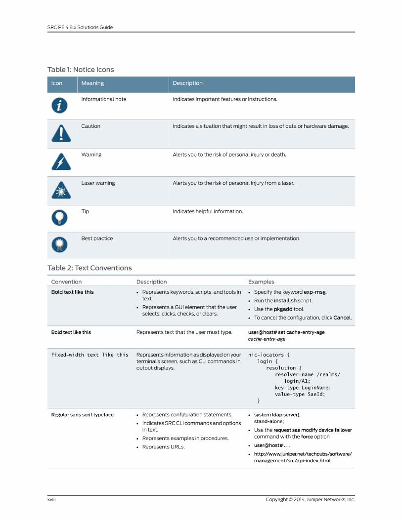
Table 1: Notice Icons
DescriptionMeaningIcon
Indicates important features or instructions.Informational note
Indicates a situation that might result in loss of data or hardware damage.Caution
Alerts you to the risk of personal injury or death.Warning
Alerts you to the risk of personal injury from a laser.Laser warning
Indicates helpful information.Tip
Alerts you to a recommended use or implementation.Best practice
Table 2: Text Conventions
ExamplesDescriptionConvention
• Specify the keyword exp-msg.
• Run the install.sh script.
• Use the pkgadd tool.
• To cancel the configuration, click Cancel.
• Represents keywords, scripts, and tools intext.
• Represents a GUI element that the userselects, clicks, checks, or clears.
Bold text like this
user@host# set cache-entry-agecache-entry-age
Represents text that the user must type.Bold text like this
nic-locators { login { resolution { resolver-name /realms/ login/A1; key-type LoginName; value-type SaeId; }
Represents information as displayed on yourterminal’s screen, such as CLI commands inoutput displays.
Fixed-width text like this
• system ldap server{stand-alone;
• Use the request saemodify device failovercommand with the force option
• user@host# . . .
• http://www.juniper.net/techpubs/software/management/src/api-index.html
• Represents configuration statements.
• Indicates SRC CLI commands and optionsin text.
• Represents examples in procedures.
• Represents URLs.
Regular sans serif typeface
Copyright © 2014, Juniper Networks, Inc.xviii
SRC PE 4.8.x Solutions Guide
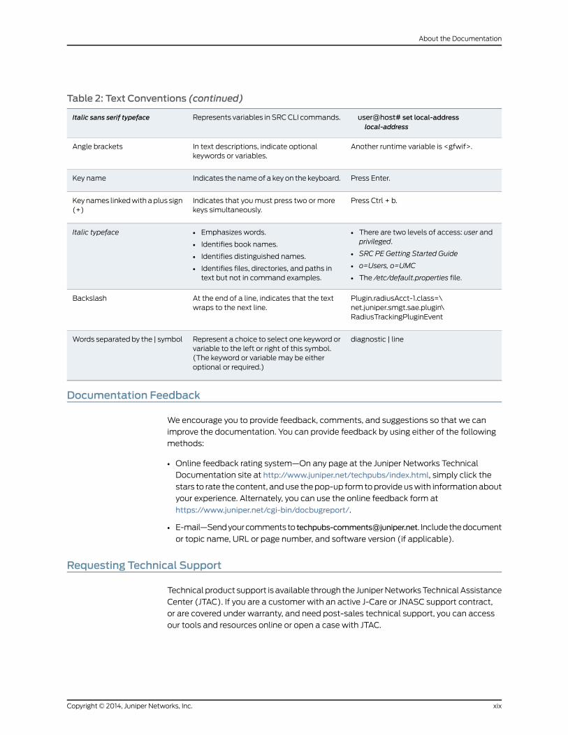
Table 2: Text Conventions (continued)
user@host# set local-addresslocal-address
Represents variables in SRC CLI commands.Italic sans serif typeface
Another runtime variable is <gfwif>.In text descriptions, indicate optionalkeywords or variables.
Angle brackets
Press Enter.Indicates the name of a key on the keyboard.Key name
Press Ctrl + b.Indicates that you must press two or morekeys simultaneously.
Key names linked with a plus sign(+)
• There are two levels of access: user andprivileged.
• SRC PE Getting Started Guide
• o=Users, o=UMC
• The /etc/default.properties file.
• Emphasizes words.
• Identifies book names.
• Identifies distinguished names.
• Identifies files, directories, and paths intext but not in command examples.
Italic typeface
Plugin.radiusAcct-1.class=\net.juniper.smgt.sae.plugin\RadiusTrackingPluginEvent
At the end of a line, indicates that the textwraps to the next line.
Backslash
diagnostic | lineRepresent a choice to select one keyword orvariable to the left or right of this symbol.(The keyword or variable may be eitheroptional or required.)
Words separated by the | symbol
Documentation Feedback
We encourage you to provide feedback, comments, and suggestions so that we can
improve the documentation. You can provide feedback by using either of the following
methods:
• Online feedback rating system—On any page at the Juniper Networks Technical
Documentation site at http://www.juniper.net/techpubs/index.html, simply click the
stars to rate the content, and use the pop-up form to provide us with information about
your experience. Alternately, you can use the online feedback form at
https://www.juniper.net/cgi-bin/docbugreport/.
• E-mail—Send your comments to [email protected]. Include the document
or topic name, URL or page number, and software version (if applicable).
Requesting Technical Support
Technical product support is available through the Juniper Networks Technical Assistance
Center (JTAC). If you are a customer with an active J-Care or JNASC support contract,
or are covered under warranty, and need post-sales technical support, you can access
our tools and resources online or open a case with JTAC.
xixCopyright © 2014, Juniper Networks, Inc.
About the Documentation
• JTAC policies—For a complete understanding of our JTAC procedures and policies,
review the JTAC User Guide located at
http://www.juniper.net/us/en/local/pdf/resource-guides/7100059-en.pdf.
• Product warranties—For product warranty information, visit
http://www.juniper.net/support/warranty/.
• JTAC hours of operation—The JTAC centers have resources available 24 hours a day,
7 days a week, 365 days a year.
Self-Help Online Tools and Resources
For quick and easy problem resolution, Juniper Networks has designed an online
self-service portal called the Customer Support Center (CSC) that provides you with the
following features:
• Find CSC offerings: http://www.juniper.net/customers/support/
• Search for known bugs: http://www2.juniper.net/kb/
• Find product documentation: http://www.juniper.net/techpubs/
• Find solutions and answer questions using our Knowledge Base: http://kb.juniper.net/
• Download the latest versions of software and review release notes:
http://www.juniper.net/customers/csc/software/
• Search technical bulletins for relevant hardware and software notifications:
http://kb.juniper.net/InfoCenter/
• Join and participate in the Juniper Networks Community Forum:
http://www.juniper.net/company/communities/
• Open a case online in the CSC Case Management tool: http://www.juniper.net/cm/
To verify service entitlement by product serial number, use our Serial Number Entitlement
(SNE) Tool: https://tools.juniper.net/SerialNumberEntitlementSearch/
Opening a Casewith JTAC
You can open a case with JTAC on the Web or by telephone.
• Use the Case Management tool in the CSC at http://www.juniper.net/cm/.
• Call 1-888-314-JTAC (1-888-314-5822 toll-free in the USA, Canada, and Mexico).
For international or direct-dial options in countries without toll-free numbers, see
http://www.juniper.net/support/requesting-support.html.
Copyright © 2014, Juniper Networks, Inc.xx
SRC PE 4.8.x Solutions Guide
PART 1
Providing Specialized Services in an SRCEnvironment
• Managing Tiered and Premium Services with QoS on JunosE Routers (SRC
CLI) on page 3
• Managing Subscribers for a Wireless Roaming Environment on page 17
• Configuring VoIP Services in an SRC Network on page 25
• Providing Packet Mirroring in an SRC Network on page 29
1Copyright © 2014, Juniper Networks, Inc.

Copyright © 2014, Juniper Networks, Inc.2
SRC PE 4.8.x Solutions Guide
CHAPTER 1
Managing Tiered and Premium Serviceswith QoS on JunosE Routers (SRC CLI)
• QoS on JunosE Routers Overview on page 3
• Dynamically Managing QoS Profiles on page 4
• Configuring QoS Profile-Tracking Plug-Ins (SRC CLI) on page 9
• Configuring Search Filters for QoS Profile-Tracking Plug-Ins on page 10
• Updating QoS Profile Data in the Directory on page 12
• Query Fields on page 12
• Examples: Searching for QoS Information on page 13
QoS on JunosE Routers Overview
Tiered Internet access and premium services such as video on demand, gaming, or
videoconferencing require quality-of-service (QoS) profiles to be running on the subscriber
interface on the router running JunosE Software. The router allows only one QoS profile
to be attached to an interface at one time. Therefore, as a subscriber activates and
deactivates different services, the QoS profile running on the interface needs to change.
Also, as subscribers activate services, they may have multiple QoS services running at
the same time; for example, internet-gold with videoconferencing.
With the SRC software, you can:
• Dynamically manage QoS profiles on the router running JunosE Software to control a
combination of services that require QoS.
• Update the directory with a list of QoS profiles that are currently configured on a router
running JunosE Software.
• Search the directory for QoS policy information.
RelatedDocumentation
Dynamically Managing QoS Profiles on page 4•
• Delivering QoS Services in a Cable Environment
• Configuring QoS Profile-Tracking Plug-Ins (SRC CLI) on page 9
• Updating QoS Profile Data in the Directory on page 12
3Copyright © 2014, Juniper Networks, Inc.
• Examples: Searching for QoS Information on page 13
Dynamically Managing QoS Profiles
The SAE provides a QoS-tracking plug-in (QTP) that you can use to ensure that, as a
subscriber activates and deactivates services, the required QoS profile is attached to the
subscriber interface. With the QTP, the QoS profile selected is based on the activation
state of an aggregation of services, not just one service.
For example, a subscriber activates a QoS service on a subscriber interface that requires
a QoS profile that supports 512 best effort. The subscriber then activates a faster service
(for example, 1024 best effort), as well as video on demand, and now has two QoS
services running on an interface. The subscriber now needs a QoS profile to be attached
to the interface that supports both video on demand and 1024 best-effort service. The
QTP can determine which QoS profile the subscriber needs, and can cause the existing
QoS profile to be removed from the subscriber interface and the new QoS profile to be
attached to the interface.
Note that if a profile is installed on a subscriber interface and the QTP installs a new
profile, the new profile is based on QoS services that are currently active. The new profile
does not combine the functionality of the previous profile with the new profile. For
example, if a subscriber has a default policy with QoS profile be-512 installed on the
subscriber interface, and the subscriber activates a video-on-demand service, the QTP
does not combine the functionality of be-512 with the profile that supports video on
demand.
HowQoS Profile TrackingWorks
The SAE manages policies on router interfaces through service sessions. Service session
configurations contain the policy that needs to be installed on an interface when a service
is activated. The policy definition can include the name of a QoS profile to attach to the
interface when the policy is installed.
When you set up the QTP, you create a QoS profile attachment service. The purpose of
this service is to attach the required QoS profile to an interface. This service is hidden
from subscribers and is under only QTP control.
Because profiles need to be changed only when QoS services are activated or deactivated,
the QTP tracks services and reacts to service state changes by adjusting the QoS profile
attachment as needed by deactivating and activating the QoS profile attachment service.
Subscribers who need their services managed by the QTP are subscribed to the QoS
profile attachment service.
Identifying QoS Services
When you set up a service, you identify the service as a QoS service in one of the fields
in the service definition. For example, you can assign a service name or category to indicate
that the service is a QoS service, or you could assign the QTP instance name in the
Tracking Plugin field.
Copyright © 2014, Juniper Networks, Inc.4
SRC PE 4.8.x Solutions Guide
When the SAE notifies the QTP that a service has been activated or deactivated, the
QTP determines whether it is a QoS service by searching attributes in the service object.
The QTP uses a search filter that you set up to search an attribute for the information
that you assigned to the service to indicate that it is a QoS service.
For example, suppose you enter myqtp in the tracking plug-in field of QoS services to
indicate that the service is a QoS service. You would set up the search filter to search
tracking plug-in attributes for any service that contains myqtp:
(attribute.trackPlug=*myqtp*)
Or you might configure the category to indicate that a service is a QoS service. The
following filter searches service category attributes for any entry that contains ultra, video
on demand, or video telephony:
(|(serviceCategory=*ultra*)(|(serviceCategory=*video ondemand*)(serviceCategory=*video telephony*)))
To obtain a list of attribute names for the sspService object class, see the LDAP schema
documentation in SDK+AppSupport+Demos+Samples.tar.gz file in the folder
SDK/doc/ldap or on the Juniper Networks Web site at
http://www.juniper.net/techpubs/software/management/src.
Determining the QoS Profile
After the QTP determines that a service is a QoS service, it needs to obtain the name of
the QoS profile for the service. The QTP generates a QoS profile name based on active
QoS services as follows:
1. Obtains QoS profile input values.
The QTP obtains these values by taking the value of an attribute in the service
definition. You specify which attribute that you want the QTP to use as the input value.
For example, you can specify the service name, the category, or the contents of the
design and graphics attribute.
2. Compiles a list of the QoS profile input values.
3. Removes duplicate values from the list.
4. Sorts the remaining list by using a case-sensitive alphanumeric comparison.
5. Concatenates the values with a separator. The default value for the separator is a
hyphen (-). You can specify a different separator.
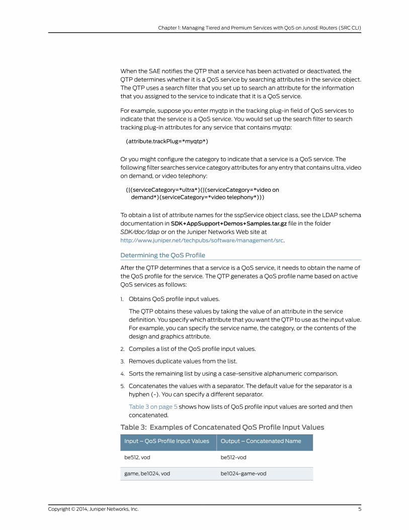
Table 3 on page 5 shows how lists of QoS profile input values are sorted and then
concatenated.
Table 3: Examples of Concatenated QoS Profile Input Values
Output – Concatenated NameInput – QoS Profile Input Values
be512-vodbe512, vod
be1024-game-vodgame, be1024, vod
5Copyright © 2014, Juniper Networks, Inc.
Chapter 1: Managing Tiered and Premium Services with QoS on JunosE Routers (SRC CLI)

Table3: ExamplesofConcatenatedQoSProfile InputValues (continued)
Output – Concatenated NameInput – QoS Profile Input Values
be128be128
6. Adds a prefix to the resulting name. The default prefix is qos-profile. (You can specify
a different value.) The output from our examples now looks like this:
• qos-profile-be512-vod
• qos-profile-be1024-game-vod
• qos-profile-be128
The names that result from this process are the QoS profile names.
As you can see from this process, you need to design services and configure the QTP so
that the resulting QoS profile names match the names of the QoS profiles configured
on the router running JunosE Software.
Typically, a QoS designer creates a number of QoS profiles that support all the services
that are expected to be used. This design results in various QoS profiles that need to be
configured on each router. If a required QoS profile is not configured on the router, the
hidden QoS profile attachment service cannot be activated. Services are still activated
for the subscriber, but the services will not provide the expected traffic requirements.
When this happens, the SAE logs the error but does not send an error message to the
subscriber.
Setting Up Policy Groups
You need to create two types of policy groups in your QTP configuration. The QoS profile
attachment service needs a policy group that attaches the required QoS profile to the
subscriber interface when the attachment service is activated. QoS services need policy
groups that classify traffic and specify the action to take on traffic that matches the
classifier. (You can set up traffic classifiers to match any traffic.)
Policy Group for QoS Profile Attachment Service
The policy group for the hidden QoS profile attachment service must have an egress
policy list with only one policy rule that contains a QoS profile attachment action. The
QoS profile attachment action must have a variable parameter in the QoS profile field.
NOTE: Thepolicy group for theQoSprofile attachment servicemust containonly one egress policy list andmust contain one and only one QoS profileattachment action.Otherwise, theSRC softwarewill require a license for thehidden service.
When the profile attachment service is activated, the QTP substitutes the QoS profile
attribute in the policy with the QoS profile name that it determined. The service then
loads the policy.
Copyright © 2014, Juniper Networks, Inc.6
SRC PE 4.8.x Solutions Guide
The following example creates a policy group for the QoS profile attachment service.
This policy group does not match any traffic.
1. Create a policy group called Pg-qos-attach, and add an egress policy list.
2. In the egress policy list, create a policy rule that has a QoS profile attachment action
with QoS profile qpName.
By default, the QTP looks for qpName as the variable parameter.
When the QTP determines the required QoS profile name, it substitutes qpName with
the value that it acquired.
Setting Up Services
You need to set up a QoS profile attachment service and QoS services. Both types of
services are value-added (SSP) services.
In the QoS profile attachment service, assign the policy group that you configured for the
service. For example, policyGroupName=Pg-qos-attach, ou=ent, o=Policies, o=umc.
In QoS services, assign the policy group that you configured for the service.
Subscribe subscribers to the QoS profile attachment service and to the appropriate QoS
services.
Reestablishing Default QoS Profile
A default QoS profile may be installed on the subscriber interface before the QTP installs
QoS profiles in response to the activation of QoS services. For example, a profile may
have been attached to the subscriber interface when the default policy was installed.
Once QoS services are no longer active on the interface, the QTP can reestablish the
QoS profile that was installed on the interface before the QTP began tracking services
and installing profiles on the interface.
Example: HowQTP Activates a QoS Service
The following example shows the process that QTP uses when a subscriber activates a
QoS service. In this example, QoS profile input values are taken from the service name
attribute. The hidden QoS profile attachment service is named svc-qos-attach. The
svc-qos-attach service contains a policy that has the variable parameter qpName
assigned as the QoS profile name.
1. The subscriber does not have any active services.
2. The subscriber activates service be512, which is a QoS service.
a. The SAE sends a Service Session Start event to the QTP.
b. The QTP searches an attribute in the service definition and determines that the
service is a QoS service.
c. Using the SAE Common Object Request Broker Architecture (CORBA) remote
application programming interface (API), the QTP gets a list of the subscriber’s
active QoS services.
7Copyright © 2014, Juniper Networks, Inc.
Chapter 1: Managing Tiered and Premium Services with QoS on JunosE Routers (SRC CLI)

The list contains only service be512 because that is the only service that the
subscriber has activated.
d. The QTP adds the default prefix to the QoS profile input value to obtain the QoS
profile name. The result is:
qos-profile-be512
e. The QTP deactivates the hidden svc-qos-attach service. Because this
svc-qos-attach service was not active before, this operation does not have any
effect.
f. The QTP activates the hidden svc-qos-attach service, and it substitutes variable
parameter qpName with $’qos-profile-be512’ as the QoS profile name in the policy.
g. The policy loads qos-profile-be512 on the subscriber interface.
3. The subscriber activates service vod, which is a QoS service.
a. The SAE sends a Service Session Start event to the QTP.
b. QTP searches attributes in active service definitions and determines that the service
is a QoS service.
c. The QTP gets a list of the subscriber’s active QoS services. The result is:
be512, vod
d. The QTP sorts the list and concatenates the QoS profile input values with the
separator. The result is:
be512-vod
e. The QTP adds the default prefix to the concatenated name to obtain the QoS
profile name. The result is:
qos-profile-be512-vod.
f. The QTP deactivates the hidden svc-qos-attach service.
g. The QTP activates the hidden svc-qos-attach service, and it substitutes variable
parameter qpName with $’qos-profile-be512-vod’ as the QoS profile name in the
policy.
h. The policy loads qos-profile-be512-vod.
4. The subscriber deactivates service vod.
a. The QTP follows the same procedure as in Step 2 above and determines that the
QoS profile name is qos-profile-vod.
b. The QTP deactivates the hidden svc-qos-attach service.
c. The QTP reactivates the hidden svc-qos-attach service, and it substitutes variable
parameter qpName with $’qos-profile-be512’ as the QoS profile name in the policy.
d. The policy loads qos-profile-be512.
Copyright © 2014, Juniper Networks, Inc.8
SRC PE 4.8.x Solutions Guide
RelatedDocumentation
QoS on JunosE Routers Overview on page 3•
• Configuring QoS Profile-Tracking Plug-Ins (SRC CLI) on page 9
• Configuring QoS Profile Attachment Actions (SRC CLI)
• Configuring Search Filters for QoS Profile-Tracking Plug-Ins on page 10
• Updating QoS Profile Data in the Directory on page 12
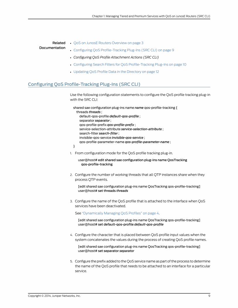
Configuring QoS Profile-Tracking Plug-Ins (SRC CLI)
Use the following configuration statements to configure the QoS profile tracking plug-in
with the SRC CLI:
shared sae configuration plug-ins name name qos-profile-tracking {threads threads ;default-qos-profile default-qos-profile ;separator separator ;qos-profile-prefix qos-profile-prefix ;service-selection-attribute service-selection-attribute ;search-filter search-filter ;invisible-qos-service invisible-qos-service ;qos-profile-parameter-name qos-profile-parameter-name ;
}
1. From configuration mode for the QoS profile tracking plug-in.
user@host# edit shared sae configuration plug-ins nameQosTrackingqos-profile-tracking
2. Configure the number of working threads that all QTP instances share when they
process QTP events.
[edit shared sae configuration plug-ins nameQosTracking qos-profile-tracking]user@host# set threads threads
3. Configure the name of the QoS profile that is attached to the interface when QoS
services have been deactivated.
See “Dynamically Managing QoS Profiles” on page 4.
[edit shared sae configuration plug-ins nameQosTracking qos-profile-tracking]user@host# set default-qos-profile default-qos-profile
4. Configure the character that is placed between QoS profile input values when the
system concatenates the values during the process of creating QoS profile names.
[edit shared sae configuration plug-ins nameQosTracking qos-profile-tracking]user@host# set separator separator
5. Configure the prefix added to the QoS service name as part of the process to determine
the name of the QoS profile that needs to be attached to an interface for a particular
service.
9Copyright © 2014, Juniper Networks, Inc.
Chapter 1: Managing Tiered and Premium Services with QoS on JunosE Routers (SRC CLI)
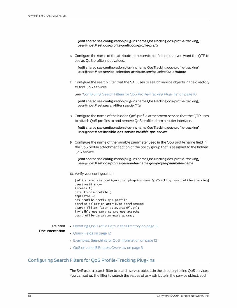
[edit shared sae configuration plug-ins nameQosTracking qos-profile-tracking]user@host# set qos-profile-prefix qos-profile-prefix
6. Configure the name of the attribute in the service definition that you want the QTP to
use as QoS profile input values.
[edit shared sae configuration plug-ins nameQosTracking qos-profile-tracking]user@host# set service-selection-attribute service-selection-attribute
7. Configure the search filter that the SAE uses to search service objects in the directory
to find QoS services.
See “Configuring Search Filters for QoS Profile-Tracking Plug-Ins” on page 10
[edit shared sae configuration plug-ins nameQosTracking qos-profile-tracking]user@host# set search-filter search-filter
8. Configure the name of the hidden QoS profile attachment service that the QTP uses
to attach QoS profiles to and remove QoS profiles from a router interface.
[edit shared sae configuration plug-ins nameQosTracking qos-profile-tracking]user@host# set invisible-qos-service invisible-qos-service
9. Configure the name of the variable parameter used in the QoS profile name field in
the QoS profile attachment action of the policy group that is assigned to the hidden
QoS service.
[edit shared sae configuration plug-ins nameQosTracking qos-profile-tracking]user@host# set qos-profile-parameter-name qos-profile-parameter-name
10. Verify your configuration.
[edit shared sae configuration plug-ins name QosTracking qos-profile-tracking]user@host# showthreads 1;default-qos-profile ;separator -;qos-profile-prefix qos-profile;service-selection-attribute serviceName;search-filter (attribute.trackPlug=);invisible-qos-service svc-qos-attach;qos-profile-parameter-name qpName;
RelatedDocumentation
Updating QoS Profile Data in the Directory on page 12•
• Query Fields on page 12
• Examples: Searching for QoS Information on page 13
• QoS on JunosE Routers Overview on page 3
Configuring Search Filters for QoS Profile-Tracking Plug-Ins
The SAE uses a search filter to search service objects in the directory to find QoS services.
You can set up the filter to search the values of any attribute in the service object, such
Copyright © 2014, Juniper Networks, Inc.10
SRC PE 4.8.x Solutions Guide
as service name, category, or tracking plug-in. The search is successful when a value
matches the filter.
To configure the search:
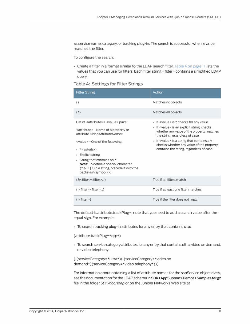
• Create a filter in a format similar to the LDAP search filter. Table 4 on page 11 lists the
values that you can use for filters. Each filter string <filter> contains a simplified LDAP
query.
Table 4: Settings for Filter Strings
ActionFilter String
Matches no objects()
Matches all objects(*)
List of <attribute>= <value> pairs
<attribute>—Name of a property orattribute <ldapAttributeName>
<value>—One of the following:
• If <value> is *, checks for any value.
• If <value> is an explicit string, checkswhether any value of the property matchesthe string, regardless of case.
• If <value> is a string that contains a *,checks whether any value of the propertycontains the string, regardless of case.• * (asterisk)
• Explicit string
• String that contains an *Note: To define a special character(* & , ! | \)in a string, precede it with thebackslash symbol (\).
True if all filters match(&<filter><filter>...)
True if at least one filter matches(|<filter><filter>...)
True if the filter does not match(!<filter>)
The default is attribute.trackPlug=; note that you need to add a search value after the
equal sign. For example:
• To search tracking plug-in attributes for any entry that contains qtp:
(attribute.trackPlug=*qtp*)
• To search service category attributes for any entry that contains ultra, video on demand,
or video telephony:
(|(serviceCategory=*ultra*)(|(serviceCategory=*video on
demand*)(serviceCategory=*video telephony*)))
For information about obtaining a list of attribute names for the sspService object class,
see the documentation for the LDAP schema inSDK+AppSupport+Demos+Samples.tar.gz
file in the folder SDK/doc/ldap or on the Juniper Networks Web site at
11Copyright © 2014, Juniper Networks, Inc.
Chapter 1: Managing Tiered and Premium Services with QoS on JunosE Routers (SRC CLI)
http://www.juniper.net/techpubs/software/management/src.
RelatedDocumentation
Dynamically Managing QoS Profiles on page 4•
• Configuring QoS Profile-Tracking Plug-Ins (SRC CLI) on page 9
• Updating QoS Profile Data in the Directory on page 12
• Examples: Searching for QoS Information on page 13
Updating QoS Profile Data in the Directory
You can update the directory with a list of QoS profiles that are currently configured on
a router running JunosE Software.
RelatedDocumentation
Dynamically Managing QoS Profiles on page 4•
• Configuring QoS Profile-Tracking Plug-Ins (SRC CLI) on page 9
• Configuring Search Filters for QoS Profile-Tracking Plug-Ins on page 10
• Query Fields on page 12
• QoS on JunosE Routers Overview on page 3
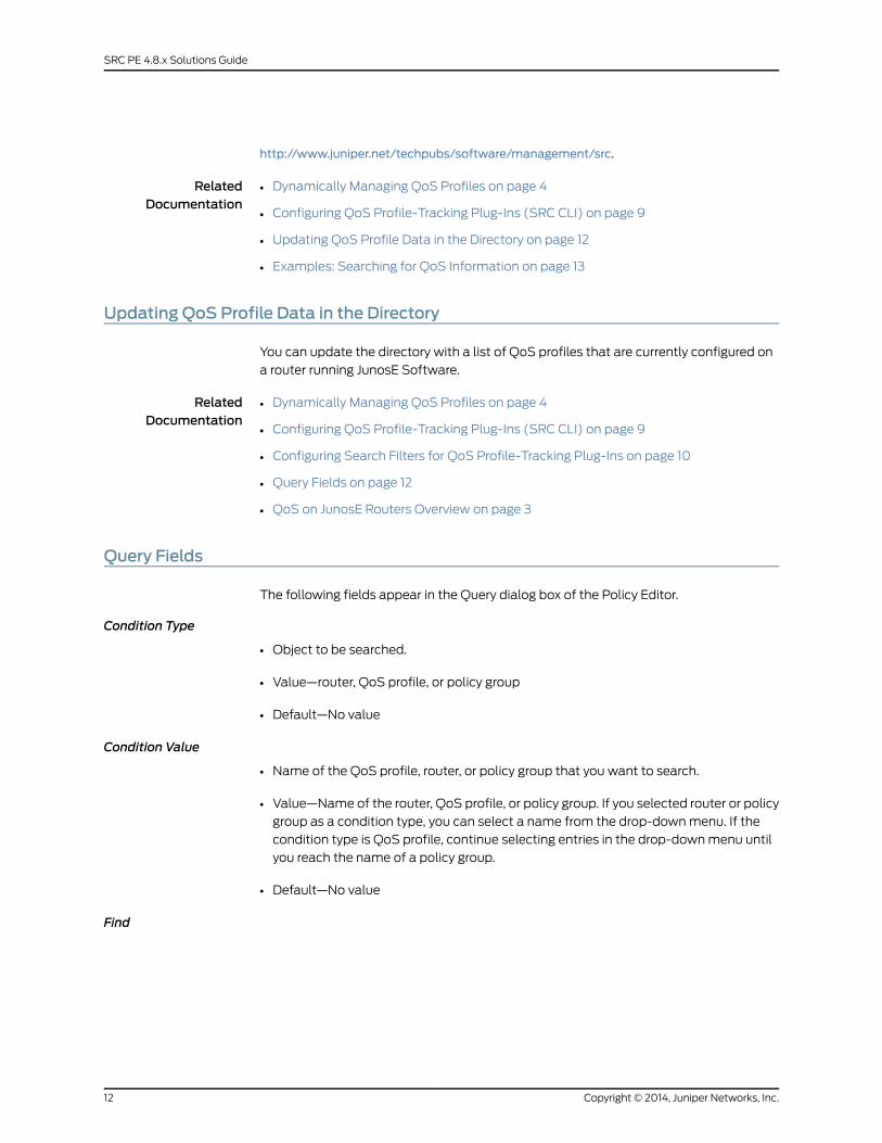
Query Fields
The following fields appear in the Query dialog box of the Policy Editor.
Condition Type
• Object to be searched.
• Value—router, QoS profile, or policy group
• Default—No value
Condition Value
• Name of the QoS profile, router, or policy group that you want to search.
• Value—Name of the router, QoS profile, or policy group. If you selected router or policy
group as a condition type, you can select a name from the drop-down menu. If the
condition type is QoS profile, continue selecting entries in the drop-down menu until
you reach the name of a policy group.
• Default—No value
Find
Copyright © 2014, Juniper Networks, Inc.12
SRC PE 4.8.x Solutions Guide
• Object that you want to find. The software searches for this object on the QoS profile,
router, or policy group defined in condition type and condition value.
• Value—Name of the router, QoS profile, or policy group. If you selected router or policy
group as a condition type, you can select a name from the drop-down menu. If the
condition type is QoS profile, continue selecting entries in the drop-down menu until
you reach the name of a policy group.
• Default—No value
Supported
• Whether or not to search for the condition type that exists or does not exist on the
router, QoS profile, or policy group.
• Value—Checked or unchecked
• Checked—Searches for the condition type that is on the router, QoS profile, or policy
group
• Unchecked—Searches for the condition type that is not on the router, QoS profile,
or policy group
• Default—No value
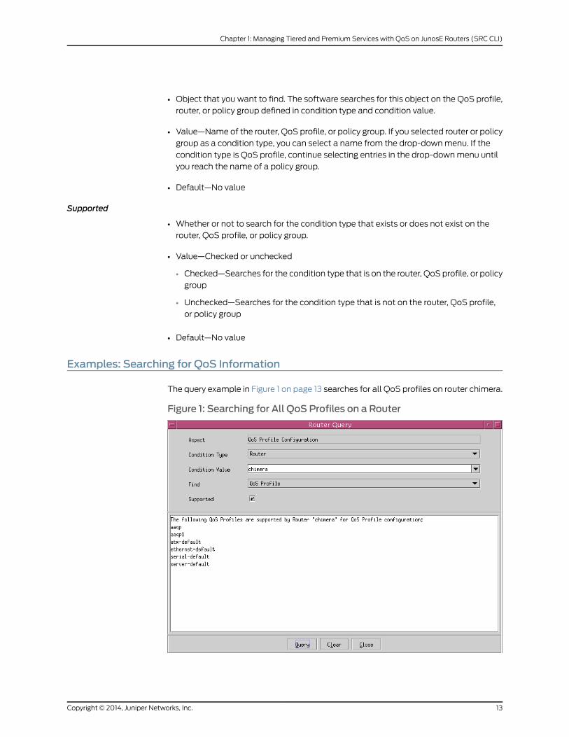
Examples: Searching for QoS Information
The query example in Figure 1 on page 13 searches for all QoS profiles on router chimera.
Figure 1: Searching for All QoS Profiles on a Router
13Copyright © 2014, Juniper Networks, Inc.
Chapter 1: Managing Tiered and Premium Services with QoS on JunosE Routers (SRC CLI)
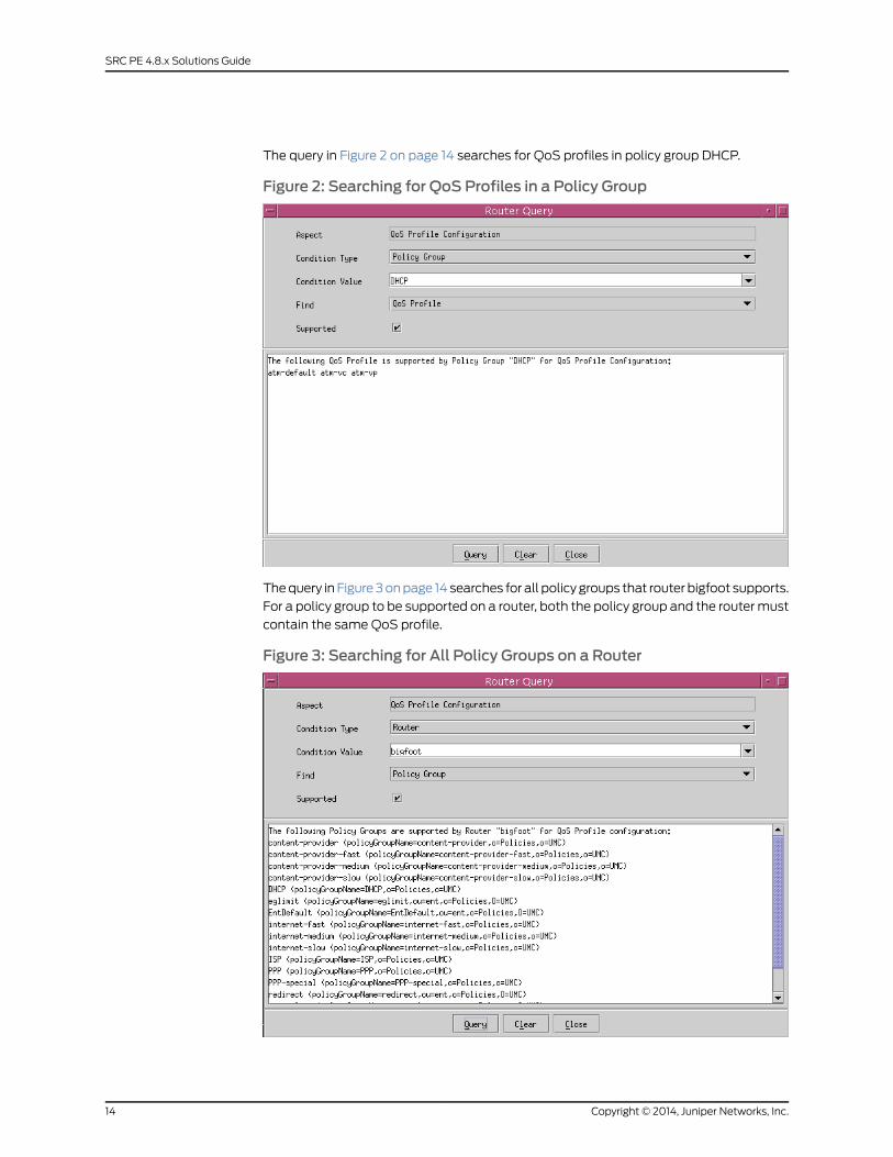
The query in Figure 2 on page 14 searches for QoS profiles in policy group DHCP.
Figure 2: Searching for QoS Profiles in a Policy Group
The query in Figure 3 on page 14 searches for all policy groups that router bigfoot supports.
For a policy group to be supported on a router, both the policy group and the router must
contain the same QoS profile.
Figure 3: Searching for All Policy Groups on a Router
Copyright © 2014, Juniper Networks, Inc.14
SRC PE 4.8.x Solutions Guide

RelatedDocumentation
• Dynamically Managing QoS Profiles on page 4
• Policy Management Overview
• Policy Components
• QoS on JunosE Routers Overview on page 3
15Copyright © 2014, Juniper Networks, Inc.
Chapter 1: Managing Tiered and Premium Services with QoS on JunosE Routers (SRC CLI)

Copyright © 2014, Juniper Networks, Inc.16
SRC PE 4.8.x Solutions Guide

CHAPTER 2
Managing Subscribers for aWirelessRoaming Environment
• Wireless Roaming Environment Overview on page 17
• Subscriber Access in a Wireless Roaming Environment on page 17
• Configuring Subscriber Access for a Wireless Location on page 18
Wireless Roaming Environment Overview
In a roaming wireless environment, subscribers can log in to a wireless access point at a
variety of wireless locations owned by service providers that participate in a roaming
network agreement. The wireless locations participating in the agreement can be owned
by one or more service providers.
Typically, RADIUS manages information about subscribers between the wireless locations.
A RADIUS server for an Internet service provider (ISP) manages authentication for its
subscribers, and shares information with the other ISPs with which the service provider
has a roaming agreement. Subscribers can log in to a service activation engine (SAE)
from any supported site.
The SAE provides support for RADIUS vendor-specific attributes for wireless Internet
service provider roaming (WISPr).
RelatedDocumentation
Subscriber Access in a Wireless Roaming Environment on page 17•
• Configuring Subscriber Access for a Wireless Location on page 18
• For more information about RADIUS vendor-specific attributes for wireless Internet
service provider roaming (WISPr): http://www.wi-fialliance.org/opensection/wispr.asp
Subscriber Access in aWireless Roaming Environment
When subscribers log in to a wireless location that has a roaming agreement with other
locations, the following sequence of events occurs:
17Copyright © 2014, Juniper Networks, Inc.
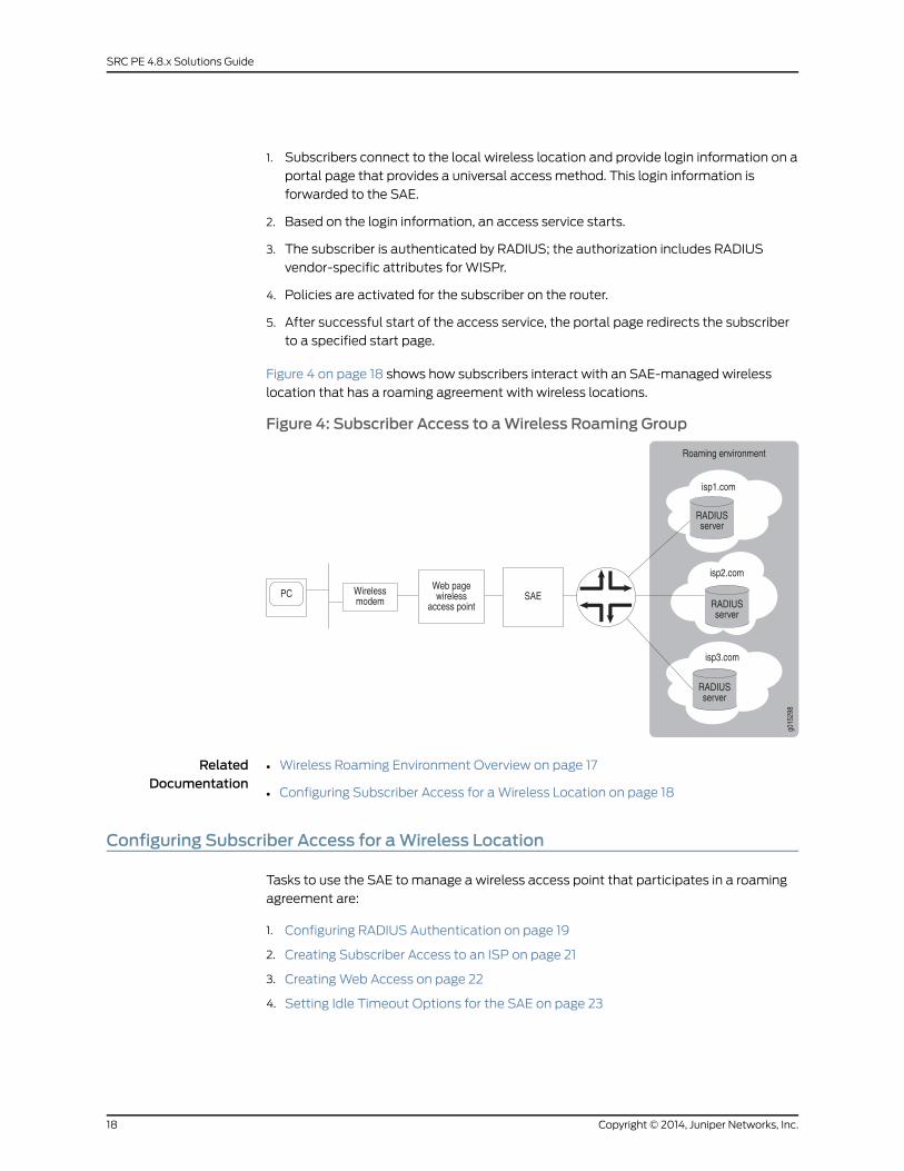
1. Subscribers connect to the local wireless location and provide login information on a
portal page that provides a universal access method. This login information is
forwarded to the SAE.
2. Based on the login information, an access service starts.
3. The subscriber is authenticated by RADIUS; the authorization includes RADIUS
vendor-specific attributes for WISPr.
4. Policies are activated for the subscriber on the router.
5. After successful start of the access service, the portal page redirects the subscriber
to a specified start page.
Figure 4 on page 18 shows how subscribers interact with an SAE-managed wireless
location that has a roaming agreement with wireless locations.
Figure 4: Subscriber Access to aWireless Roaming Group
RelatedDocumentation
Wireless Roaming Environment Overview on page 17•
• Configuring Subscriber Access for a Wireless Location on page 18
Configuring Subscriber Access for aWireless Location
Tasks to use the SAE to manage a wireless access point that participates in a roaming
agreement are:
1. Configuring RADIUS Authentication on page 19
2. Creating Subscriber Access to an ISP on page 21
3. Creating Web Access on page 22
4. Setting Idle Timeout Options for the SAE on page 23
Copyright © 2014, Juniper Networks, Inc.18
SRC PE 4.8.x Solutions Guide
Configuring RADIUS Authentication
You configure RADIUS authentication for users who connect from a wireless location,
and set up RADIUS authentication to support a roaming environment between wireless
Internet service providers. You can use the Flexible RADIUS Authentication plug-in that
is provided with the SRC software, or you can create a custom RADIUS authentication
plug-in.
Configuring a CustomRADIUS
AuthenticationPlug-In
If you create a custom plug-in, be sure that it supports the same RADIUS attributes as
those configured for the flexible RADIUS authentication plug-in. See “Configuring the
Flexible RADIUS Authentication Plug-In” on page 19.
For information about creating a custom plug-in, seeSAECORBAPlug-In Service Provider
Interface (SPI) on the Juniper Networks Web site at:
http://www.juniper.net/techpubs/software/management/src/api-index.html.
Configuring theFlexible RADIUS
AuthenticationPlug-In
The default flexible RADIUS authentication plug-in, flexRadiusAuth, provides support
for RADIUS vendor-specific attributes for WISPr, which are listed in the following
procedure. These attributes use the IANA private enterprise number 14122 assigned to
the Wi-Fi Alliance. For more information about these attributes, see
http://www.wi-fialliance.org/opensection/wispr.asp.
You should be familiar with the general procedure for configuring the flexible RADIUS
authentication plug-in before configuring it to include the WISPr attributes. For information
about configuring the flexible RADIUS authentication plug-in, see Configuring Tracking
Plug-Ins (SRC CLI).
When you configure the plug-in, you can use the following standard attribute values to
set values in authentication response packets:
• setAcctInterimTime
• setSubstitution
• setTerminateTime
Examples in the following procedure show how you can use these attribute values.
To configure the plug-in to support a roaming environment:
1. Configure attributes.
• Required attributes:
• An identifier for the wireless location:
vendor-specific.WISPr.Location-ID=Identifier
This attribute can be an interface description (ifAlias) or other value that identifies
the JunosE interface to which the wireless access point connects.
• The URL of the start page returned by the RADIUS server of the ISP:
vendor-specific.WISPr.Redirection-URL=Command tomake the URL available tothe SRC software
19Copyright © 2014, Juniper Networks, Inc.
Chapter 2: Managing Subscribers for a Wireless Roaming Environment
For example:
vendor-specific.WISPr.Redirection-URL=setProperty(“ startURL=%s”%ATTR)
The default configuration sets a session property named startURL.
• The URL of a page that a subscriber can use to log out of the network:
vendor-specific.WISPr.Logoff-URL=URL of a log out page
• Bandwidth attributes (recommended):
• The maximum transmission rate in bits per second:
vendor-specific.WISPr.Bandwidth-Max-Up=Command tomake the rate availableto the SRC software
For example:
vendor-specific.WISPr.Bandwidth-Max-Up=setSubstitution(“ max_up_rate=%s”%ATTR)
• The maximum receive rate in bits per second:
vendor-specific.WISPr.Bandwidth-Max-Down=Commandtomakethe rateavailableto the SRC software
For example:
vendor-specific.WISPr.Bandwidth-Max-Down=setSubstitution(“max_down_rate=%s”% \ ATTR)
• Optional attributes:
• The name of the wireless location:
vendor-specific.WISPr.Location-Name=Name of the wireless location
• The date and time that the subscriber session is to end:
vendor-specific.WISPr.Session-Terminate-Time=Command to set the sessionterminate time
For example:
vendor-specific.WISPr.Session-Terminate-Time=setTerminateTime(ATTR)
• The end of the subscriber session at the end of the billing day:
vendor-specific.WISPr.Session-Terminate-End-Of-Day=ATTR orsetTerminateTime("00:00:00")
If the operator of the wireless location does not support daily billing, do not
configure this attribute, and remove it if present.
• A service type for billing:
vendor-specific.WISPr.Billing-Class-Of-Service=Service type
2. For each attribute that you configure, configure the packet type to which the attribute
applies. Table 5 on page 21 shows the packet types associated with each attribute.
Copyright © 2014, Juniper Networks, Inc.20
SRC PE 4.8.x Solutions Guide
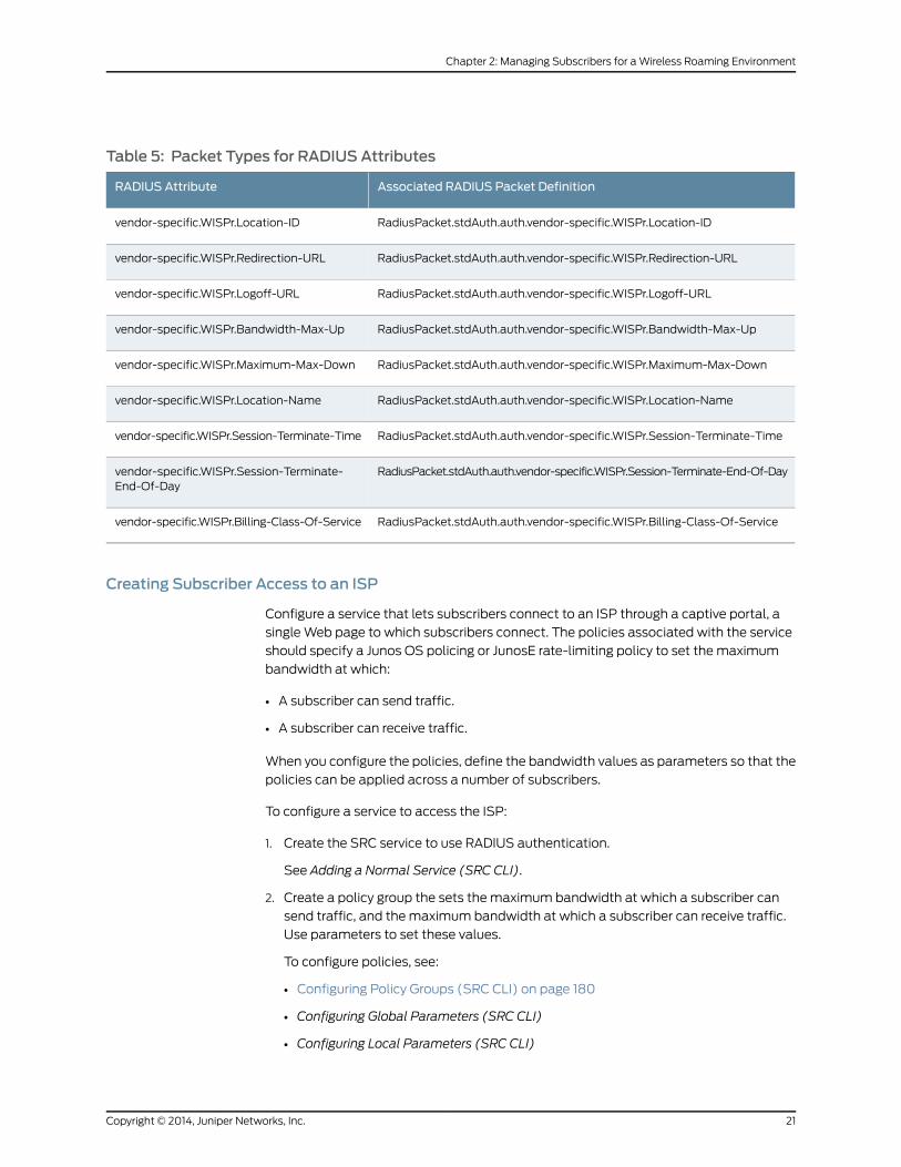
Table 5: Packet Types for RADIUS Attributes
Associated RADIUS Packet DefinitionRADIUS Attribute
RadiusPacket.stdAuth.auth.vendor-specific.WISPr.Location-IDvendor-specific.WISPr.Location-ID
RadiusPacket.stdAuth.auth.vendor-specific.WISPr.Redirection-URLvendor-specific.WISPr.Redirection-URL
RadiusPacket.stdAuth.auth.vendor-specific.WISPr.Logoff-URLvendor-specific.WISPr.Logoff-URL
RadiusPacket.stdAuth.auth.vendor-specific.WISPr.Bandwidth-Max-Upvendor-specific.WISPr.Bandwidth-Max-Up
RadiusPacket.stdAuth.auth.vendor-specific.WISPr.Maximum-Max-Downvendor-specific.WISPr.Maximum-Max-Down
RadiusPacket.stdAuth.auth.vendor-specific.WISPr.Location-Namevendor-specific.WISPr.Location-Name
RadiusPacket.stdAuth.auth.vendor-specific.WISPr.Session-Terminate-Timevendor-specific.WISPr.Session-Terminate-Time
RadiusPacket.stdAuth.auth.vendor-specific.WISPr.Session-Terminate-End-Of-Dayvendor-specific.WISPr.Session-Terminate-End-Of-Day
RadiusPacket.stdAuth.auth.vendor-specific.WISPr.Billing-Class-Of-Servicevendor-specific.WISPr.Billing-Class-Of-Service
Creating Subscriber Access to an ISP
Configure a service that lets subscribers connect to an ISP through a captive portal, a
single Web page to which subscribers connect. The policies associated with the service
should specify a Junos OS policing or JunosE rate-limiting policy to set the maximum
bandwidth at which:
• A subscriber can send traffic.
• A subscriber can receive traffic.
When you configure the policies, define the bandwidth values as parameters so that the
policies can be applied across a number of subscribers.
To configure a service to access the ISP:
1. Create the SRC service to use RADIUS authentication.
See Adding a Normal Service (SRC CLI).
2. Create a policy group the sets the maximum bandwidth at which a subscriber can
send traffic, and the maximum bandwidth at which a subscriber can receive traffic.
Use parameters to set these values.
To configure policies, see:
• Configuring Policy Groups (SRC CLI) on page 180
• Configuring Global Parameters (SRC CLI)
• Configuring Local Parameters (SRC CLI)
21Copyright © 2014, Juniper Networks, Inc.
Chapter 2: Managing Subscribers for a Wireless Roaming Environment
For example, you can create a policy configuration that includes:
• A local parameter named max_up_rate that sets the maximum rate at which the
subscriber can send data
• A local parameter named max_down_rate that sets the maximum rate at which the
subscriber can receive data
• A policy group Receive(Downstream) that references max_down_rate
• A policy group Send(Upstream) that references max_up_rate
Substitutions for these parameters can then be referenced in the RADIUS attributes:
vendor-specific.WISPr.Bandwidth-Max-Up=setSubstitution(“max_up_rate=%s”%ATTR)vendor-specific.WISPr.Bandwidth-Max-Down=setSubstitution(“ max_down_rate=%s”%ATTR)
CreatingWeb Access
When subscribers connect to and log in to a wireless access point, they are directed to
a single Web page that is referred to as a captive portal page. This page is part of a service
selection portal. A captive portal page receives and manages redirected Web requests.
The SRC Application Library provides an unsupported, demonstration application for a
residential service selection portal.
When creating a captive portal page for a wireless roaming environment, configure the
page to:
• Start an access service that is configured to be authenticated by the RADIUS server
of the ISP.
• After the access service starts, redirect the subscriber to the page specified by the
Redirect-URL RADIUS attribute. This page is the start page for the subscriber's home
ISP.
You can retrieve the URL of the start page from the service session property startURL.
Note that startURL is the default name used for the flexible RADIUS authentication
plug-in; you can assign a different name to this property.
You can use the Subscriber.readSubscription() method in the Common Object Request
Broker Architecture (CORBA) remote application programming interface (API) to
retrieve the redirect URL.
Note that when you develop the portal, you can use the following methods in the SAE
CORBA remote API to retrieve session data after the access service starts:
• Subscriber.readSubscriber()
• Subscriber.readSubscription()
For more information about these methods, see the SAE CORBA remote API
documentation on the Juniper Networks Web site at
http://www.juniper.net/techpubs/software/management/src/api-index.html.
Copyright © 2014, Juniper Networks, Inc.22
SRC PE 4.8.x Solutions Guide

Setting Idle Timeout Options for the SAE
You can configure the following options to ensure that the timeout values are consistent
with the requirements for your environment:
• Idle timeout—Defines how long a session is idle before the connection is closed.
• Adjust session time—Adjusts the session time reported in an accounting messaged by
subtracting idle time from the time if the session times out.
To configure the timeout settings:
1. Configure the service activation authentication through a RADIUS server to return an
idle timeout. This configuration requires that the RADIUS server returns the idle timeout
vendor-specific attribute (VSA).
or
Configure the idle timeout in the SRC service definition. For example:
[edit services global service service1]user@host# set idle-timeout 5
Although an interval up to 5 minutes is typically recommended, for the SRC software,
we recommend a minimum of 15 minutes.
2. Configure the adjust-session-time statement for the SAE to ensure that session time
is accurately reported for accounting purposes. For example:
[edit shared sae group wireless configuration]user@host# set idle-timeout adjust-session-time
RelatedDocumentation
• Wireless Roaming Environment Overview on page 17
• Subscriber Access in a Wireless Roaming Environment on page 17
23Copyright © 2014, Juniper Networks, Inc.
Chapter 2: Managing Subscribers for a Wireless Roaming Environment

Copyright © 2014, Juniper Networks, Inc.24
SRC PE 4.8.x Solutions Guide
CHAPTER 3
Configuring VoIP Services in an SRCNetwork
• Session Management for VoIP Services Overview on page 25
• Configuring Policies and Services for VoIP on page 26
• Activating VoIP Services for Assigned IP Subscribers on page 27
• Setting Timeouts for Assigned IP Subscriber Sessions on page 28
SessionManagement for VoIP Services Overview
When the service activation engine (SAE) activates a service session, it authorizes the
session with authorization plug-ins; it may use the admission control plug-in (ACP) to
perform call admission control and allocate bandwidth; and it installs the policy required
for the service on a JunosE interface.
VoIP and multimedia service sessions are typically established in multiple phases that
require changes to installed policies and authorized bandwidth while the service session
remains active. To support VoIP sessions, the SAE allows changes to active service
sessions. These changes include:
• Controlled bandwidth. If bandwidth demand increases, the authorization plug-in must
authorize the change.
• Policy parameters. Only parameter substitution values can be changed. Policy
parameters can include classifiers, such as destination address and port, and actions,
such as rate-limit profiles.
• Session and idle timeouts. All attributes that can be set for initial service activation
can be set for service session modifications.
Accounting and Tracking
Accounting information is preserved across service session changes. Accounting
information for a complete service session includes the sum of counters for all service
session segments.
When the ACP receives an interim update request, it compares the upstream and
downstream bandwidth in the request with the current values. If the bandwidth has
25Copyright © 2014, Juniper Networks, Inc.
changed, ACP modifies its counters based on the difference between the current and
new values.
Tracking plug-ins are informed of service session changes through an interim update
message. The interim update is sent even if regular interim updates are disabled. If the
controlled bandwidth changes, the interim update message contains the new bandwidth
settings.
VoIP Call Setup
Initial setup of a VoIP call requires changes to bandwidth and to the endpoint address
during call setup. The setup sequence for a VoIP call can follow this pattern:
1. The subscriber attempts to establish a call.
2. The gatekeeper (or Session Initiation Protocol [SIP] proxy) performs local admission
control.
3. The gatekeeper allocates a Codec for the call; for example, 64 kbps.
4. The gatekeeper activates the VoIP service on the SAE with 64 kbps bandwidth and
a destination address of unknown.
5. The SAE performs admission control, activates a service session, and installs policies
on the router.
6. The gatekeeper negotiates call parameters with the remote endpoint.
7. The gatekeeper modifies the VoIP service with negotiated parameters; for example,
32 kbps, destination address 10.10.3.4, and UDP port 5678.
8. The SAE creates new policies that reflect changes to the traffic classifier and rate-limit
profile, and then removes the existing policies from the router and installs the new
policies.
9. The SAE sends interim updates to the ACP and tracking plug-ins.
For information about configuring and managing policies, see the SRC PE Services and
Policies Guide.
RelatedDocumentation
Global and Local Parameters Overview•
• Configuring Policies and Services for VoIP on page 26
• Activating VoIP Services for Assigned IP Subscribers on page 27
Configuring Policies and Services for VoIP
When you set up a service that supports VoIP, you need to create a policy group for the
VoIP service and assign the policy group to the VoIP service.
The SAE installs the policy on the router when the service is activated. When the service
session is modified during VoIP call setup, the SAE replaces policy values with new values
that were negotiated during call setup. The SAE then creates a new policy and installs
it on the router.
Copyright © 2014, Juniper Networks, Inc.26
SRC PE 4.8.x Solutions Guide
When you set up a policy group for VoIP services, you need to assign variable parameters
to fields that the SAE will need to modify. For example, source and destination addresses
and UDP ports might be replaced with actual values. Upstream and downstream rate-limit
parameters, such as committed rate and burst sizes, are likely to be modified.
RelatedDocumentation
Session Management for VoIP Services Overview on page 25•
• Configuring Policy Groups (SRC CLI) on page 180
• Activating VoIP Services for Assigned IP Subscribers on page 27
Activating VoIP Services for Assigned IP Subscribers
When the SAE activates VoIP services, signaling proxies must identify subscriber
equipment based on the IP address of the equipment. In the enterprise model, an IT
manager typically subscribes to a service at a particular level in the subscriber hierarchy,
and then provides the service to all access lines and subscribers who are at lower levels
in the hierarchy. In cases such as this, the SAE manages the router interface but not the
subscriber. The SAE does not know the IP addresses of the subscribers and therefore
cannot provide the IP address to the signaling proxies.
A type of subscriber session called assigned IP supports the case in which the SAE does
not manage the subscriber but needs to provide the IP address to signaling proxies. The
SAE dynamically creates an assigned IP session based on an API call. The VoIP gateway
must provide the following information to the SAE before the SAE can create the assigned
IP session:
• The subscriber’s IP address
• The name of a managed interface (The SAE applies policies for service sessions to
this interface.)
• The name of the virtual router in which the managed interface resides
The NIC maps the subscriber’s IP address to the SAE reference of the managing SAE, the
interface name, and the virtual router name and provides this information to the VoIP
gateway.
The network information collector (NIC) keeps track of managed interfaces through a
NIC SAE plug-in agent. When an interface start, stop, or interim update event occurs, the
SAE sends the interface tracking events to the NIC SAE plug-in agent. The NIC uses this
information as part of the process of creating these mappings.
RelatedDocumentation
Session Management for VoIP Services Overview on page 25•
• Configuring the NIC (SRC CLI)
• Configuring Policies and Services for VoIP on page 26
• Setting Timeouts for Assigned IP Subscriber Sessions on page 28
27Copyright © 2014, Juniper Networks, Inc.
Chapter 3: Configuring VoIP Services in an SRC Network
Setting Timeouts for Assigned IP Subscriber Sessions
To set timeouts for assigned IP subscriber sessions in the SAE configuration:
1. From configuration mode, access the SAE configuration statement that configures
subscriber sessions.
[edit]user@host# edit shared sae configuration subscriber-sessions
2. Specify the interval after which assigned IP subscriber sessions are deactivated if no
service session is active.
[edit shared sae configuration subscriber-sessions]user@host# set assigned-ip-idle-timeout assigned-ip-idle-timeout
RelatedDocumentation
• Session Management for VoIP Services Overview on page 25
• Tracking and Controlling Subscriber and Service Sessions with SAE APIs
• Configuring Access to Subscriber Data (SRC CLI)
• Activating VoIP Services for Assigned IP Subscribers on page 27
Copyright © 2014, Juniper Networks, Inc.28
SRC PE 4.8.x Solutions Guide
CHAPTER 4
Providing Packet Mirroring in an SRCNetwork
• Packet-Mirroring Services Overview on page 29
• Configuring Packet-Mirroring Support in an SRC Network on page 30
• Configuring the Script Service for Packet Mirroring on page 31
• Configuring Parameters for the Script Service for Packet Mirroring on page 32
• Specifying Maximum Number of RADIUS Peers (SRC CLI) on page 34
• Example: Using the Sample Packet-Mirroring Application on page 35
• Defining RADIUS Attributes for Dynamic Authorization Requests with the SAE Core
API on page 37
Packet-Mirroring Services Overview
Packet mirroring allows you to mirror subscriber traffic by configuring a script service
with the SRC software that applies policies on a router running JunosE Software for
RADIUS-based packet mirroring.
When the service activation engine (SAE) activates a packet-mirroring service session,
the session sends dynamic RADIUS requests, such as change-of-authorization (COA)
messages, to a RADIUS device such as a router running JunosE Software.
In RADIUS-based packet mirroring on a router running JunosE Software, a RADIUS
administrator uses RADIUS attributes to configure packet mirroring of a particular
subscriber’s traffic. The router creates dynamic secure policies for the mirroring operation.
The original traffic is sent to its intended destination, and the mirrored traffic is sent to
an analyzer device (the mediation device). The mirroring operations are transparent to
the subscriber whose traffic is being mirrored. This dynamic method uses RADIUS
attributes and RADIUS vendor-specific attributes (VSAs) to identify a subscriber whose
traffic is to be mirrored and to trigger the mirroring session. RADIUS-based mirroring uses
dynamically created secure policies based on certain RADIUS VSAs. You attach the
secure policies to the interface used by the mirrored subscriber. The packet-mirroring
VSAs that the RADIUS server sends to the E Series router are MD5 salt-encrypted.
You must deploy RADIUS-based packet mirroring on routers running JunosE Software
to monitor the subscriber traffic.
29Copyright © 2014, Juniper Networks, Inc.
RelatedDocumentation
Configuring Packet-Mirroring Support in an SRC Network on page 30•
• Configuring the Script Service for Packet Mirroring on page 31
• Configuring Parameters for the Script Service for Packet Mirroring on page 32
• Example: Using the Sample Packet-Mirroring Application on page 35
Configuring Packet-Mirroring Support in an SRCNetwork
To support packet mirroring in an SRC network, configure a script service that can be
activated to set up RADIUS-based packet-mirroring policies on a router running JunosE
Software. The script service defines the parameters needed to mirror subscriber traffic,
such as the address of the subscriber or the analyzer device. This script service is activated
for the subscriber whose traffic should be mirrored.
You must have preconfigured RADIUS-based packet mirroring on routers running JunosE
Software. The JunosE software provides RADIUS-based packet mirroring, which allows
the router to create dynamic secure policies for the mirroring operation. The RADIUS
administrator can configure and manage interface mirroring services that are activated
by means of COA.
To set up the SRC software for packet mirroring:
• Create a script service for packet mirroring.
The SRC software includes a sample script service that you can configure to send
dynamic RADIUS requests to the router running JunosE Software. You can use the
sample service definition and customize it for your environment by modifying the service
substitutions.
See “Configuring Parameters for the Script Service for Packet Mirroring” on page 32.
• Configure subscriptions to the packet-mirroring service.
You can set up the subscriptions to activate immediately on login.
See Configuring Subscriptions (SRC CLI).
• (Optional) Configure the maximum number of RADIUS peers.
See “Specifying Maximum Number of RADIUS Peers (SRC CLI)” on page 34.
For information about configuring RADIUS-based packet mirroring on the router running
JunosE Software, see the JunosE Policy Management Configuration Guide.
For information about dynamic RADIUS requests, see RFC 3576—Dynamic Authorization
Extensions to Remote Authentication Dial In User Service (RADIUS) (July 2003).
RelatedDocumentation
Configuring the Script Service for Packet Mirroring on page 31•
• Example: Using the Sample Packet-Mirroring Application on page 35
• Packet-Mirroring Services Overview on page 29
Copyright © 2014, Juniper Networks, Inc.30
SRC PE 4.8.x Solutions Guide
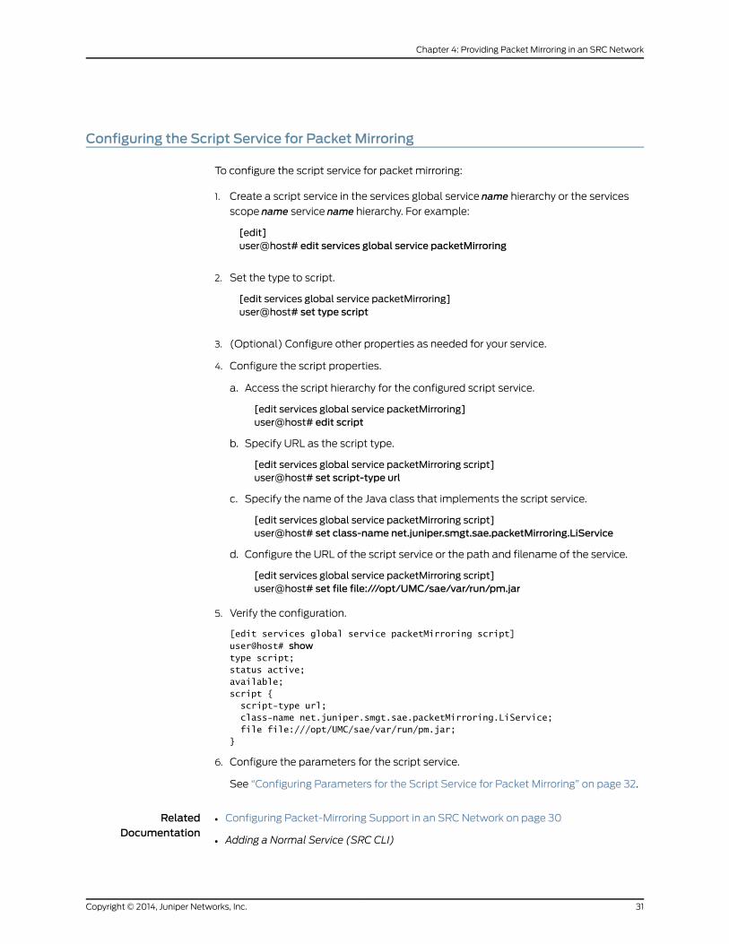
Configuring the Script Service for Packet Mirroring
To configure the script service for packet mirroring:
1. Create a script service in the services global service name hierarchy or the services
scope name service name hierarchy. For example:
[edit]user@host# edit services global service packetMirroring
2. Set the type to script.
[edit services global service packetMirroring]user@host# set type script
3. (Optional) Configure other properties as needed for your service.
4. Configure the script properties.
a. Access the script hierarchy for the configured script service.
[edit services global service packetMirroring]user@host# edit script
b. Specify URL as the script type.
[edit services global service packetMirroring script]user@host# set script-type url
c. Specify the name of the Java class that implements the script service.
[edit services global service packetMirroring script]user@host# set class-name net.juniper.smgt.sae.packetMirroring.LiService
d. Configure the URL of the script service or the path and filename of the service.
[edit services global service packetMirroring script]user@host# set file file:///opt/UMC/sae/var/run/pm.jar
5. Verify the configuration.
[edit services global service packetMirroring script]user@host# showtype script;status active;available;script { script-type url; class-name net.juniper.smgt.sae.packetMirroring.LiService; file file:///opt/UMC/sae/var/run/pm.jar;}
6. Configure the parameters for the script service.
See “Configuring Parameters for the Script Service for Packet Mirroring” on page 32.
RelatedDocumentation
Configuring Packet-Mirroring Support in an SRC Network on page 30•
• Adding a Normal Service (SRC CLI)
31Copyright © 2014, Juniper Networks, Inc.
Chapter 4: Providing Packet Mirroring in an SRC Network
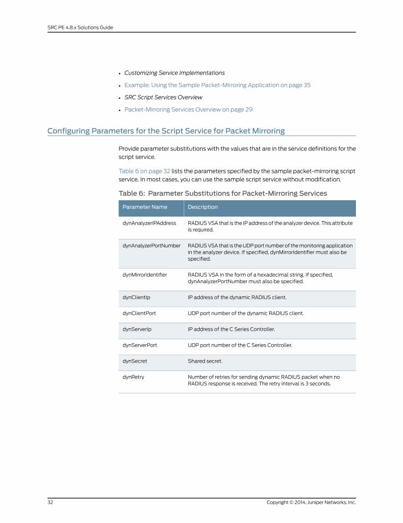
• Customizing Service Implementations
• Example: Using the Sample Packet-Mirroring Application on page 35
• SRC Script Services Overview
• Packet-Mirroring Services Overview on page 29
Configuring Parameters for the Script Service for Packet Mirroring
Provide parameter substitutions with the values that are in the service definitions for the
script service.
Table 6 on page 32 lists the parameters specified by the sample packet-mirroring script
service. In most cases, you can use the sample script service without modification.
Table 6: Parameter Substitutions for Packet-Mirroring Services
DescriptionParameter Name
RADIUS VSA that is the IP address of the analyzer device. This attributeis required.
dynAnalyzerIPAddress
RADIUS VSA that is the UDP port number of the monitoring applicationin the analyzer device. If specified, dynMirrorIdentifier must also bespecified.
dynAnalyzerPortNumber
RADIUS VSA in the form of a hexadecimal string. If specified,dynAnalyzerPortNumber must also be specified.
dynMirrorIdentifier
IP address of the dynamic RADIUS client.dynClientIp
UDP port number of the dynamic RADIUS client.dynClientPort
IP address of the C Series Controller.dynServerIp
UDP port number of the C Series Controller.dynServerPort
Shared secret.dynSecret
Number of retries for sending dynamic RADIUS packet when noRADIUS response is received. The retry interval is 3 seconds.
dynRetry
Copyright © 2014, Juniper Networks, Inc.32
SRC PE 4.8.x Solutions Guide
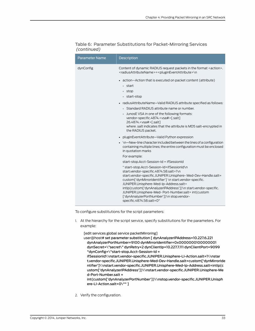
Table 6: Parameter Substitutions for Packet-Mirroring Services(continued)
DescriptionParameter Name
Content of dynamic RADIUS request packets in the format <action>.<radiusAttributeName>=<pluginEventAttribute>\n
• action—Action that is executed on packet content (attribute)
• start
• stop
• start-stop
• radiusAttributeName—Valid RADIUS attribute specified as follows:
• Standard RADIUS attribute name or number.
• JunosE VSA in one of the following formats:vendor-specific.4874.<vsa#>[.salt]26.4874.<vsa#>[.salt]where .salt indicates that the attribute is MD5 salt-encrypted inthe RADIUS packet.
• pluginEventAttribute—Valid Python expression
• \n—New-line character included between the lines of a configurationcontaining multiple lines; the entire configuration must be enclosedin quotation marks
For example:
start-stop.Acct-Session-Id = ifSessionId
“ start-stop.Acct-Session-Id=ifSessionId\nstart.vendor-specific.4874.58.salt=1\nstart.vendor-specific.JUNIPER.Unisphere- Med-Dev-Handle.salt=custom['dynMirrorIdentifier'] \n start.vendor-specific.JUNIPER.Unisphere-Med-Ip-Address.salt=intIp(custom['dynAnalyzerIPAddress'])\n start.vendor-specific.JUNIPER.Unisphere-Med- Port-Number.salt= int(custom['dynAnalyzerPortNumber'])\n stop.vendor-specific.4874.58.salt=0"
dynConfig
To configure substitutions for the script parameters:
1. At the hierarchy for the script service, specify substitutions for the parameters. For
example:
[edit services global service packetMirroring]user@host# set parameter substitution [ dynAnalyzerIPAddress=10.227.6.221dynAnalyzerPortNumber=9100 dynMirrorIdentifier=0x0000000100000001dynSecret=\”secret\” dynRetry=2 dynClientIp=10.227.7.111 dynClientPort=9099"dynConfig=\"start-stop.Acct-Session-Id =ifSessionId\\nstart.vendor-specific.JUNIPER.Unisphere-LI-Action.salt=1\\nstart.vendor-specific.JUNIPER.Unisphere-Med-Dev-Handle.salt=custom['dynMirrorIdentifier']\\nstart.vendor-specific.JUNIPER.Unisphere-Med-Ip-Address.salt=intIp(custom['dynAnalyzerIPAddress'])\\nstart.vendor-specific.JUNIPER.Unisphere-Med-Port-Number.salt =int(custom['dynAnalyzerPortNumber'])\\nstop.vendor-specific.JUNIPER.Unisphere-LI-Action.salt=0\"" ]
2. Verify the configuration.
33Copyright © 2014, Juniper Networks, Inc.
Chapter 4: Providing Packet Mirroring in an SRC Network
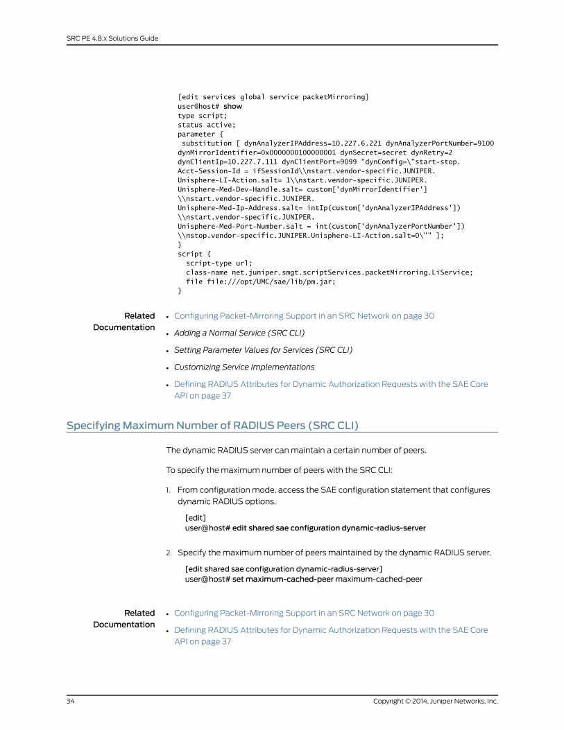
[edit services global service packetMirroring]user@host# showtype script;status active;parameter { substitution [ dynAnalyzerIPAddress=10.227.6.221 dynAnalyzerPortNumber=9100 dynMirrorIdentifier=0x0000000100000001 dynSecret=secret dynRetry=2 dynClientIp=10.227.7.111 dynClientPort=9099 "dynConfig=\"start-stop.Acct-Session-Id = ifSessionId\\nstart.vendor-specific.JUNIPER.Unisphere-LI-Action.salt= 1\\nstart.vendor-specific.JUNIPER.Unisphere-Med-Dev-Handle.salt= custom['dynMirrorIdentifier']\\nstart.vendor-specific.JUNIPER.Unisphere-Med-Ip-Address.salt= intIp(custom['dynAnalyzerIPAddress'])\\nstart.vendor-specific.JUNIPER.Unisphere-Med-Port-Number.salt = int(custom['dynAnalyzerPortNumber'])\\nstop.vendor-specific.JUNIPER.Unisphere-LI-Action.salt=0\"" ];}script { script-type url; class-name net.juniper.smgt.scriptServices.packetMirroring.LiService; file file:///opt/UMC/sae/lib/pm.jar;}
RelatedDocumentation
Configuring Packet-Mirroring Support in an SRC Network on page 30•
• Adding a Normal Service (SRC CLI)
• Setting Parameter Values for Services (SRC CLI)
• Customizing Service Implementations
• Defining RADIUS Attributes for Dynamic Authorization Requests with the SAE Core
API on page 37
SpecifyingMaximumNumber of RADIUS Peers (SRC CLI)
The dynamic RADIUS server can maintain a certain number of peers.
To specify the maximum number of peers with the SRC CLI:
1. From configuration mode, access the SAE configuration statement that configures
dynamic RADIUS options.
[edit]user@host# edit shared sae configuration dynamic-radius-server
2. Specify the maximum number of peers maintained by the dynamic RADIUS server.
[edit shared sae configuration dynamic-radius-server]user@host# setmaximum-cached-peermaximum-cached-peer
RelatedDocumentation
Configuring Packet-Mirroring Support in an SRC Network on page 30•
• Defining RADIUS Attributes for Dynamic Authorization Requests with the SAE Core
API on page 37
Copyright © 2014, Juniper Networks, Inc.34
SRC PE 4.8.x Solutions Guide
• Example: Using the Sample Packet-Mirroring Application on page 35
• Packet-Mirroring Services Overview on page 29
Example: Using the Sample Packet-Mirroring Application
To use the sample packet-mirroring application:
1. Download the SRC sample applications to your system from the Juniper Networks
Web site:
http://www.juniper.net/support/csc/swdist-erx/src.html
2. Locate the file that contains the service definition:
/SDK/scriptServices/packetMirroring/ldif/service.ldif
3. Import the sample service definition to the Juniper Networks Database on the C Series
Controller. To load the sample data into the database, you can use an LDAP tool, such
as ldapadd.
You can obtain ldapadd from the following Web site:
http://www.openldap.org/
To load data into the Juniper Networks database, you need the IP address of the
database and the database credentials. The default bind distinguished name (DN)
for the database is cn=umcadmin, o=umc and the password is admin123.
4. Copy the /lib/pm.jar file used by the script service to the /opt/UMC/sae /var/run
directory on the C Series Controller.
5. Modify the service substitutions for your environment.
You can make these substitutions by defining the parameter substitutions in the
packetMirroring service (serviceName=packetMirroring, o=Services, o=umc) with the
SRC CLI or by passing the values through the SAE core API.
For information about parameter substitutions, see “Configuring Parameters for the
Script Service for Packet Mirroring” on page 32. For information about passing the
values through the SAE core API, see “Defining RADIUS Attributes for Dynamic
Authorization Requests with the SAE Core API” on page 37.
6. Configure a subscription to the packetMirroring service that is activated on login.
For information about subscriptions, see Subscriptions Overview.
7. If you are modifying the sample application, copy the sae.jar and logger.jar files from
the SKD/lib directory, and add the sae.jar and logger.jar files to the class path when
you compile your application.
Example: Packet Mirroring for PPP Subscribers
When a PPP subscriber is subscribed to the packet-mirroring service, configure the service
as an activate-on-login service at user connection time. After the subscriber has logged
in through the SAE remote API, the packet-mirroring service can be subscribed to the
35Copyright © 2014, Juniper Networks, Inc.
Chapter 4: Providing Packet Mirroring in an SRC Network
PPP subscriber and activated. When the service is activated, a COA request is sent to
the router running JunosE Software that includes the PPP subscriber’s accounting session
ID to start packet mirroring for this subscriber.
Example: Packet Mirroring for DHCP Subscribers
When a DHCP subscriber is subscribed to the packet-mirroring service, configure the
service as an activate-on-login service at user connection time. After the subscriber has
logged in through the SAE remote API, the packet-mirroring service can be subscribed
to the DHCP subscriber and activated. When the service is activated, a COA request is
sent to the router running JunosE Software that includes the DHCP subscriber’s IP address
and virtual router name for the router running JunosE Software to start packet mirroring
for this subscriber.
Configuring DHCP Subscriber Sessions
You can use DHCP option 82 to identify the subscriber session. For example, if you set
DHCP option 82 as the user login name, an external application can use this setting to
search for the subscriber session. The following subscriber classification script illustrates
this example:
[retailername=default,o=Users,o=UMC?loginName=<-dhcp[82].suboptions[1].string->?sub?(interfaceName=<-dhcp[82].suboptions[1].string->)]
loginType = “ ADDR”[<-retailerDN->??sub?(uniqueID=<-userName->)]retailerDN != “ “& userName != “ “[<-unauthenticatedUserDn->]loginType == "ADDR"loginType == "AUTHADDR"
Disabling RADIUS Authentication for DHCP Subscribers
Packet mirroring for DHCP subscribers does not involve RADIUS authentication, so you
might have to configure authentication to grant all IP subscriber management interfaces
access without authentication. For example, configure the router running JunosE Software
with the following authentication:
aaa authentication ip default none
You can still configure other subscribers to use RADIUS authentication. For example,
configure the router running JunosE Software with the following authentication for PPP
subscribers:
aaa authentication ppp default radius
RelatedDocumentation
Configuring Packet-Mirroring Support in an SRC Network on page 30•
• Packet-Mirroring Services Overview on page 29
Copyright © 2014, Juniper Networks, Inc.36
SRC PE 4.8.x Solutions Guide
Defining RADIUS Attributes for Dynamic Authorization Requests with the SAE CoreAPI
The SRC software provides two ways to define RADIUS attributes for dynamic RADIUS
authorization requests:
• Service definition
• SAE core API
NOTE: Parameters set in the API override parameters set by the servicedefinition.
To send dynamic RADIUS authorization requests with the SAE core API, the script service
uses the sendDynamicRadius and getRouterDynRadiusAddr methods in the
ServiceSessionInfo interface to provide the content of the RADIUS packet for the dynamic
authorization request to the router running JunosE Software that is attached to the service
session.
For information about the ServiceSessionInfo interface, see the script service
documentation in the SAE core API documentation on the Juniper Networks Web site at
http://www.juniper.net/techpubs/software/management/src/api-index.html.
For a sample implementation, see the following file in the
SDK+AppSupport+Demos+Samples.tar.gz file:
SDK/scriptServices/packetMirroring/java/net/juniper/smgt/scriptServices/
packetMirroring/LiService.java.
RelatedDocumentation
• Configuring Parameters for the Script Service for Packet Mirroring on page 32
37Copyright © 2014, Juniper Networks, Inc.
Chapter 4: Providing Packet Mirroring in an SRC Network

Copyright © 2014, Juniper Networks, Inc.38
SRC PE 4.8.x Solutions Guide
PART 2
Managing Services in a PCMMEnvironment
• Providing Premium Services in a PCMM Environment on page 41
• Configuring the SAE for a PCMM Environment (SRC CLI) on page 57
• Adding Objects for CMTS Devices (SRC CLI) on page 69
• Using the NIC Resolver in a PCMM Environment on page 73
• Using PCMM Policy Servers on page 75
• Configuring the JPS (SRC CLI) on page 79
• Monitoring the JPS (SRC CLI) on page 105
• Monitoring the JPS (C-Web Interface) on page 109
39Copyright © 2014, Juniper Networks, Inc.

Copyright © 2014, Juniper Networks, Inc.40
SRC PE 4.8.x Solutions Guide
CHAPTER 5
Providing Premium Services in a PCMMEnvironment
• PCMM Environment Overview on page 41
• Using the SAE in a PCMM Environment on page 50
PCMMEnvironment Overview
The PacketCable Multimedia (PCMM) specification defines a standards-based way to
deliver premium quality of service (QoS)–enhanced services across the radio frequency
(RF) portion of a cable network. The PCMM capabilities of the SRC software along with
Juniper Networks routers provide an end-to-end solution that seamlessly links the cable
operator’s RF domain with IP edge and core QoS services.
Key services supported in this environment include:
• Bandwidth on demand and variable bandwidth
• QoS-enabled streaming media, including video on demand and video telephony
• Residential voice over IP (VoIP)
• Multicast audio and video applications
• Videoconferencing
• Interactive gaming
• Peer-to-peer controls and protection services
PCMMArchitecture
Figure 5 on page 42 depicts the PCMM architectural framework. The basic roles of the
various PCMM components are:
• Application manager—Provides an interface to policy server(s) for the purpose of
requesting QoS-based service on behalf of a subscriber or a network management
system. It maps session requests to resource requests and creates policies.
• Policy server—Acts as a policy decision point and policy enforcement point and manages
relationships between application managers and cable modem termination system
(CMTS) devices.
41Copyright © 2014, Juniper Networks, Inc.
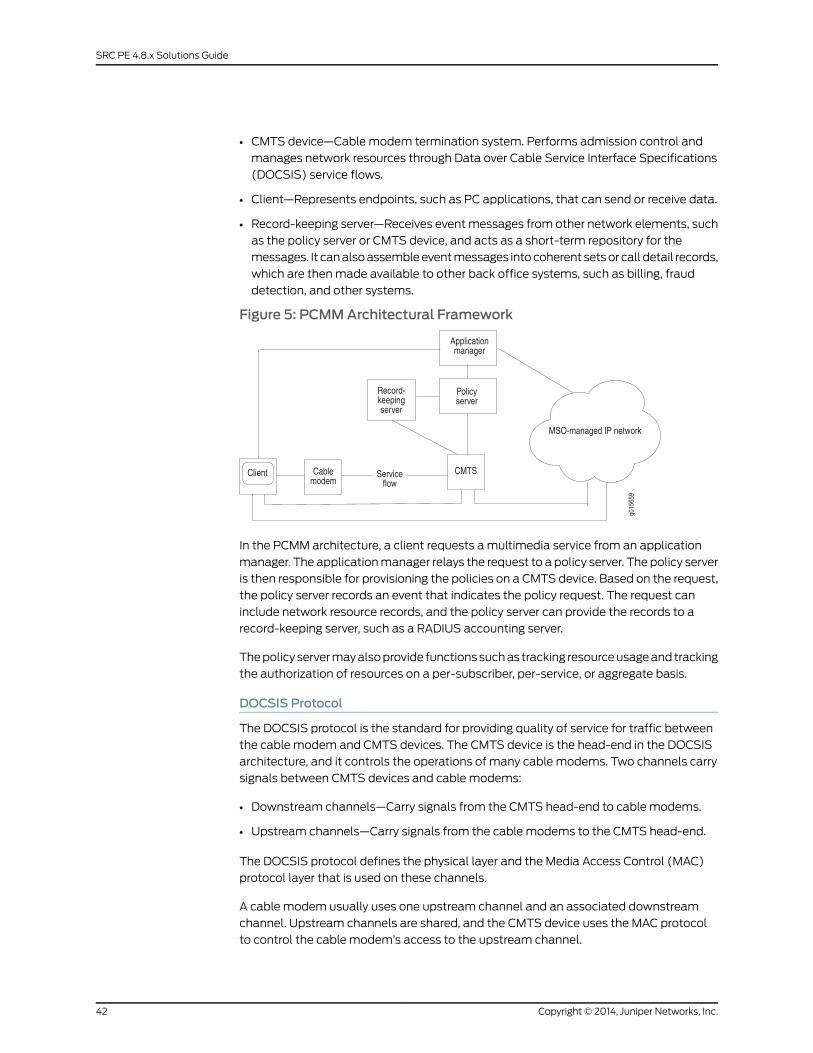
• CMTS device—Cable modem termination system. Performs admission control and
manages network resources through Data over Cable Service Interface Specifications
(DOCSIS) service flows.
• Client—Represents endpoints, such as PC applications, that can send or receive data.
• Record-keeping server—Receives event messages from other network elements, such
as the policy server or CMTS device, and acts as a short-term repository for the
messages. It can also assemble event messages into coherent sets or call detail records,
which are then made available to other back office systems, such as billing, fraud
detection, and other systems.
Figure 5: PCMMArchitectural Framework
In the PCMM architecture, a client requests a multimedia service from an application
manager. The application manager relays the request to a policy server. The policy server
is then responsible for provisioning the policies on a CMTS device. Based on the request,
the policy server records an event that indicates the policy request. The request can
include network resource records, and the policy server can provide the records to a
record-keeping server, such as a RADIUS accounting server.
The policy server may also provide functions such as tracking resource usage and tracking
the authorization of resources on a per-subscriber, per-service, or aggregate basis.
DOCSIS Protocol
The DOCSIS protocol is the standard for providing quality of service for traffic between
the cable modem and CMTS devices. The CMTS device is the head-end in the DOCSIS
architecture, and it controls the operations of many cable modems. Two channels carry
signals between CMTS devices and cable modems:
• Downstream channels—Carry signals from the CMTS head-end to cable modems.
• Upstream channels—Carry signals from the cable modems to the CMTS head-end.
The DOCSIS protocol defines the physical layer and the Media Access Control (MAC)
protocol layer that is used on these channels.
A cable modem usually uses one upstream channel and an associated downstream
channel. Upstream channels are shared, and the CMTS device uses the MAC protocol
to control the cable modem’s access to the upstream channel.
Copyright © 2014, Juniper Networks, Inc.42
SRC PE 4.8.x Solutions Guide

Service Flows
The DOCSIS protocol uses the concept of service flows to support QoS on upstream and
downstream channels. A service flow is a unidirectional flow of packets that provides a
particular quality of service. Traffic is classified into a service flow, and each service flow
has its own set of QoS parameters. The SRC software is compliant with the following
upstream service flow scheduling types, as defined in the PacketCable Multimedia
Specification PKT-SP-MM-I03-051221.
• Best effort—Used for standard Internet traffic such as Web browsing, e-mail, or instant
messaging.
• Non-real-time polling service (NRTPS)—Used for standard Internet traffic that requires
high throughput, and traffic that requires variable-sized data packets on a regular basis,
such as high-bandwidth File Transfer Protocol (FTP).
• Real-time polling service (RTPS)—Used for applications such as Moving Pictures
Experts Group (MPEG) video.
• Unsolicited grant service (UGS)—Used for real-time traffic that generates fixed-size
data packets on a periodic basis. Applications include VoIP.
• Unsolicited grant service with activity detection (UGS-AD)—Used for applications such
as voice activity detection, also known as silence suppression.
Downstream service flows are defined through a similar set of QoS parameters that are
associated with the best-effort scheduling type on upstream service flows.
Client Types
The PCMM specification uses the concept of clients and defines a client as a logical entity
that can send or receive data. The SRC software supports type 1 and type 2 clients.
The PCMM specification defines two resource reservation models for each client type—a
single phase and a dual phase. The SRC software supports the single-phase model.
Client Type 1 Single Phase Resource Reservation Model
Type 1 clients represent endpoints, such as PC applications or gaming consoles, that lack
specific QoS awareness or signaling capabilities. Type 1 clients communicate with an
application manager to request a service. They do not request QoS resources directly
from the multiple service operator (MSO) network.
Client type 1 entities support the proxied-QoS with policy-push scenario of service delivery
defined in PacketCable Multimedia Architecture Framework Technical Report
(PKT-TR-MM-ARCH). In this scenario, the application manager requests QoS resources
on behalf of the client, and the policy server pushes the request to the CMTS device. The
CMTS device sets up and manages the DOCSIS service flow that the application requires,
and might also set up and manage the cable modems.
Figure 6 on page 44 shows the message flow in an application scenario for the client type
1 single-phase resource reservation model.
43Copyright © 2014, Juniper Networks, Inc.
Chapter 5: Providing Premium Services in a PCMM Environment
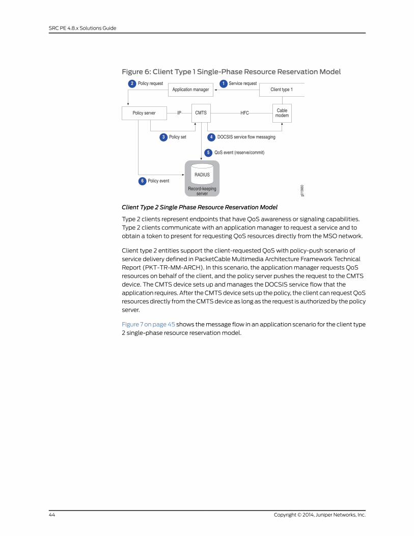
Figure 6: Client Type 1 Single-Phase Resource ReservationModel
Client Type 2 Single Phase Resource Reservation Model
Type 2 clients represent endpoints that have QoS awareness or signaling capabilities.
Type 2 clients communicate with an application manager to request a service and to
obtain a token to present for requesting QoS resources directly from the MSO network.
Client type 2 entities support the client-requested QoS with policy-push scenario of
service delivery defined in PacketCable Multimedia Architecture Framework Technical
Report (PKT-TR-MM-ARCH). In this scenario, the application manager requests QoS
resources on behalf of the client, and the policy server pushes the request to the CMTS
device. The CMTS device sets up and manages the DOCSIS service flow that the
application requires. After the CMTS device sets up the policy, the client can request QoS
resources directly from the CMTS device as long as the request is authorized by the policy
server.
Figure 7 on page 45 shows the message flow in an application scenario for the client type
2 single-phase resource reservation model.
Copyright © 2014, Juniper Networks, Inc.44
SRC PE 4.8.x Solutions Guide
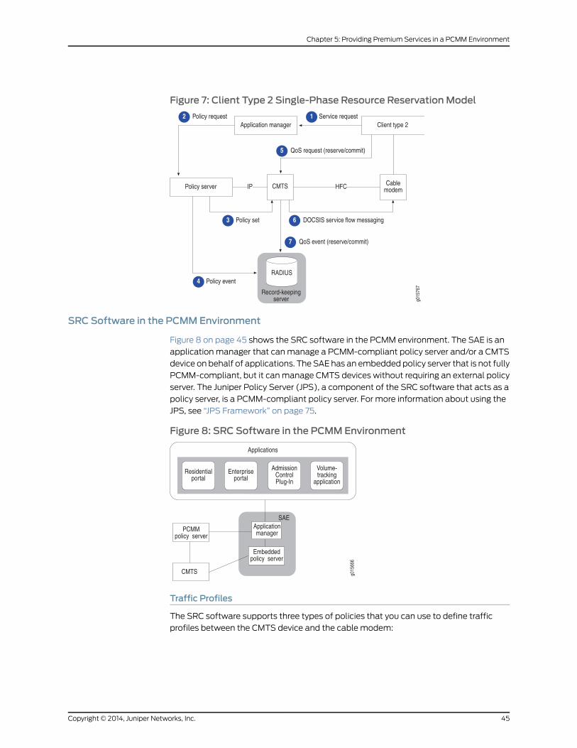
Figure 7: Client Type 2 Single-Phase Resource ReservationModel
SRC Software in the PCMMEnvironment
Figure 8 on page 45 shows the SRC software in the PCMM environment. The SAE is an
application manager that can manage a PCMM-compliant policy server and/or a CMTS
device on behalf of applications. The SAE has an embedded policy server that is not fully
PCMM-compliant, but it can manage CMTS devices without requiring an external policy
server. The Juniper Policy Server (JPS), a component of the SRC software that acts as a
policy server, is a PCMM-compliant policy server. For more information about using the
JPS, see “JPS Framework” on page 75.
Figure 8: SRC Software in the PCMMEnvironment
Traffic Profiles
The SRC software supports three types of policies that you can use to define traffic
profiles between the CMTS device and the cable modem:
45Copyright © 2014, Juniper Networks, Inc.
Chapter 5: Providing Premium Services in a PCMM Environment
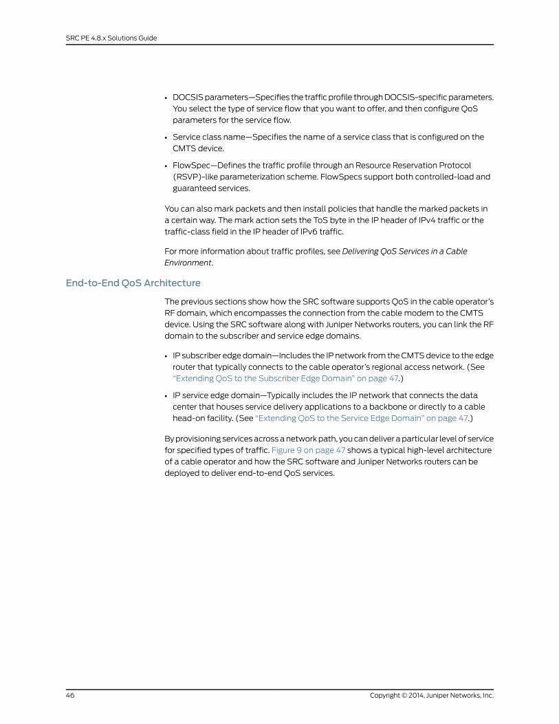
• DOCSIS parameters—Specifies the traffic profile through DOCSIS-specific parameters.
You select the type of service flow that you want to offer, and then configure QoS
parameters for the service flow.
• Service class name—Specifies the name of a service class that is configured on the
CMTS device.
• FlowSpec—Defines the traffic profile through an Resource Reservation Protocol
(RSVP)-like parameterization scheme. FlowSpecs support both controlled-load and
guaranteed services.
You can also mark packets and then install policies that handle the marked packets in
a certain way. The mark action sets the ToS byte in the IP header of IPv4 traffic or the
traffic-class field in the IP header of IPv6 traffic.
For more information about traffic profiles, see Delivering QoS Services in a Cable
Environment.
End-to-End QoS Architecture
The previous sections show how the SRC software supports QoS in the cable operator’s
RF domain, which encompasses the connection from the cable modem to the CMTS
device. Using the SRC software along with Juniper Networks routers, you can link the RF
domain to the subscriber and service edge domains.
• IP subscriber edge domain—Includes the IP network from the CMTS device to the edge
router that typically connects to the cable operator’s regional access network. (See
“Extending QoS to the Subscriber Edge Domain” on page 47.)
• IP service edge domain—Typically includes the IP network that connects the data
center that houses service delivery applications to a backbone or directly to a cable
head-on facility. (See “Extending QoS to the Service Edge Domain” on page 47.)
By provisioning services across a network path, you can deliver a particular level of service
for specified types of traffic. Figure 9 on page 47 shows a typical high-level architecture
of a cable operator and how the SRC software and Juniper Networks routers can be
deployed to deliver end-to-end QoS services.
Copyright © 2014, Juniper Networks, Inc.46
SRC PE 4.8.x Solutions Guide
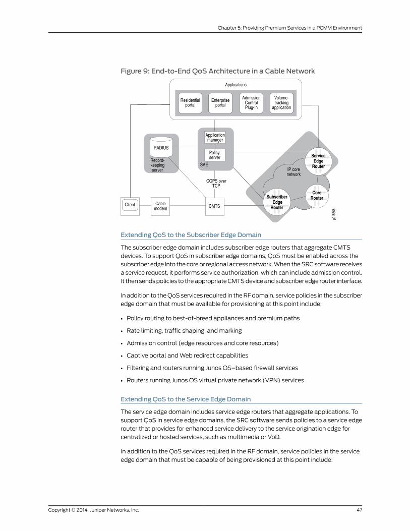
Figure 9: End-to-End QoS Architecture in a Cable Network
Extending QoS to the Subscriber Edge Domain
The subscriber edge domain includes subscriber edge routers that aggregate CMTS
devices. To support QoS in subscriber edge domains, QoS must be enabled across the
subscriber edge into the core or regional access network. When the SRC software receives
a service request, it performs service authorization, which can include admission control.
It then sends policies to the appropriate CMTS device and subscriber edge router interface.
In addition to the QoS services required in the RF domain, service policies in the subscriber
edge domain that must be available for provisioning at this point include:
• Policy routing to best-of-breed appliances and premium paths
• Rate limiting, traffic shaping, and marking
• Admission control (edge resources and core resources)
• Captive portal and Web redirect capabilities
• Filtering and routers running Junos OS–based firewall services
• Routers running Junos OS virtual private network (VPN) services
Extending QoS to the Service Edge Domain
The service edge domain includes service edge routers that aggregate applications. To
support QoS in service edge domains, the SRC software sends policies to a service edge
router that provides for enhanced service delivery to the service origination edge for
centralized or hosted services, such as multimedia or VoD.
In addition to the QoS services required in the RF domain, service policies in the service
edge domain that must be capable of being provisioned at this point include:
47Copyright © 2014, Juniper Networks, Inc.
Chapter 5: Providing Premium Services in a PCMM Environment
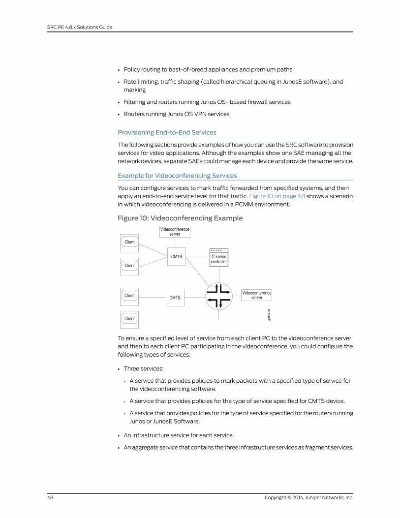
• Policy routing to best-of-breed appliances and premium paths
• Rate limiting, traffic shaping (called hierarchical queuing in JunosE software), and
marking
• Filtering and routers running Junos OS–based firewall services
• Routers running Junos OS VPN services
Provisioning End-to-End Services
The following sections provide examples of how you can use the SRC software to provision
services for video applications. Although the examples show one SAE managing all the
network devices, separate SAEs could manage each device and provide the same service.
Example for Videoconferencing Services
You can configure services to mark traffic forwarded from specified systems, and then
apply an end-to-end service level for that traffic. Figure 10 on page 48 shows a scenario
in which videoconferencing is delivered in a PCMM environment.
Figure 10: Videoconferencing Example
To ensure a specified level of service from each client PC to the videoconference server
and then to each client PC participating in the videoconference, you could configure the
following types of services:
• Three services:
• A service that provides policies to mark packets with a specified type of service for
the videoconferencing software.
• A service that provides policies for the type of service specified for CMTS device.
• A service that provides policies for the type of service specified for the routers running
Junos or JunosE Software.
• An infrastructure service for each service.
• An aggregate service that contains the three infrastructure services as fragment services.
Copyright © 2014, Juniper Networks, Inc.48
SRC PE 4.8.x Solutions Guide
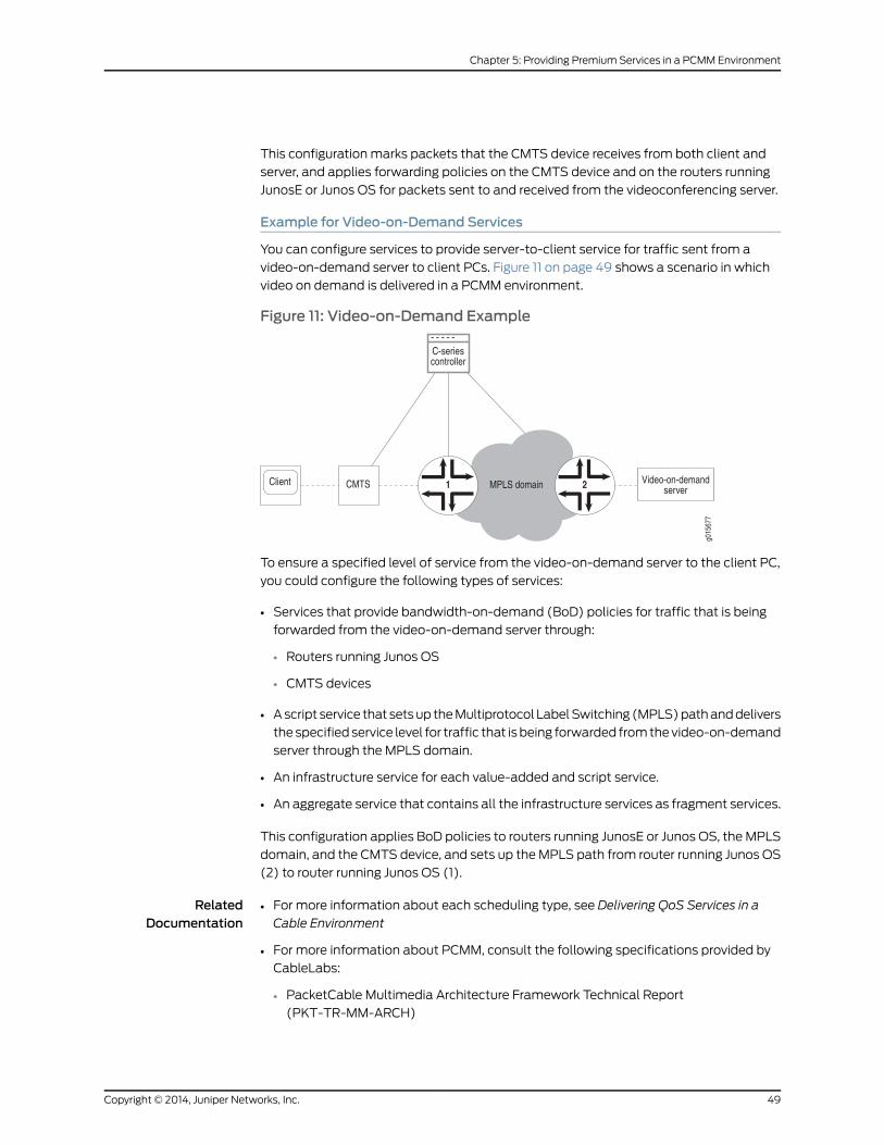
This configuration marks packets that the CMTS device receives from both client and
server, and applies forwarding policies on the CMTS device and on the routers running
JunosE or Junos OS for packets sent to and received from the videoconferencing server.
Example for Video-on-Demand Services
You can configure services to provide server-to-client service for traffic sent from a
video-on-demand server to client PCs. Figure 11 on page 49 shows a scenario in which
video on demand is delivered in a PCMM environment.
Figure 11: Video-on-Demand Example
To ensure a specified level of service from the video-on-demand server to the client PC,
you could configure the following types of services:
• Services that provide bandwidth-on-demand (BoD) policies for traffic that is being
forwarded from the video-on-demand server through:
• Routers running Junos OS
• CMTS devices
• A script service that sets up the Multiprotocol Label Switching (MPLS) path and delivers
the specified service level for traffic that is being forwarded from the video-on-demand
server through the MPLS domain.
• An infrastructure service for each value-added and script service.
• An aggregate service that contains all the infrastructure services as fragment services.
This configuration applies BoD policies to routers running JunosE or Junos OS, the MPLS
domain, and the CMTS device, and sets up the MPLS path from router running Junos OS
(2) to router running Junos OS (1).
RelatedDocumentation
For more information about each scheduling type, see Delivering QoS Services in a
Cable Environment
•
• For more information about PCMM, consult the following specifications provided by
CableLabs:
• PacketCable Multimedia Architecture Framework Technical Report
(PKT-TR-MM-ARCH)
49Copyright © 2014, Juniper Networks, Inc.
Chapter 5: Providing Premium Services in a PCMM Environment
• PacketCable Multimedia Specification PKT-SP-MM-I03-051221
• PacketCable Security Specifications (PKT-SP-SEC)
• Using the SAE in a PCMM Environment on page 50
• Using the NIC Resolver in PCMM Environments on page 73
• Example: Providing Premium Services
Using the SAE in a PCMMEnvironment
The SAE uses the Common Open Policy Service (COPS) protocol as specified in the
PacketCable Multimedia Specification PKT-SP-MM-I03-051221 to manage
PCMM-compliant CMTS devices in a cable network environment. The SAE connects to
the CMTS device by using a COPS over Transmission Control Protocol (TCP) connection.
In cable environments, the SAE manages the connection to the CMTS device.
The CMTS device does not provide address requests or notify the SAE of new subscribers,
subscriber IP addresses, or any other attributes. IP address detection and all other
subscriber attributes are collected outside of the COPS connection to the CMTS device.
The SAE uses COPS only to push policies to the CMTS device and to learn about the
CMTS status and usage data.
Because the CMTS device does not have the concept of interfaces, the SRC software
uses pseudointerfaces to model CMTS subscriber connections similar to subscriber
connections for routers running Junos OS.
This section describes how the SAE is used in cable networks. It includes the following
topics:
• Logging In Subscribers and Creating Sessions on page 50
• SAE Communities on page 53
• Storing Session Data on page 54
Logging In Subscribers and Creating Sessions
You can use two mechanisms to obtain subscriber address requests and other information
and to set up a pseudointerface on the CMTS device. (You must choose one mechanism;
you cannot mix them.):
1. Assigned IP subscriber. The SAE learns about a subscriber through subscriber-initiated
activities, such as activating a service through the portal or through the Advanced
Services Gateway (ASG).
With this method, you use the assigned IP subscriber login type along with the network
interface collector (NIC) to map IP addresses to the SAE.
2. Event notification from an IP address manager. The SAE learns about subscribers
through notifications from an external IP address manager, such as a DHCP server or
a RADIUS server.
Copyright © 2014, Juniper Networks, Inc.50
SRC PE 4.8.x Solutions Guide
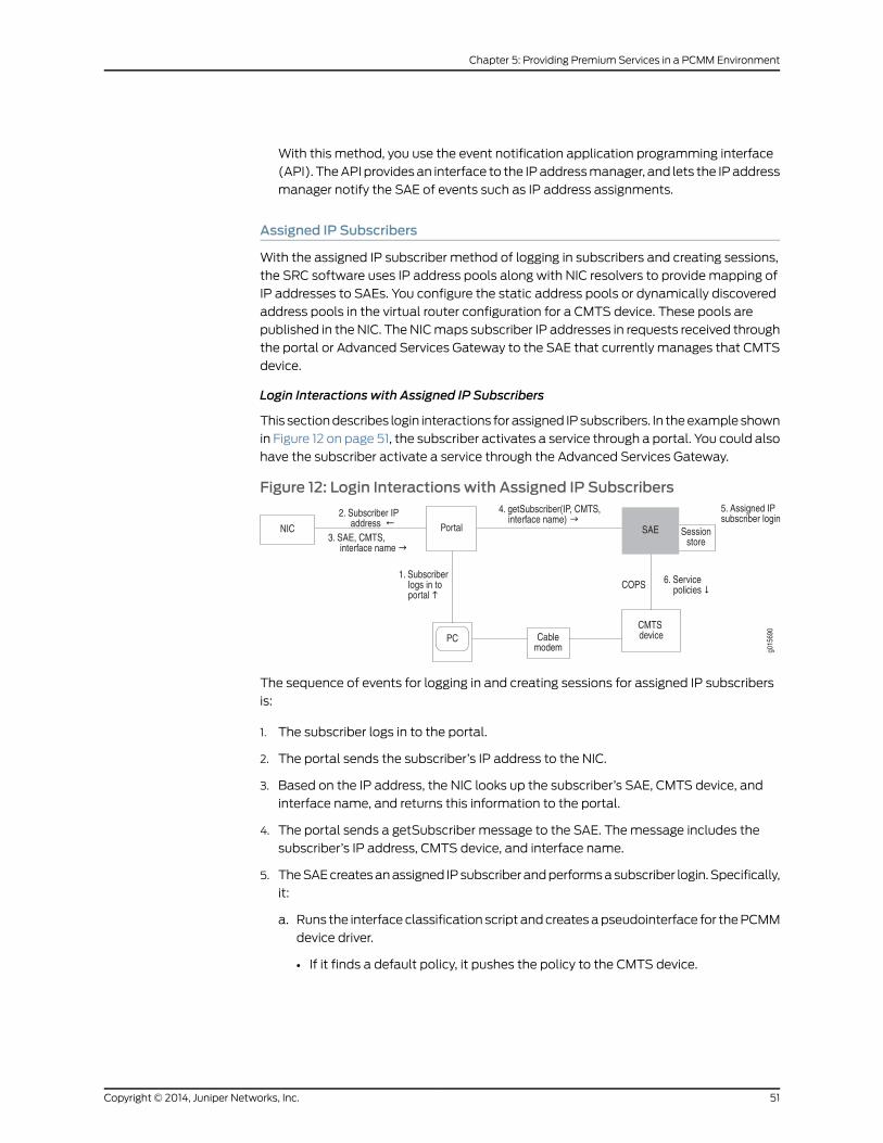
With this method, you use the event notification application programming interface
(API). The API provides an interface to the IP address manager, and lets the IP address
manager notify the SAE of events such as IP address assignments.
Assigned IP Subscribers
With the assigned IP subscriber method of logging in subscribers and creating sessions,
the SRC software uses IP address pools along with NIC resolvers to provide mapping of
IP addresses to SAEs. You configure the static address pools or dynamically discovered
address pools in the virtual router configuration for a CMTS device. These pools are
published in the NIC. The NIC maps subscriber IP addresses in requests received through
the portal or Advanced Services Gateway to the SAE that currently manages that CMTS
device.
Login Interactions with Assigned IP Subscribers
This section describes login interactions for assigned IP subscribers. In the example shown
in Figure 12 on page 51, the subscriber activates a service through a portal. You could also
have the subscriber activate a service through the Advanced Services Gateway.
Figure 12: Login Interactions with Assigned IP Subscribers
The sequence of events for logging in and creating sessions for assigned IP subscribers
is:
1. The subscriber logs in to the portal.
2. The portal sends the subscriber’s IP address to the NIC.
3. Based on the IP address, the NIC looks up the subscriber’s SAE, CMTS device, and
interface name, and returns this information to the portal.
4. The portal sends a getSubscriber message to the SAE. The message includes the
subscriber’s IP address, CMTS device, and interface name.
5. The SAE creates an assigned IP subscriber and performs a subscriber login. Specifically,
it:
a. Runs the interface classification script and creates a pseudointerface for the PCMM
device driver.
• If it finds a default policy, it pushes the policy to the CMTS device.
51Copyright © 2014, Juniper Networks, Inc.
Chapter 5: Providing Premium Services in a PCMM Environment
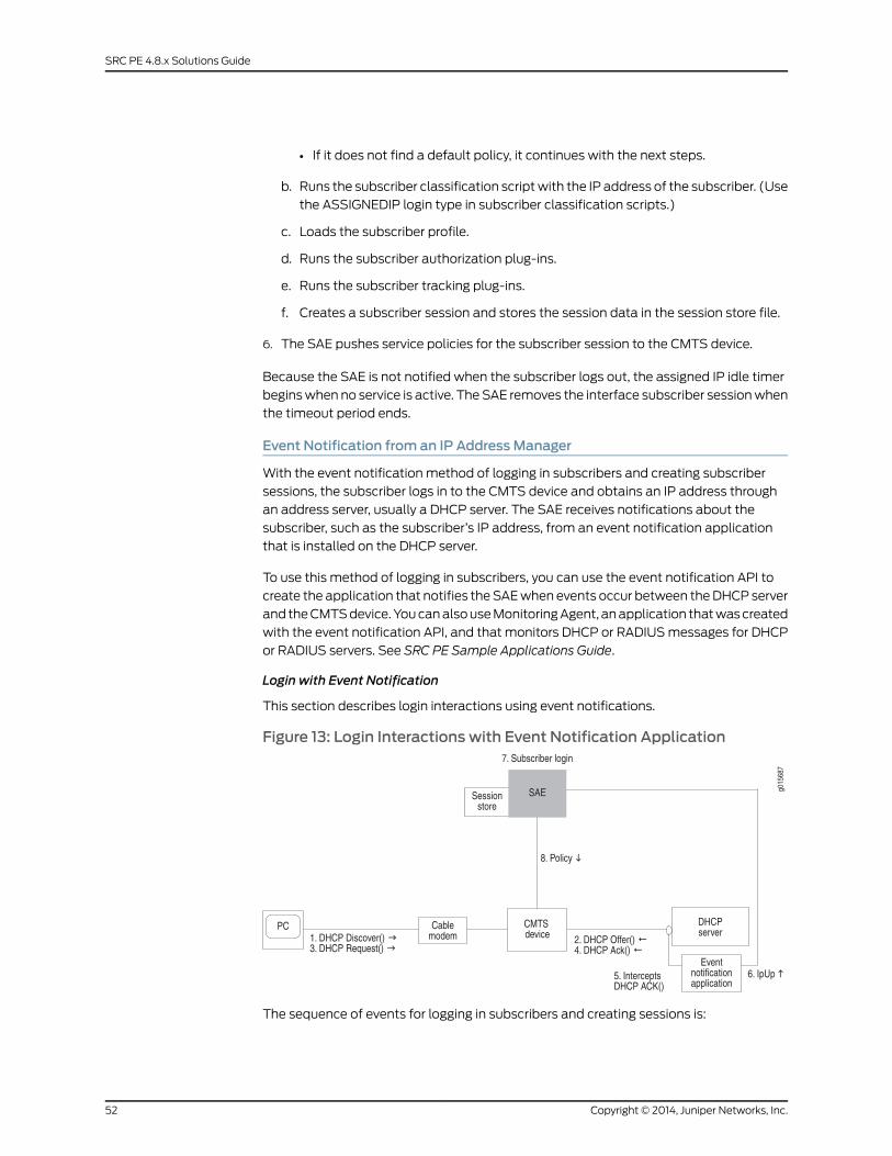
• If it does not find a default policy, it continues with the next steps.
b. Runs the subscriber classification script with the IP address of the subscriber. (Use
the ASSIGNEDIP login type in subscriber classification scripts.)
c. Loads the subscriber profile.
d. Runs the subscriber authorization plug-ins.
e. Runs the subscriber tracking plug-ins.
f. Creates a subscriber session and stores the session data in the session store file.
6. The SAE pushes service policies for the subscriber session to the CMTS device.
Because the SAE is not notified when the subscriber logs out, the assigned IP idle timer
begins when no service is active. The SAE removes the interface subscriber session when
the timeout period ends.
Event Notification from an IP Address Manager
With the event notification method of logging in subscribers and creating subscriber
sessions, the subscriber logs in to the CMTS device and obtains an IP address through
an address server, usually a DHCP server. The SAE receives notifications about the
subscriber, such as the subscriber’s IP address, from an event notification application
that is installed on the DHCP server.
To use this method of logging in subscribers, you can use the event notification API to
create the application that notifies the SAE when events occur between the DHCP server
and the CMTS device. You can also use Monitoring Agent, an application that was created
with the event notification API, and that monitors DHCP or RADIUS messages for DHCP
or RADIUS servers. See SRC PE Sample Applications Guide.
Login with Event Notification
This section describes login interactions using event notifications.
Figure 13: Login Interactions with Event Notification Application
The sequence of events for logging in subscribers and creating sessions is:
Copyright © 2014, Juniper Networks, Inc.52
SRC PE 4.8.x Solutions Guide
1. The DHCP client in the subscriber’s computer sends a DHCP discover request to the
DHCP server.
2. The DHCP server sends a DHCP offer to the subscriber’s DHCP client.
3. The DHCP client sends a DHCP request to the DHCP server.
4. The DHCP server acknowledges the request by sending a DHCP Ack message to the
DHCP client.
5. The event notification application that is running on the DHCP server intercepts the
DHCP Ack message.
6. The event notification application sends an ipUp message to the SAE that notifies
the SAE that an IP address is up.
7. The SAE performs a subscriber login. Specifically, it:
a. Runs the interface classification script and creates a pseudointerface for the PCMM
device driver.
• If it finds a default policy, it pushes the policy to the CMTS device.
• If it does not find a default policy, it continues with the next steps.
b. Runs the subscriber classification script.
c. Loads the subscriber profile.
d. Runs the subscriber authorization plug-ins.
e. Runs the subscriber tracking plug-ins.
f. Creates a subscriber session and stores the session in the session store file.
8. The SAE provisions policies for the subscriber session on the CMTS device.
The ipUp event should be sent with a timeout set to the DHCP lease time. The DHCP
server sends an ipUp event for each Ack sent to the client. The SAE restarts the timeout
each time it receives an ipUp event.
If the client explicitly releases the DHCP address (that is, it sends a DHCP release event),
the DHCP server sends an ipDown event. If the client does not renew the address, the
lease expires on the DHCP server and the timeout expires on the SAE.
SAE Communities
For SAE redundancy in a cable network, you can have a community of two or more SAEs.
SAEs in a community are given the role of either active SAE or passive SAE. The active
SAE manages the connection to the CMTS device and keeps session data up to date
within the community. Figure 14 on page 54 shows a typical SAE community.
53Copyright © 2014, Juniper Networks, Inc.
Chapter 5: Providing Premium Services in a PCMM Environment
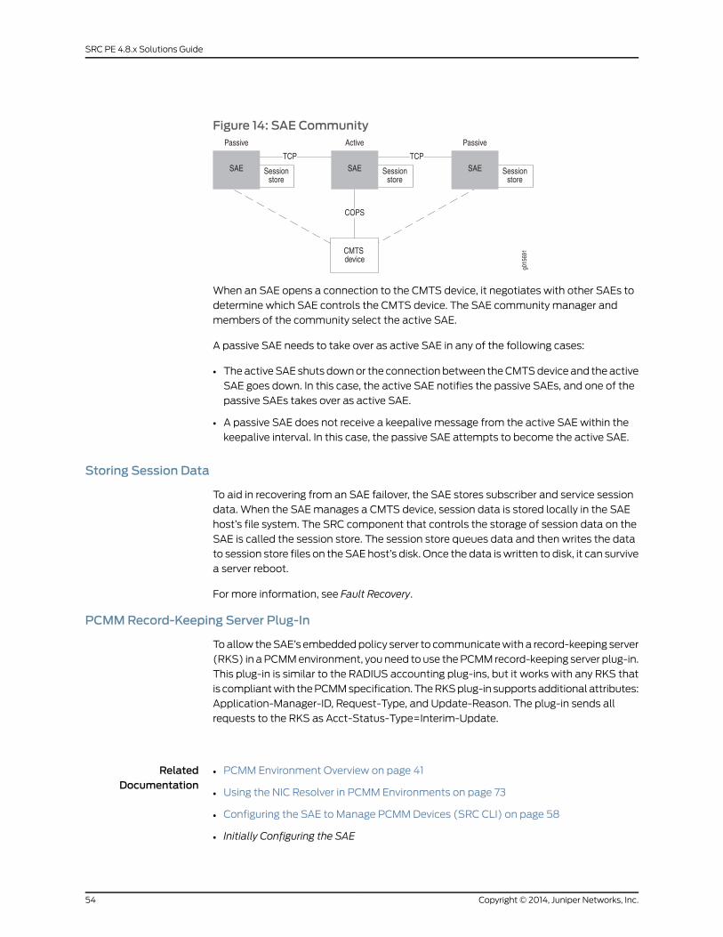
Figure 14: SAE Community
When an SAE opens a connection to the CMTS device, it negotiates with other SAEs to
determine which SAE controls the CMTS device. The SAE community manager and
members of the community select the active SAE.
A passive SAE needs to take over as active SAE in any of the following cases:
• The active SAE shuts down or the connection between the CMTS device and the active
SAE goes down. In this case, the active SAE notifies the passive SAEs, and one of the
passive SAEs takes over as active SAE.
• A passive SAE does not receive a keepalive message from the active SAE within the
keepalive interval. In this case, the passive SAE attempts to become the active SAE.
Storing Session Data
To aid in recovering from an SAE failover, the SAE stores subscriber and service session
data. When the SAE manages a CMTS device, session data is stored locally in the SAE
host’s file system. The SRC component that controls the storage of session data on the
SAE is called the session store. The session store queues data and then writes the data
to session store files on the SAE host’s disk. Once the data is written to disk, it can survive
a server reboot.
For more information, see Fault Recovery.
PCMMRecord-Keeping Server Plug-In
To allow the SAE’s embedded policy server to communicate with a record-keeping server
(RKS) in a PCMM environment, you need to use the PCMM record-keeping server plug-in.
This plug-in is similar to the RADIUS accounting plug-ins, but it works with any RKS that
is compliant with the PCMM specification. The RKS plug-in supports additional attributes:
Application-Manager-ID, Request-Type, and Update-Reason. The plug-in sends all
requests to the RKS as Acct-Status-Type=Interim-Update.
RelatedDocumentation
• PCMM Environment Overview on page 41
• Using the NIC Resolver in PCMM Environments on page 73
• Configuring the SAE to Manage PCMM Devices (SRC CLI) on page 58
• Initially Configuring the SAE
Copyright © 2014, Juniper Networks, Inc.54
SRC PE 4.8.x Solutions Guide

• Storing Subscriber and Service Session Data
55Copyright © 2014, Juniper Networks, Inc.
Chapter 5: Providing Premium Services in a PCMM Environment

Copyright © 2014, Juniper Networks, Inc.56
SRC PE 4.8.x Solutions Guide
CHAPTER 6
Configuring the SAE for a PCMMEnvironment (SRC CLI)
• Configuring the SAE for a Cable Network Environment (SRC CLI) on page 57
• Configuring the SAE to Manage PCMM Devices (SRC CLI) on page 58
• Setting Up SAE Communities (SRC CLI) on page 61
• Configuring the SAE Community Manager on page 61
• Configuring SAE Properties for the Event Notification API (SRC CLI) on page 62
• Configuring Record-Keeping Server Peers for Plug-Ins (SRC CLI) on page 63
• Configuring PCMM Record-Keeping Server Plug-Ins (SRC CLI) on page 64
• Configuring CMTS-Specific RKS Plug-Ins (SRC CLI) on page 66
Configuring the SAE for a Cable Network Environment (SRC CLI)
The tasks to configure the SAE for a cable network environment are:
1. Configure the SAE to manage PCMM devices.
“Configuring the SAE to Manage PCMM Devices (SRC CLI)” on page 58.
2. Configure the session store.
See Configuring the Session Store Feature (SRC CLI).
3. Set up SAE communities.
See “Setting Up SAE Communities (SRC CLI)” on page 61.
4. (Optional) Configure SAE properties for the event notification API.
See “Configuring SAE Properties for the Event Notification API (SRC CLI)” on page 62
(if you are using an external address manager).
5. (Optional) Configure record-keeping server peers for plug-ins.
See “Configuring Record-Keeping Server Peers for Plug-Ins (SRC CLI)” on page 63 (if
you are using the RKS plug-in).
6. (Optional) Configure PCMM record-keeping server plug-ins.
57Copyright © 2014, Juniper Networks, Inc.
See “Configuring PCMM Record-Keeping Server Plug-Ins (SRC CLI)” on page 64 (if
you are using the SAE’s embedded policy server).
7. (Optional) Configure CMTS-specific RKS plug-ins.
See “Configuring CMTS-Specific RKS Plug-Ins (SRC CLI)” on page 66.
In addition to configuring the SAE, you need to:
1. Configure the CMTS device in the directory (if you are using the SAE’s embedded
policy server).
See “Adding Objects for CMTS Devices (SRC CLI)” on page 69.
2. Configure the NIC (if you are using assigned IP subscribers).
See “Using the NIC Resolver” on page 102.
3. Enable the Common Open Policy Service (COPS) interface on the CMTS device. See
the documentation for your CMTS device for information about how to do this.
RelatedDocumentation
PCMM Environment Overview on page 41•
• Configuring the SAE for a Cable Network Environment (C-Web Interface)
• Configuring the SAE to Manage PCMMDevices (C-Web Interface)
• Configuring an SAE Group
Configuring the SAE toManage PCMMDevices (SRC CLI)
The SAE connects to the PCMM device by using a COPS over TCP connection. The PCMM
device driver controls this connection.
Use the following configuration statements to configure the SAE to manage CMTS
devices:
shared sae configuration driver pcmm {keepalive-interval keepalive-interval ;tcp-connection-timeout tcp-connection-timeout ;application-manager-id application-manager-id ;message-timeoutmessage-timeout ;cops-message-maximum-length cops-message-maximum-length ;cops-message-read-buffer-size cops-message-read-buffer-size ;cops-message-write-buffer-size cops-message-write-buffer-size ;sae-community-manager sae-community-manager ;disable-full-sync disable-full-sync ;disable-pcmm-i03-policy disable-pcmm-i03-policy ;session-recovery-retry-interval session-recovery-retry-interval ;element-id element-id ;default-rks-plug-in default-rks-plug-in ;
}
To configure the SAE to manage CMTS devices:
Copyright © 2014, Juniper Networks, Inc.58
SRC PE 4.8.x Solutions Guide

1. From configuration mode, access the configuration statement that configures the
PCMM driver. In this sample procedure, the PCMM device driver is configured in the
west-region group.
user@host# edit shared sae groupwest-region configuration driver pcmm
2. Configure the interval between keepalive messages sent from the COPS client (the
PCMM device) to the COPS server (the SAE).
[edit shared sae group west-region configuration driver pcmm]user@host# set keepalive-interval keepalive-interval
3. Configure the timeout for opening a TCP connection to the PCMM device.
[edit shared sae group west-region configuration driver pcmm]user@host# set tcp-connection-timeout tcp-connection-timeout
4. When this SAE is configured as the application manager, configure the identifier of
the application manager.
[edit shared sae group west-region configuration driver pcmm]user@host# set application-manager-id application-manager-id
5. Configure the time that the COPS server (the SAE) waits for a response to COPS
requests from the COPS client (the PCMM device). Change this value only if a high
number of COPS timeout events appear in the error log.
[edit shared sae group west-region configuration driver pcmm]user@host# setmessage-timeoutmessage-timeout
6. Configure the maximum length of a COPS message.
[edit shared sae group west-region configuration driver pcmm]user@host# set cops-message-maximum-length cops-message-maximum-length
7. Configure the buffer size for receiving COPS messages from the COPS client.
[edit shared sae group west-region configuration driver pcmm]user@host# set cops-message-read-buffer-size cops-message-read-buffer-size
8. Configure the buffer size for sending COPS messages to the COPS client.
[edit shared sae group west-region configuration driver pcmm]user@host# set cops-message-write-buffer-size cops-message-write-buffer-size
9. Configure the name of the community manager that manages PCMM driver
communities. Active SAEs are selected from this community.
[edit shared sae group west-region configuration driver pcmm]user@host# set sae-community-manager sae-community-manager
10. Enable or disable state synchronization with PCMM policy servers.
[edit shared sae group west-region configuration driver pcmm]user@host# set disable-full-sync disable-full-sync
59Copyright © 2014, Juniper Networks, Inc.
Chapter 6: Configuring the SAE for a PCMM Environment (SRC CLI)
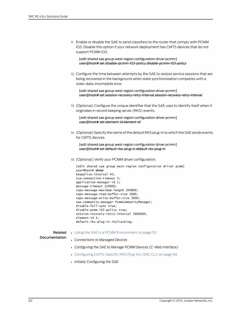
11. Enable or disable the SAE to send classifiers to the router that comply with PCMM
IO3. Disable this option if your network deployment has CMTS devices that do not
support PCMM IO3.
[edit shared sae group west-region configuration driver pcmm]user@host# set disable-pcmm-i03-policy disable-pcmm-i03-policy
12. Configure the time between attempts by the SAE to restore service sessions that are
being recovered in the background when state synchronization completes with a
state-data-incomplete error.
[edit shared sae group west-region configuration driver pcmm]user@host# set session-recovery-retry-interval session-recovery-retry-interval
13. (Optional) Configure the unique identifier that the SAE uses to identify itself when it
originates in record-keeping server (RKS) events.
[edit shared sae group west-region configuration driver pcmm]user@host# set element-id element-id
14. (Optional) Specify the name of the default RKS plug-in to which the SAE sends events
for CMTS devices.
[edit shared sae group west-region configuration driver pcmm]user@host# set default-rks-plug-in default-rks-plug-in
15. (Optional) Verify your PCMM driver configuration.
[edit shared sae group west-region configuration driver pcmm]user@host# showkeepalive-interval 45;tcp-connection-timeout 5;application-manager-id 1;message-timeout 120000;cops-message-maximum-length 204800;cops-message-read-buffer-size 3000;cops-message-write-buffer-size 3000;sae-community-manager PcmmCommunityManager;disable-full-sync true;disable-pcmm-i03-policy true;session-recovery-retry-interval 3600000;element-id 1;default-rks-plug-in rksTracking;
RelatedDocumentation
Using the SAE in a PCMM Environment on page 50•
• Connections to Managed Devices
• Configuring the SAE to Manage PCMMDevices (C-Web Interface)
• Configuring CMTS-Specific RKS Plug-Ins (SRC CLI) on page 66
• Initially Configuring the SAE
Copyright © 2014, Juniper Networks, Inc.60
SRC PE 4.8.x Solutions Guide
Setting Up SAE Communities (SRC CLI)
You can configure the following for SAE communities:
• Define the members of an SAE community by adding the IP addresses of SAEs in the
community to the virtual router object of the network device in the directory.
See “Creating Virtual Routers for the CMTS Device (SRC CLI)” on page 70.
• Configure parameters for the SAE community manager.
See “Configuring the SAE Community Manager” on page 61.
• Specify the name of the community manager with the set sae-community-manager
option in the PCMM driver configuration.
See “Configuring the SAE to Manage PCMM Devices (SRC CLI)” on page 58.
• If there is a firewall in the network, configure the firewall to allow SAE messages through.
RelatedDocumentation
Using the SAE in a PCMM Environment on page 50•
• Setting Up SAE Communities (C-Web Interface)
• Initially Configuring the SAE
• Configuring SAE Properties for the Event Notification API (SRC CLI) on page 62
Configuring the SAE Community Manager
Use the following configuration statements to configure the SAE community manager
that manages PCMM device communities:
shared sae configuration external-interface-features name CommunityManager {keepalive-interval keepalive-interval ;threads threads ;acquire-timeout acquire-timeout ;blackout-time blackout-time ;
}
To configure the community manager:
1. From configuration mode, access the configuration statements for the community
manager. In this sample procedure, west_region is the name of the SAE group, and
sae_mgr is the name of the community manager.
user@host# edit shared sae groupwest-region configurationexternal-interface-features sae_mgr CommunityManager
2. Specify the interval between keepalive messages sent from the active SAE to the
passive members of the community.
[edit shared sae group west-region configuration external-interface-features sae_mgrCommunityManager]
user@host# set keepalive-interval keepalive-interval
61Copyright © 2014, Juniper Networks, Inc.
Chapter 6: Configuring the SAE for a PCMM Environment (SRC CLI)
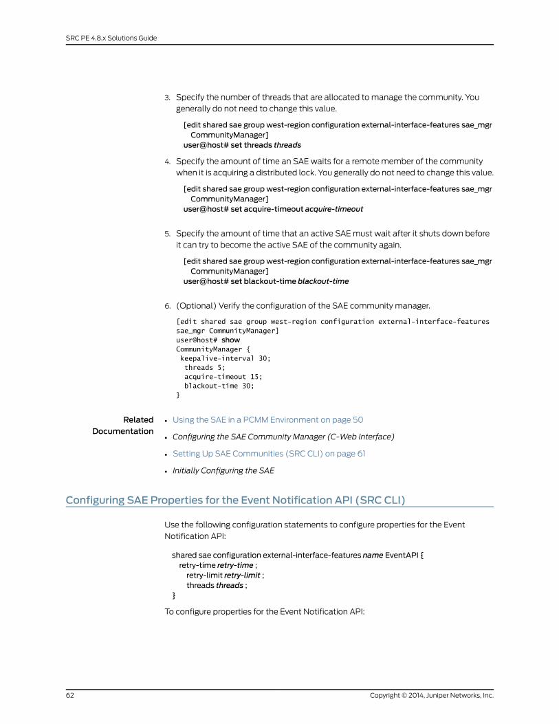
3. Specify the number of threads that are allocated to manage the community. You
generally do not need to change this value.
[edit shared sae group west-region configuration external-interface-features sae_mgrCommunityManager]
user@host# set threads threads
4. Specify the amount of time an SAE waits for a remote member of the community
when it is acquiring a distributed lock. You generally do not need to change this value.
[edit shared sae group west-region configuration external-interface-features sae_mgrCommunityManager]
user@host# set acquire-timeout acquire-timeout
5. Specify the amount of time that an active SAE must wait after it shuts down before
it can try to become the active SAE of the community again.
[edit shared sae group west-region configuration external-interface-features sae_mgrCommunityManager]
user@host# set blackout-time blackout-time
6. (Optional) Verify the configuration of the SAE community manager.
[edit shared sae group west-region configuration external-interface-features sae_mgr CommunityManager] user@host# showCommunityManager { keepalive-interval 30; threads 5; acquire-timeout 15; blackout-time 30;}
RelatedDocumentation
Using the SAE in a PCMM Environment on page 50•
• Configuring the SAE Community Manager (C-Web Interface)
• Setting Up SAE Communities (SRC CLI) on page 61
• Initially Configuring the SAE
Configuring SAE Properties for the Event Notification API (SRC CLI)
Use the following configuration statements to configure properties for the Event
Notification API:
shared sae configuration external-interface-features name EventAPI {retry-time retry-time ;retry-limit retry-limit ;threads threads ;
}
To configure properties for the Event Notification API:
Copyright © 2014, Juniper Networks, Inc.62
SRC PE 4.8.x Solutions Guide
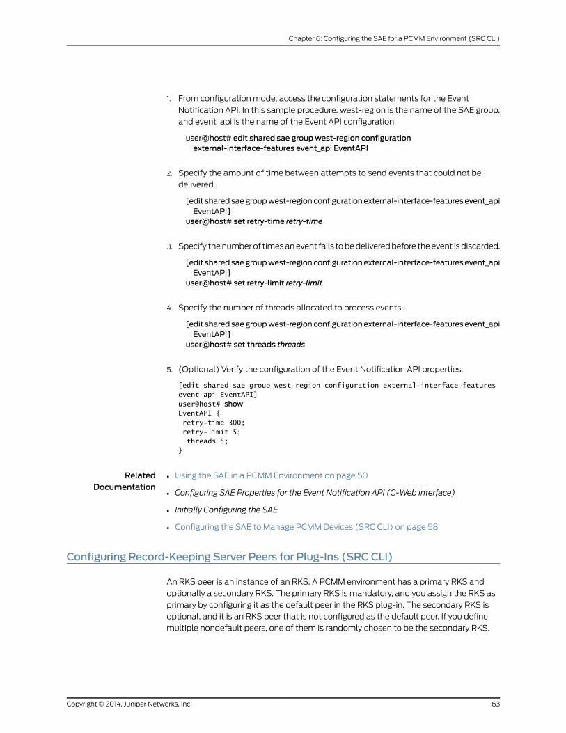
1. From configuration mode, access the configuration statements for the Event
Notification API. In this sample procedure, west-region is the name of the SAE group,
and event_api is the name of the Event API configuration.
user@host# edit shared sae groupwest-region configurationexternal-interface-features event_api EventAPI
2. Specify the amount of time between attempts to send events that could not be
delivered.
[edit shared saegroupwest-region configuration external-interface-features event_apiEventAPI]
user@host# set retry-time retry-time
3. Specify the number of times an event fails to be delivered before the event is discarded.
[edit shared saegroupwest-region configuration external-interface-features event_apiEventAPI]
user@host# set retry-limit retry-limit
4. Specify the number of threads allocated to process events.
[edit shared saegroupwest-region configuration external-interface-features event_apiEventAPI]
user@host# set threads threads
5. (Optional) Verify the configuration of the Event Notification API properties.
[edit shared sae group west-region configuration external-interface-features event_api EventAPI] user@host# showEventAPI { retry-time 300; retry-limit 5; threads 5;}
RelatedDocumentation
Using the SAE in a PCMM Environment on page 50•
• Configuring SAE Properties for the Event Notification API (C-Web Interface)
• Initially Configuring the SAE
• Configuring the SAE to Manage PCMM Devices (SRC CLI) on page 58
Configuring Record-Keeping Server Peers for Plug-Ins (SRC CLI)
An RKS peer is an instance of an RKS. A PCMM environment has a primary RKS and
optionally a secondary RKS. The primary RKS is mandatory, and you assign the RKS as
primary by configuring it as the default peer in the RKS plug-in. The secondary RKS is
optional, and it is an RKS peer that is not configured as the default peer. If you define
multiple nondefault peers, one of them is randomly chosen to be the secondary RKS.
63Copyright © 2014, Juniper Networks, Inc.
Chapter 6: Configuring the SAE for a PCMM Environment (SRC CLI)
RKS peers are configured in the peer group for each PCMM RKS plug-in instance. To
create an RKS peer group:
Use the following configuration statements to configure an RKS peer group.
shared sae configuration plug-ins name name pcmm-rks peer-group name {server-address server-address ;server-port server-port ;
}
To configure an RKS peer group:
1. From configuration mode, access the configuration statements for RKS plug-ins. In
this sample procedure, west-region is the name of the SAE group, and rksPlugin is the
name of the plug-in and rksPeer is the name of the peer group.
user@host# edit shared sae groupwest-region configuration plug-ins name rksPluginpcmm-rks peer-group rksPeer
2. Specify the IP address of the RKS server to which the SAE sends accounting data.
[edit shared sae group west-region configuration plug-ins name rksPlugin pcmm-rkspeer-group rksPeer]
user@host# set server-address server-address
3. Specify the port used for sending accounting packets.
[edit shared sae group west-region configuration plug-ins name rksPlugin pcmm-rkspeer-group rksPeer]
user@host# set server-port server-port
4. (Optional) Verify your configuration.
[edit shared sae group west-region configuration plug-ins name rksPlugin pcmm-rks peer-group rksPeer]user@host# showserver-address 10.10.3.60;server-port 1812;
RelatedDocumentation
Using the SAE in a PCMM Environment on page 50•
• Configuring Record-Keeping Server Peers for Plug-Ins (C-Web Interface)
• Configuring PCMM Record-Keeping Server Plug-Ins (SRC CLI) on page 64
• Configuring CMTS-Specific RKS Plug-Ins (SRC CLI) on page 66
• Initially Configuring the SAE
Configuring PCMMRecord-Keeping Server Plug-Ins (SRC CLI)
Use the following configuration statements to configure an RKS plug-in.
shared sae configuration plug-ins name name pcmm-rks {load-balancing-mode (failover | roundRobin);failback-timer failback-timer;
Copyright © 2014, Juniper Networks, Inc.64
SRC PE 4.8.x Solutions Guide
retry-interval retry-interval ;maximum-queue-lengthmaximum-queue-length ;bind-address bind-address ;udp-port udp-port ;feid-mso-data feid-mso-data ;feid-mso-domain-name feid-mso-domain-name ;trusted-element;default-peer default-peer ;
}
To configure an RKS plug-in:
1. From configuration mode, access the configuration statements for RKS plug-ins. In
this sample procedure, west-region is the name of the SAE group, and rksPlugin is the
name of the plug-in.
user@host# edit shared sae groupwest-region configuration plug-ins name rksPluginpcmm-rks
2. Specify the mode for load-balancing RKSs.
[edit shared sae group west-region configuration plug-ins name rksPlugin pcmm-rks]user@host# set load-balancing-mode (failover | roundRobin)
3. Specify if and when the SAE attempts to fail back to the default peer.
[edit shared sae group west-region configuration plug-ins name rksPlugin pcmm-rks]user@host# set failback-timer failback-timer
4. Specify the time the SAE waits for a response from an RKS before it resends the
packet.
[edit shared sae group west-region configuration plug-ins name rksPlugin pcmm-rks]user@host# set retry-interval retry-interval
5. Specify the maximum number of unacknowledged messages that the plug-in receives
from the RKS before it discards new messages.
[edit shared sae group west-region configuration plug-ins name rksPlugin pcmm-rks]user@host# setmaximum-queue-lengthmaximum-queue-length
6. (Optional) Specify the source IP address that the plug-in uses to communicate with
the RKS.
[edit shared sae group west-region configuration plug-ins name rksPlugin pcmm-rks]user@host# set bind-address bind-address
7. (Optional) Specify the source UDP port or a pool of ports that the plug-in uses to
communicate with the RKS.
[edit shared sae group west-region configuration plug-ins name rksPlugin pcmm-rks]user@host# set udp-port udp-port
8. (Optional) Specify the multiple service operator (MSO)—defined data in the financial
entity ID (FEID) attribute, which is included in event messages.
65Copyright © 2014, Juniper Networks, Inc.
Chapter 6: Configuring the SAE for a PCMM Environment (SRC CLI)
[edit shared sae group west-region configuration plug-ins name rksPlugin pcmm-rks]user@host# set feid-mso-data feid-mso-data
9. (Optional) Specify the MSO domain name in the FEID attribute that uniquely identifies
the MSO for billing and settlement purposes.
[edit shared sae group west-region configuration plug-ins name rksPlugin pcmm-rks]user@host# set feid-mso-domain-name feid-mso-domain-name
10. (Optional) When the SAE is running as a policy server—which means that the SAE
sends event messages directly to the RKS—enable the SAE as a trusted network
element.
[edit shared sae group west-region configuration plug-ins name rksPlugin pcmm-rks]user@host# set trusted-element
11. Specify the name of the primary RKS peer to which the SAE sends accounting packets.
See “Configuring Record-Keeping Server Peers for Plug-Ins (SRC CLI)” on page 63.
[edit shared sae group west-region configuration plug-ins name rksPlugin pcmm-rks]user@host# set default-peer default-peer
12. (Optional) Verify your RKS plug-in configuration.
[edit shared sae group west-region configuration plug-ins name rksPlugin pcmm-rks]user@host> showload-balancing-mode failover;failback-timer -1;retry-interval 3000;maximum-queue-length 10000;feid-mso-domain-name abcd.com;trusted-element;default-peer radius01;
13. (Optional) Specify an RKS plug-in for specific CMTS devices.
See “Configuring CMTS-Specific RKS Plug-Ins (SRC CLI)” on page 66.
RelatedDocumentation
Using the SAE in a PCMM Environment on page 50•
• PCMM Environment Overview on page 41
• Configuring PCMM Record-Keeping Server Plug-Ins (C-Web Interface)
• Initially Configuring the SAE
Configuring CMTS-Specific RKS Plug-Ins (SRC CLI)
You can configure an RKS plug-in for specific CMTS devices. When there are events for
the CMTS device, the SAE sends the events to the specified plug-in.
Use the following configuration statement to assign a CMTS-specific RKS plug-in.
shared sae configuration driver pcmm cmts-specific-rks-plug-ins name {
Copyright © 2014, Juniper Networks, Inc.66
SRC PE 4.8.x Solutions Guide
rks-plug-in rks-plug-in ;}
To configure a CMTS-specific RKS plug-in:
1. From configuration mode, access the configuration statements for RKS plug-ins. In
this sample procedure, west-region is the name of the SAE group, and cmtsPlugin is
the name of the plug-in assignment.
user@host# edit shared sae groupwest-region configuration driver pcmmcmts-specific-rks-plug-ins cmtsPlugin
2. Specify the name of the CMTS-specific RKS plug-in.
[edit sharedsaegroupwest-regionconfigurationdriverpcmmcmts-specific-rks-plug-inscmtsPlugin]
user@host# set rks-plug-in rks-plug-in
3. (Optional) Verify your configuration.
[edit shared sae group west-region configuration driver pcmm cmts-specific-rks-plug-ins cmtsPlugin]user@host# showrks-plug-in rksPlugin;
RelatedDocumentation
• Configuring CMTS-Specific RKS Plug-Ins (C-Web Interface)
• Configuring Record-Keeping Server Peers for Plug-Ins (SRC CLI) on page 63
• Configuring PCMM Record-Keeping Server Plug-Ins (SRC CLI) on page 64
• Adding Objects for CMTS Devices (SRC CLI) on page 69
• Initially Configuring the SAE
67Copyright © 2014, Juniper Networks, Inc.
Chapter 6: Configuring the SAE for a PCMM Environment (SRC CLI)

Copyright © 2014, Juniper Networks, Inc.68
SRC PE 4.8.x Solutions Guide
CHAPTER 7
Adding Objects for CMTS Devices (SRCCLI)
• Adding Objects for CMTS Devices (SRC CLI) on page 69
• Creating Virtual Routers for the CMTS Device (SRC CLI) on page 70
Adding Objects for CMTS Devices (SRC CLI)
To manage CMTS devices, the SAE creates and manages pseudointerfaces that it
associates with a virtual router object. Each CMTS device in the SRC network must appear
in the configuration as a router object, and it must be associated with a virtual router
object called default. The router and virtual router are not actually configured on the
CMTS device; the router and virtual router provide a way for the SAE to manage the CMTS
device by using the SAE’s embedded policy server.
Use the following configuration statements to add a router object:
shared network device name {description description ;management-addressmanagement-address ;device-type (junose | junos | pcmm | proxy);qos-profile [ qos-profile ...];
}
To add a router:
1. From configuration mode, access the configuration statements that configure network
devices. You must specify the name of a device with lowercase characters. In this
sample procedure, pcmm_dtr is the name of the object.
user@host# edit shared network device pcmm_dtr
2. (Optional) Add a description for the CMTS device.
[edit shared network device pcmm_dtr]user@host# set description description
3. Add the IP address of the CMTS device.
[edit shared network device pcmm_dtr]user@host# setmanagement-addressmanagement-address
69Copyright © 2014, Juniper Networks, Inc.
4. (Optional) Specify the type of device that you are adding.
[edit shared network device pcmm_dtr]user@host# set device-type pcmm
5. (Optional) Verify your configuration.
[edit shared network device pcmm_dtr] user@host# showdescription "CMTS device";management-address 192.168.3.5;device-type pcmm;interface-classifier { rule rule-0 { script #; }}
RelatedDocumentation
Connections to Managed Devices•
• Configuring CMTS-Specific RKS Plug-Ins (SRC CLI) on page 66
• Creating Virtual Routers for the CMTS Device (SRC CLI) on page 70
Creating Virtual Routers for the CMTSDevice (SRC CLI)
You need to add a virtual router object called default to the CMTS device.
Use the following configuration statements to add a virtual router:
shared network device name virtual-router name {sae-connection [ sae-connection ...];snmp-read-community snmp-read-community ;snmp-write-community snmp-write-community ;scope [ scope ...];local-address-pools local-address-pools ;static-address-pools static-address-pools ;tracking-plug-in [ tracking-plug-in ...];
}
To add a virtual router:
1. From configuration mode, access the configuration statements for virtual routers.
You must specify the name of a device with lowercase characters. In this sample
procedure, pcmm_dtr is the name of the router and default is the name of the virtual
router.
user@host# edit shared network device pcmm_dtr virtual-router default
2. Specify the addresses of SAEs that can manage this router. This step is required for
the SAE to work with the router.
[edit shared network device pcmm_dtr virtual-router default]user@host# set sae-connection [ sae-connection ...]
Copyright © 2014, Juniper Networks, Inc.70
SRC PE 4.8.x Solutions Guide

To specify the active SAE and the redundant SAE, enter an exclamation point (!) after
the hostname or IP address of the connected SAE. For example:
[edit shared network device pcmm_dtr virtual-router default]user@host# set sae-connection [sae1! sae2!]
3. (Optional) Specify an SNMP community name for SNMP read-only operations for
this VR.
[edit shared network device pcmm_dtr virtual-router default]user@host# set snmp-read-community snmp-read-community
4. (Optional) Specify an SNMP community name for SNMP write operations for this
virtual router.
[edit shared network device pcmm_dtr virtual-router default]user@host# set snmp-write-community snmp-write-community
5. (Optional) Specify service scopes assigned to this virtual router.
See Configuring Service Scopes (SRC CLI).
[edit shared network device pcmm_dtr virtual-router default]user@host# set scope [ scope ...]
6. (Optional) Specify the list of IP address pools that a CMTS virtual router currently
manages and stores.
If you are using assigned IP subscribers along with the network information collector
(NIC), you need to configure either a local or static address pool so that the NIC can
resolve the IP-to-SAE mapping.
[edit shared network device pcmm_dtr virtual-router default]user@host# set local-address-pools local-address-pools
7. (Optional) Specify the list of IP address pools that a CMTS VR manages but does not
store.
If you are using assigned IP subscribers along with the NIC, you need to configure either
a local or static address pool so that the NIC can resolve the IP-to-SAE mapping.
[edit shared network device pcmm_dtr virtual-router default]user@host# set static-address-pools static-address-pools
8. (Optional) Specify the plug-ins that track interfaces that the SAE manages on this
virtual router.
[edit shared network device pcmm_dtr virtual-router default]user@host# tracking-plug-in [ tracking-plug-in ...]
9. (Optional) Verify your configuration.
[edit shared network device pcmm_dtr virtual-router default] user@host# showsae-connection [ 10.14.39.2 10.10.5.30 ];snmp-read-community ********;
71Copyright © 2014, Juniper Networks, Inc.
Chapter 7: Adding Objects for CMTS Devices (SRC CLI)

snmp-write-community ********;scope POP-Westford;local-address-pools "10.25.8.0 10.25.20.255";tracking-plug-in rksPlugin;
RelatedDocumentation
• Adding Objects for CMTS Devices (SRC CLI) on page 69
• Configuring CMTS-Specific RKS Plug-Ins (SRC CLI) on page 66
• Associating Security Names with a Community (SRC CLI)
Copyright © 2014, Juniper Networks, Inc.72
SRC PE 4.8.x Solutions Guide
CHAPTER 8
Using the NIC Resolver in a PCMMEnvironment
• Using the NIC Resolver in PCMM Environments on page 73
Using the NIC Resolver in PCMMEnvironments
If you are using the NIC to map the subscriber IP address to the SAE, you need to configure
a NIC host. The NIC system uses IP address pools to map IP addresses to SAEs. You
configure the local address pools in the application manager configuration for a policy
server group. These pools are published in the NIC. The NIC maps subscriber IP addresses
in requests received through the portal or Advanced Services Gateway to the policy server
group that currently manages that CMTS device.
The OnePopPcmm sample configuration data supports this scenario for a PCMM
environment in which you use the assigned IP subscriber method to log in subscribers
and in which you use the NIC to determine the subscriber’s SAE. The OnePopPcmm
configuration supports one point of presence (POP). NIC replication can be used to
provide high availability. The realm for this configuration accommodates the situation
in which IP pools are configured locally on each application manager group object.
The resolution process takes a subscriber’s IP address as the key and returns a reference
to the SAE managing this subscriber as the value.
The following agents collect information for resolvers in this realm:
• Directory agent PoolVr collects and publishes information about the mappings of IP
pools to the policy server group.
• Directory agent VrSaeId collects and publishes information about the mappings of
policy server groups to SAEs.
RelatedDocumentation
• PCMM Environment Overview on page 41
• Using the SAE in a PCMM Environment on page 50
• Specifying Application Manager Identifiers for Policy Servers (C-Web Interface)
• Configuring the NIC (SRC CLI)
• OnePopPcmm Scenario
73Copyright © 2014, Juniper Networks, Inc.

Copyright © 2014, Juniper Networks, Inc.74
SRC PE 4.8.x Solutions Guide
CHAPTER 9
Using PCMM Policy Servers
• JPS Overview on page 75
• JPS Framework on page 75
• JPS Interfaces on page 76
JPS Overview
In a PacketCable Multimedia (PCMM) environment, the policy server acts as a policy
decision point (PDP) and policy enforcement point (PEP) that manages the relationships
between application managers and cable management termination system (CMTS)
devices.
The Juniper Policy Server (JPS) is a PCMM-compliant policy server. The JPS must be
deployed in an SRC environment that satisfies these conditions:
• Organizes PCMM devices into groups (for example, one or more per POP). For
redundancy, a community of two or more JPSs will manage each group of PCMM
devices.
• Achieves successful state synchronization by requiring an application manager (for
example, a pair of redundant service activation engines [SAEs]) to talk to one JPS
instance at a time.
• Uses IPSec connections for the network interfaces.
RelatedDocumentation
JPS Framework on page 75•
• JPS Interfaces on page 76
• Starting the JPS (SRC CLI) on page 103
• Configuring the JPS (SRC CLI) on page 81
• Monitoring the JPS on page 105
JPS Framework
Figure 15 on page 76 depicts the PCMM architectural framework. The JPS communicates
with application managers, CMTS devices, and record-keeping servers.
75Copyright © 2014, Juniper Networks, Inc.

Figure 15: PCMMArchitectural Framework
The interactions between the various PCMM components are centered on the policy
server. In the PCMM architecture, these basic interactions occur:
1. A client requests a multimedia service from an application manager.
2. Depending on the client type and its QoS signaling capabilities, the application manager
relays the request to a policy server.
3. The policy server relays the request to the CMTS device and is responsible for
provisioning the policies on a CMTS device.
Depending on the request, the policy server records an event for the policy request
and provides that information to the record-keeping server (RKS).
4. The CMTS device performs admission control and manages network resources through
Data over Cable Service Interface Specifications (DOCSIS) service flows based on
the provisioned policies.
5. The RKS receives event messages from other network elements, such as the policy
server or CMTS device, and acts as a short-term repository for the messages.
RelatedDocumentation
JPS Overview on page 75•
• JPS Interfaces on page 76
• Policy Information Model
• Configuring the JPS (SRC CLI) on page 81
JPS Interfaces
The JPS has interfaces, implemented as plug-ins, to communicate with:
• Application managers, such as the SAE
• Record-keeping servers
• CMTS devices
The JPS is relatively stateless, but the individual plug-ins can be stateful.
Copyright © 2014, Juniper Networks, Inc.76
SRC PE 4.8.x Solutions Guide
The JPS uses the Common Open Policy Service (COPS) protocol as specified in the
PacketCable Multimedia Specification PKT-SP-MM-I03-051221 for its interface
connections. The JPS communicates with the CMTS device and the application manager
by using a COPS over Transmission Control Protocol (TCP) connection.
ApplicationManager to Policy Server Interface
To allow the JPS to communicate with the application manager, this interface accepts
and manages COPS over TCP connections from application managers, such as the SAE.
Policy Server to RKS Interface
To allow the JPS to communicate with a set of redundant record-keeping servers, this
interface sends a policy event message to the RKS when receiving a PCMM-COPS gate
control (request, delete, update) message. This interface also sends time change events
to the RKS.
Policy Server to CMTS Interface
To allow the JPS to communicate with policy enforcement points (PCMM devices), this
interface initiates and manages COPS over TCP connections with CMTS devices.
RelatedDocumentation
• JPS Overview on page 75
• JPS Framework on page 75
• Configuring the JPS (SRC CLI) on page 81
• Connections to Managed Devices
• Viewing JPS State on page 106
77Copyright © 2014, Juniper Networks, Inc.
Chapter 9: Using PCMM Policy Servers

Copyright © 2014, Juniper Networks, Inc.78
SRC PE 4.8.x Solutions Guide
CHAPTER 10
Configuring the JPS (SRC CLI)
• Configuration Statements for the JPS on page 79
• Configuring the JPS (SRC CLI) on page 81
• Modifying the JPS Configuration (SRC CLI) on page 82
• Configuring General Properties for the JPS (SRC CLI) on page 82
• Specifying Policy Server Identifiers in Messages (SRC CLI) on page 83
• Configuring Logging Destinations for the JPS (SRC CLI) on page 84
• Configuring JPS to Store Log Messages in a File (SRC CLI) on page 85
• Configuring JPS to Send Log Messages to System Logging Facility (SRC CLI) on page 85
• Specifying Connections to the Application Managers (SRC CLI) on page 86
• Configuring Connections to RKSs (SRC CLI) on page 88
• Configuring RKS Pairs for Associated Application Managers (SRC CLI) on page 91
• Specifying Connections to CMTS Devices (SRC CLI) on page 92
• Modifying the Subscriber Configuration (SRC CLI) on page 95
• Configuring Subscriber IP Pools as IP Address Ranges (SRC CLI) on page 96
• Configuring Subscriber IP Pools as IP Subnets (SRC CLI) on page 96
• Configuring the SAE to Interact with the JPS (SRC CLI) on page 97
• Specifying Application Managers for the Policy Server (SRC CLI) on page 98
• Specifying Application Manager Identifiers for Policy Servers (SRC CLI) on page 99
• Adding Objects for Policy Servers to the Directory (SRC CLI) on page 100
• Configuring Initialization Scripts (SRC CLI) on page 101
• Enabling State Synchronization (SRC CLI) on page 101
• Using the NIC Resolver on page 102
• Managing the JPS on page 103
Configuration Statements for the JPS
Use the following configuration statements to configure the JPS at the [edit] hierarchy
level.
slot number jps {
79Copyright © 2014, Juniper Networks, Inc.

java-heap-size java-heap-size;snmp-agent;policy-server-id policy-server-id;use-psid-in-gate-commands;cmts-message-buffer-size cmts-message-buffer-size;am-message-buffer-size am-message-buffer-size;
}slot number jps am-interface {pep-id pep-id;listening-address listening-address;validate-pcmm-objects;message-max-lengthmessage-max-length;message-read-buffer-sizemessage-read-buffer-size;message-write-buffer-sizemessage-write-buffer-size;open-connection-timeout open-connection-timeout;
}slot number jps cmts-interface {cmts-addresses [cmts-addresses...];keepalive-interval keepalive-interval;synch-despite-unreachable-pep;synch-despite-pre-i03-pep;use-ssq-ssc-with-pre-i03-pep;local-address local-address;message-max-lengthmessage-max-length;message-read-buffer-sizemessage-read-buffer-size;message-write-buffer-sizemessage-write-buffer-size;open-connection-timeout open-connection-timeout;connection-open-retry-interval connection-open-retry-interval;sent-message-timeout sent-message-timeout;validate-pcmm-objects;
}slot number jps cmts-registry cmts cmts-ip ...slot number jps cmts-registry cmts cmts-ip range-pool pool-index {low low;high high;
}slot number jps cmts-registry cmts cmts-ip subnet-pool subnet {exclude [exclude];
}slot number jps logger name ...slot number jps logger name file {filter filter;filename filename;rollover-filename rollover-filename;maximum-file-sizemaximum-file-size;
}slot number jps logger name syslog {filter filter;host host;facility facility;format format;
}slot number jps rks-interface {element-id element-id;local-address local-address;local-port local-port;
Copyright © 2014, Juniper Networks, Inc.80
SRC PE 4.8.x Solutions Guide
retry-interval retry-interval;local-timeout local-timeout;mso-datamso-data;mso-domain-namemso-domain-name;default-rks-pair default-rks-pair;pending-rks-event-max-size pending-rks-event-max-size;pending-rks-event-max-age pending-rks-event-max-age;held-decs-max-size held-decs-max-size;held-decs-max-age held-decs-max-age;bcid-cache-size bcid-cache-size;bcid-cache-age bcid-cache-age;use-default-when-am-requests-unconfigured-rks;
}slot number jps rks-interface am am-name {am-id am-id;rks-pair-name rks-pair-name;trusted;
}slot number jps rks-interface rks-pair rks-pair-name {primary-address primary-address;primary-port primary-port;secondary-address secondary-address;secondary-port secondary-port;
}
For detailed information about each configuration statement, see the SRC PE CLI
Command Reference.
RelatedDocumentation
JPS Overview on page 75•
• JPS Interfaces on page 76
• Configuring the JPS (SRC CLI) on page 81
Configuring the JPS (SRC CLI)
You can modify the JPS configuration, which includes configuring the logging destinations
and connections to the JPS interfaces. Any configuration changes will be applied within
15 seconds.
Before you configure the JPS, deploy an SRC-managed PCMM network. For more
information about PCMM and the SRC software, see “PCMM Environment Overview” on
page 41.
You can configure the subscriber configuration, which maps a subscriber address to the
CMTS address.
The tasks to configure the JPS for a cable network environment are:
• Modifying the JPS Configuration (SRC CLI) on page 82
• Modifying the Subscriber Configuration (SRC CLI) on page 95
In addition to configuring the JPS, you might need to perform these tasks:
81Copyright © 2014, Juniper Networks, Inc.
Chapter 10: Configuring the JPS (SRC CLI)
• Configuring the SAE to Interact with the JPS (SRC CLI) on page 97
• Using the NIC Resolver on page 102
RelatedDocumentation
JPS Overview on page 75•
• Configuring the JPS (C-Web Interface)
• Configuring General Properties for the JPS (SRC CLI) on page 82
• Monitoring the JPS on page 105
• Configuration Statements for the JPS on page 79
Modifying the JPS Configuration (SRC CLI)
To modify the current JPS configuration:
1. Configure general properties for the JPS, including Java heap memory, maximum
number of buffered messages for CMTS and application manager destinations, and
policy server identifiers.
See “Configuring General Properties for the JPS (SRC CLI)” on page 82.
See “Specifying Policy Server Identifiers in Messages (SRC CLI)” on page 83.
2. Configure logging destinations for the JPS.
See “Configuring Logging Destinations for the JPS (SRC CLI)” on page 84.
3. Configure the connections to the JPS interfaces.
See “Specifying Connections to the Application Managers (SRC CLI)” on page 86.
See “Specifying Connections to CMTS Devices (SRC CLI)” on page 92.
RelatedDocumentation
JPS Overview on page 75•
• Modifying the JPS Configuration (C-Web Interface)
• Configuring the JPS (SRC CLI) on page 81
• Viewing JPS State on page 106
Configuring General Properties for the JPS (SRC CLI)
Use the following configuration statements to configure general properties for the JPS:
slot number jps {java-heap-size java-heap-size;snmp-agent;cmts-message-buffer-size cmts-message-buffer-size;am-message-buffer-size am-message-buffer-size;
}
To configure general properties for the JPS:
Copyright © 2014, Juniper Networks, Inc.82
SRC PE 4.8.x Solutions Guide
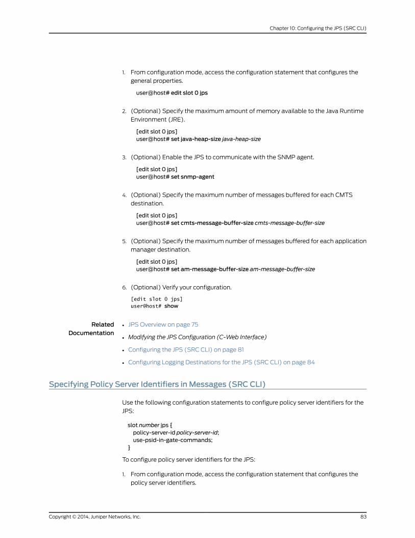
1. From configuration mode, access the configuration statement that configures the
general properties.
user@host# edit slot 0 jps
2. (Optional) Specify the maximum amount of memory available to the Java Runtime
Environment (JRE).
[edit slot 0 jps]user@host# set java-heap-size java-heap-size
3. (Optional) Enable the JPS to communicate with the SNMP agent.
[edit slot 0 jps]user@host# set snmp-agent
4. (Optional) Specify the maximum number of messages buffered for each CMTS
destination.
[edit slot 0 jps]user@host# set cmts-message-buffer-size cmts-message-buffer-size
5. (Optional) Specify the maximum number of messages buffered for each application
manager destination.
[edit slot 0 jps]user@host# set am-message-buffer-size am-message-buffer-size
6. (Optional) Verify your configuration.
[edit slot 0 jps] user@host# show
RelatedDocumentation
JPS Overview on page 75•
• Modifying the JPS Configuration (C-Web Interface)
• Configuring the JPS (SRC CLI) on page 81
• Configuring Logging Destinations for the JPS (SRC CLI) on page 84
Specifying Policy Server Identifiers in Messages (SRC CLI)
Use the following configuration statements to configure policy server identifiers for the
JPS:
slot number jps {policy-server-id policy-server-id;use-psid-in-gate-commands;
}
To configure policy server identifiers for the JPS:
1. From configuration mode, access the configuration statement that configures the
policy server identifiers.
83Copyright © 2014, Juniper Networks, Inc.
Chapter 10: Configuring the JPS (SRC CLI)
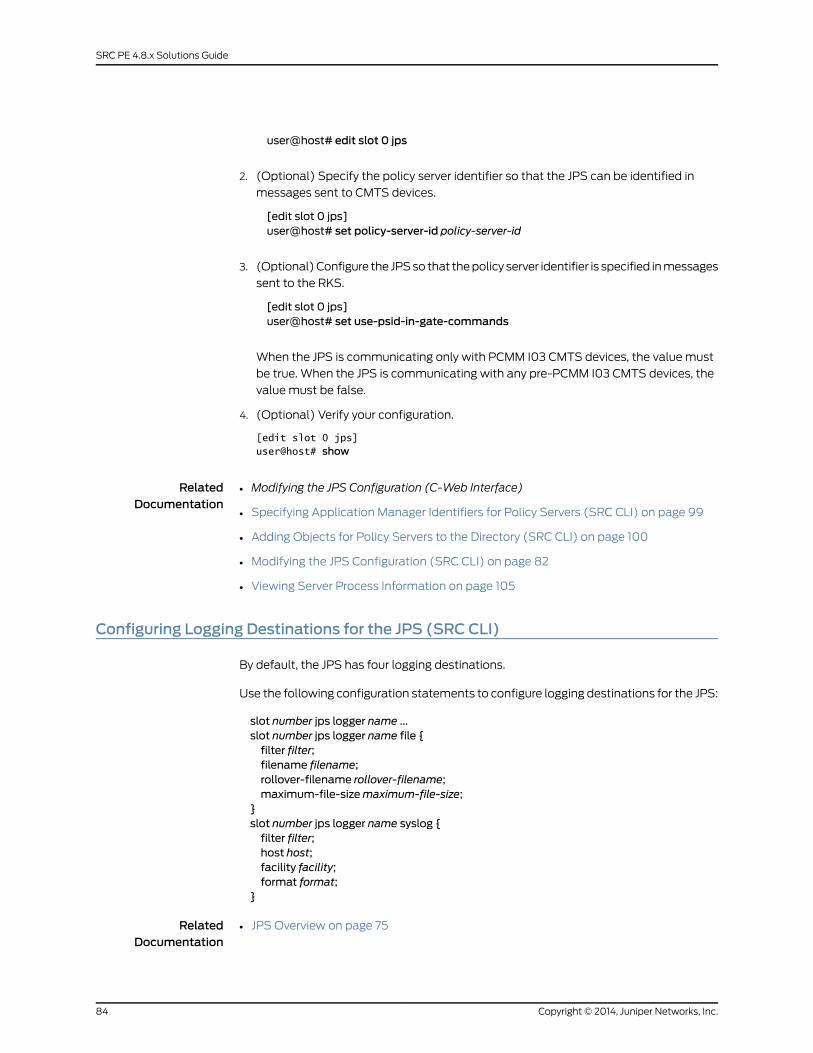
user@host# edit slot 0 jps
2. (Optional) Specify the policy server identifier so that the JPS can be identified in
messages sent to CMTS devices.
[edit slot 0 jps]user@host# set policy-server-id policy-server-id
3. (Optional) Configure the JPS so that the policy server identifier is specified in messages
sent to the RKS.
[edit slot 0 jps]user@host# set use-psid-in-gate-commands
When the JPS is communicating only with PCMM I03 CMTS devices, the value must
be true. When the JPS is communicating with any pre-PCMM I03 CMTS devices, the
value must be false.
4. (Optional) Verify your configuration.
[edit slot 0 jps] user@host# show
RelatedDocumentation
Modifying the JPS Configuration (C-Web Interface)•
• Specifying Application Manager Identifiers for Policy Servers (SRC CLI) on page 99
• Adding Objects for Policy Servers to the Directory (SRC CLI) on page 100
• Modifying the JPS Configuration (SRC CLI) on page 82
• Viewing Server Process Information on page 105
Configuring Logging Destinations for the JPS (SRC CLI)
By default, the JPS has four logging destinations.
Use the following configuration statements to configure logging destinations for the JPS:
slot number jps logger name ...slot number jps logger name file {filter filter;filename filename;rollover-filename rollover-filename;maximum-file-sizemaximum-file-size;
}slot number jps logger name syslog {filter filter;host host;facility facility;format format;
}
RelatedDocumentation
JPS Overview on page 75•
Copyright © 2014, Juniper Networks, Inc.84
SRC PE 4.8.x Solutions Guide
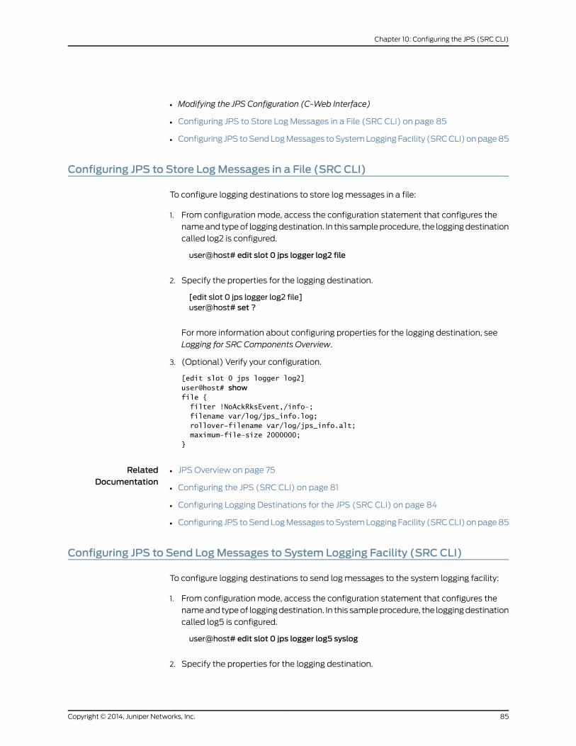
• Modifying the JPS Configuration (C-Web Interface)
• Configuring JPS to Store Log Messages in a File (SRC CLI) on page 85
• Configuring JPS to Send Log Messages to System Logging Facility (SRC CLI) on page 85
Configuring JPS to Store LogMessages in a File (SRC CLI)
To configure logging destinations to store log messages in a file:
1. From configuration mode, access the configuration statement that configures the
name and type of logging destination. In this sample procedure, the logging destination
called log2 is configured.
user@host# edit slot 0 jps logger log2 file
2. Specify the properties for the logging destination.
[edit slot 0 jps logger log2 file]user@host# set ?
For more information about configuring properties for the logging destination, see
Logging for SRC Components Overview.
3. (Optional) Verify your configuration.
[edit slot 0 jps logger log2] user@host# showfile { filter !NoAckRksEvent,/info-; filename var/log/jps_info.log; rollover-filename var/log/jps_info.alt; maximum-file-size 2000000;}
RelatedDocumentation
JPS Overview on page 75•
• Configuring the JPS (SRC CLI) on page 81
• Configuring Logging Destinations for the JPS (SRC CLI) on page 84
• Configuring JPS to Send Log Messages to System Logging Facility (SRC CLI) on page 85
Configuring JPS to Send LogMessages to System Logging Facility (SRC CLI)
To configure logging destinations to send log messages to the system logging facility:
1. From configuration mode, access the configuration statement that configures the
name and type of logging destination. In this sample procedure, the logging destination
called log5 is configured.
user@host# edit slot 0 jps logger log5 syslog
2. Specify the properties for the logging destination.
85Copyright © 2014, Juniper Networks, Inc.
Chapter 10: Configuring the JPS (SRC CLI)

[edit slot 0 jps logger log5 syslog]user@host# set ?
For more information about configuring properties for the logging destination, see
Logging for SRC Components Overview.
3. (Optional) Verify your configuration.
[edit slot 0 jps logger log5] user@host# show
RelatedDocumentation
JPS Overview on page 75•
• Configuring the JPS (SRC CLI) on page 81
• Configuring Logging Destinations for the JPS (SRC CLI) on page 84
• Configuring JPS to Store Log Messages in a File (SRC CLI) on page 85
Specifying Connections to the ApplicationManagers (SRC CLI)
Use the following configuration statement to configure the application manager–to–policy
server interface (PKT-MM3) so that the policy server can communicate with application
managers:
slot number jps am-interface {pep-id pep-id;listening-address listening-address;validate-pcmm-objects;message-max-lengthmessage-max-length;message-read-buffer-sizemessage-read-buffer-size;message-write-buffer-sizemessage-write-buffer-size;open-connection-timeout open-connection-timeout;
}
To configure the connections to the application managers:
1. From configuration mode, access the configuration statement that configures the
application manager–to–policy server interface.
user@host# edit slot 0 jps am-interface
2. (Optional) Specify the network-wide unique identifier for this JPS instance.
[edit slot 0 jps am-interface]user@host# set pep-id pep-id
Changes apply only to COPS connections that are established after you make the
change.
3. (Optional) Specify the local IP address on which the JPS listens for incoming
connections from application managers.
[edit slot 0 jps am-interface]user@host# set listening-address listening-address
Copyright © 2014, Juniper Networks, Inc.86
SRC PE 4.8.x Solutions Guide
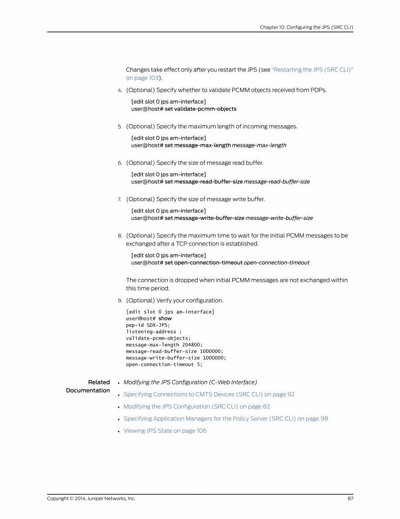
Changes take effect only after you restart the JPS (see “Restarting the JPS (SRC CLI)”
on page 103).
4. (Optional) Specify whether to validate PCMM objects received from PDPs.
[edit slot 0 jps am-interface]user@host# set validate-pcmm-objects
5. (Optional) Specify the maximum length of incoming messages.
[edit slot 0 jps am-interface]user@host# setmessage-max-lengthmessage-max-length
6. (Optional) Specify the size of message read buffer.
[edit slot 0 jps am-interface]user@host# setmessage-read-buffer-sizemessage-read-buffer-size
7. (Optional) Specify the size of message write buffer.
[edit slot 0 jps am-interface]user@host# setmessage-write-buffer-sizemessage-write-buffer-size
8. (Optional) Specify the maximum time to wait for the initial PCMM messages to be
exchanged after a TCP connection is established.
[edit slot 0 jps am-interface]user@host# set open-connection-timeout open-connection-timeout
The connection is dropped when initial PCMM messages are not exchanged within
this time period.
9. (Optional) Verify your configuration.
[edit slot 0 jps am-interface] user@host# showpep-id SDX-JPS;listening-address ;validate-pcmm-objects;message-max-length 204800;message-read-buffer-size 1000000;message-write-buffer-size 1000000;open-connection-timeout 5;
RelatedDocumentation
Modifying the JPS Configuration (C-Web Interface)•
• Specifying Connections to CMTS Devices (SRC CLI) on page 92
• Modifying the JPS Configuration (SRC CLI) on page 82
• Specifying Application Managers for the Policy Server (SRC CLI) on page 98
• Viewing JPS State on page 106
87Copyright © 2014, Juniper Networks, Inc.
Chapter 10: Configuring the JPS (SRC CLI)

Configuring Connections to RKSs (SRC CLI)
1. Specifying Connections to RKSs (SRC CLI) on page 88
2. Configuring RKS Pairs (SRC CLI) on page 90
Specifying Connections to RKSs (SRC CLI)
To configure the policy server-to-RKS interface (PKT-MM4) so that policy events can
be sent to the RKS, you can configure RKS pairs (see “Configuring RKS Pairs (SRC CLI)”
on page 90) and their associated application managers (see “Configuring RKS Pairs for
Associated Application Managers (SRC CLI)” on page 91).
Use the following configuration statement to configure the policy server-to-RKS interface:
slot number jps rks-interface {element-id element-id;local-address local-address;local-port local-port;retry-interval retry-interval;local-timeout local-timeout;mso-datamso-data;mso-domain-namemso-domain-name;default-rks-pair default-rks-pair;pending-rks-event-max-size pending-rks-event-max-size;pending-rks-event-max-age pending-rks-event-max-age;held-decs-max-size held-decs-max-size;held-decs-max-age held-decs-max-age;bcid-cache-size bcid-cache-size;bcid-cache-age bcid-cache-age;use-default-when-am-requests-unconfigured-rks;
}
To configure the policy server-to-RKS interface:
1. From configuration mode, access the configuration statement that configures the
policy server-to-RKS interface.
user@host# edit slot 0 jps rks-interface
2. ier for RKS event origin.
[edit slot 0 jps rks-interface]user@host# set element-id element-id
3. (Optional) Specify the source IP address that the plug-in uses to communicate with
the RKS.
[edit slot 0 jps rks-interface]user@host# set local-address local-address
If no value is specified and there is more than one local address, the JPS randomly
selects a local address to be used as the source address.
Copyright © 2014, Juniper Networks, Inc.88
SRC PE 4.8.x Solutions Guide
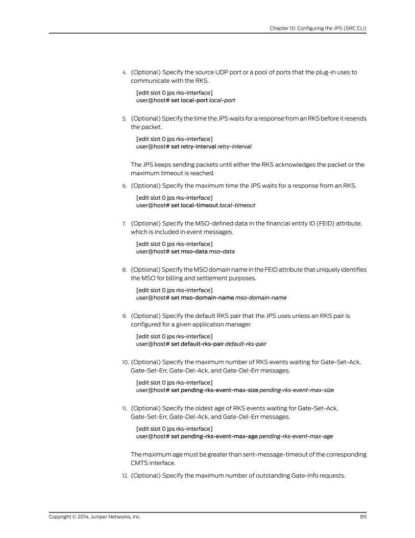
4. (Optional) Specify the source UDP port or a pool of ports that the plug-in uses to
communicate with the RKS.
[edit slot 0 jps rks-interface]user@host# set local-port local-port
5. (Optional) Specify the time the JPS waits for a response from an RKS before it resends
the packet.
[edit slot 0 jps rks-interface]user@host# set retry-interval retry-interval
The JPS keeps sending packets until either the RKS acknowledges the packet or the
maximum timeout is reached.
6. (Optional) Specify the maximum time the JPS waits for a response from an RKS.
[edit slot 0 jps rks-interface]user@host# set local-timeout local-timeout
7. (Optional) Specify the MSO-defined data in the financial entity ID (FEID) attribute,
which is included in event messages.
[edit slot 0 jps rks-interface]user@host# setmso-datamso-data
8. (Optional) Specify the MSO domain name in the FEID attribute that uniquely identifies
the MSO for billing and settlement purposes.
[edit slot 0 jps rks-interface]user@host# setmso-domain-namemso-domain-name
9. (Optional) Specify the default RKS pair that the JPS uses unless an RKS pair is
configured for a given application manager.
[edit slot 0 jps rks-interface]user@host# set default-rks-pair default-rks-pair
10. (Optional) Specify the maximum number of RKS events waiting for Gate-Set-Ack,
Gate-Set-Err, Gate-Del-Ack, and Gate-Del-Err messages.
[edit slot 0 jps rks-interface]user@host# set pending-rks-event-max-size pending-rks-event-max-size
11. (Optional) Specify the oldest age of RKS events waiting for Gate-Set-Ack,
Gate-Set-Err, Gate-Del-Ack, and Gate-Del-Err messages.
[edit slot 0 jps rks-interface]user@host# set pending-rks-event-max-age pending-rks-event-max-age
The maximum age must be greater than sent-message-timeout of the corresponding
CMTS interface.
12. (Optional) Specify the maximum number of outstanding Gate-Info requests.
89Copyright © 2014, Juniper Networks, Inc.
Chapter 10: Configuring the JPS (SRC CLI)
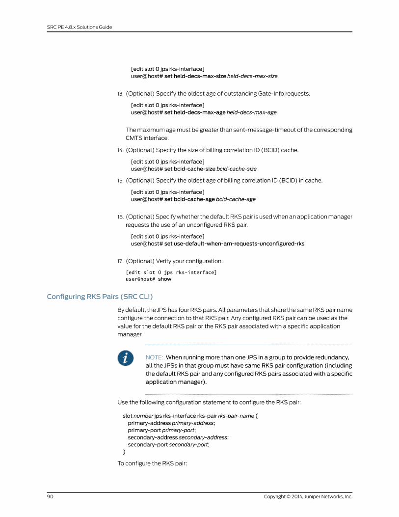
[edit slot 0 jps rks-interface]user@host# set held-decs-max-size held-decs-max-size
13. (Optional) Specify the oldest age of outstanding Gate-Info requests.
[edit slot 0 jps rks-interface]user@host# set held-decs-max-age held-decs-max-age
The maximum age must be greater than sent-message-timeout of the corresponding
CMTS interface.
14. (Optional) Specify the size of billing correlation ID (BCID) cache.
[edit slot 0 jps rks-interface]user@host# set bcid-cache-size bcid-cache-size
15. (Optional) Specify the oldest age of billing correlation ID (BCID) in cache.
[edit slot 0 jps rks-interface]user@host# set bcid-cache-age bcid-cache-age
16. (Optional) Specify whether the default RKS pair is used when an application manager
requests the use of an unconfigured RKS pair.
[edit slot 0 jps rks-interface]user@host# set use-default-when-am-requests-unconfigured-rks
17. (Optional) Verify your configuration.
[edit slot 0 jps rks-interface] user@host# show
Configuring RKS Pairs (SRC CLI)
By default, the JPS has four RKS pairs. All parameters that share the same RKS pair name
configure the connection to that RKS pair. Any configured RKS pair can be used as the
value for the default RKS pair or the RKS pair associated with a specific application
manager.
NOTE: When runningmore than one JPS in a group to provide redundancy,all the JPSs in that groupmust have same RKS pair configuration (includingthe default RKS pair and any configured RKSpairs associatedwith a specificapplicationmanager).
Use the following configuration statement to configure the RKS pair:
slot number jps rks-interface rks-pair rks-pair-name {primary-address primary-address;primary-port primary-port;secondary-address secondary-address;secondary-port secondary-port;
}
To configure the RKS pair:
Copyright © 2014, Juniper Networks, Inc.90
SRC PE 4.8.x Solutions Guide
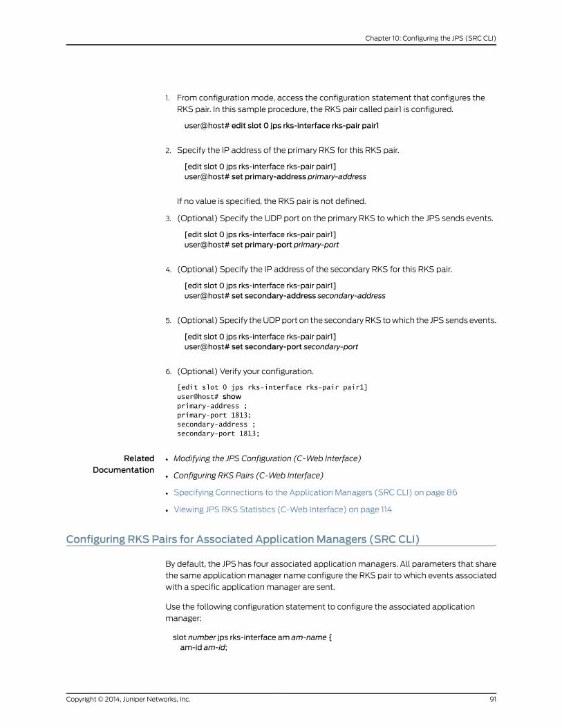
1. From configuration mode, access the configuration statement that configures the
RKS pair. In this sample procedure, the RKS pair called pair1 is configured.
user@host# edit slot 0 jps rks-interface rks-pair pair1
2. Specify the IP address of the primary RKS for this RKS pair.
[edit slot 0 jps rks-interface rks-pair pair1]user@host# set primary-address primary-address
If no value is specified, the RKS pair is not defined.
3. (Optional) Specify the UDP port on the primary RKS to which the JPS sends events.
[edit slot 0 jps rks-interface rks-pair pair1]user@host# set primary-port primary-port
4. (Optional) Specify the IP address of the secondary RKS for this RKS pair.
[edit slot 0 jps rks-interface rks-pair pair1]user@host# set secondary-address secondary-address
5. (Optional) Specify the UDP port on the secondary RKS to which the JPS sends events.
[edit slot 0 jps rks-interface rks-pair pair1]user@host# set secondary-port secondary-port
6. (Optional) Verify your configuration.
[edit slot 0 jps rks-interface rks-pair pair1] user@host# showprimary-address ;primary-port 1813;secondary-address ;secondary-port 1813;
RelatedDocumentation
Modifying the JPS Configuration (C-Web Interface)•
• Configuring RKS Pairs (C-Web Interface)
• Specifying Connections to the Application Managers (SRC CLI) on page 86
• Viewing JPS RKS Statistics (C-Web Interface) on page 114
Configuring RKS Pairs for Associated ApplicationManagers (SRC CLI)
By default, the JPS has four associated application managers. All parameters that share
the same application manager name configure the RKS pair to which events associated
with a specific application manager are sent.
Use the following configuration statement to configure the associated application
manager:
slot number jps rks-interface am am-name {am-id am-id;
91Copyright © 2014, Juniper Networks, Inc.
Chapter 10: Configuring the JPS (SRC CLI)
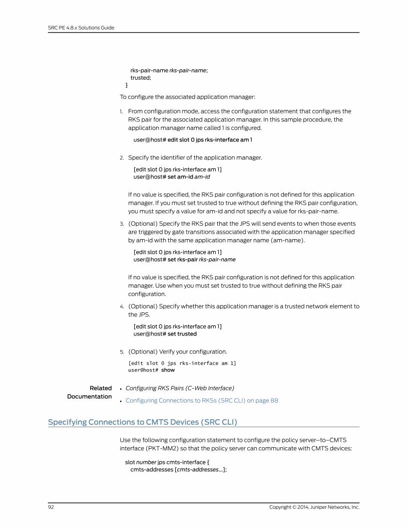
rks-pair-name rks-pair-name;trusted;
}
To configure the associated application manager:
1. From configuration mode, access the configuration statement that configures the
RKS pair for the associated application manager. In this sample procedure, the
application manager name called 1 is configured.
user@host# edit slot 0 jps rks-interface am 1
2. Specify the identifier of the application manager.
[edit slot 0 jps rks-interface am 1]user@host# set am-id am-id
If no value is specified, the RKS pair configuration is not defined for this application
manager. If you must set trusted to true without defining the RKS pair configuration,
you must specify a value for am-id and not specify a value for rks-pair-name.
3. (Optional) Specify the RKS pair that the JPS will send events to when those events
are triggered by gate transitions associated with the application manager specified
by am-id with the same application manager name (am-name).
[edit slot 0 jps rks-interface am 1]user@host# set rks-pair rks-pair-name
If no value is specified, the RKS pair configuration is not defined for this application
manager. Use when you must set trusted to true without defining the RKS pair
configuration.
4. (Optional) Specify whether this application manager is a trusted network element to
the JPS.
[edit slot 0 jps rks-interface am 1]user@host# set trusted
5. (Optional) Verify your configuration.
[edit slot 0 jps rks-interface am 1] user@host# show
RelatedDocumentation
Configuring RKS Pairs (C-Web Interface)•
• Configuring Connections to RKSs (SRC CLI) on page 88
Specifying Connections to CMTSDevices (SRC CLI)
Use the following configuration statement to configure the policy server–to–CMTS
interface (PKT-MM2) so that the policy server can communicate with CMTS devices:
slot number jps cmts-interface {cmts-addresses [cmts-addresses...];
Copyright © 2014, Juniper Networks, Inc.92
SRC PE 4.8.x Solutions Guide

keepalive-interval keepalive-interval;synch-despite-unreachable-pep;synch-despite-pre-i03-pep;use-ssq-ssc-with-pre-i03-pep;local-address local-address;message-max-lengthmessage-max-length;message-read-buffer-sizemessage-read-buffer-size;message-write-buffer-sizemessage-write-buffer-size;open-connection-timeout open-connection-timeout;connection-open-retry-interval connection-open-retry-interval;sent-message-timeout sent-message-timeout;validate-pcmm-objects;
}
To configure the policy server–to–CMTS interface:
1. From configuration mode, access the configuration statement that configures the
policy server–to–CMTS interface.
user@host# edit slot 0 jps cmts-interface
2. Specify the IP addresses of all the CMTS devices to which the JPS will try to connect.
[edit slot 0 jps cmts-interface]user@host# set cmts-addresses [cmts-addresses...]
3. (Optional) Specify the interval between keepalive messages sent from the COPS
client (CMTS device) to the COPS server (the JPS). Changes apply only to COPS
connections that are established after you make the change.
[edit slot 0 jps cmts-interface]user@host# set keepalive-interval keepalive-interval
A value of 0 means that no keepalive messages will be exchanged between the CMTS
device and the JPS.
4. (Optional) Specify whether synchronization proceeds when the JPS receives a
synchronization request from an application manager (such as the SAE) and the JPS
is not connected to a CMTS device to which it should be connected.
[edit slot 0 jps cmts-interface]user@host# set synch-despite-unreachable-pep
5. (Optional) Specify whether synchronization proceeds when the JPS receives a
synchronization request from an application manager (such as the SAE) and the JPS
is connected to a pre-PCMM I03 CMTS device.
[edit slot 0 jps cmts-interface]user@host# set synch-despite-pre-i03-pep
6. (Optional) Specify whether synchronization includes both pre-PCMM I03 and PCMM
I03 CMTS devices when the JPS receives a synchronization request from an application
manager (such as the SAE) and the JPS is connected to a pre-PCMM I03 CMTS device.
93Copyright © 2014, Juniper Networks, Inc.
Chapter 10: Configuring the JPS (SRC CLI)
Relevant only when at least one pre-PCMM I03 CMTS device is connected and
sync-despite-pre-i03-pep is specified as true.
[edit slot 0 jps cmts-interface]user@host# set use-ssq-ssc-with-pre-i03-pep
7. (Optional) Specify the source IP address that the JPS uses to communicate with
CMTS devices.
[edit slot 0 jps cmts-interface]user@host# set local-address local-address
If no value is specified and there is more than one local address, a random local address
is used as the source address.
8. (Optional) Specify the maximum length of incoming messages.
[edit slot 0 jps cmts-interface]user@host# setmessage-max-lengthmessage-max-length
9. (Optional) Specify the size of message read buffer.
[edit slot 0 jps cmts-interface]user@host# setmessage-read-buffer-sizemessage-read-buffer-size
10. (Optional) Specify the size of message write buffer.
[edit slot 0 jps cmts-interface]user@host# setmessage-write-buffer-sizemessage-write-buffer-size
11. (Optional) Specify the maximum time to wait for the initial PCMM messages to be
exchanged after a TCP connection is established.
[edit slot 0 jps cmts-interface]user@host# set open-connection-timeout open-connection-timeout
The connection is dropped when initial PCMM messages are not exchanged within
this time period.
12. (Optional) Specify the time to wait before the JPS tries to reconnect to CMTS devices.
[edit slot 0 jps cmts-interface]user@host# set connection-open-retry-interval connection-open-retry-interval
13. (Optional) Specify the maximum time to wait for the sent messages to be exchanged
after a TCP connection is established.
[edit slot 0 jps cmts-interface]user@host# set sent-message-timeout sent-message-timeout
This value must be less than the held-decs-max-age and pending-rks-event-max-age
values for the corresponding RKS interface.
14. (Optional) Specify whether to validate PCMM objects received from PDPs.
[edit slot 0 jps cmts-interface]
Copyright © 2014, Juniper Networks, Inc.94
SRC PE 4.8.x Solutions Guide
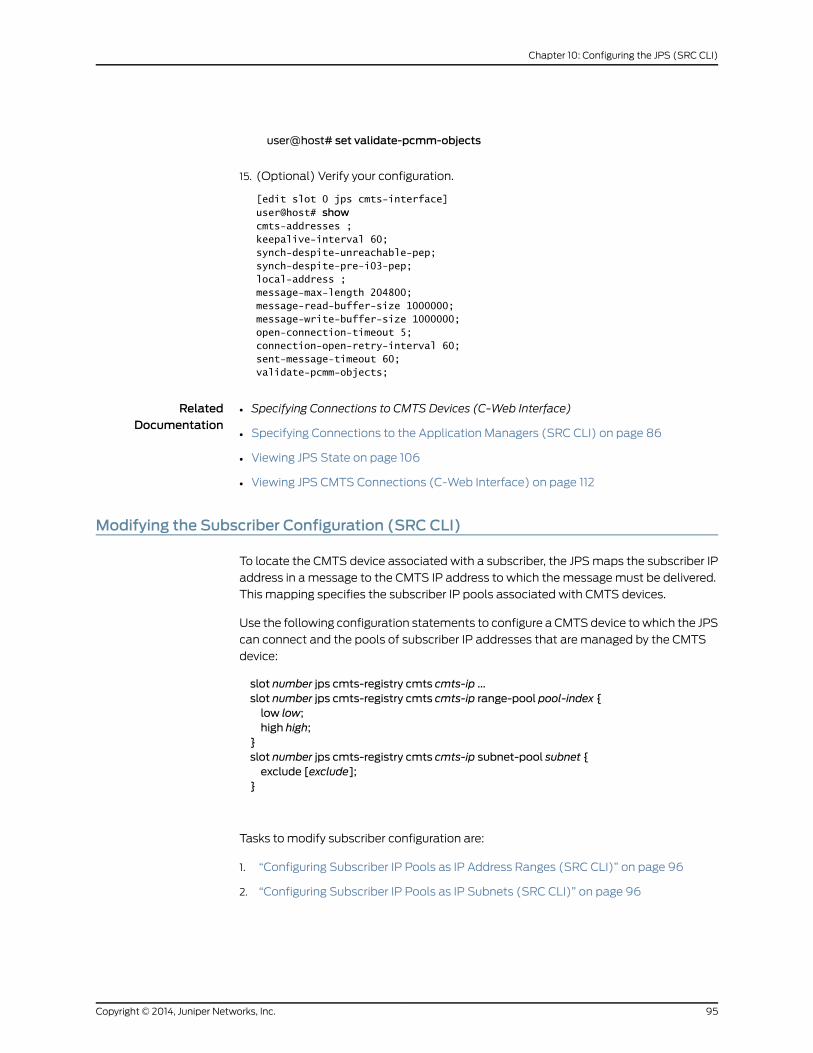
user@host# set validate-pcmm-objects
15. (Optional) Verify your configuration.
[edit slot 0 jps cmts-interface] user@host# showcmts-addresses ;keepalive-interval 60;synch-despite-unreachable-pep;synch-despite-pre-i03-pep;local-address ;message-max-length 204800;message-read-buffer-size 1000000;message-write-buffer-size 1000000;open-connection-timeout 5;connection-open-retry-interval 60;sent-message-timeout 60;validate-pcmm-objects;
RelatedDocumentation
Specifying Connections to CMTS Devices (C-Web Interface)•
• Specifying Connections to the Application Managers (SRC CLI) on page 86
• Viewing JPS State on page 106
• Viewing JPS CMTS Connections (C-Web Interface) on page 112
Modifying the Subscriber Configuration (SRC CLI)
To locate the CMTS device associated with a subscriber, the JPS maps the subscriber IP
address in a message to the CMTS IP address to which the message must be delivered.
This mapping specifies the subscriber IP pools associated with CMTS devices.
Use the following configuration statements to configure a CMTS device to which the JPS
can connect and the pools of subscriber IP addresses that are managed by the CMTS
device:
slot number jps cmts-registry cmts cmts-ip ...slot number jps cmts-registry cmts cmts-ip range-pool pool-index {low low;high high;
}slot number jps cmts-registry cmts cmts-ip subnet-pool subnet {exclude [exclude];
}
Tasks to modify subscriber configuration are:
1. “Configuring Subscriber IP Pools as IP Address Ranges (SRC CLI)” on page 96
2. “Configuring Subscriber IP Pools as IP Subnets (SRC CLI)” on page 96
95Copyright © 2014, Juniper Networks, Inc.
Chapter 10: Configuring the JPS (SRC CLI)

RelatedDocumentation
Modifying the Subscriber Configuration (C-Web Interface)•
• Specifying Connections to CMTS Devices (SRC CLI) on page 92
Configuring Subscriber IP Pools as IP Address Ranges (SRC CLI)
To configure subscriber IP pools that are managed by the CMTS device as IP address
ranges:
1. From configuration mode, access the configuration statement that configures the
CMTS device to which the JPS can connect.
user@host# edit slot 0 jps cmts-registry cmts cmts-ip range-pool pool-index
Specify the IP address of the CMTS device and the address range pool index.
2. Specify the first IP address in the IP range for the pool of subscriber IP addresses that
are managed by the CMTS device.
[edit slot 0 jps cmts-registry cmts cmts-ip range-pool pool-index]user@host# set low low
3. Specify the last IP address in the IP range for the pool of subscriber IP addresses that
are managed by the CMTS device.
[edit slot 0 jps cmts-registry cmts cmts-ip range-pool pool-index]user@host# set high high
4. (Optional) Verify your configuration.
[edit slot 0 jps cmts-registry] user@host# show
RelatedDocumentation
Configuring Subscriber IP Pools as IP Address Ranges (C-Web Interface)•
• Modifying the Subscriber Configuration (SRC CLI) on page 95
• Configuring Subscriber IP Pools as IP Subnets (SRC CLI) on page 96
• Specifying Connections to CMTS Devices (SRC CLI) on page 92
Configuring Subscriber IP Pools as IP Subnets (SRC CLI)
To configure subscriber IP pools that are managed by the CMTS device as IP subnets:
1. From configuration mode, access the configuration statement that configures the
CMTS device to which the JPS can connect.
user@host# edit slot 0 jps cmts-registry cmts cmts-ip subnet-pool subnet
Specify the IP address of the CMTS device and the IP address and mask of the subnet
for the pool of subscriber IP addresses.
Copyright © 2014, Juniper Networks, Inc.96
SRC PE 4.8.x Solutions Guide

2. (Optional) Specify the IP addresses of the subnet that are excluded from the subscriber
IP pool managed by the CMTS device.
[edit slot 0 jps cmts-registry cmts cmts-ip subnet-pool subnet]user@host# set exclude [exclude...]
3. (Optional) Verify your configuration.
[edit slot 0 jps cmts-registry] user@host# show
RelatedDocumentation
Configuring Subscriber IP Pools as IP Subnets (C-Web Interface)•
• Modifying the Subscriber Configuration (SRC CLI) on page 95
• Configuring Subscriber IP Pools as IP Address Ranges (SRC CLI) on page 96
• Specifying Connections to CMTS Devices (SRC CLI) on page 92
Configuring the SAE to Interact with the JPS (SRC CLI)
You must configure the SAE as an application manager to allow it to interact with
PCMM-compliant policy servers. The policy server acts as a policy decision point that
manages the relationships between application managers and CMTS devices. Policy
servers that manage the same group of CMTS devices are grouped together and are
simultaneously active. The policy server group provides a way for the SAE to communicate
with any CMTS device that is managed by a policy server in the policy server group. To
provide redundancy, the SAEs are grouped in an SAE community that connects to a policy
server group. Only one of the SAEs in the SAE community is active. The active SAE
establishes connections to all the policy servers in the policy server group. The active
SAE will fail over to a redundant SAE only when it loses the connection to all the policy
servers in the policy server group. State synchronization enables the SAE to synchronize
its state with all the CMTS devices connected to a policy server group.
The tasks to configure the SAE as an application manager are:
• “Specifying Application Managers for the Policy Server (SRC CLI)” on page 98
• “Specifying Application Manager Identifiers for Policy Servers (SRC CLI)” on page 99
• “Adding Objects for Policy Servers to the Directory (SRC CLI)” on page 100
• “Configuring Initialization Scripts (SRC CLI)” on page 101
• “Enabling State Synchronization (SRC CLI)” on page 101
RelatedDocumentation
JPS Overview on page 75•
• Configuring the SAE to Interact with the JPS (C-Web Interface)
• Configuring the JPS (SRC CLI) on page 81
• Initially Configuring the SAE
97Copyright © 2014, Juniper Networks, Inc.
Chapter 10: Configuring the JPS (SRC CLI)
Specifying ApplicationManagers for the Policy Server (SRC CLI)
To specify the SAE community that connects to a policy server group, you need to add
an application manager group object to the directory.
Use the following configuration statements to specify the application manager for the
policy server:
shared network application-manager-group name {description description;application-manager-id application-manager-id;connected-sae [connected-sae...];pdp-group pdp-group;local-address-pools [local-address-pools...];managing-sae-iormanaging-sae-ior;
}
To add an application manager group:
1. From configuration mode, access the configuration statement that specifies the
application managers.
user@host# edit shared network application-manager-group name
2. (Optional) Specify information about the SAE community.
[edit shared network application-manager-group name]user@host# set description description
3. (Optional) Specify the unique identifier within the domain of the service provider for
the application manager that handles the service session (Application Manager Tag)
as a 2-byte unsigned integer.
[edit shared network application-manager-group name]user@host# set application-manager-id application-manager-id
4. (Optional) Specify the SAEs that are connected to the specified policy server group.
This list becomes the community of SAEs.
[edit shared network application-manager-group name]user@host# set connected-sae [connected-sae...]
When you modify a community, wait for passive session stores of the new community
members to be updated before you shut down the current active SAE. Otherwise, a
failover from the current active SAE to the new member is triggered immediately, and
the new member’s session store may not have received all data from the active SAE’s
session store.
5. (Optional) Specify the name of the policy server group associated with this SAE
community.
[edit shared network application-manager-group name]user@host# set pdp-group pdp-group
Copyright © 2014, Juniper Networks, Inc.98
SRC PE 4.8.x Solutions Guide
6. (Optional) Specify the list of IP address pools that the specified PDP group currently
manages and stores.
[edit shared network application-manager-group name]user@host# set local-address-pools local-address-pools
You must configure a local address pool if you are using the NIC so that the NIC can
resolve the IP-to-SAE mapping. See “Using the NIC Resolver” on page 102.
7. (Optional) Specify the Common Object Request Broker Architecture (CORBA)
reference for the SAE managing this policy server group.
[edit shared network application-manager-group name]user@host# setmanaging-sae-iormanaging-sae-ior
The amIorPublisher script provides this information when the SAE connects to the
policy server. If you do not select this script when configuring initialization scripts,
enter a value. For information about configuring initialization scripts, see “Configuring
Initialization Scripts (SRC CLI)” on page 101.
RelatedDocumentation
JPS Interfaces on page 76•
• Specifying Application Managers for the Policy Server (C-Web Interface)
• Specifying Application Manager Identifiers for Policy Servers (SRC CLI) on page 99
• Viewing JPS State on page 106
• Viewing JPS AM Statistics (C-Web Interface) on page 110
Specifying ApplicationManager Identifiers for Policy Servers (SRC CLI)
The application manager identifier (AMID) identifies the application manager (such as
the SAE) in messages sent to and from the policy server. The SAE constructs the AMID
value by concatenating two fields: Application Manager Tag and Application Type.
The Application Manager Tag value is obtained from the specification of application
managers for policy servers. See “Specifying Application Managers for the Policy Server
(SRC CLI)” on page 98.
The Application Type value is obtained during service activation from the specification
of the PCMM Application Type value when you configure normal services.
For more information about configuring services, see Adding a Normal Service (SRC CLI).
RelatedDocumentation
JPS Interfaces on page 76•
• Specifying Application Manager Identifiers for Policy Servers (C-Web Interface)
• Specifying Policy Server Identifiers in Messages (SRC CLI) on page 83
• Adding Objects for Policy Servers to the Directory (SRC CLI) on page 100
• Viewing JPS State on page 106
99Copyright © 2014, Juniper Networks, Inc.
Chapter 10: Configuring the JPS (SRC CLI)
Adding Objects for Policy Servers to the Directory (SRC CLI)
To communicate with policy servers, the SAE creates and manages pseudointerfaces
that it associates with a policy decision point object in the directory. Each policy server
in the SRC network must appear in the directory as a policy decision point object.
Use the following configuration statements to specify the policy server as a policy decision
point:
shared network policy-decision-point name {description description;pdp-address pdp-address;pdp-group pdp-group;
}
To add a policy server to the directory with the SRC CLI:
1. From configuration mode, access the configuration statement that configures the
policy decision point.
user@host# edit shared network policy-decision-point name
2. (Optional) Specify information about the policy server.
[edit shared network policy-decision-point name]user@host# set description description
3. (Optional) Specify the IP address of the policy server. The SAE uses this address to
establish a COPS connection with the policy server.
[edit shared network policy-decision-point name]user@host# set pdp-address pdp-address
4. (Optional) Specify the name of the policy server group.
[edit shared network policy-decision-point name]user@host# set pdp-group pdp-group
5. Create an SAE community for the policy servers. See “Specifying Application Managers
for the Policy Server (SRC CLI)” on page 98.
RelatedDocumentation
Policy Components•
• Adding Objects for Policy Servers to the Directory (C-Web Interface)
• Configuring Initialization Scripts (SRC CLI) on page 101
• Specifying Application Manager Identifiers for Policy Servers (SRC CLI) on page 99
• Enabling State Synchronization (SRC CLI) on page 101
Copyright © 2014, Juniper Networks, Inc.100
SRC PE 4.8.x Solutions Guide
Configuring Initialization Scripts (SRC CLI)
When the SAE establishes a connection with a policy server, it runs an initialization script
to customize the setup of the connection.
Use the following configuration statement to configure the initialization script:
shared sae configuration driver scripts {pcmm pcmm;
}
To configure initialization scripts for the SAE:
1. From configuration mode, access the configuration statement that configures the
initialization scripts.
user@host# edit shared sae configuration driver scripts
2. Specify the initialization script for a PCMM environment.
[edit shared sae configuration driver scripts]user@host# set pcmm pcmm
The script is run when the connection between a policy server and the SAE is
established and again when the connection is dropped. For the JPS, we recommend
setting this value to amIorPublisher.
RelatedDocumentation
Configuring Initialization Scripts (C-Web Interface)•
• Specifying Application Managers for the Policy Server (SRC CLI) on page 98
• Configuring the SAE to Interact with the JPS (SRC CLI) on page 97
• Specifying Initialization Scripts on the SAE (SRC CLI)
• DevelopingRouter InitializationScripts forNetworkDevices and JuniperNetworksRouters
Enabling State Synchronization (SRC CLI)
State synchronization is achieved when the SAE is required to communicate with the
policy server over the COPS connection.
Use the following configuration statement to configure state synchronization:
shared sae configuration driver pcmm {disable-full-sync;disable-pcmm-i03-policy;session-recovery-retry-interval session-recovery-retry-interval;
}
To enable state synchronization with policy servers:
1. From configuration mode, access the configuration statement that configures the
PCMM device driver.
101Copyright © 2014, Juniper Networks, Inc.
Chapter 10: Configuring the JPS (SRC CLI)

user@host# edit shared sae configuration driver pcmm
2. Specify whether state synchronization with the PCMM policy servers is disabled.
[edit shared sae configuration driver pcmm]user@host# set disable-full-sync
When using other PCMM-compliant policy servers (instead of the JPS), we recommend
setting this value to true.
3. Specify whether PCMM I03 policies are disabled when the SAE is deployed with
pre-PCMM I03 CMTS devices.
[edit shared sae configuration driver pcmm]user@host# set disable-pcmm-i03-policy
When there are pre-PCMM I03 CMTS devices in the network, you must set this value
to true.
4. Specify the time interval between attempts by the SAE to restore service sessions
that are still being recovered in the background when state synchronization completes
with a state-data-incomplete error.
[edit shared sae configuration driver pcmm]user@host# set session-recovery-retry-interval session-recovery-retry-interval
We recommend setting this value to 3600000 (1 hour) or longer.
RelatedDocumentation
Enabling State Synchronization (C-Web Interface)•
• Configuring the SAE to Interact with the JPS (SRC CLI) on page 97
• Viewing JPS State on page 106
Using the NIC Resolver
If you are using the NIC to map the subscriber IP address to the SAE, you need to configure
a NIC host. The NIC system uses IP address pools to map IP addresses to SAEs. You
configure the local address pools in the application manager configuration for a policy
server group. These pools are published in the NIC. The NIC maps subscriber IP addresses
in requests received through the portal or Advanced Services Gateway to the policy server
group that currently manages that CMTS device. For information about configuring the
SAE for policy servers, see “Specifying Application Managers for the Policy Server (SRC
CLI)” on page 98.
The OnePopPcmm sample configuration data supports this scenario for a PCMM
environment in which you use the assigned IP subscriber method to log in subscribers
and in which you use the NIC to determine the subscriber’s SAE. The OnePopPcmm
configuration supports one point of presence (POP). NIC replication can be used to
provide high availability. The realm for this configuration accommodates the situation
in which IP pools are configured locally on each application manager group object.
Copyright © 2014, Juniper Networks, Inc.102
SRC PE 4.8.x Solutions Guide
The resolution process takes a subscriber’s IP address as the key and returns a reference
to the SAE managing this subscriber as the value.
The following agents collect information for resolvers in this realm:
• Directory agent PoolVr collects and publishes information about the mappings of IP
pools to the policy server group.
• Directory agent VrSaeId collects and publishes information about the mappings of
policy server groups to SAEs.
For more information about configuring the NIC, see Configuring the NIC (SRC CLI).
RelatedDocumentation
PCMM Environment Overview on page 41•
• OnePopPcmm Scenario
Managing the JPS
After you have installed the JPS and applied the local configuration of the JPS, you can
perform these tasks:
• Starting the JPS (SRC CLI) on page 103
• Restarting the JPS (SRC CLI) on page 103
• Stopping the JPS (SRC CLI) on page 104
• Displaying JPS Status (SRC CLI) on page 104
Starting the JPS (SRC CLI)
You must start the JPS when you install the JPS without rebooting the JPS host.
To start the JPS:
user@host> enable component jps
The system responds with a start message. If the JPS is already running, the system
responds with a warning message.
RelatedDocumentation
Starting the JPS (C-Web Interface)•
• Stopping the JPS (SRC CLI) on page 104
• Configuring the JPS (SRC CLI) on page 81
• Monitoring the JPS on page 105
• JPS Overview on page 75
Restarting the JPS (SRC CLI)
To restart the JPS:
user@host> restart component jps
103Copyright © 2014, Juniper Networks, Inc.
Chapter 10: Configuring the JPS (SRC CLI)
The system responds with a start message. If the JPS is already running, the system
responds with a shutdown message and then a start message.
RelatedDocumentation
Restarting the JPS (C-Web Interface)•
• Stopping the JPS (SRC CLI) on page 104
• Configuring the JPS (SRC CLI) on page 81
• Monitoring the JPS on page 105
• JPS Overview on page 75
Stopping the JPS (SRC CLI)
To stop the JPS:
user@host> disable component jps
The system responds with a shutdown message. If the JPS is not running when you issue
the command, the system responds with the command prompt.
To start the JPS, see “Starting the JPS (SRC CLI)” on page 103.
RelatedDocumentation
Stopping the JPS (C-Web Interface)•
• Restarting the JPS (SRC CLI) on page 103
• Monitoring the JPS on page 105
• JPS Overview on page 75
Displaying JPS Status (SRC CLI)
Purpose Display the JPS status.
Action user@host> show component
The system responds with a status message.
RelatedDocumentation
• Displaying JPS Status (C-Web Interface)
• Monitoring the JPS on page 105
• Viewing JPS State on page 106
Copyright © 2014, Juniper Networks, Inc.104
SRC PE 4.8.x Solutions Guide
CHAPTER 11
Monitoring the JPS (SRC CLI)
• Monitoring the JPS on page 105
• Viewing Server Process Information on page 105
• Viewing JPS State on page 106
Monitoring the JPS
Purpose Monitor the following JPS information:
• The basic health indicators for the server process
• The current state of the JPS, such as the current network connections or recent
performance statistics
Action user@host> show jps statistics
RelatedDocumentation
Displaying JPS Status (SRC CLI) on page 104•
• Viewing JPS State on page 106
• Viewing Server Process Information on page 105
• Configuring the JPS (SRC CLI) on page 81
• JPS Overview on page 75
Viewing Server Process Information
Purpose View information about the server process.
Action user@host> show jps statistics process
RelatedDocumentation
Viewing Information About the JPS Server Process (C-Web Interface) on page 109•
• Monitoring the JPS on page 105
• Viewing JPS State on page 106
• JPS Overview on page 75
105Copyright © 2014, Juniper Networks, Inc.
Viewing JPS State
You can monitor the current state of the JPS by:
1. Viewing Performance Statistics for the JPS Interfaces on page 106
2. Viewing Network Connections for the Application Manager on page 106
3. Viewing Network Connections for the CMTS Device on page 106
4. Viewing Performance Statistics for the CMTS Locator on page 107
5. Viewing Message Handler Information on page 107
Viewing Performance Statistics for the JPS Interfaces
Purpose View performance statistics for JPS interfaces.
Action To view recent performance statistics for the application manager-to-policy server
interface:
user@host> show jps statistics am
To view recent performance statistics for the policy server-to-CMTS interface:
user@host> show jps statistics cmts
To view recent performance statistics for the policy server-to-RKS interface:
user@host> show jps statistics rks
Viewing Network Connections for the ApplicationManager
Purpose View network connections for the application manager.
Action To view information about the current JPS network connections for all the application
managers:
user@host> show jps statistics am connections
To view information about the current JPS network connections for a specific application
manager:
user@host> show jps statistics am connections ip-address ip-address
Enter all or part of the IP address to list connections for all matching addresses.
Viewing Network Connections for the CMTSDevice
Purpose View network connections for the CMTS Device.
Action To view information about the current JPS connections for all the CMTS devices:
user@host> show jps statistics cmts connections
To view information about the current JPS connections for a specific CMTS device:
user@host> show jps statistics cmts connections ip-address ip-address
Enter all or part of the IP address to list connections for all matching addresses.
Copyright © 2014, Juniper Networks, Inc.106
SRC PE 4.8.x Solutions Guide

Viewing Performance Statistics for the CMTS Locator
Purpose View information about the recent performance statistics for the CMTS locator.
Action user@host> show jps statistics cmts-locator
ViewingMessage Handler Information
Purpose View message handler information.
Action To view information about the JPS message handler and message flows:
user@host> show jps statisticsmessage-handleruser@host> show jps statisticsmessage-handler message-flow
To view information about specific JPS message flows:
user@host> show jps statisticsmessage-handler message-flow id id
Enter all or part of the message flow identifier to list all matching message flows.
RelatedDocumentation
• Displaying JPS Status (SRC CLI) on page 104
• Monitoring the JPS on page 105
• Viewing Server Process Information on page 105
• JPS Overview on page 75
107Copyright © 2014, Juniper Networks, Inc.
Chapter 11: Monitoring the JPS (SRC CLI)

Copyright © 2014, Juniper Networks, Inc.108
SRC PE 4.8.x Solutions Guide
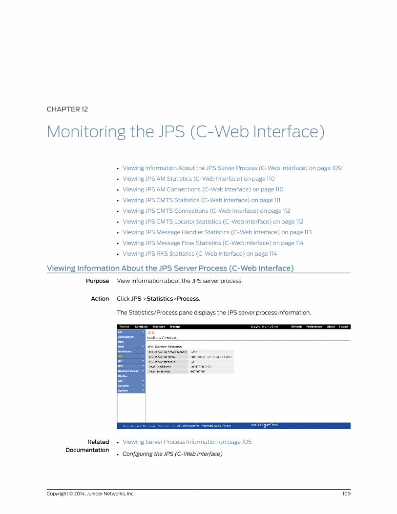
CHAPTER 12
Monitoring the JPS (C-Web Interface)
• Viewing Information About the JPS Server Process (C-Web Interface) on page 109
• Viewing JPS AM Statistics (C-Web Interface) on page 110
• Viewing JPS AM Connections (C-Web Interface) on page 110
• Viewing JPS CMTS Statistics (C-Web Interface) on page 111
• Viewing JPS CMTS Connections (C-Web Interface) on page 112
• Viewing JPS CMTS Locator Statistics (C-Web Interface) on page 112
• Viewing JPS Message Handler Statistics (C-Web Interface) on page 113
• Viewing JPS Message Flow Statistics (C-Web Interface) on page 114
• Viewing JPS RKS Statistics (C-Web Interface) on page 114
Viewing Information About the JPS Server Process (C-Web Interface)
Purpose View information about the JPS server process.
Action Click JPS >Statistics>Process.
The Statistics/Process pane displays the JPS server process information.
RelatedDocumentation
Viewing Server Process Information on page 105•
• Configuring the JPS (C-Web Interface)
109Copyright © 2014, Juniper Networks, Inc.
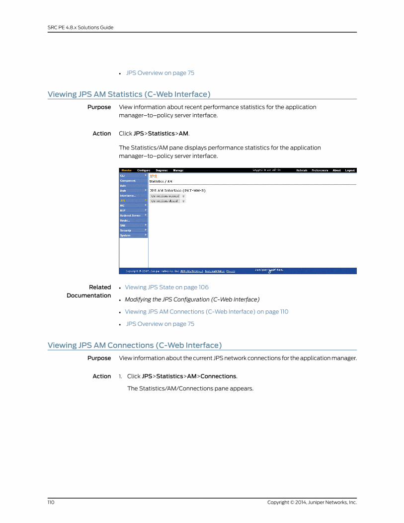
• JPS Overview on page 75
Viewing JPS AMStatistics (C-Web Interface)
Purpose View information about recent performance statistics for the application
manager–to–policy server interface.
Action Click JPS>Statistics>AM.
The Statistics/AM pane displays performance statistics for the application
manager–to–policy server interface.
RelatedDocumentation
Viewing JPS State on page 106•
• Modifying the JPS Configuration (C-Web Interface)
• Viewing JPS AM Connections (C-Web Interface) on page 110
• JPS Overview on page 75
Viewing JPS AMConnections (C-Web Interface)
Purpose View information about the current JPS network connections for the application manager.
Action Click JPS>Statistics>AM>Connections.1.
The Statistics/AM/Connections pane appears.
Copyright © 2014, Juniper Networks, Inc.110
SRC PE 4.8.x Solutions Guide
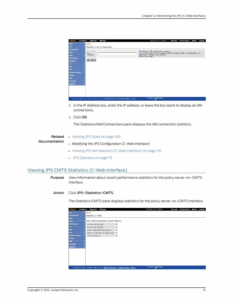
2. In the IP Address box, enter the IP address, or leave the box blank to display all AM
connections.
3. ClickOK.
The Statistics/AM/Connections pane displays the AM connection statistics.
RelatedDocumentation
Viewing JPS State on page 106•
• Modifying the JPS Configuration (C-Web Interface)
• Viewing JPS AM Statistics (C-Web Interface) on page 110
• JPS Overview on page 75
Viewing JPS CMTS Statistics (C-Web Interface)
Purpose View information about recent performance statistics for the policy server–to–CMTS
interface.
Action Click JPS>Statistics>CMTS.
The Statistics/CMTS pane displays statistics for the policy server–to–CMTS interface.
111Copyright © 2014, Juniper Networks, Inc.
Chapter 12: Monitoring the JPS (C-Web Interface)
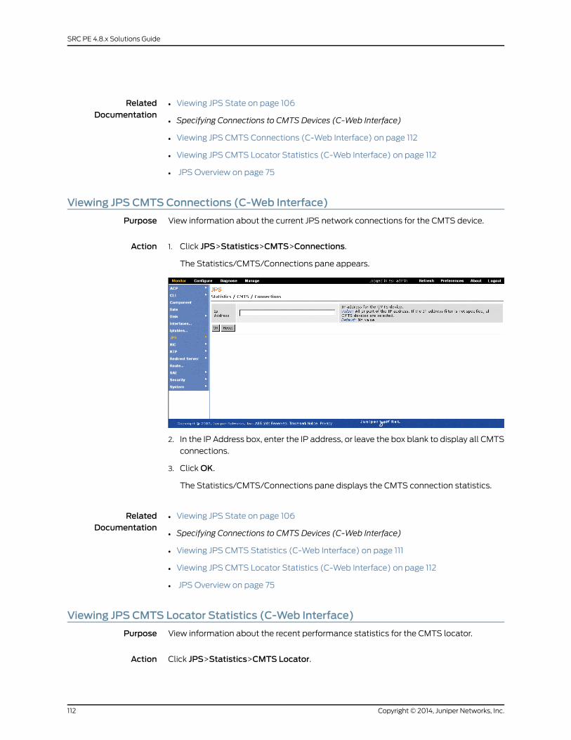
RelatedDocumentation
Viewing JPS State on page 106•
• Specifying Connections to CMTS Devices (C-Web Interface)
• Viewing JPS CMTS Connections (C-Web Interface) on page 112
• Viewing JPS CMTS Locator Statistics (C-Web Interface) on page 112
• JPS Overview on page 75
Viewing JPS CMTS Connections (C-Web Interface)
Purpose View information about the current JPS network connections for the CMTS device.
Action Click JPS>Statistics>CMTS>Connections.1.
The Statistics/CMTS/Connections pane appears.
2. In the IP Address box, enter the IP address, or leave the box blank to display all CMTS
connections.
3. ClickOK.
The Statistics/CMTS/Connections pane displays the CMTS connection statistics.
RelatedDocumentation
Viewing JPS State on page 106•
• Specifying Connections to CMTS Devices (C-Web Interface)
• Viewing JPS CMTS Statistics (C-Web Interface) on page 111
• Viewing JPS CMTS Locator Statistics (C-Web Interface) on page 112
• JPS Overview on page 75
Viewing JPS CMTS Locator Statistics (C-Web Interface)
Purpose View information about the recent performance statistics for the CMTS locator.
Action Click JPS>Statistics>CMTS Locator.
Copyright © 2014, Juniper Networks, Inc.112
SRC PE 4.8.x Solutions Guide
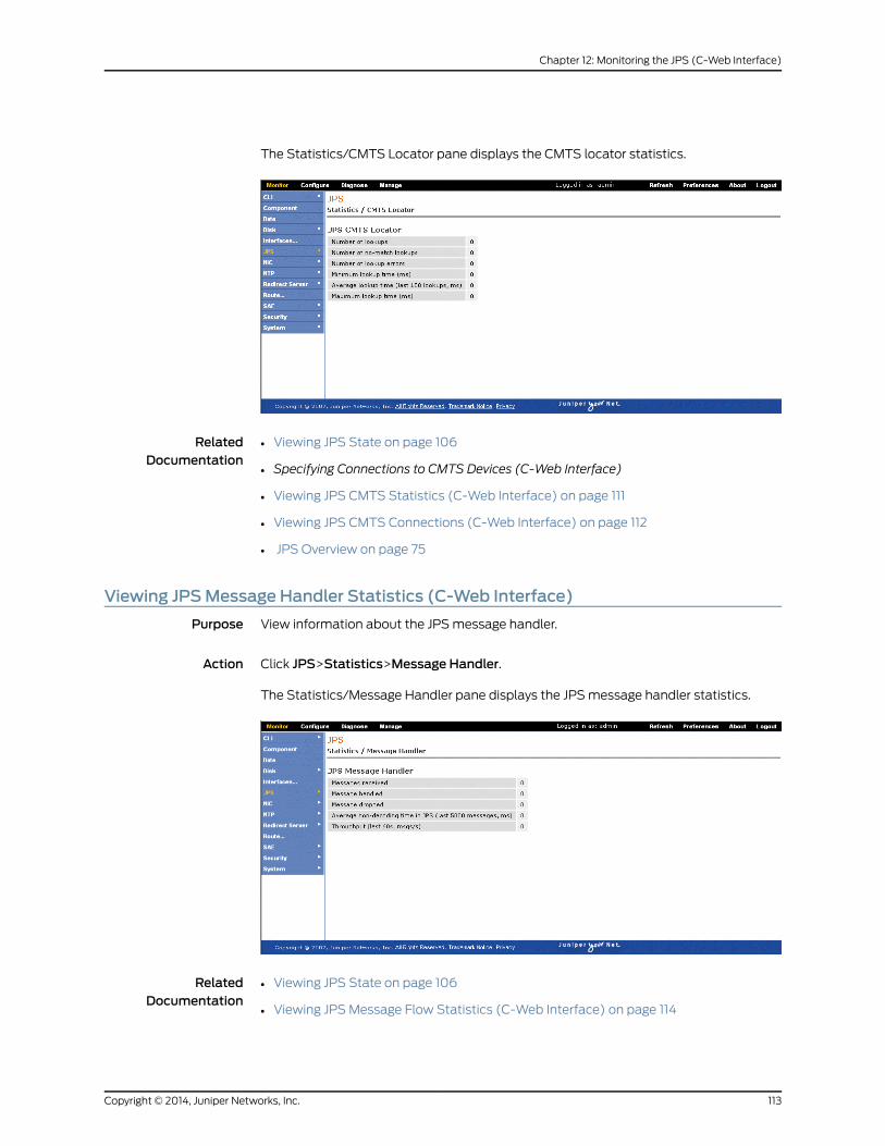
The Statistics/CMTS Locator pane displays the CMTS locator statistics.
RelatedDocumentation
Viewing JPS State on page 106•
• Specifying Connections to CMTS Devices (C-Web Interface)
• Viewing JPS CMTS Statistics (C-Web Interface) on page 111
• Viewing JPS CMTS Connections (C-Web Interface) on page 112
• JPS Overview on page 75
Viewing JPSMessage Handler Statistics (C-Web Interface)
Purpose View information about the JPS message handler.
Action Click JPS>Statistics>Message Handler.
The Statistics/Message Handler pane displays the JPS message handler statistics.
RelatedDocumentation
Viewing JPS State on page 106•
• Viewing JPS Message Flow Statistics (C-Web Interface) on page 114
113Copyright © 2014, Juniper Networks, Inc.
Chapter 12: Monitoring the JPS (C-Web Interface)
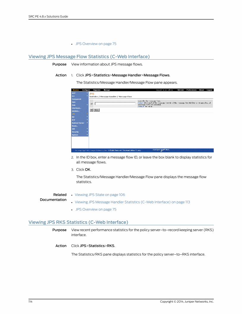
• JPS Overview on page 75
Viewing JPSMessage Flow Statistics (C-Web Interface)
Purpose View information about JPS message flows.
Action Click JPS>Statistics>Message Handler>Message Flows.1.
The Statistics/Message Handler/Message Flow pane appears.
2. In the ID box, enter a message flow ID, or leave the box blank to display statistics for
all message flows.
3. ClickOK.
The Statistics/Message Handler/Message Flow pane displays the message flow
statistics.
RelatedDocumentation
Viewing JPS State on page 106•
• Viewing JPS Message Handler Statistics (C-Web Interface) on page 113
• JPS Overview on page 75
Viewing JPS RKS Statistics (C-Web Interface)
Purpose View recent performance statistics for the policy server–to–record keeping server (RKS)
interface.
Action Click JPS>Statistics>RKS.
The Statistics/RKS pane displays statistics for the policy server–to–RKS interface.
Copyright © 2014, Juniper Networks, Inc.114
SRC PE 4.8.x Solutions Guide
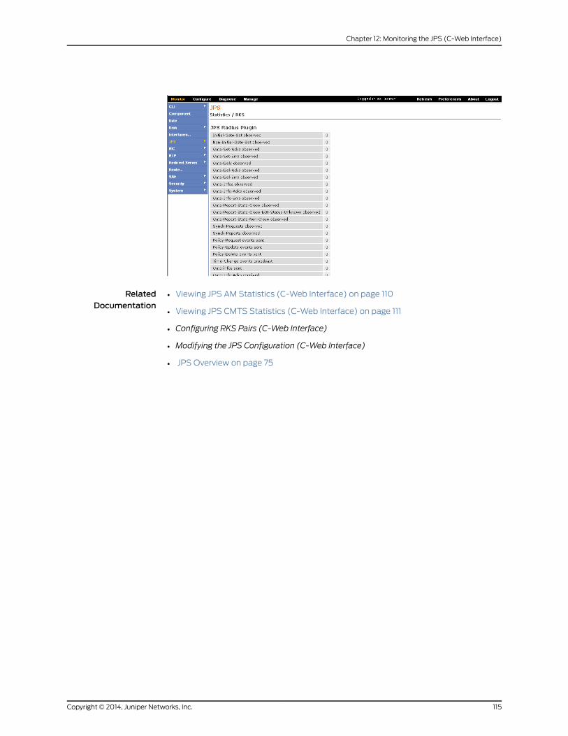
RelatedDocumentation
• Viewing JPS AM Statistics (C-Web Interface) on page 110
• Viewing JPS CMTS Statistics (C-Web Interface) on page 111
• Configuring RKS Pairs (C-Web Interface)
• Modifying the JPS Configuration (C-Web Interface)
• JPS Overview on page 75
115Copyright © 2014, Juniper Networks, Inc.
Chapter 12: Monitoring the JPS (C-Web Interface)

Copyright © 2014, Juniper Networks, Inc.116
SRC PE 4.8.x Solutions Guide

PART 3
Managing Services on RADIUS andDiameter Devices
• Managing Services on Third-Party Devices in the SRC Network on page 119
• Managing the SRC Diameter Server on page 127
• Monitoring the SRC Diameter Server (SRC CLI) on page 135
• Managing Services with Diameter on MX Series Routers on page 139
• Managing an MX Series Router as a Service Node on page 155
• Managing Subscriber-Level Policies on MX Series Routers on page 165
• Managing Subscriber Sessions on MX Series Routers in an SRC Network on page 205
• Configuring Services for SRC-Managed Routers on page 223
117Copyright © 2014, Juniper Networks, Inc.

Copyright © 2014, Juniper Networks, Inc.118
SRC PE 4.8.x Solutions Guide
CHAPTER 13
ManagingServicesonThird-PartyDevicesin the SRC Network
• COA Script Service Overview on page 119
• Configuring COA Script Services on page 120
• Configuring Monitoring Agent to Receive RADIUS Accounting Messages on page 120
• Creating the COA Script Service (SRC CLI) on page 121
• Configuring the COA Script Service (SRC CLI) on page 122
• Parameters for Sample COA Script Service on page 123
• Configuring Subscriptions to the COA Script Service on page 124
• Example: Using the Sample COA Script Service on page 124
• Defining RADIUS Attributes for COA Requests with the API on page 125
COA Script Service Overview
The service activation engine (SAE) can use change-of-authorization (COA) messages
to manage services for a specific subscriber session. The COA script service allows the
SAE to exchange COA messages with third-party devices that do not support Common
Open Policy Service (COPS) protocol to activate or deactivate services for specific
subscriber sessions. When the SAE activates a COA script service session, the session
sends COA messages to a RADIUS-enabled device. This method uses RADIUS attributes
and RADIUS vendor-specific attributes (VSAs) to identify a subscriber session whose
services are to be activated or deactivated.
RelatedDocumentation
Configuring COA Script Services on page 120•
• Configuring Subscriptions to the COA Script Service on page 124
• Configuring Monitoring Agent to Receive RADIUS Accounting Messages on page 120
• Parameters for Sample COA Script Service on page 123
• Example: Using the Sample COA Script Service on page 124
119Copyright © 2014, Juniper Networks, Inc.
Configuring COA Script Services
To support COA message exchange in an SRC network, configure a script service that
can be activated on a third-party device. The script service defines the parameters needed
to activate or deactivate services for a subscriber session, such as the address of the
third-party device. This script service is activated for the subscriber session whose services
are activated or deactivated. For detailed information about configuring script services,
see Customizing Service Implementations.
When you use the COA script service with third-party devices that do not notify the SAE
about subscriber events, you must set up the Monitoring Agent application to handle
RADIUS accounting request packets.
For information about configuring services on the third-party device, see the device’s
software documentation.
The tasks to set up the SRC software for COA message exchange are:
• “Configuring Monitoring Agent to Receive RADIUS Accounting Messages” on page 120
• “Creating the COA Script Service (SRC CLI)” on page 121
• “Configuring the COA Script Service (SRC CLI)” on page 122
• “Configuring Subscriptions to the COA Script Service” on page 124
The SRC software includes a sample script service that you can configure to exchange
COA messages with the third-party device. You can use the sample service definition
and customize it for your environment by modifying the service substitutions. For
information about the sample COA script service, see
“Example: Using the Sample COA Script Service” on page 124.
RelatedDocumentation
COA Script Service Overview on page 119•
• Defining RADIUS Attributes for COA Requests with the API on page 125
• Setting Up Script Services
• Parameters for Sample COA Script Service on page 123
ConfiguringMonitoring Agent to Receive RADIUS AccountingMessages
If you install the Monitoring Agent application on the same host as the RADIUS server,
you must disable the MonAgent.radius.server property.
You can configure Monitoring Agent to act as a pseudo–RADIUS server that listens for
RADIUS accounting packets sent to the RADIUS accounting port. To receive RADIUS
packets from RADIUS clients:
• Make sure there is no other RADIUS server listening on the RADIUS accounting port,
and enable the MonAgent.radius.server property.
Copyright © 2014, Juniper Networks, Inc.120
SRC PE 4.8.x Solutions Guide

• Configure the shared secret between the RADIUS server and the RADIUS client by
specifying the MonAgent.radius.secret.<IP address> property.
For information about installing and using Monitoring Agent, see the SRC Sample
Applications Guide.
RelatedDocumentation
Configuring the COA Script Service (SRC CLI) on page 122•
• Defining RADIUS Attributes for COA Requests with the API on page 125
Creating the COA Script Service (SRC CLI)
To create the script service:
1. From configuration mode, enter the service configuration. In this sample procedure,
the service is configured in the global service scope, and COAservice is the name of
the service.
user@host# edit services global service COAservice
2. Configure the type of service.
[edit services global service COAservice]user@host# set type script
3. (Optional) Specify whether the service is visible only to administrators who have
permission to see secret information.
[edit services global service COAservice]user@host# set secret
4. Configure URL as the type of script that the sample COA script service uses.
[edit services global service COAservice]user@host# set script script-type url
5. Configure net.juniper.smgt.sae.coa.CoaService as the name of the class that
implements the script service.
[edit services global service COAservice]user@host# set script class-name net.juniper.smgt.sae.coa.CoaService
6. Configure the URL of the script service or the path and filename of the service. Copy
the /lib/coa.jar file used by the script service to a location that is accessible by a URL
(such as an FTP or HTTP server). In this sample procedure, the coa.jar file was copied
to the /opt/UMC/sae/var/run directory.
[edit services global service COAservice]user@host# set file file:///opt/UMC/sae/var/run/coa.jar
7. (Optional) Verify your configuration.
121Copyright © 2014, Juniper Networks, Inc.
Chapter 13: Managing Services on Third-Party Devices in the SRC Network
[edit services global service COAservice]user@host# showtype script;status active;available;script { script-type url; class-name net.juniper.smgt.sae.coa.CoaService; file file:///opt/UMC/sae/var/run/coa.jar;}
After you create the script service, you need to configure parameters for the script service.
For more information about configuring script services and parameters, see SRC Script
Services Overview.
RelatedDocumentation
COA Script Service Overview on page 119•
• Configuring Subscriptions to the COA Script Service on page 124
• Configuring COA Script Services on page 120
• Configuring the COA Script Service (SRC CLI) on page 122
• Parameters for Sample COA Script Service on page 123
Configuring the COA Script Service (SRC CLI)
To configure the script service, you provide parameter substitutions with the values that
are in the service definitions.
To configure parameters:
1. From configuration mode, enter the service parameter configuration. In this sample
procedure, the service called COAservice is configured in the global service scope.
user@host# edit services global service COAservice parameter
2. (Optional) Configure actual values for other parameters.
[edit services global service COAservice parameter]user@host# set substitution [ substitution... ]
The script file / SDK/scriptServices/coa/ldif/BOD1M.ldif in the
SDK+AppSupport+Demos+Samples.tar.gz file provides parameters specified by the
sample COA script service. You can use the sample script service as a starting point.
See “Parameters for Sample COA Script Service” on page 123.
RelatedDocumentation
COA Script Service Overview on page 119•
• Configuring Subscriptions to the COA Script Service on page 124
• Creating the COA Script Service (SRC CLI) on page 121
• Configuring COA Script Services on page 120
• Example: Using the Sample COA Script Service on page 124
Copyright © 2014, Juniper Networks, Inc.122
SRC PE 4.8.x Solutions Guide

Parameters for Sample COA Script Service
Table 7 on page 123 lists the parameters specified by the sample COA script service, which
is the /SDK/scriptServices/coa/ldif/BOD1M.ldif file in the
SDK+AppSupport+Demos+Samples.tar.gz file. You can use the sample script service as
a starting point.
Table 7: Parameter Substitutions for COA Services
DescriptionParameter Name
IP address of the third-party device.dynClientIp
UDP port number of the third-party device.dynClientPort
IP address of the C Series Controller.dynServerIp
UDP port number of the C Series Controller.dynServerPort
Shared secret between RADIUS server and RADIUS client.dynSecret
Number of retries for sending COA messages when no RADIUSresponse is received. The retry interval is 3 seconds.
dynRetry
Content of service definition in the format<action>. <radiusAttributeName>=<pluginEventAttribute>\n
• action—Action that is executed on packet content (attribute):
• start
• stop
• start-stop
• radiusAttributeName—Valid RADIUS attribute specified as follows:
• Standard RADIUS attribute name or number
• Third-party VSA in the formatvendor-specific.<vendor#>.<vsa#>.string
• pluginEventAttribute—Valid expression in the format:
• Python expression
• <commandCode><serviceName>; the entire expression mustbe enclosed in single quotation marks and you must use threebackslashes (\\\) to escape the backslash that starts a<commandCode>For example: \x0b would be replaced by \\\\x0b
• \n—New-line character included between the lines of a configurationcontaining multiple lines; the entire configuration must be enclosedin quotation marks.
For example:
start-stop.Acct-Session-Id = ifSessionId
“ start-stop.Acct-Session-Id=ifSessionId\nstart.vendor-specific.9.252.string=’\\\\x0bBOD1M’\nstop.vendor-specific.9.252.string=’\\\\x0cBOD1M’\n"
dynConfig
123Copyright © 2014, Juniper Networks, Inc.
Chapter 13: Managing Services on Third-Party Devices in the SRC Network
You can also configure dynamic RADIUS requests with the sendDynamicRadius method
of the ServiceSessionInfo interface (see “Defining RADIUS Attributes for COA Requests
with the API” on page 125).
RelatedDocumentation
COA Script Service Overview on page 119•
• Configuring Monitoring Agent to Receive RADIUS Accounting Messages on page 120
• Creating the COA Script Service (SRC CLI) on page 121
• Configuring COA Script Services on page 120
• Example: Using the Sample COA Script Service on page 124
Configuring Subscriptions to the COA Script Service
You need to configure subscriptions to the COA script service. You can set up the
subscriptions to activate immediately on login.
For more information, see Adding Subscribers (SRC CLI).
RelatedDocumentation
COA Script Service Overview on page 119•
• Configuring COA Script Services on page 120
• Configuring the COA Script Service (SRC CLI) on page 122
• Example: Using the Sample COA Script Service on page 124
Example: Using the Sample COA Script Service
To use the sample COA script service provided:
1. Import the sample script service using an LDAP browser.
The /SDK/scriptServices/coa/ldif/BOD1M.ldif file (in the
SDK+AppSupport+Demos+Samples.tar.gz file) is the sample service definition for
exchanging COA messages with a Cisco 10000 Series router.
2. Copy the /lib/coa.jar file used by the script service to a location that is accessible to
the SAE by a URL, such as an FTP or HTTP server. If you do not have multiple SAEs,
it can be convenient to copy the file to the /var/run directory in the SAE installation
directory (/opt/UMC/sae by default).
3. Modify the service substitutions for your device.
You can make these substitutions by defining the parameter substitutions in the
BOD1M service with the SRC CLI or by passing the values through the SAE core API.
For information about parameter substitutions, see “Configuring the COA Script Service
(SRC CLI)” on page 122. For information about passing the values through the SAE
core API, see “Defining RADIUS Attributes for COA Requests with the API” on page 125.
4. Configure a subscription to the BOD1M service that is activated on login.
Copyright © 2014, Juniper Networks, Inc.124
SRC PE 4.8.x Solutions Guide
For more information about subscriptions, see Subscriptions Overview.
If you are modifying the sample application, add the sae.jarand logger.jar files to the class
path when you compile your application. These two files can be found in the lib directory
of the SAE installation directory.
RelatedDocumentation
COA Script Service Overview on page 119•
• Configuring Subscriptions to the COA Script Service on page 124
• Configuring COA Script Services on page 120
• Creating the COA Script Service (SRC CLI) on page 121
Defining RADIUS Attributes for COA Requests with the API
The SRC software provides two ways to define RADIUS attributes for dynamic RADIUS
authorization requests:
• Service definition (see “Configuring the COA Script Service (SRC CLI)” on page 122)
• SAE core API
NOTE: Parameters set in the API override parameters set by the servicedefinition.
To send dynamic RADIUS authorization requests with the SAE core API, the script service
uses the sendDynamicRadius and getRouterDynRadiusAddr methods in the
ServiceSessionInfo interface to provide the content of the RADIUS packet for the dynamic
authorization request to the router that is attached to the service session.
For information about the ServiceSessionInfo interface, see the script service
documentation in the SAE core API documentation on the Juniper Networks Web site at
http://www.juniper.net/techpubs/software/management/src/api-index.html.
For a sample implementation, see the following file in the
SDK+AppSupport+Demos+Samples.tar.gzfile:
SDK/scriptServices/coa/java/net/juniper/smgt/scriptServices/coa/CoaService.java.
RelatedDocumentation
• COA Script Service Overview on page 119
• Configuring COA Script Services on page 120
• Creating the COA Script Service (SRC CLI) on page 121
• Configuring Monitoring Agent to Receive RADIUS Accounting Messages on page 120
125Copyright © 2014, Juniper Networks, Inc.
Chapter 13: Managing Services on Third-Party Devices in the SRC Network

Copyright © 2014, Juniper Networks, Inc.126
SRC PE 4.8.x Solutions Guide
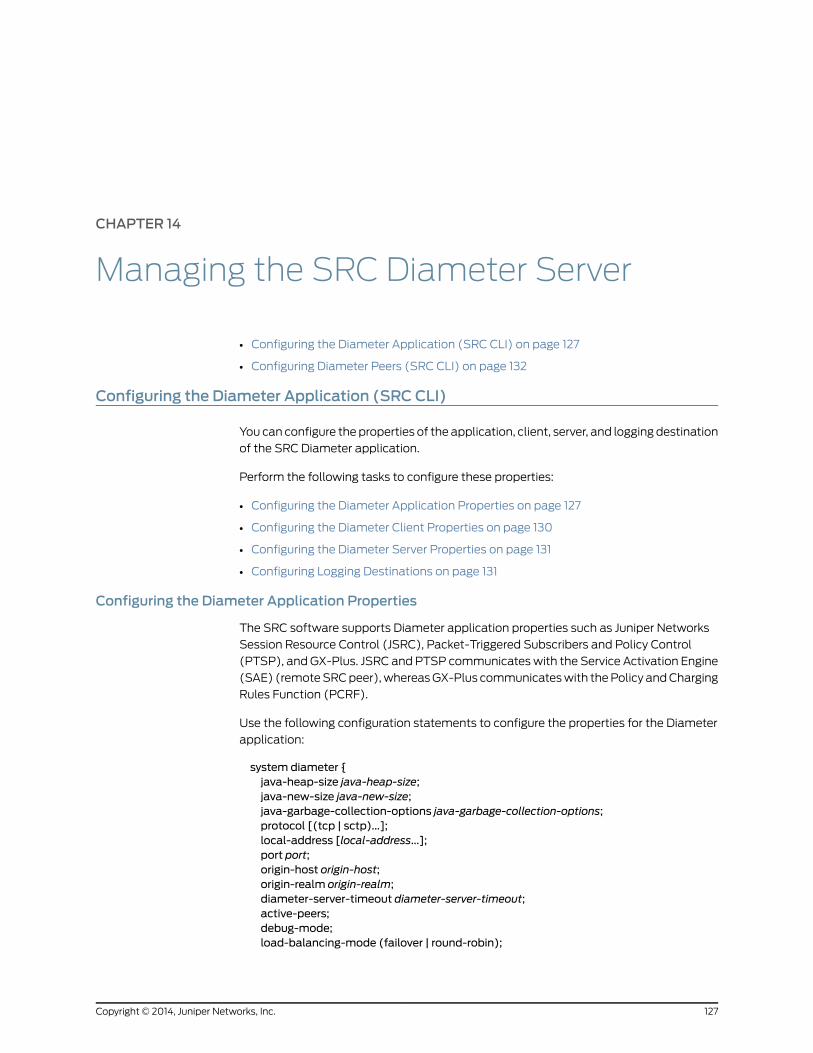
CHAPTER 14
Managing the SRC Diameter Server
• Configuring the Diameter Application (SRC CLI) on page 127
• Configuring Diameter Peers (SRC CLI) on page 132
Configuring the Diameter Application (SRC CLI)
You can configure the properties of the application, client, server, and logging destination
of the SRC Diameter application.
Perform the following tasks to configure these properties:
• Configuring the Diameter Application Properties on page 127
• Configuring the Diameter Client Properties on page 130
• Configuring the Diameter Server Properties on page 131
• Configuring Logging Destinations on page 131
Configuring the Diameter Application Properties
The SRC software supports Diameter application properties such as Juniper Networks
Session Resource Control (JSRC), Packet-Triggered Subscribers and Policy Control
(PTSP), and GX-Plus. JSRC and PTSP communicates with the Service Activation Engine
(SAE) (remote SRC peer), whereas GX-Plus communicates with the Policy and Charging
Rules Function (PCRF).
Use the following configuration statements to configure the properties for the Diameter
application:
system diameter {java-heap-size java-heap-size;java-new-size java-new-size;java-garbage-collection-options java-garbage-collection-options;protocol [(tcp | sctp)...];local-address [local-address...];port port;origin-host origin-host;origin-realm origin-realm;diameter-server-timeout diameter-server-timeout;active-peers;debug-mode;load-balancing-mode (failover | round-robin);
127Copyright © 2014, Juniper Networks, Inc.
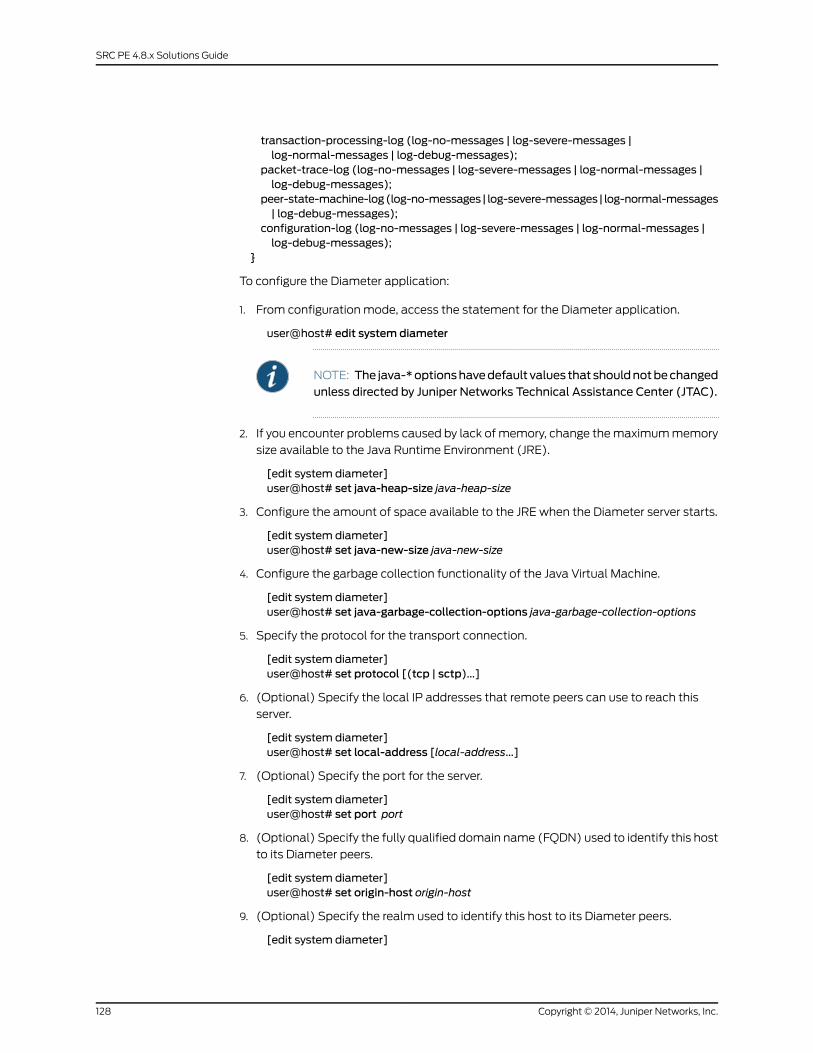
transaction-processing-log (log-no-messages | log-severe-messages |log-normal-messages | log-debug-messages);
packet-trace-log (log-no-messages | log-severe-messages | log-normal-messages |log-debug-messages);
peer-state-machine-log(log-no-messages| log-severe-messages| log-normal-messages| log-debug-messages);
configuration-log (log-no-messages | log-severe-messages | log-normal-messages |log-debug-messages);
}
To configure the Diameter application:
1. From configuration mode, access the statement for the Diameter application.
user@host# edit system diameter
NOTE: The java-*optionshavedefault values that shouldnotbechangedunless directed by Juniper Networks Technical Assistance Center (JTAC).
2. If you encounter problems caused by lack of memory, change the maximum memory
size available to the Java Runtime Environment (JRE).
[edit system diameter]user@host# set java-heap-size java-heap-size
3. Configure the amount of space available to the JRE when the Diameter server starts.
[edit system diameter]user@host# set java-new-size java-new-size
4. Configure the garbage collection functionality of the Java Virtual Machine.
[edit system diameter]user@host# set java-garbage-collection-options java-garbage-collection-options
5. Specify the protocol for the transport connection.
[edit system diameter]user@host# set protocol [(tcp | sctp)...]
6. (Optional) Specify the local IP addresses that remote peers can use to reach this
server.
[edit system diameter]user@host# set local-address [local-address...]
7. (Optional) Specify the port for the server.
[edit system diameter]user@host# set port port
8. (Optional) Specify the fully qualified domain name (FQDN) used to identify this host
to its Diameter peers.
[edit system diameter]user@host# set origin-host origin-host
9. (Optional) Specify the realm used to identify this host to its Diameter peers.
[edit system diameter]
Copyright © 2014, Juniper Networks, Inc.128
SRC PE 4.8.x Solutions Guide

user@host# set origin-realm origin-realm
The Diameter realm should be configured to the domain name of the origin host. For
example, if the FQDN of the host is host.juniper.net, then the realm should be
juniper.net. For PTSP, realm-based Diameter routing is not used.
10. (Optional) Configure the timeout value until which the Diameter server holds
unsolicited requests such as Point to Point Protocol (PPP) and Abort Session Request
(ASR), and waits for a matching response such as Push Profile Answer (PPA) and
Abort Session Answer (ASA). The server discards the responses received after the
specified time. The value range is 1–65,565 seconds. The preferred value is 10–30
seconds. By default, the value is set to 25 seconds.
[edit system diameter]user@host# set diameter-server-timeout diameter-server-timeout
NOTE: diameter-server-timeoutand reply-timeoutunder the [editsharedsae group configuration driver] hierarchy should be configured with thesame value.
11. (Optional) Specify whether the peer connection is in active mode.
[edit system diameter]user@host# set active-peers
NOTE:• Activemodemeans that the SRC software actively tries to connect tothepeer.Makesure thepeer youareconnecting tosupportsactivepeers.The MX Series router does not support active peers. The SRC softwarecan still be configured, but the connection attempts will not work.
• If the peer connection is configured to be in activemode, youmustconfigure the remote peer address for all Diameter peers by using theaddress option under the [edit shared network diameter peer name]hierarchy.
12. (Optional) Specify whether the peer connection is in debug mode.
[edit system diameter]user@host# set debug-mode
13. (Optional) Configure the load-balancing mode for peer selection when forwarding a
request message.
[edit system diameter]user@host# set load-balancing-mode (failover | round-robin)
14. (Optional) Configure the log level for the transaction processing log.
[edit system diameter]user@host# set transaction-processing-log log-level
129Copyright © 2014, Juniper Networks, Inc.
Chapter 14: Managing the SRC Diameter Server
where log-level is one of the following:
• log-no-messages—Do not log any messages.
• log-severe-messages—Log only severe messages.
• log-normal-messages—Log only normal messages.
• log-debug-messages—Log only debug messages.
15. (Optional) Configure the log level for the packet tracing log.
[edit system diameter]user@host# set packet-trace-log log-level
where log-level is one of the following:
• log-no-messages—Do not log any messages.
• log-severe-messages—Log only severe messages.
• log-normal-messages—Log only normal messages.
• log-debug-messages—Log only debug messages.
16. (Optional) Configure the log level for the peer state machine log.
[edit system diameter]user@host# set peer-state-machine-log log-level
where log-level is one of the following:
• log-no-messages—Do not log any messages.
• log-severe-messages—Log only severe messages.
• log-normal-messages—Log only normal messages.
• log-debug-messages—Log only debug messages.
17. (Optional) Configure the log level for the configuration log.
[edit system diameter]user@host# set configuration-log log-level
where log-level is one of the following:
• log-no-messages—Do not log any messages.
• log-severe-messages—Log only severe messages.
• log-normal-messages—Log only normal messages.
• log-debug-messages—Log only debug messages.
Configuring the Diameter Client Properties
This procedure configures the client-side adapter of the SRC Diameter server, which
handles client connections. Configuration should be necessary only if you encounter
performance problems.
Use the following statements to configure the properties for the Diameter client:
Copyright © 2014, Juniper Networks, Inc.130
SRC PE 4.8.x Solutions Guide
system diameter client {threads threads;keep-alive-time keep-alive-time;
}
To configure the Diameter client properties:
1. From configuration mode, access the statement for the Diameter client.
user@host# edit system diameter client
2. (Optional) Specify the number of threads to use.
[edit system diameter client]user@host# set threads threads
3. (Optional) Specify the time to wait for new commands.
[edit system diameter client]user@host# set keep-alive-time keep-alive-time
Configuring the Diameter Server Properties
Use the following statements to configure the properties for the Diameter server:
system diameter server {threads threads;keep-alive-time keep-alive-time;
}
To configure the Diameter server properties:
1. From configuration mode, access the statement for the Diameter server.
user@host# edit system diameter server
2. (Optional) Specify the minimum number of threads to use.
[edit system diameter server]user@host# set threads threads
3. (Optional) Specify the time to wait for new commands.
[edit system diameter server]user@host# set keep-alive-time keep-alive-time
Configuring Logging Destinations
Use the following configuration statements to configure logging destinations for Diameter:
system diameter logger name ...
system diameter logger name file {filter filter;filename filename;
131Copyright © 2014, Juniper Networks, Inc.
Chapter 14: Managing the SRC Diameter Server
rollover-filename rollover-filename;maximum-file-sizemaximum-file-size;
}
To configure logging destinations to store log messages in a file:
1. From configuration mode, access the statement that configures the name and type
of logging destination.
user@host# edit system diameter logger name file
2. Specify the properties for the logging destination.
[edit system diameter logger name file]user@host# set ?
For more information about configuring properties for the logging destination, see
Configuring Logging Destinations to Store Messages in a File (SRC CLI).
RelatedDocumentation
SRC CLI Commands to Monitor the SRC Diameter Server on page 135•
• To manage services for JSRC peers on MX Series routers, see Managing Services on
MX Series Routers Using the Diameter Application on page 140.
• To manage policies for PTSP peers on MX Series routers, see Configuring PTSP to
Manage Subscriber-Level Policies on page 167.
Configuring Diameter Peers (SRC CLI)
Use the following configuration statements to configure the Diameter peers:
shared network diameter peer name {protocol [(tcp | sctp)...];address [address...];enforce-source-address;local-address local-address;connect-timeout connect-timeout;watchdog-timeoutwatchdog-timeout;state-machine-timeout state-machine-timeout;reconnect-timeout reconnect-timeout;port port;origin-host origin-host;incoming-queue-limit incoming-queue-limit;active-peer;
}
Copyright © 2014, Juniper Networks, Inc.132
SRC PE 4.8.x Solutions Guide
NOTE: When you commit the Diameter peer configuration, keep inmind thefollowing conditions:
• The origin host, remote peer address, or both should be specified for theDiameter peer.
• If theenforcesourceaddress is configured for theDiameterpeer, the remotepeer address should be specified for the Diameter peer.
• If the peer connection is configured to be in activemode for the particularDiameter peer or globally for all Diameter peers by using the active-peersoptionunder the [edit systemdiameter]hierarchy, the remotepeeraddressshould be specified for the Diameter peers.
To configure the Diameter peer:
1. From configuration mode, access the statements for the peer.
user@host# edit shared network diameter peer name
The peer name must be unique.
2. Specify the protocol for the transport connection.
[edit shared network diameter peer name]user@host# set protocol [(tcp | sctp)...]
3. (Optional) Specify the addresses of the remote peer. If SCTP is the transport protocol,
you can specify multiple addresses. If TCP is the transport protocol, you can specify
only a single address.
[edit shared network diameter peer name]user@host# set address [address...]
4. (Optional) Specify whether the remote peer must connect from one of the IP addresses
listed by the address option.
[edit shared network diameter peer name]user@host# set enforce-source-address
5. (Optional) Specify the local address of the peer.
[edit shared network diameter peer name]user@host# set local-address local-address
6. (Optional) Specify the maximum amount of time allowed for the Diameter peer to
respond to a connection request.
[edit shared network diameter peer name]user@host# set connect-timeout connect-timeout
7. (Optional) Specify the watchdog timeout used for the connection to the remote peer.
[edit shared network diameter peer name]user@host# set watchdog-timeoutwatchdog-timeout
8. (Optional) Specify the Diameter state machine timeout.
[edit shared network diameter peer name]
133Copyright © 2014, Juniper Networks, Inc.
Chapter 14: Managing the SRC Diameter Server
user@host# set state-machine-timeout state-machine-timeout
9. (Optional) Specify the time interval between connection attempts when the peer is
in the disconnected state.
[edit shared network diameter peer name]user@host# set reconnect-timeout reconnect-timeout
10. (Optional) Specify the port for the client.
[edit shared network diameter peer name]user@host# set port port
11. (Optional) Specify the identifier for the endpoint that the peer presents during
connection establishment.
[edit shared network diameter peer name]user@host# set origin-host origin-host
12. (Optional) Specify the number of messages allowed on the incoming message queue
for a peer.
[edit shared network diameter peer name]user@host# set incoming-queue-limit incoming-queue-limit
13. (Optional) Specify whether the peer connection is in active mode.
[edit shared network diameter peer name]user@host# set active-peer
NOTE: Activemodemeansthat theSRCsoftwareactively tries toconnectto the peer. Make sure the peer you are connecting to supports activepeers. The MX Series router does not support active peers. The SRCsoftware can still be configured, but the connection attempts will notwork.
RelatedDocumentation
• Configuring the Diameter Application (SRC CLI) on page 127
• Viewing SRC Diameter Server State (SRC CLI) on page 137
Copyright © 2014, Juniper Networks, Inc.134
SRC PE 4.8.x Solutions Guide
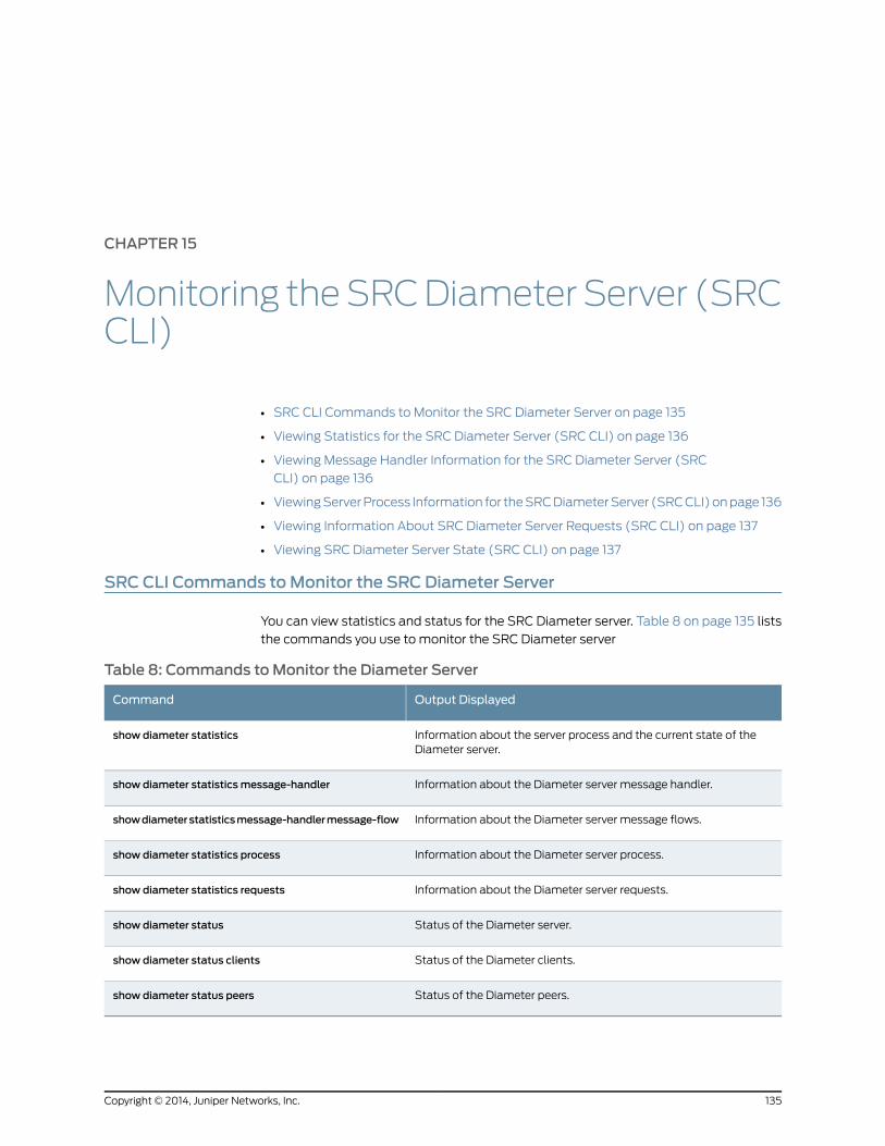
CHAPTER 15
Monitoring theSRCDiameterServer (SRCCLI)
• SRC CLI Commands to Monitor the SRC Diameter Server on page 135
• Viewing Statistics for the SRC Diameter Server (SRC CLI) on page 136
• Viewing Message Handler Information for the SRC Diameter Server (SRC
CLI) on page 136
• Viewing Server Process Information for the SRC Diameter Server (SRC CLI) on page 136
• Viewing Information About SRC Diameter Server Requests (SRC CLI) on page 137
• Viewing SRC Diameter Server State (SRC CLI) on page 137
SRC CLI Commands toMonitor the SRC Diameter Server
You can view statistics and status for the SRC Diameter server. Table 8 on page 135 lists
the commands you use to monitor the SRC Diameter server
Table 8: Commands toMonitor the Diameter Server
Output DisplayedCommand
Information about the server process and the current state of theDiameter server.
show diameter statistics
Information about the Diameter server message handler.show diameter statisticsmessage-handler
Information about the Diameter server message flows.showdiameterstatisticsmessage-handlermessage-flow
Information about the Diameter server process.show diameter statistics process
Information about the Diameter server requests.show diameter statistics requests
Status of the Diameter server.show diameter status
Status of the Diameter clients.show diameter status clients
Status of the Diameter peers.show diameter status peers
135Copyright © 2014, Juniper Networks, Inc.
RelatedDocumentation
Configuring the Diameter Application (SRC CLI) on page 127•
• Viewing Statistics for the SRC Diameter Server (SRC CLI) on page 136
• Viewing Message Handler Information for the SRC Diameter Server (SRC CLI) on
page 136
• Viewing Server Process Information for the SRC Diameter Server (SRC CLI) on page 136
• Viewing Information About SRC Diameter Server Requests (SRC CLI) on page 137
• Viewing SRC Diameter Server State (SRC CLI) on page 137
Viewing Statistics for the SRC Diameter Server (SRC CLI)
Purpose View information about the server process and the state of the Diameter server.
Action To display information about the server process and the state of the Diameter server:
user@host> show diameter statistics
RelatedDocumentation
Configuring the Diameter Application (SRC CLI) on page 127•
• SRC CLI Commands to Monitor the SRC Diameter Server on page 135
ViewingMessage Handler Information for the SRC Diameter Server (SRC CLI)
Purpose View information about the message handler and message flows for the Diameter server.
Action To display information about the message handler for the Diameter server:
user@host> show diameter statisticsmessage-handler
To display information about message flows for the Diameter server:
user@host> show diameter statisticsmessage-handler message-flow
To display information about a specific message flow:
user@host> show diameter statisticsmessage-handler message-flow id id
RelatedDocumentation
Configuring the Diameter Application (SRC CLI) on page 127•
• SRC CLI Commands to Monitor the SRC Diameter Server on page 135
Viewing Server Process Information for the SRC Diameter Server (SRC CLI)
Purpose View information about the server process.
Action To display about the server process:
user@host> show diameter statistics process
Copyright © 2014, Juniper Networks, Inc.136
SRC PE 4.8.x Solutions Guide
RelatedDocumentation
Configuring the Diameter Application (SRC CLI) on page 127•
• SRC CLI Commands to Monitor the SRC Diameter Server on page 135
Viewing Information About SRC Diameter Server Requests (SRC CLI)
Purpose View information about Diameter server requests.
Action To display information about Diameter server requests:
user@host> show diameter statistics requests
RelatedDocumentation
Configuring the Diameter Application (SRC CLI) on page 127•
• SRC CLI Commands to Monitor the SRC Diameter Server on page 135
Viewing SRC Diameter Server State (SRC CLI)
Purpose View status information about the Diameter server.
Action To display information about the status of the Diameter server:
user@host> show diameter status
To display information about the Diameter clients:
user@host> show diameter status clients
To display information about a specific client:
user@host> show diameter status clients client-name client-name
To display information about the Diameter peers:
user@host> show diameter status peers
To display information about a specific peer:
user@host> show diameter status peers peer-name peer-name
RelatedDocumentation
• Configuring the Diameter Application (SRC CLI) on page 127
• Configuring Diameter Peers (SRC CLI) on page 132
• SRC CLI Commands to Monitor the SRC Diameter Server on page 135
137Copyright © 2014, Juniper Networks, Inc.
Chapter 15: Monitoring the SRC Diameter Server (SRC CLI)

Copyright © 2014, Juniper Networks, Inc.138
SRC PE 4.8.x Solutions Guide
CHAPTER 16
Managing Services with Diameter on MXSeries Routers
• SRC Peer Support on MX Series Routers Overview on page 139
• Managing Services on MX Series Routers Using the Diameter Application on page 140
• Configuring JSRC on the MX Series Router on page 141
• Configuring the Diameter Application (SRC CLI) on page 141
• Adding Network Devices (SRC CLI) on page 146
• Configuring Diameter Peers (SRC CLI) on page 147
• Configuring the SAE to Manage Network Devices (SRC CLI) on page 149
• Configuring JSRC Policies (SRC CLI) on page 151
SRC Peer Support onMX Series Routers Overview
When the Juniper Networks routing platform supports the use of the Diameter protocol
to provide extended authentication, authorization, and accounting (AAA) functionality,
the SRC software can dynamically manage services on these devices. The SRC software
uses the Diameter protocol for communications between the local SRC peer on a Juniper
Networks routing platform, such as the Juniper Networks MX Series Ethernet Services
Router, and the service activation engine (SAE). The local SRC peer is known as Junos
OS (JSRC) and is part of the AAA application.
JSRC has the following responsibilities:
• Request address authorization from the SAE.
• Request service activations from the SAE.
• Activate and deactivate services as specified by the SAE.
• Log out subscribers as specified by the SAE.
• Update the SAE with status of new service activations and deactivations.
• Synchronize subscriber state and service information with the SAE.
• Notify the SAE when subscribers log out.
139Copyright © 2014, Juniper Networks, Inc.
The SRC software enables the SAE to activate and deactivate subscriber services and
log out subscribers. The SAE can control only those resources that have been provisioned
through the SAE. Therefore, the SAE receives information about only those subscribers
for whom JSRC has requested provisioning from the SAE. Similarly, the SAE can control
only the subscriber services that it has activated.
RelatedDocumentation
Managing Services on MX Series Routers Using the Diameter Application on page 140•
• Configuring JSRC on the MX Series Router on page 141
• Configuring the SAE to Manage Network Devices (SRC CLI) on page 149
• Configuring Diameter Peers (SRC CLI) on page 132
Managing Services onMX Series Routers Using the Diameter Application
You can use the SRC software to manage services on Juniper Networks routing platforms
using the Diameter protocol. The SRC software communicates with the local SRC peer
on the device using Diameter messages to dynamically manage services for a subscriber
session.
The SRC software includes a Diameter server that forwards AAR, ACR, SRQ, and STR
messages from JSRC to the device driver in the SAE and that forwards PPR and ASR
messages from the device driver to JSRC. These Diameter messages perform these
functions:
• AA-Request (AAR)—Attach subscriber to access network
• Accounting-Request (ACR)—Provide accounting information
• Abort-Session-Request (ASR)—Disconnect subscriber
• Push-Profile-Request (PPR)—Start, modify, or stop service session
• Session-Resource-Query (SRQ)—Initiate synchronization
• Session-Termination-Request (STR)—Detach subscriber from access network
You configure the Diameter peers and a device for each device managed by the SAE. The
Diameter server searches all devices of type junos-ise for virtual routers that include the
local host in their SAE connections. For these devices, the Diameter server establishes a
connection with the peers referenced in the device configuration.
Tasks to set up the management of services on devices using Diameter protocol:
• Configuring JSRC on the MX Series Router on page 141
• Configuring the Diameter Application (SRC CLI) on page 127
• Adding Network Devices (SRC CLI) on page 146
• Configuring Diameter Peers (SRC CLI) on page 132
• Configuring the SAE to Manage Network Devices (SRC CLI) on page 149
• Configuring JSRC Policies (SRC CLI) on page 151
Copyright © 2014, Juniper Networks, Inc.140
SRC PE 4.8.x Solutions Guide
Configuring JSRC on theMX Series Router
Tasks to set up JSRC on the Juniper Networks routing platform are:
1. Configure the Diameter instance.
See “Configuring the Diameter Application (SRC CLI)” on page 127.
2. Set up the MX Series router so that it can be managed by the SAE.
See “Adding Network Devices (SRC CLI)” on page 146
3. Configure the Diameter peer.
See “Configuring Diameter Peers (SRC CLI)” on page 132.
4. Configure the SAE to manage the MX Series router.
See “Configuring the SAE to Manage Network Devices (SRC CLI)” on page 149.
5. Configure JSRC policies.
See “Configuring JSRC Policies (SRC CLI)” on page 151.
For more information about JSRC and subscriber access, see the Junos OS Broadband
Subscriber Management and Services Library.
Configuring the Diameter Application (SRC CLI)
You can configure the properties of the application, client, server, and logging destination
of the SRC Diameter application.
Perform the following tasks to configure these properties:
• Configuring the Diameter Application Properties on page 141
• Configuring the Diameter Client Properties on page 145
• Configuring the Diameter Server Properties on page 145
• Configuring Logging Destinations on page 146
Configuring the Diameter Application Properties
The SRC software supports Diameter application properties such as Juniper Networks
Session Resource Control (JSRC), Packet-Triggered Subscribers and Policy Control
(PTSP), and GX-Plus. JSRC and PTSP communicates with the Service Activation Engine
(SAE) (remote SRC peer), whereas GX-Plus communicates with the Policy and Charging
Rules Function (PCRF).
Use the following configuration statements to configure the properties for the Diameter
application:
system diameter {java-heap-size java-heap-size;java-new-size java-new-size;java-garbage-collection-options java-garbage-collection-options;protocol [(tcp | sctp)...];
141Copyright © 2014, Juniper Networks, Inc.
Chapter 16: Managing Services with Diameter on MX Series Routers
local-address [local-address...];port port;origin-host origin-host;origin-realm origin-realm;diameter-server-timeout diameter-server-timeout;active-peers;debug-mode;load-balancing-mode (failover | round-robin);transaction-processing-log (log-no-messages | log-severe-messages |log-normal-messages | log-debug-messages);
packet-trace-log (log-no-messages | log-severe-messages | log-normal-messages |log-debug-messages);
peer-state-machine-log(log-no-messages| log-severe-messages| log-normal-messages| log-debug-messages);
configuration-log (log-no-messages | log-severe-messages | log-normal-messages |log-debug-messages);
}
To configure the Diameter application:
1. From configuration mode, access the statement for the Diameter application.
user@host# edit system diameter
NOTE: The java-*optionshavedefault values that shouldnotbechangedunless directed by Juniper Networks Technical Assistance Center (JTAC).
2. If you encounter problems caused by lack of memory, change the maximum memory
size available to the Java Runtime Environment (JRE).
[edit system diameter]user@host# set java-heap-size java-heap-size
3. Configure the amount of space available to the JRE when the Diameter server starts.
[edit system diameter]user@host# set java-new-size java-new-size
4. Configure the garbage collection functionality of the Java Virtual Machine.
[edit system diameter]user@host# set java-garbage-collection-options java-garbage-collection-options
5. Specify the protocol for the transport connection.
[edit system diameter]user@host# set protocol [(tcp | sctp)...]
6. (Optional) Specify the local IP addresses that remote peers can use to reach this
server.
[edit system diameter]user@host# set local-address [local-address...]
7. (Optional) Specify the port for the server.
[edit system diameter]user@host# set port port
Copyright © 2014, Juniper Networks, Inc.142
SRC PE 4.8.x Solutions Guide

8. (Optional) Specify the fully qualified domain name (FQDN) used to identify this host
to its Diameter peers.
[edit system diameter]user@host# set origin-host origin-host
9. (Optional) Specify the realm used to identify this host to its Diameter peers.
[edit system diameter]user@host# set origin-realm origin-realm
The Diameter realm should be configured to the domain name of the origin host. For
example, if the FQDN of the host is host.juniper.net, then the realm should be
juniper.net. For PTSP, realm-based Diameter routing is not used.
10. (Optional) Configure the timeout value until which the Diameter server holds
unsolicited requests such as Point to Point Protocol (PPP) and Abort Session Request
(ASR), and waits for a matching response such as Push Profile Answer (PPA) and
Abort Session Answer (ASA). The server discards the responses received after the
specified time. The value range is 1–65,565 seconds. The preferred value is 10–30
seconds. By default, the value is set to 25 seconds.
[edit system diameter]user@host# set diameter-server-timeout diameter-server-timeout
NOTE: diameter-server-timeoutand reply-timeoutunder the [editsharedsae group configuration driver] hierarchy should be configured with thesame value.
11. (Optional) Specify whether the peer connection is in active mode.
[edit system diameter]user@host# set active-peers
NOTE:• Activemodemeans that the SRC software actively tries to connect tothepeer.Makesure thepeer youareconnecting tosupportsactivepeers.The MX Series router does not support active peers. The SRC softwarecan still be configured, but the connection attempts will not work.
• If the peer connection is configured to be in activemode, youmustconfigure the remote peer address for all Diameter peers by using theaddress option under the [edit shared network diameter peer name]hierarchy.
12. (Optional) Specify whether the peer connection is in debug mode.
[edit system diameter]user@host# set debug-mode
13. (Optional) Configure the load-balancing mode for peer selection when forwarding a
request message.
[edit system diameter]
143Copyright © 2014, Juniper Networks, Inc.
Chapter 16: Managing Services with Diameter on MX Series Routers
user@host# set load-balancing-mode (failover | round-robin)
14. (Optional) Configure the log level for the transaction processing log.
[edit system diameter]user@host# set transaction-processing-log log-level
where log-level is one of the following:
• log-no-messages—Do not log any messages.
• log-severe-messages—Log only severe messages.
• log-normal-messages—Log only normal messages.
• log-debug-messages—Log only debug messages.
15. (Optional) Configure the log level for the packet tracing log.
[edit system diameter]user@host# set packet-trace-log log-level
where log-level is one of the following:
• log-no-messages—Do not log any messages.
• log-severe-messages—Log only severe messages.
• log-normal-messages—Log only normal messages.
• log-debug-messages—Log only debug messages.
16. (Optional) Configure the log level for the peer state machine log.
[edit system diameter]user@host# set peer-state-machine-log log-level
where log-level is one of the following:
• log-no-messages—Do not log any messages.
• log-severe-messages—Log only severe messages.
• log-normal-messages—Log only normal messages.
• log-debug-messages—Log only debug messages.
17. (Optional) Configure the log level for the configuration log.
[edit system diameter]user@host# set configuration-log log-level
where log-level is one of the following:
• log-no-messages—Do not log any messages.
• log-severe-messages—Log only severe messages.
• log-normal-messages—Log only normal messages.
• log-debug-messages—Log only debug messages.
Copyright © 2014, Juniper Networks, Inc.144
SRC PE 4.8.x Solutions Guide

Configuring the Diameter Client Properties
This procedure configures the client-side adapter of the SRC Diameter server, which
handles client connections. Configuration should be necessary only if you encounter
performance problems.
Use the following statements to configure the properties for the Diameter client:
system diameter client {threads threads;keep-alive-time keep-alive-time;
}
To configure the Diameter client properties:
1. From configuration mode, access the statement for the Diameter client.
user@host# edit system diameter client
2. (Optional) Specify the number of threads to use.
[edit system diameter client]user@host# set threads threads
3. (Optional) Specify the time to wait for new commands.
[edit system diameter client]user@host# set keep-alive-time keep-alive-time
Configuring the Diameter Server Properties
Use the following statements to configure the properties for the Diameter server:
system diameter server {threads threads;keep-alive-time keep-alive-time;
}
To configure the Diameter server properties:
1. From configuration mode, access the statement for the Diameter server.
user@host# edit system diameter server
2. (Optional) Specify the minimum number of threads to use.
[edit system diameter server]user@host# set threads threads
3. (Optional) Specify the time to wait for new commands.
[edit system diameter server]user@host# set keep-alive-time keep-alive-time
145Copyright © 2014, Juniper Networks, Inc.
Chapter 16: Managing Services with Diameter on MX Series Routers
Configuring Logging Destinations
Use the following configuration statements to configure logging destinations for Diameter:
system diameter logger name ...
system diameter logger name file {filter filter;filename filename;rollover-filename rollover-filename;maximum-file-sizemaximum-file-size;
}
To configure logging destinations to store log messages in a file:
1. From configuration mode, access the statement that configures the name and type
of logging destination.
user@host# edit system diameter logger name file
2. Specify the properties for the logging destination.
[edit system diameter logger name file]user@host# set ?
For more information about configuring properties for the logging destination, see
Configuring Logging Destinations to Store Messages in a File (SRC CLI).
RelatedDocumentation
SRC CLI Commands to Monitor the SRC Diameter Server on page 135•
• To manage services for JSRC peers on MX Series routers, see Managing Services on
MX Series Routers Using the Diameter Application on page 140.
• To manage policies for PTSP peers on MX Series routers, see Configuring PTSP to
Manage Subscriber-Level Policies on page 167.
Adding Network Devices (SRC CLI)
To set up the MX Series router so that it can be managed by the SAE:
1. From configuration mode, access the statements that configure network devices. You
must specify the name of a device with lowercase characters. The name must match
the Origin-Host AVP for the Diameter instance on the device. This sample procedure
uses mx1 as the name of the router.
user@host# edit shared network devicemx1
2. Set the type of device to junos-ise.
[edit shared network devicemx1]user@host# set device-type junos-ise
3. Specify the configured peers associated with the device. See “Configuring Diameter
Peers (SRC CLI)” on page 132.
Copyright © 2014, Juniper Networks, Inc.146
SRC PE 4.8.x Solutions Guide
[edit shared network devicemx1]user@host# set peers [peers...]
NOTE: MXSeries routers support only a single peer connection.
4. From configuration mode, access the statements for virtual routers. The name must
match the JSRC partition configured on the MX Series router, which is configured
within the logical system:routing instance context. This sample procedure uses the
name * for the virtual router.
[edit shared network devicemx1]user@host# edit virtual-router *
where * matches any JSRC partition. You can also specify that the JSRC partition be
configured in a logical system or in a logical system and routing instance. By default,
logical system default and routing instancemaster are used.
5. Specify the SAEs that can manage this router.
[edit shared network devicemx1 virtual-router default]user@host# set sae-connection [sae-connection...]
6. (Optional) Specify the VPN identifier used by this virtual router. You can specify VRF
instead of a string to use the VRF instance reported by the device as the VPN identifier.
In this case, the VPN identifier is the name of the routing instance.
[edit shared network devicemx1 virtual-router default]user@host# set vpn-id (vpn-id | VRF)
7. (Optional) Verify your configuration.
[edit shared network device mx1] user@host# show
RelatedDocumentation
Configuring the SAE to Manage Network Devices (SRC CLI) on page 149•
• Configuring JSRC on the MX Series Router on page 141
Configuring Diameter Peers (SRC CLI)
Use the following configuration statements to configure the Diameter peers:
shared network diameter peer name {protocol [(tcp | sctp)...];address [address...];enforce-source-address;local-address local-address;connect-timeout connect-timeout;watchdog-timeoutwatchdog-timeout;state-machine-timeout state-machine-timeout;reconnect-timeout reconnect-timeout;port port;origin-host origin-host;incoming-queue-limit incoming-queue-limit;active-peer;
147Copyright © 2014, Juniper Networks, Inc.
Chapter 16: Managing Services with Diameter on MX Series Routers
}
NOTE: When you commit the Diameter peer configuration, keep inmind thefollowing conditions:
• The origin host, remote peer address, or both should be specified for theDiameter peer.
• If theenforcesourceaddress is configured for theDiameterpeer, the remotepeer address should be specified for the Diameter peer.
• If the peer connection is configured to be in activemode for the particularDiameter peer or globally for all Diameter peers by using the active-peersoptionunder the [edit systemdiameter]hierarchy, the remotepeeraddressshould be specified for the Diameter peers.
To configure the Diameter peer:
1. From configuration mode, access the statements for the peer.
user@host# edit shared network diameter peer name
The peer name must be unique.
2. Specify the protocol for the transport connection.
[edit shared network diameter peer name]user@host# set protocol [(tcp | sctp)...]
3. (Optional) Specify the addresses of the remote peer. If SCTP is the transport protocol,
you can specify multiple addresses. If TCP is the transport protocol, you can specify
only a single address.
[edit shared network diameter peer name]user@host# set address [address...]
4. (Optional) Specify whether the remote peer must connect from one of the IP addresses
listed by the address option.
[edit shared network diameter peer name]user@host# set enforce-source-address
5. (Optional) Specify the local address of the peer.
[edit shared network diameter peer name]user@host# set local-address local-address
6. (Optional) Specify the maximum amount of time allowed for the Diameter peer to
respond to a connection request.
[edit shared network diameter peer name]user@host# set connect-timeout connect-timeout
7. (Optional) Specify the watchdog timeout used for the connection to the remote peer.
[edit shared network diameter peer name]user@host# set watchdog-timeoutwatchdog-timeout
8. (Optional) Specify the Diameter state machine timeout.
Copyright © 2014, Juniper Networks, Inc.148
SRC PE 4.8.x Solutions Guide
[edit shared network diameter peer name]user@host# set state-machine-timeout state-machine-timeout
9. (Optional) Specify the time interval between connection attempts when the peer is
in the disconnected state.
[edit shared network diameter peer name]user@host# set reconnect-timeout reconnect-timeout
10. (Optional) Specify the port for the client.
[edit shared network diameter peer name]user@host# set port port
11. (Optional) Specify the identifier for the endpoint that the peer presents during
connection establishment.
[edit shared network diameter peer name]user@host# set origin-host origin-host
12. (Optional) Specify the number of messages allowed on the incoming message queue
for a peer.
[edit shared network diameter peer name]user@host# set incoming-queue-limit incoming-queue-limit
13. (Optional) Specify whether the peer connection is in active mode.
[edit shared network diameter peer name]user@host# set active-peer
NOTE: Activemodemeansthat theSRCsoftwareactively tries toconnectto the peer. Make sure the peer you are connecting to supports activepeers. The MX Series router does not support active peers. The SRCsoftware can still be configured, but the connection attempts will notwork.
RelatedDocumentation
Configuring the Diameter Application (SRC CLI) on page 127•
• Viewing SRC Diameter Server State (SRC CLI) on page 137
Configuring the SAE toManage Network Devices (SRC CLI)
Use the following configuration statements to configure the device driver for MX Series
routers:
shared sae configuration driver junos-ise {sae-community-manager sae-community-manager;cached-driver-expiration cached-driver-expiration;keep-alive-timeout keep-alive-timeout;registry-retry-interval registry-retry-interval;reply-timeout reply-timeout;sequential-message-timeout sequential-message-timeout;thread-pool-size thread-pool-size;thread-idle-timeout thread-idle-timeout;
149Copyright © 2014, Juniper Networks, Inc.
Chapter 16: Managing Services with Diameter on MX Series Routers

}
To configure the device driver:
1. From configuration mode, access the statements for the device driver.
user@host# edit shared sae configuration driver junos-ise
2. Specify the name of the community manager.
[edit shared sae configuration driver junos-ise]user@host# set sae-community-manager sae-community-manager
3. (Optional) Specify the minimum amount of time to keep the state of a device driver
after its Diameter connection is closed.
[edit shared sae configuration driver junos-ise]user@host# set cached-driver-expiration cached-driver-expiration
4. (Optional) Specify the keepalive timeout before the registry to a Diameter server
expires.
[edit shared sae configuration driver junos-ise]user@host# set keep-alive-timeout keep-alive-timeout
5. (Optional) Specify the interval between retrying a failed registry to a Diameter server.
[edit shared sae configuration driver junos-ise]user@host# set registry-retry-interval registry-retry-interval
6. (Optional) Specify the timeout before a request sent to a Diameter server expires.
[edit shared sae configuration driver junos-ise]user@host# set reply-timeout reply-timeout
7. (Optional) Specify the timeout before an expected message expires.
[edit shared sae configuration driver junos-ise]user@host# set sequential-message-timeout sequential-message-timeout
8. (Optional) Specify the number of working threads that process requests.
[edit shared sae configuration driver junos-ise]user@host# set thread-pool-size thread-pool-size
9. (Optional) Specify the timeout for stopping working threads after they become idle.
[edit shared sae configuration driver junos-ise]user@host# set thread-idle-timeout thread-idle-timeout
10. (Optional) Configure the session store parameters for the device driver.
From configuration mode, access the statement that configures the session store for
the device driver.
user@host# edit shared sae configuration driver junos-ise session-store
For more information about configuring session store parameters, seeConfiguring the
Session Store Feature (SRC CLI).
Copyright © 2014, Juniper Networks, Inc.150
SRC PE 4.8.x Solutions Guide
RelatedDocumentation
Adding Network Devices (SRC CLI) on page 146•
• Configuring the Diameter Application (SRC CLI) on page 127
• Configuring Local Properties for the SAE (SRC CLI)
• SRC Peer Support on MX Series Routers Overview on page 139
Configuring JSRC Policies (SRC CLI)
Tasks to configure JSRC policies are:
• Configuring JSRC Policy Lists on page 151
• Configuring JSRC Policy Rules on page 151
• Configuring Dynamic Profile Actions on page 151
• Configuring Operation Script for Policy Provisioning (SRC CLI) on page 153
Configuring JSRC Policy Lists
To configure policy lists:
1. From configuration mode, create a policy list. For example, to create a policy list called
l1 within a policy group called ise:
user@host# edit policies group ise list l1
2. Specify the type of policy list.
[edit policies group ise list l1]user@host# set role junos-ise
3. Specify where the policy is applied on the device.
[edit policies group ise list l1]user@host# set applicability both
Configuring JSRC Policy Rules
To configure policy rules:
1. From configuration mode, create a policy rule inside a policy list that has already been
created and configured. For example, to create a policy rule called r1 within policy list
l1:
user@host# edit policies group ise list l1 rule r1
2. Specify the type of policy rule.
[edit policies group ise list l1 rule r1]user@host# set type junos-ise
Configuring Dynamic Profile Actions
Use this action to install existing dynamic profiles. You can configure dynamic profile
actions for devices such as the MX Series routers.
151Copyright © 2014, Juniper Networks, Inc.
Chapter 16: Managing Services with Diameter on MX Series Routers

The profile name must match a dynamic profile configured on the device and the variable
name must match a variable configured for the dynamic profile.
Use the following configuration statements to configure a dynamic profile action:
policies group name list name rule name dynamic-profile name {profile-name profile-name;description description;
}
policies group name list name rule name dynamic-profile name variables name {value value;type type;
}
To configure a dynamic profile action:
1. From configuration mode, enter the dynamic profile action configuration. In this sample
procedure, dp is the name of the dynamic profile action.
user@host# edit policies group ise list l1 rule r1 dynamic-profile dp
2. Enter the profile name to activate.
[edit policies group ise list l1 rule r1 dynamic-profile dp]user@host# set profile-name profile-name
3. (Optional) Enter a description for the dynamic profile action.
[edit policies group ise list l1 rule r1 dynamic-profile dp]user@host# set description description
4. From configuration mode, enter the parameters used by the profile.
user@host# edit policies group ise list l1 rule r1 dynamic-profile dp variables name
For example:
user@host# edit policies group ise list l1 rule r1 dynamic-profile dp variablesupstreamBandwidth
5. (Optional) Configure the value for the variable.
[edit policies group ise list l1 rule r1 dynamic-profile dp variables name]user@host# set value value
For example:
[edit policies group ise list l1 rule r1 dynamic-profile dp variables upstreamBandwidth]user@host# set value rateParameter
6. (Optional) Configure the variable type. Variable types are mapped to parameter types.
[edit policies group ise list l1 rule r1 dynamic-profile dp variables name]user@host# set type type
For example:
[edit policies group ise list l1 rule r1 dynamic-profile dp variables upstreamBandwidth]user@host# set type rate
For more information about dynamic profiles and subscriber access, see the Junos OS
Broadband Subscriber Management and Services Library.
Copyright © 2014, Juniper Networks, Inc.152
SRC PE 4.8.x Solutions Guide
Configuring Operation Script for Policy Provisioning (SRC CLI)
You can use operation scripts to support the policy provisioning for JSRC policy rules.
The SRC software passes the operation script values configured by using the
operation-script option under the [edit policies group name list name rule name] hierarchy
level to the Extensible Subscriber Services Manager Daemon on the MX Series router.
You can assign the operation script only to the rules for which the role of the policy list
is set as junos-ise and the applicability is set as both.
NOTE:
• AA-Answer message can have both dynamic profile and operation scriptin the policy rule, whereas the Push-Profile-Request can have eitherdynamic profile or operation script in the policy rule.
• In the policy rule configuration, the dynamic-profile and operation-script
options aremutually exclusive.
Use the following configuration statements to configure an operation script for JSRC
policy rules:
policies group name list name rule name operation-script{description description;script-name script-name;script-args-format script-args-format ;
}policies group name list name rule name operation-script variables name {value value;type type;
}
To configure an operation script for JSRC policy rules:
1. From configuration mode, enter the operation script configuration.
[edit policies group name list name rule name]user@host# set operation-script
2. (Optional) Enter a description for the operation script.
[edit policies group name list name rule name operation-script]user@host# set description description
3. Enter a name for the operation script.
[edit policies group name list name rule name operation-script]user@host# set script-name script-name
4. Enter the operation script arguments.
[edit policies group name list name rule name operation-script]user@host# set script-args-format script-args-format
Use the format ‘$[arg1];$[arg2];$[arg3]’.
For example: '$[user_ipAddress];[vlan]';
153Copyright © 2014, Juniper Networks, Inc.
Chapter 16: Managing Services with Diameter on MX Series Routers
NOTE:• Youmust enclose the arguments in quotationmarks.
• The operation script argument namemust match a variable nameconfigured for policy provisioning.
5. From configuration mode, enter the parameters used by the operation script for policy
provisioning.
[edit]user@host# set policies group name list name rule name operation-script variablesname]
6. (Optional) Configure a value for the variable.
[edit policies group name list name rule name operation-script variables name]user@host# set value value
7. (Optional) Configure the variable type. Variable types are mapped to parameter types.
[edit policies group name list name rule name operation-script variables name]user@host# set type type
8. (Optional) Verify the operation script configuration.
[edit policies group name list name rule nameuser@host# showoperation-script {script-args-format '$[user_ipAddress];$[vlan]';script-name ngcoco;variables {var1 {type any;value user_ipAddress;
}var2 {type any;value vlan;
}}
}type junos-ise;
RelatedDocumentation
• Configuring JSRC on the MX Series Router on page 141
• Policy Rules Overview
Copyright © 2014, Juniper Networks, Inc.154
SRC PE 4.8.x Solutions Guide
CHAPTER 17
Managing an MX Series Router as aService Node
• Service Nodes in an SRC Environment Overview on page 155
• Using the SRC Software to Support PTSP on page 159
• Configuring SRC Software to Support Service Nodes on page 162
Service Nodes in an SRC Environment Overview
The Juniper Networks MX Series Ethernet Services Router supports the packet-triggered
subscribers and policy control (PTSP) feature that allows the dynamic application of
policies on a per-subscriber basis to individual source IP addresses flowing through a
given interface. A subscriber context is created for each distinct source IP address seen
in a given underlying interface. This feature can be used to support subscribers who are
controlled by a subscriber termination device, such as a Broadband Remote Access
Service (B-RAS) or gateway GSN (GGSN) device, that is connected to an MX Series
router. MX Series routers that support PTSP are called service nodes.
Service nodes act as intelligent policy enforcement points for IP edge devices with these
features:
• Single access–agnostic policy enforcement point that allows the easy introduction of
new services independent of access technologies. Subscribers and policies are tracked
by a subscriber’s IP address and do not require subscriber interfaces.
• Single point for management, reporting, and troubleshooting, which includes support
for dynamic policy attachment and updates.
When the MX Series router acts as a service node in the SRC environment, the SRC
software supports this role by providing subscriber awareness to the service node.
To support service nodes, the SRC software:
• Collects and dispatches RADIUS accounting events.
• Creates an IP edge attachment session and stores it.
155Copyright © 2014, Juniper Networks, Inc.
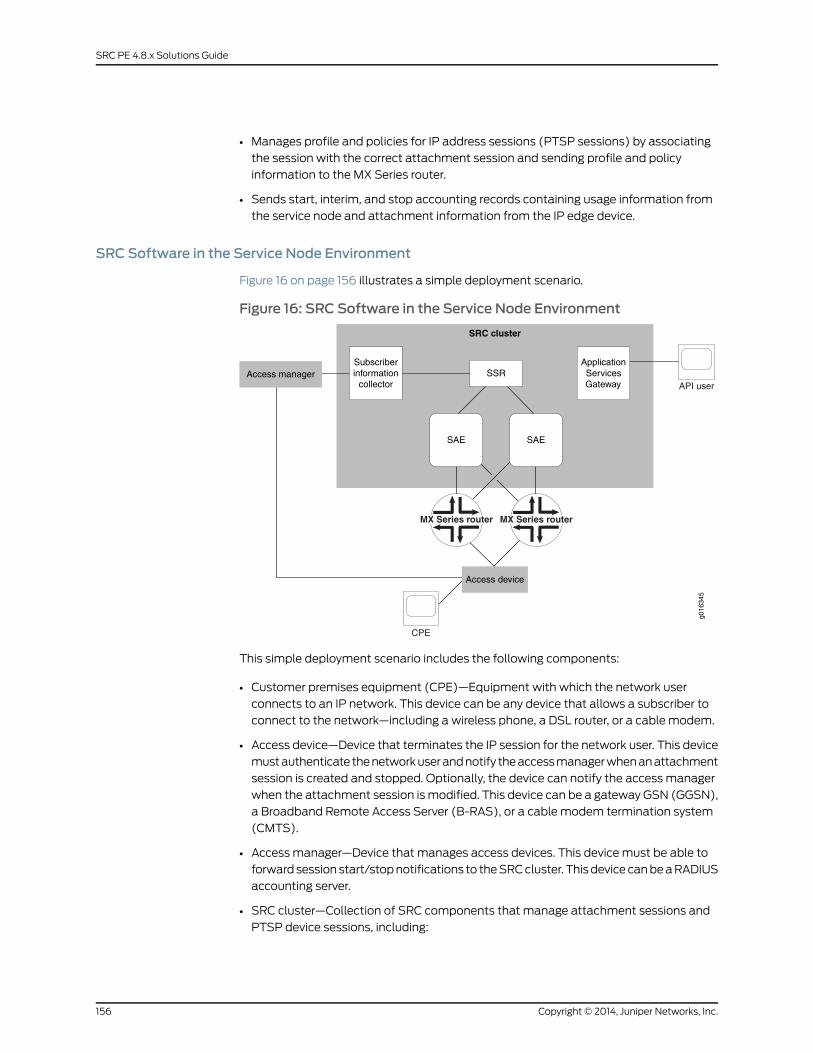
• Manages profile and policies for IP address sessions (PTSP sessions) by associating
the session with the correct attachment session and sending profile and policy
information to the MX Series router.
• Sends start, interim, and stop accounting records containing usage information from
the service node and attachment information from the IP edge device.
SRC Software in the Service Node Environment
Figure 16 on page 156 illustrates a simple deployment scenario.
Figure 16: SRC Software in the Service Node Environment
API user
SRC cluster
Access managerSubscriberinformation
collectorSSR
ApplicationServicesGateway
Access device
g016
345
SAESAE
CPE
MX Series router MX Series router
This simple deployment scenario includes the following components:
• Customer premises equipment (CPE)—Equipment with which the network user
connects to an IP network. This device can be any device that allows a subscriber to
connect to the network—including a wireless phone, a DSL router, or a cable modem.
• Access device—Device that terminates the IP session for the network user. This device
must authenticate the network user and notify the access manager when an attachment
session is created and stopped. Optionally, the device can notify the access manager
when the attachment session is modified. This device can be a gateway GSN (GGSN),
a Broadband Remote Access Server (B-RAS), or a cable modem termination system
(CMTS).
• Access manager—Device that manages access devices. This device must be able to
forward session start/stop notifications to the SRC cluster. This device can be a RADIUS
accounting server.
• SRC cluster—Collection of SRC components that manage attachment sessions and
PTSP device sessions, including:
Copyright © 2014, Juniper Networks, Inc.156
SRC PE 4.8.x Solutions Guide
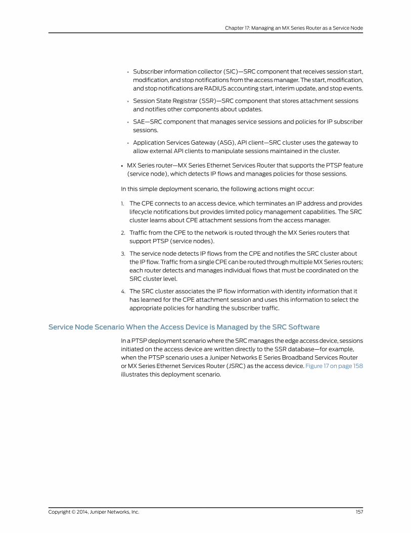
• Subscriber information collector (SIC)—SRC component that receives session start,
modification, and stop notifications from the access manager. The start, modification,
and stop notifications are RADIUS accounting start, interim update, and stop events.
• Session State Registrar (SSR)—SRC component that stores attachment sessions
and notifies other components about updates.
• SAE—SRC component that manages service sessions and policies for IP subscriber
sessions.
• Application Services Gateway (ASG), API client—SRC cluster uses the gateway to
allow external API clients to manipulate sessions maintained in the cluster.
• MX Series router—MX Series Ethernet Services Router that supports the PTSP feature
(service node), which detects IP flows and manages policies for those sessions.
In this simple deployment scenario, the following actions might occur:
1. The CPE connects to an access device, which terminates an IP address and provides
lifecycle notifications but provides limited policy management capabilities. The SRC
cluster learns about CPE attachment sessions from the access manager.
2. Traffic from the CPE to the network is routed through the MX Series routers that
support PTSP (service nodes).
3. The service node detects IP flows from the CPE and notifies the SRC cluster about
the IP flow. Traffic from a single CPE can be routed through multiple MX Series routers;
each router detects and manages individual flows that must be coordinated on the
SRC cluster level.
4. The SRC cluster associates the IP flow information with identity information that it
has learned for the CPE attachment session and uses this information to select the
appropriate policies for handling the subscriber traffic.
Service Node ScenarioWhen the Access Device is Managed by the SRC Software
In a PTSP deployment scenario where the SRC manages the edge access device, sessions
initiated on the access device are written directly to the SSR database—for example,
when the PTSP scenario uses a Juniper Networks E Series Broadband Services Router
or MX Series Ethernet Services Router (JSRC) as the access device. Figure 17 on page 158
illustrates this deployment scenario.
157Copyright © 2014, Juniper Networks, Inc.
Chapter 17: Managing an MX Series Router as a Service Node
Figure 17: SRC-Managed Access Nodes in a Service Node Deployment
API user
SRC cluster
SSRApplicationServicesGateway
g017
618
SAESAE
CPE
MX Series router MX Series router Service nodes
Edge router SRC-managed access node
An SAE user-tracking plug-in publishes subscriber session information to the SSR after
the subscriber has successfully logged in through the access node. The SSR writer plug-in
is a user-tracking plug-in that creates a user session record and writes it into the SSR.
The SSR writer plug-in specifies which SAE plug-in attributes are written to the SSR and
the SSR maps the SAE plug-in attributes to SSR attributes. The SSR writer plug-in
configuration specifies the association between the SAE plug-in attributes, which are
used in the SAE access session and carried in the user-tracking event, and the respective
SAE plug-in attributes configured in the SSR association. Plug-in attributes associated
with the SSR can be mapped either to the plug-in attributes used to identify the access
session or to literal values.
User Login
An access subscriber session can be created before or after the PTSP IP flow is detected.
User Login ScenarioWhen the Access Session is Created Before the PTSP Session
When a user logs in through the SRC-managed access device, a user session is created
in the SAE. A user-tracking event is then sent to the SSR writer plug-in, which provides
sufficient information to successfully identify the user and store the associated record
in the SSR. When the PTSP flow is detected by the SAE, a temporary user session is
created and a user authentication event is sent to the SSR reader authentication plug-in
to authenticate the user. The SSR reader authentication plug-in reads the record and
updates the event with the session attributes read from the SSR. When the user is
authenticated, a permanent user session is created and the SAE installs the policies on
the service node managing PTSP traffic.
Copyright © 2014, Juniper Networks, Inc.158
SRC PE 4.8.x Solutions Guide
User Login ScenarioWhen the PTSP Session is Created Before the Access Session
The service node detects the new IP flow and creates a PTSP session. The SRC software
starts an anonymous subscriber session and the SAE installs policies on the service node.
The user logs in through the access device, an access user session is created in the SAE,
and the user-tracking event is sent to the SSR writer. The record associated with the
subscriber session is stored in the SSR. When the access session is created in the SSR,
the identity of the PTSP subscriber session is changed through an SSR event. The SAE
receives a notification that contains the IP-Address and VPN-ID attributes. The event
handler searches for matching sessions that have been authorized by the SSR reader
authentication plug-in and performs a re-authentication of those sessions. If the
re-authentication does not change the existing session, the event handler re-evaluates
all policies and sends updates to the PTSP router.
User Logout
When the access session is dropped because the user logs out, the SSR writer plug-in
updates the session state associated with the user. After the access session state
becomes inactive in the SSR, the SAE receives a notification and terminates the PTSP
subscriber session associated with the attachment session and all services are
deactivated. In the case when the PTSP session is dropped but the access session remains
active, the user may activate PTSP services at a later time reusing the same access
session stored in the SSR. PTSP session termination does not affect the attachment
session.
RelatedDocumentation
Subscriber Information Collector Overview•
• Session State Registrar Overview
• Managing Subscriber-Level Policies on MX Series Routers Overview on page 165
Using the SRC Software to Support PTSP
When you use the SRC software to support PTSP on MX Series routers, the SRC software
can become aware of the subscribers before or after a PTSP session has been created.
This topic describes the interaction among the components in the basic scenario and
the sequence of events for different situations.
Accessing the Network Before the SRC Cluster Is Notified About a PTSP Session
The CPE connects to the network and the SRC cluster is notified about the connection
before a PTSP session is created. In this case, the attachment session exists before the
PTSP session. The sequence of events is:
1. The CPE connects to the network through the access device.
2. The access device notifies the access manager about the session start.
3. The access manager forwards the session start notification to the SIC, which translates
the attributes into SRC-specific attributes.
4. The SIC creates an attachment session in the SSR.
159Copyright © 2014, Juniper Networks, Inc.
Chapter 17: Managing an MX Series Router as a Service Node
5. (Optional) The subscriber activates a service through the ASG. (In the sequence of
events, this step is the earliest one for using the ASG.)
6. (Optional) The ASG creates a service session in the SSR that is associated with the
attachment session. If the attachment session does not exist, the service activation
fails.
7. The CPE accesses the network. The service node detects a new IP flow and creates
a PTSP session.
8. The service node notifies the SAE that is currently managing the MX Series router. The
SAE extracts the IP address, and optionally the VPN ID, from the PTSP session
information.
9. The SAE starts managing the PTSP session and calls the SSR reader authentication
plug-in to obtain attachment session information from the SSR. The data from the
SSR is used in the classification context.
10. The SAE runs the subscriber classification script, loads a subscriber profile, and creates
a subscriber session. The subscriber session activates any subscribed activate-on-login
service.
11. When the subscriber session is completely activated, the SAE installs any active
policies on the service node.
Accessing the Network After the SRC Cluster Is Notified About a PTSP Session
The CPE connects to the network and the SRC cluster is notified about the connection
after a PTSP session is processed. In this case, the attachment session does not exist
before the PTSP session. The sequence of events is:
1. The CPE connects to the network through the access device.
2. The CPE accesses the network. The service node detects the new IP flow and creates
a PTSP session.
3. The service node notifies the SAE that is currently managing the MX Series router. The
SAE extracts the VPN ID from the PTSP session information.
4. The SAE starts managing the PTSP session and calls the SSR reader authentication
plug-in to obtain attachment session information from the SSR. No information is
returned to the SAE because the attachment session does not exist yet.
5. The SAE creates an unauthenticated (anonymous) subscriber session.
6. When the subscriber session is completely activated, the SAE installs any active
policies on the service node.
7. The access device notifies the access manager about the session start.
8. The access manager forwards the session start notification to the SIC.
9. The SIC creates the attachment session in the SSR.
10. The SSR notifies the SAE that the attachment session has been modified. The SAE
finds any affected subscriber sessions. The SSR notifies all active SAEs in the same
cluster.
Copyright © 2014, Juniper Networks, Inc.160
SRC PE 4.8.x Solutions Guide
11. For any affected subscriber session, the SAE updates the classification context and
initiates a login. This login runs the subscriber classification script and compares the
result.
• If the subscriber profile has changed, the existing session is terminated and a new
session is created.
• If the subscriber profile has not changed, the provisioned policies for active services
are verified to determine whether they are affected by the updated attachment
information.
12. Any changes are applied to the service node. If no policies have changed but the
subscriber identity is different, the SAE changes the subscriber identity on the service
node.
13. The subscriber activates a service through the ASG.
14. The ASG creates a service session in the SSR.
15. The SSR notifies all SAEs that a new service session exists.
16. The SAE that manages PTSP sessions for the attachment session activates a service
session for the appropriate subscriber session.
Changing the Network Connection
The CPE connects to the network by different means. The attachment session is modified
without changing the IP layer. The sequence of events is:
1. The CPE connects to the network through the access device in a different manner.
For example, a wireless device roams to a different access point.
2. The access device notifies the access manager about the modified session parameters.
3. The access manager forwards the notification to the SIC.
4. The SIC updates the attachment session in the SSR.
5. The SSR notifies the SAE that the attachment session has been modified. The SAE
finds any affected subscriber sessions. The SSR notifies all active SAEs in the same
cluster.
6. For any affected subscriber session, the SAE updates the classification context and
initiates a login. This login runs the subscriber classification script and compares the
result.
• If the subscriber profile has changed, the existing session is terminated and a new
session is created.
• If the subscriber profile has not changed, the provisioned policies for active services
are verified to determine whether they are affected by the updated attachment
information.
7. Any changes are applied to the service node. If no policies have changed but the
subscriber identity is different, the SAE installs a policy on the service node with the
changed subscriber identity.
161Copyright © 2014, Juniper Networks, Inc.
Chapter 17: Managing an MX Series Router as a Service Node
If the IP layer is modified, the existing attachment session is terminated and a new
attachment session is created.
Disconnecting from the Network
The network connection is terminated. The sequence of events for attachment session
termination is:
1. The CPE disconnects from the network.
2. The access device notifies the access manager.
3. The access manager forwards the notification to the SIC.
4. The SIC terminates the attachment session in the SSR.
5. The SSR notifies the SAE.
6. The SAE terminates the subscriber session.
7. The SAE terminates the PTSP session on the service node.
Terminating the PTSP Session
The service node detects the end of the PTSP session because of an idle timeout. The
sequence of events for PTSP session termination is:
1. The service node detects an idle timeout, terminates the PTSP session, and notifies
the SAE.
2. The SAE terminates any subscriber session associated with the PTSP session, which
terminates any service session and generates final accounting information.
PTSP session termination does not affect the attachment session.
If the attachment session remains active and the CPE accesses the network again, the
sequence of events is the same as connecting to the network without a PTSP session.
If the attachment session terminates, the SAE receives a notification and terminates any
remaining PTSP sessions associated with the attachment session. If there are no
associated PTSP sessions, the SAE ignores the event.
RelatedDocumentation
Service Nodes in an SRC Environment Overview on page 155•
Configuring SRC Software to Support Service Nodes
To configure the SRC components to support service nodes:
1. Configure the SRC software to communicate with the PTSP peer on the MX Series
router, manage the MX Series router, and manage subscriber policies.
See “Configuring PTSP to Manage Subscriber-Level Policies” on page 167.
2. Configure the SIC to listen for RADIUS accounting events from IP edge devices and
filter events based on attachment session attributes.
Copyright © 2014, Juniper Networks, Inc.162
SRC PE 4.8.x Solutions Guide

See Subscriber Information Collector Overview.
3. Configure the SSR to store information about IP edge attachment sessions.
See Configuring the Initial SSR Cluster (SRC CLI).
4. (Optional) Configure Dynamic Service Activator methods for all subscriber sessions.
See Enabling Dynamic Service Activator on aWeb Application Server (SRC CLI).
163Copyright © 2014, Juniper Networks, Inc.
Chapter 17: Managing an MX Series Router as a Service Node

Copyright © 2014, Juniper Networks, Inc.164
SRC PE 4.8.x Solutions Guide
CHAPTER 18
Managing Subscriber-Level Policies onMX Series Routers
• Managing Subscriber-Level Policies on MX Series Routers Overview on page 165
• Managing Dynamic Policy Changes on MX Series Routers Using the Diameter
Application on page 166
• Configuring PTSP to Manage Subscriber-Level Policies on page 167
• Configuring PTSP on the MX Series Router on page 168
• Adding an MX Series Router as a PTSP Network Device (SRC CLI) on page 168
• Configuring the SAE to Obtain Information About Subscribers (SRC CLI) on page 170
• Configuring the SAE to Write Information About Subscribers to the SSR Database (SRC
CLI) on page 172
• Configuring the PTSP Device Driver (SRC CLI) on page 173
• Configuring the PTSP Device Driver Session Store (SRC CLI) on page 174
• Configuration Statements for PTSP Policies (SRC CLI) on page 178
• Configuring PTSP Policies (SRC CLI) on page 180
• Configuring Policy Groups (SRC CLI) on page 180
• Configuring PTSP Policy Lists (SRC CLI) on page 181
• Configuring the PTSP Policer Instance (SRC CLI) on page 182
• Configuring PTSP Policy Rules (SRC CLI) on page 183
• Configuring PTSP Classify-Traffic Conditions (SRC CLI) on page 186
• Configuring PTSP Actions on page 197
• Example: Configuring the SRC Software to Support PTSP on the MX Series
Router on page 201
• Example: Configuring the SRC Software to Support Both PTSP and JSRC on the MX
Series Router on page 203
Managing Subscriber-Level Policies onMX Series Routers Overview
The Juniper Networks MX Series Ethernet Services Router supports a feature known as
packet-triggered subscribers and policy control (PTSP). This feature allows dynamic
policy and profile changes to be applied on a per-subscriber basis. The PTSP in the MX
165Copyright © 2014, Juniper Networks, Inc.
Series router signals the SRC policy manager when a new IP address flow is detected or
when an existing flow is idle, and allows the policy manager to dynamically apply new
policies associated with the IP address flow.
The SRC software uses the Diameter protocol for communications between the local
SRC peer on a Juniper Networks routing platform, such as the MX Series router, and the
service activation engine (SAE). The local SRC peer in the MX Series router is known as
the PTSP.
The PTSP device driver has the following responsibilities:
• Manage the logical connection to the MX Series router Diameter peer (PTSP).
• Receive IP address notifications from the MX Series router and dynamically activate,
modify, or deactivate policies for existing subscriber sessions.
• Send subscriber identification information to the MX Series router.
• Push subscriber policy changes to MX Series router.
• Retrieve accounting information for active service sessions.
• Terminate a subscriber session.
• Synchronize the state of a single subscriber session or all sessions.
The PTSP device driver responds to requests from the MX Series router, which signals
subscribers logging in and logging out. The driver publishes interface tracking events,
performs interface classification to determine any default policies, and initiates SAE
subscriber session login and logout processing.
Multiple instances of the device driver for the same device (MX Series router) can be
configured in the network. The instances communicate with each other to provide
redundancy. Only one driver for a given device is active at the same time.
The SAE activates, modifies and deactivates subscriber policies. The SAE can control
only those resources that have been provisioned through the SAE. Therefore, the SAE
receives information about only those subscribers (IP address flows) for whom PTSP
has requested provisioning from the SAE. Similarly, the SAE can control only the subscriber
policies that it has activated.
RelatedDocumentation
Managing Dynamic Policy Changes on MX Series Routers Using the Diameter Application
on page 166
•
• Policy Management Overview
• Policy Information Model
ManagingDynamicPolicyChangesonMXSeriesRoutersUsingtheDiameterApplication
You can use the policy manager in the SRC software to dynamically manage subscriber
level policy changes on MX Series routers. The PTSP device driver in the SRC software
and the PTSP in the MX Series router are peers that communicate using a Diameter
Copyright © 2014, Juniper Networks, Inc.166
SRC PE 4.8.x Solutions Guide
application. Information about subscriber policy changes is communicated between the
PTSP and PTSP device driver using Diameter messages.
The SRC software includes a Diameter server process that forwards AAR, ACR, SRQ, and
STR messages from PTSP to the PTSP device driver in the SAE, and that forwards PPR
and ASR messages from the PTSP device driver to PTSP. These Diameter messages
perform these functions:
• AA-Answer (AAA)—Sent in response to the AAR message for confirmation of the result
of QoS provisioning.
• AA-Request (AAR)—Attaches the subscriber to the access network.
• Accounting-Request (ACR)—Provides accounting information.
• Abort-Session-Request (ASR)—Disconnects the subscriber.
• Push-Profile-Request (PPR)—Starts, modifies, or stops a service session.
• Session-Resource-Query (SRQ)—Initiates synchronization.
• Session-Termination-Request (STR)—Detaches the subscriber from the access
network.
In the SRC software, you configure the Diameter peer (the MX Series router) and a device
type (junos-ptsp) for each device managed by the SAE. The Diameter server process in
the SRC software searches all devices of device type junos-ptsp for virtual routers that
include the local host in their SAE connections. For these devices, the Diameter server
process establishes a logical connection with the peers (in this case the MX Series router
PTSP) referenced in the device configuration.
RelatedDocumentation
Managing Subscriber-Level Policies on MX Series Routers Overview on page 165•
• Configuring the Diameter Application (SRC CLI) on page 127
• Configuring Diameter Peers (SRC CLI) on page 132
Configuring PTSP toManage Subscriber-Level Policies
To configure PTSP to manage subscriber-level policies on the MX Series router:
• Configure PTSP on the MX Series router.
See “Configuring PTSP on the MX Series Router” on page 168.
• Configure the Diameter application.
See “Configuring the Diameter Application (SRC CLI)” on page 127
• Configure the Diameter peers.
See “Configuring Diameter Peers (SRC CLI)” on page 132.
• Configure the SAE to manage PTSP on the MX Series router.
See “Adding an MX Series Router as a PTSP Network Device (SRC CLI)” on page 168.
• Configure the SAE to obtain attachment session information from the SSR database.
167Copyright © 2014, Juniper Networks, Inc.
Chapter 18: Managing Subscriber-Level Policies on MX Series Routers
See “Configuring the SAE to Obtain Information About Subscribers (SRC CLI)” on
page 170.
• Configure the PTSP device driver.
See “Configuring the PTSP Device Driver (SRC CLI)” on page 173.
• Configure the session storage parameters for the PSTP device driver.
See “Configuring the PTSP Device Driver Session Store (SRC CLI)” on page 174
• Configure the PTSP policies.
See “Configuring PTSP Policies (SRC CLI)” on page 180.
Configuring PTSP on theMX Series Router
Tasks to set up PTSP on the Juniper Networks routing platform are:
• Configure the Multiservices DPC for PTSP.
• Configure the Diameter application to download dynamic PTSP policies.
• Configure any static PTSP policies.
RelatedDocumentation
For more information about running PTSP on the MX Series router, see the Junos OS
Broadband Subscriber Management and Services Library.
•
• Configuring PTSP to Manage Subscriber-Level Policies on page 167
Adding anMX Series Router as a PTSPNetwork Device (SRC CLI)
You can configure the service activation engine (SAE) to manage a packet-triggered
subscribers and policy control (PTSP) network device on an MX Series router.
Use the following configuration statements to configure the network device:
shared network device name {device-type (junose | junos-ise | junos-ptsp | junos | pcmm | thirdparty);origin-host origin-host;peers [peers...];
}shared network device name virtual-router name {sae-connection [sae-connection...];user-tracking-plug-in user-tracking-plug-in ...];authentication-plug-in [authentication-plug-in...];vpn-id vpn-id;
}
To configure an MX Series router as a PTSP network device so that the router can be
managed by the SAE:
1. From configuration mode, access the statements that configure network devices. You
must specify the name of a device with lowercase characters. This sample procedure
uses mx-name as the name of the router.
Copyright © 2014, Juniper Networks, Inc.168
SRC PE 4.8.x Solutions Guide

user@host# edit shared network devicemx-name
2. Set the type of device to junos-ptsp.
[edit shared network devicemx-name]user@host# set device-type junos-ptsp
3. (Optional) Specify the origin hostname of the MX Series router. This example procedure
uses mx-origin-host as the origin hostname. The active SAE registers events from the
router based on the configured origin host attribute (mx-origin-host in the example).
If the origin host is not configured, SAE uses the device name (mx-name in the
example) instead.
user@host# edit shared network origin-hostmx-origin-host
4. Specify the configured peers associated with the device. See “Configuring Diameter
Peers (SRC CLI)” on page 132.
[edit shared network devicemx-name]user@host# set peers [peers...]
NOTE: MXSeries routers support only a single peer connection.
5. From configuration mode, access the statements for virtual routers. The name you
specify must match the PTSP partition configured on the MX Series router, which is
configured within the logical system:routing instance context. This sample procedure
uses the name * for the virtual router.
[edit shared network devicemx-name]user@host# edit virtual-router *
where * matches any PTSP partition. You can also specify that the PTSP partition be
configured in a logical system or in a logical system and routing instance. By default,
logical system default and routing instancemaster are used.
6. Specify the SAEs that can manage this router.
[edit shared network devicemx-name virtual-router default]user@host# set sae-connection [sae-connection...]
7. (Optional) Specify a single tracking plug-in or a list of tracking plug-ins used to track
subscriber sessions associated with this virtual router.
[edit shared network devicemx-name virtual-router default]user@host# set user-tracking-plug-in [user-tracking-plug-in...]
Set the user-tracking-plug-in option to the name of the configuration plug-in you
configured with the edit shared sae configuration plug-ins name name ssr-writer
statement.
8. (Optional) Specify the plug-ins that authenticate subscribers who log in through this
virtual router.
[edit shared network devicemx-name virtual-router default]user@host# set authentication-plug-in [authentication-plug-in...]
169Copyright © 2014, Juniper Networks, Inc.
Chapter 18: Managing Subscriber-Level Policies on MX Series Routers
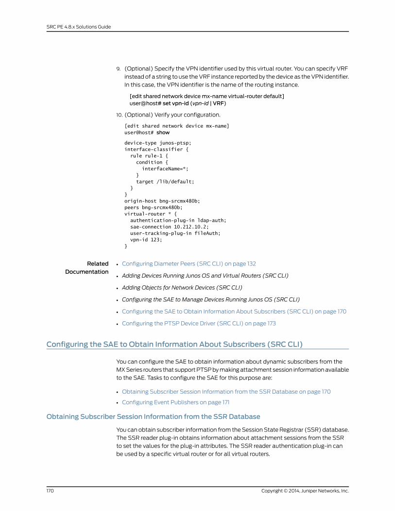
9. (Optional) Specify the VPN identifier used by this virtual router. You can specify VRF
instead of a string to use the VRF instance reported by the device as the VPN identifier.
In this case, the VPN identifier is the name of the routing instance.
[edit shared network devicemx-name virtual-router default]user@host# set vpn-id (vpn-id | VRF)
10. (Optional) Verify your configuration.
[edit shared network device mx-name] user@host# show
device-type junos-ptsp;interface-classifier { rule rule-1 { condition { interfaceName=*; } target /lib/default; }}origin-host bng-srcmx480b;peers bng-srcmx480b;virtual-router * { authentication-plug-in ldap-auth; sae-connection 10.212.10.2; user-tracking-plug-in fileAuth; vpn-id 123;}
RelatedDocumentation
Configuring Diameter Peers (SRC CLI) on page 132•
• Adding Devices Running Junos OS and Virtual Routers (SRC CLI)
• Adding Objects for Network Devices (SRC CLI)
• Configuring the SAE to Manage Devices Running Junos OS (SRC CLI)
• Configuring the SAE to Obtain Information About Subscribers (SRC CLI) on page 170
• Configuring the PTSP Device Driver (SRC CLI) on page 173
Configuring the SAE to Obtain Information About Subscribers (SRC CLI)
You can configure the SAE to obtain information about dynamic subscribers from the
MX Series routers that support PTSP by making attachment session information available
to the SAE. Tasks to configure the SAE for this purpose are:
• Obtaining Subscriber Session Information from the SSR Database on page 170
• Configuring Event Publishers on page 171
Obtaining Subscriber Session Information from the SSR Database
You can obtain subscriber information from the Session State Registrar (SSR) database.
The SSR reader plug-in obtains information about attachment sessions from the SSR
to set the values for the plug-in attributes. The SSR reader authentication plug-in can
be used by a specific virtual router or for all virtual routers.
Copyright © 2014, Juniper Networks, Inc.170
SRC PE 4.8.x Solutions Guide
Use the following configuration statements to set up an SSR reader plug-in:
shared sae configuration plug-ins name name ssr-reader {read-attributes [read-attributes...];
}
To configure the SSR reader plug-in:
1. From configuration mode, access the SSR reader plug-in configuration.
user@host# edit shared sae configuration plug-ins name name ssr-reader
2. (Optional) Specify the plug-in attribute whose value is set from the SSR subscriber
sessions table.
[edit shared sae configuration plug-ins name name ssr-reader]user@host# set read-attributes [read-attributes...]
Configuring Event Publishers
You can configure the event publisher to use the SSR reader authentication plug-in.
To configure the global or default event publisher for PTSP:
1. From configuration mode, access the statement that configures the event publisher.
user@host# edit shared sae configuration plug-ins event-publishers
2. (Optional) Specify the plug-ins that authenticate subscribers who are assigned to a
virtual router that does not specify an authentication plug-in.
[edit shared sae configuration plug-ins event-publishers]user@host# set default-vr-authentication [default-vr-authentication...]
3. (Optional) Specify the plug-ins that authenticate subscribers who log in through a
specific type of device (for example, junos-ptsp).
[edit shared sae configuration plug-ins event-publishers]user@host# set device-type-authentication junos-ptsp [plug-ins...]
To specify the plug-ins that authenticate subscribers who log in through a specific virtual
router, set the authentication-plug-in option when you are adding the virtual router for
the network device. See “Adding an MX Series Router as a PTSP Network Device (SRC
CLI)” on page 168.
RelatedDocumentation
Adding an MX Series Router as a PTSP Network Device (SRC CLI) on page 168•
• Configuring Global and Default Retailer Event Publishers (SRC CLI)
• SSR Database Schema
• Making Modifications to the SSR Database Schema Overview
171Copyright © 2014, Juniper Networks, Inc.
Chapter 18: Managing Subscriber-Level Policies on MX Series Routers
Configuring the SAE toWrite Information About Subscribers to the SSR Database(SRC CLI)
When you use an SRC-managed device—for example, an E Series Broadband Services
Router as the access node in a PTSP application—you can configure the SAE to write
information about dynamic subscribers directly to the SSR database. To do this, you
need to configure the SSR writer and specify the mapping between access subscriber
session attributes and the SAE plug-in attributes used to identify service node subscriber
sessions.
NOTE: Beforeyouconfigure theSSRwriter,we recommendthatyouconfigurethemapping between the SAE plug-in attributes and the SSR subscribersessions table. The subscriber sessions table schema requires the user IPaddress and VPN ID; see SSR Database Schema.
Use the following statements to configure the mapping between access subscriber
session attributes and the SAE plug-in attributes:
shared sae configuration plug-ins name name ssr-writer {}shared sae configuration plug-ins name name ssr-writer plugin-attributes id {access-plugin-attribute access-plugin-attribute;literal literal;
}
To configure the mapping between access subscriber session attributes and the SAE
plug-in attributes:
1. From configuration mode, access the statement that configures the SSR writer plug-in
and specify a name for the plug-in configuration. For example, to configure a plug-in
configuration called pc1:
[edit]user@host# edit shared sae configuration plug-ins name pc1 ssr-writer
The name you specify for the configuration plug-in must be specified for the
user-tracking-plug-in option under the edit shared network device name virtual-router
name statement.
2. Specify the name of an SAE plug-in attribute to be mapped to the access session
attribute, or literal. For example, to specify the login-name SAE plugin attribute:
[edit shared sae configuration plug-ins name pc1 ssr-writer]user@host# edit plugin-attributes login-name
3. Specify the name of either an access plug-in attribute or a literal to be mapped to the
SAE plug-in attribute.
• To specify an access plug-in attribute—for example, login-name:
Copyright © 2014, Juniper Networks, Inc.172
SRC PE 4.8.x Solutions Guide
[edit shared sae configuration plug-ins name pc1 ssr-writer plugin-attributeslogin-name]
user@host# set access-plugin-attributes login-name
• To specify a literal—for example, xyz-name:
[edit shared sae configuration plug-ins name pc1 ssr-writer plugin-attributeslogin-name]
user@host# set literal xyz-name
RelatedDocumentation
Configuring the Fields in the Subscriber Sessions Table (SRC CLI)•
• SSR Database Schema
• Modifying Attribute Mapping in an Active SSR Cluster (SRC CLI)
• Modifying the SSR Database Schema in an Active Cluster (SRC CLI)
Configuring the PTSP Device Driver (SRC CLI)
In most cases, all attributes have reasonable defaults and should not require configuration.
The configuration should be changed only by advanced users wishing to tune the
performance.
Use the following configuration statements to configure the PTSP device driver for MX
Series routers:
shared sae configuration driver junos-ptsp {sae-community-manager sae-community-manager;cached-driver-expiration cached-driver-expiration;keep-alive-timeout keep-alive-timeout;registry-retry-interval registry-retry-interval;reply-timeout reply-timeout;sequential-message-timeout sequential-message-timeout;thread-pool-size thread-pool-size;thread-idle-timeout thread-idle-timeout;
}
To configure the device driver:
1. From configuration mode, access the statements for the device driver.
user@host# edit shared sae configuration driver junos-ptsp
2. Specify the name of the community manager.
[edit shared sae configuration driver junos-ptsp]user@host# set sae-community-manager sae-community-manager
3. (Optional) Specify the minimum amount of time to keep the state of a device driver
after its Diameter connection is closed.
[edit shared sae configuration driver junos-ptsp]user@host# set cached-driver-expiration cached-driver-expiration
173Copyright © 2014, Juniper Networks, Inc.
Chapter 18: Managing Subscriber-Level Policies on MX Series Routers
4. (Optional) Specify the keepalive timeout before the registry to a Diameter server
expires.
[edit shared sae configuration driver junos-ptsp]user@host# set keep-alive-timeout keep-alive-timeout
5. (Optional) Specify the interval between retrying a failed registry to a Diameter server.
[edit shared sae configuration driver junos-ptsp]user@host# set registry-retry-interval registry-retry-interval
6. (Optional) Specify the length of time before a request sent to a Diameter server
expires.
[edit shared sae configuration driver junos-ptsp]user@host# set reply-timeout reply-timeout
7. (Optional) Specify the length of time before an expected message expires.
[edit shared sae configuration driver junos-ptsp]user@host# set sequential-message-timeout sequential-message-timeout
8. (Optional) Specify the number of working threads that process requests.
[edit shared sae configuration driver junos-ptsp]user@host# set thread-pool-size thread-pool-size
9. (Optional) Specify the length of time for stopping working threads after they become
idle.
[edit shared sae configuration driver junos-ptsp]user@host# set thread-idle-timeout thread-idle-timeout
10. (Optional) Configure the session store parameters for the device driver.
From configuration mode, access the statement that configures the session store for
the device driver.
user@host# edit shared sae configuration driver junos-ptsp session-store
For more information about configuring session store parameters, seeConfiguring the
Session Store Feature (SRC CLI).
RelatedDocumentation
Configuring the SAE to Manage Devices Running Junos OS (SRC CLI)•
• Configuring the PTSP Device Driver Session Store (SRC CLI) on page 174
Configuring the PTSP Device Driver Session Store (SRC CLI)
In most cases, all attributes have reasonable defaults and should not require configuration.
The configuration should be changed only by advanced users wishing to tune the
performance.
Use the following configuration statements to configure the PTSP device driver session
storage configuration:
shared sae configuration driver junos-ptsp session-store {maximum-queue-agemaximum-queue-age;
Copyright © 2014, Juniper Networks, Inc.174
SRC PE 4.8.x Solutions Guide

maximum-queued-operationsmaximum-queued-operations;maximum-queue-sizemaximum-queue-size;maximum-file-sizemaximum-file-size;minimum-disk-space-usageminimum-disk-space-usage;rotation-batch-size rotation-batch-size;maximum-session-sizemaximum-session-size;disk-load-buffer-size disk-load-buffer-size;network-buffer-size network-buffer-size;retry-interval retry-interval;communications-timeout communications-timeout;load-timeout load-timeout;idle-timeout idle-timeout;maximum-backlog-ratiomaximum-backlog-ratio;minimum-backlogminimum-backlog;
}
To configure the PTSP device driver session storage:
1. From configuration mode, access the statements for the driver session storage.
user@host# edit shared sae configuration driver junos-ptsp session-store
2. (Optional) Specify the maximum age that a queue of buffered store operations (such
as adding a session to the store or removing a session from the store) can reach before
the queue is written to a session store file.
[edit shared sae configuration driver junos-ptsp session-store]user@host# setmaximum-queue-agemaximum-queue-age
Enter a value for the number of milliseconds in the range 0–2147483647. A value of
–1 indicates that there is no limit. A value of 0 causes the session store to write each
store operation to a session store file immediately.
3. (Optional) Specify the number of buffered store operations that are queued before
the queue is written to a session store file.
[edit shared sae configuration driver junos-ptsp session-store]user@host# setmaximum-queued-operationsmaximum-queued-operations
Enter an integer in the range 0–2147483647. A value of –1 indicates that there is no
limit. A value of 0 causes the session store to write each store operation to a session
store file immediately.
4. (Optional) Specify the maximum size that a queue of buffered store operations can
reach before the queue is written to a session store file.
[edit shared sae configuration driver junos-ptsp session-store]user@host# setmaximum-queue-sizemaximum-queue-size
Enter the number of bytes in the range 0–2147483647.
5. (Optional) Specify the maximum size of session store files. When a file reaches this
size, a new file is created.
[edit shared sae configuration driver junos-ptsp session-store]user@host# setmaximum-file-sizemaximum-file-size
Enter the number of bytes in the range 0–2147483647.
175Copyright © 2014, Juniper Networks, Inc.
Chapter 18: Managing Subscriber-Level Policies on MX Series Routers
6. (Optional) Specify the percentage of space in all session store files that is used by
live sessions. When the space in the session store files that is used by live sessions
decreases to this percentage, the oldest session store file is compacted and appended
to the newest session store file, and then the oldest session store file is deleted.
[edit shared sae configuration driver junos-ptsp session-store]user@host# setminimum-disk-space-usageminimum-disk-space-usage
Enter a percentage of disk space in the range 1–100. We recommend a range of 30-50.
7. (Optional) Specify when the oldest session store file is rotated. The value specifies
the number of sessions that are rotated from the oldest file to the newest file at the
same time. While a set of sessions is rotated, no other session store activity can take
place
[edit shared sae configuration driver junos-ptsp session-store]user@host# set rotation-batch-size rotation-batch-size
Enter an integer in the range 0–2147483647.
8. (Optional) Specify the maximum size of a single subscriber or service session. Use
this parameter to reserve memory for an internal buffer.
[edit shared sae configuration driver junos-ptsp session-store]user@host# setmaximum-session-sizemaximum-session-size
Enter the number of bytes in the range 0–2147483647.
9. (Optional) Specify the size of the buffer that is used to load all of a session store's
files from disk at startup.
[edit shared sae configuration driver junos-ptsp session-store]user@host# set disk-load-buffer-size disk-load-buffer-size
Enter the number of bytes in the range 0–2147483647.
10. (Optional) Specify the size of the buffer that holds messages or message segments
that are waiting to be sent to passive session stores.
[edit shared sae configuration driver junos-ptsp session-store]user@host# set network-buffer-size network-buffer-size
The number of bytes entered must be larger than or equal to 21 plus
maximum-session-size and less than 2147483647.
11. (Optional) Specify the time interval to be allowed between attempts by the active
session store to connect to missing passive session stores.
[edit shared sae configuration driver junos-ptsp session-store]user@host# set retry-interval retry-interval
Enter the number of milliseconds in the range 0–2147483647.
12. (Optional) Specify the amount of time in milliseconds that a session store should
wait before closing when it is blocked from reading or writing a message. This timeout
does not apply when a session store is waiting for a remote session store to load its
state from disk.
[edit shared sae configuration driver junos-ptsp session-store]user@host# set communications-timeout communications-timeout
Copyright © 2014, Juniper Networks, Inc.176
SRC PE 4.8.x Solutions Guide
Enter the number of milliseconds. (A nonpositive number means wait forever. This is
not recommended.)
13. (Optional) Specify the amount of time in milliseconds that an active session store
should wait for a passive session store or a passive session store waits for an active
session store to load its data from disk before it closes the connection to the session
store.
[edit shared sae configuration driver junos-ptsp session-store]user@host# set load-timeout load-timeout
Enter the number of milliseconds. (A nonpositive number means wait forever. This is
not recommended.)
14. (Optional) Specify the amount of time that a passive session store waits for activity
from the active session store before it closes the connection to the active session
store. This timeout applies after the session store startup and initial update processes
are complete.
[edit shared sae configuration driver junos-ptsp session-store]user@host# set idle-timeout idle-timeout
Enter the number of milliseconds in the range 0–2147483647.
15. (Optional) Specify the maximum backlog ratio. Along with the minimum backlog size,
this ratio specifies when the active session store closes the connection to a passive
session store because of a backlog of messages waiting to be sent. After the startup
and initial update processes are complete, if the backlog becomes too large, the
connection to the passive session store is closed. After the retry interval ends, a new
connection is opened.
If the backlog of unsent operations (in bytes) divided by the total size (in bytes) of all
live store operations is greater than this number, the connection is closed.
[edit shared sae configuration driver junos-ptsp session-store]user@host# setmaximum-backlog-ratiomaximum-backlog-ratio
Enter a floating point number.
16. (Optional) Specify the size of the minimum backlog. Along with the maximum backlog
ratio, this number specifies when the active session store closes the connection to a
passive session store because of a backlog of messages waiting to be sent to the
passive session store. After the startup and initial update processes are complete, if
the backlog becomes too large, the connection to the passive session store is closed.
After the retry interval ends, a new connection is opened. If the maximum backlog
ratio is met, the active session store does not close the connection unless the backlog
of messages (in bytes) is greater than this number.
[edit shared sae configuration driver junos-ptsp session-store]user@host# setminimum-backlogminimum-backlog
Enter the number of bytes in the range 0–2147483647.
RelatedDocumentation
Configuring PTSP Policies (SRC CLI) on page 180•
• Managing Subscriber-Level Policies on MX Series Routers Overview on page 165
177Copyright © 2014, Juniper Networks, Inc.
Chapter 18: Managing Subscriber-Level Policies on MX Series Routers

Configuration Statements for PTSP Policies (SRC CLI)
Use the following configuration statements to configure PTSP policies:
policies group name {description description ;
}policies group name list name {role [(junos | junose-ipv4 | junose-ipv6 | junose-l2tp |pcmm|aaa | junos-ise | junos-ptsp)];applicability [(input | output | both | secondary-input)];description description;
}policies group name list name rule name {precedence precedence;accounting;application-accounting application-accounting;type [(ptsp-service-rule | ptsp-subscriber-profile | ptsp-template)];subscriber-profile subscriber-profile;
}policies group name list name policer name {bandwidth bandwidth;max-burst-sizemax-burst-size;
}policies group name list name rule name traffic-condition name {match-directionmatch-direction;description description;
}policies group name list name rule name traffic-condition name destination-networknetwork {ip-address ip-address;ip-mask ip-mask;
}policies group name list name rule name traffic-condition name destination-networkgroup-network {network-specifier network-specifier;
}policies group name list name rule name traffic-condition name protocol-condition {protocol protocol;
}policies group name list name rule name traffic-condition name protocol-port-condition {protocol protocol;
}policies group name list name rule name traffic-condition name protocol-port-conditiondestination-port port {from-port from-port;
}policies group name list name rule name traffic-condition name protocol-port-conditionsource-port port {from-port from-port;
}policies group name list name rule name traffic-condition nameparameter-protocol-condition {protocol protocol;
}
Copyright © 2014, Juniper Networks, Inc.178
SRC PE 4.8.x Solutions Guide
policies group name list name rule name traffic-condition nameparameter-protocol-condition proto-attr destination-port port {from-port from-port;
}policies group name list name rule name traffic-condition nameparameter-protocol-condition proto-attr source-port port {from-port from-port;
}policies group name list name rule name traffic-condition name tcp-condition {protocol protocol;
}policies group name list name rule name traffic-condition name tcp-conditiondestination-port port {from-port from-port;
}policies group name list name rule name traffic-condition name tcp-condition source-portport {from-port from-port;
}policies group name list name rule name traffic-condition name traffic-match-condition {term-precedence term-precedenceapplication [application...];application-group [application-group...];
}policies group name list name rule name policer-ref {policer-name;description description;
}policies group name list name rule name forwarding-instance {forwarding-instance;forwarding-unit forwarding-unit ;description description ;
}policies group name list name rule name forwarding-class name {forwarding-class forwarding-class ;description description ;
}policies group name list name rule name filter name {description description ;
}
RelatedDocumentation
Configuring PTSP Policies (SRC CLI) on page 180•
• Configuring PTSP to Manage Subscriber-Level Policies on page 167
• Configuring PTSP Policy Lists (SRC CLI) on page 181
• Configuring Policy Groups (SRC CLI) on page 180
• Configuring PTSP Policy Rules (SRC CLI) on page 183
• Configuring the PTSP Policer Instance (SRC CLI) on page 182
179Copyright © 2014, Juniper Networks, Inc.
Chapter 18: Managing Subscriber-Level Policies on MX Series Routers
Configuring PTSP Policies (SRC CLI)
The role of the policy list for the PTSP device driver must be set to junos-ptsp. The policy
list must be configured to contain the rule of type ptsp-service-rule. A ptsp-service-rule
object can contain one or more traffic-conditions and any number of actions (filter,
policer-ref, forwarding-class, forwarding-instance). Each traffic-condition is translated
to the PTSP policy template using the same action variables defined in the policy rule.
Before you configure PTSP policies, review the information about configuring and
managing policies:
• Policy Management Overview
• Policy Information Model
• Before You Configure SRC Policies
• Enabling the Policy Configuration on the SRC CLI
To configure PTSP policies:
1. Create a policy group.
See “Configuring Policy Groups (SRC CLI)” on page 180.
2. Configure the policy list and set the role of the list to junos-ptsp and the applicability
to both.
See “Configuring PTSP Policy Lists (SRC CLI)” on page 181.
3. Configure the PTSP policer instance.
See “Configuring the PTSP Policer Instance (SRC CLI)” on page 182.
4. Configure the PTSP policy rule and set the rule type to ptsp-service-rule or
ptsp-subscriber-profile.
See “Configuring PTSP Policy Rules (SRC CLI)” on page 183.
5. Configure the PTSP classify-traffic conditions.
See “Configuring PTSP Classify-Traffic Conditions (SRC CLI)” on page 186.
6. Configure the PTSP actions.
See “Configuring PTSP Actions” on page 197.
RelatedDocumentation
Policy Components•
• Configuration Statements for PTSP Policies (SRC CLI) on page 178
Configuring Policy Groups (SRC CLI)
Policy groups hold policy lists. You can create policy groups within policy folders. Use the
following configuration statement to create a policy group:
Copyright © 2014, Juniper Networks, Inc.180
SRC PE 4.8.x Solutions Guide
policies group name {description description;
}
To create a policy group:
1. From configuration mode, enter the edit policies group statement. For example, to
create a group called dhcp-default:
NOTE: Thenameconfigured for the policy group is case-sensitive. Hence,youmust use the same configured name in all instances.
user@host# edit policies group dhcp-default
2. (Optional) Enter a description for the policy group.
[edit policies group dhcp-default]user@host# set description description
3. (Optional) Verify your policy group configuration.
[edit policies group dhcp-default]user@host#showdescription "Default policy for JunosE routers";
RelatedDocumentation
Before You Configure SRC Policies•
• Configuring Policy Folders (SRC CLI)
• Enabling the Policy Configuration on the SRC CLI
• Configuring Policy Groups (C-Web Interface)
• Example: Creating Access Policies for Subscribers
Configuring PTSP Policy Lists (SRC CLI)
NOTE: For PTSP youmust:
• Set the role of the policy list to junos-ptsp
• Set the policy list rule type to ptsp-service-rule
• Set the policy list applicability option to both
• Create a policer instance.
Use the following configuration statements to PTSP policy lists:
policies group name list name {role [(junos | junose-ipv4 | junose-ipv6 | junose-l2tp |pcmm|aaa | junos-ise | junos-ptsp)];applicability [(input | output | both | secondary-input)];description description;
}
181Copyright © 2014, Juniper Networks, Inc.
Chapter 18: Managing Subscriber-Level Policies on MX Series Routers
To configure policy lists:
1. From configuration mode, create a policy list. For example, to create a policy list called
list1 within a policy group called group1:
user@host# edit policies group group1 list list1
2. Specify the role of the policy list. For PTSP the role must be set to junos-ptsp.
[edit policies group group1 list list1]user@host# set role junos-ptsp
3. Specify where the policy is applied on the device. For PTSP the applicability option
must be set to both.
[edit policies group group1 list list1]user@host# set applicability both
RelatedDocumentation
Policy Management Overview•
• Configuring PTSP Policies (SRC CLI) on page 180
• Configuring PTSP Policy Rules (SRC CLI) on page 183
• Configuring the PTSP Policer Instance (SRC CLI) on page 182
Configuring the PTSP Policer Instance (SRC CLI)
Optionally, configure one or more policer instances that can be referenced by one or
more PTSP policer-ref actions. The policer instance can be shared by different service
rules inside the same policy list. If the policer instance is shared, all packets matching
any of the service rules are policed together.
NOTE: Youneed toconfigureapolicer instanceonly if apolicy rule referencesthe policer.
NOTE: For PTSP youmust:
• Set the role of the policy list to junos-ptsp
• Set the policy list rule type to ptsp-service-rule
• Set the policy list applicability option to both
• Create a policer instance.
Use the following configuration statements to configure the policer instance:
policies group name list name policer name {bandwidth bandwidth;max-burst-sizemax-burst-size;
}
Copyright © 2014, Juniper Networks, Inc.182
SRC PE 4.8.x Solutions Guide
To configure a policer instance:
1. (Optional) From configuration mode, create a policer instance. In this example the
policer instance is called policer1.
user@host# edit policies group name list name policer policer1
2. (Optional) Specify the bandwidth for the policer instance.
[edit policies group name list name policer policer1]
user@host# set bandwidth bandwidth
Enter an integer between 8000–40000000000 bits per second.
3. (Optional) Specify the maximum burst size for the policer instance.
[edit policies group name list name policer policer1]user@host# setmax-burst-sizemax-burst-size
Enter an integer between 1500–100000000000 octets.
RelatedDocumentation
Configuring PTSP Policies (SRC CLI) on page 180•
• Configuring PTSP Actions on page 197
• Configuring PTSP Policy Lists (SRC CLI) on page 181
• Configuring PTSP Policy Rules (SRC CLI) on page 183
• Configuring PTSP Classify-Traffic Conditions (SRC CLI) on page 186
Configuring PTSP Policy Rules (SRC CLI)
NOTE: For PTSP youmust:
• Set the role of the policy list to junos-ptsp
• Set the policy list rule type to ptsp-service-rule
• Set the policy list applicability option to both
• Create a policer instance.
Use the following configuration statements to configure PTSP policy rules:
policies group name list name rule name {precedence precedence;accounting;application-accounting application-accounting;type [(ptsp-service-rule | ptsp-subscriber-profile | ptsp-template)];subscriber-profile subscriber-profile;
}
To configure policy rules:
183Copyright © 2014, Juniper Networks, Inc.
Chapter 18: Managing Subscriber-Level Policies on MX Series Routers

1. From configuration mode, create a policy rule inside a policy list that has already been
created and configured. For example, to create a policy rule called rule1 within a policy
list called list1:
user@host# edit policies group group1 list list1 rule rule1
2. (Optional) Specify the order in which the policy manager applies the policy rule. Rules
are evaluated from lowest to highest precedence value. Precedence has meaning
only if two rules have different classifiers and if those classifiers overlap. If this is the
case and a packet is received that satisfies both classifiers, then only the action of
the rule with the lower precedence value is performed.
For PTSP policies, enter an integer in the range 1–254.
[edit policies group group1 list list1 rule rule1]user@host# set precedence precedence
3. (Optional) Specify whether accounting data is collected for the actions in the policy
rule.
The value set for thea-s variable in the ptsp-service-rule policy template (__svc_rule__)
on the MX Series router corresponds to the setting of the accounting and
application-accounting options under the policy rule. If the accounting option is set, it
corresponds to setting the a-s variable to the “rule” value, and statistics are collected
on a per subscriber/per rule basis. If the accounting option is not set, you can define
the value for the application-accounting option.
If you specify that accounting data is collected, the SAE begins collecting accounting
information when a service that uses the policy rule is activated. When the service is
deactivated, the SAE sends the accounting records to the RADIUS accounting server
or to a plug-in.
When you specify multiple actions for accounting, the SAE adds the accounting data
for individual actions together to obtain a summary accounting record for that interface
direction.
Accounting is not available for all actions.
[edit policies group group1 list list1 rule rule1user@host# set accounting
4. (Optional) Specify application accounting.
If PTSP application accounting is configured on the MX Series router, this attribute
selects how application accounting is collected. Application accounting is maintained
in a flat file on the router and is not collected by the SRC software. Application
accounting and rule accounting are mutually exclusive.
[edit policies group group1 list list1 rule rule1user@host# set application-accounting application-accounting
Copyright © 2014, Juniper Networks, Inc.184
SRC PE 4.8.x Solutions Guide
The value set for thea-s variable in theptsp-service-rulepolicy template (__svc_rule__)
on the MX Series router corresponds to the setting of the accounting and
application-accounting options under the policy rule. If the accounting option is not
set, you can define one of the following values for the application-accounting option:
• “application”—Router maintains one counter per subscriber/application. This value
corresponds to setting the a-s variable in the ptsp-service-rule policy template
(__svc_rule__) on the MX Series router to the “app” value, and statistics are collected
on a per subscriber/per application basis.
• “group”—Router maintains one counter per subscriber/application group. This value
corresponds to setting the a-s variable in the ptsp-service-rule policy template
(__svc_rule__) on the MX Series router to the “group” value, and statistics are
collected on a per subscriber/per application-group basis.
• “any”—Router maintains one counter per subscriber. This value corresponds to
setting the a-s variable in the ptsp-service-rule policy template (__svc_rule__) on
the MX Series router to the “any” value, and statistics are collected on a per
subscriber basis.
• “nested-app”—Router maintains one counter per subscriber/per nested application.
This value corresponds to setting the a-s variable in the ptsp-service-rule policy
template (__svc_rule__) on the MX Series router to the “nested-app” value, and
statistics are collected on a per subscriber/per nested application basis. Use the
nanl variable, in the policy template for the router to specify the list of nested
application names. Items in the list are separated by commas.
• A parameter of type applicationAccounting.
NOTE: Thevaluesapplication,group,any, andnested-appare literal strings
andmust be enclosed in double quotationmarks (“ ”). To enter them inthe SRC CLI, enclose the literal string with double quotationmarks (“ ”)within single quotationmarks (‘ ’). For example “nested-app” is entered
as ‘“nested-app”’ in the SRC CLI. Alternatively, you can enclose them in
doublequotationmarkswithinbackslashes. For example, \“nested-app”\.
5. Specify the type of policy rule.
[edit policies group group1 list list1 rule rule1user@host# set type type
Where type is one of the following values:
• ptsp-service-rule—Use the predefined policy template called __svc_rule__ on the
MX Series router.
• ptsp-subscriber-profile—Use the policy template called __opt__ on the MX Series
router. The router running Junos OS allows a service chain to be configured inside
service sets, which are attached to the router interfaces. To configure this feature
you need to specify a subscriber profile using the subscriber-profile option. The
subscriber profile indicates which services should be enabled or disabled for the
matching traffic flow. All traffic flows passing through the interface receive the
185Copyright © 2014, Juniper Networks, Inc.
Chapter 18: Managing Subscriber-Level Policies on MX Series Routers
same service chain irrespective of the subscriber. Using this option allows you to
apply differentiated services to different sets of subscribers. Subscriber profiles
must be preconfigured on the router. Only one subscriber profile can be bound to
a subscriber at any given time. This option does not support classifiers or accounting.
• ptsp-template—This setting is for future use.
6. (Optional) Specify the name of the subscriber profile to attach to the matching flow.
This option is used only when the policy rule type is set to ptsp-subscriber-profile.
[edit policies group group1 list list1 rule rule1user@host# set subscriber-profile subscriber-profile
Set the value to one of the following:
• A literal specifying the name of the subscriber profile. There are no predefined values
for the subscriber-profile name; you must enter the name of a subscriber-profile you
previously configured on the router. The name must be enclosed in double quotation
marks, and entered in the SRC CLI enclosed within single quotation marks or
backslashes. For example, ‘“vod1-profile”’ or \“vod1-profile”\.
• A parameter of type profileName.
RelatedDocumentation
Policy Management Overview•
• Configuring PTSP Policies (SRC CLI) on page 180
• Configuring the PTSP Policer Instance (SRC CLI) on page 182
• Configuring PTSP Actions on page 197
• Configuring PTSP Classify-Traffic Conditions (SRC CLI) on page 186
Configuring PTSP Classify-Traffic Conditions (SRC CLI)
Before you configure PTSP classify-traffic conditions, review the following topics:
• Policy Management Overview
• Policy Components
• Policy Information Model
Topics that discuss configuring PTSP classify-traffic conditions include:
• Creating PTSP Classify-Traffic Conditions (SRC CLI) on page 187
• Configuring Destination Networks for PTSP Classify-Traffic Conditions (SRC
CLI) on page 187
• Configuring Destination Grouped Networks for PTSP Classify-Traffic Conditions (SRC
CLI) on page 189
• Configuring Protocol Conditions for PTSP Classify-Traffic Conditions (SRC
CLI) on page 189
• Configuring Protocol Conditions with Ports for PTSP Classify-Traffic Conditions (SRC
CLI) on page 190
Copyright © 2014, Juniper Networks, Inc.186
SRC PE 4.8.x Solutions Guide
• Configuring Protocol Conditions with Parameters for PTSP Classify-Traffic Conditions
(SRC CLI) on page 192
• Configuring TCP Conditions for PTSP Classify-Traffic Conditions (SRC CLI) on page 194
• Configuring Traffic Match Conditions for PTSP Classify-Traffic Conditions (SRC
CLI) on page 196
Creating PTSP Classify-Traffic Conditions (SRC CLI)
You create classify-traffic conditions within policy rules. Use the following configuration
statements to create a classify-traffic condition:
policies group name list name rule name traffic-condition name {match-directionmatch-direction;description description;
}
To add a classify-traffic condition:
1. From configuration mode, create a classify-traffic condition inside a policy rule that
has already been created and configured. For example, to create a traffic-condition
called condition1 within policy rule rule1:
user@host# edit policies group group1 list list1 rule rule1 traffic-condition condition1
2. (Optional) Specify the direction of the packet flow on which you want to match
packets.
[edit policies group group1 list list1 rule rule1 traffic-condition condition1]user@host# setmatch-directionmatch-direction
Set to one of the following values:
• input
• output
• both
• Parameter of type matchDirection
3. (Optional) Provide a description of the classify-traffic condition.
[edit policies group group1 list list1 rule rule1 traffic-condition condition1]user@host# set description description
4. (Optional) Verify your PTSP classify-traffic condition configuration.
[edit policies group group1 list list1 rule rule1 traffic-condition condition1]user@host# showmatch-direction output;description "Destination classifier";
Configuring Destination Networks for PTSP Classify-Traffic Conditions (SRC CLI)
Use the following configuration statements to add destination networks to a PTSP
classify-traffic condition:
187Copyright © 2014, Juniper Networks, Inc.
Chapter 18: Managing Subscriber-Level Policies on MX Series Routers
policies group name list name rule name traffic-condition name destination-networknetwork {ip-address ip-address;ip-mask ip-mask;
}
To add a destination network to a PTSP classify-traffic condition:
1. From configuration mode, enter the destination network within a classify-traffic
condition. For example:
user@host# edit policies group group1 list list1 rule rule1 traffic-condition condition1destination-network network
2. (Optional) Specify the IP address of the destination network or host.
[edit policies group group1 list list1 rule rule1 traffic-condition condition1destination-network network]
user@host# set ip-address ip-address
Where ip-address is one of the following values:
• IP address
• Predefined global parameter:
• gateway_ipAddress—IP address of the gateway as specified by the service object.
• interface_ipAddress—IP address of the router interface.
• service_ipAddress—IP address of the service as specified by the service object.
• user_ipAddress—IP address of the subscriber.
• virtual_ipAddress—Virtual portal address of the SAE that is used in redundant
redirect server installations.
• Parameter of type address
3. (Optional) Configure the IP mask of the destination network or host.
[edit policies group group1 list list1 rule rule1 traffic-condition condition1destination-network network]
user@host# set ip-mask ip-mask
Where ip-mask is one of the following values:
• IP address mask
• Predefined global parameter:
• interface_ ipMask—IP mask of the router interface.
• service_ ipMask—IP mask of the service as specified by the service object.
• user_ ipMask—IP mask of the subscriber.
• Parameter of type address.
4. (Optional) Verify your destination network configuration.
Copyright © 2014, Juniper Networks, Inc.188
SRC PE 4.8.x Solutions Guide
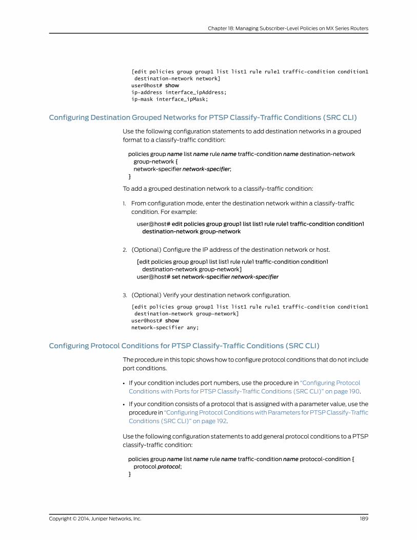
[edit policies group group1 list list1 rule rule1 traffic-condition condition1 destination-network network]user@host# showip-address interface_ipAddress;ip-mask interface_ipMask;
Configuring Destination Grouped Networks for PTSP Classify-Traffic Conditions (SRC CLI)
Use the following configuration statements to add destination networks in a grouped
format to a classify-traffic condition:
policies group name list name rule name traffic-condition name destination-networkgroup-network {network-specifier network-specifier;
}
To add a grouped destination network to a classify-traffic condition:
1. From configuration mode, enter the destination network within a classify-traffic
condition. For example:
user@host# edit policies group group1 list list1 rule rule1 traffic-condition condition1destination-network group-network
2. (Optional) Configure the IP address of the destination network or host.
[edit policies group group1 list list1 rule rule1 traffic-condition condition1destination-network group-network]
user@host# set network-specifier network-specifier
3. (Optional) Verify your destination network configuration.
[edit policies group group1 list list1 rule rule1 traffic-condition condition1 destination-network group-network] user@host# shownetwork-specifier any;
Configuring Protocol Conditions for PTSP Classify-Traffic Conditions (SRC CLI)
The procedure in this topic shows how to configure protocol conditions that do not include
port conditions.
• If your condition includes port numbers, use the procedure in “Configuring Protocol
Conditions with Ports for PTSP Classify-Traffic Conditions (SRC CLI)” on page 190.
• If your condition consists of a protocol that is assigned with a parameter value, use the
procedure in “Configuring Protocol Conditions with Parameters for PTSP Classify-Traffic
Conditions (SRC CLI)” on page 192.
Use the following configuration statements to add general protocol conditions to a PTSP
classify-traffic condition:
policies group name list name rule name traffic-condition name protocol-condition {protocol protocol;
}
189Copyright © 2014, Juniper Networks, Inc.
Chapter 18: Managing Subscriber-Level Policies on MX Series Routers
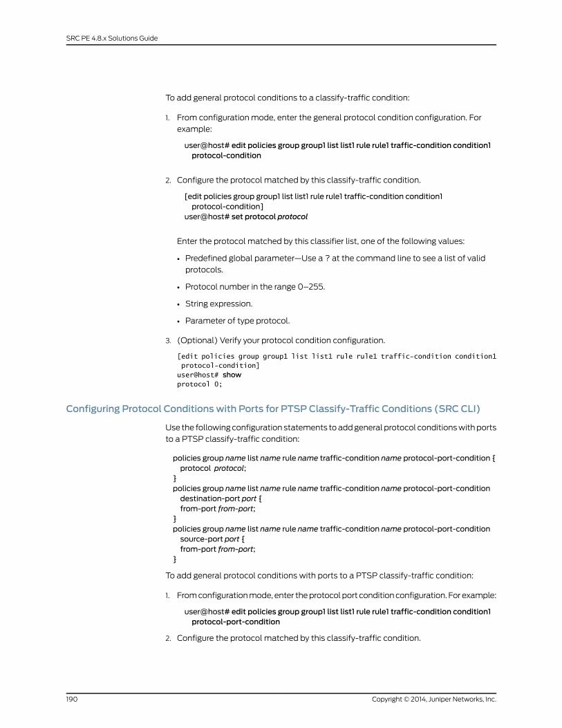
To add general protocol conditions to a classify-traffic condition:
1. From configuration mode, enter the general protocol condition configuration. For
example:
user@host# edit policies group group1 list list1 rule rule1 traffic-condition condition1protocol-condition
2. Configure the protocol matched by this classify-traffic condition.
[edit policies group group1 list list1 rule rule1 traffic-condition condition1protocol-condition]
user@host# set protocol protocol
Enter the protocol matched by this classifier list, one of the following values:
• Predefined global parameter—Use a ? at the command line to see a list of valid
protocols.
• Protocol number in the range 0–255.
• String expression.
• Parameter of type protocol.
3. (Optional) Verify your protocol condition configuration.
[edit policies group group1 list list1 rule rule1 traffic-condition condition1 protocol-condition]user@host# showprotocol 0;
Configuring Protocol Conditions with Ports for PTSP Classify-Traffic Conditions (SRC CLI)
Use the following configuration statements to add general protocol conditions with ports
to a PTSP classify-traffic condition:
policies group name list name rule name traffic-condition name protocol-port-condition {protocol protocol;
}policies group name list name rule name traffic-condition name protocol-port-conditiondestination-port port {from-port from-port;
}policies group name list name rule name traffic-condition name protocol-port-conditionsource-port port {from-port from-port;
}
To add general protocol conditions with ports to a PTSP classify-traffic condition:
1. From configuration mode, enter the protocol port condition configuration. For example:
user@host# edit policies group group1 list list1 rule rule1 traffic-condition condition1protocol-port-condition
2. Configure the protocol matched by this classify-traffic condition.
Copyright © 2014, Juniper Networks, Inc.190
SRC PE 4.8.x Solutions Guide

[edit policies group group1 list list1 rule rule1 traffic-condition condition1protocol-port-condition]
user@host# set protocol protocol
UDP is the only valid value for PTSP.
3. (Optional) Enter the destination port configuration for the protocol port configuration.
[edit policies group group1 list list1 rule rule1 traffic-condition condition1protocol-port-condition]
user@host# edit destination-port
4. (Optional) Configure the destination port.
[edit policies group group1 list list1 rule rule1 traffic-condition condition1protocol-port-condition destination-port port]
user@host# set from-port from-port
Where from-port is one of the following values:
• service_port—A predefined global parameter that is the port of the service as
specified by the service object
• Integer in the range 0–65535
• Expression—A range of port numbers; for example, 10..20
• Parameter of type port
Use a range of ports to specify port numbers that are greater than or less than a
specified port number. For example:
• To set a range of ports that is greater than 10, use 11..65535.
• To set a range of ports that is less than 200, use 0..199.
5. (Optional) Enter the source port configuration for the protocol port configuration.
user@host# up[edit policies group group1 list list1 rule rule1 traffic-condition condition1protocol-port-condition]
user@host# edit source-port
6. (Optional) Configure the source port.
[edit policies group group1 list list1 rule rule1 traffic-condition condition1protocol-port-condition source-port port]
user@host# set from-port from-port[edit policies group group1 list list1 rule rule1 traffic-condition condition1protocol-port-condition source-port port]
user@host# up
Where from-port is one of the following values:
• service_port—A predefined global parameter that is the port of the service as
specified by the service object.
• Integer in the range 0–65535
• Expression—A range of port numbers; for example, 10..20.
• Parameter of type port
191Copyright © 2014, Juniper Networks, Inc.
Chapter 18: Managing Subscriber-Level Policies on MX Series Routers
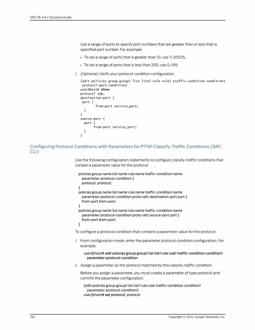
Use a range of ports to specify port numbers that are greater than or less than a
specified port number. For example:
• To set a range of ports that is greater than 10, use 11..65535.
• To set a range of ports that is less than 200, use 0..199.
7. (Optional) Verify your protocol condition configuration.
[edit policies group group1 list list1 rule rule1 traffic-condition condition1 protocol-port-condition]user@host# showprotocol udp;destination-port { port { from-port service_port; }}source-port { port { from-port service_port; }}
Configuring Protocol Conditions with Parameters for PTSP Classify-Traffic Conditions (SRCCLI)
Use the following configuration statements to configure classify-traffic conditions that
contain a parameter value for the protocol:
policies group name list name rule name traffic-condition nameparameter-protocol-condition {protocol protocol;
}policies group name list name rule name traffic-condition nameparameter-protocol-condition proto-attr destination-port port {from-port from-port;
}policies group name list name rule name traffic-condition nameparameter-protocol-condition proto-attr source-port port {from-port from-port;
}
To configure a protocol condition that contains a parameter value for the protocol:
1. From configuration mode, enter the parameter protocol condition configuration. For
example:
user@host# edit policies group group1 list list1 rule rule1 traffic-condition condition1parameter-protocol-condition
2. Assign a parameter as the protocol matched by this classify-traffic condition.
Before you assign a parameter, you must create a parameter of type protocol and
commit the parameter configuration.
[edit policies group group1 list list1 rule rule1 traffic-condition condition1parameter-protocol-condition]
user@host# set protocol protocol
Copyright © 2014, Juniper Networks, Inc.192
SRC PE 4.8.x Solutions Guide

3. (Optional) Enter the protocol attribute configuration.
[edit policies group group1 list list1 rule rule1 traffic-condition condition1parameter-protocol-condition]
user@host# edit proto-attr
4. (Optional) Enter the destination port configuration.
[edit policies group group1 list list1 rule rule1 traffic-condition condition1parameter-protocol-condition proto-attr]
user@host# edit destination-port port
5. (Optional) Configure the TCP or UDP destination port.
[edit policies group group1 list list1 rule rule1 traffic-condition condition1parameter-protocol-condition proto-attr destination-port port]
user@host# set from-port from-port
Where from-port is one of the following values:
• service_port—A predefined global parameter that is the port of the service as
specified by the service object.
• Integer in the range 0–65535.
• Expression—A range of port numbers; for example, 10..20.
• Parameter of type port.
Use a range of ports to specify port numbers that are greater than or less than a
specified port number. For example:
• To set a range of ports that is greater than 10, use 11..65535.
• To set a range of ports that is less than 200, use 0..199.
6. (Optional) Enter the source port configuration.
[edit policies group group1 list list1 rule rule1 traffic-condition condition1parameter-protocol-condition proto-attr destination-port port]
user@host# up[edit policies group group1 list list1 rule rule1 traffic-condition condition1parameter-protocol-condition proto-attr]
user@host# edit source-port port
7. (Optional) Configure the TCP or UDP source port.
[edit policies group group1 list list1 rule rule1 traffic-condition condition1parameter-protocol-condition proto-attr source-port port]
user@host# set from-port from-port[edit policies group group1 list list1 rule rule1 traffic-condition condition1parameter-protocol-condition proto-attr source-port port]
user@host# up[edit policies group group1 list list1 rule rule1 traffic-condition condition1parameter-protocol-condition proto-attr source-port]
user@host# up[edit policies group group1 list list1 rule rule1 traffic-condition condition1parameter-protocol-condition proto-attr ]
user@host# up
193Copyright © 2014, Juniper Networks, Inc.
Chapter 18: Managing Subscriber-Level Policies on MX Series Routers

Where from-port is one of the following values:
• service_port—A predefined global parameter that is the port of the service as
specified by the service object.
• Integer in the range 0–65535.
• Expression—A range of port numbers; for example, 10..20.
• Parameter of type port.
Use a range of ports to specify port numbers that are greater than or less than a
specified port number. For example:
• To set a range of ports that is greater than 10, use 11..65535.
• To set a range of ports that is less than 200, use 0..199.
8. (Optional) Verify the parameter protocol configuration.
[edit policies group group1 list list1 rule rule1 traffic-condition condition1 parameter-protocol-condition]user@host# showprotocol protocol; destination-port { port { from-port service_port; } }}
Configuring TCP Conditions for PTSP Classify-Traffic Conditions (SRC CLI)
Use the following configuration statements to add TCP conditions to a PTSP
classify-traffic condition:
policies group name list name rule name traffic-condition name tcp-condition {protocol tcp;
}
Because the protocol is already set to TCP, do not change the protocol or
protocol-operation options.
policies group name list name rule name traffic-condition name tcp-conditiondestination-port port {from-port from-port;
}
policies group name list name rule name traffic-condition name tcp-condition source-portport {from-port from-port;
}
To add TCP conditions to a PTSP classify-traffic condition:
1. From configuration mode, enter the TCP configuration. For example:
user@host# edit policies group group1 list list1 rule rule1 traffic-condition condition1tcp-condition
Copyright © 2014, Juniper Networks, Inc.194
SRC PE 4.8.x Solutions Guide

2. (Optional) Enter the protocol for the TCP configuration.
[edit policies group group1 list list1 rule rule1 traffic-condition condition1 tcp-condition]user@host# set protocol protocol
For PTSP this is set to TCP.
3. (Optional) Enter the destination port configuration for the TCP configuration.
[edit policies group group1 list list1 rule rule1 traffic-condition condition1 tcp-condition]user@host# edit destination-port port
4. (Optional) Configure the destination port.
[edit policies group group1 list list1 rule rule1 traffic-condition condition1 tcp-conditiondestination-port port]
user@host# set from-port from-port
Where from-port is one of the following values:
• service_port—A predefined global parameter that is the port of the service as
specified by the service object.
• Integer in the range 0–65535.
• Expression—A range of port numbers; for example, 10..20.
• Parameter of type port.
Use a range of ports to specify port numbers that are greater than or less than a
specified port number. For example:
• To set a range of ports that is greater than 10, use 11..65535.
• To set a range of ports that is less than 200, use 0..199.
5. (Optional) Enter the source port configuration for the TCP configuration.
[edit policies group group1 list list1 rule rule1 traffic-condition condition1 tcp-conditionsource-port port]
user@host# up[edit policies group group1 list list1 rule rule1 traffic-condition condition1]user@host# edit source-port port
6. (Optional) Configure the source port.
[edit policies group group1 list list1 rule rule1 traffic-condition condition1 tcp-conditionsource-port port]
user@host# set from-port from-port[edit policies group group1 list list1 rule rule1 traffic-condition condition1 tcp-conditionsource-port port]
user@host# up
Where from-port is one of the following values:
• service_port—A predefined global parameter that is the port of the service as
specified by the service object.
• Integer in the range 0–65535
• Expression—A range of port numbers; for example, 10..20.
• Parameter of type port
195Copyright © 2014, Juniper Networks, Inc.
Chapter 18: Managing Subscriber-Level Policies on MX Series Routers
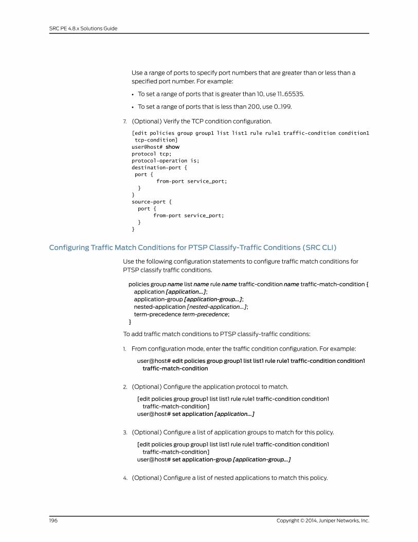
Use a range of ports to specify port numbers that are greater than or less than a
specified port number. For example:
• To set a range of ports that is greater than 10, use 11..65535.
• To set a range of ports that is less than 200, use 0..199.
7. (Optional) Verify the TCP condition configuration.
[edit policies group group1 list list1 rule rule1 traffic-condition condition1 tcp-condition]user@host# showprotocol tcp;protocol-operation is;destination-port { port { from-port service_port; }}source-port { port { from-port service_port; }}
Configuring Traffic Match Conditions for PTSP Classify-Traffic Conditions (SRC CLI)
Use the following configuration statements to configure traffic match conditions for
PTSP classify traffic conditions.
policies group name list name rule name traffic-condition name traffic-match-condition {application [application...];application-group [application-group...];nested-application [nested-application...];term-precedence term-precedence;
}
To add traffic match conditions to PTSP classify-traffic conditions:
1. From configuration mode, enter the traffic condition configuration. For example:
user@host# edit policies group group1 list list1 rule rule1 traffic-condition condition1traffic-match-condition
2. (Optional) Configure the application protocol to match.
[edit policies group group1 list list1 rule rule1 traffic-condition condition1traffic-match-condition]
user@host# set application [application...]
3. (Optional) Configure a list of application groups to match for this policy.
[edit policies group group1 list list1 rule rule1 traffic-condition condition1traffic-match-condition]
user@host# set application-group [application-group...]
4. (Optional) Configure a list of nested applications to match this policy.
Copyright © 2014, Juniper Networks, Inc.196
SRC PE 4.8.x Solutions Guide
[edit policies group group1 list list1 rule rule1 traffic-condition condition1traffic-match-condition]
user@host# set nested-application [nested-application...]
Separate items in the list with commas.
5. (Optional) Configure the term-precedence for this term in a given policy in relation to
other terms. Lower precedence terms are searched first. Precedence matters only
within the same class of policies, either dynamic or static. Terms with the same
precedence may be evaluated in any order.
[edit policies group group1 list list1 rule rule1 traffic-condition condition1traffic-match-condition]
user@host# set term-precedence term-precedence
Enter an integer in the range 1–254.
6. (Optional) Verify the filter condition configuration.
[edit policies group group1 list list1 rule rule1 traffic-condition condition1 traffic-match-condition]user@host# showterm—precedence 100;application—group group1;}
Configuring PTSP Actions
Actions define the action taken on packets that match conditions in a policy rule. You
create actions within policy rules.
Topics that discuss how to configure PTSP actions include:
• Configuring Policer-Ref Actions (SRC CLI) on page 197
• Configuring Forwarding Instance Actions (SRC CLI) on page 198
• Configuring Forwarding Class Actions (SRC CLI) on page 199
• Configuring Filter Actions (SRC CLI) on page 200
Configuring Policer-Ref Actions (SRC CLI)
Use this action to specify an action that references a PTSP policer instance. You can
configure policer ref actions for PTSP policy rules. The policer instance can be shared by
different service rules inside the same policy list. Multiple policy rules can reference the
same policer instance, so that the traffic matched by those rules is policed by the same
policer instance. If the policer instance is shared, all packets matching any of the service
rules are policed together.
197Copyright © 2014, Juniper Networks, Inc.
Chapter 18: Managing Subscriber-Level Policies on MX Series Routers
NOTE: For PTSP youmust:
• Set the role of the policy list to junos-ptsp
• Set the policy list rule type to ptsp-service-rule
• Set the policy list applicability option to both
• Create a policer instance.
Use the following configuration statements to configure a policer-ref action:
policies group name list name rule name policer-ref {policer-ref policer-name ;description description ;
}
To configure the policer-ref action:
1. From configuration mode, access the statements for the policer-ref action.
user@host# edit policies group name list name rule name policer-ref
2. Specify the name of the policer instance you want to reference.
[edit policies group name list name rule name policer-ref]user@host# set policer–name
3. Enter a description for the action.
[edit policies group name list name rule name policer-ref]user@host# set description description
Configuring Forwarding Instance Actions (SRC CLI)
You can configure forwarding instance actions for routers running the PTSP feature. This
action specifies a forwarding instance to assign to flows that match this policy.
NOTE: For PTSP youmust:
• Set the role of the policy list to junos-ptsp
• Set the policy list rule type to ptsp-service-rule
• Set the policy list applicability option to both
• Create a policer instance.
Use the following configuration statements to configure a forwarding instance action:
policies group name list name rule name forwarding-instance {forwarding-instance;forwarding-unit forwarding-unit ;description description ;
Copyright © 2014, Juniper Networks, Inc.198
SRC PE 4.8.x Solutions Guide
}
To configure a forwarding instance action:
1. From configuration mode, enter the forwarding instance configuration. For example:
user@host# edit policies group group1 list list1 rule rule1 forwarding-instance
2. (Optional) Specify a forwarding instance to assign to flows matching the policy.
user@host#editpoliciesgroupgroup1 list list1 rule rule1 forwarding-instance“_same_”
Allowed values are __same__, or one of the forwarding instances configured on the
router. The value __same__ forwards the flow in whatever forwarding instance it came
in or is set from static configuration.
3. (Optional) Specify a forwarding unit to assign to flows matching this policy. Forwarding
unit specifies the multiservice interface unit number for forward flows to in order to
reach the forwarding instance specified by the attribute forwarding-instance. Note
that there is only a very loose coupling between this unit number and the forwarding
instance. The binding between them only happens with the aid of additional router
configuration.
[edit policies group group1 list list1 rule rule1 forwarding-instance]user@host# set forwarding-unit forwarding-unit
Enter a value in the range 0–16384.
4. (Optional) Enter a description for the forwarding instance action.
[edit policies group group1 list list1 rule rule1 forwarding-instance]user@host# set description description
5. (Optional) Verify the forwarding instance action configuration.
[edit policies group bod list input rule pr forwarding-instance]user@host# show"'fi1'" forwarding-instance 1 description fi-sample
Configuring Forwarding Class Actions (SRC CLI)
You can configure forwarding class actions for Junos OS filter policy rules. The forwarding
class action causes the router to assign a forwarding class to packets that match the
associated classify-traffic condition.
The type of action that you can create depends on the type of policy rule. See Policy
Information Model.
Use the following configuration statements to configure a forwarding class action:
policies group name list name rule name forwarding-class {forwarding-class;description description;
}
To configure a forwarding class action:
199Copyright © 2014, Juniper Networks, Inc.
Chapter 18: Managing Subscriber-Level Policies on MX Series Routers
1. From configuration mode, enter the forwarding class action configuration.
user@host# edit policies group bod list input rule pr forwarding-class
2. (Optional) Configure the name of the forwarding class assigned to packets.
[edit policies group bod list input rule pr forwarding-class]user@host# set forwarding-class
3. (Optional) Enter a description for the forwarding class action.
[edit policies group bod list input rule pr forwarding-class]user@host# set description description
4. (Optional) Verify the forwarding class action configuration.
[edit policies group bod list input rule pr forwarding-class]user@host# showforwarding-class fc_expedited;description "Expedited forwarding class";
Configuring Filter Actions (SRC CLI)
Use this action to discard packets. You can configure filter actions for Junos OS filters
and JunosE policy rules. The type of action that you can create depends on the type of
policy rule. See Policy Information Model.
Use the following configuration statement to configure a filter action:
policies group name list name rule name filter {description description ;
}
To configure a filter action:
1. From configuration mode, enter the filter action configuration.
user@host# edit policies group junos_filter list in rule pr filter
2. (Optional) Enter a description for the filter action.
[edit policies group junos_filter list in rule pr filter]user@host# set description description
3. (Optional) Verify the filter action configuration.
[edit policies group junos_filter list in rule pr filter]user@host# showdescription "Filter action for Junos OS policies";
RelatedDocumentation
Configuring PTSP Policies (SRC CLI) on page 180•
• Configuring PTSP Policy Lists (SRC CLI) on page 181
• Configuring the PTSP Policer Instance (SRC CLI) on page 182
• Configuring PTSP Policy Rules (SRC CLI) on page 183
Copyright © 2014, Juniper Networks, Inc.200
SRC PE 4.8.x Solutions Guide
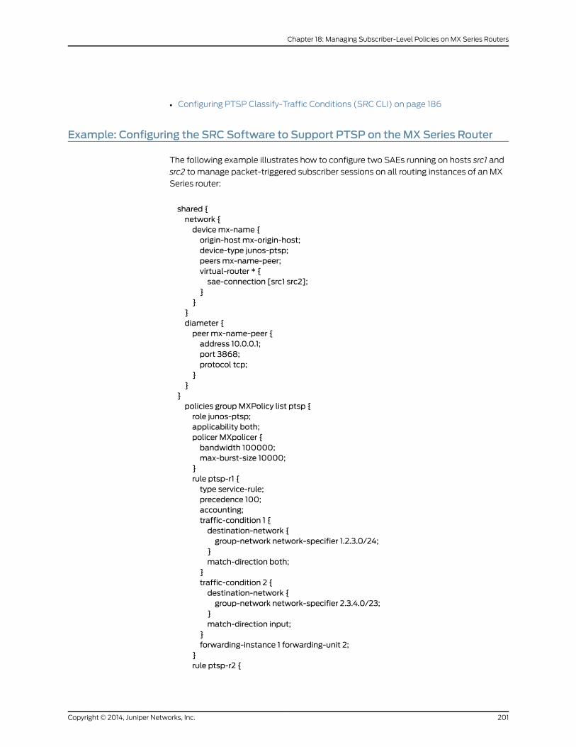
• Configuring PTSP Classify-Traffic Conditions (SRC CLI) on page 186
Example: Configuring the SRC Software to Support PTSP on theMX Series Router
The following example illustrates how to configure two SAEs running on hosts src1 and
src2 to manage packet-triggered subscriber sessions on all routing instances of an MX
Series router:
shared {network {devicemx-name {origin-host mx-origin-host;device-type junos-ptsp;peers mx-name-peer;virtual-router * {sae-connection [src1 src2];
}}
}diameter {peer mx-name-peer {address 10.0.0.1;port 3868;protocol tcp;
}}
}policies groupMXPolicy list ptsp {role junos-ptsp;applicability both;policer MXpolicer {bandwidth 100000;max-burst-size 10000;
}rule ptsp-r1 {type service-rule;precedence 100;accounting;traffic-condition 1 {destination-network {group-network network-specifier 1.2.3.0/24;
}match-direction both;
}traffic-condition 2 {destination-network {group-network network-specifier 2.3.4.0/23;
}match-direction input;
}forwarding-instance 1 forwarding-unit 2;
}rule ptsp-r2 {
201Copyright © 2014, Juniper Networks, Inc.
Chapter 18: Managing Subscriber-Level Policies on MX Series Routers

type service-rule;precedence 100;traffic-condition 1 {destination-network {group-network network-specifier 3.4.5.0/24;
}match-direction both;
}filter;
}}shared {sae {group <name-of-config-group> {configuration {driver {junos-ptsp {cached-driver-expiration 600;keep-alive-timeout 60;registry-retry-interval 30;reply-timeout 20;sae-community-manager PTSPCommunityManager;sequential-message-timeout 20;session-store {communications-timeout 60000;disk-load-buffer-size 1000000;idle-timeout 3600000;load-timeout 420000;maximum-backlog-ratio 1.5;maximum-file-size 25000000;maximum-queue-age 100;maximum-queue-size 51050;maximum-queued-operations 50;maximum-session-size 10000;minimum-backlog 5000000;minimum-disk-space-usage 25;network-buffer-size 51050;retry-interval 300000;rotation-batch-size 50;
}thread-idle-timeout 60;thread-pool-size 200;
}}
}}
}
The active SAE registers events from the MX Series router based on the configured origin
host (mx-origin-host in the example). If the origin host is not configured, the SAE uses
the device name (mx-name) instead.
RelatedDocumentation
Configuring PTSP on the MX Series Router on page 168•
• Managing Subscriber-Level Policies on MX Series Routers Overview on page 165
Copyright © 2014, Juniper Networks, Inc.202
SRC PE 4.8.x Solutions Guide
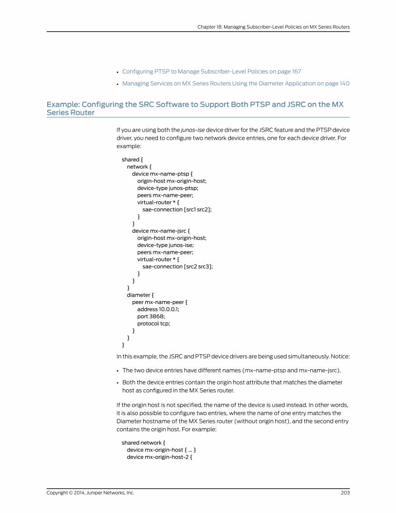
• Configuring PTSP to Manage Subscriber-Level Policies on page 167
• Managing Services on MX Series Routers Using the Diameter Application on page 140
Example: Configuring the SRC Software to Support Both PTSP and JSRC on theMXSeries Router
If you are using both the junos-ise device driver for the JSRC feature and the PTSP device
driver, you need to configure two network device entries, one for each device driver. For
example:
shared {network {devicemx-name-ptsp {origin-host mx-origin-host;device-type junos-ptsp;peers mx-name-peer;virtual-router * {sae-connection [src1 src2];
}}devicemx-name-jsrc {origin-host mx-origin-host;device-type junos-ise;peers mx-name-peer;virtual-router * {sae-connection [src2 src3];
}}
}diameter {peer mx-name-peer {address 10.0.0.1;port 3868;protocol tcp;
}}
}
In this example, the JSRC and PTSP device drivers are being used simultaneously. Notice:
• The two device entries have different names (mx-name-ptsp and mx-name-jsrc).
• Both the device entries contain the origin host attribute that matches the diameter
host as configured in the MX Series router.
If the origin host is not specified, the name of the device is used instead. In other words,
it is also possible to configure two entries, where the name of one entry matches the
Diameter hostname of the MX Series router (without origin host), and the second entry
contains the origin host. For example:
shared network {devicemx-origin-host { ... }devicemx-origin-host-2 {
203Copyright © 2014, Juniper Networks, Inc.
Chapter 18: Managing Subscriber-Level Policies on MX Series Routers

origin-host mx-origin-host;...
}}
RelatedDocumentation
• Managing Subscriber-Level Policies on MX Series Routers Overview on page 165
• Adding Network Devices (SRC CLI) on page 146
• Configuring JSRC on the MX Series Router on page 141
• Managing Services on MX Series Routers Using the Diameter Application on page 140
Copyright © 2014, Juniper Networks, Inc.204
SRC PE 4.8.x Solutions Guide
CHAPTER 19
Managing Subscriber Sessions on MXSeries Routers in an SRC Network
• Subscriber Sessions on MX Series Routers Overview on page 205
• Managing Subscriber Sessions on MX Series Routers (SRC CLI) on page 206
• Viewing Statistics for the Pseudo–RADIUS Authorization Server (SRC CLI) on page 221
• Monitoring Statistics for the Pseudo–RADIUS Authorization Server (SRC CLI) on page 221
Subscriber Sessions onMX Series Routers Overview
The SRC software can manage subscriber sessions on MX Series routers. Common types
of subscriber sessions on MX Series routers include:
• One interface subscriber session for each statically configured virtual local area network
(VLAN).
• One address subscriber session for each Dynamic Host Configuration Protocol (DHCP)
address.
You can manage subscriber sessions with the External Subscriber Monitor application
and the change-of-authorization (COA) script service. You can use External Subscriber
Monitor to authorize access requests from the MX Series router and to log in or log out
authorized subscribers. You can use the pseudo-RADIUS authorization server in External
Subscriber Monitor to limit the number of DHCP leases for a subscriber by specifying the
interface-name attribute in the subscriber profile and then setting a parameter substitution
for the dhcpLeaseLimit parameter for that interface. You can configure the COA script
service to dynamically activate or deactivate services on the MX Series router. This method
uses RADIUS attributes and RADIUS vendor-specific attributes (VSAs) to identify a
subscriber session whose services are to be activated or deactivated.
RelatedDocumentation
Configuring External Subscriber Monitor (SRC CLI) on page 206•
• Setting Up MX Series Routers in the SRC Network (SRC CLI) on page 217
205Copyright © 2014, Juniper Networks, Inc.
Managing Subscriber Sessions onMX Series Routers (SRC CLI)
The following topics provide procedures that allow you to manage subscriber sessions
on MX Series routers with the SRC CLI:
• Configuring External Subscriber Monitor (SRC CLI) on page 206
• Configuring Pseudo–RADIUS Authorization Server Properties (SRC CLI) on page 207
• Configuring the NIC Proxy for the Pseudo-RADIUS Authorization Server (SRC
CLI) on page 211
• Extracting RADIUS Attributes with the Pseudo–RADIUS Authorization Server (SRC
CLI) on page 214
• Enabling the Pseudo-RADIUS Authorization Server (SRC CLI) on page 217
• Disabling the Pseudo-RADIUS Authorization Server (SRC CLI) on page 217
• Setting Up MX Series Routers in the SRC Network (SRC CLI) on page 217
• Configuring the COA Script Service for MX Series Routers (SRC CLI) on page 218
• Configuring Parameters for the Script Service for MX Series Routers (SRC
CLI) on page 219
• Configuring Subscriptions to the Script Service on page 221
Configuring External Subscriber Monitor (SRC CLI)
Use External Subscriber Monitor to log in and log out authorized subscribers and to provide
interim updates for authorized subscribers.
To configure External Subscriber Monitor as a pseudo–RADIUS accounting server:
1. From configuration mode, access the configuration statement that configures the
local properties.
user@host# edit slot 0 external-subscriber-monitor
2. Configure the local properties for External Subscriber Monitor.
If you are configuring the pseudo–RADIUS authorization server, specify the
include-mac-address and include-interface-name options when configuring External
Subscriber Monitor so that the MAC address and interface name attributes are included
in the event notifications sent to the SAE.
[edit slot 0 external-subscriber-monitor]user@host# set ?
For more information about configuring External Subscriber Monitor, see Configuring
External Subscriber Monitor (SRC CLI).
RelatedDocumentation
Configuring Pseudo–RADIUS Authorization Server Properties (SRC CLI) on page 207•
• Configuring the NIC Proxy for the Pseudo-RADIUS Authorization Server (SRC CLI) on
page 211
Copyright © 2014, Juniper Networks, Inc.206
SRC PE 4.8.x Solutions Guide
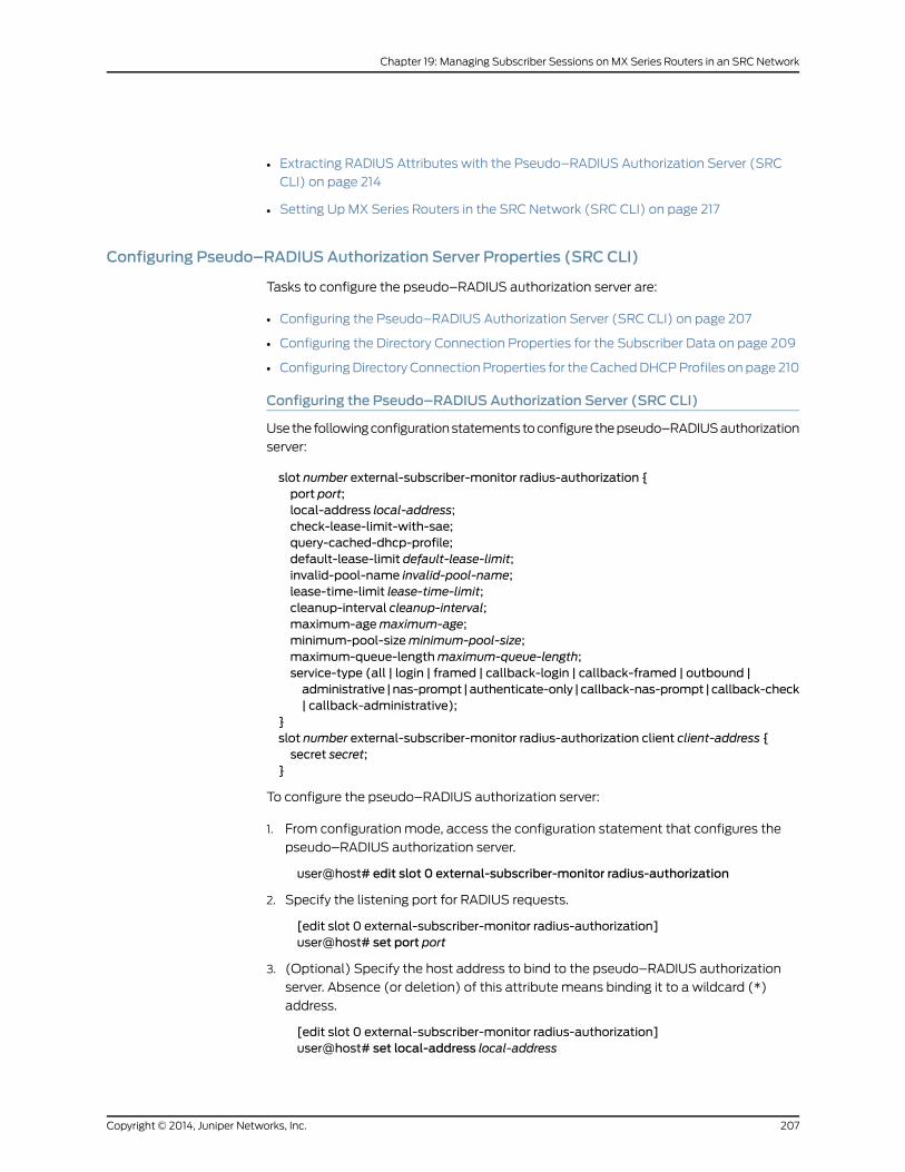
• Extracting RADIUS Attributes with the Pseudo–RADIUS Authorization Server (SRC
CLI) on page 214
• Setting Up MX Series Routers in the SRC Network (SRC CLI) on page 217
Configuring Pseudo–RADIUS Authorization Server Properties (SRC CLI)
Tasks to configure the pseudo–RADIUS authorization server are:
• Configuring the Pseudo–RADIUS Authorization Server (SRC CLI) on page 207
• Configuring the Directory Connection Properties for the Subscriber Data on page 209
• Configuring Directory Connection Properties for the Cached DHCP Profiles on page 210
Configuring the Pseudo–RADIUS Authorization Server (SRC CLI)
Use the following configuration statements to configure the pseudo–RADIUS authorization
server:
slot number external-subscriber-monitor radius-authorization {port port;local-address local-address;check-lease-limit-with-sae;query-cached-dhcp-profile;default-lease-limit default-lease-limit;invalid-pool-name invalid-pool-name;lease-time-limit lease-time-limit;cleanup-interval cleanup-interval;maximum-agemaximum-age;minimum-pool-sizeminimum-pool-size;maximum-queue-lengthmaximum-queue-length;service-type (all | login | framed | callback-login | callback-framed | outbound |administrative |nas-prompt |authenticate-only | callback-nas-prompt |callback-check| callback-administrative);
}slot number external-subscriber-monitor radius-authorization client client-address {secret secret;
}
To configure the pseudo–RADIUS authorization server:
1. From configuration mode, access the configuration statement that configures the
pseudo–RADIUS authorization server.
user@host# edit slot 0 external-subscriber-monitor radius-authorization
2. Specify the listening port for RADIUS requests.
[edit slot 0 external-subscriber-monitor radius-authorization]user@host# set port port
3. (Optional) Specify the host address to bind to the pseudo–RADIUS authorization
server. Absence (or deletion) of this attribute means binding it to a wildcard (*)
address.
[edit slot 0 external-subscriber-monitor radius-authorization]user@host# set local-address local-address
207Copyright © 2014, Juniper Networks, Inc.
Chapter 19: Managing Subscriber Sessions on MX Series Routers in an SRC Network
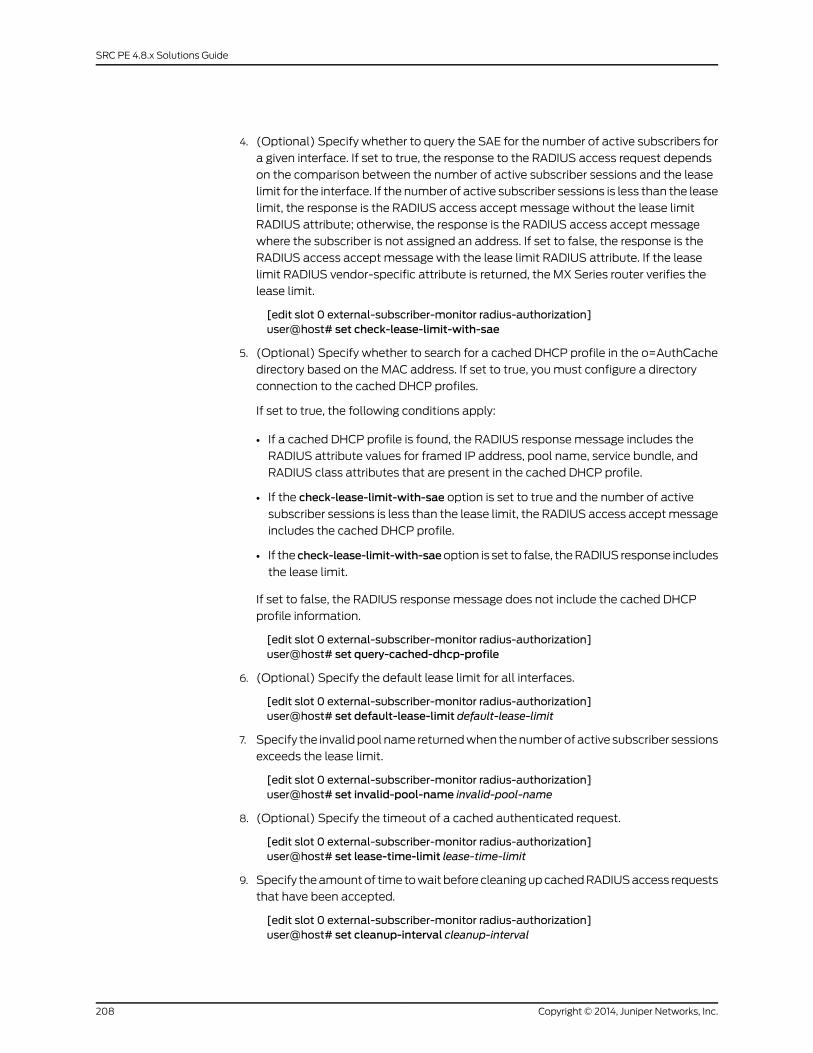
4. (Optional) Specify whether to query the SAE for the number of active subscribers for
a given interface. If set to true, the response to the RADIUS access request depends
on the comparison between the number of active subscriber sessions and the lease
limit for the interface. If the number of active subscriber sessions is less than the lease
limit, the response is the RADIUS access accept message without the lease limit
RADIUS attribute; otherwise, the response is the RADIUS access accept message
where the subscriber is not assigned an address. If set to false, the response is the
RADIUS access accept message with the lease limit RADIUS attribute. If the lease
limit RADIUS vendor-specific attribute is returned, the MX Series router verifies the
lease limit.
[edit slot 0 external-subscriber-monitor radius-authorization]user@host# set check-lease-limit-with-sae
5. (Optional) Specify whether to search for a cached DHCP profile in the o=AuthCache
directory based on the MAC address. If set to true, you must configure a directory
connection to the cached DHCP profiles.
If set to true, the following conditions apply:
• If a cached DHCP profile is found, the RADIUS response message includes the
RADIUS attribute values for framed IP address, pool name, service bundle, and
RADIUS class attributes that are present in the cached DHCP profile.
• If the check-lease-limit-with-sae option is set to true and the number of active
subscriber sessions is less than the lease limit, the RADIUS access accept message
includes the cached DHCP profile.
• If the check-lease-limit-with-saeoption is set to false, the RADIUS response includes
the lease limit.
If set to false, the RADIUS response message does not include the cached DHCP
profile information.
[edit slot 0 external-subscriber-monitor radius-authorization]user@host# set query-cached-dhcp-profile
6. (Optional) Specify the default lease limit for all interfaces.
[edit slot 0 external-subscriber-monitor radius-authorization]user@host# set default-lease-limit default-lease-limit
7. Specify the invalid pool name returned when the number of active subscriber sessions
exceeds the lease limit.
[edit slot 0 external-subscriber-monitor radius-authorization]user@host# set invalid-pool-name invalid-pool-name
8. (Optional) Specify the timeout of a cached authenticated request.
[edit slot 0 external-subscriber-monitor radius-authorization]user@host# set lease-time-limit lease-time-limit
9. Specify the amount of time to wait before cleaning up cached RADIUS access requests
that have been accepted.
[edit slot 0 external-subscriber-monitor radius-authorization]user@host# set cleanup-interval cleanup-interval
Copyright © 2014, Juniper Networks, Inc.208
SRC PE 4.8.x Solutions Guide
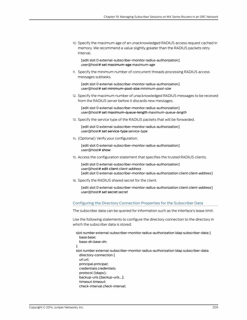
10. Specify the maximum age of an unacknowledged RADIUS access request cached in
memory. We recommend a value slightly greater than the RADIUS packets retry
interval.
[edit slot 0 external-subscriber-monitor radius-authorization]user@host# setmaximum-agemaximum-age
11. Specify the minimum number of concurrent threads processing RADIUS access
messages subtasks.
[edit slot 0 external-subscriber-monitor radius-authorization]user@host# setminimum-pool-sizeminimum-pool-size
12. Specify the maximum number of unacknowledged RADIUS messages to be received
from the RADIUS server before it discards new messages.
[edit slot 0 external-subscriber-monitor radius-authorization]user@host# setmaximum-queue-lengthmaximum-queue-length
13. Specify the service type of the RADIUS packets that will be forwarded.
[edit slot 0 external-subscriber-monitor radius-authorization]user@host# set service-type service-type
14. (Optional) Verify your configuration.
[edit slot 0 external-subscriber-monitor radius-authorization]user@host# show
15. Access the configuration statement that specifies the trusted RADIUS clients.
[edit slot 0 external-subscriber-monitor radius-authorization]user@host# edit client client-address[edit slot 0 external-subscriber-monitor radius-authorization client client-address]
16. Specify the RADIUS shared secret for the client.
[edit slot 0 external-subscriber-monitor radius-authorization client client-address]user@host# set secret secret
Configuring the Directory Connection Properties for the Subscriber Data
The subscriber data can be queried for information such as the interface’s lease limit.
Use the following statements to configure the directory connection to the directory in
which the subscriber data is stored:
slot number external-subscriber-monitor radius-authorization ldap subscriber-data {base base;base-dn base-dn;
}slot number external-subscriber-monitor radius-authorization ldap subscriber-datadirectory-connection {url url;principal principal;credentials credentials;protocol (ldaps);backup-urls [backup-urls...];timeout timeout;check-interval check-interval;
209Copyright © 2014, Juniper Networks, Inc.
Chapter 19: Managing Subscriber Sessions on MX Series Routers in an SRC Network

blacklist;snmp-agent;signature-dn signature-dn;
}
To configure directory connection properties:
1. From configuration mode, access the configuration statement that configures the
directory connection.
user@host# edit slot 0 external-subscriber-monitor radius-authorization ldapsubscriber-data
2. Specify the top-level directory DN.
[edit slot 0 external-subscriber-monitor radius-authorization ldap subscriber-data]user@host# set base base
3. Specify the subtree in the directory in which the subscriber data is stored.
[edit slot 0 external-subscriber-monitor radius-authorization ldap subscriber-data]user@host# set base-dn base-dn
4. Access the configuration statement that configures the directory connection properties.
[edit slot 0 external-subscriber-monitor radius-authorization ldap subscriber-data]user@host# edit directory-connection
5. Specify the directory connection properties for the subscriber data.
[edit slot 0 external-subscriber-monitor radius-authorization ldap subscriber-datadirectory-connection]
user@host# set ?
6. (Optional) Verify your configuration.
[edit slot 0 external-subscriber-monitor radius-authorization ldap subscriber-data]user@host# show
Configuring Directory Connection Properties for the Cached DHCP Profiles
The DHCP profiles can be queried by MAC address for the RADIUS framed IP address for
authorized subscribers or invalid pool name for unauthorized subscribers.
Use the following statements to configure the directory connection to the directory in
which the cached DHCP profiles are stored:
slot number external-subscriber-monitor radius-authorization ldap cached-dhcp-profile{base base;base-dn base-dn;
}slot number external-subscriber-monitor radius-authorization ldap cached-dhcp-profiledirectory-connection {url url;principal principal;credentials credentials;protocol (ldaps);backup-urls [backup-urls...];timeout timeout;
Copyright © 2014, Juniper Networks, Inc.210
SRC PE 4.8.x Solutions Guide
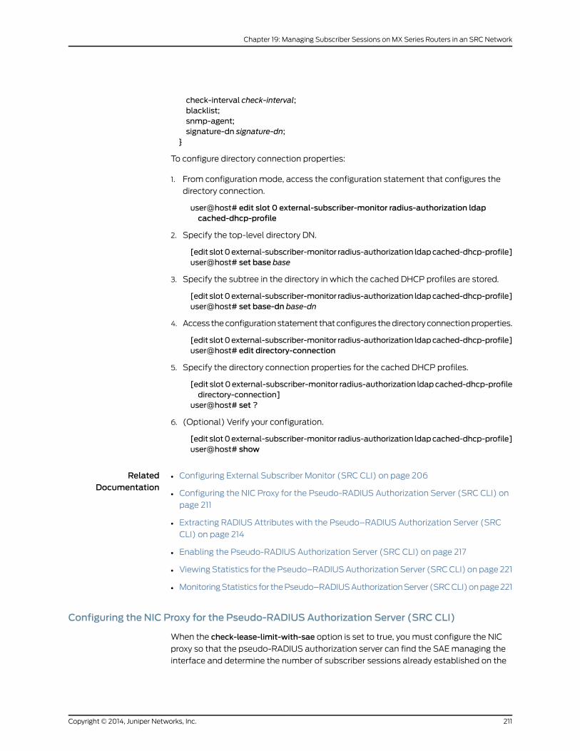
check-interval check-interval;blacklist;snmp-agent;signature-dn signature-dn;
}
To configure directory connection properties:
1. From configuration mode, access the configuration statement that configures the
directory connection.
user@host# edit slot 0 external-subscriber-monitor radius-authorization ldapcached-dhcp-profile
2. Specify the top-level directory DN.
[edit slot0external-subscriber-monitor radius-authorization ldapcached-dhcp-profile]user@host# set base base
3. Specify the subtree in the directory in which the cached DHCP profiles are stored.
[edit slot0external-subscriber-monitor radius-authorization ldapcached-dhcp-profile]user@host# set base-dn base-dn
4. Access the configuration statement that configures the directory connection properties.
[edit slot0external-subscriber-monitor radius-authorization ldapcached-dhcp-profile]user@host# edit directory-connection
5. Specify the directory connection properties for the cached DHCP profiles.
[edit slot0external-subscriber-monitor radius-authorization ldapcached-dhcp-profiledirectory-connection]
user@host# set ?
6. (Optional) Verify your configuration.
[edit slot0external-subscriber-monitor radius-authorization ldapcached-dhcp-profile]user@host# show
RelatedDocumentation
Configuring External Subscriber Monitor (SRC CLI) on page 206•
• Configuring the NIC Proxy for the Pseudo-RADIUS Authorization Server (SRC CLI) on
page 211
• Extracting RADIUS Attributes with the Pseudo–RADIUS Authorization Server (SRC
CLI) on page 214
• Enabling the Pseudo-RADIUS Authorization Server (SRC CLI) on page 217
• Viewing Statistics for the Pseudo–RADIUS Authorization Server (SRC CLI) on page 221
• Monitoring Statistics for the Pseudo–RADIUS Authorization Server (SRC CLI) on page 221
Configuring the NIC Proxy for the Pseudo-RADIUS Authorization Server (SRC CLI)
When the check-lease-limit-with-sae option is set to true, you must configure the NIC
proxy so that the pseudo-RADIUS authorization server can find the SAE managing the
interface and determine the number of subscriber sessions already established on the
211Copyright © 2014, Juniper Networks, Inc.
Chapter 19: Managing Subscriber Sessions on MX Series Routers in an SRC Network
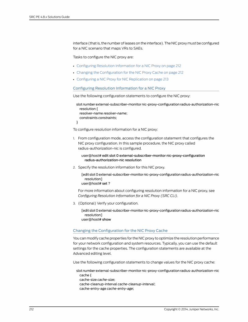
interface (that is, the number of leases on the interface). The NIC proxy must be configured
for a NIC scenario that maps VRs to SAEs.
Tasks to configure the NIC proxy are:
• Configuring Resolution Information for a NIC Proxy on page 212
• Changing the Configuration for the NIC Proxy Cache on page 212
• Configuring a NIC Proxy for NIC Replication on page 213
Configuring Resolution Information for a NIC Proxy
Use the following configuration statements to configure the NIC proxy:
slotnumberexternal-subscriber-monitor nic-proxy-configuration radius-authorization-nicresolution {resolver-name resolver-name;constraints constraints;
}
To configure resolution information for a NIC proxy:
1. From configuration mode, access the configuration statement that configures the
NIC proxy configuration. In this sample procedure, the NIC proxy called
radius-authorization-nic is configured.
user@host# edit slot 0 external-subscriber-monitor nic-proxy-configurationradius-authorization-nic resolution
2. Specify the resolution information for this NIC proxy.
[edit slot0external-subscriber-monitornic-proxy-configuration radius-authorization-nicresolution]
user@host# set ?
For more information about configuring resolution information for a NIC proxy, see
Configuring Resolution Information for a NIC Proxy (SRC CLI).
3. (Optional) Verify your configuration.
[edit slot0external-subscriber-monitornic-proxy-configuration radius-authorization-nicresolution]
user@host# show
Changing the Configuration for the NIC Proxy Cache
You can modify cache properties for the NIC proxy to optimize the resolution performance
for your network configuration and system resources. Typically, you can use the default
settings for the cache properties. The configuration statements are available at the
Advanced editing level.
Use the following configuration statements to change values for the NIC proxy cache:
slotnumberexternal-subscriber-monitor nic-proxy-configuration radius-authorization-niccache {cache-size cache-size;cache-cleanup-interval cache-cleanup-interval;cache-entry-age cache-entry-age;
Copyright © 2014, Juniper Networks, Inc.212
SRC PE 4.8.x Solutions Guide
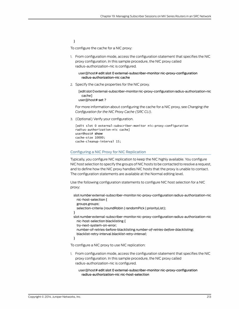
}
To configure the cache for a NIC proxy:
1. From configuration mode, access the configuration statement that specifies the NIC
proxy configuration. In this sample procedure, the NIC proxy called
radius-authorization-nic is configured.
user@host# edit slot 0 external-subscriber-monitor nic-proxy-configurationradius-authorization-nic cache
2. Specify the cache properties for the NIC proxy.
[edit slot0external-subscriber-monitornic-proxy-configuration radius-authorization-niccache]
user@host# set ?
For more information about configuring the cache for a NIC proxy, see Changing the
Configuration for the NIC Proxy Cache (SRC CLI).
3. (Optional) Verify your configuration.
[edit slot 0 external-subscriber-monitor nic-proxy-configuration radius-authorization-nic cache]user@host# showcache-size 10000; cache-cleanup-interval 15;
Configuring a NIC Proxy for NIC Replication
Typically, you configure NIC replication to keep the NIC highly available. You configure
NIC host selection to specify the groups of NIC hosts to be contacted to resolve a request,
and to define how the NIC proxy handles NIC hosts that the proxy is unable to contact.
The configuration statements are available at the Normal editing level.
Use the following configuration statements to configure NIC host selection for a NIC
proxy:
slotnumberexternal-subscriber-monitor nic-proxy-configuration radius-authorization-nicnic-host-selection {groups groups;selection-criteria (roundRobin | randomPick | priorityList);
}slotnumberexternal-subscriber-monitor nic-proxy-configuration radius-authorization-nicnic-host-selection blacklisting {try-next-system-on-error;number-of-retries-before-blacklisting number-of-retries-before-blacklisting;blacklist-retry-interval blacklist-retry-interval;
}
To configure a NIC proxy to use NIC replication:
1. From configuration mode, access the configuration statement that specifies the NIC
proxy configuration. In this sample procedure, the NIC proxy called
radius-authorization-nic is configured.
user@host# edit slot 0 external-subscriber-monitor nic-proxy-configurationradius-authorization-nic nic-host-selection
213Copyright © 2014, Juniper Networks, Inc.
Chapter 19: Managing Subscriber Sessions on MX Series Routers in an SRC Network
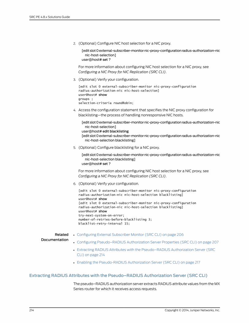
2. (Optional) Configure NIC host selection for a NIC proxy.
[edit slot0external-subscriber-monitornic-proxy-configuration radius-authorization-nicnic-host-selection]
user@host# set ?
For more information about configuring NIC host selection for a NIC proxy, see
Configuring a NIC Proxy for NIC Replication (SRC CLI).
3. (Optional) Verify your configuration.
[edit slot 0 external-subscriber-monitor nic-proxy-configuration radius-authorization-nic nic-host-selection]user@host# showgroups ; selection-criteria roundRobin;
4. Access the configuration statement that specifies the NIC proxy configuration for
blacklisting—the process of handling nonresponsive NIC hosts.
[edit slot0external-subscriber-monitornic-proxy-configuration radius-authorization-nicnic-host-selection]
user@host# edit blacklisting[edit slot0external-subscriber-monitornic-proxy-configuration radius-authorization-nicnic-host-selection blacklisting]
5. (Optional) Configure blacklisting for a NIC proxy.
[edit slot0external-subscriber-monitornic-proxy-configuration radius-authorization-nicnic-host-selection blacklisting]
user@host# set ?
For more information about configuring NIC host selection for a NIC proxy, see
Configuring a NIC Proxy for NIC Replication (SRC CLI).
6. (Optional) Verify your configuration.
[edit slot 0 external-subscriber-monitor nic-proxy-configurationradius-authorization-nic nic-host-selection blacklisting]user@host# show[edit slot 0 external-subscriber-monitor nic-proxy-configuration radius-authorization-nic nic-host-selection blacklisting]user@host# showtry-next-system-on-error; number-of-retries-before-blacklisting 3; blacklist-retry-interval 15;
RelatedDocumentation
Configuring External Subscriber Monitor (SRC CLI) on page 206•
• Configuring Pseudo–RADIUS Authorization Server Properties (SRC CLI) on page 207
• Extracting RADIUS Attributes with the Pseudo–RADIUS Authorization Server (SRC
CLI) on page 214
• Enabling the Pseudo-RADIUS Authorization Server (SRC CLI) on page 217
Extracting RADIUS Attributes with the Pseudo–RADIUS Authorization Server (SRC CLI)
The pseudo–RADIUS authorization server extracts RADIUS attribute values from the MX
Series router for which it receives access requests.
Copyright © 2014, Juniper Networks, Inc.214
SRC PE 4.8.x Solutions Guide

Tasks to configure the RADIUS attribute value extraction are:
• Extracting Interface Name Attribute Values on page 215
• Extracting Virtual Router Name Attribute Values on page 215
Extracting Interface Name Attribute Values
The interface name value is the subscriber line interface. This value is extracted from the
NAS-Port-ID attribute. The default settings for this configuration are sufficient for most
applications.
Use the following configuration statements to extract the interface name value from the
RADIUS access request:
slotnumberexternal-subscriber-monitor radius-attribute-extractiondefault interface-name{regular-expression [regular-expression...];
}
To extract the interface name value:
1. From configuration mode, access the configuration statement that configures RADIUS
attribute extraction for the interface name value.
user@host#editslot0external-subscriber-monitor radius-attribute-extractiondefaultinterface-name
2. (Optional) Specify the RADIUS attribute value format with a regular expression. You
can group regular expressions by enclosing them in parentheses. The value for the
interface is the part of the NAS-Port-ID matched by the first group in your regular
expression. For more information about using regular expressions, see
http://java.sun.com/j2se/1.4.2/docs/api/java/util/regex/Pattern.html.
[edit slot 0 external-subscriber-monitor radius-attribute-extraction defaultinterface-name]
user@host# set regular-expression [regular-expression...]
For example, to specify that the extracted interface name value is ge-0/0/3.0 from
the NAS-Port attribute value of ge-0/0/3.0[:0-0]:
[edit slot 0 external-subscriber-monitor radius-attribute-extraction defaultinterface-name]
user@host# set regular-expression ([a-zA-Z0-9-/.]+)\\[:.*
Extracting Virtual Router Name Attribute Values
In most cases, the virtual router name value is in the format default@<NAS-ID attribute>.
The default settings extract a virtual router name in this format. If your environment is
different, you can configure a different format for the extracted value.
Use the following configuration statements to extract the virtual router name value from
the RADIUS access request:
slot number external-subscriber-monitor radius-attribute-extraction defaultvirtual-router-name {id id;
215Copyright © 2014, Juniper Networks, Inc.
Chapter 19: Managing Subscriber Sessions on MX Series Routers in an SRC Network

vsa;vsa-id vsa-id;regular-expression [regular-expression...];type (raw-byte | chars);prefix prefix;
}
To extract the virtual router name value:
1. From configuration mode, access the configuration statement that configures RADIUS
attribute extraction for the virtual router name value.
user@host#editslot0external-subscriber-monitor radius-attribute-extractiondefaultvirtual-router-name
2. Specify the RADIUS attribute identifier.
[edit slot 0 external-subscriber-monitor radius-attribute-extraction defaultvirtual-router-name]
user@host# set id id
3. (Optional) Specify whether the RADIUS attribute is a vendor-specific attribute.
[edit slot 0 external-subscriber-monitor radius-attribute-extraction defaultvirtual-router-name]
user@host# set vsa
4. (Optional) Specify the RADIUS vendor-specific attribute identifier.
[edit slot 0 external-subscriber-monitor radius-attribute-extraction defaultvirtual-router-name]
user@host# set vsa-id vsa-id
5. (Optional) Specify the RADIUS attribute value format with a regular expression. You
can group regular expressions by enclosing them in parentheses. The value for the
interface is the part of the NAS-Port-ID matched by the first group in your regular
expression. For more information about using regular expressions, see
http://java.sun.com/j2se/1.4.2/docs/api/java/util/regex/Pattern.html.
[edit slot 0 external-subscriber-monitor radius-attribute-extraction defaultvirtual-router-name]
user@host# set regular-expression [regular-expression...]
For example:
[edit slot 0 external-subscriber-monitor radius-attribute-extraction defaultvirtual-router-name]
user@host# set regular-expression ([a-zA-Z0-9-/.]+)\\[:.*
6. (Optional) Specify the value type of this RADIUS attribute.
[edit slot 0 external-subscriber-monitor radius-attribute-extraction defaultvirtual-router-name]
user@host# set type (raw-byte | chars)
where:
• raw-byte—Raw bytes
• chars—Sequence of characters
Copyright © 2014, Juniper Networks, Inc.216
SRC PE 4.8.x Solutions Guide
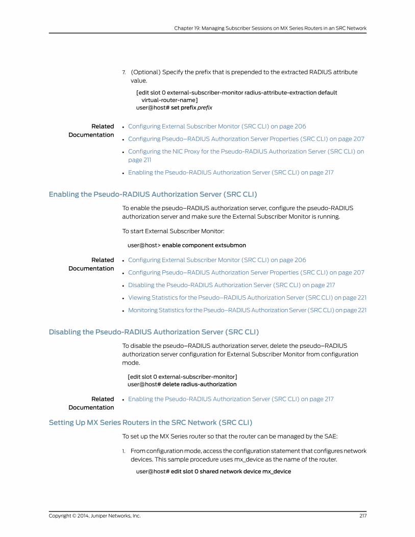
7. (Optional) Specify the prefix that is prepended to the extracted RADIUS attribute
value.
[edit slot 0 external-subscriber-monitor radius-attribute-extraction defaultvirtual-router-name]
user@host# set prefix prefix
RelatedDocumentation
Configuring External Subscriber Monitor (SRC CLI) on page 206•
• Configuring Pseudo–RADIUS Authorization Server Properties (SRC CLI) on page 207
• Configuring the NIC Proxy for the Pseudo-RADIUS Authorization Server (SRC CLI) on
page 211
• Enabling the Pseudo-RADIUS Authorization Server (SRC CLI) on page 217
Enabling the Pseudo-RADIUS Authorization Server (SRC CLI)
To enable the pseudo–RADIUS authorization server, configure the pseudo-RADIUS
authorization server and make sure the External Subscriber Monitor is running.
To start External Subscriber Monitor:
user@host> enable component extsubmon
RelatedDocumentation
Configuring External Subscriber Monitor (SRC CLI) on page 206•
• Configuring Pseudo–RADIUS Authorization Server Properties (SRC CLI) on page 207
• Disabling the Pseudo-RADIUS Authorization Server (SRC CLI) on page 217
• Viewing Statistics for the Pseudo–RADIUS Authorization Server (SRC CLI) on page 221
• Monitoring Statistics for the Pseudo–RADIUS Authorization Server (SRC CLI) on page 221
Disabling the Pseudo-RADIUS Authorization Server (SRC CLI)
To disable the pseudo–RADIUS authorization server, delete the pseudo–RADIUS
authorization server configuration for External Subscriber Monitor from configuration
mode.
[edit slot 0 external-subscriber-monitor]user@host# delete radius-authorization
RelatedDocumentation
Enabling the Pseudo-RADIUS Authorization Server (SRC CLI) on page 217•
Setting UpMX Series Routers in the SRCNetwork (SRC CLI)
To set up the MX Series router so that the router can be managed by the SAE:
1. From configuration mode, access the configuration statement that configures network
devices. This sample procedure uses mx_device as the name of the router.
user@host# edit slot 0 shared network devicemx_device
217Copyright © 2014, Juniper Networks, Inc.
Chapter 19: Managing Subscriber Sessions on MX Series Routers in an SRC Network

2. Set the type of device to third-party.
[edit shared network devicemx_device]user@host# set device-type third-party
3. From configuration mode, access the configuration statements for virtual routers. For
MX Series routers, use the name default for the virtual router.
[edit shared network devicemx_device]user@host# edit virtual-router default
4. Specify the addresses of SAEs that can manage this router.
[edit shared network devicemx_device virtual-router default]user@host# set sae-connection [sae-connection...]
RelatedDocumentation
Configuring External Subscriber Monitor (SRC CLI) on page 206•
• Configuring Pseudo–RADIUS Authorization Server Properties (SRC CLI) on page 207
• Configuring the COA Script Service for MX Series Routers (SRC CLI) on page 218
• Configuring Subscriptions to the Script Service on page 221
Configuring the COA Script Service for MX Series Routers (SRC CLI)
To configure the script service for the MX Series router:
1. Create a script service in the services global service name hierarchy or the services
scope name service name hierarchy. For example:
[edit]user@host# edit services global service cos-service
2. Set the type to script.
[edit services global service cos-service]user@host# set type script
3. (Optional) Configure other properties as needed for your service.
4. Configure the script properties.
a. Access the script hierarchy for the configured script service.
[edit services global service cos-service]user@host# edit script
b. Specify URL as the script type.
[edit services global service cos-service script]user@host# set script-type url
c. Specify the name of the Java class that implements the script service.
[edit services global service cos-service script]user@host# set class-name net.juniper.smgt.scriptServices.coa.CoaService
d. Configure the URL of the script service or the path and filename of the service.
[edit services global service cos-service script]user@host# set file file:///opt/UMC/sae/lib/coa.jar
Copyright © 2014, Juniper Networks, Inc.218
SRC PE 4.8.x Solutions Guide
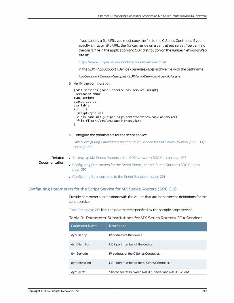
If you specify a file URL, you must copy the file to the C Series Controller. If you
specify an ftp or http URL, the file can reside on a centralized server. You can find
the coa.jar file in the application and SDK distribution on the Juniper Networks Web
site at:
https://www.juniper.net/support/csc/swdist-erx/src.html
in the SDK+AppSupport+Demos+Samples.tar.gz archive file with the pathname:
AppSupport+Demos+Samples/SDK/scriptServices/coa/lib/coa.jar
5. Verify the configuration.
[edit services global service cos-service script]user@host# showtype script;status active;available;script { script-type url; class-name net.juniper.smgt.scriptServices.coa.CoaService; file file:///opt/UMC/sae/lib/coa.jar;}
6. Configure the parameters for the script service.
See “Configuring Parameters for the Script Service for MX Series Routers (SRC CLI)”
on page 219.
RelatedDocumentation
Setting Up MX Series Routers in the SRC Network (SRC CLI) on page 217•
• Configuring Parameters for the Script Service for MX Series Routers (SRC CLI) on
page 219
• Configuring Subscriptions to the Script Service on page 221
Configuring Parameters for the Script Service for MX Series Routers (SRC CLI)
Provide parameter substitutions with the values that are in the service definitions for the
script service.
Table 9 on page 219 lists the parameters specified by the sample script service.
Table 9: Parameter Substitutions for MX Series Routers COA Services
DescriptionParameter Name
IP address of the device.dynClientIp
UDP port number of the device.dynClientPort
IP address of the C Series Controller.dynServerIp
UDP port number of the C Series Controller.dynServerPort
Shared secret between RADIUS server and RADIUS client.dynSecret
219Copyright © 2014, Juniper Networks, Inc.
Chapter 19: Managing Subscriber Sessions on MX Series Routers in an SRC Network
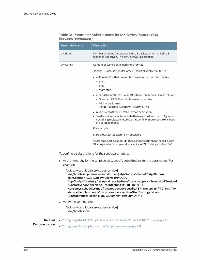
Table 9: Parameter Substitutions for MX Series Routers COAServices (continued)
DescriptionParameter Name
Number of retries for sending RADIUS packets when no RADIUSresponse is received. The retry interval is 3 seconds.
dynRetry
Content of service definition in the format
<action>.<radiusAttributeName>=<pluginEventAttribute>\n
• action—Action that is executed on packet content (attribute):
• start
• stop
• start-stop
• radiusAttributeName—Valid RADIUS attribute specified as follows:
• Standard RADIUS attribute name or number
• VSA in the formatvendor-specific.<vendor#>.<vsa#>.string
• pluginEventAttribute—Valid Python expression
• \n—New-line character included between the lines of a configurationcontaining multiple lines; the entire configuration must be enclosedin quotation marks.
For example:
start-stop.Acct-Session-Id = ifSessionId
“start-stop.Acct-Session-Id=ifSessionId\nstart.vendor-specific.4874.10.string=’video’\nstop.vendor-specific.4874.10.string=’default’\n"
dynConfig
To configure substitutions for the script parameters:
1. At the hierarchy for the script service, specify substitutions for the parameters. For
example:
[edit services global service cos-service]user@host# set parameter substitution [ dynSecret=\”secret\” dynRetry=2dynClientIp=10.227.7.111 dynClientPort=9099"dynConfig=\"start-stop.1.string=primaryUserName\\nstart-stop.Acct-Session-id=ifSessionId\\nstart.vendor-specific.4874.108.string=['T01 3m', 'T04consumer-scheduler-map']\\nstop.vendor-specific.4874.108.string=['T01 1m', 'T04data-scheduler-map']\\nstart.vendor-specific.4874.10.string='video'\\nstop.vendor-specific.4874.10.string='default'\\n\"" ]
2. Verify the configuration.
[edit services global service cos-service]user@host# show
RelatedDocumentation
Configuring the COA Script Service for MX Series Routers (SRC CLI) on page 218•
• Configuring Subscriptions to the Script Service on page 221
Copyright © 2014, Juniper Networks, Inc.220
SRC PE 4.8.x Solutions Guide
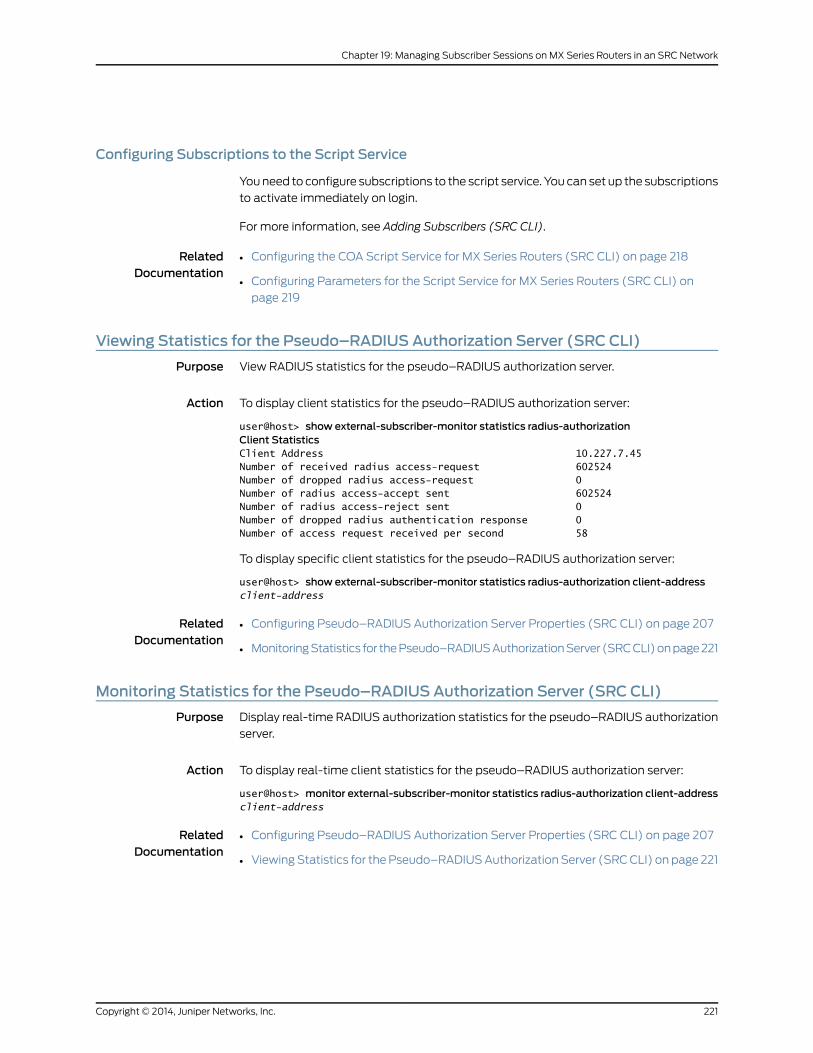
Configuring Subscriptions to the Script Service
You need to configure subscriptions to the script service. You can set up the subscriptions
to activate immediately on login.
For more information, see Adding Subscribers (SRC CLI).
RelatedDocumentation
Configuring the COA Script Service for MX Series Routers (SRC CLI) on page 218•
• Configuring Parameters for the Script Service for MX Series Routers (SRC CLI) on
page 219
Viewing Statistics for the Pseudo–RADIUS Authorization Server (SRC CLI)
Purpose View RADIUS statistics for the pseudo–RADIUS authorization server.
Action To display client statistics for the pseudo–RADIUS authorization server:
user@host> show external-subscriber-monitor statistics radius-authorizationClient StatisticsClient Address 10.227.7.45Number of received radius access-request 602524Number of dropped radius access-request 0Number of radius access-accept sent 602524Number of radius access-reject sent 0Number of dropped radius authentication response 0Number of access request received per second 58
To display specific client statistics for the pseudo–RADIUS authorization server:
user@host> show external-subscriber-monitor statistics radius-authorization client-addressclient-address
RelatedDocumentation
Configuring Pseudo–RADIUS Authorization Server Properties (SRC CLI) on page 207•
• Monitoring Statistics for the Pseudo–RADIUS Authorization Server (SRC CLI) on page 221
Monitoring Statistics for the Pseudo–RADIUS Authorization Server (SRC CLI)
Purpose Display real-time RADIUS authorization statistics for the pseudo–RADIUS authorization
server.
Action To display real-time client statistics for the pseudo–RADIUS authorization server:
user@host> monitor external-subscriber-monitor statistics radius-authorization client-addressclient-address
RelatedDocumentation
• Configuring Pseudo–RADIUS Authorization Server Properties (SRC CLI) on page 207
• Viewing Statistics for the Pseudo–RADIUS Authorization Server (SRC CLI) on page 221
221Copyright © 2014, Juniper Networks, Inc.
Chapter 19: Managing Subscriber Sessions on MX Series Routers in an SRC Network

Copyright © 2014, Juniper Networks, Inc.222
SRC PE 4.8.x Solutions Guide
CHAPTER 20
Configuring Services for SRC-ManagedRouters
• DPI Script Service Overview on page 223
• Creating the DPI Script Service (SRC CLI) on page 224
• Configuring Subscriptions to the DPI Script Service on page 225
• Parameters for DPI Script Service on page 226
• Creating a Configuration File on page 228
• Example: Using the DPI Script Service on page 235
DPI Script Service Overview
The SRC software has a Deep Packet Inspection (DPI) script service that can be used to
modify services on routers managed by the SRC software to provide resource
management based on supported applications. The DPI script service allows the SRC
software to manage services on Juniper Networks routers running Junos OS, such as the
Juniper Networks MX Series Ethernet Services Router. When the service activation engine
(SAE) activates the DPI script service, the session uses the command channel to manage
policies on MX Series routers. The DPI script service can use the Junos XML management
protocol to change the configuration on the MX Series router as well as send commands
to third-party devices that support Telnet access.
The DPI script service activates services by applying policy rules to the managed interface
on a network device. The DPI script service allows you to modify existing rules by
parameter substitutions; that is, you can replace existing rules with new rules or delete
existing rules. The DPI script service supports only default SRC subscriptions and default
SAE service sessions. The script service supports policy rules to handle Junos XML
management protocol requests for MX Series routers and Telnet commands for
third-party routers.
RelatedDocumentation
For information about the Junos XML management protocol, see the Junos XML
Management Protocol Developer Guide
•
• For information about service set configuration on routers running Junos OS, see the
Junos OS Services Interfaces Library for Routing Devices
• For information about accessing and configuring the third-party device using Telnet,
see the device’s software documentation
223Copyright © 2014, Juniper Networks, Inc.
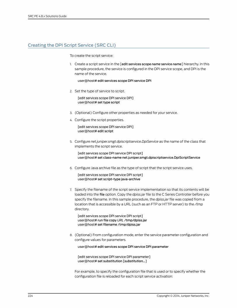
Creating the DPI Script Service (SRC CLI)
To create the script service:
1. Create a script service in the [edit services scope name service name] hierarchy. In this
sample procedure, the service is configured in the DPI service scope, and DPI is the
name of the service.
user@host# edit services scope DPI service DPI
2. Set the type of service to script.
[edit services scope DPI service DPI]user@host# set type script
3. (Optional) Configure other properties as needed for your service.
4. Configure the script properties.
[edit services scope DPI service DPI]user@host# edit script
5. Configure net.juniper.smgt.dpiscriptservice.DpiService as the name of the class that
implements the script service.
[edit services scope DPI service DPI script]user@host# set class-name net.juniper.smgt.dpiscriptservice.DpiScriptService
6. Configure Java archive file as the type of script that the script service uses.
[edit services scope DPI service DPI script]user@host# set script-type java-archive
7. Specify the filename of the script service implementation so that its contents will be
loaded into the file option. Copy the dpiss.jar file to the C Series Controller before you
specify the filename. In this sample procedure, the dpiss.jar file was copied from a
location that is accessible by a URL (such as an FTP or HTTP server) to the /tmp
directory.
[edit services scope DPI service DPI script]user@host# run file copyURL /tmp/dpiss.jaruser@host# set filename /tmp/dpiss.jar
8. (Optional) From configuration mode, enter the service parameter configuration and
configure values for parameters.
user@host# edit services scope DPI service DPI parameter
[edit services scope DPI service DPI parameter]user@host# set substitution [substitution...]
For example, to specify the configuration file that is used or to specify whether the
configuration file is reloaded for each script service activation:
Copyright © 2014, Juniper Networks, Inc.224
SRC PE 4.8.x Solutions Guide
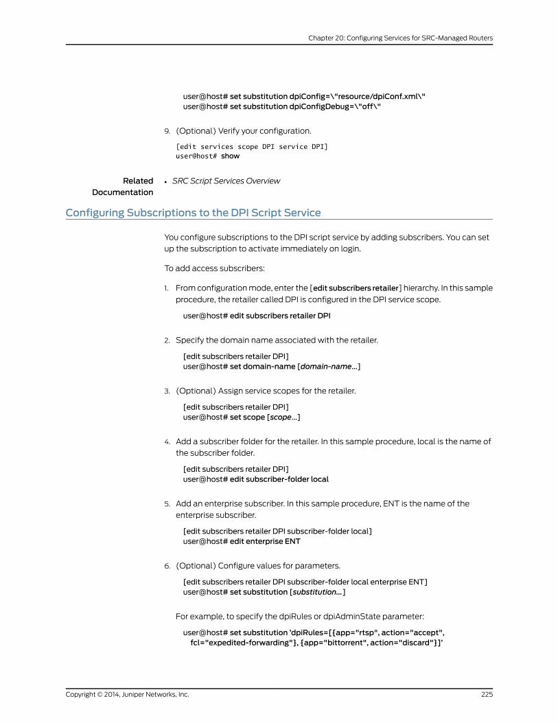
user@host# set substitution dpiConfig=\"resource/dpiConf.xml\"user@host# set substitution dpiConfigDebug=\"off\"
9. (Optional) Verify your configuration.
[edit services scope DPI service DPI]user@host# show
RelatedDocumentation
SRC Script Services Overview•
Configuring Subscriptions to the DPI Script Service
You configure subscriptions to the DPI script service by adding subscribers. You can set
up the subscription to activate immediately on login.
To add access subscribers:
1. From configuration mode, enter the [edit subscribers retailer] hierarchy. In this sample
procedure, the retailer called DPI is configured in the DPI service scope.
user@host# edit subscribers retailer DPI
2. Specify the domain name associated with the retailer.
[edit subscribers retailer DPI]user@host# set domain-name [domain-name...]
3. (Optional) Assign service scopes for the retailer.
[edit subscribers retailer DPI]user@host# set scope [scope...]
4. Add a subscriber folder for the retailer. In this sample procedure, local is the name of
the subscriber folder.
[edit subscribers retailer DPI]user@host# edit subscriber-folder local
5. Add an enterprise subscriber. In this sample procedure, ENT is the name of the
enterprise subscriber.
[edit subscribers retailer DPI subscriber-folder local]user@host# edit enterprise ENT
6. (Optional) Configure values for parameters.
[edit subscribers retailer DPI subscriber-folder local enterprise ENT]user@host# set substitution [substitution...]
For example, to specify the dpiRules or dpiAdminState parameter:
user@host# set substitution ’dpiRules=[{app="rtsp", action="accept",fcl="expedited-forwarding"}, {app="bittorrent", action="discard"}]’
225Copyright © 2014, Juniper Networks, Inc.
Chapter 20: Configuring Services for SRC-Managed Routers
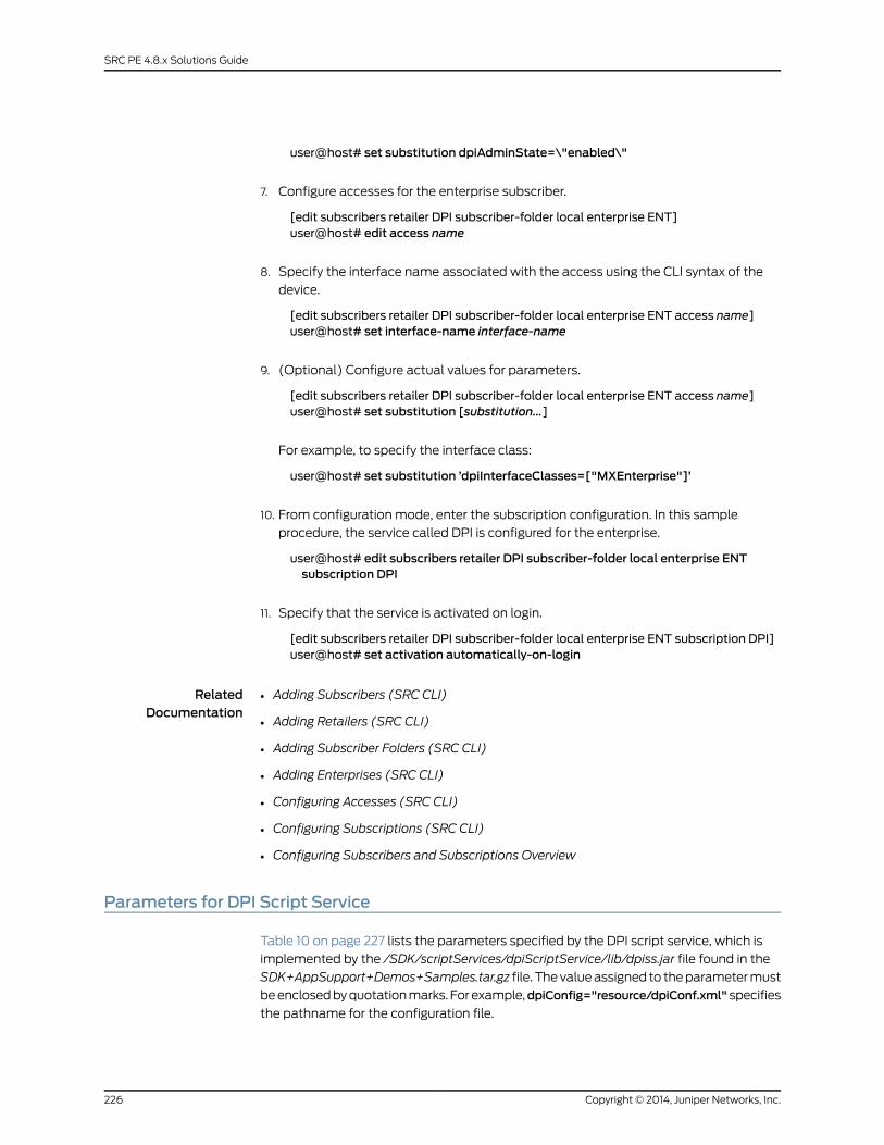
user@host# set substitution dpiAdminState=\"enabled\"
7. Configure accesses for the enterprise subscriber.
[edit subscribers retailer DPI subscriber-folder local enterprise ENT]user@host# edit access name
8. Specify the interface name associated with the access using the CLI syntax of the
device.
[edit subscribers retailer DPI subscriber-folder local enterprise ENT access name]user@host# set interface-name interface-name
9. (Optional) Configure actual values for parameters.
[edit subscribers retailer DPI subscriber-folder local enterprise ENT access name]user@host# set substitution [substitution...]
For example, to specify the interface class:
user@host# set substitution ’dpiInterfaceClasses=["MXEnterprise"]’
10. From configuration mode, enter the subscription configuration. In this sample
procedure, the service called DPI is configured for the enterprise.
user@host# edit subscribers retailer DPI subscriber-folder local enterprise ENTsubscription DPI
11. Specify that the service is activated on login.
[edit subscribers retailer DPI subscriber-folder local enterprise ENT subscription DPI]user@host# set activation automatically-on-login
RelatedDocumentation
Adding Subscribers (SRC CLI)•
• Adding Retailers (SRC CLI)
• Adding Subscriber Folders (SRC CLI)
• Adding Enterprises (SRC CLI)
• Configuring Accesses (SRC CLI)
• Configuring Subscriptions (SRC CLI)
• Configuring Subscribers and Subscriptions Overview
Parameters for DPI Script Service
Table 10 on page 227 lists the parameters specified by the DPI script service, which is
implemented by the /SDK/scriptServices/dpiScriptService/lib/dpiss.jar file found in the
SDK+AppSupport+Demos+Samples.tar.gz file. The value assigned to the parameter must
be enclosed by quotation marks. For example,dpiConfig="resource/dpiConf.xml"specifies
the pathname for the configuration file.
Copyright © 2014, Juniper Networks, Inc.226
SRC PE 4.8.x Solutions Guide
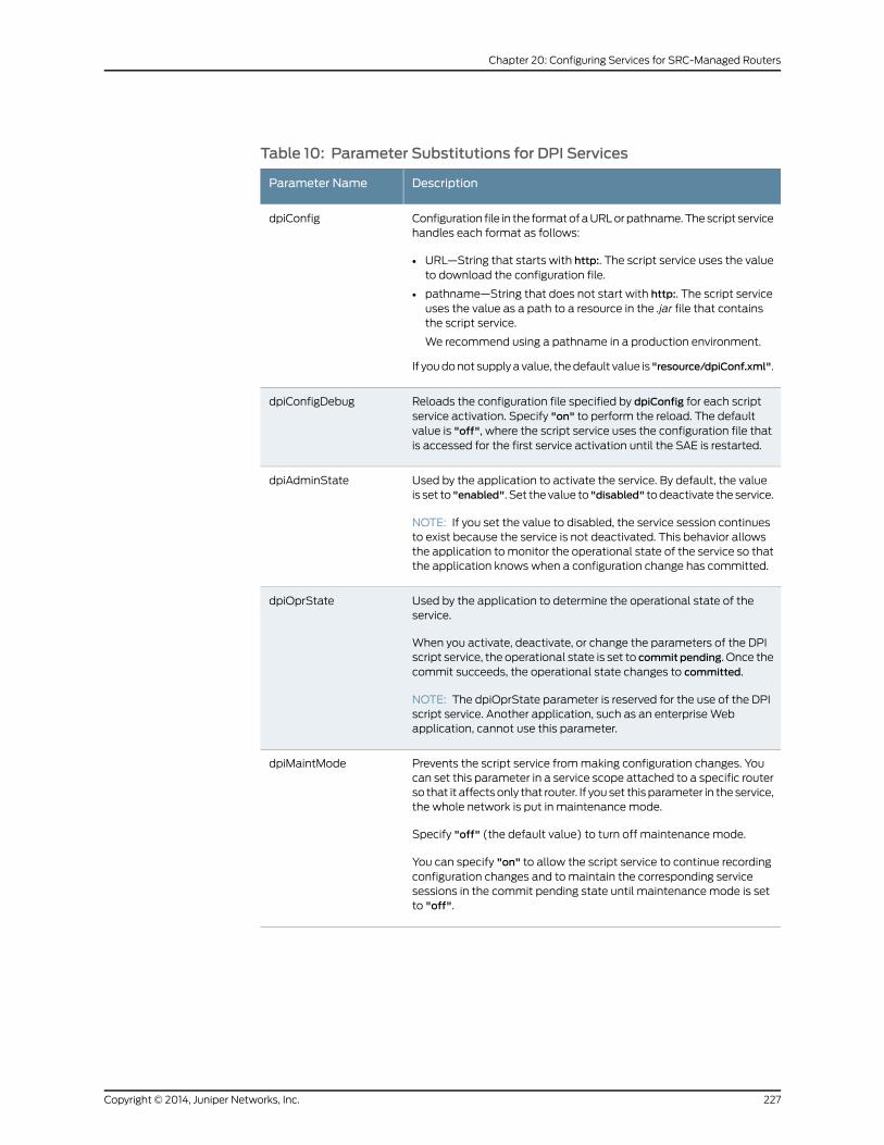
Table 10: Parameter Substitutions for DPI Services
DescriptionParameter Name
Configuration file in the format of a URL or pathname. The script servicehandles each format as follows:
• URL—String that starts with http:. The script service uses the valueto download the configuration file.
• pathname—String that does not start with http:. The script serviceuses the value as a path to a resource in the .jar file that containsthe script service.
We recommend using a pathname in a production environment.
If you do not supply a value, the default value is "resource/dpiConf.xml".
dpiConfig
Reloads the configuration file specified by dpiConfig for each scriptservice activation. Specify "on" to perform the reload. The defaultvalue is "off", where the script service uses the configuration file thatis accessed for the first service activation until the SAE is restarted.
dpiConfigDebug
Used by the application to activate the service. By default, the valueis set to "enabled". Set the value to "disabled" to deactivate the service.
NOTE: If you set the value to disabled, the service session continuesto exist because the service is not deactivated. This behavior allowsthe application to monitor the operational state of the service so thatthe application knows when a configuration change has committed.
dpiAdminState
Used by the application to determine the operational state of theservice.
When you activate, deactivate, or change the parameters of the DPIscript service, the operational state is set to commitpending. Once thecommit succeeds, the operational state changes to committed.
NOTE: The dpiOprState parameter is reserved for the use of the DPIscript service. Another application, such as an enterprise Webapplication, cannot use this parameter.
dpiOprState
Prevents the script service from making configuration changes. Youcan set this parameter in a service scope attached to a specific routerso that it affects only that router. If you set this parameter in the service,the whole network is put in maintenance mode.
Specify "off" (the default value) to turn off maintenance mode.
You can specify "on" to allow the script service to continue recordingconfiguration changes and to maintain the corresponding servicesessions in the commit pending state until maintenance mode is setto "off".
dpiMaintMode
227Copyright © 2014, Juniper Networks, Inc.
Chapter 20: Configuring Services for SRC-Managed Routers
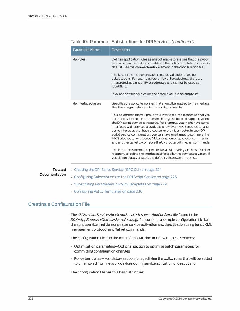
Table 10: Parameter Substitutions for DPI Services (continued)
DescriptionParameter Name
Defines application rules as a list of map expressions that the policytemplate can use to bind variables in the policy template to values inthis list. See the <for-each-rule> element in the configuration file.
The keys in the map expression must be valid identifiers forsubstitutions. For example, four or fewer hexadecimal digits areinterpreted as parts of IPv6 addresses and cannot be used asidentifiers.
If you do not supply a value, the default value is an empty list.
dpiRules
Specifies the policy templates that should be applied to the interface.See the <target> element in the configuration file.
This parameter lets you group your interfaces into classes so that youcan specify for each interface which targets should be applied whenthe DPI script service is triggered. For example, you might have someinterfaces with services provided entirely by an MX Series router andsome interfaces that have a customer premises router. In your DPIscript service configuration, you can have one target to configure theMX Series router with Junos XML management protocol commandsand another target to configure the CPE router with Telnet commands.
The interface is normally specified as a list of strings in the subscriberhierarchy to define the interfaces affected by the service activation. Ifyou do not supply a value, the default value is an empty list.
dpiInterfaceClasses
RelatedDocumentation
Creating the DPI Script Service (SRC CLI) on page 224•
• Configuring Subscriptions to the DPI Script Service on page 225
• Substituting Parameters in Policy Templates on page 229
• Configuring Policy Templates on page 230
Creating a Configuration File
The /SDK/scriptServices/dpiScriptService/resource/dpiConf.xml file found in the
SDK+AppSupport+Demos+Samples.tar.gz file contains a sample configuration file for
the script service that demonstrates service activation and deactivation using Junos XML
management protocol and Telnet commands.
The configuration file is in the form of an XML document with these sections:
• Optimization parameters—Optional section to optimize batch parameters for
committing configuration changes
• Policy templates—Mandatory section for specifying the policy rules that will be added
to or removed from network devices during service activation or deactivation
The configuration file has this basic structure:
Copyright © 2014, Juniper Networks, Inc.228
SRC PE 4.8.x Solutions Guide
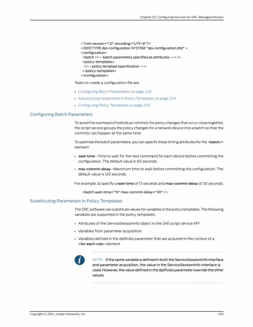
<?xml version="1.0" encoding="UTF-8"?><!DOCTYPE dpi-configuration SYSTEM "dpi-configuration.dtd" ><configuration><batch <!-– batch parameters specified as attributes -–> /><policy-templates><!-– policy template specification -–></policy-templates></configuration>
Tasks to create a configuration file are:
• Configuring Batch Parameters on page 229
• Substituting Parameters in Policy Templates on page 229
• Configuring Policy Templates on page 230
Configuring Batch Parameters
To avoid the overhead of individual commits for policy changes that occur close together,
the script service groups the policy changes for a network device into a batch so that the
commits can happen at the same time.
To optimize the batch parameters, you can specify these timing attributes for the<batch/>
element:
• wait-time—Time to wait for the next command for each device before committing the
configuration. The default value is 60 seconds.
• max-commit-delay—Maximum time to wait before committing the configuration. The
default value is 120 seconds.
For example, to specify await-time of 15 seconds andmax-commit-delay of 30 seconds:
<batch wait-time="15"max-commit-delay="30" />
Substituting Parameters in Policy Templates
The SRC software can substitute values for variables in the policy templates. The following
variables are supported in the policy templates:
• Attributes of the ServiceSessionInfo object in the SAE script service API
• Variables from parameter acquisition
• Variables defined in the dpiRules parameter that are acquired in the context of a
<for-each-rule> element
NOTE: If thesamevariable isdefined inboth theServiceSessionInfo interfaceand parameter acquisition, the value in the ServiceSessionInfo interface isused.However, thevaluedefined in thedpiRulesparameteroverride theothervalues.
229Copyright © 2014, Juniper Networks, Inc.
Chapter 20: Configuring Services for SRC-Managed Routers
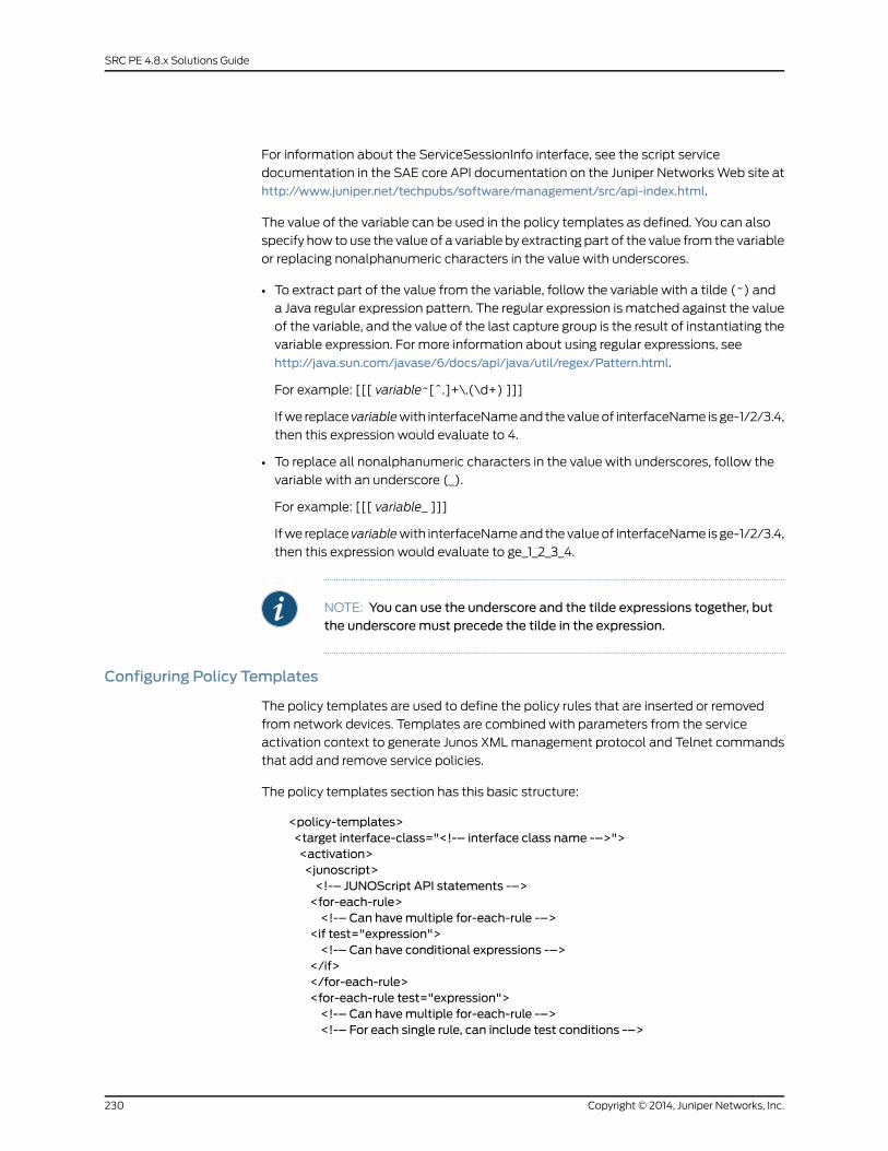
For information about the ServiceSessionInfo interface, see the script service
documentation in the SAE core API documentation on the Juniper Networks Web site at
http://www.juniper.net/techpubs/software/management/src/api-index.html.
The value of the variable can be used in the policy templates as defined. You can also
specify how to use the value of a variable by extracting part of the value from the variable
or replacing nonalphanumeric characters in the value with underscores.
• To extract part of the value from the variable, follow the variable with a tilde (~) and
a Java regular expression pattern. The regular expression is matched against the value
of the variable, and the value of the last capture group is the result of instantiating the
variable expression. For more information about using regular expressions, see
http://java.sun.com/javase/6/docs/api/java/util/regex/Pattern.html.
For example: [[[ variable~[^.]+\.(\d+) ]]]
If we replace variablewith interfaceName and the value of interfaceName is ge-1/2/3.4,
then this expression would evaluate to 4.
• To replace all nonalphanumeric characters in the value with underscores, follow the
variable with an underscore (_).
For example: [[[ variable_ ]]]
If we replace variablewith interfaceName and the value of interfaceName is ge-1/2/3.4,
then this expression would evaluate to ge_1_2_3_4.
NOTE: You can use the underscore and the tilde expressions together, butthe underscoremust precede the tilde in the expression.
Configuring Policy Templates
The policy templates are used to define the policy rules that are inserted or removed
from network devices. Templates are combined with parameters from the service
activation context to generate Junos XML management protocol and Telnet commands
that add and remove service policies.
The policy templates section has this basic structure:
<policy-templates><target interface-class="<!-– interface class name -–>"><activation><junoscript><!-– JUNOScript API statements -–><for-each-rule><!-– Can havemultiple for-each-rule -–>
<if test="expression"><!-– Can have conditional expressions -–>
</if></for-each-rule><for-each-rule test="expression"><!-– Can havemultiple for-each-rule -–><!-– For each single rule, can include test conditions -–>
Copyright © 2014, Juniper Networks, Inc.230
SRC PE 4.8.x Solutions Guide
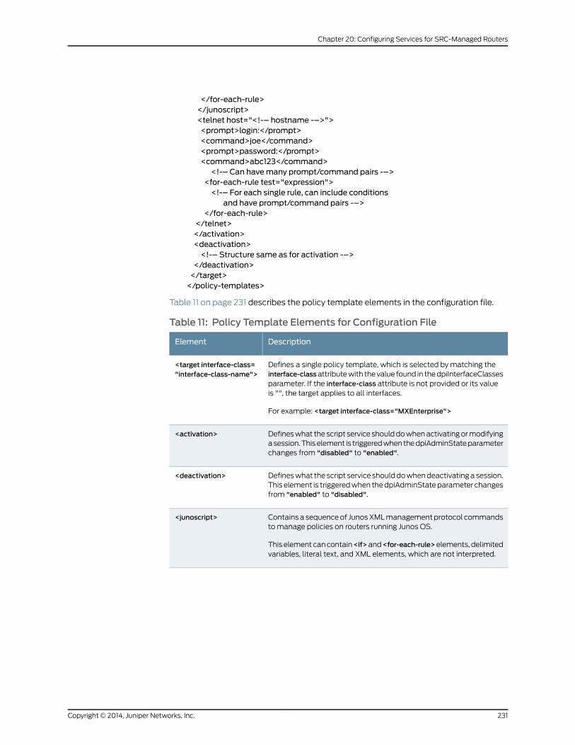
</for-each-rule></junoscript><telnet host="<!-– hostname -–>"><prompt>login:</prompt><command>joe</command><prompt>password:</prompt><command>abc123</command><!-– Can havemany prompt/command pairs -–>
<for-each-rule test="expression"><!-– For each single rule, can include conditions
and have prompt/command pairs -–></for-each-rule>
</telnet></activation><deactivation><!-– Structure same as for activation -–>
</deactivation></target></policy-templates>
Table 11 on page 231 describes the policy template elements in the configuration file.
Table 11: Policy Template Elements for Configuration File
DescriptionElement
Defines a single policy template, which is selected by matching theinterface-classattribute with the value found in the dpiInterfaceClassesparameter. If the interface-class attribute is not provided or its valueis "", the target applies to all interfaces.
For example: <target interface-class="MXEnterprise">
<target interface-class="interface-class-name">
Defines what the script service should do when activating or modifyinga session. This element is triggered when the dpiAdminState parameterchanges from "disabled" to "enabled".
<activation>
Defines what the script service should do when deactivating a session.This element is triggered when the dpiAdminState parameter changesfrom "enabled" to "disabled".
<deactivation>
Contains a sequence of Junos XML management protocol commandsto manage policies on routers running Junos OS.
This element can contain<if>and<for-each-rule>elements, delimitedvariables, literal text, and XML elements, which are not interpreted.
<junoscript>
231Copyright © 2014, Juniper Networks, Inc.
Chapter 20: Configuring Services for SRC-Managed Routers
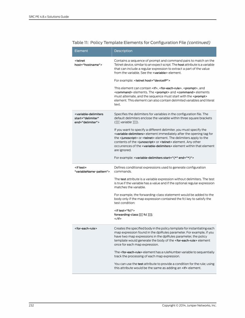
Table 11: Policy Template Elements for Configuration File (continued)
DescriptionElement
Contains a sequence of prompt and command pairs to match on theTelnet device, similar to an expect script. Thehostattribute is a variablethat can include a regular expression to extract a part of the valuefrom the variable. See the <variable> element.
For example: <telnet host="deviceIP">
This element can contain <if>, <for-each-rule>, <prompt>, and<command> elements. The <prompt> and <command> elementsmust alternate, and the sequence must start with the <prompt>element. This element can also contain delimited variables and literaltext.
<telnethost="hostname">
Specifies the delimiters for variables in the configuration file. Thedefault delimiters enclose the variable within three square brackets([[[ variable ]]]).
If you want to specify a different delimiter, you must specify the<variable-delimiters> element immediately after the opening tag forthe <junoscript> or <telnet> element. The delimiters apply to thecontents of the <junoscript> or <telnet> element. Any otheroccurrences of the <variable-delimiters> element within that elementare ignored.
For example: <variable-delimiters start="(*" end="*)">
<variable-delimitersstart="delimiter"end="delimiter">
Defines conditional expressions used to generate configurationcommands.
The test attribute is a variable expression without delimiters. The testis true if the variable has a value and if the optional regular expressionmatches the variable.
For example, the forwarding-class statement would be added to thebody only if the map expression contained the fcl key to satisfy thetest condition:
<if test="fcl">forwarding-class [[[ fcl ]]];</if>
<if test="variableName~pattern">
Creates the specified body in the policy template for instantiating eachmap expression found in the dpiRules parameter. For example, if youhave two map expressions in the dpiRules parameter, the policytemplate would generate the body of the <for-each-rule> elementonce for each map expression.
The<for-each-rule>element has a ruleNumber variable to sequentiallytrack the processing of each map expression.
You can use the test attribute to provide a condition for the rule; usingthis attribute would be the same as adding an <if> element.
<for-each-rule>
Copyright © 2014, Juniper Networks, Inc.232
SRC PE 4.8.x Solutions Guide

NOTE: When using special XML characters as part of the policy templates,theymust be coded in XML. For example, the left angle bracket (<)must becoded as<.
The following example uses some elements to show a policy template that activates
application-aware access list (AACL) services and service sets on an MX Series router
by loading the configuration in text format using Junos XML management protocol.
<policy-templates><target interface-class="MXEnterprise"><activation><junoscript><rpc><load-configuration action="replace" format="text"><configuration-text>
services {aacl {rule AACL_[[[ interfaceName_ ]]] {match-direction input-output;<for-each-rule>term [[[ ruleNumber ]]] {from {application junos:[[[ app ]]];
}then {
<if test="fcl">forwarding-class [[[ fcl ]]];
</if><if test="action~accept">
count application;</if>
[[[ action ]]];}
}</for-each-rule>}
}service-set SSET_[[[ interfaceName_ ]]] {aacl-rules AACL_[[[ interfaceName_ ]]];interface-service {service-interfacems-1/[[[ interfaceName~[^.]+-\d+/(\d+/\d+\.\d+) ]]];}
}}interfaces {[[[ interfaceName~[^.]+)\.\d+ ]]] {unit [[[ interfaceName~[^.]+)\.(\d+) ]]] {family inet {service {input {service-set SSET_[[[ interfaceName_ ]]]
}output {
233Copyright © 2014, Juniper Networks, Inc.
Chapter 20: Configuring Services for SRC-Managed Routers
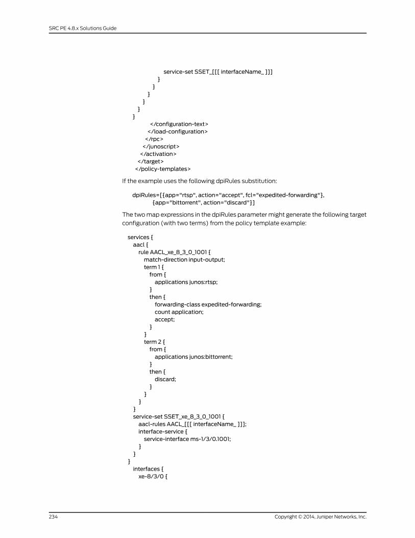
service-set SSET_[[[ interfaceName_ ]]]}
}}
}}
}</configuration-text></load-configuration></rpc></junoscript></activation></target></policy-templates>
If the example uses the following dpiRules substitution:
dpiRules=[{app="rtsp", action="accept", fcl="expedited-forwarding"},{app="bittorrent", action="discard"}]
The two map expressions in the dpiRules parameter might generate the following target
configuration (with two terms) from the policy template example:
services {aacl {rule AACL_xe_8_3_0_1001 {match-direction input-output;term 1 {from {applications junos:rtsp;
}then {forwarding-class expedited-forwarding;count application;accept;
}}term 2 {from {applications junos:bittorrent;
}then {discard;
}}
}}service-set SSET_xe_8_3_0_1001 {aacl-rules AACL_[[[ interfaceName_ ]]];interface-service {service-interfacems-1/3/0.1001;
}}
}interfaces {xe-8/3/0 {
Copyright © 2014, Juniper Networks, Inc.234
SRC PE 4.8.x Solutions Guide
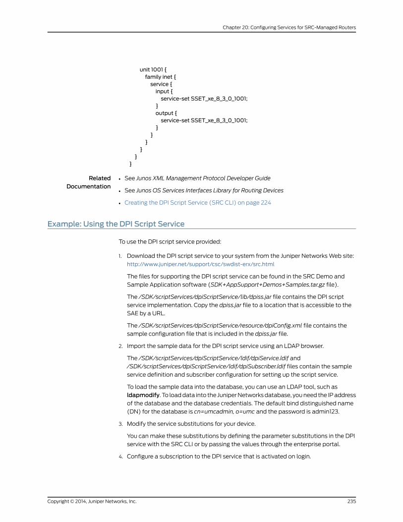
unit 1001 {family inet {service {input {service-set SSET_xe_8_3_0_1001;
}output {service-set SSET_xe_8_3_0_1001;
}}
}}
}}
RelatedDocumentation
See Junos XML Management Protocol Developer Guide•
• See Junos OS Services Interfaces Library for Routing Devices
• Creating the DPI Script Service (SRC CLI) on page 224
Example: Using the DPI Script Service
To use the DPI script service provided:
1. Download the DPI script service to your system from the Juniper Networks Web site:
http://www.juniper.net/support/csc/swdist-erx/src.html
The files for supporting the DPI script service can be found in the SRC Demo and
Sample Application software (SDK+AppSupport+Demos+Samples.tar.gz file).
The /SDK/scriptServices/dpiScriptService/lib/dpiss.jar file contains the DPI script
service implementation. Copy the dpiss.jar file to a location that is accessible to the
SAE by a URL.
The /SDK/scriptServices/dpiScriptService/resource/dpiConfig.xml file contains the
sample configuration file that is included in the dpiss.jar file.
2. Import the sample data for the DPI script service using an LDAP browser.
The /SDK/scriptServices/dpiScriptService/ldif/dpiService.ldif and
/SDK/scriptServices/dpiScriptService/ldif/dpiSubscriber.ldif files contain the sample
service definition and subscriber configuration for setting up the script service.
To load the sample data into the database, you can use an LDAP tool, such as
ldapmodify. To load data into the Juniper Networks database, you need the IP address
of the database and the database credentials. The default bind distinguished name
(DN) for the database is cn=umcadmin, o=umc and the password is admin123.
3. Modify the service substitutions for your device.
You can make these substitutions by defining the parameter substitutions in the DPI
service with the SRC CLI or by passing the values through the enterprise portal.
4. Configure a subscription to the DPI service that is activated on login.
235Copyright © 2014, Juniper Networks, Inc.
Chapter 20: Configuring Services for SRC-Managed Routers

RelatedDocumentation
• For information about defining parameter substitutions with the SRC CLI, see Creating
the DPI Script Service (SRC CLI) on page 224 or Configuring Subscriptions to the DPI
Script Service on page 225
• For information about passing the values through the SAE core API, see Substituting
Parameters in Policy Templates on page 229
• Subscriptions Overview
Copyright © 2014, Juniper Networks, Inc.236
SRC PE 4.8.x Solutions Guide
PART 4
Using SRC ConfigurationWizards
• SRC Configuration Wizards Overview (SRC CLI) on page 239
• SRC Configuration Wizards Overview (C-Web Interface) on page 243
• Using the Fair Usage on MX Series Routers Configuration Wizard on page 247
237Copyright © 2014, Juniper Networks, Inc.

Copyright © 2014, Juniper Networks, Inc.238
SRC PE 4.8.x Solutions Guide

CHAPTER 21
SRC ConfigurationWizards Overview(SRC CLI)
• SRC Configuration Wizards Overview (SRC CLI) on page 239
• Running a Configuration Wizard (SRC CLI) on page 241
SRC ConfigurationWizards Overview (SRC CLI)
The SRC software includes configurationwizards to simplify configuring the most common
configuration scenarios. Each configuration wizard uses an XML definition file that
generates a specific configuration scenario. Most of the configuration is predefined in
the definition file. However, because each configuration scenario is unique, definition files
cannot predefine all options, so the wizard prompts you for input specific to your
implementation.
HowConfigurationWizardsWork (SRC CLI)
You can invoke a configuration wizard from the SRC CLI. At runtime, the configuration
wizard processes the definition file and presents the corresponding configuration steps.
The interface prompts you to enter information for any options specific to your
configuration that are not predefined in the definition file. The values you enter are used
for the respective parameters in the definition file. After you enter all required parameters,
the interface displays a list of SRC CLI set commands corresponding to the parameters
you entered. After you review the configuration, you can either select Commit to commit
the configuration or you can select Back to make changes to the parameters.
While running a configuration wizard, if you close the wizard midway, the uncommitted
configurations are saved to a temporary file called the tag file. The naming convention
of a tag file is <wizard definition filename>_<username>_ CLItag _<timestamp>.tmp.
Where:
• wizard definition filename—Specifies the name of the wizard definition file.
• username—Specifies the name of the user.
• timestamp—Specifies the current system timestamp.
239Copyright © 2014, Juniper Networks, Inc.
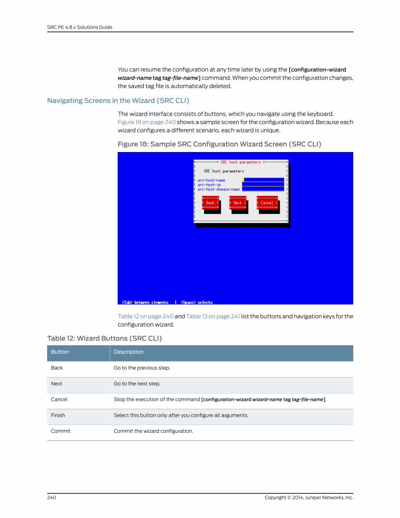
You can resume the configuration at any time later by using the [configuration-wizard
wizard-name tag tag-file-name] command. When you commit the configuration changes,
the saved tag file is automatically deleted.
Navigating Screens in theWizard (SRC CLI)
The wizard interface consists of buttons, which you navigate using the keyboard.
Figure 18 on page 240 shows a sample screen for the configuration wizard. Because each
wizard configures a different scenario, each wizard is unique.
Figure 18: Sample SRC ConfigurationWizard Screen (SRC CLI)
Table 12 on page 240 and Table 13 on page 241 list the buttons and navigation keys for the
configuration wizard.
Table 12: Wizard Buttons (SRC CLI)
DescriptionButton
Go to the previous step.Back
Go to the next step.Next
Stop the execution of the command [configuration-wizardwizard-name tag tag-file-name].Cancel
Select this button only after you configure all arguments.Finish
Commit the wizard configuration.Commit
Copyright © 2014, Juniper Networks, Inc.240
SRC PE 4.8.x Solutions Guide
Table 13:Wizard Navigation Keys
DescriptionKey
Move between buttons (elements) such as Back, Next, Cancel, Commit, Finish, andso on.
Tab
Select the highlighted button.Space bar
RelatedDocumentation
Running a Configuration Wizard (SRC CLI) on page 241•
• SRC Configuration Wizards Overview (C-Web Interface) on page 243
Running a ConfigurationWizard (SRC CLI)
To run a configuration wizard:
• From configuration mode, access the configuration statement that runs the
configuration wizard.
user@host# configuration-wizard wizard-namewizard-name tag tag-file-name
Where:
• wizard-name—Specifies the name of the wizard you want to run.
• tag-file-name—Specifies the name of a tag file that is automatically generated when
you save the uncommitted configurations.
RelatedDocumentation
• SRC Configuration Wizards Overview (SRC CLI) on page 239
• Running a Configuration Wizard (C-Web Interface) on page 245
241Copyright © 2014, Juniper Networks, Inc.
Chapter 21: SRC Configuration Wizards Overview (SRC CLI)

Copyright © 2014, Juniper Networks, Inc.242
SRC PE 4.8.x Solutions Guide
CHAPTER 22
SRC ConfigurationWizards Overview(C-Web Interface)
• SRC Configuration Wizards Overview (C-Web Interface) on page 243
• Running a Configuration Wizard (C-Web Interface) on page 245
SRC ConfigurationWizards Overview (C-Web Interface)
The C-Web configuration wizard enables you to enter the most common configuration
scenarios and prompts you for input specific to your configuration scenario. At the end
of the wizard, you can either commit or discard the configuration changes that are
displayed in a tree-like format.
How the ConfigurationWizardsWork (C-Web Interface)
You can invoke a configuration wizard from the SRC C-Web interface. The configuration
wizard uses the standard or customized wizard definition file as input to group and present
related configurations on a single page of the wizard. You can upload the customized
definition file by navigating to the specific wizard definition file from your environment.
You can also edit the wizard definition file, upload the modified file, and customize the
configuration wizard display by using the C-Web interface. In the pop-up wizard, each
configuration step is presented in the order in which it is defined in the wizard definition
file. A step is composed of closely knit configuration inputs for the same component. A
collection defines repetitive steps in the wizard, which enables you to use multiple
instances of the configuration setup. Collections helps you easily configure multiple
instances.
When you close the configuration wizard pop-up, a confirmation pop-up asks you if you
want to save the uncommitted changes. On confirmation, the uncommitted changes
are saved in a temporary file called the tag file. The naming convention of a tag file is
<wizard definition filename>_<username>_Cwebtag_<timestamp>.tmp.
Where:
• wizard definition filename—Specifies the name of the wizard definition file.
• username—Specifies the name of the user.
• timestamp—Specifies the current system timestamp.
243Copyright © 2014, Juniper Networks, Inc.
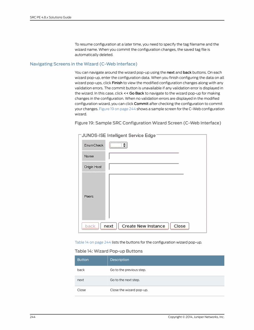
To resume configuration at a later time, you need to specify the tag filename and the
wizard name. When you commit the configuration changes, the saved tag file is
automatically deleted.
Navigating Screens in theWizard (C-Web Interface)
You can navigate around the wizard pop-up using the next and back buttons. On each
wizard pop-up, enter the configuration data. When you finish configuring the data on all
wizard pop-ups, click Finish to view the modified configuration changes along with any
validation errors. The commit button is unavailable if any validation error is displayed in
the wizard. In this case, click << Go Back to navigate to the wizard pop-up for making
changes in the configuration. When no validation errors are displayed in the modified
configuration wizard, you can click Commit after checking the configuration to commit
your changes. Figure 19 on page 244 shows a sample screen for the C-Web configuration
wizard.
Figure 19: Sample SRC ConfigurationWizard Screen (C-Web Interface)
Table 14 on page 244 lists the buttons for the configuration wizard pop-up.
Table 14:Wizard Pop-up Buttons
DescriptionButton
Go to the previous step.back
Go to the next step.next
Close the wizard pop-up.Close
Copyright © 2014, Juniper Networks, Inc.244
SRC PE 4.8.x Solutions Guide
Table 14:Wizard Pop-up Buttons (continued)
DescriptionButton
Create a new collection instance.
NOTE: You can view this button only if the configuration inputs are part ofa collection.
Create NewInstance
Commit the wizard configuration.
NOTE: This button is displayed only in the final wizard pop-up containingthe modified configuration tree.
Commit
Navigate back to the configuration wizard pop-up.
NOTE: This button is displayed only in the final wizard pop-up containingthe modified configuration tree.
<<Go Back
Display the modified configuration wizard in a tree-like format.
NOTE: This button is displayed on the last page of the wizard pop-up.
Finish
RelatedDocumentation
Running a Configuration Wizard (C-Web Interface) on page 245•
• SRC Configuration Wizards Overview (SRC CLI) on page 239
Running a ConfigurationWizard (C-Web Interface)
The configuration wizard simplifies configuring the most common configuration scenarios.
To run a configuration wizard using the C-Web Interface:
1. Click Configure > ConfigurationWizard.
The configuration wizard appears.
NOTE:• You can access the configuration wizard only if your privilege is set assuperuser.
• You are prompted to commit or roll back the configuration, if there areany previous uncommitted configuration changes.
2. Select an option button to locate the standard or custom wizard definition file.
• To open the standard definition file, enter the name of the wizard definition file you
want to run.
• To upload the customized definition file, click the Browse button and navigate to
the specific wizard definition file from your environment. Then clickUpload.
245Copyright © 2014, Juniper Networks, Inc.
Chapter 22: SRC Configuration Wizards Overview (C-Web Interface)

NOTE: Incorrect changes to the wizard definition file can result inundesired configuration changes. Any customization of the wizarddefinition file must be approved by Juniper Networks.
3. In the Tag File text box, enter the name of the tag file.
NOTE:• The naming convention of a tag file is <wizard definitionfilename>_<username>_Cwebtag_<timestamp>.tmp.
Where:
• wizarddefinition filename—Specifies thenameof thewizarddefinitionfile.
• username—Specifies the name of the user.
• timestamp—Specifies the current system timestamp.
• You can access the configuration wizard along with the tag file whenthe tag file is compatible with the wizard definition file. These files arecompatible only if the tag file is created from the corresponding wizarddefinition file.
4. ClickOpenwizard. The configuration wizard is displayed. On each wizard pop-up,
enter the configuration data.
5. Click Finish on the final wizard pop-up. The modified CLI data tree is displayed.
6. Click Commit to commit your changes.
You can navigate back to the wizard and correct any validation errors by using the
<<Go Back button.
RelatedDocumentation
• SRC Configuration Wizards Overview (C-Web Interface) on page 243
• Running a Configuration Wizard (SRC CLI) on page 241
Copyright © 2014, Juniper Networks, Inc.246
SRC PE 4.8.x Solutions Guide
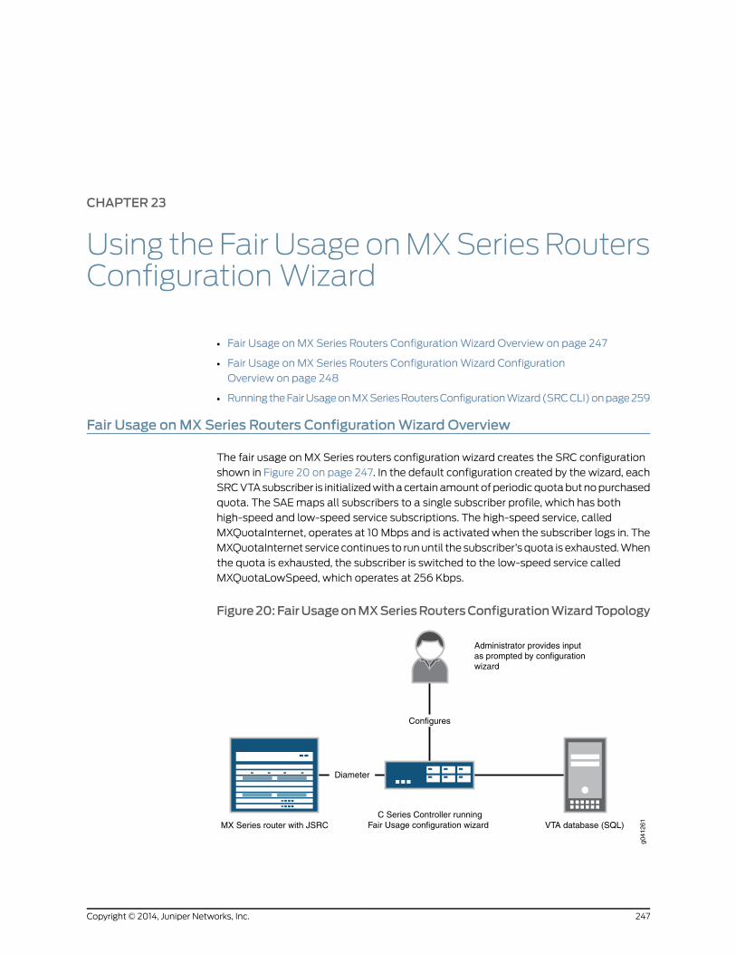
CHAPTER 23
Using theFair UsageonMXSeriesRoutersConfigurationWizard
• Fair Usage on MX Series Routers Configuration Wizard Overview on page 247
• Fair Usage on MX Series Routers Configuration Wizard Configuration
Overview on page 248
• Running the Fair Usage on MX Series Routers Configuration Wizard (SRC CLI) on page 259
Fair Usage onMX Series Routers ConfigurationWizard Overview
The fair usage on MX Series routers configuration wizard creates the SRC configuration
shown in Figure 20 on page 247. In the default configuration created by the wizard, each
SRC VTA subscriber is initialized with a certain amount of periodic quota but no purchased
quota. The SAE maps all subscribers to a single subscriber profile, which has both
high-speed and low-speed service subscriptions. The high-speed service, called
MXQuotaInternet, operates at 10 Mbps and is activated when the subscriber logs in. The
MXQuotaInternet service continues to run until the subscriber’s quota is exhausted. When
the quota is exhausted, the subscriber is switched to the low-speed service called
MXQuotaLowSpeed, which operates at 256 Kbps.
Figure20:FairUsageonMXSeriesRoutersConfigurationWizardTopology
g041
261
Administrator provides inputas prompted by configurationwizard
MX Series router with JSRCC Series Controller running
Fair Usage configuration wizard VTA database (SQL)
Diameter
Configures
247Copyright © 2014, Juniper Networks, Inc.
The fair usage on MX Series routers configuration wizard requires one C Series Controller,
one SQL database, and one MX Series router. The wizard configures a single SRC host.
The wizard does not configure the SQL database or the MX Series router; you must
configure these separately in order for them to work with the configuration created by
the wizard.
The SRC policies and service substitution configured by the wizard refer to certain Junos
OS dynamic profile names and firewall filter names. You must configure these names
on the MX Series router for the configuration to work properly. Alternatively, you can
modify these names in the SRC CLI to match those configured on the MX Series router
after you run the wizard and commit the SRC configuration.
The wizard configures the SRC VTA component to use a MySQL database. This database
must be deployed on a separate host and you must create the database by using the
“vta-database-mysql.sql” file, which is included with the SRC VTA component. The
wizard requires you to enter the database host IP address, database username, and
password.
The wizard also requires you to enter the SRC hostname, IP address, and domain name,
as well as the router hostname, IP address, and domain name. These parameters are
essential for the configuration of Diameter peers and SAE-managed devices.
RelatedDocumentation
Fair Usage on MX Series Routers Configuration Wizard Configuration Overview on
page 248
•
• Running the Fair Usage on MX Series Routers Configuration Wizard (SRC CLI) on
page 259
Fair Usage onMX Series Routers ConfigurationWizard Configuration Overview
When you use the fair usage on MX Series routers configuration wizard, the wizard
definition file specifies most of the SRC configuration. However, you must provide values
for certain parameters in the configuration.
Fair Usage onMX Series Routers ConfigurationWizard Definition File
The fair usage on MX Series routers configuration wizard definition file is an .xml file that
controls the parameters of the wizard.
The following sample shows the definition file for the fair usage on MX Series routersconfiguration wizard. The first part of the definition file defines the dialog boxes you useto enter values specific to your environment. The next part of the definition file lists theSRC CLI set commands the wizard invokes.
This file is shown only for reference purposes. Modification of definition files is notsupported.
<?xml version="1.0" encoding="UTF-8"?><!DOCTYPE cli SYSTEM "configuration-wizard.dtd"><cli name="fair-usage-mx"><help>Configure SRC for fair usage MX scenario</help><step name="src-config">
Copyright © 2014, Juniper Networks, Inc.248
SRC PE 4.8.x Solutions Guide

<step name="src-host-parameters"><caption>SRC host parameters</caption><help>SRC host parameters</help><description>This step collect SRC host parameters that will be usedin configuration. The parameters are SRC host names, IP addressesand domain names.
</description><wiz-argument name="src-host-name"mandatory="true"><help>SRC host name</help><description>SRC host name.</description>
</wiz-argument><wiz-argument name="src-host-ip" mandatory="true" type="inet"><help>SRC host IP address</help><description>SRC host IP address used to communicate with diameter peers and
VTA database.</description></wiz-argument><wiz-argument name="src-host-domain-name"mandatory="true"><help>SRC host domain name</help><description>SRC host domain name used as origin-realm for
diameter.</description></wiz-argument>
</step><step name="vta-db-host-parameters"><caption>VTA database host and database parameters</caption><help>VTA database host and database parameters</help><description>This step collect VTA database host and database parameters that will be usedin configuration. The parameters are VTA database host IP addresses, databaseconnection user name and password.
</description><wiz-argument name="vta-database-ip" mandatory="true" type="inet"><help>VTA database IP address</help><description>The IP address of the host where VTA database runs.</description>
</wiz-argument><wiz-argument name="vta-database-user" mandatory="true"><help>VTA database connection user name</help><description>The user name for VTA to connect to VTA database.</description>
</wiz-argument><wiz-argument name="vta-database-passwd"mandatory="true" type="passwd">
<help>VTA database connection password</help><description>The password for VTA to connect to VTA database.</description>
</wiz-argument></step><step name="router-host-parameters"><caption>Router host parameters</caption><help>Router host parameters</help><description>This step collect router host parameters that will be usedin configuration. The parameters are router host names, IP addressesand domain names.
</description><wiz-argument name="mx-router-name"mandatory="true">
249Copyright © 2014, Juniper Networks, Inc.
Chapter 23: Using the Fair Usage on MX Series Routers Configuration Wizard
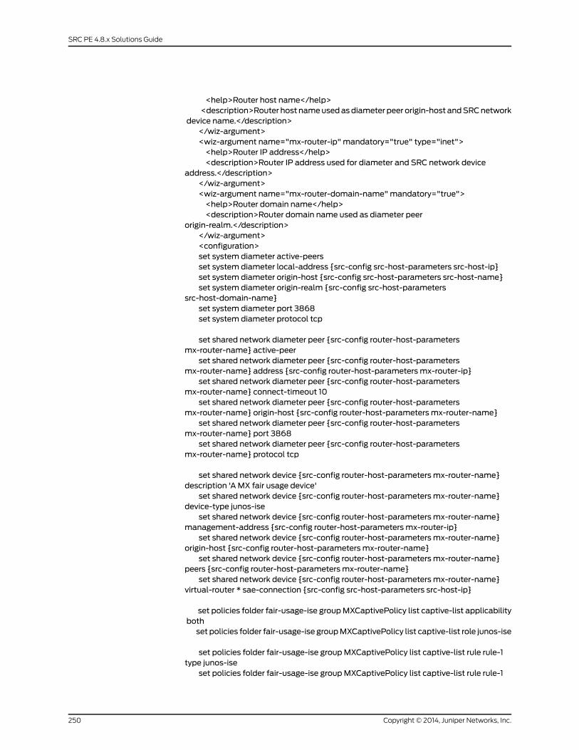
<help>Router host name</help><description>Router host nameusedasdiameter peer origin-host andSRCnetwork
device name.</description></wiz-argument><wiz-argument name="mx-router-ip" mandatory="true" type="inet"><help>Router IP address</help><description>Router IP address used for diameter and SRC network device
address.</description></wiz-argument><wiz-argument name="mx-router-domain-name"mandatory="true"><help>Router domain name</help><description>Router domain name used as diameter peer
origin-realm.</description></wiz-argument><configuration>set system diameter active-peersset system diameter local-address {src-config src-host-parameters src-host-ip}set system diameter origin-host {src-config src-host-parameters src-host-name}set system diameter origin-realm {src-config src-host-parameters
src-host-domain-name}set system diameter port 3868set system diameter protocol tcp
set shared network diameter peer {src-config router-host-parametersmx-router-name} active-peer
set shared network diameter peer {src-config router-host-parametersmx-router-name} address {src-config router-host-parameters mx-router-ip}
set shared network diameter peer {src-config router-host-parametersmx-router-name} connect-timeout 10
set shared network diameter peer {src-config router-host-parametersmx-router-name} origin-host {src-config router-host-parameters mx-router-name}
set shared network diameter peer {src-config router-host-parametersmx-router-name} port 3868
set shared network diameter peer {src-config router-host-parametersmx-router-name} protocol tcp
set shared network device {src-config router-host-parameters mx-router-name}description 'A MX fair usage device'
set shared network device {src-config router-host-parameters mx-router-name}device-type junos-ise
set shared network device {src-config router-host-parameters mx-router-name}management-address {src-config router-host-parameters mx-router-ip}
set shared network device {src-config router-host-parameters mx-router-name}origin-host {src-config router-host-parameters mx-router-name}
set shared network device {src-config router-host-parameters mx-router-name}peers {src-config router-host-parameters mx-router-name}
set shared network device {src-config router-host-parameters mx-router-name}virtual-router * sae-connection {src-config src-host-parameters src-host-ip}
set policies folder fair-usage-ise groupMXCaptivePolicy list captive-list applicabilitybothset policies folder fair-usage-ise groupMXCaptivePolicy list captive-list role junos-ise
set policies folder fair-usage-ise groupMXCaptivePolicy list captive-list rule rule-1type junos-ise
set policies folder fair-usage-ise groupMXCaptivePolicy list captive-list rule rule-1
Copyright © 2014, Juniper Networks, Inc.250
SRC PE 4.8.x Solutions Guide
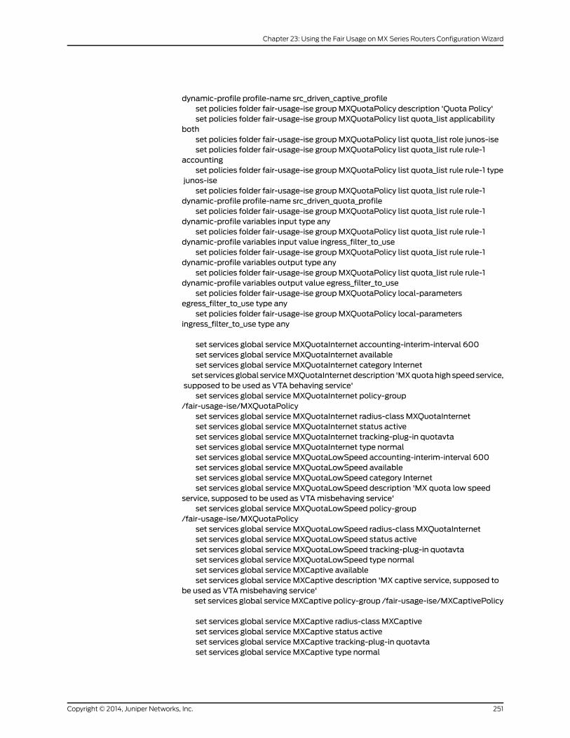
dynamic-profile profile-name src_driven_captive_profileset policies folder fair-usage-ise groupMXQuotaPolicy description 'Quota Policy'set policies folder fair-usage-ise groupMXQuotaPolicy list quota_list applicability
bothset policies folder fair-usage-ise groupMXQuotaPolicy list quota_list role junos-iseset policies folder fair-usage-ise groupMXQuotaPolicy list quota_list rule rule-1
accountingset policies folder fair-usage-ise groupMXQuotaPolicy list quota_list rule rule-1 type
junos-iseset policies folder fair-usage-ise groupMXQuotaPolicy list quota_list rule rule-1
dynamic-profile profile-name src_driven_quota_profileset policies folder fair-usage-ise groupMXQuotaPolicy list quota_list rule rule-1
dynamic-profile variables input type anyset policies folder fair-usage-ise groupMXQuotaPolicy list quota_list rule rule-1
dynamic-profile variables input value ingress_filter_to_useset policies folder fair-usage-ise groupMXQuotaPolicy list quota_list rule rule-1
dynamic-profile variables output type anyset policies folder fair-usage-ise groupMXQuotaPolicy list quota_list rule rule-1
dynamic-profile variables output value egress_filter_to_useset policies folder fair-usage-ise groupMXQuotaPolicy local-parameters
egress_filter_to_use type anyset policies folder fair-usage-ise groupMXQuotaPolicy local-parameters
ingress_filter_to_use type any
set services global service MXQuotaInternet accounting-interim-interval 600set services global service MXQuotaInternet availableset services global service MXQuotaInternet category Internetset servicesglobal serviceMXQuotaInternetdescription 'MXquotahighspeedservice,
supposed to be used as VTA behaving service'set services global service MXQuotaInternet policy-group
/fair-usage-ise/MXQuotaPolicyset services global service MXQuotaInternet radius-class MXQuotaInternetset services global service MXQuotaInternet status activeset services global service MXQuotaInternet tracking-plug-in quotavtaset services global service MXQuotaInternet type normalset services global service MXQuotaLowSpeed accounting-interim-interval 600set services global service MXQuotaLowSpeed availableset services global service MXQuotaLowSpeed category Internetset services global service MXQuotaLowSpeed description 'MX quota low speed
service, supposed to be used as VTAmisbehaving service'set services global service MXQuotaLowSpeed policy-group
/fair-usage-ise/MXQuotaPolicyset services global service MXQuotaLowSpeed radius-class MXQuotaInternetset services global service MXQuotaLowSpeed status activeset services global service MXQuotaLowSpeed tracking-plug-in quotavtaset services global service MXQuotaLowSpeed type normalset services global service MXCaptive availableset services global service MXCaptive description 'MX captive service, supposed to
be used as VTAmisbehaving service'set services global serviceMXCaptive policy-group /fair-usage-ise/MXCaptivePolicy
set services global service MXCaptive radius-class MXCaptiveset services global service MXCaptive status activeset services global service MXCaptive tracking-plug-in quotavtaset services global service MXCaptive type normal
251Copyright © 2014, Juniper Networks, Inc.
Chapter 23: Using the Fair Usage on MX Series Routers Configuration Wizard

set subscribers retailer fair-usage-mx domain-name fair-usage-mx.comset subscribers retailer fair-usage-mx subscriber-folder local subscriber
quota-subscriber-1 common-nameOneset subscribers retailer fair-usage-mx subscriber-folder local subscriber
quota-subscriber-1 surnameQuotasubscriberset subscribers retailer fair-usage-mx subscriber-folder local subscriber
quota-subscriber-1 subscription MXCaptive activationmanualset subscribers retailer fair-usage-mx subscriber-folder local subscriber
quota-subscriber-1 subscription MXCaptive status activeset subscribers retailer fair-usage-mx subscriber-folder local subscriber
quota-subscriber-1 subscription MXQuotaInternet activation automatically-on-loginset subscribers retailer fair-usage-mx subscriber-folder local subscriber
quota-subscriber-1 subscription MXQuotaInternet status activeset subscribers retailer fair-usage-mx subscriber-folder local subscriber
quota-subscriber-1 subscription MXQuotaInternet substitution ['egress_filter_to_use=\"10m-service\"' 'ingress_filter_to_use=\"10m-service\"' ]
set subscribers retailer fair-usage-mx subscriber-folder local subscriberquota-subscriber-1 subscription MXQuotaLowSpeed activationmanual
set subscribers retailer fair-usage-mx subscriber-folder local subscriberquota-subscriber-1 subscription MXQuotaLowSpeed status active
set subscribers retailer fair-usage-mx subscriber-folder local subscriberquota-subscriber-1 subscription MXQuotaLowSpeed substitution ['egress_filter_to_use=\"256k-service\"' 'ingress_filter_to_use=\"256k-service\"' ]
set slot 0 nic scenario-nameOnePopLoginset slot 0 nic snmp-agent
set slot 0 sae shared /SAE/fair-usage
set shared sae group fair-usage configuration plug-ins name quotavta ejb-adaptorjndi-sae-event-listener vta-Quota/SAEEventListenerBean
set shared sae group fair-usage configuration plug-ins name quotavta ejb-adaptorapplication-server-url {src-config src-host-parameters src-host-ip}:1099
set shared sae group fair-usage configuration plug-ins name quotavta ejb-adaptorejb-clustering-strategy EJBObjectClustering
set shared sae group fair-usage configuration plug-ins name quotavta ejb-adaptorjndi-service-provider org.jnp.interfaces.NamingContextFactory
set shared sae group fair-usage configuration plug-ins name nic externalcorba-object-reference corbaname::{src-config src-host-parameterssrc-host-ip}:2809/NameService#nicsae/saePort
set shared sae group fair-usage configuration plug-ins event-publisherssubscriber-tracking [fileAcct quotavta nic ]
set shared sae group fair-usage configuration plug-ins event-publishersservice-tracking [fileAcct quotavta ]
set shared sae group fair-usage subscriber-classifier rule rule-mx targetuniqueID=quota-subscriber-1,ou=local,retailerName=fair-usage-mx,o=Users,o=umc
set shared sae group fair-usage subscriber-classifier rule rule-mx conditionnasPortId==ge-*
insert shared sae group fair-usage subscriber-classifier rule rule-mx before rule-1
set slot 0 application-server web virtual-host eth0 alias [ {src-configsrc-host-parameters src-host-name} {src-config src-host-parameters src-host-ip} ]
set shared vta group Quota nic-proxy IdToSaeNicProxyset shared vta group fairusage subscriber-id-solution login-nameset shared vta group fairusage actionCalcUsage function db-engine-calculate-usage
Copyright © 2014, Juniper Networks, Inc.252
SRC PE 4.8.x Solutions Guide
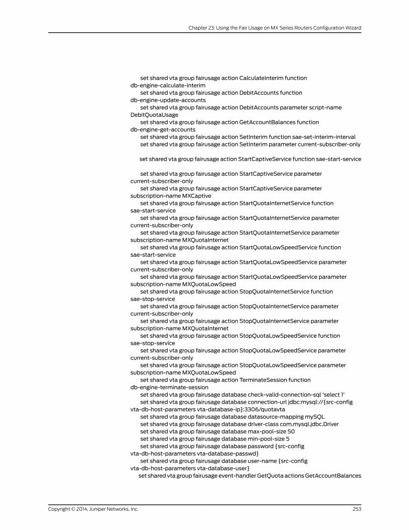
set shared vta group fairusage action CalculateInterim functiondb-engine-calculate-interim
set shared vta group fairusage action DebitAccounts functiondb-engine-update-accounts
set shared vta group fairusage action DebitAccounts parameter script-nameDebitQuotaUsage
set shared vta group fairusage action GetAccountBalances functiondb-engine-get-accounts
set shared vta group fairusage action SetInterim function sae-set-interim-intervalset shared vta group fairusage action SetInterim parameter current-subscriber-only
set shared vta group fairusage action StartCaptiveService function sae-start-service
set shared vta group fairusage action StartCaptiveService parametercurrent-subscriber-only
set shared vta group fairusage action StartCaptiveService parametersubscription-nameMXCaptive
set shared vta group fairusage action StartQuotaInternetService functionsae-start-service
set shared vta group fairusage action StartQuotaInternetService parametercurrent-subscriber-only
set shared vta group fairusage action StartQuotaInternetService parametersubscription-nameMXQuotaInternet
set shared vta group fairusage action StartQuotaLowSpeedService functionsae-start-service
set shared vta group fairusage action StartQuotaLowSpeedService parametercurrent-subscriber-only
set shared vta group fairusage action StartQuotaLowSpeedService parametersubscription-nameMXQuotaLowSpeed
set shared vta group fairusage action StopQuotaInternetService functionsae-stop-service
set shared vta group fairusage action StopQuotaInternetService parametercurrent-subscriber-only
set shared vta group fairusage action StopQuotaInternetService parametersubscription-nameMXQuotaInternet
set shared vta group fairusage action StopQuotaLowSpeedService functionsae-stop-service
set shared vta group fairusage action StopQuotaLowSpeedService parametercurrent-subscriber-only
set shared vta group fairusage action StopQuotaLowSpeedService parametersubscription-nameMXQuotaLowSpeed
set shared vta group fairusage action TerminateSession functiondb-engine-terminate-session
set shared vta group fairusage database check-valid-connection-sql 'select 1'set shared vta group fairusage database connection-url jdbc:mysql://{src-config
vta-db-host-parameters vta-database-ip}:3306/quotavtaset shared vta group fairusage database datasource-mappingmySQLset shared vta group fairusage database driver-class com.mysql.jdbc.Driverset shared vta group fairusage databasemax-pool-size 50set shared vta group fairusage databasemin-pool-size 5set shared vta group fairusage database password {src-config
vta-db-host-parameters vta-database-passwd}set shared vta group fairusage database user-name {src-config
vta-db-host-parameters vta-database-user}set shared vta group fairusage event-handler GetQuota actionsGetAccountBalances
253Copyright © 2014, Juniper Networks, Inc.
Chapter 23: Using the Fair Usage on MX Series Routers Configuration Wizard
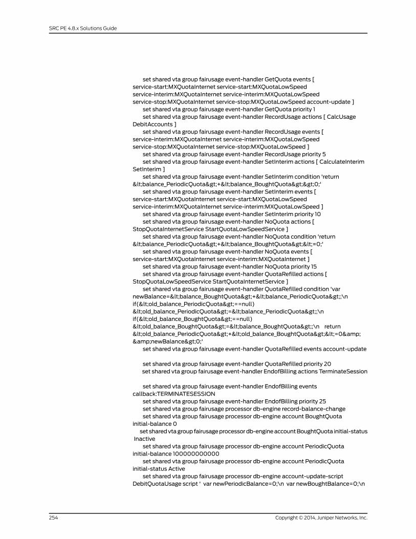
set shared vta group fairusage event-handler GetQuota events [service-start:MXQuotaInternet service-start:MXQuotaLowSpeedservice-interim:MXQuotaInternet service-interim:MXQuotaLowSpeedservice-stop:MXQuotaInternet service-stop:MXQuotaLowSpeed account-update ]
set shared vta group fairusage event-handler GetQuota priority 1set shared vta group fairusage event-handler RecordUsage actions [ CalcUsage
DebitAccounts ]set shared vta group fairusage event-handler RecordUsage events [
service-interim:MXQuotaInternet service-interim:MXQuotaLowSpeedservice-stop:MXQuotaInternet service-stop:MXQuotaLowSpeed ]
set shared vta group fairusage event-handler RecordUsage priority 5set shared vta group fairusage event-handler SetInterim actions [ CalculateInterim
SetInterim ]set shared vta group fairusage event-handler SetInterim condition 'return
<balance_PeriodicQuota>+<balance_BoughtQuota>>0;'set shared vta group fairusage event-handler SetInterim events [
service-start:MXQuotaInternet service-start:MXQuotaLowSpeedservice-interim:MXQuotaInternet service-interim:MXQuotaLowSpeed ]
set shared vta group fairusage event-handler SetInterim priority 10set shared vta group fairusage event-handler NoQuota actions [
StopQuotaInternetService StartQuotaLowSpeedService ]set shared vta group fairusage event-handler NoQuota condition 'return
<balance_PeriodicQuota>+<balance_BoughtQuota><=0;'set shared vta group fairusage event-handler NoQuota events [
service-start:MXQuotaInternet service-interim:MXQuotaInternet ]set shared vta group fairusage event-handler NoQuota priority 15set shared vta group fairusage event-handler QuotaRefilled actions [
StopQuotaLowSpeedService StartQuotaInternetService ]set shared vta group fairusage event-handler QuotaRefilled condition 'var
newBalance=<balance_BoughtQuota>+<balance_PeriodicQuota>;\nif(<old_balance_PeriodicQuota>==null)<old_balance_PeriodicQuota>=<balance_PeriodicQuota>;\nif(<old_balance_BoughtQuota>==null)<old_balance_BoughtQuota>=<balance_BoughtQuota>;\n return<old_balance_PeriodicQuota>+<old_balance_BoughtQuota><=0&&newBalance>0;'
set shared vta group fairusage event-handler QuotaRefilled events account-update
set shared vta group fairusage event-handler QuotaRefilled priority 20set shared vta group fairusage event-handler EndofBilling actions TerminateSession
set shared vta group fairusage event-handler EndofBilling eventscallback:TERMINATESESSION
set shared vta group fairusage event-handler EndofBilling priority 25set shared vta group fairusage processor db-engine record-balance-changeset shared vta group fairusage processor db-engine account BoughtQuota
initial-balance 0setsharedvtagroupfairusageprocessordb-engineaccountBoughtQuota initial-status
Inactiveset shared vta group fairusage processor db-engine account PeriodicQuota
initial-balance 100000000000set shared vta group fairusage processor db-engine account PeriodicQuota
initial-status Activeset shared vta group fairusage processor db-engine account-update-script
DebitQuotaUsage script ' var newPeriodicBalance=0;\n var newBoughtBalance=0;\n
Copyright © 2014, Juniper Networks, Inc.254
SRC PE 4.8.x Solutions Guide
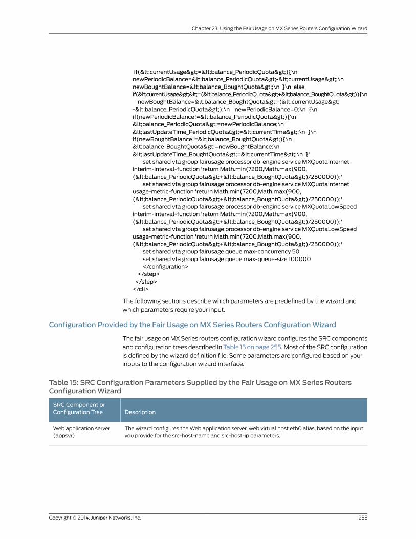
if(<currentUsage>=<balance_PeriodicQuota>){\nnewPeriodicBalance=<balance_PeriodicQuota>-<currentUsage>;\nnewBoughtBalance=<balance_BoughtQuota>;\n }\n elseif(<currentUsage><=(<balance_PeriodicQuota>+<balance_BoughtQuota>)){\nnewBoughtBalance=<balance_BoughtQuota>-(<currentUsage>
-<balance_PeriodicQuota>);\n newPeriodicBalance=0;\n }\nif(newPeriodicBalance!=<balance_PeriodicQuota>){\n<balance_PeriodicQuota>=newPeriodicBalance;\n<lastUpdateTime_PeriodicQuota>=<currentTime>;\n }\nif(newBoughtBalance!=<balance_BoughtQuota>){\n<balance_BoughtQuota>=newBoughtBalance;\n<lastUpdateTime_BoughtQuota>=<currentTime>;\n }'
set shared vta group fairusage processor db-engine service MXQuotaInternetinterim-interval-function 'return Math.min(7200,Math.max(900,(<balance_PeriodicQuota>+<balance_BoughtQuota>)/250000));'
set shared vta group fairusage processor db-engine service MXQuotaInternetusage-metric-function 'return Math.min(7200,Math.max(900,(<balance_PeriodicQuota>+<balance_BoughtQuota>)/250000));'
set shared vta group fairusage processor db-engine service MXQuotaLowSpeedinterim-interval-function 'return Math.min(7200,Math.max(900,(<balance_PeriodicQuota>+<balance_BoughtQuota>)/250000));'
set shared vta group fairusage processor db-engine service MXQuotaLowSpeedusage-metric-function 'return Math.min(7200,Math.max(900,(<balance_PeriodicQuota>+<balance_BoughtQuota>)/250000));'
set shared vta group fairusage queuemax-concurrency 50set shared vta group fairusage queuemax-queue-size 100000</configuration>
</step></step></cli>
The following sections describe which parameters are predefined by the wizard and
which parameters require your input.
Configuration Provided by the Fair Usage onMX Series Routers ConfigurationWizard
The fair usage on MX Series routers configuration wizard configures the SRC components
and configuration trees described in Table 15 on page 255. Most of the SRC configuration
is defined by the wizard definition file. Some parameters are configured based on your
inputs to the configuration wizard interface.
Table 15: SRC Configuration Parameters Supplied by the Fair Usage onMX Series RoutersConfigurationWizard
DescriptionSRC Component orConfiguration Tree
The wizard configures the Web application server, web virtual host eth0 alias, based on the inputyou provide for the src-host-name and src-host-ip parameters.
Web application server(appsvr)
255Copyright © 2014, Juniper Networks, Inc.
Chapter 23: Using the Fair Usage on MX Series Routers Configuration Wizard
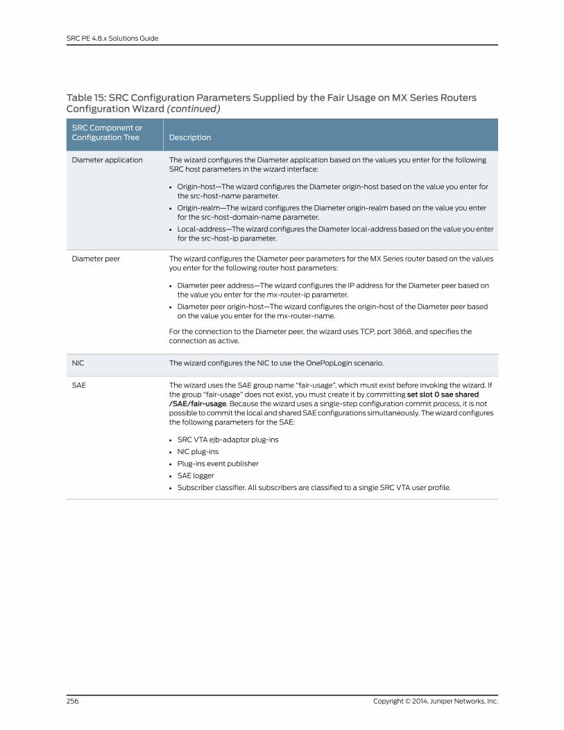
Table 15: SRC Configuration Parameters Supplied by the Fair Usage onMX Series RoutersConfigurationWizard (continued)
DescriptionSRC Component orConfiguration Tree
The wizard configures the Diameter application based on the values you enter for the followingSRC host parameters in the wizard interface:
• Origin-host—The wizard configures the Diameter origin-host based on the value you enter forthe src-host-name parameter.
• Origin-realm—The wizard configures the Diameter origin-realm based on the value you enterfor the src-host-domain-name parameter.
• Local-address—The wizard configures the Diameter local-address based on the value you enterfor the src-host-ip parameter.
Diameter application
The wizard configures the Diameter peer parameters for the MX Series router based on the valuesyou enter for the following router host parameters:
• Diameter peer address—The wizard configures the IP address for the Diameter peer based onthe value you enter for the mx-router-ip parameter.
• Diameter peer origin-host—The wizard configures the origin-host of the Diameter peer basedon the value you enter for the mx-router-name.
For the connection to the Diameter peer, the wizard uses TCP, port 3868, and specifies theconnection as active.
Diameter peer
The wizard configures the NIC to use the OnePopLogin scenario.NIC
The wizard uses the SAE group name “fair-usage”, which must exist before invoking the wizard. Ifthe group “fair-usage” does not exist, you must create it by committing set slot 0 sae shared/SAE/fair-usage. Because the wizard uses a single-step configuration commit process, it is notpossible to commit the local and shared SAE configurations simultaneously. The wizard configuresthe following parameters for the SAE:
• SRC VTA ejb-adaptor plug-ins
• NIC plug-ins
• Plug-ins event publisher
• SAE logger
• Subscriber classifier. All subscribers are classified to a single SRC VTA user profile.
SAE
Copyright © 2014, Juniper Networks, Inc.256
SRC PE 4.8.x Solutions Guide
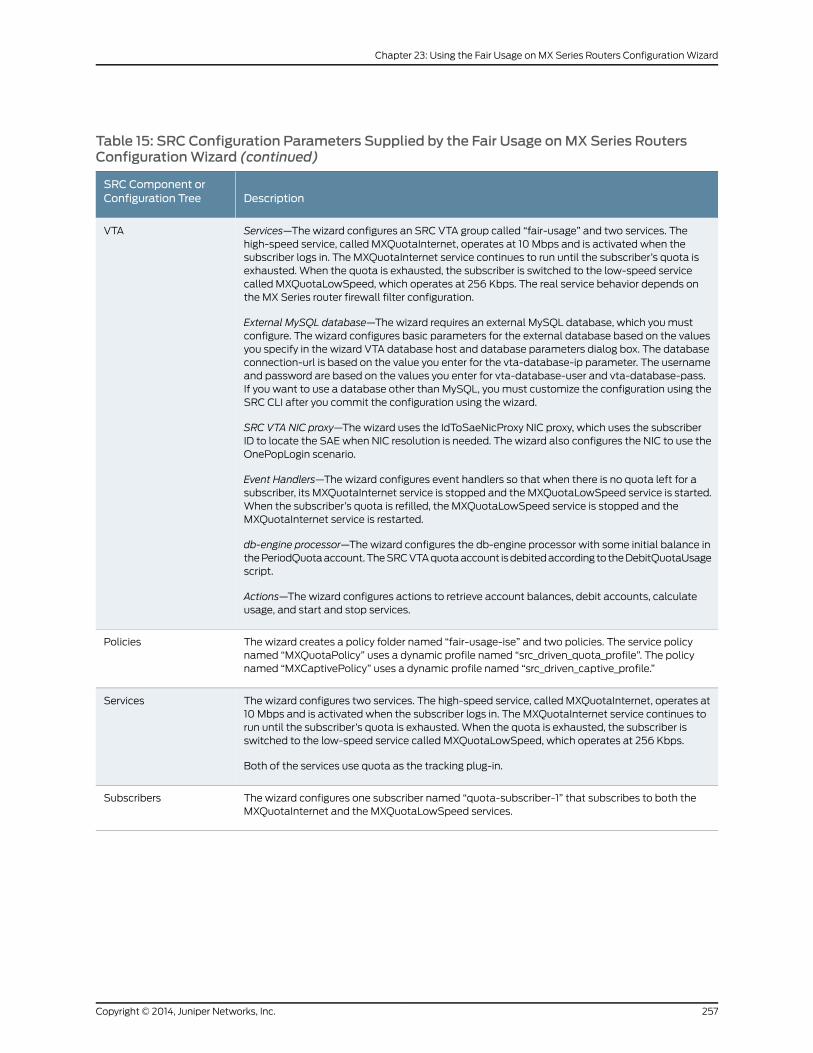
Table 15: SRC Configuration Parameters Supplied by the Fair Usage onMX Series RoutersConfigurationWizard (continued)
DescriptionSRC Component orConfiguration Tree
Services—The wizard configures an SRC VTA group called “fair-usage” and two services. Thehigh-speed service, called MXQuotaInternet, operates at 10 Mbps and is activated when thesubscriber logs in. The MXQuotaInternet service continues to run until the subscriber’s quota isexhausted. When the quota is exhausted, the subscriber is switched to the low-speed servicecalled MXQuotaLowSpeed, which operates at 256 Kbps. The real service behavior depends onthe MX Series router firewall filter configuration.
External MySQL database—The wizard requires an external MySQL database, which you mustconfigure. The wizard configures basic parameters for the external database based on the valuesyou specify in the wizard VTA database host and database parameters dialog box. The databaseconnection-url is based on the value you enter for the vta-database-ip parameter. The usernameand password are based on the values you enter for vta-database-user and vta-database-pass.If you want to use a database other than MySQL, you must customize the configuration using theSRC CLI after you commit the configuration using the wizard.
SRC VTA NIC proxy—The wizard uses the IdToSaeNicProxy NIC proxy, which uses the subscriberID to locate the SAE when NIC resolution is needed. The wizard also configures the NIC to use theOnePopLogin scenario.
Event Handlers—The wizard configures event handlers so that when there is no quota left for asubscriber, its MXQuotaInternet service is stopped and the MXQuotaLowSpeed service is started.When the subscriber’s quota is refilled, the MXQuotaLowSpeed service is stopped and theMXQuotaInternet service is restarted.
db-engine processor—The wizard configures the db-engine processor with some initial balance inthe PeriodQuota account. The SRC VTA quota account is debited according to the DebitQuotaUsagescript.
Actions—The wizard configures actions to retrieve account balances, debit accounts, calculateusage, and start and stop services.
VTA
The wizard creates a policy folder named “fair-usage-ise” and two policies. The service policynamed “MXQuotaPolicy” uses a dynamic profile named “src_driven_quota_profile”. The policynamed “MXCaptivePolicy” uses a dynamic profile named “src_driven_captive_profile.”
Policies
The wizard configures two services. The high-speed service, called MXQuotaInternet, operates at10 Mbps and is activated when the subscriber logs in. The MXQuotaInternet service continues torun until the subscriber’s quota is exhausted. When the quota is exhausted, the subscriber isswitched to the low-speed service called MXQuotaLowSpeed, which operates at 256 Kbps.
Both of the services use quota as the tracking plug-in.
Services
The wizard configures one subscriber named “quota-subscriber-1” that subscribes to both theMXQuotaInternet and the MXQuotaLowSpeed services.
Subscribers
257Copyright © 2014, Juniper Networks, Inc.
Chapter 23: Using the Fair Usage on MX Series Routers Configuration Wizard
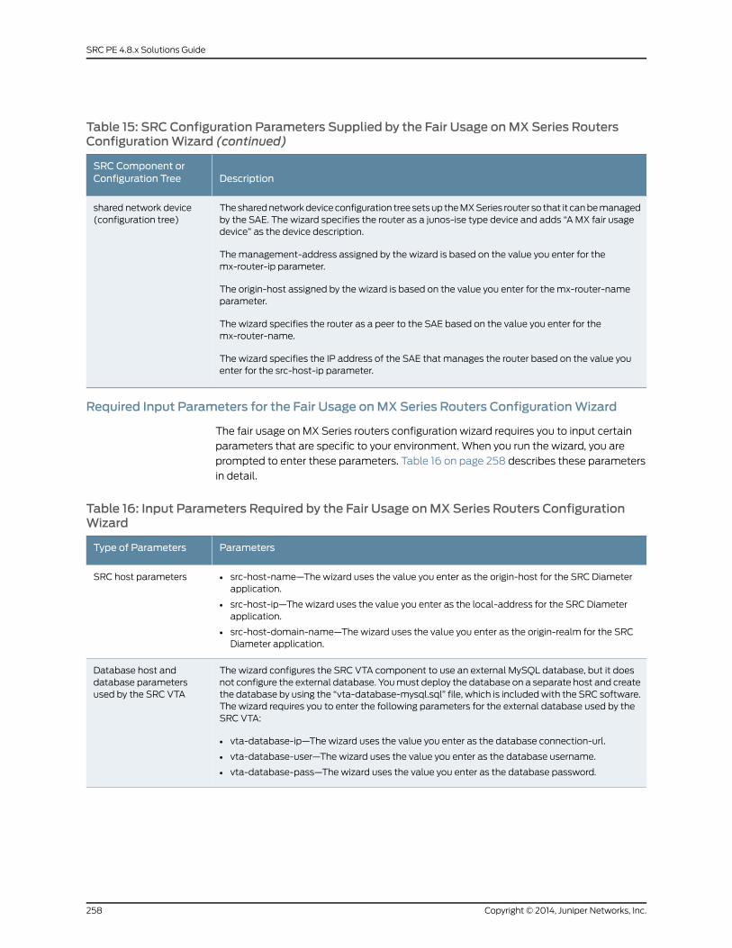
Table 15: SRC Configuration Parameters Supplied by the Fair Usage onMX Series RoutersConfigurationWizard (continued)
DescriptionSRC Component orConfiguration Tree
The shared network device configuration tree sets up the MX Series router so that it can be managedby the SAE. The wizard specifies the router as a junos-ise type device and adds “A MX fair usagedevice” as the device description.
The management-address assigned by the wizard is based on the value you enter for themx-router-ip parameter.
The origin-host assigned by the wizard is based on the value you enter for the mx-router-nameparameter.
The wizard specifies the router as a peer to the SAE based on the value you enter for themx-router-name.
The wizard specifies the IP address of the SAE that manages the router based on the value youenter for the src-host-ip parameter.
shared network device(configuration tree)
Required Input Parameters for the Fair Usage onMX Series Routers ConfigurationWizard
The fair usage on MX Series routers configuration wizard requires you to input certain
parameters that are specific to your environment. When you run the wizard, you are
prompted to enter these parameters. Table 16 on page 258 describes these parameters
in detail.
Table 16: Input Parameters Required by the Fair Usage onMX Series Routers ConfigurationWizard
ParametersType of Parameters
• src-host-name—The wizard uses the value you enter as the origin-host for the SRC Diameterapplication.
• src-host-ip—The wizard uses the value you enter as the local-address for the SRC Diameterapplication.
• src-host-domain-name—The wizard uses the value you enter as the origin-realm for the SRCDiameter application.
SRC host parameters
The wizard configures the SRC VTA component to use an external MySQL database, but it doesnot configure the external database. You must deploy the database on a separate host and createthe database by using the “vta-database-mysql.sql” file, which is included with the SRC software.The wizard requires you to enter the following parameters for the external database used by theSRC VTA:
• vta-database-ip—The wizard uses the value you enter as the database connection-url.
• vta-database-user—The wizard uses the value you enter as the database username.
• vta-database-pass—The wizard uses the value you enter as the database password.
Database host anddatabase parametersused by the SRC VTA
Copyright © 2014, Juniper Networks, Inc.258
SRC PE 4.8.x Solutions Guide
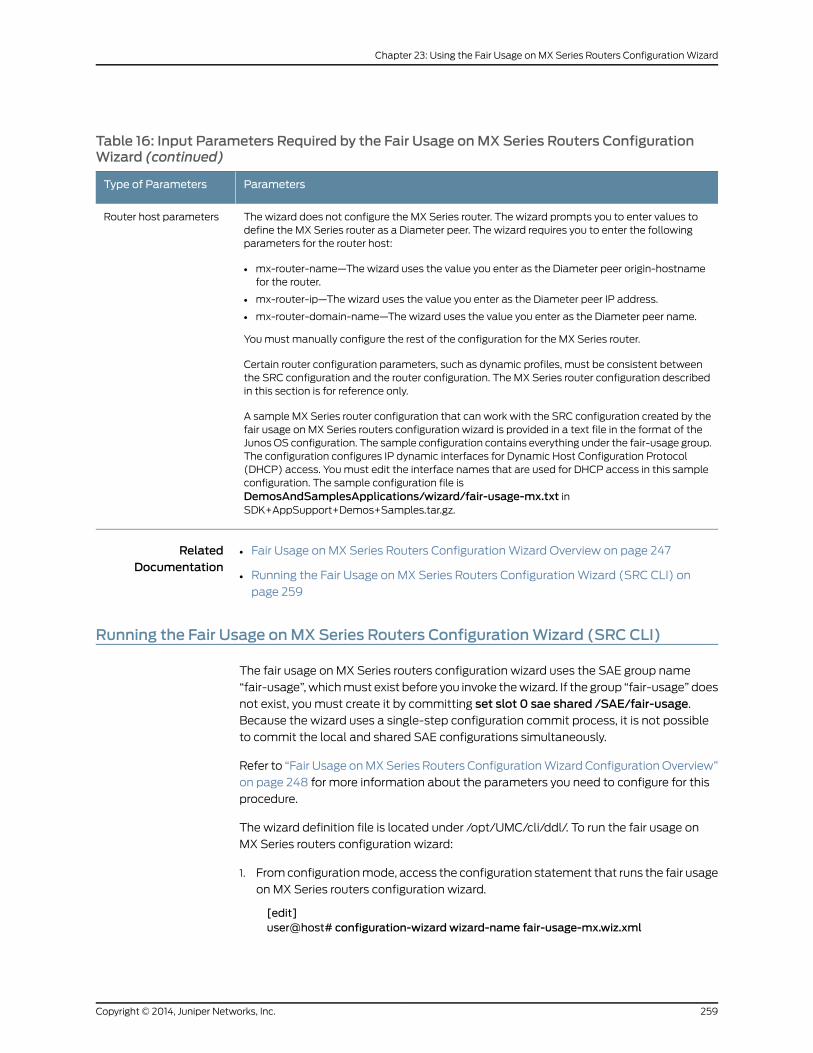
Table 16: Input Parameters Required by the Fair Usage onMX Series Routers ConfigurationWizard (continued)
ParametersType of Parameters
The wizard does not configure the MX Series router. The wizard prompts you to enter values todefine the MX Series router as a Diameter peer. The wizard requires you to enter the followingparameters for the router host:
• mx-router-name—The wizard uses the value you enter as the Diameter peer origin-hostnamefor the router.
• mx-router-ip—The wizard uses the value you enter as the Diameter peer IP address.
• mx-router-domain-name—The wizard uses the value you enter as the Diameter peer name.
You must manually configure the rest of the configuration for the MX Series router.
Certain router configuration parameters, such as dynamic profiles, must be consistent betweenthe SRC configuration and the router configuration. The MX Series router configuration describedin this section is for reference only.
A sample MX Series router configuration that can work with the SRC configuration created by thefair usage on MX Series routers configuration wizard is provided in a text file in the format of theJunos OS configuration. The sample configuration contains everything under the fair-usage group.The configuration configures IP dynamic interfaces for Dynamic Host Configuration Protocol(DHCP) access. You must edit the interface names that are used for DHCP access in this sampleconfiguration. The sample configuration file isDemosAndSamplesApplications/wizard/fair-usage-mx.txt inSDK+AppSupport+Demos+Samples.tar.gz.
Router host parameters
RelatedDocumentation
Fair Usage on MX Series Routers Configuration Wizard Overview on page 247•
• Running the Fair Usage on MX Series Routers Configuration Wizard (SRC CLI) on
page 259
Running the Fair Usage onMX Series Routers ConfigurationWizard (SRC CLI)
The fair usage on MX Series routers configuration wizard uses the SAE group name
“fair-usage”, which must exist before you invoke the wizard. If the group “fair-usage” does
not exist, you must create it by committing set slot 0 sae shared /SAE/fair-usage.
Because the wizard uses a single-step configuration commit process, it is not possible
to commit the local and shared SAE configurations simultaneously.
Refer to “Fair Usage on MX Series Routers Configuration Wizard Configuration Overview”
on page 248 for more information about the parameters you need to configure for this
procedure.
The wizard definition file is located under /opt/UMC/cli/ddl/. To run the fair usage on
MX Series routers configuration wizard:
1. From configuration mode, access the configuration statement that runs the fair usage
on MX Series routers configuration wizard.
[edit]user@host# configuration-wizard wizard-name fair-usage-mx.wiz.xml
259Copyright © 2014, Juniper Networks, Inc.
Chapter 23: Using the Fair Usage on MX Series Routers Configuration Wizard
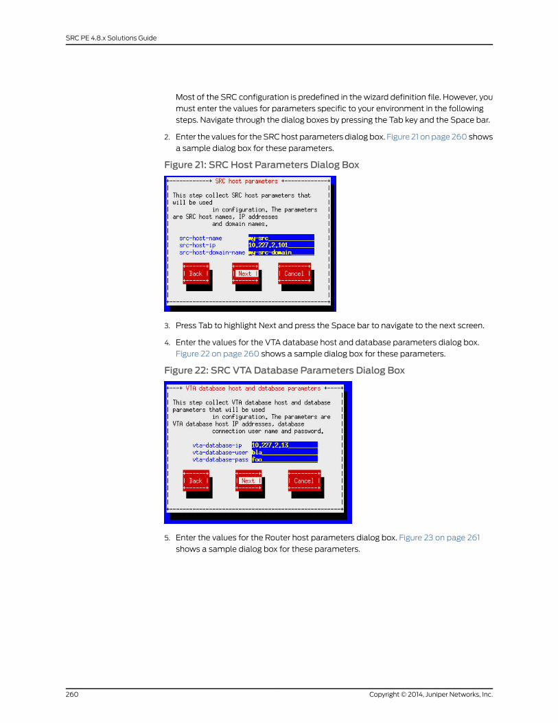
Most of the SRC configuration is predefined in the wizard definition file. However, you
must enter the values for parameters specific to your environment in the following
steps. Navigate through the dialog boxes by pressing the Tab key and the Space bar.
2. Enter the values for the SRC host parameters dialog box. Figure 21 on page 260 shows
a sample dialog box for these parameters.
Figure 21: SRC Host Parameters Dialog Box
3. Press Tab to highlight Next and press the Space bar to navigate to the next screen.
4. Enter the values for the VTA database host and database parameters dialog box.
Figure 22 on page 260 shows a sample dialog box for these parameters.
Figure 22: SRC VTADatabase Parameters Dialog Box
5. Enter the values for the Router host parameters dialog box. Figure 23 on page 261
shows a sample dialog box for these parameters.
Copyright © 2014, Juniper Networks, Inc.260
SRC PE 4.8.x Solutions Guide
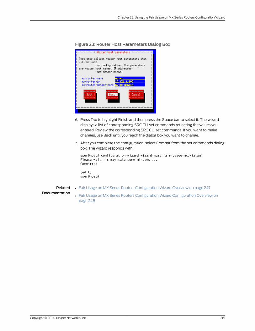
Figure 23: Router Host Parameters Dialog Box
6. Press Tab to highlight Finish and then press the Space bar to select it. The wizard
displays a list of corresponding SRC CLI set commands reflecting the values you
entered. Review the corresponding SRC CLI set commands. If you want to make
changes, use Back until you reach the dialog box you want to change.
7. After you complete the configuration, select Commit from the set commands dialog
box. The wizard responds with:
user@host# configuration-wizard wizard-name fair-usage-mx.wiz.xmlPlease wait, it may take some minutes ...Committed
[edit]user@host#
RelatedDocumentation
• Fair Usage on MX Series Routers Configuration Wizard Overview on page 247
• Fair Usage on MX Series Routers Configuration Wizard Configuration Overview on
page 248
261Copyright © 2014, Juniper Networks, Inc.
Chapter 23: Using the Fair Usage on MX Series Routers Configuration Wizard

Copyright © 2014, Juniper Networks, Inc.262
SRC PE 4.8.x Solutions Guide

PART 5
Index
• Index on page 265
263Copyright © 2014, Juniper Networks, Inc.

Copyright © 2014, Juniper Networks, Inc.264
SRC PE 4.8.x Solutions Guide

Index
Aaddress pools
assigned IP subscribers
configuring...............................................................98
address pools. See IP address pools
application manager
role, in PCMM environment.........................................41
assigned IP subscribers
PCMM network........................................................50, 70
address pools.........................................................98
IP address pools....................................................50
setting timeouts.............................................................28
voice over IP......................................................................27
Ccable modem termination system. See CMTS
devices
classify-traffic condition
match direction, setting
SRC CLI....................................................................187
client type 1, PCMM................................................................43
client type 2, PCMM...............................................................44
CMTS devices
adding objects to directory
SRC CLI.....................................................................69
adding virtual router objects to directory
SRC CLI.....................................................................70
configuration statements....................................69, 70
role........................................................................................41
CMTS locator
monitoring
C-Web interface....................................................112
SRC CLI....................................................................107
COA script services, configuring......................................120
configuration wizard
fair usage
configuration overview.....................................248
running....................................................................259
running....................................................................241, 245
configuration wizards
fair usage
overview..................................................................247
overview................................................................239, 243
conventions
notice icons.....................................................................xvii
text......................................................................................xvii
custom RADIUS authentication plug-ins.......................19
customer support...................................................................xix
contacting JTAC..............................................................xix
DData over Cable Service Interface Specifications.
See DOCSIS protocol
Diameter
peers
configuring.....................................................132, 147
Diameter server
clients, viewing
SRC CLI....................................................................137
message flows, viewing
SRC CLI....................................................................136
message handler, viewing
SRC CLI....................................................................136
monitoring
SRC CLI....................................................................135
peers, viewing
SRC CLI....................................................................137
server process, viewing
SRC CLI....................................................................136
server requests, viewing
SRC CLI....................................................................137
statistics, viewing
SRC CLI....................................................................136
status, viewing
SRC CLI....................................................................137
DOCSIS protocol.....................................................................42
documentation
comments on..................................................................xix
domains
IP service edge................................................................46
IP subscriber edge.........................................................46
radio frequency...............................................................46
Dynamic policy changes
Dynamic policy changes, managing.....................166
dynamic RADIUS authorization requests
RADIUS packets, defining...................................37, 125
265Copyright © 2014, Juniper Networks, Inc.
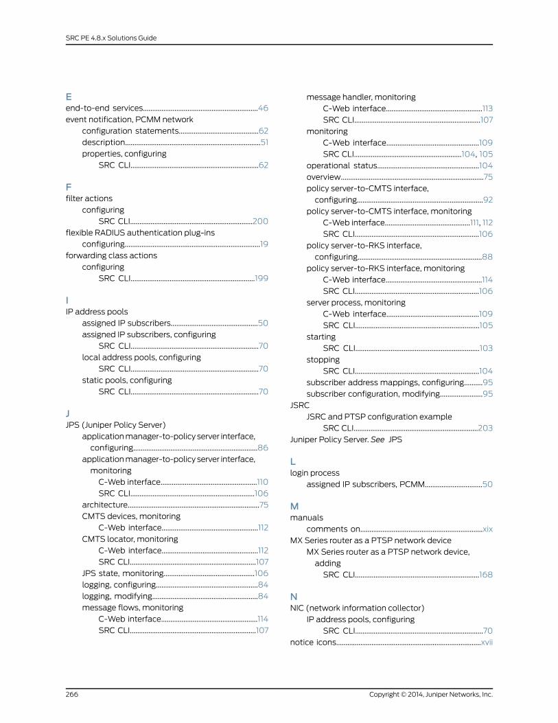
Eend-to-end services..............................................................46
event notification, PCMM network
configuration statements...........................................62
description.........................................................................51
properties, configuring
SRC CLI.....................................................................62
Ffilter actions
configuring
SRC CLI..................................................................200
flexible RADIUS authentication plug-ins
configuring.........................................................................19
forwarding class actions
configuring
SRC CLI...................................................................199
IIP address pools
assigned IP subscribers...............................................50
assigned IP subscribers, configuring
SRC CLI.....................................................................70
local address pools, configuring
SRC CLI.....................................................................70
static pools, configuring
SRC CLI.....................................................................70
JJPS (Juniper Policy Server)
application manager-to-policy server interface,
configuring...................................................................86
application manager-to-policy server interface,
monitoring
C-Web interface....................................................110
SRC CLI...................................................................106
architecture.......................................................................75
CMTS devices, monitoring
C-Web interface....................................................112
CMTS locator, monitoring
C-Web interface....................................................112
SRC CLI....................................................................107
JPS state, monitoring.................................................106
logging, configuring.......................................................84
logging, modifying.........................................................84
message flows, monitoring
C-Web interface....................................................114
SRC CLI....................................................................107
message handler, monitoring
C-Web interface....................................................113
SRC CLI....................................................................107
monitoring
C-Web interface..................................................109
SRC CLI..........................................................104, 105
operational status.......................................................104
overview.............................................................................75
policy server-to-CMTS interface,
configuring....................................................................92
policy server-to-CMTS interface, monitoring
C-Web interface..............................................111, 112
SRC CLI...................................................................106
policy server-to-RKS interface,
configuring...................................................................88
policy server-to-RKS interface, monitoring
C-Web interface....................................................114
SRC CLI...................................................................106
server process, monitoring
C-Web interface..................................................109
SRC CLI...................................................................105
starting
SRC CLI...................................................................103
stopping
SRC CLI...................................................................104
subscriber address mappings, configuring..........95
subscriber configuration, modifying.......................95
JSRC
JSRC and PTSP configuration example
SRC CLI...................................................................203
Juniper Policy Server. See JPS
Llogin process
assigned IP subscribers, PCMM...............................50
Mmanuals
comments on..................................................................xix
MX Series router as a PTSP network device
MX Series router as a PTSP network device,
adding
SRC CLI...................................................................168
NNIC (network information collector)
IP address pools, configuring
SRC CLI.....................................................................70
notice icons..............................................................................xvii
Copyright © 2014, Juniper Networks, Inc.266
SRC PE 4.8.x Solutions Guide
Ppacket mirroring, configuring.............................................30
PCMM (PacketCable Multimedia)
application manager, role............................................41
client type 1.......................................................................43
client type 2......................................................................44
CMTS device, role...........................................................41
configuring SAE
SRC CLI......................................................................57
creating sessions...........................................................50
description.........................................................................41
end-to-end QoS architecture...................................46
end-to-end services.....................................................46
integrating SRC software.............................................41
IP service edge domain...............................................46
IP subscriber edge domain........................................46
logging in subscribers
assigned IP method.............................................50
overview...................................................................50
overview..............................................................................41
policy server, role.............................................................41
provisioning end-to-end services.............................47
record-keeping server....................................................41
RF domain.........................................................................41
SAE......................................................................................50
SAE communities...........................................................53
session store....................................................................54
single-phase resource reservation model............43
SRC software in
description...............................................................45
traffic profiles.........................................................45
video-on-demand example......................................48
videoconferencing example.......................................47
PCMM device driver
configuration statements...........................................58
configuring
SRC CLI.....................................................................58
PCMM record-keeping server plug-in
configuration statements...........................................64
configuring
SRC CLI.....................................................................64
description........................................................................54
plug-ins
PCMM record-keeping server plug-in.....................54
policy actions
filter
configuring, SRC CLI.........................................200
forwarding class
configuring, SRC CLI...........................................199
forwarding instance
configuring, SRC CLI...........................................198
policy groups
configuring
SRC CLI...................................................................180
policy servers
adding application manager groups
SRC CLI.....................................................................98
adding objects to directory
SRC CLI...................................................................100
role, in PCMM architecture..........................................41
specifying application managers
SRC CLI.....................................................................98
specifying SAE communities
SRC CLI.....................................................................98
PTSP
configuring
SRC CLI....................................................................167
PTSP and JSRC configuration example
SRC CLI...................................................................203
PTSP configuration example
SRC CLI....................................................................201
PTSP policies, configuration statements
SRC CLI....................................................................178
ssr-writer
SRC CLI....................................................................172
PTSP actions
PTSP actions, configuring
SRC CLI....................................................................197
PTSP classify-traffic condition
destination grouped network, configuring
SRC CLI...................................................................189
destination network, configuring
SRC CLI....................................................................187
protocol conditions with parameters, setting
SRC CLI....................................................................192
protocol conditions with ports, setting
SRC CLI...................................................................190
protocol conditions, setting
SRC CLI...................................................................189
TCP conditions, setting
SRC CLI...................................................................194
traffic match conditions, setting
SRC CLI...................................................................196
267Copyright © 2014, Juniper Networks, Inc.
Index
PTSP classify-traffic conditions
creating
SRC CLI....................................................................187
PTSP classify-traffic conditions, configuring
SRC CLI...................................................................186
PTSP device driver
overview...........................................................................165
PTSP device driver, configuring
SRC CLI....................................................................173
PTSP on MX Series router
PTSP on MX Series router, configuring
SRC CLI...................................................................168
PTSP policer instance
PTSP policer instance, configuring
SRC CLI....................................................................182
PTSP policies
PTSP policies, configuring
SRC CLI...................................................................180
PTSP policy list
PTSP policy list, configuring
SRC CLI.....................................................................181
PTSP policy rules
network, specifying.....................................................189
PTSP policy rules, configuring
SRC CLI....................................................................183
PTSP session store
PTSP device driver session store, configuring
SRC CLI....................................................................174
PTSP traffic match
conditions, setting
SRC CLI...................................................................196
QQoS (quality of service)
PCMM environments
end-to-end QoS architecture..........................46
extending to service edge domain..................47
extending to subscriber edge domain...........47
searching for policies in directory.............................14
QoS profile-tracking plug-in
description..........................................................................4
QoS profiles, routers running JunosE Software
how tracking works..........................................................4
managing dynamically...................................................4
updating directory, using
qosProfilePublish...................................................12
quality of service. See QoS
RRADIUS
vendor-specific attributes for wireless ISP
roaming..........................................................................19
record-keeping server. See RKS
RKS (record-keeping server)
peers, configuration statements..............................63
peers, configuring in plug-ins
SRC CLI.....................................................................63
plug-in................................................................................54
plug-in, configuration statements..........................66
plug-in, configuring
SRC CLI.....................................................................64
role in PCMM environment..........................................41
roaming wireless environment............................................17
SSAE (service activation engine)
configuring as an application manager
SRC CLI......................................................................97
PCMM environment......................................................50
redundancy. See SAE communities
SAE (service activation engine), configuring
community manager
SRC CLI......................................................................61
event notification API properties
SRC CLI.....................................................................62
PCMM device driver
SRC CLI.....................................................................58
SAE communities
configuration overview
SRC CLI......................................................................61
configuration statements............................................61
configuring manager
SRC CLI......................................................................61
defining members
SRC CLI.....................................................................70
description........................................................................53
service flows.............................................................................43
services
voice over IP (VoIP).......................................................25
session store
in PCMM environment.................................................54
single phase resource reservation model,
PCMM.....................................................................................43
subscriber
wireless environment.....................................................17
support, technical See technical support
Copyright © 2014, Juniper Networks, Inc.268
SRC PE 4.8.x Solutions Guide

Ttechnical support
contacting JTAC..............................................................xix
text conventions defined....................................................xvii
traffic policies, PCMM...........................................................45
Wwireless environment..............................................................17
269Copyright © 2014, Juniper Networks, Inc.
Index

Copyright © 2014, Juniper Networks, Inc.270
SRC PE 4.8.x Solutions Guide