srm control algorithm for electric vehicles drives ...pe.org.pl/articles/2012/1a/14.pdf ·...
TRANSCRIPT
70 PRZEGLĄD ELEKTROTECHNICZNY (Electrical Review), ISSN 0033-2097, R. 88 NR 1a/2012
Krzysztof TOMCZUK, Marcin PARCHOMIUK
Electrotechnical Institute, Power Converters Department
SRM control algorithm for electric vehicles drives applications
Abstract. In the article author describes a measurements of generated torque and flux in SRM for different rotor positions. The measurements are compared with simulations results. At the end of the article author describes a algorithm of realization traction drive characteristic required by mechanical vehicles. Streszczenie. W artykule autor prezentuje wyniki pomiarów momentu oraz strumienia elektromagnetycznego dla różnych położeń wirnika. Wyniki pomiarów porównano z wynikami otrzymanymi drogą symulacji komputerowych. Przedstawiony jest także algorytm realizacji charakterystyki trakcyjnej wymaganej do napędy pojazdów mechanicznych. (Algorytm realizacji charakterystyki trakcyjnej wymaganej do napędy pojazdów mechanicznych) Keywords: SRM, Switched reluctance motor, torque, flux Słowa kluczowe: SRM, silnik reluktancyjny przełączalny, moment, strumień Introduction
Switched reluctance motors (SRM) belong to a group of motors with electronic commutation, where the phenomenon of variable reluctance is used in their operations. Because of the absence of rotor windings and of a relatively simple machine phase winding system they belong to motors with the lowest production costs and they are characterized by high durability, similar to that of induction machines. The SRM have several advantages which cause that they are ideally suitable for use in certain applications for drives. These machines do not have mechanical commutator, that is there are not any problems related to commutator operation. They can be operated in explosive environments and in conditions of high dustiness, without any special casing. In case of any damage to one winding , their operation can be continued at a reduced load which constitutes an essential advantage for fans and pumps. The SRM do not have permanent magnets or rotor windings which permits the machines to operated at much higher temperatures, and permits the machine to be designed with reduced dimensions. A drive with a reluctance motor (SRM and converter) has higher efficiency [6] than one realized using an induction motor with converter. It is of basic importance to minimize the amount of energy consumption by vehicles with electric drive.
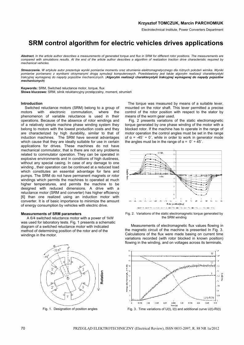
Measurements of SRM parameters A 6/4 switched reluctance motor with a power of 1kW was used for laboratory tests. Fig. 1 presents a schematic diagram of a switched reluctance motor with indicated method of determining position of the rotor and of the windings in the motor.
Fig. 1. Designation of position angles
The torque was measured by means of a suitable lever, mounted on the rotor shaft. This lever permitted a precise control of the rotor position with respect to the stator by means of the worm gear used.
Fig. 2 presents variations of the static electromagnetic torque generated by one phase winding of the motor with a blocked rotor. If the machine has to operate in the range of motor operation the control angles must be set in the range of α = -45˚ ÷ 0˚, while in order to work in generator mode the angles must be in the range of α = 0˚ ÷ 45˚.
Fig. 2. Variations of the static electromagnetic torque generated by
the SRM winding
Measurements of electromagnetic flux values flowing in the magnetic circuit of the machine is presented In Fig. 3. Calculations of the flux were made basing on current time variations recorded (with rotor blocked in known position) flowing in the winding, and on voltages across its terminals.
Fig. 3. Time variations of U(t), I(t) and additional curve U(t)-RI(t)

PRZEGLĄD ELEKTROTECHNICZNY (Electrical Review), ISSN 0033-2097, R. 88 NR 1a/2012 71
Measurement of the electromagnetic flux value generated by the motor phase winding was connected with determining an additional curve U(t)-RI(t), and by integrating it then according to Formula (1).
dttIRtUtt
0
)]()([)( (1)
where: U – voltage [V], I - current [A], R – winding resistance [Ω], Ψ - flux [Wb]
Measurements of the flux were repeated for other rotor
positions. The value of the voltage applied across winding terminals was selected in such a way that it forced the flow of rated current in the winding in stationary state.
Fig. 4. Variations of the electromagnetic flux
Fig. 5. Variations of the electromagnetic flux
Fig. 4 shows variations of the electromagnetic flux as a
function of rotor position for various values of the current flowing in the motor phase winding, while Fig. 5 presents electromagnetic flux variations as a function of the current in the motor phase winding for different positions of the rotor.
The results were introduced into the simulation model (Formulas 3 and 4).
Verification of the motor parameters A field model of the motor was elaborated in the
programme FEMAG-DC in order to verify the values of torque and flux. Model of the reluctance motor was made introducing the real machine dimensions and the characteristic of magnetic circuit material. On the basis of field model tests there were determined magnetic flux values and variations of electromagnetic torque generated in the motor for different rotor positions. The results are shown in Figs. 11 and 12.
Fig. 6. Grid in the whole cross-section of the motor
Fig. 7. Magnetic flux lines for the position α=0˚ and current I=10A
Fig. 8. Magnetic flux lines for the position α=-22.5˚ and current I=10A
Fig. 9. Magnetic flux lines for the position α=-45˚ and current
I=10A

72 PRZEGLĄD ELEKTROTECHNICZNY (Electrical Review), ISSN 0033-2097, R. 88 NR 1a/2012
-4
-5
4
5
0-45 45
M [Nm]
2A
4A
6A
8A
10A
3
2
1
0
-1
-2
-3
Fig. 10. Variations of the electromagnetic flux determined on the basis of field model tests In the FEMAG-DC programme
[Wb]
0.05
0.10
0.15
0.20
0.25
0.30
0.35
10 2 3 4 5 6 7 8 9 10
Prąd [A]
deg
deg
+-
Fig. 11. Variations of electromagnetic flux determined on the basis of field model tests In the FEMAG-DC programme
0.35
0.30
0.25
0.20
0.15
0.10
0.05
0-45 45
[deg]
[Wb]
1A
2A
3A
4A
5A
10A
Fig. 12. Variations of electromagnetic flux determined on the basis of field model tests In the FEMAG-DC programme
Table 1. Comparison between laboratory and field model results
Max. values of the torque
[Nm] Max. values of the flux
[Wb]
Current [A]
Laboratorymodel (Fig. 1)
Field model
(Fig. 10)
Laboratorymodel (Fig. 4)
Field model
(Fig. 12)
2 0.5 0.2 0.138 0.142
4 1.5 1.2 0.271 0.276
6 2.8 2.5 0.314 0.320
8 3.9 3.6 0.331 0.335 10 5.1 5.0 0.346 0.348
Satisfactory convergence of measurement results was
obtained from both models. The obtained results were used as input data for the simulation model realized in the Matlab-Simulink programme. The results are shown in Table 1.
Mathematical model of SRM Formula (2) show the voltage equation for the SRM
phase winding.
(2) dt
idiRU jjjjj
),(
where: U – supply voltage, R – winding resistance, Ψ – flux, j – winding number, α - rotor position, i – winding current
The value of electromagnetic flux depends on the rotor position “α” and on the value of current “i” in the winding, thus partial derivatives of the variables appear in Formula (3).
(3) dt
di
i
i
dt
di
dt
i j
j
jjjjjj
),(),(),(
The voltage equation for one phase winding with partial derivatives is shown by Equation (4) which was used in the simulation programme.
(4) dt
di
i
i
dt
diiRU j
j
jjjjjjj
),(),(
The rotation speed of rotor was calculated according to Formulas (5) and (6).
(5) TLdt
dT
dt
dD
dt
dJM f
sgn2
2
where: M – sum of torques generated by motor phases, J – rotor inertia, D – friction, Tf – friction, TL – external load
(6) t
dt0
0
where: α – rotor position, ω – rotation speed, α0 – starting position Selected laboratory test results and verification of the mathematical model
Fig. 13. Characteristics M=f(n) for Uz=320V ; UG=400V ; αon=var ;
αoff=-1.4° Fig. 13 presents a family of M=f(n) characteristics for
various current switching angles αon and for a constant current switching angle αoff = -1.4°.
The measurements presented were performed on a laboratory model of a drive with a reluctance motor, in order to verify the mathematical model. Fig. 10 presents selected measurements results of the M=f(n) characteristics obtained from the laboratory and simulation model. A satisfactory convergence of measurements was obtained from both models. Thus it can be assumed that the mathematical model is correct.
α [deg]

PRZEGLĄD ELEKTROTECHNICZNY (Electrical Review), ISSN 0033-2097, R. 88 NR 1a/2012 73
Fig. 14. Comparison of results obtained from the simulation model with the measurement for Uz=320V ; UG=400V; αon= -11.2°; αoff=-
1.4°
Figs. 15a, 15b, 15c presents exemplary test results of the simulation model of the variables of rotational speed (rys. 15a), torque ripples (rys. 15b) and of the efficiency (rys. 15c), at changes of the firing angle αon and of the current conduction angle (∆on= |αon - αoff|). The tests were performed for the converter supply voltage Uz=320V, UG=640V, motor load torque TL=4Nm.
Fig. 15a. Variability of the rotation speed
Fig. 15b. Variability of the torque pulsation
Fig. 15c. Variability of the efficiency of the motor with converter According to the test results it is possible to obtain
simultaneously a minimum of torque pulsation and maximum of SRM and converter efficiency. It is possible to obtain these parameters for αon= -40˚ ÷ -35˚ and ∆on= 40˚ ÷ 35˚.
Traction characteristic realization algorithm
Two control methods can be distinguished during realization of the traction characteristic: at a constant torque
and a constant power. During the controlling with a constant torque the force applied to the vehicle wheels is constant and it does not depend on speed. The power consumed by the motor increases as well as the temperature of windings. The moment of going over from the first method to the second one is determined by the thermal safety limit which should not be exceed, as it can lead to overheating the motor windings. If a further increase in the vehicle speed is required, then the control algorithm shall be changed to another one, in which the force applied to the vehicle wheels decreases with rise in the rotation speed. The power supplied to the motor is then constant and consequently, so is also the windings temperature.
Fig. 16. Description of the traction characteristic
The realization algorithm of traction characteristic was defined on the basis of tests of the simulation model. The results are presented in Table II.
Table 2. Traction characteristic realization algorithm
Speed range [RPM] αon [˚] ∆on [˚] Imax [A]
Torque ripples
0 – 500 -45 45 10 1,4
500 – 1100 -45 40 10 1,5
1100 – 2000 -45 35 10 1,6
2000 – 3500 -45 30 10 1,7
> 3500 -45 25 10 1,5 where: αon – firing angle, ∆on – conduction angle, Imax – current limitations in motor windings
The highest values of the torque generated were achieved when the phase currents were fired at αon = -45˚ and conducted by the angle ∆on = 45˚. The current conduction angle shall undergo reduction when the rotation increases. The variation of the torque shown in Fig. 17 is not mild, there are two local decreases of the torque value for n = 2000 RPM and n = 4000 RPM. It is related to the fact that the conduction angle ∆on in the algorithm was reduced in steps of 5˚ (see Table II).
Fig. 17. Graphical interpretation of Table II

74 PRZEGLĄD ELEKTROTECHNICZNY (Electrical Review), ISSN 0033-2097, R. 88 NR 1a/2012
If simulation is performed by steps of 1˚, then the variation of torque becomes smooth. At the same time the number of rotation speed ranges described In Table II, must be increased.
Fig. 18. Limit-wise interpretation of Table II in case of the number of control intervals increased by five times with a reduction step ∆on every 1˚. C-DUMP Converter
A C-DUMP converter was used to supply the laboratory model of a switched reluctance motor with power supplied from mains of 230V, 50Hz. It permitted the currents in motor windings to be switched on and off in precisely defined positions, determined by the αon and αoff angles. During switching off the currents in windings, the energy collected in the magnetic fields L1, L2, L3 charges the CG capacitor through the D1, D2, D3 diodes. The system has the possibility of controlling the UG voltage which influences the speed of the current decay in motor windings. Such a capability of the system is particularly useful in the range of high rotation speeds (high voltage across UG). The value of the UG voltage is controlled by the TG transistor. The control system of the converter had the possibility to control the αon and αoff in the range from -45˚ to 45˚. The value of UG could be set in the range from 325 Vdc to 1200 Vdc.
Fig. 19. Connection topology of the C-DUMP converter
Fig. 20. View of the motor with an electric dynamometer
Fig. 21. View of the converter laboratory model
Conclusions
The present paper describes a method of measuring the torque and the electromagnetic flux in a switched reluctance motor. The investigations carried out determine the possibility of applying SRM in electric and hybrid vehicles. An algorithm of realization of a traction characteristic required for the drive of mechanical vehicles is presented. Characteristics of M=f(n) for constant αon and αoff angles used in simple control algorithms are shown.
REFERENCES
[1] X. D. Xue, K.W.E.Cheng, J. K. Lin, Z. Zhang, K. F. Luk, T. W. Ng, N. C. Cheung. “Optimal Control Method of motoring Operation for SRM Drives in Electric Vehicles”. IEEE Transactions on Vehicular Technology, vol. 59, No. 3, March 2010.
[2] V. L. Do, M. C. Ta. “Modeling, Simulation and Control of Reluctance Motor Drives for High Speed Operation”. Energy Conversion Congress and Exposition. September 12-16, 2010. IEEE.
[3] P. Krishnamurthy, W. Lu, F. Khorrami, A. Keyhani. “Robust Force Control of an SRM-Based Electromechanical Brake and Experimental Results”. IEEE Transcations on Control Systems Technology, vol. 17, No. 6, November 2009
[4]. W. Jazdzynski, M. Majchrowicz. “An Approach to Find an Optimum Designed SRM for Electric Vehicle Drive”. Proceedings of the 2008 International Conference on Electrical Machines
[5] Ch. Mademlis, I. Kioskeridis. “Smooth Transition between Optimal Control Modes in Switched Reluctance Motoring and Generating Operation”. International Conference on Power Systems Transients (IPST’07) in Lyon, France on June 4-7, 2007
[6] P. Andrada, B. Blanqué, J.I. Perat, M. Torrent, E. Martínez, J. A. Sánchez. “Comparative efficiency of switched reluctance and induction motor drives for slowly varying loads”. International Conference on Renewable Energy and Power Quality (ICREPQ’06), Palma de Mallorca, 5, 6, 7 April,2006
Authors: Ph.D. Krzysztof Tomczuk, Electrotechnical Institute, Power Converters Department, Pozaryskiego Street 28, 04-703 Warsaw, e-mail: [email protected] M.S. Marcin Parchomiuk, Electrotechnical Institute, Power Converters Department, Pozaryskiego Street 28, 04-703 Warsaw, e-mail: [email protected]