s&t efforts for navy corrosion control - exponaval · s&t efforts for navy corrosion...
TRANSCRIPT
S&T Efforts for
Navy Corrosion
Control
Edward LemieuxCenter for Corrosion Science & Engineering
NRL Code 6130
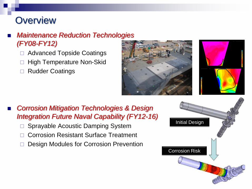
Overview
Maintenance Reduction Technologies
(FY08-FY12)
Advanced Topside Coatings
High Temperature Non-Skid
Rudder Coatings
Corrosion Mitigation Technologies & Design
Integration Future Naval Capability (FY12-16)
Sprayable Acoustic Damping System
Corrosion Resistant Surface Treatment
Design Modules for Corrosion Prevention
2
Initial Design
Corrosion Risk
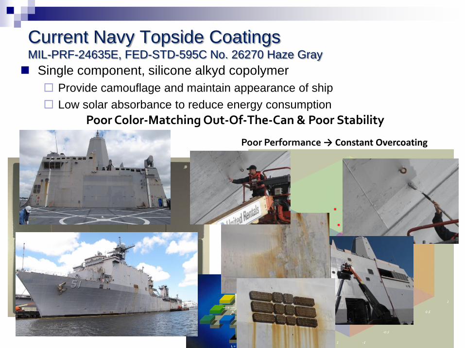
Current Navy Topside CoatingsMIL-PRF-24635E, FED-STD-595C No. 26270 Haze Gray
Single component, silicone alkyd copolymer
Provide camouflage and maintain appearance of ship
Low solar absorbance to reduce energy consumption
Poor Performance → Constant Overcoating
Poor Color-Matching Out-Of-The-Can & Poor Stability
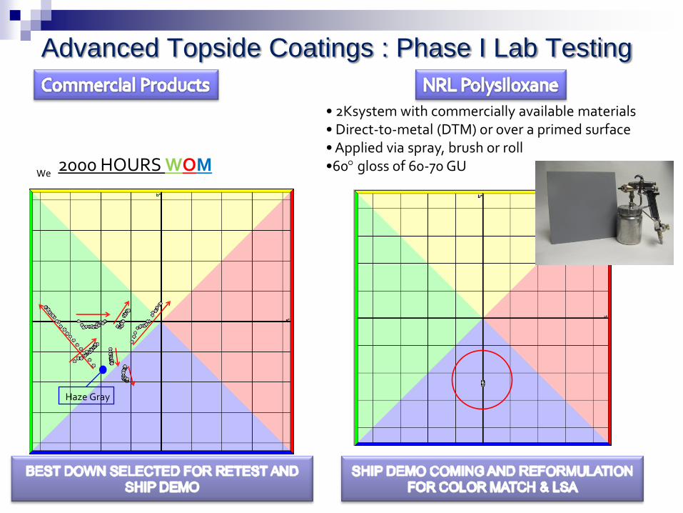
Advanced Topside Coatings : Phase I Lab Testing
Haze Gray
Weatherometerperformance2000 HOURS WOM
• 2Ksystem with commercially available materials• Direct-to-metal (DTM) or over a primed surface• Applied via spray, brush or roll•60 gloss of 60-70 GU
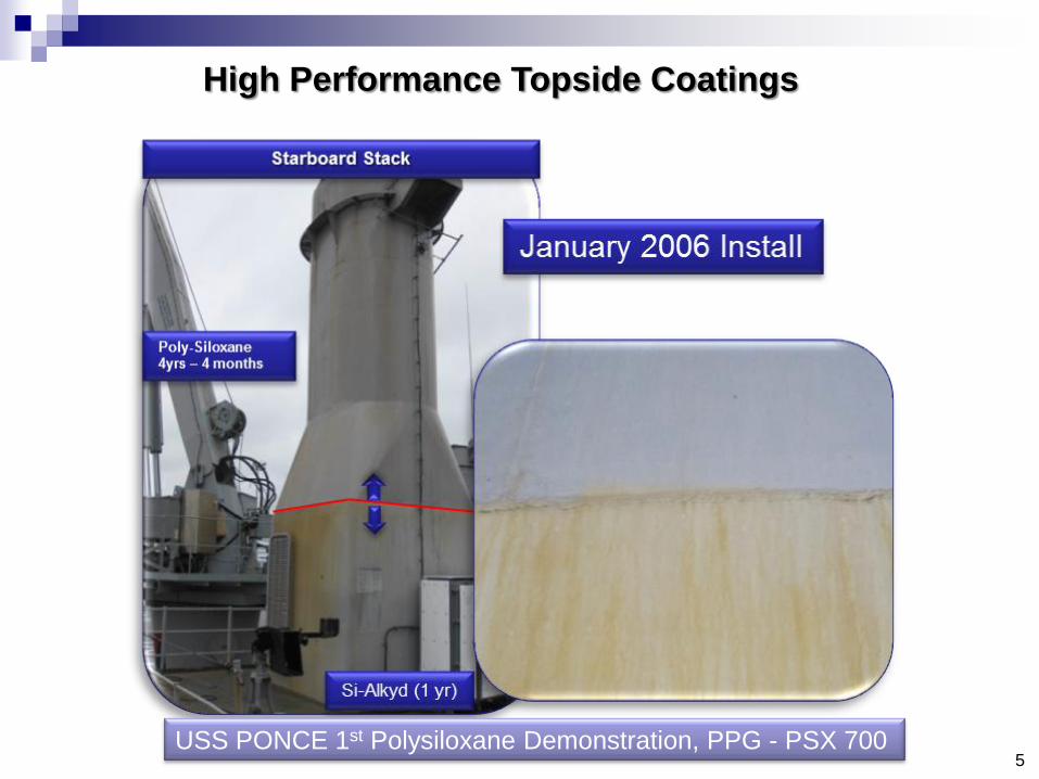
High Performance Topside Coatings
USS PONCE 1st Polysiloxane Demonstration, PPG - PSX 7005
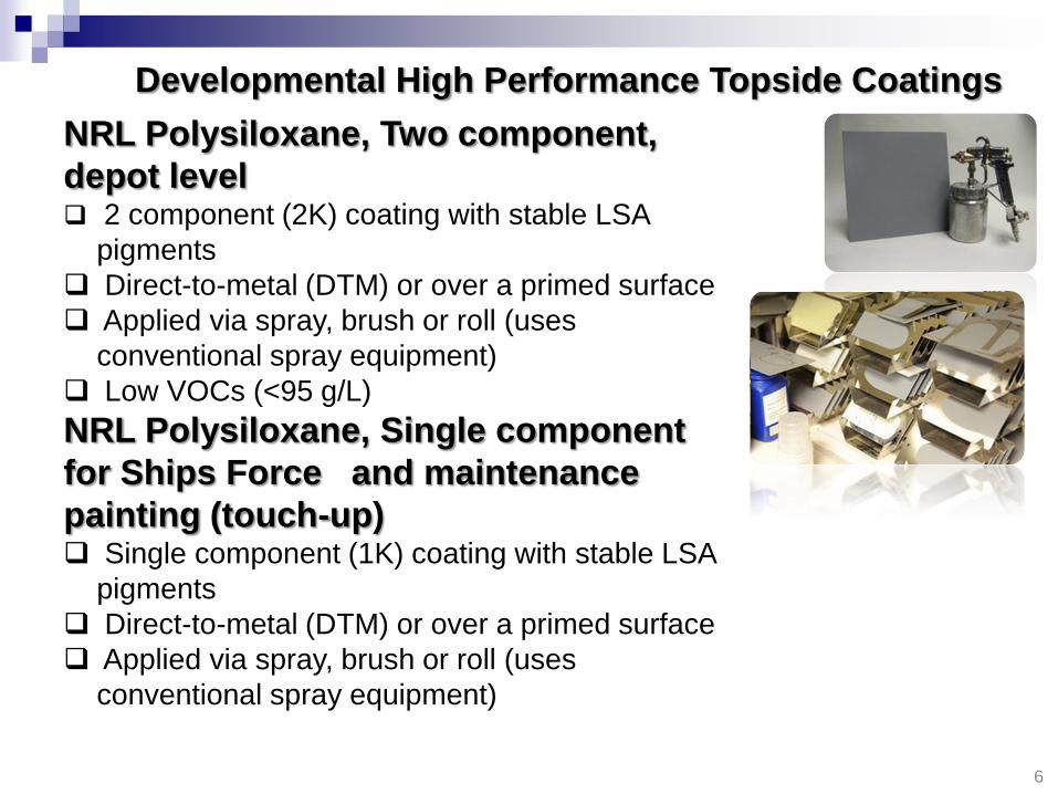
NRL Polysiloxane, Two component,
depot level 2 component (2K) coating with stable LSA
pigments
Direct-to-metal (DTM) or over a primed surface
Applied via spray, brush or roll (uses
conventional spray equipment)
Low VOCs (<95 g/L)
NRL Polysiloxane, Single component
for Ships Force and maintenance
painting (touch-up) Single component (1K) coating with stable LSA
pigments
Direct-to-metal (DTM) or over a primed surface
Applied via spray, brush or roll (uses
conventional spray equipment)
6
Developmental High Performance Topside Coatings
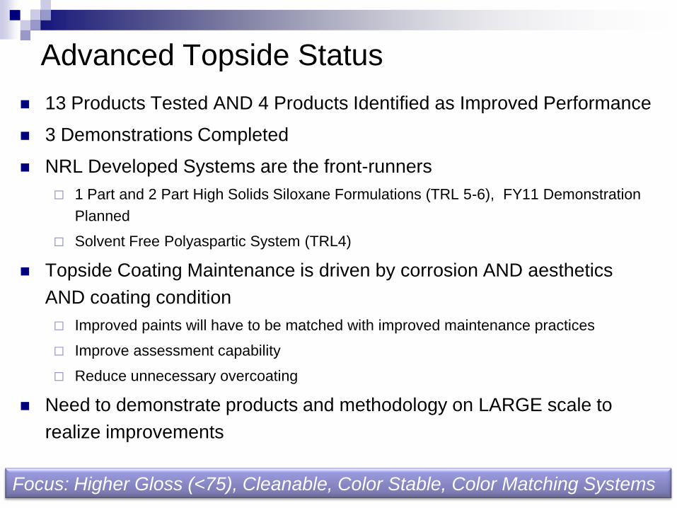
Advanced Topside Status
13 Products Tested AND 4 Products Identified as Improved Performance
3 Demonstrations Completed
NRL Developed Systems are the front-runners
1 Part and 2 Part High Solids Siloxane Formulations (TRL 5-6), FY11 Demonstration
Planned
Solvent Free Polyaspartic System (TRL4)
Topside Coating Maintenance is driven by corrosion AND aesthetics
AND coating condition
Improved paints will have to be matched with improved maintenance practices
Improve assessment capability
Reduce unnecessary overcoating
Need to demonstrate products and methodology on LARGE scale to
realize improvements
7Focus: Higher Gloss (<75), Cleanable, Color Stable, Color Matching Systems

Advanced Rudder Coatings
Problem: Rudder coating system fails in less than 2
year time period, which results in
corrosion of the structure. This is the
highest priority problem with the DDG 51
Type Desk at NAVSEA.
Objectives &
Approach: Enhance performance coatings to provide
minimum of 2 to 5 years service life on
rudders.
Utilize computational model to predict
forces & loadings on surfaces
Use stresses and deflections to design
and validate test apparatus to replicate
field conditions for use as screening test
8
Cavitation
Structural Failure
Modeling
Improved
Coatings
Cavitation
Resistance
Problem Solution
Cathodic
Disbondment
Resistance
Cavitation
Resistance

ar = -10o ar = -5o ar = -0o ar = 5o
1/3 Speed
Velocity (No
cavitation)
2/3 Speed
Velocity (Small
area of
cavitation on
leading edge)
Standard Speed
Velocity
(Cavitation for all
angles)
Rudder Coatings: CFD
Outboard
Inboard
Outboard
Inboard
Outboard
Inboard
Cavitation Coefficient with Velocity and Angle of Attack
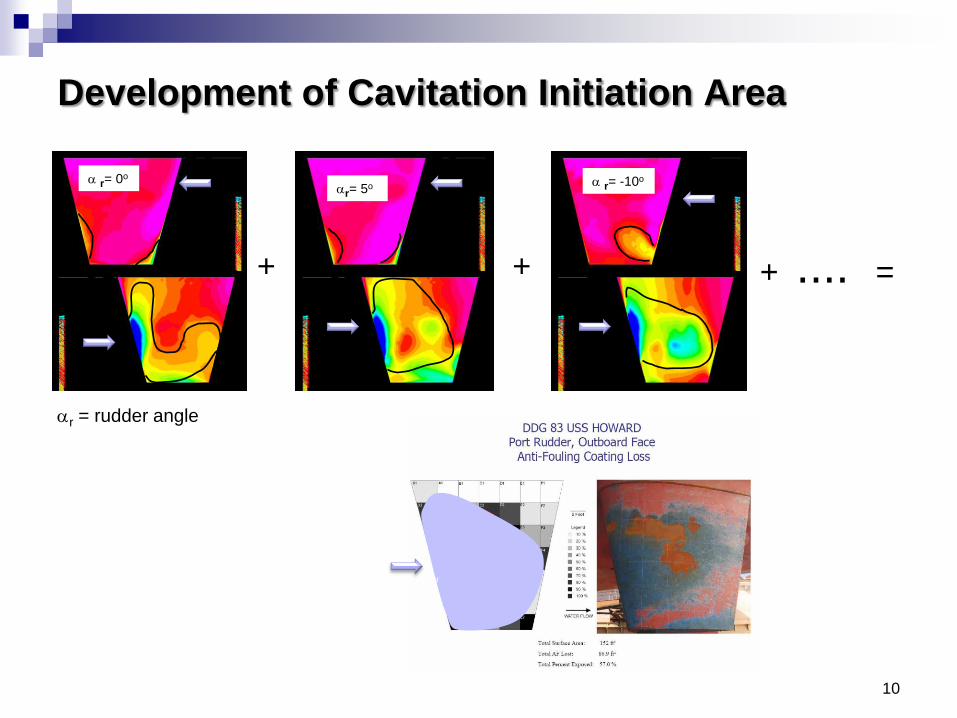
Development of Cavitation Initiation Area
10
+ + .... =+
ar= 5o
Water Flow
Water Flow
Water Flow
a r= 0o
Outboard
Water Flow
Water Flow
a r= -10o
Water Flow
Water Flow
ar = rudder angle
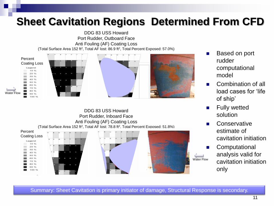
DDG 83 USS Howard
Port Rudder, Inboard Face
Anti Fouling (AF) Coating Loss(Total Surface Area 152 ft2, Total AF lost: 78.8 ft2, Total Percent Exposed: 51.8%)
Sheet Cavitation Regions Determined From CFD
11
Based on port
rudder
computational
model
Combination of all
load cases for „life
of ship‟
Fully wetted
solution
Conservative
estimate of
cavitation initiation
Computational
analysis valid for
cavitation initiation
only
Water Flow
DDG 83 USS Howard
Port Rudder, Outboard Face
Anti Fouling (AF) Coating Loss (Total Surface Area 152 ft2, Total AF lost: 86.9 ft2, Total Percent Exposed: 57.0%)
Percent
Coating Loss
Percent
Coating Loss
Summary: Sheet Cavitation is primary initiator of damage, Structural Response is secondary.
Water Flow

NSWC Demonstration—Versalink P1000
12
Composite section with Versathane film is placed
over notched troweled adhesive on MIL-P-24441
surface
Vacuum Bag to Hold Section in Place for Cure
USN R/V ATHENA
Final Installation
GREAT CONDITION!!!
VERSALINK COMPOSITE AFTER 1
YEAR ABOARD THE USN R/V ATHENA

ADVANCED RUDDER COATINGS: Road Forward
NSWC Code 65 success with Versalink P1000
provides light at the end of the tunnel!
Pre-cast with adhesive to epoxy
Historically poor adhesion directly to epoxy
NRL Modifications for Producibility
Modified pot life adequate for roll/brush/spray
Developed a tie coat to promote adhesion between
the anti-corrosive epoxy coating layer and the
cavitation resistant topcoat
Modified the Versalink to a sprayable topcoat, multi-
pass single coat high build film (150 mils)
Utilize with anti-corrosive epoxy primer system
resistant to cathodic disbondment.
GREAT CONDITION!!!
VERSALINK COMPOSITE AFTER 1
YEAR ABOARD THE USN R/V HELENA
PLANNING FOR 2-3 DEMONSTRATIONS IN FY11:
1. Pre-cast Sheet with Adhesive & Vacuum Sealed Cure
2. Brushed/Rolled Versalink over MIL-P-24441
3. Spray Applied over MIL-P-24441
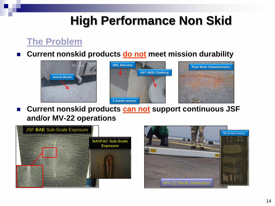
Current nonskid products do not meet mission durability
Current nonskid products can not support continuous JSF
and/or MV-22 operations
High Performance Non Skid
The Problem
JSF BAE Sub-Scale Exposure
MV-22 Deck Deflection
NRL Siloxane
AST 440G Chalking
5 month service
Poor Wear Characteristics
Amine Blush
NAVFAC Sub-Scale
Exposure
MV-22 Heat Testing
14
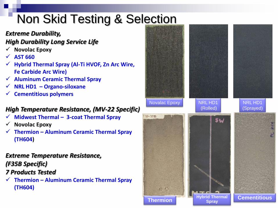
Non Skid Testing & SelectionExtreme Durability, High Durability Long Service Life Novolac Epoxy AST 660 Hybrid Thermal Spray (Al-Ti HVOF, Zn Arc Wire,
Fe Carbide Arc Wire) Aluminum Ceramic Thermal Spray NRL HD1 – Organo-siloxane Cementitious polymers
High Temperature Resistance, (MV-22 Specific) Midwest Thermal – 3-coat Thermal Spray Novolac Epoxy Thermion – Aluminum Ceramic Thermal Spray
(TH604)
Extreme Temperature Resistance, (F35B Specific)7 Products Tested Thermion – Aluminum Ceramic Thermal Spray
(TH604)
NRL HD1
(Sprayed)
Thermion Cementitious
NRL HD1
(Rolled)
Novalac Epoxy
Hybrid Thermal Spray
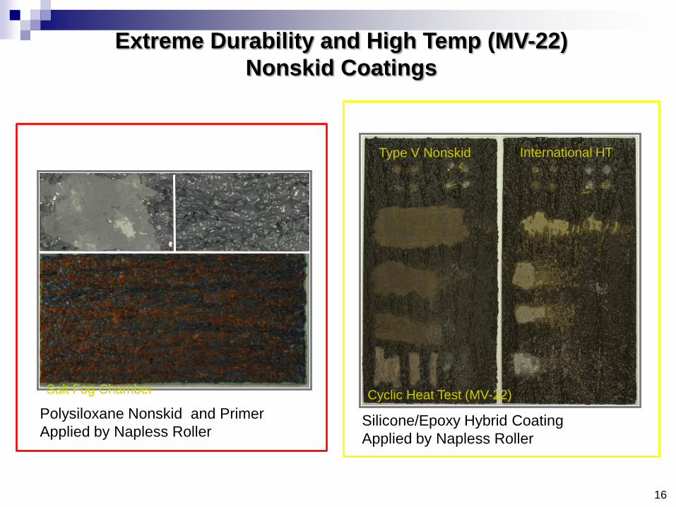
Extreme Durability and High Temp (MV-22)
Nonskid Coatings
Polysiloxane Nonskid and Primer
Applied by Napless Roller
Salt Fog Chamber
16
Silicone/Epoxy Hybrid Coating
Applied by Napless Roller
Cyclic Heat Test (MV-22)
Type V Nonskid International HT
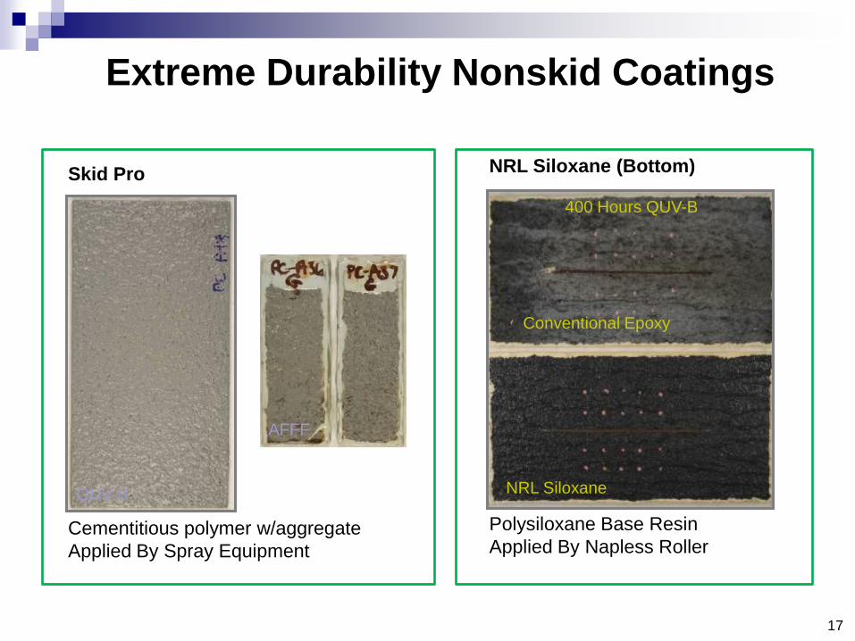
Extreme Durability Nonskid Coatings
NRL Siloxane (Bottom)
Polysiloxane Base Resin
Applied By Napless Roller
400 Hours QUV-B
Conventional Epoxy
NRL Siloxane
17
Skid Pro
Cementitious polymer w/aggregate
Applied By Spray Equipment
QUV-B
AFFF
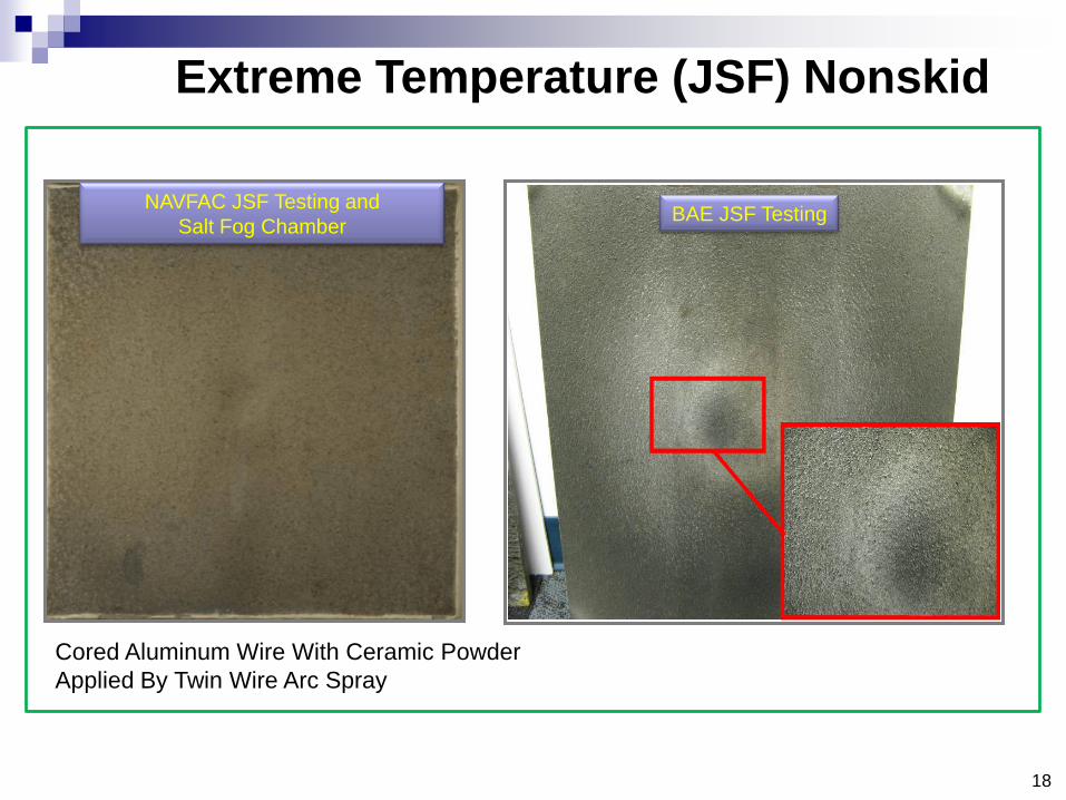
Cored Aluminum Wire With Ceramic Powder
Applied By Twin Wire Arc Spray
NAVFAC JSF Testing and
Salt Fog ChamberBAE JSF Testing
18
Extreme Temperature (JSF) Nonskid
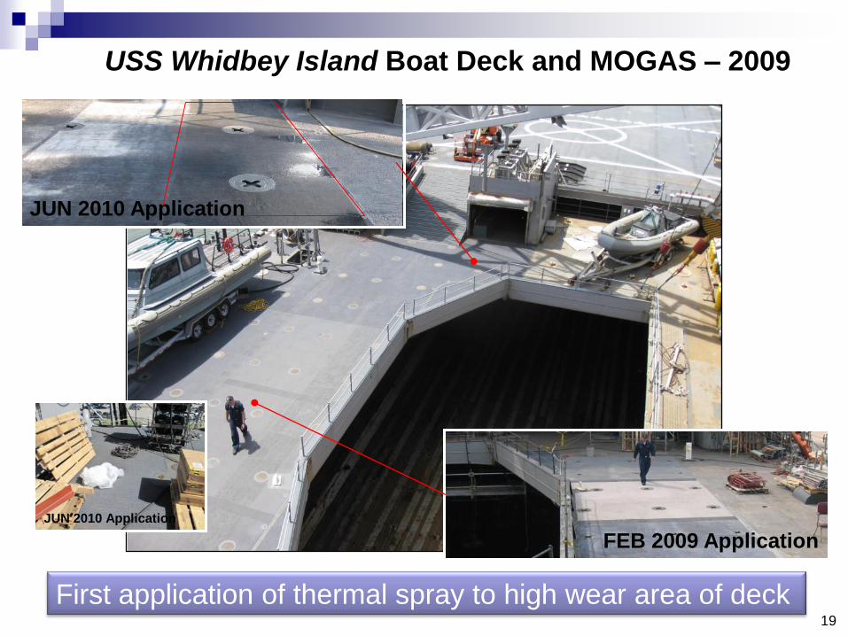
FEB 2009 Application
JUN 2010 Application
JUN 2010 Application
19
USS Whidbey Island Boat Deck and MOGAS – 2009
First application of thermal spray to high wear area of deck

03 Aux Conn – 5 Month Follow-Up
NRL Silxoane Rev 1
Conventional Nonskid,
chalking after 5
months
CIWS Foundation – Initial Installation
NRL Polysiloxane outperforming conventional nonskid,
20
USS Ponce CIWS Foundation and 03 Aux Conn
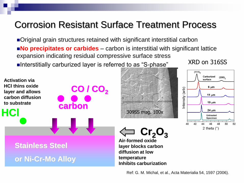
Original grain structures retained with significant interstitial carbon
No precipitates or carbides – carbon is interstitial with significant lattice
expansion indicating residual compressive surface stress
Interstitially carburized layer is referred to as “S-phase”
309SS mag. 100x
XRD on 316SS
Ref: G. M. Michal, et al., Acta Materialia 54, 1597 (2006).
Stainless Steel
or Ni-Cr-Mo Alloy
CO / CO2
HClcarbon
Cr2O3Air-formed oxide
layer blocks carbon
diffusion at low
temperature
Inhibits carburization
Activation via
HCl thins oxide
layer and allows
carbon diffusion
to substrate
Corrosion Resistant Surface Treatment Process
22
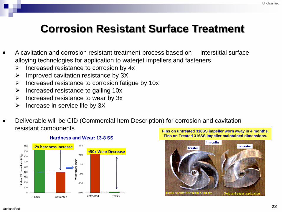
Technical Description:
A cavitation and corrosion resistant treatment process based on interstitial surface
alloying technologies for application to waterjet impellers and fasteners
Increased resistance to corrosion by 4x
Improved cavitation resistance by 3X
Increased resistance to corrosion fatigue by 10x
Increased resistance to galling 10x
Increased resistance to wear by 3x
Increase in service life by 3X
Deliverable will be CID (Commercial Item Description) for corrosion and cavitation
resistant componentsFins on untreated 316SS impeller worn away in 4 months.
Fins on Treated 316SS impeller maintained dimensions.
≈50x Wear Decrease
LTCSS untreated untreated LTCSS
≈2x hardness increase
Hardness and Wear: 13-8 SS
Unclassified
Unclassified
Corrosion Resistant Surface Treatment
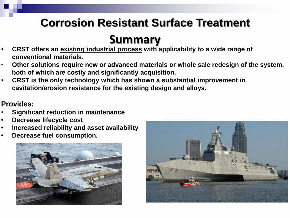
• CRST offers an existing industrial process with applicability to a wide range of
conventional materials.
• Other solutions require new or advanced materials or whole sale redesign of the system,
both of which are costly and significantly acquisition.
• CRST is the only technology which has shown a substantial improvement in
cavitation/erosion resistance for the existing design and alloys.
Provides:• Significant reduction in maintenance
• Decrease lifecycle cost
• Increased reliability and asset availability
• Decrease fuel consumption.
Corrosion Resistant Surface Treatment
Summary
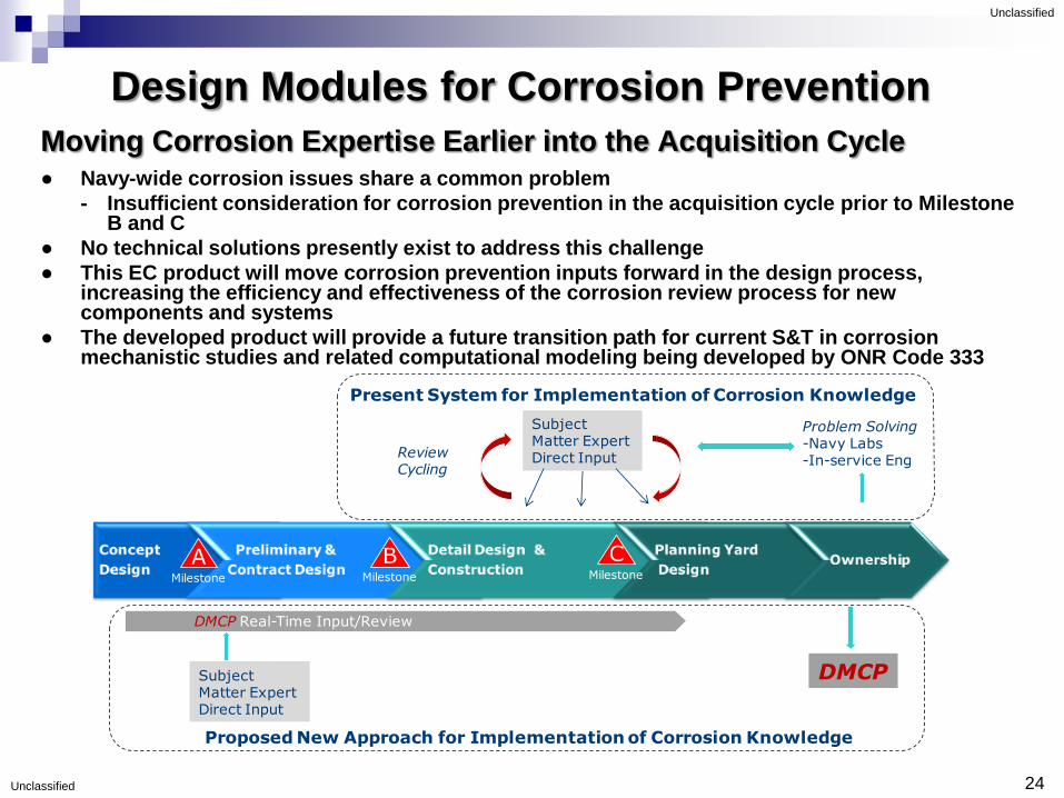
Design Modules for Corrosion Prevention
Moving Corrosion Expertise Earlier into the Acquisition Cycle● Navy-wide corrosion issues share a common problem
- Insufficient consideration for corrosion prevention in the acquisition cycle prior to Milestone B and C
● No technical solutions presently exist to address this challenge
● This EC product will move corrosion prevention inputs forward in the design process, increasing the efficiency and effectiveness of the corrosion review process for new components and systems
● The developed product will provide a future transition path for current S&T in corrosion mechanistic studies and related computational modeling being developed by ONR Code 333
24
Unclassified
Unclassified
Present System for Implementation of Corrosion Knowledge
Proposed New Approach for Implementation of Corrosion Knowledge
Subject Matter Expert Direct InputReview
Cycling
DMCP Real-Time Input/Review
Problem Solving-Navy Labs-In-service Eng
Subject Matter Expert Direct Input
Lessons
learned
DMCP
AMilestone
BMilestone
CMilestone

Design Modules for Corrosion Prevention
System/Component Drawing
• Geometry
• Materials & Coatings
• Component Connectivity
Component Usage
• Environment
• Function
• Maintainability
DMCP
Corrosion Analysis Results
• Corrosion Risks
• Life Prediction
• Design Revisions
Interaction with DMCP Module:Act as a tool native to
the CAD system
environment
Assimilate
results into overall
corrosion risk score

Acknowledgements
NRL gratefully acknowledges Dr. Airan
Perez, the ONR program manager for
these efforts and the Office of Naval
Research for sponsoring these programs.
NRL would also like to recognize the
continued partnership with NSWCCD
which has substantially contributed to
these programs.
26