stabalux zl-s stabalux_zl-s_en.pdf · stabalux zl-s system 01.11.19 8 stabalux zl-s system 1 cover...
TRANSCRIPT

Stabalux ZL-S
20 Stabalux ZL-S 1
21 Stabalux ZL-S - System 3
211 System properties 3212 System cross sections and inner seals - facade 6213 System cross sections and inner seals - roof 12214 Cover strips and outer seals 14
22 Stabalux ZL-S - Processing notes 17
221 Material information 17222 Assembly sequence 20223 Attaching the spacer strip 22224 Tips for laying seals 23225 Seals - Facade 25226 Seals - roof 34227 Glass inset and glass support 40228 Screw fittings 52229 Flat cover strip DL 5073 DL 6073 552210 Slab insulation 56
23 Stabalux ZL-S - Design 59
231 Pane support variants 59232 System cross sections 62233 System details 63234 Structural attachments 68235 Installing windows and doors 79
S T A B A L U X
Stabalux ZL-S System 011119 3
Stabalux ZL-SSystem
System properties
Steel facade system with spacer strip ZL
ZL-S_21_001dwg
211
S T A B A L U X
Stabalux ZL-S System 011119 4
Stabalux ZL-S
System properties
Stabalux ZL-S system description
bull Stabalux ZL-S is a simple and affordable add-on sys-tem for single and double glazing with a complete and customisable range to create facades and roofs with a steel supporting structure
bull The Stabalux ZL-S system is available in 50 60 and 80 mm widths
bull The spacer strip is attached centrally to the sub-structure to ensure precise seals are made Together with the seal this provides a uniform appearance
bull The system can be installed on the construction site without any prior processing of the sub-structure and is therefore an ideal choice for facade refurbish-ment work
Specifications
Suitable for passive building construction
Facade Roof up to 2deg inclination
System widths 50 60 80 mm 50 60 80 mm
Air permeability EN 12152 AE AE
WatertightnessEN 12154ENV 13050
StaticDynamic
RE 1650 Pa250 Pa750 Pa RE 1350 Pa2)
Resistanceto wind load
permitted loadincreased load
20 kNmsup230 kNmsup2
20 kNmsup230 kNmsup2
Impact resistanceEN 14019 E5 I5
Increased requirements in accordance with Cahier 3228 du CSTB Meacutethode dlsquoes-sai de choc sur verriegravere Weight 50 kgHead 24 m
2) the test was carried out using a water volume of 34l(m2min) - above the amount required by the standard
Facade
System designeg ZL-S-60120-44-15 Uf = 067 W(m2K) 1) Glass thickness 44 mm
1) Without effect of screws
System
211
only works without the use of threaded sockets
S T A B A L U X
Stabalux ZL-S System 011119 5
Stabalux ZL-S
System properties
System
Certifications authorisations CE mark (Section 9)
The tests we have conducted provide the processor and planner with the certainty and the ability to use the test findings and the products fits for instance to award the CE mark
PermeabilitySafety
bull The Stabalux sealing geometry prevents moisture ingress
bull Condensation is guided away in a controlled mannerbull Stabalux offers slotted and overlapping sealing sys-
tems for vertical glazing Overlapping systems have been tested for inclined facades up to 20deg
bull Transom flags increase the safety and impermeabili-ty of the installation on vertical glazing
bull A special Stabalux sealing system with offset sealing sections is used for roof glazing This keeps the sup-porting structure level during planning and produc-tion processes
bull Sealing the transom rebate allows flat roofs to be created with an incline of up to 2deg
bull Creation of the required drainage takes place direct-ly at the construction site by pushing together the seals in the facade or slotting together the offset sealing sections in the roof
InsulationThermal Separation (Section 9)
The Stabalux System ZL has excellent thermal proper-ties It allows a heat transfer coefficient of Uf for frames of up to 060 W(msup2K)
Noise insulation of the glass facade (Section 9)
The noise insulating properties of a facade depend on a variety of factors each of which affects the properties in a different way The task of the planner is to expert-ly select the optimum design on a case-by-case basis Different combinations of frame profiles glazing systems and noise reducing glass have vastly different effects on noise insulation Investigations and measurements per-formed by us are just examples of a huge range of possi-bilities and serve only as a guideline
Stabalux SOL sun protection (Section 9)
We offer our proprietary system with exterior lamellae in addition to the familiar measures for protection against glare and excessive sunlight Particular attention has been paid here to ensure attachment and assembly can be completed easily with Stabalux systems whilst meeting architectural and climatic requirements Glass panes and clamping strips are not subject to any load from application of the sun protection Assembly and sealing are simple and efficient
211
ZL-S_21_002dwg
S T A B A L U X
Stabalux ZL-S System 011119 6
Stabalux ZL-SSystem
212
System cross sections and inner seals - facade
1 Cover profile
2 Pressure profile
3 Outer seal
31 Outer seal convex polygonal glazing
32 Outer seal concave polygonal glazing
4 Glass panel
5 Inner seal
Vertical glazing transomVertical glazing mullion
51 Inner sealing using a transom flag
52 Inner seal convex polygonal glazing
53 Inner seal concave polygonal glazing
6 System screw fittings
7 Spacer strip
8 Support profile
Polygonal glazing mullions - concave 3deg - 10degPolygonal glazing mullions - convex 3deg - 15deg
ZL-S_21_004dwg
1
2
3
4
5
6
7
1
2
3 4 51
6
8
8
7
12
31
4
52
6
8
12
32
4
53
6
8
7 7
Inner seal 5 mm tall 1 drainage level
S T A B A L U X
Stabalux ZL-S System 011119 7
Stabalux ZL-S
System cross sections and inner seals - facade
System
System 50 mm
System 60 mm
System 80 mm
GD 6036 Polygonalconcave
GD 6025
ZL 6053 eg GD 6030
GD 8025
ZL 8053 GD 8030
GD 6038 Polygonalconvex
GD 5025
ZL 5053
GD 5030
Mullion Transom
Mullion
Mullion Transom
Transom
ZL-S_21_004dwg
212
Inner seal 5 mm tall 1 drainage level
S T A B A L U X
Stabalux ZL-S System 011119 8
Stabalux ZL-SSystem
1 Cover profile
2 Pressure profile
3 Outer seal
4 Glass panel
5 Inner seal 10 mm
Vertical glazing transom -1st levelVertical glazing mullion - 2nd level
System cross sections and inner seals - facade 212
51 Inner sealing using a transom flag 10 mm
6 System screw fittings
7 Spacer strip
8 Support profile
Inner seal 10 mm tall 2 overlapping drainage levels
ZL-S_21_004dwg
tested system for vertical facades and facades with an incline up to 20deg
1
2
3
4
5
6
7
1
2
3 4 51
6
8
8
7
S T A B A L U X
Stabalux ZL-S System 011119 9
Stabalux ZL-SSystem
System cross sections and inner seals - facade 212
Inner seal 10 mm tall 2 overlapping drainage levels
System 50 mm and System 60 mm upon request
Mullions - 2nd level
Mullions - 2nd level
Mullions - 2nd level
GD 6033
ZL 6053
GD 8033
ZL 8053 GD 8031
GD 5033
ZL 5053
System 50 mm
System 60 mm
System 80 mm
Transom - 1st level
Transom - 1st level
Transom - 1st level
ZL-S_21_004dwg
S T A B A L U X
Stabalux ZL-S System 011119 10
Stabalux ZL-SSystem
212
1 Cover profile
2 Pressure profile
3 Outer seal
4 Glass panel
5 Inner seal 12 mm main mullion
Vertical glazing transom - 2nd levelVertical glazing main mullion - 3rd level
System cross sections and inner seals - facade
51 Inner seal using a transom flag
52 Inner seal 12 mm secondary mullion
6 System screw fittings
7 Spacer strip
8 Support profile
Inner seal 12 mm tall 3 overlapping drainage levels
Vertical glazing secondary mullion - 1st level
ZL-S_21_004dwg
tested system for vertical facades and facades with an incline up to 20deg
1
2
3
4
5
6
7
1
2
3 4 51
6
8
8
7
12
3
4
52
6
8
7
S T A B A L U X
Stabalux ZL-S System 011119 11
Stabalux ZL-SSystem
System cross sections and inner seals - facade 212
Inner seal 12 mm tall 3 overlapping drainage levels
System 50 mm 60 mm and 80 mm upon request
System 50 mm
System 60 mm
System 80 mm
Main mullion - 3rd level Secondary mullion - 1st level
Main mullion - 3rd level Secondary mullion - 1st level
Main mullion - 3rd level Secondary mullion - 1st level
Transom - 2nd level
Transom - 2nd level
Transom - 2nd level
ZL-S_21_004dwg
6
S T A B A L U X
Stabalux ZL-S System 011119 12
Stabalux ZL-SSystem
System cross sections and inner seals - roof
1 Cover profile
11 Cover profile
2 Pressure profile
3 Outer seal
4 Glass panel
5 Inner seal 10 mm rafter
51 Inner seal 10 mm transom
6 System screw fittings
7 Spacer strip
8 Support profile
9 Hold-down clamp
10 Washer
11 All weather silicone seal
12 Rope seal
Angled glazing transom up to 2deg inclinationAngled glazing rafter up to 2deg inclination
ZL-S_21_004dwg
Inner seal 10 mm tall 2 overlapping drainage levels
213
Inclined glazing rafter Angled glazing transom
11
3
4
5167
8
910
4
51
7
8
11
12
1
2
3
4
5
6
7
8
12
3
4
5
6
8
7
S T A B A L U X
Stabalux ZL-S System 011119 13
Stabalux ZL-SSystem
System cross sections and inner seals - roof
Inner seal 10 mm tall 2 overlapping drainage levels
213
ZL-S_21_004dwg
System 50 mm
System 60 mm
System 80 mm
GD 6033
ZL 6053
eg GD 6034
GD 8033
ZL 8053
GD 8034
GD 5033
ZL 5053
GD 5034
Rafter - 2nd level Transom - 1st level
Rafter - 2nd level
Rafter - 2nd level Transom - 1st level
Transom - 1st level
System 80 mm upon request
S T A B A L U X
Stabalux ZL-S System 011119 14
Stabalux ZL-SSystem
Cover strips and outer seals
Aluminium - concealed screw fittings
214
Check mountability (height of U plate + cap nut possi-ble use of sealing washer or special screws)
1)
2)
3)
only possible with special screws
The geometry of the clipping process is different for the 50 60 and 80 mm widths
ZL-S_21_005dwg
S T A B A L U X
Stabalux ZL-S System 011119 15
Stabalux ZL-SSystem
Cover strips and outer seals
Stainless steel - concealed screw fittings
214
Aluminium - visiblescrew fittings
Stainless steel - visiblescrew fittings
Flat cover stripDL 5073DL 6073
ZL-S_21_005dwg
S T A B A L U X
Stabalux ZL-S Processing notes 011119 17
Stabalux ZL-SProcessing notes
Material information
Quality of the supporting structure
The steel load-bearing substructure is used for mounting the glazing and must meet all load and suitability require-ments The static system profile dimensions and choice of materials are key The client architect andor proces-sor is responsible for this decision
The following limit values must be adhered to in the se-lection of the steel typeRated values of yield strength fy ge 235 Nmmsup2Tensile strength fu ge 360 Nmmsup2
We recommend selecting materials according to Euroco-de 3 (DIN EN 1993)
The cross-sectional geometries and dimensions of the supporting profiles should also enable dimensioning ac-cording to Eurocode 3
Corrosion protection and coating on the supporting structure
Mullion and transom constructions usually receive a coloured coating for aesthetic reasons Galvanization is used to improve anti-corrosion where necessary The following corrosion protection options are therefore con-ceivable
bull Colour coating on supporting profiles with strip-gal-vanized surface
bull Colour coating on supporting profiles with dip-galva-nized surface
bull Supporting profiles with galvanized surface but with-out colour coating
bull Colour coating on supporting profiles with non-gal-vanized surface
Conventional coating methods such as air-drying multi-lay-er coating systems (wet coating) or thermosetting coatings (stove enamelling powder-coating) can be used provid-ed suitable pre-treatment is applied
Stabalux T-profileStabalux T-profile Steel - hollow profile Stabalux I-profile Steel - special profile
ZL-S_21-003dwg
221
S T A B A L U X
Stabalux ZL-S Processing notes 011119 18
Stabalux ZL-S
Material information
Processing notes
Profile design
The diagram below shows some examples for the geome-try of supporting profiles The profiles must be protected against corrosion and free of dirt
The spacer strips can also be mounted onto existing pro-files
Spacer strip quality
Stabalux spacer strips are made of hard PVC unpunched in black - suitable for a uniform visual appearance for in-ner Stabalux seals
Seal profiles
Stabalux seals are organic natural rubber materials based on EPDM and conform to the DIN 7863 standard non-cellular elastomer sealing profiles for window and facade construction Compatibility with contact media should tested by the processor particularly when using plastic glazing and making structural joints with non-Stabalux products Sealing the rebate with all weather silicone seal is possible
All weather silicone seal
Only certified materials may be used for sealing the re-bate with all-weather silicone Pay attention to all infor-mation provided by the manufacturer and the sealing work must be carried out by trained persons It is recom-mended that a licensed and certified specialist contrac-tor is hired for this purpose We further refer you to the DIN 52460 standard and IVD data sheets (Trade Associ-ation for Sealants) The compatibility of the materials is particularly impor-
tant when using all-weather silicone In this case the compatibility of the sealant with the edge bonding of the glass and the backfill of the joints If self-cleaning glass is used the compatibility must be established in advance Glass sealants and edge bonding must be UV-resistant The incline of roofs should also be taken into account Information about UV-resistance can be requested from the manufacturer Silicone edge bonding generally pro-vides better UV-resistance than polysulfide-based ma-terials The advantage of silicone lies in its high vapour sealing properties which is particularly useful when using more volatile argon fillings Highly elastic weatherproof and UV-resistant seals meet the widest range of demands for reliable joints
Aluminium profiles
The aluminium profiles we supply are generally made from EN AW 6060 according to DIN EN 573-3 T66 ac-cording to DIN EN 755-2
Coating the aluminium
Alongside anodic oxidation with the corresponding pre-treatment conventional coating methods such as air-drying multi-layer coating systems (wet coating) or thermosetting coatings (stove enamelling powder-coat-ing) can be used By using different mass distribution longitudinal shadow formation is possible with cover pro-files DL 5073 and DL 6073 Resulting actions are to be taken with the agreement of the coater
221
S T A B A L U X
Stabalux ZL-S Processing notes 011119 19
Stabalux ZL-SProcessing notes
Longitudinal expansions in aluminium pro-files exposed to temperature stress
When cutting the lower upper and cover profiles from al-uminium allowance should be made for temperature-in-duced longitudinal expansion The theoretical rod lengths ℓ should be shortened by ∆ℓ = αT ∆T ℓ
Example
∆ℓ = 24 10-6 40 1000 = 096 asymp 1 mm
αT asymp 24 10-6 1K
Coefficient of thermal expansion for alumin-ium
∆T = 40 K Assumed temperature difference of alumini-um dependent on the colour and amount of solar radiation
ℓ = 1000 mm Rod length
∆ℓ asymp 1 mm Longitudinal expansion
further examples
∆ℓ = 24 10-6 60 1000 = 144 asymp 15 mm∆ℓ = 24 10-6 100 1000 = 24 asymp 25 mm
A rod with a system length of ℓ = 1000 mm should be shortened by 1 mm for a temperature difference of ∆T = 40 degC A rod of length ℓ = 3000 mm should be shortened by 3 mm For ∆T = 100 degC (often occurs in roof areas and south-facing facades) a rod of length ℓ = 1000 should be shortened by 25 mm
Rod length ℓ (mm) Temperature differ-ence ∆T
Longitudinal expan-sion ∆ℓ (mm)
1000 40degC 13000 40degC 31000 60degC 153000 60degC 451000 100degC 253000 100degC 75
Material information 221
Note
We recommend shortening the lower strip by asymp 25 mm per ℓ = 1000 mm of length When doing so ensure to use the correct length of the outer seal
When using cover profiles in roof area it is recommended that holes for screwing on the cover strip are created with a diameter of d = 9 mm
Stainless steel profile
Pressure profiles and bottom sections of cover profiles are made from 14301 stainless steel for visible screw fittings The surface is equivalent to classification 2B ac-cording to DIN 10088-2
Cover profiles using 14401 stainless steel The surface has a ground finish (grain 220 DIN EN 10088-2) The upper parts of the cover profiles are made from 14571 stainless steel with ground finish (grain 240 DIN EN 10088-2) A film is attached on one side to protect the surface its knife edge remains visible on one narrow side
Other items
All system items are produced according to applicable standards
Maintenance and care
The information sheets WP01 ndash WP05 from the Associa-tion of Window and Facade Producers (VFF) must be ob-served The address can be found in the address section Further information can be found in section 90 - Clean-ing Maintenance
S T A B A L U X
Stabalux ZL-S Processing notes 011119 20
Stabalux ZL-S
Assembly sequence
1 Threaded bolts M6 ie threaded welding studs must be fastened to the primary steel supporting structure Pay attention to the intervals between the bolts The length of the bolts is variable and depends on the height of the inner seal (refer also the section of screw technology)
2 Carry out preparatory work on the steel profiles to suit the statically required glass supports
3 Drill holes must be prepared for the spacer strips eg ZL 6053 with empty 7mm in the same intervals as for the threaded bolts and the spacer strips are then placed over the threaded bolts (fasteners) The spacer strips are positioned continuously in a vertical direction and abutted in a horizontal direc-tion
ZL-S_22_001dwg
Processing notes
9
10
11
8
5
6
4
1
3
222
4 Installation of the inner seal eg GD 60255 Screw the threaded sockets (eg Z 0032 M6 with
wrench opening M10 length 25 mm) on to the threaded boltsthreaded welding studs on the sup-porting steel construction
6 Screw the threaded bars eg Z 0036 into the threaded bars sockets and pay attention to the clamping length This depends on the glass thick-ness and the clamping strips
S T A B A L U X
Stabalux ZL-S Processing notes 011119 21
Stabalux ZL-S
Assembly sequence
ZL-S_22_002dwg
Processing notes
1
3
4
56
3
4
9
10
5 6
1
222
7 Attach the glass support eg Z 08888 Mounting the filling elements9 Lay the outer seal eg GD 6024 together with the
clamping strips10 Attach the clamping strips (cover profiles eg DL
6061 bottom strips eg UL 6009 L) using sealing washer eg Z 0086 and cap nut Z 0043
11 Clip on the upper strip eg OL 6013 with con-cealed screw fittings
a
e
e
S T A B A L U X
Stabalux ZL-S Processing notes 011119 22
Stabalux ZL-S
Attaching the spacer strip
ZL-S_22_003dwg
Mounting to the supporting structure
bull Attach the threaded welding studs M6 according to building approval specifications andor technical regulations ie supplier instructions Make threaded holes or threaded blind holes in the steel supporting structure in order to attach the threaded bolts M6
bull Carry out preparatory work on the steel profiles to suit the statically required glass supports
bull Drill holes must be prepared for the spacer strips with empty 7mm in the same intervals as for the thread-ed bolts and the spacer strips are then placed over the threaded bolts
eg Z 0036
eg ZL 6053
eg ZL 6053
Processing notes
223
bull The distance for screw fittings is variable The maxi-mum distance is a = 250 mm
bull The distance from the edge for the first screw fit-ting should generally be in the region of 30 mm le e le 80 mm The placement of the glass supports should also be taken into account The mullion-tran-som joints in the structure must also be taken into consideration when selecting the distances
bull The spacer strips are positioned continuously in a vertical direction and abutted with the mullions
bull The length of the spacer strip corresponds to the length of the substructure for mullions and transoms
S T A B A L U X
Stabalux ZL-S Processing notes 011119 23
Stabalux ZL-SProcessing notes
Sealing system principle general information about glazing seals
The Stabalux sealing system consists of the outer and inner sealing sections
bull The outer sealing section has the primary function of preventing the ingress of moisture At the same time the sealing section provides a flexible support for the glass panes
bull The inner sealing section acts to protect the inner space water guiding section and elastic glass sup-ports from moisture and vapour
Both sealing sections must perform this function over a long period of time
Seals should be adapted on the construction site but may also be pre-cut to the required length in the factory and pulled into the spacer strips andor clamping strips following the mounting instructions for seals Always en-sure that seals are not bearing any loads once installed and are firmly pressed onto joints All joints should be sealed as per the following descriptions
Tips for laying seals 224
Pressure equalisation and controlled drainage
Pressure equalisation is generally achieved via openings at the base head and ridge points Should additional ven-tilation be required in the area of the transom (eg where panes are only supported on 2 sides or where transom length is ℓ ge 2 m) then this ventilation should be created by placing holes into the cover strip andor using notch-es on the lower sealing lips of the outer seal
The pressure equalisation openings also serve to drain away moisture The inner sealing section is formed in such a way that when the joints are properly sealed any moisture that occurs and does not dissipate via the rebate ventilation will drain away downwards In facades water is guided via the transom flag into the mullions There is a choice between using tested sealing systems with between 1 and 3 levels With inclined glazing with 2 drainage levels the higher sealing section of the transom overlaps the lower mullion seal These principles must be consistently implemented down to the lowest point of the glazing so that the water-guiding level of the structure carries moisture to the outside Film is placed beneath the seals accordingly It must be ensured that the film will last for a long time
S T A B A L U X
Stabalux ZL-S Processing notes 011119 24
Stabalux ZL-SProcessing notes
Inner sealing section
The structure of the inner sealing section is different for vertical facades and facades with an inward incline up to 20deg as well as roof glazing
Inner sealing for vertical glazing and glazing with an inward incline up to 20deg
bull 5 mm butt jointed seals with a drainage section for vertical facades (α=0deg)
bull 10 mm high seals with two drainage sections to safely guide away any moisture or condensation to the outside These seals are created by overlapping the seal joints in which the higher sealing section of the transom goes underneath the lower level of the mullion These seals can be used for vertical facades and facades with an incline up to 20deg
bull 12 mm high seals follow the same principle but al-low an additional third drainage section for an inter-mediate mullion
bull The shaped transom flag protects the vulnerable area of the rebate and ensures that moisture is drained away via the vertical or up to 20deg inwards inclined mullions
Inner seals for glazed roofs
bull A special seal geometry for glazed roofs also allows for two-level stepped drainage The 10 mm high seals are laid with overlapping joints
224
Tips for laying seals
Some basic information for sealing and sticking down Stabalux seals
bull All joints and seal penetrations must be water-proofed An exception to this is the Stabalux system screw fittings where the hole diameter of the inner seal is at most the same as the core diameter of the M6 thread of the bolts and the seals are laid close together
bull Gasket joints are should always be sealed using Stabalux sealant regardless of whether they are butt joints or overlapping (We recommend Stabalux con-necting paste Z 0094 Pay attention to the directions provided by the manufacturer)
bull For difficult to seal places we recommend first using a fixing adhesive such as the Stabalux quick fixing glue Z 0055
bull Before gluing ensure all surfaces are free from mois-ture dirt and grease
bull Weather conditions such as snow and rain prevent an effective seal
bull Temperatures below +5 degC are not suitable for fixing seals
bull The hardened connecting paste should not prevent level support of glass
S T A B A L U X
Stabalux ZL-S Processing notes 011119 25
Stabalux ZL-S
Seals - Facade
Processing notes
Assemble the inner seal on vertical facade glazing - 1 level join
bull The horizontal transom seals are laid continuously across the mullion-transom joints Ensure here that the clamping feet of the horizontal seal are released around the mullion
bull Mullion seals are butt jointed to the transom seals bull The transom flags should be released to a width of
10-15 mm at the mullion joint bull The protruding length of the transom flag should be
removed at the perforation once glazing is complet-ed
bull In order to safely drain away moisture from transoms even at the edges of the facade the inner transom seals must be laid into the released mullion seals To release and remove the clamping feet we recom-mend using our release pliers Z 0078 for System 60 and Z 0077 for System 50
bull Ensure all joints are cleanly and solidly sealed Ex-cess sealant should be removed
ZL-S_22_005dwg
1
2
3
1
2
3
inner continuous transom seal inner jointed mullion seal
Transom flag in mullion area released
Threaded socket und threaded bolteg screw on to threaded welding studs
eg Z 0044
eg Z 0032
eg GD 6025
eg ZL 6053
Inner seal mullions Inner seal transoms
eg GD 6025 eg GD 6030
225
S T A B A L U X
Stabalux ZL-S Processing notes 011119 26
Stabalux ZL-SProcessing notes
Seals - Facade
Assemble the inner seal on vertical facade glazing - 1 level join
ZL-S_22_005dwg
Release edge mullion seal near transom
The transom flag should always cover the inset ldquoerdquo of the filling element (eg glass panes panels)
Seal gasket joints
Seal gasket joints
e gt glass inset
NoteAny joints in the transom seal that are required due to the delivered length should be fitted with an intermediate mullion and put together like in point A
Intermediate mullions
Edge mullions
Transom
Transom
edge mullion seal around a transomnear transom
B
A
225
S T A B A L U X
Stabalux ZL-S Processing notes 011119 27
Stabalux ZL-S
bull The 10 mm high seals can be divided across their height to allow a simple overlap at critical transom joints
bull The vertical seals for the mullions (2nd drainage sec-tion) are laid continuously
bull The transom seals overlap the mullion seals bull Moisture and condensation is guided away via the
transom flag of the transom seal (1st drainage sec-tion) to the main mullion
Assembly of the inner seal for vertical facade glazing and facade glazing with an incline of up to 20deg - 2 overlapping sections
bull The transom flag must always cover the inset depth of the glass panes and filling element
bull The protruding length of the transom flag should be removed at the perforation once glazing is complet-ed
bull All joints must be sealed Before laying seals we recommend completely coating the entire support surfaces and sides with Stabalux connection paste
bull Ensure all joints are cleanly and solidly sealed Ex-cess sealant must be removed Absolutely no un-evenness in the glass support surface must occur from applying sealant too thickly
Processing notes
1
2
1
2
inner continuous mullion seal inner overlapping transom seal clipped in
Transom flag should always cover the filling element
ZL-S_22005dwg
Seals - Facade
eg GD 6033 Seals
upon request
Inner seal mullions Inner seal transoms
Seal gasket joints
B
225
eg Z 0044
eg Z 0032
eg GD 6033
eg ZL 6053
S T A B A L U X
Stabalux ZL-S Processing notes 011119 28
Stabalux ZL-S
Assembly of the inner seal for vertical facade glazing and facade glazing with an incline of up to 20deg - 2 overlapping sections
Processing notes
Seals - Facade
ZL-S_22005dwg
The transom flag should always cover the inset ldquoerdquo of the filling element (eg glass panes panels)
Transom
edge mullion seal around a transom upper section to the width of the transom seal
Transom seal separate lower section at the length of the overlap ldquoerdquo
Mullion seals around a transom upper section to the width of the transom seal
Transom
Transom seal separate lower section at length of the overlap ldquoerdquo
Seal gasket jointsoverlapping joints
Seal gasket jointsoverlapping joints
e gt glass inset
e gt glass inset
225
Intermediate mullions
B
Edge mullions
A
S T A B A L U X
Stabalux ZL-S Processing notes 011119 29
Stabalux ZL-S
Assembly of the inner seal for vertical facade glazing and facade glazing with an incline of up to 20deg - 3 overlapping sections
bull The transom seals overlap the main mullion sealsbull Along a transom seals must be laid continuouslybull Moisture and condensation is guided away via the
transom flag of the transom seal (2nd drainage sec-tion) to the main mullion
Processing notes
1
2
3
1
2
3
inner continuous mullion seal inner over-lapping transom seal clipped in
The transom flag should always cover the filling element
Secondary mullion seal is clipped into the transom seal with an overlap
ZL-S_22_005dwg
Seal gasket joints
Inner seal main mullion Inner seal transoms
Inner seal secondary mullion
Seals - Facade
Seal gasket joints
eg GD 6318eg GD 6314
eg GD 6315
C
B
225
bull Optionally Stabalux seals with three offset water channels can be used in the facade area which safe-ly drain any moisture or condensation to the outside
bull The 12 mm high seals can be divided across their height to allow a simple overlap at critical secondary mulliontransom joints ie transomprimary mul-lion joints
bull The vertical seals for main mullions (3rd drainage section) are laid continuously
S T A B A L U X
Stabalux ZL-S Processing notes 011119 30
Stabalux ZL-S
bull The transom flag must always cover the inset depth of the glass panes and filling element
bull The protruding length of the transom flag should be removed at the perforation once glazing is complet-ed
bull Vertical seals on the secondary mullion are butt jointed beneath the upper transom The tran-som flag of the upper transom runs continuously in the upper part of the joint
bull Drainage of the secondary mullion (1st drainage sec-tion) is achieved by overlapping the seals of the sec-ondary mullion with the seal of the upper transom
Assembly of the inner seal for vertical facade glazing and facade glazing with an incline of up to 20deg - 3 overlapping sections
Processing notes
Edge mullionsSecondary mullion Transom
Transom
The transom flag runscontinuously through
Transom sealConnection to the secondary mullionCut the uppermost section to the width of the secondary mullion seal
The secondary mullion seal isclipped into the mullion sealwith an overlap
e gt
glas
s in
set
e gt glass inset
Seal gasket jointsoverlapping joints
Cut the around the secondary mullion seal to separate the lower section to match the length of the overlap
Secondary mullion butt joint-ed seal the gasket joints
Seals - Facade
ZL-S_22_005dwg
BA
D
225
S T A B A L U X
Stabalux ZL-S Processing notes 011119 31
Stabalux ZL-S
bull All joints must be sealed Before laying seals we rec-ommend completely coating the support surfaces and edges with Stabalux connection paste
bull Ensure all joints are cleanly and solidly sealed Ex-cess sealant must be removed Absolutely no un-evenness in the glass support surface must occur from applying sealant too thickly
Assembly of the inner seal for vertical facade glazing and facade glazing with an incline of up to 20deg - 3 overlapping sections
Processing notes
Main mullion
TransomSeparate lower section of the tran-som seal along the length of the overlap
Separate the main mullion sealaround the upper section of the transom to match the width of the transom seal
The transom flag should always cover the inset ldquoerdquo of the filling element (eg glass panes panels)
Seals - Facade
ZL-S_22_005dwg
e gt glass inset e gt glass inset
Seal gasket jointsoverlapping joints
Seal gasket jointsoverlapping joints
C
225
S T A B A L U X
Stabalux ZL-S Processing notes 011119 32
Stabalux ZL-S
Seals - Facade
Processing notes
Assembly of the outer seal for vertical facade glazing
bull As well as gently clamping the glass in place the out-er sealing system has the primary task of protecting the rebate against moisture ingress
bull The outer sealing sections must be completely sealed except for the necessary openings for pres-sure equalisation and condensation dissipation
bull The outer mullion seals are laid continuously and the transom seals are joined
bull Sealant joints are to be laid flat with a slight excess in dimensions Exact specifications depends on the situation in which the system is used
bull It is not necessary to glue the outer sealing in the mullion-transom joint if the sealant joints fit precise-ly
bull The flag for the inner transom joint in combination with the outer seal creates additional safety
bull The transom flag should be separate at its perfora-tions to match the thickness of the glass in order that this is clamped down and concealed under the outer seal
bull Different heights of sealing lips on the outer seal bridge the height different created by the transom flag in the outer sealing section
bull Differently high split seals allow a balance between filling elements of different total thickness of up to 6 mm
bull When mounting the clamping strip be aware of aluminium profile expansion (see section 221 - Material information)
ZL-S_22_007dwg
outer continuous mullion sealouter jointed transom seal
eg GD 6054 outer transom seal with different heights of sealing lip
225
eg Z 0044eg GD 6024
eg Z 0032
eg GD 6025eg ZL 6053
S T A B A L U X
Stabalux ZL-S Processing notes 011119 33
Stabalux ZL-S
Assembly of the outer seal for facade glaz-ing with an inwards incline of 20deg
bull If the facade is inclined inwards from the vertical (max permitted incline 20deg) the open ends of the outer transom seals must be closed up using butyl
bull When constructing inwardly inclined facades (up to max 20deg) if flat cover profiles are used in the transoms (eg DL 5059 DL 6059 DL 5061 DL 6061 DL 5067 DL 6067 DL 5071 DL 6071 DL 6043 DL 6044) and flat lower and upper strips (eg UL 6005 with OL 6066) then the central hollows at each end must be sealed with silicone
Processing notes
The open end of the transom sealin inwardly inclined facades(up to max 20deg) must be sealed using butyl
When using flat cover profiles on inwardly inclined facades (up to max 20deg) the central hollow at each end should be sealed with silicone
Trim the seals to be slightly larger than required
ZL-S_22005dwg
Seals - Facade 225
2
S T A B A L U X
Stabalux ZL-S Processing notes 011119 34
Stabalux ZL-SProcessing notes
Seals - roof
Assembly of the inner seal for roof glazing
bull Optionally Stabalux seals with offset water channels can be used in the facade area which safely drain any moisture or condensation to the outside
bull The 10 mm high seals can be divided across their height to allow a simple overlap at critical transom joints
bull The transom seals are geometrically shaped so as to create a condensation channel
bull This channel drains from the overlapping transom joint in the rafters
bull Along a transom seals must be laid continuouslybull All joints must be sealed Before laying transom
seals we recommend applying a thin coating to the entire support surfaces Absolutely no unevenness in the glass support surface must occur from apply-ing sealant too thickly
ZL-S_22_008dwg
1 remove the lower perforated part and the clamping foot on
the transom seal at around 15 mm
2 remove the upper perforated part on the rafter seal
3 Length of transom seal = transom length + ~13 mm per side
Seal gasket joints
1
3
226
S T A B A L U X
Stabalux ZL-S Processing notes 011119 35
Stabalux ZL-S
Seals - roof
Processing notes
Assembly of the outer seal for for glazed roofing
bull These are laid in fundamentally the same way as for vertical glazing Split seals such as GD 1932 are not suitable for transom seals in roofs Split seals can only be installed in mullions in combination with slab insulation Each installation situation will differ to some degree and always check how well sealed it is
bull For cross joints we recommend using our self-adhe-sive stainless steel sealing plates with butyl coating Z 0601 for System 60 and Z 0501 for System 50 The stainless steel sealing plates are 35 mm wide and are attached to the edge of the glass panes parallel to the mullion axis
bull Butyl tape is not suitable as a sealing tape between the glass and the outer seal
bull The outer mullion seals are laid continuously and the transom seals are joined
bull Sealant joints are to be laid flat with a slight excess in dimensions Exact specifications depends on the situation in which the system is used
Notebull Horizontal clamping strips prevent the free run off of
rain water and dirtbull Cover strips and upper strips with angled edges re-
duce the build up of water in front of the clamping strip
bull Shorten the clamping strips on the transoms by 5 mm in the area of the transom joins in order to improve drainage of water Gasket joints however are to be laid flat with a slight excess in dimensions Open ends of transom clamping strips (upper and cover profiles) should be sealed
Detail of sealing plate Z 0501 = 35 x 40 mm Z 0601 = 35 x 50 mm
AttentionThe sealing plates must be glued central to the transom axis
For glass insets of 15 mm the first screw fittings for the transom cover strip begin 30 mm from the end of the cover strip
ZL-S_22_009dwg
226
S T A B A L U X
Stabalux ZL-S Processing notes 011119 36
Stabalux ZL-SProcessing notes
Seals - roof
Assembly of the outer seal for for inclined glazed roofing up to 2deg
bull These are laid in fundamentally the same way as for vertical glazing Split seals around the mullions in roofs such as GD 1932 are only suitable when us-ing in combination with slab insulation Each installation situation will differ to some degree and always check how well sealed it is
bull To ensure free run-off of rain water and dirt on roofs inclined up to 2deg we recommend not using clamping strips in the transoms
bull Instead the rebate spaces should be sealed with all-weather silicone
bull Implementation of the outer sealing section around mullions is done in the same way as conventional roofs with an inclination up to 15deg
Tips for all roof designs
When using aluminium cover profiles on roofs take ac-count of the expansion factor as a result of the high de-gree of heat absorption when selecting the length to use Equally the use of single-piece cover profiles should be carefully considered In this case it is recommended that holes for screwing on the cover strip are created with a diameter of d = 9 mm (see section 221 - Material information)For wide spans we recommend using concealed screw
bull At the high point or ridge area of the inclined glazing it is recommended to also install and outer sealing section in the transoms with clamping strips
bull Only certified sealing materials may be used for seal-ing the transom rebate space
bull Pay attention to all information provided by the manufacturer and the sealing work must be carried out by trained persons It is recommended that a li-censed and certified specialist contractor is hired for this purpose We further refer you to the DIN 52460 standard and IVD data sheets (Trade Association for Sealants)
ZL-S_22_009dwg
fittings when selecting the clamping strips (lower + up-per strip) This is the preferred option for rafters Unused holes in the lower strip must be sealedSome roof areas such as the eaves see the use of sev-eral different materials (glass silicone aluminium sheets ) each with different expansion coefficients To avoid the formation of cracks aluminium sheets should be in-stalled with expansion joints
226
ZL-S_22_009-4
Stabalux ZL-S
ZL-S_22_009-4
Stabalux ZL-S
4 4
S T A B A L U X
Stabalux ZL-S Processing notes 011119 37
Stabalux ZL-S
Seals - roof
Processing notes
Assembly of the outer seal for glazed roofing up to 2deg incline
bull The compatibility of the materials is particularly important when using all-weather silicone In this case the compatibility of the sealant with the edge bonding of the glass and the backfill of the joints If self-cleaning glass is used the compatibility must be established in advance
bull Glass sealants and edge bonding must be UV-resist-ant The incline of roofs should also be taken into account Information about UV-resistance can be requested from the manufacturer Silicone bonding generally provides better UV-resistance than poly-sulfide-based edge bonding The advantage of sili-cone lies in its high vapour sealing properties which is particularly useful when using more volatile argon fillings
Angled glazing transom up to 2deg inclination with all-weather silicone and round rope seal
Angled glazing transom up to 2deg inclinationwith all-weather silicone and insulation block
bull Highly elastic weatherproof and UV-resistant seals meet the widest range of demands for reliable joints
bull If the silicone joint is created without additional me-chanical safety devices ensure that the glass is sup-ported from two sides only Selective installation of holding clamps can be used to provide support for all glass edges
bull The clamps are made from stainless steal with sil-icone washers and are screwed in the same as pressure strips The hold-down clamp should be ad-ditionally sealed around the perimeter with silicone sealant The design is based upon the dimensions of the glass as documented in the glass static analysis
1 Hold-down clamp
2 Silicone washer
3 Silicone sealant seal around the
clamp
4 All weather silicone seal
51 Round section rope seal
1 19 9
3 3
6 6
7 7
8 8
10 10
2 2
52 Insulation block
6 Glass filling element
7 Inner seal 10 mm transom
8 Spacer strip
9 System screw fittings
10 Support profile
ZL-S_22_009dwg
226
51 52
S T A B A L U X
Stabalux ZL-S Processing notes 011119 38
Stabalux ZL-SProcessing notes
Seals - roof
Assembly of the outer seal for glazed roofing up to 2deg incline
bull The joint width and the joint height for Stabalux SR are defined as w x h = 20 mm x 10 mm These measurements should always checked when selecting the sealing material and adapted if neces-sary Generally w h = 2 1 to 35 1
bull PE round section seals or Stabalux slab insulation is suitable as a back fill material
bull Silicone sealant should be applied before laying the mullion seals and cover profiles
bull After the specified setting time the seals and screw fittings can be installed in the areas around mullions
bull The mullion-transom joints around the clamps are then sealed
bull Before applying this second layer the joints around transoms must have completely set
Rafters with clamping strips
Transom with clamp all-weather silicone seal and
round rope seal
Transom with clamp all-weather silicone and
insulation block
Joint design according to manufacturers specificationsGenerally w h = 2 1 ndash 35 1
Transom with all-weather silicone and round section rope seal
ZL-S_22_009dwg
226
S T A B A L U X
Stabalux ZL-S Processing notes 011119 39
Stabalux ZL-S
Seals - roof
Processing notes
Steps for creating the seal with all-weather silicone
bull Test the silicone sealant and glass edge bond-ings and other contact surfaces (eg panels) for suitability
bull Clean edge bonding adhesive impurities from the surfaces to which sealant will be applied following manufacturerrsquos directions
bull Fill the joints as per the joint dimensions using only non-water absorbent closed-cell PE profiles (no damage to the edge bonding)
bull The remaining space in the glass rebate must be large enough that the pressure is able to equalise and a drainage level is available
bull Clean any impurities from the surfaces to which the sealing material is to be applied and any adjacent surfaces according to manufacturerrsquos directions
bull Be particularly aware of any adjacent metal compo-nents Prime according to manufacturerrsquos directions
bull Seal joints without leaving any cavities or bubbles Mask any adjacent components in advance where necessary
bull Smooth out the filled joints using the manufactur-errsquos smoothing agents and conventional tools with as little water as possible Remove the adhesive tape when liquid
bull If two or more reactive sealants are used in combina-tion the first must completely set before the second is applied
System screw fittings
Hold-down clamp
Washer made from silicone
Silicone sealant seal around the clamp
All weather silicone seal
Silicone sealant
Rafter
Transom
ZL-S_22_009dwg
226
S T A B A L U X
Stabalux ZL-S Processing notes 011119 40
Stabalux ZL-SProcessing notes
Glass inset and glass support 227
RebateGlass inset
ZL-S_22_010dwg
Glass inset
bull Glass industry guidelines must be observedbull The glass inset is generally 15 mmbull An increase in the glass inset to 20 mm has a bene-
ficial effect on the heat transfer coefficient Uf of the frame structure
S T A B A L U X
Stabalux ZL-S Processing notes 011119 41
Stabalux ZL-SProcessing notes
Glass inset and glass support
Glass support types and selection of glass support
Glass supports carry the load of the glass panes through to the structure The permissible glass weights also depend on the structure of the glass and the selected mullion-transom connection The mullion-transom con-nection must be selected in such a way as to minimise any subsequent turning of the transoms The depth of the glass supports is determined by the glass structure Section 9 contains more information in this respect
The Stabalux ZL-S system distinguishes between two dif-ferent types and techniques for attaching glass supports
bull Glass support GH 5053 ie GH 5055 with 2 or 3 welding studs empty 10 mm
bull Heavy glass loads require welded glass supports For this purpose flat sheets with a thickness of t = 5 mm are welded on to the transoms
Mounting the glass supports
bull Positioning the glass supports and glazing according to glass industry guidelines and guidelines of the In-stitute for Window Technology
bull The weight of the glass panes is distributed via the glass supports attached to the transoms
bull Glass supports should be attached at an interval of 100 mm from the end of the transom When doing so avoid a collision with the cover strip screw fittings at the end of the transom
Glazing blocks
bull Glazing blocks must be compatible with the edge bonding of the insulated glass panes
bull They should be stable under constant pressure and be able to withstand loads aging and temperature changes
bull It is important that the blocks ensure circumferential pressure equalisation and that drainage of conden-sation is not obstructed as well as allowing the glass edges to be offset and small design tolerances to be accommodated
bull If the length of the glass support is more than 100 mm blocks should be placed along the entire length of the glass support to ensure equal load distribu-tion
227
Positioning the glass support approx 100 mm from the end of the transom
ZL-S_22_010dwg
S T A B A L U X
Stabalux ZL-S Processing notes 011119 42
Stabalux ZL-SProcessing notes
Glass inset and glass support
Glass support GH 5053 with bolts
bull The glass support consists of the Stabalux system component GH 5053 and 2 welding studs empty10 mm which must be made available on the building site
bull The glass supports GH 5073 are manufactured using aluminium in EN AW 6060 quality condition T66
bull The depth of the glass supports depends on the in-stalled thickness of the glass panes and the geome-try of the inner seal The require cuts are delivered to match glass support GH 5053
bull The bolts must be sufficiently protected against cor-rosion and be suitable for weld connections with the steel grade of the supporting structure Stainless steel bolts must be used otherwise
bull The length of the bolts is calculated based on the installed thickness of the glass panes plus the height of the inner seal and the height of the spacer strip
bull The centre distance between the bolts is 80 mm
bull The bolts must be welded in the centre of the tran-som in the substructure to disperse the load from the glass Screw fittings must be positioned vertical-ly to the transom
bull The spacer strip should also be pre-drilled with empty 11 mm holes at the relevant points to attach the bolts
bull Holes must be made at the relevant points of the transom seal Here it is important to ensure that the holes have as precise a fit as possible We recom-mend sealing the holes with Stabalux Z 0094 paste
bull The glass supports are mounted loosely on the build-ing site once the spacer strip and the inner sealing section have been fitted
bull Blocks must be placed under the glass panes along the entire length of the glass supports
bull It is essential to ensure when installing the glazing that neither the glazing blocks nor the glass supports slip
bull The glass supports (bolts) must be validated for the glass thickness the glass weight and the selected mullion-transom connection
227
S T A B A L U X
Stabalux ZL-S Processing notes 011119 43
Stabalux ZL-S
Glass support GH 5053 Attachment with welding studs
Processing notes
Glass inset and glass support
Glass support GH 5053 with bolts
ZL-S_22_010dwg
A-A
Glass support GH 5053
Block Bolts empty 10 mm
Glass support
Bolt
Inner seal
Spacer strip
227
S T A B A L U X
Stabalux ZL-S Processing notes 011119 44
Stabalux ZL-SProcessing notes
Glass inset and glass support
Glass support GH 5055 with bolts
bull The glass support consists of the Stabalux system component GH 5055 and 3 welding studs empty10 mm which must be made available on the building site
bull The glass supports GH 5055 are manufactured using aluminium in EN AW 6060 quality condition T66
bull The depth of the glass supports depends on the in-stalled thickness of the glass panes and the geome-try of the inner seal The require cuts are delivered to match glass support GH 5055
ZL-S_22_010dwg
Glass support GH 5055 Attachment with welding studs
227
bull The bolts must be sufficiently protected against cor-rosion and be suitable for weld connections with the steel grade of the supporting structure Stainless steel bolts must be used otherwise
bull The length of the bolts is calculated based on the installed thickness of the glass panes plus the height of the inner seal and the height of the spacer strip
bull Installation is performed the same way as GH 5053 but using three screws at intervals of 80 mm
A-AGlass support GH 5055
Block Bolt empty 10 mm
Glass support
Bolt
Inner seal
Spacer strip
S T A B A L U X
Stabalux ZL-S Processing notes 011119 45
Stabalux ZL-SProcessing notes
227
Glass inset and glass support
RowTotal glass thickness tGlass (mm)
for vertical glazingGlass supports 1)
GH 5053 GH 5055 Depth (mm)1 4 5 6 7 GH 0081 Section 9
2 8 9 Section Section 12
3 10 11 Section Section 144 12 13 Section Section 165 14 15 Section Section 186 16 17 Section Section 207 18 19 Section Section 228 20 21 GH 0082 Section 249 22 23 GH 0083 GH 0851 2610 24 25 GH 0084 GH 0852 2811 26 27 GH 0085 GH 0853 3012 28 29 30 GH 0886 GH 0854 3213 31 32 33 GH 0887 GH 0855 3514 34 35 36 GH 0888 GH 0856 3815 37 38 39 GH 0889 GH 0857 4116 40 41 42 GH 0890 GH 0858 4417 43 44 GH 0891 GH 0859 47
Classification of system components
Table 1 Vertical glazing | System 50 60 80 | threaded bolt
1) Cut from GH 5053 or GH 5055
S T A B A L U X
Stabalux ZL-S Processing notes 011119 46
Stabalux ZL-SProcessing notes
227
Glass inset and glass support
RowTotal glass thickness tGlass (mm)
for inclined glazing 1)
Glass supports 2)
GH 5053 GH 5055 Depth (mm)1 24 25 26 Section Section 18
2 27 28 Section Section 20
3 29 30 Section Section 224 31 32 GH 0082 Section 245 33 34 GH 0083 GH 0851 26
Classification of system components
Table 2 Inclined glazing | System 50 60 80 | Threaded bolts
1) Accounting for a 10 mm inner seal
2) Cut from GH 5053 or GH 5055
Glass support GH 5053
Glass support GH 5055
TI-H_92_005dwg
S T A B A L U X
Stabalux ZL-S Processing notes 011119 47
Stabalux ZL-SProcessing notes
Glass inset and glass support
Welded glass support
bull Welded glass supports made of flat steel that are welded on to the transom profiles The glass sup-ports must be made available on the building site
bull Flat steel in grade S235 ie matched with the qual-ity of the supporting construction It must be possi-ble to weld the steel grades together The weld seam must connect the entire cross section of the glass supports
bull The glass supports must be sufficiently protected against corrosion
bull The depth of the glass supports depends on the in-stalled thickness of the glass panes the geometry of the inner seal and the height of the spacer strip
bull The glass supports must be welded in the centre of the transom in the substructure to disperse the load from the glass The glass supports must be posi-tioned vertically to the transom
227
bull The spacer strip must be cut out at the relevant points so as to ensure that the glass support and the weld seam cannot collide
bull The transom seals must be cut out around the holes for the glass supports and then sealed using Stabalux connection paste Z 0094
bull Blocks must be placed under the glass panes along the entire length of the glass supports
bull It is essential to ensure when installing the glazing that the glazing blocks cannot slip
bull The width of the glass supports is at least 100 mm their size must suit the static requirements
bull The glass supports must be validated for the glass thickness the glass weights and the selected mul-lion-transom connection
S T A B A L U X
Stabalux ZL-S Processing notes 011119 48
Stabalux ZL-SProcessing notes
Glass inset and glass support
Welded glass support
Glass support
Width ldquoWrdquo
Block
Glass support
Block
Inner seal
Spacer strip
227
Match the thickness of the glass support with the glass thickness
Make the weld seam as even as possiblefully connect the cross sectionmould the spacer strip around the glass supports
Cut out the sealing around the holes for the glass supports and sealwith Stabalux connecting paste
1
2
3
ZL-S_22_010dwg
A-A
S T A B A L U X
Stabalux ZL-S Processing notes 011119 49
Stabalux ZL-SProcessing notes
Glass inset and glass support 227
Glass support GH 5055 with threaded bolt
bull The depth of the glass support must be matched with the thickness of the glass
T = depth of the glass supportT1 = height of the spacer stripT2 = height of the inner seal (eg 5 m 10 mm or 12 mm)T3 thickness of the glass pane
T = T1 + T2 + T3
ExampleSpacer strip T1 = 10 mmInner seal (eg GD 6030) T2 = 5 mmThickness of pane 6 16 6 T3 = 28 mm
T = 10 + 5 + 28 = 43 mm
Wid
th ldquo
Wrdquo
ZL-S_22_010dwg
S T A B A L U X
Stabalux ZL-S Processing notes 011119 50
Stabalux ZL-SProcessing notes
Screw fittings
Fastenings
bull The system screw fittings are a combination of basic room-side screw fittings a coupling using a threaded socket that allows thermal separation in the rebate and a flexible bolt-nut connection or screw connec-tion on the glazing side
Basic room-side screw fittings
bull The threaded bolts M6 can be used for the basic room-side screw fittings they are screwed into the threaded holes ie the threaded blind holes Weld-ing studs M6 can be used alternatively
bull The length of the threaded bolts depends on the height of the spacer strip the height of the inner seal and the material selected for the supporting struc-ture (mullion and transom profiles) ie the selected depth of the blind holes which must be ge 7 mm Grade 14301 A2 stainless steel bolts must be used
bull In most cases the selected welding studs should have a length of 25 mm and they must be made available on the building site The bolts must be suf-ficiently protected against corrosion and be suitable for weld connections with the steel grade of the sup-porting structure Stainless steel bolts must be used otherwise
Coupling with threaded socket
bull The threaded socket is delivered in a length of 25 mm and twisted tight on to the basic screw fittings without excessively compressing the inner seal The Stabalux threaded sockets can be delivered in stainless steel (art no Z 0029) or plastic (art no Z 0032)
Bolt nuts ie screw connections on the glazing side
bull The assembly consists of a threaded bolt and option-ally a sealing washer and a cap nut Screws accord-ing to DIN 6912 stainless steel 14301 A2 can be used alternatively
bull Screws in the Stabalux system are produced using stainless steel usually with the material number 14301 DIN EN 10088
228
bull The length of the bolts ie screws is variable and depends on the height of the spacer strip the height of the inner seal and thickness of the glass A suffi-cient screw depth in the threaded socket must be ensured
bull Threaded bolts in suitable lengths are available for all standard glass thicknesses The length of bolt re-quired can usually be determined using a table of figures The combination chosen for the clamp con-nection will depend on the specific situation
bull Depending on the type of screw fittings selected 2 and 4 mm vulcanised EPDM washers are available
bull The distance for screw fittings is variable The maxi-mum distance is a = 250 mm
bull The distance from the edge for the first screw fitting should generally be in the region of 30 mm le a le 80 mm The placement of the glass supports and the choice of mullion-transom connection should also be taken into account
bull The clamp connection is exclusively exposed to ten-sile forces The pressure strips are connected using Stabalux system components To determine the stress limit (maximum tensile force) and permitted tensile forces for the connection the terms defined in the relevant general building approval and the Eu-rocode 3 (DIN EN 1993-3) series of standards shall apply
bull Screw fittings are applied using a conventional elec-tric screwdriver with depth stop This guarantees uniform application of pressure The depth setting should be chosen so that when using 4 mm EPDM washers a washer compression of around 15 - 18 mm is achieved
S T A B A L U X
Stabalux ZL-S Processing notes 011119 51
Stabalux ZL-S
Concealed screw fittings
bull Assembly is facilitated by the selection of pre-drilled clamping strips (eg UL 5009-L and UL 6009-L slot 7 x 10 mm a = 125 mm) with clippable upper strips A round hole of d = 8 mm should be made in the remaining clamping strips The functionality of the clip procedure can be checked after the first cover profile has been pushed against the lower strip
Note
When using aluminium cover profiles on roofs take ac-count of the expansion factor as a result of the high de-gree of heat absorption and its impact on the selected length Equally the use of single-piece cover profiles should be carefully considered In this case it is recom-mended that holes for screwing on the clamping strip are created with a diameter of d = 9 mm
Processing notes
227
Screw fittings
Visible screw fittings
bull Cover strips should be drilled with a round hole of d = 8 mm
Note
(see Note on concealed screw fittings)
Visible recessed screw fittings
bull When creating visible recessed screw fittings a stepped bore is required The lower part of the cover strip should be drilled with a d = 7 mm diameter The upper part of the cover strip needs a d = 11 mm diameter for the screw head It is recommended to install a washer (PA washer eg Z 0033) with all screw fittings
S T A B A L U X
Stabalux ZL-S Processing notes 011119 52
Stabalux ZL-SProcessing notes
Screw fittings
Concealed screw fittings
1 cap nut M6 Z004321 4 mm sealing washer Z 008631 threaded bolt M6 eg Z 3532 threaded bolt M6 in the threaded hole eg Z 004041 threaded socket M6 eg Z 29
Visible screw fittings
1 cap nut M6 Z004321 4 mm sealing washer Z 008631 threaded bolt M6 eg Z 3542 threaded socket M6 eg Z 296 threaded welding stud M6
Visible recessed screw fittings
22 PA washer Z 003333 threaded bolt M6 in the threaded hole eg Z 4042 threaded socket M6 eg Z 325 internal hex screw M6 eg GD 6912
Fastenings
ZL-S_22_011dwg
228
eg Z 0043
eg Z 0029 eg Z 0029
eg Z 0086
eg Z 0086
Screw M6
eg Z 0033
eg Z 0035
eg Z 0040 Threaded welding stud M6
Diagram and item numbers are examples for System 60
The calculation is the same for system 50
S T A B A L U X
Stabalux ZL-S Processing notes 011119 53
Stabalux ZL-SProcessing notes
Screw fittings
Calculating the screw length
ZL-S_22_012dwg
228
System width 50 60 mm System width 80 mm
Attention
The calculation to determine screw lengths for the the calculation to determine screw lengths is
Glass thickness - 14 mm with facade seal (5 mm)Glass thickness - 9 mm with facade seal (10 mm)Glass thickness - 7 mm with facade seal (12 mm)
S T A B A L U X
Stabalux ZL-S Processing notes 011119 54
Stabalux ZL-SProcessing notes
Screw fittings
System screws for Stabalux ZL
Cap nut
Z 0043 Cap nut stainless steel M6
Sealing washers
Z 46 U washer stainless steel with 2 mm seal
Z 0086 U washer stainless steel with 4 mm seal
Threaded sockets
Z 0029 Threaded socket stainless steel
M6 x 25 mm
Z 0032 Threaded socket stainless steel
M6 x 25 mm
Threaded bolts
Z 0034 Threaded bolts stainless steel M6 x 20 mm
Z 0038 Threaded bolts stainless steel M6 x 25 mm
Z 0035 Threaded bolts stainless steel M6 x 30 mm
Z 0040 Threaded bolts stainless steel M6 x 35 mm
Z 0036 Threaded bolts stainless steel M6 x 40 mm
Z 0037 Threaded bolts stainless steel M6 x 50 mm
Z 0044 Threaded bolts stainless steel M6 x 60 mm
Z 0045 Threaded bolts stainless steel M6 x 75 mm
Z 0039 Threaded bolts stainless steel M6 x 90 mm
Z 0053 Threaded bolts stainless steel M6 x 100 mm
Z 0054 Threaded bolts stainless steel M6 x 120 mm
228
ZL-S_22_013dwg
Calculating the screw length
S T A B A L U X
Stabalux ZL-S Processing notes 011119 55
Stabalux ZL-SProcessing notes
Flat cover strip DL 5073 DL 6073
Tips for laying the cover strip DL 5073 DL 6073
We assume that this cover strip will be used with glass panes that are supported on two sides and the recessed screw head is concealed In this case a cylinder head screw with inner hex is to be used (eg M6 DIN 6912 stainless steel A2 with low head) When covering with a 2 mm cover plug Z 0089 a bore depth of 6 mm is cal-culated
Depending on the precision of the bore it should be de-cided on case by case basis if any slight changes to this depth are necessary The cover plug Z 0089 does not need to be glued in place but may be levelled using lev-elling compound
Coating the cover strip
Profile production (aluminium extrusion moulding) with different mass distribution is extremely difficult Length-wise shadow formation may result Resulting actions are to be taken with the agreement of the coater
Intersections
Due to the special shape of the strip (the material ex-tends into the rebate) there is no closed sealing section available at intersections We therefore recommend plac-ing particular attention to ensure tightness of the joints and fill will Stabalux connecting paste Z 0094
Glass supportsblocking
Special attention should be given to dimensional propor-tions Glass supports should be designed by the proces-sor depending on the glass thickness and weight (eg for welded glass supports)To support the outer pane a sufficiently large glazing block must be installed that can carry the load to safely ensure the glass load is distributed effectively
ZL-S_22_014dwgZL-S_22_013dwg
229
Cover plug Z 0089Screw eg M6 DIN 6912
ZL-S_22_015-1
Stabalux ZL-S
S T A B A L U X
Stabalux ZL-S Processing notes 011119 56
Stabalux ZL-SProcessing notes
Slab insulation
ZL-S_22_015dwg
Use of slab insulation
bull Using insulation blacks significantly reduces heat dissipation
bull The highly effective slab insulation has a permanent-ly adhesive HOT-MELT
bull Depending on the situation where they are used in-sulation blocks can be directly applied to the cover striplower strip or placed into the rebate over the screw fittings and pushed into position with the cov-er striplower strip The type of screw connection (bolt-socket-bolt) means that a groove must first be cut in the insulating block at the points of connec-tion
bull With system width 80 mm and a 40 mm rebate 2x 20 mm wide slab insulation blocks can be combined (40 mm wide insulation blocks available upon request)
Note
bull The use of slab insulation with cover profiles DL 5073 DL 6073 should be tested for each individual situation
bull 2-piece outer seals are always used with slab insula-tion blocks for example outer seal GD 1932
Insulation block Width (=rebate)
Height
Z 0605 insulation block 20 42 20 mm 42 mm glass thickness from 44 mm
Z 0606 insulation block 20 26 20 mm 26 mm glass thickness from 28 mm
Z 0607 insulation block 30 42 30 mm 42 mm glass thickness from 44 mm
Z 0608 insulation block 30 26 30 mm 26 mm glass thickness from 28 mm
Correctly position the transom flag when installing the insulation blocks
2210
Z 0607Insulation block 3042
Z 0608Insulation block 3026
Z 0605Insulation block 2042
Z 0606Insulation block 2026
Z 0605Insulation block 2042
GD 1932
GD 1932
GD 1932
GD 1932
GD 1932
GD 1932
Z 0606Insulation block 2026
S T A B A L U X
Stabalux ZL-S Processing notes 011119 57
Stabalux ZL-SProcessing notes
Slab insulation
Examples
ZL-S_22_015dwg
2210
S T A B A L U X
Stabalux ZL-S Design 011119 59
Stabalux ZL-S
Pane support variants
Design
Special design
Glass structures that partially refrain from using visible cover profiles are considered special designs
These designs do not conform to the intended uses of the system No guarantees are made for eg quality of seals durability and structural stability Responsibility here lies entirely with the company implementing the design
Based on our experience we recommend paying close at-tention to the points made on the following pages during planning and implementation
Cut A - A Cut C - C
Cut B - B Cut D - D
ZL-S_23_001dwg
Mullion-transom structure 2-sided cover strip
231
Mullion-transom structurewith transom cover profiles 1)
1) Seals with 1 2 or 3 sections are possible
2) Use of mullion seals with 1 section in mullions and transoms
Mullion-transom structurewith mullion cover profiles 2)
S T A B A L U X
Stabalux ZL-S Design 011119 60
Stabalux ZL-SDesign
Transom - design Mullion - design
ZL-S_23_001dwg
Pane support variants
Vapour seal
When using this type of structure it is important to be aware that any loss of contact pressure can affect the room-side permeability There is an increased risk of con-densation build up in the rebate
Vertical clamping strips
The glass supports should be placed to below the outer pane and sealed with it
Horizontal clamping strips
Ventilation and condensation drainage is achieved via a recess in the lower sealing lip in the centre of the outer seal or at one third intervals
Transom structure mullion structure 2-sided cover strip
Cut A - A Cut C - C
Cut B - B Cut D - D
231
S T A B A L U X
Stabalux ZL-S Design 011119 61
Stabalux ZL-SDesign
Design requirements
1 Vapour seal
The room-side level of glazing must have the best possi-ble vapour seal In this regard the vapour diffusion prop-erties of the silicone sealant to be used should be tested
Ensure that there are no permeable areas around con-cave cross joints
2 Rebate ventilation pressure equalisa-tion and condensation drainage
Systems with partially sealed rebate represent a limita-tion to rebate ventilation Check on a case-by-case basis that no damage will be caused by standing condensation It is especially critical that designs with sealed vertical joints are evaluated To allow ventilation of the horizontal rebate we recommend installing a suitable vertical ven-tilation space Alternatively ventilation can be achieved using the outer joints
3 Weatherproofing
The outward facing seals must be watertight In cross joints it is especially important to ensure a firm join be-tween the Stabalux profile seal and the silicone joints We recommend sealing up to the outer edge of the glass before mounting the cover profiles
We would like emphasise once again that our profile seals will not make a permanent bond with commonly used silicone sealants A seal can only be created at con-tact points through permanent application of pressure
4 Mechanical strength of the screw fittings
Ensure screw fittings are of a sufficiently size Special at-tention should be given to the effects of wind suction and the reduced support
5 Glass weight distribution
Mechanical distribution of the weight of the glass panes through the structure must be ensured System glass supports can be used for existing horizontal transoms Designs using ldquoonlyrdquo mullions require special glass sup-ports which carry the weight of the glass directly into the mullions
6 Glass sizing
Attention should be given to the reduced support of panes when dimensioning the glass For example only the vertical or horizontal cover profiles are effective in the event of wind suction stresses or stress on the fall protection
7 Material compatibility
Compatibility of the silicone sealants with our profile seal-ants and the edge bonding of the glass must be ensured We recommend the exclusive use of tested silicone seal-ants from the whole-glass facades sector Approval is usually given by the silicone manufacturer
Pane support variants
ZL-S_23_001dwg
231
Examples
S T A B A L U X
Stabalux ZL-S Design 011119 62
Stabalux ZL-S
System cross sections
Design
ZL-S_23_001dwg
1 Vertical glazing mullion
concealed screw fittings
2 Vertical glazing mullion
visible screw fittings
3 Vertical glazing mullion
flat cover strip DL 5073 DL 6073
4 Vertical glazing transom
visible recessed screw fittings
Outer seal for height compensation
5 Vertical glazing transom
concealed screw fittings
single glazing
6 Vertical glazing transom
concealed screw fittings
7 Inclined glazing mullion
concealed screw fittings
8 Inclined glazing transom
visible screw fittings
1 2
3 4
5 6
7 8
232
S T A B A L U X
Stabalux ZL-S Design 011119 63
Stabalux ZL-SDesign
System details
Creating facade corners
At exposed areas such as glass facade corners it is par-ticularly important to ensure sufficient heat insulation in order to avoid the creation of thermal bridges and pre-vent a build-up of condensation Thermal current calcula-tions provide information about the actual heat loss
Outer corner Inner corner
ZL-S_23_002dwg ZL-S_23_002dwg
Facade polygon
Special seal allow a polygon shaped arrangement of the facade mullions For convex glass surfaces an angle be-tween 3deg and 15deg can be freely chosen For concave glass surfaces the angle can vary between 3deg and 10deg
ZL-S_23_002dwg
Geometrically check the feasibility Recommendation Use System 60 at minimum
ATTENTIONAdhere to the minimum glass inset
Determine the threaded bolt length using consideration of the angle
233
S T A B A L U X
Stabalux ZL-S Design 011119 64
Stabalux ZL-SDesign
System details
Eaves with glass roof connection
bull Depending on the construction of the transoms a design with or without rain gutters and the choice of stepped glazing or closable cover profiles gives us different variants for implementation
bull All options require condensation and moisture to be drained away at the eaves
Design with stepped glazing
bull With a stepped glazing design it is important to select a UV-resistant edge bonding for the glass This edge bonding systems usually silicone-based are quite permeable to gases and are therefore unable to achieve the required high values for sound and heat insulation of conventional systems ie require additional sealing around the edges
Example 1
Design with stepped glazing
bull Our thermal calculations show that stepped glass panes compared to covered glass edges have a much less favourable isothermal movement
bull Stepped glass panes must also be statically meas-ured according to their reduced hold against wind suction
bull The additional thermal loads that occur in stepped glass panes should countered by the use of pre-ten-sioned glass (TVG ESG) for the outer panes
bull Stepped glass panes should be preferred for flatter inclined roofs as water can drain away at the eaves unhindered
ZL-S_23_003dwg
233
S T A B A L U X
Stabalux ZL-S Design 011119 65
Stabalux ZL-SDesign
Eaves with glass roof connection Design using cover profiles
bull Horizontal pressure strips prevent the free run off of rain water and dirt
bull Cover strips with angled edges reduce the build up of water in front of the cover strip
bull The outer sealing level on glass roofs must also be thoroughly sealed
bull In combination with our butyl clad stainless steel panels glazing with pressure strips on 4 sides achieves a higher level of safety
bull Make sure that the inner sealing section provides guaranteed drainage for condensation
bull To improve drainage and heat-induced expansion cover profiles should be shortened by 5 mm at tran-som joints Gasket joints however are to be laid flat with a slight excess in dimensions Open ends of the transom cover profiles must be sealed
Note
Due to the increased thermal stresses in the roof we rec-ommend using concealed screw fitting when choosing clamping strips for larger system lengths and in rafters Unused holes in the lower strip must be sealed
System details
Example 2
Design using cover profiles
ZL-S_23_004dwg
233
S T A B A L U X
Stabalux ZL-S Design 011119 66
Stabalux ZL-SDesign
System details
Eaves with glass roof connection Design with gutter
bull The gutter must be able to take its own weight and mounted in such a way that stresses from its own weight water and ice will not lead to deformations and directly apply a load to the glazing
bull Overflowing water must not be able to get inside the structure Alongside the gutter-shaped outer rafter seal the moisture barrier installed over the guide plate also acts to drain away condensation
Example 3
Design with gutter
ZL-S_23_005dwg
233
S T A B A L U X
Stabalux ZL-S Design 011119 67
Stabalux ZL-SDesign
System details
Roof ridge design
bull When designing the ridge cap ensure that the rafter cover profiles are pulled under the ridge cap
ZL-S_23_006dwg
233
S T A B A L U X
Stabalux ZL-S Design 011119 68
Stabalux ZL-S
Structural attachments
Design
Structural attachment film baffles
bull Attachment of glazing to the building structure re-quires a well thought out approach
bull Moisture damage can occur if moisture condenses at any thermal bridges
bull Thermal bridges must be avoided and warm air from the inside spaces must not penetrate too deeply into the structure
bull The required moisture barriers must be installed as deeply as possible into the inner space using imper-meable structural film baffles This prevents mois-ture penetration into the structure via condensation from the air inside
bull An additional foil to seal against rainwater must be permeable to moisture Only if this foil has a water vapour diffusion resistance value μ of max μ = 3000 can a dry structure be guaranteed in the transition zones
234
S T A B A L U X
Stabalux ZL-S Design 011119 69
Stabalux ZL-S
Structural attachments
Design
Facade base
bull Controlled drainage of the rebate space can only be ensured if the sealing sections overlap in such a way that no moisture can get under the seals and foils
bull Run foils under the transom seal to act as a moisture barrier and glue to the steel structure In accordance with DIN 18195 the seal should be run at least 150 mm above the water-guiding layer
bull Attach foil with moisture barrier in accordance with the requirements of DIN 18195
Example 1 Mounting intermediate mullion to base plate
Drainage of the base area is achieved via the transom flag towards the outside In this case the transom flag around the mullion at the base should not be released For edge mullions ensure there is a
corresponding seal placed (continuous transom seal up the to the end point) and a constructive design of the drainage section
ZL-S_23_007dwg
234
S T A B A L U X
Stabalux ZL-S Design 011119 70
Stabalux ZL-SDesign
Structural attachments
Facade base
bull Rebate space ventilation is achieved via the open end of the vertical cover profiles
bull Ensure the connection is impermeable to vapourbull Mullion mountings must be sufficiently statically di-
mensioned Required axis and edge distances for an-choring the base plates and in the building structure must be observed
Example 2 Mounting intermediate mullion to base plate
Where transom flags are interrupted by joints filler rods in the joint must also be cut
ZL-S_23_008dwg
234
S T A B A L U X
Stabalux ZL-S Design 011119 71
Stabalux ZL-SDesign
Structural attachments
Facade base
bull Heat insulation around the structural connection should be designed in such as way as to prevent cold bridges forming
bull Steel parts should also be provided with sufficient protection against corrosion even in concealed ar-eas
bull Weather-protection sheets should be used depend-ing on the requirements of the construction Suffi-cient rear ventilation must be ensured
Example 3 Attaching intermediate mullions at base plates
ZL-S_23_009dwg
234
ZL-S_23_010-2
Stabalux ZL-S
S T A B A L U X
Stabalux ZL-S Design 011119 72
Stabalux ZL-SDesign
Connection before intermediate floors
bull Depending on requirements mullions are designed as continuous multi-span transoms or separated at each floor
bull Reasons for separating mullions can include eg building settlement fire protection sound insulation etc
bull If the separation joint is intended to absorb expan-sion then as well as the required degree of freedom for mullions the ability for movement of integrated elements must also be ensured
Structural attachments
bull The constructive design of the mullion joint and mounting should be chosen according to the stat-ically calculated base system and determines the choice and arrangement of fixed and movable bear-ings type of screw fittings structural connection parts and attachment to the concrete floor
bull With continuous mullions and a corresponding mount the multi-span support principle is in effect Sagging due to horizontal effects is lower The required mo-ment of inertia reduces for 2-span supports with the same span length compared to the 1-span support by a factor of 0415 However a tension and stability analysis should be carried out
Example Mullions separated at each floor
In this example distribution of horizontal and vertical loads is achieved at each floor through the existing floor structure
ZL-S_23_010dwg
234
S T A B A L U X
Stabalux ZL-S Design 011119 73
Stabalux ZL-SDesign
Ceiling connection
bull Structural connections should take account of any movement that may occur
bull As well as temperature induced expansion in the fa-cade all longitudinal expansions and movements of the affected components must be considered
bull Additional stresses from restraints must be avoided
Structural attachments
ZL-S_23_011dwg
234
S T A B A L U X
Stabalux ZL-S Design 011119 74
Stabalux ZL-SDesign
Facade connection to parapets
Structural attachments
ZL-S_23_012dwg
234
S T A B A L U X
Stabalux ZL-S Design 011119 75
Stabalux ZL-SDesign
Connection to structural eaves
bull This connection is suitable for glass roofs that are being installed as skylights in the structure These may be gabled roofs single pitch roofs pyramids or arched roofs
Structural attachments
ZL-S_23_013dwg
234
S T A B A L U X
Stabalux ZL-S Design 011119 76
Stabalux ZL-SDesign
Ridge connection to walls
bull When making ridge connections to walls permea-bility to moisture is particularly important Warm air with a high level of moisture gets into cooler zones of the inner sealing section where the design is not sufficiently sealed and can cause structural damage from penetrating into the connecting structure
bull Joint seals made from butyl-clad stainless steel plates (Z 0501 Z 0601) must be installed on the out-side of joint areas
Structural attachments
ZL-S_23_014dwg
234
S T A B A L U X
Stabalux ZL-S Design 011119 77
Stabalux ZL-SDesign
Horizontal wall connection to heat insulation bonding system
Structural attachments
ZL-S_23_015dwg
234
Ceiling conection including WAREMA external blinds
Structural attachments
ZL-S_23_024dwg
234
S T A B A L U X
Stabalux ZL-S Design 011119 78
Stabalux ZL-S
S T A B A L U X
Stabalux ZL-S Design 011119 79
Stabalux ZL-SDesign
Installing windows and doors
Mullion and transom facades and glass roofs from Stabalux are neutral with regards to the selection of in-sert elements All commonly available window and door systems made from steel aluminium wood or plastic can be used Frame profiles from the window and door man-ufacturerrsquos should be selected to match the chosen glass thickness If no profiles with a suitable insert rebate are available mountings may be used as shown in the fol-lowing examples Like with glass elements windows are set into the facade on glass supports padded and then secured against slippage
Insert window transom sectionSystem HUECKSeries Lambda WS 075 IS
Use a locating screwas an assembly aid if necessary
Use
a lo
catin
g sc
rew
as a
n as
sem
bly
aid
if ne
cess
ary Insert window mullion section
System HUECKSeries Lambda WS 075 IS
ZL-S_23_01 dwg
235
S T A B A L U X
Stabalux ZL-S Design 011119 80
Stabalux ZL-SDesign
Installing windows and doors
ZL-S_23_017dwg
Insert window mullion sectionSystem HUECKSeries Lambda WS 075
Insert window transom sectionSystem HUECKSeries Lambda WS 075
235
Use a locating screwas an assembly aidif necessary
Use
a lo
catin
g sc
rew
as a
n as
sem
bly
aid
if ne
cess
ary
S T A B A L U X
Stabalux ZL-S Design 011119 81
Stabalux ZL-S
ZL-S_23_018dwg
Design
Installing windows and doors
Insert door outward in the mullion sectionSystem HUECKSeries Lambda DS 075
Insert door outward in the transom sectionSystem HUECKSeries Lambda DS 075
235
Use a locating screw as an assembly aid if necessary
Use
a lo
catin
g sc
rew
as a
n as
sem
bly
aid
if ne
cess
ary
S T A B A L U X
Stabalux ZL-S Design 011119 82
Stabalux ZL-SDesign
Installing windows and doors
Insert door inward in the mullion sectionSystem HUECKSeries Lambda DS 075
Insert door inward in the transom sectionSystem HUECKSeries Lambda DS 075
ZL-S_23_019dwg
235
Use a locating screwas an assembly aidif necessary
Use
a lo
catin
g sc
rew
as a
n as
sem
bly
aid
if ne
cess
ary
ZL-S_23_020dwg
Design
Installing windows and doors
Insert top-hung window in the mullion sectionSystem HUECKSeries Lambda 110
Insert top-hung window in the transom sectionSystem HUECKSeries Lambda 110
235
S T A B A L U X
Stabalux ZL-S Design 011119 83
Stabalux ZL-S
Design
Installing windows and doors
Sliding system in the mullion sectionSystem HUECKSeries Volato M
Sliding system in the transom sectionSystem HUECKSeries Volato M
ZL-S_23_021dwg
235
S T A B A L U X
Stabalux ZL-S Design 011119 84
Stabalux ZL-S
S T A B A L U X
Stabalux ZL-S Design 011119 85
Stabalux ZL-SDesign
Installing windows and doors
Flush roof surface windowSystem HUECK-HARTMANNSeries 85E
Connection at top
Connection at bottom
Powered accordingto system specifications
ZL-S_23_020dwg
235
S T A B A L U X
Stabalux ZL-S Design 011119 86
Stabalux ZL-SDesign
Installing windows and doors
Insert window - mullion sectionSystem HahnSeries Lamellae S9 iVt-05
Insert window - transom sectionsSystem HahnSeries Lamellae S9 iVt-05
ZL-S_23_021dwg
235
- Stabalux ZL-S
-
- System
-
- System properties
- System cross sections and inner seals - facade
- System cross sections and inner seals - roof
- Cover strips and outer seals
-
- Processing notes
-
- Material information
- Assembly sequence
- Attaching the spacer strip
- Tips for laying seals
- Seals - Facade
- Seals - roof
- Glass inset and glass support
- Screw fittings
- Flat cover strip DL 5073 DL 6073
- Slab insulation
-
- Design
-
- Pane support variants
- System cross sections
- System details
- Structural attachments
- Installing windows and doors
-

S T A B A L U X
Stabalux ZL-S System 011119 11
Stabalux ZL-SSystem
System cross sections and inner seals - facade 212
Inner seal 12 mm tall 3 overlapping drainage levels
System 50 mm 60 mm and 80 mm upon request
System 50 mm
System 60 mm
System 80 mm
Main mullion - 3rd level Secondary mullion - 1st level
Main mullion - 3rd level Secondary mullion - 1st level
Main mullion - 3rd level Secondary mullion - 1st level
Transom - 2nd level
Transom - 2nd level
Transom - 2nd level
ZL-S_21_004dwg
6
S T A B A L U X
Stabalux ZL-S System 011119 12
Stabalux ZL-SSystem
System cross sections and inner seals - roof
1 Cover profile
11 Cover profile
2 Pressure profile
3 Outer seal
4 Glass panel
5 Inner seal 10 mm rafter
51 Inner seal 10 mm transom
6 System screw fittings
7 Spacer strip
8 Support profile
9 Hold-down clamp
10 Washer
11 All weather silicone seal
12 Rope seal
Angled glazing transom up to 2deg inclinationAngled glazing rafter up to 2deg inclination
ZL-S_21_004dwg
Inner seal 10 mm tall 2 overlapping drainage levels
213
Inclined glazing rafter Angled glazing transom
11
3
4
5167
8
910
4
51
7
8
11
12
1
2
3
4
5
6
7
8
12
3
4
5
6
8
7
S T A B A L U X
Stabalux ZL-S System 011119 13
Stabalux ZL-SSystem
System cross sections and inner seals - roof
Inner seal 10 mm tall 2 overlapping drainage levels
213
ZL-S_21_004dwg
System 50 mm
System 60 mm
System 80 mm
GD 6033
ZL 6053
eg GD 6034
GD 8033
ZL 8053
GD 8034
GD 5033
ZL 5053
GD 5034
Rafter - 2nd level Transom - 1st level
Rafter - 2nd level
Rafter - 2nd level Transom - 1st level
Transom - 1st level
System 80 mm upon request
S T A B A L U X
Stabalux ZL-S System 011119 14
Stabalux ZL-SSystem
Cover strips and outer seals
Aluminium - concealed screw fittings
214
Check mountability (height of U plate + cap nut possi-ble use of sealing washer or special screws)
1)
2)
3)
only possible with special screws
The geometry of the clipping process is different for the 50 60 and 80 mm widths
ZL-S_21_005dwg
S T A B A L U X
Stabalux ZL-S System 011119 15
Stabalux ZL-SSystem
Cover strips and outer seals
Stainless steel - concealed screw fittings
214
Aluminium - visiblescrew fittings
Stainless steel - visiblescrew fittings
Flat cover stripDL 5073DL 6073
ZL-S_21_005dwg
S T A B A L U X
Stabalux ZL-S Processing notes 011119 17
Stabalux ZL-SProcessing notes
Material information
Quality of the supporting structure
The steel load-bearing substructure is used for mounting the glazing and must meet all load and suitability require-ments The static system profile dimensions and choice of materials are key The client architect andor proces-sor is responsible for this decision
The following limit values must be adhered to in the se-lection of the steel typeRated values of yield strength fy ge 235 Nmmsup2Tensile strength fu ge 360 Nmmsup2
We recommend selecting materials according to Euroco-de 3 (DIN EN 1993)
The cross-sectional geometries and dimensions of the supporting profiles should also enable dimensioning ac-cording to Eurocode 3
Corrosion protection and coating on the supporting structure
Mullion and transom constructions usually receive a coloured coating for aesthetic reasons Galvanization is used to improve anti-corrosion where necessary The following corrosion protection options are therefore con-ceivable
bull Colour coating on supporting profiles with strip-gal-vanized surface
bull Colour coating on supporting profiles with dip-galva-nized surface
bull Supporting profiles with galvanized surface but with-out colour coating
bull Colour coating on supporting profiles with non-gal-vanized surface
Conventional coating methods such as air-drying multi-lay-er coating systems (wet coating) or thermosetting coatings (stove enamelling powder-coating) can be used provid-ed suitable pre-treatment is applied
Stabalux T-profileStabalux T-profile Steel - hollow profile Stabalux I-profile Steel - special profile
ZL-S_21-003dwg
221
S T A B A L U X
Stabalux ZL-S Processing notes 011119 18
Stabalux ZL-S
Material information
Processing notes
Profile design
The diagram below shows some examples for the geome-try of supporting profiles The profiles must be protected against corrosion and free of dirt
The spacer strips can also be mounted onto existing pro-files
Spacer strip quality
Stabalux spacer strips are made of hard PVC unpunched in black - suitable for a uniform visual appearance for in-ner Stabalux seals
Seal profiles
Stabalux seals are organic natural rubber materials based on EPDM and conform to the DIN 7863 standard non-cellular elastomer sealing profiles for window and facade construction Compatibility with contact media should tested by the processor particularly when using plastic glazing and making structural joints with non-Stabalux products Sealing the rebate with all weather silicone seal is possible
All weather silicone seal
Only certified materials may be used for sealing the re-bate with all-weather silicone Pay attention to all infor-mation provided by the manufacturer and the sealing work must be carried out by trained persons It is recom-mended that a licensed and certified specialist contrac-tor is hired for this purpose We further refer you to the DIN 52460 standard and IVD data sheets (Trade Associ-ation for Sealants) The compatibility of the materials is particularly impor-
tant when using all-weather silicone In this case the compatibility of the sealant with the edge bonding of the glass and the backfill of the joints If self-cleaning glass is used the compatibility must be established in advance Glass sealants and edge bonding must be UV-resistant The incline of roofs should also be taken into account Information about UV-resistance can be requested from the manufacturer Silicone edge bonding generally pro-vides better UV-resistance than polysulfide-based ma-terials The advantage of silicone lies in its high vapour sealing properties which is particularly useful when using more volatile argon fillings Highly elastic weatherproof and UV-resistant seals meet the widest range of demands for reliable joints
Aluminium profiles
The aluminium profiles we supply are generally made from EN AW 6060 according to DIN EN 573-3 T66 ac-cording to DIN EN 755-2
Coating the aluminium
Alongside anodic oxidation with the corresponding pre-treatment conventional coating methods such as air-drying multi-layer coating systems (wet coating) or thermosetting coatings (stove enamelling powder-coat-ing) can be used By using different mass distribution longitudinal shadow formation is possible with cover pro-files DL 5073 and DL 6073 Resulting actions are to be taken with the agreement of the coater
221
S T A B A L U X
Stabalux ZL-S Processing notes 011119 19
Stabalux ZL-SProcessing notes
Longitudinal expansions in aluminium pro-files exposed to temperature stress
When cutting the lower upper and cover profiles from al-uminium allowance should be made for temperature-in-duced longitudinal expansion The theoretical rod lengths ℓ should be shortened by ∆ℓ = αT ∆T ℓ
Example
∆ℓ = 24 10-6 40 1000 = 096 asymp 1 mm
αT asymp 24 10-6 1K
Coefficient of thermal expansion for alumin-ium
∆T = 40 K Assumed temperature difference of alumini-um dependent on the colour and amount of solar radiation
ℓ = 1000 mm Rod length
∆ℓ asymp 1 mm Longitudinal expansion
further examples
∆ℓ = 24 10-6 60 1000 = 144 asymp 15 mm∆ℓ = 24 10-6 100 1000 = 24 asymp 25 mm
A rod with a system length of ℓ = 1000 mm should be shortened by 1 mm for a temperature difference of ∆T = 40 degC A rod of length ℓ = 3000 mm should be shortened by 3 mm For ∆T = 100 degC (often occurs in roof areas and south-facing facades) a rod of length ℓ = 1000 should be shortened by 25 mm
Rod length ℓ (mm) Temperature differ-ence ∆T
Longitudinal expan-sion ∆ℓ (mm)
1000 40degC 13000 40degC 31000 60degC 153000 60degC 451000 100degC 253000 100degC 75
Material information 221
Note
We recommend shortening the lower strip by asymp 25 mm per ℓ = 1000 mm of length When doing so ensure to use the correct length of the outer seal
When using cover profiles in roof area it is recommended that holes for screwing on the cover strip are created with a diameter of d = 9 mm
Stainless steel profile
Pressure profiles and bottom sections of cover profiles are made from 14301 stainless steel for visible screw fittings The surface is equivalent to classification 2B ac-cording to DIN 10088-2
Cover profiles using 14401 stainless steel The surface has a ground finish (grain 220 DIN EN 10088-2) The upper parts of the cover profiles are made from 14571 stainless steel with ground finish (grain 240 DIN EN 10088-2) A film is attached on one side to protect the surface its knife edge remains visible on one narrow side
Other items
All system items are produced according to applicable standards
Maintenance and care
The information sheets WP01 ndash WP05 from the Associa-tion of Window and Facade Producers (VFF) must be ob-served The address can be found in the address section Further information can be found in section 90 - Clean-ing Maintenance
S T A B A L U X
Stabalux ZL-S Processing notes 011119 20
Stabalux ZL-S
Assembly sequence
1 Threaded bolts M6 ie threaded welding studs must be fastened to the primary steel supporting structure Pay attention to the intervals between the bolts The length of the bolts is variable and depends on the height of the inner seal (refer also the section of screw technology)
2 Carry out preparatory work on the steel profiles to suit the statically required glass supports
3 Drill holes must be prepared for the spacer strips eg ZL 6053 with empty 7mm in the same intervals as for the threaded bolts and the spacer strips are then placed over the threaded bolts (fasteners) The spacer strips are positioned continuously in a vertical direction and abutted in a horizontal direc-tion
ZL-S_22_001dwg
Processing notes
9
10
11
8
5
6
4
1
3
222
4 Installation of the inner seal eg GD 60255 Screw the threaded sockets (eg Z 0032 M6 with
wrench opening M10 length 25 mm) on to the threaded boltsthreaded welding studs on the sup-porting steel construction
6 Screw the threaded bars eg Z 0036 into the threaded bars sockets and pay attention to the clamping length This depends on the glass thick-ness and the clamping strips
S T A B A L U X
Stabalux ZL-S Processing notes 011119 21
Stabalux ZL-S
Assembly sequence
ZL-S_22_002dwg
Processing notes
1
3
4
56
3
4
9
10
5 6
1
222
7 Attach the glass support eg Z 08888 Mounting the filling elements9 Lay the outer seal eg GD 6024 together with the
clamping strips10 Attach the clamping strips (cover profiles eg DL
6061 bottom strips eg UL 6009 L) using sealing washer eg Z 0086 and cap nut Z 0043
11 Clip on the upper strip eg OL 6013 with con-cealed screw fittings
a
e
e
S T A B A L U X
Stabalux ZL-S Processing notes 011119 22
Stabalux ZL-S
Attaching the spacer strip
ZL-S_22_003dwg
Mounting to the supporting structure
bull Attach the threaded welding studs M6 according to building approval specifications andor technical regulations ie supplier instructions Make threaded holes or threaded blind holes in the steel supporting structure in order to attach the threaded bolts M6
bull Carry out preparatory work on the steel profiles to suit the statically required glass supports
bull Drill holes must be prepared for the spacer strips with empty 7mm in the same intervals as for the thread-ed bolts and the spacer strips are then placed over the threaded bolts
eg Z 0036
eg ZL 6053
eg ZL 6053
Processing notes
223
bull The distance for screw fittings is variable The maxi-mum distance is a = 250 mm
bull The distance from the edge for the first screw fit-ting should generally be in the region of 30 mm le e le 80 mm The placement of the glass supports should also be taken into account The mullion-tran-som joints in the structure must also be taken into consideration when selecting the distances
bull The spacer strips are positioned continuously in a vertical direction and abutted with the mullions
bull The length of the spacer strip corresponds to the length of the substructure for mullions and transoms
S T A B A L U X
Stabalux ZL-S Processing notes 011119 23
Stabalux ZL-SProcessing notes
Sealing system principle general information about glazing seals
The Stabalux sealing system consists of the outer and inner sealing sections
bull The outer sealing section has the primary function of preventing the ingress of moisture At the same time the sealing section provides a flexible support for the glass panes
bull The inner sealing section acts to protect the inner space water guiding section and elastic glass sup-ports from moisture and vapour
Both sealing sections must perform this function over a long period of time
Seals should be adapted on the construction site but may also be pre-cut to the required length in the factory and pulled into the spacer strips andor clamping strips following the mounting instructions for seals Always en-sure that seals are not bearing any loads once installed and are firmly pressed onto joints All joints should be sealed as per the following descriptions
Tips for laying seals 224
Pressure equalisation and controlled drainage
Pressure equalisation is generally achieved via openings at the base head and ridge points Should additional ven-tilation be required in the area of the transom (eg where panes are only supported on 2 sides or where transom length is ℓ ge 2 m) then this ventilation should be created by placing holes into the cover strip andor using notch-es on the lower sealing lips of the outer seal
The pressure equalisation openings also serve to drain away moisture The inner sealing section is formed in such a way that when the joints are properly sealed any moisture that occurs and does not dissipate via the rebate ventilation will drain away downwards In facades water is guided via the transom flag into the mullions There is a choice between using tested sealing systems with between 1 and 3 levels With inclined glazing with 2 drainage levels the higher sealing section of the transom overlaps the lower mullion seal These principles must be consistently implemented down to the lowest point of the glazing so that the water-guiding level of the structure carries moisture to the outside Film is placed beneath the seals accordingly It must be ensured that the film will last for a long time
S T A B A L U X
Stabalux ZL-S Processing notes 011119 24
Stabalux ZL-SProcessing notes
Inner sealing section
The structure of the inner sealing section is different for vertical facades and facades with an inward incline up to 20deg as well as roof glazing
Inner sealing for vertical glazing and glazing with an inward incline up to 20deg
bull 5 mm butt jointed seals with a drainage section for vertical facades (α=0deg)
bull 10 mm high seals with two drainage sections to safely guide away any moisture or condensation to the outside These seals are created by overlapping the seal joints in which the higher sealing section of the transom goes underneath the lower level of the mullion These seals can be used for vertical facades and facades with an incline up to 20deg
bull 12 mm high seals follow the same principle but al-low an additional third drainage section for an inter-mediate mullion
bull The shaped transom flag protects the vulnerable area of the rebate and ensures that moisture is drained away via the vertical or up to 20deg inwards inclined mullions
Inner seals for glazed roofs
bull A special seal geometry for glazed roofs also allows for two-level stepped drainage The 10 mm high seals are laid with overlapping joints
224
Tips for laying seals
Some basic information for sealing and sticking down Stabalux seals
bull All joints and seal penetrations must be water-proofed An exception to this is the Stabalux system screw fittings where the hole diameter of the inner seal is at most the same as the core diameter of the M6 thread of the bolts and the seals are laid close together
bull Gasket joints are should always be sealed using Stabalux sealant regardless of whether they are butt joints or overlapping (We recommend Stabalux con-necting paste Z 0094 Pay attention to the directions provided by the manufacturer)
bull For difficult to seal places we recommend first using a fixing adhesive such as the Stabalux quick fixing glue Z 0055
bull Before gluing ensure all surfaces are free from mois-ture dirt and grease
bull Weather conditions such as snow and rain prevent an effective seal
bull Temperatures below +5 degC are not suitable for fixing seals
bull The hardened connecting paste should not prevent level support of glass
S T A B A L U X
Stabalux ZL-S Processing notes 011119 25
Stabalux ZL-S
Seals - Facade
Processing notes
Assemble the inner seal on vertical facade glazing - 1 level join
bull The horizontal transom seals are laid continuously across the mullion-transom joints Ensure here that the clamping feet of the horizontal seal are released around the mullion
bull Mullion seals are butt jointed to the transom seals bull The transom flags should be released to a width of
10-15 mm at the mullion joint bull The protruding length of the transom flag should be
removed at the perforation once glazing is complet-ed
bull In order to safely drain away moisture from transoms even at the edges of the facade the inner transom seals must be laid into the released mullion seals To release and remove the clamping feet we recom-mend using our release pliers Z 0078 for System 60 and Z 0077 for System 50
bull Ensure all joints are cleanly and solidly sealed Ex-cess sealant should be removed
ZL-S_22_005dwg
1
2
3
1
2
3
inner continuous transom seal inner jointed mullion seal
Transom flag in mullion area released
Threaded socket und threaded bolteg screw on to threaded welding studs
eg Z 0044
eg Z 0032
eg GD 6025
eg ZL 6053
Inner seal mullions Inner seal transoms
eg GD 6025 eg GD 6030
225
S T A B A L U X
Stabalux ZL-S Processing notes 011119 26
Stabalux ZL-SProcessing notes
Seals - Facade
Assemble the inner seal on vertical facade glazing - 1 level join
ZL-S_22_005dwg
Release edge mullion seal near transom
The transom flag should always cover the inset ldquoerdquo of the filling element (eg glass panes panels)
Seal gasket joints
Seal gasket joints
e gt glass inset
NoteAny joints in the transom seal that are required due to the delivered length should be fitted with an intermediate mullion and put together like in point A
Intermediate mullions
Edge mullions
Transom
Transom
edge mullion seal around a transomnear transom
B
A
225
S T A B A L U X
Stabalux ZL-S Processing notes 011119 27
Stabalux ZL-S
bull The 10 mm high seals can be divided across their height to allow a simple overlap at critical transom joints
bull The vertical seals for the mullions (2nd drainage sec-tion) are laid continuously
bull The transom seals overlap the mullion seals bull Moisture and condensation is guided away via the
transom flag of the transom seal (1st drainage sec-tion) to the main mullion
Assembly of the inner seal for vertical facade glazing and facade glazing with an incline of up to 20deg - 2 overlapping sections
bull The transom flag must always cover the inset depth of the glass panes and filling element
bull The protruding length of the transom flag should be removed at the perforation once glazing is complet-ed
bull All joints must be sealed Before laying seals we recommend completely coating the entire support surfaces and sides with Stabalux connection paste
bull Ensure all joints are cleanly and solidly sealed Ex-cess sealant must be removed Absolutely no un-evenness in the glass support surface must occur from applying sealant too thickly
Processing notes
1
2
1
2
inner continuous mullion seal inner overlapping transom seal clipped in
Transom flag should always cover the filling element
ZL-S_22005dwg
Seals - Facade
eg GD 6033 Seals
upon request
Inner seal mullions Inner seal transoms
Seal gasket joints
B
225
eg Z 0044
eg Z 0032
eg GD 6033
eg ZL 6053
S T A B A L U X
Stabalux ZL-S Processing notes 011119 28
Stabalux ZL-S
Assembly of the inner seal for vertical facade glazing and facade glazing with an incline of up to 20deg - 2 overlapping sections
Processing notes
Seals - Facade
ZL-S_22005dwg
The transom flag should always cover the inset ldquoerdquo of the filling element (eg glass panes panels)
Transom
edge mullion seal around a transom upper section to the width of the transom seal
Transom seal separate lower section at the length of the overlap ldquoerdquo
Mullion seals around a transom upper section to the width of the transom seal
Transom
Transom seal separate lower section at length of the overlap ldquoerdquo
Seal gasket jointsoverlapping joints
Seal gasket jointsoverlapping joints
e gt glass inset
e gt glass inset
225
Intermediate mullions
B
Edge mullions
A
S T A B A L U X
Stabalux ZL-S Processing notes 011119 29
Stabalux ZL-S
Assembly of the inner seal for vertical facade glazing and facade glazing with an incline of up to 20deg - 3 overlapping sections
bull The transom seals overlap the main mullion sealsbull Along a transom seals must be laid continuouslybull Moisture and condensation is guided away via the
transom flag of the transom seal (2nd drainage sec-tion) to the main mullion
Processing notes
1
2
3
1
2
3
inner continuous mullion seal inner over-lapping transom seal clipped in
The transom flag should always cover the filling element
Secondary mullion seal is clipped into the transom seal with an overlap
ZL-S_22_005dwg
Seal gasket joints
Inner seal main mullion Inner seal transoms
Inner seal secondary mullion
Seals - Facade
Seal gasket joints
eg GD 6318eg GD 6314
eg GD 6315
C
B
225
bull Optionally Stabalux seals with three offset water channels can be used in the facade area which safe-ly drain any moisture or condensation to the outside
bull The 12 mm high seals can be divided across their height to allow a simple overlap at critical secondary mulliontransom joints ie transomprimary mul-lion joints
bull The vertical seals for main mullions (3rd drainage section) are laid continuously
S T A B A L U X
Stabalux ZL-S Processing notes 011119 30
Stabalux ZL-S
bull The transom flag must always cover the inset depth of the glass panes and filling element
bull The protruding length of the transom flag should be removed at the perforation once glazing is complet-ed
bull Vertical seals on the secondary mullion are butt jointed beneath the upper transom The tran-som flag of the upper transom runs continuously in the upper part of the joint
bull Drainage of the secondary mullion (1st drainage sec-tion) is achieved by overlapping the seals of the sec-ondary mullion with the seal of the upper transom
Assembly of the inner seal for vertical facade glazing and facade glazing with an incline of up to 20deg - 3 overlapping sections
Processing notes
Edge mullionsSecondary mullion Transom
Transom
The transom flag runscontinuously through
Transom sealConnection to the secondary mullionCut the uppermost section to the width of the secondary mullion seal
The secondary mullion seal isclipped into the mullion sealwith an overlap
e gt
glas
s in
set
e gt glass inset
Seal gasket jointsoverlapping joints
Cut the around the secondary mullion seal to separate the lower section to match the length of the overlap
Secondary mullion butt joint-ed seal the gasket joints
Seals - Facade
ZL-S_22_005dwg
BA
D
225
S T A B A L U X
Stabalux ZL-S Processing notes 011119 31
Stabalux ZL-S
bull All joints must be sealed Before laying seals we rec-ommend completely coating the support surfaces and edges with Stabalux connection paste
bull Ensure all joints are cleanly and solidly sealed Ex-cess sealant must be removed Absolutely no un-evenness in the glass support surface must occur from applying sealant too thickly
Assembly of the inner seal for vertical facade glazing and facade glazing with an incline of up to 20deg - 3 overlapping sections
Processing notes
Main mullion
TransomSeparate lower section of the tran-som seal along the length of the overlap
Separate the main mullion sealaround the upper section of the transom to match the width of the transom seal
The transom flag should always cover the inset ldquoerdquo of the filling element (eg glass panes panels)
Seals - Facade
ZL-S_22_005dwg
e gt glass inset e gt glass inset
Seal gasket jointsoverlapping joints
Seal gasket jointsoverlapping joints
C
225
S T A B A L U X
Stabalux ZL-S Processing notes 011119 32
Stabalux ZL-S
Seals - Facade
Processing notes
Assembly of the outer seal for vertical facade glazing
bull As well as gently clamping the glass in place the out-er sealing system has the primary task of protecting the rebate against moisture ingress
bull The outer sealing sections must be completely sealed except for the necessary openings for pres-sure equalisation and condensation dissipation
bull The outer mullion seals are laid continuously and the transom seals are joined
bull Sealant joints are to be laid flat with a slight excess in dimensions Exact specifications depends on the situation in which the system is used
bull It is not necessary to glue the outer sealing in the mullion-transom joint if the sealant joints fit precise-ly
bull The flag for the inner transom joint in combination with the outer seal creates additional safety
bull The transom flag should be separate at its perfora-tions to match the thickness of the glass in order that this is clamped down and concealed under the outer seal
bull Different heights of sealing lips on the outer seal bridge the height different created by the transom flag in the outer sealing section
bull Differently high split seals allow a balance between filling elements of different total thickness of up to 6 mm
bull When mounting the clamping strip be aware of aluminium profile expansion (see section 221 - Material information)
ZL-S_22_007dwg
outer continuous mullion sealouter jointed transom seal
eg GD 6054 outer transom seal with different heights of sealing lip
225
eg Z 0044eg GD 6024
eg Z 0032
eg GD 6025eg ZL 6053
S T A B A L U X
Stabalux ZL-S Processing notes 011119 33
Stabalux ZL-S
Assembly of the outer seal for facade glaz-ing with an inwards incline of 20deg
bull If the facade is inclined inwards from the vertical (max permitted incline 20deg) the open ends of the outer transom seals must be closed up using butyl
bull When constructing inwardly inclined facades (up to max 20deg) if flat cover profiles are used in the transoms (eg DL 5059 DL 6059 DL 5061 DL 6061 DL 5067 DL 6067 DL 5071 DL 6071 DL 6043 DL 6044) and flat lower and upper strips (eg UL 6005 with OL 6066) then the central hollows at each end must be sealed with silicone
Processing notes
The open end of the transom sealin inwardly inclined facades(up to max 20deg) must be sealed using butyl
When using flat cover profiles on inwardly inclined facades (up to max 20deg) the central hollow at each end should be sealed with silicone
Trim the seals to be slightly larger than required
ZL-S_22005dwg
Seals - Facade 225
2
S T A B A L U X
Stabalux ZL-S Processing notes 011119 34
Stabalux ZL-SProcessing notes
Seals - roof
Assembly of the inner seal for roof glazing
bull Optionally Stabalux seals with offset water channels can be used in the facade area which safely drain any moisture or condensation to the outside
bull The 10 mm high seals can be divided across their height to allow a simple overlap at critical transom joints
bull The transom seals are geometrically shaped so as to create a condensation channel
bull This channel drains from the overlapping transom joint in the rafters
bull Along a transom seals must be laid continuouslybull All joints must be sealed Before laying transom
seals we recommend applying a thin coating to the entire support surfaces Absolutely no unevenness in the glass support surface must occur from apply-ing sealant too thickly
ZL-S_22_008dwg
1 remove the lower perforated part and the clamping foot on
the transom seal at around 15 mm
2 remove the upper perforated part on the rafter seal
3 Length of transom seal = transom length + ~13 mm per side
Seal gasket joints
1
3
226
S T A B A L U X
Stabalux ZL-S Processing notes 011119 35
Stabalux ZL-S
Seals - roof
Processing notes
Assembly of the outer seal for for glazed roofing
bull These are laid in fundamentally the same way as for vertical glazing Split seals such as GD 1932 are not suitable for transom seals in roofs Split seals can only be installed in mullions in combination with slab insulation Each installation situation will differ to some degree and always check how well sealed it is
bull For cross joints we recommend using our self-adhe-sive stainless steel sealing plates with butyl coating Z 0601 for System 60 and Z 0501 for System 50 The stainless steel sealing plates are 35 mm wide and are attached to the edge of the glass panes parallel to the mullion axis
bull Butyl tape is not suitable as a sealing tape between the glass and the outer seal
bull The outer mullion seals are laid continuously and the transom seals are joined
bull Sealant joints are to be laid flat with a slight excess in dimensions Exact specifications depends on the situation in which the system is used
Notebull Horizontal clamping strips prevent the free run off of
rain water and dirtbull Cover strips and upper strips with angled edges re-
duce the build up of water in front of the clamping strip
bull Shorten the clamping strips on the transoms by 5 mm in the area of the transom joins in order to improve drainage of water Gasket joints however are to be laid flat with a slight excess in dimensions Open ends of transom clamping strips (upper and cover profiles) should be sealed
Detail of sealing plate Z 0501 = 35 x 40 mm Z 0601 = 35 x 50 mm
AttentionThe sealing plates must be glued central to the transom axis
For glass insets of 15 mm the first screw fittings for the transom cover strip begin 30 mm from the end of the cover strip
ZL-S_22_009dwg
226
S T A B A L U X
Stabalux ZL-S Processing notes 011119 36
Stabalux ZL-SProcessing notes
Seals - roof
Assembly of the outer seal for for inclined glazed roofing up to 2deg
bull These are laid in fundamentally the same way as for vertical glazing Split seals around the mullions in roofs such as GD 1932 are only suitable when us-ing in combination with slab insulation Each installation situation will differ to some degree and always check how well sealed it is
bull To ensure free run-off of rain water and dirt on roofs inclined up to 2deg we recommend not using clamping strips in the transoms
bull Instead the rebate spaces should be sealed with all-weather silicone
bull Implementation of the outer sealing section around mullions is done in the same way as conventional roofs with an inclination up to 15deg
Tips for all roof designs
When using aluminium cover profiles on roofs take ac-count of the expansion factor as a result of the high de-gree of heat absorption when selecting the length to use Equally the use of single-piece cover profiles should be carefully considered In this case it is recommended that holes for screwing on the cover strip are created with a diameter of d = 9 mm (see section 221 - Material information)For wide spans we recommend using concealed screw
bull At the high point or ridge area of the inclined glazing it is recommended to also install and outer sealing section in the transoms with clamping strips
bull Only certified sealing materials may be used for seal-ing the transom rebate space
bull Pay attention to all information provided by the manufacturer and the sealing work must be carried out by trained persons It is recommended that a li-censed and certified specialist contractor is hired for this purpose We further refer you to the DIN 52460 standard and IVD data sheets (Trade Association for Sealants)
ZL-S_22_009dwg
fittings when selecting the clamping strips (lower + up-per strip) This is the preferred option for rafters Unused holes in the lower strip must be sealedSome roof areas such as the eaves see the use of sev-eral different materials (glass silicone aluminium sheets ) each with different expansion coefficients To avoid the formation of cracks aluminium sheets should be in-stalled with expansion joints
226
ZL-S_22_009-4
Stabalux ZL-S
ZL-S_22_009-4
Stabalux ZL-S
4 4
S T A B A L U X
Stabalux ZL-S Processing notes 011119 37
Stabalux ZL-S
Seals - roof
Processing notes
Assembly of the outer seal for glazed roofing up to 2deg incline
bull The compatibility of the materials is particularly important when using all-weather silicone In this case the compatibility of the sealant with the edge bonding of the glass and the backfill of the joints If self-cleaning glass is used the compatibility must be established in advance
bull Glass sealants and edge bonding must be UV-resist-ant The incline of roofs should also be taken into account Information about UV-resistance can be requested from the manufacturer Silicone bonding generally provides better UV-resistance than poly-sulfide-based edge bonding The advantage of sili-cone lies in its high vapour sealing properties which is particularly useful when using more volatile argon fillings
Angled glazing transom up to 2deg inclination with all-weather silicone and round rope seal
Angled glazing transom up to 2deg inclinationwith all-weather silicone and insulation block
bull Highly elastic weatherproof and UV-resistant seals meet the widest range of demands for reliable joints
bull If the silicone joint is created without additional me-chanical safety devices ensure that the glass is sup-ported from two sides only Selective installation of holding clamps can be used to provide support for all glass edges
bull The clamps are made from stainless steal with sil-icone washers and are screwed in the same as pressure strips The hold-down clamp should be ad-ditionally sealed around the perimeter with silicone sealant The design is based upon the dimensions of the glass as documented in the glass static analysis
1 Hold-down clamp
2 Silicone washer
3 Silicone sealant seal around the
clamp
4 All weather silicone seal
51 Round section rope seal
1 19 9
3 3
6 6
7 7
8 8
10 10
2 2
52 Insulation block
6 Glass filling element
7 Inner seal 10 mm transom
8 Spacer strip
9 System screw fittings
10 Support profile
ZL-S_22_009dwg
226
51 52
S T A B A L U X
Stabalux ZL-S Processing notes 011119 38
Stabalux ZL-SProcessing notes
Seals - roof
Assembly of the outer seal for glazed roofing up to 2deg incline
bull The joint width and the joint height for Stabalux SR are defined as w x h = 20 mm x 10 mm These measurements should always checked when selecting the sealing material and adapted if neces-sary Generally w h = 2 1 to 35 1
bull PE round section seals or Stabalux slab insulation is suitable as a back fill material
bull Silicone sealant should be applied before laying the mullion seals and cover profiles
bull After the specified setting time the seals and screw fittings can be installed in the areas around mullions
bull The mullion-transom joints around the clamps are then sealed
bull Before applying this second layer the joints around transoms must have completely set
Rafters with clamping strips
Transom with clamp all-weather silicone seal and
round rope seal
Transom with clamp all-weather silicone and
insulation block
Joint design according to manufacturers specificationsGenerally w h = 2 1 ndash 35 1
Transom with all-weather silicone and round section rope seal
ZL-S_22_009dwg
226
S T A B A L U X
Stabalux ZL-S Processing notes 011119 39
Stabalux ZL-S
Seals - roof
Processing notes
Steps for creating the seal with all-weather silicone
bull Test the silicone sealant and glass edge bond-ings and other contact surfaces (eg panels) for suitability
bull Clean edge bonding adhesive impurities from the surfaces to which sealant will be applied following manufacturerrsquos directions
bull Fill the joints as per the joint dimensions using only non-water absorbent closed-cell PE profiles (no damage to the edge bonding)
bull The remaining space in the glass rebate must be large enough that the pressure is able to equalise and a drainage level is available
bull Clean any impurities from the surfaces to which the sealing material is to be applied and any adjacent surfaces according to manufacturerrsquos directions
bull Be particularly aware of any adjacent metal compo-nents Prime according to manufacturerrsquos directions
bull Seal joints without leaving any cavities or bubbles Mask any adjacent components in advance where necessary
bull Smooth out the filled joints using the manufactur-errsquos smoothing agents and conventional tools with as little water as possible Remove the adhesive tape when liquid
bull If two or more reactive sealants are used in combina-tion the first must completely set before the second is applied
System screw fittings
Hold-down clamp
Washer made from silicone
Silicone sealant seal around the clamp
All weather silicone seal
Silicone sealant
Rafter
Transom
ZL-S_22_009dwg
226
S T A B A L U X
Stabalux ZL-S Processing notes 011119 40
Stabalux ZL-SProcessing notes
Glass inset and glass support 227
RebateGlass inset
ZL-S_22_010dwg
Glass inset
bull Glass industry guidelines must be observedbull The glass inset is generally 15 mmbull An increase in the glass inset to 20 mm has a bene-
ficial effect on the heat transfer coefficient Uf of the frame structure
S T A B A L U X
Stabalux ZL-S Processing notes 011119 41
Stabalux ZL-SProcessing notes
Glass inset and glass support
Glass support types and selection of glass support
Glass supports carry the load of the glass panes through to the structure The permissible glass weights also depend on the structure of the glass and the selected mullion-transom connection The mullion-transom con-nection must be selected in such a way as to minimise any subsequent turning of the transoms The depth of the glass supports is determined by the glass structure Section 9 contains more information in this respect
The Stabalux ZL-S system distinguishes between two dif-ferent types and techniques for attaching glass supports
bull Glass support GH 5053 ie GH 5055 with 2 or 3 welding studs empty 10 mm
bull Heavy glass loads require welded glass supports For this purpose flat sheets with a thickness of t = 5 mm are welded on to the transoms
Mounting the glass supports
bull Positioning the glass supports and glazing according to glass industry guidelines and guidelines of the In-stitute for Window Technology
bull The weight of the glass panes is distributed via the glass supports attached to the transoms
bull Glass supports should be attached at an interval of 100 mm from the end of the transom When doing so avoid a collision with the cover strip screw fittings at the end of the transom
Glazing blocks
bull Glazing blocks must be compatible with the edge bonding of the insulated glass panes
bull They should be stable under constant pressure and be able to withstand loads aging and temperature changes
bull It is important that the blocks ensure circumferential pressure equalisation and that drainage of conden-sation is not obstructed as well as allowing the glass edges to be offset and small design tolerances to be accommodated
bull If the length of the glass support is more than 100 mm blocks should be placed along the entire length of the glass support to ensure equal load distribu-tion
227
Positioning the glass support approx 100 mm from the end of the transom
ZL-S_22_010dwg
S T A B A L U X
Stabalux ZL-S Processing notes 011119 42
Stabalux ZL-SProcessing notes
Glass inset and glass support
Glass support GH 5053 with bolts
bull The glass support consists of the Stabalux system component GH 5053 and 2 welding studs empty10 mm which must be made available on the building site
bull The glass supports GH 5073 are manufactured using aluminium in EN AW 6060 quality condition T66
bull The depth of the glass supports depends on the in-stalled thickness of the glass panes and the geome-try of the inner seal The require cuts are delivered to match glass support GH 5053
bull The bolts must be sufficiently protected against cor-rosion and be suitable for weld connections with the steel grade of the supporting structure Stainless steel bolts must be used otherwise
bull The length of the bolts is calculated based on the installed thickness of the glass panes plus the height of the inner seal and the height of the spacer strip
bull The centre distance between the bolts is 80 mm
bull The bolts must be welded in the centre of the tran-som in the substructure to disperse the load from the glass Screw fittings must be positioned vertical-ly to the transom
bull The spacer strip should also be pre-drilled with empty 11 mm holes at the relevant points to attach the bolts
bull Holes must be made at the relevant points of the transom seal Here it is important to ensure that the holes have as precise a fit as possible We recom-mend sealing the holes with Stabalux Z 0094 paste
bull The glass supports are mounted loosely on the build-ing site once the spacer strip and the inner sealing section have been fitted
bull Blocks must be placed under the glass panes along the entire length of the glass supports
bull It is essential to ensure when installing the glazing that neither the glazing blocks nor the glass supports slip
bull The glass supports (bolts) must be validated for the glass thickness the glass weight and the selected mullion-transom connection
227
S T A B A L U X
Stabalux ZL-S Processing notes 011119 43
Stabalux ZL-S
Glass support GH 5053 Attachment with welding studs
Processing notes
Glass inset and glass support
Glass support GH 5053 with bolts
ZL-S_22_010dwg
A-A
Glass support GH 5053
Block Bolts empty 10 mm
Glass support
Bolt
Inner seal
Spacer strip
227
S T A B A L U X
Stabalux ZL-S Processing notes 011119 44
Stabalux ZL-SProcessing notes
Glass inset and glass support
Glass support GH 5055 with bolts
bull The glass support consists of the Stabalux system component GH 5055 and 3 welding studs empty10 mm which must be made available on the building site
bull The glass supports GH 5055 are manufactured using aluminium in EN AW 6060 quality condition T66
bull The depth of the glass supports depends on the in-stalled thickness of the glass panes and the geome-try of the inner seal The require cuts are delivered to match glass support GH 5055
ZL-S_22_010dwg
Glass support GH 5055 Attachment with welding studs
227
bull The bolts must be sufficiently protected against cor-rosion and be suitable for weld connections with the steel grade of the supporting structure Stainless steel bolts must be used otherwise
bull The length of the bolts is calculated based on the installed thickness of the glass panes plus the height of the inner seal and the height of the spacer strip
bull Installation is performed the same way as GH 5053 but using three screws at intervals of 80 mm
A-AGlass support GH 5055
Block Bolt empty 10 mm
Glass support
Bolt
Inner seal
Spacer strip
S T A B A L U X
Stabalux ZL-S Processing notes 011119 45
Stabalux ZL-SProcessing notes
227
Glass inset and glass support
RowTotal glass thickness tGlass (mm)
for vertical glazingGlass supports 1)
GH 5053 GH 5055 Depth (mm)1 4 5 6 7 GH 0081 Section 9
2 8 9 Section Section 12
3 10 11 Section Section 144 12 13 Section Section 165 14 15 Section Section 186 16 17 Section Section 207 18 19 Section Section 228 20 21 GH 0082 Section 249 22 23 GH 0083 GH 0851 2610 24 25 GH 0084 GH 0852 2811 26 27 GH 0085 GH 0853 3012 28 29 30 GH 0886 GH 0854 3213 31 32 33 GH 0887 GH 0855 3514 34 35 36 GH 0888 GH 0856 3815 37 38 39 GH 0889 GH 0857 4116 40 41 42 GH 0890 GH 0858 4417 43 44 GH 0891 GH 0859 47
Classification of system components
Table 1 Vertical glazing | System 50 60 80 | threaded bolt
1) Cut from GH 5053 or GH 5055
S T A B A L U X
Stabalux ZL-S Processing notes 011119 46
Stabalux ZL-SProcessing notes
227
Glass inset and glass support
RowTotal glass thickness tGlass (mm)
for inclined glazing 1)
Glass supports 2)
GH 5053 GH 5055 Depth (mm)1 24 25 26 Section Section 18
2 27 28 Section Section 20
3 29 30 Section Section 224 31 32 GH 0082 Section 245 33 34 GH 0083 GH 0851 26
Classification of system components
Table 2 Inclined glazing | System 50 60 80 | Threaded bolts
1) Accounting for a 10 mm inner seal
2) Cut from GH 5053 or GH 5055
Glass support GH 5053
Glass support GH 5055
TI-H_92_005dwg
S T A B A L U X
Stabalux ZL-S Processing notes 011119 47
Stabalux ZL-SProcessing notes
Glass inset and glass support
Welded glass support
bull Welded glass supports made of flat steel that are welded on to the transom profiles The glass sup-ports must be made available on the building site
bull Flat steel in grade S235 ie matched with the qual-ity of the supporting construction It must be possi-ble to weld the steel grades together The weld seam must connect the entire cross section of the glass supports
bull The glass supports must be sufficiently protected against corrosion
bull The depth of the glass supports depends on the in-stalled thickness of the glass panes the geometry of the inner seal and the height of the spacer strip
bull The glass supports must be welded in the centre of the transom in the substructure to disperse the load from the glass The glass supports must be posi-tioned vertically to the transom
227
bull The spacer strip must be cut out at the relevant points so as to ensure that the glass support and the weld seam cannot collide
bull The transom seals must be cut out around the holes for the glass supports and then sealed using Stabalux connection paste Z 0094
bull Blocks must be placed under the glass panes along the entire length of the glass supports
bull It is essential to ensure when installing the glazing that the glazing blocks cannot slip
bull The width of the glass supports is at least 100 mm their size must suit the static requirements
bull The glass supports must be validated for the glass thickness the glass weights and the selected mul-lion-transom connection
S T A B A L U X
Stabalux ZL-S Processing notes 011119 48
Stabalux ZL-SProcessing notes
Glass inset and glass support
Welded glass support
Glass support
Width ldquoWrdquo
Block
Glass support
Block
Inner seal
Spacer strip
227
Match the thickness of the glass support with the glass thickness
Make the weld seam as even as possiblefully connect the cross sectionmould the spacer strip around the glass supports
Cut out the sealing around the holes for the glass supports and sealwith Stabalux connecting paste
1
2
3
ZL-S_22_010dwg
A-A
S T A B A L U X
Stabalux ZL-S Processing notes 011119 49
Stabalux ZL-SProcessing notes
Glass inset and glass support 227
Glass support GH 5055 with threaded bolt
bull The depth of the glass support must be matched with the thickness of the glass
T = depth of the glass supportT1 = height of the spacer stripT2 = height of the inner seal (eg 5 m 10 mm or 12 mm)T3 thickness of the glass pane
T = T1 + T2 + T3
ExampleSpacer strip T1 = 10 mmInner seal (eg GD 6030) T2 = 5 mmThickness of pane 6 16 6 T3 = 28 mm
T = 10 + 5 + 28 = 43 mm
Wid
th ldquo
Wrdquo
ZL-S_22_010dwg
S T A B A L U X
Stabalux ZL-S Processing notes 011119 50
Stabalux ZL-SProcessing notes
Screw fittings
Fastenings
bull The system screw fittings are a combination of basic room-side screw fittings a coupling using a threaded socket that allows thermal separation in the rebate and a flexible bolt-nut connection or screw connec-tion on the glazing side
Basic room-side screw fittings
bull The threaded bolts M6 can be used for the basic room-side screw fittings they are screwed into the threaded holes ie the threaded blind holes Weld-ing studs M6 can be used alternatively
bull The length of the threaded bolts depends on the height of the spacer strip the height of the inner seal and the material selected for the supporting struc-ture (mullion and transom profiles) ie the selected depth of the blind holes which must be ge 7 mm Grade 14301 A2 stainless steel bolts must be used
bull In most cases the selected welding studs should have a length of 25 mm and they must be made available on the building site The bolts must be suf-ficiently protected against corrosion and be suitable for weld connections with the steel grade of the sup-porting structure Stainless steel bolts must be used otherwise
Coupling with threaded socket
bull The threaded socket is delivered in a length of 25 mm and twisted tight on to the basic screw fittings without excessively compressing the inner seal The Stabalux threaded sockets can be delivered in stainless steel (art no Z 0029) or plastic (art no Z 0032)
Bolt nuts ie screw connections on the glazing side
bull The assembly consists of a threaded bolt and option-ally a sealing washer and a cap nut Screws accord-ing to DIN 6912 stainless steel 14301 A2 can be used alternatively
bull Screws in the Stabalux system are produced using stainless steel usually with the material number 14301 DIN EN 10088
228
bull The length of the bolts ie screws is variable and depends on the height of the spacer strip the height of the inner seal and thickness of the glass A suffi-cient screw depth in the threaded socket must be ensured
bull Threaded bolts in suitable lengths are available for all standard glass thicknesses The length of bolt re-quired can usually be determined using a table of figures The combination chosen for the clamp con-nection will depend on the specific situation
bull Depending on the type of screw fittings selected 2 and 4 mm vulcanised EPDM washers are available
bull The distance for screw fittings is variable The maxi-mum distance is a = 250 mm
bull The distance from the edge for the first screw fitting should generally be in the region of 30 mm le a le 80 mm The placement of the glass supports and the choice of mullion-transom connection should also be taken into account
bull The clamp connection is exclusively exposed to ten-sile forces The pressure strips are connected using Stabalux system components To determine the stress limit (maximum tensile force) and permitted tensile forces for the connection the terms defined in the relevant general building approval and the Eu-rocode 3 (DIN EN 1993-3) series of standards shall apply
bull Screw fittings are applied using a conventional elec-tric screwdriver with depth stop This guarantees uniform application of pressure The depth setting should be chosen so that when using 4 mm EPDM washers a washer compression of around 15 - 18 mm is achieved
S T A B A L U X
Stabalux ZL-S Processing notes 011119 51
Stabalux ZL-S
Concealed screw fittings
bull Assembly is facilitated by the selection of pre-drilled clamping strips (eg UL 5009-L and UL 6009-L slot 7 x 10 mm a = 125 mm) with clippable upper strips A round hole of d = 8 mm should be made in the remaining clamping strips The functionality of the clip procedure can be checked after the first cover profile has been pushed against the lower strip
Note
When using aluminium cover profiles on roofs take ac-count of the expansion factor as a result of the high de-gree of heat absorption and its impact on the selected length Equally the use of single-piece cover profiles should be carefully considered In this case it is recom-mended that holes for screwing on the clamping strip are created with a diameter of d = 9 mm
Processing notes
227
Screw fittings
Visible screw fittings
bull Cover strips should be drilled with a round hole of d = 8 mm
Note
(see Note on concealed screw fittings)
Visible recessed screw fittings
bull When creating visible recessed screw fittings a stepped bore is required The lower part of the cover strip should be drilled with a d = 7 mm diameter The upper part of the cover strip needs a d = 11 mm diameter for the screw head It is recommended to install a washer (PA washer eg Z 0033) with all screw fittings
S T A B A L U X
Stabalux ZL-S Processing notes 011119 52
Stabalux ZL-SProcessing notes
Screw fittings
Concealed screw fittings
1 cap nut M6 Z004321 4 mm sealing washer Z 008631 threaded bolt M6 eg Z 3532 threaded bolt M6 in the threaded hole eg Z 004041 threaded socket M6 eg Z 29
Visible screw fittings
1 cap nut M6 Z004321 4 mm sealing washer Z 008631 threaded bolt M6 eg Z 3542 threaded socket M6 eg Z 296 threaded welding stud M6
Visible recessed screw fittings
22 PA washer Z 003333 threaded bolt M6 in the threaded hole eg Z 4042 threaded socket M6 eg Z 325 internal hex screw M6 eg GD 6912
Fastenings
ZL-S_22_011dwg
228
eg Z 0043
eg Z 0029 eg Z 0029
eg Z 0086
eg Z 0086
Screw M6
eg Z 0033
eg Z 0035
eg Z 0040 Threaded welding stud M6
Diagram and item numbers are examples for System 60
The calculation is the same for system 50
S T A B A L U X
Stabalux ZL-S Processing notes 011119 53
Stabalux ZL-SProcessing notes
Screw fittings
Calculating the screw length
ZL-S_22_012dwg
228
System width 50 60 mm System width 80 mm
Attention
The calculation to determine screw lengths for the the calculation to determine screw lengths is
Glass thickness - 14 mm with facade seal (5 mm)Glass thickness - 9 mm with facade seal (10 mm)Glass thickness - 7 mm with facade seal (12 mm)
S T A B A L U X
Stabalux ZL-S Processing notes 011119 54
Stabalux ZL-SProcessing notes
Screw fittings
System screws for Stabalux ZL
Cap nut
Z 0043 Cap nut stainless steel M6
Sealing washers
Z 46 U washer stainless steel with 2 mm seal
Z 0086 U washer stainless steel with 4 mm seal
Threaded sockets
Z 0029 Threaded socket stainless steel
M6 x 25 mm
Z 0032 Threaded socket stainless steel
M6 x 25 mm
Threaded bolts
Z 0034 Threaded bolts stainless steel M6 x 20 mm
Z 0038 Threaded bolts stainless steel M6 x 25 mm
Z 0035 Threaded bolts stainless steel M6 x 30 mm
Z 0040 Threaded bolts stainless steel M6 x 35 mm
Z 0036 Threaded bolts stainless steel M6 x 40 mm
Z 0037 Threaded bolts stainless steel M6 x 50 mm
Z 0044 Threaded bolts stainless steel M6 x 60 mm
Z 0045 Threaded bolts stainless steel M6 x 75 mm
Z 0039 Threaded bolts stainless steel M6 x 90 mm
Z 0053 Threaded bolts stainless steel M6 x 100 mm
Z 0054 Threaded bolts stainless steel M6 x 120 mm
228
ZL-S_22_013dwg
Calculating the screw length
S T A B A L U X
Stabalux ZL-S Processing notes 011119 55
Stabalux ZL-SProcessing notes
Flat cover strip DL 5073 DL 6073
Tips for laying the cover strip DL 5073 DL 6073
We assume that this cover strip will be used with glass panes that are supported on two sides and the recessed screw head is concealed In this case a cylinder head screw with inner hex is to be used (eg M6 DIN 6912 stainless steel A2 with low head) When covering with a 2 mm cover plug Z 0089 a bore depth of 6 mm is cal-culated
Depending on the precision of the bore it should be de-cided on case by case basis if any slight changes to this depth are necessary The cover plug Z 0089 does not need to be glued in place but may be levelled using lev-elling compound
Coating the cover strip
Profile production (aluminium extrusion moulding) with different mass distribution is extremely difficult Length-wise shadow formation may result Resulting actions are to be taken with the agreement of the coater
Intersections
Due to the special shape of the strip (the material ex-tends into the rebate) there is no closed sealing section available at intersections We therefore recommend plac-ing particular attention to ensure tightness of the joints and fill will Stabalux connecting paste Z 0094
Glass supportsblocking
Special attention should be given to dimensional propor-tions Glass supports should be designed by the proces-sor depending on the glass thickness and weight (eg for welded glass supports)To support the outer pane a sufficiently large glazing block must be installed that can carry the load to safely ensure the glass load is distributed effectively
ZL-S_22_014dwgZL-S_22_013dwg
229
Cover plug Z 0089Screw eg M6 DIN 6912
ZL-S_22_015-1
Stabalux ZL-S
S T A B A L U X
Stabalux ZL-S Processing notes 011119 56
Stabalux ZL-SProcessing notes
Slab insulation
ZL-S_22_015dwg
Use of slab insulation
bull Using insulation blacks significantly reduces heat dissipation
bull The highly effective slab insulation has a permanent-ly adhesive HOT-MELT
bull Depending on the situation where they are used in-sulation blocks can be directly applied to the cover striplower strip or placed into the rebate over the screw fittings and pushed into position with the cov-er striplower strip The type of screw connection (bolt-socket-bolt) means that a groove must first be cut in the insulating block at the points of connec-tion
bull With system width 80 mm and a 40 mm rebate 2x 20 mm wide slab insulation blocks can be combined (40 mm wide insulation blocks available upon request)
Note
bull The use of slab insulation with cover profiles DL 5073 DL 6073 should be tested for each individual situation
bull 2-piece outer seals are always used with slab insula-tion blocks for example outer seal GD 1932
Insulation block Width (=rebate)
Height
Z 0605 insulation block 20 42 20 mm 42 mm glass thickness from 44 mm
Z 0606 insulation block 20 26 20 mm 26 mm glass thickness from 28 mm
Z 0607 insulation block 30 42 30 mm 42 mm glass thickness from 44 mm
Z 0608 insulation block 30 26 30 mm 26 mm glass thickness from 28 mm
Correctly position the transom flag when installing the insulation blocks
2210
Z 0607Insulation block 3042
Z 0608Insulation block 3026
Z 0605Insulation block 2042
Z 0606Insulation block 2026
Z 0605Insulation block 2042
GD 1932
GD 1932
GD 1932
GD 1932
GD 1932
GD 1932
Z 0606Insulation block 2026
S T A B A L U X
Stabalux ZL-S Processing notes 011119 57
Stabalux ZL-SProcessing notes
Slab insulation
Examples
ZL-S_22_015dwg
2210
S T A B A L U X
Stabalux ZL-S Design 011119 59
Stabalux ZL-S
Pane support variants
Design
Special design
Glass structures that partially refrain from using visible cover profiles are considered special designs
These designs do not conform to the intended uses of the system No guarantees are made for eg quality of seals durability and structural stability Responsibility here lies entirely with the company implementing the design
Based on our experience we recommend paying close at-tention to the points made on the following pages during planning and implementation
Cut A - A Cut C - C
Cut B - B Cut D - D
ZL-S_23_001dwg
Mullion-transom structure 2-sided cover strip
231
Mullion-transom structurewith transom cover profiles 1)
1) Seals with 1 2 or 3 sections are possible
2) Use of mullion seals with 1 section in mullions and transoms
Mullion-transom structurewith mullion cover profiles 2)
S T A B A L U X
Stabalux ZL-S Design 011119 60
Stabalux ZL-SDesign
Transom - design Mullion - design
ZL-S_23_001dwg
Pane support variants
Vapour seal
When using this type of structure it is important to be aware that any loss of contact pressure can affect the room-side permeability There is an increased risk of con-densation build up in the rebate
Vertical clamping strips
The glass supports should be placed to below the outer pane and sealed with it
Horizontal clamping strips
Ventilation and condensation drainage is achieved via a recess in the lower sealing lip in the centre of the outer seal or at one third intervals
Transom structure mullion structure 2-sided cover strip
Cut A - A Cut C - C
Cut B - B Cut D - D
231
S T A B A L U X
Stabalux ZL-S Design 011119 61
Stabalux ZL-SDesign
Design requirements
1 Vapour seal
The room-side level of glazing must have the best possi-ble vapour seal In this regard the vapour diffusion prop-erties of the silicone sealant to be used should be tested
Ensure that there are no permeable areas around con-cave cross joints
2 Rebate ventilation pressure equalisa-tion and condensation drainage
Systems with partially sealed rebate represent a limita-tion to rebate ventilation Check on a case-by-case basis that no damage will be caused by standing condensation It is especially critical that designs with sealed vertical joints are evaluated To allow ventilation of the horizontal rebate we recommend installing a suitable vertical ven-tilation space Alternatively ventilation can be achieved using the outer joints
3 Weatherproofing
The outward facing seals must be watertight In cross joints it is especially important to ensure a firm join be-tween the Stabalux profile seal and the silicone joints We recommend sealing up to the outer edge of the glass before mounting the cover profiles
We would like emphasise once again that our profile seals will not make a permanent bond with commonly used silicone sealants A seal can only be created at con-tact points through permanent application of pressure
4 Mechanical strength of the screw fittings
Ensure screw fittings are of a sufficiently size Special at-tention should be given to the effects of wind suction and the reduced support
5 Glass weight distribution
Mechanical distribution of the weight of the glass panes through the structure must be ensured System glass supports can be used for existing horizontal transoms Designs using ldquoonlyrdquo mullions require special glass sup-ports which carry the weight of the glass directly into the mullions
6 Glass sizing
Attention should be given to the reduced support of panes when dimensioning the glass For example only the vertical or horizontal cover profiles are effective in the event of wind suction stresses or stress on the fall protection
7 Material compatibility
Compatibility of the silicone sealants with our profile seal-ants and the edge bonding of the glass must be ensured We recommend the exclusive use of tested silicone seal-ants from the whole-glass facades sector Approval is usually given by the silicone manufacturer
Pane support variants
ZL-S_23_001dwg
231
Examples
S T A B A L U X
Stabalux ZL-S Design 011119 62
Stabalux ZL-S
System cross sections
Design
ZL-S_23_001dwg
1 Vertical glazing mullion
concealed screw fittings
2 Vertical glazing mullion
visible screw fittings
3 Vertical glazing mullion
flat cover strip DL 5073 DL 6073
4 Vertical glazing transom
visible recessed screw fittings
Outer seal for height compensation
5 Vertical glazing transom
concealed screw fittings
single glazing
6 Vertical glazing transom
concealed screw fittings
7 Inclined glazing mullion
concealed screw fittings
8 Inclined glazing transom
visible screw fittings
1 2
3 4
5 6
7 8
232
S T A B A L U X
Stabalux ZL-S Design 011119 63
Stabalux ZL-SDesign
System details
Creating facade corners
At exposed areas such as glass facade corners it is par-ticularly important to ensure sufficient heat insulation in order to avoid the creation of thermal bridges and pre-vent a build-up of condensation Thermal current calcula-tions provide information about the actual heat loss
Outer corner Inner corner
ZL-S_23_002dwg ZL-S_23_002dwg
Facade polygon
Special seal allow a polygon shaped arrangement of the facade mullions For convex glass surfaces an angle be-tween 3deg and 15deg can be freely chosen For concave glass surfaces the angle can vary between 3deg and 10deg
ZL-S_23_002dwg
Geometrically check the feasibility Recommendation Use System 60 at minimum
ATTENTIONAdhere to the minimum glass inset
Determine the threaded bolt length using consideration of the angle
233
S T A B A L U X
Stabalux ZL-S Design 011119 64
Stabalux ZL-SDesign
System details
Eaves with glass roof connection
bull Depending on the construction of the transoms a design with or without rain gutters and the choice of stepped glazing or closable cover profiles gives us different variants for implementation
bull All options require condensation and moisture to be drained away at the eaves
Design with stepped glazing
bull With a stepped glazing design it is important to select a UV-resistant edge bonding for the glass This edge bonding systems usually silicone-based are quite permeable to gases and are therefore unable to achieve the required high values for sound and heat insulation of conventional systems ie require additional sealing around the edges
Example 1
Design with stepped glazing
bull Our thermal calculations show that stepped glass panes compared to covered glass edges have a much less favourable isothermal movement
bull Stepped glass panes must also be statically meas-ured according to their reduced hold against wind suction
bull The additional thermal loads that occur in stepped glass panes should countered by the use of pre-ten-sioned glass (TVG ESG) for the outer panes
bull Stepped glass panes should be preferred for flatter inclined roofs as water can drain away at the eaves unhindered
ZL-S_23_003dwg
233
S T A B A L U X
Stabalux ZL-S Design 011119 65
Stabalux ZL-SDesign
Eaves with glass roof connection Design using cover profiles
bull Horizontal pressure strips prevent the free run off of rain water and dirt
bull Cover strips with angled edges reduce the build up of water in front of the cover strip
bull The outer sealing level on glass roofs must also be thoroughly sealed
bull In combination with our butyl clad stainless steel panels glazing with pressure strips on 4 sides achieves a higher level of safety
bull Make sure that the inner sealing section provides guaranteed drainage for condensation
bull To improve drainage and heat-induced expansion cover profiles should be shortened by 5 mm at tran-som joints Gasket joints however are to be laid flat with a slight excess in dimensions Open ends of the transom cover profiles must be sealed
Note
Due to the increased thermal stresses in the roof we rec-ommend using concealed screw fitting when choosing clamping strips for larger system lengths and in rafters Unused holes in the lower strip must be sealed
System details
Example 2
Design using cover profiles
ZL-S_23_004dwg
233
S T A B A L U X
Stabalux ZL-S Design 011119 66
Stabalux ZL-SDesign
System details
Eaves with glass roof connection Design with gutter
bull The gutter must be able to take its own weight and mounted in such a way that stresses from its own weight water and ice will not lead to deformations and directly apply a load to the glazing
bull Overflowing water must not be able to get inside the structure Alongside the gutter-shaped outer rafter seal the moisture barrier installed over the guide plate also acts to drain away condensation
Example 3
Design with gutter
ZL-S_23_005dwg
233
S T A B A L U X
Stabalux ZL-S Design 011119 67
Stabalux ZL-SDesign
System details
Roof ridge design
bull When designing the ridge cap ensure that the rafter cover profiles are pulled under the ridge cap
ZL-S_23_006dwg
233
S T A B A L U X
Stabalux ZL-S Design 011119 68
Stabalux ZL-S
Structural attachments
Design
Structural attachment film baffles
bull Attachment of glazing to the building structure re-quires a well thought out approach
bull Moisture damage can occur if moisture condenses at any thermal bridges
bull Thermal bridges must be avoided and warm air from the inside spaces must not penetrate too deeply into the structure
bull The required moisture barriers must be installed as deeply as possible into the inner space using imper-meable structural film baffles This prevents mois-ture penetration into the structure via condensation from the air inside
bull An additional foil to seal against rainwater must be permeable to moisture Only if this foil has a water vapour diffusion resistance value μ of max μ = 3000 can a dry structure be guaranteed in the transition zones
234
S T A B A L U X
Stabalux ZL-S Design 011119 69
Stabalux ZL-S
Structural attachments
Design
Facade base
bull Controlled drainage of the rebate space can only be ensured if the sealing sections overlap in such a way that no moisture can get under the seals and foils
bull Run foils under the transom seal to act as a moisture barrier and glue to the steel structure In accordance with DIN 18195 the seal should be run at least 150 mm above the water-guiding layer
bull Attach foil with moisture barrier in accordance with the requirements of DIN 18195
Example 1 Mounting intermediate mullion to base plate
Drainage of the base area is achieved via the transom flag towards the outside In this case the transom flag around the mullion at the base should not be released For edge mullions ensure there is a
corresponding seal placed (continuous transom seal up the to the end point) and a constructive design of the drainage section
ZL-S_23_007dwg
234
S T A B A L U X
Stabalux ZL-S Design 011119 70
Stabalux ZL-SDesign
Structural attachments
Facade base
bull Rebate space ventilation is achieved via the open end of the vertical cover profiles
bull Ensure the connection is impermeable to vapourbull Mullion mountings must be sufficiently statically di-
mensioned Required axis and edge distances for an-choring the base plates and in the building structure must be observed
Example 2 Mounting intermediate mullion to base plate
Where transom flags are interrupted by joints filler rods in the joint must also be cut
ZL-S_23_008dwg
234
S T A B A L U X
Stabalux ZL-S Design 011119 71
Stabalux ZL-SDesign
Structural attachments
Facade base
bull Heat insulation around the structural connection should be designed in such as way as to prevent cold bridges forming
bull Steel parts should also be provided with sufficient protection against corrosion even in concealed ar-eas
bull Weather-protection sheets should be used depend-ing on the requirements of the construction Suffi-cient rear ventilation must be ensured
Example 3 Attaching intermediate mullions at base plates
ZL-S_23_009dwg
234
ZL-S_23_010-2
Stabalux ZL-S
S T A B A L U X
Stabalux ZL-S Design 011119 72
Stabalux ZL-SDesign
Connection before intermediate floors
bull Depending on requirements mullions are designed as continuous multi-span transoms or separated at each floor
bull Reasons for separating mullions can include eg building settlement fire protection sound insulation etc
bull If the separation joint is intended to absorb expan-sion then as well as the required degree of freedom for mullions the ability for movement of integrated elements must also be ensured
Structural attachments
bull The constructive design of the mullion joint and mounting should be chosen according to the stat-ically calculated base system and determines the choice and arrangement of fixed and movable bear-ings type of screw fittings structural connection parts and attachment to the concrete floor
bull With continuous mullions and a corresponding mount the multi-span support principle is in effect Sagging due to horizontal effects is lower The required mo-ment of inertia reduces for 2-span supports with the same span length compared to the 1-span support by a factor of 0415 However a tension and stability analysis should be carried out
Example Mullions separated at each floor
In this example distribution of horizontal and vertical loads is achieved at each floor through the existing floor structure
ZL-S_23_010dwg
234
S T A B A L U X
Stabalux ZL-S Design 011119 73
Stabalux ZL-SDesign
Ceiling connection
bull Structural connections should take account of any movement that may occur
bull As well as temperature induced expansion in the fa-cade all longitudinal expansions and movements of the affected components must be considered
bull Additional stresses from restraints must be avoided
Structural attachments
ZL-S_23_011dwg
234
S T A B A L U X
Stabalux ZL-S Design 011119 74
Stabalux ZL-SDesign
Facade connection to parapets
Structural attachments
ZL-S_23_012dwg
234
S T A B A L U X
Stabalux ZL-S Design 011119 75
Stabalux ZL-SDesign
Connection to structural eaves
bull This connection is suitable for glass roofs that are being installed as skylights in the structure These may be gabled roofs single pitch roofs pyramids or arched roofs
Structural attachments
ZL-S_23_013dwg
234
S T A B A L U X
Stabalux ZL-S Design 011119 76
Stabalux ZL-SDesign
Ridge connection to walls
bull When making ridge connections to walls permea-bility to moisture is particularly important Warm air with a high level of moisture gets into cooler zones of the inner sealing section where the design is not sufficiently sealed and can cause structural damage from penetrating into the connecting structure
bull Joint seals made from butyl-clad stainless steel plates (Z 0501 Z 0601) must be installed on the out-side of joint areas
Structural attachments
ZL-S_23_014dwg
234
S T A B A L U X
Stabalux ZL-S Design 011119 77
Stabalux ZL-SDesign
Horizontal wall connection to heat insulation bonding system
Structural attachments
ZL-S_23_015dwg
234
Ceiling conection including WAREMA external blinds
Structural attachments
ZL-S_23_024dwg
234
S T A B A L U X
Stabalux ZL-S Design 011119 78
Stabalux ZL-S
S T A B A L U X
Stabalux ZL-S Design 011119 79
Stabalux ZL-SDesign
Installing windows and doors
Mullion and transom facades and glass roofs from Stabalux are neutral with regards to the selection of in-sert elements All commonly available window and door systems made from steel aluminium wood or plastic can be used Frame profiles from the window and door man-ufacturerrsquos should be selected to match the chosen glass thickness If no profiles with a suitable insert rebate are available mountings may be used as shown in the fol-lowing examples Like with glass elements windows are set into the facade on glass supports padded and then secured against slippage
Insert window transom sectionSystem HUECKSeries Lambda WS 075 IS
Use a locating screwas an assembly aid if necessary
Use
a lo
catin
g sc
rew
as a
n as
sem
bly
aid
if ne
cess
ary Insert window mullion section
System HUECKSeries Lambda WS 075 IS
ZL-S_23_01 dwg
235
S T A B A L U X
Stabalux ZL-S Design 011119 80
Stabalux ZL-SDesign
Installing windows and doors
ZL-S_23_017dwg
Insert window mullion sectionSystem HUECKSeries Lambda WS 075
Insert window transom sectionSystem HUECKSeries Lambda WS 075
235
Use a locating screwas an assembly aidif necessary
Use
a lo
catin
g sc
rew
as a
n as
sem
bly
aid
if ne
cess
ary
S T A B A L U X
Stabalux ZL-S Design 011119 81
Stabalux ZL-S
ZL-S_23_018dwg
Design
Installing windows and doors
Insert door outward in the mullion sectionSystem HUECKSeries Lambda DS 075
Insert door outward in the transom sectionSystem HUECKSeries Lambda DS 075
235
Use a locating screw as an assembly aid if necessary
Use
a lo
catin
g sc
rew
as a
n as
sem
bly
aid
if ne
cess
ary
S T A B A L U X
Stabalux ZL-S Design 011119 82
Stabalux ZL-SDesign
Installing windows and doors
Insert door inward in the mullion sectionSystem HUECKSeries Lambda DS 075
Insert door inward in the transom sectionSystem HUECKSeries Lambda DS 075
ZL-S_23_019dwg
235
Use a locating screwas an assembly aidif necessary
Use
a lo
catin
g sc
rew
as a
n as
sem
bly
aid
if ne
cess
ary
ZL-S_23_020dwg
Design
Installing windows and doors
Insert top-hung window in the mullion sectionSystem HUECKSeries Lambda 110
Insert top-hung window in the transom sectionSystem HUECKSeries Lambda 110
235
S T A B A L U X
Stabalux ZL-S Design 011119 83
Stabalux ZL-S
Design
Installing windows and doors
Sliding system in the mullion sectionSystem HUECKSeries Volato M
Sliding system in the transom sectionSystem HUECKSeries Volato M
ZL-S_23_021dwg
235
S T A B A L U X
Stabalux ZL-S Design 011119 84
Stabalux ZL-S
S T A B A L U X
Stabalux ZL-S Design 011119 85
Stabalux ZL-SDesign
Installing windows and doors
Flush roof surface windowSystem HUECK-HARTMANNSeries 85E
Connection at top
Connection at bottom
Powered accordingto system specifications
ZL-S_23_020dwg
235
S T A B A L U X
Stabalux ZL-S Design 011119 86
Stabalux ZL-SDesign
Installing windows and doors
Insert window - mullion sectionSystem HahnSeries Lamellae S9 iVt-05
Insert window - transom sectionsSystem HahnSeries Lamellae S9 iVt-05
ZL-S_23_021dwg
235
- Stabalux ZL-S
-
- System
-
- System properties
- System cross sections and inner seals - facade
- System cross sections and inner seals - roof
- Cover strips and outer seals
-
- Processing notes
-
- Material information
- Assembly sequence
- Attaching the spacer strip
- Tips for laying seals
- Seals - Facade
- Seals - roof
- Glass inset and glass support
- Screw fittings
- Flat cover strip DL 5073 DL 6073
- Slab insulation
-
- Design
-
- Pane support variants
- System cross sections
- System details
- Structural attachments
- Installing windows and doors
-
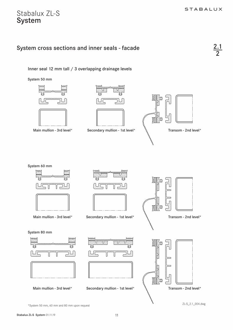
6
S T A B A L U X
Stabalux ZL-S System 011119 12
Stabalux ZL-SSystem
System cross sections and inner seals - roof
1 Cover profile
11 Cover profile
2 Pressure profile
3 Outer seal
4 Glass panel
5 Inner seal 10 mm rafter
51 Inner seal 10 mm transom
6 System screw fittings
7 Spacer strip
8 Support profile
9 Hold-down clamp
10 Washer
11 All weather silicone seal
12 Rope seal
Angled glazing transom up to 2deg inclinationAngled glazing rafter up to 2deg inclination
ZL-S_21_004dwg
Inner seal 10 mm tall 2 overlapping drainage levels
213
Inclined glazing rafter Angled glazing transom
11
3
4
5167
8
910
4
51
7
8
11
12
1
2
3
4
5
6
7
8
12
3
4
5
6
8
7
S T A B A L U X
Stabalux ZL-S System 011119 13
Stabalux ZL-SSystem
System cross sections and inner seals - roof
Inner seal 10 mm tall 2 overlapping drainage levels
213
ZL-S_21_004dwg
System 50 mm
System 60 mm
System 80 mm
GD 6033
ZL 6053
eg GD 6034
GD 8033
ZL 8053
GD 8034
GD 5033
ZL 5053
GD 5034
Rafter - 2nd level Transom - 1st level
Rafter - 2nd level
Rafter - 2nd level Transom - 1st level
Transom - 1st level
System 80 mm upon request
S T A B A L U X
Stabalux ZL-S System 011119 14
Stabalux ZL-SSystem
Cover strips and outer seals
Aluminium - concealed screw fittings
214
Check mountability (height of U plate + cap nut possi-ble use of sealing washer or special screws)
1)
2)
3)
only possible with special screws
The geometry of the clipping process is different for the 50 60 and 80 mm widths
ZL-S_21_005dwg
S T A B A L U X
Stabalux ZL-S System 011119 15
Stabalux ZL-SSystem
Cover strips and outer seals
Stainless steel - concealed screw fittings
214
Aluminium - visiblescrew fittings
Stainless steel - visiblescrew fittings
Flat cover stripDL 5073DL 6073
ZL-S_21_005dwg
S T A B A L U X
Stabalux ZL-S Processing notes 011119 17
Stabalux ZL-SProcessing notes
Material information
Quality of the supporting structure
The steel load-bearing substructure is used for mounting the glazing and must meet all load and suitability require-ments The static system profile dimensions and choice of materials are key The client architect andor proces-sor is responsible for this decision
The following limit values must be adhered to in the se-lection of the steel typeRated values of yield strength fy ge 235 Nmmsup2Tensile strength fu ge 360 Nmmsup2
We recommend selecting materials according to Euroco-de 3 (DIN EN 1993)
The cross-sectional geometries and dimensions of the supporting profiles should also enable dimensioning ac-cording to Eurocode 3
Corrosion protection and coating on the supporting structure
Mullion and transom constructions usually receive a coloured coating for aesthetic reasons Galvanization is used to improve anti-corrosion where necessary The following corrosion protection options are therefore con-ceivable
bull Colour coating on supporting profiles with strip-gal-vanized surface
bull Colour coating on supporting profiles with dip-galva-nized surface
bull Supporting profiles with galvanized surface but with-out colour coating
bull Colour coating on supporting profiles with non-gal-vanized surface
Conventional coating methods such as air-drying multi-lay-er coating systems (wet coating) or thermosetting coatings (stove enamelling powder-coating) can be used provid-ed suitable pre-treatment is applied
Stabalux T-profileStabalux T-profile Steel - hollow profile Stabalux I-profile Steel - special profile
ZL-S_21-003dwg
221
S T A B A L U X
Stabalux ZL-S Processing notes 011119 18
Stabalux ZL-S
Material information
Processing notes
Profile design
The diagram below shows some examples for the geome-try of supporting profiles The profiles must be protected against corrosion and free of dirt
The spacer strips can also be mounted onto existing pro-files
Spacer strip quality
Stabalux spacer strips are made of hard PVC unpunched in black - suitable for a uniform visual appearance for in-ner Stabalux seals
Seal profiles
Stabalux seals are organic natural rubber materials based on EPDM and conform to the DIN 7863 standard non-cellular elastomer sealing profiles for window and facade construction Compatibility with contact media should tested by the processor particularly when using plastic glazing and making structural joints with non-Stabalux products Sealing the rebate with all weather silicone seal is possible
All weather silicone seal
Only certified materials may be used for sealing the re-bate with all-weather silicone Pay attention to all infor-mation provided by the manufacturer and the sealing work must be carried out by trained persons It is recom-mended that a licensed and certified specialist contrac-tor is hired for this purpose We further refer you to the DIN 52460 standard and IVD data sheets (Trade Associ-ation for Sealants) The compatibility of the materials is particularly impor-
tant when using all-weather silicone In this case the compatibility of the sealant with the edge bonding of the glass and the backfill of the joints If self-cleaning glass is used the compatibility must be established in advance Glass sealants and edge bonding must be UV-resistant The incline of roofs should also be taken into account Information about UV-resistance can be requested from the manufacturer Silicone edge bonding generally pro-vides better UV-resistance than polysulfide-based ma-terials The advantage of silicone lies in its high vapour sealing properties which is particularly useful when using more volatile argon fillings Highly elastic weatherproof and UV-resistant seals meet the widest range of demands for reliable joints
Aluminium profiles
The aluminium profiles we supply are generally made from EN AW 6060 according to DIN EN 573-3 T66 ac-cording to DIN EN 755-2
Coating the aluminium
Alongside anodic oxidation with the corresponding pre-treatment conventional coating methods such as air-drying multi-layer coating systems (wet coating) or thermosetting coatings (stove enamelling powder-coat-ing) can be used By using different mass distribution longitudinal shadow formation is possible with cover pro-files DL 5073 and DL 6073 Resulting actions are to be taken with the agreement of the coater
221
S T A B A L U X
Stabalux ZL-S Processing notes 011119 19
Stabalux ZL-SProcessing notes
Longitudinal expansions in aluminium pro-files exposed to temperature stress
When cutting the lower upper and cover profiles from al-uminium allowance should be made for temperature-in-duced longitudinal expansion The theoretical rod lengths ℓ should be shortened by ∆ℓ = αT ∆T ℓ
Example
∆ℓ = 24 10-6 40 1000 = 096 asymp 1 mm
αT asymp 24 10-6 1K
Coefficient of thermal expansion for alumin-ium
∆T = 40 K Assumed temperature difference of alumini-um dependent on the colour and amount of solar radiation
ℓ = 1000 mm Rod length
∆ℓ asymp 1 mm Longitudinal expansion
further examples
∆ℓ = 24 10-6 60 1000 = 144 asymp 15 mm∆ℓ = 24 10-6 100 1000 = 24 asymp 25 mm
A rod with a system length of ℓ = 1000 mm should be shortened by 1 mm for a temperature difference of ∆T = 40 degC A rod of length ℓ = 3000 mm should be shortened by 3 mm For ∆T = 100 degC (often occurs in roof areas and south-facing facades) a rod of length ℓ = 1000 should be shortened by 25 mm
Rod length ℓ (mm) Temperature differ-ence ∆T
Longitudinal expan-sion ∆ℓ (mm)
1000 40degC 13000 40degC 31000 60degC 153000 60degC 451000 100degC 253000 100degC 75
Material information 221
Note
We recommend shortening the lower strip by asymp 25 mm per ℓ = 1000 mm of length When doing so ensure to use the correct length of the outer seal
When using cover profiles in roof area it is recommended that holes for screwing on the cover strip are created with a diameter of d = 9 mm
Stainless steel profile
Pressure profiles and bottom sections of cover profiles are made from 14301 stainless steel for visible screw fittings The surface is equivalent to classification 2B ac-cording to DIN 10088-2
Cover profiles using 14401 stainless steel The surface has a ground finish (grain 220 DIN EN 10088-2) The upper parts of the cover profiles are made from 14571 stainless steel with ground finish (grain 240 DIN EN 10088-2) A film is attached on one side to protect the surface its knife edge remains visible on one narrow side
Other items
All system items are produced according to applicable standards
Maintenance and care
The information sheets WP01 ndash WP05 from the Associa-tion of Window and Facade Producers (VFF) must be ob-served The address can be found in the address section Further information can be found in section 90 - Clean-ing Maintenance
S T A B A L U X
Stabalux ZL-S Processing notes 011119 20
Stabalux ZL-S
Assembly sequence
1 Threaded bolts M6 ie threaded welding studs must be fastened to the primary steel supporting structure Pay attention to the intervals between the bolts The length of the bolts is variable and depends on the height of the inner seal (refer also the section of screw technology)
2 Carry out preparatory work on the steel profiles to suit the statically required glass supports
3 Drill holes must be prepared for the spacer strips eg ZL 6053 with empty 7mm in the same intervals as for the threaded bolts and the spacer strips are then placed over the threaded bolts (fasteners) The spacer strips are positioned continuously in a vertical direction and abutted in a horizontal direc-tion
ZL-S_22_001dwg
Processing notes
9
10
11
8
5
6
4
1
3
222
4 Installation of the inner seal eg GD 60255 Screw the threaded sockets (eg Z 0032 M6 with
wrench opening M10 length 25 mm) on to the threaded boltsthreaded welding studs on the sup-porting steel construction
6 Screw the threaded bars eg Z 0036 into the threaded bars sockets and pay attention to the clamping length This depends on the glass thick-ness and the clamping strips
S T A B A L U X
Stabalux ZL-S Processing notes 011119 21
Stabalux ZL-S
Assembly sequence
ZL-S_22_002dwg
Processing notes
1
3
4
56
3
4
9
10
5 6
1
222
7 Attach the glass support eg Z 08888 Mounting the filling elements9 Lay the outer seal eg GD 6024 together with the
clamping strips10 Attach the clamping strips (cover profiles eg DL
6061 bottom strips eg UL 6009 L) using sealing washer eg Z 0086 and cap nut Z 0043
11 Clip on the upper strip eg OL 6013 with con-cealed screw fittings
a
e
e
S T A B A L U X
Stabalux ZL-S Processing notes 011119 22
Stabalux ZL-S
Attaching the spacer strip
ZL-S_22_003dwg
Mounting to the supporting structure
bull Attach the threaded welding studs M6 according to building approval specifications andor technical regulations ie supplier instructions Make threaded holes or threaded blind holes in the steel supporting structure in order to attach the threaded bolts M6
bull Carry out preparatory work on the steel profiles to suit the statically required glass supports
bull Drill holes must be prepared for the spacer strips with empty 7mm in the same intervals as for the thread-ed bolts and the spacer strips are then placed over the threaded bolts
eg Z 0036
eg ZL 6053
eg ZL 6053
Processing notes
223
bull The distance for screw fittings is variable The maxi-mum distance is a = 250 mm
bull The distance from the edge for the first screw fit-ting should generally be in the region of 30 mm le e le 80 mm The placement of the glass supports should also be taken into account The mullion-tran-som joints in the structure must also be taken into consideration when selecting the distances
bull The spacer strips are positioned continuously in a vertical direction and abutted with the mullions
bull The length of the spacer strip corresponds to the length of the substructure for mullions and transoms
S T A B A L U X
Stabalux ZL-S Processing notes 011119 23
Stabalux ZL-SProcessing notes
Sealing system principle general information about glazing seals
The Stabalux sealing system consists of the outer and inner sealing sections
bull The outer sealing section has the primary function of preventing the ingress of moisture At the same time the sealing section provides a flexible support for the glass panes
bull The inner sealing section acts to protect the inner space water guiding section and elastic glass sup-ports from moisture and vapour
Both sealing sections must perform this function over a long period of time
Seals should be adapted on the construction site but may also be pre-cut to the required length in the factory and pulled into the spacer strips andor clamping strips following the mounting instructions for seals Always en-sure that seals are not bearing any loads once installed and are firmly pressed onto joints All joints should be sealed as per the following descriptions
Tips for laying seals 224
Pressure equalisation and controlled drainage
Pressure equalisation is generally achieved via openings at the base head and ridge points Should additional ven-tilation be required in the area of the transom (eg where panes are only supported on 2 sides or where transom length is ℓ ge 2 m) then this ventilation should be created by placing holes into the cover strip andor using notch-es on the lower sealing lips of the outer seal
The pressure equalisation openings also serve to drain away moisture The inner sealing section is formed in such a way that when the joints are properly sealed any moisture that occurs and does not dissipate via the rebate ventilation will drain away downwards In facades water is guided via the transom flag into the mullions There is a choice between using tested sealing systems with between 1 and 3 levels With inclined glazing with 2 drainage levels the higher sealing section of the transom overlaps the lower mullion seal These principles must be consistently implemented down to the lowest point of the glazing so that the water-guiding level of the structure carries moisture to the outside Film is placed beneath the seals accordingly It must be ensured that the film will last for a long time
S T A B A L U X
Stabalux ZL-S Processing notes 011119 24
Stabalux ZL-SProcessing notes
Inner sealing section
The structure of the inner sealing section is different for vertical facades and facades with an inward incline up to 20deg as well as roof glazing
Inner sealing for vertical glazing and glazing with an inward incline up to 20deg
bull 5 mm butt jointed seals with a drainage section for vertical facades (α=0deg)
bull 10 mm high seals with two drainage sections to safely guide away any moisture or condensation to the outside These seals are created by overlapping the seal joints in which the higher sealing section of the transom goes underneath the lower level of the mullion These seals can be used for vertical facades and facades with an incline up to 20deg
bull 12 mm high seals follow the same principle but al-low an additional third drainage section for an inter-mediate mullion
bull The shaped transom flag protects the vulnerable area of the rebate and ensures that moisture is drained away via the vertical or up to 20deg inwards inclined mullions
Inner seals for glazed roofs
bull A special seal geometry for glazed roofs also allows for two-level stepped drainage The 10 mm high seals are laid with overlapping joints
224
Tips for laying seals
Some basic information for sealing and sticking down Stabalux seals
bull All joints and seal penetrations must be water-proofed An exception to this is the Stabalux system screw fittings where the hole diameter of the inner seal is at most the same as the core diameter of the M6 thread of the bolts and the seals are laid close together
bull Gasket joints are should always be sealed using Stabalux sealant regardless of whether they are butt joints or overlapping (We recommend Stabalux con-necting paste Z 0094 Pay attention to the directions provided by the manufacturer)
bull For difficult to seal places we recommend first using a fixing adhesive such as the Stabalux quick fixing glue Z 0055
bull Before gluing ensure all surfaces are free from mois-ture dirt and grease
bull Weather conditions such as snow and rain prevent an effective seal
bull Temperatures below +5 degC are not suitable for fixing seals
bull The hardened connecting paste should not prevent level support of glass
S T A B A L U X
Stabalux ZL-S Processing notes 011119 25
Stabalux ZL-S
Seals - Facade
Processing notes
Assemble the inner seal on vertical facade glazing - 1 level join
bull The horizontal transom seals are laid continuously across the mullion-transom joints Ensure here that the clamping feet of the horizontal seal are released around the mullion
bull Mullion seals are butt jointed to the transom seals bull The transom flags should be released to a width of
10-15 mm at the mullion joint bull The protruding length of the transom flag should be
removed at the perforation once glazing is complet-ed
bull In order to safely drain away moisture from transoms even at the edges of the facade the inner transom seals must be laid into the released mullion seals To release and remove the clamping feet we recom-mend using our release pliers Z 0078 for System 60 and Z 0077 for System 50
bull Ensure all joints are cleanly and solidly sealed Ex-cess sealant should be removed
ZL-S_22_005dwg
1
2
3
1
2
3
inner continuous transom seal inner jointed mullion seal
Transom flag in mullion area released
Threaded socket und threaded bolteg screw on to threaded welding studs
eg Z 0044
eg Z 0032
eg GD 6025
eg ZL 6053
Inner seal mullions Inner seal transoms
eg GD 6025 eg GD 6030
225
S T A B A L U X
Stabalux ZL-S Processing notes 011119 26
Stabalux ZL-SProcessing notes
Seals - Facade
Assemble the inner seal on vertical facade glazing - 1 level join
ZL-S_22_005dwg
Release edge mullion seal near transom
The transom flag should always cover the inset ldquoerdquo of the filling element (eg glass panes panels)
Seal gasket joints
Seal gasket joints
e gt glass inset
NoteAny joints in the transom seal that are required due to the delivered length should be fitted with an intermediate mullion and put together like in point A
Intermediate mullions
Edge mullions
Transom
Transom
edge mullion seal around a transomnear transom
B
A
225
S T A B A L U X
Stabalux ZL-S Processing notes 011119 27
Stabalux ZL-S
bull The 10 mm high seals can be divided across their height to allow a simple overlap at critical transom joints
bull The vertical seals for the mullions (2nd drainage sec-tion) are laid continuously
bull The transom seals overlap the mullion seals bull Moisture and condensation is guided away via the
transom flag of the transom seal (1st drainage sec-tion) to the main mullion
Assembly of the inner seal for vertical facade glazing and facade glazing with an incline of up to 20deg - 2 overlapping sections
bull The transom flag must always cover the inset depth of the glass panes and filling element
bull The protruding length of the transom flag should be removed at the perforation once glazing is complet-ed
bull All joints must be sealed Before laying seals we recommend completely coating the entire support surfaces and sides with Stabalux connection paste
bull Ensure all joints are cleanly and solidly sealed Ex-cess sealant must be removed Absolutely no un-evenness in the glass support surface must occur from applying sealant too thickly
Processing notes
1
2
1
2
inner continuous mullion seal inner overlapping transom seal clipped in
Transom flag should always cover the filling element
ZL-S_22005dwg
Seals - Facade
eg GD 6033 Seals
upon request
Inner seal mullions Inner seal transoms
Seal gasket joints
B
225
eg Z 0044
eg Z 0032
eg GD 6033
eg ZL 6053
S T A B A L U X
Stabalux ZL-S Processing notes 011119 28
Stabalux ZL-S
Assembly of the inner seal for vertical facade glazing and facade glazing with an incline of up to 20deg - 2 overlapping sections
Processing notes
Seals - Facade
ZL-S_22005dwg
The transom flag should always cover the inset ldquoerdquo of the filling element (eg glass panes panels)
Transom
edge mullion seal around a transom upper section to the width of the transom seal
Transom seal separate lower section at the length of the overlap ldquoerdquo
Mullion seals around a transom upper section to the width of the transom seal
Transom
Transom seal separate lower section at length of the overlap ldquoerdquo
Seal gasket jointsoverlapping joints
Seal gasket jointsoverlapping joints
e gt glass inset
e gt glass inset
225
Intermediate mullions
B
Edge mullions
A
S T A B A L U X
Stabalux ZL-S Processing notes 011119 29
Stabalux ZL-S
Assembly of the inner seal for vertical facade glazing and facade glazing with an incline of up to 20deg - 3 overlapping sections
bull The transom seals overlap the main mullion sealsbull Along a transom seals must be laid continuouslybull Moisture and condensation is guided away via the
transom flag of the transom seal (2nd drainage sec-tion) to the main mullion
Processing notes
1
2
3
1
2
3
inner continuous mullion seal inner over-lapping transom seal clipped in
The transom flag should always cover the filling element
Secondary mullion seal is clipped into the transom seal with an overlap
ZL-S_22_005dwg
Seal gasket joints
Inner seal main mullion Inner seal transoms
Inner seal secondary mullion
Seals - Facade
Seal gasket joints
eg GD 6318eg GD 6314
eg GD 6315
C
B
225
bull Optionally Stabalux seals with three offset water channels can be used in the facade area which safe-ly drain any moisture or condensation to the outside
bull The 12 mm high seals can be divided across their height to allow a simple overlap at critical secondary mulliontransom joints ie transomprimary mul-lion joints
bull The vertical seals for main mullions (3rd drainage section) are laid continuously
S T A B A L U X
Stabalux ZL-S Processing notes 011119 30
Stabalux ZL-S
bull The transom flag must always cover the inset depth of the glass panes and filling element
bull The protruding length of the transom flag should be removed at the perforation once glazing is complet-ed
bull Vertical seals on the secondary mullion are butt jointed beneath the upper transom The tran-som flag of the upper transom runs continuously in the upper part of the joint
bull Drainage of the secondary mullion (1st drainage sec-tion) is achieved by overlapping the seals of the sec-ondary mullion with the seal of the upper transom
Assembly of the inner seal for vertical facade glazing and facade glazing with an incline of up to 20deg - 3 overlapping sections
Processing notes
Edge mullionsSecondary mullion Transom
Transom
The transom flag runscontinuously through
Transom sealConnection to the secondary mullionCut the uppermost section to the width of the secondary mullion seal
The secondary mullion seal isclipped into the mullion sealwith an overlap
e gt
glas
s in
set
e gt glass inset
Seal gasket jointsoverlapping joints
Cut the around the secondary mullion seal to separate the lower section to match the length of the overlap
Secondary mullion butt joint-ed seal the gasket joints
Seals - Facade
ZL-S_22_005dwg
BA
D
225
S T A B A L U X
Stabalux ZL-S Processing notes 011119 31
Stabalux ZL-S
bull All joints must be sealed Before laying seals we rec-ommend completely coating the support surfaces and edges with Stabalux connection paste
bull Ensure all joints are cleanly and solidly sealed Ex-cess sealant must be removed Absolutely no un-evenness in the glass support surface must occur from applying sealant too thickly
Assembly of the inner seal for vertical facade glazing and facade glazing with an incline of up to 20deg - 3 overlapping sections
Processing notes
Main mullion
TransomSeparate lower section of the tran-som seal along the length of the overlap
Separate the main mullion sealaround the upper section of the transom to match the width of the transom seal
The transom flag should always cover the inset ldquoerdquo of the filling element (eg glass panes panels)
Seals - Facade
ZL-S_22_005dwg
e gt glass inset e gt glass inset
Seal gasket jointsoverlapping joints
Seal gasket jointsoverlapping joints
C
225
S T A B A L U X
Stabalux ZL-S Processing notes 011119 32
Stabalux ZL-S
Seals - Facade
Processing notes
Assembly of the outer seal for vertical facade glazing
bull As well as gently clamping the glass in place the out-er sealing system has the primary task of protecting the rebate against moisture ingress
bull The outer sealing sections must be completely sealed except for the necessary openings for pres-sure equalisation and condensation dissipation
bull The outer mullion seals are laid continuously and the transom seals are joined
bull Sealant joints are to be laid flat with a slight excess in dimensions Exact specifications depends on the situation in which the system is used
bull It is not necessary to glue the outer sealing in the mullion-transom joint if the sealant joints fit precise-ly
bull The flag for the inner transom joint in combination with the outer seal creates additional safety
bull The transom flag should be separate at its perfora-tions to match the thickness of the glass in order that this is clamped down and concealed under the outer seal
bull Different heights of sealing lips on the outer seal bridge the height different created by the transom flag in the outer sealing section
bull Differently high split seals allow a balance between filling elements of different total thickness of up to 6 mm
bull When mounting the clamping strip be aware of aluminium profile expansion (see section 221 - Material information)
ZL-S_22_007dwg
outer continuous mullion sealouter jointed transom seal
eg GD 6054 outer transom seal with different heights of sealing lip
225
eg Z 0044eg GD 6024
eg Z 0032
eg GD 6025eg ZL 6053
S T A B A L U X
Stabalux ZL-S Processing notes 011119 33
Stabalux ZL-S
Assembly of the outer seal for facade glaz-ing with an inwards incline of 20deg
bull If the facade is inclined inwards from the vertical (max permitted incline 20deg) the open ends of the outer transom seals must be closed up using butyl
bull When constructing inwardly inclined facades (up to max 20deg) if flat cover profiles are used in the transoms (eg DL 5059 DL 6059 DL 5061 DL 6061 DL 5067 DL 6067 DL 5071 DL 6071 DL 6043 DL 6044) and flat lower and upper strips (eg UL 6005 with OL 6066) then the central hollows at each end must be sealed with silicone
Processing notes
The open end of the transom sealin inwardly inclined facades(up to max 20deg) must be sealed using butyl
When using flat cover profiles on inwardly inclined facades (up to max 20deg) the central hollow at each end should be sealed with silicone
Trim the seals to be slightly larger than required
ZL-S_22005dwg
Seals - Facade 225
2
S T A B A L U X
Stabalux ZL-S Processing notes 011119 34
Stabalux ZL-SProcessing notes
Seals - roof
Assembly of the inner seal for roof glazing
bull Optionally Stabalux seals with offset water channels can be used in the facade area which safely drain any moisture or condensation to the outside
bull The 10 mm high seals can be divided across their height to allow a simple overlap at critical transom joints
bull The transom seals are geometrically shaped so as to create a condensation channel
bull This channel drains from the overlapping transom joint in the rafters
bull Along a transom seals must be laid continuouslybull All joints must be sealed Before laying transom
seals we recommend applying a thin coating to the entire support surfaces Absolutely no unevenness in the glass support surface must occur from apply-ing sealant too thickly
ZL-S_22_008dwg
1 remove the lower perforated part and the clamping foot on
the transom seal at around 15 mm
2 remove the upper perforated part on the rafter seal
3 Length of transom seal = transom length + ~13 mm per side
Seal gasket joints
1
3
226
S T A B A L U X
Stabalux ZL-S Processing notes 011119 35
Stabalux ZL-S
Seals - roof
Processing notes
Assembly of the outer seal for for glazed roofing
bull These are laid in fundamentally the same way as for vertical glazing Split seals such as GD 1932 are not suitable for transom seals in roofs Split seals can only be installed in mullions in combination with slab insulation Each installation situation will differ to some degree and always check how well sealed it is
bull For cross joints we recommend using our self-adhe-sive stainless steel sealing plates with butyl coating Z 0601 for System 60 and Z 0501 for System 50 The stainless steel sealing plates are 35 mm wide and are attached to the edge of the glass panes parallel to the mullion axis
bull Butyl tape is not suitable as a sealing tape between the glass and the outer seal
bull The outer mullion seals are laid continuously and the transom seals are joined
bull Sealant joints are to be laid flat with a slight excess in dimensions Exact specifications depends on the situation in which the system is used
Notebull Horizontal clamping strips prevent the free run off of
rain water and dirtbull Cover strips and upper strips with angled edges re-
duce the build up of water in front of the clamping strip
bull Shorten the clamping strips on the transoms by 5 mm in the area of the transom joins in order to improve drainage of water Gasket joints however are to be laid flat with a slight excess in dimensions Open ends of transom clamping strips (upper and cover profiles) should be sealed
Detail of sealing plate Z 0501 = 35 x 40 mm Z 0601 = 35 x 50 mm
AttentionThe sealing plates must be glued central to the transom axis
For glass insets of 15 mm the first screw fittings for the transom cover strip begin 30 mm from the end of the cover strip
ZL-S_22_009dwg
226
S T A B A L U X
Stabalux ZL-S Processing notes 011119 36
Stabalux ZL-SProcessing notes
Seals - roof
Assembly of the outer seal for for inclined glazed roofing up to 2deg
bull These are laid in fundamentally the same way as for vertical glazing Split seals around the mullions in roofs such as GD 1932 are only suitable when us-ing in combination with slab insulation Each installation situation will differ to some degree and always check how well sealed it is
bull To ensure free run-off of rain water and dirt on roofs inclined up to 2deg we recommend not using clamping strips in the transoms
bull Instead the rebate spaces should be sealed with all-weather silicone
bull Implementation of the outer sealing section around mullions is done in the same way as conventional roofs with an inclination up to 15deg
Tips for all roof designs
When using aluminium cover profiles on roofs take ac-count of the expansion factor as a result of the high de-gree of heat absorption when selecting the length to use Equally the use of single-piece cover profiles should be carefully considered In this case it is recommended that holes for screwing on the cover strip are created with a diameter of d = 9 mm (see section 221 - Material information)For wide spans we recommend using concealed screw
bull At the high point or ridge area of the inclined glazing it is recommended to also install and outer sealing section in the transoms with clamping strips
bull Only certified sealing materials may be used for seal-ing the transom rebate space
bull Pay attention to all information provided by the manufacturer and the sealing work must be carried out by trained persons It is recommended that a li-censed and certified specialist contractor is hired for this purpose We further refer you to the DIN 52460 standard and IVD data sheets (Trade Association for Sealants)
ZL-S_22_009dwg
fittings when selecting the clamping strips (lower + up-per strip) This is the preferred option for rafters Unused holes in the lower strip must be sealedSome roof areas such as the eaves see the use of sev-eral different materials (glass silicone aluminium sheets ) each with different expansion coefficients To avoid the formation of cracks aluminium sheets should be in-stalled with expansion joints
226
ZL-S_22_009-4
Stabalux ZL-S
ZL-S_22_009-4
Stabalux ZL-S
4 4
S T A B A L U X
Stabalux ZL-S Processing notes 011119 37
Stabalux ZL-S
Seals - roof
Processing notes
Assembly of the outer seal for glazed roofing up to 2deg incline
bull The compatibility of the materials is particularly important when using all-weather silicone In this case the compatibility of the sealant with the edge bonding of the glass and the backfill of the joints If self-cleaning glass is used the compatibility must be established in advance
bull Glass sealants and edge bonding must be UV-resist-ant The incline of roofs should also be taken into account Information about UV-resistance can be requested from the manufacturer Silicone bonding generally provides better UV-resistance than poly-sulfide-based edge bonding The advantage of sili-cone lies in its high vapour sealing properties which is particularly useful when using more volatile argon fillings
Angled glazing transom up to 2deg inclination with all-weather silicone and round rope seal
Angled glazing transom up to 2deg inclinationwith all-weather silicone and insulation block
bull Highly elastic weatherproof and UV-resistant seals meet the widest range of demands for reliable joints
bull If the silicone joint is created without additional me-chanical safety devices ensure that the glass is sup-ported from two sides only Selective installation of holding clamps can be used to provide support for all glass edges
bull The clamps are made from stainless steal with sil-icone washers and are screwed in the same as pressure strips The hold-down clamp should be ad-ditionally sealed around the perimeter with silicone sealant The design is based upon the dimensions of the glass as documented in the glass static analysis
1 Hold-down clamp
2 Silicone washer
3 Silicone sealant seal around the
clamp
4 All weather silicone seal
51 Round section rope seal
1 19 9
3 3
6 6
7 7
8 8
10 10
2 2
52 Insulation block
6 Glass filling element
7 Inner seal 10 mm transom
8 Spacer strip
9 System screw fittings
10 Support profile
ZL-S_22_009dwg
226
51 52
S T A B A L U X
Stabalux ZL-S Processing notes 011119 38
Stabalux ZL-SProcessing notes
Seals - roof
Assembly of the outer seal for glazed roofing up to 2deg incline
bull The joint width and the joint height for Stabalux SR are defined as w x h = 20 mm x 10 mm These measurements should always checked when selecting the sealing material and adapted if neces-sary Generally w h = 2 1 to 35 1
bull PE round section seals or Stabalux slab insulation is suitable as a back fill material
bull Silicone sealant should be applied before laying the mullion seals and cover profiles
bull After the specified setting time the seals and screw fittings can be installed in the areas around mullions
bull The mullion-transom joints around the clamps are then sealed
bull Before applying this second layer the joints around transoms must have completely set
Rafters with clamping strips
Transom with clamp all-weather silicone seal and
round rope seal
Transom with clamp all-weather silicone and
insulation block
Joint design according to manufacturers specificationsGenerally w h = 2 1 ndash 35 1
Transom with all-weather silicone and round section rope seal
ZL-S_22_009dwg
226
S T A B A L U X
Stabalux ZL-S Processing notes 011119 39
Stabalux ZL-S
Seals - roof
Processing notes
Steps for creating the seal with all-weather silicone
bull Test the silicone sealant and glass edge bond-ings and other contact surfaces (eg panels) for suitability
bull Clean edge bonding adhesive impurities from the surfaces to which sealant will be applied following manufacturerrsquos directions
bull Fill the joints as per the joint dimensions using only non-water absorbent closed-cell PE profiles (no damage to the edge bonding)
bull The remaining space in the glass rebate must be large enough that the pressure is able to equalise and a drainage level is available
bull Clean any impurities from the surfaces to which the sealing material is to be applied and any adjacent surfaces according to manufacturerrsquos directions
bull Be particularly aware of any adjacent metal compo-nents Prime according to manufacturerrsquos directions
bull Seal joints without leaving any cavities or bubbles Mask any adjacent components in advance where necessary
bull Smooth out the filled joints using the manufactur-errsquos smoothing agents and conventional tools with as little water as possible Remove the adhesive tape when liquid
bull If two or more reactive sealants are used in combina-tion the first must completely set before the second is applied
System screw fittings
Hold-down clamp
Washer made from silicone
Silicone sealant seal around the clamp
All weather silicone seal
Silicone sealant
Rafter
Transom
ZL-S_22_009dwg
226
S T A B A L U X
Stabalux ZL-S Processing notes 011119 40
Stabalux ZL-SProcessing notes
Glass inset and glass support 227
RebateGlass inset
ZL-S_22_010dwg
Glass inset
bull Glass industry guidelines must be observedbull The glass inset is generally 15 mmbull An increase in the glass inset to 20 mm has a bene-
ficial effect on the heat transfer coefficient Uf of the frame structure
S T A B A L U X
Stabalux ZL-S Processing notes 011119 41
Stabalux ZL-SProcessing notes
Glass inset and glass support
Glass support types and selection of glass support
Glass supports carry the load of the glass panes through to the structure The permissible glass weights also depend on the structure of the glass and the selected mullion-transom connection The mullion-transom con-nection must be selected in such a way as to minimise any subsequent turning of the transoms The depth of the glass supports is determined by the glass structure Section 9 contains more information in this respect
The Stabalux ZL-S system distinguishes between two dif-ferent types and techniques for attaching glass supports
bull Glass support GH 5053 ie GH 5055 with 2 or 3 welding studs empty 10 mm
bull Heavy glass loads require welded glass supports For this purpose flat sheets with a thickness of t = 5 mm are welded on to the transoms
Mounting the glass supports
bull Positioning the glass supports and glazing according to glass industry guidelines and guidelines of the In-stitute for Window Technology
bull The weight of the glass panes is distributed via the glass supports attached to the transoms
bull Glass supports should be attached at an interval of 100 mm from the end of the transom When doing so avoid a collision with the cover strip screw fittings at the end of the transom
Glazing blocks
bull Glazing blocks must be compatible with the edge bonding of the insulated glass panes
bull They should be stable under constant pressure and be able to withstand loads aging and temperature changes
bull It is important that the blocks ensure circumferential pressure equalisation and that drainage of conden-sation is not obstructed as well as allowing the glass edges to be offset and small design tolerances to be accommodated
bull If the length of the glass support is more than 100 mm blocks should be placed along the entire length of the glass support to ensure equal load distribu-tion
227
Positioning the glass support approx 100 mm from the end of the transom
ZL-S_22_010dwg
S T A B A L U X
Stabalux ZL-S Processing notes 011119 42
Stabalux ZL-SProcessing notes
Glass inset and glass support
Glass support GH 5053 with bolts
bull The glass support consists of the Stabalux system component GH 5053 and 2 welding studs empty10 mm which must be made available on the building site
bull The glass supports GH 5073 are manufactured using aluminium in EN AW 6060 quality condition T66
bull The depth of the glass supports depends on the in-stalled thickness of the glass panes and the geome-try of the inner seal The require cuts are delivered to match glass support GH 5053
bull The bolts must be sufficiently protected against cor-rosion and be suitable for weld connections with the steel grade of the supporting structure Stainless steel bolts must be used otherwise
bull The length of the bolts is calculated based on the installed thickness of the glass panes plus the height of the inner seal and the height of the spacer strip
bull The centre distance between the bolts is 80 mm
bull The bolts must be welded in the centre of the tran-som in the substructure to disperse the load from the glass Screw fittings must be positioned vertical-ly to the transom
bull The spacer strip should also be pre-drilled with empty 11 mm holes at the relevant points to attach the bolts
bull Holes must be made at the relevant points of the transom seal Here it is important to ensure that the holes have as precise a fit as possible We recom-mend sealing the holes with Stabalux Z 0094 paste
bull The glass supports are mounted loosely on the build-ing site once the spacer strip and the inner sealing section have been fitted
bull Blocks must be placed under the glass panes along the entire length of the glass supports
bull It is essential to ensure when installing the glazing that neither the glazing blocks nor the glass supports slip
bull The glass supports (bolts) must be validated for the glass thickness the glass weight and the selected mullion-transom connection
227
S T A B A L U X
Stabalux ZL-S Processing notes 011119 43
Stabalux ZL-S
Glass support GH 5053 Attachment with welding studs
Processing notes
Glass inset and glass support
Glass support GH 5053 with bolts
ZL-S_22_010dwg
A-A
Glass support GH 5053
Block Bolts empty 10 mm
Glass support
Bolt
Inner seal
Spacer strip
227
S T A B A L U X
Stabalux ZL-S Processing notes 011119 44
Stabalux ZL-SProcessing notes
Glass inset and glass support
Glass support GH 5055 with bolts
bull The glass support consists of the Stabalux system component GH 5055 and 3 welding studs empty10 mm which must be made available on the building site
bull The glass supports GH 5055 are manufactured using aluminium in EN AW 6060 quality condition T66
bull The depth of the glass supports depends on the in-stalled thickness of the glass panes and the geome-try of the inner seal The require cuts are delivered to match glass support GH 5055
ZL-S_22_010dwg
Glass support GH 5055 Attachment with welding studs
227
bull The bolts must be sufficiently protected against cor-rosion and be suitable for weld connections with the steel grade of the supporting structure Stainless steel bolts must be used otherwise
bull The length of the bolts is calculated based on the installed thickness of the glass panes plus the height of the inner seal and the height of the spacer strip
bull Installation is performed the same way as GH 5053 but using three screws at intervals of 80 mm
A-AGlass support GH 5055
Block Bolt empty 10 mm
Glass support
Bolt
Inner seal
Spacer strip
S T A B A L U X
Stabalux ZL-S Processing notes 011119 45
Stabalux ZL-SProcessing notes
227
Glass inset and glass support
RowTotal glass thickness tGlass (mm)
for vertical glazingGlass supports 1)
GH 5053 GH 5055 Depth (mm)1 4 5 6 7 GH 0081 Section 9
2 8 9 Section Section 12
3 10 11 Section Section 144 12 13 Section Section 165 14 15 Section Section 186 16 17 Section Section 207 18 19 Section Section 228 20 21 GH 0082 Section 249 22 23 GH 0083 GH 0851 2610 24 25 GH 0084 GH 0852 2811 26 27 GH 0085 GH 0853 3012 28 29 30 GH 0886 GH 0854 3213 31 32 33 GH 0887 GH 0855 3514 34 35 36 GH 0888 GH 0856 3815 37 38 39 GH 0889 GH 0857 4116 40 41 42 GH 0890 GH 0858 4417 43 44 GH 0891 GH 0859 47
Classification of system components
Table 1 Vertical glazing | System 50 60 80 | threaded bolt
1) Cut from GH 5053 or GH 5055
S T A B A L U X
Stabalux ZL-S Processing notes 011119 46
Stabalux ZL-SProcessing notes
227
Glass inset and glass support
RowTotal glass thickness tGlass (mm)
for inclined glazing 1)
Glass supports 2)
GH 5053 GH 5055 Depth (mm)1 24 25 26 Section Section 18
2 27 28 Section Section 20
3 29 30 Section Section 224 31 32 GH 0082 Section 245 33 34 GH 0083 GH 0851 26
Classification of system components
Table 2 Inclined glazing | System 50 60 80 | Threaded bolts
1) Accounting for a 10 mm inner seal
2) Cut from GH 5053 or GH 5055
Glass support GH 5053
Glass support GH 5055
TI-H_92_005dwg
S T A B A L U X
Stabalux ZL-S Processing notes 011119 47
Stabalux ZL-SProcessing notes
Glass inset and glass support
Welded glass support
bull Welded glass supports made of flat steel that are welded on to the transom profiles The glass sup-ports must be made available on the building site
bull Flat steel in grade S235 ie matched with the qual-ity of the supporting construction It must be possi-ble to weld the steel grades together The weld seam must connect the entire cross section of the glass supports
bull The glass supports must be sufficiently protected against corrosion
bull The depth of the glass supports depends on the in-stalled thickness of the glass panes the geometry of the inner seal and the height of the spacer strip
bull The glass supports must be welded in the centre of the transom in the substructure to disperse the load from the glass The glass supports must be posi-tioned vertically to the transom
227
bull The spacer strip must be cut out at the relevant points so as to ensure that the glass support and the weld seam cannot collide
bull The transom seals must be cut out around the holes for the glass supports and then sealed using Stabalux connection paste Z 0094
bull Blocks must be placed under the glass panes along the entire length of the glass supports
bull It is essential to ensure when installing the glazing that the glazing blocks cannot slip
bull The width of the glass supports is at least 100 mm their size must suit the static requirements
bull The glass supports must be validated for the glass thickness the glass weights and the selected mul-lion-transom connection
S T A B A L U X
Stabalux ZL-S Processing notes 011119 48
Stabalux ZL-SProcessing notes
Glass inset and glass support
Welded glass support
Glass support
Width ldquoWrdquo
Block
Glass support
Block
Inner seal
Spacer strip
227
Match the thickness of the glass support with the glass thickness
Make the weld seam as even as possiblefully connect the cross sectionmould the spacer strip around the glass supports
Cut out the sealing around the holes for the glass supports and sealwith Stabalux connecting paste
1
2
3
ZL-S_22_010dwg
A-A
S T A B A L U X
Stabalux ZL-S Processing notes 011119 49
Stabalux ZL-SProcessing notes
Glass inset and glass support 227
Glass support GH 5055 with threaded bolt
bull The depth of the glass support must be matched with the thickness of the glass
T = depth of the glass supportT1 = height of the spacer stripT2 = height of the inner seal (eg 5 m 10 mm or 12 mm)T3 thickness of the glass pane
T = T1 + T2 + T3
ExampleSpacer strip T1 = 10 mmInner seal (eg GD 6030) T2 = 5 mmThickness of pane 6 16 6 T3 = 28 mm
T = 10 + 5 + 28 = 43 mm
Wid
th ldquo
Wrdquo
ZL-S_22_010dwg
S T A B A L U X
Stabalux ZL-S Processing notes 011119 50
Stabalux ZL-SProcessing notes
Screw fittings
Fastenings
bull The system screw fittings are a combination of basic room-side screw fittings a coupling using a threaded socket that allows thermal separation in the rebate and a flexible bolt-nut connection or screw connec-tion on the glazing side
Basic room-side screw fittings
bull The threaded bolts M6 can be used for the basic room-side screw fittings they are screwed into the threaded holes ie the threaded blind holes Weld-ing studs M6 can be used alternatively
bull The length of the threaded bolts depends on the height of the spacer strip the height of the inner seal and the material selected for the supporting struc-ture (mullion and transom profiles) ie the selected depth of the blind holes which must be ge 7 mm Grade 14301 A2 stainless steel bolts must be used
bull In most cases the selected welding studs should have a length of 25 mm and they must be made available on the building site The bolts must be suf-ficiently protected against corrosion and be suitable for weld connections with the steel grade of the sup-porting structure Stainless steel bolts must be used otherwise
Coupling with threaded socket
bull The threaded socket is delivered in a length of 25 mm and twisted tight on to the basic screw fittings without excessively compressing the inner seal The Stabalux threaded sockets can be delivered in stainless steel (art no Z 0029) or plastic (art no Z 0032)
Bolt nuts ie screw connections on the glazing side
bull The assembly consists of a threaded bolt and option-ally a sealing washer and a cap nut Screws accord-ing to DIN 6912 stainless steel 14301 A2 can be used alternatively
bull Screws in the Stabalux system are produced using stainless steel usually with the material number 14301 DIN EN 10088
228
bull The length of the bolts ie screws is variable and depends on the height of the spacer strip the height of the inner seal and thickness of the glass A suffi-cient screw depth in the threaded socket must be ensured
bull Threaded bolts in suitable lengths are available for all standard glass thicknesses The length of bolt re-quired can usually be determined using a table of figures The combination chosen for the clamp con-nection will depend on the specific situation
bull Depending on the type of screw fittings selected 2 and 4 mm vulcanised EPDM washers are available
bull The distance for screw fittings is variable The maxi-mum distance is a = 250 mm
bull The distance from the edge for the first screw fitting should generally be in the region of 30 mm le a le 80 mm The placement of the glass supports and the choice of mullion-transom connection should also be taken into account
bull The clamp connection is exclusively exposed to ten-sile forces The pressure strips are connected using Stabalux system components To determine the stress limit (maximum tensile force) and permitted tensile forces for the connection the terms defined in the relevant general building approval and the Eu-rocode 3 (DIN EN 1993-3) series of standards shall apply
bull Screw fittings are applied using a conventional elec-tric screwdriver with depth stop This guarantees uniform application of pressure The depth setting should be chosen so that when using 4 mm EPDM washers a washer compression of around 15 - 18 mm is achieved
S T A B A L U X
Stabalux ZL-S Processing notes 011119 51
Stabalux ZL-S
Concealed screw fittings
bull Assembly is facilitated by the selection of pre-drilled clamping strips (eg UL 5009-L and UL 6009-L slot 7 x 10 mm a = 125 mm) with clippable upper strips A round hole of d = 8 mm should be made in the remaining clamping strips The functionality of the clip procedure can be checked after the first cover profile has been pushed against the lower strip
Note
When using aluminium cover profiles on roofs take ac-count of the expansion factor as a result of the high de-gree of heat absorption and its impact on the selected length Equally the use of single-piece cover profiles should be carefully considered In this case it is recom-mended that holes for screwing on the clamping strip are created with a diameter of d = 9 mm
Processing notes
227
Screw fittings
Visible screw fittings
bull Cover strips should be drilled with a round hole of d = 8 mm
Note
(see Note on concealed screw fittings)
Visible recessed screw fittings
bull When creating visible recessed screw fittings a stepped bore is required The lower part of the cover strip should be drilled with a d = 7 mm diameter The upper part of the cover strip needs a d = 11 mm diameter for the screw head It is recommended to install a washer (PA washer eg Z 0033) with all screw fittings
S T A B A L U X
Stabalux ZL-S Processing notes 011119 52
Stabalux ZL-SProcessing notes
Screw fittings
Concealed screw fittings
1 cap nut M6 Z004321 4 mm sealing washer Z 008631 threaded bolt M6 eg Z 3532 threaded bolt M6 in the threaded hole eg Z 004041 threaded socket M6 eg Z 29
Visible screw fittings
1 cap nut M6 Z004321 4 mm sealing washer Z 008631 threaded bolt M6 eg Z 3542 threaded socket M6 eg Z 296 threaded welding stud M6
Visible recessed screw fittings
22 PA washer Z 003333 threaded bolt M6 in the threaded hole eg Z 4042 threaded socket M6 eg Z 325 internal hex screw M6 eg GD 6912
Fastenings
ZL-S_22_011dwg
228
eg Z 0043
eg Z 0029 eg Z 0029
eg Z 0086
eg Z 0086
Screw M6
eg Z 0033
eg Z 0035
eg Z 0040 Threaded welding stud M6
Diagram and item numbers are examples for System 60
The calculation is the same for system 50
S T A B A L U X
Stabalux ZL-S Processing notes 011119 53
Stabalux ZL-SProcessing notes
Screw fittings
Calculating the screw length
ZL-S_22_012dwg
228
System width 50 60 mm System width 80 mm
Attention
The calculation to determine screw lengths for the the calculation to determine screw lengths is
Glass thickness - 14 mm with facade seal (5 mm)Glass thickness - 9 mm with facade seal (10 mm)Glass thickness - 7 mm with facade seal (12 mm)
S T A B A L U X
Stabalux ZL-S Processing notes 011119 54
Stabalux ZL-SProcessing notes
Screw fittings
System screws for Stabalux ZL
Cap nut
Z 0043 Cap nut stainless steel M6
Sealing washers
Z 46 U washer stainless steel with 2 mm seal
Z 0086 U washer stainless steel with 4 mm seal
Threaded sockets
Z 0029 Threaded socket stainless steel
M6 x 25 mm
Z 0032 Threaded socket stainless steel
M6 x 25 mm
Threaded bolts
Z 0034 Threaded bolts stainless steel M6 x 20 mm
Z 0038 Threaded bolts stainless steel M6 x 25 mm
Z 0035 Threaded bolts stainless steel M6 x 30 mm
Z 0040 Threaded bolts stainless steel M6 x 35 mm
Z 0036 Threaded bolts stainless steel M6 x 40 mm
Z 0037 Threaded bolts stainless steel M6 x 50 mm
Z 0044 Threaded bolts stainless steel M6 x 60 mm
Z 0045 Threaded bolts stainless steel M6 x 75 mm
Z 0039 Threaded bolts stainless steel M6 x 90 mm
Z 0053 Threaded bolts stainless steel M6 x 100 mm
Z 0054 Threaded bolts stainless steel M6 x 120 mm
228
ZL-S_22_013dwg
Calculating the screw length
S T A B A L U X
Stabalux ZL-S Processing notes 011119 55
Stabalux ZL-SProcessing notes
Flat cover strip DL 5073 DL 6073
Tips for laying the cover strip DL 5073 DL 6073
We assume that this cover strip will be used with glass panes that are supported on two sides and the recessed screw head is concealed In this case a cylinder head screw with inner hex is to be used (eg M6 DIN 6912 stainless steel A2 with low head) When covering with a 2 mm cover plug Z 0089 a bore depth of 6 mm is cal-culated
Depending on the precision of the bore it should be de-cided on case by case basis if any slight changes to this depth are necessary The cover plug Z 0089 does not need to be glued in place but may be levelled using lev-elling compound
Coating the cover strip
Profile production (aluminium extrusion moulding) with different mass distribution is extremely difficult Length-wise shadow formation may result Resulting actions are to be taken with the agreement of the coater
Intersections
Due to the special shape of the strip (the material ex-tends into the rebate) there is no closed sealing section available at intersections We therefore recommend plac-ing particular attention to ensure tightness of the joints and fill will Stabalux connecting paste Z 0094
Glass supportsblocking
Special attention should be given to dimensional propor-tions Glass supports should be designed by the proces-sor depending on the glass thickness and weight (eg for welded glass supports)To support the outer pane a sufficiently large glazing block must be installed that can carry the load to safely ensure the glass load is distributed effectively
ZL-S_22_014dwgZL-S_22_013dwg
229
Cover plug Z 0089Screw eg M6 DIN 6912
ZL-S_22_015-1
Stabalux ZL-S
S T A B A L U X
Stabalux ZL-S Processing notes 011119 56
Stabalux ZL-SProcessing notes
Slab insulation
ZL-S_22_015dwg
Use of slab insulation
bull Using insulation blacks significantly reduces heat dissipation
bull The highly effective slab insulation has a permanent-ly adhesive HOT-MELT
bull Depending on the situation where they are used in-sulation blocks can be directly applied to the cover striplower strip or placed into the rebate over the screw fittings and pushed into position with the cov-er striplower strip The type of screw connection (bolt-socket-bolt) means that a groove must first be cut in the insulating block at the points of connec-tion
bull With system width 80 mm and a 40 mm rebate 2x 20 mm wide slab insulation blocks can be combined (40 mm wide insulation blocks available upon request)
Note
bull The use of slab insulation with cover profiles DL 5073 DL 6073 should be tested for each individual situation
bull 2-piece outer seals are always used with slab insula-tion blocks for example outer seal GD 1932
Insulation block Width (=rebate)
Height
Z 0605 insulation block 20 42 20 mm 42 mm glass thickness from 44 mm
Z 0606 insulation block 20 26 20 mm 26 mm glass thickness from 28 mm
Z 0607 insulation block 30 42 30 mm 42 mm glass thickness from 44 mm
Z 0608 insulation block 30 26 30 mm 26 mm glass thickness from 28 mm
Correctly position the transom flag when installing the insulation blocks
2210
Z 0607Insulation block 3042
Z 0608Insulation block 3026
Z 0605Insulation block 2042
Z 0606Insulation block 2026
Z 0605Insulation block 2042
GD 1932
GD 1932
GD 1932
GD 1932
GD 1932
GD 1932
Z 0606Insulation block 2026
S T A B A L U X
Stabalux ZL-S Processing notes 011119 57
Stabalux ZL-SProcessing notes
Slab insulation
Examples
ZL-S_22_015dwg
2210
S T A B A L U X
Stabalux ZL-S Design 011119 59
Stabalux ZL-S
Pane support variants
Design
Special design
Glass structures that partially refrain from using visible cover profiles are considered special designs
These designs do not conform to the intended uses of the system No guarantees are made for eg quality of seals durability and structural stability Responsibility here lies entirely with the company implementing the design
Based on our experience we recommend paying close at-tention to the points made on the following pages during planning and implementation
Cut A - A Cut C - C
Cut B - B Cut D - D
ZL-S_23_001dwg
Mullion-transom structure 2-sided cover strip
231
Mullion-transom structurewith transom cover profiles 1)
1) Seals with 1 2 or 3 sections are possible
2) Use of mullion seals with 1 section in mullions and transoms
Mullion-transom structurewith mullion cover profiles 2)
S T A B A L U X
Stabalux ZL-S Design 011119 60
Stabalux ZL-SDesign
Transom - design Mullion - design
ZL-S_23_001dwg
Pane support variants
Vapour seal
When using this type of structure it is important to be aware that any loss of contact pressure can affect the room-side permeability There is an increased risk of con-densation build up in the rebate
Vertical clamping strips
The glass supports should be placed to below the outer pane and sealed with it
Horizontal clamping strips
Ventilation and condensation drainage is achieved via a recess in the lower sealing lip in the centre of the outer seal or at one third intervals
Transom structure mullion structure 2-sided cover strip
Cut A - A Cut C - C
Cut B - B Cut D - D
231
S T A B A L U X
Stabalux ZL-S Design 011119 61
Stabalux ZL-SDesign
Design requirements
1 Vapour seal
The room-side level of glazing must have the best possi-ble vapour seal In this regard the vapour diffusion prop-erties of the silicone sealant to be used should be tested
Ensure that there are no permeable areas around con-cave cross joints
2 Rebate ventilation pressure equalisa-tion and condensation drainage
Systems with partially sealed rebate represent a limita-tion to rebate ventilation Check on a case-by-case basis that no damage will be caused by standing condensation It is especially critical that designs with sealed vertical joints are evaluated To allow ventilation of the horizontal rebate we recommend installing a suitable vertical ven-tilation space Alternatively ventilation can be achieved using the outer joints
3 Weatherproofing
The outward facing seals must be watertight In cross joints it is especially important to ensure a firm join be-tween the Stabalux profile seal and the silicone joints We recommend sealing up to the outer edge of the glass before mounting the cover profiles
We would like emphasise once again that our profile seals will not make a permanent bond with commonly used silicone sealants A seal can only be created at con-tact points through permanent application of pressure
4 Mechanical strength of the screw fittings
Ensure screw fittings are of a sufficiently size Special at-tention should be given to the effects of wind suction and the reduced support
5 Glass weight distribution
Mechanical distribution of the weight of the glass panes through the structure must be ensured System glass supports can be used for existing horizontal transoms Designs using ldquoonlyrdquo mullions require special glass sup-ports which carry the weight of the glass directly into the mullions
6 Glass sizing
Attention should be given to the reduced support of panes when dimensioning the glass For example only the vertical or horizontal cover profiles are effective in the event of wind suction stresses or stress on the fall protection
7 Material compatibility
Compatibility of the silicone sealants with our profile seal-ants and the edge bonding of the glass must be ensured We recommend the exclusive use of tested silicone seal-ants from the whole-glass facades sector Approval is usually given by the silicone manufacturer
Pane support variants
ZL-S_23_001dwg
231
Examples
S T A B A L U X
Stabalux ZL-S Design 011119 62
Stabalux ZL-S
System cross sections
Design
ZL-S_23_001dwg
1 Vertical glazing mullion
concealed screw fittings
2 Vertical glazing mullion
visible screw fittings
3 Vertical glazing mullion
flat cover strip DL 5073 DL 6073
4 Vertical glazing transom
visible recessed screw fittings
Outer seal for height compensation
5 Vertical glazing transom
concealed screw fittings
single glazing
6 Vertical glazing transom
concealed screw fittings
7 Inclined glazing mullion
concealed screw fittings
8 Inclined glazing transom
visible screw fittings
1 2
3 4
5 6
7 8
232
S T A B A L U X
Stabalux ZL-S Design 011119 63
Stabalux ZL-SDesign
System details
Creating facade corners
At exposed areas such as glass facade corners it is par-ticularly important to ensure sufficient heat insulation in order to avoid the creation of thermal bridges and pre-vent a build-up of condensation Thermal current calcula-tions provide information about the actual heat loss
Outer corner Inner corner
ZL-S_23_002dwg ZL-S_23_002dwg
Facade polygon
Special seal allow a polygon shaped arrangement of the facade mullions For convex glass surfaces an angle be-tween 3deg and 15deg can be freely chosen For concave glass surfaces the angle can vary between 3deg and 10deg
ZL-S_23_002dwg
Geometrically check the feasibility Recommendation Use System 60 at minimum
ATTENTIONAdhere to the minimum glass inset
Determine the threaded bolt length using consideration of the angle
233
S T A B A L U X
Stabalux ZL-S Design 011119 64
Stabalux ZL-SDesign
System details
Eaves with glass roof connection
bull Depending on the construction of the transoms a design with or without rain gutters and the choice of stepped glazing or closable cover profiles gives us different variants for implementation
bull All options require condensation and moisture to be drained away at the eaves
Design with stepped glazing
bull With a stepped glazing design it is important to select a UV-resistant edge bonding for the glass This edge bonding systems usually silicone-based are quite permeable to gases and are therefore unable to achieve the required high values for sound and heat insulation of conventional systems ie require additional sealing around the edges
Example 1
Design with stepped glazing
bull Our thermal calculations show that stepped glass panes compared to covered glass edges have a much less favourable isothermal movement
bull Stepped glass panes must also be statically meas-ured according to their reduced hold against wind suction
bull The additional thermal loads that occur in stepped glass panes should countered by the use of pre-ten-sioned glass (TVG ESG) for the outer panes
bull Stepped glass panes should be preferred for flatter inclined roofs as water can drain away at the eaves unhindered
ZL-S_23_003dwg
233
S T A B A L U X
Stabalux ZL-S Design 011119 65
Stabalux ZL-SDesign
Eaves with glass roof connection Design using cover profiles
bull Horizontal pressure strips prevent the free run off of rain water and dirt
bull Cover strips with angled edges reduce the build up of water in front of the cover strip
bull The outer sealing level on glass roofs must also be thoroughly sealed
bull In combination with our butyl clad stainless steel panels glazing with pressure strips on 4 sides achieves a higher level of safety
bull Make sure that the inner sealing section provides guaranteed drainage for condensation
bull To improve drainage and heat-induced expansion cover profiles should be shortened by 5 mm at tran-som joints Gasket joints however are to be laid flat with a slight excess in dimensions Open ends of the transom cover profiles must be sealed
Note
Due to the increased thermal stresses in the roof we rec-ommend using concealed screw fitting when choosing clamping strips for larger system lengths and in rafters Unused holes in the lower strip must be sealed
System details
Example 2
Design using cover profiles
ZL-S_23_004dwg
233
S T A B A L U X
Stabalux ZL-S Design 011119 66
Stabalux ZL-SDesign
System details
Eaves with glass roof connection Design with gutter
bull The gutter must be able to take its own weight and mounted in such a way that stresses from its own weight water and ice will not lead to deformations and directly apply a load to the glazing
bull Overflowing water must not be able to get inside the structure Alongside the gutter-shaped outer rafter seal the moisture barrier installed over the guide plate also acts to drain away condensation
Example 3
Design with gutter
ZL-S_23_005dwg
233
S T A B A L U X
Stabalux ZL-S Design 011119 67
Stabalux ZL-SDesign
System details
Roof ridge design
bull When designing the ridge cap ensure that the rafter cover profiles are pulled under the ridge cap
ZL-S_23_006dwg
233
S T A B A L U X
Stabalux ZL-S Design 011119 68
Stabalux ZL-S
Structural attachments
Design
Structural attachment film baffles
bull Attachment of glazing to the building structure re-quires a well thought out approach
bull Moisture damage can occur if moisture condenses at any thermal bridges
bull Thermal bridges must be avoided and warm air from the inside spaces must not penetrate too deeply into the structure
bull The required moisture barriers must be installed as deeply as possible into the inner space using imper-meable structural film baffles This prevents mois-ture penetration into the structure via condensation from the air inside
bull An additional foil to seal against rainwater must be permeable to moisture Only if this foil has a water vapour diffusion resistance value μ of max μ = 3000 can a dry structure be guaranteed in the transition zones
234
S T A B A L U X
Stabalux ZL-S Design 011119 69
Stabalux ZL-S
Structural attachments
Design
Facade base
bull Controlled drainage of the rebate space can only be ensured if the sealing sections overlap in such a way that no moisture can get under the seals and foils
bull Run foils under the transom seal to act as a moisture barrier and glue to the steel structure In accordance with DIN 18195 the seal should be run at least 150 mm above the water-guiding layer
bull Attach foil with moisture barrier in accordance with the requirements of DIN 18195
Example 1 Mounting intermediate mullion to base plate
Drainage of the base area is achieved via the transom flag towards the outside In this case the transom flag around the mullion at the base should not be released For edge mullions ensure there is a
corresponding seal placed (continuous transom seal up the to the end point) and a constructive design of the drainage section
ZL-S_23_007dwg
234
S T A B A L U X
Stabalux ZL-S Design 011119 70
Stabalux ZL-SDesign
Structural attachments
Facade base
bull Rebate space ventilation is achieved via the open end of the vertical cover profiles
bull Ensure the connection is impermeable to vapourbull Mullion mountings must be sufficiently statically di-
mensioned Required axis and edge distances for an-choring the base plates and in the building structure must be observed
Example 2 Mounting intermediate mullion to base plate
Where transom flags are interrupted by joints filler rods in the joint must also be cut
ZL-S_23_008dwg
234
S T A B A L U X
Stabalux ZL-S Design 011119 71
Stabalux ZL-SDesign
Structural attachments
Facade base
bull Heat insulation around the structural connection should be designed in such as way as to prevent cold bridges forming
bull Steel parts should also be provided with sufficient protection against corrosion even in concealed ar-eas
bull Weather-protection sheets should be used depend-ing on the requirements of the construction Suffi-cient rear ventilation must be ensured
Example 3 Attaching intermediate mullions at base plates
ZL-S_23_009dwg
234
ZL-S_23_010-2
Stabalux ZL-S
S T A B A L U X
Stabalux ZL-S Design 011119 72
Stabalux ZL-SDesign
Connection before intermediate floors
bull Depending on requirements mullions are designed as continuous multi-span transoms or separated at each floor
bull Reasons for separating mullions can include eg building settlement fire protection sound insulation etc
bull If the separation joint is intended to absorb expan-sion then as well as the required degree of freedom for mullions the ability for movement of integrated elements must also be ensured
Structural attachments
bull The constructive design of the mullion joint and mounting should be chosen according to the stat-ically calculated base system and determines the choice and arrangement of fixed and movable bear-ings type of screw fittings structural connection parts and attachment to the concrete floor
bull With continuous mullions and a corresponding mount the multi-span support principle is in effect Sagging due to horizontal effects is lower The required mo-ment of inertia reduces for 2-span supports with the same span length compared to the 1-span support by a factor of 0415 However a tension and stability analysis should be carried out
Example Mullions separated at each floor
In this example distribution of horizontal and vertical loads is achieved at each floor through the existing floor structure
ZL-S_23_010dwg
234
S T A B A L U X
Stabalux ZL-S Design 011119 73
Stabalux ZL-SDesign
Ceiling connection
bull Structural connections should take account of any movement that may occur
bull As well as temperature induced expansion in the fa-cade all longitudinal expansions and movements of the affected components must be considered
bull Additional stresses from restraints must be avoided
Structural attachments
ZL-S_23_011dwg
234
S T A B A L U X
Stabalux ZL-S Design 011119 74
Stabalux ZL-SDesign
Facade connection to parapets
Structural attachments
ZL-S_23_012dwg
234
S T A B A L U X
Stabalux ZL-S Design 011119 75
Stabalux ZL-SDesign
Connection to structural eaves
bull This connection is suitable for glass roofs that are being installed as skylights in the structure These may be gabled roofs single pitch roofs pyramids or arched roofs
Structural attachments
ZL-S_23_013dwg
234
S T A B A L U X
Stabalux ZL-S Design 011119 76
Stabalux ZL-SDesign
Ridge connection to walls
bull When making ridge connections to walls permea-bility to moisture is particularly important Warm air with a high level of moisture gets into cooler zones of the inner sealing section where the design is not sufficiently sealed and can cause structural damage from penetrating into the connecting structure
bull Joint seals made from butyl-clad stainless steel plates (Z 0501 Z 0601) must be installed on the out-side of joint areas
Structural attachments
ZL-S_23_014dwg
234
S T A B A L U X
Stabalux ZL-S Design 011119 77
Stabalux ZL-SDesign
Horizontal wall connection to heat insulation bonding system
Structural attachments
ZL-S_23_015dwg
234
Ceiling conection including WAREMA external blinds
Structural attachments
ZL-S_23_024dwg
234
S T A B A L U X
Stabalux ZL-S Design 011119 78
Stabalux ZL-S
S T A B A L U X
Stabalux ZL-S Design 011119 79
Stabalux ZL-SDesign
Installing windows and doors
Mullion and transom facades and glass roofs from Stabalux are neutral with regards to the selection of in-sert elements All commonly available window and door systems made from steel aluminium wood or plastic can be used Frame profiles from the window and door man-ufacturerrsquos should be selected to match the chosen glass thickness If no profiles with a suitable insert rebate are available mountings may be used as shown in the fol-lowing examples Like with glass elements windows are set into the facade on glass supports padded and then secured against slippage
Insert window transom sectionSystem HUECKSeries Lambda WS 075 IS
Use a locating screwas an assembly aid if necessary
Use
a lo
catin
g sc
rew
as a
n as
sem
bly
aid
if ne
cess
ary Insert window mullion section
System HUECKSeries Lambda WS 075 IS
ZL-S_23_01 dwg
235
S T A B A L U X
Stabalux ZL-S Design 011119 80
Stabalux ZL-SDesign
Installing windows and doors
ZL-S_23_017dwg
Insert window mullion sectionSystem HUECKSeries Lambda WS 075
Insert window transom sectionSystem HUECKSeries Lambda WS 075
235
Use a locating screwas an assembly aidif necessary
Use
a lo
catin
g sc
rew
as a
n as
sem
bly
aid
if ne
cess
ary
S T A B A L U X
Stabalux ZL-S Design 011119 81
Stabalux ZL-S
ZL-S_23_018dwg
Design
Installing windows and doors
Insert door outward in the mullion sectionSystem HUECKSeries Lambda DS 075
Insert door outward in the transom sectionSystem HUECKSeries Lambda DS 075
235
Use a locating screw as an assembly aid if necessary
Use
a lo
catin
g sc
rew
as a
n as
sem
bly
aid
if ne
cess
ary
S T A B A L U X
Stabalux ZL-S Design 011119 82
Stabalux ZL-SDesign
Installing windows and doors
Insert door inward in the mullion sectionSystem HUECKSeries Lambda DS 075
Insert door inward in the transom sectionSystem HUECKSeries Lambda DS 075
ZL-S_23_019dwg
235
Use a locating screwas an assembly aidif necessary
Use
a lo
catin
g sc
rew
as a
n as
sem
bly
aid
if ne
cess
ary
ZL-S_23_020dwg
Design
Installing windows and doors
Insert top-hung window in the mullion sectionSystem HUECKSeries Lambda 110
Insert top-hung window in the transom sectionSystem HUECKSeries Lambda 110
235
S T A B A L U X
Stabalux ZL-S Design 011119 83
Stabalux ZL-S
Design
Installing windows and doors
Sliding system in the mullion sectionSystem HUECKSeries Volato M
Sliding system in the transom sectionSystem HUECKSeries Volato M
ZL-S_23_021dwg
235
S T A B A L U X
Stabalux ZL-S Design 011119 84
Stabalux ZL-S
S T A B A L U X
Stabalux ZL-S Design 011119 85
Stabalux ZL-SDesign
Installing windows and doors
Flush roof surface windowSystem HUECK-HARTMANNSeries 85E
Connection at top
Connection at bottom
Powered accordingto system specifications
ZL-S_23_020dwg
235
S T A B A L U X
Stabalux ZL-S Design 011119 86
Stabalux ZL-SDesign
Installing windows and doors
Insert window - mullion sectionSystem HahnSeries Lamellae S9 iVt-05
Insert window - transom sectionsSystem HahnSeries Lamellae S9 iVt-05
ZL-S_23_021dwg
235
- Stabalux ZL-S
-
- System
-
- System properties
- System cross sections and inner seals - facade
- System cross sections and inner seals - roof
- Cover strips and outer seals
-
- Processing notes
-
- Material information
- Assembly sequence
- Attaching the spacer strip
- Tips for laying seals
- Seals - Facade
- Seals - roof
- Glass inset and glass support
- Screw fittings
- Flat cover strip DL 5073 DL 6073
- Slab insulation
-
- Design
-
- Pane support variants
- System cross sections
- System details
- Structural attachments
- Installing windows and doors
-

S T A B A L U X
Stabalux ZL-S Processing notes 011119 21
Stabalux ZL-S
Assembly sequence
ZL-S_22_002dwg
Processing notes
1
3
4
56
3
4
9
10
5 6
1
222
7 Attach the glass support eg Z 08888 Mounting the filling elements9 Lay the outer seal eg GD 6024 together with the
clamping strips10 Attach the clamping strips (cover profiles eg DL
6061 bottom strips eg UL 6009 L) using sealing washer eg Z 0086 and cap nut Z 0043
11 Clip on the upper strip eg OL 6013 with con-cealed screw fittings
a
e
e
S T A B A L U X
Stabalux ZL-S Processing notes 011119 22
Stabalux ZL-S
Attaching the spacer strip
ZL-S_22_003dwg
Mounting to the supporting structure
bull Attach the threaded welding studs M6 according to building approval specifications andor technical regulations ie supplier instructions Make threaded holes or threaded blind holes in the steel supporting structure in order to attach the threaded bolts M6
bull Carry out preparatory work on the steel profiles to suit the statically required glass supports
bull Drill holes must be prepared for the spacer strips with empty 7mm in the same intervals as for the thread-ed bolts and the spacer strips are then placed over the threaded bolts
eg Z 0036
eg ZL 6053
eg ZL 6053
Processing notes
223
bull The distance for screw fittings is variable The maxi-mum distance is a = 250 mm
bull The distance from the edge for the first screw fit-ting should generally be in the region of 30 mm le e le 80 mm The placement of the glass supports should also be taken into account The mullion-tran-som joints in the structure must also be taken into consideration when selecting the distances
bull The spacer strips are positioned continuously in a vertical direction and abutted with the mullions
bull The length of the spacer strip corresponds to the length of the substructure for mullions and transoms
S T A B A L U X
Stabalux ZL-S Processing notes 011119 23
Stabalux ZL-SProcessing notes
Sealing system principle general information about glazing seals
The Stabalux sealing system consists of the outer and inner sealing sections
bull The outer sealing section has the primary function of preventing the ingress of moisture At the same time the sealing section provides a flexible support for the glass panes
bull The inner sealing section acts to protect the inner space water guiding section and elastic glass sup-ports from moisture and vapour
Both sealing sections must perform this function over a long period of time
Seals should be adapted on the construction site but may also be pre-cut to the required length in the factory and pulled into the spacer strips andor clamping strips following the mounting instructions for seals Always en-sure that seals are not bearing any loads once installed and are firmly pressed onto joints All joints should be sealed as per the following descriptions
Tips for laying seals 224
Pressure equalisation and controlled drainage
Pressure equalisation is generally achieved via openings at the base head and ridge points Should additional ven-tilation be required in the area of the transom (eg where panes are only supported on 2 sides or where transom length is ℓ ge 2 m) then this ventilation should be created by placing holes into the cover strip andor using notch-es on the lower sealing lips of the outer seal
The pressure equalisation openings also serve to drain away moisture The inner sealing section is formed in such a way that when the joints are properly sealed any moisture that occurs and does not dissipate via the rebate ventilation will drain away downwards In facades water is guided via the transom flag into the mullions There is a choice between using tested sealing systems with between 1 and 3 levels With inclined glazing with 2 drainage levels the higher sealing section of the transom overlaps the lower mullion seal These principles must be consistently implemented down to the lowest point of the glazing so that the water-guiding level of the structure carries moisture to the outside Film is placed beneath the seals accordingly It must be ensured that the film will last for a long time
S T A B A L U X
Stabalux ZL-S Processing notes 011119 24
Stabalux ZL-SProcessing notes
Inner sealing section
The structure of the inner sealing section is different for vertical facades and facades with an inward incline up to 20deg as well as roof glazing
Inner sealing for vertical glazing and glazing with an inward incline up to 20deg
bull 5 mm butt jointed seals with a drainage section for vertical facades (α=0deg)
bull 10 mm high seals with two drainage sections to safely guide away any moisture or condensation to the outside These seals are created by overlapping the seal joints in which the higher sealing section of the transom goes underneath the lower level of the mullion These seals can be used for vertical facades and facades with an incline up to 20deg
bull 12 mm high seals follow the same principle but al-low an additional third drainage section for an inter-mediate mullion
bull The shaped transom flag protects the vulnerable area of the rebate and ensures that moisture is drained away via the vertical or up to 20deg inwards inclined mullions
Inner seals for glazed roofs
bull A special seal geometry for glazed roofs also allows for two-level stepped drainage The 10 mm high seals are laid with overlapping joints
224
Tips for laying seals
Some basic information for sealing and sticking down Stabalux seals
bull All joints and seal penetrations must be water-proofed An exception to this is the Stabalux system screw fittings where the hole diameter of the inner seal is at most the same as the core diameter of the M6 thread of the bolts and the seals are laid close together
bull Gasket joints are should always be sealed using Stabalux sealant regardless of whether they are butt joints or overlapping (We recommend Stabalux con-necting paste Z 0094 Pay attention to the directions provided by the manufacturer)
bull For difficult to seal places we recommend first using a fixing adhesive such as the Stabalux quick fixing glue Z 0055
bull Before gluing ensure all surfaces are free from mois-ture dirt and grease
bull Weather conditions such as snow and rain prevent an effective seal
bull Temperatures below +5 degC are not suitable for fixing seals
bull The hardened connecting paste should not prevent level support of glass
S T A B A L U X
Stabalux ZL-S Processing notes 011119 25
Stabalux ZL-S
Seals - Facade
Processing notes
Assemble the inner seal on vertical facade glazing - 1 level join
bull The horizontal transom seals are laid continuously across the mullion-transom joints Ensure here that the clamping feet of the horizontal seal are released around the mullion
bull Mullion seals are butt jointed to the transom seals bull The transom flags should be released to a width of
10-15 mm at the mullion joint bull The protruding length of the transom flag should be
removed at the perforation once glazing is complet-ed
bull In order to safely drain away moisture from transoms even at the edges of the facade the inner transom seals must be laid into the released mullion seals To release and remove the clamping feet we recom-mend using our release pliers Z 0078 for System 60 and Z 0077 for System 50
bull Ensure all joints are cleanly and solidly sealed Ex-cess sealant should be removed
ZL-S_22_005dwg
1
2
3
1
2
3
inner continuous transom seal inner jointed mullion seal
Transom flag in mullion area released
Threaded socket und threaded bolteg screw on to threaded welding studs
eg Z 0044
eg Z 0032
eg GD 6025
eg ZL 6053
Inner seal mullions Inner seal transoms
eg GD 6025 eg GD 6030
225
S T A B A L U X
Stabalux ZL-S Processing notes 011119 26
Stabalux ZL-SProcessing notes
Seals - Facade
Assemble the inner seal on vertical facade glazing - 1 level join
ZL-S_22_005dwg
Release edge mullion seal near transom
The transom flag should always cover the inset ldquoerdquo of the filling element (eg glass panes panels)
Seal gasket joints
Seal gasket joints
e gt glass inset
NoteAny joints in the transom seal that are required due to the delivered length should be fitted with an intermediate mullion and put together like in point A
Intermediate mullions
Edge mullions
Transom
Transom
edge mullion seal around a transomnear transom
B
A
225
S T A B A L U X
Stabalux ZL-S Processing notes 011119 27
Stabalux ZL-S
bull The 10 mm high seals can be divided across their height to allow a simple overlap at critical transom joints
bull The vertical seals for the mullions (2nd drainage sec-tion) are laid continuously
bull The transom seals overlap the mullion seals bull Moisture and condensation is guided away via the
transom flag of the transom seal (1st drainage sec-tion) to the main mullion
Assembly of the inner seal for vertical facade glazing and facade glazing with an incline of up to 20deg - 2 overlapping sections
bull The transom flag must always cover the inset depth of the glass panes and filling element
bull The protruding length of the transom flag should be removed at the perforation once glazing is complet-ed
bull All joints must be sealed Before laying seals we recommend completely coating the entire support surfaces and sides with Stabalux connection paste
bull Ensure all joints are cleanly and solidly sealed Ex-cess sealant must be removed Absolutely no un-evenness in the glass support surface must occur from applying sealant too thickly
Processing notes
1
2
1
2
inner continuous mullion seal inner overlapping transom seal clipped in
Transom flag should always cover the filling element
ZL-S_22005dwg
Seals - Facade
eg GD 6033 Seals
upon request
Inner seal mullions Inner seal transoms
Seal gasket joints
B
225
eg Z 0044
eg Z 0032
eg GD 6033
eg ZL 6053
S T A B A L U X
Stabalux ZL-S Processing notes 011119 28
Stabalux ZL-S
Assembly of the inner seal for vertical facade glazing and facade glazing with an incline of up to 20deg - 2 overlapping sections
Processing notes
Seals - Facade
ZL-S_22005dwg
The transom flag should always cover the inset ldquoerdquo of the filling element (eg glass panes panels)
Transom
edge mullion seal around a transom upper section to the width of the transom seal
Transom seal separate lower section at the length of the overlap ldquoerdquo
Mullion seals around a transom upper section to the width of the transom seal
Transom
Transom seal separate lower section at length of the overlap ldquoerdquo
Seal gasket jointsoverlapping joints
Seal gasket jointsoverlapping joints
e gt glass inset
e gt glass inset
225
Intermediate mullions
B
Edge mullions
A
S T A B A L U X
Stabalux ZL-S Processing notes 011119 29
Stabalux ZL-S
Assembly of the inner seal for vertical facade glazing and facade glazing with an incline of up to 20deg - 3 overlapping sections
bull The transom seals overlap the main mullion sealsbull Along a transom seals must be laid continuouslybull Moisture and condensation is guided away via the
transom flag of the transom seal (2nd drainage sec-tion) to the main mullion
Processing notes
1
2
3
1
2
3
inner continuous mullion seal inner over-lapping transom seal clipped in
The transom flag should always cover the filling element
Secondary mullion seal is clipped into the transom seal with an overlap
ZL-S_22_005dwg
Seal gasket joints
Inner seal main mullion Inner seal transoms
Inner seal secondary mullion
Seals - Facade
Seal gasket joints
eg GD 6318eg GD 6314
eg GD 6315
C
B
225
bull Optionally Stabalux seals with three offset water channels can be used in the facade area which safe-ly drain any moisture or condensation to the outside
bull The 12 mm high seals can be divided across their height to allow a simple overlap at critical secondary mulliontransom joints ie transomprimary mul-lion joints
bull The vertical seals for main mullions (3rd drainage section) are laid continuously
S T A B A L U X
Stabalux ZL-S Processing notes 011119 30
Stabalux ZL-S
bull The transom flag must always cover the inset depth of the glass panes and filling element
bull The protruding length of the transom flag should be removed at the perforation once glazing is complet-ed
bull Vertical seals on the secondary mullion are butt jointed beneath the upper transom The tran-som flag of the upper transom runs continuously in the upper part of the joint
bull Drainage of the secondary mullion (1st drainage sec-tion) is achieved by overlapping the seals of the sec-ondary mullion with the seal of the upper transom
Assembly of the inner seal for vertical facade glazing and facade glazing with an incline of up to 20deg - 3 overlapping sections
Processing notes
Edge mullionsSecondary mullion Transom
Transom
The transom flag runscontinuously through
Transom sealConnection to the secondary mullionCut the uppermost section to the width of the secondary mullion seal
The secondary mullion seal isclipped into the mullion sealwith an overlap
e gt
glas
s in
set
e gt glass inset
Seal gasket jointsoverlapping joints
Cut the around the secondary mullion seal to separate the lower section to match the length of the overlap
Secondary mullion butt joint-ed seal the gasket joints
Seals - Facade
ZL-S_22_005dwg
BA
D
225
S T A B A L U X
Stabalux ZL-S Processing notes 011119 31
Stabalux ZL-S
bull All joints must be sealed Before laying seals we rec-ommend completely coating the support surfaces and edges with Stabalux connection paste
bull Ensure all joints are cleanly and solidly sealed Ex-cess sealant must be removed Absolutely no un-evenness in the glass support surface must occur from applying sealant too thickly
Assembly of the inner seal for vertical facade glazing and facade glazing with an incline of up to 20deg - 3 overlapping sections
Processing notes
Main mullion
TransomSeparate lower section of the tran-som seal along the length of the overlap
Separate the main mullion sealaround the upper section of the transom to match the width of the transom seal
The transom flag should always cover the inset ldquoerdquo of the filling element (eg glass panes panels)
Seals - Facade
ZL-S_22_005dwg
e gt glass inset e gt glass inset
Seal gasket jointsoverlapping joints
Seal gasket jointsoverlapping joints
C
225
S T A B A L U X
Stabalux ZL-S Processing notes 011119 32
Stabalux ZL-S
Seals - Facade
Processing notes
Assembly of the outer seal for vertical facade glazing
bull As well as gently clamping the glass in place the out-er sealing system has the primary task of protecting the rebate against moisture ingress
bull The outer sealing sections must be completely sealed except for the necessary openings for pres-sure equalisation and condensation dissipation
bull The outer mullion seals are laid continuously and the transom seals are joined
bull Sealant joints are to be laid flat with a slight excess in dimensions Exact specifications depends on the situation in which the system is used
bull It is not necessary to glue the outer sealing in the mullion-transom joint if the sealant joints fit precise-ly
bull The flag for the inner transom joint in combination with the outer seal creates additional safety
bull The transom flag should be separate at its perfora-tions to match the thickness of the glass in order that this is clamped down and concealed under the outer seal
bull Different heights of sealing lips on the outer seal bridge the height different created by the transom flag in the outer sealing section
bull Differently high split seals allow a balance between filling elements of different total thickness of up to 6 mm
bull When mounting the clamping strip be aware of aluminium profile expansion (see section 221 - Material information)
ZL-S_22_007dwg
outer continuous mullion sealouter jointed transom seal
eg GD 6054 outer transom seal with different heights of sealing lip
225
eg Z 0044eg GD 6024
eg Z 0032
eg GD 6025eg ZL 6053
S T A B A L U X
Stabalux ZL-S Processing notes 011119 33
Stabalux ZL-S
Assembly of the outer seal for facade glaz-ing with an inwards incline of 20deg
bull If the facade is inclined inwards from the vertical (max permitted incline 20deg) the open ends of the outer transom seals must be closed up using butyl
bull When constructing inwardly inclined facades (up to max 20deg) if flat cover profiles are used in the transoms (eg DL 5059 DL 6059 DL 5061 DL 6061 DL 5067 DL 6067 DL 5071 DL 6071 DL 6043 DL 6044) and flat lower and upper strips (eg UL 6005 with OL 6066) then the central hollows at each end must be sealed with silicone
Processing notes
The open end of the transom sealin inwardly inclined facades(up to max 20deg) must be sealed using butyl
When using flat cover profiles on inwardly inclined facades (up to max 20deg) the central hollow at each end should be sealed with silicone
Trim the seals to be slightly larger than required
ZL-S_22005dwg
Seals - Facade 225
2
S T A B A L U X
Stabalux ZL-S Processing notes 011119 34
Stabalux ZL-SProcessing notes
Seals - roof
Assembly of the inner seal for roof glazing
bull Optionally Stabalux seals with offset water channels can be used in the facade area which safely drain any moisture or condensation to the outside
bull The 10 mm high seals can be divided across their height to allow a simple overlap at critical transom joints
bull The transom seals are geometrically shaped so as to create a condensation channel
bull This channel drains from the overlapping transom joint in the rafters
bull Along a transom seals must be laid continuouslybull All joints must be sealed Before laying transom
seals we recommend applying a thin coating to the entire support surfaces Absolutely no unevenness in the glass support surface must occur from apply-ing sealant too thickly
ZL-S_22_008dwg
1 remove the lower perforated part and the clamping foot on
the transom seal at around 15 mm
2 remove the upper perforated part on the rafter seal
3 Length of transom seal = transom length + ~13 mm per side
Seal gasket joints
1
3
226
S T A B A L U X
Stabalux ZL-S Processing notes 011119 35
Stabalux ZL-S
Seals - roof
Processing notes
Assembly of the outer seal for for glazed roofing
bull These are laid in fundamentally the same way as for vertical glazing Split seals such as GD 1932 are not suitable for transom seals in roofs Split seals can only be installed in mullions in combination with slab insulation Each installation situation will differ to some degree and always check how well sealed it is
bull For cross joints we recommend using our self-adhe-sive stainless steel sealing plates with butyl coating Z 0601 for System 60 and Z 0501 for System 50 The stainless steel sealing plates are 35 mm wide and are attached to the edge of the glass panes parallel to the mullion axis
bull Butyl tape is not suitable as a sealing tape between the glass and the outer seal
bull The outer mullion seals are laid continuously and the transom seals are joined
bull Sealant joints are to be laid flat with a slight excess in dimensions Exact specifications depends on the situation in which the system is used
Notebull Horizontal clamping strips prevent the free run off of
rain water and dirtbull Cover strips and upper strips with angled edges re-
duce the build up of water in front of the clamping strip
bull Shorten the clamping strips on the transoms by 5 mm in the area of the transom joins in order to improve drainage of water Gasket joints however are to be laid flat with a slight excess in dimensions Open ends of transom clamping strips (upper and cover profiles) should be sealed
Detail of sealing plate Z 0501 = 35 x 40 mm Z 0601 = 35 x 50 mm
AttentionThe sealing plates must be glued central to the transom axis
For glass insets of 15 mm the first screw fittings for the transom cover strip begin 30 mm from the end of the cover strip
ZL-S_22_009dwg
226
S T A B A L U X
Stabalux ZL-S Processing notes 011119 36
Stabalux ZL-SProcessing notes
Seals - roof
Assembly of the outer seal for for inclined glazed roofing up to 2deg
bull These are laid in fundamentally the same way as for vertical glazing Split seals around the mullions in roofs such as GD 1932 are only suitable when us-ing in combination with slab insulation Each installation situation will differ to some degree and always check how well sealed it is
bull To ensure free run-off of rain water and dirt on roofs inclined up to 2deg we recommend not using clamping strips in the transoms
bull Instead the rebate spaces should be sealed with all-weather silicone
bull Implementation of the outer sealing section around mullions is done in the same way as conventional roofs with an inclination up to 15deg
Tips for all roof designs
When using aluminium cover profiles on roofs take ac-count of the expansion factor as a result of the high de-gree of heat absorption when selecting the length to use Equally the use of single-piece cover profiles should be carefully considered In this case it is recommended that holes for screwing on the cover strip are created with a diameter of d = 9 mm (see section 221 - Material information)For wide spans we recommend using concealed screw
bull At the high point or ridge area of the inclined glazing it is recommended to also install and outer sealing section in the transoms with clamping strips
bull Only certified sealing materials may be used for seal-ing the transom rebate space
bull Pay attention to all information provided by the manufacturer and the sealing work must be carried out by trained persons It is recommended that a li-censed and certified specialist contractor is hired for this purpose We further refer you to the DIN 52460 standard and IVD data sheets (Trade Association for Sealants)
ZL-S_22_009dwg
fittings when selecting the clamping strips (lower + up-per strip) This is the preferred option for rafters Unused holes in the lower strip must be sealedSome roof areas such as the eaves see the use of sev-eral different materials (glass silicone aluminium sheets ) each with different expansion coefficients To avoid the formation of cracks aluminium sheets should be in-stalled with expansion joints
226
ZL-S_22_009-4
Stabalux ZL-S
ZL-S_22_009-4
Stabalux ZL-S
4 4
S T A B A L U X
Stabalux ZL-S Processing notes 011119 37
Stabalux ZL-S
Seals - roof
Processing notes
Assembly of the outer seal for glazed roofing up to 2deg incline
bull The compatibility of the materials is particularly important when using all-weather silicone In this case the compatibility of the sealant with the edge bonding of the glass and the backfill of the joints If self-cleaning glass is used the compatibility must be established in advance
bull Glass sealants and edge bonding must be UV-resist-ant The incline of roofs should also be taken into account Information about UV-resistance can be requested from the manufacturer Silicone bonding generally provides better UV-resistance than poly-sulfide-based edge bonding The advantage of sili-cone lies in its high vapour sealing properties which is particularly useful when using more volatile argon fillings
Angled glazing transom up to 2deg inclination with all-weather silicone and round rope seal
Angled glazing transom up to 2deg inclinationwith all-weather silicone and insulation block
bull Highly elastic weatherproof and UV-resistant seals meet the widest range of demands for reliable joints
bull If the silicone joint is created without additional me-chanical safety devices ensure that the glass is sup-ported from two sides only Selective installation of holding clamps can be used to provide support for all glass edges
bull The clamps are made from stainless steal with sil-icone washers and are screwed in the same as pressure strips The hold-down clamp should be ad-ditionally sealed around the perimeter with silicone sealant The design is based upon the dimensions of the glass as documented in the glass static analysis
1 Hold-down clamp
2 Silicone washer
3 Silicone sealant seal around the
clamp
4 All weather silicone seal
51 Round section rope seal
1 19 9
3 3
6 6
7 7
8 8
10 10
2 2
52 Insulation block
6 Glass filling element
7 Inner seal 10 mm transom
8 Spacer strip
9 System screw fittings
10 Support profile
ZL-S_22_009dwg
226
51 52
S T A B A L U X
Stabalux ZL-S Processing notes 011119 38
Stabalux ZL-SProcessing notes
Seals - roof
Assembly of the outer seal for glazed roofing up to 2deg incline
bull The joint width and the joint height for Stabalux SR are defined as w x h = 20 mm x 10 mm These measurements should always checked when selecting the sealing material and adapted if neces-sary Generally w h = 2 1 to 35 1
bull PE round section seals or Stabalux slab insulation is suitable as a back fill material
bull Silicone sealant should be applied before laying the mullion seals and cover profiles
bull After the specified setting time the seals and screw fittings can be installed in the areas around mullions
bull The mullion-transom joints around the clamps are then sealed
bull Before applying this second layer the joints around transoms must have completely set
Rafters with clamping strips
Transom with clamp all-weather silicone seal and
round rope seal
Transom with clamp all-weather silicone and
insulation block
Joint design according to manufacturers specificationsGenerally w h = 2 1 ndash 35 1
Transom with all-weather silicone and round section rope seal
ZL-S_22_009dwg
226
S T A B A L U X
Stabalux ZL-S Processing notes 011119 39
Stabalux ZL-S
Seals - roof
Processing notes
Steps for creating the seal with all-weather silicone
bull Test the silicone sealant and glass edge bond-ings and other contact surfaces (eg panels) for suitability
bull Clean edge bonding adhesive impurities from the surfaces to which sealant will be applied following manufacturerrsquos directions
bull Fill the joints as per the joint dimensions using only non-water absorbent closed-cell PE profiles (no damage to the edge bonding)
bull The remaining space in the glass rebate must be large enough that the pressure is able to equalise and a drainage level is available
bull Clean any impurities from the surfaces to which the sealing material is to be applied and any adjacent surfaces according to manufacturerrsquos directions
bull Be particularly aware of any adjacent metal compo-nents Prime according to manufacturerrsquos directions
bull Seal joints without leaving any cavities or bubbles Mask any adjacent components in advance where necessary
bull Smooth out the filled joints using the manufactur-errsquos smoothing agents and conventional tools with as little water as possible Remove the adhesive tape when liquid
bull If two or more reactive sealants are used in combina-tion the first must completely set before the second is applied
System screw fittings
Hold-down clamp
Washer made from silicone
Silicone sealant seal around the clamp
All weather silicone seal
Silicone sealant
Rafter
Transom
ZL-S_22_009dwg
226
S T A B A L U X
Stabalux ZL-S Processing notes 011119 40
Stabalux ZL-SProcessing notes
Glass inset and glass support 227
RebateGlass inset
ZL-S_22_010dwg
Glass inset
bull Glass industry guidelines must be observedbull The glass inset is generally 15 mmbull An increase in the glass inset to 20 mm has a bene-
ficial effect on the heat transfer coefficient Uf of the frame structure
S T A B A L U X
Stabalux ZL-S Processing notes 011119 41
Stabalux ZL-SProcessing notes
Glass inset and glass support
Glass support types and selection of glass support
Glass supports carry the load of the glass panes through to the structure The permissible glass weights also depend on the structure of the glass and the selected mullion-transom connection The mullion-transom con-nection must be selected in such a way as to minimise any subsequent turning of the transoms The depth of the glass supports is determined by the glass structure Section 9 contains more information in this respect
The Stabalux ZL-S system distinguishes between two dif-ferent types and techniques for attaching glass supports
bull Glass support GH 5053 ie GH 5055 with 2 or 3 welding studs empty 10 mm
bull Heavy glass loads require welded glass supports For this purpose flat sheets with a thickness of t = 5 mm are welded on to the transoms
Mounting the glass supports
bull Positioning the glass supports and glazing according to glass industry guidelines and guidelines of the In-stitute for Window Technology
bull The weight of the glass panes is distributed via the glass supports attached to the transoms
bull Glass supports should be attached at an interval of 100 mm from the end of the transom When doing so avoid a collision with the cover strip screw fittings at the end of the transom
Glazing blocks
bull Glazing blocks must be compatible with the edge bonding of the insulated glass panes
bull They should be stable under constant pressure and be able to withstand loads aging and temperature changes
bull It is important that the blocks ensure circumferential pressure equalisation and that drainage of conden-sation is not obstructed as well as allowing the glass edges to be offset and small design tolerances to be accommodated
bull If the length of the glass support is more than 100 mm blocks should be placed along the entire length of the glass support to ensure equal load distribu-tion
227
Positioning the glass support approx 100 mm from the end of the transom
ZL-S_22_010dwg
S T A B A L U X
Stabalux ZL-S Processing notes 011119 42
Stabalux ZL-SProcessing notes
Glass inset and glass support
Glass support GH 5053 with bolts
bull The glass support consists of the Stabalux system component GH 5053 and 2 welding studs empty10 mm which must be made available on the building site
bull The glass supports GH 5073 are manufactured using aluminium in EN AW 6060 quality condition T66
bull The depth of the glass supports depends on the in-stalled thickness of the glass panes and the geome-try of the inner seal The require cuts are delivered to match glass support GH 5053
bull The bolts must be sufficiently protected against cor-rosion and be suitable for weld connections with the steel grade of the supporting structure Stainless steel bolts must be used otherwise
bull The length of the bolts is calculated based on the installed thickness of the glass panes plus the height of the inner seal and the height of the spacer strip
bull The centre distance between the bolts is 80 mm
bull The bolts must be welded in the centre of the tran-som in the substructure to disperse the load from the glass Screw fittings must be positioned vertical-ly to the transom
bull The spacer strip should also be pre-drilled with empty 11 mm holes at the relevant points to attach the bolts
bull Holes must be made at the relevant points of the transom seal Here it is important to ensure that the holes have as precise a fit as possible We recom-mend sealing the holes with Stabalux Z 0094 paste
bull The glass supports are mounted loosely on the build-ing site once the spacer strip and the inner sealing section have been fitted
bull Blocks must be placed under the glass panes along the entire length of the glass supports
bull It is essential to ensure when installing the glazing that neither the glazing blocks nor the glass supports slip
bull The glass supports (bolts) must be validated for the glass thickness the glass weight and the selected mullion-transom connection
227
S T A B A L U X
Stabalux ZL-S Processing notes 011119 43
Stabalux ZL-S
Glass support GH 5053 Attachment with welding studs
Processing notes
Glass inset and glass support
Glass support GH 5053 with bolts
ZL-S_22_010dwg
A-A
Glass support GH 5053
Block Bolts empty 10 mm
Glass support
Bolt
Inner seal
Spacer strip
227
S T A B A L U X
Stabalux ZL-S Processing notes 011119 44
Stabalux ZL-SProcessing notes
Glass inset and glass support
Glass support GH 5055 with bolts
bull The glass support consists of the Stabalux system component GH 5055 and 3 welding studs empty10 mm which must be made available on the building site
bull The glass supports GH 5055 are manufactured using aluminium in EN AW 6060 quality condition T66
bull The depth of the glass supports depends on the in-stalled thickness of the glass panes and the geome-try of the inner seal The require cuts are delivered to match glass support GH 5055
ZL-S_22_010dwg
Glass support GH 5055 Attachment with welding studs
227
bull The bolts must be sufficiently protected against cor-rosion and be suitable for weld connections with the steel grade of the supporting structure Stainless steel bolts must be used otherwise
bull The length of the bolts is calculated based on the installed thickness of the glass panes plus the height of the inner seal and the height of the spacer strip
bull Installation is performed the same way as GH 5053 but using three screws at intervals of 80 mm
A-AGlass support GH 5055
Block Bolt empty 10 mm
Glass support
Bolt
Inner seal
Spacer strip
S T A B A L U X
Stabalux ZL-S Processing notes 011119 45
Stabalux ZL-SProcessing notes
227
Glass inset and glass support
RowTotal glass thickness tGlass (mm)
for vertical glazingGlass supports 1)
GH 5053 GH 5055 Depth (mm)1 4 5 6 7 GH 0081 Section 9
2 8 9 Section Section 12
3 10 11 Section Section 144 12 13 Section Section 165 14 15 Section Section 186 16 17 Section Section 207 18 19 Section Section 228 20 21 GH 0082 Section 249 22 23 GH 0083 GH 0851 2610 24 25 GH 0084 GH 0852 2811 26 27 GH 0085 GH 0853 3012 28 29 30 GH 0886 GH 0854 3213 31 32 33 GH 0887 GH 0855 3514 34 35 36 GH 0888 GH 0856 3815 37 38 39 GH 0889 GH 0857 4116 40 41 42 GH 0890 GH 0858 4417 43 44 GH 0891 GH 0859 47
Classification of system components
Table 1 Vertical glazing | System 50 60 80 | threaded bolt
1) Cut from GH 5053 or GH 5055
S T A B A L U X
Stabalux ZL-S Processing notes 011119 46
Stabalux ZL-SProcessing notes
227
Glass inset and glass support
RowTotal glass thickness tGlass (mm)
for inclined glazing 1)
Glass supports 2)
GH 5053 GH 5055 Depth (mm)1 24 25 26 Section Section 18
2 27 28 Section Section 20
3 29 30 Section Section 224 31 32 GH 0082 Section 245 33 34 GH 0083 GH 0851 26
Classification of system components
Table 2 Inclined glazing | System 50 60 80 | Threaded bolts
1) Accounting for a 10 mm inner seal
2) Cut from GH 5053 or GH 5055
Glass support GH 5053
Glass support GH 5055
TI-H_92_005dwg
S T A B A L U X
Stabalux ZL-S Processing notes 011119 47
Stabalux ZL-SProcessing notes
Glass inset and glass support
Welded glass support
bull Welded glass supports made of flat steel that are welded on to the transom profiles The glass sup-ports must be made available on the building site
bull Flat steel in grade S235 ie matched with the qual-ity of the supporting construction It must be possi-ble to weld the steel grades together The weld seam must connect the entire cross section of the glass supports
bull The glass supports must be sufficiently protected against corrosion
bull The depth of the glass supports depends on the in-stalled thickness of the glass panes the geometry of the inner seal and the height of the spacer strip
bull The glass supports must be welded in the centre of the transom in the substructure to disperse the load from the glass The glass supports must be posi-tioned vertically to the transom
227
bull The spacer strip must be cut out at the relevant points so as to ensure that the glass support and the weld seam cannot collide
bull The transom seals must be cut out around the holes for the glass supports and then sealed using Stabalux connection paste Z 0094
bull Blocks must be placed under the glass panes along the entire length of the glass supports
bull It is essential to ensure when installing the glazing that the glazing blocks cannot slip
bull The width of the glass supports is at least 100 mm their size must suit the static requirements
bull The glass supports must be validated for the glass thickness the glass weights and the selected mul-lion-transom connection
S T A B A L U X
Stabalux ZL-S Processing notes 011119 48
Stabalux ZL-SProcessing notes
Glass inset and glass support
Welded glass support
Glass support
Width ldquoWrdquo
Block
Glass support
Block
Inner seal
Spacer strip
227
Match the thickness of the glass support with the glass thickness
Make the weld seam as even as possiblefully connect the cross sectionmould the spacer strip around the glass supports
Cut out the sealing around the holes for the glass supports and sealwith Stabalux connecting paste
1
2
3
ZL-S_22_010dwg
A-A
S T A B A L U X
Stabalux ZL-S Processing notes 011119 49
Stabalux ZL-SProcessing notes
Glass inset and glass support 227
Glass support GH 5055 with threaded bolt
bull The depth of the glass support must be matched with the thickness of the glass
T = depth of the glass supportT1 = height of the spacer stripT2 = height of the inner seal (eg 5 m 10 mm or 12 mm)T3 thickness of the glass pane
T = T1 + T2 + T3
ExampleSpacer strip T1 = 10 mmInner seal (eg GD 6030) T2 = 5 mmThickness of pane 6 16 6 T3 = 28 mm
T = 10 + 5 + 28 = 43 mm
Wid
th ldquo
Wrdquo
ZL-S_22_010dwg
S T A B A L U X
Stabalux ZL-S Processing notes 011119 50
Stabalux ZL-SProcessing notes
Screw fittings
Fastenings
bull The system screw fittings are a combination of basic room-side screw fittings a coupling using a threaded socket that allows thermal separation in the rebate and a flexible bolt-nut connection or screw connec-tion on the glazing side
Basic room-side screw fittings
bull The threaded bolts M6 can be used for the basic room-side screw fittings they are screwed into the threaded holes ie the threaded blind holes Weld-ing studs M6 can be used alternatively
bull The length of the threaded bolts depends on the height of the spacer strip the height of the inner seal and the material selected for the supporting struc-ture (mullion and transom profiles) ie the selected depth of the blind holes which must be ge 7 mm Grade 14301 A2 stainless steel bolts must be used
bull In most cases the selected welding studs should have a length of 25 mm and they must be made available on the building site The bolts must be suf-ficiently protected against corrosion and be suitable for weld connections with the steel grade of the sup-porting structure Stainless steel bolts must be used otherwise
Coupling with threaded socket
bull The threaded socket is delivered in a length of 25 mm and twisted tight on to the basic screw fittings without excessively compressing the inner seal The Stabalux threaded sockets can be delivered in stainless steel (art no Z 0029) or plastic (art no Z 0032)
Bolt nuts ie screw connections on the glazing side
bull The assembly consists of a threaded bolt and option-ally a sealing washer and a cap nut Screws accord-ing to DIN 6912 stainless steel 14301 A2 can be used alternatively
bull Screws in the Stabalux system are produced using stainless steel usually with the material number 14301 DIN EN 10088
228
bull The length of the bolts ie screws is variable and depends on the height of the spacer strip the height of the inner seal and thickness of the glass A suffi-cient screw depth in the threaded socket must be ensured
bull Threaded bolts in suitable lengths are available for all standard glass thicknesses The length of bolt re-quired can usually be determined using a table of figures The combination chosen for the clamp con-nection will depend on the specific situation
bull Depending on the type of screw fittings selected 2 and 4 mm vulcanised EPDM washers are available
bull The distance for screw fittings is variable The maxi-mum distance is a = 250 mm
bull The distance from the edge for the first screw fitting should generally be in the region of 30 mm le a le 80 mm The placement of the glass supports and the choice of mullion-transom connection should also be taken into account
bull The clamp connection is exclusively exposed to ten-sile forces The pressure strips are connected using Stabalux system components To determine the stress limit (maximum tensile force) and permitted tensile forces for the connection the terms defined in the relevant general building approval and the Eu-rocode 3 (DIN EN 1993-3) series of standards shall apply
bull Screw fittings are applied using a conventional elec-tric screwdriver with depth stop This guarantees uniform application of pressure The depth setting should be chosen so that when using 4 mm EPDM washers a washer compression of around 15 - 18 mm is achieved
S T A B A L U X
Stabalux ZL-S Processing notes 011119 51
Stabalux ZL-S
Concealed screw fittings
bull Assembly is facilitated by the selection of pre-drilled clamping strips (eg UL 5009-L and UL 6009-L slot 7 x 10 mm a = 125 mm) with clippable upper strips A round hole of d = 8 mm should be made in the remaining clamping strips The functionality of the clip procedure can be checked after the first cover profile has been pushed against the lower strip
Note
When using aluminium cover profiles on roofs take ac-count of the expansion factor as a result of the high de-gree of heat absorption and its impact on the selected length Equally the use of single-piece cover profiles should be carefully considered In this case it is recom-mended that holes for screwing on the clamping strip are created with a diameter of d = 9 mm
Processing notes
227
Screw fittings
Visible screw fittings
bull Cover strips should be drilled with a round hole of d = 8 mm
Note
(see Note on concealed screw fittings)
Visible recessed screw fittings
bull When creating visible recessed screw fittings a stepped bore is required The lower part of the cover strip should be drilled with a d = 7 mm diameter The upper part of the cover strip needs a d = 11 mm diameter for the screw head It is recommended to install a washer (PA washer eg Z 0033) with all screw fittings
S T A B A L U X
Stabalux ZL-S Processing notes 011119 52
Stabalux ZL-SProcessing notes
Screw fittings
Concealed screw fittings
1 cap nut M6 Z004321 4 mm sealing washer Z 008631 threaded bolt M6 eg Z 3532 threaded bolt M6 in the threaded hole eg Z 004041 threaded socket M6 eg Z 29
Visible screw fittings
1 cap nut M6 Z004321 4 mm sealing washer Z 008631 threaded bolt M6 eg Z 3542 threaded socket M6 eg Z 296 threaded welding stud M6
Visible recessed screw fittings
22 PA washer Z 003333 threaded bolt M6 in the threaded hole eg Z 4042 threaded socket M6 eg Z 325 internal hex screw M6 eg GD 6912
Fastenings
ZL-S_22_011dwg
228
eg Z 0043
eg Z 0029 eg Z 0029
eg Z 0086
eg Z 0086
Screw M6
eg Z 0033
eg Z 0035
eg Z 0040 Threaded welding stud M6
Diagram and item numbers are examples for System 60
The calculation is the same for system 50
S T A B A L U X
Stabalux ZL-S Processing notes 011119 53
Stabalux ZL-SProcessing notes
Screw fittings
Calculating the screw length
ZL-S_22_012dwg
228
System width 50 60 mm System width 80 mm
Attention
The calculation to determine screw lengths for the the calculation to determine screw lengths is
Glass thickness - 14 mm with facade seal (5 mm)Glass thickness - 9 mm with facade seal (10 mm)Glass thickness - 7 mm with facade seal (12 mm)
S T A B A L U X
Stabalux ZL-S Processing notes 011119 54
Stabalux ZL-SProcessing notes
Screw fittings
System screws for Stabalux ZL
Cap nut
Z 0043 Cap nut stainless steel M6
Sealing washers
Z 46 U washer stainless steel with 2 mm seal
Z 0086 U washer stainless steel with 4 mm seal
Threaded sockets
Z 0029 Threaded socket stainless steel
M6 x 25 mm
Z 0032 Threaded socket stainless steel
M6 x 25 mm
Threaded bolts
Z 0034 Threaded bolts stainless steel M6 x 20 mm
Z 0038 Threaded bolts stainless steel M6 x 25 mm
Z 0035 Threaded bolts stainless steel M6 x 30 mm
Z 0040 Threaded bolts stainless steel M6 x 35 mm
Z 0036 Threaded bolts stainless steel M6 x 40 mm
Z 0037 Threaded bolts stainless steel M6 x 50 mm
Z 0044 Threaded bolts stainless steel M6 x 60 mm
Z 0045 Threaded bolts stainless steel M6 x 75 mm
Z 0039 Threaded bolts stainless steel M6 x 90 mm
Z 0053 Threaded bolts stainless steel M6 x 100 mm
Z 0054 Threaded bolts stainless steel M6 x 120 mm
228
ZL-S_22_013dwg
Calculating the screw length
S T A B A L U X
Stabalux ZL-S Processing notes 011119 55
Stabalux ZL-SProcessing notes
Flat cover strip DL 5073 DL 6073
Tips for laying the cover strip DL 5073 DL 6073
We assume that this cover strip will be used with glass panes that are supported on two sides and the recessed screw head is concealed In this case a cylinder head screw with inner hex is to be used (eg M6 DIN 6912 stainless steel A2 with low head) When covering with a 2 mm cover plug Z 0089 a bore depth of 6 mm is cal-culated
Depending on the precision of the bore it should be de-cided on case by case basis if any slight changes to this depth are necessary The cover plug Z 0089 does not need to be glued in place but may be levelled using lev-elling compound
Coating the cover strip
Profile production (aluminium extrusion moulding) with different mass distribution is extremely difficult Length-wise shadow formation may result Resulting actions are to be taken with the agreement of the coater
Intersections
Due to the special shape of the strip (the material ex-tends into the rebate) there is no closed sealing section available at intersections We therefore recommend plac-ing particular attention to ensure tightness of the joints and fill will Stabalux connecting paste Z 0094
Glass supportsblocking
Special attention should be given to dimensional propor-tions Glass supports should be designed by the proces-sor depending on the glass thickness and weight (eg for welded glass supports)To support the outer pane a sufficiently large glazing block must be installed that can carry the load to safely ensure the glass load is distributed effectively
ZL-S_22_014dwgZL-S_22_013dwg
229
Cover plug Z 0089Screw eg M6 DIN 6912
ZL-S_22_015-1
Stabalux ZL-S
S T A B A L U X
Stabalux ZL-S Processing notes 011119 56
Stabalux ZL-SProcessing notes
Slab insulation
ZL-S_22_015dwg
Use of slab insulation
bull Using insulation blacks significantly reduces heat dissipation
bull The highly effective slab insulation has a permanent-ly adhesive HOT-MELT
bull Depending on the situation where they are used in-sulation blocks can be directly applied to the cover striplower strip or placed into the rebate over the screw fittings and pushed into position with the cov-er striplower strip The type of screw connection (bolt-socket-bolt) means that a groove must first be cut in the insulating block at the points of connec-tion
bull With system width 80 mm and a 40 mm rebate 2x 20 mm wide slab insulation blocks can be combined (40 mm wide insulation blocks available upon request)
Note
bull The use of slab insulation with cover profiles DL 5073 DL 6073 should be tested for each individual situation
bull 2-piece outer seals are always used with slab insula-tion blocks for example outer seal GD 1932
Insulation block Width (=rebate)
Height
Z 0605 insulation block 20 42 20 mm 42 mm glass thickness from 44 mm
Z 0606 insulation block 20 26 20 mm 26 mm glass thickness from 28 mm
Z 0607 insulation block 30 42 30 mm 42 mm glass thickness from 44 mm
Z 0608 insulation block 30 26 30 mm 26 mm glass thickness from 28 mm
Correctly position the transom flag when installing the insulation blocks
2210
Z 0607Insulation block 3042
Z 0608Insulation block 3026
Z 0605Insulation block 2042
Z 0606Insulation block 2026
Z 0605Insulation block 2042
GD 1932
GD 1932
GD 1932
GD 1932
GD 1932
GD 1932
Z 0606Insulation block 2026
S T A B A L U X
Stabalux ZL-S Processing notes 011119 57
Stabalux ZL-SProcessing notes
Slab insulation
Examples
ZL-S_22_015dwg
2210
S T A B A L U X
Stabalux ZL-S Design 011119 59
Stabalux ZL-S
Pane support variants
Design
Special design
Glass structures that partially refrain from using visible cover profiles are considered special designs
These designs do not conform to the intended uses of the system No guarantees are made for eg quality of seals durability and structural stability Responsibility here lies entirely with the company implementing the design
Based on our experience we recommend paying close at-tention to the points made on the following pages during planning and implementation
Cut A - A Cut C - C
Cut B - B Cut D - D
ZL-S_23_001dwg
Mullion-transom structure 2-sided cover strip
231
Mullion-transom structurewith transom cover profiles 1)
1) Seals with 1 2 or 3 sections are possible
2) Use of mullion seals with 1 section in mullions and transoms
Mullion-transom structurewith mullion cover profiles 2)
S T A B A L U X
Stabalux ZL-S Design 011119 60
Stabalux ZL-SDesign
Transom - design Mullion - design
ZL-S_23_001dwg
Pane support variants
Vapour seal
When using this type of structure it is important to be aware that any loss of contact pressure can affect the room-side permeability There is an increased risk of con-densation build up in the rebate
Vertical clamping strips
The glass supports should be placed to below the outer pane and sealed with it
Horizontal clamping strips
Ventilation and condensation drainage is achieved via a recess in the lower sealing lip in the centre of the outer seal or at one third intervals
Transom structure mullion structure 2-sided cover strip
Cut A - A Cut C - C
Cut B - B Cut D - D
231
S T A B A L U X
Stabalux ZL-S Design 011119 61
Stabalux ZL-SDesign
Design requirements
1 Vapour seal
The room-side level of glazing must have the best possi-ble vapour seal In this regard the vapour diffusion prop-erties of the silicone sealant to be used should be tested
Ensure that there are no permeable areas around con-cave cross joints
2 Rebate ventilation pressure equalisa-tion and condensation drainage
Systems with partially sealed rebate represent a limita-tion to rebate ventilation Check on a case-by-case basis that no damage will be caused by standing condensation It is especially critical that designs with sealed vertical joints are evaluated To allow ventilation of the horizontal rebate we recommend installing a suitable vertical ven-tilation space Alternatively ventilation can be achieved using the outer joints
3 Weatherproofing
The outward facing seals must be watertight In cross joints it is especially important to ensure a firm join be-tween the Stabalux profile seal and the silicone joints We recommend sealing up to the outer edge of the glass before mounting the cover profiles
We would like emphasise once again that our profile seals will not make a permanent bond with commonly used silicone sealants A seal can only be created at con-tact points through permanent application of pressure
4 Mechanical strength of the screw fittings
Ensure screw fittings are of a sufficiently size Special at-tention should be given to the effects of wind suction and the reduced support
5 Glass weight distribution
Mechanical distribution of the weight of the glass panes through the structure must be ensured System glass supports can be used for existing horizontal transoms Designs using ldquoonlyrdquo mullions require special glass sup-ports which carry the weight of the glass directly into the mullions
6 Glass sizing
Attention should be given to the reduced support of panes when dimensioning the glass For example only the vertical or horizontal cover profiles are effective in the event of wind suction stresses or stress on the fall protection
7 Material compatibility
Compatibility of the silicone sealants with our profile seal-ants and the edge bonding of the glass must be ensured We recommend the exclusive use of tested silicone seal-ants from the whole-glass facades sector Approval is usually given by the silicone manufacturer
Pane support variants
ZL-S_23_001dwg
231
Examples
S T A B A L U X
Stabalux ZL-S Design 011119 62
Stabalux ZL-S
System cross sections
Design
ZL-S_23_001dwg
1 Vertical glazing mullion
concealed screw fittings
2 Vertical glazing mullion
visible screw fittings
3 Vertical glazing mullion
flat cover strip DL 5073 DL 6073
4 Vertical glazing transom
visible recessed screw fittings
Outer seal for height compensation
5 Vertical glazing transom
concealed screw fittings
single glazing
6 Vertical glazing transom
concealed screw fittings
7 Inclined glazing mullion
concealed screw fittings
8 Inclined glazing transom
visible screw fittings
1 2
3 4
5 6
7 8
232
S T A B A L U X
Stabalux ZL-S Design 011119 63
Stabalux ZL-SDesign
System details
Creating facade corners
At exposed areas such as glass facade corners it is par-ticularly important to ensure sufficient heat insulation in order to avoid the creation of thermal bridges and pre-vent a build-up of condensation Thermal current calcula-tions provide information about the actual heat loss
Outer corner Inner corner
ZL-S_23_002dwg ZL-S_23_002dwg
Facade polygon
Special seal allow a polygon shaped arrangement of the facade mullions For convex glass surfaces an angle be-tween 3deg and 15deg can be freely chosen For concave glass surfaces the angle can vary between 3deg and 10deg
ZL-S_23_002dwg
Geometrically check the feasibility Recommendation Use System 60 at minimum
ATTENTIONAdhere to the minimum glass inset
Determine the threaded bolt length using consideration of the angle
233
S T A B A L U X
Stabalux ZL-S Design 011119 64
Stabalux ZL-SDesign
System details
Eaves with glass roof connection
bull Depending on the construction of the transoms a design with or without rain gutters and the choice of stepped glazing or closable cover profiles gives us different variants for implementation
bull All options require condensation and moisture to be drained away at the eaves
Design with stepped glazing
bull With a stepped glazing design it is important to select a UV-resistant edge bonding for the glass This edge bonding systems usually silicone-based are quite permeable to gases and are therefore unable to achieve the required high values for sound and heat insulation of conventional systems ie require additional sealing around the edges
Example 1
Design with stepped glazing
bull Our thermal calculations show that stepped glass panes compared to covered glass edges have a much less favourable isothermal movement
bull Stepped glass panes must also be statically meas-ured according to their reduced hold against wind suction
bull The additional thermal loads that occur in stepped glass panes should countered by the use of pre-ten-sioned glass (TVG ESG) for the outer panes
bull Stepped glass panes should be preferred for flatter inclined roofs as water can drain away at the eaves unhindered
ZL-S_23_003dwg
233
S T A B A L U X
Stabalux ZL-S Design 011119 65
Stabalux ZL-SDesign
Eaves with glass roof connection Design using cover profiles
bull Horizontal pressure strips prevent the free run off of rain water and dirt
bull Cover strips with angled edges reduce the build up of water in front of the cover strip
bull The outer sealing level on glass roofs must also be thoroughly sealed
bull In combination with our butyl clad stainless steel panels glazing with pressure strips on 4 sides achieves a higher level of safety
bull Make sure that the inner sealing section provides guaranteed drainage for condensation
bull To improve drainage and heat-induced expansion cover profiles should be shortened by 5 mm at tran-som joints Gasket joints however are to be laid flat with a slight excess in dimensions Open ends of the transom cover profiles must be sealed
Note
Due to the increased thermal stresses in the roof we rec-ommend using concealed screw fitting when choosing clamping strips for larger system lengths and in rafters Unused holes in the lower strip must be sealed
System details
Example 2
Design using cover profiles
ZL-S_23_004dwg
233
S T A B A L U X
Stabalux ZL-S Design 011119 66
Stabalux ZL-SDesign
System details
Eaves with glass roof connection Design with gutter
bull The gutter must be able to take its own weight and mounted in such a way that stresses from its own weight water and ice will not lead to deformations and directly apply a load to the glazing
bull Overflowing water must not be able to get inside the structure Alongside the gutter-shaped outer rafter seal the moisture barrier installed over the guide plate also acts to drain away condensation
Example 3
Design with gutter
ZL-S_23_005dwg
233
S T A B A L U X
Stabalux ZL-S Design 011119 67
Stabalux ZL-SDesign
System details
Roof ridge design
bull When designing the ridge cap ensure that the rafter cover profiles are pulled under the ridge cap
ZL-S_23_006dwg
233
S T A B A L U X
Stabalux ZL-S Design 011119 68
Stabalux ZL-S
Structural attachments
Design
Structural attachment film baffles
bull Attachment of glazing to the building structure re-quires a well thought out approach
bull Moisture damage can occur if moisture condenses at any thermal bridges
bull Thermal bridges must be avoided and warm air from the inside spaces must not penetrate too deeply into the structure
bull The required moisture barriers must be installed as deeply as possible into the inner space using imper-meable structural film baffles This prevents mois-ture penetration into the structure via condensation from the air inside
bull An additional foil to seal against rainwater must be permeable to moisture Only if this foil has a water vapour diffusion resistance value μ of max μ = 3000 can a dry structure be guaranteed in the transition zones
234
S T A B A L U X
Stabalux ZL-S Design 011119 69
Stabalux ZL-S
Structural attachments
Design
Facade base
bull Controlled drainage of the rebate space can only be ensured if the sealing sections overlap in such a way that no moisture can get under the seals and foils
bull Run foils under the transom seal to act as a moisture barrier and glue to the steel structure In accordance with DIN 18195 the seal should be run at least 150 mm above the water-guiding layer
bull Attach foil with moisture barrier in accordance with the requirements of DIN 18195
Example 1 Mounting intermediate mullion to base plate
Drainage of the base area is achieved via the transom flag towards the outside In this case the transom flag around the mullion at the base should not be released For edge mullions ensure there is a
corresponding seal placed (continuous transom seal up the to the end point) and a constructive design of the drainage section
ZL-S_23_007dwg
234
S T A B A L U X
Stabalux ZL-S Design 011119 70
Stabalux ZL-SDesign
Structural attachments
Facade base
bull Rebate space ventilation is achieved via the open end of the vertical cover profiles
bull Ensure the connection is impermeable to vapourbull Mullion mountings must be sufficiently statically di-
mensioned Required axis and edge distances for an-choring the base plates and in the building structure must be observed
Example 2 Mounting intermediate mullion to base plate
Where transom flags are interrupted by joints filler rods in the joint must also be cut
ZL-S_23_008dwg
234
S T A B A L U X
Stabalux ZL-S Design 011119 71
Stabalux ZL-SDesign
Structural attachments
Facade base
bull Heat insulation around the structural connection should be designed in such as way as to prevent cold bridges forming
bull Steel parts should also be provided with sufficient protection against corrosion even in concealed ar-eas
bull Weather-protection sheets should be used depend-ing on the requirements of the construction Suffi-cient rear ventilation must be ensured
Example 3 Attaching intermediate mullions at base plates
ZL-S_23_009dwg
234
ZL-S_23_010-2
Stabalux ZL-S
S T A B A L U X
Stabalux ZL-S Design 011119 72
Stabalux ZL-SDesign
Connection before intermediate floors
bull Depending on requirements mullions are designed as continuous multi-span transoms or separated at each floor
bull Reasons for separating mullions can include eg building settlement fire protection sound insulation etc
bull If the separation joint is intended to absorb expan-sion then as well as the required degree of freedom for mullions the ability for movement of integrated elements must also be ensured
Structural attachments
bull The constructive design of the mullion joint and mounting should be chosen according to the stat-ically calculated base system and determines the choice and arrangement of fixed and movable bear-ings type of screw fittings structural connection parts and attachment to the concrete floor
bull With continuous mullions and a corresponding mount the multi-span support principle is in effect Sagging due to horizontal effects is lower The required mo-ment of inertia reduces for 2-span supports with the same span length compared to the 1-span support by a factor of 0415 However a tension and stability analysis should be carried out
Example Mullions separated at each floor
In this example distribution of horizontal and vertical loads is achieved at each floor through the existing floor structure
ZL-S_23_010dwg
234
S T A B A L U X
Stabalux ZL-S Design 011119 73
Stabalux ZL-SDesign
Ceiling connection
bull Structural connections should take account of any movement that may occur
bull As well as temperature induced expansion in the fa-cade all longitudinal expansions and movements of the affected components must be considered
bull Additional stresses from restraints must be avoided
Structural attachments
ZL-S_23_011dwg
234
S T A B A L U X
Stabalux ZL-S Design 011119 74
Stabalux ZL-SDesign
Facade connection to parapets
Structural attachments
ZL-S_23_012dwg
234
S T A B A L U X
Stabalux ZL-S Design 011119 75
Stabalux ZL-SDesign
Connection to structural eaves
bull This connection is suitable for glass roofs that are being installed as skylights in the structure These may be gabled roofs single pitch roofs pyramids or arched roofs
Structural attachments
ZL-S_23_013dwg
234
S T A B A L U X
Stabalux ZL-S Design 011119 76
Stabalux ZL-SDesign
Ridge connection to walls
bull When making ridge connections to walls permea-bility to moisture is particularly important Warm air with a high level of moisture gets into cooler zones of the inner sealing section where the design is not sufficiently sealed and can cause structural damage from penetrating into the connecting structure
bull Joint seals made from butyl-clad stainless steel plates (Z 0501 Z 0601) must be installed on the out-side of joint areas
Structural attachments
ZL-S_23_014dwg
234
S T A B A L U X
Stabalux ZL-S Design 011119 77
Stabalux ZL-SDesign
Horizontal wall connection to heat insulation bonding system
Structural attachments
ZL-S_23_015dwg
234
Ceiling conection including WAREMA external blinds
Structural attachments
ZL-S_23_024dwg
234
S T A B A L U X
Stabalux ZL-S Design 011119 78
Stabalux ZL-S
S T A B A L U X
Stabalux ZL-S Design 011119 79
Stabalux ZL-SDesign
Installing windows and doors
Mullion and transom facades and glass roofs from Stabalux are neutral with regards to the selection of in-sert elements All commonly available window and door systems made from steel aluminium wood or plastic can be used Frame profiles from the window and door man-ufacturerrsquos should be selected to match the chosen glass thickness If no profiles with a suitable insert rebate are available mountings may be used as shown in the fol-lowing examples Like with glass elements windows are set into the facade on glass supports padded and then secured against slippage
Insert window transom sectionSystem HUECKSeries Lambda WS 075 IS
Use a locating screwas an assembly aid if necessary
Use
a lo
catin
g sc
rew
as a
n as
sem
bly
aid
if ne
cess
ary Insert window mullion section
System HUECKSeries Lambda WS 075 IS
ZL-S_23_01 dwg
235
S T A B A L U X
Stabalux ZL-S Design 011119 80
Stabalux ZL-SDesign
Installing windows and doors
ZL-S_23_017dwg
Insert window mullion sectionSystem HUECKSeries Lambda WS 075
Insert window transom sectionSystem HUECKSeries Lambda WS 075
235
Use a locating screwas an assembly aidif necessary
Use
a lo
catin
g sc
rew
as a
n as
sem
bly
aid
if ne
cess
ary
S T A B A L U X
Stabalux ZL-S Design 011119 81
Stabalux ZL-S
ZL-S_23_018dwg
Design
Installing windows and doors
Insert door outward in the mullion sectionSystem HUECKSeries Lambda DS 075
Insert door outward in the transom sectionSystem HUECKSeries Lambda DS 075
235
Use a locating screw as an assembly aid if necessary
Use
a lo
catin
g sc
rew
as a
n as
sem
bly
aid
if ne
cess
ary
S T A B A L U X
Stabalux ZL-S Design 011119 82
Stabalux ZL-SDesign
Installing windows and doors
Insert door inward in the mullion sectionSystem HUECKSeries Lambda DS 075
Insert door inward in the transom sectionSystem HUECKSeries Lambda DS 075
ZL-S_23_019dwg
235
Use a locating screwas an assembly aidif necessary
Use
a lo
catin
g sc
rew
as a
n as
sem
bly
aid
if ne
cess
ary
ZL-S_23_020dwg
Design
Installing windows and doors
Insert top-hung window in the mullion sectionSystem HUECKSeries Lambda 110
Insert top-hung window in the transom sectionSystem HUECKSeries Lambda 110
235
S T A B A L U X
Stabalux ZL-S Design 011119 83
Stabalux ZL-S
Design
Installing windows and doors
Sliding system in the mullion sectionSystem HUECKSeries Volato M
Sliding system in the transom sectionSystem HUECKSeries Volato M
ZL-S_23_021dwg
235
S T A B A L U X
Stabalux ZL-S Design 011119 84
Stabalux ZL-S
S T A B A L U X
Stabalux ZL-S Design 011119 85
Stabalux ZL-SDesign
Installing windows and doors
Flush roof surface windowSystem HUECK-HARTMANNSeries 85E
Connection at top
Connection at bottom
Powered accordingto system specifications
ZL-S_23_020dwg
235
S T A B A L U X
Stabalux ZL-S Design 011119 86
Stabalux ZL-SDesign
Installing windows and doors
Insert window - mullion sectionSystem HahnSeries Lamellae S9 iVt-05
Insert window - transom sectionsSystem HahnSeries Lamellae S9 iVt-05
ZL-S_23_021dwg
235
- Stabalux ZL-S
-
- System
-
- System properties
- System cross sections and inner seals - facade
- System cross sections and inner seals - roof
- Cover strips and outer seals
-
- Processing notes
-
- Material information
- Assembly sequence
- Attaching the spacer strip
- Tips for laying seals
- Seals - Facade
- Seals - roof
- Glass inset and glass support
- Screw fittings
- Flat cover strip DL 5073 DL 6073
- Slab insulation
-
- Design
-
- Pane support variants
- System cross sections
- System details
- Structural attachments
- Installing windows and doors
-

S T A B A L U X
Stabalux ZL-S Processing notes 011119 25
Stabalux ZL-S
Seals - Facade
Processing notes
Assemble the inner seal on vertical facade glazing - 1 level join
bull The horizontal transom seals are laid continuously across the mullion-transom joints Ensure here that the clamping feet of the horizontal seal are released around the mullion
bull Mullion seals are butt jointed to the transom seals bull The transom flags should be released to a width of
10-15 mm at the mullion joint bull The protruding length of the transom flag should be
removed at the perforation once glazing is complet-ed
bull In order to safely drain away moisture from transoms even at the edges of the facade the inner transom seals must be laid into the released mullion seals To release and remove the clamping feet we recom-mend using our release pliers Z 0078 for System 60 and Z 0077 for System 50
bull Ensure all joints are cleanly and solidly sealed Ex-cess sealant should be removed
ZL-S_22_005dwg
1
2
3
1
2
3
inner continuous transom seal inner jointed mullion seal
Transom flag in mullion area released
Threaded socket und threaded bolteg screw on to threaded welding studs
eg Z 0044
eg Z 0032
eg GD 6025
eg ZL 6053
Inner seal mullions Inner seal transoms
eg GD 6025 eg GD 6030
225
S T A B A L U X
Stabalux ZL-S Processing notes 011119 26
Stabalux ZL-SProcessing notes
Seals - Facade
Assemble the inner seal on vertical facade glazing - 1 level join
ZL-S_22_005dwg
Release edge mullion seal near transom
The transom flag should always cover the inset ldquoerdquo of the filling element (eg glass panes panels)
Seal gasket joints
Seal gasket joints
e gt glass inset
NoteAny joints in the transom seal that are required due to the delivered length should be fitted with an intermediate mullion and put together like in point A
Intermediate mullions
Edge mullions
Transom
Transom
edge mullion seal around a transomnear transom
B
A
225
S T A B A L U X
Stabalux ZL-S Processing notes 011119 27
Stabalux ZL-S
bull The 10 mm high seals can be divided across their height to allow a simple overlap at critical transom joints
bull The vertical seals for the mullions (2nd drainage sec-tion) are laid continuously
bull The transom seals overlap the mullion seals bull Moisture and condensation is guided away via the
transom flag of the transom seal (1st drainage sec-tion) to the main mullion
Assembly of the inner seal for vertical facade glazing and facade glazing with an incline of up to 20deg - 2 overlapping sections
bull The transom flag must always cover the inset depth of the glass panes and filling element
bull The protruding length of the transom flag should be removed at the perforation once glazing is complet-ed
bull All joints must be sealed Before laying seals we recommend completely coating the entire support surfaces and sides with Stabalux connection paste
bull Ensure all joints are cleanly and solidly sealed Ex-cess sealant must be removed Absolutely no un-evenness in the glass support surface must occur from applying sealant too thickly
Processing notes
1
2
1
2
inner continuous mullion seal inner overlapping transom seal clipped in
Transom flag should always cover the filling element
ZL-S_22005dwg
Seals - Facade
eg GD 6033 Seals
upon request
Inner seal mullions Inner seal transoms
Seal gasket joints
B
225
eg Z 0044
eg Z 0032
eg GD 6033
eg ZL 6053
S T A B A L U X
Stabalux ZL-S Processing notes 011119 28
Stabalux ZL-S
Assembly of the inner seal for vertical facade glazing and facade glazing with an incline of up to 20deg - 2 overlapping sections
Processing notes
Seals - Facade
ZL-S_22005dwg
The transom flag should always cover the inset ldquoerdquo of the filling element (eg glass panes panels)
Transom
edge mullion seal around a transom upper section to the width of the transom seal
Transom seal separate lower section at the length of the overlap ldquoerdquo
Mullion seals around a transom upper section to the width of the transom seal
Transom
Transom seal separate lower section at length of the overlap ldquoerdquo
Seal gasket jointsoverlapping joints
Seal gasket jointsoverlapping joints
e gt glass inset
e gt glass inset
225
Intermediate mullions
B
Edge mullions
A
S T A B A L U X
Stabalux ZL-S Processing notes 011119 29
Stabalux ZL-S
Assembly of the inner seal for vertical facade glazing and facade glazing with an incline of up to 20deg - 3 overlapping sections
bull The transom seals overlap the main mullion sealsbull Along a transom seals must be laid continuouslybull Moisture and condensation is guided away via the
transom flag of the transom seal (2nd drainage sec-tion) to the main mullion
Processing notes
1
2
3
1
2
3
inner continuous mullion seal inner over-lapping transom seal clipped in
The transom flag should always cover the filling element
Secondary mullion seal is clipped into the transom seal with an overlap
ZL-S_22_005dwg
Seal gasket joints
Inner seal main mullion Inner seal transoms
Inner seal secondary mullion
Seals - Facade
Seal gasket joints
eg GD 6318eg GD 6314
eg GD 6315
C
B
225
bull Optionally Stabalux seals with three offset water channels can be used in the facade area which safe-ly drain any moisture or condensation to the outside
bull The 12 mm high seals can be divided across their height to allow a simple overlap at critical secondary mulliontransom joints ie transomprimary mul-lion joints
bull The vertical seals for main mullions (3rd drainage section) are laid continuously
S T A B A L U X
Stabalux ZL-S Processing notes 011119 30
Stabalux ZL-S
bull The transom flag must always cover the inset depth of the glass panes and filling element
bull The protruding length of the transom flag should be removed at the perforation once glazing is complet-ed
bull Vertical seals on the secondary mullion are butt jointed beneath the upper transom The tran-som flag of the upper transom runs continuously in the upper part of the joint
bull Drainage of the secondary mullion (1st drainage sec-tion) is achieved by overlapping the seals of the sec-ondary mullion with the seal of the upper transom
Assembly of the inner seal for vertical facade glazing and facade glazing with an incline of up to 20deg - 3 overlapping sections
Processing notes
Edge mullionsSecondary mullion Transom
Transom
The transom flag runscontinuously through
Transom sealConnection to the secondary mullionCut the uppermost section to the width of the secondary mullion seal
The secondary mullion seal isclipped into the mullion sealwith an overlap
e gt
glas
s in
set
e gt glass inset
Seal gasket jointsoverlapping joints
Cut the around the secondary mullion seal to separate the lower section to match the length of the overlap
Secondary mullion butt joint-ed seal the gasket joints
Seals - Facade
ZL-S_22_005dwg
BA
D
225
S T A B A L U X
Stabalux ZL-S Processing notes 011119 31
Stabalux ZL-S
bull All joints must be sealed Before laying seals we rec-ommend completely coating the support surfaces and edges with Stabalux connection paste
bull Ensure all joints are cleanly and solidly sealed Ex-cess sealant must be removed Absolutely no un-evenness in the glass support surface must occur from applying sealant too thickly
Assembly of the inner seal for vertical facade glazing and facade glazing with an incline of up to 20deg - 3 overlapping sections
Processing notes
Main mullion
TransomSeparate lower section of the tran-som seal along the length of the overlap
Separate the main mullion sealaround the upper section of the transom to match the width of the transom seal
The transom flag should always cover the inset ldquoerdquo of the filling element (eg glass panes panels)
Seals - Facade
ZL-S_22_005dwg
e gt glass inset e gt glass inset
Seal gasket jointsoverlapping joints
Seal gasket jointsoverlapping joints
C
225
S T A B A L U X
Stabalux ZL-S Processing notes 011119 32
Stabalux ZL-S
Seals - Facade
Processing notes
Assembly of the outer seal for vertical facade glazing
bull As well as gently clamping the glass in place the out-er sealing system has the primary task of protecting the rebate against moisture ingress
bull The outer sealing sections must be completely sealed except for the necessary openings for pres-sure equalisation and condensation dissipation
bull The outer mullion seals are laid continuously and the transom seals are joined
bull Sealant joints are to be laid flat with a slight excess in dimensions Exact specifications depends on the situation in which the system is used
bull It is not necessary to glue the outer sealing in the mullion-transom joint if the sealant joints fit precise-ly
bull The flag for the inner transom joint in combination with the outer seal creates additional safety
bull The transom flag should be separate at its perfora-tions to match the thickness of the glass in order that this is clamped down and concealed under the outer seal
bull Different heights of sealing lips on the outer seal bridge the height different created by the transom flag in the outer sealing section
bull Differently high split seals allow a balance between filling elements of different total thickness of up to 6 mm
bull When mounting the clamping strip be aware of aluminium profile expansion (see section 221 - Material information)
ZL-S_22_007dwg
outer continuous mullion sealouter jointed transom seal
eg GD 6054 outer transom seal with different heights of sealing lip
225
eg Z 0044eg GD 6024
eg Z 0032
eg GD 6025eg ZL 6053
S T A B A L U X
Stabalux ZL-S Processing notes 011119 33
Stabalux ZL-S
Assembly of the outer seal for facade glaz-ing with an inwards incline of 20deg
bull If the facade is inclined inwards from the vertical (max permitted incline 20deg) the open ends of the outer transom seals must be closed up using butyl
bull When constructing inwardly inclined facades (up to max 20deg) if flat cover profiles are used in the transoms (eg DL 5059 DL 6059 DL 5061 DL 6061 DL 5067 DL 6067 DL 5071 DL 6071 DL 6043 DL 6044) and flat lower and upper strips (eg UL 6005 with OL 6066) then the central hollows at each end must be sealed with silicone
Processing notes
The open end of the transom sealin inwardly inclined facades(up to max 20deg) must be sealed using butyl
When using flat cover profiles on inwardly inclined facades (up to max 20deg) the central hollow at each end should be sealed with silicone
Trim the seals to be slightly larger than required
ZL-S_22005dwg
Seals - Facade 225
2
S T A B A L U X
Stabalux ZL-S Processing notes 011119 34
Stabalux ZL-SProcessing notes
Seals - roof
Assembly of the inner seal for roof glazing
bull Optionally Stabalux seals with offset water channels can be used in the facade area which safely drain any moisture or condensation to the outside
bull The 10 mm high seals can be divided across their height to allow a simple overlap at critical transom joints
bull The transom seals are geometrically shaped so as to create a condensation channel
bull This channel drains from the overlapping transom joint in the rafters
bull Along a transom seals must be laid continuouslybull All joints must be sealed Before laying transom
seals we recommend applying a thin coating to the entire support surfaces Absolutely no unevenness in the glass support surface must occur from apply-ing sealant too thickly
ZL-S_22_008dwg
1 remove the lower perforated part and the clamping foot on
the transom seal at around 15 mm
2 remove the upper perforated part on the rafter seal
3 Length of transom seal = transom length + ~13 mm per side
Seal gasket joints
1
3
226
S T A B A L U X
Stabalux ZL-S Processing notes 011119 35
Stabalux ZL-S
Seals - roof
Processing notes
Assembly of the outer seal for for glazed roofing
bull These are laid in fundamentally the same way as for vertical glazing Split seals such as GD 1932 are not suitable for transom seals in roofs Split seals can only be installed in mullions in combination with slab insulation Each installation situation will differ to some degree and always check how well sealed it is
bull For cross joints we recommend using our self-adhe-sive stainless steel sealing plates with butyl coating Z 0601 for System 60 and Z 0501 for System 50 The stainless steel sealing plates are 35 mm wide and are attached to the edge of the glass panes parallel to the mullion axis
bull Butyl tape is not suitable as a sealing tape between the glass and the outer seal
bull The outer mullion seals are laid continuously and the transom seals are joined
bull Sealant joints are to be laid flat with a slight excess in dimensions Exact specifications depends on the situation in which the system is used
Notebull Horizontal clamping strips prevent the free run off of
rain water and dirtbull Cover strips and upper strips with angled edges re-
duce the build up of water in front of the clamping strip
bull Shorten the clamping strips on the transoms by 5 mm in the area of the transom joins in order to improve drainage of water Gasket joints however are to be laid flat with a slight excess in dimensions Open ends of transom clamping strips (upper and cover profiles) should be sealed
Detail of sealing plate Z 0501 = 35 x 40 mm Z 0601 = 35 x 50 mm
AttentionThe sealing plates must be glued central to the transom axis
For glass insets of 15 mm the first screw fittings for the transom cover strip begin 30 mm from the end of the cover strip
ZL-S_22_009dwg
226
S T A B A L U X
Stabalux ZL-S Processing notes 011119 36
Stabalux ZL-SProcessing notes
Seals - roof
Assembly of the outer seal for for inclined glazed roofing up to 2deg
bull These are laid in fundamentally the same way as for vertical glazing Split seals around the mullions in roofs such as GD 1932 are only suitable when us-ing in combination with slab insulation Each installation situation will differ to some degree and always check how well sealed it is
bull To ensure free run-off of rain water and dirt on roofs inclined up to 2deg we recommend not using clamping strips in the transoms
bull Instead the rebate spaces should be sealed with all-weather silicone
bull Implementation of the outer sealing section around mullions is done in the same way as conventional roofs with an inclination up to 15deg
Tips for all roof designs
When using aluminium cover profiles on roofs take ac-count of the expansion factor as a result of the high de-gree of heat absorption when selecting the length to use Equally the use of single-piece cover profiles should be carefully considered In this case it is recommended that holes for screwing on the cover strip are created with a diameter of d = 9 mm (see section 221 - Material information)For wide spans we recommend using concealed screw
bull At the high point or ridge area of the inclined glazing it is recommended to also install and outer sealing section in the transoms with clamping strips
bull Only certified sealing materials may be used for seal-ing the transom rebate space
bull Pay attention to all information provided by the manufacturer and the sealing work must be carried out by trained persons It is recommended that a li-censed and certified specialist contractor is hired for this purpose We further refer you to the DIN 52460 standard and IVD data sheets (Trade Association for Sealants)
ZL-S_22_009dwg
fittings when selecting the clamping strips (lower + up-per strip) This is the preferred option for rafters Unused holes in the lower strip must be sealedSome roof areas such as the eaves see the use of sev-eral different materials (glass silicone aluminium sheets ) each with different expansion coefficients To avoid the formation of cracks aluminium sheets should be in-stalled with expansion joints
226
ZL-S_22_009-4
Stabalux ZL-S
ZL-S_22_009-4
Stabalux ZL-S
4 4
S T A B A L U X
Stabalux ZL-S Processing notes 011119 37
Stabalux ZL-S
Seals - roof
Processing notes
Assembly of the outer seal for glazed roofing up to 2deg incline
bull The compatibility of the materials is particularly important when using all-weather silicone In this case the compatibility of the sealant with the edge bonding of the glass and the backfill of the joints If self-cleaning glass is used the compatibility must be established in advance
bull Glass sealants and edge bonding must be UV-resist-ant The incline of roofs should also be taken into account Information about UV-resistance can be requested from the manufacturer Silicone bonding generally provides better UV-resistance than poly-sulfide-based edge bonding The advantage of sili-cone lies in its high vapour sealing properties which is particularly useful when using more volatile argon fillings
Angled glazing transom up to 2deg inclination with all-weather silicone and round rope seal
Angled glazing transom up to 2deg inclinationwith all-weather silicone and insulation block
bull Highly elastic weatherproof and UV-resistant seals meet the widest range of demands for reliable joints
bull If the silicone joint is created without additional me-chanical safety devices ensure that the glass is sup-ported from two sides only Selective installation of holding clamps can be used to provide support for all glass edges
bull The clamps are made from stainless steal with sil-icone washers and are screwed in the same as pressure strips The hold-down clamp should be ad-ditionally sealed around the perimeter with silicone sealant The design is based upon the dimensions of the glass as documented in the glass static analysis
1 Hold-down clamp
2 Silicone washer
3 Silicone sealant seal around the
clamp
4 All weather silicone seal
51 Round section rope seal
1 19 9
3 3
6 6
7 7
8 8
10 10
2 2
52 Insulation block
6 Glass filling element
7 Inner seal 10 mm transom
8 Spacer strip
9 System screw fittings
10 Support profile
ZL-S_22_009dwg
226
51 52
S T A B A L U X
Stabalux ZL-S Processing notes 011119 38
Stabalux ZL-SProcessing notes
Seals - roof
Assembly of the outer seal for glazed roofing up to 2deg incline
bull The joint width and the joint height for Stabalux SR are defined as w x h = 20 mm x 10 mm These measurements should always checked when selecting the sealing material and adapted if neces-sary Generally w h = 2 1 to 35 1
bull PE round section seals or Stabalux slab insulation is suitable as a back fill material
bull Silicone sealant should be applied before laying the mullion seals and cover profiles
bull After the specified setting time the seals and screw fittings can be installed in the areas around mullions
bull The mullion-transom joints around the clamps are then sealed
bull Before applying this second layer the joints around transoms must have completely set
Rafters with clamping strips
Transom with clamp all-weather silicone seal and
round rope seal
Transom with clamp all-weather silicone and
insulation block
Joint design according to manufacturers specificationsGenerally w h = 2 1 ndash 35 1
Transom with all-weather silicone and round section rope seal
ZL-S_22_009dwg
226
S T A B A L U X
Stabalux ZL-S Processing notes 011119 39
Stabalux ZL-S
Seals - roof
Processing notes
Steps for creating the seal with all-weather silicone
bull Test the silicone sealant and glass edge bond-ings and other contact surfaces (eg panels) for suitability
bull Clean edge bonding adhesive impurities from the surfaces to which sealant will be applied following manufacturerrsquos directions
bull Fill the joints as per the joint dimensions using only non-water absorbent closed-cell PE profiles (no damage to the edge bonding)
bull The remaining space in the glass rebate must be large enough that the pressure is able to equalise and a drainage level is available
bull Clean any impurities from the surfaces to which the sealing material is to be applied and any adjacent surfaces according to manufacturerrsquos directions
bull Be particularly aware of any adjacent metal compo-nents Prime according to manufacturerrsquos directions
bull Seal joints without leaving any cavities or bubbles Mask any adjacent components in advance where necessary
bull Smooth out the filled joints using the manufactur-errsquos smoothing agents and conventional tools with as little water as possible Remove the adhesive tape when liquid
bull If two or more reactive sealants are used in combina-tion the first must completely set before the second is applied
System screw fittings
Hold-down clamp
Washer made from silicone
Silicone sealant seal around the clamp
All weather silicone seal
Silicone sealant
Rafter
Transom
ZL-S_22_009dwg
226
S T A B A L U X
Stabalux ZL-S Processing notes 011119 40
Stabalux ZL-SProcessing notes
Glass inset and glass support 227
RebateGlass inset
ZL-S_22_010dwg
Glass inset
bull Glass industry guidelines must be observedbull The glass inset is generally 15 mmbull An increase in the glass inset to 20 mm has a bene-
ficial effect on the heat transfer coefficient Uf of the frame structure
S T A B A L U X
Stabalux ZL-S Processing notes 011119 41
Stabalux ZL-SProcessing notes
Glass inset and glass support
Glass support types and selection of glass support
Glass supports carry the load of the glass panes through to the structure The permissible glass weights also depend on the structure of the glass and the selected mullion-transom connection The mullion-transom con-nection must be selected in such a way as to minimise any subsequent turning of the transoms The depth of the glass supports is determined by the glass structure Section 9 contains more information in this respect
The Stabalux ZL-S system distinguishes between two dif-ferent types and techniques for attaching glass supports
bull Glass support GH 5053 ie GH 5055 with 2 or 3 welding studs empty 10 mm
bull Heavy glass loads require welded glass supports For this purpose flat sheets with a thickness of t = 5 mm are welded on to the transoms
Mounting the glass supports
bull Positioning the glass supports and glazing according to glass industry guidelines and guidelines of the In-stitute for Window Technology
bull The weight of the glass panes is distributed via the glass supports attached to the transoms
bull Glass supports should be attached at an interval of 100 mm from the end of the transom When doing so avoid a collision with the cover strip screw fittings at the end of the transom
Glazing blocks
bull Glazing blocks must be compatible with the edge bonding of the insulated glass panes
bull They should be stable under constant pressure and be able to withstand loads aging and temperature changes
bull It is important that the blocks ensure circumferential pressure equalisation and that drainage of conden-sation is not obstructed as well as allowing the glass edges to be offset and small design tolerances to be accommodated
bull If the length of the glass support is more than 100 mm blocks should be placed along the entire length of the glass support to ensure equal load distribu-tion
227
Positioning the glass support approx 100 mm from the end of the transom
ZL-S_22_010dwg
S T A B A L U X
Stabalux ZL-S Processing notes 011119 42
Stabalux ZL-SProcessing notes
Glass inset and glass support
Glass support GH 5053 with bolts
bull The glass support consists of the Stabalux system component GH 5053 and 2 welding studs empty10 mm which must be made available on the building site
bull The glass supports GH 5073 are manufactured using aluminium in EN AW 6060 quality condition T66
bull The depth of the glass supports depends on the in-stalled thickness of the glass panes and the geome-try of the inner seal The require cuts are delivered to match glass support GH 5053
bull The bolts must be sufficiently protected against cor-rosion and be suitable for weld connections with the steel grade of the supporting structure Stainless steel bolts must be used otherwise
bull The length of the bolts is calculated based on the installed thickness of the glass panes plus the height of the inner seal and the height of the spacer strip
bull The centre distance between the bolts is 80 mm
bull The bolts must be welded in the centre of the tran-som in the substructure to disperse the load from the glass Screw fittings must be positioned vertical-ly to the transom
bull The spacer strip should also be pre-drilled with empty 11 mm holes at the relevant points to attach the bolts
bull Holes must be made at the relevant points of the transom seal Here it is important to ensure that the holes have as precise a fit as possible We recom-mend sealing the holes with Stabalux Z 0094 paste
bull The glass supports are mounted loosely on the build-ing site once the spacer strip and the inner sealing section have been fitted
bull Blocks must be placed under the glass panes along the entire length of the glass supports
bull It is essential to ensure when installing the glazing that neither the glazing blocks nor the glass supports slip
bull The glass supports (bolts) must be validated for the glass thickness the glass weight and the selected mullion-transom connection
227
S T A B A L U X
Stabalux ZL-S Processing notes 011119 43
Stabalux ZL-S
Glass support GH 5053 Attachment with welding studs
Processing notes
Glass inset and glass support
Glass support GH 5053 with bolts
ZL-S_22_010dwg
A-A
Glass support GH 5053
Block Bolts empty 10 mm
Glass support
Bolt
Inner seal
Spacer strip
227
S T A B A L U X
Stabalux ZL-S Processing notes 011119 44
Stabalux ZL-SProcessing notes
Glass inset and glass support
Glass support GH 5055 with bolts
bull The glass support consists of the Stabalux system component GH 5055 and 3 welding studs empty10 mm which must be made available on the building site
bull The glass supports GH 5055 are manufactured using aluminium in EN AW 6060 quality condition T66
bull The depth of the glass supports depends on the in-stalled thickness of the glass panes and the geome-try of the inner seal The require cuts are delivered to match glass support GH 5055
ZL-S_22_010dwg
Glass support GH 5055 Attachment with welding studs
227
bull The bolts must be sufficiently protected against cor-rosion and be suitable for weld connections with the steel grade of the supporting structure Stainless steel bolts must be used otherwise
bull The length of the bolts is calculated based on the installed thickness of the glass panes plus the height of the inner seal and the height of the spacer strip
bull Installation is performed the same way as GH 5053 but using three screws at intervals of 80 mm
A-AGlass support GH 5055
Block Bolt empty 10 mm
Glass support
Bolt
Inner seal
Spacer strip
S T A B A L U X
Stabalux ZL-S Processing notes 011119 45
Stabalux ZL-SProcessing notes
227
Glass inset and glass support
RowTotal glass thickness tGlass (mm)
for vertical glazingGlass supports 1)
GH 5053 GH 5055 Depth (mm)1 4 5 6 7 GH 0081 Section 9
2 8 9 Section Section 12
3 10 11 Section Section 144 12 13 Section Section 165 14 15 Section Section 186 16 17 Section Section 207 18 19 Section Section 228 20 21 GH 0082 Section 249 22 23 GH 0083 GH 0851 2610 24 25 GH 0084 GH 0852 2811 26 27 GH 0085 GH 0853 3012 28 29 30 GH 0886 GH 0854 3213 31 32 33 GH 0887 GH 0855 3514 34 35 36 GH 0888 GH 0856 3815 37 38 39 GH 0889 GH 0857 4116 40 41 42 GH 0890 GH 0858 4417 43 44 GH 0891 GH 0859 47
Classification of system components
Table 1 Vertical glazing | System 50 60 80 | threaded bolt
1) Cut from GH 5053 or GH 5055
S T A B A L U X
Stabalux ZL-S Processing notes 011119 46
Stabalux ZL-SProcessing notes
227
Glass inset and glass support
RowTotal glass thickness tGlass (mm)
for inclined glazing 1)
Glass supports 2)
GH 5053 GH 5055 Depth (mm)1 24 25 26 Section Section 18
2 27 28 Section Section 20
3 29 30 Section Section 224 31 32 GH 0082 Section 245 33 34 GH 0083 GH 0851 26
Classification of system components
Table 2 Inclined glazing | System 50 60 80 | Threaded bolts
1) Accounting for a 10 mm inner seal
2) Cut from GH 5053 or GH 5055
Glass support GH 5053
Glass support GH 5055
TI-H_92_005dwg
S T A B A L U X
Stabalux ZL-S Processing notes 011119 47
Stabalux ZL-SProcessing notes
Glass inset and glass support
Welded glass support
bull Welded glass supports made of flat steel that are welded on to the transom profiles The glass sup-ports must be made available on the building site
bull Flat steel in grade S235 ie matched with the qual-ity of the supporting construction It must be possi-ble to weld the steel grades together The weld seam must connect the entire cross section of the glass supports
bull The glass supports must be sufficiently protected against corrosion
bull The depth of the glass supports depends on the in-stalled thickness of the glass panes the geometry of the inner seal and the height of the spacer strip
bull The glass supports must be welded in the centre of the transom in the substructure to disperse the load from the glass The glass supports must be posi-tioned vertically to the transom
227
bull The spacer strip must be cut out at the relevant points so as to ensure that the glass support and the weld seam cannot collide
bull The transom seals must be cut out around the holes for the glass supports and then sealed using Stabalux connection paste Z 0094
bull Blocks must be placed under the glass panes along the entire length of the glass supports
bull It is essential to ensure when installing the glazing that the glazing blocks cannot slip
bull The width of the glass supports is at least 100 mm their size must suit the static requirements
bull The glass supports must be validated for the glass thickness the glass weights and the selected mul-lion-transom connection
S T A B A L U X
Stabalux ZL-S Processing notes 011119 48
Stabalux ZL-SProcessing notes
Glass inset and glass support
Welded glass support
Glass support
Width ldquoWrdquo
Block
Glass support
Block
Inner seal
Spacer strip
227
Match the thickness of the glass support with the glass thickness
Make the weld seam as even as possiblefully connect the cross sectionmould the spacer strip around the glass supports
Cut out the sealing around the holes for the glass supports and sealwith Stabalux connecting paste
1
2
3
ZL-S_22_010dwg
A-A
S T A B A L U X
Stabalux ZL-S Processing notes 011119 49
Stabalux ZL-SProcessing notes
Glass inset and glass support 227
Glass support GH 5055 with threaded bolt
bull The depth of the glass support must be matched with the thickness of the glass
T = depth of the glass supportT1 = height of the spacer stripT2 = height of the inner seal (eg 5 m 10 mm or 12 mm)T3 thickness of the glass pane
T = T1 + T2 + T3
ExampleSpacer strip T1 = 10 mmInner seal (eg GD 6030) T2 = 5 mmThickness of pane 6 16 6 T3 = 28 mm
T = 10 + 5 + 28 = 43 mm
Wid
th ldquo
Wrdquo
ZL-S_22_010dwg
S T A B A L U X
Stabalux ZL-S Processing notes 011119 50
Stabalux ZL-SProcessing notes
Screw fittings
Fastenings
bull The system screw fittings are a combination of basic room-side screw fittings a coupling using a threaded socket that allows thermal separation in the rebate and a flexible bolt-nut connection or screw connec-tion on the glazing side
Basic room-side screw fittings
bull The threaded bolts M6 can be used for the basic room-side screw fittings they are screwed into the threaded holes ie the threaded blind holes Weld-ing studs M6 can be used alternatively
bull The length of the threaded bolts depends on the height of the spacer strip the height of the inner seal and the material selected for the supporting struc-ture (mullion and transom profiles) ie the selected depth of the blind holes which must be ge 7 mm Grade 14301 A2 stainless steel bolts must be used
bull In most cases the selected welding studs should have a length of 25 mm and they must be made available on the building site The bolts must be suf-ficiently protected against corrosion and be suitable for weld connections with the steel grade of the sup-porting structure Stainless steel bolts must be used otherwise
Coupling with threaded socket
bull The threaded socket is delivered in a length of 25 mm and twisted tight on to the basic screw fittings without excessively compressing the inner seal The Stabalux threaded sockets can be delivered in stainless steel (art no Z 0029) or plastic (art no Z 0032)
Bolt nuts ie screw connections on the glazing side
bull The assembly consists of a threaded bolt and option-ally a sealing washer and a cap nut Screws accord-ing to DIN 6912 stainless steel 14301 A2 can be used alternatively
bull Screws in the Stabalux system are produced using stainless steel usually with the material number 14301 DIN EN 10088
228
bull The length of the bolts ie screws is variable and depends on the height of the spacer strip the height of the inner seal and thickness of the glass A suffi-cient screw depth in the threaded socket must be ensured
bull Threaded bolts in suitable lengths are available for all standard glass thicknesses The length of bolt re-quired can usually be determined using a table of figures The combination chosen for the clamp con-nection will depend on the specific situation
bull Depending on the type of screw fittings selected 2 and 4 mm vulcanised EPDM washers are available
bull The distance for screw fittings is variable The maxi-mum distance is a = 250 mm
bull The distance from the edge for the first screw fitting should generally be in the region of 30 mm le a le 80 mm The placement of the glass supports and the choice of mullion-transom connection should also be taken into account
bull The clamp connection is exclusively exposed to ten-sile forces The pressure strips are connected using Stabalux system components To determine the stress limit (maximum tensile force) and permitted tensile forces for the connection the terms defined in the relevant general building approval and the Eu-rocode 3 (DIN EN 1993-3) series of standards shall apply
bull Screw fittings are applied using a conventional elec-tric screwdriver with depth stop This guarantees uniform application of pressure The depth setting should be chosen so that when using 4 mm EPDM washers a washer compression of around 15 - 18 mm is achieved
S T A B A L U X
Stabalux ZL-S Processing notes 011119 51
Stabalux ZL-S
Concealed screw fittings
bull Assembly is facilitated by the selection of pre-drilled clamping strips (eg UL 5009-L and UL 6009-L slot 7 x 10 mm a = 125 mm) with clippable upper strips A round hole of d = 8 mm should be made in the remaining clamping strips The functionality of the clip procedure can be checked after the first cover profile has been pushed against the lower strip
Note
When using aluminium cover profiles on roofs take ac-count of the expansion factor as a result of the high de-gree of heat absorption and its impact on the selected length Equally the use of single-piece cover profiles should be carefully considered In this case it is recom-mended that holes for screwing on the clamping strip are created with a diameter of d = 9 mm
Processing notes
227
Screw fittings
Visible screw fittings
bull Cover strips should be drilled with a round hole of d = 8 mm
Note
(see Note on concealed screw fittings)
Visible recessed screw fittings
bull When creating visible recessed screw fittings a stepped bore is required The lower part of the cover strip should be drilled with a d = 7 mm diameter The upper part of the cover strip needs a d = 11 mm diameter for the screw head It is recommended to install a washer (PA washer eg Z 0033) with all screw fittings
S T A B A L U X
Stabalux ZL-S Processing notes 011119 52
Stabalux ZL-SProcessing notes
Screw fittings
Concealed screw fittings
1 cap nut M6 Z004321 4 mm sealing washer Z 008631 threaded bolt M6 eg Z 3532 threaded bolt M6 in the threaded hole eg Z 004041 threaded socket M6 eg Z 29
Visible screw fittings
1 cap nut M6 Z004321 4 mm sealing washer Z 008631 threaded bolt M6 eg Z 3542 threaded socket M6 eg Z 296 threaded welding stud M6
Visible recessed screw fittings
22 PA washer Z 003333 threaded bolt M6 in the threaded hole eg Z 4042 threaded socket M6 eg Z 325 internal hex screw M6 eg GD 6912
Fastenings
ZL-S_22_011dwg
228
eg Z 0043
eg Z 0029 eg Z 0029
eg Z 0086
eg Z 0086
Screw M6
eg Z 0033
eg Z 0035
eg Z 0040 Threaded welding stud M6
Diagram and item numbers are examples for System 60
The calculation is the same for system 50
S T A B A L U X
Stabalux ZL-S Processing notes 011119 53
Stabalux ZL-SProcessing notes
Screw fittings
Calculating the screw length
ZL-S_22_012dwg
228
System width 50 60 mm System width 80 mm
Attention
The calculation to determine screw lengths for the the calculation to determine screw lengths is
Glass thickness - 14 mm with facade seal (5 mm)Glass thickness - 9 mm with facade seal (10 mm)Glass thickness - 7 mm with facade seal (12 mm)
S T A B A L U X
Stabalux ZL-S Processing notes 011119 54
Stabalux ZL-SProcessing notes
Screw fittings
System screws for Stabalux ZL
Cap nut
Z 0043 Cap nut stainless steel M6
Sealing washers
Z 46 U washer stainless steel with 2 mm seal
Z 0086 U washer stainless steel with 4 mm seal
Threaded sockets
Z 0029 Threaded socket stainless steel
M6 x 25 mm
Z 0032 Threaded socket stainless steel
M6 x 25 mm
Threaded bolts
Z 0034 Threaded bolts stainless steel M6 x 20 mm
Z 0038 Threaded bolts stainless steel M6 x 25 mm
Z 0035 Threaded bolts stainless steel M6 x 30 mm
Z 0040 Threaded bolts stainless steel M6 x 35 mm
Z 0036 Threaded bolts stainless steel M6 x 40 mm
Z 0037 Threaded bolts stainless steel M6 x 50 mm
Z 0044 Threaded bolts stainless steel M6 x 60 mm
Z 0045 Threaded bolts stainless steel M6 x 75 mm
Z 0039 Threaded bolts stainless steel M6 x 90 mm
Z 0053 Threaded bolts stainless steel M6 x 100 mm
Z 0054 Threaded bolts stainless steel M6 x 120 mm
228
ZL-S_22_013dwg
Calculating the screw length
S T A B A L U X
Stabalux ZL-S Processing notes 011119 55
Stabalux ZL-SProcessing notes
Flat cover strip DL 5073 DL 6073
Tips for laying the cover strip DL 5073 DL 6073
We assume that this cover strip will be used with glass panes that are supported on two sides and the recessed screw head is concealed In this case a cylinder head screw with inner hex is to be used (eg M6 DIN 6912 stainless steel A2 with low head) When covering with a 2 mm cover plug Z 0089 a bore depth of 6 mm is cal-culated
Depending on the precision of the bore it should be de-cided on case by case basis if any slight changes to this depth are necessary The cover plug Z 0089 does not need to be glued in place but may be levelled using lev-elling compound
Coating the cover strip
Profile production (aluminium extrusion moulding) with different mass distribution is extremely difficult Length-wise shadow formation may result Resulting actions are to be taken with the agreement of the coater
Intersections
Due to the special shape of the strip (the material ex-tends into the rebate) there is no closed sealing section available at intersections We therefore recommend plac-ing particular attention to ensure tightness of the joints and fill will Stabalux connecting paste Z 0094
Glass supportsblocking
Special attention should be given to dimensional propor-tions Glass supports should be designed by the proces-sor depending on the glass thickness and weight (eg for welded glass supports)To support the outer pane a sufficiently large glazing block must be installed that can carry the load to safely ensure the glass load is distributed effectively
ZL-S_22_014dwgZL-S_22_013dwg
229
Cover plug Z 0089Screw eg M6 DIN 6912
ZL-S_22_015-1
Stabalux ZL-S
S T A B A L U X
Stabalux ZL-S Processing notes 011119 56
Stabalux ZL-SProcessing notes
Slab insulation
ZL-S_22_015dwg
Use of slab insulation
bull Using insulation blacks significantly reduces heat dissipation
bull The highly effective slab insulation has a permanent-ly adhesive HOT-MELT
bull Depending on the situation where they are used in-sulation blocks can be directly applied to the cover striplower strip or placed into the rebate over the screw fittings and pushed into position with the cov-er striplower strip The type of screw connection (bolt-socket-bolt) means that a groove must first be cut in the insulating block at the points of connec-tion
bull With system width 80 mm and a 40 mm rebate 2x 20 mm wide slab insulation blocks can be combined (40 mm wide insulation blocks available upon request)
Note
bull The use of slab insulation with cover profiles DL 5073 DL 6073 should be tested for each individual situation
bull 2-piece outer seals are always used with slab insula-tion blocks for example outer seal GD 1932
Insulation block Width (=rebate)
Height
Z 0605 insulation block 20 42 20 mm 42 mm glass thickness from 44 mm
Z 0606 insulation block 20 26 20 mm 26 mm glass thickness from 28 mm
Z 0607 insulation block 30 42 30 mm 42 mm glass thickness from 44 mm
Z 0608 insulation block 30 26 30 mm 26 mm glass thickness from 28 mm
Correctly position the transom flag when installing the insulation blocks
2210
Z 0607Insulation block 3042
Z 0608Insulation block 3026
Z 0605Insulation block 2042
Z 0606Insulation block 2026
Z 0605Insulation block 2042
GD 1932
GD 1932
GD 1932
GD 1932
GD 1932
GD 1932
Z 0606Insulation block 2026
S T A B A L U X
Stabalux ZL-S Processing notes 011119 57
Stabalux ZL-SProcessing notes
Slab insulation
Examples
ZL-S_22_015dwg
2210
S T A B A L U X
Stabalux ZL-S Design 011119 59
Stabalux ZL-S
Pane support variants
Design
Special design
Glass structures that partially refrain from using visible cover profiles are considered special designs
These designs do not conform to the intended uses of the system No guarantees are made for eg quality of seals durability and structural stability Responsibility here lies entirely with the company implementing the design
Based on our experience we recommend paying close at-tention to the points made on the following pages during planning and implementation
Cut A - A Cut C - C
Cut B - B Cut D - D
ZL-S_23_001dwg
Mullion-transom structure 2-sided cover strip
231
Mullion-transom structurewith transom cover profiles 1)
1) Seals with 1 2 or 3 sections are possible
2) Use of mullion seals with 1 section in mullions and transoms
Mullion-transom structurewith mullion cover profiles 2)
S T A B A L U X
Stabalux ZL-S Design 011119 60
Stabalux ZL-SDesign
Transom - design Mullion - design
ZL-S_23_001dwg
Pane support variants
Vapour seal
When using this type of structure it is important to be aware that any loss of contact pressure can affect the room-side permeability There is an increased risk of con-densation build up in the rebate
Vertical clamping strips
The glass supports should be placed to below the outer pane and sealed with it
Horizontal clamping strips
Ventilation and condensation drainage is achieved via a recess in the lower sealing lip in the centre of the outer seal or at one third intervals
Transom structure mullion structure 2-sided cover strip
Cut A - A Cut C - C
Cut B - B Cut D - D
231
S T A B A L U X
Stabalux ZL-S Design 011119 61
Stabalux ZL-SDesign
Design requirements
1 Vapour seal
The room-side level of glazing must have the best possi-ble vapour seal In this regard the vapour diffusion prop-erties of the silicone sealant to be used should be tested
Ensure that there are no permeable areas around con-cave cross joints
2 Rebate ventilation pressure equalisa-tion and condensation drainage
Systems with partially sealed rebate represent a limita-tion to rebate ventilation Check on a case-by-case basis that no damage will be caused by standing condensation It is especially critical that designs with sealed vertical joints are evaluated To allow ventilation of the horizontal rebate we recommend installing a suitable vertical ven-tilation space Alternatively ventilation can be achieved using the outer joints
3 Weatherproofing
The outward facing seals must be watertight In cross joints it is especially important to ensure a firm join be-tween the Stabalux profile seal and the silicone joints We recommend sealing up to the outer edge of the glass before mounting the cover profiles
We would like emphasise once again that our profile seals will not make a permanent bond with commonly used silicone sealants A seal can only be created at con-tact points through permanent application of pressure
4 Mechanical strength of the screw fittings
Ensure screw fittings are of a sufficiently size Special at-tention should be given to the effects of wind suction and the reduced support
5 Glass weight distribution
Mechanical distribution of the weight of the glass panes through the structure must be ensured System glass supports can be used for existing horizontal transoms Designs using ldquoonlyrdquo mullions require special glass sup-ports which carry the weight of the glass directly into the mullions
6 Glass sizing
Attention should be given to the reduced support of panes when dimensioning the glass For example only the vertical or horizontal cover profiles are effective in the event of wind suction stresses or stress on the fall protection
7 Material compatibility
Compatibility of the silicone sealants with our profile seal-ants and the edge bonding of the glass must be ensured We recommend the exclusive use of tested silicone seal-ants from the whole-glass facades sector Approval is usually given by the silicone manufacturer
Pane support variants
ZL-S_23_001dwg
231
Examples
S T A B A L U X
Stabalux ZL-S Design 011119 62
Stabalux ZL-S
System cross sections
Design
ZL-S_23_001dwg
1 Vertical glazing mullion
concealed screw fittings
2 Vertical glazing mullion
visible screw fittings
3 Vertical glazing mullion
flat cover strip DL 5073 DL 6073
4 Vertical glazing transom
visible recessed screw fittings
Outer seal for height compensation
5 Vertical glazing transom
concealed screw fittings
single glazing
6 Vertical glazing transom
concealed screw fittings
7 Inclined glazing mullion
concealed screw fittings
8 Inclined glazing transom
visible screw fittings
1 2
3 4
5 6
7 8
232
S T A B A L U X
Stabalux ZL-S Design 011119 63
Stabalux ZL-SDesign
System details
Creating facade corners
At exposed areas such as glass facade corners it is par-ticularly important to ensure sufficient heat insulation in order to avoid the creation of thermal bridges and pre-vent a build-up of condensation Thermal current calcula-tions provide information about the actual heat loss
Outer corner Inner corner
ZL-S_23_002dwg ZL-S_23_002dwg
Facade polygon
Special seal allow a polygon shaped arrangement of the facade mullions For convex glass surfaces an angle be-tween 3deg and 15deg can be freely chosen For concave glass surfaces the angle can vary between 3deg and 10deg
ZL-S_23_002dwg
Geometrically check the feasibility Recommendation Use System 60 at minimum
ATTENTIONAdhere to the minimum glass inset
Determine the threaded bolt length using consideration of the angle
233
S T A B A L U X
Stabalux ZL-S Design 011119 64
Stabalux ZL-SDesign
System details
Eaves with glass roof connection
bull Depending on the construction of the transoms a design with or without rain gutters and the choice of stepped glazing or closable cover profiles gives us different variants for implementation
bull All options require condensation and moisture to be drained away at the eaves
Design with stepped glazing
bull With a stepped glazing design it is important to select a UV-resistant edge bonding for the glass This edge bonding systems usually silicone-based are quite permeable to gases and are therefore unable to achieve the required high values for sound and heat insulation of conventional systems ie require additional sealing around the edges
Example 1
Design with stepped glazing
bull Our thermal calculations show that stepped glass panes compared to covered glass edges have a much less favourable isothermal movement
bull Stepped glass panes must also be statically meas-ured according to their reduced hold against wind suction
bull The additional thermal loads that occur in stepped glass panes should countered by the use of pre-ten-sioned glass (TVG ESG) for the outer panes
bull Stepped glass panes should be preferred for flatter inclined roofs as water can drain away at the eaves unhindered
ZL-S_23_003dwg
233
S T A B A L U X
Stabalux ZL-S Design 011119 65
Stabalux ZL-SDesign
Eaves with glass roof connection Design using cover profiles
bull Horizontal pressure strips prevent the free run off of rain water and dirt
bull Cover strips with angled edges reduce the build up of water in front of the cover strip
bull The outer sealing level on glass roofs must also be thoroughly sealed
bull In combination with our butyl clad stainless steel panels glazing with pressure strips on 4 sides achieves a higher level of safety
bull Make sure that the inner sealing section provides guaranteed drainage for condensation
bull To improve drainage and heat-induced expansion cover profiles should be shortened by 5 mm at tran-som joints Gasket joints however are to be laid flat with a slight excess in dimensions Open ends of the transom cover profiles must be sealed
Note
Due to the increased thermal stresses in the roof we rec-ommend using concealed screw fitting when choosing clamping strips for larger system lengths and in rafters Unused holes in the lower strip must be sealed
System details
Example 2
Design using cover profiles
ZL-S_23_004dwg
233
S T A B A L U X
Stabalux ZL-S Design 011119 66
Stabalux ZL-SDesign
System details
Eaves with glass roof connection Design with gutter
bull The gutter must be able to take its own weight and mounted in such a way that stresses from its own weight water and ice will not lead to deformations and directly apply a load to the glazing
bull Overflowing water must not be able to get inside the structure Alongside the gutter-shaped outer rafter seal the moisture barrier installed over the guide plate also acts to drain away condensation
Example 3
Design with gutter
ZL-S_23_005dwg
233
S T A B A L U X
Stabalux ZL-S Design 011119 67
Stabalux ZL-SDesign
System details
Roof ridge design
bull When designing the ridge cap ensure that the rafter cover profiles are pulled under the ridge cap
ZL-S_23_006dwg
233
S T A B A L U X
Stabalux ZL-S Design 011119 68
Stabalux ZL-S
Structural attachments
Design
Structural attachment film baffles
bull Attachment of glazing to the building structure re-quires a well thought out approach
bull Moisture damage can occur if moisture condenses at any thermal bridges
bull Thermal bridges must be avoided and warm air from the inside spaces must not penetrate too deeply into the structure
bull The required moisture barriers must be installed as deeply as possible into the inner space using imper-meable structural film baffles This prevents mois-ture penetration into the structure via condensation from the air inside
bull An additional foil to seal against rainwater must be permeable to moisture Only if this foil has a water vapour diffusion resistance value μ of max μ = 3000 can a dry structure be guaranteed in the transition zones
234
S T A B A L U X
Stabalux ZL-S Design 011119 69
Stabalux ZL-S
Structural attachments
Design
Facade base
bull Controlled drainage of the rebate space can only be ensured if the sealing sections overlap in such a way that no moisture can get under the seals and foils
bull Run foils under the transom seal to act as a moisture barrier and glue to the steel structure In accordance with DIN 18195 the seal should be run at least 150 mm above the water-guiding layer
bull Attach foil with moisture barrier in accordance with the requirements of DIN 18195
Example 1 Mounting intermediate mullion to base plate
Drainage of the base area is achieved via the transom flag towards the outside In this case the transom flag around the mullion at the base should not be released For edge mullions ensure there is a
corresponding seal placed (continuous transom seal up the to the end point) and a constructive design of the drainage section
ZL-S_23_007dwg
234
S T A B A L U X
Stabalux ZL-S Design 011119 70
Stabalux ZL-SDesign
Structural attachments
Facade base
bull Rebate space ventilation is achieved via the open end of the vertical cover profiles
bull Ensure the connection is impermeable to vapourbull Mullion mountings must be sufficiently statically di-
mensioned Required axis and edge distances for an-choring the base plates and in the building structure must be observed
Example 2 Mounting intermediate mullion to base plate
Where transom flags are interrupted by joints filler rods in the joint must also be cut
ZL-S_23_008dwg
234
S T A B A L U X
Stabalux ZL-S Design 011119 71
Stabalux ZL-SDesign
Structural attachments
Facade base
bull Heat insulation around the structural connection should be designed in such as way as to prevent cold bridges forming
bull Steel parts should also be provided with sufficient protection against corrosion even in concealed ar-eas
bull Weather-protection sheets should be used depend-ing on the requirements of the construction Suffi-cient rear ventilation must be ensured
Example 3 Attaching intermediate mullions at base plates
ZL-S_23_009dwg
234
ZL-S_23_010-2
Stabalux ZL-S
S T A B A L U X
Stabalux ZL-S Design 011119 72
Stabalux ZL-SDesign
Connection before intermediate floors
bull Depending on requirements mullions are designed as continuous multi-span transoms or separated at each floor
bull Reasons for separating mullions can include eg building settlement fire protection sound insulation etc
bull If the separation joint is intended to absorb expan-sion then as well as the required degree of freedom for mullions the ability for movement of integrated elements must also be ensured
Structural attachments
bull The constructive design of the mullion joint and mounting should be chosen according to the stat-ically calculated base system and determines the choice and arrangement of fixed and movable bear-ings type of screw fittings structural connection parts and attachment to the concrete floor
bull With continuous mullions and a corresponding mount the multi-span support principle is in effect Sagging due to horizontal effects is lower The required mo-ment of inertia reduces for 2-span supports with the same span length compared to the 1-span support by a factor of 0415 However a tension and stability analysis should be carried out
Example Mullions separated at each floor
In this example distribution of horizontal and vertical loads is achieved at each floor through the existing floor structure
ZL-S_23_010dwg
234
S T A B A L U X
Stabalux ZL-S Design 011119 73
Stabalux ZL-SDesign
Ceiling connection
bull Structural connections should take account of any movement that may occur
bull As well as temperature induced expansion in the fa-cade all longitudinal expansions and movements of the affected components must be considered
bull Additional stresses from restraints must be avoided
Structural attachments
ZL-S_23_011dwg
234
S T A B A L U X
Stabalux ZL-S Design 011119 74
Stabalux ZL-SDesign
Facade connection to parapets
Structural attachments
ZL-S_23_012dwg
234
S T A B A L U X
Stabalux ZL-S Design 011119 75
Stabalux ZL-SDesign
Connection to structural eaves
bull This connection is suitable for glass roofs that are being installed as skylights in the structure These may be gabled roofs single pitch roofs pyramids or arched roofs
Structural attachments
ZL-S_23_013dwg
234
S T A B A L U X
Stabalux ZL-S Design 011119 76
Stabalux ZL-SDesign
Ridge connection to walls
bull When making ridge connections to walls permea-bility to moisture is particularly important Warm air with a high level of moisture gets into cooler zones of the inner sealing section where the design is not sufficiently sealed and can cause structural damage from penetrating into the connecting structure
bull Joint seals made from butyl-clad stainless steel plates (Z 0501 Z 0601) must be installed on the out-side of joint areas
Structural attachments
ZL-S_23_014dwg
234
S T A B A L U X
Stabalux ZL-S Design 011119 77
Stabalux ZL-SDesign
Horizontal wall connection to heat insulation bonding system
Structural attachments
ZL-S_23_015dwg
234
Ceiling conection including WAREMA external blinds
Structural attachments
ZL-S_23_024dwg
234
S T A B A L U X
Stabalux ZL-S Design 011119 78
Stabalux ZL-S
S T A B A L U X
Stabalux ZL-S Design 011119 79
Stabalux ZL-SDesign
Installing windows and doors
Mullion and transom facades and glass roofs from Stabalux are neutral with regards to the selection of in-sert elements All commonly available window and door systems made from steel aluminium wood or plastic can be used Frame profiles from the window and door man-ufacturerrsquos should be selected to match the chosen glass thickness If no profiles with a suitable insert rebate are available mountings may be used as shown in the fol-lowing examples Like with glass elements windows are set into the facade on glass supports padded and then secured against slippage
Insert window transom sectionSystem HUECKSeries Lambda WS 075 IS
Use a locating screwas an assembly aid if necessary
Use
a lo
catin
g sc
rew
as a
n as
sem
bly
aid
if ne
cess
ary Insert window mullion section
System HUECKSeries Lambda WS 075 IS
ZL-S_23_01 dwg
235
S T A B A L U X
Stabalux ZL-S Design 011119 80
Stabalux ZL-SDesign
Installing windows and doors
ZL-S_23_017dwg
Insert window mullion sectionSystem HUECKSeries Lambda WS 075
Insert window transom sectionSystem HUECKSeries Lambda WS 075
235
Use a locating screwas an assembly aidif necessary
Use
a lo
catin
g sc
rew
as a
n as
sem
bly
aid
if ne
cess
ary
S T A B A L U X
Stabalux ZL-S Design 011119 81
Stabalux ZL-S
ZL-S_23_018dwg
Design
Installing windows and doors
Insert door outward in the mullion sectionSystem HUECKSeries Lambda DS 075
Insert door outward in the transom sectionSystem HUECKSeries Lambda DS 075
235
Use a locating screw as an assembly aid if necessary
Use
a lo
catin
g sc
rew
as a
n as
sem
bly
aid
if ne
cess
ary
S T A B A L U X
Stabalux ZL-S Design 011119 82
Stabalux ZL-SDesign
Installing windows and doors
Insert door inward in the mullion sectionSystem HUECKSeries Lambda DS 075
Insert door inward in the transom sectionSystem HUECKSeries Lambda DS 075
ZL-S_23_019dwg
235
Use a locating screwas an assembly aidif necessary
Use
a lo
catin
g sc
rew
as a
n as
sem
bly
aid
if ne
cess
ary
ZL-S_23_020dwg
Design
Installing windows and doors
Insert top-hung window in the mullion sectionSystem HUECKSeries Lambda 110
Insert top-hung window in the transom sectionSystem HUECKSeries Lambda 110
235
S T A B A L U X
Stabalux ZL-S Design 011119 83
Stabalux ZL-S
Design
Installing windows and doors
Sliding system in the mullion sectionSystem HUECKSeries Volato M
Sliding system in the transom sectionSystem HUECKSeries Volato M
ZL-S_23_021dwg
235
S T A B A L U X
Stabalux ZL-S Design 011119 84
Stabalux ZL-S
S T A B A L U X
Stabalux ZL-S Design 011119 85
Stabalux ZL-SDesign
Installing windows and doors
Flush roof surface windowSystem HUECK-HARTMANNSeries 85E
Connection at top
Connection at bottom
Powered accordingto system specifications
ZL-S_23_020dwg
235
S T A B A L U X
Stabalux ZL-S Design 011119 86
Stabalux ZL-SDesign
Installing windows and doors
Insert window - mullion sectionSystem HahnSeries Lamellae S9 iVt-05
Insert window - transom sectionsSystem HahnSeries Lamellae S9 iVt-05
ZL-S_23_021dwg
235
- Stabalux ZL-S
-
- System
-
- System properties
- System cross sections and inner seals - facade
- System cross sections and inner seals - roof
- Cover strips and outer seals
-
- Processing notes
-
- Material information
- Assembly sequence
- Attaching the spacer strip
- Tips for laying seals
- Seals - Facade
- Seals - roof
- Glass inset and glass support
- Screw fittings
- Flat cover strip DL 5073 DL 6073
- Slab insulation
-
- Design
-
- Pane support variants
- System cross sections
- System details
- Structural attachments
- Installing windows and doors
-
S T A B A L U X
Stabalux ZL-S Processing notes 011119 26
Stabalux ZL-SProcessing notes
Seals - Facade
Assemble the inner seal on vertical facade glazing - 1 level join
ZL-S_22_005dwg
Release edge mullion seal near transom
The transom flag should always cover the inset ldquoerdquo of the filling element (eg glass panes panels)
Seal gasket joints
Seal gasket joints
e gt glass inset
NoteAny joints in the transom seal that are required due to the delivered length should be fitted with an intermediate mullion and put together like in point A
Intermediate mullions
Edge mullions
Transom
Transom
edge mullion seal around a transomnear transom
B
A
225
S T A B A L U X
Stabalux ZL-S Processing notes 011119 27
Stabalux ZL-S
bull The 10 mm high seals can be divided across their height to allow a simple overlap at critical transom joints
bull The vertical seals for the mullions (2nd drainage sec-tion) are laid continuously
bull The transom seals overlap the mullion seals bull Moisture and condensation is guided away via the
transom flag of the transom seal (1st drainage sec-tion) to the main mullion
Assembly of the inner seal for vertical facade glazing and facade glazing with an incline of up to 20deg - 2 overlapping sections
bull The transom flag must always cover the inset depth of the glass panes and filling element
bull The protruding length of the transom flag should be removed at the perforation once glazing is complet-ed
bull All joints must be sealed Before laying seals we recommend completely coating the entire support surfaces and sides with Stabalux connection paste
bull Ensure all joints are cleanly and solidly sealed Ex-cess sealant must be removed Absolutely no un-evenness in the glass support surface must occur from applying sealant too thickly
Processing notes
1
2
1
2
inner continuous mullion seal inner overlapping transom seal clipped in
Transom flag should always cover the filling element
ZL-S_22005dwg
Seals - Facade
eg GD 6033 Seals
upon request
Inner seal mullions Inner seal transoms
Seal gasket joints
B
225
eg Z 0044
eg Z 0032
eg GD 6033
eg ZL 6053
S T A B A L U X
Stabalux ZL-S Processing notes 011119 28
Stabalux ZL-S
Assembly of the inner seal for vertical facade glazing and facade glazing with an incline of up to 20deg - 2 overlapping sections
Processing notes
Seals - Facade
ZL-S_22005dwg
The transom flag should always cover the inset ldquoerdquo of the filling element (eg glass panes panels)
Transom
edge mullion seal around a transom upper section to the width of the transom seal
Transom seal separate lower section at the length of the overlap ldquoerdquo
Mullion seals around a transom upper section to the width of the transom seal
Transom
Transom seal separate lower section at length of the overlap ldquoerdquo
Seal gasket jointsoverlapping joints
Seal gasket jointsoverlapping joints
e gt glass inset
e gt glass inset
225
Intermediate mullions
B
Edge mullions
A
S T A B A L U X
Stabalux ZL-S Processing notes 011119 29
Stabalux ZL-S
Assembly of the inner seal for vertical facade glazing and facade glazing with an incline of up to 20deg - 3 overlapping sections
bull The transom seals overlap the main mullion sealsbull Along a transom seals must be laid continuouslybull Moisture and condensation is guided away via the
transom flag of the transom seal (2nd drainage sec-tion) to the main mullion
Processing notes
1
2
3
1
2
3
inner continuous mullion seal inner over-lapping transom seal clipped in
The transom flag should always cover the filling element
Secondary mullion seal is clipped into the transom seal with an overlap
ZL-S_22_005dwg
Seal gasket joints
Inner seal main mullion Inner seal transoms
Inner seal secondary mullion
Seals - Facade
Seal gasket joints
eg GD 6318eg GD 6314
eg GD 6315
C
B
225
bull Optionally Stabalux seals with three offset water channels can be used in the facade area which safe-ly drain any moisture or condensation to the outside
bull The 12 mm high seals can be divided across their height to allow a simple overlap at critical secondary mulliontransom joints ie transomprimary mul-lion joints
bull The vertical seals for main mullions (3rd drainage section) are laid continuously
S T A B A L U X
Stabalux ZL-S Processing notes 011119 30
Stabalux ZL-S
bull The transom flag must always cover the inset depth of the glass panes and filling element
bull The protruding length of the transom flag should be removed at the perforation once glazing is complet-ed
bull Vertical seals on the secondary mullion are butt jointed beneath the upper transom The tran-som flag of the upper transom runs continuously in the upper part of the joint
bull Drainage of the secondary mullion (1st drainage sec-tion) is achieved by overlapping the seals of the sec-ondary mullion with the seal of the upper transom
Assembly of the inner seal for vertical facade glazing and facade glazing with an incline of up to 20deg - 3 overlapping sections
Processing notes
Edge mullionsSecondary mullion Transom
Transom
The transom flag runscontinuously through
Transom sealConnection to the secondary mullionCut the uppermost section to the width of the secondary mullion seal
The secondary mullion seal isclipped into the mullion sealwith an overlap
e gt
glas
s in
set
e gt glass inset
Seal gasket jointsoverlapping joints
Cut the around the secondary mullion seal to separate the lower section to match the length of the overlap
Secondary mullion butt joint-ed seal the gasket joints
Seals - Facade
ZL-S_22_005dwg
BA
D
225
S T A B A L U X
Stabalux ZL-S Processing notes 011119 31
Stabalux ZL-S
bull All joints must be sealed Before laying seals we rec-ommend completely coating the support surfaces and edges with Stabalux connection paste
bull Ensure all joints are cleanly and solidly sealed Ex-cess sealant must be removed Absolutely no un-evenness in the glass support surface must occur from applying sealant too thickly
Assembly of the inner seal for vertical facade glazing and facade glazing with an incline of up to 20deg - 3 overlapping sections
Processing notes
Main mullion
TransomSeparate lower section of the tran-som seal along the length of the overlap
Separate the main mullion sealaround the upper section of the transom to match the width of the transom seal
The transom flag should always cover the inset ldquoerdquo of the filling element (eg glass panes panels)
Seals - Facade
ZL-S_22_005dwg
e gt glass inset e gt glass inset
Seal gasket jointsoverlapping joints
Seal gasket jointsoverlapping joints
C
225
S T A B A L U X
Stabalux ZL-S Processing notes 011119 32
Stabalux ZL-S
Seals - Facade
Processing notes
Assembly of the outer seal for vertical facade glazing
bull As well as gently clamping the glass in place the out-er sealing system has the primary task of protecting the rebate against moisture ingress
bull The outer sealing sections must be completely sealed except for the necessary openings for pres-sure equalisation and condensation dissipation
bull The outer mullion seals are laid continuously and the transom seals are joined
bull Sealant joints are to be laid flat with a slight excess in dimensions Exact specifications depends on the situation in which the system is used
bull It is not necessary to glue the outer sealing in the mullion-transom joint if the sealant joints fit precise-ly
bull The flag for the inner transom joint in combination with the outer seal creates additional safety
bull The transom flag should be separate at its perfora-tions to match the thickness of the glass in order that this is clamped down and concealed under the outer seal
bull Different heights of sealing lips on the outer seal bridge the height different created by the transom flag in the outer sealing section
bull Differently high split seals allow a balance between filling elements of different total thickness of up to 6 mm
bull When mounting the clamping strip be aware of aluminium profile expansion (see section 221 - Material information)
ZL-S_22_007dwg
outer continuous mullion sealouter jointed transom seal
eg GD 6054 outer transom seal with different heights of sealing lip
225
eg Z 0044eg GD 6024
eg Z 0032
eg GD 6025eg ZL 6053
S T A B A L U X
Stabalux ZL-S Processing notes 011119 33
Stabalux ZL-S
Assembly of the outer seal for facade glaz-ing with an inwards incline of 20deg
bull If the facade is inclined inwards from the vertical (max permitted incline 20deg) the open ends of the outer transom seals must be closed up using butyl
bull When constructing inwardly inclined facades (up to max 20deg) if flat cover profiles are used in the transoms (eg DL 5059 DL 6059 DL 5061 DL 6061 DL 5067 DL 6067 DL 5071 DL 6071 DL 6043 DL 6044) and flat lower and upper strips (eg UL 6005 with OL 6066) then the central hollows at each end must be sealed with silicone
Processing notes
The open end of the transom sealin inwardly inclined facades(up to max 20deg) must be sealed using butyl
When using flat cover profiles on inwardly inclined facades (up to max 20deg) the central hollow at each end should be sealed with silicone
Trim the seals to be slightly larger than required
ZL-S_22005dwg
Seals - Facade 225
2
S T A B A L U X
Stabalux ZL-S Processing notes 011119 34
Stabalux ZL-SProcessing notes
Seals - roof
Assembly of the inner seal for roof glazing
bull Optionally Stabalux seals with offset water channels can be used in the facade area which safely drain any moisture or condensation to the outside
bull The 10 mm high seals can be divided across their height to allow a simple overlap at critical transom joints
bull The transom seals are geometrically shaped so as to create a condensation channel
bull This channel drains from the overlapping transom joint in the rafters
bull Along a transom seals must be laid continuouslybull All joints must be sealed Before laying transom
seals we recommend applying a thin coating to the entire support surfaces Absolutely no unevenness in the glass support surface must occur from apply-ing sealant too thickly
ZL-S_22_008dwg
1 remove the lower perforated part and the clamping foot on
the transom seal at around 15 mm
2 remove the upper perforated part on the rafter seal
3 Length of transom seal = transom length + ~13 mm per side
Seal gasket joints
1
3
226
S T A B A L U X
Stabalux ZL-S Processing notes 011119 35
Stabalux ZL-S
Seals - roof
Processing notes
Assembly of the outer seal for for glazed roofing
bull These are laid in fundamentally the same way as for vertical glazing Split seals such as GD 1932 are not suitable for transom seals in roofs Split seals can only be installed in mullions in combination with slab insulation Each installation situation will differ to some degree and always check how well sealed it is
bull For cross joints we recommend using our self-adhe-sive stainless steel sealing plates with butyl coating Z 0601 for System 60 and Z 0501 for System 50 The stainless steel sealing plates are 35 mm wide and are attached to the edge of the glass panes parallel to the mullion axis
bull Butyl tape is not suitable as a sealing tape between the glass and the outer seal
bull The outer mullion seals are laid continuously and the transom seals are joined
bull Sealant joints are to be laid flat with a slight excess in dimensions Exact specifications depends on the situation in which the system is used
Notebull Horizontal clamping strips prevent the free run off of
rain water and dirtbull Cover strips and upper strips with angled edges re-
duce the build up of water in front of the clamping strip
bull Shorten the clamping strips on the transoms by 5 mm in the area of the transom joins in order to improve drainage of water Gasket joints however are to be laid flat with a slight excess in dimensions Open ends of transom clamping strips (upper and cover profiles) should be sealed
Detail of sealing plate Z 0501 = 35 x 40 mm Z 0601 = 35 x 50 mm
AttentionThe sealing plates must be glued central to the transom axis
For glass insets of 15 mm the first screw fittings for the transom cover strip begin 30 mm from the end of the cover strip
ZL-S_22_009dwg
226
S T A B A L U X
Stabalux ZL-S Processing notes 011119 36
Stabalux ZL-SProcessing notes
Seals - roof
Assembly of the outer seal for for inclined glazed roofing up to 2deg
bull These are laid in fundamentally the same way as for vertical glazing Split seals around the mullions in roofs such as GD 1932 are only suitable when us-ing in combination with slab insulation Each installation situation will differ to some degree and always check how well sealed it is
bull To ensure free run-off of rain water and dirt on roofs inclined up to 2deg we recommend not using clamping strips in the transoms
bull Instead the rebate spaces should be sealed with all-weather silicone
bull Implementation of the outer sealing section around mullions is done in the same way as conventional roofs with an inclination up to 15deg
Tips for all roof designs
When using aluminium cover profiles on roofs take ac-count of the expansion factor as a result of the high de-gree of heat absorption when selecting the length to use Equally the use of single-piece cover profiles should be carefully considered In this case it is recommended that holes for screwing on the cover strip are created with a diameter of d = 9 mm (see section 221 - Material information)For wide spans we recommend using concealed screw
bull At the high point or ridge area of the inclined glazing it is recommended to also install and outer sealing section in the transoms with clamping strips
bull Only certified sealing materials may be used for seal-ing the transom rebate space
bull Pay attention to all information provided by the manufacturer and the sealing work must be carried out by trained persons It is recommended that a li-censed and certified specialist contractor is hired for this purpose We further refer you to the DIN 52460 standard and IVD data sheets (Trade Association for Sealants)
ZL-S_22_009dwg
fittings when selecting the clamping strips (lower + up-per strip) This is the preferred option for rafters Unused holes in the lower strip must be sealedSome roof areas such as the eaves see the use of sev-eral different materials (glass silicone aluminium sheets ) each with different expansion coefficients To avoid the formation of cracks aluminium sheets should be in-stalled with expansion joints
226
ZL-S_22_009-4
Stabalux ZL-S
ZL-S_22_009-4
Stabalux ZL-S
4 4
S T A B A L U X
Stabalux ZL-S Processing notes 011119 37
Stabalux ZL-S
Seals - roof
Processing notes
Assembly of the outer seal for glazed roofing up to 2deg incline
bull The compatibility of the materials is particularly important when using all-weather silicone In this case the compatibility of the sealant with the edge bonding of the glass and the backfill of the joints If self-cleaning glass is used the compatibility must be established in advance
bull Glass sealants and edge bonding must be UV-resist-ant The incline of roofs should also be taken into account Information about UV-resistance can be requested from the manufacturer Silicone bonding generally provides better UV-resistance than poly-sulfide-based edge bonding The advantage of sili-cone lies in its high vapour sealing properties which is particularly useful when using more volatile argon fillings
Angled glazing transom up to 2deg inclination with all-weather silicone and round rope seal
Angled glazing transom up to 2deg inclinationwith all-weather silicone and insulation block
bull Highly elastic weatherproof and UV-resistant seals meet the widest range of demands for reliable joints
bull If the silicone joint is created without additional me-chanical safety devices ensure that the glass is sup-ported from two sides only Selective installation of holding clamps can be used to provide support for all glass edges
bull The clamps are made from stainless steal with sil-icone washers and are screwed in the same as pressure strips The hold-down clamp should be ad-ditionally sealed around the perimeter with silicone sealant The design is based upon the dimensions of the glass as documented in the glass static analysis
1 Hold-down clamp
2 Silicone washer
3 Silicone sealant seal around the
clamp
4 All weather silicone seal
51 Round section rope seal
1 19 9
3 3
6 6
7 7
8 8
10 10
2 2
52 Insulation block
6 Glass filling element
7 Inner seal 10 mm transom
8 Spacer strip
9 System screw fittings
10 Support profile
ZL-S_22_009dwg
226
51 52
S T A B A L U X
Stabalux ZL-S Processing notes 011119 38
Stabalux ZL-SProcessing notes
Seals - roof
Assembly of the outer seal for glazed roofing up to 2deg incline
bull The joint width and the joint height for Stabalux SR are defined as w x h = 20 mm x 10 mm These measurements should always checked when selecting the sealing material and adapted if neces-sary Generally w h = 2 1 to 35 1
bull PE round section seals or Stabalux slab insulation is suitable as a back fill material
bull Silicone sealant should be applied before laying the mullion seals and cover profiles
bull After the specified setting time the seals and screw fittings can be installed in the areas around mullions
bull The mullion-transom joints around the clamps are then sealed
bull Before applying this second layer the joints around transoms must have completely set
Rafters with clamping strips
Transom with clamp all-weather silicone seal and
round rope seal
Transom with clamp all-weather silicone and
insulation block
Joint design according to manufacturers specificationsGenerally w h = 2 1 ndash 35 1
Transom with all-weather silicone and round section rope seal
ZL-S_22_009dwg
226
S T A B A L U X
Stabalux ZL-S Processing notes 011119 39
Stabalux ZL-S
Seals - roof
Processing notes
Steps for creating the seal with all-weather silicone
bull Test the silicone sealant and glass edge bond-ings and other contact surfaces (eg panels) for suitability
bull Clean edge bonding adhesive impurities from the surfaces to which sealant will be applied following manufacturerrsquos directions
bull Fill the joints as per the joint dimensions using only non-water absorbent closed-cell PE profiles (no damage to the edge bonding)
bull The remaining space in the glass rebate must be large enough that the pressure is able to equalise and a drainage level is available
bull Clean any impurities from the surfaces to which the sealing material is to be applied and any adjacent surfaces according to manufacturerrsquos directions
bull Be particularly aware of any adjacent metal compo-nents Prime according to manufacturerrsquos directions
bull Seal joints without leaving any cavities or bubbles Mask any adjacent components in advance where necessary
bull Smooth out the filled joints using the manufactur-errsquos smoothing agents and conventional tools with as little water as possible Remove the adhesive tape when liquid
bull If two or more reactive sealants are used in combina-tion the first must completely set before the second is applied
System screw fittings
Hold-down clamp
Washer made from silicone
Silicone sealant seal around the clamp
All weather silicone seal
Silicone sealant
Rafter
Transom
ZL-S_22_009dwg
226
S T A B A L U X
Stabalux ZL-S Processing notes 011119 40
Stabalux ZL-SProcessing notes
Glass inset and glass support 227
RebateGlass inset
ZL-S_22_010dwg
Glass inset
bull Glass industry guidelines must be observedbull The glass inset is generally 15 mmbull An increase in the glass inset to 20 mm has a bene-
ficial effect on the heat transfer coefficient Uf of the frame structure
S T A B A L U X
Stabalux ZL-S Processing notes 011119 41
Stabalux ZL-SProcessing notes
Glass inset and glass support
Glass support types and selection of glass support
Glass supports carry the load of the glass panes through to the structure The permissible glass weights also depend on the structure of the glass and the selected mullion-transom connection The mullion-transom con-nection must be selected in such a way as to minimise any subsequent turning of the transoms The depth of the glass supports is determined by the glass structure Section 9 contains more information in this respect
The Stabalux ZL-S system distinguishes between two dif-ferent types and techniques for attaching glass supports
bull Glass support GH 5053 ie GH 5055 with 2 or 3 welding studs empty 10 mm
bull Heavy glass loads require welded glass supports For this purpose flat sheets with a thickness of t = 5 mm are welded on to the transoms
Mounting the glass supports
bull Positioning the glass supports and glazing according to glass industry guidelines and guidelines of the In-stitute for Window Technology
bull The weight of the glass panes is distributed via the glass supports attached to the transoms
bull Glass supports should be attached at an interval of 100 mm from the end of the transom When doing so avoid a collision with the cover strip screw fittings at the end of the transom
Glazing blocks
bull Glazing blocks must be compatible with the edge bonding of the insulated glass panes
bull They should be stable under constant pressure and be able to withstand loads aging and temperature changes
bull It is important that the blocks ensure circumferential pressure equalisation and that drainage of conden-sation is not obstructed as well as allowing the glass edges to be offset and small design tolerances to be accommodated
bull If the length of the glass support is more than 100 mm blocks should be placed along the entire length of the glass support to ensure equal load distribu-tion
227
Positioning the glass support approx 100 mm from the end of the transom
ZL-S_22_010dwg
S T A B A L U X
Stabalux ZL-S Processing notes 011119 42
Stabalux ZL-SProcessing notes
Glass inset and glass support
Glass support GH 5053 with bolts
bull The glass support consists of the Stabalux system component GH 5053 and 2 welding studs empty10 mm which must be made available on the building site
bull The glass supports GH 5073 are manufactured using aluminium in EN AW 6060 quality condition T66
bull The depth of the glass supports depends on the in-stalled thickness of the glass panes and the geome-try of the inner seal The require cuts are delivered to match glass support GH 5053
bull The bolts must be sufficiently protected against cor-rosion and be suitable for weld connections with the steel grade of the supporting structure Stainless steel bolts must be used otherwise
bull The length of the bolts is calculated based on the installed thickness of the glass panes plus the height of the inner seal and the height of the spacer strip
bull The centre distance between the bolts is 80 mm
bull The bolts must be welded in the centre of the tran-som in the substructure to disperse the load from the glass Screw fittings must be positioned vertical-ly to the transom
bull The spacer strip should also be pre-drilled with empty 11 mm holes at the relevant points to attach the bolts
bull Holes must be made at the relevant points of the transom seal Here it is important to ensure that the holes have as precise a fit as possible We recom-mend sealing the holes with Stabalux Z 0094 paste
bull The glass supports are mounted loosely on the build-ing site once the spacer strip and the inner sealing section have been fitted
bull Blocks must be placed under the glass panes along the entire length of the glass supports
bull It is essential to ensure when installing the glazing that neither the glazing blocks nor the glass supports slip
bull The glass supports (bolts) must be validated for the glass thickness the glass weight and the selected mullion-transom connection
227
S T A B A L U X
Stabalux ZL-S Processing notes 011119 43
Stabalux ZL-S
Glass support GH 5053 Attachment with welding studs
Processing notes
Glass inset and glass support
Glass support GH 5053 with bolts
ZL-S_22_010dwg
A-A
Glass support GH 5053
Block Bolts empty 10 mm
Glass support
Bolt
Inner seal
Spacer strip
227
S T A B A L U X
Stabalux ZL-S Processing notes 011119 44
Stabalux ZL-SProcessing notes
Glass inset and glass support
Glass support GH 5055 with bolts
bull The glass support consists of the Stabalux system component GH 5055 and 3 welding studs empty10 mm which must be made available on the building site
bull The glass supports GH 5055 are manufactured using aluminium in EN AW 6060 quality condition T66
bull The depth of the glass supports depends on the in-stalled thickness of the glass panes and the geome-try of the inner seal The require cuts are delivered to match glass support GH 5055
ZL-S_22_010dwg
Glass support GH 5055 Attachment with welding studs
227
bull The bolts must be sufficiently protected against cor-rosion and be suitable for weld connections with the steel grade of the supporting structure Stainless steel bolts must be used otherwise
bull The length of the bolts is calculated based on the installed thickness of the glass panes plus the height of the inner seal and the height of the spacer strip
bull Installation is performed the same way as GH 5053 but using three screws at intervals of 80 mm
A-AGlass support GH 5055
Block Bolt empty 10 mm
Glass support
Bolt
Inner seal
Spacer strip
S T A B A L U X
Stabalux ZL-S Processing notes 011119 45
Stabalux ZL-SProcessing notes
227
Glass inset and glass support
RowTotal glass thickness tGlass (mm)
for vertical glazingGlass supports 1)
GH 5053 GH 5055 Depth (mm)1 4 5 6 7 GH 0081 Section 9
2 8 9 Section Section 12
3 10 11 Section Section 144 12 13 Section Section 165 14 15 Section Section 186 16 17 Section Section 207 18 19 Section Section 228 20 21 GH 0082 Section 249 22 23 GH 0083 GH 0851 2610 24 25 GH 0084 GH 0852 2811 26 27 GH 0085 GH 0853 3012 28 29 30 GH 0886 GH 0854 3213 31 32 33 GH 0887 GH 0855 3514 34 35 36 GH 0888 GH 0856 3815 37 38 39 GH 0889 GH 0857 4116 40 41 42 GH 0890 GH 0858 4417 43 44 GH 0891 GH 0859 47
Classification of system components
Table 1 Vertical glazing | System 50 60 80 | threaded bolt
1) Cut from GH 5053 or GH 5055
S T A B A L U X
Stabalux ZL-S Processing notes 011119 46
Stabalux ZL-SProcessing notes
227
Glass inset and glass support
RowTotal glass thickness tGlass (mm)
for inclined glazing 1)
Glass supports 2)
GH 5053 GH 5055 Depth (mm)1 24 25 26 Section Section 18
2 27 28 Section Section 20
3 29 30 Section Section 224 31 32 GH 0082 Section 245 33 34 GH 0083 GH 0851 26
Classification of system components
Table 2 Inclined glazing | System 50 60 80 | Threaded bolts
1) Accounting for a 10 mm inner seal
2) Cut from GH 5053 or GH 5055
Glass support GH 5053
Glass support GH 5055
TI-H_92_005dwg
S T A B A L U X
Stabalux ZL-S Processing notes 011119 47
Stabalux ZL-SProcessing notes
Glass inset and glass support
Welded glass support
bull Welded glass supports made of flat steel that are welded on to the transom profiles The glass sup-ports must be made available on the building site
bull Flat steel in grade S235 ie matched with the qual-ity of the supporting construction It must be possi-ble to weld the steel grades together The weld seam must connect the entire cross section of the glass supports
bull The glass supports must be sufficiently protected against corrosion
bull The depth of the glass supports depends on the in-stalled thickness of the glass panes the geometry of the inner seal and the height of the spacer strip
bull The glass supports must be welded in the centre of the transom in the substructure to disperse the load from the glass The glass supports must be posi-tioned vertically to the transom
227
bull The spacer strip must be cut out at the relevant points so as to ensure that the glass support and the weld seam cannot collide
bull The transom seals must be cut out around the holes for the glass supports and then sealed using Stabalux connection paste Z 0094
bull Blocks must be placed under the glass panes along the entire length of the glass supports
bull It is essential to ensure when installing the glazing that the glazing blocks cannot slip
bull The width of the glass supports is at least 100 mm their size must suit the static requirements
bull The glass supports must be validated for the glass thickness the glass weights and the selected mul-lion-transom connection
S T A B A L U X
Stabalux ZL-S Processing notes 011119 48
Stabalux ZL-SProcessing notes
Glass inset and glass support
Welded glass support
Glass support
Width ldquoWrdquo
Block
Glass support
Block
Inner seal
Spacer strip
227
Match the thickness of the glass support with the glass thickness
Make the weld seam as even as possiblefully connect the cross sectionmould the spacer strip around the glass supports
Cut out the sealing around the holes for the glass supports and sealwith Stabalux connecting paste
1
2
3
ZL-S_22_010dwg
A-A
S T A B A L U X
Stabalux ZL-S Processing notes 011119 49
Stabalux ZL-SProcessing notes
Glass inset and glass support 227
Glass support GH 5055 with threaded bolt
bull The depth of the glass support must be matched with the thickness of the glass
T = depth of the glass supportT1 = height of the spacer stripT2 = height of the inner seal (eg 5 m 10 mm or 12 mm)T3 thickness of the glass pane
T = T1 + T2 + T3
ExampleSpacer strip T1 = 10 mmInner seal (eg GD 6030) T2 = 5 mmThickness of pane 6 16 6 T3 = 28 mm
T = 10 + 5 + 28 = 43 mm
Wid
th ldquo
Wrdquo
ZL-S_22_010dwg
S T A B A L U X
Stabalux ZL-S Processing notes 011119 50
Stabalux ZL-SProcessing notes
Screw fittings
Fastenings
bull The system screw fittings are a combination of basic room-side screw fittings a coupling using a threaded socket that allows thermal separation in the rebate and a flexible bolt-nut connection or screw connec-tion on the glazing side
Basic room-side screw fittings
bull The threaded bolts M6 can be used for the basic room-side screw fittings they are screwed into the threaded holes ie the threaded blind holes Weld-ing studs M6 can be used alternatively
bull The length of the threaded bolts depends on the height of the spacer strip the height of the inner seal and the material selected for the supporting struc-ture (mullion and transom profiles) ie the selected depth of the blind holes which must be ge 7 mm Grade 14301 A2 stainless steel bolts must be used
bull In most cases the selected welding studs should have a length of 25 mm and they must be made available on the building site The bolts must be suf-ficiently protected against corrosion and be suitable for weld connections with the steel grade of the sup-porting structure Stainless steel bolts must be used otherwise
Coupling with threaded socket
bull The threaded socket is delivered in a length of 25 mm and twisted tight on to the basic screw fittings without excessively compressing the inner seal The Stabalux threaded sockets can be delivered in stainless steel (art no Z 0029) or plastic (art no Z 0032)
Bolt nuts ie screw connections on the glazing side
bull The assembly consists of a threaded bolt and option-ally a sealing washer and a cap nut Screws accord-ing to DIN 6912 stainless steel 14301 A2 can be used alternatively
bull Screws in the Stabalux system are produced using stainless steel usually with the material number 14301 DIN EN 10088
228
bull The length of the bolts ie screws is variable and depends on the height of the spacer strip the height of the inner seal and thickness of the glass A suffi-cient screw depth in the threaded socket must be ensured
bull Threaded bolts in suitable lengths are available for all standard glass thicknesses The length of bolt re-quired can usually be determined using a table of figures The combination chosen for the clamp con-nection will depend on the specific situation
bull Depending on the type of screw fittings selected 2 and 4 mm vulcanised EPDM washers are available
bull The distance for screw fittings is variable The maxi-mum distance is a = 250 mm
bull The distance from the edge for the first screw fitting should generally be in the region of 30 mm le a le 80 mm The placement of the glass supports and the choice of mullion-transom connection should also be taken into account
bull The clamp connection is exclusively exposed to ten-sile forces The pressure strips are connected using Stabalux system components To determine the stress limit (maximum tensile force) and permitted tensile forces for the connection the terms defined in the relevant general building approval and the Eu-rocode 3 (DIN EN 1993-3) series of standards shall apply
bull Screw fittings are applied using a conventional elec-tric screwdriver with depth stop This guarantees uniform application of pressure The depth setting should be chosen so that when using 4 mm EPDM washers a washer compression of around 15 - 18 mm is achieved
S T A B A L U X
Stabalux ZL-S Processing notes 011119 51
Stabalux ZL-S
Concealed screw fittings
bull Assembly is facilitated by the selection of pre-drilled clamping strips (eg UL 5009-L and UL 6009-L slot 7 x 10 mm a = 125 mm) with clippable upper strips A round hole of d = 8 mm should be made in the remaining clamping strips The functionality of the clip procedure can be checked after the first cover profile has been pushed against the lower strip
Note
When using aluminium cover profiles on roofs take ac-count of the expansion factor as a result of the high de-gree of heat absorption and its impact on the selected length Equally the use of single-piece cover profiles should be carefully considered In this case it is recom-mended that holes for screwing on the clamping strip are created with a diameter of d = 9 mm
Processing notes
227
Screw fittings
Visible screw fittings
bull Cover strips should be drilled with a round hole of d = 8 mm
Note
(see Note on concealed screw fittings)
Visible recessed screw fittings
bull When creating visible recessed screw fittings a stepped bore is required The lower part of the cover strip should be drilled with a d = 7 mm diameter The upper part of the cover strip needs a d = 11 mm diameter for the screw head It is recommended to install a washer (PA washer eg Z 0033) with all screw fittings
S T A B A L U X
Stabalux ZL-S Processing notes 011119 52
Stabalux ZL-SProcessing notes
Screw fittings
Concealed screw fittings
1 cap nut M6 Z004321 4 mm sealing washer Z 008631 threaded bolt M6 eg Z 3532 threaded bolt M6 in the threaded hole eg Z 004041 threaded socket M6 eg Z 29
Visible screw fittings
1 cap nut M6 Z004321 4 mm sealing washer Z 008631 threaded bolt M6 eg Z 3542 threaded socket M6 eg Z 296 threaded welding stud M6
Visible recessed screw fittings
22 PA washer Z 003333 threaded bolt M6 in the threaded hole eg Z 4042 threaded socket M6 eg Z 325 internal hex screw M6 eg GD 6912
Fastenings
ZL-S_22_011dwg
228
eg Z 0043
eg Z 0029 eg Z 0029
eg Z 0086
eg Z 0086
Screw M6
eg Z 0033
eg Z 0035
eg Z 0040 Threaded welding stud M6
Diagram and item numbers are examples for System 60
The calculation is the same for system 50
S T A B A L U X
Stabalux ZL-S Processing notes 011119 53
Stabalux ZL-SProcessing notes
Screw fittings
Calculating the screw length
ZL-S_22_012dwg
228
System width 50 60 mm System width 80 mm
Attention
The calculation to determine screw lengths for the the calculation to determine screw lengths is
Glass thickness - 14 mm with facade seal (5 mm)Glass thickness - 9 mm with facade seal (10 mm)Glass thickness - 7 mm with facade seal (12 mm)
S T A B A L U X
Stabalux ZL-S Processing notes 011119 54
Stabalux ZL-SProcessing notes
Screw fittings
System screws for Stabalux ZL
Cap nut
Z 0043 Cap nut stainless steel M6
Sealing washers
Z 46 U washer stainless steel with 2 mm seal
Z 0086 U washer stainless steel with 4 mm seal
Threaded sockets
Z 0029 Threaded socket stainless steel
M6 x 25 mm
Z 0032 Threaded socket stainless steel
M6 x 25 mm
Threaded bolts
Z 0034 Threaded bolts stainless steel M6 x 20 mm
Z 0038 Threaded bolts stainless steel M6 x 25 mm
Z 0035 Threaded bolts stainless steel M6 x 30 mm
Z 0040 Threaded bolts stainless steel M6 x 35 mm
Z 0036 Threaded bolts stainless steel M6 x 40 mm
Z 0037 Threaded bolts stainless steel M6 x 50 mm
Z 0044 Threaded bolts stainless steel M6 x 60 mm
Z 0045 Threaded bolts stainless steel M6 x 75 mm
Z 0039 Threaded bolts stainless steel M6 x 90 mm
Z 0053 Threaded bolts stainless steel M6 x 100 mm
Z 0054 Threaded bolts stainless steel M6 x 120 mm
228
ZL-S_22_013dwg
Calculating the screw length
S T A B A L U X
Stabalux ZL-S Processing notes 011119 55
Stabalux ZL-SProcessing notes
Flat cover strip DL 5073 DL 6073
Tips for laying the cover strip DL 5073 DL 6073
We assume that this cover strip will be used with glass panes that are supported on two sides and the recessed screw head is concealed In this case a cylinder head screw with inner hex is to be used (eg M6 DIN 6912 stainless steel A2 with low head) When covering with a 2 mm cover plug Z 0089 a bore depth of 6 mm is cal-culated
Depending on the precision of the bore it should be de-cided on case by case basis if any slight changes to this depth are necessary The cover plug Z 0089 does not need to be glued in place but may be levelled using lev-elling compound
Coating the cover strip
Profile production (aluminium extrusion moulding) with different mass distribution is extremely difficult Length-wise shadow formation may result Resulting actions are to be taken with the agreement of the coater
Intersections
Due to the special shape of the strip (the material ex-tends into the rebate) there is no closed sealing section available at intersections We therefore recommend plac-ing particular attention to ensure tightness of the joints and fill will Stabalux connecting paste Z 0094
Glass supportsblocking
Special attention should be given to dimensional propor-tions Glass supports should be designed by the proces-sor depending on the glass thickness and weight (eg for welded glass supports)To support the outer pane a sufficiently large glazing block must be installed that can carry the load to safely ensure the glass load is distributed effectively
ZL-S_22_014dwgZL-S_22_013dwg
229
Cover plug Z 0089Screw eg M6 DIN 6912
ZL-S_22_015-1
Stabalux ZL-S
S T A B A L U X
Stabalux ZL-S Processing notes 011119 56
Stabalux ZL-SProcessing notes
Slab insulation
ZL-S_22_015dwg
Use of slab insulation
bull Using insulation blacks significantly reduces heat dissipation
bull The highly effective slab insulation has a permanent-ly adhesive HOT-MELT
bull Depending on the situation where they are used in-sulation blocks can be directly applied to the cover striplower strip or placed into the rebate over the screw fittings and pushed into position with the cov-er striplower strip The type of screw connection (bolt-socket-bolt) means that a groove must first be cut in the insulating block at the points of connec-tion
bull With system width 80 mm and a 40 mm rebate 2x 20 mm wide slab insulation blocks can be combined (40 mm wide insulation blocks available upon request)
Note
bull The use of slab insulation with cover profiles DL 5073 DL 6073 should be tested for each individual situation
bull 2-piece outer seals are always used with slab insula-tion blocks for example outer seal GD 1932
Insulation block Width (=rebate)
Height
Z 0605 insulation block 20 42 20 mm 42 mm glass thickness from 44 mm
Z 0606 insulation block 20 26 20 mm 26 mm glass thickness from 28 mm
Z 0607 insulation block 30 42 30 mm 42 mm glass thickness from 44 mm
Z 0608 insulation block 30 26 30 mm 26 mm glass thickness from 28 mm
Correctly position the transom flag when installing the insulation blocks
2210
Z 0607Insulation block 3042
Z 0608Insulation block 3026
Z 0605Insulation block 2042
Z 0606Insulation block 2026
Z 0605Insulation block 2042
GD 1932
GD 1932
GD 1932
GD 1932
GD 1932
GD 1932
Z 0606Insulation block 2026
S T A B A L U X
Stabalux ZL-S Processing notes 011119 57
Stabalux ZL-SProcessing notes
Slab insulation
Examples
ZL-S_22_015dwg
2210
S T A B A L U X
Stabalux ZL-S Design 011119 59
Stabalux ZL-S
Pane support variants
Design
Special design
Glass structures that partially refrain from using visible cover profiles are considered special designs
These designs do not conform to the intended uses of the system No guarantees are made for eg quality of seals durability and structural stability Responsibility here lies entirely with the company implementing the design
Based on our experience we recommend paying close at-tention to the points made on the following pages during planning and implementation
Cut A - A Cut C - C
Cut B - B Cut D - D
ZL-S_23_001dwg
Mullion-transom structure 2-sided cover strip
231
Mullion-transom structurewith transom cover profiles 1)
1) Seals with 1 2 or 3 sections are possible
2) Use of mullion seals with 1 section in mullions and transoms
Mullion-transom structurewith mullion cover profiles 2)
S T A B A L U X
Stabalux ZL-S Design 011119 60
Stabalux ZL-SDesign
Transom - design Mullion - design
ZL-S_23_001dwg
Pane support variants
Vapour seal
When using this type of structure it is important to be aware that any loss of contact pressure can affect the room-side permeability There is an increased risk of con-densation build up in the rebate
Vertical clamping strips
The glass supports should be placed to below the outer pane and sealed with it
Horizontal clamping strips
Ventilation and condensation drainage is achieved via a recess in the lower sealing lip in the centre of the outer seal or at one third intervals
Transom structure mullion structure 2-sided cover strip
Cut A - A Cut C - C
Cut B - B Cut D - D
231
S T A B A L U X
Stabalux ZL-S Design 011119 61
Stabalux ZL-SDesign
Design requirements
1 Vapour seal
The room-side level of glazing must have the best possi-ble vapour seal In this regard the vapour diffusion prop-erties of the silicone sealant to be used should be tested
Ensure that there are no permeable areas around con-cave cross joints
2 Rebate ventilation pressure equalisa-tion and condensation drainage
Systems with partially sealed rebate represent a limita-tion to rebate ventilation Check on a case-by-case basis that no damage will be caused by standing condensation It is especially critical that designs with sealed vertical joints are evaluated To allow ventilation of the horizontal rebate we recommend installing a suitable vertical ven-tilation space Alternatively ventilation can be achieved using the outer joints
3 Weatherproofing
The outward facing seals must be watertight In cross joints it is especially important to ensure a firm join be-tween the Stabalux profile seal and the silicone joints We recommend sealing up to the outer edge of the glass before mounting the cover profiles
We would like emphasise once again that our profile seals will not make a permanent bond with commonly used silicone sealants A seal can only be created at con-tact points through permanent application of pressure
4 Mechanical strength of the screw fittings
Ensure screw fittings are of a sufficiently size Special at-tention should be given to the effects of wind suction and the reduced support
5 Glass weight distribution
Mechanical distribution of the weight of the glass panes through the structure must be ensured System glass supports can be used for existing horizontal transoms Designs using ldquoonlyrdquo mullions require special glass sup-ports which carry the weight of the glass directly into the mullions
6 Glass sizing
Attention should be given to the reduced support of panes when dimensioning the glass For example only the vertical or horizontal cover profiles are effective in the event of wind suction stresses or stress on the fall protection
7 Material compatibility
Compatibility of the silicone sealants with our profile seal-ants and the edge bonding of the glass must be ensured We recommend the exclusive use of tested silicone seal-ants from the whole-glass facades sector Approval is usually given by the silicone manufacturer
Pane support variants
ZL-S_23_001dwg
231
Examples
S T A B A L U X
Stabalux ZL-S Design 011119 62
Stabalux ZL-S
System cross sections
Design
ZL-S_23_001dwg
1 Vertical glazing mullion
concealed screw fittings
2 Vertical glazing mullion
visible screw fittings
3 Vertical glazing mullion
flat cover strip DL 5073 DL 6073
4 Vertical glazing transom
visible recessed screw fittings
Outer seal for height compensation
5 Vertical glazing transom
concealed screw fittings
single glazing
6 Vertical glazing transom
concealed screw fittings
7 Inclined glazing mullion
concealed screw fittings
8 Inclined glazing transom
visible screw fittings
1 2
3 4
5 6
7 8
232
S T A B A L U X
Stabalux ZL-S Design 011119 63
Stabalux ZL-SDesign
System details
Creating facade corners
At exposed areas such as glass facade corners it is par-ticularly important to ensure sufficient heat insulation in order to avoid the creation of thermal bridges and pre-vent a build-up of condensation Thermal current calcula-tions provide information about the actual heat loss
Outer corner Inner corner
ZL-S_23_002dwg ZL-S_23_002dwg
Facade polygon
Special seal allow a polygon shaped arrangement of the facade mullions For convex glass surfaces an angle be-tween 3deg and 15deg can be freely chosen For concave glass surfaces the angle can vary between 3deg and 10deg
ZL-S_23_002dwg
Geometrically check the feasibility Recommendation Use System 60 at minimum
ATTENTIONAdhere to the minimum glass inset
Determine the threaded bolt length using consideration of the angle
233
S T A B A L U X
Stabalux ZL-S Design 011119 64
Stabalux ZL-SDesign
System details
Eaves with glass roof connection
bull Depending on the construction of the transoms a design with or without rain gutters and the choice of stepped glazing or closable cover profiles gives us different variants for implementation
bull All options require condensation and moisture to be drained away at the eaves
Design with stepped glazing
bull With a stepped glazing design it is important to select a UV-resistant edge bonding for the glass This edge bonding systems usually silicone-based are quite permeable to gases and are therefore unable to achieve the required high values for sound and heat insulation of conventional systems ie require additional sealing around the edges
Example 1
Design with stepped glazing
bull Our thermal calculations show that stepped glass panes compared to covered glass edges have a much less favourable isothermal movement
bull Stepped glass panes must also be statically meas-ured according to their reduced hold against wind suction
bull The additional thermal loads that occur in stepped glass panes should countered by the use of pre-ten-sioned glass (TVG ESG) for the outer panes
bull Stepped glass panes should be preferred for flatter inclined roofs as water can drain away at the eaves unhindered
ZL-S_23_003dwg
233
S T A B A L U X
Stabalux ZL-S Design 011119 65
Stabalux ZL-SDesign
Eaves with glass roof connection Design using cover profiles
bull Horizontal pressure strips prevent the free run off of rain water and dirt
bull Cover strips with angled edges reduce the build up of water in front of the cover strip
bull The outer sealing level on glass roofs must also be thoroughly sealed
bull In combination with our butyl clad stainless steel panels glazing with pressure strips on 4 sides achieves a higher level of safety
bull Make sure that the inner sealing section provides guaranteed drainage for condensation
bull To improve drainage and heat-induced expansion cover profiles should be shortened by 5 mm at tran-som joints Gasket joints however are to be laid flat with a slight excess in dimensions Open ends of the transom cover profiles must be sealed
Note
Due to the increased thermal stresses in the roof we rec-ommend using concealed screw fitting when choosing clamping strips for larger system lengths and in rafters Unused holes in the lower strip must be sealed
System details
Example 2
Design using cover profiles
ZL-S_23_004dwg
233
S T A B A L U X
Stabalux ZL-S Design 011119 66
Stabalux ZL-SDesign
System details
Eaves with glass roof connection Design with gutter
bull The gutter must be able to take its own weight and mounted in such a way that stresses from its own weight water and ice will not lead to deformations and directly apply a load to the glazing
bull Overflowing water must not be able to get inside the structure Alongside the gutter-shaped outer rafter seal the moisture barrier installed over the guide plate also acts to drain away condensation
Example 3
Design with gutter
ZL-S_23_005dwg
233
S T A B A L U X
Stabalux ZL-S Design 011119 67
Stabalux ZL-SDesign
System details
Roof ridge design
bull When designing the ridge cap ensure that the rafter cover profiles are pulled under the ridge cap
ZL-S_23_006dwg
233
S T A B A L U X
Stabalux ZL-S Design 011119 68
Stabalux ZL-S
Structural attachments
Design
Structural attachment film baffles
bull Attachment of glazing to the building structure re-quires a well thought out approach
bull Moisture damage can occur if moisture condenses at any thermal bridges
bull Thermal bridges must be avoided and warm air from the inside spaces must not penetrate too deeply into the structure
bull The required moisture barriers must be installed as deeply as possible into the inner space using imper-meable structural film baffles This prevents mois-ture penetration into the structure via condensation from the air inside
bull An additional foil to seal against rainwater must be permeable to moisture Only if this foil has a water vapour diffusion resistance value μ of max μ = 3000 can a dry structure be guaranteed in the transition zones
234
S T A B A L U X
Stabalux ZL-S Design 011119 69
Stabalux ZL-S
Structural attachments
Design
Facade base
bull Controlled drainage of the rebate space can only be ensured if the sealing sections overlap in such a way that no moisture can get under the seals and foils
bull Run foils under the transom seal to act as a moisture barrier and glue to the steel structure In accordance with DIN 18195 the seal should be run at least 150 mm above the water-guiding layer
bull Attach foil with moisture barrier in accordance with the requirements of DIN 18195
Example 1 Mounting intermediate mullion to base plate
Drainage of the base area is achieved via the transom flag towards the outside In this case the transom flag around the mullion at the base should not be released For edge mullions ensure there is a
corresponding seal placed (continuous transom seal up the to the end point) and a constructive design of the drainage section
ZL-S_23_007dwg
234
S T A B A L U X
Stabalux ZL-S Design 011119 70
Stabalux ZL-SDesign
Structural attachments
Facade base
bull Rebate space ventilation is achieved via the open end of the vertical cover profiles
bull Ensure the connection is impermeable to vapourbull Mullion mountings must be sufficiently statically di-
mensioned Required axis and edge distances for an-choring the base plates and in the building structure must be observed
Example 2 Mounting intermediate mullion to base plate
Where transom flags are interrupted by joints filler rods in the joint must also be cut
ZL-S_23_008dwg
234
S T A B A L U X
Stabalux ZL-S Design 011119 71
Stabalux ZL-SDesign
Structural attachments
Facade base
bull Heat insulation around the structural connection should be designed in such as way as to prevent cold bridges forming
bull Steel parts should also be provided with sufficient protection against corrosion even in concealed ar-eas
bull Weather-protection sheets should be used depend-ing on the requirements of the construction Suffi-cient rear ventilation must be ensured
Example 3 Attaching intermediate mullions at base plates
ZL-S_23_009dwg
234
ZL-S_23_010-2
Stabalux ZL-S
S T A B A L U X
Stabalux ZL-S Design 011119 72
Stabalux ZL-SDesign
Connection before intermediate floors
bull Depending on requirements mullions are designed as continuous multi-span transoms or separated at each floor
bull Reasons for separating mullions can include eg building settlement fire protection sound insulation etc
bull If the separation joint is intended to absorb expan-sion then as well as the required degree of freedom for mullions the ability for movement of integrated elements must also be ensured
Structural attachments
bull The constructive design of the mullion joint and mounting should be chosen according to the stat-ically calculated base system and determines the choice and arrangement of fixed and movable bear-ings type of screw fittings structural connection parts and attachment to the concrete floor
bull With continuous mullions and a corresponding mount the multi-span support principle is in effect Sagging due to horizontal effects is lower The required mo-ment of inertia reduces for 2-span supports with the same span length compared to the 1-span support by a factor of 0415 However a tension and stability analysis should be carried out
Example Mullions separated at each floor
In this example distribution of horizontal and vertical loads is achieved at each floor through the existing floor structure
ZL-S_23_010dwg
234
S T A B A L U X
Stabalux ZL-S Design 011119 73
Stabalux ZL-SDesign
Ceiling connection
bull Structural connections should take account of any movement that may occur
bull As well as temperature induced expansion in the fa-cade all longitudinal expansions and movements of the affected components must be considered
bull Additional stresses from restraints must be avoided
Structural attachments
ZL-S_23_011dwg
234
S T A B A L U X
Stabalux ZL-S Design 011119 74
Stabalux ZL-SDesign
Facade connection to parapets
Structural attachments
ZL-S_23_012dwg
234
S T A B A L U X
Stabalux ZL-S Design 011119 75
Stabalux ZL-SDesign
Connection to structural eaves
bull This connection is suitable for glass roofs that are being installed as skylights in the structure These may be gabled roofs single pitch roofs pyramids or arched roofs
Structural attachments
ZL-S_23_013dwg
234
S T A B A L U X
Stabalux ZL-S Design 011119 76
Stabalux ZL-SDesign
Ridge connection to walls
bull When making ridge connections to walls permea-bility to moisture is particularly important Warm air with a high level of moisture gets into cooler zones of the inner sealing section where the design is not sufficiently sealed and can cause structural damage from penetrating into the connecting structure
bull Joint seals made from butyl-clad stainless steel plates (Z 0501 Z 0601) must be installed on the out-side of joint areas
Structural attachments
ZL-S_23_014dwg
234
S T A B A L U X
Stabalux ZL-S Design 011119 77
Stabalux ZL-SDesign
Horizontal wall connection to heat insulation bonding system
Structural attachments
ZL-S_23_015dwg
234
Ceiling conection including WAREMA external blinds
Structural attachments
ZL-S_23_024dwg
234
S T A B A L U X
Stabalux ZL-S Design 011119 78
Stabalux ZL-S
S T A B A L U X
Stabalux ZL-S Design 011119 79
Stabalux ZL-SDesign
Installing windows and doors
Mullion and transom facades and glass roofs from Stabalux are neutral with regards to the selection of in-sert elements All commonly available window and door systems made from steel aluminium wood or plastic can be used Frame profiles from the window and door man-ufacturerrsquos should be selected to match the chosen glass thickness If no profiles with a suitable insert rebate are available mountings may be used as shown in the fol-lowing examples Like with glass elements windows are set into the facade on glass supports padded and then secured against slippage
Insert window transom sectionSystem HUECKSeries Lambda WS 075 IS
Use a locating screwas an assembly aid if necessary
Use
a lo
catin
g sc
rew
as a
n as
sem
bly
aid
if ne
cess
ary Insert window mullion section
System HUECKSeries Lambda WS 075 IS
ZL-S_23_01 dwg
235
S T A B A L U X
Stabalux ZL-S Design 011119 80
Stabalux ZL-SDesign
Installing windows and doors
ZL-S_23_017dwg
Insert window mullion sectionSystem HUECKSeries Lambda WS 075
Insert window transom sectionSystem HUECKSeries Lambda WS 075
235
Use a locating screwas an assembly aidif necessary
Use
a lo
catin
g sc
rew
as a
n as
sem
bly
aid
if ne
cess
ary
S T A B A L U X
Stabalux ZL-S Design 011119 81
Stabalux ZL-S
ZL-S_23_018dwg
Design
Installing windows and doors
Insert door outward in the mullion sectionSystem HUECKSeries Lambda DS 075
Insert door outward in the transom sectionSystem HUECKSeries Lambda DS 075
235
Use a locating screw as an assembly aid if necessary
Use
a lo
catin
g sc
rew
as a
n as
sem
bly
aid
if ne
cess
ary
S T A B A L U X
Stabalux ZL-S Design 011119 82
Stabalux ZL-SDesign
Installing windows and doors
Insert door inward in the mullion sectionSystem HUECKSeries Lambda DS 075
Insert door inward in the transom sectionSystem HUECKSeries Lambda DS 075
ZL-S_23_019dwg
235
Use a locating screwas an assembly aidif necessary
Use
a lo
catin
g sc
rew
as a
n as
sem
bly
aid
if ne
cess
ary
ZL-S_23_020dwg
Design
Installing windows and doors
Insert top-hung window in the mullion sectionSystem HUECKSeries Lambda 110
Insert top-hung window in the transom sectionSystem HUECKSeries Lambda 110
235
S T A B A L U X
Stabalux ZL-S Design 011119 83
Stabalux ZL-S
Design
Installing windows and doors
Sliding system in the mullion sectionSystem HUECKSeries Volato M
Sliding system in the transom sectionSystem HUECKSeries Volato M
ZL-S_23_021dwg
235
S T A B A L U X
Stabalux ZL-S Design 011119 84
Stabalux ZL-S
S T A B A L U X
Stabalux ZL-S Design 011119 85
Stabalux ZL-SDesign
Installing windows and doors
Flush roof surface windowSystem HUECK-HARTMANNSeries 85E
Connection at top
Connection at bottom
Powered accordingto system specifications
ZL-S_23_020dwg
235
S T A B A L U X
Stabalux ZL-S Design 011119 86
Stabalux ZL-SDesign
Installing windows and doors
Insert window - mullion sectionSystem HahnSeries Lamellae S9 iVt-05
Insert window - transom sectionsSystem HahnSeries Lamellae S9 iVt-05
ZL-S_23_021dwg
235
- Stabalux ZL-S
-
- System
-
- System properties
- System cross sections and inner seals - facade
- System cross sections and inner seals - roof
- Cover strips and outer seals
-
- Processing notes
-
- Material information
- Assembly sequence
- Attaching the spacer strip
- Tips for laying seals
- Seals - Facade
- Seals - roof
- Glass inset and glass support
- Screw fittings
- Flat cover strip DL 5073 DL 6073
- Slab insulation
-
- Design
-
- Pane support variants
- System cross sections
- System details
- Structural attachments
- Installing windows and doors
-

S T A B A L U X
Stabalux ZL-S Processing notes 011119 27
Stabalux ZL-S
bull The 10 mm high seals can be divided across their height to allow a simple overlap at critical transom joints
bull The vertical seals for the mullions (2nd drainage sec-tion) are laid continuously
bull The transom seals overlap the mullion seals bull Moisture and condensation is guided away via the
transom flag of the transom seal (1st drainage sec-tion) to the main mullion
Assembly of the inner seal for vertical facade glazing and facade glazing with an incline of up to 20deg - 2 overlapping sections
bull The transom flag must always cover the inset depth of the glass panes and filling element
bull The protruding length of the transom flag should be removed at the perforation once glazing is complet-ed
bull All joints must be sealed Before laying seals we recommend completely coating the entire support surfaces and sides with Stabalux connection paste
bull Ensure all joints are cleanly and solidly sealed Ex-cess sealant must be removed Absolutely no un-evenness in the glass support surface must occur from applying sealant too thickly
Processing notes
1
2
1
2
inner continuous mullion seal inner overlapping transom seal clipped in
Transom flag should always cover the filling element
ZL-S_22005dwg
Seals - Facade
eg GD 6033 Seals
upon request
Inner seal mullions Inner seal transoms
Seal gasket joints
B
225
eg Z 0044
eg Z 0032
eg GD 6033
eg ZL 6053
S T A B A L U X
Stabalux ZL-S Processing notes 011119 28
Stabalux ZL-S
Assembly of the inner seal for vertical facade glazing and facade glazing with an incline of up to 20deg - 2 overlapping sections
Processing notes
Seals - Facade
ZL-S_22005dwg
The transom flag should always cover the inset ldquoerdquo of the filling element (eg glass panes panels)
Transom
edge mullion seal around a transom upper section to the width of the transom seal
Transom seal separate lower section at the length of the overlap ldquoerdquo
Mullion seals around a transom upper section to the width of the transom seal
Transom
Transom seal separate lower section at length of the overlap ldquoerdquo
Seal gasket jointsoverlapping joints
Seal gasket jointsoverlapping joints
e gt glass inset
e gt glass inset
225
Intermediate mullions
B
Edge mullions
A
S T A B A L U X
Stabalux ZL-S Processing notes 011119 29
Stabalux ZL-S
Assembly of the inner seal for vertical facade glazing and facade glazing with an incline of up to 20deg - 3 overlapping sections
bull The transom seals overlap the main mullion sealsbull Along a transom seals must be laid continuouslybull Moisture and condensation is guided away via the
transom flag of the transom seal (2nd drainage sec-tion) to the main mullion
Processing notes
1
2
3
1
2
3
inner continuous mullion seal inner over-lapping transom seal clipped in
The transom flag should always cover the filling element
Secondary mullion seal is clipped into the transom seal with an overlap
ZL-S_22_005dwg
Seal gasket joints
Inner seal main mullion Inner seal transoms
Inner seal secondary mullion
Seals - Facade
Seal gasket joints
eg GD 6318eg GD 6314
eg GD 6315
C
B
225
bull Optionally Stabalux seals with three offset water channels can be used in the facade area which safe-ly drain any moisture or condensation to the outside
bull The 12 mm high seals can be divided across their height to allow a simple overlap at critical secondary mulliontransom joints ie transomprimary mul-lion joints
bull The vertical seals for main mullions (3rd drainage section) are laid continuously
S T A B A L U X
Stabalux ZL-S Processing notes 011119 30
Stabalux ZL-S
bull The transom flag must always cover the inset depth of the glass panes and filling element
bull The protruding length of the transom flag should be removed at the perforation once glazing is complet-ed
bull Vertical seals on the secondary mullion are butt jointed beneath the upper transom The tran-som flag of the upper transom runs continuously in the upper part of the joint
bull Drainage of the secondary mullion (1st drainage sec-tion) is achieved by overlapping the seals of the sec-ondary mullion with the seal of the upper transom
Assembly of the inner seal for vertical facade glazing and facade glazing with an incline of up to 20deg - 3 overlapping sections
Processing notes
Edge mullionsSecondary mullion Transom
Transom
The transom flag runscontinuously through
Transom sealConnection to the secondary mullionCut the uppermost section to the width of the secondary mullion seal
The secondary mullion seal isclipped into the mullion sealwith an overlap
e gt
glas
s in
set
e gt glass inset
Seal gasket jointsoverlapping joints
Cut the around the secondary mullion seal to separate the lower section to match the length of the overlap
Secondary mullion butt joint-ed seal the gasket joints
Seals - Facade
ZL-S_22_005dwg
BA
D
225
S T A B A L U X
Stabalux ZL-S Processing notes 011119 31
Stabalux ZL-S
bull All joints must be sealed Before laying seals we rec-ommend completely coating the support surfaces and edges with Stabalux connection paste
bull Ensure all joints are cleanly and solidly sealed Ex-cess sealant must be removed Absolutely no un-evenness in the glass support surface must occur from applying sealant too thickly
Assembly of the inner seal for vertical facade glazing and facade glazing with an incline of up to 20deg - 3 overlapping sections
Processing notes
Main mullion
TransomSeparate lower section of the tran-som seal along the length of the overlap
Separate the main mullion sealaround the upper section of the transom to match the width of the transom seal
The transom flag should always cover the inset ldquoerdquo of the filling element (eg glass panes panels)
Seals - Facade
ZL-S_22_005dwg
e gt glass inset e gt glass inset
Seal gasket jointsoverlapping joints
Seal gasket jointsoverlapping joints
C
225
S T A B A L U X
Stabalux ZL-S Processing notes 011119 32
Stabalux ZL-S
Seals - Facade
Processing notes
Assembly of the outer seal for vertical facade glazing
bull As well as gently clamping the glass in place the out-er sealing system has the primary task of protecting the rebate against moisture ingress
bull The outer sealing sections must be completely sealed except for the necessary openings for pres-sure equalisation and condensation dissipation
bull The outer mullion seals are laid continuously and the transom seals are joined
bull Sealant joints are to be laid flat with a slight excess in dimensions Exact specifications depends on the situation in which the system is used
bull It is not necessary to glue the outer sealing in the mullion-transom joint if the sealant joints fit precise-ly
bull The flag for the inner transom joint in combination with the outer seal creates additional safety
bull The transom flag should be separate at its perfora-tions to match the thickness of the glass in order that this is clamped down and concealed under the outer seal
bull Different heights of sealing lips on the outer seal bridge the height different created by the transom flag in the outer sealing section
bull Differently high split seals allow a balance between filling elements of different total thickness of up to 6 mm
bull When mounting the clamping strip be aware of aluminium profile expansion (see section 221 - Material information)
ZL-S_22_007dwg
outer continuous mullion sealouter jointed transom seal
eg GD 6054 outer transom seal with different heights of sealing lip
225
eg Z 0044eg GD 6024
eg Z 0032
eg GD 6025eg ZL 6053
S T A B A L U X
Stabalux ZL-S Processing notes 011119 33
Stabalux ZL-S
Assembly of the outer seal for facade glaz-ing with an inwards incline of 20deg
bull If the facade is inclined inwards from the vertical (max permitted incline 20deg) the open ends of the outer transom seals must be closed up using butyl
bull When constructing inwardly inclined facades (up to max 20deg) if flat cover profiles are used in the transoms (eg DL 5059 DL 6059 DL 5061 DL 6061 DL 5067 DL 6067 DL 5071 DL 6071 DL 6043 DL 6044) and flat lower and upper strips (eg UL 6005 with OL 6066) then the central hollows at each end must be sealed with silicone
Processing notes
The open end of the transom sealin inwardly inclined facades(up to max 20deg) must be sealed using butyl
When using flat cover profiles on inwardly inclined facades (up to max 20deg) the central hollow at each end should be sealed with silicone
Trim the seals to be slightly larger than required
ZL-S_22005dwg
Seals - Facade 225
2
S T A B A L U X
Stabalux ZL-S Processing notes 011119 34
Stabalux ZL-SProcessing notes
Seals - roof
Assembly of the inner seal for roof glazing
bull Optionally Stabalux seals with offset water channels can be used in the facade area which safely drain any moisture or condensation to the outside
bull The 10 mm high seals can be divided across their height to allow a simple overlap at critical transom joints
bull The transom seals are geometrically shaped so as to create a condensation channel
bull This channel drains from the overlapping transom joint in the rafters
bull Along a transom seals must be laid continuouslybull All joints must be sealed Before laying transom
seals we recommend applying a thin coating to the entire support surfaces Absolutely no unevenness in the glass support surface must occur from apply-ing sealant too thickly
ZL-S_22_008dwg
1 remove the lower perforated part and the clamping foot on
the transom seal at around 15 mm
2 remove the upper perforated part on the rafter seal
3 Length of transom seal = transom length + ~13 mm per side
Seal gasket joints
1
3
226
S T A B A L U X
Stabalux ZL-S Processing notes 011119 35
Stabalux ZL-S
Seals - roof
Processing notes
Assembly of the outer seal for for glazed roofing
bull These are laid in fundamentally the same way as for vertical glazing Split seals such as GD 1932 are not suitable for transom seals in roofs Split seals can only be installed in mullions in combination with slab insulation Each installation situation will differ to some degree and always check how well sealed it is
bull For cross joints we recommend using our self-adhe-sive stainless steel sealing plates with butyl coating Z 0601 for System 60 and Z 0501 for System 50 The stainless steel sealing plates are 35 mm wide and are attached to the edge of the glass panes parallel to the mullion axis
bull Butyl tape is not suitable as a sealing tape between the glass and the outer seal
bull The outer mullion seals are laid continuously and the transom seals are joined
bull Sealant joints are to be laid flat with a slight excess in dimensions Exact specifications depends on the situation in which the system is used
Notebull Horizontal clamping strips prevent the free run off of
rain water and dirtbull Cover strips and upper strips with angled edges re-
duce the build up of water in front of the clamping strip
bull Shorten the clamping strips on the transoms by 5 mm in the area of the transom joins in order to improve drainage of water Gasket joints however are to be laid flat with a slight excess in dimensions Open ends of transom clamping strips (upper and cover profiles) should be sealed
Detail of sealing plate Z 0501 = 35 x 40 mm Z 0601 = 35 x 50 mm
AttentionThe sealing plates must be glued central to the transom axis
For glass insets of 15 mm the first screw fittings for the transom cover strip begin 30 mm from the end of the cover strip
ZL-S_22_009dwg
226
S T A B A L U X
Stabalux ZL-S Processing notes 011119 36
Stabalux ZL-SProcessing notes
Seals - roof
Assembly of the outer seal for for inclined glazed roofing up to 2deg
bull These are laid in fundamentally the same way as for vertical glazing Split seals around the mullions in roofs such as GD 1932 are only suitable when us-ing in combination with slab insulation Each installation situation will differ to some degree and always check how well sealed it is
bull To ensure free run-off of rain water and dirt on roofs inclined up to 2deg we recommend not using clamping strips in the transoms
bull Instead the rebate spaces should be sealed with all-weather silicone
bull Implementation of the outer sealing section around mullions is done in the same way as conventional roofs with an inclination up to 15deg
Tips for all roof designs
When using aluminium cover profiles on roofs take ac-count of the expansion factor as a result of the high de-gree of heat absorption when selecting the length to use Equally the use of single-piece cover profiles should be carefully considered In this case it is recommended that holes for screwing on the cover strip are created with a diameter of d = 9 mm (see section 221 - Material information)For wide spans we recommend using concealed screw
bull At the high point or ridge area of the inclined glazing it is recommended to also install and outer sealing section in the transoms with clamping strips
bull Only certified sealing materials may be used for seal-ing the transom rebate space
bull Pay attention to all information provided by the manufacturer and the sealing work must be carried out by trained persons It is recommended that a li-censed and certified specialist contractor is hired for this purpose We further refer you to the DIN 52460 standard and IVD data sheets (Trade Association for Sealants)
ZL-S_22_009dwg
fittings when selecting the clamping strips (lower + up-per strip) This is the preferred option for rafters Unused holes in the lower strip must be sealedSome roof areas such as the eaves see the use of sev-eral different materials (glass silicone aluminium sheets ) each with different expansion coefficients To avoid the formation of cracks aluminium sheets should be in-stalled with expansion joints
226
ZL-S_22_009-4
Stabalux ZL-S
ZL-S_22_009-4
Stabalux ZL-S
4 4
S T A B A L U X
Stabalux ZL-S Processing notes 011119 37
Stabalux ZL-S
Seals - roof
Processing notes
Assembly of the outer seal for glazed roofing up to 2deg incline
bull The compatibility of the materials is particularly important when using all-weather silicone In this case the compatibility of the sealant with the edge bonding of the glass and the backfill of the joints If self-cleaning glass is used the compatibility must be established in advance
bull Glass sealants and edge bonding must be UV-resist-ant The incline of roofs should also be taken into account Information about UV-resistance can be requested from the manufacturer Silicone bonding generally provides better UV-resistance than poly-sulfide-based edge bonding The advantage of sili-cone lies in its high vapour sealing properties which is particularly useful when using more volatile argon fillings
Angled glazing transom up to 2deg inclination with all-weather silicone and round rope seal
Angled glazing transom up to 2deg inclinationwith all-weather silicone and insulation block
bull Highly elastic weatherproof and UV-resistant seals meet the widest range of demands for reliable joints
bull If the silicone joint is created without additional me-chanical safety devices ensure that the glass is sup-ported from two sides only Selective installation of holding clamps can be used to provide support for all glass edges
bull The clamps are made from stainless steal with sil-icone washers and are screwed in the same as pressure strips The hold-down clamp should be ad-ditionally sealed around the perimeter with silicone sealant The design is based upon the dimensions of the glass as documented in the glass static analysis
1 Hold-down clamp
2 Silicone washer
3 Silicone sealant seal around the
clamp
4 All weather silicone seal
51 Round section rope seal
1 19 9
3 3
6 6
7 7
8 8
10 10
2 2
52 Insulation block
6 Glass filling element
7 Inner seal 10 mm transom
8 Spacer strip
9 System screw fittings
10 Support profile
ZL-S_22_009dwg
226
51 52
S T A B A L U X
Stabalux ZL-S Processing notes 011119 38
Stabalux ZL-SProcessing notes
Seals - roof
Assembly of the outer seal for glazed roofing up to 2deg incline
bull The joint width and the joint height for Stabalux SR are defined as w x h = 20 mm x 10 mm These measurements should always checked when selecting the sealing material and adapted if neces-sary Generally w h = 2 1 to 35 1
bull PE round section seals or Stabalux slab insulation is suitable as a back fill material
bull Silicone sealant should be applied before laying the mullion seals and cover profiles
bull After the specified setting time the seals and screw fittings can be installed in the areas around mullions
bull The mullion-transom joints around the clamps are then sealed
bull Before applying this second layer the joints around transoms must have completely set
Rafters with clamping strips
Transom with clamp all-weather silicone seal and
round rope seal
Transom with clamp all-weather silicone and
insulation block
Joint design according to manufacturers specificationsGenerally w h = 2 1 ndash 35 1
Transom with all-weather silicone and round section rope seal
ZL-S_22_009dwg
226
S T A B A L U X
Stabalux ZL-S Processing notes 011119 39
Stabalux ZL-S
Seals - roof
Processing notes
Steps for creating the seal with all-weather silicone
bull Test the silicone sealant and glass edge bond-ings and other contact surfaces (eg panels) for suitability
bull Clean edge bonding adhesive impurities from the surfaces to which sealant will be applied following manufacturerrsquos directions
bull Fill the joints as per the joint dimensions using only non-water absorbent closed-cell PE profiles (no damage to the edge bonding)
bull The remaining space in the glass rebate must be large enough that the pressure is able to equalise and a drainage level is available
bull Clean any impurities from the surfaces to which the sealing material is to be applied and any adjacent surfaces according to manufacturerrsquos directions
bull Be particularly aware of any adjacent metal compo-nents Prime according to manufacturerrsquos directions
bull Seal joints without leaving any cavities or bubbles Mask any adjacent components in advance where necessary
bull Smooth out the filled joints using the manufactur-errsquos smoothing agents and conventional tools with as little water as possible Remove the adhesive tape when liquid
bull If two or more reactive sealants are used in combina-tion the first must completely set before the second is applied
System screw fittings
Hold-down clamp
Washer made from silicone
Silicone sealant seal around the clamp
All weather silicone seal
Silicone sealant
Rafter
Transom
ZL-S_22_009dwg
226
S T A B A L U X
Stabalux ZL-S Processing notes 011119 40
Stabalux ZL-SProcessing notes
Glass inset and glass support 227
RebateGlass inset
ZL-S_22_010dwg
Glass inset
bull Glass industry guidelines must be observedbull The glass inset is generally 15 mmbull An increase in the glass inset to 20 mm has a bene-
ficial effect on the heat transfer coefficient Uf of the frame structure
S T A B A L U X
Stabalux ZL-S Processing notes 011119 41
Stabalux ZL-SProcessing notes
Glass inset and glass support
Glass support types and selection of glass support
Glass supports carry the load of the glass panes through to the structure The permissible glass weights also depend on the structure of the glass and the selected mullion-transom connection The mullion-transom con-nection must be selected in such a way as to minimise any subsequent turning of the transoms The depth of the glass supports is determined by the glass structure Section 9 contains more information in this respect
The Stabalux ZL-S system distinguishes between two dif-ferent types and techniques for attaching glass supports
bull Glass support GH 5053 ie GH 5055 with 2 or 3 welding studs empty 10 mm
bull Heavy glass loads require welded glass supports For this purpose flat sheets with a thickness of t = 5 mm are welded on to the transoms
Mounting the glass supports
bull Positioning the glass supports and glazing according to glass industry guidelines and guidelines of the In-stitute for Window Technology
bull The weight of the glass panes is distributed via the glass supports attached to the transoms
bull Glass supports should be attached at an interval of 100 mm from the end of the transom When doing so avoid a collision with the cover strip screw fittings at the end of the transom
Glazing blocks
bull Glazing blocks must be compatible with the edge bonding of the insulated glass panes
bull They should be stable under constant pressure and be able to withstand loads aging and temperature changes
bull It is important that the blocks ensure circumferential pressure equalisation and that drainage of conden-sation is not obstructed as well as allowing the glass edges to be offset and small design tolerances to be accommodated
bull If the length of the glass support is more than 100 mm blocks should be placed along the entire length of the glass support to ensure equal load distribu-tion
227
Positioning the glass support approx 100 mm from the end of the transom
ZL-S_22_010dwg
S T A B A L U X
Stabalux ZL-S Processing notes 011119 42
Stabalux ZL-SProcessing notes
Glass inset and glass support
Glass support GH 5053 with bolts
bull The glass support consists of the Stabalux system component GH 5053 and 2 welding studs empty10 mm which must be made available on the building site
bull The glass supports GH 5073 are manufactured using aluminium in EN AW 6060 quality condition T66
bull The depth of the glass supports depends on the in-stalled thickness of the glass panes and the geome-try of the inner seal The require cuts are delivered to match glass support GH 5053
bull The bolts must be sufficiently protected against cor-rosion and be suitable for weld connections with the steel grade of the supporting structure Stainless steel bolts must be used otherwise
bull The length of the bolts is calculated based on the installed thickness of the glass panes plus the height of the inner seal and the height of the spacer strip
bull The centre distance between the bolts is 80 mm
bull The bolts must be welded in the centre of the tran-som in the substructure to disperse the load from the glass Screw fittings must be positioned vertical-ly to the transom
bull The spacer strip should also be pre-drilled with empty 11 mm holes at the relevant points to attach the bolts
bull Holes must be made at the relevant points of the transom seal Here it is important to ensure that the holes have as precise a fit as possible We recom-mend sealing the holes with Stabalux Z 0094 paste
bull The glass supports are mounted loosely on the build-ing site once the spacer strip and the inner sealing section have been fitted
bull Blocks must be placed under the glass panes along the entire length of the glass supports
bull It is essential to ensure when installing the glazing that neither the glazing blocks nor the glass supports slip
bull The glass supports (bolts) must be validated for the glass thickness the glass weight and the selected mullion-transom connection
227
S T A B A L U X
Stabalux ZL-S Processing notes 011119 43
Stabalux ZL-S
Glass support GH 5053 Attachment with welding studs
Processing notes
Glass inset and glass support
Glass support GH 5053 with bolts
ZL-S_22_010dwg
A-A
Glass support GH 5053
Block Bolts empty 10 mm
Glass support
Bolt
Inner seal
Spacer strip
227
S T A B A L U X
Stabalux ZL-S Processing notes 011119 44
Stabalux ZL-SProcessing notes
Glass inset and glass support
Glass support GH 5055 with bolts
bull The glass support consists of the Stabalux system component GH 5055 and 3 welding studs empty10 mm which must be made available on the building site
bull The glass supports GH 5055 are manufactured using aluminium in EN AW 6060 quality condition T66
bull The depth of the glass supports depends on the in-stalled thickness of the glass panes and the geome-try of the inner seal The require cuts are delivered to match glass support GH 5055
ZL-S_22_010dwg
Glass support GH 5055 Attachment with welding studs
227
bull The bolts must be sufficiently protected against cor-rosion and be suitable for weld connections with the steel grade of the supporting structure Stainless steel bolts must be used otherwise
bull The length of the bolts is calculated based on the installed thickness of the glass panes plus the height of the inner seal and the height of the spacer strip
bull Installation is performed the same way as GH 5053 but using three screws at intervals of 80 mm
A-AGlass support GH 5055
Block Bolt empty 10 mm
Glass support
Bolt
Inner seal
Spacer strip
S T A B A L U X
Stabalux ZL-S Processing notes 011119 45
Stabalux ZL-SProcessing notes
227
Glass inset and glass support
RowTotal glass thickness tGlass (mm)
for vertical glazingGlass supports 1)
GH 5053 GH 5055 Depth (mm)1 4 5 6 7 GH 0081 Section 9
2 8 9 Section Section 12
3 10 11 Section Section 144 12 13 Section Section 165 14 15 Section Section 186 16 17 Section Section 207 18 19 Section Section 228 20 21 GH 0082 Section 249 22 23 GH 0083 GH 0851 2610 24 25 GH 0084 GH 0852 2811 26 27 GH 0085 GH 0853 3012 28 29 30 GH 0886 GH 0854 3213 31 32 33 GH 0887 GH 0855 3514 34 35 36 GH 0888 GH 0856 3815 37 38 39 GH 0889 GH 0857 4116 40 41 42 GH 0890 GH 0858 4417 43 44 GH 0891 GH 0859 47
Classification of system components
Table 1 Vertical glazing | System 50 60 80 | threaded bolt
1) Cut from GH 5053 or GH 5055
S T A B A L U X
Stabalux ZL-S Processing notes 011119 46
Stabalux ZL-SProcessing notes
227
Glass inset and glass support
RowTotal glass thickness tGlass (mm)
for inclined glazing 1)
Glass supports 2)
GH 5053 GH 5055 Depth (mm)1 24 25 26 Section Section 18
2 27 28 Section Section 20
3 29 30 Section Section 224 31 32 GH 0082 Section 245 33 34 GH 0083 GH 0851 26
Classification of system components
Table 2 Inclined glazing | System 50 60 80 | Threaded bolts
1) Accounting for a 10 mm inner seal
2) Cut from GH 5053 or GH 5055
Glass support GH 5053
Glass support GH 5055
TI-H_92_005dwg
S T A B A L U X
Stabalux ZL-S Processing notes 011119 47
Stabalux ZL-SProcessing notes
Glass inset and glass support
Welded glass support
bull Welded glass supports made of flat steel that are welded on to the transom profiles The glass sup-ports must be made available on the building site
bull Flat steel in grade S235 ie matched with the qual-ity of the supporting construction It must be possi-ble to weld the steel grades together The weld seam must connect the entire cross section of the glass supports
bull The glass supports must be sufficiently protected against corrosion
bull The depth of the glass supports depends on the in-stalled thickness of the glass panes the geometry of the inner seal and the height of the spacer strip
bull The glass supports must be welded in the centre of the transom in the substructure to disperse the load from the glass The glass supports must be posi-tioned vertically to the transom
227
bull The spacer strip must be cut out at the relevant points so as to ensure that the glass support and the weld seam cannot collide
bull The transom seals must be cut out around the holes for the glass supports and then sealed using Stabalux connection paste Z 0094
bull Blocks must be placed under the glass panes along the entire length of the glass supports
bull It is essential to ensure when installing the glazing that the glazing blocks cannot slip
bull The width of the glass supports is at least 100 mm their size must suit the static requirements
bull The glass supports must be validated for the glass thickness the glass weights and the selected mul-lion-transom connection
S T A B A L U X
Stabalux ZL-S Processing notes 011119 48
Stabalux ZL-SProcessing notes
Glass inset and glass support
Welded glass support
Glass support
Width ldquoWrdquo
Block
Glass support
Block
Inner seal
Spacer strip
227
Match the thickness of the glass support with the glass thickness
Make the weld seam as even as possiblefully connect the cross sectionmould the spacer strip around the glass supports
Cut out the sealing around the holes for the glass supports and sealwith Stabalux connecting paste
1
2
3
ZL-S_22_010dwg
A-A
S T A B A L U X
Stabalux ZL-S Processing notes 011119 49
Stabalux ZL-SProcessing notes
Glass inset and glass support 227
Glass support GH 5055 with threaded bolt
bull The depth of the glass support must be matched with the thickness of the glass
T = depth of the glass supportT1 = height of the spacer stripT2 = height of the inner seal (eg 5 m 10 mm or 12 mm)T3 thickness of the glass pane
T = T1 + T2 + T3
ExampleSpacer strip T1 = 10 mmInner seal (eg GD 6030) T2 = 5 mmThickness of pane 6 16 6 T3 = 28 mm
T = 10 + 5 + 28 = 43 mm
Wid
th ldquo
Wrdquo
ZL-S_22_010dwg
S T A B A L U X
Stabalux ZL-S Processing notes 011119 50
Stabalux ZL-SProcessing notes
Screw fittings
Fastenings
bull The system screw fittings are a combination of basic room-side screw fittings a coupling using a threaded socket that allows thermal separation in the rebate and a flexible bolt-nut connection or screw connec-tion on the glazing side
Basic room-side screw fittings
bull The threaded bolts M6 can be used for the basic room-side screw fittings they are screwed into the threaded holes ie the threaded blind holes Weld-ing studs M6 can be used alternatively
bull The length of the threaded bolts depends on the height of the spacer strip the height of the inner seal and the material selected for the supporting struc-ture (mullion and transom profiles) ie the selected depth of the blind holes which must be ge 7 mm Grade 14301 A2 stainless steel bolts must be used
bull In most cases the selected welding studs should have a length of 25 mm and they must be made available on the building site The bolts must be suf-ficiently protected against corrosion and be suitable for weld connections with the steel grade of the sup-porting structure Stainless steel bolts must be used otherwise
Coupling with threaded socket
bull The threaded socket is delivered in a length of 25 mm and twisted tight on to the basic screw fittings without excessively compressing the inner seal The Stabalux threaded sockets can be delivered in stainless steel (art no Z 0029) or plastic (art no Z 0032)
Bolt nuts ie screw connections on the glazing side
bull The assembly consists of a threaded bolt and option-ally a sealing washer and a cap nut Screws accord-ing to DIN 6912 stainless steel 14301 A2 can be used alternatively
bull Screws in the Stabalux system are produced using stainless steel usually with the material number 14301 DIN EN 10088
228
bull The length of the bolts ie screws is variable and depends on the height of the spacer strip the height of the inner seal and thickness of the glass A suffi-cient screw depth in the threaded socket must be ensured
bull Threaded bolts in suitable lengths are available for all standard glass thicknesses The length of bolt re-quired can usually be determined using a table of figures The combination chosen for the clamp con-nection will depend on the specific situation
bull Depending on the type of screw fittings selected 2 and 4 mm vulcanised EPDM washers are available
bull The distance for screw fittings is variable The maxi-mum distance is a = 250 mm
bull The distance from the edge for the first screw fitting should generally be in the region of 30 mm le a le 80 mm The placement of the glass supports and the choice of mullion-transom connection should also be taken into account
bull The clamp connection is exclusively exposed to ten-sile forces The pressure strips are connected using Stabalux system components To determine the stress limit (maximum tensile force) and permitted tensile forces for the connection the terms defined in the relevant general building approval and the Eu-rocode 3 (DIN EN 1993-3) series of standards shall apply
bull Screw fittings are applied using a conventional elec-tric screwdriver with depth stop This guarantees uniform application of pressure The depth setting should be chosen so that when using 4 mm EPDM washers a washer compression of around 15 - 18 mm is achieved
S T A B A L U X
Stabalux ZL-S Processing notes 011119 51
Stabalux ZL-S
Concealed screw fittings
bull Assembly is facilitated by the selection of pre-drilled clamping strips (eg UL 5009-L and UL 6009-L slot 7 x 10 mm a = 125 mm) with clippable upper strips A round hole of d = 8 mm should be made in the remaining clamping strips The functionality of the clip procedure can be checked after the first cover profile has been pushed against the lower strip
Note
When using aluminium cover profiles on roofs take ac-count of the expansion factor as a result of the high de-gree of heat absorption and its impact on the selected length Equally the use of single-piece cover profiles should be carefully considered In this case it is recom-mended that holes for screwing on the clamping strip are created with a diameter of d = 9 mm
Processing notes
227
Screw fittings
Visible screw fittings
bull Cover strips should be drilled with a round hole of d = 8 mm
Note
(see Note on concealed screw fittings)
Visible recessed screw fittings
bull When creating visible recessed screw fittings a stepped bore is required The lower part of the cover strip should be drilled with a d = 7 mm diameter The upper part of the cover strip needs a d = 11 mm diameter for the screw head It is recommended to install a washer (PA washer eg Z 0033) with all screw fittings
S T A B A L U X
Stabalux ZL-S Processing notes 011119 52
Stabalux ZL-SProcessing notes
Screw fittings
Concealed screw fittings
1 cap nut M6 Z004321 4 mm sealing washer Z 008631 threaded bolt M6 eg Z 3532 threaded bolt M6 in the threaded hole eg Z 004041 threaded socket M6 eg Z 29
Visible screw fittings
1 cap nut M6 Z004321 4 mm sealing washer Z 008631 threaded bolt M6 eg Z 3542 threaded socket M6 eg Z 296 threaded welding stud M6
Visible recessed screw fittings
22 PA washer Z 003333 threaded bolt M6 in the threaded hole eg Z 4042 threaded socket M6 eg Z 325 internal hex screw M6 eg GD 6912
Fastenings
ZL-S_22_011dwg
228
eg Z 0043
eg Z 0029 eg Z 0029
eg Z 0086
eg Z 0086
Screw M6
eg Z 0033
eg Z 0035
eg Z 0040 Threaded welding stud M6
Diagram and item numbers are examples for System 60
The calculation is the same for system 50
S T A B A L U X
Stabalux ZL-S Processing notes 011119 53
Stabalux ZL-SProcessing notes
Screw fittings
Calculating the screw length
ZL-S_22_012dwg
228
System width 50 60 mm System width 80 mm
Attention
The calculation to determine screw lengths for the the calculation to determine screw lengths is
Glass thickness - 14 mm with facade seal (5 mm)Glass thickness - 9 mm with facade seal (10 mm)Glass thickness - 7 mm with facade seal (12 mm)
S T A B A L U X
Stabalux ZL-S Processing notes 011119 54
Stabalux ZL-SProcessing notes
Screw fittings
System screws for Stabalux ZL
Cap nut
Z 0043 Cap nut stainless steel M6
Sealing washers
Z 46 U washer stainless steel with 2 mm seal
Z 0086 U washer stainless steel with 4 mm seal
Threaded sockets
Z 0029 Threaded socket stainless steel
M6 x 25 mm
Z 0032 Threaded socket stainless steel
M6 x 25 mm
Threaded bolts
Z 0034 Threaded bolts stainless steel M6 x 20 mm
Z 0038 Threaded bolts stainless steel M6 x 25 mm
Z 0035 Threaded bolts stainless steel M6 x 30 mm
Z 0040 Threaded bolts stainless steel M6 x 35 mm
Z 0036 Threaded bolts stainless steel M6 x 40 mm
Z 0037 Threaded bolts stainless steel M6 x 50 mm
Z 0044 Threaded bolts stainless steel M6 x 60 mm
Z 0045 Threaded bolts stainless steel M6 x 75 mm
Z 0039 Threaded bolts stainless steel M6 x 90 mm
Z 0053 Threaded bolts stainless steel M6 x 100 mm
Z 0054 Threaded bolts stainless steel M6 x 120 mm
228
ZL-S_22_013dwg
Calculating the screw length
S T A B A L U X
Stabalux ZL-S Processing notes 011119 55
Stabalux ZL-SProcessing notes
Flat cover strip DL 5073 DL 6073
Tips for laying the cover strip DL 5073 DL 6073
We assume that this cover strip will be used with glass panes that are supported on two sides and the recessed screw head is concealed In this case a cylinder head screw with inner hex is to be used (eg M6 DIN 6912 stainless steel A2 with low head) When covering with a 2 mm cover plug Z 0089 a bore depth of 6 mm is cal-culated
Depending on the precision of the bore it should be de-cided on case by case basis if any slight changes to this depth are necessary The cover plug Z 0089 does not need to be glued in place but may be levelled using lev-elling compound
Coating the cover strip
Profile production (aluminium extrusion moulding) with different mass distribution is extremely difficult Length-wise shadow formation may result Resulting actions are to be taken with the agreement of the coater
Intersections
Due to the special shape of the strip (the material ex-tends into the rebate) there is no closed sealing section available at intersections We therefore recommend plac-ing particular attention to ensure tightness of the joints and fill will Stabalux connecting paste Z 0094
Glass supportsblocking
Special attention should be given to dimensional propor-tions Glass supports should be designed by the proces-sor depending on the glass thickness and weight (eg for welded glass supports)To support the outer pane a sufficiently large glazing block must be installed that can carry the load to safely ensure the glass load is distributed effectively
ZL-S_22_014dwgZL-S_22_013dwg
229
Cover plug Z 0089Screw eg M6 DIN 6912
ZL-S_22_015-1
Stabalux ZL-S
S T A B A L U X
Stabalux ZL-S Processing notes 011119 56
Stabalux ZL-SProcessing notes
Slab insulation
ZL-S_22_015dwg
Use of slab insulation
bull Using insulation blacks significantly reduces heat dissipation
bull The highly effective slab insulation has a permanent-ly adhesive HOT-MELT
bull Depending on the situation where they are used in-sulation blocks can be directly applied to the cover striplower strip or placed into the rebate over the screw fittings and pushed into position with the cov-er striplower strip The type of screw connection (bolt-socket-bolt) means that a groove must first be cut in the insulating block at the points of connec-tion
bull With system width 80 mm and a 40 mm rebate 2x 20 mm wide slab insulation blocks can be combined (40 mm wide insulation blocks available upon request)
Note
bull The use of slab insulation with cover profiles DL 5073 DL 6073 should be tested for each individual situation
bull 2-piece outer seals are always used with slab insula-tion blocks for example outer seal GD 1932
Insulation block Width (=rebate)
Height
Z 0605 insulation block 20 42 20 mm 42 mm glass thickness from 44 mm
Z 0606 insulation block 20 26 20 mm 26 mm glass thickness from 28 mm
Z 0607 insulation block 30 42 30 mm 42 mm glass thickness from 44 mm
Z 0608 insulation block 30 26 30 mm 26 mm glass thickness from 28 mm
Correctly position the transom flag when installing the insulation blocks
2210
Z 0607Insulation block 3042
Z 0608Insulation block 3026
Z 0605Insulation block 2042
Z 0606Insulation block 2026
Z 0605Insulation block 2042
GD 1932
GD 1932
GD 1932
GD 1932
GD 1932
GD 1932
Z 0606Insulation block 2026
S T A B A L U X
Stabalux ZL-S Processing notes 011119 57
Stabalux ZL-SProcessing notes
Slab insulation
Examples
ZL-S_22_015dwg
2210
S T A B A L U X
Stabalux ZL-S Design 011119 59
Stabalux ZL-S
Pane support variants
Design
Special design
Glass structures that partially refrain from using visible cover profiles are considered special designs
These designs do not conform to the intended uses of the system No guarantees are made for eg quality of seals durability and structural stability Responsibility here lies entirely with the company implementing the design
Based on our experience we recommend paying close at-tention to the points made on the following pages during planning and implementation
Cut A - A Cut C - C
Cut B - B Cut D - D
ZL-S_23_001dwg
Mullion-transom structure 2-sided cover strip
231
Mullion-transom structurewith transom cover profiles 1)
1) Seals with 1 2 or 3 sections are possible
2) Use of mullion seals with 1 section in mullions and transoms
Mullion-transom structurewith mullion cover profiles 2)
S T A B A L U X
Stabalux ZL-S Design 011119 60
Stabalux ZL-SDesign
Transom - design Mullion - design
ZL-S_23_001dwg
Pane support variants
Vapour seal
When using this type of structure it is important to be aware that any loss of contact pressure can affect the room-side permeability There is an increased risk of con-densation build up in the rebate
Vertical clamping strips
The glass supports should be placed to below the outer pane and sealed with it
Horizontal clamping strips
Ventilation and condensation drainage is achieved via a recess in the lower sealing lip in the centre of the outer seal or at one third intervals
Transom structure mullion structure 2-sided cover strip
Cut A - A Cut C - C
Cut B - B Cut D - D
231
S T A B A L U X
Stabalux ZL-S Design 011119 61
Stabalux ZL-SDesign
Design requirements
1 Vapour seal
The room-side level of glazing must have the best possi-ble vapour seal In this regard the vapour diffusion prop-erties of the silicone sealant to be used should be tested
Ensure that there are no permeable areas around con-cave cross joints
2 Rebate ventilation pressure equalisa-tion and condensation drainage
Systems with partially sealed rebate represent a limita-tion to rebate ventilation Check on a case-by-case basis that no damage will be caused by standing condensation It is especially critical that designs with sealed vertical joints are evaluated To allow ventilation of the horizontal rebate we recommend installing a suitable vertical ven-tilation space Alternatively ventilation can be achieved using the outer joints
3 Weatherproofing
The outward facing seals must be watertight In cross joints it is especially important to ensure a firm join be-tween the Stabalux profile seal and the silicone joints We recommend sealing up to the outer edge of the glass before mounting the cover profiles
We would like emphasise once again that our profile seals will not make a permanent bond with commonly used silicone sealants A seal can only be created at con-tact points through permanent application of pressure
4 Mechanical strength of the screw fittings
Ensure screw fittings are of a sufficiently size Special at-tention should be given to the effects of wind suction and the reduced support
5 Glass weight distribution
Mechanical distribution of the weight of the glass panes through the structure must be ensured System glass supports can be used for existing horizontal transoms Designs using ldquoonlyrdquo mullions require special glass sup-ports which carry the weight of the glass directly into the mullions
6 Glass sizing
Attention should be given to the reduced support of panes when dimensioning the glass For example only the vertical or horizontal cover profiles are effective in the event of wind suction stresses or stress on the fall protection
7 Material compatibility
Compatibility of the silicone sealants with our profile seal-ants and the edge bonding of the glass must be ensured We recommend the exclusive use of tested silicone seal-ants from the whole-glass facades sector Approval is usually given by the silicone manufacturer
Pane support variants
ZL-S_23_001dwg
231
Examples
S T A B A L U X
Stabalux ZL-S Design 011119 62
Stabalux ZL-S
System cross sections
Design
ZL-S_23_001dwg
1 Vertical glazing mullion
concealed screw fittings
2 Vertical glazing mullion
visible screw fittings
3 Vertical glazing mullion
flat cover strip DL 5073 DL 6073
4 Vertical glazing transom
visible recessed screw fittings
Outer seal for height compensation
5 Vertical glazing transom
concealed screw fittings
single glazing
6 Vertical glazing transom
concealed screw fittings
7 Inclined glazing mullion
concealed screw fittings
8 Inclined glazing transom
visible screw fittings
1 2
3 4
5 6
7 8
232
S T A B A L U X
Stabalux ZL-S Design 011119 63
Stabalux ZL-SDesign
System details
Creating facade corners
At exposed areas such as glass facade corners it is par-ticularly important to ensure sufficient heat insulation in order to avoid the creation of thermal bridges and pre-vent a build-up of condensation Thermal current calcula-tions provide information about the actual heat loss
Outer corner Inner corner
ZL-S_23_002dwg ZL-S_23_002dwg
Facade polygon
Special seal allow a polygon shaped arrangement of the facade mullions For convex glass surfaces an angle be-tween 3deg and 15deg can be freely chosen For concave glass surfaces the angle can vary between 3deg and 10deg
ZL-S_23_002dwg
Geometrically check the feasibility Recommendation Use System 60 at minimum
ATTENTIONAdhere to the minimum glass inset
Determine the threaded bolt length using consideration of the angle
233
S T A B A L U X
Stabalux ZL-S Design 011119 64
Stabalux ZL-SDesign
System details
Eaves with glass roof connection
bull Depending on the construction of the transoms a design with or without rain gutters and the choice of stepped glazing or closable cover profiles gives us different variants for implementation
bull All options require condensation and moisture to be drained away at the eaves
Design with stepped glazing
bull With a stepped glazing design it is important to select a UV-resistant edge bonding for the glass This edge bonding systems usually silicone-based are quite permeable to gases and are therefore unable to achieve the required high values for sound and heat insulation of conventional systems ie require additional sealing around the edges
Example 1
Design with stepped glazing
bull Our thermal calculations show that stepped glass panes compared to covered glass edges have a much less favourable isothermal movement
bull Stepped glass panes must also be statically meas-ured according to their reduced hold against wind suction
bull The additional thermal loads that occur in stepped glass panes should countered by the use of pre-ten-sioned glass (TVG ESG) for the outer panes
bull Stepped glass panes should be preferred for flatter inclined roofs as water can drain away at the eaves unhindered
ZL-S_23_003dwg
233
S T A B A L U X
Stabalux ZL-S Design 011119 65
Stabalux ZL-SDesign
Eaves with glass roof connection Design using cover profiles
bull Horizontal pressure strips prevent the free run off of rain water and dirt
bull Cover strips with angled edges reduce the build up of water in front of the cover strip
bull The outer sealing level on glass roofs must also be thoroughly sealed
bull In combination with our butyl clad stainless steel panels glazing with pressure strips on 4 sides achieves a higher level of safety
bull Make sure that the inner sealing section provides guaranteed drainage for condensation
bull To improve drainage and heat-induced expansion cover profiles should be shortened by 5 mm at tran-som joints Gasket joints however are to be laid flat with a slight excess in dimensions Open ends of the transom cover profiles must be sealed
Note
Due to the increased thermal stresses in the roof we rec-ommend using concealed screw fitting when choosing clamping strips for larger system lengths and in rafters Unused holes in the lower strip must be sealed
System details
Example 2
Design using cover profiles
ZL-S_23_004dwg
233
S T A B A L U X
Stabalux ZL-S Design 011119 66
Stabalux ZL-SDesign
System details
Eaves with glass roof connection Design with gutter
bull The gutter must be able to take its own weight and mounted in such a way that stresses from its own weight water and ice will not lead to deformations and directly apply a load to the glazing
bull Overflowing water must not be able to get inside the structure Alongside the gutter-shaped outer rafter seal the moisture barrier installed over the guide plate also acts to drain away condensation
Example 3
Design with gutter
ZL-S_23_005dwg
233
S T A B A L U X
Stabalux ZL-S Design 011119 67
Stabalux ZL-SDesign
System details
Roof ridge design
bull When designing the ridge cap ensure that the rafter cover profiles are pulled under the ridge cap
ZL-S_23_006dwg
233
S T A B A L U X
Stabalux ZL-S Design 011119 68
Stabalux ZL-S
Structural attachments
Design
Structural attachment film baffles
bull Attachment of glazing to the building structure re-quires a well thought out approach
bull Moisture damage can occur if moisture condenses at any thermal bridges
bull Thermal bridges must be avoided and warm air from the inside spaces must not penetrate too deeply into the structure
bull The required moisture barriers must be installed as deeply as possible into the inner space using imper-meable structural film baffles This prevents mois-ture penetration into the structure via condensation from the air inside
bull An additional foil to seal against rainwater must be permeable to moisture Only if this foil has a water vapour diffusion resistance value μ of max μ = 3000 can a dry structure be guaranteed in the transition zones
234
S T A B A L U X
Stabalux ZL-S Design 011119 69
Stabalux ZL-S
Structural attachments
Design
Facade base
bull Controlled drainage of the rebate space can only be ensured if the sealing sections overlap in such a way that no moisture can get under the seals and foils
bull Run foils under the transom seal to act as a moisture barrier and glue to the steel structure In accordance with DIN 18195 the seal should be run at least 150 mm above the water-guiding layer
bull Attach foil with moisture barrier in accordance with the requirements of DIN 18195
Example 1 Mounting intermediate mullion to base plate
Drainage of the base area is achieved via the transom flag towards the outside In this case the transom flag around the mullion at the base should not be released For edge mullions ensure there is a
corresponding seal placed (continuous transom seal up the to the end point) and a constructive design of the drainage section
ZL-S_23_007dwg
234
S T A B A L U X
Stabalux ZL-S Design 011119 70
Stabalux ZL-SDesign
Structural attachments
Facade base
bull Rebate space ventilation is achieved via the open end of the vertical cover profiles
bull Ensure the connection is impermeable to vapourbull Mullion mountings must be sufficiently statically di-
mensioned Required axis and edge distances for an-choring the base plates and in the building structure must be observed
Example 2 Mounting intermediate mullion to base plate
Where transom flags are interrupted by joints filler rods in the joint must also be cut
ZL-S_23_008dwg
234
S T A B A L U X
Stabalux ZL-S Design 011119 71
Stabalux ZL-SDesign
Structural attachments
Facade base
bull Heat insulation around the structural connection should be designed in such as way as to prevent cold bridges forming
bull Steel parts should also be provided with sufficient protection against corrosion even in concealed ar-eas
bull Weather-protection sheets should be used depend-ing on the requirements of the construction Suffi-cient rear ventilation must be ensured
Example 3 Attaching intermediate mullions at base plates
ZL-S_23_009dwg
234
ZL-S_23_010-2
Stabalux ZL-S
S T A B A L U X
Stabalux ZL-S Design 011119 72
Stabalux ZL-SDesign
Connection before intermediate floors
bull Depending on requirements mullions are designed as continuous multi-span transoms or separated at each floor
bull Reasons for separating mullions can include eg building settlement fire protection sound insulation etc
bull If the separation joint is intended to absorb expan-sion then as well as the required degree of freedom for mullions the ability for movement of integrated elements must also be ensured
Structural attachments
bull The constructive design of the mullion joint and mounting should be chosen according to the stat-ically calculated base system and determines the choice and arrangement of fixed and movable bear-ings type of screw fittings structural connection parts and attachment to the concrete floor
bull With continuous mullions and a corresponding mount the multi-span support principle is in effect Sagging due to horizontal effects is lower The required mo-ment of inertia reduces for 2-span supports with the same span length compared to the 1-span support by a factor of 0415 However a tension and stability analysis should be carried out
Example Mullions separated at each floor
In this example distribution of horizontal and vertical loads is achieved at each floor through the existing floor structure
ZL-S_23_010dwg
234
S T A B A L U X
Stabalux ZL-S Design 011119 73
Stabalux ZL-SDesign
Ceiling connection
bull Structural connections should take account of any movement that may occur
bull As well as temperature induced expansion in the fa-cade all longitudinal expansions and movements of the affected components must be considered
bull Additional stresses from restraints must be avoided
Structural attachments
ZL-S_23_011dwg
234
S T A B A L U X
Stabalux ZL-S Design 011119 74
Stabalux ZL-SDesign
Facade connection to parapets
Structural attachments
ZL-S_23_012dwg
234
S T A B A L U X
Stabalux ZL-S Design 011119 75
Stabalux ZL-SDesign
Connection to structural eaves
bull This connection is suitable for glass roofs that are being installed as skylights in the structure These may be gabled roofs single pitch roofs pyramids or arched roofs
Structural attachments
ZL-S_23_013dwg
234
S T A B A L U X
Stabalux ZL-S Design 011119 76
Stabalux ZL-SDesign
Ridge connection to walls
bull When making ridge connections to walls permea-bility to moisture is particularly important Warm air with a high level of moisture gets into cooler zones of the inner sealing section where the design is not sufficiently sealed and can cause structural damage from penetrating into the connecting structure
bull Joint seals made from butyl-clad stainless steel plates (Z 0501 Z 0601) must be installed on the out-side of joint areas
Structural attachments
ZL-S_23_014dwg
234
S T A B A L U X
Stabalux ZL-S Design 011119 77
Stabalux ZL-SDesign
Horizontal wall connection to heat insulation bonding system
Structural attachments
ZL-S_23_015dwg
234
Ceiling conection including WAREMA external blinds
Structural attachments
ZL-S_23_024dwg
234
S T A B A L U X
Stabalux ZL-S Design 011119 78
Stabalux ZL-S
S T A B A L U X
Stabalux ZL-S Design 011119 79
Stabalux ZL-SDesign
Installing windows and doors
Mullion and transom facades and glass roofs from Stabalux are neutral with regards to the selection of in-sert elements All commonly available window and door systems made from steel aluminium wood or plastic can be used Frame profiles from the window and door man-ufacturerrsquos should be selected to match the chosen glass thickness If no profiles with a suitable insert rebate are available mountings may be used as shown in the fol-lowing examples Like with glass elements windows are set into the facade on glass supports padded and then secured against slippage
Insert window transom sectionSystem HUECKSeries Lambda WS 075 IS
Use a locating screwas an assembly aid if necessary
Use
a lo
catin
g sc
rew
as a
n as
sem
bly
aid
if ne
cess
ary Insert window mullion section
System HUECKSeries Lambda WS 075 IS
ZL-S_23_01 dwg
235
S T A B A L U X
Stabalux ZL-S Design 011119 80
Stabalux ZL-SDesign
Installing windows and doors
ZL-S_23_017dwg
Insert window mullion sectionSystem HUECKSeries Lambda WS 075
Insert window transom sectionSystem HUECKSeries Lambda WS 075
235
Use a locating screwas an assembly aidif necessary
Use
a lo
catin
g sc
rew
as a
n as
sem
bly
aid
if ne
cess
ary
S T A B A L U X
Stabalux ZL-S Design 011119 81
Stabalux ZL-S
ZL-S_23_018dwg
Design
Installing windows and doors
Insert door outward in the mullion sectionSystem HUECKSeries Lambda DS 075
Insert door outward in the transom sectionSystem HUECKSeries Lambda DS 075
235
Use a locating screw as an assembly aid if necessary
Use
a lo
catin
g sc
rew
as a
n as
sem
bly
aid
if ne
cess
ary
S T A B A L U X
Stabalux ZL-S Design 011119 82
Stabalux ZL-SDesign
Installing windows and doors
Insert door inward in the mullion sectionSystem HUECKSeries Lambda DS 075
Insert door inward in the transom sectionSystem HUECKSeries Lambda DS 075
ZL-S_23_019dwg
235
Use a locating screwas an assembly aidif necessary
Use
a lo
catin
g sc
rew
as a
n as
sem
bly
aid
if ne
cess
ary
ZL-S_23_020dwg
Design
Installing windows and doors
Insert top-hung window in the mullion sectionSystem HUECKSeries Lambda 110
Insert top-hung window in the transom sectionSystem HUECKSeries Lambda 110
235
S T A B A L U X
Stabalux ZL-S Design 011119 83
Stabalux ZL-S
Design
Installing windows and doors
Sliding system in the mullion sectionSystem HUECKSeries Volato M
Sliding system in the transom sectionSystem HUECKSeries Volato M
ZL-S_23_021dwg
235
S T A B A L U X
Stabalux ZL-S Design 011119 84
Stabalux ZL-S
S T A B A L U X
Stabalux ZL-S Design 011119 85
Stabalux ZL-SDesign
Installing windows and doors
Flush roof surface windowSystem HUECK-HARTMANNSeries 85E
Connection at top
Connection at bottom
Powered accordingto system specifications
ZL-S_23_020dwg
235
S T A B A L U X
Stabalux ZL-S Design 011119 86
Stabalux ZL-SDesign
Installing windows and doors
Insert window - mullion sectionSystem HahnSeries Lamellae S9 iVt-05
Insert window - transom sectionsSystem HahnSeries Lamellae S9 iVt-05
ZL-S_23_021dwg
235
- Stabalux ZL-S
-
- System
-
- System properties
- System cross sections and inner seals - facade
- System cross sections and inner seals - roof
- Cover strips and outer seals
-
- Processing notes
-
- Material information
- Assembly sequence
- Attaching the spacer strip
- Tips for laying seals
- Seals - Facade
- Seals - roof
- Glass inset and glass support
- Screw fittings
- Flat cover strip DL 5073 DL 6073
- Slab insulation
-
- Design
-
- Pane support variants
- System cross sections
- System details
- Structural attachments
- Installing windows and doors
-
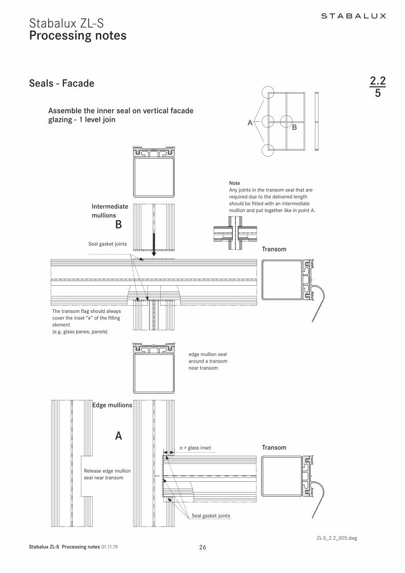
S T A B A L U X
Stabalux ZL-S Processing notes 011119 29
Stabalux ZL-S
Assembly of the inner seal for vertical facade glazing and facade glazing with an incline of up to 20deg - 3 overlapping sections
bull The transom seals overlap the main mullion sealsbull Along a transom seals must be laid continuouslybull Moisture and condensation is guided away via the
transom flag of the transom seal (2nd drainage sec-tion) to the main mullion
Processing notes
1
2
3
1
2
3
inner continuous mullion seal inner over-lapping transom seal clipped in
The transom flag should always cover the filling element
Secondary mullion seal is clipped into the transom seal with an overlap
ZL-S_22_005dwg
Seal gasket joints
Inner seal main mullion Inner seal transoms
Inner seal secondary mullion
Seals - Facade
Seal gasket joints
eg GD 6318eg GD 6314
eg GD 6315
C
B
225
bull Optionally Stabalux seals with three offset water channels can be used in the facade area which safe-ly drain any moisture or condensation to the outside
bull The 12 mm high seals can be divided across their height to allow a simple overlap at critical secondary mulliontransom joints ie transomprimary mul-lion joints
bull The vertical seals for main mullions (3rd drainage section) are laid continuously
S T A B A L U X
Stabalux ZL-S Processing notes 011119 30
Stabalux ZL-S
bull The transom flag must always cover the inset depth of the glass panes and filling element
bull The protruding length of the transom flag should be removed at the perforation once glazing is complet-ed
bull Vertical seals on the secondary mullion are butt jointed beneath the upper transom The tran-som flag of the upper transom runs continuously in the upper part of the joint
bull Drainage of the secondary mullion (1st drainage sec-tion) is achieved by overlapping the seals of the sec-ondary mullion with the seal of the upper transom
Assembly of the inner seal for vertical facade glazing and facade glazing with an incline of up to 20deg - 3 overlapping sections
Processing notes
Edge mullionsSecondary mullion Transom
Transom
The transom flag runscontinuously through
Transom sealConnection to the secondary mullionCut the uppermost section to the width of the secondary mullion seal
The secondary mullion seal isclipped into the mullion sealwith an overlap
e gt
glas
s in
set
e gt glass inset
Seal gasket jointsoverlapping joints
Cut the around the secondary mullion seal to separate the lower section to match the length of the overlap
Secondary mullion butt joint-ed seal the gasket joints
Seals - Facade
ZL-S_22_005dwg
BA
D
225
S T A B A L U X
Stabalux ZL-S Processing notes 011119 31
Stabalux ZL-S
bull All joints must be sealed Before laying seals we rec-ommend completely coating the support surfaces and edges with Stabalux connection paste
bull Ensure all joints are cleanly and solidly sealed Ex-cess sealant must be removed Absolutely no un-evenness in the glass support surface must occur from applying sealant too thickly
Assembly of the inner seal for vertical facade glazing and facade glazing with an incline of up to 20deg - 3 overlapping sections
Processing notes
Main mullion
TransomSeparate lower section of the tran-som seal along the length of the overlap
Separate the main mullion sealaround the upper section of the transom to match the width of the transom seal
The transom flag should always cover the inset ldquoerdquo of the filling element (eg glass panes panels)
Seals - Facade
ZL-S_22_005dwg
e gt glass inset e gt glass inset
Seal gasket jointsoverlapping joints
Seal gasket jointsoverlapping joints
C
225
S T A B A L U X
Stabalux ZL-S Processing notes 011119 32
Stabalux ZL-S
Seals - Facade
Processing notes
Assembly of the outer seal for vertical facade glazing
bull As well as gently clamping the glass in place the out-er sealing system has the primary task of protecting the rebate against moisture ingress
bull The outer sealing sections must be completely sealed except for the necessary openings for pres-sure equalisation and condensation dissipation
bull The outer mullion seals are laid continuously and the transom seals are joined
bull Sealant joints are to be laid flat with a slight excess in dimensions Exact specifications depends on the situation in which the system is used
bull It is not necessary to glue the outer sealing in the mullion-transom joint if the sealant joints fit precise-ly
bull The flag for the inner transom joint in combination with the outer seal creates additional safety
bull The transom flag should be separate at its perfora-tions to match the thickness of the glass in order that this is clamped down and concealed under the outer seal
bull Different heights of sealing lips on the outer seal bridge the height different created by the transom flag in the outer sealing section
bull Differently high split seals allow a balance between filling elements of different total thickness of up to 6 mm
bull When mounting the clamping strip be aware of aluminium profile expansion (see section 221 - Material information)
ZL-S_22_007dwg
outer continuous mullion sealouter jointed transom seal
eg GD 6054 outer transom seal with different heights of sealing lip
225
eg Z 0044eg GD 6024
eg Z 0032
eg GD 6025eg ZL 6053
S T A B A L U X
Stabalux ZL-S Processing notes 011119 33
Stabalux ZL-S
Assembly of the outer seal for facade glaz-ing with an inwards incline of 20deg
bull If the facade is inclined inwards from the vertical (max permitted incline 20deg) the open ends of the outer transom seals must be closed up using butyl
bull When constructing inwardly inclined facades (up to max 20deg) if flat cover profiles are used in the transoms (eg DL 5059 DL 6059 DL 5061 DL 6061 DL 5067 DL 6067 DL 5071 DL 6071 DL 6043 DL 6044) and flat lower and upper strips (eg UL 6005 with OL 6066) then the central hollows at each end must be sealed with silicone
Processing notes
The open end of the transom sealin inwardly inclined facades(up to max 20deg) must be sealed using butyl
When using flat cover profiles on inwardly inclined facades (up to max 20deg) the central hollow at each end should be sealed with silicone
Trim the seals to be slightly larger than required
ZL-S_22005dwg
Seals - Facade 225
2
S T A B A L U X
Stabalux ZL-S Processing notes 011119 34
Stabalux ZL-SProcessing notes
Seals - roof
Assembly of the inner seal for roof glazing
bull Optionally Stabalux seals with offset water channels can be used in the facade area which safely drain any moisture or condensation to the outside
bull The 10 mm high seals can be divided across their height to allow a simple overlap at critical transom joints
bull The transom seals are geometrically shaped so as to create a condensation channel
bull This channel drains from the overlapping transom joint in the rafters
bull Along a transom seals must be laid continuouslybull All joints must be sealed Before laying transom
seals we recommend applying a thin coating to the entire support surfaces Absolutely no unevenness in the glass support surface must occur from apply-ing sealant too thickly
ZL-S_22_008dwg
1 remove the lower perforated part and the clamping foot on
the transom seal at around 15 mm
2 remove the upper perforated part on the rafter seal
3 Length of transom seal = transom length + ~13 mm per side
Seal gasket joints
1
3
226
S T A B A L U X
Stabalux ZL-S Processing notes 011119 35
Stabalux ZL-S
Seals - roof
Processing notes
Assembly of the outer seal for for glazed roofing
bull These are laid in fundamentally the same way as for vertical glazing Split seals such as GD 1932 are not suitable for transom seals in roofs Split seals can only be installed in mullions in combination with slab insulation Each installation situation will differ to some degree and always check how well sealed it is
bull For cross joints we recommend using our self-adhe-sive stainless steel sealing plates with butyl coating Z 0601 for System 60 and Z 0501 for System 50 The stainless steel sealing plates are 35 mm wide and are attached to the edge of the glass panes parallel to the mullion axis
bull Butyl tape is not suitable as a sealing tape between the glass and the outer seal
bull The outer mullion seals are laid continuously and the transom seals are joined
bull Sealant joints are to be laid flat with a slight excess in dimensions Exact specifications depends on the situation in which the system is used
Notebull Horizontal clamping strips prevent the free run off of
rain water and dirtbull Cover strips and upper strips with angled edges re-
duce the build up of water in front of the clamping strip
bull Shorten the clamping strips on the transoms by 5 mm in the area of the transom joins in order to improve drainage of water Gasket joints however are to be laid flat with a slight excess in dimensions Open ends of transom clamping strips (upper and cover profiles) should be sealed
Detail of sealing plate Z 0501 = 35 x 40 mm Z 0601 = 35 x 50 mm
AttentionThe sealing plates must be glued central to the transom axis
For glass insets of 15 mm the first screw fittings for the transom cover strip begin 30 mm from the end of the cover strip
ZL-S_22_009dwg
226
S T A B A L U X
Stabalux ZL-S Processing notes 011119 36
Stabalux ZL-SProcessing notes
Seals - roof
Assembly of the outer seal for for inclined glazed roofing up to 2deg
bull These are laid in fundamentally the same way as for vertical glazing Split seals around the mullions in roofs such as GD 1932 are only suitable when us-ing in combination with slab insulation Each installation situation will differ to some degree and always check how well sealed it is
bull To ensure free run-off of rain water and dirt on roofs inclined up to 2deg we recommend not using clamping strips in the transoms
bull Instead the rebate spaces should be sealed with all-weather silicone
bull Implementation of the outer sealing section around mullions is done in the same way as conventional roofs with an inclination up to 15deg
Tips for all roof designs
When using aluminium cover profiles on roofs take ac-count of the expansion factor as a result of the high de-gree of heat absorption when selecting the length to use Equally the use of single-piece cover profiles should be carefully considered In this case it is recommended that holes for screwing on the cover strip are created with a diameter of d = 9 mm (see section 221 - Material information)For wide spans we recommend using concealed screw
bull At the high point or ridge area of the inclined glazing it is recommended to also install and outer sealing section in the transoms with clamping strips
bull Only certified sealing materials may be used for seal-ing the transom rebate space
bull Pay attention to all information provided by the manufacturer and the sealing work must be carried out by trained persons It is recommended that a li-censed and certified specialist contractor is hired for this purpose We further refer you to the DIN 52460 standard and IVD data sheets (Trade Association for Sealants)
ZL-S_22_009dwg
fittings when selecting the clamping strips (lower + up-per strip) This is the preferred option for rafters Unused holes in the lower strip must be sealedSome roof areas such as the eaves see the use of sev-eral different materials (glass silicone aluminium sheets ) each with different expansion coefficients To avoid the formation of cracks aluminium sheets should be in-stalled with expansion joints
226
ZL-S_22_009-4
Stabalux ZL-S
ZL-S_22_009-4
Stabalux ZL-S
4 4
S T A B A L U X
Stabalux ZL-S Processing notes 011119 37
Stabalux ZL-S
Seals - roof
Processing notes
Assembly of the outer seal for glazed roofing up to 2deg incline
bull The compatibility of the materials is particularly important when using all-weather silicone In this case the compatibility of the sealant with the edge bonding of the glass and the backfill of the joints If self-cleaning glass is used the compatibility must be established in advance
bull Glass sealants and edge bonding must be UV-resist-ant The incline of roofs should also be taken into account Information about UV-resistance can be requested from the manufacturer Silicone bonding generally provides better UV-resistance than poly-sulfide-based edge bonding The advantage of sili-cone lies in its high vapour sealing properties which is particularly useful when using more volatile argon fillings
Angled glazing transom up to 2deg inclination with all-weather silicone and round rope seal
Angled glazing transom up to 2deg inclinationwith all-weather silicone and insulation block
bull Highly elastic weatherproof and UV-resistant seals meet the widest range of demands for reliable joints
bull If the silicone joint is created without additional me-chanical safety devices ensure that the glass is sup-ported from two sides only Selective installation of holding clamps can be used to provide support for all glass edges
bull The clamps are made from stainless steal with sil-icone washers and are screwed in the same as pressure strips The hold-down clamp should be ad-ditionally sealed around the perimeter with silicone sealant The design is based upon the dimensions of the glass as documented in the glass static analysis
1 Hold-down clamp
2 Silicone washer
3 Silicone sealant seal around the
clamp
4 All weather silicone seal
51 Round section rope seal
1 19 9
3 3
6 6
7 7
8 8
10 10
2 2
52 Insulation block
6 Glass filling element
7 Inner seal 10 mm transom
8 Spacer strip
9 System screw fittings
10 Support profile
ZL-S_22_009dwg
226
51 52
S T A B A L U X
Stabalux ZL-S Processing notes 011119 38
Stabalux ZL-SProcessing notes
Seals - roof
Assembly of the outer seal for glazed roofing up to 2deg incline
bull The joint width and the joint height for Stabalux SR are defined as w x h = 20 mm x 10 mm These measurements should always checked when selecting the sealing material and adapted if neces-sary Generally w h = 2 1 to 35 1
bull PE round section seals or Stabalux slab insulation is suitable as a back fill material
bull Silicone sealant should be applied before laying the mullion seals and cover profiles
bull After the specified setting time the seals and screw fittings can be installed in the areas around mullions
bull The mullion-transom joints around the clamps are then sealed
bull Before applying this second layer the joints around transoms must have completely set
Rafters with clamping strips
Transom with clamp all-weather silicone seal and
round rope seal
Transom with clamp all-weather silicone and
insulation block
Joint design according to manufacturers specificationsGenerally w h = 2 1 ndash 35 1
Transom with all-weather silicone and round section rope seal
ZL-S_22_009dwg
226
S T A B A L U X
Stabalux ZL-S Processing notes 011119 39
Stabalux ZL-S
Seals - roof
Processing notes
Steps for creating the seal with all-weather silicone
bull Test the silicone sealant and glass edge bond-ings and other contact surfaces (eg panels) for suitability
bull Clean edge bonding adhesive impurities from the surfaces to which sealant will be applied following manufacturerrsquos directions
bull Fill the joints as per the joint dimensions using only non-water absorbent closed-cell PE profiles (no damage to the edge bonding)
bull The remaining space in the glass rebate must be large enough that the pressure is able to equalise and a drainage level is available
bull Clean any impurities from the surfaces to which the sealing material is to be applied and any adjacent surfaces according to manufacturerrsquos directions
bull Be particularly aware of any adjacent metal compo-nents Prime according to manufacturerrsquos directions
bull Seal joints without leaving any cavities or bubbles Mask any adjacent components in advance where necessary
bull Smooth out the filled joints using the manufactur-errsquos smoothing agents and conventional tools with as little water as possible Remove the adhesive tape when liquid
bull If two or more reactive sealants are used in combina-tion the first must completely set before the second is applied
System screw fittings
Hold-down clamp
Washer made from silicone
Silicone sealant seal around the clamp
All weather silicone seal
Silicone sealant
Rafter
Transom
ZL-S_22_009dwg
226
S T A B A L U X
Stabalux ZL-S Processing notes 011119 40
Stabalux ZL-SProcessing notes
Glass inset and glass support 227
RebateGlass inset
ZL-S_22_010dwg
Glass inset
bull Glass industry guidelines must be observedbull The glass inset is generally 15 mmbull An increase in the glass inset to 20 mm has a bene-
ficial effect on the heat transfer coefficient Uf of the frame structure
S T A B A L U X
Stabalux ZL-S Processing notes 011119 41
Stabalux ZL-SProcessing notes
Glass inset and glass support
Glass support types and selection of glass support
Glass supports carry the load of the glass panes through to the structure The permissible glass weights also depend on the structure of the glass and the selected mullion-transom connection The mullion-transom con-nection must be selected in such a way as to minimise any subsequent turning of the transoms The depth of the glass supports is determined by the glass structure Section 9 contains more information in this respect
The Stabalux ZL-S system distinguishes between two dif-ferent types and techniques for attaching glass supports
bull Glass support GH 5053 ie GH 5055 with 2 or 3 welding studs empty 10 mm
bull Heavy glass loads require welded glass supports For this purpose flat sheets with a thickness of t = 5 mm are welded on to the transoms
Mounting the glass supports
bull Positioning the glass supports and glazing according to glass industry guidelines and guidelines of the In-stitute for Window Technology
bull The weight of the glass panes is distributed via the glass supports attached to the transoms
bull Glass supports should be attached at an interval of 100 mm from the end of the transom When doing so avoid a collision with the cover strip screw fittings at the end of the transom
Glazing blocks
bull Glazing blocks must be compatible with the edge bonding of the insulated glass panes
bull They should be stable under constant pressure and be able to withstand loads aging and temperature changes
bull It is important that the blocks ensure circumferential pressure equalisation and that drainage of conden-sation is not obstructed as well as allowing the glass edges to be offset and small design tolerances to be accommodated
bull If the length of the glass support is more than 100 mm blocks should be placed along the entire length of the glass support to ensure equal load distribu-tion
227
Positioning the glass support approx 100 mm from the end of the transom
ZL-S_22_010dwg
S T A B A L U X
Stabalux ZL-S Processing notes 011119 42
Stabalux ZL-SProcessing notes
Glass inset and glass support
Glass support GH 5053 with bolts
bull The glass support consists of the Stabalux system component GH 5053 and 2 welding studs empty10 mm which must be made available on the building site
bull The glass supports GH 5073 are manufactured using aluminium in EN AW 6060 quality condition T66
bull The depth of the glass supports depends on the in-stalled thickness of the glass panes and the geome-try of the inner seal The require cuts are delivered to match glass support GH 5053
bull The bolts must be sufficiently protected against cor-rosion and be suitable for weld connections with the steel grade of the supporting structure Stainless steel bolts must be used otherwise
bull The length of the bolts is calculated based on the installed thickness of the glass panes plus the height of the inner seal and the height of the spacer strip
bull The centre distance between the bolts is 80 mm
bull The bolts must be welded in the centre of the tran-som in the substructure to disperse the load from the glass Screw fittings must be positioned vertical-ly to the transom
bull The spacer strip should also be pre-drilled with empty 11 mm holes at the relevant points to attach the bolts
bull Holes must be made at the relevant points of the transom seal Here it is important to ensure that the holes have as precise a fit as possible We recom-mend sealing the holes with Stabalux Z 0094 paste
bull The glass supports are mounted loosely on the build-ing site once the spacer strip and the inner sealing section have been fitted
bull Blocks must be placed under the glass panes along the entire length of the glass supports
bull It is essential to ensure when installing the glazing that neither the glazing blocks nor the glass supports slip
bull The glass supports (bolts) must be validated for the glass thickness the glass weight and the selected mullion-transom connection
227
S T A B A L U X
Stabalux ZL-S Processing notes 011119 43
Stabalux ZL-S
Glass support GH 5053 Attachment with welding studs
Processing notes
Glass inset and glass support
Glass support GH 5053 with bolts
ZL-S_22_010dwg
A-A
Glass support GH 5053
Block Bolts empty 10 mm
Glass support
Bolt
Inner seal
Spacer strip
227
S T A B A L U X
Stabalux ZL-S Processing notes 011119 44
Stabalux ZL-SProcessing notes
Glass inset and glass support
Glass support GH 5055 with bolts
bull The glass support consists of the Stabalux system component GH 5055 and 3 welding studs empty10 mm which must be made available on the building site
bull The glass supports GH 5055 are manufactured using aluminium in EN AW 6060 quality condition T66
bull The depth of the glass supports depends on the in-stalled thickness of the glass panes and the geome-try of the inner seal The require cuts are delivered to match glass support GH 5055
ZL-S_22_010dwg
Glass support GH 5055 Attachment with welding studs
227
bull The bolts must be sufficiently protected against cor-rosion and be suitable for weld connections with the steel grade of the supporting structure Stainless steel bolts must be used otherwise
bull The length of the bolts is calculated based on the installed thickness of the glass panes plus the height of the inner seal and the height of the spacer strip
bull Installation is performed the same way as GH 5053 but using three screws at intervals of 80 mm
A-AGlass support GH 5055
Block Bolt empty 10 mm
Glass support
Bolt
Inner seal
Spacer strip
S T A B A L U X
Stabalux ZL-S Processing notes 011119 45
Stabalux ZL-SProcessing notes
227
Glass inset and glass support
RowTotal glass thickness tGlass (mm)
for vertical glazingGlass supports 1)
GH 5053 GH 5055 Depth (mm)1 4 5 6 7 GH 0081 Section 9
2 8 9 Section Section 12
3 10 11 Section Section 144 12 13 Section Section 165 14 15 Section Section 186 16 17 Section Section 207 18 19 Section Section 228 20 21 GH 0082 Section 249 22 23 GH 0083 GH 0851 2610 24 25 GH 0084 GH 0852 2811 26 27 GH 0085 GH 0853 3012 28 29 30 GH 0886 GH 0854 3213 31 32 33 GH 0887 GH 0855 3514 34 35 36 GH 0888 GH 0856 3815 37 38 39 GH 0889 GH 0857 4116 40 41 42 GH 0890 GH 0858 4417 43 44 GH 0891 GH 0859 47
Classification of system components
Table 1 Vertical glazing | System 50 60 80 | threaded bolt
1) Cut from GH 5053 or GH 5055
S T A B A L U X
Stabalux ZL-S Processing notes 011119 46
Stabalux ZL-SProcessing notes
227
Glass inset and glass support
RowTotal glass thickness tGlass (mm)
for inclined glazing 1)
Glass supports 2)
GH 5053 GH 5055 Depth (mm)1 24 25 26 Section Section 18
2 27 28 Section Section 20
3 29 30 Section Section 224 31 32 GH 0082 Section 245 33 34 GH 0083 GH 0851 26
Classification of system components
Table 2 Inclined glazing | System 50 60 80 | Threaded bolts
1) Accounting for a 10 mm inner seal
2) Cut from GH 5053 or GH 5055
Glass support GH 5053
Glass support GH 5055
TI-H_92_005dwg
S T A B A L U X
Stabalux ZL-S Processing notes 011119 47
Stabalux ZL-SProcessing notes
Glass inset and glass support
Welded glass support
bull Welded glass supports made of flat steel that are welded on to the transom profiles The glass sup-ports must be made available on the building site
bull Flat steel in grade S235 ie matched with the qual-ity of the supporting construction It must be possi-ble to weld the steel grades together The weld seam must connect the entire cross section of the glass supports
bull The glass supports must be sufficiently protected against corrosion
bull The depth of the glass supports depends on the in-stalled thickness of the glass panes the geometry of the inner seal and the height of the spacer strip
bull The glass supports must be welded in the centre of the transom in the substructure to disperse the load from the glass The glass supports must be posi-tioned vertically to the transom
227
bull The spacer strip must be cut out at the relevant points so as to ensure that the glass support and the weld seam cannot collide
bull The transom seals must be cut out around the holes for the glass supports and then sealed using Stabalux connection paste Z 0094
bull Blocks must be placed under the glass panes along the entire length of the glass supports
bull It is essential to ensure when installing the glazing that the glazing blocks cannot slip
bull The width of the glass supports is at least 100 mm their size must suit the static requirements
bull The glass supports must be validated for the glass thickness the glass weights and the selected mul-lion-transom connection
S T A B A L U X
Stabalux ZL-S Processing notes 011119 48
Stabalux ZL-SProcessing notes
Glass inset and glass support
Welded glass support
Glass support
Width ldquoWrdquo
Block
Glass support
Block
Inner seal
Spacer strip
227
Match the thickness of the glass support with the glass thickness
Make the weld seam as even as possiblefully connect the cross sectionmould the spacer strip around the glass supports
Cut out the sealing around the holes for the glass supports and sealwith Stabalux connecting paste
1
2
3
ZL-S_22_010dwg
A-A
S T A B A L U X
Stabalux ZL-S Processing notes 011119 49
Stabalux ZL-SProcessing notes
Glass inset and glass support 227
Glass support GH 5055 with threaded bolt
bull The depth of the glass support must be matched with the thickness of the glass
T = depth of the glass supportT1 = height of the spacer stripT2 = height of the inner seal (eg 5 m 10 mm or 12 mm)T3 thickness of the glass pane
T = T1 + T2 + T3
ExampleSpacer strip T1 = 10 mmInner seal (eg GD 6030) T2 = 5 mmThickness of pane 6 16 6 T3 = 28 mm
T = 10 + 5 + 28 = 43 mm
Wid
th ldquo
Wrdquo
ZL-S_22_010dwg
S T A B A L U X
Stabalux ZL-S Processing notes 011119 50
Stabalux ZL-SProcessing notes
Screw fittings
Fastenings
bull The system screw fittings are a combination of basic room-side screw fittings a coupling using a threaded socket that allows thermal separation in the rebate and a flexible bolt-nut connection or screw connec-tion on the glazing side
Basic room-side screw fittings
bull The threaded bolts M6 can be used for the basic room-side screw fittings they are screwed into the threaded holes ie the threaded blind holes Weld-ing studs M6 can be used alternatively
bull The length of the threaded bolts depends on the height of the spacer strip the height of the inner seal and the material selected for the supporting struc-ture (mullion and transom profiles) ie the selected depth of the blind holes which must be ge 7 mm Grade 14301 A2 stainless steel bolts must be used
bull In most cases the selected welding studs should have a length of 25 mm and they must be made available on the building site The bolts must be suf-ficiently protected against corrosion and be suitable for weld connections with the steel grade of the sup-porting structure Stainless steel bolts must be used otherwise
Coupling with threaded socket
bull The threaded socket is delivered in a length of 25 mm and twisted tight on to the basic screw fittings without excessively compressing the inner seal The Stabalux threaded sockets can be delivered in stainless steel (art no Z 0029) or plastic (art no Z 0032)
Bolt nuts ie screw connections on the glazing side
bull The assembly consists of a threaded bolt and option-ally a sealing washer and a cap nut Screws accord-ing to DIN 6912 stainless steel 14301 A2 can be used alternatively
bull Screws in the Stabalux system are produced using stainless steel usually with the material number 14301 DIN EN 10088
228
bull The length of the bolts ie screws is variable and depends on the height of the spacer strip the height of the inner seal and thickness of the glass A suffi-cient screw depth in the threaded socket must be ensured
bull Threaded bolts in suitable lengths are available for all standard glass thicknesses The length of bolt re-quired can usually be determined using a table of figures The combination chosen for the clamp con-nection will depend on the specific situation
bull Depending on the type of screw fittings selected 2 and 4 mm vulcanised EPDM washers are available
bull The distance for screw fittings is variable The maxi-mum distance is a = 250 mm
bull The distance from the edge for the first screw fitting should generally be in the region of 30 mm le a le 80 mm The placement of the glass supports and the choice of mullion-transom connection should also be taken into account
bull The clamp connection is exclusively exposed to ten-sile forces The pressure strips are connected using Stabalux system components To determine the stress limit (maximum tensile force) and permitted tensile forces for the connection the terms defined in the relevant general building approval and the Eu-rocode 3 (DIN EN 1993-3) series of standards shall apply
bull Screw fittings are applied using a conventional elec-tric screwdriver with depth stop This guarantees uniform application of pressure The depth setting should be chosen so that when using 4 mm EPDM washers a washer compression of around 15 - 18 mm is achieved
S T A B A L U X
Stabalux ZL-S Processing notes 011119 51
Stabalux ZL-S
Concealed screw fittings
bull Assembly is facilitated by the selection of pre-drilled clamping strips (eg UL 5009-L and UL 6009-L slot 7 x 10 mm a = 125 mm) with clippable upper strips A round hole of d = 8 mm should be made in the remaining clamping strips The functionality of the clip procedure can be checked after the first cover profile has been pushed against the lower strip
Note
When using aluminium cover profiles on roofs take ac-count of the expansion factor as a result of the high de-gree of heat absorption and its impact on the selected length Equally the use of single-piece cover profiles should be carefully considered In this case it is recom-mended that holes for screwing on the clamping strip are created with a diameter of d = 9 mm
Processing notes
227
Screw fittings
Visible screw fittings
bull Cover strips should be drilled with a round hole of d = 8 mm
Note
(see Note on concealed screw fittings)
Visible recessed screw fittings
bull When creating visible recessed screw fittings a stepped bore is required The lower part of the cover strip should be drilled with a d = 7 mm diameter The upper part of the cover strip needs a d = 11 mm diameter for the screw head It is recommended to install a washer (PA washer eg Z 0033) with all screw fittings
S T A B A L U X
Stabalux ZL-S Processing notes 011119 52
Stabalux ZL-SProcessing notes
Screw fittings
Concealed screw fittings
1 cap nut M6 Z004321 4 mm sealing washer Z 008631 threaded bolt M6 eg Z 3532 threaded bolt M6 in the threaded hole eg Z 004041 threaded socket M6 eg Z 29
Visible screw fittings
1 cap nut M6 Z004321 4 mm sealing washer Z 008631 threaded bolt M6 eg Z 3542 threaded socket M6 eg Z 296 threaded welding stud M6
Visible recessed screw fittings
22 PA washer Z 003333 threaded bolt M6 in the threaded hole eg Z 4042 threaded socket M6 eg Z 325 internal hex screw M6 eg GD 6912
Fastenings
ZL-S_22_011dwg
228
eg Z 0043
eg Z 0029 eg Z 0029
eg Z 0086
eg Z 0086
Screw M6
eg Z 0033
eg Z 0035
eg Z 0040 Threaded welding stud M6
Diagram and item numbers are examples for System 60
The calculation is the same for system 50
S T A B A L U X
Stabalux ZL-S Processing notes 011119 53
Stabalux ZL-SProcessing notes
Screw fittings
Calculating the screw length
ZL-S_22_012dwg
228
System width 50 60 mm System width 80 mm
Attention
The calculation to determine screw lengths for the the calculation to determine screw lengths is
Glass thickness - 14 mm with facade seal (5 mm)Glass thickness - 9 mm with facade seal (10 mm)Glass thickness - 7 mm with facade seal (12 mm)
S T A B A L U X
Stabalux ZL-S Processing notes 011119 54
Stabalux ZL-SProcessing notes
Screw fittings
System screws for Stabalux ZL
Cap nut
Z 0043 Cap nut stainless steel M6
Sealing washers
Z 46 U washer stainless steel with 2 mm seal
Z 0086 U washer stainless steel with 4 mm seal
Threaded sockets
Z 0029 Threaded socket stainless steel
M6 x 25 mm
Z 0032 Threaded socket stainless steel
M6 x 25 mm
Threaded bolts
Z 0034 Threaded bolts stainless steel M6 x 20 mm
Z 0038 Threaded bolts stainless steel M6 x 25 mm
Z 0035 Threaded bolts stainless steel M6 x 30 mm
Z 0040 Threaded bolts stainless steel M6 x 35 mm
Z 0036 Threaded bolts stainless steel M6 x 40 mm
Z 0037 Threaded bolts stainless steel M6 x 50 mm
Z 0044 Threaded bolts stainless steel M6 x 60 mm
Z 0045 Threaded bolts stainless steel M6 x 75 mm
Z 0039 Threaded bolts stainless steel M6 x 90 mm
Z 0053 Threaded bolts stainless steel M6 x 100 mm
Z 0054 Threaded bolts stainless steel M6 x 120 mm
228
ZL-S_22_013dwg
Calculating the screw length
S T A B A L U X
Stabalux ZL-S Processing notes 011119 55
Stabalux ZL-SProcessing notes
Flat cover strip DL 5073 DL 6073
Tips for laying the cover strip DL 5073 DL 6073
We assume that this cover strip will be used with glass panes that are supported on two sides and the recessed screw head is concealed In this case a cylinder head screw with inner hex is to be used (eg M6 DIN 6912 stainless steel A2 with low head) When covering with a 2 mm cover plug Z 0089 a bore depth of 6 mm is cal-culated
Depending on the precision of the bore it should be de-cided on case by case basis if any slight changes to this depth are necessary The cover plug Z 0089 does not need to be glued in place but may be levelled using lev-elling compound
Coating the cover strip
Profile production (aluminium extrusion moulding) with different mass distribution is extremely difficult Length-wise shadow formation may result Resulting actions are to be taken with the agreement of the coater
Intersections
Due to the special shape of the strip (the material ex-tends into the rebate) there is no closed sealing section available at intersections We therefore recommend plac-ing particular attention to ensure tightness of the joints and fill will Stabalux connecting paste Z 0094
Glass supportsblocking
Special attention should be given to dimensional propor-tions Glass supports should be designed by the proces-sor depending on the glass thickness and weight (eg for welded glass supports)To support the outer pane a sufficiently large glazing block must be installed that can carry the load to safely ensure the glass load is distributed effectively
ZL-S_22_014dwgZL-S_22_013dwg
229
Cover plug Z 0089Screw eg M6 DIN 6912
ZL-S_22_015-1
Stabalux ZL-S
S T A B A L U X
Stabalux ZL-S Processing notes 011119 56
Stabalux ZL-SProcessing notes
Slab insulation
ZL-S_22_015dwg
Use of slab insulation
bull Using insulation blacks significantly reduces heat dissipation
bull The highly effective slab insulation has a permanent-ly adhesive HOT-MELT
bull Depending on the situation where they are used in-sulation blocks can be directly applied to the cover striplower strip or placed into the rebate over the screw fittings and pushed into position with the cov-er striplower strip The type of screw connection (bolt-socket-bolt) means that a groove must first be cut in the insulating block at the points of connec-tion
bull With system width 80 mm and a 40 mm rebate 2x 20 mm wide slab insulation blocks can be combined (40 mm wide insulation blocks available upon request)
Note
bull The use of slab insulation with cover profiles DL 5073 DL 6073 should be tested for each individual situation
bull 2-piece outer seals are always used with slab insula-tion blocks for example outer seal GD 1932
Insulation block Width (=rebate)
Height
Z 0605 insulation block 20 42 20 mm 42 mm glass thickness from 44 mm
Z 0606 insulation block 20 26 20 mm 26 mm glass thickness from 28 mm
Z 0607 insulation block 30 42 30 mm 42 mm glass thickness from 44 mm
Z 0608 insulation block 30 26 30 mm 26 mm glass thickness from 28 mm
Correctly position the transom flag when installing the insulation blocks
2210
Z 0607Insulation block 3042
Z 0608Insulation block 3026
Z 0605Insulation block 2042
Z 0606Insulation block 2026
Z 0605Insulation block 2042
GD 1932
GD 1932
GD 1932
GD 1932
GD 1932
GD 1932
Z 0606Insulation block 2026
S T A B A L U X
Stabalux ZL-S Processing notes 011119 57
Stabalux ZL-SProcessing notes
Slab insulation
Examples
ZL-S_22_015dwg
2210
S T A B A L U X
Stabalux ZL-S Design 011119 59
Stabalux ZL-S
Pane support variants
Design
Special design
Glass structures that partially refrain from using visible cover profiles are considered special designs
These designs do not conform to the intended uses of the system No guarantees are made for eg quality of seals durability and structural stability Responsibility here lies entirely with the company implementing the design
Based on our experience we recommend paying close at-tention to the points made on the following pages during planning and implementation
Cut A - A Cut C - C
Cut B - B Cut D - D
ZL-S_23_001dwg
Mullion-transom structure 2-sided cover strip
231
Mullion-transom structurewith transom cover profiles 1)
1) Seals with 1 2 or 3 sections are possible
2) Use of mullion seals with 1 section in mullions and transoms
Mullion-transom structurewith mullion cover profiles 2)
S T A B A L U X
Stabalux ZL-S Design 011119 60
Stabalux ZL-SDesign
Transom - design Mullion - design
ZL-S_23_001dwg
Pane support variants
Vapour seal
When using this type of structure it is important to be aware that any loss of contact pressure can affect the room-side permeability There is an increased risk of con-densation build up in the rebate
Vertical clamping strips
The glass supports should be placed to below the outer pane and sealed with it
Horizontal clamping strips
Ventilation and condensation drainage is achieved via a recess in the lower sealing lip in the centre of the outer seal or at one third intervals
Transom structure mullion structure 2-sided cover strip
Cut A - A Cut C - C
Cut B - B Cut D - D
231
S T A B A L U X
Stabalux ZL-S Design 011119 61
Stabalux ZL-SDesign
Design requirements
1 Vapour seal
The room-side level of glazing must have the best possi-ble vapour seal In this regard the vapour diffusion prop-erties of the silicone sealant to be used should be tested
Ensure that there are no permeable areas around con-cave cross joints
2 Rebate ventilation pressure equalisa-tion and condensation drainage
Systems with partially sealed rebate represent a limita-tion to rebate ventilation Check on a case-by-case basis that no damage will be caused by standing condensation It is especially critical that designs with sealed vertical joints are evaluated To allow ventilation of the horizontal rebate we recommend installing a suitable vertical ven-tilation space Alternatively ventilation can be achieved using the outer joints
3 Weatherproofing
The outward facing seals must be watertight In cross joints it is especially important to ensure a firm join be-tween the Stabalux profile seal and the silicone joints We recommend sealing up to the outer edge of the glass before mounting the cover profiles
We would like emphasise once again that our profile seals will not make a permanent bond with commonly used silicone sealants A seal can only be created at con-tact points through permanent application of pressure
4 Mechanical strength of the screw fittings
Ensure screw fittings are of a sufficiently size Special at-tention should be given to the effects of wind suction and the reduced support
5 Glass weight distribution
Mechanical distribution of the weight of the glass panes through the structure must be ensured System glass supports can be used for existing horizontal transoms Designs using ldquoonlyrdquo mullions require special glass sup-ports which carry the weight of the glass directly into the mullions
6 Glass sizing
Attention should be given to the reduced support of panes when dimensioning the glass For example only the vertical or horizontal cover profiles are effective in the event of wind suction stresses or stress on the fall protection
7 Material compatibility
Compatibility of the silicone sealants with our profile seal-ants and the edge bonding of the glass must be ensured We recommend the exclusive use of tested silicone seal-ants from the whole-glass facades sector Approval is usually given by the silicone manufacturer
Pane support variants
ZL-S_23_001dwg
231
Examples
S T A B A L U X
Stabalux ZL-S Design 011119 62
Stabalux ZL-S
System cross sections
Design
ZL-S_23_001dwg
1 Vertical glazing mullion
concealed screw fittings
2 Vertical glazing mullion
visible screw fittings
3 Vertical glazing mullion
flat cover strip DL 5073 DL 6073
4 Vertical glazing transom
visible recessed screw fittings
Outer seal for height compensation
5 Vertical glazing transom
concealed screw fittings
single glazing
6 Vertical glazing transom
concealed screw fittings
7 Inclined glazing mullion
concealed screw fittings
8 Inclined glazing transom
visible screw fittings
1 2
3 4
5 6
7 8
232
S T A B A L U X
Stabalux ZL-S Design 011119 63
Stabalux ZL-SDesign
System details
Creating facade corners
At exposed areas such as glass facade corners it is par-ticularly important to ensure sufficient heat insulation in order to avoid the creation of thermal bridges and pre-vent a build-up of condensation Thermal current calcula-tions provide information about the actual heat loss
Outer corner Inner corner
ZL-S_23_002dwg ZL-S_23_002dwg
Facade polygon
Special seal allow a polygon shaped arrangement of the facade mullions For convex glass surfaces an angle be-tween 3deg and 15deg can be freely chosen For concave glass surfaces the angle can vary between 3deg and 10deg
ZL-S_23_002dwg
Geometrically check the feasibility Recommendation Use System 60 at minimum
ATTENTIONAdhere to the minimum glass inset
Determine the threaded bolt length using consideration of the angle
233
S T A B A L U X
Stabalux ZL-S Design 011119 64
Stabalux ZL-SDesign
System details
Eaves with glass roof connection
bull Depending on the construction of the transoms a design with or without rain gutters and the choice of stepped glazing or closable cover profiles gives us different variants for implementation
bull All options require condensation and moisture to be drained away at the eaves
Design with stepped glazing
bull With a stepped glazing design it is important to select a UV-resistant edge bonding for the glass This edge bonding systems usually silicone-based are quite permeable to gases and are therefore unable to achieve the required high values for sound and heat insulation of conventional systems ie require additional sealing around the edges
Example 1
Design with stepped glazing
bull Our thermal calculations show that stepped glass panes compared to covered glass edges have a much less favourable isothermal movement
bull Stepped glass panes must also be statically meas-ured according to their reduced hold against wind suction
bull The additional thermal loads that occur in stepped glass panes should countered by the use of pre-ten-sioned glass (TVG ESG) for the outer panes
bull Stepped glass panes should be preferred for flatter inclined roofs as water can drain away at the eaves unhindered
ZL-S_23_003dwg
233
S T A B A L U X
Stabalux ZL-S Design 011119 65
Stabalux ZL-SDesign
Eaves with glass roof connection Design using cover profiles
bull Horizontal pressure strips prevent the free run off of rain water and dirt
bull Cover strips with angled edges reduce the build up of water in front of the cover strip
bull The outer sealing level on glass roofs must also be thoroughly sealed
bull In combination with our butyl clad stainless steel panels glazing with pressure strips on 4 sides achieves a higher level of safety
bull Make sure that the inner sealing section provides guaranteed drainage for condensation
bull To improve drainage and heat-induced expansion cover profiles should be shortened by 5 mm at tran-som joints Gasket joints however are to be laid flat with a slight excess in dimensions Open ends of the transom cover profiles must be sealed
Note
Due to the increased thermal stresses in the roof we rec-ommend using concealed screw fitting when choosing clamping strips for larger system lengths and in rafters Unused holes in the lower strip must be sealed
System details
Example 2
Design using cover profiles
ZL-S_23_004dwg
233
S T A B A L U X
Stabalux ZL-S Design 011119 66
Stabalux ZL-SDesign
System details
Eaves with glass roof connection Design with gutter
bull The gutter must be able to take its own weight and mounted in such a way that stresses from its own weight water and ice will not lead to deformations and directly apply a load to the glazing
bull Overflowing water must not be able to get inside the structure Alongside the gutter-shaped outer rafter seal the moisture barrier installed over the guide plate also acts to drain away condensation
Example 3
Design with gutter
ZL-S_23_005dwg
233
S T A B A L U X
Stabalux ZL-S Design 011119 67
Stabalux ZL-SDesign
System details
Roof ridge design
bull When designing the ridge cap ensure that the rafter cover profiles are pulled under the ridge cap
ZL-S_23_006dwg
233
S T A B A L U X
Stabalux ZL-S Design 011119 68
Stabalux ZL-S
Structural attachments
Design
Structural attachment film baffles
bull Attachment of glazing to the building structure re-quires a well thought out approach
bull Moisture damage can occur if moisture condenses at any thermal bridges
bull Thermal bridges must be avoided and warm air from the inside spaces must not penetrate too deeply into the structure
bull The required moisture barriers must be installed as deeply as possible into the inner space using imper-meable structural film baffles This prevents mois-ture penetration into the structure via condensation from the air inside
bull An additional foil to seal against rainwater must be permeable to moisture Only if this foil has a water vapour diffusion resistance value μ of max μ = 3000 can a dry structure be guaranteed in the transition zones
234
S T A B A L U X
Stabalux ZL-S Design 011119 69
Stabalux ZL-S
Structural attachments
Design
Facade base
bull Controlled drainage of the rebate space can only be ensured if the sealing sections overlap in such a way that no moisture can get under the seals and foils
bull Run foils under the transom seal to act as a moisture barrier and glue to the steel structure In accordance with DIN 18195 the seal should be run at least 150 mm above the water-guiding layer
bull Attach foil with moisture barrier in accordance with the requirements of DIN 18195
Example 1 Mounting intermediate mullion to base plate
Drainage of the base area is achieved via the transom flag towards the outside In this case the transom flag around the mullion at the base should not be released For edge mullions ensure there is a
corresponding seal placed (continuous transom seal up the to the end point) and a constructive design of the drainage section
ZL-S_23_007dwg
234
S T A B A L U X
Stabalux ZL-S Design 011119 70
Stabalux ZL-SDesign
Structural attachments
Facade base
bull Rebate space ventilation is achieved via the open end of the vertical cover profiles
bull Ensure the connection is impermeable to vapourbull Mullion mountings must be sufficiently statically di-
mensioned Required axis and edge distances for an-choring the base plates and in the building structure must be observed
Example 2 Mounting intermediate mullion to base plate
Where transom flags are interrupted by joints filler rods in the joint must also be cut
ZL-S_23_008dwg
234
S T A B A L U X
Stabalux ZL-S Design 011119 71
Stabalux ZL-SDesign
Structural attachments
Facade base
bull Heat insulation around the structural connection should be designed in such as way as to prevent cold bridges forming
bull Steel parts should also be provided with sufficient protection against corrosion even in concealed ar-eas
bull Weather-protection sheets should be used depend-ing on the requirements of the construction Suffi-cient rear ventilation must be ensured
Example 3 Attaching intermediate mullions at base plates
ZL-S_23_009dwg
234
ZL-S_23_010-2
Stabalux ZL-S
S T A B A L U X
Stabalux ZL-S Design 011119 72
Stabalux ZL-SDesign
Connection before intermediate floors
bull Depending on requirements mullions are designed as continuous multi-span transoms or separated at each floor
bull Reasons for separating mullions can include eg building settlement fire protection sound insulation etc
bull If the separation joint is intended to absorb expan-sion then as well as the required degree of freedom for mullions the ability for movement of integrated elements must also be ensured
Structural attachments
bull The constructive design of the mullion joint and mounting should be chosen according to the stat-ically calculated base system and determines the choice and arrangement of fixed and movable bear-ings type of screw fittings structural connection parts and attachment to the concrete floor
bull With continuous mullions and a corresponding mount the multi-span support principle is in effect Sagging due to horizontal effects is lower The required mo-ment of inertia reduces for 2-span supports with the same span length compared to the 1-span support by a factor of 0415 However a tension and stability analysis should be carried out
Example Mullions separated at each floor
In this example distribution of horizontal and vertical loads is achieved at each floor through the existing floor structure
ZL-S_23_010dwg
234
S T A B A L U X
Stabalux ZL-S Design 011119 73
Stabalux ZL-SDesign
Ceiling connection
bull Structural connections should take account of any movement that may occur
bull As well as temperature induced expansion in the fa-cade all longitudinal expansions and movements of the affected components must be considered
bull Additional stresses from restraints must be avoided
Structural attachments
ZL-S_23_011dwg
234
S T A B A L U X
Stabalux ZL-S Design 011119 74
Stabalux ZL-SDesign
Facade connection to parapets
Structural attachments
ZL-S_23_012dwg
234
S T A B A L U X
Stabalux ZL-S Design 011119 75
Stabalux ZL-SDesign
Connection to structural eaves
bull This connection is suitable for glass roofs that are being installed as skylights in the structure These may be gabled roofs single pitch roofs pyramids or arched roofs
Structural attachments
ZL-S_23_013dwg
234
S T A B A L U X
Stabalux ZL-S Design 011119 76
Stabalux ZL-SDesign
Ridge connection to walls
bull When making ridge connections to walls permea-bility to moisture is particularly important Warm air with a high level of moisture gets into cooler zones of the inner sealing section where the design is not sufficiently sealed and can cause structural damage from penetrating into the connecting structure
bull Joint seals made from butyl-clad stainless steel plates (Z 0501 Z 0601) must be installed on the out-side of joint areas
Structural attachments
ZL-S_23_014dwg
234
S T A B A L U X
Stabalux ZL-S Design 011119 77
Stabalux ZL-SDesign
Horizontal wall connection to heat insulation bonding system
Structural attachments
ZL-S_23_015dwg
234
Ceiling conection including WAREMA external blinds
Structural attachments
ZL-S_23_024dwg
234
S T A B A L U X
Stabalux ZL-S Design 011119 78
Stabalux ZL-S
S T A B A L U X
Stabalux ZL-S Design 011119 79
Stabalux ZL-SDesign
Installing windows and doors
Mullion and transom facades and glass roofs from Stabalux are neutral with regards to the selection of in-sert elements All commonly available window and door systems made from steel aluminium wood or plastic can be used Frame profiles from the window and door man-ufacturerrsquos should be selected to match the chosen glass thickness If no profiles with a suitable insert rebate are available mountings may be used as shown in the fol-lowing examples Like with glass elements windows are set into the facade on glass supports padded and then secured against slippage
Insert window transom sectionSystem HUECKSeries Lambda WS 075 IS
Use a locating screwas an assembly aid if necessary
Use
a lo
catin
g sc
rew
as a
n as
sem
bly
aid
if ne
cess
ary Insert window mullion section
System HUECKSeries Lambda WS 075 IS
ZL-S_23_01 dwg
235
S T A B A L U X
Stabalux ZL-S Design 011119 80
Stabalux ZL-SDesign
Installing windows and doors
ZL-S_23_017dwg
Insert window mullion sectionSystem HUECKSeries Lambda WS 075
Insert window transom sectionSystem HUECKSeries Lambda WS 075
235
Use a locating screwas an assembly aidif necessary
Use
a lo
catin
g sc
rew
as a
n as
sem
bly
aid
if ne
cess
ary
S T A B A L U X
Stabalux ZL-S Design 011119 81
Stabalux ZL-S
ZL-S_23_018dwg
Design
Installing windows and doors
Insert door outward in the mullion sectionSystem HUECKSeries Lambda DS 075
Insert door outward in the transom sectionSystem HUECKSeries Lambda DS 075
235
Use a locating screw as an assembly aid if necessary
Use
a lo
catin
g sc
rew
as a
n as
sem
bly
aid
if ne
cess
ary
S T A B A L U X
Stabalux ZL-S Design 011119 82
Stabalux ZL-SDesign
Installing windows and doors
Insert door inward in the mullion sectionSystem HUECKSeries Lambda DS 075
Insert door inward in the transom sectionSystem HUECKSeries Lambda DS 075
ZL-S_23_019dwg
235
Use a locating screwas an assembly aidif necessary
Use
a lo
catin
g sc
rew
as a
n as
sem
bly
aid
if ne
cess
ary
ZL-S_23_020dwg
Design
Installing windows and doors
Insert top-hung window in the mullion sectionSystem HUECKSeries Lambda 110
Insert top-hung window in the transom sectionSystem HUECKSeries Lambda 110
235
S T A B A L U X
Stabalux ZL-S Design 011119 83
Stabalux ZL-S
Design
Installing windows and doors
Sliding system in the mullion sectionSystem HUECKSeries Volato M
Sliding system in the transom sectionSystem HUECKSeries Volato M
ZL-S_23_021dwg
235
S T A B A L U X
Stabalux ZL-S Design 011119 84
Stabalux ZL-S
S T A B A L U X
Stabalux ZL-S Design 011119 85
Stabalux ZL-SDesign
Installing windows and doors
Flush roof surface windowSystem HUECK-HARTMANNSeries 85E
Connection at top
Connection at bottom
Powered accordingto system specifications
ZL-S_23_020dwg
235
S T A B A L U X
Stabalux ZL-S Design 011119 86
Stabalux ZL-SDesign
Installing windows and doors
Insert window - mullion sectionSystem HahnSeries Lamellae S9 iVt-05
Insert window - transom sectionsSystem HahnSeries Lamellae S9 iVt-05
ZL-S_23_021dwg
235
- Stabalux ZL-S
-
- System
-
- System properties
- System cross sections and inner seals - facade
- System cross sections and inner seals - roof
- Cover strips and outer seals
-
- Processing notes
-
- Material information
- Assembly sequence
- Attaching the spacer strip
- Tips for laying seals
- Seals - Facade
- Seals - roof
- Glass inset and glass support
- Screw fittings
- Flat cover strip DL 5073 DL 6073
- Slab insulation
-
- Design
-
- Pane support variants
- System cross sections
- System details
- Structural attachments
- Installing windows and doors
-
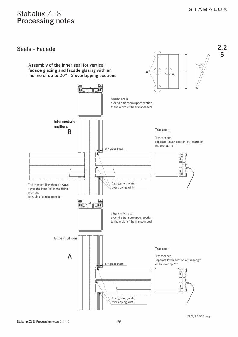
S T A B A L U X
Stabalux ZL-S Processing notes 011119 30
Stabalux ZL-S
bull The transom flag must always cover the inset depth of the glass panes and filling element
bull The protruding length of the transom flag should be removed at the perforation once glazing is complet-ed
bull Vertical seals on the secondary mullion are butt jointed beneath the upper transom The tran-som flag of the upper transom runs continuously in the upper part of the joint
bull Drainage of the secondary mullion (1st drainage sec-tion) is achieved by overlapping the seals of the sec-ondary mullion with the seal of the upper transom
Assembly of the inner seal for vertical facade glazing and facade glazing with an incline of up to 20deg - 3 overlapping sections
Processing notes
Edge mullionsSecondary mullion Transom
Transom
The transom flag runscontinuously through
Transom sealConnection to the secondary mullionCut the uppermost section to the width of the secondary mullion seal
The secondary mullion seal isclipped into the mullion sealwith an overlap
e gt
glas
s in
set
e gt glass inset
Seal gasket jointsoverlapping joints
Cut the around the secondary mullion seal to separate the lower section to match the length of the overlap
Secondary mullion butt joint-ed seal the gasket joints
Seals - Facade
ZL-S_22_005dwg
BA
D
225
S T A B A L U X
Stabalux ZL-S Processing notes 011119 31
Stabalux ZL-S
bull All joints must be sealed Before laying seals we rec-ommend completely coating the support surfaces and edges with Stabalux connection paste
bull Ensure all joints are cleanly and solidly sealed Ex-cess sealant must be removed Absolutely no un-evenness in the glass support surface must occur from applying sealant too thickly
Assembly of the inner seal for vertical facade glazing and facade glazing with an incline of up to 20deg - 3 overlapping sections
Processing notes
Main mullion
TransomSeparate lower section of the tran-som seal along the length of the overlap
Separate the main mullion sealaround the upper section of the transom to match the width of the transom seal
The transom flag should always cover the inset ldquoerdquo of the filling element (eg glass panes panels)
Seals - Facade
ZL-S_22_005dwg
e gt glass inset e gt glass inset
Seal gasket jointsoverlapping joints
Seal gasket jointsoverlapping joints
C
225
S T A B A L U X
Stabalux ZL-S Processing notes 011119 32
Stabalux ZL-S
Seals - Facade
Processing notes
Assembly of the outer seal for vertical facade glazing
bull As well as gently clamping the glass in place the out-er sealing system has the primary task of protecting the rebate against moisture ingress
bull The outer sealing sections must be completely sealed except for the necessary openings for pres-sure equalisation and condensation dissipation
bull The outer mullion seals are laid continuously and the transom seals are joined
bull Sealant joints are to be laid flat with a slight excess in dimensions Exact specifications depends on the situation in which the system is used
bull It is not necessary to glue the outer sealing in the mullion-transom joint if the sealant joints fit precise-ly
bull The flag for the inner transom joint in combination with the outer seal creates additional safety
bull The transom flag should be separate at its perfora-tions to match the thickness of the glass in order that this is clamped down and concealed under the outer seal
bull Different heights of sealing lips on the outer seal bridge the height different created by the transom flag in the outer sealing section
bull Differently high split seals allow a balance between filling elements of different total thickness of up to 6 mm
bull When mounting the clamping strip be aware of aluminium profile expansion (see section 221 - Material information)
ZL-S_22_007dwg
outer continuous mullion sealouter jointed transom seal
eg GD 6054 outer transom seal with different heights of sealing lip
225
eg Z 0044eg GD 6024
eg Z 0032
eg GD 6025eg ZL 6053
S T A B A L U X
Stabalux ZL-S Processing notes 011119 33
Stabalux ZL-S
Assembly of the outer seal for facade glaz-ing with an inwards incline of 20deg
bull If the facade is inclined inwards from the vertical (max permitted incline 20deg) the open ends of the outer transom seals must be closed up using butyl
bull When constructing inwardly inclined facades (up to max 20deg) if flat cover profiles are used in the transoms (eg DL 5059 DL 6059 DL 5061 DL 6061 DL 5067 DL 6067 DL 5071 DL 6071 DL 6043 DL 6044) and flat lower and upper strips (eg UL 6005 with OL 6066) then the central hollows at each end must be sealed with silicone
Processing notes
The open end of the transom sealin inwardly inclined facades(up to max 20deg) must be sealed using butyl
When using flat cover profiles on inwardly inclined facades (up to max 20deg) the central hollow at each end should be sealed with silicone
Trim the seals to be slightly larger than required
ZL-S_22005dwg
Seals - Facade 225
2
S T A B A L U X
Stabalux ZL-S Processing notes 011119 34
Stabalux ZL-SProcessing notes
Seals - roof
Assembly of the inner seal for roof glazing
bull Optionally Stabalux seals with offset water channels can be used in the facade area which safely drain any moisture or condensation to the outside
bull The 10 mm high seals can be divided across their height to allow a simple overlap at critical transom joints
bull The transom seals are geometrically shaped so as to create a condensation channel
bull This channel drains from the overlapping transom joint in the rafters
bull Along a transom seals must be laid continuouslybull All joints must be sealed Before laying transom
seals we recommend applying a thin coating to the entire support surfaces Absolutely no unevenness in the glass support surface must occur from apply-ing sealant too thickly
ZL-S_22_008dwg
1 remove the lower perforated part and the clamping foot on
the transom seal at around 15 mm
2 remove the upper perforated part on the rafter seal
3 Length of transom seal = transom length + ~13 mm per side
Seal gasket joints
1
3
226
S T A B A L U X
Stabalux ZL-S Processing notes 011119 35
Stabalux ZL-S
Seals - roof
Processing notes
Assembly of the outer seal for for glazed roofing
bull These are laid in fundamentally the same way as for vertical glazing Split seals such as GD 1932 are not suitable for transom seals in roofs Split seals can only be installed in mullions in combination with slab insulation Each installation situation will differ to some degree and always check how well sealed it is
bull For cross joints we recommend using our self-adhe-sive stainless steel sealing plates with butyl coating Z 0601 for System 60 and Z 0501 for System 50 The stainless steel sealing plates are 35 mm wide and are attached to the edge of the glass panes parallel to the mullion axis
bull Butyl tape is not suitable as a sealing tape between the glass and the outer seal
bull The outer mullion seals are laid continuously and the transom seals are joined
bull Sealant joints are to be laid flat with a slight excess in dimensions Exact specifications depends on the situation in which the system is used
Notebull Horizontal clamping strips prevent the free run off of
rain water and dirtbull Cover strips and upper strips with angled edges re-
duce the build up of water in front of the clamping strip
bull Shorten the clamping strips on the transoms by 5 mm in the area of the transom joins in order to improve drainage of water Gasket joints however are to be laid flat with a slight excess in dimensions Open ends of transom clamping strips (upper and cover profiles) should be sealed
Detail of sealing plate Z 0501 = 35 x 40 mm Z 0601 = 35 x 50 mm
AttentionThe sealing plates must be glued central to the transom axis
For glass insets of 15 mm the first screw fittings for the transom cover strip begin 30 mm from the end of the cover strip
ZL-S_22_009dwg
226
S T A B A L U X
Stabalux ZL-S Processing notes 011119 36
Stabalux ZL-SProcessing notes
Seals - roof
Assembly of the outer seal for for inclined glazed roofing up to 2deg
bull These are laid in fundamentally the same way as for vertical glazing Split seals around the mullions in roofs such as GD 1932 are only suitable when us-ing in combination with slab insulation Each installation situation will differ to some degree and always check how well sealed it is
bull To ensure free run-off of rain water and dirt on roofs inclined up to 2deg we recommend not using clamping strips in the transoms
bull Instead the rebate spaces should be sealed with all-weather silicone
bull Implementation of the outer sealing section around mullions is done in the same way as conventional roofs with an inclination up to 15deg
Tips for all roof designs
When using aluminium cover profiles on roofs take ac-count of the expansion factor as a result of the high de-gree of heat absorption when selecting the length to use Equally the use of single-piece cover profiles should be carefully considered In this case it is recommended that holes for screwing on the cover strip are created with a diameter of d = 9 mm (see section 221 - Material information)For wide spans we recommend using concealed screw
bull At the high point or ridge area of the inclined glazing it is recommended to also install and outer sealing section in the transoms with clamping strips
bull Only certified sealing materials may be used for seal-ing the transom rebate space
bull Pay attention to all information provided by the manufacturer and the sealing work must be carried out by trained persons It is recommended that a li-censed and certified specialist contractor is hired for this purpose We further refer you to the DIN 52460 standard and IVD data sheets (Trade Association for Sealants)
ZL-S_22_009dwg
fittings when selecting the clamping strips (lower + up-per strip) This is the preferred option for rafters Unused holes in the lower strip must be sealedSome roof areas such as the eaves see the use of sev-eral different materials (glass silicone aluminium sheets ) each with different expansion coefficients To avoid the formation of cracks aluminium sheets should be in-stalled with expansion joints
226
ZL-S_22_009-4
Stabalux ZL-S
ZL-S_22_009-4
Stabalux ZL-S
4 4
S T A B A L U X
Stabalux ZL-S Processing notes 011119 37
Stabalux ZL-S
Seals - roof
Processing notes
Assembly of the outer seal for glazed roofing up to 2deg incline
bull The compatibility of the materials is particularly important when using all-weather silicone In this case the compatibility of the sealant with the edge bonding of the glass and the backfill of the joints If self-cleaning glass is used the compatibility must be established in advance
bull Glass sealants and edge bonding must be UV-resist-ant The incline of roofs should also be taken into account Information about UV-resistance can be requested from the manufacturer Silicone bonding generally provides better UV-resistance than poly-sulfide-based edge bonding The advantage of sili-cone lies in its high vapour sealing properties which is particularly useful when using more volatile argon fillings
Angled glazing transom up to 2deg inclination with all-weather silicone and round rope seal
Angled glazing transom up to 2deg inclinationwith all-weather silicone and insulation block
bull Highly elastic weatherproof and UV-resistant seals meet the widest range of demands for reliable joints
bull If the silicone joint is created without additional me-chanical safety devices ensure that the glass is sup-ported from two sides only Selective installation of holding clamps can be used to provide support for all glass edges
bull The clamps are made from stainless steal with sil-icone washers and are screwed in the same as pressure strips The hold-down clamp should be ad-ditionally sealed around the perimeter with silicone sealant The design is based upon the dimensions of the glass as documented in the glass static analysis
1 Hold-down clamp
2 Silicone washer
3 Silicone sealant seal around the
clamp
4 All weather silicone seal
51 Round section rope seal
1 19 9
3 3
6 6
7 7
8 8
10 10
2 2
52 Insulation block
6 Glass filling element
7 Inner seal 10 mm transom
8 Spacer strip
9 System screw fittings
10 Support profile
ZL-S_22_009dwg
226
51 52
S T A B A L U X
Stabalux ZL-S Processing notes 011119 38
Stabalux ZL-SProcessing notes
Seals - roof
Assembly of the outer seal for glazed roofing up to 2deg incline
bull The joint width and the joint height for Stabalux SR are defined as w x h = 20 mm x 10 mm These measurements should always checked when selecting the sealing material and adapted if neces-sary Generally w h = 2 1 to 35 1
bull PE round section seals or Stabalux slab insulation is suitable as a back fill material
bull Silicone sealant should be applied before laying the mullion seals and cover profiles
bull After the specified setting time the seals and screw fittings can be installed in the areas around mullions
bull The mullion-transom joints around the clamps are then sealed
bull Before applying this second layer the joints around transoms must have completely set
Rafters with clamping strips
Transom with clamp all-weather silicone seal and
round rope seal
Transom with clamp all-weather silicone and
insulation block
Joint design according to manufacturers specificationsGenerally w h = 2 1 ndash 35 1
Transom with all-weather silicone and round section rope seal
ZL-S_22_009dwg
226
S T A B A L U X
Stabalux ZL-S Processing notes 011119 39
Stabalux ZL-S
Seals - roof
Processing notes
Steps for creating the seal with all-weather silicone
bull Test the silicone sealant and glass edge bond-ings and other contact surfaces (eg panels) for suitability
bull Clean edge bonding adhesive impurities from the surfaces to which sealant will be applied following manufacturerrsquos directions
bull Fill the joints as per the joint dimensions using only non-water absorbent closed-cell PE profiles (no damage to the edge bonding)
bull The remaining space in the glass rebate must be large enough that the pressure is able to equalise and a drainage level is available
bull Clean any impurities from the surfaces to which the sealing material is to be applied and any adjacent surfaces according to manufacturerrsquos directions
bull Be particularly aware of any adjacent metal compo-nents Prime according to manufacturerrsquos directions
bull Seal joints without leaving any cavities or bubbles Mask any adjacent components in advance where necessary
bull Smooth out the filled joints using the manufactur-errsquos smoothing agents and conventional tools with as little water as possible Remove the adhesive tape when liquid
bull If two or more reactive sealants are used in combina-tion the first must completely set before the second is applied
System screw fittings
Hold-down clamp
Washer made from silicone
Silicone sealant seal around the clamp
All weather silicone seal
Silicone sealant
Rafter
Transom
ZL-S_22_009dwg
226
S T A B A L U X
Stabalux ZL-S Processing notes 011119 40
Stabalux ZL-SProcessing notes
Glass inset and glass support 227
RebateGlass inset
ZL-S_22_010dwg
Glass inset
bull Glass industry guidelines must be observedbull The glass inset is generally 15 mmbull An increase in the glass inset to 20 mm has a bene-
ficial effect on the heat transfer coefficient Uf of the frame structure
S T A B A L U X
Stabalux ZL-S Processing notes 011119 41
Stabalux ZL-SProcessing notes
Glass inset and glass support
Glass support types and selection of glass support
Glass supports carry the load of the glass panes through to the structure The permissible glass weights also depend on the structure of the glass and the selected mullion-transom connection The mullion-transom con-nection must be selected in such a way as to minimise any subsequent turning of the transoms The depth of the glass supports is determined by the glass structure Section 9 contains more information in this respect
The Stabalux ZL-S system distinguishes between two dif-ferent types and techniques for attaching glass supports
bull Glass support GH 5053 ie GH 5055 with 2 or 3 welding studs empty 10 mm
bull Heavy glass loads require welded glass supports For this purpose flat sheets with a thickness of t = 5 mm are welded on to the transoms
Mounting the glass supports
bull Positioning the glass supports and glazing according to glass industry guidelines and guidelines of the In-stitute for Window Technology
bull The weight of the glass panes is distributed via the glass supports attached to the transoms
bull Glass supports should be attached at an interval of 100 mm from the end of the transom When doing so avoid a collision with the cover strip screw fittings at the end of the transom
Glazing blocks
bull Glazing blocks must be compatible with the edge bonding of the insulated glass panes
bull They should be stable under constant pressure and be able to withstand loads aging and temperature changes
bull It is important that the blocks ensure circumferential pressure equalisation and that drainage of conden-sation is not obstructed as well as allowing the glass edges to be offset and small design tolerances to be accommodated
bull If the length of the glass support is more than 100 mm blocks should be placed along the entire length of the glass support to ensure equal load distribu-tion
227
Positioning the glass support approx 100 mm from the end of the transom
ZL-S_22_010dwg
S T A B A L U X
Stabalux ZL-S Processing notes 011119 42
Stabalux ZL-SProcessing notes
Glass inset and glass support
Glass support GH 5053 with bolts
bull The glass support consists of the Stabalux system component GH 5053 and 2 welding studs empty10 mm which must be made available on the building site
bull The glass supports GH 5073 are manufactured using aluminium in EN AW 6060 quality condition T66
bull The depth of the glass supports depends on the in-stalled thickness of the glass panes and the geome-try of the inner seal The require cuts are delivered to match glass support GH 5053
bull The bolts must be sufficiently protected against cor-rosion and be suitable for weld connections with the steel grade of the supporting structure Stainless steel bolts must be used otherwise
bull The length of the bolts is calculated based on the installed thickness of the glass panes plus the height of the inner seal and the height of the spacer strip
bull The centre distance between the bolts is 80 mm
bull The bolts must be welded in the centre of the tran-som in the substructure to disperse the load from the glass Screw fittings must be positioned vertical-ly to the transom
bull The spacer strip should also be pre-drilled with empty 11 mm holes at the relevant points to attach the bolts
bull Holes must be made at the relevant points of the transom seal Here it is important to ensure that the holes have as precise a fit as possible We recom-mend sealing the holes with Stabalux Z 0094 paste
bull The glass supports are mounted loosely on the build-ing site once the spacer strip and the inner sealing section have been fitted
bull Blocks must be placed under the glass panes along the entire length of the glass supports
bull It is essential to ensure when installing the glazing that neither the glazing blocks nor the glass supports slip
bull The glass supports (bolts) must be validated for the glass thickness the glass weight and the selected mullion-transom connection
227
S T A B A L U X
Stabalux ZL-S Processing notes 011119 43
Stabalux ZL-S
Glass support GH 5053 Attachment with welding studs
Processing notes
Glass inset and glass support
Glass support GH 5053 with bolts
ZL-S_22_010dwg
A-A
Glass support GH 5053
Block Bolts empty 10 mm
Glass support
Bolt
Inner seal
Spacer strip
227
S T A B A L U X
Stabalux ZL-S Processing notes 011119 44
Stabalux ZL-SProcessing notes
Glass inset and glass support
Glass support GH 5055 with bolts
bull The glass support consists of the Stabalux system component GH 5055 and 3 welding studs empty10 mm which must be made available on the building site
bull The glass supports GH 5055 are manufactured using aluminium in EN AW 6060 quality condition T66
bull The depth of the glass supports depends on the in-stalled thickness of the glass panes and the geome-try of the inner seal The require cuts are delivered to match glass support GH 5055
ZL-S_22_010dwg
Glass support GH 5055 Attachment with welding studs
227
bull The bolts must be sufficiently protected against cor-rosion and be suitable for weld connections with the steel grade of the supporting structure Stainless steel bolts must be used otherwise
bull The length of the bolts is calculated based on the installed thickness of the glass panes plus the height of the inner seal and the height of the spacer strip
bull Installation is performed the same way as GH 5053 but using three screws at intervals of 80 mm
A-AGlass support GH 5055
Block Bolt empty 10 mm
Glass support
Bolt
Inner seal
Spacer strip
S T A B A L U X
Stabalux ZL-S Processing notes 011119 45
Stabalux ZL-SProcessing notes
227
Glass inset and glass support
RowTotal glass thickness tGlass (mm)
for vertical glazingGlass supports 1)
GH 5053 GH 5055 Depth (mm)1 4 5 6 7 GH 0081 Section 9
2 8 9 Section Section 12
3 10 11 Section Section 144 12 13 Section Section 165 14 15 Section Section 186 16 17 Section Section 207 18 19 Section Section 228 20 21 GH 0082 Section 249 22 23 GH 0083 GH 0851 2610 24 25 GH 0084 GH 0852 2811 26 27 GH 0085 GH 0853 3012 28 29 30 GH 0886 GH 0854 3213 31 32 33 GH 0887 GH 0855 3514 34 35 36 GH 0888 GH 0856 3815 37 38 39 GH 0889 GH 0857 4116 40 41 42 GH 0890 GH 0858 4417 43 44 GH 0891 GH 0859 47
Classification of system components
Table 1 Vertical glazing | System 50 60 80 | threaded bolt
1) Cut from GH 5053 or GH 5055
S T A B A L U X
Stabalux ZL-S Processing notes 011119 46
Stabalux ZL-SProcessing notes
227
Glass inset and glass support
RowTotal glass thickness tGlass (mm)
for inclined glazing 1)
Glass supports 2)
GH 5053 GH 5055 Depth (mm)1 24 25 26 Section Section 18
2 27 28 Section Section 20
3 29 30 Section Section 224 31 32 GH 0082 Section 245 33 34 GH 0083 GH 0851 26
Classification of system components
Table 2 Inclined glazing | System 50 60 80 | Threaded bolts
1) Accounting for a 10 mm inner seal
2) Cut from GH 5053 or GH 5055
Glass support GH 5053
Glass support GH 5055
TI-H_92_005dwg
S T A B A L U X
Stabalux ZL-S Processing notes 011119 47
Stabalux ZL-SProcessing notes
Glass inset and glass support
Welded glass support
bull Welded glass supports made of flat steel that are welded on to the transom profiles The glass sup-ports must be made available on the building site
bull Flat steel in grade S235 ie matched with the qual-ity of the supporting construction It must be possi-ble to weld the steel grades together The weld seam must connect the entire cross section of the glass supports
bull The glass supports must be sufficiently protected against corrosion
bull The depth of the glass supports depends on the in-stalled thickness of the glass panes the geometry of the inner seal and the height of the spacer strip
bull The glass supports must be welded in the centre of the transom in the substructure to disperse the load from the glass The glass supports must be posi-tioned vertically to the transom
227
bull The spacer strip must be cut out at the relevant points so as to ensure that the glass support and the weld seam cannot collide
bull The transom seals must be cut out around the holes for the glass supports and then sealed using Stabalux connection paste Z 0094
bull Blocks must be placed under the glass panes along the entire length of the glass supports
bull It is essential to ensure when installing the glazing that the glazing blocks cannot slip
bull The width of the glass supports is at least 100 mm their size must suit the static requirements
bull The glass supports must be validated for the glass thickness the glass weights and the selected mul-lion-transom connection
S T A B A L U X
Stabalux ZL-S Processing notes 011119 48
Stabalux ZL-SProcessing notes
Glass inset and glass support
Welded glass support
Glass support
Width ldquoWrdquo
Block
Glass support
Block
Inner seal
Spacer strip
227
Match the thickness of the glass support with the glass thickness
Make the weld seam as even as possiblefully connect the cross sectionmould the spacer strip around the glass supports
Cut out the sealing around the holes for the glass supports and sealwith Stabalux connecting paste
1
2
3
ZL-S_22_010dwg
A-A
S T A B A L U X
Stabalux ZL-S Processing notes 011119 49
Stabalux ZL-SProcessing notes
Glass inset and glass support 227
Glass support GH 5055 with threaded bolt
bull The depth of the glass support must be matched with the thickness of the glass
T = depth of the glass supportT1 = height of the spacer stripT2 = height of the inner seal (eg 5 m 10 mm or 12 mm)T3 thickness of the glass pane
T = T1 + T2 + T3
ExampleSpacer strip T1 = 10 mmInner seal (eg GD 6030) T2 = 5 mmThickness of pane 6 16 6 T3 = 28 mm
T = 10 + 5 + 28 = 43 mm
Wid
th ldquo
Wrdquo
ZL-S_22_010dwg
S T A B A L U X
Stabalux ZL-S Processing notes 011119 50
Stabalux ZL-SProcessing notes
Screw fittings
Fastenings
bull The system screw fittings are a combination of basic room-side screw fittings a coupling using a threaded socket that allows thermal separation in the rebate and a flexible bolt-nut connection or screw connec-tion on the glazing side
Basic room-side screw fittings
bull The threaded bolts M6 can be used for the basic room-side screw fittings they are screwed into the threaded holes ie the threaded blind holes Weld-ing studs M6 can be used alternatively
bull The length of the threaded bolts depends on the height of the spacer strip the height of the inner seal and the material selected for the supporting struc-ture (mullion and transom profiles) ie the selected depth of the blind holes which must be ge 7 mm Grade 14301 A2 stainless steel bolts must be used
bull In most cases the selected welding studs should have a length of 25 mm and they must be made available on the building site The bolts must be suf-ficiently protected against corrosion and be suitable for weld connections with the steel grade of the sup-porting structure Stainless steel bolts must be used otherwise
Coupling with threaded socket
bull The threaded socket is delivered in a length of 25 mm and twisted tight on to the basic screw fittings without excessively compressing the inner seal The Stabalux threaded sockets can be delivered in stainless steel (art no Z 0029) or plastic (art no Z 0032)
Bolt nuts ie screw connections on the glazing side
bull The assembly consists of a threaded bolt and option-ally a sealing washer and a cap nut Screws accord-ing to DIN 6912 stainless steel 14301 A2 can be used alternatively
bull Screws in the Stabalux system are produced using stainless steel usually with the material number 14301 DIN EN 10088
228
bull The length of the bolts ie screws is variable and depends on the height of the spacer strip the height of the inner seal and thickness of the glass A suffi-cient screw depth in the threaded socket must be ensured
bull Threaded bolts in suitable lengths are available for all standard glass thicknesses The length of bolt re-quired can usually be determined using a table of figures The combination chosen for the clamp con-nection will depend on the specific situation
bull Depending on the type of screw fittings selected 2 and 4 mm vulcanised EPDM washers are available
bull The distance for screw fittings is variable The maxi-mum distance is a = 250 mm
bull The distance from the edge for the first screw fitting should generally be in the region of 30 mm le a le 80 mm The placement of the glass supports and the choice of mullion-transom connection should also be taken into account
bull The clamp connection is exclusively exposed to ten-sile forces The pressure strips are connected using Stabalux system components To determine the stress limit (maximum tensile force) and permitted tensile forces for the connection the terms defined in the relevant general building approval and the Eu-rocode 3 (DIN EN 1993-3) series of standards shall apply
bull Screw fittings are applied using a conventional elec-tric screwdriver with depth stop This guarantees uniform application of pressure The depth setting should be chosen so that when using 4 mm EPDM washers a washer compression of around 15 - 18 mm is achieved
S T A B A L U X
Stabalux ZL-S Processing notes 011119 51
Stabalux ZL-S
Concealed screw fittings
bull Assembly is facilitated by the selection of pre-drilled clamping strips (eg UL 5009-L and UL 6009-L slot 7 x 10 mm a = 125 mm) with clippable upper strips A round hole of d = 8 mm should be made in the remaining clamping strips The functionality of the clip procedure can be checked after the first cover profile has been pushed against the lower strip
Note
When using aluminium cover profiles on roofs take ac-count of the expansion factor as a result of the high de-gree of heat absorption and its impact on the selected length Equally the use of single-piece cover profiles should be carefully considered In this case it is recom-mended that holes for screwing on the clamping strip are created with a diameter of d = 9 mm
Processing notes
227
Screw fittings
Visible screw fittings
bull Cover strips should be drilled with a round hole of d = 8 mm
Note
(see Note on concealed screw fittings)
Visible recessed screw fittings
bull When creating visible recessed screw fittings a stepped bore is required The lower part of the cover strip should be drilled with a d = 7 mm diameter The upper part of the cover strip needs a d = 11 mm diameter for the screw head It is recommended to install a washer (PA washer eg Z 0033) with all screw fittings
S T A B A L U X
Stabalux ZL-S Processing notes 011119 52
Stabalux ZL-SProcessing notes
Screw fittings
Concealed screw fittings
1 cap nut M6 Z004321 4 mm sealing washer Z 008631 threaded bolt M6 eg Z 3532 threaded bolt M6 in the threaded hole eg Z 004041 threaded socket M6 eg Z 29
Visible screw fittings
1 cap nut M6 Z004321 4 mm sealing washer Z 008631 threaded bolt M6 eg Z 3542 threaded socket M6 eg Z 296 threaded welding stud M6
Visible recessed screw fittings
22 PA washer Z 003333 threaded bolt M6 in the threaded hole eg Z 4042 threaded socket M6 eg Z 325 internal hex screw M6 eg GD 6912
Fastenings
ZL-S_22_011dwg
228
eg Z 0043
eg Z 0029 eg Z 0029
eg Z 0086
eg Z 0086
Screw M6
eg Z 0033
eg Z 0035
eg Z 0040 Threaded welding stud M6
Diagram and item numbers are examples for System 60
The calculation is the same for system 50
S T A B A L U X
Stabalux ZL-S Processing notes 011119 53
Stabalux ZL-SProcessing notes
Screw fittings
Calculating the screw length
ZL-S_22_012dwg
228
System width 50 60 mm System width 80 mm
Attention
The calculation to determine screw lengths for the the calculation to determine screw lengths is
Glass thickness - 14 mm with facade seal (5 mm)Glass thickness - 9 mm with facade seal (10 mm)Glass thickness - 7 mm with facade seal (12 mm)
S T A B A L U X
Stabalux ZL-S Processing notes 011119 54
Stabalux ZL-SProcessing notes
Screw fittings
System screws for Stabalux ZL
Cap nut
Z 0043 Cap nut stainless steel M6
Sealing washers
Z 46 U washer stainless steel with 2 mm seal
Z 0086 U washer stainless steel with 4 mm seal
Threaded sockets
Z 0029 Threaded socket stainless steel
M6 x 25 mm
Z 0032 Threaded socket stainless steel
M6 x 25 mm
Threaded bolts
Z 0034 Threaded bolts stainless steel M6 x 20 mm
Z 0038 Threaded bolts stainless steel M6 x 25 mm
Z 0035 Threaded bolts stainless steel M6 x 30 mm
Z 0040 Threaded bolts stainless steel M6 x 35 mm
Z 0036 Threaded bolts stainless steel M6 x 40 mm
Z 0037 Threaded bolts stainless steel M6 x 50 mm
Z 0044 Threaded bolts stainless steel M6 x 60 mm
Z 0045 Threaded bolts stainless steel M6 x 75 mm
Z 0039 Threaded bolts stainless steel M6 x 90 mm
Z 0053 Threaded bolts stainless steel M6 x 100 mm
Z 0054 Threaded bolts stainless steel M6 x 120 mm
228
ZL-S_22_013dwg
Calculating the screw length
S T A B A L U X
Stabalux ZL-S Processing notes 011119 55
Stabalux ZL-SProcessing notes
Flat cover strip DL 5073 DL 6073
Tips for laying the cover strip DL 5073 DL 6073
We assume that this cover strip will be used with glass panes that are supported on two sides and the recessed screw head is concealed In this case a cylinder head screw with inner hex is to be used (eg M6 DIN 6912 stainless steel A2 with low head) When covering with a 2 mm cover plug Z 0089 a bore depth of 6 mm is cal-culated
Depending on the precision of the bore it should be de-cided on case by case basis if any slight changes to this depth are necessary The cover plug Z 0089 does not need to be glued in place but may be levelled using lev-elling compound
Coating the cover strip
Profile production (aluminium extrusion moulding) with different mass distribution is extremely difficult Length-wise shadow formation may result Resulting actions are to be taken with the agreement of the coater
Intersections
Due to the special shape of the strip (the material ex-tends into the rebate) there is no closed sealing section available at intersections We therefore recommend plac-ing particular attention to ensure tightness of the joints and fill will Stabalux connecting paste Z 0094
Glass supportsblocking
Special attention should be given to dimensional propor-tions Glass supports should be designed by the proces-sor depending on the glass thickness and weight (eg for welded glass supports)To support the outer pane a sufficiently large glazing block must be installed that can carry the load to safely ensure the glass load is distributed effectively
ZL-S_22_014dwgZL-S_22_013dwg
229
Cover plug Z 0089Screw eg M6 DIN 6912
ZL-S_22_015-1
Stabalux ZL-S
S T A B A L U X
Stabalux ZL-S Processing notes 011119 56
Stabalux ZL-SProcessing notes
Slab insulation
ZL-S_22_015dwg
Use of slab insulation
bull Using insulation blacks significantly reduces heat dissipation
bull The highly effective slab insulation has a permanent-ly adhesive HOT-MELT
bull Depending on the situation where they are used in-sulation blocks can be directly applied to the cover striplower strip or placed into the rebate over the screw fittings and pushed into position with the cov-er striplower strip The type of screw connection (bolt-socket-bolt) means that a groove must first be cut in the insulating block at the points of connec-tion
bull With system width 80 mm and a 40 mm rebate 2x 20 mm wide slab insulation blocks can be combined (40 mm wide insulation blocks available upon request)
Note
bull The use of slab insulation with cover profiles DL 5073 DL 6073 should be tested for each individual situation
bull 2-piece outer seals are always used with slab insula-tion blocks for example outer seal GD 1932
Insulation block Width (=rebate)
Height
Z 0605 insulation block 20 42 20 mm 42 mm glass thickness from 44 mm
Z 0606 insulation block 20 26 20 mm 26 mm glass thickness from 28 mm
Z 0607 insulation block 30 42 30 mm 42 mm glass thickness from 44 mm
Z 0608 insulation block 30 26 30 mm 26 mm glass thickness from 28 mm
Correctly position the transom flag when installing the insulation blocks
2210
Z 0607Insulation block 3042
Z 0608Insulation block 3026
Z 0605Insulation block 2042
Z 0606Insulation block 2026
Z 0605Insulation block 2042
GD 1932
GD 1932
GD 1932
GD 1932
GD 1932
GD 1932
Z 0606Insulation block 2026
S T A B A L U X
Stabalux ZL-S Processing notes 011119 57
Stabalux ZL-SProcessing notes
Slab insulation
Examples
ZL-S_22_015dwg
2210
S T A B A L U X
Stabalux ZL-S Design 011119 59
Stabalux ZL-S
Pane support variants
Design
Special design
Glass structures that partially refrain from using visible cover profiles are considered special designs
These designs do not conform to the intended uses of the system No guarantees are made for eg quality of seals durability and structural stability Responsibility here lies entirely with the company implementing the design
Based on our experience we recommend paying close at-tention to the points made on the following pages during planning and implementation
Cut A - A Cut C - C
Cut B - B Cut D - D
ZL-S_23_001dwg
Mullion-transom structure 2-sided cover strip
231
Mullion-transom structurewith transom cover profiles 1)
1) Seals with 1 2 or 3 sections are possible
2) Use of mullion seals with 1 section in mullions and transoms
Mullion-transom structurewith mullion cover profiles 2)
S T A B A L U X
Stabalux ZL-S Design 011119 60
Stabalux ZL-SDesign
Transom - design Mullion - design
ZL-S_23_001dwg
Pane support variants
Vapour seal
When using this type of structure it is important to be aware that any loss of contact pressure can affect the room-side permeability There is an increased risk of con-densation build up in the rebate
Vertical clamping strips
The glass supports should be placed to below the outer pane and sealed with it
Horizontal clamping strips
Ventilation and condensation drainage is achieved via a recess in the lower sealing lip in the centre of the outer seal or at one third intervals
Transom structure mullion structure 2-sided cover strip
Cut A - A Cut C - C
Cut B - B Cut D - D
231
S T A B A L U X
Stabalux ZL-S Design 011119 61
Stabalux ZL-SDesign
Design requirements
1 Vapour seal
The room-side level of glazing must have the best possi-ble vapour seal In this regard the vapour diffusion prop-erties of the silicone sealant to be used should be tested
Ensure that there are no permeable areas around con-cave cross joints
2 Rebate ventilation pressure equalisa-tion and condensation drainage
Systems with partially sealed rebate represent a limita-tion to rebate ventilation Check on a case-by-case basis that no damage will be caused by standing condensation It is especially critical that designs with sealed vertical joints are evaluated To allow ventilation of the horizontal rebate we recommend installing a suitable vertical ven-tilation space Alternatively ventilation can be achieved using the outer joints
3 Weatherproofing
The outward facing seals must be watertight In cross joints it is especially important to ensure a firm join be-tween the Stabalux profile seal and the silicone joints We recommend sealing up to the outer edge of the glass before mounting the cover profiles
We would like emphasise once again that our profile seals will not make a permanent bond with commonly used silicone sealants A seal can only be created at con-tact points through permanent application of pressure
4 Mechanical strength of the screw fittings
Ensure screw fittings are of a sufficiently size Special at-tention should be given to the effects of wind suction and the reduced support
5 Glass weight distribution
Mechanical distribution of the weight of the glass panes through the structure must be ensured System glass supports can be used for existing horizontal transoms Designs using ldquoonlyrdquo mullions require special glass sup-ports which carry the weight of the glass directly into the mullions
6 Glass sizing
Attention should be given to the reduced support of panes when dimensioning the glass For example only the vertical or horizontal cover profiles are effective in the event of wind suction stresses or stress on the fall protection
7 Material compatibility
Compatibility of the silicone sealants with our profile seal-ants and the edge bonding of the glass must be ensured We recommend the exclusive use of tested silicone seal-ants from the whole-glass facades sector Approval is usually given by the silicone manufacturer
Pane support variants
ZL-S_23_001dwg
231
Examples
S T A B A L U X
Stabalux ZL-S Design 011119 62
Stabalux ZL-S
System cross sections
Design
ZL-S_23_001dwg
1 Vertical glazing mullion
concealed screw fittings
2 Vertical glazing mullion
visible screw fittings
3 Vertical glazing mullion
flat cover strip DL 5073 DL 6073
4 Vertical glazing transom
visible recessed screw fittings
Outer seal for height compensation
5 Vertical glazing transom
concealed screw fittings
single glazing
6 Vertical glazing transom
concealed screw fittings
7 Inclined glazing mullion
concealed screw fittings
8 Inclined glazing transom
visible screw fittings
1 2
3 4
5 6
7 8
232
S T A B A L U X
Stabalux ZL-S Design 011119 63
Stabalux ZL-SDesign
System details
Creating facade corners
At exposed areas such as glass facade corners it is par-ticularly important to ensure sufficient heat insulation in order to avoid the creation of thermal bridges and pre-vent a build-up of condensation Thermal current calcula-tions provide information about the actual heat loss
Outer corner Inner corner
ZL-S_23_002dwg ZL-S_23_002dwg
Facade polygon
Special seal allow a polygon shaped arrangement of the facade mullions For convex glass surfaces an angle be-tween 3deg and 15deg can be freely chosen For concave glass surfaces the angle can vary between 3deg and 10deg
ZL-S_23_002dwg
Geometrically check the feasibility Recommendation Use System 60 at minimum
ATTENTIONAdhere to the minimum glass inset
Determine the threaded bolt length using consideration of the angle
233
S T A B A L U X
Stabalux ZL-S Design 011119 64
Stabalux ZL-SDesign
System details
Eaves with glass roof connection
bull Depending on the construction of the transoms a design with or without rain gutters and the choice of stepped glazing or closable cover profiles gives us different variants for implementation
bull All options require condensation and moisture to be drained away at the eaves
Design with stepped glazing
bull With a stepped glazing design it is important to select a UV-resistant edge bonding for the glass This edge bonding systems usually silicone-based are quite permeable to gases and are therefore unable to achieve the required high values for sound and heat insulation of conventional systems ie require additional sealing around the edges
Example 1
Design with stepped glazing
bull Our thermal calculations show that stepped glass panes compared to covered glass edges have a much less favourable isothermal movement
bull Stepped glass panes must also be statically meas-ured according to their reduced hold against wind suction
bull The additional thermal loads that occur in stepped glass panes should countered by the use of pre-ten-sioned glass (TVG ESG) for the outer panes
bull Stepped glass panes should be preferred for flatter inclined roofs as water can drain away at the eaves unhindered
ZL-S_23_003dwg
233
S T A B A L U X
Stabalux ZL-S Design 011119 65
Stabalux ZL-SDesign
Eaves with glass roof connection Design using cover profiles
bull Horizontal pressure strips prevent the free run off of rain water and dirt
bull Cover strips with angled edges reduce the build up of water in front of the cover strip
bull The outer sealing level on glass roofs must also be thoroughly sealed
bull In combination with our butyl clad stainless steel panels glazing with pressure strips on 4 sides achieves a higher level of safety
bull Make sure that the inner sealing section provides guaranteed drainage for condensation
bull To improve drainage and heat-induced expansion cover profiles should be shortened by 5 mm at tran-som joints Gasket joints however are to be laid flat with a slight excess in dimensions Open ends of the transom cover profiles must be sealed
Note
Due to the increased thermal stresses in the roof we rec-ommend using concealed screw fitting when choosing clamping strips for larger system lengths and in rafters Unused holes in the lower strip must be sealed
System details
Example 2
Design using cover profiles
ZL-S_23_004dwg
233
S T A B A L U X
Stabalux ZL-S Design 011119 66
Stabalux ZL-SDesign
System details
Eaves with glass roof connection Design with gutter
bull The gutter must be able to take its own weight and mounted in such a way that stresses from its own weight water and ice will not lead to deformations and directly apply a load to the glazing
bull Overflowing water must not be able to get inside the structure Alongside the gutter-shaped outer rafter seal the moisture barrier installed over the guide plate also acts to drain away condensation
Example 3
Design with gutter
ZL-S_23_005dwg
233
S T A B A L U X
Stabalux ZL-S Design 011119 67
Stabalux ZL-SDesign
System details
Roof ridge design
bull When designing the ridge cap ensure that the rafter cover profiles are pulled under the ridge cap
ZL-S_23_006dwg
233
S T A B A L U X
Stabalux ZL-S Design 011119 68
Stabalux ZL-S
Structural attachments
Design
Structural attachment film baffles
bull Attachment of glazing to the building structure re-quires a well thought out approach
bull Moisture damage can occur if moisture condenses at any thermal bridges
bull Thermal bridges must be avoided and warm air from the inside spaces must not penetrate too deeply into the structure
bull The required moisture barriers must be installed as deeply as possible into the inner space using imper-meable structural film baffles This prevents mois-ture penetration into the structure via condensation from the air inside
bull An additional foil to seal against rainwater must be permeable to moisture Only if this foil has a water vapour diffusion resistance value μ of max μ = 3000 can a dry structure be guaranteed in the transition zones
234
S T A B A L U X
Stabalux ZL-S Design 011119 69
Stabalux ZL-S
Structural attachments
Design
Facade base
bull Controlled drainage of the rebate space can only be ensured if the sealing sections overlap in such a way that no moisture can get under the seals and foils
bull Run foils under the transom seal to act as a moisture barrier and glue to the steel structure In accordance with DIN 18195 the seal should be run at least 150 mm above the water-guiding layer
bull Attach foil with moisture barrier in accordance with the requirements of DIN 18195
Example 1 Mounting intermediate mullion to base plate
Drainage of the base area is achieved via the transom flag towards the outside In this case the transom flag around the mullion at the base should not be released For edge mullions ensure there is a
corresponding seal placed (continuous transom seal up the to the end point) and a constructive design of the drainage section
ZL-S_23_007dwg
234
S T A B A L U X
Stabalux ZL-S Design 011119 70
Stabalux ZL-SDesign
Structural attachments
Facade base
bull Rebate space ventilation is achieved via the open end of the vertical cover profiles
bull Ensure the connection is impermeable to vapourbull Mullion mountings must be sufficiently statically di-
mensioned Required axis and edge distances for an-choring the base plates and in the building structure must be observed
Example 2 Mounting intermediate mullion to base plate
Where transom flags are interrupted by joints filler rods in the joint must also be cut
ZL-S_23_008dwg
234
S T A B A L U X
Stabalux ZL-S Design 011119 71
Stabalux ZL-SDesign
Structural attachments
Facade base
bull Heat insulation around the structural connection should be designed in such as way as to prevent cold bridges forming
bull Steel parts should also be provided with sufficient protection against corrosion even in concealed ar-eas
bull Weather-protection sheets should be used depend-ing on the requirements of the construction Suffi-cient rear ventilation must be ensured
Example 3 Attaching intermediate mullions at base plates
ZL-S_23_009dwg
234
ZL-S_23_010-2
Stabalux ZL-S
S T A B A L U X
Stabalux ZL-S Design 011119 72
Stabalux ZL-SDesign
Connection before intermediate floors
bull Depending on requirements mullions are designed as continuous multi-span transoms or separated at each floor
bull Reasons for separating mullions can include eg building settlement fire protection sound insulation etc
bull If the separation joint is intended to absorb expan-sion then as well as the required degree of freedom for mullions the ability for movement of integrated elements must also be ensured
Structural attachments
bull The constructive design of the mullion joint and mounting should be chosen according to the stat-ically calculated base system and determines the choice and arrangement of fixed and movable bear-ings type of screw fittings structural connection parts and attachment to the concrete floor
bull With continuous mullions and a corresponding mount the multi-span support principle is in effect Sagging due to horizontal effects is lower The required mo-ment of inertia reduces for 2-span supports with the same span length compared to the 1-span support by a factor of 0415 However a tension and stability analysis should be carried out
Example Mullions separated at each floor
In this example distribution of horizontal and vertical loads is achieved at each floor through the existing floor structure
ZL-S_23_010dwg
234
S T A B A L U X
Stabalux ZL-S Design 011119 73
Stabalux ZL-SDesign
Ceiling connection
bull Structural connections should take account of any movement that may occur
bull As well as temperature induced expansion in the fa-cade all longitudinal expansions and movements of the affected components must be considered
bull Additional stresses from restraints must be avoided
Structural attachments
ZL-S_23_011dwg
234
S T A B A L U X
Stabalux ZL-S Design 011119 74
Stabalux ZL-SDesign
Facade connection to parapets
Structural attachments
ZL-S_23_012dwg
234
S T A B A L U X
Stabalux ZL-S Design 011119 75
Stabalux ZL-SDesign
Connection to structural eaves
bull This connection is suitable for glass roofs that are being installed as skylights in the structure These may be gabled roofs single pitch roofs pyramids or arched roofs
Structural attachments
ZL-S_23_013dwg
234
S T A B A L U X
Stabalux ZL-S Design 011119 76
Stabalux ZL-SDesign
Ridge connection to walls
bull When making ridge connections to walls permea-bility to moisture is particularly important Warm air with a high level of moisture gets into cooler zones of the inner sealing section where the design is not sufficiently sealed and can cause structural damage from penetrating into the connecting structure
bull Joint seals made from butyl-clad stainless steel plates (Z 0501 Z 0601) must be installed on the out-side of joint areas
Structural attachments
ZL-S_23_014dwg
234
S T A B A L U X
Stabalux ZL-S Design 011119 77
Stabalux ZL-SDesign
Horizontal wall connection to heat insulation bonding system
Structural attachments
ZL-S_23_015dwg
234
Ceiling conection including WAREMA external blinds
Structural attachments
ZL-S_23_024dwg
234
S T A B A L U X
Stabalux ZL-S Design 011119 78
Stabalux ZL-S
S T A B A L U X
Stabalux ZL-S Design 011119 79
Stabalux ZL-SDesign
Installing windows and doors
Mullion and transom facades and glass roofs from Stabalux are neutral with regards to the selection of in-sert elements All commonly available window and door systems made from steel aluminium wood or plastic can be used Frame profiles from the window and door man-ufacturerrsquos should be selected to match the chosen glass thickness If no profiles with a suitable insert rebate are available mountings may be used as shown in the fol-lowing examples Like with glass elements windows are set into the facade on glass supports padded and then secured against slippage
Insert window transom sectionSystem HUECKSeries Lambda WS 075 IS
Use a locating screwas an assembly aid if necessary
Use
a lo
catin
g sc
rew
as a
n as
sem
bly
aid
if ne
cess
ary Insert window mullion section
System HUECKSeries Lambda WS 075 IS
ZL-S_23_01 dwg
235
S T A B A L U X
Stabalux ZL-S Design 011119 80
Stabalux ZL-SDesign
Installing windows and doors
ZL-S_23_017dwg
Insert window mullion sectionSystem HUECKSeries Lambda WS 075
Insert window transom sectionSystem HUECKSeries Lambda WS 075
235
Use a locating screwas an assembly aidif necessary
Use
a lo
catin
g sc
rew
as a
n as
sem
bly
aid
if ne
cess
ary
S T A B A L U X
Stabalux ZL-S Design 011119 81
Stabalux ZL-S
ZL-S_23_018dwg
Design
Installing windows and doors
Insert door outward in the mullion sectionSystem HUECKSeries Lambda DS 075
Insert door outward in the transom sectionSystem HUECKSeries Lambda DS 075
235
Use a locating screw as an assembly aid if necessary
Use
a lo
catin
g sc
rew
as a
n as
sem
bly
aid
if ne
cess
ary
S T A B A L U X
Stabalux ZL-S Design 011119 82
Stabalux ZL-SDesign
Installing windows and doors
Insert door inward in the mullion sectionSystem HUECKSeries Lambda DS 075
Insert door inward in the transom sectionSystem HUECKSeries Lambda DS 075
ZL-S_23_019dwg
235
Use a locating screwas an assembly aidif necessary
Use
a lo
catin
g sc
rew
as a
n as
sem
bly
aid
if ne
cess
ary
ZL-S_23_020dwg
Design
Installing windows and doors
Insert top-hung window in the mullion sectionSystem HUECKSeries Lambda 110
Insert top-hung window in the transom sectionSystem HUECKSeries Lambda 110
235
S T A B A L U X
Stabalux ZL-S Design 011119 83
Stabalux ZL-S
Design
Installing windows and doors
Sliding system in the mullion sectionSystem HUECKSeries Volato M
Sliding system in the transom sectionSystem HUECKSeries Volato M
ZL-S_23_021dwg
235
S T A B A L U X
Stabalux ZL-S Design 011119 84
Stabalux ZL-S
S T A B A L U X
Stabalux ZL-S Design 011119 85
Stabalux ZL-SDesign
Installing windows and doors
Flush roof surface windowSystem HUECK-HARTMANNSeries 85E
Connection at top
Connection at bottom
Powered accordingto system specifications
ZL-S_23_020dwg
235
S T A B A L U X
Stabalux ZL-S Design 011119 86
Stabalux ZL-SDesign
Installing windows and doors
Insert window - mullion sectionSystem HahnSeries Lamellae S9 iVt-05
Insert window - transom sectionsSystem HahnSeries Lamellae S9 iVt-05
ZL-S_23_021dwg
235
- Stabalux ZL-S
-
- System
-
- System properties
- System cross sections and inner seals - facade
- System cross sections and inner seals - roof
- Cover strips and outer seals
-
- Processing notes
-
- Material information
- Assembly sequence
- Attaching the spacer strip
- Tips for laying seals
- Seals - Facade
- Seals - roof
- Glass inset and glass support
- Screw fittings
- Flat cover strip DL 5073 DL 6073
- Slab insulation
-
- Design
-
- Pane support variants
- System cross sections
- System details
- Structural attachments
- Installing windows and doors
-
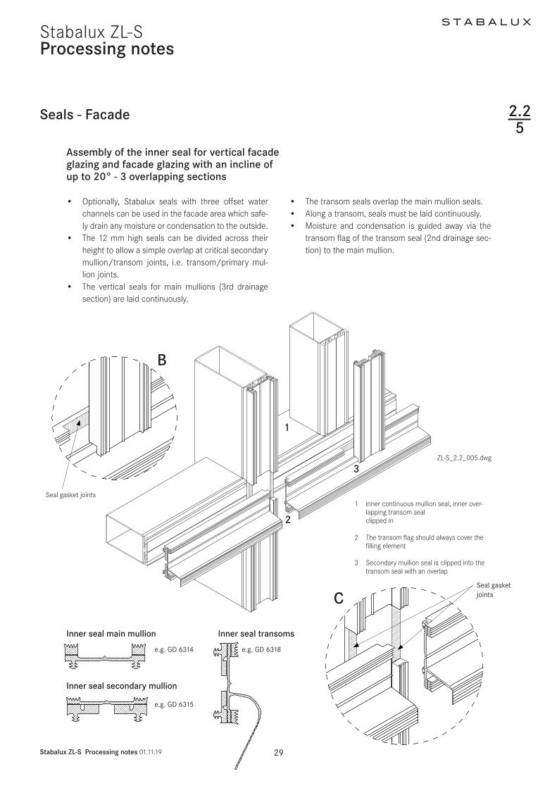
S T A B A L U X
Stabalux ZL-S Processing notes 011119 33
Stabalux ZL-S
Assembly of the outer seal for facade glaz-ing with an inwards incline of 20deg
bull If the facade is inclined inwards from the vertical (max permitted incline 20deg) the open ends of the outer transom seals must be closed up using butyl
bull When constructing inwardly inclined facades (up to max 20deg) if flat cover profiles are used in the transoms (eg DL 5059 DL 6059 DL 5061 DL 6061 DL 5067 DL 6067 DL 5071 DL 6071 DL 6043 DL 6044) and flat lower and upper strips (eg UL 6005 with OL 6066) then the central hollows at each end must be sealed with silicone
Processing notes
The open end of the transom sealin inwardly inclined facades(up to max 20deg) must be sealed using butyl
When using flat cover profiles on inwardly inclined facades (up to max 20deg) the central hollow at each end should be sealed with silicone
Trim the seals to be slightly larger than required
ZL-S_22005dwg
Seals - Facade 225
2
S T A B A L U X
Stabalux ZL-S Processing notes 011119 34
Stabalux ZL-SProcessing notes
Seals - roof
Assembly of the inner seal for roof glazing
bull Optionally Stabalux seals with offset water channels can be used in the facade area which safely drain any moisture or condensation to the outside
bull The 10 mm high seals can be divided across their height to allow a simple overlap at critical transom joints
bull The transom seals are geometrically shaped so as to create a condensation channel
bull This channel drains from the overlapping transom joint in the rafters
bull Along a transom seals must be laid continuouslybull All joints must be sealed Before laying transom
seals we recommend applying a thin coating to the entire support surfaces Absolutely no unevenness in the glass support surface must occur from apply-ing sealant too thickly
ZL-S_22_008dwg
1 remove the lower perforated part and the clamping foot on
the transom seal at around 15 mm
2 remove the upper perforated part on the rafter seal
3 Length of transom seal = transom length + ~13 mm per side
Seal gasket joints
1
3
226
S T A B A L U X
Stabalux ZL-S Processing notes 011119 35
Stabalux ZL-S
Seals - roof
Processing notes
Assembly of the outer seal for for glazed roofing
bull These are laid in fundamentally the same way as for vertical glazing Split seals such as GD 1932 are not suitable for transom seals in roofs Split seals can only be installed in mullions in combination with slab insulation Each installation situation will differ to some degree and always check how well sealed it is
bull For cross joints we recommend using our self-adhe-sive stainless steel sealing plates with butyl coating Z 0601 for System 60 and Z 0501 for System 50 The stainless steel sealing plates are 35 mm wide and are attached to the edge of the glass panes parallel to the mullion axis
bull Butyl tape is not suitable as a sealing tape between the glass and the outer seal
bull The outer mullion seals are laid continuously and the transom seals are joined
bull Sealant joints are to be laid flat with a slight excess in dimensions Exact specifications depends on the situation in which the system is used
Notebull Horizontal clamping strips prevent the free run off of
rain water and dirtbull Cover strips and upper strips with angled edges re-
duce the build up of water in front of the clamping strip
bull Shorten the clamping strips on the transoms by 5 mm in the area of the transom joins in order to improve drainage of water Gasket joints however are to be laid flat with a slight excess in dimensions Open ends of transom clamping strips (upper and cover profiles) should be sealed
Detail of sealing plate Z 0501 = 35 x 40 mm Z 0601 = 35 x 50 mm
AttentionThe sealing plates must be glued central to the transom axis
For glass insets of 15 mm the first screw fittings for the transom cover strip begin 30 mm from the end of the cover strip
ZL-S_22_009dwg
226
S T A B A L U X
Stabalux ZL-S Processing notes 011119 36
Stabalux ZL-SProcessing notes
Seals - roof
Assembly of the outer seal for for inclined glazed roofing up to 2deg
bull These are laid in fundamentally the same way as for vertical glazing Split seals around the mullions in roofs such as GD 1932 are only suitable when us-ing in combination with slab insulation Each installation situation will differ to some degree and always check how well sealed it is
bull To ensure free run-off of rain water and dirt on roofs inclined up to 2deg we recommend not using clamping strips in the transoms
bull Instead the rebate spaces should be sealed with all-weather silicone
bull Implementation of the outer sealing section around mullions is done in the same way as conventional roofs with an inclination up to 15deg
Tips for all roof designs
When using aluminium cover profiles on roofs take ac-count of the expansion factor as a result of the high de-gree of heat absorption when selecting the length to use Equally the use of single-piece cover profiles should be carefully considered In this case it is recommended that holes for screwing on the cover strip are created with a diameter of d = 9 mm (see section 221 - Material information)For wide spans we recommend using concealed screw
bull At the high point or ridge area of the inclined glazing it is recommended to also install and outer sealing section in the transoms with clamping strips
bull Only certified sealing materials may be used for seal-ing the transom rebate space
bull Pay attention to all information provided by the manufacturer and the sealing work must be carried out by trained persons It is recommended that a li-censed and certified specialist contractor is hired for this purpose We further refer you to the DIN 52460 standard and IVD data sheets (Trade Association for Sealants)
ZL-S_22_009dwg
fittings when selecting the clamping strips (lower + up-per strip) This is the preferred option for rafters Unused holes in the lower strip must be sealedSome roof areas such as the eaves see the use of sev-eral different materials (glass silicone aluminium sheets ) each with different expansion coefficients To avoid the formation of cracks aluminium sheets should be in-stalled with expansion joints
226
ZL-S_22_009-4
Stabalux ZL-S
ZL-S_22_009-4
Stabalux ZL-S
4 4
S T A B A L U X
Stabalux ZL-S Processing notes 011119 37
Stabalux ZL-S
Seals - roof
Processing notes
Assembly of the outer seal for glazed roofing up to 2deg incline
bull The compatibility of the materials is particularly important when using all-weather silicone In this case the compatibility of the sealant with the edge bonding of the glass and the backfill of the joints If self-cleaning glass is used the compatibility must be established in advance
bull Glass sealants and edge bonding must be UV-resist-ant The incline of roofs should also be taken into account Information about UV-resistance can be requested from the manufacturer Silicone bonding generally provides better UV-resistance than poly-sulfide-based edge bonding The advantage of sili-cone lies in its high vapour sealing properties which is particularly useful when using more volatile argon fillings
Angled glazing transom up to 2deg inclination with all-weather silicone and round rope seal
Angled glazing transom up to 2deg inclinationwith all-weather silicone and insulation block
bull Highly elastic weatherproof and UV-resistant seals meet the widest range of demands for reliable joints
bull If the silicone joint is created without additional me-chanical safety devices ensure that the glass is sup-ported from two sides only Selective installation of holding clamps can be used to provide support for all glass edges
bull The clamps are made from stainless steal with sil-icone washers and are screwed in the same as pressure strips The hold-down clamp should be ad-ditionally sealed around the perimeter with silicone sealant The design is based upon the dimensions of the glass as documented in the glass static analysis
1 Hold-down clamp
2 Silicone washer
3 Silicone sealant seal around the
clamp
4 All weather silicone seal
51 Round section rope seal
1 19 9
3 3
6 6
7 7
8 8
10 10
2 2
52 Insulation block
6 Glass filling element
7 Inner seal 10 mm transom
8 Spacer strip
9 System screw fittings
10 Support profile
ZL-S_22_009dwg
226
51 52
S T A B A L U X
Stabalux ZL-S Processing notes 011119 38
Stabalux ZL-SProcessing notes
Seals - roof
Assembly of the outer seal for glazed roofing up to 2deg incline
bull The joint width and the joint height for Stabalux SR are defined as w x h = 20 mm x 10 mm These measurements should always checked when selecting the sealing material and adapted if neces-sary Generally w h = 2 1 to 35 1
bull PE round section seals or Stabalux slab insulation is suitable as a back fill material
bull Silicone sealant should be applied before laying the mullion seals and cover profiles
bull After the specified setting time the seals and screw fittings can be installed in the areas around mullions
bull The mullion-transom joints around the clamps are then sealed
bull Before applying this second layer the joints around transoms must have completely set
Rafters with clamping strips
Transom with clamp all-weather silicone seal and
round rope seal
Transom with clamp all-weather silicone and
insulation block
Joint design according to manufacturers specificationsGenerally w h = 2 1 ndash 35 1
Transom with all-weather silicone and round section rope seal
ZL-S_22_009dwg
226
S T A B A L U X
Stabalux ZL-S Processing notes 011119 39
Stabalux ZL-S
Seals - roof
Processing notes
Steps for creating the seal with all-weather silicone
bull Test the silicone sealant and glass edge bond-ings and other contact surfaces (eg panels) for suitability
bull Clean edge bonding adhesive impurities from the surfaces to which sealant will be applied following manufacturerrsquos directions
bull Fill the joints as per the joint dimensions using only non-water absorbent closed-cell PE profiles (no damage to the edge bonding)
bull The remaining space in the glass rebate must be large enough that the pressure is able to equalise and a drainage level is available
bull Clean any impurities from the surfaces to which the sealing material is to be applied and any adjacent surfaces according to manufacturerrsquos directions
bull Be particularly aware of any adjacent metal compo-nents Prime according to manufacturerrsquos directions
bull Seal joints without leaving any cavities or bubbles Mask any adjacent components in advance where necessary
bull Smooth out the filled joints using the manufactur-errsquos smoothing agents and conventional tools with as little water as possible Remove the adhesive tape when liquid
bull If two or more reactive sealants are used in combina-tion the first must completely set before the second is applied
System screw fittings
Hold-down clamp
Washer made from silicone
Silicone sealant seal around the clamp
All weather silicone seal
Silicone sealant
Rafter
Transom
ZL-S_22_009dwg
226
S T A B A L U X
Stabalux ZL-S Processing notes 011119 40
Stabalux ZL-SProcessing notes
Glass inset and glass support 227
RebateGlass inset
ZL-S_22_010dwg
Glass inset
bull Glass industry guidelines must be observedbull The glass inset is generally 15 mmbull An increase in the glass inset to 20 mm has a bene-
ficial effect on the heat transfer coefficient Uf of the frame structure
S T A B A L U X
Stabalux ZL-S Processing notes 011119 41
Stabalux ZL-SProcessing notes
Glass inset and glass support
Glass support types and selection of glass support
Glass supports carry the load of the glass panes through to the structure The permissible glass weights also depend on the structure of the glass and the selected mullion-transom connection The mullion-transom con-nection must be selected in such a way as to minimise any subsequent turning of the transoms The depth of the glass supports is determined by the glass structure Section 9 contains more information in this respect
The Stabalux ZL-S system distinguishes between two dif-ferent types and techniques for attaching glass supports
bull Glass support GH 5053 ie GH 5055 with 2 or 3 welding studs empty 10 mm
bull Heavy glass loads require welded glass supports For this purpose flat sheets with a thickness of t = 5 mm are welded on to the transoms
Mounting the glass supports
bull Positioning the glass supports and glazing according to glass industry guidelines and guidelines of the In-stitute for Window Technology
bull The weight of the glass panes is distributed via the glass supports attached to the transoms
bull Glass supports should be attached at an interval of 100 mm from the end of the transom When doing so avoid a collision with the cover strip screw fittings at the end of the transom
Glazing blocks
bull Glazing blocks must be compatible with the edge bonding of the insulated glass panes
bull They should be stable under constant pressure and be able to withstand loads aging and temperature changes
bull It is important that the blocks ensure circumferential pressure equalisation and that drainage of conden-sation is not obstructed as well as allowing the glass edges to be offset and small design tolerances to be accommodated
bull If the length of the glass support is more than 100 mm blocks should be placed along the entire length of the glass support to ensure equal load distribu-tion
227
Positioning the glass support approx 100 mm from the end of the transom
ZL-S_22_010dwg
S T A B A L U X
Stabalux ZL-S Processing notes 011119 42
Stabalux ZL-SProcessing notes
Glass inset and glass support
Glass support GH 5053 with bolts
bull The glass support consists of the Stabalux system component GH 5053 and 2 welding studs empty10 mm which must be made available on the building site
bull The glass supports GH 5073 are manufactured using aluminium in EN AW 6060 quality condition T66
bull The depth of the glass supports depends on the in-stalled thickness of the glass panes and the geome-try of the inner seal The require cuts are delivered to match glass support GH 5053
bull The bolts must be sufficiently protected against cor-rosion and be suitable for weld connections with the steel grade of the supporting structure Stainless steel bolts must be used otherwise
bull The length of the bolts is calculated based on the installed thickness of the glass panes plus the height of the inner seal and the height of the spacer strip
bull The centre distance between the bolts is 80 mm
bull The bolts must be welded in the centre of the tran-som in the substructure to disperse the load from the glass Screw fittings must be positioned vertical-ly to the transom
bull The spacer strip should also be pre-drilled with empty 11 mm holes at the relevant points to attach the bolts
bull Holes must be made at the relevant points of the transom seal Here it is important to ensure that the holes have as precise a fit as possible We recom-mend sealing the holes with Stabalux Z 0094 paste
bull The glass supports are mounted loosely on the build-ing site once the spacer strip and the inner sealing section have been fitted
bull Blocks must be placed under the glass panes along the entire length of the glass supports
bull It is essential to ensure when installing the glazing that neither the glazing blocks nor the glass supports slip
bull The glass supports (bolts) must be validated for the glass thickness the glass weight and the selected mullion-transom connection
227
S T A B A L U X
Stabalux ZL-S Processing notes 011119 43
Stabalux ZL-S
Glass support GH 5053 Attachment with welding studs
Processing notes
Glass inset and glass support
Glass support GH 5053 with bolts
ZL-S_22_010dwg
A-A
Glass support GH 5053
Block Bolts empty 10 mm
Glass support
Bolt
Inner seal
Spacer strip
227
S T A B A L U X
Stabalux ZL-S Processing notes 011119 44
Stabalux ZL-SProcessing notes
Glass inset and glass support
Glass support GH 5055 with bolts
bull The glass support consists of the Stabalux system component GH 5055 and 3 welding studs empty10 mm which must be made available on the building site
bull The glass supports GH 5055 are manufactured using aluminium in EN AW 6060 quality condition T66
bull The depth of the glass supports depends on the in-stalled thickness of the glass panes and the geome-try of the inner seal The require cuts are delivered to match glass support GH 5055
ZL-S_22_010dwg
Glass support GH 5055 Attachment with welding studs
227
bull The bolts must be sufficiently protected against cor-rosion and be suitable for weld connections with the steel grade of the supporting structure Stainless steel bolts must be used otherwise
bull The length of the bolts is calculated based on the installed thickness of the glass panes plus the height of the inner seal and the height of the spacer strip
bull Installation is performed the same way as GH 5053 but using three screws at intervals of 80 mm
A-AGlass support GH 5055
Block Bolt empty 10 mm
Glass support
Bolt
Inner seal
Spacer strip
S T A B A L U X
Stabalux ZL-S Processing notes 011119 45
Stabalux ZL-SProcessing notes
227
Glass inset and glass support
RowTotal glass thickness tGlass (mm)
for vertical glazingGlass supports 1)
GH 5053 GH 5055 Depth (mm)1 4 5 6 7 GH 0081 Section 9
2 8 9 Section Section 12
3 10 11 Section Section 144 12 13 Section Section 165 14 15 Section Section 186 16 17 Section Section 207 18 19 Section Section 228 20 21 GH 0082 Section 249 22 23 GH 0083 GH 0851 2610 24 25 GH 0084 GH 0852 2811 26 27 GH 0085 GH 0853 3012 28 29 30 GH 0886 GH 0854 3213 31 32 33 GH 0887 GH 0855 3514 34 35 36 GH 0888 GH 0856 3815 37 38 39 GH 0889 GH 0857 4116 40 41 42 GH 0890 GH 0858 4417 43 44 GH 0891 GH 0859 47
Classification of system components
Table 1 Vertical glazing | System 50 60 80 | threaded bolt
1) Cut from GH 5053 or GH 5055
S T A B A L U X
Stabalux ZL-S Processing notes 011119 46
Stabalux ZL-SProcessing notes
227
Glass inset and glass support
RowTotal glass thickness tGlass (mm)
for inclined glazing 1)
Glass supports 2)
GH 5053 GH 5055 Depth (mm)1 24 25 26 Section Section 18
2 27 28 Section Section 20
3 29 30 Section Section 224 31 32 GH 0082 Section 245 33 34 GH 0083 GH 0851 26
Classification of system components
Table 2 Inclined glazing | System 50 60 80 | Threaded bolts
1) Accounting for a 10 mm inner seal
2) Cut from GH 5053 or GH 5055
Glass support GH 5053
Glass support GH 5055
TI-H_92_005dwg
S T A B A L U X
Stabalux ZL-S Processing notes 011119 47
Stabalux ZL-SProcessing notes
Glass inset and glass support
Welded glass support
bull Welded glass supports made of flat steel that are welded on to the transom profiles The glass sup-ports must be made available on the building site
bull Flat steel in grade S235 ie matched with the qual-ity of the supporting construction It must be possi-ble to weld the steel grades together The weld seam must connect the entire cross section of the glass supports
bull The glass supports must be sufficiently protected against corrosion
bull The depth of the glass supports depends on the in-stalled thickness of the glass panes the geometry of the inner seal and the height of the spacer strip
bull The glass supports must be welded in the centre of the transom in the substructure to disperse the load from the glass The glass supports must be posi-tioned vertically to the transom
227
bull The spacer strip must be cut out at the relevant points so as to ensure that the glass support and the weld seam cannot collide
bull The transom seals must be cut out around the holes for the glass supports and then sealed using Stabalux connection paste Z 0094
bull Blocks must be placed under the glass panes along the entire length of the glass supports
bull It is essential to ensure when installing the glazing that the glazing blocks cannot slip
bull The width of the glass supports is at least 100 mm their size must suit the static requirements
bull The glass supports must be validated for the glass thickness the glass weights and the selected mul-lion-transom connection
S T A B A L U X
Stabalux ZL-S Processing notes 011119 48
Stabalux ZL-SProcessing notes
Glass inset and glass support
Welded glass support
Glass support
Width ldquoWrdquo
Block
Glass support
Block
Inner seal
Spacer strip
227
Match the thickness of the glass support with the glass thickness
Make the weld seam as even as possiblefully connect the cross sectionmould the spacer strip around the glass supports
Cut out the sealing around the holes for the glass supports and sealwith Stabalux connecting paste
1
2
3
ZL-S_22_010dwg
A-A
S T A B A L U X
Stabalux ZL-S Processing notes 011119 49
Stabalux ZL-SProcessing notes
Glass inset and glass support 227
Glass support GH 5055 with threaded bolt
bull The depth of the glass support must be matched with the thickness of the glass
T = depth of the glass supportT1 = height of the spacer stripT2 = height of the inner seal (eg 5 m 10 mm or 12 mm)T3 thickness of the glass pane
T = T1 + T2 + T3
ExampleSpacer strip T1 = 10 mmInner seal (eg GD 6030) T2 = 5 mmThickness of pane 6 16 6 T3 = 28 mm
T = 10 + 5 + 28 = 43 mm
Wid
th ldquo
Wrdquo
ZL-S_22_010dwg
S T A B A L U X
Stabalux ZL-S Processing notes 011119 50
Stabalux ZL-SProcessing notes
Screw fittings
Fastenings
bull The system screw fittings are a combination of basic room-side screw fittings a coupling using a threaded socket that allows thermal separation in the rebate and a flexible bolt-nut connection or screw connec-tion on the glazing side
Basic room-side screw fittings
bull The threaded bolts M6 can be used for the basic room-side screw fittings they are screwed into the threaded holes ie the threaded blind holes Weld-ing studs M6 can be used alternatively
bull The length of the threaded bolts depends on the height of the spacer strip the height of the inner seal and the material selected for the supporting struc-ture (mullion and transom profiles) ie the selected depth of the blind holes which must be ge 7 mm Grade 14301 A2 stainless steel bolts must be used
bull In most cases the selected welding studs should have a length of 25 mm and they must be made available on the building site The bolts must be suf-ficiently protected against corrosion and be suitable for weld connections with the steel grade of the sup-porting structure Stainless steel bolts must be used otherwise
Coupling with threaded socket
bull The threaded socket is delivered in a length of 25 mm and twisted tight on to the basic screw fittings without excessively compressing the inner seal The Stabalux threaded sockets can be delivered in stainless steel (art no Z 0029) or plastic (art no Z 0032)
Bolt nuts ie screw connections on the glazing side
bull The assembly consists of a threaded bolt and option-ally a sealing washer and a cap nut Screws accord-ing to DIN 6912 stainless steel 14301 A2 can be used alternatively
bull Screws in the Stabalux system are produced using stainless steel usually with the material number 14301 DIN EN 10088
228
bull The length of the bolts ie screws is variable and depends on the height of the spacer strip the height of the inner seal and thickness of the glass A suffi-cient screw depth in the threaded socket must be ensured
bull Threaded bolts in suitable lengths are available for all standard glass thicknesses The length of bolt re-quired can usually be determined using a table of figures The combination chosen for the clamp con-nection will depend on the specific situation
bull Depending on the type of screw fittings selected 2 and 4 mm vulcanised EPDM washers are available
bull The distance for screw fittings is variable The maxi-mum distance is a = 250 mm
bull The distance from the edge for the first screw fitting should generally be in the region of 30 mm le a le 80 mm The placement of the glass supports and the choice of mullion-transom connection should also be taken into account
bull The clamp connection is exclusively exposed to ten-sile forces The pressure strips are connected using Stabalux system components To determine the stress limit (maximum tensile force) and permitted tensile forces for the connection the terms defined in the relevant general building approval and the Eu-rocode 3 (DIN EN 1993-3) series of standards shall apply
bull Screw fittings are applied using a conventional elec-tric screwdriver with depth stop This guarantees uniform application of pressure The depth setting should be chosen so that when using 4 mm EPDM washers a washer compression of around 15 - 18 mm is achieved
S T A B A L U X
Stabalux ZL-S Processing notes 011119 51
Stabalux ZL-S
Concealed screw fittings
bull Assembly is facilitated by the selection of pre-drilled clamping strips (eg UL 5009-L and UL 6009-L slot 7 x 10 mm a = 125 mm) with clippable upper strips A round hole of d = 8 mm should be made in the remaining clamping strips The functionality of the clip procedure can be checked after the first cover profile has been pushed against the lower strip
Note
When using aluminium cover profiles on roofs take ac-count of the expansion factor as a result of the high de-gree of heat absorption and its impact on the selected length Equally the use of single-piece cover profiles should be carefully considered In this case it is recom-mended that holes for screwing on the clamping strip are created with a diameter of d = 9 mm
Processing notes
227
Screw fittings
Visible screw fittings
bull Cover strips should be drilled with a round hole of d = 8 mm
Note
(see Note on concealed screw fittings)
Visible recessed screw fittings
bull When creating visible recessed screw fittings a stepped bore is required The lower part of the cover strip should be drilled with a d = 7 mm diameter The upper part of the cover strip needs a d = 11 mm diameter for the screw head It is recommended to install a washer (PA washer eg Z 0033) with all screw fittings
S T A B A L U X
Stabalux ZL-S Processing notes 011119 52
Stabalux ZL-SProcessing notes
Screw fittings
Concealed screw fittings
1 cap nut M6 Z004321 4 mm sealing washer Z 008631 threaded bolt M6 eg Z 3532 threaded bolt M6 in the threaded hole eg Z 004041 threaded socket M6 eg Z 29
Visible screw fittings
1 cap nut M6 Z004321 4 mm sealing washer Z 008631 threaded bolt M6 eg Z 3542 threaded socket M6 eg Z 296 threaded welding stud M6
Visible recessed screw fittings
22 PA washer Z 003333 threaded bolt M6 in the threaded hole eg Z 4042 threaded socket M6 eg Z 325 internal hex screw M6 eg GD 6912
Fastenings
ZL-S_22_011dwg
228
eg Z 0043
eg Z 0029 eg Z 0029
eg Z 0086
eg Z 0086
Screw M6
eg Z 0033
eg Z 0035
eg Z 0040 Threaded welding stud M6
Diagram and item numbers are examples for System 60
The calculation is the same for system 50
S T A B A L U X
Stabalux ZL-S Processing notes 011119 53
Stabalux ZL-SProcessing notes
Screw fittings
Calculating the screw length
ZL-S_22_012dwg
228
System width 50 60 mm System width 80 mm
Attention
The calculation to determine screw lengths for the the calculation to determine screw lengths is
Glass thickness - 14 mm with facade seal (5 mm)Glass thickness - 9 mm with facade seal (10 mm)Glass thickness - 7 mm with facade seal (12 mm)
S T A B A L U X
Stabalux ZL-S Processing notes 011119 54
Stabalux ZL-SProcessing notes
Screw fittings
System screws for Stabalux ZL
Cap nut
Z 0043 Cap nut stainless steel M6
Sealing washers
Z 46 U washer stainless steel with 2 mm seal
Z 0086 U washer stainless steel with 4 mm seal
Threaded sockets
Z 0029 Threaded socket stainless steel
M6 x 25 mm
Z 0032 Threaded socket stainless steel
M6 x 25 mm
Threaded bolts
Z 0034 Threaded bolts stainless steel M6 x 20 mm
Z 0038 Threaded bolts stainless steel M6 x 25 mm
Z 0035 Threaded bolts stainless steel M6 x 30 mm
Z 0040 Threaded bolts stainless steel M6 x 35 mm
Z 0036 Threaded bolts stainless steel M6 x 40 mm
Z 0037 Threaded bolts stainless steel M6 x 50 mm
Z 0044 Threaded bolts stainless steel M6 x 60 mm
Z 0045 Threaded bolts stainless steel M6 x 75 mm
Z 0039 Threaded bolts stainless steel M6 x 90 mm
Z 0053 Threaded bolts stainless steel M6 x 100 mm
Z 0054 Threaded bolts stainless steel M6 x 120 mm
228
ZL-S_22_013dwg
Calculating the screw length
S T A B A L U X
Stabalux ZL-S Processing notes 011119 55
Stabalux ZL-SProcessing notes
Flat cover strip DL 5073 DL 6073
Tips for laying the cover strip DL 5073 DL 6073
We assume that this cover strip will be used with glass panes that are supported on two sides and the recessed screw head is concealed In this case a cylinder head screw with inner hex is to be used (eg M6 DIN 6912 stainless steel A2 with low head) When covering with a 2 mm cover plug Z 0089 a bore depth of 6 mm is cal-culated
Depending on the precision of the bore it should be de-cided on case by case basis if any slight changes to this depth are necessary The cover plug Z 0089 does not need to be glued in place but may be levelled using lev-elling compound
Coating the cover strip
Profile production (aluminium extrusion moulding) with different mass distribution is extremely difficult Length-wise shadow formation may result Resulting actions are to be taken with the agreement of the coater
Intersections
Due to the special shape of the strip (the material ex-tends into the rebate) there is no closed sealing section available at intersections We therefore recommend plac-ing particular attention to ensure tightness of the joints and fill will Stabalux connecting paste Z 0094
Glass supportsblocking
Special attention should be given to dimensional propor-tions Glass supports should be designed by the proces-sor depending on the glass thickness and weight (eg for welded glass supports)To support the outer pane a sufficiently large glazing block must be installed that can carry the load to safely ensure the glass load is distributed effectively
ZL-S_22_014dwgZL-S_22_013dwg
229
Cover plug Z 0089Screw eg M6 DIN 6912
ZL-S_22_015-1
Stabalux ZL-S
S T A B A L U X
Stabalux ZL-S Processing notes 011119 56
Stabalux ZL-SProcessing notes
Slab insulation
ZL-S_22_015dwg
Use of slab insulation
bull Using insulation blacks significantly reduces heat dissipation
bull The highly effective slab insulation has a permanent-ly adhesive HOT-MELT
bull Depending on the situation where they are used in-sulation blocks can be directly applied to the cover striplower strip or placed into the rebate over the screw fittings and pushed into position with the cov-er striplower strip The type of screw connection (bolt-socket-bolt) means that a groove must first be cut in the insulating block at the points of connec-tion
bull With system width 80 mm and a 40 mm rebate 2x 20 mm wide slab insulation blocks can be combined (40 mm wide insulation blocks available upon request)
Note
bull The use of slab insulation with cover profiles DL 5073 DL 6073 should be tested for each individual situation
bull 2-piece outer seals are always used with slab insula-tion blocks for example outer seal GD 1932
Insulation block Width (=rebate)
Height
Z 0605 insulation block 20 42 20 mm 42 mm glass thickness from 44 mm
Z 0606 insulation block 20 26 20 mm 26 mm glass thickness from 28 mm
Z 0607 insulation block 30 42 30 mm 42 mm glass thickness from 44 mm
Z 0608 insulation block 30 26 30 mm 26 mm glass thickness from 28 mm
Correctly position the transom flag when installing the insulation blocks
2210
Z 0607Insulation block 3042
Z 0608Insulation block 3026
Z 0605Insulation block 2042
Z 0606Insulation block 2026
Z 0605Insulation block 2042
GD 1932
GD 1932
GD 1932
GD 1932
GD 1932
GD 1932
Z 0606Insulation block 2026
S T A B A L U X
Stabalux ZL-S Processing notes 011119 57
Stabalux ZL-SProcessing notes
Slab insulation
Examples
ZL-S_22_015dwg
2210
S T A B A L U X
Stabalux ZL-S Design 011119 59
Stabalux ZL-S
Pane support variants
Design
Special design
Glass structures that partially refrain from using visible cover profiles are considered special designs
These designs do not conform to the intended uses of the system No guarantees are made for eg quality of seals durability and structural stability Responsibility here lies entirely with the company implementing the design
Based on our experience we recommend paying close at-tention to the points made on the following pages during planning and implementation
Cut A - A Cut C - C
Cut B - B Cut D - D
ZL-S_23_001dwg
Mullion-transom structure 2-sided cover strip
231
Mullion-transom structurewith transom cover profiles 1)
1) Seals with 1 2 or 3 sections are possible
2) Use of mullion seals with 1 section in mullions and transoms
Mullion-transom structurewith mullion cover profiles 2)
S T A B A L U X
Stabalux ZL-S Design 011119 60
Stabalux ZL-SDesign
Transom - design Mullion - design
ZL-S_23_001dwg
Pane support variants
Vapour seal
When using this type of structure it is important to be aware that any loss of contact pressure can affect the room-side permeability There is an increased risk of con-densation build up in the rebate
Vertical clamping strips
The glass supports should be placed to below the outer pane and sealed with it
Horizontal clamping strips
Ventilation and condensation drainage is achieved via a recess in the lower sealing lip in the centre of the outer seal or at one third intervals
Transom structure mullion structure 2-sided cover strip
Cut A - A Cut C - C
Cut B - B Cut D - D
231
S T A B A L U X
Stabalux ZL-S Design 011119 61
Stabalux ZL-SDesign
Design requirements
1 Vapour seal
The room-side level of glazing must have the best possi-ble vapour seal In this regard the vapour diffusion prop-erties of the silicone sealant to be used should be tested
Ensure that there are no permeable areas around con-cave cross joints
2 Rebate ventilation pressure equalisa-tion and condensation drainage
Systems with partially sealed rebate represent a limita-tion to rebate ventilation Check on a case-by-case basis that no damage will be caused by standing condensation It is especially critical that designs with sealed vertical joints are evaluated To allow ventilation of the horizontal rebate we recommend installing a suitable vertical ven-tilation space Alternatively ventilation can be achieved using the outer joints
3 Weatherproofing
The outward facing seals must be watertight In cross joints it is especially important to ensure a firm join be-tween the Stabalux profile seal and the silicone joints We recommend sealing up to the outer edge of the glass before mounting the cover profiles
We would like emphasise once again that our profile seals will not make a permanent bond with commonly used silicone sealants A seal can only be created at con-tact points through permanent application of pressure
4 Mechanical strength of the screw fittings
Ensure screw fittings are of a sufficiently size Special at-tention should be given to the effects of wind suction and the reduced support
5 Glass weight distribution
Mechanical distribution of the weight of the glass panes through the structure must be ensured System glass supports can be used for existing horizontal transoms Designs using ldquoonlyrdquo mullions require special glass sup-ports which carry the weight of the glass directly into the mullions
6 Glass sizing
Attention should be given to the reduced support of panes when dimensioning the glass For example only the vertical or horizontal cover profiles are effective in the event of wind suction stresses or stress on the fall protection
7 Material compatibility
Compatibility of the silicone sealants with our profile seal-ants and the edge bonding of the glass must be ensured We recommend the exclusive use of tested silicone seal-ants from the whole-glass facades sector Approval is usually given by the silicone manufacturer
Pane support variants
ZL-S_23_001dwg
231
Examples
S T A B A L U X
Stabalux ZL-S Design 011119 62
Stabalux ZL-S
System cross sections
Design
ZL-S_23_001dwg
1 Vertical glazing mullion
concealed screw fittings
2 Vertical glazing mullion
visible screw fittings
3 Vertical glazing mullion
flat cover strip DL 5073 DL 6073
4 Vertical glazing transom
visible recessed screw fittings
Outer seal for height compensation
5 Vertical glazing transom
concealed screw fittings
single glazing
6 Vertical glazing transom
concealed screw fittings
7 Inclined glazing mullion
concealed screw fittings
8 Inclined glazing transom
visible screw fittings
1 2
3 4
5 6
7 8
232
S T A B A L U X
Stabalux ZL-S Design 011119 63
Stabalux ZL-SDesign
System details
Creating facade corners
At exposed areas such as glass facade corners it is par-ticularly important to ensure sufficient heat insulation in order to avoid the creation of thermal bridges and pre-vent a build-up of condensation Thermal current calcula-tions provide information about the actual heat loss
Outer corner Inner corner
ZL-S_23_002dwg ZL-S_23_002dwg
Facade polygon
Special seal allow a polygon shaped arrangement of the facade mullions For convex glass surfaces an angle be-tween 3deg and 15deg can be freely chosen For concave glass surfaces the angle can vary between 3deg and 10deg
ZL-S_23_002dwg
Geometrically check the feasibility Recommendation Use System 60 at minimum
ATTENTIONAdhere to the minimum glass inset
Determine the threaded bolt length using consideration of the angle
233
S T A B A L U X
Stabalux ZL-S Design 011119 64
Stabalux ZL-SDesign
System details
Eaves with glass roof connection
bull Depending on the construction of the transoms a design with or without rain gutters and the choice of stepped glazing or closable cover profiles gives us different variants for implementation
bull All options require condensation and moisture to be drained away at the eaves
Design with stepped glazing
bull With a stepped glazing design it is important to select a UV-resistant edge bonding for the glass This edge bonding systems usually silicone-based are quite permeable to gases and are therefore unable to achieve the required high values for sound and heat insulation of conventional systems ie require additional sealing around the edges
Example 1
Design with stepped glazing
bull Our thermal calculations show that stepped glass panes compared to covered glass edges have a much less favourable isothermal movement
bull Stepped glass panes must also be statically meas-ured according to their reduced hold against wind suction
bull The additional thermal loads that occur in stepped glass panes should countered by the use of pre-ten-sioned glass (TVG ESG) for the outer panes
bull Stepped glass panes should be preferred for flatter inclined roofs as water can drain away at the eaves unhindered
ZL-S_23_003dwg
233
S T A B A L U X
Stabalux ZL-S Design 011119 65
Stabalux ZL-SDesign
Eaves with glass roof connection Design using cover profiles
bull Horizontal pressure strips prevent the free run off of rain water and dirt
bull Cover strips with angled edges reduce the build up of water in front of the cover strip
bull The outer sealing level on glass roofs must also be thoroughly sealed
bull In combination with our butyl clad stainless steel panels glazing with pressure strips on 4 sides achieves a higher level of safety
bull Make sure that the inner sealing section provides guaranteed drainage for condensation
bull To improve drainage and heat-induced expansion cover profiles should be shortened by 5 mm at tran-som joints Gasket joints however are to be laid flat with a slight excess in dimensions Open ends of the transom cover profiles must be sealed
Note
Due to the increased thermal stresses in the roof we rec-ommend using concealed screw fitting when choosing clamping strips for larger system lengths and in rafters Unused holes in the lower strip must be sealed
System details
Example 2
Design using cover profiles
ZL-S_23_004dwg
233
S T A B A L U X
Stabalux ZL-S Design 011119 66
Stabalux ZL-SDesign
System details
Eaves with glass roof connection Design with gutter
bull The gutter must be able to take its own weight and mounted in such a way that stresses from its own weight water and ice will not lead to deformations and directly apply a load to the glazing
bull Overflowing water must not be able to get inside the structure Alongside the gutter-shaped outer rafter seal the moisture barrier installed over the guide plate also acts to drain away condensation
Example 3
Design with gutter
ZL-S_23_005dwg
233
S T A B A L U X
Stabalux ZL-S Design 011119 67
Stabalux ZL-SDesign
System details
Roof ridge design
bull When designing the ridge cap ensure that the rafter cover profiles are pulled under the ridge cap
ZL-S_23_006dwg
233
S T A B A L U X
Stabalux ZL-S Design 011119 68
Stabalux ZL-S
Structural attachments
Design
Structural attachment film baffles
bull Attachment of glazing to the building structure re-quires a well thought out approach
bull Moisture damage can occur if moisture condenses at any thermal bridges
bull Thermal bridges must be avoided and warm air from the inside spaces must not penetrate too deeply into the structure
bull The required moisture barriers must be installed as deeply as possible into the inner space using imper-meable structural film baffles This prevents mois-ture penetration into the structure via condensation from the air inside
bull An additional foil to seal against rainwater must be permeable to moisture Only if this foil has a water vapour diffusion resistance value μ of max μ = 3000 can a dry structure be guaranteed in the transition zones
234
S T A B A L U X
Stabalux ZL-S Design 011119 69
Stabalux ZL-S
Structural attachments
Design
Facade base
bull Controlled drainage of the rebate space can only be ensured if the sealing sections overlap in such a way that no moisture can get under the seals and foils
bull Run foils under the transom seal to act as a moisture barrier and glue to the steel structure In accordance with DIN 18195 the seal should be run at least 150 mm above the water-guiding layer
bull Attach foil with moisture barrier in accordance with the requirements of DIN 18195
Example 1 Mounting intermediate mullion to base plate
Drainage of the base area is achieved via the transom flag towards the outside In this case the transom flag around the mullion at the base should not be released For edge mullions ensure there is a
corresponding seal placed (continuous transom seal up the to the end point) and a constructive design of the drainage section
ZL-S_23_007dwg
234
S T A B A L U X
Stabalux ZL-S Design 011119 70
Stabalux ZL-SDesign
Structural attachments
Facade base
bull Rebate space ventilation is achieved via the open end of the vertical cover profiles
bull Ensure the connection is impermeable to vapourbull Mullion mountings must be sufficiently statically di-
mensioned Required axis and edge distances for an-choring the base plates and in the building structure must be observed
Example 2 Mounting intermediate mullion to base plate
Where transom flags are interrupted by joints filler rods in the joint must also be cut
ZL-S_23_008dwg
234
S T A B A L U X
Stabalux ZL-S Design 011119 71
Stabalux ZL-SDesign
Structural attachments
Facade base
bull Heat insulation around the structural connection should be designed in such as way as to prevent cold bridges forming
bull Steel parts should also be provided with sufficient protection against corrosion even in concealed ar-eas
bull Weather-protection sheets should be used depend-ing on the requirements of the construction Suffi-cient rear ventilation must be ensured
Example 3 Attaching intermediate mullions at base plates
ZL-S_23_009dwg
234
ZL-S_23_010-2
Stabalux ZL-S
S T A B A L U X
Stabalux ZL-S Design 011119 72
Stabalux ZL-SDesign
Connection before intermediate floors
bull Depending on requirements mullions are designed as continuous multi-span transoms or separated at each floor
bull Reasons for separating mullions can include eg building settlement fire protection sound insulation etc
bull If the separation joint is intended to absorb expan-sion then as well as the required degree of freedom for mullions the ability for movement of integrated elements must also be ensured
Structural attachments
bull The constructive design of the mullion joint and mounting should be chosen according to the stat-ically calculated base system and determines the choice and arrangement of fixed and movable bear-ings type of screw fittings structural connection parts and attachment to the concrete floor
bull With continuous mullions and a corresponding mount the multi-span support principle is in effect Sagging due to horizontal effects is lower The required mo-ment of inertia reduces for 2-span supports with the same span length compared to the 1-span support by a factor of 0415 However a tension and stability analysis should be carried out
Example Mullions separated at each floor
In this example distribution of horizontal and vertical loads is achieved at each floor through the existing floor structure
ZL-S_23_010dwg
234
S T A B A L U X
Stabalux ZL-S Design 011119 73
Stabalux ZL-SDesign
Ceiling connection
bull Structural connections should take account of any movement that may occur
bull As well as temperature induced expansion in the fa-cade all longitudinal expansions and movements of the affected components must be considered
bull Additional stresses from restraints must be avoided
Structural attachments
ZL-S_23_011dwg
234
S T A B A L U X
Stabalux ZL-S Design 011119 74
Stabalux ZL-SDesign
Facade connection to parapets
Structural attachments
ZL-S_23_012dwg
234
S T A B A L U X
Stabalux ZL-S Design 011119 75
Stabalux ZL-SDesign
Connection to structural eaves
bull This connection is suitable for glass roofs that are being installed as skylights in the structure These may be gabled roofs single pitch roofs pyramids or arched roofs
Structural attachments
ZL-S_23_013dwg
234
S T A B A L U X
Stabalux ZL-S Design 011119 76
Stabalux ZL-SDesign
Ridge connection to walls
bull When making ridge connections to walls permea-bility to moisture is particularly important Warm air with a high level of moisture gets into cooler zones of the inner sealing section where the design is not sufficiently sealed and can cause structural damage from penetrating into the connecting structure
bull Joint seals made from butyl-clad stainless steel plates (Z 0501 Z 0601) must be installed on the out-side of joint areas
Structural attachments
ZL-S_23_014dwg
234
S T A B A L U X
Stabalux ZL-S Design 011119 77
Stabalux ZL-SDesign
Horizontal wall connection to heat insulation bonding system
Structural attachments
ZL-S_23_015dwg
234
Ceiling conection including WAREMA external blinds
Structural attachments
ZL-S_23_024dwg
234
S T A B A L U X
Stabalux ZL-S Design 011119 78
Stabalux ZL-S
S T A B A L U X
Stabalux ZL-S Design 011119 79
Stabalux ZL-SDesign
Installing windows and doors
Mullion and transom facades and glass roofs from Stabalux are neutral with regards to the selection of in-sert elements All commonly available window and door systems made from steel aluminium wood or plastic can be used Frame profiles from the window and door man-ufacturerrsquos should be selected to match the chosen glass thickness If no profiles with a suitable insert rebate are available mountings may be used as shown in the fol-lowing examples Like with glass elements windows are set into the facade on glass supports padded and then secured against slippage
Insert window transom sectionSystem HUECKSeries Lambda WS 075 IS
Use a locating screwas an assembly aid if necessary
Use
a lo
catin
g sc
rew
as a
n as
sem
bly
aid
if ne
cess
ary Insert window mullion section
System HUECKSeries Lambda WS 075 IS
ZL-S_23_01 dwg
235
S T A B A L U X
Stabalux ZL-S Design 011119 80
Stabalux ZL-SDesign
Installing windows and doors
ZL-S_23_017dwg
Insert window mullion sectionSystem HUECKSeries Lambda WS 075
Insert window transom sectionSystem HUECKSeries Lambda WS 075
235
Use a locating screwas an assembly aidif necessary
Use
a lo
catin
g sc
rew
as a
n as
sem
bly
aid
if ne
cess
ary
S T A B A L U X
Stabalux ZL-S Design 011119 81
Stabalux ZL-S
ZL-S_23_018dwg
Design
Installing windows and doors
Insert door outward in the mullion sectionSystem HUECKSeries Lambda DS 075
Insert door outward in the transom sectionSystem HUECKSeries Lambda DS 075
235
Use a locating screw as an assembly aid if necessary
Use
a lo
catin
g sc
rew
as a
n as
sem
bly
aid
if ne
cess
ary
S T A B A L U X
Stabalux ZL-S Design 011119 82
Stabalux ZL-SDesign
Installing windows and doors
Insert door inward in the mullion sectionSystem HUECKSeries Lambda DS 075
Insert door inward in the transom sectionSystem HUECKSeries Lambda DS 075
ZL-S_23_019dwg
235
Use a locating screwas an assembly aidif necessary
Use
a lo
catin
g sc
rew
as a
n as
sem
bly
aid
if ne
cess
ary
ZL-S_23_020dwg
Design
Installing windows and doors
Insert top-hung window in the mullion sectionSystem HUECKSeries Lambda 110
Insert top-hung window in the transom sectionSystem HUECKSeries Lambda 110
235
S T A B A L U X
Stabalux ZL-S Design 011119 83
Stabalux ZL-S
Design
Installing windows and doors
Sliding system in the mullion sectionSystem HUECKSeries Volato M
Sliding system in the transom sectionSystem HUECKSeries Volato M
ZL-S_23_021dwg
235
S T A B A L U X
Stabalux ZL-S Design 011119 84
Stabalux ZL-S
S T A B A L U X
Stabalux ZL-S Design 011119 85
Stabalux ZL-SDesign
Installing windows and doors
Flush roof surface windowSystem HUECK-HARTMANNSeries 85E
Connection at top
Connection at bottom
Powered accordingto system specifications
ZL-S_23_020dwg
235
S T A B A L U X
Stabalux ZL-S Design 011119 86
Stabalux ZL-SDesign
Installing windows and doors
Insert window - mullion sectionSystem HahnSeries Lamellae S9 iVt-05
Insert window - transom sectionsSystem HahnSeries Lamellae S9 iVt-05
ZL-S_23_021dwg
235
- Stabalux ZL-S
-
- System
-
- System properties
- System cross sections and inner seals - facade
- System cross sections and inner seals - roof
- Cover strips and outer seals
-
- Processing notes
-
- Material information
- Assembly sequence
- Attaching the spacer strip
- Tips for laying seals
- Seals - Facade
- Seals - roof
- Glass inset and glass support
- Screw fittings
- Flat cover strip DL 5073 DL 6073
- Slab insulation
-
- Design
-
- Pane support variants
- System cross sections
- System details
- Structural attachments
- Installing windows and doors
-

2
S T A B A L U X
Stabalux ZL-S Processing notes 011119 34
Stabalux ZL-SProcessing notes
Seals - roof
Assembly of the inner seal for roof glazing
bull Optionally Stabalux seals with offset water channels can be used in the facade area which safely drain any moisture or condensation to the outside
bull The 10 mm high seals can be divided across their height to allow a simple overlap at critical transom joints
bull The transom seals are geometrically shaped so as to create a condensation channel
bull This channel drains from the overlapping transom joint in the rafters
bull Along a transom seals must be laid continuouslybull All joints must be sealed Before laying transom
seals we recommend applying a thin coating to the entire support surfaces Absolutely no unevenness in the glass support surface must occur from apply-ing sealant too thickly
ZL-S_22_008dwg
1 remove the lower perforated part and the clamping foot on
the transom seal at around 15 mm
2 remove the upper perforated part on the rafter seal
3 Length of transom seal = transom length + ~13 mm per side
Seal gasket joints
1
3
226
S T A B A L U X
Stabalux ZL-S Processing notes 011119 35
Stabalux ZL-S
Seals - roof
Processing notes
Assembly of the outer seal for for glazed roofing
bull These are laid in fundamentally the same way as for vertical glazing Split seals such as GD 1932 are not suitable for transom seals in roofs Split seals can only be installed in mullions in combination with slab insulation Each installation situation will differ to some degree and always check how well sealed it is
bull For cross joints we recommend using our self-adhe-sive stainless steel sealing plates with butyl coating Z 0601 for System 60 and Z 0501 for System 50 The stainless steel sealing plates are 35 mm wide and are attached to the edge of the glass panes parallel to the mullion axis
bull Butyl tape is not suitable as a sealing tape between the glass and the outer seal
bull The outer mullion seals are laid continuously and the transom seals are joined
bull Sealant joints are to be laid flat with a slight excess in dimensions Exact specifications depends on the situation in which the system is used
Notebull Horizontal clamping strips prevent the free run off of
rain water and dirtbull Cover strips and upper strips with angled edges re-
duce the build up of water in front of the clamping strip
bull Shorten the clamping strips on the transoms by 5 mm in the area of the transom joins in order to improve drainage of water Gasket joints however are to be laid flat with a slight excess in dimensions Open ends of transom clamping strips (upper and cover profiles) should be sealed
Detail of sealing plate Z 0501 = 35 x 40 mm Z 0601 = 35 x 50 mm
AttentionThe sealing plates must be glued central to the transom axis
For glass insets of 15 mm the first screw fittings for the transom cover strip begin 30 mm from the end of the cover strip
ZL-S_22_009dwg
226
S T A B A L U X
Stabalux ZL-S Processing notes 011119 36
Stabalux ZL-SProcessing notes
Seals - roof
Assembly of the outer seal for for inclined glazed roofing up to 2deg
bull These are laid in fundamentally the same way as for vertical glazing Split seals around the mullions in roofs such as GD 1932 are only suitable when us-ing in combination with slab insulation Each installation situation will differ to some degree and always check how well sealed it is
bull To ensure free run-off of rain water and dirt on roofs inclined up to 2deg we recommend not using clamping strips in the transoms
bull Instead the rebate spaces should be sealed with all-weather silicone
bull Implementation of the outer sealing section around mullions is done in the same way as conventional roofs with an inclination up to 15deg
Tips for all roof designs
When using aluminium cover profiles on roofs take ac-count of the expansion factor as a result of the high de-gree of heat absorption when selecting the length to use Equally the use of single-piece cover profiles should be carefully considered In this case it is recommended that holes for screwing on the cover strip are created with a diameter of d = 9 mm (see section 221 - Material information)For wide spans we recommend using concealed screw
bull At the high point or ridge area of the inclined glazing it is recommended to also install and outer sealing section in the transoms with clamping strips
bull Only certified sealing materials may be used for seal-ing the transom rebate space
bull Pay attention to all information provided by the manufacturer and the sealing work must be carried out by trained persons It is recommended that a li-censed and certified specialist contractor is hired for this purpose We further refer you to the DIN 52460 standard and IVD data sheets (Trade Association for Sealants)
ZL-S_22_009dwg
fittings when selecting the clamping strips (lower + up-per strip) This is the preferred option for rafters Unused holes in the lower strip must be sealedSome roof areas such as the eaves see the use of sev-eral different materials (glass silicone aluminium sheets ) each with different expansion coefficients To avoid the formation of cracks aluminium sheets should be in-stalled with expansion joints
226
ZL-S_22_009-4
Stabalux ZL-S
ZL-S_22_009-4
Stabalux ZL-S
4 4
S T A B A L U X
Stabalux ZL-S Processing notes 011119 37
Stabalux ZL-S
Seals - roof
Processing notes
Assembly of the outer seal for glazed roofing up to 2deg incline
bull The compatibility of the materials is particularly important when using all-weather silicone In this case the compatibility of the sealant with the edge bonding of the glass and the backfill of the joints If self-cleaning glass is used the compatibility must be established in advance
bull Glass sealants and edge bonding must be UV-resist-ant The incline of roofs should also be taken into account Information about UV-resistance can be requested from the manufacturer Silicone bonding generally provides better UV-resistance than poly-sulfide-based edge bonding The advantage of sili-cone lies in its high vapour sealing properties which is particularly useful when using more volatile argon fillings
Angled glazing transom up to 2deg inclination with all-weather silicone and round rope seal
Angled glazing transom up to 2deg inclinationwith all-weather silicone and insulation block
bull Highly elastic weatherproof and UV-resistant seals meet the widest range of demands for reliable joints
bull If the silicone joint is created without additional me-chanical safety devices ensure that the glass is sup-ported from two sides only Selective installation of holding clamps can be used to provide support for all glass edges
bull The clamps are made from stainless steal with sil-icone washers and are screwed in the same as pressure strips The hold-down clamp should be ad-ditionally sealed around the perimeter with silicone sealant The design is based upon the dimensions of the glass as documented in the glass static analysis
1 Hold-down clamp
2 Silicone washer
3 Silicone sealant seal around the
clamp
4 All weather silicone seal
51 Round section rope seal
1 19 9
3 3
6 6
7 7
8 8
10 10
2 2
52 Insulation block
6 Glass filling element
7 Inner seal 10 mm transom
8 Spacer strip
9 System screw fittings
10 Support profile
ZL-S_22_009dwg
226
51 52
S T A B A L U X
Stabalux ZL-S Processing notes 011119 38
Stabalux ZL-SProcessing notes
Seals - roof
Assembly of the outer seal for glazed roofing up to 2deg incline
bull The joint width and the joint height for Stabalux SR are defined as w x h = 20 mm x 10 mm These measurements should always checked when selecting the sealing material and adapted if neces-sary Generally w h = 2 1 to 35 1
bull PE round section seals or Stabalux slab insulation is suitable as a back fill material
bull Silicone sealant should be applied before laying the mullion seals and cover profiles
bull After the specified setting time the seals and screw fittings can be installed in the areas around mullions
bull The mullion-transom joints around the clamps are then sealed
bull Before applying this second layer the joints around transoms must have completely set
Rafters with clamping strips
Transom with clamp all-weather silicone seal and
round rope seal
Transom with clamp all-weather silicone and
insulation block
Joint design according to manufacturers specificationsGenerally w h = 2 1 ndash 35 1
Transom with all-weather silicone and round section rope seal
ZL-S_22_009dwg
226
S T A B A L U X
Stabalux ZL-S Processing notes 011119 39
Stabalux ZL-S
Seals - roof
Processing notes
Steps for creating the seal with all-weather silicone
bull Test the silicone sealant and glass edge bond-ings and other contact surfaces (eg panels) for suitability
bull Clean edge bonding adhesive impurities from the surfaces to which sealant will be applied following manufacturerrsquos directions
bull Fill the joints as per the joint dimensions using only non-water absorbent closed-cell PE profiles (no damage to the edge bonding)
bull The remaining space in the glass rebate must be large enough that the pressure is able to equalise and a drainage level is available
bull Clean any impurities from the surfaces to which the sealing material is to be applied and any adjacent surfaces according to manufacturerrsquos directions
bull Be particularly aware of any adjacent metal compo-nents Prime according to manufacturerrsquos directions
bull Seal joints without leaving any cavities or bubbles Mask any adjacent components in advance where necessary
bull Smooth out the filled joints using the manufactur-errsquos smoothing agents and conventional tools with as little water as possible Remove the adhesive tape when liquid
bull If two or more reactive sealants are used in combina-tion the first must completely set before the second is applied
System screw fittings
Hold-down clamp
Washer made from silicone
Silicone sealant seal around the clamp
All weather silicone seal
Silicone sealant
Rafter
Transom
ZL-S_22_009dwg
226
S T A B A L U X
Stabalux ZL-S Processing notes 011119 40
Stabalux ZL-SProcessing notes
Glass inset and glass support 227
RebateGlass inset
ZL-S_22_010dwg
Glass inset
bull Glass industry guidelines must be observedbull The glass inset is generally 15 mmbull An increase in the glass inset to 20 mm has a bene-
ficial effect on the heat transfer coefficient Uf of the frame structure
S T A B A L U X
Stabalux ZL-S Processing notes 011119 41
Stabalux ZL-SProcessing notes
Glass inset and glass support
Glass support types and selection of glass support
Glass supports carry the load of the glass panes through to the structure The permissible glass weights also depend on the structure of the glass and the selected mullion-transom connection The mullion-transom con-nection must be selected in such a way as to minimise any subsequent turning of the transoms The depth of the glass supports is determined by the glass structure Section 9 contains more information in this respect
The Stabalux ZL-S system distinguishes between two dif-ferent types and techniques for attaching glass supports
bull Glass support GH 5053 ie GH 5055 with 2 or 3 welding studs empty 10 mm
bull Heavy glass loads require welded glass supports For this purpose flat sheets with a thickness of t = 5 mm are welded on to the transoms
Mounting the glass supports
bull Positioning the glass supports and glazing according to glass industry guidelines and guidelines of the In-stitute for Window Technology
bull The weight of the glass panes is distributed via the glass supports attached to the transoms
bull Glass supports should be attached at an interval of 100 mm from the end of the transom When doing so avoid a collision with the cover strip screw fittings at the end of the transom
Glazing blocks
bull Glazing blocks must be compatible with the edge bonding of the insulated glass panes
bull They should be stable under constant pressure and be able to withstand loads aging and temperature changes
bull It is important that the blocks ensure circumferential pressure equalisation and that drainage of conden-sation is not obstructed as well as allowing the glass edges to be offset and small design tolerances to be accommodated
bull If the length of the glass support is more than 100 mm blocks should be placed along the entire length of the glass support to ensure equal load distribu-tion
227
Positioning the glass support approx 100 mm from the end of the transom
ZL-S_22_010dwg
S T A B A L U X
Stabalux ZL-S Processing notes 011119 42
Stabalux ZL-SProcessing notes
Glass inset and glass support
Glass support GH 5053 with bolts
bull The glass support consists of the Stabalux system component GH 5053 and 2 welding studs empty10 mm which must be made available on the building site
bull The glass supports GH 5073 are manufactured using aluminium in EN AW 6060 quality condition T66
bull The depth of the glass supports depends on the in-stalled thickness of the glass panes and the geome-try of the inner seal The require cuts are delivered to match glass support GH 5053
bull The bolts must be sufficiently protected against cor-rosion and be suitable for weld connections with the steel grade of the supporting structure Stainless steel bolts must be used otherwise
bull The length of the bolts is calculated based on the installed thickness of the glass panes plus the height of the inner seal and the height of the spacer strip
bull The centre distance between the bolts is 80 mm
bull The bolts must be welded in the centre of the tran-som in the substructure to disperse the load from the glass Screw fittings must be positioned vertical-ly to the transom
bull The spacer strip should also be pre-drilled with empty 11 mm holes at the relevant points to attach the bolts
bull Holes must be made at the relevant points of the transom seal Here it is important to ensure that the holes have as precise a fit as possible We recom-mend sealing the holes with Stabalux Z 0094 paste
bull The glass supports are mounted loosely on the build-ing site once the spacer strip and the inner sealing section have been fitted
bull Blocks must be placed under the glass panes along the entire length of the glass supports
bull It is essential to ensure when installing the glazing that neither the glazing blocks nor the glass supports slip
bull The glass supports (bolts) must be validated for the glass thickness the glass weight and the selected mullion-transom connection
227
S T A B A L U X
Stabalux ZL-S Processing notes 011119 43
Stabalux ZL-S
Glass support GH 5053 Attachment with welding studs
Processing notes
Glass inset and glass support
Glass support GH 5053 with bolts
ZL-S_22_010dwg
A-A
Glass support GH 5053
Block Bolts empty 10 mm
Glass support
Bolt
Inner seal
Spacer strip
227
S T A B A L U X
Stabalux ZL-S Processing notes 011119 44
Stabalux ZL-SProcessing notes
Glass inset and glass support
Glass support GH 5055 with bolts
bull The glass support consists of the Stabalux system component GH 5055 and 3 welding studs empty10 mm which must be made available on the building site
bull The glass supports GH 5055 are manufactured using aluminium in EN AW 6060 quality condition T66
bull The depth of the glass supports depends on the in-stalled thickness of the glass panes and the geome-try of the inner seal The require cuts are delivered to match glass support GH 5055
ZL-S_22_010dwg
Glass support GH 5055 Attachment with welding studs
227
bull The bolts must be sufficiently protected against cor-rosion and be suitable for weld connections with the steel grade of the supporting structure Stainless steel bolts must be used otherwise
bull The length of the bolts is calculated based on the installed thickness of the glass panes plus the height of the inner seal and the height of the spacer strip
bull Installation is performed the same way as GH 5053 but using three screws at intervals of 80 mm
A-AGlass support GH 5055
Block Bolt empty 10 mm
Glass support
Bolt
Inner seal
Spacer strip
S T A B A L U X
Stabalux ZL-S Processing notes 011119 45
Stabalux ZL-SProcessing notes
227
Glass inset and glass support
RowTotal glass thickness tGlass (mm)
for vertical glazingGlass supports 1)
GH 5053 GH 5055 Depth (mm)1 4 5 6 7 GH 0081 Section 9
2 8 9 Section Section 12
3 10 11 Section Section 144 12 13 Section Section 165 14 15 Section Section 186 16 17 Section Section 207 18 19 Section Section 228 20 21 GH 0082 Section 249 22 23 GH 0083 GH 0851 2610 24 25 GH 0084 GH 0852 2811 26 27 GH 0085 GH 0853 3012 28 29 30 GH 0886 GH 0854 3213 31 32 33 GH 0887 GH 0855 3514 34 35 36 GH 0888 GH 0856 3815 37 38 39 GH 0889 GH 0857 4116 40 41 42 GH 0890 GH 0858 4417 43 44 GH 0891 GH 0859 47
Classification of system components
Table 1 Vertical glazing | System 50 60 80 | threaded bolt
1) Cut from GH 5053 or GH 5055
S T A B A L U X
Stabalux ZL-S Processing notes 011119 46
Stabalux ZL-SProcessing notes
227
Glass inset and glass support
RowTotal glass thickness tGlass (mm)
for inclined glazing 1)
Glass supports 2)
GH 5053 GH 5055 Depth (mm)1 24 25 26 Section Section 18
2 27 28 Section Section 20
3 29 30 Section Section 224 31 32 GH 0082 Section 245 33 34 GH 0083 GH 0851 26
Classification of system components
Table 2 Inclined glazing | System 50 60 80 | Threaded bolts
1) Accounting for a 10 mm inner seal
2) Cut from GH 5053 or GH 5055
Glass support GH 5053
Glass support GH 5055
TI-H_92_005dwg
S T A B A L U X
Stabalux ZL-S Processing notes 011119 47
Stabalux ZL-SProcessing notes
Glass inset and glass support
Welded glass support
bull Welded glass supports made of flat steel that are welded on to the transom profiles The glass sup-ports must be made available on the building site
bull Flat steel in grade S235 ie matched with the qual-ity of the supporting construction It must be possi-ble to weld the steel grades together The weld seam must connect the entire cross section of the glass supports
bull The glass supports must be sufficiently protected against corrosion
bull The depth of the glass supports depends on the in-stalled thickness of the glass panes the geometry of the inner seal and the height of the spacer strip
bull The glass supports must be welded in the centre of the transom in the substructure to disperse the load from the glass The glass supports must be posi-tioned vertically to the transom
227
bull The spacer strip must be cut out at the relevant points so as to ensure that the glass support and the weld seam cannot collide
bull The transom seals must be cut out around the holes for the glass supports and then sealed using Stabalux connection paste Z 0094
bull Blocks must be placed under the glass panes along the entire length of the glass supports
bull It is essential to ensure when installing the glazing that the glazing blocks cannot slip
bull The width of the glass supports is at least 100 mm their size must suit the static requirements
bull The glass supports must be validated for the glass thickness the glass weights and the selected mul-lion-transom connection
S T A B A L U X
Stabalux ZL-S Processing notes 011119 48
Stabalux ZL-SProcessing notes
Glass inset and glass support
Welded glass support
Glass support
Width ldquoWrdquo
Block
Glass support
Block
Inner seal
Spacer strip
227
Match the thickness of the glass support with the glass thickness
Make the weld seam as even as possiblefully connect the cross sectionmould the spacer strip around the glass supports
Cut out the sealing around the holes for the glass supports and sealwith Stabalux connecting paste
1
2
3
ZL-S_22_010dwg
A-A
S T A B A L U X
Stabalux ZL-S Processing notes 011119 49
Stabalux ZL-SProcessing notes
Glass inset and glass support 227
Glass support GH 5055 with threaded bolt
bull The depth of the glass support must be matched with the thickness of the glass
T = depth of the glass supportT1 = height of the spacer stripT2 = height of the inner seal (eg 5 m 10 mm or 12 mm)T3 thickness of the glass pane
T = T1 + T2 + T3
ExampleSpacer strip T1 = 10 mmInner seal (eg GD 6030) T2 = 5 mmThickness of pane 6 16 6 T3 = 28 mm
T = 10 + 5 + 28 = 43 mm
Wid
th ldquo
Wrdquo
ZL-S_22_010dwg
S T A B A L U X
Stabalux ZL-S Processing notes 011119 50
Stabalux ZL-SProcessing notes
Screw fittings
Fastenings
bull The system screw fittings are a combination of basic room-side screw fittings a coupling using a threaded socket that allows thermal separation in the rebate and a flexible bolt-nut connection or screw connec-tion on the glazing side
Basic room-side screw fittings
bull The threaded bolts M6 can be used for the basic room-side screw fittings they are screwed into the threaded holes ie the threaded blind holes Weld-ing studs M6 can be used alternatively
bull The length of the threaded bolts depends on the height of the spacer strip the height of the inner seal and the material selected for the supporting struc-ture (mullion and transom profiles) ie the selected depth of the blind holes which must be ge 7 mm Grade 14301 A2 stainless steel bolts must be used
bull In most cases the selected welding studs should have a length of 25 mm and they must be made available on the building site The bolts must be suf-ficiently protected against corrosion and be suitable for weld connections with the steel grade of the sup-porting structure Stainless steel bolts must be used otherwise
Coupling with threaded socket
bull The threaded socket is delivered in a length of 25 mm and twisted tight on to the basic screw fittings without excessively compressing the inner seal The Stabalux threaded sockets can be delivered in stainless steel (art no Z 0029) or plastic (art no Z 0032)
Bolt nuts ie screw connections on the glazing side
bull The assembly consists of a threaded bolt and option-ally a sealing washer and a cap nut Screws accord-ing to DIN 6912 stainless steel 14301 A2 can be used alternatively
bull Screws in the Stabalux system are produced using stainless steel usually with the material number 14301 DIN EN 10088
228
bull The length of the bolts ie screws is variable and depends on the height of the spacer strip the height of the inner seal and thickness of the glass A suffi-cient screw depth in the threaded socket must be ensured
bull Threaded bolts in suitable lengths are available for all standard glass thicknesses The length of bolt re-quired can usually be determined using a table of figures The combination chosen for the clamp con-nection will depend on the specific situation
bull Depending on the type of screw fittings selected 2 and 4 mm vulcanised EPDM washers are available
bull The distance for screw fittings is variable The maxi-mum distance is a = 250 mm
bull The distance from the edge for the first screw fitting should generally be in the region of 30 mm le a le 80 mm The placement of the glass supports and the choice of mullion-transom connection should also be taken into account
bull The clamp connection is exclusively exposed to ten-sile forces The pressure strips are connected using Stabalux system components To determine the stress limit (maximum tensile force) and permitted tensile forces for the connection the terms defined in the relevant general building approval and the Eu-rocode 3 (DIN EN 1993-3) series of standards shall apply
bull Screw fittings are applied using a conventional elec-tric screwdriver with depth stop This guarantees uniform application of pressure The depth setting should be chosen so that when using 4 mm EPDM washers a washer compression of around 15 - 18 mm is achieved
S T A B A L U X
Stabalux ZL-S Processing notes 011119 51
Stabalux ZL-S
Concealed screw fittings
bull Assembly is facilitated by the selection of pre-drilled clamping strips (eg UL 5009-L and UL 6009-L slot 7 x 10 mm a = 125 mm) with clippable upper strips A round hole of d = 8 mm should be made in the remaining clamping strips The functionality of the clip procedure can be checked after the first cover profile has been pushed against the lower strip
Note
When using aluminium cover profiles on roofs take ac-count of the expansion factor as a result of the high de-gree of heat absorption and its impact on the selected length Equally the use of single-piece cover profiles should be carefully considered In this case it is recom-mended that holes for screwing on the clamping strip are created with a diameter of d = 9 mm
Processing notes
227
Screw fittings
Visible screw fittings
bull Cover strips should be drilled with a round hole of d = 8 mm
Note
(see Note on concealed screw fittings)
Visible recessed screw fittings
bull When creating visible recessed screw fittings a stepped bore is required The lower part of the cover strip should be drilled with a d = 7 mm diameter The upper part of the cover strip needs a d = 11 mm diameter for the screw head It is recommended to install a washer (PA washer eg Z 0033) with all screw fittings
S T A B A L U X
Stabalux ZL-S Processing notes 011119 52
Stabalux ZL-SProcessing notes
Screw fittings
Concealed screw fittings
1 cap nut M6 Z004321 4 mm sealing washer Z 008631 threaded bolt M6 eg Z 3532 threaded bolt M6 in the threaded hole eg Z 004041 threaded socket M6 eg Z 29
Visible screw fittings
1 cap nut M6 Z004321 4 mm sealing washer Z 008631 threaded bolt M6 eg Z 3542 threaded socket M6 eg Z 296 threaded welding stud M6
Visible recessed screw fittings
22 PA washer Z 003333 threaded bolt M6 in the threaded hole eg Z 4042 threaded socket M6 eg Z 325 internal hex screw M6 eg GD 6912
Fastenings
ZL-S_22_011dwg
228
eg Z 0043
eg Z 0029 eg Z 0029
eg Z 0086
eg Z 0086
Screw M6
eg Z 0033
eg Z 0035
eg Z 0040 Threaded welding stud M6
Diagram and item numbers are examples for System 60
The calculation is the same for system 50
S T A B A L U X
Stabalux ZL-S Processing notes 011119 53
Stabalux ZL-SProcessing notes
Screw fittings
Calculating the screw length
ZL-S_22_012dwg
228
System width 50 60 mm System width 80 mm
Attention
The calculation to determine screw lengths for the the calculation to determine screw lengths is
Glass thickness - 14 mm with facade seal (5 mm)Glass thickness - 9 mm with facade seal (10 mm)Glass thickness - 7 mm with facade seal (12 mm)
S T A B A L U X
Stabalux ZL-S Processing notes 011119 54
Stabalux ZL-SProcessing notes
Screw fittings
System screws for Stabalux ZL
Cap nut
Z 0043 Cap nut stainless steel M6
Sealing washers
Z 46 U washer stainless steel with 2 mm seal
Z 0086 U washer stainless steel with 4 mm seal
Threaded sockets
Z 0029 Threaded socket stainless steel
M6 x 25 mm
Z 0032 Threaded socket stainless steel
M6 x 25 mm
Threaded bolts
Z 0034 Threaded bolts stainless steel M6 x 20 mm
Z 0038 Threaded bolts stainless steel M6 x 25 mm
Z 0035 Threaded bolts stainless steel M6 x 30 mm
Z 0040 Threaded bolts stainless steel M6 x 35 mm
Z 0036 Threaded bolts stainless steel M6 x 40 mm
Z 0037 Threaded bolts stainless steel M6 x 50 mm
Z 0044 Threaded bolts stainless steel M6 x 60 mm
Z 0045 Threaded bolts stainless steel M6 x 75 mm
Z 0039 Threaded bolts stainless steel M6 x 90 mm
Z 0053 Threaded bolts stainless steel M6 x 100 mm
Z 0054 Threaded bolts stainless steel M6 x 120 mm
228
ZL-S_22_013dwg
Calculating the screw length
S T A B A L U X
Stabalux ZL-S Processing notes 011119 55
Stabalux ZL-SProcessing notes
Flat cover strip DL 5073 DL 6073
Tips for laying the cover strip DL 5073 DL 6073
We assume that this cover strip will be used with glass panes that are supported on two sides and the recessed screw head is concealed In this case a cylinder head screw with inner hex is to be used (eg M6 DIN 6912 stainless steel A2 with low head) When covering with a 2 mm cover plug Z 0089 a bore depth of 6 mm is cal-culated
Depending on the precision of the bore it should be de-cided on case by case basis if any slight changes to this depth are necessary The cover plug Z 0089 does not need to be glued in place but may be levelled using lev-elling compound
Coating the cover strip
Profile production (aluminium extrusion moulding) with different mass distribution is extremely difficult Length-wise shadow formation may result Resulting actions are to be taken with the agreement of the coater
Intersections
Due to the special shape of the strip (the material ex-tends into the rebate) there is no closed sealing section available at intersections We therefore recommend plac-ing particular attention to ensure tightness of the joints and fill will Stabalux connecting paste Z 0094
Glass supportsblocking
Special attention should be given to dimensional propor-tions Glass supports should be designed by the proces-sor depending on the glass thickness and weight (eg for welded glass supports)To support the outer pane a sufficiently large glazing block must be installed that can carry the load to safely ensure the glass load is distributed effectively
ZL-S_22_014dwgZL-S_22_013dwg
229
Cover plug Z 0089Screw eg M6 DIN 6912
ZL-S_22_015-1
Stabalux ZL-S
S T A B A L U X
Stabalux ZL-S Processing notes 011119 56
Stabalux ZL-SProcessing notes
Slab insulation
ZL-S_22_015dwg
Use of slab insulation
bull Using insulation blacks significantly reduces heat dissipation
bull The highly effective slab insulation has a permanent-ly adhesive HOT-MELT
bull Depending on the situation where they are used in-sulation blocks can be directly applied to the cover striplower strip or placed into the rebate over the screw fittings and pushed into position with the cov-er striplower strip The type of screw connection (bolt-socket-bolt) means that a groove must first be cut in the insulating block at the points of connec-tion
bull With system width 80 mm and a 40 mm rebate 2x 20 mm wide slab insulation blocks can be combined (40 mm wide insulation blocks available upon request)
Note
bull The use of slab insulation with cover profiles DL 5073 DL 6073 should be tested for each individual situation
bull 2-piece outer seals are always used with slab insula-tion blocks for example outer seal GD 1932
Insulation block Width (=rebate)
Height
Z 0605 insulation block 20 42 20 mm 42 mm glass thickness from 44 mm
Z 0606 insulation block 20 26 20 mm 26 mm glass thickness from 28 mm
Z 0607 insulation block 30 42 30 mm 42 mm glass thickness from 44 mm
Z 0608 insulation block 30 26 30 mm 26 mm glass thickness from 28 mm
Correctly position the transom flag when installing the insulation blocks
2210
Z 0607Insulation block 3042
Z 0608Insulation block 3026
Z 0605Insulation block 2042
Z 0606Insulation block 2026
Z 0605Insulation block 2042
GD 1932
GD 1932
GD 1932
GD 1932
GD 1932
GD 1932
Z 0606Insulation block 2026
S T A B A L U X
Stabalux ZL-S Processing notes 011119 57
Stabalux ZL-SProcessing notes
Slab insulation
Examples
ZL-S_22_015dwg
2210
S T A B A L U X
Stabalux ZL-S Design 011119 59
Stabalux ZL-S
Pane support variants
Design
Special design
Glass structures that partially refrain from using visible cover profiles are considered special designs
These designs do not conform to the intended uses of the system No guarantees are made for eg quality of seals durability and structural stability Responsibility here lies entirely with the company implementing the design
Based on our experience we recommend paying close at-tention to the points made on the following pages during planning and implementation
Cut A - A Cut C - C
Cut B - B Cut D - D
ZL-S_23_001dwg
Mullion-transom structure 2-sided cover strip
231
Mullion-transom structurewith transom cover profiles 1)
1) Seals with 1 2 or 3 sections are possible
2) Use of mullion seals with 1 section in mullions and transoms
Mullion-transom structurewith mullion cover profiles 2)
S T A B A L U X
Stabalux ZL-S Design 011119 60
Stabalux ZL-SDesign
Transom - design Mullion - design
ZL-S_23_001dwg
Pane support variants
Vapour seal
When using this type of structure it is important to be aware that any loss of contact pressure can affect the room-side permeability There is an increased risk of con-densation build up in the rebate
Vertical clamping strips
The glass supports should be placed to below the outer pane and sealed with it
Horizontal clamping strips
Ventilation and condensation drainage is achieved via a recess in the lower sealing lip in the centre of the outer seal or at one third intervals
Transom structure mullion structure 2-sided cover strip
Cut A - A Cut C - C
Cut B - B Cut D - D
231
S T A B A L U X
Stabalux ZL-S Design 011119 61
Stabalux ZL-SDesign
Design requirements
1 Vapour seal
The room-side level of glazing must have the best possi-ble vapour seal In this regard the vapour diffusion prop-erties of the silicone sealant to be used should be tested
Ensure that there are no permeable areas around con-cave cross joints
2 Rebate ventilation pressure equalisa-tion and condensation drainage
Systems with partially sealed rebate represent a limita-tion to rebate ventilation Check on a case-by-case basis that no damage will be caused by standing condensation It is especially critical that designs with sealed vertical joints are evaluated To allow ventilation of the horizontal rebate we recommend installing a suitable vertical ven-tilation space Alternatively ventilation can be achieved using the outer joints
3 Weatherproofing
The outward facing seals must be watertight In cross joints it is especially important to ensure a firm join be-tween the Stabalux profile seal and the silicone joints We recommend sealing up to the outer edge of the glass before mounting the cover profiles
We would like emphasise once again that our profile seals will not make a permanent bond with commonly used silicone sealants A seal can only be created at con-tact points through permanent application of pressure
4 Mechanical strength of the screw fittings
Ensure screw fittings are of a sufficiently size Special at-tention should be given to the effects of wind suction and the reduced support
5 Glass weight distribution
Mechanical distribution of the weight of the glass panes through the structure must be ensured System glass supports can be used for existing horizontal transoms Designs using ldquoonlyrdquo mullions require special glass sup-ports which carry the weight of the glass directly into the mullions
6 Glass sizing
Attention should be given to the reduced support of panes when dimensioning the glass For example only the vertical or horizontal cover profiles are effective in the event of wind suction stresses or stress on the fall protection
7 Material compatibility
Compatibility of the silicone sealants with our profile seal-ants and the edge bonding of the glass must be ensured We recommend the exclusive use of tested silicone seal-ants from the whole-glass facades sector Approval is usually given by the silicone manufacturer
Pane support variants
ZL-S_23_001dwg
231
Examples
S T A B A L U X
Stabalux ZL-S Design 011119 62
Stabalux ZL-S
System cross sections
Design
ZL-S_23_001dwg
1 Vertical glazing mullion
concealed screw fittings
2 Vertical glazing mullion
visible screw fittings
3 Vertical glazing mullion
flat cover strip DL 5073 DL 6073
4 Vertical glazing transom
visible recessed screw fittings
Outer seal for height compensation
5 Vertical glazing transom
concealed screw fittings
single glazing
6 Vertical glazing transom
concealed screw fittings
7 Inclined glazing mullion
concealed screw fittings
8 Inclined glazing transom
visible screw fittings
1 2
3 4
5 6
7 8
232
S T A B A L U X
Stabalux ZL-S Design 011119 63
Stabalux ZL-SDesign
System details
Creating facade corners
At exposed areas such as glass facade corners it is par-ticularly important to ensure sufficient heat insulation in order to avoid the creation of thermal bridges and pre-vent a build-up of condensation Thermal current calcula-tions provide information about the actual heat loss
Outer corner Inner corner
ZL-S_23_002dwg ZL-S_23_002dwg
Facade polygon
Special seal allow a polygon shaped arrangement of the facade mullions For convex glass surfaces an angle be-tween 3deg and 15deg can be freely chosen For concave glass surfaces the angle can vary between 3deg and 10deg
ZL-S_23_002dwg
Geometrically check the feasibility Recommendation Use System 60 at minimum
ATTENTIONAdhere to the minimum glass inset
Determine the threaded bolt length using consideration of the angle
233
S T A B A L U X
Stabalux ZL-S Design 011119 64
Stabalux ZL-SDesign
System details
Eaves with glass roof connection
bull Depending on the construction of the transoms a design with or without rain gutters and the choice of stepped glazing or closable cover profiles gives us different variants for implementation
bull All options require condensation and moisture to be drained away at the eaves
Design with stepped glazing
bull With a stepped glazing design it is important to select a UV-resistant edge bonding for the glass This edge bonding systems usually silicone-based are quite permeable to gases and are therefore unable to achieve the required high values for sound and heat insulation of conventional systems ie require additional sealing around the edges
Example 1
Design with stepped glazing
bull Our thermal calculations show that stepped glass panes compared to covered glass edges have a much less favourable isothermal movement
bull Stepped glass panes must also be statically meas-ured according to their reduced hold against wind suction
bull The additional thermal loads that occur in stepped glass panes should countered by the use of pre-ten-sioned glass (TVG ESG) for the outer panes
bull Stepped glass panes should be preferred for flatter inclined roofs as water can drain away at the eaves unhindered
ZL-S_23_003dwg
233
S T A B A L U X
Stabalux ZL-S Design 011119 65
Stabalux ZL-SDesign
Eaves with glass roof connection Design using cover profiles
bull Horizontal pressure strips prevent the free run off of rain water and dirt
bull Cover strips with angled edges reduce the build up of water in front of the cover strip
bull The outer sealing level on glass roofs must also be thoroughly sealed
bull In combination with our butyl clad stainless steel panels glazing with pressure strips on 4 sides achieves a higher level of safety
bull Make sure that the inner sealing section provides guaranteed drainage for condensation
bull To improve drainage and heat-induced expansion cover profiles should be shortened by 5 mm at tran-som joints Gasket joints however are to be laid flat with a slight excess in dimensions Open ends of the transom cover profiles must be sealed
Note
Due to the increased thermal stresses in the roof we rec-ommend using concealed screw fitting when choosing clamping strips for larger system lengths and in rafters Unused holes in the lower strip must be sealed
System details
Example 2
Design using cover profiles
ZL-S_23_004dwg
233
S T A B A L U X
Stabalux ZL-S Design 011119 66
Stabalux ZL-SDesign
System details
Eaves with glass roof connection Design with gutter
bull The gutter must be able to take its own weight and mounted in such a way that stresses from its own weight water and ice will not lead to deformations and directly apply a load to the glazing
bull Overflowing water must not be able to get inside the structure Alongside the gutter-shaped outer rafter seal the moisture barrier installed over the guide plate also acts to drain away condensation
Example 3
Design with gutter
ZL-S_23_005dwg
233
S T A B A L U X
Stabalux ZL-S Design 011119 67
Stabalux ZL-SDesign
System details
Roof ridge design
bull When designing the ridge cap ensure that the rafter cover profiles are pulled under the ridge cap
ZL-S_23_006dwg
233
S T A B A L U X
Stabalux ZL-S Design 011119 68
Stabalux ZL-S
Structural attachments
Design
Structural attachment film baffles
bull Attachment of glazing to the building structure re-quires a well thought out approach
bull Moisture damage can occur if moisture condenses at any thermal bridges
bull Thermal bridges must be avoided and warm air from the inside spaces must not penetrate too deeply into the structure
bull The required moisture barriers must be installed as deeply as possible into the inner space using imper-meable structural film baffles This prevents mois-ture penetration into the structure via condensation from the air inside
bull An additional foil to seal against rainwater must be permeable to moisture Only if this foil has a water vapour diffusion resistance value μ of max μ = 3000 can a dry structure be guaranteed in the transition zones
234
S T A B A L U X
Stabalux ZL-S Design 011119 69
Stabalux ZL-S
Structural attachments
Design
Facade base
bull Controlled drainage of the rebate space can only be ensured if the sealing sections overlap in such a way that no moisture can get under the seals and foils
bull Run foils under the transom seal to act as a moisture barrier and glue to the steel structure In accordance with DIN 18195 the seal should be run at least 150 mm above the water-guiding layer
bull Attach foil with moisture barrier in accordance with the requirements of DIN 18195
Example 1 Mounting intermediate mullion to base plate
Drainage of the base area is achieved via the transom flag towards the outside In this case the transom flag around the mullion at the base should not be released For edge mullions ensure there is a
corresponding seal placed (continuous transom seal up the to the end point) and a constructive design of the drainage section
ZL-S_23_007dwg
234
S T A B A L U X
Stabalux ZL-S Design 011119 70
Stabalux ZL-SDesign
Structural attachments
Facade base
bull Rebate space ventilation is achieved via the open end of the vertical cover profiles
bull Ensure the connection is impermeable to vapourbull Mullion mountings must be sufficiently statically di-
mensioned Required axis and edge distances for an-choring the base plates and in the building structure must be observed
Example 2 Mounting intermediate mullion to base plate
Where transom flags are interrupted by joints filler rods in the joint must also be cut
ZL-S_23_008dwg
234
S T A B A L U X
Stabalux ZL-S Design 011119 71
Stabalux ZL-SDesign
Structural attachments
Facade base
bull Heat insulation around the structural connection should be designed in such as way as to prevent cold bridges forming
bull Steel parts should also be provided with sufficient protection against corrosion even in concealed ar-eas
bull Weather-protection sheets should be used depend-ing on the requirements of the construction Suffi-cient rear ventilation must be ensured
Example 3 Attaching intermediate mullions at base plates
ZL-S_23_009dwg
234
ZL-S_23_010-2
Stabalux ZL-S
S T A B A L U X
Stabalux ZL-S Design 011119 72
Stabalux ZL-SDesign
Connection before intermediate floors
bull Depending on requirements mullions are designed as continuous multi-span transoms or separated at each floor
bull Reasons for separating mullions can include eg building settlement fire protection sound insulation etc
bull If the separation joint is intended to absorb expan-sion then as well as the required degree of freedom for mullions the ability for movement of integrated elements must also be ensured
Structural attachments
bull The constructive design of the mullion joint and mounting should be chosen according to the stat-ically calculated base system and determines the choice and arrangement of fixed and movable bear-ings type of screw fittings structural connection parts and attachment to the concrete floor
bull With continuous mullions and a corresponding mount the multi-span support principle is in effect Sagging due to horizontal effects is lower The required mo-ment of inertia reduces for 2-span supports with the same span length compared to the 1-span support by a factor of 0415 However a tension and stability analysis should be carried out
Example Mullions separated at each floor
In this example distribution of horizontal and vertical loads is achieved at each floor through the existing floor structure
ZL-S_23_010dwg
234
S T A B A L U X
Stabalux ZL-S Design 011119 73
Stabalux ZL-SDesign
Ceiling connection
bull Structural connections should take account of any movement that may occur
bull As well as temperature induced expansion in the fa-cade all longitudinal expansions and movements of the affected components must be considered
bull Additional stresses from restraints must be avoided
Structural attachments
ZL-S_23_011dwg
234
S T A B A L U X
Stabalux ZL-S Design 011119 74
Stabalux ZL-SDesign
Facade connection to parapets
Structural attachments
ZL-S_23_012dwg
234
S T A B A L U X
Stabalux ZL-S Design 011119 75
Stabalux ZL-SDesign
Connection to structural eaves
bull This connection is suitable for glass roofs that are being installed as skylights in the structure These may be gabled roofs single pitch roofs pyramids or arched roofs
Structural attachments
ZL-S_23_013dwg
234
S T A B A L U X
Stabalux ZL-S Design 011119 76
Stabalux ZL-SDesign
Ridge connection to walls
bull When making ridge connections to walls permea-bility to moisture is particularly important Warm air with a high level of moisture gets into cooler zones of the inner sealing section where the design is not sufficiently sealed and can cause structural damage from penetrating into the connecting structure
bull Joint seals made from butyl-clad stainless steel plates (Z 0501 Z 0601) must be installed on the out-side of joint areas
Structural attachments
ZL-S_23_014dwg
234
S T A B A L U X
Stabalux ZL-S Design 011119 77
Stabalux ZL-SDesign
Horizontal wall connection to heat insulation bonding system
Structural attachments
ZL-S_23_015dwg
234
Ceiling conection including WAREMA external blinds
Structural attachments
ZL-S_23_024dwg
234
S T A B A L U X
Stabalux ZL-S Design 011119 78
Stabalux ZL-S
S T A B A L U X
Stabalux ZL-S Design 011119 79
Stabalux ZL-SDesign
Installing windows and doors
Mullion and transom facades and glass roofs from Stabalux are neutral with regards to the selection of in-sert elements All commonly available window and door systems made from steel aluminium wood or plastic can be used Frame profiles from the window and door man-ufacturerrsquos should be selected to match the chosen glass thickness If no profiles with a suitable insert rebate are available mountings may be used as shown in the fol-lowing examples Like with glass elements windows are set into the facade on glass supports padded and then secured against slippage
Insert window transom sectionSystem HUECKSeries Lambda WS 075 IS
Use a locating screwas an assembly aid if necessary
Use
a lo
catin
g sc
rew
as a
n as
sem
bly
aid
if ne
cess
ary Insert window mullion section
System HUECKSeries Lambda WS 075 IS
ZL-S_23_01 dwg
235
S T A B A L U X
Stabalux ZL-S Design 011119 80
Stabalux ZL-SDesign
Installing windows and doors
ZL-S_23_017dwg
Insert window mullion sectionSystem HUECKSeries Lambda WS 075
Insert window transom sectionSystem HUECKSeries Lambda WS 075
235
Use a locating screwas an assembly aidif necessary
Use
a lo
catin
g sc
rew
as a
n as
sem
bly
aid
if ne
cess
ary
S T A B A L U X
Stabalux ZL-S Design 011119 81
Stabalux ZL-S
ZL-S_23_018dwg
Design
Installing windows and doors
Insert door outward in the mullion sectionSystem HUECKSeries Lambda DS 075
Insert door outward in the transom sectionSystem HUECKSeries Lambda DS 075
235
Use a locating screw as an assembly aid if necessary
Use
a lo
catin
g sc
rew
as a
n as
sem
bly
aid
if ne
cess
ary
S T A B A L U X
Stabalux ZL-S Design 011119 82
Stabalux ZL-SDesign
Installing windows and doors
Insert door inward in the mullion sectionSystem HUECKSeries Lambda DS 075
Insert door inward in the transom sectionSystem HUECKSeries Lambda DS 075
ZL-S_23_019dwg
235
Use a locating screwas an assembly aidif necessary
Use
a lo
catin
g sc
rew
as a
n as
sem
bly
aid
if ne
cess
ary
ZL-S_23_020dwg
Design
Installing windows and doors
Insert top-hung window in the mullion sectionSystem HUECKSeries Lambda 110
Insert top-hung window in the transom sectionSystem HUECKSeries Lambda 110
235
S T A B A L U X
Stabalux ZL-S Design 011119 83
Stabalux ZL-S
Design
Installing windows and doors
Sliding system in the mullion sectionSystem HUECKSeries Volato M
Sliding system in the transom sectionSystem HUECKSeries Volato M
ZL-S_23_021dwg
235
S T A B A L U X
Stabalux ZL-S Design 011119 84
Stabalux ZL-S
S T A B A L U X
Stabalux ZL-S Design 011119 85
Stabalux ZL-SDesign
Installing windows and doors
Flush roof surface windowSystem HUECK-HARTMANNSeries 85E
Connection at top
Connection at bottom
Powered accordingto system specifications
ZL-S_23_020dwg
235
S T A B A L U X
Stabalux ZL-S Design 011119 86
Stabalux ZL-SDesign
Installing windows and doors
Insert window - mullion sectionSystem HahnSeries Lamellae S9 iVt-05
Insert window - transom sectionsSystem HahnSeries Lamellae S9 iVt-05
ZL-S_23_021dwg
235
- Stabalux ZL-S
-
- System
-
- System properties
- System cross sections and inner seals - facade
- System cross sections and inner seals - roof
- Cover strips and outer seals
-
- Processing notes
-
- Material information
- Assembly sequence
- Attaching the spacer strip
- Tips for laying seals
- Seals - Facade
- Seals - roof
- Glass inset and glass support
- Screw fittings
- Flat cover strip DL 5073 DL 6073
- Slab insulation
-
- Design
-
- Pane support variants
- System cross sections
- System details
- Structural attachments
- Installing windows and doors
-

S T A B A L U X
Stabalux ZL-S Processing notes 011119 36
Stabalux ZL-SProcessing notes
Seals - roof
Assembly of the outer seal for for inclined glazed roofing up to 2deg
bull These are laid in fundamentally the same way as for vertical glazing Split seals around the mullions in roofs such as GD 1932 are only suitable when us-ing in combination with slab insulation Each installation situation will differ to some degree and always check how well sealed it is
bull To ensure free run-off of rain water and dirt on roofs inclined up to 2deg we recommend not using clamping strips in the transoms
bull Instead the rebate spaces should be sealed with all-weather silicone
bull Implementation of the outer sealing section around mullions is done in the same way as conventional roofs with an inclination up to 15deg
Tips for all roof designs
When using aluminium cover profiles on roofs take ac-count of the expansion factor as a result of the high de-gree of heat absorption when selecting the length to use Equally the use of single-piece cover profiles should be carefully considered In this case it is recommended that holes for screwing on the cover strip are created with a diameter of d = 9 mm (see section 221 - Material information)For wide spans we recommend using concealed screw
bull At the high point or ridge area of the inclined glazing it is recommended to also install and outer sealing section in the transoms with clamping strips
bull Only certified sealing materials may be used for seal-ing the transom rebate space
bull Pay attention to all information provided by the manufacturer and the sealing work must be carried out by trained persons It is recommended that a li-censed and certified specialist contractor is hired for this purpose We further refer you to the DIN 52460 standard and IVD data sheets (Trade Association for Sealants)
ZL-S_22_009dwg
fittings when selecting the clamping strips (lower + up-per strip) This is the preferred option for rafters Unused holes in the lower strip must be sealedSome roof areas such as the eaves see the use of sev-eral different materials (glass silicone aluminium sheets ) each with different expansion coefficients To avoid the formation of cracks aluminium sheets should be in-stalled with expansion joints
226
ZL-S_22_009-4
Stabalux ZL-S
ZL-S_22_009-4
Stabalux ZL-S
4 4
S T A B A L U X
Stabalux ZL-S Processing notes 011119 37
Stabalux ZL-S
Seals - roof
Processing notes
Assembly of the outer seal for glazed roofing up to 2deg incline
bull The compatibility of the materials is particularly important when using all-weather silicone In this case the compatibility of the sealant with the edge bonding of the glass and the backfill of the joints If self-cleaning glass is used the compatibility must be established in advance
bull Glass sealants and edge bonding must be UV-resist-ant The incline of roofs should also be taken into account Information about UV-resistance can be requested from the manufacturer Silicone bonding generally provides better UV-resistance than poly-sulfide-based edge bonding The advantage of sili-cone lies in its high vapour sealing properties which is particularly useful when using more volatile argon fillings
Angled glazing transom up to 2deg inclination with all-weather silicone and round rope seal
Angled glazing transom up to 2deg inclinationwith all-weather silicone and insulation block
bull Highly elastic weatherproof and UV-resistant seals meet the widest range of demands for reliable joints
bull If the silicone joint is created without additional me-chanical safety devices ensure that the glass is sup-ported from two sides only Selective installation of holding clamps can be used to provide support for all glass edges
bull The clamps are made from stainless steal with sil-icone washers and are screwed in the same as pressure strips The hold-down clamp should be ad-ditionally sealed around the perimeter with silicone sealant The design is based upon the dimensions of the glass as documented in the glass static analysis
1 Hold-down clamp
2 Silicone washer
3 Silicone sealant seal around the
clamp
4 All weather silicone seal
51 Round section rope seal
1 19 9
3 3
6 6
7 7
8 8
10 10
2 2
52 Insulation block
6 Glass filling element
7 Inner seal 10 mm transom
8 Spacer strip
9 System screw fittings
10 Support profile
ZL-S_22_009dwg
226
51 52
S T A B A L U X
Stabalux ZL-S Processing notes 011119 38
Stabalux ZL-SProcessing notes
Seals - roof
Assembly of the outer seal for glazed roofing up to 2deg incline
bull The joint width and the joint height for Stabalux SR are defined as w x h = 20 mm x 10 mm These measurements should always checked when selecting the sealing material and adapted if neces-sary Generally w h = 2 1 to 35 1
bull PE round section seals or Stabalux slab insulation is suitable as a back fill material
bull Silicone sealant should be applied before laying the mullion seals and cover profiles
bull After the specified setting time the seals and screw fittings can be installed in the areas around mullions
bull The mullion-transom joints around the clamps are then sealed
bull Before applying this second layer the joints around transoms must have completely set
Rafters with clamping strips
Transom with clamp all-weather silicone seal and
round rope seal
Transom with clamp all-weather silicone and
insulation block
Joint design according to manufacturers specificationsGenerally w h = 2 1 ndash 35 1
Transom with all-weather silicone and round section rope seal
ZL-S_22_009dwg
226
S T A B A L U X
Stabalux ZL-S Processing notes 011119 39
Stabalux ZL-S
Seals - roof
Processing notes
Steps for creating the seal with all-weather silicone
bull Test the silicone sealant and glass edge bond-ings and other contact surfaces (eg panels) for suitability
bull Clean edge bonding adhesive impurities from the surfaces to which sealant will be applied following manufacturerrsquos directions
bull Fill the joints as per the joint dimensions using only non-water absorbent closed-cell PE profiles (no damage to the edge bonding)
bull The remaining space in the glass rebate must be large enough that the pressure is able to equalise and a drainage level is available
bull Clean any impurities from the surfaces to which the sealing material is to be applied and any adjacent surfaces according to manufacturerrsquos directions
bull Be particularly aware of any adjacent metal compo-nents Prime according to manufacturerrsquos directions
bull Seal joints without leaving any cavities or bubbles Mask any adjacent components in advance where necessary
bull Smooth out the filled joints using the manufactur-errsquos smoothing agents and conventional tools with as little water as possible Remove the adhesive tape when liquid
bull If two or more reactive sealants are used in combina-tion the first must completely set before the second is applied
System screw fittings
Hold-down clamp
Washer made from silicone
Silicone sealant seal around the clamp
All weather silicone seal
Silicone sealant
Rafter
Transom
ZL-S_22_009dwg
226
S T A B A L U X
Stabalux ZL-S Processing notes 011119 40
Stabalux ZL-SProcessing notes
Glass inset and glass support 227
RebateGlass inset
ZL-S_22_010dwg
Glass inset
bull Glass industry guidelines must be observedbull The glass inset is generally 15 mmbull An increase in the glass inset to 20 mm has a bene-
ficial effect on the heat transfer coefficient Uf of the frame structure
S T A B A L U X
Stabalux ZL-S Processing notes 011119 41
Stabalux ZL-SProcessing notes
Glass inset and glass support
Glass support types and selection of glass support
Glass supports carry the load of the glass panes through to the structure The permissible glass weights also depend on the structure of the glass and the selected mullion-transom connection The mullion-transom con-nection must be selected in such a way as to minimise any subsequent turning of the transoms The depth of the glass supports is determined by the glass structure Section 9 contains more information in this respect
The Stabalux ZL-S system distinguishes between two dif-ferent types and techniques for attaching glass supports
bull Glass support GH 5053 ie GH 5055 with 2 or 3 welding studs empty 10 mm
bull Heavy glass loads require welded glass supports For this purpose flat sheets with a thickness of t = 5 mm are welded on to the transoms
Mounting the glass supports
bull Positioning the glass supports and glazing according to glass industry guidelines and guidelines of the In-stitute for Window Technology
bull The weight of the glass panes is distributed via the glass supports attached to the transoms
bull Glass supports should be attached at an interval of 100 mm from the end of the transom When doing so avoid a collision with the cover strip screw fittings at the end of the transom
Glazing blocks
bull Glazing blocks must be compatible with the edge bonding of the insulated glass panes
bull They should be stable under constant pressure and be able to withstand loads aging and temperature changes
bull It is important that the blocks ensure circumferential pressure equalisation and that drainage of conden-sation is not obstructed as well as allowing the glass edges to be offset and small design tolerances to be accommodated
bull If the length of the glass support is more than 100 mm blocks should be placed along the entire length of the glass support to ensure equal load distribu-tion
227
Positioning the glass support approx 100 mm from the end of the transom
ZL-S_22_010dwg
S T A B A L U X
Stabalux ZL-S Processing notes 011119 42
Stabalux ZL-SProcessing notes
Glass inset and glass support
Glass support GH 5053 with bolts
bull The glass support consists of the Stabalux system component GH 5053 and 2 welding studs empty10 mm which must be made available on the building site
bull The glass supports GH 5073 are manufactured using aluminium in EN AW 6060 quality condition T66
bull The depth of the glass supports depends on the in-stalled thickness of the glass panes and the geome-try of the inner seal The require cuts are delivered to match glass support GH 5053
bull The bolts must be sufficiently protected against cor-rosion and be suitable for weld connections with the steel grade of the supporting structure Stainless steel bolts must be used otherwise
bull The length of the bolts is calculated based on the installed thickness of the glass panes plus the height of the inner seal and the height of the spacer strip
bull The centre distance between the bolts is 80 mm
bull The bolts must be welded in the centre of the tran-som in the substructure to disperse the load from the glass Screw fittings must be positioned vertical-ly to the transom
bull The spacer strip should also be pre-drilled with empty 11 mm holes at the relevant points to attach the bolts
bull Holes must be made at the relevant points of the transom seal Here it is important to ensure that the holes have as precise a fit as possible We recom-mend sealing the holes with Stabalux Z 0094 paste
bull The glass supports are mounted loosely on the build-ing site once the spacer strip and the inner sealing section have been fitted
bull Blocks must be placed under the glass panes along the entire length of the glass supports
bull It is essential to ensure when installing the glazing that neither the glazing blocks nor the glass supports slip
bull The glass supports (bolts) must be validated for the glass thickness the glass weight and the selected mullion-transom connection
227
S T A B A L U X
Stabalux ZL-S Processing notes 011119 43
Stabalux ZL-S
Glass support GH 5053 Attachment with welding studs
Processing notes
Glass inset and glass support
Glass support GH 5053 with bolts
ZL-S_22_010dwg
A-A
Glass support GH 5053
Block Bolts empty 10 mm
Glass support
Bolt
Inner seal
Spacer strip
227
S T A B A L U X
Stabalux ZL-S Processing notes 011119 44
Stabalux ZL-SProcessing notes
Glass inset and glass support
Glass support GH 5055 with bolts
bull The glass support consists of the Stabalux system component GH 5055 and 3 welding studs empty10 mm which must be made available on the building site
bull The glass supports GH 5055 are manufactured using aluminium in EN AW 6060 quality condition T66
bull The depth of the glass supports depends on the in-stalled thickness of the glass panes and the geome-try of the inner seal The require cuts are delivered to match glass support GH 5055
ZL-S_22_010dwg
Glass support GH 5055 Attachment with welding studs
227
bull The bolts must be sufficiently protected against cor-rosion and be suitable for weld connections with the steel grade of the supporting structure Stainless steel bolts must be used otherwise
bull The length of the bolts is calculated based on the installed thickness of the glass panes plus the height of the inner seal and the height of the spacer strip
bull Installation is performed the same way as GH 5053 but using three screws at intervals of 80 mm
A-AGlass support GH 5055
Block Bolt empty 10 mm
Glass support
Bolt
Inner seal
Spacer strip
S T A B A L U X
Stabalux ZL-S Processing notes 011119 45
Stabalux ZL-SProcessing notes
227
Glass inset and glass support
RowTotal glass thickness tGlass (mm)
for vertical glazingGlass supports 1)
GH 5053 GH 5055 Depth (mm)1 4 5 6 7 GH 0081 Section 9
2 8 9 Section Section 12
3 10 11 Section Section 144 12 13 Section Section 165 14 15 Section Section 186 16 17 Section Section 207 18 19 Section Section 228 20 21 GH 0082 Section 249 22 23 GH 0083 GH 0851 2610 24 25 GH 0084 GH 0852 2811 26 27 GH 0085 GH 0853 3012 28 29 30 GH 0886 GH 0854 3213 31 32 33 GH 0887 GH 0855 3514 34 35 36 GH 0888 GH 0856 3815 37 38 39 GH 0889 GH 0857 4116 40 41 42 GH 0890 GH 0858 4417 43 44 GH 0891 GH 0859 47
Classification of system components
Table 1 Vertical glazing | System 50 60 80 | threaded bolt
1) Cut from GH 5053 or GH 5055
S T A B A L U X
Stabalux ZL-S Processing notes 011119 46
Stabalux ZL-SProcessing notes
227
Glass inset and glass support
RowTotal glass thickness tGlass (mm)
for inclined glazing 1)
Glass supports 2)
GH 5053 GH 5055 Depth (mm)1 24 25 26 Section Section 18
2 27 28 Section Section 20
3 29 30 Section Section 224 31 32 GH 0082 Section 245 33 34 GH 0083 GH 0851 26
Classification of system components
Table 2 Inclined glazing | System 50 60 80 | Threaded bolts
1) Accounting for a 10 mm inner seal
2) Cut from GH 5053 or GH 5055
Glass support GH 5053
Glass support GH 5055
TI-H_92_005dwg
S T A B A L U X
Stabalux ZL-S Processing notes 011119 47
Stabalux ZL-SProcessing notes
Glass inset and glass support
Welded glass support
bull Welded glass supports made of flat steel that are welded on to the transom profiles The glass sup-ports must be made available on the building site
bull Flat steel in grade S235 ie matched with the qual-ity of the supporting construction It must be possi-ble to weld the steel grades together The weld seam must connect the entire cross section of the glass supports
bull The glass supports must be sufficiently protected against corrosion
bull The depth of the glass supports depends on the in-stalled thickness of the glass panes the geometry of the inner seal and the height of the spacer strip
bull The glass supports must be welded in the centre of the transom in the substructure to disperse the load from the glass The glass supports must be posi-tioned vertically to the transom
227
bull The spacer strip must be cut out at the relevant points so as to ensure that the glass support and the weld seam cannot collide
bull The transom seals must be cut out around the holes for the glass supports and then sealed using Stabalux connection paste Z 0094
bull Blocks must be placed under the glass panes along the entire length of the glass supports
bull It is essential to ensure when installing the glazing that the glazing blocks cannot slip
bull The width of the glass supports is at least 100 mm their size must suit the static requirements
bull The glass supports must be validated for the glass thickness the glass weights and the selected mul-lion-transom connection
S T A B A L U X
Stabalux ZL-S Processing notes 011119 48
Stabalux ZL-SProcessing notes
Glass inset and glass support
Welded glass support
Glass support
Width ldquoWrdquo
Block
Glass support
Block
Inner seal
Spacer strip
227
Match the thickness of the glass support with the glass thickness
Make the weld seam as even as possiblefully connect the cross sectionmould the spacer strip around the glass supports
Cut out the sealing around the holes for the glass supports and sealwith Stabalux connecting paste
1
2
3
ZL-S_22_010dwg
A-A
S T A B A L U X
Stabalux ZL-S Processing notes 011119 49
Stabalux ZL-SProcessing notes
Glass inset and glass support 227
Glass support GH 5055 with threaded bolt
bull The depth of the glass support must be matched with the thickness of the glass
T = depth of the glass supportT1 = height of the spacer stripT2 = height of the inner seal (eg 5 m 10 mm or 12 mm)T3 thickness of the glass pane
T = T1 + T2 + T3
ExampleSpacer strip T1 = 10 mmInner seal (eg GD 6030) T2 = 5 mmThickness of pane 6 16 6 T3 = 28 mm
T = 10 + 5 + 28 = 43 mm
Wid
th ldquo
Wrdquo
ZL-S_22_010dwg
S T A B A L U X
Stabalux ZL-S Processing notes 011119 50
Stabalux ZL-SProcessing notes
Screw fittings
Fastenings
bull The system screw fittings are a combination of basic room-side screw fittings a coupling using a threaded socket that allows thermal separation in the rebate and a flexible bolt-nut connection or screw connec-tion on the glazing side
Basic room-side screw fittings
bull The threaded bolts M6 can be used for the basic room-side screw fittings they are screwed into the threaded holes ie the threaded blind holes Weld-ing studs M6 can be used alternatively
bull The length of the threaded bolts depends on the height of the spacer strip the height of the inner seal and the material selected for the supporting struc-ture (mullion and transom profiles) ie the selected depth of the blind holes which must be ge 7 mm Grade 14301 A2 stainless steel bolts must be used
bull In most cases the selected welding studs should have a length of 25 mm and they must be made available on the building site The bolts must be suf-ficiently protected against corrosion and be suitable for weld connections with the steel grade of the sup-porting structure Stainless steel bolts must be used otherwise
Coupling with threaded socket
bull The threaded socket is delivered in a length of 25 mm and twisted tight on to the basic screw fittings without excessively compressing the inner seal The Stabalux threaded sockets can be delivered in stainless steel (art no Z 0029) or plastic (art no Z 0032)
Bolt nuts ie screw connections on the glazing side
bull The assembly consists of a threaded bolt and option-ally a sealing washer and a cap nut Screws accord-ing to DIN 6912 stainless steel 14301 A2 can be used alternatively
bull Screws in the Stabalux system are produced using stainless steel usually with the material number 14301 DIN EN 10088
228
bull The length of the bolts ie screws is variable and depends on the height of the spacer strip the height of the inner seal and thickness of the glass A suffi-cient screw depth in the threaded socket must be ensured
bull Threaded bolts in suitable lengths are available for all standard glass thicknesses The length of bolt re-quired can usually be determined using a table of figures The combination chosen for the clamp con-nection will depend on the specific situation
bull Depending on the type of screw fittings selected 2 and 4 mm vulcanised EPDM washers are available
bull The distance for screw fittings is variable The maxi-mum distance is a = 250 mm
bull The distance from the edge for the first screw fitting should generally be in the region of 30 mm le a le 80 mm The placement of the glass supports and the choice of mullion-transom connection should also be taken into account
bull The clamp connection is exclusively exposed to ten-sile forces The pressure strips are connected using Stabalux system components To determine the stress limit (maximum tensile force) and permitted tensile forces for the connection the terms defined in the relevant general building approval and the Eu-rocode 3 (DIN EN 1993-3) series of standards shall apply
bull Screw fittings are applied using a conventional elec-tric screwdriver with depth stop This guarantees uniform application of pressure The depth setting should be chosen so that when using 4 mm EPDM washers a washer compression of around 15 - 18 mm is achieved
S T A B A L U X
Stabalux ZL-S Processing notes 011119 51
Stabalux ZL-S
Concealed screw fittings
bull Assembly is facilitated by the selection of pre-drilled clamping strips (eg UL 5009-L and UL 6009-L slot 7 x 10 mm a = 125 mm) with clippable upper strips A round hole of d = 8 mm should be made in the remaining clamping strips The functionality of the clip procedure can be checked after the first cover profile has been pushed against the lower strip
Note
When using aluminium cover profiles on roofs take ac-count of the expansion factor as a result of the high de-gree of heat absorption and its impact on the selected length Equally the use of single-piece cover profiles should be carefully considered In this case it is recom-mended that holes for screwing on the clamping strip are created with a diameter of d = 9 mm
Processing notes
227
Screw fittings
Visible screw fittings
bull Cover strips should be drilled with a round hole of d = 8 mm
Note
(see Note on concealed screw fittings)
Visible recessed screw fittings
bull When creating visible recessed screw fittings a stepped bore is required The lower part of the cover strip should be drilled with a d = 7 mm diameter The upper part of the cover strip needs a d = 11 mm diameter for the screw head It is recommended to install a washer (PA washer eg Z 0033) with all screw fittings
S T A B A L U X
Stabalux ZL-S Processing notes 011119 52
Stabalux ZL-SProcessing notes
Screw fittings
Concealed screw fittings
1 cap nut M6 Z004321 4 mm sealing washer Z 008631 threaded bolt M6 eg Z 3532 threaded bolt M6 in the threaded hole eg Z 004041 threaded socket M6 eg Z 29
Visible screw fittings
1 cap nut M6 Z004321 4 mm sealing washer Z 008631 threaded bolt M6 eg Z 3542 threaded socket M6 eg Z 296 threaded welding stud M6
Visible recessed screw fittings
22 PA washer Z 003333 threaded bolt M6 in the threaded hole eg Z 4042 threaded socket M6 eg Z 325 internal hex screw M6 eg GD 6912
Fastenings
ZL-S_22_011dwg
228
eg Z 0043
eg Z 0029 eg Z 0029
eg Z 0086
eg Z 0086
Screw M6
eg Z 0033
eg Z 0035
eg Z 0040 Threaded welding stud M6
Diagram and item numbers are examples for System 60
The calculation is the same for system 50
S T A B A L U X
Stabalux ZL-S Processing notes 011119 53
Stabalux ZL-SProcessing notes
Screw fittings
Calculating the screw length
ZL-S_22_012dwg
228
System width 50 60 mm System width 80 mm
Attention
The calculation to determine screw lengths for the the calculation to determine screw lengths is
Glass thickness - 14 mm with facade seal (5 mm)Glass thickness - 9 mm with facade seal (10 mm)Glass thickness - 7 mm with facade seal (12 mm)
S T A B A L U X
Stabalux ZL-S Processing notes 011119 54
Stabalux ZL-SProcessing notes
Screw fittings
System screws for Stabalux ZL
Cap nut
Z 0043 Cap nut stainless steel M6
Sealing washers
Z 46 U washer stainless steel with 2 mm seal
Z 0086 U washer stainless steel with 4 mm seal
Threaded sockets
Z 0029 Threaded socket stainless steel
M6 x 25 mm
Z 0032 Threaded socket stainless steel
M6 x 25 mm
Threaded bolts
Z 0034 Threaded bolts stainless steel M6 x 20 mm
Z 0038 Threaded bolts stainless steel M6 x 25 mm
Z 0035 Threaded bolts stainless steel M6 x 30 mm
Z 0040 Threaded bolts stainless steel M6 x 35 mm
Z 0036 Threaded bolts stainless steel M6 x 40 mm
Z 0037 Threaded bolts stainless steel M6 x 50 mm
Z 0044 Threaded bolts stainless steel M6 x 60 mm
Z 0045 Threaded bolts stainless steel M6 x 75 mm
Z 0039 Threaded bolts stainless steel M6 x 90 mm
Z 0053 Threaded bolts stainless steel M6 x 100 mm
Z 0054 Threaded bolts stainless steel M6 x 120 mm
228
ZL-S_22_013dwg
Calculating the screw length
S T A B A L U X
Stabalux ZL-S Processing notes 011119 55
Stabalux ZL-SProcessing notes
Flat cover strip DL 5073 DL 6073
Tips for laying the cover strip DL 5073 DL 6073
We assume that this cover strip will be used with glass panes that are supported on two sides and the recessed screw head is concealed In this case a cylinder head screw with inner hex is to be used (eg M6 DIN 6912 stainless steel A2 with low head) When covering with a 2 mm cover plug Z 0089 a bore depth of 6 mm is cal-culated
Depending on the precision of the bore it should be de-cided on case by case basis if any slight changes to this depth are necessary The cover plug Z 0089 does not need to be glued in place but may be levelled using lev-elling compound
Coating the cover strip
Profile production (aluminium extrusion moulding) with different mass distribution is extremely difficult Length-wise shadow formation may result Resulting actions are to be taken with the agreement of the coater
Intersections
Due to the special shape of the strip (the material ex-tends into the rebate) there is no closed sealing section available at intersections We therefore recommend plac-ing particular attention to ensure tightness of the joints and fill will Stabalux connecting paste Z 0094
Glass supportsblocking
Special attention should be given to dimensional propor-tions Glass supports should be designed by the proces-sor depending on the glass thickness and weight (eg for welded glass supports)To support the outer pane a sufficiently large glazing block must be installed that can carry the load to safely ensure the glass load is distributed effectively
ZL-S_22_014dwgZL-S_22_013dwg
229
Cover plug Z 0089Screw eg M6 DIN 6912
ZL-S_22_015-1
Stabalux ZL-S
S T A B A L U X
Stabalux ZL-S Processing notes 011119 56
Stabalux ZL-SProcessing notes
Slab insulation
ZL-S_22_015dwg
Use of slab insulation
bull Using insulation blacks significantly reduces heat dissipation
bull The highly effective slab insulation has a permanent-ly adhesive HOT-MELT
bull Depending on the situation where they are used in-sulation blocks can be directly applied to the cover striplower strip or placed into the rebate over the screw fittings and pushed into position with the cov-er striplower strip The type of screw connection (bolt-socket-bolt) means that a groove must first be cut in the insulating block at the points of connec-tion
bull With system width 80 mm and a 40 mm rebate 2x 20 mm wide slab insulation blocks can be combined (40 mm wide insulation blocks available upon request)
Note
bull The use of slab insulation with cover profiles DL 5073 DL 6073 should be tested for each individual situation
bull 2-piece outer seals are always used with slab insula-tion blocks for example outer seal GD 1932
Insulation block Width (=rebate)
Height
Z 0605 insulation block 20 42 20 mm 42 mm glass thickness from 44 mm
Z 0606 insulation block 20 26 20 mm 26 mm glass thickness from 28 mm
Z 0607 insulation block 30 42 30 mm 42 mm glass thickness from 44 mm
Z 0608 insulation block 30 26 30 mm 26 mm glass thickness from 28 mm
Correctly position the transom flag when installing the insulation blocks
2210
Z 0607Insulation block 3042
Z 0608Insulation block 3026
Z 0605Insulation block 2042
Z 0606Insulation block 2026
Z 0605Insulation block 2042
GD 1932
GD 1932
GD 1932
GD 1932
GD 1932
GD 1932
Z 0606Insulation block 2026
S T A B A L U X
Stabalux ZL-S Processing notes 011119 57
Stabalux ZL-SProcessing notes
Slab insulation
Examples
ZL-S_22_015dwg
2210
S T A B A L U X
Stabalux ZL-S Design 011119 59
Stabalux ZL-S
Pane support variants
Design
Special design
Glass structures that partially refrain from using visible cover profiles are considered special designs
These designs do not conform to the intended uses of the system No guarantees are made for eg quality of seals durability and structural stability Responsibility here lies entirely with the company implementing the design
Based on our experience we recommend paying close at-tention to the points made on the following pages during planning and implementation
Cut A - A Cut C - C
Cut B - B Cut D - D
ZL-S_23_001dwg
Mullion-transom structure 2-sided cover strip
231
Mullion-transom structurewith transom cover profiles 1)
1) Seals with 1 2 or 3 sections are possible
2) Use of mullion seals with 1 section in mullions and transoms
Mullion-transom structurewith mullion cover profiles 2)
S T A B A L U X
Stabalux ZL-S Design 011119 60
Stabalux ZL-SDesign
Transom - design Mullion - design
ZL-S_23_001dwg
Pane support variants
Vapour seal
When using this type of structure it is important to be aware that any loss of contact pressure can affect the room-side permeability There is an increased risk of con-densation build up in the rebate
Vertical clamping strips
The glass supports should be placed to below the outer pane and sealed with it
Horizontal clamping strips
Ventilation and condensation drainage is achieved via a recess in the lower sealing lip in the centre of the outer seal or at one third intervals
Transom structure mullion structure 2-sided cover strip
Cut A - A Cut C - C
Cut B - B Cut D - D
231
S T A B A L U X
Stabalux ZL-S Design 011119 61
Stabalux ZL-SDesign
Design requirements
1 Vapour seal
The room-side level of glazing must have the best possi-ble vapour seal In this regard the vapour diffusion prop-erties of the silicone sealant to be used should be tested
Ensure that there are no permeable areas around con-cave cross joints
2 Rebate ventilation pressure equalisa-tion and condensation drainage
Systems with partially sealed rebate represent a limita-tion to rebate ventilation Check on a case-by-case basis that no damage will be caused by standing condensation It is especially critical that designs with sealed vertical joints are evaluated To allow ventilation of the horizontal rebate we recommend installing a suitable vertical ven-tilation space Alternatively ventilation can be achieved using the outer joints
3 Weatherproofing
The outward facing seals must be watertight In cross joints it is especially important to ensure a firm join be-tween the Stabalux profile seal and the silicone joints We recommend sealing up to the outer edge of the glass before mounting the cover profiles
We would like emphasise once again that our profile seals will not make a permanent bond with commonly used silicone sealants A seal can only be created at con-tact points through permanent application of pressure
4 Mechanical strength of the screw fittings
Ensure screw fittings are of a sufficiently size Special at-tention should be given to the effects of wind suction and the reduced support
5 Glass weight distribution
Mechanical distribution of the weight of the glass panes through the structure must be ensured System glass supports can be used for existing horizontal transoms Designs using ldquoonlyrdquo mullions require special glass sup-ports which carry the weight of the glass directly into the mullions
6 Glass sizing
Attention should be given to the reduced support of panes when dimensioning the glass For example only the vertical or horizontal cover profiles are effective in the event of wind suction stresses or stress on the fall protection
7 Material compatibility
Compatibility of the silicone sealants with our profile seal-ants and the edge bonding of the glass must be ensured We recommend the exclusive use of tested silicone seal-ants from the whole-glass facades sector Approval is usually given by the silicone manufacturer
Pane support variants
ZL-S_23_001dwg
231
Examples
S T A B A L U X
Stabalux ZL-S Design 011119 62
Stabalux ZL-S
System cross sections
Design
ZL-S_23_001dwg
1 Vertical glazing mullion
concealed screw fittings
2 Vertical glazing mullion
visible screw fittings
3 Vertical glazing mullion
flat cover strip DL 5073 DL 6073
4 Vertical glazing transom
visible recessed screw fittings
Outer seal for height compensation
5 Vertical glazing transom
concealed screw fittings
single glazing
6 Vertical glazing transom
concealed screw fittings
7 Inclined glazing mullion
concealed screw fittings
8 Inclined glazing transom
visible screw fittings
1 2
3 4
5 6
7 8
232
S T A B A L U X
Stabalux ZL-S Design 011119 63
Stabalux ZL-SDesign
System details
Creating facade corners
At exposed areas such as glass facade corners it is par-ticularly important to ensure sufficient heat insulation in order to avoid the creation of thermal bridges and pre-vent a build-up of condensation Thermal current calcula-tions provide information about the actual heat loss
Outer corner Inner corner
ZL-S_23_002dwg ZL-S_23_002dwg
Facade polygon
Special seal allow a polygon shaped arrangement of the facade mullions For convex glass surfaces an angle be-tween 3deg and 15deg can be freely chosen For concave glass surfaces the angle can vary between 3deg and 10deg
ZL-S_23_002dwg
Geometrically check the feasibility Recommendation Use System 60 at minimum
ATTENTIONAdhere to the minimum glass inset
Determine the threaded bolt length using consideration of the angle
233
S T A B A L U X
Stabalux ZL-S Design 011119 64
Stabalux ZL-SDesign
System details
Eaves with glass roof connection
bull Depending on the construction of the transoms a design with or without rain gutters and the choice of stepped glazing or closable cover profiles gives us different variants for implementation
bull All options require condensation and moisture to be drained away at the eaves
Design with stepped glazing
bull With a stepped glazing design it is important to select a UV-resistant edge bonding for the glass This edge bonding systems usually silicone-based are quite permeable to gases and are therefore unable to achieve the required high values for sound and heat insulation of conventional systems ie require additional sealing around the edges
Example 1
Design with stepped glazing
bull Our thermal calculations show that stepped glass panes compared to covered glass edges have a much less favourable isothermal movement
bull Stepped glass panes must also be statically meas-ured according to their reduced hold against wind suction
bull The additional thermal loads that occur in stepped glass panes should countered by the use of pre-ten-sioned glass (TVG ESG) for the outer panes
bull Stepped glass panes should be preferred for flatter inclined roofs as water can drain away at the eaves unhindered
ZL-S_23_003dwg
233
S T A B A L U X
Stabalux ZL-S Design 011119 65
Stabalux ZL-SDesign
Eaves with glass roof connection Design using cover profiles
bull Horizontal pressure strips prevent the free run off of rain water and dirt
bull Cover strips with angled edges reduce the build up of water in front of the cover strip
bull The outer sealing level on glass roofs must also be thoroughly sealed
bull In combination with our butyl clad stainless steel panels glazing with pressure strips on 4 sides achieves a higher level of safety
bull Make sure that the inner sealing section provides guaranteed drainage for condensation
bull To improve drainage and heat-induced expansion cover profiles should be shortened by 5 mm at tran-som joints Gasket joints however are to be laid flat with a slight excess in dimensions Open ends of the transom cover profiles must be sealed
Note
Due to the increased thermal stresses in the roof we rec-ommend using concealed screw fitting when choosing clamping strips for larger system lengths and in rafters Unused holes in the lower strip must be sealed
System details
Example 2
Design using cover profiles
ZL-S_23_004dwg
233
S T A B A L U X
Stabalux ZL-S Design 011119 66
Stabalux ZL-SDesign
System details
Eaves with glass roof connection Design with gutter
bull The gutter must be able to take its own weight and mounted in such a way that stresses from its own weight water and ice will not lead to deformations and directly apply a load to the glazing
bull Overflowing water must not be able to get inside the structure Alongside the gutter-shaped outer rafter seal the moisture barrier installed over the guide plate also acts to drain away condensation
Example 3
Design with gutter
ZL-S_23_005dwg
233
S T A B A L U X
Stabalux ZL-S Design 011119 67
Stabalux ZL-SDesign
System details
Roof ridge design
bull When designing the ridge cap ensure that the rafter cover profiles are pulled under the ridge cap
ZL-S_23_006dwg
233
S T A B A L U X
Stabalux ZL-S Design 011119 68
Stabalux ZL-S
Structural attachments
Design
Structural attachment film baffles
bull Attachment of glazing to the building structure re-quires a well thought out approach
bull Moisture damage can occur if moisture condenses at any thermal bridges
bull Thermal bridges must be avoided and warm air from the inside spaces must not penetrate too deeply into the structure
bull The required moisture barriers must be installed as deeply as possible into the inner space using imper-meable structural film baffles This prevents mois-ture penetration into the structure via condensation from the air inside
bull An additional foil to seal against rainwater must be permeable to moisture Only if this foil has a water vapour diffusion resistance value μ of max μ = 3000 can a dry structure be guaranteed in the transition zones
234
S T A B A L U X
Stabalux ZL-S Design 011119 69
Stabalux ZL-S
Structural attachments
Design
Facade base
bull Controlled drainage of the rebate space can only be ensured if the sealing sections overlap in such a way that no moisture can get under the seals and foils
bull Run foils under the transom seal to act as a moisture barrier and glue to the steel structure In accordance with DIN 18195 the seal should be run at least 150 mm above the water-guiding layer
bull Attach foil with moisture barrier in accordance with the requirements of DIN 18195
Example 1 Mounting intermediate mullion to base plate
Drainage of the base area is achieved via the transom flag towards the outside In this case the transom flag around the mullion at the base should not be released For edge mullions ensure there is a
corresponding seal placed (continuous transom seal up the to the end point) and a constructive design of the drainage section
ZL-S_23_007dwg
234
S T A B A L U X
Stabalux ZL-S Design 011119 70
Stabalux ZL-SDesign
Structural attachments
Facade base
bull Rebate space ventilation is achieved via the open end of the vertical cover profiles
bull Ensure the connection is impermeable to vapourbull Mullion mountings must be sufficiently statically di-
mensioned Required axis and edge distances for an-choring the base plates and in the building structure must be observed
Example 2 Mounting intermediate mullion to base plate
Where transom flags are interrupted by joints filler rods in the joint must also be cut
ZL-S_23_008dwg
234
S T A B A L U X
Stabalux ZL-S Design 011119 71
Stabalux ZL-SDesign
Structural attachments
Facade base
bull Heat insulation around the structural connection should be designed in such as way as to prevent cold bridges forming
bull Steel parts should also be provided with sufficient protection against corrosion even in concealed ar-eas
bull Weather-protection sheets should be used depend-ing on the requirements of the construction Suffi-cient rear ventilation must be ensured
Example 3 Attaching intermediate mullions at base plates
ZL-S_23_009dwg
234
ZL-S_23_010-2
Stabalux ZL-S
S T A B A L U X
Stabalux ZL-S Design 011119 72
Stabalux ZL-SDesign
Connection before intermediate floors
bull Depending on requirements mullions are designed as continuous multi-span transoms or separated at each floor
bull Reasons for separating mullions can include eg building settlement fire protection sound insulation etc
bull If the separation joint is intended to absorb expan-sion then as well as the required degree of freedom for mullions the ability for movement of integrated elements must also be ensured
Structural attachments
bull The constructive design of the mullion joint and mounting should be chosen according to the stat-ically calculated base system and determines the choice and arrangement of fixed and movable bear-ings type of screw fittings structural connection parts and attachment to the concrete floor
bull With continuous mullions and a corresponding mount the multi-span support principle is in effect Sagging due to horizontal effects is lower The required mo-ment of inertia reduces for 2-span supports with the same span length compared to the 1-span support by a factor of 0415 However a tension and stability analysis should be carried out
Example Mullions separated at each floor
In this example distribution of horizontal and vertical loads is achieved at each floor through the existing floor structure
ZL-S_23_010dwg
234
S T A B A L U X
Stabalux ZL-S Design 011119 73
Stabalux ZL-SDesign
Ceiling connection
bull Structural connections should take account of any movement that may occur
bull As well as temperature induced expansion in the fa-cade all longitudinal expansions and movements of the affected components must be considered
bull Additional stresses from restraints must be avoided
Structural attachments
ZL-S_23_011dwg
234
S T A B A L U X
Stabalux ZL-S Design 011119 74
Stabalux ZL-SDesign
Facade connection to parapets
Structural attachments
ZL-S_23_012dwg
234
S T A B A L U X
Stabalux ZL-S Design 011119 75
Stabalux ZL-SDesign
Connection to structural eaves
bull This connection is suitable for glass roofs that are being installed as skylights in the structure These may be gabled roofs single pitch roofs pyramids or arched roofs
Structural attachments
ZL-S_23_013dwg
234
S T A B A L U X
Stabalux ZL-S Design 011119 76
Stabalux ZL-SDesign
Ridge connection to walls
bull When making ridge connections to walls permea-bility to moisture is particularly important Warm air with a high level of moisture gets into cooler zones of the inner sealing section where the design is not sufficiently sealed and can cause structural damage from penetrating into the connecting structure
bull Joint seals made from butyl-clad stainless steel plates (Z 0501 Z 0601) must be installed on the out-side of joint areas
Structural attachments
ZL-S_23_014dwg
234
S T A B A L U X
Stabalux ZL-S Design 011119 77
Stabalux ZL-SDesign
Horizontal wall connection to heat insulation bonding system
Structural attachments
ZL-S_23_015dwg
234
Ceiling conection including WAREMA external blinds
Structural attachments
ZL-S_23_024dwg
234
S T A B A L U X
Stabalux ZL-S Design 011119 78
Stabalux ZL-S
S T A B A L U X
Stabalux ZL-S Design 011119 79
Stabalux ZL-SDesign
Installing windows and doors
Mullion and transom facades and glass roofs from Stabalux are neutral with regards to the selection of in-sert elements All commonly available window and door systems made from steel aluminium wood or plastic can be used Frame profiles from the window and door man-ufacturerrsquos should be selected to match the chosen glass thickness If no profiles with a suitable insert rebate are available mountings may be used as shown in the fol-lowing examples Like with glass elements windows are set into the facade on glass supports padded and then secured against slippage
Insert window transom sectionSystem HUECKSeries Lambda WS 075 IS
Use a locating screwas an assembly aid if necessary
Use
a lo
catin
g sc
rew
as a
n as
sem
bly
aid
if ne
cess
ary Insert window mullion section
System HUECKSeries Lambda WS 075 IS
ZL-S_23_01 dwg
235
S T A B A L U X
Stabalux ZL-S Design 011119 80
Stabalux ZL-SDesign
Installing windows and doors
ZL-S_23_017dwg
Insert window mullion sectionSystem HUECKSeries Lambda WS 075
Insert window transom sectionSystem HUECKSeries Lambda WS 075
235
Use a locating screwas an assembly aidif necessary
Use
a lo
catin
g sc
rew
as a
n as
sem
bly
aid
if ne
cess
ary
S T A B A L U X
Stabalux ZL-S Design 011119 81
Stabalux ZL-S
ZL-S_23_018dwg
Design
Installing windows and doors
Insert door outward in the mullion sectionSystem HUECKSeries Lambda DS 075
Insert door outward in the transom sectionSystem HUECKSeries Lambda DS 075
235
Use a locating screw as an assembly aid if necessary
Use
a lo
catin
g sc
rew
as a
n as
sem
bly
aid
if ne
cess
ary
S T A B A L U X
Stabalux ZL-S Design 011119 82
Stabalux ZL-SDesign
Installing windows and doors
Insert door inward in the mullion sectionSystem HUECKSeries Lambda DS 075
Insert door inward in the transom sectionSystem HUECKSeries Lambda DS 075
ZL-S_23_019dwg
235
Use a locating screwas an assembly aidif necessary
Use
a lo
catin
g sc
rew
as a
n as
sem
bly
aid
if ne
cess
ary
ZL-S_23_020dwg
Design
Installing windows and doors
Insert top-hung window in the mullion sectionSystem HUECKSeries Lambda 110
Insert top-hung window in the transom sectionSystem HUECKSeries Lambda 110
235
S T A B A L U X
Stabalux ZL-S Design 011119 83
Stabalux ZL-S
Design
Installing windows and doors
Sliding system in the mullion sectionSystem HUECKSeries Volato M
Sliding system in the transom sectionSystem HUECKSeries Volato M
ZL-S_23_021dwg
235
S T A B A L U X
Stabalux ZL-S Design 011119 84
Stabalux ZL-S
S T A B A L U X
Stabalux ZL-S Design 011119 85
Stabalux ZL-SDesign
Installing windows and doors
Flush roof surface windowSystem HUECK-HARTMANNSeries 85E
Connection at top
Connection at bottom
Powered accordingto system specifications
ZL-S_23_020dwg
235
S T A B A L U X
Stabalux ZL-S Design 011119 86
Stabalux ZL-SDesign
Installing windows and doors
Insert window - mullion sectionSystem HahnSeries Lamellae S9 iVt-05
Insert window - transom sectionsSystem HahnSeries Lamellae S9 iVt-05
ZL-S_23_021dwg
235
- Stabalux ZL-S
-
- System
-
- System properties
- System cross sections and inner seals - facade
- System cross sections and inner seals - roof
- Cover strips and outer seals
-
- Processing notes
-
- Material information
- Assembly sequence
- Attaching the spacer strip
- Tips for laying seals
- Seals - Facade
- Seals - roof
- Glass inset and glass support
- Screw fittings
- Flat cover strip DL 5073 DL 6073
- Slab insulation
-
- Design
-
- Pane support variants
- System cross sections
- System details
- Structural attachments
- Installing windows and doors
-

ZL-S_22_009-4
Stabalux ZL-S
ZL-S_22_009-4
Stabalux ZL-S
4 4
S T A B A L U X
Stabalux ZL-S Processing notes 011119 37
Stabalux ZL-S
Seals - roof
Processing notes
Assembly of the outer seal for glazed roofing up to 2deg incline
bull The compatibility of the materials is particularly important when using all-weather silicone In this case the compatibility of the sealant with the edge bonding of the glass and the backfill of the joints If self-cleaning glass is used the compatibility must be established in advance
bull Glass sealants and edge bonding must be UV-resist-ant The incline of roofs should also be taken into account Information about UV-resistance can be requested from the manufacturer Silicone bonding generally provides better UV-resistance than poly-sulfide-based edge bonding The advantage of sili-cone lies in its high vapour sealing properties which is particularly useful when using more volatile argon fillings
Angled glazing transom up to 2deg inclination with all-weather silicone and round rope seal
Angled glazing transom up to 2deg inclinationwith all-weather silicone and insulation block
bull Highly elastic weatherproof and UV-resistant seals meet the widest range of demands for reliable joints
bull If the silicone joint is created without additional me-chanical safety devices ensure that the glass is sup-ported from two sides only Selective installation of holding clamps can be used to provide support for all glass edges
bull The clamps are made from stainless steal with sil-icone washers and are screwed in the same as pressure strips The hold-down clamp should be ad-ditionally sealed around the perimeter with silicone sealant The design is based upon the dimensions of the glass as documented in the glass static analysis
1 Hold-down clamp
2 Silicone washer
3 Silicone sealant seal around the
clamp
4 All weather silicone seal
51 Round section rope seal
1 19 9
3 3
6 6
7 7
8 8
10 10
2 2
52 Insulation block
6 Glass filling element
7 Inner seal 10 mm transom
8 Spacer strip
9 System screw fittings
10 Support profile
ZL-S_22_009dwg
226
51 52
S T A B A L U X
Stabalux ZL-S Processing notes 011119 38
Stabalux ZL-SProcessing notes
Seals - roof
Assembly of the outer seal for glazed roofing up to 2deg incline
bull The joint width and the joint height for Stabalux SR are defined as w x h = 20 mm x 10 mm These measurements should always checked when selecting the sealing material and adapted if neces-sary Generally w h = 2 1 to 35 1
bull PE round section seals or Stabalux slab insulation is suitable as a back fill material
bull Silicone sealant should be applied before laying the mullion seals and cover profiles
bull After the specified setting time the seals and screw fittings can be installed in the areas around mullions
bull The mullion-transom joints around the clamps are then sealed
bull Before applying this second layer the joints around transoms must have completely set
Rafters with clamping strips
Transom with clamp all-weather silicone seal and
round rope seal
Transom with clamp all-weather silicone and
insulation block
Joint design according to manufacturers specificationsGenerally w h = 2 1 ndash 35 1
Transom with all-weather silicone and round section rope seal
ZL-S_22_009dwg
226
S T A B A L U X
Stabalux ZL-S Processing notes 011119 39
Stabalux ZL-S
Seals - roof
Processing notes
Steps for creating the seal with all-weather silicone
bull Test the silicone sealant and glass edge bond-ings and other contact surfaces (eg panels) for suitability
bull Clean edge bonding adhesive impurities from the surfaces to which sealant will be applied following manufacturerrsquos directions
bull Fill the joints as per the joint dimensions using only non-water absorbent closed-cell PE profiles (no damage to the edge bonding)
bull The remaining space in the glass rebate must be large enough that the pressure is able to equalise and a drainage level is available
bull Clean any impurities from the surfaces to which the sealing material is to be applied and any adjacent surfaces according to manufacturerrsquos directions
bull Be particularly aware of any adjacent metal compo-nents Prime according to manufacturerrsquos directions
bull Seal joints without leaving any cavities or bubbles Mask any adjacent components in advance where necessary
bull Smooth out the filled joints using the manufactur-errsquos smoothing agents and conventional tools with as little water as possible Remove the adhesive tape when liquid
bull If two or more reactive sealants are used in combina-tion the first must completely set before the second is applied
System screw fittings
Hold-down clamp
Washer made from silicone
Silicone sealant seal around the clamp
All weather silicone seal
Silicone sealant
Rafter
Transom
ZL-S_22_009dwg
226
S T A B A L U X
Stabalux ZL-S Processing notes 011119 40
Stabalux ZL-SProcessing notes
Glass inset and glass support 227
RebateGlass inset
ZL-S_22_010dwg
Glass inset
bull Glass industry guidelines must be observedbull The glass inset is generally 15 mmbull An increase in the glass inset to 20 mm has a bene-
ficial effect on the heat transfer coefficient Uf of the frame structure
S T A B A L U X
Stabalux ZL-S Processing notes 011119 41
Stabalux ZL-SProcessing notes
Glass inset and glass support
Glass support types and selection of glass support
Glass supports carry the load of the glass panes through to the structure The permissible glass weights also depend on the structure of the glass and the selected mullion-transom connection The mullion-transom con-nection must be selected in such a way as to minimise any subsequent turning of the transoms The depth of the glass supports is determined by the glass structure Section 9 contains more information in this respect
The Stabalux ZL-S system distinguishes between two dif-ferent types and techniques for attaching glass supports
bull Glass support GH 5053 ie GH 5055 with 2 or 3 welding studs empty 10 mm
bull Heavy glass loads require welded glass supports For this purpose flat sheets with a thickness of t = 5 mm are welded on to the transoms
Mounting the glass supports
bull Positioning the glass supports and glazing according to glass industry guidelines and guidelines of the In-stitute for Window Technology
bull The weight of the glass panes is distributed via the glass supports attached to the transoms
bull Glass supports should be attached at an interval of 100 mm from the end of the transom When doing so avoid a collision with the cover strip screw fittings at the end of the transom
Glazing blocks
bull Glazing blocks must be compatible with the edge bonding of the insulated glass panes
bull They should be stable under constant pressure and be able to withstand loads aging and temperature changes
bull It is important that the blocks ensure circumferential pressure equalisation and that drainage of conden-sation is not obstructed as well as allowing the glass edges to be offset and small design tolerances to be accommodated
bull If the length of the glass support is more than 100 mm blocks should be placed along the entire length of the glass support to ensure equal load distribu-tion
227
Positioning the glass support approx 100 mm from the end of the transom
ZL-S_22_010dwg
S T A B A L U X
Stabalux ZL-S Processing notes 011119 42
Stabalux ZL-SProcessing notes
Glass inset and glass support
Glass support GH 5053 with bolts
bull The glass support consists of the Stabalux system component GH 5053 and 2 welding studs empty10 mm which must be made available on the building site
bull The glass supports GH 5073 are manufactured using aluminium in EN AW 6060 quality condition T66
bull The depth of the glass supports depends on the in-stalled thickness of the glass panes and the geome-try of the inner seal The require cuts are delivered to match glass support GH 5053
bull The bolts must be sufficiently protected against cor-rosion and be suitable for weld connections with the steel grade of the supporting structure Stainless steel bolts must be used otherwise
bull The length of the bolts is calculated based on the installed thickness of the glass panes plus the height of the inner seal and the height of the spacer strip
bull The centre distance between the bolts is 80 mm
bull The bolts must be welded in the centre of the tran-som in the substructure to disperse the load from the glass Screw fittings must be positioned vertical-ly to the transom
bull The spacer strip should also be pre-drilled with empty 11 mm holes at the relevant points to attach the bolts
bull Holes must be made at the relevant points of the transom seal Here it is important to ensure that the holes have as precise a fit as possible We recom-mend sealing the holes with Stabalux Z 0094 paste
bull The glass supports are mounted loosely on the build-ing site once the spacer strip and the inner sealing section have been fitted
bull Blocks must be placed under the glass panes along the entire length of the glass supports
bull It is essential to ensure when installing the glazing that neither the glazing blocks nor the glass supports slip
bull The glass supports (bolts) must be validated for the glass thickness the glass weight and the selected mullion-transom connection
227
S T A B A L U X
Stabalux ZL-S Processing notes 011119 43
Stabalux ZL-S
Glass support GH 5053 Attachment with welding studs
Processing notes
Glass inset and glass support
Glass support GH 5053 with bolts
ZL-S_22_010dwg
A-A
Glass support GH 5053
Block Bolts empty 10 mm
Glass support
Bolt
Inner seal
Spacer strip
227
S T A B A L U X
Stabalux ZL-S Processing notes 011119 44
Stabalux ZL-SProcessing notes
Glass inset and glass support
Glass support GH 5055 with bolts
bull The glass support consists of the Stabalux system component GH 5055 and 3 welding studs empty10 mm which must be made available on the building site
bull The glass supports GH 5055 are manufactured using aluminium in EN AW 6060 quality condition T66
bull The depth of the glass supports depends on the in-stalled thickness of the glass panes and the geome-try of the inner seal The require cuts are delivered to match glass support GH 5055
ZL-S_22_010dwg
Glass support GH 5055 Attachment with welding studs
227
bull The bolts must be sufficiently protected against cor-rosion and be suitable for weld connections with the steel grade of the supporting structure Stainless steel bolts must be used otherwise
bull The length of the bolts is calculated based on the installed thickness of the glass panes plus the height of the inner seal and the height of the spacer strip
bull Installation is performed the same way as GH 5053 but using three screws at intervals of 80 mm
A-AGlass support GH 5055
Block Bolt empty 10 mm
Glass support
Bolt
Inner seal
Spacer strip
S T A B A L U X
Stabalux ZL-S Processing notes 011119 45
Stabalux ZL-SProcessing notes
227
Glass inset and glass support
RowTotal glass thickness tGlass (mm)
for vertical glazingGlass supports 1)
GH 5053 GH 5055 Depth (mm)1 4 5 6 7 GH 0081 Section 9
2 8 9 Section Section 12
3 10 11 Section Section 144 12 13 Section Section 165 14 15 Section Section 186 16 17 Section Section 207 18 19 Section Section 228 20 21 GH 0082 Section 249 22 23 GH 0083 GH 0851 2610 24 25 GH 0084 GH 0852 2811 26 27 GH 0085 GH 0853 3012 28 29 30 GH 0886 GH 0854 3213 31 32 33 GH 0887 GH 0855 3514 34 35 36 GH 0888 GH 0856 3815 37 38 39 GH 0889 GH 0857 4116 40 41 42 GH 0890 GH 0858 4417 43 44 GH 0891 GH 0859 47
Classification of system components
Table 1 Vertical glazing | System 50 60 80 | threaded bolt
1) Cut from GH 5053 or GH 5055
S T A B A L U X
Stabalux ZL-S Processing notes 011119 46
Stabalux ZL-SProcessing notes
227
Glass inset and glass support
RowTotal glass thickness tGlass (mm)
for inclined glazing 1)
Glass supports 2)
GH 5053 GH 5055 Depth (mm)1 24 25 26 Section Section 18
2 27 28 Section Section 20
3 29 30 Section Section 224 31 32 GH 0082 Section 245 33 34 GH 0083 GH 0851 26
Classification of system components
Table 2 Inclined glazing | System 50 60 80 | Threaded bolts
1) Accounting for a 10 mm inner seal
2) Cut from GH 5053 or GH 5055
Glass support GH 5053
Glass support GH 5055
TI-H_92_005dwg
S T A B A L U X
Stabalux ZL-S Processing notes 011119 47
Stabalux ZL-SProcessing notes
Glass inset and glass support
Welded glass support
bull Welded glass supports made of flat steel that are welded on to the transom profiles The glass sup-ports must be made available on the building site
bull Flat steel in grade S235 ie matched with the qual-ity of the supporting construction It must be possi-ble to weld the steel grades together The weld seam must connect the entire cross section of the glass supports
bull The glass supports must be sufficiently protected against corrosion
bull The depth of the glass supports depends on the in-stalled thickness of the glass panes the geometry of the inner seal and the height of the spacer strip
bull The glass supports must be welded in the centre of the transom in the substructure to disperse the load from the glass The glass supports must be posi-tioned vertically to the transom
227
bull The spacer strip must be cut out at the relevant points so as to ensure that the glass support and the weld seam cannot collide
bull The transom seals must be cut out around the holes for the glass supports and then sealed using Stabalux connection paste Z 0094
bull Blocks must be placed under the glass panes along the entire length of the glass supports
bull It is essential to ensure when installing the glazing that the glazing blocks cannot slip
bull The width of the glass supports is at least 100 mm their size must suit the static requirements
bull The glass supports must be validated for the glass thickness the glass weights and the selected mul-lion-transom connection
S T A B A L U X
Stabalux ZL-S Processing notes 011119 48
Stabalux ZL-SProcessing notes
Glass inset and glass support
Welded glass support
Glass support
Width ldquoWrdquo
Block
Glass support
Block
Inner seal
Spacer strip
227
Match the thickness of the glass support with the glass thickness
Make the weld seam as even as possiblefully connect the cross sectionmould the spacer strip around the glass supports
Cut out the sealing around the holes for the glass supports and sealwith Stabalux connecting paste
1
2
3
ZL-S_22_010dwg
A-A
S T A B A L U X
Stabalux ZL-S Processing notes 011119 49
Stabalux ZL-SProcessing notes
Glass inset and glass support 227
Glass support GH 5055 with threaded bolt
bull The depth of the glass support must be matched with the thickness of the glass
T = depth of the glass supportT1 = height of the spacer stripT2 = height of the inner seal (eg 5 m 10 mm or 12 mm)T3 thickness of the glass pane
T = T1 + T2 + T3
ExampleSpacer strip T1 = 10 mmInner seal (eg GD 6030) T2 = 5 mmThickness of pane 6 16 6 T3 = 28 mm
T = 10 + 5 + 28 = 43 mm
Wid
th ldquo
Wrdquo
ZL-S_22_010dwg
S T A B A L U X
Stabalux ZL-S Processing notes 011119 50
Stabalux ZL-SProcessing notes
Screw fittings
Fastenings
bull The system screw fittings are a combination of basic room-side screw fittings a coupling using a threaded socket that allows thermal separation in the rebate and a flexible bolt-nut connection or screw connec-tion on the glazing side
Basic room-side screw fittings
bull The threaded bolts M6 can be used for the basic room-side screw fittings they are screwed into the threaded holes ie the threaded blind holes Weld-ing studs M6 can be used alternatively
bull The length of the threaded bolts depends on the height of the spacer strip the height of the inner seal and the material selected for the supporting struc-ture (mullion and transom profiles) ie the selected depth of the blind holes which must be ge 7 mm Grade 14301 A2 stainless steel bolts must be used
bull In most cases the selected welding studs should have a length of 25 mm and they must be made available on the building site The bolts must be suf-ficiently protected against corrosion and be suitable for weld connections with the steel grade of the sup-porting structure Stainless steel bolts must be used otherwise
Coupling with threaded socket
bull The threaded socket is delivered in a length of 25 mm and twisted tight on to the basic screw fittings without excessively compressing the inner seal The Stabalux threaded sockets can be delivered in stainless steel (art no Z 0029) or plastic (art no Z 0032)
Bolt nuts ie screw connections on the glazing side
bull The assembly consists of a threaded bolt and option-ally a sealing washer and a cap nut Screws accord-ing to DIN 6912 stainless steel 14301 A2 can be used alternatively
bull Screws in the Stabalux system are produced using stainless steel usually with the material number 14301 DIN EN 10088
228
bull The length of the bolts ie screws is variable and depends on the height of the spacer strip the height of the inner seal and thickness of the glass A suffi-cient screw depth in the threaded socket must be ensured
bull Threaded bolts in suitable lengths are available for all standard glass thicknesses The length of bolt re-quired can usually be determined using a table of figures The combination chosen for the clamp con-nection will depend on the specific situation
bull Depending on the type of screw fittings selected 2 and 4 mm vulcanised EPDM washers are available
bull The distance for screw fittings is variable The maxi-mum distance is a = 250 mm
bull The distance from the edge for the first screw fitting should generally be in the region of 30 mm le a le 80 mm The placement of the glass supports and the choice of mullion-transom connection should also be taken into account
bull The clamp connection is exclusively exposed to ten-sile forces The pressure strips are connected using Stabalux system components To determine the stress limit (maximum tensile force) and permitted tensile forces for the connection the terms defined in the relevant general building approval and the Eu-rocode 3 (DIN EN 1993-3) series of standards shall apply
bull Screw fittings are applied using a conventional elec-tric screwdriver with depth stop This guarantees uniform application of pressure The depth setting should be chosen so that when using 4 mm EPDM washers a washer compression of around 15 - 18 mm is achieved
S T A B A L U X
Stabalux ZL-S Processing notes 011119 51
Stabalux ZL-S
Concealed screw fittings
bull Assembly is facilitated by the selection of pre-drilled clamping strips (eg UL 5009-L and UL 6009-L slot 7 x 10 mm a = 125 mm) with clippable upper strips A round hole of d = 8 mm should be made in the remaining clamping strips The functionality of the clip procedure can be checked after the first cover profile has been pushed against the lower strip
Note
When using aluminium cover profiles on roofs take ac-count of the expansion factor as a result of the high de-gree of heat absorption and its impact on the selected length Equally the use of single-piece cover profiles should be carefully considered In this case it is recom-mended that holes for screwing on the clamping strip are created with a diameter of d = 9 mm
Processing notes
227
Screw fittings
Visible screw fittings
bull Cover strips should be drilled with a round hole of d = 8 mm
Note
(see Note on concealed screw fittings)
Visible recessed screw fittings
bull When creating visible recessed screw fittings a stepped bore is required The lower part of the cover strip should be drilled with a d = 7 mm diameter The upper part of the cover strip needs a d = 11 mm diameter for the screw head It is recommended to install a washer (PA washer eg Z 0033) with all screw fittings
S T A B A L U X
Stabalux ZL-S Processing notes 011119 52
Stabalux ZL-SProcessing notes
Screw fittings
Concealed screw fittings
1 cap nut M6 Z004321 4 mm sealing washer Z 008631 threaded bolt M6 eg Z 3532 threaded bolt M6 in the threaded hole eg Z 004041 threaded socket M6 eg Z 29
Visible screw fittings
1 cap nut M6 Z004321 4 mm sealing washer Z 008631 threaded bolt M6 eg Z 3542 threaded socket M6 eg Z 296 threaded welding stud M6
Visible recessed screw fittings
22 PA washer Z 003333 threaded bolt M6 in the threaded hole eg Z 4042 threaded socket M6 eg Z 325 internal hex screw M6 eg GD 6912
Fastenings
ZL-S_22_011dwg
228
eg Z 0043
eg Z 0029 eg Z 0029
eg Z 0086
eg Z 0086
Screw M6
eg Z 0033
eg Z 0035
eg Z 0040 Threaded welding stud M6
Diagram and item numbers are examples for System 60
The calculation is the same for system 50
S T A B A L U X
Stabalux ZL-S Processing notes 011119 53
Stabalux ZL-SProcessing notes
Screw fittings
Calculating the screw length
ZL-S_22_012dwg
228
System width 50 60 mm System width 80 mm
Attention
The calculation to determine screw lengths for the the calculation to determine screw lengths is
Glass thickness - 14 mm with facade seal (5 mm)Glass thickness - 9 mm with facade seal (10 mm)Glass thickness - 7 mm with facade seal (12 mm)
S T A B A L U X
Stabalux ZL-S Processing notes 011119 54
Stabalux ZL-SProcessing notes
Screw fittings
System screws for Stabalux ZL
Cap nut
Z 0043 Cap nut stainless steel M6
Sealing washers
Z 46 U washer stainless steel with 2 mm seal
Z 0086 U washer stainless steel with 4 mm seal
Threaded sockets
Z 0029 Threaded socket stainless steel
M6 x 25 mm
Z 0032 Threaded socket stainless steel
M6 x 25 mm
Threaded bolts
Z 0034 Threaded bolts stainless steel M6 x 20 mm
Z 0038 Threaded bolts stainless steel M6 x 25 mm
Z 0035 Threaded bolts stainless steel M6 x 30 mm
Z 0040 Threaded bolts stainless steel M6 x 35 mm
Z 0036 Threaded bolts stainless steel M6 x 40 mm
Z 0037 Threaded bolts stainless steel M6 x 50 mm
Z 0044 Threaded bolts stainless steel M6 x 60 mm
Z 0045 Threaded bolts stainless steel M6 x 75 mm
Z 0039 Threaded bolts stainless steel M6 x 90 mm
Z 0053 Threaded bolts stainless steel M6 x 100 mm
Z 0054 Threaded bolts stainless steel M6 x 120 mm
228
ZL-S_22_013dwg
Calculating the screw length
S T A B A L U X
Stabalux ZL-S Processing notes 011119 55
Stabalux ZL-SProcessing notes
Flat cover strip DL 5073 DL 6073
Tips for laying the cover strip DL 5073 DL 6073
We assume that this cover strip will be used with glass panes that are supported on two sides and the recessed screw head is concealed In this case a cylinder head screw with inner hex is to be used (eg M6 DIN 6912 stainless steel A2 with low head) When covering with a 2 mm cover plug Z 0089 a bore depth of 6 mm is cal-culated
Depending on the precision of the bore it should be de-cided on case by case basis if any slight changes to this depth are necessary The cover plug Z 0089 does not need to be glued in place but may be levelled using lev-elling compound
Coating the cover strip
Profile production (aluminium extrusion moulding) with different mass distribution is extremely difficult Length-wise shadow formation may result Resulting actions are to be taken with the agreement of the coater
Intersections
Due to the special shape of the strip (the material ex-tends into the rebate) there is no closed sealing section available at intersections We therefore recommend plac-ing particular attention to ensure tightness of the joints and fill will Stabalux connecting paste Z 0094
Glass supportsblocking
Special attention should be given to dimensional propor-tions Glass supports should be designed by the proces-sor depending on the glass thickness and weight (eg for welded glass supports)To support the outer pane a sufficiently large glazing block must be installed that can carry the load to safely ensure the glass load is distributed effectively
ZL-S_22_014dwgZL-S_22_013dwg
229
Cover plug Z 0089Screw eg M6 DIN 6912
ZL-S_22_015-1
Stabalux ZL-S
S T A B A L U X
Stabalux ZL-S Processing notes 011119 56
Stabalux ZL-SProcessing notes
Slab insulation
ZL-S_22_015dwg
Use of slab insulation
bull Using insulation blacks significantly reduces heat dissipation
bull The highly effective slab insulation has a permanent-ly adhesive HOT-MELT
bull Depending on the situation where they are used in-sulation blocks can be directly applied to the cover striplower strip or placed into the rebate over the screw fittings and pushed into position with the cov-er striplower strip The type of screw connection (bolt-socket-bolt) means that a groove must first be cut in the insulating block at the points of connec-tion
bull With system width 80 mm and a 40 mm rebate 2x 20 mm wide slab insulation blocks can be combined (40 mm wide insulation blocks available upon request)
Note
bull The use of slab insulation with cover profiles DL 5073 DL 6073 should be tested for each individual situation
bull 2-piece outer seals are always used with slab insula-tion blocks for example outer seal GD 1932
Insulation block Width (=rebate)
Height
Z 0605 insulation block 20 42 20 mm 42 mm glass thickness from 44 mm
Z 0606 insulation block 20 26 20 mm 26 mm glass thickness from 28 mm
Z 0607 insulation block 30 42 30 mm 42 mm glass thickness from 44 mm
Z 0608 insulation block 30 26 30 mm 26 mm glass thickness from 28 mm
Correctly position the transom flag when installing the insulation blocks
2210
Z 0607Insulation block 3042
Z 0608Insulation block 3026
Z 0605Insulation block 2042
Z 0606Insulation block 2026
Z 0605Insulation block 2042
GD 1932
GD 1932
GD 1932
GD 1932
GD 1932
GD 1932
Z 0606Insulation block 2026
S T A B A L U X
Stabalux ZL-S Processing notes 011119 57
Stabalux ZL-SProcessing notes
Slab insulation
Examples
ZL-S_22_015dwg
2210
S T A B A L U X
Stabalux ZL-S Design 011119 59
Stabalux ZL-S
Pane support variants
Design
Special design
Glass structures that partially refrain from using visible cover profiles are considered special designs
These designs do not conform to the intended uses of the system No guarantees are made for eg quality of seals durability and structural stability Responsibility here lies entirely with the company implementing the design
Based on our experience we recommend paying close at-tention to the points made on the following pages during planning and implementation
Cut A - A Cut C - C
Cut B - B Cut D - D
ZL-S_23_001dwg
Mullion-transom structure 2-sided cover strip
231
Mullion-transom structurewith transom cover profiles 1)
1) Seals with 1 2 or 3 sections are possible
2) Use of mullion seals with 1 section in mullions and transoms
Mullion-transom structurewith mullion cover profiles 2)
S T A B A L U X
Stabalux ZL-S Design 011119 60
Stabalux ZL-SDesign
Transom - design Mullion - design
ZL-S_23_001dwg
Pane support variants
Vapour seal
When using this type of structure it is important to be aware that any loss of contact pressure can affect the room-side permeability There is an increased risk of con-densation build up in the rebate
Vertical clamping strips
The glass supports should be placed to below the outer pane and sealed with it
Horizontal clamping strips
Ventilation and condensation drainage is achieved via a recess in the lower sealing lip in the centre of the outer seal or at one third intervals
Transom structure mullion structure 2-sided cover strip
Cut A - A Cut C - C
Cut B - B Cut D - D
231
S T A B A L U X
Stabalux ZL-S Design 011119 61
Stabalux ZL-SDesign
Design requirements
1 Vapour seal
The room-side level of glazing must have the best possi-ble vapour seal In this regard the vapour diffusion prop-erties of the silicone sealant to be used should be tested
Ensure that there are no permeable areas around con-cave cross joints
2 Rebate ventilation pressure equalisa-tion and condensation drainage
Systems with partially sealed rebate represent a limita-tion to rebate ventilation Check on a case-by-case basis that no damage will be caused by standing condensation It is especially critical that designs with sealed vertical joints are evaluated To allow ventilation of the horizontal rebate we recommend installing a suitable vertical ven-tilation space Alternatively ventilation can be achieved using the outer joints
3 Weatherproofing
The outward facing seals must be watertight In cross joints it is especially important to ensure a firm join be-tween the Stabalux profile seal and the silicone joints We recommend sealing up to the outer edge of the glass before mounting the cover profiles
We would like emphasise once again that our profile seals will not make a permanent bond with commonly used silicone sealants A seal can only be created at con-tact points through permanent application of pressure
4 Mechanical strength of the screw fittings
Ensure screw fittings are of a sufficiently size Special at-tention should be given to the effects of wind suction and the reduced support
5 Glass weight distribution
Mechanical distribution of the weight of the glass panes through the structure must be ensured System glass supports can be used for existing horizontal transoms Designs using ldquoonlyrdquo mullions require special glass sup-ports which carry the weight of the glass directly into the mullions
6 Glass sizing
Attention should be given to the reduced support of panes when dimensioning the glass For example only the vertical or horizontal cover profiles are effective in the event of wind suction stresses or stress on the fall protection
7 Material compatibility
Compatibility of the silicone sealants with our profile seal-ants and the edge bonding of the glass must be ensured We recommend the exclusive use of tested silicone seal-ants from the whole-glass facades sector Approval is usually given by the silicone manufacturer
Pane support variants
ZL-S_23_001dwg
231
Examples
S T A B A L U X
Stabalux ZL-S Design 011119 62
Stabalux ZL-S
System cross sections
Design
ZL-S_23_001dwg
1 Vertical glazing mullion
concealed screw fittings
2 Vertical glazing mullion
visible screw fittings
3 Vertical glazing mullion
flat cover strip DL 5073 DL 6073
4 Vertical glazing transom
visible recessed screw fittings
Outer seal for height compensation
5 Vertical glazing transom
concealed screw fittings
single glazing
6 Vertical glazing transom
concealed screw fittings
7 Inclined glazing mullion
concealed screw fittings
8 Inclined glazing transom
visible screw fittings
1 2
3 4
5 6
7 8
232
S T A B A L U X
Stabalux ZL-S Design 011119 63
Stabalux ZL-SDesign
System details
Creating facade corners
At exposed areas such as glass facade corners it is par-ticularly important to ensure sufficient heat insulation in order to avoid the creation of thermal bridges and pre-vent a build-up of condensation Thermal current calcula-tions provide information about the actual heat loss
Outer corner Inner corner
ZL-S_23_002dwg ZL-S_23_002dwg
Facade polygon
Special seal allow a polygon shaped arrangement of the facade mullions For convex glass surfaces an angle be-tween 3deg and 15deg can be freely chosen For concave glass surfaces the angle can vary between 3deg and 10deg
ZL-S_23_002dwg
Geometrically check the feasibility Recommendation Use System 60 at minimum
ATTENTIONAdhere to the minimum glass inset
Determine the threaded bolt length using consideration of the angle
233
S T A B A L U X
Stabalux ZL-S Design 011119 64
Stabalux ZL-SDesign
System details
Eaves with glass roof connection
bull Depending on the construction of the transoms a design with or without rain gutters and the choice of stepped glazing or closable cover profiles gives us different variants for implementation
bull All options require condensation and moisture to be drained away at the eaves
Design with stepped glazing
bull With a stepped glazing design it is important to select a UV-resistant edge bonding for the glass This edge bonding systems usually silicone-based are quite permeable to gases and are therefore unable to achieve the required high values for sound and heat insulation of conventional systems ie require additional sealing around the edges
Example 1
Design with stepped glazing
bull Our thermal calculations show that stepped glass panes compared to covered glass edges have a much less favourable isothermal movement
bull Stepped glass panes must also be statically meas-ured according to their reduced hold against wind suction
bull The additional thermal loads that occur in stepped glass panes should countered by the use of pre-ten-sioned glass (TVG ESG) for the outer panes
bull Stepped glass panes should be preferred for flatter inclined roofs as water can drain away at the eaves unhindered
ZL-S_23_003dwg
233
S T A B A L U X
Stabalux ZL-S Design 011119 65
Stabalux ZL-SDesign
Eaves with glass roof connection Design using cover profiles
bull Horizontal pressure strips prevent the free run off of rain water and dirt
bull Cover strips with angled edges reduce the build up of water in front of the cover strip
bull The outer sealing level on glass roofs must also be thoroughly sealed
bull In combination with our butyl clad stainless steel panels glazing with pressure strips on 4 sides achieves a higher level of safety
bull Make sure that the inner sealing section provides guaranteed drainage for condensation
bull To improve drainage and heat-induced expansion cover profiles should be shortened by 5 mm at tran-som joints Gasket joints however are to be laid flat with a slight excess in dimensions Open ends of the transom cover profiles must be sealed
Note
Due to the increased thermal stresses in the roof we rec-ommend using concealed screw fitting when choosing clamping strips for larger system lengths and in rafters Unused holes in the lower strip must be sealed
System details
Example 2
Design using cover profiles
ZL-S_23_004dwg
233
S T A B A L U X
Stabalux ZL-S Design 011119 66
Stabalux ZL-SDesign
System details
Eaves with glass roof connection Design with gutter
bull The gutter must be able to take its own weight and mounted in such a way that stresses from its own weight water and ice will not lead to deformations and directly apply a load to the glazing
bull Overflowing water must not be able to get inside the structure Alongside the gutter-shaped outer rafter seal the moisture barrier installed over the guide plate also acts to drain away condensation
Example 3
Design with gutter
ZL-S_23_005dwg
233
S T A B A L U X
Stabalux ZL-S Design 011119 67
Stabalux ZL-SDesign
System details
Roof ridge design
bull When designing the ridge cap ensure that the rafter cover profiles are pulled under the ridge cap
ZL-S_23_006dwg
233
S T A B A L U X
Stabalux ZL-S Design 011119 68
Stabalux ZL-S
Structural attachments
Design
Structural attachment film baffles
bull Attachment of glazing to the building structure re-quires a well thought out approach
bull Moisture damage can occur if moisture condenses at any thermal bridges
bull Thermal bridges must be avoided and warm air from the inside spaces must not penetrate too deeply into the structure
bull The required moisture barriers must be installed as deeply as possible into the inner space using imper-meable structural film baffles This prevents mois-ture penetration into the structure via condensation from the air inside
bull An additional foil to seal against rainwater must be permeable to moisture Only if this foil has a water vapour diffusion resistance value μ of max μ = 3000 can a dry structure be guaranteed in the transition zones
234
S T A B A L U X
Stabalux ZL-S Design 011119 69
Stabalux ZL-S
Structural attachments
Design
Facade base
bull Controlled drainage of the rebate space can only be ensured if the sealing sections overlap in such a way that no moisture can get under the seals and foils
bull Run foils under the transom seal to act as a moisture barrier and glue to the steel structure In accordance with DIN 18195 the seal should be run at least 150 mm above the water-guiding layer
bull Attach foil with moisture barrier in accordance with the requirements of DIN 18195
Example 1 Mounting intermediate mullion to base plate
Drainage of the base area is achieved via the transom flag towards the outside In this case the transom flag around the mullion at the base should not be released For edge mullions ensure there is a
corresponding seal placed (continuous transom seal up the to the end point) and a constructive design of the drainage section
ZL-S_23_007dwg
234
S T A B A L U X
Stabalux ZL-S Design 011119 70
Stabalux ZL-SDesign
Structural attachments
Facade base
bull Rebate space ventilation is achieved via the open end of the vertical cover profiles
bull Ensure the connection is impermeable to vapourbull Mullion mountings must be sufficiently statically di-
mensioned Required axis and edge distances for an-choring the base plates and in the building structure must be observed
Example 2 Mounting intermediate mullion to base plate
Where transom flags are interrupted by joints filler rods in the joint must also be cut
ZL-S_23_008dwg
234
S T A B A L U X
Stabalux ZL-S Design 011119 71
Stabalux ZL-SDesign
Structural attachments
Facade base
bull Heat insulation around the structural connection should be designed in such as way as to prevent cold bridges forming
bull Steel parts should also be provided with sufficient protection against corrosion even in concealed ar-eas
bull Weather-protection sheets should be used depend-ing on the requirements of the construction Suffi-cient rear ventilation must be ensured
Example 3 Attaching intermediate mullions at base plates
ZL-S_23_009dwg
234
ZL-S_23_010-2
Stabalux ZL-S
S T A B A L U X
Stabalux ZL-S Design 011119 72
Stabalux ZL-SDesign
Connection before intermediate floors
bull Depending on requirements mullions are designed as continuous multi-span transoms or separated at each floor
bull Reasons for separating mullions can include eg building settlement fire protection sound insulation etc
bull If the separation joint is intended to absorb expan-sion then as well as the required degree of freedom for mullions the ability for movement of integrated elements must also be ensured
Structural attachments
bull The constructive design of the mullion joint and mounting should be chosen according to the stat-ically calculated base system and determines the choice and arrangement of fixed and movable bear-ings type of screw fittings structural connection parts and attachment to the concrete floor
bull With continuous mullions and a corresponding mount the multi-span support principle is in effect Sagging due to horizontal effects is lower The required mo-ment of inertia reduces for 2-span supports with the same span length compared to the 1-span support by a factor of 0415 However a tension and stability analysis should be carried out
Example Mullions separated at each floor
In this example distribution of horizontal and vertical loads is achieved at each floor through the existing floor structure
ZL-S_23_010dwg
234
S T A B A L U X
Stabalux ZL-S Design 011119 73
Stabalux ZL-SDesign
Ceiling connection
bull Structural connections should take account of any movement that may occur
bull As well as temperature induced expansion in the fa-cade all longitudinal expansions and movements of the affected components must be considered
bull Additional stresses from restraints must be avoided
Structural attachments
ZL-S_23_011dwg
234
S T A B A L U X
Stabalux ZL-S Design 011119 74
Stabalux ZL-SDesign
Facade connection to parapets
Structural attachments
ZL-S_23_012dwg
234
S T A B A L U X
Stabalux ZL-S Design 011119 75
Stabalux ZL-SDesign
Connection to structural eaves
bull This connection is suitable for glass roofs that are being installed as skylights in the structure These may be gabled roofs single pitch roofs pyramids or arched roofs
Structural attachments
ZL-S_23_013dwg
234
S T A B A L U X
Stabalux ZL-S Design 011119 76
Stabalux ZL-SDesign
Ridge connection to walls
bull When making ridge connections to walls permea-bility to moisture is particularly important Warm air with a high level of moisture gets into cooler zones of the inner sealing section where the design is not sufficiently sealed and can cause structural damage from penetrating into the connecting structure
bull Joint seals made from butyl-clad stainless steel plates (Z 0501 Z 0601) must be installed on the out-side of joint areas
Structural attachments
ZL-S_23_014dwg
234
S T A B A L U X
Stabalux ZL-S Design 011119 77
Stabalux ZL-SDesign
Horizontal wall connection to heat insulation bonding system
Structural attachments
ZL-S_23_015dwg
234
Ceiling conection including WAREMA external blinds
Structural attachments
ZL-S_23_024dwg
234
S T A B A L U X
Stabalux ZL-S Design 011119 78
Stabalux ZL-S
S T A B A L U X
Stabalux ZL-S Design 011119 79
Stabalux ZL-SDesign
Installing windows and doors
Mullion and transom facades and glass roofs from Stabalux are neutral with regards to the selection of in-sert elements All commonly available window and door systems made from steel aluminium wood or plastic can be used Frame profiles from the window and door man-ufacturerrsquos should be selected to match the chosen glass thickness If no profiles with a suitable insert rebate are available mountings may be used as shown in the fol-lowing examples Like with glass elements windows are set into the facade on glass supports padded and then secured against slippage
Insert window transom sectionSystem HUECKSeries Lambda WS 075 IS
Use a locating screwas an assembly aid if necessary
Use
a lo
catin
g sc
rew
as a
n as
sem
bly
aid
if ne
cess
ary Insert window mullion section
System HUECKSeries Lambda WS 075 IS
ZL-S_23_01 dwg
235
S T A B A L U X
Stabalux ZL-S Design 011119 80
Stabalux ZL-SDesign
Installing windows and doors
ZL-S_23_017dwg
Insert window mullion sectionSystem HUECKSeries Lambda WS 075
Insert window transom sectionSystem HUECKSeries Lambda WS 075
235
Use a locating screwas an assembly aidif necessary
Use
a lo
catin
g sc
rew
as a
n as
sem
bly
aid
if ne
cess
ary
S T A B A L U X
Stabalux ZL-S Design 011119 81
Stabalux ZL-S
ZL-S_23_018dwg
Design
Installing windows and doors
Insert door outward in the mullion sectionSystem HUECKSeries Lambda DS 075
Insert door outward in the transom sectionSystem HUECKSeries Lambda DS 075
235
Use a locating screw as an assembly aid if necessary
Use
a lo
catin
g sc
rew
as a
n as
sem
bly
aid
if ne
cess
ary
S T A B A L U X
Stabalux ZL-S Design 011119 82
Stabalux ZL-SDesign
Installing windows and doors
Insert door inward in the mullion sectionSystem HUECKSeries Lambda DS 075
Insert door inward in the transom sectionSystem HUECKSeries Lambda DS 075
ZL-S_23_019dwg
235
Use a locating screwas an assembly aidif necessary
Use
a lo
catin
g sc
rew
as a
n as
sem
bly
aid
if ne
cess
ary
ZL-S_23_020dwg
Design
Installing windows and doors
Insert top-hung window in the mullion sectionSystem HUECKSeries Lambda 110
Insert top-hung window in the transom sectionSystem HUECKSeries Lambda 110
235
S T A B A L U X
Stabalux ZL-S Design 011119 83
Stabalux ZL-S
Design
Installing windows and doors
Sliding system in the mullion sectionSystem HUECKSeries Volato M
Sliding system in the transom sectionSystem HUECKSeries Volato M
ZL-S_23_021dwg
235
S T A B A L U X
Stabalux ZL-S Design 011119 84
Stabalux ZL-S
S T A B A L U X
Stabalux ZL-S Design 011119 85
Stabalux ZL-SDesign
Installing windows and doors
Flush roof surface windowSystem HUECK-HARTMANNSeries 85E
Connection at top
Connection at bottom
Powered accordingto system specifications
ZL-S_23_020dwg
235
S T A B A L U X
Stabalux ZL-S Design 011119 86
Stabalux ZL-SDesign
Installing windows and doors
Insert window - mullion sectionSystem HahnSeries Lamellae S9 iVt-05
Insert window - transom sectionsSystem HahnSeries Lamellae S9 iVt-05
ZL-S_23_021dwg
235
- Stabalux ZL-S
-
- System
-
- System properties
- System cross sections and inner seals - facade
- System cross sections and inner seals - roof
- Cover strips and outer seals
-
- Processing notes
-
- Material information
- Assembly sequence
- Attaching the spacer strip
- Tips for laying seals
- Seals - Facade
- Seals - roof
- Glass inset and glass support
- Screw fittings
- Flat cover strip DL 5073 DL 6073
- Slab insulation
-
- Design
-
- Pane support variants
- System cross sections
- System details
- Structural attachments
- Installing windows and doors
-

S T A B A L U X
Stabalux ZL-S Processing notes 011119 42
Stabalux ZL-SProcessing notes
Glass inset and glass support
Glass support GH 5053 with bolts
bull The glass support consists of the Stabalux system component GH 5053 and 2 welding studs empty10 mm which must be made available on the building site
bull The glass supports GH 5073 are manufactured using aluminium in EN AW 6060 quality condition T66
bull The depth of the glass supports depends on the in-stalled thickness of the glass panes and the geome-try of the inner seal The require cuts are delivered to match glass support GH 5053
bull The bolts must be sufficiently protected against cor-rosion and be suitable for weld connections with the steel grade of the supporting structure Stainless steel bolts must be used otherwise
bull The length of the bolts is calculated based on the installed thickness of the glass panes plus the height of the inner seal and the height of the spacer strip
bull The centre distance between the bolts is 80 mm
bull The bolts must be welded in the centre of the tran-som in the substructure to disperse the load from the glass Screw fittings must be positioned vertical-ly to the transom
bull The spacer strip should also be pre-drilled with empty 11 mm holes at the relevant points to attach the bolts
bull Holes must be made at the relevant points of the transom seal Here it is important to ensure that the holes have as precise a fit as possible We recom-mend sealing the holes with Stabalux Z 0094 paste
bull The glass supports are mounted loosely on the build-ing site once the spacer strip and the inner sealing section have been fitted
bull Blocks must be placed under the glass panes along the entire length of the glass supports
bull It is essential to ensure when installing the glazing that neither the glazing blocks nor the glass supports slip
bull The glass supports (bolts) must be validated for the glass thickness the glass weight and the selected mullion-transom connection
227
S T A B A L U X
Stabalux ZL-S Processing notes 011119 43
Stabalux ZL-S
Glass support GH 5053 Attachment with welding studs
Processing notes
Glass inset and glass support
Glass support GH 5053 with bolts
ZL-S_22_010dwg
A-A
Glass support GH 5053
Block Bolts empty 10 mm
Glass support
Bolt
Inner seal
Spacer strip
227
S T A B A L U X
Stabalux ZL-S Processing notes 011119 44
Stabalux ZL-SProcessing notes
Glass inset and glass support
Glass support GH 5055 with bolts
bull The glass support consists of the Stabalux system component GH 5055 and 3 welding studs empty10 mm which must be made available on the building site
bull The glass supports GH 5055 are manufactured using aluminium in EN AW 6060 quality condition T66
bull The depth of the glass supports depends on the in-stalled thickness of the glass panes and the geome-try of the inner seal The require cuts are delivered to match glass support GH 5055
ZL-S_22_010dwg
Glass support GH 5055 Attachment with welding studs
227
bull The bolts must be sufficiently protected against cor-rosion and be suitable for weld connections with the steel grade of the supporting structure Stainless steel bolts must be used otherwise
bull The length of the bolts is calculated based on the installed thickness of the glass panes plus the height of the inner seal and the height of the spacer strip
bull Installation is performed the same way as GH 5053 but using three screws at intervals of 80 mm
A-AGlass support GH 5055
Block Bolt empty 10 mm
Glass support
Bolt
Inner seal
Spacer strip
S T A B A L U X
Stabalux ZL-S Processing notes 011119 45
Stabalux ZL-SProcessing notes
227
Glass inset and glass support
RowTotal glass thickness tGlass (mm)
for vertical glazingGlass supports 1)
GH 5053 GH 5055 Depth (mm)1 4 5 6 7 GH 0081 Section 9
2 8 9 Section Section 12
3 10 11 Section Section 144 12 13 Section Section 165 14 15 Section Section 186 16 17 Section Section 207 18 19 Section Section 228 20 21 GH 0082 Section 249 22 23 GH 0083 GH 0851 2610 24 25 GH 0084 GH 0852 2811 26 27 GH 0085 GH 0853 3012 28 29 30 GH 0886 GH 0854 3213 31 32 33 GH 0887 GH 0855 3514 34 35 36 GH 0888 GH 0856 3815 37 38 39 GH 0889 GH 0857 4116 40 41 42 GH 0890 GH 0858 4417 43 44 GH 0891 GH 0859 47
Classification of system components
Table 1 Vertical glazing | System 50 60 80 | threaded bolt
1) Cut from GH 5053 or GH 5055
S T A B A L U X
Stabalux ZL-S Processing notes 011119 46
Stabalux ZL-SProcessing notes
227
Glass inset and glass support
RowTotal glass thickness tGlass (mm)
for inclined glazing 1)
Glass supports 2)
GH 5053 GH 5055 Depth (mm)1 24 25 26 Section Section 18
2 27 28 Section Section 20
3 29 30 Section Section 224 31 32 GH 0082 Section 245 33 34 GH 0083 GH 0851 26
Classification of system components
Table 2 Inclined glazing | System 50 60 80 | Threaded bolts
1) Accounting for a 10 mm inner seal
2) Cut from GH 5053 or GH 5055
Glass support GH 5053
Glass support GH 5055
TI-H_92_005dwg
S T A B A L U X
Stabalux ZL-S Processing notes 011119 47
Stabalux ZL-SProcessing notes
Glass inset and glass support
Welded glass support
bull Welded glass supports made of flat steel that are welded on to the transom profiles The glass sup-ports must be made available on the building site
bull Flat steel in grade S235 ie matched with the qual-ity of the supporting construction It must be possi-ble to weld the steel grades together The weld seam must connect the entire cross section of the glass supports
bull The glass supports must be sufficiently protected against corrosion
bull The depth of the glass supports depends on the in-stalled thickness of the glass panes the geometry of the inner seal and the height of the spacer strip
bull The glass supports must be welded in the centre of the transom in the substructure to disperse the load from the glass The glass supports must be posi-tioned vertically to the transom
227
bull The spacer strip must be cut out at the relevant points so as to ensure that the glass support and the weld seam cannot collide
bull The transom seals must be cut out around the holes for the glass supports and then sealed using Stabalux connection paste Z 0094
bull Blocks must be placed under the glass panes along the entire length of the glass supports
bull It is essential to ensure when installing the glazing that the glazing blocks cannot slip
bull The width of the glass supports is at least 100 mm their size must suit the static requirements
bull The glass supports must be validated for the glass thickness the glass weights and the selected mul-lion-transom connection
S T A B A L U X
Stabalux ZL-S Processing notes 011119 48
Stabalux ZL-SProcessing notes
Glass inset and glass support
Welded glass support
Glass support
Width ldquoWrdquo
Block
Glass support
Block
Inner seal
Spacer strip
227
Match the thickness of the glass support with the glass thickness
Make the weld seam as even as possiblefully connect the cross sectionmould the spacer strip around the glass supports
Cut out the sealing around the holes for the glass supports and sealwith Stabalux connecting paste
1
2
3
ZL-S_22_010dwg
A-A
S T A B A L U X
Stabalux ZL-S Processing notes 011119 49
Stabalux ZL-SProcessing notes
Glass inset and glass support 227
Glass support GH 5055 with threaded bolt
bull The depth of the glass support must be matched with the thickness of the glass
T = depth of the glass supportT1 = height of the spacer stripT2 = height of the inner seal (eg 5 m 10 mm or 12 mm)T3 thickness of the glass pane
T = T1 + T2 + T3
ExampleSpacer strip T1 = 10 mmInner seal (eg GD 6030) T2 = 5 mmThickness of pane 6 16 6 T3 = 28 mm
T = 10 + 5 + 28 = 43 mm
Wid
th ldquo
Wrdquo
ZL-S_22_010dwg
S T A B A L U X
Stabalux ZL-S Processing notes 011119 50
Stabalux ZL-SProcessing notes
Screw fittings
Fastenings
bull The system screw fittings are a combination of basic room-side screw fittings a coupling using a threaded socket that allows thermal separation in the rebate and a flexible bolt-nut connection or screw connec-tion on the glazing side
Basic room-side screw fittings
bull The threaded bolts M6 can be used for the basic room-side screw fittings they are screwed into the threaded holes ie the threaded blind holes Weld-ing studs M6 can be used alternatively
bull The length of the threaded bolts depends on the height of the spacer strip the height of the inner seal and the material selected for the supporting struc-ture (mullion and transom profiles) ie the selected depth of the blind holes which must be ge 7 mm Grade 14301 A2 stainless steel bolts must be used
bull In most cases the selected welding studs should have a length of 25 mm and they must be made available on the building site The bolts must be suf-ficiently protected against corrosion and be suitable for weld connections with the steel grade of the sup-porting structure Stainless steel bolts must be used otherwise
Coupling with threaded socket
bull The threaded socket is delivered in a length of 25 mm and twisted tight on to the basic screw fittings without excessively compressing the inner seal The Stabalux threaded sockets can be delivered in stainless steel (art no Z 0029) or plastic (art no Z 0032)
Bolt nuts ie screw connections on the glazing side
bull The assembly consists of a threaded bolt and option-ally a sealing washer and a cap nut Screws accord-ing to DIN 6912 stainless steel 14301 A2 can be used alternatively
bull Screws in the Stabalux system are produced using stainless steel usually with the material number 14301 DIN EN 10088
228
bull The length of the bolts ie screws is variable and depends on the height of the spacer strip the height of the inner seal and thickness of the glass A suffi-cient screw depth in the threaded socket must be ensured
bull Threaded bolts in suitable lengths are available for all standard glass thicknesses The length of bolt re-quired can usually be determined using a table of figures The combination chosen for the clamp con-nection will depend on the specific situation
bull Depending on the type of screw fittings selected 2 and 4 mm vulcanised EPDM washers are available
bull The distance for screw fittings is variable The maxi-mum distance is a = 250 mm
bull The distance from the edge for the first screw fitting should generally be in the region of 30 mm le a le 80 mm The placement of the glass supports and the choice of mullion-transom connection should also be taken into account
bull The clamp connection is exclusively exposed to ten-sile forces The pressure strips are connected using Stabalux system components To determine the stress limit (maximum tensile force) and permitted tensile forces for the connection the terms defined in the relevant general building approval and the Eu-rocode 3 (DIN EN 1993-3) series of standards shall apply
bull Screw fittings are applied using a conventional elec-tric screwdriver with depth stop This guarantees uniform application of pressure The depth setting should be chosen so that when using 4 mm EPDM washers a washer compression of around 15 - 18 mm is achieved
S T A B A L U X
Stabalux ZL-S Processing notes 011119 51
Stabalux ZL-S
Concealed screw fittings
bull Assembly is facilitated by the selection of pre-drilled clamping strips (eg UL 5009-L and UL 6009-L slot 7 x 10 mm a = 125 mm) with clippable upper strips A round hole of d = 8 mm should be made in the remaining clamping strips The functionality of the clip procedure can be checked after the first cover profile has been pushed against the lower strip
Note
When using aluminium cover profiles on roofs take ac-count of the expansion factor as a result of the high de-gree of heat absorption and its impact on the selected length Equally the use of single-piece cover profiles should be carefully considered In this case it is recom-mended that holes for screwing on the clamping strip are created with a diameter of d = 9 mm
Processing notes
227
Screw fittings
Visible screw fittings
bull Cover strips should be drilled with a round hole of d = 8 mm
Note
(see Note on concealed screw fittings)
Visible recessed screw fittings
bull When creating visible recessed screw fittings a stepped bore is required The lower part of the cover strip should be drilled with a d = 7 mm diameter The upper part of the cover strip needs a d = 11 mm diameter for the screw head It is recommended to install a washer (PA washer eg Z 0033) with all screw fittings
S T A B A L U X
Stabalux ZL-S Processing notes 011119 52
Stabalux ZL-SProcessing notes
Screw fittings
Concealed screw fittings
1 cap nut M6 Z004321 4 mm sealing washer Z 008631 threaded bolt M6 eg Z 3532 threaded bolt M6 in the threaded hole eg Z 004041 threaded socket M6 eg Z 29
Visible screw fittings
1 cap nut M6 Z004321 4 mm sealing washer Z 008631 threaded bolt M6 eg Z 3542 threaded socket M6 eg Z 296 threaded welding stud M6
Visible recessed screw fittings
22 PA washer Z 003333 threaded bolt M6 in the threaded hole eg Z 4042 threaded socket M6 eg Z 325 internal hex screw M6 eg GD 6912
Fastenings
ZL-S_22_011dwg
228
eg Z 0043
eg Z 0029 eg Z 0029
eg Z 0086
eg Z 0086
Screw M6
eg Z 0033
eg Z 0035
eg Z 0040 Threaded welding stud M6
Diagram and item numbers are examples for System 60
The calculation is the same for system 50
S T A B A L U X
Stabalux ZL-S Processing notes 011119 53
Stabalux ZL-SProcessing notes
Screw fittings
Calculating the screw length
ZL-S_22_012dwg
228
System width 50 60 mm System width 80 mm
Attention
The calculation to determine screw lengths for the the calculation to determine screw lengths is
Glass thickness - 14 mm with facade seal (5 mm)Glass thickness - 9 mm with facade seal (10 mm)Glass thickness - 7 mm with facade seal (12 mm)
S T A B A L U X
Stabalux ZL-S Processing notes 011119 54
Stabalux ZL-SProcessing notes
Screw fittings
System screws for Stabalux ZL
Cap nut
Z 0043 Cap nut stainless steel M6
Sealing washers
Z 46 U washer stainless steel with 2 mm seal
Z 0086 U washer stainless steel with 4 mm seal
Threaded sockets
Z 0029 Threaded socket stainless steel
M6 x 25 mm
Z 0032 Threaded socket stainless steel
M6 x 25 mm
Threaded bolts
Z 0034 Threaded bolts stainless steel M6 x 20 mm
Z 0038 Threaded bolts stainless steel M6 x 25 mm
Z 0035 Threaded bolts stainless steel M6 x 30 mm
Z 0040 Threaded bolts stainless steel M6 x 35 mm
Z 0036 Threaded bolts stainless steel M6 x 40 mm
Z 0037 Threaded bolts stainless steel M6 x 50 mm
Z 0044 Threaded bolts stainless steel M6 x 60 mm
Z 0045 Threaded bolts stainless steel M6 x 75 mm
Z 0039 Threaded bolts stainless steel M6 x 90 mm
Z 0053 Threaded bolts stainless steel M6 x 100 mm
Z 0054 Threaded bolts stainless steel M6 x 120 mm
228
ZL-S_22_013dwg
Calculating the screw length
S T A B A L U X
Stabalux ZL-S Processing notes 011119 55
Stabalux ZL-SProcessing notes
Flat cover strip DL 5073 DL 6073
Tips for laying the cover strip DL 5073 DL 6073
We assume that this cover strip will be used with glass panes that are supported on two sides and the recessed screw head is concealed In this case a cylinder head screw with inner hex is to be used (eg M6 DIN 6912 stainless steel A2 with low head) When covering with a 2 mm cover plug Z 0089 a bore depth of 6 mm is cal-culated
Depending on the precision of the bore it should be de-cided on case by case basis if any slight changes to this depth are necessary The cover plug Z 0089 does not need to be glued in place but may be levelled using lev-elling compound
Coating the cover strip
Profile production (aluminium extrusion moulding) with different mass distribution is extremely difficult Length-wise shadow formation may result Resulting actions are to be taken with the agreement of the coater
Intersections
Due to the special shape of the strip (the material ex-tends into the rebate) there is no closed sealing section available at intersections We therefore recommend plac-ing particular attention to ensure tightness of the joints and fill will Stabalux connecting paste Z 0094
Glass supportsblocking
Special attention should be given to dimensional propor-tions Glass supports should be designed by the proces-sor depending on the glass thickness and weight (eg for welded glass supports)To support the outer pane a sufficiently large glazing block must be installed that can carry the load to safely ensure the glass load is distributed effectively
ZL-S_22_014dwgZL-S_22_013dwg
229
Cover plug Z 0089Screw eg M6 DIN 6912
ZL-S_22_015-1
Stabalux ZL-S
S T A B A L U X
Stabalux ZL-S Processing notes 011119 56
Stabalux ZL-SProcessing notes
Slab insulation
ZL-S_22_015dwg
Use of slab insulation
bull Using insulation blacks significantly reduces heat dissipation
bull The highly effective slab insulation has a permanent-ly adhesive HOT-MELT
bull Depending on the situation where they are used in-sulation blocks can be directly applied to the cover striplower strip or placed into the rebate over the screw fittings and pushed into position with the cov-er striplower strip The type of screw connection (bolt-socket-bolt) means that a groove must first be cut in the insulating block at the points of connec-tion
bull With system width 80 mm and a 40 mm rebate 2x 20 mm wide slab insulation blocks can be combined (40 mm wide insulation blocks available upon request)
Note
bull The use of slab insulation with cover profiles DL 5073 DL 6073 should be tested for each individual situation
bull 2-piece outer seals are always used with slab insula-tion blocks for example outer seal GD 1932
Insulation block Width (=rebate)
Height
Z 0605 insulation block 20 42 20 mm 42 mm glass thickness from 44 mm
Z 0606 insulation block 20 26 20 mm 26 mm glass thickness from 28 mm
Z 0607 insulation block 30 42 30 mm 42 mm glass thickness from 44 mm
Z 0608 insulation block 30 26 30 mm 26 mm glass thickness from 28 mm
Correctly position the transom flag when installing the insulation blocks
2210
Z 0607Insulation block 3042
Z 0608Insulation block 3026
Z 0605Insulation block 2042
Z 0606Insulation block 2026
Z 0605Insulation block 2042
GD 1932
GD 1932
GD 1932
GD 1932
GD 1932
GD 1932
Z 0606Insulation block 2026
S T A B A L U X
Stabalux ZL-S Processing notes 011119 57
Stabalux ZL-SProcessing notes
Slab insulation
Examples
ZL-S_22_015dwg
2210
S T A B A L U X
Stabalux ZL-S Design 011119 59
Stabalux ZL-S
Pane support variants
Design
Special design
Glass structures that partially refrain from using visible cover profiles are considered special designs
These designs do not conform to the intended uses of the system No guarantees are made for eg quality of seals durability and structural stability Responsibility here lies entirely with the company implementing the design
Based on our experience we recommend paying close at-tention to the points made on the following pages during planning and implementation
Cut A - A Cut C - C
Cut B - B Cut D - D
ZL-S_23_001dwg
Mullion-transom structure 2-sided cover strip
231
Mullion-transom structurewith transom cover profiles 1)
1) Seals with 1 2 or 3 sections are possible
2) Use of mullion seals with 1 section in mullions and transoms
Mullion-transom structurewith mullion cover profiles 2)
S T A B A L U X
Stabalux ZL-S Design 011119 60
Stabalux ZL-SDesign
Transom - design Mullion - design
ZL-S_23_001dwg
Pane support variants
Vapour seal
When using this type of structure it is important to be aware that any loss of contact pressure can affect the room-side permeability There is an increased risk of con-densation build up in the rebate
Vertical clamping strips
The glass supports should be placed to below the outer pane and sealed with it
Horizontal clamping strips
Ventilation and condensation drainage is achieved via a recess in the lower sealing lip in the centre of the outer seal or at one third intervals
Transom structure mullion structure 2-sided cover strip
Cut A - A Cut C - C
Cut B - B Cut D - D
231
S T A B A L U X
Stabalux ZL-S Design 011119 61
Stabalux ZL-SDesign
Design requirements
1 Vapour seal
The room-side level of glazing must have the best possi-ble vapour seal In this regard the vapour diffusion prop-erties of the silicone sealant to be used should be tested
Ensure that there are no permeable areas around con-cave cross joints
2 Rebate ventilation pressure equalisa-tion and condensation drainage
Systems with partially sealed rebate represent a limita-tion to rebate ventilation Check on a case-by-case basis that no damage will be caused by standing condensation It is especially critical that designs with sealed vertical joints are evaluated To allow ventilation of the horizontal rebate we recommend installing a suitable vertical ven-tilation space Alternatively ventilation can be achieved using the outer joints
3 Weatherproofing
The outward facing seals must be watertight In cross joints it is especially important to ensure a firm join be-tween the Stabalux profile seal and the silicone joints We recommend sealing up to the outer edge of the glass before mounting the cover profiles
We would like emphasise once again that our profile seals will not make a permanent bond with commonly used silicone sealants A seal can only be created at con-tact points through permanent application of pressure
4 Mechanical strength of the screw fittings
Ensure screw fittings are of a sufficiently size Special at-tention should be given to the effects of wind suction and the reduced support
5 Glass weight distribution
Mechanical distribution of the weight of the glass panes through the structure must be ensured System glass supports can be used for existing horizontal transoms Designs using ldquoonlyrdquo mullions require special glass sup-ports which carry the weight of the glass directly into the mullions
6 Glass sizing
Attention should be given to the reduced support of panes when dimensioning the glass For example only the vertical or horizontal cover profiles are effective in the event of wind suction stresses or stress on the fall protection
7 Material compatibility
Compatibility of the silicone sealants with our profile seal-ants and the edge bonding of the glass must be ensured We recommend the exclusive use of tested silicone seal-ants from the whole-glass facades sector Approval is usually given by the silicone manufacturer
Pane support variants
ZL-S_23_001dwg
231
Examples
S T A B A L U X
Stabalux ZL-S Design 011119 62
Stabalux ZL-S
System cross sections
Design
ZL-S_23_001dwg
1 Vertical glazing mullion
concealed screw fittings
2 Vertical glazing mullion
visible screw fittings
3 Vertical glazing mullion
flat cover strip DL 5073 DL 6073
4 Vertical glazing transom
visible recessed screw fittings
Outer seal for height compensation
5 Vertical glazing transom
concealed screw fittings
single glazing
6 Vertical glazing transom
concealed screw fittings
7 Inclined glazing mullion
concealed screw fittings
8 Inclined glazing transom
visible screw fittings
1 2
3 4
5 6
7 8
232
S T A B A L U X
Stabalux ZL-S Design 011119 63
Stabalux ZL-SDesign
System details
Creating facade corners
At exposed areas such as glass facade corners it is par-ticularly important to ensure sufficient heat insulation in order to avoid the creation of thermal bridges and pre-vent a build-up of condensation Thermal current calcula-tions provide information about the actual heat loss
Outer corner Inner corner
ZL-S_23_002dwg ZL-S_23_002dwg
Facade polygon
Special seal allow a polygon shaped arrangement of the facade mullions For convex glass surfaces an angle be-tween 3deg and 15deg can be freely chosen For concave glass surfaces the angle can vary between 3deg and 10deg
ZL-S_23_002dwg
Geometrically check the feasibility Recommendation Use System 60 at minimum
ATTENTIONAdhere to the minimum glass inset
Determine the threaded bolt length using consideration of the angle
233
S T A B A L U X
Stabalux ZL-S Design 011119 64
Stabalux ZL-SDesign
System details
Eaves with glass roof connection
bull Depending on the construction of the transoms a design with or without rain gutters and the choice of stepped glazing or closable cover profiles gives us different variants for implementation
bull All options require condensation and moisture to be drained away at the eaves
Design with stepped glazing
bull With a stepped glazing design it is important to select a UV-resistant edge bonding for the glass This edge bonding systems usually silicone-based are quite permeable to gases and are therefore unable to achieve the required high values for sound and heat insulation of conventional systems ie require additional sealing around the edges
Example 1
Design with stepped glazing
bull Our thermal calculations show that stepped glass panes compared to covered glass edges have a much less favourable isothermal movement
bull Stepped glass panes must also be statically meas-ured according to their reduced hold against wind suction
bull The additional thermal loads that occur in stepped glass panes should countered by the use of pre-ten-sioned glass (TVG ESG) for the outer panes
bull Stepped glass panes should be preferred for flatter inclined roofs as water can drain away at the eaves unhindered
ZL-S_23_003dwg
233
S T A B A L U X
Stabalux ZL-S Design 011119 65
Stabalux ZL-SDesign
Eaves with glass roof connection Design using cover profiles
bull Horizontal pressure strips prevent the free run off of rain water and dirt
bull Cover strips with angled edges reduce the build up of water in front of the cover strip
bull The outer sealing level on glass roofs must also be thoroughly sealed
bull In combination with our butyl clad stainless steel panels glazing with pressure strips on 4 sides achieves a higher level of safety
bull Make sure that the inner sealing section provides guaranteed drainage for condensation
bull To improve drainage and heat-induced expansion cover profiles should be shortened by 5 mm at tran-som joints Gasket joints however are to be laid flat with a slight excess in dimensions Open ends of the transom cover profiles must be sealed
Note
Due to the increased thermal stresses in the roof we rec-ommend using concealed screw fitting when choosing clamping strips for larger system lengths and in rafters Unused holes in the lower strip must be sealed
System details
Example 2
Design using cover profiles
ZL-S_23_004dwg
233
S T A B A L U X
Stabalux ZL-S Design 011119 66
Stabalux ZL-SDesign
System details
Eaves with glass roof connection Design with gutter
bull The gutter must be able to take its own weight and mounted in such a way that stresses from its own weight water and ice will not lead to deformations and directly apply a load to the glazing
bull Overflowing water must not be able to get inside the structure Alongside the gutter-shaped outer rafter seal the moisture barrier installed over the guide plate also acts to drain away condensation
Example 3
Design with gutter
ZL-S_23_005dwg
233
S T A B A L U X
Stabalux ZL-S Design 011119 67
Stabalux ZL-SDesign
System details
Roof ridge design
bull When designing the ridge cap ensure that the rafter cover profiles are pulled under the ridge cap
ZL-S_23_006dwg
233
S T A B A L U X
Stabalux ZL-S Design 011119 68
Stabalux ZL-S
Structural attachments
Design
Structural attachment film baffles
bull Attachment of glazing to the building structure re-quires a well thought out approach
bull Moisture damage can occur if moisture condenses at any thermal bridges
bull Thermal bridges must be avoided and warm air from the inside spaces must not penetrate too deeply into the structure
bull The required moisture barriers must be installed as deeply as possible into the inner space using imper-meable structural film baffles This prevents mois-ture penetration into the structure via condensation from the air inside
bull An additional foil to seal against rainwater must be permeable to moisture Only if this foil has a water vapour diffusion resistance value μ of max μ = 3000 can a dry structure be guaranteed in the transition zones
234
S T A B A L U X
Stabalux ZL-S Design 011119 69
Stabalux ZL-S
Structural attachments
Design
Facade base
bull Controlled drainage of the rebate space can only be ensured if the sealing sections overlap in such a way that no moisture can get under the seals and foils
bull Run foils under the transom seal to act as a moisture barrier and glue to the steel structure In accordance with DIN 18195 the seal should be run at least 150 mm above the water-guiding layer
bull Attach foil with moisture barrier in accordance with the requirements of DIN 18195
Example 1 Mounting intermediate mullion to base plate
Drainage of the base area is achieved via the transom flag towards the outside In this case the transom flag around the mullion at the base should not be released For edge mullions ensure there is a
corresponding seal placed (continuous transom seal up the to the end point) and a constructive design of the drainage section
ZL-S_23_007dwg
234
S T A B A L U X
Stabalux ZL-S Design 011119 70
Stabalux ZL-SDesign
Structural attachments
Facade base
bull Rebate space ventilation is achieved via the open end of the vertical cover profiles
bull Ensure the connection is impermeable to vapourbull Mullion mountings must be sufficiently statically di-
mensioned Required axis and edge distances for an-choring the base plates and in the building structure must be observed
Example 2 Mounting intermediate mullion to base plate
Where transom flags are interrupted by joints filler rods in the joint must also be cut
ZL-S_23_008dwg
234
S T A B A L U X
Stabalux ZL-S Design 011119 71
Stabalux ZL-SDesign
Structural attachments
Facade base
bull Heat insulation around the structural connection should be designed in such as way as to prevent cold bridges forming
bull Steel parts should also be provided with sufficient protection against corrosion even in concealed ar-eas
bull Weather-protection sheets should be used depend-ing on the requirements of the construction Suffi-cient rear ventilation must be ensured
Example 3 Attaching intermediate mullions at base plates
ZL-S_23_009dwg
234
ZL-S_23_010-2
Stabalux ZL-S
S T A B A L U X
Stabalux ZL-S Design 011119 72
Stabalux ZL-SDesign
Connection before intermediate floors
bull Depending on requirements mullions are designed as continuous multi-span transoms or separated at each floor
bull Reasons for separating mullions can include eg building settlement fire protection sound insulation etc
bull If the separation joint is intended to absorb expan-sion then as well as the required degree of freedom for mullions the ability for movement of integrated elements must also be ensured
Structural attachments
bull The constructive design of the mullion joint and mounting should be chosen according to the stat-ically calculated base system and determines the choice and arrangement of fixed and movable bear-ings type of screw fittings structural connection parts and attachment to the concrete floor
bull With continuous mullions and a corresponding mount the multi-span support principle is in effect Sagging due to horizontal effects is lower The required mo-ment of inertia reduces for 2-span supports with the same span length compared to the 1-span support by a factor of 0415 However a tension and stability analysis should be carried out
Example Mullions separated at each floor
In this example distribution of horizontal and vertical loads is achieved at each floor through the existing floor structure
ZL-S_23_010dwg
234
S T A B A L U X
Stabalux ZL-S Design 011119 73
Stabalux ZL-SDesign
Ceiling connection
bull Structural connections should take account of any movement that may occur
bull As well as temperature induced expansion in the fa-cade all longitudinal expansions and movements of the affected components must be considered
bull Additional stresses from restraints must be avoided
Structural attachments
ZL-S_23_011dwg
234
S T A B A L U X
Stabalux ZL-S Design 011119 74
Stabalux ZL-SDesign
Facade connection to parapets
Structural attachments
ZL-S_23_012dwg
234
S T A B A L U X
Stabalux ZL-S Design 011119 75
Stabalux ZL-SDesign
Connection to structural eaves
bull This connection is suitable for glass roofs that are being installed as skylights in the structure These may be gabled roofs single pitch roofs pyramids or arched roofs
Structural attachments
ZL-S_23_013dwg
234
S T A B A L U X
Stabalux ZL-S Design 011119 76
Stabalux ZL-SDesign
Ridge connection to walls
bull When making ridge connections to walls permea-bility to moisture is particularly important Warm air with a high level of moisture gets into cooler zones of the inner sealing section where the design is not sufficiently sealed and can cause structural damage from penetrating into the connecting structure
bull Joint seals made from butyl-clad stainless steel plates (Z 0501 Z 0601) must be installed on the out-side of joint areas
Structural attachments
ZL-S_23_014dwg
234
S T A B A L U X
Stabalux ZL-S Design 011119 77
Stabalux ZL-SDesign
Horizontal wall connection to heat insulation bonding system
Structural attachments
ZL-S_23_015dwg
234
Ceiling conection including WAREMA external blinds
Structural attachments
ZL-S_23_024dwg
234
S T A B A L U X
Stabalux ZL-S Design 011119 78
Stabalux ZL-S
S T A B A L U X
Stabalux ZL-S Design 011119 79
Stabalux ZL-SDesign
Installing windows and doors
Mullion and transom facades and glass roofs from Stabalux are neutral with regards to the selection of in-sert elements All commonly available window and door systems made from steel aluminium wood or plastic can be used Frame profiles from the window and door man-ufacturerrsquos should be selected to match the chosen glass thickness If no profiles with a suitable insert rebate are available mountings may be used as shown in the fol-lowing examples Like with glass elements windows are set into the facade on glass supports padded and then secured against slippage
Insert window transom sectionSystem HUECKSeries Lambda WS 075 IS
Use a locating screwas an assembly aid if necessary
Use
a lo
catin
g sc
rew
as a
n as
sem
bly
aid
if ne
cess
ary Insert window mullion section
System HUECKSeries Lambda WS 075 IS
ZL-S_23_01 dwg
235
S T A B A L U X
Stabalux ZL-S Design 011119 80
Stabalux ZL-SDesign
Installing windows and doors
ZL-S_23_017dwg
Insert window mullion sectionSystem HUECKSeries Lambda WS 075
Insert window transom sectionSystem HUECKSeries Lambda WS 075
235
Use a locating screwas an assembly aidif necessary
Use
a lo
catin
g sc
rew
as a
n as
sem
bly
aid
if ne
cess
ary
S T A B A L U X
Stabalux ZL-S Design 011119 81
Stabalux ZL-S
ZL-S_23_018dwg
Design
Installing windows and doors
Insert door outward in the mullion sectionSystem HUECKSeries Lambda DS 075
Insert door outward in the transom sectionSystem HUECKSeries Lambda DS 075
235
Use a locating screw as an assembly aid if necessary
Use
a lo
catin
g sc
rew
as a
n as
sem
bly
aid
if ne
cess
ary
S T A B A L U X
Stabalux ZL-S Design 011119 82
Stabalux ZL-SDesign
Installing windows and doors
Insert door inward in the mullion sectionSystem HUECKSeries Lambda DS 075
Insert door inward in the transom sectionSystem HUECKSeries Lambda DS 075
ZL-S_23_019dwg
235
Use a locating screwas an assembly aidif necessary
Use
a lo
catin
g sc
rew
as a
n as
sem
bly
aid
if ne
cess
ary
ZL-S_23_020dwg
Design
Installing windows and doors
Insert top-hung window in the mullion sectionSystem HUECKSeries Lambda 110
Insert top-hung window in the transom sectionSystem HUECKSeries Lambda 110
235
S T A B A L U X
Stabalux ZL-S Design 011119 83
Stabalux ZL-S
Design
Installing windows and doors
Sliding system in the mullion sectionSystem HUECKSeries Volato M
Sliding system in the transom sectionSystem HUECKSeries Volato M
ZL-S_23_021dwg
235
S T A B A L U X
Stabalux ZL-S Design 011119 84
Stabalux ZL-S
S T A B A L U X
Stabalux ZL-S Design 011119 85
Stabalux ZL-SDesign
Installing windows and doors
Flush roof surface windowSystem HUECK-HARTMANNSeries 85E
Connection at top
Connection at bottom
Powered accordingto system specifications
ZL-S_23_020dwg
235
S T A B A L U X
Stabalux ZL-S Design 011119 86
Stabalux ZL-SDesign
Installing windows and doors
Insert window - mullion sectionSystem HahnSeries Lamellae S9 iVt-05
Insert window - transom sectionsSystem HahnSeries Lamellae S9 iVt-05
ZL-S_23_021dwg
235
- Stabalux ZL-S
-
- System
-
- System properties
- System cross sections and inner seals - facade
- System cross sections and inner seals - roof
- Cover strips and outer seals
-
- Processing notes
-
- Material information
- Assembly sequence
- Attaching the spacer strip
- Tips for laying seals
- Seals - Facade
- Seals - roof
- Glass inset and glass support
- Screw fittings
- Flat cover strip DL 5073 DL 6073
- Slab insulation
-
- Design
-
- Pane support variants
- System cross sections
- System details
- Structural attachments
- Installing windows and doors
-
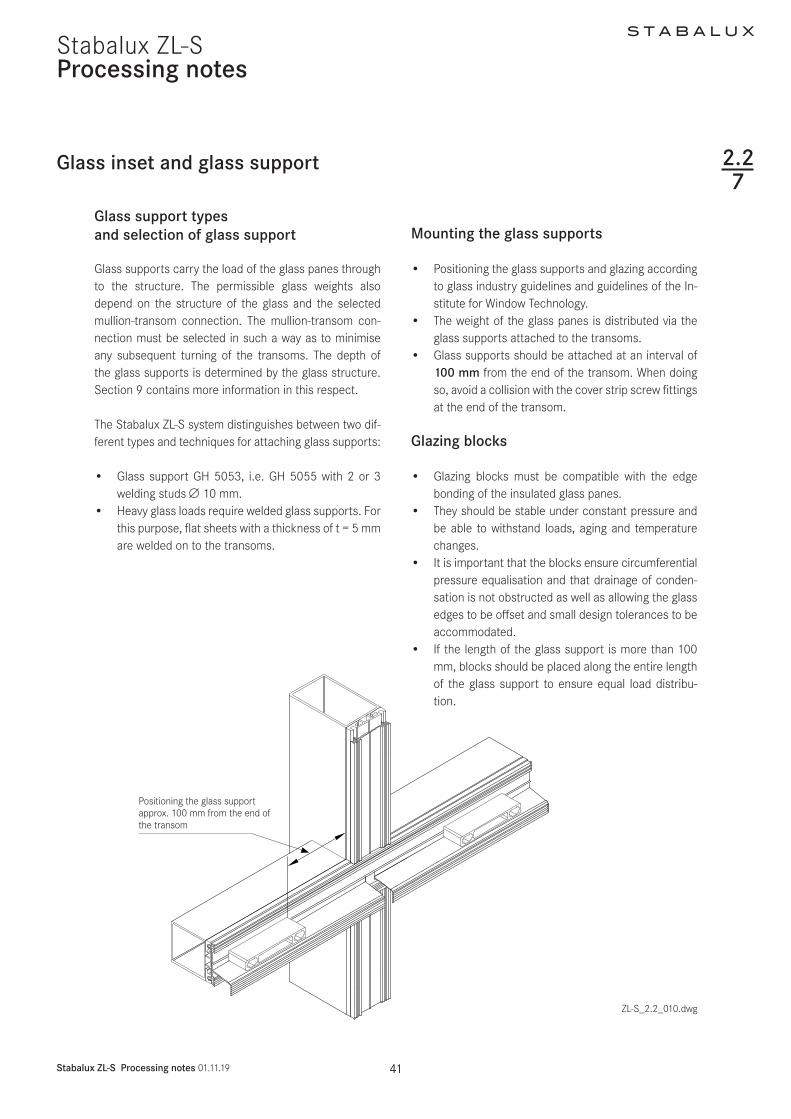
S T A B A L U X
Stabalux ZL-S Processing notes 011119 46
Stabalux ZL-SProcessing notes
227
Glass inset and glass support
RowTotal glass thickness tGlass (mm)
for inclined glazing 1)
Glass supports 2)
GH 5053 GH 5055 Depth (mm)1 24 25 26 Section Section 18
2 27 28 Section Section 20
3 29 30 Section Section 224 31 32 GH 0082 Section 245 33 34 GH 0083 GH 0851 26
Classification of system components
Table 2 Inclined glazing | System 50 60 80 | Threaded bolts
1) Accounting for a 10 mm inner seal
2) Cut from GH 5053 or GH 5055
Glass support GH 5053
Glass support GH 5055
TI-H_92_005dwg
S T A B A L U X
Stabalux ZL-S Processing notes 011119 47
Stabalux ZL-SProcessing notes
Glass inset and glass support
Welded glass support
bull Welded glass supports made of flat steel that are welded on to the transom profiles The glass sup-ports must be made available on the building site
bull Flat steel in grade S235 ie matched with the qual-ity of the supporting construction It must be possi-ble to weld the steel grades together The weld seam must connect the entire cross section of the glass supports
bull The glass supports must be sufficiently protected against corrosion
bull The depth of the glass supports depends on the in-stalled thickness of the glass panes the geometry of the inner seal and the height of the spacer strip
bull The glass supports must be welded in the centre of the transom in the substructure to disperse the load from the glass The glass supports must be posi-tioned vertically to the transom
227
bull The spacer strip must be cut out at the relevant points so as to ensure that the glass support and the weld seam cannot collide
bull The transom seals must be cut out around the holes for the glass supports and then sealed using Stabalux connection paste Z 0094
bull Blocks must be placed under the glass panes along the entire length of the glass supports
bull It is essential to ensure when installing the glazing that the glazing blocks cannot slip
bull The width of the glass supports is at least 100 mm their size must suit the static requirements
bull The glass supports must be validated for the glass thickness the glass weights and the selected mul-lion-transom connection
S T A B A L U X
Stabalux ZL-S Processing notes 011119 48
Stabalux ZL-SProcessing notes
Glass inset and glass support
Welded glass support
Glass support
Width ldquoWrdquo
Block
Glass support
Block
Inner seal
Spacer strip
227
Match the thickness of the glass support with the glass thickness
Make the weld seam as even as possiblefully connect the cross sectionmould the spacer strip around the glass supports
Cut out the sealing around the holes for the glass supports and sealwith Stabalux connecting paste
1
2
3
ZL-S_22_010dwg
A-A
S T A B A L U X
Stabalux ZL-S Processing notes 011119 49
Stabalux ZL-SProcessing notes
Glass inset and glass support 227
Glass support GH 5055 with threaded bolt
bull The depth of the glass support must be matched with the thickness of the glass
T = depth of the glass supportT1 = height of the spacer stripT2 = height of the inner seal (eg 5 m 10 mm or 12 mm)T3 thickness of the glass pane
T = T1 + T2 + T3
ExampleSpacer strip T1 = 10 mmInner seal (eg GD 6030) T2 = 5 mmThickness of pane 6 16 6 T3 = 28 mm
T = 10 + 5 + 28 = 43 mm
Wid
th ldquo
Wrdquo
ZL-S_22_010dwg
S T A B A L U X
Stabalux ZL-S Processing notes 011119 50
Stabalux ZL-SProcessing notes
Screw fittings
Fastenings
bull The system screw fittings are a combination of basic room-side screw fittings a coupling using a threaded socket that allows thermal separation in the rebate and a flexible bolt-nut connection or screw connec-tion on the glazing side
Basic room-side screw fittings
bull The threaded bolts M6 can be used for the basic room-side screw fittings they are screwed into the threaded holes ie the threaded blind holes Weld-ing studs M6 can be used alternatively
bull The length of the threaded bolts depends on the height of the spacer strip the height of the inner seal and the material selected for the supporting struc-ture (mullion and transom profiles) ie the selected depth of the blind holes which must be ge 7 mm Grade 14301 A2 stainless steel bolts must be used
bull In most cases the selected welding studs should have a length of 25 mm and they must be made available on the building site The bolts must be suf-ficiently protected against corrosion and be suitable for weld connections with the steel grade of the sup-porting structure Stainless steel bolts must be used otherwise
Coupling with threaded socket
bull The threaded socket is delivered in a length of 25 mm and twisted tight on to the basic screw fittings without excessively compressing the inner seal The Stabalux threaded sockets can be delivered in stainless steel (art no Z 0029) or plastic (art no Z 0032)
Bolt nuts ie screw connections on the glazing side
bull The assembly consists of a threaded bolt and option-ally a sealing washer and a cap nut Screws accord-ing to DIN 6912 stainless steel 14301 A2 can be used alternatively
bull Screws in the Stabalux system are produced using stainless steel usually with the material number 14301 DIN EN 10088
228
bull The length of the bolts ie screws is variable and depends on the height of the spacer strip the height of the inner seal and thickness of the glass A suffi-cient screw depth in the threaded socket must be ensured
bull Threaded bolts in suitable lengths are available for all standard glass thicknesses The length of bolt re-quired can usually be determined using a table of figures The combination chosen for the clamp con-nection will depend on the specific situation
bull Depending on the type of screw fittings selected 2 and 4 mm vulcanised EPDM washers are available
bull The distance for screw fittings is variable The maxi-mum distance is a = 250 mm
bull The distance from the edge for the first screw fitting should generally be in the region of 30 mm le a le 80 mm The placement of the glass supports and the choice of mullion-transom connection should also be taken into account
bull The clamp connection is exclusively exposed to ten-sile forces The pressure strips are connected using Stabalux system components To determine the stress limit (maximum tensile force) and permitted tensile forces for the connection the terms defined in the relevant general building approval and the Eu-rocode 3 (DIN EN 1993-3) series of standards shall apply
bull Screw fittings are applied using a conventional elec-tric screwdriver with depth stop This guarantees uniform application of pressure The depth setting should be chosen so that when using 4 mm EPDM washers a washer compression of around 15 - 18 mm is achieved
S T A B A L U X
Stabalux ZL-S Processing notes 011119 51
Stabalux ZL-S
Concealed screw fittings
bull Assembly is facilitated by the selection of pre-drilled clamping strips (eg UL 5009-L and UL 6009-L slot 7 x 10 mm a = 125 mm) with clippable upper strips A round hole of d = 8 mm should be made in the remaining clamping strips The functionality of the clip procedure can be checked after the first cover profile has been pushed against the lower strip
Note
When using aluminium cover profiles on roofs take ac-count of the expansion factor as a result of the high de-gree of heat absorption and its impact on the selected length Equally the use of single-piece cover profiles should be carefully considered In this case it is recom-mended that holes for screwing on the clamping strip are created with a diameter of d = 9 mm
Processing notes
227
Screw fittings
Visible screw fittings
bull Cover strips should be drilled with a round hole of d = 8 mm
Note
(see Note on concealed screw fittings)
Visible recessed screw fittings
bull When creating visible recessed screw fittings a stepped bore is required The lower part of the cover strip should be drilled with a d = 7 mm diameter The upper part of the cover strip needs a d = 11 mm diameter for the screw head It is recommended to install a washer (PA washer eg Z 0033) with all screw fittings
S T A B A L U X
Stabalux ZL-S Processing notes 011119 52
Stabalux ZL-SProcessing notes
Screw fittings
Concealed screw fittings
1 cap nut M6 Z004321 4 mm sealing washer Z 008631 threaded bolt M6 eg Z 3532 threaded bolt M6 in the threaded hole eg Z 004041 threaded socket M6 eg Z 29
Visible screw fittings
1 cap nut M6 Z004321 4 mm sealing washer Z 008631 threaded bolt M6 eg Z 3542 threaded socket M6 eg Z 296 threaded welding stud M6
Visible recessed screw fittings
22 PA washer Z 003333 threaded bolt M6 in the threaded hole eg Z 4042 threaded socket M6 eg Z 325 internal hex screw M6 eg GD 6912
Fastenings
ZL-S_22_011dwg
228
eg Z 0043
eg Z 0029 eg Z 0029
eg Z 0086
eg Z 0086
Screw M6
eg Z 0033
eg Z 0035
eg Z 0040 Threaded welding stud M6
Diagram and item numbers are examples for System 60
The calculation is the same for system 50
S T A B A L U X
Stabalux ZL-S Processing notes 011119 53
Stabalux ZL-SProcessing notes
Screw fittings
Calculating the screw length
ZL-S_22_012dwg
228
System width 50 60 mm System width 80 mm
Attention
The calculation to determine screw lengths for the the calculation to determine screw lengths is
Glass thickness - 14 mm with facade seal (5 mm)Glass thickness - 9 mm with facade seal (10 mm)Glass thickness - 7 mm with facade seal (12 mm)
S T A B A L U X
Stabalux ZL-S Processing notes 011119 54
Stabalux ZL-SProcessing notes
Screw fittings
System screws for Stabalux ZL
Cap nut
Z 0043 Cap nut stainless steel M6
Sealing washers
Z 46 U washer stainless steel with 2 mm seal
Z 0086 U washer stainless steel with 4 mm seal
Threaded sockets
Z 0029 Threaded socket stainless steel
M6 x 25 mm
Z 0032 Threaded socket stainless steel
M6 x 25 mm
Threaded bolts
Z 0034 Threaded bolts stainless steel M6 x 20 mm
Z 0038 Threaded bolts stainless steel M6 x 25 mm
Z 0035 Threaded bolts stainless steel M6 x 30 mm
Z 0040 Threaded bolts stainless steel M6 x 35 mm
Z 0036 Threaded bolts stainless steel M6 x 40 mm
Z 0037 Threaded bolts stainless steel M6 x 50 mm
Z 0044 Threaded bolts stainless steel M6 x 60 mm
Z 0045 Threaded bolts stainless steel M6 x 75 mm
Z 0039 Threaded bolts stainless steel M6 x 90 mm
Z 0053 Threaded bolts stainless steel M6 x 100 mm
Z 0054 Threaded bolts stainless steel M6 x 120 mm
228
ZL-S_22_013dwg
Calculating the screw length
S T A B A L U X
Stabalux ZL-S Processing notes 011119 55
Stabalux ZL-SProcessing notes
Flat cover strip DL 5073 DL 6073
Tips for laying the cover strip DL 5073 DL 6073
We assume that this cover strip will be used with glass panes that are supported on two sides and the recessed screw head is concealed In this case a cylinder head screw with inner hex is to be used (eg M6 DIN 6912 stainless steel A2 with low head) When covering with a 2 mm cover plug Z 0089 a bore depth of 6 mm is cal-culated
Depending on the precision of the bore it should be de-cided on case by case basis if any slight changes to this depth are necessary The cover plug Z 0089 does not need to be glued in place but may be levelled using lev-elling compound
Coating the cover strip
Profile production (aluminium extrusion moulding) with different mass distribution is extremely difficult Length-wise shadow formation may result Resulting actions are to be taken with the agreement of the coater
Intersections
Due to the special shape of the strip (the material ex-tends into the rebate) there is no closed sealing section available at intersections We therefore recommend plac-ing particular attention to ensure tightness of the joints and fill will Stabalux connecting paste Z 0094
Glass supportsblocking
Special attention should be given to dimensional propor-tions Glass supports should be designed by the proces-sor depending on the glass thickness and weight (eg for welded glass supports)To support the outer pane a sufficiently large glazing block must be installed that can carry the load to safely ensure the glass load is distributed effectively
ZL-S_22_014dwgZL-S_22_013dwg
229
Cover plug Z 0089Screw eg M6 DIN 6912
ZL-S_22_015-1
Stabalux ZL-S
S T A B A L U X
Stabalux ZL-S Processing notes 011119 56
Stabalux ZL-SProcessing notes
Slab insulation
ZL-S_22_015dwg
Use of slab insulation
bull Using insulation blacks significantly reduces heat dissipation
bull The highly effective slab insulation has a permanent-ly adhesive HOT-MELT
bull Depending on the situation where they are used in-sulation blocks can be directly applied to the cover striplower strip or placed into the rebate over the screw fittings and pushed into position with the cov-er striplower strip The type of screw connection (bolt-socket-bolt) means that a groove must first be cut in the insulating block at the points of connec-tion
bull With system width 80 mm and a 40 mm rebate 2x 20 mm wide slab insulation blocks can be combined (40 mm wide insulation blocks available upon request)
Note
bull The use of slab insulation with cover profiles DL 5073 DL 6073 should be tested for each individual situation
bull 2-piece outer seals are always used with slab insula-tion blocks for example outer seal GD 1932
Insulation block Width (=rebate)
Height
Z 0605 insulation block 20 42 20 mm 42 mm glass thickness from 44 mm
Z 0606 insulation block 20 26 20 mm 26 mm glass thickness from 28 mm
Z 0607 insulation block 30 42 30 mm 42 mm glass thickness from 44 mm
Z 0608 insulation block 30 26 30 mm 26 mm glass thickness from 28 mm
Correctly position the transom flag when installing the insulation blocks
2210
Z 0607Insulation block 3042
Z 0608Insulation block 3026
Z 0605Insulation block 2042
Z 0606Insulation block 2026
Z 0605Insulation block 2042
GD 1932
GD 1932
GD 1932
GD 1932
GD 1932
GD 1932
Z 0606Insulation block 2026
S T A B A L U X
Stabalux ZL-S Processing notes 011119 57
Stabalux ZL-SProcessing notes
Slab insulation
Examples
ZL-S_22_015dwg
2210
S T A B A L U X
Stabalux ZL-S Design 011119 59
Stabalux ZL-S
Pane support variants
Design
Special design
Glass structures that partially refrain from using visible cover profiles are considered special designs
These designs do not conform to the intended uses of the system No guarantees are made for eg quality of seals durability and structural stability Responsibility here lies entirely with the company implementing the design
Based on our experience we recommend paying close at-tention to the points made on the following pages during planning and implementation
Cut A - A Cut C - C
Cut B - B Cut D - D
ZL-S_23_001dwg
Mullion-transom structure 2-sided cover strip
231
Mullion-transom structurewith transom cover profiles 1)
1) Seals with 1 2 or 3 sections are possible
2) Use of mullion seals with 1 section in mullions and transoms
Mullion-transom structurewith mullion cover profiles 2)
S T A B A L U X
Stabalux ZL-S Design 011119 60
Stabalux ZL-SDesign
Transom - design Mullion - design
ZL-S_23_001dwg
Pane support variants
Vapour seal
When using this type of structure it is important to be aware that any loss of contact pressure can affect the room-side permeability There is an increased risk of con-densation build up in the rebate
Vertical clamping strips
The glass supports should be placed to below the outer pane and sealed with it
Horizontal clamping strips
Ventilation and condensation drainage is achieved via a recess in the lower sealing lip in the centre of the outer seal or at one third intervals
Transom structure mullion structure 2-sided cover strip
Cut A - A Cut C - C
Cut B - B Cut D - D
231
S T A B A L U X
Stabalux ZL-S Design 011119 61
Stabalux ZL-SDesign
Design requirements
1 Vapour seal
The room-side level of glazing must have the best possi-ble vapour seal In this regard the vapour diffusion prop-erties of the silicone sealant to be used should be tested
Ensure that there are no permeable areas around con-cave cross joints
2 Rebate ventilation pressure equalisa-tion and condensation drainage
Systems with partially sealed rebate represent a limita-tion to rebate ventilation Check on a case-by-case basis that no damage will be caused by standing condensation It is especially critical that designs with sealed vertical joints are evaluated To allow ventilation of the horizontal rebate we recommend installing a suitable vertical ven-tilation space Alternatively ventilation can be achieved using the outer joints
3 Weatherproofing
The outward facing seals must be watertight In cross joints it is especially important to ensure a firm join be-tween the Stabalux profile seal and the silicone joints We recommend sealing up to the outer edge of the glass before mounting the cover profiles
We would like emphasise once again that our profile seals will not make a permanent bond with commonly used silicone sealants A seal can only be created at con-tact points through permanent application of pressure
4 Mechanical strength of the screw fittings
Ensure screw fittings are of a sufficiently size Special at-tention should be given to the effects of wind suction and the reduced support
5 Glass weight distribution
Mechanical distribution of the weight of the glass panes through the structure must be ensured System glass supports can be used for existing horizontal transoms Designs using ldquoonlyrdquo mullions require special glass sup-ports which carry the weight of the glass directly into the mullions
6 Glass sizing
Attention should be given to the reduced support of panes when dimensioning the glass For example only the vertical or horizontal cover profiles are effective in the event of wind suction stresses or stress on the fall protection
7 Material compatibility
Compatibility of the silicone sealants with our profile seal-ants and the edge bonding of the glass must be ensured We recommend the exclusive use of tested silicone seal-ants from the whole-glass facades sector Approval is usually given by the silicone manufacturer
Pane support variants
ZL-S_23_001dwg
231
Examples
S T A B A L U X
Stabalux ZL-S Design 011119 62
Stabalux ZL-S
System cross sections
Design
ZL-S_23_001dwg
1 Vertical glazing mullion
concealed screw fittings
2 Vertical glazing mullion
visible screw fittings
3 Vertical glazing mullion
flat cover strip DL 5073 DL 6073
4 Vertical glazing transom
visible recessed screw fittings
Outer seal for height compensation
5 Vertical glazing transom
concealed screw fittings
single glazing
6 Vertical glazing transom
concealed screw fittings
7 Inclined glazing mullion
concealed screw fittings
8 Inclined glazing transom
visible screw fittings
1 2
3 4
5 6
7 8
232
S T A B A L U X
Stabalux ZL-S Design 011119 63
Stabalux ZL-SDesign
System details
Creating facade corners
At exposed areas such as glass facade corners it is par-ticularly important to ensure sufficient heat insulation in order to avoid the creation of thermal bridges and pre-vent a build-up of condensation Thermal current calcula-tions provide information about the actual heat loss
Outer corner Inner corner
ZL-S_23_002dwg ZL-S_23_002dwg
Facade polygon
Special seal allow a polygon shaped arrangement of the facade mullions For convex glass surfaces an angle be-tween 3deg and 15deg can be freely chosen For concave glass surfaces the angle can vary between 3deg and 10deg
ZL-S_23_002dwg
Geometrically check the feasibility Recommendation Use System 60 at minimum
ATTENTIONAdhere to the minimum glass inset
Determine the threaded bolt length using consideration of the angle
233
S T A B A L U X
Stabalux ZL-S Design 011119 64
Stabalux ZL-SDesign
System details
Eaves with glass roof connection
bull Depending on the construction of the transoms a design with or without rain gutters and the choice of stepped glazing or closable cover profiles gives us different variants for implementation
bull All options require condensation and moisture to be drained away at the eaves
Design with stepped glazing
bull With a stepped glazing design it is important to select a UV-resistant edge bonding for the glass This edge bonding systems usually silicone-based are quite permeable to gases and are therefore unable to achieve the required high values for sound and heat insulation of conventional systems ie require additional sealing around the edges
Example 1
Design with stepped glazing
bull Our thermal calculations show that stepped glass panes compared to covered glass edges have a much less favourable isothermal movement
bull Stepped glass panes must also be statically meas-ured according to their reduced hold against wind suction
bull The additional thermal loads that occur in stepped glass panes should countered by the use of pre-ten-sioned glass (TVG ESG) for the outer panes
bull Stepped glass panes should be preferred for flatter inclined roofs as water can drain away at the eaves unhindered
ZL-S_23_003dwg
233
S T A B A L U X
Stabalux ZL-S Design 011119 65
Stabalux ZL-SDesign
Eaves with glass roof connection Design using cover profiles
bull Horizontal pressure strips prevent the free run off of rain water and dirt
bull Cover strips with angled edges reduce the build up of water in front of the cover strip
bull The outer sealing level on glass roofs must also be thoroughly sealed
bull In combination with our butyl clad stainless steel panels glazing with pressure strips on 4 sides achieves a higher level of safety
bull Make sure that the inner sealing section provides guaranteed drainage for condensation
bull To improve drainage and heat-induced expansion cover profiles should be shortened by 5 mm at tran-som joints Gasket joints however are to be laid flat with a slight excess in dimensions Open ends of the transom cover profiles must be sealed
Note
Due to the increased thermal stresses in the roof we rec-ommend using concealed screw fitting when choosing clamping strips for larger system lengths and in rafters Unused holes in the lower strip must be sealed
System details
Example 2
Design using cover profiles
ZL-S_23_004dwg
233
S T A B A L U X
Stabalux ZL-S Design 011119 66
Stabalux ZL-SDesign
System details
Eaves with glass roof connection Design with gutter
bull The gutter must be able to take its own weight and mounted in such a way that stresses from its own weight water and ice will not lead to deformations and directly apply a load to the glazing
bull Overflowing water must not be able to get inside the structure Alongside the gutter-shaped outer rafter seal the moisture barrier installed over the guide plate also acts to drain away condensation
Example 3
Design with gutter
ZL-S_23_005dwg
233
S T A B A L U X
Stabalux ZL-S Design 011119 67
Stabalux ZL-SDesign
System details
Roof ridge design
bull When designing the ridge cap ensure that the rafter cover profiles are pulled under the ridge cap
ZL-S_23_006dwg
233
S T A B A L U X
Stabalux ZL-S Design 011119 68
Stabalux ZL-S
Structural attachments
Design
Structural attachment film baffles
bull Attachment of glazing to the building structure re-quires a well thought out approach
bull Moisture damage can occur if moisture condenses at any thermal bridges
bull Thermal bridges must be avoided and warm air from the inside spaces must not penetrate too deeply into the structure
bull The required moisture barriers must be installed as deeply as possible into the inner space using imper-meable structural film baffles This prevents mois-ture penetration into the structure via condensation from the air inside
bull An additional foil to seal against rainwater must be permeable to moisture Only if this foil has a water vapour diffusion resistance value μ of max μ = 3000 can a dry structure be guaranteed in the transition zones
234
S T A B A L U X
Stabalux ZL-S Design 011119 69
Stabalux ZL-S
Structural attachments
Design
Facade base
bull Controlled drainage of the rebate space can only be ensured if the sealing sections overlap in such a way that no moisture can get under the seals and foils
bull Run foils under the transom seal to act as a moisture barrier and glue to the steel structure In accordance with DIN 18195 the seal should be run at least 150 mm above the water-guiding layer
bull Attach foil with moisture barrier in accordance with the requirements of DIN 18195
Example 1 Mounting intermediate mullion to base plate
Drainage of the base area is achieved via the transom flag towards the outside In this case the transom flag around the mullion at the base should not be released For edge mullions ensure there is a
corresponding seal placed (continuous transom seal up the to the end point) and a constructive design of the drainage section
ZL-S_23_007dwg
234
S T A B A L U X
Stabalux ZL-S Design 011119 70
Stabalux ZL-SDesign
Structural attachments
Facade base
bull Rebate space ventilation is achieved via the open end of the vertical cover profiles
bull Ensure the connection is impermeable to vapourbull Mullion mountings must be sufficiently statically di-
mensioned Required axis and edge distances for an-choring the base plates and in the building structure must be observed
Example 2 Mounting intermediate mullion to base plate
Where transom flags are interrupted by joints filler rods in the joint must also be cut
ZL-S_23_008dwg
234
S T A B A L U X
Stabalux ZL-S Design 011119 71
Stabalux ZL-SDesign
Structural attachments
Facade base
bull Heat insulation around the structural connection should be designed in such as way as to prevent cold bridges forming
bull Steel parts should also be provided with sufficient protection against corrosion even in concealed ar-eas
bull Weather-protection sheets should be used depend-ing on the requirements of the construction Suffi-cient rear ventilation must be ensured
Example 3 Attaching intermediate mullions at base plates
ZL-S_23_009dwg
234
ZL-S_23_010-2
Stabalux ZL-S
S T A B A L U X
Stabalux ZL-S Design 011119 72
Stabalux ZL-SDesign
Connection before intermediate floors
bull Depending on requirements mullions are designed as continuous multi-span transoms or separated at each floor
bull Reasons for separating mullions can include eg building settlement fire protection sound insulation etc
bull If the separation joint is intended to absorb expan-sion then as well as the required degree of freedom for mullions the ability for movement of integrated elements must also be ensured
Structural attachments
bull The constructive design of the mullion joint and mounting should be chosen according to the stat-ically calculated base system and determines the choice and arrangement of fixed and movable bear-ings type of screw fittings structural connection parts and attachment to the concrete floor
bull With continuous mullions and a corresponding mount the multi-span support principle is in effect Sagging due to horizontal effects is lower The required mo-ment of inertia reduces for 2-span supports with the same span length compared to the 1-span support by a factor of 0415 However a tension and stability analysis should be carried out
Example Mullions separated at each floor
In this example distribution of horizontal and vertical loads is achieved at each floor through the existing floor structure
ZL-S_23_010dwg
234
S T A B A L U X
Stabalux ZL-S Design 011119 73
Stabalux ZL-SDesign
Ceiling connection
bull Structural connections should take account of any movement that may occur
bull As well as temperature induced expansion in the fa-cade all longitudinal expansions and movements of the affected components must be considered
bull Additional stresses from restraints must be avoided
Structural attachments
ZL-S_23_011dwg
234
S T A B A L U X
Stabalux ZL-S Design 011119 74
Stabalux ZL-SDesign
Facade connection to parapets
Structural attachments
ZL-S_23_012dwg
234
S T A B A L U X
Stabalux ZL-S Design 011119 75
Stabalux ZL-SDesign
Connection to structural eaves
bull This connection is suitable for glass roofs that are being installed as skylights in the structure These may be gabled roofs single pitch roofs pyramids or arched roofs
Structural attachments
ZL-S_23_013dwg
234
S T A B A L U X
Stabalux ZL-S Design 011119 76
Stabalux ZL-SDesign
Ridge connection to walls
bull When making ridge connections to walls permea-bility to moisture is particularly important Warm air with a high level of moisture gets into cooler zones of the inner sealing section where the design is not sufficiently sealed and can cause structural damage from penetrating into the connecting structure
bull Joint seals made from butyl-clad stainless steel plates (Z 0501 Z 0601) must be installed on the out-side of joint areas
Structural attachments
ZL-S_23_014dwg
234
S T A B A L U X
Stabalux ZL-S Design 011119 77
Stabalux ZL-SDesign
Horizontal wall connection to heat insulation bonding system
Structural attachments
ZL-S_23_015dwg
234
Ceiling conection including WAREMA external blinds
Structural attachments
ZL-S_23_024dwg
234
S T A B A L U X
Stabalux ZL-S Design 011119 78
Stabalux ZL-S
S T A B A L U X
Stabalux ZL-S Design 011119 79
Stabalux ZL-SDesign
Installing windows and doors
Mullion and transom facades and glass roofs from Stabalux are neutral with regards to the selection of in-sert elements All commonly available window and door systems made from steel aluminium wood or plastic can be used Frame profiles from the window and door man-ufacturerrsquos should be selected to match the chosen glass thickness If no profiles with a suitable insert rebate are available mountings may be used as shown in the fol-lowing examples Like with glass elements windows are set into the facade on glass supports padded and then secured against slippage
Insert window transom sectionSystem HUECKSeries Lambda WS 075 IS
Use a locating screwas an assembly aid if necessary
Use
a lo
catin
g sc
rew
as a
n as
sem
bly
aid
if ne
cess
ary Insert window mullion section
System HUECKSeries Lambda WS 075 IS
ZL-S_23_01 dwg
235
S T A B A L U X
Stabalux ZL-S Design 011119 80
Stabalux ZL-SDesign
Installing windows and doors
ZL-S_23_017dwg
Insert window mullion sectionSystem HUECKSeries Lambda WS 075
Insert window transom sectionSystem HUECKSeries Lambda WS 075
235
Use a locating screwas an assembly aidif necessary
Use
a lo
catin
g sc
rew
as a
n as
sem
bly
aid
if ne
cess
ary
S T A B A L U X
Stabalux ZL-S Design 011119 81
Stabalux ZL-S
ZL-S_23_018dwg
Design
Installing windows and doors
Insert door outward in the mullion sectionSystem HUECKSeries Lambda DS 075
Insert door outward in the transom sectionSystem HUECKSeries Lambda DS 075
235
Use a locating screw as an assembly aid if necessary
Use
a lo
catin
g sc
rew
as a
n as
sem
bly
aid
if ne
cess
ary
S T A B A L U X
Stabalux ZL-S Design 011119 82
Stabalux ZL-SDesign
Installing windows and doors
Insert door inward in the mullion sectionSystem HUECKSeries Lambda DS 075
Insert door inward in the transom sectionSystem HUECKSeries Lambda DS 075
ZL-S_23_019dwg
235
Use a locating screwas an assembly aidif necessary
Use
a lo
catin
g sc
rew
as a
n as
sem
bly
aid
if ne
cess
ary
ZL-S_23_020dwg
Design
Installing windows and doors
Insert top-hung window in the mullion sectionSystem HUECKSeries Lambda 110
Insert top-hung window in the transom sectionSystem HUECKSeries Lambda 110
235
S T A B A L U X
Stabalux ZL-S Design 011119 83
Stabalux ZL-S
Design
Installing windows and doors
Sliding system in the mullion sectionSystem HUECKSeries Volato M
Sliding system in the transom sectionSystem HUECKSeries Volato M
ZL-S_23_021dwg
235
S T A B A L U X
Stabalux ZL-S Design 011119 84
Stabalux ZL-S
S T A B A L U X
Stabalux ZL-S Design 011119 85
Stabalux ZL-SDesign
Installing windows and doors
Flush roof surface windowSystem HUECK-HARTMANNSeries 85E
Connection at top
Connection at bottom
Powered accordingto system specifications
ZL-S_23_020dwg
235
S T A B A L U X
Stabalux ZL-S Design 011119 86
Stabalux ZL-SDesign
Installing windows and doors
Insert window - mullion sectionSystem HahnSeries Lamellae S9 iVt-05
Insert window - transom sectionsSystem HahnSeries Lamellae S9 iVt-05
ZL-S_23_021dwg
235
- Stabalux ZL-S
-
- System
-
- System properties
- System cross sections and inner seals - facade
- System cross sections and inner seals - roof
- Cover strips and outer seals
-
- Processing notes
-
- Material information
- Assembly sequence
- Attaching the spacer strip
- Tips for laying seals
- Seals - Facade
- Seals - roof
- Glass inset and glass support
- Screw fittings
- Flat cover strip DL 5073 DL 6073
- Slab insulation
-
- Design
-
- Pane support variants
- System cross sections
- System details
- Structural attachments
- Installing windows and doors
-
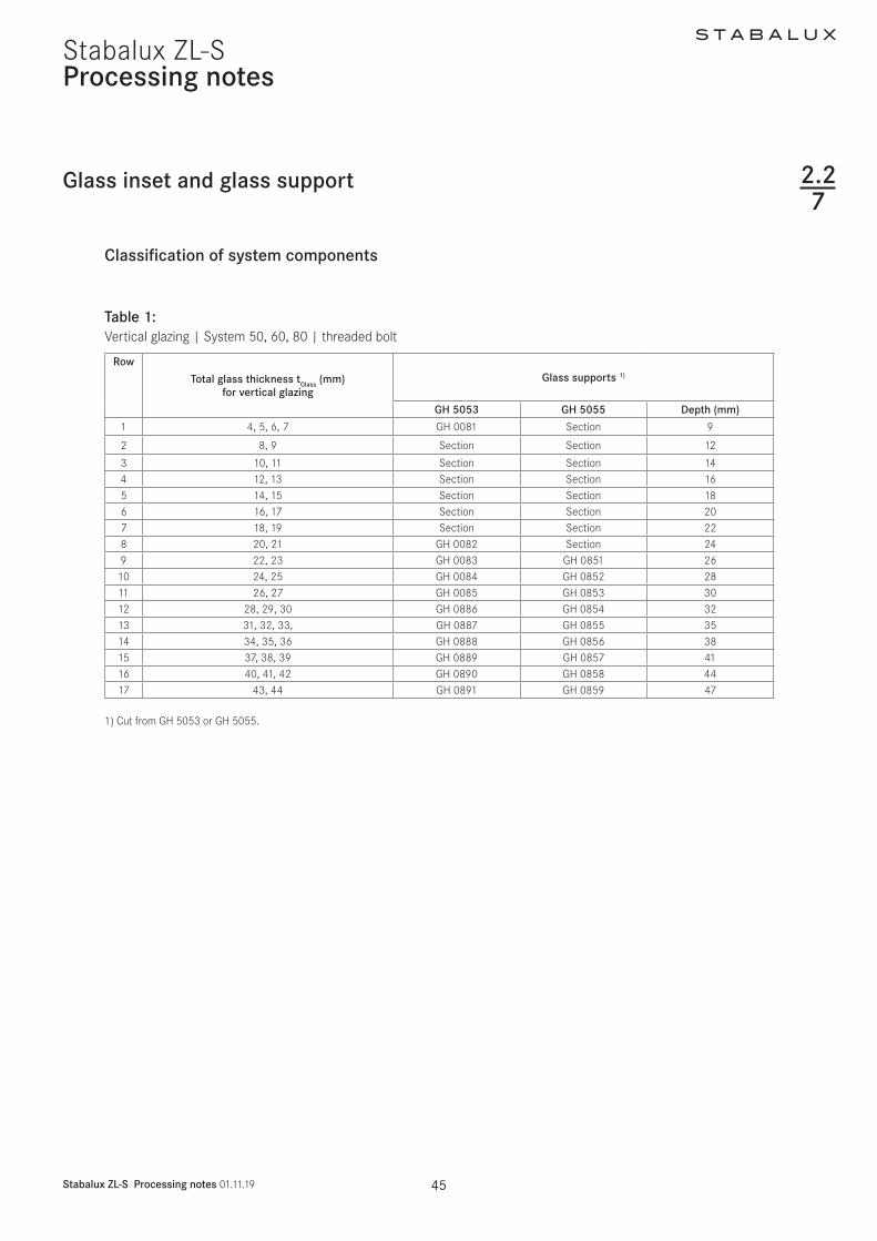
S T A B A L U X
Stabalux ZL-S Processing notes 011119 50
Stabalux ZL-SProcessing notes
Screw fittings
Fastenings
bull The system screw fittings are a combination of basic room-side screw fittings a coupling using a threaded socket that allows thermal separation in the rebate and a flexible bolt-nut connection or screw connec-tion on the glazing side
Basic room-side screw fittings
bull The threaded bolts M6 can be used for the basic room-side screw fittings they are screwed into the threaded holes ie the threaded blind holes Weld-ing studs M6 can be used alternatively
bull The length of the threaded bolts depends on the height of the spacer strip the height of the inner seal and the material selected for the supporting struc-ture (mullion and transom profiles) ie the selected depth of the blind holes which must be ge 7 mm Grade 14301 A2 stainless steel bolts must be used
bull In most cases the selected welding studs should have a length of 25 mm and they must be made available on the building site The bolts must be suf-ficiently protected against corrosion and be suitable for weld connections with the steel grade of the sup-porting structure Stainless steel bolts must be used otherwise
Coupling with threaded socket
bull The threaded socket is delivered in a length of 25 mm and twisted tight on to the basic screw fittings without excessively compressing the inner seal The Stabalux threaded sockets can be delivered in stainless steel (art no Z 0029) or plastic (art no Z 0032)
Bolt nuts ie screw connections on the glazing side
bull The assembly consists of a threaded bolt and option-ally a sealing washer and a cap nut Screws accord-ing to DIN 6912 stainless steel 14301 A2 can be used alternatively
bull Screws in the Stabalux system are produced using stainless steel usually with the material number 14301 DIN EN 10088
228
bull The length of the bolts ie screws is variable and depends on the height of the spacer strip the height of the inner seal and thickness of the glass A suffi-cient screw depth in the threaded socket must be ensured
bull Threaded bolts in suitable lengths are available for all standard glass thicknesses The length of bolt re-quired can usually be determined using a table of figures The combination chosen for the clamp con-nection will depend on the specific situation
bull Depending on the type of screw fittings selected 2 and 4 mm vulcanised EPDM washers are available
bull The distance for screw fittings is variable The maxi-mum distance is a = 250 mm
bull The distance from the edge for the first screw fitting should generally be in the region of 30 mm le a le 80 mm The placement of the glass supports and the choice of mullion-transom connection should also be taken into account
bull The clamp connection is exclusively exposed to ten-sile forces The pressure strips are connected using Stabalux system components To determine the stress limit (maximum tensile force) and permitted tensile forces for the connection the terms defined in the relevant general building approval and the Eu-rocode 3 (DIN EN 1993-3) series of standards shall apply
bull Screw fittings are applied using a conventional elec-tric screwdriver with depth stop This guarantees uniform application of pressure The depth setting should be chosen so that when using 4 mm EPDM washers a washer compression of around 15 - 18 mm is achieved
S T A B A L U X
Stabalux ZL-S Processing notes 011119 51
Stabalux ZL-S
Concealed screw fittings
bull Assembly is facilitated by the selection of pre-drilled clamping strips (eg UL 5009-L and UL 6009-L slot 7 x 10 mm a = 125 mm) with clippable upper strips A round hole of d = 8 mm should be made in the remaining clamping strips The functionality of the clip procedure can be checked after the first cover profile has been pushed against the lower strip
Note
When using aluminium cover profiles on roofs take ac-count of the expansion factor as a result of the high de-gree of heat absorption and its impact on the selected length Equally the use of single-piece cover profiles should be carefully considered In this case it is recom-mended that holes for screwing on the clamping strip are created with a diameter of d = 9 mm
Processing notes
227
Screw fittings
Visible screw fittings
bull Cover strips should be drilled with a round hole of d = 8 mm
Note
(see Note on concealed screw fittings)
Visible recessed screw fittings
bull When creating visible recessed screw fittings a stepped bore is required The lower part of the cover strip should be drilled with a d = 7 mm diameter The upper part of the cover strip needs a d = 11 mm diameter for the screw head It is recommended to install a washer (PA washer eg Z 0033) with all screw fittings
S T A B A L U X
Stabalux ZL-S Processing notes 011119 52
Stabalux ZL-SProcessing notes
Screw fittings
Concealed screw fittings
1 cap nut M6 Z004321 4 mm sealing washer Z 008631 threaded bolt M6 eg Z 3532 threaded bolt M6 in the threaded hole eg Z 004041 threaded socket M6 eg Z 29
Visible screw fittings
1 cap nut M6 Z004321 4 mm sealing washer Z 008631 threaded bolt M6 eg Z 3542 threaded socket M6 eg Z 296 threaded welding stud M6
Visible recessed screw fittings
22 PA washer Z 003333 threaded bolt M6 in the threaded hole eg Z 4042 threaded socket M6 eg Z 325 internal hex screw M6 eg GD 6912
Fastenings
ZL-S_22_011dwg
228
eg Z 0043
eg Z 0029 eg Z 0029
eg Z 0086
eg Z 0086
Screw M6
eg Z 0033
eg Z 0035
eg Z 0040 Threaded welding stud M6
Diagram and item numbers are examples for System 60
The calculation is the same for system 50
S T A B A L U X
Stabalux ZL-S Processing notes 011119 53
Stabalux ZL-SProcessing notes
Screw fittings
Calculating the screw length
ZL-S_22_012dwg
228
System width 50 60 mm System width 80 mm
Attention
The calculation to determine screw lengths for the the calculation to determine screw lengths is
Glass thickness - 14 mm with facade seal (5 mm)Glass thickness - 9 mm with facade seal (10 mm)Glass thickness - 7 mm with facade seal (12 mm)
S T A B A L U X
Stabalux ZL-S Processing notes 011119 54
Stabalux ZL-SProcessing notes
Screw fittings
System screws for Stabalux ZL
Cap nut
Z 0043 Cap nut stainless steel M6
Sealing washers
Z 46 U washer stainless steel with 2 mm seal
Z 0086 U washer stainless steel with 4 mm seal
Threaded sockets
Z 0029 Threaded socket stainless steel
M6 x 25 mm
Z 0032 Threaded socket stainless steel
M6 x 25 mm
Threaded bolts
Z 0034 Threaded bolts stainless steel M6 x 20 mm
Z 0038 Threaded bolts stainless steel M6 x 25 mm
Z 0035 Threaded bolts stainless steel M6 x 30 mm
Z 0040 Threaded bolts stainless steel M6 x 35 mm
Z 0036 Threaded bolts stainless steel M6 x 40 mm
Z 0037 Threaded bolts stainless steel M6 x 50 mm
Z 0044 Threaded bolts stainless steel M6 x 60 mm
Z 0045 Threaded bolts stainless steel M6 x 75 mm
Z 0039 Threaded bolts stainless steel M6 x 90 mm
Z 0053 Threaded bolts stainless steel M6 x 100 mm
Z 0054 Threaded bolts stainless steel M6 x 120 mm
228
ZL-S_22_013dwg
Calculating the screw length
S T A B A L U X
Stabalux ZL-S Processing notes 011119 55
Stabalux ZL-SProcessing notes
Flat cover strip DL 5073 DL 6073
Tips for laying the cover strip DL 5073 DL 6073
We assume that this cover strip will be used with glass panes that are supported on two sides and the recessed screw head is concealed In this case a cylinder head screw with inner hex is to be used (eg M6 DIN 6912 stainless steel A2 with low head) When covering with a 2 mm cover plug Z 0089 a bore depth of 6 mm is cal-culated
Depending on the precision of the bore it should be de-cided on case by case basis if any slight changes to this depth are necessary The cover plug Z 0089 does not need to be glued in place but may be levelled using lev-elling compound
Coating the cover strip
Profile production (aluminium extrusion moulding) with different mass distribution is extremely difficult Length-wise shadow formation may result Resulting actions are to be taken with the agreement of the coater
Intersections
Due to the special shape of the strip (the material ex-tends into the rebate) there is no closed sealing section available at intersections We therefore recommend plac-ing particular attention to ensure tightness of the joints and fill will Stabalux connecting paste Z 0094
Glass supportsblocking
Special attention should be given to dimensional propor-tions Glass supports should be designed by the proces-sor depending on the glass thickness and weight (eg for welded glass supports)To support the outer pane a sufficiently large glazing block must be installed that can carry the load to safely ensure the glass load is distributed effectively
ZL-S_22_014dwgZL-S_22_013dwg
229
Cover plug Z 0089Screw eg M6 DIN 6912
ZL-S_22_015-1
Stabalux ZL-S
S T A B A L U X
Stabalux ZL-S Processing notes 011119 56
Stabalux ZL-SProcessing notes
Slab insulation
ZL-S_22_015dwg
Use of slab insulation
bull Using insulation blacks significantly reduces heat dissipation
bull The highly effective slab insulation has a permanent-ly adhesive HOT-MELT
bull Depending on the situation where they are used in-sulation blocks can be directly applied to the cover striplower strip or placed into the rebate over the screw fittings and pushed into position with the cov-er striplower strip The type of screw connection (bolt-socket-bolt) means that a groove must first be cut in the insulating block at the points of connec-tion
bull With system width 80 mm and a 40 mm rebate 2x 20 mm wide slab insulation blocks can be combined (40 mm wide insulation blocks available upon request)
Note
bull The use of slab insulation with cover profiles DL 5073 DL 6073 should be tested for each individual situation
bull 2-piece outer seals are always used with slab insula-tion blocks for example outer seal GD 1932
Insulation block Width (=rebate)
Height
Z 0605 insulation block 20 42 20 mm 42 mm glass thickness from 44 mm
Z 0606 insulation block 20 26 20 mm 26 mm glass thickness from 28 mm
Z 0607 insulation block 30 42 30 mm 42 mm glass thickness from 44 mm
Z 0608 insulation block 30 26 30 mm 26 mm glass thickness from 28 mm
Correctly position the transom flag when installing the insulation blocks
2210
Z 0607Insulation block 3042
Z 0608Insulation block 3026
Z 0605Insulation block 2042
Z 0606Insulation block 2026
Z 0605Insulation block 2042
GD 1932
GD 1932
GD 1932
GD 1932
GD 1932
GD 1932
Z 0606Insulation block 2026
S T A B A L U X
Stabalux ZL-S Processing notes 011119 57
Stabalux ZL-SProcessing notes
Slab insulation
Examples
ZL-S_22_015dwg
2210
S T A B A L U X
Stabalux ZL-S Design 011119 59
Stabalux ZL-S
Pane support variants
Design
Special design
Glass structures that partially refrain from using visible cover profiles are considered special designs
These designs do not conform to the intended uses of the system No guarantees are made for eg quality of seals durability and structural stability Responsibility here lies entirely with the company implementing the design
Based on our experience we recommend paying close at-tention to the points made on the following pages during planning and implementation
Cut A - A Cut C - C
Cut B - B Cut D - D
ZL-S_23_001dwg
Mullion-transom structure 2-sided cover strip
231
Mullion-transom structurewith transom cover profiles 1)
1) Seals with 1 2 or 3 sections are possible
2) Use of mullion seals with 1 section in mullions and transoms
Mullion-transom structurewith mullion cover profiles 2)
S T A B A L U X
Stabalux ZL-S Design 011119 60
Stabalux ZL-SDesign
Transom - design Mullion - design
ZL-S_23_001dwg
Pane support variants
Vapour seal
When using this type of structure it is important to be aware that any loss of contact pressure can affect the room-side permeability There is an increased risk of con-densation build up in the rebate
Vertical clamping strips
The glass supports should be placed to below the outer pane and sealed with it
Horizontal clamping strips
Ventilation and condensation drainage is achieved via a recess in the lower sealing lip in the centre of the outer seal or at one third intervals
Transom structure mullion structure 2-sided cover strip
Cut A - A Cut C - C
Cut B - B Cut D - D
231
S T A B A L U X
Stabalux ZL-S Design 011119 61
Stabalux ZL-SDesign
Design requirements
1 Vapour seal
The room-side level of glazing must have the best possi-ble vapour seal In this regard the vapour diffusion prop-erties of the silicone sealant to be used should be tested
Ensure that there are no permeable areas around con-cave cross joints
2 Rebate ventilation pressure equalisa-tion and condensation drainage
Systems with partially sealed rebate represent a limita-tion to rebate ventilation Check on a case-by-case basis that no damage will be caused by standing condensation It is especially critical that designs with sealed vertical joints are evaluated To allow ventilation of the horizontal rebate we recommend installing a suitable vertical ven-tilation space Alternatively ventilation can be achieved using the outer joints
3 Weatherproofing
The outward facing seals must be watertight In cross joints it is especially important to ensure a firm join be-tween the Stabalux profile seal and the silicone joints We recommend sealing up to the outer edge of the glass before mounting the cover profiles
We would like emphasise once again that our profile seals will not make a permanent bond with commonly used silicone sealants A seal can only be created at con-tact points through permanent application of pressure
4 Mechanical strength of the screw fittings
Ensure screw fittings are of a sufficiently size Special at-tention should be given to the effects of wind suction and the reduced support
5 Glass weight distribution
Mechanical distribution of the weight of the glass panes through the structure must be ensured System glass supports can be used for existing horizontal transoms Designs using ldquoonlyrdquo mullions require special glass sup-ports which carry the weight of the glass directly into the mullions
6 Glass sizing
Attention should be given to the reduced support of panes when dimensioning the glass For example only the vertical or horizontal cover profiles are effective in the event of wind suction stresses or stress on the fall protection
7 Material compatibility
Compatibility of the silicone sealants with our profile seal-ants and the edge bonding of the glass must be ensured We recommend the exclusive use of tested silicone seal-ants from the whole-glass facades sector Approval is usually given by the silicone manufacturer
Pane support variants
ZL-S_23_001dwg
231
Examples
S T A B A L U X
Stabalux ZL-S Design 011119 62
Stabalux ZL-S
System cross sections
Design
ZL-S_23_001dwg
1 Vertical glazing mullion
concealed screw fittings
2 Vertical glazing mullion
visible screw fittings
3 Vertical glazing mullion
flat cover strip DL 5073 DL 6073
4 Vertical glazing transom
visible recessed screw fittings
Outer seal for height compensation
5 Vertical glazing transom
concealed screw fittings
single glazing
6 Vertical glazing transom
concealed screw fittings
7 Inclined glazing mullion
concealed screw fittings
8 Inclined glazing transom
visible screw fittings
1 2
3 4
5 6
7 8
232
S T A B A L U X
Stabalux ZL-S Design 011119 63
Stabalux ZL-SDesign
System details
Creating facade corners
At exposed areas such as glass facade corners it is par-ticularly important to ensure sufficient heat insulation in order to avoid the creation of thermal bridges and pre-vent a build-up of condensation Thermal current calcula-tions provide information about the actual heat loss
Outer corner Inner corner
ZL-S_23_002dwg ZL-S_23_002dwg
Facade polygon
Special seal allow a polygon shaped arrangement of the facade mullions For convex glass surfaces an angle be-tween 3deg and 15deg can be freely chosen For concave glass surfaces the angle can vary between 3deg and 10deg
ZL-S_23_002dwg
Geometrically check the feasibility Recommendation Use System 60 at minimum
ATTENTIONAdhere to the minimum glass inset
Determine the threaded bolt length using consideration of the angle
233
S T A B A L U X
Stabalux ZL-S Design 011119 64
Stabalux ZL-SDesign
System details
Eaves with glass roof connection
bull Depending on the construction of the transoms a design with or without rain gutters and the choice of stepped glazing or closable cover profiles gives us different variants for implementation
bull All options require condensation and moisture to be drained away at the eaves
Design with stepped glazing
bull With a stepped glazing design it is important to select a UV-resistant edge bonding for the glass This edge bonding systems usually silicone-based are quite permeable to gases and are therefore unable to achieve the required high values for sound and heat insulation of conventional systems ie require additional sealing around the edges
Example 1
Design with stepped glazing
bull Our thermal calculations show that stepped glass panes compared to covered glass edges have a much less favourable isothermal movement
bull Stepped glass panes must also be statically meas-ured according to their reduced hold against wind suction
bull The additional thermal loads that occur in stepped glass panes should countered by the use of pre-ten-sioned glass (TVG ESG) for the outer panes
bull Stepped glass panes should be preferred for flatter inclined roofs as water can drain away at the eaves unhindered
ZL-S_23_003dwg
233
S T A B A L U X
Stabalux ZL-S Design 011119 65
Stabalux ZL-SDesign
Eaves with glass roof connection Design using cover profiles
bull Horizontal pressure strips prevent the free run off of rain water and dirt
bull Cover strips with angled edges reduce the build up of water in front of the cover strip
bull The outer sealing level on glass roofs must also be thoroughly sealed
bull In combination with our butyl clad stainless steel panels glazing with pressure strips on 4 sides achieves a higher level of safety
bull Make sure that the inner sealing section provides guaranteed drainage for condensation
bull To improve drainage and heat-induced expansion cover profiles should be shortened by 5 mm at tran-som joints Gasket joints however are to be laid flat with a slight excess in dimensions Open ends of the transom cover profiles must be sealed
Note
Due to the increased thermal stresses in the roof we rec-ommend using concealed screw fitting when choosing clamping strips for larger system lengths and in rafters Unused holes in the lower strip must be sealed
System details
Example 2
Design using cover profiles
ZL-S_23_004dwg
233
S T A B A L U X
Stabalux ZL-S Design 011119 66
Stabalux ZL-SDesign
System details
Eaves with glass roof connection Design with gutter
bull The gutter must be able to take its own weight and mounted in such a way that stresses from its own weight water and ice will not lead to deformations and directly apply a load to the glazing
bull Overflowing water must not be able to get inside the structure Alongside the gutter-shaped outer rafter seal the moisture barrier installed over the guide plate also acts to drain away condensation
Example 3
Design with gutter
ZL-S_23_005dwg
233
S T A B A L U X
Stabalux ZL-S Design 011119 67
Stabalux ZL-SDesign
System details
Roof ridge design
bull When designing the ridge cap ensure that the rafter cover profiles are pulled under the ridge cap
ZL-S_23_006dwg
233
S T A B A L U X
Stabalux ZL-S Design 011119 68
Stabalux ZL-S
Structural attachments
Design
Structural attachment film baffles
bull Attachment of glazing to the building structure re-quires a well thought out approach
bull Moisture damage can occur if moisture condenses at any thermal bridges
bull Thermal bridges must be avoided and warm air from the inside spaces must not penetrate too deeply into the structure
bull The required moisture barriers must be installed as deeply as possible into the inner space using imper-meable structural film baffles This prevents mois-ture penetration into the structure via condensation from the air inside
bull An additional foil to seal against rainwater must be permeable to moisture Only if this foil has a water vapour diffusion resistance value μ of max μ = 3000 can a dry structure be guaranteed in the transition zones
234
S T A B A L U X
Stabalux ZL-S Design 011119 69
Stabalux ZL-S
Structural attachments
Design
Facade base
bull Controlled drainage of the rebate space can only be ensured if the sealing sections overlap in such a way that no moisture can get under the seals and foils
bull Run foils under the transom seal to act as a moisture barrier and glue to the steel structure In accordance with DIN 18195 the seal should be run at least 150 mm above the water-guiding layer
bull Attach foil with moisture barrier in accordance with the requirements of DIN 18195
Example 1 Mounting intermediate mullion to base plate
Drainage of the base area is achieved via the transom flag towards the outside In this case the transom flag around the mullion at the base should not be released For edge mullions ensure there is a
corresponding seal placed (continuous transom seal up the to the end point) and a constructive design of the drainage section
ZL-S_23_007dwg
234
S T A B A L U X
Stabalux ZL-S Design 011119 70
Stabalux ZL-SDesign
Structural attachments
Facade base
bull Rebate space ventilation is achieved via the open end of the vertical cover profiles
bull Ensure the connection is impermeable to vapourbull Mullion mountings must be sufficiently statically di-
mensioned Required axis and edge distances for an-choring the base plates and in the building structure must be observed
Example 2 Mounting intermediate mullion to base plate
Where transom flags are interrupted by joints filler rods in the joint must also be cut
ZL-S_23_008dwg
234
S T A B A L U X
Stabalux ZL-S Design 011119 71
Stabalux ZL-SDesign
Structural attachments
Facade base
bull Heat insulation around the structural connection should be designed in such as way as to prevent cold bridges forming
bull Steel parts should also be provided with sufficient protection against corrosion even in concealed ar-eas
bull Weather-protection sheets should be used depend-ing on the requirements of the construction Suffi-cient rear ventilation must be ensured
Example 3 Attaching intermediate mullions at base plates
ZL-S_23_009dwg
234
ZL-S_23_010-2
Stabalux ZL-S
S T A B A L U X
Stabalux ZL-S Design 011119 72
Stabalux ZL-SDesign
Connection before intermediate floors
bull Depending on requirements mullions are designed as continuous multi-span transoms or separated at each floor
bull Reasons for separating mullions can include eg building settlement fire protection sound insulation etc
bull If the separation joint is intended to absorb expan-sion then as well as the required degree of freedom for mullions the ability for movement of integrated elements must also be ensured
Structural attachments
bull The constructive design of the mullion joint and mounting should be chosen according to the stat-ically calculated base system and determines the choice and arrangement of fixed and movable bear-ings type of screw fittings structural connection parts and attachment to the concrete floor
bull With continuous mullions and a corresponding mount the multi-span support principle is in effect Sagging due to horizontal effects is lower The required mo-ment of inertia reduces for 2-span supports with the same span length compared to the 1-span support by a factor of 0415 However a tension and stability analysis should be carried out
Example Mullions separated at each floor
In this example distribution of horizontal and vertical loads is achieved at each floor through the existing floor structure
ZL-S_23_010dwg
234
S T A B A L U X
Stabalux ZL-S Design 011119 73
Stabalux ZL-SDesign
Ceiling connection
bull Structural connections should take account of any movement that may occur
bull As well as temperature induced expansion in the fa-cade all longitudinal expansions and movements of the affected components must be considered
bull Additional stresses from restraints must be avoided
Structural attachments
ZL-S_23_011dwg
234
S T A B A L U X
Stabalux ZL-S Design 011119 74
Stabalux ZL-SDesign
Facade connection to parapets
Structural attachments
ZL-S_23_012dwg
234
S T A B A L U X
Stabalux ZL-S Design 011119 75
Stabalux ZL-SDesign
Connection to structural eaves
bull This connection is suitable for glass roofs that are being installed as skylights in the structure These may be gabled roofs single pitch roofs pyramids or arched roofs
Structural attachments
ZL-S_23_013dwg
234
S T A B A L U X
Stabalux ZL-S Design 011119 76
Stabalux ZL-SDesign
Ridge connection to walls
bull When making ridge connections to walls permea-bility to moisture is particularly important Warm air with a high level of moisture gets into cooler zones of the inner sealing section where the design is not sufficiently sealed and can cause structural damage from penetrating into the connecting structure
bull Joint seals made from butyl-clad stainless steel plates (Z 0501 Z 0601) must be installed on the out-side of joint areas
Structural attachments
ZL-S_23_014dwg
234
S T A B A L U X
Stabalux ZL-S Design 011119 77
Stabalux ZL-SDesign
Horizontal wall connection to heat insulation bonding system
Structural attachments
ZL-S_23_015dwg
234
Ceiling conection including WAREMA external blinds
Structural attachments
ZL-S_23_024dwg
234
S T A B A L U X
Stabalux ZL-S Design 011119 78
Stabalux ZL-S
S T A B A L U X
Stabalux ZL-S Design 011119 79
Stabalux ZL-SDesign
Installing windows and doors
Mullion and transom facades and glass roofs from Stabalux are neutral with regards to the selection of in-sert elements All commonly available window and door systems made from steel aluminium wood or plastic can be used Frame profiles from the window and door man-ufacturerrsquos should be selected to match the chosen glass thickness If no profiles with a suitable insert rebate are available mountings may be used as shown in the fol-lowing examples Like with glass elements windows are set into the facade on glass supports padded and then secured against slippage
Insert window transom sectionSystem HUECKSeries Lambda WS 075 IS
Use a locating screwas an assembly aid if necessary
Use
a lo
catin
g sc
rew
as a
n as
sem
bly
aid
if ne
cess
ary Insert window mullion section
System HUECKSeries Lambda WS 075 IS
ZL-S_23_01 dwg
235
S T A B A L U X
Stabalux ZL-S Design 011119 80
Stabalux ZL-SDesign
Installing windows and doors
ZL-S_23_017dwg
Insert window mullion sectionSystem HUECKSeries Lambda WS 075
Insert window transom sectionSystem HUECKSeries Lambda WS 075
235
Use a locating screwas an assembly aidif necessary
Use
a lo
catin
g sc
rew
as a
n as
sem
bly
aid
if ne
cess
ary
S T A B A L U X
Stabalux ZL-S Design 011119 81
Stabalux ZL-S
ZL-S_23_018dwg
Design
Installing windows and doors
Insert door outward in the mullion sectionSystem HUECKSeries Lambda DS 075
Insert door outward in the transom sectionSystem HUECKSeries Lambda DS 075
235
Use a locating screw as an assembly aid if necessary
Use
a lo
catin
g sc
rew
as a
n as
sem
bly
aid
if ne
cess
ary
S T A B A L U X
Stabalux ZL-S Design 011119 82
Stabalux ZL-SDesign
Installing windows and doors
Insert door inward in the mullion sectionSystem HUECKSeries Lambda DS 075
Insert door inward in the transom sectionSystem HUECKSeries Lambda DS 075
ZL-S_23_019dwg
235
Use a locating screwas an assembly aidif necessary
Use
a lo
catin
g sc
rew
as a
n as
sem
bly
aid
if ne
cess
ary
ZL-S_23_020dwg
Design
Installing windows and doors
Insert top-hung window in the mullion sectionSystem HUECKSeries Lambda 110
Insert top-hung window in the transom sectionSystem HUECKSeries Lambda 110
235
S T A B A L U X
Stabalux ZL-S Design 011119 83
Stabalux ZL-S
Design
Installing windows and doors
Sliding system in the mullion sectionSystem HUECKSeries Volato M
Sliding system in the transom sectionSystem HUECKSeries Volato M
ZL-S_23_021dwg
235
S T A B A L U X
Stabalux ZL-S Design 011119 84
Stabalux ZL-S
S T A B A L U X
Stabalux ZL-S Design 011119 85
Stabalux ZL-SDesign
Installing windows and doors
Flush roof surface windowSystem HUECK-HARTMANNSeries 85E
Connection at top
Connection at bottom
Powered accordingto system specifications
ZL-S_23_020dwg
235
S T A B A L U X
Stabalux ZL-S Design 011119 86
Stabalux ZL-SDesign
Installing windows and doors
Insert window - mullion sectionSystem HahnSeries Lamellae S9 iVt-05
Insert window - transom sectionsSystem HahnSeries Lamellae S9 iVt-05
ZL-S_23_021dwg
235
- Stabalux ZL-S
-
- System
-
- System properties
- System cross sections and inner seals - facade
- System cross sections and inner seals - roof
- Cover strips and outer seals
-
- Processing notes
-
- Material information
- Assembly sequence
- Attaching the spacer strip
- Tips for laying seals
- Seals - Facade
- Seals - roof
- Glass inset and glass support
- Screw fittings
- Flat cover strip DL 5073 DL 6073
- Slab insulation
-
- Design
-
- Pane support variants
- System cross sections
- System details
- Structural attachments
- Installing windows and doors
-
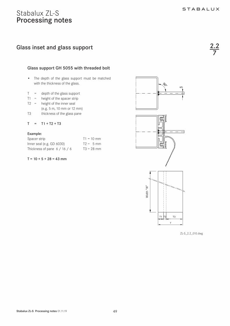
S T A B A L U X
Stabalux ZL-S Processing notes 011119 52
Stabalux ZL-SProcessing notes
Screw fittings
Concealed screw fittings
1 cap nut M6 Z004321 4 mm sealing washer Z 008631 threaded bolt M6 eg Z 3532 threaded bolt M6 in the threaded hole eg Z 004041 threaded socket M6 eg Z 29
Visible screw fittings
1 cap nut M6 Z004321 4 mm sealing washer Z 008631 threaded bolt M6 eg Z 3542 threaded socket M6 eg Z 296 threaded welding stud M6
Visible recessed screw fittings
22 PA washer Z 003333 threaded bolt M6 in the threaded hole eg Z 4042 threaded socket M6 eg Z 325 internal hex screw M6 eg GD 6912
Fastenings
ZL-S_22_011dwg
228
eg Z 0043
eg Z 0029 eg Z 0029
eg Z 0086
eg Z 0086
Screw M6
eg Z 0033
eg Z 0035
eg Z 0040 Threaded welding stud M6
Diagram and item numbers are examples for System 60
The calculation is the same for system 50
S T A B A L U X
Stabalux ZL-S Processing notes 011119 53
Stabalux ZL-SProcessing notes
Screw fittings
Calculating the screw length
ZL-S_22_012dwg
228
System width 50 60 mm System width 80 mm
Attention
The calculation to determine screw lengths for the the calculation to determine screw lengths is
Glass thickness - 14 mm with facade seal (5 mm)Glass thickness - 9 mm with facade seal (10 mm)Glass thickness - 7 mm with facade seal (12 mm)
S T A B A L U X
Stabalux ZL-S Processing notes 011119 54
Stabalux ZL-SProcessing notes
Screw fittings
System screws for Stabalux ZL
Cap nut
Z 0043 Cap nut stainless steel M6
Sealing washers
Z 46 U washer stainless steel with 2 mm seal
Z 0086 U washer stainless steel with 4 mm seal
Threaded sockets
Z 0029 Threaded socket stainless steel
M6 x 25 mm
Z 0032 Threaded socket stainless steel
M6 x 25 mm
Threaded bolts
Z 0034 Threaded bolts stainless steel M6 x 20 mm
Z 0038 Threaded bolts stainless steel M6 x 25 mm
Z 0035 Threaded bolts stainless steel M6 x 30 mm
Z 0040 Threaded bolts stainless steel M6 x 35 mm
Z 0036 Threaded bolts stainless steel M6 x 40 mm
Z 0037 Threaded bolts stainless steel M6 x 50 mm
Z 0044 Threaded bolts stainless steel M6 x 60 mm
Z 0045 Threaded bolts stainless steel M6 x 75 mm
Z 0039 Threaded bolts stainless steel M6 x 90 mm
Z 0053 Threaded bolts stainless steel M6 x 100 mm
Z 0054 Threaded bolts stainless steel M6 x 120 mm
228
ZL-S_22_013dwg
Calculating the screw length
S T A B A L U X
Stabalux ZL-S Processing notes 011119 55
Stabalux ZL-SProcessing notes
Flat cover strip DL 5073 DL 6073
Tips for laying the cover strip DL 5073 DL 6073
We assume that this cover strip will be used with glass panes that are supported on two sides and the recessed screw head is concealed In this case a cylinder head screw with inner hex is to be used (eg M6 DIN 6912 stainless steel A2 with low head) When covering with a 2 mm cover plug Z 0089 a bore depth of 6 mm is cal-culated
Depending on the precision of the bore it should be de-cided on case by case basis if any slight changes to this depth are necessary The cover plug Z 0089 does not need to be glued in place but may be levelled using lev-elling compound
Coating the cover strip
Profile production (aluminium extrusion moulding) with different mass distribution is extremely difficult Length-wise shadow formation may result Resulting actions are to be taken with the agreement of the coater
Intersections
Due to the special shape of the strip (the material ex-tends into the rebate) there is no closed sealing section available at intersections We therefore recommend plac-ing particular attention to ensure tightness of the joints and fill will Stabalux connecting paste Z 0094
Glass supportsblocking
Special attention should be given to dimensional propor-tions Glass supports should be designed by the proces-sor depending on the glass thickness and weight (eg for welded glass supports)To support the outer pane a sufficiently large glazing block must be installed that can carry the load to safely ensure the glass load is distributed effectively
ZL-S_22_014dwgZL-S_22_013dwg
229
Cover plug Z 0089Screw eg M6 DIN 6912
ZL-S_22_015-1
Stabalux ZL-S
S T A B A L U X
Stabalux ZL-S Processing notes 011119 56
Stabalux ZL-SProcessing notes
Slab insulation
ZL-S_22_015dwg
Use of slab insulation
bull Using insulation blacks significantly reduces heat dissipation
bull The highly effective slab insulation has a permanent-ly adhesive HOT-MELT
bull Depending on the situation where they are used in-sulation blocks can be directly applied to the cover striplower strip or placed into the rebate over the screw fittings and pushed into position with the cov-er striplower strip The type of screw connection (bolt-socket-bolt) means that a groove must first be cut in the insulating block at the points of connec-tion
bull With system width 80 mm and a 40 mm rebate 2x 20 mm wide slab insulation blocks can be combined (40 mm wide insulation blocks available upon request)
Note
bull The use of slab insulation with cover profiles DL 5073 DL 6073 should be tested for each individual situation
bull 2-piece outer seals are always used with slab insula-tion blocks for example outer seal GD 1932
Insulation block Width (=rebate)
Height
Z 0605 insulation block 20 42 20 mm 42 mm glass thickness from 44 mm
Z 0606 insulation block 20 26 20 mm 26 mm glass thickness from 28 mm
Z 0607 insulation block 30 42 30 mm 42 mm glass thickness from 44 mm
Z 0608 insulation block 30 26 30 mm 26 mm glass thickness from 28 mm
Correctly position the transom flag when installing the insulation blocks
2210
Z 0607Insulation block 3042
Z 0608Insulation block 3026
Z 0605Insulation block 2042
Z 0606Insulation block 2026
Z 0605Insulation block 2042
GD 1932
GD 1932
GD 1932
GD 1932
GD 1932
GD 1932
Z 0606Insulation block 2026
S T A B A L U X
Stabalux ZL-S Processing notes 011119 57
Stabalux ZL-SProcessing notes
Slab insulation
Examples
ZL-S_22_015dwg
2210
S T A B A L U X
Stabalux ZL-S Design 011119 59
Stabalux ZL-S
Pane support variants
Design
Special design
Glass structures that partially refrain from using visible cover profiles are considered special designs
These designs do not conform to the intended uses of the system No guarantees are made for eg quality of seals durability and structural stability Responsibility here lies entirely with the company implementing the design
Based on our experience we recommend paying close at-tention to the points made on the following pages during planning and implementation
Cut A - A Cut C - C
Cut B - B Cut D - D
ZL-S_23_001dwg
Mullion-transom structure 2-sided cover strip
231
Mullion-transom structurewith transom cover profiles 1)
1) Seals with 1 2 or 3 sections are possible
2) Use of mullion seals with 1 section in mullions and transoms
Mullion-transom structurewith mullion cover profiles 2)
S T A B A L U X
Stabalux ZL-S Design 011119 60
Stabalux ZL-SDesign
Transom - design Mullion - design
ZL-S_23_001dwg
Pane support variants
Vapour seal
When using this type of structure it is important to be aware that any loss of contact pressure can affect the room-side permeability There is an increased risk of con-densation build up in the rebate
Vertical clamping strips
The glass supports should be placed to below the outer pane and sealed with it
Horizontal clamping strips
Ventilation and condensation drainage is achieved via a recess in the lower sealing lip in the centre of the outer seal or at one third intervals
Transom structure mullion structure 2-sided cover strip
Cut A - A Cut C - C
Cut B - B Cut D - D
231
S T A B A L U X
Stabalux ZL-S Design 011119 61
Stabalux ZL-SDesign
Design requirements
1 Vapour seal
The room-side level of glazing must have the best possi-ble vapour seal In this regard the vapour diffusion prop-erties of the silicone sealant to be used should be tested
Ensure that there are no permeable areas around con-cave cross joints
2 Rebate ventilation pressure equalisa-tion and condensation drainage
Systems with partially sealed rebate represent a limita-tion to rebate ventilation Check on a case-by-case basis that no damage will be caused by standing condensation It is especially critical that designs with sealed vertical joints are evaluated To allow ventilation of the horizontal rebate we recommend installing a suitable vertical ven-tilation space Alternatively ventilation can be achieved using the outer joints
3 Weatherproofing
The outward facing seals must be watertight In cross joints it is especially important to ensure a firm join be-tween the Stabalux profile seal and the silicone joints We recommend sealing up to the outer edge of the glass before mounting the cover profiles
We would like emphasise once again that our profile seals will not make a permanent bond with commonly used silicone sealants A seal can only be created at con-tact points through permanent application of pressure
4 Mechanical strength of the screw fittings
Ensure screw fittings are of a sufficiently size Special at-tention should be given to the effects of wind suction and the reduced support
5 Glass weight distribution
Mechanical distribution of the weight of the glass panes through the structure must be ensured System glass supports can be used for existing horizontal transoms Designs using ldquoonlyrdquo mullions require special glass sup-ports which carry the weight of the glass directly into the mullions
6 Glass sizing
Attention should be given to the reduced support of panes when dimensioning the glass For example only the vertical or horizontal cover profiles are effective in the event of wind suction stresses or stress on the fall protection
7 Material compatibility
Compatibility of the silicone sealants with our profile seal-ants and the edge bonding of the glass must be ensured We recommend the exclusive use of tested silicone seal-ants from the whole-glass facades sector Approval is usually given by the silicone manufacturer
Pane support variants
ZL-S_23_001dwg
231
Examples
S T A B A L U X
Stabalux ZL-S Design 011119 62
Stabalux ZL-S
System cross sections
Design
ZL-S_23_001dwg
1 Vertical glazing mullion
concealed screw fittings
2 Vertical glazing mullion
visible screw fittings
3 Vertical glazing mullion
flat cover strip DL 5073 DL 6073
4 Vertical glazing transom
visible recessed screw fittings
Outer seal for height compensation
5 Vertical glazing transom
concealed screw fittings
single glazing
6 Vertical glazing transom
concealed screw fittings
7 Inclined glazing mullion
concealed screw fittings
8 Inclined glazing transom
visible screw fittings
1 2
3 4
5 6
7 8
232
S T A B A L U X
Stabalux ZL-S Design 011119 63
Stabalux ZL-SDesign
System details
Creating facade corners
At exposed areas such as glass facade corners it is par-ticularly important to ensure sufficient heat insulation in order to avoid the creation of thermal bridges and pre-vent a build-up of condensation Thermal current calcula-tions provide information about the actual heat loss
Outer corner Inner corner
ZL-S_23_002dwg ZL-S_23_002dwg
Facade polygon
Special seal allow a polygon shaped arrangement of the facade mullions For convex glass surfaces an angle be-tween 3deg and 15deg can be freely chosen For concave glass surfaces the angle can vary between 3deg and 10deg
ZL-S_23_002dwg
Geometrically check the feasibility Recommendation Use System 60 at minimum
ATTENTIONAdhere to the minimum glass inset
Determine the threaded bolt length using consideration of the angle
233
S T A B A L U X
Stabalux ZL-S Design 011119 64
Stabalux ZL-SDesign
System details
Eaves with glass roof connection
bull Depending on the construction of the transoms a design with or without rain gutters and the choice of stepped glazing or closable cover profiles gives us different variants for implementation
bull All options require condensation and moisture to be drained away at the eaves
Design with stepped glazing
bull With a stepped glazing design it is important to select a UV-resistant edge bonding for the glass This edge bonding systems usually silicone-based are quite permeable to gases and are therefore unable to achieve the required high values for sound and heat insulation of conventional systems ie require additional sealing around the edges
Example 1
Design with stepped glazing
bull Our thermal calculations show that stepped glass panes compared to covered glass edges have a much less favourable isothermal movement
bull Stepped glass panes must also be statically meas-ured according to their reduced hold against wind suction
bull The additional thermal loads that occur in stepped glass panes should countered by the use of pre-ten-sioned glass (TVG ESG) for the outer panes
bull Stepped glass panes should be preferred for flatter inclined roofs as water can drain away at the eaves unhindered
ZL-S_23_003dwg
233
S T A B A L U X
Stabalux ZL-S Design 011119 65
Stabalux ZL-SDesign
Eaves with glass roof connection Design using cover profiles
bull Horizontal pressure strips prevent the free run off of rain water and dirt
bull Cover strips with angled edges reduce the build up of water in front of the cover strip
bull The outer sealing level on glass roofs must also be thoroughly sealed
bull In combination with our butyl clad stainless steel panels glazing with pressure strips on 4 sides achieves a higher level of safety
bull Make sure that the inner sealing section provides guaranteed drainage for condensation
bull To improve drainage and heat-induced expansion cover profiles should be shortened by 5 mm at tran-som joints Gasket joints however are to be laid flat with a slight excess in dimensions Open ends of the transom cover profiles must be sealed
Note
Due to the increased thermal stresses in the roof we rec-ommend using concealed screw fitting when choosing clamping strips for larger system lengths and in rafters Unused holes in the lower strip must be sealed
System details
Example 2
Design using cover profiles
ZL-S_23_004dwg
233
S T A B A L U X
Stabalux ZL-S Design 011119 66
Stabalux ZL-SDesign
System details
Eaves with glass roof connection Design with gutter
bull The gutter must be able to take its own weight and mounted in such a way that stresses from its own weight water and ice will not lead to deformations and directly apply a load to the glazing
bull Overflowing water must not be able to get inside the structure Alongside the gutter-shaped outer rafter seal the moisture barrier installed over the guide plate also acts to drain away condensation
Example 3
Design with gutter
ZL-S_23_005dwg
233
S T A B A L U X
Stabalux ZL-S Design 011119 67
Stabalux ZL-SDesign
System details
Roof ridge design
bull When designing the ridge cap ensure that the rafter cover profiles are pulled under the ridge cap
ZL-S_23_006dwg
233
S T A B A L U X
Stabalux ZL-S Design 011119 68
Stabalux ZL-S
Structural attachments
Design
Structural attachment film baffles
bull Attachment of glazing to the building structure re-quires a well thought out approach
bull Moisture damage can occur if moisture condenses at any thermal bridges
bull Thermal bridges must be avoided and warm air from the inside spaces must not penetrate too deeply into the structure
bull The required moisture barriers must be installed as deeply as possible into the inner space using imper-meable structural film baffles This prevents mois-ture penetration into the structure via condensation from the air inside
bull An additional foil to seal against rainwater must be permeable to moisture Only if this foil has a water vapour diffusion resistance value μ of max μ = 3000 can a dry structure be guaranteed in the transition zones
234
S T A B A L U X
Stabalux ZL-S Design 011119 69
Stabalux ZL-S
Structural attachments
Design
Facade base
bull Controlled drainage of the rebate space can only be ensured if the sealing sections overlap in such a way that no moisture can get under the seals and foils
bull Run foils under the transom seal to act as a moisture barrier and glue to the steel structure In accordance with DIN 18195 the seal should be run at least 150 mm above the water-guiding layer
bull Attach foil with moisture barrier in accordance with the requirements of DIN 18195
Example 1 Mounting intermediate mullion to base plate
Drainage of the base area is achieved via the transom flag towards the outside In this case the transom flag around the mullion at the base should not be released For edge mullions ensure there is a
corresponding seal placed (continuous transom seal up the to the end point) and a constructive design of the drainage section
ZL-S_23_007dwg
234
S T A B A L U X
Stabalux ZL-S Design 011119 70
Stabalux ZL-SDesign
Structural attachments
Facade base
bull Rebate space ventilation is achieved via the open end of the vertical cover profiles
bull Ensure the connection is impermeable to vapourbull Mullion mountings must be sufficiently statically di-
mensioned Required axis and edge distances for an-choring the base plates and in the building structure must be observed
Example 2 Mounting intermediate mullion to base plate
Where transom flags are interrupted by joints filler rods in the joint must also be cut
ZL-S_23_008dwg
234
S T A B A L U X
Stabalux ZL-S Design 011119 71
Stabalux ZL-SDesign
Structural attachments
Facade base
bull Heat insulation around the structural connection should be designed in such as way as to prevent cold bridges forming
bull Steel parts should also be provided with sufficient protection against corrosion even in concealed ar-eas
bull Weather-protection sheets should be used depend-ing on the requirements of the construction Suffi-cient rear ventilation must be ensured
Example 3 Attaching intermediate mullions at base plates
ZL-S_23_009dwg
234
ZL-S_23_010-2
Stabalux ZL-S
S T A B A L U X
Stabalux ZL-S Design 011119 72
Stabalux ZL-SDesign
Connection before intermediate floors
bull Depending on requirements mullions are designed as continuous multi-span transoms or separated at each floor
bull Reasons for separating mullions can include eg building settlement fire protection sound insulation etc
bull If the separation joint is intended to absorb expan-sion then as well as the required degree of freedom for mullions the ability for movement of integrated elements must also be ensured
Structural attachments
bull The constructive design of the mullion joint and mounting should be chosen according to the stat-ically calculated base system and determines the choice and arrangement of fixed and movable bear-ings type of screw fittings structural connection parts and attachment to the concrete floor
bull With continuous mullions and a corresponding mount the multi-span support principle is in effect Sagging due to horizontal effects is lower The required mo-ment of inertia reduces for 2-span supports with the same span length compared to the 1-span support by a factor of 0415 However a tension and stability analysis should be carried out
Example Mullions separated at each floor
In this example distribution of horizontal and vertical loads is achieved at each floor through the existing floor structure
ZL-S_23_010dwg
234
S T A B A L U X
Stabalux ZL-S Design 011119 73
Stabalux ZL-SDesign
Ceiling connection
bull Structural connections should take account of any movement that may occur
bull As well as temperature induced expansion in the fa-cade all longitudinal expansions and movements of the affected components must be considered
bull Additional stresses from restraints must be avoided
Structural attachments
ZL-S_23_011dwg
234
S T A B A L U X
Stabalux ZL-S Design 011119 74
Stabalux ZL-SDesign
Facade connection to parapets
Structural attachments
ZL-S_23_012dwg
234
S T A B A L U X
Stabalux ZL-S Design 011119 75
Stabalux ZL-SDesign
Connection to structural eaves
bull This connection is suitable for glass roofs that are being installed as skylights in the structure These may be gabled roofs single pitch roofs pyramids or arched roofs
Structural attachments
ZL-S_23_013dwg
234
S T A B A L U X
Stabalux ZL-S Design 011119 76
Stabalux ZL-SDesign
Ridge connection to walls
bull When making ridge connections to walls permea-bility to moisture is particularly important Warm air with a high level of moisture gets into cooler zones of the inner sealing section where the design is not sufficiently sealed and can cause structural damage from penetrating into the connecting structure
bull Joint seals made from butyl-clad stainless steel plates (Z 0501 Z 0601) must be installed on the out-side of joint areas
Structural attachments
ZL-S_23_014dwg
234
S T A B A L U X
Stabalux ZL-S Design 011119 77
Stabalux ZL-SDesign
Horizontal wall connection to heat insulation bonding system
Structural attachments
ZL-S_23_015dwg
234
Ceiling conection including WAREMA external blinds
Structural attachments
ZL-S_23_024dwg
234
S T A B A L U X
Stabalux ZL-S Design 011119 78
Stabalux ZL-S
S T A B A L U X
Stabalux ZL-S Design 011119 79
Stabalux ZL-SDesign
Installing windows and doors
Mullion and transom facades and glass roofs from Stabalux are neutral with regards to the selection of in-sert elements All commonly available window and door systems made from steel aluminium wood or plastic can be used Frame profiles from the window and door man-ufacturerrsquos should be selected to match the chosen glass thickness If no profiles with a suitable insert rebate are available mountings may be used as shown in the fol-lowing examples Like with glass elements windows are set into the facade on glass supports padded and then secured against slippage
Insert window transom sectionSystem HUECKSeries Lambda WS 075 IS
Use a locating screwas an assembly aid if necessary
Use
a lo
catin
g sc
rew
as a
n as
sem
bly
aid
if ne
cess
ary Insert window mullion section
System HUECKSeries Lambda WS 075 IS
ZL-S_23_01 dwg
235
S T A B A L U X
Stabalux ZL-S Design 011119 80
Stabalux ZL-SDesign
Installing windows and doors
ZL-S_23_017dwg
Insert window mullion sectionSystem HUECKSeries Lambda WS 075
Insert window transom sectionSystem HUECKSeries Lambda WS 075
235
Use a locating screwas an assembly aidif necessary
Use
a lo
catin
g sc
rew
as a
n as
sem
bly
aid
if ne
cess
ary
S T A B A L U X
Stabalux ZL-S Design 011119 81
Stabalux ZL-S
ZL-S_23_018dwg
Design
Installing windows and doors
Insert door outward in the mullion sectionSystem HUECKSeries Lambda DS 075
Insert door outward in the transom sectionSystem HUECKSeries Lambda DS 075
235
Use a locating screw as an assembly aid if necessary
Use
a lo
catin
g sc
rew
as a
n as
sem
bly
aid
if ne
cess
ary
S T A B A L U X
Stabalux ZL-S Design 011119 82
Stabalux ZL-SDesign
Installing windows and doors
Insert door inward in the mullion sectionSystem HUECKSeries Lambda DS 075
Insert door inward in the transom sectionSystem HUECKSeries Lambda DS 075
ZL-S_23_019dwg
235
Use a locating screwas an assembly aidif necessary
Use
a lo
catin
g sc
rew
as a
n as
sem
bly
aid
if ne
cess
ary
ZL-S_23_020dwg
Design
Installing windows and doors
Insert top-hung window in the mullion sectionSystem HUECKSeries Lambda 110
Insert top-hung window in the transom sectionSystem HUECKSeries Lambda 110
235
S T A B A L U X
Stabalux ZL-S Design 011119 83
Stabalux ZL-S
Design
Installing windows and doors
Sliding system in the mullion sectionSystem HUECKSeries Volato M
Sliding system in the transom sectionSystem HUECKSeries Volato M
ZL-S_23_021dwg
235
S T A B A L U X
Stabalux ZL-S Design 011119 84
Stabalux ZL-S
S T A B A L U X
Stabalux ZL-S Design 011119 85
Stabalux ZL-SDesign
Installing windows and doors
Flush roof surface windowSystem HUECK-HARTMANNSeries 85E
Connection at top
Connection at bottom
Powered accordingto system specifications
ZL-S_23_020dwg
235
S T A B A L U X
Stabalux ZL-S Design 011119 86
Stabalux ZL-SDesign
Installing windows and doors
Insert window - mullion sectionSystem HahnSeries Lamellae S9 iVt-05
Insert window - transom sectionsSystem HahnSeries Lamellae S9 iVt-05
ZL-S_23_021dwg
235
- Stabalux ZL-S
-
- System
-
- System properties
- System cross sections and inner seals - facade
- System cross sections and inner seals - roof
- Cover strips and outer seals
-
- Processing notes
-
- Material information
- Assembly sequence
- Attaching the spacer strip
- Tips for laying seals
- Seals - Facade
- Seals - roof
- Glass inset and glass support
- Screw fittings
- Flat cover strip DL 5073 DL 6073
- Slab insulation
-
- Design
-
- Pane support variants
- System cross sections
- System details
- Structural attachments
- Installing windows and doors
-

S T A B A L U X
Stabalux ZL-S Processing notes 011119 55
Stabalux ZL-SProcessing notes
Flat cover strip DL 5073 DL 6073
Tips for laying the cover strip DL 5073 DL 6073
We assume that this cover strip will be used with glass panes that are supported on two sides and the recessed screw head is concealed In this case a cylinder head screw with inner hex is to be used (eg M6 DIN 6912 stainless steel A2 with low head) When covering with a 2 mm cover plug Z 0089 a bore depth of 6 mm is cal-culated
Depending on the precision of the bore it should be de-cided on case by case basis if any slight changes to this depth are necessary The cover plug Z 0089 does not need to be glued in place but may be levelled using lev-elling compound
Coating the cover strip
Profile production (aluminium extrusion moulding) with different mass distribution is extremely difficult Length-wise shadow formation may result Resulting actions are to be taken with the agreement of the coater
Intersections
Due to the special shape of the strip (the material ex-tends into the rebate) there is no closed sealing section available at intersections We therefore recommend plac-ing particular attention to ensure tightness of the joints and fill will Stabalux connecting paste Z 0094
Glass supportsblocking
Special attention should be given to dimensional propor-tions Glass supports should be designed by the proces-sor depending on the glass thickness and weight (eg for welded glass supports)To support the outer pane a sufficiently large glazing block must be installed that can carry the load to safely ensure the glass load is distributed effectively
ZL-S_22_014dwgZL-S_22_013dwg
229
Cover plug Z 0089Screw eg M6 DIN 6912
ZL-S_22_015-1
Stabalux ZL-S
S T A B A L U X
Stabalux ZL-S Processing notes 011119 56
Stabalux ZL-SProcessing notes
Slab insulation
ZL-S_22_015dwg
Use of slab insulation
bull Using insulation blacks significantly reduces heat dissipation
bull The highly effective slab insulation has a permanent-ly adhesive HOT-MELT
bull Depending on the situation where they are used in-sulation blocks can be directly applied to the cover striplower strip or placed into the rebate over the screw fittings and pushed into position with the cov-er striplower strip The type of screw connection (bolt-socket-bolt) means that a groove must first be cut in the insulating block at the points of connec-tion
bull With system width 80 mm and a 40 mm rebate 2x 20 mm wide slab insulation blocks can be combined (40 mm wide insulation blocks available upon request)
Note
bull The use of slab insulation with cover profiles DL 5073 DL 6073 should be tested for each individual situation
bull 2-piece outer seals are always used with slab insula-tion blocks for example outer seal GD 1932
Insulation block Width (=rebate)
Height
Z 0605 insulation block 20 42 20 mm 42 mm glass thickness from 44 mm
Z 0606 insulation block 20 26 20 mm 26 mm glass thickness from 28 mm
Z 0607 insulation block 30 42 30 mm 42 mm glass thickness from 44 mm
Z 0608 insulation block 30 26 30 mm 26 mm glass thickness from 28 mm
Correctly position the transom flag when installing the insulation blocks
2210
Z 0607Insulation block 3042
Z 0608Insulation block 3026
Z 0605Insulation block 2042
Z 0606Insulation block 2026
Z 0605Insulation block 2042
GD 1932
GD 1932
GD 1932
GD 1932
GD 1932
GD 1932
Z 0606Insulation block 2026
S T A B A L U X
Stabalux ZL-S Processing notes 011119 57
Stabalux ZL-SProcessing notes
Slab insulation
Examples
ZL-S_22_015dwg
2210
S T A B A L U X
Stabalux ZL-S Design 011119 59
Stabalux ZL-S
Pane support variants
Design
Special design
Glass structures that partially refrain from using visible cover profiles are considered special designs
These designs do not conform to the intended uses of the system No guarantees are made for eg quality of seals durability and structural stability Responsibility here lies entirely with the company implementing the design
Based on our experience we recommend paying close at-tention to the points made on the following pages during planning and implementation
Cut A - A Cut C - C
Cut B - B Cut D - D
ZL-S_23_001dwg
Mullion-transom structure 2-sided cover strip
231
Mullion-transom structurewith transom cover profiles 1)
1) Seals with 1 2 or 3 sections are possible
2) Use of mullion seals with 1 section in mullions and transoms
Mullion-transom structurewith mullion cover profiles 2)
S T A B A L U X
Stabalux ZL-S Design 011119 60
Stabalux ZL-SDesign
Transom - design Mullion - design
ZL-S_23_001dwg
Pane support variants
Vapour seal
When using this type of structure it is important to be aware that any loss of contact pressure can affect the room-side permeability There is an increased risk of con-densation build up in the rebate
Vertical clamping strips
The glass supports should be placed to below the outer pane and sealed with it
Horizontal clamping strips
Ventilation and condensation drainage is achieved via a recess in the lower sealing lip in the centre of the outer seal or at one third intervals
Transom structure mullion structure 2-sided cover strip
Cut A - A Cut C - C
Cut B - B Cut D - D
231
S T A B A L U X
Stabalux ZL-S Design 011119 61
Stabalux ZL-SDesign
Design requirements
1 Vapour seal
The room-side level of glazing must have the best possi-ble vapour seal In this regard the vapour diffusion prop-erties of the silicone sealant to be used should be tested
Ensure that there are no permeable areas around con-cave cross joints
2 Rebate ventilation pressure equalisa-tion and condensation drainage
Systems with partially sealed rebate represent a limita-tion to rebate ventilation Check on a case-by-case basis that no damage will be caused by standing condensation It is especially critical that designs with sealed vertical joints are evaluated To allow ventilation of the horizontal rebate we recommend installing a suitable vertical ven-tilation space Alternatively ventilation can be achieved using the outer joints
3 Weatherproofing
The outward facing seals must be watertight In cross joints it is especially important to ensure a firm join be-tween the Stabalux profile seal and the silicone joints We recommend sealing up to the outer edge of the glass before mounting the cover profiles
We would like emphasise once again that our profile seals will not make a permanent bond with commonly used silicone sealants A seal can only be created at con-tact points through permanent application of pressure
4 Mechanical strength of the screw fittings
Ensure screw fittings are of a sufficiently size Special at-tention should be given to the effects of wind suction and the reduced support
5 Glass weight distribution
Mechanical distribution of the weight of the glass panes through the structure must be ensured System glass supports can be used for existing horizontal transoms Designs using ldquoonlyrdquo mullions require special glass sup-ports which carry the weight of the glass directly into the mullions
6 Glass sizing
Attention should be given to the reduced support of panes when dimensioning the glass For example only the vertical or horizontal cover profiles are effective in the event of wind suction stresses or stress on the fall protection
7 Material compatibility
Compatibility of the silicone sealants with our profile seal-ants and the edge bonding of the glass must be ensured We recommend the exclusive use of tested silicone seal-ants from the whole-glass facades sector Approval is usually given by the silicone manufacturer
Pane support variants
ZL-S_23_001dwg
231
Examples
S T A B A L U X
Stabalux ZL-S Design 011119 62
Stabalux ZL-S
System cross sections
Design
ZL-S_23_001dwg
1 Vertical glazing mullion
concealed screw fittings
2 Vertical glazing mullion
visible screw fittings
3 Vertical glazing mullion
flat cover strip DL 5073 DL 6073
4 Vertical glazing transom
visible recessed screw fittings
Outer seal for height compensation
5 Vertical glazing transom
concealed screw fittings
single glazing
6 Vertical glazing transom
concealed screw fittings
7 Inclined glazing mullion
concealed screw fittings
8 Inclined glazing transom
visible screw fittings
1 2
3 4
5 6
7 8
232
S T A B A L U X
Stabalux ZL-S Design 011119 63
Stabalux ZL-SDesign
System details
Creating facade corners
At exposed areas such as glass facade corners it is par-ticularly important to ensure sufficient heat insulation in order to avoid the creation of thermal bridges and pre-vent a build-up of condensation Thermal current calcula-tions provide information about the actual heat loss
Outer corner Inner corner
ZL-S_23_002dwg ZL-S_23_002dwg
Facade polygon
Special seal allow a polygon shaped arrangement of the facade mullions For convex glass surfaces an angle be-tween 3deg and 15deg can be freely chosen For concave glass surfaces the angle can vary between 3deg and 10deg
ZL-S_23_002dwg
Geometrically check the feasibility Recommendation Use System 60 at minimum
ATTENTIONAdhere to the minimum glass inset
Determine the threaded bolt length using consideration of the angle
233
S T A B A L U X
Stabalux ZL-S Design 011119 64
Stabalux ZL-SDesign
System details
Eaves with glass roof connection
bull Depending on the construction of the transoms a design with or without rain gutters and the choice of stepped glazing or closable cover profiles gives us different variants for implementation
bull All options require condensation and moisture to be drained away at the eaves
Design with stepped glazing
bull With a stepped glazing design it is important to select a UV-resistant edge bonding for the glass This edge bonding systems usually silicone-based are quite permeable to gases and are therefore unable to achieve the required high values for sound and heat insulation of conventional systems ie require additional sealing around the edges
Example 1
Design with stepped glazing
bull Our thermal calculations show that stepped glass panes compared to covered glass edges have a much less favourable isothermal movement
bull Stepped glass panes must also be statically meas-ured according to their reduced hold against wind suction
bull The additional thermal loads that occur in stepped glass panes should countered by the use of pre-ten-sioned glass (TVG ESG) for the outer panes
bull Stepped glass panes should be preferred for flatter inclined roofs as water can drain away at the eaves unhindered
ZL-S_23_003dwg
233
S T A B A L U X
Stabalux ZL-S Design 011119 65
Stabalux ZL-SDesign
Eaves with glass roof connection Design using cover profiles
bull Horizontal pressure strips prevent the free run off of rain water and dirt
bull Cover strips with angled edges reduce the build up of water in front of the cover strip
bull The outer sealing level on glass roofs must also be thoroughly sealed
bull In combination with our butyl clad stainless steel panels glazing with pressure strips on 4 sides achieves a higher level of safety
bull Make sure that the inner sealing section provides guaranteed drainage for condensation
bull To improve drainage and heat-induced expansion cover profiles should be shortened by 5 mm at tran-som joints Gasket joints however are to be laid flat with a slight excess in dimensions Open ends of the transom cover profiles must be sealed
Note
Due to the increased thermal stresses in the roof we rec-ommend using concealed screw fitting when choosing clamping strips for larger system lengths and in rafters Unused holes in the lower strip must be sealed
System details
Example 2
Design using cover profiles
ZL-S_23_004dwg
233
S T A B A L U X
Stabalux ZL-S Design 011119 66
Stabalux ZL-SDesign
System details
Eaves with glass roof connection Design with gutter
bull The gutter must be able to take its own weight and mounted in such a way that stresses from its own weight water and ice will not lead to deformations and directly apply a load to the glazing
bull Overflowing water must not be able to get inside the structure Alongside the gutter-shaped outer rafter seal the moisture barrier installed over the guide plate also acts to drain away condensation
Example 3
Design with gutter
ZL-S_23_005dwg
233
S T A B A L U X
Stabalux ZL-S Design 011119 67
Stabalux ZL-SDesign
System details
Roof ridge design
bull When designing the ridge cap ensure that the rafter cover profiles are pulled under the ridge cap
ZL-S_23_006dwg
233
S T A B A L U X
Stabalux ZL-S Design 011119 68
Stabalux ZL-S
Structural attachments
Design
Structural attachment film baffles
bull Attachment of glazing to the building structure re-quires a well thought out approach
bull Moisture damage can occur if moisture condenses at any thermal bridges
bull Thermal bridges must be avoided and warm air from the inside spaces must not penetrate too deeply into the structure
bull The required moisture barriers must be installed as deeply as possible into the inner space using imper-meable structural film baffles This prevents mois-ture penetration into the structure via condensation from the air inside
bull An additional foil to seal against rainwater must be permeable to moisture Only if this foil has a water vapour diffusion resistance value μ of max μ = 3000 can a dry structure be guaranteed in the transition zones
234
S T A B A L U X
Stabalux ZL-S Design 011119 69
Stabalux ZL-S
Structural attachments
Design
Facade base
bull Controlled drainage of the rebate space can only be ensured if the sealing sections overlap in such a way that no moisture can get under the seals and foils
bull Run foils under the transom seal to act as a moisture barrier and glue to the steel structure In accordance with DIN 18195 the seal should be run at least 150 mm above the water-guiding layer
bull Attach foil with moisture barrier in accordance with the requirements of DIN 18195
Example 1 Mounting intermediate mullion to base plate
Drainage of the base area is achieved via the transom flag towards the outside In this case the transom flag around the mullion at the base should not be released For edge mullions ensure there is a
corresponding seal placed (continuous transom seal up the to the end point) and a constructive design of the drainage section
ZL-S_23_007dwg
234
S T A B A L U X
Stabalux ZL-S Design 011119 70
Stabalux ZL-SDesign
Structural attachments
Facade base
bull Rebate space ventilation is achieved via the open end of the vertical cover profiles
bull Ensure the connection is impermeable to vapourbull Mullion mountings must be sufficiently statically di-
mensioned Required axis and edge distances for an-choring the base plates and in the building structure must be observed
Example 2 Mounting intermediate mullion to base plate
Where transom flags are interrupted by joints filler rods in the joint must also be cut
ZL-S_23_008dwg
234
S T A B A L U X
Stabalux ZL-S Design 011119 71
Stabalux ZL-SDesign
Structural attachments
Facade base
bull Heat insulation around the structural connection should be designed in such as way as to prevent cold bridges forming
bull Steel parts should also be provided with sufficient protection against corrosion even in concealed ar-eas
bull Weather-protection sheets should be used depend-ing on the requirements of the construction Suffi-cient rear ventilation must be ensured
Example 3 Attaching intermediate mullions at base plates
ZL-S_23_009dwg
234
ZL-S_23_010-2
Stabalux ZL-S
S T A B A L U X
Stabalux ZL-S Design 011119 72
Stabalux ZL-SDesign
Connection before intermediate floors
bull Depending on requirements mullions are designed as continuous multi-span transoms or separated at each floor
bull Reasons for separating mullions can include eg building settlement fire protection sound insulation etc
bull If the separation joint is intended to absorb expan-sion then as well as the required degree of freedom for mullions the ability for movement of integrated elements must also be ensured
Structural attachments
bull The constructive design of the mullion joint and mounting should be chosen according to the stat-ically calculated base system and determines the choice and arrangement of fixed and movable bear-ings type of screw fittings structural connection parts and attachment to the concrete floor
bull With continuous mullions and a corresponding mount the multi-span support principle is in effect Sagging due to horizontal effects is lower The required mo-ment of inertia reduces for 2-span supports with the same span length compared to the 1-span support by a factor of 0415 However a tension and stability analysis should be carried out
Example Mullions separated at each floor
In this example distribution of horizontal and vertical loads is achieved at each floor through the existing floor structure
ZL-S_23_010dwg
234
S T A B A L U X
Stabalux ZL-S Design 011119 73
Stabalux ZL-SDesign
Ceiling connection
bull Structural connections should take account of any movement that may occur
bull As well as temperature induced expansion in the fa-cade all longitudinal expansions and movements of the affected components must be considered
bull Additional stresses from restraints must be avoided
Structural attachments
ZL-S_23_011dwg
234
S T A B A L U X
Stabalux ZL-S Design 011119 74
Stabalux ZL-SDesign
Facade connection to parapets
Structural attachments
ZL-S_23_012dwg
234
S T A B A L U X
Stabalux ZL-S Design 011119 75
Stabalux ZL-SDesign
Connection to structural eaves
bull This connection is suitable for glass roofs that are being installed as skylights in the structure These may be gabled roofs single pitch roofs pyramids or arched roofs
Structural attachments
ZL-S_23_013dwg
234
S T A B A L U X
Stabalux ZL-S Design 011119 76
Stabalux ZL-SDesign
Ridge connection to walls
bull When making ridge connections to walls permea-bility to moisture is particularly important Warm air with a high level of moisture gets into cooler zones of the inner sealing section where the design is not sufficiently sealed and can cause structural damage from penetrating into the connecting structure
bull Joint seals made from butyl-clad stainless steel plates (Z 0501 Z 0601) must be installed on the out-side of joint areas
Structural attachments
ZL-S_23_014dwg
234
S T A B A L U X
Stabalux ZL-S Design 011119 77
Stabalux ZL-SDesign
Horizontal wall connection to heat insulation bonding system
Structural attachments
ZL-S_23_015dwg
234
Ceiling conection including WAREMA external blinds
Structural attachments
ZL-S_23_024dwg
234
S T A B A L U X
Stabalux ZL-S Design 011119 78
Stabalux ZL-S
S T A B A L U X
Stabalux ZL-S Design 011119 79
Stabalux ZL-SDesign
Installing windows and doors
Mullion and transom facades and glass roofs from Stabalux are neutral with regards to the selection of in-sert elements All commonly available window and door systems made from steel aluminium wood or plastic can be used Frame profiles from the window and door man-ufacturerrsquos should be selected to match the chosen glass thickness If no profiles with a suitable insert rebate are available mountings may be used as shown in the fol-lowing examples Like with glass elements windows are set into the facade on glass supports padded and then secured against slippage
Insert window transom sectionSystem HUECKSeries Lambda WS 075 IS
Use a locating screwas an assembly aid if necessary
Use
a lo
catin
g sc
rew
as a
n as
sem
bly
aid
if ne
cess
ary Insert window mullion section
System HUECKSeries Lambda WS 075 IS
ZL-S_23_01 dwg
235
S T A B A L U X
Stabalux ZL-S Design 011119 80
Stabalux ZL-SDesign
Installing windows and doors
ZL-S_23_017dwg
Insert window mullion sectionSystem HUECKSeries Lambda WS 075
Insert window transom sectionSystem HUECKSeries Lambda WS 075
235
Use a locating screwas an assembly aidif necessary
Use
a lo
catin
g sc
rew
as a
n as
sem
bly
aid
if ne
cess
ary
S T A B A L U X
Stabalux ZL-S Design 011119 81
Stabalux ZL-S
ZL-S_23_018dwg
Design
Installing windows and doors
Insert door outward in the mullion sectionSystem HUECKSeries Lambda DS 075
Insert door outward in the transom sectionSystem HUECKSeries Lambda DS 075
235
Use a locating screw as an assembly aid if necessary
Use
a lo
catin
g sc
rew
as a
n as
sem
bly
aid
if ne
cess
ary
S T A B A L U X
Stabalux ZL-S Design 011119 82
Stabalux ZL-SDesign
Installing windows and doors
Insert door inward in the mullion sectionSystem HUECKSeries Lambda DS 075
Insert door inward in the transom sectionSystem HUECKSeries Lambda DS 075
ZL-S_23_019dwg
235
Use a locating screwas an assembly aidif necessary
Use
a lo
catin
g sc
rew
as a
n as
sem
bly
aid
if ne
cess
ary
ZL-S_23_020dwg
Design
Installing windows and doors
Insert top-hung window in the mullion sectionSystem HUECKSeries Lambda 110
Insert top-hung window in the transom sectionSystem HUECKSeries Lambda 110
235
S T A B A L U X
Stabalux ZL-S Design 011119 83
Stabalux ZL-S
Design
Installing windows and doors
Sliding system in the mullion sectionSystem HUECKSeries Volato M
Sliding system in the transom sectionSystem HUECKSeries Volato M
ZL-S_23_021dwg
235
S T A B A L U X
Stabalux ZL-S Design 011119 84
Stabalux ZL-S
S T A B A L U X
Stabalux ZL-S Design 011119 85
Stabalux ZL-SDesign
Installing windows and doors
Flush roof surface windowSystem HUECK-HARTMANNSeries 85E
Connection at top
Connection at bottom
Powered accordingto system specifications
ZL-S_23_020dwg
235
S T A B A L U X
Stabalux ZL-S Design 011119 86
Stabalux ZL-SDesign
Installing windows and doors
Insert window - mullion sectionSystem HahnSeries Lamellae S9 iVt-05
Insert window - transom sectionsSystem HahnSeries Lamellae S9 iVt-05
ZL-S_23_021dwg
235
- Stabalux ZL-S
-
- System
-
- System properties
- System cross sections and inner seals - facade
- System cross sections and inner seals - roof
- Cover strips and outer seals
-
- Processing notes
-
- Material information
- Assembly sequence
- Attaching the spacer strip
- Tips for laying seals
- Seals - Facade
- Seals - roof
- Glass inset and glass support
- Screw fittings
- Flat cover strip DL 5073 DL 6073
- Slab insulation
-
- Design
-
- Pane support variants
- System cross sections
- System details
- Structural attachments
- Installing windows and doors
-
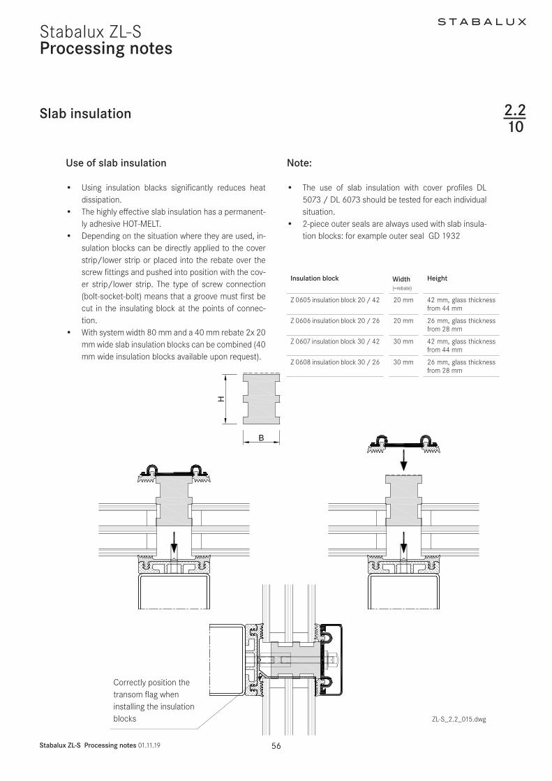
S T A B A L U X
Stabalux ZL-S Design 011119 61
Stabalux ZL-SDesign
Design requirements
1 Vapour seal
The room-side level of glazing must have the best possi-ble vapour seal In this regard the vapour diffusion prop-erties of the silicone sealant to be used should be tested
Ensure that there are no permeable areas around con-cave cross joints
2 Rebate ventilation pressure equalisa-tion and condensation drainage
Systems with partially sealed rebate represent a limita-tion to rebate ventilation Check on a case-by-case basis that no damage will be caused by standing condensation It is especially critical that designs with sealed vertical joints are evaluated To allow ventilation of the horizontal rebate we recommend installing a suitable vertical ven-tilation space Alternatively ventilation can be achieved using the outer joints
3 Weatherproofing
The outward facing seals must be watertight In cross joints it is especially important to ensure a firm join be-tween the Stabalux profile seal and the silicone joints We recommend sealing up to the outer edge of the glass before mounting the cover profiles
We would like emphasise once again that our profile seals will not make a permanent bond with commonly used silicone sealants A seal can only be created at con-tact points through permanent application of pressure
4 Mechanical strength of the screw fittings
Ensure screw fittings are of a sufficiently size Special at-tention should be given to the effects of wind suction and the reduced support
5 Glass weight distribution
Mechanical distribution of the weight of the glass panes through the structure must be ensured System glass supports can be used for existing horizontal transoms Designs using ldquoonlyrdquo mullions require special glass sup-ports which carry the weight of the glass directly into the mullions
6 Glass sizing
Attention should be given to the reduced support of panes when dimensioning the glass For example only the vertical or horizontal cover profiles are effective in the event of wind suction stresses or stress on the fall protection
7 Material compatibility
Compatibility of the silicone sealants with our profile seal-ants and the edge bonding of the glass must be ensured We recommend the exclusive use of tested silicone seal-ants from the whole-glass facades sector Approval is usually given by the silicone manufacturer
Pane support variants
ZL-S_23_001dwg
231
Examples
S T A B A L U X
Stabalux ZL-S Design 011119 62
Stabalux ZL-S
System cross sections
Design
ZL-S_23_001dwg
1 Vertical glazing mullion
concealed screw fittings
2 Vertical glazing mullion
visible screw fittings
3 Vertical glazing mullion
flat cover strip DL 5073 DL 6073
4 Vertical glazing transom
visible recessed screw fittings
Outer seal for height compensation
5 Vertical glazing transom
concealed screw fittings
single glazing
6 Vertical glazing transom
concealed screw fittings
7 Inclined glazing mullion
concealed screw fittings
8 Inclined glazing transom
visible screw fittings
1 2
3 4
5 6
7 8
232
S T A B A L U X
Stabalux ZL-S Design 011119 63
Stabalux ZL-SDesign
System details
Creating facade corners
At exposed areas such as glass facade corners it is par-ticularly important to ensure sufficient heat insulation in order to avoid the creation of thermal bridges and pre-vent a build-up of condensation Thermal current calcula-tions provide information about the actual heat loss
Outer corner Inner corner
ZL-S_23_002dwg ZL-S_23_002dwg
Facade polygon
Special seal allow a polygon shaped arrangement of the facade mullions For convex glass surfaces an angle be-tween 3deg and 15deg can be freely chosen For concave glass surfaces the angle can vary between 3deg and 10deg
ZL-S_23_002dwg
Geometrically check the feasibility Recommendation Use System 60 at minimum
ATTENTIONAdhere to the minimum glass inset
Determine the threaded bolt length using consideration of the angle
233
S T A B A L U X
Stabalux ZL-S Design 011119 64
Stabalux ZL-SDesign
System details
Eaves with glass roof connection
bull Depending on the construction of the transoms a design with or without rain gutters and the choice of stepped glazing or closable cover profiles gives us different variants for implementation
bull All options require condensation and moisture to be drained away at the eaves
Design with stepped glazing
bull With a stepped glazing design it is important to select a UV-resistant edge bonding for the glass This edge bonding systems usually silicone-based are quite permeable to gases and are therefore unable to achieve the required high values for sound and heat insulation of conventional systems ie require additional sealing around the edges
Example 1
Design with stepped glazing
bull Our thermal calculations show that stepped glass panes compared to covered glass edges have a much less favourable isothermal movement
bull Stepped glass panes must also be statically meas-ured according to their reduced hold against wind suction
bull The additional thermal loads that occur in stepped glass panes should countered by the use of pre-ten-sioned glass (TVG ESG) for the outer panes
bull Stepped glass panes should be preferred for flatter inclined roofs as water can drain away at the eaves unhindered
ZL-S_23_003dwg
233
S T A B A L U X
Stabalux ZL-S Design 011119 65
Stabalux ZL-SDesign
Eaves with glass roof connection Design using cover profiles
bull Horizontal pressure strips prevent the free run off of rain water and dirt
bull Cover strips with angled edges reduce the build up of water in front of the cover strip
bull The outer sealing level on glass roofs must also be thoroughly sealed
bull In combination with our butyl clad stainless steel panels glazing with pressure strips on 4 sides achieves a higher level of safety
bull Make sure that the inner sealing section provides guaranteed drainage for condensation
bull To improve drainage and heat-induced expansion cover profiles should be shortened by 5 mm at tran-som joints Gasket joints however are to be laid flat with a slight excess in dimensions Open ends of the transom cover profiles must be sealed
Note
Due to the increased thermal stresses in the roof we rec-ommend using concealed screw fitting when choosing clamping strips for larger system lengths and in rafters Unused holes in the lower strip must be sealed
System details
Example 2
Design using cover profiles
ZL-S_23_004dwg
233
S T A B A L U X
Stabalux ZL-S Design 011119 66
Stabalux ZL-SDesign
System details
Eaves with glass roof connection Design with gutter
bull The gutter must be able to take its own weight and mounted in such a way that stresses from its own weight water and ice will not lead to deformations and directly apply a load to the glazing
bull Overflowing water must not be able to get inside the structure Alongside the gutter-shaped outer rafter seal the moisture barrier installed over the guide plate also acts to drain away condensation
Example 3
Design with gutter
ZL-S_23_005dwg
233
S T A B A L U X
Stabalux ZL-S Design 011119 67
Stabalux ZL-SDesign
System details
Roof ridge design
bull When designing the ridge cap ensure that the rafter cover profiles are pulled under the ridge cap
ZL-S_23_006dwg
233
S T A B A L U X
Stabalux ZL-S Design 011119 68
Stabalux ZL-S
Structural attachments
Design
Structural attachment film baffles
bull Attachment of glazing to the building structure re-quires a well thought out approach
bull Moisture damage can occur if moisture condenses at any thermal bridges
bull Thermal bridges must be avoided and warm air from the inside spaces must not penetrate too deeply into the structure
bull The required moisture barriers must be installed as deeply as possible into the inner space using imper-meable structural film baffles This prevents mois-ture penetration into the structure via condensation from the air inside
bull An additional foil to seal against rainwater must be permeable to moisture Only if this foil has a water vapour diffusion resistance value μ of max μ = 3000 can a dry structure be guaranteed in the transition zones
234
S T A B A L U X
Stabalux ZL-S Design 011119 69
Stabalux ZL-S
Structural attachments
Design
Facade base
bull Controlled drainage of the rebate space can only be ensured if the sealing sections overlap in such a way that no moisture can get under the seals and foils
bull Run foils under the transom seal to act as a moisture barrier and glue to the steel structure In accordance with DIN 18195 the seal should be run at least 150 mm above the water-guiding layer
bull Attach foil with moisture barrier in accordance with the requirements of DIN 18195
Example 1 Mounting intermediate mullion to base plate
Drainage of the base area is achieved via the transom flag towards the outside In this case the transom flag around the mullion at the base should not be released For edge mullions ensure there is a
corresponding seal placed (continuous transom seal up the to the end point) and a constructive design of the drainage section
ZL-S_23_007dwg
234
S T A B A L U X
Stabalux ZL-S Design 011119 70
Stabalux ZL-SDesign
Structural attachments
Facade base
bull Rebate space ventilation is achieved via the open end of the vertical cover profiles
bull Ensure the connection is impermeable to vapourbull Mullion mountings must be sufficiently statically di-
mensioned Required axis and edge distances for an-choring the base plates and in the building structure must be observed
Example 2 Mounting intermediate mullion to base plate
Where transom flags are interrupted by joints filler rods in the joint must also be cut
ZL-S_23_008dwg
234
S T A B A L U X
Stabalux ZL-S Design 011119 71
Stabalux ZL-SDesign
Structural attachments
Facade base
bull Heat insulation around the structural connection should be designed in such as way as to prevent cold bridges forming
bull Steel parts should also be provided with sufficient protection against corrosion even in concealed ar-eas
bull Weather-protection sheets should be used depend-ing on the requirements of the construction Suffi-cient rear ventilation must be ensured
Example 3 Attaching intermediate mullions at base plates
ZL-S_23_009dwg
234
ZL-S_23_010-2
Stabalux ZL-S
S T A B A L U X
Stabalux ZL-S Design 011119 72
Stabalux ZL-SDesign
Connection before intermediate floors
bull Depending on requirements mullions are designed as continuous multi-span transoms or separated at each floor
bull Reasons for separating mullions can include eg building settlement fire protection sound insulation etc
bull If the separation joint is intended to absorb expan-sion then as well as the required degree of freedom for mullions the ability for movement of integrated elements must also be ensured
Structural attachments
bull The constructive design of the mullion joint and mounting should be chosen according to the stat-ically calculated base system and determines the choice and arrangement of fixed and movable bear-ings type of screw fittings structural connection parts and attachment to the concrete floor
bull With continuous mullions and a corresponding mount the multi-span support principle is in effect Sagging due to horizontal effects is lower The required mo-ment of inertia reduces for 2-span supports with the same span length compared to the 1-span support by a factor of 0415 However a tension and stability analysis should be carried out
Example Mullions separated at each floor
In this example distribution of horizontal and vertical loads is achieved at each floor through the existing floor structure
ZL-S_23_010dwg
234
S T A B A L U X
Stabalux ZL-S Design 011119 73
Stabalux ZL-SDesign
Ceiling connection
bull Structural connections should take account of any movement that may occur
bull As well as temperature induced expansion in the fa-cade all longitudinal expansions and movements of the affected components must be considered
bull Additional stresses from restraints must be avoided
Structural attachments
ZL-S_23_011dwg
234
S T A B A L U X
Stabalux ZL-S Design 011119 74
Stabalux ZL-SDesign
Facade connection to parapets
Structural attachments
ZL-S_23_012dwg
234
S T A B A L U X
Stabalux ZL-S Design 011119 75
Stabalux ZL-SDesign
Connection to structural eaves
bull This connection is suitable for glass roofs that are being installed as skylights in the structure These may be gabled roofs single pitch roofs pyramids or arched roofs
Structural attachments
ZL-S_23_013dwg
234
S T A B A L U X
Stabalux ZL-S Design 011119 76
Stabalux ZL-SDesign
Ridge connection to walls
bull When making ridge connections to walls permea-bility to moisture is particularly important Warm air with a high level of moisture gets into cooler zones of the inner sealing section where the design is not sufficiently sealed and can cause structural damage from penetrating into the connecting structure
bull Joint seals made from butyl-clad stainless steel plates (Z 0501 Z 0601) must be installed on the out-side of joint areas
Structural attachments
ZL-S_23_014dwg
234
S T A B A L U X
Stabalux ZL-S Design 011119 77
Stabalux ZL-SDesign
Horizontal wall connection to heat insulation bonding system
Structural attachments
ZL-S_23_015dwg
234
Ceiling conection including WAREMA external blinds
Structural attachments
ZL-S_23_024dwg
234
S T A B A L U X
Stabalux ZL-S Design 011119 78
Stabalux ZL-S
S T A B A L U X
Stabalux ZL-S Design 011119 79
Stabalux ZL-SDesign
Installing windows and doors
Mullion and transom facades and glass roofs from Stabalux are neutral with regards to the selection of in-sert elements All commonly available window and door systems made from steel aluminium wood or plastic can be used Frame profiles from the window and door man-ufacturerrsquos should be selected to match the chosen glass thickness If no profiles with a suitable insert rebate are available mountings may be used as shown in the fol-lowing examples Like with glass elements windows are set into the facade on glass supports padded and then secured against slippage
Insert window transom sectionSystem HUECKSeries Lambda WS 075 IS
Use a locating screwas an assembly aid if necessary
Use
a lo
catin
g sc
rew
as a
n as
sem
bly
aid
if ne
cess
ary Insert window mullion section
System HUECKSeries Lambda WS 075 IS
ZL-S_23_01 dwg
235
S T A B A L U X
Stabalux ZL-S Design 011119 80
Stabalux ZL-SDesign
Installing windows and doors
ZL-S_23_017dwg
Insert window mullion sectionSystem HUECKSeries Lambda WS 075
Insert window transom sectionSystem HUECKSeries Lambda WS 075
235
Use a locating screwas an assembly aidif necessary
Use
a lo
catin
g sc
rew
as a
n as
sem
bly
aid
if ne
cess
ary
S T A B A L U X
Stabalux ZL-S Design 011119 81
Stabalux ZL-S
ZL-S_23_018dwg
Design
Installing windows and doors
Insert door outward in the mullion sectionSystem HUECKSeries Lambda DS 075
Insert door outward in the transom sectionSystem HUECKSeries Lambda DS 075
235
Use a locating screw as an assembly aid if necessary
Use
a lo
catin
g sc
rew
as a
n as
sem
bly
aid
if ne
cess
ary
S T A B A L U X
Stabalux ZL-S Design 011119 82
Stabalux ZL-SDesign
Installing windows and doors
Insert door inward in the mullion sectionSystem HUECKSeries Lambda DS 075
Insert door inward in the transom sectionSystem HUECKSeries Lambda DS 075
ZL-S_23_019dwg
235
Use a locating screwas an assembly aidif necessary
Use
a lo
catin
g sc
rew
as a
n as
sem
bly
aid
if ne
cess
ary
ZL-S_23_020dwg
Design
Installing windows and doors
Insert top-hung window in the mullion sectionSystem HUECKSeries Lambda 110
Insert top-hung window in the transom sectionSystem HUECKSeries Lambda 110
235
S T A B A L U X
Stabalux ZL-S Design 011119 83
Stabalux ZL-S
Design
Installing windows and doors
Sliding system in the mullion sectionSystem HUECKSeries Volato M
Sliding system in the transom sectionSystem HUECKSeries Volato M
ZL-S_23_021dwg
235
S T A B A L U X
Stabalux ZL-S Design 011119 84
Stabalux ZL-S
S T A B A L U X
Stabalux ZL-S Design 011119 85
Stabalux ZL-SDesign
Installing windows and doors
Flush roof surface windowSystem HUECK-HARTMANNSeries 85E
Connection at top
Connection at bottom
Powered accordingto system specifications
ZL-S_23_020dwg
235
S T A B A L U X
Stabalux ZL-S Design 011119 86
Stabalux ZL-SDesign
Installing windows and doors
Insert window - mullion sectionSystem HahnSeries Lamellae S9 iVt-05
Insert window - transom sectionsSystem HahnSeries Lamellae S9 iVt-05
ZL-S_23_021dwg
235
- Stabalux ZL-S
-
- System
-
- System properties
- System cross sections and inner seals - facade
- System cross sections and inner seals - roof
- Cover strips and outer seals
-
- Processing notes
-
- Material information
- Assembly sequence
- Attaching the spacer strip
- Tips for laying seals
- Seals - Facade
- Seals - roof
- Glass inset and glass support
- Screw fittings
- Flat cover strip DL 5073 DL 6073
- Slab insulation
-
- Design
-
- Pane support variants
- System cross sections
- System details
- Structural attachments
- Installing windows and doors
-

S T A B A L U X
Stabalux ZL-S Design 011119 70
Stabalux ZL-SDesign
Structural attachments
Facade base
bull Rebate space ventilation is achieved via the open end of the vertical cover profiles
bull Ensure the connection is impermeable to vapourbull Mullion mountings must be sufficiently statically di-
mensioned Required axis and edge distances for an-choring the base plates and in the building structure must be observed
Example 2 Mounting intermediate mullion to base plate
Where transom flags are interrupted by joints filler rods in the joint must also be cut
ZL-S_23_008dwg
234
S T A B A L U X
Stabalux ZL-S Design 011119 71
Stabalux ZL-SDesign
Structural attachments
Facade base
bull Heat insulation around the structural connection should be designed in such as way as to prevent cold bridges forming
bull Steel parts should also be provided with sufficient protection against corrosion even in concealed ar-eas
bull Weather-protection sheets should be used depend-ing on the requirements of the construction Suffi-cient rear ventilation must be ensured
Example 3 Attaching intermediate mullions at base plates
ZL-S_23_009dwg
234
ZL-S_23_010-2
Stabalux ZL-S
S T A B A L U X
Stabalux ZL-S Design 011119 72
Stabalux ZL-SDesign
Connection before intermediate floors
bull Depending on requirements mullions are designed as continuous multi-span transoms or separated at each floor
bull Reasons for separating mullions can include eg building settlement fire protection sound insulation etc
bull If the separation joint is intended to absorb expan-sion then as well as the required degree of freedom for mullions the ability for movement of integrated elements must also be ensured
Structural attachments
bull The constructive design of the mullion joint and mounting should be chosen according to the stat-ically calculated base system and determines the choice and arrangement of fixed and movable bear-ings type of screw fittings structural connection parts and attachment to the concrete floor
bull With continuous mullions and a corresponding mount the multi-span support principle is in effect Sagging due to horizontal effects is lower The required mo-ment of inertia reduces for 2-span supports with the same span length compared to the 1-span support by a factor of 0415 However a tension and stability analysis should be carried out
Example Mullions separated at each floor
In this example distribution of horizontal and vertical loads is achieved at each floor through the existing floor structure
ZL-S_23_010dwg
234
S T A B A L U X
Stabalux ZL-S Design 011119 73
Stabalux ZL-SDesign
Ceiling connection
bull Structural connections should take account of any movement that may occur
bull As well as temperature induced expansion in the fa-cade all longitudinal expansions and movements of the affected components must be considered
bull Additional stresses from restraints must be avoided
Structural attachments
ZL-S_23_011dwg
234
S T A B A L U X
Stabalux ZL-S Design 011119 74
Stabalux ZL-SDesign
Facade connection to parapets
Structural attachments
ZL-S_23_012dwg
234
S T A B A L U X
Stabalux ZL-S Design 011119 75
Stabalux ZL-SDesign
Connection to structural eaves
bull This connection is suitable for glass roofs that are being installed as skylights in the structure These may be gabled roofs single pitch roofs pyramids or arched roofs
Structural attachments
ZL-S_23_013dwg
234
S T A B A L U X
Stabalux ZL-S Design 011119 76
Stabalux ZL-SDesign
Ridge connection to walls
bull When making ridge connections to walls permea-bility to moisture is particularly important Warm air with a high level of moisture gets into cooler zones of the inner sealing section where the design is not sufficiently sealed and can cause structural damage from penetrating into the connecting structure
bull Joint seals made from butyl-clad stainless steel plates (Z 0501 Z 0601) must be installed on the out-side of joint areas
Structural attachments
ZL-S_23_014dwg
234
S T A B A L U X
Stabalux ZL-S Design 011119 77
Stabalux ZL-SDesign
Horizontal wall connection to heat insulation bonding system
Structural attachments
ZL-S_23_015dwg
234
Ceiling conection including WAREMA external blinds
Structural attachments
ZL-S_23_024dwg
234
S T A B A L U X
Stabalux ZL-S Design 011119 78
Stabalux ZL-S
S T A B A L U X
Stabalux ZL-S Design 011119 79
Stabalux ZL-SDesign
Installing windows and doors
Mullion and transom facades and glass roofs from Stabalux are neutral with regards to the selection of in-sert elements All commonly available window and door systems made from steel aluminium wood or plastic can be used Frame profiles from the window and door man-ufacturerrsquos should be selected to match the chosen glass thickness If no profiles with a suitable insert rebate are available mountings may be used as shown in the fol-lowing examples Like with glass elements windows are set into the facade on glass supports padded and then secured against slippage
Insert window transom sectionSystem HUECKSeries Lambda WS 075 IS
Use a locating screwas an assembly aid if necessary
Use
a lo
catin
g sc
rew
as a
n as
sem
bly
aid
if ne
cess
ary Insert window mullion section
System HUECKSeries Lambda WS 075 IS
ZL-S_23_01 dwg
235
S T A B A L U X
Stabalux ZL-S Design 011119 80
Stabalux ZL-SDesign
Installing windows and doors
ZL-S_23_017dwg
Insert window mullion sectionSystem HUECKSeries Lambda WS 075
Insert window transom sectionSystem HUECKSeries Lambda WS 075
235
Use a locating screwas an assembly aidif necessary
Use
a lo
catin
g sc
rew
as a
n as
sem
bly
aid
if ne
cess
ary
S T A B A L U X
Stabalux ZL-S Design 011119 81
Stabalux ZL-S
ZL-S_23_018dwg
Design
Installing windows and doors
Insert door outward in the mullion sectionSystem HUECKSeries Lambda DS 075
Insert door outward in the transom sectionSystem HUECKSeries Lambda DS 075
235
Use a locating screw as an assembly aid if necessary
Use
a lo
catin
g sc
rew
as a
n as
sem
bly
aid
if ne
cess
ary
S T A B A L U X
Stabalux ZL-S Design 011119 82
Stabalux ZL-SDesign
Installing windows and doors
Insert door inward in the mullion sectionSystem HUECKSeries Lambda DS 075
Insert door inward in the transom sectionSystem HUECKSeries Lambda DS 075
ZL-S_23_019dwg
235
Use a locating screwas an assembly aidif necessary
Use
a lo
catin
g sc
rew
as a
n as
sem
bly
aid
if ne
cess
ary
ZL-S_23_020dwg
Design
Installing windows and doors
Insert top-hung window in the mullion sectionSystem HUECKSeries Lambda 110
Insert top-hung window in the transom sectionSystem HUECKSeries Lambda 110
235
S T A B A L U X
Stabalux ZL-S Design 011119 83
Stabalux ZL-S
Design
Installing windows and doors
Sliding system in the mullion sectionSystem HUECKSeries Volato M
Sliding system in the transom sectionSystem HUECKSeries Volato M
ZL-S_23_021dwg
235
S T A B A L U X
Stabalux ZL-S Design 011119 84
Stabalux ZL-S
S T A B A L U X
Stabalux ZL-S Design 011119 85
Stabalux ZL-SDesign
Installing windows and doors
Flush roof surface windowSystem HUECK-HARTMANNSeries 85E
Connection at top
Connection at bottom
Powered accordingto system specifications
ZL-S_23_020dwg
235
S T A B A L U X
Stabalux ZL-S Design 011119 86
Stabalux ZL-SDesign
Installing windows and doors
Insert window - mullion sectionSystem HahnSeries Lamellae S9 iVt-05
Insert window - transom sectionsSystem HahnSeries Lamellae S9 iVt-05
ZL-S_23_021dwg
235
- Stabalux ZL-S
-
- System
-
- System properties
- System cross sections and inner seals - facade
- System cross sections and inner seals - roof
- Cover strips and outer seals
-
- Processing notes
-
- Material information
- Assembly sequence
- Attaching the spacer strip
- Tips for laying seals
- Seals - Facade
- Seals - roof
- Glass inset and glass support
- Screw fittings
- Flat cover strip DL 5073 DL 6073
- Slab insulation
-
- Design
-
- Pane support variants
- System cross sections
- System details
- Structural attachments
- Installing windows and doors
-
S T A B A L U X
Stabalux ZL-S Design 011119 71
Stabalux ZL-SDesign
Structural attachments
Facade base
bull Heat insulation around the structural connection should be designed in such as way as to prevent cold bridges forming
bull Steel parts should also be provided with sufficient protection against corrosion even in concealed ar-eas
bull Weather-protection sheets should be used depend-ing on the requirements of the construction Suffi-cient rear ventilation must be ensured
Example 3 Attaching intermediate mullions at base plates
ZL-S_23_009dwg
234
ZL-S_23_010-2
Stabalux ZL-S
S T A B A L U X
Stabalux ZL-S Design 011119 72
Stabalux ZL-SDesign
Connection before intermediate floors
bull Depending on requirements mullions are designed as continuous multi-span transoms or separated at each floor
bull Reasons for separating mullions can include eg building settlement fire protection sound insulation etc
bull If the separation joint is intended to absorb expan-sion then as well as the required degree of freedom for mullions the ability for movement of integrated elements must also be ensured
Structural attachments
bull The constructive design of the mullion joint and mounting should be chosen according to the stat-ically calculated base system and determines the choice and arrangement of fixed and movable bear-ings type of screw fittings structural connection parts and attachment to the concrete floor
bull With continuous mullions and a corresponding mount the multi-span support principle is in effect Sagging due to horizontal effects is lower The required mo-ment of inertia reduces for 2-span supports with the same span length compared to the 1-span support by a factor of 0415 However a tension and stability analysis should be carried out
Example Mullions separated at each floor
In this example distribution of horizontal and vertical loads is achieved at each floor through the existing floor structure
ZL-S_23_010dwg
234
S T A B A L U X
Stabalux ZL-S Design 011119 73
Stabalux ZL-SDesign
Ceiling connection
bull Structural connections should take account of any movement that may occur
bull As well as temperature induced expansion in the fa-cade all longitudinal expansions and movements of the affected components must be considered
bull Additional stresses from restraints must be avoided
Structural attachments
ZL-S_23_011dwg
234
S T A B A L U X
Stabalux ZL-S Design 011119 74
Stabalux ZL-SDesign
Facade connection to parapets
Structural attachments
ZL-S_23_012dwg
234
S T A B A L U X
Stabalux ZL-S Design 011119 75
Stabalux ZL-SDesign
Connection to structural eaves
bull This connection is suitable for glass roofs that are being installed as skylights in the structure These may be gabled roofs single pitch roofs pyramids or arched roofs
Structural attachments
ZL-S_23_013dwg
234
S T A B A L U X
Stabalux ZL-S Design 011119 76
Stabalux ZL-SDesign
Ridge connection to walls
bull When making ridge connections to walls permea-bility to moisture is particularly important Warm air with a high level of moisture gets into cooler zones of the inner sealing section where the design is not sufficiently sealed and can cause structural damage from penetrating into the connecting structure
bull Joint seals made from butyl-clad stainless steel plates (Z 0501 Z 0601) must be installed on the out-side of joint areas
Structural attachments
ZL-S_23_014dwg
234
S T A B A L U X
Stabalux ZL-S Design 011119 77
Stabalux ZL-SDesign
Horizontal wall connection to heat insulation bonding system
Structural attachments
ZL-S_23_015dwg
234
Ceiling conection including WAREMA external blinds
Structural attachments
ZL-S_23_024dwg
234
S T A B A L U X
Stabalux ZL-S Design 011119 78
Stabalux ZL-S
S T A B A L U X
Stabalux ZL-S Design 011119 79
Stabalux ZL-SDesign
Installing windows and doors
Mullion and transom facades and glass roofs from Stabalux are neutral with regards to the selection of in-sert elements All commonly available window and door systems made from steel aluminium wood or plastic can be used Frame profiles from the window and door man-ufacturerrsquos should be selected to match the chosen glass thickness If no profiles with a suitable insert rebate are available mountings may be used as shown in the fol-lowing examples Like with glass elements windows are set into the facade on glass supports padded and then secured against slippage
Insert window transom sectionSystem HUECKSeries Lambda WS 075 IS
Use a locating screwas an assembly aid if necessary
Use
a lo
catin
g sc
rew
as a
n as
sem
bly
aid
if ne
cess
ary Insert window mullion section
System HUECKSeries Lambda WS 075 IS
ZL-S_23_01 dwg
235
S T A B A L U X
Stabalux ZL-S Design 011119 80
Stabalux ZL-SDesign
Installing windows and doors
ZL-S_23_017dwg
Insert window mullion sectionSystem HUECKSeries Lambda WS 075
Insert window transom sectionSystem HUECKSeries Lambda WS 075
235
Use a locating screwas an assembly aidif necessary
Use
a lo
catin
g sc
rew
as a
n as
sem
bly
aid
if ne
cess
ary
S T A B A L U X
Stabalux ZL-S Design 011119 81
Stabalux ZL-S
ZL-S_23_018dwg
Design
Installing windows and doors
Insert door outward in the mullion sectionSystem HUECKSeries Lambda DS 075
Insert door outward in the transom sectionSystem HUECKSeries Lambda DS 075
235
Use a locating screw as an assembly aid if necessary
Use
a lo
catin
g sc
rew
as a
n as
sem
bly
aid
if ne
cess
ary
S T A B A L U X
Stabalux ZL-S Design 011119 82
Stabalux ZL-SDesign
Installing windows and doors
Insert door inward in the mullion sectionSystem HUECKSeries Lambda DS 075
Insert door inward in the transom sectionSystem HUECKSeries Lambda DS 075
ZL-S_23_019dwg
235
Use a locating screwas an assembly aidif necessary
Use
a lo
catin
g sc
rew
as a
n as
sem
bly
aid
if ne
cess
ary
ZL-S_23_020dwg
Design
Installing windows and doors
Insert top-hung window in the mullion sectionSystem HUECKSeries Lambda 110
Insert top-hung window in the transom sectionSystem HUECKSeries Lambda 110
235
S T A B A L U X
Stabalux ZL-S Design 011119 83
Stabalux ZL-S
Design
Installing windows and doors
Sliding system in the mullion sectionSystem HUECKSeries Volato M
Sliding system in the transom sectionSystem HUECKSeries Volato M
ZL-S_23_021dwg
235
S T A B A L U X
Stabalux ZL-S Design 011119 84
Stabalux ZL-S
S T A B A L U X
Stabalux ZL-S Design 011119 85
Stabalux ZL-SDesign
Installing windows and doors
Flush roof surface windowSystem HUECK-HARTMANNSeries 85E
Connection at top
Connection at bottom
Powered accordingto system specifications
ZL-S_23_020dwg
235
S T A B A L U X
Stabalux ZL-S Design 011119 86
Stabalux ZL-SDesign
Installing windows and doors
Insert window - mullion sectionSystem HahnSeries Lamellae S9 iVt-05
Insert window - transom sectionsSystem HahnSeries Lamellae S9 iVt-05
ZL-S_23_021dwg
235
- Stabalux ZL-S
-
- System
-
- System properties
- System cross sections and inner seals - facade
- System cross sections and inner seals - roof
- Cover strips and outer seals
-
- Processing notes
-
- Material information
- Assembly sequence
- Attaching the spacer strip
- Tips for laying seals
- Seals - Facade
- Seals - roof
- Glass inset and glass support
- Screw fittings
- Flat cover strip DL 5073 DL 6073
- Slab insulation
-
- Design
-
- Pane support variants
- System cross sections
- System details
- Structural attachments
- Installing windows and doors
-
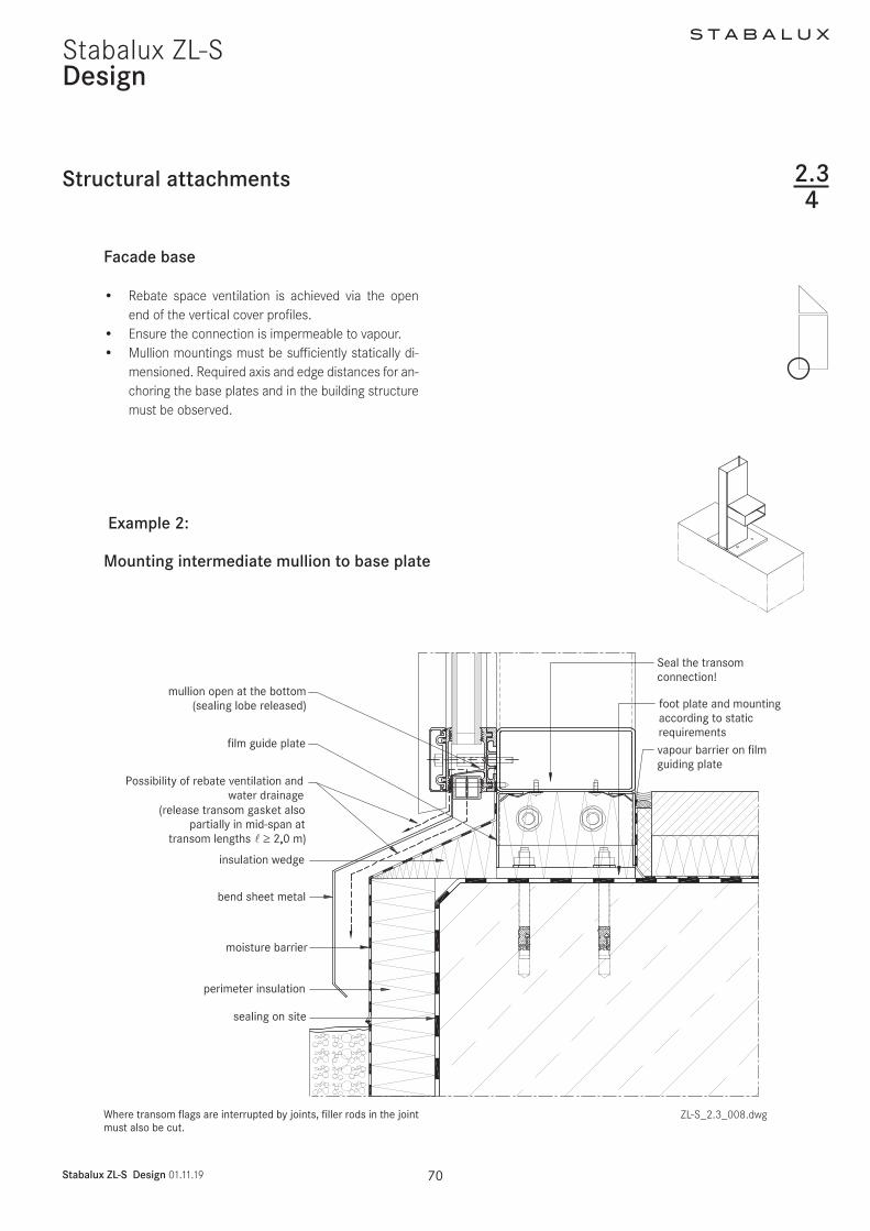
S T A B A L U X
Stabalux ZL-S Design 011119 77
Stabalux ZL-SDesign
Horizontal wall connection to heat insulation bonding system
Structural attachments
ZL-S_23_015dwg
234
Ceiling conection including WAREMA external blinds
Structural attachments
ZL-S_23_024dwg
234
S T A B A L U X
Stabalux ZL-S Design 011119 78
Stabalux ZL-S
S T A B A L U X
Stabalux ZL-S Design 011119 79
Stabalux ZL-SDesign
Installing windows and doors
Mullion and transom facades and glass roofs from Stabalux are neutral with regards to the selection of in-sert elements All commonly available window and door systems made from steel aluminium wood or plastic can be used Frame profiles from the window and door man-ufacturerrsquos should be selected to match the chosen glass thickness If no profiles with a suitable insert rebate are available mountings may be used as shown in the fol-lowing examples Like with glass elements windows are set into the facade on glass supports padded and then secured against slippage
Insert window transom sectionSystem HUECKSeries Lambda WS 075 IS
Use a locating screwas an assembly aid if necessary
Use
a lo
catin
g sc
rew
as a
n as
sem
bly
aid
if ne
cess
ary Insert window mullion section
System HUECKSeries Lambda WS 075 IS
ZL-S_23_01 dwg
235
S T A B A L U X
Stabalux ZL-S Design 011119 80
Stabalux ZL-SDesign
Installing windows and doors
ZL-S_23_017dwg
Insert window mullion sectionSystem HUECKSeries Lambda WS 075
Insert window transom sectionSystem HUECKSeries Lambda WS 075
235
Use a locating screwas an assembly aidif necessary
Use
a lo
catin
g sc
rew
as a
n as
sem
bly
aid
if ne
cess
ary
S T A B A L U X
Stabalux ZL-S Design 011119 81
Stabalux ZL-S
ZL-S_23_018dwg
Design
Installing windows and doors
Insert door outward in the mullion sectionSystem HUECKSeries Lambda DS 075
Insert door outward in the transom sectionSystem HUECKSeries Lambda DS 075
235
Use a locating screw as an assembly aid if necessary
Use
a lo
catin
g sc
rew
as a
n as
sem
bly
aid
if ne
cess
ary
S T A B A L U X
Stabalux ZL-S Design 011119 82
Stabalux ZL-SDesign
Installing windows and doors
Insert door inward in the mullion sectionSystem HUECKSeries Lambda DS 075
Insert door inward in the transom sectionSystem HUECKSeries Lambda DS 075
ZL-S_23_019dwg
235
Use a locating screwas an assembly aidif necessary
Use
a lo
catin
g sc
rew
as a
n as
sem
bly
aid
if ne
cess
ary
ZL-S_23_020dwg
Design
Installing windows and doors
Insert top-hung window in the mullion sectionSystem HUECKSeries Lambda 110
Insert top-hung window in the transom sectionSystem HUECKSeries Lambda 110
235
S T A B A L U X
Stabalux ZL-S Design 011119 83
Stabalux ZL-S
Design
Installing windows and doors
Sliding system in the mullion sectionSystem HUECKSeries Volato M
Sliding system in the transom sectionSystem HUECKSeries Volato M
ZL-S_23_021dwg
235
S T A B A L U X
Stabalux ZL-S Design 011119 84
Stabalux ZL-S
S T A B A L U X
Stabalux ZL-S Design 011119 85
Stabalux ZL-SDesign
Installing windows and doors
Flush roof surface windowSystem HUECK-HARTMANNSeries 85E
Connection at top
Connection at bottom
Powered accordingto system specifications
ZL-S_23_020dwg
235
S T A B A L U X
Stabalux ZL-S Design 011119 86
Stabalux ZL-SDesign
Installing windows and doors
Insert window - mullion sectionSystem HahnSeries Lamellae S9 iVt-05
Insert window - transom sectionsSystem HahnSeries Lamellae S9 iVt-05
ZL-S_23_021dwg
235
- Stabalux ZL-S
-
- System
-
- System properties
- System cross sections and inner seals - facade
- System cross sections and inner seals - roof
- Cover strips and outer seals
-
- Processing notes
-
- Material information
- Assembly sequence
- Attaching the spacer strip
- Tips for laying seals
- Seals - Facade
- Seals - roof
- Glass inset and glass support
- Screw fittings
- Flat cover strip DL 5073 DL 6073
- Slab insulation
-
- Design
-
- Pane support variants
- System cross sections
- System details
- Structural attachments
- Installing windows and doors
-

S T A B A L U X
Stabalux ZL-S Design 011119 79
Stabalux ZL-SDesign
Installing windows and doors
Mullion and transom facades and glass roofs from Stabalux are neutral with regards to the selection of in-sert elements All commonly available window and door systems made from steel aluminium wood or plastic can be used Frame profiles from the window and door man-ufacturerrsquos should be selected to match the chosen glass thickness If no profiles with a suitable insert rebate are available mountings may be used as shown in the fol-lowing examples Like with glass elements windows are set into the facade on glass supports padded and then secured against slippage
Insert window transom sectionSystem HUECKSeries Lambda WS 075 IS
Use a locating screwas an assembly aid if necessary
Use
a lo
catin
g sc
rew
as a
n as
sem
bly
aid
if ne
cess
ary Insert window mullion section
System HUECKSeries Lambda WS 075 IS
ZL-S_23_01 dwg
235
S T A B A L U X
Stabalux ZL-S Design 011119 80
Stabalux ZL-SDesign
Installing windows and doors
ZL-S_23_017dwg
Insert window mullion sectionSystem HUECKSeries Lambda WS 075
Insert window transom sectionSystem HUECKSeries Lambda WS 075
235
Use a locating screwas an assembly aidif necessary
Use
a lo
catin
g sc
rew
as a
n as
sem
bly
aid
if ne
cess
ary
S T A B A L U X
Stabalux ZL-S Design 011119 81
Stabalux ZL-S
ZL-S_23_018dwg
Design
Installing windows and doors
Insert door outward in the mullion sectionSystem HUECKSeries Lambda DS 075
Insert door outward in the transom sectionSystem HUECKSeries Lambda DS 075
235
Use a locating screw as an assembly aid if necessary
Use
a lo
catin
g sc
rew
as a
n as
sem
bly
aid
if ne
cess
ary
S T A B A L U X
Stabalux ZL-S Design 011119 82
Stabalux ZL-SDesign
Installing windows and doors
Insert door inward in the mullion sectionSystem HUECKSeries Lambda DS 075
Insert door inward in the transom sectionSystem HUECKSeries Lambda DS 075
ZL-S_23_019dwg
235
Use a locating screwas an assembly aidif necessary
Use
a lo
catin
g sc
rew
as a
n as
sem
bly
aid
if ne
cess
ary
ZL-S_23_020dwg
Design
Installing windows and doors
Insert top-hung window in the mullion sectionSystem HUECKSeries Lambda 110
Insert top-hung window in the transom sectionSystem HUECKSeries Lambda 110
235
S T A B A L U X
Stabalux ZL-S Design 011119 83
Stabalux ZL-S
Design
Installing windows and doors
Sliding system in the mullion sectionSystem HUECKSeries Volato M
Sliding system in the transom sectionSystem HUECKSeries Volato M
ZL-S_23_021dwg
235
S T A B A L U X
Stabalux ZL-S Design 011119 84
Stabalux ZL-S
S T A B A L U X
Stabalux ZL-S Design 011119 85
Stabalux ZL-SDesign
Installing windows and doors
Flush roof surface windowSystem HUECK-HARTMANNSeries 85E
Connection at top
Connection at bottom
Powered accordingto system specifications
ZL-S_23_020dwg
235
S T A B A L U X
Stabalux ZL-S Design 011119 86
Stabalux ZL-SDesign
Installing windows and doors
Insert window - mullion sectionSystem HahnSeries Lamellae S9 iVt-05
Insert window - transom sectionsSystem HahnSeries Lamellae S9 iVt-05
ZL-S_23_021dwg
235
- Stabalux ZL-S
-
- System
-
- System properties
- System cross sections and inner seals - facade
- System cross sections and inner seals - roof
- Cover strips and outer seals
-
- Processing notes
-
- Material information
- Assembly sequence
- Attaching the spacer strip
- Tips for laying seals
- Seals - Facade
- Seals - roof
- Glass inset and glass support
- Screw fittings
- Flat cover strip DL 5073 DL 6073
- Slab insulation
-
- Design
-
- Pane support variants
- System cross sections
- System details
- Structural attachments
- Installing windows and doors
-
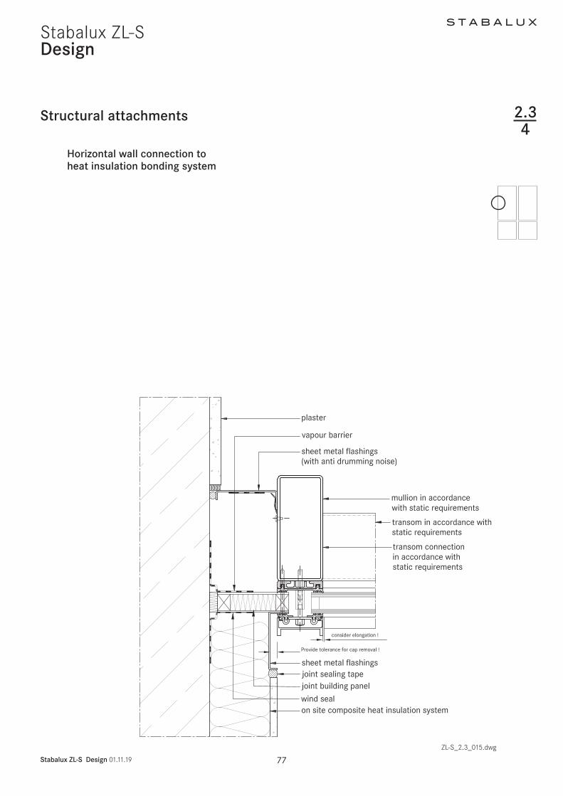
S T A B A L U X
Stabalux ZL-S Design 011119 82
Stabalux ZL-SDesign
Installing windows and doors
Insert door inward in the mullion sectionSystem HUECKSeries Lambda DS 075
Insert door inward in the transom sectionSystem HUECKSeries Lambda DS 075
ZL-S_23_019dwg
235
Use a locating screwas an assembly aidif necessary
Use
a lo
catin
g sc
rew
as a
n as
sem
bly
aid
if ne
cess
ary
ZL-S_23_020dwg
Design
Installing windows and doors
Insert top-hung window in the mullion sectionSystem HUECKSeries Lambda 110
Insert top-hung window in the transom sectionSystem HUECKSeries Lambda 110
235
S T A B A L U X
Stabalux ZL-S Design 011119 83
Stabalux ZL-S
Design
Installing windows and doors
Sliding system in the mullion sectionSystem HUECKSeries Volato M
Sliding system in the transom sectionSystem HUECKSeries Volato M
ZL-S_23_021dwg
235
S T A B A L U X
Stabalux ZL-S Design 011119 84
Stabalux ZL-S
S T A B A L U X
Stabalux ZL-S Design 011119 85
Stabalux ZL-SDesign
Installing windows and doors
Flush roof surface windowSystem HUECK-HARTMANNSeries 85E
Connection at top
Connection at bottom
Powered accordingto system specifications
ZL-S_23_020dwg
235
S T A B A L U X
Stabalux ZL-S Design 011119 86
Stabalux ZL-SDesign
Installing windows and doors
Insert window - mullion sectionSystem HahnSeries Lamellae S9 iVt-05
Insert window - transom sectionsSystem HahnSeries Lamellae S9 iVt-05
ZL-S_23_021dwg
235
- Stabalux ZL-S
-
- System
-
- System properties
- System cross sections and inner seals - facade
- System cross sections and inner seals - roof
- Cover strips and outer seals
-
- Processing notes
-
- Material information
- Assembly sequence
- Attaching the spacer strip
- Tips for laying seals
- Seals - Facade
- Seals - roof
- Glass inset and glass support
- Screw fittings
- Flat cover strip DL 5073 DL 6073
- Slab insulation
-
- Design
-
- Pane support variants
- System cross sections
- System details
- Structural attachments
- Installing windows and doors
-

ZL-S_23_020dwg
Design
Installing windows and doors
Insert top-hung window in the mullion sectionSystem HUECKSeries Lambda 110
Insert top-hung window in the transom sectionSystem HUECKSeries Lambda 110
235
S T A B A L U X
Stabalux ZL-S Design 011119 83
Stabalux ZL-S
Design
Installing windows and doors
Sliding system in the mullion sectionSystem HUECKSeries Volato M
Sliding system in the transom sectionSystem HUECKSeries Volato M
ZL-S_23_021dwg
235
S T A B A L U X
Stabalux ZL-S Design 011119 84
Stabalux ZL-S
S T A B A L U X
Stabalux ZL-S Design 011119 85
Stabalux ZL-SDesign
Installing windows and doors
Flush roof surface windowSystem HUECK-HARTMANNSeries 85E
Connection at top
Connection at bottom
Powered accordingto system specifications
ZL-S_23_020dwg
235
S T A B A L U X
Stabalux ZL-S Design 011119 86
Stabalux ZL-SDesign
Installing windows and doors
Insert window - mullion sectionSystem HahnSeries Lamellae S9 iVt-05
Insert window - transom sectionsSystem HahnSeries Lamellae S9 iVt-05
ZL-S_23_021dwg
235
- Stabalux ZL-S
-
- System
-
- System properties
- System cross sections and inner seals - facade
- System cross sections and inner seals - roof
- Cover strips and outer seals
-
- Processing notes
-
- Material information
- Assembly sequence
- Attaching the spacer strip
- Tips for laying seals
- Seals - Facade
- Seals - roof
- Glass inset and glass support
- Screw fittings
- Flat cover strip DL 5073 DL 6073
- Slab insulation
-
- Design
-
- Pane support variants
- System cross sections
- System details
- Structural attachments
- Installing windows and doors
-
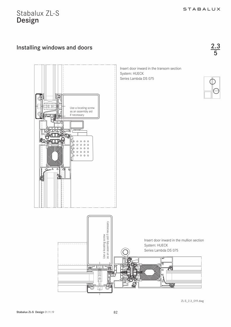
S T A B A L U X
Stabalux ZL-S Design 011119 86
Stabalux ZL-SDesign
Installing windows and doors
Insert window - mullion sectionSystem HahnSeries Lamellae S9 iVt-05
Insert window - transom sectionsSystem HahnSeries Lamellae S9 iVt-05
ZL-S_23_021dwg
235
- Stabalux ZL-S
-
- System
-
- System properties
- System cross sections and inner seals - facade
- System cross sections and inner seals - roof
- Cover strips and outer seals
-
- Processing notes
-
- Material information
- Assembly sequence
- Attaching the spacer strip
- Tips for laying seals
- Seals - Facade
- Seals - roof
- Glass inset and glass support
- Screw fittings
- Flat cover strip DL 5073 DL 6073
- Slab insulation
-
- Design
-
- Pane support variants
- System cross sections
- System details
- Structural attachments
- Installing windows and doors
-