zl a s3oel - nasa
TRANSCRIPT

NASA Tach.M M e a l o d 83801
(JASA-Ttl-8.380 1) I i iE EPE ECT 01 CB AK UBL Y85-10303 CGHVSBGEYCE Ub 86bT i f i l i 3 E E i i ZL A P A S S A G E UlTh S 3 O E l Pi& EiYS (YASA) 17 p dC A02/!lP A01 CSCL 20D Unclas
63/34 24197
The Effect of Channel Convergence on Heat Transfer LI a Passage With Short Pin Fins
Barbara A. Brigham Lewis Reseu~~~tr Center Chdand, Ohio
October 1984

THE EFFECT OF CHANNEL CONVERGEICE ON HEAT TRANSFER
IN A PASSAGE WITH SHORT PIN FINS
Barbara A. Brigham National Aeronautics and Space Admlnistrat!on
L w i s Research Center Clevelaid, Ohio 44135
Results from a series o f experiments are presented showing the e f f e t t of channel convergence on heat t rans fer I n shor t p i n f i n s as used i n tu rb tne blade i n te rna l cool ing schemes. Array averaged heat t ransfer coe f f i c i en ts e r e ob- tained f o r two conf igurat ions o f staggered arrays o f shor t p i n f i n s i n a con- verging channel. One conf igurat ion contained plns w l t h length t o dianteror r a t i o o f two I n a constant helght channel w i t h channel sidewal ls converging t o g ive an area r a t i o o f two t o one from i n l e t t o ou t l e t , g i v i ng only accelzrated flw. The second conf igurat ion ccntained plns I n a constant width channel w l t h the top 2nd bottom surfaces o f the channel converging and w i t h length t o diameter r a t i o varying from tuo t o one streanwise through the t e s t section. This conf igurat ion had the same area r a t i o from i n l e t t o o u t l e t as i n the f i r s t conf igurat ion, g i v ing varying p i n length as we l l 4s accelerated flow. I n ad- d i t i o n t o the p i n f i n conf!gur3tions, two f l a t p l a t e conf igurat ions were a lso tested which had the same geornetrles as the p i n f i n conf lgurat lons but no pins.
Results show tha t f o r the constant height p i n f i n conf igurat ion, the Nusselt numhers are approximately the s z m as i n previous tes ts done on s t ra igh t channel t e s t sectlons w l t h p ins o f the same length t o diameter r a t i o . For the constant width p i n f i n conf igurat lon, resu l t s i nd i ca te Nusselt numbers approximately 20 percent lower than f o r t es t s performed on configurations w l t h constant p l n length t n the same range o f length t o diameter r a t i o . This sug- gests tha t the varying p i n length does have some e f f e c t on the heat t rans fer , but t ha t the f low accelerat'on has a n e g l i g i b l e e f fec t . For the f l a t p l a t e conf lgurat lons, both ind ica te Nusseit numbers i n the same range as i s other s im i l a r f l a t p la te tests. As i n the above mentioned p i n f i n tests, the con- s tant width conf ig~ra t !on exhib i ted Nusselt numbers s l i s h t l y lower (about 6 percent) than f o r the constant height conf igurat ion. This shows tha t a con- s tant width conf igurat ion ( p i n f i n or f l a t p la te ) exh ib i t s a lower Nusselt number leve l than a constant height conf igurat ion.
IFTRODUCTION
I n modern gas turb ine engines, tbere are many d i f f e r e n t types o f tc rb lne blade cool lng schemes ava i lab le t o the designer. The method of pa r t i cu la r i n te res t i n the present study i s the use of short p l n f i n s as used i n t r a l l l n g edge coul ing passages. U n t i l qut te recent ly, the only information o f t h i s type avai lab le I n the l i t e r a t u r e was f o r r e l a t i v e l y locg pins of more than four diameters I n length. Slnce the length of the p:n f i n s used f o r gas t u r - bine appl icat ions I s general ly less than four diameters, most of t h i s informa- t i o n could not be used e f fec t i ve l y .

Recently, some data s p e c l f l c a l l y f o r appl lcat lons of p l n f l n s t o gas t u r - blnes have become avai lab le. One program undertaken a t Arlzona State Un lvers l ty ( re fs . 1 t o 3) measured the heat t rans fe r from short p i n f l n s ar- ranged I n staggered 10-row (streanwlse) arrays. Thls work ( re f s . 1 and 2) measured the spamise-averaged heat t rans fer f o r both the p l n and enduall sur- f a ~ e s on a row by row bast; f o r p ins w l t h L /D o f one. These resu l t s showed t h a t the heat t rans fer Increased l n tRe f l r s t four rows o f the array and then decreased s l i g h t l y through the res t o f the array. Thls was s lm l l a r t o the trends found i n long cy l inder and tube bank data.
VanFossen ( r e f . 4) measured the heat t rans fe r from both p l n and enduall surfaces fo r several staggered four-row (streanulse) arrays o f si.,rt p l n f l n s w l t h Lp/D o f one h a l f and tuo. It was found t h a t f o r t h i s range of length t o dlameter r a t l o , a l l the data could be represented by a s lng le curve. It was a lso found t h a t the heat t rans fer coe f f l c l en ts on the p i n f i n surface were about 35 percent hlgher than on the endwall surface.
Another set o l experiments determlned the e f f e c t o f pos l t l on w l t h l n an array on the t o a t t rans fer t c a s ing le p i n w;th L /D of three ( re f . 5). The resu l t s here lndlcated tha t the heat t rans fer Po a s lng le p l n i n a stag- gered array increased s l g n l f l c a n t l y f o r one, two o r three rows of p ins added upstream o f the t e s t p ln. For four o r more rows added upstream, the heat t rans fer decreased s l l g h t l y . Thls t rend i s s lm l l a r t o t h a t found i n r e f e r - ences 1 and 2. I t was a lso determined tha t the average channel ve loc l t y should be used as the reference v e l o c l t y i n the Reynolds number.
I n reference 6 the e f f e c t o f the number o f rows and the length t o dlameter r a t i o on the heat t rans fer was Invest igated. I t was determined tha t the number o f streanrwlse rows has only a s l i g h t e f f e c t on the heat t rans fer t o shor t p i n f i n s . The domlnant e f fec t . however, was the length t o dlameter ra t i o , w l t h Lp/D o f four g l v ing much hlgher heat t rans fer than was found I n references 1, 2 and 4 f o r shorter pins. Reference 6 also showed tha t by using the average channel ve loc l t y and the proper d e f l n l t l o n of the cha rac te r i s t l c lenqth, the data o f references 1 and 2 could be made t o f a l l on the co r re la t i on derived I n reference 4.
Reference 7 presents heat t rans fer resu l t s f o r several short p l n f i n con- f lgura t lons i n whlch the length t o dlameter r a t l o var led streanwlse through the length o f the t e s t sectlon. However, t h l s work does not s p e c l f l c a l l y ad- dress the current object ive and l e f t unresolved whlch e f f e c t was domlnant, channel convergence w l th the r e s u l t i n g accelerat lng f low or varylng length t o dlameter r a t l o .
Thls paper presents the r e s ~ l t s o f a series o f t es t s designed t o separate the e f fec ts o f varylng p i n length from channel convergence. Four t e s t sectlons were fabr lcated t o glve an arza r a t i o from I n l e t t o o u t l e t o f two t o one. One t e s t sect lon contalned plns I n a constant helght channel w i th length t o dlame- t e r r a t l o o f two w l t h the channel sidewal ls converglng. Another t e s t sect lon contained plns i n a constant wldth channel u l t h the top and bo~ tom channel surfaces converglng and w l th length t o dlameter r a t i o varying from two t o one streanulse through the t e s t sectlon. The plns were a l l spaced 4 dlameters coar t i n an equ l i a te ra l t r langu lar array w l th four rows I n the streanrwlse d l - r f .ct lon, as i n prevlous work done a t NASA ( re f s . 4 and 6 ) . Two other t e s t sectlons were fabr icated whlch were l den t l ca l t o the above two t e s t sectlans

but ccntalned only f l a t p l a t e surfaces (no p I n f i n s ) . Heat t rans fe r resu l t s are presented I n the form of Nusselt number versus Reynolds number over a range o f Reynolds numbers o f I n t e r e s t f o r t h l s app l l ca t l o r . Results are conlpared t o those o f references 4 and 6.
NORENCLATURE
A ' 2 2 average f low area, V/L, cm ( In . )
2 2 Ah surface area o f heaters. 2LW, cm (In. )
A 2 2 2
p i n cross sect ional area, r D o /4, cm ( In . ) P
2 2 enduall area per pln. ( G ~ ) ( X ~ D ~ ) ~ , cm ( i n . )
0 ' c9arac ter ls t Ic length, cra ( in . )
p i n diameter, cm ( in . )
hi average heat t ransfer c o e f f i c i e n t I n p i n f i n t e s t section,
u/n2-u ( ~ t u / h r - f t ~ - - ~ )
he f f e f f ec t i ve heat t rans fer coef f Ic Ien t . ii/m2-K ( ~ t u / h r * f t ~ * ~ ~ )
b average heat transGer c o e f f i c i e n t on p i n surface, Y/&*K ( ~ t u / h r * f t2-OR)
h& average heat t ransfer coef f l c l e n t on endwall surface, w / ~ * K ( ~ t u / h r - f t Z - ~ R )
ka thermal conduct iv i ty of a l r , W/m*K (Btu/hr-f teOR)
k thermal c m d u c t i v i t y o f p i n mater ial , W/m*K (Btu/hr-ftw0R) 0
L . t e s t sect lo^ s t r e a w j s e length, cm ( In . )
L,/D p i n length t o diameter r a t i o r
1 p i n h a l f length, cm ( In . )
f 1 n parameter, dh ' ~ / k A ? P
Nusselt number, htD'/ka
p i n perimeter, rD cm ( I n . ) 0 '
heat d iss ipzted l n e l e c t r i c heater, W (Btu/hr)
Reynolds number, (u/A1)D'/p 2 2
t o t a l heat t rans fer surface area, cm ( I n . )
adiabat ic wa l l temperature, K (OR)
Lckert reference tempe~ature. K (OR)
s t a t i c temperature, K (OR)
enduall temperature, K (OR) 3 3 f low channel vclume minus p j n volune, cm ( i n . )
t e s t sect lon u ldth, cm ( in . )
mass f low rate, kg/s (lbm/s)

Xs ;atlo o f p i n h2ight t o p i n diameter, (same as Lp/D)
t r a t i o o f p i n spacing t o p i n diameter, transverse d l r e c t i o n
)r v i scos i t y o f a i r , kg/m.s (lbm/ft.s)
DESCRIPTION OF EXPERIMENT
Test Section and Flow Apparatus
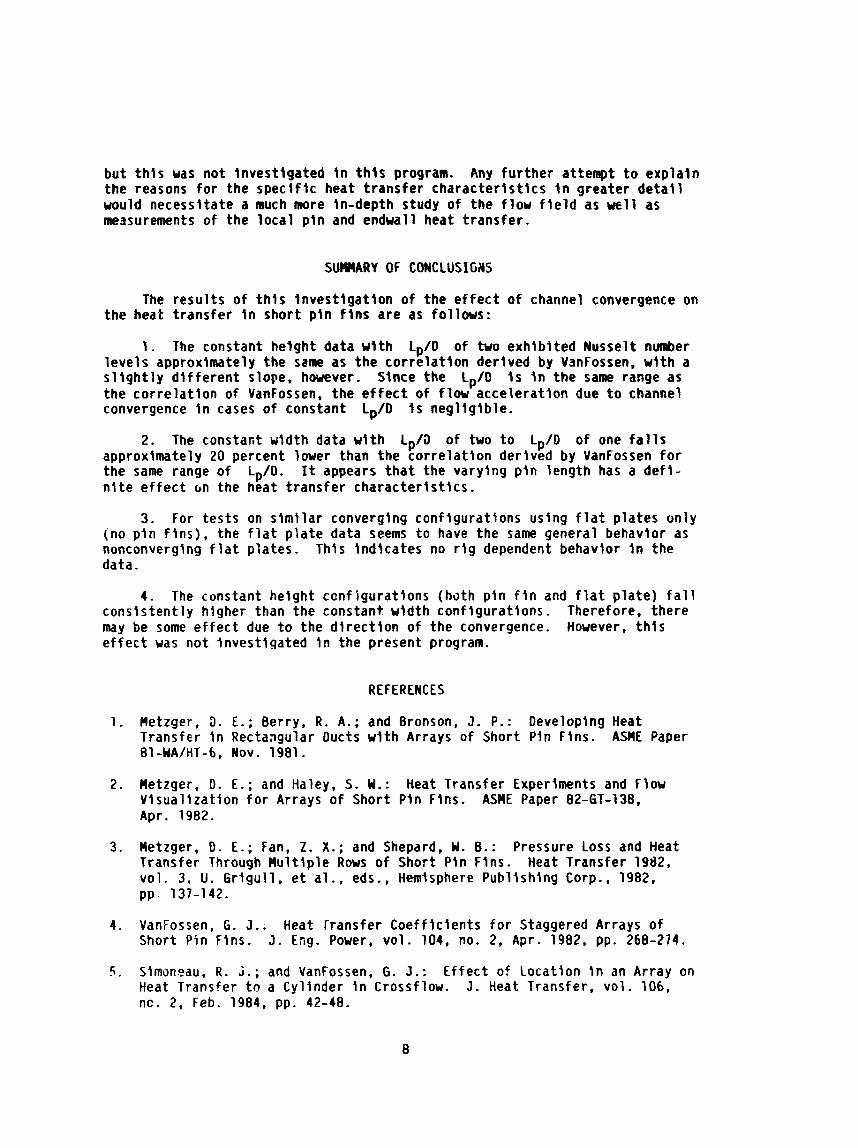
A schematic o f the r i g used f o r the p i n f i n experiments i s shown i n f i g u r e 1. Room a i r was drawn through a constant accelerat ion i n l e t , i n t o the t e s t sect ion and then through e i t h e r an o r i f i c e f low meter ( la rge f low rates) or through a ventur i f low meter (small f low rates) . The a i r passed through the respect ive f low cont ro l valves and then on I n t o the laboratory a l t i t u d e exhaust system. A i r temperatures were measured a t the t e s t sect lon I n l e t , t e s t sect lon ou t l e t , and i l o w meters. A i r densi ty a t the f l ow meters was ca l - culated using the idea l gas law. The data were co l lec ted and converted t o engineering un i t s using the laboratory data c o l l e c t i o n system ( re f . 8) .
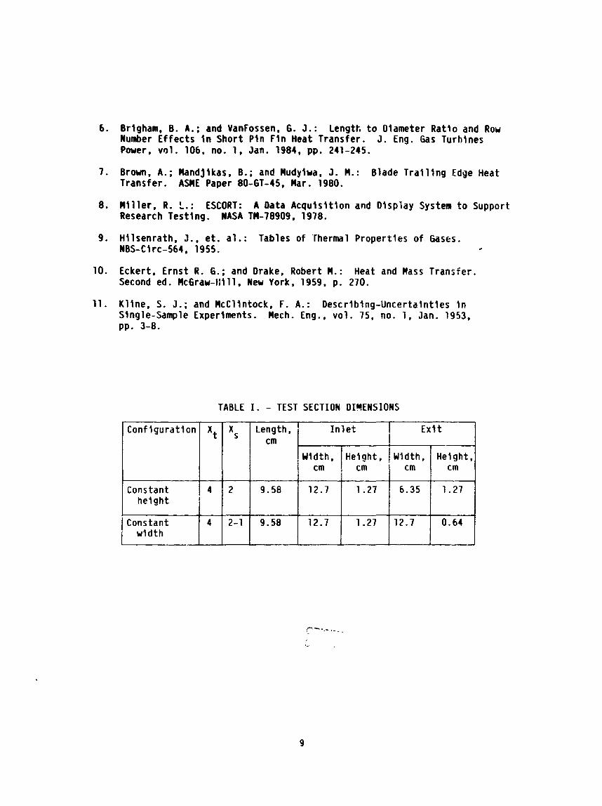
Figure 2 shows the t e s t sect lon assembly used f o r a l l the p i n f i n experl- ments. Shown i n the f i g u r e are the I n l e t , endwall, and o u t l e t thermocouples. The top and bottom surfaces o f the i n l e t were covered w i t h f i n e g r i t sandpaper and a 0.519 cm (0.063 in . ) diameter t r i p w i re was attached t o the surface i n order t o ensure turbulent f low. The t e s t sect ion was enclosed I n c lo th - reinforced pheno .1~ p l a s t i c and the e n t i r e assembly was wrapped i n f iberg lass i nsu la t i on i n order t o minimize heat losses.
Figures 3 and 4 show schematics o f the two p i n f i n t e s t sections used, i l l u s t r a t i n g the channel geometry. Figures 5 and 6 show the assembled p i n f i n t e s t sections, viewrd i n the d i rec t i on o f flw. These p ic tu res show the d i f - ference i n the convergence between the constant height conf igurat ion and the constant width conf igurat ion. The two f l a t p l a t e t e s t sections were i d e n t i c a l i n geometry but have no pi11 f i c s . Each t e s t sect ion was m d e of two 0.635 cm (0.250 in . ) t h i ck copper plates, w i t h holes d r i l l e d f o r the i nse r t i on o f the pins fo r the two p i n f i n t e s t sections. The pins, which extended completely through the endwall plates, were soldered i n t o place. The dimensions o f the f low channels f o r a l l conf igurat ions are given I n tab le I.
The t e s t sections were heated w i t h comnercially ava i lab le e l e c t r i c f o i l resistance heaters attached ex terna l ly t o the endwalls w l t h pressure sens i t i ve adhesive. The streanwise center l ine temperatures o f the endwalls were ,neasured by thermocouples inser ted i n t o holes d r i l l e d along the edge of each endwall p late. The thermocouple connections and the e l e c t r i c heaters can be seen i n f igures 5 and 6.
Test Procedure
I n order t o account f o r heat losses, a set o f ca l ib ra t ions was made f o r each t e s t sect ion w i th no a l r f low through the t e s t section. By measuring the endwall temperatures, the ambient a i r temperature, and the t o t a l heat f l u x , an overa l l heat loss coe f f i c i en t was determined f o r each conf lgurat lon. This was done a f t e r the t e s t sect ion had reached a steady s ta te condit ion, which was

usual ly overnlght. Durlng a data run, the Reynolds number was changed by vary- l n g the f low r a t e through the t e s t sectlon. The temperature of the endwall p la tes was kept constant uslng an electronic heater c o n t r o l l i n g system which regulated the power t o each set o f heaters.
Data Analysls
The theore t ica l model used as the basis f o r the p l n f l n data analysts I s shown i n f i g u r e 7. The t o t a l heat f l u x f o r the p l n and endwall surfaces I s the sum of the beat f l u x through the endwall and the heat f l u x through the p in . The average heat t rans fer coe f f l c l en ts on the p l n surface and endwall surface are h i and h; respect lve ly . The heat l o s t by the p t n f i n surface (endwalls Included) i s equated t o the heat l o s t by a p l a l n surface w i t h heat t rans fer c o e f f l c l e n t he f f - For the purpose o f t h l s work, the average heat t rans fe r coe f f l c l en t on the pln, hp, i s assumed equal t o the heat t rans fer c o e f f i c i e n t on the endwalls, hw, and I s denoted by h ' .
The ove ra l l loss heat t rans fer coef f lc ient , h loss . I s defined as
This loss c o e f f l c i e n t was found over a range of temperature differences, Tw - T a m and a leas t squares curve f i t was appl led t o the data w l t h tem- perature as the independent var iable. Thus, f o r a given temperature d i f fe rence a corresponding loss c o e f f j c l e n t could be found and the heat loss from the t e s t sect lon could be calculated.
The e f fec t i ve heat t rans fer coef f i c ien t , heff . i s deflned as
khere Tau i s the adlabat jc wal l temperature calculated from
wl th r, the recovery factor , taken as the square roo t o f the Prandt l number. The t o t a l temperatures were found by ma!;ing an energy balance through the channel. The s t a t i c temperatures were found uslng the compressible gas r c la - t ionsh lp between t o t a l and s t a t i c temperatures.
Equation 2 gives the e f f e c t i v e heat t rans fer coe f f i c i en t , lnc lud lng the e f fec ts of p i n efficiency. This can be r e u r l t t e n as
Q t o t a l = heffAw(Tw - Taw) ( 4 )
The heat f l u x through the endualls I s given by

where A,,, 1 s the endwall area and Ap I s tne cross-sect lcnal area o f the pln. The heat f l u x through the p i n only I s given by
w l th P belng the perimeter o f a pin, 1 belng the h a l f length o f the pln, and the f i n parameter n being def lned by
The p l n conduct lv l ty , kp, was taken ps 3.46 W/cm*K (200 Btu/hr-ftmOR). - Then the energy balance y lo lds the fo l low ing equation:
The above transcendental equation was solved i t e r a t i v e l y f o r h ' f o r each measured value of heff.
For the f l a t p la te t e s t sections, an ove ra l l :ass heat t rans fer c o e f f l - c l en t was found as described zoove. Then slnce there were no plns, there was no need f o r an l t e r a t l v e procedure t o solve f o r h ' . The heat t rans fer coef- f l c l e n t I s calculated as
w i t h h ' being the average heat t rans fer c o e f f l c l e n t on the endwall and side- wa l l surfaces i n the p l a l n channel.
The data was put l n dlmenslonless form of Reynolds number and Nusselt number fo r purposes o f comparlson. The Reynolds number i s deflned as
where
and p !s the v!scosity of a i r . The Nusselt number I s defined as
where ka I s the thermal conduct lv l ty of a i r . Both p and ka were found from curve f i t s of data from reference 9 and were evaluated a t the Eckert reference temperature ( r e f . l o ) , deflned as

The experimental uncer ta inty based on Ine method o f K l i n e and HcClintock ( r e f . 11) i s less than three percest f o r t he Reynolds number and less than four percent f o r the Nusselt number.
RESULTS AND DISCUSSION
Array averaged heat t rans fer coe f f i c i en ts f o r both p i n and endwall sur- faces were found f o r a range o f f low rates and are presented i n the form o f Nusselt number versus Reynolds number f o r two p i n f i n conf igurat ions and two f l a t p l a t e conf igurat ions i n a converging channel. Figure 8 i s a compari~on o f the constant height p i n f i n data w:tn the resu l t s of references 4 and 6. The constant height data w i t h Lp/D o f two exh ib i t s approximately the same Nusselt numbers as the co r re la t i on derived i n reference 4 f o r L /D of less than o r equal t o two. I n addition. the constant height data w i t [ Lp/D of two f a l l s approxlmately 20 percent below both the four and e igh t row data of reference 6 w i t h Lp/D o f four . This d i f fe rence I s t o be expected based on the recu l t s o f reference 6. The e f f e c t o f the channel convergence on the heat t rans fer t o short p i n f i n s o f constant length t o d ianster r a t i o i s merely a s l i g h t change i n the slope o f the data and v i r t u a l l y no change i n the Nusselt number levels .
Figure 9 shows both the constant helght data and the constant width data p lo t ted w i t h the co r re la t i on from reference 4. This co r re la t i on i s f o r a l l short p i n f i n s w i th length t o diameter r a t i o between one h a l f and two. I t can be seen from f i g u r e 9 t h a t the constant width data w i t h Lp/D of two t o L,/D o f one ( the sane range as i n reference 4) f a l l approximately 20 percent bhlou the co r re la t i on from reference 4. This i s s i g n i f i c a n t since the length t o diameter r a t i o s fo r these two sets of data are i n the same range. One would have expected these t w o sets o f data t o be Iden t i ca l since the Lp/D are i n the same range. Thus the changing p i n length must be a s i g n i f i c a n t fac tor . A l eas t squares curve f i t of the constant width data i s
where the Nusselt number and Reynolds number are based on the cha rac te r i s t i c length 0 ' . Since the area r a t i o s i n both converging p i n f i n conf igurat ions are the same (two t o one from i n l e t t o o u t l e t ) , i t i s apparsnt t ha t I n the constant wldth conf igurat ion the changing p i n length has a s i g n l f i c a n t e f f e c t on the Nusselt number leve l .
Figure 10 shows the current p i n f i n data and the current f l a t p l a t e data p lo t ted w i t h the resu l ts o f reference 4. I t can be seen tha t both the constant height and the constant width f l a t p l a t e data f a l l a t approx!mately the same leve l as the nonconverging f l a t p l a t e data from reference 4. This tends t o ind ica te tha t these resu l t s are not r i g dependent since the data from re fe r - ence 4 were obtained i n the same experimental f a c l l l t y . This a lso shows tha t there i s no t much e f f e c t on Nusselt ndmber leve ls i n converglng conf igurat ions without p i n f i ns . Also, the basic t rend of the two sets of data are the same w i th the constant height conf igurat ions having cons is ten t ly higher Nusselt number leve ls than the constant width conf igurat ions. This would tend t o 4n- d icate t h a t there may be some e f f e c t due t o the d i r e c t i o n of the convergence,
but t h i s was not invest igated I n t h i s program. Any fu r the r attempt t o expla in the reasons f o r the spec l f i c heat t rans fer charac ter is t i cs i n greater d e t a i l would necessitate a much more in-depth study of the f low f i e l d as ell as measurements of the l oca l p i n and endwall heat t rans fer .
SUMMARY OF CONCLUSIGHS
The resu l t s o f t h i s i nves t i ga t i on o f the e f f e c t o f channel convergence on the heat t rans fer I n shor t p i n f i n s are as f o l l w s :
1. The constant height data w l t h Lp/D o f two exh ib i ted Nusselt nunber leve ls approximately the same as the co r re la t i on derived by VanFossen, w i t h a s l i g h t l y d i f f e r e n t slope, h w v e r . Since the Lp/O I s i n the same range as the co r re la t i on of VanFossen, the e f f e c t o f f l ow accelerat ion due t o channel convergence i n cases o f constant Lp/D i s neg l i g ib le .
2. The constant u i d t h data w l t h Lp/D o f two t o Lp/D o f one f a l l s approximately 20 percent lower than the co r re la t i on derived by VanFossen f o r the same range o f Lp/O. It appears t h a t the varying p i n length has a d e f i - n i t e e f f e c t on the heat t rans fer charac ter is t i cs .
3 . For tes ts on s im i l a r converging conf igurat ions using f l a t p lates only (no p i n f i n s ) , the f l a t p l a t e data seems t o have the same general behavior as nonconverglng f l a t plates. This Indicates no r i g dependent behavior i n the data.
4. The constant height canf igurat ions (both p i n f i n and f l a t p la te ) f a l l consis tent ly higher than the constant width conf igurat ions. Therefore, there may be some e f f e c t due t o the d i r e c t i o n o f the convergence. However. t h i s e f f e c t was not invest igated i n the present program.
REFERENCES
1. Hetzger, 3. E.; Berry, R. A.; and Bronson, J . P.: Developing Heat Transfer i n Rectangular Ducts w i t h Arrays of Short Pin Fins. ASnE Paper 81 -WA/HT-6, NOV . 1981 .
2. Hetzger, D. E.; and Haley, S. W . : Heat Transfer Experiments and Flow V isua l iza t ion fo r Arrays o f Short Pin Fins. ASME Paper 82-GT-138, Apr. 1982.
3. Metzger, D. E.; Fan, 2 . X.; and Shepard, W . 8.: Pressure Loss and Heat Transfer Through Mu l t i p le Rows o f Short Pin Fins. Heat Transfer 1982, vo l . 3, U. G r igu l l , e t a l . , eds., Hemisphere Publ ishing Corp., 1982, pp. 137-142.
4. Vaniossen, G. 3 . . Heat fransfer Coef f ic ients f o r Staggered Arrays o f Short Pin Fins. J. Eng. Power, vo l . 104, no. 2, Apr. 1982, pp. 268-274.
5. Simoneau, R . j.; and VanFossen, 6. J.: E f fec t of Location I n an Array on Heat Transfer t o a Cylinder i n Crossflow. J. Heat Transfer, vol . 106, nc. 2, Feb. 1984, pp. 42-48.
6. Brlgham, 8. A.; and Vanfossen, 6. J.: Length t o Diameter Rat lo and Row Number E f fec ts i n Short Pln F l n Heat Transfer. J. Eng. Gas Turhlnes Power, vol . 106, no. 1, Jan. 1984, pp. 241-245.
7. Brwn, A.; Mandjlkas, B.; and Mudylwa, J. M.: Blade T r a l l l n g Edge Heat Transfer. ASHE Paper 80-61-15, Mar. 1980.
8. M i l l e r , R. L.: ESCORT: A Data Acqu ls l t ton and Display System t o Support Research Testtng. NASA TM-78909, 1978.
9. Hl lsenrath, J., e t . al . : Tables of Thermal Propert ies o f Gases. WBS-Clrc-564, 1955. .
10. Eckert, Ernst R. 6.; and Drake, Robert M.: Heat and Mass Transfer. Second ed. Mc6raw-tlll l, New York, 1959, p. 270.
11. Kl lne, S. 3.; and McCllntock, F. A.: Descr lblng-Uncertaint ies i n Single-Sample Experlntents. Mech. Eng., vo l . 75, no. 1, Jan. 1953, pp. 3-8.
TABLE I. - TEST SECTION DIMENSIONS
Exl t Conf i gu ra t l on
Constant height
1 Constant width
Xt Length,
cm Xs I n l e t
4 I
4
9.58
9.58
2
2-1
Height. cm
1.27
0.64
-
Yldth, cm
12.7
12.7
Helght, I Uidth. cm
1.27
1.27
cm
6.35
12.7
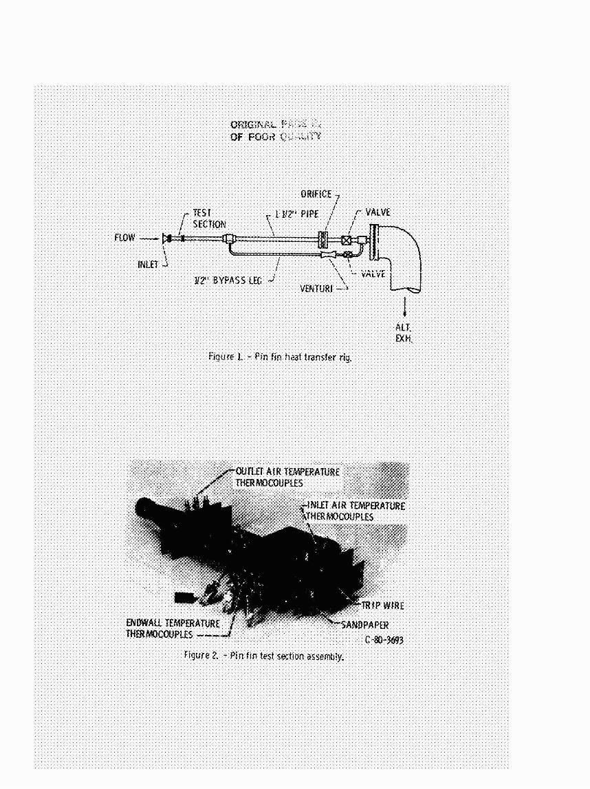

Figure 3. - Schematic of constant height test sectiorl.
Figure 4. - Schenlatic of constant width test section.


ORIG~NAL PASE 15 OF POOR QUALITY
Q TOTP L
Q~~~~~ = QWAU + QFIN
qOTAL = haw (Aw - A 1 IT - T ) + Ph' A ianh (mi, ITw - Taw) P w aw ; P $ P
QTOTAL = hdf 'w 'Tw - Taw'
Figure 7. - Theoretical r r d e l .
0 $!D OF 4. 8-ROWS (STREAMWISE) (REF. 6) 4-ROWS (STREAMWISE) (REF. 6) .",ONSTANT HEIGHT CHANNEL
OF REF. 4 (bt D OF LESS THAN
RED'
Figure 8. - Constant height data plotted with results of refs. 4 and 6.

om^!?!,?.: r- - % - . - . a :-;< L . + - OF PC:; q: ;. , ]*j -'-.&. ,
A I D OF 2 TO LplD OF 1. CONSTANT WIOTH CHANNEL
/

- OOR~TICNWUEF. 4 ~ p r n o ~ ~ f s s m a C + i D O f 2 T O L p i D 0 . C 1 . ~ S T ~ T W l D M ~ 0 Lp !D of 2 artSTA%i iElW cwI.vlm h FLAT PLATE DATA. REF. 4 0 RAT RATE DATA. (XIISTAWT WIDTH QiAllmYL 0 R A T RATE DATA. C)HS?ANT M l M OWNEL
figure 1Q - Currart pin fim 80 potl' llm; c m t M @a&