stability of steel decks in cable stayed bridges having
TRANSCRIPT

156
Stability of Steel Decks in Cable Stayed Bridges Having Delta Framing
Towers
Nahla Kamal Hassan1, Hisham Ahmed El-Arabaty
1 and Mohamed Elsaeed Elsayed Badawi
2
ABSTRACT Steel decks in cable stayed Bridges with Delta Framing Towers are considered one of the most important types in
cable stayed bridge category (truss girders or box steel girders). In order to evaluate the potential of decreasing
horizontal drift in super-structure. Four suggested bracing systems were investigated in this paper geometry of „Tatara
Bridge‟ deck and its steel towers will be used. The “Tatara Bridge” is one of the world‟s longest steel-concrete hybrid
cable stayed bridge. The side spans consist of steel and pre-stressed concrete precast concrete (PC) g irders about 50m
from anchored spans.
KEYWORDS: stability of steel deck, cable-stayed bridges, delta framing towers, truss girders, box steel girders,
super-structure, bracing systems, steel concrete hybrid cable stayed bridge and steel towers.
1. INTRODUCTION The horizontal sway problem in steel decks will be
explained which happened due to wind and earth quack
loads at three stages of erection at steel decks have one
plane of motion or two level o f motion and a lot of types
of bracing systems will be applied on both types of
decks and present all results in tables and charts.
The Structure system for superstructure plays an
important part to determine the main stiffness for the
overall bridge. Two different superstructure systems
(one plan and two plans) of motion will be discussed
and several bracing systems will be used to investigate
the optimum stability of the superstructure.
Stability of steel decks play an important part to
determine the overall stability for cab le stayed bridges
and its bracing system is very important to decrease
horizontal d rift in decks.
Yabuno Masashi et al., 2008 [1] present the design of
all structure elements of Tatara Bridge by using finite
elements models and present all erection steps for
structure elements of the bridge. The “Tatara Bridge” is
the world‟s longest steel-concrete hybrid cable stayed
bridge. It measures 1480 m in total length and 890 m in
the center span.
Satouy Yoshiyuki et al., 2008 [2] present the erection
of tatara bridge; the construction works for bridge began
in April 1995. During the 3-month period starting in
March 1996, each upper member of the main tower was
installed using a climbing crane in 18 levels and the last
block of the main tower was erected at the end of June
1996 (226 m high above the sea level).
M.S. Troitsky, D.SC. 1988 [3] present number of
techniques can be used for the analysis of cable-stayed
bridge. Examples include the use of a scaled-down
model for testing, and the use of analytical model which
_____________________________________________ 1 Department of Civil Engineering, Faculty of Engineering, Ain Shams University, Egypt. 2Civil Engineer
stayed bridge when subjected to static and dynamic
conditions of loading. For small models, certain
parameters should be defined and idealized, such as the
restraints at the joints, the stiffness or flexibility of each
member, and connections between the cables, stiffening
girders and towers.
Noguchi et al., 2003; Sato et al., 2003; and Petrangeli
et al., 2000 [4] reported that Nagisa Bridge was the first
challenge as a compound bridge of cable-stayed pre-
stressed concrete bridge and steel suspension bridge.
Therefore there were many problems to deal with during
design, material selection, and execution. Nagisa
Bridge, however, was completed in December 2002.
And the bridge was opened for pedestrians in July 2003.
George Moir et al, 2010 [5] reported that description
for design and erection for The Phu My Bridge spans
the Saigon River between Districts 7 and 2 o f Ho Chi
Minh City (HCMC).
Morgenthal et al., 2011 [6] described the fabrication
and erection procedures for towers and the main span
superstructures. The results supported that extensive
wind tunnel testing as well as numerical analyses were
performed to ascertain the effects of typhoon wind loads
on the structure. The structural deformat ions predicted
by the erection analysis were incorporated into a
comprehensive geometric control procedure.
In this paper the deck for bridge will be enhanced,
which changed from steel box section to main two
trusses as main girders with cross trusses as cross beams
and stringers at longitudinal direct ion.
Four bracing types will be used at new deck to
decrease horizontal drift witch happened due to wind
and earth quack forces.
Two cases from steel decks will be studded in this
paper:-
Case (I) has one level of mot ion
Case (II) has two level of motion
PORT SAID ENGINEERING RESEARCH JOURNAL
Faculty of Engineering - Port Said University
Volume 17 No. 2 September 2013 pp: 156-171

157
2. DESCRIPTION OF THE STUDIED BRIDGE “TATARA BRIDGE”
The “Tatara Bridge” is the one of world‟s longest
cable stayed bridges, whose 890 m center span is longer
than that of the “Normandy Bridge” in France by 34 m.
Fig. 1 shows the general arrangement of the “Tatara
Bridge,” while the main tower is shown in Fig. 2. The
section distribution is shown in Fig. 3. The main tower
is 220 m high and designed as an inverted Y shape
(Delta). It has a cross-shaped section with corners cut
for higher wind stability and better landscaping.
The main girder section consists of three spans, 270
m, 890 m, and 320 m, and measures 1 480 m in total
length. Both side spans is shorter than the center span,
precast concrete (PC) girders are installed at each end of
both side span sections as counterweight girders to resist
negative reaction. This cable stayed bridge, uses a steel
and precast concrete (PC) connection girder. The bridge
has a total width of 30.6 m, including a road for
motorized bicycles and pedestrians (hereafter called
sidewalk) and a girder height of 2.7 m. Cables installed
in 21 levels were two-p lane multi-fan cables (maximum
cable length: about 460 m).
Fig. 1: General arrangement (unit: mm)
3. MATERIAL
3.1. Main Tower (Steel Products) Specifications of extra th ick steel plates (for floor
plates) Four floor steel plates were welded together and
surfaced after annealing. The size of the plate was 13.8
* 10.3 m. The design thickness of the plate was 200
mm, and a 235-mm thick plate was purchased in
consideration of tolerances for plate thickness, surface
smoothness, deformat ion in welded corners, and a
margin for surfacing. Defects that occurred during the
rolling of the steel plates were checked based on the
regulations ultrasonic testing of steel plates for pressure
vessels. With regard to the (Japanese standard
specifications) JIC inspection classification, an A-
shaped configuration was used.
Countermeasures against samellar tearing tensile
force is generated at the joints of the horizontal
members of tower walls and the flanges of horizontal
members where wind tanks are installed by weld ing in
the direction of the thickness of a plate. Steel products
used for these parts were strictly managed for their
sulfur content as materials that should be managed for
their sulfur content in order to prevent lamellar tearing.
In addition, the soundness of steel products were
confirmed where joints were welded by ultrasonic
testing. With respect to susceptibility to lamellar
tearing, the evaluation method of susceptibility to
lamellar testing of the Japan Society of Civil Engineers
was used. As the results of our study, the following
specifications were added to our model in program.
Type of steel materials SM490Y
Grade Z25 or equivalent
(JIS G 3199)
Specification Su lfur content of
0.008% or less
Implementation of
u ltrasonic testing
Inspection certificate
indicat ion:SM490Y-S
3.2. Main Girder (Steel Products) Type of steel materials SM490Y
Grade Z25 or equivalent
(JIS G 3199)
Specification Su lfur content of
0.008% or less
3.3. Main construction specifications are as follows.
Bridge type Three -span continuous
cab le stayed bridge
with composite
box girder
Bridge length 1 480 m
Span length 270 m + 890 m + 320 m
Road specification Category 1, class 3

158
Design speed 80 km/h
Number of lanes Two lanes for car traffic
going in opposite directions (9.5
m 2) and another two lanes
(2.5 m 2) fo r motorized
Bicycles, bicycles and pedestrians
Fig. (2) Main two shapes of towers will be used in deference models Concrete Dimension (general
arrangement).

159
Fig. (3) nonlinear static cable stayed bridge model
Main tower
Shape Steel monocell cross section (inverted Y-
shaped superstructure and a base designed as a
trapezoidal structure with the bottom side shorter than
the topside with an extended base)
Tower height 220 m (T.P. + 226.000)
Sectional dimensions
12 m 8.5 m at the base
5.561 m 5.881 m at the top
Main girder
Shape 2- main t russ from two edge side with cross
trusses at connection point every 5.0 m with steel
stander cross section as stringer at the direction of
motion.
Girder height 2.7 m (at the center of the
bridge of the standard part)
Girder width
Total width 30.6 m
Outside web interval 21.8 m
Cable anchoring width 23.0 m
Pavement Asphalt pavement
4. PROPOSED ANALYTICAL
PROGRAM Sap program offers the widest assortment of analysis
and design tools available for the structural engineer
working on ordinary and special structures.
Special Frame elements will be used to descript main
towers and main structure elements at deck.
5. MODELING AND ANALYSES Different bracing systems will be presented which
are used to decrease lateral sway of bridge deck. Tatara
Bridge during construction as shown in Fig (4).
The current study will consider the stability of the
bridge during the erection states at 33.3%, 66.6% and
100% just before combination between two sides of
bridge at the erection stage as shown in Fig. (5). Fin ite
element for model of cable stayed bridge for one Plan
super structure, case (I) and in Fig. (5-a,c,d) display
Fig. (4) The deck of Tatara bridge during erection
Fin ite element for model of cable stayed bridge at
33.3% at erection 7 cables are done from each side
from deck and at 66.6% from erection was done 14
cables were fixed to the deck. Fig. (6) Fin ite element
for model of cable stayed bridge for two Plan super
structures case (II).
Fig. (6-a,b) displays the Finite element model of
cable stayed bridge at 33.3% of the erection 7 cables
were fixed from each side from deck and at 66.6% of
erection was done 14 cab le was done from erection.
Spacing between cables at tower is 180 cm and at deck
spacing between cables is 15 m and relating between
every two faced connections for cables at tower by
strong horizontal beam as a diaphragm.
6. GENERAL STRUCTURAL ANALYSIS The general structural analysis flowchart is shown in
Fig. (7). To begin with, cable pre -stress was
determined by infinitesimal deformat ion analysis to
finalize the condition of the final profile. Then,
sectional force analysis was conducted for each loading
case by linearized finite d isplacement analysis using
this completed system model in which init ial internal
force was set under this condition of the final profile.
Then, sectional force, displacement and reaction were
calculated and the results were edited for use in design
of each member.

160
a. Finite element for model of one plane cable
stayed bridge at 33.3% from erection.
b. Finite element for model of one plane cable
stayed bridge at 66.6% from erection
c. Finite element for model of one plane cable
stayed bridge at 100 % from erection just before
combination between two sides of bridge
Fig. 5
a- Finite element for model of two plane cable
stayed bridge at 33.3% from erection
b- Finite element for model of two plane cable
stayed bridge at 66.6% from erection
c- Finite element for model of two plane cable
stayed bridge at 100 % from erection just before
combination between two sides of bridge
Fig. (6)
7. ANALYTICAL MODEL
7.1. Modeling of Main Girders
A three-dimensional skeleton model was used for
analysis of the overall structure. Fig. (8) Shows the
cross section for the bridge at case (1) and case (2) of
motion. In our super-structure has two main trusses
from two sides and cross trusses replicated every 5m.
Make body between all top points for every cross truss
and make a diaphragm as shell element to be decks so
as to allow it to be used also as a dynamic analysis
model.
7.2. Modeling of Main Tower
Cable length was taken into consideration for
analysis of the main tower by creating a main tower
model in which virtual members are extended from the

161
axial center of the tower to cable anchor points (Fig. 9).
In reality, even though the target points of cables for
the center span and the side spans are set on the axial
line of the main tower with some deviation from each
other, they are sometimes designed as identical in
structural analysis. In this case, it is easy, in analysis, to
make bending moment of the main tower zero by
balancing the horizontal components of cable tension
in the final profile. But if we try to manage an actual
bridge with this tension and balance horizontal
components of force, bending moment will occur in the
tower and can slope the tower due to misaligned setting
of target points in the actual structure and the defective
consequence will appear in the form of camber errors
in the girder.
Table 1. Design specifications
Ref. [1]
8. CABLE MODELING A cable is converted to a rod model, with its
sectional area alone being considered. The bending
rig idity of the cable is ignored. Converted modulus of
elasticity Eeq by the equation of H. J. Ernst, as shown
below, is used to consider reduction of rigidity by the
influence of cable sag.
𝐸𝑒𝑞 =𝐸0
1 +γ2. L2.E012σ3
E0 : Modulus of elasticity of a straight cable (2.0 x
105 N/mm2)
: Unit volumetric weight of cable = ω/A (N/mm3)
L : Horizontal pro jection length of cable (mm)
σ : Tensile stress of cable = T/A (N/mm2)
ω : Weight per unit length of cable (N/mm)
T : Cable tension (N)
A : Cab le sectional area (mm2)
Note that the value of T is the value when the final
profile is prepared (when pre-stressing was studied, T
= (D + PS) given in the basic design was used). When
the loading was calculated for each loading case after
determination of the final profile model, cable tension
T = (D2 + PS) determined in the detail design phase
was used to set Eeq (where D, PS, and D2 represent
dead load, cable pre-stress and dead loads other than
PC girder dead load).
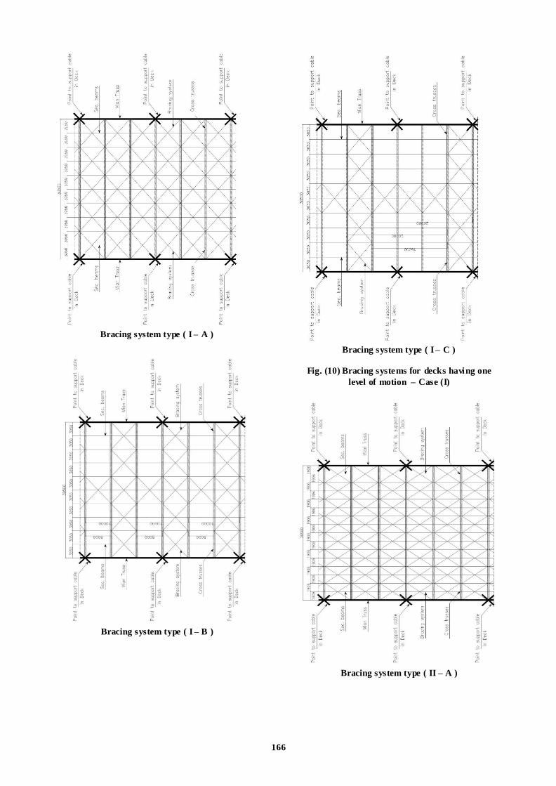
9. BRACING SYSTEMS FOR DECKS HAVING ONE PLAN OF MOTION.
Many shapes of bracing systems will be investigated
using finite element model having (one plan of motion)
as shown in Fig. (10). Figs. (10&11) Show different
bracing systems for decks with two plans of motion.
For type (I-A & II-A) bracing systems of all of the
deck width and the total length of bridge is 2C U.P.N.
NO.200 back to back.
For type (I-B & II-B) bracing is used every 3 meters
of deck width at the midd le and along the total length
of bridge in additional with cross bracing every 10
meters.
For type (I-C & II-C) bracing every 3 meters of deck
width at the middle and along the total length of bridge
with additional crosses bracing every 20 meters is
installed.
For the double plane duplicate bracing systems in
upper and lower deck are used.
10. FIXATION POINT AND CABLE
SUPPORTS This style will be presented as the fourth system (
Type D) of bracing which using cables or weirs to
support four points from deck during erection sate with
four support point as a concrete blocks as shown in
Fig. (12-a, b, c).
11. EQUIVALENT STATIC EARTHQUAKE LOAD
A response spectrum method is used to represent the
earthquake load using the function 1 as shown in Fig.
(13) In two d irections (x-dir. And y-dir.).
Design and design checks were carried out by two
seismic analytical methods: spectral response analysis,
which is one of the mode analysis techniques, and time
history response analysis, which is a time-domain
analysis using mode analysis. Load combinations used
in the design are shown by the following equation.
D+ PS+ CW+ EQ+ L +EQ+T +SD+ E
D : Dead load
CW : Counterweight
L(EQ) : Live load during earthquake
SD : Influence of supporting point
movement
PS : Pre-stress
EQ : Influence of earthquake
T : Influence of temperature change E : Fabrication/erection error

162
Table 2. Design loads
.

163
Table 3. Combinations of loads

164
Fig. 7 Flow chart of analysis.
a- Finite element model for The first Deck Case ( I )

165
b- Finite element model for The second Deck Case (II) Fig. 8: Main two cross sections for fini te elements decks for bridges
Fig. 9: Modeling of main tower
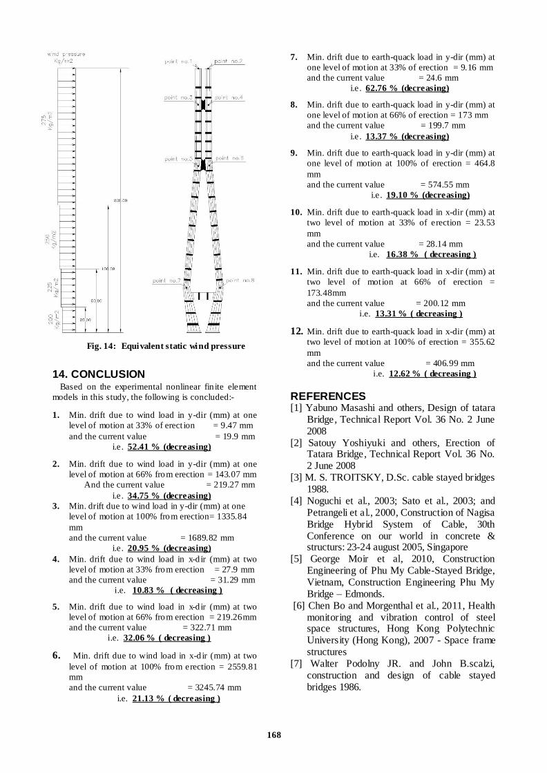
12. EQUIVALENT STATIC WIND LOAD Equivalent static wind load is applied in two
directions as shown in Fig. (14).
Nonlinear analysis of Earthquake and wind loads is
calculated according to Egyptian code for loads 2003.
13. RESULTS Various kinds of superstructures are used these days
and the designer job is to choose the suitable kind
according to the particular site and the levels of
motions needed (one or two) level of motions for the
bridge.
First for one level of motion; tables and charts of
Horizontal Drift resulted at 33%, 66% and 100% from
erection of super-structure are shown in table (4) to
table (6) and charts from (15) to chart (17).
Second; for two levels of motion; tables and charts of
Horizontal Drift resulted at 33%, 66% and 100% from
erection of super-structure are shown in table (7) to
table (9) and from chart (18) to chart (20).
From the last charts we can explain why the Bracing
system type (d) (fixat ion points or concrete blocks)
present the best geometric requirements since drifts are
greatly decreased. In this system we make a fixation
points a long superstructure at any points. This fixation
gives the superstructure more stability to resist any
forces at any direction if these loads are main loads or
secondary loads.
And all these results are clear in last charts which
display the big decreasing in drifts at critical points
along the length of deck at all effect ive loads in x and y
directions.
166
Bracing system type ( I – A )
Bracing system type ( I – B )
Bracing system type ( I – C )
Fig. (10) Bracing systems for decks having one
level of motion – Case (I)
Bracing system type ( II – A )

167
Bracing system type ( II – B )
Bracing system type ( II – C )
Fig. (11) Bracing systems for decks having two
levels of motion – Case (II)
Fig. (12) Fourth system of bracing
Fig. (13) Function 1 for response spectrum
00.10.20.30.40.50.60.70.80.9
0 1 2 3 4 5 6 7 8 9 101112
pe
rio
d
Acceleration
Function 1
168
Fig. 14: Equivalent static wind pressure
14. CONCLUSION Based on the experimental nonlinear fin ite element
models in this study, the following is concluded:-
1. Min. drift due to wind load in y-dir (mm) at one
level of motion at 33% of erect ion = 9.47 mm
and the current value = 19.9 mm
i.e . 52.41 % (decreasing)
2. Min. drift due to wind load in y-dir (mm) at one
level of motion at 66% from erection = 143.07 mm
And the current value = 219.27 mm
i.e . 34.75 % (decreasing)
3. Min. drift due to wind load in y-dir (mm) at one
level of motion at 100% from erection= 1335.84
mm
and the current value = 1689.82 mm
i.e . 20.95 % (decreasing)
4. Min. drift due to wind load in x-d ir (mm) at two
level of motion at 33% from erection = 27.9 mm
and the current value = 31.29 mm
i.e. 10.83 % ( decreasing )
5. Min. drift due to wind load in x-d ir (mm) at two
level of motion at 66% from erection = 219.26mm
and the current value = 322.71 mm
i.e. 32.06 % ( decreasing )
6. Min. drift due to wind load in x-d ir (mm) at two
level of motion at 100% from erection = 2559.81
mm and the current value = 3245.74 mm i.e. 21.13 % ( decreasing )
7. Min. drift due to earth-quack load in y-dir (mm) at
one level of mot ion at 33% of erection = 9.16 mm
and the current value = 24.6 mm
i.e . 62.76 % (decreasing)
8. Min. drift due to earth-quack load in y-dir (mm) at
one level of mot ion at 66% of erection = 173 mm
and the current value = 199.7 mm
i.e . 13.37 % (decreasing)
9. Min. drift due to earth-quack load in y-dir (mm) at
one level of motion at 100% of erection = 464.8
mm
and the current value = 574.55 mm
i.e . 19.10 % (decreasing)
10. Min. drift due to earth-quack load in x-dir (mm) at
two level of motion at 33% of erection = 23.53
mm
and the current value = 28.14 mm
i.e. 16.38 % ( decreasing )
11. Min. drift due to earth-quack load in x-dir (mm) at
two level of mot ion at 66% of erection =
173.48mm
and the current value = 200.12 mm
i.e. 13.31 % ( decreasing )
12. Min. drift due to earth-quack load in x-dir (mm) at
two level of mot ion at 100% of erection = 355.62
mm and the current value = 406.99 mm i.e. 12.62 % ( decreasing )
REFERENCES [1] Yabuno Masashi and others, Design of tatara
Bridge, Technical Report Vol. 36 No. 2 June 2008
[2] Satouy Yoshiyuki and others, Erection of Tatara Bridge, Technical Report Vol. 36 No. 2 June 2008
[3] M. S. TROITSKY, D.Sc. cable stayed bridges 1988.
[4] Noguchi et al., 2003; Sato et al., 2003; and Petrangeli et al., 2000, Construction of Nagisa Bridge Hybrid System of Cable, 30th Conference on our world in concrete & structurs: 23-24 august 2005, Singapore
[5] George Moir et al, 2010, Construction Engineering of Phu My Cable-Stayed Bridge, Vietnam, Construction Engineering Phu My Bridge – Edmonds.
[6] Chen Bo and Morgenthal et al., 2011, Health monitoring and vibration control of steel space structures, Hong Kong Polytechnic University (Hong Kong), 2007 - Space frame structures
[7] Walter Podolny JR. and John B.scalzi, construction and design of cable stayed bridges 1986.

169
[8] ECP Egyptian code of practice for steel construction and bridges (allowable stress design) code no. 205-2001 edition-2009.
[9] Negrao and Simoes, Optimization of cable stayed bridges with three dimensional modeling 1997.
[10] Karoumi, modeling of cable-stayed bridges for analysis of traffic induced 2000.
[11] George Mori, Construction Engineering of Phu My Cable-Stayed Bridge, Vietnam 2010.
[12] Han Dajian and SU Cheng, construction control of the yamen cable stayed bridge 2003.
[13] Guido Moregenthal; Robin Sham; and Brian West Engineering the Tower and Main Span Construction of Stonecutters Bridge 2009
[14] AISC code of standard practice for steel buildings and bridges 2000.
[15] ASCE standard American Society of Civil Engineers Minimum Design Loads for Buildings and Other Structures.
[16] T. Fujiwara and A. Moriyama, Wind-Proof Design on the Tower of Tatara Bridge, Honshi. Technical Report Vol.19 No.74 Apr. 1995 pp.24-37

170

171