stabilized photonic links for frequency and …tycho.usno.navy.mil/ptti/2006papers/paper23.pdf ·...
TRANSCRIPT
38th Annual Precise Time and Time Interval (PTTI) Meeting
STABILIZED PHOTONIC LINKS
FOR FREQUENCY AND TIME TRANSFER IN ANTENNA ARRAYS
Shouhua Huang and Robert L. Tjoelker Jet Propulsion Laboratory, California Institute of Technology
4800 Oak Grove Dr., MS298-100, Pasadena, CA 91109, USA
E-mail: [email protected]
Abstract
A stabilized photonic link has been developed that significantly simplifies X-band and Ka-band signal transport for high-performance reference frequency distribution and antenna array applications. A cost-effective, integrated fiber-optic calibration technology provides long-term phase stability in the actual link used for broadband signal transport. This should directly benefit antenna array downlink applications that require signal phase alignment at a central site in order to correlate received signals. It also provides direct benefit to antenna array uplink applications that require phase alignment of all transmitted signals at the receiving target. We report the general design concepts with applicability to downlink/uplink array designs and present initial phase sensitivity tests and stabilization results.
I. INTRODUCTION
For useful application of time and frequency metrology, it is essential that the signal distribution capability does not degrade the reference source or transported data. For example, in NASA’s Deep Space Network (DSN), the Frequency and Timing Subsystem (FTS) has several fiber-optic distribution capabilities to transport calibrated and stable atomic frequency standard and clock reference signals to users distributed up to 30 km from the reference source. Applications requiring multiple antennas, such as antenna arraying and connected element interferometery, place significant demands on relative and temporal stability of parallel distribution links to or from each antenna. NASA has recently undertaken an ambitious effort to develop an antenna array system with capability to replace the current DSN. A preliminary downlink design envisions ~400 12-meter diameter antennas per DSN site to detect signals at both X and Ka band. It requires signal phase alignment between all antennas to successfully correlate received signals. This provides a challenge for stable and efficient signal processing each antenna front-end, along each distribution link, and at the signal processing center. The initial baseline array design [1] and the method used in a three-antenna element breadboard array on the JPL MESA is to down-convert the received signal at each antenna before transport to a central correlation site. This requires an X-band Local Oscillator signal be centrally synthesized and distributed to and returned from each antenna and a separate transport line to transmit the down-converted Intermediate Frequency (IF) signal back to the central processing center. Operationally, subsets of the
293
38th Annual Precise Time and Time Interval (PTTI) Meeting
antenna elements are to be selectable and tunable to different bands in order to simultaneously track multiple missions. This requires the X band LO distribution to also have a complicated switching and fan-out multiplexing scheme. Varying phase perturbations (typically thermal or mechanical in origin) in each fiber-optic link and associated electronics must be accounted for in order to phase-align received and transported signals for correlation. This is accommodated in the three-antenna element breadboard array by loop back of the X-band signal from each antenna, an additional X-band photonic receiver, and precision phase monitoring of each link [2]. As this is performed in parallel fibers to the actual IF transport fiber, the monitored data provide only an approximation of the actual phase perturbations experienced by the transported down-converted signal. In addition to primary signal transport, typically one or two lower performance links are required for each antenna for monitor & control functions. For an array involving ~400 antennas per site, more than one thousand optical links will be operating between the antennas and the control center. Simplicity and low initial and life cycle cost are key requirements for the signal distribution design. The DSN FTS currently uses both open-loop and stabilized transport links to distribute stable reference signals to frequency and timing users. For the most demanding DSN application, long-term phase variations over a 16 km fiber optic cable are measured and controlled to very high precision by the JPL-developed Stabilized Fiber Optic Distribution Assembly (SFODA) [3-5]. This capability transports stable 100 MHz reference and 4 GHz exciter signals from SPC-10 to DSS-25 in support of the Cassini Radio Science Gravity Wave Experiment. This technology is large and not cost-effective for mass production to support hundreds of antenna elements, as envisioned for the downlink array. II. ALL PHOTONIC LINK APPROACH The all photonic link approach combines the benefits of active stabilization [3-5] with an antenna remoting architecture (see e.g. [6]) resulting in a dramatically simplified signal architecture. Photonic components, such as transmitters, receivers, and modulators with capability up to 1 GHz are cost-effective and widely available in the telecommunications industry. Photonic components with capability for signal processing at X band are more expensive, though availability of cost-effectiveness continues to improve. For the proposed DSN array, signals must be transported at X and Ka band. Ka-band components are also now commercially available, with markets growing and prices falling. Nevertheless, significant initial and life cycle savings can be realized by keeping part counts down, and where possible, by using lower frequency components. A key feature of the all photonic link designs presented here is the integration of a low-cost transport fiber stabilization method operating at ~400 MHz. A central high-power laser provides the light channel for several antennas, thus eliminating the need for expensive X- and Ka-capable Transmitters in each antenna. In this approach, only an X- and Ka-band optical modulator is required at each antenna. Received X- and Ka-band signals are directly modulated and transported to the central processing facility for correlation. This eliminates the need for RF down-conversion, PLLs, multipliers, or a separate IF transmitter and significantly reduces the complexity, part count, environmental control, and maintenance requirements at each antenna. III. ALL PHOTONIC LINK CONCEPT FOR DOWNLINK ARRAYS The system design for a downlink array capable of receiving X- and Ka-band signals and transporting them without perturbing phase is shown in Figure 1. For the main downlink signal path, a high-power laser diode (HPLD) generates light that is distributed to several antennas through a 1xN optical power divider. Each channel of light from the output of the 1xN divider is fed to an individual antenna and
294

38th Annual Precise Time and Time Interval (PTTI) Meeting
launched into the fiber optical modulator (FO Mod). The received RF signal from the antenna front-end amplifier is used for driving the modulator at X band, Ka band, or both. Figure 1a shows the setup for both X- and Ka-band operation. The modulator output light (modulated by the received X / Ka band signal) passes through an optical coupler (Opt Cpl), a circulator, and a single mode fiber (SMF) back to the control center. At the control center, the signal light passes through a voltage-controlled optical phase shifter (VOPS), an optical circulator, and an optical filter to reach a fiber-optical receiver (X-RX, Ka-RX, or Cal RX). The X-RX recovers the RF signal from the signal light (λ1) and provides it for further processing at the control center. Except for being at a slightly different optical wavelength λ2, the RF recovery for Ka-band signals is similar to the X-band system. The optical signal path along the downlink fiber f11 (or f21, f31, …) is stabilized to compensate for any phase change due to fiber length fluctuations or other component sensitivity in the signal path. This phase compensation consists of a central, low-cost calibration laser transmitter (Cal TX) which is modulated by a fixed frequency reference signal (~ 400 MHz). The calibration light (λ3) is sent out to each antenna and back through the signal fiber f11 (shown in Figure 1a). Approximately 99.9% of the critical signal path length is through fiber f11 (fN1). To stabilize the system, any phase change variation is measured and compensated by comparing the phase of the reference calibration signal with the phase of the returned λ3 after RF demodulation. The error signal out of the phase comparator is then applied to a voltage- controlled phase shifter (VOPS) to compensate any phase variation over time. IV. COMPONENT PERFORMANCE REQUIREMENTS HIGH-POWER LASER DIODE (HPLD) A high-power laser diode (HPLD) may be used for driving multiple antenna modulators. Referring to Figure 1, the total insertion loss of the modulator, optical coupler, two circulators, and the optical filter is approximately 11 dB. Assuming a laser power of +20 dBm (100 mW), the optical receiver requires a minimum input signal of -5 dBm, and system margin of 2 dB, then the total acceptable loss for the optical power divider is )(12211)5(20 dBLD =−−−−= . Therefore, a single HPLD may support up to 16 antennas. THERMAL CONTROL RANGE Temperature compensation is critical to achieve high-performance distribution, especially in open-loop systems. The maximum distance L between the antenna and the control center is anticipated to be about 1 km. Figure 2 shows ground temperature profiles of one of NASA’s DSN centers, GDSCC, in the Mojave Desert [4]. Assuming the length of the signal fiber is 3 km and that ~98% of the fiber cable is buried 1 meter underground, the temperature change on the fiber cable will be less than 0.5 °C over 24 hours. This is ~ 1% of the maximum surface temperature variation of ~ 40 °C at GDSCC. Approximately 2% of the fiber (i.e. 60 m) may be more exposed (such as in cable vaults, antenna cable wraps, etc.) and may be subjected to direct air temperature variations. We assume a conservative worst case of ΔTSF = 50°C as the surface temperature change and ΔTUG = 2.5°C as the underground temperature change at 1 meter depth. The fiber thermal coefficient k is the typical 7 ppm/°C of a standard telecom fiber. One meter of optical fiber is equivalent to ~5 ns delay. Therefore, the total temperature-induced phase shift (delay change) may be expressed as SFUGT DDD += , where DUG is the delay change caused by underground fiber and DSF is that caused by fiber on the surface. Temperature-induced delay change (D) can be calculated from the following equation:
295
38th Annual Precise Time and Time Interval (PTTI) Meeting
D= L × k × ΔT × 5000 ps/m
where L is the length of cable in meters, k is the thermal coefficient of the fiber (ppm/°C), and ΔT is the temperature change in °C. Then,
psmpsmDUG 257/50005.21072940 6 =××××= −
psmpsmDSF 105/50005010760 6 =××××= − .
The total delay change will be less than 363 ps. We currently use a VOPS with 600 ps maximum shifting range as the compensation delay line. The VOPS easily compensates the temperature change of more than 50°C and, when the control loop is closed, should keep the antenna links continually compensated for long periods of time.
SFUGT DDD +=
PHOTONIC LINK RELIABILITY The semiconductor laser diode life is about 200,000 hours (23 years). This mean-time-to fail is sufficient for a system with a single laser (such as a point-to-point system used in the telecom industry). However, an antenna array with 400 antennas can involve more than one thousand lasers per site. With an M/C service channel included, the number of required laser modules is even larger. Statistically, for a full- sized 400-antenna array complex, on average one laser module/transmitter will need to be replaced per week. In the all photonic link design, one HPLD laser located in the control center may drive up to 16 antennas. This implies that ~25 HPLD are needed per DSCC, with an average failure rate of ~1 HPLD per year. A “hot backup” HPLD laser could be implemented and connected to the main signal channel through a 2x1 coupler and operated in parallel to the primary HPLD. The backup laser current can be set to run below the lasing threshold to extend its life, and the output power of the prime HPLD has been monitored. If the primary HPLD output power drops below a preset level, the backup laser could be turned on, but not put online. If the primary HPLD power falls below a second threshold, the backup HPLD could then be switched online. So the whole array will not be interrupted by laser module replacement. WAVELENGTH DIVISION MULTIPLEXING (WDM) Wavelength division multiplexing (WDM) is a very efficient approach for high-capacity signal transmission and has been widely used in telecommunication industry. A WDM system allows multiplexing different wavelengths (up to hundreds of channels) through one single fiber. Each wavelength may carry up to 40 Gb/s signal; therefore, one single optical fiber can carry signals to several terra-bits per second (Tb/s, i.e. 1012 bits per second), or may carry several hundred channels of X-band signals. Note that in Figure 1b, the blocks labeled Opt Cpl are WDM couplers. In this design, we use three wavelengths passing through the main signal fiber f11 (up to fn1, in Figure 1a): λ1 and λ2 are used for RF signal modulation and transmission and λ3 for phase fluctuation detection and compensation. The laser diode labeled CalTX in Figure 1a transmits wavelength λ3. This light signal is modulated by a calibration signal (~400 MHz) and sent out and back through the signal transport fiber f11. The final received signal λ3 is demodulated at the calibration receiver (CalRX) and compared with the original calibration reference signal. The resulting error signal is sent back to the voltage-controlled optical phase shifter (VOPS) to correct and compensate any phase change. Since both light λ1 and λ2 are passed through the same fiber at different wavelengths, the system phase error will be correct without any
296
38th Annual Precise Time and Time Interval (PTTI) Meeting
channel (frequency) interference. In Figure 1a, λ1 is the X-band signal, λ2 is the Ka-band signal, and λ3 is the calibration signal. V. INITIAL CALIBRATION CHANNEL TESTS The integral calibration channel has been bread-boarded and tested as shown schematically in Figure 1b. Initial open- and closed-loop operation of the signal transport stabilization circuit to an external thermal perturbation on a 2 km length of fiber-optic cable is shown in Figures 3, 4, and 5. With a perturbation of 3 degrees C, the open loop phase shift of ~400mV/°C (Figure 3) was reduced to ~1 mV/°C (Figure 4) with the loop closed. This implies that the transport link is stabilized at least a factor of 400 times. As can be seen in Figure 5, the compensation factor may actually be higher and is currently limited to the precision of the phase measurement. The system electronic sensitivity to thermal and mechanical stress must still be determined to complete the feasibility demonstration of the stabilization approach, though a factor of 400 times is already similar to that achieved in the DSN SFODA systems [3-5]. Following complete characterization of the calibration channel, the X-band modulator will be integrated, which will allow demonstration of stabilized transport of received X-band signals. Characterization will then be extended to Ka-Band signal transport. VI. APPLICABILITY TO UPLINK ARRAYS A key challenge for the viability of replacing the DSN with a large array of antennas is the capability of the array to support uplink. Several uplink scenarios are presently under investigation, ranging from using a small number of large antennas (e.g. the 34 m antennas in the present DSN) to using a large array of very small antennas. There are multiple challenges with each scenario, but the primary consideration is that the phase of the transmitted signals from each antenna sum coherently at the receiving target. If uplink is accomplished using a very small number of antennas, existing techniques such as the FTS SFODA are still feasible. If the design included a very large number of antennas, a lower cost stabilization approach such as described in this report becomes necessary. Operationally, the two primary issues are how best to initially calibrate an array of antennas for a specific target, and how to hold the calibration for long periods of uplink operation to avoid repeated recalibration. The error budget to phase-align and stabilize transmitted signals to the receiving target has three major components: 1) local phase variations along the local signal path from the central transmitting source to each antenna, 2) variations due to the instantaneous and changing antenna geometry with respect to the moving spacecraft, 3) variations in the atmosphere. The impact of temporal atmosphere variations depends on atmospheric cell size and the distance between the antennas. The effect of antenna geometry is in principle calculable, though knowledge and reproducibility of the phase center needs to be confirmed. This development is directly applicable to 1) and, with a means to provide closed-loop feedback control, the link can be continuously stabilized. The distribution and stabilization concept for downlink arrays can also benefit uplink applications. One such uplink approach is schematically shown in Figure 6. Only a single, central source X-band oscillator/synthesizer is required. The X-band signal to be transmitted is modulated onto the optical path originating from a single HPLD (in the uplink approach, only one modulator is required, rather than one per antenna in the downlink approach). A lower-frequency (~400 MHz) calibration signal is also modulated onto the optical carrier. Both signals pass through a circulator and an optical phase shifter before traveling through the transport fiber to the antenna. Both signals are received by an optical
297

38th Annual Precise Time and Time Interval (PTTI) Meeting
receiver, where the X-band signal is amplified and transmitted to the spacecraft or uplink calibration target. The lower-frequency calibration signal is retransmitted back down the transport fiber where the stabilization control loop is closed. While this scheme does require a low cost optical transmitter at each antenna, the entire link is continually stabilized. Ideally, the stabilized loop would account for phase variations all the way to the antenna phase center. In principle, the stabilized photonic link can be used to compensate for variations of the power amplifier as well. While the transmission link will be continually stabilized independent of the X-band signal transported up it, the inclusion of phase information measured at the output of the power amplifier (and ideally at the antenna phase center) could also be used, in principle, to control the VOPS. This feedback is schematically represented in Figure 6 as a dashed line and would require a somewhat more expensive optical transmitter capable of transmitting an X-band feedback signal. This approach likely requires a discrete measurement and loop-control method. The feasibility of this approach is not well known, but the potential benefit may warrant further study. VII. CONCLUSION A development effort to design, develop, demonstrate, and evaluate a cost-effective “stabilized photonic antenna link” architecture providing stabilized broadband signal transport from near base band to Ka band is reported. The approach modulates RF signals directly onto an optical carrier that is derived from a central high-power laser transmitter. This photonic architecture eliminates all RF down conversion at the antenna, eliminates the requirement for PLLs or multipliers, and allows for all signal processing to be performed at the signal processing center. An integrated, low-frequency and low-cost calibration channel is passed through the same signal transport fiber and continuously compensates for distribution path length changes that result from temperature fluctuations and/or mechanical disturbances. The stabilized photonic link approach provides improved operational stability and reliability, and relaxes control and maintenance requirements at all antenna pedestals. This should significantly simplify needed electronics, environmental control, and maintenance at each antenna in downlink and uplink antenna array architectures. These simplifications should provide significant benefit in reducing initial and life cycle array cost. Currently, a low-cost calibration channel has been bread-boarded and tested in the JPL Frequency Standards Test Laboratory (FSTL) and has demonstrated stabilization similar to the best state- of-the-art systems currently operating in the DSN. This should have direct applicability to future FTS distribution applications, and antenna array downlink and uplink system designs. VIII. ACKNOWLEDGMENTS The authors would like to thank M. Calhoun for useful discussions on photonic system design and M. Tu for the optical components testing. This work was carried out at the Jet Propulsion Laboratory, California Institute of Technology, under a contract with the National Aeronautics and Space Administration.
IX. REFERENCES [1] D. Bagri, 2004, “A Proposed Array System for the Deep Space Network,” NASA IPN Progress
Report 42-157, 15 May 2004, pp. 1-16.
298
38th Annual Precise Time and Time Interval (PTTI) Meeting
[2] S. Huang, M. Calhoun, and R. L. Tjoelker, 2006, “Stabilized Photonic Links for Frequency and Time Transfer”, in Proceedings of the 2006 IEEE International Frequency Control Symposium and Exposition, 5-7 June 2006, Miami, Florida, USA (IEEE).
[3] M. Calhoun, G.J. Dick, and R.T. Wang, 1999, “Frequency Transfer and Cleanup for Ultra-High
Stability of Both Long and Short Times for Cassini Ka-Band Experiment,” in Proceedings of the 30th Annual Precise Time and Time Interval (PTTI) Systems and Applications Meeting (PTTI), 1-3 December 1998, Reston, Virginia, USA (U.S. Naval Observatory, Washington, D.C.), pp. 405-412.
[4] M. Calhoun, R. Sydnor, and W. Deiner, 2002, “A Stabilized 100 MHz and 1 GHz Reference
Frequency Distribution for Cassini Radio Science,” NASA IPN Progress Report 42-148, 15 February 2002, pp. 1-11.
[5] M. Calhoun, R. Wang, A. Kirk, G. J. Dick, and R. L. Tjoelker, 2001, “Stabilized Reference Frequency
Distribution for Radio Science with the Cassini Spacecraft and the Deep Space Network,” in Proceedings of the 32nd Annual Precise Time and Time Interval (PTTI) Systems and Applications Meeting, 28-30 November 2000, Reston, Virginia, USA (U.S. Naval Observatory, Washington, D.C.), pp. 331-340.
[6] W. Shieh, G. Lutes, S. Yao, L. Maleki, and J. Garnica, 1999, “Performance of a 12-Kilometer
Photonic Link for X-Band Antenna Remoting in NASA’s Deep Space Network,” TMO Progress Report 42-138, 15 August 1999, pp. 1-8.
299
38th Annual Precise Time and Time Interval (PTTI) Meeting
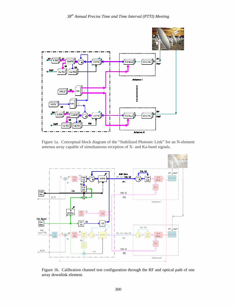
Figure 1a. Conceptual block diagram of the “Stabilized Photonic Link” for an N-element antenna array capable of simultaneous reception of X- and Ka-band signals.
Figure 1b. Calibration channel test configuration through the RF and optical path of one array downlink element.
300
38th Annual Precise Time and Time Interval (PTTI) Meeting
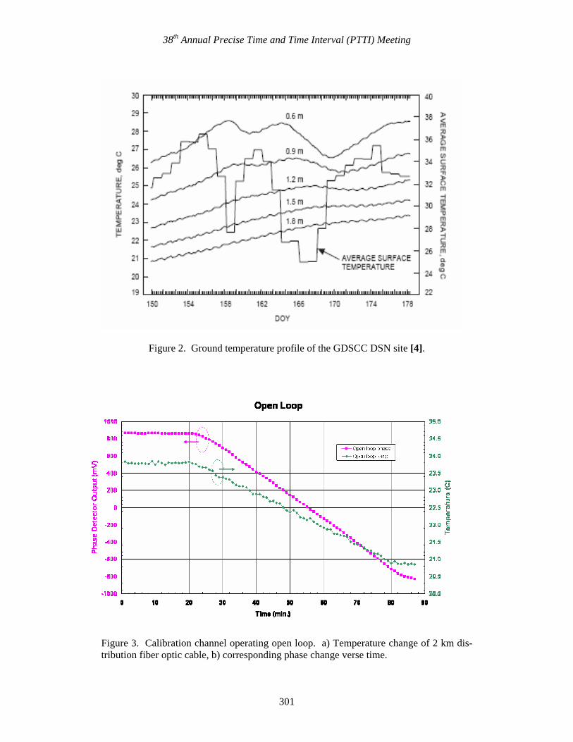
Figure 2. Ground temperature profile of the GDSCC DSN site [4].
Figure 3. Calibration channel operating open loop. a) Temperature change of 2 km dis-tribution fiber optic cable, b) corresponding phase change verse time.
301

38th Annual Precise Time and Time Interval (PTTI) Meeting
Figure 4. Calibration channel closed/open loop. a) Temperature change of 2 km distribu-tion fiber-optic cable, b) corresponding phase change versus time.
302
38th Annual Precise Time and Time Interval (PTTI) Meeting
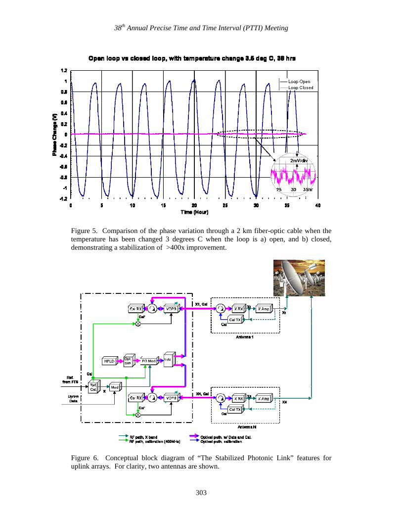
Figure 5. Comparison of the phase variation through a 2 km fiber-optic cable when the temperature has been changed 3 degrees C when the loop is a) open, and b) closed, demonstrating a stabilization of >400x improvement.
Figure 6. Conceptual block diagram of “The Stabilized Photonic Link” features for uplink arrays. For clarity, two antennas are shown.
303

38th Annual Precise Time and Time Interval (PTTI) Meeting
304