stamping and flux option 17-01 - die bonder / micro assembly … · 2020-06-14 · stamping and...
TRANSCRIPT
Dr. TRESKY AG Böhnirainstr. 13 CH-8800 Thalwil Switzerland Tel. +41 44 772 1941 Fax. +41 44 772 1949 Email: [email protected]
STAMPING and FLUX Station with Tresky’s motorised adhesive/flux container
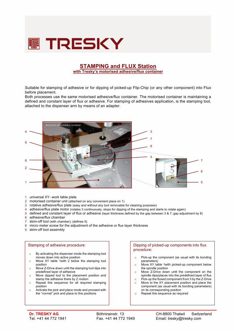
Suitable for stamping of adhesive or for dipping of picked-up Flip-Chip (or any other component) into Flux before placement. Both processes use the same motorised adhesive/flux container. The motorised container is maintaining a defined and constant layer of flux or adhesive. For stamping of adhesives application, is the stamping tool, attached to the dispenser arm by means of an adapter. 4 3 7 9 6 5 8 7 2 6 1 5 1 universal XY- work table plate 2 motorised container unit (attached on any convenient place on 1) 3 rotative adhesive/flux plate (easy and without any tool removable for cleaning purposes) 4 adhesive/flux plate motor (rotates 3 continuously, stops for dipping of the stamping and starts to rotate again) 5 defined and constant layer of flux or adhesive (layer thickness defined by the gap between 3 & 7; gap adjustment by 8) 6 adhesive/flux chamber 7 skim-off tool (with chamber); (defines 5) 8 micro meter screw for the adjustment of the adhesive or flux layer thickness 9 skim-off tool assembly
Motorized adhesive/flux container
Stamping of adhesive procedure: o By activating the dispenser mode the stamping tool
moves down into active position o Move XY table 1with 2 below the stamping tool
position o Move Z-Drive down until the stamping tool dips into
predefined layer of adhesive o Move dipped tool to the placement position and
stamp the adhesive there by Z motion o Repeat this sequence for all required stamping
position o Activate the pick and place mode and proceed with
the “normal” pick and place to this positions
Dipping of picked-up components into flux procedure: o Pick-up the component (as usual with its bonding
parameters) o Move XY table 1with picked-up component below
the spindle position o Move Z-Drive down until the component on the
spindle dips/places into the predefined layer of flux o Pick-up the fluxed component from 3 by the Z-Drive o Move to the XY placement position and place the
component (as usual with its bonding parameters) on its corresponding position
o Repeat this sequence as required