standard catalogue - myonic gmbh
TRANSCRIPT

Standard Catalogue
w w w . m y o n i c . c o m

Company4-5 Ultra Precision Made in Germany
6-7 Applications
8 Research and Development
Technology10-11 myonic Designation System for Ball Bearings
12 Cleanliness and Quality Assurance
13 Material for Ball Bearing Races
14 Closures
15 Preloading and Duplex Mounting
16-17 Ball Cages
18-19 Dimensional and Running Accuracy of Radial Deep Groove Ball Bearings
20 Radial and Axial Bearing Clearance and Contact Angle
21 Friction
22 Starting Torque
23 Code for Grading by Dimensional Groups
24-25 Lubrication
26 Mounting Advice
27 Tolerances for Shafts and Housing Fits
28 Design Information
29 Calculation of Loads
30-37 Calculation of the Theoretical Life Expectancy of Ball Bearings
38 Packaging
Products40-66 Product Tables
Accessories68-73 Product Accessories
74-75 Addresses / Contacts
TABLE OF CONTENTS
© myonic GmbH, Edition 1, June 2014, Vers. 17062014
All information has been carefully prepared and checked. However, we cannot accept responsibility for errors or omissions. Reprinting (including extracts) is only permitted with the explicit consent of myonic GmbH.

Ultra Precision Made in Germany
myonic GmbH Production Site Nadlerstraße, Leutkirch
myonic GmbH Headquarter and Production Site Steinbeisstraße, Leutkirch
myonic s.r.o. Production SiteRoznov, Czech Republic

ULTRA PRECISION MADE IN GERMANY
4
From a modest beginning, myonic has developed into a market leader
History:
2013 Acquisition APB Service GmbH, Ebensee (AT)
2012 Completion of new production hall Steinbeisstraße (GER)
2009 Acquired by Minebea Co., Ltd. (JP)
2006 Management Buy-Out with Süd Private Equity + DZ Equity Partner
2001 RMB becomes myonic
1994 Foundation of MPC (CZ)
1971 Acquisition of MKL (DE) by RMB SA (CH)
1968 Foundation of MKL GmbH (DE)
1936 Foundation of RMB SA (CH)
Size comparison of a myonic UL 103X bearing with a 1 Euro cent coin

This is myonic
“Since the foundation of the company in 1936 as RMB SA, we have searched every day for the most efficient solutions for our customers. Our capacity for innovation and our know-how is valued worldwide by all our customers. Originally focussing on the challenges of the dental industry – high speeds, maximum precision and compact dimensions – we have continually expanded our product range based on our core competencies.
Today, myonic is distinguished by the latest production technologies combined with high quality requirements and well thought-out logistics concepts. Our products can be found wherever intelligent solutions are required under the harshest environmental conditions.
Whether in space, in the medical sector, the automotive sector or in high-tech industrial products, myonic always has a suitable solution.”
Part of the Minebea Group
Minebea is the world‘s leading vertically integrated manufacturer of miniature ball bearings and high-precision components for the telecommunications, aerospace, automotive, and electrical appliance industries.
The Minebea Group consists of 52 subsidiaries in 18 countries and employs more than 55,000 employees. In addition to its global manufacturing capabilities, Minebea‘s vision is to lead the competition through extensive research and development in new methods and technologies.
ULTRA PRECISION MADE IN GERMANY
5
Bernhard BöckManaging Director

Dental Technology
Originally, our company mainly developed solutions for the dental industry. Today, a large proportion of our turnover comes from this sector. myonic solutions can be found in turbines, contra angle handpieces and dental motors. These dental products reach speeds of up to 500,000 r.p.m. and withstand thousands of sterilisation processes. They are designed for maximum durability and minimum noise emission. Due to comprehensive detailed expertise, such as specially adapted tribology systems and material combinations, we have been the world market leaders for many years. Our customers also benefit from the lubrications and materials available only from myonic.
Medical Technology
myonic solutions are essentially designed for a wide range of medical engineering applications such as X-ray diagnostics, computer tomography, minimally invasive surgery and prosthetics.Our bearing design for X-ray tubes with rotating anodes consists of high quality coatings from space technology, which ensure the functions in a temperature range of up to 530°C in a high vacuum at 10–8 mbar. Many manufacturers of surgical instruments and prosthetics also rely on our system solutions.
Aviation and Aerospace / Defence myonic is a supplier of bearings for fuel control systems, mechanical systems for satellites and gyroscopic instruments. Our products withstand extreme temperature conditions, vacuums and vibrations and also provide full output after long standby periods.
The extreme requirements of the aviation and aerospace industry, also in terms of documentation requirements and traceability of all components and production steps, are implemented in full at myonic.
APPLICATIONS
6

Automotive Industry
myonic and Minebea are jointly successful in the development and production of ball bearings for exhaust gas turbochargers. The increasingly stricter emission directives force the automobile manufacturers to find further possibilities to reduce fuel consumption.
Our rolling bearings increase the degree of efficiency of the motor by approx. 2–4 % and are therefore of interest to all renowned turbocharger manufacturers. Special materials and production processes enable the high speeds of up to 250,000 r.p.m. in a temperature range from -40 to +320°C. Areas of application are car and truck engines of all sizes.
Machine Tool Industry The machine tool industry requires system partners to further increase the efficiency of high power machines and increase its own competitiveness.
myonic products are used in rotary table systems and rotary axes as well as in in linear drive units. In close co-operation with the customers, both high-speed solutions and highly rigid or friction-optimised applications are implemented.
The requirements for precision are met with state-of-the-art production technologies.These processes enable optimised geometries and are therefore ideal solutions for our customers.
Transmission and Crane Manufacture, Mechanical Engineering and Steelworks
APB myonic implements solutions, in particular for customers from the sectors of transmission and crane manufacture, mechanical engineering and for steelworks.
The main focus is on niche and series products such as rolling mill bearings, pulley bearings or planetary gear bearings.
In addition to the production of rolling bearings, we offer developments of optimised lubrication solutions such as DUROLUB polymer-matrix lubrication systems, special coatings and individual modifications.
7
APPLICATIONS / served by other Products from myonic

8
Markets are becoming increasingly tight – we are constantly developing
myonic supports its customers right from an early development stage with a highly qualified engineering team and state-of-the-art equipment – from laboratory to production to installation. First-class, highly flexible prototype production enables short development times. The components responsible for consistent top quality are manufactured in house by myonic. A stock of bearing components offers maximum flexibility and very short delivery periods. Production is carried out in an air-conditioned environment and assembly in clean rooms of class ISO 7, under laminar flow boxes ISO 5. We also offer our expertise in assembly technology as a service to a diverse range of customers. myonic continuously develops through strategic partnerships with leading companies and is thus the innovation partner, also for system solutions at the limits of what is technologically possible – based on the motto:
myonic – more than a bearing
High Precision Component Manufacture
Clean Room Installation
Inspection and Measuring Equipment
RESEARCH AND DEVELOPMENT

Technology
1 / 2
Q
1 / 2
Fr Fr
a
Q
b
Fr1 Fr2
Q Q Q Q
I
1/2
Fr
FrQ
Qr
Q
ß
ll

TECHNOLOGY / myonic Designation System for Ball Bearings
myonic Designation System for Ball Bearings
Design types Example:UL = Design type3006 = Nominal dimension of bearing bore and outer diameter in 1/32 inch or, with metric series, in millimetres
X = 1.4125 (AISI 440 C)stainless steel> Page 13
.1 = one-sidedclosure.1c = one-sidedclosure on the flange side.1v = one-sidedclosure on the side opposite the flange > Page 14
Installation type / pre-load .9f = X arrange-ment.9d = O arrange-ment.9t = Tandem arrangement1000 = Pre-load of 10 N> Page 15
Cage design and number of ballsand material> Pages 16, 17
Dimensional and running accuracyas per ISO or ABEC> Pages 18, 19
Lower / upper limit in μm. The standard radial clearance is 6/15.> Page 20
10
g
g
g
g
g
g
g
Basic Material One-Sided Duplex Bearing Cage Tolerance Class Radial
Designation Closure Clearance
UL 3006 -48 -A5P -6/10
ULKZ 4008 .1c -A7P –
RKF 310 .1v -P5P -11/20
R 6190 -237HG -P4P -2/5
ULKU 8012 -48 -A9P -2/10
RA 4012 -257HP -A7P
R 5160 .9d/1000 -16/20

TECHNOLOGY / myonic Designation System for Ball Bearings
Contact- Quietness Friction Coding of Special instruction Lubricationangle torque bores and outer diameter
10/75D -S2 -J... -L23-L23
-G48
-10/174 -G48/20
-SB4/0C -G21/…mg
-J... -L25
-20/25° -L23
-S4/BB -J... -L23-L23
Lower / upper limit in degrees.The standard angle of contactis 17/22°.> Page 20
10 = limit value174 = gauge
10 = limit value μNm75 = axial force cND^= initial friction moment> Pages 21, 22
Classification bydimensional groups> Page 23
The letter J followed by an ordinal number refers to internal company regulations and denotes requirements which cannot be expressed with the previous suffixes.
Code letterL = oilG = greaseExample:G5/20 = grease G5,Dispersion 20%G18/... mg = grease typeG18 and dosage in mg> Pages 24, 25
11
^^
^
^^

12
TECHNOLOGY / Cleanliness and Quality Assurance
myonic meets this requirement through:
gcomplete temperature and humidity control as well as air filtering in all production areas
gUltrasonic cleaning of all components between the individual production stages gCleaning of components with special processes developed by myonic immediately before assembly gAssembly of ball bearings in clean rooms (ISO 7) under laminar flow boxes (ISO 5). gstrict observance of clean room processes by all personnel working there gcleaning of the assembled product with processes specially developed and optimised by myonic for miniature ball bearings guse of specially filtered lubricants gpackaging of the ball bearings in clean, hermetically sealed bags or tubes
myonic is thus able to supply the customers with ball bearings with the highest possible degree of cleanliness. To ensure this state up to installation of the ball bearing, our customers should also exercise this high degree of care. We therefore recommend that the following information be observed:
gAll adjacent components must be produced with the correct tolerances recommended in this catalogue.
gThe surface quality of these parts must meet the requirements for the individual area of application and the components must not have any burrs, loose particles, swarf, rust etc.
gCleaning before final assembly should be carried out away from the area of installation, during which it must be ensured that the cleaned parts are not contaminated again when transported to the area of installation.
Cleanliness is essential for correct functioning of miniature ball bearings
gThe ball bearings should be installed in an area especially prepared for this purpose, which is separated from other rooms.
Where possible, this area should meet clean room requirements and have a dust-free atmosphere as well as temperature and humidity control. Mechanical pro cessing steps should not take place in the same room.
gThe assembly personnel must observe special cleanliness regulations. Normally, gloves and work suits such as gowns and hoods made of special, lint-free material are used for this. In the clean room, smoking, eating, wearing make-up etc. must be strictly prohibited.
gThe miniature ball bearings should only be removed from their packaging immediately before installation. If a package contains more than one ball bearing, only the number of ball bearings immediately required should be removed.
gBall bearings should be handled with tweezers or other special tools. High-precision miniature ball bearings must never be touched directly with fingers. Wearing of lint-free and abrasion-free finger cots or gloves is recommended.
The higher the requirements of the bearings are, the more important it is to strictly observe these recommendations.
DIN EN ISO 14001:2004 DIN EN ISO 9001:2008
Certificates: http://www.myonic.com/isozertifikat

13
In the case of miniature ball bearings, selection of the correct material is decisive for perfect functioning in the end use.
At myonic, the materials are procured, tested and released for use in products in accordance with defined processes. The materials therefore meet the necessary requirements for safe functioning of the end product.
Standard material suffix “X”X105CrMo17– DIN 1.4125 – AISI 440C
This is the standard material which is mainly used in areas in which corrosion-resistance is important.
The steel has a high degree of corrosion resistance and due to the heat treatment, this material has good hardness of 61 HRC.
Material on request suffix “XG”X65Cr13 – DIN 1.4037
myonic introduced this grade of steel at the request of customers and to round off the range of stainless rolling bearing steels. Due to the low carbon content, the degree of hardness is lower than with AISI 440C, but still sufficient for use in rolling bearings. Due to the relatively low chromium content of 13 % (limit value for stainless steels), the requirement for corrosion resistance is easily met.
myonic miniature ball bearings have ring materials per list below
Please contact our application engineers for a recommendation of the most suitable steel grade for your application. Our engineers will offer the right solution for areas of application with maximum requirements for ball bearings. Steel grades from the above list and / or special materials are used.
myonic uses various grades of steel which meet specific customers' requirements. Please contact the engineers in our Sales and Engineering Departments. They will be pleased to help you to select the right material for your specific area of application.
Material on request suffix “V”100Cr6 – DIN 1.3505 – AISI 52100
This material is most frequently used to produce ball bearings of all sizes. Its composition complies with the standard AISI 52100 and ensures a good, uniform microstructure with a hardness after heat treatment of 62 HRC.
Material on request suffix “XA”X30CrMoN15-1 – DIN 1.4108
This stainless steel has a large proportion of nitrogen, which together with the available carbon produces a grain structure in which carbon nitrides are contained in the form of homogeneously distributed microspheres. Corrosion-resistance is ensured by the chrome content.
This special microstructure results in improved macro-mechanical properties, in particular in terms of hot hard-ness, elasticity, flexural strength and elongation at break. The achievable hardness is less than steel AISI 440C.
TECHNOLOGY / Material for Ball Bearing Races

Closures in the form of shields or seals are used for
the following:
gto prevent contamination during handling or assembly of the ball bearing
gto protect the inside of the ball bearing during operation
gto keep lubricant back and reduce its loss to a minimum
myonic standard closures, types «V, Z, X» myonic produces high-precision closures punched from stainless steel material. These closures do not come into contact with the bearing part and provide basic protection against dirt from the outside.
This ensures that neither the friction moment nor noise development nor the operating temperature of the ball bearing increases. It should be noted that this type of closure does not ensure complete protection against external contamination due to dust nor against the ingress of liquids.
Our standard closures are identified with one of the following letters: «V», «Z», «X». Depending on the requirements of the area of applicati-on, we can supply permanently mounted or removable closures.
Filmoseal from myonic, a non-contact seal, type «F» This is a capillary seal known as «Filmoseal», an exclusive myonic design identified with an «F» after the bearing type and before the size.
myonic developed this cover named «Filmoseal» to combi-ne the advantage of a contactless cover with the practical effect of a seal via the capillary effect of an oil film.
This is achieved with the advanced design of the shields and the special groove in the inner ring of the ball bearing.
Due to this design, circulation of the lubricant in the ball bearing is increased and loss of lubricant and dirt from the outside is considerably reduced.
The use of a PTFE seal which is impermeable to oil in the outer ball cage also contributes to preventing loss of lubricant. This non-contact seal is recommended in cases in which high speeds or protection against dirt is required or if the ball bearing is subjected to high centrifugal forces.
«Filmoseal» from myonic is particularly effective with a rotating outer ball cage, as the hermetic seal between the shield and the outer ball cage prevents all loss of lubricant without an increase in noise development or temperature.
Special seals from myonicmyonic develops special seals and shields which meet maximum customer requirements. Further information is available from our sales engineers or technicians.
Standard closureTypes «V» and «Z»
Standard closureType «X»
FilmosealType «F»
14
TECHNOLOGY / Closures
Closures

Preloading and Duplex Mounting
The preloading of radial or angular contact ball bearings serves the purpose of increasing rigidity and running accuracy and minimising sliding of the balls at very high speeds or in the case of rapid acceleration / deceleration. In general, pre-loading of a ball bearing is achieved by exerting an axial force on the face of the ball race. This axial force is applied either by springs or by a pre-set axial offset of the outer ring to the inner ring.
Preloading by SpringSpring preloading is achieved with the aid of one or more spring elements which act against the front face of the outer ring or inner ring of the ball bearing with a pre-set axial force.
With inner ring rotation, the spring disk is pressed against the outer ring (sliding fit). With outer ring rotation, the spring disk is pressed against the inner ring (sliding fit). myonic produces ultra precision, stainless steel spring disks for all standard bearings in our catalogue.
Here it is essential that the two front faces of the spring disks are as parallel as possible to each other, so that correct preloading is ensured and misalignments of the ball bearings are avoided.
Preloading of the duplex bearings To define preloading for two or more ball bearings with high precision, the races must be produced as shown in the diagrams. The axial offset of the inner ring front face to the outer ring front face defines the required preloading. On installation, the axial offset is cancelled and thus the pre-loading is produced.
Preloading of the “X - configuration” (suffix .9f)
With the X - arrangement, the distance between the outer rings is smaller than the distance between the inner rings. The difference between the races is produced on instal-lation by cancellation of a defined axial offset of the front
faces. The axial offset of the front face of the inner ring to the front face of the outer ring is produced by grinding the front faces of the outer rings on one side of the ball bearing. With the X – arrangement, the effective distance between the bearing centres is reduced.
The contact lines converge. The distance between the virtual pressure points (intersection of the angle of contact lines with the symmetry axis) is less than the race clearance. This arrangement is more error tolerant in terms of alig-nment of the bearing system during installation and has good rigidity.
Preloading of the “O - configuration” (suffix .9d)
With the O - arrangement, the distance between the outer races is greater than that of the inner rings. The difference between the races is produced on installation by cancella-tion of a defined axial offset of the front faces.
The axial offset between the inner and outer ring front faces is produced by grinding the front faces of the inner rings on one side of the ball bearing. With the O - arrangement, the effective distance between the centre points increases. The contact lines diverge. The distance between the virtual pressure points (intersec-tion of the angle of contact lines with the symmetry axis) is greater than the race clearance. This arrangement is used at high speeds and to increase the tilting torque.
“Tandem mounting” (suffix .9t)
The ball bearings can also be arranged in tandem form.In this case, the contact lines run parallel and the externally applied radial and axial forces are evenly distributed. This arrangement offers the advantage of a higher axial load-bearing capacity in one direction.
Normally, another bearing or another tandem bearing group is installed at the other end of the shaft to absorb any axial forces working in the opposite direction.
X - configuration (suffix .9f) face to face O - configuration (suffix .9d) back to back Tandem mounting (suffix .9t)
before mounting after mounting before mounting after mounting before mounting after mounting
15
TECHNOLOGY / Preloading and Duplex Mounting

myonic cage “480”Two piece steel ribbon cage tightly crimped
This is a two-piece pressed cage. It is sufficient for most areas of application in which no extreme requirements are made. It can be used if no start-up or bearing friction moment is required, in applications with medium or high speeds or when sufficient lubrication is ensured.
This cage type is supplied as standard with most miniature radial ball bearings, when contaminating misalignment and fast acceleration / deceleration are not of importance. If the cage is used with a speed co-efficient of n x Dm above 400,000 (n = speed in r.p.m.; Dm = pitch circle in mm), please consult our Engineering Department.
myonic cage “48” Two piece steel ribbon cage loosely crimped for low torque
This cage is produced by pressing, is very light and prevents sticking. myonic developed the model “48” especially for areas of application with a requirement for a low friction moment or relatively low speeds.At speeds above 5,000 r.p.m.,please contact our Engineering Department.
Two piece steel ribbon cage with coating
For cases where conventional lubricants are not suitable, both the two-piece standard cage model “480“ and model “48” can be coated with a fine layer of PTFE, silver, gold or other materials which are self-lubricating. PTFE-coated cages are used for very long storage times, in instruments which work in a vacuum and in optical systems.
Before selecting coated ball cages, it is strongly recommended that you contact our Engineering Department and / or carry out practical tests with the end application.
Ball Cages
The purpose of the ball cage is to keep the balls separate from each other around the pitch diameter of the bearing. In order to find the ideal solution for every ball bearing, myonic has developed many different designs of ball cages.
They differ both in design and in material.
There is no single ball cage which meets all conceivable requirements.
When selecting the most suitable ball cage, the following requirements are to be considered:
gstart-up and bearing friction momentgspeedsgacceleration and decelerationgoperating temperaturegtype and quantity of lubricantgenvironmental conditions when using (vacuum, chemicals etc.)grequirements for noise developmentgexternal vibrationsgself-lubrication
16
TECHNOLOGY / Ball Cages
myonic cage “23” for highspeed applications
This ball cage in the form of a crownor comb is machined with different synthetic materials or injection moul-ded.
With selection of the right material, this model can either be oil-impregna-ted for a longer service life or deliver-ed completely dry if the environmental conditions do not allow lubrication with conventional lubricants. The ball cage “23” is used in myonic ball bearings for areas of application in which speed co-efficients n x Dm of up to 1.3 million occur (n = speed in r.p.m; Dm = pitch circle in mm). With even higher speed co-efficients, we recommend consulting our Engineering Department.
myonic cage “25” highspeed application for angular contact ball bearing type
This is a solid one-piece race which is machined or injection moulded. The myonic cage “25” is specially designed for the angular contact ball bearings of the series RA and RKA. This ball cage can be supplied in oil-impregnated form to increase the service life in the event of inadequate lubrication.
The ball pockets are designed in such a way that the inner ring of the ball bearing can be disassembled without the balls falling out.
The two rings can therefore be in-stalled separately if required. The ball cage model “25” is used in myonic ball bearings for areas of application where speed co-efficients n x Dm of up to 1.5 million occur (n = speed in r.p.m; Dm = pitch circle in mm).
myonic cage “27” highspeed application for angular contact ball bearing type
This ball cage is very similar to the model “25”, except that the ball pockets are drilled through.
When the inner ring is disassembled, the balls are not held with this design. The advantage is the lower friction moment compared with the model “25”.
The model “27” is used in ball bearings from myonic for areas of application where speed co-efficients n x Dm of up to 2.4 million occur (n = speed in r.p.m.; Dm = pitch circle in mm).
With even higher speed co-efficients, we recommend that you contact our Engineering Department.
Materials for ball cages
In addition to metallic materials, myonic can supply many synthetic materials for ball cages. For example:gLaminated fabricgPAIgPIgPEEKgPAgPTFEgPOMgSterilisable laminated fabric (myonic patent)
gLaminated paper
Each of these materials has its advantages, depending on the area of application, lubrication and operating environment. We strongly recommend that you contact your nearest myonic sales centre or our engineers in order to select the ideal cage material.
Customised cage designs
If none of the listed standard cages is suitable for customer requirements, myonic can also produce special designs comple-tely in accordance with customer specifi-cations. Our Research and Development Department continually tests new, inno-vative materials and construction types for ball cages which offer first class perfor-mance. Please contact our sales engineers or technicians, who will be pleased to help you find the best solution for your applica-tion.
17
TECHNOLOGY / Ball Cages

Tolerance class All myonic miniature ball bearings are produced in tolerance classes pursuant to ISO and / or ABEC. The International Organization for Standardization (ISO) defines standards which apply to the tolerances of ball bearings in metric dimensions, whereas the standards of the Annular Bearings Engineers Conference (ABEC) are applied for ball bearings in inch dimensions. myonic produces according to both tolerance standards.
Grades ISO 492 2 4 5 6 0
ABEC 9P 7P 5P 3 1 myonic suffix P2 A9P P4P A7P P5P A5P P6 A3 – A1
max 0 0 0 0 0 0 0 0 0 0
min -2.5 -2.5 -5* -5 -5 -5 -7 -5 -8 -7.5
max 0 0 0 0 0 0 +1 +2.5 +1 +2.5
min -2.5 -2.5 -5* -5 -5 -5 -8 -7.5 -9 -10 Bore hole max 0.8* – – – – – 2 – – –
Race max. 0.5 – – – – – 2 – – – max 0 0 0 0 0 0 0 0 0 0
min -25 -25 -25 -25 -25 -25 -40 -125 -40 -125
max 1.5 1.25 2.5 2.5 5 5 12 – 12 –
max 0 0 0 0 0 0 0 0 0 0
min -2.5 -2.5 -5* -5 -5 -5 -7 -7.5 -8 -10
max 0 0 0 0 0 0 +1 +2.5 +1 +2.5
min -2.5 -2.5 -5* -5 -5 -5 -8 -10 -9 -12.5
from d or D max 0.5 – – – – – 2 – – – Race max 0.8* – – – – – 3 – – –
max 0 0 0 0 0 0 0 0 0 0
min -25 -25 -25 -25 -25 -25 -40 -125 -40 -125
max 1.5 1.25 2.5 2.5 5 5 – – – –
max 1.5 1.25 2.5 2.5 5* 3.75 5 5 10 7.5
Outer ring max 2* 1.25 5* 3.75 5 5 8 10 15 15
Inner ring max 2* 1.25 2.5* 2.5 7.5 7.5 – – – –
Outer ring max 4* 1.25 5 5 7.5 7.5 – – – –
Inner ring max 2* 1.25 2.5* 2.5 7.5 7.5 – – – –
Outer ring max 2* 1.25 3.75 3.75 7.5 7.5 – – – –
Dimensional and Running Accuracy of Radial Deep Groove Ball Bearings
Inner ring
Outer ring
Radial run-out
Axial run-out
Face run-out
Perpendicularity
B
D
B
d
B
D
B
d
d max+d min 2
Δ dmp=dmp
Absolute limit values, bore diameter
Δ ds
Irregularity Δ dsp
Width B Δ B
Parallelism deviation V B
D max+D min
2Δ D=Dm
Absolute limit values,outer diameter Δ D
Irregularity
Width B Δ C
Parallelism error V C
Inner ring Kia
Kea
S
S
S
S
18
TECHNOLOGY / Dimensional and Running Accuracy of Radial Deep Groove Ball Bearings
* divergent from the standard
D
d
ea
ia
s
s
s
mp
s
s

Tolerance Class The high-precision production and assembly processes at myonic make it possible to produce ball bearings from ISO 5P and / or ABEC 5P to ISO 2 and / or ABEC 9P. For areas of application which have to meet maximum requirements, myonic produces ball bearings with even lower tolerances than required by the standards. Our sales engineers and technicians will present you with the ideal solution.
Grades ISO 492 2 4 5 6 0
ABEC 9P 7P 5P 3 1 myonic suffix P2 A9P P4P A7P P5P A5P P6 A3 – A1
max 0 0 0 0 0 0 0 0 0 0
min -2.5 -2.5 -5* -5 -5 -5 -7 -5 -8 -7.5
max 0 0 0 0 0 0 +1 +2.5 +1 +2.5
min -2.5 -2.5 -5* -5 -5 -5 -8 -7.5 -9 -10 Bore hole max 0.8* – – – – – 2 – – –
Race max. 0.5 – – – – – 2 – – – max 0 0 0 0 0 0 0 0 0 0
min -25 -25 -25 -25 -25 -25 -40 -125 -40 -125
max 1.5 1.25 2.5 2.5 5 5 12 – 12 –
max 0 0 0 0 0 0 0 0 0 0
min -2.5 -2.5 -5* -5 -5 -5 -7 -7.5 -8 -10
max 0 0 0 0 0 0 +1 +2.5 +1 +2.5
min -2.5 -2.5 -5* -5 -5 -5 -8 -10 -9 -12.5
from d or D max 0.5 – – – – – 2 – – – Race max 0.8* – – – – – 3 – – –
max 0 0 0 0 0 0 0 0 0 0
min -25 -25 -25 -25 -25 -25 -40 -125 -40 -125
max 1.5 1.25 2.5 2.5 5 5 – – – –
max 1.5 1.25 2.5 2.5 5* 3.75 5 5 10 7.5
Outer ring max 2* 1.25 5* 3.75 5 5 8 10 15 15
Inner ring max 2* 1.25 2.5* 2.5 7.5 7.5 – – – –
Outer ring max 4* 1.25 5 5 7.5 7.5 – – – –
Inner ring max 2* 1.25 2.5* 2.5 7.5 7.5 – – – –
Outer ring max 2* 1.25 3.75 3.75 7.5 7.5 – – – –
Limit values of the arithmetic mean of all measurements in two planes (dm = mean inner diameter).
Limits of the absolute value of the smallest and largest inner diameter measured in two planes.
Maximum difference authorised by myonic between the radii of two concentric circles, the inscribed and the circumscribed circle, with reference to the form error diagram.
Lower and upper absolute limit values of the width of the inner ring.
Maximum deviation between the smallest and the largest measured width.
Limit values of the arithmetic mean of all measurements in two planes (Dm = mean outer diameter).
Limits of the absolute value of the smallest and largest outer dia-meter measured in two planes (only for bearing without shields).
Maximum difference authorised by myonic between the radii of two concentric circles, the inscribed and the circumscribed circle, with reference to the form error diagram.
Lower and upper absolute limit values of the width of the outer ring.
Maximum deviation between the smallest and the largest measured width.
Total pointer deflection of the dial gauge during one revolution of the inner ring with stationary outer ring.
Total pointer deflection of the dial gauge during one revolution of the outer ring with stationary inner ring (only for bearings without shields).
Total pointer deflection during one revolution of the inner ring with stationary outer ring
Total pointer deflection of the dial gauge during one revolution of the outer ring with stationary inner ring.
Total pointer deflection of the dial gauge during one revolution of the inner ring.
Total pointer deflection of the dial gauge during one revolution of the outer ring (only for bearings without shields).
19
TECHNOLOGY / Dimensional and Running Accuracy of Radial Deep Groove Ball Bearings
(Limit of the axial run-out of the race in relation to the fronts).

Radial bearing clearance (Gr)
The radial bearing clearance is one of the most important bearing specifications and not a reference to the quality of the ball bearing. Without sufficient radial bearing clearance, press fits (inter-ference fits) and the normal expansion of the components cannot be absorbed without affecting the bearing. In extreme cases, the bearing may therefore fail prematurely.
The radial bearing clearance of the installed ball bearing influences the angle of contact during operation and thus radial and axial load capacity, rigidity, service life and other basic performance characteristics. Information on installa-tion conditions which influence the radial bearing clearance is given in the section on shaft and housing tolerances (page 27).
Greater radial bearing clearance is advantageous when more heat is produced due to high speeds and when shear loads occur. Lower radial bearing clearance is more suitable for mainly radial loads. As standard, the radial bearing clearance of myonic radial bearings is between 6 and 15 μm (.0002" to .0006"). If required, the ball bearings can be supplied with a smaller or greater radial bearing clearance.
Please contact the engineers in our Sales and Engineering Departments. They will be pleased to help you to select the right radial bearing clearance for your specific area of application.
Axial bearing clearance (Ga)
The axial bearing clearance of a ball bearing corresponds to the total axial displacement of the inner ring compared with the outer ring under the influence of a low measure-ment load.
Angle of contact (α°) The angle of contact of a radial ball bearing or angular contact ball bearing is the angle between the line perpen-dicular to the axis and the connecting line through the contact points of the balls on the races, after eliminating the complete radial bearing clearance.
The angle of contact is defined by the radial bearing clearance, the size of the balls and the radius of the races. It increases slightly if an external axial load is exerted on the ball bearing.
As standard, the angle of contact of the myonic radial ball bearings is between 17° and 22°.
The greater the angle of contact is, the greater also is the axial load capacity of the ball bearings, i.e. the capacity to absorb axial loads increases.
Please contact our application engineers, who will be pleased to help you select the right contact angle for your area of application.
Gr
Ga
°
Gr Ga°
Gr
Ga
°
Gr Ga°
Gr
Ga
°
Gr Ga°
Steps
Radial bearing clearance in (μm) 2 to 5 6 to 10 11 to 15 16 to 20
Suffixes 2/5 6/10 11/15 16/20
Steps
Angle of contact α° 11° to 16° 14° to 19° 17° to 22° 20° to 25° 23° to 28°
Suffixes 11/16° 14/19° 17/22° 20/25° 23/28°
Ball bearing with cancelledclearance (without axial load)
20
Radial and Axial Bearing Clearance and Angle of Contact
TECHNOLOGY / Radial and Axial Bearing Clearance and Contact Angle

The criteria by which the bearing friction of ball bearings is determined are very complex and still the subject of detailed studies. Some of the important factors on which bearing friction depends have been determined based on research and experience:
gDimensional precision, design and surface quality of the races
gDimensional precision of the balls
gMaterial of the balls and rings
gDesign, material and guide of the ball cages
gProperties, quantity, quality and distribution of the lubricant
gPrecision of housing and shaft in or on which the bearings are installed
gthe fit tolerances with which the clearance is set on installation
gsize and direction of the externally exerted loads
gposition of the ball bearing axis
Various standardisation projects for these measurements are still at a preparatory stage. myonic has developed its own method from these, which is based on practical experience with actual applications and on tests in the company's own research and development laboratory.
The sensitivity of ball bearings is determined by the
relative value of one or more of the following forces:
gStart-up moment
gBearing friction moment
gFriction peak
In the majority of torque measuring instruments the bearing to be measured is subjected to a pure axial load (which basically has an even effect on all balls of the bearing).
The axial test load is:
g0.75 N for ball bearings with an outer diameter of up to 10 mm incl. or up to .375" for bearings in inch dimensions
g4 N for ball bearings with a diameter of more than 10 mm or an outer diameter of more than .375” for bearings in inch dimensions
21
TECHNOLOGY / Friction
Friction

The maximum value given in the table for the start-up friction moment was taken from the ABMA standard for instruments – ball bearings. They apply to ball bearings of quality ABEC 7P (with or without shields), both in stainless steel (e.g. AISI 440C) and in chromium steel (AISI 52100), with a two-piece ball cage and lubricated with instrument oil. The definitions and test conditions are defined in this standard. These values are maximum values for myonic ball bearings of the relevant category.
Inner Outer Test load Maximum starting torque μN · mdiameter diameter radial clearance innerd D Press fit Normal fit Loose fit
inches inches N .0001"- .0003" .0002"- .0005" .0005"- .0008" 2–8 μm 5–12 μm 12–20 μm
.0400 .1250 .75 18 15 14
.0469 .1563 .75 18 15 14
.0550 .1875 .75 18 15 14
.0781 .2500 .75 18 15 14
.0938 .3125 .75 18 15 14
.1250 .2500 .75 18 15 14
.1250 .3125 .75 18 15 14
.1250 .3750 .75 20 16 15
.1250 .3750 4 50 45 42
.1250 .5000 4 50 45 42
.1563 .3125 .75 18 15 14
.1875 .3125 .75 18 15 14
.1875 .3750 .75 20 16 15
.1875 .5000 4 65 55 50
.2500 .3750 .75 18 15 14
.2500 .5000 4 60 52 48
.2500 .6250 4 70 60 55
.2500 .7500 4 80 70 65
.3750 .8750 4 110 95 90
Starting Torque for Instruments – Ball Bearings
22
TECHNOLOGY / Starting Torque

In order to improve the fit conditions between bearings and shaft or housing fits, myonic uses the group classification of the inner and outer diameters of the bearings.
0-2.5
-2.5-5
-0-1.25
-1.25-2.5
-2.5-3.75
-3.75-5
notclassified
Outer diameter D
Inne
r d
iam
eter
d
S2 SN2-SB4 SN2
SN4-SB2 S4 SN4
SB2 SB4
noneSuffix
Suffixes
S4
Note: the classification may result in various dimensional groups. The measured groups are specified on the packaging. myonic cannot offer any assurance that bearings of one shipment are supplied in one single group.
d= 1st symbol = A 0-1.25
D= 2nd symbol = C-2.5-3.75
Group AC}S2
d= 1st symbol = 1 0-2.5
D= 2nd symbol = 2-2.5-5
Group 12}
SB2d= not classified = A
D= = 1 0 -2.5
Group 01}SN4
d= = A 0-1.25
D= not classified = 0Group A0}
If only one of the two diameters is to be classified, the symbol «O» stands for the other diameter.
23
TECHNOLOGY / Code for Grading by Dimensional Groups
Code for Grading by Dimensional Groups
Tolerance in μm 0 -2.5 0 -1.25 -2.5 -3.75 not -2.5 -5 -1.25 -2.5 -3.75 -5 classified
μm Code 1 2 A B C D 0
1 11 12 1A 1B 1C 1D 10
2 21 22 2A 2B 2C 2D 20
A A1 A2 AA AB AC AD A0
B B1 B2 BA BB BC BD B0
C C1 C2 CA CB CC CD C0
D D1 D2 DA DB DC DD D0
0 01 02 0A 0B 0C 0D

One of the most important factors for the effective functioning of a miniature ball bearing is the lubricant and the lubrication method. Due to the size of the miniature ball bearings, there may be considerable differences between the performance characteristics of individual lubricants. The selection of the lubricant, its quantity and distribution inside the bearing are decisive. The following characteristics must therefore be taken into account:
gSpeed of the inner and / or outer ring
gOperating conditions of the rotation (with interruptions, continual, oscillating, tilted etc.)
gExternally applied loads (axial, radial tilting movement)
gOperating temperature and environmental temperature of the ball bearings
gPermissible noise development
gExpected service life
gStorage before use
gEnvironmental conditions at the place of use of the ball bearings (vacuum, chemicals etc.)
gRequired start-up and bearing friction moment
Our Research and Development Department develops tests in co-operation with our lubricant suppliers to ensure consistent quality of the product supplied to us.
Hundreds of oil and grease types and solid lubricants have been tested and are available for maximum requirements.
Please contact our Sales and Application Engineers.
Standard lubricants of myonic
The products in our range are normally available with the following standard lubricants:
Radial ball bearings with shields, outer diameter < 9 mm L23
Radial ball bearings with shields, outer diameter ≥ 9 mm G48
Angular contact ball bearing G48
Axial ball bearing G48
The adjacent tables contain information intended to help the designer with his selection of the suitable lubricant. However, the specified values are not binding for myonic, as they were only taken from the publications of the respective manufacturers. In critical cases, practical tests with the relevant lubricants are recommended; frequently, tests are even essential.
We do not claim that the tables are exhaustive. Provided that the relevant lubricant is available, myonic can lubricate ball bearings with any required product.
Lubrication
24
TECHNOLOGY / Lubrication

g
g
g
g
g
g
g
g
g g
Characteristics of the Oils and Greases Most Frequently Used by myonic
Code Designation Temperature Temperature- Viscosity in Flash point Setting point Military speci- range in °C peaks in °C cSt at 20°C in °C in °C fication USA
L 2 Isoflex® PDP 38 -65 to + 100 - 23 +200 -70 -L23 Winsor L 245X -57 to + 185 +204 24 +216 -60 MIL-L-6085DL25 Krytox® 143 AB -40 to + 232 - 230 +215 -40 -
Code Designation Temperature Basic oil Penetration Drip Basic Military range viscosity as per ASTM point specification
in °C cSt at 25°C in °C USA
G21 Nye Instrument 704C -65 to +150 3 / 100°C 296 +260 Bentone Clay MIL-PRF-23827C
G48 Turmogrease Li 802 EP plus -35 to +140 85 / 40°C 257 > 250 Lithium -G58 Klüber Isoflex® LDS 18 Special A -50 to +120 15 / 40°C 280 +185 Lithium -G79 Isoflex® Klüber Topas NB 52 -50 to +120 30 / 40°C 280 +240 Barium -G86 Asonic® GLY 32 -50 to +140 25 / 40°C 280 +190 Lithium -G90 Isoflex® Klüber Barrierta L55/2 -40 to +260 400 / 40°C 280G100 Nye Rheolube® 740 S -30 to +120 116 / 40°C 295 +240 Polyurea -G144 myonic high speed lube -40 to +200 46 / 40°C 340 > 200 Polyurea -G163 myonic H1 high speed lube -40 to +200 46 / 40°C 325 > 200 Polyurea -
(Aeroshell grease 7)
25
TECHNOLOGY / Lubrication
g
gg
g g g
g
g
Oils
Code General High High speed High Low Low start-up Low speed and high temperature temperature friction noise temperature (> 200°C) (< -50°C) moment level
L2 L23 L25
Greases
Code General High High speed High Low Low start-up Low H1 speed and high temperature temperature friction noise approval temperature (> 200°C) (< -50°C) moment level
G21 G48 G58 G79 G86 G90 G100 G144 G163
g

Miniature ball bearings can only function perfectly as intended if installation is carried out correctly. From experience it is known that functional defects and excessive wear are due in most cases to incorrect installation. The following points should therefore be strictly observed:
Selection of the fit: Perfect functioning of the ball bearings largely depends on the quality of the fit. The following aspects are to be taken into account when selecting the suitable fit:
gSurface quality and dimensional precision of the shaft and housing. These two factors not only influence the friction moment and running noise but also ensure perfect running of the ball bearing, especially at high speeds.
gTemperature fluctuations: at high temperatures the outer ring is loosened by the radial expansion of a light alloy housing, whereas the radial expansion of a light alloy shaft reduces the radial clearance. On the other hand, the difference between the axal expansion of a steel shaft and of a light alloy housing lead to an additional axial load.
gSize, type and direction of loads. The load of a ball bearing in rest position should not exceed its static load rating.
gAxial, radial, combined and loads applied in both directions, which lead to fast load changes.
Such impact loads are very damaging to miniature ball bearings and should be prevented if possible.
gRelative movement of the inner and outer rings.
gThe precision and radial rigidity required for the complete assembly. The two tables on the following pages show in the middle column – one for shafts and once for the housing – the most favourable production tolerances for optimum design of the fit, where
gthe loads and speeds for the relevant application
gare taken as a basis on the left and the required precision and radial rigidity on the right.
The tolerances are given in μm and only apply if the material for the shafts and housing has the same expansi-on co-efficients as the steel used for the ball bearings*. In all other cases, the different expansion values must be taken into account.
In general, the fits given in these tables are suitable for normal operating temperatures.
Great differences in temperature and the direction of the heat flow in the bearing must be taken into account.
Frequently, laboratory tests are required to find the best solutions. The installation and operating conditions are important here.
Such tests can be carried out in the myonic laboratory.For easier installation, myonic ball bearings can be divided on delivery into dimensional groups of the bore hole and / or outer diameter.
Mounting Advice
26
TECHNOLOGY / Mounting Advice
* Expansion co-efficient of the steel for the ball bearing: 11 x 10-6 °C

Tolerances for Shafts
Shaft Loads / Fit Tol. d of the ball bearing Accuracy Typical The
Speeds 0/–8 0/–5 Sorting of the assembly Application Inner ring
μm μm 0/-2.5 -2.5/-5 areas is laterally
Tolerance shaft
rotating Low loads Sliding fit -5 -5 -5 -8 Normal precision without Guides fixedor fixed Low to medium special requirements. (Films, audio tapes...)
(alternating) speeds No vibrations -13 -11 -8 -11 Normal precision; Brakes fixed of the inner ring must be Couplings movable sideways (expansion). fixed Medium loads Press fit Precise radial Gyroscope fixed Medium speeds Guide Vibrations with high frequency 0 0 0 -3 Radial rigidity
rotating Low loads -8 -6 -3 -6 Normal precision Small motors free Medium speeds Potentiometer Vibrations with Servo motors low frequency
fixed High loads Press fit The press fit must Gyroscope free High speeds at high speeds Fans Vibrations with high be ensured. Electric motors frequence +4 +4 +4 +1 High radial rigidity
rotating Medium to high loads -4 -2 +1 -2 High speeds Vibrations with high frequency
Shaft and ball bearing of the same material; otherwise, the different expansion co-efficients1 are to be taken into account.
Tolerances for the Housing Fits Housing and ball bearing of the same material; otherwise, the different expansion co-efficients1 are to be taken into account.
1 Temperature expansion co-efficient ball bearing steel: 11x10–6 ºC
27
TECHNOLOGY / Tolerances for Shafts and Housing Fits
Outer Loads / Fit Tol. d of the ball bearings Accuracy Typical
ring Speeds 0/–8 0/–5 Sorting of the assembly Areas of application
μm μm 0/-2.5 -2.5/-5
Tolerance shaft
rotating Low loads Sliding fit +5 +5 +5 +2 Normal precision without Electric motorsor fixed Low to medium special requirements. Servo motors (alternating) speeds Fans No vibrations -3 -1 +2 -1 The outer ring must be Potentiometer movable sideways (expansion). fixed Medium loads Press fit Precise radial guide Synchronous motors Medium speeds Radial rigidity. Rotor suspensions Vibrations with The outer ring must fit firmly high frequency 0 0 0 0 -3 sideways.
rotating Low loads -8 -6 -3 -6 Normal precision Guides Low to medium speeds Tensioner pulleys Vibrations with Pantographs low frequency
fixed Large loads Tight fit The tight fit must Rollers High speeds at high speeds Deflecting rollers Vibrations with high be ensured. Planetary gear frequency -4 -3 -3 -6
rotating Medium to large loads -12 -9 -6 -9 It is not necessary High speeds for the outer ring Vibrations with high to be held laterally. frequency High rigidity

gIn particular, the values Li, Lo, r max and h min should be strictly observed.
gThe following diagrams show how a ball bearing should normally be installed or disassembled.
gIf for design reasons it cannot be avoided that the shoulder height is too small, a ground sliding ring should be inserted between the shoulder and the ball bearing.
gWhen installing and removing radial bearings, particular care is required to prevent all transmission of forces via the shaft to the bearing at the other end of the shaft. In addition, the ball bearing opposite the ball bearing which is being installed should be protected in such a way that the balls are not subjected to loads or impacts.
gThe load must be directly applied to the ball bearing ring which is being installed or disassembled. A flux via the ball set is to be avoided. Therefore, to facilitate disassembly, intermediate rings 1 should be inserted. If such intermediate rings cannot be used, grooves should be made in the shoulders of the housings or shafts so that special tools can be introduced for disassembly.
De
de
1
1
1
1
De
de
1
1
1
1
De
de
1
1
1
1
De
de
1
1
1
1
De
de
1
1
1
1
De
de
1
1
1
1
De
de
1
1
1
1
gLarger radii than r max and lower shoulder heights of the locking ring than h min. Consequences: axial position undetermined, risk of deformation for the ring.
gShoulder and locking ring lower than h min. Consequences: as above.
gShoulder diameter De of the housing seat less than Li. Consequences: shoulder touches the inner ring.
gShoulder diameter De of the shaft greater than Lo. Consequences: shoulder touches the outer ring.
Please avoid: Please ensure:
The ball bearing tables contain the dimensions of the myonic miniature ball bearings d, D, B (Bf), Li, Lo, r max and h min.
d = Inner diameter
D = Outer diameter
B = Width of the ball bearing rings
Li = minimum permissible shoulder diameter of the housing seat
Lo = maximum permissible shoulder diameter of the shaft
r max = maximum permissible rounding radius of the shaft or housing seat
h min = minimum permissible shoulder height of the shaft or housing seat
B B Bf Bf Bf
B
Lo Li d D h r
B B Bf Bf Bf
B
Lo Li d D h r
De
de
1
1
1
1
De
de
1
1
1
1
28
TECHNOLOGY / Design Information
Design Information

1 / 2
Q
1 / 2
Fr Fr
a
Q
b
Fr1 Fr2
Q Q Q Q
I
1/2
Fr
FrQ
Qr
Q
ß
ll
1 / 2
Q
1 / 2
Fr Fr
a
Q
b
Fr1 Fr2
Q Q Q Q
I
1/2
Fr
FrQ
Qr
Q
ß
ll
In most cases, miniature ball bearings are only subjected to relatively low loads, which can nevertheless affect their service life. For this reason, it is recommended to determine the direction and size of these loads as far as possible.
Loads which must be observed:
1. Weight of the moving part
2. Centrifugal force (imbalance)
3. Dynamic load (acceleration, deceleration)
4. Force as a result of energy transmission (Belt pulley, gears etc.)
5. Pre-tensioning of duplex bearings1
Pure axial load Fa
Tandem
>
O-arrangement
>
Tandem
>Tandem
>
O-arrangement
fa = Q (alternating load) fa = Q (one-sided) fa = Q (alternating load) fa = Q (alternating load)
Note: in order for an axial load to be absorbed by several ball bearings, they must be arranged in pairs1, either ring against ring or with very precisely manufactured intermediate rings.
Combined loads
(radial and axial)
1 ) see duplex installation on page 15
Qr = cos ß · QQa = sin ß · Q
Normal installation
Fr =
Fa = Qa (the axial load is absorbed by only one ball bearing)
Duplex installation in tandem design
(Intermediate ring)
Fr = QrFa = Qa
Qr 2
Pre-loading Fap
Ball bearings in duplex form1 (O – arrangement or X – arrangement) have pre-loading (Fap), which is above or below the axial load Fa.
This pre-loading Fap must be adapted to the operating conditions and the required useful life.
1 / 2
Q
1 / 2
Fr Fr
a
Q
b
Fr1 Fr2
Q Q Q Q
I
1/2
Fr
FrQ
Qr
Q
ß
ll
1 / 2
Q
1 / 2
Fr Fr
a
Q
b
Fr1 Fr2
Q Q Q Q
I
1/2
Fr
FrQ
Qr
Q
ß
ll
Fr =Q2
Fr1 =Q · b
I
Fr2 =Q · a
I
29
Calculation of Loads
TECHNOLOGY / Calculation of Loads
Pure radial load Fr
Direction and distribution of forces
The theoretical service life is only achieved in practice if the following conditions are met:
gprecise determination of the size and direction of permanent loads;
gconstant speeds;
gconstant temperatures of max. 100°C;
ggreatest possible cleanliness during installation and operation;
gcareful selection and dispensing of the lubricant;
ginstallation under strict observance of the information on page 26.
In more complex applications or if in doubt, we recommend that you consult our Technical Support.
Calculation of the load rating and theoretical service life of ball bearings is based on the formulae and theories of the ISO and ABMA standards.
1. Service life of radial and axial ball bearings
The following applies:
L10 = Life cycle in millions of revolutionsC = dynamic load rating in NP = dynamically equivalent load in NC/P = Load safety
2. Service life in hours
The following applies:
L10h = Service life in millions of revolutionsn = Speed in r.p.m.
Calculation of the Theoretical Life Expectancy of Ball Bearings
3. Definitions
L10, = Service life in millions of revolutions or in hours, which is achieved by 90% of a large number of similar ball bearings under similar conditions. 40% of these achieve a 5 times longer service life.
C = Dynamic load rating. In the case of radial bearings, this is a radial force and in the case of axial bearings an axial load, which has a constant effect and is stationary in relation to the outer ring.
The ball bearing can bear this load with a calculated service life of one million revolutions of the inner ring or 500 hrs. at 331⁄3 r.p.m. The dynamic load rating takes account of:
grepeated deformation of various components of the ball bearing (raceways and balls) depending on the mechanical resistance of their materials and geometric forms
gFrequency of loads
g an empirical probability factor
P = Dynamic equivalent load. This is a nominal load which records the axial and radial load components in such a way that with calculation of the theoretical service life the same values are determined as if only a pure radial load (for radial bearings) or a pure axial load (for axial bearings) is applied.
Co = Static load rating. With radial bearings this is a radial-oriented constant load and with axial bearings an axial-oriented constant load, where a residual deformation of max. .0001 of the rolling element diameter is achieved at the point of contact with the maximum load and the following operating conditions apply: gstandstill gvery slow swivel movements gvery low speeds
Po = equivalent static load.
L10=C P( ) 3
L10h=L · 106
60 · n
Conversion of units1 N = 1 kg m/s21 kgf (= 1kp) = 9.81 N
30
TECHNOLOGY / Calculation of the Theoretical Life Expectancy of Ball Bearings

4. Calculation of the dynamically equivalent load
4.1 Radial deep groove ball bearing, single row:
P = X · Fr + Y · Fa
The following applies:
P = dynamically equivalent load in N Fr = radial component of the load in N Fa = axial component of the load in N X = radial factor of the bearing as per table on page 34 Y = axial factor of the bearing as per table on page 34
4.2 Axial deep groove ball bearing:
P = Fa
5. Calculation of the static load rating
Co = so · Po
The following applies:
Co = static load rating in N Po = static equivalent load in N so = static load safety factor
The value for the static load safety factor can be selected as follows depending on operating conditions and requirements of the bearings:
so = 0.5 to 0.7 for low requirements and vibration-free operation
so = 1.0 to 1.2 for normal requirements and vibration-free operation
so = 1.5 to 2.0 for high requirements and with impact loads
6. Calculation of the statically equivalent load
6.1 Radial deep groove ball bearing:
Po = Xo · Fr + Yo · Fa
The following applies:
Po = statically equivalent bearing load in N Fr = Radial component of the highest static load in N Fa = Axial component of the highest static load in N Xo = Radial factor Yo = Axial factor
If the statically equivalent bearing load calculated with this formula is Po <Fr, then Po = Fr is used for calculation. Values for the factors Xo and Yo, Xo = 0.6 Yo = 0.5
6.2 Axial deep groove ball bearing:
Po = Fa
7. Duplex Bearings
If two single row radial deep groove ball bearings are used in duplex arrangement (X, O or tandem), the following ratios must be included in the calculation of the dynamic load rating and the dynamically equivalent load.
7.1 Duplex arrangement X or O
Dynamic load rating
Cd = (2 · cos αº) 0.7 · C
The following applies:
Cd = dynamic load rating for a ball bearing pair in N αº = Contact angle C = dynamic load rating for a single ball bearing in N L10 = service life in millions of revolutions P = dynamically equivalent load in N
Dynamically equivalent load
P = X · Fr + Y · Fa
The following applies:
P = dynamically equivalent load in N Fr = radial component of the load in N Fa = axial component of the load in N X = radial factor for a ball bearing pair as per page 34 Y = axial factor for a ball bearing page as per page 34
Duplex arrangement X or O with pre-loading
Fa = 0.8 (Fap + Fa1)*
The following applies:
Fa = effective axial load in N Fap = pre-loading of the ball bearing pair in N Fa1 = external axial force acting on the pre-loaded ball bearing pair, axial force in N.
* The ratio pre-loading Fap and axial force Fa1 must be selected in such a way that no bearing is completely relieved. Within the radial clearances and angles of contact recommended by myonic, this condition is met if:
Fap ≥ 0.35 Fa1
L10=Cd P( )3
31
TECHNOLOGY / Calculation of the Theoretical Life Expectancy of Ball Bearings

Duplex arrangement X or O without pre-loading
or with low axial clearance
For these cases, calculation must be carried out with the aid of the formulae listed under point 7.1. When determining the factors X and Y from the table on page 34, however, it is to be ensured that the number of balls of two bearings is taken into account.
7.2 Tandem arrangement
Dynamic load rating
Ct = C · N0.7
The following applies: Ct = dynamic load rating of the tandem arrangement in N C = dynamic load rating of a single ball bearing in N N = number of ball bearings
Calculation of the dynamically equivalent load and of the service life is carried out taking Ct into account, as with single bearings with one row of balls. Accordingly, the factors X, Y and e as per page 34 apply.
8. Calculation example Example 1
Calculation of the theoretical service life Lh of a radial deep groove ball bearing R 2570X for the following operating conditions:
Radial load Fr = 5.7 N Axial load Fa = 2.8 N Speed n = 8000 r.p.m. Radial clearance 2 / 5 μm
For the ball bearing R 2570X, the following applies:
C = 142N Z • Dw2 = 8 P = X · Fr + Y · Fa
X = 0.56 Y = 2.77 P = 0.56 · 5.7 + 2.77 · 2.8 = 3.2 + 7.8 = 11 N
L10h = 4473 hAccording to the table on page 33, Lh = 4500 hrs. is also found by interpolation.
Example 2
A rotor is to be mounted with two pre-loaded angular contact ball bearings RA in duplex-O arrangement:
Radial load Fr = 4 NAxial load Fa1 = 12 NSpeed n = 24000 r.p.m.Angle of contact αº = 20ºrequiredservice life = 5000 hrs.The bearing size is to be determined
or through linear interpolation from the table on page 33.
According to information on page 31:Fap ≥ 0.35 . Fa1 = 0.35 . 12 = 4.2 N
Pre-loading Fap of 6 N is selected.Fa = 0.8 (Fap + Fa1) = 0.8 (6 +12) = 0.8 •18 = 14.4 NAccording to the table on page 34,αº = 20°e = 0.50
X = 0.70Y = 1.86P = X · Fr + Y · Fa = 0.70 · 4 + 1.86 · 14.4 = 2.8 + 26.7 = 29.5 N
Cd = 19.3 · P = 19.3 · 29.5 = 569Cd = (2 · cos αº)0.7 • C
The angular contact ball bearing RA 3100X-... with a load rating of C = 332 N is a little too weak. If sufficient space is available, angular contact ball bearing RA 4130X.9d/600-..... is selected.
Fa2 · Z · Dw2
(Total number of balls in two ball bearings)
FaZ · Dw2
= 2.88
= 0.35 e=0.12
FaFr
= 2.85.7
= 0.5 therefore > e
CP
= 14211
= 12.9 CL10=( = 12.93 = 2147P)
3
L10h=L · 106
60 · n=
2147 · 106
60 · 8000
L10h=L · 106
60 · n= 5000 hrs
CdL10= = 7200( P ) 3
Cd= 3√7200 = 19.3
P
Cd= 19.3
P
FaFr
=14.4
4= 3.6 therefore > e,
Cd= 19.3
P
Cd( 2 · cos α° ) 0.7C= =
( 2 · cos 20° ) 0.7
569 5691.55
= =367 N
32
TECHNOLOGY / Calculation of the Theoretical Life Expectancy of Ball Bearings

L10 C/P L10 C/P L10 C/P
0.5 0.793
0.75 0.909
1.0 1.0
1.5 1.14
2 1.26
3 1.44
4 1.59
5 1.71
6 1.82
8 2.0
10 2.15
12 2.29
14 2.41
16 2.52
18 2.62
20 2.71
25 2.92
30 3.11
35 3.27
40 3.42
45 3.56
50 3.68
60 3.91
70 4.12
80 4.31
90 4.48
100 4.64
120 4.93
140 5.19
160 5.43
180 5.65
200 5.85
220 6.04
240 6.21
260 6.38
280 6.54
300 6.69
320 6.84
340 6.98
360 7.11
380 7.24
400 7.37
420 7.49
440 7.61
460 7.72
480 7.83
500 7.94
550 8.19
600 8.43
650 8.66
700 8.88
750 9.09
800 9.28
850 9.47
900 9.65
950 9.83
1000 10.0
1100 10.3
1200 10.6
1300 10.9
1400 11.2
1500 11.4
1600 11.7
1700 11.9
1800 12.2
1900 12.4
2000 12.6
2200 13.0
2400 13.4
2600 13.8
2800 14.1
3000 14.4
3200 14.7
3400 15.0
3600 15.3
3800 15.6
4000 15.9
4500 16.5
5000 17.1
5500 17.7
6000 18.2
6500 18.7
7000 19.1
7500 19.6
8000 20.0
8500 20.4
9000 20.8
9500 21.2
10000 21.5
12000 22.9
14000 24.1
16000 25.2
18000 26.2
20000 27.1
25000 29.2
30000 31.1
35000 32.7
40000 34.2
45000 35.5
50000 36.8
55000 38.1
60000 39.2
Load safety C/P in relation to service life L10 (106 revolutions)
33
TECHNOLOGY / Calculation of the Theoretical Life Expectancy of Ball Bearings

FaZ • Dw2 X Y e
FaFr
≥ eAngle ofcontact
FaFrAngle of
contactFa
Z • Dw2 X Y X Y e
≤ eFaFr
≥ e
34
TECHNOLOGY / Calculation of the Theoretical Life Expectancy of Ball Bearings
Radial factor X and axial factor Y for the calculation of the dynamically equivalent load of single row radial deep groove ball bearings.
≤5° 0.17 0.56 3.09 0.09 0.35 2.77 0.12approximate 0.70 2.43 0.14radial clearance 1.05 2.23 0.152 – 5 μm 1.40 2.10 0.16(Suffix 2/5) 2.10 1.92 0.18 3.51 1.71 0.21 5.27 1.56 0.23 7.03 1.44 0.24
10° 0.17 0.46 2.20 0.25 0.35 2.09 0.26approximate 0.70 1.94 0.28radial clearance 1.05 1.84 0.296 – 15 μm 1.40 1.77 0.31(Standard 2.10 1.66 0.33radial clearance, 3.51 1.53 0.35no suffix) 5.27 1.44 0.38 7.03 1.36 0.40
15° 0.17 0.44 1.55 0.35 0.35 1.51 0.36approximate 0.70 1.48 0.36radial clearance 1.05 1.42 0.3816 – 20 μm 1.40 1.39 0.39(Suffix 16/20) 2.10 1.34 0.41 3.51 1.26 0.43 5.27 1.20 0.45 7.03 1.16 0.47
20° 0.43 1.14 0.5025° 0.41 0.95 0.6230° 0.39 0.81 0.7535° 0.37 0.69 0.9140° 0.35 0.60 1.08
Factors X and Y which refer to intermediate load and angle of contact values are to be determined through linear interpolation.
Fa = Axial load in N Z = Number of ballsDw = Diameter of the balls in mm
Radial factor X and axial factor Y for the calculation of the dynami-cally equivalent load with single row radial deep groove ball bea-rings in duplex arrangement. Angle of contact between 0° and 40°.
0° 0.17 1 0 0.56 3.09 0.09 0.35 2.77 0.12for ball bearings 0.70 2.43 0.14in duplex 1.05 2.23 0.15arrangement 1.40 2.10 0.16with low 2.10 1.92 0.18axial clearance 3.51 1.71 0.21 5.27 1.56 0.23 7.03 1.44 0.24
5° 0.17 1 3.69 0.78 5.02 0.17 0.35 3.30 4.49 0.19approximate 0.70 2.89 3.94 0.22radial clearance 1.05 2.66 3.63 0.242 – 5 μm 1.40 2.50 3.41 0.25(Suffix 2/5) 2.10 2.29 3.12 0.27 3.51 2.04 2.78 0.31 5.27 1.86 2.53 0.34 7.03 1.72 2.35 0.36
10° 0.17 1 2.25 0.75 3.58 0.25 0.35 2.41 3.39 0.26approximate 0.70 2.24 3.14 0.28radial clearance 1.05 2.13 2.99 0.296 – 15 μm 1.40 2.04 2.87 0.31(Standard 2.10 1.92 2.69 0.33radial clearance, 3.51 1.77 2.49 0.35no suffix) 5.27 1.66 2.33 0.38 7.03 1.57 2.21 0.40
15° 0.17 1 1.74 0.72 2.52 0.35 0.35 1.70 2.46 0.36approximate 0.70 1.66 2.41 0.36radial clearance 1.05 1.59 2.31 0.3816 – 20 μm 1.40 1.56 2.25 0.39(Suffix 16/20) 2.10 1.50 2.17 0.41 3.51 1.42 2.05 0.43 5.27 1.35 1.96 0.45 7.03 1.30 1.88 0.47
20° 1 1.25 0.70 1.86 0.5025° 1 1.00 0.67 1.55 0.6230° 1 0.83 0.63 1.31 0.7535° 1 0.69 0.60 1.12 0.9140° 1 0.58 0.57 0.97 1.08
If ≤ e, X = 1, Y = 0 must be used for calculation.FaFr

L10h 10 40 100 160 200 250 320 400 500 630 800 1000
100 – – – – 1.06 1.15 1.24 1.34 1.45 1.56 1.68 1.82
500 – 1.06 1.45 1.68 1.82 1.96 2.12 2.29 2.47 2.67 2.88 3.11
1000 – 1.34 1.82 2.12 2.29 2.47 2.67 2.88 3.11 3.36 3.63 3.91
1250 – 1.45 1.96 2.29 2.47 2.67 2.88 3.11 3.36 3.63 3.91 4.23
1600 – 1.56 2.12 2.47 2.67 2.88 3.11 3.36 3.63 3.91 4.23 4.56
2000 1.06 1.68 2.29 2.67 2.88 3.11 3.36 3.63 3.91 4.23 4.56 4.93
2500 1.15 1.82 2.47 2.88 3.11 3.36 3.63 3.91 4.23 4.56 4.93 5.32
3200 1.24 1.96 2.67 3.11 3.36 3.63 3.91 4.23 4.56 4.93 5.32 5.75
4000 1.34 2.12 2.88 3.36 3.63 3.91 4.23 4.56 4.93 5.32 5.75 6.20
5000 1.45 2.29 3.11 3.63 3.91 4.23 4.56 4.93 5.32 5.75 6.20 6.70
6300 1.56 2.47 3.36 3.91 4.23 4.56 4.93 5.32 5.75 6.20 6.70 7.23
8000 1.68 2.67 3.63 4.23 4.56 4.93 5.32 5.75 6.20 6.70 7.23 7.81
10000 1.82 2.88 3.91 4.56 4.93 5.32 5.75 6.20 6.70 7.23 7.81 8.43
12500 1.96 3.11 4.23 4.93 5.32 5.75 6.20 6.70 7.23 7.81 8.43 9.11
16000 2.12 3.36 4.56 5.32 5.75 6.20 6.70 7.23 7.81 8.43 9.11 9.83
20000 2.29 3.63 4.93 5.75 6.20 6.70 7.23 7.81 8.43 9.11 9.83 10.6
25000 2.47 3.91 5.32 6.20 6.70 7.23 7.81 8.43 9.11 9.83 10.6 11.5
32000 2.67 4.23 5.75 6.70 7.23 7.81 8.43 9.11 9.83 10.6 11.5 12.4
40000 2.88 4.56 6.20 7.23 7.81 8.43 9.11 9.83 10.6 11.5 12.4 13.4
50000 3.11 4.93 6.70 7.81 8.43 9.11 9.83 10.6 11.5 12.4 13.4 14.5
63000 3.36 5.32 7.23 8.43 9.11 9.83 10.6 11.5 12.4 13.4 14.5 15.6
80000 3.63 5.75 7.81 9.11 9.83 10.6 11.5 12.4 13.4 14.5 15.6 16.8
100000 3.91 6.20 8.43 9.83 10.6 11.5 12.4 13.4 14.5 15.6 16.8 18.2
200000 4.93 7.81 10.6 12.4 13.4 14.5 15.6 16.8 18.2 19.6 21.2 22.9
n r.p.m.
Load safety C/P in relation to service life L10h in hrs. and speed n in r.p.m.
35
TECHNOLOGY / Calculation of the Theoretical Life Expectancy of Ball Bearings

L10h 1250 1600 2000 2500 3200 4000 5000 6300 8000 10000 12500
100 1.96 2.12 2.29 2.47 2.67 2.88 3.11 3.36 3.63 3.91 4.23
500 3.36 3.63 3.91 4.2 4.56 4.93 5.32 5.75 6.20 6.70 7.23
1000 4.23 4.56 4.93 5.32 5.75 6.20 6.70 7.23 7.81 8.43 9.11
1250 4.56 4.93 5.32 5.75 6.20 6.70 7.23 7.81 8.43 9.11 9.83
1600 4.93 5.32 5.75 6.20 6.70 7.23 7.81 8.43 9.11 9.83 10.6
2000 5.32 5.75 6.20 6.70 7.23 7.81 8.43 9.11 9.83 10.6 11.5
2500 5.75 6.20 6.70 7.23 7.81 8.43 9.11 9.83 10.6 11.5 12.4
3200 6.20 6.70 7.23 7.81 8.43 9.11 9.83 10.6 11.5 12.4 13.4
4000 6.70 7.23 7.81 8.43 9.11 9.83 10.6 11.5 12.4 13.4 14.5
5000 7.23 7.81 8.43 9.11 9.83 10.6 11.5 12.4 13.4 14.5 15.6
6300 7.81 8.43 9.11 9.83 10.6 11.5 12.4 13.4 14.5 15.6 16.8
8000 8.43 9.11 9.83 10.6 11.5 12.4 13.4 14.5 15.6 16.8 18.2
10000 9.11 9.83 10.6 11.5 12.4 13.4 14.5 15.6 16.8 18.2 19.6
12500 9.83 10.6 11.5 12.4 13.4 14.5 15.6 16.8 18.2 19.6 21.2
16000 10.6 11.5 12.4 13.4 14.5 15.6 16.8 18.2 19.6 21.2 22.9
20000 11.5 12.4 13.4 14.5 15.6 16.8 18.2 19.6 21.2 22.9 24.7
25000 12.4 13.4 14.5 15.6 16.8 18.2 19.6 21.2 22.9 24.7 26.7
32000 13.4 14.5 15.6 16.8 18.2 19.6 21.2 22.9 24.7 26.7 28.8
40000 14.5 15.6 16.8 18.2 19.6 21.2 22.9 24.7 26.7 28.8 31.1
50000 15.6 16.8 18.2 19.6 21.2 22.9 24.7 26.7 28.8 31.1 33.6
63000 16.8 18.2 19.6 21.2 22.9 24.7 26.7 28.8 31.1 33.6 36.3
80000 18.2 19.6 21.2 22.9 24.7 26.7 28.8 31.1 33.6 36.3 39.2
100000 19.6 21.2 22.9 24.7 26.7 28.8 31.1 33.6 36.3 39.2 –
200000 24.7 26.7 28.8 31.1 33.6 36.3 39.2 – – – –
n r.p.m.
Load safety C/P in relation to service life L10h in hrs. and speed n in r.p.m.
36
TECHNOLOGY / Calculation of the Theoretical Life Expectancy of Ball Bearings

L10h 16000 20000 25000 32000 40000 50000 63000 80000 100000
100 4.56 4.93 5.32 5.75 6.20 6.70 7.23 7.81 8.43
500 7.81 8.43 9.11 9.83 10.6 11.5 12.4 13.4 14.5
1000 9.83 10.6 11.5 12.4 13.4 14.5 15.6 16.8 18.2
1250 12.4 11.5 12.4 13.4 14.5 15.6 16.8 18.2 19.6
1600 11.5 12.4 13.4 14.5 15.6 16.8 18.2 19.6 21.2
2000 12.4 13.4 14.5 15.6 16.8 18.2 19.6 21.2 22.9
2500 13.4 14.5 15.6 16.8 18.2 19.6 21.2 22.9 24.7
3200 14.5 15.6 16.8 18.2 19.6 21.2 22.9 24.7 26.7
4000 15.6 16.8 18.2 19.6 21.2 22.9 24.7 26.7 28.8
5000 16.8 18.2 19.6 21.2 22.9 24.7 26.7 28.8 31.1
6300 18.2 19.6 21.2 22.9 24.7 26.7 28.8 31.1 33.6
8000 19.6 21.2 22.9 24.7 26.7 28.8 31.1 33.6 36.3
10000 21.2 22.9 24.7 26.7 28.8 31.1 33.6 36.3 39.2
12500 22.9 24.7 26.7 28.8 31.1 33.6 36.3 39.2 –
16000 24.7 26.7 28.8 31.1 33.6 36.3 39.2 – –
20000 26.7 28.8 31.1 33.6 36.3 39.2 – – –
25000 28.8 31.1 33.6 36.3 39.2 – – – –
32000 31.1 33.6 36.3 39.2 – – – – –
40000 33.6 36.3 39.2 – – – – – –
50000 36.3 39.2 – – – – – – –
63000 39.2 – – – – – – – –
80000 – – – – – – – – –
100000 – – – – – – – – –
200000 – – – – – – – – –
n r.p.m.
Load safety C/P in relation to service life L10h in hrs. and speed n in r.p.m.
37
TECHNOLOGY / Calculation of the Theoretical Life Expectancy of Ball Bearings

The myonic packaging ist designed to protect against:
g dirt
gmoisture
g influences due to transport
The packaging is adapted to the requirements.
Unless otherwise specified by the customer, myonic packs the ball bearings in plastic pouches which are hermetically heat sealed under vacuum.
The number of pouches depends on the type, characteristics and size of the ball bearings. Typically there are 40, 20, 10 or 5 ball bearings per pouch, depending on the size of the ball bearing.
The plastic pouches are delivered in cardboard boxes to protect them against mechanical influences during transport. In addition to the standard packaging described, the following packaging types for the ball bearings are also available from myonic:
g Transparent plastic strip packaging, with individual pouches separated from each other by heat sealing
g Individual packaging in heat sealed strip packaging
g Individual packaging in metallic pouches If a different type of packaging is required, please consult our Technical Department.
The Function of the Packaging is to protect the Ball Bearings during Transportation and Storage Periods before Use in final Application
38
TECHNOLOGY / Packaging

Product Tables

42–45 Single row radial deep groove ball bearings, metric dimensions:
open R, UL closed RV, ULV, ULZT, ULZ, RX, RF
46–49 Single row radial deep groove ball bearings, inch dimensions:
open R, UL closed RV, ULV, ULZ, RX, RF
50–51 Single row radial deep groove ball bearings with reinforced outer ring, inch dimensions:
closed MV, MVT, MZ, MX, MF
52–53 Single row radial deep groove ball bearings with wide inner ring, inch dimensions:
open RU, ULU, RKU, ULKU closed ULUZ, ULKUZ
54–55 Single row radial deep groove ball bearings with flange, metric dimensions:
open RK, ULK, ULKW closed RKV, ULKZ, RKX, RKF
56–59 Single row radial deep groove ball bearings with flange, inch dimensions:
open RK, ULK closed ULKZ, RKX, RKF
Product Tables
40
68–69 Circlips for shafts and bore holes:
WSR, BSR
70–71 Precision circlips: FS
72–73 Precision shims: PS
60–61 Removable angular contact ball bearings, metric dimensions: RA
62–63 Removable angular contact ball bearings, inch dimensions: RA
64–65 Removable angular contact ball bearings with flange, metric dimensions: RKA
64–65 Removable angular contact ball bearings with flange, inch dimensions: RKA
66 Axial deep groove ball bearings, metric dimensions: B
41
Product Accessories

1-31.5-41.5-52-4
2-52-62.5-5
2.5-6
2.5-72.5-8
3-6
3-7
3-8
3-10
4-7
4-9
4-10
4-11
4-13
4-16
1-31.5-41.5-52-4
2-52-62.5-5
2.5-6
2.5-72.5-8
3-6
3-7
3-8
3-10
4-7
4-9
4-10
4-11
4-13
4-16
1-31.5-41.5-52-4
2-52-62.5-5
2.5-6
2.5-72.5-8
3-6
3-7
3-8
3-10
4-7
4-9
4-10
4-11
4-13
4-16
1-31.5-41.5-52-4
2-52-62.5-5
2.5-6
2.5-72.5-8
3-6
3-7
3-8
3-10
4-7
4-9
4-10
4-11
4-13
4-16
1-31.5-41.5-52-4
2-52-62.5-5
2.5-6
2.5-72.5-8
3-6
3-7
3-8
3-10
4-7
4-9
4-10
4-11
4-13
4-16
1-31.5-41.5-52-4
2-52-62.5-5
2.5-6
2.5-72.5-8
3-6
3-7
3-8
3-10
4-7
4-9
4-10
4-11
4-13
4-16
1-31.5-41.5-52-4
2-52-62.5-5
2.5-6
2.5-72.5-8
3-6
3-7
3-8
3-10
4-7
4-9
4-10
4-11
4-13
4-16
1-31.5-41.5-52-4
2-52-62.5-5
2.5-6
2.5-72.5-8
3-6
3-7
3-8
3-10
4-7
4-9
4-10
4-11
4-13
4-16
1-31.5-41.5-52-4
2-52-62.5-5
2.5-6
2.5-72.5-8
3-6
3-7
3-8
3-10
4-7
4-9
4-10
4-11
4-13
4-16
1-31.5-41.5-52-4
2-52-62.5-5
2.5-6
2.5-72.5-8
3-6
3-7
3-8
3-10
4-7
4-9
4-10
4-11
4-13
4-16
1-31.5-41.5-52-4
2-52-62.5-5
2.5-6
2.5-72.5-8
3-6
3-7
3-8
3-10
4-7
4-9
4-10
4-11
4-13
4-16
1-31.5-41.5-52-4
2-52-62.5-5
2.5-6
2.5-72.5-8
3-6
3-7
3-8
3-10
4-7
4-9
4-10
4-11
4-13
4-16
1-31.5-41.5-52-4
2-52-62.5-5
2.5-6
2.5-72.5-8
3-6
3-7
3-8
3-10
4-7
4-9
4-10
4-11
4-13
4-16
1-31.5-41.5-52-4
2-52-62.5-5
2.5-6
2.5-72.5-8
3-6
3-7
3-8
3-10
4-7
4-9
4-10
4-11
4-13
4-16
1-31.5-41.5-52-4
2-52-62.5-5
2.5-6
2.5-72.5-8
3-6
3-7
3-8
3-10
4-7
4-9
4-10
4-11
4-13
4-165-8
5-11
5-13
5-16
5-19
6-10
6-13
6-15
6-19
7-11
7-14
7-19
7-22
8-12
8-16
8-22
9-14
9 -17
10-15
10-19
10-22
5-8
5-11
5-13
5-16
5-19
6-10
6-13
6-15
6-19
7-11
7-14
7-19
7-22
8-12
8-16
8-22
9-14
9 -17
10-15
10-19
10-22
1-31.5-41.5-52-4
2-52-62.5-5
2.5-6
2.5-72.5-8
3-6
3-7
3-8
3-10
4-7
4-9
4-10
4-11
4-13
4-16
1-31.5-41.5-52-4
2-52-62.5-5
2.5-6
2.5-72.5-8
3-6
3-7
3-8
3-10
4-7
4-9
4-10
4-11
4-13
4-16
PRODUCT TABLES Single row radial deep groove ball bearings
R/ULopen
RV/ULVwith shields
ULZwith shields
RXwith shields
RFwith capillarycovers
B B Bf Bf Bf
B
Lo Li d D h r
42
Metric dimensions
Original size d D B Bf Designation Designation
mm mm mm mm open closed
ball bearings ball bearings
1 3 1 UL 103X
1.5 4 1.2 2 UL 154X ULZ 154X
1.5 5 2 2 R 1550X RX/RF 155X
2 4 1.2 UL 204X
2 5 1.5 2.3 UL 205X ULZ 205X
2 6 2.3 2.3 R 2060X RX/RF 206X
2.5 5 1.5 UL 255X
2.5 6 1.8 2.6 UL 256X ULZ 256X
2.5 7 2.5 R 2570X RV 257X
2.5 8 2.8 2.8 R2580X RF 258X
3 6 2 2.5 UL 306X ULZ 306X
3 6 2 ULV 306X
3 7 2 3 UL 307X ULZ 307X
3 8 3 4 R 3080X RF 308X
3 8 3 RV 308X
3 10 4 4 R 3100X RX/RF 310X
4 7 2 2.5 UL 407X ULZ 407X
4 7 2 ULV407X
4 9 2.5 4 UL 409X ULZ 409X
4 10 4 RX/RF410X
4 11 4 R 4110X RV 411X
4 13 5 5 R 4130X RX/RF 413X
4 16 5 R 4160X RV416X
5 8 2 3 UL 508X ULZ 508X
5 8 2 ULV 508X

Metric dimensions
B Bf Li Lo r max h min Balls n x Ø Load ratings
Designation Designation mm mm mm mm mm dynamic static
DIN DIN C N Co N
618/1 - 1.60 2.40 0.08 0.3 7 x 0.500 38 6
618/1.5 638/1.5 2.12 3.38 0.1 0.3 6 x 0.794 87 17
619/1.5 619/1.5 2.68 3.97 0.15 0.4 7 x 0.794 100 21
617/2 - 2.48 3.55 0.05 0.25 7 x 0.700 84 18
618/2 638/2 2.86 4.14 0.1 0.4 7 x 0.794 101 22
619/2 619/2 3.16 4.75 0.15 0.5 7 x 1.000 165 38
617/2.5 - 3.15 4.40 0.08 0.3 8 x 0.794 111 25
618/2.5 638/2.5 3.54 5.02 0.15 0.5 7 x 1.000 167 40
619/2.5 - 3.95 5.53 0.15 0.6 8 x 1.000 184 47
60/2.5 60/2.5 4.22 6.23 0.15 0.6 7 x 1.250 258 65
617/3 - 3.75 5.26 0.08 0.35 8 x 1.000 183 46
617/3 - 3.75 5.26 0.08 0.35 8 x 1.000 183 46
618/3 638/3 4.14 5.85 0.15 0.5 8 x 1.150 247 66
619/3 639/3 4.40 6.61 0.15 0.6 7 x 1.450 335 86
619/3 - 4.40 6.61 0.15 0.6 7x 1.450 335 86
623 623 5.33 7.87 0.15 0.7 7 x 1.588 407 110
617/4 - 4.75 6.25 0.08 0.35 9 x 1.000 200 55
617/4 - 4.75 6.25 0.08 0.35 9 x 1.000 200 55
618/4 638/4 5.33 7.87 0.15 0.5 7 x 1.588 407 110
- - 5.33 7.87 0.15 0.7 7 x 1.588 407 110
619/4 - 5.90 9.10 0.15 0.7 6 x 2.100 667 189
624 624 6.65 10.35 0.2 0.8 6 x 2.381 920 290
634 - 8.00 13.08 0.3 1 6 x 3.175 1192 329
617/5 637/5 5.75 7.25 0.08 0.4 11 x 1.000 226 71
617/5 - 5.75 7.25 0.08 0.4 11 x 1.000 226 71
B B Bf Bf Bf
B
Lo Li d D h r
43
PRODUCT TABLES Single row radial deep groove ball bearings

5-8
5-11
5-13
5-16
5-19
6-10
6-13
6-15
6-19
7-11
7-14
7-19
7-22
8-12
8-16
8-22
9-14
9 -17
10-15
10-19
10-22
5-8
5-11
5-13
5-16
5-19
6-10
6-13
6-15
6-19
7-11
7-14
7-19
7-22
8-12
8-16
8-22
9-14
9 -17
10-15
10-19
10-22
5-8
5-11
5-13
5-16
5-19
6-10
6-13
6-15
6-19
7-11
7-14
7-19
7-22
8-12
8-16
8-22
9-14
9 -17
10-15
10-19
10-22
5-8
5-11
5-13
5-16
5-19
6-10
6-13
6-15
6-19
7-11
7-14
7-19
7-22
8-12
8-16
8-22
9-14
9 -17
10-15
10-19
10-22
5-8
5-11
5-13
5-16
5-19
6-10
6-13
6-15
6-19
7-11
7-14
7-19
7-22
8-12
8-16
8-22
9-14
9 -17
10-15
10-19
10-22
5-8
5-11
5-13
5-16
5-19
6-10
6-13
6-15
6-19
7-11
7-14
7-19
7-22
8-12
8-16
8-22
9-14
9 -17
10-15
10-19
10-22
5-8
5-11
5-13
5-16
5-19
6-10
6-13
6-15
6-19
7-11
7-14
7-19
7-22
8-12
8-16
8-22
9-14
9 -17
10-15
10-19
10-22
5-8
5-11
5-13
5-16
5-19
6-10
6-13
6-15
6-19
7-11
7-14
7-19
7-22
8-12
8-16
8-22
9-14
9 -17
10-15
10-19
10-22
5-8
5-11
5-13
5-16
5-19
6-10
6-13
6-15
6-19
7-11
7-14
7-19
7-22
8-12
8-16
8-22
9-14
9 -17
10-15
10-19
10-22
5-8
5-11
5-13
5-16
5-19
6-10
6-13
6-15
6-19
7-11
7-14
7-19
7-22
8-12
8-16
8-22
9-14
9 -17
10-15
10-19
10-22
5-8
5-11
5-13
5-16
5-19
6-10
6-13
6-15
6-19
7-11
7-14
7-19
7-22
8-12
8-16
8-22
9-14
9 -17
10-15
10-19
10-22
5-8
5-11
5-13
5-16
5-19
6-10
6-13
6-15
6-19
7-11
7-14
7-19
7-22
8-12
8-16
8-22
9-14
9 -17
10-15
10-19
10-22
Metric dimensions
Original size d D B Bf Designation Designation
mm mm mm mm open closed
ball bearings ball bearings
5 11 3 5 UL 511X ULZ 511X
5 13 4 R 5130X RV 513X
5 16 5 R 5160X RV 516X
5 19 6 R 5190X RV 519X
6 10 2.5 3 UL 610X ULZ 610X
6 13 3.5 5 UL 613X ULZ 613X
6 15 5 R 6150X RV 615X
6 19 6 R 6190X RV 619X
7 11 2.5 3 UL 711X ULZ 711X
7 14 3.5 5 UL 714X ULZ 714X
7 19 6 R 7190X RV 719X
7 22 7 R 7220X RV 722X
8 12 2.5 UL 812X
8 16 4 UL 816X
8 16 5 ULZT 816X
8 16 6 ULZ 816X
8 22 7 R 8220X RV 822X
9 14 3 UL 914X
9 17 4 6 UL 917X ULZ 917X
10 15 3 UL 1015X
10 19 5 UL 1019X ULV 1019X
10 19 7 ULZ 1019X
R/ULopen
RV/ULV/ULZT with shields
ULZwith shields
RXwith shields
RFwith capillarycovers
B B Bf Bf Bf
B
Lo Li d D h r
44
PRODUCT TABLES Single row radial deep groove ball bearings

Metric dimensions
B Bf Li Lo r max h min Balls n x Ø Load ratings
Designation Designation mm mm mm mm mm dynamic static
DIN DIN C N Co N
618/5 638/5 6.69 9.32 0.15 0.7 8 x 1.750 524 152
619/5 - 7.40 11.00 0.15 0.7 7 x 2.381 824 237
625 - 8.00 13.08 0.3 1 6 x 3.175 1192 329
635 - 9.75 14.84 0.3 1 7 x 3.175 1377 415
617/6 - 7.00 9.00 0.1 0.45 10 x 1.250 330 107
618/6 628/6 7.90 11.11 0.15 0.7 8 x 2.100 726 219
619/6 - 8.79 12.24 0.15 0.8 7 x 2.500 1027 327
626 - 9.75 14.84 0.3 1 7 x 3.175 1377 415
617/7 - 8.00 10.00 0.1 0.45 12 x 1.250 368 132
618/7 628/7 8.90 12.11 0.15 0.7 8 x 2.100 731 226
607 - 9.75 14.84 0.3 1 7 x 3.175 1377 415
627 - 11.75 18.05 0.3 1 7 x 3.969 2154 698
617/8 - 9.00 11.00 0.1 0.5 13 x 1.250 382 146
618/8 - 10.20 13.81 0.2 0.8 9 x 2.381 992 329
- - 10.20 13.81 0.2 0.8 9 x 2.381 992 329
- 638/8 10.20 13.81 0.2 0.8 9 x 2.381 992 329
608 - 11.75 18.05 0.3 1 7 x 3.969 2154 698
617/9 - 10.23 12.77 0.1 0.6 12 x 1.588 281 223
618/9 638/9 11.20 14.81 0.2 0.8 10 x 2.381 1065 374
61700 - 11.23 13.77 0.1 0.6 13 x 1.588 606 245
61800 - 12.32 16.68 0.3 1 9 x 2.778 1314 455
- 63800 12.32 16.68 0.3 1 9 x 2.778 1314 455
B B Bf Bf Bf
B
Lo Li d D h r
45
PRODUCT TABLES Single row radial deep groove ball bearings

1.016-3.175
1.191-3.967
1.397-4.763
1.984-6.350
2.380.-4.763
2.380.-7.938
3.175.-6.350
3.175.-7.938
3.175.-9.525
1.016-3.175
1.191-3.967
1.397-4.763
1.984-6.350
2.380.-4.763
2.380.-7.938
3.175.-6.350
3.175.-7.938
3.175.-9.525
1.016-3.175
1.191-3.967
1.397-4.763
1.984-6.350
2.380.-4.763
2.380.-7.938
3.175.-6.350
3.175.-7.938
3.175.-9.525
1.016-3.175
1.191-3.967
1.397-4.763
1.984-6.350
2.380.-4.763
2.380.-7.938
3.175.-6.350
3.175.-7.938
3.175.-9.525
1.016-3.175
1.191-3.967
1.397-4.763
1.984-6.350
2.380.-4.763
2.380.-7.938
3.175.-6.350
3.175.-7.938
3.175.-9.525
1.016-3.175
1.191-3.967
1.397-4.763
1.984-6.350
2.380.-4.763
2.380.-7.938
3.175.-6.350
3.175.-7.938
3.175.-9.525
1.016-3.175
1.191-3.967
1.397-4.763
1.984-6.350
2.380.-4.763
2.380.-7.938
3.175.-6.350
3.175.-7.938
3.175.-9.525
1.016-3.175
1.191-3.967
1.397-4.763
1.984-6.350
2.380.-4.763
2.380.-7.938
3.175.-6.350
3.175.-7.938
3.175.-9.525
1.016-3.175
1.191-3.967
1.397-4.763
1.984-6.350
2.380.-4.763
2.380.-7.938
3.175.-6.350
3.175.-7.938
3.175.-9.525
Inch dimensions
Original size d D B Bf Designation Designation
mm mm mm mm open closed
ball bearing ball bearing
1.016 3.175 1.191 UL 1304X
.0400 .1250 .0469
1.191 3.969 1.588 2.381 UL 1505X ULZ 1505X
.0469 .1562 .0625 .0938
1.397 4.763 1.984 2.778 R 1706X RX/RF 1706X
.0550 .1875 .0781 .1094
1.984 6.350 2.381 3.572 R 2508X RX/RF 2508X
.0781 .2500 .0938 .1406
2.381 4.763 1.588 2.381 UL 3006X ULZ 3006X
.0938 .1875 .0625 .0938
2.381 7.938 2.778 3.572 R 3010X RX/RF 3010X
.0938 .3125 .1094 .1406
3.175 6.350 2.381 UL 4008X ULV 4008X
.1250 .2500 .0938
3.175 6.350 2.778 ULZ 4008X
.1250 .2500 .1094
3.175 7.938 2.778 3.572 R 4010X RX/RF 4010X
.1250 .3125 .1094 .1406
3.175 9.525 3.969 3.969 R 4012X RX/RF 4012X
.1250 .3750 .1563 .1563
R/ULopen
RV/ULVwith shields
ULZwith shields
RXwith shields
RFwith capillarycovers
B B Bf Bf Bf
B
Lo Li d D h r
46
PRODUCT TABLES Single row radial deep groove ball bearings

Inch dimensions
Designation Li Lo r max h min Balls n x Ø Load ratings
US mm mm mm mm mm dynamic static
inches inches inches inches inches C N Co N
1.60 2.40 0.08 0.3 7 x 0.500 38 6
R 09 .0630 .0945 .003 .012 .0197
1.93 3.18 0.13 0.4 6 x 0.794 85 16
R 0 .0760 .1252 .005 .016 .03125
2.35 3.83 0.13 0.4 6 x 1.000 138 29
R 1 .0925 .1508 .005 .016 .0394
3.16 4.75 0.13 0.5 7 x 1.000 165 38
R 1-4 .1244 .1870 .005 .020 .0394
2.86 4.14 0.13 0.4 7 x 0.794 101 22
R 133 .1126 .1630 .005 .016 .03125
4.13 6.67 0.13 0.5 6 x 1.588 351 86
R 1-5 .1626 .2626 .005 .020 .0625
3.95 5.53 0.13 0.5 8 x 1.000 184 47
R 144 .1555 .2177 .005 .020 .0394
3.95 5.53 0.13 0.5 8 x 1.000 184 47
R 144 .1555 .2177 .005 .020 .0394
4.13 6.67 0.13 0.5 6 x 1.588 351 86
R 2-5 .1626 .2626 .005 .020 .0625
5.33 7.87 0.13 0.7 7 x 1.588 407 110
R 2 .2098 .3098 .005 .028 .0625
B B Bf Bf Bf
B
Lo Li d D h r
47
PRODUCT TABLES Single row radial deep groove ball bearings

3.967-7.938
4.763-7.938
4.763-9.525
4.763-12.700
6.350-9.525
6.350-12.700
6.350-15.875
7.938-12.700
9.525-22.225
12.700-19.050
3.967-7.938
4.763-7.938
4.763-9.525
4.763-12.700
6.350-9.525
6.350-12.700
6.350-15.875
7.938-12.700
9.525-22.225
12.700-19.050
3.967-7.938
4.763-7.938
4.763-9.525
4.763-12.700
6.350-9.525
6.350-12.700
6.350-15.875
7.938-12.700
9.525-22.225
12.700-19.050
3.967-7.938
4.763-7.938
4.763-9.525
4.763-12.700
6.350-9.525
6.350-12.700
6.350-15.875
7.938-12.700
9.525-22.225
12.700-19.050
3.967-7.938
4.763-7.938
4.763-9.525
4.763-12.700
6.350-9.525
6.350-12.700
6.350-15.875
7.938-12.700
9.525-22.225
12.700-19.050
3.967-7.938
4.763-7.938
4.763-9.525
4.763-12.700
6.350-9.525
6.350-12.700
6.350-15.875
7.938-12.700
9.525-22.225
12.700-19.050
3.967-7.938
4.763-7.938
4.763-9.525
4.763-12.700
6.350-9.525
6.350-12.700
6.350-15.875
7.938-12.700
9.525-22.225
12.700-19.050
3.967-7.938
4.763-7.938
4.763-9.525
4.763-12.700
6.350-9.525
6.350-12.700
6.350-15.875
7.938-12.700
9.525-22.225
12.700-19.050
3.967-7.938
4.763-7.938
4.763-9.525
4.763-12.700
6.350-9.525
6.350-12.700
6.350-15.875
7.938-12.700
9.525-22.225
12.700-19.050
Inch dimensions
Original size d D B Bf Designation Designation
mm mm mm mm open closed
ball bearing ball bearing
3.969 7.938 2.778 3.175 UL 5010X ULZ 5010X
.1563 .3125 .1094 .1250
4.763 7.938 2.778 3.175 UL 6010X ULZ 6010X
.1875 .3125 .1094 .1250
4.763 9.525 3.175 3.175 UL 6012X ULZ 6012X
.1875 .3750 .1250 .1250
4.763 12.700 3.969 R 6016X
.1875 .5000 .1563 RV 6016X
4.763 12.700 4.978 RX/RF 6016X
.1875 .5000 .1960
6.350 9.525 3.175 3.175 UL 8012X ULZ 8012X
.2500 .3750 .1250 .1250
6.350 12.700 3.175 4.763 UL 8016X ULZ 8016X
.2500 .5000 .1250 .1875
6.350 15.875 4.978 4.978 R 8020X RX/RF 8020X
.2500 .6250 .1960 .1960
7.938 12.700 3.969 3.969 UL 10016X ULZ 10016X
.3125 .5000 .1563 .1563
9.525 22.225 7.144 7.144 R 12028X RZ 12028X
.3750 .8750 .2813 .2813
12.700 19.050 4.978 ULZ 16024X
.5000 .7500 .1960
R/ULopen
RV/ULVwith shields
ULZwith shields
RXwith shields
RFwith capillarycovers
B B Bf Bf Bf
B
Lo Li d D h r
48
PRODUCT TABLES Single row radial deep groove ball bearings

Inch dimensions
Designation Li Lo r max h min Balls n x Ø Load ratings
US mm mm mm mm mm dynamic static
inches inches inches inches inches C N Co N
4.98 6.82 0.13 0.5 8 x 1.150 250 69
R 155 .1961 .2685 .005 .020 .0453
5.57 7.10 0.13 0.5 9 x 1.000 198 58
R 156 .2193 .2795 .005 .020 .0394
5.95 8.35 0.13 0.6 8 x 1.588 450 130
R 166 .2343 .3287 .005 .024 .0625
7.00 10.70 0.30 0.8 7 x 2.381 1028 346
R 3 .2756 .4213 .012 .031 .09375
7.00 10.70 0.30 0.8 7 x 2.381 1028 346
R 3 .2756 .4213 .012 .031 .09375
7.22 8.77 0.13 0.6 11 x 1.000 220 74
R 168 .2843 .3453 .005 .024 .0394
7.90 11.11 0.13 0.6 8 x 2.100 726 219
R 188 .3110 .4374 .005 .024 .0827
9.26 12.96 0.30 0.8 8 x 2.381 1145 435
R 4 .3646 .5102 .012 .031 .09375
9.23 11.40 0.13 0.6 11 x 1.588 555 199
R 1810 .3634 .4488 .005 .024 .0625
13.21 18.87 0.40 0.8 7 x 3.969 2183 719
R 6 .5201 .7429 .016 .031 .1562
14.90 17.10 0.20 0.8 14 x 1.588 608 275
- .5866 .6732 .008 .031 .0625
B B Bf Bf Bf
B
Lo Li d D h r
49
PRODUCT TABLES Single row radial deep groove ball bearings

Inch dimensions
Original size d D B Bf Designation Designation
mm mm mm mm closed ball bearing closed ball bearing
inches inches inches inches MV MVT MX/MZ MF
3.175 7.938 2.778 MV 40100X
.1250 .3125 .1094
3.175 9.525 3.572 MF 40120X MX 40120X
.1250 .3750 .1406
3.175 10.414 2.381 MVT 40131X
.1250 .4100 .0938
3.175 10.414 2.778 MV 40131X
.1250 .4100 .1094
3.175 10.795 2.778 MV 40136X
.1250 .4250 .1094
3.175 12.70 4.366 MX 40160X
.1250 .5000 .1719
4.763 9.525 2.778 MV 60120X
.1875 .3750 .1094
4.763 10.414 2.778 MV 60131X
.1875 .4100 .1094
4.763 12.70 2.778 3.969 MV 60160X MZ 60160X
.1875 .5000 .1094 .1563
MVwith shields
MVTwith shields
MX/MZwith shields
MFwith capillarycovers
B
B
Lo Li d D h r
B Bf BfB
B
Lo Li d D h r
B Bf BfB
B
Lo Li d D h r
B Bf BfB
B
Lo Li d D h r
B Bf Bf
50
PRODUCT TABLES Single row radial deep groove ball bearing with reinforced outer ring

Inch dimensions
Li Lo r max h min Balls n x Ø Load ratings
mm mm mm mm mm dynamic static
inches inches inches inches inches C N Co N
3.95 5.53 0.10 0.40 8 x 1.000 184 47
.1555 .2177 .004 .016 .0394
4.13 6.67 0.13 0.50 6 x 1.588 351 86
.1626 .2626 .005 .020 .0625
3.95 5.53 0.13 0.50 8 x 1.000 184 47
.1555 .2177 .005 .020 .0394
5.57 7.10 0.20 0.70 9 x 1.000 198 58
.2193 .2795 .008 .028 .0394
5.57 7.10 0.20 0.70 9 x 1.000 198 58
.2193 .2795 .008 .028 .0394
5.33 7.87 0.20 0.70 7 x 1.588 407 110
.2098 .3098 .008 .028 .0625
5.57 7.10 0.10 0.60 9 x 1.000 198 58
.2193 .2795 .004 .024 .0394
5.57 7.10 0.20 0.70 9 x 1.000 198 58
.2193 .2795 .008 .028 .0394
5.95 8.35 0.13 0.60 8 x 1.588 450 130
.2343 .3287 .005 .024 .0625
B B Bf Bf Bf
B
Lo Li d D h r
51
PRODUCT TABLES Single row radial deep groove ball bearing with reinforced outer ring

Inch dimensions
Original size d D B Bf Designation Designation
mm mm mm mm open ball bearing closed ball bearing
inches inches inches inches RU/ULU RKU/ULKU ULUZ ULKUZ
1.191 3.969 1.588 ULU 1505X ULKU 1505X
.0469 .1563 .0625
1.397 4.763 1.984 RU 1706X RKU 1706X
.0550 .1875 .0781
2.381 4.763 1.588 ULU 3006X ULKU 3006X
.0938 .1875 .0625
2.381 7.938 2.778 RU 3010X RKU 3010X
.0938 .3125 .1094
3.175 6.350 2.381 2.778 ULU 4008X ULKU 4008X ULUZ 4008X ULKUZ 4008X
.1250 .2500 .0938 .1094
3.175 7.938 2.778 RU 4010X RKU 4010X
.1250 .3125 .1094
4.763 7.938 3.175 ULUZ 6010X ULKUZ 6010X
.1875 .3125 .1250
4.763 9.525 3.175 3.175 ULU 6012X ULKU 6012X ULUZ 6012X ULKUZ 6012X
.1875 .3750 .1250 .1250
6.350 9.525 3.175 3.175 ULU 8012X ULKU 8012X ULUZ 8012X ULKUZ 8012X
.2500 .3750 .1250 .1250
6.350 12.700 4.763 ULUZ 8016X ULKUZ 8016X
.2500 .5000 .1875
RU/ULUopen
RKU/ULKU open
ULUZwith shields
ULKUZwith shields
Bn
B
B
Bc
Bn
Bnf
Bf
Bf
Bcf
Bnf
Dc Lo Li Dd Dc LiLo Dd
LiLo Dd
Bn
B
B
Bc
Bn
Bnf
Bf
Bf
Bcf
Bnf
Dc Lo Li Dd Dc LiLo Dd
LiLo Dd
Bn
B
B
Bc
Bn
Bnf
Bf
Bf
Bcf
Bnf
Dc Lo Li Dd Dc LiLo Dd
LiLo Dd
Bn
B
B
Bc
Bn
Bnf
Bf
Bf
Bcf
Bnf
Dc Lo Li Dd Dc LiLo Dd
LiLo Dd
52
PRODUCT TABLES Single row radial deep groove ball bearings with wide inner ring

Inch dimensions
Bn Dc1 Bc2 Bcf2 Bnf Li Lo r max h min Balls n x Ø Load ratings
mm mm mm mm mm mm mm mm mm mm dynamic static
inches inches inches inches inches inches inches inches inches C N Co N
2.381 5.156 0.330 1.93 3.18 0.13 0.4 6 x 0.794 85 16
.0938 .0230 .0130 .0760 .1252 .005 .016 .03125
2.778 5.944 0.584 2.35 3.83 0.13 0.4 6 x 1.000 138 29
.1094 .2340 0.230 .0925 .1508 .005 .016 .0394
2.381 5.944 0.457 2.86 4.14 0.13 0.4 7 x 0.794 101 22
.0938 .2340 .0180 .1126 .1630 .005 .016 .03125
3.572 9.119 0.584 4.13 6.67 0.13 0.5 6 x 1.588 351 86
.1406 .3590 .0230 .1626 .2626 .005 .020 .0625
3.175 7.518 0.584 0.787 3.572 3.95 5.53 0.13 0.5 8 x 1.000 184 47
.1250 .2960 .0230 .0310 .1406 .1555 .2177 .005 .020 .0394
3.572 9.119 0.584 4.13 6.67 0.13 0.5 6 x 1.588 351 86
.1406 .3590 .0230 .1626 .2626 .005 .020 .0625
9.119 0.914 3.969 5.57 7.10 0.13 0.5 9 x 1.000 198 58
.3590 .0360 .1563 .2193 .2795 .005 .020 .0394
3.969 10.719 0.584 0.787 3.969 5.95 8.35 0.13 0.6 8 x 1.588 450 130
.1563 .4220 .0230 .0310 .1563 .2343 .3287 .005 .024 .0625
3.969 10.719 0.584 0.914 3.969 7.22 8.77 0.13 0.6 11 x 1.000 220 74
.1563 .4220 .0230 .0360 .1563 .2843 .3453 .005 .024 .0394
13.894 1.143 5.556 7.90 11.11 0.13 0.6 8 x 2.100 726 219
.5470 .0450 .2187 .3110 .4374 .005 .024 .0827
1 Tolerance for Dc: 0 0
-125 μm -.005”
2 Tolerance for Bc and Bcf: 0 0
-50 μm -.002”
B B Bf Bf Bf
B
Lo Li d D h r
53
PRODUCT TABLES Single row radial deep groove ball bearings with wide inner ring
Bn
B
B
Bc
Bn
Bnf
Bf
Bf
Bcf
Bnf
Dc Lo Li Dd Dc LiLo Dd
LiLo Dd
Bn
B
B
Bc
Bn
Bnf
Bf
Bf
Bcf
Bnf
Dc Lo Li Dd Dc LiLo Dd
LiLo Dd

Metric dimensions
Original size d D B Bf Designation Designation
mm mm mm mm open closed
Ball bearing Ball bearing
1.5 4 1.2 2 ULK 154X ULKZ 154X
2 5 1.5 2.3 ULK 205X ULKZ 205X
2 6 2.3 2.3 RK 2060X RKX/RKF 206X
2.5 6 1.8 2.6 ULK 256X ULKZ 256X
2.5 8 2.8 2.8 RK 2580X RKF 258X
3 7 2 3 ULK 307X ULKZ 307X
3 8 3 4 RK 3080X RKF 308X
3 10 4 4 RK 3100X RKX/RKF 310X
4 9 2.5 4 ULK 409X ULKZ 409X
4 10 - 4 RKX/RKF 410X
5 11 3 5 ULK 511X ULKZ 511X
5 13 4 - RK 5130X RKV 513X
6 13 3.5 5 ULKW 613X ULKZ 613X
6 13 3.5 - ULK 613X
7 14 3.5 5 ULK 714X ULKZ 714X
8 16 4 6 ULK 816X ULKZ 816X
9 17 - 6 ULKZ 917X
10 19 5 7 ULK 1019X ULKZ 1019X
54
ULK/ULKWopen
RKVwith shields
ULKZwith shields
RKXwith shields
RKFwith capillarycovers
RKopen
B
RK ULK ULKZ RKX RKV
B
Bc
B
Bc
Bf
Bcf
Bf
BcfBc Bf
Bcf
B
RK ULK ULKZ RKX RKV
B
Bc
B
Bc
Bf
Bcf
Bf
BcfBc Bf
Bcf
B
RK ULK ULKZ RKX RKV
B
Bc
B
Bc
Bf
Bcf
Bf
BcfBc Bf
Bcf
B
RK ULK ULKZ RKX RKV
B
Bc
B
Bc
Bf
Bcf
Bf
BcfBc Bf
BcfB
RK ULK ULKZ RKX RKV
B
Bc
B
Bc
Bf
Bcf
Bf
BcfBc Bf
Bcf
B
RK ULK ULKZ RKX RKV
B
Bc
B
Bc
Bf
Bcf
Bf
BcfBc Bf
Bcf
PRODUCT TABLES Single row radial deep groove ball bearings with flange

Metric dimensions
B Bf Dc1 Bc2 Bcf2 Li Lo r max h min Balls n x Ø Load ratings
Designation Designation mm mm mm mm mm mm mm mm dynamic static
DIN DIN C N Co N
618/1.5R 638/1.5R 5 0.4 0.6 2.12 3.38 0.1 0.4 6 x 0.794 87 17
618/2R 638/2R 6.1 0.5 0.6 2.86 4.14 0.1 0.4 7 x 0.794 101 22
619/2R 619/2R 7.5 0.6 0.6 3.16 4.75 0.2 0.5 7 x 1.000 165 38
618/2.5R 638/2.5R 7.1 0.5 0.8 3.54 5.02 0.1 0.5 7 x 1.000 167 40
60/2.5R 60/2.5R 9.5 0.7 0.7 4.22 6.23 0.2 0.6 7 x 1.250 258 65
618/3R 638/3R 8.1 0.5 0.8 4.14 5.85 0.1 0.5 8 x 1.150 247 66
619/3R 639/3R 9.5 0.7 0.9 4.40 6.61 0.2 0.6 7 x 1.450 335 86
623R 623R 11.5 1 1 5.33 7.87 0.2 0.7 7 x 1.588 407 110
618/4R 638/4R 10.3 0.6 1 5.33 7.87 0.1 0.5 7 x 1.588 407 110
- - 11.5 - 1 5.33 7.87 0.2 0.7 7 x 1.588 407 110
618/5R 638/5R 12.5 0.8 1 6.69 9.32 0.2 0.7 8 x 1.750 524 152
619/5R 619/5R 15 1 - 7.40 11.00 0.2 0.7 7 x 2.381 824 237
618/6R 628/6R 15 1 1.1 7.90 11.11 0.2 0.7 8 x 2.100 726 219
618/6R - 14.5 0.7 - 7.90 11.11 0.2 0.7 8 x 2.100 726 219
618/7R 628/7R 16 1 1.1 8.90 12.11 0.2 0.7 8 x 2.100 731 226
618/8R 638/8R 18 1 1.3 10.20 13.81 0.2 0.8 9 x 2.381 992 329
- 638/9R 19 - 1.3 11.20 14.81 0.2 0.8 10 x 2.381 1065 374
61800R 63800R 21 1 1.5 12.32 16.68 0.3 1 9 x 2.778 1314 455
1 Tolerance for Dc: 0
-125 μm
2 Tolerance for Bc and Bcf: 0
-50 μm
Bn
B
B
Bc
Bn
Bnf
Bf
Bf
Bcf
Bnf
Dc Lo Li Dd Dc LiLo Dd
LiLo Dd
B B Bf Bf Bf
B
Lo Li d D h r
55
PRODUCT TABLES Single row radial deep groove ball bearings with flange

Inch dimensions
Original size d D B Bf Designation Designation
mm mm mm mm open closed
inches inches inches inches ball bearing ball bearing
1.016 3.175 1.191 ULK 1304X
.0400 .1250 .0469
1.191 3.969 1.588 2.381 ULK 1505X ULKZ 1505X
.0469 .1563 .0625 .0938
1.397 4.763 1.984 2.778 RK 1706X RKX/RKF 1706X
.0550 .1875 .0781 .1094
1.984 6.350 2.381 3.572 RK 2508X RKX/RKF 2508X
.0781 .2500 .0938 .1406
2.381 4.763 1.588 2.381 ULK 3006X ULKZ 3006X
.0938 .1875 .0625 .0938
2.381 7.938 2.778 3.572 RK 3010X RKX/RKF 3010X
.0938 .3125 .1094 .1406
3.175 6.350 2.381 2.778 ULK 4008X ULKZ 4008X
.1250 .2500 .0938 .1094
3.175 7.938 2.778 3.572 RK 4010X RKX/RKF 4010X
.1250 .3125 .1094 .1406
3.175 9.525 3.969 3.969 RK 4012X RKX/RKF 4012X
.1250 .3750 .1563 .1563
56
ULKopen
ULKZwith shields
RKXwith shields
RKFwith capillarycovers
RKopen
B
RK ULK ULKZ RKX RKV
B
Bc
B
Bc
Bf
Bcf
Bf
BcfBc Bf
Bcf
B
RK ULK ULKZ RKX RKV
B
Bc
B
Bc
Bf
Bcf
Bf
BcfBc Bf
Bcf
B
RK ULK ULKZ RKX RKV
B
Bc
B
Bc
Bf
Bcf
Bf
BcfBc Bf
Bcf
B
RK ULK ULKZ RKX RKV
B
Bc
B
Bc
Bf
Bcf
Bf
BcfBc Bf
BcfB
RK ULK ULKZ RKX RKV
B
Bc
B
Bc
Bf
Bcf
Bf
BcfBc Bf
Bcf
PRODUCT TABLES Single row radial deep groove ball bearings with flange

Inch dimensions
Designation Dc1 BC2 Bcf2 Li Lo r max h min Balls n x Ø Load ratings
US mm mm mm mm mm mm mm mm dynamic static
inches inches inches inches inches inches inches inches C N Co N
4.343 0.330 1.60 2.40 0.10 0.3 7 x 0.500 38 6
FR 09 .1710 .0130 .0630 .0945 .004 .012 .0197
5.156 0.330 0.787 1.93 3.18 0.13 0.4 6 x 0.794 85 16
FR 0 .2030 .0130 0.310 .0760 .1252 .005 .016 .03125
5.944 0.584 0.787 2.35 3.83 0.13 0.4 6 x 1.000 138 29
FR 1 .2340 .0230 .0310 .0925 .1508 .005 .016 .0394
7.518 0.584 0.787 3.16 4.75 0.13 0.5 7 x 1.000 165 38
FR 1-4 .2960 .0230 .0310 .1244 .1870 .005 .020 .0394
5.944 0.457 0.787 2.86 4.14 0.13 0.4 7 x 0.794 101 22
FR 133 .2340 .0180 .0310 .1126 .1630 .005 0.16 .03125
9.119 0.584 0.787 4.13 6.67 0.13 0.5 6 x 1.588 351 86
FR 1-5 .3590 .0230 .0310 .1626 .2626 .005 .020 .0625
7.518 0.584 0.787 3.95 5.53 0.13 0.5 8 x 1.000 184 47
FR 144 .2960 .0230 .0310 .1555 .2177 .005 .020 .0394
9.119 0.584 0.787 4.13 6.67 0.13 0.5 6 x 1.588 351 86
FR 2-5 .3590 .0230 .0310 .1626 .2626 .005 .020 .0625
11.176 0.762 0.762 5.33 7.87 0.30 0.7 7 x 1.588 407 110
FR 2 .4400 .0300 .0300 .2098 .3098 .012 .028 .0625
1 Tolerance for Dc: 0 0
-125 μm -.005”
2 Tolerance for Bc and Bcf: 0 0
-50 μm -.002”
Bn
B
B
Bc
Bn
Bnf
Bf
Bf
Bcf
Bnf
Dc Lo Li Dd Dc LiLo Dd
LiLo Dd
B B Bf Bf Bf
B
Lo Li d D h r
57
PRODUCT TABLES Single row radial deep groove ball bearings with flange

Inch dimensions
Original size d D B Bf Designation Designation
mm mm mm mm open closed
inches inches inches inches ball bearing ball bearing
3.969 7.938 2.778 3.175 ULK 5010X ULKZ 5010X
.1563 .3125 .1094 .1250
4.763 7.938 2.778 3.175 ULK 6010X ULKZ 6010X
.1875 .3125 .1094 .1250
4.763 9.525 3.175 3.175 ULK 6012X ULKZ 6012X
.1875 .3750 .1250 .1250
4.763 12.700 4.978 4.978 RK 6016X RKX/RKF 6016X
.1875 .5000 .1960 .1960
4.763 12.700 3.969 RKT 6016X
.1875 .5000 .1563
6.35 9.525 3.175 3.175 ULK 8012X ULKZ 8012X
.2500 .3750 .1250 .1250
6.35 12.700 3.175 4.763 ULK 8016X ULKZ 8016X
.2500 .5000 .1250 .1875
6.35 15.875 4.978 4.978 RK 8020X RKX/RKF 8020X
.2500 .6250 .1960 .1960
7.938 12.700 3.969 3.969 ULK 10016X ULKZ 10016X
.3125 .5000 .1563 .1563
9.525 22.225 7.144 7.144 RK 12028X RKZ 12028X
.3750 .8750 .2813 .2813
58
ULKopen
ULKZwith shields
RKXwith shields
RKFwith capillarycovers
RKopen
B
RK ULK ULKZ RKX RKV
B
Bc
B
Bc
Bf
Bcf
Bf
BcfBc Bf
Bcf
B
RK ULK ULKZ RKX RKV
B
Bc
B
Bc
Bf
Bcf
Bf
BcfBc Bf
Bcf
B
RK ULK ULKZ RKX RKV
B
Bc
B
Bc
Bf
Bcf
Bf
BcfBc Bf
Bcf
B
RK ULK ULKZ RKX RKV
B
Bc
B
Bc
Bf
Bcf
Bf
BcfBc Bf
BcfB
RK ULK ULKZ RKX RKV
B
Bc
B
Bc
Bf
Bcf
Bf
BcfBc Bf
Bcf
PRODUCT TABLES Single row radial deep groove ball bearings with flange
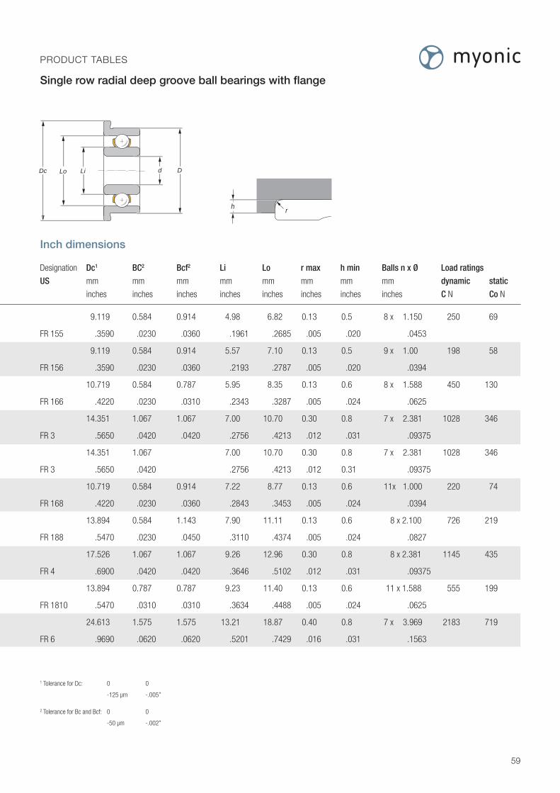
Inch dimensions
Designation Dc1 BC2 Bcf2 Li Lo r max h min Balls n x Ø Load ratings
US mm mm mm mm mm mm mm mm dynamic static
inches inches inches inches inches inches inches inches C N Co N
9.119 0.584 0.914 4.98 6.82 0.13 0.5 8 x 1.150 250 69
FR 155 .3590 .0230 .0360 .1961 .2685 .005 .020 .0453
9.119 0.584 0.914 5.57 7.10 0.13 0.5 9 x 1.00 198 58
FR 156 .3590 .0230 .0360 .2193 .2787 .005 .020 .0394
10.719 0.584 0.787 5.95 8.35 0.13 0.6 8 x 1.588 450 130
FR 166 .4220 .0230 .0310 .2343 .3287 .005 .024 .0625
14.351 1.067 1.067 7.00 10.70 0.30 0.8 7 x 2.381 1028 346
FR 3 .5650 .0420 .0420 .2756 .4213 .012 .031 .09375
14.351 1.067 7.00 10.70 0.30 0.8 7 x 2.381 1028 346
FR 3 .5650 .0420 .2756 .4213 .012 0.31 .09375
10.719 0.584 0.914 7.22 8.77 0.13 0.6 11x 1.000 220 74
FR 168 .4220 .0230 .0360 .2843 .3453 .005 .024 .0394
13.894 0.584 1.143 7.90 11.11 0.13 0.6 8 x 2.100 726 219
FR 188 .5470 .0230 .0450 .3110 .4374 .005 .024 .0827
17.526 1.067 1.067 9.26 12.96 0.30 0.8 8 x 2.381 1145 435
FR 4 .6900 .0420 .0420 .3646 .5102 .012 .031 .09375
13.894 0.787 0.787 9.23 11.40 0.13 0.6 11 x 1.588 555 199
FR 1810 .5470 .0310 .0310 .3634 .4488 .005 .024 .0625
24.613 1.575 1.575 13.21 18.87 0.40 0.8 7 x 3.969 2183 719
FR 6 .9690 .0620 .0620 .5201 .7429 .016 .031 .1563
1 Tolerance for Dc: 0 0
-125 μm -.005”
2 Tolerance for Bc and Bcf: 0 0
-50 μm -.002”
59
Bn
B
B
Bc
Bn
Bnf
Bf
Bf
Bcf
Bnf
Dc Lo Li Dd Dc LiLo Dd
LiLo Dd
B B Bf Bf Bf
B
Lo Li d D h r
PRODUCT TABLES Single row radial deep groove ball bearings with flange

Metric dimensions
Original size d D B Designation
mm mm mm
2 6 2.3 RA 2060X
2.5 8 2.8 RA 2580X
3 10 4 RA 3100X
4 13 5 RA 4130X
4 16 5 RA 4160X
5 16 5 RA 5160X
6 19 6 RA 6190X
8 22 7 RA 8220X
RAopen
These bearings are supplied as follows:
- with a solid ball cage made of synthetic material (page 17)- with an angle of contact from 17° to 22° (page 20)- in the precision tolerances of quality P5P or better (page 18, 19)
The number of balls printed in blue in the column «Balls» corresponds to thestandard design (page 61).
B
Lo Li d D
60
PRODUCT TABLES Removable angular ball bearings

6 x 190 43 78
7 x 210 50 91
6 x 338 81 148
6 x 375 95 173
6 x 356 92 167
8 x 431 123 224
7 x 780 217 394
8 x 853 248 451
6 x 1145 311 566
7 x 1268 362 659
6 x 1145 311 566
7 x 1268 362 659
7 x 1333 401 730
8 x 1457 458 833
7 x 1984 618 1125
8 x 2168 706 1285
B
Lo Li d D
B B Bf Bf Bf
B
Lo Li d D h r
61
PRODUCT TABLES Removable angular ball bearings
Standard ball set blue
Metric dimensions
B Li Lo r max h min Balls n x Ø Load ratings for α° =20°
Designation mm mm mm mm mm dynamic static axial
DIN C N Co N Coa N
719/2 3.16 4.68 0.20 0.5 1,150
70/2.5 3.95 6.23 0.20 0.6 1,588
723 5.63 7.87 0.20 0.7 7 x 1.588 394 107 195
724 6.88 10.35 0.20 0.8 2,381
734 7.62 12.38 0.30 1.0 3,175
725 7.62 12.38 0.30 1.0 3,175
726 9.92 14.68 0.30 1.0 3,175
708 11.81 17.60 0.30 1.0 3,969

1.016-3.175
1.191-3.967
1.397-4.763
1.984-6.350
2.380.-4.763
2.380.-7.938
3.175.-6.350
3.175.-7.938
3.175.-9.525
1.016-3.175
1.191-3.967
1.397-4.763
1.984-6.350
2.380.-4.763
2.380.-7.938
3.175.-6.350
3.175.-7.938
3.175.-9.525
1.016-3.175
1.191-3.967
1.397-4.763
1.984-6.350
2.380.-4.763
2.380.-7.938
3.175.-6.350
3.175.-7.938
3.175.-9.525
3.967-7.938
4.763-7.938
4.763-9.525
4.763-12.700
6.350-9.525
6.350-12.700
6.350-15.875
7.938-12.700
9.525-22.225
12.700-19.050
Inch dimensions
Original size d D B Designation mm mm mm
inches inches inches
1.984 6.35 2.381 RA 2508X
.0781 .2500 .0938
2.381 7.938 2.778 RA 3010X
.0938 .3125 .1094
3.175 9.525 3.969 RA 4012X
.1250 .3750 .1563
4.763 12.70 3.969 RA 6016X
.1875 .5000 .1563
6.35 15.875 4.978 RA 8020X
.2500 .6250 .1960
These bearings are supplied as follows:
- with a solid ball cage made of synthetic material (page 17)- with an angle of contact from 17° to 22° (page 20)- in the precision tolerances of quality “A5P” with inch dimensions or better (Pages 18, 19)
The number of balls printed in blue in the column «Balls» corresponds to thestandard design (page 63).
RAopen
B
Lo Li d D
62
PRODUCT TABLES Removable angular ball bearings

Inch dimensions
Designation Li Lo r max h min Balls n x Ø Load ratings for α° =20°
US mm mm mm mm mm dynamic static axial
inches inches inches inches inches C N Co N Coa N
3.16 4.68 0.13 0.5 6 x 1.150 190 43 78
R1-4B .1244 .1843 .005 .020 7 x .0453 210 50 91
3.95 6.23 0.13 0.5 6 x 1.588 338 81 148
R1-5B .1555 .2453 .005 .020 7 x .0625 375 95 173
5.08 7.32 0.30 0.7 6 x 1.588 353 89 162
R2B .2000 .2882 .012 .028 7 x .0625 391 104 189
6.88 10.35 0.30 0.8 7 x 2.381 780 217 395
R3B .2709 .4075 .012 .031 8 x .09375 853 248 451
9.48 12.96 0.30 0.8 8 x 2.381 878 274 499
- .3732 .5102 .012 .031 9 x .09375 950 308 561
Standard ball set blue
{{{{{
B
Lo Li d D
B B Bf Bf Bf
B
Lo Li d D h r
63
PRODUCT TABLES Removable angular ball bearings

These bearings are supplied as follows:
- with a solid ball cage made of synthetic material (page 17)- with an angle of contact from 17° to 22° (page 20)- in the precision tolerances of quality “A5P” with inch dimensions or better (page 18,19)
The number of balls printed in blue in the column «Balls» corresponds to thestandard design (page 65).
RKAopen
B
Bc
Dc Lo Li d D
64
Metric dimensions
Original size d D B Designation Dc Bc Li Lo
mm mm mm mm mm mm mm
2 6 2.3 RKA 2060X 7.50 0.60 3.16 4.68
2.5 8 2.8 RKA 2580X 9.50 0.70 3.95 6.23
Inch dimensions
Original size d D B Designation Dc Bc Li Lo
mm mm mm mm mm mm mm inches inches inches inches inches inches inches
2.381 7.938 2.778 RKA 3010X 9.12 0.58 3.95 6.23
.0938 .3125 .1094 .3590 .023 .1555 .2453
3.175 9.525 3.969 RKA 4012X 11.18 0.75 5.08 7.32
.1250 .3750 .1563 .4401 .029 .2000 .2882
4.763 12.70 3.969 RKA 6016X 14.35 1.06 6.88 10.35
.1875 .5000 .1563 .5649 .042 .2709 .4075
6.35 15.875 4.978 RKA 8020X 17.53 1.05 9.48 12.96
.2500 .6250 .1960 .6830 .041 .3732 .5102
PRODUCT TABLES Removable angular ball bearings with flange

6 x 216 52 94
7 x 216 52 94
6 x 338 81 147
7 x 375 95 173
{{{{
Standard ball set blue
B
Bc
Dc Lo Li d D
B B Bf Bf Bf
B
Lo Li d D h r
65
PRODUCT TABLES Removable angular ball bearings with flange
Standard ball set blue
Metric dimensions
Designation r max h min Balls n x Ø Load ratings for α° =20°
DIN mm mm mm dynamic static axial
C N Co N Coa N
719/2R 0.20 0.5 1.150
70/2.5R 0.20 0.6 1.588
Inch dimensions
Designation r max h min Balls n x Ø Load ratings for α° =20°
US mm mm mm dynamic static axial
inches inches inches C N Co N Coa N
0.13 0.5 6 x 1.588 338 81 147
R1-5B .005 .0200 7 x .0625 375 95 173
0.30 0.7 6 x 1.588 353 89 162
R2B .012 .0280 7 x .0625 391 104 189
0.3 0.8 7 x 2.381 780 217 395
R3B .012 .3100 8 x .09375 853 248 451
0.30 0.8 8 x 2.381 878 274 499
- .012 .3100 9 x .09375 950 308 561

recommended tolerances:Shafts: +4 / -4 μmHousing: +8 / 0 μm
0/-100 μm
D1 d d1 D
H
Dede
r
r
66
PRODUCT TABLES Axial deep groove ball bearings
Metric dimensions
d D B Designation d1 D1 de min De max r max Balls n x Ø
mm mm mm mm mm mm mm mm mm
3 8 3.5 B 308X 3.2 7.8 6 5 0.10 6 x 1.588
4 10 4 B 410X 4.2 9.8 7.5 6.5 0.10 6 x 1.588
5 12 4 B 512X 5.2 11.8 9 8 0.10 8 x 1.588
6 14 5 B 614X 6.2 13.8 10.5 9.5 0.15 7 x 2.381
7 17 6 B 717X 7.2 16.8 13 11 0.15 8 x 2.778
8 19 7 B 819X 8.2 18.8 14.5 12.5 0.25 8 x 3.175
9 20 7 B 920X 9.2 19.8 15.5 13.5 0.25 8 x 3.175
d D H Designation n Max axial load ratings
mm mm mm 1/min dynamic static
Ca N Coa N
3 8 3.5 B 308X 15000 783 675
4 10 4 B 410X 15000 728 675
5 12 4 B 512X 13000 831 900
6 14 5 B 614X 10000 1657 1702
7 17 6 B 717X 10000 2377 2661
8 19 7 B 819X 8000 3045 3492
9 20 7 B 920X 8000 2980 3692
The ball bearings are produced in quality P5P or better Ø D Tolerance class Ø d ≤17 mm ≥19 mm H Axial run-out
P5 0/-8 μm 0/-11 μm 0/-13 μm 3 μm
P4 0/-7 μm 0/-11 μm 0/-13 μm 2 μm
B

Product Accessories

Designation Shaft Circlip Groove Suitable for ball bearings
Ø d1 d3 b s* D2 m with inner diameter
max ±0.10 -0.05 +0.03
mm mm mm mm mm mm mm inches
WSR 3 3 2.60 0.50 0.30 2.70 0.33 3 .1250
WSR 4 4 3.60 0.50 0.30 3.70 0.33 4 .1562
WSR 5 5 4.50 0.70 0.40 4.60 0.44 5
WSR 6 6 5.45 0.70 0.40 5.60 0.44 6 .2500
WRS 7 7 6.45 0.70 0.40 6.60 0.44 7
WSR 8 8 7.35 0.90 0.50 7.50 0.55 8 .3125
WSR 9 9 8.30 0.90 0.50 8.50 0.55 9
WSR 10 10 9.25 0.90 0.50 9.50 0.55 10
Material: stainless steel
* Tolerance of «s»
Thickness mm Tolerance mm
< 0.4 ± 0.015
< 0.6 ± 0.02
d3
b
S
d2 d1m
d3
b
S
d2 d1m
WSR
68
PRODUCT ACCESSORIES Circlips for shafts
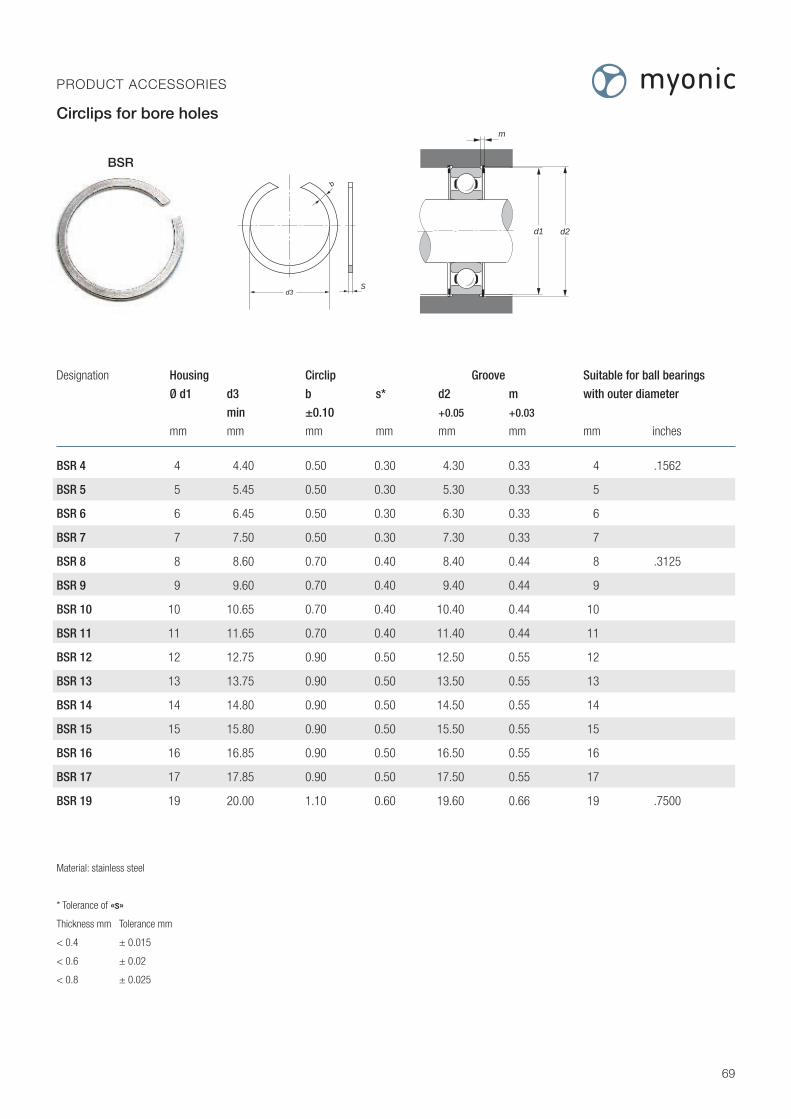
Designation Housing Circlip Groove Suitable for ball bearings
Ø d1 d3 b s* d2 m with outer diameter
min ±0.10 +0.05 +0.03
mm mm mm mm mm mm mm inches
BSR 4 4 4.40 0.50 0.30 4.30 0.33 4 .1562
BSR 5 5 5.45 0.50 0.30 5.30 0.33 5
BSR 6 6 6.45 0.50 0.30 6.30 0.33 6
BSR 7 7 7.50 0.50 0.30 7.30 0.33 7
BSR 8 8 8.60 0.70 0.40 8.40 0.44 8 .3125
BSR 9 9 9.60 0.70 0.40 9.40 0.44 9
BSR 10 10 10.65 0.70 0.40 10.40 0.44 10
BSR 11 11 11.65 0.70 0.40 11.40 0.44 11
BSR 12 12 12.75 0.90 0.50 12.50 0.55 12
BSR 13 13 13.75 0.90 0.50 13.50 0.55 13
BSR 14 14 14.80 0.90 0.50 14.50 0.55 14
BSR 15 15 15.80 0.90 0.50 15.50 0.55 15
BSR 16 16 16.85 0.90 0.50 16.50 0.55 16
BSR 17 17 17.85 0.90 0.50 17.50 0.55 17
BSR 19 19 20.00 1.10 0.60 19.60 0.66 19 .7500
Material: stainless steel
* Tolerance of «s»
Thickness mm Tolerance mm
< 0.4 ± 0.015
< 0.6 ± 0.02
< 0.8 ± 0.025
d3
b
S
d1 d2
m
d3
b
S
d1 d2
m
BSR
69
PRODUCT ACCESSORIES Circlips for bore holes

Designation h+s s* d3 d4 Suitable for ball bearings with
±0.05 Inner diameter Outer diameter
mm mm mm mm mm inches mm inches
FS 1.5 X 3 0.40 0.08 1.60 2.90 - - 3 -
FS 2 X 3.5 0.45 0.08 2.15 3.10 2 - - .1250
FS 2.5 X 4 0.50 0.08 2.70 3.80 2.5 - 4 .1562
FS 3 X 4.5 0.50 0.10 3.20 4.30 3 .1250 - -
FS 3.5 X 5 0.55 0.10 3.70 4.80 - - 5 -
FS 4 X 6 0.65 0.12 4.20 5.75 4 .1562 6 -
FS 4.5 X 6.35 0.60 0.12 4.80 6.10 - .1875 - .2500
FS 5 X 7 0.65 0.12 5.20 6.75 5 - 7 -
FS 6 X 8 0.70 0.15 6.20 7.75 6 - 8 .3125
FS 7 X 9 0.90 0.15 7.20 8.70 7 - 9 -
FS 8 X 10 0.85 0.18 8.20 9.70 8 .3125 10 -
FS 9 X 11 1.15 0.18 9.20 10.70 9 - 11 -
FS 10 X 12 1.05 0.20 10.20 11.70 10 - 12 -
FS 11 X 13 1.30 0.20 11.20 12.70 - - 13 -
FS 12 X 14 1.30 0.22 12.20 13.70 - - 14 -
FS 13 X 15 1.30 0.22 13.20 14.70 - - 15 -
FS 14 X 16 1.55 0.25 14.20 15.65 - - 16 -
FS 15 X 17 1.55 0.25 15.20 16.65 - - 17 -
FS 16 X 19 2.15 0.30 16.20 18.55 - - 19 .7500
Material: stainless steel
* Tolerance of «s»
Thickness mm Tolerance mm
< 0.2 ± 0.01
< 0.3 ± 0.012
< 0.4 ± 0.015
d3
d4
hts
s
FS
70
PRODUCT ACCESSORIES Precision spring washers

h+s at F=0N measured with 0.36N Characteristic curves apply to not set precision spring washers
71
PRODUCT ACCESSORIES Characteristic curves of the precision spring washers

Designation s* d1 d2 Suitable for ball bearings with
inner diameter outer diameter
mm mm mm mm inch mm inch PS 1.5 X 3 0.08 1.68 2.97 3
0.10
PS 2 X 3.5 0.08 2.25 3.20 2 .1250
0.10
PS 2.5 X 4 0.08 2.80 3.90 2.5 4 .1562
0.10
0.08
PS 3 X 4.5 0.10 3.30 4.40 3 .1250
0.12
0.08
PS 3.5 X 5 0.10 3.80 4.90 5
0.12
0.10
PS 4 X 6 0.12 4.30 5.85 4 .1562 6
0.15
0.10
PS 4.5 X 6.35 0.12 4.90 6.20 .1875 .2500
0.15
0.10
PS 5 X 7 0.12 5.30 6.85 5 7
0.15
0.12
PS 6 X 8 0.15 6.30 7.85 6 8 .3125
0.18
0.12
PS 7 X 9 0.15 7.30 8.80 7 9
0.18
When ordering, the thickness «s» of the precision shim is to be specified.
Example: PS 8 X 10 X 0.18
Material: stainless steel
Design: rounded edges, heat treated
finest surface quality
d2
d1
s
72
PRODUCT ACCESSORIES Precision shims
PS

Designation s* d1 d2 Suitable for ball bearings with
inner diameter outer diameter
mm mm mm mm inch mm inch 0.15
PS 8 X 10 0.18 8.30 9.80 8 .3125 10
0.20
0.15
PS 9 X 11 0.18 9.30 10.80 9 11
0.20
0.18
PS 10 X 12 0.20 10.30 11.80 10 12
0.22
0.18
PS 11 X 13 0.20 11.30 12.80 13
0.22
0.20
PS 12 X 14 0.22 12.30 13.80 14
0.25
0.20
PS 13 X 15 0.22 13.30 14.80 15
0.25
0.22
PS 14 X 16 0.25 4.35 15.80 16
0.30
0.22
PS 15 X 17 0.25 15.35 16.80 17
0.30
0.25
PS 16 X 19 0.30 16.40 18.80 19 .7500
0.35
* Tolerance of «s»
Thickness mm Tolerance mm
< 0.2 ± 0.01
< 0.3 ± 0.012
< 0.4 ± 0.015
d2
d1
s
73
PRODUCT ACCESSORIES Precision shims
PS

Sales Centres
Germany:
myonic GmbHSteinbeisstraße 488299 Leutkirch, Deutschlandphone: +49 7561 978 0fax: +49 7561 978 [email protected]
USA:
myonic USAA Division of New Hampshire Ball Bearings, Inc.9700 Independence AvenueChatsworth, CA 91311, USAmyonic USA Sales: +1 818 701-4833NHBB Sales: +1 818 993-4100Fax: +1 818 [email protected]
Great Britain Representative:
myonic UK OfficeStephen Giddings6 Tavelhurst, Two Mile Ash, Milton Keynes, MK8 8EEphone: +44 1908 227 123 fax: +44 1908 310 [email protected]
Asia / Pacific Representative
CeeU Company Ltd.Gerd Nehuis6F-20, No. 239, Sec. 5, Nanjing East Road, Taipei City, 10569, Taiwan phone: +886 909 [email protected]
myonic GmbHSteinbeisstraße 488299 Leutkirch, Deutschlandphone: +49 7561 978 0fax: +49 7561 978 [email protected]
myonic s.r.o.1 máje 2635Po Box 1875661 Rožnov pod Radhostem, Tschechienphone: +420 576 511 811fax: +420 571 602 [email protected]
Headquarters andProduction Sites myonic regional contacts
myonic contacts worldwide
Germany:
KTN Kugellager Technik Neely Moskauer Ring 5997084 Würzburg, Deutschland phone: +49 931 666 94 76 fax: +49 931 666 94 75 [email protected] www.kugellagertechnik.de
Josef Blässinger GmbH & Co.KGZeppelinstraße 1873760 Ostfildern, Deutschland phone: +49 711 167 08 – 0 fax: +49 711 167 08 - 81 [email protected] www.blaessinger.de
BODEKU GmbH Schleehofstraße 1297209 Veitshöchheim Deutschland phone: +49 931 329 295 90fax: +49 931 329 295 920 [email protected]
France, Belgium, Luxemburg, Turkey:
RBC France SAS19, avenue de NorvègeZA de Courtaboeuf 191953 Les Ulis Cedex, Frankreichphone: +33 1 60 92 17 35 fax: +33 1 69 86 12 84 [email protected]
Slowenia:
V&KL dental rotor d.o.o. Smartinska cesta 1521000 LjubljanaSlowenienphone: +386 1 361 61 57 fax: +386 1 361 61 58 [email protected]
Italy:
GMN Italia s.r.l.Via Marcantonio Colonna, 12 20149 Milano, Italienphone: +39 02 477 11 138 fax: +39 02 477 17 999 [email protected]
Sweden, Norway:
KG Fridman AB Gjuterigatan 11-13652 21 Karlstad 1Schweden phone: +46 54 18 52 15fax: +46 54 18 63 31 [email protected]
Denmark:
Herstad + Piper A/SJernholmen 48c2650 Hvidovre, Dänemarkphone: +45 367 740 00fax: +45 367 777 [email protected]
Austria:
Kurt Koller GmbHProf. Dr. Stephan Koren Straße 6A, 2700 Wiener Neustadt, Österreichphone: +43 2622 24641-0fax: +43 2622 [email protected]
Switzerland:
Ed. Schüpbach AGMittelstraße 32500 Biel-Bienne 3, Schweizphone: +41 32 343 30 00fax: +41 32 343 30 [email protected]
Israel:
H.G. Technical Agencies LtdPO Box 633921 Havradim St. Ganey Yehuda 56905Ganey-Yehuda 56905, Israelphone: +972 3 6356 726fax: +972 3 534 [email protected]
ALPHA-KOD TECHNOLOGIES LTD.9 Tamar Neve EfraimYedud6019000 Monosson, Israelphone: +972-52-3064382 fax: +153-52-3064382 [email protected]
South Africa:
BMG Group6 Tetford Circle Millennium Bridge Business Park4320 La Lucia Ridge Durban, Südafrikaphone: +27 31 576 6200fax: +27 31 576 [email protected]
Malaysia / Singapore:
GC TECHNOCRAFT PTE Ltd.57 Mohamed Sultan Road# 04-05 Sultan Link238997 SingaporeSingaporephone: +65 63 34 66 26fax: +65 900 82 [email protected]
China:
Ever Bright Precision (Shanghai) Ltd.Nr. 185, Au-Na Road,Waigaoqiao Free Trade Zone200131 ShanghaiChinaphone: +86 21 5866 8816fax: +86 21 5866 9456mobile: +86 138 1880 [email protected]
KTB LTD.959 Canton Road, Mongkok, Kowloon, Hong Kong, Chinaphone: +852 2780 0231fax: +852 2780 6410 / [email protected]
Taiwan:
Ever Bright Precision Ltd.1F., No. 52, Lane 10, Chi-Hu RoadTaipei 114Taiwanphone: +886 2 2659 7881fax: +886 2 2659 [email protected]
Japan:
MinebeaMitsumi Inc.Bearing Product Sales Management Sales engineering division. Sumitomo Fudosan Mita Twin Bldg. West Wing, 3-5-27, Mita, Minato-ku, Tokyo 108-6319, Japanphone: +81-3-6758-6748fax: +81-3-6758-6760
India:
myonic GmbH India OfficeShravanti Residency, Flat No. 203M.No. 8-2-293/82/L/86/A,MLA Colony, Road No. 12, Banjara HillHyderabad – 500 034, Indienphone: +91 40 2331 2354fax: +91 40 2331 [email protected]
Australia:
Miniature Bearings Australia Pty Ltd.3239 Old Cleveland RoadCapalaba West QLD 4157, Australienphone: +61 7 3245 7977fax: +61 7 3245 [email protected]

Germany
myonic GmbH
Steinbeisstr. 4D-88299 LeutkirchTel. +49 7561 978 0Fax +49 7561 978 [email protected]
USA
myonic USA
A Division of New Hampshire
Ball Bearings, Inc.
9700 Independence AvenueChatsworth, CA 91311Tel. +1 818 701 4833Fax +1 818 407 [email protected]
Great Britain
myonic Ltd.
10 Warren Yard, Wolverton MillMilton Keynes, MK12 5NWTel. +44 1908 227 123Fax +44 1908 310 [email protected]
Austria
APB myonic GmbH
Langwieserstr. 134A-4802 EbenseeTel. +43 61 33 50 16Fax +43 61 33 50 [email protected]
myonic is here for you.
Our engineers, sales and logistics personnel, production teams and project managers are pleased to be of service!
www.myonic.com