standard consumer safety performance specification for home
TRANSCRIPT

Designation: F 1148 – 03
Standard Consumer Safety Performance Specification forHome Playground Equipment 1
This standard is issued under the fixed designation F 1148; the number immediately following the designation indicates the year oforiginal adoption or, in the case of revision, the year of last revision. A number in parentheses indicates the year of last reapproval. Asuperscript epsilon (e) indicates an editorial change since the last revision or reapproval.
1. Scope
1.1 This consumer safety specification provides safety re-quirements for various types of home playground equipmentintended for use by children aged from over eighteen monthsthrough 10 years. It further provides such requirements forswings intended specifically for toddlers. Different age limitsfor various requirements are found in this specification. Theselimits reflect the nature of the hazards and the expected mentalor physical ability, or both, of the child to cope with thehazards.
1.2 Home playground equipment is defined as any productin which the support structure remains stationary while theactivity is taking place and is intended for a child to performany of the following activities: climbing, swinging, sliding,rocking, spinning, crawling, or creeping, or combinationthereof. Fitness equipment is specifically excluded unlessattached to the play equipment. This specification is notintended to apply to juvenile care products such as, but notlimited to, infant swings, playpens/enclosures, beds, or furni-ture (including outdoor furniture, such as picnic tables, cradlerockers, activity centers being used as walker substitutes,bouncers, jumpers, infant carriers, and products specificallydesigned for therapeutic use). This specification is not intendedto apply to equipment to be used in places of public assemblysuch as schools, nurseries, day-care centers, and parks. Equip-ment intended to be in child-care centers in private homes isnot exempt from the requirements of this specification. Suchcenters are defined as situations in which the child-careprovider does not care for more than six children under the ageof ten that are not residing in the household of the caregiver,and the total number of children under the age of ten does notexceed ten, including the caregiver’s own children.
1.3 Methods of identifying products that comply with thisconsumer safety specification are given. The illustrations ofhome playground equipment shown in Figs. A1.1–A1.4 are forinformational purposes only and are not intended to limit orendorse certain types of playground equipment or equipment
features. These illustrations are not intended to limit the varietyor various combinations of equipment that are covered by thisconsumer safety specification.
1.4 The purpose of this specification is to reduce thelikelihood of life-threatening or debilitating injuries.
1.5 The values stated in inch-pound units are to be regardedas the standard. The values given in parentheses are forinformation only.
1.6 If toy accessories or toy chests are attached to homeplayground equipment, they are applicable to this consumersafety specification and to any other applicable safety stan-dards.
NOTE 1—See Annex A1 for figures referenced throughout this con-sumer safety performance specification.
2. Referenced Documents
2.1 ASTM Standards:2
D 2240 Test Method for Rubber Property—DurometerHardness
2.2 Federal Standards:16 CFR 1303 Ban of Lead-Containing Paint and Certain
Consumer Products Bearing Lead-Containing Paint3
16 CFR 1500 Hazardous Substances Act Regulations, in-cluding sections:3
1500.48 Technical Requirements for Determining a SharpPoint in Toys and Other Articles Intended for Use byChildren Under 8 Years of Age
1500.49 Technical Requirements for Determining a SharpMetal or Glass Edge in Toys and Other Articles Intendedfor Use by Children Under 8 Years of Age
1500.52 and .53 Test Methods for Simulating Use andAbuse of Toys and Other Articles Intended for Use byChildren
16 CFR 1501 Method for Identifying Toys and OtherArticles Intended for Use by Children Under 3 Years ofAge Which Present Choking, Aspiration, or Ingestion
1 This specification is under the jurisdiction of ASTM Committee F15 onConsumer Products and is the direct responsibility of Subcommittee F15.09 onHome Playground Equipment.
Current edition approved Nov. 1, 2003. Published January 2004. Originallyapproved in 1988. Last previous edition approved in 2000 as F 1148 – 00.
2 For referenced ASTM standards, visit the ASTM website, www.astm.org, orcontact ASTM Customer Service at [email protected]. ForAnnual Book of ASTMStandardsvolume information, refer to the standard’s Document Summary page onthe ASTM website.
3 Available from Consumer Product Safety Commission, Washington, DC20207.
1
Copyright © ASTM International, 100 Barr Harbor Drive, PO Box C700, West Conshohocken, PA 19428-2959, United States.

Hazards Because of Small Parts3
Federal Motor Vehicle Safety Standard No. 2184
2.3 Society for Automotive Engineers Recommended Prac-tice:5
SAE J211 Instrumentation for Barrier Collision
3. Terminology
3.1 Definitions of Terms Specific to This Standard:3.1.1 anchors—accessories used to minimize possible tip-
ping of the playground equipment, or lifting of the support legsduring normal use or reasonably foreseeable abuse.
3.1.2 continuous surface—a surface smooth to the extentthat no hazard such as a catch point for clothing or sharpedge/sharp point is created.
3.1.3 edge, sharp6—an edge that can cut a child’s skinduring normal use or reasonably foreseeable abuse of theplayground equipment. Such an edge is judged as sharppursuant to the provisions of 16 CFR Section 1500.49.
3.1.4 guardrail—a guardrail is a device around an elevatedsurface that is intended to prevent inadvertent falls from theelevated surface.
3.1.5 hand grasping component—a component intended tobe grasped by the hand to steady a user (such as a handrail).
3.1.6 hand gripping component—a component intended tobe gripped by the hand to support the full body weight (such asa rung of a horizontal ladder or trapeze bar).
3.1.7 handrail—the structural member that helps a childsteady himself. As used in this consumer safety performancespecification, a handrail is the structural member at the top ofa slide that helps a child steady himself while he sits down (seeFig. A1.1).
3.1.8 normal use—of playground equipment, those safe playmodes which conform to the instructions that accompany theequipment, or have been established by tradition or custom.
3.1.9 platform—any elevated horizontal surface intended tobe used by children as a place for play or as a transitionbetween components. Slide transition areas <200 in.2 are notconsidered platforms.
3.1.10 point, sharp7—a point that can puncture or lacerate achild’s skin during normal use or reasonably foreseeable abuseof the playground equipment. Such a point is judged aspotentially sharp pursuant to the provisions of 16 CFR Section1500.48.
3.1.11 protective barrier—an enclosure around an elevatedsurface that is intended to prevent both inadvertent anddeliberate attempts to pass through the device.
3.1.12 reasonably foreseeable abuse—reasonable foresee-able abuse is defined as those unsafe play modes that arereasonably foreseeable. Examples include a child in the way ofa moving swinging element and overloading the equipment orcomponent with more children, or heavier children, than thatfor which the equipment was designed.
3.1.13 rung—a cross-piece in a ladder or other climbingequipment used for supporting the user’s feet or grasping bythe user’s hands, or both. A rung must comply with 4.6 forhand-gripping components.
3.1.14 small part8—a component that may become de-tached during normal use or reasonably foreseeable abuse ofthe playground equipment and presents a choking, aspiration,or ingestion hazard to a child. Such a component is determinedto be a hazard pursuant to the provisions of 16 CFR Part 1501.
3.1.15 toddler swing—a fully enclosed single occupantswing intended for young children who can sit upright unaided.A seat is considered fully enclosed when a containment systemis employed that supports the child on all sides and in betweenthe legs (see Fig. A1.31).
3.1.16 toy accessory—an article that provides certain playvalue separate from, but attached to or sold with, homeplayground equipment intended for play-time use by a child.Such articles include miniature imitations for play use ofobjects intended primarily for a specific purpose (for example,a toy telephone or a toy gas pump).
3.1.17 turnbar—the horizontal bar between the supportinglegs of a swing set, such as the one shown in Fig. A1.1.
4. Performance Requirements
4.1 General—Home playground equipment shall be manu-factured and constructed only of materials that have a demon-strated durability in an outdoor setting. Any new materials shallbe documented or tested accordingly for durability by theplayground equipment manufacturer or their agent.
4.1.1 Metals subject to structural degradation such as by rustor corrosion shall be painted, galvanized, or otherwise treated.Woods shall be naturally rot- and insect-resistant or treated toavoid such deterioration. Creosote, pentachlorophenol, tributyltin oxide, and surface coatings that contain pesticides shall notbe used for playground equipment. Wood treaters and play-ground equipment manufacturers shall practice technologiesand procedures that minimize the level of dislodgeable toxin.Plastics and other materials that experience ultraviolet (UV)degradation shall be stabilized against ultraviolet light.
4.1.2 Regardless of the material or the treatment process,the manufacturer shall ensure that the users of the playgroundequipment cannot ingest, inhale, or absorb any potentialhazardous amounts of substances through body surfaces as aresult of contact with the equipment.
4.1.3 Lead in Paint—All paints and finishes used on play-ground equipment shall be in accordance with Title 16 CFRPart 1303.
4 Available from National Highway Traffic Safety Administration, 400 7th St.SW, Washington, DC 20590.
5 Available from the Society of Automotive Engineers, 400 CommonwealthDrive, Warrendale, PA 15096.
6 A sharp edge tester suitable for conducting tests in accordance with the Federalregulation at 16 CFR Section 1500.49 is available from U.S. Testing Co., Inc., 1415Park Avenue, Hoboken, NJ 07030. Engineering drawings from which a sharp edgetester may be fabricated are available from the Office of the Secretary, ConsumerProduct Safety Commission, Washington, DC 20207.
7 A sharp point tester for conducting tests in accordance with the Federalregulation at 16 CFR Section 1500.48 is available from U.S. Testing Co., Inc., 1415Park Avenue, Hoboken, NJ 07030. An engineering drawing from which a sharppoint tester may be fabricated is available from the Office of the Secretary,Consumer Products Safety Commission, Washington, DC 20207.
8 A small parts cylinder suitable for conducting tests in accordance with theFederal regulation at 16 CFR Part 1501 is available from U.S. Testing Company,Inc., 1415 Park Avenue, Hoboken, NJ 07030, or Toys to Grow On, P.O. Box 17,Long Beach, CA 90801.
F 1148 – 03
2

4.1.4 Edges, Points, and Surfaces—Following assembly ofthe unit in accordance with the instructions to be provided tothe consumer, there shall be no sharp edges, points, or surfaceson any portion of the home playground equipment capable ofinflicting a cut on a child during normal use or reasonablyforeseeable abuse.
4.1.5 Open Tubing—All open tubing ends that are notresting on the ground, or otherwise covered, shall be providedwith caps or plugs that have a smooth finish and are tight-fitting. They shall be subjected to a torque of 4 lbf-in. (0.45N-m) and a force of 15-lbf (67-N) when tested in accordancewith Title 16 CFR Section 1500.53(e and f).
4.1.6 Pinch, Crush, and Shear Points— There shall be nopinch, crush, or shear points caused by junctures of twocomponents moving relative to one another that could cause acontusion, laceration, abrasion, amputation, or fracture duringnormal use or reasonably foreseeable abuse. A pinch, crush, orshear point is any point that allows a3⁄16 in. (5 mm) diameterneoprene rod to enter at one or more positions and entraps atone or more positions a1⁄2-in. (13-mm) diameter neoprene rod.Entrapment shall mean that a force of more than 2 lbf (9 N) isrequired to pull out the rod. The neoprene rods shall have ahardness reading between 50 and 60 as determined by a TypeA durometer in accordance with Test Method D 2240.
4.1.7 Acute Angles—There shall be no acute angles, orgroup of acute angles, formed by two or more members inwhich the legs point upward from the apex so that theconfiguration approximates a “V” with an interior angle lessthan 55° (0.96 rad).
4.1.7.1 Exemptions to 4.1.7:(1) Inverted Angle or “V” Condition—Those “V’s” that
are inverted. A “V” is considered inverted if the lower adjacentleg forming the “V” is horizontal or slopes downward from theapex (see Fig. A1.5).
(2) Filled Apex Condition—“V” angles less than 55° wherethe apex of the angle is filled to the point that will not allow thehead probe to contact both surfaces of the angle simultaneously(see Fig. A1.5). The angle shall be covered with a shield that ismade of a rigid material. The shield shall be capable ofwithstanding impact of at least 20 ft·lbf (27 J) imparted to aspot within 1 in. (25 mm) of the geometric center of the shieldby a 5-in. (127-mm) diameter steel ball. The shield shall betested while secured to the members of the playgroundequipment by the hardware provided. During the test, theequipment or portions thereof, if required, shall be oriented sothat the surface of the shield is horizontal.
(3) Rope, Chain and Cable—“V” angles less than 55°where the apex of the angle is formed by an inclined or verticalclimbing surface and a rope, chain or cable. To be exempt, thepoint of the formed “V” angle must be no greater than 1.5 in.(38 mm) above the protective surfacing. See Fig. A1.6.
4.1.8 Spacing Between Adjacent Swing Elements:4.1.8.1 Swing sets containing adjacent swing elements shall
be designed so that there is a minimum of 8 in. (205 mm)separating elements that are capable of limited lateral motion(where two or more chains, ropes, or poles are used forsuspension). The outermost lateral extremities of the swinging
elements shall govern the measurement of separation; anexample is illustrated by Dimension A in Fig. A1.7.
4.1.8.2 Swing elements that are capable of unlimited lateralmotion shall be provided with a minimum separation of 15 in.(380 mm) from other swinging elements. The outermost lateralextremities of the swinging elements shall govern the measure-ment of separation (as illustrated by Dimension B in Fig.A1.7).
4.1.9 Spacing Between Swing Elements and StationaryFrame Members:
4.1.9.1 Occupant Enclosed—Elements with two or morelaterally spaced supports where supports are on both sides ofthe occupant (for example, suspended chain or rope swings andtubularly suspended lawn swings). Minimum spacing betweenthe outer extremity of the swing element and stationarymembers shall be 7 in. (180 mm) when measured at a height of28 in. (710 mm) above the seating surface (see Dimension C inFig. A1.7).
NOTE 2—Twenty-eight inches (710 mm) is the approximate sittingheight of a ten-year-old.
4.1.9.2 Occupant-Exposed Rides—Examples are: the pen-dulum seesaw, horse rides, and others where the suspensionsystem is in line with the occupant. Minimum spacing fromstationary members shall be 16 in. (405 mm) as measured fromthe center of the seating surface at a height of 22 in. (560 mm)above the seating surface (see Dimension D in Fig. A1.7).
NOTE 3—Sixteen inches (405 mm) and 22 in. (560 mm) equate to theclearance required for a ten-year-old when leaning to the side at an angleof 30° (0.52 rad).
4.1.9.3 Occupant-Exposed Single Suspension— Examplesare: suspended ropes or poles. Minimum spacing from station-ary members shall be 15 in. (380 mm) to a height of 53 in.(1350 mm) above ground level (see Dimension E in Fig. A1.7).
NOTE 4—Fifty-three inches (1350 mm) is the approximate standingheight of a ten-year-old.
4.1.10 Hardware:4.1.10.1 Upon final assembly, bolt ends shall not protrude
beyond the nuts more than the diameter of the bolt when thenuts are tightened to a torque between 20 and 25 lbf·in. (2.3and 2.8 N·m)).
4.1.10.2 Threaded bolt ends that are recessed such that theend of the bolt lies at or below a surrounding surface locatedwithin 1 in. (25 mm) of the centerline of the bolt are exemptfrom the requirements of 4.1.10.1 (see Fig. A1.8). Recessedthreaded bolt ends that are free from hazardous sharp edges andburrs are exempt from the requirements of 4.1.10.3.
NOTE 5—The surrounding surface shall be blended wherever possibleto create smooth contours without abrupt changes in shape that could posea potential impact hazard.
4.1.10.3 If the threaded ends of exposed bolts or rodsprotrude from adjacent surfaces in areas of normally expectedplay, or if the thread is not free of exposed hazardous sharpedges or burrs, or both, then the threaded ends shall be coveredby smooth finish caps.
4.1.10.4 Any caps that are used shall be tight-fitting wheninstalled in accordance with the manufacturer’s instructions.
F 1148 – 03
3

They shall be subjected to a torque of 4 lbf·in. (0.45 N·m) anda tensile force of 15 lbf (67 N). These components shall complywith the requirements of 16 CFR 1500.48, 1500.49, 1500.53 (eand f), and 1501.
4.1.11 Lock washers, self-locking nuts, or other lockingmeans shall be provided for all bolts.
4.1.12 Hooks—Open-ended hooks may be used for theuppermost suspension point of suspended elements providedthat they have openings, or entry to an opening, in the areainside the boundaries represented by a line that is adjacent tothe outer extremity of the uppermost portion of the hook, andparallel to the normal plane of suspension. Some examples ofhooks that are acceptable and unacceptable are shown in Fig.A1.8.
4.1.12.1 Hooks used for attachment of rides, or swingelements at any point other than at the uppermost suspensionpoint, shall be designed to allow full closure, or be otherwiseprotected (for example, protective coverings). A hook isconsidered closed when the gap or space cannot admit a0.04-in. (1-mm) feeler gage.
4.1.13 Guardrails and Protective Barriers—Guardrails orprotective barriers shall be provided on elevated surfaces suchas platforms, landings, walkways, ramps and similar transi-tional play surfaces, in accordance with the following subsec-tions. Guardrails and protective barriers shall be designed todiscourage climbing and must have a top surface less than threeinches wide or having greater than a 30 degree angle fromhorizontal.
4.1.13.1 Elevated surfaces less than or equal to 30 in. (76cm) above the surfacing do not require guardrails. Guardrailsshall be provided on elevated surfaces greater than 30 in. (76cm) but less than or equal to 48 in. (122 cm) above thesurfacing. Protective barriers shall be provided on elevatedsurfaces greater than 48 in. (122 cm) above the surfacing.
4.1.13.2 Guardrails shall completely surround the elevatedsurface except for entrance and exit openings necessary foreach event. Guardrail overall height shall be 25 in. (63 cm) ormore. The maximum vertical opening between the lowermostmember of a guardrail and the elevated surface it surroundsshall be 24 in. (61 cm). Openings between guardrail membersor between a guardrail and the elevated surface it surroundsshall conform to the recommendations addressing head andneck entrapment. If the top surface of the guardrail creates acompletely bounded opening which presents a head and neckentrapment hazard, it is permissible to lower the guardrail tobelow the 25 in. (63 cm) height requirement to eliminate thehead and neck entrapment hazard (see example in Fig. A1.10).
4.1.13.3 Elevated surfaces that are greater than 48 in. (122cm) above the surfacing but less than or equal to 72 in. (183cm) above the surfacing shall have protective barriers at least27 in. (69 cm) high. Elevated surfaces greater than 72 in. (183cm) above the surfacing shall have protective barriers at least33 in. high.
(1) Protective barriers shall completely surround the el-evated surface except for entrance and exit openings necessaryfor each event. Protective barriers shall be designed to mini-mize the likelihood of climbing. Openings within barriers or
between the platform surface and lower edge of protectivebarriers shall preclude passage of the torso probe (see Fig.A1.12).
4.1.14 Head and Neck Entrapment—Home playgroundequipment shall be designed and constructed so that whenassembled any accessible opening shall meet the followingperformance requirements to reduce the risk of accidental heador neck entrapment by either a head first or feet first entry intothe opening. Openings between the ground and the bottomedge of the equipment (such as rails, platforms, steps, etc.) areexempt from this requirement as illustrated in Fig. A1.11.
4.1.14.1Accessible Openings—Any completely boundedopening that completely accepts the torso test probe. Acompletely bounded opening is accessible when a torso testprobe may be inserted into the opening to a depth of 4 in. (100mm) using the following test method (see Fig. A1.12).
(1) Test Procedure and Performance Criteria for Com-pletely Bounded Openings—Place the torso probe in theopening, tapered end first, with the plane of its base parallel tothe plane of the opening; rotate the probe while keeping itsbase parallel to the plane of the opening. If the base of theprobe passes through the opening when it is rotated about itsown axis in any orientation, place the head probe (see Fig.A1.13) in the opening, tapered end first, while its plane isparallel to the plane of the opening.
(2) An opening can pass this test when tested in accordancewith 4.1.13.1(1) in one of two ways: (1) the opening does notadmit the torso probe when it is rotated to any orientation aboutits own axis, or (2) the opening admits the torso probe and alsoadmits the head probe.
(3) An opening fails the test under the following condi-tions: The opening admits the torso probe but does not admitthe head probe.
4.1.14.2 Completely bounded openings that are accessiblemust also meet requirements for angles as outlined in 4.1.7.
4.1.14.3Nonrigid Completely Bounded Openings—A non-rigid opening such as, but not limited to, flexible nets, tarps,and plastic enclosures, is considered accessible if a torso probewill penetrate the opening to a depth of 4 in. (100 mm) whentested in accordance with 4.1.14.1(1) (see Fig. A1.12). Flexiblerestraining systems on toddler swings are exempt from thisrequirement unless they form leg openings.
(1) Test Procedure for Entrapment in Nonrigid Openings—Place the torso probe in the opening, tapered end first, with theplane of its base parallel to the plane of the opening; rotate theprobe while keeping its base parallel to the plane of theopening; apply 50 lbf (222 N) while attempting to push theprobe through the opening. If the base of the probe passesthrough the opening when it is rotated about its own axis in anyorientation and 50 lbf (222 N) is applied, place the head probein the opening, tapered end first, while its plane is parallel tothe plane of the opening and 50 lbf (222 N) is applied.
(2) A nonrigid opening can pass the test when tested inaccordance with 4.1.14.3(1) in one of two ways: (1) theopening does not allow the torso probe to be inserted so deepthat the opening admits the base of the probe when it is rotatedto any orientation about its own axis, or (2) the opening allows
F 1148 – 03
4

full passage of the torso probe and also allows the head probeto pass completely through.
(3) A nonrigid opening fails the test under the followingconditions: the opening allows full passage of the torso probebut does not admit the head probe.
4.1.15 Holes and Slots—If a hole or slot in any rigidmaterial can admit a1⁄4-in. (6-mm) diameter rod to a depth of3⁄8 in. (10 mm) or greater, it shall also admit a1⁄2-in. (13-mm)diameter rod.
4.2 Swings:4.2.1 Hangers—All swing elements shall have hanger ar-
rangements whose durability shall be determined by either ofthe following dynamic cycling tests. At the completion of thetest there shall be no loosening or structural failure of thehanger.
4.2.1.1 Each type of swing element shall be attached to itssupport member in accordance with the installation instructionsand mounted in a suitable test fixture. Flexible components ofthe swing element may be replaced by rigid components of atleast the same size and weight as long as the alternatecomponents do not affect the swing element’s moving parts.The appropriate test weight shall be secured to each occupantposition to be tested. This suspended unit shall then beoscillated through an arc with an included angle as specified inTable 1 for a total of 180 000 cycles (forward and backward).
4.2.1.2 As an alternative to the test in 4.2.1.1, swing hangersmay be tested individually in a laboratory test fixture asfollows: Secure the hanger to a portion of its support memberin accordance with the manufacturer’s installation instructions.Install the support member and hanger in the test fixture shownin Fig. A1.14, ensuring that the pivot axis of the test fixture andthe pivot point of the hanger are aligned. In accordance withTable 1, attach the appropriate test weight to the hanger andoscillate the hanger support member 180 000 cycles (forwardand backward) through the appropriate arc.
4.2.2 Minimum Ground Clearance—When the assembledswing set is installed according to the manufacturer’s instruc-tions, the minimum clearance between the ground surface andthe underside of any suspended unit shall be 8 in. (200 mm).
4.2.3 Single-Occupancy Swings—Swings designed for indi-vidual use, when tested in accordance with the impact testmethod in Appendix X1, shall not impart a peak acceleration inexcess of 100g (980 m/s2) to the test headform.
NOTE 6—Rides with straddle-type seats (such as a horse) are exemptfrom this requirement.
4.2.4 Multiple-Occupancy Swings—These swings shall beprovided with platforms or footrests and seats meeting thecriteria given in 4.2.4.1-4.2.4.4.
4.2.4.1 Seats intended for individual or dual passengers thatinclude a backrest shall be designed so that any openingbetween the seat and the backrest shall prevent entry of the testfixture (see Fig. A1.15 and Fig. A1.16) when it is located at anypoint in the opening and a force of 45 lb (200 N) is applied tothe fixture in a direction perpendicular to the entrance plane ofthe opening. The force shall be applied gradually and main-tained for 5 min.
4.2.4.2 The platform or footrest shall extend no less than 1in. (25 mm) behind the forward leading edge of the seat (seeDimension A, Fig. A1.15). This dimension shall be measuredhorizontally with the swing in its at-rest position. The spacebetween any slats in the platform shall be no greater than 11⁄2in. (38 mm).
4.2.4.3 The area of the platform that extends beyond thevertical supports of the swing shall be angled upwards not lessthan 30° from the horizontal (see Angle C, Fig. A1.15).
4.2.4.4 The bottom edge of the seat skirt shall not be morethan 10 in. (250 mm) above the top surface of the platform orfootrest when the swing is in its at-rest position (see DimensionB, Fig. A1.15).
4.2.5 Pendulum See-Saws—Pendulum seesaws shall be pro-vided with footrests. There shall be no openings with internaldimensions of which both the length and width are greater than3.5 in. (89 mm) and less than 9 in. (229 mm). The spacingbetween the two support bars shall not decrease toward the seatsupports. In the case of a pendulum seesaw designed withformed handles providing a greater opening, the minimumspacing below the formed handles shall be greater than 9 in.(229 mm).
4.2.6 Toddler Swings:4.2.6.1 Restraining System—Toddler swings shall have a
child restraining system. Fully enclosed flexible bucket seatsare exempt from this requirement.
(1) Toddler swings shall be equipped with a crotch re-straint. A crotch restraint designed to work with a lap belt shallbe designed such that its use is mandatory when the restraintsystem is in use.
4.2.6.2 Chains—Chains on swing seats that support theweight of a child, intended for children 36 months or less inage, shall be shielded if the chain is accessible and if a 0.19 in.(4.8 mm) diameter rod can be inserted between two links, as inFig. A1.32 , with the chain in a slack configuration. A chain isconsidered accessible within 33 in. (840 mm) of the top ofseating surface.
NOTE 7—The 33 in. is based on a Netherlands anthropometry studyshowing the seated vertical reach height of a 97 % 3-year-old male to be32.7 in.
4.2.6.3 Toddler Swing Stability—Toddler swings shall re-main stable when tested in accordance with the stability testmethod in 4.2.6.5. A swing is considered unstable and fails thisrequirement if, during any of the six swing attempts, thependulum test apparatus (see Fig. A1.33) tips or falls forwardor backward and causes the horizontal reference line of thetoddler swing to hang at an angle greater than 30° from itsoriginal position (see Fig. A1.34).
4.2.6.4 Toddler Swing Stability Test Setup:
TABLE 1 Swing Hanger Arc and Test Weight
Swing Type uo, degrees Test Weight, lb (kg)
Single-occupancy swing (two hangers) 90 80 (37)Multiple-occupancy exposed swing (two
hangers, two occupants)60 130 (60)
Multiple-occupancy enclosed swing (fourhangers, two occupants)
45 60 (27)
Multiple-occupancy enclosed swing (fourhangers, four occupants)
45 120 (54)
F 1148 – 03
5

(1) Toddler swings shall be tested for stability utilizing apendulum test apparatus constructed in accordance with thedimensions and materials specified in Fig. A1.33. The pendu-lum test apparatus consists of a 10 lb (4.5 kg) barbell weight atthe top of a freely pivoting bar and a 10 lb (4.5 kg) barbellweight affixed to the bottom of the test apparatus. The barbellweights shall have a maximum diameter of 8.25 in. (210 mm).The total weight of the pendulum test apparatus shall notexceed 24.0 lb (10.9 kg).
(2) Suspend the toddler swing seat in accordance with themanufacturer’s instructions. If the swing height is adjustable,perform the test at both the highest and lowest settings. Withthe swing at rest, establish a horizontal reference line on theswing seat.
(3) Secure the complete pendulum test apparatus within 0.5in. (13 mm) of the geometric center of the swing seatingsurface with the direction of travel of the pendulum arm thesame as the swing direction.
(4) If the seating area of the toddler swing is made of aflexible material, additional bracing material may be added tothe exterior bottom of the swing seat to aid in securing thependulum test apparatus. Care should be taken to assure theadditional bracing material does not influence the test results.
(5) The center of gravity (cg) of the top weight of thependulum test apparatus shall be at a height of 16 in. (410 mm)from the top of the seating surface when the pivot arm ispositioned vertically.
NOTE 8—The 16 in. height is based on field testing of swings that wererecalled because of tipover and swings that have performed withouttipping over.
4.2.6.5 Toddler Swing Stability Test Method:(1) While holding the pendulum test apparatus to the rear
of the seat, raise the swing seat in the rear direction to an angleof 60º +5/-0 as measured from vertical to a line that connectsthe swing hanger pivot point with the geometric center of theseating surface.
(2) Simultaneously release the swing and pendulum testapparatus and allow it to swing freely until the swing arc iswithin 15º from vertical in either direction. At this point, stopthe swinging motion by slowly returning the swing to its at-restcondition while being careful not to disturb the position of thependulum test apparatus. Measure the angle of the referenceline on the swing seat from the horizontal.
(3) Perform steps 1 and 2 three times.(4) Repeat steps 1 through 3, except that the pendulum test
apparatus shall be held in the forward direction.(5) If after any of the six swing attempts the angle of the
swing in its at-rest condition exceeds 30º, as noted in 4.2.6.3,the swing is considered unstable and fails.
4.3 Slides:4.3.1 Slide Requirements:4.3.1.1 Slides shall be constructed in a manner that elimi-
nates exposed vertical members or angular up-rights.4.3.1.2 A handrail shall be provided on all sides of the
transition area (except on entrance and exit areas) that meet theenclosed opening requirements of 4.1.13. Slide transition areas
larger than 200 in.2 are considered platforms and shall complywith the requirements for guardrails and protective barriersfound in 4.1.13.
(1) All handrail bend radii shall be a minimum of 2 in. (50mm).
4.3.1.3 The transition area at the top of a slide shall be atleast 10 in. (250 mm) long and shall be at least as wide as thesliding surface.
4.3.1.4 With the exception of roller slides (see 4.3.3), theinclined sliding surface and the exit surface shall be onecontinuous surface.
4.3.1.5 The slide shall have raised edges that project at least1 in. (25 mm) above the slide surface when measured perpen-dicularly to that surface.
4.3.1.6 The slide shall have a reduced-gradient exit surfaceat least 6 in. (150 mm) in length; the reduced-gradient exitsurface shall be at a minimum angle of 18° from the inclinedsliding surface, and the exit surface shall be greater than 0°, butnot more than 30° (0.52 rad), from horizontal.
(1) Slides having an entrance height of 4.5 ft (1.4 m) or lessand having an inclined angle of 30° or less from the horizontalare not subject to the reduced gradient requirement.
4.3.1.7 The end of the slide shall be no more than 12 in.(300 mm) off the ground as measured from the sliding surface.
4.3.1.8 The end of the exit surface on metal slides shall beformed through an arc of at least 170° (2.97 rad).
4.3.1.9 Slides exceeding 4.5 ft in height from platform toground level shall have a side of not less than 2.5 in. (64 mm)above the slide bed commencing at a point on the slide 4.5 ft,as measured vertically, from the ground and extending to thetop platform on the slide.
4.3.1.10 Figure A1.16 illustrates these requirements forslides.
4.3.2 Stability of Free-Standing Slides— Freestandingslides, when anchored in accordance with the instructionsenclosed with the slide, shall be capable of supporting asandbag weighing the 95th percentile weight of the maximumage user (see Table 2) completely hanging over the handrail atits highest point without any part of the slide being lifted froma level supporting surface.
4.3.3 Roller Slides—Roller slides shall meet the specifiedrequirements for slides in 4.3 with the exception of therequirement of continuous surface.
4.3.3.1 There shall be no pinch, crush, shear, entrapment,nor catch points between the junctures caused by two or more
TABLE 2 Structural Integrity Loading Chart A
Age(years)
50th Percentile,lb (kg)
95th Percentile,lb (kg)
Area Occupied byUser, ft2 (cm2)
1.5 22.7 (10.3) 26.8 (12.2) 0.6 (558)2 28 (12.7) 29 (13.2) 0.7 (651)3 32.8 (14.9) 42 (18.9) 0.8 (744)4 35.3 (16) 43 (19.7) 0.8 (744)5 39.7 (18) 50 (22.6) 0.9 (837)6 44.1 (20) 59 (26.6) 1.0 (930)7 50.5 (22.9) 69 (31.2) 1.1 (1023)8 56.2 (25.5) 81 (37) 1.2 (1116)9 63.1 (28.6) 89 (40.4) 1.3 (1209)10 70.5 (32) 105 (47.9) 1.4 (1302)
A Values given for boys or girls, whichever is higher.
F 1148 – 03
6

components that could cause a contusion, laceration, abrasion,amputation, or fracture during normal use or reasonablyforeseeable abuse.
(1) A pinch, crush, shear, entrapment or catch point is anypoint that will admit a3⁄16-in. diameter neoprene rod at one ormore positions, either between rollers or adjacent segments.
(2) The neoprene rod shall have a hardness readingbetween 50 and 60 as determined by a Type A durometer inaccordance with Test Method D 2240.
4.4 Swing Set Stability—With the swing set assembled inaccordance with the manufacturers instructions, and installedwith a 5° downward slope in the same direction as the swingingelements, the swing set shall remain upright when a weightequal to the 95th percentile weight for the maximum age user(see Table 2) is placed in the first two positions of the swing setand a weight equal to the 50th percentile weight is placed in allremaining positions that can be occupied by a child, and theswinging elements are swung freely in unison through theangles as specified in Table 1.
4.5 Merry-Go-Rounds—No stationary members of a merry-go-round device that are accessible to the child under normalconditions of use and that present an obstruction to the limbs ofthe user shall be located within the zone illustrated in Fig.A1.18 (for example, stationary legs within the excluded zoneare not acceptable, but a single center pedestal lying within theexcluded zone that is free of projections is acceptable).
4.6 Hand Gripping/Grasping Components:4.6.1 Hand Gripping Componentsintended to be gripped
by the hands to support body weight, such as rungs ofhorizontal ladders, climbing bars, and the like, shall not exceed1.55 in. (39.4 mm) in diameter or in the maximum cross-sectional dimension. When structural requirements cannotreasonably be met by the 1.55 in. diameter components, caremust be exercised in selecting alternate components anddesigns, or both, to ensure that hand-gripping potential is notseriously impaired.
4.6.2 Hand grasping components intended to be grasped bythe hand to steady the user, such as a handrail, shall have amaximum diameter or width of 1.75 in. (44.5 mm) and aminimum graspable depth of 1.5 in. (38 mm) to allow thefingers to pass over the object to be grasped. See Fig. A1.19.
4.7 Structural Integrity—The tests specified in 4.7.1-4.7.7shall be performed on units assembled in accordance with theinstallation instructions enclosed with the equipment. Thereshall be no loosening, instability of the equipment, or structuralfailure9 of any component or assembly during or immediatelyupon completion of these tests. Where it is specified that loadson structural members shall be applied through a 3.5 in.(89-mm) long wood block, the block shall have a width of atleast the width of the structural member and it shall befabricated from lumber with a minimum thickness of3⁄4 in. (19mm) (see Tables 2 and 3).
4.7.1 Rungs, Steps, and Horizontal Supporting Members—Rungs, steps, and other horizontal supporting members 24 in.(610 mm) or less in length, except turnbars and footrests, shall
be capable of sustaining a vertical load (gradually applied) of3 times the 95th percentile weight of the maximum age userapplied for 5 min to a 3.5 in. (89 mm) long wood block restingon the center of the member. Turnbars shall be capable ofsustaining a vertical load (gradually applied) of 3 times the95th percentile weight of the maximum age user applied for 5min to two 3.5 in. (89 mm) long wood blocks, one resting at the1⁄3 and the other at the2⁄3 points between the ends of theturnbar. Footrests shall be capable of sustaining a vertical load(gradually applied) of 1.5 times the 95th percentile weight ofthe maximum age user applied for 5 min to a 3.5 in. (89 mm)long wood block at the center of one (or the other) footrest.Horizontal members greater than 24 in. (610 mm) in length,except turnbars, shall be capable of sustaining for 5 min avertical load of 4 times the 95th percentile weight of themaximum age user gradually applied to two 3.5 in. (89 mm)long wood blocks, one resting at the1⁄3 and the other at the2⁄3points between the ends of the horizontal member. The load (orloads) shall be applied to one member at a time, unlessotherwise specified for the particular equipment.
4.7.2 Top Support Bar—The top support bar of any swingset shall be loaded with a total load applied vertically, withoutshock, and the total load shall remain for 5 min. This total loadshall be the sum of the following loads, as applicable:
4.7.2.1 For swings, ropes, and poles, a load of 1.5 times the95th percentile weight of the maximum age user for eachposition normally occupied by a child at play.
4.7.2.2 For pendulum see-saws, a load of 1.2 times the 95thpercentile weight of the maximum age user for each positionnormally occupied by a child at play.
4.7.2.3 For multiple-occupancy swings, a load of 1.1 timesthe 95th percentile weight of the maximum age user for eachposition normally occupied by a child at play.
4.7.3 Individual Suspended Units—Individual suspendedunits shall be tested one at a time, as indicated in Table 3,without evidence of structural failure to the unit or its support-ing system. The loads shall be gradually applied and each unitshall be loaded for 5 min.
9 Structural failure occurs when the equipment or any component thereof nolonger meets the requirement of this consumer safety specification.
TABLE 3 Minimum Test Loads for Individual Suspended Units
Unit Test Conditions
SimultaneousMinimum
Weight Load perChild
Position
Swing in swing setA 6 3 95 % weight ofmaximum age user
2 passenger occupantexposed swing (seats)B
in swing set 1.5 3 95 % weight ofmaximum age user
2 passenger occupantenclosed swing (seats)B
in swing set 1.5 3 95 % weight ofmaximum age user
2 passenger occupantenclosed swing (platforms)B
in swing set 1.5 3 95 % weight ofmaximum age user
4 passenger occupantenclosed swing (seats)B
in swing setA 1.5 3 95 % weight ofmaximum age user
4 passenger occupantenclosed swing (platforms)B
in swing setA 1.5 3 95 % weight ofmaximum age user
Trapeze in swing set 3 3 95 % weight ofmaximum age user
Poles, ropes, chains,“O” rings
in swing set 3 3 95 % weight ofmaximum age user
A Auxiliary support of the top bar during the test shall be permissible.B The seats shall be tested separately from the platforms.
F 1148 – 03
7

4.7.4 Slides—A load of 3 times the 95th percentile weight ofthe maximum age user each shall be applied simultaneously atthe starting point of the inclined sliding surface and exitsurfaces of the slide. The loads shall be gradually applied andshall remain in position for 5 min.
4.7.5 Rockers(See Fig. A1.20)—A load of 1.5 times the95th percentile weight of the maximum age user shall beapplied vertically, without shock, to each position that wouldnormally be occupied by a child at play, and all the loads shallremain in position simultaneously for 5 min.
4.7.6 Merry-Go-Rounds(See Fig. A1.21)—A load of 1.5times the 95th percentile weight of the maximum age user shallbe applied vertically, without shock, to each position thatwould normally be occupied by a child at play, and all the loadsshall remain in position simultaneously for 5 min.
4.7.7 Climbing Towers/Jungle Gyms(See Fig. A1.22)—Atotal load of 7.5 times the 95th percentile weight of themaximum age user shall be divided and applied in five equalsegments. These five loads shall be applied in the worstpossible configuration (that is, in the positions that will mostlikely cause failure or instability, or both, of the climbing toweror jungle gym). The loads shall be applied by loading horizon-tal members using 3.5 in. (89 mm) long wood blocks in thecenter of the member, with the loads remaining simultaneouslyfor 5 min.
4.7.8 Platforms—A platform shall be loaded with a totalload applied vertically without shock, and the total load shallremain for 5 min. For the purpose of applying the load, theplatform shall be divided into four equal area quadrants. Thetotal load shall be located in equal portions, in the center ofeach quadrant and at the center point of the platform, a total of5 points (see Fig. A1.23).
4.7.8.1 When the square foot area of a platform is smallerthan the square foot area for the maximum intended user, thetotal load shall be applied at the center point of the platform.
4.7.8.2 For this test, weights shall be placed on loaddistribution devices. Each device shall be a 6 by 6 by 2 in.nominal thickness wood block.
4.7.8.3 The total load shall be the sum of the following:(1) Based on the area of the platform, determine the
maximum number of users, as follows:
area of platform~ft2 ~cm2!!X 5 N (1)
where:N = maximum number of users, andX = area for maximum age user from Table 2.
Round to the nearest whole number.(2) With the maximum number of users, apply the load for
two 95th percentile maximum age users and the balance of thetotal users, 50th percentile maximum age users mass fromTable 2, as follows:
N 2 2 5 N1 (2)
2 3 95th percentile lb~kg! of maximum age user1 N 1
3 50th percentile lb~kg! of maximum age user5 total load (3)
4.8 Protrusions—When tested in accordance with 4.8.1-4.8.6.1, no protrusion shall extend beyond the face of theappropriate test gage as defined in 4.8 and shown in Fig. A1.24and Fig. A1.25.
4.8.1 Perform protrusion tests by successively placing eachtest gage shown in Fig. A1.23 to determine if the protrusionextends beyond the face of the smallest gage that can besuccessfully placed over the protrusion (for example of testgage use, see Fig. A1.26).
4.8.2 Upright Protrusions—Protrusions that fit within anyof the gages and that project upwards from a horizontal planeshall have no projection extending more than1⁄8 in. (3 mm)perpendicular to the plane of the initial surface (see Fig.A1.27).
4.8.3 Motion Rides—Protrusions on the front and rearsurfaces of suspended members of swinging elements andthose on the interior surface of slides shall not protrude beyondthe face of the test gage shown in Fig. A1.25. Conduct the testwith the suspended member in its rest position. Place the gageshown in Fig. A1.25 over any protrusions on the front and rearsurfaces of the suspended member such that the axis of the holeis parallel to both the intended path of the suspended memberand a horizontal plane.
4.8.4 Slides—Slides, including protective barriers and theirmethod of attachment and transition areas, pose a greater riskof entanglement than other areas of play equipment. Therefore,the following requirements apply to slides and sliding devices:
4.8.4.1 Any accessible protrusion that allows the 3.0 in. (76mm) protrusion gage to pass over it shall have no projectionextending perpendicular from the initial surface more than1⁄8in. (3 mm). The area that is subject to this requirement isoutlined in Fig. A1.28. The outside surface of tunnel slides thatare completely enclosed are not subject to the requirements ofthis section.
4.8.4.2 Slides shall be constructed in such a manner as toprovide a smooth continuous sliding surface with no gaps orspaces that might create an entanglement hazard such as, butnot limited to, the space created between sidewalls when twosingle slides are combined to create a double wide slide or thepoint where a hood attaches to the sidewalls of a slide. Rollerslides are exempt from the requirements of this section. See4.3.3 for specific requirements for roller slides.
4.8.5 No protrusion may terminate in a dimension greaterthan that of the base dimension (see Fig. A1.28). In the case ofhardware as defined in 4.1.8, the base dimension shall bedefined as the major dimension of the attachment nut or bolthead.
4.8.6 Exclusions—Protrusions are exempt from the require-ments of 4.8.2 and may be considered inaccessible if theprotrusion cannot be placed within the 3.0-in. diameter testgage (see Fig. A1.29).
4.8.6.1 Rope protrusions are specifically exempted from therequirements of 4.8.
4.9 Ropes:4.9.1 A suspended climbing rope, chain, or cable shall be
secured at both ends to prevent the rope, chain or cable frombeing looped back on itself creating a loop with an interior
F 1148 – 03
8
perimeter of 5 in. A rope, chain, or cable that is used to supporta swing seat is exempt.
4.10 Requirements for Access4.10.1 Rung Ladders, Stepladders and Stairways:4.10.1.1 Rungs, steps and stairs shall be evenly spaced
within a tolerance of60.25 in. (66 mm) and horizontal withina tolerance of62°. The even spacing will include the distancebetween the top rung, step or stair and the top surface of theplatform.
4.10.1.2 Rung ladders, stepladders and stairways shall com-ply with the recommendations found in Table 4.
4.10.2 Handrails:4.10.2.1 Continuous handrails shall be provided on both
sides of stairways at a point where the top surface of the treadexceeds 30 in. above the ground surface. The handrail shallcomply with the requirements for guardrails and barriers in4.1.13.
4.10.2.2 Rung ladders and step ladders with an inclinegreater than 65° and all step ladders with closed risers, mustprovide hand gripping components or other means of continu-ous hand support beginning at the first step of a step ladder orfirst rung of a rung ladder that conform to the requirements of4.6 for hand-gripping components.
(1) Rung ladders shall have hand-gripping support abovethe platform to facilitate the transition from the ladder to theplatform.
5. Labeling
5.1 Each item of playground equipment shall be perma-nently marked in a conspicuous location with the name andaddress (city, state, and zip code) of the manufacturer, distribu-tor, or seller.
5.2 The following information shall be permanently andprominently displayed on the product:
THIS PRODUCT IS INTENDED FOR USE BYCHILDREN FROM AGES ____ TO ____.
5.3 Toddler Swings shall have the following informationpermanently and prominently displayed:
(1) Information requiring adult supervision.(2) If a restraint system is provided, instructions to always
use the restraint system should be displayed.
6. Instructions
6.1 General Information:6.1.1 Information on Manufacturer or Distributor—The
instructions shall carry in a prominent place the name andaddress of the manufacturer or distributor, and the modelnumber of the playground equipment. Also, there shall be aninstruction advising the buyer to save this instruction andinformation sheet in the event that the manufacturer has to becontacted.
6.1.2 Information on Playground Surfacing Materials:6.1.2.1 The instructions shall include the manufacturers
determination of maximum fall height for the product.6.1.2.2 Maximum fall height for the product is determined
as follows:(1) Swings = pivot point,(2) Elevated platforms with guardrails = top surface of the
guardrail,(3) Elevated platforms with protective barriers = the height
of the platform,(4) Climbers and horizontal ladders = top surface of the
component, and(5) Rockers and seesaws = maximum height of the desig-
nated play surface normally occupied by a user.6.1.2.3 The instructions shall also include the United States
Consumer Product Safety Commission’s (USCPSC) ConsumerInformation Sheet for playground surfacing material or specificsurfacing guidelines for the product consistent with the US-CPSC Consumer Information Sheet. A copy of this documentmay be found in Appendix X3.
6.1.2.4 Equipment with a designated playing surface of 20in. or less in height is exempt from the requirements of 6.1.2.
6.2 Installation Instructions and Information—The installa-tion instructions and information shall state the following:
6.2.1 Place the equipment on level ground, not less than 6 ft(1.8 m) from any structure or obstruction such as a fence,garage, house, overhanging branches, laundry lines, or electri-cal wires.
6.2.2 Do not install home playground equipment over con-crete, asphalt, packed earth, or any other hard surface. A fallonto a hard surface can result in serious injury to the equipmentuser.
6.2.3 Equipment that is required by the manufacturer to beanchored, either in concrete or by ground anchors not providedwith the equipment shall have a statement informing theconsumer that the product must be anchored and that theanchors are sold separately. This statement shall be promi-nently displayed: (1) on the shipping carton, (2) in theinstructions, (3) on the point of purchase display, and (4) onpromotional materials, informing the consumer that the prod-uct must be anchored. Such equipment shall be accompanied
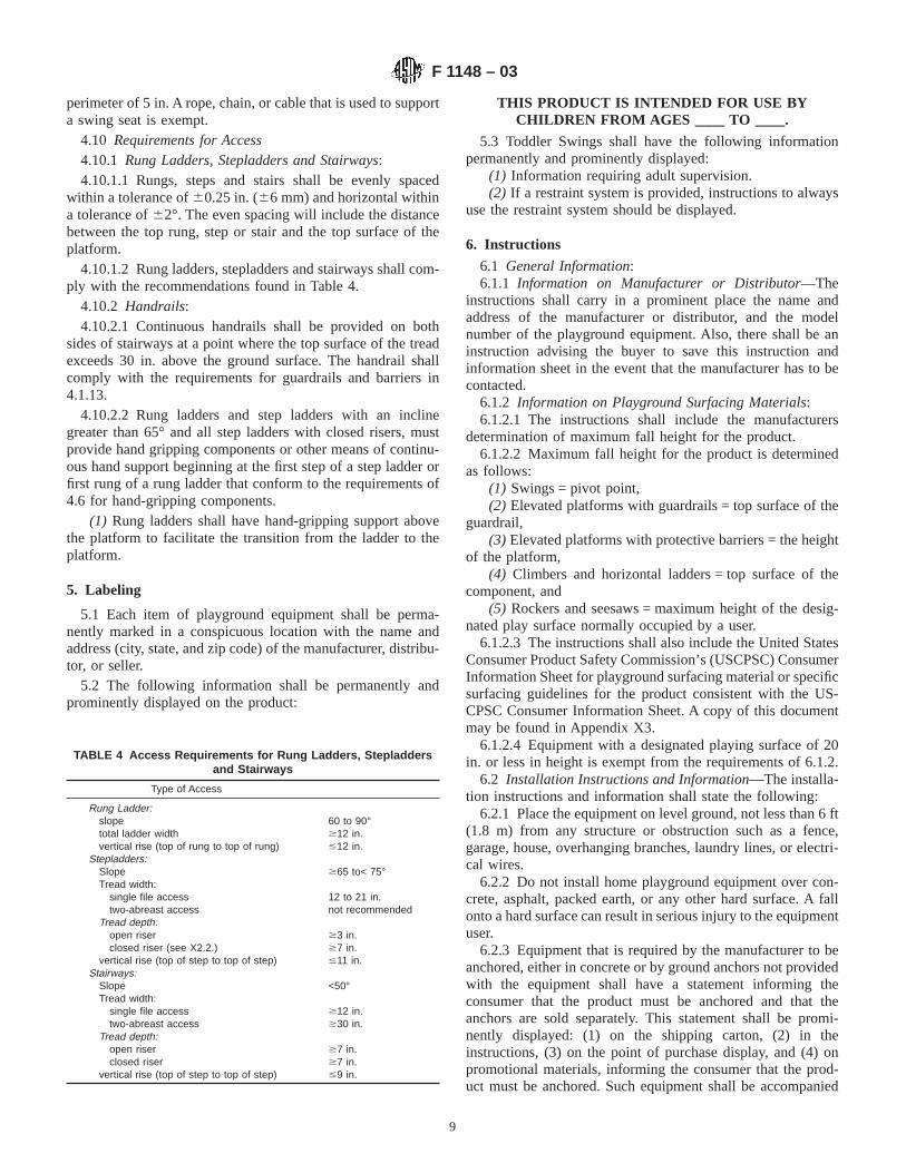
TABLE 4 Access Requirements for Rung Ladders, Stepladdersand Stairways
Type of Access
Rung Ladder:slope 60 to 90°total ladder width $12 in.vertical rise (top of rung to top of rung) #12 in.
Stepladders:Slope $65 to< 75°Tread width:
single file access 12 to 21 in.two-abreast access not recommended
Tread depth:open riser $3 in.closed riser (see X2.2.) $7 in.
vertical rise (top of step to top of step) #11 in.Stairways:
Slope <50°Tread width:
single file access $12 in.two-abreast access $30 in.
Tread depth:open riser $7 in.closed riser $7 in.
vertical rise (top of step to top of step) #9 in.
F 1148 – 03
9

by detailed instructions on how anchoring is to be accom-plished to prevent tipping, overturning, or lifting of the supportmembers during anticipated use. The instruction shall includeinformation on anchoring in sandy soil conditions. The instruc-tion shall also state that all anchoring devices must be placedbelow the level of the playing surface to prevent tripping orinjury resulting from a fall.
6.2.4 When the equipment is shipped other than completelyassembled, assembly instructions shall be provided includingschematic drawings or renderings which, when followed, willenable an unskilled layman to correctly assemble the equip-ment and to avoid errors that could result in unsafe assembly.
6.2.5 Full-size diagrams of bolts, nuts, and washers and alist and description of all tools required shall be incorporatedinto the instructions. Lock nuts shall be clearly identified.Cautionary statements shall be included that recommend tight-ening bolts securely. There shall be instructions advising thebuyer to tighten the nuts on bolts flush to the tube (or member)and that caps which go over the exposed bolts shall be put onsnug to the nut.
6.2.6 To prevent serious injury, cautionary statements shallbe included which warn that children must not use theequipment until properly installed.
6.3 Operating Instructions—The operating instructionsshall include statements:
6.3.1 Observing the following statements and warningsreduces the likelihood of serious or fatal injury.
6.3.2 Specifying the number and weight of occupants thatmay safely use the equipment singly or simultaneously,
6.3.3 Recommending on-site adult supervision for childrenof all ages,
6.3.4 Warning the buyer to instruct children not to walkclose to, in front of, behind, or between moving items,
6.3.5 Warning the buyer to instruct children not to twistswing chains or ropes or loop them over the top support barsince this may reduce the strength of the chain or rope,
6.3.6 Warning the buyer to instruct children to avoid swing-ing empty seats,
6.3.7 Warning the buyer to teach children to sit in the centerof the swings with their full weight on the seats,
6.3.8 Warning the buyer to instruct children not to use theequipment in a manner other than intended,
6.3.9 Warning the buyer to instruct children not to get offequipment while it is in motion,
6.3.10 Warning the parent to dress children appropriately(examples would include the use of well-fitting shoes and theavoidance of ponchos, scarfs, and other loose-fitting clothingthat is potentially hazardous while using equipment),
6.3.11 Warning the buyer to instruct children not to climbwhen the equipment is wet,
6.3.12 Warning the buyer to check the openings betweenrollers and sliding surfaces of roller slides for foreign materialsthat could be potentially hazardous to users,
6.3.13 Warning the buyer to verify that suspended climbingropes, chain, or cable are secured at both ends, and
6.3.14 Warning the buyer to verify that suspended climbingropes, chain, or cable cannot be looped back on itself.
6.3.15 Warning the buyer to instruct children not to attachitems to the playground equipment that are not specificallydesigned for use with the equipment, such as, but not limitedto, jump ropes, clothesline, pet leashes, cables and chain asthey may cause a strangulation hazard.
6.4 The following warning statements shall appear in theinstruction manual concerning use of two- or four-passengerlawn swings that have an opening between the seat and theback surfaces:WARNING: Lawn swings are designed for use by childrentwo years of age and older. The use by children under the ageof two can result in entrapment between the seat and back restbecause the child’s body may pass through the opening,causing entrapment of the child’s head. Such entrapment mayresult in strangulation. NEVER place children in a rearwardfacing position or with legs between the seat and backrest.
6.5 Maintenance Instructions—The maintenance instruc-tions shall include the following statements:
6.5.1 Check all nuts and bolts twice monthly during theusage season for tightness and tighten as required. It isparticularly important that this procedure be followed at thebeginning of each season.
6.5.2 Remove plastic swing seats and take indoors or do notuse when the temperature drops below °F (temperature to beselected by the manufacturer).
6.5.3 Oil all metallic moving parts monthly during the usageperiod.
6.5.4 Check all coverings for bolts and sharp edges twicemonthly during usage season to be certain they are in place.Replace when necessary. It is especially important to do this atthe beginning of each new season.
6.5.5 Check swing seats, ropes, cables and chains monthlyduring usage season for evidence of deterioration. Replace-ment should be made in accordance with manufacturer’sinstructions.
6.5.6 Sand rusted areas on tubular members and repaintusing a nonlead-based paint meeting the requirements of Title16 CFR Part 1303.
6.6 Disposal Instructions—There shall be instructions ad-vising the buyer to disassemble and dispose of the playgroundequipment in such a way that no unreasonable hazards willexist at the time the swing set is discarded.
7. General Requirements
7.1 Applicable to All Home Playground Equipment—Playground equipment represented as complying with thisvoluntary consumer safety performance specification shallmeet all applicable requirements specified herein. Anyonerepresenting compliance with this consumer safety perfor-mance specification shall keep such essential records as arenecessary to document his claim that the requirements withinthis consumer safety specification have been met.
NOTE 9—A rationale for provisions in this consumer safety perfor-mance specification is given in Appendix X2.
8. Packaging
8.1 All equipment shall be packaged in a manner that willpreclude any sharp edges from being exposed during transit orstorage.
F 1148 – 03
10

9. Identification of Conformance to This Standard
9.1 No item of playground equipment shall indicate, bylabel or other means, conformance with this specificationunless it conforms to all requirements contained herein. The
following statement is suggested for use in identifying aproduct that conforms to all requirements in this specification:
9.1.1 “This conforms to ASTM F 1148, Consumer SafetyPerformance Specification for Home Playground Equipment.”
ANNEX
(Mandatory Information)
A1. FIGURES
FIG. A1.1 Swing Set (Metal)
F 1148 – 03
11

FIG. A1.2 Swing Set (Wood)
FIG. A1.3 Clubhouse or Fort with Climbers and Slides
F 1148 – 03
12

FIG. A1.4 Portable Plastic Play Equipment
FIG. A1.5 Recommendations for Angles
F 1148 – 03
13

FIG. A1.6 Rope, Chain or Cable
FIG. A1.7 Minimum Spacing of Swinging Elements/Rides
F 1148 – 03
14

FIG. A1.8 Example of Bolt End Exempt from Requirements of 4.1.10.2
FIG. A1.9 Examples of Acceptable and Unacceptable Hooks
F 1148 – 03
15
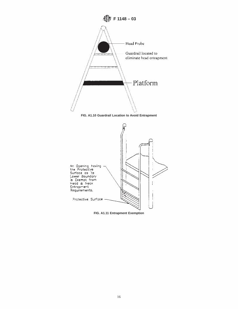
FIG. A1.10 Guardrail Location to Avoid Entrapment
FIG. A1.11 Entrapment Exemption
F 1148 – 03
16

FIG. A1.12 Torso Probe
F 1148 – 03
17

FIG. A1.13 Head Probe
FIG. A1.14 Hanger Test Fixture
F 1148 – 03
18

FIG. A1.15 Side View of Multiple-Occupancy Swing
F 1148 – 03
19

FIG. A1.16 Test Fixture for Multiple-Occupancy Swings
FIG. A1.17 Requirements for Slides (see 4.3)
F 1148 – 03
20

FIG. A1.18 Clearance Zone for Merry-Go-Round Stationary Members
F 1148 – 03
21

FIG. A1.19 Hand Gripping and Grasping Components
F 1148 – 03
22
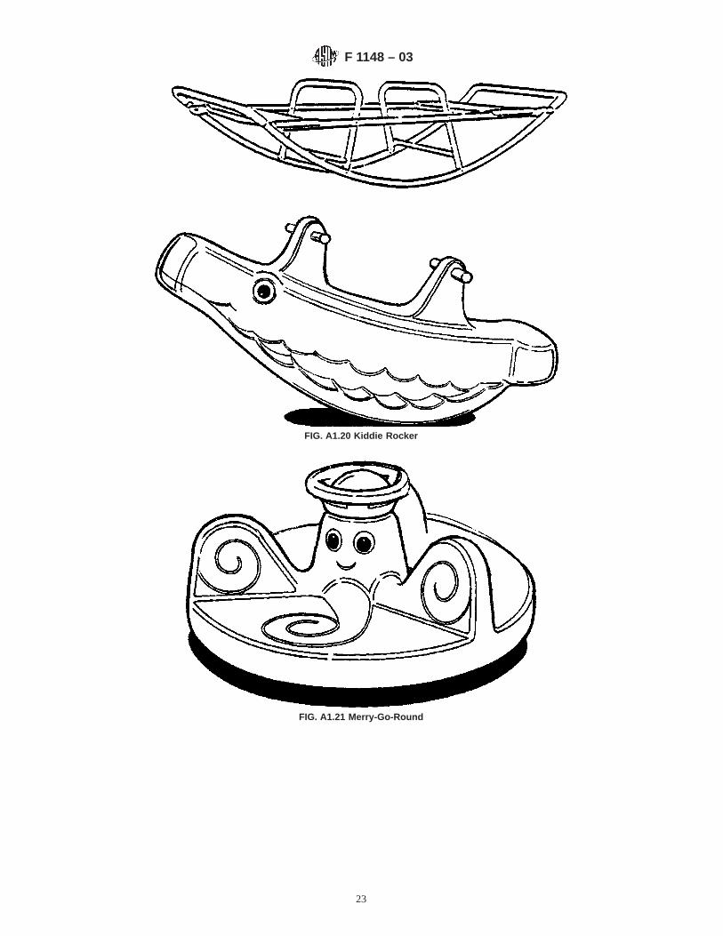
FIG. A1.20 Kiddie Rocker
FIG. A1.21 Merry-Go-Round
F 1148 – 03
23

FIG. A1.22 Dome Climber and Ladder Climber
F 1148 – 03
24

FIG. A1.23 Load Distribution on Platforms
F 1148 – 03
25

FIG. A1.24 Protrusion Test Gages
F 1148 – 03
26

NOTE 1—Gage made of any rigid material.FIG. A1.25 Motion Ride Test Gage
NOTE 1—Starting with the smallest gage, successively place each gage over the projection.FIG. A1.26 Compound Protrusion Test
FIG. A1.27 Upright Protrusion Test
F 1148 – 03
27

FIG. A1.28 Nonentanglement/Protrusion Zone
F 1148 – 03
28
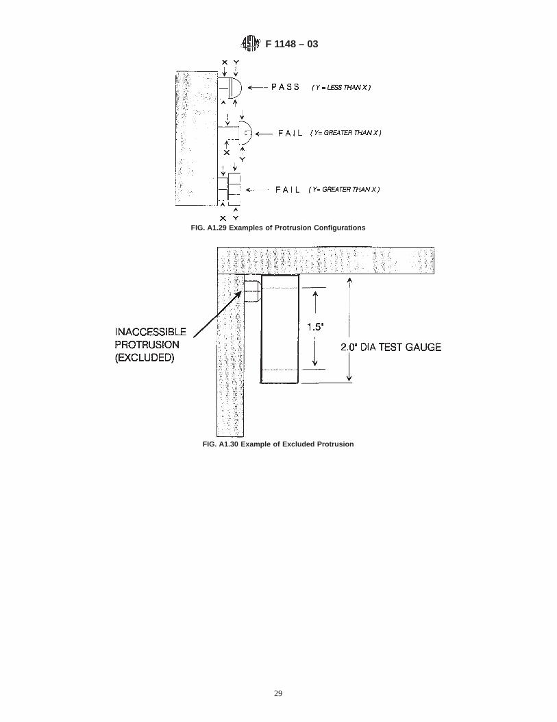
FIG. A1.29 Examples of Protrusion Configurations
FIG. A1.30 Example of Excluded Protrusion
F 1148 – 03
29

FIG. A1.31 Illustration of Fully Enclosed Toddler Swing Set
FIG. A1.32 Chain Criteria for Toddler Swings
F 1148 – 03
30

FIG
.A1.
33P
endu
lum
Test
Fix
ture
F 1148 – 03
31

APPENDIXES
(Nonmandatory Information)
X1. DYNAMIC IMPACT TEST FOR SINGLE-OCCUPANCY SWINGS
X1.1 Test Equipment
X1.1.1 Headform and Support Assembly:X1.1.1.1 The peak acceleration imparted by a suspended
member is determined by impacting an instrumented headformwith the suspended member. The Size C headform specified inthe Federal Motor Vehicle Safety Standard No. 218 shall beused for this test.
X1.1.1.2 The headform support assembly shall be con-structed in such a manner that the total headform and supportassembly mass does not exceed 10.5 lb (4.8 kN). An acceler-ometer shall be mounted at the center of gravity (CG) of theheadform and support assembly combination with the sensitiveaxis of the accelerometer aligned to within 5° (0.087 rad) of thedirection of travel of the headform.
X1.1.2 Guidance Structure—The motion of the headformafter impact shall be restricted to horizontal travel with theheadform centerline remaining in the central plane, as depictedin Fig. X1.1. To provide the required headform motion, theprimary support structure (see Fig. X1.2) shall be a 6-in.(21-mm) I beam (6 I12.5 American Standard I Beam), or anequivalent structure, secured in such a manner as to remainstationary during the test (see Fig. X1.3). The static coefficientof friction between the headform support assembly and thestationary guidance system structure shall be less than 0.02.
X1.1.3 Instrumentation— The instrumentation to be usedfor the test, including accelerometer, signal conditioner, andoscilloscope, are to be selected and operated in accordancewith SAE Practice J 211, Channel Class 1000.
FIG. A1.34 Pass/Fail Criteria for Toddler Swings
F 1148 – 03
32

X1.2 Test Method
X1.2.1 Ambient laboratory conditions are required for thetest (62 to 82°F (16.7 to 27.8°C)). All test equipment and
suspended members shall be exposed to these conditions for atleast 4 h prior to test.
X1.2.2 Assemble and install the suspended member to betested in accordance with the manufacturer’s instructions,
FIG. X1.1 Impact Test Setup
FIG. X1.2 Headform and Support Assembly
FIG. X1.3 Guidance Structure
F 1148 – 03
33

utilizing the hardware and the maximum length suspendingelements supplied or specified by the manufacturer.
X1.2.3 Allow the suspended member to assume its freehanging rest position (refer to Fig. X1.1) and adjust the relativepositions of the suspended member, headform, and guidancesystem to meet the following conditions:
X1.2.3.1 The centerlines of the headform and guidancestructure and the chosen impact point on the suspendedmember shall lie in the central plane.
X1.2.3.2 The lower edge of the headform shall be horizon-tal, with the headform contacting the impacting surface of thesuspended member.
X1.2.3.3 The suspended member’s impacting point shall bein line with and adjacent to the impact point on the headform.The impact point is that point on the headform that lies in thecentral plane and is tangent to the vertical.
X1.2.3.4 Affix an index mark to the side of suspendedmembers that are supported by chains, ropes, cables, or othernonrigid suspending elements. The index mark may be on anypart of the suspended member that is immediately below thepivot point in the free-hanging rest position.
NOTE X1.1—Flexible belt-type suspended members require a brace(see Fig. X1.4) to maintain seat configuration during this procedure andduring impact testing. The mass of the brace shall not exceed 10 % of themass of the suspended member.
X1.2.4 Place the suspended member in the test positionindicated by one of the following methods:
X1.2.4.1 Suspended members that are supported by chains,ropes, cables, or other nonrigid suspending elements shall be
raised along their arc of travel until the side-view projection ofa straight line through the pivot point and index mark forms anangle of 60° (105 rad) with the vertical. Once the suspendedmember is raised to the test position, some curvature will beproduced in the suspending elements. Adjust the suspendedmember position to determine that curvature which provides astable trajectory.
X1.2.4.2 Suspended members that are supported by rigidsuspending elements shall be elevated along their arc of traveluntil the side-view projection of the suspending element, whichwas vertical in the rest position, is at an angle of 60° (105 rad),or at the maximum angle attainable, whichever is less.
X1.2.5 In consideration of the test positions specified inX1.2.4.1 and X1.2.4.2, caution should be exercised to preventdamage to the test equipment. If an unusually heavy or hardsuspended member is to be tested, preliminary tests should bemade at lower test angles (for example, 10°, 20°, 30°, etc.)(0.17 rad, 0.35 rad, 0.52 rad). If the requirements of 4.2.3 areexceeded at a lower test angle than that specified in X1.2.4.1 orX1.2.4.2, the member fails and no further tests are necessary.Additionally, if there is doubt concerning the suspendedmember trajectory or stability, the headform or guidancestructure, or both, should be set aside to allow trial releaseswithout impacting the headform.
X1.2.6 The suspended member shall be supported in the testposition by a mechanism that provides release without theapplication of external forces which would disturb the trajec-tory of the suspended member. Prior to release, the suspendedmember and suspending elements shall be motionless. Uponrelease, the assembly shall travel in a smooth downward arcwithout any visible oscillations or rotations of the suspendedmember which will prevent it from striking the headform at theimpact point.
X1.2.7 Once satisfactory system operation and calibration isobtained, collect data for ten impacts. Measure the peakacceleration ing for each impact. If the data for any two of theten impacts do not meet the requirements of 4.2.3, thesuspended member fails the test.
X2. RATIONALE FOR SAFETY REQUIREMENTS FOR HOME PLAYGROUND EQUIPMENT
X2.1 Introduction
X2.1.1 This consumer safety specification, originally pub-lished in 1988, replaced the Voluntary Product Standard PS66-75, Safety Requirements for Home Playground Equipment.
X2.2 References to “Sharp Edge” and “Sharp Point”
X2.2.1 Reference to CPSC Sharp Edge Regulation 16 CFRPart 1500.49 and Sharp Point Regulation 16 CFR Part 1500.48have been added to this consumer safety specification for homeplayground equipment (see section 3.1.3 and section 3.1.10).Such additions recognize the development and implementationof CPSC sharp edge and sharp point regulations and tests,applicable to products intended for children under 8 years ofage. Failure to comply with the sharp point and sharp edge test
requirements does not in and of itself determine the existenceof sharp points and edges. It must still be determined thatnoncomplying points or edges present an unreasonable risk ofinjury.
X2.3 Definition and Reference to “Small Parts”
X2.3.1 The definition and reference to small parts (seesection 3.1.14) has been added to this consumer safety speci-fication in order to alert manufacturers that products within thescope of this consumer safety specification must comply withConsumer Product Safety Commission mandatory regulation16 CFR 1501 which addresses choking, aspiration, and inges-tion hazards because of small parts if products are intended forchildren under three years of age.
FIG. X1.4 Brace for Flexible Seats
F 1148 – 03
34

X2.4 Definitions of Pinch, Crush, and Shear Points
X2.4.1 The practical test for the definition of a pinch, crush,and shear point (see 4.1.6) was originally proposed by a CPSCstaff member in an early discussion related to the bicyclerequirements. The3⁄16-in. (10-mm) dimension provides forfinger accessibility. An opening at the juncture of a moving anda stationary member, if present, is required to have a greaterclearance because of the greater hazard potential. The changeto 1⁄2 in. is an attempt to be more severe and to keep themeasurements consistent throughout the document.
X2.5 Acute Angles
X2.5.1 The 55° minimum angle was established by obser-vation and a limited amount of testing. The intent is to prevententrapment which could result in strangulation. The exclusionof angles with the apex less than 18 in. (460 mm) above groundlevel is no longer allowed as new studies indicate that it ispossible for young children to strangle even when their feet areon the ground. The 20-ft·lbf (27-J) impact is an arbitrarilyestablished requirement to prevent the use of flimsy shields thatwould introduce a secondary hazard. The use of the head probeto determine where to place the shield has been added to enablethe manufacturer to determine at which point a hazard is nolonger present.
X2.6 Spacing Between Swing Elements and StationaryFrame Members
X2.6.1 Based upon an I.D.I. Report provided by the Con-sumer Product Safety Commission,3 evidence is presented thatspacing between supporting legs of the swing set frames andthe pendulum seesaw rides may be insufficient to prevent ridercontact and potential for injury. Reference is made to thatreport with attention to Item Numbers 2, 3, 4, 5, and 6, wherein each instance children came into contact with frame-supporting elements while riding a pendulum see-saw.
X2.6.2 A review of the Voluntary Standard, Section Number4.1.9 (simplified) allows for a 7-in. (180-mm) clearancebetween the outermost lateral extremity of the ride (seat) andthe supporting legs, as measured at a distance of 28 in. (710mm) above the seating surface when the seat is at least 15 in.(380 mm) from the ground.
X2.6.2.1 It is important to note that no incidents arerecorded which indicate collision of the pendulum see-sawwith adjacent swing rides. It is theorized that this is due in partto the additional dimension required between adjacent rides bythe current standard 8 in. (205 mm) between outermostextremities of the seating service and also because the naturaltendency of a pendulum is to maintain a vertical position at thecenter of its arc, which is where adjacent swing rides arelocated. This is as opposed to the location of the supportinglegs, which are set at the outer region of the arc path wheregreater lateral motion may occur. Furthermore, there is no datato indicate that pendulum rides such as two or four-passengerlawn swings have resulted in occupant collision with support-ing members. Logically, it can be assumed that this is becausethe occupant is seated between the pendulum supports. Fur-thermore, the use of multiple pendulums, which are separatedlaterally, reduces the possibility of lateral motion dramatically.
X2.6.2.2 The following data are compiled specifically toaddress clearance between the occupant of pendulum see-sawsand supporting structures. It is not intended to apply to adjacentswing rides or to govern clearances between supporting mem-bers and laterally controlled swing elements.
X2.6.2.3 By observing children at play on pendulum see-saws, it can be determined that they often lean from side to sidewhile riding, and must lean to some degree for comfortablepositioning and clearance from the pendulums, which aredirectly in front of the rider.
X2.6.2.4 Further observance demonstrates that the maxi-mum lean angle which occurs during normal use is from 20 to25° (0.35 to 0.44 rad) as measured from the center line of thependulum to the center line of the rider’s head. Table X2.1illustrates the appropriate anthropometric data for a 10-year-old 50th percentile child, in conjunction with a pendulumsee-saw and a lean factor of 30° (0.52 rad). An evaluation canbe made using Table X2.1 with regard to determining anadequate dimension for clearance from supporting members.
X2.7 Hardware
X2.7.1 The requirements of this section are intended toaccomplish the following:
X2.7.1.1 Limit the amount a threaded bolt end can protrudebeyond the nut unless the bolt end is recessed to reduce thepossibility of producing a catch point.
X2.7.1.2 Necessitate the use of end caps on threaded boltends which protrude from adjacent surfaces in areas ofnormally expected play to protect the user from unintentionalcontact with bolt ends.
X2.7.1.3 Avoid the unnecessary use of end caps wherethreaded bolt ends existing in areas outside of normal play arefree of hazardous sharp edges and burrs. The CPSC is aware ofchoking incidents resulting from end caps that have come offplayground equipment, so an effort has been made to requireend caps only where they are necessary for safety reasons.
X2.7.1.4 Require any end cap used to meet the Federalrequirements for small parts (16 CFR 1501) in productsintended for children under three years of age.
X2.8 Enclosed Openings
X2.8.1 The purpose of this requirement (see 4.1.14) was toeliminate a strangulation potential, where a child could insertits head into an opening from which it could not be removedwithout difficulty and where a child could enter an opening feet
TABLE X2.1 Anthropometric Data for a 10-year-old 50thPercentile Child
28 in. (710 mm) = head height at seated position12.5 in. (320 mm) = shoulder width18 in. (460 mm) = shoulder height5.6 in. (140 mm) = head width30° (0.52 rad) = lean angle providedA
14 in. (355 mm) = distance from center line of pendulum to the center of thehead at a 30° (0.52 rad) lean angle
15.4 in. (390 mm) = head extremity at a 30° (0.52 rad) lean angleX = proposed clearance standard16 in. (405 mm) = dimension to X from center line of pendulum22 in. (560 mm) = dimension to X from the seating surfaceC = clearance as required by present standard
A In excess of 25° (0.44 rad) observed.
F 1148 – 03
35
first. The numerical values limiting the openings are basedupon the dimensions of a child’s head and torso. The change inthis consumer safety specification was prompted by a recom-mendation of the CPSC. A study was conducted by the HumanFactors Division of the CPSC relating to head entrapment. Thisstudy showed that children were entering openings feet first,their torso sliding completely through, entrapping their heads.This study, along with accident data obtained from the NationalElectronic Injury Surveillance System suggested that a changewas needed. The torso probe dimensions are based on themeasurements of the 5th percentile two-year-old. The headprobe dimensions are based on the tip of chin to top of headmeasurement of the oldest user at risk (95th percentile five-year-old).
X2.9 Holes and Slots
X2.9.1 The limitations on holes and slots are to preventfinger entrapment, as discussed previously in X2.5.
X2.10 Hanger and Bearing Assemblies
X2.10.1 The dynamic test of hanger and bearing assembliesemploys the 105 lb (47.7 kg) weight of a 95th percentile10-year-old. Application of the principles of a simple pendu-lum to a swing or pendulum see-saw indicates that they willoperate at approximately 20 cycles/min, or 1200 cycles/h. Therequired 180 000 cycles is then equivalent to 150 h of testing.The full correlation of this 150 h to normal usage is notrepeated in this discussion, as the basis for this figure wasdeveloped in Committee F15 Report 53685-2, dated Sept. 30,1971, and distributed by John Tascher to the Standard ReviewCommittee under the date of Jan. 20, 1975.
X2.11 Minimum Ground Clearance
X2.11.1 The minimum ground clearance of 8 in. (203 mm)(see 4.2.2) provides clearance for a prone 95th percentile10-year-old, whose chest depth is only 175 mm.
X2.12 Single-Occupancy Swings
X2.12.1 In order to minimize injury due to impact bysingle-occupancy swings (see 4.2.3), Voluntary Standard PS66-75 was amended to include a dynamic impact test originallydeveloped for single-occupancy units in public playgroundequipment. While this consumer safety specification originallyaddressed criteria to minimize injury due to impact, it did notcontain any specific test methods by which to make such adetermination. The impact test which replaces the previousdesign requirements was developed by the National Institute ofStandards and Technology for single-occupancy units in publicplayground equipment and is incorporated into this consumersafety specification as Appendix X1. Trapezes and exerciserings are exempt from this requirement based on the lack ofcurrent injury data. Straddle-type seats, such as a horse, andmultiple occupancy swings are exempt from the requirement,subject to future revision.
X2.13 Multiple-Occupancy Swings
X2.13.1 Based upon I.D.I. reports provided by the Con-sumer Product Safety Commission, evidence is presented thatthe spacing between lawn swing footrests or platforms and the
leading edge of the seating surface may allow excessivedimension, thereby permitting riders to place their legs throughthis area and contact the ground, causing leg injuries. Thedimensional requirements for the multiple occupancy swingare intended to reduce the possibility of a child’s foot beingtrapped in the gap between the seat and the footrest.
X2.13.2 The thickness of the test fixture (Fig. A1.14)reduces to 3 in. (76 mm) based on buttock depth of the smallestuser (such as, 5th percentile child in 19 to 24-month agerange = 3.3 in. [84 mm]). In addition, incidents have beenreported that involved lawn swings which had a space betweenseat and backrest of between 3 and 33⁄4 in. (76 and 95 mm)(IDI’s 850530CCC3161 & 861107CCC1057). Also, a Germanstandard for playground equipment (DIN 7926) states that thespace between seat and backrest of multiple-occupancy swingsshall be between 60 and 75 mm (2.4 and 3.0 in.).
X2.13.3 Force to be applied to the wedge block test fixtureincreased to 45 lbf based on the weight of the largest user atrisk (a 95th percentile child in the 49 to 54-month age range).Entrapment incidents generally involve children under 5 yearsof age.
X2.13.4 The direction of the force (perpendicular to planeof opening) was changed to simulate the most adverse condi-tion.
X2.13.5 Since some openings between the seat and thebackrest of lawn swings do not have uniform width along thelength of the seat, we believe the test fixture should not enterthe opening when applied at any location in the opening.
X2.13.6 We believe the minimum height (Fig. A1.14, Di-mension B) of the seat skirt above the end of the platformshould be 7.5 in. (190 mm) to minimize the likelihood ofentrapment.
X2.14 Slides
X2.14.1 The dimensional limits of 4.3 were established inearly discussions with the Bureau of Product Safety, with theangular requirements more or less arbitrarily selected todescribe existing practice. The limitations of the 10 to 30°(0.17 to 0.52-rad) angle, with the horizontal together with themaximum 12 in. (300 mm) off the ground at the exit end,places the child in suitable position for dismounting from theslide.
X2.14.2 In order to minimize or eliminate the potential forclothing entanglement and falls from the top of slides, thefollowing changes were made: A minimum radius was pre-scribed for all bends in handrails at the top of slides and aminimum length was added for the transition area. The sideheight was increased for that portion of the slide that is over 4.5ft (1370 mm) from the ground. Figure A1.16 was added toillustrate all dimensional requirements for slides.
X2.15 Slide Ladders
X2.15.1 These dimensional requirements (see 4.3.1) weredeveloped in early discussions with the Bureau of ProductSafety. The basis for excluding climbers from the slide ladderrequirements comes from a draft standard for public play-ground equipment which was prepared for the CPSC in 1976by a committee sponsored by the National Recreation and ParkAssociation (NRPA). The rationale for a provision addressing
F 1148 – 03
36

Ladder and Stairway Design in the NRPA draft standard stated:“It is not the intent of this requirement to preclude the use ofclimbing devices to reach elevations, and therefore the require-ments addressed only ladders and stairways that are notintended as climbing devices other than for ascending anddescending.”3
X2.16 Stability of Free-Standing Slides
X2.16.1 This requirement (see 4.3.2) provides for stabilitywith the weight of the 95th percentile age user hanging over thehand rail.
X2.17 Swing Set Stability
X2.17.1 The angular limitations were derived from thegeometry and construction of the various swinging elementsincluded in 4.4. In 1997 the standard was changed to reflect theneed to design product for a specific age group within the 18month to ten year age range. To accomplish this the weight ofthe 95th percentile age user is applied.
X2.18 Merry-Go-Rounds
X2.18.1 Instead of any submitted data by the ConsumerProduct Safety Commission, but with regard to specific re-quests by ASTM Task Group members, consideration is givento the adequacy of clearance between merry-go-round movingand stationary members.
X2.18.2 Reference is made to Fig. A1.17, which illustratesa typical merry-go-round ride and displays the leg length of a95th percentile 10-year-old (see Table X2.1).
X2.18.3 By comparing these figures, it may be assumed thatchildren’s legs would not come into contact with stationaryelements of the product if said stationary elements wereexcluded from the area bounded by a 28-in. (710-mm) radius(center point located at center of seating surface and extendingfrom a horizontal plane to a vertical plane projected from theextreme rear of the seating surface).
X2.19 Structural Integrity-Load Test
X2.19.1 In order to provide a more specific and uniformsystem of structural load testing (see 4.7-4.7.8), provisionshave been added whereby loads on structural members shall beapplied through a standardized wood block according tospecific weight and time applications. In 1997 in order toaccommodate the need to manufacture product within a spe-cific age range the provisions to apply the 95th percentileweight of the user for whom the product was designed wasadded. The basis for the loading did not change.
X2.20 Rungs, Steps, and Horizontal SupportingMembers
X2.20.1 The 3.5-in. (90-mm) resilient block represents theload distribution on the member under test by the shoe of a10-year-old. The proof loads of 4.7.1 provide a factor of safetyof at least 3 times the 95th percentile weight of the maximumage user.
X2.21 Top Support Bar
X2.21.1 The composite loads applied to the top support barare rounded values of the maximum anticipated loading,
assumed to be in excess of the 95th percentile weight of theintended user increased by appropriate factors which considerthe centripetal force from the swinging elements. For a fullderivation of the multiplication factors, refer to the study byBal M. Mahajan, National Bureau of Standards Report NBSIR74-563.
X2.22 Individual Suspended Units
X2.22.1 The loads specified in Table 3 represent roundedvalues which call for proof loads providing a factor of safetyranging from 1.5 to 6, dependent upon the nature of thesuspended unit.
X2.22.2 The reasoning applies to the loads specified in4.7.4, 4.7.5, and 4.7.6.
X2.23 Climbing Towers/Jungle Gyms
X2.23.1 Section 4.7.7 requires testing with five individualloads, each more than twice the weight of the 95th percentileage user, with the additional requirement that the loads beapplied in a manner to cause the greatest tendency forinstability. In this test, both the structural integrity and thestability of the unit are evaluated.
X2.24 Instructions
X2.24.1 Installation instructions and information (see 6.2)have been expanded through requirements that all installationinstructions contain additional warnings advising consumersthat falls onto hard surfaces can result in serious injury to theplayground equipment user.
X2.24.2 Instructions on removal or nonuse of plastic swingseats when temperature drops below specific levels have beenclarified to allow the manufacturer to select the applicablethreshold temperature level, if any. Such amendment recog-nizes wide variations in the characteristics of existing plasticsand the plastic rigidity/temperature ratio.
X2.25 Protrusions
X2.25.1 These requirements are intended to prevent protru-sions that may puncture, impale, produce an eye or ear injury,or which are catch points for clothing that could result in falls.Protrusions of this type are identified if they protrude beyondthe back surface of any of the specified gages.
X2.25.2 Portions of these requirements have been takenfrom proposals that were prepared for and referenced by theConsumer Product Safety Commission in a document entitled“A Hand Book for Public Playground Safety,” Volume II, thatrefers to proposals and studies conducted by The Recreationand Park Association and by The National Bureau of Stan-dards. The requirements of this consumer safety specificationare believed to be more stringent, and adapted to the present-day concerns of injuries related to entanglement and puncture.As related in a proposal to the ASTM committee (dated Feb.14, 1992) after review of the prior documents referencedabove, a 1-in. inner diameter test gage has been added thatlimits protrusions less than 1 in. in dimension to not more than1⁄2 in., as compared to the CPSC guidelines that allow3⁄4 in.
F 1148 – 03
37

X2.25.3 While this consumer safety specification includessections that set forth requirements for bolts and threadedfasteners, those components must also conform to the protru-sion requirements.
X2.25.4 While there is an endless variety of configurationsfor protrusions that could conceivably be contacted by the user,the specified test gages provide a means of determiningpermissible protrusions. The gage with a1⁄2-in. opening limitsprojections of that maximum size to not more than1⁄4 in.; the1-in. gage to not more than1⁄2 in.; the 11⁄2 in. to not more than3⁄4 in.; and the 3 in. to not more than 11⁄2-in. projections.
X2.25.5 A protrusion that fits inside any of the protrusiontest gages and projects upwards from a horizontal plane may beconsidered an entanglement hazard if the projection extendsmore than1⁄8 in. perpendicular to the plane of its initial surface.The 1⁄8 in. dimension was arrived at by reviewing existing
standards that had provisions for entanglement, evaluation ofinjury data, and by using sound engineering practices.
X2.25.6 Motion rides and the motion of the user areconsidered by the use of the1⁄8-in. thick test gage that isrequired for testing of protrusion in areas with potential forpossible impact.
X2.26 Summary
X2.26.1 In summary, the requirements of this consumersafety specification have been based, to the greatest extentpossible, on sound anthropometric data. It should also be notedthat the essential content of 4.1.2, 4.1.5, 4.1.6, 4.1.7, 4.1.8, 4.2,4.3, 4.3.1, 4.4, and 4.5 were included in a working draft of aproposed regulation by the Bureau of Product Safety in early1973, just prior to the formation of the Consumer ProductSafety Commission.
X3. CONSUMER INFORMATION SHEET FOR PLAYGROUND SURFACING MATERIALS 10
X3.1 The U.S. Consumer Product Safety Commission(CPSC) estimates that about 100 000 playground equipment-related injuries resulting from falls to the ground surface aretreated annually in U.S. hospital emergency rooms. Injuriesinvolving this hazard pattern tend to be among the most seriousof all playground injuries, and have the potential to be fatal,particularly when the injury is to the head. The surface underand around playground equipment can be a major factor indetermining the injury-causing potential of a fall. It is selfevident that a fall onto a shock absorbing surface is less likelyto cause a serious injury than a fall onto a hard surface.Playground equipment should never be placed on hard surfacessuch as concrete or asphalt and while grass may appear to beacceptable it may quickly turn to hard packed earth in areas ofhigh traffic. Shredded bark mulch, wood chips, fine sand or finegravel are considered to be acceptable shock absorbing sur-faces when installed and maintained at a sufficient depth underand around playground equipment.
X3.2 Table X3.1 lists the maximum height from which achild would not be expected to sustain a life-threatening headinjury in a fall onto four different loose-fill surfacing materialsif they are installed and maintained at depths of 6, 9, and 12 in.
However, it should be recognized that all injuries due to fallscannot be prevented no matter what surfacing material is used.
X3.3 It is recommended that a shock absorbing materialshould extend a minimum of 6 ft in all directions from theperimeter of stationary equipment such as climbers and slides.However, because children may deliberately jump from amoving swing, the shock absorbing material should extend inthe front and rear of a swing a minimum distance of 2 times theheight of the pivot point measured from a point directlybeneath the pivot on the supporting structure.
X3.4 This information is intended to assist in comparingthe relative shock-absorbing properties of various materials.No particular material is recommended over another. However,each material is only effective when properly maintained.Materials should be checked periodically and replenished tomaintain correct depth as determined necessary for yourequipment. The choice of a material depends on the type andheight of the playground equipment, the availability of thematerial in your area, and its cost.
10 This information has been extracted from the CPSC publications “PlaygroundSurfacing—Technical Information Guide” and “Handbook for Public PlaygroundSafety.” Copies of these reports can be obtained by sending a postcard to the: Officeof Public Affairs, U.S. Consumer Product Safety Commission, Washington, D.C.,20207 or call the toll-free hotline: 1-800-638-2772.
TABLE X3.1 Fall Height in Feet From Which a Life ThreateningHead Injury Would Not Be Expected
Type of Material 6 in. depth 9 in. depth 12 in. depth
Double Shredded Bark Mulch 6 10 11Wood Chips 6 7 12Fine Sand 5 5 9Fine Gravel 6 7 10
F 1148 – 03
38

ASTM International takes no position respecting the validity of any patent rights asserted in connection with any item mentionedin this standard. Users of this standard are expressly advised that determination of the validity of any such patent rights, and the riskof infringement of such rights, are entirely their own responsibility.
This standard is subject to revision at any time by the responsible technical committee and must be reviewed every five years andif not revised, either reapproved or withdrawn. Your comments are invited either for revision of this standard or for additional standardsand should be addressed to ASTM International Headquarters. Your comments will receive careful consideration at a meeting of theresponsible technical committee, which you may attend. If you feel that your comments have not received a fair hearing you shouldmake your views known to the ASTM Committee on Standards, at the address shown below.
This standard is copyrighted by ASTM International, 100 Barr Harbor Drive, PO Box C700, West Conshohocken, PA 19428-2959,United States. Individual reprints (single or multiple copies) of this standard may be obtained by contacting ASTM at the aboveaddress or at 610-832-9585 (phone), 610-832-9555 (fax), or [email protected] (e-mail); or through the ASTM website(www.astm.org).
F 1148 – 03
39