standard specification for design and performance of a · pdf file ·...
TRANSCRIPT

Designation: F 2245 – 06
Standard Specification forDesign and Performance of a Light Sport Airplane1
This standard is issued under the fixed designation F 2245; the number immediately following the designation indicates the year oforiginal adoption or, in the case of revision, the year of last revision. A number in parentheses indicates the year of last reapproval. Asuperscript epsilon (e) indicates an editorial change since the last revision or reapproval.
1. Scope
1.1 This specification covers airworthiness requirements forthe design of powered fixed wing light sport aircraft, an“airplane.”
1.2 This specification is applicable to the design of a lightsport aircraft/airplane as defined by regulations and limited toVFR flight.
1.3 This standard does not purport to address all of thesafety concerns, if any, associated with its use. It is theresponsibility of the user of this standard to establish appro-priate safety and health practices and determine the applica-bility of regulatory requirements prior to use.
2. Referenced Documents
2.1 ASTM Standards:2
F 2316 Specification for Airframe Emergency Parachutesfor Light Sport Aircraft
F 2339 Practice for Design and Manufacture of Reciprocat-ing Spark Ignition Engines for Light Sport Aircraft
2.2 Federal Aviation Regulations:3
FAR-33 Airworthiness Standards: Aircraft Engines2.3 Joint Aviation Requirements:4
JAR-E EnginesJAR-22 Sailplanes and Powered Sailplanes
3. Terminology
3.1 Definitions:3.1.1 flaps—any movable high lift device.3.1.2 maximum empty weight, WE (lb)—largest empty
weight of the airplane, including all operational equipment thatis installed in the airplane: weight of the airframe, powerplant,required equipment, optional and specific equipment, fixed
ballast, full engine coolant and oil, hydraulic fluid, and theunusable fuel. Hence, the maximum empty weight equalsmaximum takeoff weight minus minimum useful load: WE = W− WU.
3.1.3 minimum useful load, WU (lb)—where WU = W − WE.3.1.4 night—hours between the end of evening civil twilight
and the beginning of morning civil twilight.3.1.4.1 Discussion—Civil twilight ends in the evening when
the center of the sun’s disc is 6 degrees below the horizon, andbegins in the morning when the center of the sun’s disc is 6degrees below the horizon.
3.2 Abbreviations:3.2.1 AR—aspect ratio = b2 / S3.2.2 b—wing span, (ft)3.2.3 BHP—brake horse power3.2.4 c—chord, (ft)3.2.5 CAS—calibrated air speed, (fps, kts, mph)3.2.6 CL—lift coefficient of the airplane3.2.7 CD—drag coefficient of the airplane3.2.8 CG—center of gravity3.2.9 Cm—moment coefficient (Cm is with respect to c/4
point, positive nose up)3.2.10 CMO—zero lift moment coefficient3.2.11 Cn—normal coefficient3.2.12 FPM—feet per minute3.2.13 g—acceleration as a result of gravity = 32.2 ft/s2
3.2.14 IAS—indicated air speed (fps, kts, mph)3.2.15 ICAO—International Civil Aviation Organization3.2.16 LSA—light sport aircraft3.2.17 MAC—mean aerodynamic chord3.2.18 n—load factor3.2.19 n1—airplane positive maneuvering limit load factor3.2.20 n2—airplane negative maneuvering limit load factor3.2.21 n3—load factor on wheels3.2.22 POH—Pilot Operating Handbook3.2.23 q—dynamic pressure = ~V / 19.77!2
5 V2 / 391lb/ft2, when V is in mph
3.2.24 S—wing area (ft2)3.2.25 V—airspeed (mph)3.2.26 VA—design maneuvering speed3.2.27 VC—design cruising speed3.2.28 VD—design diving speed3.2.29 VDF—demonstrated flight diving speed (VDF # VD)3.2.30 VF—design flap speed
1 This specification is under the jurisdiction of ASTM Committee F37 on LightSport Aircraft and is the direct responsibility of Subcommittee F37.20 on Airplane.
Current edition approved Oct. 15, 2006. Published October 2006. Originallyapproved in 2004. Last previous edition approved in 2004 as F 2245 – 04.
2 For referenced ASTM standards, visit the ASTM website, www.astm.org, orcontact ASTM Customer Service at [email protected]. For Annual Book of ASTMStandards volume information, refer to the standard’s Document Summary page onthe ASTM website.
3 Available from Federal Aviation Administration (FAA), 800 IndependenceAve., SW, Washington, DC 20591, http://www.faa.gov.
4 Available from Global Engineering Documents, 15 Inverness Way, EastEnglewood, CO 80112-5704, http://global.ihs.com.
1
Copyright © ASTM International, 100 Barr Harbor Drive, PO Box C700, West Conshohocken, PA 19428-2959, United States.

3.2.31 VFE—maximum flap extended speed3.2.32 VH—maximum speed in level flight with maximum
continuous power (corrected for sea level standard conditions)3.2.33 VNE—never exceed speed (VH # VNE # 0.9VDF)3.2.34 VS—stalling speed or minimum steady flight speed at
which the airplane is controllable (flaps retracted)3.2.35 VS1—stalling speed or minimum steady flight speed
with the flaps in a specific configuration3.2.36 VS0—stalling speed or minimum steady flight speed
at which the airplane is controllable in the landing configura-tion (flaps fully deployed)
3.2.37 VSP—maximum spoiler/speed brake extended speed3.2.38 VR—ground gust speed3.2.39 VX—speed for best angle of climb3.2.40 VY—speed for best rate of climb3.2.41 W—maximum takeoff or maximum design weight
(lb)3.2.42 WE—maximum empty airplane weight (lb)3.2.43 WU—minimum useful load (lb)3.2.44 w—average design surface load (PSF)
4. Flight
4.1 Proof of Compliance:4.1.1 Each of the following requirements shall be met at the
most critical weight and CG configuration. Unless otherwisespecified, the speed range from stall to VDF or the maximumallowable speed for the configuration being investigated shallbe considered.
4.1.1.1 VDF may be less than or equal to VD.4.1.1.2 If VDF chosen is less than VD, VNE must be less than
or equal to 0.9VDF and greater than or equal to 1.1VC.4.1.2 The following tolerances are acceptable during flight
testing:Weight +5 %, −10 %Weight, when critical +5 %, −1 %CG 67 % of total travel
4.2 Load Distribution Limits:4.2.1 Minimum Useful Load Requirement:4.2.1.1 For a single-place airplane:
WU 5 190 1 0.5P, lb
where:P = rated engine power, BHP.
4.2.1.2 For a two-place airplane:
WU 5 380 1 0.5P
where:P = rated engine power, BHP.
4.2.2 Minimum flying weight shall be determined.
NOTE 1—For reference, standard occupant weight = 190 lb. For theminimum flying weight, standard occupant weight = 120 lb. Fuel density= 6 lb/U.S. gal.
4.2.3 Empty CG, most forward, and most rearward CG shallbe determined.
4.2.4 Fixed or removable ballast, or both, may be used ifproperly installed and placarded.
4.3 Propeller Speed and Pitch Limits—Propeller configura-tion shall not allow the engine to exceed safe operating limitsestablished by the engine manufacturer under normal condi-tions.
4.3.1 Maximum RPM shall not be exceeded with fullthrottle during takeoff, climb, or flight at 0.9VH, and 110 %maximum continuous RPM shall not be exceeded during aglide at VNE with throttle closed.
4.4 Performance, General—All performance requirementsapply in standard ICAO atmosphere in still air conditions andat sea level. Speeds shall be given in indicated (IAS) andcalibrated (CAS) airspeeds.
4.4.1 Stalling Speeds—Wing level stalling speeds VSO andVS shall be determined by flight test at a rate of speed decreaseof 1 knot/s or less, throttle closed, with maximum takeoffweight, and most unfavorable CG.
4.4.2 Takeoff—With the airplane at maximum takeoffweight, full throttle, the following shall be measured usingnormal takeoff procedures:
NOTE 2—The procedure used for normal takeoff, including flap posi-tion, shall be specified within the POH.
4.4.2.1 Ground roll distance to takeoff on a runway withminimal grade.
4.4.2.2 Distance to clear a 50-ft (15-m) obstacle at a climbspeed of at least 1.3VS1.
4.4.3 Climb—At maximum takeoff weight, flaps in theposition specified for climb within the POH, and full throttle:
4.4.3.1 Rate of climb at VY shall exceed 300 fpm.4.4.3.2 Climb gradient at VX shall exceed 1⁄12 .4.4.4 Landing—For landing with throttle closed and flaps
extended, the following shall be determined:4.4.4.1 Landing distance from 50 ft (15 m) above ground
when speed at 50 ft (15 m) is 1.3VSO.4.4.4.2 Ground roll distance with reasonable braking if so
equipped.4.4.5 Balked Landing—The airplane shall demonstrate a
full-throttle climb gradient at 1.3VSO which shall exceed 1⁄30
within 5 s of power application from aborted landing. If theflaps may be promptly and safely retracted without loss ofaltitude and without sudden changes in attitude, they may beretracted.
4.5 Controllability and Maneuverability:4.5.1 General:4.5.1.1 The airplane shall be safely controllable and maneu-
verable during takeoff, climb, level flight (cruise), dive to VDF
or the maximum allowable speed for the configuration beinginvestigated, approach, and landing (power off and on, flapsretracted and extended) through the normal use of primarycontrols.
4.5.1.2 Smooth transition between all flight conditions shallbe possible without exceeding pilot force as shown in Table 1.
4.5.1.3 Full control shall be maintained when retracting andextending flaps within their normal operating speed range (VSO
to VFE).4.5.1.4 Lateral, directional, and longitudinal control shall be
possible down to VSO.4.5.2 Longitudinal Control:
F 2245 – 06
2

4.5.2.1 With the airplane trimmed as closely as possible forsteady flight at 1.3VS1, it must be possible at any speed between1.1VS1 and 1.3VS1 to pitch the nose downward so that a speednot less than 1.3VS1 can be reached promptly. This must beshown with the airplane in all possible configurations, withsimultaneous application of full power and nose down pitchcontrol, and with power at idle.
4.5.2.2 Longitudinal control forces shall increase with in-creasing load factor.
4.5.3 Directional and Lateral Control:4.5.3.1 It must be possible to reverse a steady 30° banked
coordinated turn through an angle of 60°, from both directions:(1) within 5 s from initiation of roll reversal, with the airplanetrimmed as closely as possible to 1.3VS1, flaps in the takeoffposition, and maximum takeoff power; and (2) within 4 s frominitiation of roll reversal, with the airplane trimmed as closelyas possible to 1.3VSO, flaps fully extended, and engine at idle.
4.5.3.2 With and without flaps deployed, rapid entry into, orrecovery from, a maximum cross-controlled slip shall notresult in uncontrollable flight characteristics.
4.5.3.3 Lateral and directional control forces shall not re-verse with increased deflection.
4.5.4 Static Longitudinal Stability:4.5.4.1 The airplane shall demonstrate the ability to trim for
steady flight at speeds appropriate to the climb, cruise, andlanding approach configurations; at minimum and maximumweight; and forward and aft CG limits.
4.5.4.2 The airplane shall exhibit positive longitudinal sta-bility characteristics at any speed above VS1, up to themaximum allowable speed for the configuration being inves-tigated, and at the most critical power setting and CG combi-nation.
4.5.4.3 Stability shall be shown by a tendency for theairplane to return toward trimmed steady flight after: (1) a“push” from trimmed flight that results in a speed increase,followed by a non-abrupt release of the pitch control; and (2)a “pull” from trimmed flight that results in a speed decrease,followed by a non-abrupt release of the pitch control.
4.5.4.4 The airplane shall demonstrate compliance with thissection while in trimmed steady flight for each flap and powersetting appropriate to the following configurations: (1) climb(flaps set as appropriate and maximum continuous power); (2)cruise (flaps retracted and 75 % maximum continuous power);and (3) approach to landing (flaps fully extended and engine atidle).
4.5.4.5 While returning toward trimmed steady flight, theairplane shall: (1) not decelerate below stalling speed VS1; (2)not exceed VNE or the maximum allowable speed for theconfiguration being investigated; and (3) exhibit decreasingamplitude for any long-period oscillations.
4.5.5 Static Directional and Lateral Stability:4.5.5.1 The airplane must maintain a trimmed condition
around the roll and yaw axis with respective controls fixed.4.5.5.2 The airplane shall exhibit positive directional and
lateral stability characteristics at any speed above VS1, up to themaximum allowable speed for the configuration being inves-tigated, and at the most critical power setting and CG combi-nation.
4.5.5.3 Directional stability shall be shown by a tendencyfor the airplane to recover from a skid condition after release ofthe yaw control.
4.5.5.4 Lateral stability shall be shown by a tendency for theairplane to return toward a level-wing attitude after release ofthe roll control from a slip condition.
4.5.5.5 The airplane shall demonstrate compliance with thissection while in trimmed steady flight for each flap and powersetting appropriate to the following configurations: (1) climb(flaps as appropriate and maximum continuous power); (2)cruise (flaps retracted and 75 % maximum continuous power);and (3) approach to landing (flaps fully extended and engine atidle).
4.5.6 Dynamic Stability—Any oscillations shall exhibit de-creasing amplitude within the appropriate speed range (VSO toVFE flaps extended and VS to VDF flaps retracted).
4.5.7 Wings Level Stall—It shall be possible to preventmore than 20° of roll or yaw by normal use of the controlsduring the stall and the recovery at all weight and CGcombinations.
4.5.8 Turning Flight and Accelerated Stalls:4.5.8.1 Turning flight and accelerated stalls shall be per-
formed in both directions as follows: after establishing a 30°coordinated turn, the turn shall be tightened until the stall. Afterthe turning stall, level flight shall be regained without exceed-ing 60° of additional roll in either direction. No excessive lossof altitude, nor tendency to spin, nor speed buildup shall beassociated with the recovery. The rate of speed reduction mustbe constant, and may not exceed 1 knot/s for a turning flightstall, and be 3 to 5 knots/s with steadily increasing load factorfor an accelerated stall.
4.5.8.2 Both turning flight and accelerated stalls shall beperformed: (1) with flaps retracted, at 75 % maximum continu-ous power and at idle; and (2) with flaps extended, at 75 %maximum continuous power and at idle (speed not to exceedVFE).
4.5.9 Spinning:4.5.9.1 For airplanes placarded “no intentional spins,” the
airplane must be able to recover from a one-turn spin or a 3-sspin, whichever takes longer, in not more than one additionalturn, with the controls used in the manner normally used forrecovery.
4.5.9.2 For airplanes in which intentional spinning is al-lowed, the airplane must be able to recover from a three-turnspin in not more than one and one-half additional turn.
4.5.9.3 In addition, for either 4.5.9.1 or 4.5.9.2:(1) For both the flaps-retracted and flaps-extended condi-
tions, the applicable airspeed limit and limit maneuvering loadfactor may not be exceeded.
TABLE 1 Pilot Force
Pilot force as applied to the controlsPitch,
lbRoll,
lbYaw,
lb
For temporary application: (less than 2 min)StickWheel (applied to rim)Rudder pedal
4545…
2222…
……90
For prolonged application: 5 5 25
F 2245 – 06
3
(2) There may be no excessive control forces during thespin or recovery.
(3) It must be impossible to obtain uncontrollable spinswith any use of the controls.
(4) For the flaps-extended condition, the flaps may beretracted during recovery.
4.5.9.4 For those airplanes of which the design is inherentlyspin resistant, such resistance must be proven by test anddocumented. If proven spin resistant, the airplane must beplacarded “no intentional spins” but need not comply with4.5.9.1-4.5.9.3.
4.6 Vibrations—Flight testing shall not reveal, by pilotobservation, heavy buffeting (except as associated with a stall),excessive airframe or control vibrations, flutter (with properattempts to induce it), or control divergence, at any speed fromVSO to VDF.
4.7 Ground Control and Stability:4.7.1 It must be possible to taxi, takeoff, and land while
maintaining control of the airplane, up to the maximumcrosswind component specified within the POH.
4.7.2 Wheel brakes must operate so as not to cause unpre-dictable airplane response or control difficulties.
5. Structure
5.1 General:5.1.1 Loads:5.1.1.1 Strength requirements are specified in terms of limit
loads (the maximum loads to be expected in service) andultimate loads (limit loads multiplied by prescribed factors ofsafety). Unless otherwise provided, prescribed loads are limitloads.
5.1.1.2 Unless otherwise provided, the air, ground, andwater loads must be placed in equilibrium with inertia forces,considering each item of mass in the airplane. These loads mustbe distributed to conservatively approximate or closely repre-sent actual conditions.
5.1.1.3 If deflections under load would significantly changethe distribution of external or internal loads, this redistributionmust be taken into account.
5.1.1.4 The simplified structural design criteria given inAppendix X1 may be used for airplanes with conventionalconfigurations. If Appendix X1 is used, the entire appendixmust be substituted for the corresponding paragraphs of thissubpart, that is, 5.2.1 to 5.7.3. Appendix X2 contains accept-able methods of analysis that may be used for compliance withthe loading requirements for the wings and fuselage.
5.1.2 Factor of Safety:5.1.2.1 Unless otherwise provided in 5.1.2.2, an ultimate
load factor of safety of 1.5 must be used.5.1.2.2 Special ultimate load factors of safety shall be
applied to the following:2.0 3 1.5 = 3.0 on castings1.2 3 1.5 = 1.8 on fittings2.0 3 1.5 = 3.0 on bearings at bolted or pinned joints subject to rotation4.45 3 1.5 = 6.67 on control surface hinge-bearing loads except ball
and roller bearing hinges2.2 3 1.5 = 3.3 on push-pull control system joints1.33 3 1.5 = 2 on cable control system joints, seat belt/harness fittings
(including the seat if belt/harness is attached to it)
5.1.3 Strength and Deformation:
5.1.3.1 The structure must be able to support limit loadswithout permanent deformation. At any load up to limit loads,the deformation may not interfere with safe operation.
5.1.3.2 The structure must be able to support ultimate loadswithout failure for at least 3-s. However, when proof ofstrength is shown by dynamic tests simulating actual loadconditions, the 3 s limit does not apply.
5.1.4 Proof of Structure—Each design requirement must beverified by means of conservative analysis or test (static,component, or flight), or both.
5.1.4.1 Compliance with the strength and deformation re-quirements of 5.1.3 must be shown for each critical loadcondition. Structural analysis may be used only if the structureconforms to those for which experience has shown this methodto be reliable. In other cases, substantiating load tests must bemade. Dynamic tests, including structural flight tests, areacceptable if the design load conditions have been simulated.Substantiating load tests should normally be taken to ultimatedesign load.
5.1.4.2 Certain parts of the structure must be tested asspecified in 6.9.
5.2 Flight Loads:5.2.1 General:5.2.1.1 Flight load factors, n, represent the ratio of the
aerodynamic force component (acting normal to the assumedlongitudinal axis of the airplane) to the weight of the airplane.A positive flight load factor is one in which the aerodynamicforce acts upward, with respect to the airplane.
5.2.1.2 Compliance with the flight load requirements of thissection must be shown at each practicable combination ofweight and disposable load within the operating limitationsspecified in the POH.
5.2.2 Symmetrical Flight Conditions:5.2.2.1 The appropriate balancing horizontal tail loads must
be accounted for in a rational or conservative manner whendetermining the wing loads and linear inertia loads correspond-ing to any of the symmetrical flight conditions specified in5.2.2 to 5.2.6.
5.2.2.2 The incremental horizontal tail loads due to maneu-vering and gusts must be reacted by the angular inertia of theairplane in a rational or conservative manner.
5.2.2.3 In computing the loads arising in the conditionsprescribed above, the angle of attack is assumed to be changedsuddenly without loss of air speed until the prescribed loadfactor is attained. Angular accelerations may be disregarded.
5.2.2.4 The aerodynamic data required for establishing theloading conditions must be verified by tests, calculations, or byconservative estimation. In the absence of better information,the maximum negative lift coefficient for rigid lifting surfacesmay be assumed to be equal to −0.80. If the pitching momentcoefficient, Cmo, is less than 60.025, a coefficient of at least60.025 must be used.
5.2.3 Flight Envelope—Compliance shall be shown at anycombination of airspeed and load factor on the boundaries ofthe flight envelope. The flight envelope represents the envelopeof the flight loading conditions specified by the criteria of 5.2.4and 5.2.5 (see Fig. 1).
F 2245 – 06
4

5.2.3.1 General—Compliance with the strength require-ments of this subpart must be shown at any combination ofairspeed and load factor on and within the boundaries of aflight envelope similar to the one in Fig. 1 that represents theenvelope of the flight loading conditions specified by themaneuvering and gust criteria of 5.2.5 and 5.2.6 respectively.
5.2.3.2 Maneuvering Envelope—Except where limited bymaximum (static) lift coefficients, the airplane is assumed to besubjected to symmetrical maneuvers resulting in the followinglimit load factors: (1) the positive maneuvering load factorspecified in 5.2.5.1 at speeds up to VD; and (2) the negativemaneuvering load factor specified in 5.2.5.2 at speeds up to VD.
5.2.3.3 Gust Envelope—The airplane is assumed to besubjected to symmetrical vertical gusts in level flight. Theresulting limit load factors must correspond to the conditionsdetermined as follows: (1) positive (up) and negative (down)gusts of 50 ft/s at VC; and (2) positive and negative gusts of 25ft/s at VD (see Fig. 1).
5.2.4 Design Airspeeds:5.2.4.1 Design Maneuvering Speed, VA:
VA 5 VS · =n1
VSkts 5 17.18 ·Œ WS · CLMAX
where:VS = computed stalling speed at the design maximum
weight with the flaps retracted, andn1 = positive limit maneuvering load factor used in design.
5.2.4.2 Design Flap Speed, VF—For each landing setting,VF must not be less than the greater of: (1) 1.4 VS, where VS isthe computed stalling speed with the wing flaps retracted at themaximum weight; and (2) 2.0 VSO, where VSO is the computedstalling speed with wing flaps fully extended at the maximumweight.
5.2.4.3 Design Cruising Speed, VC—(1) VC in knots maynot be less than 33 · =W / S; and (2) VC need not be greaterthan 0.9 VH at sea level.
5.2.4.4 Design Dive Speed, VD:
VD 5 1.4 3 VC min
where:VC min = required minimum cruising speed.
5.2.5 Limit Maneuvering Load Factors:5.2.5.1 The positive limit maneuvering load factor n1 may
not be less than 4.0.5.2.5.2 The negative limit maneuvering load factor n2 may
not be greater than −2.0.5.2.5.3 Loads with wing flaps extended: (1) if flaps or other
similar high lift devices are used, the airplane must be designedfor n1 = 2.0 with the flaps in any position up to VF; and (2) n2
= 0.5.2.5.4 Loads with speed control devices: (1) if speed
control devices such as speed brakes or spoilers are used, theairplane must be designed for a positive limit load factor of 3.0with the devices extended in any position up to the placarddevice extended speed; and (2) maneuvering load factors lowerthan those specified in 5.2.5 may be used if the airplane hasdesign features that make it impossible to exceed these inflight.
5.2.6 Gust Load Factors—The airplane must be designedfor the loads resulting from:
5.2.6.1 The gust velocities specified in 5.2.3.3 with flapsretracted, and
5.2.6.2 Positive and negative gusts of 25-ft/s nominal inten-sity at VF with the flaps fully extended.
NOTE 3—In the absence of a more rational analysis, the gust loadfactors may be computed by the method of Appendix X3.
FIG. 1 Flight Envelope
F 2245 – 06
5

5.2.7 Unsymmetrical Flight Conditions—The airplane isassumed to be subjected to the unsymmetrical flight conditionsof 5.2.7.1 and 5.2.7.2. Unbalanced aerodynamic momentsabout the center of gravity must be reacted in a rational orconservative manner considering the principle masses furnish-ing the reacting inertia forces.
5.2.7.1 Rolling Conditions—The airplane shall be designedfor the loads resulting from the roll control deflections andspeeds specified in 5.7.1 in combination with a load factor ofat least two thirds of the positive maneuvering load factorprescribed in 5.2.5.1. The rolling accelerations may be ob-tained by the methods given in X2.3. The effect of the rollcontrol displacement on the wing torsion may be accounted forby the method of X2.3.2 and X2.3.3.
5.2.7.2 Yawing Conditions—The airplane must be designedfor the yawing loads resulting from the vertical surface loadsspecified in 5.5.
5.2.8 Special Conditions for Rear Lift Truss:5.2.8.1 If a rear lift truss is used, it must be designed for
conditions of reversed air flow at a design speed of:
V 5 8.7 · =W / S 1 8.7 knots
where:W/S = wing loading, lb/ft2.
5.2.8.2 Either aerodynamic data for the particular wingsection used, or a value of CL equaling −0.8 with a chord-wisedistribution that is triangular between a peak at the trailingedge and zero at the leading edge, must be used.
5.2.9 Engine Torque—The engine mount and its supportingstructure must be designed for the effects of:
5.2.9.1 The limit torque corresponding to takeoff power andpropeller speed acting simultaneously with 75 % of the limitloads from flight condition of 5.2.5.1.
5.2.9.2 The limit torque corresponding to maximum con-tinuous power and propeller speed acting simultaneously withthe limit loads from flight condition of 5.2.5.1.
5.2.9.3 For conventional reciprocating engines with positivedrive to the propeller, the limit torque to be accounted for in5.2.9.1 and 5.2.9.2 is obtained by multiplying the mean torqueby one of the following factors:
For four-stroke engines:(1) 1.33 for engines with five or more cylinders; or(2) 2, 3, 4, or 8 for engines with four, three, two, or one
cylinders, respectively.For two-stroke engines:
(1) 2 for engines with three or more cylinders; or(2) 3 or 6, for engines with two or one cylinders, respec-
tively.5.2.10 Side Load on Engine Mount:5.2.10.1 The engine mount and its supporting structure must
be designed for a limit load factor in a lateral direction, for theside load on the engine mount, of not less than 1.5.
5.2.10.2 The side load prescribed in 5.2.10.1 may be as-sumed to be independent other flight conditions.
5.2.10.3 If applicable, the nose wheel loads of 5.8.1.7 mustalso be considered.
5.3 Control Surface and System Loads:
5.3.1 Control Surface Loads—The control surface loadsspecified in 5.3.3 through 5.7.3 are assumed to occur in theconditions described in 5.2.2 through 5.2.6.
5.3.2 Control System Loads—Each part of the primarycontrol system situated between the stops and the controlsurfaces must be designed for the loads corresponding to atleast 125 % of the of the computed hinge moments of themovable control surfaces resulting from the loads in theconditions prescribed in 5.3.1 through 5.7.3. In computing thehinge moments, reliable aerodynamic data must be used. In nocase may the load in any part of the system be less than thoseresulting from the application of 60 % of the pilot forcesdescribed in 5.3.3. In addition, the system limit loads need notexceed the loads that can be produced by the pilot. Pilot forcesused for design need not exceed the maximum pilot forcesprescribed in 5.3.3.
5.3.3 Loads Resulting from Limit Pilot Forces—The maincontrol systems for the direct control of the airplane about itslongitudinal, lateral, or yaw axis, including the supportingpoints and stops, must be designed for the limit loads resultingfrom the limit pilot forces as follows:
5.3.3.1 Pitch—100 lb at the grips of the stick or wheel.5.3.3.2 Roll—40 lb at the grip(s) of the stick or wheel.5.3.3.3 Yaw—130 lb acting forward on one rudder pedal.5.3.3.4 The rudder control system must be designed to a
load of 130 lb per pedal acting simultaneously on both pedalsin the forward direction.
5.3.4 Dual-Control Systems—Dual-control systems must bedesigned for the loads resulting from each pilot applying 0.75times the load specified in 5.3.3 with the pilots acting inopposition.
5.3.5 Secondary Control Systems—Secondary control sys-tems, such as those for flaps and trim control must be designedfor the maximum forces that a pilot is likely to apply.
5.3.6 Control System Stiffness and Stretch—The amount ofcontrol surface or tab movement available to the pilot shall notbe dangerously reduced by elastic stretch or shortening of thesystem in any condition.
5.3.7 Ground Gust Conditions—The control system fromthe control surfaces to the stops or control locks, wheninstalled, must be designed for limit loads due to gustscorresponding to the following hinge moments:
MS 5 k · CS · SS · q (1)
where:MS = limit hinge moment,CS = mean chord of the control surface aft of the hinge
line,SS = area of the control surface aft of the hinge line,q = dynamic pressure corresponding to an airspeed of 38
knots, andk = limit hinge moment coefficient due to ground gust =
0.75.5.3.8 Control Surface Mass Balance Weights—If applicable
shall be designed for:5.3.8.1 The n = 16 limit load normal to the surface, and5.3.8.2 The n = 8 limit load fore and aft and parallel to the
hinge line.
F 2245 – 06
6

5.3.9 The motion of wing flaps on opposite sides of theplane of symmetry must be synchronized by a mechanicalinterconnection unless the airplane has safe flight characteris-tics with the wing flaps retracted on one side and extended onthe other.
5.3.10 All primary controls shall have stops within thesystem to withstand the greater of pilot force, 125 % of surfaceloads, or ground gust loads (see 5.3.7).
5.4 Horizontal Stabilizing and Balancing Surfaces:5.4.1 Balancing Loads:5.4.1.1 A horizontal stabilizing surface balancing load is the
load necessary to maintain equilibrium in any specified flightcondition with no pitching acceleration.
5.4.1.2 Horizontal stabilizing surfaces must be designed forthe balancing loads occurring at any point on the limitmaneuvering envelope and in the air-brake and wing-flappositions specified in 5.2.5.3.
5.4.2 Maneuvering Loads—Horizontal stabilizing surfacesmust be designed for pilot-induced pitching maneuvers im-posed by the following conditions:
5.4.2.1 At speed VA, maximum upward deflection of pitchcontrol surface,
5.4.2.2 At speed VA, maximum downward deflection ofpitch control surface,
5.4.2.3 At speed VD, one-third maximum upward deflectionof pitch control surface, and
5.4.2.4 At speed VD, one-third maximum downward deflec-tion of pitch control surface.
NOTE 4—In 5.4.2, the following assumptions should be made: theairplane is initially in level flight, and its altitude and airspeed do notchange. The loads are balanced by inertia forces.
5.4.3 Gust Loads—The horizontal stabilizing surfaces mustbe designed for the loads resulting from:
5.4.3.1 The gust velocities specified in 5.2.3.3 with flapsretracted, and
5.4.3.2 Positive and negative gusts of 25-ft/s nominal inten-sity at VF with the flaps fully extended.
NOTE 5—In the absence of a more rational analysis, the horizontalsurfaces gust loads may be computed by the method of Appendix X4.
5.5 Vertical Stabilizing Surfaces:5.5.1 Maneuvering Loads—The vertical stabilizing surfaces
must be designed for maneuvering loads imposed by thefollowing conditions:
5.5.1.1 At speed VA, full deflection of the yaw control inboth directions.
5.5.1.2 At speed VD, one-third full deflection of the yawcontrol in both directions.
5.5.2 Gust Loads:5.5.2.1 The vertical stabilizing surfaces must be designed to
withstand lateral gusts of the values prescribed in 5.2.3.3.
NOTE 6—In the absence of a more rational analysis, the verticalsurfaces gust loads may be computed by the method in Appendix X4.2.
5.5.3 Outboard Fins or Winglets:5.5.3.1 If outboard fins or winglets are on the horizontal
surfaces or wings, the horizontal surfaces or wings must bedesigned for their maximum load in combination with loads
induced by the fins or winglets and moments or forces exertedon the horizontal surfaces or wings by the fins or winglets.
5.5.3.2 If outboard fins or winglets extend above and belowthe horizontal surface, the critical vertical surface loading (theload per unit area determined in accordance with 5.5.1 and5.5.2) must be applied to:
(1) The part of the vertical surface above the horizontalsurface with 80 % of that loading applied to the part below thehorizontal surface or wing, and
(2) The part of the vertical surface below the horizontalsurface or wing with 80 % of that loading applied to the partabove the horizontal surface or wing.
5.5.3.3 The end plate effects of outboard fins or wingletsmust be taken into account in applying the yawing conditionsof 5.5.1 and 5.5.2 to the vertical surfaces in 5.5.3.2.
5.5.3.4 When rational methods are used for computingloads, the maneuvering loads of 5.5.1 on the vertical surfacesand the n = 1 horizontal surface or wing load, includinginduced loads on the horizontal surface or wing and momentsor forces exerted on the horizontal surfaces or wing, must beapplied simultaneously for the structural loading condition.
5.6 Supplementary Conditions for Stabilizing Surfaces:5.6.1 Combined Loads on Stabilizing Surfaces:5.6.1.1 With the airplane in a loading condition correspond-
ing to A or D in Fig. 1 (whichever condition leads to the higherbalance load) the loads on the horizontal surface must becombined with those on the vertical surface as specified in5.5.1. It must be assumed that 75 % of the loads according to5.4.2 for the horizontal stabilizing surface and 5.5.1 for thevertical stabilizing surface are acting simultaneously.
5.6.1.2 The stabilizing surfaces and fuselage must be de-signed for asymmetric loads on the stabilizing surfaces whichwould result from application of the highest symmetric ma-neuver loads of 5.5.1 so that 100 % of the horizontal stabilizersurface loading is applied to one side of the plane symmetryand 70 % on the opposite side.
5.6.2 Additional Loads Applying to V-Tails—An airplanewith a V-tail must be designed for a gust acting perpendicularto one of the surfaces at speed VC. This condition is supple-mental to the equivalent horizontal and vertical cases previ-ously specified.
5.7 Ailerons, Wing Flaps, and Special Devices:5.7.1 Ailerons—The ailerons must be designed for control
loads corresponding to the following conditions:5.7.1.1 At speed VA, the full deflection of the roll control.5.7.1.2 At speed VD, one-third of the full deflection of the
roll control.5.7.2 Flaps—Wing flaps, their operating mechanisms, and
supporting structure must be designed for the critical loadsoccurring in the flaps-extended operating range with the flapsin any position. The effects of propeller slipstream, correspond-ing to takeoff power, must be taken into account at a airspeedof not less than 1.4 VS, where VS is the computed stalling speedwith flaps fully retracted at the design weight. For investigatingthe slipstream effects, the load factor may be assumed to be1.0.
5.7.3 Special Devices—The loadings for special devicesusing aerodynamic surfaces, such as slots and spoilers, must be
F 2245 – 06
7
determined from test data or reliable aerodynamic data thatallows close estimates.
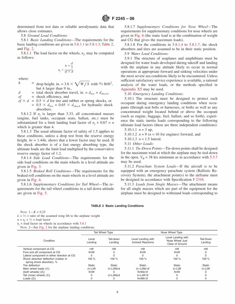
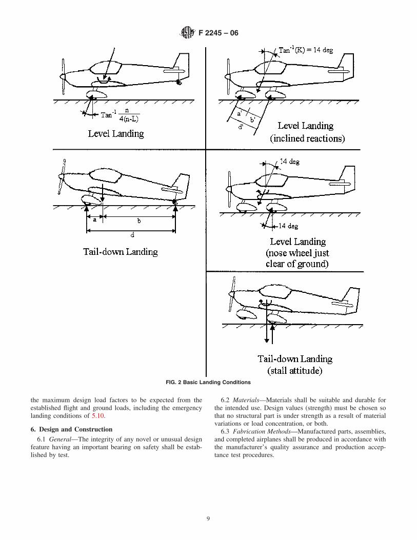
5.8 Ground Load Conditions:5.8.1 Basic Landing Conditions—The requirements for the
basic landing conditions are given in 5.8.1.1 to 5.8.1.3, Table 2,and Fig. 2.
5.8.1.1 The load factor on the wheels, nj, may be computedas follows:
nj 5
h 1d3
ef 3 d
where:h = drop height, in. = 3.6 3 =W / S with W⁄S lb/ft2,
but h larger than 9 in.,d = total shock absorber travel, in. = dtire + dshock,ef = shock efficiency, andef 3 d = 0.5 3 d for tire and rubber or spring shocks, or
= 0.5 3 dtire + 0.65 3 dshock for hydraulic shockabsorbers.
5.8.1.2 If nj is larger than 3.33, all concentrated masses(engine, fuel tanks, occupant seats, ballast, etc.) must besubstantiated for a limit landing load factor of nj + 0.67 = nwhich is greater than 4.
5.8.1.3 The usual ultimate factor of safety of 1.5 applies tothese conditions, unless a drop test from the reserve energyheight, hr = 1.44h, shows that a lower factor may be used. Ifthe shock absorber is of a fast energy absorbing type, theultimate loads are the limit load multiplied by the conservativereserve energy factor of 1.2.
5.8.1.4 Side Load Conditions—The requirements for theside load conditions on the main wheels in a level attitude aregiven in Fig. 3.
5.8.1.5 Braked Roll Conditions—The requirements for thebraked roll conditions on the main wheels in a level attitude aregiven in Fig. 4.
5.8.1.6 Supplementary Conditions for Tail Wheel—The re-quirements for the tail wheel conditions in a tail down attitudeare given in Fig. 5.
5.8.1.7 Supplementary Conditions for Nose Wheel—Therequirements for supplementary conditions for nose wheels aregiven in Fig. 6 (the static load is at the combination of weightand CG that gives the maximum loads).
5.8.1.8 For the conditions in 5.8.1.4 to 5.8.1.7, the shockabsorbers and tires are assumed to be in their static position.
5.9 Water Load Conditions:5.9.1 The structure of seaplanes and amphibians must be
designed for water loads developed during takeoff and landingwith the airplane in any attitude likely to occur in normaloperations at appropriate forward and sinking velocities underthe most severe sea conditions likely to be encountered. Unlesssufficient satisfactory service experience is available, a rationalanalysis of the water loads, or the methods specified inAppendix X5 may be used.
5.10 Emergency Landing Conditions:5.10.1 The structure must be designed to protect each
occupant during emergency landing conditions when occu-pants (through seat belts or harnesses, or both) as well as anyconcentrated weight located behind or above the occupant(such as engine, baggage, fuel, ballast, and so forth), experi-ence the static inertia loads corresponding to the followingultimate load factors (these are three independent conditions):
5.10.1.1 n = 3 up,5.10.1.2 n = 9 (n = 10 for engines) forward, and5.10.1.3 n = 1.5 lateral.5.11 Other Loads:5.11.1 Tie-Down Points—Tie-down points shall be designed
for the maximum wind at which the airplane may be tied downin the open. VR = 38 kts minimum as in accordance with 5.3.7may be used.
5.11.2 Parachute System Loads—If the aircraft is to beequipped with an emergency parachute system (Ballistic Re-covery System), the attachment point(s) to the airframe mustbe designed in accordance with Specification F 2316.
5.11.3 Loads from Single Masses—The attachment meansfor all single masses which are part of the equipment for theairplane must be designed to withstand loads corresponding to
TABLE 2 Basic Landing Conditions
NOTE 1—K = 0.25L = 2⁄3 = ratio of the assumed wing lift to the airplane weightn = nj + 2⁄3 = load factornj = load factor on wheels in accordance with 5.8.1
NOTE 2—See Fig. 2 for the airplane landing conditions.
Tail Wheel Type Nose Wheel Type
ConditionLevel
LandingTail-downLanding
Level Landing withInclined Reactions
Level Landing withNose Wheel JustClear of Ground
Tail-DownLanding
Vertical component at CG nW nW nW nW nWFore and aft component at CG KnW 0 KnW KnW 0Lateral component in either direction at CG 0 0 0 0 0Shock absorber deflection (rubber or
spring shock absorber), %100 % 100 % 100 % 100 % 100 %
Tire deflection Static Static Static Static StaticMain wheel loads (Vr) (n-L)W (n-L)Wb/d (n−L)Wa’/d’ (n-L)W (n-L)W(both wheels) (Dr) KnW 0 KnWa’/d’ KnW 0Tail (nose) wheels (Vr) 0 (n-L)Wa/d (n-L)W’/d’ 0 0Loads (Dr) 0 0 KnWb’/d’ 0 0
F 2245 – 06
8
the maximum design load factors to be expected from theestablished flight and ground loads, including the emergencylanding conditions of 5.10.
6. Design and Construction
6.1 General—The integrity of any novel or unusual designfeature having an important bearing on safety shall be estab-lished by test.
6.2 Materials—Materials shall be suitable and durable forthe intended use. Design values (strength) must be chosen sothat no structural part is under strength as a result of materialvariations or load concentration, or both.
6.3 Fabrication Methods—Manufactured parts, assemblies,and completed airplanes shall be produced in accordance withthe manufacturer’s quality assurance and production accep-tance test procedures.
FIG. 2 Basic Landing Conditions
F 2245 – 06
9

6.4 Self-Locking Nuts—No self-locking nut shall be used onany bolt subject to rotation in operation unless a nonfrictionlocking device is used in addition to the self-locking device.
6.5 Protection of Structure—Protection of the structureagainst weathering, corrosion, and wear, as well as suitableventilation and drainage, shall be provided as required.
6.6 Accessibility—Accessibility for critical structural ele-ments and control system inspection, adjustment, maintenance,and repair shall be provided.
6.7 Rigging—Unless specified otherwise, rigging and de-rigging must be able to be performed by persons having nomore than average skill. It must be possible to inspect theairplane easily for correct rigging and safe-tying.
6.8 Proof of Design—Fulfillment of the design requirementsfor the airplane shall be determined by conservative analysis,or tests, or a combination of both. Structural analysis alonemay be used for validation of the structural requirements onlyif the structure conforms to those for which experience hasshown this method to be reliable. Flight tests to limit loadfactors at maximum takeoff weight and at speeds from VA tothe maximum allowable speed for the configuration beinginvestigated are an acceptable proof (see 5.1.3 and 5.1.4).
6.9 Control System-Operation Test—It must be shown byfunctional tests that the control system installed on the airplaneis free from interference, jamming, excessive friction, andexcessive deflection when the control system design loads (see5.3) are applied to the controls and the surfaces. The controlsystem stops must withstand those loads.
6.10 Pilot Compartment:6.10.1 Pilot comfort, appropriate visibility (instruments,
placards, and outside), accessibility, ability to conduct anemergency escape, and ability to reach all controls for smoothand positive operation shall be provided.
6.10.2 Occupant seat belts, harnesses, and baggage re-straints, and their attachments to the structure shall be designedfor the maximum load factors corresponding to the specifiedground and flight conditions including the emergency landingconditions prescribed in 5.10.
7. Powerplant
7.1 Installation—The powerplant installation shall be easilyaccessible for inspection and maintenance. The powerplantattachment to the airframe is part of the structure and shallwithstand the applicable load factors.
FIG. 3 Side Load Conditions
FIG. 4 Braked Roll Conditions
F 2245 – 06
10

7.2 Engines—Installed engines shall meet Practice F 2339,LSA engine design and production standards, or shall be typeand production certified under FAR-33, JAR-E, or JAR-22Subpart H, design and production standards.
NOTE 7—Type certified engines may be subject to additional regulatorymaintenance requirements.
7.3 Fuel System:7.3.1 The unusable fuel quantity for each tank must be
established by tests and shall not be less than the quantity atwhich the first evidence of engine fuel starvation occurs undereach intended flight operation and maneuver.
7.3.2 Tanks must be protected against wear from vibrationsand their installation shall be able to withstand the applicableinertia loads.
7.3.3 Fuel tanks shall be designed, to withstand a positivepressure of 3.5 psi (8-ft (2.4-m) water column).
7.3.4 The filler must be located outside the passengercompartment and spilled fuel must be prevented from enteringor accumulating in any enclosed part of the airplane.
7.3.5 Each tank must be vented. The vent must dischargeclear of the airplane.
7.3.6 There must be at least one drain to allow safedrainage. A drainable sediment bowl located at the lowest pointin the fuel system may be used instead of the drainable sumpin the fuel tank.
7.3.7 A fuel strainer or filter accessible for cleaning andreplacement must be included in the system.
7.3.8 The fuel lines must be properly supported and pro-tected from vibrations and wear.
7.3.9 Fuel lines located in an area subject to high heat(engine compartment) must be fire resistant or protected with afire-resistant covering.
FIG. 5 Supplementary Conditions for Tail Wheel
FIG. 6 Supplementary Conditions for Nose Wheel
F 2245 – 06
11

7.3.10 There must be a fuel shutoff valve accessible to thepilot while wearing a seat belt or harness.
7.4 Oil System—If an engine is provided with an oil system,it must be:
7.4.1 Capable of supplying the engine with an adequatequantity of oil at a temperature not exceeding the maximumestablished by the engine manufacturer, and
7.4.2 The oil tank or radiator, or both, must be installed towithstand the applicable inertia loads and vibrations, and theoil breather (vent) must be resistant to blockage caused byicing. Oil foam from the breather shall not constitute a hazard.
7.5 Induction System—The engine air induction systemshall be designed to minimize the potential of carburetor icing.
7.6 Fire Prevention—The engine, if enclosed, must beisolated from the rest of the airplane by a firewall or shroud. Itmust be constructed as far as practical to prevent liquid, gas, orflames, or a combination thereof, from entering the airplane.The use of any one of the following materials shall beacceptable without further testing:
7.6.1 Stainless steel, not less than 0.018 in. thick,7.6.2 Mild steel (corrosion-protected), not less than 0.018
in. thick, or7.6.3 Alternative materials that provide protection equiva-
lent to 7.6.1 or 7.6.2.
8. Required Equipment
8.1 The aircraft shall be designed with the following mini-mum instrumentation and equipment:
8.2 Flight and Navigation Instruments:8.2.1 Airspeed indicator, and8.2.2 Altimeter.8.3 Powerplant Instruments:8.3.1 Fuel quantity indicator,8.3.2 Tachometer (RPM),8.3.3 Engine “kill” switch, and8.3.4 Engine instruments as required by the engine manu-
facturer.8.4 Miscellaneous Equipment:8.4.1 If installed, an electrical system shall include a master
switch and overload protection devices (fuses or circuit break-ers).
8.4.2 The electric wiring shall be sized according to the loadof each circuit.
8.4.3 The battery installation shall withstand all applicableinertia loads.
8.4.4 Battery containers shall be vented outside of theairplane (see 6.5).
8.5 Safety Belts and Harnesses—There must be a seat beltand harness for each occupant and adequate means to restrainthe baggage.
9. Pilot Operating Handbook
9.1 Each airplane shall include a Pilot Operating Handbook(POH). The POH shall contain at least the following sectionheadings and related information when applicable to a specificairplane and shall be listed in the order shown as follows. Allflight speeds shall be presented as calibrated airspeeds (CAS)and all specifications and limitations shall be those determinedfrom the preceding relative design criteria.
9.2 General Information:9.3 Airplane and Systems Descriptions:9.3.1 Engine,9.3.2 Propeller,9.3.3 Fuel and fuel capacity,9.3.4 Oil, and9.3.5 Operating weights and loading (occupants, baggage,
fuel, ballast).9.4 Operating Limitations:9.4.1 Stalling speeds at maximum takeoff weight (VS and
VS0),9.4.2 Flap extended speed range (VS0 to VFE),9.4.3 Maximum maneuvering speed (VA),9.4.4 Never exceed speed (VNE),9.4.5 Crosswind and wind limitations,9.4.6 Service ceiling,9.4.7 Load factors, and9.4.8 Prohibited maneuvers.9.5 Weight And Balance Information:9.5.1 Installed equipment list, and9.5.2 Center of gravity (CG) range and determination.9.6 Performance:9.6.1 Takeoff and landing distances,9.6.2 Rate of climb,9.6.3 Cruise speeds,9.6.4 RPM, and9.6.5 Fuel consumption.9.7 Emergency Procedures.9.8 Normal Procedures—The following operating proce-
dures and handling information shall be provided:9.8.1 Preflight check,9.8.2 Engine starting,9.8.3 Taxiing,9.8.4 Normal takeoff,9.8.5 Best angle of climb speed (VX),9.8.6 Best rate of climb speed (VY),9.8.7 Cruise,9.8.8 Approach,9.8.9 Normal landing,9.8.10 Short field takeoff and landing procedures, if any,9.8.11 Balked landing procedures, and9.8.12 Information on stalls, spins, and any other useful
pilot information.9.9 Aircraft Ground Handling and Servicing:9.9.1 Servicing fuel, oil, coolant, and9.9.2 Towing and tie-down instructions.9.10 Required Placards and Markings:9.10.1 Airspeed indicator range markings,9.10.2 Operating limitations on instrument panel, if appli-
cable,9.10.3 Passenger Warning: “This aircraft was manufactured
in accordance with Light Sport Aircraft airworthiness standardsand does not conform to standard category airworthinessrequirements,”
9.10.4 “NO INTENTIONAL SPINS,” if applicable, and9.10.5 Miscellaneous placards and markings.9.11 Supplementary Information:9.11.1 Familiarization flight procedures, and
F 2245 – 06
12

9.11.2 Pilot operating advisories, if any.
10. Keywords
10.1 fixed-wing aircraft; light sport airplane
ANNEXES
(Mandatory Information)
A1. ADDITIONAL REQUIREMENTS FOR LIGHT SPORT AIRPLANES USED TO TOW GLIDERS
A1.1 Applicability
A1.1.1 This annex is applicable to light sport airplanes thatare to be used to tow gliders.
A1.2 Minimum Climb Performance While Towing
A1.2.1 The aircraft must be capable of achieving a gradientof climb while towing of at least 1⁄18 , while not exceeding themaximum placarded towing speed of the towing aircraft, or themaximum safe towing speed of the aircraft being towed.
A1.2.2 The aircraft must be capable of achieving a rate ofclimb while towing of at least 150 ft/min, while not exceedingthe maximum placarded towing speed of the towing aircraft, orthe maximum safe towing speed of the aircraft being towed.
NOTE A1.1—Compliance with this section must take into account theperformance and control capabilities of both the towing aircraft and theaircraft being towed. In order to account for varying performance andcontrol capabilities on the part of the towed aircraft, the manufacturer ofthe towing aircraft may specify a maximum weight and maximum drag forthe towed aircraft at each speed for which the towing aircraft is approvedfor tow operations, such that the required climb performances can beachieved. Compliance with this section is then shown when the towedaircraft is safely controllable under tow at a speed for which its drag andweight are within these prescribed maximum weight and drag limits.
A1.3 Controllability and Maneuverability
A1.3.1 The tow aircraft shall be safely controllable andmaneuverable during all ground and flight operations appli-cable to normal towing operations, including both deliberateand inadvertent release of the glider being towed.
A1.4 Stability
A1.4.1 It shall be possible to conduct normal towing opera-tions, including both deliberate and inadvertent release of theglider being towed, without incurring any dangerous reductionin the stability of the aircraft.
A1.5 Structure and Strength Requirements
A1.5.1 Strength requirements for the aircraft structure shalltake into account the effects of loads arising from towingequipment that is installed on the aircraft in accordance withA1.6.
A1.6 Design and Construction
A1.6.1 Glider Towing Equipment Installations:A1.6.1.1 The maximum all up takeoff weight of the glider to
be towed, including pilot and all equipment, shall be selectedby the manufacturer.
A1.6.1.2 The maximum glider towing speed (VT), shall beselected by the manufacturer. The VT shall be at least 1.3VS,where VS is the computed stalling speed of the aircraft in thecruise configuration without a glider in tow.
A1.6.1.3 Tow equipment attach points on the airframe shallhave limit and ultimate factors of safety of not less than 1.0 and1.5 respectively, when loads equal to 1.2 of the nominalstrength of the weak link (see A1.6.1.5) are applied through thetowing hook installation for the following conditions, simulta-neously with the loads arising from the most critical normalaccelerations (as defined in the normally applicable require-ments for structure and strength) at the speed VT. The appli-cable conditions are as follows:
(1) The speed is assumed to be at the maximum glidertowing speed VT, and
(2) The load at the towing hook installation is assumed tobe acting in each of the following directions, relative to thelongitudinal centerline of the aircraft: horizontally backwards;backwards and upwards at 40° to the horizontal; backwardsand downwards at 20° to the horizontal; and horizontallybackwards and 25° sideways in both directions.
A1.6.1.4 The towing hook shall be of a quick release type.It shall be established by test that when the release control isoperated simultaneously with loads equal to 10 % and 180 %of the nominal strength of the weak link (see A1.6.1.5) appliedto the towing hook in each of the directions prescribed inA1.6.1.3(2): (1) the tow cable will be released; (2) the releasedcable will be unlikely to cause damage to or become entangledwith any part of the aircraft; and (3) the pilot effort requiredshall not be less than 20 N (4.5 lbf) nor greater than 100 N(22.5 lbf).
A1.6.1.5 The release control shall be located so that thepilot can operate it without having to release any other primaryflight control.
A1.6.1.6 The maximum strength of any weak link that maybe interposed in the towing cable shall be established. For thedetermination of loads to be applied for the purpose of thissection, the strength of the weak link shall not be less than 900N (202.3 lbf).
A1.7 Operating Limitations
A1.7.1 Operating limitations applicable to towing opera-tions must be established and included in the Pilot’s OperatingHandbook, to include at a minimum:
A1.7.1.1 The maximum permissible towing speed (VT).
F 2245 – 06
13

A1.7.1.2 The maximum weak link strength (may be speci-fied in terms of the weight of the glider to be towed).
A1.7.1.3 The maximum permissible all up weight of theglider to be towed.
A2. LIGHT SPORT AIRCRAFT TO BE FLOWN AT NIGHT
A2.1 Applicability
A2.1.1 This annex is applicable to light sport airplanes thatare to be flown at night.
A2.2 Flight
A2.2.1 No additional requirements for night operations.
A2.3 Structure
A2.3.1 No additional requirements for night operations.
A2.4 Design and Construction
A2.4.1 No additional requirements for night operations.
A2.5 Powerplant
A2.5.1 A powerplant that has been specifically approved fornight operations and complies with Section 7.
A2.6 Required Equipment
A2.6.1 Instrument lights as specified in A2.7.1;A2.6.2 Position lights as specified in A2.7.2;A2.6.3 An aviation red or aviation white anti-collision light
system specified in A2.7.3;A2.6.4 If the aircraft is operated for hire, one electric
landing light specified in A2.7.4;A2.6.5 An adequate source of electrical energy for all
installed electrical and radio equipment specified in A2.9.2;A2.6.6 One spare set of fuses, or three spare fuses of each
kind required, that are accessible to the pilot in flight if fusesare installed;
A2.6.7 One switch for each: position lights, anti-collisionlight system, and if installed, landing light, taxi light, and cabinlight as specified in A2.9.1; and
A2.6.8 One attitude indicator.
A2.7 Lighting Requirements
A2.7.1 Instrument Lights—The instrument lights must:A2.7.1.1 Make each instrument and control easily readable
and discernible;A2.7.1.2 Be installed so that their direct rays and rays
reflected from the windshield or other surface are shieldedfrom the pilot’s eyes;
A2.7.1.3 Have dimmer(s) capable of decreasing the inten-sity of all instrument, radio, and control lighting; and
A2.7.1.4 Have enough distance or insulating material be-tween current carrying parts and the housing so that vibrationin flight will not cause shorting.
A2.7.1.5 A cabin dome light is not an instrument light.A2.7.2 Position Lights:A2.7.2.1 General—Each part of each position light system
must meet the applicable requirements of this specification andeach system as a whole must meet the requirements ofA2.7.2.6-A2.7.2.11.
A2.7.2.2 Left and Right Position Lights—Left and rightposition lights must consist of a red and a green light spacedlaterally as far apart as practicable and installed on the airplanesuch that, with the airplane in the normal flying position, thered light is on the left side and the green light is on the rightside.
A2.7.2.3 Rear Position Light—The rear position light mustbe a white light mounted as far aft as practicable on the tail oron each wing tip.
A2.7.2.4 Light Covers and Color Filters—Each light coveror color filter must be at least flame-resistant and may notchange color or shape or lose any appreciable light transmis-sion during normal use.
A2.7.2.5 —Position light system dihedral angles.A2.7.2.6 Position Light System Dihedral Angles:
(1) Except as provided in (5) of this section, each positionlight must, as installed, show unbroken light within thedihedral angles described in this section.
(2) Dihedral angle L (left) is formed by two intersectingvertical planes, the first parallel to the longitudinal axis of theairplane, and the other at 110° to the left of the first, as viewedwhen looking forward along the longitudinal axis.
(3) Dihedral angle R (right) is formed by two intersectingvertical planes, the first parallel to the longitudinal axis of theairplane, and the other at 110° to the right of the first, as viewedwhen looking forward along the longitudinal axis.
(4) Dihedral angle A (aft) is formed by two intersectingvertical planes making angles of 70° to the right and to the left,respectively, to a vertical plane passing through the longitudi-nal axis, as viewed when looking aft along the longitudinalaxis.
(5) If the rear position light, when mounted as far aft aspracticable in accordance with Sec. 2.7.2(c), cannot showunbroken light within dihedral angle A (as defined in (4) of thissection), a solid angle or angles of obstructed visibility totalingnot more than 0.04 steradians is allowable within that dihedralangle, if such solid angle is within a cone whose apex is at therear position light and whose elements make an angle of 30°with a vertical line passing through the rear position light (seeFig. A2.1).
A2.7.2.7 Position Light Distribution and Intensities:(1) General—The intensities prescribed in this section
must be provided by new equipment with each light cover andcolor filter in place. Intensities must be determined with thelight source operating at a steady value equal to the averageluminous output of the source at the normal operating voltageof the airplane. The light distribution and intensity of eachposition light must meet the requirements of the section onposition lights.
(2) Position Lights—The light distribution and intensitiesof position lights must be expressed in terms of minimumintensities in any vertical plane, and maximum intensities in
F 2245 – 06
14

NOTE 1—On the side view drawing, draw a line through the light center perpendicular to the aircraft longitudinal axis. Draw a second line upwardthrough the light center to the most aft point on the vertical stabilizer. The angle Z between the two lines is limited by the airworthiness rules to 30°.Fig. A2.1 shows an example of angle Z.
NOTE 2—On the rear view drawing, draw angle W, which is formed by two lines drawn upward from the light center to the maximum right and leftobstructions with angle Z. When a protrusion causes a very small zone of obstruction, it may be discounted, unless total obstructions are near theregulatory limit. When a rear view drawing is not available, a combination of other drawings or measurements on the actual aircraft can be used todetermine angle W.
NOTE 3—Multiple angle Z degrees by angle W degrees to obtain the amount of obstruction in square degrees. The method is conservative, asobstructions as wide as angle W may not exist throughout angle Z. Convert the measurement to steradians by dividing the square degree value by 3284.The number 3284 is a conversion factor to obtain steradians from square degrees.
FIG. A2.1 Rear Position Light Obstructions
F 2245 – 06
15

overlapping beams, with dihedral angles L, R, and A, and mustmeet the following requirements:
(a) Intensities in the horizontal plane—Each intensity inthe horizontal plane (the plane containing the longitudinal axisof the airplane and perpendicular to the plane of symmetry ofthe airplane) must equal or exceed the values in A2.7.2.8.
(b) Intensities in any vertical plane—Each intensity in anyvertical plane (the plane perpendicular to the horizontal plane)must equal or exceed the appropriate value in A2.7.2.9, whereI is the minimum intensity prescribed in A2.7.2.8 for thecorresponding angles in the horizontal plane.
(c) Intensities in overlaps between adjacent signals—Nointensity in any overlap between adjacent signals may exceedthe values in A2.7.2.10, except that higher intensities inoverlaps may be used with main beam intensities substantiallygreater than the minima specified in A2.7.2.8 and A2.7.2.9, ifthe overlap intensities in relation to the main beam intensitiesdo not adversely affect signal clarity. When the peak intensityof the left and right position lights is more than 100 candles,the maximum overlap intensities between them may exceed thevalues in A2.7.2.10 if the overlap intensity in Area A is notmore than 10 % of peak position light intensity and the overlapintensity in Area B is not more than 2.5 % of peak positionlight intensity.
(3) Rear position light installation—A single rear positionlight may be installed in a position displaced laterally from theplane of symmetry of an airplane if: (1) the axis of themaximum cone of illumination is parallel to the flight path inlevel flight; and (2) there is no obstruction aft of the light andbetween planes 70° to the right and left of the axis of maximumillumination.
A2.7.2.8 Minimum Intensities in the Horizontal Plane ofPosition Lights—Each position light intensity must equal orexceed the applicable values in the following table:
Dihedral Angle(Light Included)
Angle from Right or Leftof Longitudinal Axis,
Meausured from Dead Ahead
Intensity(Candles)
L and R (red and green) 0° to 10°-----------------------------10° to 20°-----------------------------
4030
20° to 110°----------------------------- 5A (rear white)--------------- 110° to 180°----------------------------- 20
A2.7.2.9 Minimum Intensities in any Vertical Plane ofPosition Lights— Each position light intensity must equal orexceed the applicable values in the following table:
Angle above or below the horizontal plane Intensity0°------------------------------------------------------ 1.00 I.
0° to 5°------------------------------------------------- 0.90 I.5° to 10°-------------------------------------------------- 0.80 I.10° to 15°------------------------------------------------- 0.70 I.15° to 20°------------------------------------------------- 0.50 I.20° to 30°------------------------------------------------- 0.30 I.30° to 40°-------------------------------------------------- 0.10 I.40° to 90°-------------------------------------------------- 0.05 I.
A2.7.2.10 Maximum Intensities in Overlapping Beams ofPosition Lights—No position light intensity may exceed theapplicable values in the following table, except as provided inA2.7.2.7 (2)(c):
OverlapsMaximum IntensityArea A(candles)
Area B(candles)
Green in dihedral angle L---------------------------------- 10 1Red in dihedral angle R------------------------------------- 10 1Green in dihedral angle A---------------------------------- 5 1Red in dihedral angle A------------------------------------- 5 1Rear white in dihedral angle L----------------------------- 5 1Rear white in dihedral angle R----------------------------- 5 1
where:Area A = all directions in the adjacent dihedral angle that
pass through the light source and intersect thecommon boundary plant at more than 10° butless than 20°, and
Area B = all directions in the adjacent dihedral angle thatpass through the light source and intersect thecommon boundary plane at more than 20°.
A2.7.2.11 Color Specifications—Each position light colormust have the applicable International Commission on Illumi-nation chromaticity coordinates as follows:
(1) Aviation Red—y is not greater than 0.335; and z is notgreater than 0.002.
(2) Aviation Green—x is not greater than 0.440 – 0.320 y;x is not greater than y – 0.170; and y is not less than 0.390 –0.170 x.
(3) Aviation White—x is not less than 0.300 and not greaterthan 0.540; y is not less than 9x – 0.0409 or 9y0 – 0.0109,whichever is the smaller; and y is not greater than 9x + 0.0209
nor 90.636 – 0.400x9; where y0 is the y coordinate of thePlanckian radiator for the value of x considered.
A2.7.3 Anticollision Light System:A2.7.3.1 General—The airplane must have an anti-collision
light system that: (1) consists of one or more anti-collisionlights located so that their light will not impair the flightcrewmembers’ vision or detract from the conspicuity of theposition lights; and (2) meets the requirements of A2.7.3.2through A2.7.3.6.
A2.7.3.2 Field of Coverage—The system must consist ofenough lights to illuminate the vital areas around the airplane,considering the physical configuration and flight characteristicsof the airplane. The field of coverage must extend in eachdirection within at least 75° above and 75° below the horizon-tal plane of the airplane, except that there may be solid anglesof obstructed visibility totaling not more than 0.5 steradians.
A2.7.3.3 Flashing Characteristics—The arrangement of thesystem, that is, the number of light sources, beam width, speedof rotation, and other characteristics, must give an effectiveflash frequency of not less than 40, nor more than 100, cyclesper minute. The effective flash frequency is the frequency atwhich the airplane’s complete anti-collision light system isobserved from a distance, and applies to each sector of light,
F 2245 – 06
16

including any overlaps that exist when the system consists ofmore than one light source. In overlaps, flash frequencies mayexceed 100, but not 180, cycles per minute.
A2.7.3.4 Color—Each anti-collision light must be eitheraviation red or aviation white and must meet the applicablerequirements of A2.7.2.11.
A2.7.3.5 Light Intensity—The minimum light intensities inany vertical plane, measured with the red filter (if used) andexpressed in terms of 9effective9 intensities, must meet therequirements of A2.7.3.6. The following relation must beassumed:
Ie 5*t1
t2I~t! dt
0.2 1 ~t2 – t1!(A2.1)
where:Ie = effective intensity (candles),I(t) = instantaneous intensity as a function of time, andt2 – t1 = flash time interval.
Normally, the maximum value of effective intensity isobtained when t2 and t1 are chosen so that the effectiveintensity is equal to the instantaneous intensity at t2 and t1.
A2.7.3.6 Minimum Effective Intensities for Anti-collisionLights—Each anti-collision light effective intensity must equalor exceed the applicable values in the following table.
Angle above or belowthe horizontal plane
Effective intensity(candles)
0° to 5°----------------------------- 4005° to 10°----------------------------- 24010° to 20°----------------------------- 8020° to 30°----------------------------- 4030° to 75°----------------------------- 20
A2.7.4 Taxi and Landing Lights— Each taxi and landinglight must be designed and installed so that:
A2.7.4.1 No dangerous glare is visible to the pilots,A2.7.4.2 The pilot is not seriously affected by halation,A2.7.4.3 It provides enough light for night operations, andA2.7.4.4 It does not cause a fire hazard in any configuration.
A2.8 Avionics—Must be illuminated in accordance withA2.7.1.
A2.9 Electrical Requirements
A2.9.1 Switches—Each switch must be:A2.9.1.1 Rated by the switch manufacturer to carry its
circuit’s current;A2.9.1.2 For circuits containing incandescent lamps, have a
minimum in-rush rating of 15 times the lamp’s continuouscurrent;
A2.9.1.3 Constructed with enough distance or insulatingmaterial between current carrying parts and the housing so thatvibration in flight will not cause shorting;
A2.9.1.4 Accessible to the pilot;A2.9.1.5 Labeled as to operation and the circuit controlled;
andA2.9.1.6 Illuminated in accordance with A2.7.1.A2.9.2 Circuit Protection Requirements—Circuit overload
protection (fuses or circuit breakers) must:A2.9.2.1 Be installed on each circuit containing wiring,
equipment, or other components rated for less than the maxi-mum output of the battery and alternator or generator;
A2.9.2.2 Be appropriately rated for each component in-stalled on the protected circuit;
A2.9.2.3 Be accessible to and in clear view of the pilot;A2.9.2.4 Open before the conductor emits smoke; andA2.9.2.5 Automatic re-set circuit breakers may not be used.A2.9.3 Electrical Energy Requirements—The total continu-
ous electrical load may not exceed 80 % of the total ratedgenerator or alternator output capacity.
A2.9.4 Conductor Requirements—Any wire or other mate-rial intended to conduct electricity must be:
A2.9.4.1 Rated to carry its circuits current;A2.9.4.2 For wiring rated to 150°C, 600 V minimum;A2.9.4.3 Constructed with enough distance or insulating
material between current carrying conductors so that vibrationin flight will not cause shorting; and
A2.9.4.4 Where used, insulating material must have, at aminimum, the equivalent or better properties of either PTFE-polytetrafluoroethylene (commonly known by the trade name,TEFLON) or ETFE-(Frequently referred to by the trade name,TEFZEL) a copolymer of PTFE and of polyethylene including:
(1) Temperature,(2) Abrasion resistance,(3) Cut-through resistance,(4) Chemical resistance,(5) Flammability,(6) Smoke generation,(7) Flexibility,(8) Creep (at temperature), and(9) Arc propagation resistance.
A2.10 Operating Instructions (AOI)
A2.10.1 Electrical system description must be included fornight.
A2.11 Learning Documents
A2.11.1 FAA AC 20-30B —Aircraft position light and anti-collision light instillations.
A2.11.2 A2.10.2 FAA AC 65-15A Chapter 11—AircraftElectrical Systems.
F 2245 – 06
17

APPENDIXES
(Nonmandatory Information)
X1. SIMPLIFIED DESIGN LOAD CRITERIA FOR LIGHT SPORT AIRPLANES
X1.1 Abbreviations
n1 = airplane positive maneuvering limit load factorn2 = airplane negative maneuvering limit load factorn3 = airplane positive gust limit load factor at VCn4 = airplane negative gust limit load factor at VCnflap = airplane positive limit load factor with flaps fully
extended at VFVF min = minimum design flap speed = 11.0 · =n1W/S
knotsVA min = minimum design maneuvering speed = 15.0 ·
=n1W/S knots but need not exceed VC used indesign
VC min = minimum design cruising speed = 17.0 ·=n1W/S knots but need not exceed 0.9 · VH
VD min = minimum design dive speed = 24.0 · =n1W/Sknots but need not exceed 1.4 · =n1/3.8 · VC min(see X1.2.5.2)
X1.2 Flight Loads
X1.2.1 Each flight load may be considered independent ofaltitude and, except for the local supporting structure for deadweight items, only the maximum design weight conditionsmust be investigated.
X1.2.2 Table X1.1 must be used to determine values of n1,n2, n3, and n4, corresponding to the maximum design weights.
X1.2.3 Figs. X1.2 and X1.3 must be used to determinevalues of n3 and n4, corresponding to the minimum flyingweights, and, if these load factors are greater than the loadfactors at the design weight, the supporting structure for deadweight items must be substantiated for the resulting higher loadfactors.
X1.2.4 Each specified wing and tail loading is independentof the center of gravity range. The applicant, however, mustselect a CG range, and the basic fuselage structure must beinvestigated for the most adverse dead weight loading condi-tions for the CG range selected.
X1.2.5 The following loads and loading conditions are theminimums for which strength must be provided in the struc-ture:
X1.2.5.1 Airplane Equilibrium—The aerodynamic wingloads may be considered to act normal to the relative wind andto have a magnitude of 1.05 times the airplane normal loads (as
determined from X1.3.2 and X1.3.3) for the positive flightconditions and magnitude equal to the airplane normal loadsfor the negative conditions. Each chord-wise and normalcomponent of this wing load must be considered.
X1.2.5.2 Minimum Design Airspeeds—The minimum de-sign airspeeds may be chosen by the applicant except that theymay not be less than the minimum speeds found in X1.1. Inaddition, VC min need not exceed values of 0.9 VH actuallyobtained at sea level for the lowest design weight category forwhich certification is desired. In computing these minimumdesign airspeeds, n1 may not be less than 4.0.
X1.2.5.3 Flight Load Factor—The limit flight load factorsspecified in Table X1.1 represent the ratio of the aerodynamicforce component (acting normal to the assumed longitudinalaxis of the airplane) to the weight of the airplane. A positiveflight load factor is an aerodynamic force acting upward, withrespect to the airplane.
X1.3 Flight Conditions
X1.3.1 General—Each design condition in X1.3.2-X1.3.4must be used to assure sufficient strength for each condition ofspeed and load factor on or within the boundary of a flightenvelope diagram for the airplane similar to the diagram in Fig.X1.1. This diagram must also be used to determine the airplanestructural operating limitations.
X1.3.2 Symmetrical Flight Conditions—The airplane mustbe designed for symmetrical flight conditions as follows:
X1.3.2.1 The airplane must be designed for at least the fourbasic flight conditions, “A,” “D,” “E,” and “G” as noted on theflight envelope of Fig. X1.1. In addition, the following require-ments apply:
(1) The design limit flight load factors corresponding toConditions “D” and “E” of Fig. X1.1 must be at least as greatas those specified in Table X1.1, and the design speed for theseconditions must be at least equal to the value of VD min fromX1.1.
(2) For conditions “A” and “G” of Fig. X1.1, the loadfactors must correspond to those specified in Table X1.1, andthe design speeds must be computed using these load factorswith the maximum static lift coefficient CNA determined by theapplicant. However, in the absence of more precise computa-tions, these latter conditions may be based on a value of CNA =61.35 and the design speed for Condition “A” may be lessthan VA min.
(3) Conditions “C” and “F” of Fig. X1.1 need only beinvestigated when n3W/S or n4W/S of Appendix X1, is greaterthan n1W/S and n2W/S, respectively.
X1.3.2.2 If the flaps or other high-lift devices intended foruse at the relatively low airspeed of approach, landing, andtakeoff are installed, the airplane must be designed for the twoflight conditions corresponding to the values of limit flap-down
TABLE X1.1 Minimum Design Limit Flight Load Factors
Flaps Up n1= 4.0n2= -0.5n1
n3 from Fig. X1.2n4 from Fig. X1.3
Flaps Down nf = 0.5n1
nf = 0A
A Vertical wing load may be assumed equal to zero and only the flap part of thewing need be checked for this condition.
F 2245 – 06
18

factors specified in Table X1.1 with the flaps fully extended atnot less than the design flap speed VF min from X1.1.
X1.3.3 Unsymmetrical Flight Conditions—Each affectedstructure must be designed for unsymmetrical loadings asfollows:
X1.3.3.1 The aft fuselage-to-wing attachment must be de-signed for the critical vertical surface load determined inaccordance with X1.4.3.
X1.3.3.2 The wing and wing carry-through structures mustbe designed for 100 % of Condition “A” loading on one side ofthe airplanes plane of symmetry and 70 % on the opposite side.
X1.3.3.3 The wing and wing carry-through structures mustbe designed for the loads resulting from a combination 75 % ofthe positive maneuvering wing loading on both sides of the
plane of symmetry and the maximum wing torsion resultingfrom aileron displacement. The effect of aileron displacementon wing torsion at VC or VA using the basic airfoil momentcoefficient modified over the aileron portion of the span, mustbe computed as follows:
(1) Cm = Cm + 0.01 du (up aileron side) wing basic airfoil(2) Cm = Cm – 0.01 dd (down aileron side) wing basic
airfoil, where du is the up aileron deflection and dd is the downaileron deflection.
X1.3.3.4 Dcritical, which is the sum of du + dd must becomputed as follows:
(1) Compute Da and Db from the formulas:
Da 5 VA/VC 3 Dp, and (X1.1)
FIG. X1.1 Generalized Flight Envelope
FIG. X1.2 Chart for Finding n3 Factor at Speed Vc
F 2245 – 06
19

Db 5 0.5 3 VA/VD 3 Dp
where:Dp = maximum total deflection (sum of both aileron de-
flections) at VA with VA, VC, and VD described inX1.2.5.2
(2) Compute K from the formula:
K 5~Cm – 0.01db!VD
2
~Cm – 0.01da!VC2 (X1.2)
where:da = down aileron deflection corresponding to Da, anddb = down aileron deflection corresponding to Db as com-
puted in X1.3.3.4(1).(3) If K is less than 1.0, Da is Dcritical and must be used to
determine du and dd. In this case, VC is the critical speed thatmust be used in computing the wing torsion loads over theaileron span.
(4) If K is equal to or greater than 1.0, Db is Dcritical andmust be used to determine du and dd. In this case, VD is thecritical speed that must be used in computing the wing torsionloads over the aileron span.
X1.3.4 Supplementary Conditions; Rear Lift Truss; EngineTorque; Side Load on Engine Mount—Each of the followingsupplementary conditions must be investigated:
X1.3.4.1 In designing the rear lift truss, the followingspecial condition may be investigated instead of Condition “G”of Fig. X1.1. The rear lift truss must be designed for conditionsof reversed airflow at a design speed of V = 39 knots. Eitheraerodynamic data for a particular wing section used, or a value
of CL equaling -0.8 with a chord-wise distribution that istriangular between a peak at the trailing edge and zero at theleading edge, must be used.
X1.3.4.2 Each engine mount and its supporting structuresmust be designed for the maximum limit torque correspondingto maximum expected takeoff power and propeller speed actingsimultaneously with the limit loads resulting from the maxi-mum positive maneuvering flight load factory n1. The limittorque must be obtained from 5.2.9.
X1.3.4.3 Each engine mount and its supporting structuremust be designed for the loads resulting from a lateral limitload factor of not less than 1.47.
X1.4 Control Surface Loads
X1.4.1 General—Each control surface load must be deter-mined using the criteria of X1.4.2 and must lie within thesimplified loadings of X1.4.3.
X1.4.2 Limit Pilot Forces—In each control surface loadingcondition described in X1.4.3, the air loads on the movablesurfaces and the corresponding deflections need not exceedthose which could be obtained in flight by using the maximumlimit pilot forces specified in 5.3.3.
X1.4.3 Surface Loading Conditions—Each surface loadingcondition must be investigated as follows: Simplified limitsurface loadings and distributions for the horizontal tail,vertical tail, aileron, wing flaps, and trim tabs are specified inTable X1.2, and Figs. X1.4 and X1.5. If more than onedistribution is given, each distribution must be investigated.
FIG. X1.3 Chart for Finding n4 Factor at Speed Vc
F 2245 – 06
20

X1.5 Control System Loads
X1.5.1 Primary Flight Controls and Systems—Each pri-mary flight control and system must be designed as follows:
X1.5.1.1 The flight control system and its supporting struc-ture must be designed for loads corresponding to 125 % of thecomputed hinge moments of the movable control surface in theconditions prescribed in X1.4. In addition, the system limit
loads need not exceed those that could be produced by the pilotand automatic devices operating the controls, and the designmust provide a rugged system for service use, includingjamming, ground gusts, taxiing downwind, control inertia, andfriction.
X1.5.2 Dual controls must meet 5.3.3 and 5.3.4.X1.5.3 Ground gust condition must meet 5.3.7.
TABLE X1.2 Average Limit Control Surface Loading
Surface Direction of Loading Magnitude of Loading Chord-wise Distribution
I. Horizontal tail a) up and down Fig. X1.4Curve (2)
b) unsymmetrical loading(up and down)
100 % w on oneside airplane65 % w on otherside airplane
II. Vertical tail a) right and left Fig. X1.4Curve (1)
same as (A)
b) right and left Fig. X1.4Curve (1)
same as (B)
III. Aileron a) up and down Fig. X1.5Curve (5)
IV. Wing flap a) up Fig. X1.5Curve (4)
b) down 0.25 3 Up Load
V. Trim tab a) up and down Fig. X1.5Curve (3)
same as (D)
FIG. X1.4 Average Limit Control Surface Loading
F 2245 – 06
21

X2. ACCEPTABLE METHODS OF WING AND FUSELAGE LOAD CALCULATIONS
NOTE X2.1—These may not include all of the loads that are imposed onthe wing or fuselage.
X2.1 Symmetrical Wing Loads
X2.1.1 As a minimum, the following four conditions needinvestigation:
Point A normal load up = 4 3 Wtangential forward = W
Point D normal load up = 4 3 Wtangential rearward = W/5
Point G normal down = 2 3 Wtangential forward = 2 3 W/5 = 0.4 3 Wwith flaps extended:
Point F normal up = 2 3 Wtangential forward = W
X2.2 Instead of the above simplification, a more rationalanalysis using the following lift and drag components in Fig.X2.1 may be used:
X2.3 Unsymmetrical Wing Loads
X2.3.1 Shear, Wing Carry Through—Assume 100 % ofPoint A on one wing and apply 75 % of Point A on the otherwing.
X2.3.2 Torsion, Wing—Assume 75 % of Point A or D oneach wing and add the torsional loads because of the ailerondeflection as shown in Fig. X2.2):
X2.3.3 Torsion, Wing—Assume 75 % of Point D on eachwing and add the torsion loads as a result of 1⁄3 of the ailerondeflection.
X2.3.4 If the landing gear is attached to the wing, the wingstructure shall be justified for the ground loads as well.
X2.4 Rear Fuselage Loads—The rear fuselage shall besubstantiated for:
X2.4.1 The symmetrical horizontal tail load of 5.4.2 and5.4.3,
X2.4.2 The vertical tail loads of 5.5.1 and 5.5.2, and
X2.4.3 The tail wheel loads if applicable.
X2.5 Forward Fuselage Loads—The forward fuselage shallbe substantiated for each of the following conditions:
X2.5.1 Inertia forces of n = 4 and n = −2 (or for n3 and n4
if they are larger than 4 and −2) (see also 5.8 if nj is larger than3.33), and
X2.5.2 Engine limit torque (lb 3 in.) equal to the valuesspecified in 5.2.9.
FIG. X1.5 Average Limit Control Surface Loading
F 2245 – 06
22

X3. ACCEPTABLE MEANS OF GUST LOAD FACTOR CALCULATIONS
X3.1 In the absence of a more rational analysis, the gustload factors may be computed as follows:
n 5 1 1Kg · Ude · V · a
498 · ~W/S!(X3.1)
where:Kg = 0.88 · µg / 5.3 1 µg = gust alleviation factor,µg = 2 · ~W/S! / r · C
–· a · g = airplane mass ratio,
Ude = derived gust velocities referred to in 5.2.3.3, ft/s,r = density of air, slugs/ft3,W/S = wing loading, lb/ft2,C = mean geometric chord of wing, ft,
g = acceleration of gravity, ft/s2,V = airplane equivalent airspeed (or CAS for LSA),
knots, anda = slope of the airplane normal force coefficient curve,
CNA per radian.
X3.2 The wing lift curve slope, CL per radian, may be usedwhen the gust load applied to the wing only and the horizontaltail gust loads are treated as separate condition. The value of ncalculated from the preceding expression need not exceed:
n 5 1.25 · S VVS1
D2
(X3.2)
NOTE 1—Both components (normal and tangential) must be considered simultaneously.NOTE 2—The aerodynamic loads shall be considered to be located at the aerodynamic center.NOTE 3—The wing normal and tangential loads are balanced by the inertia loads at the corresponding load factors.NOTE 4—If wing flaps are installed, the resulting loads shall also be investigated at Point F (symmetrical load condition).
FIG. X2.1 Normal and Tangential Loads
FIG. X2.2 Unsymmetrical Wing Loads
F 2245 – 06
23

X4. ACCEPTABLE MEANS FOR CALCULATING GUST LOADS ON STABILIZING SURFACES
X4.1 In the absence of a more rational analysis, thehorizontal stabilizing surfaces gust loads may be computed asfollows:
DLHT 5Kg · Ude · V · aHT · SHT
498 S1 2de
daD (X4.1)
where:DLHT = incremental horizontal surface load, lb,Kg = gust alleviation factor; same value used in
5.2.6,Ude = derived gust velocity, ft/s,V = airplane airspeed (CAS for LSA), knots,aHT = slope of horizontal surface lift curve, per ra-
dian,SHT = area of horizontal surface, ft2, and(1−de⁄da) = downwash factor.
X4.2 In the absence of a more rational analysis, the verticalstabilizing surfaces gust loads may be computed as follows:
LVT 5Kgt · Ude · V · aVT · SVT
498 (X4.2)
Kgt 5.88 · µgt
5.3 1 µgt(X4.3)
µgt 52 · W
r · CVT · g · aVT · SVT
· S KlVTD2
(X4.4)
where:LVT = incremental vertical surface load, lb,Kgt = gust alleviation factor,µgt = lateral mass ratio,Ude = derived gust velocity, ft/s,r = density of air, slugs/ft3,V = airplane equivalent airspeed (CAS may be used for
LSA), knots,aVT = slope of vertical surface lift curve, per radian,SVT = area of vertical surface, ft2,Cvt = mean geometric chord of vertical surface, ft2,K = Radius of gyration in yaw, ft,lvt = distance from airplane c.g. to lift center of vertical
surface, ft, andg = acceleration due to gravity, ft/s2.
X5. ACCEPTABLE MEANS FOR CALCULATION OF WATER LOADS
NOTE X5.1—In the absence of a more rational analysis, the water loadsmay be calculated as follows:
X5.1 Water Load Conditions
X5.1.1 The structure of seaplanes and amphibians must bedesigned for water loads developed during takeoff and landingwith the seaplane in any attitude likely to occur in normaloperation at appropriate forward and sinking velocities underthe most severe sea conditions likely to be encountered.
X5.1.2 In the absence of a more rational analysis of thewater loads, X5.2 through X5.9 apply.
X5.2 Design Weights and Center of Gravity Positions
X5.2.1 Design Weights—The water load requirements mustbe met at each operating weight up to the design landingweight except that, for the takeoff condition prescribed in X5.6,the design water takeoff weight (the maximum weight forwater taxi and takeoff run) must be used.
X5.2.2 Center of Gravity Positions—The critical centers ofgravity within the limits for which certification is requestedmust be considered to reach maximum design loads for eachpart of the seaplane structure.
X5.3 Application of Loads
X5.3.1 Unless otherwise prescribed, the seaplane as a wholeis assumed to be subjected to the loads corresponding to theload factors specified in X5.4.
X5.3.2 In applying the loads resulting from the load factorsprescribed in X5.4, the loads may be distributed over the hull
or main float bottom (in order to avoid excessive local shearloads and bending moments at the location of water loadapplication) using pressures not less than those prescribed inX5.7.3.
X5.3.3 For twin float seaplanes, each float must be treatedas an equivalent hull on a fictitious seaplane with a weightequal to one half the weight of the twin float seaplane.
X5.3.4 Except in the takeoff condition of X5.6, the aerody-namic lift on the seaplane during the impact is assumed to betwo thirds of the weight of the seaplane.
X5.4 Hull and Main Float Load Factors
X5.4.1 Water reaction load factors nw must be computed inthe following manner:
X5.4.1.1 For the step landing case:
nw 5C1Vs0
2
Stan23bD W
13
(X5.1)
X5.4.1.2 For the bow and stern landing cases:
nw 5C1Vs0
2
Stan23bD W
13
3K1
~1 1 rx2!
23
(X5.2)
X5.4.2 The following values are used:
nw = water reaction load factor (that is, the water reactiondivided by seaplane weight),
F 2245 – 06
24

C1 = empirical seaplane operations factor equal to 0.012(except that this factor may not be less than thatnecessary to obtain the minimum value of step loadfactor of 2.33),
Vs0 = seaplane stalling speed in knots with flaps extendedin the appropriate landing position and with noslipstream effect,
b = angle of dead rise at the longitudinal station at whichthe load factor is being determined in accordancewith Fig. X1.1,
W = seaplane design landing weight in pounds,K1 = empirical hull station weighing factor, in accordance
with Fig. X1.2, andrx = ratio of distance, measured parallel to hull reference
axis, from the center of gravity of the seaplane to thehull longitudinal station at which the load factor isbeing computed to the radius of gyration in pitch ofthe seaplane, the hull reference axis being a straightline, in the plane of symmetry, tangential to the keelat the main step.
X5.4.3 For a twin float seaplane, because of the effect offlexibility of the attachment of the floats to the seaplane, thefactor K1 may be reduced at the bow and stern to 0.8 of thevalue shown in Fig. X1.2. This reduction applies only to thedesign of the carry-through and seaplane structure.
X5.5 Hull and Main Float Landing Conditions
X5.5.1 Symmetrical Step, Bow, and Stern Landing—Forsymmetrical step, bow, and stern landings, the limit waterreaction load factors are those computed in X5.4.
X5.5.1.1 For symmetrical step landings, the resultant waterload must be applied at the keel, through the center of gravity,and must be directed perpendicularly to the keel line;
X5.5.1.2 For symmetrical bow landings, the resultant waterload must be applied at the keel, one-fifth of the longitudinaldistance from the bow to the step, and must be directedperpendicularly to the keel line; and
X5.5.1.3 For symmetrical stern landings, the resultant waterload must be applied at the keel, at a point 85 percent of thelongitudinal distance from the step to the stern post, and mustbe directed perpendicularly to the keel line.
X5.5.2 Unsymmetrical Landing for Hull and Single FloatSeaplanes—Unsymmetrical step, bow, and stern landing con-ditions must be investigated.
X5.5.2.1 The loading for each condition consists of anupward component and a side component equal, respectively,to 0.75 and 0.25 tan b times the resultant load in thecorresponding symmetrical landing condition; and
X5.5.2.2 The point of application and direction of theupward component of the load is the same as that in thesymmetrical condition, and the point of application of the sidecomponent is at the same longitudinal station as the upwardcomponent but is directed inward perpendicularly to the planeof symmetry at a point midway between the keel and the chinelines.
X5.5.3 Unsymmetrical Landing; Twin Float Seaplanes—The unsymmetrical loading consists of an upward load at thestep of each float of 0.75 and a side load of 0.25 tan b at onefloat times the step landing load in X5.4. The side load is
directed inboard, perpendicularly to the plane of symmetrymidway between the keel and chine lines of the float, at thesame longitudinal station as the upward load.
X5.6 Hull and Main Float Takeoff Condition
X5.6.1 For the wing and its attachment to the hull or mainfloat:
X5.6.1.1 The aerodynamic wing lift is assumed to be zero;and
X5.6.1.2 A downward inertia load, corresponding to a loadfactor computed from the following formula, must be applied:
n 5CTOVs1
2
Stan23bD W
13
(X5.3)
where:n = inertia load factor,CTO = empirical seaplane operations factor equal to 0.004,Vs1 = seaplane stalling speed (knots) at the design takeoff
weight with the flaps extended in the appropriatetakeoff position,
b = angle of dead rise at the main step (degrees), andW = design water takeoff weight in pounds.
X5.7 Hull and Main Float Bottom Pressures
X5.7.1 General—The hull and main float structure, includ-ing frames and bulkheads, stringers, and bottom plating, mustbe designed under this section.
X5.7.2 Local Pressures—For the design of the bottomplating and stringers and their attachments to the supportingstructure, the following pressure distributions must be applied:
X5.7.2.1 For an unflared bottom, the pressure at the chine is0.75 times the pressure at the keel, and the pressures betweenthe keel and chine vary linearly, in accordance with Fig. X5.3.The pressure at the keel (psi) is computed as follows:
Pk 5C2K2Vs1
2
tan bk(X5.4)
where:Pk = pressure at the keel, psi,C2 = 0.00213,K2 = hull station weighing factor, in accordance with Fig.
X5.2,Vs1 = seaplane stalling speed (knots) at the design water
takeoff weight with flaps extended in the appropriatetakeoff position, and
bk = angle of dead rise at keel, in accordance with Fig.X5.1.
X5.7.2.2 For a flared bottom, the pressure at the beginningof the flare is the same as that for an unflared bottom, and thepressure between the chine and the beginning of the flare varieslinearly, in accordance with Fig. X5.3. The pressure distribu-tion is the same at that prescribed in X5.7.2.1 for an unflaredbottom except that the pressure at the chine is computed asfollows:
Pch 5C3K2Vs1
2
tan b(X5.5)
F 2245 – 06
25

FIG. X5.1 Pictorial Definition of Angles, Dimensions, and Directions on a Seaplane
FIG. X5.2 Hull Station Weighing Factor
F 2245 – 06
26

where:Pch = pressure at the chine, psi,C3 = 0.0016,K2 = hull station weighing factor, in accordance with Fig.
X5.2,Vs1 = seaplane stalling speed (knots) at the design water
takeoff weight with flaps extended in the appropriatetakeoff position, and
b = angle of dead rise at appropriate station.
NOTE X5.2—The area over which these pressures are applied mustsimulate pressures occurring during high localized impacts on the hull orfloat, but need not extend over an area that would induce critical stressesin the frames or in the overall structure.
X5.7.3 Distributed Pressures—For the design of the frames,keel, and chine structure, the following pressure distributionsapply:
X5.7.3.1 Symmetrical pressures as computed as follows:
P 5C4K2Vs0
2
tan b(X5.6)
where:P = pressure, psi,C4 = 0.078 C1(with C1 computed in X5.4),K2 = hull station weighing factor, determined in accor-
dance with Fig. X5.2,Vs0 = seaplane stalling speed (knots) with landing flaps
extended in the appropriate position and with noslipstream effect, and
b = angle of dead rise at appropriate station.
X5.7.3.2 The unsymmetrical pressure distribution consistsof the pressures prescribed in X5.7.3.1 on one side of the hullor main float centerline and one-half of that pressure on theother side of the hull or main float centerline in accordancewith Fig. X5.3.
X5.7.3.3 These pressures are uniform and must be appliedsimultaneously over the entire hull or main float bottom. Theloads obtained must be carried into the sidewall structure of thehull proper, but need not be transmitted in a fore and aftdirection as shear and bending loads.
X5.8 Auxiliary Float Loads
X5.8.1 General—Auxiliary floats and their attachments andsupporting structures must be designed for the conditionsprescribed in this section. In the cases specified in X5.8.2through X5.8.5, the prescribed water loads may be distributedover the float bottom to avoid excessive local loads, usingbottom pressures not less than those prescribed in X5.8.7.
X5.8.2 Step Loading—The resultant water load must beapplied in the plane of symmetry of the float at a pointthree-fourths of the distance from the bow to the step and mustbe perpendicular to the keel. The resultant limit load iscomputed as follows, except that the value of L need notexceed three times the weight of the displaced water when thefloat is completely submerged:
L 5C5Vs0
2W2
3
tan23b3 ~1 1 ry
2!2
3
(X5.7)
FIG. X5.3 Transverse Pressure Distributions
F 2245 – 06
27

where:L = limit load, lb,C5 = 0.0053,Vs0 = seaplane stalling speed (knots) with landing flaps
extended in the appropriate position and with noslipstream effect,
W = seaplane design landing weight, lbs,b3 = angle of dead rise at a station three-fourths of the
distance from the bow to the step, but need not beless than 15°; and
ry = ratio of the lateral distance between the center ofgravity and the plane of symmetry of the float to theradius of gyration in roll.
X5.8.3 Bow Loading—The resultant limit load must beapplied in the plane of symmetry of the float at a pointone-fourth of the distance from the bow to the step and must beperpendicular to the tangent to the keel line at that point. Themagnitude of the resultant load is that specified in X5.8.2.
X5.8.4 Unsymmetrical Step Loading—The resultant waterload consists of a component equal to 0.75 times the loadspecified in X5.8.1 and a side component equal to 0.25 tan b
times the load specified in X5.8.2. The side load must beapplied perpendicularly to the plane of symmetry of the float ata point midway between the keel and the chine.
X5.8.5 Unsymmetrical Bow Loading—The resultant waterload consists of a component equal to 0.75 times the loadspecified in X5.8.2 and a side component equal to 0.25 tan b
times the load specified in X5.8.3. The side load must beapplied perpendicularly to the plane of symmetry at a pointmidway between the keel and the chine.
X5.8.6 Immersed Float Condition—The resultant load mustbe applied at the centroid of the cross section of the float at apoint one-third of the distance from the bow to the step. Thelimit load components are as follows:
vertical 5 rgV (X5.8)
aft 5CxrV
2
3 ~KVs0!2
2
side 5CyrV
2
3 ~KVs0!2
2
where:r = mass density of water, slugs/ft3,V = volume of float, ft3,Cx = coefficient of drag force, equal to 0.133,Cy = coefficient of side force, equal to 0.106,K = 0.8, except that lower values may be used if it is
shown that the floats are incapable of submerging ata speed of 0.8Vs0 in normal operations,
Vs0 = seaplane stalling speed (knots) with landing flapsextended in the appropriate position and with noslipstream effect, and
g = acceleration due to gravity, ft/s2.X5.8.7 Float Bottom Pressures—The float bottom pressures
must be established in X5.7, except that the value of K2 in theformulae may be taken as 1.0. The angle of dead rise to be usedin determining the float bottom pressures is set forth in X5.8.2.
X5.9 Seawing Loads—Seawing design loads must be basedon applicable test data.
X6. IMPERIAL AND METRIC UNITS
X6.1 : Only those units relevant to this specification arelisted as follows, with a conversion accuracy adequate for theintended use.Length 1 ft = 12 in. = 0.305 m
1 in. = 2.54 cm1 m = 100 cm = 1000 mm = 39.37 in. = 3.28 ft
Surface 1 ft2 = 0.093 m2
1 m2 = 10.76 ft2
Volume 1 U.S. gal = 3.78 L1 L = 0.264 U.S. gal(1 British gal = 1.2 U.S. gal = 4.5 L)
Weight 1 lb = 0.454 kg1 kg = 2.205 lb
Pressure 1 PSF = 4.88 kg/m2
1 kg/m2 = 0.205 PSF1 psi = 2.3-ft water column = 0.000 703 kg/m2
1 ksi = 1000 psi = 0.703 kg/m2
1 kg/mm2 = 1.43 ksi = 1430 psiDynamic pressure in standardatmosphere, at sea level
q = V2/391 in lb/ft2 when V in mph
q = (V/14.4)2 in kg/m2 when V in km/hSpeeds 1 mph = 1.61 km/h
1 knot = 1.15 mph = 1.85 km/h1 km/h = 0.62 mph = 0.54 knots1 fpm = 0.005 08 m/s (rate of climb)1 m/s = 197 FPM
Earth acceleration g = 32.2 ft/s2 = 9.81 m/s2
Fuel density 6 lb/U.S. gal0.72 kg/L
F 2245 – 06
28

ASTM International takes no position respecting the validity of any patent rights asserted in connection with any item mentionedin this standard. Users of this standard are expressly advised that determination of the validity of any such patent rights, and the riskof infringement of such rights, are entirely their own responsibility.
This standard is subject to revision at any time by the responsible technical committee and must be reviewed every five years andif not revised, either reapproved or withdrawn. Your comments are invited either for revision of this standard or for additional standardsand should be addressed to ASTM International Headquarters. Your comments will receive careful consideration at a meeting of theresponsible technical committee, which you may attend. If you feel that your comments have not received a fair hearing you shouldmake your views known to the ASTM Committee on Standards, at the address shown below.
This standard is copyrighted by ASTM International, 100 Barr Harbor Drive, PO Box C700, West Conshohocken, PA 19428-2959,United States. Individual reprints (single or multiple copies) of this standard may be obtained by contacting ASTM at the aboveaddress or at 610-832-9585 (phone), 610-832-9555 (fax), or [email protected] (e-mail); or through the ASTM website(www.astm.org).
F 2245 – 06
29