standard equations of motion for submarine simulation...
TRANSCRIPT
STANDARD EQUATIONS OF MOTION FOR SUBMARINESIMULATION
by
Morton Gertl*r"adGraul R. lhgenAi
-tt
B5100.901 alJUNE 196.7 Taak 0102
-- " -.... . -. : - -- • - -
IS' - )
STANDARD EQUATI'NS or MOTION r(. SUBMARuNESIMULATION
by
Morton Ocrtlv'
andGrani A. lagen
S
SR 00901 0!3UNE 1967 Task OIOZ
I.--
idr

"4 - - -•
TABLE OF CONTENTS
Page
ABSTRACT .................................. ..... ........ 1ADMINISTRATIVE INFORMATION ............ . . ....... I
INTRODUCTION .................. ............... ....... 1
HISTORY ......................... .. .... .. ..... 2STANDARD EQUATIONS OF MOTION ......................... 4
AXIAL1 FORCE . .................. ...... * ......... 6
L.ATERAL FORCE .................... & ..... ........ .. 7
NORMAL.e FORCE ............................*.# 6
ROLLING MOMENT .................. 9........... .. 9PITCING MOMENT ... * .. ..... * 10
YAWING MOME..NT ................. o .......... * 11
KINEMATIC RELATIONS . .......... o ............... 12
IDENTITY AND SDURCE OF INPUT DATA ...................... 13
T14E HYDRODYNAMIC COEFFICIENTS ........................ 15
APPLICA71ON AND RANGE OF VALIDITY ...................... 20
CONCLUDING REMARKS ...................................... 25
ACICNO WLED)GMENTS ................... ....... . ....... ...... 26REFERENCES ......................... ................. 27
30
•- o4
. ... .
041
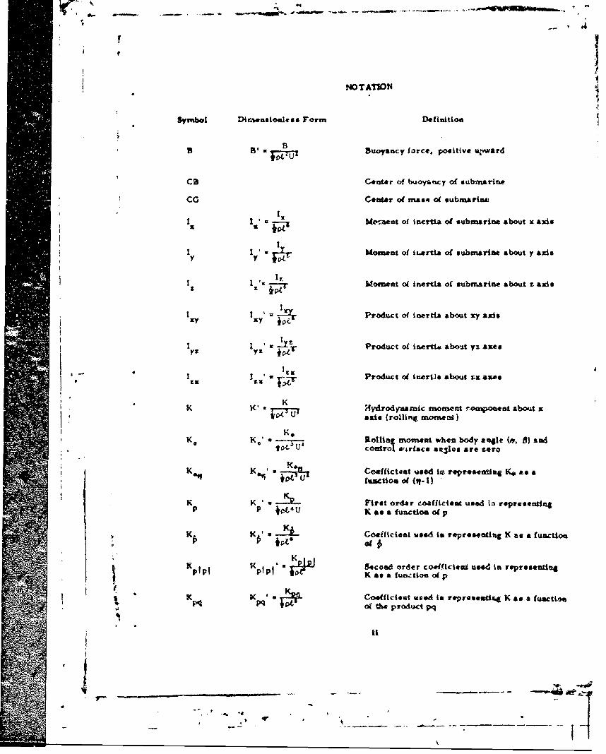
NOTATION
Sym tbol Dimenmsionless Form Defliition
. Buoyancy force, positive u1.ward
Ca Center of buoyanlcy of submarine
Cc Center o( na&4 of submarint,
I I w Moment of irtiza of submarine about y axis
u- Moment o inertia of subrarine about z ads
iota
Sxyt •Product of inertia about xy axis
I Product of in•ertia abot yz autoIys yz y4;ýr
* "-£3 w' "•-- Product of inertla about zx ax&*
K Hydrody-namic rnomet r.oonenot about xlK u axis {roning momecs)
SK, .---, ollia moewat when body angle (w, 8) andco l BarLace sa.les are zero
K • K , UCoeffictent used to repre•enting Ke as a
K K - Fivet or4dr coaffideuc used ia repreentin~gP P 4, 'U K e Afunctioa ot p
K K u Coefficiest used to representiu K as a futaUon
K Kpi K ljj Secod• order coeffictoel u"d tm represenalftafIn K as a fuazttoa ot p
K K .NS Ctwefitiont used is repr*sescie. K as a fUaCtion%M PQ lb PP' of the product pq
ti
N •
-- K07 Coefficient wed in reupr.eenting K as aI iKqr function of the product qr
SI Kr First order coefficient used in repreeatia•g- r 7 K K af a function o( r
K, K;' z Kf Coefficient used in representing K as ar TZ-rfuinction (-( f
K K' First order coefficient used in representingTOM K.. a function ol v
K•. Coefficient used in representing K as afunction V~ £'
K K a Iecond order caeffictiet used in representinvfvf K v IX &a a function of v
Kvq vq' Coefficient used in representing K as & fLnctionyqFL of the product vq
w K " a Coeffic.ent used in representing K as a fuactionK Toe of the product vw
K K , . Ku p Coefficleat used ti representiag K as & f£vctioeWP iwp 4:t, of the product wp
K~rK K sCoefficient Used in repraewettag V. of a function ..
wr wr k of the product wr
K First ordor cotfeictest utsd tn reprse*tning
6r K asa a function of
S-2 3Overall iemth oftsuartias
-v - oif a %bmarim, i kc tus wator is A -
L4 H-/4rodyaamic mommet comaossa about 7 axnis(pttcbii4 esoanat)
U. U, Pitcjktr4 mowve abetu body &041e0 (4t. B) &adcoftrol sur(Rct Anlee Art•z ro
S' m e 5cosi order Celficia. t 'Aged in represea"nimp mP i U st a Nu-ctioa adP. First order coefficiast to
Uq lUi ' o rirt oOder coffiCtVet" Ueed Ws *tsr..sna4invc- t M ansafunction 0 (4-1
UId. Firsticrder? ceInceu used~i% A & 6I .e
I intactions ofli
i "
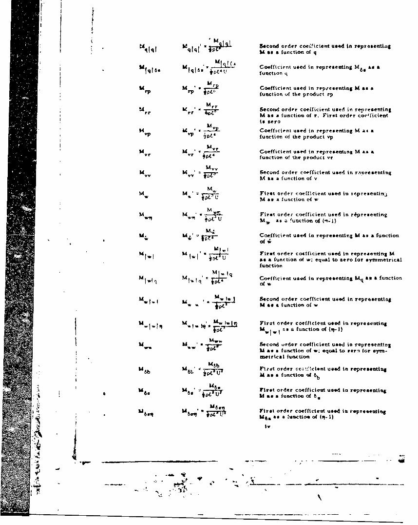
-I-.d qjq ' 3 3 Second order coe;!icient used in representlitM as a function of q
M q A Coefficient used in representing M6 as ajU u function q
Mr Coefficient used in representing M as arP fr"C? function of the product rp
M Mrr r Second order coe!ficient used in representingM as a function of r. Firat order coceficientIs zero
M M '- Coefficient used in representing M as aVP VP 110• function of the product vp
SInM
M M * yr Coefficient used in representing M as avr yr W04- function of the product vr
i M~ - v Second order coefficient used in r,-oreventing-vv f7' M as a function of v
HFirst order coefficient used in xepre3entin~jiM as a function tf w.
MM M First order coefficient used in rCpresentlngtw MW & as a unction of ('...1)
M. mi. Coefficient used in represenairq M as a function
M Mjj wFirst order coefficient used in representlng MU as a imction of w; equal to zero for symmcetricalfunction
M •_• q Coefficient uaed in reprecseattng MI, as a functionlw~q M1,&' ofw
, * 1 Second order coefficient uied in represeutingw aU as a function of w
M Mw !W Firat order coefficient used in representingS- "I, .! MI a- l i~sfunctioel o (v?-l)
U •, Second urder coefficient used in representing" , as a function of w; oqual to e*rw for eylm-
metrical ounction
U 6b M 3b Fitt order .cc.t'.cient used in represe**tinM' as a funcuou eA
Mhi M First order coefficieut used in represeutiagS60 8', .Z- M as functtoc of 8
M 1A First order co-efficirt used in repre*e•ting
iv
:1 * ' _ _ _ _ ,.... iU ,a-to 1
A "
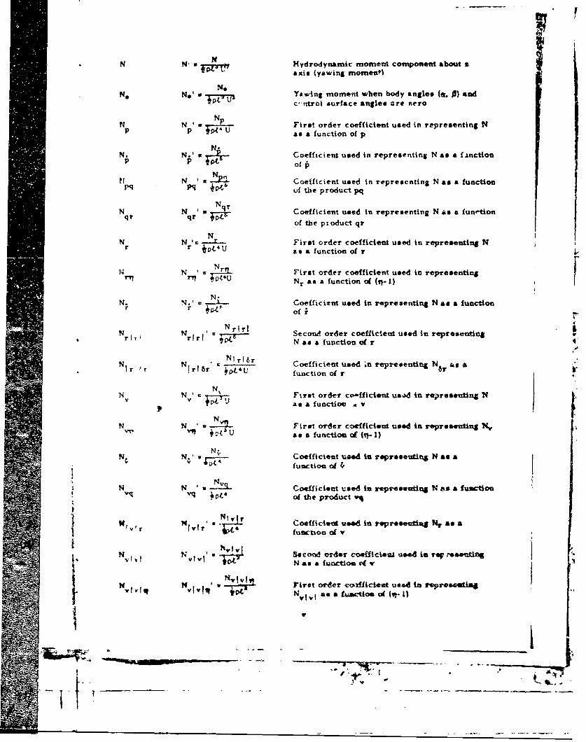
i01N' • •axis (yawing morns,,1
N,
No No' Co Yawfng moment when body anelesp(sn n) and9OT-1 c.-ntrol surface angles are zero
SN Np, First order coefficient used in re-p•resenting NP U tse function of p
N. N u Coefficient used in representing N a a &function
S.... ofthepioductqr
NN N '. ---- First order coefficcent used in representinNa NN N Coefficeas a function oe N
-N First order coefficient used in representing Nrriq r p Nr as a function of (r.-)
N.
N. *.4 , Coefficient used in representing N as a functionr r of f
NrITrNrfr Nr ' NrlrI Second order coefficient used in represealine
N as a function of r
N N = 6 Coefficient used in representing Nb as AI r • rl b6r j4U function ofT
N Nv' N First order co-fficlent us..d in representing Nv +Vas a functioe v
N N W !I First order coefficlent used in represeutinS X,a? a a funtiionof (it- 1)
N Coefficient used in rsproovating N &a a
V ~function0 of l
N N 'u -Coefficient used in repr-eseduna N as a fumCto1Svqvq • *of the produ~ct v
N ' • Coeffictenvd ud in repr..e9cifg N As ar functioa of
N N 'v I SecoMd order coeffwcien u.d is reW resendingViviN t 4 Nasa functim 4 W
S• 0 Iirst ordr coýffict* usedIAn to 1res.tiNv q avV N a a afioe of (vt- I I
, lo-,

*NN uNV Coofficient used in representing N as A functionv vw W3' of the product vw
Nw Nw Coefficient used in representing N as a functionWp WP of the product wp
N N z Nwr Coefficient used in representing N as a functionr wrI of the product wr
N 'N!- First order coefficient used in representing Nas A function of 6r
NN6r NN6?, = 6r-ip First order coefficient used in representing
N6r as a function of (Yj-1)
p p -t Angular velocity component about y axisP U rsrlative to fluid (roll)
I' 7JT An ulL: acceleration component about x axisrelative to fluid
U Angular velocity component about y axis relativeto fluid (pitch)
Anular Acceler 'tion component about y uxisrelative to fluid
r r Angular velocity component about z axis
reLative to fluid (yaw)
Angular acceleration component about z axisrelative to fluid
U" U Linear velocity of origin of body axes relativeto fluid
"." Component of U in direction of the x axis
"1T Time rate of chlange of u in direction of the
x &ads
u u *Conm-and speed: steady value of ahead spoedC U component u for a given propeller rpm v hen
body antles (a. 6) and control surface saglesare uevo, Sign chat&es with propeller rever~.l
V. a- COov.xena ofU i direction of the y axiU
V I- Timew rate of change of v In Airection of theU2 Y
.'. • N

uW Con-1poncnt of U in direction of the A axismq. U
-" -Time rate of change of w, in direction of the[i Z.axis- UI .
-•W W. w V eight, including wa ter in free flooding space$
x' X Lonritkidinal body &:do; also the coordinate of aSpoint relative to the origin of bcd- ;,xea
XxB'- The x coordinate of CB
XG ' The x coordinate of CGxGC
xo' A .-•z dinate of the displaccment of cW Telativeo" to the origin of a set of fx-,d axes
X Hydrodynamic foice component along x axis~o~t'ti ~(longituidinal. or axial. fqrce)
X Second order coefficient used in representingqq qq X as a function of q. First order coefficient
is zero
X X Coefficient ueed in repreoenting X as a functionrT rp of the product rp
Xr
X x iT S-ecornd order coefficient used in representlingrr X as a tunction of r. First orde- cocfficieat is
X. X , Coefficient used in representing X as a function
X X Secoad Order coefflcient used in ropreasozingUu u 1U X as a functioln of u to the uomn-potled case.
Ftrst order coefficieni is -erO
' -In Cee~ficient .-sed is repreoeatia X as a fuactiosvyr vr +0V of th, product vi
X X 'w '- coedor COr Clent used In rOur•M.OSGi Xas a function oa V. -krst ordor -oeffiCent to saero
X .vn ,P First order coofWideni %*a.d is vsrep~eiiug 3L,as a fuctioe 09 ftt-I)
X v X - Coe.fficies uti In tieproeatitt X as a function
v401
S.... . 1-
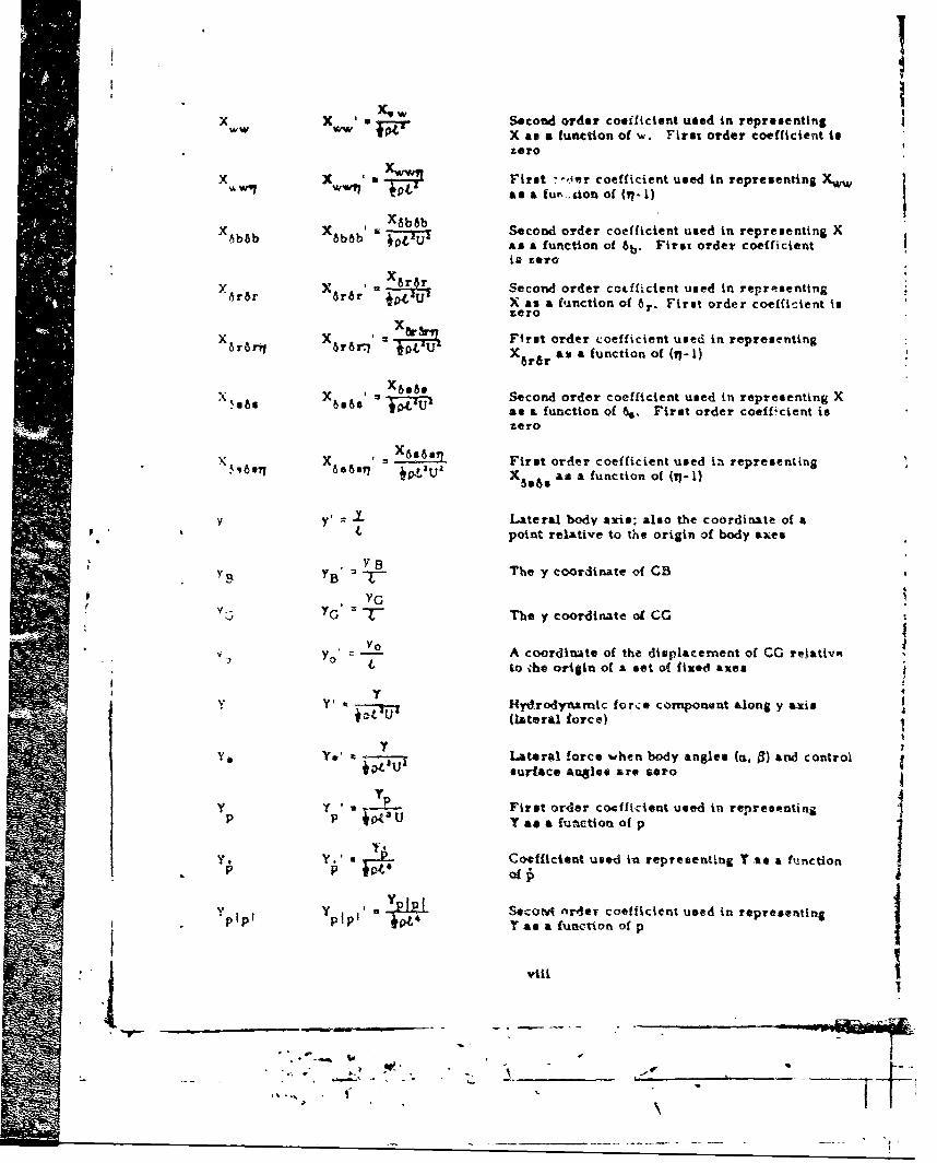
, XW Second order coeificient used in representingX Xw Xvw' X as a function of w. First order coefficient tizero
X X I First -der coefficient used in representing iasa a fur... gion, of (17 -1)j
X bsb X X Second order coefficient used in representing X
6b~b 0,00 as a function of 6b. First order coefficient
is zero
Y X Second order cotffictent used in representing6r~r 6rdr " U X as a function of 6r. First order coefficient is
zero
X r X •f First order coefficient used in representing8r6 WrXWrf am a function of (q7-1)
S~X6482 SSecond order coefficient used in representing X
11s 686•e TPU as a function of %. First order coefficient iszero
X X =First order coefficient used in representing65691 • X 5lUZ as a function of (17-1)
Yy Lateral body axis; also the coordinate of a4, point relative to the origin of body axes
SY B1 The y coordinate of CBYC;
" IG 7- The y coordinate of CC
•Y o A coordla~te of the displacement of CC reiativeyo to ihe origin of a set o( fites axes
Y Hydrodynarmic force component &long y axis.(lateral force)
Y, e Lateral force when body angle* (mi. 0) and controlP VLUI surface angles are vero
Y P First order coeffi-cient used in represetntingP P jo(3U T as afuaction of P
Y,Y. Y., A Coefficient used lo reprecenting Y -s a function
Yp YP • 1 nrder coefficient used in representinf* "Y as a function of p
viii
• ZZ,o \
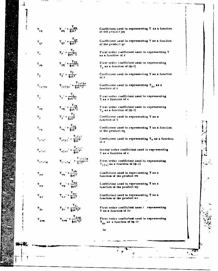
yyy a r 2 .Coefficient used in repre~sevting Y as a function
Mq pq of the pro-.2uct pq
y qry .r1jt Coefficient used in representing Y as a functionqt q VOLof the p ro-duc t qr
y y yi First order coefficient used in reprementing Yr ip 04 Uas afunction of r
y y * First ord~r coefficient used in representingrnrly *04aU Yr as a function of (17-1)
Y. y Coeff cient used in ropreser~ting Y as & function
y y Y8r rl 8r Coefficient used in reprnsenting Y, asmaIr6r'~ v ol functionofr6
y , Y First orider coefficient used in representingivFu as afunction of v
y y First order coefficient usmed in representingV~7 Vlj 4,, am a function of (11-1)
Y. Y. Coefficient used in representing Y as av v function of ~
Y vq y a Coefficient used In representing Y as a functionof th~e product vtq
y Yr Coefficient used in representing Y,, as a function
- - y 1 Second order co~ficient used in representingTw y as a function of v
YY1, I v 117 First order coefficient used in representingyvivin TV I vlY v I, Iasaa function Dti O-I1)
y y Coefficient used Is repus eawling Y as alunctioa of the9 product v
y Y * w Cooehicient uzed is reprcsouting YV as a'A P wp bC-tl3 function of the prodtmct wp
Y y Coefficietzt used lit ropresevntin- YV as aw.r funacti on of the prod-utt -ar
y y 6-f Firilt order co-efficeiet used I reprmentiag* r 6" *PQU Yasfunctioof 67
y F'Jrgt Order COefficitelt use4d it representing 0.
is
01

1
* -N-Morm.l body axis; also the coordinate of apoint rale'tive to the origin of body axes
V- The s coordinate of CB
~~ The a coordinate of CC%tG 3
It 0 0 A coordinate of the displacemnent of CG0 0 relative to the or'.gin of a set of fixed &,to
SZ' Z* Z Hydrodynnamic forct component along r
&xis (normal force)
Z' Zoo w - Normnal force when body angles (a. - andcontrol surface angles are zero
ZZ Z Second ordier coefficient u- ., representing
pp Zp 04. Z as a function of p. First o•der coefficientis zero
Z Z 'Zq Firt order coefficient used it. representingq q JOL3U Z at. a (unction of q
7 Z 0-M First order coefficient used in representing917 *q¶ U Zq as a function o (1-l1)
Z.Z Coefficient used to representtn3 Z as a
q q I function of 4e7
Z 7 Coefficient used in representing Z is alqI~A ZIqt•s' ?ot U function oa q
r Z r * Coefficient used in r,-tpresenting Z as arp rp *pL ffnction of the product ap
Z Z ZrrZ 7. - Second order coefficient used in representingrr yr 7. as a functtoq of r. First owdir coefficient
ti sero
7. ZFirst order coefficiant -.ved in rep-esentingV a*U sa fu.-Ctionoad
Z7 .2 First order coefficient used in representingOIL Y
7 - . •a •fuactiot o" (1.-I)
7. 1 " ! Cosfftclet used in representin .Z as afu action of W2
7. 7 ~ 1' First or-dty coefficiez! use-d ilk r~ep'ssentitl .l I U . a d a tunctoaof 'i'; e val to Coro for oym-
mrtrical kn fwctiod
7.or
Zw tqi wlqi • Coe~flcient ules lI. retpreseuet• 7.. a a
[Uato oq
-V---tT
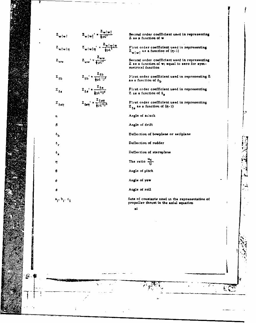
Z Z aw'u " Second order coefficient used in reprosentingWIWI WIWI 041Z as a function of w
Zwjw7 Z wwlw 2 i w First order coefficient used in represeutingZw I w I iats afunction of (.1)- )
z ' W Second order coefficient used in representingPIT• Z as a function s w; equal to zero for sym-
metrical function
Z ' Z" . First order coefficient used in representing Z6b 6b t ý'Z- as a function of 6b
Z. Z60 a Z First order coefficient used in representingSWpQU' Z as a function of 66
Z Z ' M First order coefficient used in representing0T P1*YU Z 6 as a function of (17-)
SAngle of avs)•ck
Angle of drift
6 b Deflection of bowplane or sailplane
Ar Deflection of rudder
69 Deflection of aternpiane
SThe ratio
e Angle of pitch IAngle of yaw
Angle of roll
&i, bt, CI Sets of consantU meed in the representatioa ofpropeller thruet in the axial equatiou
xi
Pr• .. i ,4
| n • | • it is i it it t 1
ABSTRACT
'%Standard equations of motion are presented for use in submarinesimulation studies being conducted for the U. S. Navy. The equations aregeneral enough to simulate the, trajectories and responses of submarinesin Bix degrees of freedom resulting f-rom various types of normalmaneuvers as well as for extreme maneqvers such as those associatedwith emergency recoveries from sternplane jam and flooding casualties.Information is also presented pertaining to the hydrodynamic coefficient&and other input data needed to perform simulation studies of specificsubmarine designs with the Standard Equations of Motion.
ADMINISTRATIVE INFORMATION
The development of the NSRDC Standard Equations of Motion forSubmarines and associated experimental techniques to provide thenecessary hydrodynamic coefficients was sponsored primarily by theGeneral Hydrornechanici Research Program (Sub Project SR 009 01 01Task 0102). Additional support was provided by the Submarine SafetyProgram (Sub Project S4611010 Tasks 11077 and 11083).
IN TRODUCTION
The Naval Ship Research and Development Center was requested to* ovide the Naval Ship Engineering Center with a report on the generalequations of motion currently being used for submarine simulation stud-ies. The primary purpoue of the report to to establish standards, pro-"vide guidance, and establish a firm basis for contract negotiations. Thereport would thus serve to facilitate the Navy's dealings with contractor$engaged in the manufacturt of equipment such as training simulators andautomnatic control systems for submarines. Particular interest wasexpressed in having equations which would fnlly describe the hydrody-narrfc aspects of a submarine experiencing a casualty while in a-headmotion, with provis.ons for inserting detailed r.presentationa of thecasualties and recovery systems.
The Stability anrd Control Division of the Hvdromechanics Laboratoryhau been conducting submarine motion simulation studiev io- a numberof years in connection with its various assigned rerponaobt'ities. Suchstudies have been utilited with considerable success to solve a widevariety of problems pertaining to the design and operation of submarinesfrom the sta-ndpoint of stability ;-nd control. Most recently, theseatudies have included: emergency recovery from aternplane Jams, loaasupportability, and vertical ascents after emergi.ncy blowing (5oth withand without forward propulsion). Tbepe simulation studies have beenmade. possible as the result of a progreseive in-house development of
I References are listed on pag. Z7.
"i
_ ',._ - •- * -,-- _ -,
~ ., I

six-degree-of -freedom motion equations and a coordinated development ofadvanced experimental and analytical techniques to provide the necessarycoefficients.
The equations of motion as they now rxist at NSRDC are generalenough to simulate trajectories of oubmarines for all of the various typesof normal maneuvers and emergency situationa th&t have been of concernup to the present time. Furthermore, it is believed that they willadequately cotier most of the situations that may be reasonably anticipatedfor the future. These equations, which form the subject of this report,have been used continuously for the past three years with little change,and are considered to be standard at NSRDIC. In the interest of consistency,it is proposed herein that these equations be adopted and serve as theU.S. Navy Standard until notice is given by NSRDC that they chould bechanged. It shovdd be emphasized, however, that these equations havebeen validated only with the types of coefficients being generated by the1Hydromechanics Laboratory. Therefore, prospective users areadvised to first contact NSRDC to determine whether the requiredhydrodynamic coefficients are available.
It is the intention eventually to issue a complete and comprehensivereport on the NSRDC Standard Equationi of Motion for Submarines whichwould be tantamount to a textbook. This would include a discussion of thephysi.-s involved and the various meann for d&terminlng the ntmer:caiva tues of each of the individual hydrodynarmic coefficients required for* the equations. In addition, it is planned to discuss the various computertechiiiques used for simulation and to present those cornpu~er programswhich have reached an advanced state of development. Such a treatise,however, is considered to be much beyond the scope of what is requiredto satisfy the immediate needs stated in the request.
To accomplish the specific objectives mentioned at the outset, thisrepot t presents a brief history of the development of the equations ofmotion -t NSRDC; defines 1lie nomenclature, axe systenis, and sign .-convert-ons used for the equations; presents the NSRDC StandardEquations of Motion for conducting submarine simulation studies; outlinestCe niethods and sources for obtaining the hydrodynamic coefficients and *
other input data required for simulation; and briefly discusses theappli': ation and range of validity of the Standard Equations.
HISTORY
The equations of motion now in use at NSRDC are the direct resultof a continuing program .)f in-house research carried out by the Stabilityand Control Division of the Hydromechanics Laboratory. This prgrsrmwas officially started in June 1956 when it became evident that a rapidtechnological expansion was taking place in the area of oubmarinestability and control. The decision was made at that time to developgeneral equations of motion for six degrees of freedom w-hlch could boused in conjunction with coefficients obtained fronm model experimentsto predict and study the behaavior of submarines and associated systems'S.- I

in a variety of maneuvers. Concurrently, studies were undertaken todevelop suitable techniques to determine experimentally all of the hydro-dynamic coefficients required for these equations for any arbitrary sub-merged body-appendage configuration. The Planar-Motion-MechanismSystem, which was constructed and placed into regular service in 1957,was one outgrowth of theae studies, This system is still the standardmethod used at NSRDC to determine numerically most of the requiredcoefficients. It was realized at the outset that many years of researchwould be required to develop, implement, and validate a completelygeneral set of equations that could be used to study all situations involvedin the motions of submerged bodiem. In view of the presaing needs, how-ever, it was decided to approach the ultimate objective by progressivestages.
The first effort was directed toward the development of equations topermit simulation of normal types of maneuvers involving six degrees offreedom, such as those required by submarines to fulfill effectively theirvarious missions. The existing linearized equations of motion were Airstused as a basis to study moderate or small-scale muaneuvers. Thesewere later'extended to include various nonlinear and cot.plhng terms. By1960, it -vas felt that the state of the art had progressed to the point whereso :.e standardization would be desirable. Arcordingly, the Stabf'ity andControl Division of the Hyd,'omechanics Laboratory adopted a "atandard"set of six-degre -of-freedom equations for submarit.es in normal typesof mane-'vers. The term standard was applied in the sense that theequations were to be used for their designated purpose in all studiesmade by the 1,abor6,tory, and were to have official status until a suf-ficient advance, was made in the state of the art to justify a change. Ifsuch tuened out to be the case, it was intended that the rcvisions wouldbe made officiaily and a new set of standard equations would be issued.
V' Together wit l- the adoption of standard equations, a continuing program'vas hiitlated to correlate fail-sca.1e trial measurements with computerpledictions involving these equations. On baein of correlation studiesmade subsequently. it appeared that these standard equations togetherwith coefficiernts determined with the •Planar-Motion-Mechanism Sybtemwv-ul, tor most part, .:eld ac4.,rate predictions of the submarinetrajectories for a variety v. normal or definitive maneuvers tha. couldbe used to evaluate the hand.i.g qualities of submarines.
During 196Z, in anticipation of a progrem airected toward thedevelopmer.t of conteol proceoures and aLxiliary devicee to improvethe emerg,-ncy reco--ery capabilities of stbma-ines, the research programwas reoriented to establ -h prediction terhcdques for studying the behaviorof sILbmarines in a variety of possiblt, emergency situations. The revisedreserrch program inc.laded !undamental theoretical and exper' .,entalstudies such as: cxpandiag the standard equations of notion v,ý includeterms (s.,ch as those %nsociated with "backing" on propellers and blowingof brllast tankfs) which were not required for simulation of normalmeneuverv; extetnding the range of validity of hydrodynamic coeiicients
to provide accurate representato.on. in extreme situations (auch as thoseinvolving angles of attack up to 90 degrees); and estabi•shing correlation
3
t t i #
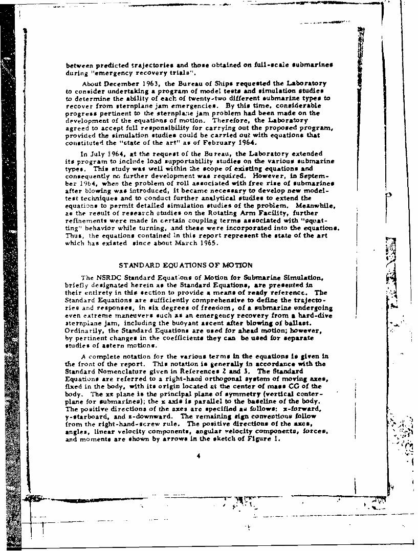
between predicted trajectories and those obtained on full-scale submarinesduring "emergency recovery trials".
About December 1963, the Bureau of Ships requested the Laboratoryto consider undertaking a program of model test# and simulation studiesto determine the ability of each of twenty-two different submarine types torecover from sternplane jam emergencies. By this time, considerableprogress pertinent to the sternplane jam problem had been made on thedevelopment of the equations of motion. Therefore, the Laboratoryagreed to accept full responsibility for carrying out the proposed program,provided the simulation studies could be carried out with equations thatconstituted the "state of the art" as of February 1964.
In July 1964, at the request of the Bureau, the Laboratory extendedits program to inclihde load supportability studies on the various submarinetypes. This study was well within the scope of existing equations andconsequently no further development was required. However, in Septem-ber 19b64, when the problem of roll associated with free rise of submarinesafter blowing was introduced, it became necessary to develop new model-test techniques and to conduct further analytical studies to extend theequations to permit detailed simulation studies of the problem. Meanwhile,as the result of research studies on the Rotating Arm Facility, furtherrefinements were made in certain coupling terms associated with "oquat-ting" behavior while turning, and these were incorporated into the equations.Thus, the equations contained In this report represent the state of the artwhich has existed since about March 1965.
STANDARD EQUATIONS OF MOTION
The NSRDC Standard Equalons of Motion for Submarine Simulation,briefly designated herein as the Standard Equations, are presented intheir entirety in thip section to provide a meants of ready referencc. TheStandard Equations are sufficiently comprehensive to define the trajecto-ries and responses, in six degrees of freedom, of a submarine undergoingeven extreme maneuvers such as an emergency recovery from a hard-divesternplane jam, including the buoyant ascent after blowing of ballast. *
Ordinarily, the Standard Equations are used for ahead motion; however,by pertinent changes in the coefficients they can be used for separatestudies of astern motions.
A complete notation for the various terms in the equations is given inthe front of the report. This notation is generally in accordance with theStandard Nomenclature given in References Z and 3. The StandardEquations are referred to a right-hand orthogonal system of moving axes,fixed in the body, with its origin located at the center of mass CG of thebody. The xz plane is the principal plane of symmetry (vertical center-plane for submarines); the x axis is parallel to the baseline of the body.The positive directions of the axes are specified a, follows: x-forward,y-starboard, and z-downward. The remaining sign conveootion followfrom the right-hand-screw rule. The positive directions of the axes, , A
angles, linear velocity components, angular velocity componerts, forces., '
and moments are shown by arrows in the sketch of Figure 1.
4 - s,.".

J -R -.
2 0
Va4,U'4
I 0
'I,a
''I -4,4.U-4�6o
-4
4,
U4,
-
- Si-I
0- U
0".44,
U4,'4
4,
I 4,U0
£1
0A
AU4,C
I-i
T�K7,
* /
// 5
4 / _______
/
___ .4 4-
-4- - - - ____
'4
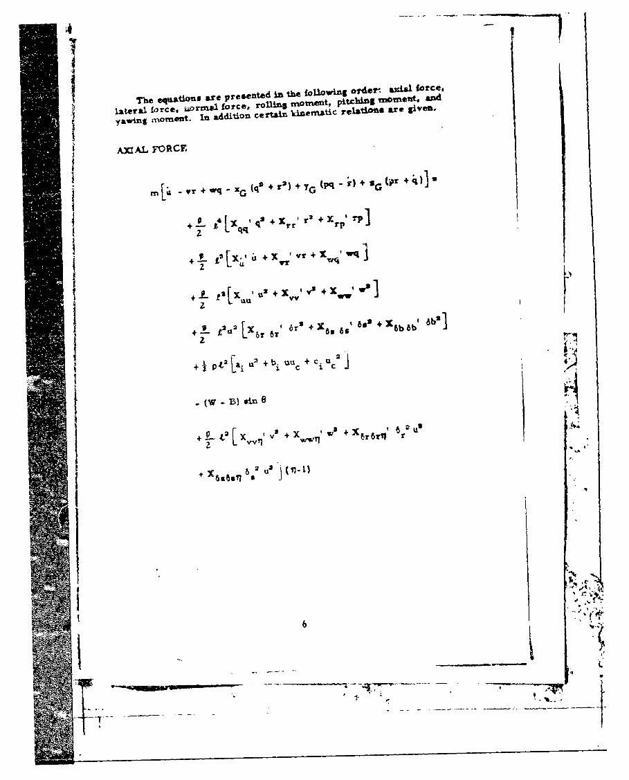
I ~ ~The Cql&tlifLs are presented iii the iO1XOwii1g order. &%W force,
l.at~eral force, ~ wrunIe £Orce, rOUUS~ ramn~tvlft pitchinlg M*~t and
Y&Vwing moment. in additiOu certain kInematiC reIstiO5S are given,
AjaAL FoRCTE
m va r + wq - x G (q! + T2) + yG (pq - )+ S,(j +q~)I
+4- LqqIq! rr r+x rp I '
2 U2d~ + yr V + x,, Wx
+ sX~ VI + C,
+ 126l 6w * 6I 6. 6.' bo + 1 6b 6b' 6bS
+ )2 w + x. + 2~ US
+ j 60o 602 11
I6
got..,__ T4 'W
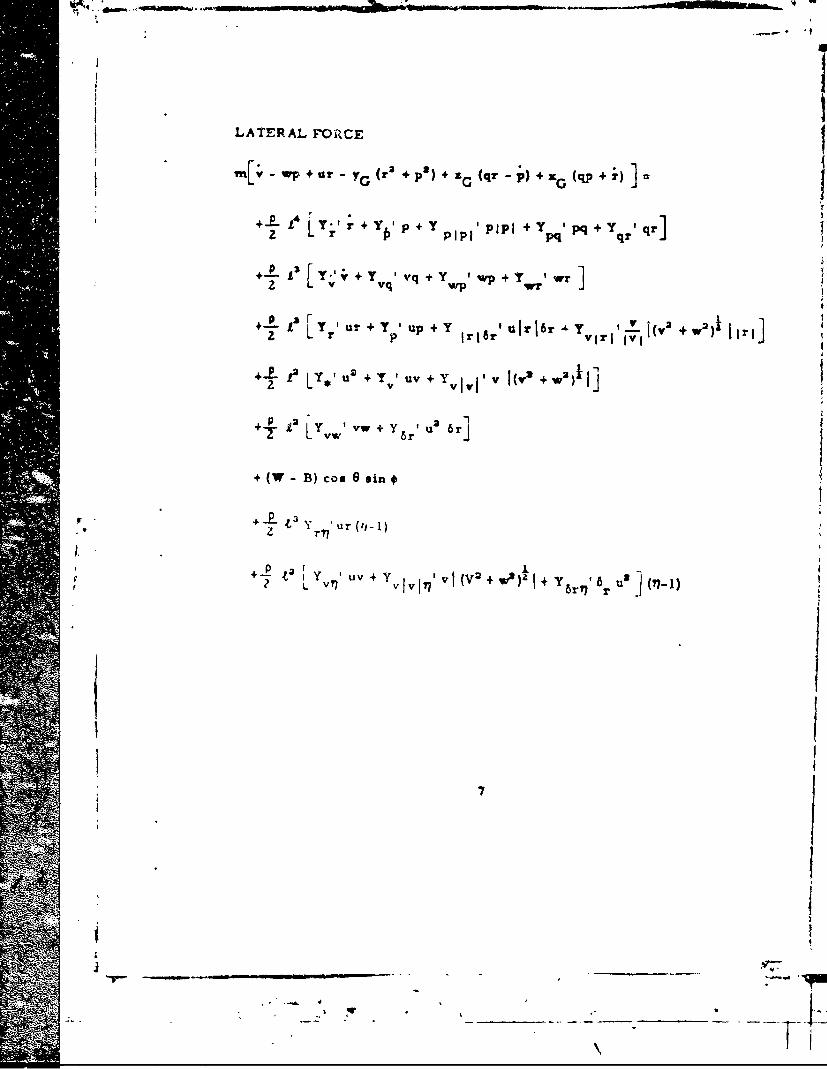
LATERAL FOR~CE
14 LIYt + fPp + Y PZIPI +y I q+ Yqqr]
+-fL ~T Iur + Y up +Y ulrl~r -l?~.Y1 Y 1(VI 2 +) ~I
+ T ' v + Y I I (v + W2)1~
+2 Ip V + y +' 6rwj'T+ £Lvw+Y 6rt' r
+ (W -B) cos 6 sin t
+ y r (ti 1) ~-.+ 6u ~IP u
7
A-
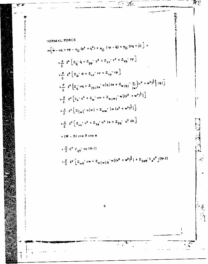
NjORMAL FOIRCE-
w uq + VP - G(P2 +q') + C OZG Y r
+ t [r. q4 2 + Z1 2 r~ + Z rpi Tp
till~s+ z I V + %a)V kI'
+- e3 uq 4 Z aqO +q1%wq
U2 2 +ww +
L[Z w Wwiw
+ p [7jWt Ulwl + z WWI JW + W2),1
2 2 z vvI v2 + Z a' u 2 6S Z 6b' U2.6b]*
+ (W - B) coo 0 cOs*
+ t3 ZqyI Uq(-1 q
z LL ww7
8
'ia. _ _ _A,
avow-.
Ma-
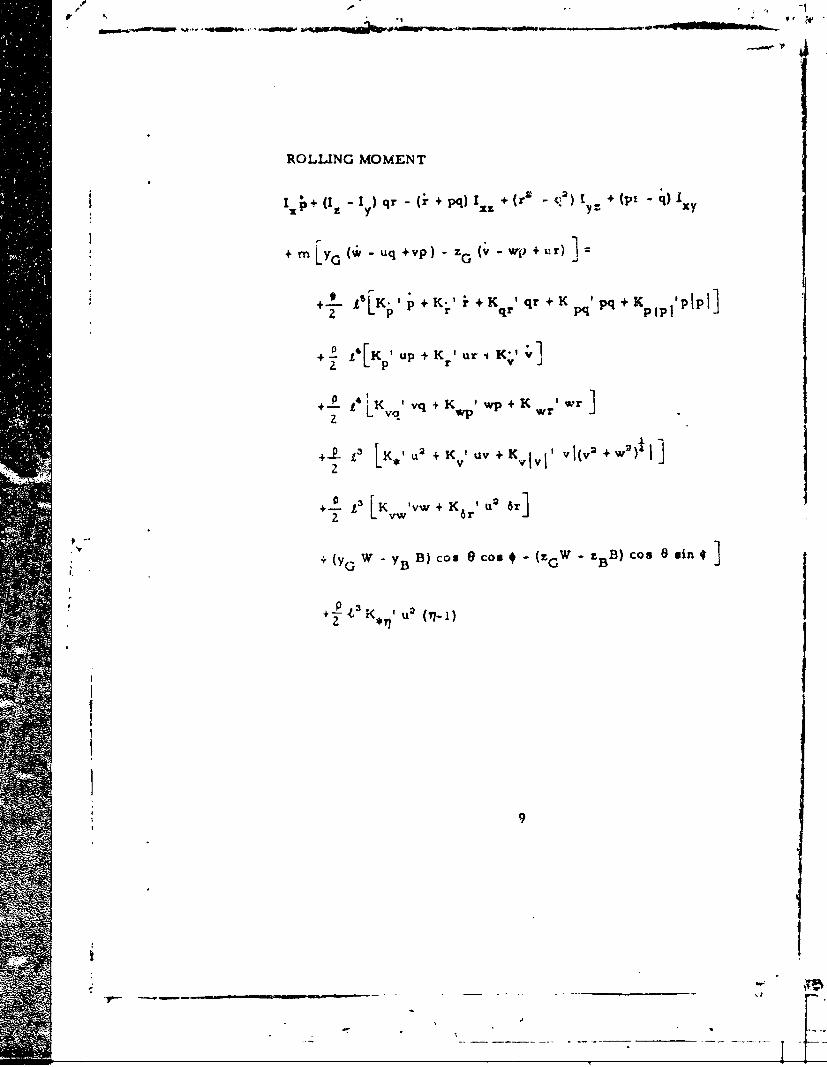
ROLLING MOMENT
i, - ) qr -i+ pq)I + (r2 ~ + (pt q*)
+ mn z. "- q+p)- (v - wjp + r)1
+2 'K- p +,,~+Ki +K qr+ q+
+- P 131LK' u: + 1Kv' uv + Kv ,IjI v (v3 + w2)f
+ tsK 'vw + K ' 2~ 6rI
+ (yG. W -YBB)o co*(GW BBc58n
K pa(7-1
9
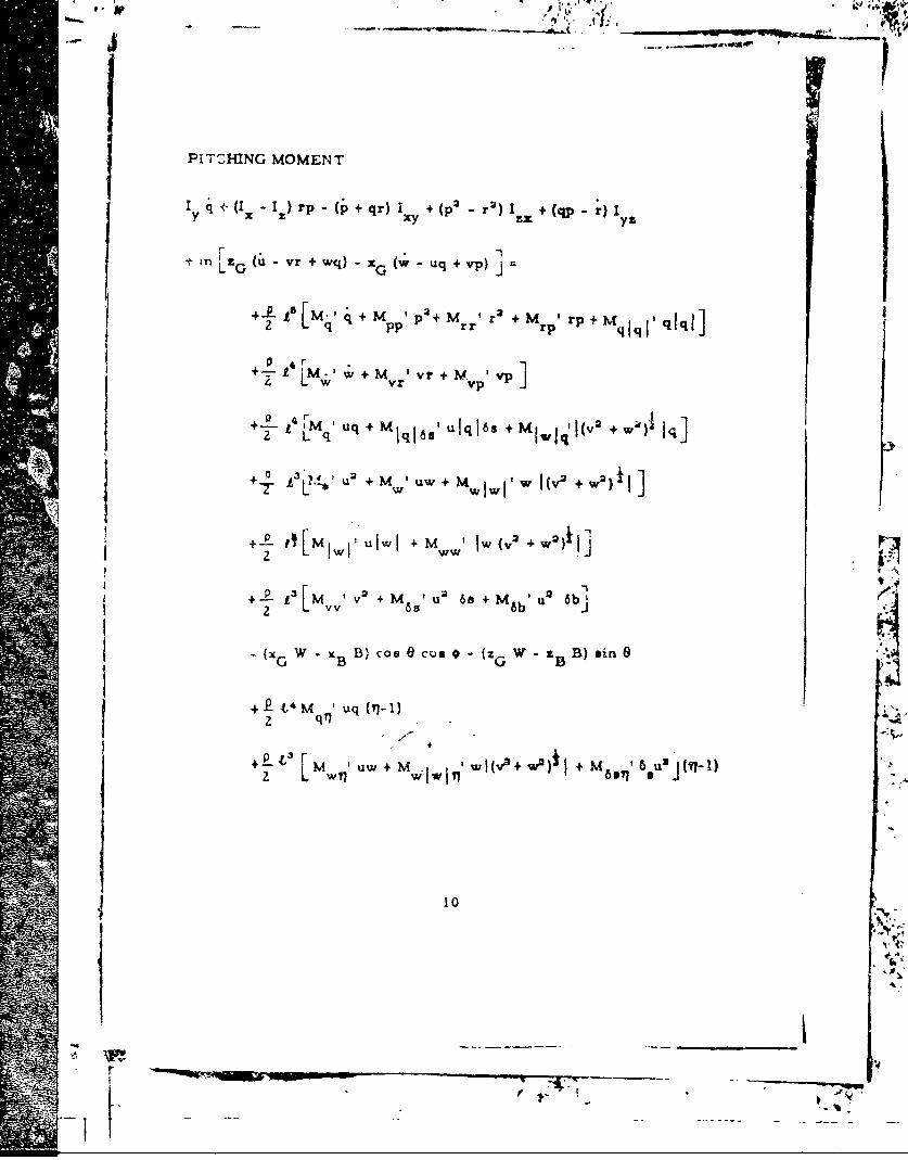
PITCHING MOMENT
q vc(I x z) rp -(pj+qr)Ix + (P 2 r')IE + (qp r) I
In ' LG (u-r + wq) - xG w uq + v-p) j
+.k ts[m.,+M -P7+MI r +m Irp + M j qlql
I LýM I vr + m 1Vp 4 wM 'v]
+-4 ' 'i + M j 165 u Iq I s + MvIýl I(v 2 + w4), Iqj
+~. 0 u2 +M Iu uW + W~IWI, W I(V,2 +W2)1 I
+-L- 11[Mji uluwi + M' 1W (v 2+W2)1j
V +- E 1im tv + M u 2 68 + M u 2 6b
~(xG W x B Blcos cus 0 (zG W zB B) *inl6
+EL'M 'uq1+-M i .t I,' w l(v2+ W2)f + M8 1
10
t4.

YAWING MOMENT
I z ;+(I v.I1 ) pq (+rp)!y + (q 2 p )I x + (rq-p)I
+ m Lx G (v-wp + ur) - {G u - yr + wq) j'
+lL t[NIr+ Nj p + N~ Pq+ Nqrr+ N jylrlrI
I 'N~lv + Nwr +N wp + N Iz L w W N q'vq
N2 'NP up + Nr ur +Nj -6 u IrI6r + N~r +" +w2)i]
+ L N' u 2 + Nv uv + Nv IV,, V I (V2 + W2)1 Ij
P 13 vw + N 6 u 26r]
+ (xG W - x B B) cosO sin# +( G -B B) si (
+L 0 07fur (f7-1)
[N,,N 'uv+N 1 7viil jN'$+ ? + N 8ril ar U2i(

j KINEM AIIC RELATIONS
-- • o ''u gine+vcos Gaino +Wco e Scoo
p =+ @in9
r + e +sin +
I cose Cos#
' i
II
d$.
i
IDENTITY AND SOURCE OF INPUT DATA
As mentioned in the Introduction, it is beyond the scope of this reportto go into t detailed treatment on the use of computer techniques to performIsimulation studies involving the Standard Equations. The purpose of this
section is merely to identify the kinds of input data required to performsuch studies and to indicate where such data can be obtained. In addition,an attempt is made to indicate some of the cub-routines that are alsoneeded to perform various types of simulation studies. In particular, thosesub-routines required for the sternplane jam phase of the SubmarineSafety Program are listed. A somewhat more detailed account of thenature of the hydrodynamic coefficients and the processes for obtainingthem is relegated to the next section.
The NSRDC Standard Equations of Motion given in the precedingsection are written in a form utilizing nondimens.onal coefficients, andare applicable in a general sens', to the rigid body motions of submarine&and other submerged 'vehicles. Certain input data "e required, however,to obtain a mathematical model which can be used to realisticallysimulate the motions of a specific submarine design. A complete set -)finput data for this purpose consists of the numerical values of all of thehydrodynamic coefficients, inertial properties, and pertinent geometriccharacteristics for the given submarine that enter into the various termsof :he equations. Fortunately, as the result of the concentrated effort onthe Submarine Saety Program,as well as contract design studiea madeprior to construction, complete sets of inp. data for about 25 differentexlsting submarine designs are on hand at N._DC. The data, for most
7w part, -arry the classification of "CONFIDENTIAL'. However upon request,they . n be furnished to outside agencies and contractors having theproper security clearance and "need to know".
Similar data can be obtained for new submarine designs by address-ing a request to the Commanding Officer and Director of the Naval ShipResearch and Development Center. Tis request should be accompaniedVk. an outLine of program obje'tives, lines plans, and other pertinent data.An estimate of time and cost will be provided, after which funds must bedeposited at NSRDC before work can proceed. If the information is neededon a short term basis, this should be clearly stated by the requestingagency so that a-uffitient lead time, particularly to allow fcr mode! con-struction and scheduling of test facilities, can De alowed. Furthermore,in contractual dealings, an eariy committnent to supply the data shouldbe obtained from NSRDG before final negotiations are made. This isespecially stressed for tho.•e contracts in which time is of the essence,or where the contractor may tunderstand that having prior possession ofthe information is a condition precedent to performance.
The primary mathematical model, eonsisting of the StandardEquatioes =nd input data pertinent to a specific stbmarine, can be readilyprogrammed on either an analog or digital comater. To perform acomplete motion simulation study, bowwc~r, the computer program must
'3
" • ...... , . * _-~ _

also inclede certain supplementary mathematical models or sub-routines.For example, to conduct * complete simulation study of the motions insix degrees of freedom of a submarine involved in emergency recoveryfrom a alernplane jam cacuaity requires at least the sub-routines whichinclude the following representatiins:
1. Time history of sternplane movement in degrees including variousprescribed sternplane "jams"
2. Time history of sailplane movement in degrees starting from timethe order is given
3. Time history of rudder movement in degrees starting from timethe order is given with provision for various modes of motionsuch as swinging the rudder sharply over to a hardover position(either right or left), or fishtailing
4. Time history of change in propeller rpm from "full ahead" to"back emergency" starting from the time the order is given andincluding appropriate time allowances for communication, humanreaction and manipulation of controls, and primc -mover response
5. Time 1-tstory of weight of ballast wat-r discarged or taken on dueto blowiug or venting, respectively each of the main ballasttanks. The time is measured fron, the instant the order is givenand i 7udcs the effects of system lags. as well as pressurechange- due to changes in air-bank pressure and submarinedepth on rate o' water discharge.
The first three of these sub-routines convert time histories ofcontrol surface movement to tirne histories of hydrodynamic forces andmoments exerted on the submarine hull when they are applied to theternis in the primary mathentatical model containing 5., 6,, and 6b.The time history of propeller rprn is converted to external hvdrodynamicforces and moments by means of the termse containing (11-1) and u.These terms reflect the Incremental changea in forces and momet-a dueto either over or under propulsion (including backing on the propellerswhile the tubmarine is proceeding ahead). For the moderate changesin ahead speed involved in most normal maneuver;, all of the (17-I)terms usually can be neglected. The sub-routine for blowing or Ventingof ballast tanks is already in the form of forces and moments. It can betied in directly with the primary mathematical model by replacing thecon•aart weght terms, such as W-B. with the appropriate time historiesof weight cha,.geg.
It is apparent that the primary mathematical model, in conjunctionwith the foregoing typ'.s of sub-routines, can be used to simul:ate thesubmarine undergoing a host of other normal submerged maneuvers aswell. These maneu~vers, however, are essentially of the open loop type.To perform :losed loop studies, such as depthkeeping or coursekeepingunder the inllvence of various environmental conditiona, other oub-routines
14
___ 4
'-. - - -- _ _ _
including either marnual operators or automatic control systems niust beadded. A typical simulation study of this type it the problem of main-
Staining periscope depth while operating under a hoavy sea (say State 5).A sub-routine to represent the effects of an ahead, random sea on thesubmarine has been developed and used by NSRDC on a number of oc-casions in the past. This sub-routine, sometimes called the sea-stateanalog, is in the form of forcing functions which are generally applied inan analog computer simulation by means of a white-noise generator, theoutput of which, in some cases, has been prerecorded on magnetic tal.e.The major components of the sea-state analog are as follows:
1. The surface configuration of the representative random, seaway
2. The effects of the seaway on the depth (pressure) sensor whichare functions of depth
3. The oscillatory forces and moments acting on the submarine hull,hich are functions of depth
4. The suction forces acting on the submarine which are functions ofdepth
The Standard Equations have been programmed at NSRDC both on theanalog computers of the Systems Simulation Facility of the Hydrome-chanics Laboratory and the digital computer (IBM 7090) of the AppliedMathematics Laboratory. These programs, however, have not yet beenadequately documented for general public•.tion. Similarly, computerprograms exist for a variety of sub-routines. Since these sub-routinesusually must be tailored to a particular problem, or in some cases to aparticular computer, uo concerted effort has been made to systematizeand document them for general publication. Nevertheless, the input datarequired to construct the sub-routines for existing submarines which havebeen studied ace available at NSRDC and can be futnished to those entitledto receive them. Other sources for such input data, particularly thosefor sub-routines dealing with hardware items such as propulsion machinery,ballast blowing systems, control linkages, and automatic control systemsare: the Naval Ship Engineering Center (NAVSEC), the submarine con-Ptruction shipyards, and the equipment mnanufacturers.
THE HYDRODYNAMIC COEFFICIENTS
The hydrodynamic •:oefficients constitu|te the heart of tht prim-arymathematical model used in simriulation studies of rigid-body motions of
submarines. In fact, the form selected for the equations of motions isinfluenced to a large extent by the kiod& of hydrodynamic coefficientsemployed. With this quA)ification in mind, this section of the reportpresents further informnation as to the nature of the hydrodynamic coaf-ficients used at T7RDC a- well as some insight into how they are obtained.It is hoped that this will serve to asaure that the hydroAynamic coefficientsbeing used for a parti<'l.ar study are compatible with the Standard Equations.
15
II

Unless mentioned otherwise, the hydrodynamic coefficients apply to thedeeply submerged case, free of free-surface, bottom, and wall effects.
The hydrodynamic forces and moments which enter into the StandardEquations as coefficients are usually classified into three general cate-gories: static, rotary, and acceleration. The static coefficients are dueto the c-naponents of l near velocity of the body relative to the fluid; therotary coefficients are due to components of angular velocity; and theacceleration coefficients are due to either linear or angular accelerationcomponents. Within limited ranges, the coefficients are linear withrespect to the appropriate variables, and thus may be utilized as static,rotary, andc'celeration derivatives in linearized equations of motion.
For six degrees of freedom, the coefficients in each of the threecategories which appear in the Standard Equations are quite nurnerous.The problem thus becomes one of determining the numerical values ofthe individual coef'.cients with sufficient accuracy to support the objectivesof the particular simulation study involved, Ideally, it would be desirableto acquire the required numerical values for a given submarine configura-tion by means of hydrodynamic theory. Unfortunately, those coefficientswhich are primarily due to viscous flow, such as the static i.nd rotarycoeft-cients, cannot be obtained reliably using only existing theory. Theor,"has been used with reasonable success to compute acceleration coefficienfor simple forms without appendages, such as bodies of revolution, whiare imenable to tri-atment on basis of potential flow considerations.ever, for actual submarine configurations which include appendages ch
e4as ccntrol surfaces, decks, bridge fairwaters, and propellers, th se oftheory to determine the values for coefficients even of this type theaccuracy required for certain simulation studies becomes aom tquestionable. Accordingly, the present state of the art is to y almostentirely on expertmeatal means for determining the numeri values ofthe hydrodyn'; mic coefficients for specific design problem
Thle primary methodology used at NSRDC to obtain e required hydro-dynamic coefficients is the Fylanar-Mtion-Mechani ystenma. Thissyst m was conceived and developed in the Stabili Control Divisionof the Hydromechanics Laboratory. It incorpora in one device a meansfor experimentally determining all of the types ydrodynamic coef-ficiL'rts in each of the three categories that ar equired in equations ofmotion for a submerged body in six degrees freedom. A completedzscription of the system includig its oncepts, principles ofoperation, apparatus, instrumentation, d'typical test results, in givenin References 5 and 6. Planar-Motion- lechanism System, Mark I, asit is presently constituted, can be use to obtain the numerical values ofJ all of the coefficients except certai ourling terms and thobe nnn-
* linearities associated with high va)4cm of nondimensional angular velocitycomponent, such as r', which arý asaociated with maneuvers involving
I relatively gfght turns. Where ch values are required, the data obtainedfrom Planar-Motion-Mechanit tests are supplemented by the results ofRotating-Arm tests and/or p-timates based on theory. The Rotating ArmFacility ind the instrume •ion and techniques used to conduct submarine
t /1
9 _
model tests thereon are descri -ed in Reftrences 7 and 6, respectively.Further details on the experirr -ntal and estimation techniques whichrelate to the kinds and quality f coefficierts to be used specifically withthe Standard Equations are presented in the following paragraphs.
The Standard Equations ar written in terms of the complete sub-marine configuration. Accord.ngly, for quantitative studies pertainingto specific submarine designs, the standard practice at NSRDC is to con-
/ duct all of the required tests v- th models that are fully equipped with allsignificant appendages including bridge fairwater, deck, bowplanes orsailplaraes. sternplanes, rudders and propellers. These tests effectivelycover a matrix containing a range of motion variables (referred to the hullcenter of gravity) that generall.- exceeds that which could be encounteredby the prototype submarine, ar & ranges of control surface angles and pro-peller rpm's which are at leas' equal to the capacity of the specified sub-marine. The resulting characerization of hydrodynamic forces andmoments thus embraces interaction efiects involved in the various rodesof rigid body motion between: control surfaces and hull, propeller andhull, and propeller and stern control surfaces. Also included are down-wash effects of forward appendages, such as bridge fairwater, sailplanes,and deck, acting on the stern control surfaces.
Since the foregoing process yields hydrodynamic coefficients whichpertain to the complete configuration, there is no need to iiclude separateterms in the equations in an attempt to account for local angles of attackin way of control surfaces. The latter procedure has been suggested bysome other investigators as a means for obtaining a better representationof control-surface stall, particularly where large local anglea of att Ickoccur when the control surfaces are deflected. On the other hand, theprocedure for testing the complete'configuration embraces the effects oncontrol coefficients due to changes in local angles of attack resultingfrom the various modes of motion. Since true flow angles of attack areinherent in this process, the resulting control coefficients should providea more accurate representation. In fact, if the two procedures are com-bined, and numerical valuee are assigned to the various coefficients, thereis always a possibility of creating a redundancy in the equations. It isstrongly recommended, therefore, if a complete set of hydrodynamiccoefficients, based primarily on experiment is furnished by NSRDC, thatthe numerical values of all coefficients be used directly without alteration.
In addition to their being completely equipped and self-propelled, asa matter of standard practice, the models used at NSRDC for tests involv-ing specific submarine designs are large (usually about Z0 feet in length).Such large models used in conjunction with the large, rigid towing tankfacill,'ies of the Hydromechanics Laboratory permit the determinationof hydrodynamic coefficients which are corriparatively free of scaleeffects and other cirtraneous experimental problems. The advantages oflarge models and large facilities are particularly prevalent when obtain-ing data at high angles of attack on the hull and/or control surfaces. It isessential, in both caspe, that the Reynoldp number UL be high enough to
17
-'[h. v
- \OA** .*'
avoid the effects of transitional flow over the hull and appendages of themodel. The effects of transitional flow at large hull angles of attack aremanifested as cross-flow drag coefficients that are much higher thaL&' theyshould be for the corresponding full-scale subrmarine. The effect of
transitional flow on the control surfaces is primarily manifested as prema-ture stall (breakdown in forces) on the model control surfaces. This resultsin control coefficients at the larger control deflections which are lowerthan they should be for the corresponding full-scale subutarine. With thelarge models, a sufficiently high Reynolds number can be obtained at amoderate speed, say about 6 knots for a 20-foot model, to avoid scaleeffects in most cases. With the large facilities, i.e. facilities having cross-sectional dimensions that are large compared with the correspondingdimension of the model, these Reynolds numbers can be obtained withoutencountering blockage or free-surface effects which require correctionsto the data. Other advantages in the use of large models include: minimi-zation of tow-strut interference effects,6 reduction of propeller scale
effects, ease of model alignment, accuracy of model ballasting, and abilityto house standard instrumentation, propulsion motors, and control actuatorswithin the model. All of these factors contribute to the accuracy and repeat-ability of the end results.
It should be noted that the use of small models (5 feet long or less) Fdoes not in itself preclude the ability to obtain hydrodynamic force andmoment data which, for the deep submergence case, are essentiallyfree of transitional flaw effects. For example, in water of the sametemperature, the same Reynolds number can be obtained with a 5-footmodel at a speed of 24 knots as that mentioned as adequate for the 20-sfoo, model at 6 knots. Unfortunately, most of the laboratories whichemploy small models have relatively small facilities especially if theyhave the speed capability. Therefore, the blockage effects constitute thelimiting problem, particularly when conducting tests at large hull anglesof attack.
Where fairly complete data are available for a specific submarinedeeýgn as the result of an extensive series of tests with the Planar-Motion-Mechanism System, the decision frequently is made to forego supple-mentary Rotating-Arm tests to obtain the missing nonlinearities mentionedpreviously. This is because estimation techniques, based on empiricaldata derived from prior Rotating-Arm tests with comparable submergedbodies, have been developed by NSRDC. Indications to date are that theseestimation techniques are sufficie'itly accurate for the purpose of makingnearly all of the various kinds of simulation studies required for mootmodern types of military submarines. Therefore, in these cases, it isfelt that any possible further refinement would not justify the costs of thesupplom~n*'.ry 4 er~e with the Rotating-Arm Facility. Also, as mentionedpreviously, there are a few coupling coefficients that are not beingpresently obtained by either of the two experimental techniques. Theseare estimated on basis of theory using the relationships given in Reference8.
18
--nmW.•u=N • • . .: . ... ..- --
'. .

The hydrodynarmic cata required for simulation studies of a specificsubmarine design are usually trarsmitted by NSRDC to the users in astandardized tabular form. The table contains a complete listing ofthe numerical values for each of the coefficients shown in the StandardEquations. The numerical values of the coefficients are derived asfollows:
The hydrodynamic force and moment data obtained by the afore-mentioned experimental and analytical techniques are first reduced tonondimensional form in accordance with the normalization formulasgiven in the Notation. These data can then be plotted or tabulated asfunctions of each of the appropriate nondimensional kinematic variables.In general, a least square fit can then be applied to the data representingeach of the functional relationships to obtain the desired nondimensionalcoefficients. Certain functional relationships are known to be linear fromconsiderations of theory, such as those associated with the acceleration or"added mass" coefficients. In such cases, only a straightline fit is made,and the resulting numerical values can be used interchangeabl7 as coef-ficients in the Standard Equations or as stability derivatives in linearizedequations of motion. For nonlinear functional relationships, least squarefits to polynomials are used. The current practice, in nearly all cases,is to carry such fits only up to the second order coefficients. This isdone primarily to facilitate computer representation, particularly whereanalog computer techniques are to be employed. The use of a secondorder representation, however, has at least some foundation in theoryfor certain quantities such 3s those arising from cross-flow drag. Itshould be emphasized that the numerical values of first order coei'Icientsassociated with second order fits are not necessarily equal to thosecustomarily used for corresponding stability and ccntrol derivatives inlinearized equations of motion. However, the standard notation used -odescribe the various first order coefficients, including.*he accelerationcoefficients previously mentioned, is the same as that used for the cor-responding stability and control derivatives.a To apoid misunderstanding,therefore, all of the values contained in the standardized tables providedby NSRDC are to be taken as coefficients of the Standard Equations to beused for simulation studies, uless mentioned4,therwise. Any table whichcontains numerical values being provided fo' use in stability and controlanalyses involving linearized equations ofnotion, will be clearly markedas a table of stability and control derivapves.
It may be noted in the Standard F.4(uations that some of the coefficientsinvolve absolute v:lues of certain )nematic variables. This is done toassure the proper signs in the c Qtiuter representations and, in somecases, to obtain a better repredentation when a function happens to beasymmetrical, such as the variation of M' with w' with respect to riseand dive. /
Although the standardized tables list all of the coefficients shown in theStandard Equations, some of the coefficients may be assigned a value ofzero. This is becaose, for some subnarine types, the values are actuallyzero or smalU enough to be neglected. Furthermore, for certain submarinetypes, it rnay not be necessary to represent the coefficients that vary withif when studying only normal .vpet of marneuvers.
19
In addition to the hydrodynamic coefficients shown explicitly in theStandard Equations for the deep submergence case, NSRDC provides
other hydrodynamic data for ume in submarine simulation st-dies.Typical data in this respect are the coefficients or forcing -unctionsassociated with proximity to: the free surface (either in still water orwaves), the ocean bottom, or otht: boundaries. These data are obtainedby model experiment, by theory, or by a combination of Ioth.
An example of such supplementary data are the hydrodynamic forc•.igfunctions used to construct the sea-state analog which was mentionedearlier as one of the sub-routines used for depthkeeping studies. Theseforcing functions are compounded on the basis of the forces and momentsacting on th submerged body moving under trains of regular waves ofprogressively varied frequencies and amplitudes. When a body moves atconstant speed beneath a regular train of waves of a given period andamplitude, two general types of forces arise: oscillatory forces having afrequency equivalent to the encounte- frequency, and a constant forcecalled a suction force which always tends to pull the submarine towardthe surface. The oscillatory forces and moments are determined ex-perimentally, in sorne cases. This is done by" conducting special testsin wh:ch the model is restrained to the towing carriage at each of severaldepths near the surface and towed over a range of constant speeds for each-Of sL ',.(ral uniform wave conditions. The resulting forces and momentsand the wave conf:guration Are recorded as time histories. The phase anglebetween the forces and moments and wave, referred to the hull center ofgravity, is also determined. Oscillatory forces and moments whic,-h, inmany cases, are sufficiently accurate for depthkeeping studies can bedetermined by the method of Reference 9. The suction forces are dif-ficult to determine experimentally. Therefore, the usual practice isto c(;mpute them by me ins of theory. 10
Once the oscillatory and suction forces have been determined for arangv of cases involving regular waves, they are compounded into spectrafor the case of a representative random sea, say a State 5 sea, by a techniquedeveloped by the Hydromechanics Laboratory. It should be mentioned thatalto•ough the suction forces generated by this technique are random, theyalvýays remain directed toward the surface. The data for the seaway con-figuration, the forcing functions, and response of the depth sensor to theseaway are presented in spectral form, including functiont to ac:ountfor attenuation with increase in depth. In some cases, the data have beenrecorded on magnetic tapes for runs of .0-minute duration which can bIeused directly in an analog computer simulation.
APPLICATION AND RANGE OF VALIDITY
The N•SRDC Standard Equations of Motion can be used in conjunctionwith the aforementioned hydrodynamic coefficients and sub-routines toperform a wide variety of submarine simulation studies. Several of theseapplications have been mentioned eai-lier in a somewhat different context.
Zo
-]
: -...

The purpose of this section it to present a more complete listing of thevarious applications and discuss their ranges of validity.
Simulation techniques, such as those discussed in this report, haveprogressed to the point where they have become the primary tools forstudying rigid-body motions and related phenomena pertaining to sub-marines. Aa mentioned in the Introduction, such techniques alreadyhave baen applied to solve a wide variety of problems pertaining to thedesign and operation of submarines. In addition, they have been usedeffectively with training simulators to achieve improved Fleet readiness,with large savings in personnel-training costs. Undoubtedly, there arenumerous other applications which will become apparent as time goes by.The following is a compilation, not aecessarily all inclusive, of the variouscategories of simulation studies that have been carried out using theStandard Equations. Unless mentioned otherwise, all of the maneuversinvolved in these studies perlin to the submerged condition in aheadmotion.
1. Definitive maneuvers (open loop) to evaluate inherent handlingqualities
a. Meanders (vertical plane)b. Vertical overshootsc. Horizontal steady turnsd. Horizontal overshootse. Horizontal spiralsIf. Acceleration and deceleration in straightline motion
2. Normal maneuvers (operational or tactical)
a. Depthkeeping and coursekeeping at various speeds, in-
cluding hovering, using manual or automatic control
I. Deeply submerged with environmental disturbancessuch as density gradients and cross-currents
2. Near-surface under various sea states3. Near-bottom including large-scale bottom
irregularitiesb. Limit dives using manual, semi-automatic, or automatic
control
c. Transient horizontal turns using manual, osmi-automatic,or automatic control
d. Spiral descents
e. Mission profiles of various types including targettracking, weapons delivery, and a variety of evasivemaneuvers
3. Emergency Maneuvers
a. Recovery from sternplane jam casualties using variouscombinations of recovery mea'sures
21
!
. • ~~ ,'t•. •.
S. . '• . . .. . .' "• "• ' }
b. Recovery from flooding casualties using various combinationsof recovery measures
c. Buoyant ascents to develop safe procedures for exercisingemergency ballast blow systems
d. Maneuvers to determine load supportability an a function ofspeed
The main strength of the simulation techniques described hereinlies in their ability to predict or represent, with reasonable accuracy,the behavior of a given submarine in a variety of modes of motion.Furthermore, if maximum benefit is to be derived, these techniquesshould perform this function either in advance of construction, or with-out involvement of the full-acale submarine where it already exlsts. Toarrive at this state of the art, it is apparent that an active and vigilantcorrelaton program to verify the accuracy and validity of predictionsmust be maintained.
The Hydromechanics Laboratory devotes a large part of its effortsto the business of prediction, namely providing solutions to problemsb..;re the fact, and therefore, has recognized the need for a strongcorrelation program. Such a program has been maintained on a continu-ing basis by the Stability and Control Division over the past ten years.The overall objective of this program is to determine the accuracy withwhich the stability and concrol characteristics of submarines, surfaceships, and other marine vehicles can be predicted by various alternativemodel and analytical techniques. In the more recent years, a large seg- [nent of the program has been devoted to establishing correlation betweencomputer predictions based on techniques of the type described hereiu,and measurements taken on full-scale trials of submarines.
To provide meaningful correlation data for submarine@, the needfor desigrdng and carrying out carefully conducted special types offull-scale trials cannot be overemphasized. In addition, to assure success,these special trials should be carried out as a complete package and not "Nintermingled with operational maneuvers or other runs being performedfor entirely different objectives. It is beyond the scope of this report togo into detail as to the manner in which these trials are conducted. Suf-fice it to say that the subject submarine must be highly instrumented withaccurate sensors and recording equipment which may either supplementor be used in lieu of some of the ship's own instrumentation. Sufficientinstrumentation coverage must be provided not only to measure the directkinematic quantities involved, but also some of the more subtle quantities,which may affect later comparisons. Furthermore, in conducting suchtrials, strict attention must 1e paid to contr,'llng initial or referenceconditions including such prec-.utionary measures as periodically taling"stop trirr-e".
For a number of years, the Stability and Control Division has beenconducting full-scale trials primarily to evaluate and establish numerical
Z2 .
,, ~.W*,;.
/ .. =
wI
measures of handling qualities of submarines. In general, these trialsconsist of definitive maneuvers of the types listed previously. Thedefinitive maneuvers are programmed maneuvers carried out undercontrolled conditions in which measurements of all signifia.ant motionvariables are taken with accurate instrumentation. Consequently, theyare ideal for providing correlation data which are representative notonly of definitive maneuvers, but most normal operational maneuvers aswell. Included in the handling quality trials are some depthkeeping andcoursekeeping runs at periscope depth under various sea states. Thedata from these tests can, at best, be used as a statistical tie-in withthe co.nputer predictions. Since the foregoing types of trials are usuallycarried out on the first of each new class of submarines, correlationdata representative of normal maneuvers have been acquired on most ofthe different types of submarines that have been put into service from theAGSS 569 on.
Corre-ation da.a related to the various modes of motion associatedwith emcr-•' .y recovery maneuvers have been considerably less abundant.This is because the emergency recovery maneuvers which were incl.dedin the handling-quality trials were conducted primarily to cemonstrate thesubn-Arine's capability of recovering from sternplanc jams of varyingdegrees. Consequently, accurate measurements were not taken of thevar:ous events and other quantities pertinent to the correlation problem.Accordingly, about 2 years ago, it became necessary to design andinitiate a series of special trials specifically directed toward providingthe desired correlation data. These trials were conducted under thesponsorship of the Submarine Safety Program. They were of two types:one, to provide data on the behavior of representative submarines insternplane jam recovery maneuvers; and the other, to provide data onbehavior during buoyant ascents following blovring of the main ballasttanks. Obviously, in both types, the program was confined to maneuversthat could be carried out without endangering the submarine, as pre-determined on the basis of computer predictions. Up to the present time,correlation trials of both the sternplane jam and emergency blow varietyhave been conducted on about six different submarines, although notnecessarily the same ones in each case.
It will be several yearo before all of the data accumulated from thespecial trials of the various submarine types can be thoroughly analyzedand issued in a formal report containing a comprehensive treaaent of
* the correlation problem for all of tit modes of motion involved. In theinterim, it is planned to issue separate reports for individual submarineswhich Will compare measured trajectories with computed trajectories.based on the Standard Equations, for both normal and emergency maneuvers,These reports should serve to provide an indication of the current statusof the prediction techniques. Some reports of this type have been issuedfor the cases of normal vertical-plane maneuvers, n'-mal horizontal-plane maneuvers, and buoyant ascents associated with emergency blows.In addition. ccmparisona of measured and predicted trajectories weremade, preparatory to conducting simulation studies to determine safeoperating limits and emergency recovery capabilities, for about ten dif-ferent submarine types. These comparisons included representative
23 .
f 41.
T.-•~ ~ ~ ~ ~~~~: , A•-- " -•... ...... •''--
7
nor rnl maneuvers such as vertical ov'ershoots, horizontal turns, anddece'K.ration runs as well as some moderate sternplane jam emergencyrecevery maneuvers.
On the basis of the correlation studies and preliminary comparisonsmahd to date, it appears that t]'e Standard Equations together with coef-ficients of the type described herein will, for most part, yield accuratepredictions of all pertinent trajectories associated with a variety ofnormal definitive or operational maneuvers in submerged ahead motion.In fact, the agreement in the majority of the cases Investigated was wellwithin the ability of the full-scale submarine to repeat the same maneuver.For emergency recovery maneuvers, generally good agreement has beenfound between measured and computed trajectories for moderate stern-plane jam recoveries and buoyant ascents after bal"Ast blows. Some un-usual effects and discrepancies have been discovered while conductingemergency recovery maneuvers on a few of the submarines. Most of thediscrepancies have been traceable to a variety of factoru other than thehydrodynami: coefficients. However, certain unusual effects such asgross differences in behavior between the use of right and left rudderas a recovery measure, have not yet been adequately explained. In sum-mary, within the range of the correl.Ltion studies made to date and inspite of the few discrepancies noted, there appears to be no valid reasonto criange the Standard Equations as they now exist.
The complete range of validity of the Standard Equations cannot beestablished solely on the basis of correlation studies of the types describedherein. At best, these studies are limited to maneuvers that can be under-t.-kn by the submarine with a reasonable margin of safety. For example,i4-rrnal maneuvere for high-speed submarines are not carried out to theiritUll potentiality. Also, the emergency recovery maneuvers are generallyc.ý'rried out at much less extreme conditions than those that could be en-cot.,uered in real casualties. Consequently, it is necessary to use asomewhat different basis to assess the validity of the Standard Equationsbeyu 'f the range covered by the correlation trials.
Bas:'cally, the range of validity of the Standard Equations couldextend to all modes of motion encountered by a submarine during sub-merged fli-gt at zero or any ahead speed. This would embrace variousnormal an, er.,ergency situations involving angles of attack or drift up to90 degrees. TL achieve this range, however, would require a completecharacterization of the hydrodynamic forces and moments acting on asubmarine model whch covers a broad matrix of kinematic variables andcormbinations thereof, including various control-surface deflections. Thecharacterizations curre.itly being made, particularly those being used forthe Submarine Saftty Program, are fairly extensive and include angles ofattack and drift up to 90 degr-e-s. The results of such characterisationsare, for most part, incorporatt d in the hydrodynamic coefficients in theStandard Equations. However, a simplified representation is still beingused for the control coefficients aoociated with the deflection of stern-planes, bowplanes or sailplanes, ant. rudde;. Although simplified, therepresentation for the control coefficienm appe...rs to give approximately
.Z4
ISI
F-
TI _K
the same results ge are obtained by a more rophisticated representation.even for fairly extreme maLneuvers.
SThe simplified representation could become inadequate only if the
effective angle of attach at a rontrol surface becomes large, causing acondition of stall in which the lift no longer increases with the deflectionangle. In normal submerged maneuvers, including steep dires and tightturns, the effective angles of attack at the control surfaces of a submarinetend to be substantially smaller than the nominal angles, and consequentlystall will not be experienced. There are, however, some unusual con-ditions, such as may occur in certain flooding casualtiev, which could
produce effective angles at the diving planes large enough to cause at-mll.If the condition is transient, and the large angle o0 attack is only of shortduration, there may be little effect on the trajectories by using the moresophisticated representatioa. However, in studies of lead supportability,large angles of attack can be obtained on the sternplanes, parz,•cularlywhere the load is concentrated at the stern. Since therz- studies involvea steady-state maneuver, the use of the simplified representation forsternplanes could be erroneous for the type of loading mentioned. Ratherthan encumber the Standard Equation to treat these few special cases, aseparate sub-routine to represent diving plane stall has been developedand is available at NSRDC. The sub-routine represents the leveling offof lift, which is an approximate characteristic of control-surface stall,but allows the drag to increase %rith deflection angle.
In addition to the unusual, and as yet unexplained, effects which havebeen observed on full-scale submarines, there are several other factorswhich may be pertinent to the range of validity of the Standard E&-uations.Included among these are the effects of vortex shedding on rollingbehavior, and effects due to the submarine moving close to the freesurface while carrying large pitch, roll, or yaw angles of orientation.A research program to investigate these factors and which could possibly
* lead to future refinements and extensions of the Standard Equations, isbeing maintained at NSRDC.
CONCLUDING REMARKS
The Standard Equations presented in this report have been usedsuccessfully by NSRDC for the past Zi years to conduct simulationstudies of specific submarines engaged in submerged maneuvers rangingfrom normal maneuvers to extreme maneuvers such as those encounteredin emergency recovery from sternplane Jam and flooding casualtes.During this period, several hundred of such studies involving about 25different submarine designs have been carried out and the results of man7of these studies are contained in the classified literature. A companion
- program of correlation studies is also being carried out to determine theextent to which computer predictions, involving the use of the StandardEqurdions, agree with measured trajectories ob*ained from full-scaletrials of submarines undergoing various types of maneuvers. Those
* • comparisons made to date ruve generally shown good agreement between
* 25
4 **4•.-i -,2
predicted and measured trajectories of representative fmaneuvers ofboth the normal and emergency types. It can be exrected, therefore,that the NSRDC Equations used in conjunction with the specified hydro-dynamic coet'lcients and sub-routines will provide simulations oftr,.fctories that are well within the accuracy required for the purposesof those kinds oi'rstudies conducted up to the present time.
Although the NSRDC Standard Equations have reached a fairlyadvanced stage of development, they still must be considered only asrepiesentative of the state of the art, and subject to change if sodictated by future research. An active research program is beingrm.Aintained at NSRDC to examine some of the remainIng problem areasand to continue the development, if required. However, in interest ofconsistency, a policy has been established not to change the StandardEquations unless it can be demonstrated thai sigaificant improyementsin predictions can be obtained. Such a change must be officially madeby NSR:)C, and all parties concerned will be properly notified.
In view of the foregoing, it is recommended that the NSRDC StandardEquations and associated methodology be adopted as a U.S. Navy-widettandard for simulation of specific submarine designs, and that they begiven official status in dealing with contractors and other outsideactivities.
ACKNO WLEDGMENTS
The development of the NSRDC Standard Equations of Motion for Sub- -..marines and the associated experimental, analytical, and computer tech-niques required to implement them it the result of a strong team efforton the part of the members of the Stability and Control Division of theHydroniechanics L.•.h<ratory. Those members or former members ofthe Division dese-ving special mention are: Miss Eliabeth M. Dempseywho cor tributed to the refinement of the equations and developmerat oftechniques for estimating nonlinear coefficients; Mr. F, H. Irmlay foridentifying and systematizing cross-relationships for estimating couplings;Mr. Ali-x Goodman, co-inventor of the Planar-Motion-Mechaniom System.who con~tributed strongly to the development of experimental techniquesfor detcrmining the hydrodynamrc coefficients; Mr. P.C. Clawson whodevise9 and carried out full-scale ,riale to provide correlation data per-taining to normal and emergency recovery maneuvers which were neededto validite the primary mathematical models; and Mr-. P. E. Markstromernd Mr. G. L. Santore who have been condticting correlation studleo tovalidatr tiie v: •rious ma.hematical models.
The authors zlso wish to acknowledge the active interest au -•pportcontributed by per-conn el of NAVSEC and other actlvitoea of tbh NavalShips Systems Command. In this respect, the support provided byMr. A. J. Giddings and Mr. W. L. Louis of NAVSEC in connection withOe Subm'arine Safety Program. aided considerably in accel'rating thedevelopment of the equations.
-26*Z6 - Cf
l ---44
nt - , -L=4
-amo.

4t
REFER~ENCES
1. Naval Ship EngiLneering Center letter SS/9290. Serial 6136B-312 ofI May 1967 to Naval Ship Research and Development Center.
2. "Nomenclature for Treating the Motion -'f a Submerged Body Througha Fluid", The Society of Naval Architects ind Marine EngineersTechnical and Research iBulletin No. 1-5 (April 1950).
3. Imlay. Frederick H., "A Nomenclature for Stability and Control"
David Taylor Model Basin Report 1319.
4. "Planar-Motion-Mechanism System," U.S. Patent No. 3.052, IZ0.4 September 196Z, co-inventors M. Gertler and A. Goodman.
5. Gertler, Morton, "The DTMB Planar-Motion-Mechanism System,Proceedings of Syrnpcsiumn on Towing Tank Facilities, Instrumentationand Measuring Techniques, Zagreb, Yugoslavia (September 1959)(Copies of paper available at NSRDC).
6. Goodman, Alex. "Experhnental Techniques and Methods of Analysisused in Submerged Body Research, " Proceedings of the ThirdSymposium on Naval HIdrodynainics, Office of Naval Research(1960).
7. BrowneUl, W.H., "Two New Hydromechanice Research Facilities at
David Taylor Miodel Basin" David Taylor Model Basin Report 1690'Ii (December 1962).
8. Inlay, Frederick H.. "The CGmnplete Expressions for Added Mass ofBody Moving in an Ideal Fluid," David Taylor Model Basin Report"1528 (July 1961).
9. Cumrnmins, W. E., "HydrodynarT'.ic Forces and Moments Acting on aSlender Body of Revolution Movning Under a Regular Train of Waves,."Uavid Taylor Model Basin Report 910 (Deccmber 1954).
10. 'Fortran Program for Computing Suction Forces on SubmergedBodie, of Revolution Under Regular Wavee Based on Theory ofW. E. Cummins", NSRDC Designation XUFS (July 1962).
Z7I
S .. ..I ..
- .m- - -. 1
UNCLASSIFIEDsecurity Cusijicfimation
DOCi'!MT CONTROL DATA I090fsoowietv #lI4 fd t oI .t 6.*1 e *" rC a, 44 mmod wo b smouEo d s, a* 4i 1I e t #@Poo 10 beflto led)
IOAIGNA TIN 6 ACTIVIýY (C..pofm* oc44hot) 10. mg9POAT SCURIV C &ASSIItC5. Isom
Naval Ship Recearch and Development Center
,;,h aItPOer TITLE
Standard Equations of k.lotlon for Submarine Simulation
4 DIESCAIPIVIC No-Is " of PW a" m9e t" gd " deto)
Research and Development (Formal)% AUTMON(S) (LM r Pnae. S-f . e. I.fti4.)
Gertler, Morton and Hagen, Grant R.
4 Ott "•AP•T oATI •O•TOTAL No. ov, P.A.$. J i... No ofUmp0
_440. c~ma•o •~ o 4. O34444TA70'S REPoRTv M*uMS1)snJune 1967 1 39 10
0 •.o€J9C NO. SR 009 01 01 2510
C 96. VHI APOWT WWI() AAs, ooe~m ~ 'e.dao"
A VA ILABILI1Y/LIMITA31041 NOYICES
$.P, LEWIdE[TAP• NO-$S 1 1 00116O00111 OLLINANY ACCTINITY
4 t) A3$TR•CY
Standard equations of motion are presented for use in submarinesimulation studies being conducted for the U.S. Navy. The equations v-egeneral enough to simulate the trajectories and rerponses of submarinesin six degrees of freedom resulting from various types of normal maneuversac well as for extreme maneuvers such an those associated with emergencyrecoveries from sternplrne jam and flooding casualties. Information teLlso presented pertaining to the hydrodynamic coefficients and other inputdata needed to perform simulation studies of specific 5ubmarini designswith the S:andard Equations of Motion.
S- ..-- . . .
~~D 1473T~L
! '
1 I 9
not V WN"166 A LIMES LINKt C
Stainda. d Equations of 14otionSubmarine SimulationHydradyiu mic CoefficientsAnalog ComputersDigita ComputersDefinitive Maneuvers
Emergency Maneuvers
I.ORIGINATING ACTtVITY- atow the seen and oddmra Swoosd by socsirlty cdmssifiemtlom. soling stamlad statementsof t Ie contralcto. subcoatrctor. Umutee. Depatmem of Do. each as:
the r. ).eatwt (0) eta tumatoe(e.eet uhe)lain Qatd wrqaters my ohana copies of tkisthe tp~t*tep~d. bee DMCIT
2o REPORT SECIJVET CLABBIMAT1O)t E ~atsrte vr (2) "Fervelp mnisotscumsaan d cintaeeaston of hi.04t sec-tetty cstaittlfl~ittel of the report. Lassic~st whetbherbyDCisnta~eiW-Reetti-std Deaga is tulare-d. Nat~et is to be to accodtu b O . nAath"~~d&ACV .111 Agplo"046t 11eCz.'u ren'1Zwaloe. (3) "UL .I ovesarmief agencies asay obetai vcopla of
this "~s directly Isom DDC. Othe wasliflad ODCMh GW(R2P' Auoatick dowagrdiMG is specified its DOD D*- *ears sQW1 rettseet thmaglis
Ie~ctive 5200.10 erd Amvn~d Fercs3s lmdsolvial MamiaL £Etertke group ounber Also. wisest aIlcablo. show that optionalmarkingl havir beom wed for Gnrup 3 *ad Grosip 4 me atdhur. (4) "'U. L. m~iitary agencies may *M~ain copies, of thia
,god repart~ t~ly foeoc, otba Woauifle vwser3. RIPOUT TffLJL tatev ther conytete topvit title in all Vbmi vFoues tbriweshc~wiW letters. TItles in all cooe. ashould be wmiclofld,If a triatantatfstl tat* coea-i to selected without classifies-t,.oN show tidle classificatbon Ia all capital@ $1s painesthacis (5) -AVl dieft"Lbtai of this rqpor is cooaotle& Qual.it-tawdiately followinge the titles. IifW4 00C utors shall request thtso"It
a' o_~.t1 C4.. Unl. gwoveso, ouin*as. amal or fiait the respett baa be". fwWWLshe to the Offlce of TcalcaclC., Vista k'sc~ilufts* dties whes a specific ,lptptling Period is g.,tice,, Dqeremavt of Csinerce' for sale to Oth public. isdi.
* t05?4 CIA*. twon fact and sale th pelc*. if *:Nowft .S. AUTTPIX(Sk fAmer the siaesi(s) of outhoss(s) as showss eo IL PPUW1&MrA*Y WYTK2 Us* (or abldl*Snmd e~spla-of sm the opolt. gain?, lean fdnas (trot ftmm. tudde itiftial. W7-tV wahistry. Abou t valk & branch of worlee. The sme ofow t. 'ifc~op aspliar as 2^o3~olaq fite .J m. ta," out" 12. UPOWIMMN XMITARY ACIIVTY't Raw thewe. itma
&. lt!PONT ')ATL_ Eater tAn dam*a( of : rapatt &Ola. do!- t ,)th OW mew proand dr~a Wea~ I ah spondme (po
-h acut. wa date of root attlesa 13. A521tRACITi Cater an ajsheect giving * as WW nmd factreal~ TOAL itima O l'A3f~ymo. 5rimsy 44 dis daceatrt IndicatiUS of the 159544 *tonU lh"41A7:vt TOTLo MY10M ( AIMTi al oflto~pocdun.L. Coast t it tia" @fem "?0"iss a.e avi~e in as bsdit telo !9ccbel ~Is0-%KýW Iflowassoal q~tmies ptcoiarv. L.. aste Ilso t. it sddletim pe. space ed ad000 cmatimae~ess shoet MAU~maivtes of p".s C644*e1eitt imforuntaa. he
7& mr~iA OfRWYVZMCM Wr *AtotA sw~w f t is Jieltp do~kahla that th. abstreci of cLavolfted rpstotsy.e cgced MR the otP01i. be socimqAtfle. Each 04aepbis atte abstrac shuit me" withU M CnTTWCT OR GRAN! M A1IM. If sois"Wetvt. 3aet an Lednla. 0t die oullitary sacrt7 closeasIcattlof . the WA.
tbý- qWl itt .61. imosr of tow cwwtlect a* e g ader u#w uA.c Woeanstan is the Pososena,A P api ums Ieane MVft). (2). (C). so (U)the .99s WAS0 wrtittee Two" to so limitation O&an theeGO at tue suatMs4. Hoew.91s. k. & &S. PIOjEWV P1.30 "Wate the owespiat* OWNat the emuad length is hem, 150 to 125 Words.sailitary dapmatmem t4rdIIfcattse. sch as pesiori usse, KYV4S Ewed eekhlcl 7 savgl a.siihesjer4 Wa'W swan.. bawaro. task ob" in s ict MetrOM,9 at nie clt vsis& sn
sotshe"t puma"e listhal otqz a as"e And aft be usand asgo OU10lNAWý31' REPOWT WmeR(S ritess, the amti heq2 msba (o fo cabblogja t. sP.art. aey atod asst he
.'V IAt "Port matabor by 16ftcb thes decsm wilt ha e tdatmled 9tiocied As tStol m sestity, cLaeslticatlaq to ")Mj~d. Wed-aIOXd cosoeatlt %1 tite ariginetl,& scuw~tt. Iwo setLer usalt fno". wsech em 09.4mat model dsstesunea beds name. maito,17be -ftsese In Iths ropaet. Pta*ct C*& Aeta * sarphec location, @m he used $a It"91 OT1#" RE-PO91T PIMEWSYS) "4 Ike aPw i kenIm = 1 bat will be fol lows by amldo ets f ote Cast-assymigs Val, etker topo" at Aisahrs (@*1" 6, $, ase aes~itimar sai b ei~saeatM ofsA.rt". a." mo4isss to "do"n.a
to. AVAILAIKLITfT/tLm-ATMo NOTICK2 toter saytimItato ae ea far~hor C$1 g~..o the nowni. *a-- that Z-
UNCLASSIFIEDsecu~rity C).SBJc.LIO
* I~~5*~ - --. -- 1/ *