standard technology title: fibre optic cable joint … · · 2017-05-03in the opgw cables and...
TRANSCRIPT

PCM Reference: 240-5348797
SCOT Study Committee Number/Name: Overhead HV Lines
Standard Technology
Title: FIBRE OPTIC CABLE JOINT ENCLOSURE FOR AERIAL CABLES
Unique Identifier: 240-72274816
Alternative Reference Number: <n/a>
Area of Applicability: Engineering
Documentation Type: Standard
Revision: 1
Total Pages: 16
Next Review Date: September 2021
Disclosure Classification: Public
Compiled by Approved by Authorized by
Hussain Khan
Mechanical Engineer
Bharat Haridass
Senior Consultant
Riaz Vajeth
Senior Manager LES
Date: Date: Date:
Supported by SCOT/SC
Riaz Vajeth
SCOT/SC Chairperson
Date:

Document Classification: Public
FIBRE OPTIC CABLE JOINT ENCLOSURE FOR AERIAL CABLES
Unique Identifier: 240-72274816
Revision: 1
Page: 2 of 16
ESKOM COPYRIGHT PROTECTED
When downloaded from the WEB, this document is uncontrolled and the responsibility rests with the user
to ensure it is in line with the authorized version on the WEB.
Content
Page
Executive Summary ............................................................................................................................................ 3
1. Introduction .................................................................................................................................................. 4
2. Supporting clauses ...................................................................................................................................... 4 2.1 Scope ................................................................................................................................................. 4
2.1.1 Purpose .................................................................................................................................. 4 2.1.2 Applicability ............................................................................................................................ 4
2.2 Normative/informative references ...................................................................................................... 4 2.2.1 Normative ............................................................................................................................... 4 2.2.2 Informative ............................................................................................................................. 5
2.3 Definitions ........................................................................................................................................... 5 2.3.1 General .................................................................................................................................. 5 2.3.2 Disclosure classification ......................................................................................................... 5
2.4 Abbreviations ...................................................................................................................................... 5 2.5 Roles and responsibilities .................................................................................................................. 5 2.6 Process for monitoring ....................................................................................................................... 5 2.7 Related/supporting documents .......................................................................................................... 6
3. Cable Requirements .................................................................................................................................... 6 3.1 The Joint Enclosure Encasing ............................................................................................................ 6
Figure 1: Diagram of a fibre optic joint enclosure ............................................................................. 6 3.2 The Joint Enclosure Interior ............................................................................................................... 7 3.3 Testing ................................................................................................................................................ 7
3.3.1 Routine Tests ......................................................................................................................... 7 3.3.2 Type Tests ............................................................................................................................. 7
3.4 Environmental .................................................................................................................................. 12 3.5 Identification and Labelling ............................................................................................................... 12 3.6 Packaging ......................................................................................................................................... 13 3.7 Documentation ................................................................................................................................. 13
4. Authorization .............................................................................................................................................. 13
5. Revisions ................................................................................................................................................... 13
6. Development team .................................................................................................................................... 13
7. Acknowledgements ................................................................................................................................... 14
Annex A – Schedule A/B (Technical Particulars for Joint Enclosure) .............................................................. 15
Annex B – Statement of Non - Compliance ...................................................................................................... 16
Figures
Figure 1: Diagram of a fibre optic joint enclosure .............................................................................................. 6
Figure 2: Test set-up for determining change in insertion loss........................................................................ 12

Document Classification: Public
FIBRE OPTIC CABLE JOINT ENCLOSURE FOR AERIAL CABLES
Unique Identifier: 240-72274816
Revision: 1
Page: 3 of 16
ESKOM COPYRIGHT PROTECTED
When downloaded from the WEB, this document is uncontrolled and the responsibility rests with the user
to ensure it is in line with the authorized version on the WEB.
Executive Summary
Fibre optic joint enclosures are devices used to encase the joints between different drums of OPGW cables. The joint boxes provide support and protection for the splicing which is required to bond the individual cores in the OPGW cables and also provide a means to optically connect different types of fibre cables such as OPGW, DUCT and ADSS. This document details the technical requirements for joint boxes which are to be used on Eskom power lines and outlines the testing which is to be carried out on these devices to ensure they are fit for operation.

Document Classification: Public
FIBRE OPTIC CABLE JOINT ENCLOSURE FOR AERIAL CABLES
Unique Identifier: 240-72274816
Revision: 1
Page: 4 of 16
ESKOM COPYRIGHT PROTECTED
When downloaded from the WEB, this document is uncontrolled and the responsibility rests with the user
to ensure it is in line with the authorized version on the WEB.
1. Introduction
This specification provides for the manufacture, testing at works, delivery to site, off-loading and if called for, installation and testing, of fibre optic cable joint enclosures. The enclosures are required principally for use with OPGW installations, but on occasion also required to permit the use of ADSS and DUCT. A non-metallic version described shall also be made available for Distribution lines.
2. Supporting clauses
2.1 Scope
2.1.1 Purpose
a) This specification provides for the manufacture, testing at works, delivery to site, off-loading and if called for, installation and testing, of fibre optic joint enclosures.
b) The following Annexures are attached to and form part of the specification:
1) Annexure A: Schedule A/B (Technical Particulars)
2) Annexure B: Statement of Non-Compliance
Note:
This specification overrides any other Recommendation or Specification.
In cases of conflicting requirements, Column B to the Tender or Contract Documents only override this Specification and Schedule A/B.
Nevertheless, nothing in this specification shall lessen the obligations of the supplier detailed in any other document forming part of the contract.
2.1.2 Applicability
This specification is applicable to all Transmission and Distribution Group fibre systems.
2.2 Normative/informative references
Parties using this document shall apply the most recent edition of the documents listed in the following paragraphs.
2.2.1 Normative
[1] ISO 9001:2000 , Quality Management Systems
[2] IEC 61073-1: Splices for optical fibres and cables. (ED2-94).
[3] IEC 60068-2-6, Basic Environmental Testing Procedures: Test Fc: Vibration (Sinusoidal).
[4] IEC 60068-2-14, Basic Environmental Testing Procedures: Test Nb: Change of Temperature with Specified Rate of Change.
[5] IEC 60068-2-17,Basic Environmental Testing Procedures: Test Qc: Sealing Tests - Gas Leakage (Bubble Test).
[6] IEC 60068-2-27: Basic Environmental Testing Procedures: Test Ea: Shock Test.
[7] IEC 60794-1-2, Optical fibre cables - Part 1-2: Generic Specification – Basic Optical Cable Test Procedures
[8] IEC 61300-2-1, Fibre Optic interconnecting devices and passive components - Basic test and measurement procedures: Tests – Vibration (Sinusoidal).
[9] IEC 61300-2-22, Fiber Optic interconnecting devices and passive components - Basic test and measurement procedures: Tests – Change of Temperature.

Document Classification: Public
FIBRE OPTIC CABLE JOINT ENCLOSURE FOR AERIAL CABLES
Unique Identifier: 240-72274816
Revision: 1
Page: 5 of 16
ESKOM COPYRIGHT PROTECTED
When downloaded from the WEB, this document is uncontrolled and the responsibility rests with the user
to ensure it is in line with the authorized version on the WEB.
[10] IEC 61300-3-3, Examination and measurements – Monitoring change in attenuation and in return loss (multiple paths).
[11] TST41-168, Quality assurance requirements for procurement of assets, goods and services
[12] TST32-245, Eskom waste management procedure
2.2.2 Informative
[13] ITU-T G.652, Characteristics of a Single Mode Optical Fibre Cable.
[14] IEC 60793-2-10, Characteristics of a 50/125µm multimode graded index fibre optic cable
[15] EIA/TIA 598-A, Colour Coding of Fibre Optic Cables
[16] IEC Guide 104, Preparation of safety publications and the use of basic safety publications and group safety publications.
2.3 Definitions
2.3.1 General
Definition Description
Eskom Transmission A division of Eskom Holdings Limited (Reg. No. 2002/015527/06) a juristic person incorporated in terms of the company laws of the Republic of South Africa, with its registered office at Megawatt Park, Maxwell Drive, Sandton, herein referred to as Eskom.
Technical Terms For the purpose of this specification, technical terms used shall be as defined in the documents listed in clause 2.2 (Normative and Informative References).
2.3.2 Disclosure classification
Public domain: published in any public forum without constraints (either enforced by law, or discretionary).
2.4 Abbreviations
Abbreviation Description
ADLash All Dielectric Lashed Fibre Optic Cable
ADSS All Dielectric Self-Supporting
GRP Glass-reinforced plastic
OPGW Optical Ground Wire
OTDR Optical Domain Time Reflectometer
PMD Polarization Mode Dispersion
2.5 Roles and responsibilities
This document shall provide the guidelines which suppliers will refer to when supplying Eskom with fibre joint enclosures. As a result, all Eskom employees involved in the evaluation of suppliers’ products as well as the inspection of installations on site will be responsible for the implementation of the requirements outlined in this document.
2.6 Process for monitoring
Not applicable.
Document Classification: Public
FIBRE OPTIC CABLE JOINT ENCLOSURE FOR AERIAL CABLES
Unique Identifier: 240-72274816
Revision: 1
Page: 6 of 16
ESKOM COPYRIGHT PROTECTED
When downloaded from the WEB, this document is uncontrolled and the responsibility rests with the user
to ensure it is in line with the authorized version on the WEB.
2.7 Related/supporting documents
This document supersedes the previous version titled Fibre Optic Cable Joint Enclosure (TSP41-692).
3. Cable Requirements
3.1 The Joint Enclosure Encasing
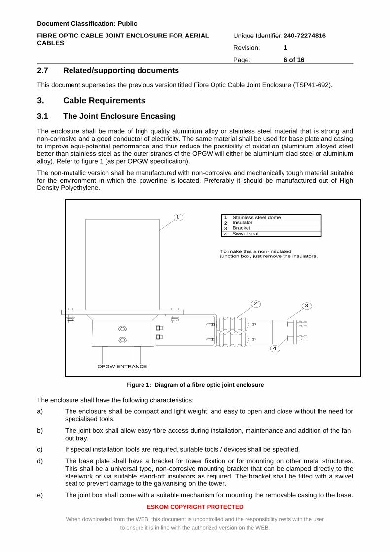
The enclosure shall be made of high quality aluminium alloy or stainless steel material that is strong and non-corrosive and a good conductor of electricity. The same material shall be used for base plate and casing to improve equi-potential performance and thus reduce the possibility of oxidation (aluminium alloyed steel better than stainless steel as the outer strands of the OPGW will either be aluminium-clad steel or aluminium alloy). Refer to figure 1 (as per OPGW specification).
The non-metallic version shall be manufactured with non-corrosive and mechanically tough material suitable for the environment in which the powerline is located. Preferably it should be manufactured out of High Density Polyethylene.
Figure 1: Diagram of a fibre optic joint enclosure
The enclosure shall have the following characteristics:
a) The enclosure shall be compact and light weight, and easy to open and close without the need for specialised tools.
b) The joint box shall allow easy fibre access during installation, maintenance and addition of the fan-out tray.
c) If special installation tools are required, suitable tools / devices shall be specified.
d) The base plate shall have a bracket for tower fixation or for mounting on other metal structures. This shall be a universal type, non-corrosive mounting bracket that can be clamped directly to the steelwork or via suitable stand-off insulators as required. The bracket shall be fitted with a swivel seat to prevent damage to the galvanising on the tower.
e) The joint box shall come with a suitable mechanism for mounting the removable casing to the base.
4
1
2 3
To make this a non-insulated
junction box, just remove the insulators.
OPGW ENTRANCE
4 Swivel seat32
1 Stainless steel dome
Insulator
Bracket
7

Document Classification: Public
FIBRE OPTIC CABLE JOINT ENCLOSURE FOR AERIAL CABLES
Unique Identifier: 240-72274816
Revision: 1
Page: 7 of 16
ESKOM COPYRIGHT PROTECTED
When downloaded from the WEB, this document is uncontrolled and the responsibility rests with the user
to ensure it is in line with the authorized version on the WEB.
f) The joint enclosure shall come with a cable clamp arrangement capable of clamping up to four fibre cables. The clamps shall be adjustable for various diameters of optical cable (from 10mm to 18mm diameter), and shall be threaded to accommodate a number 0 compression gland.
g) The base plate shall have four entry ports and shall come with two disposable plugs to temporarily protect the cable ports, and a minimum of two aluminium (or material similar to joint enclosure base) caps to seal the unused cable ports. The non-metallic version shall be injection moulded polycarbonate.
h) There shall be adequate sealing between the base plate and the removable casing, and all cable entrances. This sealing shall ensure that the joint box is water-tight, pressure-tight and able to be opened when needed. The enclosure shall come with four compression glands and associated adapters.
i) All component materials shall be non-toxic and shall not be a potential environmental hazard.
j) If mounted on insulated earth-wire towers, a minimum clearance of 15mm shall be maintained between the joint enclosure and the structure.
3.2 The Joint Enclosure Interior
The interior of the joint box shall have the following components:
a) An internal mounting bracket shall be provided for the splice and fan-out trays. This shall allow modular and flexible mounting of all trays.
b) The joint box shall have an assembly with a minimum of 1 fan-out tray and multiple organiser trays for the splices required. Each tray shall serve to accommodate spare fibre length (1m to 2m) for further splicing.
c) Each splice tray shall be able to accommodate a minimum of 12 fibres each. The trays shall be provided with a facility to secure the fibres.
d) Four fibre optic transportation tubes shall be provided per splice organising tray.
e) The splice and fan-out trays shall be suitable for both single and multi-mode fibres, allowing for an optical fibre minimum bending radius of 45mm in the fan-out and organiser trays.
f) The joint box shall come with a strain relief clamping bracket which shall allow mechanical fastening of different sizes of the optical fibre cable in the enclosure, including the GRP strength member (where applicable).
3.3 Testing
The joint enclosure shall be able to undergo traction, compression, flexure and torsion stresses acting on the splice cables, as outlined in the following paragraphs:
3.3.1 Routine Tests
3.3.1.1 Visual Appearance
This is included to ensure that no obvious defects are present that would affect product performance.
Testing shall be performed in accordance with IEC 61073-1.
The closure system and components shall be inspected for flaws, defects, pinholes, cracks or inclusions visible to the naked eye.
3.3.2 Type Tests
The mechanical and optical tests called for in this specification are considered as type tests. Eskom is prepared to review the results of similar tests which the supplier may have performed in the past and possibly waive the requirements for one or more of the tests specified in this document.

Document Classification: Public
FIBRE OPTIC CABLE JOINT ENCLOSURE FOR AERIAL CABLES
Unique Identifier: 240-72274816
Revision: 1
Page: 8 of 16
ESKOM COPYRIGHT PROTECTED
When downloaded from the WEB, this document is uncontrolled and the responsibility rests with the user
to ensure it is in line with the authorized version on the WEB.
3.3.2.1 Sealing Performance (Tightness)
This is the criterion test to check the integrity of the seals both after installation and after mechanical or environmental testing. Testing shall be performed in accordance with IEC 60068-2-17 Test Qc. The tightness of installed closures shall be checked by pressurizing to 40 kPa for a period of 15 minutes while immersed in water at room temperature. A sample shall be considered tight if there is no continuous stream of air bubbles escaping from it.
3.3.2.2 Axial Tension
This test is designed to stimulate cable / closure manipulation. It specifically addresses seal performance. The enclosure shall be tested in accordance with IEC 61073-1. Samples shall be pressurized internally at 40 kPa at room temperature and sealed prior to testing. The internal pressure shall be measured and recorded. The base assembly shall be clamped, and a force shall be applied to each of the extending cables individually for a period of one hour. The force per cable shall be calculated according to the equation:
(D (cable outer diameter in mm) / 45mm) x 1000 N, with a maximum of 1000 N.
After completion of the test, internal pressure shall be checked and specimens shall be subjected to the tightness test described in this document. The cable displacement shall be less than or equal to 3 mm.
3.3.2.3 Impact Resistance
This test is included to cover the effect of falling objects (by accident), e.g. tools, etc. on the metal closure. The enclosure shall be tested as per IEC 61073. Testing shall be at room temperature.
a) Samples shall be pressurized internally at 40 kPa at room temperature and sealed prior to testing. The internal pressure will be measured and recorded.
b) A sample shall be placed on a smooth, flat, horizontal surface with its longitudinal axis parallel to it.
c) A steel ball weighing 1 kg shall be suspended at a height of 2 meters above the centre of the test specimen then allowed to fall under the influence of gravity.
d) After visual inspection with the naked eye (as described above), pressure is checked and samples shall be subjected to the tightness test described in this document.
3.3.2.4 Re-Entry
This is the criterion test to check the tightness performance of closure which will be re-entered several times during its lifetime.
a) Testing shall be performed in accordance with IEC 61073-1.
b) Samples shall be pressurized internally at 40 kPa regulated.
c) Samples shall be supported in racks during testing in such a way that they are thermally isolated.
d) There shall be free circulation of air both between specimens and between the specimens and the chamber surfaces.
e) They shall be subjected to at least 1 cycle defined as follows:
Time Temperature or Range
4 hrs +20°C
1 hr +20°C to +60°C
4 hrs +60°C
2 hrs +60°C to -30°C
4 hrs -30°C
1 hr -30°C to +20°C
4 hrs +20°C

Document Classification: Public
FIBRE OPTIC CABLE JOINT ENCLOSURE FOR AERIAL CABLES
Unique Identifier: 240-72274816
Revision: 1
Page: 9 of 16
ESKOM COPYRIGHT PROTECTED
When downloaded from the WEB, this document is uncontrolled and the responsibility rests with the user
to ensure it is in line with the authorized version on the WEB.
f) The closures are opened, resealed and pressurized again at 40 kPa regulated and the whole sequence is repeated.
g) In total 10 re-entries will be carried out on each test sample.
h) After testing, samples shall be examined with the naked eye for signs of defects and subjected to the tightness test described in this document.
3.3.2.5 Shot Gun Damage
This test specifically addresses an aerial closure’s resistance when shot at.
a) Testing shall be performed in accordance with IEC 60794-1-2 Method E13.
b) Samples shall not be pressurized.
c) 3mm lead pellets (calibre: 12/70, Size Nr. 5) will be fired at the closure from a distance of 20 meters.
d) After completion of the test, the closure shall be subjected to the tightness test described in this document.
e) The closure shall be opened and checked for internal damage (visual appearance). No ammunition shall be found inside the closure.
3.3.2.6 Torsion
This test simulates cable/closure manipulation and focuses on the performance of seal integrity.
a) Testing shall be performed in accordance with IEC 61073-1.
b) Testing shall be done at -15°C and +45°C.
c) Samples shall be pressurized internally at 40 kPa at room temperature and sealed prior to testing. The internal pressure will be measured and recorded.
d) Samples shall be conditioned at -15°C or +45°C.
e) Each extending cable shall in turn be clamped rigidly at a distance of 400 mm, measured from the cable seal sleeve.
f) The closure system shall be axially rotated through 90° and retained in that position for a period of 5 minutes. The torque applied shall not exceed 50 Nm.
g) It shall then be returned to its original position and the procedure repeated in the opposite direction.
h) After 5 cycles, specimens shall be examined with the naked eye (visual appearance). internal pressure is checked and then subjected to the tightness test described in this document.
3.3.2.7 Temperature Cycling
This is an accelerated ageing test designed to highlight possible material incompatibility. It is also a lifetime simulation of seal integrity. The temperature range selected covers both indoor and outdoor closure applications but may be modified to accommodate cable specifications as necessary. Testing shall be according to IEC 60068-2-14, Test Nb.
a) For mechanical evaluation (using tightness as the criterion test) installed closure systems shall be pressurized internally at 40 kPa regulated.
b) Samples shall be supported in racks during testing in such a way that they are thermally isolated.
c) There shall be free circulation of air both between specimens and between the specimens and the chamber surfaces.

Document Classification: Public
FIBRE OPTIC CABLE JOINT ENCLOSURE FOR AERIAL CABLES
Unique Identifier: 240-72274816
Revision: 1
Page: 10 of 16
ESKOM COPYRIGHT PROTECTED
When downloaded from the WEB, this document is uncontrolled and the responsibility rests with the user
to ensure it is in line with the authorized version on the WEB.
d) They shall be subjected to 20 cycles defined as follows:
e) After testing, specimens will be subjected to the tightness test described in this document and samples shall be examined with the naked eye (visual appearance).
3.3.2.8 Vibration (Tightness)
This test simulates cable movement in the ports and tests the performance of the seals. The conditions relate to vibration caused by passing traffic.
a) Testing shall be in accordance with IEC 60068-2-6, Test Fc.
b) Samples shall be pressurized internally at 40 kPa regulated.
c) The dome shall be mounted horizontally on a vibration bank while the cables shall be clamped at a distance of 500 mm from the cable seal sleeves.
d) The closure shall be subjected to a vibration test with the following parameters:
Parameter Value
Frequency (10 ±1) Hz
Cycle Sinusoidal
Amplitude 3 mm
Duration 10 days
e) After testing, specimens shall be examined with the naked eye and then subjected to the tightness test described in this document.
3.3.2.9 Shock
This checks the effect of sudden, sharp movements during transport or closure handling. Testing shall be according to IEC 60068-2-27, Test Ea.
a) Samples shall be pressurized internally at 40 kPa at room temperature and sealed prior to testing. The internal pressure will be measured and recorded.
b) Samples shall be strapped onto a vibration bank and subjected to 3 shocks in each direction (up and down) for 3 mutually perpendicular axes.
c) Shocks shall have a half-sine waveform and an acceleration of 150 m/s² and a duration of 11 ms.
d) After the test, samples shall be examined with the naked eye (visual appearance), and then be subjected to the pressure loss test and the tightness test described in this document.
3.3.2.10 Vibration
a) This vibration test highlights possible problems caused by resonance effects. The effect on fibre and splice storage is checked. The conditions relate to vibration caused by passing traffic.
b) Testing shall be in accordance with IEC 61300-2-1.
Time Temperature or Range
2 hrs -30°C to +60°C
4 hrs +60°C
2 hrs +60°C to -30°C
4 hrs -30°C

Document Classification: Public
FIBRE OPTIC CABLE JOINT ENCLOSURE FOR AERIAL CABLES
Unique Identifier: 240-72274816
Revision: 1
Page: 11 of 16
ESKOM COPYRIGHT PROTECTED
When downloaded from the WEB, this document is uncontrolled and the responsibility rests with the user
to ensure it is in line with the authorized version on the WEB.
c) The optical test sample shall be built as described in this document.
d) The optical circuit will be connected to optical transient test equipment as described in this document.
e) The closure shall be mounted on a vibration bank and shall be subjected to a sweep range of 5-500 Hz at 1 octave/minute with the following parameters:
Parameter Value
Crossover frequency 9 Hz
Amplitude below 9 Hz 3.5 mm
Acceleration above 9 Hz 10 m/s² (~ 1 g)
f) The test shall be repeated for each of 3 mutually perpendicular axes, for a total of 10 cycles per axis.
g) During and after the test the optical signal will be monitored for transient optical losses. After completion of the test specimens shall be examined with the unaided eye for damage that would impair product functionality.
3.3.2.11 Temperature Cycling
This is a lifetime simulation of optical performance. The temperature range selected covers both indoor and outdoor closure applications but may need to be modified (to less severe extremes) to accommodate cable specifications as necessary.
a) The optical test samples shall be built as described in this document.
b) The circuit of the test sample will be connected to optical test equipment.
c) Temperature cycling test shall be according to IEC 61300-2-22.
d) Samples for optical evaluation are sealed but not pressurized.
e) Samples shall be supported in racks during testing in such a way that they are thermally isolated, and there shall be free circulation of air both between specimens and between the specimens and the chamber surfaces.
f) They shall be subjected to 20 cycles defined as follows:
Time (in hrs) Temperature or Range (ºC)
2 -30 to +60
4 +60
2 +60 to -30
4 -30
g) The change in optical signal during and after the test is checked for each circuit.
h) After the test, samples shall be examined with the naked eye (visual appearance).
3.3.2.12 Change in Insertion Loss
This is the criterion test for optical measurements during and after the test. The value quoted assumes the use of a stable qualified splice/protector, well installed. Testing shall be performed in accordance with IEC61300-3-3 Method 1. This is defined as a measured attenuation which is exhibited by stable transmission measurements taken before, during and after a test. It shall be measured using an optical source and a detector operating at 1310 nm and 1550 nm. The test set-up is shown below in figure 2:

Document Classification: Public
FIBRE OPTIC CABLE JOINT ENCLOSURE FOR AERIAL CABLES
Unique Identifier: 240-72274816
Revision: 1
Page: 12 of 16
ESKOM COPYRIGHT PROTECTED
When downloaded from the WEB, this document is uncontrolled and the responsibility rests with the user
to ensure it is in line with the authorized version on the WEB.
Figure 2: Test set-up for determining change in insertion loss
a) The in and out-going fibres of each circuit are spliced onto the connection fibres of the equipment. Splices shall be made using good-quality fusion splices.
b) During the test the optical signal in each fibre of the fibre circuit shall be monitored with the light source and detector at both wavelengths.
c) A change of more than 0.2 dB per incoming fibre (during the test) from the initial value constitutes a failure.
d) A change of more than 0.1 dB per incoming fibre (after the test) from the initial value constitutes a failure.
Note: The abovementioned loss criteria are per incoming fibre. Since one circuit can contain several incoming fibres it is possible that the total circuit generates higher losses. In this case the loss contribution per incoming fibre needs to be checked. This can be done using an OTDR or by reducing the number of incoming fibres per circuit.
3.4 Environmental
The performance of the fibre optic enclosure shall not be degraded under the following ambient conditions:
a) Temperature : -10 to 50C
b) Altitude : 0 to 2500 metres (ASL)
c) Relative Humidity : 100%
d) Barometric Pressure : 76 - 104 kPa
IEC Guide 104 should be taken into account as far as possible in regard to environmental and product safety requirements. If requested the manufacturer shall provide details on the environmental impact of the cable. Waste resulting from fibre joints and off-cuts shall be disposed in accordance with TPC41-212.
3.5 Identification and Labelling
The following information shall be clearly marked on the cable joint box:
a) The marking must be permanent (name of manufacturer).
b) Electrical Hazard Marker such as a Lightning flash or the traditional skull and bones logo.
c) Date of manufacture.
d) Laser radiation warning sticker.

Document Classification: Public
FIBRE OPTIC CABLE JOINT ENCLOSURE FOR AERIAL CABLES
Unique Identifier: 240-72274816
Revision: 1
Page: 13 of 16
ESKOM COPYRIGHT PROTECTED
When downloaded from the WEB, this document is uncontrolled and the responsibility rests with the user
to ensure it is in line with the authorized version on the WEB.
3.6 Packaging
The joint box shall be packaged such that it incurs no damage during shipping and handling.
The additional enclosure components shall be sealed and packaged within the overall packaging. Each package shall be labelled to outline what is contained inside.
3.7 Documentation
a) Upon request the supplier shall supply one copy of the type test report.
b) On delivery of the enclosure, the supplier shall supply installation guidelines with each joint box.
c) All documentation called for shall be provided in soft copy and hard covered ring files which comply with the following requirements:
Supplied in English.
A4 Paper Size.
Of a construction that can open flat on any page.
d) Any drawings and descriptions included shall conform to the A4 series (295mm x 220mm). Larger drawings shall be folded in a single panel along the 200mm axis of the standard A4 size. Drawings which must be folded in two directions are not acceptable.
e) Different sections of the documentation shall be separated by means of thumb – tag separators.
f) The documentation shall include the following:
Index.
Manufacturer’s specification sheet, including details of the joint box construction.
Test Certificates for tests done in compliance with clause 3.3.
The manufacturer shall supply this, together with full installation instructions, to the project manager.
4. Authorization
This document has been seen and accepted by:
Name and surname Designation
Vanessa Naidu Senior Engineer
Lesiba Buthane Dx TCM
5. Revisions
Date Rev Compiler Remarks
Sept 2016 1 Hussain Khan Information from old document has been included in this updated template.
6. Development team
The following people were involved in the development of this document:
Hussain Khan
Bharat Haridass
Vanessa Naidu

Document Classification: Public
FIBRE OPTIC CABLE JOINT ENCLOSURE FOR AERIAL CABLES
Unique Identifier: 240-72274816
Revision: 1
Page: 14 of 16
ESKOM COPYRIGHT PROTECTED
When downloaded from the WEB, this document is uncontrolled and the responsibility rests with the user
to ensure it is in line with the authorized version on the WEB.
7. Acknowledgements
Not applicable.

Document Classification: Public
FIBRE OPTIC CABLE JOINT ENCLOSURE FOR AERIAL CABLES
Unique Identifier: 240-72274816
Revision: 1
Page: 15 of 16
ESKOM COPYRIGHT PROTECTED
When downloaded from the WEB, this document is uncontrolled and the responsibility rests with the user
to ensure it is in line with the authorized version on the WEB.
Annex A – Schedule A/B (Technical Particulars for Joint Enclosure)
DESCRIPTION
COLUMN A
PARTICULARS OF ESKOM'S
REQUIREMENTS
COLUMN B
GUARANTEED TECHNICAL
PARTICULARS OFFERED
REMARKS
1) Joint enclosure dimensions (mm)
(Section 3.1)
Specify
2) Weight of joint box (g)
(Section 3.1)
Specify
3) Type of material used:
Enclosure
Mounting Brackets
Cable clamps
Base plate
(Section 3.1)
Specify
4) Mounting brackets universal?
(Section 3.1)
Yes
5) Specialised installation tools required?
(Section 3.1)
Specify
6) Installation guidelines supplied with enclosure?
(Section 3.7)
Yes
7) Maximum capacity
(Section 3.1)
4 cables
8) Fibre fan-out tray bending radius
(Section 3.2)
45mm
9) Retained fibre length
(Section 3.2)
1m to 2m
10) Cable clamps entry adjustable
(Section 3.1)
Yes
11) Type test results available? (Section 3.7)
Yes / No
12) If not available, by when? Specify
13) Applicable temperature range? Specify

Document Classification: Public
FIBRE OPTIC CABLE JOINT ENCLOSURE FOR AERIAL CABLES
Unique Identifier: 240-72274816
Revision: 1
Page: 16 of 16
ESKOM COPYRIGHT PROTECTED
When downloaded from the WEB, this document is uncontrolled and the responsibility rests with the user
to ensure it is in line with the authorized version on the WEB.
Annex B – Statement of Non - Compliance
The equipment supplied on this contract complies in all respects with the requirements of the specification and Schedule A/B with the exception of the following points:
Page Paragraph Deviation or Non-Compliance