standard test methods for deep foundations under lateral · pdf filestandard test methods for...
TRANSCRIPT
Designation: D3966 – 07
Standard Test Methods forDeep Foundations Under Lateral Load1
This standard is issued under the fixed designation D3966; the number immediately following the designation indicates the year oforiginal adoption or, in the case of revision, the year of last revision. A number in parentheses indicates the year of last reapproval. Asuperscript epsilon (´) indicates an editorial change since the last revision or reapproval.
1. Scope*
1.1 The test methods described in this standard measure thelateral deflection of a vertical or inclined deep foundation whensubjected to lateral loading. These methods apply to all deepfoundations, referred to herein as “pile(s),” that function in amanner similar to driven piles or cast in place piles, regardlessof their method of installation, and may be used for testingsingle piles or pile groups. The test results may not representthe long-term performance of a deep foundation.
1.2 These test methods provide minimum requirements fortesting deep foundations under lateral load. Plans, specifica-tions, provisions, or combinations thereof prepared by aqualified engineer may provide additional requirements andprocedures as needed to satisfy the objectives of a particulartest program. The engineer in responsible charge of thefoundation design, referred to herein as the engineer, shallapprove any deviations, deletions, or additions to the require-ments of these test methods.
1.3 These test methods allow the following test procedures:Procedure Test Section
A Standard Loading 8.1.2B Excess Loading (optional) 8.1.3C Cyclic Loading (optional) 8.1.4D Surge Loading (optional) 8.1.5E Reverse Loading (optional) 8.1.6F Reciprocal Loading (optional) 8.1.7G Specified Lateral Movement (optional) 8.1.8H Combined Loading (optional) 8.1.9
1.4 Apparatus and procedures herein designated “optional”may produce different test results and may be used only whenapproved by the engineer. The word “shall” indicates amandatory provision, and the word “should” indicates a
recommended or advisory provision. Imperative sentencesindicate mandatory provisions.
1.5 A qualified geotechnical engineer should interpret thetest results obtained from the procedures of these test methodsso as to predict the actual performance and adequacy of pilesused in the constructed foundation. See Appendix X1 forcomments regarding some of the factors influencing theinterpretation of test results.
1.6 A qualified engineer shall design and approve all load-ing apparatus, loaded members, support frames, and testprocedures. The text of these test methods references notes andfootnotes which provide explanatory material. These notes andfootnotes (excluding those in tables and figures) shall not beconsidered as requirements of the test methods. These testmethods also include illustrations and appendices intendedonly for explanatory or advisory use.
1.7 The values stated in either SI units or inch-pound unitsare to be regarded separately as standard. The values stated ineach system may not be exact equivalents; therefore, eachsystem shall be used independently of the other. Combiningvalues from the two systems may result in non-conformancewith the standard.
1.8 The gravitational system of inch-pound units is usedwhen dealing with inch-pound units. In this system, the pound(lbf) represents a unit of force (weight), while the unit for massis slugs. The rationalized slug unit is not given, unless dynamic(F=ma) calculations are involved.
1.9 All observed and calculated values shall conform to theguidelines for significant digits and rounding established inPractice D6026.
1.10 The method used to specify how data are collected,calculated, or recorded in these test methods is not directlyrelated to the accuracy to which the data can be applied indesign or other uses, or both. How one applies the resultsobtained using this standard is beyond its scope.
1.11 ASTM International takes no position respecting thevalidity of any patent rights asserted in connection with anyitem mentioned in this standard. Users of this standard are
1 These test methods are under the jurisdiction of ASTM Committee D18 on Soiland Rock and are the direct responsibility of Subcommittee D18.11 on DeepFoundations.
Current edition approved Sept. 1, 2007. Published October 2007. Originallyapproved in 1981. Last previous edition approved in 1995 as D3966 – 90 (1995)which was withdrawn in December 2003 and reinstated in September 2007. DOI:10.1520/D3966-07.
1
*A Summary of Changes section appears at the end of this standard.
Copyright © ASTM International, 100 Barr Harbor Drive, PO Box C700, West Conshohocken, PA 19428-2959, United States.
Copyright by ASTM Int'l (all rights reserved); Sat Apr 2 09:10:05 EDT 2011Downloaded/printed byAli Qazaz () pursuant to License Agreement. No further reproductions authorized.
expressly advised that determination of the validity of any suchpatent rights, and the risk of infringement of such rights, areentirely their own responsibility.
1.12 This standard does not purport to address all of thesafety concerns, if any, associated with its use. It is theresponsibility of the user of this standard to establish appro-priate safety and health practices and determine the applica-bility of regulatory limitations prior to use.
2. Referenced Documents
2.1 ASTM Standards:2
A36/A36M Specification for Carbon Structural SteelA240/A240M Specification for Chromium and Chromium-
Nickel Stainless Steel Plate, Sheet, and Strip for PressureVessels and for General Applications
A572/A572M Specification for High-Strength Low-AlloyColumbium-Vanadium Structural Steel
D653 Terminology Relating to Soil, Rock, and ContainedFluids
D1143 Test Method for Piles Under Static Axial Compres-sive Load3
D3689 Test Methods for Deep Foundations Under StaticAxial Tensile Load
D3740 Practice for Minimum Requirements for AgenciesEngaged in Testing and/or Inspection of Soil and Rock asUsed in Engineering Design and Construction
D5882 Test Method for Low Strain Impact Integrity Testingof Deep Foundations
D6026 Practice for Using Significant Digits in GeotechnicalData
D6760 Test Method for Integrity Testing of Concrete DeepFoundations by Ultrasonic Crosshole Testing
2.2 American Society of Mechanical Engineer Standards:4
ASME B30.1 JacksASME B40.100 Pressure Gauges and Gauge AttachmentsASME B46.1 Surface TextureASME B89.1.10.M Dial Indicators (For Linear Measure-
ments)
3. Terminology
3.1 Definitions—For common definitions of terms used inthis standard see Terminology D653.
3.2 Definitions of Terms Specific to This Standard:3.2.1 cast in-place pile, n—a deep foundation unit made of
cement grout or concrete and constructed in its final location,e.g. drilled shafts, bored piles, caissons, auger cast piles,pressure-injected footings, etc.
3.2.2 deep foundation, n—a relatively slender structuralelement that transmits some or all of the load it supports to soil
or rock well below the ground surface, such as a steel pipe pileor concrete drilled shaft.
3.2.3 driven pile, n—a deep foundation unit made of pre-formed material with a predetermined shape and size andtypically installed by impact hammering, vibrating, or pushing.
3.2.4 failure load, n—for the purpose of terminating alateral load test, the test load at which continuing, progressivemovement occurs, or as specified by the engineer.
3.2.5 wireline, n—a steel wire mounted with a constanttension force between two supports and used as a reference lineto read a scale indicating movement of the test pile.
4. Significance and Use
4.1 Field tests provide the most reliable relationship be-tween the lateral load applied to a deep foundation and theresulting lateral movement. Test results may also provideinformation used to assess the distribution of lateral resistancealong the pile shaft and the long-term load-deflection behavior.A foundation designer may evaluate the test results to deter-mine if, after applying an appropriate factor of safety, the pileor pile group has an ultimate lateral capacity and a deflectionat service load satisfactory to satisfy specific foundationrequirements. When performed as part of a multiple-pile testprogram, the designer may also use the results to assess theviability of different piling types and the variability of the testsite.
4.2 The analysis of lateral test results obtained using properinstrumentation helps the foundation designer characterize thevariation of pile-soil interaction properties, such as the coeffi-cient of horizontal subgrade reaction, to estimate bendingstresses and lateral deflection over the length of the pile for usein the structural design of the pile.
4.3 If feasible, without exceeding the safe structural load onthe pile(s) or pile cap, the maximum load applied should reacha failure load from which the engineer may determine theultimate lateral load capacity of the pile(s). Tests that achievea failure load may help the designer improve the efficiency ofthe foundation by reducing the piling length, quantity, or size.
4.4 If deemed impractical to apply lateral test loads to aninclined pile, the engineer may elect to use lateral test resultsfrom a nearby vertical pile to evaluate the lateral capacity ofthe inclined pile.
NOTE 1—The quality of the result produced by this test method isdependent on the competence of the personnel performing it, and thesuitability of the equipment and facilities used. Agencies that meet thecriteria of Practice D3740 are generally considered capable of competentand objective testing/sampling/inspection/etc. Users of this test methodare cautioned that compliance with Practice D3740 does not in itselfassure reliable results. Reliable results depend on many factors; PracticeD3740 provides a means of evaluating some of those factors.
5. Test Foundation Preparation
5.1 Excavate or fill the test area to the final grade elevationwithin a radius of 6 m (20 ft) from the test pile or group usingthe same material and backfilling methods as for productionpiles. Cut off or build up the test pile(s) as necessary to permitconstruction of the load-application apparatus, placement ofthe necessary testing and instrumentation equipment, andobservation of the instrumentation. Remove any damaged or
2 For referenced ASTM standards, visit the ASTM website, www.astm.org, orcontact ASTM Customer Service at [email protected]. For Annual Book of ASTMStandards volume information, refer to the standard’s Document Summary page onthe ASTM website.
3 Withdrawn. The last approved version of this historical standard is referencedon www.astm.org.
4 Available from American Society of Mechanical Engineers (ASME), ASMEInternational Headquarters, Three Park Ave., New York, NY 10016-5990, http://www.asme.org.
D3966 – 07
2
Copyright by ASTM Int'l (all rights reserved); Sat Apr 2 09:10:05 EDT 2011Downloaded/printed byAli Qazaz () pursuant to License Agreement. No further reproductions authorized.
unsound material from the pile top as necessary to properlyinstall the apparatus for measuring movement, for applyingload, and for measuring load.
5.2 For tests of single piles, install solid steel test plate(s) atleast 50 mm (2 in.) thick against the side of the pile at thepoint(s) of load application and perpendicular to the line of theload action. The test plate shall have side dimensions not morethan, and not less than one half of, the diameter or sidedimension of the test pile(s). The test plate(s) shall span acrossand between any unbraced flanges on the test pile.
5.3 For tests on pile groups, cap the pile group withsteel-reinforced concrete or a steel load frame designed andconstructed to safely sustain and equally distribute the antici-pated loads. The connection between the piles and the cap shallsimulate in-service conditions. Pile caps shall be cast abovegrade unless otherwise specified and may be formed on theground surface.
5.4 For each loading point on a pile cap, provide a solidsteel test plate oriented perpendicular to the axis of the pilegroup with a minimum thickness of 50 mm (2 in.), as neededto safely apply load to the pile cap. Center a single test plate onthe centroid of the pile group. Locate multiple test platessymmetrically about the centroid of the pile group.
5.5 To minimize stress concentrations due to minor irregu-larities of the pile surface, set test plates bearing on precast orcast-in-place concrete piles in a thin layer of quick-setting,non-shrink grout, less than 6 mm (0.25 in.) thick and having acompressive strength greater than the test pile at the time of thetest. Set test plates designed to bear on a concrete pile cap in athin layer of quick-setting, non-shrink grout, less than 6 mm(0.25 in.) thick and having a compressive strength greater thanthe pile cap at the time of the test. For tests on steel piles, or asteel load frame, weld the test plates to the pile or load frame.For test piles without a flat side of adequate width to mount thetest plate, cap the head of the pile to provide a bearing surfacefor the test plate or set the test plate in high-strength grout. Inall cases, provide full bearing for the test plate against theprojected area of the pile.
5.6 Elimination of Pile Cap Friction (optional)—Provide aclear space beneath the pile cap as specified by the engineer.This option isolates the lateral response of the piles from thatof the pile cap.
5.7 Passive Soil Pressure Against Pile Cap (optional)—Develop passive soil pressure against the pile cap by construct-ing the pile cap below the ground surface and backfilling withcompacted fill on the side opposite the point of load applica-tion, or by constructing the pile cap above the ground surfaceagainst an embankment. If specified, place compacted againstthe sides of the pile cap to the extent practicable.
NOTE 2—Deep foundations sometimes include hidden defects that maygo unnoticed prior to static testing. Low strain integrity tests as describedin Test Method D5882 and ultrasonic crosshole integrity tests as describedin Test Method D6760 may provide a useful pre-test evaluation of the testfoundation.
6. Apparatus for Applying and Measuring Loads
6.1 General:6.1.1 The apparatus for applying tensile loads to a test pile
or pile group shall conform to one of the methods described in
6.3-6.6. Unless otherwise specified, construct the test apparatusso that the resultant loads are applied horizontally, at approxi-mately pile cut-off elevation, and in line with the centralvertical axis of the pile or pile group so as to minimizeeccentric loading and avoid a vertical load component.
NOTE 3—For lateral tests on inclined pile frames or pile groupsinvolving inclined piles, consider applying the lateral test loads at theactual or theoretical point of intersection of the longitudinal axis of thepiles in the frame or group.
6.1.2 Struts and Blocking—Struts shall be of steel and ofsufficient size and stiffness to transmit the applied test loadswithout bending or buckling. Blocking used between reactionpiles or between the hydraulic jack and the reaction systemshall be of sufficient size and strength to prevent crushing orother distortion under the applied test loads.
6.1.3 Reaction piles, if used, shall be of sufficient numberand installed so as to safely provide adequate reaction capacitywithout excessive movement. When using two or more reac-tion piles at each end of the test beam(s), cap or block them asneeded to develop the reaction load. Locate reaction piles sothat resultant test beam load supported by them acts at thecenter of the reaction pile group. Cribbing or deadmen, if usedas a reaction, shall be of sufficient plan dimensions and weightto transfer the reaction loads to the soil without excessivelateral movement that would prevent maintaining the appliedloads.
6.1.4 Provide a clear distance between the test pile(s) andthe reaction piles or cribbing of at least five times themaximum diameter of the largest test or reaction pile(s), butnot less than 2.5 m (8 ft). The engineer may increase ordecrease this minimum clear distance based on factors such asthe type and depth of reaction, soil conditions, and magnitudeof loads so that reaction forces do not significantly effect thetest results.
NOTE 4—Excessive vibrations during reaction pile installation in noncohesive soils may affect test results. Reaction piles that penetrate deeperthan the test pile may affect test results. Install the anchor piles nearest thetest pile first to help reduce installation effects.
6.1.5 Each jack shall include a lubricated hemisphericalbearing or similar device to minimize lateral loading of the pileor pile group. The hemispherical bearing(s) should include alocking mechanism for safe handling and setup.
6.1.6 Provide bearing stiffeners as needed between theflanges of test and reaction beams.
6.1.7 Provide steel bearing plates to spread the load to andbetween the jack(s), load cell(s), hemispherical bearing(s), testbeam(s), reaction beam(s), and reaction pile(s). Unless other-wise specified by the engineer, the size of the bearing platesshall be not less than the outer perimeter of the jack(s), loadcell(s), or hemispherical bearing(s), nor less than the totalwidth of the test beam(s), reaction beam(s), reaction piles so asto provide full bearing and distribution of the load. Bearingplates supporting the jack(s), test beam(s), or reaction beamson timber or concrete cribbing shall have an area adequate forsafe bearing on the cribbing.
6.1.8 Unless otherwise specified, where using steel bearingplates, provide a total plate thickness adequate to spread thebearing load between the outer perimeters of loaded surfaces at
D3966 – 07
3
Copyright by ASTM Int'l (all rights reserved); Sat Apr 2 09:10:05 EDT 2011Downloaded/printed byAli Qazaz () pursuant to License Agreement. No further reproductions authorized.
a maximum angle of 45 degrees to the loaded axis. For centerhole jacks and center hole load cells, also provide steel platesadequate to spread the load from their inner diameter to thetheir central axis at a maximum angle of 45 degrees, or permanufacturer recommendations.
6.1.9 Align all struts, blocking, bearing plates, jacks, loadcells, hemispherical bearings, and testing apparatus to mini-mize eccentric loading, and, where necessary, restrain themfrom shifting as test loads are applied so as not to affect the testresults and to prevent instability. Test members and apparatusshall have flat, parallel bearing surfaces. Design and constructthe support reactions to prevent instability and to limit undes-ired rotations or lateral displacements.
6.1.10 Unless otherwise specified by the engineer, designand construct the apparatus for applying and measuring loads,including all struts and structural members, of steel withsufficient size, strength, and stiffness to safely prevent exces-sive deflection and instability up to 125 % of the maximumanticipated test load.
6.1.11 Inspect all tension rods, lines, rope, cable, and theirconnections used for pull tests to insure good, serviceablecondition. Unless otherwise specified by the engineer, designand construct these tension members with sufficient strength tosafely resist a load at least 50 % greater than the maximumanticipated test load. Tension members with a cross-sectionalarea reduced by corrosion or damage, or with material prop-erties compromised by fatigue, bending, or excessive heat, mayrupture suddenly under load. Do not use brittle materials fortension connections.
6.1.12 A qualified engineer shall design and approve allloading apparatus, loaded members, support frames, and load-ing procedures.
6.2 Hydraulic Jacks, Gauges, Transducers, and Load Cells:6.2.1 The hydraulic jack(s) and their operation shall con-
form to ASME B30.1 and shall have a nominal load capacityexceeding the maximum anticipated jack load by at least 20 %.The jack, pump, and any hoses, pipes, fittings, gauges, ortransducers used to pressurize it shall be rated to a safe pressurecorresponding to the nominal jack capacity.
6.2.2 The hydraulic jack ram(s) shall have a travel greaterthan the sum of the anticipated maximum axial movement ofthe pile plus the deflection of the test beam and the elongationof the tension connection, but not less than 15 % of the averagepile diameter or width. Use a single high capacity jack whenpossible. When using a multiple jack system, provide jacks ofthe same make, model, and capacity, and supply the jackpressure through a common manifold with a master pressuregauge. Fit the manifold and each jack with a pressure gauge todetect malfunctions and imbalances.
6.2.3 Unless otherwise specified, the hydraulic jack(s), pres-sure gauge(s), and pressure transducer(s) shall have a calibra-tion to at least the maximum anticipated jack load, over theircomplete range of piston travel for increasing and decreasingapplied loads and performed within the six months prior toeach test or series of tests. Hydraulic jacks used in double-action shall be calibrated in both the push and pull modes.Furnish the calibration report(s) prior to performing a test,
which shall include the ambient temperature and calibrationsperformed for multiple ram strokes up to the maximum strokeof the jack.
6.2.4 If the lateral load is applied by pulling, the apparatusused to produce the pulling force shall be capable of applyinga steady constant force over the required load testing range.The dynamometer(s), or other in-line load indicating device(s),shall be calibrated to an accuracy of not less than 10% of theapplied load.
6.2.5 Each complete jacking and pressure measurementsystem, including the hydraulic pump, should be calibrated asa unit when practicable. The hydraulic jack(s) shall be cali-brated over the complete range of ram travel for increasing anddecreasing applied loads. If two or more jacks are to be used toapply the test load, they shall be of the same make, model, andsize, connected to a common manifold and pressure gauge, andoperated by a single hydraulic pump. The calibrated jackingsystem(s) shall have accuracy within 5 % of the maximumapplied load. When not feasible to calibrate a jacking system asa unit, calibrate the jack, pressure gauges, and pressuretransducers separately, and each of these components shallhave accuracy within 2 % of the applied load.
6.2.6 Pressure gauges shall have minimum graduations lessthan or equal to 1 % of the maximum applied load and shallconform to ASME B40.100 with an accuracy grade 1A havinga permissible error 61 % of the span. Pressure transducersshall have a minimum resolution less than or equal to 1 % ofthe maximum applied load and shall conform to AS-ME B40.100 with an accuracy grade 1A having a permissibleerror 61 % of the span. When used for control of the test,pressure transducers shall include a real-time display.
6.2.7 If the maximum test load will exceed 900 kN (100tons), place a properly constructed load cell or equivalentdevice in series with each hydraulic jack or pulling apparatus.Unless otherwise specified the load cell(s) shall have a cali-bration to at least the maximum anticipated jack load per-formed within the six months prior to each test or series oftests. The calibrated load cell(s) or equivalent device(s) shallhave accuracy within 1 % of the applied load, including aneccentric loading of up to 1 % applied at an eccentric distanceof 25 mm (1 in.). After calibration, load cells shall not besubjected to impact loads. A load cell is recommended, but notrequired, for lesser load. If not practicable to use a load cellwhen required, include embedded strain gauges located inclose proximity to the jack to confirm the applied load.
6.2.8 Do not leave the hydraulic jack pump unattended atany time during the test. An automatic regulator is recom-mended to help hold the load constant as pile movementoccurs. Automated jacking systems shall include a clearlymarked mechanical override to safely reduce hydraulic pres-sure in an emergency.
6.3 Load Applied by Hydraulic Jack(s) Acting Against aReaction System (Fig. 1):
6.3.1 General—Apply the test loads to the pile or pile groupusing one or more hydraulic cylinders and a suitable reactionsystem according to 6.3.2, 6.3.3, 6.3.4, or 6.3.5. The reactionsystem may be any convenient distance from the test pile orpile group and shall provide a resistance greater than the
D3966 – 07
4
Copyright by ASTM Int'l (all rights reserved); Sat Apr 2 09:10:05 EDT 2011Downloaded/printed byAli Qazaz () pursuant to License Agreement. No further reproductions authorized.
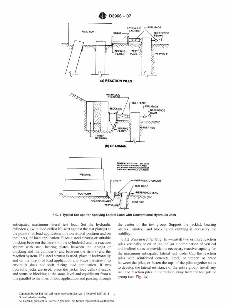
anticipated maximum lateral test load. Set the hydrauliccylinder(s) (with load cell(s) if used) against the test plate(s) atthe point(s) of load application in a horizontal position and onthe line(s) of load application. Place a steel strut(s) or suitableblocking between the base(s) of the cylinder(s) and the reactionsystem with steel bearing plates between the strut(s) orblocking and the cylinder(s) and between the strut(s) and thereaction system. If a steel strut(s) is used, place it horizontallyand on the line(s) of load application and brace the strut(s) toensure it does not shift during load application. If twohydraulic jacks are used, place the jacks, load cells (if used),and struts or blocking at the same level and equidistant from aline parallel to the lines of load application and passing through
the center of the test group. Support the jack(s), bearingplate(s), strut(s), and blocking on cribbing if necessary forstability.
6.3.2 Reaction Piles (Fig. 1a)—Install two or more reactionpiles vertically or on an incline (or a combination of verticaland incline) so as to provide the necessary reactive capacity forthe maximum anticipated lateral test loads. Cap the reactionpiles with reinforced concrete, steel, or timber, or bracebetween the piles, or fasten the tops of the piles together so asto develop the lateral resistance of the entire group. Install anyinclined reaction piles in a direction away from the test pile orgroup (see Fig. 1a).
FIG. 1 Typical Set-ups for Applying Lateral Load with Conventional Hydraulic Jack
D3966 – 07
5
Copyright by ASTM Int'l (all rights reserved); Sat Apr 2 09:10:05 EDT 2011Downloaded/printed byAli Qazaz () pursuant to License Agreement. No further reproductions authorized.
6.3.3 Deadman (Fig. 1b)—Where soil or site conditions aresuitable, install a deadman consisting of cribbing, timberpanels, sheeting, or similar construction bearing against anembankment or the sides of an excavation so as to provide thenecessary reactive capacity to the maximum anticipated lateraltest loads.
6.3.4 Weighted Platforms (Fig. 1c)—Construct a platform ofany suitable material such as timber, concrete, or steel, andload the platform with sufficient weights to provide thenecessary resistance to the maximum anticipated lateral testloads to be applied. Provide a suitable bearing surface on theedge of the platform against which the reactive lateral load willbe applied.
6.3.5 Other Reaction Systems (optional)—Use any otherspecified suitable reaction system such as an existing structure.
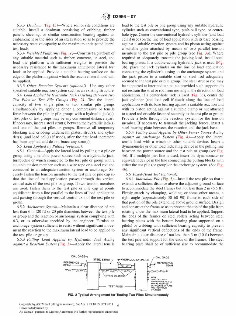
6.4 Load Applied by Hydraulic Jack(s) Acting Between TwoTest Piles or Test Pile Groups (Fig. 2)—Test the lateralcapacity of two single piles or two similar pile groupssimultaneously by applying either a compressive or tensileforce between the pile or pile groups with a hydraulic jack(s).Test piles or test groups may be any convenient distance apart.If necessary, insert a steel strut(s) between the hydraulic jack(s)and one of the test piles or groups. Remove all temporaryblocking and cribbing underneath plates, strut(s), and cylin-der(s) (and load cell(s) if used), after the first load incrementhas been applied and do not brace any strut(s).
6.5 Load Applied by Pulling (optional):6.5.1 General—Apply the lateral load by pulling test pile or
group using a suitable power source such as a hydraulic jack,turnbuckle or winch connected to the test pile or group with asuitable tension member such as a wire rope or a steel rod andconnected to an adequate reaction system or anchorage. Se-curely fasten the tension member to the test pile or pile cap sothat the line of load application passes through the verticalcentral axis of the test pile or group. If two tension membersare used, fasten them to the test pile or pile cap at pointsequidistant from a line parallel to the lines of load applicationand passing through the vertical central axis of the test pile orgroup.
6.5.2 Anchorage System—Maintain a clear distance of notless than 6 m (20 ft) or 20 pile diameters between the test pileor group and the reaction or anchorage system complying with6.3, or as otherwise specified by the engineer. Furnish ananchorage system sufficient to resist without significant move-ment the reaction to the maximum lateral load to be applied tothe test pile or group.
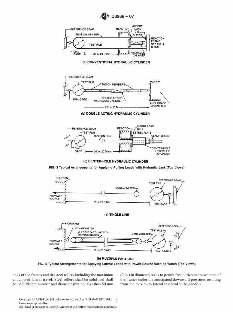
6.5.3 Pulling Load Applied by Hydraulic Jack Actingagainst a Reaction System (Fig. 3)—Apply the lateral tensile
load to the test pile or pile group using any suitable hydrauliccylinder such as conventional type, push-pull type, or center-hole type. Center the conventional hydraulic cylinder (and loadcell if used) on the line of load application with its base bearingagainst a suitable reaction system and its piston acting againsta suitable yoke attached by means of two parallel tensionmembers to the test pile or pile group (see Fig. 3a). Whererequired to adequately transmit the jacking load, install steelbearing plates. If a double-acting hydraulic jack is used (Fig.3b), place the jack cylinder on the line of load applicationconnecting the cylinder’s casing to the anchorage system andthe jack piston to a suitable strut or steel rod adequatelysecured to the test pile or pile group. The steel strut or rod maybe supported at intermediate points provided such supports donot restrain the strut or rod from moving in the direction of loadapplication. If a center-hole jack is used (Fig. 3c), center thejack cylinder (and load cell if used) along the line of loadapplication with its base bearing against a suitable reaction andwith its piston acting against a suitable clamp or nut attachedto a steel rod or cable fastened securely to the test pile or group.Provide a hole through the reaction system for the tensionmember. If necessary to transmit the jacking forces, insert asteel bearing plate between the reaction and the jack base.
6.5.4 Pulling Load Applied by Other Power Source Actingagainst an Anchorage System (Fig. 4)—Apply the lateraltensile load with a winch or other suitable device. Insert adynamometer or other load indicating device in the pulling linebetween the power source and the test pile or group (see Fig.4a). If a multiple part line is used, insert the dynamometer orequivalent device in the line connecting the pulling blocks witheither the test pile (or group) or the anchorage system. (See Fig.4b).
6.6 Fixed-Head Test (optional):6.6.1 Individual Pile (Fig. 5)—Install the test pile so that it
extends a sufficient distance above the adjacent ground surfaceto accommodate the steel frames but not less than 2 m (6.5 ft).Firmly attach by clamping, welding, or some other means, aright angle (approximately 30–60–90) frame to each side ofthat portion of the pile extending above ground surface. Designand construct the frame so as to prevent the top of the pile fromrotating under the maximum lateral load to be applied. Supportthe ends of the frames on steel rollers acting between steelbearing plates with the bottom bearing plate supported on apile(s) or cribbing with sufficient bearing capacity to preventany significant vertical deflections of the ends of the frame.Maintain a clear distance of not less than 3 m (10 ft) betweenthe test pile and support for the ends of the frames. The steelbearing plate shall be of sufficient size to accommodate the
FIG. 2 Typical Arrangement for Testing Two Piles Simultaneously
D3966 – 07
6
Copyright by ASTM Int'l (all rights reserved); Sat Apr 2 09:10:05 EDT 2011Downloaded/printed byAli Qazaz () pursuant to License Agreement. No further reproductions authorized.
ends of the frames and the steel rollers including the maximumanticipated lateral travel. Steel rollers shall be solid and shallbe of sufficient number and diameter (but not less than 50 mm
(2 in.) in diameter) so as to permit free horizontal movement ofthe frames under the anticipated downward pressures resultingfrom the maximum lateral test load to be applied.
FIG. 3 Typical Arrangements for Applying Pulling Loads with Hydraulic Jack (Top Views)
FIG. 4 Typical Arrangements for Applying Lateral Loads with Power Source such as Winch (Top Views)
D3966 – 07
7
Copyright by ASTM Int'l (all rights reserved); Sat Apr 2 09:10:05 EDT 2011Downloaded/printed byAli Qazaz () pursuant to License Agreement. No further reproductions authorized.
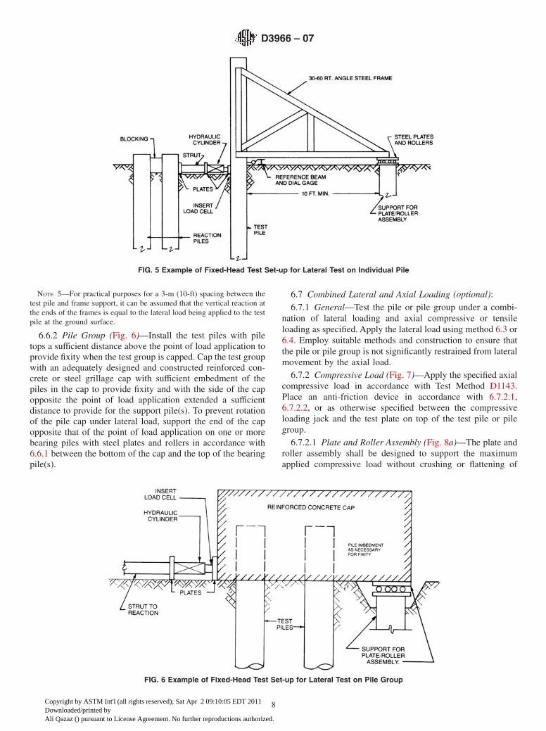
NOTE 5—For practical purposes for a 3-m (10-ft) spacing between thetest pile and frame support, it can be assumed that the vertical reaction atthe ends of the frames is equal to the lateral load being applied to the testpile at the ground surface.
6.6.2 Pile Group (Fig. 6)—Install the test piles with piletops a sufficient distance above the point of load application toprovide fixity when the test group is capped. Cap the test groupwith an adequately designed and constructed reinforced con-crete or steel grillage cap with sufficient embedment of thepiles in the cap to provide fixity and with the side of the capopposite the point of load application extended a sufficientdistance to provide for the support pile(s). To prevent rotationof the pile cap under lateral load, support the end of the capopposite that of the point of load application on one or morebearing piles with steel plates and rollers in accordance with6.6.1 between the bottom of the cap and the top of the bearingpile(s).
6.7 Combined Lateral and Axial Loading (optional):6.7.1 General—Test the pile or pile group under a combi-
nation of lateral loading and axial compressive or tensileloading as specified. Apply the lateral load using method 6.3 or6.4. Employ suitable methods and construction to ensure thatthe pile or pile group is not significantly restrained from lateralmovement by the axial load.
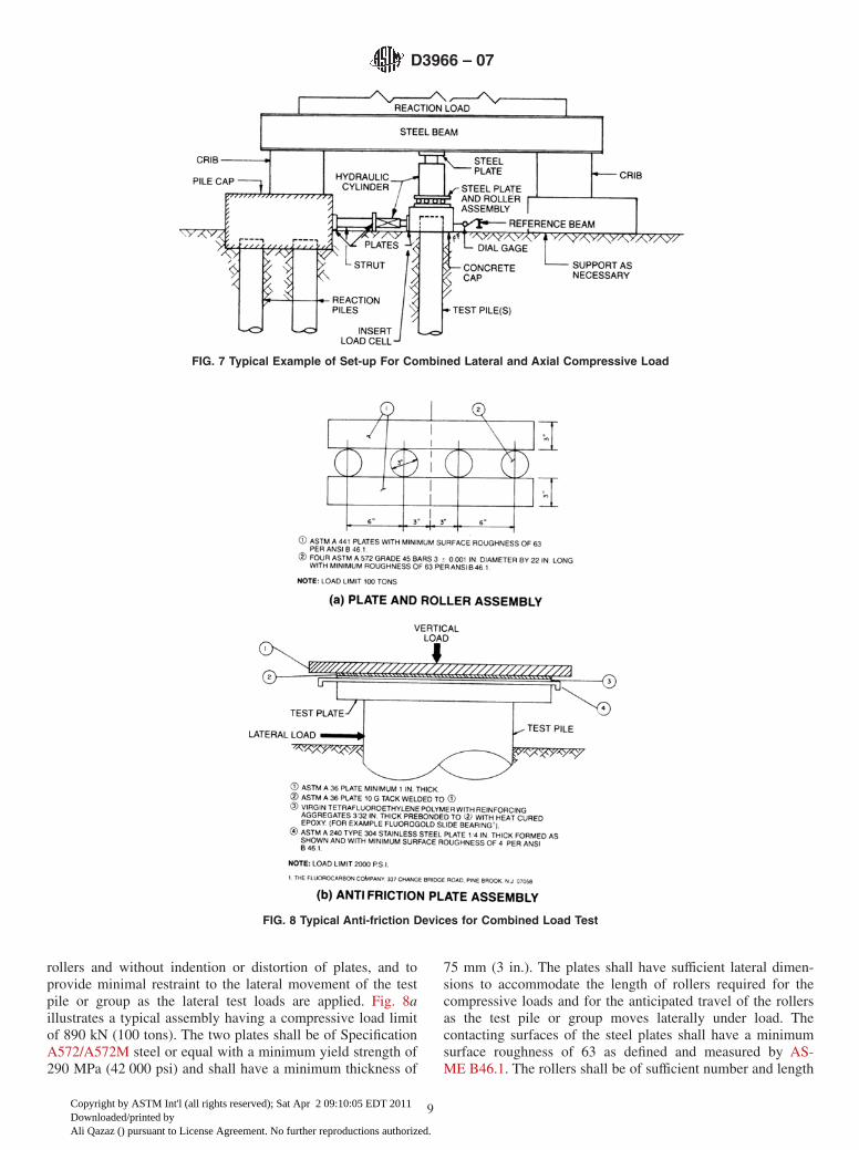
6.7.2 Compressive Load (Fig. 7)—Apply the specified axialcompressive load in accordance with Test Method D1143.Place an anti-friction device in accordance with 6.7.2.1,6.7.2.2, or as otherwise specified between the compressiveloading jack and the test plate on top of the test pile or pilegroup.
6.7.2.1 Plate and Roller Assembly (Fig. 8a)—The plate androller assembly shall be designed to support the maximumapplied compressive load without crushing or flattening of
FIG. 5 Example of Fixed-Head Test Set-up for Lateral Test on Individual Pile
FIG. 6 Example of Fixed-Head Test Set-up for Lateral Test on Pile Group
D3966 – 07
8
Copyright by ASTM Int'l (all rights reserved); Sat Apr 2 09:10:05 EDT 2011Downloaded/printed byAli Qazaz () pursuant to License Agreement. No further reproductions authorized.
rollers and without indention or distortion of plates, and toprovide minimal restraint to the lateral movement of the testpile or group as the lateral test loads are applied. Fig. 8aillustrates a typical assembly having a compressive load limitof 890 kN (100 tons). The two plates shall be of SpecificationA572/A572M steel or equal with a minimum yield strength of290 MPa (42 000 psi) and shall have a minimum thickness of
75 mm (3 in.). The plates shall have sufficient lateral dimen-sions to accommodate the length of rollers required for thecompressive loads and for the anticipated travel of the rollersas the test pile or group moves laterally under load. Thecontacting surfaces of the steel plates shall have a minimumsurface roughness of 63 as defined and measured by AS-ME B46.1. The rollers shall be of sufficient number and length
FIG. 7 Typical Example of Set-up For Combined Lateral and Axial Compressive Load
FIG. 8 Typical Anti-friction Devices for Combined Load Test
D3966 – 07
9
Copyright by ASTM Int'l (all rights reserved); Sat Apr 2 09:10:05 EDT 2011Downloaded/printed byAli Qazaz () pursuant to License Agreement. No further reproductions authorized.
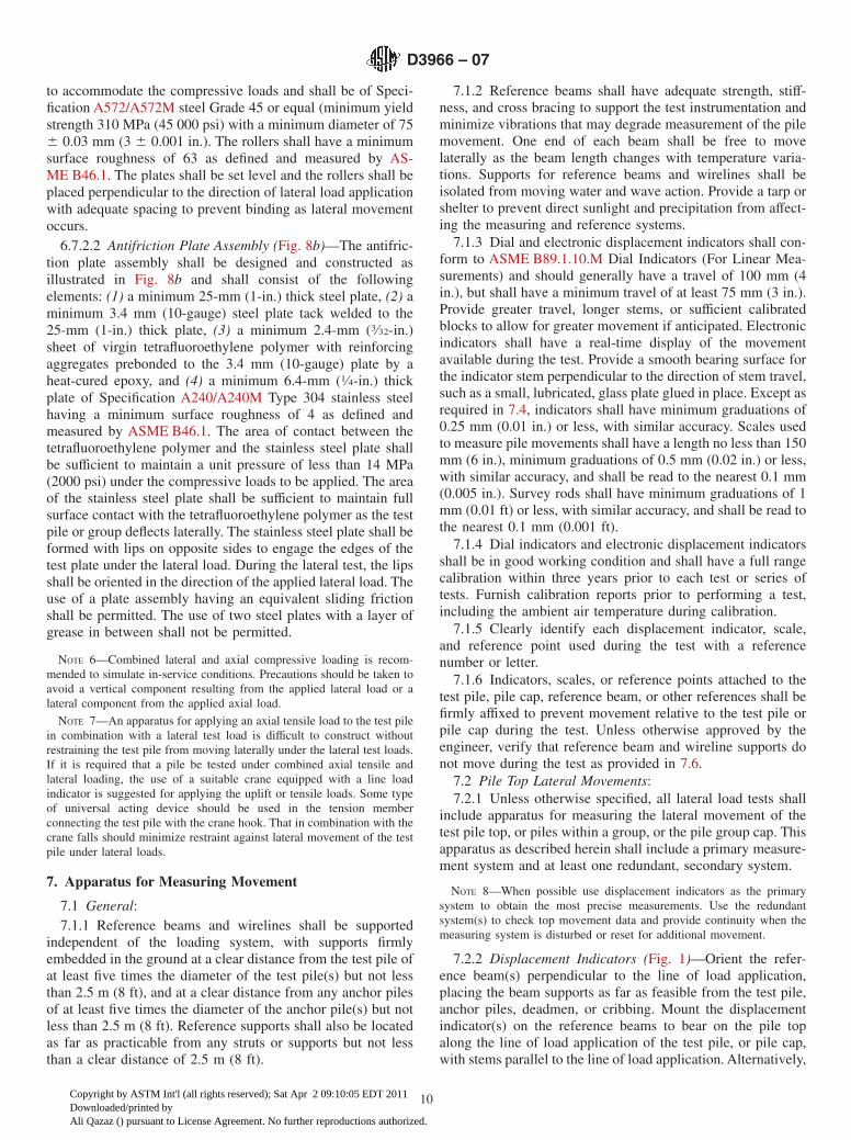
to accommodate the compressive loads and shall be of Speci-fication A572/A572M steel Grade 45 or equal (minimum yieldstrength 310 MPa (45 000 psi) with a minimum diameter of 756 0.03 mm (3 6 0.001 in.). The rollers shall have a minimumsurface roughness of 63 as defined and measured by AS-ME B46.1. The plates shall be set level and the rollers shall beplaced perpendicular to the direction of lateral load applicationwith adequate spacing to prevent binding as lateral movementoccurs.
6.7.2.2 Antifriction Plate Assembly (Fig. 8b)—The antifric-tion plate assembly shall be designed and constructed asillustrated in Fig. 8b and shall consist of the followingelements: (1) a minimum 25-mm (1-in.) thick steel plate, (2) aminimum 3.4 mm (10-gauge) steel plate tack welded to the25-mm (1-in.) thick plate, (3) a minimum 2.4-mm (3⁄32-in.)sheet of virgin tetrafluoroethylene polymer with reinforcingaggregates prebonded to the 3.4 mm (10-gauge) plate by aheat-cured epoxy, and (4) a minimum 6.4-mm (1⁄4-in.) thickplate of Specification A240/A240M Type 304 stainless steelhaving a minimum surface roughness of 4 as defined andmeasured by ASME B46.1. The area of contact between thetetrafluoroethylene polymer and the stainless steel plate shallbe sufficient to maintain a unit pressure of less than 14 MPa(2000 psi) under the compressive loads to be applied. The areaof the stainless steel plate shall be sufficient to maintain fullsurface contact with the tetrafluoroethylene polymer as the testpile or group deflects laterally. The stainless steel plate shall beformed with lips on opposite sides to engage the edges of thetest plate under the lateral load. During the lateral test, the lipsshall be oriented in the direction of the applied lateral load. Theuse of a plate assembly having an equivalent sliding frictionshall be permitted. The use of two steel plates with a layer ofgrease in between shall not be permitted.
NOTE 6—Combined lateral and axial compressive loading is recom-mended to simulate in-service conditions. Precautions should be taken toavoid a vertical component resulting from the applied lateral load or alateral component from the applied axial load.
NOTE 7—An apparatus for applying an axial tensile load to the test pilein combination with a lateral test load is difficult to construct withoutrestraining the test pile from moving laterally under the lateral test loads.If it is required that a pile be tested under combined axial tensile andlateral loading, the use of a suitable crane equipped with a line loadindicator is suggested for applying the uplift or tensile loads. Some typeof universal acting device should be used in the tension memberconnecting the test pile with the crane hook. That in combination with thecrane falls should minimize restraint against lateral movement of the testpile under lateral loads.
7. Apparatus for Measuring Movement
7.1 General:7.1.1 Reference beams and wirelines shall be supported
independent of the loading system, with supports firmlyembedded in the ground at a clear distance from the test pile ofat least five times the diameter of the test pile(s) but not lessthan 2.5 m (8 ft), and at a clear distance from any anchor pilesof at least five times the diameter of the anchor pile(s) but notless than 2.5 m (8 ft). Reference supports shall also be locatedas far as practicable from any struts or supports but not lessthan a clear distance of 2.5 m (8 ft).
7.1.2 Reference beams shall have adequate strength, stiff-ness, and cross bracing to support the test instrumentation andminimize vibrations that may degrade measurement of the pilemovement. One end of each beam shall be free to movelaterally as the beam length changes with temperature varia-tions. Supports for reference beams and wirelines shall beisolated from moving water and wave action. Provide a tarp orshelter to prevent direct sunlight and precipitation from affect-ing the measuring and reference systems.
7.1.3 Dial and electronic displacement indicators shall con-form to ASME B89.1.10.M Dial Indicators (For Linear Mea-surements) and should generally have a travel of 100 mm (4in.), but shall have a minimum travel of at least 75 mm (3 in.).Provide greater travel, longer stems, or sufficient calibratedblocks to allow for greater movement if anticipated. Electronicindicators shall have a real-time display of the movementavailable during the test. Provide a smooth bearing surface forthe indicator stem perpendicular to the direction of stem travel,such as a small, lubricated, glass plate glued in place. Except asrequired in 7.4, indicators shall have minimum graduations of0.25 mm (0.01 in.) or less, with similar accuracy. Scales usedto measure pile movements shall have a length no less than 150mm (6 in.), minimum graduations of 0.5 mm (0.02 in.) or less,with similar accuracy, and shall be read to the nearest 0.1 mm(0.005 in.). Survey rods shall have minimum graduations of 1mm (0.01 ft) or less, with similar accuracy, and shall be read tothe nearest 0.1 mm (0.001 ft).
7.1.4 Dial indicators and electronic displacement indicatorsshall be in good working condition and shall have a full rangecalibration within three years prior to each test or series oftests. Furnish calibration reports prior to performing a test,including the ambient air temperature during calibration.
7.1.5 Clearly identify each displacement indicator, scale,and reference point used during the test with a referencenumber or letter.
7.1.6 Indicators, scales, or reference points attached to thetest pile, pile cap, reference beam, or other references shall befirmly affixed to prevent movement relative to the test pile orpile cap during the test. Unless otherwise approved by theengineer, verify that reference beam and wireline supports donot move during the test as provided in 7.6.
7.2 Pile Top Lateral Movements:7.2.1 Unless otherwise specified, all lateral load tests shall
include apparatus for measuring the lateral movement of thetest pile top, or piles within a group, or the pile group cap. Thisapparatus as described herein shall include a primary measure-ment system and at least one redundant, secondary system.
NOTE 8—When possible use displacement indicators as the primarysystem to obtain the most precise measurements. Use the redundantsystem(s) to check top movement data and provide continuity when themeasuring system is disturbed or reset for additional movement.
7.2.2 Displacement Indicators (Fig. 1)—Orient the refer-ence beam(s) perpendicular to the line of load application,placing the beam supports as far as feasible from the test pile,anchor piles, deadmen, or cribbing. Mount the displacementindicator(s) on the reference beams to bear on the pile topalong the line of load application of the test pile, or pile cap,with stems parallel to the line of load application. Alternatively,
D3966 – 07
10
Copyright by ASTM Int'l (all rights reserved); Sat Apr 2 09:10:05 EDT 2011Downloaded/printed byAli Qazaz () pursuant to License Agreement. No further reproductions authorized.
mount two indicators on axisymmetric points equidistant fromthe center of the test pile, or pile cap, with the stems parallel tothe line of load application to bear on the reference beam(s).When locating reference beam(s) on the side of the test pile, orpile cap, opposite a compressive load, or on the same side astensile load application, allow sufficient clearance between thetest pile or pile cap and the reference beam for the anticipatedlateral movement of the pile or pile group.
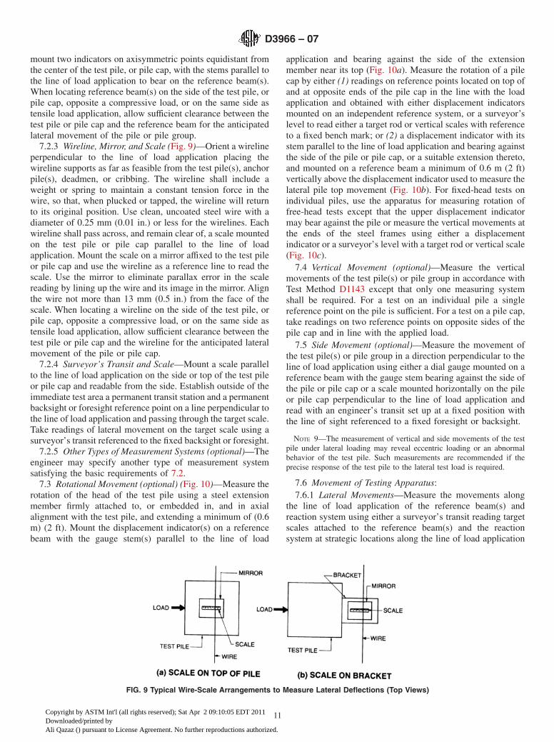
7.2.3 Wireline, Mirror, and Scale (Fig. 9)—Orient a wirelineperpendicular to the line of load application placing thewireline supports as far as feasible from the test pile(s), anchorpile(s), deadmen, or cribbing. The wireline shall include aweight or spring to maintain a constant tension force in thewire, so that, when plucked or tapped, the wireline will returnto its original position. Use clean, uncoated steel wire with adiameter of 0.25 mm (0.01 in.) or less for the wirelines. Eachwireline shall pass across, and remain clear of, a scale mountedon the test pile or pile cap parallel to the line of loadapplication. Mount the scale on a mirror affixed to the test pileor pile cap and use the wireline as a reference line to read thescale. Use the mirror to eliminate parallax error in the scalereading by lining up the wire and its image in the mirror. Alignthe wire not more than 13 mm (0.5 in.) from the face of thescale. When locating a wireline on the side of the test pile, orpile cap, opposite a compressive load, or on the same side astensile load application, allow sufficient clearance between thetest pile or pile cap and the wireline for the anticipated lateralmovement of the pile or pile cap.
7.2.4 Surveyor’s Transit and Scale—Mount a scale parallelto the line of load application on the side or top of the test pileor pile cap and readable from the side. Establish outside of theimmediate test area a permanent transit station and a permanentbacksight or foresight reference point on a line perpendicular tothe line of load application and passing through the target scale.Take readings of lateral movement on the target scale using asurveyor’s transit referenced to the fixed backsight or foresight.
7.2.5 Other Types of Measurement Systems (optional)—Theengineer may specify another type of measurement systemsatisfying the basic requirements of 7.2.
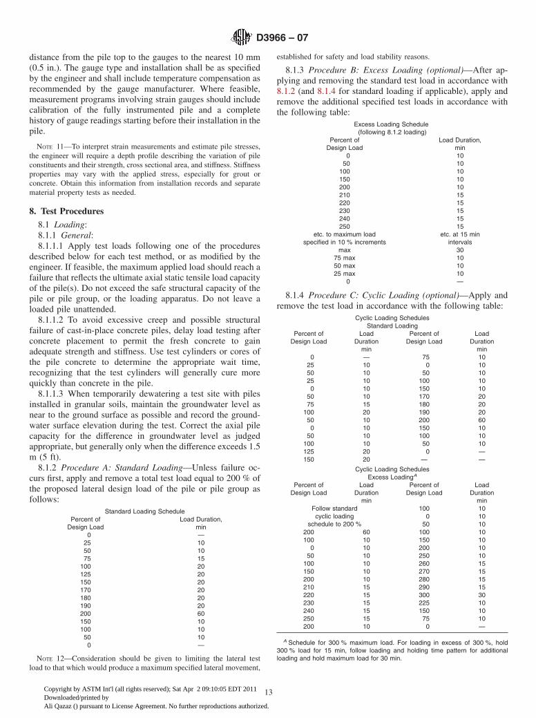
7.3 Rotational Movement (optional) (Fig. 10)—Measure therotation of the head of the test pile using a steel extensionmember firmly attached to, or embedded in, and in axialalignment with the test pile, and extending a minimum of (0.6m) (2 ft). Mount the displacement indicator(s) on a referencebeam with the gauge stem(s) parallel to the line of load
application and bearing against the side of the extensionmember near its top (Fig. 10a). Measure the rotation of a pilecap by either (1) readings on reference points located on top ofand at opposite ends of the pile cap in the line with the loadapplication and obtained with either displacement indicatorsmounted on an independent reference system, or a surveyor’slevel to read either a target rod or vertical scales with referenceto a fixed bench mark; or (2) a displacement indicator with itsstem parallel to the line of load application and bearing againstthe side of the pile or pile cap, or a suitable extension thereto,and mounted on a reference beam a minimum of 0.6 m (2 ft)vertically above the displacement indicator used to measure thelateral pile top movement (Fig. 10b). For fixed-head tests onindividual piles, use the apparatus for measuring rotation offree-head tests except that the upper displacement indicatormay bear against the pile or measure the vertical movements atthe ends of the steel frames using either a displacementindicator or a surveyor’s level with a target rod or vertical scale(Fig. 10c).
7.4 Vertical Movement (optional)—Measure the verticalmovements of the test pile(s) or pile group in accordance withTest Method D1143 except that only one measuring systemshall be required. For a test on an individual pile a singlereference point on the pile is sufficient. For a test on a pile cap,take readings on two reference points on opposite sides of thepile cap and in line with the applied load.
7.5 Side Movement (optional)—Measure the movement ofthe test pile(s) or pile group in a direction perpendicular to theline of load application using either a dial gauge mounted on areference beam with the gauge stem bearing against the side ofthe pile or pile cap or a scale mounted horizontally on the pileor pile cap perpendicular to the line of load application andread with an engineer’s transit set up at a fixed position withthe line of sight referenced to a fixed foresight or backsight.
NOTE 9—The measurement of vertical and side movements of the testpile under lateral loading may reveal eccentric loading or an abnormalbehavior of the test pile. Such measurements are recommended if theprecise response of the test pile to the lateral test load is required.
7.6 Movement of Testing Apparatus:7.6.1 Lateral Movements—Measure the movements along
the line of load application of the reference beam(s) andreaction system using either a surveyor’s transit reading targetscales attached to the reference beam(s) and the reactionsystem at strategic locations along the line of load application
FIG. 9 Typical Wire-Scale Arrangements to Measure Lateral Deflections (Top Views)
D3966 – 07
11
Copyright by ASTM Int'l (all rights reserved); Sat Apr 2 09:10:05 EDT 2011Downloaded/printed byAli Qazaz () pursuant to License Agreement. No further reproductions authorized.

or displacement indicators suitably mounted and referenced.For transit readings, establish permanent transit stations andfixed backsights or foresights outside of the immediate testarea.
7.6.2 Vertical Movement (optional)—Measure verticalmovements of the reference beam(s) and reaction system usinga surveyor’s level reading and a target rod or vertical scalelocated at strategic reference points along the line of loadapplication. Reference level readings to a fixed benchmarklocated outside of the test area.
7.7 Axial Deflections (optional)—Install in or on the testpile(s) to the depth(s) specified, tubing or ducts suitable toaccommodate the types of inclinometer specified to be used.
NOTE 10—Except for very short stiff piles, inclinometer measurements
are generally not warranted for the full length of the pile. Generally suchmeasurements can be limited to the upper third or half of the pile length.The project specifications should clearly indicate the contractor’s respon-sibility for providing this instrumentation system as appropriate includingmaterials, installation, equipment, and use.
7.8 Strain Measurements (optional)—Measure the strain ofthe test pile(s) during loading at locations specified by theengineer to help evaluate the distribution of load transfer fromthe pile to the surrounding soil. Measure pile strain directlyusing strain gauges installed along the length of the pile axis.Install the gauge in pairs to measure axial strain, with thegauges in each pair located at the same depth, symmetricallyopposite each other, equidistant from and parallel to the pileaxis, and in line with the applied load. Measure and record the
FIG. 10 Typical Arrangements for Measuring Pile Head Rotation
D3966 – 07
12
Copyright by ASTM Int'l (all rights reserved); Sat Apr 2 09:10:05 EDT 2011Downloaded/printed byAli Qazaz () pursuant to License Agreement. No further reproductions authorized.
distance from the pile top to the gauges to the nearest 10 mm(0.5 in.). The gauge type and installation shall be as specifiedby the engineer and shall include temperature compensation asrecommended by the gauge manufacturer. Where feasible,measurement programs involving strain gauges should includecalibration of the fully instrumented pile and a completehistory of gauge readings starting before their installation in thepile.
NOTE 11—To interpret strain measurements and estimate pile stresses,the engineer will require a depth profile describing the variation of pileconstituents and their strength, cross sectional area, and stiffness. Stiffnessproperties may vary with the applied stress, especially for grout orconcrete. Obtain this information from installation records and separatematerial property tests as needed.
8. Test Procedures
8.1 Loading:8.1.1 General:8.1.1.1 Apply test loads following one of the procedures
described below for each test method, or as modified by theengineer. If feasible, the maximum applied load should reach afailure that reflects the ultimate axial static tensile load capacityof the pile(s). Do not exceed the safe structural capacity of thepile or pile group, or the loading apparatus. Do not leave aloaded pile unattended.
8.1.1.2 To avoid excessive creep and possible structuralfailure of cast-in-place concrete piles, delay load testing afterconcrete placement to permit the fresh concrete to gainadequate strength and stiffness. Use test cylinders or cores ofthe pile concrete to determine the appropriate wait time,recognizing that the test cylinders will generally cure morequickly than concrete in the pile.
8.1.1.3 When temporarily dewatering a test site with pilesinstalled in granular soils, maintain the groundwater level asnear to the ground surface as possible and record the ground-water surface elevation during the test. Correct the axial pilecapacity for the difference in groundwater level as judgedappropriate, but generally only when the difference exceeds 1.5m (5 ft).
8.1.2 Procedure A: Standard Loading—Unless failure oc-curs first, apply and remove a total test load equal to 200 % ofthe proposed lateral design load of the pile or pile group asfollows:
Standard Loading SchedulePercent of
Design LoadLoad Duration,
min0 —
25 1050 1075 15
100 20125 20150 20170 20180 20190 20200 60150 10100 1050 100 —
NOTE 12—Consideration should be given to limiting the lateral testload to that which would produce a maximum specified lateral movement,
established for safety and load stability reasons.
8.1.3 Procedure B: Excess Loading (optional)—After ap-plying and removing the standard test load in accordance with8.1.2 (and 8.1.4 for standard loading if applicable), apply andremove the additional specified test loads in accordance withthe following table:
Excess Loading Schedule(following 8.1.2 loading)
Percent ofDesign Load
Load Duration,min
0 1050 10
100 10150 10200 10210 15220 15230 15240 15250 15
etc. to maximum loadspecified in 10 % increments
etc. at 15 minintervals
max 3075 max 1050 max 1025 max 10
0 —
8.1.4 Procedure C: Cyclic Loading (optional)—Apply andremove the test load in accordance with the following table:
Cyclic Loading SchedulesStandard Loading
Percent ofDesign Load
LoadDuration
min
Percent ofDesign Load
LoadDuration
min0 — 75 10
25 10 0 1050 10 50 1025 10 100 100 10 150 10
50 10 170 2075 15 180 20
100 20 190 2050 10 200 600 10 150 10
50 10 100 10100 10 50 10125 20 0 —150 20 — —
Cyclic Loading SchedulesExcess LoadingA
Percent ofDesign Load
LoadDuration
min
Percent ofDesign Load
LoadDuration
minFollow standardcyclic loading
schedule to 200 %
100 100 10
50 10200 60 100 10100 10 150 10
0 10 200 1050 10 250 10
100 10 260 15150 10 270 15200 10 280 15210 15 290 15220 15 300 30230 15 225 10240 15 150 10250 15 75 10200 10 0 —
A Schedule for 300 % maximum load. For loading in excess of 300 %, hold300 % load for 15 min, follow loading and holding time pattern for additionalloading and hold maximum load for 30 min.
D3966 – 07
13
Copyright by ASTM Int'l (all rights reserved); Sat Apr 2 09:10:05 EDT 2011Downloaded/printed byAli Qazaz () pursuant to License Agreement. No further reproductions authorized.
8.1.5 Procedure D: Surge Loading (optional):8.1.5.1 General—Surge loading involves the application of
any specified number of multiple loading cycles at anyspecified load level. Surge loading may be applied in conjunc-tion with standard loading or after the completion of standardloading. Apply surge loads at a uniform rate by continuousactivation of the hydraulic jack (or other power source) andremove the surge load at a uniform rate by continuous releaseof the power source.
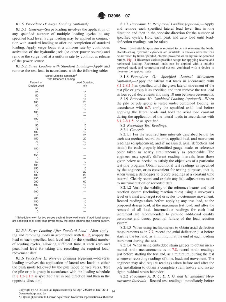
8.1.5.2 Surge Loading with Standard Loading—Apply andremove the test load in accordance with the following table:
Surge Loading ScheduleA
with Standard LoadingPercent of
Design LoadLoad Duration,
min0 —
25 1050 1075 15
100 2050 100 10
100 —0 —
100 —0 —
50 1075 10
100 10125 20150 2075 100 10
150 —0 —
150 —0 —
50 10100 10150 10170 20180 20190 20200 60100 10
0 10200 —
0 —200 —150 10100 1050 100 —
A Schedule shown for two surges each at three load levels. If additional surgesare specified or at other load levels follow the same loading and holding pattern.
8.1.5.3 Surge Loading After Standard Load—After apply-ing and removing loads in accordance with 8.1.2, reapply theload to each specified load level and for the specified numberof loading cycles, allowing sufficient time at each zero andpeak load level for taking and recording the required load-movement data.
8.1.6 Procedure E: Reverse Loading (optional)—Reverseloading involves the application of lateral test loads in eitherthe push mode followed by the pull mode or vice versa. Testthe pile or pile group in accordance with the loading schedulein 8.1.2-8.1.5 as specified first in one direction and then in theopposite direction.
8.1.7 Procedure F: Reciprocal Loading (optional)—Applyand remove each specified lateral load level first in onedirection and then in the opposite direction for the number ofspecified cycles. Hold each peak and zero load until load-deflection readings can be taken.
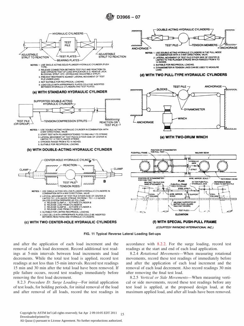
NOTE 13—Suitable apparatus is required to permit reversing the loads.Double-acting hydraulic cylinders are available in various sizes that canbe activated by hand-operated, electric-powered, or air-hydraulic-poweredpumps. Fig. 11 illustrates various possible setups for applying reverse andreciprocal loading. Reciprocal loads can be applied with a suitablepowered crank and connecting rod system combined with a device tomeasure the applied loads.
8.1.8 Procedure G: Specified Lateral Movement(optional)—Apply the lateral test loads in accordance with8.1.2-8.1.5 as specified until the gross lateral movement of thetest pile or group is as specified and then remove the test loadin four equal decrements allowing 10 min between decrements.
8.1.9 Procedure H: Combined Loading (optional)—Whenthe pile or pile group is tested under combined loading, inaccordance with 6.7, apply the specified axial load beforeapplying the lateral loads and hold the axial load constantduring the application of the lateral loads in accordance with8.1.2-8.1.5, or as specified.
8.2 Recording Test Readings:8.2.1 General:8.2.1.1 For the required time intervals described below for
each test method, record the time, applied load, and movementreadings (displacement, and if measured, axial deflection andstrain) for each properly identified gauge, scale, or referencepoint taken as nearly simultaneously as practicable. Theengineer may specify different reading intervals from thosegiven below as needed to satisfy the objectives of a particulartest pile program. Obtain additional test readings as specifiedby the engineer, or as convenient for testing purposes, that is,when using a datalogger to record readings at a constant timeinterval. Clearly record and explain any field adjustments madeto instrumentation or recorded data.
8.2.1.2 Verify the stability of the reference beams and loadreaction system (including reaction piles) using a surveyor’slevel or transit and target rod or scales to determine movement.Record readings taken before applying any test load, at theproposed design load, at the maximum test load, and after theremoval of all load. Intermediate readings for each loadincrement are recommended to provide additional qualityassurance and detect potential failure of the load reactionsystem.
8.2.1.3 When using inclinometers to obtain axial deflectionmeasurements as in 7.7, record the axial deflection just beforestarting the test and, as a minimum, at the end of each loadingincrement during the test.
8.2.1.4 When using embedded strain gauges to obtain incre-mental strain measurements as in 7.8, record strain readingsjust before starting the test and, as a minimum, during the testwhenever recording readings of time, load, and movement. Theengineer may also require readings taken before and after thepile installation to obtain a complete strain history and inves-tigate residual stress behavior.
8.2.2 Procedure A, B, C, E, F, G, and H: Standard Mea-surement Intervals—Record test readings immediately before
D3966 – 07
14
Copyright by ASTM Int'l (all rights reserved); Sat Apr 2 09:10:05 EDT 2011Downloaded/printed byAli Qazaz () pursuant to License Agreement. No further reproductions authorized.
and after the application of each load increment and theremoval of each load decrement. Record additional test read-ings at 5-min intervals between load increments and loaddecrements. While the total test load is applied, record testreadings at not less than 15-min intervals. Record test readings15 min and 30 min after the total load have been removed. Ifpile failure occurs, record test readings immediately beforeremoving the first load decrement.
8.2.3 Procedure D: Surge Loading—For initial applicationof test loads, for holding periods, for initial removal of the loadand after removal of all loads, record the test readings in
accordance with 8.2.2. For the surge loading, record testreadings at the start and end of each load application.
8.2.4 Rotational Movements—When measuring rotationalmovements, record these test readings of immediately beforeand after the application of each load increment and theremoval of each load decrement. Also record readings 30 minafter removing the final test load.
8.2.5 Vertical or Side Movements—When measuring verti-cal or side movements, record these test readings before anytest load is applied, at the proposed design load, at themaximum applied load, and after all loads have been removed.
FIG. 11 Typical Reverse Lateral Loading Set-ups
D3966 – 07
15
Copyright by ASTM Int'l (all rights reserved); Sat Apr 2 09:10:05 EDT 2011Downloaded/printed byAli Qazaz () pursuant to License Agreement. No further reproductions authorized.
Intermediate readings for each load increment are recom-mended to provide additional quality assurance.
9. Safety Requirements
9.1 All operations in connection with pile load testing shallbe carried out in such a manner so as to minimize, avoid, oreliminate the exposure of people to hazard. The followingsafety rules are in addition to general safety requirementsapplicable to construction operations:
9.1.1 Keep all test and adjacent work areas, walkways,platforms, etc. clear of scrap, debris, small tools, and accumu-lations of snow, ice, mud, grease, oil, or other slipperysubstances.
9.1.2 Provide timbers, blocking, and cribbing materialsmade of quality material and in good serviceable conditionwith flat surfaces and without rounded edges.
9.1.3 Hydraulic jacks shall be equipped with hemisphericalbearing plates or shall be in complete and firm contact with thebearing surfaces and shall be aligned so as to avoid eccentricloading.
9.1.4 Loads shall not be hoisted, swung, or suspended overanyone and shall be controlled by tag lines.
9.1.5 The test apparatus shall be designed and approved bya qualified engineer and installed to transmit the required loadswith an adequate factor of safety.
9.1.6 All jacks, bearing plates, test beam(s), or framemembers shall be firmly fixed into place or adequately blockedto prevent slippage under load and upon release of load.
9.1.7 All reaction components shall be stable and balanced.During testing, monitor movements of the reaction system todetect impending unstable conditions.
9.1.8 All test members, reaction frames, and test apparatusshall be adequately supported at all times.
9.1.9 Only authorized personnel shall be permitted withinthe immediate test area, and only as necessary to monitor testequipment. As best as possible, locate pumps, load cellreadouts, dataloggers, and test monitoring equipment at a safedistance away from jacks, loaded members (tension or com-pression), and their supports and connections.
10. Report
10.1 The report of the load test shall include the followinginformation as required by the engineer and as appropriate tothe pile type, test apparatus, and test method:
10.1.1 General:10.1.1.1 Project identification and location,10.1.1.2 Test site location,10.1.1.3 Owner, structural engineer, geotechnical engineer,
pile contractor, boring contractor,10.1.1.4 Nearest test boring(s) or sounding(s), and their
location with reference to test location,10.1.1.5 Insitu and laboratory soil test results, and10.1.1.6 Horizontal and vertical control datum.10.1.2 Pile Installation Equipment:10.1.2.1 Make, model, type and size of hammer,10.1.2.2 Weight of hammer and ram,10.1.2.3 Stroke or ram,10.1.2.4 Rated energy of hammer,10.1.2.5 Rated capacity of boiler or compressor,
10.1.2.6 Type and dimensions of capblock and pile cushion,10.1.2.7 Weight and dimensions of drive cap and follower,10.1.2.8 Size of predrilling or jetting equipment,10.1.2.9 Weight of clamp, follower, adaptor, and oscillator
for vibratory driver,10.1.2.10 Type, size, length, and weight of mandrel,10.1.2.11 Type, size, and length of auger,10.1.2.12 Type and size of grout pump,10.1.2.13 Type, size, wall thickness, and length of drive
casing,10.1.2.14 Detailed description of drilling equipment and
techniques, and10.1.2.15 Size, type, length, and installation or extraction
method of casings, or both.10.1.3 Test and Anchor Pile Details:10.1.3.1 Identification and location of test and anchor piles,10.1.3.2 Design load of test pile or pile group,10.1.3.3 Type and dimensions of test and anchor piles,10.1.3.4 Test pile material including basic specifications,10.1.3.5 Pile quality including knots, splits, checks and
shakes, and straightness of piles, preservative treatment andconditioning process used for timber test piles includinginspection certificates,
10.1.3.6 Wall thickness of pipe test pile,10.1.3.7 Weight per foot of H test pile,10.1.3.8 Description of test pile tip reinforcement or protec-
tion,10.1.3.9 Description of banding–timber piles,10.1.3.10 Description of special coatings used,10.1.3.11 Test pile (mandrel) weight as driven,10.1.3.12 Date precast test piles made,10.1.3.13 Details of concrete design, grout mix design, or
both.10.1.3.14 Concrete or grout (or both) placement techniques
and records,10.1.3.15 Concrete or grout (or both) sample strengths and
date of strength test,10.1.3.16 Description of internal reinforcement used in test
pile (size, length, number longitudinal bars, arrangement,spiral, or tie steel),
10.1.3.17 Condition of precast piles including spalled areas,cracks, top surface, and straightness of piles,
10.1.3.18 Effective prestress,10.1.3.19 Degree of inclination for each pile,10.1.3.20 Length of test pile during driving,10.1.3.21 Final pile top and bottom elevations, and ground
elevation referenced to a datum,10.1.3.22 Embedded length-test and anchor piles,10.1.3.23 Tested length of test pile, and10.1.3.24 Final elevation of top of test pile referenced to
fixed datum.10.1.4 Test and Anchor Pile Installation:10.1.4.1 Date installed,10.1.4.2 Volume of concrete or grout placed in pile,10.1.4.3 Grout pressure used,10.1.4.4 Description of pre-excavation or jetting (depth,
size, pressure, duration),
D3966 – 07
16
Copyright by ASTM Int'l (all rights reserved); Sat Apr 2 09:10:05 EDT 2011Downloaded/printed byAli Qazaz () pursuant to License Agreement. No further reproductions authorized.
10.1.4.5 Operating pressure for double-acting and differen-tial type hammers,
10.1.4.6 Throttle setting—diesel hammer (at final driving),10.1.4.7 Fuel type—diesel hammer,10.1.4.8 Horsepower delivered and frequency of vibratory
driver during final 3 m (10 ft) of pile penetration,10.1.4.9 Description of special installation procedures used
such as piles cased off,10.1.4.10 Type and location of pile splices,10.1.4.11 Driving or drilling records,10.1.4.12 Final penetration resistance (blows per inch),10.1.4.13 Rate of pile penetration in m/s (ft/s) for last 3 m
(10 ft), vibratory driving,10.1.4.14 When cap block replaced (indicate on log),10.1.4.15 When pile cushion replaced (indicate on log),10.1.4.16 Cause and duration of interruptions in pile instal-
lation, and10.1.4.17 Notation of any unusual occurrences during in-
stallation.10.1.5 Pile Testing:10.1.5.1 Date and type of test,10.1.5.2 Temperature and weather conditions during tests,10.1.5.3 Number of piles in group test,10.1.5.4 Brief description of load application apparatus,
including jack capacity,10.1.5.5 Location of point of load application with reference
to top of pile or pile cap, and to ground surface,10.1.5.6 Description of instrumentation used to measure
pile movement including location of indicators, scales, andother reference points with respect to pile top,
10.1.5.7 Description of special instrumentation such asinclinometers or strain gauges including location of such withreference to pile top,
10.1.5.8 Axial load—type, amount, how applied,
10.1.5.9 Special testing procedures used,10.1.5.10 Tabulation of all time, load, and movement read-
ings,10.1.5.11 Tabulation of inclinometer readings, declination
versus depth,10.1.5.12 Identification and location sketch of all indicators,
scales, and reference points,10.1.5.13 Description and explanation of adjustments made
to instrumentation or field data, or both,10.1.5.14 Notation of any unusual occurrences during test-
ing,10.1.5.15 Test jack and other required calibration reports,10.1.5.16 Groundwater level, and10.1.5.17 Suitable photographs showing the test instrumen-
tation and set-up.
11. Precision and Bias
11.1 Precision—Test data on precision is not presented dueto the nature of this test method. It is either not feasible or toocostly at this time to have ten or more agencies participate inan in situ testing program at a given site. Each test pile isunique due to the variable nature of the ground in which it isembedded. Furthermore, retesting a particular pile commonlyresults in different data from the initial testing due to plasticmovement of the ground in which the pile is embedded.
11.1.1 The Subcommittee D18.11 is seeking any data fromthe users of this test method that might be used to make alimited statement on precision.
11.2 Bias—There is no accepted reference value for this testmethod, therefore, bias cannot be determined.
12. Keywords
12.1 field testing; jack; lateral static pile capacity; load cell;loading procedure; reference beam
APPENDIX
(Nonmandatory Information)
X1. SOME FACTORS INFLUENCING INTERPRETATION OF TEST RESULTS
X1.1 Possible interaction of lateral loads from test pile(s)with lateral loads transferred to the soil from reaction piles orcribbing obtaining part or all of their support in soil at levelsabove the tip level of the test pile.
X1.2 Changes in pore water pressure in the soil caused bypile driving, construction fill, and other construction operationswhich may influence the test results for frictional support inrelatively impervious soils such as clay and silt.
X1.3 Differences between conditions at time of testing andafter final construction such as changes in grade or groundwa-ter level.
X1.4 Loss or gain of test pile soil resistance due to changesin the soil stress distribution around the test pile(s) such asexcavation, scour, fill, etc.
X1.5 Possible differences in the performance of a pile in agroup or of a pile group from that of a single isolated pile.
X1.6 Affect on long-term pile performance of factors suchas creep, environmental effects on pile material, negativefriction loads, swelling soils, and strength losses.
X1.7 Type of structure to be supported, including sensitiv-ity of structure to movement and relation between live anddead loads.
X1.8 Special testing procedures which may be required forthe application of certain acceptance criteria or methods ofinterpretation.
X1.9 Requirement that non tested pile(s) have essentiallyidentical conditions to those for tested pile(s) including, but not
D3966 – 07
17
Copyright by ASTM Int'l (all rights reserved); Sat Apr 2 09:10:05 EDT 2011Downloaded/printed byAli Qazaz () pursuant to License Agreement. No further reproductions authorized.
limited to, subsurface conditions, pile type, length, size andstiffness, and pile installation methods and equipment so that
application or extrapolation of the test results to such otherpiles is valid.
SUMMARY OF CHANGES
Subcommittee D18 has identified the location of selected changes to this standard since the last issue(D3966 – 90 (1995)) that may impact the use of this standard (approved Sept. 1, 2007).
(1) Reorganization following current D18 guidelines, includ-ing addition of “Terminology” and “Significance and Use.”(2) Change title and text to indicate multiple procedures andinclude deep foundations that function similar to driven piles.(3) Inclusion of current D18 caveats D6026 and D3740.(4) Require load cell(s) for tests over 900 kN (100 tons), andhemispherical bearings.
(5) More specific requirements for test plates.
(6) Addition of references for pressure gauges and displace-ment indicators. Note that these references are ANSI standardsthat are maintained by ASME. At some future point, D18.11hopes to develop ASTM standards for these references.
(7) Additional requirements for measuring systems.
ASTM International takes no position respecting the validity of any patent rights asserted in connection with any item mentionedin this standard. Users of this standard are expressly advised that determination of the validity of any such patent rights, and the riskof infringement of such rights, are entirely their own responsibility.
This standard is subject to revision at any time by the responsible technical committee and must be reviewed every five years andif not revised, either reapproved or withdrawn. Your comments are invited either for revision of this standard or for additional standardsand should be addressed to ASTM International Headquarters. Your comments will receive careful consideration at a meeting of theresponsible technical committee, which you may attend. If you feel that your comments have not received a fair hearing you shouldmake your views known to the ASTM Committee on Standards, at the address shown below.
This standard is copyrighted by ASTM International, 100 Barr Harbor Drive, PO Box C700, West Conshohocken, PA 19428-2959,United States. Individual reprints (single or multiple copies) of this standard may be obtained by contacting ASTM at the aboveaddress or at 610-832-9585 (phone), 610-832-9555 (fax), or [email protected] (e-mail); or through the ASTM website(www.astm.org).
D3966 – 07
18
Copyright by ASTM Int'l (all rights reserved); Sat Apr 2 09:10:05 EDT 2011Downloaded/printed byAli Qazaz () pursuant to License Agreement. No further reproductions authorized.