standard test methods of conducting strength test of panels for ... · standard test methods of...
TRANSCRIPT

KENYA STANDARD DKS 2641: 2016
Standard Test methods of Conducting Strength Test of panels for Building Construction
© KEBS 2016 First Edition 2016

DKS 2641: 2016
© KEBS 2016 — All rights reserved ii
TECHNICAL COMMITTEE REPRESENTATION
The following organizations were represented on the Technical Committee: Architectural Association of Kenya National Housing Corporation Sutech limited Consumer information network Ministry of land Bamburi Cement Limited National Construction Authority KOTO housing Kenya LTD Boleyn magic wall panel LTD Kenya Bureau of Standards — Secretariat
REVISION OF KENYA STANDARDS In order to keep abreast of progress in industry, Kenya Standards shall be regularly reviewed. Suggestions for improvements to published standards, addressed to the Managing Director, Kenya Bureau of Standards, are welcome.
© Kenya Bureau of Standards, 2015
Copyright. Users are reminded that by virtue of Section 25 of the Copyright Act, Cap. 12 of 2001 of the Laws of Kenya, copyright subsists in all Kenya Standards and except as provided under Section 26 of this Act, no Kenya Standard produced by Kenya Bureau of Standards may be reproduced, stored in a retrieval system in any form or transmitted by any means without prior permission in writing from the Managing Director.

KENYA STANDARD DKS 2641: 2016
© KEBS 2016 — All rights reserved iii
Standard Test methods of Conducting Strength Test of panels for Building Construction
KENYA BUREAU OF STANDARDS (KEBS)
Head Office: P.O. Box 54974, Nairobi-00200, Tel.: (+254 020) 605490, 602350, Fax: (+254 020) 604031 E-Mail: [email protected], Web:http://www.kebs.org
Coast Region Lake Region Rift Valley Region P.O. Box 99376, Mombasa-80100 P.O. Box 2949, Kisumu-40100 P.O. Box 2138, Nakuru-20100 Tel.: (+254 041) 229563, 230939/40 Tel.: (+254 057) 23549, 22396 Tel.: (+254 051) 210553, 210555 Fax: (+254 041) 229448 Fax: (+254 057) 21814

DKS 2641: 2016
© KEBS 2016 — All rights reserved iv
Foreword This Kenya Standard was prepared by the Construction technology Technical Committee under the guidance of the Standards Projects Committee and it is in accordance with the procedures of the Kenya Bureau of Standards. Sound engineering design of structures using existing or new materials requires accurate technical data on the strength and rigidity of the basic elements employed in various construction systems. It is the purpose of these test methods to provide a systematic basis for obtaining engineering data on various construction elements and structural details of value to designers, builders, building officials, and others interested in this field. The results should closely approximate the performance in actual service. During the preparation of this standard, reference was made to the following documents:
ASTM E72 - 17 Standard Test methods of Conducting Strength Test of panels for Building Construction
Acknowledgement is hereby made for the assistance received from this source.

KENYA STANDARD DKS 2641: 2016
© KEBS 2016 — All rights reserved 1
Standard Test methods of Conducting Strength Test of panels for Building Construction 1 Scope
These test methods cover the following procedures for determining the structural properties of segments of wall, floor, and roof constructions:
The values stated in newton per meter units are to be regarded as standard. The values given in parentheses are mathematical conversions to SI units that are provided for information only and are not considered standard.
Exception-SI units are used in Fig. 6.
2 Normative references The following referenced documents are indispensable for the application of this document. For dated references, only the edition cited applies. For undated references, the latest edition of the referenced document (including any amendments) applies. Information on currently valid national and international standards can be obtained from the Kenya Bureau of Standards.
D2395 Test Methods for Density and Specific Gravity (Relative Density) of Wood and Wood-Based Materials
D4442 'fest Methods for Direct Moist.ure Content Measurement of Wood and Wood Base Materials
D7438 Practice for Field Calibration and Application of Hand-Held Moisture Meters
E4 Practices for Force Verification of Testing Machines
E73 Practice for Static Load Testing of Truss Assemblies
E564 Practice for Static Load Test for Shear Resistance of Framed Walls for Buildings
E575 Practice for Reporting Data from Structural 'Tests of Building Constructions, Elements, Connections and Assemblies
E661 Test Method for Performance of Wood and Wood Based Floor and Roof Sheathing Under Concentrated Static and Impact Loads
E695 Test Method of Measuring Relative Resistance of Wall, Floor, and Roof Construction to Impact Loading
E2126 Test Methods for Cyclic (Reversed) Load Test for Shear Resistance of Vertical Elements of the Lateral Force Resisting Systems for Buildings
E2309/E2309M Practices for Verification of Displacement Measuring Systems and Devices Used in Material Testing Machines
E2322 Test Method for Conducting Transverse and Concentrated Load Tests on Pane1s used in Floor and Roof Construction
3 Test Specimens
3.1 Size There shall be at least three specimens for each test. Specimens shall be constructed to
represent sections of the wall, floor, or roof assembly. The specimens shall be representative as to material and workmanship and shall be of the largest practical size to predict structural performance attri-butes of the assembly. Unsymmetrical assemblies shall be tested in each axis for which the results may be different.

© KEBS 2016 — All rights reserved 2
3.2 Length or Height-The length or height of specimen for each element shall be chosen to conform to
the length or height of that element in actual use. 3.3 Width - The width of specimen shall be chosen, insofar as possible, to include several of the principal
load-carrying members to ensure that the behavior under load will simulate that under service conditions. With the exception of specimens for the racking load test, the nominal width of wall specimens shall be 4 ft (1.2 m). The actual width of specimens shall be a whole number multiplied by the spacing of the principal load-carrying members except for prefabricated panels, for which the actual width shall be the width of panel used. If the structural properties of a particular construction are to be compared with another construction, there should not be a great difference in the actual widths of the specimens.
3.4 Age - Constructions, such as concrete and masonry (brick, structural clay tile, concrete block) for
which the structural properties depend upon the age of the specimen, shall be tested not less than 25 days nor more than 31 days after fabrication. This age requirement applies also to plastered and stuccoed constructions.
4 Loading 4.1 Apparatus The testing machine or load-measuring apparatus shall comply with the requirements
prescribed in Practices E4.
4.2 Application of load Apply the load to all of the specimens in any test in increments so chosen that a sufficient number of readings will be obtained to determine definitely the load-deformation curve (see Section 6). Record the initial reading of the load and the reading of the deformation, either with no load on the specimen or under a small initial load. Increase the load to the first increment and record the deformation. Unless otherwise specified, decrease the load to the initial load and record the set (sometimes designated "permanent set"). Increase the load to two increments and record the set, when it is released to the initial load. Follow this sequence of readings for three increments, four increments, and so forth, of load. When for each specimen the behavior of the specimen under load indicates that the specimen might fail suddenly and damage the deformation-measuring apparatus, remove this apparatus from the specimen and increase the load continuously until the maximum load that can be applied to the specimen is determined.
4.3 Duration of load application - Except for racking tests, after each increment of load is applied, maintain the load level as constant as possible for a period of 5 min (see Note 1). Take deformation readings as soon as practical after load application, at the end of the 5-min period under constant load, and immediately and at the end of the 5-min period after any partial or complete load release. Plot initial and 5-min readings in the form of load-deformation curves. Maintain complete load-deformation-time records throughout the test. If application of a given load is required for a certain period, such as 24 h, take deformation readings at the beginning, at intervals during this period, and at the end of this period, to allow the satisfactory plotting of a time-deformation curve for the complete period.
Note 1- Reasons for the 5-min application of constant-level increment loads are as follows:
a) To permit the assembly to come to a substantial rest prior to taking the second set of readings (Depending on the method employed for applying the test load, it may be necessary to continue, at a reduced rate, the motion of the loading device in order to maintain the constant load level during the 5-min period.)
b) To provide sufficient time for making all observations. (Longer time intervals may be required under certain conditions.)
c) To observe any time-dependent deformation or load redistribution, or both, and to record accurately the load level when time-dependent deformation starts, that is, at the divergence of the immediate and delayed load-deformation curves. This load level may, under certain conditions, have an important bearing on the design load.
d) To be able to stop the test, if this should be desirable, prior to total failure, after initial failure has been anticipated as a result of the observations.

DKS 2641: 2016
© KEBS 2016 — All rights reserved 3
e) To assure uniformity in test performance and consistency in test results. 5 Deformation measurement 5.1 Measurement the deformations with sufficient precision to define the load-deformation relationship,
and report at least to the nearest 0.01 in. (0.25 mm). The deformation-measuring apparatus specified for any loading may be replaced by other apparatus, provided that it permits readings of deformation that are equivalent in accuracy to those from the specified apparatus.
6 Reports 6.1 Show the results of each of the tests graphically, as illustrated in Fig. 1. Plot loads as ordinates and
the deformations as abscissas for all tests. There shall be at least three specimens for each test, and the results for each test shall be shown on the same graph. Show the points for deformation under load by open circles and those for set by solid circles. Average the three values for either the deformation or the set and plot this average value in pencil on the graph. Draw a smooth curve among the average points to show the average behavior of the construction. The load-deformation curves shall be continuous lines and the load-set curves shall be dashed lines. Although the particular specimen for each point on the graph is not designated, record it on the laboratory data sheets. If readings are obtained under greater loads for some specimens than for others, plot all the values, but draw the curves only to the average values for which there are three values.
FIG. 1 Typical Graph Showing Results
6.2 Prepare the test report in accordance with Practice E575. 7 Precision and Bias 7.1 No statement is made either on the precision or on the bias of these test methods due to the variety of
materials and combinations of materials involved.

© KEBS 2016 — All rights reserved 4
8 Testing Wall Panels 8.1 Significance and use 8.1.1 The procedures described are those that will test the behavior of segments of wall construction under
conditions representative of those encountered in service. Performance criteria based on data from those procedures can ensure structural adequacy and service life.
9 Compressive Load 9.1 Test specimens - Tests shall be made on three like specimens, each having a height equal to the length
of the element and a nominal width of 4 ft (1.2 m) (see Section 3). 9.2 Apparatus - The apparatus shall be assembled as shown in Fig. 2 and shall conform to the detailed
requirements for component parts prescribed in 9.2.1 and 9.2.2, or the equivalent. 9.2.1 Compressometer - A bracket shall be attached to the specimen near the upper end, supporting a
metal rod. A bracket shall also be attached to the specimen near its lower end, supporting a deflection-measuring device with the spindle up and the gage length shall be recorded. The conical end of the rod shall seat in a hole in the end of the spindle and the rod and spindle shall be held in contact by stretched rubber bands. The deflection-measuring device shall be graduated to 0.001 in. (0.025 mm) or less.
9.2.2 Deflectometer - A fine wire shall be attached to a clamp near the upper end of the specimen. The free end connected to stretched rubber bands shall be attached to a clamp near the lower end of the specimen. A mirror having a paper scale one-half the width of the mirror shall be attached horizontally to the edge of the specimen at midheight. The scale shall be graduated to 0.1 in. (2.5 mm) or less.
FIG. 2 Compressive Load Test on wall panel specimen
9.3 Procedure 9.3.1 Loading - Test the specimen as a column having a flat end at the bottom (Fig. 2). Apply compressive
loads to a steel plate covering the upper end of the specimen. Apply the load uniformly along a line parallel to the inside face, and one-third the thickness of the specimen from the inside face. For
DKS 2641: 2016
© KEBS 2016 — All rights reserved 5
wood construction, a rate of loading corresponding to a movement of the testing machine crosshead of nominally 0.03 in.lmin (0.8 mm/min) has been found satisfactory.
9.3.2 Load - Deformation Data-Attach four compressometers to the faces of the specimen, one near each corner of the specimen as shown in Fig. 2, to measure the shortening of the specimen. Record the readings to the nearest 0.001 in. (0.025 mm).
9.3.3 Lateral Deflection-Calculate the lateral deflection and the lateral set under each load for each deflectometer as the difference between the reading of the deflectometer when the load is applied and the initial reading. Calculate the lateral deflection and lateral set for the specimen as the average of the lateral deflection and lateral set of the two deflectometers.
9.3.4 Data Presentation-Record the maximum load for each specimen and report the results of load-deformation and load-deflection measurements in the form of a graph in accordance with Section 6. Report gage lengths of all deflection or deformation gages.
10 Tensile Load
10.1 Test Specimens-Tests shall be made on three like specimens, each having a height equal to the length of the element and a nominal width of 4 ft (1.2 m) (see Section 3).
10.2 Apparatus - The apparatus preferably shall be assembled in a vertical testing machine and shall conform to the detailed requirements for component parts prescribed in 9.2.1 and 9.2.2, or the equivalent, with the exception that the compressometers prescribed in 9.2.1 shall be replaced by extensometers which shall be like the compressometers but so adjusted before load is applied that the stretch of the specimen can be measured.
10.3 Procedure
10.3.1 Loading - Test the specimen as a tension specimen by uniform application of tensile forces along the line of the fastenings at the top and the bottom of the wall in a building. The top and bottom pulling fixtures may be attached to the specimen by fastenings similar to those used in a building, provided that, under the maximum load, failure of the specimen occurs between the top and the bottom of the specimen, not in either the pulling fixtures or the fastenings. If, under the tensile load, failure occurs either in a pulling fixture or in a fastening, the results of the test determine only the properties of the fixtures or the fastenings, not of the wall construction. When the failure occurs in fastenings, the tensile load indicates the maximum tensile strength of the construction that can be realized in actual service unless improved fastenings are provided.
10.3.1.1 Masonry construction - The construction may be continued upward beyond the top of the specimen and downward below the bottom of the specimen to enclose attachments for the pulling fixtures.
10.3.1.2 Framed Wall Constructions-If the construction has studs (either of wood or metal) the studs may be extended upward and downward beyond the top and bottom of the specimen and attached to the pulling fixtures. If the framed wall has plates at the top and the bottom, attach the pulling fixtures to the plates in the specimen.
10.3.2 Load Deformation Data-Attach four extensometers to the faces of the specimen, one near each corner, as shown in Fig. 2, to measure the stretch of the specimen. Record the readings to the nearest 0.001 in. (0.025 mm).
10.3.3 Lateral Deflection-Attach two deflectometers, one to each edge of the specimen, as shown in Fig. 2. Record the readings, when the image of the wire coincides with the wire, to the nearest 0.01 in. (0.25 mm). Lateral deflection (if any) may be caused by nonaxial loading of the specimen.
10.4 Calculations and Report-For tensile loads, the calculations and report shall be similar to those required for compressive loads (see 9.4).

© KEBS 2016 — All rights reserved 6
11 Transverse Load-Specimen Horizontal
11.1 Test Specimens-Tests shall be made on three like specimens on symmetrical assemblies and six like specimens on unsymmetrical assemblies, each having a length equal to the length of the element and a nominal width of 4 ft (1.2 m) (see Section 3).
11.2 Apparatus - The apparatus shall be assembled as shown in Fig. 3 and shall conform to the detailed requirements for component parts prescribed in 11.2.1 - 11.2.3, or the equivalent.
11.2.1 Supports - Two steel rollers with a steel plate between each supporting roller and the specimen.
11.2.2 Loading Assembly- Two steel rollers with a steel plate between each loading roller and the specimen.
11.2.3 Deflection gauge - A frame shall be placed on the upper face of the specimen. To prevent stresses deforming the frame as the specimen deforms under load, this frame shall rest on three hardened steel balls each supported by a steel block on the face of the specimen. Two of the balls shall be placed in a line vertically above one support and the third ball vertically above the other support. Two deflection-measuring devices, one near each longitudinal edge of the specimen, shall be attached to the frame at midspan. The spindles shall rest on the upper face of the specimen. The devices shall be graduated to 0.001 in. (0.025 mm) or less.
FIG 3 Transverse Load Test on Wall panel Specimen
11.3 Procedure
11.3.1 Loading - Use "two-point" loading for transverse load tests. Test the specimen as a simple beam (Fig. 3) on a span approximately 6 in. (I50 mm) less than the specimen length. Apply two equal loads, each at a distance of one quarter of the span from the supports, toward the middle of the span. For wall specimens tested horizontally (Fig. 3), the load on the specimen shall include the weight of specimen between the supports. Apply the transverse loads to the outside face for three of the specimens and to the inside face for three of the specimens. For symmetrical assemblies, test only three specimens.
11.3.1.1 Uniformly distributed loading may be used instead of quarter-point loading, if a satisfactory method is available. The transverse strength for any span may be greater for some constructions under uniformly distributed load than under loads applied at the quarter-points of the span. Transverse load, uniformly distributed, may be applied by air pressure, either in a bag or in a chamber having

DKS 2641: 2016
© KEBS 2016 — All rights reserved 7
the specimen as one face. Support specimens tested under uniform loading by rollers as for quarter-point loading.
11.3.1.2 The bag method of loading is shown schematically in Fig. 4. Connect a reaction platform parallel to the face to be loaded and wider than the specimen to the supports by tie rods. Place an airtight bag of rubberized cloth as wide as the specimen and as long as the span between the specimen and the reaction platform. Apply transverse load to the specimen by increasing the air pressure in the bag. Measure the pressure by means of a manometer. Water is usually the liquid in the manometer, but the specific gravity of the liquid shall be such that the error in pressure readings does not exceed 1 %.
11.3.1.3 When the chamber method of loading is used with the specimen horizontal, place the specimen near the floor, which should be practically airtight. An airtight frame or curb shall surround the specimen closely and be about flush with the upper surface of the specimen. A rubber blanket covers the specimen, overlaps the frame, and is sealed so that it is reasonably airtight. Use a small vacuum pump or positive action exhaust blower to reduce air pressure between the specimen and floor. Measure the difference in pressure above and below the specimen by means of a manometer.
FIG. 4 Apparatus for Uniformly Distributed Transverse Load (Bag Method)
11.3.2 Strength on Short Span-The transverse strength of any construction increases as the span is shortened. If the strength of the construction for a shorter span is desired, do not compute it, but test the construction on the short span.
Note ; transverse test should be done pallerel to the profile
11.4 Calculations and Report:
11.4.1 Load - Deflection Data-For each micrometer, calculate the deflection under a given load as the difference between the reading to the nearest division of the micrometer when the load is applied and the initial reading. Calculate the deflection of the specimen for the span as the average of the deflections obtained from each of the two micrometers. Calculate the sets under the initial load by using a similar method. Record the maximum load for each specimen.
11.4.2 Data Presentation-Report the results in the form of a graph in accordance with Section 6.
12 Transverse strength
12.1 Principle
12.1.1 A test piece is placed on two supports and a force applied at midspan until failure. The bending strength is calculated from the ultimate force, the distance between the supports and the width and thickness of the test piece.
12.2 Apparatus

© KEBS 2016 — All rights reserved 8
12.2.1 Measuring instruments shall be
Micrometer, having flat parallel circular measuring surfaces of 16 ± 1mm diameter and an operating force of 4 ± 1N. the graduation of the apparatus shall allow a reading of accuracy of 1.01mm.
Sliding caliper or any other measuring equipment with measuring surfaces of at least 5mm width, graduated to allow reading to the accuracy of 1.1mm
12.2.2 Testing apparatus (see Figure 5) having essentially:
12.2.3 Two parallel cylindrical supports adjustable in the horizontal plane having a length exceeding 75 mm and a diameter 0 of:
- 15 ± 0.5 mm, if the thickness of the test piece is ≤7 mm.
- 30 ± 0.5 mm, if the thickness of the test piece is > 7 mm and ≤ 20 mm.
- 50 ± 0.5 mm, if the thickness of the test piece is > 20 mm.
12.2.4 A loading head, placed parallel to the supports and equidistance to them, adjustable in the vertical plane, and having the same length and radius as those of the support.
12.3 Conditioning Of Test Specimens
FIG.5- TEST APPARATUS FOR DETERMINATION OF BENDING STRENGTH
12.4 Test Pieces
12.4.1 Four rectangular test pieces (Y1, Y2, X1 and X2) shall be prepared from each test specimen in accordance with Figure 1. The test pieces shall be of the following dimensions
- Width b = 75 mm.
- Length L = 25 times the nominal thickness, plus 50 mm.
12.4.2 Mark each test piece to identify it with the test specimen from which it was cut.
12.5 Procedure
12.5.1 The width and thickness of each test piece shall be measured as described in C5.2 and C5.3 as follows:
- The thickness, at three points along the transverse axis, one in the middle, the other two 15 mm from the edge, as shown in Figure 5.
DKS 2641: 2016
© KEBS 2016 — All rights reserved 9
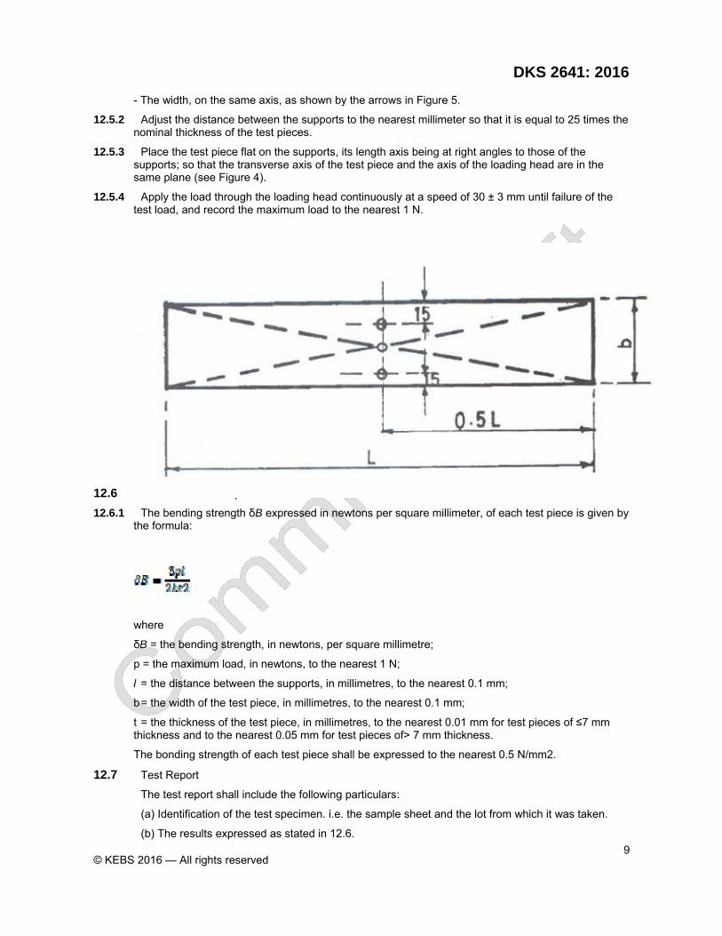
- The width, on the same axis, as shown by the arrows in Figure 5.
12.5.2 Adjust the distance between the supports to the nearest millimeter so that it is equal to 25 times the nominal thickness of the test pieces.
12.5.3 Place the test piece flat on the supports, its length axis being at right angles to those of the supports; so that the transverse axis of the test piece and the axis of the loading head are in the same plane (see Figure 4).
12.5.4 Apply the load through the loading head continuously at a speed of 30 ± 3 mm until failure of the test load, and record the maximum load to the nearest 1 N.
FIG. 5 ~ MEASUREMENT OF WIDTH AND THICKNESS
12.6 Calculation And Expression Of Results
12.6.1 The bending strength δB expressed in newtons per square millimeter, of each test piece is given by the formula:
where
δB = the bending strength, in newtons, per square millimetre;
p = the maximum load, in newtons, to the nearest 1 N;
l = the distance between the supports, in millimetres, to the nearest 0.1 mm;
b = the width of the test piece, in millimetres, to the nearest 0.1 mm;
t = the thickness of the test piece, in millimetres, to the nearest 0.01 mm for test pieces of ≤7 mm thickness and to the nearest 0.05 mm for test pieces of> 7 mm thickness.
The bonding strength of each test piece shall be expressed to the nearest 0.5 N/mm2.
12.7 Test Report
The test report shall include the following particulars:
(a) Identification of the test specimen. i.e. the sample sheet and the lot from which it was taken.
(b) The results expressed as stated in 12.6.
© KEBS 2016 — All rights reserved 10
13 Transverse Load-Specimen Vertical
13.1 Test specimens-Tests shall be made on three like specimens on symmetrical assemblies and six like specimens on unsymmetrical assemblies each having a length equal to the length of the element and a nominal width of 4 ft (1.2 m) (see Section 3).
13.2 Apparatus - The apparatus shall be assembled as shown in Fig. 3 and shall conform to the requirements for component parts prescribed in 12.2. I - 12.2.5, or the equivalent.
13.2.1 Steel channel
13.2.2 Rollers - Cylindrical rollers, two supporting rollers, two loading rollers.
13.2.3 Screw jack
13.2.4 Ring Dynamometer
13.2.5 Deflectometers - Two taut-wire mirror-scale deflectometers similar to those described in 9.2.2.
13.3 Procedure - Transverse loads cannot be applied satisfactorily to some wall constructions, such as masonry, with the specimen in a horizontal position. For such constructions, apply the loads with the specimen in a vertical position, as shown in Fig. 3, thus simulating service conditions. The specimen, on a steel channel, shall rest on cylindrical rollers to prevent restrained end conditions. The axes of the rollers shall be parallel to the faces of the specimen. The two supporting rollers shall be in contact with the vertical surface of the frame and each roller shall rest horizontally on sponge rubber about 0.4 in. (10 mm) thick to prevent longitudinal restraint. Each of the two loading rollers shall also rest on sponge rubber. Apply the loads horizontally by a screw jack and measure by a ring dynamometer between the jack and the specimen. The error in the load indicated by the dynamometer shall not exceed I %. Attach two taut-wire mirror-scale deflectometers to the specimen, one to each vertical edge.
13.3.1 Apply the transverse load to the outside face for three of the specimens, and to the inside face for three of the specimens. For symmetrical assemblies, test only three specimens.
13.3.2 The bag method of loading is shown schematically in Fig. 4. Connect a reaction platform parallel to the face to be loaded and wider than the specimen to the supports by tie rods. Place an airtight bag as wide as the specimen and as long as the span between the specimen and the reaction platform. Apply transverse load to the specimen by increasing the air pressure in the bag. Measure the pressure by means of a manometer or other pressure measuring device. The en-or of the pressure reading shall not exceed I %.
13.3.3 When the Chamber Method of loading is used with the specimen vertical, the specimen forms one face of an airtight chamber from which the air is exhausted. If all four edges of the specimen bear on the chamber, this loading determines the strength of the specimen as a plate supported at the four edges, not the transverse strength as defined in these methods.
13.3.4 If a specimen tested by the chamber method, either horizontally or vertically, has an airtight cavity, vent each cavity to the low-pressure face by a hole in the face of the specimen not less than 0.2 in. (5 mm) in diameter, located where it will least affect the transverse strength of the specimen.
13.4 Calculations and Report-Calculate the results of test and report as described in 11.4, and report deflectometer readings to the nearest 0.01 in. (0.25 mm).
14 Concentrated Load
14.1 Test Specimens-Concentrated load tests shall be made on each transverse specimen after the transverse load tests, the concentrated load being applied to the same face to which the transverse load was applied.
14.2 Apparatus - The apparatus shall be assembled as shown in Fig. 5 and shall conform to the requirements for component parts prescribed in 13.2.1 - 13.2.3, or the equivalent.
14.2.1 Steel bar - Steel bar having a diameter of I in. (25.4 mm) and the edge of the face contacting the specimen rounded to a radius of 0.05 in. (1.3 mm).
14.2.2 Depth Gauge-The depth gauge shall consist of a deflection-measuring device graduated to 0.001 in. (0.025 mm) or less mounted on a three-legged support shall notched to permit placing the device

DKS 2641: 2016
© KEBS 2016 — All rights reserved 11
directly adjacent to the bar and shall be long enough to permit placing the supporting legs on undisturbed areas of the face of the specimen.
FIG. 5 Concentrated Load Test
14.2.3 Loading - Any convenient means for applying compressive load up to 1100 Ibf (5 kN) and means for measuring the load within 1 %.
14.3 Procedure:
14.3.1 Loading - Place the entire specimen or portion of the specimen on a horizontal support and properly level. Place the steel bar on the face of the specimen at what is judged to be the weakest place and, also, at what is judged to be the strongest place. Apply a load vertically downward to the upper surface of the bar. Continue loading until maximum load or 1000 Ibf (4.45 kN) is attained.
14.3.2 Depth of Indentation-Measure the depth of indentation, by means of the depth gage, and record the reading of the micrometer to the nearest 0.001 in. (0.025 mm).
14.4 Calculations and Report:
14.4.1 Depth of lndentation - Calculate the depth of indentation (set) after a given load has been applied and the bar removed to the nearest 0.001 in. (0.025 mm) as the difference between the depth for that load and the initial reading of the micrometer before a load has been applied to the specimen.
14.4.2 Data Presentation-Report the results in the form of a graph in accordance with Section 6.
15 Racking Load-Evaluation of Sheathing Materials on a Standard Wood Frame
Note 2- These test methods have been used to evaluate design shear resistance of wall assemblies without the involvement of anchorage details. If the test objective is to measure the performance of the complete wall, Practice E564 is recommended.
15.1 Scope - This test method measures the resistance of panels, having a wood frame, and sheathed with sheet materials such as structural insulating board, plywood, gypsum board, transite, and so forth, to a racking load such as would be imposed by winds blowing on a wall oriented at 90° to the panel. It is intended to provide a reliable, uniform procedure for determining the resistance to racking load provided by these sheet materials as commonly employed in building construction. Since a standard frame is employed, the relative performance of the sheathing is the test objective.

© KEBS 2016 — All rights reserved 12
15.1.1 This test is conducted with standardized framing, loading procedures, and method of measuring deflection, as detailed in the method to ensure reproducibility. Provision is made for following the sheathing manufacturers' recommendations for attaching the sheathing to the frame, and for reporting the behavior of the specimen over its entire range of' use.
15.1.2 In applying the results, due allowance shall be made for any variation in construction details or test conditions from those in actual service.
15.2 Test specimens
15.2.1 Size and number - The test specimen shall be 8 by 8 ft (2.4 by 2.4 m) and the framing shall be constructed as shown in Fig. 6 and a minimum of three panels of each construction shall be testing.
15.2.2 Framing - Frames shall be newly constructed for each test. All individual framing members shall be continuous.
15.2.2.1 Sheathing Material Evaluation - The frame shall be constructed as nearly like the frames shown in Fig. 6 as possible. No. 1 Douglas-fir Larch or Southern Pine lumber conforming to NIST Voluntary Product Standard PS20 shall be used. The stud spacing and size of the stud at the vertical panel joint shall be permitted to vary as necessary to reflect the manufacturer's specified test condition or standardized requirements. Any deviations from the framing scheme depicted in Fig. 6 shall be reported.
Note 3 - A common situation where the 14.2.2.1 framing provisions apply would be for product qualification and evaluation of sheathing products where design values have already been established. In those instances, the sheathing performance and variation is the primary interest.
15.2.2.2 Sheathing and Sheathing-to-Framing Attachment Design Shear Evaluation without the Involvement of Anchorage-The framing shall be constructed in accordance with Fig. 6 except that the framing materials (size and specific gravity), stud spacing, and sheathing fastener size and spacing shall conservatively represent the range of applications that use the same design shear or racking resistance. The oven-dry specific gravity of the framing materials that receive perimeter sheathing fasteners at the panel boundaries and center stud shall be determined in accordance with Test Methods D2395 and reported. The average framing specific gravity for any test assembly shall not exceed the targeted average by more than 0.03. Note 4-The framing details of 14.2.2.2 apply in instances where the racking test is used to evaluate the racking resistance of the sheathing and sheathing-to-framing attachment for the establishment of design values. This may include evaluation for sheathing, fastener, or framing products to be used in engineered or braced wall applications. In these instances, the goal is to ensure that the interaction between the framing, sheathing fastener, and sheathing is representative of the end use condition
15.2.3 Moisture Content-The average moisture content of framing material shall be between 6 and 15 % at the time of testing. Immediately after the racking test, the moisture content of all framing members that receive sheathing perimeter fasteners shall be determined using Test Methods D4442 or Practice D7438 and reported. Racking tests shall be conducted within 72 h of fabrication unless the moisture content was determined at the time of fabrication. The average moisture content for each test frame at the time of fabrication, if applicable, and at the time of testing shall be reported. The elapsed time between fabrication and testing shall be reported.
15.2.4 Application of Sheathing-The method of applying the sheathing shall be as specified by the manufacturer and include at least one centered vertical sheathing joint. Sheathing fasteners shall be installed using the minimum edge distance recommended by the manufacturer along all four sheathing edges. The number of fasteners installed along each edge shall be equal to the length of the sheathing edge, divided by the specified fastener spacing, plus one. Spacing between the sheathing corner fastener and the next adjacent fastener is permitted to be less than the recommended spacing to accommodate the required edge distance. Sheathing fasteners shall be driven through the sheathing into only the outside stud of each corner post shown in Fig. 6. Unless otherwise specified, fasteners shall be driven perpendicular to the surface of the sheathing. Sheathing fasteners shall be driven so that the head of the fastener contacts the surface of the sheathing but not so deep as to crush the surface, unless specified differently by the manufacturers.
NOTE 5 -Differences in edge distance, angle of fastener, and amount of fastener head penetration into the sheathing may impact the results of the tests and should be consistently installed in accordance with the manufacturer's installation instructions.
DKS 2641: 2016
© KEBS 2016 — All rights reserved 13
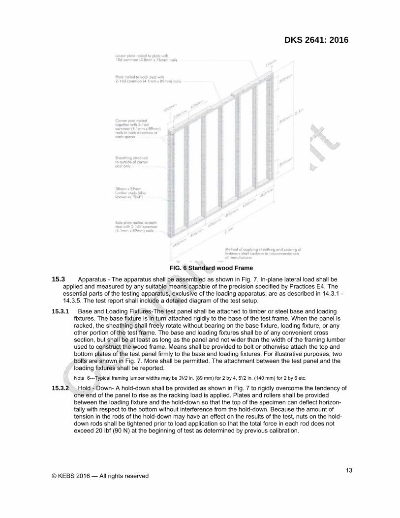
FIG. 6 Standard wood Frame
15.3 Apparatus - The apparatus shall be assembled as shown in Fig. 7. In-plane lateral load shall be applied and measured by any suitable means capable of the precision specified by Practices E4. The essential parts of the testing apparatus, exclusive of the loading apparatus, are as described in 14.3.1 - 14.3.5. The test report shall include a detailed diagram of the test setup.
15.3.1 Base and Loading Fixtures-The test panel shall be attached to timber or steel base and loading fixtures. The base fixture is in turn attached rigidly to the base of the test frame. When the panel is racked, the sheathing shall freely rotate without bearing on the base fixture, loading fixture, or any other portion of the test frame. The base and loading fixtures shall be of any convenient cross section, but shall be at least as long as the panel and not wider than the width of the framing lumber used to construct the wood frame. Means shall be provided to bolt or otherwise attach the top and bottom plates of the test panel firmly to the base and loading fixtures. For illustrative purposes, two bolts are shown in Fig. 7. More shall be permitted. The attachment between the test panel and the loading fixtures shall be reported.
Note 6---Typical framing lumber widths may be 3V2 in. (89 mm) for 2 by 4, 5'/2 in. (140 mm) for 2 by 6 etc.
15.3.2 Hold - Down- A hold-down shall be provided as shown in Fig. 7 to rigidly overcome the tendency of one end of the panel to rise as the racking load is applied. Plates and rollers shall be provided between the loading fixture and the hold-down so that the top of the specimen can deflect horizon-tally with respect to the bottom without interference from the hold-down. Because the amount of tension in the rods of the hold-down may have an effect on the results of the test, nuts on the hold-down rods shall be tightened prior to load application so that the total force in each rod does not exceed 20 Ibf (90 N) at the beginning of test as determined by previous calibration.

© KEBS 2016 — All rights reserved 14
FIG. 7 Racking Load Assembly
15.3.3 Loading Apparatus-Load shall be applied to the specimen in shear through a horizontal compressive force applied to the loading fixture parallel to the top plate.
15.3.4 Lateral Guides-Lateral guides shall be provided so that the specimen will deflect in a plane. The rollers should be bearing-supported to reduce friction to a minimum. The lateral guides shall be firmly attached to the loading frame. Plates for the rollers shall be provided.
15.3.5 Displacement Measuring Devices-linear displacement measuring devices shall be provided to measure the displacement of the different parts of the panel during test. The deflection measurement devices shall be Class "B" or higher when evaluated in accordance with Practices E23091E2309M. The locations and sign conventions of the displacement measuring devices shall be as shown in Fig. 7. The devices are used to measure: the lateral displacement of the centerline of the top plate (Ll.) and the bottom plate (Ll2), and the vertical displacement at the center of the tension stud (Ll3) and the compression stud (Ll4).
Note 7 – ∆1 provides a gross horizontal displacement measurement for the racking test specimen that includes lateral movement from specimen shear deformation, rigid body rotation, and rigid body translation. ~2' ~3' and ~4 provide displacement measurements used to analytically determine the assembly deformation that excludes movement from rigid body rotation and translation.
15.4 Procedure - The racking load shall be applied using a series of stages that are a function of the expected maximum load. The panel shall be loaded at a constant rate using a minimum of three stages, with the final stage loading the panel to failure. Loads and displacements are measured and recorded through all stages at a frequency of not less than once every 10s.
NOTE 8- The expected maximum load may be determined based upon preliminary tests, experience, calculation, or standardized product requirements

DKS 2641: 2016
© KEBS 2016 — All rights reserved 15
15.4.1 Loading Rate-Load shall be applied continuously throughout test at a uniform rate of racking load or fixture displacement. The loading rate shall be such that the peak load in the first stage shall be achieved in not less than 2 min. The same load or displacement rate shall be used for subsequent stages. Report the loading rate used and the time from load initiation to maximum load for each test specimen. The average time to the maximum load, excluding relaxation time, for a series of specimens shall not be less than 10 min
15.4.2 Loading Procedure-Load the specimen using a minimum of the three mandatory stages outlined below. Additional preliminary stages shall be permitted.
15.4.2.1 First Stage-Load the specimen to a load level not less than 30 % of the expected maximum load. Unload the specimen in 30 s or less and record the set.
Note 9 -Some performance standards that use this test method may require a minimum relaxation time between loading stages. For example, as min recovery period between loading stages is typically required when testing wood Structural panels.
15.4.2.2 Second Stage-Load the specimen to not less than 60 % of the expected maximum load. Unload the specimen in 30 s or less and record the set
15.4.2.3 Third Stage-Load the specimen beyond the maximum load to failure or to the point where the measured post-peak racking resistance represents 80 % of the maximum load, whichever occurs first.
15.5 Calculation ad report
15.5.1 Deformation - For each measuring device, calculate the movement under each racking load as the difference between the readings when load is applied and the initial readings at the start of the test. Calculate set readings as the difference between the readings when the load is removed and the initial readings. Calculate and report the horizontal deformation of the test specimen as:
where:
∆h= horizontal deformation of the assembly that excludes movement from rigid body rotation and translation, in (mm)
∆1= horizontal displacement of the top plate, in. (mm)
∆2 = horizontal displacement of the bottom plate, in. (mm)
∆3 = vertical displacement of the tension stud, in. (mm)
∆4 = vertical displacement of the compression stud, in. (mm)
15.5.2 Data Presentation-Report the targeted load levels for each stage, peak loads, and corresponding deformations measured during each load stage. Report the set after loading to these amounts. Present the load-deflection curves obtained in the form of a graph. Include maximum load, the interpolated load corresponding to horizontal deformations of interest (see Note 10), the post-peak deflection at 80 % of the maximum load and any observations on the behavior of the panel during test and at failure. Express residual deflections (sets) as percentages of the deflections that produced the sets in millimetres or inches. Describe the visible failures. If the specimen has been subjected to any special conditioning prior to test, describe this treatment in detail. Describe in the report the sheathing used, the method of applying the sheathing, the type and spacing of fasteners, and the method and loading rate employed.
Note 10-The load at a horizontal deformation of 0.2 in. (5 mm) is often used by performance standards that reference E72.
16 Racking Load-Evaluation of Sheathing Materials (Wet) on a Standard Wood Frame
16.1 Scope - This test has been developed to simulate the degree of wetting possible during construction of a structure when, because of rain, the framing and sheathing may be wetted on one or both sides. Both sides of the wall panel are wetted because this represents the maximum exposure possible during the stage of construction before the structure is roofed.
16.2 Test Specimens-The test specimens shall conform in size and fabrication details to the requirements of 14.2.

© KEBS 2016 — All rights reserved 16
16.3 Specimen Conditioning-Mount the fabricated test specimens or suspend them in a vertical position in such a manner as to prevent continuous immersion of the bottom edge of the specimen. Expose both sides of the test specimen to a water spray applied at or near the top along the entire length to ensure that the top of the specimen is being wetted. The spray shall have no jet action that cuts into the sheathing material, and the spray areas shall overlay sufficiently so that a continuous sheet of water flows down both surfaces of the specimen. Maintain the temperature of the water in the line to the spray nozzle at 75 ± 5°F (24 ± 3°C). Wet the specimens for a period of 6 h and then allow to dry for a period of 18 h. Dry in laboratory air, preferably at a temperature of 75 ± 5˚ F (24 ± 3°C). Make no attempt to increase the air movement over the specimens by fans or blowers. Subject the test specimens to two complete wetting and drying cycles and then a third wetting cycle.
16.3.1 No more than 2 h shall elapse between the completion of the third wetting cycle and the start of the racking test.
16.4 Procedure - Test the specimens in accordance with the procedure described in 14.4.
16.5 Moisture - Content Determination-After the racking test is completed, cut moisture samples from the sheathing material, and determine moisture content on a weight basis with the moisture content expressed as a percentage of the oven dry weight in accordance with 15.5.1. Preferably, take five moisture content samples at least 4 by 6 in. (100 by ISO mm) in size from each 4 by 8-ft (1.2 by 2.4-m) sheathing panel of the test specimen: one from the center of each sheathing panel at the top and bottom edges, one from midlength on each side, and one from the panel center. Weigh the moisture content samples immediately upon being cut from the test specimen to an accuracy of not less than ± 2 %. Carefully remove all loose particles from the sample before weighing. Then dry the samples to constant weight in an oven at (217 ± 4°F (103 ± 2°C). If large amounts of volatile matter or substances other than free water are removed from the sheathing material by drying at 103 ± 2°C, the sheathing material may be dried to constant weight at a lower temperature and the drying time and temperature given in the report.
16.5.1 Calculation - Calculate the moisture content as follows:
M = 100 [(w - F)/F]
Where:
M = moisture content, %,
W = initial weight, and
F = final weight when oven dry.
16.6 Calculations and Report-The report shall include the racking test data as specified in 14.5. It shall also include the line temperature of the water sprayed on the test specimens; the air temperature and relative humidity during the drying portion of the cycle; and the location of the moisture content samples and the moisture content of each.
17 Testing Floors
17.1 Significance and use
17.1.1 The procedures outlined will serve to evaluate the performance of floor segments under conditions representative of those sustained in service. Performance criteria based on data from these procedures can ensure structural adequacy and effective service.
18 Transverse load
18.1 Test in accordance with Test Method E2322, Section 10.
19 Concentrated Load
19.1 Test in accordance with Test Method E2322, Section 11.
20 Testing Roof panel
20.1 These procedures will serve to evaluate performance of roof segments under simulated service conditions. Roof trusses shall be evaluated under Practice E73.

DKS 2641: 2016
© KEBS 2016 — All rights reserved 17
21 Transverse Load
21.1 Test in accordance with Test Method E2322, Section 12.
22 Concentrated Load
22.1 Test in accordance with Test Method E2322, Section 13
23 Keywords
23.1 Compressive load; concentrated loads; deformation; floors; load duration; racking load; roofs; sheathing; strength tests; tensile load; transverse load; walls
24 Determination Of Water Absorption After Immersion In Water
24.1 Principle
Determination of the water absorption by calculating the increase in mass of the test pieces after complete immersion in water.
24.2 Apparatus
24.2.1 Balance used in measuring should have an accuracy of 0.01g.
24.2.2 A thermostatic tank, the temperature of which can be kept at 20 ±1 °c and in which the immersed test pieces can be maintained in the conditions indicated in 24.4.2.
24.2.3 Sheets of cellulose wadding, or blotting paper, square in shape, with sides of at least 120 mm and of substance equal to or more than 200 g/m 2.
24.2.4 Square steel plate with sides measuring 120 mm and having a mass of approximately 3 kg.
24.3 Test Pieces
24.3.1 Cut the test pieces DW1 and DW2 from the test specimen in accordance with Figure 1.
24.3.2 Mark each test to identify it with the test specimen from which it was cut.
24.4 Procedure
24.4.1 Each test piece shall be weighed to an accuracy of ± 0.01 g.
24.4.2 The test pieces, well separated from each other as well as from the- bottom and sides of the tank, shall then be immersed vertically in dean and calm-water having a 'pH value of 6 ± 1 and a temperature of 20 ± 1 °C at the beginning of every new test. The upper edges shall be immersed approximately 20 mm below the surface of the water
The immersion time shall be 2 h ± 15 min.
24.4.3 Then take the test pieces out of the water and place each separately horizontally between the cellulose wadding or blotting paper in piles of a maximum of five, in order to remove excess water.
24.4.4 Load each pile with a square-steel plate.
24.4.5 Keep the plate in this position for 30 s and then remove it and the absorbing sheets.
24.4.6 Weigh each test piece within 10 min from the time of removal from the tank.
24.5 Calculation and expression of results
The percentage of water, A, absorbed by each test piece shall be calculated in accordance with the following formula:
where,

© KEBS 2016 — All rights reserved 18
A = the percentage water absorption;
M1 = the mass, in grams, of the test piece before immersion;
m2 = the mass, in grams, of the test piece after immersion,
The water absorption shall be expressed to the nearest 0.1 %.
24.6 Test report
The test report shall include the following particulars:
(a) Identification of the test specimen, i.e. the sample sheet and the lot from which it was taken.
(b) The results expressed as stated in D6.