standardi (bbm italija)
TRANSCRIPT

1 MATERIALS
2002
2 DRILLING AND THREAD DEPTHSTHREAD SELECTION SERIES AND UNDERCUTS
3 CURVES, DIAGONALS, UNDERCUTS
4 PERMISSIBLE BOLT LOADS,TIGHTENING TORQUES, PRETENSIONING UNITS
DE
SIG
N D
IRE
CT
IVE
S
5
DESIGN INSTRUCTIONS ON FASTENERSSCREWS, BOLTS, NUTS, WASHERS IN CONJUNCTION WITHCOUNTERSINKINGS/COUNTERBORES AND/OR HOLES;FOUNDATION ANCHORING ELEMENTS
6
MECHANICAL FASTENERSSCREWS, BOLTS, NUTS; SETSCREWS, PINS, STUDS, OTHERSCREWS/BOLTS; WASHERS AND RETAINING ELEMENTS;LOCKNUTS AND LOCKING PLATES
7 FITTING KEYS, TAPER KEYS
ST
AN
DA
RD
S B
OO
K
8 AXLE STOP PLATES, PINS, BUSHINGS
9 SEMI-FINISHED PRODUCTS AVAILABLE FROM STOCK,STRUCTURAL STEEL SECTIONS
PR
OD
UC
T S
TA
ND
AR
DS
/ P
AR
TS
KE
PT
IN S
TO
CK
10STANDARD PIPE DIMENSIONS, PIPE COUPLINGS,FLANGES, WELDING FITTINGS, PIPE FASTENERS,HOSELINES, AUXILIARY AND OPERATING MATERIALS

The most recent versions of the standards can be found in the Intranet under:
• Online Standards
All rights reserved. DIN 34
SMS Demag AktiengesellschaftDüsseldorf and Hilchenbach
Normung / Standardisierung (Dept. of Standardisation)
1st edition (January 2002)

January 2002
Materials
SelectionSN 359
This standard lists materials which are used in SMS Demag products; priority shall be given to the materials of SN 483,which are available from stock.
Contents:
Material designations (designation systems) ..................................................Pages 2 to 8
Footnotes .................................................................................................................... Page 9
Rolled and forged steelsEngineering steels ...................................................... DIN EN 10025, ........................................................... Pages 10/11
DIN EN 10137-2, SEW 090-2...................................... Pages 16/17Fine grained engineering steels................................... DIN EN 10113-2 ......................................................... Pages 12/13Bright steels ............................................................... DIN EN 10083-2, DIN EN 10277-2 .............................. Pages 12/13Sheets........................................................................ DIN EN 10130 ........................................................... Pages 12/13Pipe/tube steels.......................................................... DIN 1629, DIN 1630, DIN 2391, DIN 17175, ................ Pages 12/13
DIN 17457, DIN 17458................................................ Pages 12/13Steels for pressure purposes....................................... DIN EN 10028-2 und 3................................................ Pages 14/15Quenched and tempered steels................................... DIN EN 10083-1 und 2................................................ Pages 16-19Flame and induction hardening steels.......................... DIN 17212.................................................................. Pages 18/19Case hardening steels ................................................ DIN EN 10084 ............................................................ Pages 20/21Steels for forgings....................................................... DIN EN 10222-2, ........................................................ Pages 20/21
DIN EN 10250-2 bis 4, SEW 550................................. Pages 20-23High temperature steels.............................................. DIN EN 10269 ............................................................ Pages 20/21Stainless steels .......................................................... DIN 17440, DIN EN 10088-1 bis 3, DIN EN 10250-4.... Pages 24/25
Cast ironGrey cast iron ............................................................. DIN EN 1561 .............................................................. Pages 26/27Spheroidal graphite cast iron....................................... DIN EN 1563 .............................................................. Pages 26/27Malleable cast iron...................................................... DIN EN 1562 .............................................................. Pages 26/27
Cast steelCast steel ................................................................... DIN 1681, DIN 17182,................................................. Pages 26/27
DIN 17205, SEW 835, DIN EN 10213-2....................... Pages 28/29
Non-ferrous metalsRed brass................................................................... DIN EN 1982 .............................................................. Pages 30/31Tin bronze .................................................................. DIN EN 1982 .............................................................. Pages 30/31Cast tin-lead bronze.................................................... DIN EN 1982 .............................................................. Pages 30/31Cast aluminium bronze ............................................... DIN EN 1982 .............................................................. Pages 30/31White bronze .................................................................................................................................................... Pages 30/31Special brass.............................................................. DIN EN 12164 ............................................................ Pages 32/33Special cast brass ...................................................... DIN EN 1982 .............................................................. Pages 32/33Babbitt metal .............................................................. DIN ISO 4381 ............................................................. Pages 32/33Sintered bronze ................................................................................................................................................ Pages 32/33Maintenance-free sliding materials ................................................................................................................... Pages 32/33
Continued on pages 2 to 33
Th
is c
op
y w
ill n
ot
be
up
dat
ed in
cas
e o
f ch
ang
es!

Page 2SN 359 : 2002-01
- Blank page -

Steel grade classification
as in EN 10020
Unalloyed steelsas in table 1
Main quality grades
Alloyed steelsas in table 1
Main quality grades
Base steels
BS
Unalloyed quality steels
UQS
Unalloyed high-grade steels
UES
Alloyed quality steels
LQS
Alloyed high-grade steels
LES
Steels with no particular Steels with no require- Quenched and tempered or Steels whose applications are similar to those of Steels which exceed the requirements made on thequality requirements ments made on the degree surface-hardened steels having unalloyed quality steels and which contain alloying alloying elements in table 3 and which, due to their
(deep drawing, cold- of purity with regard to a higher degree of purity with elements because of their special requirements. chemical compositioni, have a wide variety offorming ..) on the steel non-metallic inclusions. regard to non-metallic in- Alloyed quality steels are not intended for quenching processing and utilisation properties,grade in production. No uniform response to clusions as compared with and tempering or for surface treatment for exampleNo heat treatment heat treatment. unalloyed quality steels. Fine-grain engineering steels for steel construction, Stainless, heat-resisting, high-temperature steels,Requirements defined Steel whose quality re- Uniform response to heat pressure vessel manufacture and line pipe engin- antifriction-bearing, tool, mechanical-engineeringby standards and quirements exceed the treatment. eering with a minimum yield point < 380 N/mm² for steels and steels for steel structures, with particulardelivery specifications limit contents of table 2 for Exact chemical composition thicknesses < 16 mm; limit content of alloying elem- physical properties. Stainless steels with C = 1,20%as in table 2. base steels. makes it possible to obtain ents as in table 3; alloyed steels for rails, sheet and Cr = 10,5% and Ni <2,5%: ferritic andNo alloying elements In comparison with the special properties such as piling products and structural sections for mines. martensitic steels, Ni = 2,5%: austenitic steels.besides Si and Mn. base steels more severe Alloyed steels with Si or with Si and Al.
requirements are made - high strength or harden- Hot or cold-rolled flat steel products alloyed with High-speed steels with at least two of the followingwith regard to sensibility to ability in conjunction with B, Nb, Ti, V or Zr alone or combinations of these three elements: Mo, W, V with an overall massbrittle fracture, grain size, the shapability elements. content of 7% and with C = 0,60% andshapability etc. - suitability for welding Cr = 3 to 6 %.
- ductility- etc.
Designation system as in EN 10 027-1 Table 1Group 1 Short name based on usage and mechanical
and physical properties (Figs. 2, 3)Prescribedelements
Limit contentPercentage by mass
as in EN 10 020, appendices A, B Al Aluminium 0,1BS UQS UES LQS LES B Boron 0,0008
G = Unalloyed cast steel x x x Bi Bismuth 0,10S = Steels for steel construction x x x x x Co Cobalt 0,10P = Steels for pressure vessel manuf. x x x x x Cr Chromium 0,30L = Steels for line pipe engineering x x x Cu Copper 1) 0,40E = Mechanical-engineering steels x x La Lanthanides 0,05B = Concrete reinforcing steel x Mn Manganese 1,65 3)
Y = Prestressing steels x Mo Molybdenum 1) 0,08R = Steels for or in the shape or rails x x Nb Niobium 2) 0,06H = Cold-rolled flat products of higher x Ni Nickel 1) 0,30
-strength drawing qualities P Lead 0,40D = Flat products in low-carbon steels x x x Se Selenium 0,10
for cold shaping Si Silicium 0,50T = Packing plate and strapping band x Te Tellurium 0,10M = Electr. sheet & magnet. steel strip x x Ti Titanium 2) 0,05Group 2 Short name based on chemical composition (Fig. 4) V Vanadium 2) 0,10
as in EN 10 020, appendices A, B W Tungsten 0,10BS UQS UES LQS LES Zr Circonium 2) 0,05
G = Alloyed cast steel x x Others (except C, P, S, N) 0,05x x x x 1) If 2, 3 or 4 elements are marked for steel with this footnote and if their contents
C = Carbon x are smaller than the limit contents stated in the table, a limit content of 70%of the total resulting from the 2, 3, or 4 elements must be taken into account.
X = mean content of at least 2) The rule given under footnote 1) applies by analogy to the elements markedone alloying element x with footnote 2).= 5 % 3) If only a maximum value is indicated for Mn, the applicable limit content is
1.80 percent by weight.HS = High-speed steel
Table 2
Requirements
Typeapply for
thicknesses (d)mm
Limit value
Minimum tensile strength = 16 = 690 N/mm²Minimum yield point = 16 = 360 N/mm²Minimum elongation at fracture 1) = 16 = 26 %Minimum diameter = 3 = 1 x dMinimum energy consumption in the notched bar impact test (at 20°C) = 10 = 16 = 27 joule
Max. allowable C content = 0,10 %Max. allowable P content = 0,045 %Max. allowable S content = 0,045 %1) see EN 10020 Table 2, page 5
Table 3
Prescribedelements
Limit contentPercentage by mass
Cr Chromium 1) 0,50Cu Copper 1) 0,50La Lanthanides 0,06Mn Manganese 1,80Mo Molybdenum 1) 0,10Nb Niobium 2) 0,08Ni Nickel 1) 0,50Ti Titanium 2) 0,12V Vanadium 2) 0,12Zr Circonium 2) 0,12Elements which are not stated (see Table 1)1) If 2, 3 or 4 elements are marked for steel with this footnote and if their
contents are smaller than the limit contents stated in the table, a limitcontent of 70% of the total resulting from the 2, 3 or 4 elements must betaken into account.
2) The rule given under footnote 1) applies by analogy to the elements markedwith footnote 2).
ClassificationDesignation systemFig. 1
Seite 3
SN
359 : 2002-01
European steel gradesDesignation system and comparison with DIN
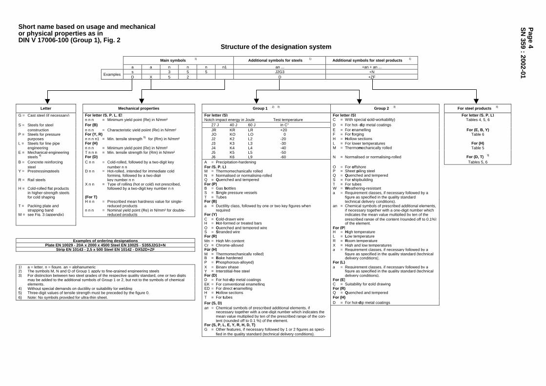
Short name based on usage and mechanicalor physical properties as inDIN V 17006-100 (Group 1), Fig. 2
Structure of the designation system
Main symbols 1) Additional symbols for steels 1) Additional symbols for steel products 1)
a a n n n n1 an ... +an + an ...s 3 5 5 J2G3 +N
ExamplesD X 5 2 D +ZF
Letter Mechanical properties Group 1 2) 3) Group 2 3) For steel products 3)
G = Cast steel (if necessary) For letter (S, P, L, E) For letter (S) For letter (S) For letter (S, P, L)n n n = Minimum yield point (Re) in N/mm² Notch impact energy in Joule Test temperature C = With special cold-workability) Tables 4, 5, 6
S = Steels for steel For (B) 27 J 40 J 60 J in C° D = For hot- dip metal coatingsconstruction n n n = Characteristic yield poiint (Re) in N/mm² JR KR LR +20 E = For enamelling For (E, B, Y)
P = Steels for pressure For (Y, R) JO KO LO 0 F = For forging Table 6purposes n n n n1 = Min. tensile strength 5) for (Rm) in N/mm² J2 K2 L2 -20 H = Hollow sections
L = Steels for line pipe For (H) J3 K3 L3 -30 L = For lower temperatures For (H)engineering n n n = Minimum yield point (Re) in N/mm² J4 K4 L4 -40 M = Thermomechanically rolled Table 5
E = Mechanical-engineering T n n n = Min. tensile strength for (Rm) in N/mm² J5 K5 L5 -50steels 4) For (D) J6 K6 L9 -60 N = Normalised or normalising-rolled For (D, T) 3)
B = Concrete reinforcing C n n = Cold-rolled, followed by a two-digit key A = Precipitation-hardening Tables 5, 6steel number n n For (S, P, L) O = For offshore
Y = Prestressingsteels D n n = Hot-rolled, intended for immediate cold M = Thermomechanically rolled P = Sheet piling steelforming, followed by a two-digit N = Normalised or normalising-rolled Q = Quenched and tempered
R = Rail steels key number n n Q = Quenched and tempered S = For shipbuildingX n n = Type of rolling (hot or cold) not prescribed, For (P) T = For tubes
H = Cold-rolled flat products followed by a two-digit key number n n B = Gas bottles W = Weathering-resistantin higher-strength steels S = Single pressure vessels a = Requirement classes, if necessary followed by afor cold shaping (For T) T = Tubes figure as specified in the quality standard
H n n = Prescribed mean hardness value for single- For (B) technical delivery conditions).T = Packing plate and reduced products a = Ductility class, followed by one or two key figures when an = Chemical symbols of prescribed additional elements,
strapping band n n n = Nominal yield point (Re) in N/mm² for double- required if necessary together with a one-digit number whichM = see Fig. 3 (appendix) reduced products For (Y) indicates the mean value multiplied by ten of the
C = Cold-drawn wire prescribed range of the content (rounded off to 0.1%)H = Hot-formed or treated bars of the element.Q = Quenched and tempered wire For (P)S = Stranded wire H = High temperatureFor (R) L = Low temperature
Examples of ordering designations Mn = High Mn content R = Room temperaturePlate EN 10029 - 20A x 2000 x 4500 Steel EN 10025 - S355J2G3+N Cr = Chrome-alloyed X = High and low temperatures
Strip EN 10143 - 2,5 x 500 Steel EN 10142 - DX52D+ZF Für (H) a = Requirement classes, if necessary followed by aM = Thermomechanically rolled) figure as specified in the quality standard (technicalB = Bake hardened delivery conditions).P = Phosphorous-alloyed) For (L)
1) a = letter, n = figure, an = alphanumeric X = Binary phase a = Requirement classes, if necessary followed by a2) The symbols M, N and Q of Group 1 apply to fine-grained engineering steels Y = Interstitial-free steel figure as specified in the quality standard (technical3) For distinction between two steel grades of the respective quality standard, one or two digits For (D) delivery conditions).
may be added to the additional symbols of Group 1 or 2, but not to the symbols of chemical D = For hot-dip metal coatings For (E)elements. EK = For conventional enamelling C = Suitability for cold drawing
4) Without special demands on ductility or suitability for welding ED = For direct enamelling For (R)5) Three-digit values of tensile strength must be preceded by the figure 0. H = Hollow sections Q = Quenched and tempered6) Note: No symbols provided for ultra-thin sheet. T = For tubes For (H)
For (S, D) D = For hot-dip metal coatingsan = Chemical symbols of prescribed additional elements, if
necessary together with a one-digit number which indicates themean value multiplied by ten of the prescribed range of the con-tent (rounded off to 0.1 %) of the element.
For (S, P, L, E, Y, R, H, D, T)G = Other features, if necessary followed by 1 or 2 figures as speci-
fied in the quality standard (technical delivery conditions).
Pag
e 4S
N 359 : 2002-01

Short name based on chemical compositionas in DIN V 17006-100 (Group 2), Fig. 4
Structure of the designation system
Main symbols 1) Additional symbols for steels 1) Additionial symbols for steel products 1)
a n n n a... n-n an ... +an + an ...
C 3 5Examples
2 8 Mn 6
Letter Carbon content 2) Alloying elements Group 1 3) 4) Group 2 For steel productsG = Cast steel (if For letter (G, C, X) a = Symbols of the alloy elements For letter (C) For letter (C) For letter (C, HS)
necessary) n n n = 100 times the mean which are characteristic of the E = Prescribed max. S content an = Chemical symbols of pre- Table 6C = Carbon C content of the steel, followed by hyphenated scribed additional elem-X = Mean content of at prescribed range. n-n = numbers which represent the R = Prescribed range of the ents, if necessary to- For (G, X)
least one alloying When no carbon-content mean contents of the elements, S content gether with a one-digit Tables 4, 6element = 5 % range is specified, a multiplied by the factors given D = For wire drawing number which indicates
HS = High speed steel suitable representative below. the mean value multi-value is assumed. C = Special cold-workability plied by ten of the pre-
(cold heading, cold scribed range of contentextrusion) (rounded off to 0.1%)
Cr, Co, Mn, Ni, Si, W x 4 of the element.Al, Be, Cu, Mo, Nb, S = For springsPb, Ta, Ti, V, Zr x 10 U = For tools
1) a = letter, n = figure, an = alphanumeric Ce, N, P, S x 100 W = For welding wire)2) For distinction between two steel grades of similar B x 1000
chemical compositions, the key number of the carbon G = Other features, if necessarycontent can be increased by one. For letter (X) followed by 1 or 2 figures
3) The symboles of Group 1, except E and R, can be followed n-n = Numbers separated by hyphens as specified in the qualityby one or two figures for distinction between two steel grades which indicate the mean standard (technical deliveryof the respective quality standard. contents of the elements conditions)
4) The symbols E and R of Group 1 can be followed by a figure rounded to the next integer.which represents the maximum allowable or mean sulphurcontent, rounded off to 0.01% and then multiplied by 100. For (HS)
n-n = Numbers separated by hyphenswhich indicate the percentagesof the alloying elements in thefollowing order:
- Tungsten (W)- Molybdenum (Mo)- Vanadium (V)- Cobalt (Co)
Table 4: Special requirementsSymbol Meaning
+CC * Nonworked conticast material+H With special hardenability+HL * With restricted hardenability scatterbands+HH * With restricted higher hardenability scatterbands+Z15 Min. area reduction at break perpendicular to surface 15 %+Z25 Min. area reduction at break perpendicular to surface 25 %+Z35 Min. area reduction at break perpendicular to surface 35 %Note: The symbols are separated from the preceding symbols by a plus sign (+).Basically, these symbols mark special requirements which are made on the steel.For practical reasons, however, they are treated like additional symbols for steelproducts.* acc. to DIN EN 10083-1 (edition of Oct. 96)
Table 5: Type of coatingSymbol Meaning
+A * Hot aluminium plated+AR Aluminium-clad by rolling+AS Coated with Al-Si alloy+AZ Coated with Al-Zn alloy (> 50 % Al)+CE Special chromium electrodeposition plated (ECCS)+CU Copper coating+IC Anorganic coating+OC Organic coating+S * Hot tin plated+SE Electrolytic tin plated+T * Hot dipped with lead-tin alloy (terne)+TE Electroplated with lead-tin alloy+Z * Hot-dip galvanized+ZA Coated with Zn-Al alloy (> 50 % Zn)+ZE Electrogalvanized+ZF Diffusion-annealed zinc coats (with diffused Fe)+ZN Zinc-nickel coat (electrolytic)* Note: The symbols are separated from the preceding symbols by a plus sign(+). To avoid confuction with other symbols, the letter S can be placed before thesymbol, e.g. +SA.
Table 6: Treatment condition+A Soft annealed+AC Annealed for obtaining spheroidal carbides+AR As rolled (no particular rolling and heat-treatment conditions)+AT Solution-annealed+BC Hot worked and blasted (DIN EN 10083-1, edition of Oct. 96)+C Cold worked (e.g. by rolling or drawing)+Cnnn Cold-worked to a min. tensile strength of n n n N/mm²+CR Cold-rolled+DC Delivery condition at maker's discretion+FP Treated for ferrite-pearlite structure and hardness range+HC Hot-cold worked+HW Hot-shaped+I Isothermally treated+LC Slightly cold redrawn or slightly skin pass rolled+M Thermomechanically rolled+N Normalised or normalising-rolled+NT Normalised and tempered+P Precipitation-hardened+P Hot worked and pickled (DIN EN 10083-1, edition of Oct. 96)+RA Recrystallisation-annealed+Q Quenched+QA Air-hardened+QL Hardened and tempered (DIN EN 10028-2, edition of April 93)+QO Oil-hardened+QT Quenched and tempered+QW Water-quenched+S Treated for cold-shearing property+SR Stress-free annealed+T Tempered+TH Treated for hardness range+U Unprocessed+WW Hot-work hardenedAnmerkung: The symbols are separated from the preceding symbols by aplus sign (+). To avoid confusion with other symbols, the letter T can beplaced before the symbol, e.g. +TA.
Pag
e 5S
N 359 : 2002-01
Heat treatment conditions acc. toDIN EN 10083
+A = dead-soft annealed+N = normalized+QT = quenched and tempered
Page 6SN 359 : 2002-01
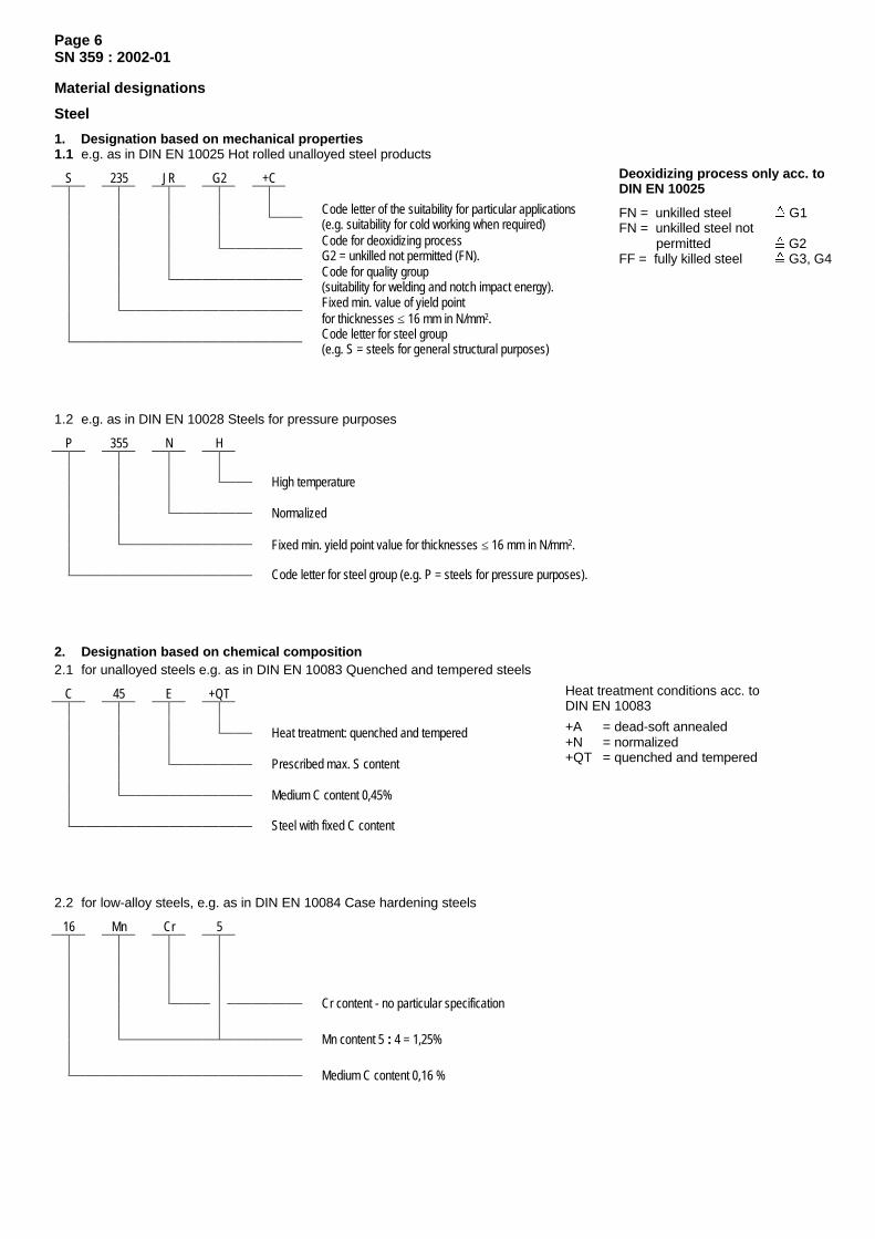
Material designations
Steel
1. Designation based on mechanical properties1.1 e.g. as in DIN EN 10025 Hot rolled unalloyed steel products
S 235 JR G2 +C
Code letter of the suitability for particular applications(e.g. suitability for cold working when required)Code for deoxidizing processG2 = unkilled not permitted (FN).Code for quality group(suitability for welding and notch impact energy).Fixed min. value of yield pointfor thicknesses ≤ 16 mm in N/mm2.Code letter for steel group(e.g. S = steels for general structural purposes)
1.2 e.g. as in DIN EN 10028 Steels for pressure purposes
P 355 N H
High temperature
Normalized
Fixed min. yield point value for thicknesses ≤ 16 mm in N/mm2.
Code letter for steel group (e.g. P = steels for pressure purposes).
2. Designation based on chemical composition2.1 for unalloyed steels e.g. as in DIN EN 10083 Quenched and tempered steels
C 45 E +QT
Heat treatment: quenched and tempered
Prescribed max. S content
Medium C content 0,45%
Steel with fixed C content
2.2 for low-alloy steels, e.g. as in DIN EN 10084 Case hardening steels
16 Mn Cr 5
Cr content - no particular specification
Mn content 5 : 4 = 1,25%
Medium C content 0,16 %
Deoxidizing process only acc. toDIN EN 10025
FN = unkilled steel G1FN = unkilled steel not permitted G2FF = fully killed steel G3, G4

Page 7SN 359 : 2002-01
2.3 for high-alloy steels, e.g. as in DIN EN 10088 Stainless steels
X 6 Cr Ni Ti 18 - 10
Ti content: no particular specification
Ni content = 10,0 %
Cr content = 18,0 %
Medium C content 0,06 %
Alloy constituents other than the C content are stated in plain text
3. Multipliers for low-alloy steels
Alloying additions Multipliers for low-alloy steelsCr, Co, Mn, Ni, Si, W 4Al, Be, Cu, Mo, Nb, Pb, Ta, Ti, V, Zr 10Ce, N, P, S 100B 1000
Cast iron
Designation according to yield pointe.g. as in DIN EN 1563 Spheroidal graphite cast iron
EN - GJS - 400 - 15 U
Proving on integrally cast test boss
Min. value of elongation A in per cent
Tensile strength min. 400 N/mm² at wall thicknesses ≤ 30 mm
Spheroidal graphite cast iron
European standard
Cast steel
1. Designation based on mechanical properties1.1 e.g. DIN 1681 Cast steels for general engineering purposes (remaining from the old designation system)
GS - 52
Tensile strength min. 520 N/mm²
Cast steel
1.2 for unalloyed cast steel, e.g. DIN EN 10213 Ferritic steel castings for service at elevated temperatures
GP 240 GH + N
Normalized
High temperature (heat resistant)
Code no. of min. yield point Rp 0,2 in Mpa (Mpa N/mm²)
Cast steel for pressure purposes
Designation forG = castingsP = pressure vessels

Page 8SN 359 : 2002-01
2. Designation based on chemical composition2.1 for low-alloy cast steel, e.g. DIN 17205 Quenched and tempered steel casting (remaining from the old designation
system)
GS - 42 Cr Mo 4 V I
Hardened and tempered to strength class I
Mo content: no particular specification
Cr content 4 : 4 = 1,0 %
C content 0,42 %
Cast steel
2.2 for high-alloy cast steel, e.g. DIN EN 10213 Steel castings for service at elevated temperatures
G X 23 Cr Mo V 12 - 1 +QT
Heat treatment: quenched and tempered
V content: no particular specification
Mo content 1 %
Cr content 12 %
C content 0,23 %
High-alloy, alloy information in plain text
Cast steel
Non-ferrous metals
Designation based on chemical composition (in the case of wrought alloys the strength class is added).e.g. DIN EN 1982 Copper-tin-zinc casting alloy (former designation red brass)
CU Sn7 Zn4 Pb7 - C - GZ
Casting process: centrifugal casting
Casting
Zn content 4%, Pb content 7%
Sn content = 7%
Principal alloying element, no quantity specification

Page 9SN 359 : 2002-01
Footnotes
1) Semi-finished products available from stock see SN 483 (Standards Book, Chapter 9).
2) The notch impact energy values are determined at 20°C (for S355J2G3 at –20°C) and are valid for samples withlongitudinal fibre orientation.
3) Measured on polished round bars of 10 mm dia.
4) The hardening depth (Eht) depends upon the duration of use. Therefore, only the absolutely necessary Eht has to beindicated for reasons of economy.
5) Categories of suitability for welding:Category 1: Well-suited for welding.Category 2: In general well-suited for welding, heat pre- and/or post-treatment may be required.Category 3: Moderately suited for welding, preheating and tempering required after welding.Category 4: Limited suitability for welding. Moderately suited for welding, preheating and tempering required after
welding; special electrode must be used.Category 5: Difficult to weld or no suitability for welding.
6) The specified temperatures are guidance values; for the exact determination of the preheat temperature the influencesexerted by electrode thickness, plate thickness and type of weld must be taken into account. If necessary, thedepartment of welded fabrications must be consulted.
7) In the case of steel the relative cost refers to S355J2G3 (St 52-3), in the case of cast iron EN-GJL (GG) and EN-GJS(GGG) to EN-GJL-2900 (GG-20), and in the case of cast steel to GS-38 (GS-38). Comparisons are possible only withinthe individual groups of steel, cast iron or cast steel. The data on relative cost must not be used for cost estimating. Inthe case of cast iron and cast steel the relative cost does not include the cost of the wage, mould and core components,which lead to a higher relative cost depending upon the degree of difficulty in the making of the castings.
8) There are difficulties in the supply of hot-rolled pipe St 37.4, for this reason St 35.8 (boiler pipe) has to be used, whichincludes St 37.4 in terms of quality.
9) NBK = normalised (former designation system) + (bright annealed, after the last cold working the pipes have beenannealed in a shielding gas atmosphere at a temperature above the upper transformation point).
10) The materials of DIN 17212 are steels specially developed for flame and induction hardening, which are not alwaysavailable from stock; in this case the corresponding C-steels of DIN EN 10083 can be used as substitutes. These steelsare not always fine-grained, there may be an increased risk of failure.
11) For workpieces with thicknesses above 30 mm the hardness values are lower.
12) The steel is available in two strength categories and the drawing must bear an indication like e.g. "Quenched andtempered to 700-850 N/mm²".
13) When used for castings for hydraulic components, the drawing must state: Casting for hydraulic components, testpressure e.g. 300 bar.
14) Entries concerning heat treatment after casting are not required in addition to the material designation itself.
15) Entry required for weld-in parts: Product analysis C ≤ 0,25 %.
15) Wrought alloy
16) Bushings in sintered bronze B 50 are standardised up to d1 = 80 mm and commercially available up to d1 = 100 mm.To be used only up to an operating temperature of 80 °C. In the case of bigger diameters and temperatures above80 °C, "DEVA metal" or "devagleit" must be used instead.
18) Upon agreement
19) Observe DIN EN 10164 when loading is in thickness direction (lamellar tearing).
20) The desired heat-treatment condition in the as-delivered state is indicated by additional symbols preceded by a plus sign(e.g. 13CrMo4-5+NT) after the material designation.
21) The material designation already indicates the heat-treatment condition upon delivery.

Page 10SN 359 : 2002-01
Strength characteristics1) 2) 3)
Material
Nom
inal
thick
ness
Yiel
d po
int o
r0,
2% p
roof
stre
ss
Tens
ile s
treng
th
Elon
gatio
n at
frac
ture
Redu
ctio
n of
are
a at
rupt
ure
Notc
h im
pact
ene
rgy
ISO
V-s
pecim
en, l
ongi
tudi
nal
Fatig
ue s
treng
th u
nder
reve
rsed
ben
ding
stre
sses
Brin
ell h
ardn
ess
G(G
uide
val
ues)
Designation(Heat
treatmentcondition) 21) mm
ReH /Rp 0,2
N/mm2
Rm
N/mm2
A5
%
Z
%
KV
J
Rbw
N/mm2
HBTypeand
standard Current No. Former min. min. min. min. min. max.≤ 16 235 26 180
> 16 ≤ 40 225 26 -> 40 ≤ 63 215 25 -> 63 ≤ 80 215 24 -> 80 ≤ 100 215 24 -> 100 ≤ 150 195
340 to 470
22
27
-> 150 ≤ 200 185 21 -
S235JRG2 1.0038 RSt 37-2 -
> 200 ≤ 250 175 320 to 470 21
-
23 -
-
≤ 16 275 22 200> 16 ≤ 40 265 22 -> 40 ≤ 63 255 21 -> 63 ≤ 80 245 20 -> 80 ≤ 100 235
410 to 560
20 -> 100 ≤ 150 225 400 to 540 18
27
-> 150 ≤ 200 215 17 -
S275JR 1.0044 St 44-2 -
> 200 ≤ 250 205 380 to 540 17 23 -
-
≤ 16 355 22 270> 16 ≤ 40 345 22 -> 40 ≤ 63 335 21 -> 63 ≤ 80 325 20 -> 80 ≤ 100 315
490 to 630
20 -> 100 ≤ 150 295 470 to 630 18
27 2)
-> 150 ≤ 200 285 17 -
S355J2G3 1.0570 St 52-3 normalised *
> 200 ≤ 250 275 450 to 630 17 23 2)-
-
≤ 16 295 20 - 240> 16 ≤ 40 285 20 - -> 40 ≤ 63 275 19 - -> 63 ≤ 80 265 18 - -> 80 ≤ 100 255
470 to 610
18 - -> 100 ≤ 150 245 450 to 610 16 - -> 150 ≤ 200 235 15 - -
E295 1.0050 St 50-2 -
> 200 ≤ 250 225 440 to 610 15 - -
-
≤ 16 335 16 - -> 16 ≤ 40 325 16 - -> 40 ≤ 63 315 15 - -> 63 ≤ 80 305 14 - -> 80 ≤ 100 295
570 to 710
14 - -> 100 ≤ 150 275 550 to 710 12 - -> 150 ≤ 200 265 11 - -
E335 1.0060 St 60-2 -
> 200 ≤ 250 255 540 to 710 11
-
- -
-
≤ 16 360 11 - -> 16 ≤ 40 355 11 - -> 40 ≤ 63 345 10 - -> 63 ≤ 80 335 9 - -> 80 ≤ 100 325
670 to 830
9 - -> 100 ≤ 150 305 650 to 830 8 - -> 150 ≤ 200 295 7 - -
Engineeringsteels
DIN EN 10025
19)
E360 1.0070 St 70-2 -
> 200 ≤ 250 285 640 to 830 7
-
- -
-
*) normalised or state achieved by normalising shaping
For footnotes see page 9
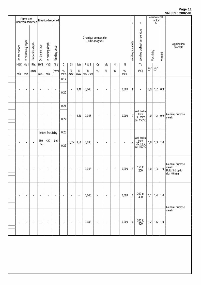
Page 11SN 359 : 2002-01
Relative costfactorFlame and
induction hardened Nitration-hardened5) 6) 7)
On
the
surfa
ce
In h
arde
ning
dep
th
Hard
enin
g de
pth
On
the
surfa
ce
In n
itrid
ing
dept
h
Nitri
ding
dep
th
Chemical composition(ladle analysis)
Wel
ding
sui
tabi
lity
Wel
ding
pre
heat
tem
pera
ture
Mac
hini
ng
Mat
eria
l
HRC HV1 Rht
(mm)
HV3 HV3 Nht
(mm)
C
%
Si
%
Mn
%
P & S
%
Cr
%
Mo
%
Ni
%
N
%min. min. min. min. max. max. max. max. each max.
TV
(°C)
Applicationexample
0,17
- - - - - -0,20
- 1,40 0,045 - - - 0,009 1 - 0,9 1,2 0,9
0,21
- - - - - -0,22
- 1,50 0,045 - - - 0,009 2Wall thickn.
from30 mm:
ca. 150°C1,0 1,2 0,9
0,20
- - - 480+ 50
420 0,6
0,220,55 1,60 0,035 - - - - 2
Wall thickn.from
30 mm:ca. 150°C
1,0 1,3 1,0
General purpose steels
- - - - - - - - - 0,045 - - - 0,009 3 150 to200 1,0 1,3 1,0
General purpose steels. Bolts 5.6 up to dia. 40 mm
- - - - - - - - - 0,045 - - - 0,009 4 200 to400 1,1 1,4 1,0
- - - - - - - - - 0,045 - - - 0,009 4 200 to400 1,2 1,6 1,0
General purpose steels
limited feasibility

Page 12SN 359 : 2002-01
Strength characteristics1) 2) 3)
Material
Nom
inal
thick
ness
Yiel
d po
int o
r0,
2% p
roof
stre
ss
Tens
ile s
treng
th
Elon
gatio
n at
frac
ture
Redu
ctio
n of
are
a at
rupt
ure
Notc
h im
pact
ene
rgy
ISO
V-s
pecim
en, l
ongi
tudi
nal
Fatig
ue s
treng
th u
nder
reve
rsed
bend
ing
stre
sses
Brin
ell h
ardn
ess
G(G
uide
val
ues)
Designation(Heat
treatmentcondition) 21) mm
ReH /Rp 0,2
N/mm2
Rm
N/mm2
A5
%
Z
%
KV
J
Rbw
N/mm2
HBTypeand
standard Current No. Former min. min. min. min. min. max.
470 to 630
355345335325315295 450 to 600
22 S355N 1.0545 StE 355
> 16> 40> 63> 80>100>150
≤ 16≤ 40≤ 63≤ 80≤ 100≤ 150
18) 18) 18)
- 55 - -
520 to 680
420400390370360340 500 to 650
19 S420N 1.8902 StE 420
> 16> 40> 63> 80>100>150
≤ 16≤ 40≤ 63≤ 80≤ 100≤ 150
18) 18) 18)
- 55 - -
460440430410400
550 to 720 17
Weldable fine-grained
engineeringsteels
DIN EN10113-2
19)
S460N 1.8901 StE 460
normalised
> 16> 40> 63> 80>100>150
≤ 16≤ 40≤ 63≤ 80≤ 100≤ 150 18) 18) 18)
- 55 - -
E295GC 1.0533 St 50-2 KGcold drawn
andsoft annealed
≥ 5> 10> 16> 40> 63
≤ 10≤ 16≤ 40≤ 63≤ 100
510420320300255
650 to 950 600 to 900 550 to 850 520 to 770 470 to 740
67899
- - - 140-168140-168
Unalloyedbright steels
DIN EN10083-2
DIN EN10277-2
C45+C 1.0503 C 45 K cold drawn
≥ 5> 10> 16> 40> 63
≤ 10≤ 16≤ 40≤ 63≤ 100
565500410360310
750 to 1050 710 to 1030 650 to 1000 630 to 900 580 to 850
56788
- - - -
SheetsDIN EN 10130 DC01+LC 1.0330 St 12 03 Slightly cold
redrawn ≤ 3 140 270 to 410 28 - - - -
St 37.0 1.0254 St 37.0 - - -
St 37.4 NBK 8) 9) 1.0255 St 37.4 NBK350 to 480
- 43 -
St 35.8 8) 1.0305 St 35.8
normalized(bright
annealed) > 16 > 40
≤ 16 ≤ 40 ≤ 65
235225215
360 to 480
25
- 39 -
100 to140
Tubes
DIN 1629DIN 1630DIN 2391
DIN 17175 St 52.4 1.0581 St 52.4 - > 16
> 40
≤ 16≤ 40≤ 65
355345335
500 to 650 21 - 43 - 145 to185
X6CrNiTi18-10 1.4541 X10 CrNiTi 18 9 ≤ 50 200 500 to 730 35 - 85 - 130 to
180Stainless steel
tubes
DIN 17457DIN 17458 X6CrNiMoTi17-12-2 1.4571 X10 CrNiMoTi
18 10
solution heattreated andquenched ≤ 50 210 500 to 730 35 - 85 - 130 to
180
For footnotes see page 9

Page 13SN 359 : 2002-01
Relative costfactorFlame and
induction hardened Nitration-hardened5) 6) 7)
On
the
surfa
ce
In h
arde
ning
dep
th
Hard
enin
g de
pth
On
the
surfa
ce
In n
itrid
ing
dept
h
Nitri
ding
dep
th
Chemical composition(ladle analysis)
Wel
ding
sui
tabi
lity
Wel
ding
pre
heat
tem
pera
ture
Mac
hini
ng
Mat
eria
l
HRC
min.
HV1
min.
Rht
(mm)
HV3
min.
HV3
min.
Nht
(mm)
C
%
Si
%max.
Mn
%
P & S
%max. each
Cr
%
Mo
%
Ni
%
Others
%
TV
(°C)
Applicationexample
- - - - - - max.0,20 0,50
0,90to
1,65
P: 0,035S: 0,030
max.0,30
max.0,10
max.0,50
N max. Al min. total
Cu max. Nb max. V max. Ti max.
0,0150,02 †)
0,350,050,120,03
1 150 1,1 1,6 1,2
- - - - - - max.0,20 0,60
1,00to
1,70
P: 0,035S: 0,030
max.0,30
max.0,10
max.0,80
N max. Al min. total
Cu max. Nb max. V max. Ti max.
0,0250,02 †)
0,70 ‡)
0,050,200,03
2 150 1,2 1,7 1,2
- - - - - - max.0,20 0,60
1,00to
1,70P: 0,035S: 0,030
max.0,30
max.0,10
max.0,80
N max. Al min. total
Cu max. Nb max. V max. Ti max.
0,0250,02 †)
0,70 ‡)
0,050,200,03
2 150 1,3 1,8 1,2
Welding regulations of SEW 088 must be observed.
Subsequent attachment welds are not permitted; bolted connections must be used instead.
- - - - - - - - - 0,045 - - - N = 0,009 3 150 to200 1,0 1,3 1,3
- - - - - -0,42to
0,500,40
0,50to
0,800,045 max.
0,40max.0,10
max.0,40
Cr+Mo+Nimax. 0,63 4 200 to
400 1,1 1,4 2,3
Bright unalloyed steels, key steels
- - - - - - max.0,12 - max.
0,60 0,045 - - - - 2 - - - 1,0 Sheets
max.0,17 - - 0,040 - - - N ≤ 0,009 1,0
max.0,17 0,35 min.
0,35 0,040 - - - - 2,3- - - - - -
max.0,17
0,10to
0,35
0,40to
0,800,040 - - - -
1 - 0,9 1,2
3,0
- - - - - - max.0,22 0,55 max.
1,60P: 0,040S: 0,035 - - - - 1 - 1,0 1,3 1,3
- - - - - - max.0,08 1,0 max.
2,0P: 0,045S: 0,030
17,0to
19,0-
9,0to
12,0
Ti 5x%Cto 0,80 1 - - - 8,1
- - - - - - max.0,08 1,0 max.
2,0P: 0,045S: 0,030
16,5to
18,5
2,0to
2,5
10,5to
13,5
Ti 5x%Cto 0,80 1 - - - 12,0
Pipelines
†) The minimum value of the Al total content does not apply if there are sufficient contents of nitrogen-fixing elements.‡) When the copper content exceeds 0,35%, the nickel content must amount up to at least half the copper content.

Page 14SN 359 : 2002-01
Strength characteristics1) 2) 3)
Material
Nom
inal
thick
ness
Yiel
d po
int o
r0,
2% p
roof
stre
ss
Tens
ile s
treng
th
Elon
gatio
n at
frac
ture
Redu
ctio
n of
are
a at
rupt
ure
Notc
h im
pact
ene
rgy
ISO
V-s
pecim
en, l
ongi
tudi
nal
Fatig
ue s
treng
th u
nder
reve
rsed
ben
ding
stre
sses
Brin
ell h
ardn
ess
G(g
uide
val
ues)
DesignationAdditional symbols 20)
(heat treatmentcondition) 21) mm
ReH /Rp 0,2
N/mm2
Rm
N/mm2
A5
%
Z
%
KV
J
Rbw
N/mm2
HBTypeand
standard Current No. Former min. min. min. min. min. max.≤ 16 275
> 16 ≤ 40 270 24
> 40 ≤ 60 260440 to 590
2331
> 60 ≤ 100 240 430 to 580 22> 100 ≤ 150 220 420 to 570 19 27
16Mo3 1.5415 15 Mo 3 normalised
> 150 18) 18) 18)
-
18)
- ***
≤ 16 265> 16 ≤ 40 255> 40 ≤ 60 245
23
> 60 ≤ 100 215
410 to 530
> 100 ≤ 150 200 400 to 530 22
27P265GH 1.0425 H II normalised
> 150 18) 18) 18)
-
18)
- ***
≤ 16 300+NT > 16 ≤ 60 295 450 to 600 20 31
+NT, +QAoder +QL ≥ 60 ≤ 100 275 440 to 590
≥ 100 ≤ 150 255 430 to 58019 2713CrMo4-5 1.7335 13 CrMo 4 4
+QL > 150 18) 18) 18)
-
18)
- ***
≤ 16 275> 16 ≤ 35 275> 35 ≤ 50 265> 50 ≤ 70 255
390 to 510 24
> 70 ≤ 100 235 370 to 490> 100 ≤ 150 225 350 to 470 23
55P275NH 1.0487 WStE 285 normalised
> 150 18) 18) 18)
-
18)
- -
≤ 16 355> 16 ≤ 35 355> 35 ≤ 50 345> 50 ≤ 70 325
490 to 630 22
> 70 ≤ 100 315 470 to 610> 100 ≤ 150 295 450 to 590 21
55P355NH 1.0565 WStE 385 normalised
> 150 18) 18) 18)
-
18)
- -
≤ 16 460> 16 ≤ 35 450> 35 ≤ 50 440> 50 ≤ 70 420
570 to 720 17
> 70 ≤ 100 400 540 to 710> 100 ≤ 150 380 520 to 690 16
55
Steels forpressurepurposes
DIN EN10028-2 and 3
19)
P460NH 1.8935 WStE 460 normalised
> 150 18) 18) 18)
-
18)
- -
*** Mechanical properties of transverse samples
For footnotes see page 9

Page 15SN 359 : 2002-01
Relative costfactorFlame and
induction hardened Nitration-hardened5) 6) 7)
On
the
surfa
ce
In h
arde
ning
dep
th
Hard
enin
g de
pth
On
the
surfa
ce
In n
itrid
ing
dept
h
Nitri
ding
dep
th
Chemical composition(ladle analysis)
Wel
ding
sui
tabi
lity
Wel
ding
pre
heat
tem
pera
ture
Mac
hini
ng
Mat
eria
l
HRC
min.
HV1
min.
Rht
(mm)
HV3
min.
HV3
min.
Nht
(mm)
C
%
Si
%max.
Mn
%
P & S
%max. each
Cr
%
Mo
%
Ni
%
Others
%
TV
(°C)
Applicationexample
- - - - - -0,12to
0,200,35
0,40to
0,90
P: 0,030S: 0,025
max.0,30
0,25to
0,35
max.0,30
Al tot.. *
Cu max. 0,302 - - - -
- - - - - - max.0,20 0,40
0,50to
1,40
P: 0,030S: 0,025
max.0,30
max.0,08
max.0,30
Al tot..
min. 0,020 Cu max. 0,30 Nb max. 0,010 Ti max. 0,03 V max. 0,02 Cr+Cu+Mo+Ni max. 0,70
2 - - - -
- - - - - -0,08to
0,180,35
0,40to
1,00
P: 0,030S: 0,025
0,70to
1,15
0,40to
0,60-
Al tot.. *
Cu max. 0,302 - - - -
- - - - - - max.0,18 0,40
0,50to
1,40
P: 0,030S: 0,025
**max.0,30
**max.0,08
max.0,50
Al tot..
min. 0,020 Cu max. 0,30 N max. 0,020 Nb max. 0,05 Ti max. 0,03 V max. 0,05 Nb + Ti + V max. 0,05
2 - - - -
- - - - - - max.0,20 0,50
0,90to
1,70
P: 0,030S: 0,025
**max.0,30
**max.0,08
max.0,50
Al tot..
min. 0,020 Cu max. 0,30 N max. 0,020 Nb max. 0,05 Ti max. 0,03 V max. 0,10 Nb + Ti + V max. 0,12
2 - - - -
- - - - - - max.0,20 0,60
1,00to
1,70
P: 0,030S: 0,025
max.0,30
max.0,10
max.0,80
Al tot..
min. 0,020 Cu max. 0,70 N max. 0,025 Nb max. 0,05 Ti max. 0,03 V max. 0,20 Nb + Ti + V max. 0,22
2 - - - -
Pressure vessels, metal sheets, steel strips
* The Al content of the heat must be determined and stated in the certificate. ** The total content of the three elements chromium, copper and molybdenum taken together must not exceed 0,45 %.
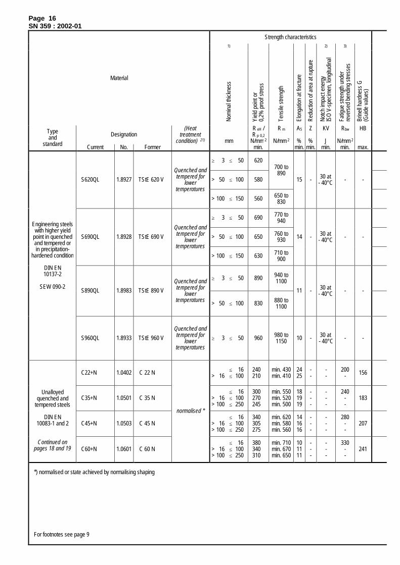
Page 16SN 359 : 2002-01
Strength characteristics1) 2) 3)
Material
Nom
inal
thick
ness
Yiel
d po
int o
r0,
2% p
roof
stre
ss
Tens
ile s
treng
th
Elon
gatio
n at
frac
ture
Redu
ctio
n of
are
a at
rupt
ure
Notc
h im
pact
ene
rgy
ISO
V-s
pecim
en, l
ongi
tudi
nal
Fatig
ue s
treng
th u
nder
reve
rsed
ben
ding
stre
sses
Brin
ell h
ardn
ess
G(G
uide
val
ues)
Designation(Heat
treatmentcondition) 21) mm
R eH /R p 0,2
N/mm 2
R m
N/mm 2
A5
%
Z
%
KV
J
Rbw
N/mm 2
HBTypeand
standard Current No. Former min. min. min. min. min. max.
≥ 3 ≤ 50 620
> 50 ≤ 100 580
700 to890
S620QL 1.8927 TStE 620 V
Quenched andtempered for
lowertemperatures
> 100 ≤ 150 560 650 to830
15 - 30 at- 40°C - -
≥ 3 ≤ 50 690 770 to940
> 50 ≤ 100 650 760 to930S690QL 1.8928 TStE 690 V
Quenched andtempered for
lowertemperatures
> 100 ≤ 150 630 710 to900
14 - 30 at- 40°C - -
≥ 3 ≤ 50 890 940 to1100
S890QL 1.8983 TStE 890 V
Quenched andtempered for
lowertemperatures > 50 ≤ 100 830 880 to
1100
11 - 30 at- 40°C - -
Engineering steelswith higher yield
point in quenchedand tempered orin precipitation-
hardened condition
DIN EN10137-2
SEW 090-2
S960QL 1.8933 TStE 960 V
Quenched andtempered for
lowertemperatures
≥ 3 ≤ 50 960 980 to1150 10 - 30 at
- 40°C - -
C22+N 1.0402 C 22 N ≤ 16 > 16 ≤ 100
240210
min. 430min. 410
2425
--
--
200- 156
C35+N 1.0501 C 35 N≤ 16
> 16 ≤ 100 > 100 ≤ 250
300270245
min. 550min. 520min. 500
181919
---
---
240--
183
C45+N 1.0503 C 45 N≤ 16
> 16 ≤ 100 > 100 ≤ 250
340305275
min. 620min. 580min. 560
141616
---
---
280--
207
Unalloyedquenched and
tempered steels
DIN EN10083-1 and 2
Continued onpages 18 and 19 C60+N 1.0601 C 60 N
normalised *
≤ 16 > 16 ≤ 100 > 100 ≤ 250
380340310
min. 710min. 670min. 650
101111
---
---
330--
241
*) normalised or state achieved by normalising shaping
For footnotes see page 9
Page 17SN 359 : 2002-01
Relative costfactorFlame and
induction hardened Nitration-hardened5) 6) 7)
On
the
surfa
ce
In h
arde
ning
dep
th
Hard
enin
g de
pth
On
the
surfa
ce
In n
itrid
ing
dept
h
Nitri
ding
dep
th
Chemical composition(ladle analysis)
Wel
ding
sui
tabi
lity
Wel
ding
pre
heat
tem
pera
ture
Mac
hini
ng
Mat
eria
l
HRC
min.
HV1
min.
Rht
(mm)
HV3
min.
HV3
min.
Nht
(mm)
C
%max.
Si
%max.
Mn
%max.
P u. S
%max. each
Cr
%max.
Mo
%max.
Ni
%max.
Others
%max.
TV
(°C)
Applicationexample
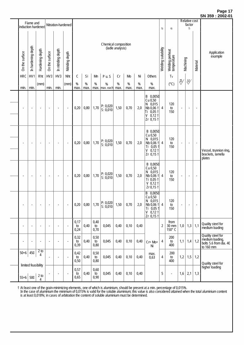
- - - - - - 0,20 0,80 1,70 P: 0,020S: 0,010 1,50 0,70 2,0
B 0,0050Cu 0,50N 0,015Nb 0,06 †Ti 0,05 †V 0,12 †Zr 0,15 †
4120to
150- - -
- - - - - - 0,20 0,80 1,70 P: 0,020S: 0,010 1,50 0,70 2,0
B 0,0050 Cu 0,50 N 0,015 Nb 0,06 † Ti 0,05 † V 0,12 † Zr 0,15 †
4120to
150- - -
- - - - - - 0,20 0,80 1,70 P: 0,020S: 0,010 1,50 0,70 2,0
B 0,0050 Cu 0,50 N 0,015 Nb 0,06 † Ti 0,05 † V 0,12 † Zr 0,15 †
4120to
150- - -
- - - - - - 0,20 0,80 1,70 P: 0,020S: 0,010 1,50 0,70 2,0
B 0,0050 Cu 0,50 N 0,015 Nb 0,06 † Ti 0,05 † V 0,12 † Zr 0,15 †
4120to
150- - -
Vessel, trunnion ring, brackets, lamella plates
- - - - - -0,17to
0,240,40
0,40to
0,700,045 0,40 0,10 0,40 2
from30 mm150° C
1,0 1,3 1,1 Quality steel for medium loading
- - - - - -0,32to
0,390,40
0,50to
0,800,045 0,40 0,10 0,40 4
200to
4001,1 1,4 1,2
Quality steel for medium loading, bolts 5.6 from dia. 40 to 160 mm
50+6 450 2 to4 - - -
0,42to
0,500,40
0,50to
0,800,045 0,40 0,10 0,40 4
200to
4001,2 1,5 1,2
limited feasibility
55+6 500 2 to4
- - -0,57to
0,650,40
0,60to
0,900,045 0,40 0,10 0,40
Cr+ Mo+Ni
max.0,63
5 - 1,6 2,1 1,3
Quality steel for higher loading
† At least one of the grain-minimizing elements, one of which is aluminium, should be present at a min. percentage of 0,015%.In the case of aluminium the minimum of 0,015% is valid for the soluble aluminium; this value is also considered attained when the total aluminium contentis at least 0,018%; in cases of arbitration the content of soluble aluminium must be determined.
Page 18SN 359 : 2002-01
Strength characteristics1) 2) 3)
Material
Nom
inal
thick
ness
Yie
ld p
oint
or
0,2
% p
roof
stre
ss
Ten
sile
stre
ngth
Elo
ngat
ion
at fr
actu
re
Red
uctio
n of
are
a at
rupt
ure
Not
ch im
pact
ene
rgy
ISO
V-s
pecim
en, l
ongi
tudi
nal
Fat
igue
stre
ngth
und
er re
vers
ed b
endi
ng s
tress
es
Brin
ell h
ardn
ess
G (G
uide
val
ues)
Designation
(Heattreatmentcondition)
21) mm
ReH /Rp 0,2
N/mm2
Rm
N/mm2
A5
%
Z
%
KV
J
Rbw
N/mm2
HBypeand
standardCurrent No. Former min. min. min. min. min. max.
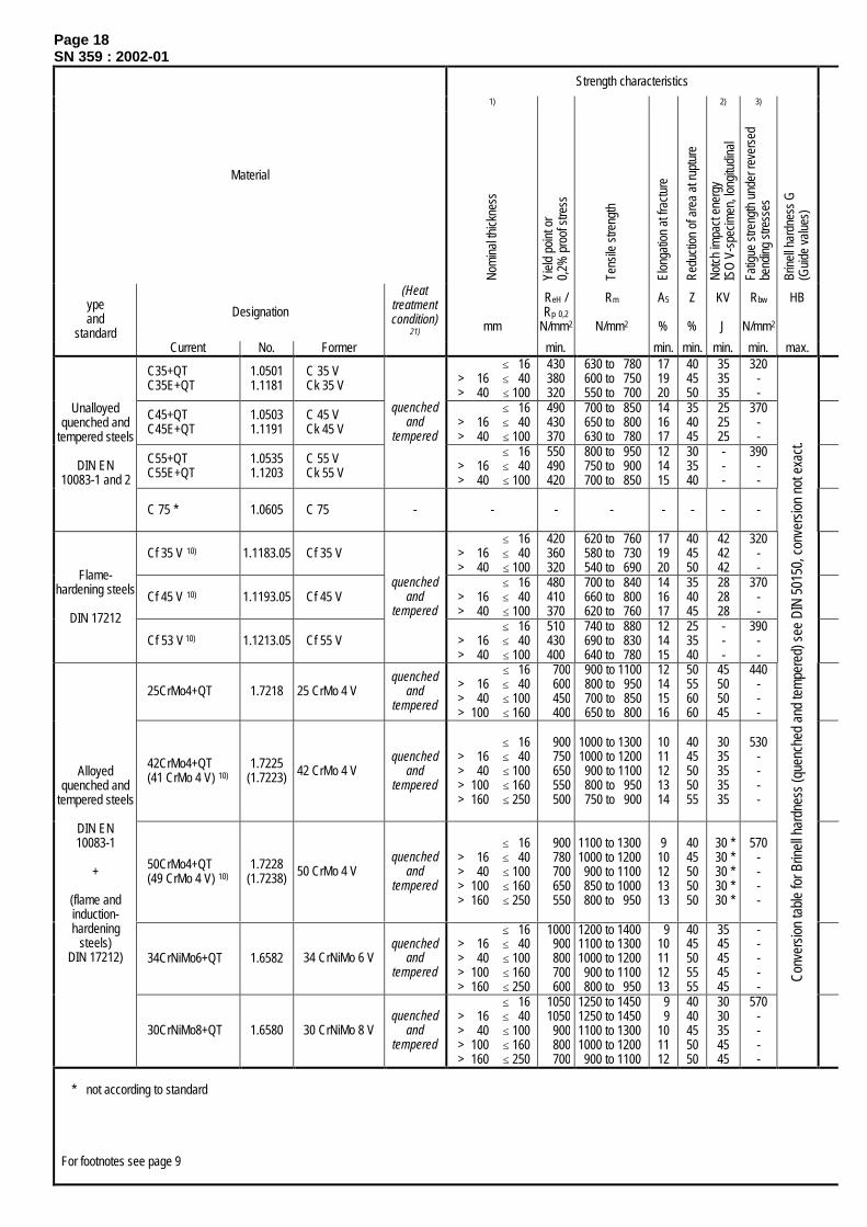
C35+QTC35E+QT
1.05011.1181
C 35 VCk 35 V
≤ 16 > 16 ≤ 40 > 40 ≤ 100
430380320
630 to 780600 to 750550 to 700
171920
404550
353535
320--
C45+QTC45E+QT
1.05031.1191
C 45 VCk 45 V
≤ 16 > 16 ≤ 40 > 40 ≤ 100
490430370
700 to 850650 to 800630 to 780
141617
354045
252525
370--
C55+QTC55E+QT
1.05351.1203
C 55 VCk 55 V
quenchedand
tempered≤ 16
> 16 ≤ 40 > 40 ≤ 100
550490420
800 to 950750 to 900700 to 850
121415
303540
---
390--
Unalloyedquenched and
tempered steels
DIN EN10083-1 and 2
C 75 * 1.0605 C 75 - - - - - - - -
Cf 35 V 10) 1.1183.05 Cf 35 V≤ 16
> 16 ≤ 40 > 40 ≤ 100
420360320
620 to 760580 to 730540 to 690
171920
404550
424242
320--
Cf 45 V 10) 1.1193.05 Cf 45 V≤ 16
> 16 ≤ 40> 40 ≤ 100
480410370
700 to 840660 to 800620 to 760
141617
354045
282828
370--
Flame-hardening steels
DIN 17212
Cf 53 V 10) 1.1213.05 Cf 55 V
quenchedand
tempered≤ 16
> 16 ≤ 40> 40 ≤ 100
510430400
740 to 880690 to 830640 to 780
121415
253540
---
390--
25CrMo4+QT 1.7218 25 CrMo 4 Vquenched
andtempered
≤ 16> 16 ≤ 40> 40 ≤ 100> 100 ≤ 160
700600450400
900 to 1100800 to 950700 to 850650 to 800
12141516
50556060
45505045
440---
42CrMo4+QT(41 CrMo 4 V) 10)
1.7225(1.7223) 42 CrMo 4 V
quenchedand
tempered
≤ 16> 16 ≤ 40> 40 ≤ 100> 100 ≤ 160> 160 ≤ 250
900750650550500
1000 to 13001000 to 1200900 to 1100800 to 950750 to 900
1011121314
4045505055
3035353535
530----
50CrMo4+QT(49 CrMo 4 V) 10)
1.7228(1.7238) 50 CrMo 4 V
quenchedand
tempered
≤ 16> 16 ≤ 40> 40 ≤ 100> 100 ≤ 160> 160 ≤ 250
900780700650550
1100 to 13001000 to 1200900 to 1100850 to 1000800 to 950
910121313
4045505050
30 * 30 * 30 * 30 * 30 *
570----
34CrNiMo6+QT 1.6582 34 CrNiMo 6 Vquenched
andtempered
≤ 16> 16 ≤ 40> 40 ≤ 100> 100 ≤ 160> 160 ≤ 250
1000900800700600
1200 to 14001100 to 13001000 to 1200900 to 1100800 to 950
910111213
4045505555
3545454545
-----
Alloyedquenched and
tempered steels
DIN EN10083-1
+
(flame andinduction-hardening
steels)DIN 17212)
30CrNiMo8+QT 1.6580 30 CrNiMo 8 Vquenched
andtempered
≤ 16> 16 ≤ 40> 40 ≤ 100> 100 ≤ 160> 160 ≤ 250
10501050900800700
1250 to 14501250 to 14501100 to 13001000 to 1200900 to 1100
9 9101112
4040455050
3030354545
570----
Conv
ersio
n ta
ble
for B
rinel
l har
dnes
s (q
uenc
hed
and
tem
pere
d) s
ee D
IN 5
0150
, con
vers
ion
not e
xact
.
* not according to standard
For footnotes see page 9

Page 19SN 359 : 2002-01
Relative costfactorFlame and
induction-hardened Nitration-hardened5) 6) 7)
On
the
surfa
ce
In
hard
enin
g de
pth
Har
deni
ng d
epth
On
the
surfa
ce
In
nitri
ding
dep
th
Nitr
idin
g de
pth
Chemical composition(ladle analysis)
Wel
ding
sui
tabi
lity
Wel
ding
pre
heat
tem
pera
ture
Mac
hini
ng
Mat
eria
l
HRC
min.
HV1
min.
Rht
(mm)
HV3
min.
HV3
min.
Nht
(mm)
C
%
Si
%max.
Mn
%
P u. S
%max. each
Cr
%max.
Mo
%max.
Ni
%max.
Others
%
TV
(°C)
Applicationexample
51+6 425 2 to4
300+50 200 0,5
0,32to
0,390,40
0,50to
0,800,035 0,40 0,10 0,40 4
200to
4001,1 1,4 1,6
55+6 500 2 to4
360+50 300 0,5
0,42to
0,500,40
0,50to
0,800,035 0,40 0,10 0,40 4
200to
4001,2 1,5 1,7
57+6 525 2 to4
400+50 330 0,5
0,57to
0,650,40
0,60to
0,900,035 0,40 0,10 0,40
Cr+Mo+Ni
max.0,63
5 - 1,2 1,5 1,8
QT and flame- hardening steels for medium and high loads
- - - - - -0,70to
0,80
0,15to
0,35
0,60to
0,800,045 - - - - - - - - - Steel strips
51+6 425 2 to4
300+50 200 0,5
0,33to
0,39
0,15to
0,35
0,50to
0,80
P: 0,025S: 0,035 - - - - 4
200to
4001,1 1,4 1,6
55+6 500 2 to4
360+50 300 0,5
0,43to
0,49
0,15to
0,35
0,50to
0,80
P: 0,025S: 0,035 - - - - 4
200to
4001,2 1,5 1,7
57+6 525 2 to4
400+50 330 0,5
0,50to
0,57
0,15to
0,35
0,40to
0,70
P: 0,025S: 0,035 - - - - 5 - 1,2 1,5 1,8
QT and flame- hardening steels for medium and high loads
- - - 600+100 310 0,6
0,22to
0,290,40
0,60to
0,900,035
0,90to
1,20
0,15to
0,30- 4
200to
4001,5 1,9 1,6 Trunnions, pressure
plates, piston rods
54+6 4752to6
500+100 310 0,6
0,38to
0,450,40
0,60to
0,900,035
0,90to
1,20
0,15to
0,30- - 4
300to
3501,7 2,1 1,6
Bolts 8.8 up to 100mm dia., nuts, piston rods, drive shafts, universal joint shafts, coupling hubs, mill pinions, gear wheels
56+6 5002to6
500+100 310 0,6
0,46to
0,540,40
0,50to
0,800,035
0,90to
1,20
0,15to
0,30- - 4 a)
350to
4001,7 2,2 1,6
Bolts 8.8, dia. 100 to 160 mm, pressure plates, piston rods, pinch rolls, universal joint shaft heads, pinion shafts, bevel gears
52+6 4502to6
600+100 330 0,6
0,30to
0,380,40
0,50to
0,800,035
1,30to
1,70
0,15to
0,30
1,30to
1,70- 4
300to
3501,7 2,2 2,9
Universal joint shaft heads, worm shafts, pinion shafts, gear racks, gearwheels, mill pinions
- - - 650+100 350 0,6
0,26to
0,340,40
0,30to
0,600,035
1,80to
2,20
0,30to
0,50
1,80to
2,20- 4
300to
3501,7 2,2 2,9
Bolts 10.9 up to dia. 100 mm, gear wheels
a) Forms Cr carbides, which are difficult to machine.

Page 20SN 359 : 2002-01
Strength characteristics1) 2) 3)
Material
Nom
inal
thick
ness
Yie
ld p
oint
or
0,2
% p
roof
stre
ss
Ten
sile
stre
ngth
Elo
ngat
ion
at fr
actu
re
Red
uctio
n of
are
a at
rupt
ure
Not
ch im
pact
ene
rgy
ISO
V-s
pecim
en, l
ongi
tudi
nal
Fat
igue
stre
ngth
und
er re
vers
ed b
endi
ng s
tress
es
Brin
ell h
ardn
ess
G (G
uide
val
ues)
Designation Supplementarysymbol 20)
mm
ReH /Rp 0,2
N/mm2
Rm
N/mm2
A5
%
Z
%
KV
J
Rbw
N/mm2
HBTypeand
standard Current No. Former min. min. min. min. min. max.
16MnCr5+TH 1.7131 16 MnCr 5 BF - - 720** - - - - 207
20MnCr5+TH 1.7147 20 MnCr 5 BF - - 760** - - - - 217
Case hardeningsteels
DIN EN10084
18CrNiMo7-6+TH 1.6587 17 CrNiMo 6 BF
For storage theheat treatment
condition can beindicated:
+ TH- - 800** - - - - 229
Hightemperature
steelsDIN EN 10269
X22CrMoV12-1 1.4923 X 22 CrMoV 12 1 +QT ≤ 160 600 800 to 950 14 40 27 - -
Steels forforgings
DIN EN 10222-2X20CrMoV11-1 1.4922 X 20 CrMoV
12 1 +QT≤ 100
> 100 ≤ 250 > 250 ≤ 330
500 700 to 850 16 -393127
310 -
S235JRG2 1.0038 RSt 37-2 +N≤ 100
> 100 ≤ 250> 250 ≤ 500
215175165
340340340
242323
-353027
- -
S235J2G3 1.0116 St 37-3 +N≤ 100
> 100 ≤ 250> 250 ≤ 500
215175165
340340340
242323
-35 ***30 ***27 ***
- -
S355J2G3 1.0570 St 52-3 +N≤ 100
> 100 ≤ 250> 250 ≤ 500
315275265
490450450
201818
-35 ***30 ***27 ***
- -
C22 1.0402 C 22 +N ≤ 100 210 410 25 - - - -
+N
≤ 100> 100 ≤ 250> 250 ≤ 500> 500 ≤ 750
300280260250
530520500490
22222222
-
50504040
- -
20Mn5 1.1133 20 Mn 5
+QT≤ 70
> 70 ≤ 160> 160 ≤ 330
400300300
550500500
162020
-504545
- -
+N
≤ 100> 100 ≤ 250> 250 ≤ 500> 500 ≤ 1000
s >500 ≤1000
270245220210245
520500480470
490 to 610
1919191820
-
30252017
(31) ∆
- -
C35E 1.1181 Ck 35
+QT≤ 70
> 70 ≤ 160> 160 ≤ 330
320290270
550490470
202221
-353125
- -
+N
≤ 100> 100 ≤ 250> 250 ≤ 500> 500 ≤ 1000
s >500 ≤1000
305275240230295
580560540530
590 to 720
1616161515
-
-181512
(24) ∆
- 207
C45E 1.1191 Ck 45
+QT≤ 70
> 70 ≤ 160> 160 ≤ 330
370340320
630590540
171817
-252220
- -
+N
≤ 100> 100 ≤ 250> 250 ≤ 500> 500 ≤ 1000
s >500 ≤1000
340310275260345
670650630620
680 to 830
1111111012
-
----
(-) ∆
- 241
Steels forforgings
DIN EN10250-2
s SEW 550(for >500 mm)
C60E 1.1221 Ck 60
+QT≤ 70
> 70 ≤ 160> 160 ≤ 330
450390350
750690670
141514
- - - -
* Preliminary value, ** Only guide values, *** Notched bar impact bending tests at approx. –20°C∆ DVM specimen longitudinal
For footnotes see page 9

Page 21SN 359 : 2002-01
Relative costfactorFlame and induction-hardened
5) 6) 7)
Car
buriz
ing
dept
h C
min
.: 0,
4%
Per
miss
ible
dev
iatio
n
On
the
surfa
ce
In h
arde
ning
dep
th
Har
deni
ng d
epth
Rel
ative
cos
t fac
tor f
or h
arde
ning
trea
tmen
t Chemical composition(ladle analysis)
Wel
ding
sui
tabi
lity
Wel
ding
pre
heat
tem
pera
ture
Mac
hini
ng
Mat
eria
l
(mm) (mm)
HRC
min.
HV1
min.
Eht
(mm)max.
C
%
Si
%max.
Mn
%
P, S
%max. each
Cr
%
Mo
%
Ni
%
Others
%
TV
(°C)
Applicationexample
0,14to
0,190,40
1,00to
1,300,035
0,80to
1,10- - - 4 200 to
400 1,5 1,9 1,2
0,17to
0,220,40
1,10to
1,40 0,035
1,00to
1,30- - - 4 200 to
400 1,5 1,9 1,2
Pins, bushings, sliding liners, eccentrics, cylinders, worm shafts, pinion shafts, bevel gears, gearwheels
1,62,43,24,0
0,20,30,30,3
57+511) 550
0,8 4)
1,2 4)
1,6 4)
2,0 4)
1,01,11,21,4 0,15
to0,21
0,400,50to
0,90
0,0350,015 d)
1,50to
1,80
0,25to
0,35
1,40to
1,70- 2 a) - 1,6 2,1 2,9
Gear components, ring gears, drive pinions, wear parts
- - - - - -0,18to
0,240,50
0,40to
0,90P: 0,025S: 0,015
11,00to
12,50
0,80to
1,20
0,30to
0,80
V0,25 to
0,354 350 to
450 b) - - -
4 350 to450 b)
- - - - - -0,17to
0,230,40
0,30to
1,00P: 0,025S: 0,015
10,00to
12,50
0,80to
1,20
0,30to
0,80
V0,20 to
0,35 4 150 to280 c)
- - -
Coiler segments (hot strip), table rollers (covering), shafts for mandrel extension
- - - - - - max.0,20 0,55 max.
1,40 0,045 0,30 max.0,08 0,30 e) e) 0,9 1,2 1
- - - - - - max.0,17 0,55 max.
1,40 0,035 0,30 max.0,08 0,30 e) e) - - 1
- - - - - - max.0,22 0,55 max.
1,60 0,035 0,30 max.0,08 0,30
Al min.0,020
Cr+ Mo+Ni max.0,48 e) e) 1,0 1,3 1
for low loads, for general use
- - - - - -0,17to
0,240,40
0,40to
0,700,045 0,40 max.
0,10 0,40Cr+Mo+Ni max.0,63
e) e) 1,0 1,3 1
1
- - - - - -0,17to
0,230,40
1,00to
1,500,035 0,40
max.0,10 0,40
Al min.0,020
Cr+Mo+Ni max.0,63
e) e) - -
1,3
for medium loads, for general use
1
- - - - - -0,32to
0,390,40
0,50to
0,800,035 0,40 max.
0,10 0,40 e) e) 1,1 1,4
1,3
1
- - - - - -0,42to
0,500,40
0,50to
0,800,035 0,40 max.
0,10 0,40 e) e) 1,2 1,5
1,3
1
- - - - - -0,57to
0,650,40
0,60to
0,900,035 0,40 max.
0,10 0,40
Cr+Mo+Ni max.0,63
e) e) 1,6 2,1
1,3
for medium loads, for general use, surface-hardening
a) In non-hardened condition (otherwise 5: not weldable). b) Welding in the austenitic range.c) Welding in the martensitic range. d) Special requirement of SMS Demag.e) Forgings weldable only under certain conditions, to be agreed upon with design department.

Page 22SN 359 : 2002-01
Strength characteristics1) 2) 3)
Material
Nom
inal
thick
ness
Yiel
d po
int o
r0,
2% p
roof
stre
ss
Tens
ile s
treng
th
Elon
gatio
n at
frac
ture
Redu
ctio
n of
are
a at
rupt
ure
Notc
h im
pact
ene
rgy
ISO
V-s
pecim
en, l
ongi
tudi
nal
Fatig
ue s
treng
th u
nder
reve
rsed
ben
ding
stre
sses
Brin
ell h
ardn
ess
G(g
uide
val
ues)
Designation20)
Supplementarysymbols
mmReH /Rp 0,2
N/mm2
Rm
N/mm2
A5
%
Z
%
KV
J
Rbw
N/mm2
HBTypeand
standard Current No. Former min. min. min. min. min. max.
25CrMo4 1.7218 25 CrMo 4 +QT≤ 70
> 70 ≤ 160 > 160 ≤ 330
450400380
700 650 600
151718
-504538
- -
34CrMo4 1.7220 34 CrMo 4 +QT≤ 70
> 70 ≤ 160 > 160 ≤ 330
550450410
800 700 650
141516
-454033
- -
42CrMo4 1.7225 42 CrMo 4 +QT
≤ 160 > 160 ≤ 330 > 330 ≤ 500 > 500 ≤ 750
500460390390
750 700 600
590 to 740
14151616
-
302722
(38) ∆
- -
50CrMo4 1.7228 50 CrMo 4 +QT
≤ 160 > 160 ≤ 330 > 330 ≤ 500 > 500 ≤ 750
550540490490
800 750 700
690 to 840
13141515
-
252015
(31) ∆
- -
30CrNiMo8 1.6580 30 CrNiMo 8 +QT
≤ 160 > 160 ≤ 330 > 330 ≤ 660 > 500 ≤ 1000
700630590590
800 750 700
780 to 930
12121212
-
454540
(45) ∆
- -
34CrNiMo6 1.6582 34 CrNiMo 6 +QT
≤ 160 > 160 ≤ 330 > 330 ≤ 660 > 500 ≤ 1000
600540490490
900 850 800
690 to 840
13141515
-
454540
(41) ∆
- -
Steels forforgings
DIN EN10250-3
SEW 550(for > 500 mm)
33NiCrMoV14-5 1.6956 33 NiCrMoV 14 5 +QT
≤ 70 > 70 ≤ 160 > 160 ≤ 330
≤ 1000 >1000 ≤ 1500 >1500 ≤ 2000
980820780785735685
11001000 950
930 to 1130880 to 1080830 to 980
101212121314
-
284848
(34) ∆(34) ∆(34) ∆
- -
X 20 Cr 13 V I +QT 700 500 700 to 850 13 25 370
X 20 Cr 13 V II +QT 800
≤ 160
600 800 to 950 12 20 400
-
X20Cr13 1.4021
X 20 Cr 13 +A - - ≤ 760 -
-
- - 230
X 17 CrNi 16 2 V +QT 800 600 800 to 900 20X 17 CrNi 16 2 V +QT 900 700 900 to 1050 10 15 -X17CrNi16-2 1.4057X 17 CrNi 16 2 +A
≤ 250- ≤ 1000 -
--
-295
X4CrNi18-10 1.4301 X 5 CrNi 18 9 - ≤ 250 190 500 to 700 35 - 100 - -
X6CrNiTi18-10 1.4541 X 10 CrNiTi 18 9 - ≤ 450 190 500 to 700 30 - 100 - -
X6CrNiMoTi17-12-2 1.4571 X 10 CrNiMoTi 18 10 - ≤ 450 200 500 to 700 30 - 100 - -
X4CrNiMo17-12-2 1.4401 X 5 CrNiMo 17 12 2 - ≤ 250 200 500 to 700 30 - 100 - -
+QT 760 550 760 to 960 90+QT 900 ≤ 450 700 900 to 1100 16 80 -
Steels forforgings
DIN EN10250-4
X4CrNiMo16-5-1 1.4418 -+A - - ≤ 1100 -
--
-320
∆ DVM specimen longitudinal
For footnotes see page 9

Page 23SN 359 : 2002-01
Relative costfactor
5) 6) 7)
Chemical composition(ladle analysis)
Wel
ding
sui
tabi
lity
Wel
ding
pre
heat
tem
pera
ture
Mac
hini
ng
Mat
eria
l
C
%
Si
%max.
Mn
%
P, S
%max. each
Cr
%
Mo
%
Ni
%
Others
%
TV
(°C)
Applicationexample
0,22to
0,290,40
0,60to
0,900,035
0,90to
1,20
0,15to
0,30- - a) a) 1,5 1,9 1,6
0,30to
0,370,40
0,60to
0,900,035
0,90to
1,20
0,15to
0,30- - a) a) - - -
0,38to
0,450,40
0,60to
0,90)0,035
0,90to
1,20
0,15to
0,30- - a) a) 1,7 2,1 1,6
Pressure plates, coupling hubs, drive shafts, bending blocks
0,46to
0,540,40
0,50to
0,800,035
0,90to
1,20
0,15to
0,30- - a) a) 1,7 2,2 1,6 Pressure rolls, mandrel bodies,
coilers for hot rolling mills
0,26to
0,340,40
0,30to
0,600,035
1,80to
2,20
0,30to
0,50
1,80to
2,20- a) a) 1,7 2,2 2,9
0,30to
0,380,40
0,50to
0,800,035
1,30to
1,70
0,15to
0,30
1,30to
1,70- a) a) 1,7 2,2 2,9
Reel shafts for cold rolling mill, tie-rods, spindle shafts, gear wheels
0,28to
0,380,40
0,15to
0,400,035
1,00to
1,70
0,30to
0,60
2,90to
3,80
V: 0,08to 0,25
a) a) - - -
350 to450 b)
4 150 to280 c)
1,1
350 to450 b)
4 150 to280 c)
1,1
350 to450 b)
0,16to
0,251,00 max.
1,50P: 0,040S: 0,030
12,0to
14,0- - -
4 150 to280 c)
- -
1
0,12to
0,22
max.1,00
max.1,50
P: 0,040S: 0,030
15,00to
17,00-
1,50to
2,50- 2 - - - 1,7
Big-diameter reel mandrels for cold rolling mills, spades, spindle shafts, CVC blocks, pins, push rods, top clamp release cylinders
max.0,07 1,00 max.
2,00P: 0,045S: 0,030
17,0to
19,5-
8,00to
10,50
N max.0,11 1 - 1,5 1,9 3,8
max.0,08 1,00 max.
2,00P: 0,045S: 0,030
17,0to
19,0-
9,00to
12,00
Ti5x C,
to 0,701 - 1,6 2,0 5,0
max.0,08 1,00 max.
2,00P: 0,045S: 0,030
16,50to
18,50
2,00to
2,50
10,50to
13,50
Ti5x C,
to 0,701 - - - 6,5
max.0,07
max.1,00
max.2,00
P: 0,045S: 0,030
16,50to
18,50
2,00to
2,50
10,00to
13,00
N max.0,11 1 - - - -
Water boxes
max.0,06
max.0,70
max.1,50
P: 0,045S: 0,030
15,00to
17,00
0,80to
1,50
4,00to
6,00
N max.0,020 - - - Discharge covers,
bottom clamp release cylinders
a) Forgings weldable only under certain conditions, to be agreed upon with design department.b) Welding in the austenitic range.c) Welding in the martensitic range.

Page 24SN 359 : 2002-01
Strength characteristics1) 2) 3)
Material
Type
of p
rodu
ct *
Nom
inal
thick
ness
Yiel
d po
int o
r0,
2% p
roof
stre
ss
Tens
ile s
treng
th
Elon
gatio
n at
frac
ture
Redu
ctio
n of
are
a at
rupt
ure
Notc
h im
pact
ene
rgy
ISO
V-s
pecim
en, l
ongi
tudi
nal
Fatig
ue s
treng
th u
nder
reve
rsed
ben
ding
stre
sses
Brin
ell h
ardn
ess
G(g
uide
val
ues)
Designation20)
Supplementarysymbol
mmReH /Rp 0,2
N/mm2
Rm
N/mm2
A5
%
Z
%
KV
J
Rbw
N/mm2
HBTypeand
standard Current No. Former min. min. min. min. min. max.
X 20 Cr 13 VI +QT700 - ≤ 160 500 700 to850 13 - 25 370 -
X 20 Cr 13 VII +QT800 - ≤ 160 600 800 to950 12 - 20 400 -X20Cr13 1.4021
X 20 Cr 13 +A - - - max. 760 - - - - 230
+QT800 600 800 to900 20
+QT900 700 900 to1050
10 -
15
- -
X17CrNi16-2 1.4057 X 17 CrNi 16 2
+A
- ≤ 250
- ≤ 1000 - - - - 295
X39 CrMo 17 1V +QT C ≤ 3 - - - - - - -
C ≤ 6 X39CrMo17-1 1.4122
X39 CrMo 17 1 +AH ≤ 12
- ≤ 900 12 - - - 280
X4CrNi18-10 1.4301 X 5 CrNi 18 9 quenched - ≤ 160> 160 ≤ 250 190 500 to
700 35 - 100 180- -
C ≤ 6 240 -
H ≤ 12 220
530 to680 40 **
X4CrNiMo17-12-2 1.4401 X 5 CrNiMo 17 12 2
solution-annealed
P ≤ 75 220 520 to670 45 **
-
90
- -
X6CrNiTi18-10 1.4541 X 10 CrNiTi 18 9 quenched - ≤ 160
> 160 ≤ 450 190 500 to700 30 - 100 200 -
Stainless steels
DIN 17440
and
DIN EN10088-1 to 3
X6CrNiMoTi17-12-2 1.4571 X 10 CrNiMoTi 18 10 quenched - ≤ 160
> 160 ≤ 450 200 500 to700 30 - 100 - -
* C = cold-rolled strip; H = hot-rolled strip; P = hot-rolled plate;** Thickness at least 3 mm
For footnotes see page 9

Page 25SN 359 : 2002-01
Relative costfactor
Flame andinduction-hardened
Nitration-hardened5) 6) 7)
On
the
surfa
ce
In h
arde
ning
dep
th
Hard
enin
g de
pth
On
the
surfa
ce
In n
itrid
ing
dept
h
Nitri
ding
dep
th
Chemical composition(ladle analysis)
Wel
ding
sui
tabi
lity
Wel
ding
pre
heat
tem
pera
ture
Mac
hini
ng
Mat
eria
l
HRC
min.
HV1
min.
Rht
(mm)
HV3
min.
HV3
min.
Nht
(mm)
C
%
Si
%max.
Mn
%
P, S
%max. each
Cr
%
Mo
%
Ni
%
Others
%
TV
(°C)
Applicationexample
350 to450 b)
- - - - - - 4 150 to280 c)
- - -
350 to450 b)
- - - - - - 4 150 to280 c)
- - -
350 to450 b)
- - - - - -
0,16to
0,251,00 max.
1,50
P: 0,040S: 0,015
a)
12,0to
14,0- - -
4 150 to280 c)
- - -
Pins, shafts, bushings, pipe supports, oil distributors, screws, washers, semi- finished products
- - - - - -0,12to
0,22max.1,00
max.1,50
P: 0,040S: 0,030
15,00to
17,00-
1,50to
2,50- 2 - - - - Semi-finished
products
47to53
480to
580- - - - - - - - -
- - - - - -
0,33to
0,45
max.1,00
max.1,50
P: 0,040S: 0,015
15,50to
17,50
0,80to
1,30
max.1,00 -
5 - - - -
Cold and hot rolled strip, hot rolled plate
- - - - - - max.0,07 1,00 max.
2,00P: 0,045S: 0,015
a)
17,0to
19,5-
8,00to
10,50N ≤ 0,11 1 - 1,5 1,9 3,8
Screws, washers, flanges, vessels, shapes, wires, chains, semi-finished products
- - - - - - max.0,07
max.1,00
max.2,00
P: 0,045S: 0,015
16,50to
18,50
2,00to
2,50
10,00to
13,00
N max.0,11 1 - - - -
Anchor bolts, shim packs, plates, stud anchors, seals
- - - - - - max.0,08 1,00 max.
2,00
P: 0,045S: 0,015
a)
17,0to
19,0-
9,00to
12,00
Ti5x C
to 0,701 - 1,6 2,0 5,2
Flanges, vessels, pipe couplings, shapes, semi-finished products, seals
- - - - - - max.0,08 1,00 max.
2,00
P: 0,045S: 0,015
a)
16,50to
18,50
2,00to
2,50
10,50to
13,50
Ti5x C
to 0,701 - - - -
Flanges, pipes, pipe couplings, semi- finished products
a) In the case of bars, wires and forgings a max. content of 0.030 % S is applicable.b) Welding in the austenitic range.c) Welding in the martensitic range.

Page 26SN 359 : 2002-01
Strength characteristics1) 2) 3)
Material
Stre
ngth
cat
egor
y
Nom
inal
thick
ness
Yie
ld s
treng
th
Ten
sile
stre
ngth
Elo
ngat
ion
at fr
actu
re
Red
uctio
n of
are
a at
rupt
ure
Not
ch im
pact
ene
rgy
ISO
V-s
pecim
en, l
ongi
tudi
nal
Fat
igue
stre
ngth
und
er re
vers
ed b
endi
ng s
tress
es
Brin
ell h
ardn
ess
G (G
uide
val
ues)
Designation mmRp 0,2
N/mm2Rm
N/mm2A5%
Z%
KVJ
RbwN/mm2
HBTypeand
standard Current No. Former
(Heattreatment
condition) 21)min. min. min. min. min.
EN-GJL-200 EN-JL1030 GG-20 - -
10> 20> 40
≤ 20≤ 40≤ 80
---
° min. 180° min. 155° min. 130
0,8to
0,3
---
---
90--
---
EN-GJL-250 13) EN-JL1040 GG-25 - -
10> 20> 40
≤ 20≤ 40≤ 80
---
° min. 225° min. 195° min. 170
0,8to
0,3
---
---
120--
---
Cast iron withlamellargraphite
DIN EN 1561
EN-GJL-300 EN-JL1050 GG-30 - -
10> 20> 40
≤ 20≤ 40≤ 80
---
° min. 270° min. 240° min. 210
0,8to
0,3
---
---
140--
---
Cast iron withlamellargraphite
GGL-320 MoCr 8 - -untreated orannealed forstress relief
- - - min. 350 - - - - max.280
EN-GJS-400-18U EN-JS1062 - - > 30
> 60
≤ 30≤ 60≤ 200
250250240
min. 400min. 390
min. 370
181512
---
---
---
130to
180
EN-GJS-400-15U 13) EN-JS1072
GGG-40
- - > 30> 60
≤ 30≤ 60≤ 200
250250240
min. 400min. 390min. 370
151411
---
---
---
130to
180
EN-GJS-500-7U EN-JS1082 GGG-50 - - > 30
> 60
≤ 30≤ 60≤ 200
320300290
min. 500 min. 450 min. 420
775
---
---
---
170to
230
EN-GJS-600-3U EN-JS1092 GGG-60 - - > 30
> 60
≤ 30≤ 60≤ 200
370360340
min. 600 min. 600 min. 550
321
---
---
---
190to
270
Spheroidalgraphite cast
iron
DIN EN 1563
EN-GJS-700-2U EN-JS1102 GGG-70 - - > 30
> 60
≤ 30≤ 60≤ 200
420400380
min. 700 min. 700 min. 660
221
---
---
---
225to
305
EN-GJMW-360-12 EN-JM1020 GTW-S 38-12 190 360 max.
200Malleable cast
iron
DIN EN 1562 EN-GJMW-400-5 EN-JM1030 GTW-40-05
annealed fordecarburi-
sation- sample
diameter: 12 220 400
(A3,4)5 - - - max.
220
GS-38 1.0420 GS-38 normalized - > 30≤ 30≤ 100
200200
min. 380min. 380
2525
4040
3535
160-
110to
150
GS-45 15) 1.0446 GS-45 normalized - > 30≤ 30≤ 100
230230
min. 450min. 450
2222
3131
2727
190-
130to
170
GS-52 1.0552 GS-52 normalized - > 30≤ 30≤ 100
260260
min. 520min. 520
1818
2525
2722
210210
150to
200
General-purpose cast
steel
DIN1681
14)
GS-60 1.0558 GS-60 normalized - > 30≤ 30≤ 100
300300
min. 600min. 600
1515
2121
2720
240240
175to
220Cast steel(weldable,
strong, tough)DIN 17182
GS-20Mn5V 1.1120 GS-20Mn5Vquenched
andtempered
- > 50> 100
≤ 50≤ 100≤ 160
360300280
500 to 650500 to 650500 to 650
242422
---
705040
---
---
° Expected values in the casting
For footnotes see page 9

Page 27SN 359 : 2002-01
Relative costfactorFlame and
induction-hardened Physical properties5) 6) 7)
On
the
surfa
ce
In h
arde
ning
dep
th
Har
deni
ng d
epth
Den
sity
Coe
fficie
nt o
f exp
ansio
n
Mod
ulus
of e
last
icity Chemical composition
(ladle analysis)
Wel
ding
sui
tabi
lity
Wel
ding
pre
heat
tem
pera
ture
Mac
hini
ng
Mat
eria
l
HRC HV1 Rht(mm) kg/
dm310-6/
KkN/mm2
C
%
Si
%
Mn
%
P, S
%
Cr
%
Mo
%
Ni
%
Others
%
TV
(°C)min. min. max. each
Applicationexample
- - - 7,15 10,0
88to
113- - - - 4 - 1,0 1,3 1,0
- - - 7,20 10,0
103to
118- - - - 4 - 1,0 1,2 1,0
- - - 7,25 10,0 at
–10
0°C
to +
20°C
108to
137- - - -
at supplier's discretion
4 - 1,0 1,2 1,0
GG-25 suitable for castings for hydraulic systems ≤ 200 bar
drawing indication: casting for hydr. systems test pressure e.g.: 300 bar
Housings, fittings, valves
- - - 7,30 - -3,0to3,4
1,6to2,4
0,5to1,0
P: 0,20S: 0,12
0,20to
0,40
0,60to
1,00- - 4 - 1,0 1,2
To be used only in exceptional cases upon previous agreement. Better wear resistance at higher temperature.
- - - 7,10 12,5 169 - - - - 4 - 0,9 1,1 1,0 Mill housings, gen. cast machine components with ductility requirement
- - - 7,10 12,5 169 - - - - 4
for r
epai
r wel
ding
onl
y
- 0,9 1,1 1,0
GGG-40 suited for castings for hydr. systems ≤ 200 bar Chocks
- - - 7,10 12,5 169 - - - - 5 - 1,0 1,3 1,1 High impact resistance, bearing and gear components
47+6 372 2 to4 7,20 12,5 174 - - - - 5 - 1,0 1,3 1,2
47+6 375 2 to4 7,20 12,5 176 - - - -
at supplier's discretion
5 - 1,3 1,6 1,2
Pistons, gearwheels, wear parts
malleable cast iron specially developed for welding 4- - - 7,30 - -
cosmetic repairs only 5- - - - Threaded fittings
- - - 7,85 11,1 2110,15to
0,18
0,30to
0,50
0,60to
0,800,025 max.
0,30 2 - 1,0 1,3 1,0 For medium loads
- - -0,18to
0,23
0,30to
0,50
0,60to
0,80
P: 0,020S: 0,015
max.0,30 2
from30mm150°C
1,1 1,3 1,0
- - -0,28to
0,35
0,30to
0,50
0,60to
0,800,025 max.
0,30 3150to
2001,2 1,4 1,0
Cylinders, mill housings
- - -0,40to
0,44
0,30to
0,50
0,70to
0,900,025 max.
0,30
approximate analysis
4200to
4001,2 1,5 1,0 Track rollers,
gear components
- - - 7,85 - -0,17to
0,23max.0,60
1,00to
1,50P: 0,020S: 0,015
max.0,30
max.0,15
max.0,40 - 2
150to
2001,2 1,4 1,0
For welded highly loaded machine components, mill housings

Page 28SN 359 : 2002-01
Strength characteristics1) 2) 3)
Material
Stre
ngth
cat
egor
y
Nom
inal
thick
ness
Yiel
d st
reng
th
Tens
ile s
treng
th
Elon
gatio
n at
frac
ture
Redu
ctio
n of
are
a at
rupt
ure
Notc
h im
pact
ene
rgy
ISO
V-s
pecim
en, l
ongi
tudi
nal
Fatig
ue s
treng
th u
nder
reve
rsed
ben
ding
stre
sses
Brin
ell h
ardn
ess
G(g
uide
val
ues)
Designation mmRp 0,2
N/mm2Rm
N/mm2A5%
Z%
KVJ
RbwN/mm2
HBTypeand
standard Current No. Former
(Heattreatment
condition) 21)min. min. min. min. min. max.
I 400 520 to 670 14 - 50 - -II ≤ 50 550 700 to 850 10 - 35 - -I 360 500 to 650 12 - 35 - -GS-30 Mn 5 V 1.1165 GS-30 Mn 5 V
hardenedand
tempered II > 50 ≤ 100 450 600 to 750 10 - 27 - -I 450 600 to 750 18 - 50 - -II ≤ 50 600 750 to 900 10 - 35 - -I 450 600 to 750 14 - 40 - -II > 50 ≤ 100 550 700 to 850 10 - 32 - -
GS-25 CrMo 4 V 1.7218 GS-25 CrMo 4 V
hardenedand
temperedI > 100 ≤ 150 410 600 to 750 12 - 32 - -I 650 780 to 930 14 - 35 - -II ≤ 50 800 900 to 1100 10 - 27 - -I 600 800 to 950 12 - 30 - -II > 50 ≤ 100 700 850 to 1000 10 - 27 - -
GS-42 CrMo 4 V 1.7225 GS-42 CrMo 4 V
hardenedand
temperedI > 100 ≤ 150 550 700 to 850 10 - 27 - -I 700 850 to 1000 12 - 45 - -II ≤ 100 800 900 to 1100 10 - 35 - -I > 100 ≤ 250 650 800 to 950 12 - 30 - -
Quenched andtempered cast
steel
DIN 17205
GS-34 CrNiMo 6 V 1.6582 GS-34 CrNiMo 6 V
hardenedand
tempered I > 250 ≤ 400 600 800 to 950 10 - 27 - -
G42CrMo4 1.7231 G42CrMo4quenched
andtempered
- ≤ 150 470 min. 680 12 - - - -Cast steel forflame andinductionhardening
SEW 835 G50CrMo4 1.7232 G50CrMo4quenched
andtempered
- ≤ 150 520 min. 730 11 - - - -
GP240GR+N 1.0621 GS-C 25 N normalized 27
GP240GH+QT 1.0619 GS-C 25 Vquenched
andtempered
- ≤ 100 240◊ MPa
420 to 600◊ MPa 22 -
40
- -
G20Mo5+QT 1.5419 GS-22 Mo 4 Vquenched
andtempered
- ≤ 100 245◊ MPa
440 to 590◊ Mpa 22 - 27 - -
G17CrMo5-5+QT 1.7357 GS-17CrMo 5 5 V
quenchedand
tempered- ≤ 100 315
◊ MPa490 to 690
◊ Mpa 20 - 27 - -
G17CrMoV5-10+QT 1.7706 GS-17 CrMoV 5 11 V
quenchedand
tempered- ≤ 150 440
◊ MPa590 to 780
◊ Mpa 15 - 27 - -
Cast steel forservice atelevated
temperatures
DIN EN10213-2
GX23CrMoV12-1+QT 1.4931 G-X22CrMoV 12 1 V
quenchedand
tempered- ≤ 150 540
◊ MPa740 to 880
◊ Mpa 15 - 27 - -
◊ 1 MPa = 1 N/mm2
** The hardness values apply to the condition after stress-relieving at temperatures between 140 and 180°C (see SEW 835; section 5.3)
For footnotes see page 9

Page 29SN 359 : 2002-01
Relative costfactorFlame and
induction-hardened Physical properties5) 6) 7)
On
the
surfa
ce
In h
arde
ning
dep
th
Har
deni
ng d
epth
Den
sity
Coe
fficie
nt o
f exp
ansio
n
Mod
ulus
of e
last
icity
Chemical composition(ladle analysis)
Wel
ding
sui
tabi
lity
Wel
ding
pre
heat
tem
pera
ture
Mac
hini
ng
Mat
eria
l
HRC HV1 Rht(mm) kg/ 10-6/ kN/
C%
Si%
Mn%
P, S%
Cr%
Mo%
Ni%
Others%
TV(°C)
min. min.dm3 K mm2
max. each
Applicationexample
- - - 7,85 - -0,27to
0,34
max.0,60
1,20to
1,50
P: 0,020S: 0,015 - - - - 3
150to
2001,2 1,5 1,0 Bearing races, wheels
- - - 7,85 11,0 2110,22to
0,29
max.0,60
0,50to
0,80
P: 0,020S: 0,015
0,80to
1,20
0,20to
0,30- - 4
200to
4001,5 1,9 1,2
54+6 475 2 to6 7,85 - -
0,38to
0,45
max.0,60
0,60to
1,00
P: 0,020S: 0,015
0,80to
1,20
0,20to
0,30- - 4
300to
3501,6 2,0 1,2
Wheels, pinions, bevel gears
- - - 7,85 - -0,30to
0,37max.0,60
0,60to
1,00P: 0,020S: 0,015
1,40to
1,70
0,20to
0,30
1,40to
1,70- 4
300to
3501,9 2,4 1,3 Gear construction, pinions,
wheels
54 ** - min.5 7,85 - -
0,38to
0,45max.0,60
0,60to
1,00P: 0,020S: 0,015
0,80to
1,20
0,20to
0,30- - 4
300to
350- - - Toggle levers, crane wheels,
bevel gears
57 ** min.6 7,85
0,46to
0,54
0,25to
0,50
0,50to
0,80P: 0,035S: 0,035
0,90to
1,20
0,15to
0,25- - 4
350to
400- - -
Parts subject to wear which have high strength and good depth hardening capacity
0,18to
0,25
max.1,20
- - - 7,85 - - 0,18to
0,23
max.0,60 0,50
to1,20
P: 0,030S: 0,020 - - - - 2
from30 mm150°C
1,2 1,4 1,0 Housings, covers
- - - 7,85 12,2 2110,15to
0,23
max.0,60
0,50to
1,00
P: 0,025S: 0,020 -
0,40to
0,60- - 2 200 1,2 1,5 1,1 Valves, elbows
- - - 7,85 12,2 2110,15to
0,20
max.0,60
0,50to
1,000,020
1,00to
1,50
0,45to
0,65- - 3 250 1,3 1,6 1,2 for highly stressed machine
components
- - - 7,85 - -0,15to
0,20
max.0,60
0,50to
0,90
P: 0,020S: 0,015
1,20to
1,50
0,90to
1,10-
V0,20to
0,30Sn max.0,025
3 300 1,5 1,8 1,3 good high-temperature strength, see DIN EN 10213
- - - 7,7 10,5 2160,20to
0,260,40
0,50to
0,80
P: 0,030S: 0,020
11,30to
12,20
1,00to
1,20
max.1,00
V0,25to
0,35W max.0,50
4 400 1,5 1,9 1,7 Coiler segments

Page 30SN 359 : 2002-01
Strength characteristics Hardness data3)
Material
Yie
ld s
treng
th
Ten
sile
stre
ngth
Elo
ngat
ion
at fr
actu
re
Fat
igue
stre
ngth
und
er re
vers
ed b
endi
ng s
tress
es
Brinell hardness
Designation Rp 0,2N/mm2
RmN/mm2
A5%
RbwN/mm2 HB 10/1000 atType
andstandard Current No. Former min.
20°Cmin.
150°Cmin.
200°Cmin.
250°Cmin.
GK-CuSn10Zn * - GK-S1 min. 160 min. 290 min. 20 - 85 - - -
CuSn7Zn4Pb7-C-GS CC493K-GS G-CuSn7ZnPb(Rg 7) min. 120 min. 230 min. 15 60 - - -
CuSn7Zn4Pb7-C-GZ CC493K-GZ GZ-CuSn7ZnPb(GZ-Rg 7) min. 120 min. 260 min. 12 70 - - -
Copper-tin-zinc castalloys (red brass)
DIN EN 1982
CuSn7Zn4Pb7-C-GC CC493K-GC GC-CuSn7ZnPb(GC-Rg 7) min. 120 min. 260 min. 12
110
70 - - -
CuSn12-C-GS CC483K-GS G-CuSn12 min. 140 min. 260 min. 7 80 - - -
CuSn12-C-GZ CC483K-GZ GZ-CuSn12 min. 280 min. 5 - - -
CuSn12-C-GC CC483K-GC GC-CuSn12min. 150
min. 300 min. 6
9090
- - -
CuSn12Ni2-C-GS CC484K-GS G-CuSn12Ni min. 160 min. 280 min. 12 85 - - -
CuSn12Ni2-C-GZ CC484K-GZ GZ-CuSn12Ni min. 8 - - -
CuSn12Ni2-C-GC CC484K-GC GC-CuSn12Nimin. 180 min. 300
min. 10
14095
- - -
CuSn11Pb2-C-GS CC482K-GS G-CuSn12Pb min. 130 min. 240 80 - - -
CuSn11Pb2-C-GZ CC482K-GZ GZ-CuSn12Pb - - -
Copper-tin cast alloys(tin bronze)
DIN EN 1982
CuSn11Pb2-C-GC CC482K-GC GC-CuSn12Pbmin. 150 min. 280
min. 5 13090
- - -
CuSn10Pb10-C-GS CC495K-GS G-CuPb10Sn min. 80 min. 180 min. 8 70 60 - - -Copper-tin-lead castalloys (cast tin-lead-
bronze)
DIN EN 1982 CuSn10Pb10-C-GZ CC495K-GZ GZ-CuPb10Sn min. 110 min. 220 min. 6 (80) 70 - - -
CuAl10Fe5Ni5-C-GS CC333G-GS G-CuAl10Ni min. 250 min. 600 min. 13 185 140 - - -
CuAl10Fe5Ni5-C-GZ CC333G-GZ GZ-CuAl10Ni min. 280 min. 650 min. 13 (185) 150 - - -
AMPCO 18-23 ** - - min. 365 min. 724 min. 14 202 - - -
Copper-aluminium castalloys (cast aluminium-
bronze)
DIN EN 1982
AMPCO 18-23 (GZ) ** - - min. 386 min. 758 min. 16 (185) 207 - - -
MAIN-METALL ** - - 220 to300
280 to320
5 to15 - 85 to
125 *** - -
Alzen 305 ** - - 215 to275
290 to390
5 to 8 -
40
- -White bronze
Alzen 305 K ** - - 215 to265
290 to390
12 to20 -
9035 - -
GS = sand casting, GZ = centrifugal casting, GC = continuously cast material
* Not according to standard** Not according to standard, CuAl alloy with special guaranteed values.*** Upon request also < 80 HB
For footnotes see page 9

Page 31SN 359 : 2002-01
Physicalproperties
Dens
ity
Coef
ficie
nt o
f exp
ansio
n
Mod
ulus
of e
last
icity Chemical analysis
(main alloying constituents)
kg/dm3
10-6/K
kN/mm2
Cu%
Sn%
Zn%
Pb%
Ni%
Fe%
P, S%
Al%
Si%
Sb%
Mn%
Others%
Properties Applicationexample
- -86,0to
89,0
9,0to
11,0
1,0to3,0
- - - - - - - - - from Purchase Dept. uponrequest
Resistance to rolling emulsion in aluminium stands
8,8
18,598to
115
81,0to
85,0
‡
6,0to8,0
2,0to5,0
5,0to8,0
max.2,0
max.0,2
max.0,10
max.0,01
max.0,01
max.0,3 - -
seawater-resistant, good metal-working and emer- gency running properties, sensitive to edge loading, cost 30% lower as compared with CuSn12-C-GS, not weldable
Slide plates, high-load bearings,
operating temperature max. 150 °C
18,585,0to
88,5
11,0to
13,0- max.
0,7max.2,0
max.0,20
P: max.0,60
S: max.0,05
max.0,01
max.0,01
max.0,15
max.0,20 -
8,6
17,584,5to
87,5
11,0to
13,0max.0,4
max.0,3
1,5to2,5
max.0,20
P: 0,05to
0,40
S: max.0,05
max.0,01
max.0,01
max.0,1
max.0,20 -
8,7 18,5
90to
110
83,5to
87,0
10,5to
12,5
max.2,0
0,7to2,5
max.2,0
max.0,20
P: max.0,40
S: max.0,08
max.0,01
max.0,01
max.0,20
max.0,20 -
seawater-resistant, high wear resistance, good impact and fatigue strength, sensitive to edge pressure. CuSn12Ni with increased strength and resistance to wear.
Sliding liners, highly stressed sliding blocks, spindle nuts moving under load, highly stressed and fast-running worm gears, very well suited as bearing material with high surface quality and hardened shaft material, operating temperature max. 250 °C
9,0 18,775to83
78,0to
82,0
‡
9,0to
11,0
max.2,0
8,0to
11,0
max.2,0
max.0,25
max.0,10
max.0,01
max.0,01
max.0,5
max.0,2 -
highly corrosion and wear- resistant, good sliding properties, very good emergency running properties, insensitive to edge pressure
Bearing material for roll bearings and rotary shears. Superior to tin bronze and red brass in the case of journals without surface hardening.
7,617to19
100to
128
76,0to
83,0
max.0,1
max.0,50
max.0,03
4,0to6,0
4,0to5,5
-8,5to
10,5
max.0,1 - max.
3,0
Cr max.0,05;
Mg max.0,05;Bi max.0,01
7,45 16 112 85,5 - - - - 3,5 - 10,5 - - - 0,5
high resistance to wear and heat, acid-proof, poor emergency running properties.
Bearing material for roll bearings and rotary shears. Superior to tin bronze and red brass in the case of journals without surface hardening. Resistant to rolling emulsion in aluminium stands
4,4 241,0to5,0
- - - - -35,0to
40,0- - - -
4,8 26
75 3,0to5,0
- rem
nant
- - - -30,0to
35,0- - - -
good metal-working and emergency running prop- erties, very long life, high load-bearing capacity, less costly than CuSn12-C-GS.
Heavily loaded wear strips and bearings, worm gears up to medium load. Operating temperature max. 120 °C
‡ Including nickel

Page 32SN 359 : 2002-01
Strength characteristics Hardness data Physicalproperties
3)
Material
Yiel
d st
reng
th
Tens
ile s
treng
th
Elon
gatio
n at
frac
ture
Fatig
ue s
treng
th u
nder
reve
rsed
ben
ding
stre
sses
Brinell hardness
Dens
ity
Coef
ficie
nt o
f exp
ansio
n
Mod
ulus
of e
last
icity
Designation Rp 0,2 Rm A5 Rbw HB 10/1000 atTypeand
standard Current No. Former N/mm2 N/mm2 dm3 N/mm2
min.20°Cmin.
150°Cmin.
200°Cmin.
250°Cmin.
kg/dm3
10-6/K
kN/mm²
GS CC765S-GS G-CuZn35Al1 (G-SoMsF 45)
min.170
min.450
min.20 - 110 - - -
CuZn35Mn2Al1Fe1-GZ CC765S-GZ GZ-CuZn35Al1
(GZ-SoMsF 45)min.200
min.500
min.18 - 120 - - -
1995to
110
GS CC764S-GS G-CuZn34Al2 (G-SoMsF 60)
min.250
min.600
min.15 - 140 - - -
CuZn34Mn3Al2Fe1-C-GZ CC764S-GZ GZ-CuZn34Al2
(GZ-SoMsF 60)min.260
min.620
min.14 - 150 - - -
8,6
2090to98
GS CC762S-GS G-CuZn25Al5 (G-SoMsF 75)
min.450
min.8 - 180 - - -
Copper-zinc cast alloys(cast special brass)
DIN EN 1982
CuZn25Al5Mn4Fe3-C-
GZ CC762S-GZ GZ-CuZn25Al5 min.480
min.750 min.
5 - 190 - - -
8,2 18105to
115
Copper-zinc alloy(Special brass)
DIN EN 12164CuZn37Mn3Al2PbSi-R540 CW713R-
R540 CuZn40Al2F5416)
(SoMs 58 Al 2 F 55)ca.280
min.540
min.15 - ca.
150 - - - 8,1 20 105
Tin cast alloy formultilayer plain bearings
(babbitt metal)
DIN ISO 4381
SnSb8Cu4 2.3791 LgSn 89 47 - - 3122at
20°C
17at
50°C
11at
120°C
8at
150°C7,3 23,9 57
Sintered bronzeoil-impregnated Sintered bronze B 50 17) - - 60 to
10090 to120
5 to8 - 25 to
45 - - - 6,8 18 45
H CuSn8613/8-1 - - - min.50 2 40 - - - 6,8 50
H CuSn8613/8p-1 - - - min.85 2 65 - - - 6,6 53
H CuSn8613/10p-1T1 - - - min.65 2 40 - - - 6,4 46
H CuSnPb8313/8p-2Mo - - - min.85 2 65 - - - 6,6
18
51
Microdistributed solid lubricant *
DEVATM metal
H FeCu9404/10pf-2MoT5 - - - min.60 - Co
mpr
essiv
e st
reng
th:
250t
o 30
0 N
/ mm
2
140 - - - 5,7 13 45
BM11 CuSnPb8213/8E - - 300 **500to
700 **- - - - 6,3
BM11 CuSnPb8213/10pfE - - 300 **500to
700 **- - - - 6,4
Microdistributed solid lubricant *
DEVATM
strip metal
BM11 CuSn8713/6E - - 300 **500to
700 **- Co
mpr
essiv
e st
reng
th:
300
N / m
m2
40
- - - 6,5
17,5 210**
dg02(2.1061) + C 2.1061.01 - 140 min.260 10 90 80 - - - 8,7 18,5 100
Mai
nten
ance
-free
slid
ing
mat
eria
ls
Macrodistributed solid lubricant *
devagleitTM dg03(2.0975) + C 2.0975.03 - 300 min.700 13 185 160 - - - 7,6 17 130
GS = sand casting, GZ = centrifugal casting, GC = continuously cast material* not according to standard
** carrier material
For footnotes see page 9

Page 33SN 359 : 2002-01
Chemical analysis(main alloying constituents)
Dimensions(commercial) Properties Application example
%
Cu¨57,0 to 65,0; Al 0,5 to 2,5;Fe 0,5 to 2,0; Mn 0,5 to 3,0;Sb max. 0,08; Ni max. 6,0;Pb max. 0,5; Sn max. 1,0;
Forcing nuts
Cu¨ 55,0 to 66,0; Al 1,0 to 3,0;Fe 0,5 to 2,5; Mn 1,0 to 4,0;Sb max. 0,05; Ni max. 3,0;Pb max. & Sn max. each 0,3;
Forcing nuts under peak stress, piston rings, sliding blocks
Cu¨60,0 to 67,0; Al 3,0 to 7,0;Fe 1,5 to 4,0; Mn 2,5 to 5,0;Sb max.0,03; Ni max. 3,0;Pb max. & Sn max. each 0,2; P
max
. 0,0
3;
Si m
ax.
0,1;
bal
ance
: Zn
- Statically very high loaded construc tional parts, such as bearings under high load and at low number of revolutions, highly stressed, slow-running worm gear wheels, internal parts of high- pressure fittings
Cu 57,0 to 59,0; Al 1,3 to 2,3;Mn 1,5 to 3,0; Pb 0,2 to 0,8;Si 0,3 to 1,3; Sn max. 0,4;
Fe max. and Ni max. each 1,0; balance: Zn
-
high strength even at higher operating temperatures moderate sliding and emergency running properties
Slide liners, shafts, washers, rings
Sn 87,2 to 89,2; Sb 7,0 to 8,0;Cu 3,0 to 4,0; As and Fe each 0,1;Al and Zn each 0,01; Pb 0,35; Bi0,08;Others in total 0,2
- high deformability very good antiseizure performance, insensitive to edge pressure
For highly stressed rolling mill bear- ings, Morgoil® bearings
Cu 89,0 to 91,0;Sn 9,0 to 11,0 Bushes up to 100 mm dia.
excellent antiseizure performance, no maintenance, sensitive to edge pressure and shock loading.
For bearings under low load 8 to 5 N/mm² at low speeds (0.5 to 1.0 m /s)
C 8,0 (% of weight)
C 8,0 (% of weight)
C 10,0 (% of weight)
Cu 86,0;Mo 2,0;S 1,0;
Sn 13,0;
Cu 86,0; Pb 2,0; Sn 13,0; C 8,0 (% of weight)
self-lubricating sliding materials: load carrying capacity: static loads up to 200 N/mm² dynamic loads up to 100 N/mm²
for use at temperatures up to 200 °C, through heat treatment up to 350 °C, to be specified in the order.
Fe 94,0; Cu 4,0; Mo 2,0; S 2,0; C 8,0 (% of weight)
20 to 28020/40 to 550/60084 x 25490 x 350116 x 268126 x 227spherical plain bearing(as floating or locatingbearing) for use at temperatures up to 600 °C
Self-lubricating sliding materials made by the powder-metallurgical process, extremely high-compressed, corrosion-resistant, suitable for high temperatures.
Steel back: stainless steel Slide layer: Cu 82,0; Pb 5,0; Sn 13,0; C 8,0 (% of weight)
Steel back: Niro steel Slide layer: Cu 82,0; Pb 5,0; Sn 13,0; C 10,0 (% of weight)
Steel back: Niro steel Slide layer: Cu 87,0; Sn 13,0; C 6,0 (% of weight)
Thin-walled high per- Wall formance material thickness10 < D1 < 18 mm 1 mm20 < D1 < 28 mm 1,5 mm28 < D1 < 46 mm 2 mm45 < D1 < 75 mm 2,5 mm75 < D1 < 246 mm 3 mm
> 250 mm 5 mmrolled plain bearings up to 1000 mm> 1000 mm in segment arrangement
load carrying capacity:static loads up to 320 N/mm²dynamic loads up to 120 N/mm²at temperat. from –150 °C to +280 °C
rolled bearings usable up to 280 °C. plates usable up to 350 °C.
Self-lubricating compound sliding ma terial, consisting of steel back with DEVA slide layer made by the rolling- sintering process, for extremely high loads, particularly cost-efficient due to thin walls, corrosion-resistant.
Cu 85,0 to 88,0; Sn 10,0 to 12,0; Pb 1,0 to 1,5; Ni 0,8 to 1,5
Self-lubricating sliding material, load- capable up to 60 N/mm² and 250 °C
Cu min.78,0; Mn max. 3,5; Fe 3,0 to 5,0 Al 10,0 to 11,5; Ni 3,0 to 5,5;
Cylindrical plain bearings, spherical plain bearings, thrust bearings, thrust faces, collar sleeves in nearly all dimensions Self-lubricating sliding material, load-
capable up to 150 N/mm² and 250 °C
Devagleit enables maintenance-free use of bronze plain bearings so far with lubrication requirement, recom- mended for big dimensions, corrosion- resistant.
¨ including nickel

January 2002
Drilling and thread depthsThread selection series and undercuts SN 480
Dimensions in mm
Maximum drilling depths
d 1 t 1 t 2 d 1 t 1 t 2 d 1 t 1 t 2 d 1 t 1 t 2
1,2 16 - 11,8 94 125 26 165 1500 50 220 321
2 24 56 12 101 250 26,5 165 214 52 225 1500
2,5 30 62 12,5 101 - 28 170 600 53 225 -
3 33 160 13,5 108 700 28,5 175 - 54 230 -
3,3 36 69 14 108 1500 29,5 175 - 56 235 -
3,5 39 180 14,5 114 - 30 175 1100 57 235 -
4 43 190 15,25 120 230 30,5 180 - 58 235 -
4,2 43 78 15,5 120 - 32 185 500 60 235 -
4,5 47 200 16 120 315 33 185 1500 61 240 -
5 52 250 16,5 125 230 33,5 185 - 62 240 600
5,3 52 - 17 125 315 34 190 340 66 245 -
5,5 57 250 17,5 130 700 35 190 - 68 250 -
6 57 900 18 130 1500 36 195 267 70 250 -
6,6 63 - 18,5 135 - 37,5 195 267 76 260 -
6,8 69 155 19 135 310 38 200 - 78 260 -
7 69 1200 19,5 140 260 38,5 200 -
8 75 265 20 140 500 39 200 1500
8,5 75 265 20,5 145 - 39,5 200 360
8,8 81 115 21 145 400 40 200 277
9 81 900 22 150 1500 42 205 -
9,5 81 280 22,5 155 - 43 210 -
10 87 500 23 155 198 43,5 210 -
10,2 87 185 23,5 155 345 44 210 750
10,5 87 185 24,5 160 290 45 210 1500
t1 for bits of normal lengths
t2 for overlength bits andfor drilling tools (twist,
single-lip and ejector drills)
11 94 1500 25 160 1500 48 220 320
In the d1 range from 45 mmto 186 mm holes in 1 mm
dia. steps and drillingdepths of 6 x d1 can bemade with drilling tools.
Maximum drilling depths for multi-diameter and single-diameter holes
Threaded connectionDrilling depthMax. depth
Core hole dia.d 1
t 1 d 2 t 2 bmin.
1200 8,8 115 7 1200 8 G 1/8
1500 11,8 125 11 1500 12 G 1/4
1500 15,25 230 14 1500 12 G 3/8
1500 19 310 18 1500 14 G 1/2
1500 24,5 290 22 1500 16 G 3/4
1500 30,5 180 26 1500 18 G 1
It is also possible to make single-diameter holes instead of multi-diameter holes. If no definite diameter isrequired for the hole (d2), a diameter range, e.g. d2 = 11 mm to 22 mm, should be indicated to enable optimumand cost-effective manufacture of the hole. The drawing indication of multi-diameter and single-diameter holes isas follows:
e.g.
All holes having bigger depths than those stated in the above tables must be approved by the Operations Scheduling Dept.
Continued on pages 2 to 7
or
Th
is c
op
y w
ill n
ot
be
up
dat
ed in
cas
e o
f ch
ang
es!

Page 2SN 480 : 2002-01
Drilling and thread depths
d Outside dia. Core dia. b min. t
G 1/8 9,728 8,8 8 13G 1/4 13,157 11,8G 3/8 16,662 15,25
12 18
G 1/2 20,955 19 14 22G 3/4 26,441 24,5 16 24G 1 33,249 30,5 18 28G 1 1/4 41,91 39,5 20 30G 1 1/2 47,803 45 22 32G 1 3/4 53,746 51G 2 59,614 57
24 34
G 2 1/2 75,184 72,5G 3 87,884 85,5
30 40
G 3 1/2 100,33 97,5 35 45
For pipe threads as in DIN ISO 228
b = useful thread length G 4 113,03 110,5G 4 1/2 125,73 123
40 50
G 5 138,43 136G 5 1/2 151,13 148,5
Drawing indication
e.g. G 6 163,83 16145 55
Drilling and thread depths
d Core dia. a b 1) t normal case t short 2) d 1 + 1 t 1 = 3)
M 4 3,3 5 7 11 10 - -
M 5 4,2 6,5 9 14 12 8,5 8
M 6 5 7,5 10 16 14 10,2 11
M 8 6,8 10 13 20 17 11,9 17
M 10 8,5 12 15 23 20 14,1 22
For metric thread as in DIN 13
b = useful thread length M 12 10,2 15 18 27 24 17,6 27
M 16 14 20 24 34 30 22 39
M 20 17,5 25 29 41 36 28 50
M 24 21 30 34 48 43 32 61
Drawing indication:
e.g. M 30 26,5 38 42 58 52 37,6 78
M 36 32 45 49 66 60 43 96
M 42 37,5 52 56 75 - 50 114
M 48 43 60 65 86 - 58 115
M 56 50,5 70 75 100 - 66 131
M 64 58 80 86 110 - -
M 72 x 6 66 90 95 119 - -
M 80 x 6 74 100 106 130 - -
M 90 x 6 84 112 118 142 - -
For metric thread as in DIN 13
M 100 x 6 94 125 132 156 - -
M 110 x 6 104 137 143 167 - -
M 125 x 6 119 156 162 186 - -
M 140 x 6 134 175 182 206 - -
Drawing indication:
e.g. M 160 x 6 154 200 206 230 - -
Important!
t1 sinkingdepth to bechosen as
small as pos-sible.
The manufacturing shop is free to choose a thread runout or undercut provided that the useful thread length isobserved.
1) Guidance values for length of thread engagement ≈ 1,25 d.2) To be used only in exceptional cases. The values for b can be attained only by manual recutting of the
threads.3) Bigger depths only upon agreement with the Operations Scheduling Dept.

Page 3SN 480 : 2002-01
Thread runout / thread undercut per DIN 76-1
Thread runout Thread undercutx 1 normal case a 1 normal case Type A normal casex 2 short a 2 short Type B short
a 3 long
Thread runout Clearance Thread undercutx 1 x 2 a 1 a 2 a 3 d g g 1 g 2 r
max. max. min. max.
Thread pitch
P
Nominal threaddiameter (coarse
pitch thread)d
normal short normal short long h13A
normalB
shortA
normalB
short ≈0,7 4 1,75 0,9 2,1 1,4 - d - 1,1 1,5 0,8 2,45 1,750,8 5 2 1 2,4 1,6 3,2 d - 1,3 1,7 0,9 2,8 2 0,4
1 6; 7 2,5 1,25 3 2 4 d - 1,6 2,1 1,1 3,5 2,51,25 8 3,2 1,6 3,75 2,5 5 d - 2 2,7 1,5 4,4 3,2 0,6
1,5 10 3,8 1,9 4,5 3 6 d - 2,3 3,2 1,8 5,2 3,8 0,81,75 12 4,3 2,2 5,25 3,5 7 d - 2,6 3,9 2,1 6,1 4,32 14; 16 5 2,5 6 4 8 d - 3 4,5 2,5 7 5 1
2,5 18; 20; 22 6,3 3,2 7,5 5 10 d - 3,6 5,6 3,2 8,7 6,3 1,23 24; 27 7,5 3,8 9 6 12 d - 4,4 6,7 3,7 10,5 7,53,5 30; 33 9 4,5 10,5 7 14 d - 5 7,7 4,7 12 9 1,6
4 36; 39 10 5 12 8 16 d - 5,7 9 5 14 104,5 42; 45 11 5,5 13,5 9 18 d - 6,4 10,5 5,5 16 11 2
5 48; 52 12,5 6,3 15 10 20 d - 7 11,5 6,5 17,5 12,5 2,55,5 56; 60 14 7 16,5 11 22 d - 7,7 12,5 7,5 19 146 64; 68 15 7,5 18 12 24 d - 8,3 14 8 21 15 3,2
Thread runout Thread undercute 1 normal case Type A normal casee 2 short Type B shorte 3 long
Other dimensions as for thread runout
Thread runout(incl. excess length of pocket
hole)Thread undercut
e 1 e 2 e 3 d g g 1 g 2 rGuidance values min. max.
Gewinde-steigung
P
Nominal thread diameter(coarse pitch thread)
d normal short long H13C
normalD
shortC
normalD
short ≈0,7 4 3,8 2,4 6,1 2,8 1,75 3,8 2,750,8 5 4,2 2,7 6,8 d + 0,3 3,2 2 4,2 3 0,4
1 6; 7 5,1 3,2 8,2 4 2,5 5,2 3,71,25 8 6,2 3,9 10 5 3,2 6,7 4,9 0,6
1,5 10 7,3 4,6 11,6 6 3,8 7,8 5,6 0,81,75 12 8,3 5,2 13,3 7 4,3 9,1 6,42 14; 16 9,3 5,8 14,8 8 5 10,3 7,3 1
2,5 18; 20; 22 11,2 7 17,9 10 6,3 13 9,3 1,23 24; 27 13,1 8,2 21 12 7,5 15,2 10,73,5 30; 33 15,2 9,5 24,3 14 9 17,7 12,7 1,6
4 36; 39 16,8 10,5 26,9 16 10 20 144,5 42; 45 18,4 11,5 29,4 18 11 23 16 2
5 48; 52 20,8 13 33,3 20 12,5 26 18,5 2,55,5 56; 60 22,4 14 35,8 22 14 28 206 64; 68 24 15 38,4
d + 0,5
24 15 30 21 3,2

Page 4SN 480 : 2002-01
Thread runout / thread undercut as in DIN 76-2
Thread runout Thread undercutx 1 normal case a 1 normal case Type A2 normal casex 2 short a 2 short Type B2 short
a 3 long
Threadrunout Clearance Thread undercut
x 1 x 2 a 1 a 2 a 3 d g g 1 g 2 r
Threads
DIN ISO 228-1 max. max. min. max.Pitch
P d normal short normal short long h13A2
normalB2
shortA2
normalB2
short ≈0,907 G 1/8A 2,3 1,3 3 2 4 d - 2 1,5 0,6 3,2 2,3 0,451,337 G 1/4A to G 3/8 3,3 1,7 4 2,7 5,4 d - 2,5 2,5 1,1 4,7 3,3 0,71,814 G 1/2A to G 7/8 4,5 2,3 5,5 3,6 7,2 d - 3 3,8 2 6,3 4,5 0,92,309 G1 A to G 6 5,8 2,9 7 4,6 9,2 d - 4 4,6 2,3 8,1 5,8 1,2
Thread runout Thread undercute 1 normal case Type C2 normal casee 2 short Type D2 short
Other dimensions as for thread runout
b = useful thread length
Excess length ofpocket hole Thread undercutThreads
DIN ISO 228-1 e 1 e 2 d g g 1min.
g 2max.
r
PitchP d normal short H13
C2normal
D2short
C2normal
D2short ≈
0,907 G 1/8 4,5 3 3,8 2,3 4,7 3,2 0,451,337 G 1/4 to G 3/8 6,5 4 5,3 3,3 6,1 4,4 0,71,814 G 1/2 to G 7/8 8,5 5,5 7,2 4,5 8 5,6 0,92,309 G 1 to G 6 10 6,5
d + 0,5
9,2 5,8 10,1 6,7 1,2
1) Recommended permissible deviation from the calculated dimension t = P2) d a min. = 1 d
d a max. = 1,05 d
The normal case applies every time no other indications are made on the drawings.
+0,5 0

Page 5SN 480 : 2002-01
Thread selection series
Metric thread as in DIN 13 (SN 152)Core hole
Shaded background = coarse pitch threadPitch
Threaddesignation Through-hole
0,5 0,7 0,75 0,8 1 1,25 1,5 1,75 2 2,5 3 3,5 4 4,5 5 5,5 6M 4 4,5 3,5 3,3 - -M 5 5,5 4,5 - - 4,2M 6 6,6 5,25 5,2 5M 8 9 7,25 7,2 7 6,8M 10 11 9,25 - 9 8,75 8,5M 12 13,5 11 10,75 10,5 10,2
(M 14) 15,5 13 - 12,5 - 12M 16 17,5 15 - 14,5 - 14
(M 18) 20 17 - 16,5 - 16 15,5M 20 22 19 - 18,5 - 18 17,5
(M 22) 24 21 - 20,5 - 20 19,5M 24 26 23 - 22,5 - 22 - 21
(M 27) 30 25,5 - 25 - 24M 30 33 28,5 - 28 - - 26,5
(M 33) 36 31,5 - 31 - - 29,5M 36 39 34,5 - 34 - 33 - 32
(M 39) 42 - - 37 - 36 - 35M 42 45 40,5 - 40 - 39 - - 37,5
(M 45) 48 43,5 - 43 - 42 - - 40,5M 48 52 46,5 - 46 - 45 - - - 43
(M 52) 56 50,5 - 50 - 49 - - - 47M 56 62 54,5 - 54 - 53 - 52 - - 50,5
(M 60) 66 58,5 - 58 - 57 - 56 - - 54,5M 64 70 62 - 61 - 60 - - - 58
(M 68) 74 66 - 65 - 64 - - - 62M 72 x 6 78 70 - 69 - 68 - - - 66M 80 x 6 86 78 - - - 76 - - - 74M 90 x 6 96 88 - - - 86 - - - 84M100 x 6 107 98 - - - 96 - - - 94M110 x 6 117 108 - - - 106 - - - 104M125 x 6 132 123 - - - 121 - - - 119M140 x 6 147 138 - - - 136 - - - 134M160 x 6 168 157 - - - - - 154M180 x 6 188 177 - - - - - 174M200 x 6 208 197 - - - - - 194M220 x 6 228 217 - - - - - 214M250 x 6 258 247 - 246 - - - 244M280 x 6 288 277 - 276 - - - 274
Sizes in brackets are used only in special cases.
UNF threadSN 452
Heavy-gauge conduit thread (Pg)DIN 40430 Seating threads for thread inserts as in DIN 8140-1Size
ininches Designation 2) Outside
dia.Core hole
dia. Designation Outsidedia.
Core holedia. *) Designation Length
L 1 3)Core hole
dia. 1/4 1/4 - 28 UNF 6,35 5,5 Pg 7 12,5 11,4 EG M 5 5 to 12,5 5,2 3/8 3/8 - 24 UNF 9,525 8,5 Pg 9 15,2 14 EG M 6 6 to 15 6,3 1/2 1/2 - 20 UNF 12,7 11,5 Pg 11 18,6 17,5 EG M 8 8 to 20 8,4 5/8 5/8 - 18 UNF 15,875 14,5 Pg 13,5 20,4 19,1 EG M 10 10 to 25 10,5 3/4 3/4 - 16 UNF 19,05 17,5 Pg 16 22,5 21,3 EG M 12 12 to 30 12,5 7/8 7/8 - 14 UNF 22,225 20,5 Pg 21 28,3 27 EG M 16 16 to 40 16,51 1 - 12 UNF 25,4 23,5 Pg 29 37 35,5 EG M 20 20 to 40 20,751 1/8 1 1/8 - 12 UNF 28,575 26,5 Pg 36 47 45,5 EG M 24 24 to 48 24,751 1/4 1 1/4 - 12 UNF 31,75 29,5 Pg 42 54 52,5 EG M 30 30 to 60 311 1/2 1 1/2 - 12 UNF 38,1 36 Pg 48 59,3 58 EG M 36 36 to 72 37
*) defined specifically for SMS Demag purposes
1) Designation of female thread; for designation of male thread, add "A" for tolerance class A (e.g. G 1A).2) Add tolerance class 2A for male threads and tolerance class 2B for female threads to the designation
(e.g. 1-8 UNC-2A or 1-8 UNC – 2B).3) L1 = nominal length of threaded insert (calculation value).

Page 6SN 480 : 2002-01
d 1Thread
Nomnial size andnumber of threads
NPT
SN 453
NPTFt 1
˜
1/16 - 27 6,25 6,15 12 1/8 - 27 8,5 8,4 12 1/4 - 18 11,1 11 17,5 3/8 - 18 14,7 14,5 17,6 1/2 - 14 18 17,75 22,9 3/4 - 14 23,25 23 231 - 11 29,25 29 27,4
1 1/4 - 11 3837,5
(37,75)28,1
1 1/2 - 11 44,2544
(43,75)28,4
2 - 11 56,25 56 28,42 1/2 - 8 67 66,5 40,83 - 8 83 82,5 433 1/2 - 8 95,5 - 44,74 - 8 108 - 45,6
UNC threadSN 451
Designation 2) Outside dia. Core hole dia. *)
1/4 - 20 UNC 6,35 5,2 3/8 - 16 UNC 9,525 8 1/2 - 13 UNC 12,7 10,8 5/8 - 11 UNC 15,875 13,5 3/4 - 10 UNC 19,05 16,5 7/8 - 9 UNC 22,225 19,51 - 8 UNC 25,4 22,11 1/8 - 7 UNC 28,575 251 1/4 - 7 UNC 31,75 28,21 1/2 - 6 UNC 38,1 341 3/4 - 5 UNC 44,45 39,62 - 4,5 UNC 50,8 452 1/4 - 4,5 UNC 57,15 51,52 1/2 - 4 UNC 63,5 572 3/4 - 4 UNC 69,85 633 - 4 UNC 76,2 69,53 1/2 - 4 UNC 88,9 82,54 - 4 UNC 101,6 95
For thread depths exceeding 1,5-fold dia., the operations schedulingdept. must be consulted.
Hole depths analogous to metric threads
*) defined specifically for SMS Demag purposes
For footnotes see page 5
Predrill cylindrical hole withoutuse of an expanding reamer

Top edge
Page 7SN 480 : 2002-01
Simplified representation in drawings
All holes with a common center must be dimensioned from the top edge of the mounting plate.
Exceptions are as follows:Thread and core-hole depths commencing centrically or non-centrically in a centering area and holescommencing non-centrically in a centering area. In these cases dimensioning is from the lower surface. Ifthe simplified representation is not clear enough, a sectional view of the situation is required.
Holes commencingnoncentrically in acentering area. Holes and countersinks/counter-
bores with a common center
Thread andcore-hole depths.
Mounting plate = datum surface
Core hole also serving ashydraulic bore

January 2002
Curves, diagonals, undercuts
OverviewSN 481
Dimensions in mm
Curves and diagonals on turned parts
Table 1 for turned parts (for manufacturing reasons, use the same sizes on one workpiece whenever possible)
r 1 0,2 0,4 0,6 0,8 1 1,2 1,6 2 2,5 3 4 5 6 8 10 12,5 16 20 25 32 40f 1 2 3 4 4,5 6 7,5 9,5 11,2 13 15 22,5 26 30 37 52 60 75 93 120 150 187f 2 1 1,5 2 2,5 3 3,5 4,5 5 6 7 11 12 14 17 24 28 35 43 55 69 87f 3 0,5 0,8 1 1,2 1,6 2 2,5 3 3,5 4 6 7 8 10 14 16 20 25 32 40 50
Chamfers of 15° have to be used with preference on shafts and holes when the installation of bearings, bushes, rotaryshaft seals, wipers, guide strips etc. is intended.
Curves and diagonals on milled parts
to be used with preference
Table 2 for milled parts(for manufacturing reasons, use the same sizes on one workpiece whenever possible.)
Current sizes are shown in shaded boxes.0,16 0,25 0,4 0,6 0,8 1 1,2 1,6 2 2,5 3 4 5 6 8 10 12,5 16 20 25
r 2 permissibledeviation - 0,08 - 0,09 - 0,15 - 0,2 - 0,2 - 0,3 - 0,3 - 0,4 - 0,4 - 0,5 - 0,5 - 2 - 2 - 2 - 5 - 5 - 5 - 10 - 10 - 10
f 4 0,4 0,5 0,8 1 1,2 2 2 2,5 3 3,5 4 6 7 8 10 14 16 20 25 32If required for reasons of function, the curves r2 are stated with the permissible deviation.
Otherwise, the general tolerances as in SN 200 are applicable.
Undercuts on grooved holes
For manufacturing reasons, grooved holes must be provided with undercuts. The type of execution is selected from Figs. 1 to3. The dimensioning of the undercut depends upon the type of key (SN 708) used; the normal case is a depth t2 of 20 mm. If adimension t2 of less than 20 mm is required for reasons of design, then t2 min must not be smaller than 10 mm.
Fig. 1 Fig. 2 Fig. 3
Continued on page 2
Th
is c
op
y w
ill n
ot
be
up
dat
ed in
cas
e o
f ch
ang
es!

Page 2SN 481 : 2002-01
Undercuts and curves on antifriction-bearing seats(for antifriction bearings as in DIN 5418)
Important: Use type F for antifriction bearings combined with Nilos rings as in DIN 509.
CurvesFig. 1: Housing
Fig. 2: Shaft Fig. 3: Shaft with undercut - DIN 509, type E
rs = edge clearance on antifriction bearingras = groove radius on shaftrbs = groove radius on housing
Table 3Curves of the antifriction bearings (edge clearance) rs min
0,6 1 1,1 1,5 2 2,1 3 4 5 6 7,5 9,5 12 15r as / r bs 0,4 0,8 0,8 1,3 1,8 1,9 2,3 2,5 3,5 4,5 5 7 9 11
permissibledeviation ± 0,2 ± 0,5 ± 1
r 0,6 1,6 2,5 4 t 1 + 0,1 0,2 0,3 0,4 0,5
f 2 4 5 7
For the designation and graphical representation of an undercut according to DIN 509 see next page.
Undercuts on shafts with constant nominal dimensions
When shafts have constant nominal dimensions but differing tolerance fields, the respective areas have to be separated by anundercut. This undercut is then assigned to the smaller tolerance field and included in its length.
Table 4Recommended assignment to nominal diameter
r 3 t 2+ 0,1
f 5at normal load at increased resistance to
alternating stresses0,6 0,2 2 > 10 ≤ 180,6 0,3 2,5 > 18 ≤ 801 0,4 4 > 801 0,2 2,5 > 18 ≤ 50
1,6 0,3 4 > 50 ≤ 802,5 0,4 5 > 80 ≤ 1254 0,5 7 > 125

January 2002
Undercuts SN 695
Dimensions in mm DIN 509 abridged and enlarged
Undercuts according to DIN 509The dimensions stated in the tables refer to the finished part. The figures show external undercuts on turned parts.
Type E undercut for further machining Type F undercut for further machining of of a cylindrical surface cylindrical and end faces
z = machining allowance d 1 = diameter of workpiece
Designation of an undercut of type E with radius r1 = 0,6 mm and depth t1 = 0,2 mm:
Undercut DIN 509 - E 0,6 x 0,2Table 1
Recommended assignment to diameter d 1 1) for workpiecesr
±0,1
t 1+0,1
0
f+0,2
0
g t 2+0,05
0 at normal load at increased resistance toalternating stresses
0,6 0,2 2 (1,4) 0,1 > 10 ≤ 180,6 0,3 2,5 (2,1) 0,2 > 18 ≤ 801 0,4 4 (3,2) 0,3 > 801 0,2 2,5 (1,8) 0,1 > 18 ≤ 50
1,6 0,3 4 (3,1) 0,2 > 50 ≤ 802,5 0,4 5 (4,8) 0,3 > 80 ≤ 1254 0,5 7 (6,4) 0,3 > 125
Surface quality Ra = 3,2, other qualities must be expressly stated in the designation, e.g.
Designation of an undercut of type E with radius r = 0,6 mm, depth t1 = 0,2 mmand surface roughness Ra = 1,6:
Undercut DIN 509 - E 0,6 x 0,2 – Ra 1,6
1) The assignment to the diameter range does not apply to short projections and thin-walled parts.When a workpiece has different diameters, it is practical, for reasons of manufacture, to use several undercutsof the same type and size.
Depression on the counterpart Table 2a
Minimum dimensionType
UndercutSizer x t 1 E F
0,6 x 0,2 0,8 0,20,6 x 0,3 0,6 01 x 0,2 1,6 0,81 x 0,4 1,2 01,6 x 0,3 2,6 1,12,5 x 0,4 4,0 1,74 x 0,5 7,0 4,0
Representation and indications of undercuts in drawings
In drawings undercuts are shown in a simplified way with their respective designations.
Example: Undercut type F Example: Undercut type E with radius r = 1 mm and a with radius r = 1 mm and a
depth t 1 = 0,2 mm depth t 1 = 0,2 mm
Th
is c
op
y w
ill n
ot
be
up
dat
ed in
cas
e o
f ch
ang
es!

January 2002
Permissible bolt loadsfor bolts of strength category 8.8
Operating loads, pretensioning forces, tightening torques,pretensioning units
SN 403
This guideline is intended to enable rapid determination of bolt sizes of the strength category 8.81) and of the minimum spacerequirement for the associated pretensioning units. The guideline does not apply to bolts with fine threads and to necked-down bolts. In the hydraulic systems department special computer programs are available for the calculation of bolts forpipeline flanges.
The permissible axial operating loads FA stated in the table take account of the fatigue strength of abolted joint. If these operating loads are exceeded, there is no guarantee against fatigue fracture. In thiscase a recalculation of the bolted joint according to VDI 2230 is required. A computer program for thispurpose is available in the development department.
The operating loads stated in the table refer to purely axial loading and centric load introduction in the case of bolts withmetric ISO threads at a permissible temperature range from -50 °C to +300 °C. The calculation is based on a fatigue loadingof 40 N/mm² for bolts < M 20 and of 33 N/mm² for bolts ≥ M 20. The controlled tightening of the bolts using the specifiedtorques and pretensioning forces is an essential precondition for the durability of the bolted joints. Fine threads havedifferent permissible tightening torques, operating and pretensioning forces; tools for tightening by stretching, however, arenot available at SMS Demag. To avoid excess interfacial pressure under bolt head and nut and the resulting loss in tension,washers according to SN 808 must be used. The strength categories 10.9 and 12.9 should be used only in exceptional cases.Bolted joints which need controlled pretensioning must be specially marked in the drawing. This marking must be in the formof a drawing sticker (F0403).
Permissible axial operating load FA [kN]Tightening method Tightening method
Turning Stretching Turning 2) Stretching 3)
Bolt size
Stre
ssed
cro
ss-s
ectio
n
d 1 P A s Grip ratio Ik / d for up to 3 joints
Pret
ensio
ning
forc
e 4)
Tigh
teni
ng to
rque
M A
(µ =
0,1
25)
Units
ava
ilabl
e at
SMS
Dem
ag
Pret
ensio
ning
forc
e 5)
Units
ava
ilabl
e at
SMS
Dem
ag
[mm] [mm] 2 2 3 4 6 > 6 2 3 4 6 > 6 Fv [kN] [Nm] Fv [kN]
M 6 1 20,1 3 3 3 3 3 - - - - - 7 7 - -M 8 1,25 36,6 7 7 7 7 7 - - - - - 13 18 - -M 10 1,5 58 11 11 11 11 11 - - - - - 20 35 - -M 12 1,75 84,3 16 17 17 16 16 - - - - - 29 61 - -M 16 2 157 27 32 33 32 32 - - - - - 55 149 - -M 20 2,5 245 36 42 49 51 50 - - - - - 86 290 - -M 24 3 353 52 61 71 73 72 52 61 71 90 99 124 500 158M 30 3,5 561 85 100 115 118 116 85 100 115 146 157 199 1004 251M 36 4 817 124 146 168 173 170 124 146 168 214 230 291 1749 366M 42 4,5 1121 175 206 237 239 235 175 206 237 300 315 401 2806 502M 48 5 1473 231 273 314 315 310 231 273 314 398 415 529 4236 660M 56 5,5 2030 299 354 408 440 432 299 354 408 519 576 732 6791 909M 64 6 2676 384 454 583 586 574 384 454 523 667 762 969 10147 1199M 72 x 6 3463 486 575 663 768 752 486 575 663 846 991 1265 14689 1551M 80 x 6 4344 600 708 817 972 952 599 708 817 1045 1247 1597 20368 - 1946M 90 x 6 5590 782 924 1065 1260 1233 782 924 1065 1359 1605 2069 29492 - 2504M100 x 6 7000 983 1161 1334 1586 1553 983 1161 1339 1708 2011 2605 41122 - 3136M110 x 6 8560 1153 1363 1573 1957 1915 1153 1363 1573 2013 2469 3198 54799 - 3835M125 x 6 11800 1410 1666 1926 2477 2534 1409 1666 1926 2477 3079 4205 80284 - 5018M140 x 6 14200 1749 2067 2390 3078 3233 1749 2067 2391 3079 3832 5352 113326 - 6362M160 x 6 18700 2346 2773 3205 4122 4268 2346 2773 3205 4122 5184 7073 171027 - 8378
For footnotes see page 2 Continued on pages 2 to 7
Th
is c
op
y w
ill n
ot
be
up
dat
ed in
cas
e o
f ch
ang
es!
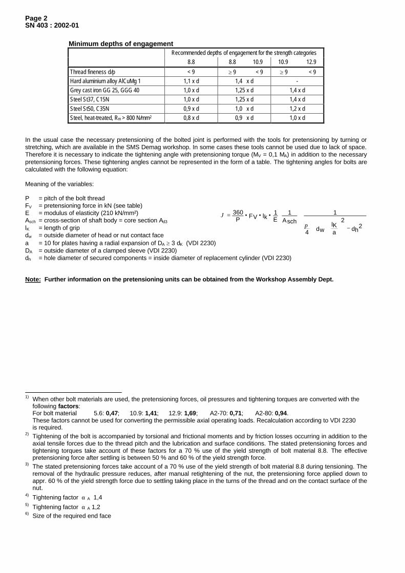
−
+
+•••=
2dh
2
alKdw4
1Asch
1E1lkFVP
360
π
ϑ
Page 2SN 403 : 2002-01
Minimum depths of engagementRecommended depths of engagement for the strength categories
8.8 8.8 10.9 10.9 12.9
Thread fineness d/p < 9 ≥ 9 < 9 ≥ 9 < 9Hard aluminium alloy AlCuMg 1 1,1 x d 1,4 x d -Grey cast iron GG 25, GGG 40 1,0 x d 1,25 x d 1,4 x dSteel St37, C15N 1,0 x d 1,25 x d 1,4 x dSteel St50, C35N 0,9 x d 1,0 x d 1,2 x dSteel, heat-treated, Rm > 800 N/mm2 0,8 x d 0,9 x d 1,0 x d
In the usual case the necessary pretensioning of the bolted joint is performed with the tools for pretensioning by turning orstretching, which are available in the SMS Demag workshop. In some cases these tools cannot be used due to lack of space.Therefore it is necessary to indicate the tightening angle with pretensioning torque (MV = 0,1 MA) in addition to the necessarypretensioning forces. These tightening angles cannot be represented in the form of a table. The tightening angles for bolts arecalculated with the following equation:
Meaning of the variables:
P = pitch of the bolt threadFV = pretensioning force in kN (see table)E = modulus of elasticity (210 kN/mm²)Asch = cross-section of shaft body = core section Ad3
lK = length of gripdw = outside diameter of head or nut contact facea = 10 for plates having a radial expansion of DA ≥ 3 dK (VDI 2230)DA = outside diameter of a clamped sleeve (VDI 2230)dh = hole diameter of secured components = inside diameter of replacement cylinder (VDI 2230)
Note: Further information on the pretensioning units can be obtained from the Workshop Assembly Dept.
1) When other bolt materials are used, the pretensioning forces, oil pressures and tightening torques are converted with thefollowing factors:For bolt material 5.6: 0,47; 10.9: 1,41; 12.9: 1,69; A2-70: 0,71; A2-80: 0,94.These factors cannot be used for converting the permissible axial operating loads. Recalculation according to VDI 2230is required.
2) Tightening of the bolt is accompanied by torsional and frictional moments and by friction losses occurring in addition to theaxial tensile forces due to the thread pitch and the lubrication and surface conditions. The stated pretensioning forces andtightening torques take account of these factors for a 70 % use of the yield strength of bolt material 8.8. The effectivepretensioning force after settling is between 50 % and 60 % of the yield strength force.
3) The stated pretensioning forces take account of a 70 % use of the yield strength of bolt material 8.8 during tensioning. Theremoval of the hydraulic pressure reduces, after manual retightening of the nut, the pretensioning force applied down toappr. 60 % of the yield strength force due to settling taking place in the turns of the thread and on the contact surface of thenut.
4) Tightening factor α A 1,45) Tightening factor α A 1,26) Size of the required end face
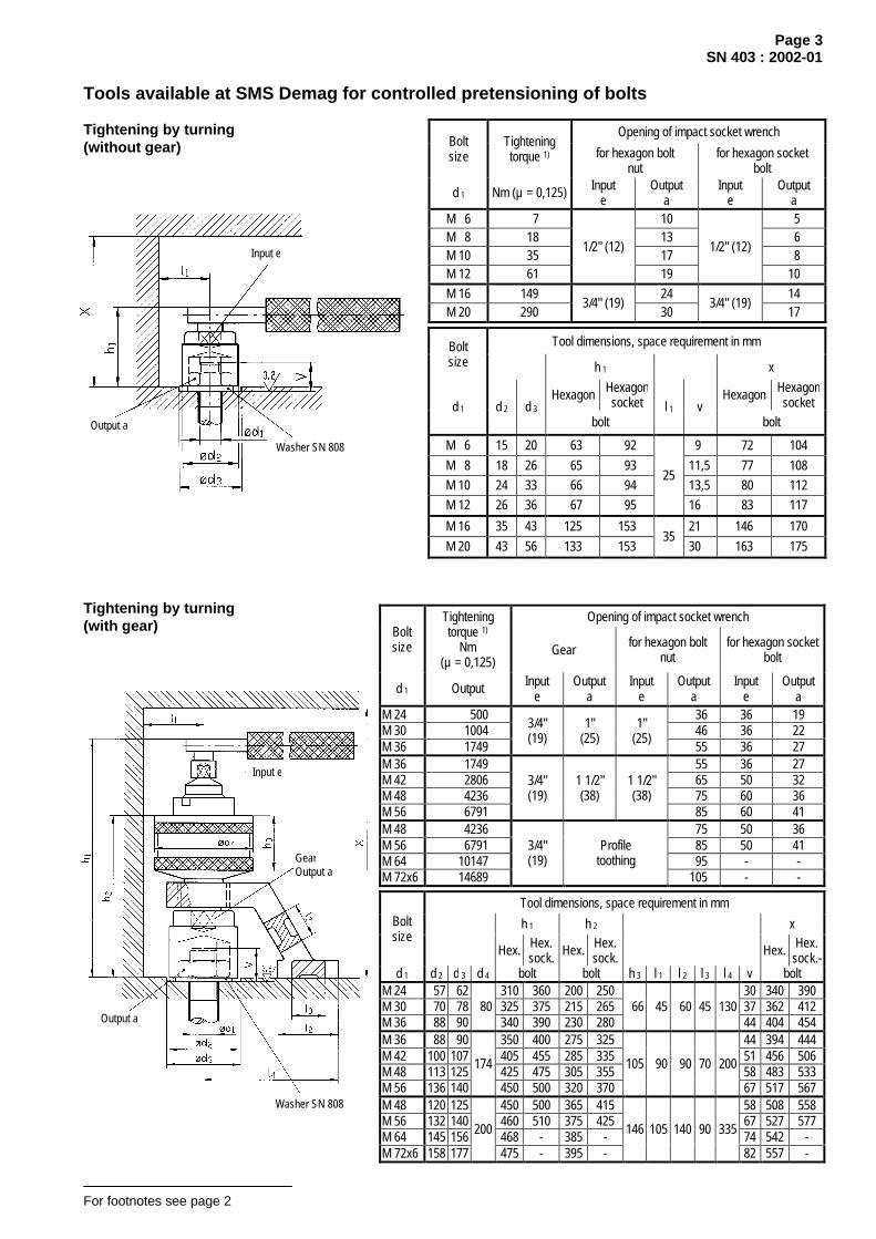
Page 3SN 403 : 2002-01
Tools available at SMS Demag for controlled pretensioning of bolts
Opening of impact socket wrenchBoltsize
Tighteningtorque 1) for hexagon bolt
nutfor hexagon socket
bolt
d 1 Nm (µ = 0,125) Inpute
Outputa
Inpute
Outputa
M 6 7 10 5M 8 18 13 6M 10 35 17 8M 12 61
1/2" (12)
19
1/2" (12)
10M 16 149 24 14M 20 290
3/4" (19)30
3/4" (19)17
Tool dimensions, space requirement in mmBoltsize h 1 x
Hexagon Hexagonsocket Hexagon Hexagon
socketd 1 d 2 d 3
boltl 1 v
bolt
M 6 15 20 63 92 9 72 104M 8 18 26 65 93 11,5 77 108M 10 24 33 66 94 13,5 80 112M 12 26 36 67 95
25
16 83 117
M 16 35 43 125 153 21 146 170M 20 43 56 133 153
3530 163 175
Opening of impact socket wrenchBoltsize
Tighteningtorque 1)
Nm(µ = 0,125)
Gear for hexagon boltnut
for hexagon socketbolt
d 1 Output Inpute
Outputa
Inpute
Outputa
Inpute
Outputa
M 24 500 36 36 19M 30 1004 46 36 22M 36 1749
3/4"(19)
1"(25)
1"(25)
55 36 27M 36 1749 55 36 27M 42 2806 65 50 32M 48 4236 75 60 36M 56 6791
3/4"(19)
1 1/2"(38)
1 1/2"(38)
85 60 41M 48 4236 75 50 36M 56 6791 85 50 41M 64 10147 95 - -M 72x6 14689
3/4"(19)
Profiletoothing
105 - -
Tool dimensions, space requirement in mm
h 1 h 2 xBoltsize
Hex. Hex.sock. Hex. Hex.
sock. Hex. Hex.sock.-
d 1 d 2 d 3 d 4 bolt bolt h 3 l 1 l 2 l 3 l 4 v boltM 24 57 62 310 360 200 250 30 340 390M 30 70 78 325 375 215 265 37 362 412M 36 88 90
80340 390 230 280
66 45 60 45 13044 404 454
M 36 88 90 350 400 275 325 44 394 444M 42 100 107 405 455 285 335 51 456 506M 48 113 125 425 475 305 355 58 483 533M 56 136 140
174
450 500 320 370
105 90 90 70 200
67 517 567M 48 120 125 450 500 365 415 58 508 558M 56 132 140 460 510 375 425 67 527 577M 64 145 156 468 - 385 - 74 542 -M 72x6 158 177
200
475 - 395 -
146 105 140 90 335
82 557 -
For footnotes see page 2
Tightening by turning(with gear)
Washer SN 808
Input e
Output a
GearOutput a
Input e
Output a
Washer SN 808
Tightening by turning(without gear)

Output a
Washer SN 808
Input e
Page 4SN 403 : 2002-01
Boltsize
Tighteningtorque 1)
Openingof impact
socket wrench
Width across flatsof insert socket
Max.torque
forinsert socket
d 1Nm
(µ = 0,125)Input
eOutput
aInput
eOutput
a Nm
M 30 1004 46 22M 36 1749 55 27M 42 2806 65 32M 48 4236
1 1/2"(38)
75
50
36
5000
Tool dimensions, space requirement in mmh 1 min.*) xBolt
sizeHex. Hex.
sock. Hex. Hex.sock.
d 1 d 2 d 3 A B C E F G bolt l 1 l 2 v boltM 30 70 78 180 40 37 220 170M 36 82 90 190
13050 44 240 180
M 42 100 107 192 136 60 51 250 190M 48 110 125
192 88 41 32 45 120
202 134 65
120
58 265 200 *) space requirement with handle: plus 80 mm.
Boltsize
Tighteningtorque 1)
Opening ofimpact
socket wrench
Width acrossflats of
insert socket
Max.torque
forinsert socket
d 1Nm
(µ = 0,125)Input e /Output a
Inpute
Outputa Nm
M 24 500 36 19 1450M 30 1004 46 22 2200M 36 1749 55
3627 3500
M 42 2806 65 32 6800M 48 4236 75 36 8950M 56 6791 85
5041 8950
M 64 10147 95 - - -M 42 2806 65 32 6800M 48 4236 75 36 9700M 56 6791 85
5041 14300
M 64 10147 95M 72 14689 105M 80 20368 115
- - 25000
Tool dimensions, space requirement in mmh 1 XBolt
sizeHex.
Hex.sock. Hex.
Hex.sock.
d 1 d 2 d 3 bolt h 2 l 1 l 2 l 3 V boltM 24 63 62 25 75 33 30 55 105M 30 75 78 25 75 40 37 62 112M 36 87 90 30 80 48 44 74 124M 42 99 107 40 90 55 51 91 141M 48 112 125 65 58 103 153M 56 124 140
45 9570 67 112 162
M 64 138 156 50 -
320
80
222 430
74 124 -M 42 109 112 40 90 60 51 100 150M 48 122 125 65 58 115 165M 56 134 140
45 9575 67 125 175
M 64 147 156 50 100 80 74 135 185M 72 159 177 55 105 85 80 145 195M 80 172 177 60 -
365
90
300 545
88 160 -
For footnotes see page 2
Tightening by turning(sockets with hydraulic cylinder andratchet)
Tightening by turning(wrench with hydraulic cylinder)
Tool weights:
Type HPR 1000 = 20 kgType HPR 2500 = 25 kg
pertaining hydraulic units = 71 kg
WasherSN 808
With
reac
tion
arm
app
lied
Tool weights:
Type LT 50 MS = 14 kg
pertaining hydraulic unit = 50 kg

Washer SN 808Output a
Page 5SN 403 : 2002-01
Tool dimensions, space requirement in mm
h 1 XBoltsize
Tighteningtorque 1)
Opening ofimpact
socket wrench
d 1Nm
(µ = 0,125)Output
a d 3 A B EHexagon
bolt h 2 l 1 VHexagon
bolt
M 24 500 36 62 30 83
M 30 1004 46 78173 143 38 43,75 53 45
37 90
M 24 500 36 62 30 96
M 30 1004 46 78 37 103
M 36 1749 55 90 44 110
M 42 2806 65 107
230 175 60
51 117
M 48 4236 75 125 228 180 58,5
57,95 66 70
58 124
M 48 4236 75 125 58 142
M 56 6791 85 140 67 151
M 64 10147 95 156
300 203 75 67,5 84 87
74 158
Boltsize
Tighteningtorque 1)
Openingof impact
socket wrench
Width acrossflats of insert
socket
Max.torque
forinsert socket
d 1Nm
(µ = 0,125) Input e Output a Output a Nm
M 42 2806 65 32 6020
M 48 4236 75 36 9700
M 56 6791 85 41 12750
M 64 10147 95 46
M 72x6 14689
1 1/2“
105 5515500
Tool dimensions, space requirement in mm
h 1 min. *) XBoltsize
Hex. Hex.sock. Hex. Hex.
sock.d 1 d 2 d 3 A B D E bolt l 1 V bolt
M 42 100 107 260 176 55 51 320
M 48 112 125 242 175 62 58260
M 56 126 140 237 70 67340
280
M 64 137 156 263180
75 74
M 72x6 150 177
230 191 275 49
260 183 82 82370 290
*) space requirement with handle: plus 60 mm.
Tool weight:
Type MSX/T155 TS = 14,1 kg
For footnotes see page 2
Tightening by turning
Tool weights:Type HSX 246 F = 1,45 kgType HSX 575 W = 3,25 kgType HSX 12100 F = 4,4 kg
Tightening methodhydraulic turning
Output a Washer SN 808

Page 6SN 403 : 2002-01
Tightening by stretching(hydraulic pretensioning tool)
Bolt size Pretensioning force Tool dimensions, space requirement in mm
d 1FvkN s d 2 d 3 d 4 6) h 1 l 1 l 2 v X
M 24 158 36 45 64 50 300M 30 251 46 55
78 84 250 45 70 60 310
M 36 366 55 65 97 80 395M 42 502 65 75
102 108 320 55 93 90 405
M 48 660 75 90 121 100 470M 56 909 85 100 128 120 485M 64 1199 95 110
145 157 370 79133 130 500
M 64 1199 95 110 153 130 630M 72 x 6 1551 105 120 158 150 645M 80 x 6 *) 1946 115 140
180 192 500 96165 160 660
M 80 x 6 *) 1946 115 140 215 160 870M 90 x 6 *) 2504 130 160 225 180 890M100 x 6 *) 3136 145 175 233 200 910M110 x 6 *) 3835 150 185
¨ 280 264 710 145
238 220 925M125 x 6 *) 5018 180 220 295 250 970M140 x 6 *) 6362 200 240 305 280 990M160 x 6 *) 8378 230 270
364 356 710 190320 320 1030
*) to be used only in exceptional cases, use ITH units instead.
Tool weights:
Type 02.382 = 7 kgType 02.383 = 15 kgType 2.83 = 38 kgType 2.135 = 70 kgType 2.250 = 270 kgType 3722 = 480 kg
pertaining hydraulic units = 71 kg
For footnotes see page 2
WasherSN 808Pay attention to welds
Nut
Unit shown:type SKF-HTS
Note:
Given the narrow supporting surfacesof the hydraulic pretensioning unitsas from M 80 x 6, the pretensioningforces may cause indentations on thecomponent.
+10 0

Page 7SN 403 : 2002-01
Boltsize
Preten-sioningforce
Max.torque
forinsertsocket
Tool dimensions,space requirement in mm
d 1 F v [kN] s Nm d 2 d 3 d 4 h 1 l 1 v XM 30 348 46 3484 55 107 95 63 200M 36 348 55 3484 65 107 105
119 6075 215
M 42 788 65 7881 75 150 125 137 80 90 250M 48 989 75 9893 90 169 140 145 90 100 270M 56 1274 85 12743 100 190 168 153,5 102 120 300
Boltsize
Preten-sioningforce
Tool dimensions,space requirement in mm
d 1 F v [kN] s d 2 d 3 d 4 h 1 l 1 l 2 v XM 80x6 1946 115 140 200 160 462M 90x6 2504 130 160 210 180 482M100x6 3136 145 175
225 237 302 125220 200 502
M110x6 3835 155 185 240 220 590M120x6 4614 170 210 255 235 605M125x6 5018 180 220
280 292 370 153260 250 620
M125x6 5018 180 220 300 250 678M140x6 6362 200 240 310 280 708M160x6 8378 230 270
358 370 428 195320 320 748
For footnotes see page 2
Tightening by stretching
Tool weights (heads and bridges):
Type Flexitallic M30 = 3,46 kgType Flexitallic M36 = 3,42 kgType Flexitallic M42 = 6,9 kgType Flexitallic M48 = 8,05 kgType Flexitallic M56 = 10,67 kg
Washer SN 808
Nuts
Pay attention totransition areas(radii, weld seams, etc.)
+10 0
Tightening by stretching
Tool weights:Type ITH M 80 / M 90 / M100 x 6 = 68 kgType ITH M110 / M120 / M125 x 6 = 122 kgType ITH M125 / M140 / M160 x 6 = 224 kg
Nuts
Washer SN 808
+10 0
Pay attention totransition areas(radii, weld seams,etc.)

d 2
d 1
c i
January 2002
Design instructions on fastenersScrews and bolts, nuts, washers in conjunction
with countersinks/counterbores and/or holesSelection
SN 351
Dimensions in mm
Plug screws
up to G2: DIN 908 above G2: SN 595
SN 870Type VSTI
Countersinksas in
DIN 3852-2
For plug screws as in DIN 908, SN 595, SN 870; pipe couplings as in SN 456; ventingvalves as in SN 501, and screw joints as in SN 834, SN 839.
Thre
ad d
ia.
DIN
ISO
228
Pertaining sealing ringstype A as per
DIN 7603Material: Cu
The profile packing ispart of the coupling(Perbunan or Viton)
Laid downspecifically forSMS Demag
purposesfor DIN 908;
SN 595; SN 870
forSN 456; SN 501SN 834; SN 839
Laid downspecifically
for SMSDemag
purposes
d 1 d 2 c i d 2 l i a a 1 max. b 1 min. d 4 min. d 7permiss.
dev. t 1 W G 1/8 14 4 8 14 12 8 5 1 8 19 9,8 13 G 1/4 19 5 12 19 17 12 6 1,5 12 25 13,2 18 G 3/8 22 5 12 22 17 12 6 2 12 28 16,7 18 G 1/2 27 5 14 27 19 14 7 2,5 14 34 21 22
0,1
G 3/4 32 5 16 32 21 16 7 2,5 16 42 26,5
+0,2 0
24 G 1 40 6,5 16 40 22,5 16 8 2,5 18 47 33,3 28 G 1 1/4 50 6,5 16 50 22,5 16 8 2,5 20 58 42 30 G 1 1/2 55 6,5 16 55 22,5 16 8 2,5 22 65 47,9 32 G 2 68 5 20 - - - 8 3 24 76 59,7
+0,3 0
34
0,2
G 2 1/2 84 8 26 - - - 12 - 30 85 - - 40 - G 3 100 8 26 - - - 17 - 30 102 - - 40 -
MetricISO thread
T-head bolts
DIN 186
T-slots
DIN 649
Thre
ad d
ia.
DIN
13
Lead
Min
or d
ia. o
f bol
t thr
ead
(max
. dim
.)
Core
sec
tion
for T-head bolts per DIN 186
h min.
d 1 P mm² k n m a bpermissibledeviation GG GG; St c r
M 6 1 4,77 17,9 4,5 6 16 7 19 - 1 15 15 8 0,6M 8 1,25 6,47 32,8 5,5 8 18 10 22 - 1 17 17 9 0,6M 10 1,5 8,16 52,3 7 10 21 12 26 - 2 25 21 11 0,6M 12 1,75 9,85 76,2 8 12 26 14,5 31 - 2 31 25 12 0,6M 16 2 13,55 144,1 10,5 16 30 18,5 36 - 2 38 30 15 0,6M 20 2,5 16,93 225,2 13 20 36 24 44 - 3 44 34 17 0,6M 24 3 20,32 324,3 15 24 43 28 52 - 3 51 39 19 0,6M 30 3,5 25,71 519 19 30 54 35 65 - 4 63 48 24 1M 36 4 31,09 759,3 23 36 66 42 80 - 4 75 57 28 1,6M 42 4,5 36,48 1045 26 42 80 48 95 - 5 89 67 32 1,6M 48 5 41,87 1377 30 48 88 56 105 - 5 102 76 36 1,6
Continued on pages 2 to 5
b = useful thread length
Th
is c
op
y w
ill n
ot
be
up
dat
ed in
cas
e o
f ch
ang
es!

Page 2SN 351 : 2002-01
MetricISO thread
Hexagon head bolts Hexagon fit bolts Studs
DIN
13
DIN
336
(Max
. dim
)
DIN
13 P
art 2
8
DIN
EN 2
0273
med
ium
for m
echa
nica
l eng
inee
ring
DIN
EN 2
0273
coa
rse
for s
teel
con
truct
ion
DIN EN ISO 4014DIN EN ISO 4017
DIN 609SN 550
DIN 939SN 343
DIN EN ISO4032
Thre
ad d
ia.
Lead
Min
or d
ia. o
f bol
t thr
ead
Core
sec
tion
Thro
ugh-
hole
DIN EN ISO4032 DIN EN ISO
4032
d 1 P
Di
a. o
f cor
e ho
le b
it:
mm² d 3 medium d 3 coarse k v min. a b t d s k6 d 4 k v min. a b t v min.
M 4 0,7 3,3 3,14 7,8 4,5 4,8 2,8 4,5 5 7 11 - - - - 5 7 11 4,5
M 5 0,8 4,2 4,02 12,7 5,5 5,8 3,5 6,5 6,5 9 14 - - - - 6,5 9 14 6,5
M 6 1 5 4,77 17,9 6,6 7 4 7 7,5 10 16 - - - - 7,5 10 16 7
M 8 1,25 6,8 6,47 32,8 9 10 5,3 9,5 10 13 20 9 10 5,3 9,5 10 13 20 9,5
M 10 1,5 8,5 8,16 52,3 11 12 6,4 11,5 12 15 23 11 13 6,4 11,5 12 15 23 11,5
M 12 1,75 10,2 9,85 76,3 13,5 14,5 7,5 14,5 15 18 27 13 15 7,5 14,5 15 18 27 14,5
M 16 2 14 13,55 144,1 17,5 18,5 10 19 20 24 34 17 19 10 19 20 24 34 19
M 20 2,5 17,5 16,93 225,2 22 24 12,5 23 25 29 41 21 23 12,5 23 25 29 41 23
M 24 3 21 20,32 324,3 26 28 15 27,5 30 34 48 25 28 15 27,5 30 34 48 27,5
M 30 3,5 26,5 25,71 519 33 35 18,7 32,5 38 42 58 32 34 19 32,5 38 42 58 32,5
M 36 4 32 31,09 759,3 39 42 22,5 39 45 49 66 38 40 22 39 45 49 66 39
M 42 4,5 37,5 36,48 1045 45 48 26 43 52 56 75 44 46 26 43 52 56 75 43
M 48 5 43 41,87 1377 52 56 30 48 60 65 86 50 54 30 48 60 65 86 48
M 56 5,5 50,5 49,25 1905 62 66 35 56 70 75 100 58 63 35 56 70 75 100 56
M 64 6 58 56,64 2520 70 74 40 63 80 86 110 65 70 40 63 80 86 110 63
M 72 x 6 6 66 64,64 3287 78 82 45 70 90 95 119 75 80 45 70 90 95 119 70
M 80 x 6 6 74 72,64 4144 86 91 50 76 100 106 130 82 87 50 76 100 106 130 76
M 90 x 6 6 84 82,64 5364 96 101 57 84 112 118 142 - - - - 112 118 142 84
M100 x 6 6 94 92,64 6740 107 112 63 92 125 132 156 - - - - 125 132 156 92
M110 x 6 6 104 102,64 8273 117 122 69 100 137 143 167 - - - - 137 143 167 100
M125 x 6 6 119 117,64 10869 132 137 79 112 156 162 186 - - - - 156 162 186 112
M140 x 6 6 134 132,64 13818 147 155 88 124 175 182 206 - - - - 175 182 206 124
M160 x 6 6 154 152,64 18299 168 175 100 140 200 206 230 - - - - 200 206 230 140
According to DIN EN ISO 4014, DIN EN ISO 4017 and DIN EN ISO 4032 hexagon bolts and nuts are standardised only up to size M 64.For bigger thread diameters the invalid standards DIN 931 and DIN 934 must be used.

Page 3SN 351 : 2002-01
Widths across flats
for bolts and nuts asin:
DIN 609, DIN 561,DIN 935,
DIN EN ISO 4014,(DIN 931),
DIN EN ISO 4017,DIN EN ISO 4032,
(DIN 934)
Hexagon nuts
DIN EN ISO 4032
Hexagon nuts,self-locking
DIN EN ISO7042
Castle nuts
DIN 935
Cotter pins
DIN EN ISO 1234
Lockwashers
for hexagonand socket headbolts, hexagon
nuts
SN 778
Washers
for bolts andnuts
DIN EN ISO7089
Washers
for high-strengthpretensionedbolted joints
SN 808
Thre
ad d
ia.
D
IN 1
3
e min. s m max. v min. h max. v min. m max. v min. n min.Cotter pin
Ø x l d 2 s d 2 h d 2 s d 1
7,66 7 3,2 8 - - 5 6,5 1,2 1 x 10 7 0,5 9 0,8 - - M 4
8,79 8 4,7 11 5,1 7,5 6 8 1,4 1 x 12 9 1 10 1 - - M 5
11,05 10 5,2 13 6 9 7,5 10 2 1,8 x 14 10 1 12 1,6 11 2 M 6
14,38 13 6,8 16 8 12 9,5 12 2,5 2,3 x 16 13 1,2 16 1,6 16 2,5 M 8
17,77 16 8,4 20 10 15 12 15 2,8 2,3 x 20 16 1,5 20 2 20 2,5 M 10
20,03 18 10,8 25 12 17 15 19 3,5 2,9 x 22 18 1,5 24 2,5 24 3 M 12
26,75 24 14,8 34 16,4 22 19 23 4,5 3,7 x 28 24 2 30 3 30 4 M 16
33,53 30 18 41 20,3 28 22 27 4,5 3,7 x 36 30 2 37 3 35 4,5 M 20
39,98 36 21,5 49 23,9 33 27 33 5,5 4,6 x 40 36 2,5 44 4 45 5 M 24
50,85 46 25,6 58 30 41 33 40 7 5,9 x 50 45 2,5 56 4 55 6 M 30
60,79 55 31 70 36 48 38 46 7 5,9 x 63 - - 66 5 65 7 M 36
71,3 65 34 77 - - 46 55 9 7,5 x 71 - - 78 8 75 8 M 42
82,6 75 38 86 - - 50 60 9 7,5 x 80 - - 92 8 90 10 M 48
93,56 85 45 101 - - 57 68 9 7,5 x 100 - - 105 10 100 11 M 56
DIN
EN IS
O 4
014,
DIN
EN
ISO
401
7, D
IN E
N IS
O 4
032
104,86 95
DIN
EN IS
O 4
032
51 114 - - 66 78 11 9,5 x 100 - - 115 10 110 11 M 64
116,16 105 58 128 - - 73 85 11 9,5 x 112 - - - - 120 12 M 72 x 6
127,46 115 64 140 - - 79 91 11 9,5 x 140 - - - - 140 14 M 80 x 6
144,08 130 72 156 - - 92 104 14 12,4 x 140 - - - - 160 16 M 90 x 6
161,02 145 80 172 - - 100 112 14 12,4 x 160 - - - - 175 16 M100 x 6
172,32 155 88 188 - - - - - - - - - - 185 16 M110 x 6
200,57 180 100 212 - - - - - - - - - - 220 22 M125 x 6
220,8 200 112 236 - - - - - - - - - - 240 22 M140 x 6
DIN
931,
DIN
934
254,7 230
DIN
934
128 268 - - - - - - - - - - 270 22 M160 x 6
1) The necessary washers, spring washers and locking washers must be included in the grip length.2) Length of engagement at 1.25 d1.3) Bolt length (minimum length) = grip length + projection length. This minimum length must be rounded off to the next bigger bolt length stated in the relevant
standards.

Page 4SN 351 : 2002-01
Socket head bolts Counterbores for socket head bolts
DIN 974-1
DIN EN ISO 4762 DIN 7984 DIN EN ISO 1207 DIN EN ISO4762,
DIN 912
DIN EN ISO1207
DIN7984
Thre
ad d
ia.
D
IN 1
3
Thro
ugh
hole
per
DIN
EN 2
0 27
3 m
ediu
m
For sizes above M 64:DIN 912
(all sizes withfine threads as in DIN 912) w
ithou
t was
her
with
lock
wash
er a
s in
SN
778
upto
stre
ngth
gra
de 8
.8
with
out w
ashe
r
with
was
her
with
out w
ashe
r
with
lock
wash
er a
s in
SN
778
upto
stre
ngth
gra
de 8
.8
d 1 d 3 d k l g max. k d k l g max. k d k a max. k d 2 H13 t t t t t t
M 4 4,5 7 2,1 4 7 2,1 2,8 7 1,4 2,6 8 4,6 5 3,4 4,5 3,2 4
M 5 5,5 8,5 2,4 5 8,5 2,4 3,5 8,5 1,6 3,3 10 5,7 6,5 4,2 5,5 4 5
M 6 6,6 10 3 6 10 3 4 10 2 3,9 11 6,8 7,5 4,8 6,5 4,7 5,5
M 8 9 13 3,75 8 13 3,75 5 13 2,5 5 15 9 10 6 8 6 7
M 10 11 16 4,5 10 16 4,5 6 16 3 6 18 11 12,5 7,5 9,5 7 8,5
M 12 13,5 18 5,25 12 18 5,25 7 - - - 20 13 14,5 8,5 11 8 9,5
M 16 17,5 24 6 16 24 6 9 - - - 26 17,5 19 11,5 15 10,5 12
M 20 22 30 7,5 20 30 7,5 11 - - - 33 21,5 23 13,5 17,5 12,5 14
M 24 26 36 9 24 36 9 13 - - - 40 25,5 27,5 15,5 20,5 14,5 16,5
M 30 33 45 10,5 30 - - - - - - 50 32 34 19,5 25,5 - -
M 36 39 54 12 36 - - - - - - 58 38 - 23,5 29,5 - -
M 42 45 63 13,5 42 - - - - - - 69 44 - - - - -
M 48 52 72 15 48 - - - - - - 78 50 - - - - -
M 56 62 84 16,5 56 - - - - - - 93 58 - - - - -
M 64 70
DIN
EN IS
O 4
762
96 18 64 - - - - - - 107 66 - - - - -
M 72 x 6 78 108 18 72 - - - - - - 118 74 - - - - -
M 80 x 6 86 120 18 80 - - - - - - 132 82 - - - - -
M 90 x 6 96 135 18 90 - - - - - - 145 92 - - - - -
M100 x 6 107
DIN
912
150 18 100 - - - - - - 160 102 - - - - -
M110 x 6 117 - - - - - - - - - Short designation (d 3 / d 2 x t)
M125 x 6 132 - - - - - - - - -
M140 x 6 147 - - - - - - - - -
M160 x 6 168 - - - - - - - - -

Page 5SN 351 : 2002-01
Counterbores
DIN 974-2
forhexagon head
screws, hexagon nuts,lockwashers
SN 778and washers
DIN EN ISO 7089,DIN EN ISO 7090,
SN 808
Counterbores
forsocket wrenches,box wrenches andstriking-face box
spanners
Counterbores
foreye boltsDIN 580
and eye nutsDIN 582
Countersunk headscrews as in
DIN EN ISO 10642
α = 90° +2°
Countersinks
as in DIN 74-1
for countersunkhead screws as inDIN EN ISO 10642
Type F
for wear plates
α = 90° ±1° Thre
ad d
ia.
D
IN 1
3
d 2 H13 d 2 d 4 d k min. k max. d 4 H13 s min. d 1
10 18 - 7,53 2,48 10 7 M 4
11 18 - 9,43 3,1 12,5 8 M 5
13 20 - 11,34 3,72 14,5 9 M 6
18 26 24 15,24 4,96 19 11 M 8
22 33 30 19,22 6,2 23,5 13 M 10
26 36 36 23,12 7,44 28 15 M 12
33 43 40 29,01 8,8 35 19 M 16
40 56 46 36,05 10,16 41,5 24 M 20
48 62 57 - - - - M 24
61 78 71 - - - - M 30
71 90 82 - - - - M 36
82 107 92 - - - - M 42
98 125 112 - - - - M 48
112 140 118 - - - - M 56
125 156 132 - - - - M 64
132 177 162 - - - - M 72 x 6
150 177 180 - - - - M 80 x 6
170 208 - - - - - M 90 x 6
190 236 200 - - - - M100 x 6
200 264 - - - - - M110 x 6
240 380 - - - - - M125 x 6
260 380 - - - - - M140 x 6
290 380 - - - - - M160 x 6
faced

Foundation
Dimensions in mm
Graphicalsymbol 1)
DIN 24536
Gra
phic
sym
bol.
Exam
ple:
M 3
0
Stone bolt
T-head bolt
Adhesiveanchor
Threadedpin
Through-hole Threaded pin
SN 172
Stone bolt
DIN 529
Note: Observe SN 559 and other standards.
T-head bolt
SN 425
Note: Always combined with anchor plate or double anchor plate
Adhesive anchor
SN 705
Weightin kg
Weightin kg
Weightin kg
Forthreadsize T-head Bo
lt
d 1 e1 2
0+ e2
20+ d 3 d 2
20+ f x 30° L 2 W
eigh
t in
kg /
m
t 1 t 2 e for 5
00 m
mle
ngth
per 1
0 m
mle
ngth
w for 1
000
mm
leng
th
per 1
0 m
mle
ngth
d 2 t for 1
00 m
mle
ngth
per 1
0 m
mle
ngth
M 10 - - 12 - - - - 200 100 45 0,34 0,006 - - - - - - -
M 12 - - 16 - - - - 250 100 55 0,5 0,009 - - - 15 110 0,113 0,009
M 16 - - 20 - - - - 320 100 70 0,92 0,016 - - - 20 125 0,205 0,016
M 20 - - 25 - - - - 400 100 85 1,49 0,025 - - - 25 170 0,336 0,025
M 24 27 54 28 24 5 100 3,55 500 100 100 2,22 0,036 500 3,66 0,036 30 210 0,505 0,036
M 30 34 68 35 30 5 120 5,55 600 100 120 3,63 0,055 600 5,77 0,055 36 280 0,857 0,055
M 36 40 82 40 36 5 160 8 700 100 140 5,51 0,08 700 8,36 0,08 42 300 1,32 0,08
M 42 47 94 48 42 5 180 10,87 800 100 160 7,83 0,109 800 11,48 0,109 48 350 1,94 0,109
M 48 53 102 54 48 5 210 14,2 1000 100 180 10,65 0,142 1000 15,09 0,142 55 400 2,76 0,142
M 56 62 116 62 56 10 250 19,33 1100 100 210 15,27 0,193 1100 20,71 0,193 62 500 3,87 0,193
M 64 70 128 70 64 10 280 25,25 1300 100 250 21,09 0,253 1300 27,31 0,253 72 600 5,1 0,252
M 72x6 78 142 80 72 10 300 31,96 1400 100 290 27,81 0,32 1400 34,87 0,32 - - - -
M 80x6 87 154 90 80 15 320 39,46 - - - - - 1600 43,36 0,395 - - - -
M 90x6 97 170 100 90 15 360 49,94 - - - - - 1800 55,33 0,499 - - - -
M100x6 107 185 110 100 15 400 61,65 - - - - - 2000 69,07 0,617 - - - -
M110x6 118 205 120 110 15 440 74,6 - - - - - 2200 84,52 0,746 - - - -
M125x6 133 230 135 125 15 500 96,33 - - - - - 2500 111,2 0,963 - - - -
M140x6 148 255 150 140 15 560 120,8 - - - - - 2800 141,2 1,208 - - - -
M160x6 168 290 170 - - - - - - - - - 3200 189,1 1,578 - - - -
The graphic symbols must always be drawn with axes of coordinates (see Figs. 1 and 2). The positions of the stone bolts or T-headbolts. In the case of graphic symbols for T-head bolts with double anchor plates the T-head bolt clearance (k) is stated as specified in
1) The graphical symbols are standardised in DIN 24536 up to size M100 x 6. For M110 x 6 and above the symbols have been definedspecifically for SMS Demag purposes.
2) v-dimensions are based on washer thicknesses per SN 220 or SN 808 + 1 x nut height per ISO 4032/DIN 934 + 1 x d 1 for the application of hydraulic pretensioning units as in SN 403.
Grout
Shank type A
Groutand shrouderpipesealing
Anch
or p
late
ب
Th
is c
op
y w
ill n
ot
be
up
dat
ed in
cas
e o
f ch
ang
es!

January 2002
anchoring elements SN 372
Dimensions in mm
Rectangular washer
SN 220
Round washer
SN 808
Projection Nutup to M64:DIN EN ISO
4032
above M64:DIN 934
Anchor plate
SN 227-1
[Double anchor plateSN 227-2]
Graphic symbolwith T-head bolte.g. for M30:
Shrouder pipe
DIN 2458
Single:
Double:
v 2)d i
as for washeras in SN 808
alsoSN220 For
thread size
SN 808 SN 220 a b s Wei
ght i
nkg
/uni
t
d i d a s Wei
ght i
nkg
/uni
t
m Wei
ght i
nkg
/uni
t
b 1 a t 1 Wei
ght i
nkg
/uni
td a d i s W
eigh
t in
kg /
m
d 1
25 - - - - - 10,5 20 2,5 0,005 8,4 0,012 - - - - - - - - M 1030 - - - - - 13 24 3 0,008 10,8 0,017 - - - - - - - - M 1235 - - - - - 17 30 4 0,015 14,8 0,033 - - - - - - - - M 1640 - - - - - 21 35 4,5 0,026 18 0,064 - - - - - - - - M 2050 60 50 80 10 0,28 25 45 5 0,04 21,5 0,11 180 20 75 7,5 114,3 109,1 2,6 7,16 M 2460 75 60 90 15 0,55 31 55 6 0,08 25,6 0,223 210 25 90 11,5 114,3 109,1 2,6 7,16 M 3080 90 70 100 20 0,94 37 65 7 0,129 31 0,393 240 30 110 17 139,7 134,5 2,6 8,79 M 3690 105 80 115 25 1,49 43 75 8 0,209 34 0,652 270 30 120 22 139,7 134,5 2,6 8,79 M 42
100 120 90 130 30 2,28 50 90 10 0,368 38 0,977 300 35 140 30 168,3 162,5 2,9 11,8 M 48120 135 100 145 30 2,83 58 100 11 0,52 45 1,42 330 35 150 36 168,3 162,5 2,9 11,8 M 56130 155 110 160 35 3,93 66 110 11 0,601 51 1,98 370 40 175 50 193,7 187,9 2,9 13,6 M 64150 170 120 180 35 4,79 74 120 12 0,751 58 2,67 410 40 190 62,5 219,1 212,7 3,2 17 M 72x6160 190 130 200 40 6,52 82 140 14 1,111 64 3,44 450 40 205 74,5 219,1 212,7 3,2 17 M 80x6180 220 145 220 50 9,9 93 160 16 1,672 72 4,93 500 50 235 108,5 244,5 238,1 3,2 19 M 90x6200 240 160 240 50 11,8 104 175 16 1,954 80 6,82 550 50 255 129 273 266,6 3,2 21,3 M100x6220 265 180 260 60 17,3 114 185 16 2,094 88 8,2 600 60 285 182 323,9 317,5 3,2 25,3 M110x6250 305 205 290 70 25,5 129 220 22 4,308 100 13 660 60 315 220 323,9 317,5 3,2 25,3 M125x6280 340 230 320 80 36,1 144 240 22 4,995 112 17,5 750 80 355 366 355,6 349,2 3,2 27,8 M140x6320 395 260 350 100 54,9 164 270 22 6,24 128 26,5 850 80 365 466 406,4 399,2 3,6 35,8 M160x6
with anchor plates are determined by dimensioning the axes of coordinates. SN 227-2 (see Figs. 1 and 2). The graphic symbols themselves need not be drawn to scale.
Fig. 1 Fig. 2
+10 0
• Stud anchors see SN 854• Shrouder pipe sealing for T-head bolts, threaded pins and rectangular shrouder pipes
see SN 207-1 to 3
t 1
a
b 1

January 2002
Mechanical fastenersScrews, bolts and nuts
Selection
SN 485
Dimensions in mmd M 4 M 5 M 6 M 8 M10 M12 M16 M20 M24 M30 M36 M42 M48 M56 M64
1) 14 16 18 22 26 30 38 46 54 66 - - - - -2) 20 22 24 28 32 36 44 52 60 72 84 96 108 - -b3) 33 35 37 41 45 49 57 65 73 85 97 109 121 137 153
d a max. 4,7 5,7 6,8 9,2 11,2 13,7 17,7 22,4 26,4 33,4 39,4 45,6 52,6 63 71e min. 7,66 8,79 11,05 14,38 17,77 20,03 26,75 33,53 39,98 50,85 60,79 71,3 82,6 93,56 104,86
k 2,8 3,5 4 5,3 6,4 7,5 10 12,5 15 18,7 22,5 26 30 35 40s 7 8 10 13 16 18 24 30 36 46 55 65 75 85 95l Weight (7,85 kg/dm³) in kg per 1000 pieces
25 3,12 4,8630 3,61 5,64 8,0635 4,04 6,42 9,1340 4,53 7,2 10,2 20,345 7,98 11,3 22,2 3850 8,76 12,3 24,2 41,1 58,155 13,4 25,8 43,8 62,660 14,4 27,8 46,9 67
For lengths in shaded area refer toISO 4017
65 29,8 50 70,3 13170 31,8 53,1 74,7 13980 35,7 59,3 83,6 155 25590 65,5 92,4 171 279 428
100 71,7 101 186 303 464110 109 202 327 500 823120 118 218 351 535 880130 230 374 560 920140 246 398 595 975 1470150 262 422 630 1030 1550160 278 446 665 1085 1630 2310180 494 735 1200 1790 2520 3440200 544 805 1310 1950 2740 3720220 870 1420 2110 2960 4010 5660240 935 1530 2270 3180 4290 6030260 1640 2430 3400 4570 6410 8600280 1750 2590 3520 4850 6800 9100300 1) For lengths l ≤ 125 mm 1860 2750 3640 5130 7190 9600320 2) For lengths 125 mm < l ≤ 200 mm 2910 3860 5410 7580 10100340 3) For lengths l > 200 mm 3070 4080 5690 7970 10600
Hexagon head bolt
DIN EN ISO 4014
Ordering example:ISO 4014 – M 20 x 80 – 8.8
Note: For sizes above M 64 please refer to DIN 931-2.
360 3230 4300 5970 8350 11100
d M 72 x 6 M 80 x 6 M 90 x 6 M 100 x 6 M 110 x 6 M 125 x 6 M 140 x 6 M 160 x 62) 156 172 192 - - - - -
b3) 169 185 205 225 245 275 305 345
d a max. 79 87 97 107 117 132 147 167e min. 116,16 127,46 144,08 161,02 172,32 200,57 220,8 254,7
k 45 50 57 63 69 79 88 100s 105 115 130 145 155 180 200 230l Weight (7,85 kg/dm³) in kg per 1000 pieces
200 9,36220 9,9 12,6240 10,5 13,3 17,6260 11,1 14,1 18,5 24,2280 11,7 14,9 19,5 25,3 31300 12,4 15,6 20,5 26,5 32,5320 13 16,4 21,5 27,7 34 45,8340 13,7 17,2 22,5 28,9 35,4 47,7 61,7360 14,3 18 23,5 30,1 36,8 49,6 64380 15 18,8 24,5 31,3 38,2 51,5 66,4 92,1400 15,6 19,6 25,5 32,5 39,6 53,5 68,8 95,3420 20,4 26,5 33,8 41 55,4 71,2 98,4440 21,2 27,5 35 42,5 57,3 73,6 101,5460 22 28,5 36,2 44 59,2 76 104,7480 29,5 37,4 45,5 61,1 78,4 107,9500 30,5 38,6 47 63 80,8 111,1
Hexagon head cap screw
DIN 931-2
DIN 931 – M 80 x 6 x 300 – 8.8
Note: For sizes up to M 64 please refer to DIN EN ISO 4014. 2) For lengths 125 mm < l ≤ 200 mm
3) For lengths l > 200 mmContinued on pages 2 to 7
Th
is c
op
y w
ill n
ot
be
up
dat
ed in
cas
e o
f ch
ang
es!

Page 2SN 485 : 2002-01
d M 4 M 5 M 6 M 8 M10 M12 M16 M20 M24 M30 M36 M42 M48 M56 M64a max. 2,1 2,4 3 4 4,5 5,3 6 7,5 9 10,5 12 13,5 15 16,5 18
d a max. 4,7 5,7 6,8 9,2 11,2 13,7 17,7 22,4 26,4 33,4 39,4 45,6 52,6 63 71e min. 7,66 8,79 11,05 14,38 17,77 20,03 26,75 33,53 39,98 50,85 60,79 71,3 82,6 93,56 104,86
k 2,8 3,5 4 5,3 6,4 7,5 10 12,5 15 18,7 22,5 26 30 35 40s 7 8 10 13 16 18 24 30 36 46 55 65 75 85 95l Weight (7,85 kg/dm3) in kg per 1000 pieces
12 1,8 2,87 4,4216 2,1 3,37 5,11 11,120 2,41 3,87 5,8 12,3 21,225 2,8 4,49 6,65 13,9 23,7 34,130 3,19 5,11 7,51 15,5 26,2 37,7 76,935 3,75 5,73 8,37 17,1 28,7 41,3 83,540 3,96 6,35 9,23 18,7 31,2 44,9 90,2 15545 6,99 10,1 20,3 33,7 48,5 97,1 16550 7,59 11 21,8 36,2 52 103 176 27455 11,9 23,4 38,7 55,6 110 186 28960 12,7 25 41,3 58,2 117 196 304 54365 26,6 43,8 62,8 123 207 319 56670 28,2 46,3 66,4 130 217 334 590 91080 31,4 51,3 73,6 144 238 363 637 990 146090 56,3 80,8 157 258 393 685 1060 1550
100 61,3 88 170 279 423 732 1140 1650 2320110 95,2 184 300 453 779 1200 1740 2450 3410120 102 197 320 483 827 1260 1840 2570 3580 4900130 210 340 513 874 1330 1930 2690 3750 5120140 224 361 543 921 1400 2020 2820 3920 5340150 237 381 572 969 1470 2120 2940 4080 5560160 1010 1540 2210 3060 4250 5780180
For lengths in the shaded arearefer to ISO 4014
(SMS Demag determination)1110 1680 2400 3310 4590 6230
Hexagon head screwwith coarse-pitch thread
DIN EN ISO 4017
Ordering example:ISO 4017 – M12 x 30 – 8.8
Note: Fine-pitch threads only according to DIN EN ISO 8676. Table values acc. to DIN EN ISO 4017 do not match for fine-pitch threads.
200 1210 1810 2590 3560 4920 6670
d M 4 M 5 M 6 M 8 M10 M12 M16 M20P 0,7 0,8 1 1,25 1,5 1,75 2 2,5b 20 22 24 28 32 36 44 52
d k max. 8,96 11,2 13,44 17,92 22,4 26,88 33,6 40,32k max. 2,48 3,1 3,72 4,96 6,2 7,44 8,8 10,16
l g max. *) 4,58 5,5 6,72 8,71 10,7 12,69 14,8 17,66s 2,5 3 4 5 6 8 10 12a 90° to 92°l Weight (7,85 kg/dm3) in kg per 1000 pieces
8 0,92 1,6 2,35 10 1,07 1,85 2,7 5,47 12 1,23 2,1 3,05 6,1 10,1 16 1,53 2,59 3,76 7,35 12,1 20 1,84 3,09 4,46 8,6 14,1 21,2 25 2,23 3,71 5,34 10,2 16,6 24,8 30 2,9 4,33 6,22 11,7 19,1 28,5 51,8 35 3,4 5,43 7,1 13,3 21,6 32,1 58,4 91,4 40 3,9 6,2 8,83 14,8 24,1 35,7 65,1 102 45 7 9,9 17,3 27,1 39,3 71,7 112 50 7,74 11 19,9 30,1 43 78,4 123 55 12,1 22,3 32,9 48,5 85 133 60 13,2 24,8 35,7 54 91,7 143 65 27,3 38,5 59,5 98,4 153 70 29,8 41,2 62,9 111 164 80 32,3 44 67,4 127 200 90 46,8 71,9 143 226100 49,6 76,4 159 253
Hexagon socket countersunkhead screws
DIN EN ISO 10642
The following applies to screwsover - - - : b = l – l g max.
The following applies to screwsbelow - - - : l g max. = l – b
Ordering example: ISO 10642 – M 12 x 40 – 8.8
*) Lengths indicated above the dashed stepped line have threads up to the screw head within a distance of 3P. This leads to the equation l g max. = k max. + 3P

Page 3SN 485 : 2002-01
d M 8 M10 M12 M16 M20 M24 M30 M36 M42 M481) 14,5 17,5 20,5 25 28,5 - - - - -2) 16,5 19,5 22,5 27 30,5 36,5 43 49 56 63b3) 21,5 24,5 27,5 32 35,5 41,5 48 54 61 68
d s k6 9 11 13 17 21 25 32 38 44 50
e min. 14,38 17,77 19,85 26,17 32,95 39,55 50,85 60,79 71,3 82,6k 5,3 6,4 7,5 10 12,5 15 19 22 26 30
s max. 13 16 18 24 30 36 46 55 65 75l Weight (7,85 kg/dm3) in kg per 1000 pieces
35 22 35,5 48,640 24,5 39,2 53,8 10445 27 42,9 59 112 19550 29,5 46,7 64,2 121 20355 32 49,9 68,7 130 215 31060 34,5 53,6 73,9 139 229 33965 37 57,4 79,2 148 242 358 63070 39,5 61,1 84,4 157 256 378 661 102075 42 64,8 89,6 166 269 397 693 107080 44,5 68,6 94,8 175 283 416 724 1110 160090 76 105 193 310 455 787 1200 1720 2410
100 83,5 115 211 338 493 850 1290 1840 2570110 126 228 365 532 914 1380 1960 2720120 136 246 392 570 977 1470 2080 2870130 264 419 609 1050 1560 2200 3020140 282 446 647 1110 1650 2320 3180150 300 474 686 1170 1740 2440 3330160 1230 1810 2540 3470170 1) For lengths l ≤ 50 mm 1290 1900 2660 3630180 2) For lengths 50 mm < l ≤ 150 mm 1350 1990 2780 3780190 3) For lengths l > 150 mm 1420 2080 2900 3940
Hexagon fitting boltwith long threaded portion
DIN 609
DIN 609 – M 12 x 50 – 8.8200 1480 2170 3020 4090
d M 6 M 8 M10 M12 M16 M20 M24 M30 M36 M42 M48 M56a 1 max. 3 3,75 4,5 5,25 6 7,5 9 10,5 12 13,5 15 16,5d a max. 6,8 9,2 11,2 13,7 17,7 22,4 26,4 33,4 39,4 45,6 52,6 63
d p 4 5,5 7 8,5 12 15 18 23 28 32 38 45e min. 8,79 11,05 14,38 17,77 19,92 26,75 33,53 39,98 51,28 61,31 72,61 83,91
k 5 6 7 9 11 14 17 21 25 30 34 40s max. 8 10 13 16 18 24 30 36 46 55 65 75
z 2 min. 3 4 5 6 8 10 12 15 18 21 24 28l Weight (7,85 kg/dm3) in kg per 1000 pieces
12 4,2616 4,95 8,6620 5,65 9,94 1725 6,53 11,4 19,5 34,130 7,38 13 22 37,7 62,635 14,6 24,4 41,2 69,140 16,1 26,9 44,8 75,7 13245 29,4 48,4 82,3 143 23350 31,9 52 88,9 154 24960 59,2 102 176 281 44670 66,4 115 198 313 49380 128 220 345 540 876 132090 142 242 377 587 944 1410 2040
100 264 409 634 1010 1510 2160 3120120 473 727 1150 1700 2410 3450140 821 1280 1890 2660 3780160 914 1420 2080 2910 4110180 1560 2270 3160 4440200 1690 2460 3410 4770220 2650 3660 5100240 2840 3910 5430260 3030 4160 5760280 4410 6090
Hexagon head screw with full dogpoint and small hexagon
DIN 561
Material acc. to DIN ISO 898-5
DIN 561 - M 16 x 70 - 14H
300 4660 6420

Page 4SN 485 : 2002-01
d M 4 M 5 M 6 M 8 M10 M12 M16 M20 M24 M30 M36 M42 M48 M56 M64b 20 22 24 28 32 36 44 52 60 72 84 96 108 124 140
d a max. 4,7 5,7 6,8 9,2 11,2 13,7 17,7 22,4 26,4 33,4 39,4 45,6 52,6 63 71d k max. 7 8,5 10 13 16 18 24 30 36 45 54 63 72 84 96k max. 4 5 6 8 10 12 16 20 24 30 36 42 48 56 64
l g max. *) 2,1 2,4 3 3,75 4,5 5,25 6 7,5 9 10,5 12 13,5 15 16,5 18s 3 4 5 6 8 10 14 17 19 22 27 32 36 41 46l Weight (7,85 kg/dm3) in kg per 1000 pieces
12 1,95 2,95 5,07 10,916 2,25 3,45 5,75 12,1 20,920 2,65 4,01 6,53 13,4 22,9 32,125 3,15 4,78 7,59 15 25,4 35,7 71,330 3,65 5,55 8,3 16,9 27,9 39,3 77,8 12835 4,15 6,32 9,91 18,9 30,4 42,9 84,4 13940 4,65 7,09 11 20,9 32,9 46,5 91 150 27045 7,86 12,1 22,9 36,1 50,1 97,6 161 285 50050 8,63 13,2 24,9 39,3 54,5 106 172 300 52755 14,3 26,9 42,5 58,9 114 183 316 554 87060 15,4 28,9 45,7 63,4 122 194 330 581 910 137065 31 48,9 67,8 130 205 345 608 950 142070 33 52,1 71,3 138 216 363 635 990 1470 204080 37 58,5 80,2 154 241 399 690 1070 1580 2180 334090 64,9 89,1 170 266 435 745 1150 1680 2320 3530 5220
100 71,2 98 186 291 471 800 1230 1790 2460 3720 5470110 107 202 316 507 855 1310 1890 2600 3920 5730120 116 218 341 543 910 1390 2000 2740 4110 5980130 234 366 579 965 1470 2100 2880 4300 6230140 250 391 615 1020 1550 2210 3020 4490 6490150 266 416 651 1080 1630 2320 3160 4680 6740160 282 441 687 1130 1710 2420 3300 4880 6900180 491 759 1240 1870 2640 3590 5270 7250200 541 831 1350 2030 2860 3870 5650 7750220 903 1460 2190 3080 4150 6040 8250240 975 1570 2250 3300 4430 6420 8750260 1680 2410 3520 4710 6810 9260280 1790 2570 3740 4990 7200 9760300 1900 2730 3960 5270 7580 10300
Hexagon socket head boltwith coarse-pitch thread
DIN EN ISO 4762
The following applies to screwsover - - - : b = l – l g max.
The following applies to screwsbelow - - - : l g max. = l – b
Ordering example:ISO 4762 – M 12 x 50 - 8.8
Note: Both in case of the hexagon socket head bolts with fine-pitch threads and those with coarse-pitch threads above M 64 reference must be made to DIN 912. *) Lengths indicated above the dashed stepped line in bolt type have threads up to the screw head within a
distance of 3P. This leads to the equation l g max. = 3P
d M 4 M 5 M 6 M 8 M10 M12 M16 M20 M24b 2) 14 16 18 22 26 30 38 46 54d k 7 8,5 10 13 16 18 24 30 36
d a max. 4,7 5,7 6,8 9,2 11,2 13,7 17,7 22,4 26,4k 2,8 3,5 4 5 6 7 9 11 13
l g max. 2,1 2,4 3 3,75 4,5 5,25 6 7,5 9s 2,5 3 4 5 7 8 12 14 17l Weight (7,85 kg/dm3) in kg per 1000 pieces6 0,968 1,12 2,26
10 1,28 2,5 3,5912 1,44 2,74 3,94 8,0516 1,76 3,22 4,64 9,25 14,420 2,15 3,77 5,34 10,5 16,4 24,125 2,64 4,54 6,45 12 19 27,730 5,31 7,56 14 21,6 31,3 62,135 8,67 16 24,7 34,9 68,840 9,78 18 27,8 39,3 75,5 13045 20 30,9 43,7 82,2 14050 22 34 48,1 89,6 150 22360 26 40,2 56,9 104 172 25370 46,4 65,8 119 197 28880 74,7 134 222 32490
2) For lengths l ≤ 125 mm247 359
Hexagon socket head boltwith low head
DIN 7984
The following applies to screwsover - - - : l g max. = 3 P
The following applies to screwsbelow - - - : l g max. = l – b
DIN 7984 – M 12 x 60 - 8.8100 272 395

Page 5SN 485 : 2002-01
d R 1/8 R 1/4 R 3/8 R 1/2 R 3/4 R 1 R 1 1/4 R 1 1/2
b 8 10 12 18 20
s 5 7 8 10 12 17 22 24
t min. 4 5 6 11,5
SMS Demag manufacturing instruction: When a plug screw with tapered thread, e.g. R ½, must be flush with the surface after insertion in a cylindrical hole, e.g. G ½ or Rp ½, the first turns of the female thread must be removed.
d G 1/8 G 1/4 G 3/8 G 1/2 G 3/4 G 1 G 1 1/4 G 1 1/2Counterbore
depth 2 3 4 5 6
If possible this counterbore depth must be specified in the drawing and taken into account during assembly.
Hexagon socket pipe plug
DIN 906
DIN 906 – R 1/2 – St Weightkg/1000 pcs.
3,38 7 12,2 19 40,2 57,5 135 214
d G 1/8 A G 1/4 A G 3/8 A G 1/2 A G 3/4 A G 1 A G 1 1/4A G 1 1/2A G 2 A
b 8 10 12 18 20 22
s 5 7 8 10 12 17 22 24 32
t min. 4 5 6 11,5 13
Use only for closing holes without pressure.
Hexagon socket plugwith parallel thread
SN 869
SN 869 – G1A – StWeight
kg/1000 pcs.3,38 7 12,2 19 40 57,5 135 214 350
DIN 908 SN 595d 1 Sizes ininches G1/8A G1/4A G3/8A G1/2A G3/4A G1A G1 1/4A G1 1/2A G2A G2 1/2A G3A
c + 0,5 3 3 3 4 4 5 5 5 5 8 8 d 2 h14 14 18 22 26 32 39 49 55 68 84 100 i ±0,2 8 12 12 14 16 16 16 16 20 26 26 l ≈ 11 15 15 18 20 21 21 21 25 34 34 s D12 5 6 8 10 12 17 22 24 32 30 30 t min. 5 7 7,5 7,5 9 9 10,5 10,5 14 20 20
Weightkg/1000 pcs
6,34 14,6 21,4 40,8 73,5 111 187 246 445 1110 1530
Pertaining sealing rings of type A as per DIN 7603 Material: CuInside dia.
xoutside dia.
10x
13,5
14x
18
17x
21
21x
26
27x
32
33x
39
42x
49
48x
55
60x
68
75x
84
90x
100d 1
MetricM10x1
-M12x1,5
-M16x1,5
-M20x1,5
-M24x1,5
-M30x1,5M30x2
M36x1,5M36x2
M42x1,5M42x2
M48x1,5M48x2
-M56x2
-M64x2
c + 0,5 3 3 3 4 4 4 5 5 5 5 5 d 2 h14 14 17 21 25 29 36 42 49 55 64 72 i ±0,2 8 12 12 14 14 16 16 16 16 20 20 l ≈ 11 15 15 18 18 20 21 21 21 25 25 s D12 5 6 8 10 12 17 19 22 24 32 32 t min. 5 7 7,5 7,5 7,5 9 10,5 10,5 10,5 14 14
Weightkg/1000 pcs
6,34 11,3 19 37,5 53,5 84 134 187 246 386 530
Pertaining sealing rings of type A as per DIN 7603 Material: Cu
Plug screw with collar,hexagon socket and
parallel thread(metric and inch threads)
up to G 2 A or M64DIN 908
above G 2 ASN 595
DIN 908 – G 1 A – St,DIN 908 – M30 x 2 – StSN 595 – G 3 A – St
Inside dia.x
outside dia.
10x
13,5
12x
16
17x
21
21x
26
25x
30
32x
38
38x
44
44x
51
50x
57
58x
66
65x
74
d
b
s
t
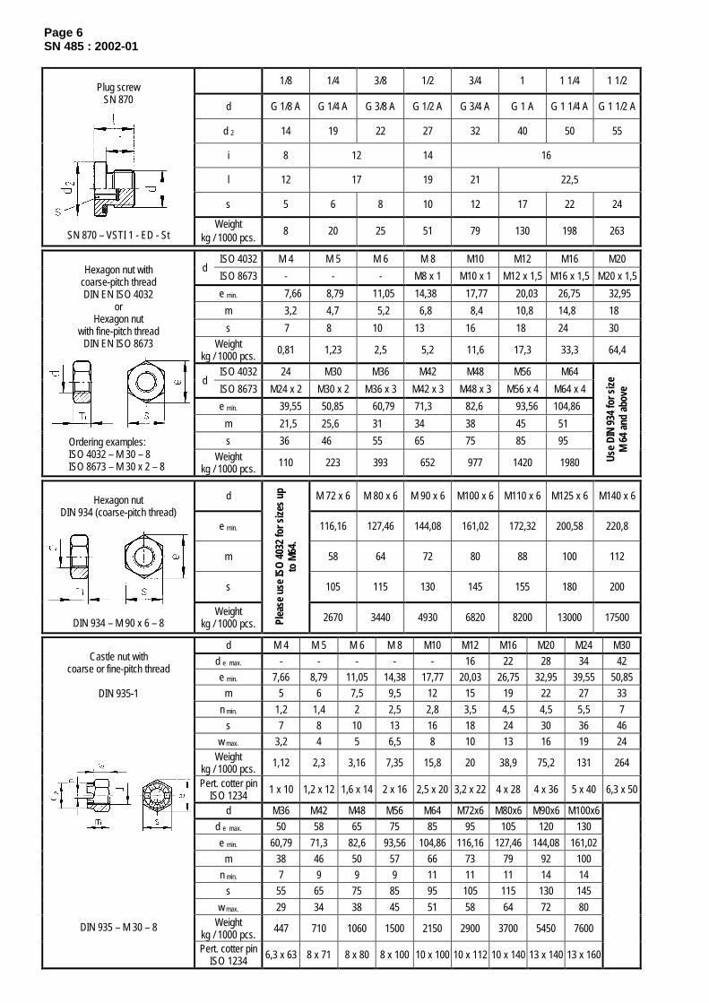
Page 6SN 485 : 2002-01
1/8 1/4 3/8 1/2 3/4 1 1 1/4 1 1/2
d G 1/8 A G 1/4 A G 3/8 A G 1/2 A G 3/4 A G 1 A G 1 1/4 A G 1 1/2 A
d 2 14 19 22 27 32 40 50 55
i 8 12 14 16
l 12 17 19 21 22,5
s 5 6 8 10 12 17 22 24
Plug screwSN 870
SN 870 – VSTI 1 - ED - StWeight
kg / 1000 pcs.8 20 25 51 79 130 198 263
ISO 4032 M 4 M 5 M 6 M 8 M10 M12 M16 M20d
ISO 8673 - - - M8 x 1 M10 x 1 M12 x 1,5 M16 x 1,5 M20 x 1,5
e min. 7,66 8,79 11,05 14,38 17,77 20,03 26,75 32,95
m 3,2 4,7 5,2 6,8 8,4 10,8 14,8 18
s 7 8 10 13 16 18 24 30Weight
kg / 1000 pcs. 0,81 1,23 2,5 5,2 11,6 17,3 33,3 64,4
ISO 4032 24 M30 M36 M42 M48 M56 M64d
ISO 8673 M24 x 2 M30 x 2 M36 x 3 M42 x 3 M48 x 3 M56 x 4 M64 x 4
e min. 39,55 50,85 60,79 71,3 82,6 93,56 104,86
m 21,5 25,6 31 34 38 45 51
s 36 46 55 65 75 85 95
Hexagon nut withcoarse-pitch threadDIN EN ISO 4032
orHexagon nut
with fine-pitch threadDIN EN ISO 8673
Ordering examples: ISO 4032 – M 30 – 8 ISO 8673 – M 30 x 2 – 8
Weightkg / 1000 pcs. 110 223 393 652 977 1420 1980 Us
e DI
N 93
4 fo
r siz
eM
64
and
abov
e
d M 72 x 6 M 80 x 6 M 90 x 6 M100 x 6 M110 x 6 M125 x 6 M140 x 6
e min. 116,16 127,46 144,08 161,02 172,32 200,58 220,8
m 58 64 72 80 88 100 112
s 105 115 130 145 155 180 200
Hexagon nutDIN 934 (coarse-pitch thread)
DIN 934 – M 90 x 6 – 8Weight
kg / 1000 pcs. Plea
se u
se IS
O 4
032
for s
izes
up
to M
64.
2670 3440 4930 6820 8200 13000 17500
d M 4 M 5 M 6 M 8 M10 M12 M16 M20 M24 M30d e max. - - - - - 16 22 28 34 42e min. 7,66 8,79 11,05 14,38 17,77 20,03 26,75 32,95 39,55 50,85
m 5 6 7,5 9,5 12 15 19 22 27 33n min. 1,2 1,4 2 2,5 2,8 3,5 4,5 4,5 5,5 7
s 7 8 10 13 16 18 24 30 36 46w max. 3,2 4 5 6,5 8 10 13 16 19 24
Weightkg / 1000 pcs. 1,12 2,3 3,16 7,35 15,8 20 38,9 75,2 131 264
Pert. cotter pinISO 1234 1 x 10 1,2 x 12 1,6 x 14 2 x 16 2,5 x 20 3,2 x 22 4 x 28 4 x 36 5 x 40 6,3 x 50
d M36 M42 M48 M56 M64 M72x6 M80x6 M90x6 M100x6d e max. 50 58 65 75 85 95 105 120 130e min. 60,79 71,3 82,6 93,56 104,86 116,16 127,46 144,08 161,02
m 38 46 50 57 66 73 79 92 100n min. 7 9 9 9 11 11 11 14 14
s 55 65 75 85 95 105 115 130 145w max. 29 34 38 45 51 58 64 72 80
Weightkg / 1000 pcs. 447 710 1060 1500 2150 2900 3700 5450 7600
Castle nut withcoarse or fine-pitch thread
DIN 935-1
DIN 935 – M 30 – 8
Pert. cotter pinISO 1234 6,3 x 63 8 x 71 8 x 80 8 x 100 10 x 100 10 x 112 10 x 140 13 x 140 13 x 160

Page 7SN 485 : 2002-01
d M 5 M 6 M 8 M10 M12 M16 M20 M24 M 30 M36
e min. 8,79 11,05 14,38 17,77 20,03 26,75 32,95 39,55 50,85 60,79
h max. 5,1 6 8 10 12 16,4 20,3 23,9 30 36
s max. 8 10 13 16 18 24 30 36 46 55
Hexagon nut withclamping section
DIN EN ISO 7042
Ordering example:ISO 7042 – M 30 – 8 Weight
kg / 1000 pcs. 1,23 2,5 5,2 11,6 17,3 33,3 64,4 110 223 393
d 1 M 4 M 5 M 6 M 8 M10 M12 M16 M20 M24
d 2 max. 8 11 13 16 20 23 29 35 44
m max. 4,6 6,5 8 10 12 14 17 21 25
e max. 20 26 33 39 51 65 73 90 110
h max. 10,5 13 17 20 25 33,5 37,5 46,5 56,5
Wing nut,round wing shape
DIN 315
DIN 315 – M 10 – St Weightkg / 1000 pcs. 2 4 8 17 35 60 90 180 260
dAcc. to series 1 M 8 M10 M12 M16 M20 M24 M30 M 36 M 42 M 48
t min. 9,21 10,65 13,15 16,65 20,58 23,58 27,58 35,5 41,5 47,5
g 2 max. *)
Acc. to series 1 - - 6,4 7,3 9,3 10,7 12,7 14 16 18,5
h max. 12 14 16 20 25 30 34 44 52 58
s max. 13 16 18 24 30 36 46 55 65 75
e min. 14,38 17,77 20,03 26,75 32,95 39,55 50,85 60,79 72,02 82,60
Weightkg / 1000 pcs. 9,5 19,3 25,5 48,1 94,1 165 310 577 958 1410
Hexagon cap nut,low shape and
coarse-pitch thread (series 1)
DIN 917
DIN 917 – M 30 – 8 *) > M10 thread undercut g 2 max. (type D, short) acc. to DIN 76-1

January 2002
Mechanical fastenersSetscrews, pins, studs, other screws/bolts
Selection
SN 486
Dimensions in mmd M 4 M 5 M 6 M 8 M10
a max. 1,4 1,6 2 2,5 3
d a max. 4,7 5,7 6,8 9,2 11,2
d k max. 7 8,5 10 13 16
k max. 2,6 3,3 3,9 5 6
l Weight (7,85 kg/dm3) in kg per 1000 pieces
10 1,47 2,55 3,92 7,85
12 1,63 2,8 4,27 8,49 14,6
16 1,95 3,3 4,98 9,77 16,6
20 2,25 3,78 5,69 11 18,6
25 2,64 4,4 6,56 12,6 21,1
30 3,02 5,02 7,45 14,2 23,6
35 3,41 5,62 8,25 15,8 26,1
40 3,8 6,25 9,2 17,4 28,6
45 6,88 10 18,9 31,1
Slotted cheese head screws
DIN EN ISO 1207
Ordering example:ISO 1207 – M10 x 20 – 4.8
50 7,5 10,9 20,6 33,6
d M 4 M 5 M 6 M 8 M10 M12
n 0,6 0,8 1 1,2 1,6 2
t min. 1,12 1,28 1,6 2 2,4 2,8
d t max. 0,4 0,5 1,5 2 2,5 3
l Weight (7,85 kg / dm3 ) in kg per 1000 pieces
6 0,36
8 0,51 0,77 1,04
10 0,66 1,02 1,44 2,65
12 0,82 1,27 1,84 3,25 4,6
16 1,12 1,76 2,64 4,45 6,6 9,5
20 1,42 2,25 3,44 5,65 8,6 11,8
25 2,88 4,44 7,15 11,1 14,7
30 5,44 8,65 13,6 17,6
Slotted setscrewwith cone point
DIN EN 27434
Ordering example:ISO 7434 – M 10 x 30 – 14H
35 10,2 16,1 20,4
d M 4 M 5 M 6 M 8 M10 M12 M16 M20 M24
s 2 2,5 3 4 5 6 8 10 12
t min. 2,5 3 3,5 5 6 8 10 12 15
d t max. - - 1,5 2 2,5 3 4 5 6
l Weight (7,85 kg / dm3 ) in kg per 1000 pieces
12 0,79 1,21 1,74 2,98 4,42
16 1,09 1,69 2,44 4,24 6,42 8,9
20 1,39 2,17 3,14 5,5 8,4 11,7 20,1
25 2,77 4,02 7,09 10,8 15,3 26,6 40,7
30 4,9 8,68 13,3 18,9 33,2 51 68,7
35 5,78 10,3 15,8 22,5 39,7 61,3 83,2
40 11,9 18,3 26,1 46,3 71,6 98,2
45 81,9 113
Hexagon socket setscrewwith cone point
DIN 914
DIN 914 – M 12 x 40 – 45H50 92,2 128
Continued on pages 2 to 6
Th
is c
op
y w
ill n
ot
be
up
dat
ed in
cas
e o
f ch
ang
es!
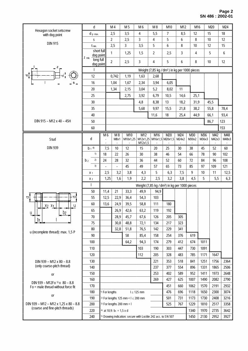
Page 2SN 486 : 2002-01
d M 4 M 5 M 6 M 8 M10 M12 M16 M20 M24
d p max. 2,5 3,5 4 5,5 7 8,5 12 15 18
s 2 2,5 3 4 5 6 8 10 12
t min. 2,5 3 3,5 5 6 8 10 12 15 short fulldog point 1 1,25 1,5 2 2,5 3 4 5 6
z min. long fulldog point
2 2,5 3 4 5 6 8 10 12
l Weight (7,85 kg / dm3 ) in kg per 1000 pieces
12 0,742 1,19 1,63 2,68
16 1,04 1,67 2,34 3,94 6,05
20 1,34 2,15 3,04 5,2 8,02 11
25 2,75 3,92 6,79 10,5 14,6 25,1
30 4,8 8,38 13 18,2 31,9 45,5
35 5,68 9,97 15,5 21,8 38,2 55,8 78,4
40 11,6 18 25,4 44,9 66,1 93,4
50 86,7 123
Hexagon socket setscrewwith dog point
DIN 915
DIN 915 – M12 x 40 – 45H
60 153
dM 6
--
M 8M8x1
-
M10M10x1,25
-
M12M12x1,25M12x1,5
M16M16x1,5
-
M20M20x1,5
-
M24M24x2
-
M30M30x2
-
M36M36x3
-
M42M42x3
-
M48M48x3
-
b 1 4) 7,5 10 12 15 20 25 30 38 45 52 601) 18 22 26 30 38 46 54 66 78 90 1022) 24 28 32 36 44 52 60 72 84 96 108b 23) - - 45 49 57 65 73 85 97 109 121
x 1 2,5 3,2 3,8 4,3 5 6,3 7,5 9 10 11 12,5
x 2 1,25 1,6 1,9 2,2 2,5 3,2 3,8 4,5 5 5,5 6,3
l Weight (7,85 kg / dm3) in kg per 1000 pieces
50 11,4 21 33,3 49,9 94,9
55 12,5 22,9 36,4 54,3 103
60 13,6 24,9 39,5 58,8 111 180
65 26,9 42,6 63,2 119 192
70 28,9 45,7 67,6 126 205 305
75 30,8 48,8 72,1 134 217 323
80 32,8 51,8 76,5 142 229 341
90 58 85,4 158 254 376 619
100 64,2 94,3 174 279 412 674 1011
110 103 190 303 447 730 1091
120 112 205 328 483 785 1171 1647
130 221 353 518 841 1251 1756 2364
140 237 377 554 896 1331 1865 2506
150 253 402 589 952 1411 1973 2648
160 269 427 625 1007 1490 2082 2790
170 451 660 1062 1570 2191 2932
180 1) For lengths l ≤ 125 mm 476 696 1118 1650 2300 3074
190 2) For lengths 125 mm < l ≤ 200 mm 501 731 1173 1730 2408 3216
200 3) For lengths 200 mm < l 525 767 1229 1810 2517 3358
220 4) at 10.9: b1 = 1,5 x d 1340 1970 2735 3642
Stud
DIN 939
u (incomplete thread): max. 1,5 P
DIN 939 – M12 x 80 – 8.8(only coarse-pitch thread)
or
DIN 939 – M12Fo 5) x 80 – 8.8Fo = male thread without force fit
or
DIN 939 – M12 – M12 x 1,25 x 80 – 8.8(coarse and fine-pitch threads)
240 5) Drawing indication: secure with Loctite 242 acc. to SN 507 1450 2130 2952 3927

Page 3SN 486 : 2002-01
d M 6 M 8 M10 M12 M16 M20 M24 M30 M36 M42 M48
l g max. 10 13 16 19 25 31 37 43 55 54 72
k 4,5 5,5 7 8 10,5 13 15 19 23 26 30
n 6 8 10 12 16 20 24 30 36 42 48
m 16 18 21 26 30 36 43 54 66 80 88
l Weight (7,85 kg / dm3) in kg per 1000 pieces
50 14,3 24,2 40,6 62,3 117
60 16,5 28,2 46,8 71,1 130 220
70 32,2 53 78,9 145 240 377
80 36,2 59,2 88,7 161 262 407
90 65,4 97,6 177 287 437 727
100 71,6 106 193 302 467 773
120 124 225 351 538 874 1380
140 257 401 618 985 1530 2220
T-head boltwith square neck
DIN 186
DIN 186 – AM 20 x 100 – 5.6Type A with shank
DIN 186 – BM 20 x 100 – 5.6Type B with long thread
160 289 450 689 1090 1690 2420 3300
d 1 M 8 M10 M12 M16 M20 M24 M30 M36 M42 M48 M56P 1,25 1,5 1,75 2 2,5 3 3,5 4 4,5 5 5,5
a max. 25 32 40 55 65 80 100 120 140 160 185
b P20+ 20 25 30 40 50 60 75 90 105 120 140
c max. 55 55 70 90 110 130 160 190 230 260 290l Weight (7,85 kg / dm3) in kg per 100 pieces
160 8 13,8 20,5 39,2200 9,5 16,3 24,1 45,4 76250 19,4 28,5 53,5 88 136320 34,7 64,5 106 160 270400 77,2 126 189 314 477500 93 150 225 370 557 798630 182 270 441 660 939 1277800 224 331 536 796 1124 1517 2135
Masonry / foundation bolt
DIN 529, type A
DIN 529 – AM 20 x 500 – 5.61000 401 648 955 1344 1802 2525
Selection of bolt materials and possible treatments for surface refinement
Bolt material as in DIN EN ISO 898-1
3.6 R m = 300 N/mm 2, R eL = 180 N/mm2
4.6 R m = 400 N/mm 2, R eL = 240 N/mm2
4.8 R m = 400 N/mm 2, R eL = 320 N/mm2
5.6 R m = 500 N/mm 2, R eL = 300 N/mm2
5.8 R m = 500 N/mm 2, R eL = 400 N/mm2
8.8 R m = 800 N/mm 2, R p0,2 = 640 N/mm2
10.9 R m = 1000 N/mm 2, R p0,2 = 900 N/mm2
12.9 R m = 1200 N/mm 2, R p0,2 = 1080 N/mm2
14H22H
Surface refinement as in DIN EN ISO 4042
A2E zinc coat applied by electroplating (A), layer thickness 5 µm (2), degree of lustre: bright, no colour (E).tZn zinc coat applied by hot galvanizing, layer thickness 40 µm.
SMS Demag determination
OV5 Surface refinement, layer thickness min. 5 µm, but not above permissible thread tolerance on the basis ofzinc, nickel and/or chromium (DNC, DAC, Delta-Tone), salt spray testing as in DIN 50021, min. 240 h.
Stainless and acid-resistant steelsA2–70 R m = 700 N/mm 2, austenitic steel, strain hardened 1.4541A4–70 R m = 700 N/mm 2, austenitic steel, strain hardened 1.4571C3 R m = 800 N/mm 2, martensitic steel, quenched and tempered 1.4057
see DIN EN ISO 898-5

surfaced
Page 4SN 486 : 2002-01
d 1 M 8 2) M10 2) M12 2) M16 2) M20 2) M24 2) M30 2) M36 2) M42 2) M48 2) M56 M64
d 2 20 25 30 35 40 50 65 75 85 100 110 120
d 3 36 45 54 63 72 90 108 126 144 166 184 206
d 4 20 25 30 35 40 50 60 70 80 90 100 110
h 36 45 53 62 71 90 109 128 147 168 187 208
l 13 17 20,5 27 30 36 45 54 63 68 78 90
d 5 24 30 36 40 46 57 71 82 92 112 118 132
b 16 20 23 30 33 39 48 57 66 71 81 93SMS Demag-
specificdetermination t 24 29 33 41 46 54 65 76 87 94 107 121
Lifting eye bolt
DIN 580
DIN 580 – M 20 – C 15Lifting eye nut see DIN 582
Weightkg / piece
0,06 0,11 0,18 0,28 0,45 0,74 1,66 2,65 4,03 6,38 8,8 12,4
Max. permissible load from suspended part, in kg
using one bolt 140 230 340 700 1200 1800 3600 5100 7000 8600 11500 16000Direction of pull
using two bolts,in total
95 170 240 500 830 1270 2600 3700 5000 6100 8300 11000
1) judging from experience the indication of a permissible angle deviation between tap hole and supporting face is not required, provided both are made in one set-up of the same workpiece. 2) available from stock
Type d 1d 3h12
b± 0,1
emin.
hmax.
kj16
l- 0,5
sh13
Weightkg / 1000 pcs.
G 1/4 A 16 6,5 19,3 17,6 4,5 5,5 17 18G 1/4 AAG 3/8 A
22 8,5 25 23,1 5,5 7,5 22 34
Button-head lubricating nipple
DIN 3404
DIN 3404 - A G 1/4 A – 22 – St-A3F
Minimum space requirement for
grease gun connection socket wrench
d 1 m6 1) 6 8 10 12 16 20 25 30 40 50c 1 ≈ 0,8 1 1,2 1,6 2 2,5 3 4 5 6,3c 2 ≈ 1,2 1,6 2 2,5 3 3,5 4 5 6,3 8
l Weight (7,85 kg / dm3) in kg per 1000 pieces16 2,7920 3,67 6,424 4,55 7,98 12,228 5,43 9,56 14,7 19,532 6,31 10,3 17,2 23,1 39,440 8,07 13,5 22,2 30,3 52 80,250 10,3 17,5 28,4 39,9 67,8 105 15060 12,5 21,5 34,6 49,5 82,8 130 188 26570 25,5 40,8 59,1 98,5 155 226 32080 29,5 47 68,7 115 180 264 376 68090 53,2 78,3 131 205 303 431 754
100 59,4 87,9 147 230 341 487 852 1360120 107 180 280 418 598 1050 1720
Parallel pin with internal thread,unhardened
DIN EN ISO 8733
c 2 c 1
l
Ordering example: ISO 8733 – 6 x 30 – St
1) other tolerances upon agreement.

Page 5SN 486 : 2002-01
d 1 m6 1) 6 8 10 12 16 20 25 30 40 50
a ≈ 0,8 1 1,2 1,6 2 2,5 3 4 5 6,3c 2,1 2,6 3 3,8 4,6 6 6 7 8 10l Weight (7,85 kg / dm3) in kg per 1000 pieces16 2,7920 3,67 6,424 4,55 7,98 12,228 5,43 9,56 14,7 19,532 6,31 10,3 17,2 23,1 39,440 8,07 13,5 22,2 30,3 52 80,250 10,3 17,5 28,4 39,9 67,8 105 15060 12,5 21,5 34,6 49,5 82,8 130 188 26570 25,5 40,8 59,1 98,5 155 226 32080 29,5 47 68,7 115 180 264 376 68090 53,2 78,3 131 205 303 431 754
100 59,4 87,9 147 230 341 487 852 1360120 107 180 280 418 598 1050 1720
Parallel pinwith internal thread, hardened
DIN EN ISO 8735
Ordering example:ISO 8735 – 6 x 30 – A – St
1) other tolerances upon agreement.
d h10 1) 2 3 4 5 6 8 10 12 16 20 25 30 40 50
l Weight (7,85 kg / dm3) in kg per 1000 pieces
32 1,06 2,17 3,68 5,58 7,88 13,7 21 29,9
35 1,19 2,42 4,08 6,18 8,7 15 23,1 32,9
40 2,85 4,77 7,19 10,1 17,4 26,7 37,9 66,3
50 6,24 9,33 13 22,3 34 48,2 83,9 130 200
60 11,6 16,1 27,4 41,6 58,7 102 157 242 346 610
70 19,4 32,7 49,4 69,6 120 185 285 407 715 1109
80 22,8 38,2 57,5 80,8 139 213 328 468 821 1273
90 26,4 44 65,9 92,3 158 242 372 530 928 1438
100 49,9 74,6 104 178 272 417 592 1036 1604
120 62,6 92,8 129 219 333 508 720 1256 1939
140 112 155 261 395 602 851 1479 2280
Taper pin,unhardened
DIN EN 22339
Ordering example: ISO 2339 – A - 6 x 30 – St
Note: Type A (ground):
surface roughness R a = 0,8 µm Type B (turned)
surface roughness R a = 3,2 µm 1) other tolerances upon agreement.
d 1 h10 1) 6 8 10 12 16 20 25 30 40 50
l Weight (7,85 kg / dm3) in kg per 1000 pieces
40 9,13 15,5 23,2 30,3 51,1 78
45 10,5 17,9 26,8 35,4 59,9 91
55 13,5 22,9 34,2 45,8 77,7 118 165
60 15,1 25,5 38,1 51,1 86,8 132 186 246
80 36,3 54 73,2 124 188 272 368 708
90 62,4 84,7 143 217 316 430 815
100 71,1 96,4 163 247 361 492 923 1396
120 121 204 308 452 620 1143 1731
140 246 370 546 751 1366 2072
160 291 435 642 885 1594 2419
200 572 843 1163 2062 3126
Taper pinwith internal thread, unhardened
DIN EN 28736
Ordering example: ISO 8736 – A - 6 x 30 – St
Note: Type A (ground):
surface roughness R a = 0,8 µm Type B (turned):
surface roughness R a = 3,2 µm 1) other tolerances upon agreement.
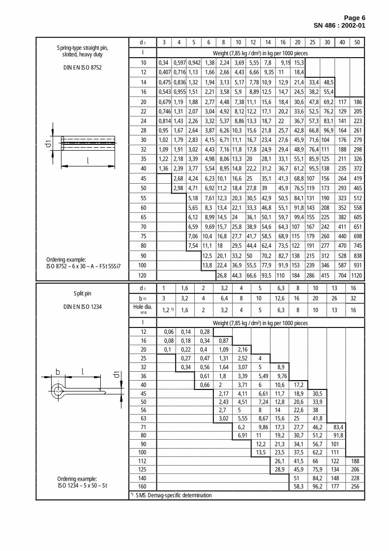
Page 6SN 486 : 2002-01
d 1 3 4 5 6 8 10 12 14 16 20 25 30 40 50
l Weight (7,85 kg / dm3) in kg per 1000 pieces
10 0,34 0,597 0,942 1,38 2,24 3,69 5,55 7,8 9,19 15,3
12 0,407 0,716 1,13 1,66 2,66 4,43 6,66 9,35 11 18,4
14 0,475 0,836 1,32 1,94 3,13 5,17 7,78 10,9 12,9 21,4 33,4 48,5
16 0,543 0,955 1,51 2,21 3,58 5,9 8,89 12,5 14,7 24,5 38,2 55,4
20 0,679 1,19 1,88 2,77 4,48 7,38 11,1 15,6 18,4 30,6 47,8 69,2 117 186
22 0,746 1,31 2,07 3,04 4,92 8,12 12,2 17,1 20,2 33,6 52,5 76,2 129 205
24 0,814 1,43 2,26 3,32 5,37 8,86 13,3 18,7 22 36,7 57,3 83,1 141 223
28 0,95 1,67 2,64 3,87 6,26 10,3 15,6 21,8 25,7 42,8 66,8 96,9 164 261
30 1,02 1,79 2,83 4,15 6,71 11,1 16,7 23,4 27,6 45,9 71,6 104 176 279
32 1,09 1,91 3,02 4,43 7,16 11,8 17,8 24,9 29,4 48,9 76,4 111 188 298
35 1,22 2,18 3,39 4,98 8,06 13,3 20 28,1 33,1 55,1 85,9 125 211 326
40 1,36 2,39 3,77 5,54 8,95 14,8 22,2 31,2 36,7 61,2 95,5 138 235 372
45 2,68 4,24 6,23 10,1 16,6 25 35,1 41,3 68,8 107 156 264 419
50 2,98 4,71 6,92 11,2 18,4 27,8 39 45,9 76,5 119 173 293 465
55 5,18 7,61 12,3 20,3 30,5 42,9 50,5 84,1 131 190 323 512
60 5,65 8,3 13,4 22,1 33,3 46,8 55,1 91,8 143 208 352 558
65 6,12 8,99 14,5 24 36,1 50,1 59,7 99,4 155 225 382 605
70 6,59 9,69 15,7 25,8 38,9 54,6 64,3 107 167 242 411 651
75 7,06 10,4 16,8 27,7 41,7 58,5 68,9 115 179 260 440 698
80 7,54 11,1 18 29,5 44,4 62,4 73,5 122 191 277 470 745
90 12,5 20,1 33,2 50 70,2 82,7 138 215 312 528 838
100 13,8 22,4 36,9 55,5 77,9 91,9 153 239 346 587 931
Spring-type straight pin,slotted, heavy duty
DIN EN ISO 8752
Ordering example:ISO 8752 – 6 x 30 – A – FSt 55Si7
120 26,8 44,3 66,6 93,5 110 184 286 415 704 1120
d 1 1 1,6 2 3,2 4 5 6,3 8 10 13 16
b ≈ 3 3,2 4 6,4 8 10 12,6 16 20 26 32Hole dia.
H14 1,2 1) 1,6 2 3,2 4 5 6,3 8 10 13 16
l Weight (7,85 kg / dm3) in kg per 1000 pieces12 0,06 0,14 0,2816 0,08 0,18 0,34 0,8720 0,1 0,22 0,4 1,09 2,1625 0,27 0,47 1,31 2,52 432 0,34 0,56 1,64 3,07 5 8,936 0,61 1,8 3,39 5,49 9,7640 0,66 2 3,71 6 10,6 17,245 2,17 4,11 6,61 11,7 18,9 30,550 2,43 4,51 7,24 12,8 20,6 33,956 2,7 5 8 14 22,6 3863 3,02 5,55 8,67 15,6 25 41,871 6,2 9,86 17,3 27,7 46,2 83,480 6,91 11 19,2 30,7 51,2 91,890 12,2 21,3 34,1 56,7 101
100 13,5 23,5 37,5 62,2 111112 26,1 41,5 66 122 188125 28,9 45,9 75,9 134 206140 51 84,2 148 228160 58,3 96,2 177 256
Split pin
DIN EN ISO 1234
Ordering example:ISO 1234 – 5 x 50 – St
*) SMS Demag-specific determination

January 2002
Mechanical fastenersWashers and retaining elements
Selection
SN 487
Dimensions in mmScrew dia.= nom. size 4 5 6 8 10 12 16 20 24 30
d 1 H14 4,3 5,3 6,4 8,4 10,5 13 17 21 25,6 31,6
d 2 H14 7 9 10 13 16 18 24 30 36 45
s 0,5 1 1 1,2 1,5 1,5 2 2 2,5 2,5
Weight (7,85 kg / dm3) in kg per 1000 pieces
Lock washer
SN 778
SN 778 – 6 0,09 0,29 0,33 0,67 1,26 1,34 3,36 5,38 9,48 15,2
for screws M20 M24 M30 M36 M42 M48 M56 M64 M72 M80 M90 M100 M110 M125 M140 M160
d 1 =nom. size 21 25 31 37 43 50 58 66 74 82 93 104 114 129 144 164
35 45 55 65 75 90 100 110 120 140 160 175 185 220 240 270d 2
± 1 ± 2 ± 5
d 3 23 27 34 40 46 53 64 72 80 88 98 108 118 133 148 168
s 4,5 5 6 7 8 10 11 12 14 16 22Tensilestrength
R mmin. 900 N/mm² min. 700 N/mm²
Weight (7,85 kg / dm3) in kg per 1000 pieces
Washer for prestressed high-strengthscrew connection
SN 808
SN 808 – 21 – St26 40 80 129 209 368 520 601 751 1111 1670 1950 2090 4300 5000 6240
for screws M 4 M 5 M 6 M 8 M10 M12 M16 M20
nom. size 4 5 6 8 10 12 16 20
d 1 4,3 5,3 6,4 8,4 10,5 13 17 21
d 2 9 10 12 16 20 24 30 37
s 0,8 1 1,6 1,6 2 2,5 3 3
Weight (7,85 kg / dm3) in kg per 1000 pieces
0,308 0,443 1,02 1,83 3,57 6,27 11,3 17,2
for screws M24 M30 M36 M42 M48 M56 M64 -
nom. size 24 30 36 42 48 56 64 -
d 1 25 31 37 45 52 62 70 -
d 2 44 56 66 78 92 105 115 -
s 4 4 5 8 8 10 10 -
Weight (7,85 kg / dm3) in kg per 1000 pieces
Plain washerNormal series
DIN EN ISO 7089 up to M64DIN 125 above M64
Ordering example:ISO 7089 – 16 – 200HV
32,3 53,6 92,1 209 284 472 547 -
Forbolt dia. 8 10 12 14 16 18 20 22 25 28 30 32
33d 1 =
nom. size 9 11 13 15 17 19 21 23 26 29 31 34
d 2 16 20 25 28 28 30 32 34 40 42 45 50s 2 2,5 3 3 3 4 4 4 4 5 5 5
Weight (7,85 kg / dm3) in kg per 1000 pieces2,16 4,3 8,43 10,3 9,16 13,3 14,4 15,5 22,8 28,5 32,8 43,5
For bolt dia. 3536 40 45 50 55 60 65 70 75 80 90 100
d 1 =nom. size 37 41 46 51 56 62 68 72 78 82 92 102
d 2 52 58 62 68 75 80 90 95 100 110 115 125s 6 6 7 8 9 9 9 10 10 12 12 14
Weight (7,85 kg / dm3) in kg per 1000 pieces
Washer,coarse type, for bolts
DIN 1441
DIN 1441 – 19 St49,4 59,2 70,6 94,7 138 142 193 237 241 298 352 451
Continued on pages 2 and 3
Th
is c
op
y w
ill n
ot
be
up
dat
ed in
cas
e o
f ch
ang
es!
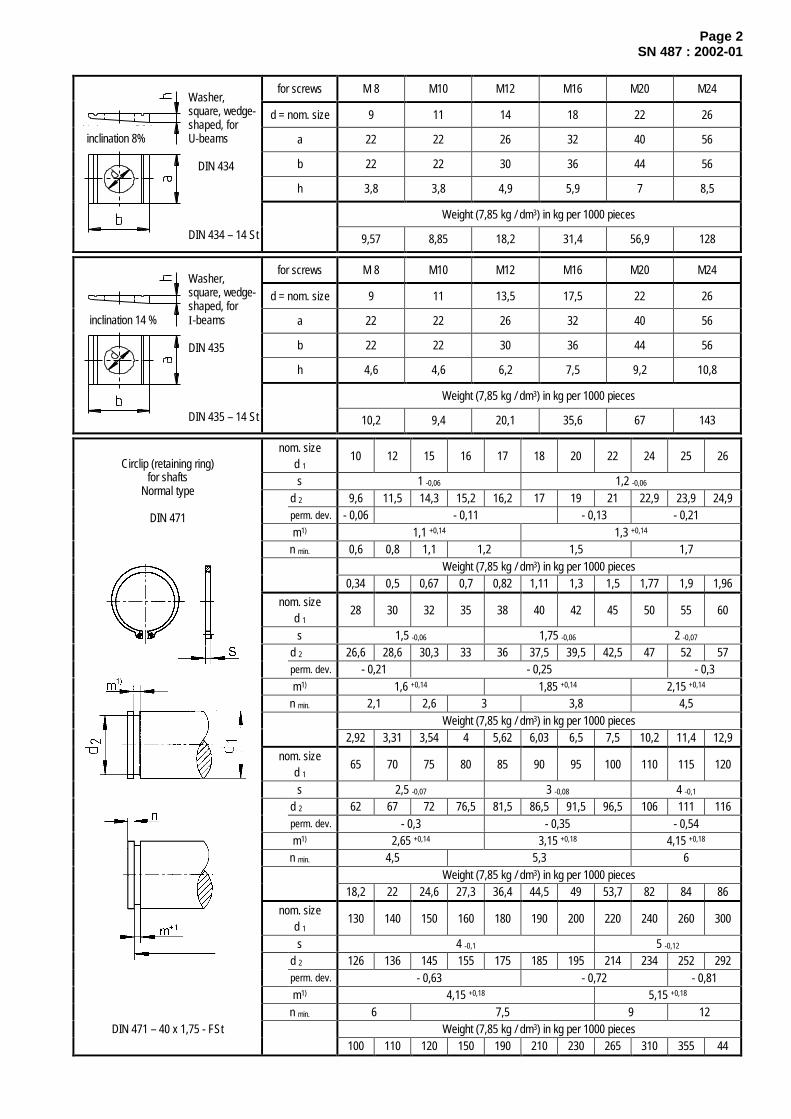
Page 2SN 487 : 2002-01
for screws M 8 M10 M12 M16 M20 M24
d = nom. size 9 11 14 18 22 26
a 22 22 26 32 40 56
b 22 22 30 36 44 56
h 3,8 3,8 4,9 5,9 7 8,5
Weight (7,85 kg / dm3) in kg per 1000 pieces
Washer,square, wedge-shaped, for
inclination 8% U-beams
DIN 434
DIN 434 – 14 St 9,57 8,85 18,2 31,4 56,9 128
for screws M 8 M10 M12 M16 M20 M24
d = nom. size 9 11 13,5 17,5 22 26
a 22 22 26 32 40 56
b 22 22 30 36 44 56
h 4,6 4,6 6,2 7,5 9,2 10,8
Weight (7,85 kg / dm3) in kg per 1000 pieces
Washer,square, wedge-shaped, for
inclination 14 % I-beams
DIN 435
DIN 435 – 14 St 10,2 9,4 20,1 35,6 67 143
nom. sized 1
10 12 15 16 17 18 20 22 24 25 26
s 1 -0,06 1,2 -0,06
d 2 9,6 11,5 14,3 15,2 16,2 17 19 21 22,9 23,9 24,9perm. dev. - 0,06 - 0,11 - 0,13 - 0,21m1) 1,1 +0,14 1,3 +0,14
n min. 0,6 0,8 1,1 1,2 1,5 1,7Weight (7,85 kg / dm3) in kg per 1000 pieces
0,34 0,5 0,67 0,7 0,82 1,11 1,3 1,5 1,77 1,9 1,96
nom. sized 1
28 30 32 35 38 40 42 45 50 55 60
s 1,5 -0,06 1,75 -0,06 2 -0,07
d 2 26,6 28,6 30,3 33 36 37,5 39,5 42,5 47 52 57perm. dev. - 0,21 - 0,25 - 0,3m1) 1,6 +0,14 1,85 +0,14 2,15 +0,14
n min. 2,1 2,6 3 3,8 4,5Weight (7,85 kg / dm3) in kg per 1000 pieces
2,92 3,31 3,54 4 5,62 6,03 6,5 7,5 10,2 11,4 12,9
nom. sized 1
65 70 75 80 85 90 95 100 110 115 120
s 2,5 -0,07 3 -0,08 4 -0,1
d 2 62 67 72 76,5 81,5 86,5 91,5 96,5 106 111 116perm. dev. - 0,3 - 0,35 - 0,54m1) 2,65 +0,14 3,15 +0,18 4,15 +0,18
n min. 4,5 5,3 6Weight (7,85 kg / dm3) in kg per 1000 pieces
18,2 22 24,6 27,3 36,4 44,5 49 53,7 82 84 86
nom. sized 1
130 140 150 160 180 190 200 220 240 260 300
s 4 -0,1 5 -0,12
d 2 126 136 145 155 175 185 195 214 234 252 292perm. dev. - 0,63 - 0,72 - 0,81m1) 4,15 +0,18 5,15 +0,18
n min. 6 7,5 9 12Weight (7,85 kg / dm3) in kg per 1000 pieces
Circlip (retaining ring)for shafts
Normal type
DIN 471
DIN 471 – 40 x 1,75 - FSt100 110 120 150 190 210 230 265 310 355 44

Page 3SN 487 : 2002-01
nom. sized 1
25 28 32 35 40 42 45 47 50 52 55
s 1,2 -0,06 1,5 -0,06 1,75 -0,06 2 -0,07
d 2 26,2 29,4 33,7 37 42,5 44,5 47,5 49,5 53 55 58
perm. dev. + 0,21 + 0,25 + 0,3
m1) 1,3 +,14 1,6 +0,14 1,85 +0,14 2,15 +0,14
n min. 1,8 2,1 2,6 3 3,8 4,5
Weight (7,85 kg / dm3) in kg per 1000 pieces
1,5 1,8 2,21 3,54 4,7 5,4 6 6,1 7,3 8,2 8,3
nom. sized 1
60 62 72 80 85 90 95 100 110 115 120
s 2 –0,07 2,5 -0,07 3 -0,08 4 -0,1
d 2 63 65 75 83,5 88,5 93,5 98,5 103,5 114 119 124
perm. dev. + 0,30 + 0,35 + 0,54 + 0,63
m1) 2,15 +0,14 2,65 +0,14 3,15 +0,18 4,15 +0,18
n min. 4,5 5,3 6
Weight (7,85 kg / dm3) in kg per 1000 pieces
11,1 11,2 18,1 22 25,3 31 35 38 64,5 74,5 77
nom. sized 1
130 140 145 150 160 180 200 210 240 280 300
s 4 -0,1 5 -0,12
d 2 134 144 149 155 165 185 205 216 246 288 308
perm. dev. + 0,63 + 0,72 + 0,81
m1) 4,15 +0,18 5,15 +0,18
n min. 6 7,5 9 12
Weight (7,85 kg / dm3) in kg per 1000 pieces
Circlip (retaining ring)for bores
Normal type
DIN 472
DIN 472 – 50 x 2 – FSt82 87,5 93 105 110 165 195 270 345 400 435
1) As a rule, tolerance range H13 applies to the groove width m. In case of one-side force transmission the grooves canbe widened and/or bevelled towards the force-relieved side. The width of the groove has no effect on the load bearingcapacity of the retaining-ring joint.

January 2002
Mechanical fastenersLock nuts, locking plates
Selection from DIN standardsSN 489
Dimensions in mmShort
designationd 1 d 2
h13
d 3h13
hh13
bJS14
tH17 *)
Weightkg / piece
KM 5 M 25x1,5 38 32 0,025
KM 6 M 30x1,5 45 387
0,043
KM 7 M 35x1,5 52 44 8
5 2
0,053
KM 8 M 40x1,5 58 50 9 0,085
KM 9 M 45x1,5 65 56 10 0,119
KM 10 M 50x1,5 70 61
6 2,5
0,148
KM 11 M 55x2 75 67 0,158
KM 12 M 60x2 80 73
11
0,174
KM 13 M 65x2 85 79
7 3
0,203
KM 14 M 70x2 92 8512
0,242
KM 16 M 80x2 105 95 15 0,397
KM 17 M 85x2 110 102
8 3,5
0,451
KM 18 M 90x2 120 10816
0,556
KM 19 M 95x2 125 113 17 0,658
KM 20 M100x2 130 120 18
10 4
0,698
KM 22 M110x2 145 133 0,965
KM 23 M115x2 150 13719
1,01
KM 24 M120x2 155 138 20 1,08
KM 25 M125x2 160 148 1,19
KM 26 M130x2 165 14921
12 5
1,25
KM 27 M135x2 175 1,55
KM 28 M140x2 180160 22
1,56
KM 30 M150x2 195 171 24
14 6
2,03
KM 32 M160x3 210 182 25 2,59
KM 34 M170x3 220 193 2616 7
2,8
KM 36 M180x3 230 203 27 3,07
KM 38 M190x3 240 214 2818 8
3,39
Locknut
DIN 981
DIN 981 – KM 17 - St *) Applies only to t > 3 mm. For t up to 2 mm: mm; t above 2 up to 3 mm: mm
Continued on page 2
0- 0,5
+ 0,9 0

Page 2SN 489 : 2002-01
SlotShortdesig-nation
d 1
C11
d 2
js17
d 3
h13
e
a15
f
C11
s
min.b 3H11 t
Weightkg/piece
Associatedlocknut acc. to
DIN 981-...
MB 5 25 42 32 23 3 0,006 KM 5
MB 6 30 49 385
27,56
0,008 KM 6
MB 7 35 57 44 32,5 0,01 KM 7
MB 8 40 62 50 37,5 0,012 KM 8
MB 9 45 69 56 42,5 0,015 KM 9
MB 10 50 74 61
6
47,5
1,25
7
0,016 KM 10
MB 11 55 81 67 52,5 0,02 KM 11
MB 12 60 86 73 57,5 0,025 KM 12
MB 13 65 92 79 62,5
4
0,029 KM 13
MB 14 70 98 85
8
66,5
1,5 9
0,033 KM 14
MB 16 80 112 95 76,5 0,046 KM 16
MB 17 85 119 102 81,5 0,052 KM 17
MB 18 90 126 108 86,5 0,062 KM 18
MB 19 95 133 113
10
91,5
11
0,067 KM 19
MB 20 100 142 120 96,5
5
0,077 KM 20
MB 22 110 154 133 105,5
1,75
0,094 KM 22
MB 23 115 159 137
12
110,5
146
0,108 KM 23
MB 24 120 164 138 115 0,105 KM 24
MB 25 125 170 148 120 0,118 KM 25
MB 26 130 175 149 125 0,113 KM 26
MB 27 135 185 160
14
130
16
0,144 KM 27
MB 28 140 192 160 135 0,142 KM 28
MB 30 150 205 17116
145
2
18
7
0,155 KM 30
MB 32 160 217 182 154 0,229 KM 32
MB 34 170 232 19318
16420
0,247 KM 34
MB 36 180 242 203 174 0,268 KM 36
Nut lock(locking plate)
DIN 5406
DIN 5406 – MB 17 - St
MB 38 190 252 21420
184
2,5
22
8
0,278 KM 38
The locking plate must not be within the clearance cut.
If necessary, use spacer ring,or secure using a locknut without tab washer,or glue using glue as in SN 507 – Loctite 675.
b 3
+ 0,5 0

January 2002
Fitting keys, taper keys
Selection from DIN standardsSN 708
Dimensions in mmParallel keys as in DIN 6885Type B1) Type D1)2) Type F3)
Surfaces for keywayswithout drawing indication(see SN 200).
Example of designation: Parallel key DIN 6885 – B 12 x 8 x 80 – C45+C
above 10 12 17 22 30 38 44 50 58 65 75 85 95 110 130 150 170 200 230 260 290 330 380 440for shaft dia. d 1 up to 12 17 22 30 38 44 50 58 65 75 85 95 110 130 150 170 200 230 260 290 330 380 440 500d 2 = d 1 + 4 5 6 8 8 8 9 11 11 12 14 14 16 18 21 23 26 28 32 32 36 40 45 50
Width b1 h9 4 5 6 8 10 12 14 16 18 20 22 25 28 32 36 40 45 50 56 63 70 80 90 100Height h h11 4 5 6 7 8 8 9 10 11 12 14 14 16 18 20 22 25 28 32 32 36 40 45 50Length l Determined and indicated on the basis of design
r 1 0,16 0,25 0,4 0,6 1 1,6 2,5Bevel orcurve perm.
deviation +0,09 + 0,15 + 0,2 + 0,4 + 0,5
Thread d 5 M4 M5 M6 M8 M10 M12 M16 M20d 3 4,5 5,5 6,6 9 11 13,5 17,5 22d 4 8 10 11 15 18 20 26 33Countersinkt 5 3,2 4,1 4,8 6 7,3 8,3 11,5 13,5
Para
llel k
ey
Material C45+C (C 45 K)t 1 2,5 3 3,5 4 5 5 5,5 6 7 7,5 9 9 10 11 12 13 15 17 20 20 22 25 28 31
perm. dev. + 0,1 + 0,2 + 0,3Width b 1 P9
r 2 0,16 0,25 0,4 0,6 1 1,6 2,5Curveperm. dev. - 0,08 - 0,09 - 0,15 - 0,2 - 0,3 - 0,4 - 0,5
Shaf
t key
seat
Position tolerance 0,06 0,08 0,1Depth t 2 1,8 2,3 2,8 3,3 3,3 3,3 3,8 4,3 4,4 4,9 5,4 5,4 6,4 7,4 8,4 9,4 10,4 11,4 12,4 12,4 14,4 15,4 17,4 19,5
perm. dev. + 0,1 + 0,2 + 0,3Width Parallel key – b 1 P9 , sliding key – b 1 F7 5)
r 2 0,16 0,25 0,4 0,6 1 1,6 2,5Curveperm. dev. - 0,08 - 0,09 - 0,15 - 0,2 - 0,3 - 0,4 - 0,5Hu
b ke
yway
Position tolerance 0,06 0,08 0,1d 6 - M4 M5 M6 M8 M10 M12 M16 M20t 3 - 6 6 6 7 6 8 9 9 11 15 13 15 12 13 13 17 18 20 20Threadt 4 - 10 11 11 13 12 14 16 17 19 24 22 24 21 22 22 27 28 32 32
ISO 1207 – M ....x.... – 4.8 DIN 7984 – M ....x.... – 8.8d 6 x - 10 10 10 12 12 16 16 16 20 25 25 30 30 35 35 40 40 50 50Fa
sten
ing
ScrewTo be stated separately in the bill of materials
For footnotes see page 2 Continued on page 2
functional dimension
Example:
Example:
shaft hub
Th
is c
op
y w
ill n
ot
be
up
dat
ed in
cas
e o
f ch
ang
es!

Page 2SN 708 : 2002-01
Taper key with gib head to DIN 6887
shaft
hub
Example of designation: DIN 6887 - 12 x 8 x 80 – C45+C
Removal of sharp edges on all sides
above 10 12 17 22 30 38 44 50 58 65 75 85 95 110 130 150 170 200 230 260 290 330 380 440for shaft dia. d 1
up to 12 17 22 30 38 44 50 58 65 75 85 95 110 130 150 170 200 230 260 290 330 380 440 500d 2 = d 1 + 4 5 6 8 8 8 9 11 11 12 14 14 16 18 21 23 26 28 32 32 36 40 45 50
Width b1 h9 4 5 6 8 10 12 14 16 18 20 22 25 28 32 36 40 45 50 56 63 70 80 90 100Height h h11 4 5 6 7 8 8 9 10 11 12 14 14 16 18 20 22 25 28 32 32 36 40 45 50Length l Determined and indicated on the basis of design
r 1 0,16 0,25 0,4 0,6 1 1,6 2,5Bevel orcurve perm. dev. +0,09 + 0,15 + 0,2 + 0,2 + 0,2 + 0,4 + 0,5Thread d 5 M4 M5 M6 M8 M10 M12 M16 M20
d 3 4,5 5,5 6,6 9 11 13,5 17,5 22d 4 8 10 11 15 18 20 26 33Countersinkt 5 3,2 4,1 4,8 6 7,3 8,3 11,5 13,5
Key
Material C45+C (C 45 K) or St 60-1t 1 -2,5 3 3,5 4 5 5 5,5 6 7 7,5 9 9 10 11 12 13 15 17 20 20 22 25 28 31
Depthperm. dev. + 0,1 + 0,2 + 0,3
Width for taper key b 1 D10
r 2 0,16 0,25 0,4 0,6 1 1,6 2,5
Shaf
t key
seat
Curveperm. dev. - 0,08 - 0,09 - 0,15 - 0,2 - 0,3 - 0,4 - 0,5
Depth t 2 1,8 2,3 2,8 3,3 3,3 3,3 3,8 4,3 4,4 4,9 5,4 5,4 6,4 7,4 8,4 9,4 10,4 11,4 12,4 12,4 14,4 15,4 17,4 19,5perm. dev. + 0,1 + 0,2 + 0,3
Width b 1 D10
r 2 0,16 0,25 0,4 0,6 1 1,6 2,5
Hub
keyw
ay
Curveperm. dev. - 0,08 - 0,09 - 0,15 - 0,2 - 0,3 - 0,4 - 0,5
1) When fitting keys of types B and D with hole for jack screw (s) are used, this has to be expressly stated in the order.Example of designation: DIN 6885 – BS 12 x 8 x 80 – C45+C
2) Use type D if l : b1 < 43) Use type F if l : b1 > 44) The keyway length depends upon the design and must be stated in the drawing.
The keyway length of the key types B, D and F is defined as the useful load-bearing length (functional dimension) withoutcurves.
5) H8 for secondary applications (e.g. support strip for pillow block) without transmission of moments.
Example: Example:
inclination

January 2002
Axle stop plate SN 370
Dimensions in mm DIN 15058 expandedAxle stop plate as in DIN 15058
ArrangementParallel to or against the loading directionof the axle
The axle stop plates must be arranged in such a way thatthe fastening screws are not stressed by the axle load.
Designation of an axle stop plate of width a = 40 mm and thickness b = 10 mm1) in S235JRG2:
Axle stop plate DIN 15058 – 40 x 10 – S235JRG2For axle diameter d 2 Pertaining 2)
Range Bolt orbush dia.
a b c 1 c 2 d 1 1) d 3min.
n f g h hexagon headbolt
ISO 4017-...8.8
lock washerSN 778-...
Weightkg / piece
18 320 16
22 1724 18
above 16 up to 25
* 25
20 5 60 36 9 85 6
18,5
4 16 M 8 x 16 8 0,042
27 21,5* 28 22
(30) 234,5
* 32
110
23,533 24
* (35)5
36 25
* 38 26
above 25up to 40
40
25 6 80 50 11
115
7
275,5
19 M10 x 20 10 0,085
* 42 29,545
14031
* 48 32,56,5
50 145 33 7(55) 7,5
* 5635
8(60)
15036 9
above 40up to 63
* 63
30 8 100 70 13,5 9
37 9,5
21 M12 x 25 12 0,19
* 65 192 42,570 195 45 10
* (75) 47 10,580
19848
* 85 50,590 53
12
* 95205
52,5
above 63up to 100
100
40 10 140 100 17,5
210
11
55 15
27 M16 x 30 16 0,4
* 105 62,5* 110
26565
15
* 120* 125
270 67 18
* 130 275 70* 140 280 75 20
* 150 285 78
above 100up to 160
* 160
50 12 190 140 22
290
13
8322
32 M20 x 40 20 0,9
* 170 350 90* 180 95
25
* 190360
97* 200 370 102 28
* 220 380 110
above 160up to 250
* 250
60 16 250 200 26
405
17
12530
38 M24 x 50 24 1,75
* These are no pin diameters as in DIN EN 22340 and 22341 Whenever possible, avoid sizes shown in round brackets.Material: S235JRG2 (RSt 37-2) as in DIN EN 10025
1) Other hole diameters have to be stated in the order, e.g. axle stop plate 40 x 10 with d1 = 18 mm in S235JRG2:axle stop plate DIN 15058 – 40 x 10 x 18 – S235JRG2
2) To be stated separately in the bill of materials.
groove surface
stop collar
Th
is c
op
y w
ill n
ot
be
up
dat
ed in
cas
e o
f ch
ang
es!

January 2002
Pin without head SN 530
Dimensions in mm derived fromDIN EN 22340
Pin without head as in SN 530
Type A (manufacturing cost FK = 116%) Type B (dimensions like types A and C)up to d1 = 100mm dia. (FK = 221%) from d1 = 18mm dia.
Designation of a pin, type A, as in SN 530 Designation of a pin, type B, as in SN 530with diameter d 1 = 40 mm, tolerance range h9 1), with diameter d 1 = 40 mm, tolerance range h9 1),length l 1 = 130 mm and l h = 110 mm in E295: length = 130 mm, l 2 = 60 mm and l 4 2) = 30 mm in E295:
Pin SN 530 – A 40h9 x 130 x 110 – E295 Pin SN 530 – B 40h9 x 130 x 60 x 30 – E295
Type C (dimensions like types A and B) Type D (dimensions like type A)(FK = 221%) (FK = 136%) from d1 = 25mm dia.
Designation of a pin, type C, as in SN 530 Designation of a pin, type D, as in SN 530with diameter d 1 = 40 mm, tolerance range h9 and with diameter d 1 = 40 mm, tolerance range h9 andl 1 = 130 mm; l 2 = 60 mm and l 4
2) = 30 mm in E295: l 1 = 130 mm in E295:
Pin SN 530 – C 40h9 x 130 x 60 x 30 – E295 Pin SN 530 – D 40h9 x 130 – E295
Type E (dimensions like types A and D)(FK = 100%)
Designation of a pin, type E, as in SN 530with diameter d 1 = 40 mm, tolerance range h9 andl 1 = 130 mm in E295:
Pin SN 530 – E 40h9 x 130 – E295
Continued on page 2
rounded off
Th
is c
op
y w
ill n
ot
be
up
dat
ed in
cas
e o
f ch
ang
es!

Page 2SN 530 : 2002-01
Washer,
coarse typeDIN 1441
d 1 1)
h9
d l
H13
d 2 n c
max.
g h 1 t 1 Split pin
DIN EN ISO 1234 Inside dia. s
Axle stop plate
DIN 15058
6 1,6 1,6 x 12 7 1,68 2 2 x 12 9 2
102
3,2 x 16 11 2,512
3,23,2 x 20 13
14 1533
* 15 - -16
4
- - -
4 x 2517 3
-
18
3
3 1920
5 x 3221
225
5 x 36 2324
- -
6,3 x 36 25* 25
64
16
6,3 x 40 26
4 20 x 5
27 28* 28
6,30,4
6,3 x 4529
304,5
8 x 45 31 * 32 34
33 34
5
* 35
3
5 8 x 5037
36 376
* 38 - -40
7
5,5
190,6
8 x 5641 6
25 x 6
* 42
8
8 x 63 - -45 46 7
* 486,5
- -50
4
710 x 63
51 855
4
7,5 10 x 71 5660
9
9
21
62
30 x 8
* 65
100,8
10 x 8068
9
7010
72* 75 10,5
13 x 9078
10
80 13 x 100 82* 85 86
9012
13 x 11292
* 95 98100
136
116
271
13 x 125102
12
40 x 10
* 11015
13 x 140* 120 18 13 x 160* 130 13 x 180* 140
2016 x 180
* 150* 160
13
22
32
16 x 200
50 x 12
* 170* 180
25 16 x 224
* 190* 200
- 8
17
8
2838
1,6
16 x 250
- -
60 x 16
* These are no pin diameters as in DIN EN 22340.
Material: E295 (St50-2); preferred round bar as in DIN EN 10278.
1) When other tolerances are required, these must be stated in the designation.2) L 4 defined according to SN 364-3, bush length b 1 – 2 (a + c 1).

round off
drill duringshop assembly
January 2002
Pin with head SN 358
Dimensions in mm DIN EN 22341abridged and expanded
Pin with head as in DIN EN 22341up to d 1 = 100mm dia.
Without split-pin hole – type A
Designation of a pin as in DIN EN 22341with diameter d 1 = 65 mm, tolerance range h9 1)
and length l 1 = 95 mm, without split pin hole, in S355J2G3:
Ordering example:Pin ISO 2341 – A 65h9 x 95 – S355J2G3
With split-pin hole – type B(dimensions as for pin without split-pin hole)d 1 h9, f7 FK = 165% (FK: manufacturing cost)d 1 g6 FK = 234%
Designation of a pin as in DIN EN 22341with diameter d 1 = 65 mm, tolerance range h9 1)
length l 1 = 95 mm and distance between split-pin hole and extreme end of shankl h = 83 mm, made of S355J2G3:
Ordering example:Pin ISO 2341 - B 65h9 x 95 x 83 – S355J2G3
Continued on page 2
rounded offT
his
co
py
will
no
t b
e u
pd
ated
in c
ase
of
chan
ges
!

Page 2SN 358 : 2002-01
Washer,coarse typeDIN 1441
d 1 1)
h9
d K d l
H13
c
max.
k r e
Inside dia. s
Split pin
DIN EN ISO 1234
6 10 1,6 2 7 1,6 1,6 x 128 14 2 3 9 2 2 x 12
10 182 1
11 2,5 3,2 x 1612 20
3,213 3,2 x 20
14 224
0,6
1,615
3
* 15 - - - - - -16 25
44,5 0,6 17 3
4 x 25
18 28
3
1,619
20 305
215 x 32
22 335
5,5 23 5 x 3624 36 6
12
25 6,3 x 36* 25 - - - - 26
4
6,3 x 4027 40 6 1 2 28
* 28 -
6,3
- - - 296,3 x 45
30 44 8 1 2 31 8 x 45* 32 - - - - 34
33 47 8 1 2 34
5
* 35 - - - - 378 x 50
36 50 8 1 2 376
* 38 - - - - - -40 55 8 1 2 41 6
8 x 56
* 42 -
8
- - - - - 8 x 6345 60 9 1 2 46 7
* 48 - - - - - -50 66
4
9 2 51 810 x 63
55 72 11 56 10 x 7160 78 12
1 362
* 65 -
10
- - - 689 10 x 80
70 90 13 1 3 72* 75 - - - - 78
10 13 x 90
80 100 13 1 3 82 13 x 100* 85 - - - - 86
90 110 13 1 3 9213 x 112
* 95 - - - - 98100 120
13
6
13 1 3 102
12
13 x 125
* 110 13 x 140* 120 13 x 160* 130 13 x 180* 140 16 x 180* 150* 160
16 x 200
* 170* 180
16 x 224
* 190* 200
- - 8 - - - - -
16 x 250
* These are no pin diameters as in DIN EN 22341.
Material: S355J2G3 (St52-3); preferred round bar as in DIN EN 10278.
1) When other tolerances are required, these must be stated in the designation.

January 2002
Pin with head and lubrication hole SN 356
Dimensions in mm
Type A with spring pinType B without spring pind1 h9, f7 FK (manuf. cost) = 165% d1 g6 FK = 234%
from d1 = 25mm dia. to 100mm dia.
Designation of a pin with spring pin, type A 3), diameter d1 = 30 mm,with tolerance range h9 1) and length l 1 = 80 mm, l 2 = 35 mm, l 4
2) = 20 mm aus S355J2G3:
Pin SN 356 – A30h9 x 80 x 35 x 20 – S355J2G3
For footnotes see page 2
Continued on page 2
axle stop plateDIN 15058
unmachined washer(DIN 1441)
rounded off
drill during shopassembly
)
Th
is c
op
y w
ill n
ot
be
up
dat
ed in
cas
e o
f ch
ang
es!

Page 2SN 356: 2002-01
Washer,coarse type
DIN 1441d 1 1)
h9
d k d l
H13
d 2 d 3 c
max.
h 1 h 2 k l 6 r t 1 t 2 e l e
min.
h 3with washerDIN 1441
Springpin 3)
ISO 8752
I.-Ø S
Axle stop plate
DIN 15058
6 10 1,6 2 3,2 6,5 7 1,68 14 2 3 3,5 7,5 9 2
10 182 1
4,5 9,5 11 2,512 20
3,25,5 11 13
14 224
0,6
1,612 15
3
* 15 - - - - - - -16 25
4
- -
4,5 0,66
12 17 3
-
18 28
3
1,67 14,5 19
20 305
2122 33
55,5
8 15,523
24 36
- -
6
-
1
- -
2
-
25* 25 -
16 5
- - 3 -17
26
4 20 x 5
27 40 6 1 2 28* 28 -
6,3
- -0,4
-
918
2930 44
4
8
4
14
2
4 x 10
31* 32 - - - -
33 47 8 1 220,5
34
5
* 35 -
3
5- -
6-
5 x 12
36 50 8 1 221,5 37 6
* 38 - - - - - - -40 55
6
19 6
8 1
0,6
82 21,5
6 x 1441 6
25 x 6
* 42 -
8
- - -
10
- - -45 60 9
5
1 2 25,5 46 7* 48 - - - - - - -
50 66
8
4
9
10
212
26,5
8 x 16
51 855 72
4
11 5660 78
21 7
121
362
30 x 8
* 65 -
10
- -
0,8
-14 29,5
689
70 90 13 1 3 72* 75 -
10
-
6
-
13
-34
10 x 20
7810
80 100 13 1 3 82* 85 - - - - 86
90 110 13 1 3 92* 95 - - - - 98
100 120
136
12
627 8
13
7
1
117
3
1636 12 x 24
102
12
40 x 10
* 110* 120* 130* 140
14 8 14 x 30
* 150* 160
32 50 x 12
* 170* 180* 190* 200
- - 8
16
8
38
10 -
9
- 1,6 20 - - -
16 x 30
- -
60 x 16
* These are no pin diameters as in DIN EN 22340 and 22341.
Material: S355J2G3 (St52-3); preferred round bar as in DIN EN 10278.
1) When other tolerances are required, these must be stated in the designation.2) L 4 defined according to DIN 1850-2, bush length b 1 – 2 (a + c 1).3) To be stated separately in the bill of materials.4) When other thread connections are required, these must be specified as follows, e.g.: G 1/4 x 12/18 Ø 11 x l 2 + 6
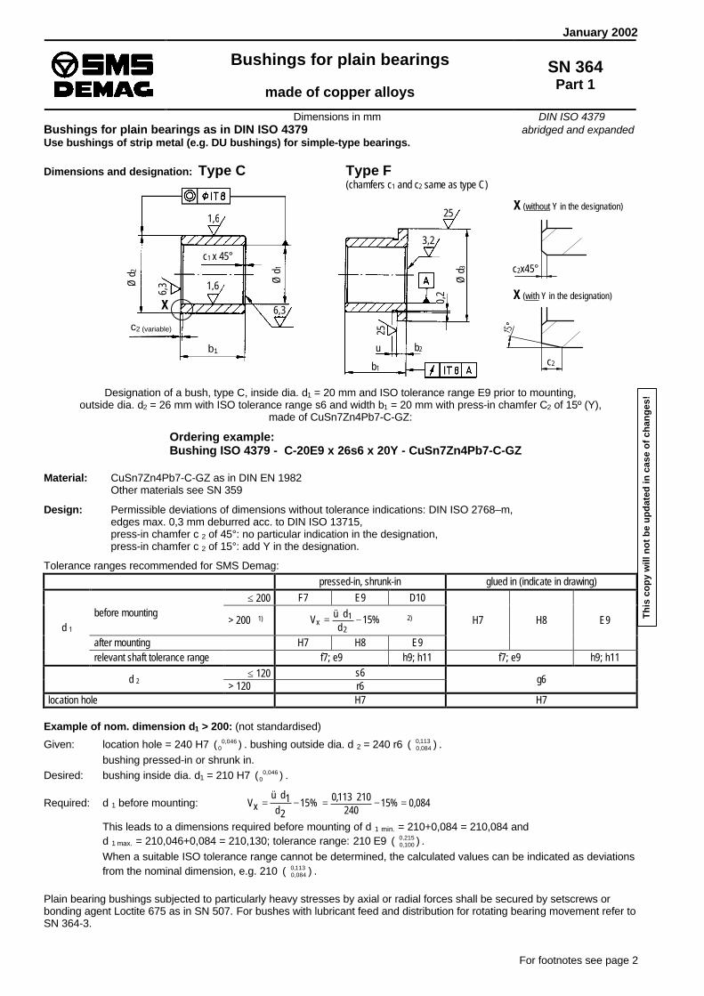
Ø d
3
0,2
25
b1
Ø d
2
Ø d
1
6,3
c2 (variable)
c1 x 45°
January 2002
Bushings for plain bearings
made of copper alloys
SN 364Part 1
Dimensions in mm DIN ISO 4379Bushings for plain bearings as in DIN ISO 4379 abridged and expandedUse bushings of strip metal (e.g. DU bushings) for simple-type bearings.
Dimensions and designation: Type C Type F(chamfers c1 and c2 same as type C)
Designation of a bush, type C, inside dia. d1 = 20 mm and ISO tolerance range E9 prior to mounting,outside dia. d2 = 26 mm with ISO tolerance range s6 and width b1 = 20 mm with press-in chamfer C2 of 15º (Y),
made of CuSn7Zn4Pb7-C-GZ:
Ordering example:Bushing ISO 4379 - C-20E9 x 26s6 x 20Y - CuSn7Zn4Pb7-C-GZ
Material: CuSn7Zn4Pb7-C-GZ as in DIN EN 1982Other materials see SN 359
Design: Permissible deviations of dimensions without tolerance indications: DIN ISO 2768–m,edges max. 0,3 mm deburred acc. to DIN ISO 13715,press-in chamfer c 2 of 45°: no particular indication in the designation,press-in chamfer c 2 of 15°: add Y in the designation.
Tolerance ranges recommended for SMS Demag:pressed-in, shrunk-in glued in (indicate in drawing)
≤ 200 F7 E9 D10before mounting
> 200 1) %15d
düV2
1x −⋅= 2)
after mounting H7 H8 E9
H7 H8 E9d 1
relevant shaft tolerance range f7; e9 h9; h11 f7; e9 h9; h11≤ 120 s6
d 2 > 120 r6g6
location hole H7 H7
Example of nom. dimension d1 > 200: (not standardised)
Given: location hole = 240 H7 )( 046,00+ . bushing outside dia. d 2 = 240 r6 )( 113,0
084,0++ .
bushing pressed-in or shrunk in.Desired: bushing inside dia. d1 = 210 H7 )( 046,0
0+ .
Required: d 1 before mounting: %152d1dü
xV −⋅
= 084,0%15240
210113,0 =−⋅=
This leads to a dimensions required before mounting of d 1 min. = 210+0,084 = 210,084 andd 1 max. = 210,046+0,084 = 210,130; tolerance range: 210 E9 )( 215,0
100,0++ .
When a suitable ISO tolerance range cannot be determined, the calculated values can be indicated as deviationsfrom the nominal dimension, e.g. 210 )( 113,0
084,0++ .
Plain bearing bushings subjected to particularly heavy stresses by axial or radial forces shall be secured by setscrews orbonding agent Loctite 675 as in SN 507. For bushes with lubricant feed and distribution for rotating bearing movement refer toSN 364-3.
For footnotes see page 2
c2x45°
c2
X (without Y in the designation)
X (with Y in the designation)
25
3,2
u b2
b1
X
1,6
6,3
1,6
Th
is c
op
y w
ill n
ot
be
up
dat
ed in
cas
e o
f ch
ang
es!

Page 2SN 364 Part 1 : 2002-01
b1 3) Chamfer Weight (8,8 kg/dm3 red brass and bronze)kg per 1000 pieces
Series 45° 15° Type C Type Fc1, c2 c2 for series b1
d1 d2 d3
1 2 3
b2
max. max.
u
1 2 3 1 2 36 4) 12 14 4,5 7,5 8,68 14 18 5,5 9,1 11,7
10 16 206 10 - 0,3 1
6,5 10,8- -
13,7-
12 18 22 12,4 18,7 24,9 15,7 22 28,214 20 25 14,1 21,1 28,2 18,7 25,7 32,815 21 27
10
1
14,9 22,4 29,9 20,8 26,3 35,816 22 28
15 20
18,9 23,6 31,5 25,1 29,8 37,718 24 30
1220,9 34,8 52,3 27,6 41,5 59
20 26 32 28,6 38,2 57,2 35,8 45,4 64,422 28 34 31,1 41,5 62,2 38,8 49,2 69,9
(24) 30 3615
20 30
3
33,6 44,8 67,2 41,8 53 75,425 32 38 55,2 82,7 110,3 66,8 94,3 121,9
(27) 34 40 59 88,5 118 71,2 100,7 130,228 36 42
1,5
70,8 106,2 141,5 83,7 119,1 154,430 38 44
0,5 2
75,2 112,8 150,4 88,8 126,4 16432 40 46
4
79,6 119,4 159,2 93,8 133,6 173,4(33) 42 48
20 30 40
93,3 140 186,6 111,9 158,6 205,235 45 50 165,9 221,2 276,5 182,3 237,6 292,9
(36) 46 52 170 226,7 283,4 190,3 247 303,738 48 54
50178,3 237,8 297,2 199,3 258,8 318,2
40 50 58 186,6 248,8 373,2 216,4 278,6 40342 52 60 194,9 259,9 389,8 225,8 290,8 420,745 55 63
30 40
207,3 276,5 414,7 239,9 309,1 447,348 58 66 293 366 440 327 400 47450 60 68
60
304 380 456 339 415 49155 65 73
5070
5
332 415 581 370 453 61960 75 83
40
0,8 3
560 840 1120 625 905 118565 80 88
60 80752 902 1203 821 971 1272
70 85 95
2
803 1125 1446 896 1218 153975 90 100
50 70 90855 1197 1540 953 1295 1638
80 95 105 1089 1451 1814 1192 1554 191785 100 110
100
7,5
1151 1534 1918 1259 1642 202690 110 120
801659 2212 3318 1817 2370 3476
95 115 125
60
1742 2903 3483 1907 3068 3648100 120 130 2433 3041 3649 2605 3213 3820105 125 135 2543 3179 3815 2722 3358 3994110 130 140
80100 120
2654 3317 3981 2840 3503 4167120 140 150
1 43
3594 4313 5391 3794 4513 5591130 150 160
120 1503871 4645 5806 4085 4859 6020
140 160 170100
4147 6220 7464 4375 6448 7692150 170 180
10
5308 6635 7962 5549 6876 8203160 185 200
150 1807153 8942 10730 7651 9440 11228
170 195 210120
20012,5
7568 11352 12614 8092 11876 13138180 210 220 12130 14556 20216 12575 15001 20661190 220 230
150 18012751 15302 21253 13217 15768 21719
200 230 240 180 200250 15
2 5 4
16049 17832 22290 16536 18319 22777
Whenever possible, avoid sizes shown in round brackets.
1) dimensions above 200 mm are not standardised.2) Explanations of the variables in the equation:
V x = biggest anticipated diameter reduction of d1 after pressing or shrinking in.ü = biggest interference between location hole and bushing outside diameter d2.d 1 = nominal inside dia. of bushing.d 2 = nominal outside dia. of bushing = nom. dia. of location hole.
3) The dimensions of b1 indicated here have to be preferred. Other dimensions are allowed, but must not exceed 1,5 x d1.
4) Dimension applies only to bushings of type C.

January 2003
Bushings for hydraulic cylinderswith pivot trunnionmade of copper alloys
SN 364Part 2
Dimensions in mm derived fromDIN ISO 4379
The bushings of this SN 364-2 are designed only for hydraulic cylinders with pivot trunnions.They differ from types C and F of SN 364-1 by a bigger chamfer c1.
Dimensions and designation: Type A Type B(chamfers c1 and c2 same as type A)
Designation of a bushing, type A, inside dia. d1 = 30 mm and ISO tolerance range E9 prior to mounting,outside dia. d2 = 38 mm with ISO tolerance range s6, width b1 = 30 mm with press-in chamfer C2 of 15º (Y)
made of CuSn7Zn4Pb7-C-GZ:
Bushing SN 364 - A-30E9 x 38s6 x 30Y - CuSn7Zn4Pb7-C-GZ
Material: CuSn7Zn4Pb7-C-GZ as in DIN EN 1982For other materials see SN 359
Design: Permissible deviations of dimensions without tolerance indications: DIN ISO 2768–m,edges max. 0,3 mm deburred acc. to DIN ISO 13715,press-in chamfer c2 of 45°: no particular indication in the designation,press-in chamfer c2 of 15°: add Y in the designation.
Tolerance ranges recommended for SMS Demag:
Pressed-in, shrunk-in Glued in (indicate in drawing)
Before mounting ≤ 200 F7 E9 D10
After mounting H7 H8 E9H7 H8 E9
d 1
Relevant shaft tolerance range *) f8 a) , c) or e8 b) , c), d) h9; h11 f7; e9 h9; h11
≤ 120 s6d 2
> 120 r6g6
Location hole H7 H7
*) In most cases the tolerance indications are standardised by the suppliers.
Example:a) Hydraulic cylinder up to 160 bar (type CDM1)b) Hydraulic cylinder up to 250 bar (types CDH1, CGH1)c) Hydraulic cylinder up to 250 bar (types CDH2, CGH2)d) Hydraulic cylinder up to 350 bar (types CDH3, CGH3)
c 2 (variable)
Ø d
2
6,3
c 1 x 45°Ø
d 1
1,6
6,3
b1
Ø d
3
3,2
25
0,2
u b2
25b 1
X
c2x45°
c2
X ( with Y in designation)1,6
X ( without Y in designation)
Messrs. Mannesmann Rexroth AG
Th
is c
op
y w
ill n
ot
be
up
dat
ed in
cas
e o
f ch
ang
es!

Page 2SN 364 Part 2 : 2003-01
b1 1) Chamfer Weight (8,8 kg/dm3 for red brass and bronze)kg per 1000 pieces
Series 45° 15° Type A Type Bc1 c2 c2 For series b1
d1 d2 d3
1 2 3
b2
max. max. max.
u
1 2 3 1 2 330 38 44 0,5 2 75,2 112,8 150,4 88,8 126,4 16432 40 46
479,6 119,4 159,2 93,8 133,6 173,4
(33) 42 4820 30 40
93,3 140 186,6 111,9 158,6 205,235 45 50 165,9 221,2 276,5 182,3 237,6 292,9
(36) 46 52 170 226,7 283,4 190,3 247 303,738 48 54
50178,3 237,8 297,2 199,3 258,8 318,2
40 50 58 186,6 248,8 373,2 216,4 278,6 40342 52 60 194,9 259,9 389,8 225,8 290,8 420,745 55 63
30 40
207,3 276,5 414,7 239,9 309,1 447,348 58 66 293 366 440 327 400 47450 60 68
60
304 380 456 339 415 49155 65 73
5070
52
332 415 581 370 453 61960 75 83
40
0,8 3
560 840 1120 625 905 118563 2) 78 2) 86 2) 731 877 1169 799 945 123765 80 88
60 80752 902 1203 821 971 1272
70 85 95
2
803 1125 1446 896 1218 153975 90 100
5070 90
855 1197 1540 953 1295 163880 95 105 1089 1451 1814 1192 1554 191785 100 110
100
7,5
1151 1534 1918 1259 1642 202690 110 120
801659 2212 3318 1817 2370 3476
95 115 125
60
1742 2903 3483 1907 3068 3648100 120 130
2,5
2433 3041 3649 2605 3213 3820105 125 135 2543 3179 3815 2722 3358 3994110 130 140
80100
120
2654 3317 3981 2840 3503 4167120 140 150
1 4
3
3594 4313 5391 3794 4513 5591130 150 160
120 1503871 4645 5806 4085 4859 6020
140 160 170100
4147 6220 7464 4375 6448 7692150 170 180
10
5308 6635 7962 5549 6876 8203160 185 200
150 1807153 8942 10730 7651 9440 11228
170 195 210120
20012,5
7568 11352 12614 8092 11876 13138180 210 220 12130 14556 20216 12575 15001 20661190 220 230
150180
12751 15302 21253 13217 15768 21719200 230 240 180 200
250 15
5
2 5 4
16049 17832 22290 16536 18319 22777
Whenever possible, avoid sizes shown in round brackets.
Revision of January 2003 Previous editionsAddition of bore diameter d1 = 63. 2002-01
1) The dimensions of b1 indicated here have to be preferred. Other dimensions are allowed, but must not exceed 1,5 x d1.2) Dimension not in accordance with DIN ISO 4379.

January 2002
Bushings for plain bearingswith lubrication holes and grooves
for rotating bearings
SN 364Part 3
Dimensions in mm DIN ISO 12128 and parts ofDIN 1850-2 (of March 1969),abridged and expanded
1 Field of application
This standard enables the assignment of types of lubricant feeders and distributors to the copper-alloy plain bearing bushingsas in DIN ISO 4379 (in part from DIN 1850-2 of March 1969); it shows that the bushing types C and F can be designed withbores, longitudinal and ring grooves or combinations of these.
Ring grooves in conjunction with longitudinal grooves must be used only in exceptional cases (e.g. greasingthrough tappet), as they heavily reduce the load bearing capacity of the plain bearings; longitudinal and ringgrooves must always be provided in the stationary section; for the types stated in section 3 below, blankdrawings of the bushing types C and F with press-in chamfers of 45° and 15° (Y) are available for in-housemanufacture.
Design recommendation:
For cost reasons it is useful in many cases to utilise bushings made of maintenance-free graphitic slidingmaterial or of sintered bronze (see SN 359). In this case there will be no manufacturing cost for the variouslubricant groove types A to H.
2 Types of lubricant feed and distribution(Selection from DIN ISO 12128)
Lubrication hole Longitudinal groove Ring groove
Type L
Hole d2 drilled together with locating element,except for locating elements with ring grooves.
Indication in assembly drawing or assembly notein bill of materials is required.
Type D Type G
For types L, D, G Type L Type D Type G For types L, D, G
Bearing wall thicknesss d2
e1
≈t
r≈
e2
≈ t
d1
≈
≤ 2 2,5 5 0,8 2,5 1,8 0,8
> 2 ≤ 2,5 3 8 1 4 2 1≤ 30
> 2,5 ≤ 3 4 10,5 1,2 6 2,5 1,2
> 3 ≤ 4 5 14 1,6 8 3,5 1,6
> 4 ≤ 5 6 19 2 12 4,5 2
> 30 ≤ 100
> 5 ≤ 7,5 8 28 2,5 20 7,5 2,5
> 7,5 ≤ 10 10 38 3,2 28 11 3,2
> 10 12 49 4 35 14 4
> 100
Continued on page 2
round off round off
+0,2 0
+0,2 0
Th
is c
op
y w
ill n
ot
be
up
dat
ed in
cas
e o
f ch
ang
es!

Page 2SN 364 Part 3 : 2002-01
3 Table of types and designations
Lubrication holes and groovesQuantity: 1, 2 or 3
Lubricantfeeding anddistributionthrough ...
TypeType Type and arrangement
Example of designation:
according toDIN ISO 12128
A L
Lubr
icatio
n ho
le c
entri
cor
off-
cent
er
Dimension x for centric lubrication hole is 1/2 x b1.
Designation of a bushing for plain bearing, type F, according to DIN ISO 4379 or a bush for cylinder, type B, acc. to SN 364-2, each with a dimension of 18E9x24s6x20Y, type A (A), with one lubrication hole (1) of type L (L) at a distance of x = 10 acc. to DIN ISO 12128 and made of CuSn7Zn4Pb7-C-GZ:
Bushing ISO 4379 – F-18E9x24s6x20Y–A1L10 - CuSn7Zn4Pb7-C-GZ Bushing SN 364 – B-18E9x24s6x20Y–A1L10 - CuSn7Zn4Pb7-C-GZ
according toDIN 1850-2
of March 1969
Designation of a bushing for plain bearing, type F, according to DIN ISO 4379 or a bush for cylinder, type B, acc. to SN 364-2, each with a dimension of 18E9x24s6x20Y, type B (B), with one longitudinal groove (1) of type D (D) and one lubrication hole (1) of type L (L) at a distance of x = 6 acc. to DIN ISO 1850-2 and made of CuSn7Zn4Pb7-C-GZ:
Bushing ISO 4379–F–18E9x24s6x20Y–B1D1L6- CuSn7Zn4Pb7-C-GZ Bushing SN 364–B–18E9x24s6x20Y–B1D1L6 - CuSn7Zn4Pb7-C-GZ
b 1 > 15 ≤ 30 > 30 ≤ 60 > 60 ≤100 > 100
Hub
BD
andL
Long
itudi
nal g
roov
e clo
sed
onbo
th s
ides
and
lubr
ic. h
ole
cent
ricor
off-
cent
er
Dimension x for centric lubrication hole is 1/2 x b1. a 3 4 6 10
according toDIN ISO 12128
Designation of a bushing for plain bearing, type C, according to DIN ISO 4379 or a bushing for cylinder, type A, acc. to SN 364-2, each with a dimension of 18E9x24s6x20Y, type C (C), with three longitudinal grooves (3), type D (D), according to DIN ISO 12128, and made of CuSn7Zn4Pb7-C-GZ:
Bushing ISO 4379 – C–18E9x24s6x20Y–C3D – CuSn7Zn4Pb7-C-GZ Bushing SN 364 – A–18E9x24s6x20Y–C3D – CuSn7Zn4Pb7-C-GZ
b 1 > 15 ≤ 30 > 30 ≤ 60 > 60 ≤100 > 100
C D
Long
itudi
nal g
roov
eclo
sed
on b
oth
sides
a 3 4 6 10according toDIN 1850-2
of March 1969 Designation of a bushing for plain bearing, type F, according to DIN ISO 4379 or a bush for cylinder, type B, acc. to SN 364-2, each with a dimension of 18E9x24s6x20Y, type F (F), with three longitudinal grooves (3) of type D (D) and one ring groove (1) of type G (G) at a distance of x = 6 acc. to DIN ISO 1850-2, and made of CuSn7Zn4Pb7-C-GZ:
Bushing ISO 4379–F–18E9x24s6x20Y–F3D1G6-CuSn7Zn4Pb7-C-GZ Bushing SN 364–B–18E9x24s6x20Y–F3D1G6-CuSn7Zn4Pb7-C-GZ
b 1 > 15 ≤ 30 > 30 ≤ 60 > 60 ≤100 > 100
Tapp
et
FD
andG
Long
itudi
nal g
roov
e, tw
o sid
esclo
sed,
and
one
ring
gro
ove
with
diag
onal
sid
es, c
entri
c or
off-
cent
re
Dimension x for centric ring groove is 1/2 x b1. a 3 4 6 10
according toDIN ISO 12128
Designation of a bushing for plain bearing, type C, according to DIN ISO 4379 or a bushing for cylinder, type A, acc. to SN 364-2, each with a dimension of 18E9x24s6x20Y, type G (G), with one longitudinal groove (1), type D (D), according to DIN ISO 12128, and made of CuSn7Zn4Pb7-C-GZ:
Bushing ISO 4379 – C–18E9x24s6x20Y–G1D - CuSn7Zn4Pb7-C-GZ Bushing SN 364 – A–18E9x24s6x20Y–C3D - CuSn7Zn4Pb7-C-GZ
b 1 > 15 ≤ 30 > 30 ≤ 60 > 60 ≤100 > 100
G D
Long
itud.
gro
ove,
ope
n on
side
oppo
site
to p
ress
-insid
e
a 3 4 6 10according to
DIN ISO 12128 Designation of a bushing for plain bearing, type C, according to DIN ISO 4379 or a bushing for cylinder, type A, acc. to SN 364-2, each with a dimension of 18E9x24s6x20Y, type H (H), with one longitudinal groove (1), type D (D), according to DIN ISO 12128, and made of CuSn7Zn4Pb7-C-GZ:
Bushing ISO 4379 – C–18E9x24s6x20Y–H1D – CuSn7Zn4Pb7-C-GZ Bushing SN 364 – A–18E9x24s6x20Y–H1D – CuSn7Zn4Pb7-C-GZ
b 1 > 15 ≤ 30 > 30 ≤ 60 > 60 ≤100 > 100
Fron
t fac
e
H D
Long
itudi
nal g
roov
e, o
pen
on p
ress
-in s
ide
a 3 4 6 10
Material: CuSn7Zn4Pb7-C-GZ (GZ-CuSn7ZnPb) according to DIN EN 1982 or other materials as in SN 359.
a a
a a
a
a

January 2002
Semi-finished products kept in stock SN 483
This printed overview of parts kept in stock is updated only when a new edition of the standards book is issued. Forthis reason the marking of availability from stock given in the STOR master data is relevant.
Parts whose stockkeeping will be discontinued are not stated in this standard.
A Dimensions in mmSec-tion
Current mat. designat.material number,
(former mat. designat.)
Semi-finish.productacc. to G Weight in kg/m
A 20 30 40 50 60 70 80 90 100 110 120G 2,47 5,55 9,86 15,4 22,2 30,2 39,5 49,9 61,7 74,6 88,8A 130 140 150 160 170 180 190 200
S355J2G3 1)
1.0570(St 52-3)
G 104 121 139 158 178 200 223 247Dimension 16
also in S235JRG2
A 100 120 200C60+N1.0601
(C 60 N) G 61,7 88,8 247
A 40 50 60 80 100 120 140 160 180 20042CrMo4+QT1.7225
(42 CrMo4 V) G 9,86 15,4 22,2 39,5 61,7 88,8 121 158 200 247
A 50 65 100 130 160X20Cr13+QT8001.0421
(X20 Cr13 V-II)
DIN1013
G 15,1 25,5 60,5 102 155Strength values according to SN 359
A 140 160 180 21518CrNiMo7-6+FP1.6587
(17 CrNiMo 6 BG) G 121 158 200 285
A 220 240 260 280 300 320 340 360 400S355J2G3 1)
1.0570(St 52-3)
DIN7527-6
G 298 355 417 483 555 631 713 799 986
dimensionscorrespond to
the forgingdimensions as in
DIN 7527-6
A 5 6 8 10 12 16 20 24 25 30 40E295+C1.0050+C(St 50-2K) G 0,154 0,222 0,395 0,617 0,888 1,58 2,47 3,55 3,85 5,55 9,86
A 50 55 70E295+SH1.0050+SH(St 50-2SH)
DIN EN10278
(DIN 671)
G 15,4 18,7 30,2tolerance range h9
A 0,9 2Wire
X5CrNi18-101.4301*
(X5 CrNi 18-10)
DIN EN10218
(DIN 177) G 0,006 0,025Dimensions 1,4 mm also in St galvanized
2 mm also in D9 annealed
A 20 25 30 40 50 60 70 80 90 100 110G 3,14 4,91 7,07 12,6 19,6 28,3 38,5 50,2 63,6 78,5 95A 120 130 2) 140 2)
S355J2G3 1)
1.0570(St 52-3)
DIN1014
G 113 133 154A 5 x 5 6 x 6 8 x 7 10 x 8 12 x 8 14 x 14 16 x 10 20 x 12G 0,196 0,283 0,44 0,628 0,754 1,54 1,26 1,88A 28 x 16 36 x 20 40 x 22 45 x 25 50 x 28 56 x 32 70 x 36 90 x 45G 3,52 5,65 6,91 8,83 11 14,1 19,8 31,8A 100 x 50
C45+C1.0503
(C 45 K)
DIN6880
G 39,3
A 20 x 3 30 x 3S235JRG21.0038
(RSt 37-2)
DIN EN10 048 G 0,471 0,707
A 0,1 x 200C 751.0605
DIN EN10140 G 0,157
* This material designation will be kept as search criterion in STOR.
For footnotes see page 3Continued on pages 2 and 3
Th
is c
op
y w
ill n
ot
be
up
dat
ed in
cas
e o
f ch
ang
es!

Page 2SN 483 : 2002-01
A Dimensions in mmSection
Current mat. designat.material number,
(former mat. designat.)
Semi-finish.productacc. to G Weight in kg/m, for plates in kg/m²
A 30 x 6 30 x 10 30 x 20 40 x 5 40 x 8 40 x 10 40 x 15 40 x 20
G 1,41 2,36 4,71 1,57 2,51 3,14 4,71 6,28
A 40 x 25 50 x 5 50 x 8 50 x 10 50 x 15 50 x 20 50 x 25 60 x 5
G 7,85 1,96 3,14 3,93 5,89 7,85 9,81 2,36
A 60 x 8 60 x 10 60 x 12 60 x 15 60 x 20 60 x 25 60 x 30 60 x 40
G 3,77 4,71 5,65 7,07 9,42 11,8 14,1 18,8
A 70 x 10 70 x 15 70 x 20 70 x 25 70 x 30 80 x 8 80 x 10 80 x 12
G 5,5 8,24 11 13,7 16,5 5,02 6,28 7,54
A 80 x 15 80 x 20 80 x 30 80 x 40 90 x 10 90 x 20 100 x 6 100 x 10
G 9,42 12,6 18,8 25,1 7,07 14,1 4,71 7,85
A 100 x 15 100 x 20 100 x 25 100 x 30 100 x 40 120 x 10 120 x 15 120 x 20
G 11,8 15,7 19,6 23,6 31,4 9,42 14,1 18,8
A 120 x 25 150 x 10 150 x 15 150 x 20
S235JRG21.0038
(RSt 37-2)
DIN1017
G 23,6 11,8 17,7 23,6
A 0,5 1 1,5 2DC01+LC1.0330
(St 12 03)
DIN EN10131 G 3,9 7,85 11,8 15,7
It is recommended processing the products made ofsteel DC01 within 6 weeks after their placing at disposal.
A 3 4 5 6 8 10 12 15S235JR 3)
1.0037(St 37-2) G 23,6 31,4 39,3 47,1 62,8 78,5 94,2 117,8
A 20 25 30 40 45 50 60 70 80 150S235JRG2 3)
1.0038(RSt 37-2) G 157 196 235,5 314 353,3 392,5 471 549,5 628 1177
A 15 20 25 30 40 50 60 70 80 90 100
G 117,8 157 196 235,5 314 392,5 471 549,5 628 720 785
A 110 120 130 140 150 160 170 180 200 210
S355J2G3 4)
1.0570(St 52-3)
DIN EN10029,class A
G 863,5 942 1040 1099 1177 1280 1334 1413 1570 1648
A 0,1 x 400 2) 0,15 x 400 2) 0,2 x 400 0,5 x 600 1 x 1000 2 x 1000CuZn37-R370CW508L
(CuZn 37.F37) G 0,84 1,26 1,68 4,2 8,4 16,8
A 0,7 1 2Cu-DHP-R240CW024A
(SF-Cu.F24)
DIN1751
G 6,2 8,9 17,8
A 1 2
Plate
Al99,0-H12EN AW-1200
(Al99F10)
DIN EN485 G 2,7 5,4
Panel sizesSheet thickness 0,5 to 2 – 1000 x 2000Sheet thickness 3 to 4 – 1500 x 3000Plate thickness 5 to 90 – 2000 x 6000Plate thickness 100 to 140 – 2000 x 4000Plate thickness 150 to 210 – 2000 x 3000
A T 5 T 8 T 10S235JR1.0037(St37-2) G 41,25 64,8 80,5
Dimensions correspond to plate thickness without bulbs.Panel size 1500 x 3000
A T 5Bulb
pla
te
Al
DIN59220
G 14,5
A 187 x 162 256 x 256 332 x 302
Cast
. f. h
ydr.
com
pone
nts
EN-GJS-400-15EN-JS 1030(GGG-40)
-
G 247 478 732
* This material designation will be kept as search criterion in STOR.
For footnotes see page 3

Page 3SN 483 : 2002-01
A Dimensions in mmSection
Current mat. designat.material number,
(former mat. designat.)
Semi-finish.productacc. to G Weight in kg/m
A 26,9 x 2,3 33,7 x 2,6 42,4 x 2,6 48,3 x 2,6 60,3 x 2,9 76,1 x 2,9
G 1,4 1,99 2,55 2,93 4,11 5,24
A 88,9 x 3,2 114,3 x 3,6 139,7 x 4 168,3 x 4,5 219,1 x 6,3St 37.01.0254
DIN2448
G 6,76 9,83 13,4 18,2 33,1
A 6 x 1 8 x 1 8 x 1,5 10 x 1,5 12 x 2 16 x 2 16 x 2,5
G 0,12 0,17 0,24 0,32 0,5 0,7 0,83
A 18 x 2 20 x 2,5 20 x 3 22 x 2 25 x 3 25 x 4 28 x 2
G 0,8 1,1 1,26 1 1,65 2,1 1,28
A 30 x 4 30 x 5 35 x 2,5 38 x 3 38 x 5 38 x 6
St 37.4NBK1.0255
DIN2391
G 2,6 3,1 2 2,6 4,06 4,74
A 6 x 1 8 x 1 10 x 1,5 12 x 2 16 x 2,5 20 x 3 25 x 4
G 0,12 0,18 0,32 0,5 0,85 1,28 2,1
A 30 x 5 38 x 3 38 x 6 42,4 x 2,6 48,3 x 2,6 48,3 x 8 60,3 x 2,9
G 3,13 2,6 4,74 2,59 2,93 7,93 4,17
A 60,3 x 10 76,1 x 2,9 76,1 x 12,5 88,9 x 3,2 88,9 x 14,2 114,3 x 3,6
X6CrNiMoTi17-12-21.4571 h*
(X10 CrNiMoTi 18 10)
DIN EN ISO1127
(DIN 2462)
G 12,6 5,24 19,9 6,86 26,6 9,98
A 25 x 25 x 3 30 x 30 x 3 40 x 40 x 4 50 x 50 x 5 50 x 50 x 7
G 1,12 1,36 2,42 3,77 5,15
A 60 x 60 x 6 60 x 60 x 8 70 x 70 x 7 80 x 80 x 8 80 x 80 x 10
G 5,42 7,09 7,38 9,63 11,9
A 100 x 100 x 12 150 x 150 x 12
DIN EN10056
equal-sided
G 17,8 27,3
A 75 x 55 x 7 120 x 80 x 12 130 x 65 x 10 150 x 100 x 12 200 x 100 x 10
G 6,8 17,8 14,6 22,5 22,8
A 200 x 100 x 12
DIN EN10056
unequal-sided G 27,3
A 100 120 140 160 200IPB DIN
1025/2 G 20,4 26,7 33,7 42,6 61,3
A 40 80 100 120 140 160 200
S235JRG21.0038
(RSt37-2)
DIN1026 G 4,87 8,64 10,6 13,4 16 18,8 25,3
* This material designation will be kept as search criterion in STOR.
1) Selection of material:Whenever possible use has to be made of the stocked semi-finished products stated in this standard or of the materialsgiven in the SMS Demag selection of SN 359.
The designation "St" is permitted for steel components without particular strength requirements. In this case it is at themaker's discretion to use semi-finished products such as sheet, round material C22, E295+C (St50-2) or tubing for themanufacture. Suitability for welding must be ensured.When materials like St50 are indicated, the above procedure is used by analogy; the melting and treatment processes canbe freely chosen, but on condition that the tensile strength of the specified basic material is achieved. Manufacture inE295+C (St50-2), S355J2G3 (St52-3), C35+N (C35N) is possible.
2) Cannot be ordered according to DIN.3) The stocked plates in S235JR (St37-2) have not been ultrasonically tested; if necessary, such testing of parts exposed to
high dynamic loads has to be indicated in the drawings as follows: ultrasonic testing acc. to SEL 072 Table 1, Class 2, withcertificate of ultrasonic testing and certificate DIN EN 10204 -3.1.B, or plates in S355J2G3 (St52-3) must be used instead.
4) Stocked plates in S355J2G3 (St52-3) have been ultrasonically tested acc. to SEL 072 Table 1, Class 2, with certificate ofultrasonic testing and certificate DIN EN 10204 - 3-1.B.

January 2002
Steel structural sections
SelectionSN 805
Round-edge unequal steel angle (hot rolled) as in DIN EN 10056-1.
Section dimensions Leg bores *) Bending axesin mm in mm in cm in cm3
Symbol
L a b s r 1 r 2 d 1 d 2 w 1 w 2 w 3 e x e y w x w y
Weightin
kg / m 30x 20x 3 30 20 3 4 2 8,4 4,3 17 - 12 0,99 0,502 0,621 0,292 1,12
4 30 20 4 4 2 8,4 4,3 17 - 12 1,03 0,541 0,807 0,379 1,46 40x 20x 4 40 20 4 4 2 11 4,3 22 - 12 1,47 0,48 1,42 0,393 1,77 40x 25x 4 40 25 4 4 2 11 6,4 22 - 15 1,36 0,623 1,47 0,619 1,93 45x 30x 4 45 30 4 4,5 2,25 13 8,4 25 - 17 1,48 0,74 1,91 0,91 2,25 50x 30x 5 50 30 5 5 2,5 13 8,4 30 - 17 1,73 0,741 2,86 1,11 2,96 60x 30x 5 60 30 5 5 2,5 17 8,4 35 - 17 2,17 0,684 4,07 1,14 3,36 60x 40x 5 60 40 5 6 3 17 11 35 - 22 1,96 0,972 4,25 2,02 3,76
6 60 40 6 6 3 17 11 35 - 22 2 1,01 5,03 2,38 4,46 65x 50x 5 65 50 5 6 3 21 13 35 - 30 1,99 1,25 5,14 3,19 4,35 70x 50x 6 70 50 6 7 3,5 21 13 40 - 30 2,23 1,25 7,01 3,78 5,41 75x 50x 6 75 50 6 7 3,5 23 13 35 - 30 2,44 1,21 8,01 3,81 5,65
8 75 50 8 7 3,5 23 13 35 - 30 2,52 1,29 10,4 4,95 7,39 80x 40x 6 80 40 6 7 3,5 23 11 45 - 22 2,85 0,884 8,73 2,44 5,41
8 80 40 8 7 3,5 23 11 45 - 22 2,94 0,963 11,4 3,16 7,07 80x 60x 7 80 60 7 8 4 23 17 45 - 35 2,51 1,52 10,7 6,34 7,36100x 50x 6 100 50 6 8 4 25 13 55 - 30 3,51 1,05 13,8 3,89 6,84
8 100 50 8 8 4 25 13 55 - 30 3,6 1,13 18,2 5,08 8,97100x 65x 7 100 65 7 10 5 25 21 55 - 35 3,23 1,51 16,6 7,53 8,77
8 100 65 8 10 5 25 21 55 - 35 3,27 1,55 18,9 8,54 9,9410 100 65 10 10 5 25 21/17 55 - 35 3,36 1,63 23,2 10,5 12,3
100x 75x 8 100 75 8 10 5 25 23 55 - 40 3,1 1,87 19,3 11,4 10,610 100 75 10 10 5 25 23 55 - 40 3,19 1,95 23,8 14 1312 100 75 12 10 5 25 23 55 - 40 3,27 2,03 28 16,5 15,4
120x 80x 8 120 80 8 11 5,5 25 23 50 80 45 3,83 1,87 27,6 13,2 12,210 120 80 10 11 5,5 25 23 50 80 45 3,92 1,95 34,1 16,2 1512 120 80 12 11 5,5 25 23 50 80 45 4 2,03 40,4 19,1 17,8
125x 75x 8 125 75 8 11 5,5 25 23 50 85 40 4,14 1,68 29,6 11,6 12,210 125 75 10 11 5,5 25 23 50 85 40 4,23 1,76 36,5 14,3 1512 125 75 12 11 5,5 25 23 50 85 40 4,31 1,84 43,2 16,9 17,8
135x 65x 8 135 65 8 11 5,5 25 21 55 95 35 4,78 1,34 33,4 8,75 12,210 135 65 10 11 5,5 25 21 55 95 35 4,88 1,42 41,3 10,8 15
150x 75x 9 150 75 9 12 6 28 23 60 105 40 5,26 1,57 46,7 13,1 15,410 150 75 10 12 6 28 23 60 105 40 5,31 1,61 51,6 14,5 1712 150 75 12 12 6 28 23 60 105 40 5,4 1,69 61,3 17,1 20,215 150 75 15 12 6 28 23 60 105 40 5,52 1,81 75,2 21 24,8
150x 90x10 150 90 10 12 6 28 25 60 105 50 5 2,04 53,3 21 18,212 150 90 12 12 6 28 25 60 105 50 5,08 2,12 63,3 24,8 21,615 150 90 15 12 6 28 25 60 105 50 5,21 2,23 77,7 30,4 26,6
150x100x10 150 100 10 12 6 28 25 60 105 55 4,81 2,34 54,2 25,9 1912 150 100 12 12 6 28 25 60 105 55 4,89 2,42 64,4 30,7 22,5
200x100x10 200 100 10 15 7,5 28 25 65 150 55 6,93 2,01 93,2 26,3 2312 200 100 12 15 7,5 28 25 65 150 55 7,03 2,1 111 31,3 27,315 200 100 15 15 7,5 28 25 65 150 55 7,16 2,22 137 38,5 33,75
200x150x12 200 150 12 15 7,5 28 25 65 150 100 6,08 3,61 119 70,5 3215 200 150 15 15 7,5 28 25 65 150 100 6,21 3,73 147 86,9 39,6
For footnotes see page 4
Continued on pages 2 to 4
Th
is c
op
y w
ill n
ot
be
up
dat
ed in
cas
e o
f ch
ang
es!

Page 2SN 805 : 2002-01
Round-edge equal steel angle (hot rolled) as in DIN EN 10056-1.
Section dimensions Leg bores *) Bending axesin mm in mm in cm in cm3
Symbol
a s r 1 r 2 d w 1 4) w 2 e x = e y w x = w y
Weight inkg/m
20x 20x 3 20 3 3,5 1,75 4,3 12 - 0,598 0,279 0,882 25x 25x 3 25 3 3,5 1,75 6,4 15 - 0,723 0,452 1,12
4 25 4 3,5 1,75 6,4 15 - 0,762 0,586 1,45 30x 30x 3 30 3 5 2,5 8,4 17 - 0,835 0,649 1,36
4 30 4 5 2,5 8,4 17 - 0,878 0,85 1,78 35x 35x 4 35 4 5 2,5 11 18 - 1 1,18 2,09 40x 40x 4 40 4 6 3 11 22 - 1,12 1,55 2,42
5 40 5 6 3 11 22 - 1,16 1,91 2,97 45x 45x 4,5 45 4,5 7 3,5 13 25 - 1,25 2,2 3,06 50x 50x 4 50 4 7 3,5 13 30 - 1,36 2,46 3,06
5 50 5 7 3,5 13 30 - 1,4 3,05 3,77 6 50 6 7 3,5 13 30 - 1,45 3,61 4,47
60x 60x 5 60 5 8 4 17 35 - 1,64 4,45 4,576 60 6 8 4 17 35 - 1,69 5,29 5,428 60 8 8 4 17 35 - 1,77 6,89 7,09
65x 65x 7 65 7 9 4,5 21 35 - 1,85 7,18 6,83 70x 70x 6 70 6 9 4,5 21 40 - 1,93 7,27 6,38
7 70 7 9 4,5 21 40 - 1,97 8,41 7,38 75x 75x 6 75 6 9 4,5 23 40 - 2,05 8,41 6,85
8 75 8 9 4,5 23 40 - 2,14 11 8,99 80x 80x 8 80 8 10 5 23 45 - 2,26 12,6 9,63
10 80 10 10 5 23 45 - 2,34 15,4 11,9 90x 90x 7 90 7 11 5,5 25 50 - 2,45 14,1 9,61
8 90 8 11 5,5 25 50 - 2,5 16,1 10,99 90 9 11 5,5 25 50 - 2,54 17,9 12,2
10 90 10 11 5,5 25 50 - 2,58 19,8 13,4100x100x 8 100 8 12 6 25 55 - 2,74 19,9 12,2
10 100 10 12 6 25 55 - 2,82 24,6 1512 100 12 12 6 25 55 - 2,9 29,1 17,8
120x120x10 120 10 13 6,5 25 50 80 3,31 36 18,212 120 12 13 6,5 25 50 80 3,4 42,7 21,6
130x130x12 130 12 14 7 25 50 90 3,64 50,4 23,6150x150x10 150 10 16 8 28 60 105 4,03 56,9 23
12 150 12 16 8 28 60 105 4,12 67,7 27,315 150 15 16 8 28 60 105 4,25 83,5 33,8
160x160x15 160 15 17 8,5 28 60 115 4,49 95,6 36,2180x180x16 180 16 18 9 28 60 135 5,02 130 43,5
18 180 18 18 9 28 60 / 65 135 5,1 145 48,6200x200x16 200 16 18 9 28 65 150 5,52 162 48,5
18 200 18 18 9 28 65 150 5,6 181 54,320 200 20 18 9 28 65 150 5,68 199 59,924 200 24 18 9 28 65 / 70 150 5,84 235 71,1
250x250x28 250 28 18 9 28 75 200 7,24 433 10435 250 35 18 9 28 75 200 7,5 529 128
For footnotes see page 4
Y
Y

Page 3SN 805: 2002-01
Wide I-beams with parallel flange surfaces, IPB series as in DIN 1025-2.
Symbol Section dimensions Leg bores Bending axesin mm in mm in cm3I PB h b s t r e d w 1 w 2 w 3 w x w y
Weight inkg/m
100 100 100 6 10 12 56 13 56 - 89,9 33,5 20,4120 120 120 6,5 11 12 74 17 66 - 144 52,9 26,7140 140 140 7 12 12 92 21 76 - 216 78,5 33,7160 160 160 8 13 15 104 23 86 - 311 111 42,6180 180 180 8,5 14 15 122 25 100 - 426 151 51,2200 200 200 9 15 18 134 25 110 - 570 200 61,3220 220 220 9,5 16 18 152 25 120 - 736 258 71,5240 240 240 10 17 21 164 25 96 35 938 327 83,2260 260 260 10 17,5 24 177 25 106 40 1150 395 93280 280 280 10,5 18 24 196 25 110 45 1380 471 103300 300 300 11 19 27 208 28 120 45 1680 571 117320 320 300 11,5 20,5 27 225 28 120 45 1930 616 127340 340 300 12 21,5 27 243 28 120 45 2160 646 134360 360 300 12,5 22,5 27 261 28 120 45 2400 676 142400 400 300 13,5 24 27 298 28 120 45 2880 721 155450 450 300 14 26 27 344 28 120 45 3550 781 171500 500 300 14,5 28 27 390 28 120 45 4290 842 187550 550 300 15 29 27 438 28 120 45 4970 872 199600 600 300 15,5 30 27 486 28 120 45 5700 902 212650 650 300 16 31 27 534 28 120 45 6480 932 225
Medium-flange I-beams with parallel flange surfaces, IPB series (hot rolled) as in DIN 1025-5.
Section dimensions Leg bores 3) Bending axesSymbolin mm in mm in cm3
I PE h b s t r ed
Max. dim1) w w x w y
Weight inkg/m
80 80 46 3,8 5,2 5 59 6,4 26 20 3,69 6100 100 55 4,1 5,7 7 74 8,4 30 34,2 5,79 8,1120 120 64 4,4 6,3 7 93 8,4 36 53 8,65 10,4140 140 73 4,7 6,9 7 112 11 40 77,3 12,3 12,9160 160 82 5 7,4 9 127 13 **) 44 109 16,7 15,8180 180 91 5,3 8 9 146 13 50 146 22,2 18,8200 200 100 5,6 8,5 12 159 13 56 194 28,5 22,4220 220 110 5,9 9,2 12 177 17 60 252 37,3 26,2240 240 120 6,2 9,8 15 190 17 68 324 47,3 30,7270 270 135 6,6 10,2 15 219 21/17 72 429 62,2 36,1300 300 150 7,1 10,7 15 248 23 80 557 80,5 42,2330 330 160 7,5 11,5 18 271 25/23 86 713 98,5 49,1360 360 170 8 12,7 18 298 25 90 904 123 57,1400 400 180 8,6 13,5 21 331 28/25 96 1160 146 66,3450 450 190 9,4 14,6 21 378 28 106 1500 176 77,6500 500 200 10,2 16 21 426 28 110 1930 214 90,7550 550 210 11,1 17,2 24 467 28 120 2440 254 106600 600 220 12 19 24 514 28 120 3070 308 122
For footnotes see page 4

Page 4SN 805: 2002-01
Normal U-sections as in DIN 1026-1.
Slopes of inner flanges:up to h = 300 mm : 8%above h = 300 mm : 5%
Section dimensions Leg bores 3) *) Bending axesSymbolin mm in mm in cm in cm3
Uh b s t = r 1 c r 2 e
dGrößt-
maße1) 2) w e y w x w y
Weight inkg/m
30 x 15 30 15 4 4,5 7,5 2 12 4,3 10 0,52 1,69 0,39 1,7430 30 33 5 7 16,5 3,5 1 8,4 20 1,31 4,26 2,68 4,27
40 x 20 40 20 5 5,5 10 2,5 18 6,4 11 0,67 3,79 0,86 2,8740 40 35 5 7 17,5 3,5 11 8,4 20 1,33 7,05 3,08 4,87
50 x 25 50 25 5 6 12,5 3 25 8,4 16 0,81 6,73 1,48 3,8650 50 38 5 7 19 3,5 20 11 20 1,37 10,6 3,75 5,5960 60 30 6 6 15 3 35 8,4 18 0,91 10,5 2,16 5,0765 65 42 5,5 7,5 21 4 33 11 25 1,42 17,7 5,07 7,0980 80 45 6 8 22,5 4 47 13 **) 25 1,45 26,5 6,36 8,64
100 100 50 6 8,5 25 4,5 64 13 30 1,55 41,2 8,49 10,6120 120 55 7 9 27,5 4,5 82 17/13 30 1,6 60,7 11,1 13,4140 140 60 7 10 30 5 97 17 35 1,75 86,4 14,8 16160 160 65 7,5 10,5 32,5 5,5 116 21/17 35 1,84 116 18,3 18,8180 180 70 8 11 35 5,5 133 21 40 1,92 150 22,4 22200 200 75 8,5 11,5 37,5 6 151 23/21 40 2,01 191 27 25,3220 220 80 9 12,5 40 6,5 166 23 45 2,14 245 33,6 29,4240 240 85 9,5 13 42,5 6,5 185 25/23 45 2,23 300 39,6 33,2260 260 90 10 14 45 7 201 25 50 2,36 371 47,7 37,9280 280 95 10 15 47,5 7,5 216 25 50 2,53 448 57,2 41,8300 300 100 10 16 50 8 232 28 55 2,7 535 67,8 46,2320 320 100 14 17,5 43 8,75 247 28 58 2,6 679 80,6 59,5350 350 100 14 16 43 8 283 28 58 2,4 734 75 60,6380 380 102 13,5 16 44 8 313 28 60 2,38 829 78,7 63,1400 400 110 14 18 48 9 325 28 60 2,65 1020 102 71,8
1) The same tracing dimensions can be used for rivets and screws having smaller diameters than the max. diametersstated here.
2) When two d values are stated for a section, the smaller one is used for screws for high-tensile connections as inDIN 6914. The bigger diameter applies to the rivet.
3) Tracing dimensions for bars and rolled steel sections as in 997.4) When two tracing dimensions for w1 are stated for a section, the greater one is used for screws for high-tensile
connections as in DIN 6914.*) Values shown in italics are not standardised. They have been taken from the booklet on "Stahlbau-Profile" (steel structural
sections), 23rd edition, by Verlag Stahleisen GmbH.**) Here the use of standardised screws for high-tensile connections as in DIN 6914 is not possible.
Other sections:
- Narrow I-beams as in DIN 1025-1- Wide I-beams with parallel flanges, series IPBI (HE-A) as in DIN 1025-3- Wide I-beams with parallel flanges, series IPBv (HE-M) as in DIN 1025-4- Round-edged zeds as in DIN 1027- Round-edged T-sections as in DIN EN 10055- Crane rails as in DIN 536-1- Square and rectangular tubing as in DIN 10210-2- Square and rectangular tubing as in DIN 10219-2
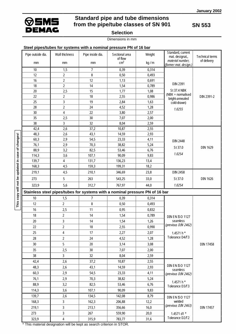
January 2002
Standard pipe and tube dimensionsfrom the pipe/tube classes of SN 901
Selection
SN 553
Dimensions in mm
Steel pipes/tubes for systems with a nominal pressure PN of 16 bar
Pipe outside dia.
mm
Wall thickness
mm
Pipe inside dia.
mm
Sectional areaof flow
cm²
Weight
kg / m
Standard, currentmat. designat.,
material number,(former mat. design.)
Technical termsof delivery
10 1,5 7 0,39 0,31412 2 8 0,50 0,49316 2 12 1,13 0,69118 2 14 1,54 0,78920 2,5 15 1,77 1,0822 2 18 2,55 0,98625 3 19 2,84 1,6328 2 24 4,52 1,2830 4 22 3,80 2,5735 2,5 30 7,07 2,0038 3 32 8,04 2,59
DIN 2391
St 37.4 NBK(NBK = normalised
bright-annealedcold-drawn)
1.0255
DIN 2391-2
42,4 2,6 37,2 10,87 2,5548,3 2,6 43,1 14,59 2,9360,3 2,9 54,5 23,33 4,1176,1 2,9 70,3 38,82 5,2488,9 3,2 82,5 53,46 6,76
114,3 3,6 107,1 90,09 9,83139,7 4 131,7 136,23 13,4168,3 4,5 159,3 199,31 18,2
DIN 2448
St 37.0
1.0254
DIN 1629
219,1 4,5 210,1 346,69 23,8
273 5 263 543,25 33,0
323,9 5,6 312,7 767,97 44,0
DIN 2458
St 37.0
1.0254
DIN 1626
Stainless steel pipes/tubes for systems with a nominal pressure PN of 16 bar10 1,5 7 0,39 0,314
12 2 8 0,50 0,493
16 2,5 11 0,95 0,832
18 2 14 1,54 0,789
20 3 14 1,54 1,26
22 2 18 2,55 0,990
25 4 17 2,27 2,07
28 2 24 4,52 1,28
30 5 20 3,14 3,08
35 2,5 30 7,07 2,00
38 3 32 8,04 2,59
DIN EN ISO 1127seamless
(previous DIN 2462)
1.4571 h *Tolerance D4/T3
42,4 2,6 37,2 10,87 2,55
48,3 2,6 43,1 14,59 2,93
60,3 2,9 54,5 23,33 4,11
76,1 2,9 70,3 38,82 5,24
88,9 3,2 82,5 53,46 6,76
114,3 3,6 107,1 90,09 9,83
DIN EN ISO 1127seamless
(previous DIN 2462)
1.4571 h *Tolerance D3/T3
DIN 17458
139,7 2,6 134,5 142,08 8,79
168,3 3 162,3 206,88 12,2
219,1 3 213,1 356,66 16,0
273 3 267 559,90 20,0
323,9 4 315,9 783,77 31,6
DIN EN ISO 1127welded
(previous DIN 2463)
1.4571 d1 *Tolerance D2/T2
DIN 17457
* This material designation will be kept as search criterion in STOR.
Th
is c
op
y w
ill n
ot
be
up
dat
ed in
cas
e o
f ch
ang
es!

Page 2SN 553 : 2002-01
Steel pipes/tubes for hydraulic systems with a nominal pressure PN of 250 bar
Pipe outside dia.
mm
Wall thickness
mm
Pipe inside dia.
mm
Sectional areaof flow
cm²
Weight
kg / m
Standard, currentmat. designat.,
material number,(former mat. design.)
Technical termsof delivery
10 1,5 7 0,39 0,31412 2 8 0,50 0,49316 2 12 1,13 0,69120 2,5 15 1,77 1,0825 3 19 2,84 1,6330 4 22 3,80 2,5738 5 28 6,16 4,07
DIN 2391
St 37.4 NBK(normalised bright-
annealed cold-drawn)
1.0255
DIN 2391-2
48,3 6,3 35,7 10,01 6,5360,3 8 44,3 15,41 10,376,1 10 56,1 24,72 16,388,9 11 66,9 35,15 21,1
114,3 14,2 85,9 57,95 35,0
DIN 2448
St 52.4
1.0581
DIN 1630
Stainless steel pipes/tubes for hydraulic systems with a nominal pressure PN of 250 bar10 1,5 7 0,39 0,31412 2 8 0,50 0,49316 2,5 11 0,95 0,83220 3 14 1,54 1,2625 4 17 2,27 2,0730 5 20 3,14 3,0838 6 26 5,31 4,74
DIN EN ISO 1127(previous DIN 2462)
1.4571 h *Tolerance D4/T3
48,3 8 32,3 8,19 7,9560,3 10 40,3 12,76 12,476,1 12,5 51,1 20,51 19,688,9 14,2 60,5 28,75 26,2
114,3 20 74,3 43,36 46,5
DIN EN ISO 1127(previous DIN 2462)
1.4571 h *Tolerance D2/T2
DIN 17458
Steel pipes/tubes for hydraulic systems with a nominal pressure PN of 315 bar
Pipe outside dia.
mm
Wall thickness
mm
Pipe inside dia.
mm
Sectional areaof flow
cm²
Weight
kg / m
Standard, currentmat. designat.,
material number,(former mat. design.)
Technical termsof delivery
10 1,5 7 0,39 0,31412 2 8 0,50 0,49316 2,5 11 0,95 0,83220 3 14 1,54 1,2625 4 17 2,27 2,0730 5 20 3,14 3,0838 6 26 5,31 4,74
DIN 2391
St 37.4 NBK(normalised bright-
annealed cold-drawn)
1.0255
DIN 2391-2
48,3 8 32,3 8,19 7,9560,3 10 40,3 12,76 12,476,1 12,5 51,1 20,51 19,688,9 14,2 60,5 28,75 26,2
114,3 20 74,3 43,36 46,5
DIN 2448
St 52.4
1.0581
DIN 1630
Stainless steel pipes/tubes for hydraulic systems with a nominal pressure PN of 315 bar10 1,5 7 0,39 0,31412 2 8 0,50 0,49316 2,5 11 0,95 0,83220 3 14 1,54 1,2625 4 17 2,27 2,0730 5 20 3,14 3,0838 6 26 5,31 4,74
DIN EN ISO 1127seamless
(previous DIN 2462)
1.4571 h *Tolerance D4/T3
48,3 8 32,3 8,19 7,9560,3 10 40,3 12,76 12,476,1 12,5 51,1 20,51 19,688,9 14,2 60,5 28,75 26,2
114,3 20 74,3 43,36 46,5
DIN EN ISO 1127seamless
(previous DIN 2462)
1.4571 h *Tolerance D2/T2
DIN 17458
* This material designation will be kept as search criterion in STOR.
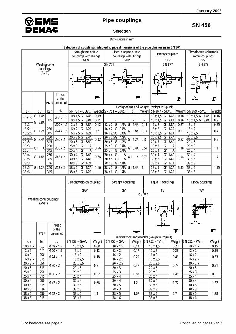
January 2002
Pipe couplings
SelectionSN 456
Dimensions in mm
Selection of couplings, adapted to pipe dimensions of the pipe classes as in SN 901Straight male stud
couplings with U-ringsReducing male stud
couplings with U-rings Rotary couplings Throttle-free adjustablerotary couplings
GUV GUR SKV SVWelding cone SN 751 SN 877 SN 879
couplings(AVIT)
Designations and weights (weight in kg/unit)d 1 d 2
PN 1)
bar
Threadof the
union nut
d 4 SN 751 – GUV... Weight SN 751 – GUR... d 3 Weight SN 877 – SKV... Weight SN 879 – SV... WeightG 1/4A 10 x 1,5 G 1/4A 0,09 - - - 10 x 1,5 G 1/4A 0,18 10 x 1,5 G 1/4A 0,16 10x1,5 M18 x 1,5
10 x 1,5 G 3/8A 0,11 - - - 10 x 1,5 G 3/8A 0,26 10 x 1,5 G 3/8A 0,2 12x2
G 3/8A315
M20 x 1,5 12 x 2 G 3/8A 0,12 12 x 2 G 1/4A G 1/4A 0,11 12 x 2 G 3/8A 0,27 12 x 2 0,35 16x2 250 16 x 2 G 1/2A 16 x 2 G 3/8A 16 x 2 G 1/2A 16 x 2 16x2,5
G 1/2A315
M24 x 1,5 16 x 2,5 G 1/2A
0,2 16 x 2,5G 3/8A
G 3/8A 0,17 16 x 2,5 G 1/2A
0,57 16 x 2,5
0,4
20x2,5 250 20 x 2,5 G 3/4A 20 x 2,5G 1/2A 20 x 2,5 G 3/4A 20 x 2,5 20x3
G 3/4A315
M30 x 2 20 x 3 G 3/4A
0,32 20 x 3 G 1/2A
G 1/2A 0,3 20 x 3 G 3/4A
0,82 20 x 3
0,9
25x3 250 25 x 3 G1 A 25 x 3 G 3/4A 25 x 3 G1 A 25 x 3 25x4
G1 A315
M36 x 2 25 x 4 G1 A
0,56 25 x 4 G 3/4A
G 3/4A 0,54 25 x 4 G1 A
1,18 25 x 4
1,1
30x4 250 30 x 4 G1 1/4A 30 x 4 G1 A 30 x 4 G1 1/4A 30 x 4 30x5
G1 1/4A315
M42 x 2 30 x 5 G1 1/4A
0,78 30 x 5 G1 A
G1 A 0,72 30 x 5 G1 1/4A
1,94 30 x 5
1,7
38x3 16 38 x 3 G1 1/2A 38 x 3 G1 1/4A 38 x 3 G1 1/2A 38 x 3 38x5 250 38 x 5 G1 1/2A 38 x 5 G1 1/4A 38 x 5 G1 1/2A 38 x 5 38x6
G1 1/2A315
M52 x 2 38 x 6 G1 1/2A
1,16 38 x 6 G1 1/4A
G1 1/4A 1,1 38 x 6 G1 1/2A
3,45 38 x 6
1,95
Straight weld-on couplings Straight couplings Equal T couplings Elbow couplings
GAV GV TV WVSN 752
Welding cone couplings(AVIT)
Designations and weights (weight in kg/unit)d 1
PN 1)
bar
Threadof the
union nut
d 4 SN 752 – GAV... Weight SN 752 – GV... Weight SN 752 – TV... Weight SN 752 – WV... Weight 10 x 1,5 M 18 x 1,5 10 x 1,5 0,08 10 x 1,5 0,14 10 x 1,5 0,22 10 x 1,5 0,15 12 x 2
315M 20 x 1,5 12 x 2 0,12 12 x 2 0,17 12 x 2 0,28 12 x 2 0,19
16 x 2 250 16 x 2 16 x 2 16 x 2 16 x 2 16 x 2,5 315
M 24 x 1,5 16 x 2,5
0,18 16 x 2,5
0,29 16 x 2,5
0,49 16 x 2,5
0,33
20 x 2,5 250 20 x 2,5 20 x 2,5 20 x 2,5 20 x 2,5 20 x 3 315
M 30 x 2 20 x 3
0,3 20 x 3
0,47 20 x 3
0,74 20 x 3
0,51
25 x 3 250 25 x 3 25 x 3 25 x 3 25 x 3 25 x 4 315
M 36 x 2 25 x 4
0,52 25 x 4
0,83 25 x 4
1,49 25 x 4
0,9
30 x 4 250 30 x 4 30 x 4 30 x 4 30 x 4 30 x 5 315
M 42 x 2 30 x 5
0,66 30 x 5
1,2 30 x 5
1,72 30 x 5
1,22
38 x 3 16 38 x 3 38 x 3 38 x 3 38 x 3 38 x 5 250 38 x 5 38 x 5 38 x 5 38 x 5 38 x 6 315
M 52 x 2 38 x 6
1,1 38 x 6
1,67 38 x 6
2,7 38 x 6
1,88
For footnotes see page 7 Continued on pages 2 to 7

Page 2SN 456: 2002-01
Straight bulkheadcouplings
Angular bulkheadcouplings
Pressure testand vent couplings
Pressure-gaugecouplings
GSV WSV DEV MAVSN 732 SN 753
Welding cone couplings(AVIT)
Designations and weights (weight in kg/unit)d 1
PN 1)
bar
Threadof the
union nut
d 4 SN 732 – GSV... Weight SN 732 – WSV... Weight SN 753 – DEV... Weight SN 753 – MAV-S.. d 3 Wght. 10 x 1,5 M18 x 1,5 10 x 1,5 0,2 10 x 1,5 0,21 10 x 1,5 0,25 10 x 1,5 G 1/2A 0,14 12 x 2
315 M20 x 1,5 12 x 2 0,27 12 x 2 0,28 12 x 2 0,28 12 x 2 G 1/2A
G 1/2A0,15
16 x 2 250 16 x 2 16 x 2 16 x 2 - - - 16 x 2,5 315
M24 x 1,516 x 2,5
0,416 x 2,5
0,44 16 x 2,5
0,38- - -
20 x 2,5 250 20 x 2,5 20 x 2,5 20 x 2,5 - - - 20 x 3 315
M30 x 220 x 3
0,64 20 x 3
0,51 20 x 3
0,62- - -
25 x 3 250 25 x 3 25 x 3 25 x 3 - - - 25 x 4 315
M36 x 225 x 4
1,05 25 x 4
0,9 25 x 4
0,89- - -
30 x 4 250 30 x 4 30 x 4 30 x 4 - - - 30 x 5 315
M42 x 230 x 5
1,33 30 x 5
1,22 30 x 5
1,11- - -
38 x 3 16 38 x 3 38 x 3 38 x 3 - - - 38 x 5 250 38 x 5 38 x 5 38 x 5 - - - 38 x 6 315
M52 x 238 x 6
2,15 38 x 6
1,88 38 x 6
1,73- - -
Welding cone Designations and weights (weight in kg/unit)AK
SN 807 SN 807 – AK ... d 1 d 2 Wght.
PertainingO-rings
SN 430- ...Pertaining
pipes continued SN 807 – AK ... d 1 d 2 Wght.
PertainingO-rings
SN 430- ...Pertaining
pipes10 x 1,5 10 7 0,02 7,5 x 1,5 10 x 1,5 25 x 4 25 17 0,11 20,3 x 2,4 25 x 412 x 2 12 8 0,02 9 x 1,5 12 x 2 30 x 4 22 0,14 30 x 416 x 2 12 0,03 16 x 2 30 x 5
3020 0,17
25,3 x 2,430 x 5
16 x 2,516
11 0,0412 x 2
16 x 2,5 38 x 3 32 0,22 38 x 420 x 2,5 15 0,06 20 x 2,5 38 x 5 28 0,25 38 x 520 x 3
2014 0,06
16,3 x 2,420 x 3 38 x 6
3826 0,28
33,3 x 2,438 x 6
25 x 3 25 19 0,09 20,3 x 2,4 25 x 3 - - - - - -Reducing
welding cones Designations and weights (weight in kg/unit)
ARK
SN 807 SN 807 – ARK ... d 1 d 2 Wght.
PertainingO-rings
SN 430- ...Pertaining
pipes continued SN 807 – ARK ... d 1 d 2 Wght.
PertainingO-rings
SN 430– ...Pertaining
pipes12/10 x 1,5 0,02 9 x 1,5 30/16 x 2,5 16 11 16 x 2,516/10 x 1,5
10 70,03
10 x 1,5 30/20 x 2,5 15 20 x 2,5
16/12 x 2 12 8 0,0412 x 2
12 x 2 30/20 x 320
140,17
20 x 320/10 x 1,5 10 7 10 x 1,5 30/25 x 3 19 25 x 320/12 x 2 12 8 12 x 2 30/25 x 4
2517
0,16
25,3 x 2,4
25 x 420/16 x 2 12
0,0716 x 2 38/10 x 1,5 10 7 10 x 1,5
20/16 x 2,516
11 0,08
16,3 x 2,4
16 x 2,5 38/12 x 2 12 80,32
12 x 225/10 x 1,5 10 7 0,13 10 x 1,5 38/16 x 2 12 16 x 225/12 x 2 12 8 0,15 12 x 2 38/16 x 2,5
1611 16 x 2,5
25/16 x 2 12 16 x 2 38/20 x 2,5 15 20 x 2,525/16 x 2,5
1611 16 x 2,5 38/20 x 3
2014
0,28
20 x 325/20 x 2,5 15
0,1120 x 2,5 38/25 x 3 19 25 x 3
25/20 x 320
14 0,12
20,3 x 2,4
20 x 3 38/25 x 425
170,27
25 x 430/10 x 1,5 10 7 10 x 1,5 38/30 x 4 22 30 x 430/12 x 2 12 8
0,2212 x 2 38/30 x 5
3020
0,26
33,4 x 2,4
30 x 530/16 x 2 16 12 0,17
25,3 x 2,416 x 2 - - - - - -
For footnotes see page 7

Page 3SN 456 : 2002-01
Straight male stud couplingwith profile packing
Tapered pipe reducerwith sealing cone
GE-R-ED REDSN 883 SN 882
Pipe couplings(ERMETO)
Designations and weights (weight in kg/unit)
d 1
PN 1)
bar
Thread of theunion nut
d 4 SN 883 – GE ... d 2 Weight SN 882 – RED ... d 2 WeightO-ring
SN 430 -... 6 M 14 x 1,5 6 – SR – ED G 1/4A 0,053 - - - - 8 M 16 x 1,5 8 – SR – ED G 1/4A 0,062 - - - -
10 – SR – ED G 3/8A 0,087 - - - -10 M 18 x 1,5 10 – S/R 1/4 – ED G 1/4A 0,073 10/ 8 – S 0,078 7,5 x 1,5 12 – SR – ED G 3/8A 0,099 12/ 8 – S
80,09312
630
M 20 x 1,5 12 – S/R 1/4 – ED G 1/4A 0,093 12/10 – S 10 0,107
9 x 1,5
16 – SR – ED G 1/2A 0,161 16/ 8 – S 8 16 – S/R 3/8 – ED G 3/8A 0,152 16/10 – S 10
0,14816 M 24 x 1,5
- - - 16/12 – S 12 0,15512 x 2
20 – SR – ED G 3/4A 0,259 20/10 – S 10 0,206 20 – S/R 1/2 – ED G 1/2A 0,25 20/12 – S 12 0,21320 M 30 x 2
- - - 20/16 – S 16 0,25916,3 x 2,4
25 – SR – ED G1 A 0,485 25/10 – S 10 0,332 25 – S/R 3/4 – ED G 3/4A 0,461 25/12 – S 12 0,334
- - - 25/16 – S 16 0,37325 M 36 x 2
- - - 25/20 – S 20 0,436
20,3 x 2,4
30 – SR – ED G1 1/4A 0,659 30/12 – S 12 0,443 30 – S/R1 – ED G1 A 0,6 30/16 – S 16 0,487
- - - 30/20 – S 20 0,53630
400
M 42 x 2
- - - 30/25 – S 25 0,673
25,3 x 2,4
38 – SR – ED G1 1/2A 0,904 38/16 – S 16 0,77 38 – S/R1 1/4 – ED G1 1/4A 0,89 38/20 – S 20 0,812
- - - 38/25 – S 25 0,8538 315 M 52 x 2
- - - 38/30 – S 30 0,878
33,3 x 2,4
6 M 12 x 1,5 6 – LR – ED G 1/8A 0,024 - - - - 8 M 24 x 1,5 8 – LR – ED G 1/4A 0,043 - - - -10 M 16 x 1,5 10 – LR – ED G 1/4A 0,047 - - - -
12 – LR – ED G 3/8A 0,068 - - - -12 M 18 x 1,5 12 – L/R 1/4 – ED G 1/4A 0,058 12/10 – L 10 0,07 9 x 1,5 18 – LR – ED G 1/2A 0,135 18/10 – L 12 0,12818
315
M 26 x 1,5 18 – L/R 3/8 – ED G 3/8A 0,13 18/12 – L 12 0,172
15 x 1,5
22 – LR – ED G 3/4A 0,188 22/10 – L 10 0,178 22 – L/R 1/2 – ED G 1/2A 0,179 22/12 – L 12 0,18622 M 30 x 2
- - - 22/18 – L 18 0,24420 x 2
28 – LR – ED G1 A 0,27 28/10 – L 10 0,299 28 – L/R 3/4 – ED G 3/4A 0,268 28/12 – L 12 0,308
- - - 28/18 – L 18 0,38328 M 36 x 2
- - - 28/22 – L 22
26 x 2
35 – LR – ED G1 1/4A 0,426 35/18 – L 180,391
35 – L/R1 – ED G1 A 0,405 35/22 – L 22 0,41635 M 45 x 2- - - 35/28 – L 28 0,426
32 x 2,5
42 – LR – ED G1 1/2A 0,582 42/22 – L 22 0,665 42 – L/R1 1/4 – ED G1 1/4A 0,57 42/28 – L 28 0,6842
160
M 52 x 2- - - 42/35 – L 35 0,695
38 x 2,5
For footnotes see page 7

Page 4SN 456 : 2002-01
Straight bulkheadcouplings
Angular bulkheadcouplings
Weld-in bulkheadcouplings
Weld-on pipecouplings
SV WSV ESV ASSN 517 SN 789
Pipe couplings(ERMETO)
Designations and weights (weight in kg/unit)
d 1
PN 1)
bar
Threadof the
union nut
d 4 SN 517 – SV ... Weight SN 517 – WSV ... Weight SN 517 – ESV ... d 8 Weight SN 789 – AS ... d 2 Weight 6 M 14 x 1,5 6 – S 0,103 6 – S 0,11 6 – S 20 0,174 6 – S 11 0,039 8 M 16 x 1,5 8 – S 0,132 8 – S 0,143 8 – S 22 0,208 8 – S 13 0,05310 M 18 x 1,5 10 – S 0,179 10 – S 0,196 10 – S 25 0,268 10 – S 15 0,07312
630
M 20 x 1,5 12 – S 0,216 12 – S 0,233 12 – S 28 0,324 12 – S 17 0,09216 M 24 x 1,5 16 – S 0,343 16 – S 0,391 16 – S 35 0,584 16 – S 21 0,15120 M 30 x 2 20 – S 0,569 20 – S 0,612 20 – S 38 0,737 20 – S 26 0,24125 M 36 x 2 25 – S 0,922 25 – S 1,048 25 – S 45 1,151 25 – S 31 0,43830
400
M 42 x 2 30 – S 1,106 30 – S 1,364 30 – S 50 1,348 30 – S 36 0,53838 315 M 52 x 2 38 – S 1,805 38 – S 2,059 38 – S 60 1,97 38 – S 44 0,7896 M 12 x 1,5 6 – L 0,061 6 – L 0,072 6 – L 18 0,126 6 – L 10 0,0228 M 14 x 1,5 8 – L 0,084 8 – L 0,095 8 – L 20 0,156 8 – L 12 0,031
10 M 16 x 1,5 10 – L 0,109 10 – L 0,12 10 – L 22 0,184 10 – L 14 0,04212 M 18 x 1,5 12 – L 0,136 12 – L 0,153 12 – L 25 0,234 12 – L 16 0,05418
315
M 26 x 1,5 18 – L 0,334 18 – L 0,374 18 – L 32 0,469 18 – L 22 0,1322 M 30 x 2 22 – L 0,43 22 – L 0,49 22 – L 36 0,572 22 – L 27 0,18428 M 36 x 2 28 – L 0,566 28 – L 0,679 28 – L 40 0,645 28 – L 32 0,26535 M 45 x 2 35 – L 0,858 35 – L 1,041 30 – L 50 1,025 35 – L 40 0,38642
160
M 52 x 2 42 – L 1,236 42 – L 1,511 42 – L 60 1,475 42 – L 46 0,56
AdjustableT connecting sockets
Adjustable 45° angularconnecting sockets
Adjustableangular connection sockets
ET EV EWSN 884
Pipe couplings(ERMETO)
Designations and weights (weight in kg/unit)
d 1
PN 1)
bar
Threadof the
union nut
d 4 SN 884 – ET ... WeightO-ring
SN 430 - ... SN 884 – EV ... WeightO-ring
SN 430 - ... SN 884 – EW ... WeightO–ring
SN 430 - ... 6 M 14 x 1,5 6 – S 0,096 4 x 1,5 6 – S 0,064 4 x 1,5 6 – S 0,064 4 x 1,5 8 M 16 x 1,5 8 – S 0,121 6 x 1,5 8 – S 0,084 6 x 1,5 8 – S 0,084 6 x 1,510 M 18 x 1,5 10 – S 0,168 7,5 x 1,5 10 – S 0,115 7,5 x 1,5 10 – S 0,115 7,5 x 1,512
630
M 20 x 1,5 12 – S 0,208 9 x 1,5 12 – S 0,142 9 x 1,5 12 – S 0,142 9 x 1,516 M 24 x 1,5 16 – S 0,377 12 x 2 16 – S 0,26 12 x 2 16 – S 0,26 12 x 220 M 30 x 2 20 – S 0,575 16,3 x 2,4 20 – S 0,406 16,3 x 2,4 20 – S 0,406 16,3 x 2,425 M 36 x 2 25 – S 1,071 20,3 x 2,4 25 – S 0,747 20,3 x 2,4 25 – S 0,747 20,3 x 2,430
400
M 42 x 2 30 – S 1,356 25,3 x 2,4 30 – S 0,957 25,3 x 2,4 30 – S 0,957 25,3 x 2,438 315 M 52 x 2 38 – S 2,06 33,3 x 2,4 38 – S 1,429 33,3 x 2,4 38 – S 1,429 33,3 x 2,46 M 12 x 1,5 6 – L 0,059 4 x 1,5 6 – L 0,043 4 x 1,5 6 – L 0,043 4 x 1,58 M 24 x 1,5 8 – L 0,082 6 x 1,5 8 – L 0,057 6 x 1,5 8 – L 0,057 6 x 1,5
10 M 16 x 1,5 10 – L 0,105 7,5 x 1,5 10 – L 0,073 7,5 x 1,5 10 – L 0,073 7,5 x 1,512 M 18 x 1,5 12 – L 0,139 9 x 1,5 12 – L 0,1 9 x 1,5 12 – L 0,1 9 x 1,518
315
M 26 x 1,5 18 – L 0,342 15 x 2 18 – L 0,241 15 x 2 18 – L 0,241 15 x 222 M 30 x 2 22 – L 0,453 20 x 2 22 – L 0,33 20 x 2 22 – L 0,33 20 x 228 M 36 x 2 28 – L 0,659 26 x 2 28 – L 0,493 26 x 2 28 – L 0,493 26 x 235 M 45 x 2 35 – L 0,965 32 x 2,5 35 – L 0,69 32 x 2,5 35 – L 0,69 32 x 2,542
160
M 52 x 2 42 – L 1,464 38 x 2,5 42 – L 1,081 38 x 2,5 42 – L 1,081 38 x 2,5
For footnotes see page 7

Page 5SN 456 : 2002-01
Straight male studswith sealing cones
Straight male stud couplingswith metric threads
Straight male stud couplingswith NPT threads
EGE – R – ED GE – M – ED GE – NPTSN 878 SN 788
Pipe couplings(ERMETO)
Designations and weights (weight in kg/unit)
d 1
PN 1)
bar
Threadof the
union nut
d 4 SN 878 – EGE ... d 2 Weight SN 788 – GE ... d 2 Weight SN 788 – GE ... d 2 Weight 6 M 14 x 1,5 6 SR – ED 0,053 6 – SM – ED M 12 x 1,5 0,048 6 – S / 1/4 NPT 0,056 8 M 16 x 1,5 8 SR – ED
G 1/4A 0,064 8 – SM – ED M 14 x 1,5 0,064 8 – S / 1/4 NPT
1/4 – 18 NPT 0,061
10 M 18 x 1,5 10 SR – ED 0,093 10 – SM – ED M 16 x 1,5 0,088 10 – S / 3/8 NPT 0,08212
630
M 20 x 1,5 12 SR – EDG 3/8A
0,1 12 – SM – ED M 18 x 1,5 0,108 12 – S / 3/8 NPT 3/8 – 18 NPT
0,116 M 24 x 1,5 16 SR – ED G 1/2A 0,17 16 – SM – ED M 22 x 1,5 0,167 16 – S / 1/2 NPT 1/2 – 14 NPT 0,16820 M 30 x 2 20 SR – ED G 3/4A 0,273 20 – SM – ED M 27 x 2 0,264 20 – S / 3/4 NPT 3/4 – 14 NPT 0,26325 M 36 x 2 25 SR – ED G1 A 0,493 25 – SM – ED M 33 x 2 0,479 25 – S / 1 NPT 1 – 11,5 NPT 0,49330
400
M 42 x 2 30 SR – ED G1 1/4A 0,691 30 – SM – ED M 42 x 2 0,66 30 – S / 1 1/4 NPT 1 1/4 – 11,5 NPT 0,63538 315 M 52 x 2 38 SR – ED G1 1/2A 0,934 38 – SM – ED M 48 x 2 0,93 38 – S / 1 1/2 NPT 1 1/2 – 11,5 NPT 0,932 6 M 12 x 1,5 6 LR – ED G 1/8A 0,027 6 – LM – ED M 10 x 1 0,025 6 – L / 1/8 NPT 1/8 – 27 NPT 0,024 8 M 14 x 1,5 8 LR – ED G 1/4A 0,026 8 – LM – ED M 12 x 1,5 0,039 8 – L / 1/4 NPT 1/4 – 18 NPT 0,04210 M 16 x 1,5 10 LR – ED G 1/4A 0,054 10 – LM – ED M 14 x 1,5 0,05 10 – L / 1/4 NPT 1/4 – 18 NPT 0,04712 M 18 x 1,5 12 LR – ED G 3/8A 0,095 12 – LM – ED M 16 x 1,5 0,068 12 – L / 3/8 NPT 3/8 – 18 NPT 0,06518
315
M 26 x 1,5 18 LR – ED G 1/2A 0,143 18 – LM – ED M 22 x 1,5 0,142 18 – L / 1/2 NPT 1/2 – 14 NPT 0,14722 M 30 x 2 22 LR – ED G 3/4A 0,2 22 – LM – ED M 26 x 1,5 0,192 22 – L / 3/4 NPT 3/4 – 14 NPT 0,19728 M 36 x 2 28 LR – ED G1 A 0,289 28 – LM – ED M 33 x 2 0,267 28 – L / 1 NPT 1 – 11,5 NPT 0,37635 M 45 x 2 35 LR – ED G1 1/4A 0,5 35 – LM – ED M 42 x 2 0,437 35 – L / 1 1/4 NPT 1 1/4 – 11,5 NPT 0,45642
160
M 52 x 2 42 LR – ED G1 1/2A 0,718 42 – LM – ED M 48 x 2 0,595 42 – L / 1 1/2 NPT 1 1/2 – 11,5 NPT 0,616
Straight couplings Angular pipe couplings Equal T couplings Adjustable angularmale stud couplings
G W T WHSN 832 SN 865
Pipe couplings(ERMETO)
Designations and weights (weight in kg/unit)
d 1
PN 1)
bar
Threadof the
union nut
d 4 SN 832 – G... Weight SN 832 – W... Weight SN 832 – T... WeightPN 1)
bar SN 865 – WH... d 2 Weight 6 M 14 x 1,5 6 – S 0,064 6 – S 0,09 6 – S 0,124 6 SR – KDS 0,127 8 M 16 x 1,5 8 – S 0,081 8 – S 0,118 8 – S 0,131 8 SR – KDS
G 1/4 A0,13
10 M 18 x 1,5 10 – S 0,111 10 – S 0,164 10 – S 0,185 10 SR – KDS 0,22112
630
M 20 x 1,5 12 – S 0,135 12 – S 0,212 12 – S 0,223
400
12 SR – KDSG 3/8 A
0,22816 M 24 x 1,5 16 – S 0,231 16 – S 0,28 16 – S 0,404 16 SR – KDS G 1/2 A 0,38920 M 30 x 2 20 – S 0,371 20 – S 0,422 20 – S 0,6
31520 SR – KDS G 3/4 A 0,701
25 M 36 x 2 25 – S 0,681 25 – S 0,788 25 – S 1,112 250 25 SR – KDS G1 A 1,28830
400
M 42 x 2 30 – S 0,805 30 – S 1,021 30 – S 1,399 30 SR – KDS G1 1/4 A 1,79738 315 M 52 x 2 38 – S 1,267 38 – S 1,59 38 – S 2,168
16038 SR – KDS G1 1/2 A 2,656
6 M 12 x 1,5 6 – L 0,035 6 – L 0,052 6 – L 0,072 6 LR – KDS G 1/8 A 0,0648 M 14 x 1,5 8 – L 0,051 8 – L 0,077 8 – L 0,104 8 LR – KDS 0,118
10 M 16 x 1,5 10 – L 0,065 10 – L 0,1 10 – L 0,105 10 LR – KDS 0,12412 M 18 x 1,5 12 – L 0,086 12 – L 0,136 12 – L 0,14 12 LR – KDS
G 1/4 A0,21
18
315
M 26 x 1,5 18 – L 0,202 18 – L 0,249 18 – L 0,356
315
18 LR – KDS G 1/2 A 0,38722 M 30 x 2 22 – L 0,269 22 – L 0,33 22 – L 0,462 22 LR – KDS G 3/4 A 0,66628 M 36 x 2 28 – L 0,333 28 – L 0,454 28 – L 0,61 28 LR – KDS G1 A 1,13335 M 45 x 2 35 – L 0,523 30 – L 0,71 35 – L 0,953 35 LR – KDS G1 1/4 A 1,65642
160
M 52 x 2 42 – L 0,775 42 – L 1,088 42 – L 1,41
160
42 LR – KDS G1 1/2 A 2,434For footnotes see page 7

Page 6SN 456 : 2002-01
Socket-type pipe reducers for high and low-pressure lines Plug conesRI VK
SN 455 SN 591 SN 811
Screwed plug > female thread Screwed plug < female thread
Designations and weights (weight in kg/unit)PNbar SN 455 – RI ... d 1 d 2 Weight
PNbar SN 591 – RI ... d 1 d 2 Weight
PNbar SN 811-VK... d l Weight
1/4 – ED x 1/8 G 1/4A 0,038 1/8 – ED x 1/4 G 1/4A 0,039 6 6 0,008 3/8 – ED x 1/8
G 1/8A 0,039 1/8 – ED x 3/8
G 1/8A 0,063 8 8
25 0,012
3/8 – ED x 1/4G 3/8A
0,068 1/4 – ED x 3/8G 3/8A
0,067 10 10 18 0,014 1/2 – ED x 1/4
G 1/4A 0,056 1/4 – ED x 1/2 G 1/2A 0,116
630
12 12 19 0,02630
1/2 – ED x 3/8G 1/2A
G 3/8A 0,091 1/4 – ED x 3/4G 1/4A
G 3/4A 0,17 16 16 20 0,034 3/4 – ED x 1/4 G 1/4A 0,103
630
3/8 – ED x 1/2 G 1/2A 0,125 20 20 22 0,061 3/4 – ED x 3/8 G 3/8A 0,087 3/8 – ED x 3/4
G 3/8A 0,183 25 25 24 0,1
3/4 – ED x 1/2G 3/4A
0,143 1/2 – ED x 3/4G 3/4A
0,182
400
30 30 26 0,153 1 – ED x 1/2
G 1/2A 0,195 1/2 – ED x 1 G1 A 0,221 315 38 38 28 0,256
1 – ED x 3/8 G 3/8A 0,179 1/2 – ED x 1 1/4G 1/2A
G1 1/4A 0,482 315 18 18 21 0,047 1 – ED x 1/2 G 1/2A 0,157 3/4 – ED x 1 G1 A 0,235 22 22 23 0,075 1 – ED x 3/4
G1 A
G 3/4A 0,268
400
3/4 – ED x 1 1/4 G1 1/4A 0,481 28 28 25 0,13 1 1/4 – ED x 1/2 G 1/2A 0,308 315 3/4 – ED x 1 1/2
G 3/4AG1 1/2A 0,56 35 35 27 0,216
1 1/4 – ED x 3/4 G 3/4A 0,266 400 1 – ED x 1 1/4 G1 1/4A 0,503
160
42 42 29 0,33
400
1 1/4 – ED x 1G1 1/4A
G1 A 0,458 1 – ED x 1 1/2G1 A
0,585 - - - - - 1 1/2 – ED x 1/2 G 1/2A 0,47
315 1 1/4 – ED x 1 1/2 G1 1/4A
G1 1/2A 0,616 - - - - -
1 1/2 – ED x 3/4 G 3/4A 0,402 - - - - - - - - - - 1 1/2 – ED x 1 G1 A 0,337 - - - - - - - - - -
315
1 1/2 – ED x 1 1/4
G1 1/2A
G1 1/4A 0,542 - - - - - - - - - -250 2 – ED x 1 1/2 G2 A G1 1/2A 0,99 - - - - - - - - - -
Double nipples Cutting rings Straight intermediate socketwith sealing cone
DU B GZSN 718 DIN 3861 SN 880
Designations and weights (weight in kg/unit)
PNbar SN 718 – DU ... i l SW Weight
PNbar DIN 3861–B... d Weight
PNbar SN 880–GZ ... d 1
Thread ofthe union nut
d 4 L 1 L 2 WeightG 1/4 A 19 0,055 S 6 6 10 – S 10 M 18 x 1,5 35 33 0,074G 3/8 A
12 4022 0,076 S 8 8
0,002 63012 – S 12 M 20 x 1,5 38 36 0,095
G 1/2 A 14 50 27 0,145 S 10 10 16 – S 16 M 24 x 1,5 42 39 0,172G 3/4 A 16 55 32 0,255
630
S 12 120,003
20 – S 20 M 30 x 2 48 44 0,261G 1 A 18 60 41 0,4 S 16 16 0,006 25 – S 25 M 36 x 2 53 46 0,477G 1 1/4 A 20 65 50 0,52 S 20 20 0,011
400
30 – S 30 M 42 x 2 62 0,605
400
G 1 1/2 A 22 70 55 0,765400
S 25 25 0,013 315 38 – S 38 M 52 x 2 6752
0,826- - - - - - S 30 30 0,018 10 – L 10 M 16 x 1,5 0,053- - - - - -
250S 38 38,3 0,022 12 – L 12 M 18 x 1,5
34 330,071
- - - - - - L 18 18 0,006315
18 – L 18 M 26 x 1,5 38 36 0,165- - - - - -
160L 22 22 0,007 22 – L 22 M 30 x 2 44 42 0,243
- - - - - - L 28 28 0,009 28 – L 28 M 36 x 2 48 46 0,319- - - - - - L 35 35,3 0,019 35 – L 35 M 45 x 2 52 48 0,449- - - - - -
100L 42 42,3 0,022
160
42 – L 42 M 52 x 2 57 52 0,737
d

SW
Page 7SN 456: 2002-01
Double nipplesfor low pressure (PN ≤ 40 bar)
Socketsfor low pressure (PN ≤ 40 bar)
Pipe couplings type Kfor low pressure (PN ≤ 40 bar)
KDIN 2990 DIN 2986 DIN 2993
Designations and weights (weight in kg/unit)
DIN 2990 – ... l SW Weight DIN 2986 – ... d l Weight DIN 2993 – K ... dl
Stl
1.4571 m SW Weight 1/4 24 14 0,02 1/4 18,5 25 0,03 1/4 17,5 40 38 15 27 0,08 3/8 28 19 0,04 3/8 21,3 26 0,04 3/8 21,5 46 41 16 32 0,11 1/2 34 22 0,06 1/2 26,4 34 0,07 1/2 27 54 46 18 41 0,23 3/4 40 30 0,09 3/4 31,8 36 0,12 3/4 33,5 60 50 20 50 0,36 1 46 36 0,16 1 39,5 43 0,17 1 40,5 66 56 22 55 0,60 1 1/4 52 46 0,27 1 1/4 48,3 0,25 1 1/4 50 72 62 24 70 0,80 1 1/2 54 50 0,36 1 1/2 54,5
480,34 1 1/2 57 81 64 25 75 1,10
2 62 65 0,45 2 66,3 56 0,46 2 70 91 69 27 90 1,35 2 1/2 70 80 0,85 2 1/2 82 65 0,78 2 1/2 86 102 75 30 110 2,10 3 78 90 1,22 3 95 71 1,13 3 100 107 83 31 130 3,25
Weld-on pipe couplings with sealing conesfor low pressure (PN ≤ 75 bar)
Shut-off valvefor low pressure (PN ≤ 10 bar)
K VSN 862 SN 555
Designations and weights (weight in kg/unit)SW
SN 862 – K ... d 1 l SW Weight SN 555 – V ... d h l Hexagon Octagon Weight17,2 x 2 17,2 x 2 40 27 0,075 6 G 1/4 55 50 18 - 0,1221,3 x 2 21,3 x 2 48 32 0,106 10 G 3/8 21 - 0,226,9 x 2,3 26,9 x 2,3 55 41 0,185 16 G 1/2
65 6527 - 0,24
33,7 x 2,6 33,7 x 2,6 62 50 0,315 20 G 3/4 75 75 32 - 0,3642,4 x 2,6 42,4 x 2,6 68 60 0,42 25 G 1 95 90 41 - 0,6548,3 x 2,6 48,3 x 2,6 75 70 0,75 32 G 1 1/4 115 110 - 50 1,0460,3 x 2,9 60,3 x 2,9 80 85 0,91 40 G 1 1/2 130 120 - 55 1,3876,1 x 2,9 76,1 x 2,9 90 100 1,4 50 G 2 145 150 - 70 2,3288,9 x 3,2 88,9 x 3,2 100 120 2,32 - - - - - - -
1) PN refers to the permissible nominal pressure of the complete coupling.
with
val
ve o
pen

January 2002
Flanges Welding fittings
SelectionSN 836
Dimensions in mm
SAE flanges with welding collars as in SN 532LA LB
Flange connection, type A Flange-type coupling, type B
3000 PSI (PN according to pipe dimension)
Pipe connection ScrewISO 4762 - ... - 8.8PN
max.Outside Ø
max.Inside Ø
max.
A T L A L B MType A Type B
NutISO 4032
8
O-ringSN 430
NBR
Ordering example 1)
A 1/2“-3/ 20,0 x 2,5 St20 14 17,5 38,1 30 60 24,3 M 8x25 M 8x40 M 8 18,64x3,53B 1/2“-3/ 20,0 x 2,5 StA 3/4“-3/ 25,0 x 3,0 St30 20 22,3 47,6 35 70 32,2 M 10x40 24,99x3,53B 3/4“-3/ 25,0 x 3,0 StA 1 “-3/ 30,0 x 4,0 St38 28 26,2 52,4 40 80 38,5
M 10x3032,92x3,53
B 1 “-3/ 30,0 x 4,0 StA 1 1/4“-3/ 38,0 x 3,0 St
250
42,4 33 30,2 58,7 45 90 43,7 M 10x35 M 10x45
M 10
37,69x3,53B 1 1/4“-3/ 38,0 x 3,0 StA 1 1/2“-3/ 48,3 x 2,6 St 48,3 42 35,7 69,9 50 100 50,8 47,22x3,53B 1 1/2“-3/ 48,3 x 2,6 StA 2 “-3/ 60,3 x 2,9 St
200 60,3 52 42,9 77,8 60 120 62,8
M 12x35 M 12x5056,74x3,53
B 2 “-3/ 60,3 x 2,9 StA 2 1/2“-3/ 76,1 x 2,9 St160 76,1 65 50,8 88,9 70 140 74,9 M 12x40 M 12x60
M 12
69,44x3,53B 2 1/2“-3/ 76,1 x 2,9 StA 3 “-3/ 88,9 x 3,2 St100 88,9 81 61,9 106,4 80 160 90,9 M 16x45 M 16x70 85,32x3,53B 3 “-3/ 88,9 x 3,2 StA 4 “-3/ 114,3 x 3,6 St114,3 106 77,8 130,2 80 160 115,0 110,72x3,53B 4 “-3/ 114,3 x 3,6 StA 5 “-3/ 139,7 x 4,0 St
25139,7 132 92,1 152,4 80 160 140,5
M 16x50 M 16x80M 16
136,12x3,53B 5 “-3/ 139,7 x 4,0 St
6000 PSI (PN according to pipe dimension)
Pipe connection ScrewISO 4762 - ... - 8.8PN
max.Outside Ø
max.Inside Ø
max.
A T L A L B MType A Type B
NutISO 4032
8
O-RingSN 430
NBR
Ordering example 1)
A 1/2“-6/ 20,0 x 3,0 St20 14 18,2 40,5 40 80 24,6 M 8x 30 M 8x 45 M 8 18,64x3,53B 1/2“-6/ 20,0 x 3,0 StA 3/4“-6/ 25,0 x 4,0 St30 20 23,8 50,8 45 90 32,5 M 10x 35 M 10x 50 M 10 24,99x3,53B 3/4“-6/ 25,0 x 4,0 StA 1 “-6/ 30,0 x 5,0 St38 28 27,8 57,2 50 100 38,8 M 12x 40 M 12x 65 M 12 32,92x3,53B 1 “-6/ 30,0 x 5,0 StA 1 1/4“-6/ 38,0 x 6,0 St 42,4 33 31,8 66,7 55 110 44,5 M 14x 45 M 14x 70 M 14 37,69x3,53B 1 1/4“-6/ 38,0 x 6,0 StA 1 1/2“-6/ 48,3 x 8,0 St 48,3 42 36,5 79,4 60 120 51,6 M 16x 50 M 16x 80 M 16 47,22x3,53B 1 1/2“-6/ 48,3 x 8,0 StA 2 “-6/ 60,3 x10,0 St
400
60,3 52 44,5 96,8 70 140 67,6 M 20x 60 M 20x100 M 20 56,74x3,53B 2 “-6/ 60,3 x10,0 StA 2 1/2“-6/ 88,9 x14,2 St 88,9 65 58,7 123,8 75 150 89,5 M 24x 80 M 24x120 M 24 85,32x3,53B 2 1/2“-6/ 88,9 x14,2 StA 3 “-6/ 114,3 x20,0 St
320114,3 81 71,4 152,4 80 160 114,5 M 30x100 M 30x140 M 30 110,72x3,53
B 3 “-6/ 114,3 x20,0 St
1) Other pipe sizes and materials can also be specified in accordance with the above standard taking into accountthe pipe sizes and materials laid down in the pipe classes of SN 901.
Continued on pages 2 and 3
Ous
ide
dia
A
T
Insid
e di
a
Out
side
dia
A
T
Insid
e di
a
Th
is c
op
y w
ill n
ot
be
up
dat
ed in
cas
e o
f ch
ang
es!

Page 2SN 836: 2002-01
Flanges for low-pressure pipelines up to PN 16 bar
Welding neck flange PN 16DIN 2633 DN d 1 b h s D k DIN 2633... Weight
kg/unit 32 42,4 40 140 100 C 32 / 42,4 x 2,6 – S235JRG2 (RSt 37-2) 1,69 40 48,3
1642
2,6150 110 C 40 / 48,3 x 2,6 – S235JRG2 (RSt 37-2) 1,86
50 60,3 165 125 C 50 / 60,3 x 2,9 – S235JRG2 (RSt 37-2) 2,53 65 76,1
18 45 2,9185 145 C 65 / 76,1 x 2,9 – S235JRG2 (RSt 37-2) 3,06
80 88,9 50 3,2 200 160 C 80 / 88,9 x 3,2 – S235JRG2 (RSt 37-2) 3,7100 114,3
2052 3,6 220 180 C 100 / 114,3 x 3,6 – S235JRG2 (RSt 37-2) 4,62
125 139,7 4,0 250 210 C 125 / 139,7 x 4,0 – S235JRG2 (RSt 37-2) 6,3150 168,3
22 554,5 285 240 C 150 / 168,3 x 4,5 – S235JRG2 (RSt 37-2) 7,75
200 219,1 24 62 5,9 340 295 C 200 / 219,1 x 5,9 – S235JRG2 (RSt 37-2) 11Blind flange PN 16
DIN 2527 DN b D k DIN 2527... Weightkg/unit
32 140 100 B 32 PN 16 42,4 – S235JR (St 37-2) 1,8 40
16150 110 B 40 PN 16 48,3 – S235JR (St 37-2) 2,09
50 165 125 B 50 PN 16 60,3 – S235JR (St 37-2) 2,88 65
18185 145 B 65 PN 16 76,1 – S235JR (St 37-2) 3,7
80 200 160 B 80 PN 16 88,9 – S235JR (St 37-2) 4,83100
20220 180 B 100 PN 16 114,3 – S235JR (St 37-2) 5,75
125 250 210 B 125 PN 16 139,7 – S235JR (St 37-2) 8,59150
22285 240 B 150 PN 16 168,3 – S235JR (St 37-2) 10,6
200 24 340 295 B 200 PN 16 219,1 – S235JR (St 37-2) 16,5
Pertaining screws/bolts, nuts and seals to be specified separately
Screw/bolts
for flangeDNQuantity
connection coupling
NutISO 4032
8-galvanised
SealsSN 922
Material:NBR/
Metal insert
32 32 PN 40-4
40M 16 x 40
40 PN 40-4
50 50 PN 40-5
65
4 M 16 x 60
65 PN 40-5
80
M 16 x 45
80 PN 40-5
100
ISO 4017
8.8-galvanised
100 PN 16-6
125M 16 x 50
M 16 x 70
M 16
125 PN 16-6
150
8
M 20 x 50 150 PN 16-7
200 12 M 20 x 55
ISO 4017
8.8-galvanised
M 20 x 80
ISO 4014
8.8-galvanised M 20
200 PN 16-7
flangeconnection
flangecoupling
Arrangement of the bolt holes acc. to DIN 2501
Every flange is provided with a number of bolt holes which is divisible by four. In the case of pipelines and fittings, the boltholes must be arranged symmetrically to the two main axes in such a way that they do not lie on these axes.

Page 3SN 836: 2002-01
Butt welding fittings for low-pressure pipelines up to PN 16 barWelding elbow 2)
DIN 2605-1 DN d 1 s r DIN 2605-... Weightkg/unit
32 42,4 48 90 - 3 - 42,4 x 2,6 – St 37.0 0,19 40 48,3
2,657 90 - 3 - 48,3 x 2,6 – St 37.0 0,26
50 60,3 76 90 - 3 - 60,3 x 2,9 – St 37.0 0,49 65 76,1
2,995 90 - 3 - 76,1 x 2,9 – St 37.0 0,79
80 88,9 3,2 114 90 - 3 - 88,9 x 3,2 – St 37.0 1,22100 114,3 3,6 152 90 - 3 - 114,3 x 3,6 – St 37.0 2,35125 139,7 4,0 190 90 - 3 - 139,7 x 4,0 – St 37.0 4,01150 168,3 4,5 229 90 - 3 - 168,3 x 4,5 – St 37.0 6,52200 219,1 4,5 305 90 - 3 - 219,1 x 4,5 – St 37.0 15,8
T-pieceDIN 2615-1 DN d 1 s a b DIN 2615-... Weight
kg/unit 32 42,4 48 48 42,4 x 2,6 – St 37.0 0,49 40 48,3
2,6 57 57 48,3 x 2,6 – St 37.0 0,69
50 60,3 64 64 60,3 x 2,9 – St 37.0 0,99 65 76,1
2,9 76 76 76,1 x 2,9 – St 37.0 1,68
80 88,9 3,2 86 86 88,9 x 3,2 – St 37.0 2,33100 114,3 3,6 105 105 114,3 x 3,6 – St 37.0 4125 139,7 4,0 124 124 139,7 x 4,0 – St 37.0 6,9150 168,3 4,5 143 143 168,3 x 4,5 – St 37.0 10,7200 219,1 4,5 178 178 219,1 x 4,5 – St 37.0 18,3
Reducing teeDIN 2615-1 DN d 1 s 1 d 2 s 2 a b DIN 2615-... Weight
kg/unit 32 42,4 33,7 48 48 42,4 x 2,6 – 33,7 x 2,6 - St 37.0 0,49 40 48,3
2,6 42,4 57 57 48,3 x 2,6 – 42,4 x 2,6 - St 37.0 0,69
50 60,3 48,32,6
64 60 60,3 x 2,9 – 48,3 x 2,6 - St 37.0 0,99 65 76,1
2,9 60,3 76 70 76,1 x 2,9 – 60,3 x 2,9 - St 37.0 1,68
80 88,9 3,2 76,12,9
86 83 88,9 x 3,2 – 76,1 x 2,9 - St 37.0 2,33100 114,3 3,6 88,9 3,2 105 98 114,3 x 3,6 – 88,9 x 3,2 - St 37.0 4125 139,7 4,0 114,3 3,6 124 117 139,7 x 4,0 – 114,3 x 3,6 - St 37.0 6,9150 168,3 4,5 139,7 4,0 143 137 168,3 x 4,5 – 139,7 x 4,0 - St 37.0 10,7200 219,1 4,5 168,3 4,5 178 168 219,1 x 4,5 – 168,3 x 4,5 - St 37.0 18,3
Pipe reducerDIN 2616-2 DN d 1 s 1 d 2 s 2 l DIN 2616-... Weight
kg/unit 32 42,4 33,7 50 K 42,4 x 2,6 – 33,7 x 2,6 - St 37.0 0,15 40 48,3
2,6 42,4 64 K 48,3 x 2,6 – 42,4 x 2,6 - St 37.0 0,18
50 60,3 48,32,6
76 K 60,3 x 2,9 – 48,3 x 2,6 - St 37.0 0,3 65 76,1
2,9 60,3 K 76,1 x 2,9 – 60,3 x 2,9 - St 37.0 0,4
80 88,9 3,2 76,12,9 90
K 88,9 x 3,2 – 76,1 x 2,9 - St 37.0 0,56100 114,3 3,6 88,9 3,2 100 K114,3 x 3,6 – 88,9 x 3,2 - St 37.0 0,95125 139,7 4,0 114,3 3,6 127 K139,7 x 4,0 – 114,3 x 3,6 - St 37.0 1,6150 168,3 4,5 139,7 4,0 140 K168,3 x 4,5 – 139,7 x 4,0 - St 37.0 2,5
Type K
200 219,1 4,5 168,3 4,5 152 K219,1 x 4,5 – 168,3 x 4,5 - St 37.0 4,3Cap
DIN 2617 DN d 1 s h DIN 2617-... Weightkg/unit
32 42,4 42,4 x 2,6 – St 37.0 0,13 40 48,3
2,6 48,3 x 2,6 – St 37.0 0,2
50 60,3 60,3 x 2,9 – St 37.0 0,28 65 76,1
2,938
76,1 x 2,9 – St 37.0 0,34 80 88,9 3,2 51 88,9 x 3,2 – St 37.0 0,53100 114,3 3,6 64 114,3 x 3,6 – St 37.0 1125 139,7 4,0 76 139,7 x 4,0 – St 37.0 1,7150 168,3 4,5 89 168,3 x 4,5 – St 37.0 2,65200 torospherical dished ends acc. to 28011
Other wall thicknesses and materials can also be specified in accordance with the above standards taking intoaccount the wall thicknesses and materials laid down in the pipe classes of SN 901.
2) For cost-effective manufacture of pipelines, the bending of pipes has to be preferred to the welding-in of elbows,see SN 740.

January 2002
Pipe fasteners
SelectionSN 837
Dimensions in mmPipe fasteners for low-pressure lines
Pipe clampsDIN 1592
SpacersSN 428
Pipe clampsDIN 1593
SpacersSN 428
Pipeoutside
dia.
DesignationDIN 1592 -...-
St
Weight
kg/unit
Pertainingscrews
ISO 4017 - ... -8.8
DesignationSN 428 -...-
St
Weight
kg/unit
DesignationDIN 1593-...-
St
Weight
kg/unit
Pertainingscrews
ISO 4017 - ... -8.8
DesignationSN 428 - ... -
St
Weight
kg/unit 6 7 0,007 A 7 0,063 7 0,011 B 7 0,098 8 9 0,011 A 9 0,077 9 0,018 B 9 0,107 10 12
13 1) 0,014M 6 x 12
A 13 0,092 13 0,020 B 13 0,117
16 18
19 0,040 M 10 x 16 A 19 0,156 19 0,025
M 6 x 12
B 19 0,138
20 21,3 22
23 0,094 A 23 0,302 23 0,057 B 23 0,223
25 26 0,105 A 26 0,312 26 0,061 B 26 0,229 26,9 28
28,5 0,108 A 28,5 0,326 28,5 0,066 B 28,5
30 31 0,119 A 31 0,34 31 0,069 B 310,247
33,7 35
36 0,176 A 36 0,606 36 0,166
M 10 x 16
B 36 0,473
38 39 0,185
M 12 x 20
A 39 0,637 39 0,174 B 39 0,492 42,4 43 0,208 A 43 0,707 43 0,187 B 43 0,529 48,3 49 0,378 A 49 0,825 49 0,200 B 49 0,539 60,3 61 0,456
M 16 x 25 A 61 0,903 61 0,333
M 12 x 20
B 61 1,071 76,1 - - - - - 77 0,405 B 77 1,304 88,9 - - - - - 91 0,764 B 91 1,476114,3 - - - - - 115 0,930
M 16 x 25 B 115 1,696
139,7 - - - - - 142 2) 2,260 M 20 x 35 B 142 5,077168,3 - - - - - 171 2) 2,620 M 20 x 40 B 171 5,642
Steel strapsDIN 3570
Pipe clampsSN 432
Pipeoutside
Ø
DesignationDIN 3570 - ... -St-galvanised
Weight
kg/unit
Pertaining nutsISO 4032 - ... -
8
Pipeoutside
Ø
DesignationSN 432 - ... -
StWeightkg/unit
Pertaining screwsDIN 7513 - ... -
C15 – galvanised 25,0 2 x 6 0,013 26,9
A 30 0,0943 x 6 0,014
30,0 4 x 6 0,015 33,7
A 38 0,1055 x 6 0,017
38,0
6
6 x 6 0,018 42,4
A 46 0,122 x 8 0,014
48,3 A 52 0,129
M 10
3 x 8 0,016 60,3 A 64 0,222 4 x 8 0,018 76,1 A 82 0,259 5 x 8 0,02 88,9 A 94 0,288
M 128
6 x 8 0,021114,3 A 120 0,64 2 x 10 0,016139,7 A 148 0,727 3 x 10 0,018168,3 A 176 0,834
M 164 x 10 0,021
219,1 A 228 1,698 M 20 5 x 10 0,023- - - -
10
6 x 10 0,025
BE M 6 x 12
For footnotes see page 2 Continued on page 2
Th
is c
op
y w
ill n
ot
be
up
dat
ed in
cas
e o
f ch
ang
es!

Page 2SN 837: 2002-01
Pipe fasteners for high-pressure lines
Pipe holdersSN 734
Base clamps Set-up clamps
Weightkg/unit Designation Weight
kg/unit Designation
Pipeoutside
diameter
PP / PA AL SN 734 - ... PP / PA AL SN 734 - ...
10 SPAL 3010 3) – DPAL – AS 3010 3) – SIP – AF
120,4
SPAL 3012 3) – DPAL – AS0,2
3012 3) – SIP – AF
16 SPAL 3016 3) – DPAL – AS 3016 3) – SIP – AF
17,2 SPAL 3017,2 3) – DPAL – AS 3017,2 3) – SIP – AF
18
0,33
0,39
SPAL 3018 3) – DPAL – AS
0,13
0,19
3018 3) – SIP – AF
20 SPAL 4020 3) – DPAL – AS 0,2 0,31 4020 3) – SIP – AF
21,3 SPAL 4021,3 3) – DPAL – AS 4021,3 3) – SIP – AF
22 SPAL 4022 3) – DPAL – AS 4022 3) – SIP – AF
25 SPAL 4025 3) – DPAL – AS
0,19
4025 3) – SIP – AF
26,9 SPAL 4026,9 3) – DPAL – AS 4026,9 3) – SIP – AF
28
0,42 0,53
SPAL 4028 3) – DPAL – AS0,18
0,3
4028 3) – SIP – AF
30 SPAL 5030 3) – DPAL – AS 0,24 5030 3) – SIP – AF
33,7 SPAL 5033,7 3) – DPAL – AS 5033,7 3) – SIP – AF
35
0,51 0,68
SPAL 5035 3) – DPAL – AS0,23
5035 3) – SIP – AF
38 0,5 0,66 SPAL 5038 3) – DPAL – AS 0,21
0,45
5038 3) – SIP – AF
42,4 1,29 1,75 SPAL 6042 3) – DPAL – AS 0,95 1,6 6042 3) – SIP – AF
48,3 1,28 1,7 SPAL 6048,3 3) – DPAL – AS 0,93 1,55 6048,3 3) – SIP – AF
60,3 1,26 1,68 SPAL 6060,3 3) – DPAL – AS 0,88 1,4 6060,3 3) – SIP – AF
76,1 2,55 3,43 SPAL 7076,1 3) – DPAL – AS 1,95 3,2 7076,1 3) – SIP – AF
88,9 2,35 3,26 SPAL 7088,9 3) – DPAL – AS 1,85 3 7088,9 3) – SIP – AF
114,3 5,87 8,34 SPAL 8114 3) – DPAL – AS 4,75 8 8114 3) – SIP – AF
139,7 8,75 12,4 SPAL 9140 3) – DPAL – AS 7,5 12 9140 3) – SIP – AF
168,3 8,31 11,9 SPAL 9168 3) – DPAL – AS 7 11 9168 3) – SIP – AF
219,1 23,2 28,5 SPAL 10219 3) – DPAL – AS 17 26,5 10219 3) – SIP – AF
1) This pipe clamp has to be specified according to DIN 1596.2) This pipe clamp has to be specified according to SN 589.3) The material of the clamping element (PP, PA, AL) must be inserted in the supplier's designation.

High- and low-pressure
SelectionDimensions in mm
High-pressure
Complete hoselines 5)
SN 756with hose fittings for
Component parts for complete hoselineaccording to SN 756from DN 6 to DN 32
Operatingpressure
bar
Welding cone couplingsfrom DN 6 to DN 32
Type A
Solderless pipe couplingsfrom DN 6 to DN 8
Type B
HosesSN 757
DNdyna-mic static
Nominalsize d 4
Weightkg / m
Nominalsize d 3
Weightkg / m
Nominalsize d 1 d 3
Smallestbendingradius
Weightkg / m
HB 6 x l 6 0,45HB 6 x l 8 0,45 6 400 600 HA 6 x l M 18 x 1,5 0,53HB 6 x l 10 0,47
H 6 x l 6,4 15 100 0,35
8 350 560 HA 8 x l M 20 x 1,5 0,6 HB 8 x l 12 0,54 H 8 x l 7,9 16,6 115 0,412 415 660 4 HA 12 x l M 24 x 1,5 1,19 - - - 4 H 12 x l 12,7 24,6 230 0,8716 4 HA 16 x l M 30 x 2 1,69 - - - 4 H 16 x l 15,9 28,2 250 1,1920
350 500 4 HA 20 x l M 36 x 2 2,37 - - - 4 H 20 x l 19 32,2 300 1,49
25 380 550 4SHA 25 x l M 42 x 2 3,38 - - - 4SH 25 x l 25,4 38,7 340 2,0832 350 500 4SHA 32 x l M 52 x 2 4,74 - - - 4SH 32 x l 31,8 45,5 460 2,51
Complete hoseline with SAE flange connection6000 PSI
from DN 12 to DN 32SN 756
pertaining SAE flange SN 532
Type C Type D90°
Type E45°
Operatingpressure
barFlange
size
DN dynamic static 6000 psi Nominal sizeWeightkg / m Nominal size
Weightkg / m Nominal size
Weightkg / m
12 415 660 4 HC 12 1,29 4 HD 12 1,29 4 HE 12 1,2916
1/2“4 HC 16 1,77 4 HD 16 1,77 4 HE 16 1,77
20350 500
3/4“ 4 HC 20 2,31 4 HD 20 2,31 4 HE 20 2,3125 380 550 1 “ 4SHC 25 3,08 4SHD 25 3,08 4SHE 25 3,0832 350 500 1 1/2“ 4SHC 32 4,14 4SHD 32 4,14 4SHE 32 4,14
Specification in the bill of materials:
Complete hoselines are specified in the bill of materials on AP (order item) level. This means that the hoselinecomponents (hose and fittings) are specified only by the operations scheduling department on AUP (order sub-item)level.
Hoselines with fire protection (thermal protection) are specified as bought-out item numbers with indication of thethermal stability.
1) High-pressure hoselines of DN 6, 8, 12 and 16 are also used as low-pressure hoselines.2) The length is specified as appropriate, however, with due regard to the standard lengths.3) Connection to the compression ferrule couplings according to SN 456.
This
cop
y w
ill n
ot b
e up
date
d in
cas
e of
cha
nges
!

January 2002
Hoselines
SelectionSN 576
Dimensions in mm
Hoselines 1)
Components for completehoseline acc. to SN 756Hose fitting SN 758 for ...
Connection socketSN 759
Couplingsfrom DN 6 to DN 32
Type A
Solderless couplingsfrom DN 6 to DN 8
Type B
AVIT male studsfrom DN 6 to DN 32
Type GUV
AVIT weld-on socketsfrom DN 6 to DN 32
Type GAV
Nom.size d 4
Weightkg / unit
Nom.size d 3
Weightkg / unit
Nominal size SN 759 – GUV ... d 2 d 4
Weightkg / unit
Nominal size SN 759 – GAV ... d 1 d 4
Weightkg / unit
B 6 6 0,05B 6 8 0,05A 6 M 18 x 1,5 0,09B 6 10 0,06
10 / G 3/8 A – 1+ 5 G 3/8A M 18 x 1,5 0,05 10 x 1,5 – 1 10 M 18 x 1,5 0,04
A 8 M 20 x 1,5 0,1 B 8 12 0,07 12 / G 3/8 A – 1+ 5 G 3/8A M 20 x 1,5 0,06 12 x 2 – 1 12 M 20 x 1,5 0,05A 12 M 24 x 1,5 0,16 - - - 16 / G 1/2 A – 1+ 5 G 1/2A M 24 x 1,5 0,09 16 x 2,5 – 1 16 M 24 x 1,5 0,07A 16 M 30 x 2 0,25 - - - 20 / G 3/4 A – 1+ 5 G 3/4A M 30 x 2 0,15 20 x 3 – 1 20 M 30 x 2 0,14A 20 M 36 x 2 0,44 - - - 25 / G1 A – 1+ 5 G1 A M 36 x 2 0,27 25 x 4 – 1 25 M 36 x 2 0,22A 25 M 42 x 2 0,65 - - - 30 / G1 1/4 A – 1+ 5 G1 1/4A M 42 x 2 0,42 30 x 5 – 1 30 M 42 x 2 0,32A 32 M 52 x 2 1,1 - - - 38 / G1 1/2 A – 1+ 5 G1 1/2A M 52 x 2 0,56 38 x 6 – 1 38 M 52 x 2 0,51
Hose fittings for SAE flange connections6000 PSI
from DN 12 to DN 32SN 758
Type C Type D90°
Type E45°
Nominal sizeWeightkg / unit Nominal size l 5 + 4
Weightkg / unit Nominal size l 4 + 4
Weightkg / unit
C 12 0,21 D 12 0,21 E 12 0,21C 16 0,29 D 16
500,29 E 16
250,29
C 20 0,41 D 20 58 0,41 E 20 26 0,41C 25 0,5 D 25 70 0,5 E 25 32 0,5C 32 0,8 D 32 94 0,8 E 32 44 0,8
4) Stainless-steel welding nipples which are put on the pipes and fastened by welding must have at least twice the length (2 x l3)indicated in the table. Otherwise the welding stresses will deform the thread (to oval shape) and the hoseline cannot be screwed on.
5) These hoselines are interchangeable with the corresponding types of Aeroquip and Argus and therefore should be usedwith preference.
Examples of application on page 5
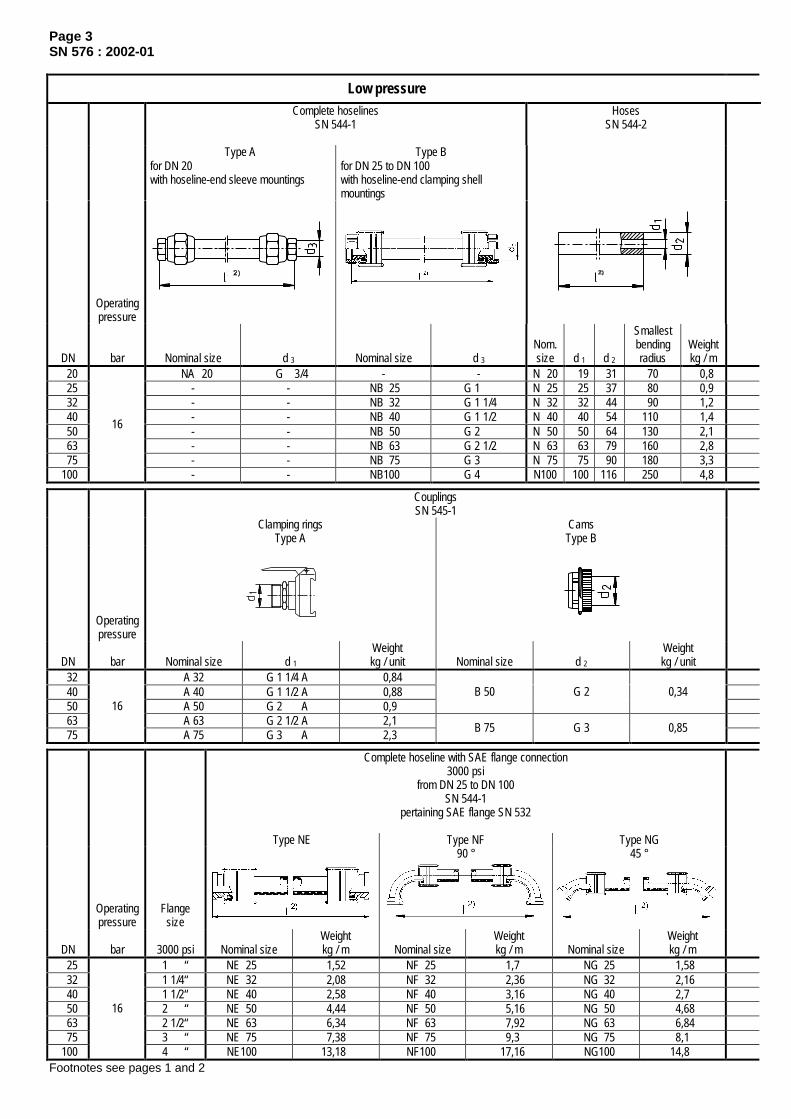
Page 3SN 576 : 2002-01
Low pressureComplete hoselines
SN 544-1Hoses
SN 544-2
Type A for DN 20 with hoseline-end sleeve mountings
Type B for DN 25 to DN 100 with hoseline-end clamping shell mountings
Operatingpressure
DN bar Nominal size d 3 Nominal size d 3Nom.size d 1 d 2
Smallestbendingradius
Weightkg / m
20 NA 20 G 3/4 - - N 20 19 31 70 0,825 - - NB 25 G 1 N 25 25 37 80 0,932 - - NB 32 G 1 1/4 N 32 32 44 90 1,240 - - NB 40 G 1 1/2 N 40 40 54 110 1,450 - - NB 50 G 2 N 50 50 64 130 2,163 - - NB 63 G 2 1/2 N 63 63 79 160 2,875 - - NB 75 G 3 N 75 75 90 180 3,3
100
16
- - NB100 G 4 N100 100 116 250 4,8
CouplingsSN 545-1
Clamping ringsType A
CamsType B
Operatingpressure
DN bar Nominal size d 1Weightkg / unit Nominal size d 2
Weightkg / unit
32 A 32 G 1 1/4 A 0,8440 A 40 G 1 1/2 A 0,8850 A 50 G 2 A 0,9
B 50 G 2 0,34
63 A 63 G 2 1/2 A 2,175
16
A 75 G 3 A 2,3B 75 G 3 0,85
Complete hoseline with SAE flange connection3000 psi
from DN 25 to DN 100SN 544-1
pertaining SAE flange SN 532
Type NE Type NF Type NG
Operatingpressure
Flangesize
90 ° 45 °
DN bar 3000 psi Nominal sizeWeightkg / m Nominal size
Weightkg / m Nominal size
Weightkg / m
25 1 “ NE 25 1,52 NF 25 1,7 NG 25 1,5832 1 1/4“ NE 32 2,08 NF 32 2,36 NG 32 2,1640 1 1/2“ NE 40 2,58 NF 40 3,16 NG 40 2,750 2 “ NE 50 4,44 NF 50 5,16 NG 50 4,6863 2 1/2“ NE 63 6,34 NF 63 7,92 NG 63 6,8475 3 “ NE 75 7,38 NF 75 9,3 NG 75 8,1
100
16
4 “ NE100 13,18 NF100 17,16 NG100 14,8Footnotes see pages 1 and 2

Page 4SN 576 : 2002-01
Hoselines
Hose fittings Types of connections for hoselinesSN 544-4
SN 544-3Type A
SN 545-2Type C
Double nipplesType C
Welding nipplesType D
for DN 20 with hoseline-end sleeve mountings
for DN 20 sleeve mounting
Type B for DN 25 to DN 100 with hoseline-end clamping shell mountings
for DN 25 to DN 75 clamping shell mounting
Nominalsize d 3
Weightkg / unit
Nominalsize d 2
Weightkg / unit
Nominalsize d
Weightkg / unit
Nominalsize d
l 3 4)
for StWeightkg / unit
A 20 G 3/4 0,16 C 20 0,2 C 20 G 3/4 A 0,05 D 20 G 3/4 A 30 0,06 B 25 G 1 0,19 C 25
G 10,23 C 25 G 1 A 0,1 D 25 G 1 A 35 0,1
B 32 G 1 1/4 0,28 C 32 0,55 C 32 G 1 1/4 A 0,2 D 32 G 1 1/4 A 35 0,14 B 40 G 1 1/2 0,5 C 40 0,6 C 40 G 1 1/2 A 0,21 D 40 G 1 1/2 A 35 0,15 B 50 G 2 0,75 C 50
G 20,7 C 50 G 2 A 0,4 D 50 G 2 A 45 0,31
B 63 G 2 1/2 1,35 C 63 1,53 C 63 G 2 1/2 A 0,75 D 63 G 2 1/2 A 45 0,36 B 75 G 3 1,47 C 75
G 31,42 C 75 G 3 A 0,8 D 75 G 3 A 45 0,46
B100 G 4 3,37 - - - C100 G 4 A - D100 G 4 A 45 0,65
CouplingsSN 545-3
Filler plugsType Dfor clamping rings
Type Efor cams
Nominal sizeWeightkg / unit Nominal size
Weightkg / unit
D 50 0,31 E 50 0,45
D 75 0,77 E 75 1,2
Hose fittings for SAE flange connections3000 psi
from DN 25 to DN 100SN 544-3
Type E Type F90 °
Type G45 °
Nominal sizeWeightkg / unit Nominal size l 5 + 4
Weightkg / unit Nominal size l 4 + 4
Weightkg / unit
E 25 0,31 F 25 55 0,4 G 25 25 0,34E 32 0,44 F 32 65 0,58 G 32 27 0,48E 40 0,69 F 40 75 0,88 G 40 30 0,75E 50 1,17 F 50 100 1,53 G 50 40 1,29E 63 1,77 F 63 120 2,56 G 63 60 2,02E 75 2,04 F 75 145 3 G 75 73 2,4E100 4,19 F100 185 6,18 G100 92 5
d 3

Page 5SN 576: 2002-01
The illustrations are given only as a help for better understanding of the possible applications.
Examples of application: for high-pressure hoseline
Examples of application: for low-pressure hoselines
Flange connectionSN 532 F
Flange connectionSN 532 F
HoselineSN 756 HC
Male studSN 759
HoselineSN 756 HA
CouplingSN 753 DEV
Male studSN 759 GUV
Intermediate socketSN 880
Male studSN 759 GUV
CouplingSN 884 EW
HoselineSN 756 HB
PipeCouplingSN 832 T
Pipe
Double nippleDIN 2990
Double nippleSN 544-4
ElbowDIN 2987
CouplingSN 545-1
Hose fittingSN 545-2
Hose fittingSN 544-3
HoseSN 544-2
Pipe
T-pieceDIN 2987
CouplingSN 545-1
Hose fittingSN 544-3
Hose fittingSN 544-3
HoseSN 544-2
Pipe Pipe
SocketDIN 2986
Welding nippleSN 544-4
Double nippleSN 544-4
HoselineSN 544-1
Pipe
Welding nippleSN 544-4
Hoseline fittingSN 545-2
HoseSN 544-2
Filler plugSN 545-3
CamSN 545-1

January 2002 (July 1997)
Hydraulic cylinders
Double-acting with cushioning and SAE flange connectionsPmax. = 250 bar 1)
SN 690
Dimensions in mm
For hydraulic cylinders with piston dia. ≤ 160 see SN 806.
This standard specifies the dimensions and weights of double-acting hydraulic cylinders with cushioning for maximum workingpressures of Pmax = 250 bar.
Types of constructionType A: clevis with spherical plain bearing 5)
Type B: pivotType C: foot mountingType E: flange mounting
Cylinder sizes with pertaining connection ports
Piston rod ∅ Cushioning 3) SAE flange connection 6000 psid2 when
Piston dia.
d1 ϕ = 1,4 ϕ = 1,6 ϕ = 2Length
Workcapacity 7)
W ≥ [J] NW A ±0,25 B ±0,25 C D Hole pattern
160 90 100 110 50 8500 2 44,5 96,8 50,8 M20
200 110 6) 125 140 60 16000
220 125 140 160 70 20000
250 140 160 180 80 30000
280 160 180 200 90 42500
2 1/2 58,7 123,8 63,5 M24
320 180 200 220 100 67500 3 71,4 152,4 76,2 M30
Designation of a hydraulic cylinder, type A, acc. to SN 690 with a piston dia. d1 = 160 mm,hard-chrome plated piston rod of diameter d2 = 100 mm and stroke l1
2) = 200 mm:
Hydraulic cylinder SN 690 - A 160/100 x 200
1)The cylinder rating is for a max. working pressure Pmax = 250 bar. For use under pulsating loads the max. working pressurehas to be reduced according to the pressure increase.The test pressure is at least 375 bar.
2) Stroke l1 is indicated as required for the respective purpose. The max. lifts of stroke for the different installation positions(3.5-fold safety against buckling) can be taken from the tables in the manufacturers' catalogues.
3) All cylinders are equipped with adjustable cushioning devices on both sides. The cushioning sleeves are made in bronze orequivalent material. For lifts of stroke up to 100 mm cushioning is not provided as a standard feature.
4) If the pivot of type B has to be in an extreme off-center position, the cylinder manufacturer must be consulted to clarify thedimensional details.
5) Lubrication of the spherical plain bearing (GE ... DO) is through the hinged clevis via hydraulic-type lubricating nippleaccording to DIN 71412 - AS6.
6) When the piston rod diameter is d2 = 110, the thread d5 is M 100 x 2 and the lengths are l7 = 100; l8 = 210; l9 = 115.7) The kinetic energy (E) as the product of all masses (m) acting upon the piston rod and the stroke speed (v) at the beginning
of cushioning, must not exceed the maximum work capacity (W) of the cushioning device.The following relation applies:
22
2s
PDAWvm
ED
×=≤×= ×
The calculation of W is based on:AD = max. effective cushioning area, assuming that piston-side and piston-rod side areas are identical.
PD = 350 bars = cushioning lengthIf the kinetic energy (E) exceeds the given working capacity of the cushioning device, our department of hydraulic systemsmust be informed so that the remaining residual energy can be taken into account for the control system.
Continued on pages 2 and 3
The above mentioned company standard is currently under revision in cooperation with the department ofhydraulic systems and media. Given the huge coordination work, it was not possible to include a revised versionin this edition of the standards book.
Please note that the company standards SN 690 and SN 806 will remain valid till the revised versions are issued.
Data sheets of the company standards will be kept available via the SMS Demag Intranet under"Standardization/Standards Online" or can be obtained from the Dept. of Standardization.
Th
is c
op
y w
ill n
ot
be
up
dat
ed in
cas
e o
f ch
ang
es!

cushioning valve
cushioning valve
Page 2SN 690 : 2002-01
Type A
d1 b1 b2
Width of sphericalplain bearing
b3
d3
max. d4 d5 d6 d7 h1 h2 s
160 135 60 55 0- 0,15 195 270 M 80 x 2 180 80 0
- 0,015 0 145 27
200 170 70 70 0- 0,20 245 320 M100 x 2
M110 x 2 6) 215 100 0- 0,020 0 180 27
220 170 80 70 0- 0,20 276 365 M120 x 3 260 110 0
- 0,020 0 200 27
250 170 90 85 0- 0,20 300 410 M130 x 3 280 120 0
- 0,020 0 230 27
280 215 100 90 0- 0,25 324 450 M140 x 4 305 140 0
- 0,025 0 260 27
320 215 110 105 0- 0,25 381 508 M150 x 4 340 160 0
- 0,025 0 290 27
Total weight G1 + G2 (kg/unit)G2 per 100 mm stroke whend1 l2 l3 l4 l5 l6 l7 l8 l9
≈
l10 l11
G1 ϕ = 1,4 ϕ = 1,6 ϕ = 2
160 630 ± 4 58 201 59 142 80 170 95 85 180 292 12,7 13,8 15,1
200 795 ± 4 78 253 78 175 100 5)
110 210 6)
235 115 6)
125 115 240 405 19,8 22,0 24,4
220 850 ± 5 78 287 78 209 115 265 145 125 270 545 26,8 29,2 32,9
250 889 ± 5 78 310 78 232 120 310 180 140 300 676 29,1 32,7 36,9
280 975 ± 5 90 322 90 232 125 345 185 150 325 938 32,2 36,3 41,1
320 1070 ± 5 90 360 90 270 140 400 200 175 375 1310 46,4 51,0 56,2
Type B
d1 b1 b4 b5 b6 b7d3
max. d4 d5 d6 d7 d8 s r
160 135 80 90 275 52 195 270 M 80x2 180 80 0- 0,015 75 - 0,06
- 0,10 27 1
200 170 100 120 320 55 245 320 M 100x2M 110x2 215 100 0
- 0,020 90 - 0,07- 0,12 27 2
220 170 110 130 370 60 276 365 M 120x3 260 110 0- 0,020 100 - 0,07
- 0,12 27 2
250 170 125 147 410 65 300 410 M 130x3 280 120 0- 0,020 110 - 0,07
- 0,12 27 2
280 215 150 158 450 70 324 450 M 140x4 305 140 0- 0,025 130 - 0,08
- 0,15 27 2
320 215 180 184 510 90 381 508 M 150x4 340 160 0- 0,025 160 - 0,08
- 0,15 27 2,5
Total weight G1 + G2 (kg/unit)G2 per 100 mm stroke when
d1 h1 h2 l2 l3 l4 l5 l8 l7 l8 l9≈ G1 ϕ = 1,4 ϕ = 1,6 ϕ = 2
160 0 145 545 ± 4 58 201 59 142 80 170 95 290 12,7 13,8 15,1
200 0 180 680 ± 4 78 253 78 175 100 6)
110 210 6)
235 115 6)
125 395 19,8 22,0 24,4
220 0 200 725 ± 5 78 287 78 209 115 265 145 535 26,8 29,2 32,9
250 0 230 749 ± 5 78 310 78 232 120 310 180 650 29,1 32,7 36,9
280 0 260 825 ± 5 90 322 90 232 125 345 185 715 32,2 36,3 41,1
320 0 290 895 ± 5 90 360 90 270 140 400 200 1295 46,4 51,0 56,2

cushioning valve
cushioning valve
Page 3SN 690 : 2002-01
Type C
d1 b1 b8 b9 b10d3
max. d4 d5 d6 d7 d9 h1 h2 h3 h4 s
160 135 76 330 400 195 270 M 80 x 2 180 80 0- 0,015 33 0 145 70 140 27
200 170 96 390 470 245 320 M100 x 2 M110 x 2 6) 215 100 0
- 0,020 39 0 180 85 165 27
220 170 104 445 535 276 365 M120 x 3 260 110 0- 0,020 45 0 200 95 188 27
250 170 114 510 610 300 410 M130 x 3 280 120 0- 0,020 52 0 230 110 210 27
280 215 124 540 640 324 450 M140 x 4 305 140 0- 0,025 52 0 260 125 230 27
320 215 134 620 740 381 508 M150 x 4 340 160 0- 0,025 52 0 290 140 260 27
Total weight G1 + G2 (kg/unit)G2 per 100 mm stroke whend1 l2 l3 l4 l5 l6 l7 l8 l9
≈
l12 l13 l14
G1 ϕ = 1,4 ϕ = 1,6 ϕ = 2160 94 58 201 59 142 80 170 95 297 154 38 302 12,7 13,8 15,1
200 97 78 253 78 175 100 5)
110 210 6)
235 115 6)
125 379 204 48 415 19,8 22,0 24,4
220 100 78 287 78 209 115 265 145 417 208 52 563 26,8 29,2 32,9
250 100 78 310 78 232 120 310 180 440 208 52 697 29,1 32,7 36,9
280 108 90 322 90 232 125 345 185 474 242 62 957 32,2 36,3 41,1
320 131 90 360 90 270 140 400 200 517 247 67 1330 46,4 51,0 56,2
Type E
d1 b1 b11d3
max. d4 d5 d6 d7 d10 d11 d12 d13 h1 h2 s
160 135 70 195 270 M 80x2 180 80 0- 0,015 325 385 275 - 0,11
- 0,19 26 0 145 27
200 170 85 245 320 M 100x2M 110x2 215 100 0
- 0,020 375 445 320- 0,12- 0,21 33 0 180 27
220 170 95 276 365 M 120x3 260 110 0- 0,020 430 490 370 - 0,12
- 0,21 33 0 200 27
250 170 95 300 410 M 130x3 280 120 0- 0,020 485 555 415 -.0,13
- 0,23 39 0 230 27
280 215 105 324 450 M 140x4 305 140 0- 0,025 520 590 450 - 0,13
- 0,23 39 0 260 27
320 215 105 381 508 M 150x4 340 160 0- 0,025 600 680 510 - 0,14
- 0,25 45 0 290 27
Total weight G1 + G2 (kg/unit)G2 per 100 mm stroke whend1 l2 l3 l4 l5 l6 l7 l8 l9
≈
l15 l16 YG1
ϕ = 1,4 ϕ = 1,6 ϕ = 2
160 545 ± 4 58 129 59 72 80 170 95 10 22 55° 332 12,7 13,8 15,1
200 680 ± 4 78 163 78 90 100 210 115 10 30 50° 462 19,8 22,0 24,4
220 725 ± 5 78 173 78 114 115 265 145 10 44 55° 622 26,8 29,2 32,9
250 749 ± 5 78 173 78 137 120 310 180 10 62 60° 768 29,1 32,7 36,9
280 825 ± 5 90 195 90 127 125 345 185 10 47 55° 1048 32,2 36,3 41,1
320 895 ± 5 90 195 90 165 140 400 200 10 80 60° 1442 46,4 51,0 56,2

Hydraulic cylinders
double-acting with cushioning 2)
Pmax = 250 bar 5)
Dimensions in mm
Type A: clevis with spherical plain bearing 6)
Type B: pivot
Designation of a hydraulic cylinder, type A, with piston dia. d1 = 100 mm,hard-chrome-plated piston rod with diameter d2 = 56 mm and stroke l11) = 200 mm:
Hydraulic cylinder SN 806 - A 100/56 x 200Piston rod diameter
d2 when CushioningPistondiameter
d1 2) φ=1,4 φ=1,6 φ=2 LengthWork
capacity W≥ (J) 9)
b1 b2 b3 b4 b5 b6 b7 b8
Width ofspherical plain
bearingb9
b10 d3 d4
40 22 28 18 50 135 110 95 23 20 G 3/8“ 2550 28 36 24 350
35 25155 130
38115 28 22
40G 1/2“ 31
63 36 45 28 650 30 180 150 42 13020
30 25 5080 45 56 35 1350
4040 210 170 48 145 25 35 28 55
G 3/4“ 44
100 56 70 40 2500 50 50 250 205 58 175 30 40 35
0-0,12
68 G1“ 50125 70
-
90 45 4200 55 60 305 255 68 215 40 50 44 74140 80 90 100 50 6000 60 65 340 280 72 230 42,5 55 49
0-0,15 80
G1 1/4“ 60
Piston rod diameterd2 when
Pistondiameter
d1 2) φ=1,4 φ=1,6 φ=2l4 l5 l6 l7 l8 l9 l10 l11 l12 l13 l14
40 22 28 16 60 ± 2 122,5 210 ± 2 30 50 28 36 22
55 25 65 ± 2
60132,5
12,5 57,5 215 ± 2 40
63 36 45 28 62,5 27,5 67,5 155 15 65 240 ± 2 50 80 45 56 35 65 30
70 ± 370 170 20 75 260 ± 2 55
100 56 70 45 77,5
5
32,5 75 ± 3 82,5 210 25 85 295 ± 2 75125 70
-
90 58 87,5 40,5 90 ± 4 97,5 250 30 103 353 ± 2 90140 80 90 100 65 95
1043 105 ± 4 105 272,5 32,5 110,5 388 ± 2 100
1) Stroke l1 is indicated as required for the respective purpose. The max. lifts of stroke for the different installation positions canbe taken from the diagrams of the manufacturers' catalogues.
2) All cylinders are equipped with adjustable cushioning devices on both sides. The cushioning sleeves are made of bronze.For reasons of functioning, venting and check valves are installed separately of each other. Cylinder bottom and cylinderhead are screw-fastened.
3) In exceptional cases the pivot length b7 of type B can be increased to the value of diameter d14. This has to be stated in thenote column of the parts list.
4) If the pivot of type B has to be in an extreme off-center position, the cylinder manufacturer must be consulted to clarify thedimensional details.
5) The cylinder rating is for a max. working pressure Pmax = 250 bar. In the case of pulsating loads the max. working pressuremust be reduced according to the pressure increase.
bottom side (cylinder bottom)
cushioning valve
section B-B
detail Xturned by 90
variable
rod side(cylinder head) section A-A
Th
is c
op
y w
ill n
ot
be
up
dat
ed in
cas
e o
f ch
ang
es!

January 2002 (July 1997)
SN 806
Dimensions in mm abridged
Type C: foot mounting
Type E: Front flange mounting
d5 d6
e8
d7
min.
d8 d9 d10 d11 d12 d13 9) d14
e8
d15 h1 h2 h3 h4 h5 l2 l3
85 90 56 M 16x1,5 9 108 130 55 25 87,5 45 25 18 41,5 205 ±2105 110 63,5 M 22x1,5 11 130 160
1168
3030
0-0,010 107,5 55 30 21 51,5 210 ±2
120 130 76,1 M 28x1,5 155 185 14 75 35 35 125 65 35 56 235 ±3135 145 101,6 M 35x1,5
14170 200 18 95 40 40 137,5 70 40 64 255 ±2
165 175 121 M 45x1,5 18 205 245 22 115 50 50
0-0,012
67,5 85 5031
79,5 290 ±3200 210 152,4 M 58x1.5 245 295 135 60 60 205 105 60 96 343 ±4220 230 171 M 65x1,5
22265 315
26155 65 70
-0-0,015 225 115 65
38106 378 ±4
-
Total weight G1 and G2 (kg/unit)G2 per 100 mm strokeG1
Type piston rod dia. whenl15 l16 l17 l18 l19 l20 l21 r s
A B C E φ = 1,4 φ = 1,6 φ = 2
235 ± 2 30 60 50 28 10 7 8 7,6 9,5 1,2 1,4245 ± 2
2035 69
4060 32 14 11 12,5 12 15 1,4 1,7
280 ± 3 22,5 45 87 70 39 18 19 18 23 1,8 2,2305 ± 2 25 50 100
4585 47 24,5 25,6 27 30,2 3,5 4,3
350 ± 3 27,5 60 123 55 105 58
0,519
43,5 45,8 46 54 4,7 5,9415 ± 4 32,5 70 140 65 130 70 80 81 83 95 7,7
-
8,6455 ± 4 35 75 157 70 150 82
1 24101 104,5 110,5 121,5 9,9 10,4 12,1
6) The spherical plain bearing is lubricated through the pin.8) Up to a piston diameter of 140 without extension piece.9) The kinetic energy (E) as the product of all masses (m) acting upon the piston rod and the stroke speed (v) at the beginning
of cushioning, must not exceed the maximum work capacity (W) of the cushioning device.The following relation applies:
The calculation of W is based on:AD = max. effective cushioning area, assuming that piston-side and piston-rod side areas are identical.pD = 350 barIf the kinetic energy (E) exceeds the given working capacity of the cushioning device, our department of hydraulic systemsmust be informed so that the remaining residual energy can be taken into account for the control system.
22
2s
PDAWvm
ED
×=≤×= ×

January 2002
Materials kept in stockAuxiliary and operating materials
Overview
SN 531
Dimensions in mmDimensions
Designation Thickn.mm
Widthmm
Lengthmm
Technical values Notes
Sealing material
Sealing plates, one side graphitized Supplier: Fa. Hellhake
44143 Dortmund
2 1500 1500 material: NP 815 (aramide-nitrile) permiss. pressure: up to 50 bar perm. temperature: up to ± 300 °C
For general purposes of sealing against oils, greases, petrol, benzol and solvents. Substitute for ITÖ
Nebar standard No. 1 Supplier: Fa. Haacke & Söhne
22767 Hamburg0,8 1200 1200
permiss. pressure: up to ≈ 20 bar perm. temperature: - 30°C to + 120°C oil resistance: good (also resistant against Somentor N35)
Levels up slight roughnesses of the sealing surface; hence particularly suited for large sealing surfaces. Required min. surface pressure = 300 N/cm².
Sealing tape ≈ 0,1 12,5 runn.meter
material: PTFE perm. temperature: - 100°C to + 300°C
For sealing screwed joints on pipe lines (e.g. used instead of hemp)
2 Flat rubber with canvas lining
31000 runn.
meter
perm. pressure: up to ≈ 10 bar perm. temperature: up to ≈ + 80°C hardness: 60 Shore A oil resistance: gut
For sealing uneven (unworked) surfaces.
Soft rubber with skin on all sides 8 12 runn.
meter
material: neoprene perm. temperature: up to ≈ + 70°C hardness: 15 Shore A oil resistance: good
For use as wiper and for sealing purposes
High-temperature resistant insulating material
∅ 8 Ezeram Round-twisted ceramic-fibre cord ∅ 10
- -
perm. temperature: up to +1260°C resistant to: oil, steam, water,
chemicals, liquidmetal
outstanding feature: asbestos-free
Used for sealing flaps, covers and as insulating cord
Acrylic glass246
Acrylic glass (e.g. plexiglass)
10
1200 2000 forming temperature: + 130°C to 150°C Workable by sawing, drilling, grinding, etc.
Sealing compound
Curil K2 perm. temperature: - 40°C to +200°C oil resistence: good
Sealing of gear, machine and motor housings, pumps, flanges, oil trays etc.
Fermit-Special atoxic Used primarily for water lines Cleaning materials Nikutex 1459 Supplier: Chem. Werke Kluthe GmbH
69115 Heidelberg
mixture of organic solvents form and colour: liquid, colourless flash point A II
Machine cleaning material
Lubricant Gleitmo 805 Supplier: Gleitmolybdän Schmierstoffe GmbH
85386 Eching perm. temperature: - 20°C to + 110°C Lubricant for stainless-steel bolts, nuts and
pipe couplings.
MOLYKOTE Gn plus
Supplier: DOW CORNING GmbH80992 München
perm. temperature: - 40°C to + 450°C coefficient of friction: - with screws: 0,09 - at 40 m2/kg: 0,07 colour: black
Assembly lubricant, reduces friction and wear. Prevents seizing and metal-to-metal contact. Reduces fretting corrosion.
MOLYKOTE Un
Supplier: DOW CORNING GmbH80992 München
perm. temperature: - 40°C to + 450°C
colour: black
After the evaporation of the carrier oil, a lubrication-effective solid lubricant remains. Compatible with natural rubber and plastics. Reduces fretting corrosion.
Repair filler
METALIX S Supplier: DOW CORNING GMBH
80992 München
perm. temperature: - 50°C to + 180°C compressive strength:1500 N/cm2
tensile strength: 5500 N/cm2
chemically stable
For repair of machines, pipes, vessels and shrinkholes. Sealing against penetration of liquids under pressure
Continued on page 2
Th
is c
op
y w
ill n
ot
be
up
dat
ed in
cas
e o
f ch
ang
es!

Page 2SN 531 : 2002-01
Designation Technical values Note Adhesives acc. to SN 507 Loctite Parts to be joined 75/AAV 1)
Code No. 675 perm. temperature: - 55°C to +150°C Bonding of cylindrical joints, e.g. universal
joint shaft heads, bearings, etc.
Loctite Pipe sealant, extra strong AVX Code No. 586
perm. temperature: - 55°C to + 150°C Seals and securing of pipe couplings > 16 bar
Loctite Medium-strength bolt securing agent Code No. 242
perm. temperature: - 55°C to + 150°C Bonding of wear plates. Securing of threaded connections.
Loctite Instant adhesive IS 496 Code No. 496
perm. temperature: - 50°C to + 80°C Bonding of neoprene rubber seals.
OMNIFIT Low-strength pipe sealant Code No. 50 H
perm. temperature: - 60°C to + 150°C Sealing and securing of pipe couplings and threaded fittings ≤ 16 bar.
Technicoll 2)
Epoxy resin/hardener 8266 Part A / 8267 Part B
perm. temperature: up to + 150°C Bonding of wear plates, sliding liners, nameplates, reinforcements, scales, etc.
Hoses, except hoses as in SN 544 and SN 756
Rubber pressure 6 bar, temperature: + 50°C ∅ 1/4“ (19/13); ∅ 1/2“ (29/19); ∅ 1“ (34/23)
Water etc.
PVCTemperature: + 20°C
Compressed-air control systems etc.
Pressure 25 bar Pressure 14 bar
Hose
∅ 6 x 12∅ 8 x 14
∅ 12,5 x 18,5∅ 19 x 27
1) Previous SMS designation A12) Previous SMS designation B1
All products for which no suppliers are stated are purchased from technical dealers.
Further standards
SN 180-1 Operating media, lubricant recommendations greaseSN 180-2 Operating media, lubricant recommendations oilSN 180-3 Morgoil lubricant specification new oilSN 507 Metal bonding

Revisions made in January 2002
General• For reasons of copyright, four standards sheets of the 1997 standards book have been made SN standards:
DIN 509 is now SN 695; DIN 15058 is SN 370; DIN ISO 4379 is SN 364-1;DIN ISO 12128 and DIN 1850-2 are now SN 364-3.
• SN 833 (of chapter 8) has been split up into SN 530, SN 358 and SN 356.• SN 151 (of chapter 6) has been cancelled.• SN 690 and SN 806 (of chapter 10) are still in the versions of July 1997 and are currently under revision.• SN 364-2: addition of bushings for cylinders.• All numbers of files no longer appear in the standards book 2002, as the file numbers will be newly assigned and the files are
available e.g. through the Intranet.• Generally, all SN standards have been editorially revised.
Chapter 1: MaterialsSN 359: - The material designations have been converted to the new designation system.
- Addition of table-type designation systems.- Newly added materials: - steels for pressure purposes according to DIN EN 10028-2 and 3,
- engineering steels with higher yield point ... according to DIN EN 10137-2 and SEW 090-2,- forging steels according to DIN EN 10222, DIN EN 10250 and SEW 550,- heat resistant steel according to DIN EN 10269,- malleable cast iron according to DIN EN 1562,- sintered bronze, oil-impregnated
- As far as necessary, the values have been adapted to the new materials standards.- Relative cost factors have been rounded off to one decimal place.- Updating of suitability for welding and of welding preheat temperatures.- Updating of footnotes.
Chapter 2: Drilling and thread depths, thread selection series and undercutsSN 480: - Table of "Maximum drilling depths": updating of values
- Table of "Maximum drilling depths for multi-diameter and single-diameter holes": updating of values- Table of "Pipe threads as in DIN ISO 228": addition of outside and inside diameter values.- Table of "Metric thread as in DIN 13": tables condensed.
Chapter 3: Curves, diagonals, undercutsSN 481: - Indication of current sizes in the table of "Curves and diagonals on milled parts".SN 695: - Revision of blank form (contents as in DIN 509 unchanged).
Chapter 4: Permissible bolt loads, tightening torques, pretensioning unitsSN 403: - Indication of additional pretensioning units.
- Updating of all tables and graphic charts.
Chapter 5: Design instructions on fastenersScrews and bolts, nuts, washers in conjunction with countersinks/counterbores and/or holes; foundation anchoring elements
SN 351: - As far as necessary, graphic charts and values in tables adapted to the new standards.- Addition of screw plugs according to DIN 908.- Hexagon socket screw acc. to DIN 6912 cancelled.
SN 372: - Addition of: - Threaded pin acc. to SN 172;- Adhesive anchor acc. to SN 705.
- Lock nut in the column of "Projection" cancelled.- Addition of footnotes.
Chapter 6: Mechanical fastenersScrews, bolts, nuts; setscrews, pins, studs, other screws/bolts; washersand retaining elements, locknuts and locking plates
SN 151: - Cancelled.SN 485: - DIN 561: Addition of M 56.
- DIN 908, SN 595: Indication of metric sizes.- DIN 912 replaced by DIN EN ISO 4762, addition e.g. of M56 and M64.- DIN 980 replaced by DIN EN ISO 7042 and 10513.- DIN 6912 cancelled.- DIN 7991 replaced by DIN EN ISO 10642, cancelling e.g. of M24.- DIN EN 24014 replaced by DIN EN ISO 4014.- DIN EN 24017 replaced by DIN EN ISO 4017.- DIN EN 24032 replaced by DIN EN ISO 4032, addition e.g. of DIN EN ISO 8673.
Continued on page 2

Page 2Revisions: 2002-01
SN 486: - DIN 94 replaced by DIN EN ISO 1234, addition e.g. of diameter 1.6.- DIN 186: Addition of M48.- DIN 529: Addition of M48 and M56.- DIN 580: Addition of M56 and M64.- DIN 939: Addition of M48.- DIN EN 22338 replaced by DIN EN ISO 2338.- DIN EN 22339: Addition of diameters 16, 20, 25, 30, 40, 50, cancelling of diameters 2, 3, 4 and 5.- DIN EN 28733 replaced by DIN EN ISO 8733, addition e.g. of diameter 50.- DIN EN 28734 replaced by DIN EN ISO 8734, addition e.g. of diameter 50.- DIN EN 28736: Addition of diameters 6 and 8.- DIN EN 28752 replaced by DIN EN ISO 8752, addition e.g. of diameter 50.
SN 487: - DIN 125 replaced by DIN EN ISO 7089 (DIN EN ISO 7090), washers e.g. for screw diametersM72 and M80 cancelled.
- SN 808: Addition of washers for screw diameters M90, M100, M110, M125, M140, M160.SN 489: - No revision with regard to contents
Chapter 7: Fitting keys, keysSN 708: - Revision of sketch stating the position tolerances for fitting keys.
Chapter 8: Axle stop plates, pins, bushingsSN 370: - Revision of blank form (contents as in DIN 15058).SN 530: - Revision of blank formSN 358: - Revision of blank form previously SN 833.SN 356: - Revision of blank form
SN 364-1: - Revision of blank form (contents as in DIN ISO 4379), addition of detail X in the sketch, revision ofcalculation example.
SN 364-2: - Newly added.SN 364-3: - Revision of blank form (contents as in DIN ISO 12128 and DIN 1850-2), new structure of table on types
of lubricant feeding and distribution.
Chapter 9: Semi-finished products available from stock, structural steel sectionsSN 483: - DIN 176 cancelled.
- DIN 671 replaced by DIN EN 10278; e.g. dimensions 45 and 60 cancelled.- DIN 1025/2: Dimension 180 cancelled.- DIN 1028 replaced by DIN EN 10056, e.g. addition of dimension 150 x 150 x 15.- DIN 1029 replaced by DIN EN 10056.- DIN 1783 replaced by DIN EN 485.- DIN 2462 replaced by DIN EN ISO 1127, cancelling e.g. of dimensions 16x2; 20x2,5; 25x3; 30x4; 35x2,5
and 38x5; addition of dimensions 42,4x2,6; 60,3x2,9; 76,1x12,5; 88,9x14,2 and 114,3x3,6.SN 805: - DIN 1028 and DIN 1029 replaced by DIN EN 10056-1 and -2.
- DIN 59410 replaced by DIN EN 10210-2.- DIN 59411 replaced by DIN EN 10219-2.
Chapter 10: Pipe dimensions, flanges, welding fittings, pipe couplings and fasteners,hoselines, hydraulic cylinders, sealing and insulating materials, revisions
SN 553: - completely revised and adapted to pipe classification of SN 901, max. 300 mm nominal diameter.SN 456: - SN 875 replaced by SN 878.
- SN 787 replaced by SN 882.- SN 832 replaced by SN 883 (only straight male stud coupling).- SN 457, SN 479 and SN 790 replaced by SN 884.- Addition of: SN 811, SN 862, SN 879 and SN 880.- Revision of pressure stages.
SN 836: - Revision of pressure stages.- Addition of screw-hole arrangement as in DIN 2501 (with sketch).- Addition of new material designations.
SN 837: - No revision with regard to contents.SN 576: - Addition of data on low-pressure hoseline.
- Revision of application examples.SN 690: - Contents as in July 1997 edition, as revision not complete at copy deadline.SN 806: - Contents as in July 1997 edition, as revision not complete at copy deadline.SN 531: - Cancelling of sealing plates, thickness 1 mm, one side graphitized.
Previous editions:Standards book and SN 200: 1975-11, 1978-01, 1981-01,1985-01, 1992-03Standards book: 1997-07

Codes of the units of quantity
Code Designation Code Designation01234
setkg
piecemm2
56789
m³t
litreslabpair

Imprint
The STANDARDS BOOK 2002 is edited by SMS Demag Aktiengesellschaft, Dept. of Standardization.
Wiesenstraße 30, 57271 Hilchenbach/GermanyPhone: (0 27 33) 29–10 93Fax: (0 27 33) 29–10 73
E-mail: [email protected]@sms-demag.de