starter guide visual basic rcx
TRANSCRIPT
LegoMindstormsProgrammingwith VisualBasic
David HanleySean Hearne

Table of Contents
Acknowledgements
Introduction
Chapter OneFirst Steps in Visual Basic
Chapter TwoIntroducing the Lego Mindstorms Kit
Chapter ThreeYour First Robot
Chapter FourUsing Sensors
Chapter FiveManipulating Variables
Chapter SixBuilding Autonomous Robots
Chapter SevenA More Controllable Robot
Chapter EightDelving Deeper into the RCX
Chapter NineNetworking and Synchronisation
AppendicesAppendix A - Serial CommunicationsAppendix B - Downloading programs to the RCX with error checkingAppendix C - Setting up Visual Basic to program the Lego RCXAppendix D - The RCXdata.bas fileAppendix E - Polling MotorsAppendix F - Programming the Lego RCX with other languagesAppendix G - The Lego RCX Memory MapAppendix H - Downloading Firmware
ii
iii
1
17
28
41
56
67
77
84
102
111123126129132137142145
i

Acknowledgements
The authors wish to thank the following people who assisted them in developing this book.
Joe DalyMary BarryPaul BarryKarl Sandison
ii
Introduction
You may or may not have ever programmed a computer before. If you have, you’ll feel at
ease with some of the early concepts presented here. If not, there is no need to despair,
because this course has specifically been designed for you. This course involves you
programming and controlling robots which you will construct using the Lego Mindstorms
robotic invention kit, using Microsoft Visual Basic version 5 as the development
environment in which you will work. Visual Basic helps you quickly and easily create
programs, and programming robots with Visual Basic is not as difficult as you may at first
expect it to be. Nor should you overly worry about the actual construction of the robots.
The concepts will be introduced gradually and some of the building steps have even been
included for you.
Included with this book are several appendices which describe the fundamentals of Lego
engineering as well as some computer architecture aspects of the serial communication
carried out by the Lego robots. The methods of programming of the Lego kit with other
languages besides Visual Basic are also described, as are several available packages and
documentation related to the Lego kit.
For the most part the appendices are simply for reference, although they may be of interest
to some in building and programming the robots.
The course is broken up into a series of practical classes, each two hours long, which
explain Visual Basic concepts and then require you to put these concepts into practice
using the Lego Mindstorms robotics kit.
Let’s now start with the creation of your first Visual Basic program.
iii
ChapterOne
First Steps in Visual Basic
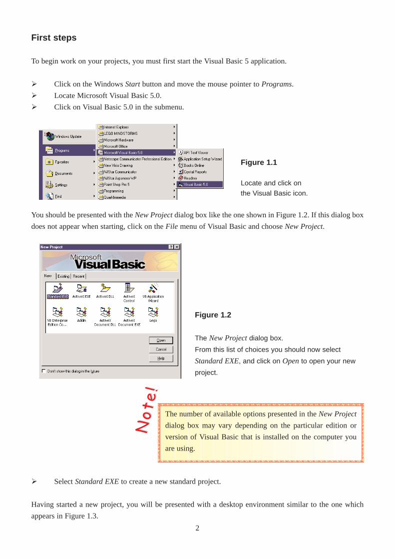
Figure 1.2
The New Projectdialog box.
From this list of choices you should now select
Standard EXE, and click on Opento open your new
project.
First steps
To begin work on your projects, you must first start the Visual Basic 5 application.
Ø Click on the Windows Startbutton and move the mouse pointer to Programs.
Ø Locate Microsoft Visual Basic 5.0.
Ø Click on Visual Basic 5.0 in the submenu.
Ø Select Standard EXEto create a new standard project.
Having started a new project, you will be presented with a desktop environment similar to the one which
appears in Figure 1.3.
The number of available options presented in the New Project
dialog box may vary depending on the particular edition or
version of Visual Basic that is installed on the computer you
are using.
You should be presented with the New Projectdialog box like the one shown in Figure 1.2. If this dialog box
does not appear when starting, click on the File menu of Visual Basic and choose New Project.
NNoo tt
ee !!Figure 1.1
Locate and click on
the Visual Basic icon.
2
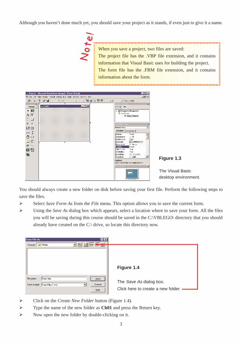
Figure 1.3
The Visual Basic
desktop environment.
Figure 1.4
The Save As dialog box.
Click here to create a new folder.
You should always create a new folder on disk before saving your first file. Perform the following steps to
save the files.
Ø Select Save Form Asfrom the File menu. This option allows you to save the current form.
Ø Using the Save Asdialog box which appears, select a location where to save your form. All the files
you will be saving during this course should be saved in the C:\VBLEGO\ directory that you should
already have created on the C:\ drive, so locate this directory now.
Ø Click on the Create New Folderbutton (Figure 1.4).
Ø Type the name of the new folder as Ch01 and press the Return key.
Ø Now open the new folder by double-clicking on it.
Although you haven’t done much yet, you should save your project as it stands, if even just to give it a name.
When you save a project, two files are saved:
The project file has the .VBP file extension, and it contains
information that Visual Basic uses for building the project.
The form file has the .FRM file extension, and it contains
information about the form.
NNoo tt
ee !!
3
Ø In the File Namebox, type Hello (Visual Basic will append the correct .FRM extension to the file
name after you have saved it).
Ø Click on the Savebutton to save the form file.
Ø Select Save Projectfrom the File menu. This option allows you to save the entire current project.
Ø In the File Namebox, type Hello.
Ø Click on the Savebutton to save the project file.
Now that you’ve given your project and form a name, you can save your updates by simply selecting Save
Project from the File menu, and it will save the file with the same name you previously used. You can also
use the save icon on the toolbar.
Project Explorer WindowAt this moment in time, your project is called Hello.VPB and it consists of a single form file: the Hello.FRM
file. However for most applications, your project will consist of more that one file.
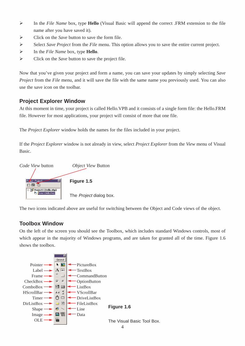
The Project Explorerwindow holds the names for the files included in your project.
If the Project Explorerwindow is not already in view, select Project Explorerfrom the Viewmenu of Visual
Basic.
Figure 1.5
The Project dialog box.
Figure 1.6
The Visual Basic Tool Box.
The two icons indicated above are useful for switching between the Object and Code views of the object.
Object ViewButtonCode Viewbutton
PictureBoxTextBoxCommandButtonOptionButtonListBoxVScrollBarDriveListBoxFileListBoxLineData
PointerLabel
FrameCheckBox
ComboBoxHScrollBar
TimerDirListBox
ShapeImageOLE
Toolbox WindowOn the left of the screen you should see the Toolbox, which includes standard Windows controls, most of
which appear in the majority of Windows programs, and are taken for granted all of the time. Figure 1.6
shows the toolbox.
4
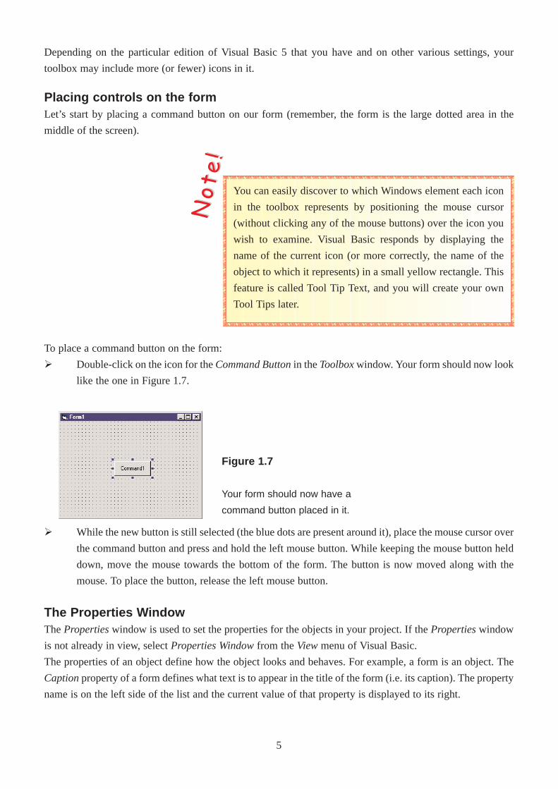
Placing controls on the formLet’s start by placing a command button on our form (remember, the form is the large dotted area in the
middle of the screen).
Ø While the new button is still selected (the blue dots are present around it), place the mouse cursor over
the command button and press and hold the left mouse button. While keeping the mouse button held
down, move the mouse towards the bottom of the form. The button is now moved along with the
mouse. To place the button, release the left mouse button.
The Properties WindowThePropertieswindow is used to set the properties for the objects in your project. If the Propertieswindow
is not already in view, select Properties Windowfrom the Viewmenu of Visual Basic.
The properties of an object define how the object looks and behaves. For example, a form is an object. The
Captionproperty of a form defines what text is to appear in the title of the form (i.e. its caption). The property
name is on the left side of the list and the current value of that property is displayed to its right.
Figure 1.7
Your form should now have a
command button placed in it.
You can easily discover to which Windows element each icon
in the toolbox represents by positioning the mouse cursor
(without clicking any of the mouse buttons) over the icon you
wish to examine. Visual Basic responds by displaying the
name of the current icon (or more correctly, the name of the
object to which it represents) in a small yellow rectangle. This
feature is called Tool Tip Text, and you will create your own
Tool Tips later.
NNoo tt
ee !!
To place a command button on the form:
Ø Double-click on the icon for the Command Buttonin the Toolboxwindow. Your form should now look
like the one in Figure 1.7.
Depending on the particular edition of Visual Basic 5 that you have and on other various settings, your
toolbox may include more (or fewer) icons in it.
5
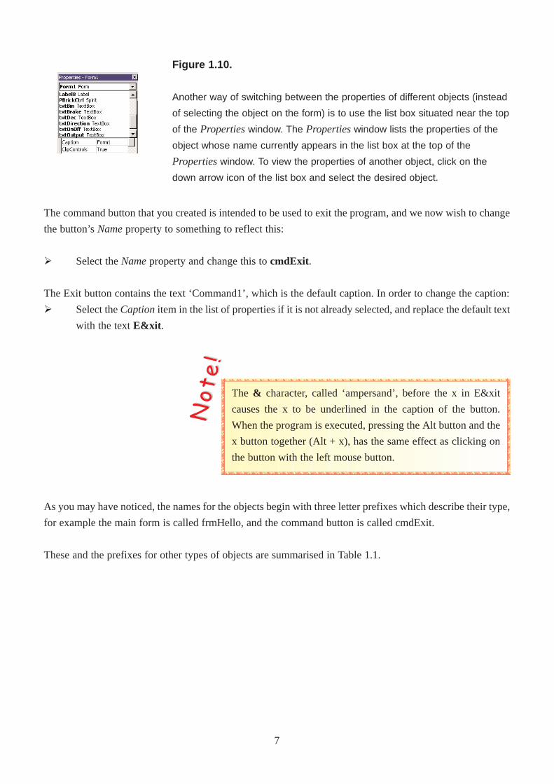
Without selecting anything else, type in the text The Hello World Program.
The form now looks like the one presented in Figure 1.9.
The Name PropertyEach object in Visual Basic must have a name, which is defined by its Nameproperty. If you look at the Name
property of the form in the Hello program, you will notice that it is called Form1. This is the name that Visual
Basic automatically assigns it when it is created, but this name is not very descriptive to us and could be made
more helpful.
To change the Nameproperty of the form:
Ø Ensure that the form is selected.
Ø Click on the Alphabetictab of the Propertieswindow.
Ø The first property referred to is the (Name)property. It is enclosed in brackets in order that it will
appear at the top of the alphabetic list. Click on this first cell and type the text frmHello .
In the preceding step, you changed the Nameproperty to frmHello. The first three characters are used to
describe the type of control that the object is. This is not necessary, but it is done because it makes the code
clearer and easier to understand.
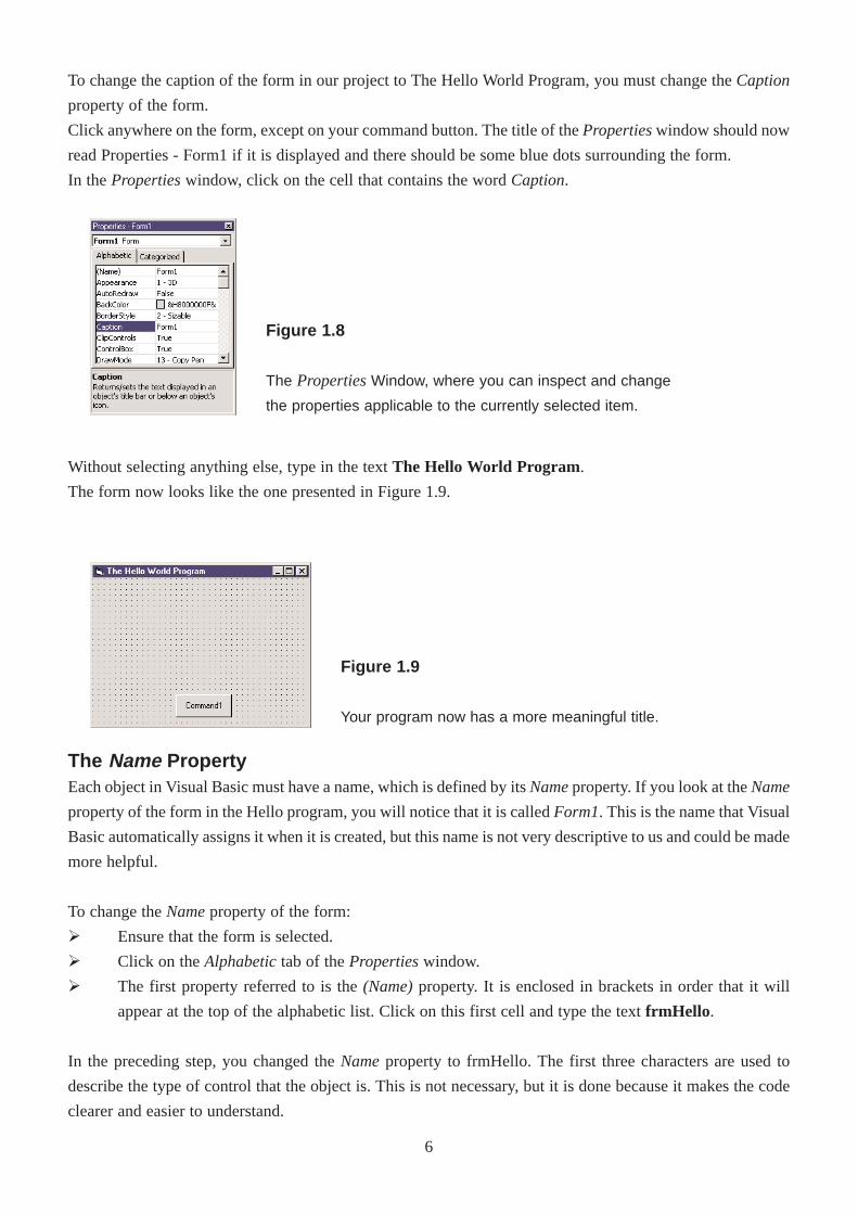
Figure 1.8
The PropertiesWindow, where you can inspect and change
the properties applicable to the currently selected item.
Figure 1.9
Your program now has a more meaningful title.
To change the caption of the form in our project to The Hello World Program, you must change the Caption
property of the form.
Click anywhere on the form, except on your command button. The title of the Propertieswindow should now
read Properties - Form1 if it is displayed and there should be some blue dots surrounding the form.
In the Propertieswindow, click on the cell that contains the word Caption.
6
The command button that you created is intended to be used to exit the program, and we now wish to change
the button’s Nameproperty to something to reflect this:
Ø Select the Nameproperty and change this to cmdExit.
The Exit button contains the text ‘Command1’, which is the default caption. In order to change the caption:
Ø Select the Captionitem in the list of properties if it is not already selected, and replace the default text
with the text E&xit .
The & character, called ‘ampersand’, before the x in E&xit
causes the x to be underlined in the caption of the button.
When the program is executed, pressing the Alt button and the
x button together (Alt + x), has the same effect as clicking on
the button with the left mouse button.
NNoo tt
ee !!
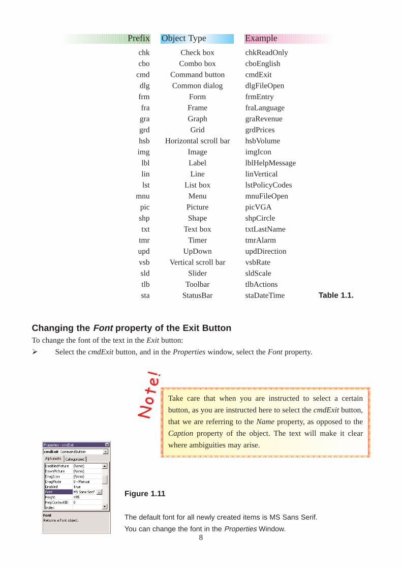
Figure 1.10.
Another way of switching between the properties of different objects (instead
of selecting the object on the form) is to use the list box situated near the top
of the Propertieswindow. The Propertieswindow lists the properties of the
object whose name currently appears in the list box at the top of the
Propertieswindow. To view the properties of another object, click on the
down arrow icon of the list box and select the desired object.
As you may have noticed, the names for the objects begin with three letter prefixes which describe their type,
for example the main form is called frmHello, and the command button is called cmdExit.
These and the prefixes for other types of objects are summarised in Table 1.1.
7
chk
cbo
cmd
dlg
frm
fra
gra
grd
hsb
img
lbl
lin
lst
mnu
pic
shp
txt
tmr
upd
vsb
sld
tlb
sta
Check box
Combo box
Command button
Common dialog
Form
Frame
Graph
Grid
Horizontal scroll bar
Image
Label
Line
List box
Menu
Picture
Shape
Text box
Timer
UpDown
Vertical scroll bar
Slider
Toolbar
StatusBar
Prefix Object Type
chkReadOnly
cboEnglish
cmdExit
dlgFileOpen
frmEntry
fraLanguage
graRevenue
grdPrices
hsbVolume
imgIcon
lblHelpMessage
linVertical
lstPolicyCodes
mnuFileOpen
picVGA
shpCircle
txtLastName
tmrAlarm
updDirection
vsbRate
sldScale
tlbActions
staDateTime
Example
Table 1.1.
Changing the Font property of the Exit ButtonTo change the font of the text in the Exit button:
Ø Select the cmdExitbutton, and in the Propertieswindow, select the Font property.
Take care that when you are instructed to select a certain
button, as you are instructed here to select the cmdExitbutton,
that we are referring to the Nameproperty, as opposed to the
Caption property of the object. The text will make it clear
where ambiguities may arise.
NNoo tt
ee !!
Figure 1.11
The default font for all newly created items is MS Sans Serif.
You can change the font in the Properties Window.8
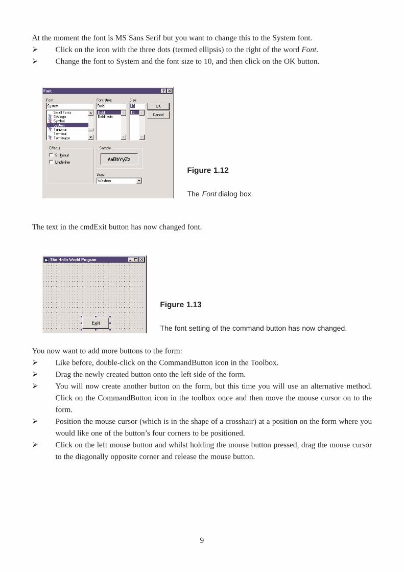
Figure 1.12
The Font dialog box.
At the moment the font is MS Sans Serif but you want to change this to the System font.
Ø Click on the icon with the three dots (termed ellipsis) to the right of the word Font.
Ø Change the font to System and the font size to 10, and then click on the OK button.
The text in the cmdExit button has now changed font.
You now want to add more buttons to the form:
Ø Like before, double-click on the CommandButton icon in the Toolbox.
Ø Drag the newly created button onto the left side of the form.
Ø You will now create another button on the form, but this time you will use an alternative method.
Click on the CommandButton icon in the toolbox once and then move the mouse cursor on to the
form.
Ø Position the mouse cursor (which is in the shape of a crosshair) at a position on the form where you
would like one of the button’s four corners to be positioned.
Ø Click on the left mouse button and whilst holding the mouse button pressed, drag the mouse cursor
to the diagonally opposite corner and release the mouse button.
Figure 1.13
The font setting of the command button has now changed.
9
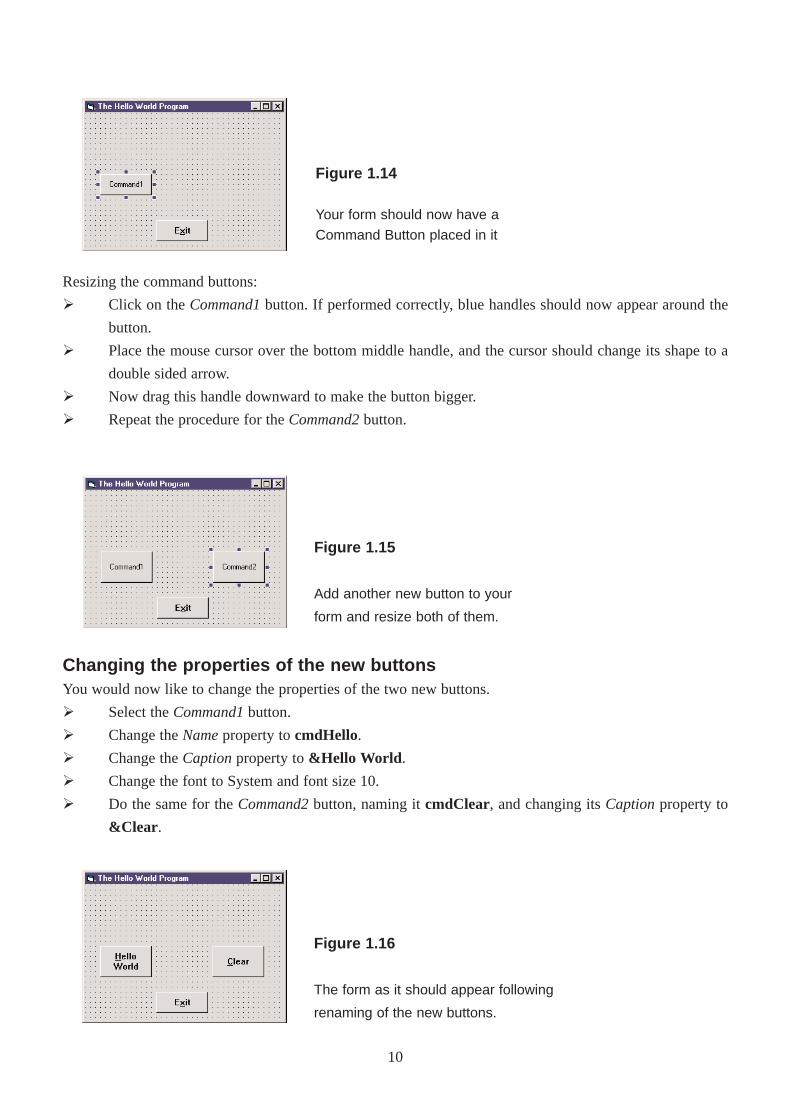
Resizing the command buttons:
Ø Click on the Command1button. If performed correctly, blue handles should now appear around the
button.
Ø Place the mouse cursor over the bottom middle handle, and the cursor should change its shape to a
double sided arrow.
Ø Now drag this handle downward to make the button bigger.
Ø Repeat the procedure for the Command2button.
Figure 1.15
Add another new button to your
form and resize both of them.
Figure 1.14
Your form should now have a
Command Button placed in it
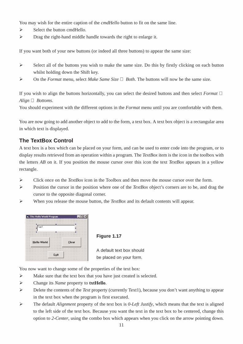
Changing the properties of the new buttonsYou would now like to change the properties of the two new buttons.
Ø Select the Command1button.
Ø Change the Nameproperty to cmdHello.
Ø Change the Captionproperty to &Hello World .
Ø Change the font to System and font size 10.
Ø Do the same for the Command2button, naming it cmdClear, and changing its Captionproperty to
&Clear .
Figure 1.16
The form as it should appear following
renaming of the new buttons.
10
You may wish for the entire caption of the cmdHellobutton to fit on the same line.
Ø Select the button cmdHello.
Ø Drag the right-hand middle handle towards the right to enlarge it.
If you want both of your new buttons (or indeed all three buttons) to appear the same size:
Ø Select all of the buttons you wish to make the same size. Do this by firstly clicking on each button
whilst holding down the Shift key.
Ø On the Formatmenu, select Make Same Size⇒ Both. The buttons will now be the same size.
If you wish to align the buttons horizontally, you can select the desired buttons and then select Format ⇒Align ⇒ Bottoms.
You should experiment with the different options in the Formatmenu until you are comfortable with them.
You are now going to add another object to add to the form, a text box. A text box object is a rectangular area
in which text is displayed.
The TextBox ControlA text box is a box which can be placed on your form, and can be used to enter code into the program, or to
display results retrieved from an operation within a program. The TextBoxitem is the icon in the toolbox with
the letters AB on it. If you position the mouse cursor over this icon the text TextBoxappears in a yellow
rectangle.
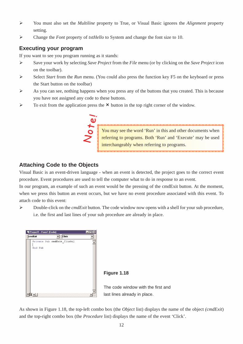
Ø Click once on the TextBoxicon in the Toolbox and then move the mouse cursor over the form.
Ø Position the cursor in the position where one of the TextBoxobject’s corners are to be, and drag the
cursor to the opposite diagonal corner.
Ø When you release the mouse button, the TextBoxand its default contents will appear.
Figure 1.17
A default text box should
be placed on your form.
You now want to change some of the properties of the text box:
Ø Make sure that the text box that you have just created is selected.
Ø Change its Nameproperty to txtHello .
Ø Delete the contents of the Text property (currently Text1), because you don’t want anything to appear
in the text box when the program is first executed.
Ø The default Alignmentproperty of the text box is 0-Left Justify, which means that the text is aligned
to the left side of the text box. Because you want the text in the text box to be centered, change this
option to 2-Center, using the combo box which appears when you click on the arrow pointing down.
11
Executing your programIf you want to see you program running as it stands:
Ø Save your work by selecting Save Projectfrom the File menu (or by clicking on the Save Projecticon
on the toolbar).
Ø Select Start from the Runmenu. (You could also press the function key F5 on the keyboard or press
the Start button on the toolbar)
Ø As you can see, nothing happens when you press any of the buttons that you created. This is because
you have not assigned any code to these buttons.
Ø To exit from the application press the×× button in the top right corner of the window.
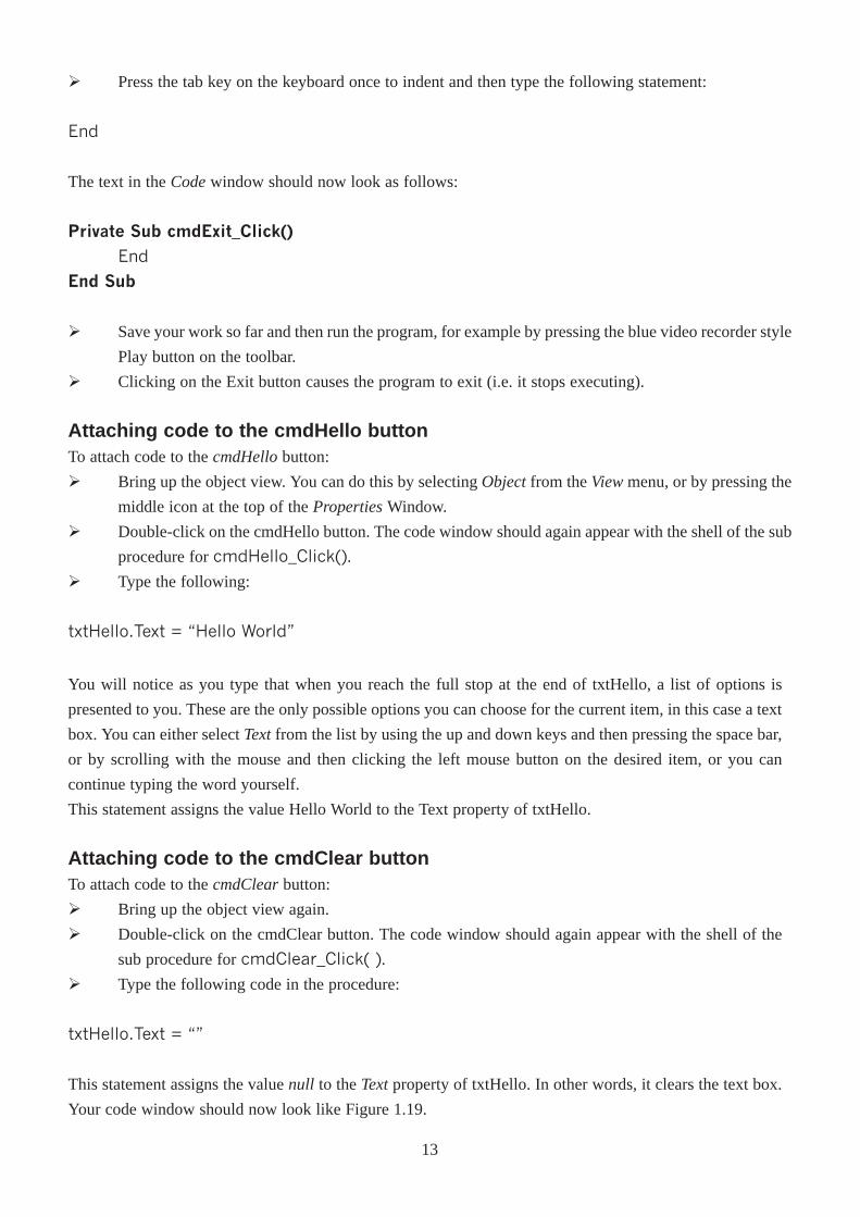
Figure 1.18
The code window with the first and
last lines already in place.
Attaching Code to the ObjectsVisual Basic is an event-driven language - when an event is detected, the project goes to the correct event
procedure. Event procedures are used to tell the computer what to do in response to an event.
In our program, an example of such an event would be the pressing of the cmdExit button. At the moment,
when we press this button an event occurs, but we have no event procedure associated with this event. To
attach code to this event:
Ø Double-click on the cmdExitbutton. The code window now opens with a shell for your sub procedure,
i.e. the first and last lines of your sub procedure are already in place.
You may see the word ‘Run’ in this and other documents when
referring to programs. Both ‘Run’ and ‘Execute’ may be used
interchangeably when referring to programs.
NNoo tt
ee !!
As shown in Figure 1.18, the top-left combo box (the Objectlist) displays the name of the object (cmdExit)
and the top-right combo box (the Procedurelist) displays the name of the event ‘Click’.
Ø You must also set the Multiline property to True, or Visual Basic ignores the Alignmentproperty
setting.
Ø Change the Font property of txtHello to System and change the font size to 10.
12
Ø Press the tab key on the keyboard once to indent and then type the following statement:
End
The text in the Codewindow should now look as follows:
Private Sub cmdExit_Click()
End
End Sub
Ø Save your work so far and then run the program, for example by pressing the blue video recorder style
Play button on the toolbar.
Ø Clicking on the Exit button causes the program to exit (i.e. it stops executing).
Attaching code to the cmdHello buttonTo attach code to the cmdHellobutton:
Ø Bring up the object view. You can do this by selecting Objectfrom the Viewmenu, or by pressing the
middle icon at the top of the Properties Window.
Ø Double-click on the cmdHello button. The code window should again appear with the shell of the sub
procedure for cmdHello_Click().
Ø Type the following:
txtHello.Text = �Hello World�
You will notice as you type that when you reach the full stop at the end of txtHello, a list of options is
presented to you. These are the only possible options you can choose for the current item, in this case a text
box. You can either select Textfrom the list by using the up and down keys and then pressing the space bar,
or by scrolling with the mouse and then clicking the left mouse button on the desired item, or you can
continue typing the word yourself.
This statement assigns the value Hello World to the Text property of txtHello.
Attaching code to the cmdClear buttonTo attach code to the cmdClearbutton:
Ø Bring up the object view again.
Ø Double-click on the cmdClear button. The code window should again appear with the shell of the
sub procedure for cmdClear_Click( ).
Ø Type the following code in the procedure:
txtHello.Text = ��
This statement assigns the value null to the Textproperty of txtHello. In other words, it clears the text box.
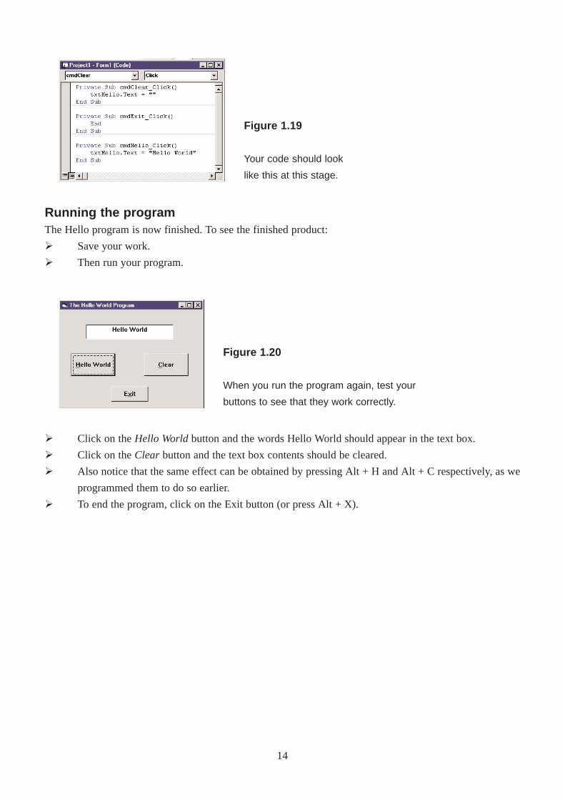
Your code window should now look like Figure 1.19.
13
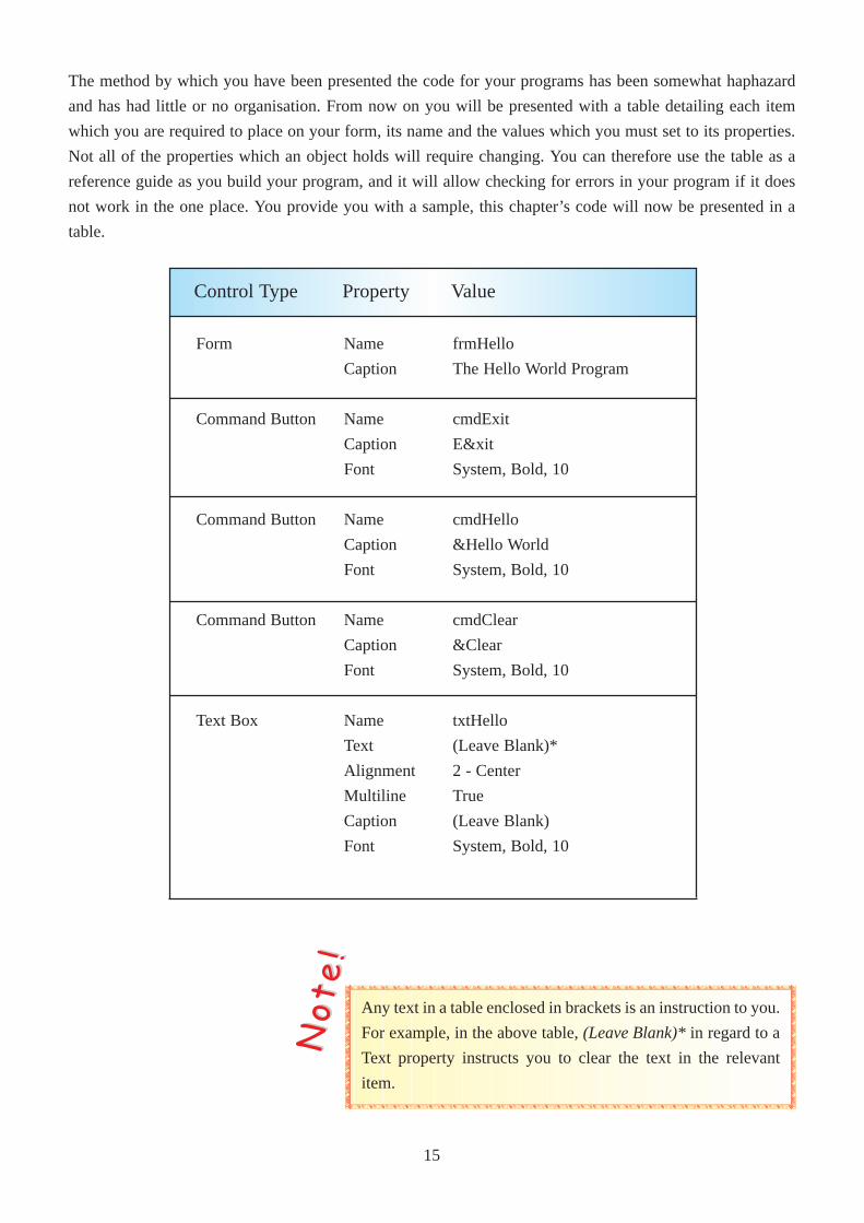
Ø Click on the Hello Worldbutton and the words Hello World should appear in the text box.
Ø Click on the Clear button and the text box contents should be cleared.
Ø Also notice that the same effect can be obtained by pressing Alt + H and Alt + C respectively, as we
programmed them to do so earlier.
Ø To end the program, click on the Exit button (or press Alt + X).
Figure 1.20
When you run the program again, test your
buttons to see that they work correctly.
Running the programThe Hello program is now finished. To see the finished product:
Ø Save your work.
Ø Then run your program.
Figure 1.19
Your code should look
like this at this stage.
14
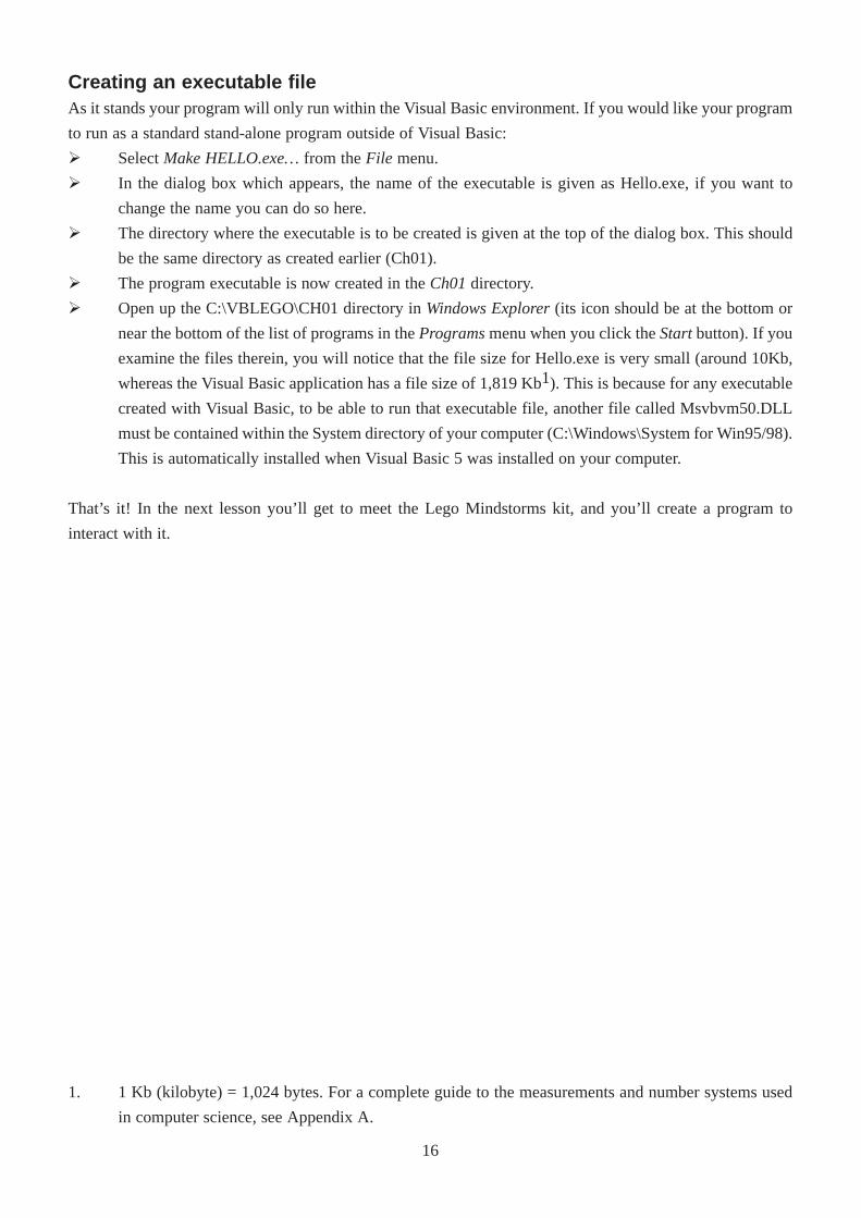
The method by which you have been presented the code for your programs has been somewhat haphazard
and has had little or no organisation. From now on you will be presented with a table detailing each item
which you are required to place on your form, its name and the values which you must set to its properties.
Not all of the properties which an object holds will require changing. You can therefore use the table as a
reference guide as you build your program, and it will allow checking for errors in your program if it does
not work in the one place. You provide you with a sample, this chapter’s code will now be presented in a
table.
Form
Command Button
Command Button
Command Button
Text Box
Name
Caption
Name
Caption
Font
Name
Caption
Font
Name
Caption
Font
Name
Text
Alignment
Multiline
Caption
Font
frmHello
The Hello World Program
cmdExit
E&xit
System, Bold, 10
cmdHello
&Hello World
System, Bold, 10
cmdClear
&Clear
System, Bold, 10
txtHello
(Leave Blank)*
2 - Center
True
(Leave Blank)
System, Bold, 10
Control Type Property Value
Any text in a table enclosed in brackets is an instruction to you.
For example, in the above table, (Leave Blank)* in regard to a
Text property instructs you to clear the text in the relevant
item.
NNoo tt
ee !!
15
Creating an executable fileAs it stands your program will only run within the Visual Basic environment. If you would like your program
to run as a standard stand-alone program outside of Visual Basic:
Ø Select Make HELLO.exe…from the File menu.
Ø In the dialog box which appears, the name of the executable is given as Hello.exe, if you want to
change the name you can do so here.
Ø The directory where the executable is to be created is given at the top of the dialog box. This should
be the same directory as created earlier (Ch01).
Ø The program executable is now created in the Ch01directory.
Ø Open up the C:\VBLEGO\CH01 directory in Windows Explorer(its icon should be at the bottom or
near the bottom of the list of programs in the Programsmenu when you click the Startbutton). If you
examine the files therein, you will notice that the file size for Hello.exe is very small (around 10Kb,
whereas the Visual Basic application has a file size of 1,819 Kb1). This is because for any executable
created with Visual Basic, to be able to run that executable file, another file called Msvbvm50.DLL
must be contained within the System directory of your computer (C:\Windows\System for Win95/98).
This is automatically installed when Visual Basic 5 was installed on your computer.
That’s it! In the next lesson you’ll get to meet the Lego Mindstorms kit, and you’ll create a program to
interact with it.
1. 1 Kb (kilobyte) = 1,024 bytes. For a complete guide to the measurements and number systems used
in computer science, see Appendix A.
16
ChapterTwo
Introducing the LegoMindstorms Kit
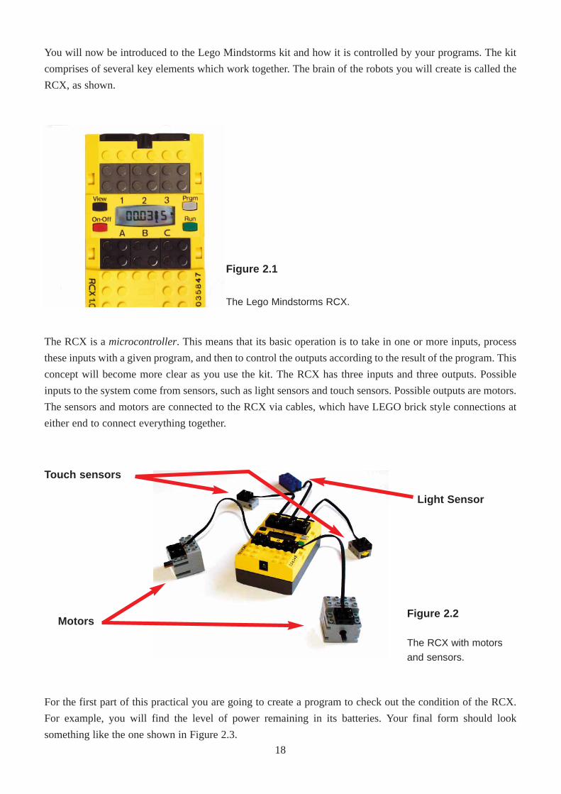
You will now be introduced to the Lego Mindstorms kit and how it is controlled by your programs. The kit
comprises of several key elements which work together. The brain of the robots you will create is called the
RCX, as shown.
Figure 2.1
The Lego Mindstorms RCX.
Motors
Touch sensors
Light Sensor
The RCX is a microcontroller. This means that its basic operation is to take in one or more inputs, process
these inputs with a given program, and then to control the outputs according to the result of the program. This
concept will become more clear as you use the kit. The RCX has three inputs and three outputs. Possible
inputs to the system come from sensors, such as light sensors and touch sensors. Possible outputs are motors.
The sensors and motors are connected to the RCX via cables, which have LEGO brick style connections at
either end to connect everything together.
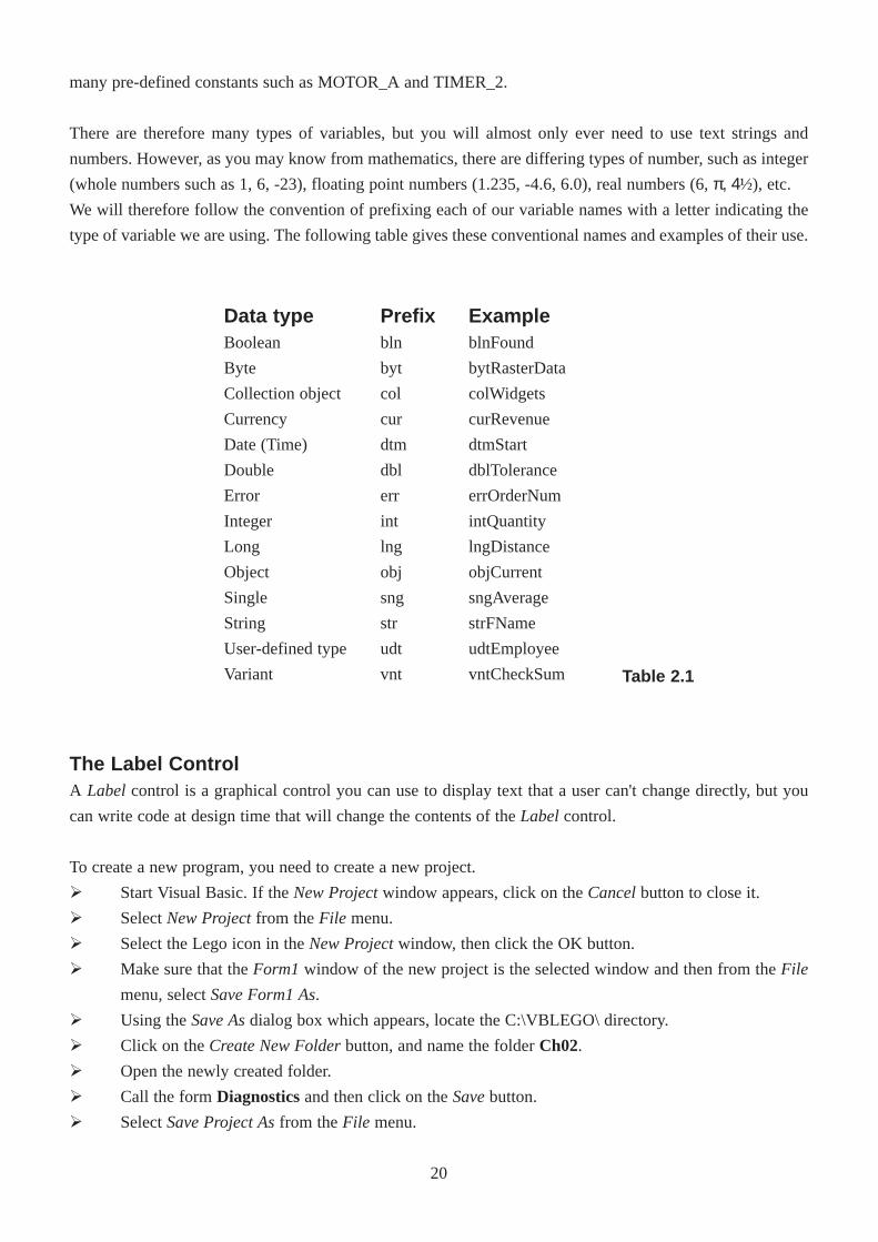
For the first part of this practical you are going to create a program to check out the condition of the RCX.
For example, you will find the level of power remaining in its batteries. Your final form should look
something like the one shown in Figure 2.3.
Figure 2.2
The RCX with motors
and sensors.
18
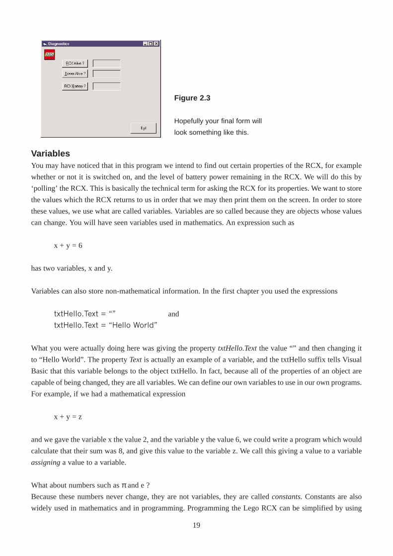
Figure 2.3
Hopefully your final form will
look something like this.
VariablesYou may have noticed that in this program we intend to find out certain properties of the RCX, for example
whether or not it is switched on, and the level of battery power remaining in the RCX. We will do this by
‘polling’ the RCX. This is basically the technical term for asking the RCX for its properties. We want to store
the values which the RCX returns to us in order that we may then print them on the screen. In order to store
these values, we use what are called variables. Variables are so called because they are objects whose values
can change. You will have seen variables used in mathematics. An expression such as
x + y = 6
has two variables, x and y.
Variables can also store non-mathematical information. In the first chapter you used the expressions
txtHello.Text = �� and
txtHello.Text = �Hello World�
What you were actually doing here was giving the property txtHello.Textthe value “” and then changing it
to “Hello World”. The property Textis actually an example of a variable, and the txtHello suffix tells Visual
Basic that this variable belongs to the object txtHello. In fact, because all of the properties of an object are
capable of being changed, they are all variables. We can define our own variables to use in our own programs.
For example, if we had a mathematical expression
x + y = z
and we gave the variable x the value 2, and the variable y the value 6, we could write a program which would
calculate that their sum was 8, and give this value to the variable z. We call this giving a value to a variable
assigninga value to a variable.
What about numbers such as π and e ?
Because these numbers never change, they are not variables, they are called constants.Constants are also
widely used in mathematics and in programming. Programming the Lego RCX can be simplified by using
19
many pre-defined constants such as MOTOR_A and TIMER_2.
There are therefore many types of variables, but you will almost only ever need to use text strings and
numbers. However, as you may know from mathematics, there are differing types of number, such as integer
(whole numbers such as 1, 6, -23), floating point numbers (1.235, -4.6, 6.0), real numbers (6, π, 4½), etc.
We will therefore follow the convention of prefixing each of our variable names with a letter indicating the
type of variable we are using. The following table gives these conventional names and examples of their use.
Data typeBoolean
Byte
Collection object
Currency
Date (Time)
Double
Error
Integer
Long
Object
Single
String
User-defined type
Variant
Prefixbln
byt
col
cur
dtm
dbl
err
int
lng
obj
sng
str
udt
vnt
ExampleblnFound
bytRasterData
colWidgets
curRevenue
dtmStart
dblTolerance
errOrderNum
intQuantity
lngDistance
objCurrent
sngAverage
strFName
udtEmployee
vntCheckSum
The Label ControlA Label control is a graphical control you can use to display text that a user can't change directly, but you
can write code at design time that will change the contents of the Labelcontrol.
To create a new program, you need to create a new project.
Ø Start Visual Basic. If the New Projectwindow appears, click on the Cancelbutton to close it.
Ø Select New Projectfrom the File menu.
Ø Select the Lego icon in the New Projectwindow, then click the OK button.
Ø Make sure that the Form1window of the new project is the selected window and then from the File
menu, select Save Form1 As.
Ø Using the Save Asdialog box which appears, locate the C:\VBLEGO\ directory.
Ø Click on the Create New Folderbutton, and name the folder Ch02.
Ø Open the newly created folder.
Ø Call the form Diagnosticsand then click on theSavebutton.
Ø Select Save Project Asfrom the File menu.
Table 2.1
20
Ø The first file to be saved is the .bas file. Enter the file name as Diagnosticsand click on the Save
button (the location should already be the Ch02 folder).
Ø You are then asked to save the .vbp file. Call this Diagnosticsalso and click on the Savebutton.
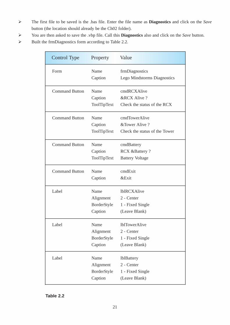
Ø Built the frmDiagnostics form according to Table 2.2.
Form
Command Button
Command Button
Command Button
Command Button
Label
Label
Label
Name
Caption
Name
Caption
ToolTipText
Name
Caption
ToolTipText
Name
Caption
ToolTipText
Name
Caption
Name
Alignment
BorderStyle
Caption
Name
Alignment
BorderStyle
Caption
Name
Alignment
BorderStyle
Caption
frmDiagnostics
Lego Mindstorms Diagnostics
cmdRCXAlive
&RCX Alive ?
Check the status of the RCX
cmdTowerAlive
&Tower Alive ?
Check the status of the Tower
cmdBattery
RCX &Battery ?
Battery Voltage
cmdExit
&Exit
lblRCXAlive
2 - Center
1 - Fixed Single
(Leave Blank)
lblTowerAlive
2 - Center
1 - Fixed Single
(Leave Blank)
lblBattery
2 - Center
1 - Fixed Single
(Leave Blank)
Control Type Property Value
Table 2.2
21
Private Sub Form_Load()
PBrickCtrl.InitComm ' Init PC Serial COM Port
End Sub
Ø Now enter the code for the Form_Load() procedure.
Let’s now examine this code in detail.
The first line of code is called a comment. A comment is any line of text which begins with an apostrophe
character ('). You can write anything you want after the ' character. It is used to make your code more
understandable to both yourself and especially anyone else who reads your program.
The Option Explicit declaration states that every variable which you use must be declared before you are
allowed to use it. This is useful because it means that if you make a mistake in typing the name of the
variable, Visual Basic will not assume that it is a new variable, but that you did indeed make a typing error.
In order to communicate with the RCX, the computer must first initialise the PC’s serial communications
port. This is done using the PBrickCtrl.InitComm command.
You would like this command to be executed immediately after the program starts. To do this you place the
command in the Private Sub Form_Load() event procedure. This procedure is immediately carried out
when the form is loaded (opened). To get the shell of the code for this procedure, double click an any part of
the form that does not contain a control.
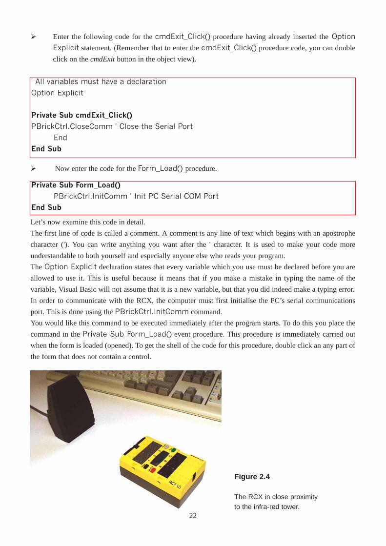
Figure 2.4
The RCX in close proximity
to the infra-red tower.
Ø Enter the following code for the cmdExit_Click() procedure having already inserted theOption
Explicit statement. (Remember that to enter the cmdExit_Click() procedure code, you can double
click on the cmdExitbutton in the object view).
' All variables must have a declaration
Option Explicit
Private Sub cmdExit_Click()
PBrickCtrl.CloseComm ' Close the Serial Port
End
End Sub
22
Having completed communications with the RCX, the command PBrickCtrl.CloseComm is called to
close the serial port. You don't normally want to call this until you are completely finished communicating
with the RCX, so the best place to put this command is in the cmdExit_Click() procedure, which ends the
entire program.
Ø Save your project by choosing Save Projectfrom the File menu.
Ø Execute your program by clicking on the Start (play) button on the toolbar.
Ø Click on the Exit button, and the program will terminate.
The program calls the InitComm procedure when the form is loaded and calls the CloseComm procedure
when the Exit button is pressed.
In between calls to these two setup commands, you will write code to initiate interaction between the RCX
and the infra-red tower.
Decisions within your programDecision statements give your program the power to choose between options available in to your code and
to react appropriately to situations that occur during execution. In order to implement decisions, you can use
the If ... Then ... Else structure.
The If ... Then ... Else structureIf introduces the condition on which the decision will be based.
Then identifies the action that will be performed if the condition is true.
Else specifies an alternate action, to be performed if the condition is false.
You now want to write some code to interact with the RCX and to discover some of its settings.
Ø Enter the rest of the code for the program, beginning with this procedure:
Private Sub cmdBattery_Click()lblBattery.Caption = Str(PBrickCtrl.PBBattery)
End Sub
Private Sub cmdRCXAlive_Click()
If PBrickCtrl.PBAliveOrNot Then
lblRCXAlive.Caption = "True"
Else
lblRCXAlive.Caption = "False"
End If
End Sub
Ø Now add this procedure:
23
Private Sub cmdTowerAlive_Click()
If PBrickCtrl.TowerAlive Then
lblTowerAlive.Caption = "True"
Else
lblTowerAlive.Caption = "False"
End If
End Sub
Ø And now add this procedure:
The event procedure cmdRCXAlive_Click() introduces the use of If�Then�Else statements in Visual
Basic. If the RCX is switched on and the infra-red tower can communicate with it, then 'True' is displayed in
the result label. If not, 'False' is displayed. Note that you must explicitly end the If statement with an End If
statement, just as you have to end a subroutine with End Sub.
Ø Save your project.
Ø Execute your program.
Ø With the RCX switched on and in close proximity to the infra-red transmitter, click on the three
buttons which perform the tests in sequence.
Ø Now switch the RCX off and click on the ‘RCX Alive ?’ button. (If the RCX is switched off, you are
advised not to click on the ‘RCX Battery ?’ button as an error will occur).
The cmdBattery_Click() procedure is also worth noting. In this line of code, the battery's voltage level is
first found, the numerical value found is then coverted to a string using the Str function, and the caption of
the lblBattery label is then set to this value.
The procedure cmdTowerAlive() checks to see if the transceiver tower is OK. If the tower hardware and the
battery are functioning, then 'True' will be displayed in the result label. If not, 'False' will be displayed.
The battery's voltage level is measured in millivolts, and with new batteries in the RCX, the value should be
close to 9000 mV. The value decreases steadily over time, so only have the RCX switched on when necessary.
You can test the range of the infra-red transmitter by repeatedly checking that it is alive (as deemed by your
program).
One problem you may encounter is a level of interference between different RCX's if there are more than one
of them in the room. In order to combat this, you can include in your program an option to specify the
transmitter power of the RCX. With several RCX's in a room, the power should be set to Short Range.
24
Add the items in Table 2.3 to the form, and following that, add the relevant code below.
Command Button
Command Button
Label
Name
Caption
ToolTipText
Name
Caption
ToolTipText
Name
BorderStyle
Caption
cmdShortIR
IR &Short
Short Range Communications
cmdLongIR
IR &Long
Long Range Communications
lblRange
1 - Fixed
(Leave Blank)
Control Type Property Value
Table 2.3
Private Sub cmdShortIR_Click()PBrickCtrl.PBTxPower SHORT_RANGE
lblRange = "RCX set up for Short Range"
End Sub
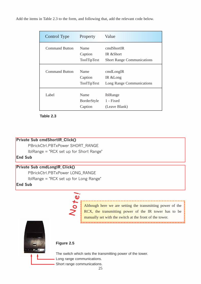
Although here we are setting the transmitting power of the
RCX, the transmitting power of the IR tower has to be
manually set with the switch at the front of the tower.
NNoo tt
ee !!
Private Sub cmdLongIR_Click()PBrickCtrl.PBTxPower LONG_RANGE
lblRange = "RCX set up for Long Range"
End Sub
Figure 2.5
The switch which sets the transmitting power of the tower.
Long range communications.
Short range communications.25
Ø Save your project.
Ø Execute the program.
Ø Click on the IR Short button.
Ø Place the RCX at a range of distances from the tower (but without obscuring it), and at each distance,
click on the ‘RCX Alive ?’ button. With experimentation, you can estimate the range for Short Range
communication.
Ø Click on the IR Long button.
Ø Repeat the above step to find the range for Long Range communication.
Increasing the functionalityYou are now going to add some more functionality to your program. We would like to allow the user to set
the RCX’s time value with the program, and also to allow the user to switch the RCX off.
Whichever RCX transmitting power you wish to use for other
programs involving the RCX, you should click on its
corresponding button before exiting the program.
NNoo tt
ee !!
Private Sub cmdSetTime_Click()PBrickCtrl.SetWatch Hour(Now), Minute(Now)
End Sub
Private Sub cmdRCXOff_Click()PBrickCtrl.PBTurnOff
End Sub
Ø Now enter the following code:
Command Button
Command Button
Name
Caption
ToolTipText
Name
Caption
ToolTipText
cmdSetTime
Set R&CX Time
Set RCX to present time
cmdRCXOff
Turn RCX &Off
Switch Off the RCX
Control Type Property Value
Table 2.4
Ø Place the following controls on your form:
26
The code to switch the RCX off is quite straightforward. Here a method named PBTurnOff is called which
instructs the RCX to switch itself off.
The second procedure is not so straightforward. You would like to set the RCX’s time setting to that of your
computer. To do this you must first find out the system time, and so this is where the function Now is used.
When the Now function is called, it "finds out" the system date and time, but you only want the hour and
minute values. To discover these values, the functions Hour and Minute are used. So what are finally passed
to the SetWatch method are in fact the values of the current hour (between 0 and 23) and the current minute
(between 0 and 59).
ExerciseThe first part of this practical allowed you to poll the RCX to find out information. Pressing the three buttons
individually is time consuming and is inefficient from a programming point of view. Instead, write code for
a button that will update all three label fields. Warning: If the RCX is not alive the battery should not be tested
and its corresponding label should be blanked out.
27
ChapterThree
Your First Robot
In the last chapter you learned how to use the Spirit control to communicate with the RCX. You are now
going to create a program that will control a car that you will make using Lego.
Thus far you have only seen the Click event been used for command buttons.
To create a new program, you need to create a new project.
Ø Start Visual Basic. If the New Projectwindow appears, click on the Cancelbutton to close it.
Ø Select New Projectfrom the File menu.
Ø Select the Lego icon in the New Projectwindow, and then click the OK button.
Ø Make sure that the Form1window of the new project is the selected window and then from the File
menu, select Save Form1 As.
Ø Using the Save Asdialog box which appears, locate the C:\VBLEGO\ directory.
Ø Click on the Create New Folderbutton, and name the folder Ch03.
Ø Open the newly created folder.
Ø Call the form Remote Controland then click on theSavebutton.
Ø Select Save Project Asfrom the File menu.
Ø The first file to be saved is the .bas file. Enter the file name as Remoteand click on the Savebutton
(the location should already be the Ch03 folder).
Ø You are then asked to save the .vbp file. Call this Remotealso and click on the Savebutton.
Ø Built the frmRemote form according to Table 3.1.
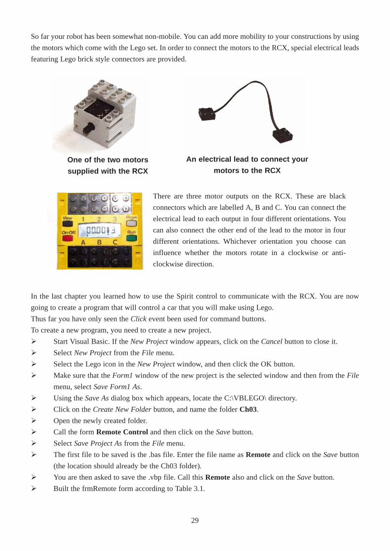
An electrical lead to connect your
motors to the RCX
So far your robot has been somewhat non-mobile. You can add more mobility to your constructions by using
the motors which come with the Lego set. In order to connect the motors to the RCX, special electrical leads
featuring Lego brick style connectors are provided.
One of the two motors
supplied with the RCX
There are three motor outputs on the RCX. These are black
connectors which are labelled A, B and C. You can connect the
electrical lead to each output in four different orientations. You
can also connect the other end of the lead to the motor in four
different orientations. Whichever orientation you choose can
influence whether the motors rotate in a clockwise or anti-
clockwise direction.
29
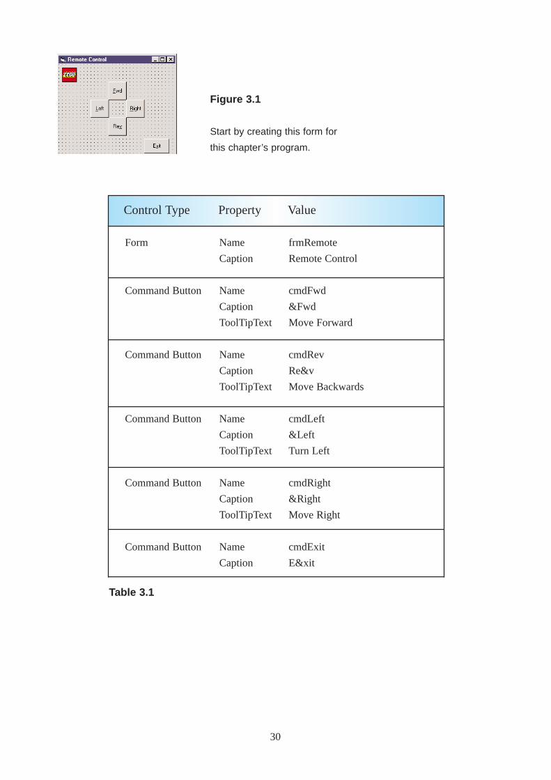
Form
Command Button
Command Button
Command Button
Command Button
Command Button
Name
Caption
Name
Caption
ToolTipText
Name
Caption
ToolTipText
Name
Caption
ToolTipText
Name
Caption
ToolTipText
Name
Caption
frmRemote
Remote Control
cmdFwd
&Fwd
Move Forward
cmdRev
Re&v
Move Backwards
cmdLeft
&Left
Turn Left
cmdRight
&Right
Move Right
cmdExit
E&xit
Table 3.1
Control Type Property Value
Figure 3.1
Start by creating this form for
this chapter’s program.
30
4
3
2
5
1
31
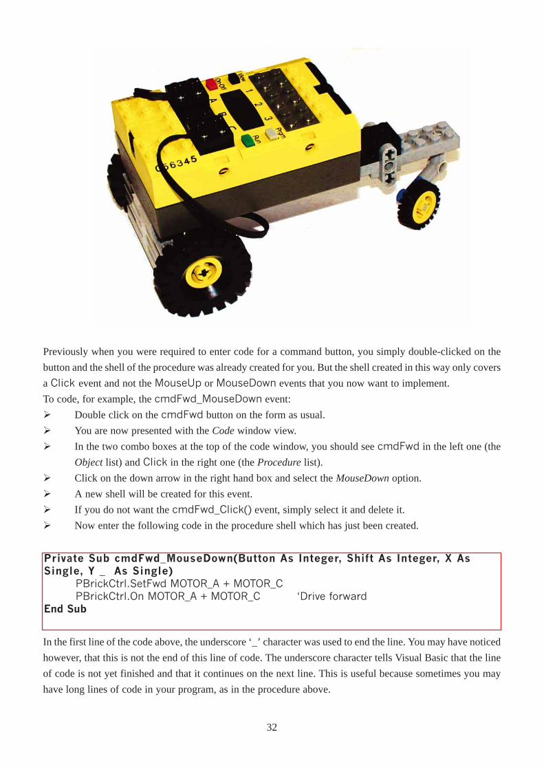
Previously when you were required to enter code for a command button, you simply double-clicked on the
button and the shell of the procedure was already created for you. But the shell created in this way only covers
a Click event and not the MouseUp or MouseDown events that you now want to implement.
To code, for example, the cmdFwd_MouseDown event:
Ø Double click on the cmdFwd button on the form as usual.
Ø You are now presented with the Codewindow view.
Ø In the two combo boxes at the top of the code window, you should see cmdFwd in the left one (the
Objectlist) and Click in the right one (the Procedurelist).
Ø Click on the down arrow in the right hand box and select the MouseDownoption.
Ø A new shell will be created for this event.
Ø If you do not want the cmdFwd_Click() event, simply select it and delete it.
Ø Now enter the following code in the procedure shell which has just been created.
Private Sub cmdFwd_MouseDown(Button As Integer, Shift As Integer, X AsSingle, Y _ As Single)
PBrickCtrl.SetFwd MOTOR_A + MOTOR_CPBrickCtrl.On MOTOR_A + MOTOR_C �Drive forward
End Sub
In the first line of the code above, the underscore ‘_’ character was used to end the line. You may have noticed
however, that this is not the end of this line of code. The underscore character tells Visual Basic that the line
of code is not yet finished and that it continues on the next line. This is useful because sometimes you may
have long lines of code in your program, as in the procedure above.
32
Ø Using the same method as previously, enter in the following code:
Private Sub Form_Load()PBrickCtrl.InitComm �Initialises the PC-Serial com port.PBrickCtrl.SetPower MOTOR_A + MOTOR_C, CON, 2
End Sub
Private Sub cmdLeft_MouseDown(Button As Integer, Shift As Integer, X AsSingle, Y _ As Single)
PBrickCtrl.SetFwd MOTOR_CPBrickCtrl.On MOTOR_C
End Sub
Private Sub cmdLeft_MouseUp(Button As Integer, Shift As Integer, X As Single,Y As _ Single)
PBrickCtrl.Off MOTOR_CEnd Sub
Private Sub cmdExit_Click()PBrickCtrl.CloseCommEnd
End Sub
Option Explicit
Private Sub cmdFwd_MouseUp(Button As Integer, Shift As Integer, X As Single,Y As _ Single)
PBrickCtrl.Off MOTOR_A + MOTOR_CEnd Sub
Ø Now select the MouseUp option from the Procedurecombo box, and type the following code:
How the Remote Control program worksAs in the last chapter the method InitComm is called in the Form_Load procedure to start. The statement:
PBrickCtrl.SetPower MOTOR_A + MOTOR_C, CON, 2
sets the power of the motors. Here the power is set to a constant (CON) value, 2. The power setting can be
any value between 0 and 7. This setting does not so much effect the speed of the motors, but the power of
the motors. When a robot is running on a surface with high friction, such as carpet, this should be set to a
high value.
When the cmdFwd button is pressed down, the robot is to move forward. The event procedure
Private Sub cmdFwd_MouseDown(Button As Integer, Shift As Integer, X As Single,Y As _ Single)
PBrickCtrl.SetFwd MOTOR_A + MOTOR_C
PBrickCtrl.On MOTOR_A + MOTOR_C 'Drive motors forward
End Sub
is triggered when the button is pressed. Here both motors are first set to the forward direction and then33
Exercise:The code to make the robot reverse and to go right is not shown. You should be able to write these by copying
and modifying the code for the Forward and Left events.
Placing graphics on command buttonsAs well as being able to place your own captions on your command buttons, you can also place graphical
images on your buttons. To do this, follow these steps.
Ø Select the command button you wish to modify.
Ø Delete the button’s Captionproperty if one exists.
Ø Change the Styleproperty to1 - Graphical.
Ø Using the Pictureproperty, locate the graphic file wish you wish to use.
Note that in this chapter, the authors have used images from the VB/GRAPHICS/ directory, however this may
or may not exist on your computer depending on the initial installation.
Expanding your control over your robotYou will now expand on this program. As can be seen from the Form_Load() event, the power of the motors
is set at a single value. You would like to be able to change this power value with the program itself. You
should aim to achieve this by using a horizontal scrollbar. Its icon’s tool tip text is HScrollBar.
Continuing with the previous program, place a horizontal scrollbar at the bottom of the Remote form. To do
this:
Ø Select the Horizontal Scrollbarcontrol from the control toolbox and place the mouse cursor on the
form. The cursor should be in the shape of a crosshair. Holding down on the left mouse button, drag
it across the screen, forming a rectangle in the process. Release the mouse button when you have
reached the desired size. You can resize the scrollbar by selecting it and dragging any of the blue dots
to another extent.
switched on.
When the button is released, the event procedure:
Private Sub cmdFwd_MouseUp(Button As Integer, Shift As Integer, X As Single,
Y As _ Single)
PBrickCtrl.Off MOTOR_A + MOTOR_C
End Sub
is triggered. Here both motors are turned off.
The code for turning left is similar, but you only want the right motor rotating in a forward direction. The
method SetFwd sets the direction of the motors to Forward. Other possible methods effecting motor
direction are:
· SetRwd - Set the rotation of the motor(s) specified to Reverse.
· AlterDir - Set the rotation of the motor(s) specified to the opposite direction.
34
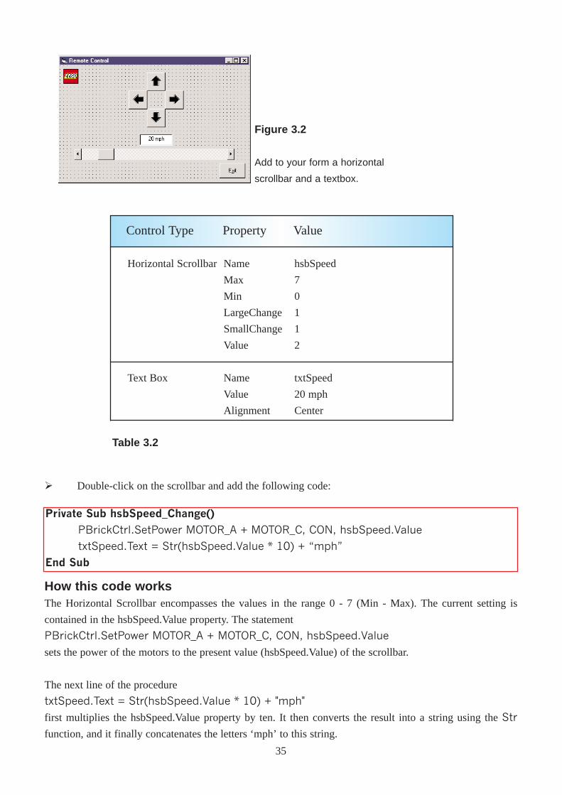
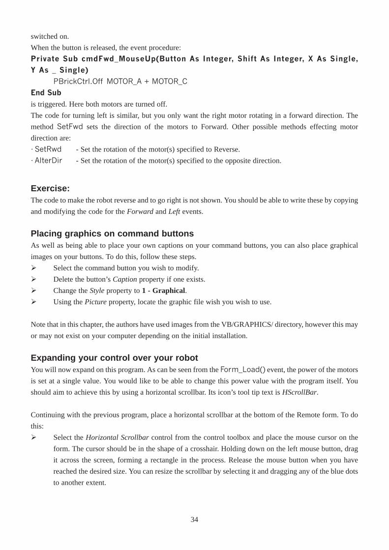
Figure 3.2
Add to your form a horizontal
scrollbar and a textbox.
Horizontal Scrollbar
Text Box
Name
Max
Min
LargeChange
SmallChange
Value
Name
Value
Alignment
hsbSpeed
7
0
1
1
2
txtSpeed
20 mph
Center
Control Type Property Value
Table 3.2
Ø Double-click on the scrollbar and add the following code:
Private Sub hsbSpeed_Change()
PBrickCtrl.SetPower MOTOR_A + MOTOR_C, CON, hsbSpeed.Value
txtSpeed.Text = Str(hsbSpeed.Value * 10) + �mph�
End Sub
How this code worksThe Horizontal Scrollbar encompasses the values in the range 0 - 7 (Min - Max). The current setting is
contained in the hsbSpeed.Value property. The statement
PBrickCtrl.SetPower MOTOR_A + MOTOR_C, CON, hsbSpeed.Value
sets the power of the motors to the present value (hsbSpeed.Value) of the scrollbar.
The next line of the procedure
txtSpeed.Text = Str(hsbSpeed.Value * 10) + "mph"
first multiplies the hsbSpeed.Value property by ten. It then converts the result into a string using the Str
function, and it finally concatenates the letters ‘mph’ to this string.
35
Extending furtherOur program at present works fine, but when building the robot the two motors have to be placed specifically
at output ports A and C (i.e. 0 and 2). You ideally want to be able to specify which of the motors you use
correspond to which output.
To do this you will be introduced to option buttons and frames.
Note that setting the power of the motors to zero does not actually turn off the motors. Instead the motors
have a power setting of close to zero, but is not actually zero.
Option buttonsAn OptionButtoncontrol displays an option that can only be on or off. If you place option buttons on a form
and then run the program, the option buttons are associated with one another and therefore you can only
select one option button at any one time. However sometimes you will need to have two or more groups of
option buttons on the same form. To do this you need to use Frames, which will allow the program to
distinguish between the differing groups.
FramesA Framecontrol provides an identifiable grouping for controls. You can also use a Frameto subdivide a form
functionally - for example, to separate groups of OptionButtoncontrols, as we wish to do here.
To group controls, first draw the Framecontrol (the icon with ‘xy’ in the top left corner), and then draw the
controls inside the Frame. Do not double-click on the control to place it on the form, rather you should draw
it on the form.
Ø Remember to draw the frame on the form before any of the option buttons. Draw the left option
buttons in the left frame and the right option buttons in the right frame.
Note: to select multiple controls on a form, hold down the CTRL key while using the mouse to click on the
controls you want to select. You can then go to the properties window and give them the same properties, e.g.
font or colour.
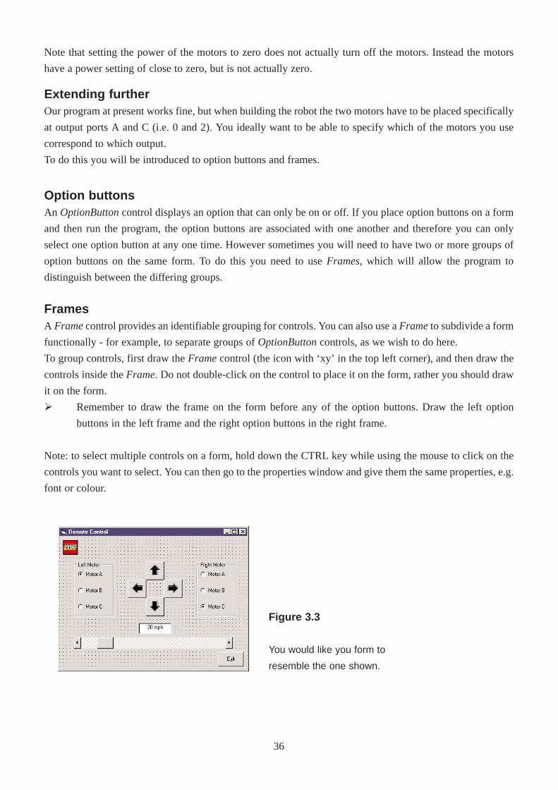
Figure 3.3
You would like you form to
resemble the one shown.
36
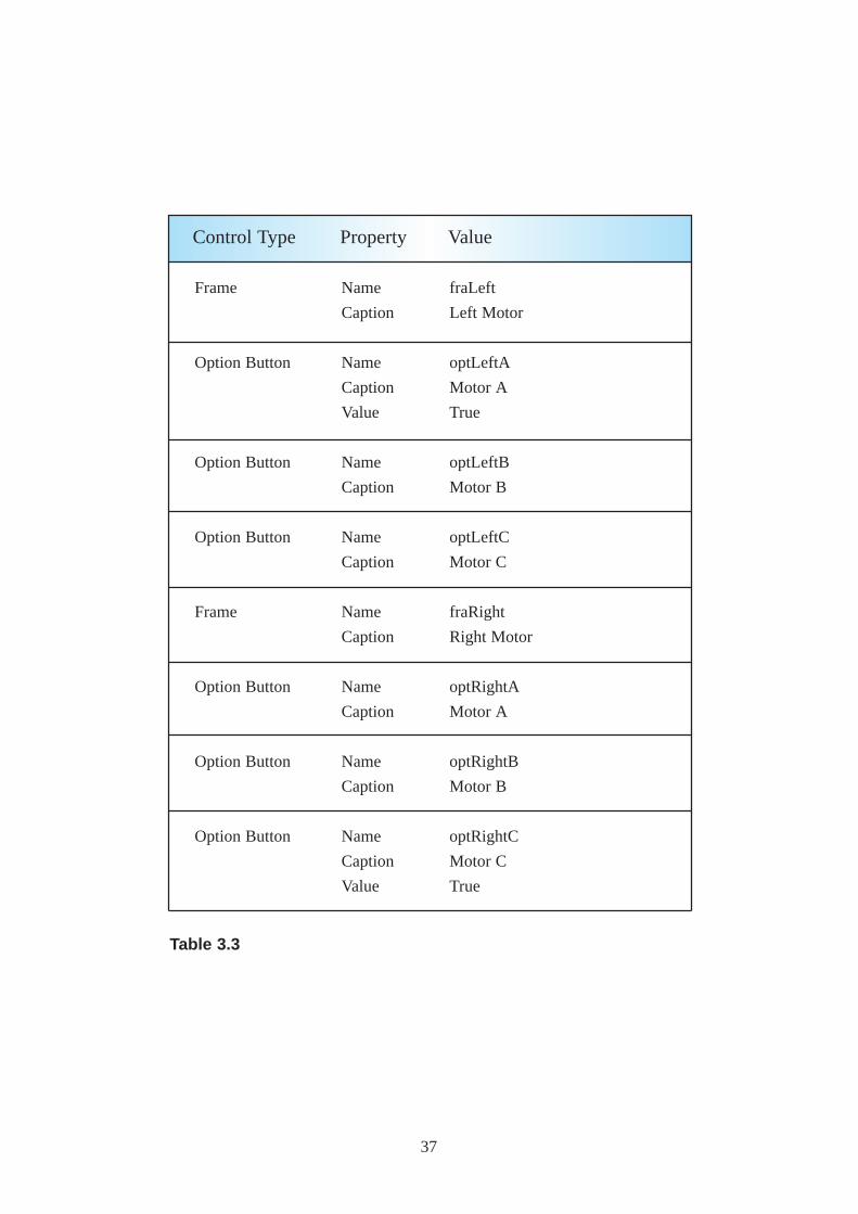
Frame
Option Button
Option Button
Option Button
Frame
Option Button
Option Button
Option Button
Name
Caption
Name
Caption
Value
Name
Caption
Name
Caption
Name
Caption
Name
Caption
Name
Caption
Name
Caption
Value
fraLeft
Left Motor
optLeftA
Motor A
True
optLeftB
Motor B
optLeftC
Motor C
fraRight
Right Motor
optRightA
Motor A
optRightB
Motor B
optRightC
Motor C
True
Control Type Property Value
Table 3.3
37
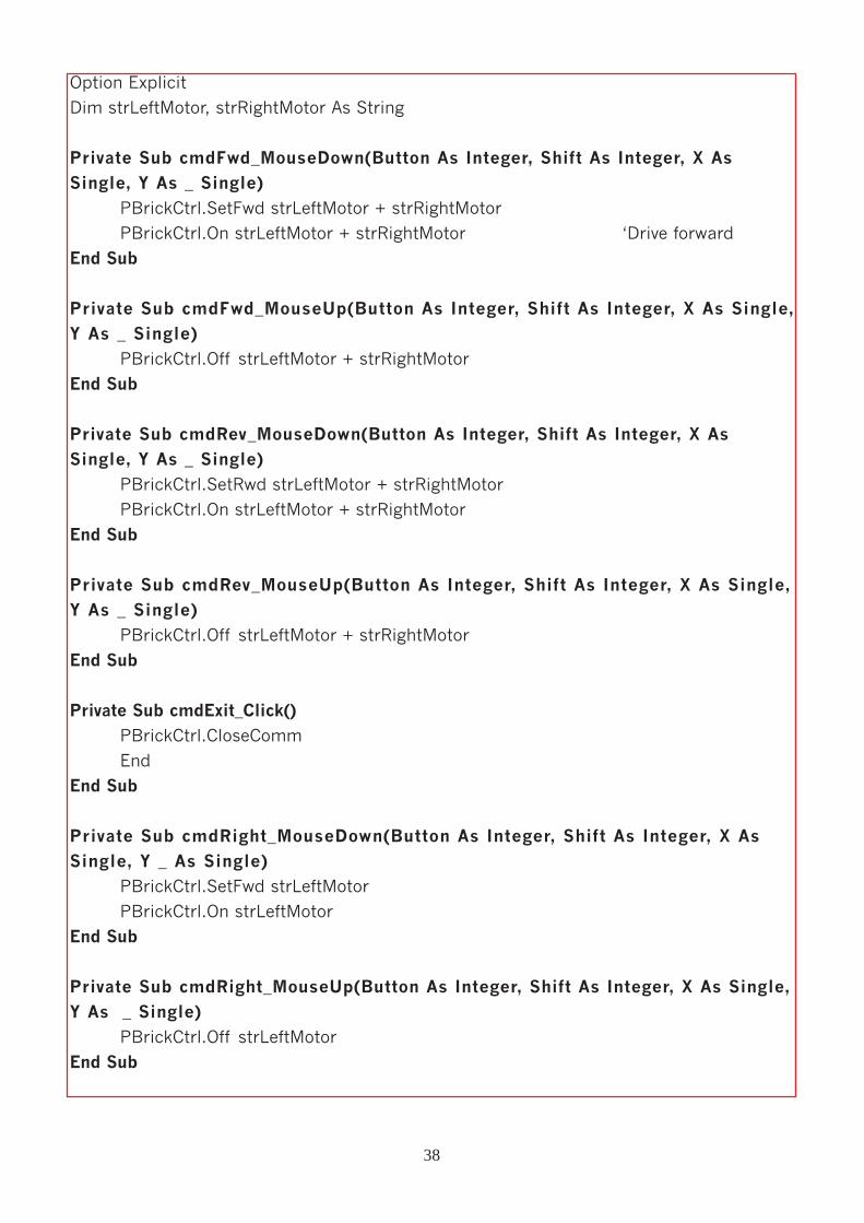
Option Explicit
Dim strLeftMotor, strRightMotor As String
Private Sub cmdFwd_MouseDown(Button As Integer, Shift As Integer, X As
Single, Y As _ Single)
PBrickCtrl.SetFwd strLeftMotor + strRightMotor
PBrickCtrl.On strLeftMotor + strRightMotor �Drive forward
End Sub
Private Sub cmdFwd_MouseUp(Button As Integer, Shift As Integer, X As Single,
Y As _ Single)
PBrickCtrl.Off strLeftMotor + strRightMotor
End Sub
Private Sub cmdRev_MouseDown(Button As Integer, Shift As Integer, X As
Single, Y As _ Single)PBrickCtrl.SetRwd strLeftMotor + strRightMotor
PBrickCtrl.On strLeftMotor + strRightMotor
End Sub
Private Sub cmdRev_MouseUp(Button As Integer, Shift As Integer, X As Single,Y As _ Single)
PBrickCtrl.Off strLeftMotor + strRightMotor
End Sub
Private Sub cmdExit_Click()PBrickCtrl.CloseComm
End
End Sub
Private Sub cmdRight_MouseDown(Button As Integer, Shift As Integer, X AsSingle, Y _ As Single)
PBrickCtrl.SetFwd strLeftMotor
PBrickCtrl.On strLeftMotor
End Sub
Private Sub cmdRight_MouseUp(Button As Integer, Shift As Integer, X As Single,
Y As _ Single)
PBrickCtrl.Off strLeftMotor
End Sub
38
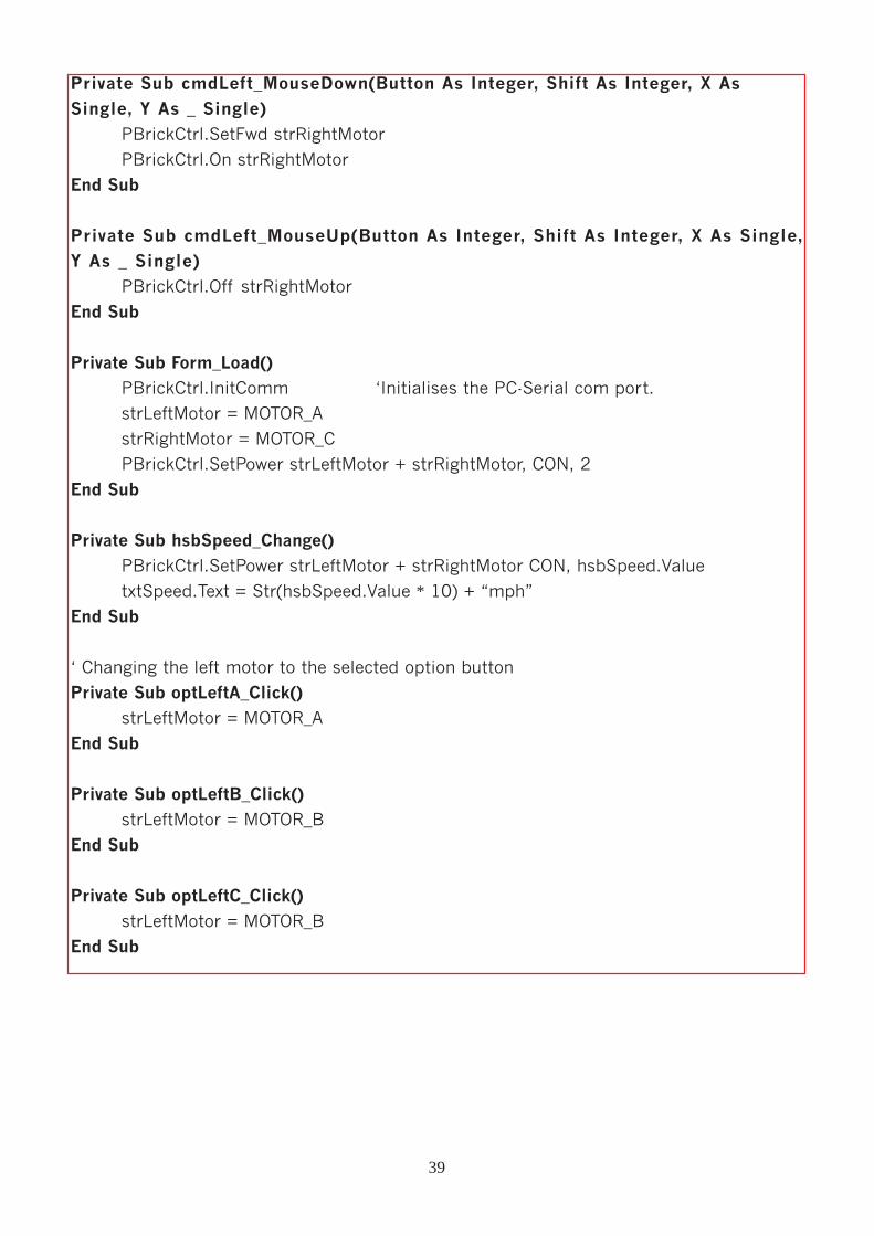
Private Sub cmdLeft_MouseDown(Button As Integer, Shift As Integer, X As
Single, Y As _ Single)
PBrickCtrl.SetFwd strRightMotor
PBrickCtrl.On strRightMotor
End Sub
Private Sub cmdLeft_MouseUp(Button As Integer, Shift As Integer, X As Single,
Y As _ Single)
PBrickCtrl.Off strRightMotor
End Sub
Private Sub Form_Load()
PBrickCtrl.InitComm �Initialises the PC-Serial com port.
strLeftMotor = MOTOR_A
strRightMotor = MOTOR_C
PBrickCtrl.SetPower strLeftMotor + strRightMotor, CON, 2
End Sub
Private Sub hsbSpeed_Change()PBrickCtrl.SetPower strLeftMotor + strRightMotor CON, hsbSpeed.Value
txtSpeed.Text = Str(hsbSpeed.Value * 10) + �mph�
End Sub
� Changing the left motor to the selected option button
Private Sub optLeftA_Click()strLeftMotor = MOTOR_A
End Sub
Private Sub optLeftB_Click()strLeftMotor = MOTOR_B
End Sub
Private Sub optLeftC_Click()strLeftMotor = MOTOR_B
End Sub
39
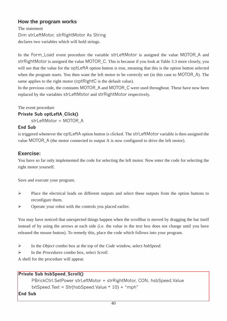
You may have noticed that unexpected things happen when the scrollbar is moved by dragging the bar itself
instead of by using the arrows at each side (i.e. the value in the text box does not change until you have
released the mouse button). To remedy this, place the code which follows into your program.
Ø In the Object combo box at the top of the Codewindow, select hsbSpeed.
Ø In the Procedurescombo box, select Scroll.
A shell for the procedure will appear.
Private Sub hsbSpeed_Scroll()PBrickCtrl.SetPower strLeftMotor + strRightMotor, CON, hsbSpeed.Value
txtSpeed.Text = Str(hsbSpeed.Value * 10) + �mph�
End Sub
How the program worksThe statement
Dim strLeftMotor, strRightMotor As String
declares two variables which will hold strings.
In the Form_Load event procedure the variable strLeftMotor is assigned the value MOTOR_A and
strRightMotor is assigned the value MOTOR_C. This is because if you look at Table 3.3 more closely, you
will see that the value for the optLeftA option button is true, meaning that this is the option button selected
when the program starts. You then want the left motor to be correctly set (in this case to MOTOR_A). The
same applies to the right motor (optRightC is the default value).
In the previous code, the constants MOTOR_A and MOTOR_C were used throughout. These have now been
replaced by the variables strLeftMotor and strRightMotor respectively.
The event procedure
Private Sub optLeftA_Click()
strLeftMotor = MOTOR_A
End Subis triggered whenever the optLeftA option button is clicked. The strLeftMotor variable is then assigned the
value MOTOR_A (the motor connected to output A is now configured to drive the left motor).
Exercise:You have so far only implemented the code for selecting the left motor. Now enter the code for selecting the
right motor yourself.
Save and execute your program.
Ø Place the electrical leads on different outputs and select these outputs from the option buttons to
reconfigure them.
Ø Operate your robot with the controls you placed earlier.
40
ChapterFour
Using Sensors
To enable the programming of the sensors within Visual Basic, they must first be configured. The type of
sensor used and the format in which you want the results returned must be supplied before you can poll (read)
the sensor.
You are now going to configure the switch sensor.
To create a new program, you need to create a new project.
Ø Start Visual Basic. If the New Projectwindow appears, click on the Cancelbutton to close it.
Ø Select New Projectfrom the File menu.
Ø Select the Lego icon in the New Projectwindow, then click the OK button.
Ø As you did before, save all of your new files, this time with the name Sensors. Select
C:\VBLEGO\Ch04 as the location to save your form.
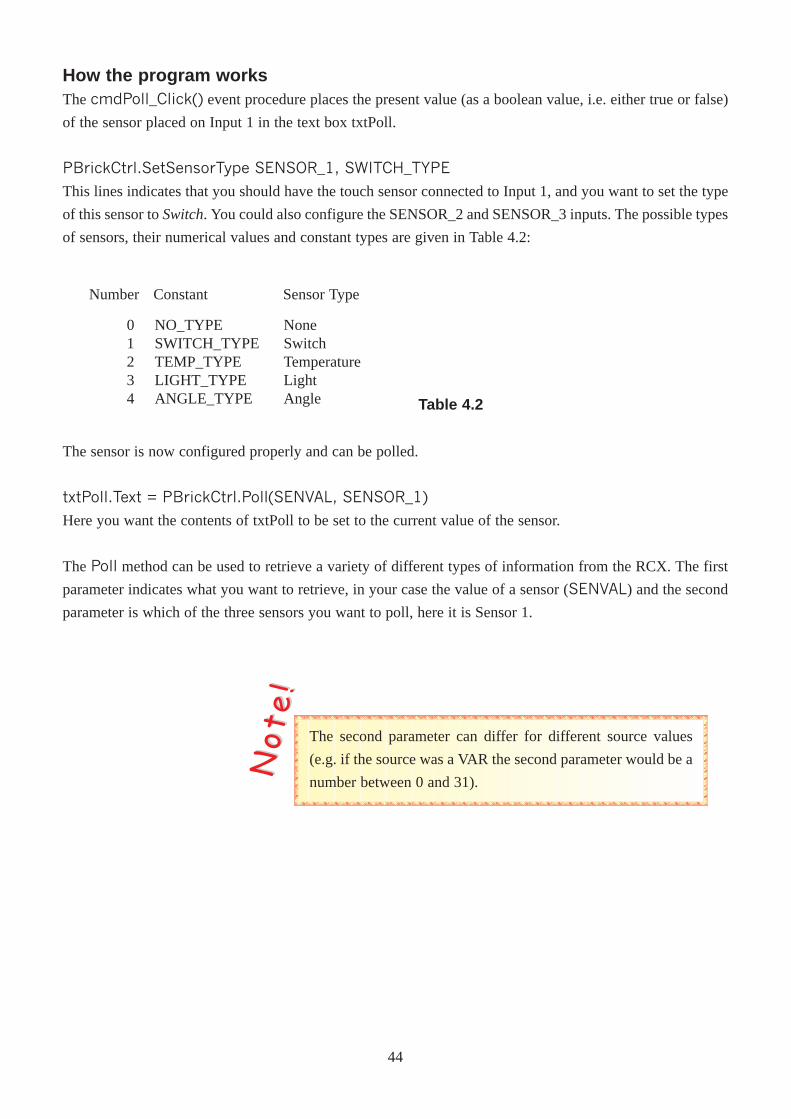
Ø Built the frmSensors form according to Table 4.1.
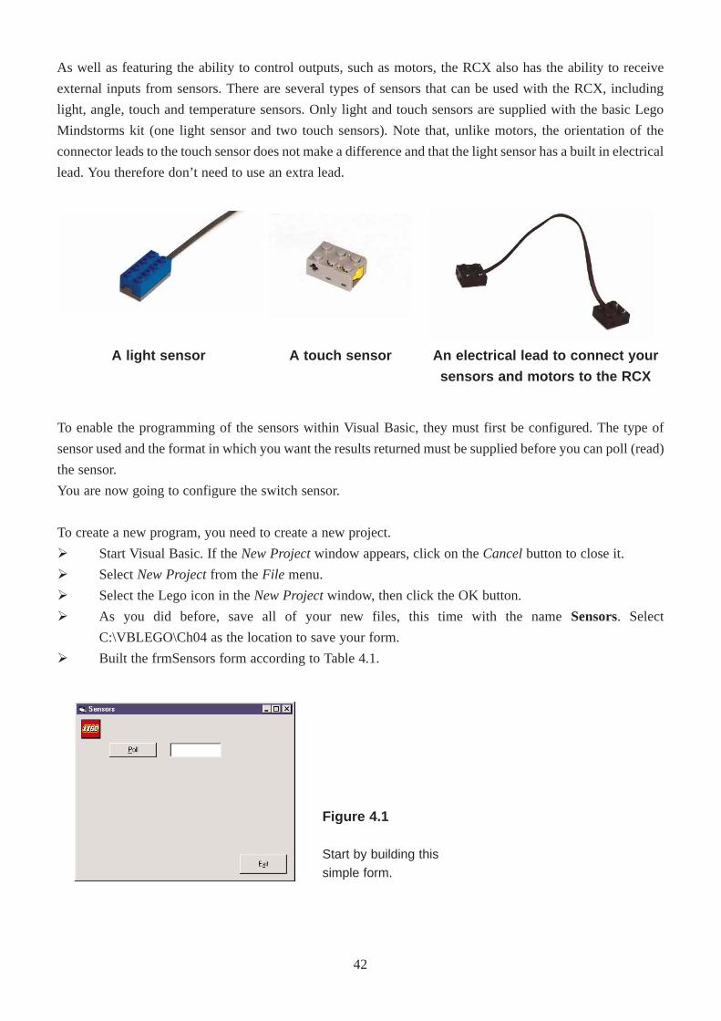
As well as featuring the ability to control outputs, such as motors, the RCX also has the ability to receive
external inputs from sensors. There are several types of sensors that can be used with the RCX, including
light, angle, touch and temperature sensors. Only light and touch sensors are supplied with the basic Lego
Mindstorms kit (one light sensor and two touch sensors). Note that, unlike motors, the orientation of the
connector leads to the touch sensor does not make a difference and that the light sensor has a built in electrical
lead. You therefore don’t need to use an extra lead.
Figure 4.1
Start by building this
simple form.
A light sensor A touch sensor An electrical lead to connect your
sensors and motors to the RCX
42

Form
Command Button
Command Button
Text Box
Name
Caption
Name
Caption
Name
Caption
Name
Alignment
Caption
frmSensors
Sensors
cmdPoll
&Poll
cmdExit
E&xit
txtPoll
2 - Center
(Leave Blank)
Control Type Property Value
Table 4.1
Ø Insert the following code.
' All Variables MUST be declared
Option Explicit
Private Sub cmdExit_Click()PBrickCtrl.CloseComm
End
End Sub
Private Sub cmdPoll_Click()' set input 1 to switch
PBrickCtrl.SetSensorType SENSOR_1, SWITCH_TYPE
' set text box to value of Sensor 1
txtPoll.Text = PBrickCtrl.Poll(SENVAL, SENSOR_1)
End Sub
Private Sub Form_Load()PBrickCtrl.InitComm 'Initialises the PC-Serial communication port.
End Sub
43
How the program worksThe cmdPoll_Click() event procedure places the present value (as a boolean value, i.e. either true or false)
of the sensor placed on Input 1 in the text box txtPoll.
PBrickCtrl.SetSensorType SENSOR_1, SWITCH_TYPE
This lines indicates that you should have the touch sensor connected to Input 1, and you want to set the type
of this sensor to Switch. You could also configure the SENSOR_2 and SENSOR_3 inputs. The possible types
of sensors, their numerical values and constant types are given in Table 4.2:
01234
NO_TYPESWITCH_TYPETEMP_TYPELIGHT_TYPEANGLE_TYPE
NoneSwitchTemperatureLightAngle
Number Constant Sensor Type
Table 4.2
The sensor is now configured properly and can be polled.
txtPoll.Text = PBrickCtrl.Poll(SENVAL, SENSOR_1)
Here you want the contents of txtPoll to be set to the current value of the sensor.
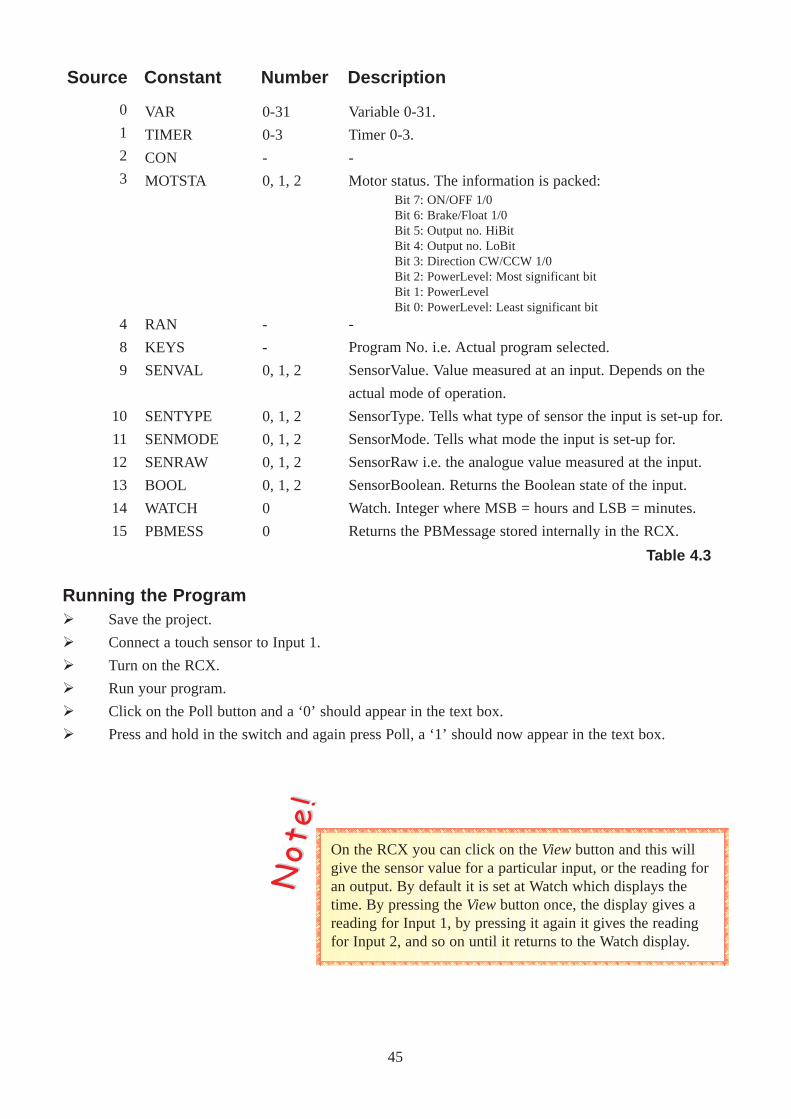
The Poll method can be used to retrieve a variety of different types of information from the RCX. The first
parameter indicates what you want to retrieve, in your case the value of a sensor (SENVAL) and the second
parameter is which of the three sensors you want to poll, here it is Sensor 1.
The second parameter can differ for different source values
(e.g. if the source was a VAR the second parameter would be a
number between 0 and 31).
NNoo tt
ee !!
44
0
1
2
3
4
8
9
10
11
12
13
14
15
VAR
TIMER
CON
MOTSTA
RAN
KEYS
SENVAL
SENTYPE
SENMODE
SENRAW
BOOL
WATCH
PBMESS
0-31
0-3
-
0, 1, 2
-
-
0, 1, 2
0, 1, 2
0, 1, 2
0, 1, 2
0, 1, 2
0
0
Source Constant Number Description
-
Program No. i.e. Actual program selected.
SensorValue. Value measured at an input. Depends on the
actual mode of operation.
SensorType. Tells what type of sensor the input is set-up for.
SensorMode. Tells what mode the input is set-up for.
SensorRaw i.e. the analogue value measured at the input.
SensorBoolean. Returns the Boolean state of the input.
Watch. Integer where MSB = hours and LSB = minutes.
Returns the PBMessage stored internally in the RCX.
Bit 7: ON/OFF 1/0Bit 6: Brake/Float 1/0Bit 5: Output no. HiBitBit 4: Output no. LoBitBit 3: Direction CW/CCW 1/0Bit 2: PowerLevel: Most significant bitBit 1: PowerLevelBit 0: PowerLevel: Least significant bit
Variable 0-31.
Timer 0-3.
-
Motor status. The information is packed:
On the RCX you can click on the Viewbutton and this willgive the sensor value for a particular input, or the reading foran output. By default it is set at Watch which displays thetime. By pressing the Viewbutton once, the display gives areading for Input 1, by pressing it again it gives the readingfor Input 2, and so on until it returns to the Watch display.
NNoo tt
ee !!
Running the ProgramØ Save the project.
Ø Connect a touch sensor to Input 1.
Ø Turn on the RCX.
Ø Run your program.
Ø Click on the Poll button and a ‘0’ should appear in the text box.
Ø Press and hold in the switch and again press Poll, a ‘1’ should now appear in the text box.
Table 4.3
45
012
3
4
567
RAW_MODEBOOL_MODETRANS_COUNT_MODE
PERIOD_COUNT_MODE
PERCENT_MODE
CELSIUS_MODEFAHRENHEIT_MODEANGLE_MODE
RawBooleanTransition
Periodic Counter
Percent
CelsiusFahrenheitAngle
Number Constant Sensor Mode Description
Raw analogue data (0-1023).TRUE or FALSEAll transitions are counted (both positiveand negative transitions are counted).Only counts whole periods (one negativeedge + a positive edge - or vice versa).Sensor value represented as a percentage offull scale.Temperature measured in Celsius.Temperature measured in Fahrenheit.Input data counted as Angle steps.
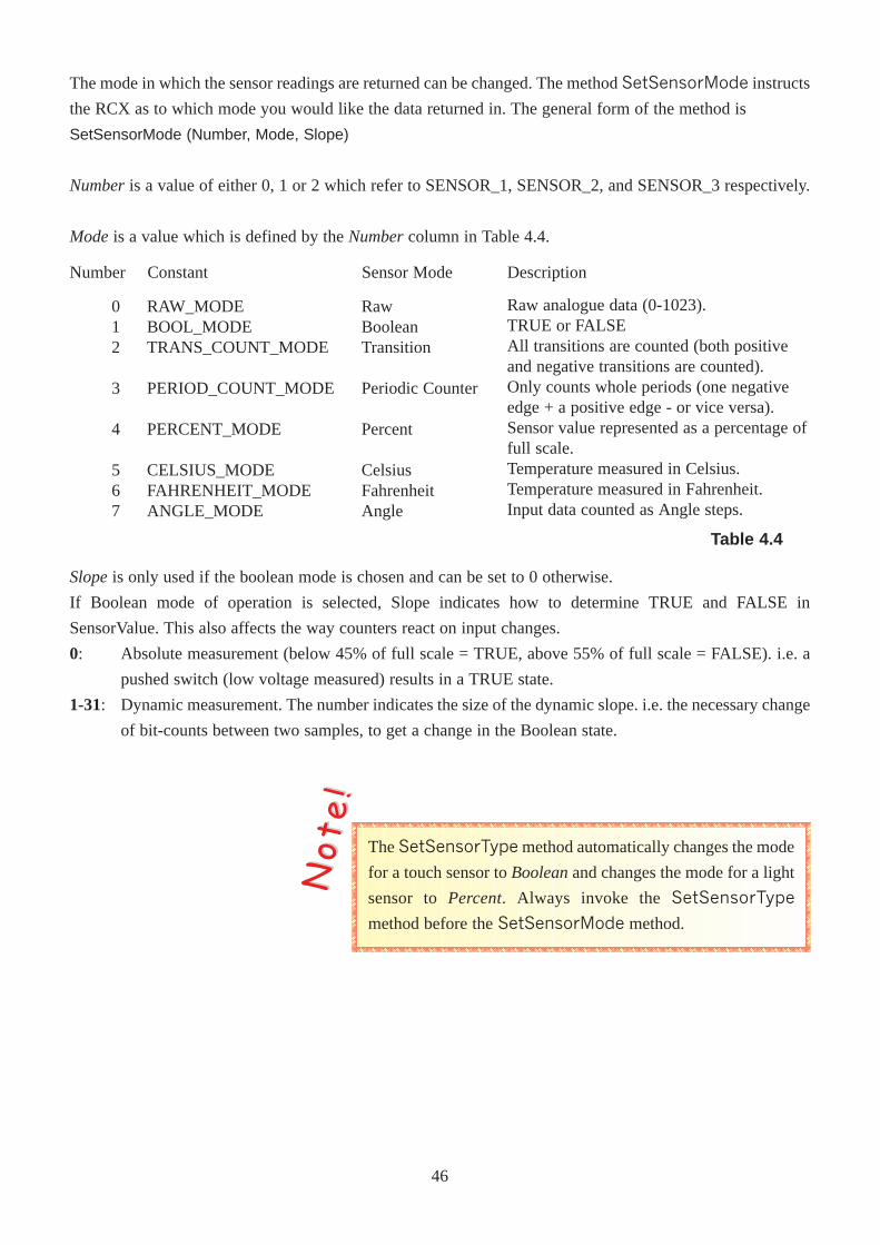
Slopeis only used if the boolean mode is chosen and can be set to 0 otherwise.
If Boolean mode of operation is selected, Slope indicates how to determine TRUE and FALSE in
SensorValue. This also affects the way counters react on input changes.
0: Absolute measurement (below 45% of full scale = TRUE, above 55% of full scale = FALSE). i.e. a
pushed switch (low voltage measured) results in a TRUE state.
1-31: Dynamic measurement. The number indicates the size of the dynamic slope. i.e. the necessary change
of bit-counts between two samples, to get a change in the Boolean state.
Table 4.4
The mode in which the sensor readings are returned can be changed. The method SetSensorMode instructs
the RCX as to which mode you would like the data returned in. The general form of the method is
SetSensorMode (Number, Mode, Slope)
Numberis a value of either 0, 1 or 2 which refer to SENSOR_1, SENSOR_2, and SENSOR_3 respectively.
Modeis a value which is defined by the Numbercolumn in Table 4.4.
The SetSensorType method automatically changes the mode
for a touch sensor to Booleanand changes the mode for a light
sensor to Percent. Always invoke the SetSensorType
method before the SetSensorMode method.
NNoo tt
ee !!
46
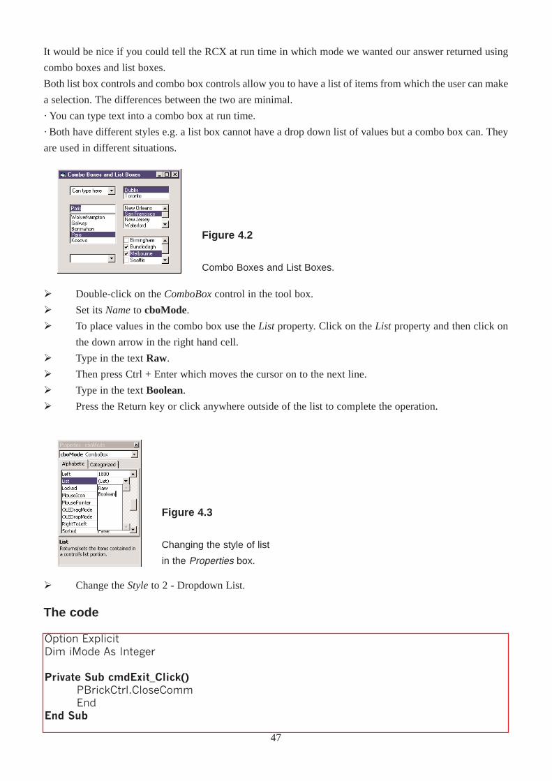
Ø Double-click on the ComboBoxcontrol in the tool box.
Ø Set its Nameto cboMode.
Ø To place values in the combo box use the List property. Click on the List property and then click on
the down arrow in the right hand cell.
Ø Type in the text Raw.
Ø Then press Ctrl + Enter which moves the cursor on to the next line.
Ø Type in the text Boolean.
Ø Press the Return key or click anywhere outside of the list to complete the operation.
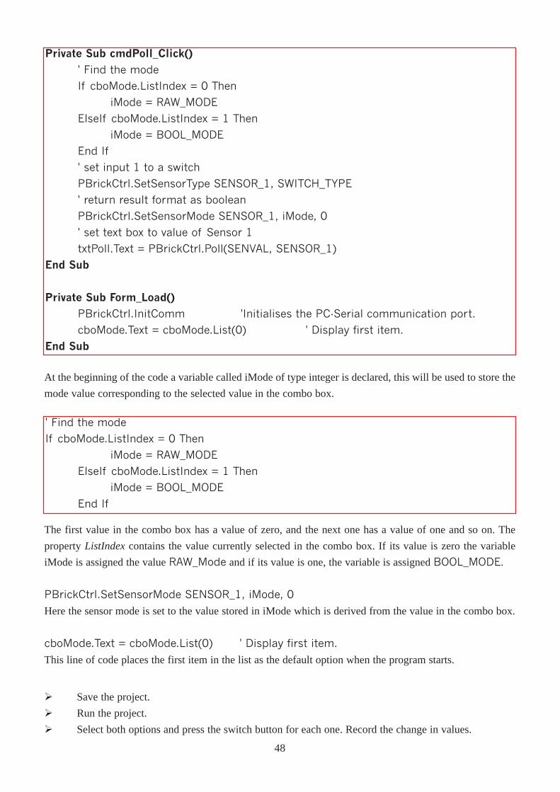
Ø Change the Styleto 2 - Dropdown List.
The code
Option ExplicitDim iMode As Integer
Private Sub cmdExit_Click()PBrickCtrl.CloseCommEnd
End Sub
Figure 4.2
Combo Boxes and List Boxes.
Figure 4.3
Changing the style of list
in the Properties box.
It would be nice if you could tell the RCX at run time in which mode we wanted our answer returned using
combo boxes and list boxes.
Both list box controls and combo box controls allow you to have a list of items from which the user can make
a selection. The differences between the two are minimal.
· You can type text into a combo box at run time.
· Both have different styles e.g. a list box cannot have a drop down list of values but a combo box can. They
are used in different situations.
47
Private Sub cmdPoll_Click()
' Find the mode
If cboMode.ListIndex = 0 Then
iMode = RAW_MODE
ElseIf cboMode.ListIndex = 1 Then
iMode = BOOL_MODE
End If
' set input 1 to a switch
PBrickCtrl.SetSensorType SENSOR_1, SWITCH_TYPE
' return result format as boolean
PBrickCtrl.SetSensorMode SENSOR_1, iMode, 0
' set text box to value of Sensor 1
txtPoll.Text = PBrickCtrl.Poll(SENVAL, SENSOR_1)
End Sub
Private Sub Form_Load()PBrickCtrl.InitComm 'Initialises the PC-Serial communication port.
cboMode.Text = cboMode.List(0) ' Display first item.
End Sub
At the beginning of the code a variable called iMode of type integer is declared, this will be used to store the
mode value corresponding to the selected value in the combo box.
' Find the mode
If cboMode.ListIndex = 0 Then
iMode = RAW_MODE
ElseIf cboMode.ListIndex = 1 Then
iMode = BOOL_MODE
End If
The first value in the combo box has a value of zero, and the next one has a value of one and so on. The
property ListIndexcontains the value currently selected in the combo box. If its value is zero the variable
iMode is assigned the value RAW_Mode and if its value is one, the variable is assigned BOOL_MODE.
PBrickCtrl.SetSensorMode SENSOR_1, iMode, 0
Here the sensor mode is set to the value stored in iMode which is derived from the value in the combo box.
cboMode.Text = cboMode.List(0) ' Display first item.
This line of code places the first item in the list as the default option when the program starts.
Ø Save the project.
Ø Run the project.
Ø Select both options and press the switch button for each one. Record the change in values.
48
Most of the code that you have written for the previous example is unnecessary. This is because if you take
a look at the index values of the combo box and the numeric values of the different modes, you will see that
they match provided that they are entered in the same order.
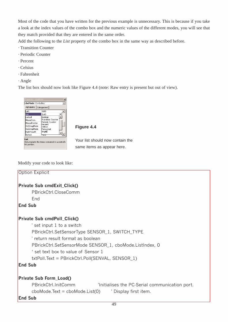
Add the following to the List property of the combo box in the same way as described before.
· Transition Counter
· Periodic Counter
· Percent
· Celsius
· Fahrenheit
· Angle
The list box should now look like Figure 4.4 (note: Raw entry is present but out of view).
Option Explicit
Private Sub cmdExit_Click()PBrickCtrl.CloseComm
End
End Sub
Private Sub cmdPoll_Click()
' set input 1 to a switch
PBrickCtrl.SetSensorType SENSOR_1, SWITCH_TYPE
' return result format as boolean
PBrickCtrl.SetSensorMode SENSOR_1, cboMode.ListIndex, 0
� set text box to value of Sensor 1
txtPoll.Text = PBrickCtrl.Poll(SENVAL, SENSOR_1)
End Sub
Private Sub Form_Load()PBrickCtrl.InitComm 'Initialises the PC-Serial communication port.
cboMode.Text = cboMode.List(0) ' Display first item.
End Sub
Figure 4.4
Your list should now contain the
same items as appear here.
Modify your code to look like:
49
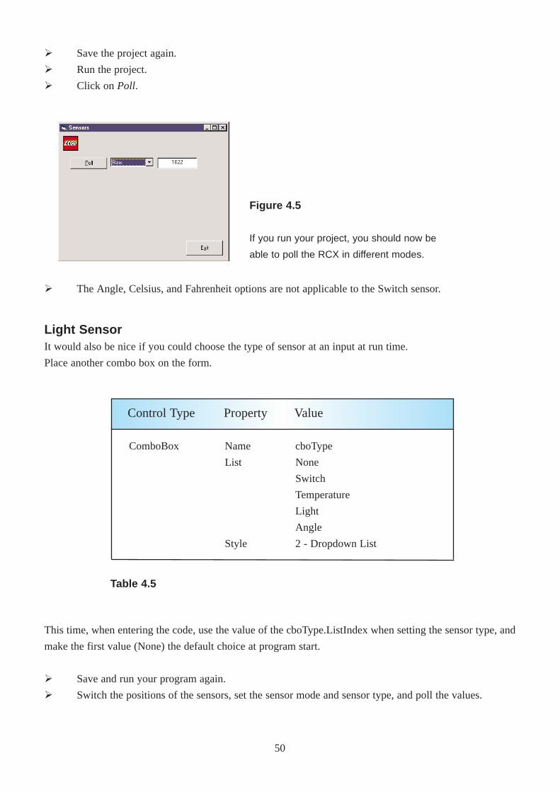
Ø Save the project again.
Ø Run the project.
Ø Click on Poll.
Ø The Angle, Celsius, and Fahrenheit options are not applicable to the Switch sensor.
Light SensorIt would also be nice if you could choose the type of sensor at an input at run time.
Place another combo box on the form.
ComboBox Name
List
Style
cboType
None
Switch
Temperature
Light
Angle
2 - Dropdown List
Control Type Property Value
Table 4.5
This time, when entering the code, use the value of the cboType.ListIndex when setting the sensor type, and
make the first value (None) the default choice at program start.
Ø Save and run your program again.
Ø Switch the positions of the sensors, set the sensor mode and sensor type, and poll the values.
Figure 4.5
If you run your project, you should now be
able to poll the RCX in different modes.
50
Block SorterYou are now going to create a program that will be able to differentiate between objects of two different
colours.
Ø Save your project.
Ø Select New Projectfrom the File menu.
Ø Select the Lego icon in the New Projectwindow, then click the OK button.
Ø Ensure that the Form1 window of the new project is the selected window and then from the File
menu, select Save Form1 As.
Ø Using the Save Asdialog box which appears, select C:\VBLEGO\Ch04 as the location to save your
form.
Ø Call the form Sorter and then click on the Savebutton.
Ø Select Save Project Asfrom the File menu.
Ø The first file to be saved is the .bas file. Enter the file name as Sorter and click on the Savebutton
(the location should already be the Ch04 folder).
Ø You are then asked to save the .vbp file. Call this Sorter also and click on the Savebutton.
The Timer ControlEach time a command button is pressed, an associated event procedure is executed ("triggered"). If you want
a certain action to occur at regular intervals automatically, you can make use of the Timer control. A timer
control allows a procedure to be executed at fixed time intervals. The Interval property dictates how long
these intervals are. It can have a value between 0 and 65,535. This value is measured in milliseconds (1
second equals 1,000 milliseconds). A timer control is invisible at run time and is only visible on the form at
design time.
The Shape ControlThe shape control is useful for drawing several shapes:
· Rectangles
· Squares
· Circle
· Oval
· Rounded Square
· Rounded Rectangle
51
Form
CommandButton
Timer
TextBox
Label
Shape
Name
Caption
Name
Caption
Name
Enabled
Interval
Name
Text
Name
Caption
Name
BorderStyle
FillStyle
frmSorter
Block Sorter
cmdExit
E&xit
tmrPoll
True
1000
txtPoll
(Blank)
lblPoll
Light Sensor
shpBlock
0 - Transparent
0 - Solid
Control Type Property Value
Table 4.6
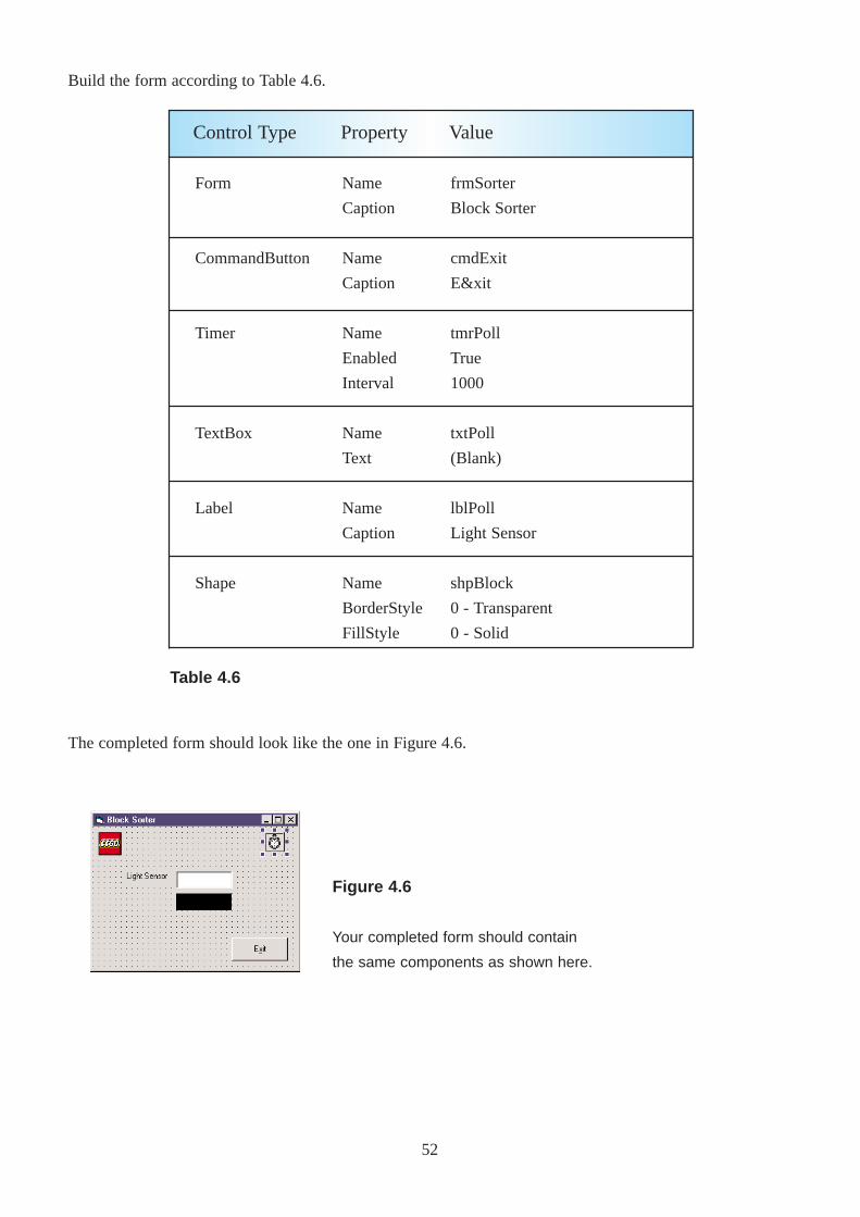
Build the form according to Table 4.6.
The completed form should look like the one in Figure 4.6.
Figure 4.6
Your completed form should contain
the same components as shown here.
52

4
3
2
51
6
7
53
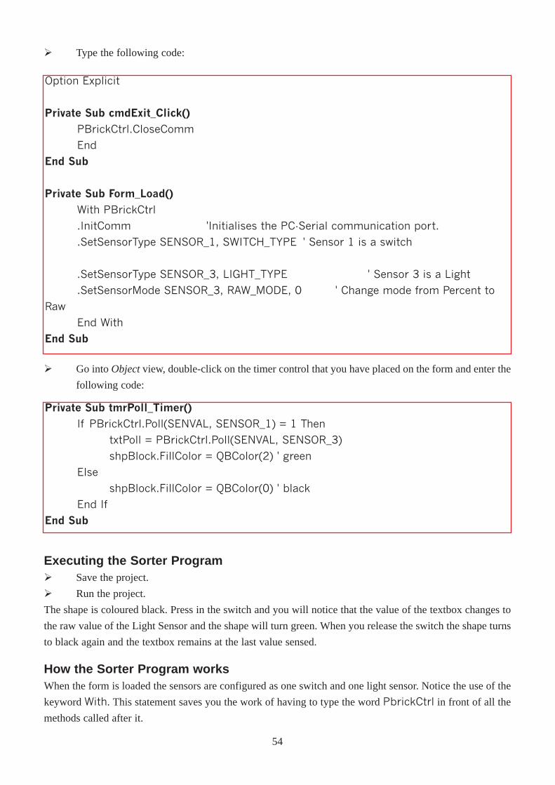
Option Explicit
Private Sub cmdExit_Click()
PBrickCtrl.CloseComm
End
End Sub
Private Sub Form_Load()
With PBrickCtrl
.InitComm 'Initialises the PC-Serial communication port.
.SetSensorType SENSOR_1, SWITCH_TYPE ' Sensor 1 is a switch
.SetSensorType SENSOR_3, LIGHT_TYPE ' Sensor 3 is a Light
.SetSensorMode SENSOR_3, RAW_MODE, 0 ' Change mode from Percent to
Raw
End With
End Sub
Ø Go intoObjectview, double-click on the timer control that you have placed on the form and enter the
following code:
Private Sub tmrPoll_Timer()If PBrickCtrl.Poll(SENVAL, SENSOR_1) = 1 Then
txtPoll = PBrickCtrl.Poll(SENVAL, SENSOR_3)
shpBlock.FillColor = QBColor(2) ' green
Else
shpBlock.FillColor = QBColor(0) ' black
End If
End Sub
Executing the Sorter ProgramØ Save the project.
Ø Run the project.
The shape is coloured black. Press in the switch and you will notice that the value of the textbox changes to
the raw value of the Light Sensor and the shape will turn green. When you release the switch the shape turns
to black again and the textbox remains at the last value sensed.
How the Sorter Program worksWhen the form is loaded the sensors are configured as one switch and one light sensor. Notice the use of the
keyword With. This statement saves you the work of having to type the word PbrickCtrl in front of all the
methods called after it.
Ø Type the following code:
54
The tmrPoll_Timer() procedure executes every 1,000 ms (1 second). The first line of code
If PBrickCtrl.Poll(SENVAL, SENSOR_1) = 1 Then
checks to see if the switch has been pressed. If it is pressed (i.e. equals 1)
txtPoll = PBrickCtrl.Poll(SENVAL, SENSOR_3)
shpBlock.FillColor = QBColor(2) ' green
the reading of the light sensor is assigned to the TextBoxtxtPoll and the colour of the shape is changed to
green. If the switch button is not pressed the colour of the shape remains as black.
The QBColor() function returns a colour corresponding to a value in Table 4.7.
0
1
2
3
4
5
6
7
Black
Blue
Green
Cyan
Red
Magenta
Yellow
White
8
9
10
11
12
13
14
15
Grey
Light Blue
Light Green
Light Cyan
Light Red
Light Magenta
Light Yellow
Bright White
Number ColourNumberColour
Exercise:Modify the Sorter program so that it will be able to differentiate between two different colour Lego blocks
placed under the light sensor. The light sensor readings should vary depending on the colour over which it is
placed. The Shapecontrol should reflect the colour of the block under the light sensor.
All of your code changes should be implemented in thetmrPoll_Timer() procedure. A shell for this
procedure may look like:
Private Sub tmrPoll_Timer()' Declare integer to hold value of light sensorDim iLightRaw As IntegerIf PBrickCtrl.Poll(SENVAL, SENSOR_1) = 1 Then
iLightRaw = PBrickCtrl.Poll(SENVAL, SENSOR_3)txtPoll = iLightRaw' Insert your own code to find out the colour of the block here
End IfEnd Sub
You can place anIf...Then...Else statement inside another
one, this is called nesting. Also because iLightRaw is declared
inside the procedure and not in the General Declarations
section as before, it can only be used in this specific procedure.
NNoo tt
ee !!
Table 4.7
55
ChapterFive
Manipulating Variables
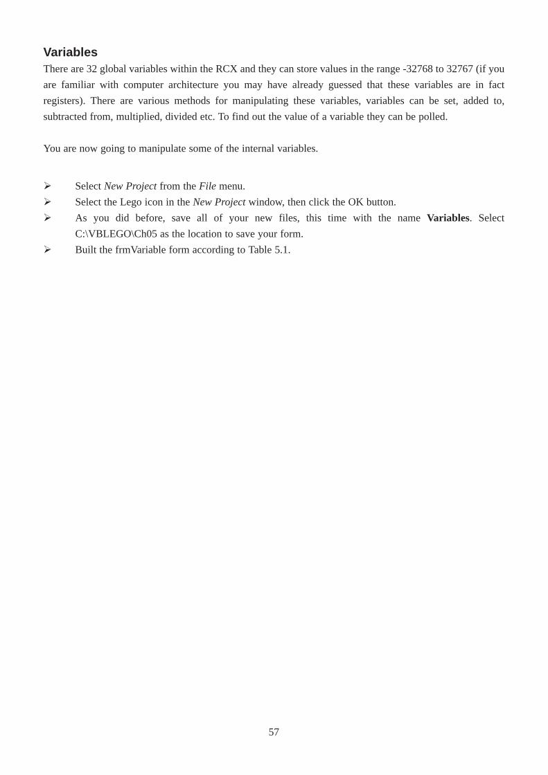
VariablesThere are 32 global variables within the RCX and they can store values in the range -32768 to 32767 (if you
are familiar with computer architecture you may have already guessed that these variables are in fact
registers). There are various methods for manipulating these variables, variables can be set, added to,
subtracted from, multiplied, divided etc. To find out the value of a variable they can be polled.
You are now going to manipulate some of the internal variables.
Ø Select New Projectfrom the File menu.
Ø Select the Lego icon in the New Projectwindow, then click the OK button.
Ø As you did before, save all of your new files, this time with the name Variables. Select
C:\VBLEGO\Ch05 as the location to save your form.
Ø Built the frmVariable form according to Table 5.1.
57
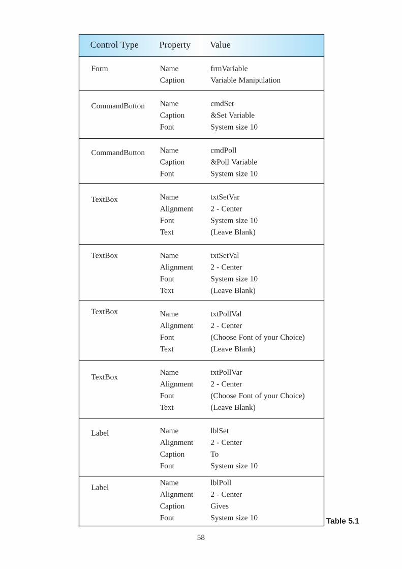
Form
CommandButton
CommandButton
TextBox
TextBox
TextBox
TextBox
Label
Label
Name
Caption
Name
Caption
Font
Name
Caption
Font
Name
Alignment
Font
Text
Name
Alignment
Font
Text
Name
Alignment
Font
Text
Name
Alignment
Font
Text
Name
Alignment
Caption
Font
Name
Alignment
Caption
Font
frmVariable
Variable Manipulation
cmdSet
&Set Variable
System size 10
cmdPoll
&Poll Variable
System size 10
txtSetVar
2 - Center
System size 10
(Leave Blank)
txtSetVal
2 - Center
System size 10
(Leave Blank)
txtPollVal
2 - Center
(Choose Font of your Choice)
(Leave Blank)
txtPollVar
2 - Center
(Choose Font of your Choice)
(Leave Blank)
lblSet
2 - Center
To
System size 10
lblPoll
2 - Center
Gives
System size 10
Control Type Property Value
Table 5.1
58
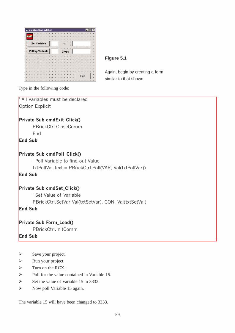
' All Variables must be declared
Option Explicit
Private Sub cmdExit_Click()
PBrickCtrl.CloseComm
End
End Sub
Private Sub cmdPoll_Click()' Poll Variable to find out Value
txtPollVal.Text = PBrickCtrl.Poll(VAR, Val(txtPollVar))
End Sub
Private Sub cmdSet_Click()' Set Value of Variable
PBrickCtrl.SetVar Val(txtSetVar), CON, Val(txtSetVal)
End Sub
Private Sub Form_Load()
PBrickCtrl.InitComm
End Sub
Type in the following code:
Ø Save your project.
Ø Run your project.
Ø Turn on the RCX.
Ø Poll for the value contained in Variable 15.
Ø Set the value of Variable 15 to 3333.
Ø Now poll Variable 15 again.
The variable 15 will have been changed to 3333.
Figure 5.1
Again, begin by creating a form
similar to that shown.
59
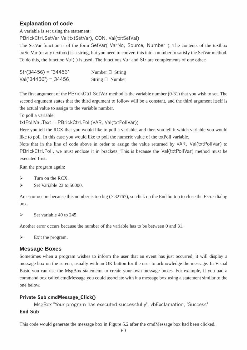
Explanation of codeA variable is set using the statement:
PBrickCtrl.SetVar Val(txtSetVar), CON, Val(txtSetVal)
The SetVar function is of the form SetVar( VarNo, Source, Number ). The contents of the textbox
txtSetVar (or any textbox) is a string, but you need to convert this into a number to satisfy the SetVar method.
To do this, the function Val( ) is used. The functions Var and Str are complements of one other:
Str(34456) = "34456" Number ⇒ String
Val("34456") = 34456 String ⇒ Number
The first argument of the PBrickCtrl.SetVar method is the variable number (0-31) that you wish to set. The
second argument states that the third argument to follow will be a constant, and the third argument itself is
the actual value to assign to the variable number.
To poll a variable:
txtPollVal.Text = PBrickCtrl.Poll(VAR, Val(txtPollVar))
Here you tell the RCX that you would like to poll a variable, and then you tell it which variable you would
like to poll. In this case you would like to poll the numeric value of the txtPoll variable.
Note that in the line of code above in order to assign the value returned by VAR, Val(txtPollVar) to
PBrickCtrl.Poll, we must enclose it in brackets. This is because theVal(txtPollVar) method must be
executed first.
Run the program again:
Ø Turn on the RCX.
Ø Set Variable 23 to 50000.
An error occurs because this number is too big (> 32767), so click on the End button to close the Error dialog
box.
Ø Set variable 40 to 245.
Another error occurs because the number of the variable has to be between 0 and 31.
Ø Exit the program.
Message BoxesSometimes when a program wishes to inform the user that an event has just occurred, it will display a
message box on the screen, usually with an OK button for the user to acknowledge the message. In Visual
Basic you can use the MsgBox statememt to create your own message boxes. For example, if you had a
command box called cmdMessage you could associate with it a message box using a statement similar to the
one below.
Private Sub cmdMessage_Click()
MsgBox "Your program has executed successfully", vbExclamation, "Success"
End Sub
This code would generate the message box in Figure 5.2 after the cmdMessage box had been clicked.60
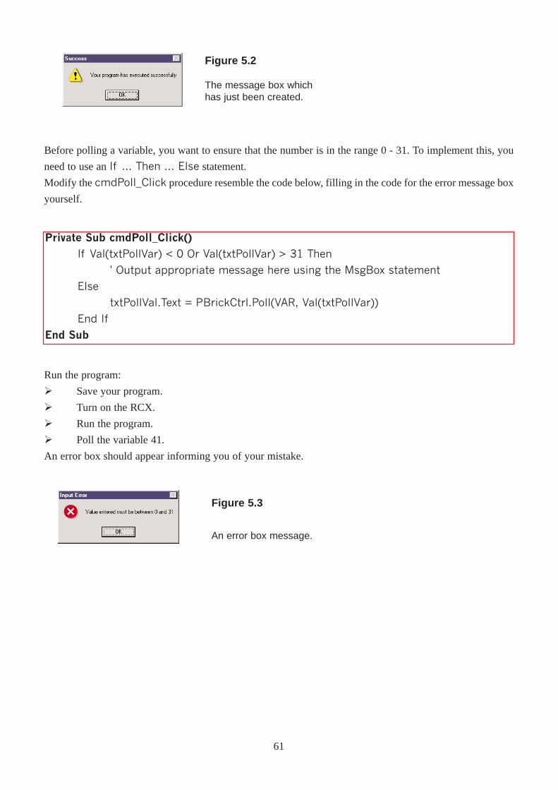
Private Sub cmdPoll_Click()
If Val(txtPollVar) < 0 Or Val(txtPollVar) > 31 Then
' Output appropriate message here using the MsgBox statement
Else
txtPollVal.Text = PBrickCtrl.Poll(VAR, Val(txtPollVar))
End If
End Sub
Before polling a variable, you want to ensure that the number is in the range 0 - 31. To implement this, you
need to use an If ... Then ... Else statement.
Modify the cmdPoll_Click procedure resemble the code below, filling in the code for the error message box
yourself.
Figure 5.2
The message box whichhas just been created.
Run the program:
Ø Save your program.
Ø Turn on the RCX.
Ø Run the program.
Ø Poll the variable 41.
An error box should appear informing you of your mistake.
Figure 5.3
An error box message.
61
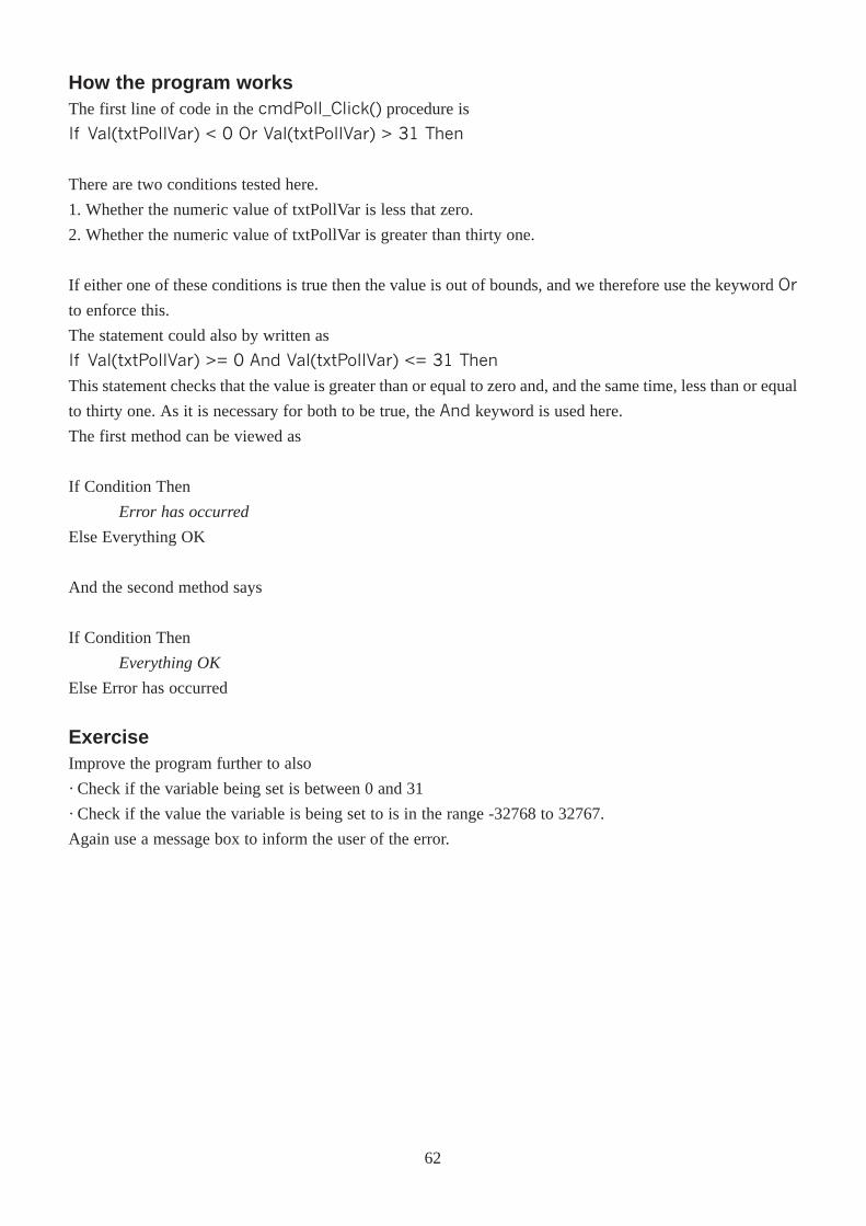
How the program worksThe first line of code in the cmdPoll_Click() procedure is
If Val(txtPollVar) < 0 Or Val(txtPollVar) > 31 Then
There are two conditions tested here.
1. Whether the numeric value of txtPollVar is less that zero.
2. Whether the numeric value of txtPollVar is greater than thirty one.
If either one of these conditions is true then the value is out of bounds, and we therefore use the keyword Or
to enforce this.
The statement could also by written as
If Val(txtPollVar) >= 0 And Val(txtPollVar) <= 31 Then
This statement checks that the value is greater than or equal to zero and, and the same time, less than or equal
to thirty one. As it is necessary for both to be true, the And keyword is used here.
The first method can be viewed as
If Condition Then
Error has occurred
Else Everything OK
And the second method says
If Condition Then
Everything OK
Else Error has occurred
ExerciseImprove the program further to also
· Check if the variable being set is between 0 and 31
· Check if the value the variable is being set to is in the range -32768 to 32767.
Again use a message box to inform the user of the error.
62
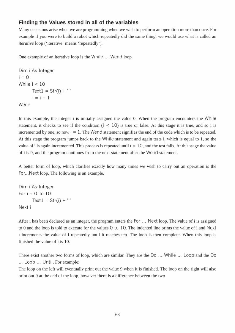
Finding the Values stored in all of the variablesMany occasions arise when we are programming when we wish to perform an operation more than once. For
example if you were to build a robot which repeatedly did the same thing, we would use what is called an
iterative loop (‘iterative’ means ‘repeatedly’).
One example of an iterative loop is the While ... Wend loop.
Dim i As Integer
i = 0
While i < 10
Text1 = Str(i) + " "
i = i + 1
Wend
In this example, the integer i is initially assigned the value 0. When the program encounters the While
statement, it checks to see if the condition (i < 10) is true or false. At this stage it is true, and so i is
incremented by one, so now i = 1. The Wend statement signifies the end of the code which is to be repeated.
At this stage the program jumps back to the While statement and again tests i, which is equal to 1, so the
value of i is again incremented. This process is repeated until i = 10, and the test fails. At this stage the value
of i is 9, and the program continues from the next statement after the Wend statement.
A better form of loop, which clarifies exactly how many times we wish to carry out an operation is the
For...Next loop. The following is an example.
Dim i As Integer
For i = 0 To 10
Text1 = Str(i) + " "
Next i
After i has been declared as an integer, the program enters the For ... Next loop. The value of i is assigned
to 0 and the loop is told to execute for the values 0 to 10. The indented line prints the value of i and Next
i increments the value of i repeatedly until it reaches ten. The loop is then complete. When this loop is
finished the value of i is 10.
There exist another two forms of loop, which are similar. They are the Do ... While ... Loop and the Do
... Loop ... Until. For example:
The loop on the left will eventually print out the value 9 when it is finished. The loop on the right will also
print out 9 at the end of the loop, however there is a difference between the two.
63
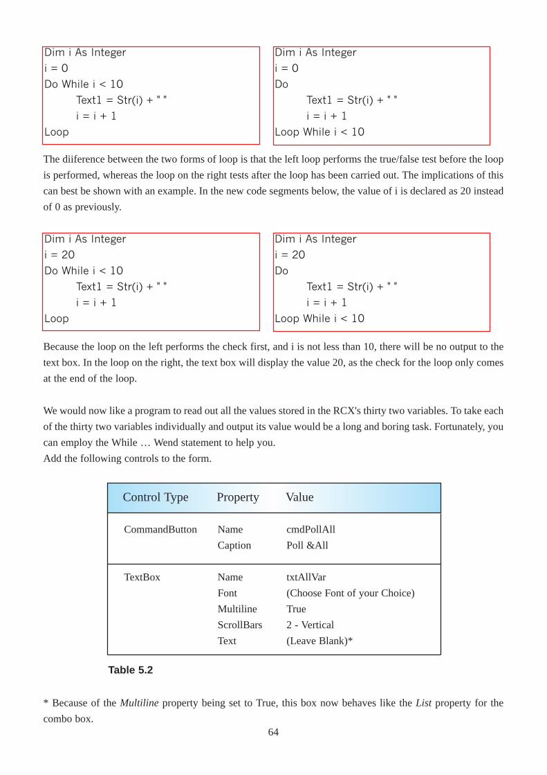
We would now like a program to read out all the values stored in the RCX's thirty two variables. To take each
of the thirty two variables individually and output its value would be a long and boring task. Fortunately, you
can employ the While … Wend statement to help you.
Add the following controls to the form.
CommandButton
TextBox
Name
Caption
Name
Font
Multiline
ScrollBars
Text
cmdPollAll
Poll &All
txtAllVar
(Choose Font of your Choice)
True
2 - Vertical
(Leave Blank)*
Control Type Property Value
Table 5.2
Dim i As Integer
i = 0
Do While i < 10
Text1 = Str(i) + " "
i = i + 1
Loop
Dim i As Integer
i = 0
Do
Text1 = Str(i) + " "
i = i + 1
Loop While i < 10
The diiference between the two forms of loop is that the left loop performs the true/false test before the loop
is performed, whereas the loop on the right tests after the loop has been carried out. The implications of this
can best be shown with an example. In the new code segments below, the value of i is declared as 20 instead
of 0 as previously.
Dim i As Integer
i = 20
Do While i < 10
Text1 = Str(i) + " "
i = i + 1
Loop
Dim i As Integer
i = 20
Do
Text1 = Str(i) + " "
i = i + 1
Loop While i < 10
Because the loop on the left performs the check first, and i is not less than 10, there will be no output to the
text box. In the loop on the right, the text box will display the value 20, as the check for the loop only comes
at the end of the loop.
* Because of the Multiline property being set to True, this box now behaves like the List property for the
combo box.64
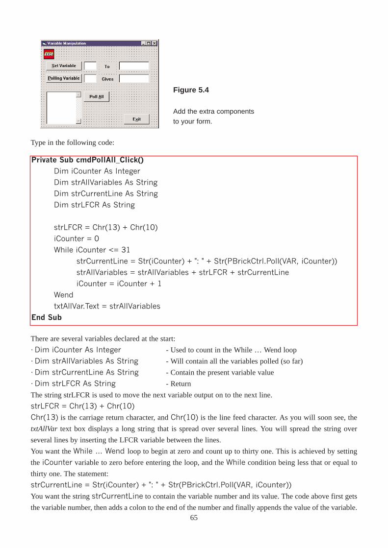
Private Sub cmdPollAll_Click()
Dim iCounter As Integer
Dim strAllVariables As String
Dim strCurrentLine As String
Dim strLFCR As String
strLFCR = Chr(13) + Chr(10)
iCounter = 0
While iCounter <= 31
strCurrentLine = Str(iCounter) + ": " + Str(PBrickCtrl.Poll(VAR, iCounter))
strAllVariables = strAllVariables + strLFCR + strCurrentLine
iCounter = iCounter + 1
Wend
txtAllVar.Text = strAllVariables
End Sub
Figure 5.4
Add the extra components
to your form.
There are several variables declared at the start:
· Dim iCounter As Integer - Used to count in the While … Wend loop
· Dim strAllVariables As String - Will contain all the variables polled (so far)
· Dim strCurrentLine As String - Contain the present variable value
· Dim strLFCR As String - Return
The string strLFCR is used to move the next variable output on to the next line.
strLFCR = Chr(13) + Chr(10)
Chr(13) is the carriage return character, and Chr(10) is the line feed character. As you will soon see, the
txtAllVar text box displays a long string that is spread over several lines. You will spread the string over
several lines by inserting the LFCR variable between the lines.
You want the While � Wend loop to begin at zero and count up to thirty one. This is achieved by setting
the iCounter variable to zero before entering the loop, and the While condition being less that or equal to
thirty one. The statement:
strCurrentLine = Str(iCounter) + ": " + Str(PBrickCtrl.Poll(VAR, iCounter))
You want the string strCurrentLine to contain the variable number and its value. The code above first gets
the variable number, then adds a colon to the end of the number and finally appends the value of the variable.
Type in the following code:
65
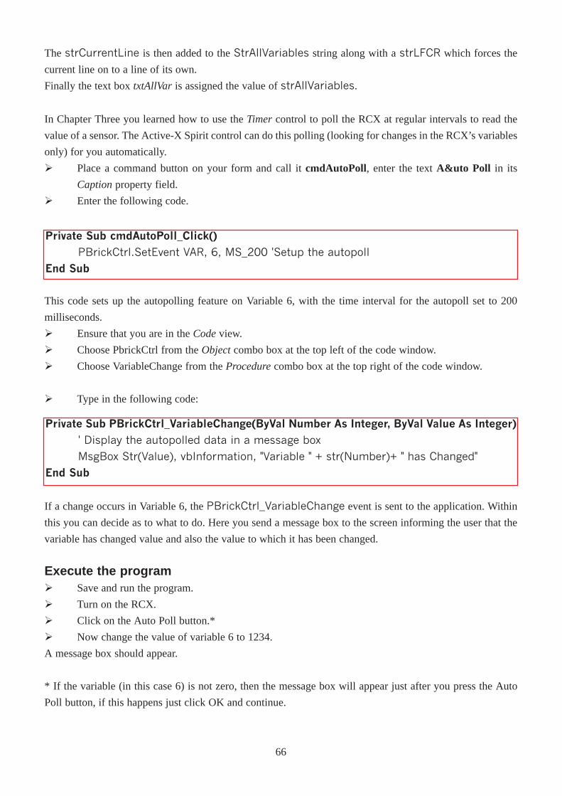
In Chapter Three you learned how to use the Timer control to poll the RCX at regular intervals to read the
value of a sensor. The Active-X Spirit control can do this polling (looking for changes in the RCX’s variables
only) for you automatically.
Ø Place a command button on your form and call it cmdAutoPoll, enter the text A&uto Poll in its
Captionproperty field.
Ø Enter the following code.
Private Sub cmdAutoPoll_Click()
PBrickCtrl.SetEvent VAR, 6, MS_200 'Setup the autopoll
End Sub
The strCurrentLine is then added to the StrAllVariables string along with a strLFCR which forces the
current line on to a line of its own.
Finally the text box txtAllVar is assigned the value of strAllVariables.
Private Sub PBrickCtrl_VariableChange(ByVal Number As Integer, ByVal Value As Integer)' Display the autopolled data in a message box
MsgBox Str(Value), vbInformation, "Variable " + str(Number)+ " has Changed"
End Sub
This code sets up the autopolling feature on Variable 6, with the time interval for the autopoll set to 200
milliseconds.
Ø Ensure that you are in the Codeview.
Ø Choose PbrickCtrl from the Objectcombo box at the top left of the code window.
Ø Choose VariableChange from the Procedurecombo box at the top right of the code window.
Ø Type in the following code:
If a change occurs in Variable 6, the PBrickCtrl_VariableChange event is sent to the application. Within
this you can decide as to what to do. Here you send a message box to the screen informing the user that the
variable has changed value and also the value to which it has been changed.
Execute the programØ Save and run the program.
Ø Turn on the RCX.
Ø Click on the Auto Poll button.*
Ø Now change the value of variable 6 to 1234.
A message box should appear.
* If the variable (in this case 6) is not zero, then the message box will appear just after you press the Auto
Poll button, if this happens just click OK and continue.
66
ChapterSix
Building AutonomousRobots
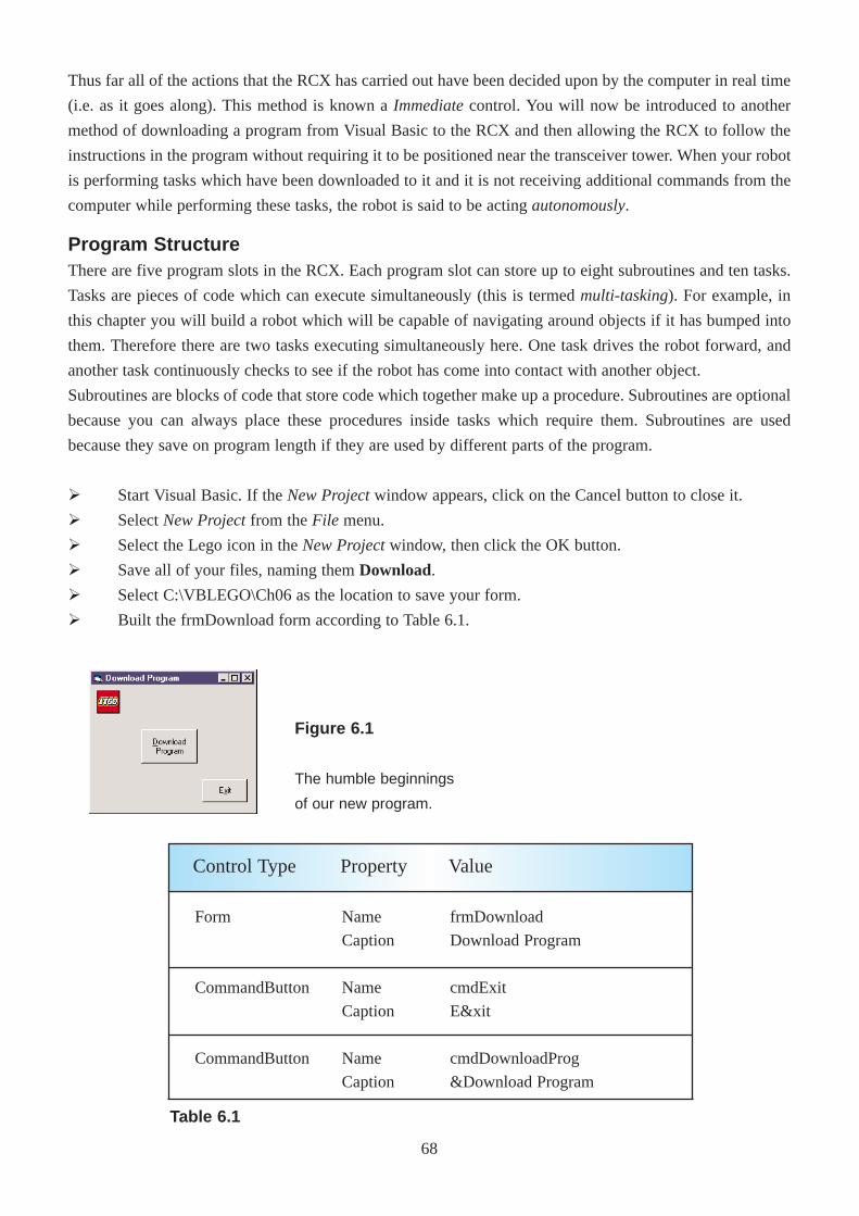
Thus far all of the actions that the RCX has carried out have been decided upon by the computer in real time
(i.e. as it goes along). This method is known a Immediatecontrol. You will now be introduced to another
method of downloading a program from Visual Basic to the RCX and then allowing the RCX to follow the
instructions in the program without requiring it to be positioned near the transceiver tower. When your robot
is performing tasks which have been downloaded to it and it is not receiving additional commands from the
computer while performing these tasks, the robot is said to be acting autonomously.
Program StructureThere are five program slots in the RCX. Each program slot can store up to eight subroutines and ten tasks.
Tasks are pieces of code which can execute simultaneously (this is termed multi-tasking). For example, in
this chapter you will build a robot which will be capable of navigating around objects if it has bumped into
them. Therefore there are two tasks executing simultaneously here. One task drives the robot forward, and
another task continuously checks to see if the robot has come into contact with another object.
Subroutines are blocks of code that store code which together make up a procedure. Subroutines are optional
because you can always place these procedures inside tasks which require them. Subroutines are used
because they save on program length if they are used by different parts of the program.
Ø Start Visual Basic. If the New Projectwindow appears, click on the Cancel button to close it.
Ø Select New Projectfrom the File menu.
Ø Select the Lego icon in the New Projectwindow, then click the OK button.
Ø Save all of your files, naming them Download.
Ø Select C:\VBLEGO\Ch06 as the location to save your form.
Ø Built the frmDownload form according to Table 6.1.
Figure 6.1
The humble beginnings
of our new program.
Form
CommandButton
CommandButton
Name
Caption
Name
Caption
Name
Caption
frmDownload
Download Program
cmdExit
E&xit
cmdDownloadProg
&Download Program
Control Type Property Value
Table 6.1
68
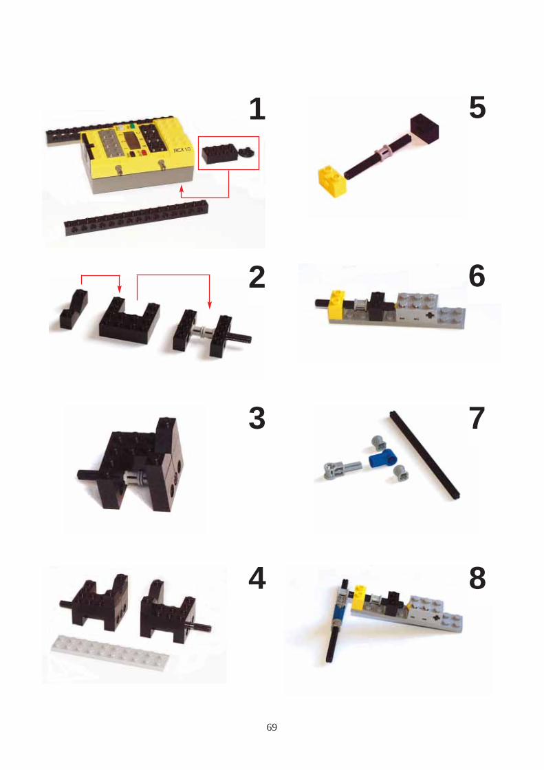
4
3
2
51
6
7
8
69
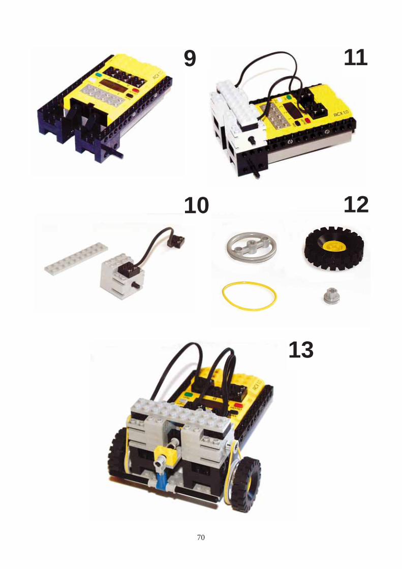
10
119
12
13
70
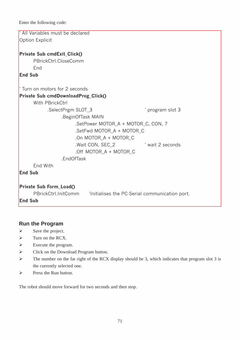
Enter the following code:
' All Variables must be declared
Option Explicit
Private Sub cmdExit_Click()
PBrickCtrl.CloseComm
End
End Sub
' Turn on motors for 2 seconds
Private Sub cmdDownloadProg_Click()
With PBrickCtrl
.SelectPrgm SLOT_3 ' program slot 3
.BeginOfTask MAIN
.SetPower MOTOR_A + MOTOR_C, CON, 7
.SetFwd MOTOR_A + MOTOR_C
.On MOTOR_A + MOTOR_C
.Wait CON, SEC_2 ' wait 2 seconds
.Off MOTOR_A + MOTOR_C
.EndOfTask
End With
End Sub
Private Sub Form_Load()PBrickCtrl.InitComm 'Initialises the PC-Serial communication port.
End Sub
Run the ProgramØ Save the project.
Ø Turn on the RCX.
Ø Execute the program.
Ø Click on the Download Program button.
Ø The number on the far right of the RCX display should be 3, which indicates that program slot 3 is
the currently selected one.
Ø Press the Run button.
The robot should move forward for two seconds and then stop.
71
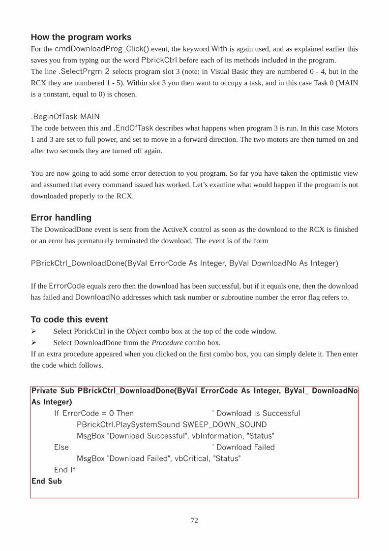
How the program worksFor the cmdDownloadProg_Click() event, the keyword With is again used, and as explained earlier this
saves you from typing out the word PbrickCtrl before each of its methods included in the program.
The line .SelectPrgm 2 selects program slot 3 (note: in Visual Basic they are numbered 0 - 4, but in the
RCX they are numbered 1 - 5). Within slot 3 you then want to occupy a task, and in this case Task 0 (MAIN
is a constant, equal to 0) is chosen.
.BeginOfTask MAIN
The code between this and .EndOfTask describes what happens when program 3 is run. In this case Motors
1 and 3 are set to full power, and set to move in a forward direction. The two motors are then turned on and
after two seconds they are turned off again.
You are now going to add some error detection to you program. So far you have taken the optimistic view
and assumed that every command issued has worked. Let’s examine what would happen if the program is not
downloaded properly to the RCX.
Private Sub PBrickCtrl_DownloadDone(ByVal ErrorCode As Integer, ByVal_ DownloadNoAs Integer)
If ErrorCode = 0 Then ' Download is Successful
PBrickCtrl.PlaySystemSound SWEEP_DOWN_SOUND
MsgBox "Download Successful", vbInformation, "Status"
Else ' Download Failed
MsgBox "Download Failed", vbCritical, "Status"
End If
End Sub
Error handlingThe DownloadDone event is sent from the ActiveX control as soon as the download to the RCX is finished
or an error has prematurely terminated the download. The event is of the form
PBrickCtrl_DownloadDone(ByVal ErrorCode As Integer, ByVal DownloadNo As Integer)
If the ErrorCode equals zero then the download has been successful, but if it equals one, then the download
has failed and DownloadNo addresses which task number or subroutine number the error flag refers to.
To code this eventØ Select PbrickCtrl in theObjectcombo box at the top of the code window.
Ø Select DownloadDone from the Procedurecombo box.
If an extra procedure appeared when you clicked on the first combo box, you can simply delete it. Then enter
the code which follows.
72
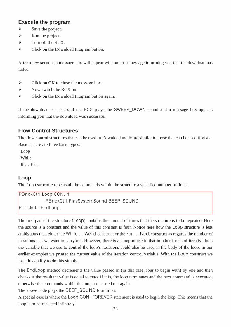
Execute the programØ Save the project.
Ø Run the project.
Ø Turn off the RCX.
Ø Click on the Download Program button.
After a few seconds a message box will appear with an error message informing you that the download has
failed.
Ø Click on OK to close the message box.
Ø Now switch the RCX on.
Ø Click on the Download Program button again.
If the download is successful the RCX plays the SWEEP_DOWN sound and a message box appears
informing you that the download was successful.
Flow Control StructuresThe flow control structures that can be used in Download mode are similar to those that can be used it Visual
Basic. There are three basic types:
· Loop
· While
· If … Else
LoopThe Loop structure repeats all the commands within the structure a specified number of times.
PBrickCtrl.Loop CON, 4
PBrickCtrl.PlaySystemSound BEEP_SOUND
Pbrickctrl.EndLoop
The first part of the structure (Loop) contains the amount of times that the structure is to be repeated. Here
the source is a constant and the value of this constant is four. Notice here how the Loop structure is less
ambiguous than either the While ... Wend construct or the For ... Next construct as regards the number of
iterations that we want to carry out. However, there is a compromise in that in other forms of iterative loop
the variable that we use to control the loop’s iterations could also be used in the body of the loop. In our
earlier examples we printed the current value of the iteration control variable. With the Loop construct we
lose this ability to do this simply.
The EndLoop method decrements the value passed in (in this case, four to begin with) by one and then
checks if the resultant value is equal to zero. If it is, the loop terminates and the next command is executed,
otherwise the commands within the loop are carried out again.
The above code plays the BEEP_SOUND four times.
A special case is where the Loop CON, FOREVER statement is used to begin the loop. This means that the
loop is to be repeated infinitely.73
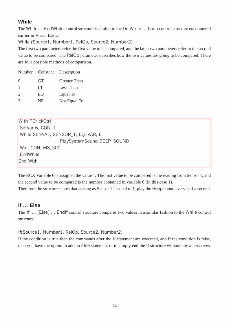
WhileThe While � EndWhile control structure is similar to the Do While � Loop control structure encountered
earlier in Visual Basic.
While (Source1, Number1, RelOp, Source2, Number2)
The first two parameters refer the first value to be compared, and the latter two parameters refer to the second
value to be compared. The RelOp parameter describes how the two values are going to be compared. There
are four possible methods of comparison.
Number Constant Description
0
1
2
3
GT
LT
EQ
NE
Greater Than
Less Than
Equal To
Not Equal To
With PBrickCtrl
.SetVar 6, CON, 1
.While SENVAL, SENSOR_1, EQ, VAR, 6
.PlaySystemSound BEEP_SOUND
.Wait CON, MS_500
.EndWhile
End With
The RCX Variable 6 is assigned the value 1. The first value to be compared is the reading from Sensor 1, and
the second value to be compared is the number contained in variable 6 (in this case 1).
Therefore the structure states that as long as Sensor 1 is equal to 1, play the Beep sound every half a second.
If … Else The If � [Else] � EndIf control structure compares two values in a similar fashion to the While control
structure.
If(Source1, Number1, RelOp, Source2, Number2)
If the condition is true then the commands after the If statement are executed, and if the condition is false,
then you have the option to add an Else statement or to simply end the If structure without any alternatives.
74
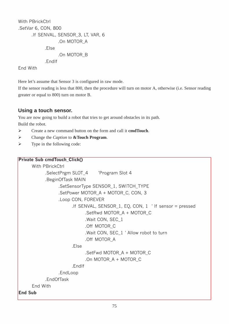
Using a touch sensor.You are now going to build a robot that tries to get around obstacles in its path.
Build the robot.
Ø Create a new command button on the form and call it cmdTouch.
Ø Change the Captionto &Touch Program.
Ø Type in the following code:
With PBrickCtrl
.SetVar 6, CON, 800
.If SENVAL, SENSOR_3, LT, VAR, 6
.On MOTOR_A
.Else
.On MOTOR_B
.EndIf
End With
Here let’s assume that Sensor 3 is configured in raw mode.
If the sensor reading is less that 800, then the procedure will turn on motor A, otherwise (i.e. Sensor reading
greater or equal to 800) turn on motor B.
Private Sub cmdTouch_Click()With PBrickCtrl
.SelectPrgm SLOT_4 'Program Slot 4
.BeginOfTask MAIN
.SetSensorType SENSOR_1, SWITCH_TYPE
.SetPower MOTOR_A + MOTOR_C, CON, 3
.Loop CON, FOREVER
.If SENVAL, SENSOR_1, EQ, CON, 1 ' If sensor = pressed
.SetRwd MOTOR_A + MOTOR_C
.Wait CON, SEC_1
.Off MOTOR_C
.Wait CON, SEC_1 ' Allow robot to turn
.Off MOTOR_A
.Else
.SetFwd MOTOR_A + MOTOR_C
.On MOTOR_A + MOTOR_C
.EndIf
.EndLoop
.EndOfTask
End With
End Sub
75
Ø Save your project.
Ø Turn on the RCX.
Ø Run your project.
Ø Download the program to the RCX by clicking on the Touch Program button.
Ø Place the RCX on the ground or on another suitable surface, and run the program.
Notice that when the robot bumps into something it reverses and tries to go around the object.
How the Touch Program works.Firstly program slot 4 in the RCX is chosen as a the destination for the program. At the beginning of the main
task the touch sensor is set-up appropriately as is the power setting for each of the motors involved. The
statement
.Loop CON, FOREVER
causes the program to go into an infinite loop. In this loop the following is repeatedly carried out:
If the touch sensor is pressed
Reverse the robot for a second, and then rotate the robot for another second.
Else
Move the robot forward.
Exercise:In the previous program, change the mode of the sensor to raw mode and also make the necessary changes
in the If condition.
Also, as you can see, while the touch sensor is not pressed, the code is commanding the RCX to go forward,
even though it is already going forward at the time. Optimise the code so that the robot will only go forward
at the beginning of the task and also only after a turning manoeuvre has been carried out.
76
ChapterSeven
A More Controllable Robot
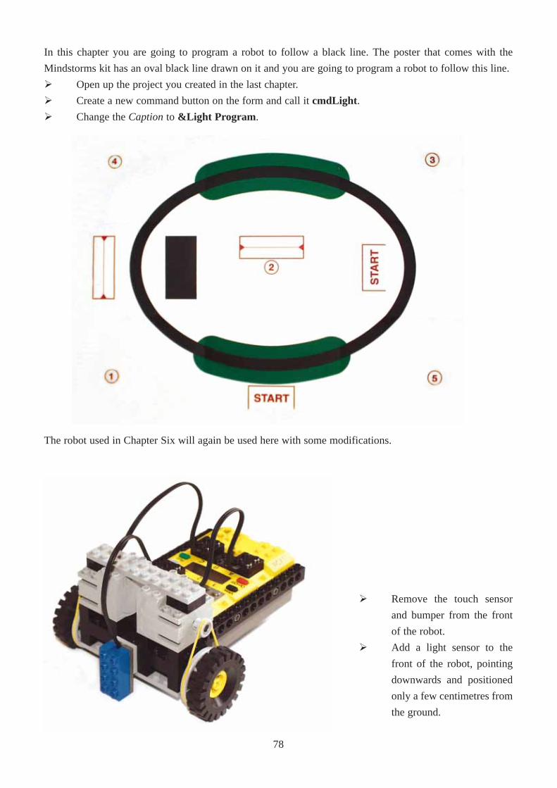
In this chapter you are going to program a robot to follow a black line. The poster that comes with the
Mindstorms kit has an oval black line drawn on it and you are going to program a robot to follow this line.
Ø Open up the project you created in the last chapter.
Ø Create a new command button on the form and call it cmdLight .
Ø Change the Captionto &Light Program .
Ø Remove the touch sensor
and bumper from the front
of the robot.
Ø Add a light sensor to the
front of the robot, pointing
downwards and positioned
only a few centimetres from
the ground.
The robot used in Chapter Six will again be used here with some modifications.
78

Enter in the following code:
The previous code places the program in program slot 4 of the RCX. Sensor 3 is a light sensor in Percent
mode, and the motors are set to full power. Variable 5 in the RCX is set to MS_200 and the reason for this
will be seen later on.
Variable 5 does not have much meaning at the moment but you would like to be able to refer to it as
something more meaningful that the number 5. To do this place the following code in the first line of your
procedure
Const ArcTime = 5
And in the existing code for cmdLight_Click( ) change the following
.SetVar ARC_TIME, CON, MS_200
This declaration of constants makes the program easier to read. You will especially notice this with longer
programs.
Ø Save and Run you program.
Ø Turn on your RCX.
Ø Click on the Light button to download your program to the RCX.
Ø Using the Viewbutton on the RCX, choose to view the reading of Sensor 3 (The arrow on the LCD
screen should now be pointing to sensor 3).
Ø Using the poster from the Mindstorms kit, run the light sensor over the white and black colours to get
their raw value readings.
Private Sub cmdLight_Click()
With PBrickCtrl
.SelectPrgm SLOT_4
.SetSensorMode SENSOR_3, RAW_MODE, 0
.SetSensorType SENSOR_3, LIGHT_TYPE
.SetPower MOTOR_A + MOTOR_C, CON, 7
.SetVar 5, CON, MS_200
End With
End Sub
You want to set up the sensor ports correctly to begin with.
Enter the following code:
Private Sub cmdLight_Click()
Const ARC_TIME = 5 ' Naming var 5
Const LIGHT_THRESH = 6 ' Naming var 6
With PBrickCtrl
.SelectPrgm SLOT_4
.BeginOfTask MAIN
.SetVar ARC_TIME, CON, MS_50
.SetVar LIGHT_THRESH, CON, XXXX 'Enter your value here
79
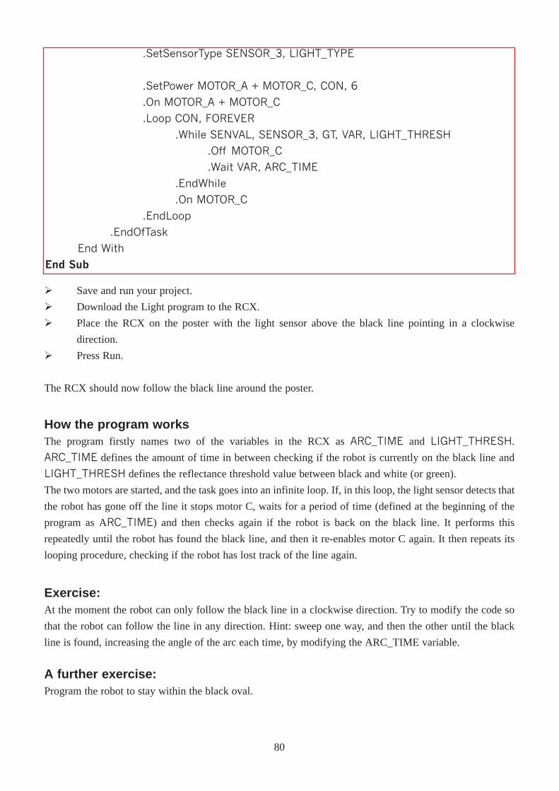
How the program worksThe program firstly names two of the variables in the RCX as ARC_TIME and LIGHT_THRESH.
ARC_TIME defines the amount of time in between checking if the robot is currently on the black line and
LIGHT_THRESH defines the reflectance threshold value between black and white (or green).
The two motors are started, and the task goes into an infinite loop. If, in this loop, the light sensor detects that
the robot has gone off the line it stops motor C, waits for a period of time (defined at the beginning of the
program as ARC_TIME) and then checks again if the robot is back on the black line. It performs this
repeatedly until the robot has found the black line, and then it re-enables motor C again. It then repeats its
looping procedure, checking if the robot has lost track of the line again.
Exercise:At the moment the robot can only follow the black line in a clockwise direction. Try to modify the code so
that the robot can follow the line in any direction. Hint: sweep one way, and then the other until the black
line is found, increasing the angle of the arc each time, by modifying the ARC_TIME variable.
A further exercise:Program the robot to stay within the black oval.
Ø Save and run your project.
Ø Download the Light program to the RCX.
Ø Place the RCX on the poster with the light sensor above the black line pointing in a clockwise
direction.
Ø Press Run.
The RCX should now follow the black line around the poster.
.SetSensorType SENSOR_3, LIGHT_TYPE
.SetPower MOTOR_A + MOTOR_C, CON, 6
.On MOTOR_A + MOTOR_C
.Loop CON, FOREVER
.While SENVAL, SENSOR_3, GT, VAR, LIGHT_THRESH
.Off MOTOR_C
.Wait VAR, ARC_TIME
.EndWhile
.On MOTOR_C
.EndLoop
.EndOfTask
End With
End Sub
80
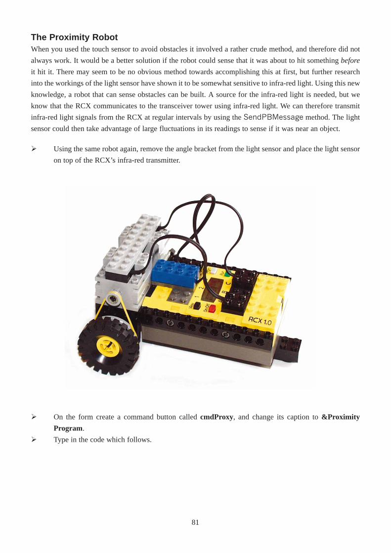
The Proximity RobotWhen you used the touch sensor to avoid obstacles it involved a rather crude method, and therefore did not
always work. It would be a better solution if the robot could sense that it was about to hit something before
it hit it. There may seem to be no obvious method towards accomplishing this at first, but further research
into the workings of the light sensor have shown it to be somewhat sensitive to infra-red light. Using this new
knowledge, a robot that can sense obstacles can be built. A source for the infra-red light is needed, but we
know that the RCX communicates to the transceiver tower using infra-red light. We can therefore transmit
infra-red light signals from the RCX at regular intervals by using the SendPBMessage method. The light
sensor could then take advantage of large fluctuations in its readings to sense if it was near an object.
Ø Using the same robot again, remove the angle bracket from the light sensor and place the light sensor
on top of the RCX’s infra-red transmitter.
Ø On the form create a command button called cmdProxy, and change its caption to &Proximity
Program.
Ø Type in the code which follows.
81
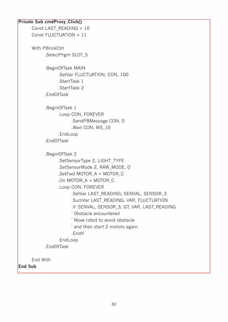
Private Sub cmdProxy_Click()
Const LAST_READING = 10
Const FLUCTUATION = 11
With PBrickCtrl
.SelectPrgm SLOT_5
.BeginOfTask MAIN
.SetVar FLUCTUATION, CON, 100
.StartTask 1
.StartTask 2
.EndOfTask
.BeginOfTask 1
.Loop CON, FOREVER
.SendPBMessage CON, 0
.Wait CON, MS_10
.EndLoop
.EndOfTask
.BeginOfTask 2
.SetSensorType 2, LIGHT_TYPE
.SetSensorMode 2, RAW_MODE, 0
.SetFwd MOTOR_A + MOTOR_C
.On MOTOR_A + MOTOR_C
.Loop CON, FOREVER
.SetVar LAST_READING, SENVAL, SENSOR_3
.SumVar LAST_READING, VAR, FLUCTUATION
.If SENVAL, SENSOR_3, GT, VAR, LAST_READING
' Obstacle encountered
' Move robot to avoid obstacle
' and then start 2 motors again
.EndIf
.EndLoop
.EndOfTask
End With
End Sub
82
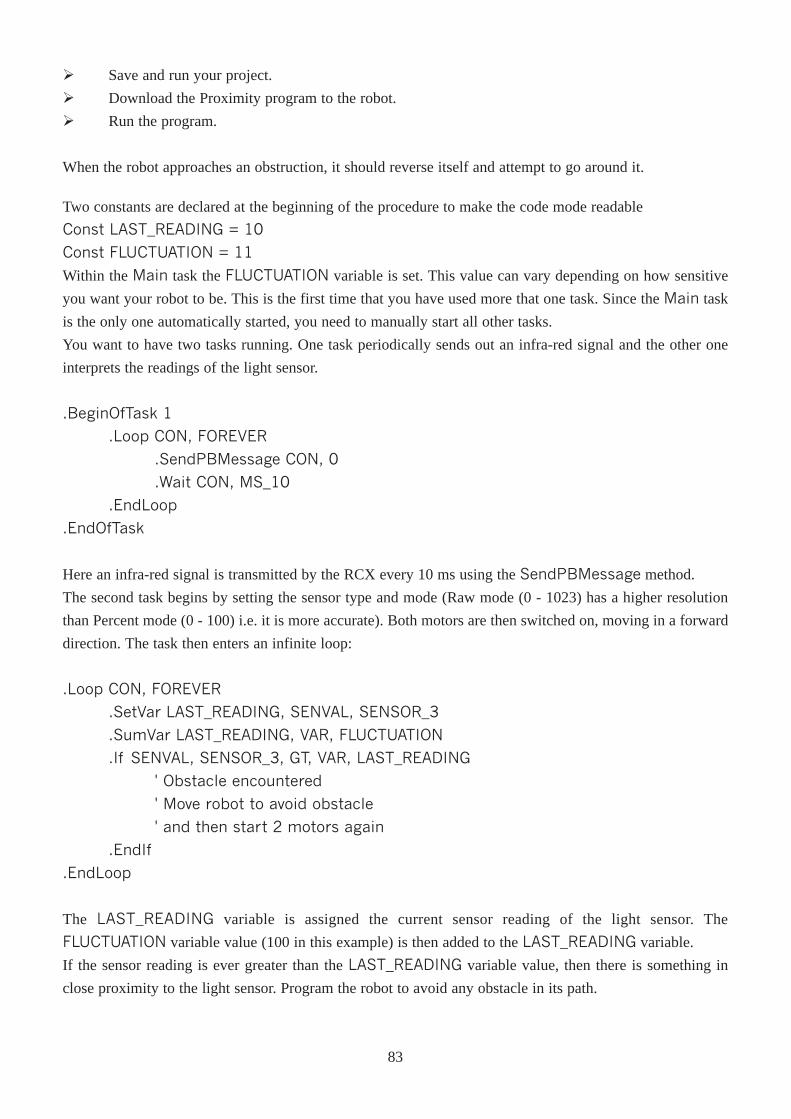
Ø Save and run your project.
Ø Download the Proximity program to the robot.
Ø Run the program.
When the robot approaches an obstruction, it should reverse itself and attempt to go around it.
Two constants are declared at the beginning of the procedure to make the code mode readable
Const LAST_READING = 10
Const FLUCTUATION = 11
Within the Main task the FLUCTUATION variable is set. This value can vary depending on how sensitive
you want your robot to be. This is the first time that you have used more that one task. Since the Main task
is the only one automatically started, you need to manually start all other tasks.
You want to have two tasks running. One task periodically sends out an infra-red signal and the other one
interprets the readings of the light sensor.
.BeginOfTask 1
.Loop CON, FOREVER
.SendPBMessage CON, 0
.Wait CON, MS_10
.EndLoop
.EndOfTask
Here an infra-red signal is transmitted by the RCX every 10 ms using the SendPBMessage method.
The second task begins by setting the sensor type and mode (Raw mode (0 - 1023) has a higher resolution
than Percent mode (0 - 100) i.e. it is more accurate). Both motors are then switched on, moving in a forward
direction. The task then enters an infinite loop:
.Loop CON, FOREVER
.SetVar LAST_READING, SENVAL, SENSOR_3
.SumVar LAST_READING, VAR, FLUCTUATION
.If SENVAL, SENSOR_3, GT, VAR, LAST_READING
' Obstacle encountered
' Move robot to avoid obstacle
' and then start 2 motors again
.EndIf
.EndLoop
The LAST_READING variable is assigned the current sensor reading of the light sensor. The
FLUCTUATION variable value (100 in this example) is then added to the LAST_READING variable.
If the sensor reading is ever greater than the LAST_READING variable value, then there is something in
close proximity to the light sensor. Program the robot to avoid any obstacle in its path.
83

ChapterEight
Delving Deeper intothe RCX
ArraysMost of the code you've seen so far has worked with very little data. Up to this point, you have been learning
about variables and control structures. An array isn't much more than a list of variables. You will see in this
chapter how the naming conventions for array variables vary a little (but not much) from the naming
conventions for regular non-array variables. With arrays, you can store many occurrences of similar data.
With non-array variables, each piece of data has a different name, and it can be difficult to track many
occurrences of data.
An array is a list of more than one variable with the same name. An example of a variable might be
Dim Result As Integer
This declaration declares a single variable Result as an integer. This variable could refer to a student’s result
in an exam. If there were more than one student in the class, then declaring a variable for each student would
be a long and boring task. This is where arrays become useful.
The different values (in this case the elements of the array) are distinguished from each other by a numeric
subscript. For instance, instead of a different variable name (Result1, Result2, Result3, Result4, and so on),
the associated data are given the same variable name (Result) and are differentiated by subscripts. E.g.
Result1 Result(1)
Result2 Result(2)
You may wonder where the advantage of using a array is seen here. The column of array names has a major
advantage over the old variable names. The number inside the parentheses is the subscript number of the
array. Subscript numbers are never part of an array name; they are always enclosed in parentheses and only
serve to distinguish one array element from another. If you had to calculate the average of a series of
examination results using only variables, it would be necessary for you to type out all of the variable names
individually, whereas with arrays, you can use a For � Next loop to change the variable names.
Given forty students
Using variables
iTotal = Result1 + Result2 + Result 3 + Result4 + � + Result40
iAverage = Total/40
Using Arrays
For iCounter = 1 To 40
iTotal = iTotal + Result(iCounter)
Next Counter
iAverage = Total/40
As you can see, even with only 40 students, there will be far less code using arrays.
85
Declaring ArraysDim MyArray(10) As Integer
This array will contain 11 elements (MyArray(0) to MyArray(10)). 0 is known as the lower boundand 10
is known as the upper bound.
The lower bound can also be specified at the declaration stage
Dim MyArray (10 To 20) As Integer
This declares an array of eleven integers with a lower bound of 10 and an upper bound of 20.
Multidimensional ArraysA multidimensional array is an array with more than one subscript. A single-dimensional array is a list of
values, whereas a multidimensional array simulates a table of values. The most commonly used table is a
two-dimensional table (an array with two subscripts). Following from the student example, if the student sat
more that one exam (say six), you could use a multidimensional array to store the results.
Dim MyMultiArray(1 To 40, 1 To 6)
This is similar to declaring a table with forty rows and six columns, each row refers an individual student and
each column to a result.
The datalogThe datalog is an area set within the RCX, it allows you to store readings from:
· Timers
· Variables
· Sensor Readings
· Watch (Time)
To use the datalog feature, you must first set the size of the datalog area you wish to use. This is done using
the SetDatalog(Size) method. The size refers to the number of elements you wish to store. Each element
takes up 3 bytes of space.
Anytime within the program that you want to store a value in the datalog, use the DatalogNext(Source,
Number)
Source Number
0
1
9
14
VAR
TIMER
SENVAL
WATCH
0 - 31
0 - 3
0 - 2
0
TIMER_1, TIMER_2, TIMER_3, TIMER_4
SENSOR_1, SENSOR_2, SENSOR_3
Then when you program is finished, you can upload the information from the RCX using the
UploadDatalog(From,Size) method.
86
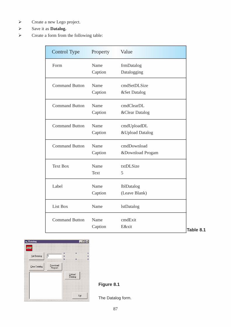
Ø Create a new Lego project.
Ø Save it as Datalog.
Ø Create a form from the following table:
Form
Command Button
Command Button
Command Button
Command Button
Text Box
Label
List Box
Command Button
Name
Caption
Name
Caption
Name
Caption
Name
Caption
Name
Caption
Name
Text
Name
Caption
Name
Name
Caption
frmDatalog
Datalogging
cmdSetDLSize
&Set Datalog
cmdClearDL
&Clear Datalog
cmdUploadDL
&Upload Datalog
cmdDownload
&Download Progam
txtDLSize
5
lblDatalog
(Leave Blank)
lstDatalog
cmdExit
E&xit
Control Type Property Value
Table 8.1
87
Figure 8.1
The Datalog form.
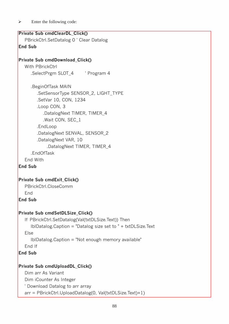
Ø Enter the following code:
Private Sub cmdClearDL_Click()
PBrickCtrl.SetDatalog 0 ' Clear Datalog
End Sub
Private Sub cmdDownload_Click()
With PBrickCtrl
.SelectPrgm SLOT_4 ' Program 4
.BeginOfTask MAIN
.SetSensorType SENSOR_2, LIGHT_TYPE
.SetVar 10, CON, 1234
.Loop CON, 3
.DatalogNext TIMER, TIMER_4
.Wait CON, SEC_1
.EndLoop
.DatalogNext SENVAL, SENSOR_2
.DatalogNext VAR, 10
.DatalogNext TIMER, TIMER_4
.EndOfTask
End With
End Sub
Private Sub cmdExit_Click()PBrickCtrl.CloseComm
End
End Sub
Private Sub cmdSetDLSize_Click()If PBrickCtrl.SetDatalog(Val(txtDLSize.Text)) Then
lblDatalog.Caption = "Datalog size set to " + txtDLSize.Text
Else
lblDatalog.Caption = "Not enough memory available"
End If
End Sub
Private Sub cmdUploadDL_Click()Dim arr As Variant
Dim iCounter As Integer
' Download Datalog to arr array
arr = PBrickCtrl.UploadDatalog(0, Val(txtDLSize.Text)+1)
88
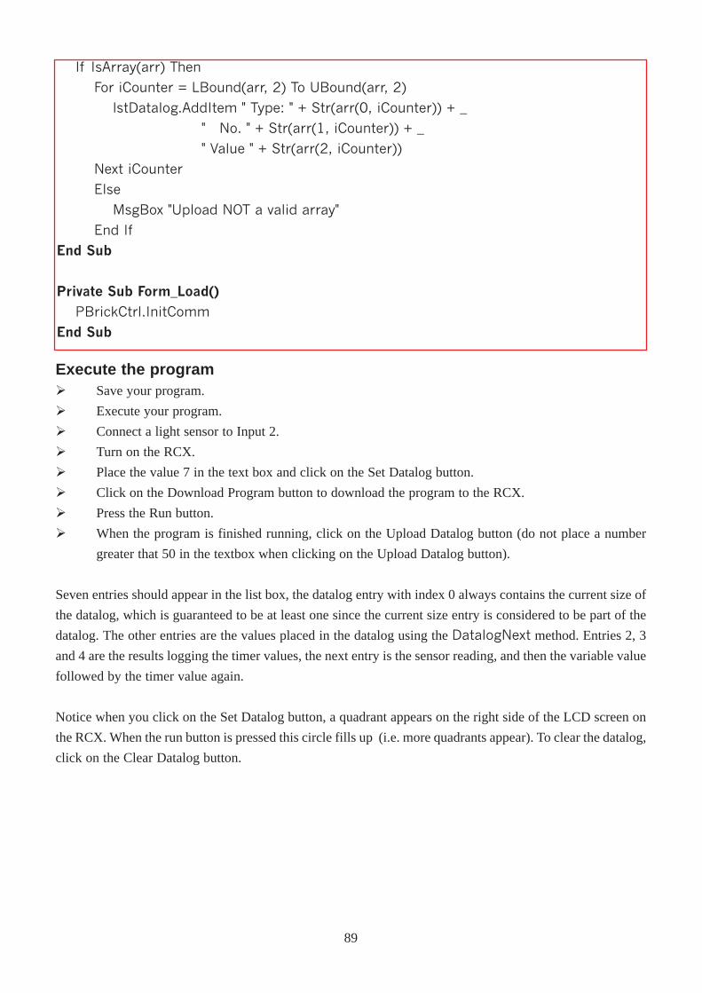
If IsArray(arr) Then
For iCounter = LBound(arr, 2) To UBound(arr, 2)
lstDatalog.AddItem " Type: " + Str(arr(0, iCounter)) + _
" No. " + Str(arr(1, iCounter)) + _
" Value " + Str(arr(2, iCounter))
Next iCounter
Else
MsgBox "Upload NOT a valid array"
End If
End Sub
Private Sub Form_Load()
PBrickCtrl.InitComm
End Sub
Execute the programØ Save your program.
Ø Execute your program.
Ø Connect a light sensor to Input 2.
Ø Turn on the RCX.
Ø Place the value 7 in the text box and click on the Set Datalog button.
Ø Click on the Download Program button to download the program to the RCX.
Ø Press the Run button.
Ø When the program is finished running, click on the Upload Datalog button (do not place a number
greater that 50 in the textbox when clicking on the Upload Datalog button).
Seven entries should appear in the list box, the datalog entry with index 0 always contains the current size of
the datalog, which is guaranteed to be at least one since the current size entry is considered to be part of the
datalog. The other entries are the values placed in the datalog using the DatalogNext method. Entries 2, 3
and 4 are the results logging the timer values, the next entry is the sensor reading, and then the variable value
followed by the timer value again.
Notice when you click on the Set Datalog button, a quadrant appears on the right side of the LCD screen on
the RCX. When the run button is pressed this circle fills up (i.e. more quadrants appear). To clear the datalog,
click on the Clear Datalog button.
89
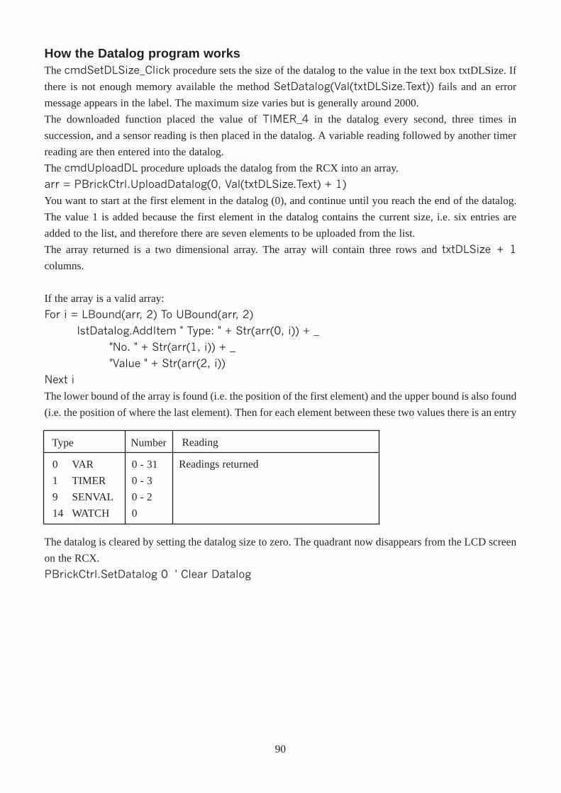
How the Datalog program worksThe cmdSetDLSize_Click procedure sets the size of the datalog to the value in the text box txtDLSize. If
there is not enough memory available the method SetDatalog(Val(txtDLSize.Text)) fails and an error
message appears in the label. The maximum size varies but is generally around 2000.
The downloaded function placed the value of TIMER_4 in the datalog every second, three times in
succession, and a sensor reading is then placed in the datalog. A variable reading followed by another timer
reading are then entered into the datalog.
The cmdUploadDL procedure uploads the datalog from the RCX into an array.
arr = PBrickCtrl.UploadDatalog(0, Val(txtDLSize.Text) + 1)
You want to start at the first element in the datalog (0), and continue until you reach the end of the datalog.
The value 1 is added because the first element in the datalog contains the current size, i.e. six entries are
added to the list, and therefore there are seven elements to be uploaded from the list.
The array returned is a two dimensional array. The array will contain three rows and txtDLSize + 1
columns.
If the array is a valid array:
For i = LBound(arr, 2) To UBound(arr, 2)
lstDatalog.AddItem " Type: " + Str(arr(0, i)) + _
"No. " + Str(arr(1, i)) + _
"Value " + Str(arr(2, i))
Next i
The lower bound of the array is found (i.e. the position of the first element) and the upper bound is also found
(i.e. the position of where the last element). Then for each element between these two values there is an entry
Type Number
0
1
9
14
VAR
TIMER
SENVAL
WATCH
0 - 31
0 - 3
0 - 2
0
Readings returned
Reading
The datalog is cleared by setting the datalog size to zero. The quadrant now disappears from the LCD screen
on the RCX.
PBrickCtrl.SetDatalog 0 ' Clear Datalog
90
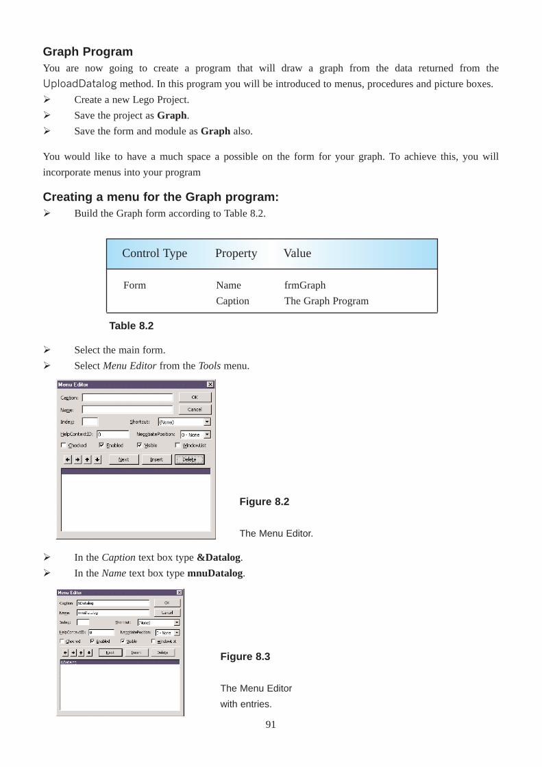
Graph ProgramYou are now going to create a program that will draw a graph from the data returned from the
UploadDatalog method. In this program you will be introduced to menus, procedures and picture boxes.
Ø Create a new Lego Project.
Ø Save the project as Graph.
Ø Save the form and module as Graph also.
You would like to have a much space a possible on the form for your graph. To achieve this, you will
incorporate menus into your program
Creating a menu for the Graph program:Ø Build the Graph form according to Table 8.2.
Form Name
Caption
frmGraph
The Graph Program
Control Type Property Value
Ø Select the main form.
Ø Select Menu Editorfrom the Toolsmenu.
Ø In the Captiontext box type &Datalog.
Ø In the Nametext box type mnuDatalog.
91
Figure 8.2
The Menu Editor.
Table 8.2
Figure 8.3
The Menu Editor
with entries.
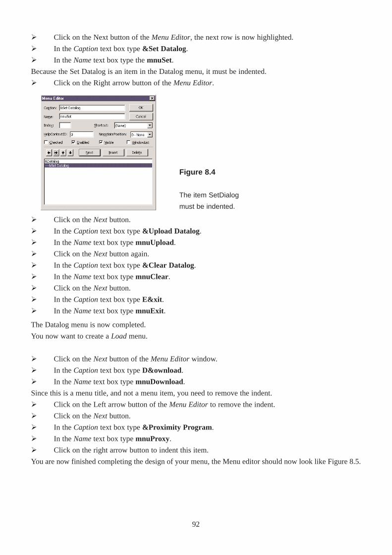
The Datalog menu is now completed.
You now want to create a Loadmenu.
Ø Click on the Nextbutton of the Menu Editorwindow.
Ø In the Captiontext box type D&ownload.
Ø In the Nametext box type mnuDownload.
Since this is a menu title, and not a menu item, you need to remove the indent.
Ø Click on the Left arrow button of the Menu Editorto remove the indent.
Ø Click on the Nextbutton.
Ø In the Captiontext box type&Proximity Program .
Ø In the Nametext box type mnuProxy.
Ø Click on the right arrow button to indent this item.
You are now finished completing the design of your menu, the Menu editor should now look like Figure 8.5.
Ø Click on the Nextbutton.
Ø In the Captiontext box type &Upload Datalog.
Ø In the Nametext box type mnuUpload.
Ø Click on the Nextbutton again.
Ø In the Captiontext box type &Clear Datalog.
Ø In the Nametext box type mnuClear.
Ø Click on the Nextbutton.
Ø In theCaptiontext box type E&xit .
Ø In the Nametext box typemnuExit .
Ø Click on the Next button of the Menu Editor, the next row is now highlighted.
Ø In the Captiontext box type &Set Datalog.
Ø In the Nametext box type the mnuSet.
Because the Set Datalog is an item in the Datalog menu, it must be indented.
Ø Click on the Right arrow button of the Menu Editor.
92
Figure 8.4
The item SetDialog
must be indented.
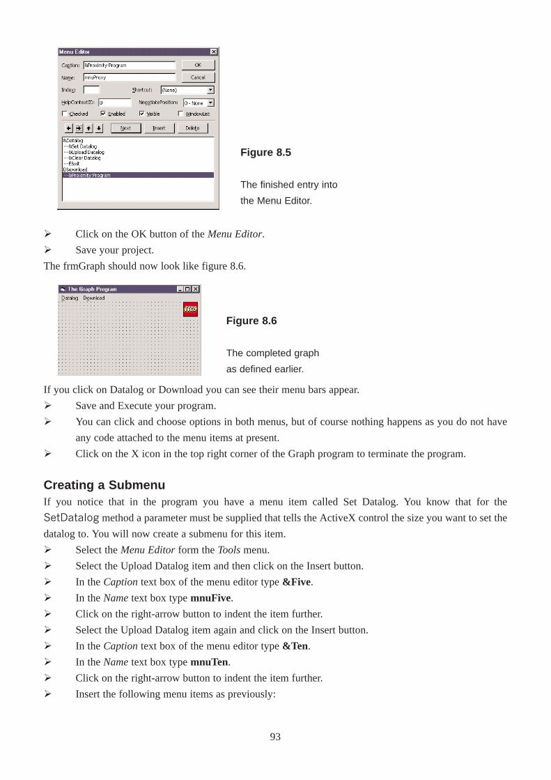
Ø Click on the OK button of the Menu Editor.
Ø Save your project.
The frmGraph should now look like figure 8.6.
If you click on Datalog or Download you can see their menu bars appear.
Ø Save and Execute your program.
Ø You can click and choose options in both menus, but of course nothing happens as you do not have
any code attached to the menu items at present.
Ø Click on the X icon in the top right corner of the Graph program to terminate the program.
Creating a SubmenuIf you notice that in the program you have a menu item called Set Datalog. You know that for the
SetDatalog method a parameter must be supplied that tells the ActiveX control the size you want to set the
datalog to. You will now create a submenu for this item.
Ø Select the Menu Editorform the Toolsmenu.
Ø Select the Upload Datalog item and then click on the Insert button.
Ø In the Captiontext box of the menu editor type &Five .
Ø In the Nametext box type mnuFive.
Ø Click on the right-arrow button to indent the item further.
Ø Select the Upload Datalog item again and click on the Insert button.
Ø In the Captiontext box of the menu editor type &Ten .
Ø In the Nametext box type mnuTen.
Ø Click on the right-arrow button to indent the item further.
Ø Insert the following menu items as previously:
93
Figure 8.5
The finished entry into
the Menu Editor.
Figure 8.6
The completed graph
as defined earlier.
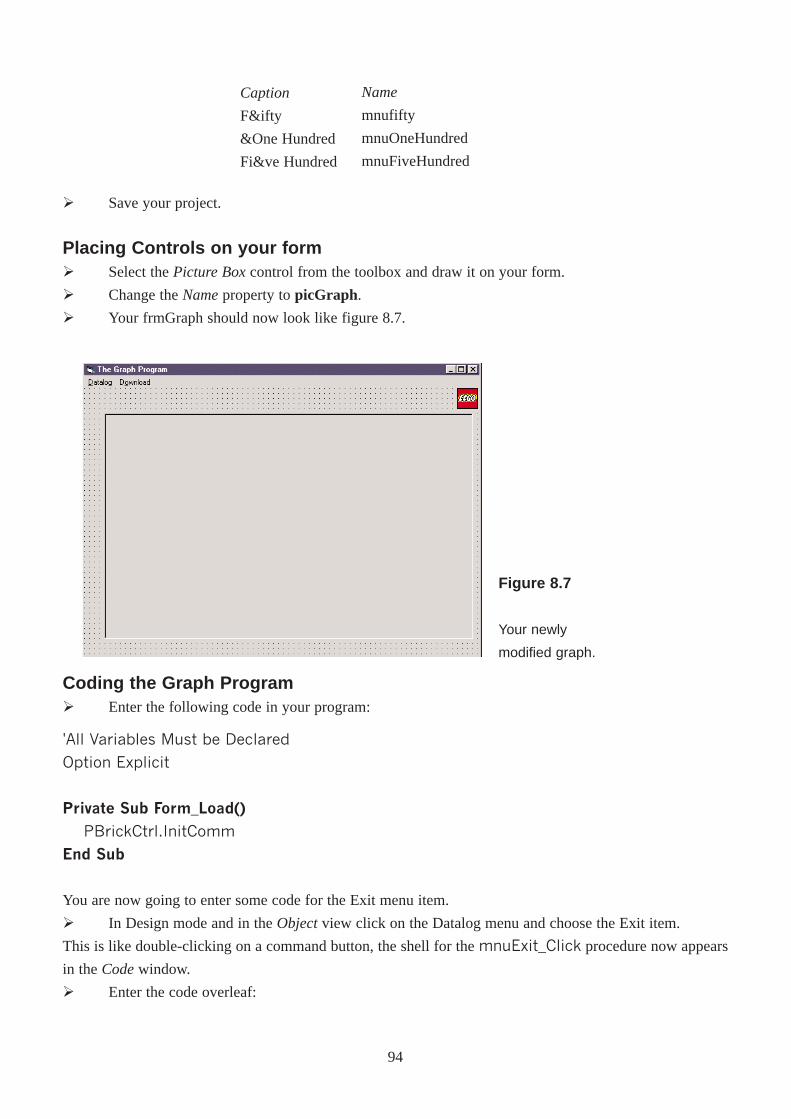
Ø Save your project.
Placing Controls on your formØ Select the Picture Boxcontrol from the toolbox and draw it on your form.
Ø Change the Nameproperty to picGraph.
Ø Your frmGraph should now look like figure 8.7.
Coding the Graph ProgramØ Enter the following code in your program:
'All Variables Must be Declared
Option Explicit
Private Sub Form_Load()
PBrickCtrl.InitComm
End Sub
You are now going to enter some code for the Exit menu item.
Ø In Design mode and in the Objectview click on the Datalog menu and choose the Exit item.
This is like double-clicking on a command button, the shell for the mnuExit_Click procedure now appears
in the Codewindow.
Ø Enter the code overleaf:
94
Caption
F&ifty
&One Hundred
Fi&ve Hundred
Name
mnufifty
mnuOneHundred
mnuFiveHundred
Figure 8.7
Your newly
modified graph.
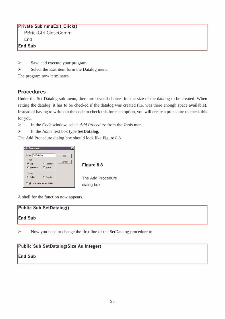
Ø Save and execute your program.
Ø Select the Exit item form the Datalog menu.
The program now terminates.
ProceduresUnder the Set Datalog sub menu, there are several choices for the size of the datalog to be created. When
setting the datalog, it has to be checked if the datalog was created (i.e. was there enough space available).
Instead of having to write out the code to check this for each option, you will create a procedure to check this
for you.
Ø In the Codewindow, select Add Procedurefrom the Toolsmenu.
Ø In the Nametext box type SetDatalog.
The Add Procedure dialog box should look like Figure 8.8.
Private Sub mnuExit_Click()
PBrickCtrl.CloseComm
End
End Sub
Figure 8.8
The Add Procedure
dialog box.
A shell for the function now appears.
Public Sub SetDatalog()
End Sub
Ø Now you need to change the first line of the SetDatalog procedure to
Public Sub SetDatalog(Size As Integer)
End Sub
95
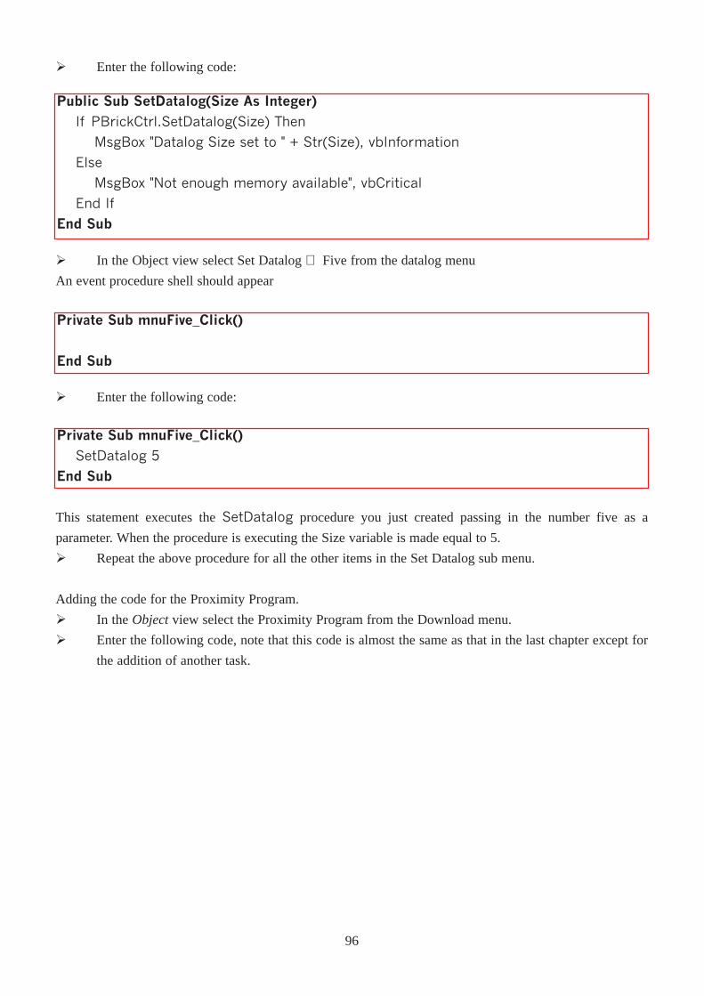
Private Sub mnuFive_Click()
End Sub
Ø Enter the following code:
Private Sub mnuFive_Click()SetDatalog 5
End Sub
This statement executes the SetDatalog procedure you just created passing in the number five as a
parameter. When the procedure is executing the Size variable is made equal to 5.
Ø Repeat the above procedure for all the other items in the Set Datalog sub menu.
Adding the code for the Proximity Program.
Ø In the Object view select the Proximity Program from the Download menu.
Ø Enter the following code, note that this code is almost the same as that in the last chapter except for
the addition of another task.
96
Ø In the Object view select Set Datalog ⇒ Five from the datalog menu
An event procedure shell should appear
Ø Enter the following code:
Public Sub SetDatalog(Size As Integer)
If PBrickCtrl.SetDatalog(Size) Then
MsgBox "Datalog Size set to " + Str(Size), vbInformation
Else
MsgBox "Not enough memory available", vbCritical
End If
End Sub
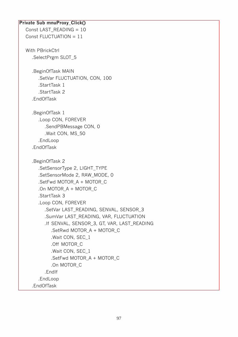
Private Sub mnuProxy_Click()
Const LAST_READING = 10
Const FLUCTUATION = 11
With PBrickCtrl
.SelectPrgm SLOT_5
.BeginOfTask MAIN
.SetVar FLUCTUATION, CON, 100
.StartTask 1
.StartTask 2
.EndOfTask
.BeginOfTask 1
.Loop CON, FOREVER
.SendPBMessage CON, 0
.Wait CON, MS_50
.EndLoop
.EndOfTask
.BeginOfTask 2
.SetSensorType 2, LIGHT_TYPE
.SetSensorMode 2, RAW_MODE, 0
.SetFwd MOTOR_A + MOTOR_C
.On MOTOR_A + MOTOR_C
.StartTask 3
.Loop CON, FOREVER
.SetVar LAST_READING, SENVAL, SENSOR_3
.SumVar LAST_READING, VAR, FLUCTUATION
.If SENVAL, SENSOR_3, GT, VAR, LAST_READING
.SetRwd MOTOR_A + MOTOR_C
.Wait CON, SEC_1
.Off MOTOR_C
.Wait CON, SEC_1
.SetFwd MOTOR_A + MOTOR_C
.On MOTOR_C
.EndIf
.EndLoop
.EndOfTask
97
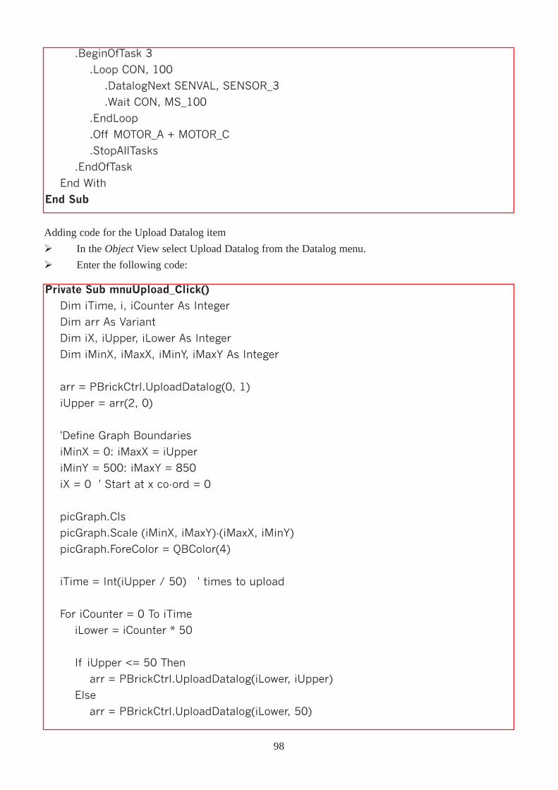
.BeginOfTask 3
.Loop CON, 100
.DatalogNext SENVAL, SENSOR_3
.Wait CON, MS_100
.EndLoop
.Off MOTOR_A + MOTOR_C
.StopAllTasks
.EndOfTask
End With
End Sub
Adding code for the Upload Datalog item
Ø In the ObjectView select Upload Datalog from the Datalog menu.
Ø Enter the following code:
Private Sub mnuUpload_Click()Dim iTime, i, iCounter As Integer
Dim arr As Variant
Dim iX, iUpper, iLower As Integer
Dim iMinX, iMaxX, iMinY, iMaxY As Integer
arr = PBrickCtrl.UploadDatalog(0, 1)
iUpper = arr(2, 0)
'Define Graph Boundaries
iMinX = 0: iMaxX = iUpper
iMinY = 500: iMaxY = 850
iX = 0 ' Start at x co-ord = 0
picGraph.Cls
picGraph.Scale (iMinX, iMaxY)-(iMaxX, iMinY)
picGraph.ForeColor = QBColor(4)
iTime = Int(iUpper / 50) ' times to upload
For iCounter = 0 To iTime
iLower = iCounter * 50
If iUpper <= 50 Then
arr = PBrickCtrl.UploadDatalog(iLower, iUpper)
Else
arr = PBrickCtrl.UploadDatalog(iLower, 50)
98
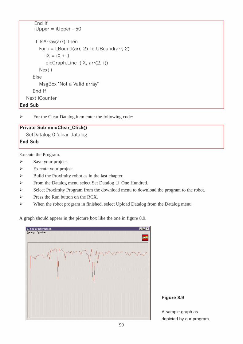
End IfiUpper = iUpper - 50
If IsArray(arr) Then
For i = LBound(arr, 2) To UBound(arr, 2)
iX = iX + 1
picGraph.Line -(iX, arr(2, i))
Next i
Else
MsgBox "Not a Valid array"
End If
Next iCounter
End Sub
Ø For the Clear Datalog item enter the following code:
Private Sub mnuClear_Click()SetDatalog 0 'clear datalog
End Sub
Execute the Program.
Ø Save your project.
Ø Execute your project.
Ø Build the Proximity robot as in the last chapter.
Ø From the Datalog menu select Set Datalog ⇒ One Hundred.
Ø Select Proximity Program from the download menu to download the program to the robot.
Ø Press the Run button on the RCX.
Ø When the robot program in finished, select Upload Datalog from the Datalog menu.
A graph should appear in the picture box like the one in figure 8.9.
99
Figure 8.9
A sample graph as
depicted by our program.
Here the robot encountered two obstacles. The slower the robot was approaching, and retracting from the
obstacles wil dictate how wide the spikes are.
Ø Exit the program, selecting Clear Datalog from the Datalog menu beforehand if you want to clear the
datalog.
How the Graph program worksWhen as the light sensor begins taking readings in the Proximity Program, task 3 is started.
.BeginOfTask 3
.Loop CON, 100
.DatalogNext SENVAL, SENSOR_3
.Wait CON, MS_100
.EndLoop
.Off MOTOR_A + MOTOR_C
.StopAllTasks
.EndOfTask
Task 3 executes the above loop 100 times, each time it loops it places the light sensor reading in the datalog.
When it has looped 100 times all tasks are stopes (i.e. the program stops).
The mnuUpload_Click procedure places the graph it the picture box. The statements
arr = PBrickCtrl.UploadDatalog(0, 1)
iUpper = arr(2, 0)
download the first item in the datalog into the arr array. IUpper is then assigned the value of the number of
elements in the datalog. The procedure then defines the co-ordinate boundaries of the picture box:
iMinX = 0: iMaxX = iUpper
iMinY = 500: iMaxY = 850
iX = 0 ' Start at x co-ord = 0
The x-axis contains the number of elements in the datalog and the y-axis contains the light sensor readings
for each element. The picture box is then cleared:
picGraph.Cls
picGraph.Scale (iMinX, iMaxY)-(iMaxX, iMinY)
picGraph.ForeColor = QBColor(4)
The scale defines the boundaries of the picture box, the first co-ordinate is the top left co-ordinate and the
second one is the bottom right co-ordinate. The forecolor setting simply sets the colour of the graph which is
red in this example.
The statement
iTime = Int(iUpper / 50) ' times to upload
sets iTime to the number of extra times that the array has to be downloaded (remember that these can only
be downloaded in blocks of 50 or less). If 69 elements had to be downloaded the datalog has to be
downloaded in two chunks; a chunk of 50 elements and then a chunk of 19 elements. The variableiTime
would equal 1 here indicating that one extra download is necessary.
100
A For loop is then entered
For iCounter = 0 To iTime
iLower = iCounter * 50
If iUpper <= 50 Then
arr = PBrickCtrl.UploadDatalog(iLower, iUpper)
Else
arr = PBrickCtrl.UploadDatalog(iLower, 50)
End If
iUpper = iUpper - 50
'code here explained below
Next iCounter
The loop starts counting at 0 and stops at the value of iTime. iLower contains the value of the start element
to be downloaded. If three chunks of elements are to be downloaded, then this will firstly equal 0, then 50
and finally 100. The If � Then � Else structure states that if 50 or less elements are to be downloaded
then download that exact number, but if more that fifty are to be downloaded, download a chunk of fifty
elements and set the number of remaining elements to be downloaded (iUpper) to the last iUpper value
minus 50) as they have now been downloaded.
If IsArray(arr) Then
For i = LBound(arr, 2) To UBound(arr, 2)
iX = iX + 1
picGraph.Line -(iX, arr(2, i))
Next i
Else
MsgBox "Not a Valid array"
End If
If the array arr is a valid array (i.e. downloaded successfully) then the lower and upper bounds of the array
are found.iX contains the x co-ordinate of the last point plotted on the graph, this is then incremented by one
so as to plot the endpoint of the next line. The statement
picGraph.Line -(iX, arr(2, i))
only has one co-ordinate. When only one co-ordinate is supplied, it defines the endpoint of the line and the
start point is where the last line plotted ended (the CurrentX, CurrentY co-ordinate).
ExerciseModify the code for than Proximity Program so that it stops emitting infra-red light (task 1) and change the
range (iMinY and iMaxY) as necessary (if the graph goes too high or too low).
If you wanted to change the amount of readings taken, change the amount of times the loop in Task 3. You
can also modify the frequency at which the readings are placed in the datalog.
101
ChapterNine
Networking andSynchronisation
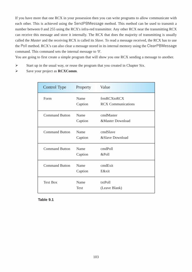
If you have more that one RCX in your possession then you can write programs to allow communicate with
each other. This is achieved using the SendPBMessage method. This method can be used to transmit a
number between 0 and 255 using the RCX's infra-red transmitter. Any other RCX near the transmitting RCX
can receive this message and store it internally. The RCX that does the majority of transmitting is usually
called the Masterand the receiving RCX is called its Slave. To read a message received, the RCX has to use
the Poll method. RCX’s can also clear a message stored in its internal memory using the ClearPBMessage
command. This command sets the internal message to '0'.
You are going to first create a simple program that will show you one RCX sending a message to another.
Ø Start up in the usual way, or reuse the program that you created in Chapter Six.
Ø Save your project as RCXComm.
Form
Command Button
Command Button
Command Button
Command Button
Text Box
Name
Caption
Name
Caption
Name
Caption
Name
Caption
Name
Caption
Name
Text
frmRCXtoRCX
RCX Communications
cmdMaster
&Master Download
cmdSlave
&Slave Download
cmdPoll
&Poll
cmdExit
E&xit
txtPoll
(Leave Blank)
Control Type Property Value
Table 9.1
103
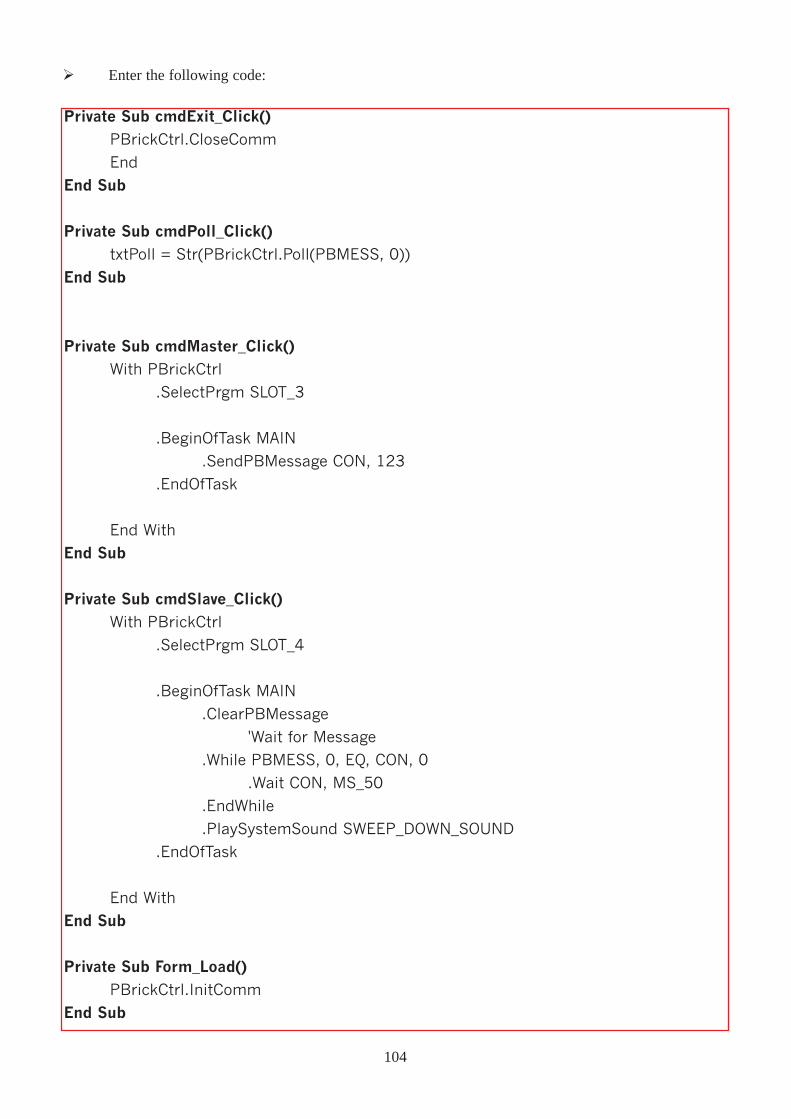
Ø Enter the following code:
Private Sub cmdExit_Click()
PBrickCtrl.CloseComm
End
End Sub
Private Sub cmdPoll_Click()
txtPoll = Str(PBrickCtrl.Poll(PBMESS, 0))
End Sub
Private Sub cmdMaster_Click()
With PBrickCtrl
.SelectPrgm SLOT_3
.BeginOfTask MAIN
.SendPBMessage CON, 123
.EndOfTask
End With
End Sub
Private Sub cmdSlave_Click()With PBrickCtrl
.SelectPrgm SLOT_4
.BeginOfTask MAIN
.ClearPBMessage
'Wait for Message
.While PBMESS, 0, EQ, CON, 0
.Wait CON, MS_50
.EndWhile
.PlaySystemSound SWEEP_DOWN_SOUND
.EndOfTask
End With
End Sub
Private Sub Form_Load()PBrickCtrl.InitComm
End Sub
104
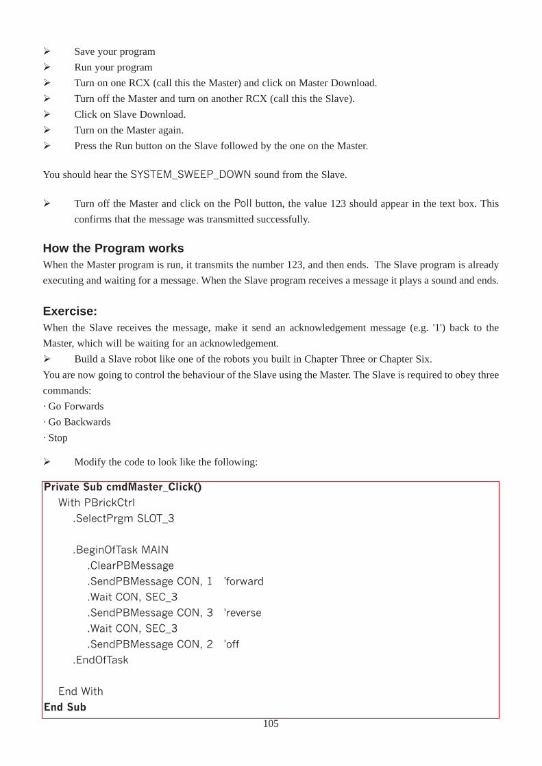
Ø Save your program
Ø Run your program
Ø Turn on one RCX (call this the Master) and click on Master Download.
Ø Turn off the Master and turn on another RCX (call this the Slave).
Ø Click on Slave Download.
Ø Turn on the Master again.
Ø Press the Run button on the Slave followed by the one on the Master.
You should hear the SYSTEM_SWEEP_DOWN sound from the Slave.
Ø Turn off the Master and click on the Poll button, the value 123 should appear in the text box. This
confirms that the message was transmitted successfully.
How the Program worksWhen the Master program is run, it transmits the number 123, and then ends. The Slave program is already
executing and waiting for a message. When the Slave program receives a message it plays a sound and ends.
Exercise:When the Slave receives the message, make it send an acknowledgement message (e.g. '1') back to the
Master, which will be waiting for an acknowledgement.
Ø Build a Slave robot like one of the robots you built in Chapter Three or Chapter Six.
You are now going to control the behaviour of the Slave using the Master. The Slave is required to obey three
commands:
· Go Forwards
· Go Backwards
· Stop
Ø Modify the code to look like the following:
Private Sub cmdMaster_Click()
With PBrickCtrl
.SelectPrgm SLOT_3
.BeginOfTask MAIN
.ClearPBMessage
.SendPBMessage CON, 1 'forward
.Wait CON, SEC_3
.SendPBMessage CON, 3 'reverse
.Wait CON, SEC_3
.SendPBMessage CON, 2 'off
.EndOfTask
End With
End Sub
105
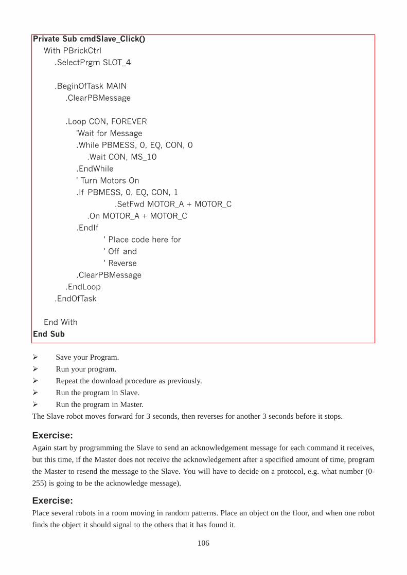
Private Sub cmdSlave_Click()
With PBrickCtrl
.SelectPrgm SLOT_4
.BeginOfTask MAIN
.ClearPBMessage
.Loop CON, FOREVER
'Wait for Message
.While PBMESS, 0, EQ, CON, 0
.Wait CON, MS_10
.EndWhile
' Turn Motors On
.If PBMESS, 0, EQ, CON, 1
.SetFwd MOTOR_A + MOTOR_C
.On MOTOR_A + MOTOR_C
.EndIf
' Place code here for
' Off and
' Reverse
.ClearPBMessage
.EndLoop
.EndOfTask
End With
End Sub
Ø Save your Program.
Ø Run your program.
Ø Repeat the download procedure as previously.
Ø Run the program in Slave.
Ø Run the program in Master.
The Slave robot moves forward for 3 seconds, then reverses for another 3 seconds before it stops.
Exercise:Again start by programming the Slave to send an acknowledgement message for each command it receives,
but this time, if the Master does not receive the acknowledgement after a specified amount of time, program
the Master to resend the message to the Slave. You will have to decide on a protocol, e.g. what number (0-
255) is going to be the acknowledge message).
Exercise:Place several robots in a room moving in random patterns. Place an object on the floor, and when one robot
finds the object it should signal to the others that it has found it.
106
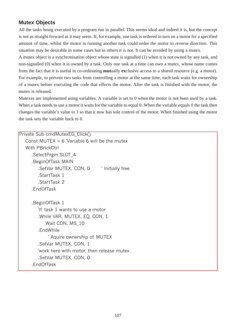
Mutex ObjectsAll the tasks being executed by a program run in parallel. This seems ideal and indeed it is, but the concept
is not as straight forward as it may seem. If, for example, one task is ordered to turn on a motor for a specified
amount of time, whilst the motor is running another task could order the motor to reverse direction. This
situation may be desirable in some cases but in others it is not. It can be avoided by using a mutex.
A mutex object is a synchronisation object whose state is signalled (1) when it is not owned by any task, and
non-signalled (0) when it is owned by a task. Only one task at a time can own a mutex, whose name comes
from the fact that it is useful in co-ordinating mutually exclusive access to a shared resource (e.g. a motor).
For example, to prevent two tasks from controlling a motor at the same time, each task waits for ownership
of a mutex before executing the code that effects the motor. After the task is finished with the motor, the
mutex is released.
Mutexes are implemented using variables. A variable is set to 0 when the motor is not been used by a task.
When a task needs to use a motor it waits for the variable to equal 0. When the variable equals 0 the task then
changes the variable’s value to 1 so that it now has sole control of the motor. When finished using the motor
the task sets the variable back to 0.
Private Sub cmdMutexEG_Click()
Const MUTEX = 6 'Variable 6 will be the mutex
With PBrickCtrl
.SelectPrgm SLOT_4
.BeginOfTask MAIN
.SetVar MUTEX, CON, 0 ' Initially free
.StartTask 1
.StartTask 2
.EndOfTask
.BeginOfTask 1
'If task 1 wants to use a motor
.While VAR, MUTEX, EQ, CON, 1
.Wait CON, MS_10
.EndWhile
' Aquire ownership of MUTEX
.SetVar MUTEX, CON, 1
'work here with motor, then release mutex
.SetVar MUTEX, CON, 0
.EndOfTask
107
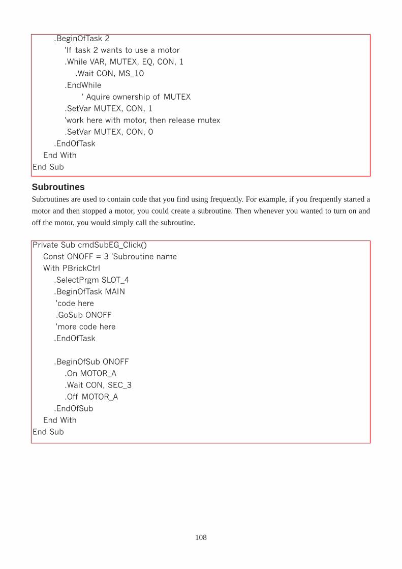
.BeginOfTask 2
'If task 2 wants to use a motor
.While VAR, MUTEX, EQ, CON, 1
.Wait CON, MS_10
.EndWhile
' Aquire ownership of MUTEX
.SetVar MUTEX, CON, 1
'work here with motor, then release mutex
.SetVar MUTEX, CON, 0
.EndOfTask
End With
End Sub
SubroutinesSubroutines are used to contain code that you find using frequently. For example, if you frequently started a
motor and then stopped a motor, you could create a subroutine. Then whenever you wanted to turn on and
off the motor, you would simply call the subroutine.
Private Sub cmdSubEG_Click()
Const ONOFF = 3 'Subroutine name
With PBrickCtrl
.SelectPrgm SLOT_4
.BeginOfTask MAIN
'code here
.GoSub ONOFF
'more code here
.EndOfTask
.BeginOfSub ONOFF
.On MOTOR_A
.Wait CON, SEC_3
.Off MOTOR_A
.EndOfSub
End With
End Sub
108
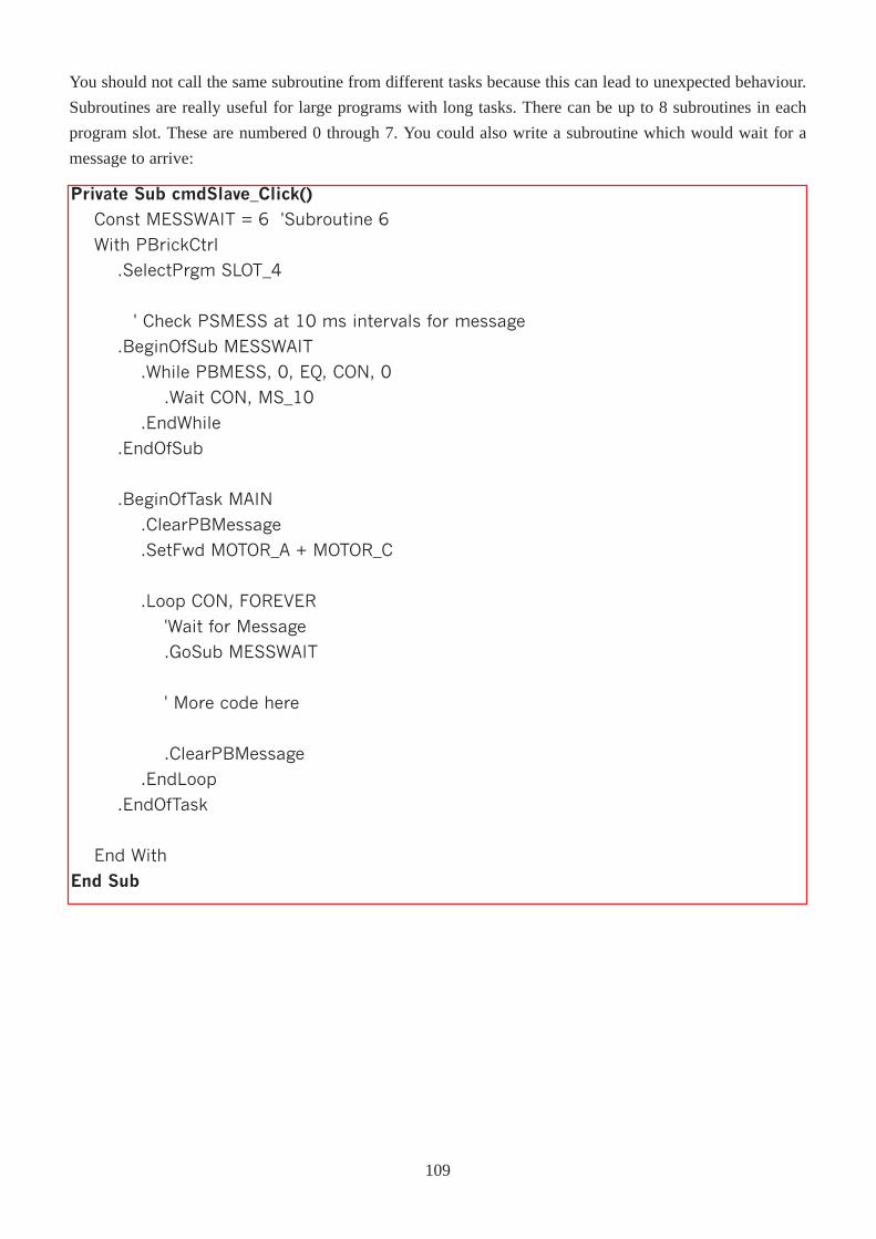
You should not call the same subroutine from different tasks because this can lead to unexpected behaviour.
Subroutines are really useful for large programs with long tasks. There can be up to 8 subroutines in each
program slot. These are numbered 0 through 7. You could also write a subroutine which would wait for a
message to arrive:
Private Sub cmdSlave_Click()
Const MESSWAIT = 6 'Subroutine 6
With PBrickCtrl
.SelectPrgm SLOT_4
' Check PSMESS at 10 ms intervals for message
.BeginOfSub MESSWAIT
.While PBMESS, 0, EQ, CON, 0
.Wait CON, MS_10
.EndWhile
.EndOfSub
.BeginOfTask MAIN
.ClearPBMessage
.SetFwd MOTOR_A + MOTOR_C
.Loop CON, FOREVER
'Wait for Message
.GoSub MESSWAIT
' More code here
.ClearPBMessage
.EndLoop
.EndOfTask
End With
End Sub
109
TimersThere are four free-running timers in the RCX, with a resolution of 100ms. They can be cleared individually
using the ClearTimer method. As soon as they are cleared they start running again from 0. At any time a
timer can have a value between 0 and 32767. This means that the counter can count up to roughly 3276
seconds which is approximately 55 minutes. To reset a timer:
PBrickCtrl.ClearTimer TIMER_1
This restarts the timer at 0, and the timer begins to count upwards, adding one to its value every 1/10 of a
second. To view the timer, use the Poll command
PBrickCtrl.Poll(TIMER, TIMER_1)
Remember that the timer has a resolution of 100ms and the Wait method uses a resolution of 10ms, i.e. the
timer ticks 10 times a second while the wait method ticks 100 times a second. Do not use the constants (e.g.
MS_100) to compare any values to values contained in the timers.
110
Appendices
Further Information
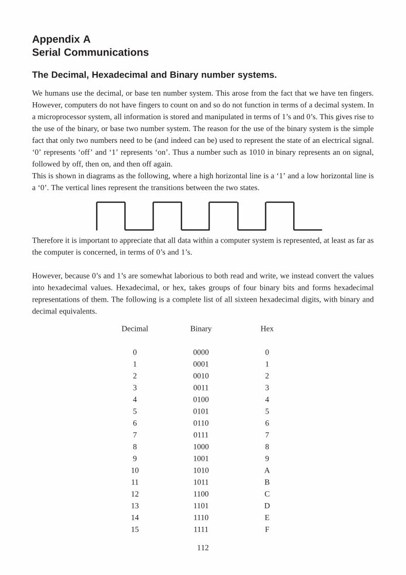
Decimal
0
1
2
3
4
5
6
7
8
9
10
11
12
13
14
15
Binary
0000
0001
0010
0011
0100
0101
0110
0111
1000
1001
1010
1011
1100
1101
1110
1111
Hex
0
1
2
3
4
5
6
7
8
9
A
B
C
D
E
F
Appendix ASerial Communications
The Decimal, Hexadecimal and Binary number systems.
Therefore it is important to appreciate that all data within a computer system is represented, at least as far as
the computer is concerned, in terms of 0’s and 1’s.
However, because 0’s and 1’s are somewhat laborious to both read and write, we instead convert the values
into hexadecimal values. Hexadecimal, or hex, takes groups of four binary bits and forms hexadecimal
representations of them. The following is a complete list of all sixteen hexadecimal digits, with binary and
decimal equivalents.
We humans use the decimal, or base ten number system. This arose from the fact that we have ten fingers.
However, computers do not have fingers to count on and so do not function in terms of a decimal system. In
a microprocessor system, all information is stored and manipulated in terms of 1’s and 0’s. This gives rise to
the use of the binary, or base two number system. The reason for the use of the binary system is the simple
fact that only two numbers need to be (and indeed can be) used to represent the state of an electrical signal.
‘0’ represents ‘off’ and ‘1’ represents ‘on’. Thus a number such as 1010 in binary represents an on signal,
followed by off, then on, and then off again.
This is shown in diagrams as the following, where a high horizontal line is a ‘1’ and a low horizontal line is
a ‘0’. The vertical lines represent the transitions between the two states.
112
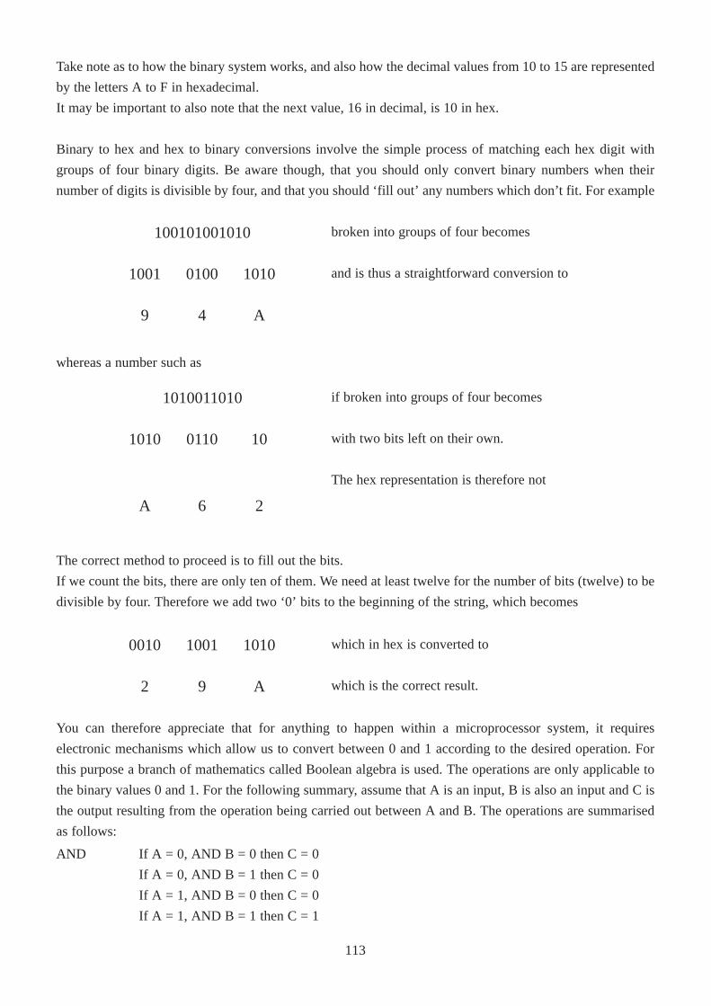
100101001010
and is thus a straightforward conversion to
broken into groups of four becomes
101001001001
A49
1010011010
with two bits left on their own.
The hex representation is therefore not
if broken into groups of four becomes
1001101010
26A
which is the correct result.
which in hex is converted to
A92
101010010010
Take note as to how the binary system works, and also how the decimal values from 10 to 15 are represented
by the letters A to F in hexadecimal.
It may be important to also note that the next value, 16 in decimal, is 10 in hex.
Binary to hex and hex to binary conversions involve the simple process of matching each hex digit with
groups of four binary digits. Be aware though, that you should only convert binary numbers when their
number of digits is divisible by four, and that you should ‘fill out’ any numbers which don’t fit. For example
whereas a number such as
The correct method to proceed is to fill out the bits.
If we count the bits, there are only ten of them. We need at least twelve for the number of bits (twelve) to be
divisible by four. Therefore we add two ‘0’ bits to the beginning of the string, which becomes
AND If A = 0, AND B = 0 then C = 0
If A = 0, AND B = 1 then C = 0
If A = 1, AND B = 0 then C = 0
If A = 1, AND B = 1 then C = 1
You can therefore appreciate that for anything to happen within a microprocessor system, it requires
electronic mechanisms which allow us to convert between 0 and 1 according to the desired operation. For
this purpose a branch of mathematics called Boolean algebra is used. The operations are only applicable to
the binary values 0 and 1. For the following summary, assume that A is an input, B is also an input and C is
the output resulting from the operation being carried out between A and B. The operations are summarised
as follows:
113
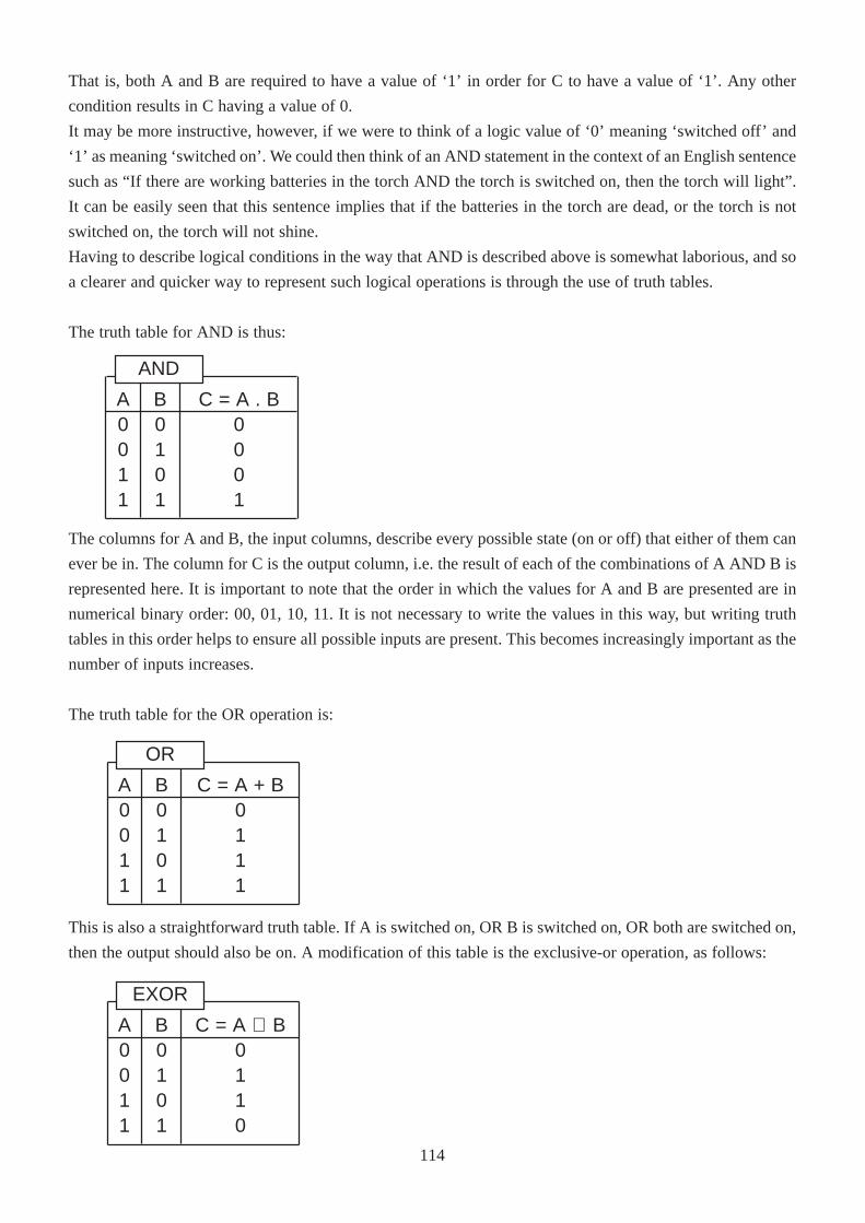
That is, both A and B are required to have a value of ‘1’ in order for C to have a value of ‘1’. Any other
condition results in C having a value of 0.
It may be more instructive, however, if we were to think of a logic value of ‘0’ meaning ‘switched off’ and
‘1’ as meaning ‘switched on’. We could then think of an AND statement in the context of an English sentence
such as “If there are working batteries in the torch AND the torch is switched on, then the torch will light”.
It can be easily seen that this sentence implies that if the batteries in the torch are dead, or the torch is not
switched on, the torch will not shine.
Having to describe logical conditions in the way that AND is described above is somewhat laborious, and so
a clearer and quicker way to represent such logical operations is through the use of truth tables.
The truth table for AND is thus:
The columns for A and B, the input columns, describe every possible state (on or off) that either of them can
ever be in. The column for C is the output column, i.e. the result of each of the combinations of A AND B is
represented here. It is important to note that the order in which the values for A and B are presented are in
numerical binary order: 00, 01, 10, 11. It is not necessary to write the values in this way, but writing truth
tables in this order helps to ensure all possible inputs are present. This becomes increasingly important as the
number of inputs increases.
The truth table for the OR operation is:
This is also a straightforward truth table. If A is switched on, OR B is switched on, OR both are switched on,
then the output should also be on. A modification of this table is the exclusive-or operation, as follows:
A0011
C = A . B0001
B0101
AND
A0011
C = A + B0111
B0101
OR
A0011
C = A ⊕ B0110
B0101
EXOR
114
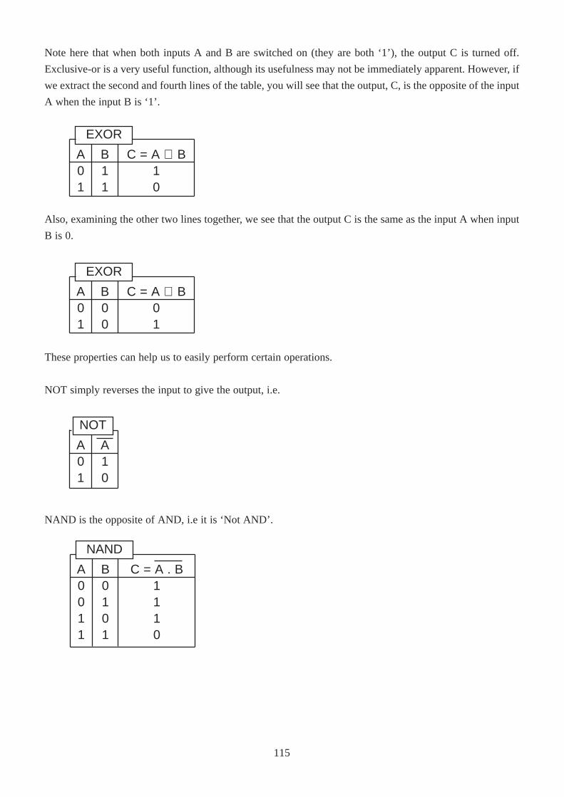
Note here that when both inputs A and B are switched on (they are both ‘1’), the output C is turned off.
Exclusive-or is a very useful function, although its usefulness may not be immediately apparent. However, if
we extract the second and fourth lines of the table, you will see that the output, C, is the opposite of the input
A when the input B is ‘1’.
Also, examining the other two lines together, we see that the output C is the same as the input A when input
B is 0.
These properties can help us to easily perform certain operations.
NOT simply reverses the input to give the output, i.e.
NAND is the opposite of AND, i.e it is ‘Not AND’.
A0011
C = A . B1110
B0101
NAND
A01
A10
NOT
A01
C = A ⊕ B01
B00
EXOR
A01
C = A ⊕ B10
B11
EXOR
115
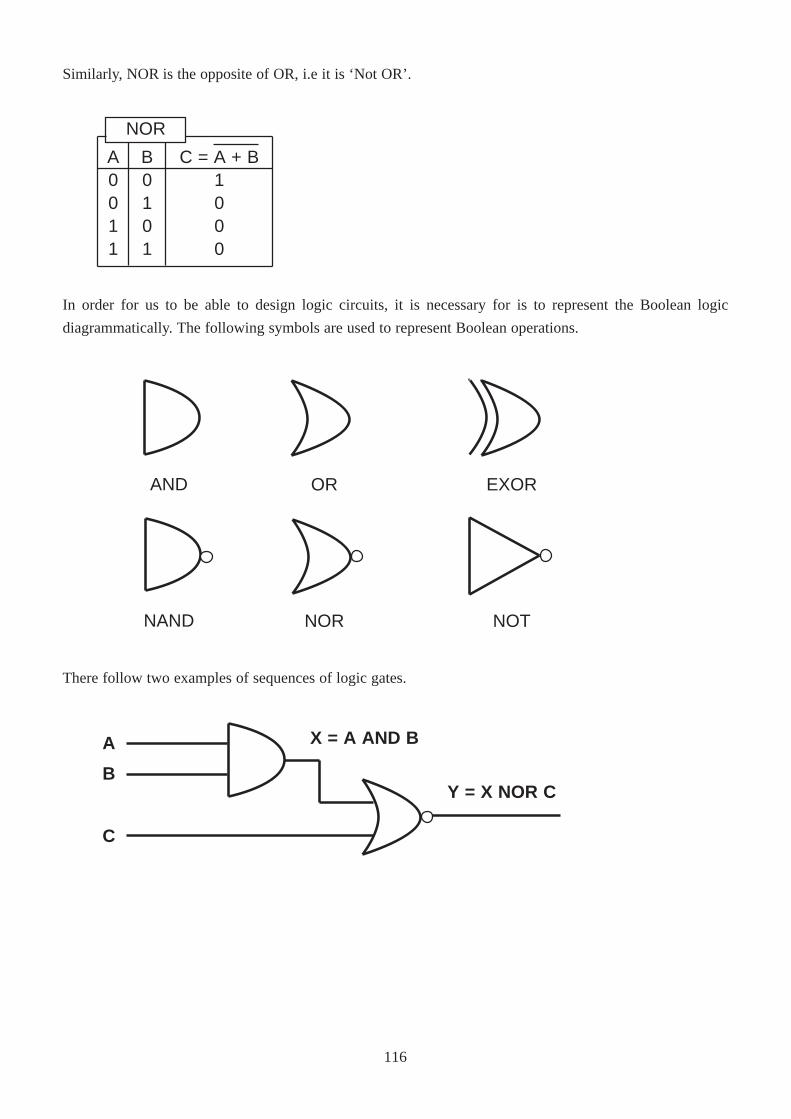
Similarly, NOR is the opposite of OR, i.e it is ‘Not OR’.
In order for us to be able to design logic circuits, it is necessary for is to represent the Boolean logic
diagrammatically. The following symbols are used to represent Boolean operations.
There follow two examples of sequences of logic gates.
A0011
C = A + B1000
B0101
NOR
AND
NAND
OR EXOR
NOR NOT
A
B
C
X = A AND B
Y = X NOR C
116
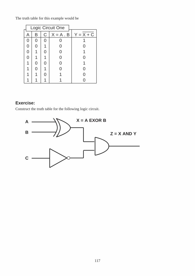
C01010101
Y = X + C10101000
The truth table for this example would be
Exercise:Construct the truth table for the following logic circuit.
A00001111
X = A . B00000011
B00110011
Logic Circuit One
A
B
C
X = A EXOR B
Z = X AND Y
117
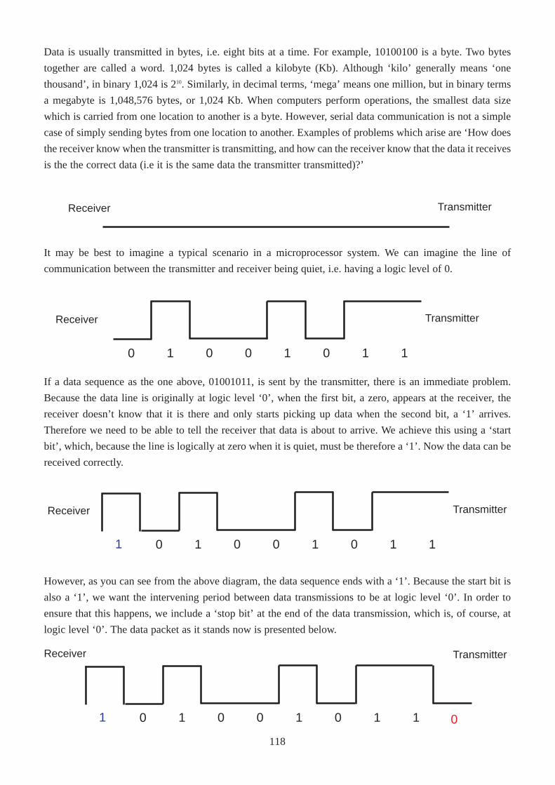
Data is usually transmitted in bytes, i.e. eight bits at a time. For example, 10100100 is a byte. Two bytes
together are called a word. 1,024 bytes is called a kilobyte (Kb). Although ‘kilo’ generally means ‘one
thousand’, in binary 1,024 is 210. Similarly, in decimal terms, ‘mega’ means one million, but in binary terms
a megabyte is 1,048,576 bytes, or 1,024 Kb. When computers perform operations, the smallest data size
which is carried from one location to another is a byte. However, serial data communication is not a simple
case of simply sending bytes from one location to another. Examples of problems which arise are ‘How does
the receiver know when the transmitter is transmitting, and how can the receiver know that the data it receives
is the the correct data (i.e it is the same data the transmitter transmitted)?’
It may be best to imagine a typical scenario in a microprocessor system. We can imagine the line of
communication between the transmitter and receiver being quiet, i.e. having a logic level of 0.
If a data sequence as the one above, 01001011, is sent by the transmitter, there is an immediate problem.
Because the data line is originally at logic level ‘0’, when the first bit, a zero, appears at the receiver, the
receiver doesn’t know that it is there and only starts picking up data when the second bit, a ‘1’ arrives.
Therefore we need to be able to tell the receiver that data is about to arrive. We achieve this using a ‘start
bit’, which, because the line is logically at zero when it is quiet, must be therefore a ‘1’. Now the data can be
received correctly.
However, as you can see from the above diagram, the data sequence ends with a ‘1’. Because the start bit is
also a ‘1’, we want the intervening period between data transmissions to be at logic level ‘0’. In order to
ensure that this happens, we include a ‘stop bit’ at the end of the data transmission, which is, of course, at
logic level ‘0’. The data packet as it stands now is presented below.
Receiver Transmitter
0 1101001
Receiver Transmitter
0 11010011
Receiver Transmitter
0 11010011 0
Receiver Transmitter
118
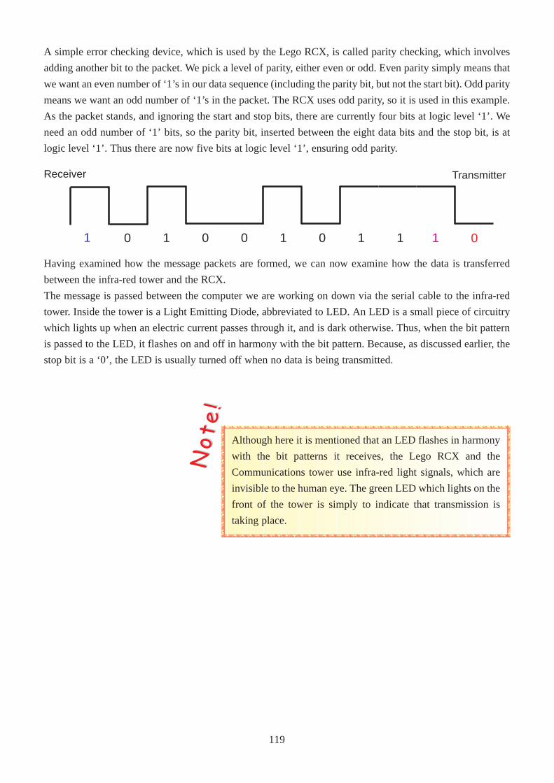
A simple error checking device, which is used by the Lego RCX, is called parity checking, which involves
adding another bit to the packet. We pick a level of parity, either even or odd. Even parity simply means that
we want an even number of ‘1’s in our data sequence (including the parity bit, but not the start bit). Odd parity
means we want an odd number of ‘1’s in the packet. The RCX uses odd parity, so it is used in this example.
As the packet stands, and ignoring the start and stop bits, there are currently four bits at logic level ‘1’. We
need an odd number of ‘1’ bits, so the parity bit, inserted between the eight data bits and the stop bit, is at
logic level ‘1’. Thus there are now five bits at logic level ‘1’, ensuring odd parity.
Having examined how the message packets are formed, we can now examine how the data is transferred
between the infra-red tower and the RCX.
The message is passed between the computer we are working on down via the serial cable to the infra-red
tower. Inside the tower is a Light Emitting Diode, abbreviated to LED. An LED is a small piece of circuitry
which lights up when an electric current passes through it, and is dark otherwise. Thus, when the bit pattern
is passed to the LED, it flashes on and off in harmony with the bit pattern. Because, as discussed earlier, the
stop bit is a ‘0’, the LED is usually turned off when no data is being transmitted.
Although here it is mentioned that an LED flashes in harmony
with the bit patterns it receives, the Lego RCX and the
Communications tower use infra-red light signals, which are
invisible to the human eye. The green LED which lights on the
front of the tower is simply to indicate that transmission is
taking place.
NNoo tt
ee !!
Receiver Transmitter
0 11010011 1 0
119

At the most basic operating level of the RCX, or of any electronic device, very simple and straightforward
instructions are carried out. An example in assembly language, which is a very low level language, would be:
MOV AX, 7
ADD AX, 3
The MOV AX, 7 instruction copies the value 7 into the register called AX.
The ADD AX, 3 instruction adds 3 to whatever is in the AX register.
Don’t worry if you don’t understand this. The important this is to note that the instructions are very short and
actually do very little (assembly language programs are typically very long).
Each instruction is made up of an opcode (e.g. MOV, ADD), and one or more operands (such as AX, 7, 3).
Thus the opcode is the actual instruction to the computer as to what to do, and the operands are the pieces of
data which are used in the action.
With this knowledge, we can know examine how the data is transmitted between the RCX and the computer.
At the packet level, all packets look like this:
0x55 0xff 0x00 D1 ~D1 D2 ~D2 ... Dn ~Dn C ~C
The first three bytes are 55, FF and 00 (in hex representation, as indicated by the leading ‘0x’).
These three bytes form the beginning of every packet sent. If we examine the bit sequence which these bits
represent,
01010101 11111111 00000000
we may notice that there are an even number of ‘1’s and ‘0’s. This start to the packet, called the ‘header’,
notifies the receiver that data is about to follow.
The data for the actual message then follows. In the case where there are both an opcode and one or more
operands, the opcode always comes first.
Because the transmission of the data is via a light signal, other sources of light can interfere with it. Because
of this, the transmission of the signal is not always received at the other end. In order to make up for this,
both the RCX and the infra-red tower continually send the same message until the other replies that it has
received the message.
Note that for every byte Dn, there is a corresponding ~Dn. This may be confusing at first, but what it means
is that every byte that is transmitted is followed by its complement i.e. the bits of the data byte are all
reversed, for example 00110101 complemented becomes 11001010.
The C value is a checksum value and the ~C is its complement. A checksum value is basically the addition
of all of the data byte values, without any carry.
An example may help to clear all of this up, as follows.
120
1111 0111
0000 1000
has now become
F7
109
+ 12
DataSource
PC
RCX
PC
RCX
Message
Checksum attained as a result of
adding these values
55
55
55
55
00
00
00
00
FF
FF
FF
FF
18
E7
E9
16
E7
18
16
E9
18
E7
47
16
E7
18
B8
E9
30 CF
18
E7
E9
16
47
The data necessary to send an infra-red message is F7 followed by the 8 bit message. For example:
55 FF 00 F7 08 12 ED 09 F6
is a packet sending the message 0x12 to the RCX.
The header for the packet is, of course, 55 FF 00. The next byte must be F7 to specify that a message is to
be communicated. This byte, F7, is now complemented (bits reversed) to form 08, i.e.:
The next byte is 12, which is the actual byte this message wishes to send. Its complement is ED.
Finally, the checksum and its complemented are calculated. This is performed thus:
However the final carry is not taken into account, so the checksum remains as 09, with complement F6.
Now let’s examine the following sequence of message transfers.
If we follow the sequence of events, the PC first sends the message ‘18’ to the RCX. 18 is the opcode which
asks the RCX ‘Are you alive?’ i.e. it attempts to discover if the RCX is switched on. The RCX is switched
on, and so it responds with E7 – which indicates that it is alive. Note that the reply, E7 is the complement of
18. All of the opcodes have their complement as their reply.
The next instruction is a little more complicated.
The opcode is E9, which is the opcode for ‘Set motor direction’. This opcode requires an operand in order to
determine what motors to operate on, and what to do with them.
The operand specified here is 47, which specifies the RCX to switch all three motors, A, B and C to the
opposite direction of that which they are currently travelling in.
The value of the operand is determined by the following table.
121
Bit
0x01
0x02
0x04
0x40
0x80
Description
Modify direction of motor A
Modify direction of motor B
Modify direction of motor C
Flip the directions of the specified motors
Set the directions of the specified motors to forward
3
47
+ 40
21
In order to specify more than one motor, as in our above program, we add together the required values. In
our case we added
Thus, 47 was the required operand value.
The reply, 16, returned to the computer from the RCX, indicates that the operation was a success. Note again
how the reply, 16, is the complement of the original opcode, 89.
Earlier it was mentioned that the header to the packet, 55 FF 00, has an equal number of ‘0’ and ‘1’ bits. In
fact, because each message byte which is sent is followed by its complement, every data transmission will
contain an equal number of 1’s and 0’s. When the data is received, it can compensate for a constant signal
bias (caused by ambient light) simply by subtracting the average signal value. In other words, the receiver
can make an attempt at eliminating the interference caused by light signals other than the infra-red signal.
122
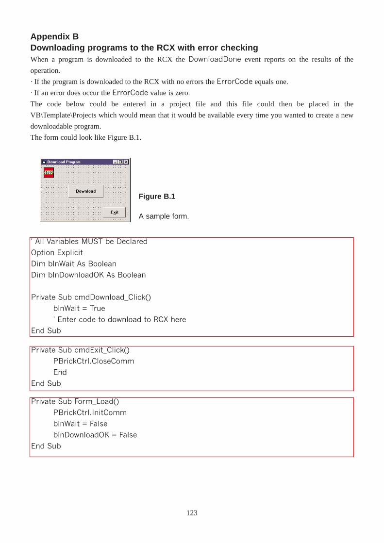
Appendix BDownloading programs to the RCX with error checkingWhen a program is downloaded to the RCX the DownloadDone event reports on the results of the
operation.
· If the program is downloaded to the RCX with no errors the ErrorCode equals one.
· If an error does occur the ErrorCode value is zero.
The code below could be entered in a project file and this file could then be placed in the
VB\Template\Projects which would mean that it would be available every time you wanted to create a new
downloadable program.
The form could look like Figure B.1.
' All Variables MUST be Declared
Option Explicit
Dim blnWait As Boolean
Dim blnDownloadOK As Boolean
Private Sub cmdDownload_Click()
blnWait = True
' Enter code to download to RCX here
End Sub
Private Sub cmdExit_Click()
PBrickCtrl.CloseComm
End
End Sub
Private Sub Form_Load()
PBrickCtrl.InitComm
blnWait = False
blnDownloadOK = False
End Sub
Figure B.1
A sample form.
123
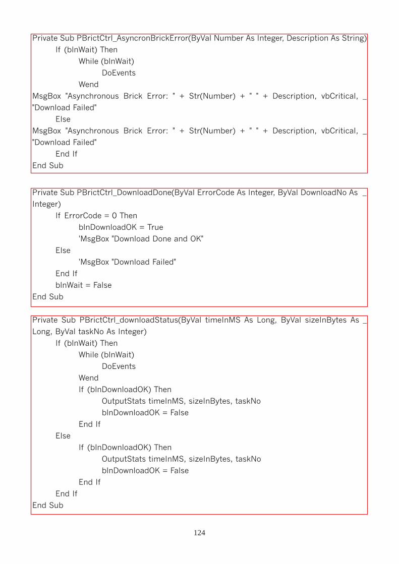
Private Sub PBrictCtrl_DownloadDone(ByVal ErrorCode As Integer, ByVal DownloadNo As _
Integer)
If ErrorCode = 0 Then
blnDownloadOK = True
'MsgBox "Download Done and OK"
Else
'MsgBox "Download Failed"
End If
blnWait = False
End Sub
Private Sub PBrictCtrl_downloadStatus(ByVal timeInMS As Long, ByVal sizeInBytes As _
Long, ByVal taskNo As Integer)
If (blnWait) Then
While (blnWait)
DoEvents
Wend
If (blnDownloadOK) Then
OutputStats timeInMS, sizeInBytes, taskNo
blnDownloadOK = False
End If
Else
If (blnDownloadOK) Then
OutputStats timeInMS, sizeInBytes, taskNo
blnDownloadOK = False
End If
End If
End Sub
Private Sub PBrictCtrl_AsyncronBrickError(ByVal Number As Integer, Description As String)
If (blnWait) Then
While (blnWait)
DoEvents
Wend
MsgBox "Asynchronous Brick Error: " + Str(Number) + " " + Description, vbCritical, _
"Download Failed"
Else
MsgBox "Asynchronous Brick Error: " + Str(Number) + " " + Description, vbCritical, _
"Download Failed"
End If
End Sub
124
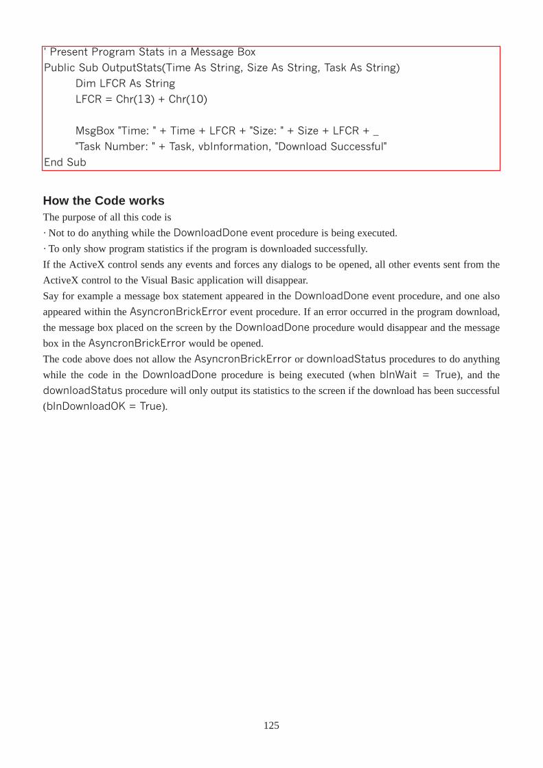
How the Code worksThe purpose of all this code is
· Not to do anything while the DownloadDone event procedure is being executed.
· To only show program statistics if the program is downloaded successfully.
If the ActiveX control sends any events and forces any dialogs to be opened, all other events sent from the
ActiveX control to the Visual Basic application will disappear.
Say for example a message box statement appeared in the DownloadDone event procedure, and one also
appeared within the AsyncronBrickError event procedure. If an error occurred in the program download,
the message box placed on the screen by the DownloadDone procedure would disappear and the message
box in the AsyncronBrickError would be opened.
The code above does not allow the AsyncronBrickError or downloadStatus procedures to do anything
while the code in the DownloadDone procedure is being executed (when blnWait = True), and the
downloadStatus procedure will only output its statistics to the screen if the download has been successful
(blnDownloadOK = True).
' Present Program Stats in a Message Box
Public Sub OutputStats(Time As String, Size As String, Task As String)
Dim LFCR As String
LFCR = Chr(13) + Chr(10)
MsgBox "Time: " + Time + LFCR + "Size: " + Size + LFCR + _
"Task Number: " + Task, vbInformation, "Download Successful"
End Sub
125
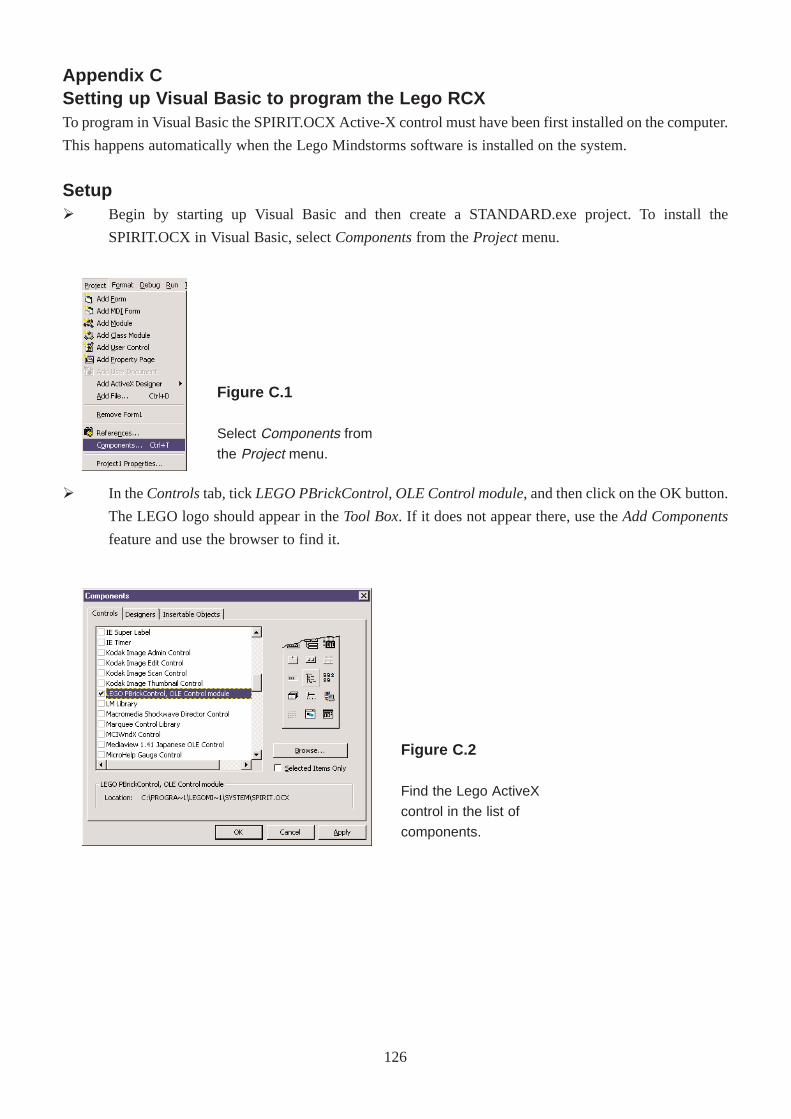
Appendix CSetting up Visual Basic to program the Lego RCXTo program in Visual Basic the SPIRIT.OCX Active-X control must have been first installed on the computer.
This happens automatically when the Lego Mindstorms software is installed on the system.
SetupØ Begin by starting up Visual Basic and then create a STANDARD.exe project. To install the
SPIRIT.OCX in Visual Basic, select Componentsfrom the Projectmenu.
Ø In the Controlstab, tickLEGO PBrickControl, OLE Control module, and then click on the OK button.
The LEGO logo should appear in the Tool Box. If it does not appear there, use the Add Components
feature and use the browser to find it.
Figure C.1
Select Components from
the Project menu.
Figure C.2
Find the Lego ActiveX
control in the list of
components.
126
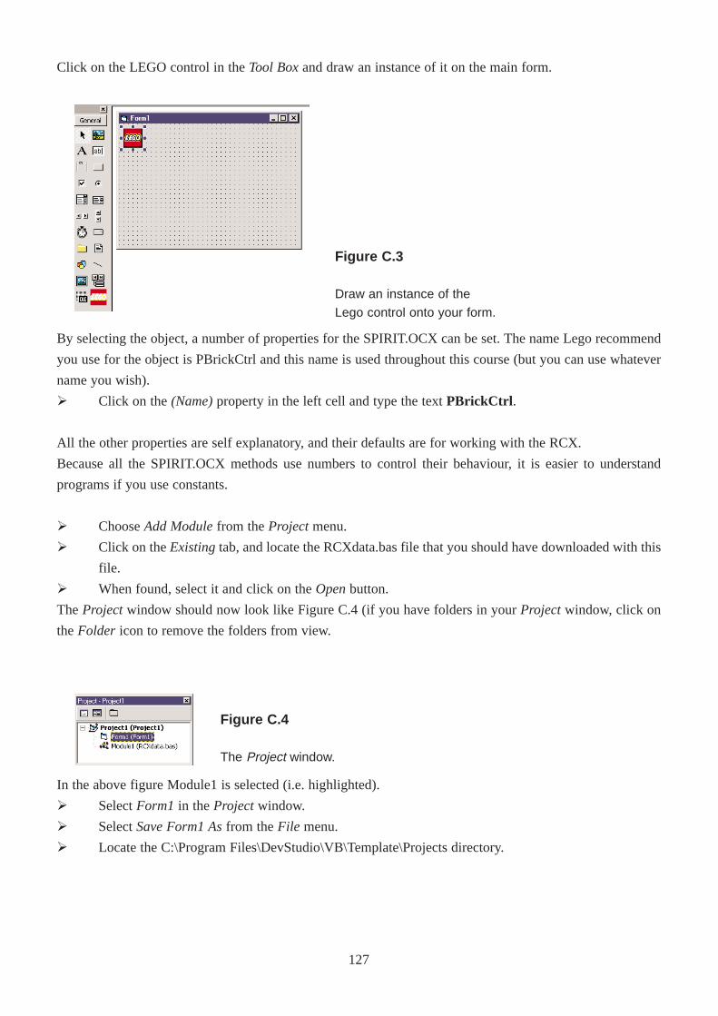
By selecting the object, a number of properties for the SPIRIT.OCX can be set. The name Lego recommend
you use for the object is PBrickCtrl and this name is used throughout this course (but you can use whatever
name you wish).
Ø Click on the (Name)property in the left cell and type the text PBrickCtrl .
All the other properties are self explanatory, and their defaults are for working with the RCX.
Because all the SPIRIT.OCX methods use numbers to control their behaviour, it is easier to understand
programs if you use constants.
Ø Choose Add Modulefrom the Projectmenu.
Ø Click on the Existingtab, and locate the RCXdata.bas file that you should have downloaded with this
file.
Ø When found, select it and click on the Openbutton.
The Projectwindow should now look like Figure C.4 (if you have folders in your Projectwindow, click on
the Folder icon to remove the folders from view.
In the above figure Module1 is selected (i.e. highlighted).
Ø Select Form1 in the Projectwindow.
Ø Select Save Form1 Asfrom the File menu.
Ø Locate the C:\Program Files\DevStudio\VB\Template\Projects directory.
Click on the LEGO control in the Tool Boxand draw an instance of it on the main form.
Figure C.3
Draw an instance of the
Lego control onto your form.
Figure C.4
The Project window.
127
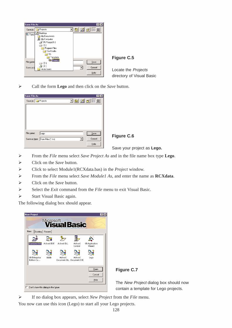
Ø Call the form Lego and then click on the Savebutton.
Ø From the File menu select Save Project Asand in the file name box type Lego.
Ø Click on the Savebutton.
Ø Click to select Module1(RCXdata.bas) in the Projectwindow.
Ø From the File menu select Save Module1 As, and enter the name as RCXdata.
Ø Click on the Savebutton.
Ø Select the Exit command from the File menu to exit Visual Basic.
Ø Start Visual Basic again.
The following dialog box should appear.
Ø If no dialog box appears, select New Projectfrom the File menu.
You now can use this icon (Lego) to start all your Lego projects.
Figure C.5
Locate the Projectsdirectory of Visual Basic
Figure C.6
Save your project as Lego.
Figure C.7
The New Project dialog box should now
contain a template for Lego projects.
128
Appendix DTheRCXdata.bas file'============================================================================'' Project: MindStorms' Unit : Global module' Rev. : 1.2''------------------------------------------------------------------------------'' Declaration of global names for RCX-related constants''============================================================================Option Explicit'============================================================================' Enter your own Constants here'============================================================================
'============================================================================' Program slots 0 -4'============================================================================Public Const SLOT_1 = 0Public Const SLOT_2 = 1Public Const SLOT_3 = 2Public Const SLOT_4 = 3Public Const SLOT_5 = 4'============================================================================' Task Names - Change Task names 1 - 9 to appropriate meaning'============================================================================Public Const MAIN = 0Public Const TASK_ONE = 1Public Const TASK_TWO = 2Public Const TASK_THREE = 3Public Const TASK_FOUR = 4Public Const TASK_FIVE = 5Public Const TASK_SIX = 6Public Const TASK_SEVEN = 7Public Const TASK_EIGHT = 8Public Const TASK_NINE = 9'============================================================================' System sounds'============================================================================Public Const CLICK_SOUND = 0Public Const BEEP_SOUND = 1Public Const SWEEP_DOWN_SOUND = 2Public Const SWEEP_UP_SOUND = 3Public Const ERROR_SOUND = 4Public Const SWEEP_FAST_SOUND = 5'============================================================================' Source names'============================================================================Public Const VAR = 0Public Const TIMER = 1Public Const CON = 2
129
Public Const MOTSTA = 3Public Const RAN = 4Public Const TACC = 5Public Const TACS = 6Public Const MOTCUR = 7Public Const KEYS = 8Public Const SENVAL = 9Public Const SENTYPE = 10Public Const SENMODE = 11Public Const SENRAW = 12Public Const BOOL = 13Public Const WATCH = 14Public Const PBMESS = 15'============================================================================' Sensor names'============================================================================Public Const SENSOR_1 = 0Public Const SENSOR_2 = 1Public Const SENSOR_3 = 2'============================================================================' Timer names'============================================================================Public Const TIMER_1 = 0Public Const TIMER_2 = 1Public Const TIMER_3 = 2Public Const TIMER_4 = 3'============================================================================' Tacho names (CyberMaster only)'============================================================================Public Const LEFT_TACHO = 0Public Const RIGHT_TACHO = 1'============================================================================' Range names'============================================================================Public Const SHORT_RANGE = 0Public Const LONG_RANGE = 1'============================================================================' Sensor types'============================================================================Public Const NO_TYPE = 0Public Const SWITCH_TYPE = 1Public Const TEMP_TYPE = 2Public Const LIGHT_TYPE = 3Public Const ANGLE_TYPE = 4'============================================================================' Sensor modes'============================================================================Public Const RAW_MODE = 0Public Const BOOL_MODE = 1Public Const TRANS_COUNT_MODE = 2Public Const PERIOD_COUNT_MODE = 3Public Const PERCENT_MODE = 4Public Const CELSIUS_MODE = 5
130
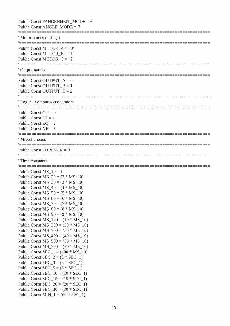
Public Const FAHRENHEIT_MODE = 6Public Const ANGLE_MODE = 7'============================================================================' Motor names (strings)'============================================================================Public Const MOTOR_A = "0"Public Const MOTOR_B = "1"Public Const MOTOR_C = "2"'============================================================================' Output names'============================================================================Public Const OUTPUT_A = 0Public Const OUTPUT_B = 1Public Const OUTPUT_C = 2'============================================================================' Logical comparison operators'============================================================================Public Const GT = 0Public Const LT = 1Public Const EQ = 2Public Const NE = 3'============================================================================' Miscellaneous'============================================================================Public Const FOREVER = 0'============================================================================' Time constants'============================================================================Public Const MS_10 = 1Public Const MS_20 = (2 * MS_10)Public Const MS_30 = (3 * MS_10)Public Const MS_40 = (4 * MS_10)Public Const MS_50 = (5 * MS_10)Public Const MS_60 = (6 * MS_10)Public Const MS_70 = (7 * MS_10)Public Const MS_80 = (8 * MS_10)Public Const MS_90 = (9 * MS_10)Public Const MS_100 = (10 * MS_10)Public Const MS_200 = (20 * MS_10)Public Const MS_300 = (30 * MS_10)Public Const MS_400 = (40 * MS_10)Public Const MS_500 = (50 * MS_10)Public Const MS_700 = (70 * MS_10)Public Const SEC_1 = (100 * MS_10)Public Const SEC_2 = (2 * SEC_1)Public Const SEC_3 = (3 * SEC_1)Public Const SEC_5 = (5 * SEC_1)Public Const SEC_10 = (10 * SEC_1)Public Const SEC_15 = (15 * SEC_1)Public Const SEC_20 = (20 * SEC_1)Public Const SEC_30 = (30 * SEC_1)Public Const MIN_1 = (60 * SEC_1)
131
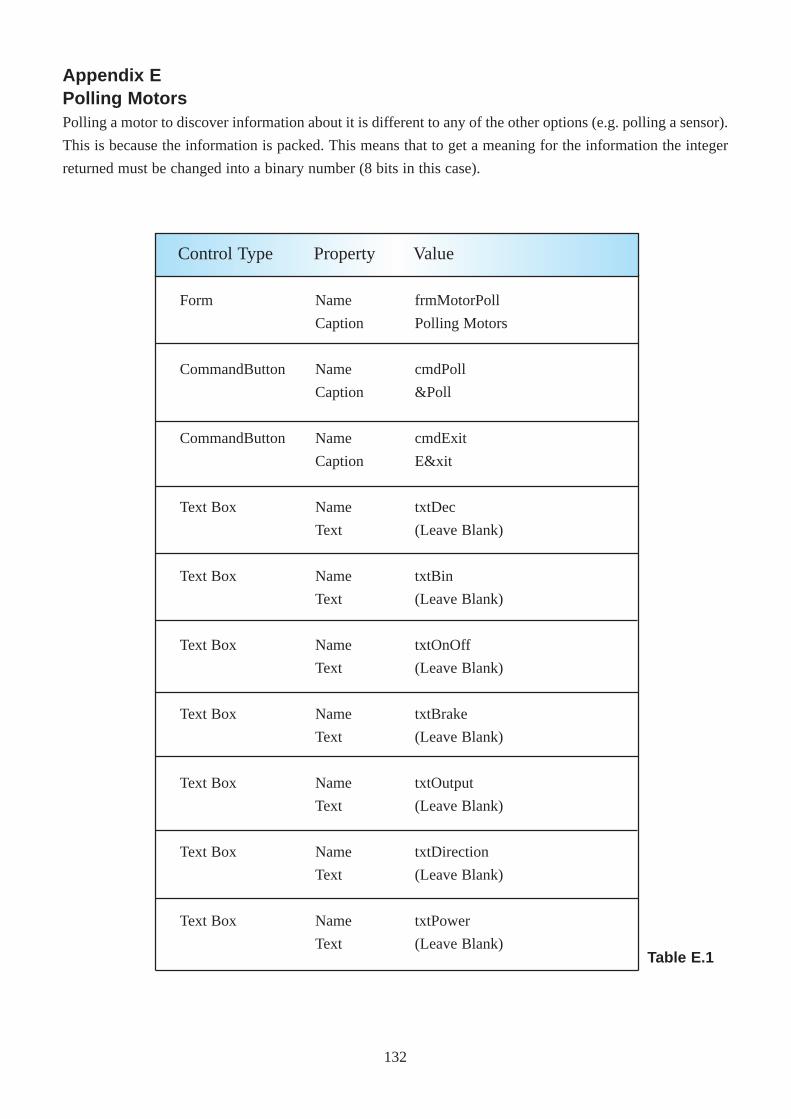
Form
CommandButton
CommandButton
Text Box
Text Box
Text Box
Text Box
Text Box
Text Box
Text Box
Name
Caption
Name
Caption
Name
Caption
Name
Text
Name
Text
Name
Text
Name
Text
Name
Text
Name
Text
Name
Text
frmMotorPoll
Polling Motors
cmdPoll
&Poll
cmdExit
E&xit
txtDec
(Leave Blank)
txtBin
(Leave Blank)
txtOnOff
(Leave Blank)
txtBrake
(Leave Blank)
txtOutput
(Leave Blank)
txtDirection
(Leave Blank)
txtPower
(Leave Blank)
Control Type Property Value
Table E.1
Appendix EPolling MotorsPolling a motor to discover information about it is different to any of the other options (e.g. polling a sensor).
This is because the information is packed. This means that to get a meaning for the information the integer
returned must be changed into a binary number (8 bits in this case).
132
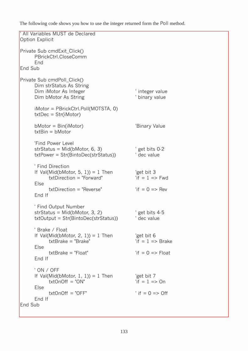
' All Variables MUST de DeclaredOption Explicit
Private Sub cmdExit_Click()PBrickCtrl.CloseCommEnd
End Sub
Private Sub cmdPoll_Click()Dim strStatus As StringDim iMotor As Integer ' integer valueDim bMotor As String ' binary value
iMotor = PBrickCtrl.Poll(MOTSTA, 0)txtDec = Str(iMotor)
bMotor = Bin(iMotor) 'Binary ValuetxtBin = bMotor
'Find Power LevelstrStatus = Mid(bMotor, 6, 3) ' get bits 0-2txtPower = Str(BintoDec(strStatus)) ' dec value
' Find DirectionIf Val(Mid(bMotor, 5, 1)) = 1 Then 'get bit 3
txtDirection = "Forward" 'if = 1 => FwdElse
txtDirection = "Reverse" 'if = 0 => RevEnd If
' Find Output NumberstrStatus = Mid(bMotor, 3, 2) ' get bits 4-5txtOutput = Str(BintoDec(strStatus)) ' dec value
' Brake / FloatIf Val(Mid(bMotor, 2, 1)) = 1 Then 'get bit 6
txtBrake = "Brake" 'if = 1 => BrakeElse
txtBrake = "Float" 'if = 0 => FloatEnd If
' ON / OFFIf Val(Mid(bMotor, 1, 1)) = 1 Then 'get bit 7
txtOnOff = "ON" 'if = 1 => OnElse
txtOnOff = "OFF" ' if = 0 => OffEnd If
End Sub
The following code shows you how to use the integer returned form the Poll method.
133
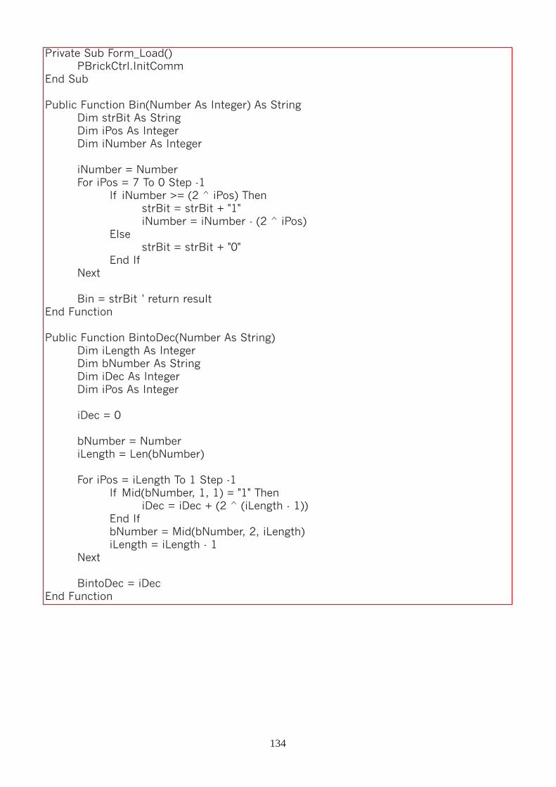
Private Sub Form_Load()PBrickCtrl.InitComm
End Sub
Public Function Bin(Number As Integer) As StringDim strBit As StringDim iPos As IntegerDim iNumber As Integer
iNumber = NumberFor iPos = 7 To 0 Step -1
If iNumber >= (2 ^ iPos) ThenstrBit = strBit + "1"iNumber = iNumber - (2 ^ iPos)
ElsestrBit = strBit + "0"
End IfNext
Bin = strBit ' return resultEnd Function
Public Function BintoDec(Number As String)Dim iLength As IntegerDim bNumber As StringDim iDec As IntegerDim iPos As Integer
iDec = 0
bNumber = NumberiLength = Len(bNumber)
For iPos = iLength To 1 Step -1If Mid(bNumber, 1, 1) = "1" Then
iDec = iDec + (2 ^ (iLength - 1))End IfbNumber = Mid(bNumber, 2, iLength)iLength = iLength - 1
Next
BintoDec = iDecEnd Function
134
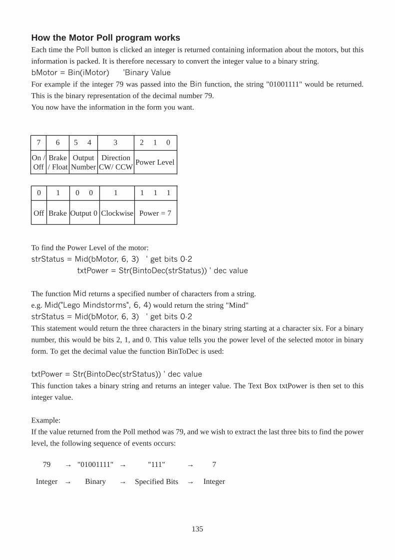
To find the Power Level of the motor:
strStatus = Mid(bMotor, 6, 3) ' get bits 0-2
txtPower = Str(BintoDec(strStatus)) ' dec value
The function Mid returns a specified number of characters from a string.
e.g. Mid("Lego Mindstorms", 6, 4) would return the string "Mind"
strStatus = Mid(bMotor, 6, 3) ' get bits 0-2
This statement would return the three characters in the binary string starting at a character six. For a binary
number, this would be bits 2, 1, and 0. This value tells you the power level of the selected motor in binary
form. To get the decimal value the function BinToDec is used:
txtPower = Str(BintoDec(strStatus)) ' dec value
This function takes a binary string and returns an integer value. The Text Box txtPower is then set to this
integer value.
Example:
If the value returned from the Poll method was 79, and we wish to extract the last three bits to find the power
level, the following sequence of events occurs:
How the Motor Poll program worksEach time the Poll button is clicked an integer is returned containing information about the motors, but this
information is packed. It is therefore necessary to convert the integer value to a binary string.
bMotor = Bin(iMotor) 'Binary Value
For example if the integer 79 was passed into the Bin function, the string "01001111" would be returned.
This is the binary representation of the decimal number 79.
You now have the information in the form you want.
7 6 34 25 1 0
On /Off
Brake/ Float
OutputNumber
DirectionCW/ CCW
Power Level
0 1 10 10 1 1
Off Brake Output 0 Clockwise Power = 7
79
IntegerSpecified BitsBinaryInteger
7"111""01001111"→ → →
→ → →
135
To find the motor direction:
If Val(Mid(bMotor, 5, 1)) = 1 Then 'get bit 3
txtDirection = "Forward" 'if = 1 => Fwd
Else
txtDirection = "Reverse" 'if = 0 => Rev
End If
To find the motor direction, we need to extract character five (bit three) from the string, and if this is equal
to 1, the motor has been set for clockwise rotation and if it is equal to 0, the motor is set for anti-clockwise.
136
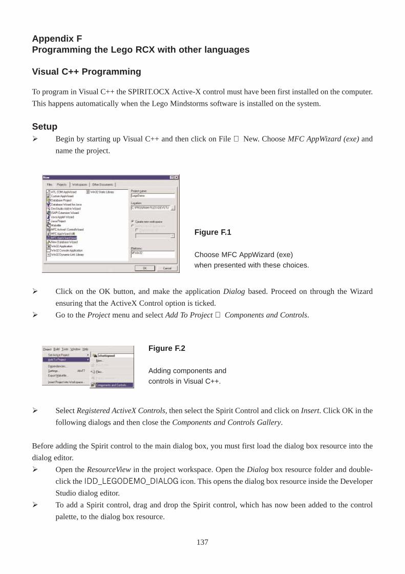
Appendix FProgramming the Lego RCX with other languages
Visual C++ Programming
To program in Visual C++ the SPIRIT.OCX Active-X control must have been first installed on the computer.
This happens automatically when the Lego Mindstorms software is installed on the system.
SetupØ Begin by starting up Visual C++ and then click on File ⇒ New. Choose MFC AppWizard (exe)and
name the project.
Ø Click on the OK button, and make the application Dialog based. Proceed on through the Wizard
ensuring that the ActiveX Control option is ticked.
Ø Go to the Projectmenu and select Add To Project ⇒ Components and Controls.
Ø Select Registered ActiveX Controls, then select the Spirit Control and click on Insert. Click OK in the
following dialogs and then close the Components and Controls Gallery.
Before adding the Spirit control to the main dialog box, you must first load the dialog box resource into the
dialog editor.
Ø Open the ResourceViewin the project workspace. Open the Dialog box resource folder and double-
click the IDD_LEGODEMO_DIALOG icon. This opens the dialog box resource inside the Developer
Studio dialog editor.
Ø To add a Spirit control, drag and drop the Spirit control, which has now been added to the control
palette, to the dialog box resource.
Figure F.1
Choose MFC AppWizard (exe)
when presented with these choices.
Figure F.2
Adding components and
controls in Visual C++.
137
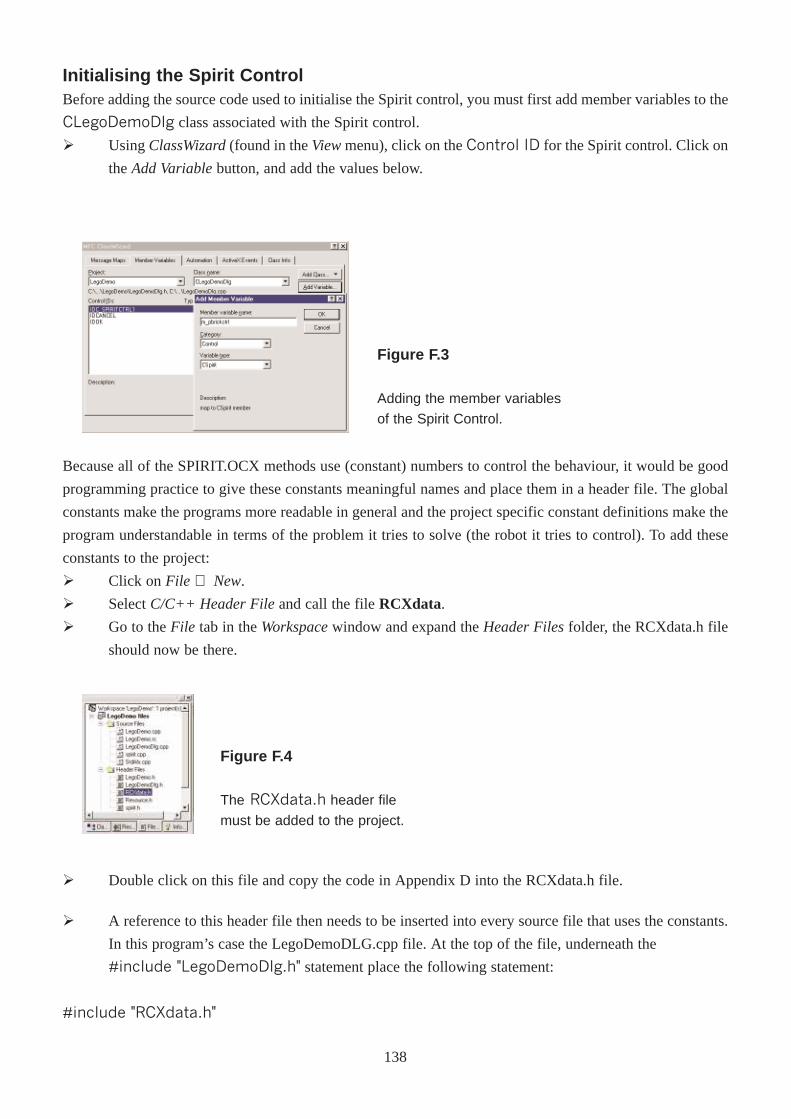
Initialising the Spirit ControlBefore adding the source code used to initialise the Spirit control, you must first add member variables to the
CLegoDemoDlg class associated with the Spirit control.
Ø Using ClassWizard(found in the Viewmenu), click on the Control ID for the Spirit control. Click on
the Add Variablebutton, and add the values below.
Because all of the SPIRIT.OCX methods use (constant) numbers to control the behaviour, it would be good
programming practice to give these constants meaningful names and place them in a header file. The global
constants make the programs more readable in general and the project specific constant definitions make the
program understandable in terms of the problem it tries to solve (the robot it tries to control). To add these
constants to the project:
Ø Click on File ⇒ New.
Ø Select C/C++ Header Fileand call the file RCXdata.
Ø Go to the File tab in the Workspacewindow and expand the Header Filesfolder, the RCXdata.h file
should now be there.
Ø Double click on this file and copy the code in Appendix D into the RCXdata.h file.
Figure F.3
Adding the member variables
of the Spirit Control.
Figure F.4
The RCXdata.h header file
must be added to the project.
Ø A reference to this header file then needs to be inserted into every source file that uses the constants.
In this program’s case the LegoDemoDLG.cpp file. At the top of the file, underneath the
#include "LegoDemoDlg.h" statement place the following statement:
#include "RCXdata.h"
138
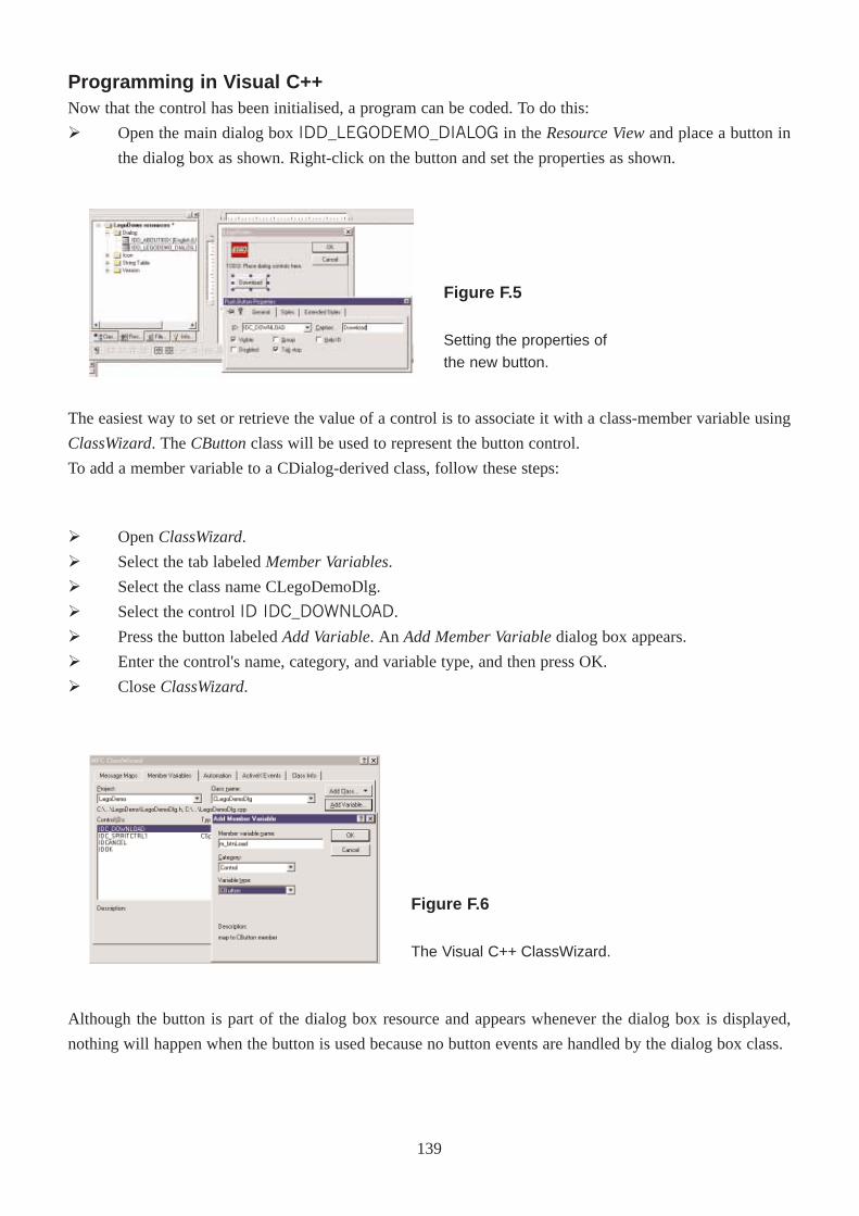
Programming in Visual C++Now that the control has been initialised, a program can be coded. To do this:
Ø Open the main dialog box IDD_LEGODEMO_DIALOG in the Resource Viewand place a button in
the dialog box as shown. Right-click on the button and set the properties as shown.
The easiest way to set or retrieve the value of a control is to associate it with a class-member variable using
ClassWizard. The CButtonclass will be used to represent the button control.
To add a member variable to a CDialog-derived class, follow these steps:
Ø Open ClassWizard.
Ø Select the tab labeled Member Variables.
Ø Select the class name CLegoDemoDlg.
Ø Select the control ID IDC_DOWNLOAD.
Ø Press the button labeled Add Variable. An Add Member Variabledialog box appears.
Ø Enter the control's name, category, and variable type, and then press OK.
Ø Close ClassWizard.
Although the button is part of the dialog box resource and appears whenever the dialog box is displayed,
nothing will happen when the button is used because no button events are handled by the dialog box class.
Figure F.5
Setting the properties of
the new button.
Figure F.6
The Visual C++ ClassWizard.
139
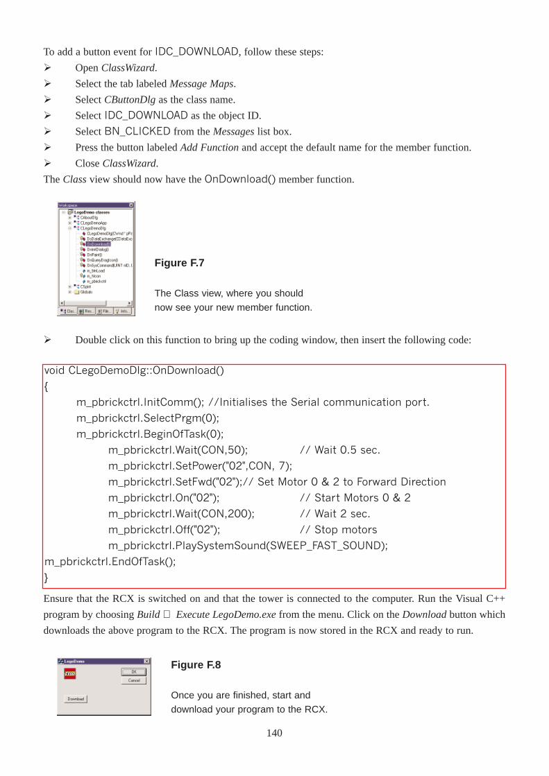
To add a button event for IDC_DOWNLOAD, follow these steps:
Ø Open ClassWizard.
Ø Select the tab labeled Message Maps.
Ø Select CButtonDlgas the class name.
Ø Select IDC_DOWNLOAD as the object ID.
Ø Select BN_CLICKED from the Messageslist box.
Ø Press the button labeled Add Functionand accept the default name for the member function.
Ø Close ClassWizard.
The Classview should now have the OnDownload() member function.
Ø Double click on this function to bring up the coding window, then insert the following code:
void CLegoDemoDlg::OnDownload()
{
m_pbrickctrl.InitComm(); //Initialises the Serial communication port.
m_pbrickctrl.SelectPrgm(0);
m_pbrickctrl.BeginOfTask(0);
m_pbrickctrl.Wait(CON,50); // Wait 0.5 sec.
m_pbrickctrl.SetPower("02",CON, 7);
m_pbrickctrl.SetFwd("02");// Set Motor 0 & 2 to Forward Direction
m_pbrickctrl.On("02"); // Start Motors 0 & 2
m_pbrickctrl.Wait(CON,200); // Wait 2 sec.
m_pbrickctrl.Off("02"); // Stop motors
m_pbrickctrl.PlaySystemSound(SWEEP_FAST_SOUND);
m_pbrickctrl.EndOfTask();
}
Ensure that the RCX is switched on and that the tower is connected to the computer. Run the Visual C++
program by choosing Build ⇒ Execute LegoDemo.exefrom the menu. Click on the Downloadbutton which
downloads the above program to the RCX. The program is now stored in the RCX and ready to run.
Figure F.7
The Class view, where you should
now see your new member function.
Figure F.8
Once you are finished, start and
download your program to the RCX.
140
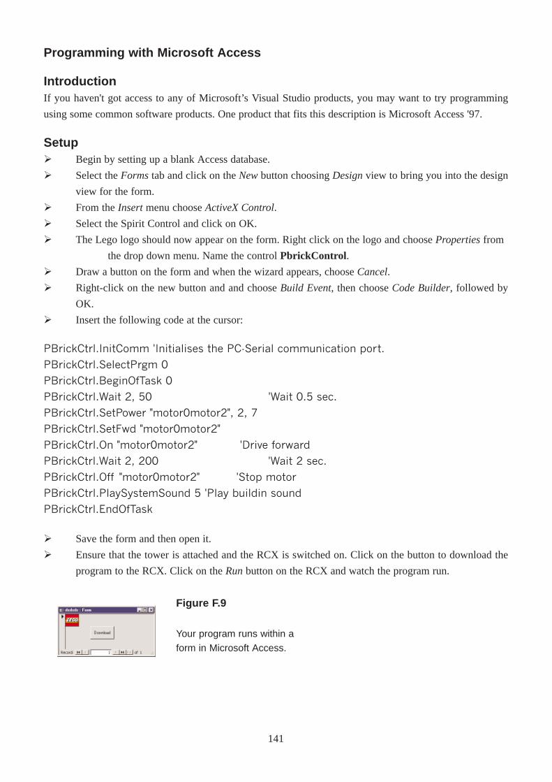
IntroductionIf you haven't got access to any of Microsoft’s Visual Studio products, you may want to try programming
using some common software products. One product that fits this description is Microsoft Access '97.
Programming with Microsoft Access
SetupØ Begin by setting up a blank Access database.
Ø Select the Formstab and click on the Newbutton choosing Designview to bring you into the design
view for the form.
Ø From the Insertmenu choose ActiveX Control.
Ø Select the Spirit Control and click on OK.
Ø The Lego logo should now appear on the form. Right click on the logo and choose Propertiesfrom
the drop down menu. Name the control PbrickControl .
Ø Draw a button on the form and when the wizard appears, choose Cancel.
Ø Right-click on the new button and and choose Build Event, then choose Code Builder, followed by
OK.
Ø Insert the following code at the cursor:
PBrickCtrl.InitComm 'Initialises the PC-Serial communication port.
PBrickCtrl.SelectPrgm 0
PBrickCtrl.BeginOfTask 0
PBrickCtrl.Wait 2, 50 'Wait 0.5 sec.
PBrickCtrl.SetPower "motor0motor2", 2, 7
PBrickCtrl.SetFwd "motor0motor2"
PBrickCtrl.On "motor0motor2" 'Drive forward
PBrickCtrl.Wait 2, 200 'Wait 2 sec.
PBrickCtrl.Off "motor0motor2" 'Stop motor
PBrickCtrl.PlaySystemSound 5 'Play buildin sound
PBrickCtrl.EndOfTask
Ø Save the form and then open it.
Ø Ensure that the tower is attached and the RCX is switched on. Click on the button to download the
program to the RCX. Click on the Runbutton on the RCX and watch the program run.
Figure F.9
Your program runs within a
form in Microsoft Access.
141
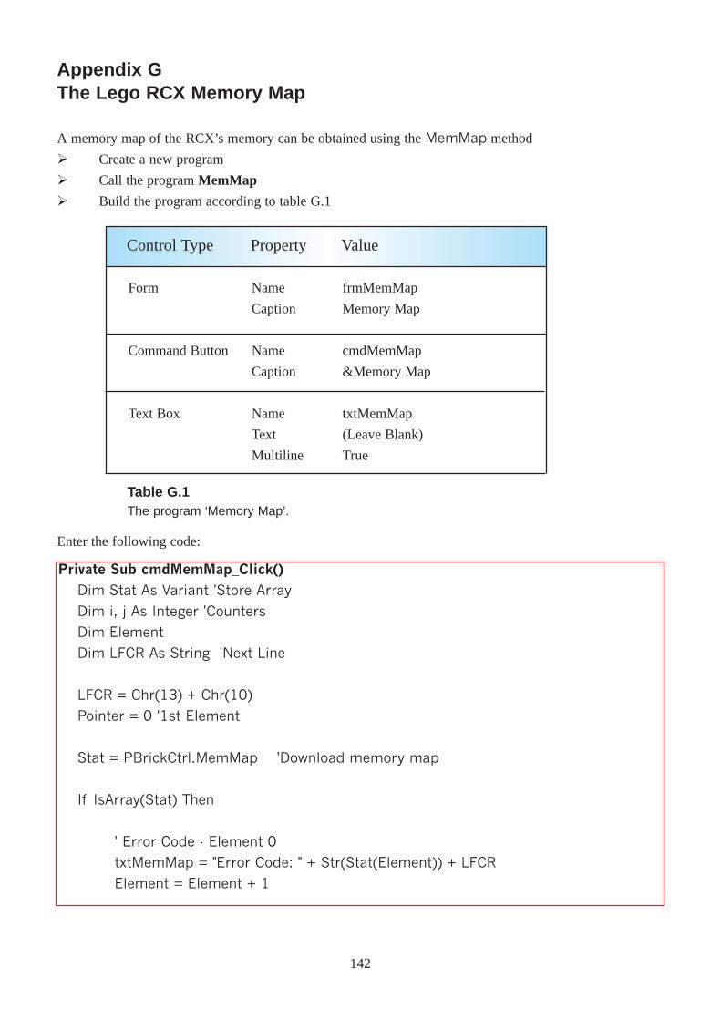
Appendix GThe Lego RCX Memory Map
A memory map of the RCX’s memory can be obtained using the MemMap method
Ø Create a new program
Ø Call the program MemMap
Ø Build the program according to table G.1
Form
Command Button
Text Box
Name
Caption
Name
Caption
Name
Text
Multiline
frmMemMap
Memory Map
cmdMemMap
&Memory Map
txtMemMap
(Leave Blank)
True
Control Type Property Value
Table G.1The program ‘Memory Map’.
Enter the following code:
Private Sub cmdMemMap_Click()Dim Stat As Variant 'Store Array
Dim i, j As Integer 'Counters
Dim Element
Dim LFCR As String 'Next Line
LFCR = Chr(13) + Chr(10)
Pointer = 0 '1st Element
Stat = PBrickCtrl.MemMap 'Download memory map
If IsArray(Stat) Then
' Error Code - Element 0
txtMemMap = "Error Code: " + Str(Stat(Element)) + LFCR
Element = Element + 1
142
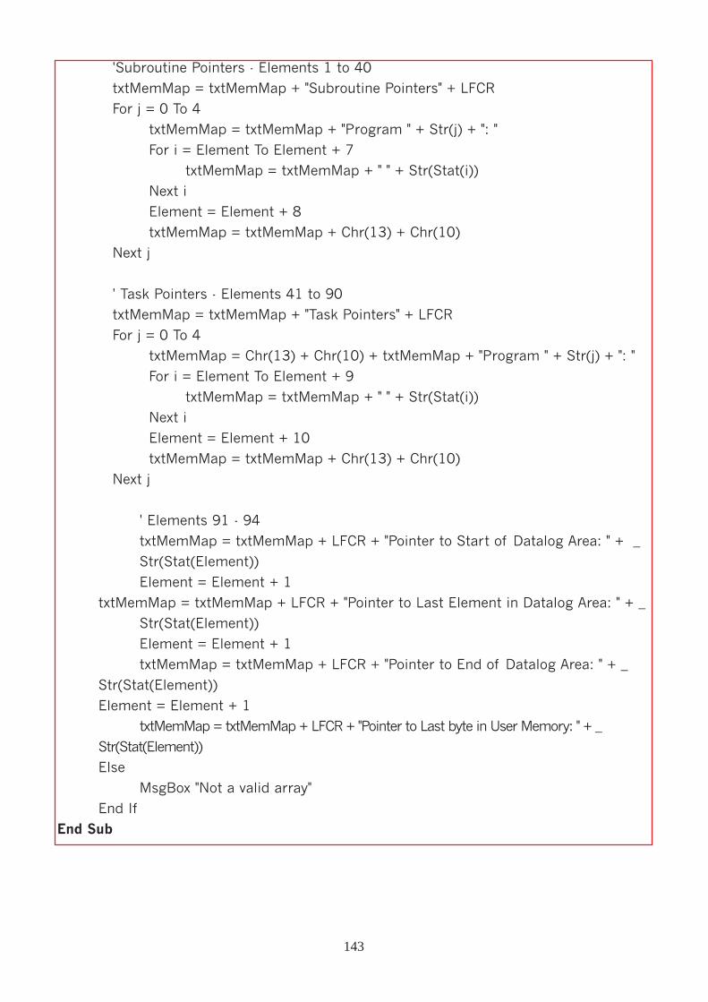
'Subroutine Pointers - Elements 1 to 40
txtMemMap = txtMemMap + "Subroutine Pointers" + LFCR
For j = 0 To 4
txtMemMap = txtMemMap + "Program " + Str(j) + ": "
For i = Element To Element + 7
txtMemMap = txtMemMap + " " + Str(Stat(i))
Next i
Element = Element + 8
txtMemMap = txtMemMap + Chr(13) + Chr(10)
Next j
' Task Pointers - Elements 41 to 90
txtMemMap = txtMemMap + "Task Pointers" + LFCR
For j = 0 To 4
txtMemMap = Chr(13) + Chr(10) + txtMemMap + "Program " + Str(j) + ": "
For i = Element To Element + 9
txtMemMap = txtMemMap + " " + Str(Stat(i))
Next i
Element = Element + 10
txtMemMap = txtMemMap + Chr(13) + Chr(10)
Next j
' Elements 91 - 94
txtMemMap = txtMemMap + LFCR + "Pointer to Start of Datalog Area: " + _
Str(Stat(Element))
Element = Element + 1
txtMemMap = txtMemMap + LFCR + "Pointer to Last Element in Datalog Area: " + _
Str(Stat(Element))
Element = Element + 1
txtMemMap = txtMemMap + LFCR + "Pointer to End of Datalog Area: " + _
Str(Stat(Element))
Element = Element + 1
txtMemMap = txtMemMap + LFCR + "Pointer to Last byte in User Memory: " + _
Str(Stat(Element))
Else
MsgBox "Not a valid array"
End If
End Sub
143
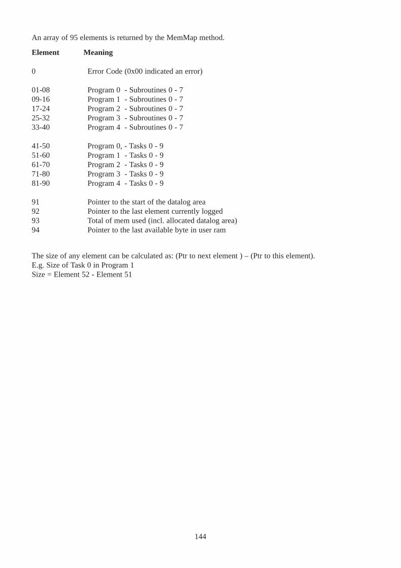
Error Code (0x00 indicated an error)
Program 0 - Subroutines 0 - 7Program 1 - Subroutines 0 - 7Program 2 - Subroutines 0 - 7Program 3 - Subroutines 0 - 7Program 4 - Subroutines 0 - 7
Program 0, - Tasks 0 - 9Program 1 - Tasks 0 - 9Program 2 - Tasks 0 - 9Program 3 - Tasks 0 - 9Program 4 - Tasks 0 - 9
Pointer to the start of the datalog areaPointer to the last element currently loggedTotal of mem used (incl. allocated datalog area)Pointer to the last available byte in user ram
0
01-0809-1617-2425-3233-40
41-5051-6061-7071-8081-90
91929394
An array of 95 elements is returned by the MemMap method.
Element Meaning
The size of any element can be calculated as: (Ptr to next element ) – (Ptr to this element).E.g. Size of Task 0 in Program 1Size = Element 52 - Element 51
144
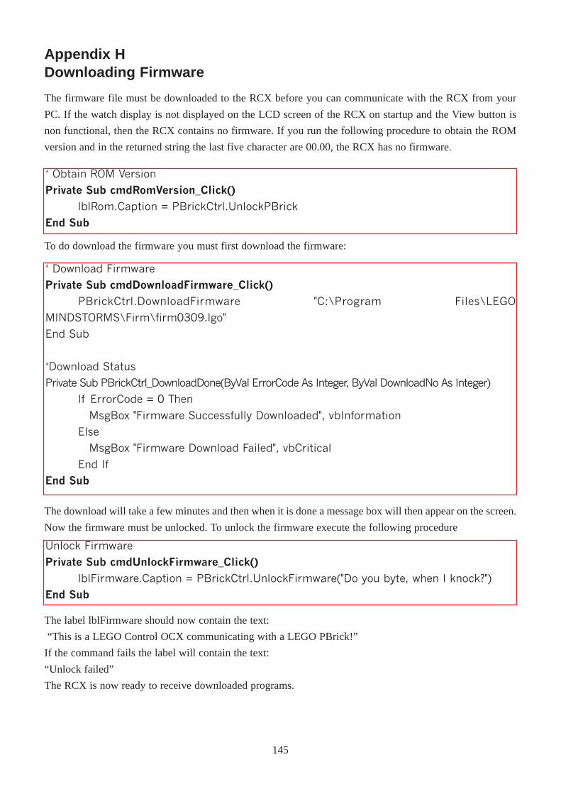
Appendix HDownloading Firmware
� Download Firmware
Private Sub cmdDownloadFirmware_Click()
PBrickCtrl.DownloadFirmware "C:\Program Files\LEGO
MINDSTORMS\Firm\firm0309.lgo"
End Sub
�Download Status
Private Sub PBrickCtrl_DownloadDone(ByVal ErrorCode As Integer, ByVal DownloadNo As Integer)
If ErrorCode = 0 Then
MsgBox "Firmware Successfully Downloaded", vbInformation
Else
MsgBox "Firmware Download Failed", vbCritical
End If
End Sub
Unlock Firmware
Private Sub cmdUnlockFirmware_Click()lblFirmware.Caption = PBrickCtrl.UnlockFirmware("Do you byte, when I knock?")
End Sub
� Obtain ROM Version
Private Sub cmdRomVersion_Click()
lblRom.Caption = PBrickCtrl.UnlockPBrick
End Sub
To do download the firmware you must first download the firmware:
The download will take a few minutes and then when it is done a message box will then appear on the screen.
Now the firmware must be unlocked. To unlock the firmware execute the following procedure
The label lblFirmware should now contain the text:
“This is a LEGO Control OCX communicating with a LEGO PBrick!”
If the command fails the label will contain the text:
“Unlock failed”
The RCX is now ready to receive downloaded programs.
145
The firmware file must be downloaded to the RCX before you can communicate with the RCX from your
PC. If the watch display is not displayed on the LCD screen of the RCX on startup and the View button is
non functional, then the RCX contains no firmware. If you run the following procedure to obtain the ROM
version and in the returned string the last five character are 00.00, the RCX has no firmware.