state-of-the-art heat transfer fluids for parabolic trough
TRANSCRIPT
1
State-of-the-art Heat Transfer Fluids for Parabolic Trough 1
Collector 2
Yathin Krishna1, M.Faizal1, R. Saidur2,3, K.C.Ng5, Navid Aslfattahi4 3
1School of Engineering, Taylor’s University, Lakeside campus, 47500 Selangor Malaysia. 4 2Research Centre for Nano-Materials and Energy Technology (RCNMET), School of Science and Technology, 5 Sunway University, No. 5, Jalan University, Bandar Sunway, Petaling Jaya, 47500 Selangor Darul Ehsan, 6 Malaysia. 7 3Department of Engineering, Lancaster University, LA1 4YW, UK. 8 4Department of Mechanical Engineering, Faculty of Engineering, University of Malaya, 50603 Kuala Lumpur, 9 Malaysia. 10 5Department of Mechanical Engineering, Materials and Manufacturing Engineering, The University of 11 Nottingham Malaysia Campus, Jalan Broga, 43500 Semenyih, Selangor Darul Ehsan, Malaysia. 12
Contents 13
Abstract ................................................................................................................................ 2 14
1. Introduction ................................................................................................................... 4 15
2. Concentrating solar power plants ................................................................................... 6 16
2.1. Influence of thermophysical properties of HTF on Parabolic trough efficiency ...... 15 17
2.2. Energy and Exergy Modelling ............................................................................... 15 18
2.3. Thermophysical properties required for HTF in PTC ............................................. 19 19
3. Recent developments in heat transfer enhancement ...................................................... 22 20
3.1. Water/steam as heat transfer fluid ......................................................................... 24 21
3.2. Synthetic thermal oil as heat transfer fluid ............................................................. 25 22
3.3. Molten Salts as heat transfer fluid ......................................................................... 26 23
3.4. Nanofluids as heat transfer fluid ............................................................................ 40 24
3.4.1. Properties and preparation ................................................................................. 42 25
3.4.2. Progress in obtaining stable nanofluid................................................................ 49 26
3.4.3. Water-based Nanofluids .................................................................................... 54 27
3.4.4. Ethylene glycol-based Nanofluids...................................................................... 56 28
3.4.5. Synthetic Oil-based Nanofluids ......................................................................... 57 29
3.4.6. Molten salt based Nanofluids ............................................................................. 59 30
3.4.7. Hybrid nanofluids .............................................................................................. 64 31
3.5. Gaseous Heat transfer fluids .................................................................................. 68 32
3.6. Liquid Metals as the heat transfer fluid .................................................................. 72 33
3.7. Ionic Liquids ......................................................................................................... 74 34
3.8. Vegetable oil ......................................................................................................... 76 35
4. Prospects of parabolic trough collector ......................................................................... 77 36
5. Conclusion ................................................................................................................... 77 37
References .......................................................................................................................... 81 38
39
40

2
Abstract 41
Solar thermal energy conversion is gaining more attention among researchers due to the 42
recent development in nanofluids and molten salt technology. Among various solar 43
collectors, parabolic trough collector has received significant attention from researchers due 44
to their operating temperature range (60-240 °C) feasible for power generation. Parabolic 45
trough collector is currently having a higher number of installations compared to other 46
concentrated solar power technology around the globe. Most of the conventional heat transfer 47
fluid used in PTC has poor heat transfer and light to heat conversion properties. Therefore, it 48
is advantageous to enhance the thermophysical properties of heat transfer fluid to improve the 49
overall efficiency of the system. Well-engineered nano-enhanced heat transfer fluid is 50
advantageous because a very low mass fraction of nanoparticles bring considerable 51
enhancement in thermophysical properties. This paper focuses on the most recent 52
advancement in heat transfer fluids, their preparation, and stability issues when doped with 53
nanoparticles. Various heat transfer fluids currently used in parabolic trough collectors and 54
the nano-enhanced heat transfer fluids having the properties better than conventional heat 55
transfer fluids are compared and their preparation methods and properties are discussed. 56
Enhancement of thermophysical properties of molten salts by doping nanoparticles and their 57
enhancement in thermal stability at high temperature, the possibility of using mono and 58
hybrid nanofluid, ionic liquids, gaseous heat transfer fluid, and vegetable oil as the heat 59
transfer fluid in parabolic trough collectors are the key highlights of this review. 60
Keywords: Parabolic trough collectors, Heat transfer fluids, Nanofluids, Renewable energy. 61

3
62
Abbreviations RGO Reduced graphene oxide
CNT Carbon nanotube SEGS Solar energy generating system
CPV Concentrated photovoltaic SEM Scanning electron microscope
CLFR Compact Linear Fresnel reflector STA Simultaneous thermal analysis
CSP Concentrated Solar Power SWCNT Single wall carbon nanotube
DASC Direct Absorption Solar Collector TEM Transmission electron microscopy
DI Deionized water TES Thermal energy storage
DLS Dynamic light scattering TGA Thermogravimetric analysis
DNI Direct normal irradiation UV-Vis Ultra Violet-Visible spectrophotometer
DOE Department of Energy Greek Symbols
DSC Differential scanning ηth Thermal efficiency
calorimetry λ Thermal conductivity, W/mK
DSG Direct steam generation µ Fluid dynamic viscosity, Pa.s
EG Ethylene glycol ρ Density, kg/m3
EEW Electrical explosive wire φ Volume fraction of nanoparticles, (%)
EO Engine oil ɛ Emittance
FPSC Flat plate solar collector
GHG Greenhouse gas Nomenclature
GE Graphene Aarea Aperture area, m2
GNP Graphene nanoparticles Ar,outer Receiver outer area, m2
GO Graphene oxide Ar,inner Receiver inner area, m2
HCE Heat collecting Elements cp Specific heat capacity, kJ/KgK
HDH Humidification and Dr,in Receiver inner diameter, m
Dehumidification Gbeam Solar beam radiation, W/m2
HTF Heat transfer fluid h Convective heat transfer coefficient, W/m2K
IEA International Energy Agency k Thermal conductivity, W/mK
LFR Linear Fresnel reflector Nu Nusselt number,-
MSBNF Molten salt based nanofluid Pr Prandtl number -
MWCNT Multi-wall carbon nanotube Re Reynolds number -
PCM Phase Change Material Qsolar Total available solar radiation, W
PNC Plasma nano colloid T Temperature ⁰C or K
PSD Particle size distribution
PTC Parabolic trough collectors
PV Photovoltaic
63

4
1. Introduction 64
The energy consumption in 2018 is twice the rate of energy consumption since 2010. Figure 65
1 shows the annual energy demand growth from 2010 to 2018. Due to increased energy 66
consumption, the CO2 emission rose to a 33.1G tonne in 2018, which is highest in history, as 67
shown in Figure 2. Therefore, there is a need to scale up renewable energy production to meet 68
the energy demands of the rapidly growing economy of the world. Also, due to changing 69
weather conditions resulting from GHG (greenhouse gas) emissions, there is an increasing 70
demand of power for heating and cooling equipment in many parts of the globe [1]. Using 71
renewable and sustainable energy sources, the impact on the environment can be reversed by 72
reducing emissions caused by GHG and fulfill the demands of energy guzzlers. Therefore, 73
there is a need for energy production in a gigawatt power scale to meet the energy demands. 74
Solar, wind, bio-energy, hydropower is well-established power sources that can meet energy 75
demands if the efficiency of the system further investigated and improved [2]. In one hour, 76
energy from sun radiating on earth is 410×1015 J, which is more than the total energy 77
consumed worldwide in 2001[3]. Therefore, solar energy is a promising alternative for 78
current challenges to fulfill energy demands. 79
There are three distinct technological approaches to utilize solar energy: solar photovoltaic, 80
solar thermal, and solar fuel technologies [4]. Currently, PV (photovoltaic) and solar thermal 81
are the leading technologies to utilize solar energy. PV directly converts solar radiation to 82
electricity [5] but, the efficiency of PV decreases with an increase in temperature, production 83
of power during overcast day is not possible; these are the significant challenges in PV solar 84
cells [6]. The solar thermal system employs mirrors or lenses to focus the sun’s radiation on 85
an absorber. HTF (Heat transfer fluid) is made to pass through the absorber tube, which 86
converts water to steam and then the steam is made to run the turbine to generate power. 87
Storage of energy after sundown and low heat transfer efficiency of the HTF are the major 88
challenges faced by solar thermal technologies. Researchers around the world have done 89
reviews on heat transfer fluid for CSP (Concentrated solar power). Recently, Vignarooban et 90
al. [7], Akbarzaheh et al.[8], Bonk et al.[9], and Farhana et al. [10] discussed the current state 91
of the art in HTF applicable for the concentrated solar power system. However, in these 92
reviews, less emphasis has been given on the preparation and stability of heat transfer fluids. 93
The current review presents various HTFs suitable for PTC (Parabolic trough collector), their 94
method of preparation to obtain stable HTF, and stability of this HTF at high temperatures. 95

5
The choice of HTF is a crucial parameter for the economic effectiveness of solar thermal 96
technology. Numerous parameters can affect the thermodynamics of PTC. The properties 97
such as specific heat capacity, thermal conductivity, viscosity, density, pressure drop, heat 98
transfer coefficients of HTF, and stability at high temperature are the governing parameters in 99
enhancing the thermal efficiency of PTC. The enhancement of heat transfer efficiency and 100
storage property of HTF is possible to achieve by using advanced heat transfer fluids like 101
molten salts and nanofluids, which significantly adds value to make PTC attain grid parity. 102
However, there are few limitations like agglomeration/flocculation of nanofluids in a short 103
time, the stability of HTF at high temperature, high viscosity due to the addition of 104
nanoparticles, low thermal conductivity, and specific heat capacity. Therefore, the current 105
review can improve our understanding of advanced HTFs currently under research which can 106
optimize the thermal performance of PTC. The main objective of the current review is to (1) 107
investigate the present state-of-the-art HTF used in PTC. The HTFs are selected based on the 108
operating temperature of both medium and high-temperature PTC applications. (2) finding 109
the most important and relevant research done to improve the heat transfer efficiency in PTC. 110
(3) Reporting the investigation of preparation techniques to obtain stable nanofluids and 111
enhance their stability at high temperatures. (4) Presenting the historical trends in terms of 112
HTF used in PTC application. The organization of the article is as follows: followed by the 113
introduction, section 2 emphasize on the thermophysical properties of HTF which influence 114
the energy and exergy efficiency of PTC, section 3 gives the comprehensive review on recent 115
research on the enhancement of thermophysical properties of conventional HTF by advanced 116
preparation methods, by doping nanoparticles, and various stabilization techniques of nano-117
enhanced HTFs and section 4 briefs on the prospects of PTC, and Section 5 concludes the 118
article with a conclusion and future direction. 119

6
120
Figure 1: Bar graph shows average global annual energy demand by primary fuel 2011-121
18[1]. 122
123
Figure 2: CO2 emission by fuel source 1990-2018 [1]. 124
2. Concentrating solar power plants 125
The concentrating solar power technology uses reflective mirrors to concentrate the sun’s 126
radiation and produces heat; later, this heat is converted into electricity by running steam 127
turbines. Globally this technology holds promising, particularly in the sunshine region, where 128
abundant sunshine is available (approximately 2,000 kWh/m2/y or more) [11]. Figure 3 129
shows the direct sunshine region on the globe suitable for CSP installation. It is the most 130
promising technology, and 10% of the global energy production will be contributed from 131
CSP and CPV (concentrated photovoltaic) by 2050 due to the following reason [11]: 132
• The bulk installation will bring down the cost ( cheaper than solar cell technology) 133

7
• Concentrating photovoltaic thermal will increase the efficiency of the combined 134
system. 135
• Thermal storage can be used to generate electricity even during night time. 136
• It is suited for sun-belt-region where the intensity of the sun’s radiation is abundant. 137

8
138
Figure 3: Global direct sunshine region [12] 139

9
140

10
Table 1 shows the probability of production of energy from concentrated solar power 141
technology until 2050, in a different part of the globe depending on the sunlight intensity 142
falling in that region [11]. Table 2 gives the specification of different types of solar thermal 143
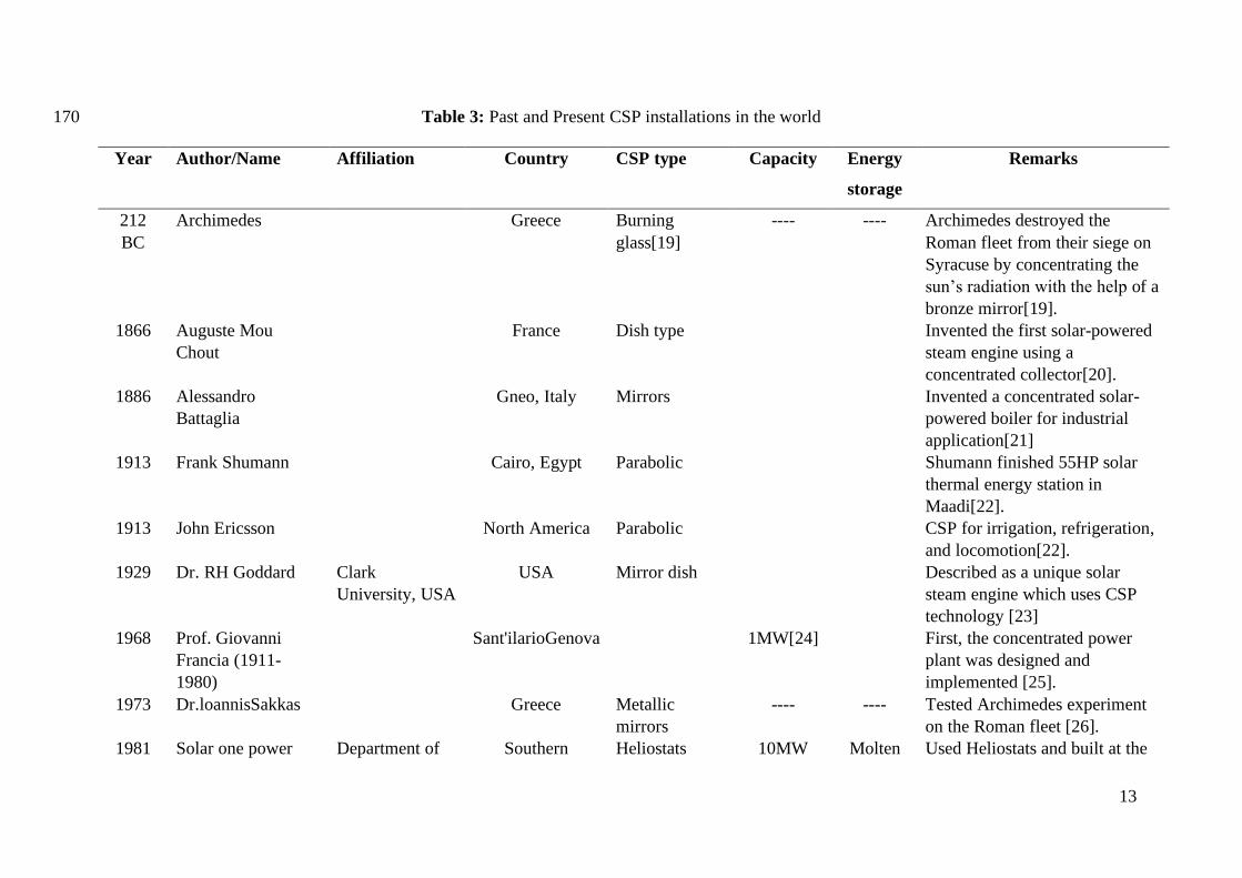
technologies, and Table 3 gives a brief history of the progress in CSP technology. 144
Therefore the potential of CSP is higher in the future, and this technology can also be 145
combined with solar photovoltaic, thermoelectric generators to form a Hybrid concentrated 146
solar photovoltaic thermal system to get higher efficiency [13]. 147
Generally, CSP plants comprise of various components such as solar radiation focusing 148
concentrators and receivers, steam turbines, and electricity generators. Until now, four kinds 149
of CSP power-producing systems are commercialized they are solar parabolic dish collector, 150
Linear Fresnel lenses, Parabolic trough collector, and solar power tower. Figure 4 presents 151
the classification of Concentrated Solar Power (CSP) technologies. In Parabolic dish, the 152
solar collector is a point focusing solar collector where solar radiation is concentrated on a 153
focal point where the receiver is placed. The power conversion using Brayton or Stirling 154
cycle engine is used with an electrical generator. It is possible to obtain a temperature of 700 155
to 750 °C and the pressure of 2×10⁴ kPa with the concentration ratio of 2000 using parabolic 156
dish technology. Linear Fresnel reflector is a line focusing solar collector which uses linear 157
mirror plates for concentrating solar radiation on the absorber tube containing heat transfer 158
fluid. It is possible to attain the operating temperature range of 150 to 400 °C with a 159
concentration ratio of 25 to 170. Whereas, Solar power towers use large mirrors to reflect the 160
sun’s radiation on a tower, placed at the center of the field. Solar power towers can obtain the 161
solar flux of 200 kW/m2 to 1000kW/m2 where the sunlight is focused, making it feasible to 162
produce high temperature higher than 1200 °C [14]. 163

11
Table 1: The probability of production of energy from concentrated solar energy technology 164
until 2050 165
166
167
Figure 4: Classification of Concentrated Solar Power technology[14] 168
Group Country/Region 2020 2030 2040 2050
1
Central Asia, Australia, India (Gujarat,
Rajasthan), Chile, Mexico, Middle East, North
Africa, South Africa, United States (south-
western region), Peru.
5% 12% 30% 40%
2 United States (outside of the south-western
region) 3% 6% 13% 20%
3 Turkey and Europe. 3% 6% 10% 15%
4 Argentina, Africa (outside of the northern
region),India and Brazil. 1% 5% 8% 15%
5 Worldwide * * * 11%
Concentrated Solar Power
Technologies
Parabolic Trough
Collector
Linear Fresnel
lenses
Parabolic
Dish
Solar Power
Tower
Major
Components
• Reflector
• Absorber
• Solar field
piping
Major
Components
• Curved mirrors
• Absorber
• Reconcentrator
Major Components
• Parabolic Dish
• Receiver
• Reflector
Major
Components
• Solar Tower
• Heliostats
• Central
receiver

12
Table 2: Specifications of different Solar thermal technologies [15-18] 169
Parabolic dish
collector
Linear Fresnel
Reflector
Parabolic
Trough
collector
Solar Power
tower
Capacity Range
(MW)
0.01-1 5-250 10-100 10-100
Operating
temperature
range (⁰C)
300-1500 150-400 150-800
(reaches high
temperature
>700 with
gaseous HTF)
300->1200
Solar
concentration
ratio
<3000 25-170 50-90 600-1000
Solar to electricity
conversion
efficiency(%)
16-29 8-12 10-16 10-22
Relative cost Very high Low Low High
Power cycle Steam Rankine;
Sterling Engine;
Brayton cycle
Organic
Rankine; Steam
Rankine;
Steam Rankine Steam
Rankine; Gas
turbine Bryton
cycle;
Commercial
Maturity
Low Medium High Medium
Outlook for
improvement
High Significant Restricted Substantial
scope for
improvement.
Advantages Suitable for mass
production with high
efficiency; No need
for water cooling
Easy to
construct;
Compatible with
hybrid
powerplants
running on oil
and gas.
Highly durable
and reliable;
Components are
modular;
Compatible with
hybrid
powerplants
running on oil
and gas.
High
efficiency;
Compatible
with hybrid
powerplants
running on oil
and gas.
Disadvantages Low
commercialization;
Lack of TES.
Comparatively
Low efficiency;
Limited
operation
temperature
range.
Comparatively
Low efficiency;
Limited
operation
temperature
range; Colling
systems are
required, and
cleaning of the
collector is
necessary.
High
maintenance
cost; water is
necessary for
cooling and
cleaning.
13
Table 3: Past and Present CSP installations in the world 170
Year Author/Name Affiliation Country CSP type Capacity Energy
storage
Remarks
212
BC
Archimedes
Greece Burning
glass[19]
---- ---- Archimedes destroyed the
Roman fleet from their siege on
Syracuse by concentrating the
sun’s radiation with the help of a
bronze mirror[19].
1866 Auguste Mou
Chout
France Dish type
Invented the first solar-powered
steam engine using a
concentrated collector[20].
1886 Alessandro
Battaglia
Gneo, Italy Mirrors
Invented a concentrated solar-
powered boiler for industrial
application[21]
1913 Frank Shumann
Cairo, Egypt Parabolic
Shumann finished 55HP solar
thermal energy station in
Maadi[22].
1913 John Ericsson
North America Parabolic
CSP for irrigation, refrigeration,
and locomotion[22].
1929 Dr. RH Goddard Clark
University, USA
USA Mirror dish
Described as a unique solar
steam engine which uses CSP
technology [23]
1968 Prof. Giovanni
Francia (1911-
1980)
Sant'ilarioGenova
1MW[24]
First, the concentrated power
plant was designed and
implemented [25].
1973 Dr.loannisSakkas Greece Metallic
mirrors
---- ---- Tested Archimedes experiment
on the Roman fleet [26].
1981 Solar one power Department of Southern Heliostats 10MW Molten Used Heliostats and built at the

14
tower Energy (DOE)
led by Sandia
National
Laboratories in
Livermore,
California
California, salt Mojave Desert, East
of Barstow, CA, USA. The first
test of large-scale solar thermal
power plants [25].
1984 Solar Energy
generating system
(SEGS)
NextEra Energy
Resources
California Parabolic
troughs, along
with natural
gas to generate
electricity.
354MW Synthetic
oil which
heats
over
400°C.
Largest solar power plant until
2014
1995 Solar two power
tower
Department of
Energy (DOE)
led by Sandia
National
Laboratories in
Livermore,
California
Southern
California,
Heliostats 10MW Molten
salt
The solar one is converted into
solar two projects by adding an
extra ring of heliostats totaling
1926 heliostats.
2006 The compact linear
Fresnel reflector
system
Liddell Power
station
Australia Fresnel
reflector
100MW Water as
the Heat
transfer
fluid
Direct steam generation (DSG)
within the solar array has been
achieved[27].
2007 Nevada solar one Eldorado Valley
the USA
Parabolic
troughs
75MW Synthetic
oil
Has a design efficiency and
annual average efficiency of
22.4 and 15.3 %[28]
2009 Kimberlina Solar
Thermal Energy
Areva Solar Bakersfield
California
Compact linear
Fresnel
reflector
(CLFR)
5MW Water Achieved 750°C superheated
steam and is used to run steam
turbines [29].

15
2011 Solar Tree power
tower later renamed
as a
Gemmasolarthermo
solar power plant.
Spain Heliostats 120MW Molten
salt
Attained a temperature of 565°C
and had thermal storage [30].
2011 Ivanpah Solar
power facility
Bright source
Energy, Google,
and NRG
Energy.
Mojave Desert,
Ivanpah Dry
Lake, CA
Heliostat, solar
tower
392 MW Molten
salt
Till 2014 it was the largest solar
thermal power plant. [31]
2014 Dhursar[32] Reliance Power
project,
DhursalJaisalmer
district of India
Linear Fresnel
Reflector(LFR)
125 MW Molten
salt
___
2018 Kathu Solar Park A partnership
between
Building Energy
Africa and Old
Mutual
Northern Cape
South Africa
Fresnel
Reflector
81 MW Molten
salt
4.5-hour Molten salt heat
storage[33]

16
2.1. Influence of thermophysical properties of HTF on Parabolic trough efficiency 171
Thermophysical properties are the essential factor to be considered for the efficient working 172
of solar collectors. In this section thermophysical properties and mathematical modeling of a 173
parabolic trough, the collector is discussed. It is essential to operate the PTC power plant 174
within the proper temperature and pressure limits. Because in water operated parabolic trough 175
power plant, the pressure of approximately 80 bar should be maintained in order to maintain 176
the liquid phase of water at high temperatures. Therminol and Dowtherm synthetic oil can 177
withstand the temperature up to 400 ⁰C, but the power plant must operate above 12 ⁰C to 178
avoid crystallization of the synthetic oil. Eutectic Nitrate molten salts (solar salt 179
NaNO3:KNO3:60:40 wt.%) must operate between 220 ⁰C and 600 ⁰C. While liquid metals 180
(Sodium) between 98⁰C and 883 ⁰C. Gaseous HTF (Air, CO2, S-CO2, He) has no constrains 181
for temperature and pressure limits; therefore, gaseous HTF is used for very high-temperature 182
applications. Therefore one has to know about the thermophysical properties of HTF before 183
designing the PTC power plant. Table 4 and Table 5 includes the thermophysical properties 184
of HTF for a characteristic temperature range. 185
2.2. Energy and Exergy Modelling 186
The fundamental thermodynamics and heat transfer modeling of the PTC is presented in this 187
section. The following equations define the Energy, Exergy efficiencies and thermodynamics 188
of the PTC. PTC utilizes the sun’s direct beam radiation (Gbeam) which is reflected on the 189
receiver by the aperture with area Aarea. The total available radiation (Qsolar) in the receiver 190
is calculated by equation (1 [34]: 191
Qsolar = Aarea ∙ Gbeam, (1)
The HTF absorbs a part of this solar energy and increases its temperature from Tin to Tout. 192
This useful heat energy (Quseful) is expressed in the energy balance equation as follows [35]: 193
Quseful = m ∙ 𝑐p ∙ (Tout − Tin), (2)
The collector efficiency is calculated by the ratio of its output, i.e. useful energy gain, to its 194
input, i.e. solar irradiation as indicated in equation (3: 195

17
ηth =Quseful
Qsolar, (3)
Also, by studying the heat transfer phenomenon inside the absorber tube, the useful energy 196
gain can be calculated using equation (4. The equation defines the heat convection from the 197
absorber tube to the HTF. 198
Quseful = h ∙ Ar,in ∙ (Tin − Tf,av) (4)
The heat transfer coefficient h can be calculated using the Nusselt number for the absorber 199
tube flow conditions, the thermal conductivity of HTF ‘k’, and the inner diameter of absorber 200
tube ‘Dr,in’ as described in equation (5: 201
h =Nu ∙ k
Dr,in (5)
The Nusselt number has been calculated depending upon the flow conditions inside the 202
absorber tube. For the laminar flow condition ( Re<2300), the Nusselt number is assumed to 203
be constant and is equal to 4.36 [36]. If Re> 2300, the flow condition changes to turbulent 204
and for such condition Dittus-Boelter correlation is well suited for determining the value of 205
Nusselt number, which is expressed in equation (6. 206
207
For thermal fluids like Liquid sodium, the more accurate value for Nusselt number is 208
obtained by equation (7. 209
Nu = 7 + 0.025 ∙ Re0.8 ∙ Pr0.8 (7)
The Reynolds number (Re) and Prandtl number (Pr) is the function of fluid properties like 210
dynamic viscosity ‘µ’, Specific heat capacity ‘cp’, thermal conductivity ‘k’ and are expressed 211
in equation (8 and(9 respectively. 212
Re =4 ∙ m
π ∙ Dr,in ∙ μ (8)
213
Nu = 0.023 ∙ Re0.8 ∙ Pr0.4 (6)

18
Pr =μ ∙ 𝑐p
k (9)
214
Energy loss analysis is an essential part of thermal analysis. Numerous ways have been used 215
to quantify these losses. The following section presents the equations which determine the 216
exergy losses. The energy absorbed by the receiver is divided into useful energy and losses 217
(Qloss), as shown in equation 10. 218
Qsolar ∙ ηoptical = Quseful + Qloss, (10)
219
The calculations of the thermal losses in the receiver are made by understanding the heat 220
transfer phenomenon taking place between the receiver and glass cover, and glass cover with 221
the environment. Equation 11 describes the thermal losses taking place between the receiver 222
and the glass tube. In this equation, radiation loss is considered, and convective losses are 223
neglected because of the vacuum present between the receiver and the glass tube [34]. 224
Qloss =
Ar,outer ∙ σ ∙ (Tr4 − Tc
4)
1εc
−1 − εc
εc∙ (
Ar,outer
Ac,inner)
, (11)
225
Another critical factor is the overall heat transfer coefficient which is presented in equation 226
12. The exchange of energy between the cover and the ambient takes place in two ways, 227
convection, and radiation. The following equation 13 presents the equation of these losses. In 228
evacuated tubes, since the cover temperature is lower than the receiver temperature, the 229
values closer to ambient temperature is applied. 230
UL =Qloss
Ar ∙ (Tr − Tamb) (12)
231
Qloss = Ac,outer ∙ hout ∙ (Tc − Tamb) + Ac.outer ∙ σ ∙ εc ∙ (Tc4 − Tamb
4 ), (13)
232

19
The next critical analysis of PTC is exergy analysis. Exergy analysis or second law analysis is 233
a vital tool to determine the useful energy available after the deduction of losses. The higher 234
the exergetic performance of the system, the lower the irreversibility and leads the system to 235
the ideal condition. For PTC, the exergetic output is the difference between the useful output 236
and the irreversibilities. Equation 14 presents this available energy using the concept of 237
entropy generation [35]. 238
Euseful = Quseful − Tamb ∙ ∆Sgen, (14)
This Equation can also be represented by splitting it into two different losses. The first loss 239
related to the thermal losses to the environment and the second quantity is related to the loss 240
in pressure along the length of the receiver tube. This is an important consideration when 241
gasses like air, He, CO2 and s-CO2 is used as HTF because in these particular cases the 242
operating pressure is very high and plays a vital role in exergetic output and is presented in 243
equation 15 [37] : 244
Euseful = Quseful − m ∙ 𝑐p ∙ Tamb ∙ ln [Tout
Tin] − m ∙ Tamb ∙
∆P
ρ∙Tfm, (15)
This can also be understood by the presence of density term in the denominator of the later 245
part of the equation. The liquids have densities 1000 times greater than gases. Therefore, for 246
liquid cases, equation 15 can be modified into equation 16, and the pressure drop can be 247
calculated using equation 17: 248
Euseful = Quseful − m ∙ 𝑐p ∙ Tamb ∙ ln [Tout
Tin], (16)
∆P = fr ∙L
Dr,inner∙ (
1
2∙ ρ ∙ u2) (17)
Where fr is the friction factor and ‘u’ is the mass flow rate of the HTF and is given by 249
equations 18 and 19: 250
fr =1
[0.79 ∙ ln(Re) − 1.64]2, (18)
u =
m
ρ ∙ (π ∙Dr,inner
2
4 )
, (19)

20
The exergetic performance of the collector is obtained by the exergetic analysis of the solar 251
irradiation. Equation 20 shows the exergetic analysis of solar radiation [38]. The temperature 252
of the sun is assumed as 5770 K for this equation [39]. 253
Esolar = Qsolar ∙ [1 −4
3∙ (
Tamb
Tsun) +
1
3∙ (
Tamb
Tsun)
4
], (20)
The exergetic efficiency of the solar collector is presented in equation 21. It is the ratio of 254
exergetic output of the collector to the solar exergy input. 255
ηexergy =Euseful
Esolar, (21)
2.3. Thermophysical properties required for HTF in PTC 256
The heat transfer fluid should be classified/characterized based on the thermophysical 257
properties in the working condition of PTC. The thermophysical properties of the HTF are 258
the basis for the characterization of HTF in the working range of the PTC. The significant 259
thermophysical properties required for HTF in PTC are the following: specific heat capacity, 260
enthalpy of phase change, thermal conductivity, viscosity, and melting point. However, the 261
thermophysical properties like density, degradation temperature, thermal expansion 262
coefficient, and thermal stability are necessary while selecting the HTF, designing the 263
operating condition of the PTC plant and TES (thermal energy storage) system. Each 264
thermophysical properties can be either obtained in the literature or can be determined 265
experimentally by various measuring techniques. However, one must evaluate whether the 266
given properties are in the working range of PTC. 267
Specific heat capacity (cp) is an important property that decides the suitability of HTF to be 268
used as heat transfer or TES material. Specific heat capacity is the factor that controls the rise 269
in temperature that can be transferred or stored. Enhancing the specific heat capacity 270
increases the thermodynamic cycle efficiency as represented in equation (2) and equation (3). 271
Loading heat transfer fluids with nanoparticles has both pros and cons concerning specific 272
heat capacity. However, doping nanoparticles to base fluids like water, ethylene glycol, and 273
ionic liquids have detrimental results, but, molten salts show positive results. Figure 5 274
represents the effect on the specific heat capacity of based fluids by doping nanoparticles 275
[40]. 276

21
Another important property of heat transfer fluid is its melting or freezing point temperature. 277
The melting point is directly related to the operational cost of the power plant because the 278
solar field has to be maintained above the freezing point even after sundown [41]. 279
Differential scanning calorimeter is also used for measuring the melting/freezing temperature 280
of the HTF. The DSC is also used for measuring the enthalpy of fusion or latent heat of 281
fusion if the heat transfer fluid is a PCM using constant heating or cooling rate under the 282
International Energy Agency (IEA) SHC/ECES T42A29 [42]. The T-history technique is yet 283
another technique developed in 1999 to measure the enthalpy of phase changing HTFs [43]. 284
The thermodynamic cycle efficiency of the power plant depends on the operating 285
temperature. It is evident from equation (2) and equation (3), that with the increase in 286
operating temperature the plant efficiency increases. Therefore, the degradation temperature 287
of HTF plays a key role in deciding the efficiency of the plant. The degradation temperature 288
refers to the temperature at which 3% of the initial sample weight is lost when heated [44]. 289
Thermogravimetric analysis (TGA) is used to obtain the thermogram of weight/mass loss as a 290
function of temperature. Thermogravimetric analysis can also be used to understand the 291
thermal behavior of the HTF under different atmospheric conditions like air, oxygen, argon 292
or nitrogen [45]. 293
The thermal conductivity of the HTF is an important thermophysical property that influences 294
the Nusselt number. The steady-state method is the commonly used method used for 295
measuring thermal conductivity (k) [46]. Thermal conductivity can be indirectly measured 296
using the laser-flash technique using equation (22): 297
𝑘 = 𝑎 ∙ 𝜌 ∙ 𝑐p (22)
Where k is thermal conductivity, a is thermal diffusivity obtained for LFA and cp is specific 298
heat capacity[45]. 299
Thermal conductivity and density of HTF are very sensitive to temperature. Therefore, it is 300
recommended to measure these parameters in the working temperature range. Density is 301
commonly measured using pycnometers, hydrometers, hydrostatic balances and density 302
meters [47]. 303
The pumping efficiency of the plant depends on the dynamic viscosity of the HTF. A 304
dynamic sheer rheometer is used to measure the viscosity and shear rates of the HTF. The 305
value of viscosity is calculated from the rheological parameters like shear stress, shear rate, 306
deflection angle, torque, speed, and deformation. Another property required for the 307

22
characterization of HTF is vapor pressure. Usually, in PTCs, low vapor pressure is suitable 308
because it shows the evaporation rate of the liquid. The vapor pressure is calculated using 309
empirical methods like the Antoine equation or Clausius-Clapeyron equation [48]. Also, 310
TGA [49] and Knudsen cell technique [50] is available for the vapor pressure measurement 311
of HTF. 312
The thermal expansion coefficient is yet another thermophysical property required for the 313
characterization of HTF. The thermal expansion is more predominant in molten salt operated 314
PTC power plants when compared to liquid phase HTF operated power plants. Peng et al. 315
investigated the thermal expansion coefficient of various molten salts using thermal 316
expansion apparatus [47]. It is essential to study the phenomenon of thermal expansion while 317
designing the PTC because of the possibility of damaging the system especially evacuated 318
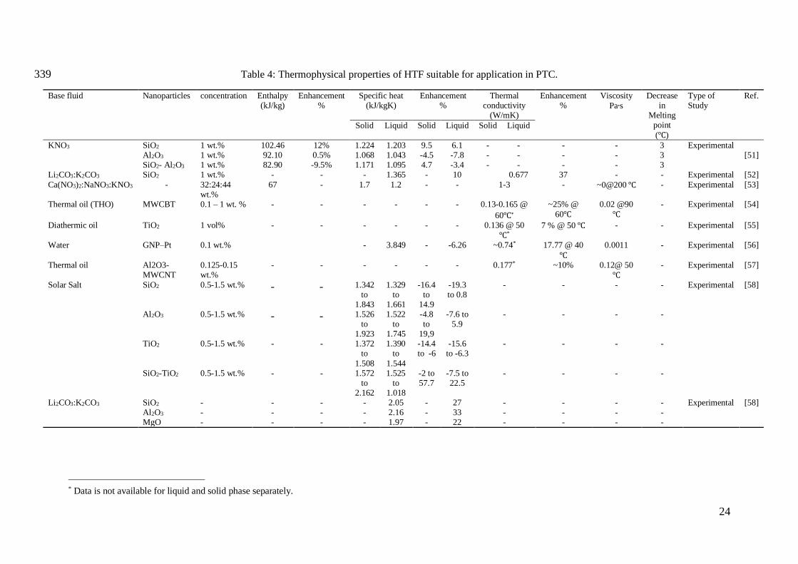
absorber tubes and field piping. Table 4 presents the thermophysical properties of various 319
HTF suitable for heat transfer applications in PTC. 320
321
Figure 5: Overview of % change in specific heat capacity by adding nanoparticles to base 322
fluids [40]. 323

23
3. Recent developments in heat transfer enhancement 324
Enhancement of thermophysical properties like specific heat, thermal conductivity, stability, 325
corrosion, and viscosity are the study areas that gained much attention by researchers in the 326
past decade. Nanomaterials are the specially engineered materials whose size will vary in 327
nanometers in any one dimension. Due to the superior thermophysical properties of 328
nanoparticles, research communities have shown interest in the field of nanotechnology. 329
Furthermore, the Stability of nanoparticles is also a significant issue to be considered while 330
investigating the properties of nanofluids. Adding nanoscale solid particles to the HTF has 331
proved to be a promising technique to improve its thermophysical properties. This section 332
covers the summary of the recent advancement in the state-of-the-art HTF used in parabolic 333
trough systems. Furthermore, heat transfer fluid with the properties suitable for use in the 334
parabolic trough is also discussed. Figure 6 shows the classification of HTF for the PTC 335
application. 336
337
Figure 6: Classification of HTF for PTC system 338
Heat transfer Fluid
Conventional HTF
Water/Steam
Synthetic thermal oil
Molten Salts
Solar Salt
Hitec
Hitec XL
Other Nitrate salts
Nanofluids (NF)
Water based NF
Ethylene glycol based NF
Synthetic oil based NF
Molten salt based NF
Ionic Liquids
Gaseous HTF
Air
Nitrogen
Carbon dioxide
Inert gasses
Vegetable oil
24
Table 4: Thermophysical properties of HTF suitable for application in PTC. 339
Base fluid Nanoparticles concentration
Enthalpy (kJ/kg)
Enhancement %
Specific heat (kJ/kgK)
Enhancement %
Thermal conductivity
(W/mK)
Enhancement %
Viscosity
Pa∙s
Decrease in
Melting point
(℃)
Type of Study
Ref.
Solid Liquid Solid Liquid Solid Liquid
KNO3 SiO2 1 wt.% 102.46 12% 1.224 1.203 9.5 6.1 - - - - 3 Experimental [51] Al2O3 1 wt.% 92.10 0.5% 1.068 1.043 -4.5 -7.8 - - - - 3
SiO2- Al2O3 1 wt.% 82.90 -9.5% 1.171 1.095 4.7 -3.4 - - - - 3 Li2CO3:K2CO3 SiO2 1 wt.% - - - 1.365 - 10 0.677 37 - - Experimental [52]
Ca(NO3)2:NaNO3:KNO3 - 32:24:44 wt.%
67 - 1.7 1.2 - - 1-3 - ~0@200 ℃ - Experimental [53]
Thermal oil (THO) MWCBT 0.1 – 1 wt. % - - - - - - 0.13-0.165 @
60℃*
~25% @
60℃
0.02 @90
℃
- Experimental [54]
Diathermic oil TiO2 1 vol% - - - - - - 0.136 @ 50
℃*
7 % @ 50 ℃ - - Experimental [55]
Water GNP–Pt 0.1 wt.% - 3.849 - -6.26 ~0.74* 17.77 @ 40
℃
0.0011 - Experimental [56]
Thermal oil Al2O3-MWCNT
0.125-0.15 wt.%
- - - - - - 0.177* ~10% 0.12@ 50
℃
- Experimental [57]
Solar Salt SiO2 0.5-1.5 wt.% - - 1.342 to
1.843
1.329 to
1.661
-16.4 to
14.9
-19.3 to 0.8
- - - - Experimental [58]
Al2O3 0.5-1.5 wt.% - - 1.526 to
1.923
1.522 to
1.745
-4.8 to
19,9
-7.6 to 5.9
- - - -
TiO2 0.5-1.5 wt.% - - 1.372 to
1.508
1.390 to
1.544
-14.4 to -6
-15.6 to -6.3
- - - -
SiO2-TiO2 0.5-1.5 wt.% - - 1.572 to
2.162
1.525 to
1.018
-2 to 57.7
-7.5 to 22.5
- - - -
Li2CO3:K2CO3 SiO2 - - - - 2.05 - 27 - - - - Experimental [58] Al2O3 - - - - 2.16 - 33 - - - - MgO - - - - 1.97 - 22 - - - -
* Data is not available for liquid and solid phase separately.

25
3.1. Water/steam as heat transfer fluid 340
Water is utilized as the conventional thermal fluid in the solar thermal system because of its 341
appreciable heat capacity of 4.185 J/Kg K and due to the application of solar thermal is 342
limited to domestic and industrial heating whose temperature ranges from 70-250 ⁰C. Silva et 343
al. [59], and Coccia et al. [60], utilized demineralized water for temperature up to 85 ⁰C using 344
PTC with rim angle 90⁰ and concentration ratio 9.25. The results were compared with 345
literature values, and the slope of the linear thermal efficiency equation related to thermal 346
losses is found to be -0.683 indicating the quality of receiver build. Silva et al. investigated 347
the use of PTC to generate steam for food processing applications [59]. In the study, PTC is 348
used to produce steam for canning and thermal treatment of vegetables. The possibility of 349
generating saturated steam with PTC for food processing industry utilizing an unfired boiler 350
was investigated. The parameters like the outlet temperature of the solar field and 351
temperature of generated steam are studied. Figure 7 represents the utilization of PTC in food 352
processing applications. The results showed that by using PTC's significant demand for 353
steam, production could be fulfilled with the small solar field, conserving land area, and 354
reaching the annual steam demand of the food processing industry. 355
356
Figure 7: Application of PTC in Industrial process [59] 357
The Direct Steam Generation (DSG) has many advantages with few limitations. Besides 358
higher temperatures at solar field outlets and simplified plant layout, the use of water during 359
the change in phase permits a more significant reduction in mean temperature at which heat is 360
transferred to the water. Required heat is absorbed during phase change at a lower 361
temperature instead of higher temperature value, improving thermal efficiency, compared to 362

26
sensible heat transfer taking place in thermal oils and molten salt. Also, water is 363
environmentally friendly, leakage of water in the solar field does not lead to environmental 364
hazards [61]. Also, the freezing point of water is lower than that of thermal oil and molten 365
salts; the energy required to maintain water in the liquid state is reduced. Moreover, water is 366
less corrosive compared to molten salts [62]. The advantage of using the direct steam 367
generating system using water/steam heat transfer is to avoid heat exchanger and its losses. 368
We do note; however, PTC produces high output temperature, to avoid boiling of water and 369
the rapid increment in water pressure with an increase in temperature requires design 370
modification of the system. Also, yet other disadvantages of water/steam heat transfer system 371
are the scaling of the absorber tube, even with the excellent feed water treatment, which is 372
unavoidable. The scaling phenomenon, in multiple row collector arrays, may cause a loss in 373
flow in the affected pipes, which may lead to tube dry-out, damaging the selective receiver 374
coating. Water/steam parabolic trough system also provides difficulties in thermal energy 375
storage. Also, the phase transition temperature is low, and superheaters are required to 376
increase the temperature of the steam to expand the steam in steam turbines to produce 377
power. We argue that using water as HTF, limits the application to process heat generation 378
and low-temperature application even though the PTC capable of producing high temperature 379
in the range of 450 to 500 ⁰C. As discussed by Coccia et al. [60], collectors with a higher 380
concentration ratio can produce higher heat flux in PTC for power generation. Therefore, 381
HTF with a higher operating temperature range is preferable for power generating 382
applications. Synthetic oils have the operating range up to 400 ⁰C, which are commonly used 383
in power plant applications, which is discussed in the next section. 384
3.2. Synthetic thermal oil as heat transfer fluid 385
CSP power plants primarily started utilizing synthetic oil as HTF for avoiding high-pressure 386
requirements and phase change at high temperature (>400 ⁰C). Synthetic oil is mostly known 387
under the brand names of Therminol VP-1, or Dowtherm A. The stability of Therminol VP-1 388
is in the range of 12-400 ⁰C. When synthetic thermal oil is heated above the operating range, 389
the hydrocarbon decomposes quickly, producing hydrogen gas. Degradation leads to makeup 390
oil requirements, which reduces the lifetime of the oil. The by-products formed by 391
overheating of the oil lead to the formation of the sludge, reducing thermal efficiency and 392
increasing maintenance cost of the plant [63]. 393

27
Selvakumar et al. estimated the performance of PTC using Therminol D-12 as HTF coupled 394
with secondary HTF as water for quick heating [64]. The performance was analyzed for 100 395
cycles. The system produced 40 ⁰C and 68 ⁰C hot water at 240W/m2 and 540W/m2 of solar 396
radiation, respectively. Use of Therminol D-12 along the evacuated tubes increase the 397
efficiency by 30% in instant hot water generation using PTC. 398
The solidification temperature of Therminol VP-1 is 12 ⁰C, and it boils at 257 ⁰C and the 399
thermal degradation temperature is 400 ⁰C. By understanding the operating temperature of 400
Therminol VP-1, here we discuss to what extent synthetic oil can be used as HTF in PTC. 401
The highest operating temperature attained by parabolic trough collectors is between 350 to 402
500 ⁰C. The maximum temperature attained by power plants also depends on the number of 403
collectors used in the plant. The efficiency of the power plant depends on the maximum 404
temperature attained by the power plant. By all these factors considered, Therminol VP-1 can 405
be used as HTF in PTC up to 400 ⁰C. However, if the plant operating temperature surpasses 406
400 ⁰C oxidation of the synthetic oil takes place. The issue with the degradation of synthetic 407
oil for the high-temperature application can be overcome by using high-temperature HTF. 408
The suitable solution for high-temperature HTF is molten salt. The forthcoming section 409
discusses the suitability of using molten salt in PTC applications. 410
3.3. Molten Salts as heat transfer fluid 411
In the nineteenth century, the separation of alkali metal from their fused hydroxide salt was 412
conducted by Humphery Davy [65]. Therefore, molten salt technology dates back to a very 413
long time in history. In the 1950s, the use of molten salts in nuclear reactors emerged. Oak 414
Ridge National Laboratory (ONRL) pioneered the first molten salt nuclear reactor, which 415
utilized thorium as nuclear fuel [66]. More recently, due to the arising challenges in 416
renewable energy and environment protection, molten salts have been used for CSP plants for 417
heat transfer and heat storage applications [67]. Figure 8 shows other applications of molten 418
salts. Molten salts used for solar thermal applications are primarily nitrate salts, which has the 419
potential to be used in thermal storage and heat transfer applications because of their 420
exuberant chemical characteristics. Molten salts show several desirable properties at an 421
elevated temperature like high density, promising specific heat, excellent stability at elavated 422
temperature, and lower vapor pressure. Compared to synthetic oil, Molten salts are cheaper 423
and have a low impact on the environment because they are non-polluting, non-flammable, 424
abundantly available, and favorable for cost savings because of their ability to reduce the size 425

28
of the thermal storage tank due to their high specific heat capacity. The main drawback of 426
molten salt is its high melting point, which requires pre-heating and maintaining the liquidus 427
temperature during the night and cloudy days. The energy required to maintain this liquidus 428
temperature leads to high operating and maintaining costs. The composition of the Molten 429
salt determines its characteristics. 430
431
Figure 8: Applications of Molten Salts [68] 432
The molten salt with 60wt% of Sodium Nitrate (NaNO3) and 40wt% of Potassium Nitrate 433
(KNO3) is called Solar salt, which is the most common salt used as HTF in CSP plants. Wang 434
et al. conducted 3-D simulation using the FVM model, with solar salt 435
(NaNO3:KNO3,60:40wt%) as HTF in PTC and concluded by stating that, the cross-sectional 436
temperature increases with an increase in inlet velocity and direct normal irradiation [69]. 437
Moreover, the thermal efficiency of oil at 573.15 is more than molten salt at 773K by 0.079 438
was the key finding of the research. To reduce the cost of HTF, the synthetic thermal oil is 439
retained as HTF but replaced with molten salt as a thermal energy storage material; typically, 440
solar salt is used for this purpose. Solar salt is made as to the standard storage medium, and 441
many research articles take solar salts as reference material in TES and heat transfer 442
applications [70]. The operating range of solar salt is between 222°C to 600 °C [71]. 443
Potassium nitrate and sodium nitrate which has the melting point of 334 °C and 208 °C 444
respectively, the mixture of both the salts reduces the melting point of the eutectic by 100 °C, 445
compared to the pure components (Figure 9). This makes it feasible to use it in CSP plants. 446
The properties of Solar salt estimated by correlation formulated by Bauer et al., Carling et al., 447
Gustafsson et al., Jriri et al., and Takahashi et al. are listed in Table 5 and Figure 10 [70, 72]. 448
The dynamic viscosity of the molten salt should be less than 0.005 Pa∙s for application in 449
PTC, because of the pumping power consumption, which goes higher with the increase in 450
viscosity. The viscosity of molten salt synthesized by Coscia et al. [73] obtained a viscosity 451
value of 0.06 Pa∙s at 200 ⁰C and the viscosity reduced to 0.001 Pa∙s at 550 ⁰C. (Chen, M. et 452
Nuclear Reactors Chemical Industry
HTF/TES for solar thermal power
Waste treatment
Molten salts

29
al., [53, 74] obtained the viscosity of the molten salt close to the viscosity of water at a 453
temperature higher than 300 °C. From the results obtained by various researchers by 454
combining Ca(NO3)2 with solar salt, the viscosity of the eutectic composite molten salt 455
reduces significantly. 456
457
Figure 9: Phase diagram of KNO3: NaNO3[73] 458

30
459
Figure 10: Thermophysical properties of solar salt-dependent on temperature [70]. Reprinted 460
with permission from Elsevier Books, Molten Salts Chemistry, Thomas Bauer, Lic.No. 461
4676481124638. 462

31
Hitec molten salt is a ternary eutectic mixture of KNO3:NaNO2: NaNO3 with mass fraction 463
53%,40%, and 7% respectively. The stability of Hitec is in the temperature range of 142-464
535°C. The properties of Hitec can be calculated using the correlation presented in Table 5. 465
Extensive research has been carried out on fluid flow properties and heat transfer 466
characteristics of HITEC molten salt flow. Xiao et al., investigated on heat transfer and flow 467
parameters using HITEC (53% KNO3 – 40% NaNO2 – 7% NaNO3, mol.%) in the helical heat 468
exchanger, where HITEC is used as the hot side HTF and DI water at the cold side [75]. 469
Their findings demonstrated that frictional pressure drop in laminar and turbulent flow 470
regimes agreed within 15% with that of past literature. Figure 11 shows the thermophysical 471
properties of HITEC salt. By the analysis of the graph, HITEC salt is highly viscous at low-472
temperature range (150⁰C -300⁰C), which results in a higher Prandtl number (Pr>7). Higher 473
Prandtl number results in a velocity boundary layer being much more significant than the 474
thermal boundary layer, enhancing the heat transfer process in the absorber tube. As the 475
temperature increase (300⁰C -500⁰C), the viscosity reduces drastically. Therefore, HITEC can 476
be considered a suitable HTF for PTC, which has a similar working temperature range of 477
PTC. 478
479
Figure 11: Thermophysical properties of Hitec Molten salt (KNO3:NaNO3: NaNO2, 53:7:40 480
mol.%) [75]. Reprinted with permission from Elsevier, Applied Thermal Engineering, 481
Investigations on heat transfer characteristic of molten salt flow in the helical annular duct, 482
Peng Xiao, Lic.No. 460589142713. 483

32
Hitec XL is a ternary eutectic mixture of Ca(NO3)2, KNO3, NaNO3 with a mass fraction of 42 484
%, 43%, and 15% respectively. It is clear from the components of the eutectic mixture that by 485
the addition of Ca(NO3)2 to solar salt forms Hitec XL molten salt. Fernandez et al. studied the 486
thermal and physical properties by adding Ca(NO3)2 and LiNO3 to solar salt and observed 487
that by adding calcium nitrate to solar salt, the mixture reduced the freezing temperature and 488
economic cost of the power plant [76]. These mixtures were designed to replace synthetic oil 489
as HTF in the PTC system by reducing economic cost and by improving thermal storage 490
capacity. Chen et al., experimentally verified and predicted 3D stable molten temperature 491
diagram for 42% KNO3-17% NaNO3-41% Ca(NO3)2 [74]. The predicted melting temperature 492
of 129.1 ⁰C and decomposition temperature of 597.9 ⁰C were in an excellent match with the 493
prediction. Chen and Zhao investigated a unique composition of Hitec XL (Ca(NO3)2-494
NaNO3-KNO3, 32:24:44 wt%) and found that the composition had the best performance by 495
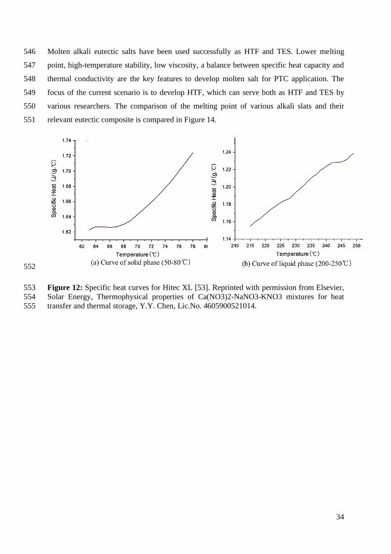
reduced melting point to 80 ⁰C having 1.7J/g ⁰C and 1.2 J/g ⁰C of specific heat for solid and 496
liquid phase respectively [53]. Figure 12a shows the rise in heat capacity in the range of 50-497
68 ⁰C and the curve becomes stable irrespective of temperature rise and Figure 12b. The 498
specific heat capacity of liquid salt increases with the rise in temperature, indicating its 499
sensitivity to variation in temperature. The viscosity is found to be near to zero at 200 ⁰C, and 500
the thermal conductivity of the composition is about 1-3 W/mK. The thermophysical 501
properties of Hitec XL are calculated using the correlation presented in Table 4. Therefore, 502
Hitec XL can be used as both HTF and TES material for line focusing collectors due to its 503
high stability, significant heat of fusion, and economic price. 504
Olivares et al. [76] and Fernandez et al. [76] investigated the thermal stability of the ternary 505
nitrate mixture. In this composite LiNO3 salt is combined with solar salt composite to 506
enhance the thermal stability of the eutectic composite. From the analysis, the working 507
temperature range is obtained in the range of 130-600 ⁰C by the addition of LiNO3. The 508
viscosity of this eutectic mixture is found to be 0.03 Pa∙s at 300 ⁰C making it a candidate salt 509
for PTC application. The only disadvantage of this composite is the high cost of LiNO3 510
($4.32/kg) [7]. 511
Zhao and Wu investigated 50-80 wt.% of KNO3, 0-25 wt.% of LiNO3 and 10-45 wt.% of 512
Ca(NO3)2 to obtain a eutectic mixture which will serve both as HTF and TES material [77]. 513
The experimental results showed better thermophysical properties like melting point (<100 514
⁰C), viscosity (< 0.003 Pa∙s at 190 ⁰C), and high-temperature stability (>500 ⁰C) is obtained in 515

33
this range of a mass fraction of KNO3, LiNO3, and Ca(NO3)2. Due to their low melting point, 516
which is less than the melting point of Hitec XL (120 ⁰C), and high-temperature stability, 517
which is higher than the conventional organic HTF [78], KNO3:LiNO3:Ca(NO3)2 will lead to 518
higher Rankine Cycle efficiency. Therefore, these special eutectic salts make them more 519
suitable for HTF and TES replacing synthetic oils in PTC plants. 520
Wang et al. investigated quaternary eutectic salts of alkali-nitrites and nitrates to explore their 521
possibility of usage as thermal fluids in the CSP system [79]. They found that the freezing 522
point of the composite eutectic combination was estimated to be <100 ⁰C by differential 523
scanning calorimeter measurements, as shown in Figure 13. The stability of the molten salt is 524
found to be 430 ⁰C, which is lower than Hitec XL, Hitec, and solar salt. However, it is 525
observed that the specific heat capacity of the salt is greater than the specific heat capacity of 526
Hitec and solar salt. The economic evaluation of the salt-containing LiNO3, as available HTF 527
and TES material for solar power plants, limits its usage in commercial power plants. 528
Bradshaw and Brosseau developed a unique molten salt at the Sandia National Laboratory 529
known by the name “Sandia Mix.” This eutectic mixture is a quaternary molten salt with 530
mass ratio NaNO3 (9–18%)–KNO3 (40–52%)–LiNO3 (13–21%)–Ca(NO3)2(20–27%) [80]. In 531
the study, three different mass ratios (QA, QB, QC) have been studied, and each ratio had a 532
melting point below 100 ⁰C and thermal stability greater than 500 ⁰C. The viscosity of the 533
composite mixture is found to be 0.003 Pa∙s, which is suitable for PTC applications. The 534
main drawback of Sandia Mix for a commercial application is due to the economic 535
limitations of LiNO3. However, by large scale production of the LiNO3 salt by the 536
conversion of LiCO3 using HNO3, the cost of production can be minimized [80, 81]. 537
Justin et al. developed a eutectic salt with KNO3 (23% wt.%)–LiNO3 (8% wt.%) – CsNO3 538
(44% wt.%)– NaNO3 (6% wt.%)–Ca(NO3)2(19% wt.%) at Halotechnics Inc., and hence the 539
name Halotechnics SS-500 [82]. Testing of this salt is done under nitrogen and air 540
atmosphere, the result showed that the melting point and stability of this molten eutectic salt 541
is 65 ⁰C and up to 500 ⁰C respectively. The addition of CsNO3 (caesium-nitrate) to the molten 542
salt mixture brings down the melting point but, CsNO3 is uneconomical compared to other 543
molten salts for application in PTC power plants. Currently, Halotechnics is optimizing the 544
weight ratio of CsNO3 to lessen the cost while maintaining the freezing point very low. 545
34
Molten alkali eutectic salts have been used successfully as HTF and TES. Lower melting 546
point, high-temperature stability, low viscosity, a balance between specific heat capacity and 547
thermal conductivity are the key features to develop molten salt for PTC application. The 548
focus of the current scenario is to develop HTF, which can serve both as HTF and TES by 549
various researchers. The comparison of the melting point of various alkali slats and their 550
relevant eutectic composite is compared in Figure 14. 551
552
Figure 12: Specific heat curves for Hitec XL [53]. Reprinted with permission from Elsevier, 553
Solar Energy, Thermophysical properties of Ca(NO3)2-NaNO3-KNO3 mixtures for heat 554
transfer and thermal storage, Y.Y. Chen, Lic.No. 4605900521014. 555

35
556
Figure 13: Melting point of LiNO3–NaNO3–KNO3-NaNO2 [83]. Reprinted with permission 557
from Springer Nature, Oxidation of Metals, Molten Salt Corrosion of Stainless Steels and 558
Low-Cr Steel in CSP Plants, A. G. Fernández, Lic.No.4611460040655. 559
560
561
Figure 14. Melting point of Alkali salts and their relevant eutectic salt. 562
According to the literature, adding LiNO3 and Ca(NO3)2 to NaNO3 and KNO3 (Solar Salt) to 563
obtain the eutectic mixture was studied by various researchers, the primary motivation behind 564
adding LiNO3 and Ca(NO3)2 is to reduce the melting point of the eutectic mixture. Coscia et 565
0
100
200
300
400
500
600
700
800
900
Tem
per
atu
re K

36
al. [73], Fernandez et al. [76], and Zhao et al. [77] obtained a eutectic mixture of Ca(NO3)2 566
KNO3 and LiNO3. From the results, it can be concluded that by the addition of LiNO3, the 567
freezing point reduced considerably in comparison with individual molten salt. The results 568
obtained by Chen et al., [74] by adding Ca(NO3)2 to solar salt had reduced the melting point 569
to 80 ⁰C which is the highest drop in temperature and not following the melting point 570
reduction pattern followed by other researchers which is between 100 and 120 ⁰C. The 571
reduction in melting point may be due to the preparation methods followed by the 572
researchers. The preparation methods of adding, LiNO3 and Ca(NO3)2 to solar salt is very 573
critical because of the hygroscopic nature of the compound. Various precautionary measures 574
need to be taken to reduce the moisture of the compounds especially Ca(NO3)2∙ 4H2O to 575
make them anhydrous. 576
By the addition of LiNO3 and Ca(NO3)2 to solar salt shows enhancement in the specific heat 577
of the eutectic mixture. According to Fernandez et al. [76], enhancement in specific heat is 578
higher by adding LiNO3 to solar salt. Zhao et al., [77] and Chen et al.[74] has obtained 579
comparatively similar specific heat capacity by adding Ca(NO3)2 to solar salt. 580
The dynamic viscosity value of the molten salt should be less than 0.005 Pa∙s for application 581
in PTC, because of the pumping power consumption, which goes higher with the increase in 582
viscosity. From the molten salt synthesized by Coscia et al. [73] viscosity value of 0.06 Pa∙s 583
is obtained at 200 ⁰C and the viscosity reduced to 0.001 Pa∙s is obtained at 550 ⁰C. Chen et al. 584
obtained the viscosity of the molten salt close to the viscosity of water [74]. From the results 585
obtained by various researchers combining LiNO3 and Ca(NO3)2 to solar salt reduces the 586
viscosity of the eutectic composite molten salt significantly. 587
Table 5: HTF thermophysical properties correlations as a function of Temperature [63] 588
Property Equation Validity
temperature
range
Th
erm
inol
VP
-1
Specific heat(J/KgK) cp=2.82T +716 285 K < T < 673K
Thermal Conductivity
(W/mK)
λ =1.73×10⁻⁷ T2+7.62× 10⁻⁶T+0.14 285 K <T < 673K
Density (kg/m3) ρ = -7.61×10⁻⁴T2-2.24×10⁻¹T+1191 285 K< T < 673K

37
Dynamic viscosity
(Pa.s)
µ = (-23×10-5T3+5.61×10⁻³ T2-
19.89T+1822)-1
285 K < T < 673K S
ola
r S
alt
Specific heat(J/KgK) cp =1443+0.172 (T-273.15) 533 K < T < 873K
Thermal Conductivity
(W/mK)
λ =0.443+1.9×10⁻⁴ (T-273.15) 533 K < T < 873K
Density (kg/m3) ρ = 2090-0.636 (T-273.15) 533 K < T < 873K
Dynamic viscosity
[Pa.s]
µ = 2.2714 ×10⁻² -1.2 ×10⁻⁴(T-
273.15)2+2.281 ×10⁻⁷(T-273.15)2 -
1.147×10⁻¹⁰ (T-273.15)3
533 K < T < 873K
Hit
ec
Specific heat(J/KgK) cp =1.56× 10 − 3 415K < T < 808K
Thermal Conductivity
(W/mK)
λ =0.411+4.36×10⁻⁴(T-273.15)-
1.54× 10⁻⁶(T-273.15)2
415K < T < 808K
Density (kg/m3) ρ = -0.74×(T-273.15)+208 415K < T < 808K
Dynamic viscosity
(Pa.s)
µ = 102.7374×(T-273.15)-2.104 415K < T < 808K
Hit
ec X
L
Specific heat(J/KgK) cp =-0.33T+1634 403K < T < 823K
Thermal Conductivity
(W/mK)
λ = 0.519 403K < T < 823K
Density (kg/m3) ρ = 2240-0.827×(T-273.15) 403K < T < 823K
Dynamic viscosity
([Pa.s)
µ = 106.1374×(T-273.15)-3.36406 403K < T < 823K
589
Table 6: HTF Thermophysical Properties at various temperature [84] 590
Tin
(K)
Property Pressurized
Water
Liquid
Sodium
Air CO2 He
300
Thermal Conductivity
k(W/mK)
0.628 - 0.036 0.031 0.16
Density ρ(kg/m3) 994 - 0.769 1.098 0.146
Specific Heat Capacity
cp (J/kgK)
4164 - 1021 1004 5193
Dynamic Viscosity 5.9×10⁻⁴ - 2.5×10⁻⁵ 2.3×10⁻⁵ 2.1×10⁻⁵

38
µ(Pa.s)
400
Thermal Conductivity
k(W/mK)
0.674 86.9 0.043 0.037 0.191
Density ρ(kg/m3) 926 918 0.632 0.939 0.112
Specific Heat Capacity
cp (J/kgK)
4277 1370 1040 1057 5193
Dynamic Viscosity
µ(Pa.s)
1.9×10⁻⁴ 5.9×10⁻⁴ 2.9×10⁻⁵ 2.6×10⁻⁵ 2.5×10⁻⁵
500
Thermal Conductivity
k(W/mK)
0.622 79.8 0.049 0.044 0.221
Density ρ(kg/m3) 813 896 0.537 0.813 0.091
Specific Heat Capacity
cp (J/kgK)
4741 1332 1062 1104 5193
Dynamic Viscosity
µ(Pa.s)
1.1×10⁻⁴ 4.1×10⁻⁴ 3.2×10⁻⁵ 3.0×10⁻⁵ 2.9×10⁻⁵
600
Thermal Conductivity
k(W/mK)
- 73.4 0.054 0.051 0.251
Density ρ(kg/m3) - 873 0.467 0.713 0.076
Specific Heat Capacity
cp (J/kgK)
- 1300 1086 1145 5193
Dynamic Viscosity
µ(Pa.s)
- 3.2×10⁻⁴ 3.5×10⁻⁵ 3.3×10⁻⁵ 3.3×10⁻⁵
700
Thermal Conductivity
k(W/mK)
- 67.8 0.059 0.057 0.281
Density ρ(kg/m3) - 851 0.413 0.633 0.066
Specific Heat Capacity
cp (J/kgK)
- 1276 1108 1180 5193
Dynamic Viscosity
µ(Pa.s)
- 2.6×10⁻⁴ 3.8×10⁻⁵ 3.6×10⁻⁵ 3.7×10⁻⁵
800
Thermal Conductivity
k(W/mK)
- 62.7 0.064 0.064 0.31
Density ρ(kg/m3) - 827 0.371 0.568 0.058

39
Specific Heat Capacity
cp (J/kgK)
- 1260 1129 1211 5193
Dynamic Viscosity
µ(Pa.s)
- 2.3×10⁻⁴ 4.0×10⁻⁵ 3.9×10⁻⁵ 4.0×10⁻⁵
900
Thermal Conductivity
k(W/mK)
- 58.1 0.069 0.07 0.338
Density ρ(kg/m3) - 804 0.336 0.515 0.052
Specific Heat Capacity
cp (J/kgK)
- 1252 1148 1238 5193
Dynamic Viscosity
µ(Pa.s)
- 2.0×10⁻⁴ 4.3×10⁻⁵ 4.2×10⁻⁵ 4.4×10⁻⁵
1000
Thermal Conductivity
k(W/mK)
- 54.1 0.073 0.076 0.366
Density ρ(kg/m3) - 780 0.307 0.471 0.047
Specific Heat Capacity
cp (J/kgK)
- 1252 1164 1262 5193
Dynamic Viscosity
µ(Pa.s)
- 1.8×10⁻⁴ 4.5×10⁻⁵ 4.5×10⁻⁵ 4.7×10⁻⁵
1100
Thermal Conductivity
k(W/mK)
- 50.4 0.077 0.082 0.394
Density ρ(kg/m3) - 755 0.283 0.433 0.043
Specific Heat Capacity
cp (J/kgK)
- 1262 1179 1282 5193
Dynamic Viscosity
µ(Pa.s)
- 1.7×10⁻⁴ 4.7×10⁻⁵ 4.8×10⁻⁵ 5.1×10⁻⁵
1200
Thermal Conductivity
k(W/mK)
- - 0.081 0.087 0.421
Density ρ(kg/m3) - - 0.262 0.401 0.039
Specific Heat Capacity
cp (J/kgK)
- - 1192 1300 5193
Dynamic Viscosity
µ(Pa.s)
- - 5.0×10⁻⁵ 5.0×10⁻⁵ 5.4×10⁻⁵
1300 Thermal Conductivity - - 0.085 0.092 0.448

40
k(W/mK)
Density ρ(kg/m3) - - 0.244 0.373 0.036
Specific Heat Capacity
cp (J/kgK)
- - 1203 1316 5193
Dynamic Viscosity
µ(Pa.s)
- - 5.2×10⁻⁵ 5.3×10⁻⁵ 5.7×10⁻⁵
Montes et al. [85] conducted a comparative analysis using a typical PTC loop of 20 MWe 591
power output for three different HTF, water/steam, Therminol VP-1, and solar salt, which is 592
presented in Table 7. It can be observed that the Energy efficiency decreases with an increase 593
in length due to the increase in heat loss along the length of the receiver. However, with the 594
outlet temperature rise, Exergy efficiency increases and follows the opposite trend. However, 595
for lengthier collector loops, exergy efficiency drops down due to the increase in pressure 596
drop. It is interesting to note that for a similar length of the receiver, molten salt has higher 597
exergy efficiency and water/steam has higher energy efficiency compared to the other two 598
HTFs. 599
Table 7: Thermodynamic performance of PTC with different loop lengths using Therminol 600
VP-1, Molten salt, and water as HTF [85]. 601
HTF Total
collector loop
length (m)
Heat
Loss
(kW)
Pressure
drop
(bar)
Outlet
Temperature
(⁰C)
Energy
Efficiency
Exergy
Efficiency
Therminol
VP-1
539.9 129.7 4.53 353 69.7 33.6
662.6 172.4 5.63 374.2 69.3 34
711.7 189.8 6.09 382.5 69.2 34.2
736.2 199.3 6.32 386.6 69.1 34.3
760.7 209 6.55 390.6 69 34.3
785.3 219 6.78 394.6 68.9 34.4
Solar Salt 294.5 109 0.53 438.6 69.4 37
429.5 198.5 0.77 556.3 67.6 37.3
589 349.8 1.04 565.9 66.9 38.3
613.5 378.1 1.08 575.2 66.5 38.2
638 407.7 1.13 584.4 66 38.1
662.6 438.8 1.17 593.3 65.5 37.9
Water
Steam
736.2 195.2 5.35 353.8 70.6 34
957.1 340.4 8.63 541.3 68.8 34.4
981.6 367.8 9.08 580.9 68.4 34.4
1006.1 398.2 9.56 561.5 68 34.4

41
1030.7 431.7 10.04 599.5 67.5 34.3
1227 818.6 14.42 711.6 62.6 32.6
3.4. Nanofluids as heat transfer fluid 602
In order to enhance the optical and thermal performance of the PTC, researchers around the 603
world are researching on enhancing the design of collectors and thermophysical properties of 604
the HTF. Doping nanoparticles to the base fluid is one such attempt to enhance the optical 605
and thermal properties of HTF. Nanofluids are broadly classified into two categories, 606
Metallic solids nanoparticles, and Nonmetallic solids nanoparticles. Metallic nanoparticles 607
often used in the preparation of nanofluids, as stated in the research articles are Cu, Fe, Al, 608
Ag, and Au. Moreover, Nonmetallic solids are Al2O3, CuO, Si, SiC, Carbon nanotubes 609
(CNTs), Boron Nitrate Nanotubes (BNNTs, and Nanodroplets. Table 8 summarises the recent 610
works on heat transfer enhancement using various nanoparticles in PTC. These nanofluids are 611
dispersed into a dispersion medium called base fluids, commonly used base fluids are water, 612
Synthetic oil or Engine oil, and Ethylene Glycol (EG). Nanofluids enhances the 613
thermophysical properties of the base fluid, enhancing the efficiency of the heat transfer 614
system [86]. Sarafraz et al. investigated the effect of zirconia acetone nanofluid on thermal 615
resistance, heat transfer coefficient, and thermal performance of a thermosyphon evaporator 616
and the results showed that there was reduction in thermal resistance of the evaporator, 617
enhancement in boiling heat transfer mechanism at the highest heat flux (~200 suns) on the 618
evaporator when doped with zirconia nanoparticles [87]. However, the addition of 619
nanoparticles may enhance the certain thermophysical property of the base fluid while some 620
other properties may degrade by doping nanoparticles. Sarafraz et al. conducted experiments 621
on methanol doped with graphene nanoplatelets in evacuated tube solar collectors and found 622
that the thermal conductivity of the heat transfer fluid enhanced by 19% by the addition of 623
0.1 wt.% of graphene nanoplatelets. Meanwhile, the heat capacity of the HTF was decreased 624
by 4% at 0.1 wt.% of the nanoparticles [88]. In yet another research on doping carbon 625
nanoparticles in acetone, they found an enhancement in thermophysical properties like 626
thermal conductivity and specific heat capacity but the viscosity of the fluid increases by 627
increasing the mass fraction of nanoparticles [89-91]. 628
Both Metallic solids and non-metallic solids can be further categorized into mono and hybrid 629
nanofluids. Mono nanofluid is an HTF where a single nanomaterial is doped into the base 630
fluid, whereas hybrid nanofluid is an HTF where two or more nanoparticles are doped to the 631

42
base fluid [92]. Mono nanofluids are discussed in the first part of this section while a separate 632
subsection is dedicated to hybrid nanofluid at the end of this section. 633
Also, some researchers predict the behavior of nanofluids in the solar thermal application 634
using two approaches using numerical studies. The first one is the single-phase approach and 635
the second is the two-phase approach. In the first approach, the base fluid and nanoparticles 636
have the same velocity field and temperature, making the HTF behave as classical newtonian 637
fluid whereas, the latter approach assumes that base fluid and the nanoparticle has separate 638
velocity vector field. Therefore, within the control volume, there is a volume fraction of base 639
fluid and volume fraction of nanoparticles. The second approach gives successful prediction 640
even when the nanoparticles are in lower concentration [93]. 641
Table 8: Recent works on Heat Transfer enhancement using Nanoparticles in PTC. 642
Nanofluids Methods % Enhancement References
Base fluids Nanoparticles ηth h
Water Al2O3 Experimental 7 32 [94]
Water Al2O3, Fe2O3,
SiO2, TiO2,ZnO
Experimental <1 - [95]
Water Al2O3, CuO CFD - 28, 35 [96]
Water Al2O3 CFD - 22 [97]
Water Al2O3, Fe2O3 Experimental 13, 11 - [98]
Water Al2O3 Experimental 8.54 - [99]
Water TiO2 Experimental 8.66 23 [100]
Ethylene glycol Fe2O3 Experimental - 13.3 [101]
Ethylene glycol Carbon black Experimental 27.9 - [102]
Thermal oil Al2O3 CFD 4.25 11 [103]
Synthetic oil Al2O3, CuO,
TiO2
Mathematical
model
1.17,1.06,
1.14
- [104]
Synthetic oil Al2O3 Mathematical
model
0.1 60 [105]
Synthetic oil Al2O3 CFD 7 - [106]
Synthetic oil Al2O3 CFD - 15 [107]
Synthetic oil Al2O3 CFD - 40 [108]
Syltherm 800 Ag, Al2O3, Cu,
CuO
Mathematical
model
- 36, 18, 33,
27
[109]
Syltherm 800 Al2O3, CuO Mathematical
model
1.13, 1.26 35, 41 [110]
Syltherm 800 Al2O3 and TiO2 Mathematical
model
1.31 117 [111]
Syltherm 800 CuO CFD 0.76 35 [112]
Syltherm 800 Al2O3 CFD 8 - [113]
Syltherm 800 Al2O3 CFD 7.6 7.6 [93]
Syltherm 800 CuO CFD 15 38 [114]
Syltherm 800 Al2O3 CFD - 40 [115]

43
Dowtherm A Al2O3, C, Cu,
SiC
CFD - 68 [116]
Therminol-
VP1
Cu CFD 12.5 32 [117]
Therminol-
VP1
Ag, Al2O3, Cu CFD 13.9, 7.2,
12.5
7.9, 3.9,
6.4
[118]
Therminol-
VP1
SWCNT CFD 4.4 234 [119]
Therminol 66 Al2O3 Mathematical
model
0.1 60 [120]
Molten salt CuO CFD 0.26 12 [112]
Mineral oil MWCNT Experimental 11 - [121]
643
3.4.1. Properties and preparation 644
The methods used in the preparation of nanofluids are the main factors that can contribute 645
significantly to the stability of nanofluid [122]. A good number of review papers have 646
discussed the preparation methods of nanofluids [123, 124]. Two kinds of methods, which are 647
a single-step method, and two-step have been used in producing nanofluids. In the single-step 648
method, nanoparticle manufacturing and nanofluid preparation are done concurrently. One of 649
the examples of equipment to prepare nanofluid by using single-step method is to use Plasma 650
Nano Colloid Maker, this method uses the Electrical Explosion of Wire (EEW) technique to 651
convert the primary wire into nanoparticles by using pulse explosive process, and this 652
explosion dispersed the metallic nano colloids in the base fluid at the same time. Researchers 653
that have applied this technique in nanofluid preparations include Bahremand et al., 654
Khoshvaght-Aliabadi et al. Mirfendereski et al. and Rakhsha et al. Bahremand, Abbassi and 655
Saffar-Avval [125], Mirfendereski, Abbassi and Saffar-avval [126], Khoshvaght-Aliabadi, 656
Tavasoli and Hormozi [127] Rakhsha, Akbaridoust, Abbassi and Majid [128]. The 657
disadvantage of the single-step method is that the leftover residuals of the reaction are 658
difficult to remove from the nanofluid. 659
The two-step method is a technique more commonly applied by researchers. This method is 660
more attractive because it is a more straightforward method compared to the single-step 661
method. Dry nanoparticles will be produced first in large quantities. Then, a small number of 662
nanoparticles will be dispersed in a base liquid according to the intended weight or volume 663
fraction. However, making a stable solution is more challenging for the two-step method as 664
ultrafine particles have a higher surface energy that will immediately lead to aggregation, 665

44
clustering, and sedimentation [122]. Therefore, researchers have applied different methods of 666
making a stable nanofluid in the two-step method, including stirring or shaking, 667
ultrasonication, surface functionalization, or adding on dispersant or surfactant in the 668
solution. 669
Stirring or shaking is the simplest and cheapest method to make a solution. For example, 670
Mahbubul et al. Mahbubul, Saidur and Amalina [129] had prepared Al2O3/R141b nano-671
refrigerant with an orbital incubator shaker continuously shaken at 240 rpm for about one 672
hour while maintaining a constant temperature of 15ºC to avoid evaporation of refrigerant. 673
Ultrasonication or ultrasonic homogenizer is the most common method applied by 674
researchers to prepare a nanofluid. The ultrasonication process can break down 675
agglomeration or clustering of nanoparticles that cannot be achieved by stirring or shaking. 676
Ultrasonication mainly depends on the frequency, nominal power of sonication and 677
sonication time [130]. For the engineering applications, the stability of nanofluid is the major 678
challenge [131], natural sedimentation of nanoparticles is observed over time. This 679
sedimentation may clog the pipes carrying HTF in the solar field creating pressure loss. 680
Theoretically, particles will have both attractive and repulsive forces, which result in the 681
agglomeration and dispersion of particles in the base fluid [132]. The attractive forces are due 682
to vanderwaals force of attraction, and the electrostatic repulsive force causes the particles to 683
repel each other. Nanoparticle will not agglomerate if the repulsive force is higher than the 684
vanderwaals force of attraction, making the particle disperse evenly in the base fluid. 685
Electrostatic repulsion can be increased by adding surfactants into the nanofluids. Sodium 686
dodecyl sulfate, sodium dodecylbenzene sulfonate, or Triton X-100 are the surfactants which 687
had been tested and proven to stabilize nanofluid [133]. However, when the Brownian motion 688
of the particles is dominating, and when the nanofluids are heated, the effect might be 689
weakened. 690
Yang and Liu [134] proposed a suitable way to stabilize the nanoparticles in the base fluid is 691
by grafting polymers on to the surface of nanoparticles. This method is also known as surface 692
functionalization. Silanes were attached to silica nanoparticles making “Si-O-Si” covalent 693
bonding and resulting in a steric stabilization effect even when heated. Functionalized SiO2 694
nanoparticles have been reported to keep dispersing well after six months, and no 695
sedimentation was observed [134, 135]. 696

45
Various methods can test the stability of nanofluid. Some methods that were commonly 697
applied by researchers include zeta potential measurement, dynamic light scattering, electron 698
microscopy, optical spectrum analysis, and observation of the natural sedimentation method. 699
Zeta potential measurement is a method to measure the level of the repulsion force between 700
particles with the same charge. Zeta potential value can indicate how stable the dispersion is 701
for nanofluid. The higher is the zeta potential value, the more the nanoparticles will resist 702
aggregation due to higher repulsive force and therefore, resulting in a more extended period 703
of stability [136]. The relationship between zeta potential value and stability of nanofluid is 704
shown more precisely in Table 9. The zeta potential values of various nanofluids obtained in 705
the literature are presented in Table 10. The surface functionalization of nanoparticles is 706
another method to enhance the zeta potential of the nanofluid. Hadi Karami et al. used 707
carboxyl functionalization of graphene nanoparticles and obtained a stable nanofluid, and the 708
results also proved that the zeta potential decreased with an increase in the mass 709
concentration of nanoparticles. 710
Table 9: Relationship between zeta potential value and stability of nanofluid 711
Zeta potential value Stability References
0 mV and ±5mV Strongly tends to precipitate
Dukhin et al. [137]
±10mV to ±30mV Tends to precipitate
±30mV to ±40mV Moderate stability
±40mV to ±60mV good stability
higher than ±61mV excellent stability
A dynamic light scattering (DLS) method can be used to determine the nanoparticle size 712
distribution in a nanofluid. However, the particle size distribution measurement can be 713
affected by the concentration of the suspension, composition of solvents, dust, and other 714
additives and therefore may lead to incorrect results to evaluate the stability of nanofluids 715
[138]. Electron microscopy equipment such as Transmission Electron Microscopy (TEM) 716
and Scanning Electron Microscope (SEM) are very useful tools to measure the shape and 717
particle size distribution (PSD) of nanoparticles [139]. However, electron microscopy cannot 718
accurately present the real situation of nanofluids because, in order to use the electron 719

46
microscopy, the nanofluid sample needs to be dried first. An example of SEM image of 720
SiO2 nanoparticles, ultrasonically dispersed in deionized water, after drying is shown in 721
Figure 15. 722

47
Table 10: Zeta-potential values obtained by different nanofluids in literature 723
Base Fluid Nanoparticle composition Method Zeta potential Remarks References
Ethylene
glycol
RGO-TiO2 0.015 wt.% & 0.025
wt.%
without using surfactant -21.5 mV Hydrodynamic radius was in the range of 100 nm and 450 nm
[140]
Water Al2O3-SiO2 0.2 wt.%,
0.4 wt.% and 0.6
wt.%
Two step method of
preparation
-60.7 mV 0.2 wt.% has leas stability and 0.6
wt. % has comparatively high stability more than a month.
[141]
Deionized
water
GNP-COOH 0.1 wt.% Covalent functionalization
of carbon nanoparticles
-20.9 mV Zeta potential decreased with
increase in mass concentration of nanoparticles.
[142]
GNP-COOH 0.2 wt.% -19 mV
MWCNT-
COOH
0.1 wt.% -20.9 mV
MWCNT-
COOH
0.2 wt.% -20.7 mV
Water CuO 0.02 wt. % Cetyl trimethyl
ammonium bromide
(CTAB) is used as the surfactant
42 mV With the increase in loading of
nanoparticles, the zeta potential
value decreased resulting in low stability
[143]
0.05 wt. % 42.1 mV
0.1 wt. % 38.9 mV
0.2 wt. % 34.3 mV
0.5 wt. % 15.5 mV
Diathermic
oil
TiO2 Up to 1
vol%
Two-step method of
preparation
52 mV The mean diameter of
nanoparticles increased from 22.2
nm to 48.5 nm after 10 days
showing some cluster formation. However, the fluid was said to be
stable.
[55]
Thermal oil Al2O3-MWCNT
0.125% wt. to 1.5 wt.%
Two-step method of preparation
55mV <ζ< 64 mV Stability of the nanofluid was observed until seven days, and the
zeta potential value was above 55
mV
[57]
Transformer
oil
Ag- WO3 1 wt.% Prepared by the electric explosion of wire (one-
step method)
47 mV@ 313K 52mV @ 373K
Zetasizer Nano ZS manufactured by Malvern, Britain was used to
finding the zeta potential at two
[144]
2 wt.% 51mV@ 313K

48
54mV @373K different temperatures
4 wt.% 50mV@313K 51mV@373K
Diphenyl
oxide and
biphenyl
eutectic
mixture
TiO2 2.5 wt.% Two-step method of
preparation, ODT (1-octadecanethiol) is used as
the surfactant
>50 mV UV-vis spectrometry was used to
verify the coagulation process in the nanofluid. 2.5% of ODT and
2.5 wt.% of TiO2 revealed the best
stability
[145]
Thermal oil MWCNT-ZnO
0.125 wt.%, 0.25 wt.%,
0.5 wt.%,
0.75 wt.%, and 1 wt.%
MWCNT-ZnO in 15% and 85% ratio and two
step method is used for
preparation
52 mV <ζ< 56 mV The samples are observed for agglomeration for 7 days
[146]
Dowtherm A Boron nitride
nanotubes
0.001 wt.%
0.003 wt.%
0.005 wt.%
Triton X-100 is used as a
surfactant and two-step
method is used for nanoparticle preparation
-10mV<ζ<-55 mV The measurements were taken for
several times in a day for 30 days
[147]

49
724
Figure 15: SEM image of SiO2 nanoparticles [148]. Reprinted with permission from 725
Elsevier, Journal of Colloid and Interface Science, Stabilising nanofluids in saline 726
environments, Sarmad Al-Anssari, Lic.No. 4676391395847. 727
Spectral analysis by using Ultra Violet-Visible spectrophotometer (UV-Vis) measurement is 728
a method to evaluate the optical absorption spectrum and nanofluids peak absorption by using 729
different wavelengths (nm) of light passing through the nanofluid [149]. An example of 730
optical spectrum measurement results is shown in Figure 16. To measure the stability of 731
nanofluids, the transmittance can be measured against time. It can be understood that as the 732
transmittance increases, stability decreases [124]. However, take note that this method is not 733
suitable for high concentration or darker colored nanofluid. 734
735
Figure 16: UV–vis spectra (a) CuO, CuO/Ag (8:2) and CuO/Ag (7:3) in the same volume 736
fraction; (b) CuO/Ag (7:3) as the function of volume fraction [149]. Reprinted with 737
permission from Elsevier, Solar Energy, Investigation on thermo-optical properties of 738
CuO/Ag plasmonic Nanofluids, Xiao Yu, Lic.No. 4676390986826. 739

50
Observing the natural sedimentation is the simplest and yet the most effective method to 740
evaluate the stability of nanofluid. Photos of prepared nanofluids with various concentration 741
or preparation methods will be taken after some time to show whether there is any visible 742
sedimentation occurred. An example of photo capturing can be seen in Figure 17. The 743
research communities agree that agglomeration plays a vital role in the thermal transport of 744
nanofluid. Agglomeration is a complex process that relies on the properties of the base fluid 745
and the surface energy of the nanoparticles. The electric charges present in the solution play a 746
dynamic role in the agglomeration and resulting dispersion of particles can be categorized 747
into different regimes of dispersion such as well dispersed, weakly dispersed, chain-like 748
aggregation, partial aggregation, and complete agglomeration. These dispersion mechanisms 749
may weaken the possible mechanism behind the enhancement in thermal conductivity. Most 750
of the studies report that an optimum agglomeration may result in maximum thermal 751
conductivity enhancement due to the nanoclustering effect and the excessive flocculation is 752
unfavorable for enhancement of thermal conductivity [150]. 753
754
Figure 17: Natural sedimentation image of CuO/Ag nanofluid [149]. Reprinted with 755
permission from Elsevier, Solar Energy, Investigation on thermo-optical properties of 756
CuO/Ag plasmonic Nanofluids, Xiaoxiao Yu, Lic.No. 4676390986826. 757
3.4.2. Progress in obtaining stable nanofluid. 758
The interest in nanofluid research has been increasing rapidly due to its unique properties 759
such as optical properties [151], electrical properties [152] and thermal properties [153]. The 760
types that are commonly applied and studied by researchers include metallic, metal oxide, 761
ceramic, and carbon-based nanoparticles [154]. Some of the metallic nanoparticles that had 762
been tested by researchers include Copper (Cu), Aluminum (Al), Iron (Fe), Gold (Au) and 763
Silver (Ag) [155-159]. Oxides of materials are significant in the area of chemistry, physics 764
and material sciences that can display semiconductor characteristics in their electronic and 765

51
magnetic properties. Alumina (Al2O3), Copper (II) oxide (CuO), Iron (II, III) oxide (Fe3O4), 766
Titanium dioxide (TiO2) and Silicon dioxide (SiO2) are some example of metal oxide 767
nanoparticles commonly utilized by researchers [160-164]. Carbon nanofibers and nanotubes 768
(CNTs) are desirable candidates for a wide range of applications due to their unique physical, 769
chemical, optical and electrical properties [165, 166]. The most interesting of all are carbon 770
nanotubes. The properties of carbon nanotubes are very close to theoretical limits. Three 771
exceptional qualities in the properties of carbon nanotubes include the electrical conductivity, 772
which is as conductive as copper, the mechanical strength, which is stronger but lighter than 773
steel and the thermal conductivity, which is more than five times than thermal conductivity of 774
copper. Iijima [167] was the pioneer observers of multi-walled carbon nanotubes (MWCNT) 775
produced using an arc-discharge evaporation method. Later in 1993, his group also managed 776
to synthesis Single-walled carbon nanotubes (SWCNT) in their lab [168]. Nevertheless, when 777
nanoparticles are used as a dopant in base HTF, there will be a chance of fouling in heat 778
exchangers, mainly when wick type thermosyphon absorbers are used. Arya et al. 779
investigated the fouling phenomenon in a thermosyphon heat pipe absorber with varying heat 780
flux by using CNT nanofluid as a heat transfer medium. They found that with the increase of 781
heat flux, the thermal performance of the evaporator increased. It was also observed that CNT 782
enhanced the thermal performance and capillarity of the mesh by producing a fouling layer 783
by changing the contact angle of liquid with the mesh surface [169]. Sarafraz et al. 784
investigated the thermal performance of a thermosyphon evaporator equipped with mesh 785
screen wick using TiO2 doped water as HTF. They found that the increase in loading of 786
nanoparticles fouling on wick and walls of the evaporator increases reducing the thermal 787
performance of the system which eventually causes system failure [170]. Both the research 788
by Arya et al., and Sarafraz et al. presented the same background with different results; this 789
shows that nanoparticles disadvantages can be utilized as an advantage and some times vice-790
versa [171] [172]. 791
The right method of preparing the nanofluids is required in order to have stable and well-792
dispersed nanofluids [173]. The viscosity of the base fluid strongly influences the dynamic 793
properties of nanoparticles dispersed in a fluid. The higher the viscosity of the base fluid, the 794
higher the drag force experienced by the nanoparticles resulting to lower Brownian velocity 795
and lower thermal conductivity of nanofluid [174]. Commonly, nanoparticles are dispersed in 796
water, ethylene glycol (automotive antifreeze) or oil as the base fluids, and thus the 797
nanofluids can be classified as either water-based or oil-based fluids [175]. Over the past ten 798

52
years, the number of research studies on nanoparticles and nanofluids has been increasing 799
dramatically. There is substantial data available including theoretical and experimental 800
evidence of enhanced thermal and physical properties of working fluids after dispersing a 801
small number of nanoparticles inside the working fluids for various applications [176-187]. 802
However, if the nanoparticles present in the base fluid failed to continue remaining stable 803
after some time, all the intended enhanced properties of nanofluid will not be possible, and 804
some adverse effects like clogging and reduction in performance can occur in the system. The 805
stability of nanofluids is an essential parameter towards long-term practical use in any 806
industrial application. In the nanometer scale, the high surface area of the particles causes a 807
significant increase in interactive forces on the surfaces of the nanomaterials. These forces 808
attract other particles to agglomerate. Stability being the most critical aspect of nanofluid, 809
was covered in almost every study in this area. Unfortunately, the information on the stability 810
of nanofluid is still unorganized. Therefore, this section aims to organize all the recent 811
information regarding the stability of nanofluid and present it in a tabular form. 812
The summary of recent progress on the stability of nanofluid is shown in Table 11 Long-term 813
stability of nanofluid is an essential element for any practical applications. Without the long-814
term stability, the use of nanofluid as working fluid will not be practical and may cause an 815
adverse effect on the system. Studies from Hordy et al., Wang et al., and Ilyas et al. has 816
shown the evidence of long-term stability from natural sedimentation after two years, 20 817
months and three months respectively [54, 188]. All these proven long-term stable nanofluids 818
were carbon-based nanoparticles, including graphene and multi-walled carbon nanotubes 819
(MWCNT). However, the preparation method from Wang et al. [188] was not clearly 820
described in their research, and the findings are somewhat doubtful. In reference Hordy et 821
al.[189], the MWCNT nanoparticles have been surface treated as functionalized nanofluid 822
and had shown excellent stability even after 20 months. Another MWCNT nanofluid in the 823
research of Ilyas et al., [54] used thermal oil as a working fluid. It was stated that the 824
nanofluid understudy remains stable after three months. However, there is still uncertainty 825
about whether the nanofluid can stay stable for a more extended period or not. The same case 826
with Sarafraz et al. [190] as well, that uses Ag nanofluids. It was shown in their paper that the 827
nanofluid remains stable after 14 days. However, the study also supplemented by Zeta 828
potential study showing the potential of 30 mV (moderate stability). All other findings also 829
showed moderate stability in terms of Zeta potential except from [191] which is also 830
MWCNT nanofluid, showing Zeta potential of more than 40 mV; meaning excellent stability. 831

53
Table 11: Summary of recent reports on the stability of Nanofluid 832
Reference Nanoparticle Base fluid Concentration Preparation method Stability
[188] Graphene
nanoparticles
(GNP)
Distilled water 1 wt% N/A Stable after 2 years
[189] Mwcnts Denatured alcohol
(85% ethanol, 14%
Methanol)
5 to 53mg/L.
0.00050 to
0.00530 %
(weight/volume
%)
Plasma surface-functionalized.
Ultrasonication
Stable after 20
months
[54] MWCNT Thermal oil 1 wt% Ultrasonication in cooling water bath (45
minutes, maintained at 20°C)
Stable for more
than 3 months
[190] Ag (silver) Deionized water 0.1 wt% Ultrasonication (20 minutes) Stable after 45 days
Zeta potential 30
mv
[192] Al2O3 Paraffinic-thermal oil 0 to 3 wt% Functionalized with oleic acid
Ultrasonication (25 minutes)
Stable after 30 days
[193] Au (gold)
Plasmonic
Doubly deionized
water (DDI water)
178 ppm Centrifuged at 10,000 rpm for 1 h Stable after 14 days
[194] Binary
MWCNT-
sio2/Ag
Deionized water 0.1 vol% Surfactant (hexadecyl trimethyl ammonium
bromide (CTAB))
Ultrasonication (1 hour)
Stable after 7 days
Zeta potential
30mv
[195] Nio Eutectic mixture of
biphenyl (C12H10,
26.5%) and diphenyl
oxide (C12H10O,
73.5%)
0.01 wt.% Surfactant (A mixture of benzalkonium chloride
(BAC) and 1-Octadecanethiol (ODT).
Ultrasonication (20 minutes)
Stable after 7 days
Zeta potential less
than -30 mv
[196] Al2O3
Tio2
Water 0.1 wt% Stirred (30 mins)
Ultrasonication (40 mins)
Stable after 3 days
[197] Al2O3 Water 0.15 wt% Ultrasonication (30 minutes) Stable after 3 days

54
Surfactant (Triton X-100)
[149] CuO/Ag
plasmonic
composite
Deionized water 0.025 vol% Ultrasonication (30 minutes) Stable after 12
hours
Sediment after 3
days
[198] Chinese ink
nanopowder
Water 0.05 wt% Stirring
Stable after 24
hours
Cu, CuO, and
carbon black
nanopowders
Water 0.05 wt% Ultrasonication (30 minutes) Sediment after 24
hours
[199] Sio2 A mixture of ethylene
glycol and water
0.3 wt% Magnetic stirring (6 hours)
Ultrasonication (2 hours)
Stable after 5 hours
[191] Magnetic
mounts
Saline water
(1000 ppm salt
concentration)
0.04 wt% PVP-K30 as dispersant
Mechanical stirrer (30 minutes)
Ultrasonication (2 hours)
Zeta potential more
than 40 mv
[200] Cuo Liquid paraffin 6 wt% Ultrasonication (1 hour) Zeta potentials less
than 40 mv
[201] Nio Eutectic mixture of
biphenyl (C12H10,
26.5%) and diphenyl
oxide (C12H10O,
73.5%)
0.01 wt% 1) Ultrasonication (20 minutes)
2) Surfactant (Benzalkonium chloride (BAC))
Zeta potential more
than 30 mv
Surfactant 1-Octadecanethiol (ODT) Zeta potential
lower than 30 mv
[202] Al2O3 Distilled water 0.1 wt% Ultrasonication (1 hour)
Surfactant (polyethylene glycol)
Zeta potential more
than 30 mv
Tio2 Surfactant (cetyltrimethylammonium bromide)
[203] Chromium
(Cr2O3)
Distilled water 0.01 vol% Ph was modified to 10 by putting an adequate
amount of NaOH solution
Ultrasonication (10 minutes)
Zeta potential less
than -30 mv

55
3.4.3. Water-based Nanofluids 833
As the development in concentrated solar thermal technology increased, the need for 834
improving the heat capacity of thermal fluid used in solar thermal increased. Hence initially 835
studies were conducted to test nanoparticles in water as base fluid initiated and lead to further 836
developments (Table 12). The preparation of nanofluids was initiated by using water as base 837
fluid, and it is observed that the thermal properties of the nanofluid had increased compared 838
to the base fluid [204]. Khanjari et al. tested Ag/water and Al2O3/water nanofluids., and CFD 839
simulation was conducted on the system and concluded that Ag/water showed an increase in 840
heat transfer coefficient than Al2O3 compared with pure water [205]. Al2O3/water showed a 841
43% increase in heat transfer coefficient, while Al2O3 leads to a 12% increase when 842
compared to pure water. This proves that Al2O3 nanoparticles have a moderately low 843
contribution to the enhancement of thermophysical properties of water, which is in line with 844
the outcome of Sardarabadi et al. [206]. Subramani et al. investigated the performance of 845
PTC using DI (Deionised water) H2O and TiO2 nanoparticles at various flow rated in the 846
turbulent region ( 2950 ≤ Re ≤ 8142) [100]. With the use of TiO2 nanoparticle, there was a 847
22.76% improvement in convective heat transfer coefficients compared to DI-H2O. With 848
0.2% vol.% of TiO2 and mass flow rate of 0.0667 kg/s provided maximum efficiency, 8.66% 849
higher than a water-based collector. 850
Ghasemi and team performed CFD simulation using FLUENT on PTC designed using 851
GAMBIT. CuO/water and Al2O3/water HTFs are used in the simulation, and the results 852
showed that with the addition of nanoparticles, the Nusselt number enhanced considerably 853
compared to the base fluid [96]. The study also found that CuO/water increased the thermal 854
performance of PTC and at the same Reynolds number and volume fraction Al2O3/water 855
lowered the friction factor compared to the base fluid. 856
Coccia and team investigated the effect of six types of water-based nanofluid composed of 857
Fe2O3, SiO2, TiO2, ZnO, Al2O3, and Au nanoparticle in low entropy PTC and found that 858
viscosity increase with the increase in the concentration of nanoparticles resulted in the 859
decrease in efficiency of HTF [95]. The convective heat transfer coefficient of the HTF with 860
nanoparticles in the receiver was measured using a gauged apparatus in the experimental 861
setup installed on the rooftop. The investigation conducted by Coccia et al., and Nicola et al., 862
are summarised in Table 13. From the investigation, lower concentration of Au, ZnO, TiO2, 863

56
and Al2O3 nanoparticles show minimal thermal efficiency enhancements, while increasing 864
their concentration had minimal improvements in heat transfer efficiency [95, 207]. 865
Table 12: Recent study on water-based Nanofluid 866
References Research
methods
Nanofluid
used
Research outcomes
% increase in thermal
efficiency
[208] Experimental Water/Al2O3 15.63-28.3
[209] Experimental Water/CuO 0.4-6.3
[210] Experimental Water/TiO2 48-60
[211] Experimental Water/MgO 4-9.34
[212] Experimental Water/Al2O3 27.51-52.79
Since water is rarely used for very high-temperature applications (where direct heat transfer 867
takes place), attempts are made to understand the results of adding nanoparticles in water. 868
The results from various researchers show that there is heat transfer enhancement in the 869
nanofluid compared to the base fluid. Different nanoparticles acted differently in the 870
enhancement of heat transfer coefficients. Al-Waeli et al.,[213] Sardarabadi et al.[206], 871
Khanjari et al.[205], and Ghasemi et al. [96] revealed in their results that Al2O3 nanoparticle 872
exhibited moderately lower thermal property enhancement compared to TiO2, ZnO, SiC, and 873
Ag nanoparticles. 874
Table 13: Maximum outlet temperature of HTF with water as base fluid and corresponding 875
thermal efficiency for 40, 50 60, and 70 °C temperature [214]. 876
HTF 40°C 50°C 60°C 70°C
Tmax
(°C)
η(Tmax)
%
Tmax
(°C)
η(Tmax)
%
Tmax
(°C)
η(Tmax)
%
Tmax
(°C)
η(Tmax)
%
H2O 47.79 63.14 57.73 62.73 67.67 62.30 77.61 61.85
TiO2 1 wt.% 47.85 63.14 57.80 62.74 67.74 62.30 77.67 61.85
TiO2 10 wt.% 48.49 63.12 58.43 62.71 68.36 62.28 78.29 61.83
TiO2 20 wt.% 49.33 63.07 59.26 62.67 69.19 62.24 79.11 61.79
TiO2 35 wt.% 50.94 62.96 60.87 62.55 70.78 62.13 80.69 61.68
SiO2 1 wt.% 47.85 63.14 57.79 62.73 67.73 62.29 77.66 61.84

57
SiO2 5 wt.% 48.09 63.13 58.04 62.72 67.97 62.29 77.90 61.83
SiO2 25 wt.% 49.60 63.03 59.53 62.61 69.45 62.18 79.37 61.73
Fe2O3 5 wt.% 48.13 63.12 58.07 62.71 68.01 62.28 77.94 61.83
Fe2O310wt.% 48.50 63.09 58.44 62.68 68.38 62.25 78.30 61.80
Fe2O320wt.% 49.36 63.02 59.30 62.62 69.22 62.19 79.14 61.74
ZnO 1 wt.% 47.86 63.14 57.80 62.73 67.74 62.30 77.67 61.85
ZnO 5 wt.% 48.14 63.13 58.8 62.73 68.02 62.29 77.95 61.84
ZnO 10 wt.% 48.53 63.12 58.47 62.71 68.40 62.28 78.33 61.83
Al2O30.1wt% 47.79 63.14 57.74 62.73 67.68 62.30 77.61 61.85
Al2O3 1 wt.% 47.85 63.14 57.79 62.73 67.73 62.30 77.67 61.85
Al2O3 2 wt.% 47.91 63.13 57.85 62.73 67.79 62.30 77.73 61.85
Au 0.1 wt.% 47.79 63.15 57.73 62.74 67.67 62.31 77.61 61.86
3.4.4. Ethylene glycol-based Nanofluids 877
One of the challenges faced while using water-based nanofluids is the nature of water to 878
freeze in sub-zero condition; the best solution to reduce this condition is by using anti freeing 879
agents like ethylene glycol. This anti-freezing property of ethylene glycol (EG) is used in 880
solar thermal systems to reduce freezing in cold weather, and by adding nanoparticles, the 881
thermal properties can be increased. Rashin et al. conducted a thermal and ultrasonic 882
investigation on CuO-EG at a different temperature ranging from 308K and 328K and found 883
that CuO/EG interactions predominate over CuO-CuO interactions at all temperatures[215]. 884
Also, due to the weakening of the attractive intermolecular forces at high-temperature, the 885
velocity was reduced. The reduction in velocity indicates that there is a threshold temperature 886
beyond which the viscosity of CuO/EG molecule will increase beyond which the nanofluid 887
cannot be used as HTF, also in conclusion this nanofluid can be used for low and medium 888
temperature solar thermal applications. 889
Rose et al. investigated the application of GO/EG nanofluids in direct absorbing solar 890
collectors for 0.004 - 0.016 vol.% and found that 0.012vol% of GO has better absorption and 891
minimum reflectance over the visible spectral range [216]. Also, at an optimal weight of 892
0.045%, there was a significant improvement in absorbing solar radiation up to 99.6% found 893
in the investigation done by Lavasani et al. [217]. 894

58
The effect of specific heat, thermal conductivity and viscosity were studied by Suleiman 895
Akilu et al. [218], using ceramic copper oxide/carbon nanoparticles in 80:20 wt.% which is 896
dispersed in a fluid mixture of Ethylene glycol and glycerol (G) using 2 step process. The 897
temperature range of 303.15 to 353.15 is taken for examination of the performance of the 898
nanofluid. It is found that with the use of SiO2-G/EG the specific heat capacity decreased by 899
5.7% and thermal conductivity by 6.9% and viscosity increased by 1.33 times compared to 900
G/EG at a maximum concentration of 2% at 353.15K. However, 80% SiO2 with 20% CuO in 901
G/EG mixture resulted in a reduction in specific heat by 21.1%, an increase in thermal 902
conductivity by 26.9% and viscosity enhanced by 1.15 times compared to G/EG base fluid. 903
A study on Parabolic trough collector is made by Kasaeian et al. [219] using EG/MWCNT 904
nanofluid with the volume fraction up to 0.3%, which revealed that the optical efficiency of 905
the collector reached up to 71.4% with 0.3% volume fraction. It should also be noted that in 906
this case, compared to pure base fluid, the solar collector has thermal efficiency up to 17%, 907
which also added to the overall efficiency of the system. 908
By doping nanoparticles, EG has shown increment in thermal conductivity, but there was a 909
decrement in specific heat capacity reported by Suleiman Akilu et al. [218]. Improvement in 910
thermal conductivity is presented by Rashin et al. [215] and is in good agreement with 911
Suleiman Akilu et al.[218] and Kasaeian et al.[219]. From the analysis of data, it can be 912
concluded that EG can be used as heat transfer fluid but, the chance of using it as a storage 913
material is infrequent. Therefore, ethylene glycol-based nanofluids can be used for those PTC 914
power plants which do not have the requirement for thermal energy storage. Furthermore, 915
works can be done in the enhancement of thermal conductivity by using a special kind of 916
nanomaterials like Graphene and MXenes [78]. 917
3.4.5. Synthetic Oil-based Nanofluids 918
Bellos et al. investigated the performance of Thermal oil, Thermal oil doped with Al2O3, and 919
pressurized water in PTC designed and simulated using Solidworks for numerous operating 920
conditions [103]. Al2O3 increased the mean efficiency of Thermal oil by 4.25% and 921
pressurized water by 6.34%. Due to the turbulence created by rough inner surface (which 922
acted like converging-diverging pattern) improved the mean efficiency by 4.55%. Collector 923
pressure loss due to the rough inner surface is the main drawback of the design. 924

59
Somayeh Toghyani et al. investigated the performance of PTC and TES, using four different 925
nanofluids (CuO, SiO2, TiO2, and Al2O3) operating under integrated Rankine power cycle 926
using the concept of finite-time thermodynamic simulations[220]. CuO/Therminol-55 927
produces higher energy and exergy efficiency in comparisons with other HTF. The overall 928
exergy efficiency of SiO2, Al2O3, TiO2, and CuO during TES charging are 24.2%, 29.4%, 929
32.8%, and 32.1%, respectively. 930
Kaloudis et al. investigated the performance of PTC using syltherm/Al2O3 nanofluid as HTF 931
using CFD simulations [93]. In order to address the nanofluid modeling challenges, the two-932
phase model of HTF is preferred for simulation. The presence of nanoparticle enhanced heat 933
transfer and absorber efficiency and found that a 10% boost in the efficiency can be obtained 934
with Al2O3 concentration of 4%. 935
Wang et al. investigated the performance of PTC using synthetic oil (Dawtherm A)/Al2O3 936
nanofluid as HTF [115]. In the CFD simulation, it is found that as the concentration of Al2O3 937
increased the maximum temperature and temperature gradient of the collector decreased, 938
increasing the performance of the collector. The results were compared with the conventional 939
PTC system and found that using Nanofluids, the efficiency of the collector can be increased 940
due to the reduction in a temperature gradient. 941
The absorber performance improved by 8%, 18% and 32% with the increase in the volume 942
fraction of CuO in Terminol VP-1 from 0%, 2%, 4%, and 6% respectively. The thermal 943
efficiency increased by 12.5% with CuO volume fraction of 6%. Also, the entropy generation 944
reduced between 20% and 30% as the CuO volume fraction increases between 0% and 6% 945
are the key findings of the simulation of performance investigation of PTC with 946
CuO/Therminol-VP-1as HTF [117]. 947
Since most of the PTC power plants in operation round the clock uses synthetic oil as HTF, it 948
would be easier to enhance the thermal efficiency of the PTC by doping with nanoparticles. 949
By comparing the studies of Somayeh Toghyani et al. [220] and Mwesigye et al.[117]. CuO 950
nanoparticles have positive effects on the thermophysical properties of synthetic oil 951
compared to SiO2, TiO2, Al2O3. Bellos et al. [103] accomplish the reduction of the 952
temperature gradient, increase in thermal efficiency by 0.76%, and Nusselt number by 40% 953
by doping CuO nanoparticles which are in line with the thermophysical enhancement 954
obtained by SomayehToghyani [220] and Mwesigye et al.[117] using CuO nanoparticle. 955

60
3.4.6. Molten salt-based Nanofluids 956
The investigations on MSBNF is an interesting area of research, which is still in its early 957
stages. Recently, significant efforts have been imposed on developing empirical results. A 958
brief review of the existing works on MSBNF is reported in this section. 959
Ho and Pan investigated the performance of pure Hitec salt by measuring the mean Nusselt 960
number by adding 0.25 wt.% Al2O3 Nanoparticles, found that there is an 11.6% increase in 961
the Nusselt number, but the result was lasting approximately for 30 min [221]. In conclusion, 962
the study proved that Hitec Molten salt doped with Al2O3 Nanoparticle, enhanced specific 963
heat capacity by less than 0.25%. The major drawback of molten salts is its high melting 964
point. By doping of nanoparticles, it is possible to reduce the melting point of eutectic salts 965
[222]. Different combination of inorganic salts doped with different Nanoparticles is 966
presented in Table 14. 967
Table 14: Summary of experimental work on MSBNF with base fluid, melting point, and 968
Nanoparticles used. 969
Base fluid Composition Nanoparticles
used
Melting
point ⁰C
Reference
Solar Salt NaNO3-KNO3
(50:50mol)
Al2O3 222 [58, 223]
SiO2 [58]
TiO2 [58]
Potassium
nitrate
KNO3 Al2O3 334 [51, 223]
BaCl2-NaCl-CaCl2-LiCl
(15.9:34.5:29.1:20.5mol)
SiO2 378 [224]
KCl-CaCl2-LiCl
(44.2:50.5:5.3 mol)
SiO2 340 [225]
Li2CO3 (62:38mol) Al2O3 488 [226, 227]
KNO3-LiNO3
(58.8:41.2mol)
SiO2 130
[228]
LiNO3-NaNO3
(45:55mol)
SiO2 192 [228]
LiCl-LiNO3 SiO2 224 [228]
Li2Co3-K2CO3
(62:38 mol)
Al2O3 488 [227, 229]
HitecXL Ca(NO3)2:KNO3-NaNO3
(49:30:21 mol)
SiO2 120 [41]
LiNO3-NaNO3-KNO3 SiO2 <100 [230]

61
(38:15:47 mol)
LiNO3-KNO3-NaNO3-
KNO2
(9:33.6:42.3:15.1 wt.)
Al2O3 <100 [231]
NaNO3 Al2O3 308 [232]
NaCl-KCl(50:50 wt.) Al2O3 658 [232]
Li2CO3-K2CO3
(62:38mol)
SiO2 488 [233]
Hitec KNO3-NaNO3-NaNO2
(53:40:7 mol)
SiO2 141 [233]
LiNO3 Al2O3 254 [233]
Stability of Molten Salt-Based Nanofluids at high temperature 970
The stability of MSBNFs is the critical property that needs to be ensured before its 971
application in the PTC system. Depending upon the working temperature range of the PTC, 972
the thermal degradation temperature of MSBNF should be determined by thermogravimetric 973
analysis. Gomez et al. used the T3 method to determine the thermal stability of Hitec XL 974
molten salt, where maximum stability temperature is determined when the salt has lost 3% of 975
its anhydrous weight [234]. The test depicted that the salt has stability up to 500⁰C and can be 976
utilized for PTC systems. 977
Investigation on Kinetics of thermal decomposition of Hitec salt by adding Na2CO3 was 978
investigated by Gimenez and Fereres [235], interestingly the result showed that the stability 979
of the salt increased meanwhile, Na2CO3 had a negative effect on the thermal stability of 980
solar salt. Figure 18 shows the thermal stability curve for pure Hitec and Hitec with 5% 981
Na2CO3 at different heating rates. 982
Zhou and Eames examined the thermal stability of LiNO3–NaCl eutectic mixtures by heating 983
and cooling the salt from 50⁰C to 250⁰C in 50 cycles [236]. From the study, it was found that 984
the weight loss is within 0.02% for every cycle. For high-temperature stability, the salt is 985
tested for TGA, and the results showed that the decomposition temperature of the salt is 986
between 400⁰C and 450⁰C. 987
Chen and Zhao investigated on the thermophysical properties of Hitec XL molten salt using 988
STA (Simultaneous Thermal Analysis) and XRD analysis [53]. The STA and XRD result 989
showed that cyclic thermal stability is higher in the temperature range 50-250⁰C, and the 990
decomposition temperature of the salt is 600⁰C, respectively. Figure 19 shows the 991

62
decomposition curve for Hitec XL molten salt with the composition 32wt.%Ca(NO3)2-24 992
wt.% NaNO3 and 44wt.%KNO3. 993
Xiong et al. investigated the thermophysical properties of solar salt doped with nano-silica by 994
TGA(Thermo Gravimetric Analysis) the decomposition temperature of the solar salt, 995
NaNO3, KNO3 is 601⁰C, 603.3⁰C, 610.4⁰C respectively [237]. By the addition of nano-silica, 996
the decomposition temperature of the eutectic mixture increased to 619⁰C, 631.5⁰C and 997
630.2⁰C for the solar salt, KNO3, and NaNO3 salts respectively and there was a noticeable 998
increase in thermal stability and working temperature range when compared with solar salt. 999
Figure 20 shows the thermogravimetric analysis of solar salt, NaNO3, and KNO3. 1000
Chen, M. et al.[74], and Zhao and Wu [77] studied the decomposition temperature of solar 1001
salt by adding LiNO3 and Ca(NO3)2 and reported that the decomposition temperature lies 1002
between 500 to 600 ⁰C. However, Olivares and Edwards [238] reported that the 1003
decomposition of solar salt depends on the working atmosphere of the molten salt. It was 1004
found that NO gas release by the Nitrate salts occurs at 325 ⁰C, 425 ⁰C, 475 ⁰C, 540 ⁰C in the 1005
presence of argon, nitrogen, air, and oxygen respectively. The results obtained by Coscia et 1006
al. [73] Fernández et al.[76], Chen, M. et al. [74], and Zhao and Wu [77] justifies the 1007
decomposition value obtained by Olivares and Edwards [238]. From the literature, it can be 1008
concluded that PTC need not be maintained in any particular atmospheric condition to 1009
preserve the chemical structure of the molten salt from decomposition. 1010
1011
Figure 18: Thermal stability of pure Hitec and Hitec with 5% Na2CO3 at different heating 1012
rates [235]. Reprinted with permission from Elsevier, Energy Procedia “Effect of Heating 1013
Rates and Composition on the Thermal Decomposition of Nitrate Based Molten Salts” P. 1014
Gimenez, Lic.No. 4676390056874. 1015

63
1016
Figure 19: Decomposition of Hitec XL (Ca(NO3)2:KNO3: NaNO3 32:24:44) [53], Reprinted 1017
with permission from the Elsevier, Solar Energy “Thermophysical properties of Ca(NO3)2-1018
NaNO3-KNO3 mixtures for heat transfer and thermal storage” (p.177) Lic.No. 1019
4676380886632. 1020

64
1021
Figure 20: TGA Analysis of Solar salt KNO3 and NaNO3[237], Reprinted with permission from the Elsevier, Energy Procedia “Experimental 1022
investigation into the thermos physical properties by dispersing nanoparticles to the nitrates, Yaxuan Xiong, (p. 5554) Lic.No. 4676351284616. 1023

65
3.4.7. Hybrid nanofluids 1024
Doping of nanofluids into the HTFs acquired importance as a result of challenges in 1025
achieving superior thermal and optical characteristics of conventional HTFs like water, 1026
synthetic oil, and Ethylene glycol. Therefore, a state-of-the-art heat transfer fluid can be 1027
introduced by doping two or more kinds of nanoscale solid particles into the base HTF for 1028
enhancing its thermal and optical properties to absorb maximum solar radiation. Exceptional 1029
enhanced thermophysical properties can be obtained by these HTFs when compared with 1030
conventional HTFs [239]. Recently, by the experimental investigation, researchers focused 1031
on a different combination of these HTFs in solar thermal applications. Tullis et al. 1032
investigated the effect of radiation on the synthesized hybrid nanofluid [240]. Additionally, 1033
CuO and Al2O3 nanoparticles are doped in the base of water, ethylene glycol and 1034
combination of both to examine the consequence of direct average radiation on the hybrid 1035
nanofluid. Based on the outcome, water-based hybrid nanofluid improved the extinction 1036
coefficient value compared to ethylene glycol-based and the mixture of water and ethylene 1037
glycol-based hybrid nanofluid. Chen et al. investigated the solar energy absorbing capacity of 1038
copper oxide/antimony doped tin oxide (CuO/ATO) and found an increment of 10.1% and 1039
9.8% in SWAF (solar weighted absorption fraction) contributed to CuO and ATO nanofluid 1040
respectively [241]. In the research performed by Fang and Xuan on CuO-ZnO/water hybrid 1041
nanofluid, three different nanofluids comprising of CuO/water, CuO-ZnO/water with 0.5:0.5 1042
concentration and CuO-ZnO/water with 0.7:0.3 concentration of nanoparticles is investigated. 1043
The volume fraction from 0.001 % to 0.01 % is considered for the study; they found the 1044
optimum performance is achieved with a volume fraction of 0.01%. According to the 1045
investigation performed Cu-ZnO/water hybrid nanofluid with 30% zinc oxide gave the 1046
photothermal conversion efficiency of 97.35% which is highest among the studied samples. 1047
The effect of temperature on photothermal efficiency is presented in Figure 21 [242]. 1048
Due to the high thermal conductivity of hybrid nanofluids, they are suitable for solar thermal 1049
systems [218]. Akilu et al. conducted a comparative study between SiO2/EG and SiO2-1050
CuO/EG nanofluids by investigating their performance in solar thermal systems. They 1051
studied and compared the specific heat capacity, thermal conductivity, and viscosity of both 1052
the nanofluids whose results are presented in Figure 22. In the research conducted by Bellos 1053
et al., hybrid and conventional nanofluids are compared by testing their performance in PTC. 1054
They tested 3% Al2O3/oil, 3% TiO2/oil, and 1.5%Al2O3-1.5% TiO2/oil in PTC and found a 1055
1.8% enhancement in the efficiency mainly due to enhancement in Nusselt number when 1056

66
hybrid nanofluid is used as HTF [111]. The enhancement of thermal properties by the hybrid 1057
nanofluids, when compared with mono nanofluids, is presented in Figure 23. 1058
From the above discussions, it can be summarised that hybrid nanofluids have the ability to 1059
enhance the performance of the PTC system significantly. In addition to enhancement in the 1060
thermodynamic properties, hybrid nanofluid also enhance the optical efficiency of the system 1061
which results in further increment in the overall efficiency. 1062
1063
Figure 21: Effect on Photothermal conversion efficiency as a function of temperature for 1064
mono and hybrid nanofluid, a comparison [242]. 1065

67
1066
Figure 22: Thermophysical properties comparison between SiO2 and SiO2-CuO nanofluids. 1067
(a) Specific heat capacity, (b) Thermal conductivity, (c) Viscosity [218]. 1068

68
1069
Figure 23: Comparison of (a) thermal efficiency enhancement, (b) Enhancement in Nusselt 1070
number, (c) heat transfer coefficient enhancement of Al2O3/oil, TiO2/oil, and Al2O3-TiO2/oil 1071
nanofluids [111]. 1072

69
3.5. Gaseous Heat transfer fluids 1073
The utilization of gaseous working fluid in PTC is yet another method to fulfill the necessity 1074
of operating at higher temperature levels. Using water/steam, synthetic oil, or molten salt as 1075
HTF in PTC has some limitations [243]. They are 1076
• Maintaining high pressure of water to keep it in a liquid state in water operated PTC. 1077
• Low thermal stability at high temperatures in synthetic oil. 1078
• High freezing point in molten salt. 1079
• High corrosion of absorber tube by synthetic oil and molten salt. 1080
• Poor environmental friendliness and cost-effectiveness. 1081
To overcome these disadvantages, gaseous heat transfer fluids are utilized as HTF in PTC. 1082
For instance, gasses like air, carbon dioxide, nitrogen, helium, and neon are non-toxic, and 1083
they are abundantly available making it cost-effective. The use of gasses in PTC makes it 1084
possible to operate the plant at high-temperature levels, hence enhancing thermodynamic 1085
cycle efficiency[39]. 1086
Due to limitations like thermal stability, operating temperature corrosiveness and eco-1087
friendliness of the HTF, the air is used as HTF for the first time in a peak pilot-scale solar 1088
power plant at Ait Baha, Morocco. The plant has a maximum operating temperature of 650 1089
⁰C and thermal power output of 3.9 MWth [243]. The design parameters of collectors and 1090
receivers of the PTC are unique and different from other trough collectors. Bi-axially oriented 1091
polyester films whose top membrane is silvered are used as collectors. Interestingly, the 1092
receiver and the absorber tube is protected from dust, wind, and external impact by an 1093
inflated membrane of ethylene tetrafluoroethylene (ETFE) at the top, which is shown the 1094
Figure 24 and Figure 25. Moreover, the design of absorber follows a cross-flow design where 1095
temperature gain is attained in each absorber cavity, the inlet and outlet of the absorber are 1096
placed on the same side for this reason as shown in Figure 26. 1097
PTC using air as HTF is effectively used in the desalination plant humidification and 1098
dehumidification (HDH) system. Fahad et al. [244] conducted a comprehensive 1099
thermodynamic analysis of an HDH system by the integration of PTC using air as HTF. Two 1100
types of systems are investigated, in the first system, PTC is placed before the humidifier and 1101
in the later system, PTC is placed between humidifier and dehumidifier. The study 1102
demonstrated that the gained output ratio (GOR) is higher in the other system and emerged as 1103
the best configuration for the desalination plant. 1104

70
1105
Figure 24: Parabolic trough collector using air as HTF at Ait Baha, Morocco [245]. 1106
1107
Figure 25: Schematic representation of Ait Baha, solar Morocco power plant [243]. 1108
1109
Figure 26: Schematic representation (Left) and CAD model (Right) of the receiver at Ait 1110
Baha Morocco [243]. 1111

71
Carbon dioxide was demonstrated to perform better at high temperature compared to air. 1112
Moreover, carbon dioxide behaves as a supercritical fluid above 30.98 ⁰C temperature and 1113
73.77 bar pressure. At this point, the density and thermal conductivity of carbon dioxide is 1114
higher compared to its gaseous state. This property of supercritical carbon dioxide makes it 1115
better HTF for the PTC application. In supercritical state carbon dioxide gives better thermal 1116
and hydronic performance compared to gaseous state hence enhancing the exergy efficiency 1117
of the system [246]. Islam et al. investigated the influence of thermodynamic and flow 1118
parameters like heat removal factor, collector aperture area, collector efficiency, and mass 1119
flow rate. Carbon dioxide, nitrogen, and ammonia are used as HTF for the analysis. It is 1120
concluded that the collector aperture area, mass flow rate, and concentration ratio of the 1121
collector significantly affect the heat removal factor and collector efficiency [247]. 1122
Bellos et al. investigated the energetic and exergetic performance of nitrogen, carbon dioxide, 1123
helium, argon, and neon. They found that nitrogen has a similar performance to air with the 1124
exergetic efficiency of 0.4169 for inlet temperature of 893 ⁰C and a flow rate of 0.15 Kg/s. 1125
The exergetic efficiency of CO2 is found to be 0.431 for inlet temperature of 922 ⁰C and a 1126
mass flow rate of 0.2 Kg/s. Among all the gases considered, helium is considered as the best 1127
HTF which showed the best exergetic efficiency of 0.4338, while neon showed 0.4047 and 1128
0.3857 by argon. Helium gave the best output because of its higher heat transfer coefficient 1129
and lower pressure drop in the absorber. The optimum flow rate of 0.0365 Kg/s is maintained 1130
for helium gas which is lowest compared to other gases in 913 ⁰C for maximum exergy 1131
efficiency. The maximum flow rate and inlet temperature of 0.125 kg/s at 853 ⁰C and 0.225 1132
kg/s at 833 ⁰C are maintained for Neon and argon respectively for optimum exergetic 1133
efficiency. Table 16 presents the energetic and exergetic efficiency of various gases obtained 1134
by Bellos et al. and Table 6 compares the thermophysical properties of gaseous and other 1135
high-temperature HTF [39]. 1136
Ravindra et al. conducted a detailed comparative study of HTF for concentrated solar power 1137
applications. They concluded that for similar collector conditions, gaseous fluids required 1138
larger absorber tube diameters compared to Hitec XL molten salt and liquid fluids working 1139
between 673-1150 ⁰C temperature. Helium proved to be more compact in terms of absorber 1140
tube diameter compared to CO2 in the temperature range of 773- 1150 ⁰C. However, CO2 is 1141
more feasible because of its ease of availability in nature. When compared to molten salt and 1142
helium, the performance of both is best in terms of heat transfer area and length of the 1143

72
absorber tube. Compared to all gaseous and liquidus HTF, CO2 performs better for the entire 1144
working temperature range in terms of energy and exergy efficiencies. Table 15 presents the 1145
comparison of the physical properties of gaseous HTF with liquidus HTF [248]. 1146
Table 15: Comparison of physical properties of liquid and gaseous HTF [248]. 1147
Working
fluid
Toxicity Flammability Corrosivity Temperature limit for
stable performance
Therminol
VP1
Toxic Flashpoint(383K) Copper
corrosive
Up to 400°C
Dowtherm Q Toxic Flashpoint(393K) Noncorrosive Upto400°C
Hitec XL Non-
toxic
Non-flammable Low
Corrosivity
Upto550 °C
He Nontoxic Non flammable Noncorrosive >550 °C
CO2 Nontoxic Non flammable Noncorrosive >550 °C
1148
Figure 27: Maximum possible exergetic efficiency of various gaseous HTF as a function of 1149
inlet temperature 1150
Table 16: Exergy and Energy efficiency of various gases used as HTF in PTC [39]. 1151
Working Fluid Tin, Optimum
(K)
moptimum
(Kg/s)
ηex ηth ΔP
(kPa)
h
(W/m2K)
Air 620 0.15 0.4174 0.6459 6.728 139.8
Nitrogen 620 0.15 0.4169 0.6475 6.886 139.5
Carbon dioxide 660 0.2 0.431 0.6771 7.012 172.6
Helium 640 0.035 0.4338 0.6631 3.839 216.1
Neon 580 0.125 0.4047 0.643 7.598 130.2
Argon 560 0.225 0.3857 0.6274 10.22 100.6

73
1152
3.6. Liquid Metals as the heat transfer fluid 1153
The application of liquid metals for heat transfer applications has been used in thermo-1154
nuclear industries. Lately, liquid metals are being investigated for their use in solar thermal 1155
applications. However, until now the utilization of liquid metals in commercial parabolic 1156
trough power plant has not been done, but their promising properties like broad working 1157
temperature range (98 ⁰C – 883 ⁰C) [249] efficient heat transfer properties, low viscosity has 1158
drawn the attention of researchers towards the application of liquid metals in solar thermal 1159
engineering [7]. Some of the key properties of liquid metals are discussed in Table 17. From 1160
the Table 17 we can say that liquid metals are relatively costlier when compared to air (0 1161
$/kg) water (~0 $/Kg), oil (0.3-5 $/kg), molten salt HTFs (0.93-1.3 $/Kg). Also, the specific 1162
heat capacities of the liquid metals are lower and hence they are poor sections for TES 1163
systems. The following section discusses state-of-the-art liquid metals that are under research 1164
which can be used as HTF in parabolic trough collectors. 1165
Almeria solar test plant in Spain first used liquid sodium as HTF for the operation of 500 1166
KWe plant. Even though the performance of the sodium was appreciable, the test plant was 1167
decommissioned because of sodium fire occurred in 1986 [250]. The fundamental 1168
thermophysical properties of sodium are discussed in Table 17. The main disadvantages of 1169
sodium metal are its combustibility when exposed to moisture or water, costlier compared to 1170
state-of-the-art HTFs. Sodium is less corrosive compared to other liquid metals with steel. 1171
However, extensive research needs to be conducted on the corrosivity of liquid metals. 1172
Therefore, silicon carbide and stainless steels are the compatible piping material suitable for 1173
liquid metals. 1174
Pb-Bi liquid metal eutectic mixture is another HTF under investigation in research 1175
communities. It is a eutectic mixture of 44.5 wt.% of Lead and 55.5 wt.% of Bismuth. The 1176
mixture is also called as LBE. The eutectic mixture melts at ~125 ⁰C, which is similar to the 1177
melting point of Hitec XL molten salt. The boiling point of the mixture is ~1533 ⁰C, the 1178
specific heat capacity, thermal conductivity, and viscosity of LBE is 0.15 KJ/kgK, 12.8 1179
W/mK and 0.00108 Pa.s respectively at 600 ⁰C [250]. 1180
However, another liquid metal under research is the eutectic mixture of Na-K. It is a eutectic 1181
mixture of 22.2 wt.% of sodium and 77.8 wt. % of potassium. The specialty of these metal 1182
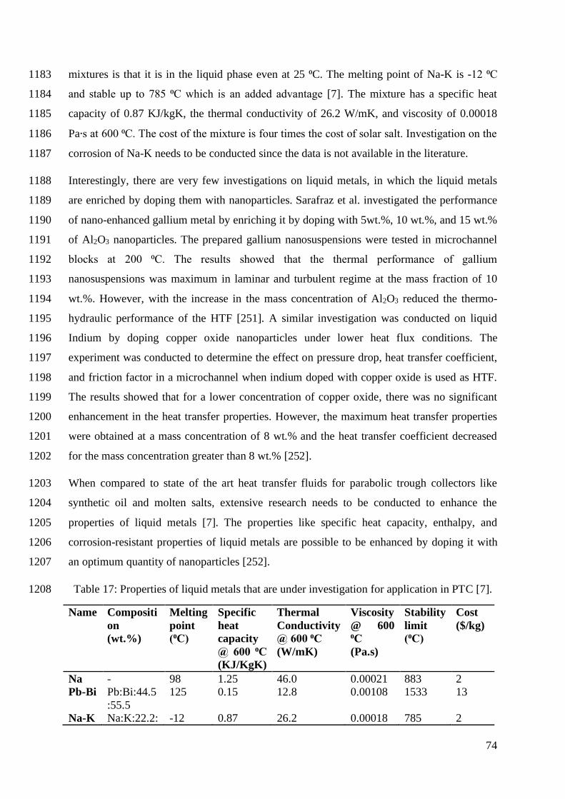
74
mixtures is that it is in the liquid phase even at 25 ⁰C. The melting point of Na-K is -12 ⁰C 1183
and stable up to 785 ⁰C which is an added advantage [7]. The mixture has a specific heat 1184
capacity of 0.87 KJ/kgK, the thermal conductivity of 26.2 W/mK, and viscosity of 0.00018 1185
Pa∙s at 600 ⁰C. The cost of the mixture is four times the cost of solar salt. Investigation on the 1186
corrosion of Na-K needs to be conducted since the data is not available in the literature. 1187
Interestingly, there are very few investigations on liquid metals, in which the liquid metals 1188
are enriched by doping them with nanoparticles. Sarafraz et al. investigated the performance 1189
of nano-enhanced gallium metal by enriching it by doping with 5wt.%, 10 wt.%, and 15 wt.% 1190
of Al2O3 nanoparticles. The prepared gallium nanosuspensions were tested in microchannel 1191
blocks at 200 ⁰C. The results showed that the thermal performance of gallium 1192
nanosuspensions was maximum in laminar and turbulent regime at the mass fraction of 10 1193
wt.%. However, with the increase in the mass concentration of Al2O3 reduced the thermo-1194
hydraulic performance of the HTF [251]. A similar investigation was conducted on liquid 1195
Indium by doping copper oxide nanoparticles under lower heat flux conditions. The 1196
experiment was conducted to determine the effect on pressure drop, heat transfer coefficient, 1197
and friction factor in a microchannel when indium doped with copper oxide is used as HTF. 1198
The results showed that for a lower concentration of copper oxide, there was no significant 1199
enhancement in the heat transfer properties. However, the maximum heat transfer properties 1200
were obtained at a mass concentration of 8 wt.% and the heat transfer coefficient decreased 1201
for the mass concentration greater than 8 wt.% [252]. 1202
When compared to state of the art heat transfer fluids for parabolic trough collectors like 1203
synthetic oil and molten salts, extensive research needs to be conducted to enhance the 1204
properties of liquid metals [7]. The properties like specific heat capacity, enthalpy, and 1205
corrosion-resistant properties of liquid metals are possible to be enhanced by doping it with 1206
an optimum quantity of nanoparticles [252]. 1207
Table 17: Properties of liquid metals that are under investigation for application in PTC [7]. 1208
Name Compositi
on
(wt.%)
Melting
point
(⁰C)
Specific
heat
capacity
@ 600 ⁰C
(KJ/KgK)
Thermal
Conductivity
@ 600 ⁰C
(W/mK)
Viscosity
@ 600
⁰C
(Pa.s)
Stability
limit
(⁰C)
Cost
($/kg)
Na - 98 1.25 46.0 0.00021 883 2
Pb-Bi Pb:Bi:44.5
:55.5
125 0.15 12.8 0.00108 1533 13
Na-K Na:K:22.2: -12 0.87 26.2 0.00018 785 2

75
77.8
1209
3.7. Ionic Liquids 1210
High thermal energy storage capacity and high thermal stability are considered as significant 1211
requirements for the next generation of solar thermal collectors in terms of cost-effectiveness 1212
[253]. Ionic liquids (ILs) have promising potential as working fluids, especially for the next 1213
generation solar thermal collectors due to the superior thermo-physical properties. The unique 1214
combination of properties of ILs such as negligible volatility, electrochemical stability, 1215
thermal stability, and ionic conductivity highlights the use of these materials as a supreme 1216
replacement for volatile organic solvents [254]. Due to the presence of the enormous number 1217
of anions and cations, there is a large number of possibilities for the proposed ILs with 1218
varying properties. Organic cations (imidazolium, pyrazolium, triazolium, thiazolium, 1219
oxazdium, pyridinium, pyridazinium, pyrimidinium, and pyrazinium) and organic or 1220
inorganic anions (halogen, fluorinated) are a major part of the ILs. However, relatively few 1221
applications have considered these materials (ILs) due to the physical properties (notable 1222
viscosity) which limits the applicability of ILs. This drawback can be addressed by using 1223
molecular solvents, although lower thermal stability might be considered as another issue of 1224
using molecular solvent for reducing viscosity. A mixture of a variety of ILs (IL-ILs mixture) 1225
seems a possible method to maintain the desirable properties of these materials. There are 1226
several applications with IL-ILs mixture that indicates promising consequential outputs 1227
comprised of dye-sensitized solar cells [255], solvent reaction media [256], gas solubilities 1228
[257] and a gas chromatography stationary phase [258]. According to the literature, there 1229
have been some limitations of physical measurements for IL-ILs mixtures including melting 1230
performance [259], nanostructures [260], molecular interrelation [261], dielectric 1231
measurements [262], transport and volumetric properties [263], responses to solvatochromic 1232
probes [264] and optical heterodyne-detected Raman-induced Kerr effect spectroscopy 1233
(OHD-RIKES) [265]. ILs are a specific class of molten salt with a low melting point of less 1234
than 100 °C as heat transfer fluids (HTFs) with maximum operating temperature of 459 °C 1235
[266]. A recent study has revealed that ILs have less thermal stability in the range of 200-250 1236
°C [267]. The operation of the collector field with Therminol VP-1 is similar to the collector 1237
which is operated with IL. Despite that ILs are expected to operate as high-temperature HTF 1238
for parabolic trough power plants, but there is scarce available data on corrosiveness, 1239
hydrogen formation or freezing of these materials during operation. In terms of safety 1240

76
aspects, ILs are eco-friendly materials with low environmental effects and considered as not 1241
toxic, not flammable and not hazardous [268]. Eck et al. reported that the expected price for 1242
IL is meager, but due to the low operation temperature, the efficiency of the power block will 1243
be lower too. Due to this deficiency (low operation temperature), there is a necessity of 1244
increasing the collector field size which will outweigh the cost-effectiveness of the HTF (IL). 1245
Paul TC et al. [269] evaluated the effectiveness of the IL induced with nanoparticles in 1246
parabolic trough collectors. They used Al2O3 nanoparticles with a concentration ratio of 0.9 1247
wt% and reported thermal conductivity enhancement by 11% and heat capacity increment by 1248
49%. Bridges et al. [270] mentioned that Nanoparticle Enhanced Ionic Liquids (NEILs) based 1249
HTF are fulfilling the required characteristics for concentrated sola power (CSP) systems. 1250
According to Nieto de Castro et al. [271] IoNanofluids, a combination of several imidazolium 1251
and pyrrolidinium based ILs/MWCNTs represents higher heat capacity and thermal 1252
conductivity in compare with the base ILs. Bridges et al. [270] mixed 1-Butyl-2,3-1253
dimethylimidazolium bis(trifluoromethylsulfonyl)imide ([C4mmim][NTf2]) with Al2O3 1254
nanoparticles (40 nm) and achieved enhancement by 40 % at volumetric heat capacity. In the 1255
conducted experiments by Wittmar et al.[272] they used hydrophobic and hydrophilic 1256
imidazolium-based ionic liquids with surface-functionalized SiO2 with achievement of 1257
higher colloidal stability and promising rheological performance. The effect of particle size, 1258
surface state and volume fraction of gold nanoparticles on thermal conductivity of a stable 1259
ionic liquid based nanofluid proved significant improvement in thermal conductivity value 1260
[273]. Perissi et al. [274] evaluated the corrosiveness of four different ILs in contact with 1261
AISI 304 and AISI 1080 steels (frequently used in solar collector plants). They conducted the 1262
experiments at 220 °C within ten days. According to their experiments, the resistance of the 1263
corrosion-resistance of the steel substances in contact with different ILs is still not 1264
satisfactory in the working operating temperature of parabolic trough collectors (220 °C) in 1265
open-air condition and more studies are necessary to be conducted comprehensively. Wu et 1266
al.[266] synthesized many types of ILs such as [C4min][PF6], [C8min][PF6], 1267
[C4min][bistrifluromethane sulflonimide], [C4min][BF4], [C8min][BF4] and 1268
[C4min][bistrifluromethane sulflonimide] and conducted comprehensive study in term of 1269
thermos-physical properties such as degradation temperature, melting point, viscosity, heat 1270
capacity and thermal conductivity. They found highly promising thermal storage and heat 1271
transfer properties for the studied ILs which proved the excellent performance of these 1272
materials for solar thermal power plants. Jian Liu et al. [275] studied experimentally and 1273
numerically ionic liquid/graphene nanofluids as a special heat transfer fluid with high 1274

77
stability and very low vapor pressure (highly desirable characters) for both concentrated solar 1275
collector and high temperature direct solar collectors. They reported that with concentration 1276
of 0.0005 wt% of graphene in 5 cm receiver under 20 kW m-2 the receiver efficiency could 1277
be maintained 0.7 at 600 K. Zhang et al. [276] showed that addition of small amount of 1278
carbon-coated Ni (Ni/C) to [HMIM][MTF2] can noticeably enhance optical properties of the 1279
ILs. 1280
3.8. Vegetable oil 1281
Vegetable oil is used in food processing industries, electrical industries, cutting oil for 1282
machining, biodiesels for the internal combustion engine and HTF for heating and cooling 1283
applications. However, due to depletion in fossil fuel reserves, vegetable oil is an alternative 1284
for high-temperature applications, especially solar thermal plants. Moreover, vegetable oil 1285
has thermophysical properties like thermal oil used for solar power applications. Very less 1286
work has been done in the thermophysical and rheological study of vegetable oil as HTF. 1287
Pikra et al.[277] investigated the development of a small-scale concentrated power plant of 1288
10 kWel utilizing parabolic trough as a solar collector and used palm oil as the HTF and TES. 1289
They picked palm oil rather than mineral oil due to accessibility, ease, and comparable 1290
physical properties with synthetic oil and mineral oil. The TES capacity limit of the small-1291
scale plant is 107 kW for 6 h run time with palm oil temperatures of 150 °C and 200 °C, for 1292
the low and high working temperature respectively. 1293
Hoffmann et al. investigated density, specific heat and thermal conductivity of soybean, 1294
palm, rapeseed, sunflower, copra, and jatropha oils at the temperature range of ambient and 1295
250⁰C. They found that rapeseed oil offered better thermophysical properties at 210⁰C; results 1296
showed that thermal conductivity, dynamic viscosity, specific heat, and density was 0.14 1297
W/mK, 3.2 mPas, 2.49 kJ/ kgK, and 788 kg/m3 respectively. It was found that all seven 1298
vegetable oils had similar heat transfer properties. Vegetable oils are widely used in solar 1299
CSP due to their low cost, availability, biodegradability, and lower greenhouse gas emissions. 1300
However, the main disadvantage of vegetable oils is their tendency to oxidate. Therefore, 1301
substantial research is required to enhance their oxidation stability, to provide adequate 1302
feedback on their application [278]. 1303

78
4. Prospects of parabolic trough collector 1304
The parabolic trough collector is considered as the future of clean energy generation 1305
technology. The cost of PTC has radically reduced, and the performance has drastically 1306
enhanced due to the extensive research conducted on PTC by research institutes like 1307
International Energy Agency (IEA) on solar projects like SolarPACES [279]. Due to the 1308
enhancement in the performance of pilot plants, R&D in large scale testing of PTC plants, 1309
and increased mass production of these power plants, made PTCs to produce lowest cost 1310
green energy in the world and promises competitiveness in cost with fossil fuel utilizing 1311
power plants [280]. Due to the design parameters of PTC and its thermal characteristics, the 1312
PTC can be hybridized in many ways to improve the availability of power by the system. The 1313
PTC power plant can be hybridized with fossil fuel or natural gas power plants to produce 1314
power round the clock which in turn will cut the cost of power production. PTC along with a 1315
photovoltaic and thermoelectric generator, will be an innovative way to enhance the 1316
performance of the photovoltaic systems and augment the overall thermal efficiency of the 1317
PTC [281]. 1318
Various methods have been adopted to reduce the losses and improve the thermal efficiency 1319
of the PTC. By optimizing the design of the collectors and refining the operation and 1320
maintenance procedures, Karmer junction PTC power plant achieved a 30% reduction in their 1321
operation and maintenance cost [282]. The critical investigation of using water as HTF 1322
instead of synthetic oil in order to reduce the cost must be conducted. Using nanofluids must 1323
not get restricted for experimentation in laboratories but also need to be applied in pilot plants 1324
to observe the broader effect of nanofluids on the thermal performance of the PTC power 1325
plant. For instance, doping nanoparticles in molten salt will enhance the specific heat 1326
capacity of the HTF which in turn boosts the thermal energy storage capacity of the plant 1327
[283]. 1328
5. Conclusion 1329
Parabolic Trough collectors are the most developed among concentrated solar power 1330
technologies, having medium and high temperature working range. The objective of this 1331
review is to present and discuss various heat transfer fluid applicable for PTC systems. While 1332
discussing the HTFs, it is also essential to present the literature on its preparation and 1333
thermophysical properties, which will help in designing the PTC systems. Various state of the 1334

79
art HTFs are reviewed in this article focusing on the enhancement of the overall thermal 1335
efficiency of PTC systems. The most important conclusion of this survey is summarised 1336
below: 1337
• The thermophysical properties which govern the selection of HTF are low melting 1338
point, stability at high temperature >400 ⁰C, low pressure (<1atm), high specific heat 1339
or heat storage capacity, high thermal conductivity, low corrosion rate, low dynamic 1340
viscosity, low cost, low toxicity flammability, and explosivity and Industrial 1341
availability. 1342
• Enhancement in thermal properties like specific heat, melting point, thermal 1343
conductivity, stability at a high temperature of HTF is more promising option to 1344
improve the thermal efficiency of PTC systems because thermal modifications of the 1345
physical system can enhance efficiency up to 2% only, due to low thermal losses in 1346
the physical system. 1347
• One of the most suitable ways to enhance thermal efficiency is by using HTF having 1348
superior thermophysical properties. Instead of using water as HTF, HTFs with higher 1349
latent heat capacity than water can be used in the system. This will also help in TES, 1350
increasing the power output of the system. 1351
• Adding Nanoparticles to HTFs to modify the thermal properties like specific heat and 1352
melting point will make the HTFs, more suitable for PTC applications. The addition 1353
of Nanoparticles like CuO, Ag, SiO2, MWCNT, CNT, and hybrid mixtures will 1354
enhance the thermal conductivity of HTFs. However, the stability of nanoparticles in 1355
the base fluid is an important issue that needs to be addressed to make the PTC system 1356
entirely depend on HTFs doped with nanoparticles. Also, there is a need for 1357
investigating the optical and thermal performances of nanofluids at high temperatures. 1358
• To overcome the stability of nanoparticles in the base fluid MSBNFs are introduced 1359
to PTC systems. State of the art Molten salts used in the PTC systems are discussed in 1360
the article. 1361
• The stability of both Nanofluids and MSBNFs is surveyed, and recent works in the 1362
area are presented. In which the addition of NPs in Molten salt has reduced the 1363
melting temperature when compared to base molten salt, making it suitable for PTC 1364
applications. 1365

80
This article can be used as a guideway for the development of alternative HTFs for PTC 1366
systems for better performance. There is a need for experimentation and comparative study 1367
on a large scale in solar fields rather than laboratory-scale experiments to gain more 1368
promising and practical results. 1369

81
Acknowledgment 1370
This work was supported by Taylor’s University through its TAYLOR’S RESEARCH 1371
SCHOLARSHIP Programme. The authors would like to thank Mohd Najib, Universiti Tun 1372
Hussein Onn Malaysia (UTHM) Johor for proof reading this review article. 1373

82
References 1374
[1] I.E.A. (IEA), Global energy and CO2 status report, IEA, 2018. 1375
[2] S. Sripadmanabhan Indira, C. Aravind Vaithilingam, K.S.P. Oruganti, F. Mohd, S. 1376
Rahman, Nanogenerators as a Sustainable Power Source: State of Art, Applications, and 1377
Challenges, Nanomaterials, 9(5) (2019) 773. 1378
[3] N.S. Lewis, D.G. Nocera, Powering the planet: Chemical challenges in solar energy 1379
utilization, Proceedings of the National Academy of Sciences, 103(43) (2006) 15729-15735. 1380
[4] N.S. Lewis, Research opportunities to advance solar energy utilization, Science, 1381
351(6271) (2016) aad1920. 1382
[5] Y. Wang, X. Gao, P. Chen, Z. Huang, T. Xu, Y. Fang, Z. Zhang, Preparation and thermal 1383
performance of paraffin/Nano-SiO2 nanocomposite for passive thermal protection of 1384
electronic devices, Applied Thermal Engineering, 96 (2016) 699-707. 1385
[6] S. Dubey, J.N. Sarvaiya, B. Seshadri, Temperature Dependent Photovoltaic (PV) 1386
Efficiency and Its Effect on PV Production in the World – A Review, Energy Procedia, 33 1387
(2013) 311-321. 1388
[7] K. Vignarooban, Xinhai Xu, A. Arvay, K. Hsu, A.M. Kannan, Heat transfer fluids for 1389
concentrating solar power systems – A review, Applied Energy, 146 (2015) 383-396. 1390
[8] S. Akbarzadeh, M.S. Valipour, Heat transfer enhancement in parabolic trough collectors: 1391
A comprehensive review, Renewable and Sustainable Energy Reviews, 92 (2018) 198-218. 1392
[9] A. Bonk, S. Sau, N. Uranga, M. Hernaiz, T. Bauer, Advanced heat transfer fluids for 1393
direct molten salt line-focusing CSP plants, Progress in energy and combustion science, 67 1394
(2018) 69-87. 1395
[10] K. Farhana, K. Kadirgama, M.M. Rahman, D. Ramasamy, M.M. Noor, G. Najafi, M. 1396
Samykano, A.S.F. Mahamude, Improvement in the performance of solar collectors with 1397
nanofluids — A state-of-the-art review, Nano-Structures & Nano-Objects, 18 (2019) 100276. 1398
[11] AsianBiomassOffice, Progress Seen in the Development of Concentrating Solar Power 1399
in India, in, 2018. 1400
[12] E. World Bank Group, Solargis, Solar Resource Map Direct Solar Irradiation, in, 2016. 1401
[13] E. Yin, Q. Li, Y. Xuan, Optimal design method for concentrating photovoltaic-1402
thermoelectric hybrid system, Applied Energy, 226 (2018) 320-329. 1403
[14] M.T. Islam, N. Huda, A.B. Abdullah, R. Saidur, A comprehensive review of state-of-1404
the-art concentrating solar power (CSP) technologies: Current status and research trends, 1405
Renewable and Sustainable Energy Reviews, 91 (2018) 987-1018. 1406
[15] Ali Jaber Abdulhamed, Nor Mariah Adam, Mohd Zainal Abidin Ab-Kadir, A.A. 1407
Hairuddin, Review of solar parabolic-trough collector geometrical and thermal analyses, 1408
performance, and applications, Renewable and Sustainable Energy Reviews, 91 (2018) 822-1409
831. 1410
[16] C. Bachelier, W. Jäger, Thermal and hydraulic evaluation of a linear Fresnel solar 1411
collector loop operated with molten salt and liquid metal, Applied Energy, 248 (2019) 207-1412
216. 1413

83
[17] M Abid, TAH Ratlamwala, U.Atikol, Performance assessment of parabolic dish and 1414
parabolic trough solar thermal power plant using nanofluids and molten salts, International 1415
journal of energy research, 40(4) (2016). 1416
[18] M. Atif, F. Al-Sulaiman, Supercritical Carbon Dioxide Brayton Cycles Driven by Solar 1417
Thermal Power Tower System, Advanced Materials Research, 1116 (2015) 94-129. 1418
[19] A.A. Mills, R. Clift, Reflections of the'Burning mirrors of Archimedes'. With a 1419
consideration of the geometry and intensity of sunlight reflected from plane mirrors, 1420
European journal of physics, 13(6) (1992) 268. 1421
[20] A.B. Mouchot, (La) Chaleur solaire et ses applications industrielles, Gauthier-Villars, 1422
1869. 1423
[21] C. Silvi, The use of solar energy in human activities throughout the centuries. Steam and 1424
Electricity Generated From Solar Heat with Flat Mirrors: An Italian Story, GSES – Solar 1425
Energy History Group, Italy, 2010. 1426
[22] I.L. García, J.L. Álvarez, D. Blanco, Performance model for parabolic trough solar 1427
thermal power plants with thermal storage: Comparison to operating plant data, Solar Energy, 1428
85(10) (2011) 2443-2460. 1429
[23] R.H. Goddard, A new Inventions to harness the sun, in: Popular scienece Magazine, 1430
USA, 1929, pp. 2. 1431
[24] K. Butti, J. Perlin, A golden thread: 2500 years of solar architecture and technology, 1432
Cheshire books, 1980. 1433
[25] W.B.S.a. R.W.Harrigan, Power From The Sun, in: Power From The Sun, John Wiley 1434
and Sons, Inc. 1986, 2011. 1435
[26] T.W. Africa, Archimedes through the looking-glass, The Classical World, 68(5) (1975) 1436
305-308. 1437
[27] D. Mills, P. Le Lievre, G. Morrison, First results from compact linear Fresnel reflector 1438
installation, Proceedings of ANZSES Solar2004, (2004). 1439
[28] A. Giostri, M. Binotti, M. Astolfi, P. Silva, E. Macchi, G. Manzolini, Comparison of 1440
different solar plants based on parabolic trough technology, Solar Energy, 86(5) (2012) 1208-1441
1221. 1442
[29] T.M. Pavlović, I.S. Radonjić, D.D. Milosavljević, L.S. Pantić, A review of concentrating 1443
solar power plants in the world and their potential use in Serbia, Renewable and Sustainable 1444
Energy Reviews, 16(6) (2012) 3891-3902. 1445
[30] J.I. Burgaleta, S. Arias, D. Ramirez, Gemasolar, the first tower thermosolar commercial 1446
plant with molten salt storage, SolarPACES, Granada, Spain, (2011) 20-23. 1447
[31] Y. Tian, C.-Y. Zhao, A review of solar collectors and thermal energy storage in solar 1448
thermal applications, Applied Energy, 104 (2013) 538-553. 1449
[32] S.-W. World Solar Thermal Electricity Association, STE/CSP TECHNOLOGIES > 1450
LINEAR FRESNEL REFLECTOR, in. 1451
[33] R. De Groot, V. Van der Veen, A. Sebitosi, Comparing solar PV (photovoltaic) with 1452
coal-fired electricity production in the centralized network of South Africa, Energy, 55 1453
(2013) 823-837. 1454

84
[34] C. Tzivanidis, E. Bellos, D. Korres, K.A. Antonopoulos, G. Mitsopoulos, Thermal and 1455
optical efficiency investigation of a parabolic trough collector, Case Studies in Thermal 1456
Engineering, 6 (2015) 226-237. 1457
[35] E. Bellos, D. Korres, C. Tzivanidis, K.A. Antonopoulos, Design, simulation and 1458
optimization of a compound parabolic collector, Sustainable Energy Technologies and 1459
Assessments, 16 (2016) 53-63. 1460
[36] Arslan F Mertkan, G. Hüseyin, Investigation of energetic and exergetic performances of 1461
parabolic trough collector with using different heat transfer fluids., in: CLIMA 2019, Les 1462
Ulis, 2019. 1463
[37] X. Ju, C. Xu, G. Wei, X. Du, Y. Yang, A novel hybrid storage system integrating a 1464
packed-bed thermocline tank and a two-tank storage system for concentrating solar power 1465
(CSP) plants, Applied Thermal Engineering, 92 (2016) 24-31. 1466
[38] N. Enteria, A. Akbarzadeh, Solar energy sciences and engineering applications, CRC 1467
Press, 2013. 1468
[39] E. Bellos, C. Tzivanidis, K.A. Antonopoulos, I. Daniil, The use of gas working fluids in 1469
parabolic trough collectors – An energetic and exergetic analysis, Applied Thermal 1470
Engineering, 109 (2016) 1-14. 1471
[40] H. Riazi, T. Murphy, G.B. Webber, R. Atkin, S.S.M. Tehrani, R.A. Taylor, Specific heat 1472
control of nanofluids: A critical review, International Journal of Thermal Sciences, 107 1473
(2016) 25-38. 1474
[41] R. Devaradjane, Utilization of molten nitrate salt nanomaterials for heat capacity 1475
enhancement in solar power applications, rc.library.uta.edu, 2013. 1476
[42] S. Gschwander, T. Haussmann, G. Hagelstein, A. Sole, G. Diarce, W. Hohenauer, D. 1477
Lager, C. Rathgeber, P. Hennemann, A. Lazaro, Standard to determine the heat storage 1478
capacity of PCM using hf-DSC with constant heating/cooling rate (dynamic mode) DSC 1479
4229 PCM Standard, A technical report of subtask, 2015. 1480
[43] A. Solé, L. Miró, C. Barreneche, I. Martorell, L.F. Cabeza, Review of the T-history 1481
method to determine thermophysical properties of phase change materials (PCM), Renewable 1482
and Sustainable Energy Reviews, 26 (2013) 425-436. 1483
[44] J.W. Raade, D. Padowitz, Development of Molten Salt Heat Transfer Fluid With Low 1484
Melting Point and High Thermal Stability, Journal of Solar Energy Engineering, 133(3) 1485
(2011). 1486
[45] T. Bauer, N. Pfleger, N. Breidenbach, M. Eck, D. Laing, S. Kaesche, Material aspects of 1487
Solar Salt for sensible heat storage, Applied Energy, 111 (2013) 1114-1119. 1488
[46] M.V. Smirnov, V.A. Khokhlov, E.S. Filatov, Thermal conductivity of molten alkali 1489
halides and their mixtures, Electrochimica Acta, 32(7) (1987) 1019-1026. 1490
[47] Q. Peng, J. Ding, X. Wei, J. Yang, X. Yang, The preparation and properties of multi-1491
component molten salts, Applied Energy, 87(9) (2010) 2812-2817. 1492
[48] R.H. Perry, D.W.G. (Eds.), Perry’s Chemical Engineers’ Handbook, seventh ed., 1493
McGraw-Hill, 1997. 1494
[49] Y. Rong, C.M. Gregson, A. Parker, Thermogravimetric measurements of liquid vapor 1495
pressure, The Journal of Chemical Thermodynamics, 51 (2012) 25-30. 1496

85
[50] R.B. Cundall, T. Frank Palmer, C.E.C. Wood, Vapour pressure measurements on some 1497
organic high explosives, Journal of the Chemical Society, Faraday Transactions 1: Physical 1498
Chemistry in Condensed Phases, 74(0) (1978) 1339-1345. 1499
[51] M. Chieruzzi, A. Miliozzi, T. Crescenzi, L. Torre, J.M. Kenny, A new phase change 1500
material based on potassium nitrate with silica and alumina nanoparticles for thermal energy 1501
storage, Nanoscale research letters, 10(1) (2015) 273. 1502
[52] D. Shin, D. Banerjee, Enhanced thermal properties of SiO2 nanocomposite for solar 1503
thermal energy storage applications, International Journal of Heat and Mass Transfer, 84 1504
(2015) 898-902. 1505
[53] Y.Y. Chen, C.Y. Zhao, Thermophysical properties of Ca(NO3)2-NaNO3-KNO3 1506
mixtures for heat transfer and thermal storage, Solar Energy, 146 (2017) 172-179. 1507
[54] S.U. Ilyas, R. Pendyala, M. Narahari, Stability and thermal analysis of MWCNT-thermal 1508
oil-based nanofluids, Colloids and Surfaces A: Physicochemical and Engineering Aspects, 1509
527 (2017) 11-22. 1510
[55] B. Wei, C. Zou, X. Li, Experimental investigation on stability and thermal conductivity 1511
of diathermic oil based TiO2 nanofluids, International Journal of Heat and Mass Transfer, 1512
104 (2017) 537-543. 1513
[56] H. Yarmand, S. Gharehkhani, S.F.S. Shirazi, M. Goodarzi, A. Amiri, W.S. Sarsam, M.S. 1514
Alehashem, M. Dahari, S.N. Kazi, Study of synthesis, stability and thermo-physical 1515
properties of graphene nanoplatelet/platinum hybrid nanofluid, International Communications 1516
in Heat and Mass Transfer, 77 (2016) 15-21. 1517
[57] A. Asadi, M. Asadi, A. Rezaniakolaei, L.A. Rosendahl, M. Afrand, S. Wongwises, Heat 1518
transfer efficiency of Al2O3-MWCNT/thermal oil hybrid nanofluid as a cooling fluid in 1519
thermal and energy management applications: An experimental and theoretical investigation, 1520
International Journal of Heat and Mass Transfer, 117 (2018) 474-486. 1521
[58] M. Chieruzzi, G.F. Cerritelli, A. Miliozzi, J.M. Kenny, Effect of nanoparticles on heat 1522
capacity of nanofluids based on molten salts as PCM for thermal energy storage, Nanoscale 1523
research letters, 8(1) (2013) 448. 1524
[59] R. Silva, F.J. Cabrera, M. Pérez-García, Process Heat Generation with Parabolic Trough 1525
Collectors for a Vegetables Preservation Industry in Southern Spain, Energy Procedia, 48 1526
(2014) 1210-1216. 1527
[60] G. Coccia, G. Di Nicola, M. Sotte, Design, manufacture, and test of a prototype for a 1528
parabolic trough collector for industrial process heat, Renewable Energy, 74 (2015) 727-736. 1529
[61] A. Fernández-García, E. Zarza, L. Valenzuela, M. Pérez, Parabolic-trough solar 1530
collectors and their applications, Renewable and Sustainable Energy Reviews, 14(7) (2010) 1531
1695-1721. 1532
[62] Andrea Giglio, Andrea Lanzini, Pierluigi Leone, Margarita M.Rodríguez García, 1533
Eduardo Zarza Moyab, Direct steam generation in parabolic-trough collectors: a review about 1534
the technology and a thermo-economic analysis of a hybrid system, Renewable and 1535
Sustainable Energy Reviews, 74 (2017) 453-473. 1536
[63] H.Benoit, L.Spreafico, D.Gauthier, G.Flaman, Review of heat transfer fluids in tube-1537
receivers used in concentrating solar thermal systems: Properties and heat transfer 1538
coefficients, Renewable and Sustainable Energy Reviews, 55 (2016) 298-315. 1539

86
[64] P. Selvakumar, P. Somasundaram, P. Thangavel, Performance study on evacuated tube 1540
solar collector using therminol D-12 as heat transfer fluid coupled with parabolic trough, 1541
Energy Conversion and Management, 85 (2014) 505-510. 1542
[65] D.G. Lovering, Molten salt technology, Springer Science + Bussiness Media, 2014. 1543
[66] A.M. Weinberg, A review of molten salt reactor technology. Preface. Molten-salt 1544
reactors, in, 1970. 1545
[67] H. Zhang, J. Baeyens, J. Degrève, G. Cacères, Concentrated solar power plants: Review 1546
and design methodology, Renewable and Sustainable Energy Reviews, 22 (2013) 466-481. 1547
[68] V.M.B. Nunes, C.S. Queirós, M.J.V. Lourenço, F.J.V. Santos, C.A. Nieto de Castro, 1548
Molten salts as engineering fluids – A review: Part I. Molten alkali nitrates, Applied Energy, 1549
183 (2016) 603-611. 1550
[69] Y. Wang, Q. Liu, J. Lei, H. Jin, A three-dimensional simulation of a parabolic trough 1551
solar collector system using molten salt as heat transfer fluid, Applied Thermal Engineering, 1552
70(1) (2014) 462-476. 1553
[70] T. Bauer, N. Pfleger, D. Laing, W.-D. Steinmann, M. Eck, S. Kaesche, 20 - High-1554
Temperature Molten Salts for Solar Power Application, in: F. Lantelme, H. Groult (Eds.) 1555
Molten Salts Chemistry, Elsevier, Oxford, 2013, pp. 415-438. 1556
[71] M. Chieruzzi, Nanofluids with Enhanced Heat Transfer Properties for Thermal Energy 1557
Storage, Rome, Italy, 2016. 1558
[72] T. Jriri, J. Rogez, C. Bergman, J. Mathieu, Thermodynamic study of the condensed 1559
phases of NaNO3, KNO3 and CsNO3 and their transitions, Thermochimica Acta, 266 (1995) 1560
147-161. 1561
[73] K. Coscia, T. Elliott, S. Mohapatra, A. Oztekin, S. Neti, Binary and Ternary Nitrate 1562
Solar Heat Transfer Fluids, Journal of Solar Energy Engineering, 135(2) (2013) 021011-1563
021011-021016. 1564
[74] M. Chen, Y. Shen, S. Zhu, P. Li, Digital phase diagram and thermophysical properties of 1565
KNO3-NaNO3-Ca(NO3)2 ternary system for solar energy storage, Vacuum, 145 (2017) 225-1566
233. 1567
[75] P. Xiao, L. Guo, X. Zhang, Investigations on heat transfer characteristic of molten salt 1568
flow in helical annular duct, Applied Thermal Engineering, 88 (2015) 22-32. 1569
[76] A. Fernández, S. Ushak, H. Galleguillos, F. Pérez, Development of new molten salts 1570
with LiNO3 and Ca (NO3) 2 for energy storage in CSP plants, Elsevier, 2014. 1571
[77] C. Zhao, Z. Wu, Thermal property characterization of a low melting-temperature ternary 1572
nitrate salt mixture for thermal energy storage systems, Solar Energy Materials and Solar 1573
Cells, 95(12) (2011) 3341-3346. 1574
[78] Yathin Krishna, R Saidur, Navid Aslfattahi, Mohd Faizal Fauzan, K. Ng, Enhancing the 1575
Thermal properties of Organic Phase Change Material (palmitic acid) by doping MXene 1576
Nanoflakes, in: 13th International Engineering Research Conference (13th EURECA 2019), 1577
AIP Conference Proceedings, Malaysia, 2019. 1578
[79] T. Wang, D. Mantha, R.G. Reddy, Novel low melting point quaternary eutectic system 1579
for solar thermal energy storage, Applied Energy, 102 (2013) 1422-1429. 1580
[80] R.W. Bradshaw, D.A. Brosseau, Low-melting point inorganic nitrate salt heat transfer 1581
fluid, in, Google Patents, 2009. 1582

87
[81] Q. Peng, X. Yang, J. Ding, X. Wei, J. Yang, Design of new molten salt thermal energy 1583
storage material for solar thermal power plant, Applied Energy, 112 (2013) 682-689. 1584
[82] Justin W. Raade, David Padowitz, Development of molten salt heat transfer fluid with 1585
low melting point and high thermal stability, Journal of solar energy engineering, 3(133) 1586
(August 2011). 1587
[83] A.G. Fernández, M.I. Lasanta, F.J. Pérez, Molten Salt Corrosion of Stainless Steels and 1588
Low-Cr Steel in CSP Plants, Oxidation of Metals, 78(5) (2012) 329-348. 1589
[84] E. Bellos, C. Tzivanidis, K.A. Antonopoulos, A detailed working fluid investigation for 1590
solar parabolic trough collectors, Applied Thermal Engineering, 114 (2017) 374-386. 1591
[85] M.J. Montes, A. Abánades, J.M. Martínez-Val, Thermofluidynamic Model and 1592
Comparative Analysis of Parabolic Trough Collectors Using Oil, Water/Steam, or Molten 1593
Salt as Heat Transfer Fluids, Journal of Solar Energy Engineering, 132(2) (2010). 1594
[86] Yathin Krishna, Abdul Razak R. K, A. Afzal, The CFD analysis of flat plate collector-1595
nanofluid as working medium, AIP Conference Proceedings, 2039(1) (2018) 020062. 1596
[87] M.M. Sarafraz, O. Pourmehran, B. Yang, M. Arjomandi, Assessment of the thermal 1597
performance of a thermosyphon heat pipe using zirconia-acetone nanofluids, Renewable 1598
Energy, 136 (2019) 884-895. 1599
[88] M.M. Sarafraz, M.R. Safaei, Diurnal thermal evaluation of an evacuated tube solar 1600
collector (ETSC) charged with graphene nanoplatelets-methanol nano-suspension, 1601
Renewable Energy, 142 (2019) 364-372. 1602
[89] Sarafraz M.M, Tlili I, Abdul Baseer M, S. M.R, Potential of Solar Collectors for Clean 1603
Thermal Energy Production in Smart Cities using Nanofluids: Experimental Assessment and 1604
Efficiency Improvement., Applied sciences, MDPI, 9(9) (2019) 1877. 1605
[90] M.M. Sarafraz, F. Hormozi, Convective boiling and particulate fouling of stabilized 1606
CuO-ethylene glycol nanofluids inside the annular heat exchanger, International 1607
Communications in Heat and Mass Transfer, 53 (2014) 116-123. 1608
[91] E. Salari, S.M. Peyghambarzadeh, M.M. Sarafraz, F. Hormozi, V. Nikkhah, Thermal 1609
behavior of aqueous iron oxide nano-fluid as a coolant on a flat disc heater under the pool 1610
boiling condition, Heat and Mass Transfer, 53(1) (2017) 265-275. 1611
[92] M.H. Ahmadi, M. Ghazvini, M. Sadeghzadeh, M. Alhuyi Nazari, M. Ghalandari, 1612
Utilization of hybrid nanofluids in solar energy applications: A review, Nano-Structures & 1613
Nano-Objects, 20 (2019) 100386. 1614
[93] E. Kaloudis, E. Papanicolaou, V. Belessiotis, Numerical simulations of a parabolic 1615
trough solar collector with nanofluid using a two-phase model, Renewable Energy, 97 (2016) 1616
218-229. 1617
[94] P.V.W. K. S. Chaudhari, U. S. Wankhede, R. S. Shelke, An Experimental Investigation 1618
of a Nanofluid (Al2O3+H2O) Based Parabolic Trough Solar Collectors, British Journal of 1619
Applied Science & Technology, 9(6) (2015) 7. 1620
[95] G. Coccia, G. Di Nicola, L. Colla, L. Fedele, M. Scattolini, Adoption of nanofluids in 1621
low-enthalpy parabolic trough solar collectors: Numerical simulation of the yearly yield, 1622
Energy Conversion and Management, 118 (2016) 306-319. 1623
[96] S.E. Ghasemi, A.A. Ranjbar, Thermal performance analysis of solar parabolic trough 1624
collector using nanofluid as working fluid: A CFD modelling study, Journal of Molecular 1625
Liquids, 222 (2016) 159-166. 1626

88
[97] A. Mwesigye, Z. Huan, Thermodynamic analysis and optimization of fully developed 1627
turbulent forced convection in a circular tube with water–Al2O3 nanofluid, International 1628
Journal of Heat and Mass Transfer, 89 (2015) 694-706. 1629
[98] M.A. Rehan, M. Ali, N.A. Sheikh, M.S. Khalil, G.Q. Chaudhary, T.u. Rashid, M. 1630
Shehryar, Experimental performance analysis of low concentration ratio solar parabolic 1631
trough collectors with nanofluids in winter conditions, Renewable Energy, 118 (2018) 742-1632
751. 1633
[99] J. Subramani, P.K. Nagarajan, S. Wongwises, S.A. El-Agouz, R. Sathyamurthy, 1634
Experimental study on the thermal performance and heat transfer characteristics of solar 1635
parabolic trough collector using Al2O3 nanofluids, Environmental Progress & Sustainable 1636
Energy, 37(3) (2018) 1149-1159. 1637
[100] J. Subramani, P.K. Nagarajan, O. Mahian, R. Sathyamurthy, Efficiency and heat 1638
transfer improvements in a parabolic trough solar collector using TiO2 nanofluids under 1639
turbulent flow regime, Renewable Energy, 119 (2018) 19-31. 1640
[101] N. Kumar, S.S. Sonawane, Experimental study of Fe2O3/water and Fe2O3/ethylene 1641
glycol nanofluid heat transfer enhancement in a shell and tube heat exchanger, International 1642
Communications in Heat and Mass Transfer, 78 (2016) 277-284. 1643
[102] S.K. Hazra, S. Ghosh, T.K. Nandi, Photo-thermal conversion characteristics of carbon 1644
black-ethylene glycol nanofluids for applications in direct absorption solar collectors, 1645
Applied Thermal Engineering, 163 (2019) 114402. 1646
[103] E. Bellos, C. Tzivanidis, K.A. Antonopoulos, G. Gkinis, Thermal enhancement of solar 1647
parabolic trough collectors by using nanofluids and converging-diverging absorber tube, 1648
Renewable Energy, 94 (2016) 213-222. 1649
[104] A. Allouhi, M. Benzakour Amine, R. Saidur, T. Kousksou, A. Jamil, Energy and 1650
exergy analyses of a parabolic trough collector operated with nanofluids for medium and high 1651
temperature applications, Energy Conversion and Management, 155 (2018) 201-217. 1652
[105] V. Ferraro, J. Settino, M.A. Cucumo, D. Kaliakatsos, Parabolic Trough System 1653
Operating with Nanofluids: Comparison with the Conventional Working Fluids and Influence 1654
on the System Performance, Energy Procedia, 101 (2016) 782-789. 1655
[106] H. Khakrah, A. Shamloo, S. Kazemzadeh Hannani, Determination of Parabolic Trough 1656
Solar Collector Efficiency Using Nanofluid: A Comprehensive Numerical Study, Journal of 1657
Solar Energy Engineering, 139(5) (2017). 1658
[107] T. Sokhansefat, A.B. Kasaeian, F. Kowsary, Heat transfer enhancement in parabolic 1659
trough collector tube using Al2O3/synthetic oil nanofluid, Renewable and Sustainable 1660
Energy Reviews, 33 (2014) 636-644. 1661
[108] P. Mohammad Zadeh, T. Sokhansefat, A.B. Kasaeian, F. Kowsary, A. Akbarzadeh, 1662
Hybrid optimization algorithm for thermal analysis in a solar parabolic trough collector based 1663
on nanofluid, Energy, 82 (2015) 857-864. 1664
[109] N. Basbous, M. Taqi, M.A. Janan, Thermal performances analysis of a parabolic trough 1665
solar collector using different nanofluids, in: 2016 International Renewable and Sustainable 1666
Energy Conference (IRSEC), 2016, pp. 322-326. 1667
[110] E. Bellos, C. Tzivanidis, Parametric investigation of nanofluids utilization in parabolic 1668
trough collectors, Thermal Science and Engineering Progress, 2 (2017) 71-79. 1669

89
[111] E. Bellos, C. Tzivanidis, Thermal analysis of parabolic trough collector operating with 1670
mono and hybrid nanofluids, Sustainable Energy Technologies and Assessments, 26 (2018) 1671
105-115. 1672
[112] E. Bellos, C. Tzivanidis, D. Tsimpoukis, Thermal, hydraulic and exergetic evaluation 1673
of a parabolic trough collector operating with thermal oil and molten salt based nanofluids, 1674
Energy Conversion and Management, 156 (2018) 388-402. 1675
[113] A. Mwesigye, Z. Huan, J.P. Meyer, Thermodynamic optimisation of the performance 1676
of a parabolic trough receiver using synthetic oil–Al2O3 nanofluid, Applied Energy, 156 1677
(2015) 398-412. 1678
[114] A. Mwesigye, Z. Huan, J.P. Meyer, Thermal Performance of a Receiver Tube for a 1679
High Concentration Ratio Parabolic Trough System and Potential for Improved Performance 1680
With Syltherm800-CuO Nanofluid, in: ASME 2015 International Mechanical Engineering 1681
Congress and Exposition, 2015. 1682
[115] Yanjuan Wang, Jinliang Xu, Qibin Liu, Yuanyuan Chen, Huan Liu, Performance 1683
analysis of a parabolic trough solar collector using Al2O3/synthetic oil nanofluid, Applied 1684
Thermal Engineering, 107 (2016) 469-478. 1685
[116] B. Amina, A. Miloud, L. Samir, B. Abdelylah, J.P. Solano, Heat transfer enhancement 1686
in a parabolic trough solar receiver using longitudinal fins and nanofluids, Journal of Thermal 1687
Science, 25(5) (2016) 410-417. 1688
[117] A. Mwesigye, Z. Huan, J.P. Meyer, Thermal performance and entropy generation 1689
analysis of a high concentration ratio parabolic trough solar collector with Cu-1690
Therminol®VP-1 nanofluid, Energy Conversion and Management, 120 (2016) 449-465. 1691
[118] A. Mwesigye, J.P. Meyer, Optimal thermal and thermodynamic performance of a solar 1692
parabolic trough receiver with different nanofluids and at different concentration ratios, 1693
Applied Energy, 193 (2017) 393-413. 1694
[119] A. Mwesigye, J. Meyer, Heat Transfer Performance of a Parabolic Trough Receiver 1695
Using SWCNTs-Therminol® VP-1 Nanofluids, in: ASME International Mechanical 1696
Engineering Congress and Exposition, Proceedings of the ASME 2017, Tampa, Florida, 1697
USA, 2017, pp. 13. 1698
[120] S.E. Ghasemi, A.A. Ranjbar, Effect of using nanofluids on efficiency of parabolic 1699
trough collectors in solar thermal electric power plants, International Journal of Hydrogen 1700
Energy, 42(34) (2017) 21626-21634. 1701
[121] A. Kasaeian, S. Daviran, R.D. Azarian, A. Rashidi, Performance evaluation and 1702
nanofluid using capability study of a solar parabolic trough collector, Energy Conversion and 1703
Management, 89 (2015) 368-375. 1704
[122] A. Ghadimi, R. Saidur, H.S.C. Metselaar, A review of nanofluid stability properties and 1705
characterization in stationary conditions, International Journal of Heat and Mass Transfer, 1706
54(17) (2011) 4051-4068. 1707
[123] Z. Haddad, C. Abid, H.F. Oztop, A. Mataoui, A review on how the researchers prepare 1708
their nanofluids, International Journal of Thermal Sciences, 76 (2014) 168-189. 1709
[124] V. Fuskele, R.M. Sarviya, Recent developments in Nanoparticles Synthesis, 1710
Preparation and Stability of Nanofluids, Materials Today: Proceedings, 4(2, Part A) (2017) 1711
4049-4060. 1712

90
[125] H. Bahremand, A. Abbassi, M. Saffar-Avval, Experimental and numerical investigation 1713
of turbulent nanofluid flow in helically coiled tubes under constant wall heat flux using 1714
Eulerian–Lagrangian approach, Powder Technology, 269 (2015) 93-100. 1715
[126] S. Mirfendereski, A. Abbassi, M. Saffar-avval, Experimental and numerical 1716
investigation of nanofluid heat transfer in helically coiled tubes at constant wall heat flux, 1717
Advanced Powder Technology, 26(5) (2015) 1483-1494. 1718
[127] M. Khoshvaght-Aliabadi, M. Tavasoli, F. Hormozi, Comparative analysis on thermal–1719
hydraulic performance of curved tubes: Different geometrical parameters and working fluids, 1720
Energy, 91 (2015) 588-600. 1721
[128] M. Rakhsha, F. Akbaridoust, A. Abbassi, S.-A. Majid, Experimental and numerical 1722
investigations of turbulent forced convection flow of nano-fluid in helical coiled tubes at 1723
constant surface temperature, Powder Technology, 283 (2015) 178-189. 1724
[129] I.M. Mahbubul, R. Saidur, M.A. Amalina, Thermal Conductivity, Viscosity and 1725
Density of R141b Refrigerant based Nanofluid, Procedia Engineering, 56 (2013) 310-315. 1726
[130] M. Kamalgharibi, F. Hormozi, S.A.H. Zamzamian, M.M. Sarafraz, Experimental 1727
studies on the stability of CuO nanoparticles dispersed in different base fluids: influence of 1728
stirring, sonication and surface active agents, Heat and Mass Transfer, 52(1) (2016) 55-62. 1729
[131] Z.-h. Liu, L. Liao, Sorption and agglutination phenomenon of nanofluids on a plain 1730
heating surface during pool boiling, International Journal of Heat and Mass Transfer, 51(9-1731
10) (2008) 2593-2602. 1732
[132] N. Ise, I. Sogami, Structure Formation in Solution: Ionic Polymers and Colloidal 1733
Particles, in, Springer, Berlin, 2005. 1734
[133] H. Wang, Dispersing carbon nanotubes using surfactants, Current Opinion in Colloid & 1735
Interface Science, 14(5) (2009) 364-371. 1736
[134] X. Yang, Z.-h. Liu, A kind of nanofluid consisting of surface-functionalized 1737
nanoparticles, Nanoscale research letters, 5(8) (2010) 1324. 1738
[135] M. Faizal, R. Saidur, S. Mekhilef, A. Hepbasli, I.M. Mahbubul, Energy, economic, and 1739
environmental analysis of a flat-plate solar collector operated with SiO2 nanofluid, Clean 1740
Technologies and Environmental Policy, 17(6) (2014) 1457–1473. 1741
[136] N.S. Souza, A.D. Rodrigues, C.A. Cardoso, H. Pardo, R. Faccio, A.W. Mombru, J.C. 1742
Galzerani, O.F. de Lima, S. Sergeenkov, F.M. Araujo-Moreira, Physical properties of 1743
nanofluid suspension of ferromagnetic graphite with high Zeta potential, Physics Letters A, 1744
376(4) (2012) 544-546. 1745
[137] Dukhin, Andrei S, Ultrasound for Characterizing Colloids Particle Sizing, Zeta 1746
Potential, Rheology, San Diego, CA: Elsevier, 2002. 1747
[138] S.-C. Yang, S.-Y.-R. Paik, J. Ryu, K.-O. Choi, T.S. Kang, J.K. Lee, C.W. Song, S. Ko, 1748
Dynamic light scattering-based method to determine primary particle size of iron oxide 1749
nanoparticles in simulated gastrointestinal fluid, Food Chemistry, 161 (2014) 185-191. 1750
[139] C. Wang, X. Zhang, M. Su, Synthesis and thermal stability of Field’s alloy 1751
nanoparticles and nanofluid, Materials Letters, 205 (2017) 6-9. 1752
[140] M.M. Bhunia, S. Das, K.K. Chattopadhyay, P. Chattopadhyay, Enhanced heat transfer 1753
properties of RGO-TiO2 based Ethylene Glycol Nanofluids, Materials Today: Proceedings, 1754
18 (2019) 1096-1107. 1755

91
[141] P.C. Mukesh Kumar, K. Palanisamy, V. Vijayan, Stability analysis of heat transfer 1756
hybrid/water nanofluids, Materials Today: Proceedings, (2019). 1757
[142] H. Karami, S. Papari-Zare, M. Shanbedi, H. Eshghi, A. Dashtbozorg, A. Akbari, E. 1758
Mohammadian, M. Heidari, A.Z. Sahin, C.B. Teng, The thermophysical properties and the 1759
stability of nanofluids containing carboxyl-functionalized graphene nano-platelets and multi-1760
walled carbon nanotubes, International Communications in Heat and Mass Transfer, 108 1761
(2019) 104302. 1762
[143] V. Singh, M. Gupta, Characterisation and Zeta Potential Measurements of CuO–Water 1763
Nanofluids, in: M. Kumar, R.K. Pandey, V. Kumar (Eds.) Advances in Interdisciplinary 1764
Engineering, Springer Singapore, Singapore, 2019, pp. 741-747. 1765
[144] S. Aberoumand, A. Jafarimoghaddam, Tungsten (III) oxide (WO3) – Silver/transformer 1766
oil hybrid nanofluid: Preparation, stability, thermal conductivity and dielectric strength, 1767
Alexandria Engineering Journal, 57(1) (2018) 169-174. 1768
[145] A. Yasinskiy, J. Navas, T. Aguilar, R. Alcántara, J.J. Gallardo, A. Sánchez-Coronilla, 1769
E.I. Martín, D. De Los Santos, C. Fernández-Lorenzo, Dramatically enhanced thermal 1770
properties for TiO2-based nanofluids for being used as heat transfer fluids in concentrating 1771
solar power plants, Renewable Energy, 119 (2018) 809-819. 1772
[146] A. Asadi, A guideline towards easing the decision-making process in selecting an 1773
effective nanofluid as a heat transfer fluid, Energy Conversion and Management, 175 (2018) 1774
1-10. 1775
[147] R. Gómez-Villarejo, P. Estellé, J. Navas, Boron nitride nanotubes-based nanofluids 1776
with enhanced thermal properties for use as heat transfer fluids in solar thermal applications, 1777
Solar Energy Materials and Solar Cells, 205 (2020) 110266. 1778
[148] S. Al-Anssari, M. Arif, S. Wang, A. Barifcani, S. Iglauer, Stabilising nanofluids in 1779
saline environments, Journal of colloid and interface science, 508 (2017) 222-229. 1780
[149] X. Yu, Y. Xuan, Investigation on thermo-optical properties of CuO/Ag plasmonic 1781
nanofluids, Solar Energy, 160 (2018) 200-207. 1782
[150] N. Bouguerra, S. Poncet, S. Elkoun, Dispersion regimes in alumina/water-based 1783
nanofluids: Simultaneous measurements of thermal conductivity and dynamic viscosity, 1784
International Communications in Heat and Mass Transfer, 92 (2018) 51-55. 1785
[151] S.H.A. Ahmad, R. Saidur, I.M. Mahbubul, F.A. Al-Sulaiman, Optical properties of 1786
various nanofluids used in solar collector: A review, Renewable and Sustainable Energy 1787
Reviews, 73 (2017) 1014-1030. 1788
[152] S. Nabati Shoghl, J. Jamali, M. Keshavarz Moraveji, Electrical conductivity, viscosity, 1789
and density of different nanofluids: An experimental study, Experimental Thermal and Fluid 1790
Science, 74(Supplement C) (2016) 339-346. 1791
[153] F. Jabbari, A. Rajabpour, S. Saedodin, Thermal conductivity and viscosity of 1792
nanofluids: A review of recent molecular dynamics studies, Chemical Engineering Science, 1793
174(Supplement C) (2017) 67-81. 1794
[154] F. Yu, Y. Chen, X. Liang, J. Xu, C. Lee, Q. Liang, P. Tao, T. Deng, Dispersion stability 1795
of thermal nanofluids, Progress in Natural Science: Materials International, 27(5) (2017) 531-1796
542. 1797

92
[155] Z. Sheng, J.D. Van Nostrand, J. Zhou, Y. Liu, Contradictory effects of silver 1798
nanoparticles on activated sludge wastewater treatment, Journal of Hazardous Materials, 1799
341(Supplement C) (2018) 448-456. 1800
[156] X. Wu, H.B. Wu, W. Xiong, Z. Le, F. Sun, F. Liu, J. Chen, Z. Zhu, Y. Lu, Robust iron 1801
nanoparticles with graphitic shells for high-performance Ni-Fe battery, Nano Energy, 1802
30(Supplement C) (2016) 217-224. 1803
[157] N. Kumar, K. Biswas, Cryomilling: an environment friendly approach of preparation 1804
large quantity ultra refined pure aluminium nanoparticles, Journal of Materials Research and 1805
Technology, (2017). 1806
[158] J. Santhoshkumar, S. Rajeshkumar, S. Venkat Kumar, Phyto-assisted synthesis, 1807
characterization and applications of gold nanoparticles – A review, Biochemistry and 1808
Biophysics Reports, 11(Supplement C) (2017) 46-57. 1809
[159] S. Chandrasekaran, A novel single step synthesis, high efficiency and cost effective 1810
photovoltaic applications of oxidized copper nano particles, Solar Energy Materials and Solar 1811
Cells, 109(Supplement C) (2013) 220-226. 1812
[160] S.U. Ilyas, R. Pendyala, N. Marneni, Stability and Agglomeration of Alumina 1813
Nanoparticles in Ethanol-Water Mixtures, Procedia Engineering, 148(Supplement C) (2016) 1814
290-297. 1815
[161] Ç. Oruç, A. Altındal, Structural and dielectric properties of CuO nanoparticles, 1816
Ceramics International, 43(14) (2017) 10708-10714. 1817
[162] Y. Wei, B. Han, X. Hu, Y. Lin, X. Wang, X. Deng, Synthesis of Fe3O4 Nanoparticles 1818
and their Magnetic Properties, Procedia Engineering, 27(Supplement C) (2012) 632-637. 1819
[163] A.J. Haider, R.H. Al– Anbari, G.R. Kadhim, C.T. Salame, Exploring potential 1820
Environmental applications of TiO2 Nanoparticles, Energy Procedia, 119(Supplement C) 1821
(2017) 332-345. 1822
[164] D.M. Constantinescu, D.A. Apostol, C.R. Picu, K. Krawczyk, M. Sieberer, Mechanical 1823
properties of epoxy nanocomposites reinforced with functionalized silica nanoparticles, 1824
Procedia Structural Integrity, 5(Supplement C) (2017) 647-652. 1825
[165] R. Eldawud, A. Wagner, C. Dong, T.A. Stueckle, Y. Rojanasakul, C.Z. Dinu, Carbon 1826
nanotubes physicochemical properties influence the overall cellular behavior and fate, 1827
NanoImpact, 9(Supplement C) (2018) 72-84. 1828
[166] S. Ravi, S. Vadukumpully, Sustainable carbon nanomaterials: recent advances and its 1829
applications in energy and environmental remediation, Journal of environmental chemical 1830
engineering, 4(1) (2016) 835-856. 1831
[167] S. Iijima, Helical microtubules of graphitic carbon, Nature, 354 (1991) 56. 1832
[168] S. Iijima, T. Ichihashi, Single-shell carbon nanotubes of 1-nm diameter, Nature, 363 1833
(1993) 603. 1834
[169] A. Arya, M.M. Sarafraz, S. Shahmiri, S.A.H. Madani, V. Nikkhah, S.M. Nakhjavani, 1835
Thermal performance analysis of a flat heat pipe working with carbon nanotube-water 1836
nanofluid for cooling of a high heat flux heater, Heat and Mass Transfer, 54(4) (2018) 985-1837
997. 1838
[170] M.M. Sarafraz, F. Hormozi, S.M. Peyghambarzadeh, Role of nanofluid fouling on 1839
thermal performance of a thermosyphon: Are nanofluids reliable working fluid?, Applied 1840
Thermal Engineering, 82 (2015) 212-224. 1841

93
[171] M.M. Sarafraz, F. Hormozi, Experimental study on the thermal performance and 1842
efficiency of a copper made thermosyphon heat pipe charged with alumina–glycol based 1843
nanofluids, Powder Technology, 266 (2014) 378-387. 1844
[172] M.M. Sarafraz, Z. Tian, I. Tlili, S. Kazi, M. Goodarzi, Thermal evaluation of a heat 1845
pipe working with n-pentane-acetone and n-pentane-methanol binary mixtures, Journal of 1846
Thermal Analysis and Calorimetry, (2019). 1847
[173] S.M.S. Murshed, C.A.N. De Castro, Nanofluids : Synthesis, Properties, and 1848
Applications, Nova Science Publishers, Inc, New York, New York, 2014. 1849
[174] R. Lenin, P.A. Joy, Role of base fluid on the thermal conductivity of oleic acid coated 1850
magnetite nanofluids, Colloids and Surfaces A: Physicochemical and Engineering Aspects, 1851
529(Supplement C) (2017) 922-929. 1852
[175] Y. Zhang, Nanofluids : Research, Development and Applications, Nova Science 1853
Publishers, Inc, Hauppauge, New York, 2013. 1854
[176] D. Banerjee, Nanofluids and Applications to Energy Systems, in: M.A. Abraham (Ed.) 1855
Encyclopedia of Sustainable Technologies, Elsevier, Oxford, 2017, pp. 429-439. 1856
[177] A.H. Elsheikh, S.W. Sharshir, M.E. Mostafa, F.A. Essa, M.K. Ahmed Ali, Applications 1857
of nanofluids in solar energy: A review of recent advances, Renewable and Sustainable 1858
Energy Reviews, 82 (2018) 3483-3502. 1859
[178] N.A.C. Sidik, S. Samion, J. Ghaderian, M.N.A.W.M. Yazid, Recent progress on the 1860
application of nanofluids in minimum quantity lubrication machining: A review, International 1861
Journal of Heat and Mass Transfer, 108 (2017) 79-89. 1862
[179] M.M. Tawfik, Experimental studies of nanofluid thermal conductivity enhancement 1863
and applications: A review, Renewable and Sustainable Energy Reviews, 75 (2017) 1239-1864
1253. 1865
[180] D.K. Devendiran, V.A. Amirtham, A review on preparation, characterization, 1866
properties and applications of nanofluids, Renewable and Sustainable Energy Reviews, 60 1867
(2016) 21-40. 1868
[181] G. Colangelo, E. Favale, M. Milanese, A. de Risi, D. Laforgia, Cooling of electronic 1869
devices: Nanofluids contribution, Applied Thermal Engineering, 127 (2017) 421-435. 1870
[182] M. Raja, R. Vijayan, P. Dineshkumar, M. Venkatesan, Review on nanofluids 1871
characterization, heat transfer characteristics and applications, Renewable and Sustainable 1872
Energy Reviews, 64 (2016) 163-173. 1873
[183] K.Y. Leong, H.C. Ong, N.H. Amer, M.J. Norazrina, M.S. Risby, K.Z. Ku Ahmad, An 1874
overview on current application of nanofluids in solar thermal collector and its challenges, 1875
Renewable and Sustainable Energy Reviews, 53 (2016) 1092-1105. 1876
[184] V. Kumar, A.K. Tiwari, S.K. Ghosh, Application of nanofluids in plate heat exchanger: 1877
a review, Energy Conversion and Management, 105 (2015) 1017-1036. 1878
[185] A. Bhattad, J. Sarkar, P. Ghosh, Improving the performance of refrigeration systems by 1879
using nanofluids: A comprehensive review, Renewable and Sustainable Energy Reviews, 82 1880
(2018) 3656-3669. 1881
[186] A. Kasaeian, A.T. Eshghi, M. Sameti, A review on the applications of nanofluids in 1882
solar energy systems, Renewable and Sustainable Energy Reviews, 43 (2015) 584-598. 1883
94
[187] T.B. Gorji, A.A. Ranjbar, A review on optical properties and application of nanofluids 1884
in direct absorption solar collectors (DASCs), Renewable and Sustainable Energy Reviews, 1885
72 (2017) 10-32. 1886
[188] Y. Wang, H.A.I. Al-Saaidi, M. Kong, J.L. Alvarado, Thermophysical performance of 1887
graphene based aqueous nanofluids, International Journal of Heat and Mass Transfer, 119 1888
(2018) 408-417. 1889
[189] N. Hordy, D. Rabilloud, J.-L. Meunier, S. Coulombe, A Stable Carbon Nanotube 1890
Nanofluid for Latent Heat-Driven Volumetric Absorption Solar Heating Applications, 1891
Journal of Nanomaterials, 16(1) (2015) 1-6. 1892
[190] M.M. Sarafraz, V. Nikkhah, M. Nakhjavani, A. Arya, Thermal performance of a heat 1893
sink microchannel working with biologically produced silver-water nanofluid: Experimental 1894
assessment, Experimental Thermal and Fluid Science, 91 (2018) 509-519. 1895
[191] W. Chen, C. Zou, X. Li, H. Liang, Application of recoverable carbon nanotube 1896
nanofluids in solar desalination system: An experimental investigation, Desalination, 451 1897
(2017) 92-101. 1898
[192] S.U. Ilyas, R. Pendyala, M. Narahari, An experimental study on the natural convection 1899
heat transfer in rectangular enclosure using functionalized alumina-thermal oil-based 1900
nanofluids, Applied Thermal Engineering, 127 (2017) 765-775. 1901
[193] X. Wang, Y. He, X. Liu, L. Shi, J. Zhu, Investigation of photothermal heating enabled 1902
by plasmonic nanofluids for direct solar steam generation, Solar Energy, 157 (2017) 35-46. 1903
[194] J. Zeng, Y. Xuan, Enhanced solar thermal conversion and thermal conduction of 1904
MWCNT-SiO2/Ag binary nanofluids, Applied Energy, 212 (2018) 809-819. 1905
[195] T. Aguilar, J. Navas, A. Sánchez-Coronilla, E.I. Martín, J.J. Gallardo, P. Martínez-1906
Merino, R. Gómez-Villarejo, J.C. Piñero, R. Alcántara, C. Fernández-Lorenzo, Investigation 1907
of enhanced thermal properties in NiO-based nanofluids for concentrating solar power 1908
applications: A molecular dynamics and experimental analysis, Applied Energy, 211 (2018) 1909
677-688. 1910
[196] C. Qi, J. Hu, M. Liu, L. Guo, Z. Rao, Experimental study on thermo-hydraulic 1911
performances of CPU cooled by nanofluids, Energy Conversion and Management, 153 1912
(2017) 557-565. 1913
[197] A.A. Hawwash, A.K. Abdel Rahman, S.A. Nada, S. Ookawara, Numerical 1914
Investigation and Experimental Verification of Performance Enhancement of Flat Plate Solar 1915
Collector Using Nanofluids, Applied Thermal Engineering, 130 (2018) 363-374. 1916
[198] H. Wang, W. Yang, L. Cheng, C. Guan, H. Yan, Chinese ink: High performance 1917
nanofluids for solar energy, Solar Energy Materials and Solar Cells, 176 (2018) 374-380. 1918
[199] Y. Guo, T. Zhang, D. Zhang, Q. Wang, Experimental investigation of thermal and 1919
electrical conductivity of silicon oxide nanofluids in ethylene glycol/water mixture, 1920
International Journal of Heat and Mass Transfer, 117 (2018) 280-286. 1921
[200] S. Ghasemi, A. Karimipour, Experimental investigation of the effects of temperature 1922
and mass fraction on the dynamic viscosity of CuO-paraffin nanofluid, Applied Thermal 1923
Engineering, 128 (2018) 189-197. 1924
[201] A. Sánchez-Coronilla, E.I. Martín, J. Navas, T. Aguilar, R. Gómez-Villarejo, R. 1925
Alcántara, J.C. Piñero, C. Fernández-Lorenzo, Experimental and theoretical analysis of NiO 1926
nanofluids in presence of surfactants, Journal of Molecular Liquids, 252 (2018) 211-217. 1927

95
[202] M.S.Y. Ebaid, A.M. Ghrair, M. Al-Busoul, Experimental investigation of cooling 1928
photovoltaic (PV) panels using (TiO2) nanofluid in water -polyethylene glycol mixture and 1929
(Al2O3) nanofluid in water- cetyltrimethylammonium bromide mixture, Energy Conversion 1930
and Management, 155 (2018) 324-343. 1931
[203] G.M. Son, K.M. Kim, I.C. Bang, Chromia coating with nanofluid deposition and 1932
sputtering for accident tolerance, CHF enhancement, International Journal of Heat and Mass 1933
Transfer, 118 (2018) 890-899. 1934
[204] S. Hoseinzadeh, Heyns, P. and Kariman, H., Numerical investigation of heat transfer of 1935
laminar and turbulent pulsating Al2O3/water nanofluid flow, International Journal of 1936
Numerical Methods for Heat & Fluid Flow, ahead-of-print (2019). 1937
[205] Y. Khanjari, F. Pourfayaz, A. Kasaeian, Numerical investigation on using of nanofluid 1938
in a water-cooled photovoltaic thermal system, Energy Conversion and Management, 122 1939
(2016) 263-278. 1940
[206] M. Sardarabadi, M. Passandideh-Fard, Experimental and numerical study of metal-1941
oxides/water nanofluids as coolant in photovoltaic thermal systems (PVT), Solar Energy 1942
Materials and Solar Cells, 157 (2016) 533-542. 1943
[207] G.D. Nicola, F. Mandorli, G. Coccia, Design, Manufacturing, Testing, and 1944
Mathematical Modeling of Concentrating Solar Systems: a Study Applied to Prototypes of 1945
Parabolic Trough Collector and Solar Box cooker, Marche Polytechnic University, Italy, 1946
2016. 1947
[208] T. Yousefi, F. Veysi, E. Shojaeizadeh, S. Zinadini, An experimental investigation on 1948
the effect of Al2O3–H2O nanofluid on the efficiency of flat-plate solar collectors, Renewable 1949
Energy, 39(1) (2012) 293-298. 1950
[209] J.J. Michael, S. Iniyan, R. Goic, Flat plate solar photovoltaic–thermal (PV/T) systems: 1951
a reference guide, Renewable and Sustainable Energy Reviews, 51 (2015) 62-88. 1952
[210] Z. Said, M.A. Sabiha, R. Saidur, A. Hepbasli, N.A. Rahim, S. Mekhilef, T.A. Ward, 1953
Performance enhancement of a Flat Plate Solar collector using Titanium dioxide nanofluid 1954
and Polyethylene Glycol dispersant, Journal of Cleaner Production, 92 (2015) 343-353. 1955
[211] S.K. Verma, A.K. Tiwari, D.S. Chauhan, Performance augmentation in flat plate solar 1956
collector using MgO/water nanofluid, Energy Conversion and Management, 124 (2016) 607-1957
617. 1958
[212] Z. Said, R. Saidur, N.A. Rahim, Energy and exergy analysis of a flat plate solar 1959
collector using different sizes of aluminium oxide based nanofluid, Journal of Cleaner 1960
Production, 133 (2016) 518-530. 1961
[213] A.H. Al-Waeli, K. Sopian, H.A. Kazem, J.H. Yousif, M.T. Chaichan, A. Ibrahim, S. 1962
Mat, M.H. Ruslan, Comparison of prediction methods of PV/T nanofluid and nano-PCM 1963
system using a measured dataset and Artificial Neural Network, Solar Energy, 162 (2018) 1964
378-396. 1965
[214] G. Coccia, G. Latini, M. Sotte, Mathematical modeling of a prototype of parabolic 1966
trough solar collector, Journal of Renewable and sustainable energy, 4(2) (2012) 023110. 1967
[215] M.N. Rashin, J. Hemalatha, A novel ultrasonic approach to determine thermal 1968
conductivity in CuO–ethylene glycol nanofluids, Journal of Molecular Liquids, 197 (2014) 1969
257-262. 1970

96
[216] B.A.J. Rose, H. Singh, N. Verma, S. Tassou, S. Suresh, N. Anantharaman, D. Mariotti, 1971
P. Maguire, Investigations into nanofluids as direct solar radiation collectors, Solar Energy, 1972
147 (2017) 426-431. 1973
[217] S. khosrojerdi, A.M. Lavasani, M. Vakili, Experimental study of photothermal 1974
specifications and stability of graphene oxide nanoplatelets nanofluid as working fluid for 1975
low-temperature Direct Absorption Solar Collectors (DASCs), Solar Energy Materials and 1976
Solar Cells, 164 (2017) 32-39. 1977
[218] Suleiman Akilu, Aklilu Tesfamichael Baheta, Mior Azman M.Said, Alina Adriana 1978
Minea, K.V. Sharma, Properties of glycerol and ethylene glycol mixture based SiO2-CuO/C 1979
hybrid nanofluid for enhanced solar energy transport, Solar Energy Materials and Solar Cells, 1980
179 (2018) 118-128. 1981
[219] A. Kasaeian, R. Daneshazarian, R. Rezaei, F. Pourfayaz, G. Kasaeian, Experimental 1982
investigation on the thermal behavior of nanofluid direct absorption in a trough collector, 1983
Journal of Cleaner Production, 158 (2017) 276-284. 1984
[220] SomayehToghyani, EhsanBaniasadi, EbrahimAfshari, Thermodynamic analysis and 1985
optimization of an integrated Rankine power cycle and nano-fluid based parabolic trough 1986
solar collector, Energy Conversion and Management, 121 (2016) 93-104. 1987
[221] M.X. Ho, C. Pan, Experimental investigation of heat transfer performance of molten 1988
HITEC salt flow with alumina nanoparticles, International Journal of Heat and Mass 1989
Transfer, 107 (2017) 1094-1103. 1990
[222] Yathin Krishna, R. Saidur, M. Faizal, Navid Aslfattahi, K.C. Ng, A. Arifutzzaman, 1991
Effect of Al2O3 dispersion on Enthalpy And Thermal Stability of Ternary Nitrate Eutectic 1992
Salt, International Jounal of Nanoelectronics and Materials, (2019). 1993
[223] M. Chieruzzi, J. Kenny, A. Miliozzi, Studio e sviluppo di un mezzo di accumulo a 1994
calore latente a media temperatura (200-400 C) costituito da una miscela di sali e 1995
nanoparticelle, 2013. 1996
[224] D. Shin, Molten salt nanomaterials for thermal energy storage and concentrated solar 1997
power applications, Texas A & M University, Texas, 2012. 1998
[225] D. Shin, D. Banerjee, Enhanced specific heat capacity of molten salt-metal oxide 1999
nanofluid as heat transfer fluid for solar thermal applications, 0148-7191, SAE Technical 2000
Paper, 2010. 2001
[226] D. Shin, D. Banerjee, Specific heat of nanofluids synthesized by dispersing alumina 2002
nanoparticles in alkali salt eutectic, International Journal of Heat and Mass Transfer, 74 2003
(2014) 210-214. 2004
[227] H. Tiznobaik, D. Banerjee, D. Shin, Effect of formation of “long range” secondary 2005
dendritic nanostructures in molten salt nanofluids on the values of specific heat capacity, 2006
International Journal of Heat and Mass Transfer, 91 (2015) 342-346. 2007
[228] S. Jung, Numerical and experimental investigation of inorganic nanomaterials for 2008
thermal energy storage (TES) and concentrated solar power (CSP) applications, Texas A & 2009
M University, 2012. 2010
[229] Bharath Dudda, Donghyun Shin, Effect of nanoparticle dispersion on specific heat 2011
capacity of a binary nitrate salt eutectic for concentrated solar power applications, 2012
International Journal of Thermal Sciences, 69 (2013) 37-42. 2013

97
[230] J. Seo, D. Shin, Enhancement of specific heat of ternary nitrate (LiNO3-NaNO3-2014
KNO3) salt by doping with SiO2 nanoparticles for solar thermal energy storage, Micro & 2015
Nano Letters, 9(11) (2014) 817-820. 2016
[231] S. Changla, Experimental study of quaternary nitrate/nitrite molten salt as advanced 2017
heat transfer fluid and energy storage material in concentrated solar power plant, University 2018
of Texas Arlington, United States, 2015. 2019
[232] V. Somani, Colloidal stability of magnetic nanoparticles in molten salts, Massachusetts 2020
Institute of Technology, Massachusetts, US, 2010. 2021
[233] M.W. Thoms, Adsorption at the nanoparticle interface for increased thermal capacity in 2022
solar thermal systems, Massachusetts Institute of Technology, Massachusetts, US, 2012. 2023
[234] Judith C. Gomez, Nicolas Calvet, Anne K. Starace, Greg C. Glatzmaier, Ca (NO3) 2—2024
NaNO3—KNO3 Molten Salt Mixtures for Direct Thermal Energy Storage Systems in 2025
Parabolic Trough Plants, Journal of solar energy engineering, 135(2) (2013) 8. 2026
[235] P. Gimenez, S. Fereres, Effect of Heating Rates and Composition on the Thermal 2027
Decomposition of Nitrate Based Molten Salts, Energy Procedia, 69 (2015) 654-662. 2028
[236] D. Zhou, P. Eames, A study of a eutectic salt of lithium nitrate and sodium chloride 2029
(87–13%) for latent heat storage, Solar Energy Materials and Solar Cells, 167 (2017) 157-2030
161. 2031
[237] Y. Xiong, Z. Wang, P. Xu, C. Hongbing, Y. Wu, Experimental investigation into the 2032
thermos-physical properties by dispersing nanoparticles to the nitrates, Energy Procedia, 158 2033
(2019) 5551-5556. 2034
[238] R.I. Olivares, W. Edwards, LiNO3–NaNO3–KNO3 salt for thermal energy storage: 2035
Thermal stability evaluation in different atmospheres, Thermochimica Acta, 560 (2013) 34-2036
42. 2037
[239] P.K. Nagarajan, J. Subramani, S. Suyambazhahan, R. Sathyamurthy, Nanofluids for 2038
solar collector applications: A Review, in: The 6th International Conference on Applied 2039
Energy – ICAE2014, 2014, pp. 2416 – 2434. 2040
[240] T.K. Tullius, Y. Bayazitoglu, Analysis of a hybrid nanofluid exposed to radiation, 2041
Numerical Heat Transfer, Part B: Fundamentals, 69(4) (2016) 271-286. 2042
[241] N. Chen, H. Ma, Y. Li, J. Cheng, C. Zhang, D. Wu, H. Zhu, Complementary optical 2043
absorption and enhanced solar thermal conversion of CuO-ATO nanofluids, Solar Energy 2044
Materials and Solar Cells, 162 (2017) 83-92. 2045
[242] J. Fang, Y. Xuan, Investigation of optical absorption and photothermal conversion 2046
characteristics of binary CuO/ZnO nanofluids, RSC Advances, 7(88) (2017) 56023-56033. 2047
[243] P. Good, G. Zanganeh, G. Ambrosetti, M.C. Barbato, A. Pedretti, A. Steinfeld, 2048
Towards a Commercial Parabolic Trough CSP System Using Air as Heat Transfer Fluid, 2049
Energy Procedia, 49 (2014) 381-385. 2050
[244] F.A. Al-Sulaiman, M.I. Zubair, M. Atif, P. Gandhidasan, S.A. Al-Dini, M.A. Antar, 2051
Humidification dehumidification desalination system using parabolic trough solar air 2052
collector, Applied Thermal Engineering, 75 (2015) 809-816. 2053
[245] A. Energy, Ait-Baha CSP power plant, in, Biasca Switzerland, 2015. 2054

98
[246] M. Biencinto, L. González, L. Valenzuela, E. Zarza, A new concept of solar thermal 2055
power plants with large-aperture parabolic-trough collectors and sCO2 as working fluid, 2056
Energy Conversion and Management, 199 (2019) 112030. 2057
[247] M.K. Islam, M. Hasanuzzaman, N.A. Rahim, Modelling and analysis of the effect of 2058
different parameters on a parabolic-trough concentrating solar system, RSC Advances, 5(46) 2059
(2015) 36540-36546. 2060
[248] R. Vutukuru, A.S. Pegallapati, R. Maddali, Suitability of various heat transfer fluids for 2061
high temperature solar thermal systems, Applied Thermal Engineering, 159 (2019) 113973. 2062
[249] A. Fritsch, C. Frantz, R. Uhlig, Techno-economic analysis of solar thermal power 2063
plants using liquid sodium as heat transfer fluid, Solar Energy, 177 (2019) 155-162. 2064
[250] J. Pacio, C. Singer, T. Wetzel, R. Uhlig, Thermodynamic evaluation of liquid metals as 2065
heat transfer fluids in concentrated solar power plants, Applied Thermal Engineering, 60(1) 2066
(2013) 295-302. 2067
[251] M.M. Sarafraz, M. Arjomandi, Demonstration of plausible application of gallium nano-2068
suspension in microchannel solar thermal receiver: Experimental assessment of thermo-2069
hydraulic performance of microchannel, International Communications in Heat and Mass 2070
Transfer, 94 (2018) 39-46. 2071
[252] M.M. Sarafraz, M. Arjomandi, Thermal performance analysis of a microchannel heat 2072
sink cooling with copper oxide-indium (CuO/In) nano-suspensions at high-temperatures, 2073
Applied Thermal Engineering, 137 (2018) 700-709. 2074
[253] T.C. Paul, A.M. Morshed, J.A. Khan, Nanoparticle Enhanced Ionic Liquids (NEILS) as 2075
working fluid for the next generation solar collector, Procedia Engineering, 56 (2013) 631-2076
636. 2077
[254] G.F. Annat, Maria MacFarlane, Douglas R, Ionic Liquid Mixtures Variations in 2078
Physical Properties and Their Origins in Molecular Structure, The Journal of Physical 2079
Chemistry B, 116(28) (2012) 8251-8258. 2080
[255] M. Zistler, P. Wachter, C. Schreiner, M. Fleischmann, D. Gerhard, P. Wasserscheid, A. 2081
Hinsch, H. Gores, Temperature dependent impedance analysis of binary ionic liquid 2082
electrolytes for dye-sensitized solar cells, Journal of The Electrochemical Society, 154(9) 2083
(2007) B925-B930. 2084
[256] I. Mohammadpoor-Baltork, A.R. Khosropour, S.F. Hojati, A novel and chemoselective 2085
synthesis of 2-aryloxazolines and bis-oxazolines catalyzed by Bi (III) salts, Synlett, 2005(18) 2086
(2005) 2747-2750. 2087
[257] A. Finotello, J.E. Bara, S. Narayan, D. Camper, R.D. Noble, Ideal gas solubilities and 2088
solubility selectivities in a binary mixture of room-temperature ionic liquids, The Journal of 2089
Physical Chemistry B, 112(8) (2008) 2335-2339. 2090
[258] Q.Q. Baltazar, S.K. Leininger, J.L. Anderson, Binary ionic liquid mixtures as gas 2091
chromatography stationary phases for improving the separation selectivity of alcohols and 2092
aromatic compounds, Journal of Chromatography A, 1182(1) (2008) 119-127. 2093
[259] M. Kunze, S. Jeong, E. Paillard, M. Winter, S. Passerini, Melting behavior of 2094
pyrrolidinium-based ionic liquids and their binary mixtures, The Journal of Physical 2095
Chemistry C, 114(28) (2010) 12364-12369. 2096
[260] T.L. Greaves, D.F. Kennedy, A. Weerawardena, N.M. Tse, N. Kirby, C.J. Drummond, 2097
Nanostructured protic ionic liquids retain nanoscale features in aqueous solution while 2098

99
precursor Brønsted acids and bases exhibit different behavior, The Journal of Physical 2099
Chemistry B, 115(9) (2011) 2055-2066. 2100
[261] F. Llovell, E. Valente, O. Vilaseca, L. Vega, Modeling complex associating mixtures 2101
with [C n-mim][Tf2N] ionic liquids: Predictions from the soft-SAFT equation, The Journal of 2102
Physical Chemistry B, 115(15) (2011) 4387-4398. 2103
[262] A. Stoppa, R. Buchner, G. Hefter, How ideal are binary mixtures of room-temperature 2104
ionic liquids?, Journal of Molecular Liquids, 153(1) (2010) 46-51. 2105
[263] J.N. Canongia Lopes, T.C. Cordeiro, J.M. Esperança, H.J. Guedes, S. Huq, L.P. 2106
Rebelo, K.R. Seddon, Deviations from ideality in mixtures of two ionic liquids containing a 2107
common ion, The Journal of Physical Chemistry B, 109(8) (2005) 3519-3525. 2108
[264] K.A. Fletcher, S.N. Baker, G.A. Baker, S. Pandey, Probing solute and solvent 2109
interactions within binary ionic liquid mixtures, New Journal of Chemistry, 27(12) (2003) 2110
1706-1712. 2111
[265] D. Xiao, J.R. Rajian, S. Li, R.A. Bartsch, E.L. Quitevis, Additivity in the optical Kerr 2112
effect spectra of binary ionic liquid mixtures: Implications for nanostructural organization, 2113
The Journal of Physical Chemistry B, 110(33) (2006) 16174-16178. 2114
[266] B. Wu, R. Reddy, R. Rogers, Novel ionic liquid thermal storage for solar thermal 2115
electric power systems, in: Proceedings of Solar Forum 2001 Solar, 2001, pp. 445-452. 2116
[267] L. Moens, D.M. Blake, Advanced heat transfer and thermal storage fluids, in: ASME 2117
2005 International Solar Energy Conference, American Society of Mechanical Engineers 2118
Digital Collection, 2008, pp. 791-793. 2119
[268] M. Eck, K. Hennecke, Heat transfer fluids for future parabolic trough solar thermal 2120
power plants, in: Proceedings of ISES World Congress 2007 (Vol. I–Vol. V), Springer, 2121
2008, pp. 1806-1812. 2122
[269] T.C. Paul, A. Morshed, E.B. Fox, J.A. Khan, Thermal performance of Al2O3 2123
nanoparticle enhanced ionic liquids (NEILs) for concentrated solar power (CSP) applications, 2124
International Journal of Heat and Mass Transfer, 85 (2015) 585-594. 2125
[270] N.J. Bridges, A.E. Visser, E.B. Fox, Potential of nanoparticle-enhanced ionic liquids 2126
(NEILs) as advanced heat-transfer fluids, Energy & Fuels, 25(10) (2011) 4862-4864. 2127
[271] C. Nieto de Castro, M. Lourenço, A. Ribeiro, E. Langa, S. Vieira, P. Goodrich, C. 2128
Hardacre, Thermal properties of ionic liquids and ionanofluids of imidazolium and 2129
pyrrolidinium liquids, Journal of Chemical & Engineering Data, 55(2) (2009) 653-661. 2130
[272] A. Wittmar, D. Ruiz-Abad, M. Ulbricht, Dispersions of silica nanoparticles in ionic 2131
liquids investigated with advanced rheology, Journal of Nanoparticle Research, 14(2) (2012) 2132
651. 2133
[273] B. Wang, X. Wang, W. Lou, J. Hao, Ionic liquid-based stable nanofluids containing 2134
gold nanoparticles, Journal of colloid and interface science, 362(1) (2011) 5-14. 2135
[274] I. Perissi, U. Bardi, S. Caporali, A. Fossati, A. Lavacchi, Ionic liquids as diathermic 2136
fluids for solar trough collectors’ technology: A corrosion study, Solar Energy Materials and 2137
Solar Cells, 92(4) (2008) 510-517. 2138
[275] J. Liu, Z. Ye, L. Zhang, X. Fang, Z. Zhang, A combined numerical and experimental 2139
study on graphene/ionic liquid nanofluid based direct absorption solar collector, Solar Energy 2140
Materials and Solar Cells, 136 (2015) 177-186. 2141

100
[276] L. Zhang, J. Liu, G. He, Z. Ye, X. Fang, Z. Zhang, Radiative properties of ionic liquid-2142
based nanofluids for medium-to-high-temperature direct absorption solar collectors, Solar 2143
Energy Materials and Solar Cells, 130 (2014) 521-528. 2144
[277] G. Pikra, A. Salim, B. Prawara, A.J. Purwanto, T. Admono, Z. Eddy, Development of 2145
Small Scale Concentrated Solar Power Plant Using Organic Rankine Cycle for Isolated 2146
Region in Indonesia, Energy Procedia, 32 (2013) 122-128. 2147
[278] J.F. Hoffmann, G. Vaitilingom, J.F. Henry, M. Chirtoc, R. Olives, V. Goetz, X. Py, 2148
Temperature dependence of thermophysical and rheological properties of seven vegetable 2149
oils in view of their use as heat transfer fluids in concentrated solar plants, Solar Energy 2150
Materials and Solar Cells, 178 (2018) 129-138. 2151
[279] C.E. Tyner, G.J. Kolb, M. Geyer, M. Romero, Concentrating solar power in 2001, An 2152
IEA/SolarPACES Summary of present status and future prospects. SolarPACES Task I: 2153
Electric Power Systems, (2001). 2154
[280] G. Kolb, C. Tyner, Solar thermal electricity, in: IEA Workshop on the Mitigation of 2155
Greenhouse Gas Emissions, 1997, pp. 15-16. 2156
[281] A. Riahi, A. Ben Haj Ali, A. Fadhel, A. Guizani, M. Balghouthi, Performance 2157
investigation of a concentrating photovoltaic thermal hybrid solar system combined with 2158
thermoelectric generators, Energy Conversion and Management, 205 (2020) 112377. 2159
[282] C.J. Winter, R.L.Sizmann, L.L.V.-H. (Eds.), Solar Power plants, Springer-Verlag, 2160
Berlin, Germany, Germany, 1991. 2161
[283] T. Wilberforce, A. Baroutaji, Z. El Hassan, J. Thompson, B. Soudan, A.G. Olabi, 2162
Prospects and challenges of concentrated solar photovoltaics and enhanced geothermal 2163
energy technologies, Science of The Total Environment, 659 (2019) 851-861. 2164
2165