state-of-the-art review on automotive radars and passive
TRANSCRIPT
State-of-the-Art Review on Automotive Radars and Passive Radar Reflectors
LAPLAND UAS PUBLICATIONS Series B. Research reports and compilations 6/2018
Arctic Challenge research project
BChris Händel • Heikki Konttaniemi • Matti Autioniemi


State-of-the-Art Review on Automotive Radars and Passive Radar Reflectors


Lapland University of Applied SciencesRovaniemi 2018
Series B. Research reports and compilations 6/2018
Arctic Challenge research project
Chris Händel • Heikki Konttaniemi • Matti Autioniemi
State-of-the-Art Review on Automotive Radars and Passive Radar Reflectors

© Lapland University of Applied Sciences and authors
ISBN 978-952-316-223-5 (pdf)ISSN 2489-2637 (verkkojulkaisu)
Lapland University of Applied Sciences PublicationsSeries B. Research reports and compilations 6/2018
Financiers: Aurora, Co Financed by the European Union - Connecting Europe Facility, Finnish Transport Agency, Finnish Transport Safety Agency Trafi, NordicWay2,Writers: Chris Händel (Roadscanners), Heikki Konttaniemi, Matti Autioniemi Layout: Lapland UAS, Communications
Lapland University of Applied SciencesJokiväylä 11 C96300 Rovaniemi
Tel. + 358 020 798 6000www.lapinamk.fi/julkaisut
The Lapland University Consortium LUC is a strategic alliance between the University of Lapland and Lapland University of Applied Scienceswww.luc.fi

Contents
ABBREVIATIONS . . . . . . . . . . . . . . . 6
LIST OF FIGURES AND TABLES . . . . . . . . . . . 8
PREFACE . . . . . . . . . . . . . . . . . 11
1. INTRODUCTION . . . . . . . . . . . . . . . 13
2. RADAR TECHNIQUES . . . . . . . . . . . . . 15
2.1 Introduction. . . . . . . . . . . . . . . . . 15
2.2 Working principle and components of radar systems . . . . . . 15
2.3 Classification of radar systems . . . . . . . . . . . 16
2.4 FMCW radar concept . . . . . . . . . . . . . . 18
3. REFLECTOR TECHNIQUES . . . . . . . . . . . . 21
3.1 Radar cross-section . . . . . . . . . . . . . . 21
3.2 Retroreflectors . . . . . . . . . . . . . . . . 22
4. CURRENT PRODUCTS ON THE MARKET . . . . . . . . . . . . . . . . 25
4.1 Radars . . . . . . . . . . . . . . . . . . 25
4.1.1 mmWave AWR from Texas Instruments (TI) . . . . . . . 25
4.1.2 ARS 408-21 sensor from Continental AG . . . . . . . . 27
4.1.3 Electronically scanning radar L2C0051TR from Delphi . . . . 29
4.1.4 The DRS4D-NXT radar from Furuno . . . . . . . . . 30
4.2 Passive radar reflectors . . . . . . . . . . . . . 31
4.2.1 Corner reflectors . . . . . . . . . . . . . . 31
4.2.2 Luneburg lens reflectors . . . . . . . . . . . . 33
4.2.4 Performance investigations . . . . . . . . . . . 34
5. SUMMARY AND CONCLUSIONS . . . . . . . . . . . 36
LIST OF REFERENCES. . . . . . . . . . . . . . 38

Abbreviations
ACC Adaptive Cruise Control
ADAS Advanced Driver Assistance Systems
CAN controller area network
CMOS complementary metal-oxide-semiconductor
CW continuous wave
ECC Electronic Communications Committee
ESR electronically scanning radar
FFT fast Fourier transformation
FTA Finnish Transport Agency
FMCW frequency modulated continuous wave
FoV field of view
GPR ground penetrating radar
IF intermediate frequency
Lidar light detection and ranging
PCB printed circuit board
PLC programmable logic controller

PLL phase-locked loop
RCS radar cross-section
TI Texas Instruments
Trafi Finnish Agency for Transport Safety

List of Figures and Tables
Fig. 2.1 Frequency and wave spectrum used by radar.
Fig. 2.2 Principle setup of a radar system.
Fig. 2.3 Classification of radar systems and the principle of pulsed radar.
Fig. 2.4 An antenna pattern and the general principle of FMCW Radar.
Fig. 2.5 Working principle of FMCW and an output of the 2-D FFT procedure.
Fig. 2.6 The influence of the chirp in the FMCW concept and the angle estimation.
Fig. 3.1 Radar cross section.
Fig. 3.2 Corner reflectors.
Fig. 3.3 Spherical retroreflectors.
Fig. 4.1 AWR1243 mmWave front-end sensors.
Fig. 4.2 Additional evaluation equipment and characteristic values of the AWR1243.
Fig. 4.3 Measured radar responses of 2 corner reflectors.
Fig. 4.4 ARS 408-21 radar sensor.
Fig. 4.5 Parameters of the ARS 408-21 radar sensor and a setup example.
Fig. 4.6 Continental Radar PLC Dual.
Fig. 4.7 ESR L2C0051TR radar sensor from Delphi.

Fig. 4.8 DRS4D-NXT radar sensor from Furuno.
Fig. 4.9 Different reflector shapes.
Fig. 4.10 Summary of passive radar reflectors found in the market.
Fig. 4.11 Tri-Lens Luneburg reflector in a yacht mast.
Fig. 4.12 Comparison of the two Tri-Lens reflectors found in the market.
Fig. 4.13: Summary of two performance tests of passive radar reflectors for boats.


State-of-the-Art Review on Automotive Radars and Passive Radar Reflectors • 11
Preface
Aurora is an Arctic ITS test site and open test ecosystem found in the E8 corridor built for automated driving and intelligent infrastructure testing in the municipality of Muonio, North of the Arctic Circle in North-Western Finland. The test ecosystem has been designed for verification and validation of new cooperative, connected, automated and mobility solutions and innovations to enable future full deployment and benefits of automated driving such as traffic safety in arctic winter conditions. Aurora is focusing on all-season automated driving, digital and physical transport infrastructure as well as intelligent infrastructure asset management. Weather, road performance and road structure will be monitored using numerous vehicle sensors and sensors installed above the road, to the road surface or in the road structures. The results of these sensors enable real-time weather follow-up and guidance of road maintenance and repair operations.
At the Aurora test site, part of the EU CEF funded NordicWay2 project, Finnish Transport Agency (FTA) and Transport Safety Agency Trafi have started the Arctic Challenge project in 2017, the results of which will be available in 2019. The aim of the Arctic Challenge project is to study requirements for posts and poles landmark reflectors embedded into roadside furniture, feasible cross-border interoperable hybrid communication C-ITS Day 1 services, remote control of vehicles using cellular communication and accurate positioning of vehicles in harsh arctic snowy and icy weather conditions. Study of new solutions for physical and digital infrastructure is needed to help automated vehicles to navigate in arctic latitudes when e.g. the white lines on the road cannot been seen due to ice and snow. The study and trials shall be carried out in the Aurora 10 km test section part of the E8 highway 21 where the Finnish Transport Agency has installed technology. Part of the study will be implemented in cross-border collaboration with the Norwegian Borealis corridor project.
This state-of-the-art review is the first part of a feasibility study carried out by the Lapland University of Applied Sciences and Roadscanners Oy. This study is based on the fact that, in addition to GPS, the only technologies that should be able to operate reliably in winter snowstorms are radar systems that penetrate snow and ice. But for being able to navigate a road in these weather conditions there needs to be reflective

12 • Chris Händel • Heikki Konttaniemi • Matti Autioniemi
posts alongside the road with known positions. This is quite analogous to marine transport navigation systems, but at a smaller scale and faster speeds.
This review report has been written by Dr. Chris Händel from Roadscanners and Heikki Konttaniemi from the Lapland University of Applied Sciences (Lapland UAS). Pekka Maijala, Timo Saarenpää and Dr. Timo Saarenketo from Roadscanners and Matti Autioniemi from Lapland UAS have also contributed to exchange of information during the process. Authors would like also to acknowledge Ilkka Kotilainen and Alina Koskela from the Finnish Transport Agency, and Anna Schirokoff from the Finnish Transport Safety Agency, for their valuable help and support. Additionally, valuable input has been given by sea captain Ilari Rainio, CEO Harri Santamala from Sensible 4 Oy and by the personnel from Continental AG and from Furuno Oy.

State-of-the-Art Review on Automotive Radars and Passive Radar Reflectors • 13
1. Introduction
Automation will enable safer, greener and more efficient road transport in the upcoming decades. In order to exploit the full potential of automation, autonomous vehicles also have to operate in arctic environments, and in cold and icy conditions.
The Arctic Challenge research project is funded by the Finnish Transport Agency (FTA) and Finnish Transport Safety Agency (Trafi). The project is part of the Aurora intelligent road project of the Finnish Transport Agency and the NordicWay2 project funded by the Connecting Europe Facility of the European Union. The testing weeks of the research project will take place on the 10-km-long test stretch of the Aurora Vt21 (E8) intelligent road section in years 2017–2019. Furthermore, the project is part of the Traffic Lab cooperation. The contracting partners involved in the research project include Dynniq Finland Oy, Indagon Oy, Infotripla Oy, Lapland University of Applied Sciences Oy, Roadscanners Oy, Sensible 4 Oy and VTT Technical Research Centre of Finland Oy.
This state-of-the-art review is part of the Arctic Challenge research project implemented jointly by the Lapland University of Applied Sciences and Roadscanners Oy. The overall objective of this particular research within Arctic Challenge is to respond to the questions: What landmarks, such as delineators and reflective posts, or snow poles and plot access marks, support automated driving? Where should these be located? What should they be like? The overall approach to this research question is to investigate the feasibility of passive roadside radar reflectors for automotive radars, used to navigate in snowy and icy conditions. This review is the first milestone of this research.
The objective of this state-of-the-art review is to respond to the following sub-questions:
• What are the basic principles and components of radar systems?• What are the specifications and features of current automotive radars on the
market today?• What are the specifications and features of current passive radar reflectors on
the market today?

14 • Chris Händel • Heikki Konttaniemi • Matti Autioniemi
Chapter 2 of this study focuses on radar techniques and elaborates in more detail on the FMCW radar concept which is most commonly used in automotive applications. Chapter 3 gives an overall understanding regarding so called retroreflectors, which is an umbrella term that also involves passive radar reflectors. In that section, an important property of the reflectors’ ability to reflect the transmitted signals back-the radar cross-section, is reviewed. Chapter 4 presents the current status of products available on the market when it comes to both automotive radars and passive radar reflectors, along with some performance investigation information. Finally, Chapter 5 summarizes the findings and gives recommendations for the Arctic Challenge research project technology selection.
Mainly, the data was acquired from secondary sources by using documented information. Additionally, some informal discussions were also held, for example, with the marine sector [1]. According to these interesting discussions, the passive radar reflectors seem to work very well in marine navigation and in increasing the visibility of smaller vessels in a radar image. Heavy snowfall creates some challenges, however, but this only reinforces the fact that autonomous systems need to be tested in harsh winter conditions. Fruitful conversations were also held with transport automation experts and technology manufacturers, among others, at the 18th International Congress and Exhibition -ELIV (Electronics in Vehicles) 2017 in Bonn.
The results of this study act as an input for the Arctic Challenge project winter testing in real field conditions. It might also be of general interest to the academic and commercial communities carrying out similar research.
Note: Arctic Challenge promotes open data policy. Data from Arctic Challenge tests is made available for third parties.

State-of-the-Art Review on Automotive Radars and Passive Radar Reflectors • 15
2. Radar Techniques
Fig. 2.1: Frequency and wave spectrum used by radar. Standard from Electronic Communications Committee (ECC). Adapted from [5, 6].
2.2 WORKING PRINCIPLE AND COMPONENTS OF RADAR SYSTEMS
A typical radar system consists of a transmitter, an antenna, a duplexer and a receiver (Fig. 2.2). The transmitter generates radar waves, which are guided to a transmitting antenna. The transmitting antenna emits a radar signal and transfers the radio waves in the space (primary signal). This primary radar signal is then scattered and reflected back by the object of interest [4]. Targets with a higher conductivity [σ ] = (Ωm)-1 reflect radar waves better than once with a lower conductivity [7]:
2.1 INTRODUCTION
Radar (radio detection and ranging) is a detection system for objects (range, velocity and angle) based on electromagnetic waves in the radiofrequency spectrum. Electromagnetic waves in the radiofrequency spectrum are called radio waves. The radiofrequency spectrum lies in a range extending from around 3MHz to 110GHz (3mm to 100m) (Fig. 2.1) [2]. Waves in this frequency range are characterized by only weak interactions with dust, fog, rain and falling snow [3]. Thus radar is an ideal tool to detect objects outside, under extreme weather conditions. Common applications are in air, marine and terrestrial traffic control (speed controls), in meteorology (weather radars), in earth science (GPR), in astronomy (radio telescopes) as well as in the automobile industry (ACC, parking assistant). [4]

16 • Chris Händel • Heikki Konttaniemi • Matti Autioniemi
Fig. 2.2: Principle setup of a radar system. The setup contains a transmitter, an antenna, a duplexer and a receiver. Adapted from [2].
2.3 CLASSIFICATION OF RADAR SYSTEMSRadar systems are not consistently classified. The most common classification is used depending on the applied technologies. Less common are classifications depending on the designed use (ground penetrating radar, air-defense radar) or on the application (military, civil). The discussion that follows hereafter will be restricted to the first mentioned classification. [2]
Radar systems can be classified in primary and secondary systems (Fig. 2.3a). Primary radars analyze only the passive reflected echo signal from the target while secondary radars work with a target connected transponder. The transponder on the target reacts to the primary signal and sends another signal back to the receiver antenna. Secondary radars can transfer much more information than only the position and work with less transmitting power (cheaper antennas) for the same distance compared to primary radars. The disadvantage of secondary radars is that the target must be able to send its own signal back. [8]
[E] = Vm-1 is the electric field and [J] = Am-2 the current density. The receiving antenna, which is often the same as the transmitting antenna, detects after a time Δt the reflected signal (secondary signal). A duplexer switches the antenna between the transmitter and the receiver. The duplexer is necessary to avoid high power signals from the transmitter in the receiver [2]. Finally, the receiver amplifies and demodulates the received radio waves and often provides video signals on the output. The next section will give an overview of different concepts of radar systems.

State-of-the-Art Review on Automotive Radars and Passive Radar Reflectors • 17
Fig. 2.3: Classification of radar systems and the principle of pulsed radar. (a) Classification of radar systems depending on the applied technologies. Adapted from [8]. (b) The working principle of pulsed radar. Adapted from [8].
Further, primary radars can be divided into pulsed and continuous wave (CW) radars depending on their emitted signal form. Pulsed radars emit high frequency pulses (low µs range). The antenna receives the reflected echo signal after a time Δt in the silent period (Fig. 2.3b). The silent periods T between the pulses are large compared to pulse duration τ (ms range). Since the propagation of radio waves happens linearly and at constant speed of light c, the distance R to the target can be determined from the runtime Δt of the transmitted signal to the target and back [8]:
The direction of the target can be estimated due to the directivity of the antenna. The directivity means the angle dependency of the transmitted and reflected signal power (Fig. 2.4a). Finally, the position of the target can be calculated using the measured parameters distance (length) and the direction (angle). [8]
In contrast to pulsed radars, continuous wave radars emit and thus detect continuous signals. If the emitted radar waves are unmodulated in frequency and amplitude, the relative velocity of the target Δv can be measured via the Doppler shift between the emitted and reflected waves [7]:
f is the emitted frequency and f0 is the received frequency. The distance to the target can however not be estimated. Unmodulated CW radars are typically used for traffic speed controls. If the emitted radar waves are periodically frequency modulated (FMCW radar), e.g. with a sawtooth pattern (Fig. 2.4b), the time shift (Δt) and frequency shift (Δf) between the emitted and received signal can be used to calculate the target’s distance and relative velocity. The amount of frequency shift is directly proportional to the travelled distance [8]:

18 • Chris Händel • Heikki Konttaniemi • Matti Autioniemi
Fig. 2.4: An antenna pattern and the general principle of FMCW Radar. (a) Radiation pattern of an antenna in a polar-coordinate graph which faces to 0°. Adapted from [9, 10]. (b) The principle of FMCW Radar illustrated in a frequency-time plot. Adapted from [11].
In addition to the classifications mentioned above, radar systems can further be divided in active and passive systems, imaging and non-imaging systems as well as monostatic and bistatic radars. Active systems emit active radar waves as described in the examples before, while passive systems do not actively emit waves and use a radar source with known frequency and pulse form (e.g. radio station). The passive systems measure the time difference between the signal arriving directly from the transmitter and the signal arriving from the reflective object. In monostatic systems the transmitter and receiver are collocated while in bistatic systems they are spatially separated which leads in astronomic dimensions to a better resolution. Due to their importance for automotive applications the concept of FMCW radars will be explained in detail in the next section.
2.4 FMCW RADAR CONCEPT
As introduced in the last section the transmitted signal of FMCW radars is a linear chirp generated by a synthesizer. A chirp is a signal changing its frequency. Each reflector in the area illuminated by the radar sends the primary signal back. The received signal is composed of several delayed and damped copies of the primary chirp signal (Fig. 2.5a) corresponding to different objects. Overlapping the reflected signals (RX) with the oscillator signal (TX) leads to a beat-frequency (also intermediate frequency - IF) output. Applying a fast Fourier transformation (FFT) of the received IF signal produces beat frequency spectrum, which is characterized by frequency peaks correlated with the various objects. A detailed discussion is given in [12].
Continuous measuring is especially used in weather radars and in air traffic control.

State-of-the-Art Review on Automotive Radars and Passive Radar Reflectors • 19
Fig. 2.5: Working principle of FMCW and an output of the 2-D FFT procedure. (a) Principle of FMCW radar and beat-frequency spectrum. [11] (b) Radar 2-D FFT image. [11]
A relative velocity between emitter and reflector yields a Doppler component in the beat-frequency (phase shift of the beat signal from one chirp to another), which can be accomplished by a second FFT over the chirps. The detection involves a 1-D FFT of the received signals corresponding to each chirp (range-FFT) followed by a 2-D FFT of this output over the chirps (Doppler-FFT). The 2-D FFT enables a visualization of multiple targets and an estimation of range and velocity of each object without ambiguity (Fig. 2.5b). 2-D FFT can only be applied for fast (sawtooth pattern) FMCW modulations if the chirp durations are in the order of tens of µs. Range, velocity and angular resolution depend on the parameters of the chirp (Fig. 2.6a) and are crucial for a clear separation between multiple targets. [11]
Fig. 2.6: The influence of the chirp in the FMCW concept and the angle estimation. (a) Dependency of range and speed from the chirp parameters. Highly linear chirps can be generated using a closed-loop phase-locked loop (PLL). [11] (b) The estimation of the angle is based on the observation that a change in the distance of a target results in a phase change in the peak of the FFT. At a minimum, two RX antennas are required to estimate the angle of arrival via relative delays. Adapted from [12].

20 • Chris Händel • Heikki Konttaniemi • Matti Autioniemi
Multiple transmit and receive chains (TX/RX antenna) can be used to perform an angle estimation for the detected targets and to produce a 3D image (range, relative speed and angle) of the measured area. For targets at the same distance and velocity, sensors rely on angle to resolve multiple targets. The angle is estimated by measuring relative delays of the received signal across multiple receiving antennas (Fig. 2.6b). A larger number of antennas improve the angular resolution. [12]

State-of-the-Art Review on Automotive Radars and Passive Radar Reflectors • 21
3. Reflector Techniques
Radar reflectors are designed to strongly reflect radar waves back to a receiving antenna. They can be used to mark poorly reflecting objects to produce a strong echo signal. Thus even small objects with a small reflective surface can send a thoroughly detectable echo back. Typical applications for radar reflectors are markings on bridge abutments, lifeboats and ships to ensure their visibility on ships’ radar system. Reflectors are further used in reflective paints and foils (reflective spherical beads) [13] on roads and traffic signs, in automobile and bicycle tail lights [14], and as tape on signs or sewn onto clothing [15]. The efficiency of radar reflectors can be characterized via the radar cross section [σ] = m2 (RCS). [2]
3.1 RADAR CROSS-SECTION
The RCS is the area of a hypothetical isotropic reflective surface, which would produce the same strength echo signal like the reflector itself. A spherical reflector (≈1.33m diameter, 1m2 area in parallel projection) with an ideal conducting surface is used as the reference system. The spherical shape is chosen to guarantee a reflection independently from the orientation of the reflector. From this sphere, only a small part reflects the radiation back to the radar source. The rest of the sphere distributes the radiation in other directions (Fig. 3.1a). [2]
Fig. 3.1: Radar cross section. (a) Illustration of the hypothetical ideal conducting sphere used as a reference system. Only a small part of the surface acts in retro-reflection (red, orange). [16] (b) Values of the radar cross-section from selected objects. The values are for a wave in cm-range. [2, 17, 18, 19]

22 • Chris Händel • Heikki Konttaniemi • Matti Autioniemi
In comparison to the hypothetical reference surface mentioned above, radar reflectors can have a much bigger surface proportion that can reflect the incoming radiation back to the receiver. Even the small surface of a corner reflector (several cm2) can send significantly more energy back to the receiver than the sphere with 1.33m diameter. Typical values of the RCS are given in Fig. 3.1b. For example, a reflector (several cm large) with a RCS of 12m2 has the same effective reflective surface than 12 ideal reference spheres of 1.33m diameter. [2]
The RCS value of a radar reflector depends on the material and the form of the reflector as well as the properties of the incoming radiation (wavelength, polarization and angle). The RCS is generally defined as the ratio between the scattered power density [Pscat] = Wm-2 at a distance R from the reflector and the power density Pem of the radiation at the reflector [2]:
3.2 RETROREFLECTORS
A retroreflector is a reflecting material, which reflects receiving radiation back to the source independently from the orientation of the reflector. Retro-reflection can be realized via corner reflectors, spherical reflectors or via phase-conjugated mirrors. [20]
Corner reflectors made from metal play a key role for radar applications due to their excellent reflecting behavior for radar waves while corner reflectors consisting of glass prisms are commonly used for Lidars (light detection and ranging). A typical radar corner reflector consists of two or three mutually perpendicular, plane and conductive surfaces, which reflect the electromagnetic wave up to three times (Fig. 3.2a). These conductive surfaces have to be large compared to the used radar wavelength (e.g. several times larger than 4mm for 76GHz). The radar wave is reflected back along a parallel vector to the radar source. The reflections on multiple perpendicular surfaces are phase synchronous, because the lengths of the single phases a, b and c are equal (Fig. 3.2b). For a random angle of incidence, the corner reflector works like a plane surface perpendicular to the direction of arrival. [20]
The effective reflective surface (RCS) σ of triangular and cubic corner reflectors (Fig. 3.2c) can be calculated with (λ << a):
a is the edge length of the isosceles triangle and λ the wavelength of the radar radiation [21, 22]. Eight triangular corner reflectors (12 isosceles triangles) can be combined back-to-back to realize reflection in all directions (Fig. 3.2d).

State-of-the-Art Review on Automotive Radars and Passive Radar Reflectors • 23
Fig. 3.2: Corner reflectors. (a) The working principle of a corner reflector. The radar wave is reflected back along a parallel vector to the radar source. [23, 20] (b) An illustration of an “in phase reflection” due to equal lengths a+b+c = a’+b’+c’. [24] (c) A triangular corner reflector for radar testing. The metal surfaces are attached to each other at the edges forming a corner. [20] (d) An arrangement of corner reflectors in an octahedron shape. [25]
In addition to corner reflectors, retro-reflection can be realized via spherical reflectors. Examples of these lens-like reflectors are Cat’s eye pavement markers (Fig. 3.3b), reflective paints consisting of small incorporated retroreflective beads and eyes of nocturnal animals. Spherical retroreflectors basically consist of a refractive transparent sphere whose focal surface corresponds with a reflective surface like a spherical mirror (Fig. 3.3a). [20] Under the small-angle approximation, the best retro-reflection (low divergence) is accomplished, if:
nSphere is the refractive index of the sphere and nMedium the refractive index of the medium where the radiation comes from (typically nMedium≈ 1 for air). In practice the refractive indices of retroreflective beads vary from ≈1.5 up to ≈1.9 instead of the ideal value 2 [26]. The smaller value is chosen due to the often favored slightly divergent reflection in the case of traffic signs, where the illumination and observation angles are different, and due to spherical aberrations. Inaccuracies caused by spherical aberration can be solved with the Luneburg lens concept.
Fig. 3.3: Spherical retroreflectors. (a) A sketch of a spherical reflector (with two light rays in blue and green) consisting of a refractive transparent sphere (gray) combined with a reflective surface (red). Adapted from [20] (b) Cat’s eye pavement marker. [20] (c) Optical path in a Luneburg lens. The gradient in the refractive index n is sketched in blue and increases from the surface to the center. [27]
24 • Chris Händel • Heikki Konttaniemi • Matti Autioniemi
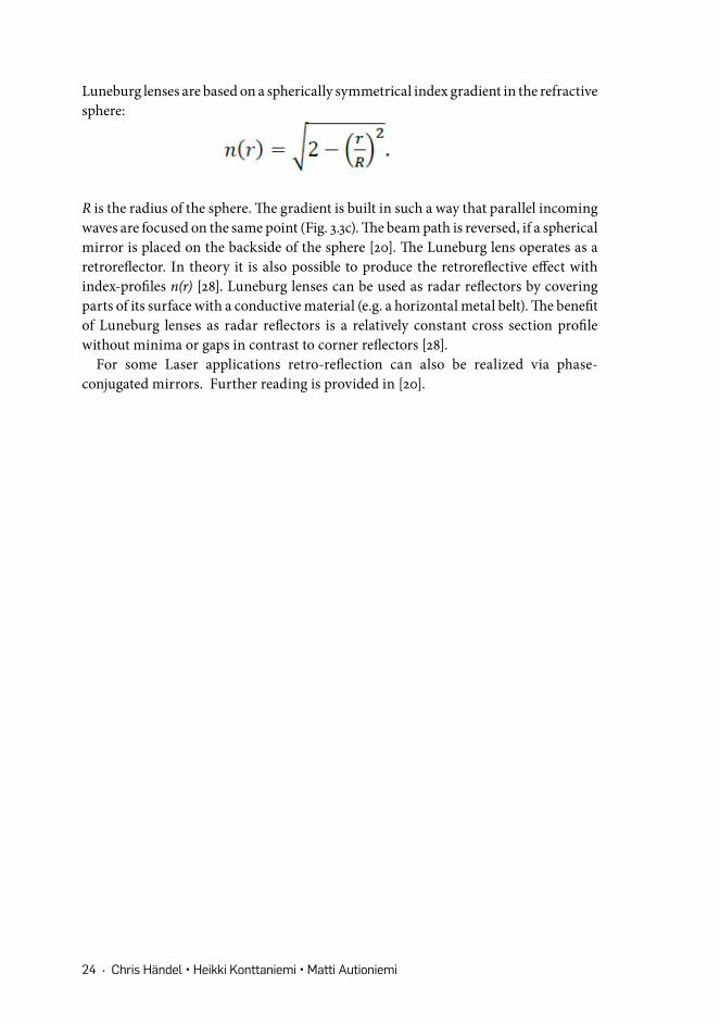
Luneburg lenses are based on a spherically symmetrical index gradient in the refractive sphere:
R is the radius of the sphere. The gradient is built in such a way that parallel incoming waves are focused on the same point (Fig. 3.3c). The beam path is reversed, if a spherical mirror is placed on the backside of the sphere [20]. The Luneburg lens operates as a retroreflector. In theory it is also possible to produce the retroreflective effect with index-profiles n(r) [28]. Luneburg lenses can be used as radar reflectors by covering parts of its surface with a conductive material (e.g. a horizontal metal belt). The benefit of Luneburg lenses as radar reflectors is a relatively constant cross section profile without minima or gaps in contrast to corner reflectors [28].
For some Laser applications retro-reflection can also be realized via phase-conjugated mirrors. Further reading is provided in [20].

State-of-the-Art Review on Automotive Radars and Passive Radar Reflectors • 25
4. Current Products on the MarketThe use of radar waves in technologies supporting autonomous driving, such as advanced driver assistance (ADAS) or adaptive cruise control (ACC), has become increasingly important in the last decade. Especially the 76-81 GHz band (millimeter waves, 2.8mm – 3mm) has been established in this field due to regulatory requirements and bandwidth availability. A further advantage of “mmWave technology” is the small size of the systems components such as the antennas. [11]
Typically, passive radar reflectors are used in aviation or in marine transport in order to make vessels, physical land infrastructure or aircrafts visible in a radar image. They can also be used to calibrate radar images from planes, for example in forest mapping. The most common radar reflectors are passive corner reflectors whereas there are some applications also based on the Luneburg lens technique.
When it comes to passive radar reflectors, the radar signal is reflected best from materials with a high conductivity [7]. Anything with metal in it, will reflect radar. The best shape to return a radar pulse is a flat metallic plate - but only at a right angle. A spherical shape provides the most coverage, but produces very weak returns. The designer’s challenge is to compromise the best between these two shapes. [29]
The next sections will introduce selected radar systems and reflectors suitable for transport applications on the current market.
4.1 RADARS
4.1.1 mmWave AWR from Texas Instruments (TI)
TI’s mmWave family of devices includes the 76–81GHz front-end sensor (AWR1243) (Fig. 4.1a), as well as, devices that pair this front-end with on-chip processing for complete radar systems (AWR1443 and AWR1642 sensors). There are evaluation modules available for these three sensors (AWR1243BOOST, AWR1443BOOST and AWR1642BOOST) for 299$ respectively (Fig. 4.1b). Each evaluation BOOST can be equipped with a mmWaveDEVPACK (299$) to configure them with the “RadarStudio” software (Fig. 4.2a). The three different BOOSTs can further be equipped with a TSW1400 EVM ”high speed data capture/pattern generator” (649$) to get raw analog data from the radar (Fig. 4.2b).

26 • Chris Händel • Heikki Konttaniemi • Matti Autioniemi
Fig. 4.1: AWR mmWave front-end sensors. (a) Picture of the AWR1243 76-to-81GHz High-Performance Automotive Radar Sensor. [30] (b) Picture of the AWR1243BOOST - AWR1243 76-to-81GHz High-Performance Automotive Radar Sensor Evaluation Board. [31] (c) Comparison of different mmWave sensors from TI. [32]
The AWR1243 form TI is a compact and high-performance front-end mmWave sensor. It supports fast chirp FMCW modulations from a closed-loop frequency synthesizer and features a wide-IF bandwidth (see section 2.1.4). All circuits are integrated in one single die (CMOS - complementary metal-oxide-semiconductor technology) along with a digital sub-system for control, calibration and digital front-end. The sensor includes 3 transmit and 4 receive chains. Application of the sensor extends from automated highway driving and ACC to automated emergency braking [32]. The sensors AWR1443 and AWR1642 work with a similar principle but differ in technical specification (Fig. 4.1c). [11]
An accurate angular and distance resolution that supports automated features, can be achieved over a wide field of view, using a four-chip cascaded AWR1243 sensor (Fig. 4.2c). AWR1243 sensors include synchronization features to cascade several devices on one single printed circuit board (PCB) to create large coherent arrays for high-resolution processing. Fig. 4.3 illustrates that a cascade of multiple chips yields sharp peaks in angle and resolution of two closely spaced targets, which are indistinguishable for the single chip case. [11]

State-of-the-Art Review on Automotive Radars and Passive Radar Reflectors • 27
Fig. 4.2: Additional evaluation equipment and characteristic values of the AWR1243 for different modes. (a) Picture of the mmWaveDEVPACK. [33] (b) Picture of the TSW1400 EVM. [34] (c) Characteristic values of the AWR1243 for different modes. Full resolution radar with long-range mode for a four AWR1243 solution. (Additionally a third mode for medium-range radar can also be inserted.) [11]
Fig. 4.3: Measured radar responses of 2 corner reflectors. FFT output for different configurations with 4° angular separation with 1- (top) and 2-chip (bottom) configurations. [11]
4.1.2 ARS 408-21 sensor from Continental AG
The 408-21 Premium (Fig. 4.4a) is a small and robust designed 77GHz long range radar sensor from the ARS 40X series, which has been developed for the automotive industry. The sensor is equipped with a simple software interface and it is optimized for applications such as distance controlling of autonomous vehicles, object detection in unknown areas as well as monitoring of hazardous or non-accessible areas. A dual

28 • Chris Händel • Heikki Konttaniemi • Matti Autioniemi
scan (serially alternating) enables detections in far and short range (Fig. 4.4b and 4.5a). Switching between near and far range scan is performed via selecting different chirps. The system is further equipped with several antennas for simultaneous detection of multiple objects. A classification of moving objects as vehicles, bicycles or pedestrians is also possible.
Fig. 4.4: ARS 408-21 radar sensor. (a) Picture of the ARS 408-21 radar sensor. [35] (b) A digital antenna offers two independent scans for far and short range. The sensor contains 2 TX and 6 RX antennas for near range and 2 TX and 6 RX antennas for far range scan using digital formed beams. [35]
The sensor can be connected to as well as configured via a CAN (Controller Area Network) which performs the communication between the sensor and a computer. The sensor’s working principle is based on fast chirp FMCW modulations and thus on independent distance and velocity measurements of targets in one cycle (see section 2.1.4). The target information is evaluated during every cycle and its position is given in a coordinate system relative to the sensor. The velocity is estimated relative to an assumed vehicle course, which is determined by using the speed and yaw rate information (if the sensor is mounted in the longitudinal direction on the front of the car (Fig. 4.5b)). The measured objects can be filtered by different criteria and thus only reflections of objects of interest are sent to the CAN-bus. A detailed description of the sensor is given in [36].
State-of-the-Art Review on Automotive Radars and Passive Radar Reflectors • 29
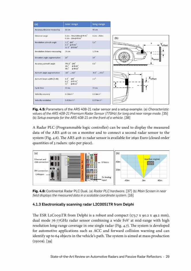
Fig. 4.5: Parameters of the ARS 408-21 radar sensor and a setup example. (a) Characteristic values of the ARS 408-21 Premium Radar Sensor (77GHz) for long and near range mode. [35] (b) Setup example for the ARS 408-21 on the front of a vehicle. [38]
A Radar PLC (Programmable logic controller) can be used to display the measured data of the ARS 408-21 on a monitor and to connect a second radar sensor to the system (Fig. 4.6). The ARS 408-21 radar sensor is available for 2690 Euro (closed order quantities of 3 radars: 1360 per piece).
Fig. 4.6: Continental Radar PLC Dual. (a) Radar PLC hardware. [37] (b) Main Screen in near field displays the measured data in a scalable coordinate system. [16]
4.1.3 Electronically scanning radar L2C0051TR from Delphi
The ESR L2C0051TR from Delphi is a robust and compact (173.7 x 90.2 x 49.2 mm), dual mode 76-77GHz radar sensor combining a wide FoV at mid-range with high resolution long-range coverage in one single radar (Fig. 4.7). The system is developed for automotive applications such as ACC and forward collision warning and can identify up to 64 objects in the vehicle’s path. The system is aimed at mass production (2500$). [39]

30 • Chris Händel • Heikki Konttaniemi • Matti Autioniemi
The radar was tested in a collision-avoidance system [40]. It was evaluated in terms of vehicle detection reliability, position, speed and acceleration accuracy. The sensor was compared to two other radars (Smartmicro SMS UMRR9 and Ibeo Lux) for the detection of cars. The Delphi system was able to detect 99.995% of the vehicles as far as 180m ahead, with a longitudinal Root-Mean Square (RMS) error of 1.8m and a lateral RMS error of 0.4m. The authors concluded that the Delphi radar was the best sensor of the three tested options in terms of performance-cost ratio, for detecting cars in this application. The test results are given in [39].
Fig. 4.7: ESR L2C0051TR radar sensor from Delphi. (a) Picture of the ESR L2C0051TR radar sensor. [39] (b) Delphi’s multimode ESR provides wide coverage at mid range and high-resolution long-range coverage using a single radar. [39]
4.1.4 The DRS4D-NXT radar from Furuno
The DRS4D-NXT radar from Furuno (Fig. 4.8a) is a 9.4GHz solid-state pulse compression Doppler radar, which is developed for maritime transport and can identify up to 100 objects. The device is equipped with a target analyser, fast target tracking and auto target acquire function to offer optimal detection and sensitivity of hazardous objects. Targets that are approaching the radar automatically change the colour to support the identification of targets. The NavNet TZtouch2 display (Fig. 4.8b) enables monitoring the data. An included rain mode demasks targets during hard weather conditions. Further specifications of the sensor are given in Fig. 4.8c. [41]

State-of-the-Art Review on Automotive Radars and Passive Radar Reflectors • 31
4.2.1 Corner reflectors
The most widely used material in corner reflectors is anodized aluminum. Many of the corner reflectors used in maritime and in aviation are of octahedral shape which is applied solely or stacked vertically, whereas some corner reflectors are more simple as they consists of three perpendicular flat surfaces, or of stacked dihedrals in a vertical plane (Fig. 4.9). The octahedral reflector is typically diamond-shaped or constructed from circular panels slotted together. [42]
Fig. 4.8: DRS4D-NXT radar sensor from Furuno. (a) Picture of the enclosure of the DRS4D-NXT radar sensor. (b) Picture of the NavNet TZtouch2 display. (c) Characteristic values of the DRS4D-NXT.
4.2 PASSIVE RADAR REFLECTORS
Fig. 4.9: Different reflector shapes. (a) Octahedron shape which is composed of eight faces, twelve edges and six vertices [43], (b) Radar tube reflector (560 mm) from SecureFlix Direct that uses stacked dihedrals [44], (c) A dihedral angle. [47]

32 • Chris Händel • Heikki Konttaniemi • Matti Autioniemi
The most typical corner reflectors are summarized in the table below (Fig. 4.10). This table gives an idea of the main shapes used, an image of the reflector, main materials as well as dimensions, weight and the price.
Shape Image Material and composition
Dimensions and weight
Price
Octahedral (diamond)
Anodized aluminum
Diameter ~40 cm, Weight 650 g
25-30 € / pc
Octaheral (circularpanels)
Anodized aluminum
Diameter ~30 cm, Weight ~500 g
90-100 € / pc
Tubular, dihedrals in a stack array
Anodized aluminum
Diameter ~5 cm, Length ~55-60 cm
30-60 € / pc
Octahedral, inflatable
DuPontmetallized, lacquered and spunbonded fabric, PVC casing
Diameter ~30 cm, Length ~75 cmWeight ~400 g
~150 € / pc
Symmetrical stack array
Polyethylene case, anodised aluminum
Height ~25 - 45 cm, Width ~20 - 25 cm (overall), Weight ~1,5 - 2,5 kg
150 - 250 € / pc
Fig. 4.10: Summary of passive radar reflectors found in the market.

State-of-the-Art Review on Automotive Radars and Passive Radar Reflectors • 33
As the table shows, the prices of passive corner reflectors used in consumer marine applications vary from 25€ up to 250€. The smallest reflector in terms of diameter is the tube reflector. Its diameter can be approximately five centimeters, which is considerably smaller as opposed to the octahedral reflectors which can have a diameter of about forty centimeters. Typically, the reflectors are from 30 centimeters to 75 centimeters tall depending on its shape. The weight varies based on the structure and size as some lighter reflectors weigh only approximately 0,5 kilograms as opposed to the heavier ones that weigh 2,5 kilograms. In some cases, the reflectors are encased in plastic.
4.2.2 Luneburg lens reflectors
The RCS of a Luneburg lens is several hundred times that of a metallic sphere of the same size and it does not require maintenance or power supply. Luneburg lens is said to be the most efficient passive radar reflector available. There are very few Luneburg lens radar reflectors in the market for transport use. Luneburg lens reflectors are used in military applications but for consumers they are familiar from marine transport (Fig. 4.11).
Fig. 4.11: Tri-Lens Luneburg reflector on a yacht mast. Image: The Rigging Company.
In maritime transport, the most typical reflectors are so called Tri-Lens reflectors that have three Luneburg lens reflectors with 120 degree angle between them. The two Tri-Lens reflectors found in the market differ by their weight, price and dimensions (Fig. 4.12). The appearance and the basic structure of these two reflectors is almost identical if size is disregarded.
Product Weight and dimensions Price
Large Tri-Lens 5,5 kg, 160 x 160 x 80 mm 300 £
Standard Tri-Lens 2,5 kg, 120 x 120 x 60 mm 160 £
Fig. 4.12: Comparison of the two Tri-Lens reflectors found in the market.

34 • Chris Händel • Heikki Konttaniemi • Matti Autioniemi
4.2.4 Performance investigations
Vessels made of glass reinforced plastic (GRP) are poor reflectors of radar signals and therefore it is essential for small vessels to be equipped with a radar reflector. The ISO 8729-1 :2010 standard determines the construction, performance and testing for passive radar reflectors. The standard has been revised in 2015 and is up to date. [46]
Passive radar reflectors have been tested in 2007 according to the new ISO 8729 standard and their performance has been investigated in 2005 in optimum laboratory conditions [29, 44]. Some of the main outcomes of these performance tests can be seen in the Fig. 4.13.
Reflector Performance investigation in 2007 according to ISO 8729 (2) standard [45]
Performance investigation in 2005 done in optimum conditions [29]
Octahedral, 16” (Plastimo)
Inexpensive; wide nulls keep its performance level down; reasonable peak; fails to meet ISO 8729
Cheap and outperformed half of the tested reflectors.
Stacked, triple array corner reflector (Echomax 230)
Just narrowly failed to meet ISO 8729 specifications; good peak and overall performance
Outperforms the Firdell Blipper and meets the ISO 8729 and SOLAS specifications
Octahedral, circular (Davis Echomaster)
Failed to get close to ISO 8729; low peak and average performance; light weight
Not very convincing; needs more size and does not offer much in comparison to a regular octahedral
Spiral stack of trihedral corner reflectors (Firdell Blipper 210-7)
Narrowly fails to meet the standard; good peak and average performance
More consistent 3D results than octahedrals
Spiral corner reflectors (Tube)
Performs very poorly Very limited amount of reflective properties
Luneberg lens (Standard Tri-Lens)
Does not meet ISO 8729 with a low peak; consistent enough to outperform most of the other reflectors
Very solid performance, very consistent returns in every angle of heel
Luneberg lens (Large Tri-Lens)
Performs very well and just falls short of ISO 8729; heavy and expensive
First-class results; very heavy
Multi dielectric lens (Visiball)
n/a Lenses have to be bigger in order to be productive; high cost; heavy
Fig. 4.13: Summary of some main results from two performance tests of passive radar reflectors for boats.

State-of-the-Art Review on Automotive Radars and Passive Radar Reflectors • 35
In 2007 performance investigation showed that none of the reflectors passed the standard. The large Tri-Lens Luneburg lens reflector is recommended for yachts, but the downside is its heavy weight and high price. Other reflectors that just narrowly passed the ISO 8729 standard are stacked array corner reflectors. It is notable that the 4” tube reflectors with a stacked array of dihedrals, performed poorly. [46]
According to the tests done in 2005 in optimum conditions, it is noticeable how the 16” octahedral reflector outperformed half of the other reflectors, even though it comes with a very low price. The stacked array corner reflector, Echomax 230, also outperformed its competitor, the Firdell Blipper, which in turn, gave a consistent return. The Tri-Lens Luneburg lens reflectors performed well and the Large Tri-Lens gave a first-class performance. The tube reflector had a very limited amount of reflective properties. Dielectric lens reflector is very expensive and gave very weak returns. [29]

5. Summary and Conclusions
To fully utilize the radar potential for automotive applications under extreme weather conditions, we have conducted a state-of-the art research including different radar systems and passive radar reflectors. The report contributes to the understanding of prospects and limitations of current technologies and products in the field of autonomous driving with a focus on radars and reflectors.
The present report provides an overview about the current state of the art of the Arctic Challenge research project. In this project, requirements for different landmark reflectors, embedded into roadside furniture (e.g. delineator posts or snow poles), will be studied in the Aurora Borealis Corridor. It will be determined, which objects have the potential to support autonomous driving and other automated features, especially under hard winter conditions. Finding out specific properties, such as the optimal size, location, form, orientation and the material composition will be further aims of this project. The experimental access to the projects’ research questions will be provided via passive roadside radar reflectors along with automotive radar systems. This state of the art report is the first part of a feasibility study carried out by the Lapland University of Applied Sciences and Roadscanners Oy for the project.
Chapter 2 in the present report addresses radar techniques in general and highlights their role for object detection, even under extreme cold and icy weather conditions. First, the radiofrequency spectrum is introduced and its potential for autonomous driving is underlined. The following sections concerning components and working principles of radar systems familiarize the reader with the topic and provide the ability to compare different products on the market and choose the correct systems for the required application. A special focus is on FMCW radars, because most of the systems, utilized in automotive applications, are based on that working principle.
Chapter 3 focuses on reflector techniques and their relevance in traffic and infrastructure. One central term in that chapter is the radar cross-section. It indicates the detectability of an object by radars and is a characteristic property of radar reflectors. This specific property is important when comparing and selecting the right radar reflector, suitable for the chosen radar system. The following section describes different technical possibilities to develop radar reflectors, such as corner and spherical reflectors, and sketches their physical background.

State-of-the-Art Review on Automotive Radars and Passive Radar Reflectors • 37
Chapter 4 introduces selected radar systems with long range distance (≈250m) and reflectors suitable for transport applications on the current market. In section 4.1 three radar systems – the AWR1243 sensor from Texas Instruments, ARS 408-21 sensor from Continental AG and the L2C0051TR from Delphi – are described concerning technology, application, specification and price level. In the next section 4.2 multiple passive radar reflectors (corner reflectors and Luneburg lenses) from different manufacturers are compared with regard to shape, composition and price level. The chapter closes with the results of two performance investigations about selected reflectors. Especially the investigation performed in 2007 signals that none of the tested reflectors passed the ISO 8729 (2) standard. The second investigation was performed under ideal laboratory conditions and led to similar results even though there were differences in RCS values between these two tests. It was not fully possible to directly compare these tests since the tests were reported differently. Additionally, the test done in 2005 was more for commercial purposes and made no mention of being based on the same test standard.
Finally, this state-of-the-art report in combination with our impressions from the 18th International Congress and Exhibition -ELIV (Electronics in Vehicles) 2017 in Bonn, and from discussions with experts, lead to the conclusion that the importance of radars for vehicle positioning under extreme weather conditions is underestimated. Accurate positioning is essential for autonomous driving. However, current systems based on Lidar detecting lane markings will not be sufficient to realize vehicles with autonomy levels higher than 2. One important reason for this is, that Lidar systems perform poorly in heavy rain, snow, fog or icy conditions. Radars might play a key role for achieving safety requirements posted by the standard ISO 26262. From the given overview of available technologies we conclude that there is an unused capacity on the infrastructure side in the area of radar detection.

38 • Chris Händel • Heikki Konttaniemi • Matti Autioniemi
List of References
[1] I. Rainio, Verbal source. Theme interview with a large-vessel sea captain, Ilari Rainio, (2017)
[2] M. I. Skolnik. “An Introduction to Radar”. In: McGraw-Hill Education, 3rd edition, London, (2002)
[3] Scherr et al. “Miniaturized 122 GHz ISM band FMCW radar with micrometer accuracy” In: Radar Conference (EuRAD), (2015) European
[4] A. S. Yadav and S. Kumar. “A REVIEW PAPER ON RADAR SYSTEM”. In: International Journal for Innovative Research in Science & Technology (2016): 45-47
[5] https://commons.wikimedia.org/wiki/File:Vergleich_der_Frequenzb%C3%A4nder.svg[6] L. A. Belov, S. M. Smolskiy and V. N. Kochemasov. “Handbook of RF, Microwave,
and Millimeter-Wave Components”, In: Artech House, Boston, (2012)[7] W. Demtröder. „Experimentalphysik 1: Mechanik und Wärme“. 6., überarb. u. akt.
Aufl., Springer-Lehrbuch. Berlin: Springer, (2013)[8] http://www.radartutorial.eu/[9] https://en.wikipedia.org/wiki/Radiation_pattern#/media/File:Sidelobes_en.svg[10] H. F. Hofmann, T. Kosako and Y. Kadoya. „Design parameters for a nano-optical
Yagi–Uda antenna”. In: New Journal of Physics, Volume 9, (2007)[11] http://www.ti.com/lit/wp/spyy003/spyy003.pdf[12] http://www.ti.com/lit/wp/spyy005/spyy005.pdf[13] TA Larsen, HV Fletcher. “Low power retroreflective communications system and
method.” (2013)[14] J Copeland - US Patent. “Bicycle single-wire lighting system with steady-flashing-
reflector rear warning device.” (1991)[15] Ville Viikari, Mikko Kantanen, Timo Varpula. “Technical Solutions for Automotive
Intermodulation Radar for Detecting Vulnerable Road Users” (2009)[16] https://commons.wikimedia.org/wiki/File:RCS_reference.jpg[17] http://targetsystems.qinetiq.com/static/media/files/Luneberg_Lens_2015.pdf[18] http://www.radar-reflector.com/wp-content/uploads/2008/07/F7.2_5_TIndex_2012.pdf[19] http://www.radartutorial.eu/01.basics/Effektive%20R%C3%BCckstrahlfl%C3%A4che.
de.html

State-of-the-Art Review on Automotive Radars and Passive Radar Reflectors • 39
[20] Voronov, A., Hultén, J., Wedlin, J., Englund, C. „Radar reflecting pavement markers for vehicle automation“. (2016)
[21] Ibrahim Osman, Tarig. (2014). Analysis of Radar Cross Sectional Area of Corner Reflectors. IOSR Journal of Engineering. 04. 47-051. 10.9790/3021-04124047051.
[22] Armin W. Doerry and Billy C. Brock. “Radar Cross Section of Triangular Trihedral Reflector with Extended Bottom Plate”. (2009) [23] https://commons.wikimedia.org/wiki/File:Corner-reflector.svg
[24] https://commons.wikimedia.org/wiki/File:Winkelreflektor3.svg[25] https://commons.wikimedia.org/wiki/File:Yachtstellung.jpg[26] B. Yang and H. Friedsam. “Ray-Tracing Studies for a Whole-Viewing-Angle
Retroreflector.” (2000)[27] https://commons.wikimedia.org/wiki/File:Luneburg_lens.svg[28] Samuel P. Morgan: General Solution of the Luneberg Lens Problem. In: Journal
of Applied Physics. Band 29, Nr. 9, 1958, S. 1358–1368[29] http://www.yachtingmonthly.com/fileBank/yachtingmonthly/PDF/reflector_
performance_ym_june.pdf [30] http://www.ti.com/product/AWR1243[31] http://www.ti.com/tool/AWR1243BOOST[32] http://www.ti.com/lit/ds/symlink/awr1243.pdf[33] http://www.ti.com/tool/MMWAVE-DEVPACK[34] http://www.ti.com/tool/tsw1400evm[35] https://www.continental-automotive.com/getattachment/5430d956-1ed7-464b-afa3-
cd9cdc98ad63/ARS408-21_datasheet_en_170707_V07.pdf.pdf[36] http://www.compotrade.ru/i/pdf/ARS404-21_ARS408-21_en_V1.03.pdf[37] https://www.continental-automotive.com/getattachment/bffa64c8-8207-4883-9b5c-
85316165824a/Radar-PLC-Manual-EN.pdf.aspx
[38] http://www.compotrade.ru/i/pdf/ARS404-21_ARS408-21_en_V1.03.pdf[39] http://www.araa.asn.au/acra/acra2015/papers/pap167.pdf[40] J. Fischer, A. Menon, A. Gorjestani, C. Shankwitz, and M. Donath. Range sensor
evaluation for use in cooperative intersection collision avoidance systems. In Vehicular Networking Conf., 2009.
[41] http://www.furuno.com/files/Brochure/334/upload/DRS6ANXT_4DNXT_en_171213.pdf[42] E. J. Condon and E. Kolbe. “Radar reflectors for boats”. Maritime electronics.
(1978)[43] https://commons.wikimedia.org/wiki/File:Octahedron.jpg[44] https://www.securefixdirect.com/50mm-x-560mm-tube-radar-reflector---tubular-
passive-powerboat-boat-marine-8668-p.asp[45] Luke, S. “Performance investigation of marine radar reflectors on the market”.
Report by QinetiQ. (2007)[46] https://www.iso.org/obp/ui/#iso:std:iso:8729:-1:ed-1:v1:en [47] https://commons.wikimedia.org/wiki/File:Dihedral_angle.svg

Automation will enable safer, more green and efficient road transport in the upcoming decades. In order to exploit the full potential of automation, autonomous vehicles have to operate also in arctic environments, and in cold and icy conditions. This review is the first part of research project that aims at testing the feasibility of passive roadside radar reflectors for autonomous driving in snowy conditions. The content comprises of state-of-the-art revi-sion of radar techniques, automotive radars and passive radar reflectors. This research is conducted by Lapland University of Applied Sciences and Roads-canners in Arctic Challenge research project.
The Arctic Challenge research project is funded by the Finnish Transport Agency (FTA) and Finnish Transport Safety Agency (TraFi). The project is part of the Aurora intelligent road project of the Finnish Transport Agency and the NordicWay2 project funded by the Connecting Europe Facility of the European Union. The testing weeks of the research project will take place on the 10-km-long test stretch of the Aurora Vt21 (E8) intelligent road section in years 2017–2019. Furthermore, the project is part of the Traffic Lab coopera-tion. The contracting partners involved in the research project include Dynniq Finland Oy, Indagon Oy, Infotripla Oy, Lapland University of Applied Sciences Oy, Roadscanners Oy, Sensible 4 Oy and VTT Technical Research Centre of Finland Oy.
www.lapinamk.fi
ISBN 978-952-316-223-5